
INSTALLATION GUIDE
RF135B, RF170B & RF170W models
JOINER KIT
US CA
2
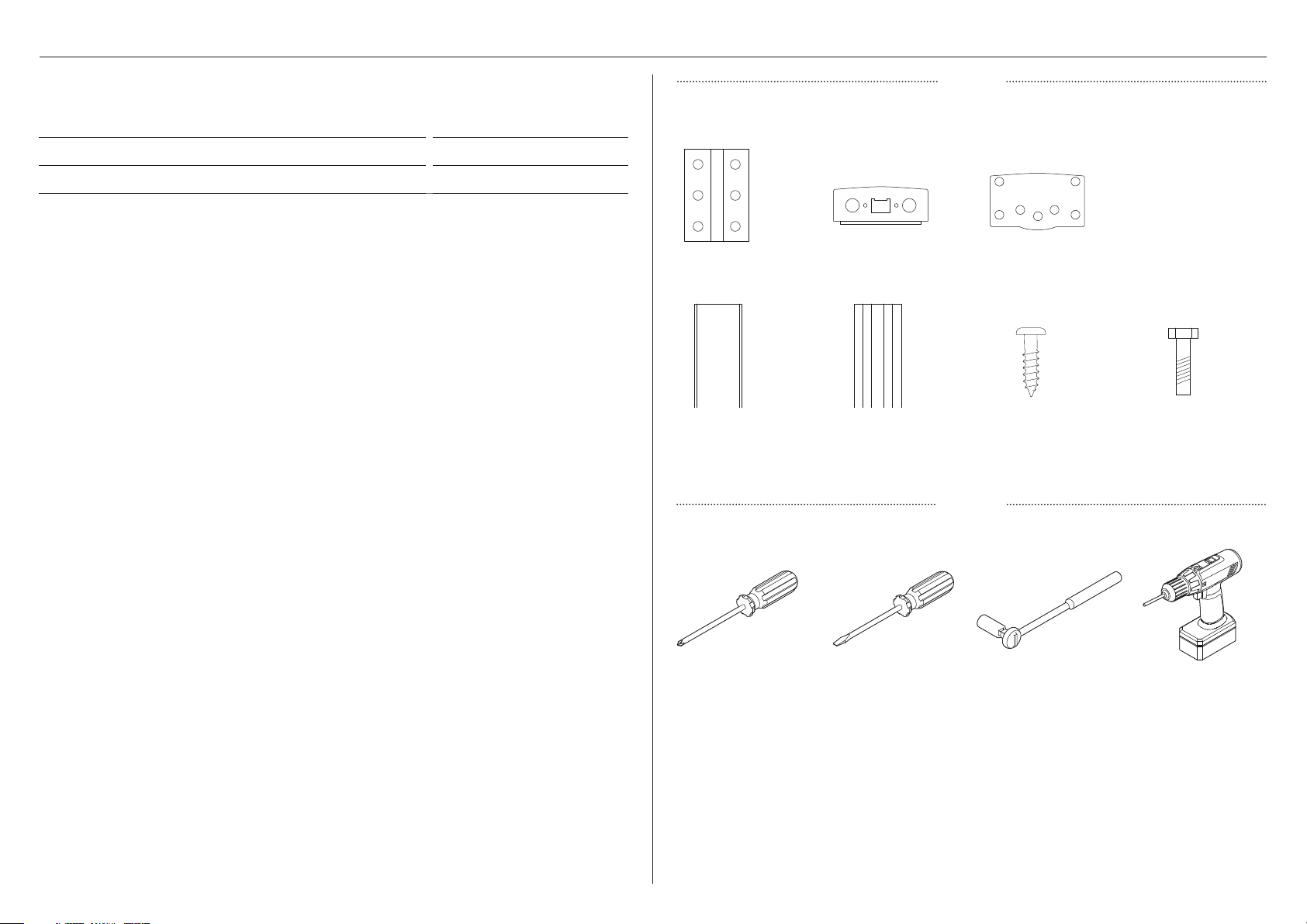
COMPONENTS REQUIRED
z
This kit is designed for use on 67 3/4"-high models and can be used to combine any
variants of RF135B, RF170B and RF170W with handles.
z
We recommend you save this installation guide for future reference.
ITEM PART NUMBER
Kit Joiner Silver AJ-RF17X 819264
TOOLS
Phillips screwdriver Flat-blade screwdriver 3/4" (19mm) socket wrench Battery drill with
90mm+ drill bit
Not supplied
PARTS
Rear bracket (1) Front lower bracket (1) Front Upper bracket (1)
Supplied
Extrusion support (1) Extrusion cover (1) 8x16 pan-head
Phillips screws (7)
5x20 hex-head
Phillips screws (6)
3
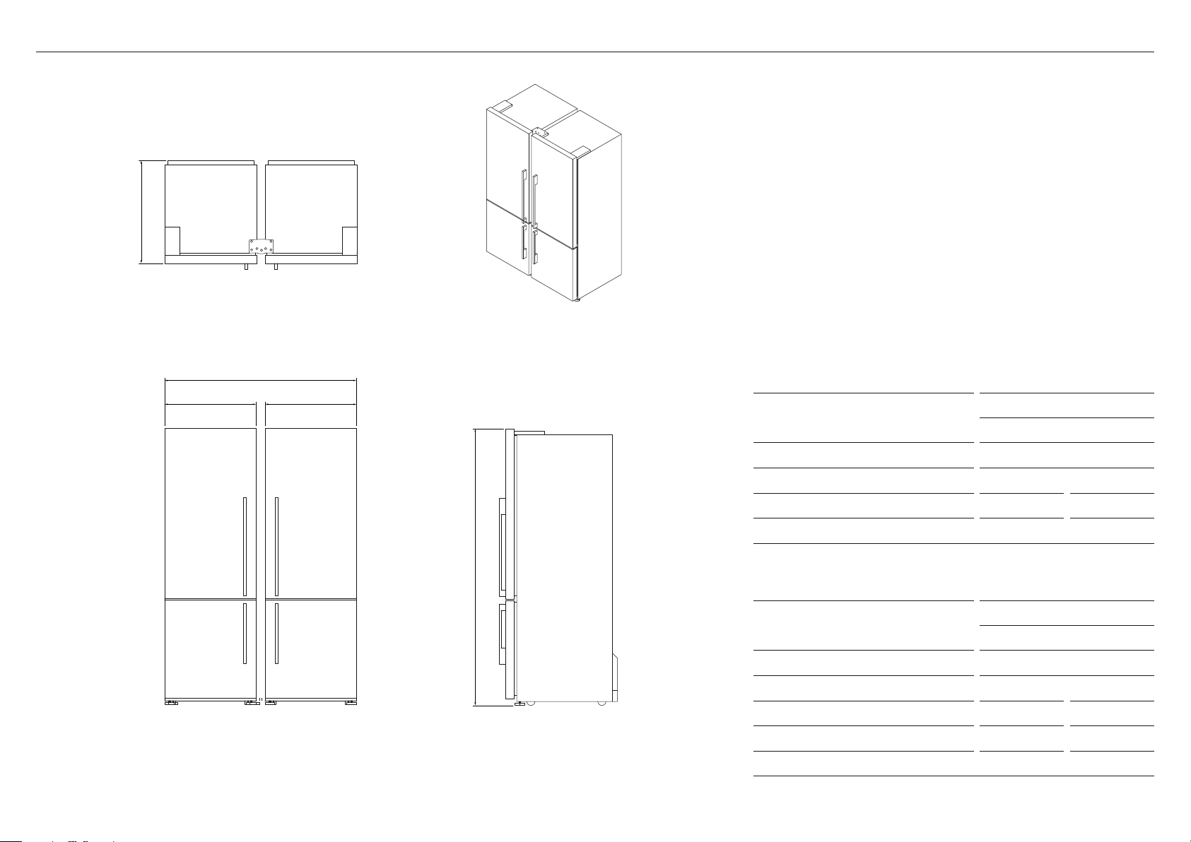
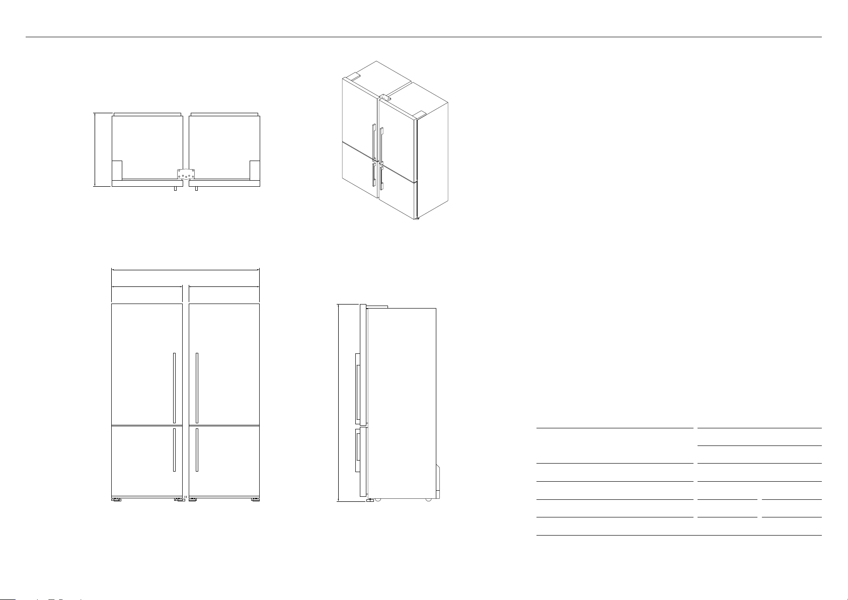
PRODUCT DIMENSIONS – RF135B COMBINATIONS
FRONT PROFILE
Actual product dimensions may vary by up to +3/16" (5 mm).
PRODUCT DIMENSIONS
RF135B + RF135B
IN MM
A Overall height 67 3/4 1720
B Overall depth* 27 3/8 695
C Overall width 51 1295
D RF135B width 25 635
*Including rear compartment cover, excluding handle.
PRODUCT DIMENSIONS
RF135B + RF170B/W
IN MM
A Overall height 67 3/4 1720
B Overall depth* 27 3/8 695
C Overall width 57 1450
D RF135B width 25 635
E RF170B/W width 32 790
*Including rear compartment cover, excluding handle.
PLAN ISOMETRIC
C
D E
A
B
4
FRONT PROFILE
Actual product dimensions may vary by up to +3/16" (5 mm).
PLAN ISOMETRIC
C
D D
A
B
PRODUCT DIMENSIONS – RF170B/W COMBINATIONS
PRODUCT DIMENSIONS
RF170B/W + RF170B/W
IN MM
A Overall height 67 3/4 1720
B Overall depth* 27 3/8 695
C Overall width 63 1/8 1605
D RF170B/W width 32 790
*Including rear compartment cover, excluding handle.
5
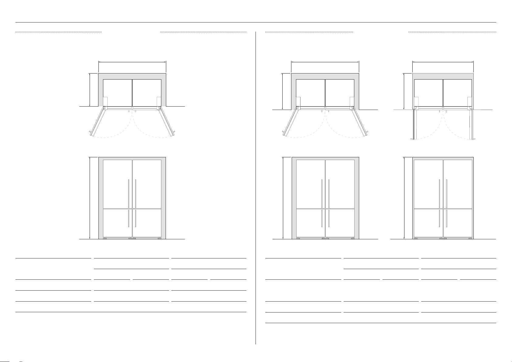
CAVITY DIMENSIONS – RF135B COMBINATIONS
CAVITY DIMENSIONS
RF135B + RF135B RF135B + RF170B/W
IN MM IN MM
A Width of cavity 52 9/16 1335 58 5/8 1490
B Height of cavity 68 5/16 1735 68 5/16 1735
C Depth of cavity 24 3/8 620 24 3/8 620
CAVITY DIMENSIONS
RF135B + RF135B RF135B + RF170B/W
IN MM IN MM
A Width of cavity
z
Full door rotation
z
90° door rotation
61 5/8
58 1/16
1565
1475
67 3/4
64 3/16
1720
1630
B Height of cavity 68 5/16 1735 68 5/16 1735
C Depth of cavity 27 3/8 695 27 3/8 695
90° door rotationFull door rotation
FLUSH INSTALLPROUD INSTALL
Full door rotation
PROUD - FULL
FLUSH - 90
FLUSH - FULL
PROUD - FULL
FLUSH - 90
FLUSH - FULL
PROUD - FULL
FLUSH - 90
FLUSH - FULL
PROUD - FULL
FLUSH - 90
FLUSH - FULL
PROUD - FULL
FLUSH - 90
FLUSH - FULL
PROUD - FULL
FLUSH - 90
FLUSH - FULL
B B B
a a a
C
C C
6
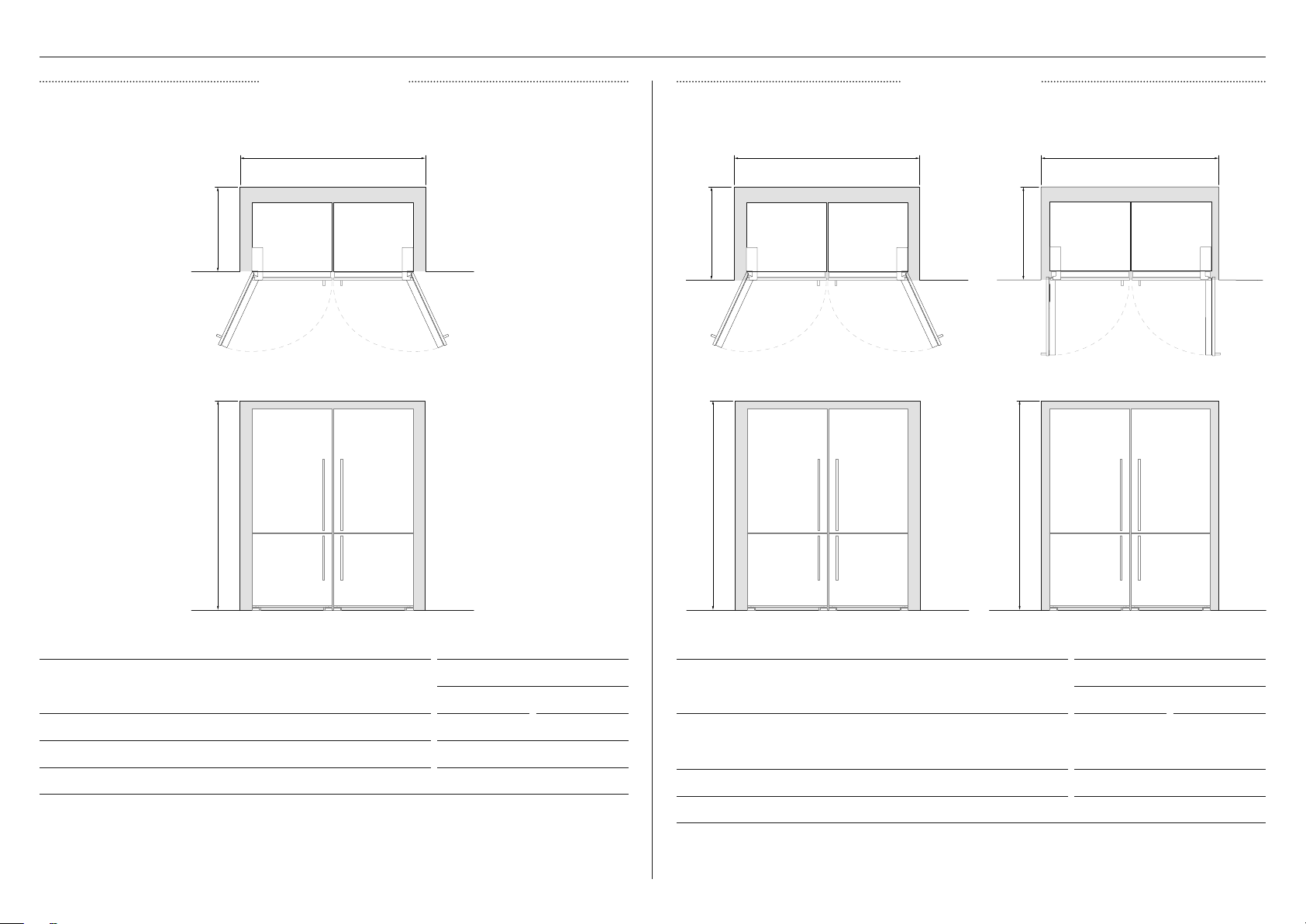
CAVITY DIMENSIONS – RF170B/W COMBINATIONS
CAVITY DIMENSIONS
RF170B/W + RF170B/W
IN MM
A Width of cavity 64 3/4 1645
B Height of cavity 68 5/16 1735
C Depth of cavity 24 3/8 620
FLUSH INSTALLPROUD INSTALL
CAVITY DIMENSIONS
RF170B/W + RF170B/W
IN MM
A With of cavity
z
Full door rotation
z
90° door rotation
73 13/16
70 1/4
1875
1785
B Height of cavity 68 5/16 1735
C Depth of cavity 27 3/8 695
90° door rotationFull door rotationFull door rotation
PROUD - FULL
FLUSH - 90
FLUSH - FULL
PROUD - FULL
FLUSH - 90
FLUSH - FULL
PROUD - FULL
FLUSH - 90
FLUSH - FULL
PROUD - FULL
FLUSH - 90
FLUSH - FULL
PROUD - FULL
FLUSH - 90
FLUSH - FULL
PROUD - FULL
FLUSH - 90
FLUSH - FULL
B B B
a a a
C
C C
7
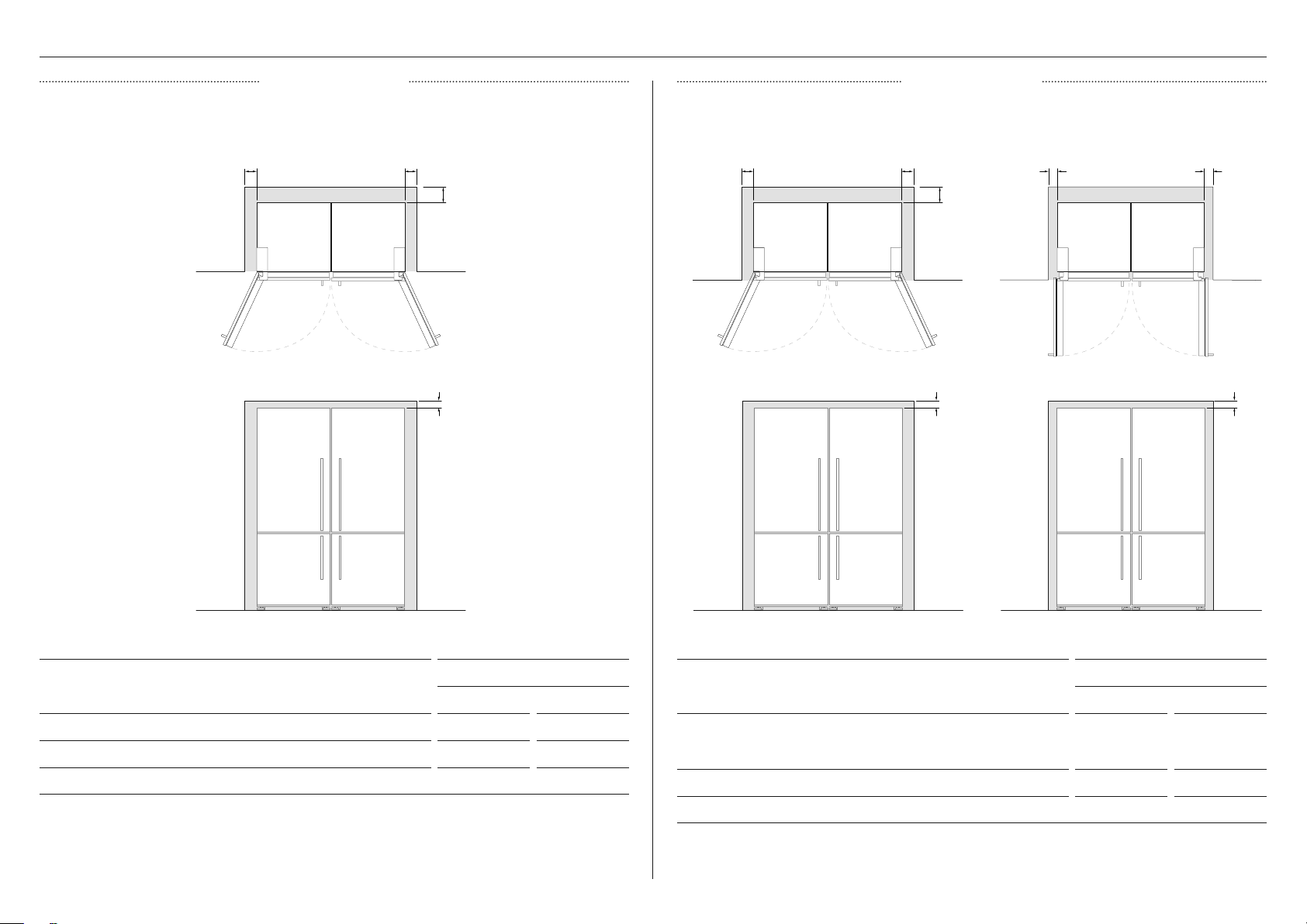
MINIMUM CLEARANCES
ALL MODELS
IN MM
A Side clearance 3/4 20
B Rear clearance (incl. evaporator tray) 1 3/16 30
C Top clearance 2 50
MINIMUM CLEARANCES
ALL COMBINATIONS
IN MM
A Side clearance
z
Full door rotation
z
90° door rotation
5 5/16
3 9/16
135
90
B Rear clearance (incl. evaporator tray) 1 3/16 30
C Top clearance 2 50
CLEARANCES
FLUSH INSTALLPROUD INSTALL
90° door rotationFull door rotationFull door rotation
PROUD - FULL
FLUSH - 90
FLUSH - FULL
PROUD - FULL
FLUSH - 90
FLUSH - FULL
PROUD - FULL
FLUSH - 90
FLUSH - FULL
PROUD - FULL
FLUSH - 90
FLUSH - FULL
PROUD - FULL
FLUSH - 90
FLUSH - FULL
PROUD - FULL
FLUSH - 90
FLUSH - FULL
aaa aaa
B B
C C C
8
INSTALLATION
Before you begin
z
Check cavity dimensions are correct for the type of dual installation you require.
z
Unpack appliances from packaging following guidance on individual cartons.
z
Ensure the floor is protected from damage during unpacking and installation.
z
Check that the Joiner Kit is complete.
z
Always position the two appliances side-by-side with the door hinges on the far left and
right, ensuring you have enough space to access the rear of the appliances.
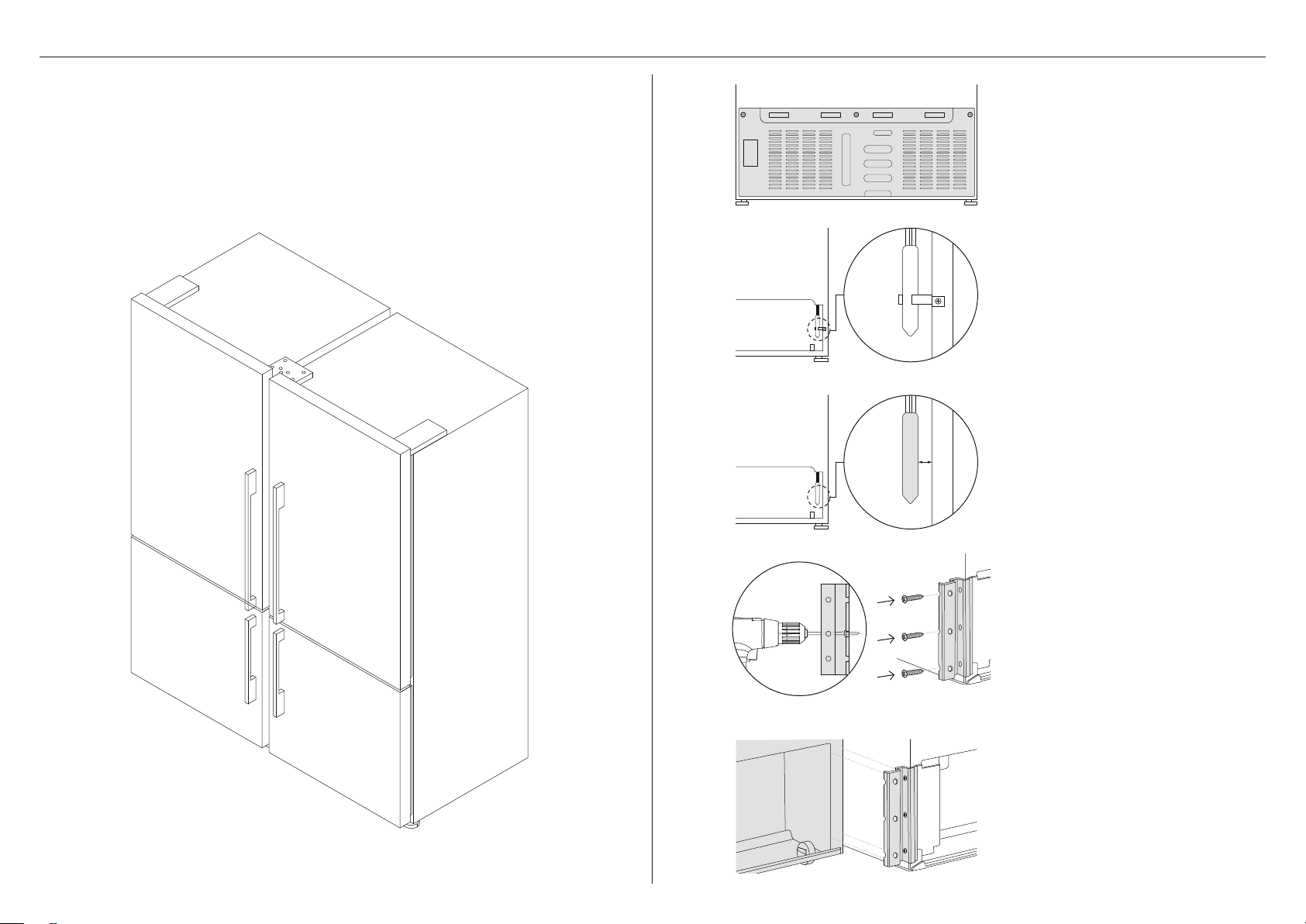
1
Remove the rear compartment cover
using a Phillips screwdriver. This will be
re-attached later.
2
Remove the screw on the filter
dryer retaining bracket using a
Phillips screwdriver.
3
Remove the retaining bracket, ensuring
the filter dryer does not touch any pipes
or the side of the rear compartment.
4
The bracket should only be added to
the left-hand appliance as viewed from
the front.
Align the top edge of the bracket to the
bottom edge of the back panel. Holes
for the bracket will need to be drilled
into the side of the chassis. Secure
bracket from the side using three of the
8x16 screws.
5
Slot the second, right-hand appliance as
viewed from the front, into the bracket,
ensuring it sits securely.
Do not fix in place.
FRONT VIEW
9
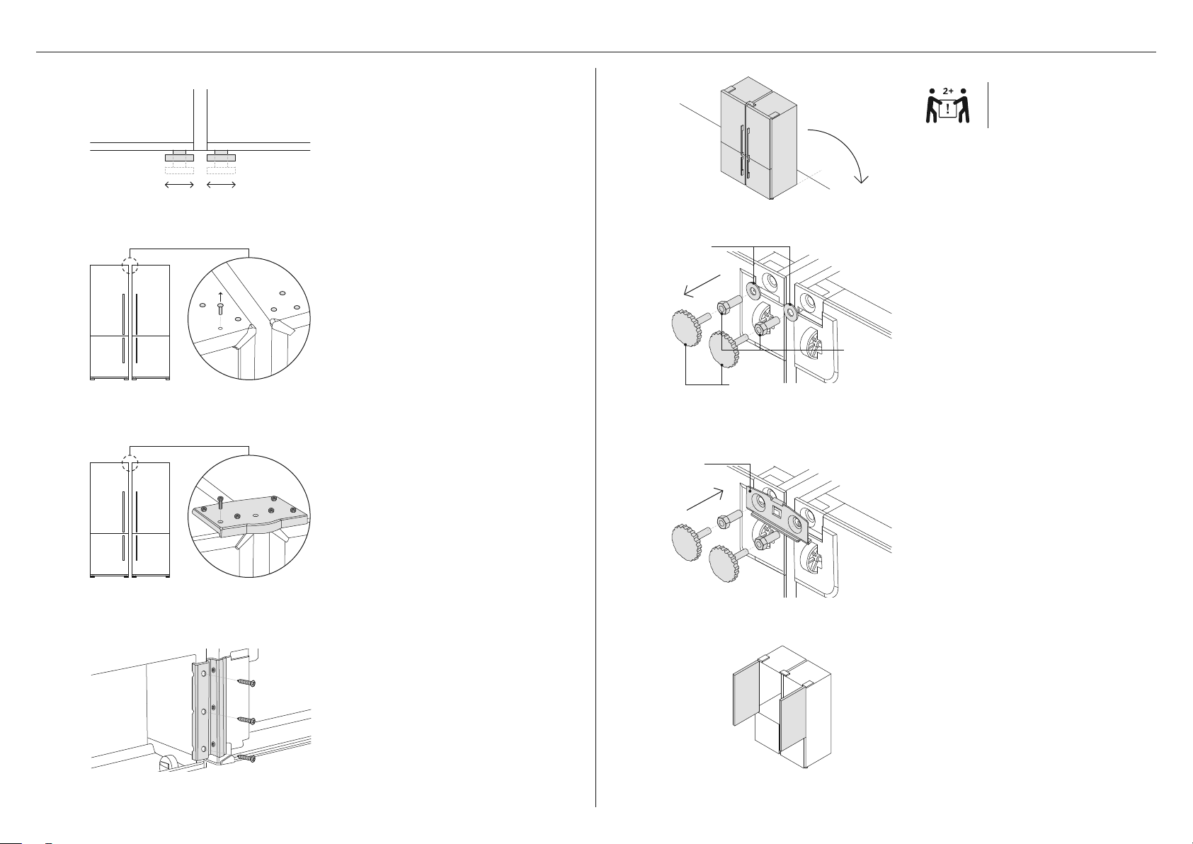
6
Adjust front feet of both appliances
until level.
Turn clockwise to decrease height or
anti-clockwise to increase height.
7
At the top of each appliance,
remove the three screw caps using
a flat-blade screwdriver.
9
Ensure both appliances are level and
aligned before securing the second
appliance to the bracket using three
8x16 screws.
Replace both rear compartment covers
using a Phillips screwdriver.
8
Align the upper bracket to the
screw holes.
Secure the bracket by partially
engaging the 5x20 screws.
INSTALLATION
!3
Open both doors for easy access to
the center join.
!1
!2
Remove the leveling feet from both
appliances using a socket wrench by
rotating them anti-clockwise.
Remove the mounting bolts and
washers, and set aside.
Align the lower bracket to the spaces
created by removing the leveling feet.
Ensure the bracket is correctly oriented
as illustrated.
Secure using the leveling feet and
mounting bolts before lowering the
appliances carefully.
Leveling
feet
!0
Carefully tilt the connected appliances
backwards to access the rear feet and
the lower front bracket location.
IMPORTANT!
Two people required.
Front
lower
bracket
Washers
Mounting
bolts
2
17
3
1
16
15
14
13
10
2
17
3
1
16
15
14
13
2
17
3
1
16
15
14
13
2
17
3
1
16
15
14
13
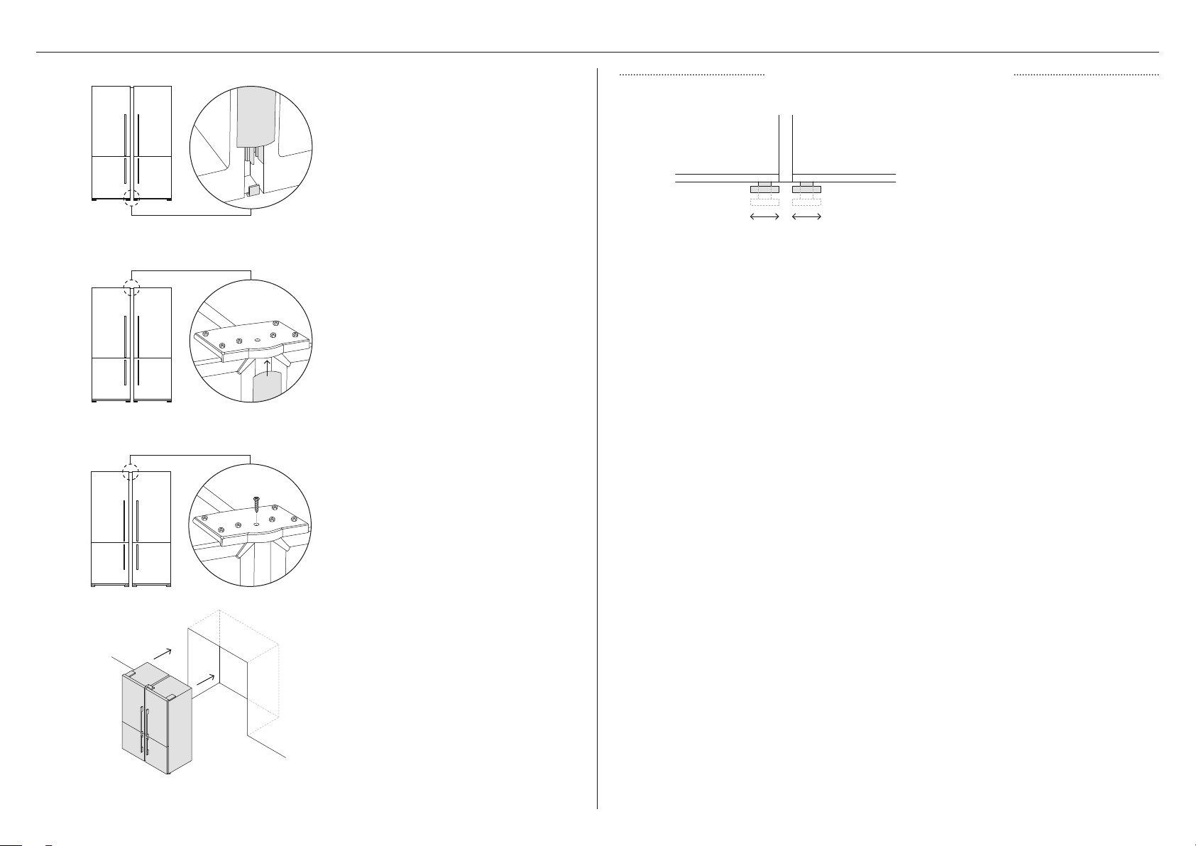
INSTALLATION
!6
!7
1
Secure the trim panel using the
remaining 8x16 screw.
Close the doors and position the
appliances within the cavity.
Ensure front leveling feet are
adjusted correctly.
Incorrect leveling may affect
door alignment.
ADJUSTING DOOR ALIGNMENT
!4
!5
Locate the trim panel assembly to the
tab on the lower bracket.
Position the trim panel under the
upper bracket before re-tightening
the six screws.
2
17
3
1
16
15
14
13
2
17
3
1
16
15
14
13

US CA
865192A 0.20
FISHERPAYKEL.COM
© Fisher & Paykel Appliances 2020. All rights reserved.
The models shown in this installation guide may not be available in all markets and are
subject to change at any time. The product specifications in this document apply to
the specific products and models described at the date of issue. Under our policy of
continuous product improvement, these specifications may change at any time.
For current details about model and specification availability in your country, please go to
our website www.fisherpaykel.com or contact your local Fisher&Paykel dealer.