
Loading ...
Loading ...
Loading ...
WARNING: If any parts are damaged or missing, do
not operate this product until the parts are replaced.
Failure to heed this warning could result in serious
personal injury.
If any parts are damaged or missing, please call
customer service at 1-800-313-5111 for assistance.
WARNING: Do not connect to power supply until
assembly is complete. Failure to comply could result
in accidental starting and possible serious personal
injury.
WARNING: Do not attempt to modify this product or
create accessories not recommended for use with this
product. Any such alteration or modification is misuse
and could result in a hazardous condition leading to
possible serious personal injury.
ASSEMBLY
5
Model TC70090
This product requires assembly.
Carefully remove the product and any accessories
from the box. Make sure that all items listed in the
packing list are included.
Inspect the product carefully to make sure no
breakage or damage occurred during shipping.
Do not discard the packing material until you have
carefully inspected and satisfactorily operated the
product.
PACKING LIST
Tiller
Upper Handle Section
Center Handle Section
Hardware Bag
Owner’s Manual
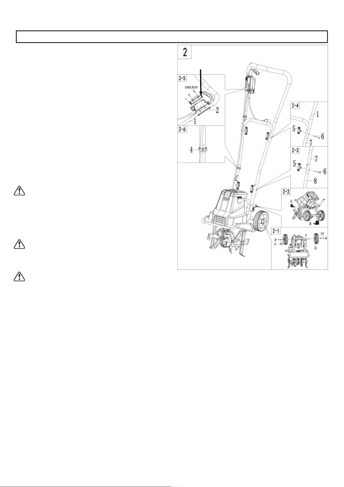
This product must be assembled correctly before use.
1. Remove the screws (M5 X 12) and washers from
each end of the wheel frame axle. Assemble the
wheels onto the axle, then install washers and
screws (M5 X 12) to secure. (Fig. 2-1)
2. Press the hub caps into the wheels and cover the
ends of the axles. You may use a hammer to seat
them securely into the wheels. (Fig. 2-1)
3. To lower wheel frame, push the lock button on back
of motor housing to release the frame (Step A).
Lower the wheel frame (Step B) and pull out the lock
pin on lower handle section (Step C). Align lock pin
to the hole in wheel frame then release it to lock the
wheel frame in position. (Fig. 2-2)
4. Attach the center handle section (7) to the lower
handle sections (8) using the two supplied M6x45
bolts (6) and wing nuts (5). (Fig. 2-3)
5. Fasten the upper handle section (1) to the center
handle section (7) using the two supplied M6x45
bolts (6) and wing nuts (5) (Fig. 2-4).
6. Remove the switch box cover at the back of the
switch box.
7. Install the switch box and power cable assembly
onto the upper handle section using the two supplied
bolts(3.9x19). (Fig.2-5)
8. Use the two supplied cable clips (4) to secure the
cord. (Fig. 2-6)
Switch box cover
Loading ...
Loading ...
Loading ...