Loading ...
Loading ...
Loading ...
5
36” DUAL FUEL RANGE INSTALLATION INSTRUCTIONS
The side cabinet depth (clearance F) must match
the front edge of the range side panel:
Location of the gas and electric
outlets
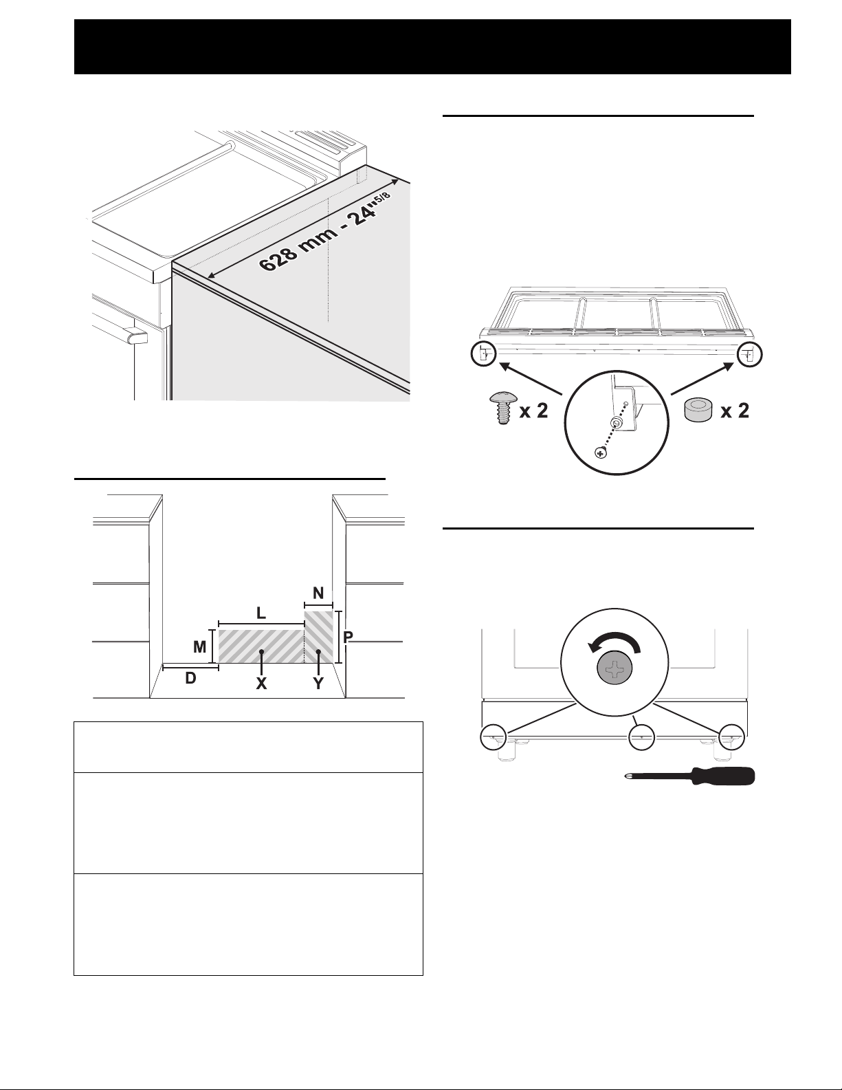
Installing the backguard
The backguard provided is an integral part of the
appliance; it must always be positioned and secured
correctly on the cooktop.
You can find the assembly instruction for the back-
guard in the instructions sheet provided.
Once you have fixed the backguard to the appli-
ance, you must insert the screws and spacers pro-
vided that are necessary for the slot-in installation.
Installing the front/side skirting
The front skirting must always be correctly posi-
tioned and secured to the appliance.
1. Use a screwdriver to remove the front screws.
2. Position the front skirting at the bottom of the
appliance and line up the holes on the side of the
skirting with the holes on the base of the appli-
ance.
D
Min: 11” 7/8 Min: 300 mm
Groun
ded
outlet
(X)
L
Min: 11” 7/8
Max: 18” 2/8
Min: 300 mm
Max: 462 mm
M
Min: 2”
Max: 9” 7/8
Min: 51 mm
Max: 250 mm
Gas
sup-
ply
Line
(Y)
N
Min: 2”
Max: 6”
Min: 51 mm
Max: 152 mm
P
Min: 2”
Max: 10” 7/8
Min: 51 mm
Max: 275 mm
Loading ...
Loading ...
Loading ...