RAD-141A
RAD-121A
RAD-123A
RADS-101A
(RADS-101A)
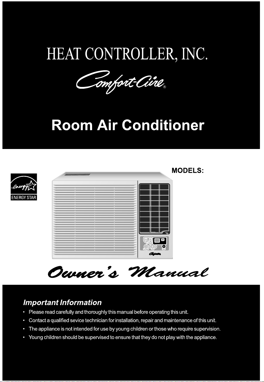
2 Room Air Conditioner
FOR YOUR RECORDS
Write the model and serial numbers here:
Model #
Serial #
You can find them on a label on the side of the product.
Dealer's Name
Date Purchased
■ Staple your receipt to this page in the event you need it
to prove date of purchase or for warranty issues.
READ THIS MANUAL
Inside you will find many helpful hints on how to use and
maintain your air conditioner properly. Just a little preventive
care on your part can save you a great deal of time and
money over the life of your air conditioner.
You'll find many answers to common problems in the chart
of troubleshooting tips. If you review our chart of
Troubleshooting Tips first, you may not need to call for
service at all.
Safety Precautions..........................3
Before Operation ............................7
Introduction ....................................8
Symbols Used in this Manual ........8
Features ........................................8
Electrical Safety
.............................9
Temporary Use of an
Adapter ........................................1
1
Temporary Use of an
Extension Cord
............................1
1
Electrical Data...
Installation ....................................12
Window Requirements ................13
Size ...........................................13
Select the best location ..........13
Preparation of Chassis ...............14
Unit Installation ............................15
Operating Instructions
.................17
Location and Function
of C ontrols....................................17
Additional F
eatures.......................20
Remote Control OperationsRemote Control Operations
Air Direct ion
..............................20
Drain Pipe
................................20
Maintenance and Service
............21
Air Filter ....................................21
Cleaning the Air Conditioner .....21
How to Remove the
Front Grille .................................22
Common Problems and
Solutions.......................................23
Troubleshooting ............................24
Window-Type Air Conditioner Owner’s Manual
TABLE OF CONTENTS
PRECAUTION
• Contact an Authorized Service Center for repair or
maintenance of this unit. Call 1-877-755-7932 to
locate the nearest ASC.
• This air conditioner is not intended for use by young
children or invalids without supervision.
• Young children should be supervised to ensure that
they do not play with the air conditioner.
• If the power cord requires replacement, have an
Authorized Servicer install an exact replacement part.
• Installation work must be performed in accordance
with the National Electric Code by qualified and
authorized personnel only.
.............................9
.......................18
Remote Control Remote Controller Remote Controller
.......................19
Owner’s Manual 3
ENGLISH
Safety Precautions
To prevent injury to the user or other people and property damage, the following instructions
must be followed.
■ Incorrect operation due to ignoring instructions will cause harm or damage. The seriousness
is classified by the following indications.
■ Because of the weight of the product, it is recommended that you have a helper to assist in
the installation.
■ Meanings of symbols used in this manual are as shown below.
WARNING
CAUTION
This symbol indicates the possibility of death or serious injury.
This symbol indicates the possibility of injury or damage to property only.
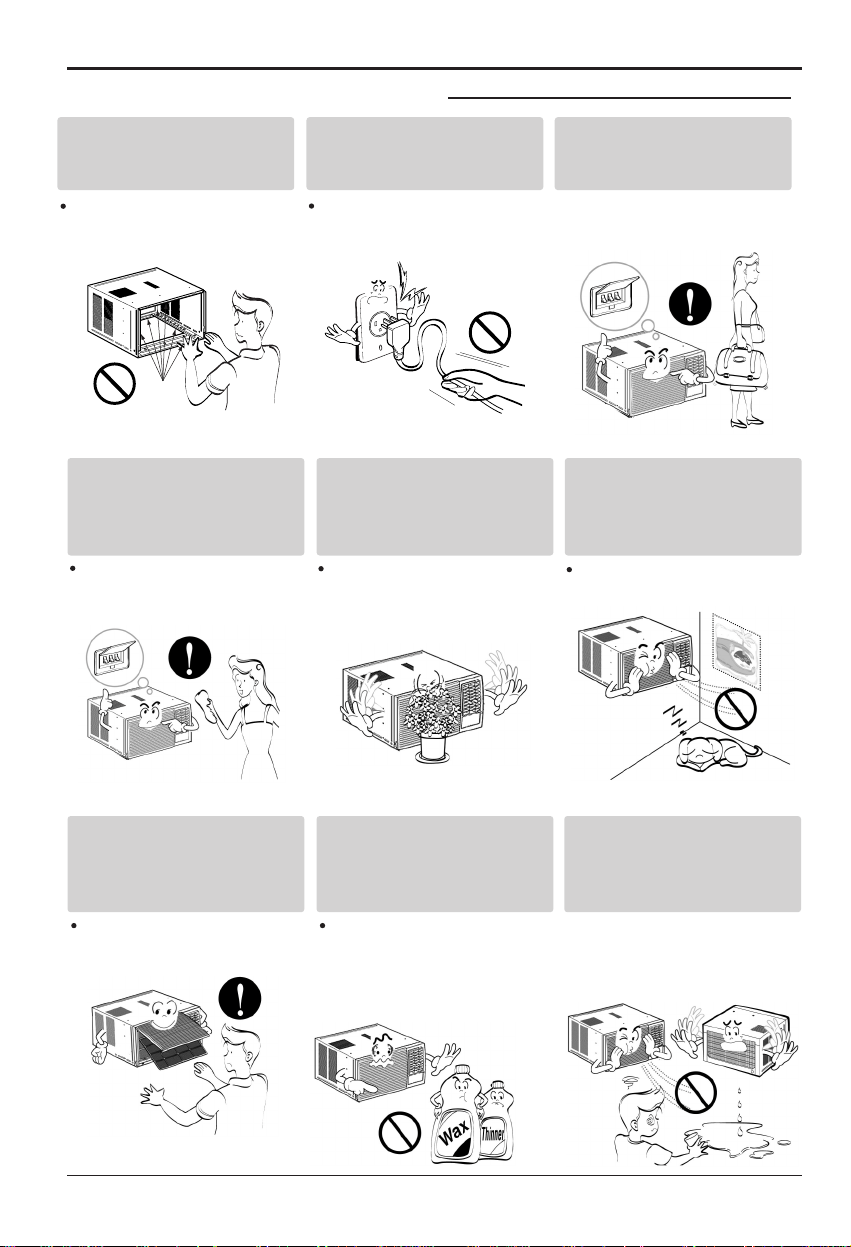
WARNING
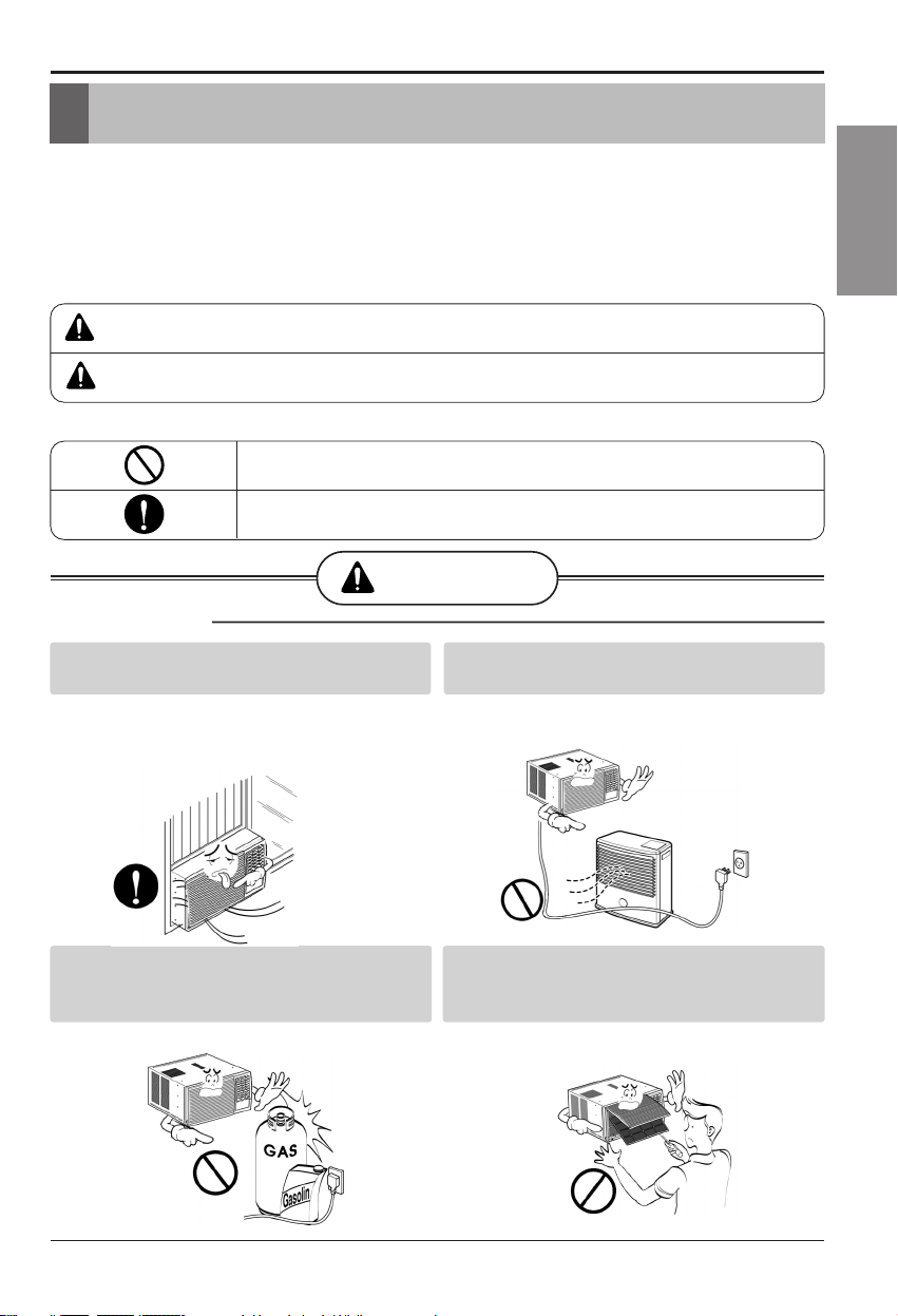
■ Installation
Always install the expansion panel(s).
• Improper assembly or installation may cause
incorrect operation, including injury, fire, and
Do not place the power cord near a heater.
• It may cause fire and electric shock.
Do not use the power cord near flammable
gas or combustibles such as gasoline,
benzene, thinner, etc.
• It may cause explosion or fire.
Do not disassemble or modify products.
• It may cause failure and electric shock.
Be sure not to do.
Be sure to follow the instruction.
Safety Precautions
poor performance,electric shock hazards.
4 Room Air Conditioner
Safety Precautions
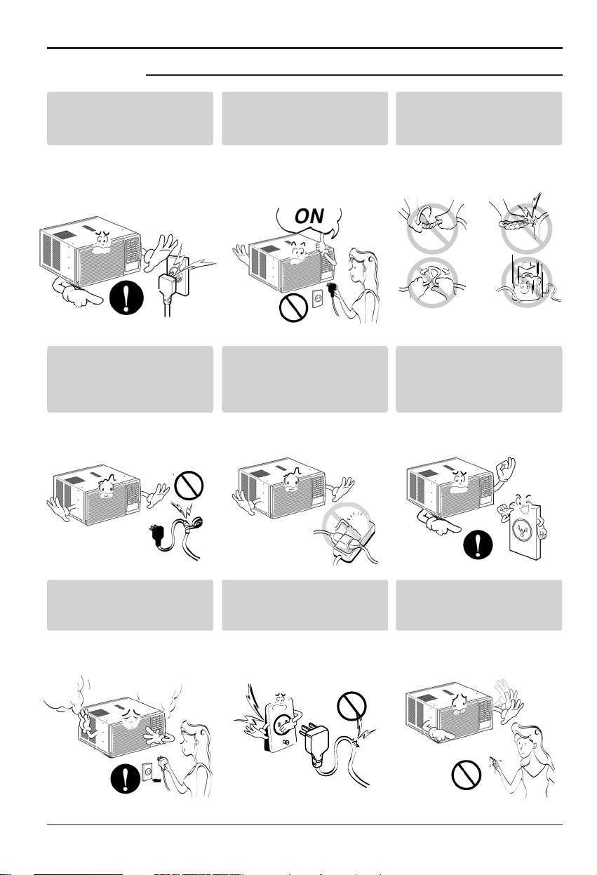
■ Operation
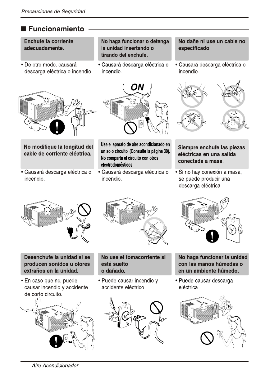
Plug in the power plug
properly.
• Otherwise, it will cause
electric shock or fire.
Do not operate or stop the
unit by inserting or pulling
out the power plug.
• It will cause electric shock or
fire.
Do not damage or use an
unspecified power cord.
• It will cause electric shock or
fire.
Unplug the unit if strange
sounds, odors, or smoke
come from it.
• Otherwise it may cause fire
and electric shock accident.
Do not use the socket if it is
loose or damaged.
• It may cause fire and electric
shock.
Do not operate with wet
hands or in damp
environment.
• It will cause electric shock.
Use the air conditioner on a
single outlet circuit.(see page 7.)
Do not share the outlet with
other appliances.
•
It will cause electric shock or
fire.
Do not modify power corDo not modify poDo not modify po dwer cor
length.
Do not modify po
•
••
It will cause electr ic shoc
•
k or
fire.
Always plug into a
grounded outlet.
• No •• grounding • may cause
electric shock.
Owner’s Manual 5
ENGLISH
CAUTION
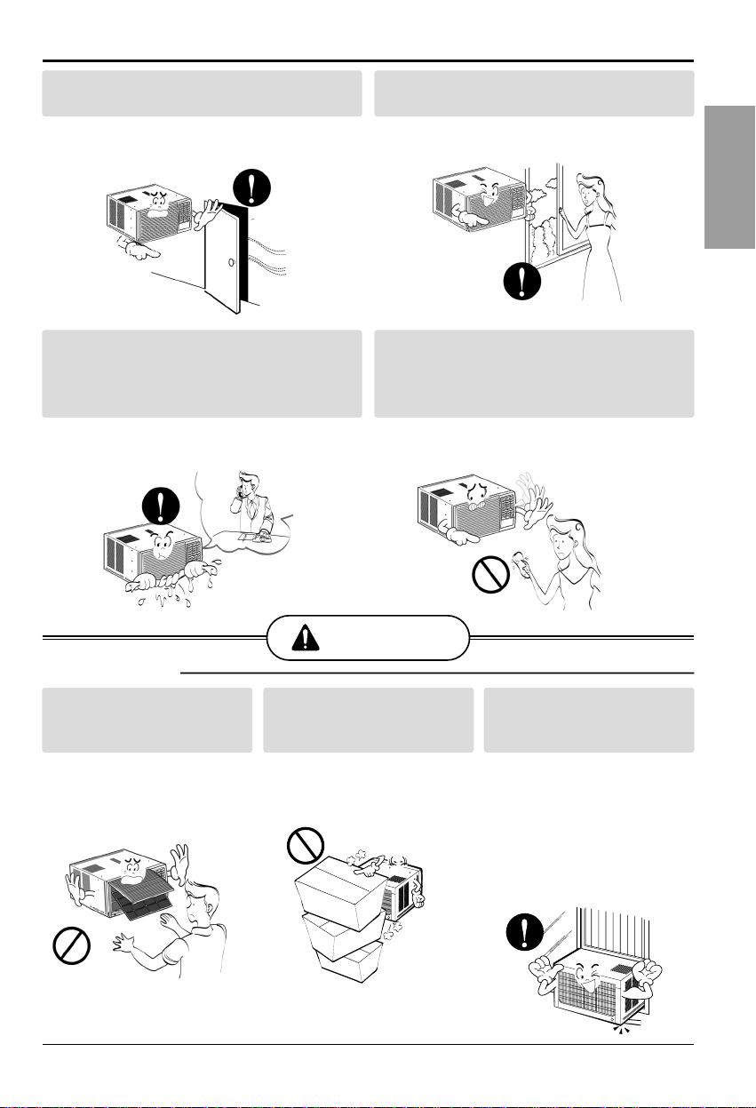
■ Installation
Safety Precautions
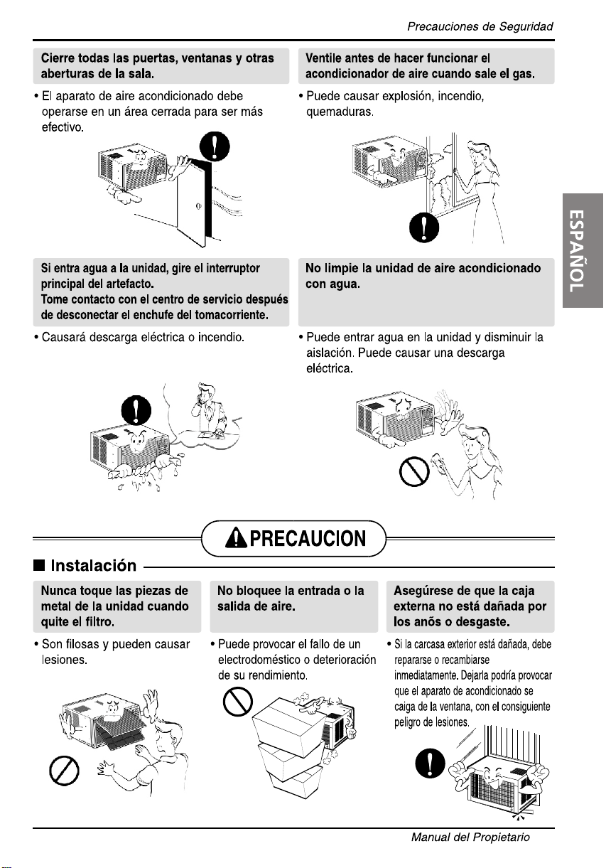
Never touch the metal parts
of the unit when removing
the filter.
• They are sharp and may
cause injury.
Do not block the inlet or
outlet.
• It may cause failure of
appliance or performance
deteriorate.
Ensure that the outer case
is not damaged by age or
wear.
• If the outer case is damaged,
it must be repaired or
replaced immediately.
Leaving it damaged could
result in the air conditioner
falling out of the window,
creating a safety hazard.
Close all doors, windows and other outside
openings to the room.
• The air conditioner must be operated in a
enclosed area to be most effective.
Do not operate the air conditioner if you
smell gas.
• It may cause explosion, fire, and burn.
If water enters the product, turn off the
power switch of the main body of appliance.
Contact service center after taking the power-
plug out from the socket.
• It will cause electric shock or failure of
machine.
Do not clean the air conditioner with water.
• Water may enter the unit and degrade the
insulation. It may cause an electric shock.
6 Room Air Conditioner
Safety Precautions
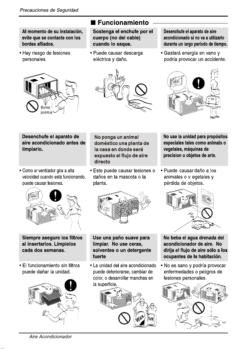
Since the fan rotates at high
speed during operation, it may
cause injury.
Do not put a pet or house
plant where it will be
exposed to direct air flow.
This could injure the pet or
plant.
Do not use this appliance for
special purposes such as
cooling pets, foods, precision
machinery, or objects of art.
It is an air conditioner, not a
precision refrigeration system.
Always insert the filter
securely.
Clean it every two weeks.
Operation without filters
will
cause failure.
Use a soft cloth to clean. Do
not use wax, thinner, or a
strong detergent.
The appearance of the air
conditioner may deteriorate,
change color, or develop
surface flaws.
Unplug the air conditioner
before cleaning it.
Be cautious not to touch the
sharp edges when
installing.
It may cause injury.
Hold the plug by the hand
when taking it out.
It may cause electric shock
and damage.
Operation
Unplug the air conditioner
if it will not be used for a
long period.
Sharp
edges
• It will waste power
and it may cause accident.
Do not drink water drained
from air conditioner. Do not
direct airflow at room
occupants only.
• It is not sanitary and could
cause illness or personal
injury hazard.
(not the cable)

Owner’s Manual 7
ENGLISH
Before Operation
1. Plug in the power cord properly.
2. Use a dedicated circuit. Overloading the line could create a fire hazard.
3. Do not use an extension cord. See page 11 for more details.
4. Do not start/stop operation by plugging/unplugging the power cord.
5. If the power cord is damaged and requires replacement, have an Authorized
Servicer install an exact replacement part.
1. Being exposed to direct airflow for an extended period of time could be
hazardous to your health. Do not expose occupants, pets, or plants to direct
airflow for extended periods of time.
2. Due to the possibility of oxygen deficiency, ventilate the room when used
together with stoves or other heating devices.
3. Do not use this air conditioner for non-specified special purposes (e.g.
preserving precision devices, food, pets, plants, and art objects). Such usage
could damage the items.
4.The air conditioner is a consumer comfort appliance, not a precision climate
control system.
1. Do not touch the metal parts of the unit when removing the filter. Injuries can
occur when handling sharp metal edges.
2. Do not use water to clean inside the air conditioner. Exposure to water can
destroy the insulation, leading to possible electric shock.
3. When cleaning the unit, first make sure that the power and breaker are turned
off.The fan rotates at a very high speed during operation.There is a
possibility of injury if the unit’s power is accidentally triggered on while
cleaning inner parts of the unit.
For repair and maintenance, contact an Authorized Service Center. See the
warranty page for details or call 1-877-755-7932. Have your model number and
serial number available.They should be written on page 2 of this manual.
Before Operation
Preparing for Operation
Usage
Cleaning and Maintenance
Service
8 Room Air Conditioner
Introduction
This symbol alerts you to the risk of electric shock.
This symbol alerts you to hazards that could cause harm to the
air conditioner.
This symbol indicates special notes.
WARNING: This appliance should be installed in accordance with
National Electric Code.
Introduction
Symbols Used in this Manual
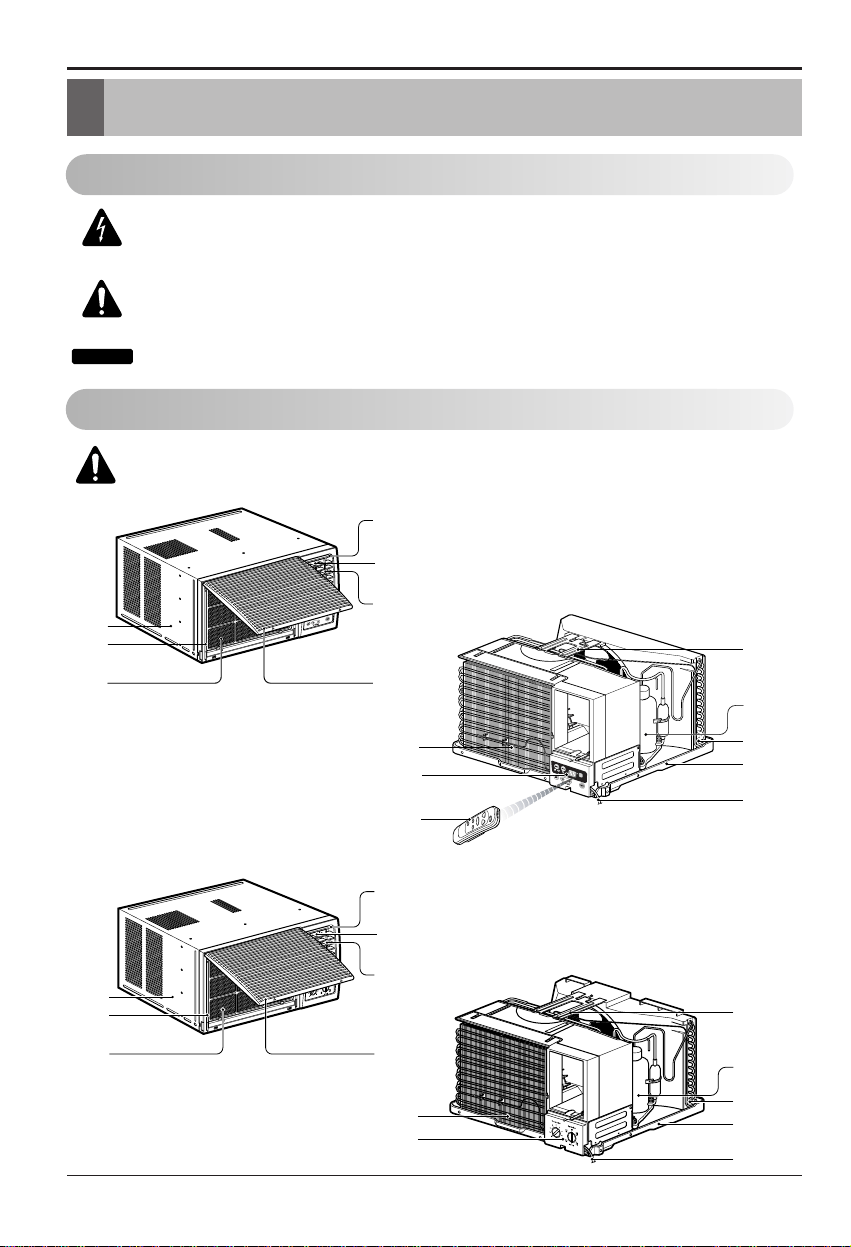
Features
CABINET
FRONT GRILLE
AIR FILTER
AIR INTAKE
(INLET GRILLE)
AIR DISCHARGE
HORIZONTAL AIR DEFLECTOR
(VERTICAL LOUVER)
VERTICAL AIR DEFLECTOR
(HORIZONTAL LOUVER)
EVAPORATOR
CONTROL BOARD
EVAPORATOR
CONTROL BOARD
POWER CORD
BASE PAN
CONDENSER
COMPRESSOR
BRACE
POWER CORD
BASE PAN
CONDENSER
COMPRESSOR
BRACE
CABINET
FRONT
AIR FILTER
AIR INTAKE
(INLET GRILLE)
AIR DISCHARGE
HORIZONTAL AIR DEFLECTOR
(VERTICAL LOUVER)
VERTICAL AIR DEFLECTOR
(HORIZONTAL LOUVER)
REMOTE
CONTROLLER
Tip!
GRILLE
Electrical Safety
9
ENGLISH
Electrical Safety
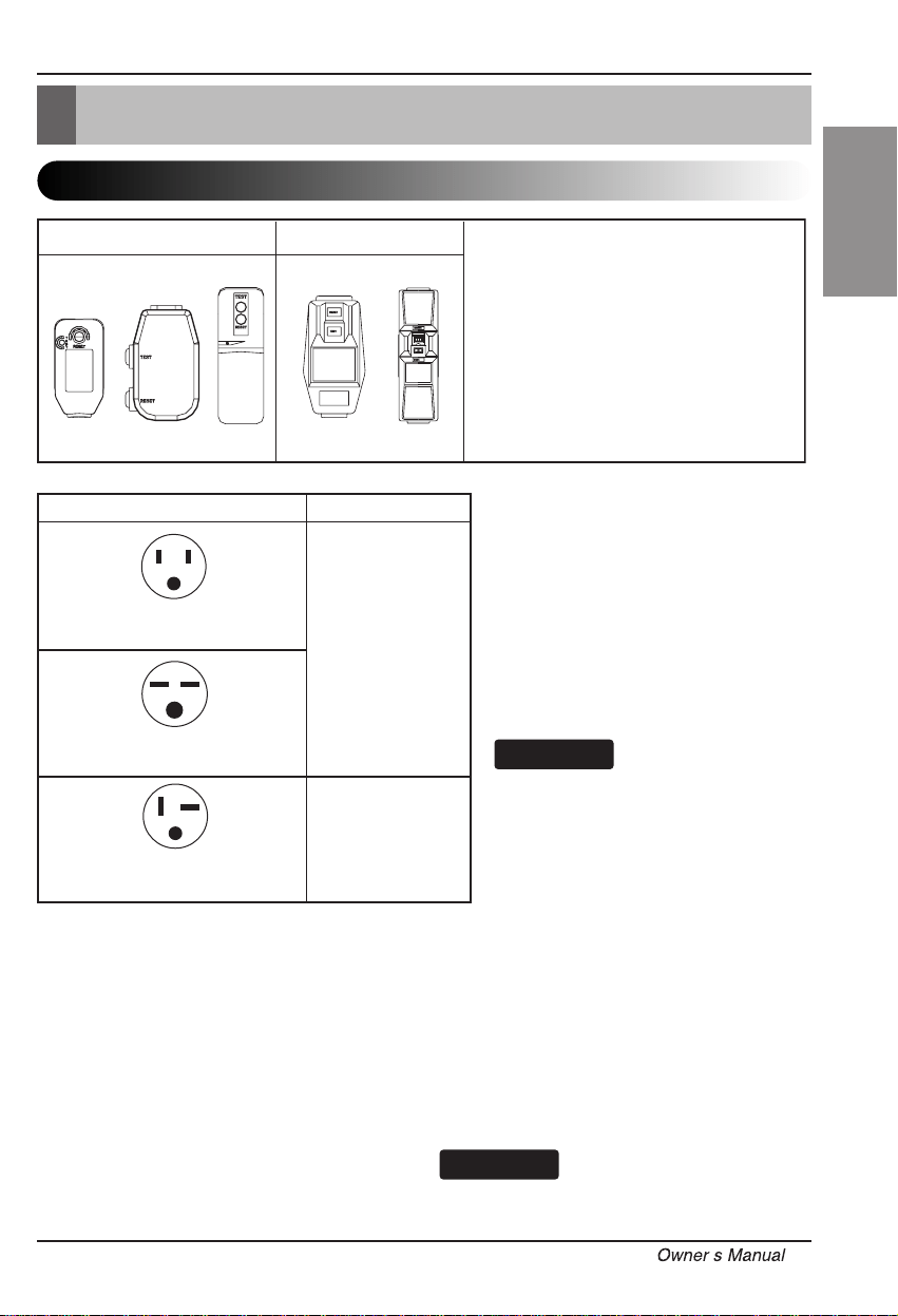
Electrical Data
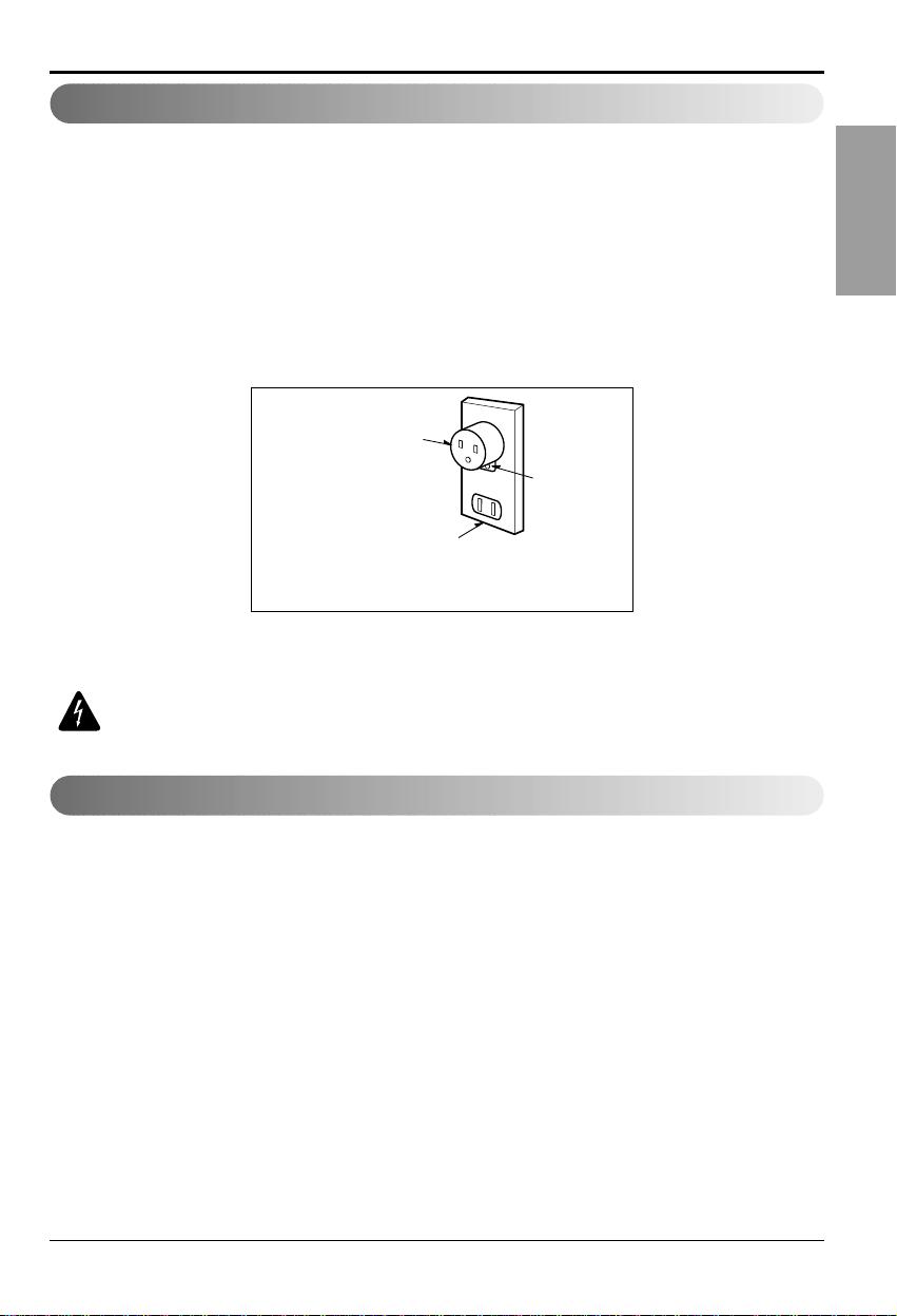
115V~ 230V~
Power cord may include a current
interrupter device. A test and reset button is
provided on the plug case. The device
should be tested on a periodic basis by first
pressing the TEST button and then the
RESET button. If the TEST button does not
trip or if the RESET button will not stay
engaged, discontinue use of the air
conditioner and contact a qualified service
technician.
Use Wall Receptacle Power Supply
Standard 125V, 3-wire grounding
receptacle rated 15A, 125V AC
Standard 250V, 3-wire grounding
receptacle rated 15A, 250V AC
Use 15 AMP. time
delay fuse or 15 AMP.
circuit breaker.
Use 20 AMP. time
delay fuse or 20 AMP.
circuit breaker.
Standard 250V, 3-wire grounding
receptacle rated 20A, 250V AC
Use of extension cords
Because of potential safety hazards, we
strongly discourage the use of an extension
cord. However, if you wish to use an
extension cord, use a CSA certified/UL-listed
3-wire (grounding) extension cord, rated 15A,
125V.
All wiring should be made in accordance with
local electrical codes and regulations.
Aluminum house wiring may pose special
problems. Consult a qualified electrician.
NOTICE
ELECTRICAL SAFETY
IMPORTANT GROUNDING INSTRUCTIONS
Air conditioner has a three-prong grounding plug on
its power supply cord, which must be plugged into
properly grounded three-prong wall receptacle for
your protection against possible shock hazard.
230, 208, and 230/208 VOLT UNITS
These units are equipped with a three-prong
grounding plug on the power supply cord, which
must be plugged into a matching properly grounded
three-prong wall receptacle for your protection
against possible shock hazard. If such an outlet is
not present, one must be installed by a qualified
electrician in accordance with the National Electrical
Code and local codes and ordinances.
DO NOT USE AN EXTENSION CORD on 230,
208, and 230/208 Volt units.
NOTICE
,
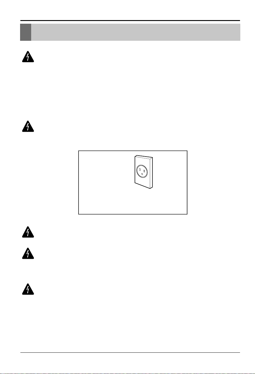
WARNING: This appliance must be properly grounded.
The power cord of this appliance is equipped with a three-prong grounding plug.
To minimize the risk of electric shock, use the plug with a standard three-slot
grounding wall power outlet. If the power outlet does not include a grounding slot,
have a qualified electrician replace the outlet before you use the room air
conditioner.
WARNING: Changing the outlet without making the appropriate wiring
changes will create an unsafe condition that could result in fire or
electrical shock. Refer all such work to a licensed and qualified
electrician.
WARNING: Do not cut or remove the grounding prong from the power
plug.
WARNING: Attaching the adapter ground terminal to the wall
receptacle cover screw does not ground the appliance unless the
cover screw is metal and not insulated, and the wall receptacle is
grounded through the house wiring.
WARNING: If you have any doubt whether the air conditioner is
properly grounded, have the wall receptacle and circuit checked by a
qualified electrician.
Electrical Safety
Preferred method
Ensure proper ground
exists before use
Electrical Safety
Room Air Conditioner10
We strongly discourage the use of an adapter due to potential safety hazards.
For temporary connections, use only a UL-listed adapter, available from most
local hardware stores. Ensure that the large slot in the adapter is aligned with
the large slot in the receptacle for a proper polarity connection.
To disconnect the power cord from the adapter, use one hand on each to avoid
damaging the ground terminal. Avoid frequently unplugging the power cord as
this can lead to eventual ground terminal damage.
WARNING: Never use the appliance with a broken adapter.
We strongly discourage the use of an extension cord due to potential safety
hazards. For temporary situations, use only CSA certified and UL listed 3-wire
grounded extension cords, rated 15 A, 125 V.
Electrical Safety
Temporary method
Adapter Plug
Receptacle Cover
Metal Screw
Temporary Use of an Adapter
Temporary Use of an Extension Cord
ENGLISH
Owner s Manual 11
,
Installation
Installation
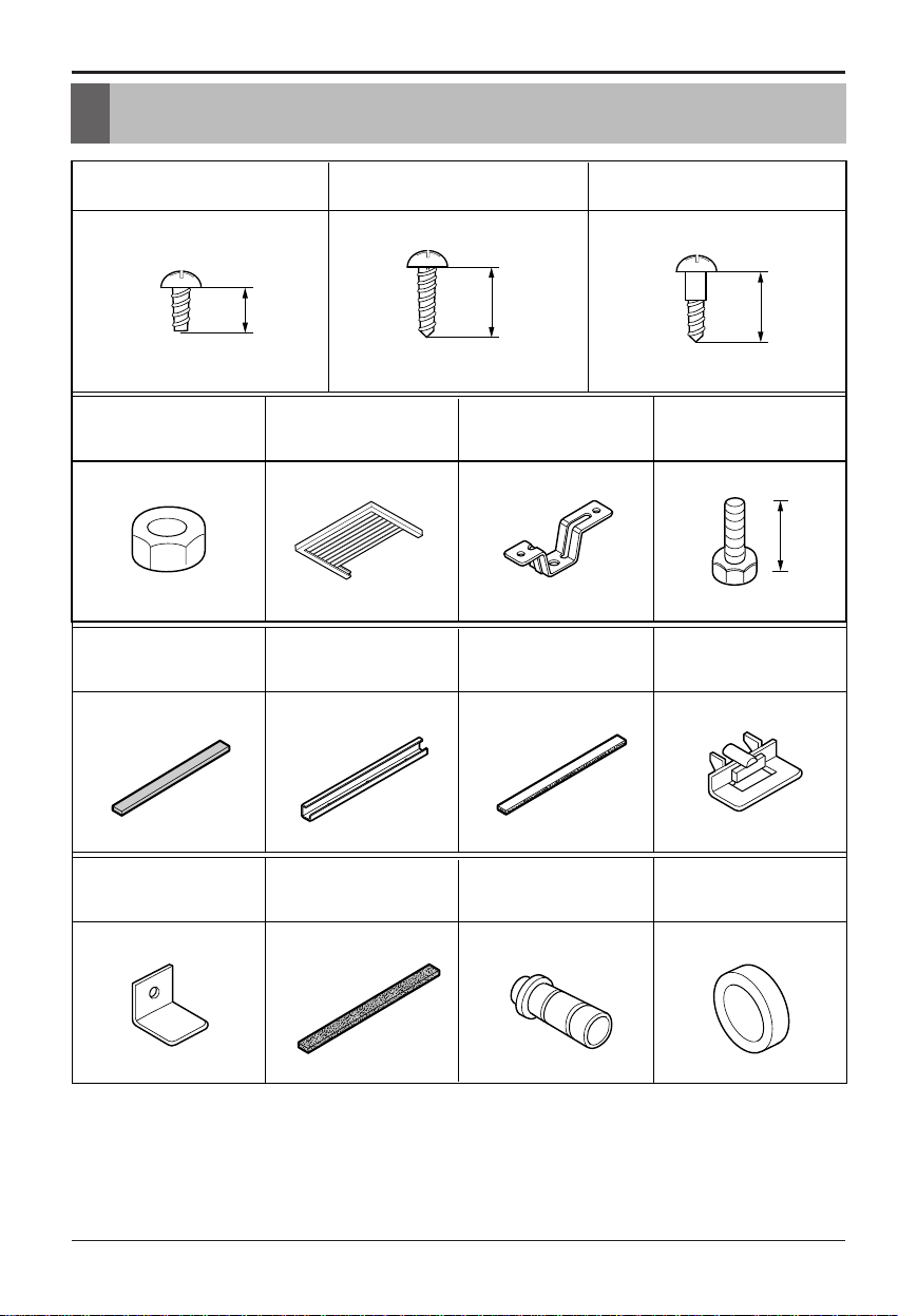
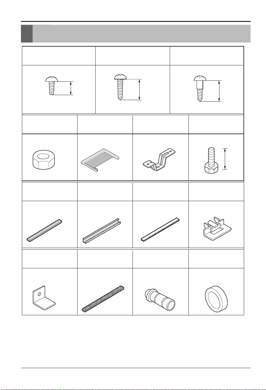
Have the following tools available for installation:
* Screwdriver (Slotted and Phillips) * Ruler
* Knife * Hammer
* Pencil * Level
Type F:2EA
(SILL SUPPORT)
Type G:2EA
(BOLT)
Type C:5EA
(SCREW)
Type A:16EA
(SCREW)
Type D:2EA
(NUT)
Type K:2EA
(FRAME-GUIDE)
Type J:1EA
(FOAM-PE)
Type I:1EA
(UPPER GUIDE)
Type H:1EA
(FOAM-STRIP)
Type O:1EA
(DRAIN WASHER)
Type N:1EA
(DRAIN JOINT PIPE)
Type M:1EA
(FOAM-PE)
Type L:1EA
(WINDOW LOCKING BRACKET)
10
16mm
16mm
Type B:3EA
(SCREW)
Type E:2EA
(FRAME CURTAIN)
10mm
12 Room Air Conditioner
Installation
27" to 39"
Offset
1
/2" to 1
1
/4"
Sill
Exterior
Interior wall
23
5
/8" min.
(Without frame curtain)
Sill
16" min
(With frame curtain)
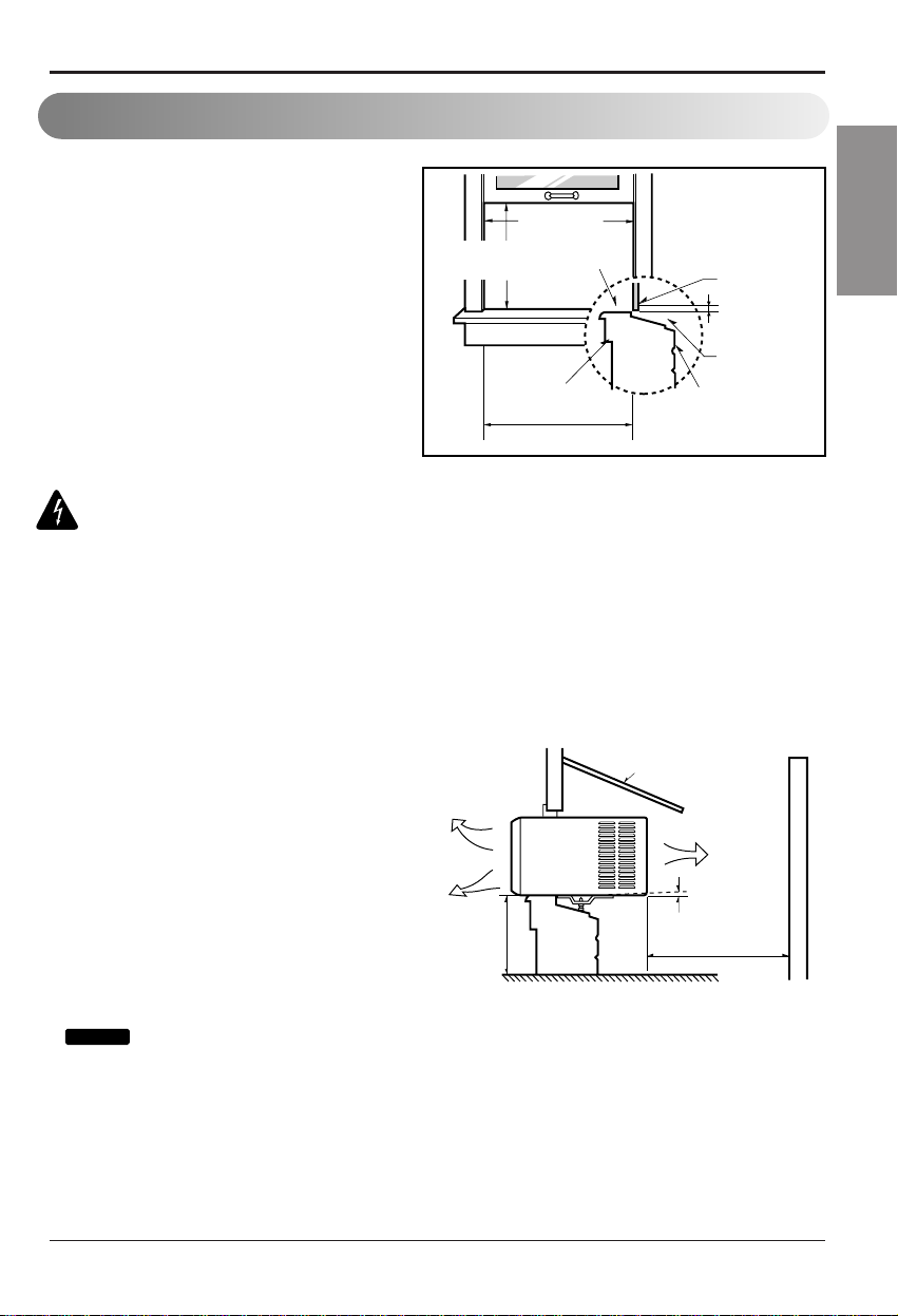
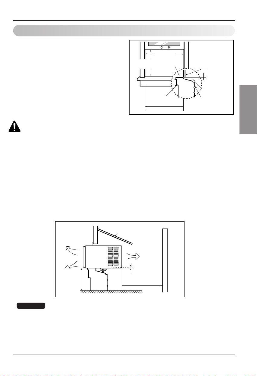
Size
This room air conditioner is
designed for installation in standard
double-hung windows with actual
opening widths from 27" to 39".
The upper and lower window sash
must open sufficiently to allow a
clear vertical opening of 16" from the
window sill.
Window Requirements
About
1
/2"
30"~60"
Awning
Cooled air
Fence
Over 20"
Heat
radiation
Select the best location
1. To prevent vibration and noise, make sure
the unit is installed securely and firmly
2. Install the unit where the sunlight does not
shine directly on the unit.
3. The outside of the cabinet must extend
outward for at least 12" and there should
be no obstacles, such as a fence or wall,
within 20" from the back of the cabinet
because it will prevent heat radiation of the
condenser.
Restriction of outside air will greatly reduce
the cooling efficiency of the air conditioner.
: All side louvers of the cabinet must remain exposed to the outside of the
structure.
4. Install the unit a little slanted so the back is slightly lower than the front(about
1
/2").
This will force condensed water to flow to the outside.
5. Install the unit with the bottom about 30"~60" above the floor level.
WARNING:This product is a WINDOW AIR CONDITIONER. As such,
a standard single-hung or double-hung window is required for proper
installation. Non-window installations, including using sleeves, holes
in walls, and other installations are not recommended.
bottom of the upper sash to the
Tip!
Owner’s Manual 13
ENGLISHENGLISHENGLISH
ENGLISH
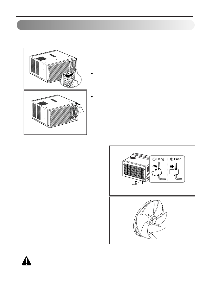
Installation
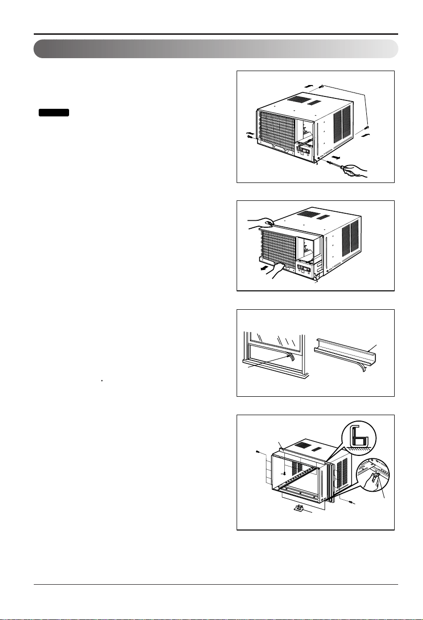
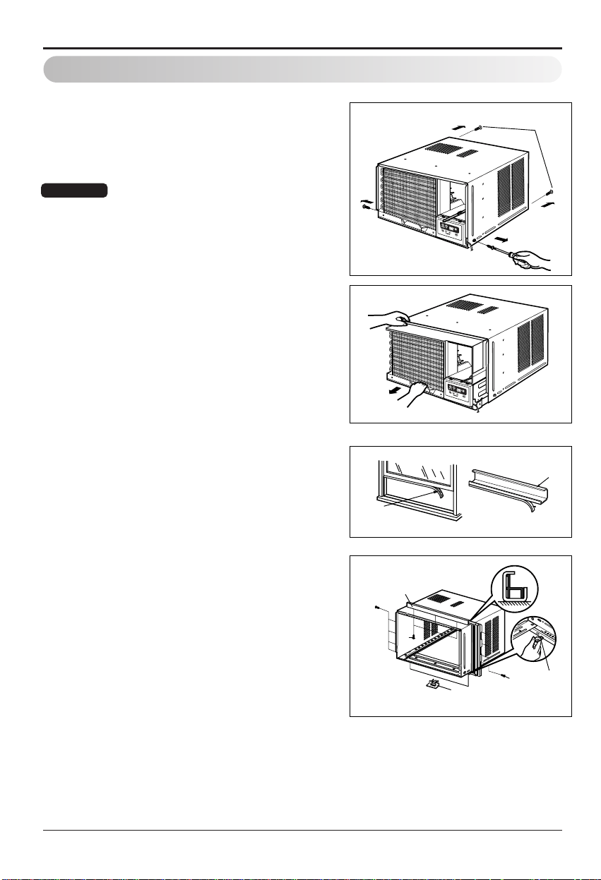
Preparation of Chassis
(Type A)
(Type A)
1. Remove the screws which fasten the cabinet
at both sides and at the back.
2. Slide the unit from the cabinet by gripping the
base pan handle and pulling forward while
bracing the cabinet.
3. Cut the window sash seal to the proper
length.
Peel off the backing and attach the Foam-PE
to the underside of the window sash.
4. Remove the backing from the top Upper Guide
Foam-PE and attach it to the bottom of the
Upper Guide
5. Attach the Upper Guide onto the top of the
cabinet with 3 Type A screws.
6. Insert the Frame Guides
into the bottom of
the cabinet.
7. Insert the Frame Curtain into the Upper Guide
and Frame Guides .
8. Fasten the curtains to the unit with 4 Type
A screws.
Shipping
Screws
Use a long screwdriver and installing the
screws will be easier.
Tip!
Foam-Pe
Upper Guide
Foam-Pe
Upper Guide
Screw
Screw
(Type A)
Frame Guides
Screw
Frame
Guides
14 Room Air Conditioner
Installation
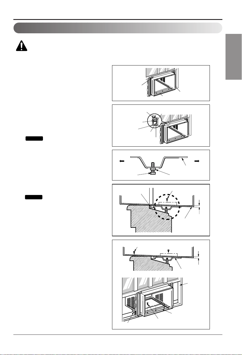
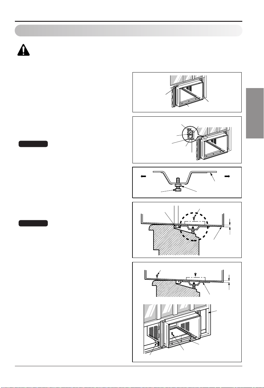
Unit Installation
Caution: During the following step, hold unit firmly until window sash
is lowered to top channel behind side panel frames. Personal injury or
property damage may result if unit falls from window.
Upper Guide
Window Sash
Window Stool
Front Angle
Upper Guide
Frame Curtain
Foam-Pe
Foam-Pe
Cabinet
INDOOR OUTDOOR
INDOOR OUTDOOR
Sash Track
Front Angle
Cabinet
About
1
/2"
About
1
/2"
Sill Support
NutBolt
Frame Guide
Screw(Type B)
Screw(Type B)
Sill Support
Sill Support
Screw(Type A)
1. Open the window. Mark a line on
center of the window stool(or desired
air conditioner location).
Carefully place the cabinet on the
window stool and align the center
mark on the bottom front with the
center line marked in the window
stool.
2. Pull the bottom window sash down
behind the upper guide until it meets.
:Do not pull the window sash
down so tightly that the movement of
Frame Curtain is restricted.
3. Loosely assemble the sill support
using the parts in Figure 3.
4. Select the position that will place the
sill support near the outer most point
on sill (See Figure 4)
: Be careful when you install
the cabinet (Frame Guides will be
broken easily).
5. Attach the sill support to the cabinet
track hole in relation to the selected
position using 2 Type A screws in
each support(See Figure 4).
6. The cabinet should be installed with a
very slight tilt(about
1
/2") downward
toward the outside (See Figure 5).
Adjust the bolt and the nut of sill
support for balancing the cabinet.
7. Attach the cabinet to the window stool
by driving the screws (Type B:Length
sixteen millimeters and below.) through
the front angle into window stool.
8. Pull each Frame curtain fully to each
window sash track, and repeat step 2.
Figure 1
Figure 2
Figure 3
Figure 4
Figure 5
Tip!
Tip!
Owner’s Manual 15
ENGLISHENGLISHENGLISH
ENGLISH
Installation
Type C
Screw(Type A)
Screw(Type A)
Power Cord
Foam-Strip
Window Locking Bracket
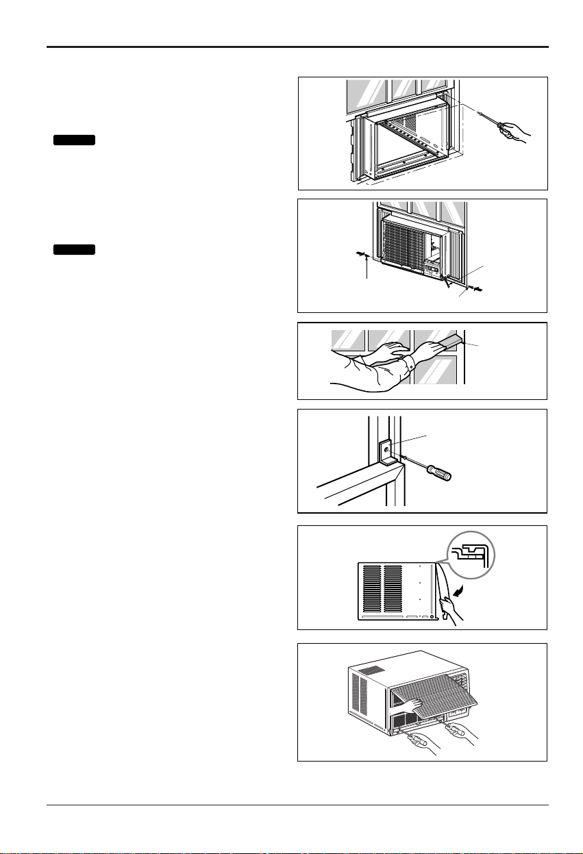
9. Attach each Frame Curtain the window sash
using screws (Type C).(See Figure 6)
: DO NOT DRILL A HOLE IN THE
BOTTOM PAN.
The unit is designed to operate
with approximately 1/2" of water in
bottom pan.
10. Slide the unit into the cabinet.(See Figure 7)
: For security purpose, reinstall
screws(Type A) at cabinet's sides.
11. Cut the Foam-Strip to the proper length
and insert between the upper window sash
and the lower window sash.
(See Figure 8)
12. Attach the Window Locking Bracket with
a Type C screw. (See Figure 9)
13. Attach the front grille to the cabinet by
inserting the tabs on the grille into the tabs
on the front of the cabinet. Push the grille
in until it snaps into place. (See Figure 10)
14. Lift the inlet grille and secure it with a Type
A screw through the front grille.
(See Figure 11)
15. Window installation of room air conditioner
is now completed. See ELECTRICAL DATA
for attaching power cord to electrical outlet.
Figure 6
Figure 7
Figure 8
Figure 9
Figure 10
Figure 11
Tip!
Tip!
16 Room Air Conditioner
CAUTION: If you turn off the air conditioner or switch from cooling to
the fan, wait at least 3 minutes before setting to cooling again.
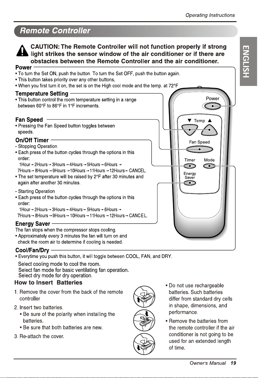
Operating Instructions
Operating Instructions
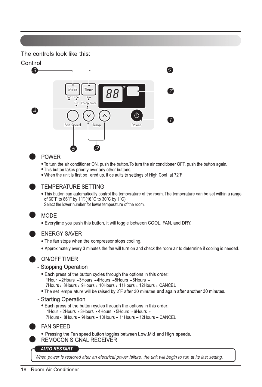
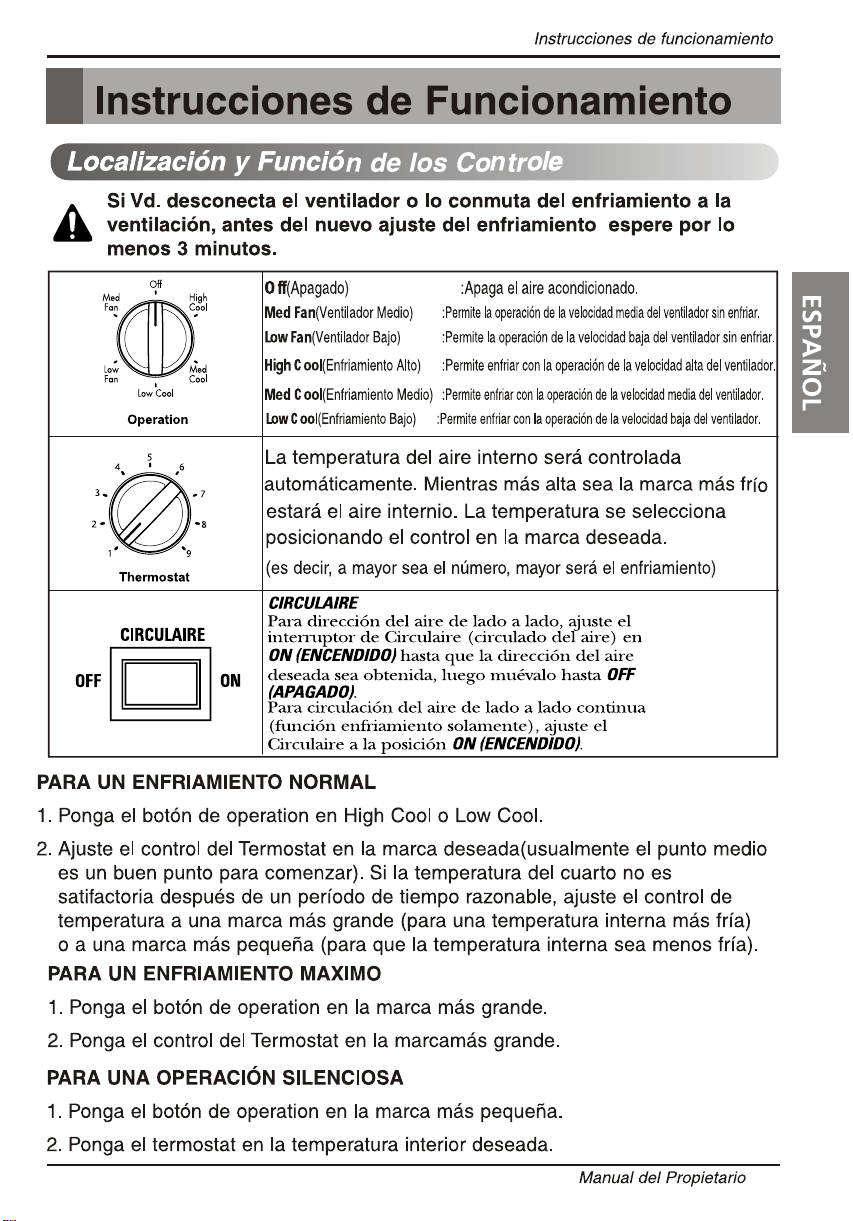
Location and Function of Controls
FOR NORMAL COOLING
1. Turn the operation switch to the High Cool or the Low Cool setting.
2. Set the thermostat control to the desired temperature mar
k (the mid-point is a
good starting position). If the room temperature is not satisfactory after a
reasonable time, adjust the control to a cooler or warmer setting, as
appropriate.
FOR MAXIMUM COOLING
1. Turn the operation switch to the High Cool setting.
2. Set the thermostat control to the largest temperature mark.
FOR QUIETER OPERATION
1. Turn the operation switch to the Low Cool setting.
2. Set the thermostat control as needed.
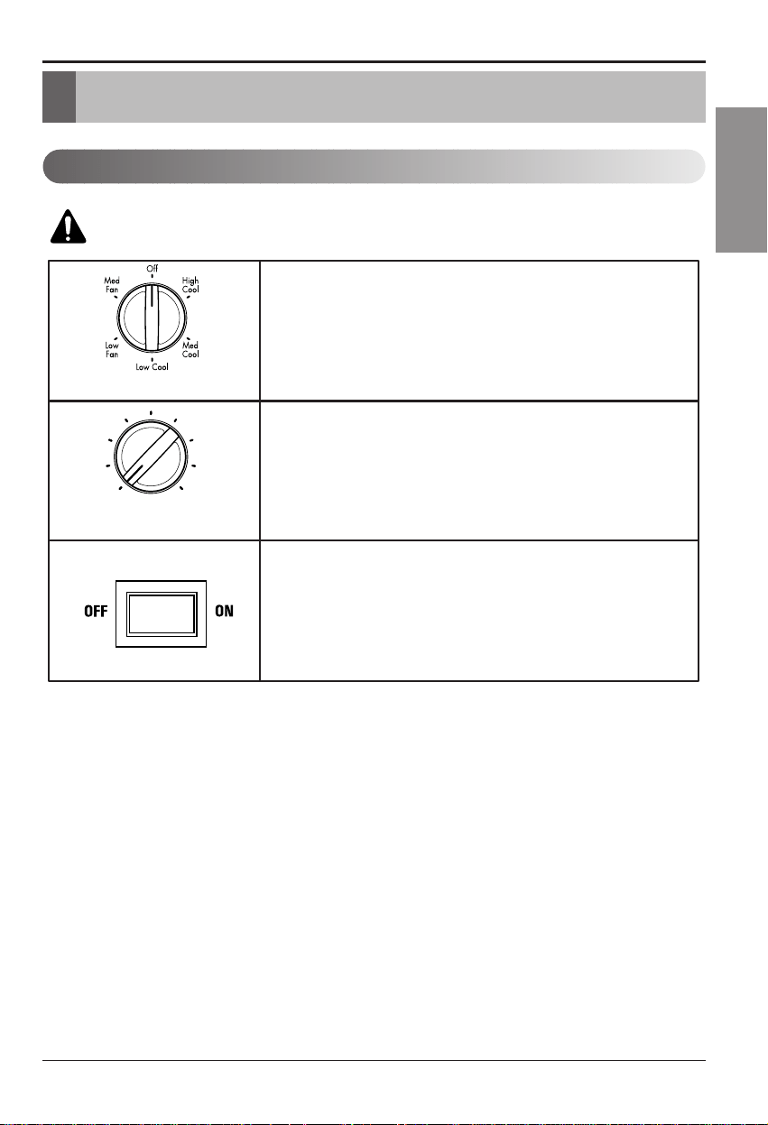
O ff - Turns air conditioner off.
Me d Fa n - Med speed fan operation without cooling.
Low Fa n - Low speed fan operation without cooling.
High C ool - Cooling with high speed fan operation.
Me d C ool - Cooling with med speed fan operation.
Low C ool - Cooling with low speed fan operation.
This automatically controls the temperature of the indoor air.
Turn the knob so that arrow points to the larger marks for greater cooling.
Point the arrow to the smaller marks for more moderate cooling.
(i.e. the higher the number, the greater the cooling)
4
3
2
1
6
7
9
5
Thermostat
Operation
8
Owner’s Manual 17
ENGLISHENGLISHENGLISH
ENGLISH
adju
For fixed side-to-side air direction, set the
Auto Swing switch to ON until the desired air
direction is obtained, then move it to OFF.
Auto Swing
For continuous side-to-side air circulation (cool
settings only), set the Auto Swing switch to ON.
Auto Swing
t r
w f
1
2
3
4
5
6
7
Remote Control Operations
Operating Instructions
Low,Mid and
High
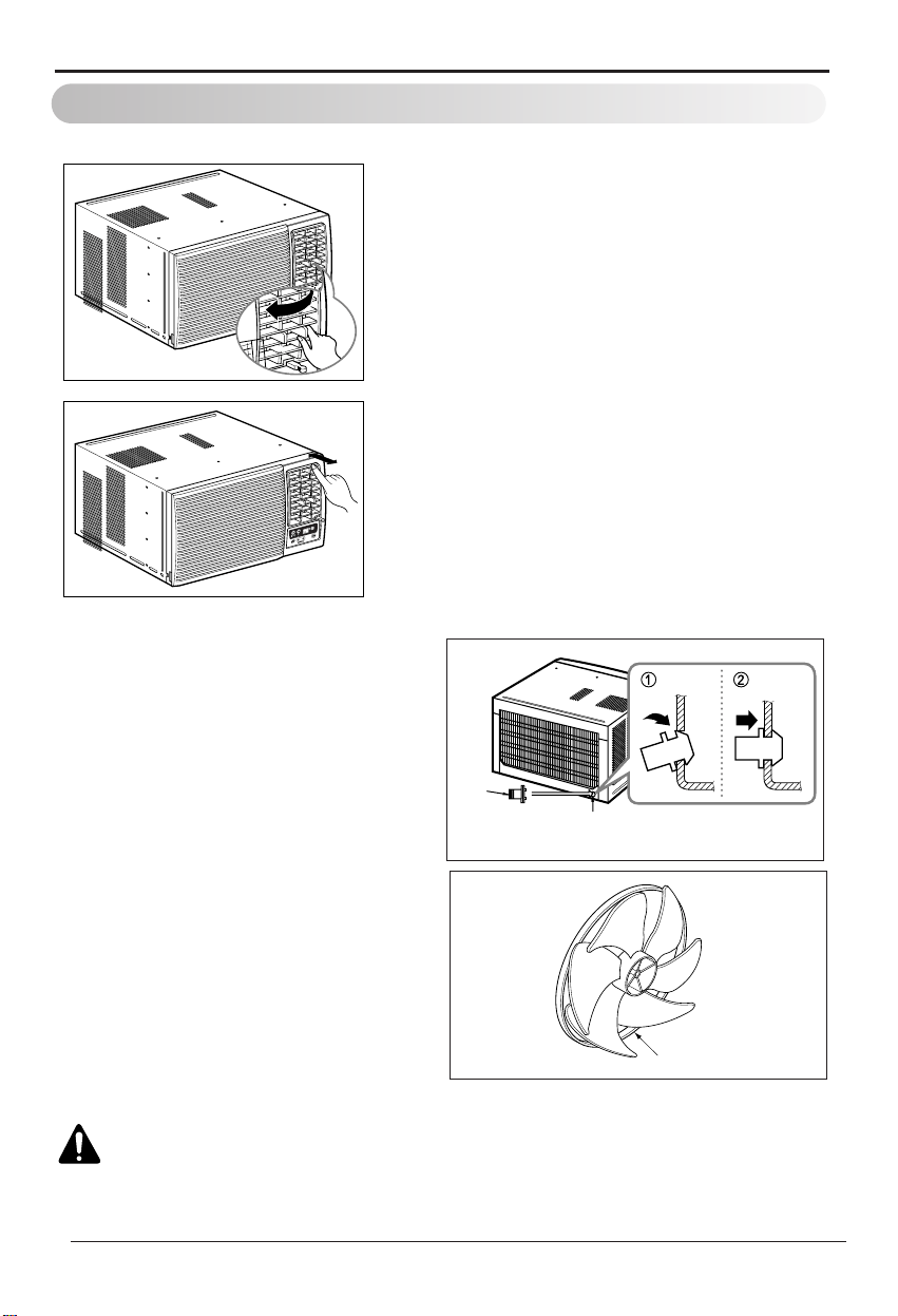
CAUTION: Be careful when inserting the drain pipe. Push away from
the sharp fin area to avoid slipping injuring yourself.
Operating Instructions
Drain Pipe
In humid weather, excess water may
cause the Base Pan to overflow
. To
drain the water, remove the Dr
ain Cap
and secure the Drain Pipe to the rear
hole of the Base Pan.
Press the drain pipe into the hole b
y
pushing down and away from the fins
to avoid injury.
Drain Pipe
Drain Cap
The direction of air can be controlled wherever you
want to cool by adjusting the horizontal louver and
the vertical louver.
HORIZONTAL AIR-DIRECTION CONTROL
The horizontal air direction is adjusted by
rotating the vertical louver right or left.
VERTICAL AIR-DIRECTION CONTROL
The vertical air direction is adjusted by
rotating the horizontal louver forward or
backward.
This air conditioner is equipped with a
slinger fan. (See drawing, below.)
The fan has an outer ring that runs in
the water that collects in the base pan
if it gets deep. That condensate is then
picked up by the fan and expelled
through the condenser, making the air
conditioner more efficient.
Ring
Additional Features
Air Direction
20 Room Air Conditioner
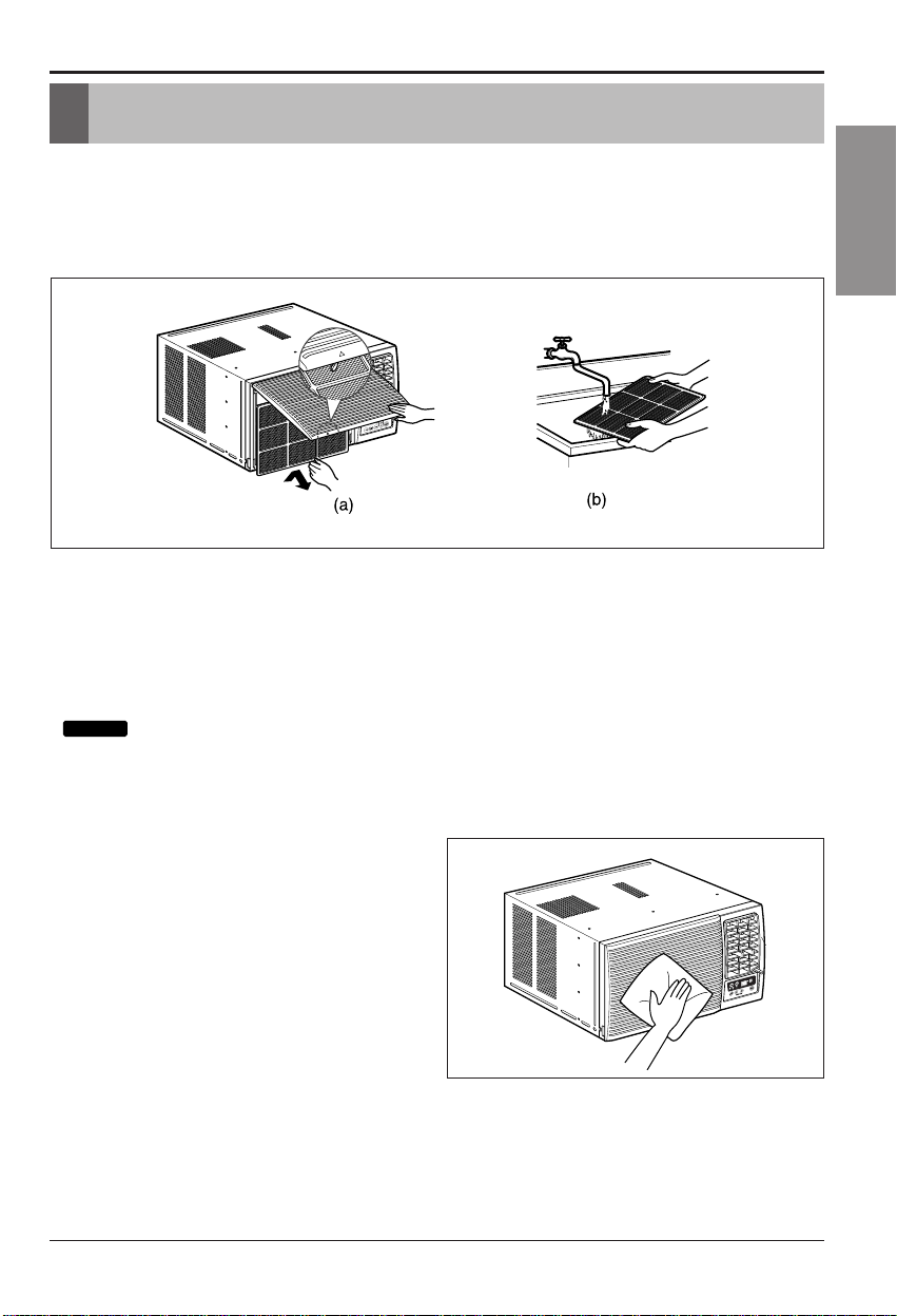
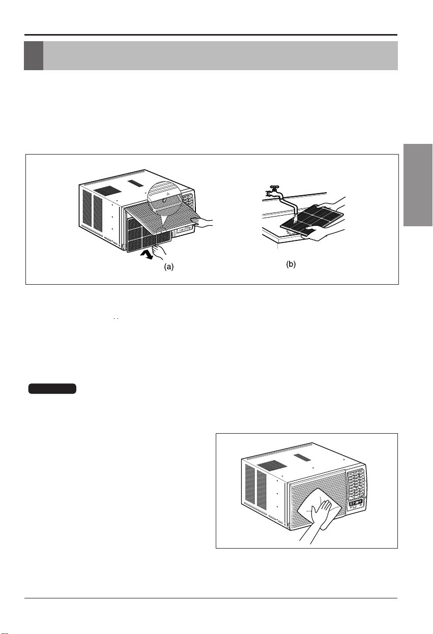
Air Filter
Check the air filter at least twice a month to see if cleaning is necessary. Trapped
particles in the filter can build up and block the airflow, reducing cooling capacity
and causing an accumulation of frost on the evaporator. To clean the air filter:
1. Lift the inlet grille.
2. Remove the air filter from the front grille by pulling the air filter up slightly.
3. Wash the filter using lukewarm water below 40 °C (104 °F).
4. Gently shake the excess water from the filter and replace.
Cleaning the Air Conditioner
The front grille and Inlet grille may be
wiped with a cloth dampened in a mild
detergent solution.
The cabinet may be washed with mild
soap or detergent and lukewarm
water, then polished with Liquid Wax
for Appliances.
To ensure continued peak efficiency,
the condenser coils (outside of unit)
should be checked periodically and
cleaned if clogged with soot or dirt
from the atmosphere.
Maintenance and Service
Maintenance and Service
:DO NOT operate the air conditioner without a filter because dirt and lint will
clog it and reduce performance.
Tip!
Owner s Manual 21
,
ENGLISHENGLISHENGLISH
ENGLISH
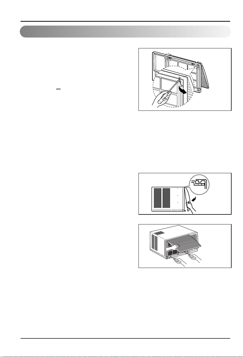
Maintenance and Service
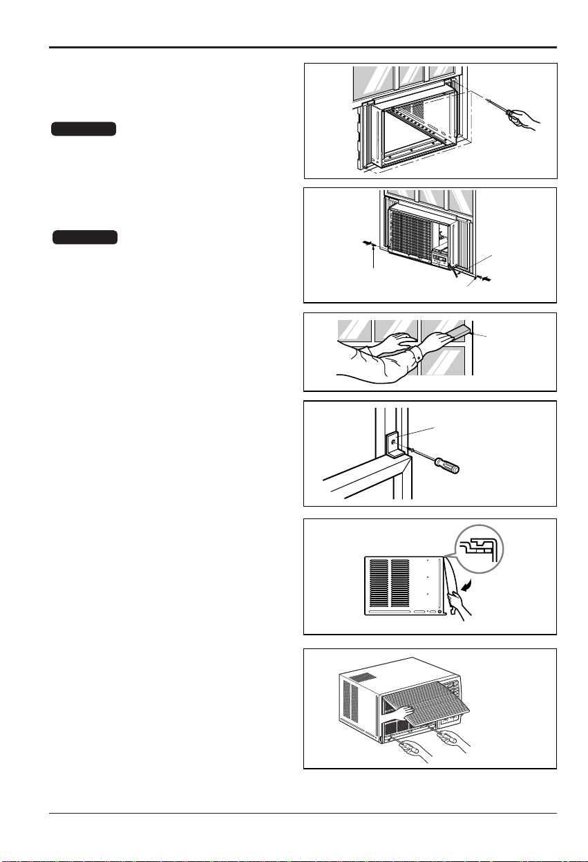
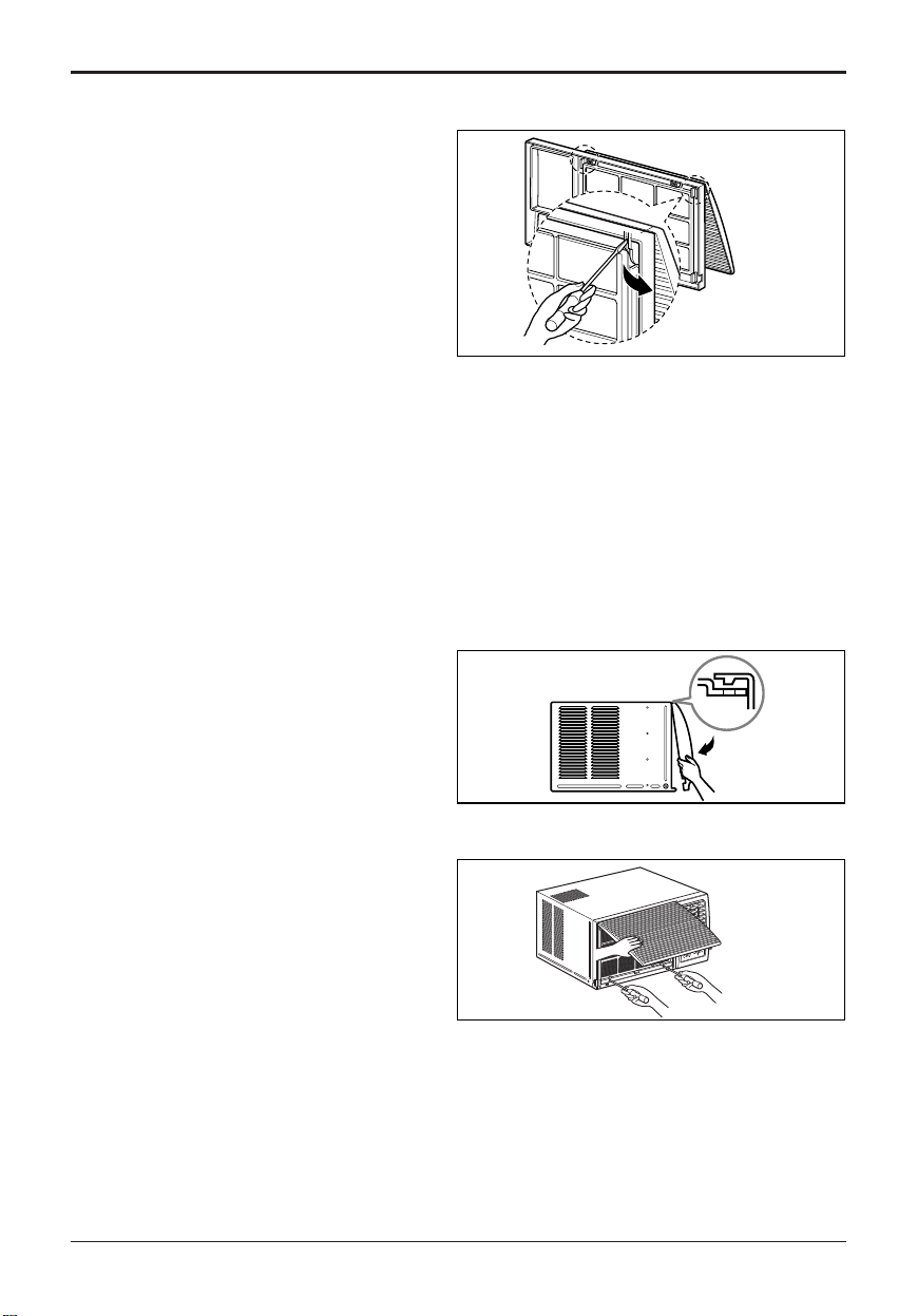
How to Remove the Front Grille
Figure 12
Figure 13
Figure 14
1. If you want to pull out the filter upward,
open the inlet grille slightly. Turn inside
out
the front grille.
Disassemble the inlet grille from the front
grille with separating the hinged part by
inserting a "
" type screw-driver tip.
Rotate the inlet grille 180 degrees and
insert the hooks into the lower holes of
front
grille.
Then, insert the filter. (See Figure12)
2. Attach the front grille to the cabinet by
inserting the tabs on the grille into the tabs
on the front of the cabinet. Push the grille in
until it snaps into place. (See Figure13)
3. Lift the inlet grille and secure it with a type
A screw through the front grille.
(See Figure 14)
4. If you want to pull out the filter downward,
use the reversible inlet grille without
change.
(The grille is already assembled for that
way.)
22 Room Air Conditioner
Before calling for service, please review the following list of common
problems and solutions.
The air conditioner is operating normally when:
Common Problems and Solutions
Before Calling for Service
If you have problems with your air conditioner, read the following information and
try to solve the problem. If you cannot find a solution, turn off the air conditioner
and contact your dealer.
Air conditioner does not operate
1. Ensure that the air conditioner is plugged into a proper outlet.
2. Check the fuse or circuit breaker.
3. Check whether the voltage is unusually high or low.
Air does not feel cold enough on the cooling setting
1. Ensure that the temperature settings are correct.
2. Check to see if the air filter is clogged with dust. If so, clean the filter.
3. Ensure that the air flow from the outside is not obstructed and that there is a
clearance of over 20" between the back of the air conditioner and the wall or
fence behind it.
4. Close all doors and windows and check for any source of heat in the room.
You hear a pinging noise.This is caused by water being picked up by the fan on
rainy days or in highly humid conditions.This feature is designed to help remove
moisture in the air and improve cooling efficiency. See the section on Slinger
Fan, page 20.
You hear the thermostat click.This is caused by the compressor cycle starting
and stopping.
You see water dripping from the rear of the unit.Water may be collected in the
base pan in highly humid conditions or on rainy days.This water overflows and
drips from the rear of the unit.
You hear the fan running while the compressor is silent.This is a normal
operational feature.
Maintenance and Service
Owner s Manual 23
,
ENGLISHENGLISHENGLISH
ENGLISH
Maintenance and Service
The air conditioner ma y be operating abnormally
when:
Problem
The air conditioner is
unplugged.
The fuse is blown/circuit
breaker is tripped.
Power failure.
Airflow is restricted.
The thermostat may not
be set high enough.
The air filter is dirty.
The room may have been
hot.
Cold air is escaping.
Cooling coils have iced up.
Ice blocks the air flow and
stops the air conditioner
from cooling the room.
Air
conditioner
does not
start
Air
conditioner
does not
cool as it
should
Air
conditioner
freezing up
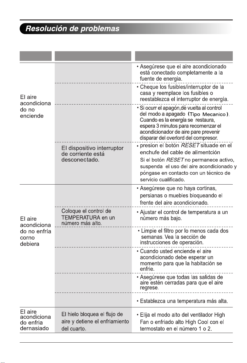
Make sure the air conditioner plug is
pushed completely into the outlet.
Check the house fuse/circuit
breaker box and replace the fuse
or reset the breaker.
If power failure occurs, turn the
mode control to
Off.(Mechanical
When power is restored, wait 3
minutes to restart the air conditioner
to prevent tripping of the compressor
overload.
Make sure there are no curtains
,
blinds, or furniture blocking the
front of the air conditioner.
Turn the knob to a higher number
.
The highest setting provides
maximum cooling.
Clean the filter at least every 2
weeks.
See the care and Maintenance
section.
When the air conditioner is first
turned on, you need to allow time
for the room to cool down.
Check for open furnace floor
registers and cold air returns.
See Air Conditioner Freezing Up
below.
Set the mode control at High Fan
or High Cool with thermostat at 1
or 2.
What To DoPossible Causes
* You can refer to the Energy Star program in detail at www.energystar.gov.
Troubleshooting
Press the RESET button located
on the power cord
plug.
stay engaged,
discontinue use of the air
conditioner and contact a qualified
service technician.
The current interrupter
device is tripped.
24 Room Air Conditioner
If the RESET button will not
Type).

25
ENGLISHENGLISHENGLISH
ENGLISH
Owner s Manual
,
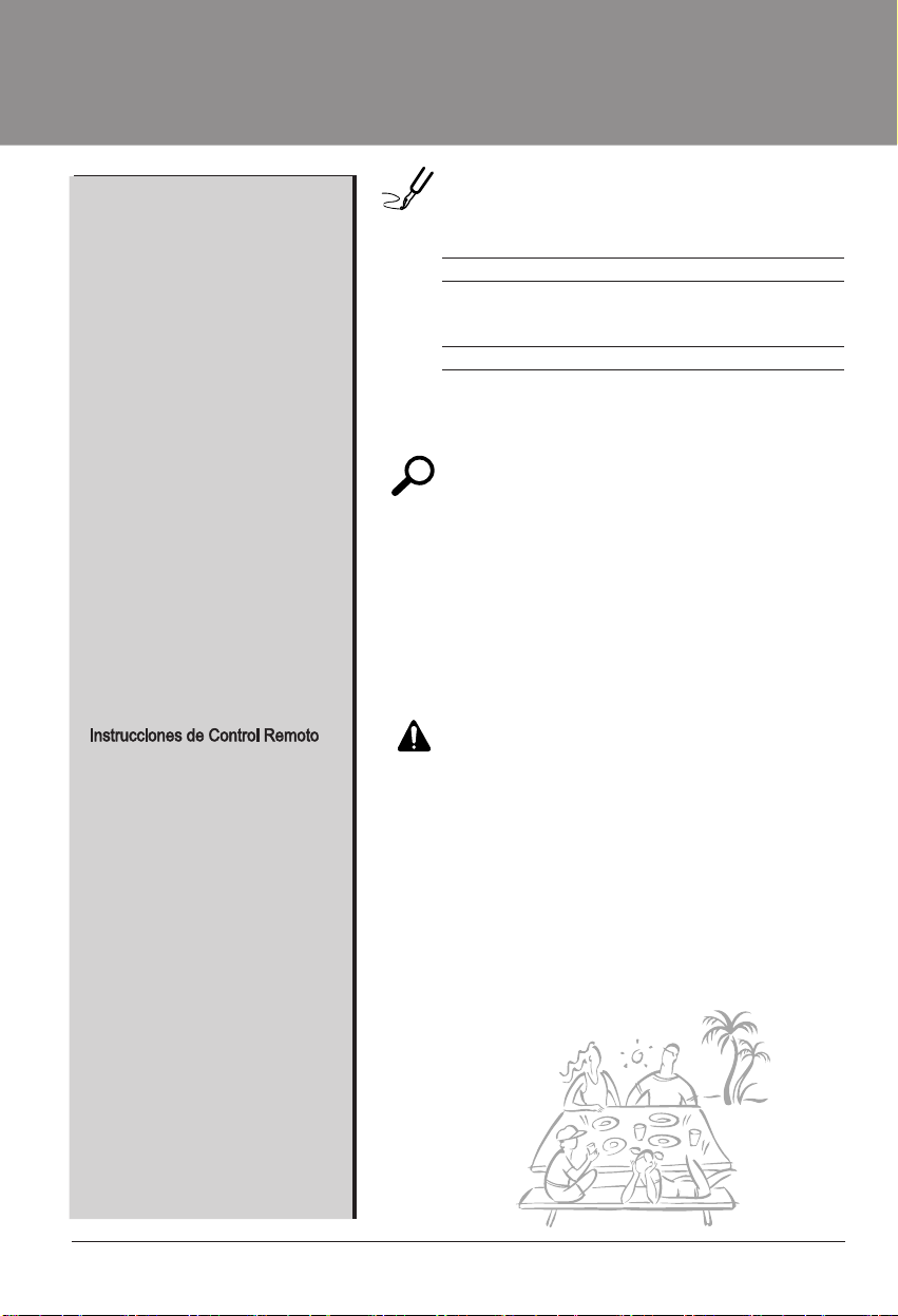
PARA SUS ARCHIVOS
Escriba aquí el modelo y número de serie:
Modelo n°:
Serie n°:
Nombre del distribuidor:
Fecha de compra:
Adjunte su recibo a esta página con la grapadora para
el momento que lo necesite para probar la fecha de su
adquisición o para la validación de la garantía.
LEA ESTE MANUAL
En su interior encontrará muchos consejos útiles sobre la
utilización y mantenimiento de su acondicionador de aire.
Unos pocos cuidados por su parte le pueden ahorrar
mucho tiempo y dinero durante la vida de su
acondicionador de aire.
En la tabla de consejos para la solución rápida de
problemas encontrará muchas respuestas a los problemas
más habituales. Si revisa primero nuestra
Tabla de
Consejos para la solución rápida de problemas, tal vez no
necesite llamar nunca al servicio técnico.
PRECAUCIÓN
•
Contacte a un Centro de Servicio Autorizado para reparar o
realizar el mantenimiento de esta unidad. Llame a 1-877-755-7932
para ubicar el CSA más cercano.
•
El aire acondicionado no es apto para ser usado por niños
pequeños o discapacitados sin la supervision adecuada.
•
Los niños pequeños deben ser supervisados para asegurar que
no jueguen con el aire acondicionado.
•
Si hay que cambiar el cable de alimentación, solicite a un técnico
de servicio que instale un recambio exacto.
• El trabajo de la instalación debe ser realizado de acuerdo al
Código Eléctrico Nacional, únicamente por el personal calificado y
autorizado.
Precauciones de Seguridad.........27
Antes de poner en marcha .......31
Introducción ..................................32
Símbolos Utilizados en
Este Manual. ................................32
Características ............................32
Seguridad Eléctrica ......................33
Uso Transitorio de un
Adaptador.....................................35
Uso Temporal de un
Cable Alargador ..........................35
Instalación ....................................36
Requerimientos de Ventana ........37
Tamaño .....................................37
Espacio Libre ............................37
Preparación de la Carcasa ..........38
Instalación de la Unidad ..............39
Instrucciones de
Funcionamiento.............................41
Localización y Función de los
Controles
.....................................41
Adicionales e Car
acterísticas
.......44
La Direcció
n del Aire
................44
T
ubo de Desag
ü
e .....................44
Mantenimiento y Servicio.............45
Filtro de Aire .............................45
Limpieza del Aire
Acondicionado ..........................45
Como Remover la Parilla
Frontal .......................................46
Problemas y Soluciones
Habituales.....................................47
Resoluci
ón de problemas
.............48
Manual del usuario del acondicionador de aire tipo Ventana
TABLA DE CONTENIDOS
Puede encontrar los números en la etiqueta de la parte
lateral del producto .
■
26 Aire Acondicionador
Datos Electricos ...........................33
......................................................42
.....
43
Control Remoto................Control Remoto................
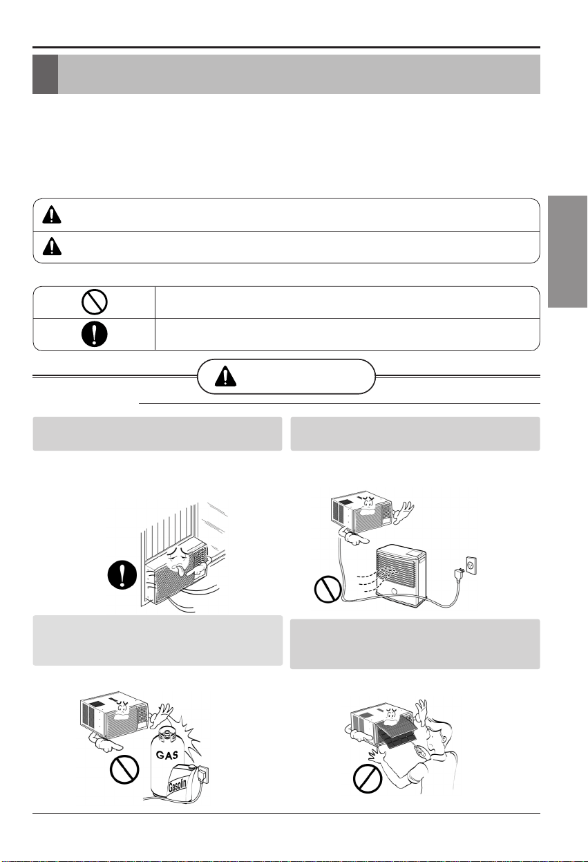
Precauciones de Seguridad
ADVERTENCIA
Para prevenir tanto lesiones al usuario u otras personas como daños materiales, es preciso
seguir estas instrucciones.
■
■ A cause del peso pesado del producto, se recomienda que usted tenga a un ayudante a
participa en la instalación.
■ El significado de los símbolos utilizados en este manual se indica a continuación.
ADVERTENCIA
PRECAUCION
Este símbolo indica la posibilidad de lesiones mortales o graves.
Este símbolo indica la posibilidad de lesiones o daños materi-ales.
Asegúrese de no hacerlo.
Asegúrese de seguir las instrucciones.
■ Instalación
Instale siempre el (los) panel(es) de
expansion.
No coloque el cable eléctrico cerca de un
calefactor.
• Puede causar explosión o incendio.
No desarme o modifique los productos.
Precauciones de Seguridad
• Un montaje o instalación defectuoso puede
provocar un funcionamiento incorrecto,
incluyendo r , incendios o
• Puede causar incendio y descarga eléctrica.
No use el cable de corriente cerca de gas
inflamable o combustibles tales como gasolina,
benzina, solvente, etc.
descargas eléctricas.
iesgos de lesiones
• Puede causar descarga eléctrica y fallos.
La incorrecta operación del aparato como consecuencia de ignorar las instrucciones
provocará daños o lesiones.
Manual del Propietario 27
ESPAÑOL
28
29
30
Antes de poner en marchaAntes de poner en marcha
31
Introducción
Este símbolo lo advierte de un peligro de accidente por corriente
eléctrica.
Este símbolo lo adiverte de un peligro que pueda causar un daño
del ventliador.
Este símbolo significa condicciones especiales.
Introducción
ADVERTENCIA : Este aparato debería instalarse de acuerdo con las
normas del Código Eléctrico Nacional.
Símbolos Utilizados en Este Manual
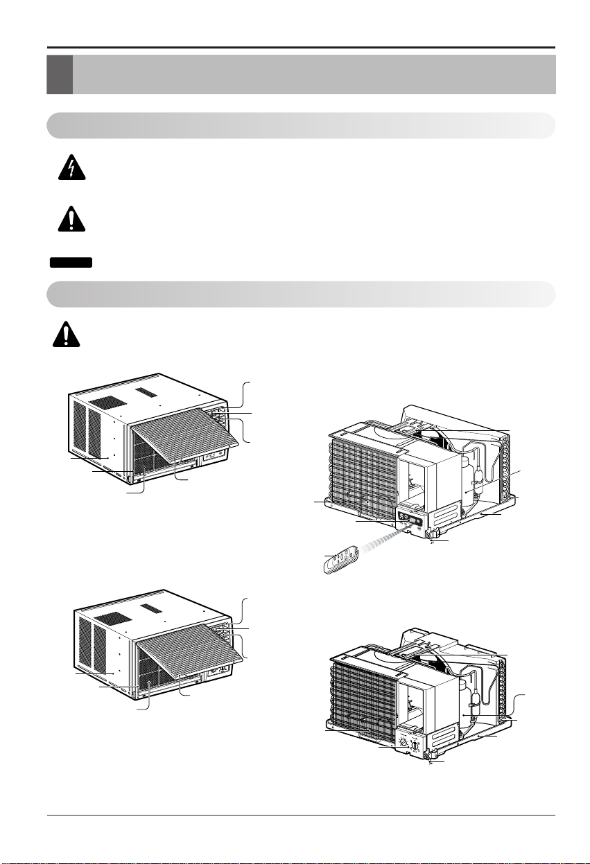
Características
GABINETE
REJILLA
FRONTAL
FILTRO DE
AIRE
SALIDA DE AIRE
DEFLECTOR HORIZONTAL
DE AIRE
(VENTANILLAS
VERTICALES)
DEFLECTOR DE
AIRE HORIZONTAL
(VENTANILLAS HORIZONTALES)
RECOLECTOR
DE AIRE
(BANDEJA DE
ENTRADA)
GABINETE
REJILLA
FRONTAL
FILTRO DE
AIRE
SALIDA DE AIRE
DEFLECTOR HORIZONTAL
DE AIRE
(VENTANILLAS
VERTICALES)
DEFLECTOR DE AIRE
HORIZONTAL
(VENTANILLAS
HORIZONTALES)
RECOLECTOR DE AIRE
(BANDEJA DE ENTRADA)
CONTROL
REMOTO
EVAPORADOR
DE CONTROL
PANEL
CABLE DE CONEXIÓN ELÉCTRICA
BANDEJA
CONDENSADOR
COMPRESOR
SUSPENSORES
EVAPORADOR
DE CONTROL
PANEL
CABLE DE CONEXIÓN
ELÉCTRICA
BANDEJA
CONDENSADOR
COMPRESOR
SUSPENSORES
CONSEJO
Aire Acondicionador
32
ESPA NOL
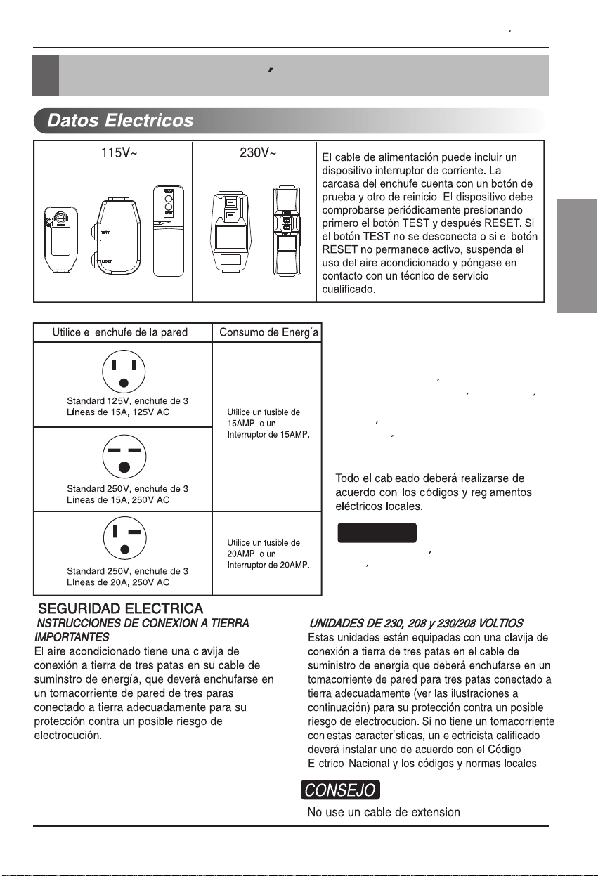
Seguraidad Electrica
USO DE CORDONES DE EXTENSION
Debido al potencial de peligro a su
seguridad bajo ciertas circunstancias
recomendamos encaredidamente no utiliar
cordones de extension. Sin embargo, si
usted decide usar un cordon de extension,
es absolutamente necesario que este sea
un cordon listado bajo UL de tres espigas
con conexion a tierra calificado 15A, 125V.
El cableado domestico de aluminio
podria ocasionar problemas especiales.
Consulte a un electricista calificado.
CONSEJO
Seguraida Electrica
Manual del Propietario 33
ESPAÑOL
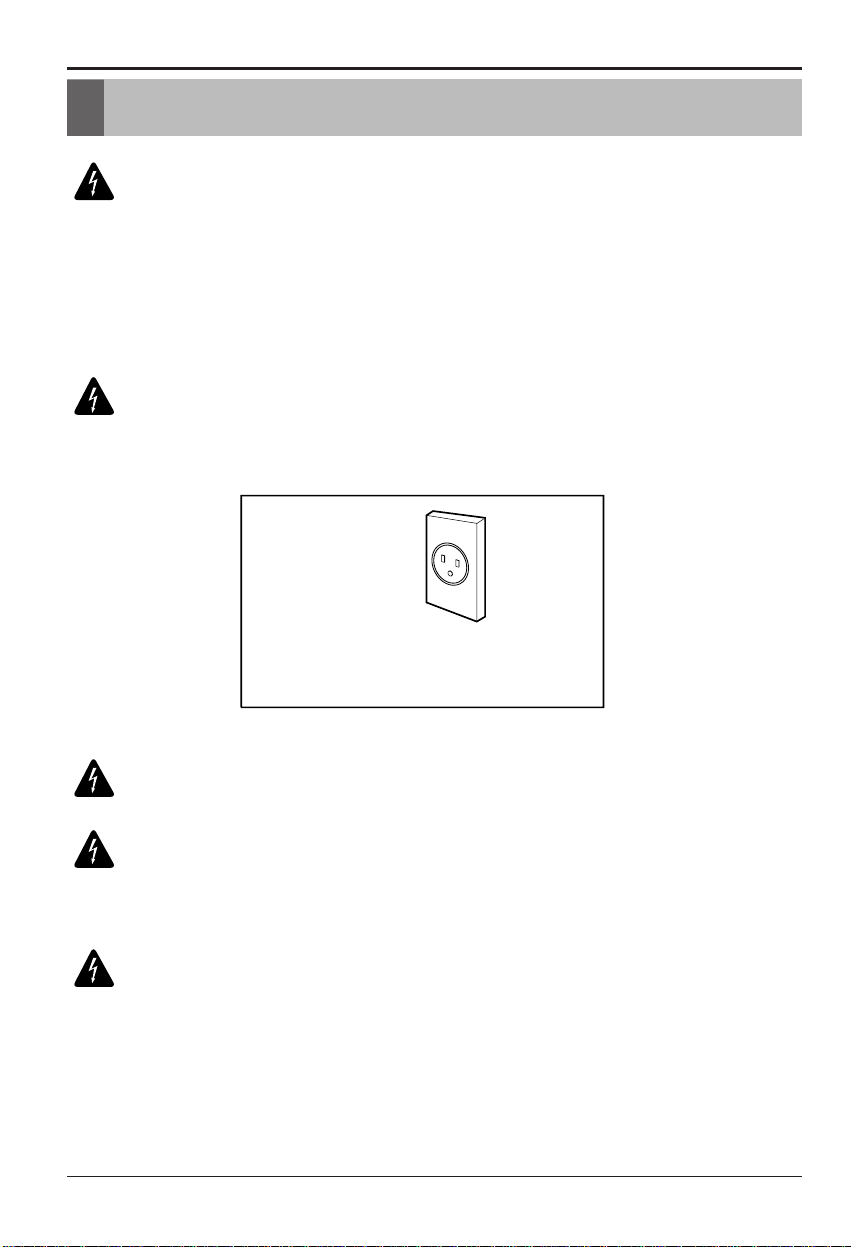
Este equipo debe estar puesto a tierra debidamente.
El cable de alimentación está equipado de una toma de tierra con tres pins. Para
minimizar el peligro de una lesión por corriente eléctrica, utilice una toma con
enchufe de tierra estándar con tres contactos. Si el enchufe de pared no contiene
un borne de tierra, antes de usar el ventilador haga cambiar el enchufe por un
electricista.
Seguridad Eléctrica
Seguridad Eléctrica
Cambiar la toma sin realizar los cambios de cableado apropiados
creará un estado eléctrico inseguro que podría resultar en un incendio
o descarga eléctrica. Para todo este tipo de trabajos, consulte siempre
con un electricista cualificado.
No corte ni quite el borne de tierra de la clavija de alimentación
El acoplamiento del borne de tierra del adaptador con el tornillo de la
cubierta del enchufe de pared no pondrá el equipo a tierra, si el
tornillo de la cubierta no es de metal y está aislado y el enchufe de
pared no está puesto a tierra a través de la red de la casa.
En el caso de cualquier duda respecto a la correcta puesta a tierra
del ventilador, haga revisar el enchufe de pared y el circuito por un
electricista profesional.
Método preferido
Asegúrese que existe debida
neutralización antes de utilizar el
aparato.
34 Aire Acondicionador
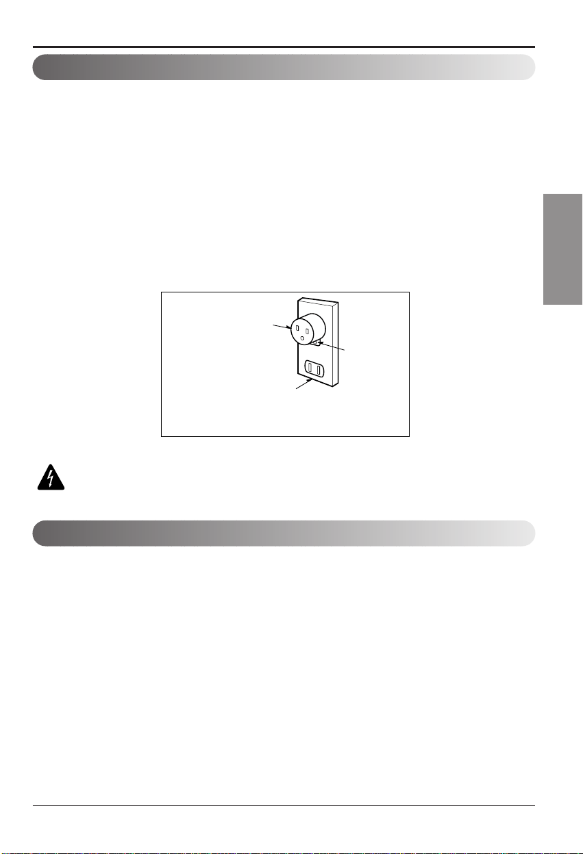
Debido a eventuales peligros de seguridad no recomendamos en absoluto el
uso de un adaptador. Sólo para una conexión transitoria se puede usar el
adaptador clasificado como UL que está a disposición en la mayoría de las
tiendas de productos eléctricos. Atienda que e orificio grande en el adaptador
corresponda al orificio grande en el enchufe para lograr la conexión con la
polaridad correcta.
Desconectando el cable de alimentación del adaptador utilice una mano para
sendas partes para evitar un daño del borne de tierra. Evite una desconexión
frecuente del cable de alimentación, pues puede causar un eventual daño del
borne de tierra.
Nunca utilice el equipo con un adaptador dañado.
Debido a un eventual peligro no recomendamos en absoluto el uso de un
cable alargador. En situaciones excepcionales utilice sólo alargadores
certificados con puesta a tierra CSA clasificados como UL con tres conductores
de valores 15 A, 125 V.
Seguridad Eléctrica
Método temporal
Adaptador
Cubierta del
Interruptor
Tornillo de Metal
Uso Transitorio de un Adaptador
Uso Temporal de un Cable Alargador
Manual del Propietario 35
ESPAÑOL
Instalaci
ón
Instalaci
ón
Para la instalación debería tener a disposición los instrumentos siguientes:
* Destornillador (Estrella y Phillips) * Regla
* Cucjillo
* Martillo
* Lápiz Nivel
Tipo F:2 EA
(SOPO
RTE DE ALFÉIZAR)
Tipo G:2 EA
(TORNILLO)
Tipo C:5 EA
(TORNILLO)
Tipo A:16 EA
(TORNILLO)
Tipo D:2 EA
(TUERCA)
Tipo K:2 EA
(GUÍA MARCO)
Tipo J:1 EA
(BAN
DA ADHESIVA)
Tipo I:1 EA
(SUPERIOR)
Tipo H:1 EA
(TIRA DE GOMA)
Tipo O:1 EA
(ARANDELA)
Tipo N:1 EA
(TAPA DEL DESAGÜE)
Tipo M:1 EA
(BANDA ADHESIVA)
Tipo B:3 EA
(TORNILLO)
Tipo E:2 EA
(PANEL GUÍA)
(CHAPA DE SOPORTE PARALA VENTANA)
10
mm61
mm61
mm01
36 AireAcondicionador
Tipo L:1 EA
Instalación
Espacio libre
30"~60"
Toldo
Aire enfriado
Valla
Radiacion
de calor
1.Para prevenir la vibración y el ruido, asegure de que la unidd esté insta alada
segura y fimemente.
2.Instale la unidad donde el sol no refleje directmente en la unidad.
3.La salida debe extenderse hacia afuera por lo menos 12" y no debe haber
obst
áculos, como cercas o paredes, en 20" de la parte de atrás del gabinete
porque va ha prevenir la rediaci
ón de calor del condensador. Restriciones dl
aire de fuera reducir
á grande mente la eficiencia del aire
:
Todas las ventanillas de los lados
del gabinete deben mantenerse
expuestas hacia afuera de la
estructura.
4.Instale la unidad un poco inclinada de tal forma que la parte trasera esté ligeram
entemás baja que fl frente(cerca de 1/2").
Esto forzará el agua del condensador hacia afuera.
5.Instale la unidad con la parte inferior cerca de 30"~60" arriba nivel de suelo.
CONSEJO
Tamaño
Este ventilador de casa está
construido para ventanas estándar de
dos alas con la extensión real de
apertura de 27" a 39". El ala superior
y el inferior de la ventana deben
abrirse lo suficiente para producir un
orificio vertical de 16" desde el ala
superior hasta el antepecho.
ADVERTENCIA :
Este producto es un aparato de AIRE ACONDICIONADO
PARA INSTALACIÓN EN VENTANAS. Como tal, se necesita una ventana de
un cuelgue o de doble cuelgue para una instalación adecuada. No se
recomiendan instalaciones en lugares que no sean ventanas, utilizando
casquillos, orificios en las paredes ni cualquier otro tipo.
Requerimientos de Ventana
27" a 39"
Compensación
1
/2" to 1
1
/4"
Sill
Exterior
Pared intema
23
5
/8" min.
(sin cortina del marco)
Banqueta
16" min
Alrededor de 1/2"
Por encima de 20"
Manual del Propietario 37
ESPAÑOL
Instalación
1. Remueva los tornillos cuales sujetan
el gabinete a ambos lados y en la parte de
2. Deslice la unidad fuera del gabinete tomando
el agarradero de la bandeja y hale hacia el
frente mientras mantiene el gabinete.
3. Corte el marco de la ventana con el largo
apropiado. Desprenda la parte de atrás y
sujete el Foam-PE
en la parte inferior del
marco de la ventana.
4. Remueva el empaque desde el sello de la
guia Superior y péguelo al fondo de la
guia Superior .
5. Sujete la guía superior en la parte de arriba
del gabinete con 3 tornillos Tipo A.
6. Inserta la Guía Marco en la parte inferior
del gabinete.
7. Inserte los Paneles Guías en la guía
Superior y en la Guia Marco .
8. Sujete el armazon a la unidad con 4 tornillos.
(Tipo A)
Preparación de la Carcasa
Use un atornillador largo. Así le será
más fácil instala los tornilos.
CONSEJO
Tornillos para
transporte
(Tipo A)
(Tipo A)
atrás.
Foam-PE
Superior
Banda Adhesive
Superior
Screw
Guia Marco
Screw
Guia Marco
Screw
(Tipo A)
38 Aire Acondicionador
Instalación
Precautión: En las siguientes instrucciones, sostenga la unidad firmemente
hasta que la parte corrediza de la ventana descanse sobre la parte superior
del canal y por detrás del marco de los paneles corredizos. Puede haber
lesiones o daños si la unidad se cae de la ventana.
Instalación de la Unidad
Aproximamente 1/2"
Soporte del Alféizar
Pista de
Marco
Angulo de Delante
Tornillo(Tipo B)
Soporte del Alféizar
Tornillo(Tipo B)
Interior
Exterior
Gabinete
Aproximamente 1/2"
Guia Marco
Tornillo(Tipo A)
Interior Exterior
Soporte del Alféizar
TuercaTornillo
Guía Superior
Marco de Ventana
Taburete de la Ventana
Angulo de Delante
Guía Superior
Panel Guía
Banda adhesiva
Banda adhesiva
Gabinet
1. Abra la ventana. Marque una línea en el
centro del banqueta de la ventana(o la
ubicación deseada del aire acondicionado).
Cuidadosamente ubique el gabinete en la
banqueta de la ventana y alinee la marca
central en el frente inferior con el centro de la
línea marcada en la banqueta de la ventana.
2. Hale hacia abajo la parte inferior de la
ventana hasta que se una detrás de la guía
superior.
3. Ligeramente ensamble el soporte del alfeizar
usando las partes de la Figura 3.
4. Seleccione la posición que ubicará el soporte
del alféizar cerca del punto más exterior del
alféizar.(Ver Figura 4)
Tenga cuidado al instalar el
gabinete(las Guías Marco se rompen fácilmente).
5. Pegue el soporte antepecho a los rieles de la
caja en relacion a la posicion deseada
usando dos tornillos Tipo A en cada soporte.
(Ver Figura 4)
6. El gabinete debe ser instalado con una
pequeña caída(cerca de
1
/2") hacia abajo
hacia afuera (Ver Figura 5).
7. Adjunte el gabinete al banquete de la ventana
atornillando los tornillos (Tipo B: Largo
dieciséis milímetros y menos.) a través del
ángulo frontal en la banqueta de la ventana.
8. Hale cada panel guía completamente a cada
lado de la ventana y repita del paso 2.
Figura 1
Figura 2
Figura 3
Figura 4
Figura 5
CONSEJO
CONSEJO
No hale la ventana hacia abajo tan
apretadamente que el movimiento del panelguía sea
restringido.
Manual del Propietario 39
ESPAÑOL
Chapa de soporte para
la ventana
Tira de Goma
Tornillo(Tipo A)
Tornillo(Tipo A)
Conrdon
de Alimentacion
Tipo C
9. Adjunte cada Panel Guía a cada lado de la
ventana usando tornillos (Tipo C).
(Ver Figura 6)
No perfore la charola del fondo.
La unidad está diseñada para operar con
aproximadamente 1/2" de agua
en la charola del
10. Deslice el chasís dentro del gabinete.
(Ver Figura 7)
: Por razones de seguridad, re
instale los tornillos(Tipo A) en los lados del
gabinete.
11. Corte la Tira De Goma a la medida
apropiada e introdúzcala entre la parte
superior e inferior de la ventana.
(Ver Figura 8)
12. Sujete la Chapade Soporte En El Marco De
La Ventana
con untornillo Tipo C.
(Ver Figura 9)
13. Pegue el panel frontal a la caja insertando
los fijadores en el panel adentro los del
panel de la caja. (Ver Figura 10)
14. Levante la parrilla de entrada y ajústela
con tornillos Tipo A, através de la parrilla
frontal. (Ver Figura 11)
15. Ahora la instalación del aire acondicionado
en la ventana es completada. Vea los DATOS
ELECTRICOS para instalar el cable de
alimentación en la toma de corriente.
Figura 6
Figura 7
Figura 8
Figura 9
Figura 10
Figura 11
Instalación
CONSEJO
CONSEJO
fondo.
40 Aire Acondicionador
41
•
•
•
•
3
•
•
•
•
•
•
á
Low,M .
6
Instrucciones de funcionamiento
PRECAUTIÓN: El mando a distancia no funcionará correctamente si
una luz fuerte hace contacto con el sensor del aire acondicionado o si
hay obsáculos entre el mando a distancia y el aire acondicionado.
Auto
Swing
Power
Temp
Fan Speed
Timer Mode
Energy
Saver
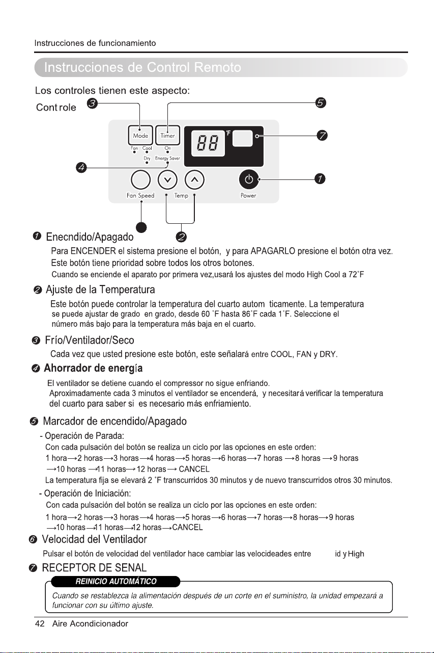
Frío/Ventilador/Seco
• Cada vez que presione este botón, las palabras COOL, FAN y DRY aparecerán alternadamente.
Enecndido/Apagado
• Para ENCENDER el sistema presione el botón, y para APAGARLO presione el botón otra vez.
• Este botón tiene prioridad sobre todos los otros botones.
• Cuando Ud. Io enciende por primera vez, el sistema está en el y la temperatura es de 72˚F.
Ajuste de la Temperatura
•
Este botón controla la temperatura de la sala entre los 60˚F y los 86˚F
en incrementos de 1˚F.
Ahorrador de Energía
El ventilador se detiene cuando el compressor no sigue enfriando.
• Aproximadamente cada 3 minutos el ventilador se encenderá,
y necesitará verificar la temperatura del cuarto para saber si
es necesario más enfriamiento.
Marcador de Encendido/Apagado
- Operación de Parada:
• Con cade pulsación del botón se realiza un ciclo por las opciones
en este orden:
La temperatura fija se elevará 2
˚
F transcurridos 30 minutos y de nuevo
transcurridos otros 30 minutos.
•
- Operación de Iniciación:
•
Velocidad del Ventilador
• Pulsar el botón de velocidad del ventilador hace cambiar las
velocidades entre Low y High.
Control Remoto
Con cade pulsación del botón se realiza un ciclo por las opciones
en este orden:
1 hora 2 horas 3 horas 4 horas 5 horas
6 horas 7 horas 8 horas 9 horas 10 horas 11 horas
12 horas CANCEL
1 hora 2 horas 3 horas 4 horas 5 horas
6 horas 7 horas 8 horas 9 horas 10 horas 11 horas
12 horas CANCEL
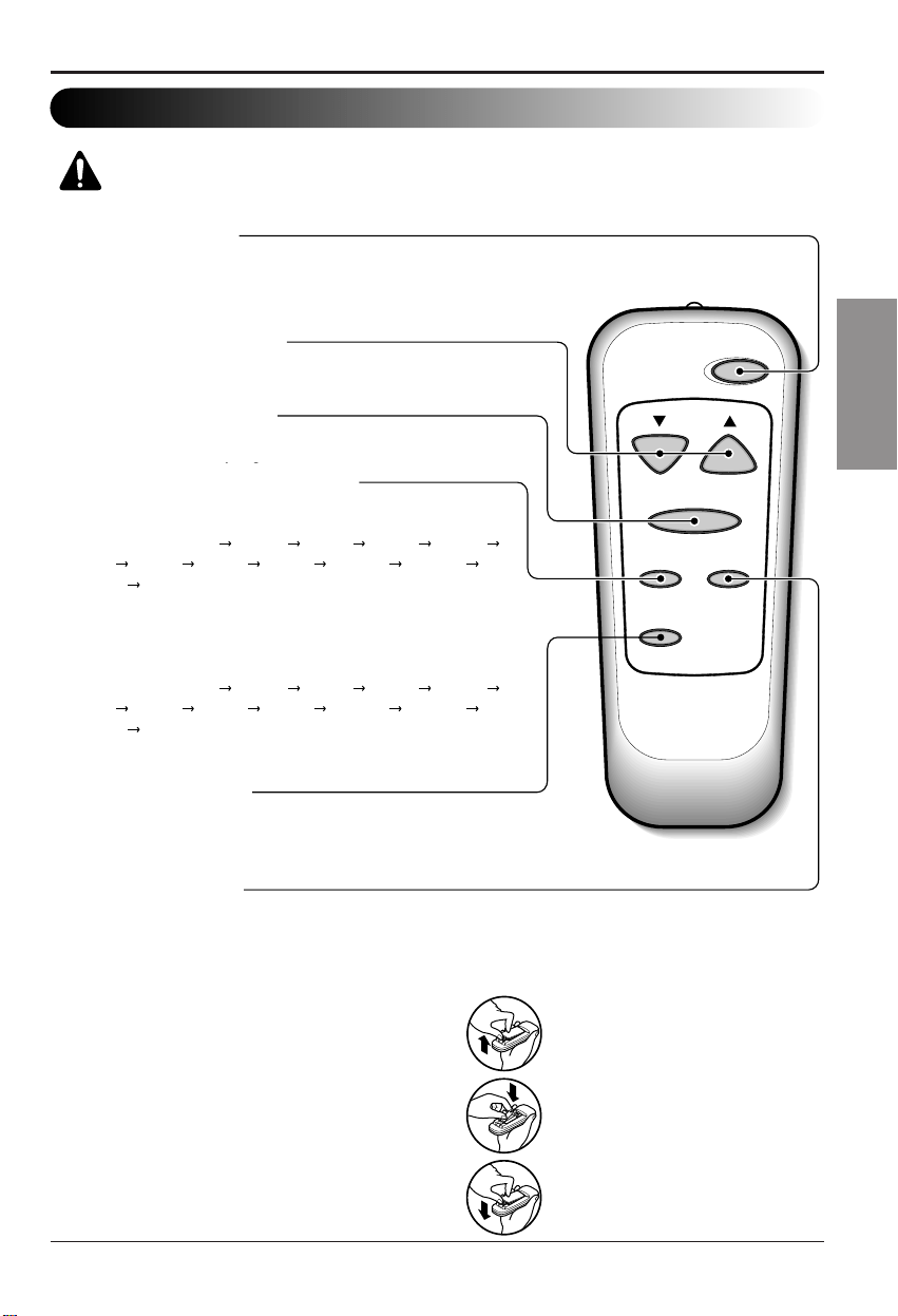
Cómo Poner las Baterías
1. Quite la tapa de la parte posterior del telemando.
Para ello haga deslizar la tapa según la dirección
del la flecha.
2. Introduzca las dos baterías, Respete siempre la
polaridad al instalar las pilas. Use baterías nuevas.
3.Volver a cerrar, resbalando la tapa hasta la
posición inicial.
• No utilice baterís recargables,
éstas son diferentes de forma,
de dimensión y uso respecto a
las baterías secas usuales.
• Seque las baterías del
telemando cuando el
acondicionador no vaya a ser
usado durante un largo período.
ESPAÑOL
Manual del Propietario 43
Low,Mid y High.
Seleccione el modo fresco (cool) para enfriar la habitación.
Seleccione el modo ventilador (fan) para el funcionamiento del ventilador.
Seleccione el modo seco (dry) para
el funcionamiento seco.
Instrucciones de funcionamiento
La dirección del aire
Tubo de Desagüe
PRECAUTIÓN: Tenga cuidado al insertar el tubo de drenaje. Aléjalo de
la area aguda para evitar el deslice y lesiones por usted mismo.
Tapa
del desagüe
Tubo
Cuelgue
Empujon
La dirección del aire puede ser controlada cuando
usteddesee enfriar, ajustando la palanca vertical
y la palanca horiziontal.
• CONTROL DE LA DIRECCIÓN HORIZONTAL DEL AIRE
La dirección horizontal del aire es ajustada
rotando lapalanca vertical hacia la derecha o
hacia la izquierda.
• CONTROL DE LA DIRECCIÓN VERTICAL DEL AIRE
La dirección vertical del aire es ajustada rotando
la palanca horizontal hacia adelanto o hacia
atrás.
En climas húmedos, es posible que la
Bandeja Evaporadora se llenne de agua.
Para quitar el agua acumulado, es
preciso conectar el tubo de desagüe.
Quite la Tapa del Desagüe y conecte el
Tubo a la Bandeja Evaporadora.
Este aparato de aire acondicionado va
equipado con un ventilador de
extracción. (Véase la ilustración de
abajo). El ventilador tiene un anillo
externo que gira en el agua que recoge
en la plancha base al entrar en
profundidad. La condensación la recoge
el ventilador y la expulsa a través del
condensador, haciendo más eficiente al
aparato de aire acondicionado
.
Adicionales e Características
Anillo
44 Aire Acondicionador
Filtro de Aire
Revise por lo menos dos veces al mes si no es necesario limpiar el filtro de aire.
Las partículas detenidad se pueden acumular en el filtro impidiendo el flujo del
aire, limitando el rendimiento de enfriamiento y causando la acumulación de hielo
en el evaporador. Proceder de la limpieza del filtro de aire:
1. Abra la rejilla hacia arriba tirando la parte inferior de la rejilla o hacia abajo tiran
parte superior de la rejilla.
2. Usando una lengueta,tire el filtro lieramente hacia arriba para sacarlo por aba
arriba.
3. Lave el filtro con agua tibia de temperatura menor de 40°C (104°F).
4. Escurra ligeramente el agua sobrante del filtro y vuelva a instalarlo.
Limpieza del Aire Acondicionado
La parrilla frontal puede ser limpiada con
un trapo húmedo mojado en un
detergente suave.
El gabinete puede ser lavado con jabón
suave o detergente y agua tibia, entonces
pulido Cera Liquida para aparatos.
Para asegurarse una eficiencia continua,
las bobinas del condensador (del lado
expuesto al exterior) debe ser revisado y
lavado periódicamente sea por que se
tranque con basura o polvo de la
atmosférico.
Mantenimiento y servicio
Mantenimiento y Servicio
NO OPERE el aire acondicionado sin filtro ya que la suciedad y el
tamo obstruira el filtro y reducira la eficiencia del funcionamiento.
CONSEJO
Manual del Propietario 45
ESPAÑOL
Mantenimiento y servicio
Como Remover la Parilla Frontal
1. Si usted desea sacar el filtro por arriba,
abra la rejilla de entrada ligeramente.
Vuelte la rejilla frontal.
Separe la parte engoznada insertando
la punta del destornillador de tipo " "
_
para desensamblar la rejilla de entrada
desde la rejilla frontal.
Gire la rejilla de entrada 180 grados e
inserte los ganchos en los huecos
inferiores del rijilla frontal.
Luego, inserte el filtro. (Ver Figura12)
2.
insertando los fijadores en el panel
adentro los del panel dela caja.
(Ver Figura 13)
3. Levante la parrilla de entrada y
ajústela con tornillos Tipo A, através de
la parrilla frontal. (Ver Figura 14)
4. Si usted desea sacar el filtro por abajo,
usar la rejilla de entrada reversible.
(La rejilla es ya diseñada para tal
Pegue el panel frontal a la caja
Figura 13
Figura 14
Figura 12
manera)
46 Aire Acondicionador
Mantenimiento y servicio
Antes de llamar al servicio, tenga a bien revisar la siguiente lista de
problemas y sus soluciones.
El acondicionador de aire está funcionando normalmente cuando:
• Escucha un sonido metálico. Lo causa el agua que recoge el condensador en
días lluviosos o en condiciones de mucha humedad. Esta característica está
diseñada para ayudar a quitar la humedad en el aire y mejorar la capacidad de
enfriamiento. Consulte la sección del Ventilador de wxtracciór en la página 44.
• Oye un clic en el termostato. Lo causa el ciclo del compresor que comienza y se
detiene.
• Ve gotear agua de la parte posterior de la unidad. El agua puede ser recogida
en la bandeja de base en condiciones de mucha humedad o días de lluvia. Esta
agua desborda y gotea desde la parte posterior de la unidad.
• Oye funcionar el ventilador mientras el compresor está silencioso. Esto es una
característica operativa normal.
Antes de Llamar el Servicio de Asistencia Técnica
Si tiene problemas con su ventilador, lea las informaciones siguientes y trate de
resolver el problema. Si no puede encontrar la solución, desconecte el ventilador
y diríjase a su suministrador.
El ventilador no funciona
1. Compruebe que el ventilador esté conectado en un enchufe correcto.
2. Revise el fusible.
3. Compruebe que la tensión no sea demasiado alta o baja.
Al ajustarse el enfriamiento, el aire no parece frío lo suficiente
1. Revise si los ajustes de la temperatura son correctos
2. Revise si el filtro de aire no está atascado de polvo. En este caso, limpie el
filtro.
3. Compruebe que afuera no haya un obstáculo del flujo de aire y si entre la
parte trasera del ventilador y la pared o la barrera haya espacio libre de por lo
menos 1 metro (20").
4. Cierre todas las puertas y ventanas y compruebe que no haya una fuente de
calor en la habitación.
Problemas y Soluciones habituales
47
Manual del Propietario
ESPAÑOL
*Usted puede referirse al Energy Star programa con todo detalle en www.energystar.gov.
El acondicionador de aire puede estar funcionando anormalmente cuando:
Problema
El aire acondicionado está
desconectado
.
El fusible está quemado/el
interruptor de energía se ha
bloqueado.
Falta de energía.
El flujo de aire esta
restringido.
El filtro de aire está sucio.
El cuarto aún está caliente.
El aire frio se está
escapando.
El serpentin de refrigeración
se ha congelado.
Qué hacerCausas posibles
Manual del Propietario 30
ESPA NOL
Seguraidad Electrica
USO DE CORDONES DE EXTENSION
Debido al potencial de peligro a su
seguridad bajo ciertas circunstancias
recomendamos encaredidamente no utiliar
cordones de extension. Sin embargo, si
usted decide usar un cordon de extension,
es absolutamente necesario que este sea
un cordon listado bajo UL de tres espigas
con conexion a tierra calificado 15A, 125V.
El cableado domestico de aluminio
podria ocasionar problemas especiales.
Consulte a un electricista calificado.
CONSEJO
Mantenimiento y servicio
48 Aire Acondicionador

49
Manual del Propietario
ESPAÑOL

Specifications and performance data subject to change without notice.
HEAT CONTROLLER, INC.
1900 WELLWORTH AVENUE • JACKSON, MICHIGAN 49203
THE QUALITY LEADER IN CONDITIONING AIR
P/No Printed in China
: