Please read this entire manual carefully
before operating your new recumbent
stepper and save it for future use.
User manual
Register your product and get support at
www.philips.com/welcome
PTE4000CS
ReActiv
Recumbent stepper
4.0 S

Thank you for your recent purchase of the Philips physical rehabilitation
recumbent stepper 4.0 S.
Philips physical therapy and exercise solutions provide simple, reliable
products that oer the most relevant feedback to caregivers and
users to achieve best-in-class outcomes and empower individuals to
build condence in rebuilding and maintaining healthy lifestyles and
keep in touch with their communities.
Your new product has been manufactured by one of the world’s leading
medical product manufactures. It is backed by one of the most
comprehensive warranties in the industry. Through our dealers,
distributors and manufacturer’s representatives, we will do all we
can to provide many years of successful and prosperous ownership.
Your warranty and service needs will be addressed either through your
regional sales representative or our highly trained service technicians.
It is their responsibility to provide you with both the technical
knowledge and access to service personnel to make your ownership
experience more informed, and resolve any issues quickly.
Product registration
Register your product and get support at:
www.philips.com/welcome
This will ensure we have all your details quickly at hand in dealing with
any after sales support. For fastest support visit us and self service
solution at :
www.philips.com/support
Philips therapy solutions
Delivering better outcomes

Contents
Important safety instructions 4
Important electrical information
Important operation instructions 7
Features 8
Assembly instructions 9
Console operation 14
6
Using a heart rate transmitter 30
Maintenance 33

4
Attention
Read all instructions in this manual before using this device.
Danger
To reduce the risk of electric shock disconnect this device from the
electrical outlet prior to cleaning and/or service work.
Warning
• Before beginning exercise on this product, or any exercise program,
consult a physician. This is especially important for persons over the
age of 35 or persons with preexisting health conditions.
• There are obvious pinch points and other caution areas that can
cause harm.
• Children under the age of 13 should be supervised to ensure that they
do not play with the device.
• Keep hands away from all moving parts.
• Never drop or insert any object into any openings.
• Do not use outdoors.
Important
safety
instructions

5
• Do not operate this product on deeply padded, plush or shag
carpet. Damage to both carpet and product may result.
• Do not attempt to use this product for any purpose other than for
the purpose it is intended.
• Do not operate where aerosol spray products are being used or
where oxygen is being administered. Sparks from the motor may
ignite a highly gaseous environment.
• Never operate the product if it has a damaged cord or plug. If the
product is not working properly, call your dealer.
• Keep the cord away from heated surfaces.
• The hand pulse sensors are not medical devices. Various factors,
including the user’s movement, may aect the accuracy of heart rate
readings. The pulse sensors are intended only as an exercise aids in
determining heart rate trends in general.
• Heart rate monitoring systems may be inaccurate. Over exercising
may result in serious injury or death. If you feel faint stop exercising
immediately.
• Wear proper shoes. High heels, dress shoes, sandals or bare feet are
not suitable for use on your tness bike. Quality athletic shoes are
recommended to avoid leg fatigue.
• This appliance is not intended for use by persons (including chil-
dren) with reduced physical, sensory or mental capabilities, or lack
of experience and knowledge, unless they have been given supervi-
sion or instruction concerning use of the appliance by a person
responsible for their safety.
• Maximum User Weight: 450 lbs.
• Save these instructions - think safety!

6
Warning
• Never expose this product to rain or moisture. This product is not
designed for use outdoors, near a pool or spa, or in any other high
humidity environment. The operating temperature specication is 5
to 48 degrees Celsius (40 to 120 degrees Fahrenheit), and humidity
is 95% non-condensing (no water drops forming on surfaces).
Important
electrical
information

7
• Never operate this product without reading and completely
understanding the results of any operational change you request
from the console.
• Understand that changes in resistance do not occur immediately.
Set your desired resistance level on the console and release the
adjustment key. The console will obey the command gradually.
• Use caution while participating in other activities while pedaling
on your product; such as watching television, reading, etc. These
distractions may cause you to lose balance which may result in
serious injury.
• Do not use excessive pressure on console control keys. They are
precision set to function properly with little nger pressure.
Important
operation
instructions
8
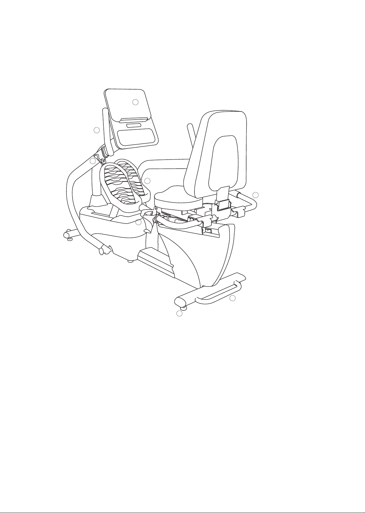
4.0 S Recumbent stepper
Parts and adjustments
1. Console
2. Upper body handles
3. Quick release lever
4. Cushioned footplates
5. Lifting handle for transport
6. Leveling glides
7. Seat angle adjustment
8. Seat position adjustment
Features
5
6
8
2
3
4
7
1

9
Unpacking
• Cut the straps, then lift the box over the unit and unpack.
• Carefully remove all parts from the carton and inspect for any damage
or missing parts. If parts are damaged or missing, contact your dealer
immediately.
• Locate the hardware package. Remove the tools rst. Remove the
hardware for each step as needed to avoid confusion. The numbers in
the instructions that are in parenthesis (#) are the item number from
the assembly drawing for reference.
Tools included
• 5mm L allen wrench
• 8mm L allen wrench
• 12/14mm wrench
• 13/14mm wrench
• Phillips screwdriver
• Short phillips screwdriver
Assembly
instructions
Parts included
• 1 main frame
• 2 foot pedals
• 1 seat cover
• 1 connecting arm
• 1 console mast
• 1 console mast cover
• 1 handle bar
• 1 drink bottle holder
• 4 end caps
• 2 transport wheels
• 1 seat
• 1 seat back frame
• 2 swing arms
• 1 console
• 1 hardware kit
• 1 power cord
10
• 4 end caps
• 2 transport wheels
• 1 seat
• 1 seat back frame
• 2 swing arms
• 1 console
• 1 hardware kit
• 1 power cord
Assembly
Read each step’s instructions and study the drawing carefully to become
familiar with all the parts and procedures before beginning each step.
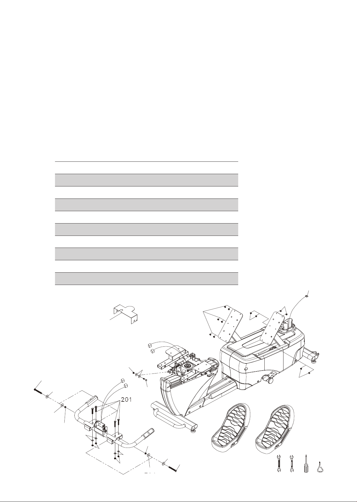
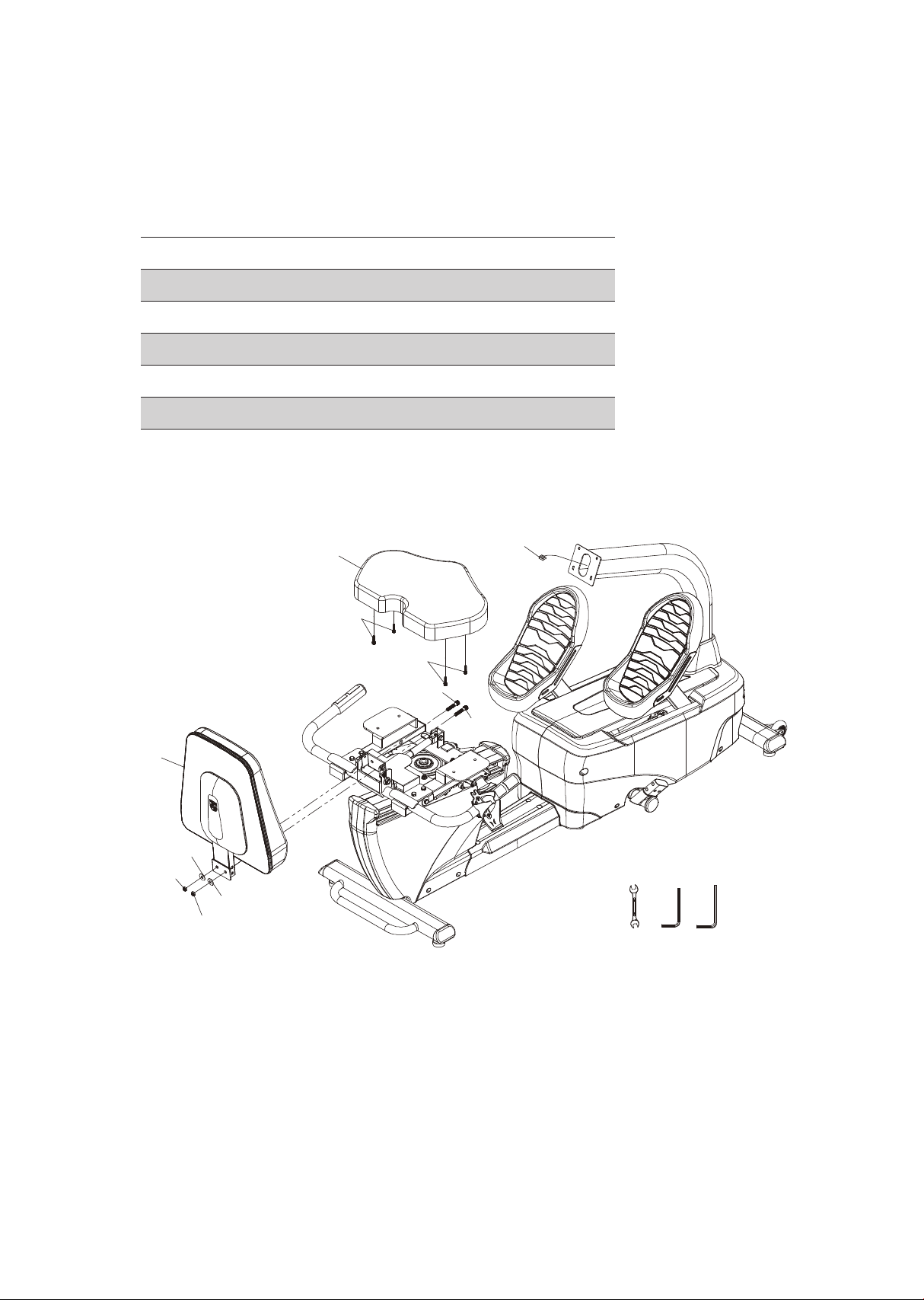
Step 1.
• Secure the pedals with phillips head screws (155).
• Install seat cover (45).
• Use hex head bolts (203) with at washers (204) and nyloc nuts (206)
and hex head bolts (201) and at washers (204) and nyloc nuts (206)
to secure handlebar on the seat assembly.
• Connect hand pulse cables; arrange cables taking care so they are not
crushed during seat adjustment.
Part Type Description
Hardware for step 1
Qty
203
201
202
155
204
205
206
161
Hex head bolt
Hex head bolt
Hex head bolt
Phillips head screw
Flat washer
Flat washer
Nyloc nut
Nyloc nut
3/8" x 3-1/4"
3/8" x 2"
5/16" x 1-1/4"
M5 x 12
3/8"
Ø8.5
3/8"
5/16"
2
4
1
12
8
2
6
1
45
203
203
220 221 176 177
204
202
205
155
155
155
Computer
cable
155
161
204
204
204
204
204
206
206
206
206
11
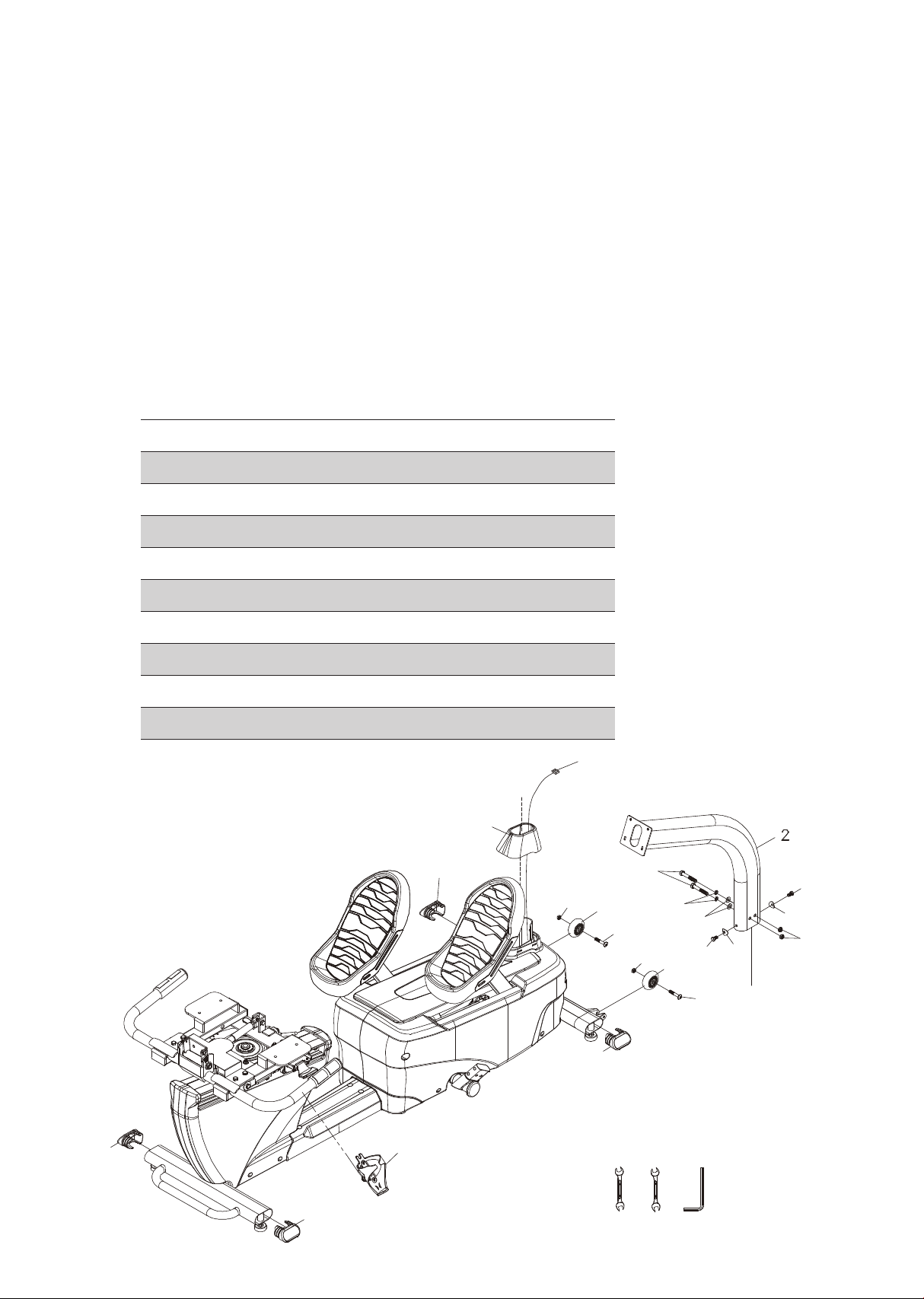
Step 2.
• Install transportation wheels (87) with button head bolts (209) and
nyloc nuts (161).
• Place the console mast (2) through the console mast cover (76) with
the correct orientation. Snake the console cables through the bottom
end of the console mast and out through the top.
• Insert the mast on the main frame and use hex head bolts (208) with
split washers (211), at washers (169) and nyloc nuts (206) to secure on
the side. Then use hex head bolts (207) and curved washers (210) to
secure at the front and back of the mast.
• Plug in the end caps (67) on oval stabilizer tubes.
• Install water bottle cage (111).
Part Type Description
Hardware for step 2
Qty
209
207
208
169
210
206
161
211
Button head bolt
Hex head bolt
Hex head bolt
Flat washer
Curved washer
Nyloc nut
Nyloc nut
Split washer
5/16" x 1-3/4"
M8 x 16
3/8" x 2-1/2"
3/8"
Ø8
3/8"
5/16"
Ø10
2
2
2
2
2
2
2
2
67
67
76
161
208
211
169
207
206
207
210
210
161
87
87
209
209
67
67
111
Computer
cable
173 174 217
12
Step 3.
• Put the seat cushion on the seat carriage and secure with hex head
bolts (145).
• Insert the seat back in the seat carriage and secure with hex head
bolts (212), at washers (172) and nyloc nuts (206).
Part Type Description
Hardware for step 3
Qty
145
172
206
212
Hex head bolt
Flat washer
Nyloc nut
Hex head bolt
M6
3/8"
3/8" x 7
3/8" x 1-3/4"
4
2
2
2
35
145
145
212
36
206
206
172
172
212
Computer
cable
221 217 219
13
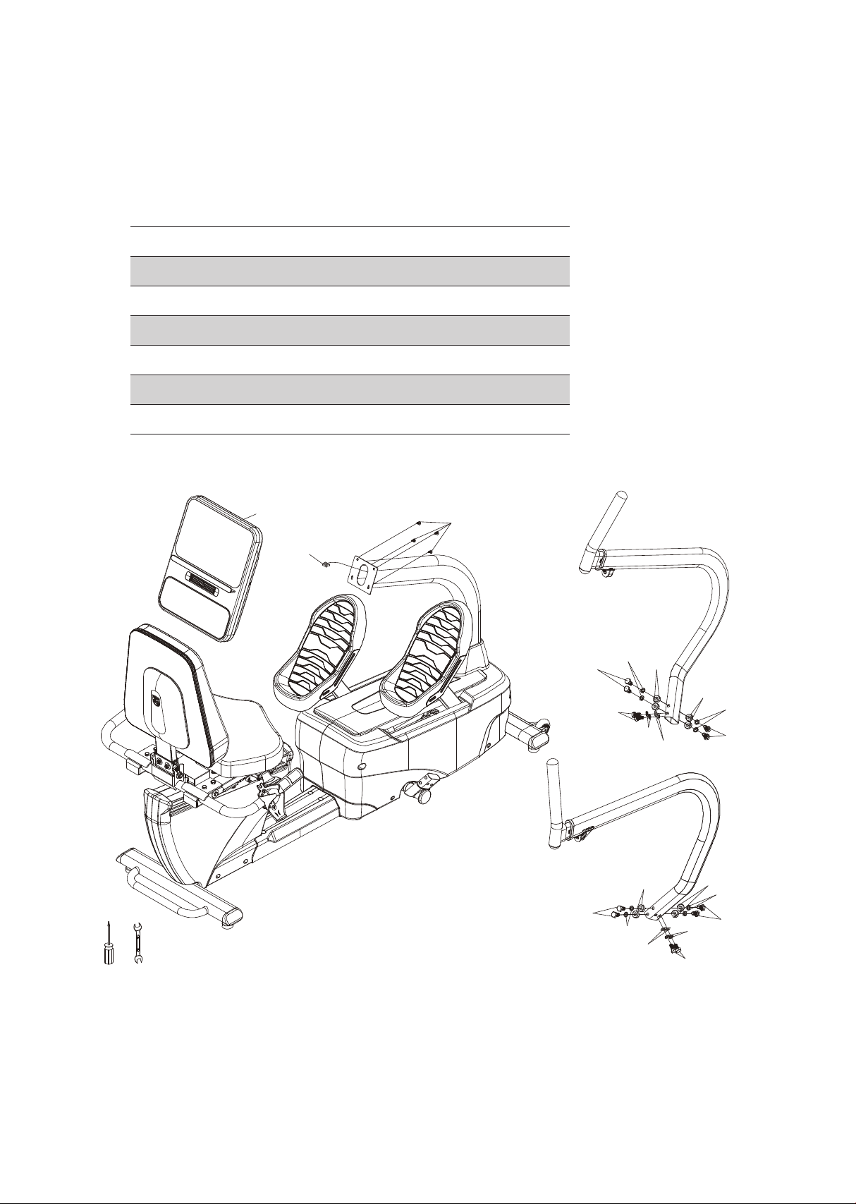
Step 4.
• Connect the cables from the mast to the console (27) and use phillips
head screws (155) to secure it.
• To install left and right swing arms use hex head bolts (213), at wash-
ers (214), split washers (216) and curved washers (215).
Part Type Description
Hardware for step 4
Qty
155
213
214
215
216
Phillips head screw
Button head bolt
Flat washer
Curved washer
Split washer
M5 x 12
3/8" x 3/4"
3/8" x 19 x 1.5
10 x 21.3 x 7.8
Ø10
4
12
4
8
12
27
155
213
213
213
213
213
213
216
215
215
215
215
216
216
216
216
216
214
214
Computer
cable
176 221
14
Parts included
• 1 main frame
• 2 foot pedals
• 1 seat cover
• 1 connecting arm
• 1 console mast
• 1 console mast cover
• 1 handle bar
• 1 drink bottle holder
• 4 end caps
• 2 transport wheels
• 1 seat
• 1 seat back frame
• 2 swing arms
• 1 console
• 1 hardware kit
• 1 power cord
4.0 S console
Power on
The 4.0 S has a built in generator for power, but can be plugged into
an outlet for very low speed operation is required. When the 4.0 S is
pedaled, or the DC power cord is connected to the equipment, the
console will automatically power up.
The console will go to the start up display, also known as Idle mode.
The message window will be scrolling the start up message. You may
now begin to use the 4.0 S.
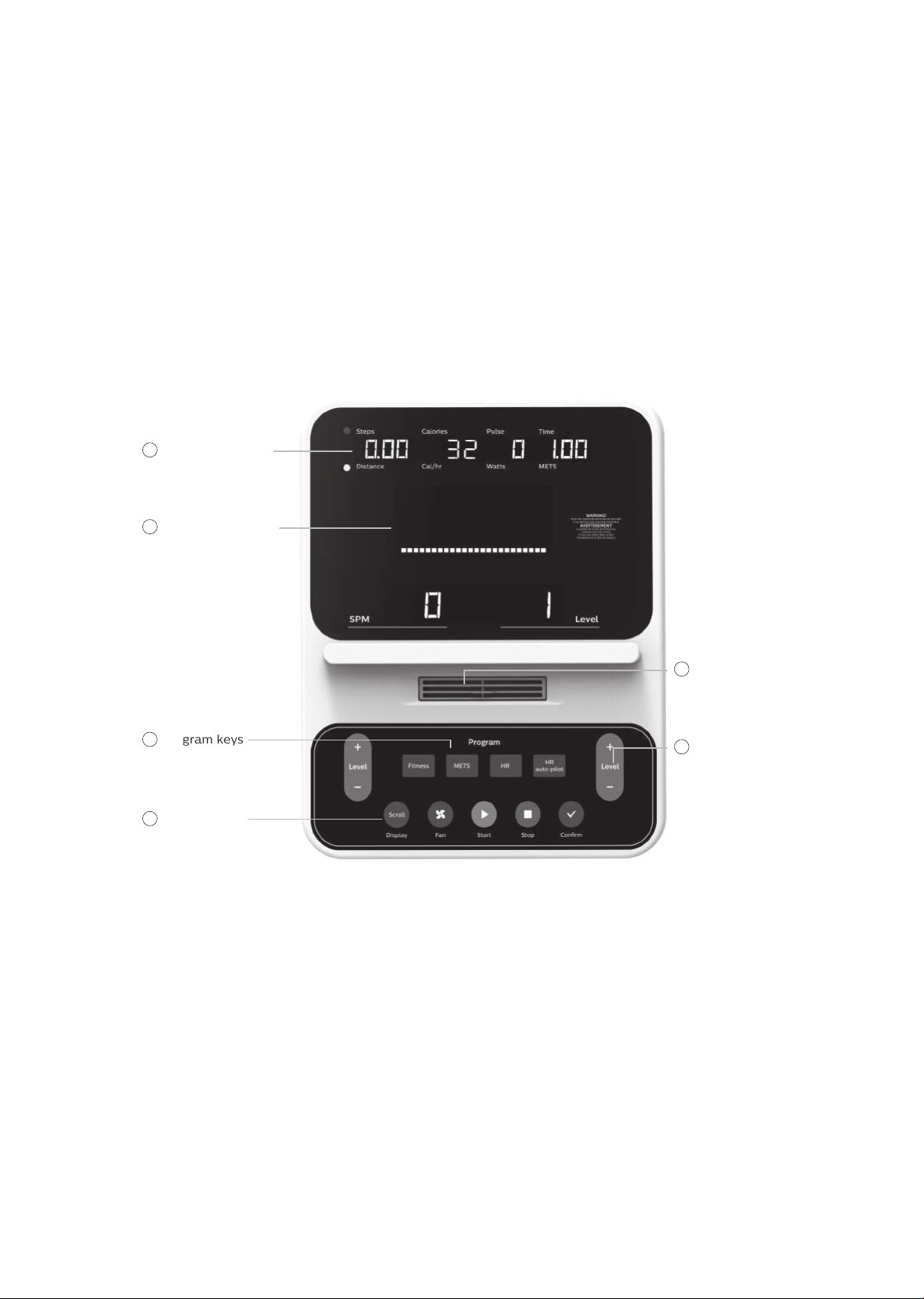
Console
operation
Program keys
2
Dot matrix window
3
Function keys
4
Message window
1
Fan
5
Resistance level
or adjustment
up / down keys
6

15
• 4 end caps
• 2 transport wheels
• 1 seat
• 1 seat back frame
• 2 swing arms
• 1 console
• 1 hardware kit
• 1 power cord
CSAFE feature
Your console is equipped with a CSAFE feature. The power (POWER)
port can be used for powering a remote controlled audio-visual system
by connecting a cable from the remote to the power port at the back of
the console. The Communication port (COMM) can be used to interact
with software applications.
Quick start
This is the quickest way to start a workout. After the console powers up
you just press the start key to begin. This will initiate the quick start
mode. In quick start, the time will count up from zero, all workout data
will start to accrue and the workload may be adjusted manually by
pressing the plus and minus keys. As you increase the workload more
rows will light indicating a harder workout. The stepper will get harder
to pedal as the rows increase.
There are 20 levels of resistance available for plenty of variety.
The rst 5 levels are very easy workloads, and the changes
between levels are set to a good progression for de-conditioned
users. Levels 6-10 are more challenging but the increases from
one level to the next remain small. Levels 11-15 start getting tough
as the levels jump more dramatically. Levels 16-20 are extremely
hard and are good for short interval peaks and higher
performance training.

16
Basic information
When you begin a program the dot matrix will display the workout
Prole.
The message window will initially be displaying distance, calories, pulse
and time information. On the bottom left of the key pad is a key labeled
display. Each time this display key is pressed the next set of information
will appear. If the display key is pressed during the second set of
information display the scan mode will come on and the message
window will show each set of data for four seconds then switch to the
next set of data in a continuous loop. Pressing the display key again will
bring you back to the rst set of information as beginning.
The product has a built in heart rate monitoring system. Simply grasping
the hand pulse sensors, or wearing a heart rate chest belt transmitter
will start the heart rate detection, the message window will display your
heart rate, or pulse, in beats per minute (this may take a few seconds).
Note: You must enter your correct age during program setup for heart
rate control program to be accurate. Refer to using a heart rate
transmitter section for details about these features and how they can
help you work out more eciently.
The stop key actually has several functions. Pressing the stop key once
during a program will Pause the program for 5 minutes (when you stop
pedaling without ac power the display will turn o but the memory will
be saved for 5 minutes just like the pause mode). If you need to get a
drink, answer the phone, or any of the many things that could interrupt
your workout, this is a great feature. To resume your workout during
pause just press the start key or start pedaling. If the stop key is pressed
twice during a workout the program will end and a summary of
information of the exercise session will be displayed, and then the
console will return to the start up screen. If the stop key is held down for
3 seconds the console will perform a complete reset. During data entry
for a program the stop key performs a previous screen function. This
allows you to go back one step in the programming each time you press
the stop key.

17
The program keys may be used to preview each program when in the
idle mode. When you rst turn the console on you may press each
program key to preview what the program prole looks like. If you
decide that you want to try a program, press the corresponding
program key and then press the conrm key to select the program and
enter into the data-setup mode.
The console includes a built-in fan to help keep you cool.
Programmable features
Each of the programs can be customized with your personal
information and changed to suit your needs. Some of the information
asked for is necessary to ensure the readouts are correct. You will be
asked for your age and weight. Entering your age ensures that the heart
rate window shows the correct number. Your age is also necessary
during the heart rate control program to ensure the correct settings are
in the program for your age. Otherwise the work settings could be too
high or low for you; entering your weight aides in calculating a more
correct calorie reading. Although we cannot provide an exact calorie
count we do want to be as close as possible.
Calorie note: Calorie readings on every piece of exercise equipment,
whether it is in a facility or at home, are not accurate and tend to vary
widely. They are meant only as a guide to monitor your progress from
workout to workout. The only way to measure your calorie burn
accurately is in a clinical setting connected to a host of machines. This
is because every person is dierent and burns calories at a dierent
rate. Some good news is that you will continue to burn calories at an
accelerated rate for at least an hour after you have nished exercising!

18
Entering a program and changing settings
When you enter a program (by pressing a program key, then conrm
key) you have the option of modifying the settings. If you want to
begin without entering new settings just press the start key. This will
bypass the programming of data and take you directly to the start of
the program. If you want to change the settings just follow the
instructions in the message window. If you start a program without
changing the settings the default or pre-saved setting will be used.
Manual
The manual program works as the name implies, manually. This
means that you control the workload yourself, not the computer. To
start the manual program follow the instructions below or just press
the manual key then the conrm key and follow the directions in the
message window.
• Press the tness key and select the manual program then press the
conrm key.
• The message window will ask you to enter your age. You may enter
your age, using the plus and minus keys, then press the conrm button
to accept the new number and proceed on to the next screen.
• You are now asked to enter your weight. You may adjust the weight
number using the plus and minus keys, then press conrm to continue.
• The next setting is time. You may adjust the time and press conrm
key to continue.
• Now you are nished editing the settings and can begin your workout
by pressing the start key. You can also go back and modify your
settings by pressing the conrm key.
Note: at any time during the editing of data you can press the stop key
to go back one level, or screen.
• The program automatically starts you at level one. This is the easiest
level and it is a good idea to stay at level one for a while to warm up. If
you want to increase the work load at any time press the plus key; the
minus key will decrease the workload.
• During the manual program you will be able to scroll through the data
in the message window by pressing the display key.
• When the program ends you may press start to begin the same
program again or stop to exit the program.

19
Preset programs
The stepper has three dierent programs that have been designed for a
variety of workout goals. These programs factory preset work level
proles for achieving dierent goals. The initial built-in level of diculty
for each program is set to a relatively easy level. You may adjust the
level of diculty (max level) for each program before beginning.
Programming preset programs
• Select the desired program by pressing tness key then press conrm
key.
• The message window will ask you to enter your age. You may adjust
the age setting, using the plus and minus keys, then press conrm key
to accept the new number and proceed on to the next screen.
• You are now asked to enter your weight. You may adjust the weight
number using the plus and minus keys, then press conrm to continue.
• Next is time. You may adjust the time and press conrm to continue.
• Now you are asked to adjust the max level. This is the peak exertion
level you will experience during the program (at the top of the hill).
Adjust the level and then press conrm.
• Now you are nished editing the settings and can begin your workout
by pressing the start key. You can also go back and modify your
settings by pressing the stop key to go back one level, or screen.
• If you want to increase or decrease the workload at any time during
the program press the plus and minus key. This will change the
workload settings of the entire prole, although the prole picture on
the screen will not change. The reason for this is so that you can see
the entire prole at all times. If the prole picture is changed it will
look distorted and not a true representation of the actual prole.
When you make a change to the workload, the message window will
show the current column, and program maximum, levels of work.
• During the program you will be able to scroll through the data in the
message window by pressing the display key.
• When the program ends the message window will show a summary of
your workout. The summary will be displayed for a short time then the
console will return to the start-up display.

20
Hill
The Hill program simulates going up and down a hill. The resistance
in the pedals will steadily increase and then decrease during the
program.
Plateau
The Plateau program provides a steady state exercise with warm up
and cool down periods.
Interval
The Interval program takes you through high levels of intensity fol-
lowed by periods of low intensity. This program increases your endur-
ance by depleting your oxygen level followed by periods of recovery
to replenish oxygen. Your cardio vascular system gets programmed to
use oxygen more eciently this way.

21
Custom program
The custom program allows you to build and save a custom program.
You can build your own custom program by following the instructions
below. The custom program allows you to further personalize it by
adding your facility name.
• Designing and saving a new program as a custom program. The
message window will show a welcome message; if you had
previously saved a program the message will contain the name you
gave it. Then press the Enter key to begin programming.
- When you press conrm, the message window will show
“name – a”, if there is no name saved. If the name
“custom workout” had been previously saved the message window
will show “name – custom workout” and the c in custom will be
blinking. If there is a name saved you can change it or you may
press the stop key to keep the name and continue to the next
step. If you want to enter a name use the plus and/or the minus
key to change the rst letter then press conrm to save the rst
letter and continue to the next letter. When you have nished
entering the name press the stop key to save the name and
continue to the next step.
- The message window will ask you to enter an age. You may enter
an age, using the plus and minus keys, then press the conrm key
to accept the new number and proceed on to the next screen.
- You are now asked to enter a weight. You may adjust the weight
number using the plus and minus keys and then press conrm to
continue.
- Next is time. You may adjust the time and press conrm to
continue.
- Now you are asked to adjust the max level. This is the peak
exertion level you will experience during the program. Adjust the
level and then press conrm.

22
- Now the rst column will be blinking and you are asked to adjust
the level for the rst segment of the workout. When you nish
adjusting the rst segment, or if you don’t want to change, then
press conrm to continue to the next segment.
- The next segment will show the same level as the previously
adjusted segment. Repeat the same process as the last segment
then press conrm. Continue this process until all twenty four
segments have been set.
- The message window will then tell you to press conrm to save the
program. After saving the program the message window says
“new program saved” then will give you the option to start or
modify the program. Pressing stop will exit to the start up screen.
- During the custom program you will be able to scroll through the
data in the message window by pressing the display key.
- Use the heart rate monitoring features and can switch to heart
rate auto-pilot mode (see hr auto pilot section for details of this
feature).
• Running a saved program – Enter the custom program then press
conrm key.
- Enter time and press conrm. Then press start to begin program.

23
METs program
METs stands for metabolic equivalent, which is one way that exercise
physiologists estimate how many calories are burned during physical
activity.
1 MET is essentially the amount of energy produced relative to body
mass whilst at rest. As you sit here now reading you are expending 1
MET of energy.
Using 1 MET as the reference value, light activities burn up to 3 times
as many calories as rest, moderate activities burn 3-6 times as many
and vigorous exercise more than 6 times as much energy as rest.
METs programming
• Press the METs key and then press conrm.
• The message window will prompt you to enter your age. Use the plus
and minus keys to change and press the conrm key to continue.
• You are now prompted to enter your weight. You may adjust the age
using the plus and minus key then press conrm key to continue.
• You are now prompted to enter your workout time. You may adjust the
time using the plus and minus key then press conrm to continue.
• You are now prompted to enter your target METs. You may adjust the
target METs using the plus and minus keys then press conrm to
continue.
• Now press start to begin the program.

24
Metabolic rate activity chart
MET
<3
0.9
1.0
1.5
2.3
2.9
3 to 6
3.0
3.3
3.5
3.6
4.0
5.5
5.8
> 6
7.0
8.0
8.0
8.8
9.8
10.0
10.5
11.0
11.2
Physical activity
Light intensity activities
Moderate intensity activities
Vigorous intensity activities
sleeping
watching television
writing, desk wirk, typing
walking, 1.7mph (2.7 km/h), level ground, strolling, very slow
walking 2.5 mph (4 km/h)
bicycling, stationary, 50 watts, very light eort
walking 3.0 mph (4.8 km/h)
calisthenics, home exercise, light or moderate eort, general
walking 3.4 mph (5.5 km/h)
bicycling, <10 mph (16 km/h), leisure, to work or for pleasure
bicycling, stationary, 100 watts, light eort
sexual activity
jogging, general
calisthenics (e.g. pushups, situps, pullups, jumping jacks),
heavy, Vigorous eort
running jogging, in place
jogging, 5.6 mph (9.0 km/h)
rope jumping (66/min)
rope jumping (70/min)
rope jumping (84/min)
rope jumping (100/min)
jogging, 6.8 mph (11.0 km/h)

25
Heart rate program
The old motto; “no pain, no gain” is a myth that has been overpow-
ered by the benets of exercising comfortably. A great deal of this
success has been promoted by the use of heart rate monitors. With
the proper use of a heart rate monitor, many people nd that their
usual choice of exercise intensity was either too high or too low and
exercise is much more enjoyable by maintaining their heart rate in the
desired benet range.
To determine the benet range in which you wish to train, you must
rst determine your maximum heart rate. This can be accomplished
by using the following formula: 220 minus your age. This will give you
the maximum Heart rate (MHR) for someone of your age. To
determine the eective heart rate range for specic goals you simply
calculate a percentage of your MHR. Your Heart rate training zone is
50% to 90% of your maximum heart rate. 60% of your MHR is the
recommended for burning fat while 80% is recommended for
strengthening the cardio vascular system. This 60% to 80% is the
zone to stay in for maximum benet.
For someone who is 40 years old their target heart rate zone is
calculated:
220 – 40 = 180 (maximum heart rate)
180 x .6 = 108 beats per minute (60% of maximum)
180 X .8 = 144 beats per minute (80% of maximum)
So for a 40 year old the training zone would be 108 to 144 beats per
minute.
90

26
If you enter your age during programming the console will perform
this calculation automatically. Entering your age is used for the heart
rate programs. After calculating your MHR you can decide upon which
goal you would like to pursue.
The two most popular reasons for, or goals, of exercise are
cardiovascular tness (training for the heart and lungs) and weight
control. The black columns on the chart above represent the MHR for
a person whose age is listed at the bottom of each column. The
training heart rate, for either cardiovascular tness or weight loss, is
represented by two dierent lines that cut diagonally through the
chart. A denition of the lines’ goal is in the bottom left-hand corner
of the chart. If your goal is cardiovascular tness or if it is weight loss,
it can be achieved by training at 80% or 60%, respectively, of your
MHR on a schedule approved by your physician. Consult your
physician before participating in any exercise program.
With all Heart Rate programs you may use the heart rate monitor
feature without using the Heart Rate program. This function can be
used during manual mode or during any other dierent programs. The
heart rate program automatically controls resistance at the pedals.
Rate of perceived exertion
Heart rate is important but listening to your body also has a lot of
advantages. There are more variables involved in how hard you
should workout than just heart rate. Your stress level, physical health,
emotional health, temperature, humidity, the time of day, the last
time you ate and what you ate, all contribute to the intensity at which
you should workout. If you listen to your body, it will tell you all of
these things.

27
The rate of perceived exertion (RPE), also known as the Borg scale,
was developed by Swedish physiologist G.A.V. Borg. This scale rates
exercise intensity from 6 to 20 depending upon how you feel or the
perception of your eort. The scale is as follows:
You can get an approximate heart rate level for each rating by simply
adding a zero to each rating. For example a rating of 12 will result in
an approximate heart rate of 120 beats per minute. Your RPE will vary
depending upon the factors discussed earlier. That is the major
benet of this type of training. If your body is strong and rested, you
will feel strong and your pace will feel easier. When your body is in
this condition, you are able to train harder and the RPE will support
this. If you are feeling tired and sluggish, it is because your body
needs a break. In this condition, your pace will feel harder. Again, this
will show up in your RPE and you will train at the proper level for that
day.
Rating perception of eort
6 Minimal
7 Very, very light
8 Very, very light +
9 Very light
10 Very light +
11 Fairly light
12 Comfortable
13 Somewhat hard
14 Somewhat hard +
15 Hard
16 Hard +
17 Very hard
18 Very hard +
19 Very, very hard
20 Maxi

28
Heart rate program programing
To start the HR program follow the instructions below and follow the
directions in the message window.
• Press the HR key to select the HR program (TA HR 65% / TA HR 80% /
HR interval) and then press the conrm key to enter.
• The message Window will ask you to enter your age. You may enter
your age, using the plus and minus key, then press the conrm key to
accept the new number and proceed on to the next screen.
• You are now asked to enter your weight. You may adjust the weight
number using the plus and minus keys, then press conrm to continue.
• Next is Time. You may adjust the Time and press enter to continue.
• Now you are asked to adjust the target HR. This is the 65% / 80%
heart rate level you will experience during the program. Adjust the
target number and then press conrm.
• Now you are nished editing the settings and can begin your workout
by pressing the start key. You can also go back and modify your
settings by pressing the conrm key. NOTE: At any time during the
editing of data you can press the Stop key to go back one level, or
screen.
• If you want to increase or decrease the workload at any time during
the program press the plus or minus keys. This will allow you to change
your target heart rate at any time during the program.
• During the HR program you will be able to scroll through the data in
the message window by pressing the display key.
When the program ends you may press Start to begin the same
program again or Stop to exit the program.

29
Heart rate auto pilot mode
The HR auto pilot mode only works in Fitness programs (manual / hill /
plateau / interval / custom). When you are exercising in a tness
program and decide to just maintain the HR level you are at currently
you can just press auto pilot and the console will automatically switch
to HR control and will maintain your current HR. To start the HR auto
pilot mode follow the instructions below and the directions in the
message window.
• Press the HR auto pilot key during the tness programs. It is necessary
to wear HR strap to enter this mode. If a HR is not detected the
message window shows NO HEART RATE.
• At the end of the HR auto pilot program a workout summary will be
displayed in the message window.

30
Note: The chest strap transmitter is not a standard part, but is a
separate purchase. Most transmitters that operate at Bluetooth or
ANT+ will also work.
How to wear your wireless chest strap transmitter?
• Attach the transmitter to the elastic strap using the locking parts.
• Adjust the strap as tightly as possible as long as the strap is not too
tight to remain comfortable.
• Position the transmitter with the logo centered in the middle of your
body facing away from your chest (some people must position the
transmitter slightly left of center). Attach the nal end of the elastic
strap by inserting the round end and, using the locking parts, secure
the transmitter and strap around your chest.
• Position the transmitter immediately below the pectoral muscles.
Using
a heart rate
transmitter

31
• Sweat is the best conductor to measure very minute heart beat
electrical signals. However, plain water can also be used to pre-wet
the electrodes (2 black square areas on the reverse side of the belt
and either side of transmitter). It’s also recommended that you wear
the transmitter strap a few minutes before your work out. Some users,
because of body chemistry, have a more dicult time in achieving a
strong, steady signal at the beginning. After “warming up”, this problem
lessens. As noted, wearing clothing over the transmitter/strap doesn’t
aect performance.
• Your workout must be within range - distance between transmitter /
receiver – to achieve a strong steady signal. The length of range may
vary somewhat but generally stay close enough to the console to
maintain good, strong, reliable readings. Wearing the transmitter
immediately against bare skin assures you of proper operation. If you
wish, you may wear the transmitter over a shirt. To do so, moisten the
areas of the shirt that the electrodes will rest upon.
Note: The transmitter is automatically activated when it detects
activity from the user’s heart. Additionally, it automatically
deactivates when it does not receive any activity. Although the
transmitter is water resistant, moisture can have the eect of creating
false signals, so you should take precautions to completely dry the
transmitter after use to prolong battery life.

32
Erratic operation
Caution! Do not use this product for heart rate control unless a
steady, solid actual heart rate value is being displayed. High, wild,
random numbers being displayed indicate a problem.
Areas to look at for interference, which may cause erratic heart rate
• Microwave ovens, TVs, small appliances, etc.
• Fluorescent lights.
• Some household security systems.
• Perimeter fence for a pet.
• Some people have problems with the transmitter picking up a signal
from their skin. If you have problems try wearing the transmitter upside
down. Normally the transmitter will be oriented so the logo is right side
up.
• The antenna that picks up your heart rate is very sensitive. If there is an
outside noise source, turning the whole machine 90 degrees may
de-tune the interference.
• If there is another person wearing a chest strap within 1 meter, it will
interfere.
• If you continue to experience problems contact your dealer.

33
• Wipe down all areas in the sweat path with a damp cloth after each
use to prevent rust.
• If a squeak, thump, clicking or rough feeling develops the main
cause is most likely one of two reasons:
- The hardware was not suciently tightened during assembly. All
bolts that were installed during assembly need to be tightened as
much as possible. It may be necessary to use a larger wrench than
the one provided if you cannot tighten the bolts suciently.
I cannot stress this point enough; 90% of calls to the service
department for noise issues can be traced to loose hardware.
- The crank arm nut and/or the pedals need to be retightened.
• If squeaks or other noises persist, check that the unit is properly
leveled. There are 2 leveling pads on the front and 2 leveling pads
on the back of the unit. Remove mast cover and center cover.
Step rail and carriage maintenance
Dirt and dust can accumulate on the pedal carriage components causing
a rough feel which means the rails and wheels most likely need cleaning.
• Remove mast cover and center cover.
• Firmly press in at the bottom of the small mast cover at the front
and rear and pull up
- Firmly press in at the top of the main cover near the top and pull
up on the center cover. Repeat this process at all four corners of
the cover.
- Slide the mast and center covers up the mast tube. Tie a rag
around the tube and let the covers rest on it so they stay in place.
• Move the pedals so one is all the way forward. Clean the wheels and
rails using a rag and alcohol.
• Replace the covers when done.
Maintenance

34
Maintenance mode in console software
The console has built in maintenance/diagnostic software. The software
will allow you to change the console settings from English to Metric and
turn o the beeping of the speaker when a key is pressed for example. To
enter the maintenance mode press and hold down the start, stop and
conrm key. Keep holding the keys down for about 2 seconds and the
message window will display “maintenance mode”. Press the conrm key
to access the menu below:
• Key test
- Will allow you to test all the keys to make sure they are
functioning. Press all the keys one at a time.
• Display test
- Tests all the display functions by lighting each LED light
sequentially.
• Functions (press conrm key to access menu)
- Units
Set to English (imperial units) or metric display readings. The
default is imperial, which means data such as bodyweight and
height will be in pounds and inches.
- Pause mode
Turn on allow 5 minutes of pause, turn o to have the console
pause indenitely.
- Odometer reset
Resets the odometer to zero (Time and distance)
- Beep sound
Turn on or o the speaker to silence beeping sound.
- LED brightness
Adjust the LED brightness.
1
1
1
1
1

35
• Service
- Motor test
Select the motor test by MANUAL or AUTO to test the functions.
- SENSOR test
Test the sensor functions.
- CSAFE test
Test the CSAFE functions.
• ANT ID
- Adjust the ANT ID.
• Update code
- Switch bootloader on/o. The default is o.
• Exit
- Press conrm key to leave maintenance mode and restart.
1
1
1
36
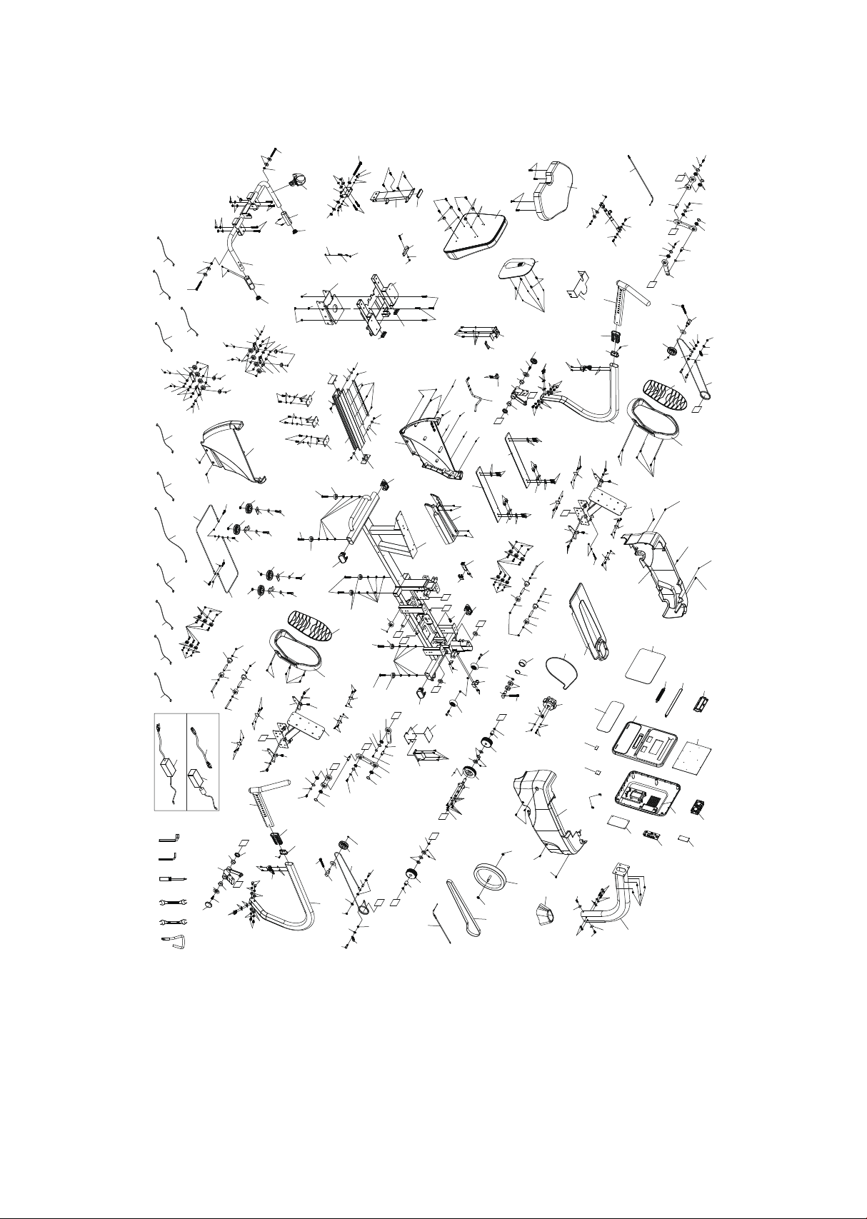
Exploded view drawing
193
91
225
225
Optional 1
Optional 2
9
2
18
19L
19R
19R
19L
42
1
3
4
5
6
8
7
10
10
11
11
18
20
20
22
21
23
23
26
114
115
28
30
30
31
31
31
31
31
31
31
31
31
33
37
38
39
40
40
41
42
42
42
43
44
44
57
50
50
50
50
51
52
53
54
55
56
56
56
59
60
60
60
60
60
60
60
60
60
60
61
61
61
61
62
63
63
64
65
65
66
66
66
66
66
67
67
67
67
68
68
68
68
68
68
68
68
69
69
70
72
72
72
72
73
73
73
74
74
74
74
74
75
76
77
79
81
84
84
84
84
85
85
86
86
87
90
93
94
94
95
95
48
48
96
96
83
83
80
57
49
49
78
70
73
64
130
130
130
134
134
134
135
135
135
136
135
136
136
137
138
138
138
138
141
141
141
141
144
129
144
144
144
144
145
145
145
145
147
146
149
150
152
153
155
155
155
155
155
155
155
191
191
155
155
155
155
156
156
156
156
157
158
158
158
159
160
160
160
161
161
161
161
161
162
164
164
165
165
165
165
163
163
163
163
167
167
168
168
168
169
169
169
172
172
172
172
173
174
174
174
174
182
175
175
175
175
175
175
175
175
175
175
175
150
150
152
176
176
176
181
181
182
182
183
183
183
185
186
186
186
187
187
188
188
190
190
190
190
190
192
192
192
192
192
192
192
193
193
193
193
193
193
193
195
195
196
197
197
197
197
197
199
199
198
199
199
200
200
200
200
129
200
200
200
200
200
33
149
161
206
207
207
208
209
209
169
210
210
211
87
93
155
116
32
189
97
160
182
182
182
175
155
29
29
102
103
134
169
102
103
60
60
69
69
137
161
161
162
162
98
142
100
142
148
148
184
142
99
184
142
100
162
100
142
142
100
162
148
99
184
142
98
148
184
142
162
162
142
100
142
100
162
100
142
142
100
162
101
101
171
171
104
104
101
170
96
96
177
177
219
14
113
112
88
89
89
194
194
74
217
222 220
221
223
198
127
173
173
173
173
111
213
213
213
216
216
216
214
215
215
213
213
213
214
215
215
216
216
216
229
230
235
228
224
234
232
227
234
235
68
236
233
27-1
27-2
27-3
27-4
27-5
27-6
27-7
27-8
27-9
27-10
27-11
27-12
27-14
27-13
27-15
122
123
124
120
126
125
119
121
118
125
35
237
161
161
161
12
201
204
204
204
204
206
206
206
206
203
203
45
151
71
71
206
172
154
171
47
171
47
154
180
166
212
34
145
145
82
15
82
161
205
202
132
179
132
16
161
161
179
106
178
143
117
24
107
92
36
226
226
155
139
139
155
13
231
231
237
239
238
240
F
C
C
F
D
G
G
H
D
E
A
B
B
A
E
H
I
J
I
J
K
K
L
L

37
4.0 S parts list
Item Description Qty
1
2
3
4
5
6
7
8
9
10
11
12
13
14
15
16
18
19L
19R
20
21
22
23
24
26
27
27~1
27~2
27~3
27~4
27~5
27~6
27~7
Main frame
Console mast
Swing arm (r)
Swing arm (l)
Pedal plate (r)
Pedal plate (l)
Handle slider (l)
Handle slider (r)
Drive pulley
Lower linkage a
lower linkage b
seat carriage
Seat back bracket
Handle bar
Rotate seat assembly
Seat back bracket
Swing arm drive weldment
Seat wheel adjustment plate(l)
Seat wheel adjustment plate(r)
Seat stop assembly
Front connecting cable (750l)
rear connecting cable (800l)
drive cable (1820l)
steel cable
Drive cable (55l)
console assembly
Console top cover
Console bottom cover
Book rack
Fan grill anchor
Deector fan grill
Wind duct
Faceplate label
1
1
1
1
1
1
1
1
1
2
2
1
1
1
1
1
2
2
2
2
1
1
2
1
1
1
1
1
1
2
1
1
1

38
Item Description Qty
27~8
27~9
27~10
27~11
27~12
27~13
27~14
27~15
28
29
30
31
32
33
34
35
36
37
38
39
40
41
42
43
44
45
47
48
49
50
51
52
53
End cap
Console display board
Fan assembly
Bluetooth
Resistance button w/cable
Interface board
Csafe w/board
Interface board
6203_ball bearing
6003_ball bearing
One way bearing
6902_ball bearing
Magnet
Ø9 × Ø49 × 1.5t_cup washers
Locking gas cylinder
Seat cushion
Seat back
Seat position latch
Fly wheel
Ø106 × 22l_drive wheel
Ø84 × 32l_cable drive pulley
Belt (8pj), 1321mm
Ø5/8" × 13.2 × 8l_sleeve
Adjustable idler wheel axle
Lower linkage
Safety cover
Scale arrowhead
Flywheel axle set collar (r)
Cable guide wheel axle
Shroud bracket
Sensor bracket
Shroud xing plate
Seat track xing plate
1
1
1
1
1
1
1
1
2
2
2
10
1
2
1
1
1
1
1
1
2
1
4
1
2
1
2
2
2
4
1
1
1

39
Item Description Qty
54
55
56
57
59
60
61
62
63
64
65
66
67
68
69
70
71
72
73
74
75
76
77
78
79
80
81
82
83
84
85
86
87
Rack, seat position
Aluminum track
Backing plate
Ø15.5 × 26.5l_spring
Ø13.5 × 30l_spring
Metal sleeve(Ø8.2×Ø12.7x5lmm)
metal sleeve(Ø8.1×Ø12×56.2lmm)
Ø10 × 386l_seat front/aft adjustment lever
Aluminum track
Pedal
Pedal foam cushion
Leveling foot
End cap, oval stabilizer tube
Transportation wheel, aluminum axle
Transportation wheel
Ø18 × Ø32 × 1.5t_high-performance polymer washer
Podwer metallurgy sleeve
Pu wheel
Ø38_seat track wheel
Roller
Bottom step cover
Console mast cover
Top cover
Shroud ( r )
Shroud ( l )
Rear shroud ( r )
Rear shroud ( l )
Slider sleeve
Hollow plug(30×70×98.5l)
WFM-2528-16_plastic bushing
End cap
Slide end cap spacer
Ø65_transportation wheel
1
1
3
2
1
20
4
1
2
2
2
6
4
9
12
4
2
4
8
6
1
1
1
1
1
1
1
2
2
4
2
2
2

40
Item Description Qty
88
89
90
91
92
93
94
95
96
97
98
99
100
101
102
103
104
106
107
111
112
113
114
115
116
117
118
119
120
121
122
123
124
Ø7_hgp wire grommet
Button head plug
Lever anchor
Seat back cover
Square end cap
Main frame housing
Quick release
Seat stop axle
Axle
Ø52 × Ø40 × 28l_bearing
Adjusting plate (l)
Adjusting plate (r)
Plastic aps
Ø25 × Ø10 × 3t_nylon washera
Cushion xing plate
Rubber foot
Podwer metallurgy sleeve
Release lever
Nylon handgrip
Drink bottle holder
750m/m_hand pulse w/cable assembly( l)
900m/m_hand pulse w/cable assembly(r)
Optical sensor board
Gear motor
450m/m_sensor w/cable
350m/m_conneting wire (smp)
350m/m_encoder cable (xhp)
300m/m_handpulse wire
300m/m_handpulse wire(white)
100m/m_dc power cord
1700m/m_computer cable
550m/m_handpulse wire
550m/m_handpulse wire(white)
1
2
1
1
1
2
2
2
4
1
2
2
8
4
2
4
2
1
1
1
1
1
1
1
1
1
1
1
1
1
1
1
1

41
Item Description Qty
125
126
127
129
130
132
133
134
135
136
137
138
139
141
142
143
144
145
146
147
148
149
150
151
152
153
154
155
156
157
158
159
160
Power adapter, 12vdc
2900m/m_hand pulse cable, lower
Block
M6 × 15m/m_hex head bolt
5/16" × unc18 × 3/4"_hex head bolt
5/16" × unc18 × 5/8"_hex head bolt
3/8" × 19m/m_hex head bolt
3/8" × 1-1/4"_hex head bolt
M10 × 40m/m_hex head bolt
M8 × p1.25_bolt
5/16" × unc18 × 1"_button head socket bolt
M6 × 10m/m_button head socket bolt
M8 × 20m/m_button head socket bolt
5/16" × unc18 × 95m/m_button head socket bolt
M5 × p0.8 × 15m/m_socket head cap bolt
M6 × p1.0 × 12m/m_socket head cap bolt
M6 × p1.0 × 15m/m_socket head cap bolt
M6 × 25m/m_socket head cap bolt
M6 × 38m/m_socket head cap bolt
M5 × p0.8 × 45m/m_socket head cap bolt
M8 × p1.25 × 12m/m_socket head cap bolt
M8 × p1.25 × 20m/m_socket head cap bolt
M10 × p1.5 × 75m/m_socket head cap bolt
M12 × p1.75 × 120m/m_socket head cap bolt
M5 × p0.8 × 10m/m_slotted set screw
M6 × 57m/m_eye bolt
M5 × 6m/m_phillips head screw
M5 × 12m/m_phillips head screw
M6 × 10m/m_phillips head screw
M4 × p0.7 × 10m/m_phillips head screw
3/8" × 7t_luck nut
M6 × p1.0 × 5t_luck nut
M8 × 6t_luck nut
1
1
1
2
6
2
8
8
4
4
12
4
4
4
24
4
8
8
1
1
4
2
3
1
4
1
2
35
4
2
18
2
4

42
Item Description Qty
161
162
163
164
165
166
167
168
169
170
171
172
173
174
175
176
177
178
179
180
181
182
183
184
185
186
187
188
189
190
191
192
193
5/16" × 6t_nyloc nut
M5 × 5t_nyloc nut
M6 × 6t_nyloc nut
M8 × 7t_nyloc nut
M10 × 8t_nyloc nut
M12_nyloc nut
M10 × p1.5 × 8t_nut
M6 × 19l_nut
Ø3/8" ×
Ø
19 × 1.5t_at washer
Ø5 ×
Ø
10 × 1t_at washer
Ø5 ×
Ø
12 × 1t_at washer
Ø3/8" ×
Ø
25 × 2t_at washer
Ø1/4" × 13 × 1t_at washer
Ø1/4" ×
Ø
16 × 1t_at washer
Ø6 ×
Ø
19 × 3t_at washer
Ø5/16" × 16 × 1.5t_at washer
Ø3/8" × 20 × 3t_at washer
Ø6.6 ×
Ø
12 × 1.5t_at washer
Ø8.5 ×
Ø
18 × 1.5t_at washer
Ø1/2" ×
Ø
26 × 2.0t_at washer
Ø45 ×
Ø
21.8 × 2.5t_at washer
Ø8 ×
Ø
18 × 3t_knurled lock washer
Ø8 × 1.5t_spring washer
Ø5 × 1.5t_spring washer
M6 × 1t_spring washer
Ø17_c ring
Ø10_c ring
Ø16_c ring
Ø40_c ring
3/8" × 2"_at head socket bolt
M5 × 6m/m_phillips head screw
M5 × p0.8 × 12l_phillips head screw
3.5 × 12m/m_sheet metal screw
25
17
5
4
4
1
2
4
10
1
8
6
5
4
12
6
2
4
2
1
2
8
6
8
4
3
2
2
1
6
4
8
12

43
Item Description Qty
194
195
196
197
198
199
200
201
202
203
204
205
206
207
208
209
210
211
212
213
214
215
216
217
219
220
221
222
223
224
225
226
227
3 × 20m/m_tapping screw
Ø5 × 16l_tapping screw
M5 × 25m/m_tapping screw
M5 × 12m/m_tapping screw
M5 × p0.8 × 10l_at phillips head screw
M6 × p1.0 × 10l_at phillips head screw
Ø28_wire clamp
3/8" × 2"_hex head bolt
5/16" × unc18 × 1-1/4"_hex head bolt
3/8" × unc16 × 3-1/4"_hex head bolt
Ø3/8" × Ø30 × 3t_at washer
Ø8.5 × Ø26 × 2t_at washer
3/8" × 7t_nyloc nut
M8 × p1.25 × 16l_hex head bolt
3/8" × unc16 × 2-1/2"_hex head bolt
5/16" × unc18 × 1-3/4"_button head socket bolt
Ø8 × 23 × 1.5t_curved washer
Ø10 × 2t_spring washer
3/8" × unc16 × 1-3/4"_socket head cap bolt
3/8" × 3/4"_hex head bolt
Ø3/8" × Ø19 × 1.5t_at washer
Ø10 × 21.3 × 7.8t_curved washer
Ø10 × 2t_spring washer
L allen wrench(5×26×120l)
m8_allen wrench
12/14m/m_wrench
13/14m/m_wrench
Phillips head screw driver
Short phillips head screw driver
Flywheel pulley
Buckle
Snap seat
Erator/brake controller
4
2
2
10
8
4
10
4
1
2
8
2
10
2
2
2
2
2
2
12
4
8
12
1
1
1
1
1
1
1
4
4
1

44
Item Description Qty
228
229
230
231
232
233
234
235
236
237
238
239
240
Belt
Generator/brake controller
Holder clamp
Ø5.5 × Ø15 × 1t_at washer
M5 × 5l_slotted set screw
5/16 × unf24 × 19l_hex head bolt
Ø4 × 14 × 1t_at washer
M4 × p0.7 × 10l_socket head cap bolt
Ø8_c ring
5/16" × unc18 × 1-1/2"_hex head bolt
150m/m_connecting cable
300m/m_generator connecting cable
Transformer power cord
1
1
1
4
1
1
3
3
1
4
1
1
1

45
Product warranty
Dyaco Commercial & Medical North America LLC (hereinafter
“Dyaco”), the manufacturer of the Philips Commercial Series Physical
Therapy Products (hereinafter “Products”) warrants all of the
Products and their components listed below for the periods of time
set out on this page below from the date of sale, as determined by
sale receipt, or in the absence of a sales receipt, eighteen (18) months
from the original factory shipping date. During the applicable
warranty periods, Dyaco’s responsibilities under these warranties
include providing, at no charge, new or remanufactured parts, as
determined by Dyaco at its sole and absolute discretion, and
covering the cost of labor deemed necessary by Dyaco, at its sole and
absolute discretion, to remedy faults giving rise to applicable
warranty claims. The warranty periods set out below are subject to
the performance of proper care and maintenance, as set out in this
user manual, by the original purchaser of the equipment. Warranties
are not transferable.
* Wear items are rubber hand grips, pedals, console overlay and drive belt
Normal responsibilities of the facility
The facility is responsible for the items listed below
• The warranty registration must be completed online to validate the
manufacturer’s limited warranty.
• Proper use of the tness equipment in accordance with the
instructions provided in this manual.
• Proper installation in accordance with instructions provided with
the tness equipment and with all local electric codes.
Magnetic resistance system
5 years
5 years
Warranty
Commercial
Residential
Frame
Lifetime
Lifetime
Parts
5 years
3 years
Labor
2 years
2 years
Wear items
6 months
6 months

46
• Proper connection to a grounded power supply of sucient voltage,
replacement of blown fuses, repair of loose connections or defects
in house or facility wiring.
• Expenses for making the tness equipment accessible for servicing,
including any item that was not part of the tness equipment at the
time it was shipped from the factory.
• Damages to the tness equipment nish during shipping,
installation or following installation.
• Routine maintenance of this unit as specied in this manual.
Exclusions
This warranty does not cover the following:
• Consequential, collateral, or incidental damages such as property
damage and incidental expenses resulting from any breach of this
written or any implied warranty. Note: Some states do not allow the
exclusion or limitation of incidental or consequential damages, so
this limitation or exclusion may not apply to you.
• Service call reimbursement to the dealer that does not involve
malfunction or defects in workmanship or material, for units that are
beyond the warranty period, for units that are beyond the service
call reimbursement period, or units not requiring component
replacement.
• Damages caused by services performed by persons other than
authorized Dyaco service companies, use of parts other than
original Dyaco parts, or external causes such as alterations,
modications, abuse, misuse, accident, improper maintenance,
inadequate power supply.
• Products with original serial numbers that have been removed or
altered.
• Products that have been; sold, transferred, bartered, or given to a
third party.
• Products that are used as store display models.
• Products that do not have a warranty registration on le at Dyaco.
Dyaco reserves the right to request proof of purchase if no warranty
record exists for the product.

47
• Manufacturer, distributor, or the Licensor shall not be responsible or
liable of any direct, indirect, general, special, punitive, incidental or
consequential damages; loss of or damage to property; claims of
third parties; loss of life; personal injury (including further injury, or
re-injury), and any other losses or damages of any kind or character,
arising out of or in connection with the use of Biophysical Agents by
the facilities or clinicians. The facilities or clinicians that select,
prescribe, and implement the use of Biophysical Agents will assume
the related responsibility.
• Denitions of “ Biophysical agents ” : Biophysical agents are a broad
group of agents that use various forms of energy and are intended
to assist muscle force generation and contraction; decrease
unwanted muscular activity; maintain strength after injury or sur-
gery; modulate or decrease pain; reduce or eliminate edema;
improve circulation; decrease inammation, connective tissue
extensibility, or restriction associated with musculoskeletal injury or
circulatory dysfunction; increase joint mobility, muscle performance,
and neuromuscular performance.
• Physical therapists select, prescribe, and implement the use of
biophysical agents when the examination ndings, diagnosis, and
prognosis indicate the use of these agents to reduce risk factors
and complications; enhance health, wellness, or tness; enhance or
maintain physical performance; or prevent or remediate impair-
ments in body functions and structures, activity limitations, or par-
ticipation restrictions. The use of biophysical agents in the absence
of other interventions should not be considered to be physical ther-
apy unless there is documentation that justies the necessity of
their exclusive use.
• Use of the products in any way other than described within
products’ operation manual, either intentionally or by error.
• Damages due to improper storage or transport or other causes not
solely attributable to Manufacturer.
• The exact amount of indemnication or cost arising out of breach of
this written or any implied warranty shall be fairly negotiated by
both you and Manufacturer.
• This warranty is expressly in lieu of all other warranties expressed or
implied, including the warranties of merchantability and/or tness
for a particular purpose.

48
Service
Keep your bill of sale. Twenty four (24) months from the date on the
bill of sale or eighteen (18) months from the date of factory shipping
as determined by the serial number establishes the warranty period
should service be required. If service is performed, it is in your best
interest to obtain and keep all receipts. This written warranty gives
you specic legal rights. You may also have other rights that vary from
state to state. Service under this warranty must be obtained by
following these steps, in order:
• Contact your selling authorized Dyaco dealer. OR
• Contact your local authorized Dyaco service organization.
• If there is a question as to where to obtain service, contact our
service department at 1-866-869-4409.
• Dyaco’s obligation under this warranty is limited to repairing or
replacing, at Dyaco’s option, the product through one of our
authorized service centers. All repairs must be preauthorized by
Dyaco. If the product is shipped to a service center freight charges
to and from the service center will be the customer’s responsibility.
• The owner is responsible for adequate packaging upon return to
Dyaco. Dyaco is not responsible for damages in shipping. Make all
freight damage claims with the appropriate freight carrier. Do not
ship any unit to our factory without a return authorization number.
All units arriving without a return authorization number will be
refused.
• For any further information, or to contact our service department by
email, or phone call, and also please refer to website for additional
information:
- Consumer care service email address: philipssupport@dcmna.com
- Consumer care service phone number: 1-886-869-4409
Product features or specications as described or illustrated are
subject to change without notice. All warranties are made by Dyaco
Commercial & Medical North America LLC. This warranty applies only
in the 48 contiguous United States.

50
2019© Dyaco Commercial & Medical North America LLC. All right reserved.
Philips and the Philips Shield Emblem are registered trademarks of Koninklijke Philips N.V. and are used under license.
This product has been manufactured by and is sold under the responsibility of Dyaco Commercial & Medical North America LLC,
and Dyaco Commercial & Mediacl North America LLC is the warrantor in relation to this product.