
Digital Video Recorder
User Manual
Version 1.0.0
Revised September 24
th
, 2018

2
Contents
Welcome ....................................................................................................................................... 7
Important Security Warning ......................................................................................................... 7
Important Safeguards and Warnings ............................................................................................ 8
1. Features and Specification ........................................................................................................ 9
1.1 Overview ............................................................................................................................. 9
1.2 Features .............................................................................................................................. 9
2. Overview and Controls ........................................................................................................... 10
2.1 Front Panel ......................................................................................................................... 11
2.2 Rear Panel .......................................................................................................................... 11
2.3 DVR Connection Example................................................................................................... 12
2.4 Mouse Control ................................................................................................................... 13
3. Connection and Installation .................................................................................................... 14
3.1 Check Hardware ................................................................................................................. 14
3.2 Hard Drive Installation ....................................................................................................... 15
3.3 Connection Port Information ............................................................................................. 16
3.4 DVR Assembly Guide .......................................................................................................... 18
3.5 Factory Reset Procedures .................................................................................................. 22
4. Overview of Navigation and Controls ..................................................................................... 23
4.1 Startup and Shut down ...................................................................................................... 23
4.2. DVR Initialization ............................................................................................................... 24
4.2.1 Default Account Usernames and Passwords ................................................................. 24
4.2.2. Unlock Pattern .............................................................................................................. 25
4.2.3. Password Protection ..................................................................................................... 26
4.3 DVR Setup .......................................................................................................................... 26
4.3.1. General .......................................................................................................................... 26
4.3.2. Date&Time .................................................................................................................... 27
4.3.3. Network ........................................................................................................................ 28
4.3.4. P2P ................................................................................................................................ 28
4.3.4. Encode .......................................................................................................................... 29
4.3.5. Snapshot ....................................................................................................................... 30
4.3.6. Basic .............................................................................................................................. 31
4.3.7. Record ........................................................................................................................... 32
4.4. Live View .......................................................................................................................... 33
4.4.1. Live View Screen ........................................................................................................... 34

3
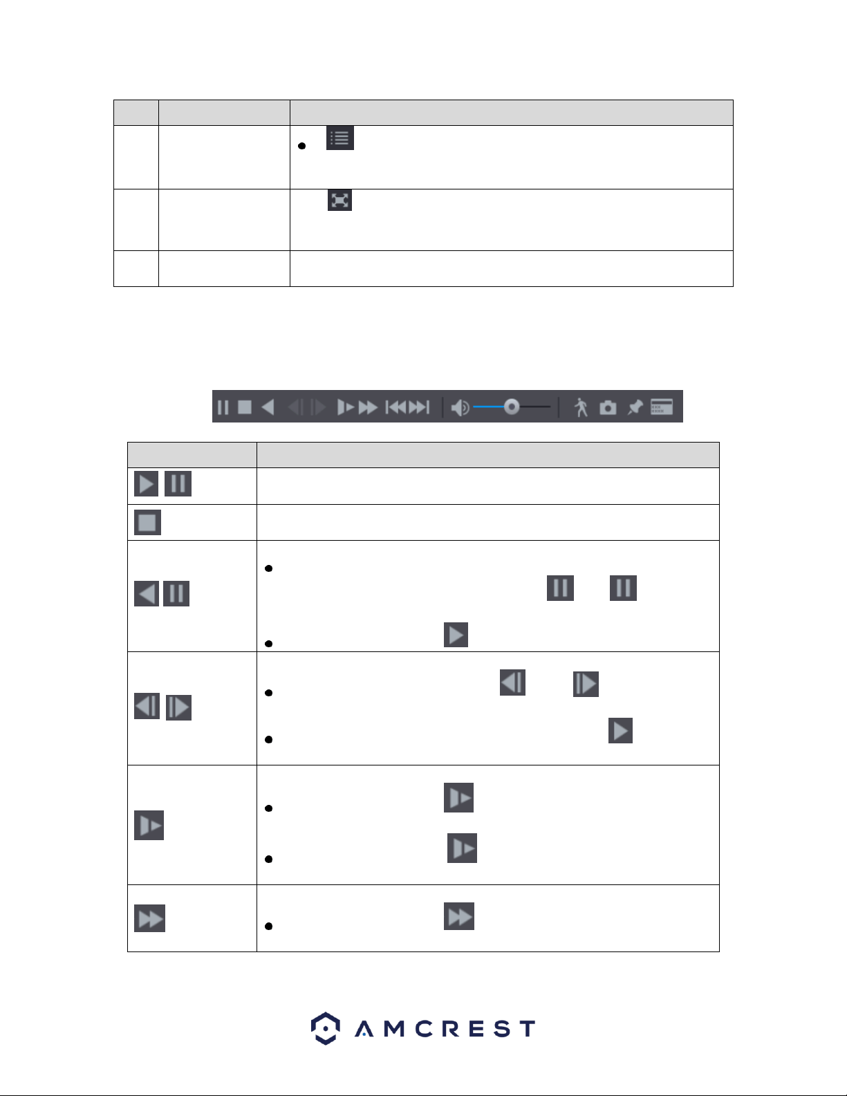
4.4.1. Live View Control Bar .................................................................................................... 35
4.4.2. Instant Playback ............................................................................................................ 36
4.4.3. Digital Zoom .................................................................................................................. 36
4.4.4. Real-time Backup .......................................................................................................... 37
4.4.5. Mute .............................................................................................................................. 37
4.4.6. Bidirectional Talk ........................................................................................................... 37
4.4.7. Remote DVRs ................................................................................................................ 37
4.5 Navigation Bar .................................................................................................................... 37
4.6 Shortcut Menu ................................................................................................................... 38
4.7. Main Menu ........................................................................................................................... 40
4.8. Function Tiles ....................................................................................................................... 41
4.8.1. Video .............................................................................................................................. 41
4.8.1.1. Playback Controls Bar ................................................................................................ 43
4.8.1.2. Selecting a Search Type .............................................................................................. 44
4.8.1.3. Clipping a Recorded Video ......................................................................................... 44
4.8.1.4. Backing up Recorded Video ....................................................................................... 45
4.8.1.5. Smart Search .............................................................................................................. 46
4.8.1.6. Marking and Playing Back Video ................................................................................ 46
4.8.1.7. Playing Back Snapshots .............................................................................................. 48
4.8.1.8. Playing Back Splices.................................................................................................... 48
4.8.1.9. Using the File List ....................................................................................................... 49
4.8.1.10. Locking and Unlocking a Recorded Video ................................................................ 50
4.8.2. Alarm .............................................................................................................................. 50
4.8.2.1. Alarm Info .................................................................................................................. 50
4.8.2.2. Alarm Input ................................................................................................................ 51
4.8.2.3. Alarm Output ............................................................................................................. 51
4.8.2.3. Video Detect .............................................................................................................. 52
4.8.2.3.1. Motion Detect ......................................................................................................... 52
4.8.2.3.2. Settings Motion Detection Regions ........................................................................ 54
4.8.2.3.3. Setting a Motion Detection Period ......................................................................... 55
4.8.3. Video Loss ..................................................................................................................... 57
4.8.4. Tampering ..................................................................................................................... 59
4.8.5. Diagnosis ....................................................................................................................... 62
4.8.5.1. Setting Types of Diagnoses Targets ........................................................................... 63
4.8.6. Abnormality .................................................................................................................. 64

4
4.8.6.1. HDD ............................................................................................................................ 65
4.8.6.2. Network ..................................................................................................................... 66
4.8.6.3. User ............................................................................................................................ 67
4.10. Backup ............................................................................................................................. 68
4.10.1. Configuring Backup Settings ....................................................................................... 68
4.11. Display ............................................................................................................................. 69
4.11.1. Configuring Display Settings ....................................................................................... 69
4.11.2. View ............................................................................................................................ 71
4.11.3. View Cycle ................................................................................................................... 72
4.11.3.1. Adding a Channel Group .......................................................................................... 73
4.11.3.2. Modifying a Channel Group ..................................................................................... 74
4.11.4. Zero-Channel ............................................................................................................... 75
4.12. Audio ............................................................................................................................... 76
4.12.1. Schedule ...................................................................................................................... 76
6. Management ........................................................................................................................... 79
6.1. Camera .............................................................................................................................. 79
6.1.1. Image ............................................................................................................................ 79
6.1.2. Encode .......................................................................................................................... 80
6.1.2.1. Configuring Snapshot Settings ................................................................................... 82
6.1.3. Overlay .......................................................................................................................... 83
6.1.3.1. Cover-Area ................................................................................................................. 84
6.1.4. PTZ................................................................................................................................. 85
6.1.4.1. PTZ Control Panel ....................................................................................................... 86
6.1.4.2. Expanded PTZ Control Panel ...................................................................................... 87
6.1.4.3. Configuring PTZ Presets ............................................................................................. 88
6.1.4.4. Configuring PTZ Tour .................................................................................................. 89
6.1.4.5. Configuring PTZ Patterns ........................................................................................... 90
6.1.4.6. Configuring PTZ Borders ............................................................................................ 90
6.1.5. Calling PTZ Functions .................................................................................................... 91
6.1.5.1. Calling Presets ............................................................................................................ 91
6.1.5.2. Calling Tours ............................................................................................................... 91
6.1.5.3. Calling Patterns .......................................................................................................... 92
6.1.5.4. Calling AutoScan ........................................................................................................ 92
6.1.5.5. Calling AutoPan .......................................................................................................... 92
6.1.6. Using AUX Button .......................................................................................................... 92

5
6.1.7. Calling the OSD Menu ................................................................................................... 92
6.1.8. Channel Type................................................................................................................. 93
6.1.10. Coaxial Upgrade .......................................................................................................... 94
6.2. Network ............................................................................................................................ 95
6.2.1. TCP/IP ............................................................................................................................ 95
6.2.2. Connection .................................................................................................................... 96
6.2.3. PPPoE ............................................................................................................................ 97
6.2.4. DDNS ............................................................................................................................. 98
6.2.5. Email.............................................................................................................................. 99
6.2.6. UPnP ............................................................................................................................ 101
6.2.7. Multicast ..................................................................................................................... 103
6.2.8. Register ....................................................................................................................... 104
6.2.9. P2P .............................................................................................................................. 105
6.2.9.1. Using the Cell Phone Client ...................................................................................... 106
6.3. Storage ............................................................................................................................ 110
6.3.1. Basic ............................................................................................................................ 110
6.3.2. Schedule ...................................................................................................................... 110
6.3.2.1. Snapshot .................................................................................................................. 114
6.3.3. HDD Manager .............................................................................................................. 116
6.3.4. HDD Detect ................................................................................................................. 118
6.3.4.1. Report ...................................................................................................................... 119
6.3.5. HDD Estimate .............................................................................................................. 120
6.3.5.1. Calculating Recording Time ...................................................................................... 121
6.3.6. FTP............................................................................................................................... 121
6.4. System ............................................................................................................................. 123
6.4.1. General ........................................................................................................................ 123
6.4.1.1 Date&Time ................................................................................................................ 123
6.4.1.2. Holiday ..................................................................................................................... 124
6.4.2. Security ....................................................................................................................... 125
6.4.2.1. Access Right ............................................................................................................. 125
6.4.2.2. System Service ......................................................................................................... 126
6.4.3. System Maintain ......................................................................................................... 127
6.4.4. IMP/EXP ...................................................................................................................... 128
6.4.5. Default ........................................................................................................................ 129
6.4.6. Upgrade....................................................................................................................... 130

6
6.5. Account ........................................................................................................................... 131
6.5.1. User ............................................................................................................................. 131
6.5.1.1. Settings Permitted Periods ...................................................................................... 133
6.5.2. Group .......................................................................................................................... 134
6.5.3. ONVIF User .................................................................................................................. 135
6.6. Info .................................................................................................................................. 137
6.6.1. Version ........................................................................................................................ 137
6.6.2. Log ............................................................................................................................... 137
6.6.3. Event ........................................................................................................................... 139
6.6.4. Network ...................................................................................................................... 139
6.6.4.1. Online User .............................................................................................................. 139
6.6.4.2. Network Load ........................................................................................................... 140
6.6.4.3. HDD .......................................................................................................................... 143
6.6.4.4. Channel Info ............................................................................................................. 144
6.6.4.5. BPS ........................................................................................................................... 144
7. Web Operation...................................................................................................................... 145
7.1 Local Web Access ............................................................................................................ 145
7.2 Remote Web Access ........................................................................................................ 146
5.3 Web Access Interface ....................................................................................................... 150
5.3.1. Resetting the Password............................................................................................... 151
5.3.2. Main Menu .................................................................................................................. 152
8. FAQs/Troubleshooting .......................................................................................................... 153
FCC Statement .......................................................................................................................... 158
IC Warning Statement ............................................................................................................... 158
Appendix A: Toxic or Hazardous Materials or Elements ........................................................... 159

7
Welcome
Thank you for purchasing our Amcrest DVR!
This user manual is designed to be a reference tool for the installation and
operation of your DVR system.
Here you can find information about the DVR’s features and functions, as well as
information to aid in troubleshooting.
Many of the setup and installation sections below have corresponding
videos on YouTube
To access the setup videos, please go to http://amcrest.com/videos
NOTE: This user manual is applicable to all 4, 8 and 16 channel Amcerst H5 and
S5 version DVR/XVRs.
Important Security Warning
To keep your Amcrest camera secure and prevent unauthorized access, please make sure to
follow the steps below:
• Always make sure that your camera has the
latest firmware as listed on
www.amcrest.com/firmware
• Never use the default password for your
camera. Always ensure that your password is at
least 8-10 characters long and contains a
combination of lowercase characters, uppercase
characters as well as numbers.
For access to the quick start guide and other support information, go to
http://amcrest.com/support
To contact Amcrest support, please do one of the following:
• Visit http://amcrest.com/contacts and use the email form
• Call Amcrest Support using one of the following numbers Toll Free:
(888) 212-7538
International Callers (Outside of US): +1-713-893-8956
USA: 888-212-7538
Canada: 437-888-0177
UK: 203-769-2757
• Email Amcrest Customer Support support@amcrest.com

8
Important Safeguards and Warnings
1.Electrical Safety
All installation and operation should conform to your local electrical safety
codes.
The product must be grounded to reduce the risk of electric shock.
We assume no liability or responsibility for any fires or electrical shock caused by improper
handling or installation.
2.Transportation Security
Heavy stress, violent vibrations, and excess moisture should not occur during
transportation, storage, and installation of the DVR.
3.Installation
Handle the DVR with care. Keep the DVR right side up.
Do not apply power to the DVR
before completing installation.
Do not place objects on top of
the DVR.
4.Repair Professionals
All the examination and repair work should be done by qualified service
engineers.
We are not liable for any problems caused by unauthorized modifications or
user-attempted repair.
5.Environment
The DVR should be installed and kept in a cool, dry place away from direct
sunlight, flammable materials, explosive substances, etc.
This product should be transported, stored, and used only in the specified
environments as stated above.
6. Accessories
Be sure to use only the accessories recommended by manufacturer.
Before installation, please open the package and check to ensure that all the
components are present.
Contact the retailer that you purchased from, or Amcrest directly if anything is
broken or missing in the package.
NOTE: This user manual is applicable to all 4, 8 and 16 channel Amcerst H5 and
S5 version DVR/XVRs
.

9
1. Features and Specification
1.1 Overview
The Amcrest is an excellent digital surveillance product designed for the security field.
The DVR uses a Linux based OS to maintain reliable operation. It’s easy to use and can
be set up in a relatively small amount of time. It has various functions such as
recording, playback, and monitoring functionality and it synchronizes audio and video
by default.
This DVR adopts a high-quality design to achieve high levels of reliability and security. It
can be configured to work locally, as well as on a network. With the provided
professional surveillance software (PSS) tool, as well as many built-in tools on the DVR’s
OS, this DVR can also help monitor and track network usage by the DVR itself.
By using industry standard cables and the latest technology, the DVR can be used with
a variety of different cameras (Analog, , or IP, etc) and can work with most standard
security system cable setups. This product can be used in a variety of locations such as
banks, residential neighborhoods or homes, factories, warehouses, transportation
(trucking), and more.
1.2 Features
The Amcrest has the following features:
• Real-time Monitoring
The has an analog output port, VGA port, and an HDMI port. You can
use a variety of monitors to display the DVR’s interface, and the DVR
can support VGA and HDMI output at the same time.
• Storage Functionality
The DVR can record multiple video and audio streams to the built-in hard drive to
allow for playback of any recorded media.
• Compression Format
By utilizing advanced compression, the DVR can support multiple channels of
audio and video, decoding audio and video from each channel to maintain video
and audio synchronization.
• Backup Function
The DVR supports backup of recorded media and settings via the USB port. A variety
of DVRs can be used for backup purposes, such as a flash drive, and internal HDDs.
• Advanced Playback Function

10
This DVR supports independent real-time recording for each channel and can
support search, fast forwarded playback, recorded searches, and downloading
of videos and screenshots. The DVR can also playback in slow motion,
backwards, and frame by frame as needed. When recording, the DVR shows a
date/time overlay to ensure accurate viewing of events when they occurred.
Lastly, the DVR can support video enlargement of certain zones within a
stream.
• Network Operation
The DVR has built-in tools to allow for remote network real-time monitoring,
remote recording of searches, and remote PTZ control.
• Alarm Activation Function
On the back of the DVR there are ports for installation and connection of
alarm outputs to enable alarm or light activation based on activity within the
video stream. The alarm input and output circuits are protected to ensure
DVR safety.
• Communication Port
By including an RS485 port, the DVR can support PTZ decoding, as well as
various other decoding protocols to allow PTZ control of the attached
cameras.
• Intelligent Operation
The DVR supports a variety of mouse and keyboard DVRs to enable easy use of
the DVR. There is also a feature that allows for the saving of settings on the DVR.
• Advanced Network Protocol Support
The DVR is UPnP compatible, and includes functionality for use with
PPPoE, and DDNS protocols to allow remote and local connection with a
large variety of network hardware.
Note: There may be slight differences in functionality due to the existence of
different product series.
2. Overview and Controls
This section provides information about the physical design and controls for the
DVR. Please refer to the diagrams below to become acquainted with the DVR
and its physical features.
11
2.1 Front Panel
Port Name
Function
1
HDD
Glows blue when HDD status is abnormal.
2
NET
Glows blue when network status is abnormal.
3
POWER
Glows blue when the power is connected properly.
4
USB Port
Connects to external DVRs such as a mouse or USB storage DVR
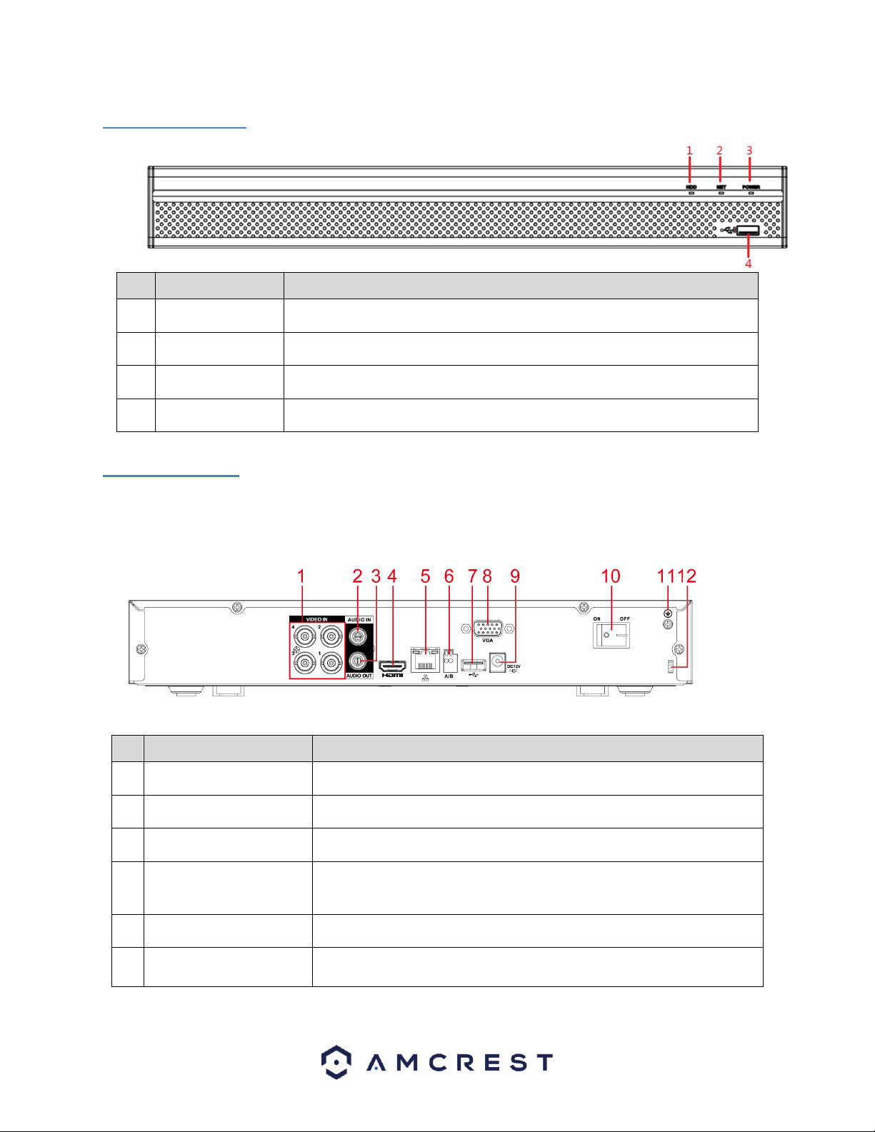
2.2 Rear Panel
This is for example purposes only, the diagram represents a 4 Channel system however, is applicable to all
units provided in the description.
Note: The 4-channel system rear panel is as shown below.
Please refer to the following table for detailed information:
Port Name
Function
1
Video input port
Connects to analog camera to input video signal.
2
Audio input port
Receives audio signal output from an RCA microphone DVR.
3
Audio output port
Outputs audio signal to an external RCA speaker.
4
HDMI port
High definition audio and video signal output port. The port outputs an
uncompressed high-definition feed as well as multi-channel audio data to a
connected HDMI compatible display.
5
Network port
Connects to Ethernet port.
6
RS485
communication port
Connects to control DVRs such as, speed dome PTZ cameras. The RS485_A
port will be connected by a cable (A) and RS485_B (B) cable.
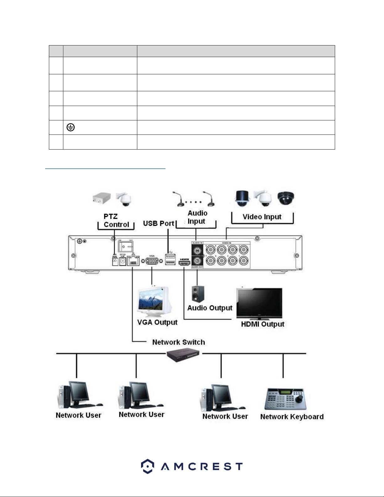
12
Port Name
Function
7
USB port
Connects to an external DVR such as, a mouse, keyboard, or external USB
storage DVR.
8
VGA port
Outputs analog video data to a connected display with a compatible VGA
port.
9
Power input port
Inputs DC 12V power.
10
Power button
Turns on/off the DVR.
11
Ground terminal.
12
Power cable fastener
Use a clamp to secure the power cable on the DVR to avoid signal error.
2.3 DVR Connection Example
The below diagram provides an example of the variety of DVRs the DVR can interface or connect with.
13
2.4 Mouse Control
The following table details the different uses for a computer mouse regarding the DVR’s controls.
Left click
mouse
System pops up password input dialogue box if you have not logged in. In real-
time monitor mode, you can go to the main menu.
When you have selected one menu item, left click mouse to view menu content.
Implement the control operation.
Modify checkbox or motion detection status.
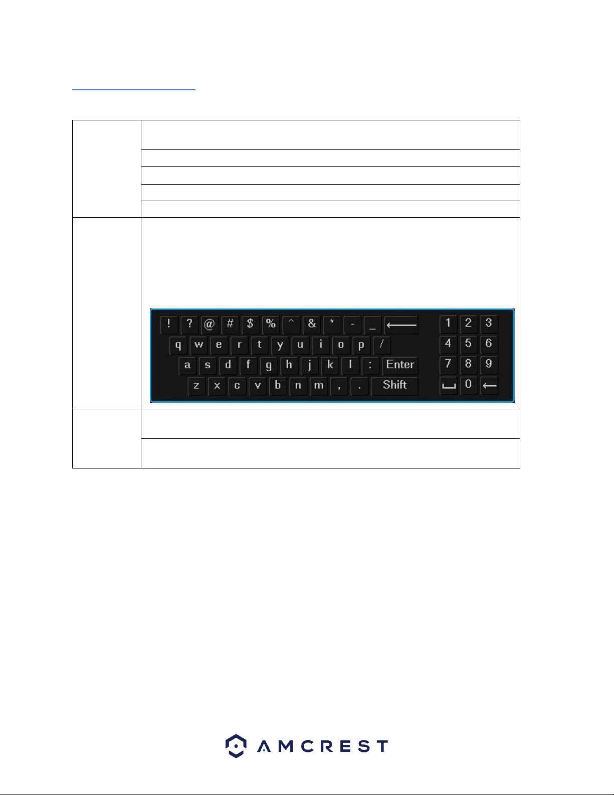
Click combo box to pop up drop down list
In the input box, you can select input methods. Left click the corresponding button on the
panel and you can input numeral/English character (small/capitalized). Here, ← stands for
backspace button. _ stands for the space button.
In English input mode: _ stands for input a backspace icon and ← stands for deleting the
previous character.
Double left
click mouse
Implement special control operation such as double click one item in the file list to
playback the video.
In multiple-window mode, double left click one channel to view in full-window.
Double left click current video again to go back to previous multiple-window mode.
14
Right click
mouse
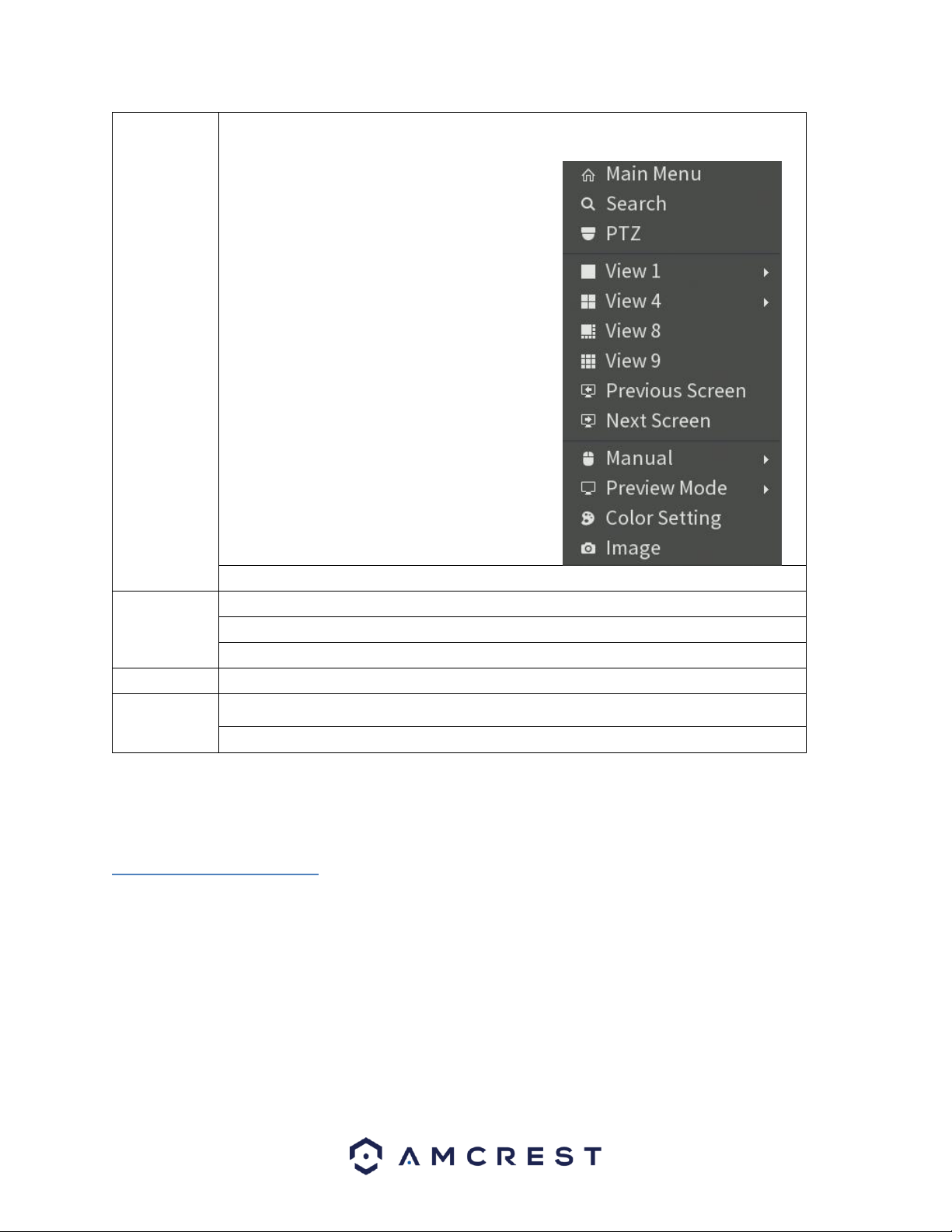
In real-time monitor mode, pops up shortcut menu: one-window, four-window, nine
window and sixteen-window, Pan/Tilt/Zoom, color setting, search, record, alarm input,
alarm output, main menu.
Among which Pan/Tilt/Zoom and color setting
applies for current selected channel. If you are in
multiple-window mode, system automatically
switches to the corresponding channel.
Exit current menu without saving the modification.
Press middle
button
In numeral input box: Increase or decrease numeral value.
Switch the items in the check box.
Page up or page down
Move mouse
Select current control or move control
Drag mouse
Select motion detection zone
Select privacy mask zone.
3. Connection and Installation
3.1 Check Hardware
When you receive the DVR system in the packaging, unpack it, and check all sides
of the DVR to see if there is any physical damage. The protective materials used
for the packaging of the DVR can protect most accidental damage during
transportation, but to ensure that your equipment is operating as expected, it is
recommended to inspect the product before proceeding further.
On the DVR unit, check specifically that the label on the bottom of the DVR is not
damaged. The serial number of the unit is usually needed to provide support.
15
Please check that all required items for your DVR are present and accounted for.
To check what is included with your purchase, go to http://amcrest.com/-
security-camera-systems.html/ and find the product you purchased, then scroll
down and click the “What’s Included” tab. If any item is missing, please contact
us as soon as possible so we can send you the missing component.
3.2 Hard Drive Installation
You can refer to the Appendix for recommended HDD brands and models. Please
use a HDD of 7200rpm or higher.
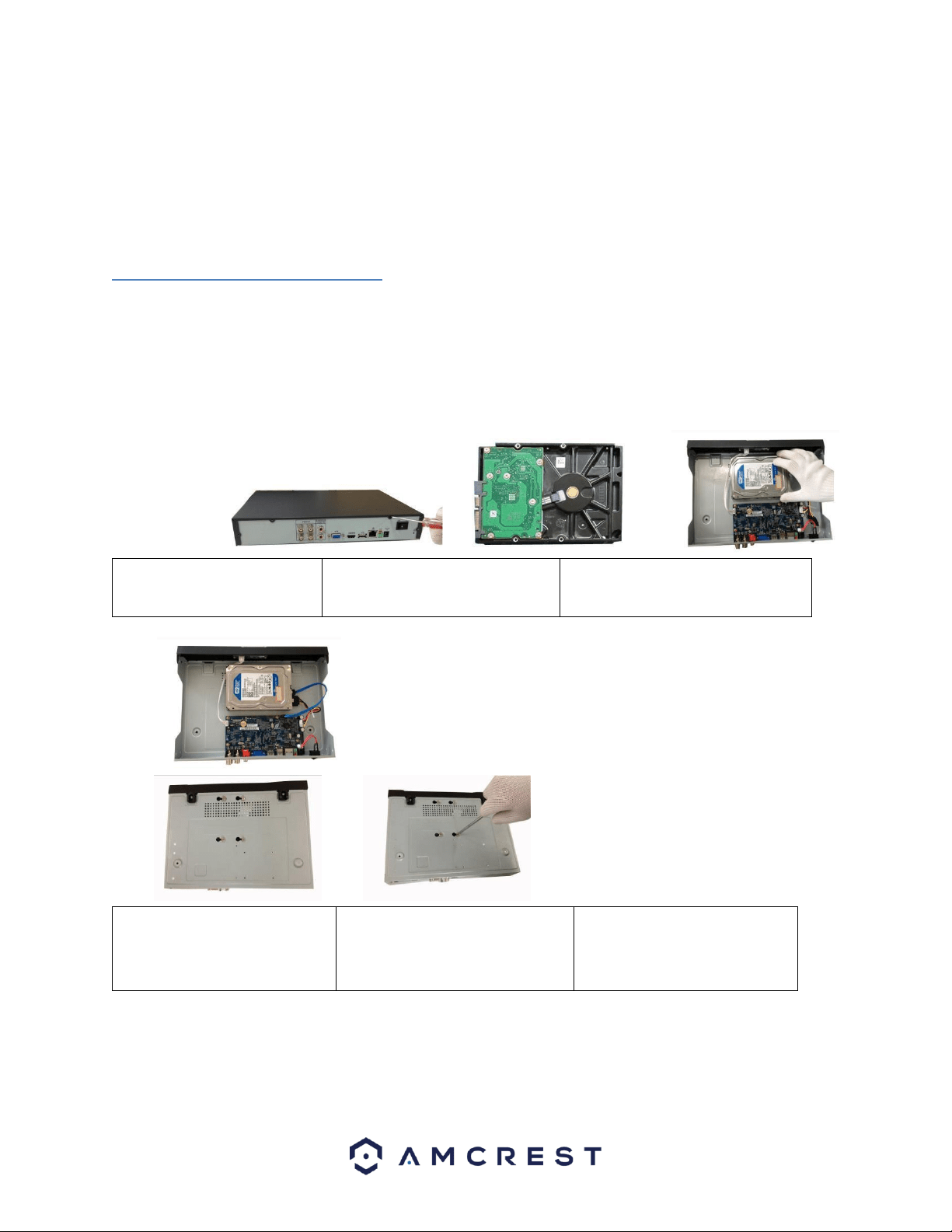
Please follow the instructions below to install a hard disk drive (HDD).
All the figures listed below are for reference only. Slight differences may be
found on the front or rear panel.
1. Loosen the screws of the
upper cover and side panel.
2. Attach four screws in the HDD
(Turn three times).
3. Place the HDD in accordance
with the four holes on the bottom.
4. Turn the DVR upside down
and then turn the screws in
firmly in the chassis.
5. Attach the HDD firmly.
6. Connect the HDD cable and
power cable.
16
7. Put the cover on in accordance
with the clip and then place the
upper cover back on.
8. Secure the screws in the rear
panel and the side panel.
Note:
• An HDD is NOT included with the DVR by default.
• To connect the HDD, connect the HDD data cable and the power cable
before attaching the HDD in the DVR.
• To remove the front cover, push the clip first, and then slide the cover
off.
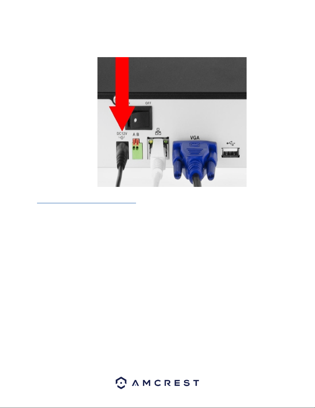
3.3 Connection Port Information
3.3.1 Power Supply Connection
Please check to make sure the input voltage is correct, and the power button is in the
off position when connecting the power supply.
We recommend you use an Uninterruptible Power Supply (UPS) to guarantee
steady operation of the DVR, as well as to elongate the life span of the DVR and
other peripheral equipment such as attached cameras and other accessories.
3.3.2 Video Input/Output Connections
3.3.2.1 Video Input Connection Information
The video input interface is BNC.
The input video format includes: PAL/NTSC BNC (1.0VBP- P, B75Ω)
The video signal should comply with your national standards.
The input video signal should have high SNR, low distortion; low interference,
natural color and suitable brightness.

17
To guarantee the stability and reliability of the camera signal, the camera should
be installed in a cool, dry place away from direct sunlight, flammable materials,
explosive substances, etc.
The camera and the DVR should have the same grounding to ensure the normal
operation of the camera.
Guarantee stability and reliability of the transmission line
Please use high quality, well shielded BNC cable. Please select suitable BNC
model according to the transmission distance.
If the distance is too long, you should use twisted pair cable. You can add video
compensation DVRs or use optical fiber to ensure video quality.
You should keep the video signal away from the strong electromagnetic
interference, especially power lines.
Keep connection lugs closely contacted.
The signal line and shielded wire should be fixed firmly and in well connection.
Avoid dry joint, lap welding, and oxidation.
3.3.2.2 Video Output Connection Information
Video output includes a BNC (PAL/NTSC1.0VP-P,75Ω)output, a VGA output,
and a HDMI output. The system supports BNC, VGA and HDMI output at the
same time.
When you are using pc monitor, please pay attention to the following points:
• To defer aging, do not allow the pc monitor to run for a long time.
• Regular demagnetization will keep your DVR in proper working
condition.
• Keep it away from strong electromagnetic interference DVRs.
Using a TV as video output DVR is not a reliable substitution method. When using
a TV as a video output DVR, it is advised to turn off the TV from time to time to
ensure its longevity. The use of a low-quality TV may result in the damage of the
DVR.
3.3.3 Audio Input/Output Connections
3.3.3.1 Audio Input Connection Information
The DVR audio input ports uses a BNC type connection.

18
Due to high impedance of audio input, please use an active sound microphone to
get the best audio quality.
Audio transmission is like video transmission. Try to avoid interference, look out
for dry joints, loose contacts, and keep the audio DVRs and cables away from
power lines.
3.3.3.2 Audio Output Connection Information
The audio output signal parameter is usually over 200mv 1KΩ (BNC or RCA).
It can directly connect to a low impedance earphone, active speaker, or
amplifier-drive audio output DVR.
If the speaker and the microphone cannot be separated spatially, it may create a
feedback loop. In this case you can adopt the following measures:
• Use a better directional microphone.
• Reduce the volume of the speaker.
• Using more sound-absorbing materials in the surrounding area can
reduce voice echo and improve the acoustic environment.
Adjust the layout of the audio output cables to reduce the occurrence of a
feedback loop.
3.3.4. USB Port
On the DVR there is a standard USB port. For information on which DVRs are
supported by this USB port, please see Appendix F.
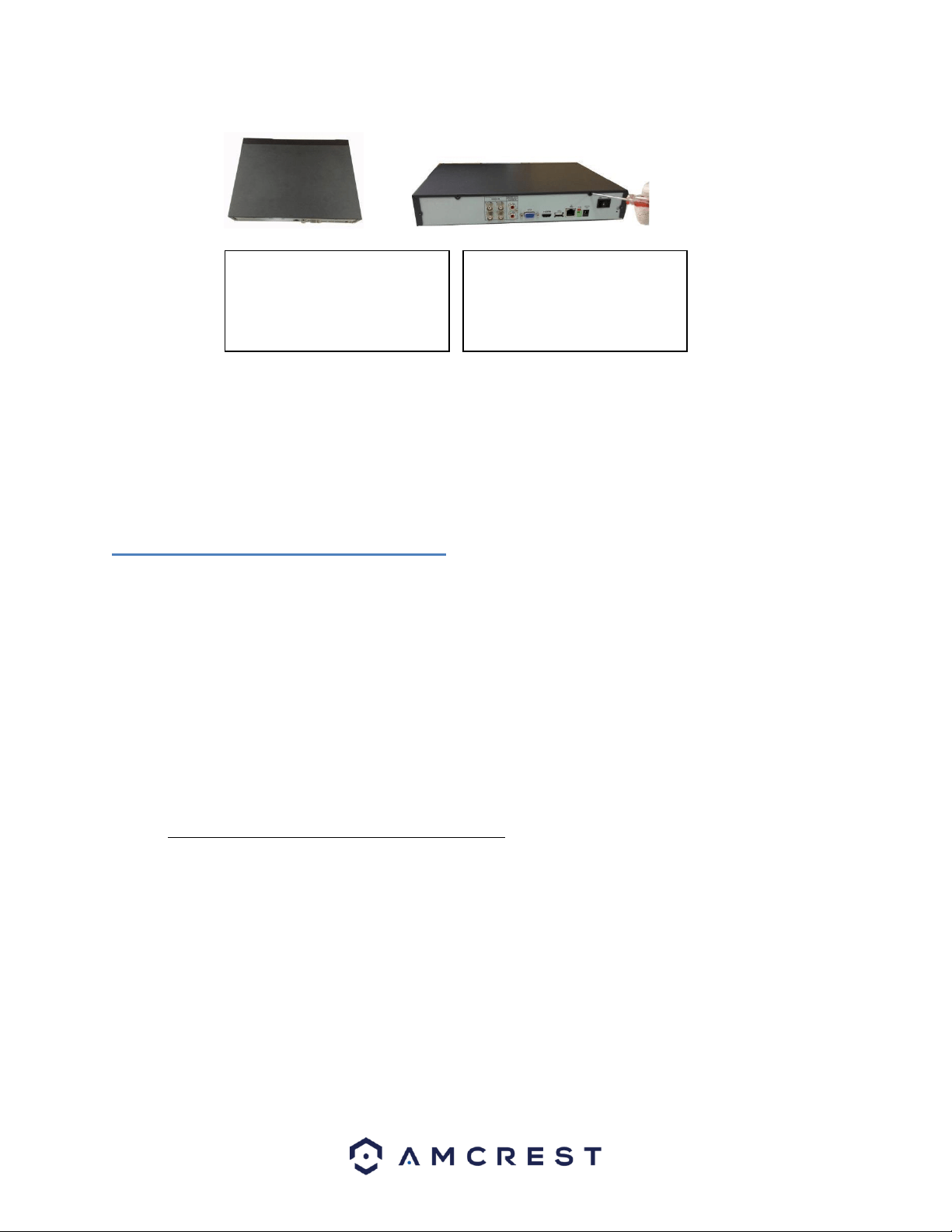
3.4 DVR Assembly Guide
Before setting up the DVR, you will probably need the following items. These
items are not included:
• A computer monitor or TV with either an HDMI or VGA input
• A power strip with room for 4 large power plugs
Note: It is recommended to connect all components of the system as shown
below BEFORE mounting any of the cameras. This is to ensure all components
are working. If any components are not functioning, please contact Amcrest
Support.
To set up the DVR hardware, there are 7 major steps:
19
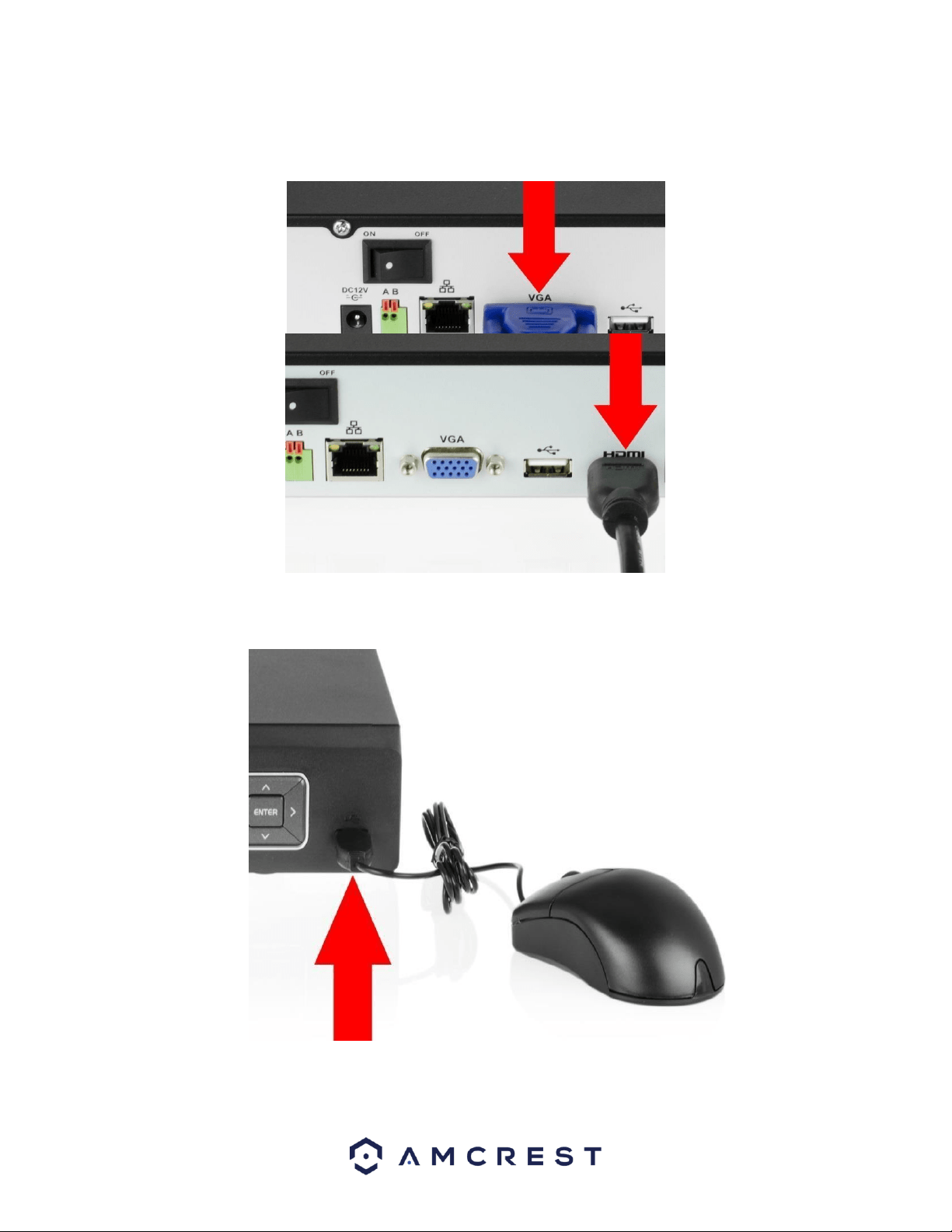
1. Connecting a monitor to the DVR. The DVR is compatible with any
monitor that uses a VGA or HDMI connection. For purposes of this
guide, we will use a VGA connection.
2. Connect a USB mouse to the front of the DVR.
20
3. Connect an Ethernet cable to your router, and then connect the other
end of the cable to the DVR.
4. Connect the camera video extension cable to the camera’s video cable
and connect the camera power extension cable to the camera’s power
cable. There should be a tag on the video cable to help you make sure
the right end of the cable is at hand.
21
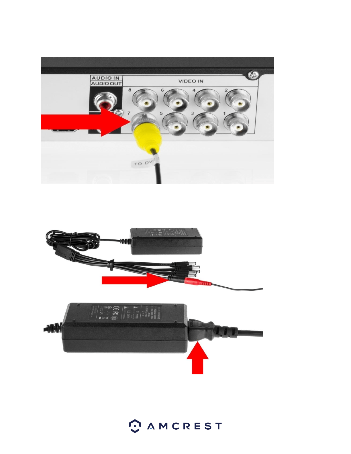
5. Connect the camera cable to any of the video input ports.
6. Connect the camera power extension cable to one of the camera power
cables, connect this power cable into the power brick, and then plug the
cable into an electrical socket.
22
7. Connect the DVR power cable into the back of the
DVR, and then plug in the DVR power adapter into an
electrical socket.
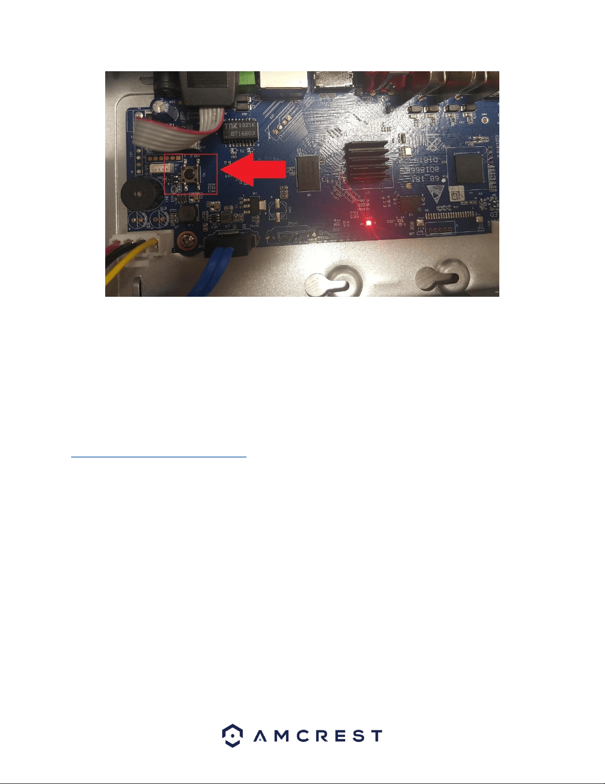
3.5 Factory Reset Procedures
Newer Amcrest model DVRs, such as the XVR or S5 models, will have a different factory reset process than its
previous counterparts.
To begin the process, you will need to remove the DVR cover. Use a Phillips head screwdriver to remove the four
screws on the back and sides of the DVR. Once the screws have been removed, lift the lid to expose the DVR's
motherboard.
On the motherboard you will notice a small black button. This is the factory reset switch for your DVR:
23
To factory reset the DVR, unplug the DVR from power. Once power is removed from the unit, press and hold the
factory reset switch for 4 - 5 seconds. Continue holding the reset switch and plug the DVR's power supply back into
the unit, you will hear a beep. Continue holding the reset switch and allow the DVR to initialize for 20 - 30 seconds
and then release the switch. The DVR will be set to default and will show the DVR initialization screen. For more
information on the DVR initialization screen, refer to section 4.2 DVR Initialization.
4. Overview of Navigation and Controls
4.1 Startup and Shut down
4.1.1 Startup
Before initial startup, please make sure:
• The rated input voltage matches the output voltage at your location.
Please make sure the power wire connection is secure before pressing
the power on-off button.
• Always use a stable current. If necessary, an Uninterruptable Power
Supply (UPS) is a good way to ensure power stability.
Please follow the steps listed below to boot up the DVR:
• Plug an Ethernet cable into your router/modem.
• Connect the Ethernet cable to the Ethernet Port of the DVR.
• Plug the power adapter into a wall outlet.
• Connect the power cable to the DVR.
24
4.1.2 Shut down
• Click the logout button located on the main menu and select Shut
Down.
• Do not unplug the power cable or click the power on-off button to shut
down the DVR directly when DVR is running (especially when it is
recording.)
4.2. DVR Initialization
In this screen you will be able to enable DVR initialization features. These are basic features related to the system,
such as password setups, recovery settings, etc.
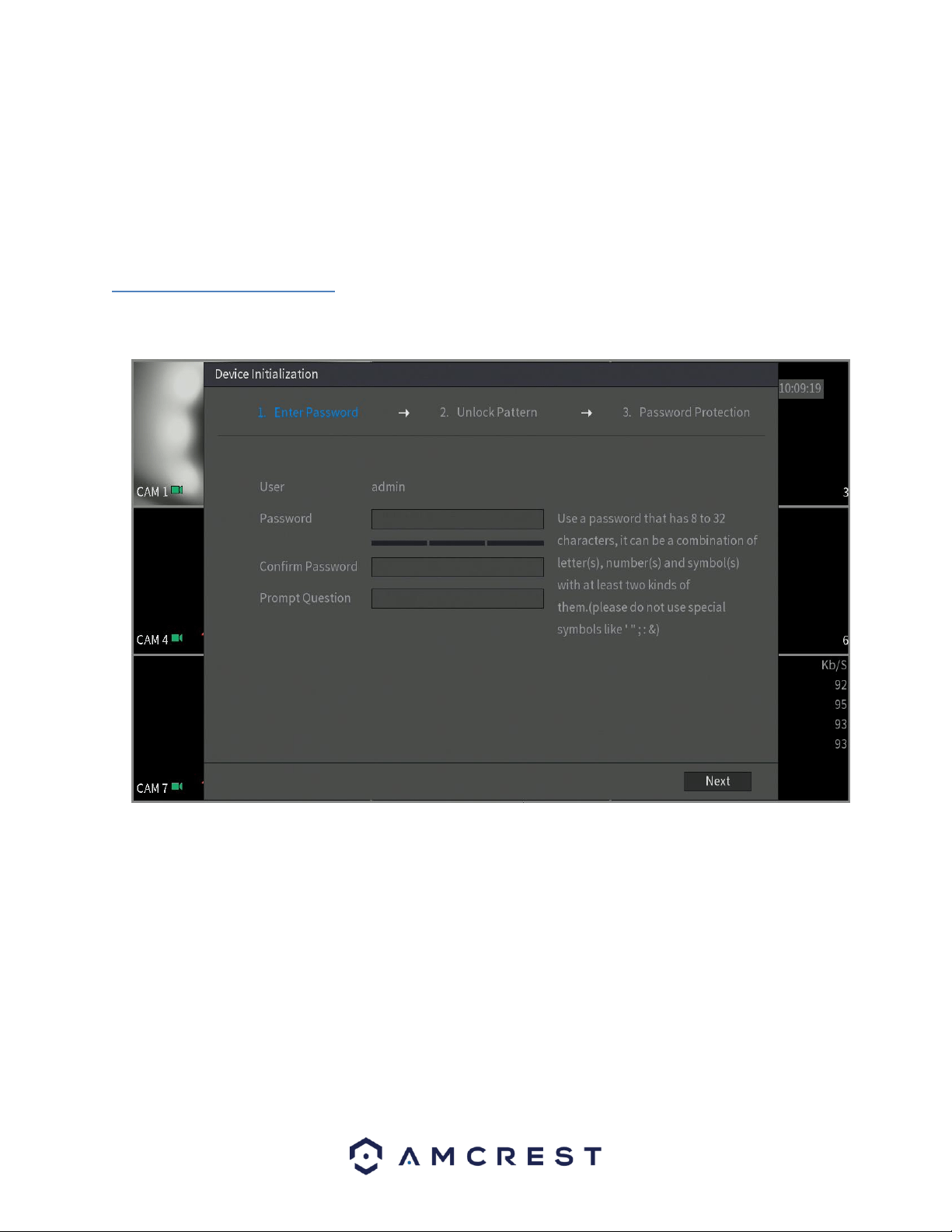
4.2.1 Default Account Usernames and Passwords
To login to the system for the first time, you will need to assign a password for
the user (admin) account. Please enter a password for the account into the
password field and rewrite it into the confirm password field. You can also add in
a prompt question that will be applicable for password recovery. The prompt
question field is optional.
Note:
• Use a password that has 8 to 32 characters, it can be a combination of letter(s),
number(s), and symbol(s) with at least two kinds of them. Do not use special
symbols such as, (‘ “ ; : &).
25
• These settings configured in the startup wizard can be changed at any time by
accessing the settings menu. Information on each of these settings screens can
be found in the Overview of Navigation and Controls -> Main Menu Interface
section.
• If the password for the administrator account is misplaced, forgotten, or a user
is locked out, contact Amcrest Support via one of the following options as a
hard password reset may be needed:
o Visit http://amcrest.com/contacts and use the email form o
Call Amcrest Support using one of the following numbers
Toll Free: (888) 212-7538
International Callers (Outside of US): +1-713-893-8956
USA: 713-893-8956
Canada: 437-888-0177
UK: 203-769-2757
o Email Amcrest Customer
Support
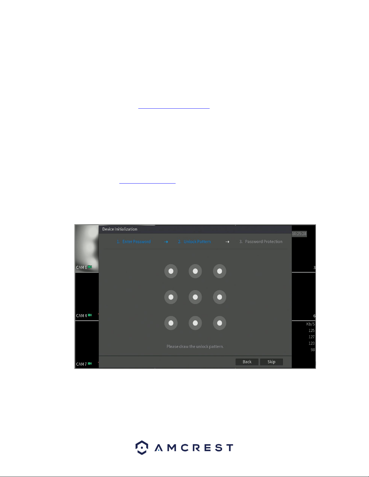
4.2.2. Unlock Pattern
The next screen that will be configured will be the unlock pattern screen. In this screen you can
configure the unlock pattern for your DVR. This setting is optional and can be skipped by pressing
the Skip button.
To set the unlock pattern, use the mouse to draw a pattern you would like to use. Once you have
drawn the desired pattern on the screen, the system will ask you to confirm the unlock pattern
you have set. To confirm the setup, use the mouse to draw the pattern again. When complete
you will be taken to the password protection screen.
26
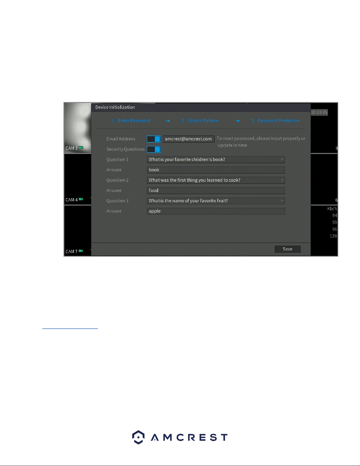
4.2.3. Password Protection
The next screen that will appear will be the password protection screen. This screen is another means of
password retrieval can be set up in this menu. To begin, enter a valid email address into the Email
Address field. The email address will be retained in the system.
Next, you will need to assign security questions. These are an added security feature that will help you
obtain your password. To begin, select a question from the drop-down menus for Question 1, Question 2,
and Question 3 and enter the answers to those questions in the Answer fields.
Once this section is complete, click on the Save button to save your information and move on to the next
initialization screen.
4.3 DVR Setup
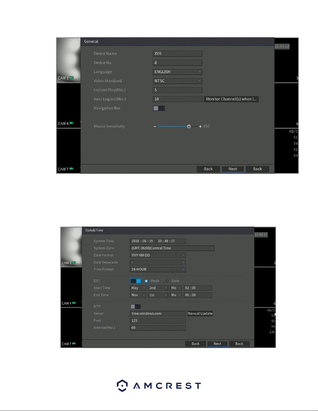
4.3.1. General
The first screen that appears in the startup wizard will be the General menu. This menu allows you to set
the name for your DVR as well as provides several general options associated with your DVR.
27
4.3.2. Date&Time
The next screen that appears will be the Date & Time settings screen. This is where you can set the date
and time for your specific location. If you wish to utilize daylight savings time, toggle the DST toggle switch
to the on position. Once you have selected the proper date and time for your DVR, click the Next button
to continue.
Note: Make sure to toggle the NTP toggle switch to the off position to avoid syncing your DVR to the NTP server.
28
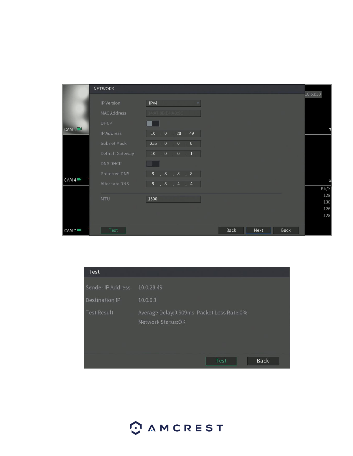
4.3.3. Network
The next screen that will appear is the Network settings screen. In this screen you can configure the
network settings. If you want to set your DVR up to have a static IP, toggle the DHCP toggle switch to the
off position.
Note: To test the connectivity of the DVR to your network, click on the Test button. The DVR will return a
network status. To return to the previous menu, click the Back button.
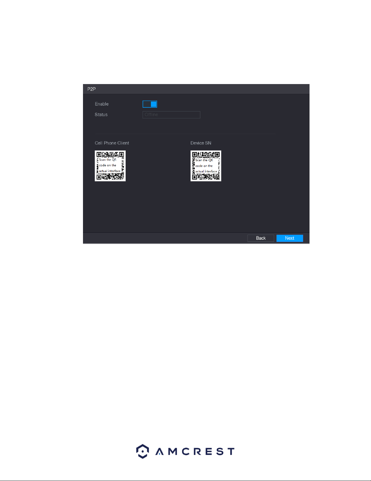
4.3.4. P2P
The next screen that appears is the P2P settings screen. It is highly recommended to keep this enabled if
you want to use the DVR in the Amcrest View Pro mobile app or AmcrestView.com so you can view your
DVR remotely on your mobile device.
29
On this screen you will notice two QR codes. These QR codes allow you to download the cell phone client
(Amcrest View Pro) app as well as quick access to your DVR’s serial number. The serial number for your
DVR is used to add the device into the Amcrest View Pro app. For more information on app setup, refer to
section 6.2.9.1. Using the Cell Phone Client.
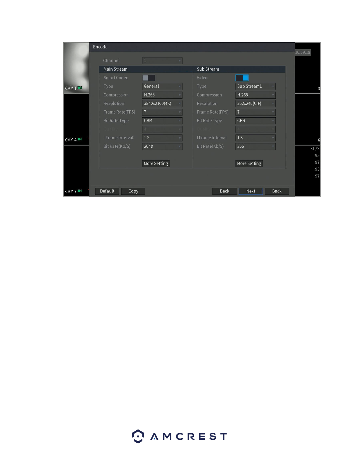
4.3.4. Encode
The next screen that appears is the encode settings screen. This is where you can adjust the video quality
settings for your device, including the compression and frame rate. If applicable, if you would like to
access or adjust audio formats and sources, click on the More Setting tab.
30
If you have made any incorrect encode settings and would like to revert the settings back to its original
default settings, click on the Default button. You can also copy and apply the settings to multiple channels
if they apply. To copy the encode settings to multiple channels press the Copy button and select which
channels you would like the settings to apply with. To return to the previous menu, click the Back button.
When you have successfully completed setting up your desired encode settings, click the Next button to
save and proceed to the next screen.
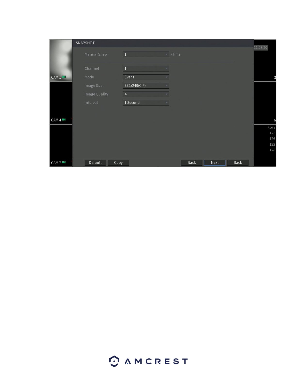
4.3.5. Snapshot
The next screen that will appear will be the snapshot settings screen. This is where you can adjust
the settings for snapshots. This includes, the image size, quality, as well as interval in which the
snapshot is retained. Once set, click on the Next button to continue.
31
If you have made any incorrect settings and would like to revert the settings back to its original default
settings, click on the Default button. You can also copy and apply the settings to multiple channels if they
apply. To copy the encode settings to multiple channels press the Copy button and select which channels
you would like the settings to apply with. To return to the previous menu, click the Back button. When
you have successfully completed setting up your desired encode settings, click the Next button to save
and proceed to the next screen.
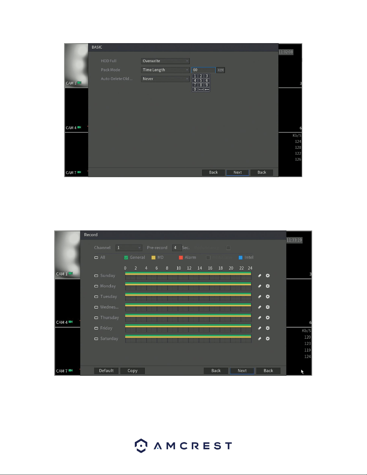
4.3.6. Basic
The next screen that will appear will be labeled Basic. This is where you can configure your hard drive
settings including, when to overwrite a full hard drive or customizing an auto-delete option. The auto-
delete option pertains to old files and how long you would like that data to remain on your hard drive.
This is measured in days and is set with a built-in number pad.
32
4.3.7. Record
The next screen you see is the Record settings screen. Your DVR is configured, by default, to record
everything on all channels 24/7 (this will only actually happen provided you have a hard drive installed).
You can also use this screen to set up motion detection and alarm schedules.
If you have made any incorrect settings and would like to revert the settings back to its original default
settings, click on the Default button. You can also copy and apply the settings to multiple channels if they
apply. To copy the encode settings to multiple channels press the Copy button and select which channels
you would like the settings to apply with. To return to the previous menu, click the Back button. When
33
you have successfully completed setting up your desired encode settings, click the Next button to save
and proceed to the next screen.
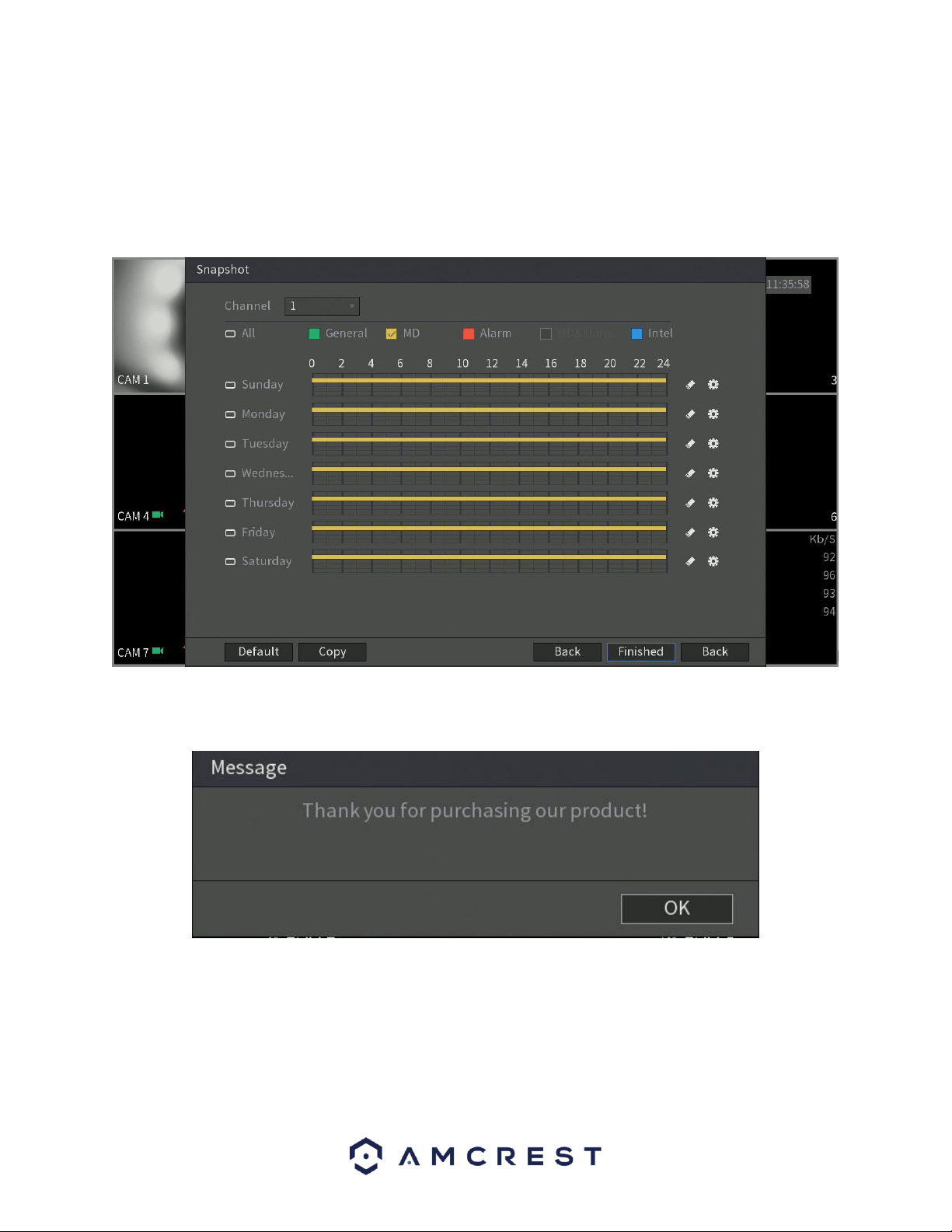
Next, you will be able to configure your snapshot settings for your scheduled recordings. You can also use
this screen to set up motion detection and alarm schedules for snapshot events. Once you have scheduled
your events, click on the Finished button to continue.
Once the setup process is finished and you have clicked the “Finished” button, you should see the below
dialog box:
Click OK to continue and the next screen you will reach will be the home video wall screen for your system.
4.4. Live View
When you have completed initial setup of the DVR, you will notice a video wall. The video wall will display
all live connected cameras, excluding IP cameras.
34
Note: The number of screens displayed will be dependent on the model of your DVR.
4.4.1. Live View Screen
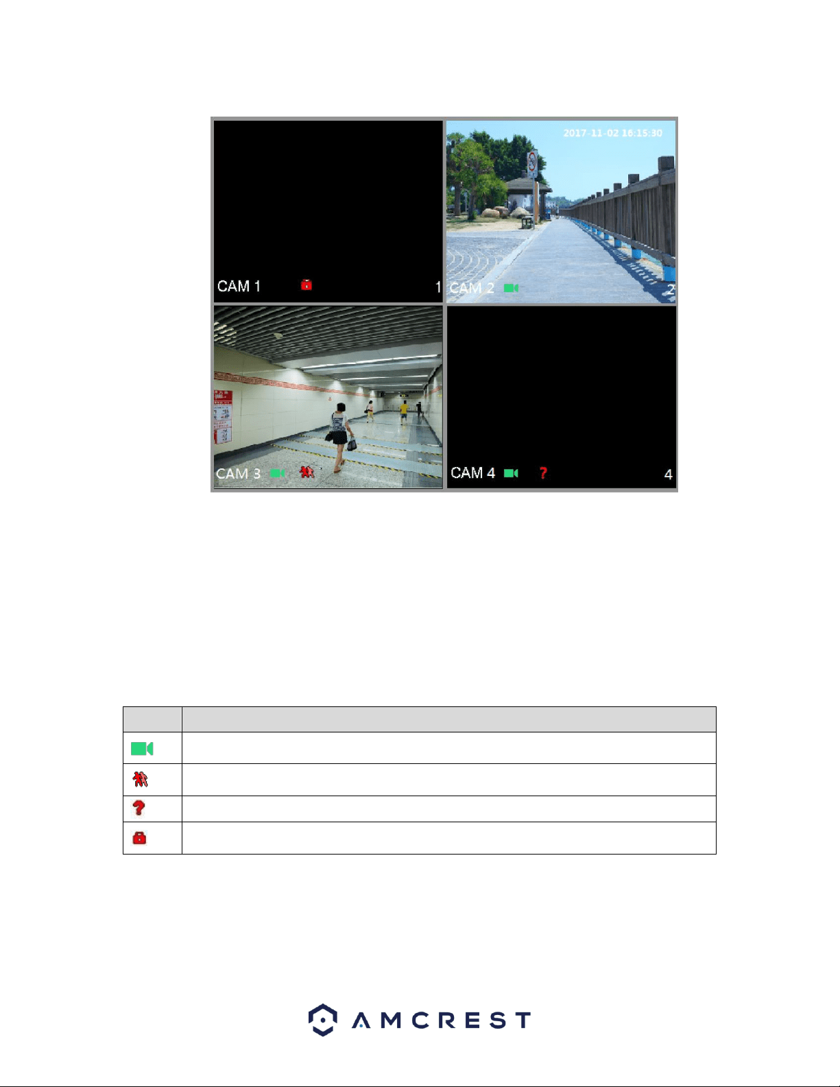
By default, the system time, channel name and channel number will be displayed on each channel
window. This setting however, can be also configured by going to, Main Menu>Camera>Overlay. The
figure in the bottom right corner represents the channel number. If the channel position is changed or the
name is modified, you can recognize the channel number by this figure. This number also represents the
channel number you will refer to for performing operations such as, record queries, and playback. For
more information on the icons listed, refer to the table below.
Icon
Function
Indicates recording status. This icon displays when the video is being recorded.
This icon displays when the motion detection occurs in the scene.
This icon displays when the video loss is detected.
This icon displays when the channel monitoring is locked.
Note: To switch the position of two channels, point to one of the two channels and drag the window to
the other channel.
35
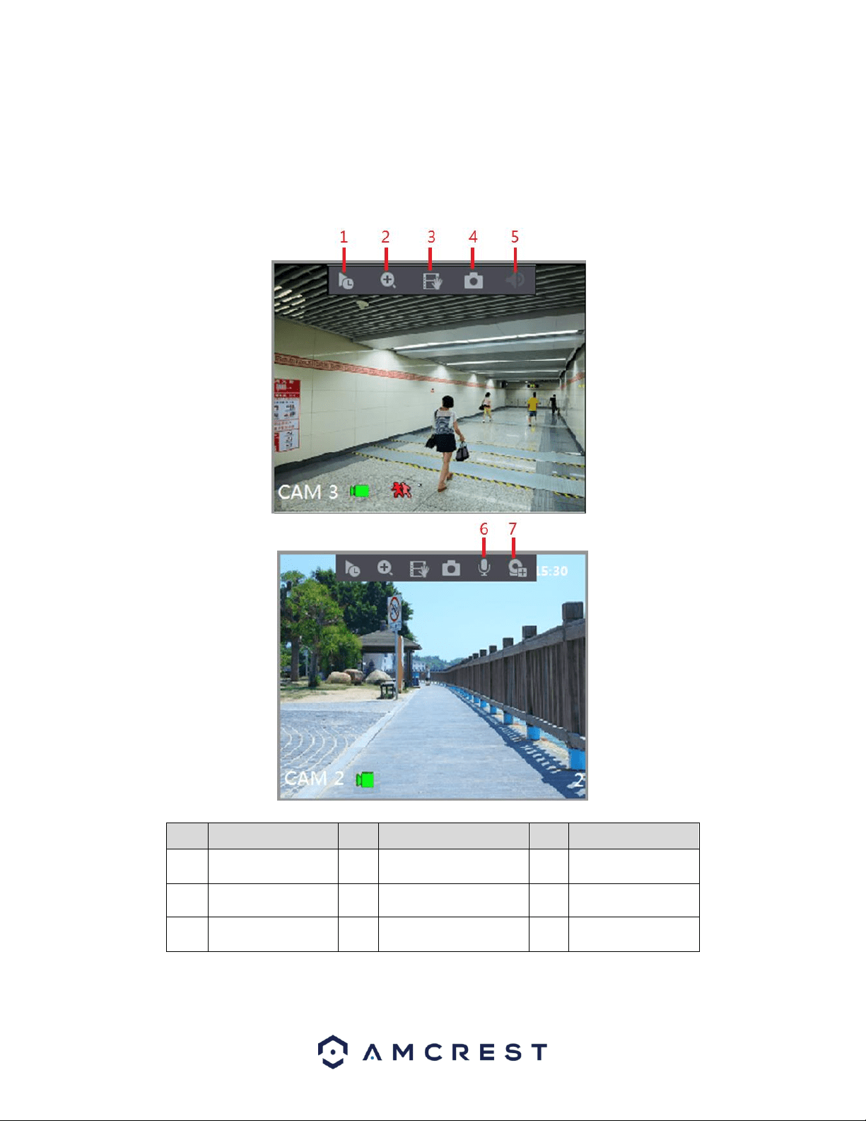
4.4.1. Live View Control Bar
The live view control bar provides you access to perform the operations such as playback (Instant Play),
digital zoom, real-time backup, manual snapshot, voice talk, adding remote DVRs, and streams switch.
These options can be applicable depending on specific model cameras that are connected to the device.
When you move the pointer to the top middle position of a channel window, the live view control bar is
displayed. For more information on these functions, refer to the table below.
No.
Function
No.
Function
No.
Function
1
Instant Play
4
Manual Snap
7
Camera
Registration
2
Digital Zoom
5
Mute
3
Real-time
Backup
6
Audio Talk
36
4.4.2. Instant Playback
This option allows you to play back the previous five to sixty minutes of a recorded video.
By clicking on the icon, the instant playback interface will be displayed. The instant playback feature
has the follow features:
⚫ Move the slider to choose the time you want to start playing.
⚫ Play, pause and close playback.
⚫ The information such as channel name and recording status icon are shielded during instant
playback and will not display until exited.
⚫ During playback, screen split layout switch is not allowed.
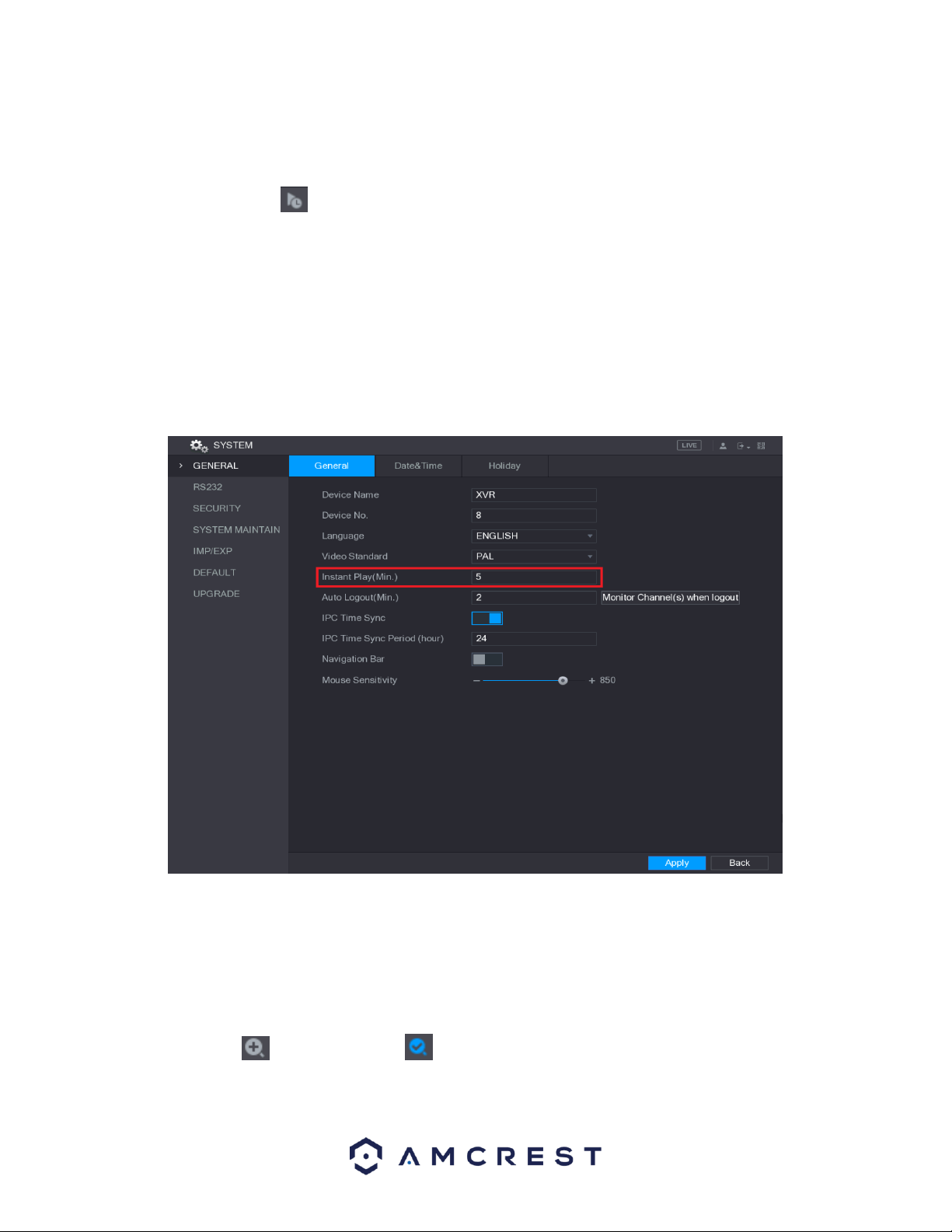
To change the playback time, select Main Menu > SYSTEM > GENERAL, in the Instant Play box, enter the
time you want to play back.
4.4.3. Digital Zoom
This feature allows you to enlarge a specific area of the image in the live view screen.
This function can be accessed in two ways:
⚫ Click , the icon switches to . Hold down the left mouse button to select an area you want to
enlarge. The area is enlarged after the left mouse button is released.

37
⚫ Point to the center that you want to enlarge, rotate the wheel button to enlarge the area.
Note: For some models, when the image is enlarged, the selected area is zoomed proportionally according to the
window. When the image is enlarged, you can drag the image toward any direction to view other enlarged areas.
To return to the original status of the image, right-click on the enlarged image.
4.4.4. Real-time Backup
This feature allows you to record the video of any channel and save the clip into a USB storage DVR.
By clicking , the recording is started. To stop recording, click this icon again. The clip is automatically
saved into the connected USB storage DVR.
4.4.5. Mute
This feature is only available on analog channels.
You can mute the video sound by clicking . This function is supported in single-channel view.
4.4.6. Bidirectional Talk
This feature is only available in digital channels.
You can perform the voice interaction between the DVR and other remote DVR to improve efficiency. This
function is supported only when the remotely connected IPC DVR supports bidirectional talk.
⚫ Click , the icon switches to , the bidirectional talk of the remote DVR is turned on. The
bidirectional talk of other digital channels is disabled.
⚫ Click to cancel the bidirectional talk. The bidirectional talk of other digital channels is
resumed.
4.4.7. Remote DVRs
This allows you to view information of remote DVRs as well as add new remote DVRs to replace any
current connected DVRs.
By clicking , the Camera Registration interface is displayed. For details about adding the remote
DVRs.
4.5 Navigation Bar
The navigation bar allows you to access functions more efficiently in the DVR. This option is not displayed
by default. It will not appear in the live view screen until it is enabled. To enable the navigation bar, go to,
Main Menu>SYSTEM>GENERAL, and enable the navigation bar toggle switch. Once enabled, click Apply
to apply the setting. For more information on the navigation bar and its features, refer to the table
provided below.
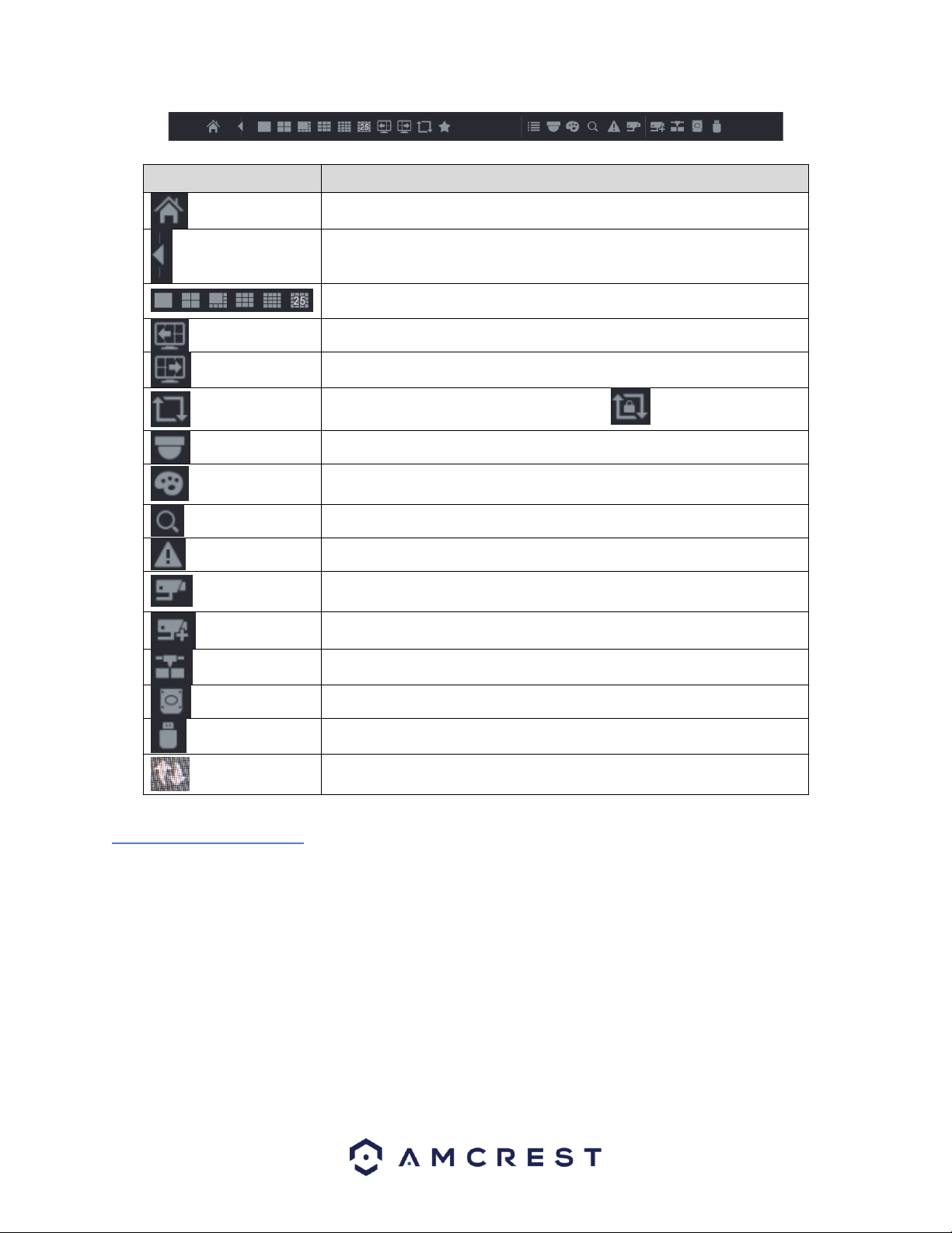
38
Icon
Function
Open Main Menu.
Expand or condense the navigation bar.
Select view layout. (Options dependent on specific models)
Go to the previous screen.
Go to the next screen.
Enable tour function. The icon switches to .
Open the PTZ control panel.
Open the Color Setting interface. This function is supported only in
single-channel layout.
Open the record search interface.
Open the EVENT interface to view the DVR alarm status.
Open the CHANNEL INFO interface to display the information of each
channel.
Open the CAMERA REGISTRATION interface.
Open the NETWORK interface.
Open the HDD MANAGER interface.
Open the USB MANAGER interface.
Open the UPGRADE MANAGER to make sure your system is operating
on the latest firmware.
4.6 Shortcut Menu
By right-clicking the mouse on the live view screen, the following menu opens:
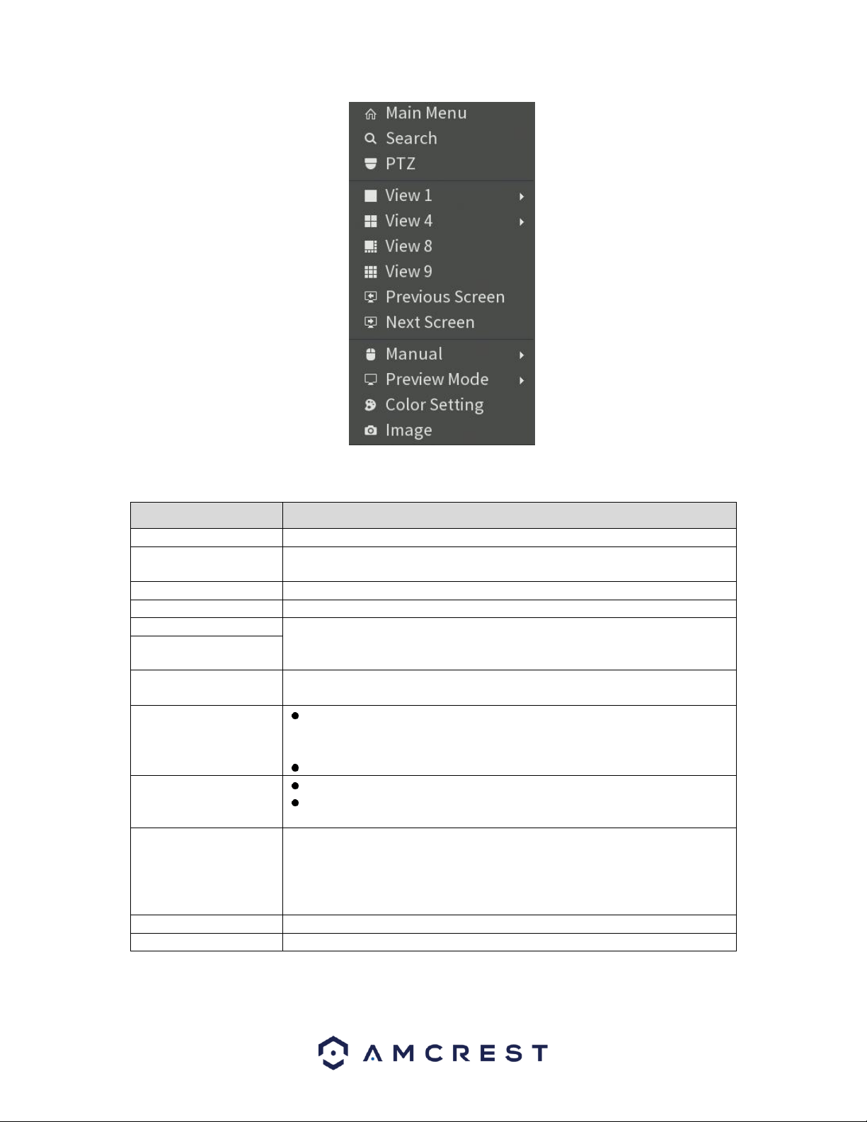
39
For more information on the shortcut menu and its functions, refer to the table provided below.
Function
Description
Main Menu
Open Main Menu interface.
Search
Open the PLAYBACK interface where you can search and play back recorded
files.
PTZ
Open the PTZ interface.
View Layout
Configure the live view screen as a single or multi-channel layout.
Previous Screen
Click the Previous Screen button to go to the previous screen. For example,
if you are using 4-split mode, the first screen is displaying the channel 1-4,
click Next screen, you can view channel 5-8.
Next Screen
Camera Registration
Open the CAMERA REGISTRATION interface.
Manual
Select Record, you can configure the recording mode as Auto or
Manual or stop the recording. You can also enable or disable snapshot
function
Select Alarm Out, you can configure alarm output settings.
Preview Mode
Select General, the layout of live view screen is as default.
Select Show Face List, the detected face snapshots are displayed in the
bottom of the live view screen.
Auto Focus
Point to the channel window and right-click on it to open the shortcut
menu, and then click Auto Focus.
Note: Not all cameras support this function.
Color Setting
Open the COLOR interface where you can adjust the video image color.
Image
Click to modify the camera properties.
40
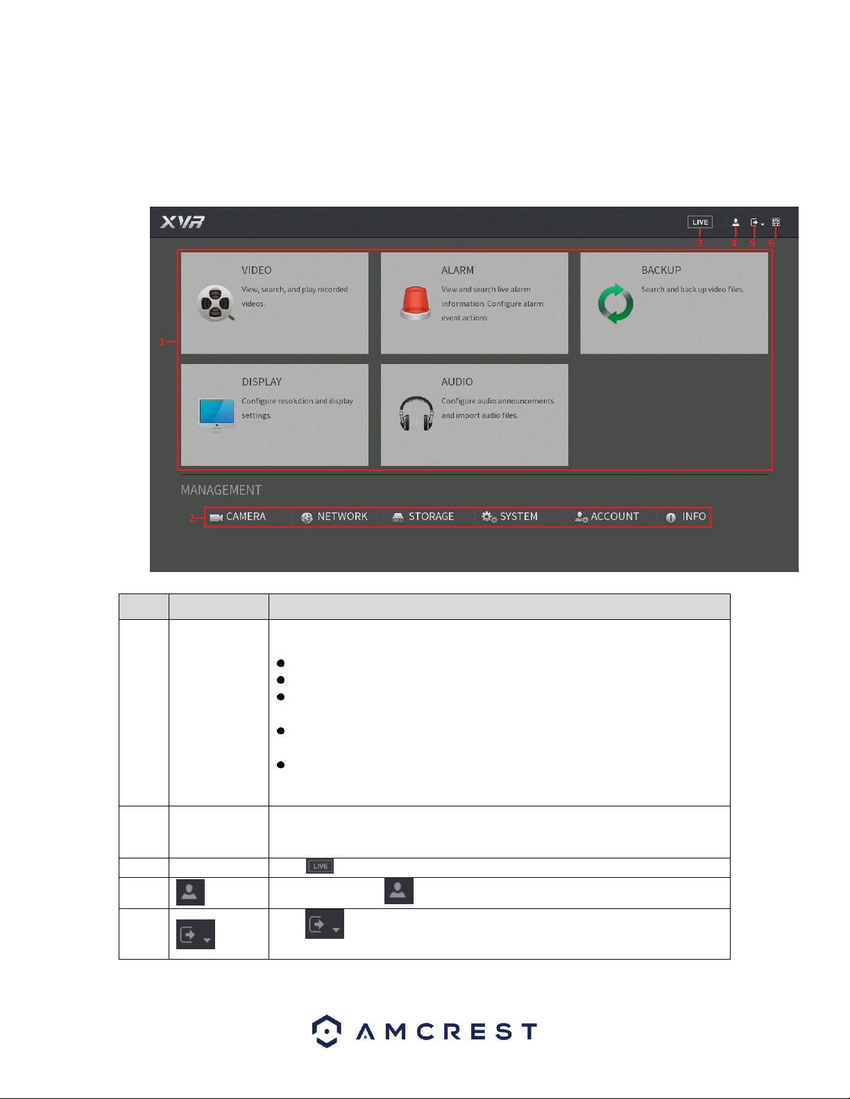
4.7. Main Menu
The main menu for your DVR can be accessed by accessing the shortcut menu and clicking on Main Menu.
You can also left-click on the live view screen which will take you right to the main menu as well. Once
accessed the main menu will be displayed. For more information on the features listed in the main menu,
refer to the table provided below.
No.
Icon
Description
1
Function tiles
Includes five function tiles: VIDEO, ALARM, BACKUP, DISPLAY, and AUDIO.
Click each tile to open the configuration interface of the tile.
VIDEO: Search for and play back the recorded video saved on the DVR.
ALARM: Search for alarm information and configure alarm event actions.
BACKUP: Search and back up the video files to the local PC or external
storage DVR such as USB storage DVR.
DISPLAY: Configure the display effect such as displaying content, image
transparency, and resolution, and enable the zero-channel function.
AUDIO: Manage audio files and configure the playing schedule. The audio
file can be played in response to an alarm event if the voice prompts
function is enabled.
2
Management
menu
Includes six configurations through which you can configure: camera settings,
network settings, storage settings, system settings, account settings, and view
information.
3
Live
Click to go to the live view screen.
4
When you point to , the current user account is displayed.
5
Click , select Logout, Reboot, or Shutdown according to your actual
situation.
41
No.
Icon
Description
6
Displays Cell Phone Client and DVR SN QR Code.
Cell Phone Client: Use your mobile phone to scan the QR code to add the
DVR into the Cell Phone Client, and then you can start accessing the DVR
from your cell phone.
DVR SN: Obtain the DVR SN by scanning the QR code. Go to the P2P
management platform and add the DVR SN into the platform. Then you
can access and manage the DVR in the WAN. For details, please refer to
the P2P operation manual. You can also configure P2P function in the
local configurations.
4.8. Function Tiles
Function tiles allow you quick access to key features of the DVRs. For more information on function tiles,
refer to the table above.
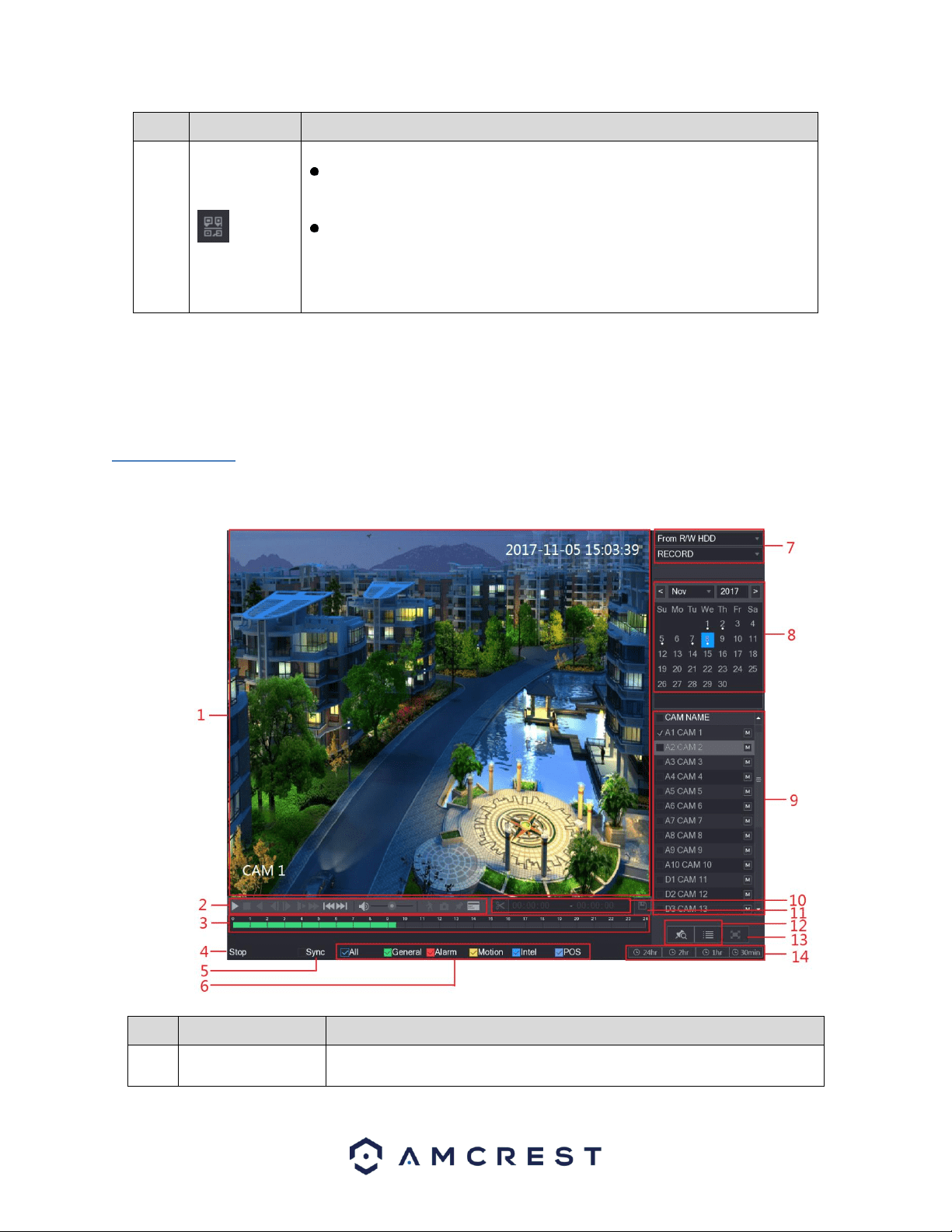
4.8.1. Video
The video function tile allows you to view, search and playback recorded video located on your DVR. For
more information on the features listed in this menu, refer to the table below.
No.
Function
Description
1
Display Window
Display the searched recorded video or picture. It supports playing in
single-channel, 4-channel, 9-channel, and 16-channel simultaneously.
42
No.
Function
Description
Note: When playing back a recording in single channel mode, hold down
the left mouse button to select the area that you want to enlarge. The
area is enlarged after the left mouse button is released. To exit the
enlarged image, right-click on the image.
2
Playback Controls
Bar
Playback control buttons.
3
Time Bar
Display the type and time period of the current recorded video.
In the 4-channel layout, there are four-time bars are displayed; in
the other view layouts, only one-time bar is displayed.
Click on the colored area to start playback from a certain time.
In the situation when you are configuring the settings, rotate the
wheel button on the time bar, the time bar is zooming in from 0. In
the situation when playback is ongoing, rotate the wheel button on
the time bar, the time bar is zooming from the time point where
the playback is located.
Time bar colors: Green indicates general type; Red indicates
external alarm; Yellow indicates motion detection; Blue indicates
intelligent events; Purple indicates POS events.
For some models, when you are clicking on the blank area in the
time bar, the system automatically jumps to the next time point
where there is a recorded video located.
4
Play Status
Includes two playback statuses: Play and Stop.
5
Sync
Select the Sync check box to simultaneously play recorded videos of
different channels in the same period in multi-channel view.
6
Record type
Select the check box to define the recording type to search for.
7
Search type
Select the content to play back: Record, PIC, Splice Playback.
8
Calendar
Click the date that you want to search, the time bar
displays the corresponding record.
The dates with record or snapshot have a small solid circle under the
date.
9
View Layout and
Channel Selection
In the CAM NAME list, select the channel(s) that you want to play back.
The window split is decided by how you select the channel(s). For
example, if you select one channel, the playback is displayed in the
single-channel view; if you select two to four channels, the
playback is displayed in the four-channel view. The maximum is
eight channels.
Click to switch the streams. indicates main stream, and
indicates sub stream.
10
Video Splice
Splice a section of recorded video and save it.
11
Backup
Back up the recorded video files.
12
List Display
This area includes Mark List and File List.
: Click the Mark List button, the marked recorded video list is
displayed. Double-click the file to start playing.
43
No.
Function
Description
: Click the File List button, the searched recorded video list is
displayed. You can lock the files. For details, see "Error! Reference
source not found. Error! Reference source not found.."
13
Full Screen
Click to display in full screen. In the full screen mode, point to the
bottom of the screen, the time bar is displayed. Right-click on the screen
to exit full screen mode.
14
Time Bar Unit
You can select 24hr, 2hr, 1hr, or 30min as the unit of time bar. The time
bar display changes with the setting.
4.8.1.1. Playback Controls Bar
The playback controls bar allows you to control the speed of the playback, add a mark, and take snapshots
of a recorded event. For more information on the playback control bar, refer to the table provided below.
Icon
Function
,
Play/Pause.
During playing back, you can switch between play and pause.
Stop.
During playing back, you can click the Stop button to stop playback.
,
Play Backward.
During playing back, click the Play Backward button to backward play
the recorded video, the button switches to ; click to stop
playing backward.
During playing back, click to start playing forward.
,
Previous Frame/Next Frame.
When the playback is paused, click or click to play single-
frame recorded video.
When playing back single-frame recorded video, click to start
playing forward.
Slow Playback.
During playing back, click to set the speed of slow playback as
SlowX1/2, SlowX1/4, SlowX1/8, or SlowX1/16.
During fast playback, click to slow down the speed of fast
playback.
Fast Playback.
During playing back, click to set the speed of fast playback as
FastX2, FastX4, FastX8, or FastX16.
44
Icon
Function
During slow playback, click to speed up slow playback.
,
Previous Day/Next Day.
Click or click to play the previous day or next day of the current
recorded video.
Adjust volume of playback.
Smart Search. For details about the using the smart search, see "Error!
Reference source not found. Error! Reference source not found.."
In the full screen mode, click to take a snapshot and save into the USB
storage DVR or mobile HDD.
Add Mark for the recorded view.
Hide POS Hide.
During single-channel playback, click to display or hide POS
information on the screen.
Note: The playback function and playback speed are dependent on the product version.
4.8.1.2. Selecting a Search Type
This menu is in the upper right-hand corner screen of the playback interface. In this menu you can search
for, recorded videos, spliced videos, or snapshots from the installed hard drive or external storage DVR.
• From R/W HDD: Recorded videos or snapshots playback from HDD of the DVR.
• From I/O DVR: Recorded videos playback from external storage DVR.
To access the recorded event and play it back, you can double-click on the video file, or click the icon to start
playing the video.
4.8.1.3. Clipping a Recorded Video
This feature allows you to clip sections of recorded video and save them to a USB storage DVR. Below is
the video clip interface.
To use this feature, select a recorded video that you want to play.
⚫ Click to start playing from the beginning.

45
⚫ Double-click anywhere in the time bar colored area to start playback.
Next, click on the time bar to select the start time, and then click the icon to start clipping. To stop clipping a
video, click on the icon again while in operation. To save the clipping to a USB storage DVR, click on the
icon. The BACKUP dialog box will then be displayed.
Note: You can clip the video of either a single channel, or multiple channels. A maximum of 1024 files can be
backed up at one time. The files selected from the File List cannot be clipped.
4.8.1.4. Backing up Recorded Video
This feature allows you to backup recorded video, or spliced files, into a USB storage DVR.
To use this feature, select the recorded video file that you want to backup. You can select the following
two types of files:
⚫ Recorded video file: Click , the File List area is displayed. Select the file(s) that you
want to back up.
⚫ Spliced video files.
After selecting a video file, click on the icon, the BACKUP dialog box with then be displayed.
In the backup dialog box, click on Backup to begin backing up the selected files to an external USB storage DVR.
Note: If you do not want to back up the file, click on the Clear button to return to the previous menu.
46
4.8.1.5. Smart Search
The Smart Search feature enables searching for motion within the recorded file for a specific channel. This
feature is useful, as it allows users to search a channel’s recorded files for motion without having to
change the recording type to a motion detection recording.
Note: Not all models will support this feature
To utilize this function, select channel you wish to play from the CAM NAME list and click on the icon.
You can also double-click anywhere in the time bar colored area to start playback. Next, click on the
icon to allow the smart search grid to be displayed. Drag the mouse pointer to select a searching area.
When finished, click on the icon, the screen will start playing back the motional splices of recorded
video for the selected area. When finished, to exit smart search, click on the icon again to exit.
Note: • The system does not support motion detection zone setup while in full-screen mode.
• Smart search is only compatible while in single channel mode. If multi-channels are selected,
double-click on the channel window to display a single channel.
• The system supports 396(22*18 PAL) and 330(22*15 NTSC) zones. Please left click mouse to
select smart search zones.
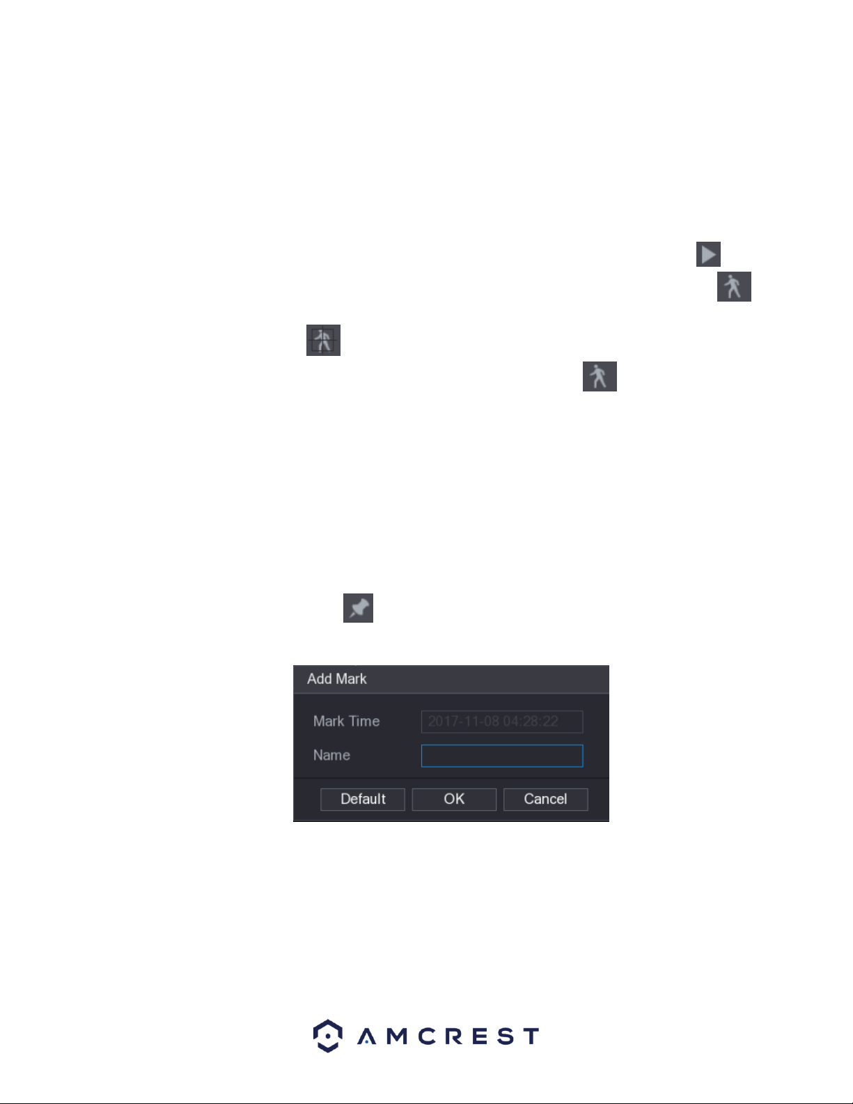
4.8.1.6. Marking and Playing Back Video
In this DVR you can mark recordings. This option is useful for areas you want to highlight or refer to when
playing back a file.
To begin marking a file, select the icon located in the playback interface. The Add Mark dialog box
will then be displayed.
In the Name field of the dialog box, enter a name for the mark and then click OK. When complete the
marked video can be found in the Mark List.
Note: This function is only supported during single-channel playback.
47
To playback the marked video, select one channel from the CAM NAME list and click on the icon to
display the mark list interface.
In the mark list interface, double-click the file that you want to play back. If you need to search
for the marked video by time, enter the time of the file in the SEARCH box at the top of the
interface and click on the icon.
The mark list interface also allows you to play the video in N seconds, or time before the marked
time. To begin, enter the name of the marked video in the Name box. Then, in the Playback time
before mark box, enter N seconds and click on the icon to begin playback. The playback will
then start from N seconds before the marked time.
Note: If there is N seconds before the marked time, the playback starts from N seconds before
the marked time. If there is not, it will not.
Managing Marked Video, in the Mark List interface, click on the icon to display the
manager interface.
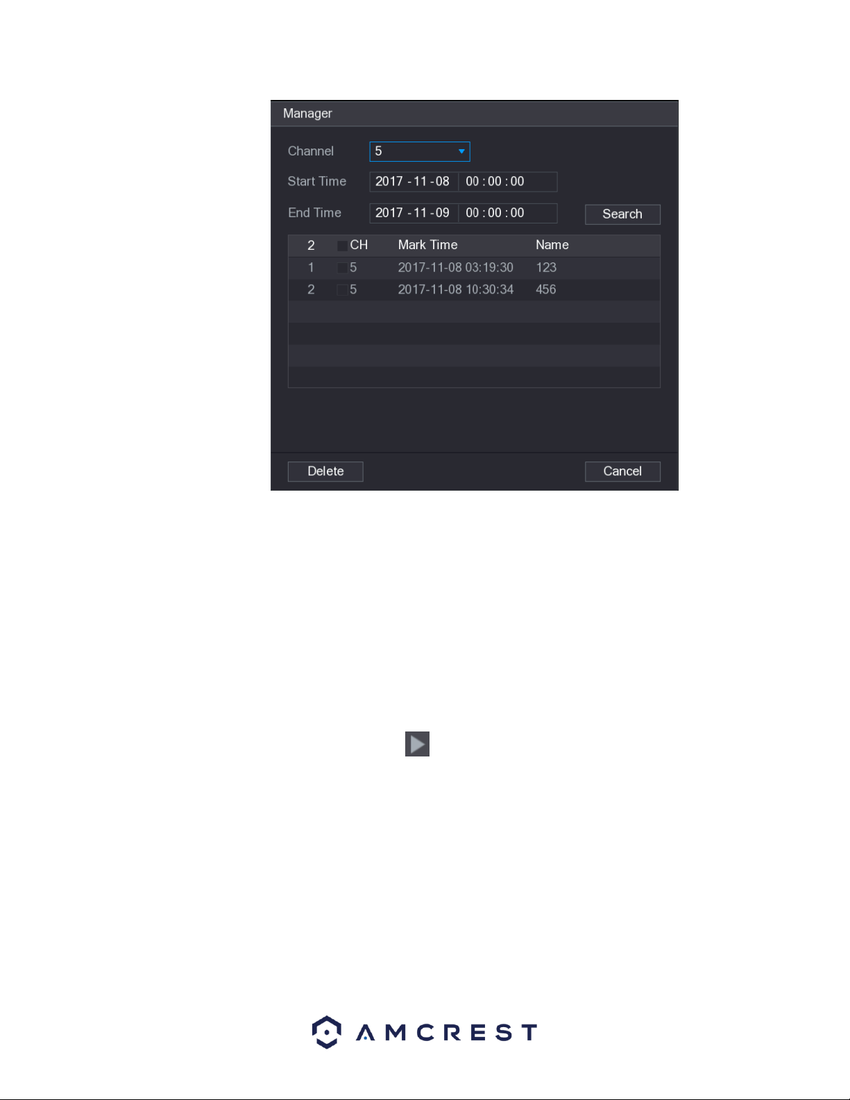
48
⚫ By default, the manager manages all the marked videos of the selected channel.
⚫ To search the marked video, select channel number from the Channel list, enter time in Start Time
box and End Time box, and then click Search.
⚫ All the marked videos display in order of time.
⚫ To modify the name of marked video, double-click a marked video, the Edit Mark dialog box is
displayed.
⚫ To delete the marked video, select the marked video, and then click Delete.
4.8.1.7. Playing Back Snapshots
To playback snapshot events via the playback interface, navigate to the Search Type field of the interface
located in the upper right-hand corner and select PIC from the drop-down menu. From the playback
interface, locate the Channel list and select the channel number you wish to access. Then, from the
Calendar area, select a date, and click on the icon to allow the system to play. All snapshots related
to that specific channel will be played at the configured intervals.
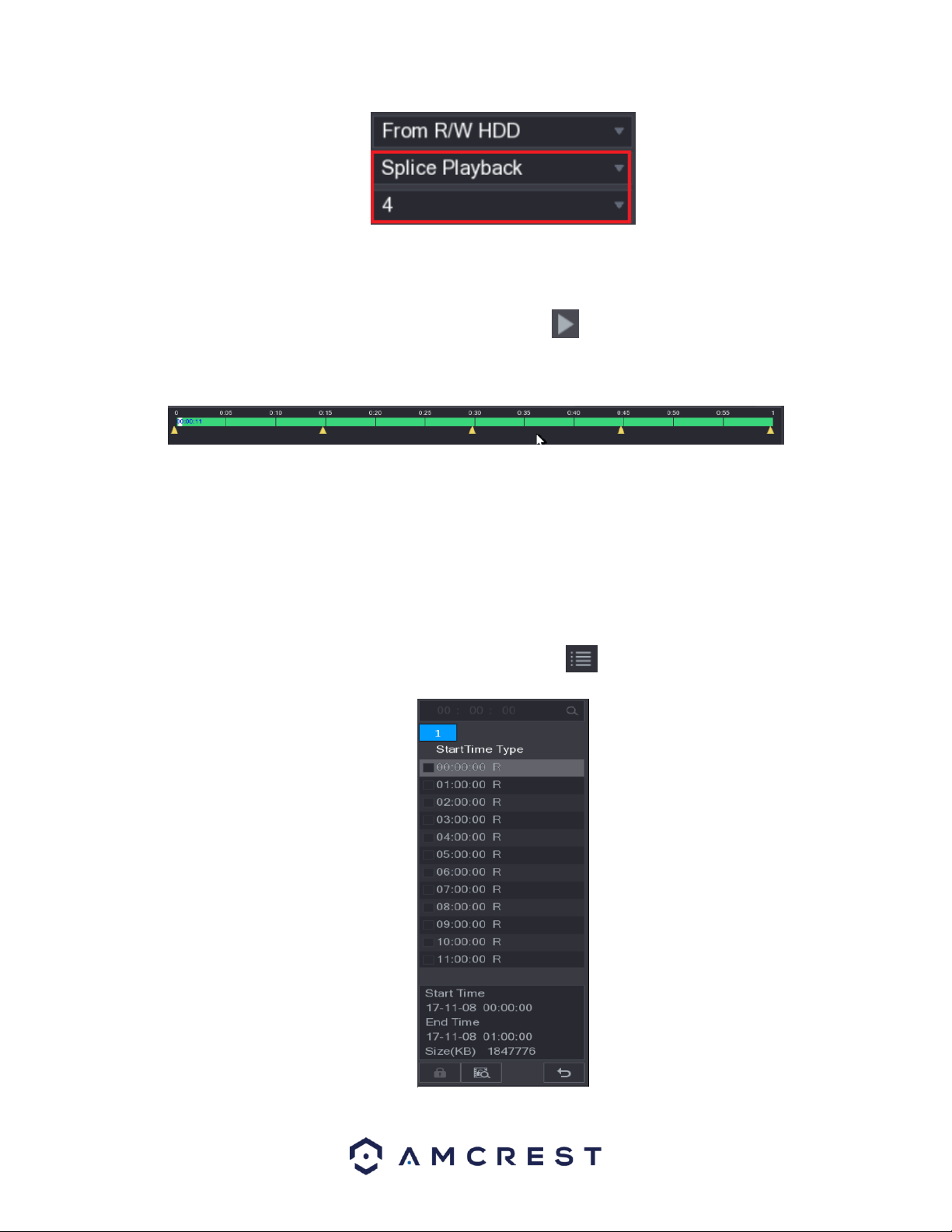
4.8.1.8. Playing Back Splices
To playback spliced events via the playback interface, navigate to the Search Type field of the interface
located in the upper right-hand corner and select Splice Playback from the drop-down menu.
49
From the playback interface, locate the Channel list and select the channel number you wish to access.
Note: Only single-channel function is compatible with this feature.
Then, from the Calendar area, select a date, and click on the icon to allow the system to play. All
snapshots related to that specific channel will be played at the configured intervals. You can also double-
click anywhere on the time bar to playback a spliced video from the interface.
Note: Every recorded video file must be at least five minutes. If a recorded video file is less than 20
minutes the system will automatically adjust the windows quantity to ensure every splice is at least five
minutes. If a recording is less than five minutes, an image will not be displayed.
4.8.1.9. Using the File List
The file list allows you to view all recorded videos within a certain period from any channel. Each channel
must be associated with the file list to view data.
To use the file list, access the playback interface and select the icon located in the bottom right-hand
corner of the screen. The File List interface will then be displayed.
50
Note: A maximum of 128 files can be displayed in this menu. File types are listed as, R for general
recordings; A for videos with external alarms; M for motion events; and I for intel events.
To start playing back a file from the file list, select the file you wish to play from the list and click on the
icon located above the time bar. In the search box, you can also enter a specific time of a file to view
a file from a specific time. To return to the playback interface, click on the icon.
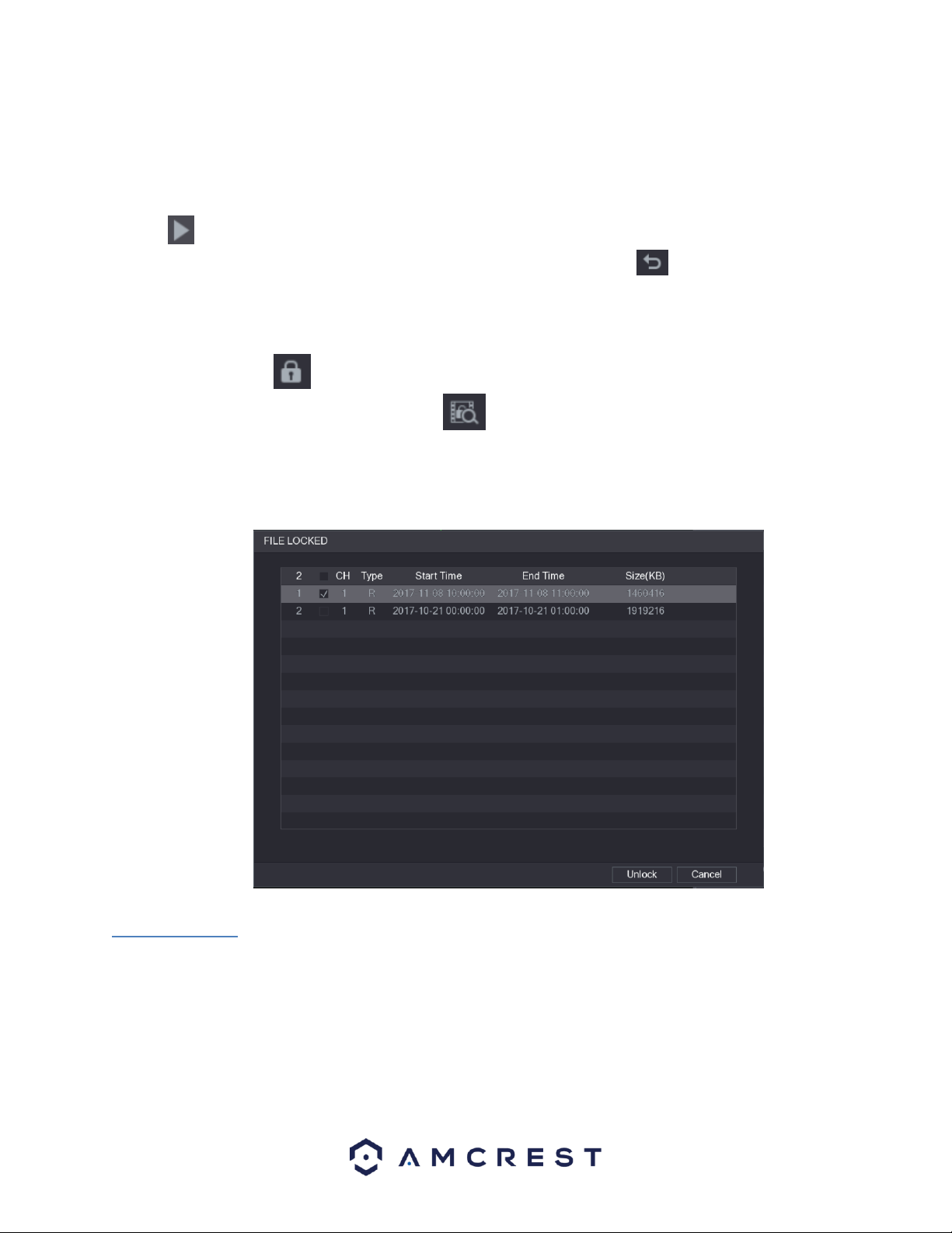
4.8.1.10. Locking and Unlocking a Recorded Video
⚫ To lock the recorded video, in the File List interface, select the check box of the recorded video, and
then click . The locked video will not be covered.
⚫ To view the locked information, click , the FILE LOCKED interface is displayed.
Note: The recorded video that is being written or overwritten cannot be locked.
To unlock the recorded video, in the FILE LOCKED interface, select the video, and then click Unlock.
4.8.2. Alarm
The alarm function tile located in the main menu of the DVR allows you to search live alarm information
as well as configure alarm action events.
4.8.2.1. Alarm Info
This feature allows you to search for specific types of alarm information related to the system. These
specific types of alarms include, Motion Detection, Video Loss, Tampering, Abnormalities, Local Alarms,
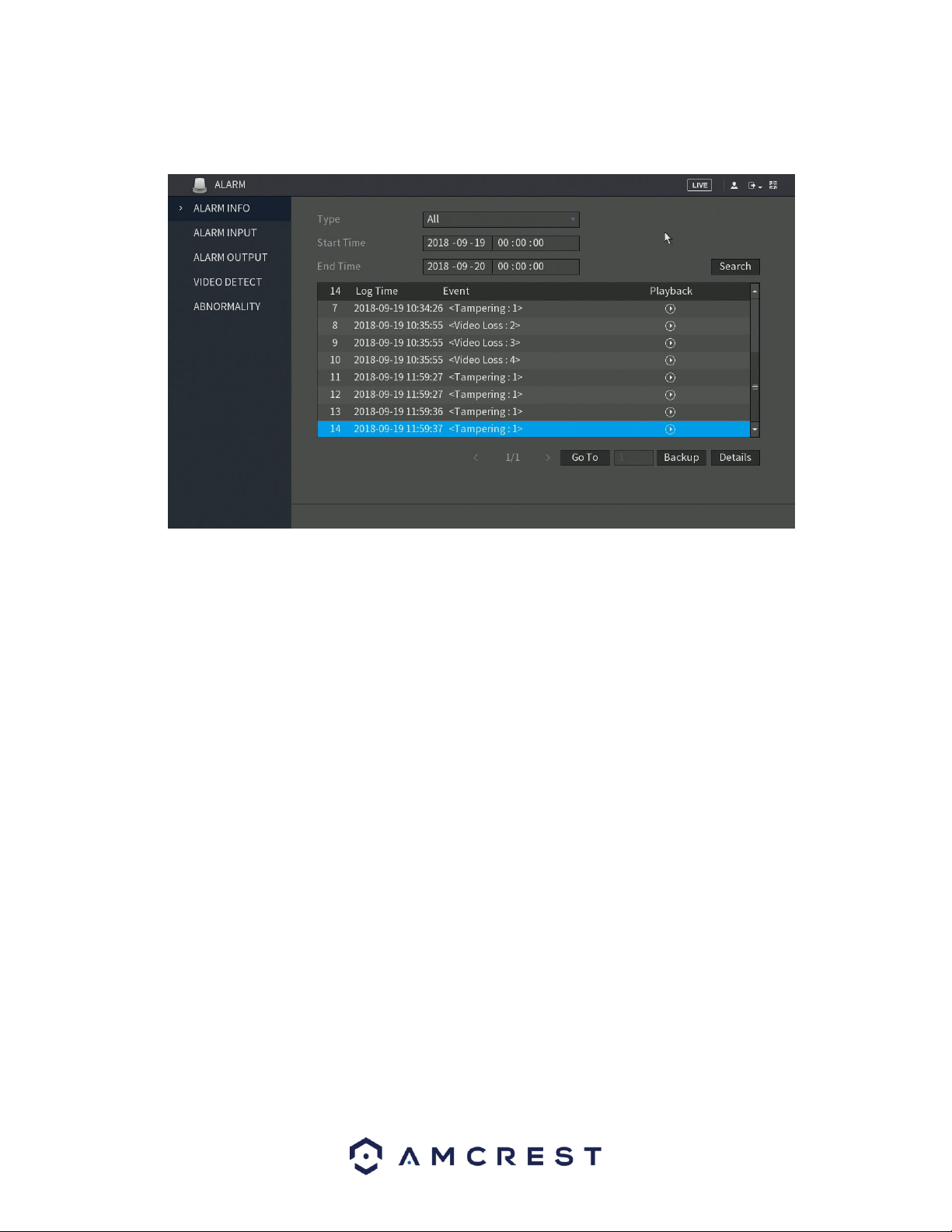
51
Intel, etc. You can also select All to view all log and alarm information. Here is a screenshot of the Alarm
Info tab:
To use this feature, access the alarm info interface and select the type of alarm you are search for from
the drop-down menu. Enter in the start and end times in the Start Time and End Time fields and click
Search. The alarm you are viewing will be accessible via the alarm info list. In this list you can view
information such as, the log time, event type and playback. To playback the event, click on the playback
icon.
If you require to back up any alarm events, the alarm info interface has a backup option. When selected,
all selected files will be saved to an external USB storage DVR. To backup events from this menu, click on
Backup and follow the on-screen instructions. Also, for a more detailed description of the selected event,
click on the Details options located next to the backup button.
4.8.2.2. Alarm Input
This feature is related to an external alarm system. If you have your system hooked up to an external
alarm system, via an RS485 port on the DVR you will be able to view alarm events from the DVR in this
screen. This screen also allows you to send email alerts and configure status, config, and PTZ settings if
applicable. To check the status of your alarm box, click on the Status button located in this menu. alarm
events can also be accessed in this menu by clicking on the Alarm tab.
4.8.2.3. Alarm Output
When the system receives an alarm, the connected external alarm will generate an alarm which can be
configured in this section. You can connect to the output port of the DVR if a port is available on your
specific model DVR. For more information about the parameters listed in this menu, refer to the table
provided below.
⚫ Auto: When an alarm event is triggered on the DVR, the connected alarm DVR generates alarms.
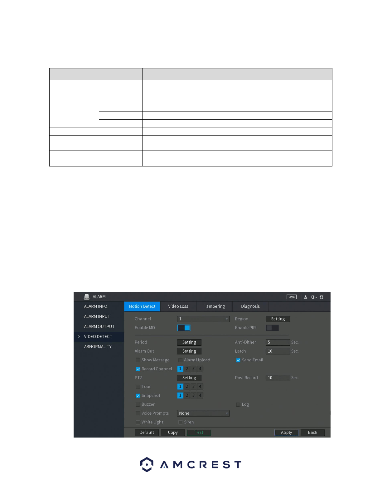
52
⚫ Manual: The alarm DVR is forced to keep generating alarms.
⚫ Stop: The alarm output function is not enabled.
Parameter
Description
General Alarm
Alarm Type
Select alarm type for each alarm output port.
Status
Indicates the status of each alarm output port.
Ext. Alarm
Alarm Box
Select the alarm box number corresponding to the address number
configured by the DIP switch on the Alarm Box.
Alarm Type
Select the alarm type for each alarm output ports.
Status
Indicates the status of each alarm output port.
Alarm Release
Click OK to clear all alarm output status.
White Light *optional
Select if applicable to certain models that detect specific light spectrums
and may be disabled by default.
Siren *optional
Select if applicable to certain models that enable siren technology. This
option may be disabled by default.
4.8.2.3. Video Detect
Video detection adopts computer vision and image processing technology. This technology analyzes the
video images to detect obvious changes such as moving objects and blurriness. The system activates
alarms when such changes are detected. These alarms include, Motion detection, Video Loss, Tampering,
and Diagnosis.
4.8.2.3.1. Motion Detect
When a moving object appears or moves fast enough to reach the preset sensitivity values, the system
will activate an alarm. These alarms are known as motion detect, or MD.
To configure the motion detection settings on your DVR, select the Motion Detect tab in the Video Detect
menu and toggle the Enable MD switch to the on position.

53
For a more detailed overview of the motion detect screen, refer to the table provided below.
Parameter
Description
Channel
In the Channel list, select a channel to set the motion detection.
Region
Click Setting to define the motion detection region.
Enable MD
Enable or disable the motion detection function.
Enable PIR
PIR function helps enhancing the accuracy and validity of motion detect. It
can filter the meaningless alarms that are activated by the objects such as
falling leaves, flies. The detection range by PIR is smaller than the field
angle.
PIR function is enabled by default if it is supported by the cameras. Enabling
PIR function will get the motion detect to be enabled automatically to
generate motion detection alarms; if the PIR function is not enabled, the
motion detect just has the general effect.
Note: The PIR function can only be enabled with a CVI channel type and if
the camera supports PIR functionality. If the DVR does not support PIR
functions, it will not be displayed in the interface.
Period
Define a period during which the motion detection is active.
Anti-Dither
Configure the event detection lasting time. The system records only one
event during this period. The value ranges from 5 seconds to 300 seconds.
Alarm Out
Click Setting to display setting interface.
General Alarm: Enable alarm activation through the alarm DVRs
connected to the selected output port.
External Alarm: Enable alarm activation through the connected alarm
box.
Wireless Siren: Enable alarm activation through DVRs connected by
USB gateway or camera gateway.
Latch
Set a length of time that will delay turning off alarms after the external
alarm is cancelled. The value ranges from 0 seconds to 300 seconds, and the
default value is 10 seconds. If you enter 0, there will be no delay.
Show Message
Select the Show Message check box to enable a pop-up message in your
local host PC.
Alarm Upload
Select the Alarm Upload check box to enable the system to upload the
alarm signal to the network (including alarm center) when an alarm event
occurs.
Send Email
Select the Send Email check box to enable the system to send an email
notification when an alarm event occurs.
Note: To use this function, make sure the email notification function is
enabled for the DVR. (Main Menu>NETWORK>EMAIL
Record Channel
Select the channel(s) that you want to record. The
selected channel(s) starts recording after an alarm event
occurs.
Note: Motion detection and auto recording functions must be enabled.

54
Parameter
Description
PTZ
Click Setting to display the PTZ interface.
Enable PTZ activation function. For each PTZ camera, select the preset that
you want to be called when an alarm event occurs.
Note: Motion Detect can only activate PTZ presets.
Post Record
Set a length of time for the DVR to delay turning off recording after the
alarm is cancelled. The value ranges from 10 seconds to 300 seconds, and
the default value is 10 seconds.
Tour
Select the Tour check box to enable a tour of the selected channels.
Note: To use this function, make sure tour is enabled by going to Main
Menu>DISPLAY>TOUR
Snapshot
Select the Snapshot check box to take a snapshot of the selected channel.
Note: To use this function, make sure the following settings are configured:
• The snapshot function is enabled for motion detect alarms
in Main Menu>STORAGE>SCHEDULE>Snapshot
• Select Main Menu>CAMERA>Snapshot, in the Mode list
and select Event.
Buzzer
Select the check box to activate a buzzer noise at the DVR.
Log
Select the check box to enable the DVR to record a local alarm log.
Voice Prompts
Select to enable audio broadcast/voice prompts in response to a motion
detection event.
White Light
Select if applicable to certain models that detect specific light spectrums
and may be disabled by default.
Siren
Select if applicable to certain models that enable siren technology. This
option may be disabled by default.
After you have enabled your desired settings for motion detection, make sure to click the Apply button to save
them to your DVR.
Note: Click the Default button to restore the motion detection settings to its default setting. To apply the settings
to multiple channels on your DVR, click Copy and in the Copy dialog box, select the additional channel(s) you
would like to set, and press Apply. To test the applied settings, click the Test button in the motion detect menu.
4.8.2.3.2. Settings Motion Detection Regions
The Setting button takes the user to the motion detection region setup screen for that specific channel.
On the next page is a screenshot of the motion detection region screen.

55
When the Setting button is clicked, the current channel’s interface comes into a full screen view. The user
can then set up to 4 regions, each with their own region name, sensitivity (1-100), and threshold (1-100).
Each region has a specific color, and the region selector tool is displayed when the mouse is moved to the
top of the screen.
▪ Sensitivity is the amount of change required to increase the motion detected by a percentage. The lower
the sensitivity, the more movement is required to trigger an alarm.
▪ Threshold is the level that the motion detection needs to reach to trigger an alarm. The lower the
threshold, the more likely that motion will trigger an alarm.
o To designate a zone, click and drag the mouse over the area desired. When a colored box is displayed
over the live feed, that area is now enabled for motion detection. Clicking the FN button will switch the
mode between armed and disarmed, so that clicking and dragging the mouse can either designate a
motion detection zone or remove any motion detection zone markers.
o After the motion detection zone is set, click the enter button to exit the motion detection screen.
Remember to click the save button on the motion detection settings screen, otherwise the motion
detection zones will not go into effect. Clicking the escape button to leave the motion detection zone and
will not save the zone setup.
4.8.2.3.3. Setting a Motion Detection Period
This Setting button takes the user to the motion detection period settings screen. Below is a screenshot of
the motion detection period settings screen.

56
In this menu, you will define the motion detection period for the selected channel. By default, it is it is
active to record motion 24/7. You can define the period, or schedule,
• Define a period for a specified day of the week by clicking the half-hour clocks you wish to
enable.
• Define several days of the week by clicking the icon before each day. The icon selected will
then switch to the icon which indicates it is linked.
• Define for all days of the week by clicking on the icon located by the All option. Each day will
then switch to the icon and all days of the week will be selected.
• Define the period by editing. In this example, we will use Sunday. Click the icon to access the
Period interface.
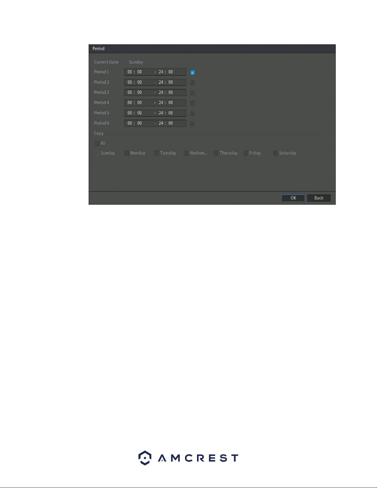
57
In the period interface, enter the time frame you would like to set as your period and select the
checkbox to enable the settings. There are a total of six periods that you can set for each day.
Under the Copy menu, you can apply these settings to all days of the week by checking the All
option or you can also select specific days as well. To save the settings in this menu, click OK to
continue.
• Once you have set your desired settings in the Motion Detect interface, click Apply to complete
the process.
4.8.3. Video Loss
The video loss settings screen is where the DVR can be setup to notify the user any time there is video loss
on any of the channels. Below is a screenshot of the video loss settings screen:
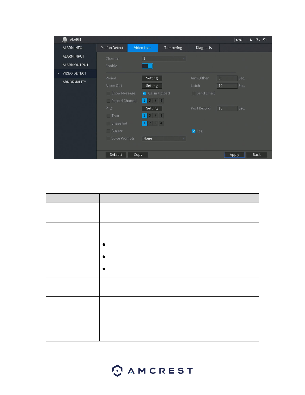
58
To configure the video loss settings on your DVR, select the Video Loss tab in the Video Detect menu and
toggle the Enable switch to the on position. For more information on the settings set in this menu, refer
to the table listed below.
Parameter
Description
Channel
In the Channel list, select a channel to set the motion detection.
Enable
Enable or disable the motion detection function.
Period
Define a period during which the motion detection is active.
CAM Anti-Dither
Configure the event detection lasting time. The system records only one
event during this period. The value ranges from 5 seconds to 300 seconds.
Alarm Out
Click Setting to display setting interface.
General Alarm: Enable alarm activation through the alarm DVRs
connected to the selected output port.
External Alarm: Enable alarm activation through the connected alarm
box.
Wireless Siren: Enable alarm activation through DVRs connected by
USB gateway or camera gateway.
Latch
Set a length of time for the DVR to delay turning off alarm after the external
alarm is cancelled. The value ranges from 0 seconds to 300 seconds, and the
default value is 10 seconds. If you enter 0, there will be no delay.
Show Message
Select the Show Message check box to enable a pop-up message in your
local host PC.
Send Email
Select the Send Email check box to enable the system to send an email
notification when an alarm event occurs.
Note: To use this function, make sure the email notification function is
enabled for the DVR. (Main Menu>NETWORK>EMAIL

59
Parameter
Description
Record Channel
Select the channel(s) that you want to record. The
selected channel(s) starts recording after an alarm event
occurs.
Note: Motion detection and auto recording functions must be enabled.
PTZ
Click Setting to display the PTZ interface.
Enable PTZ activation function. For each PTZ camera, select the preset that
you want to be called when an alarm event occurs.
Note: Motion Detect can only activate PTZ presets.
Post Record
Set a length of time for the DVR to delay turning off recording after the
alarm is cancelled. The value ranges from 10 seconds to 300 seconds, and
the default value is 10 seconds.
Tour
Select the Tour check box to enable a tour of the selected channels.
Note: To use this function, make sure tour is enabled by going to Main
Menu>DISPLAY>TOUR
Snapshot
Select the Snapshot check box to take a snapshot of the selected channel.
Note: To use this function, make sure the following settings are configured:
• The snapshot function is enabled for motion detect alarms
in Main Menu>STORAGE>SCHEDULE>Snapshot
• Select Main Menu>CAMERA>Snapshot, in the Mode list
and select Event.
Buzzer
Select the check box to activate a buzzer noise at the DVR.
Voice Prompts
Select to enable audio broadcast/voice prompts in response to a motion
detection event.
Note: For PTZ activation, video loss detection can activate PTZ presets, tours, and patterns. After setting your video
loss settings, click Apply to complete the process. If you wish to reset your video loss settings to default, click
Default. If you want to apply these settings to multiple channels on the system, click on the Copy button and apply
the settings to your desired channels.
4.8.4. Tampering
The tampering settings screen is where the DVR can be setup to notify the user any time a camera is
tampered with or if the output video is only displaying in one color. Below is a screenshot of the video
tampering settings screen:
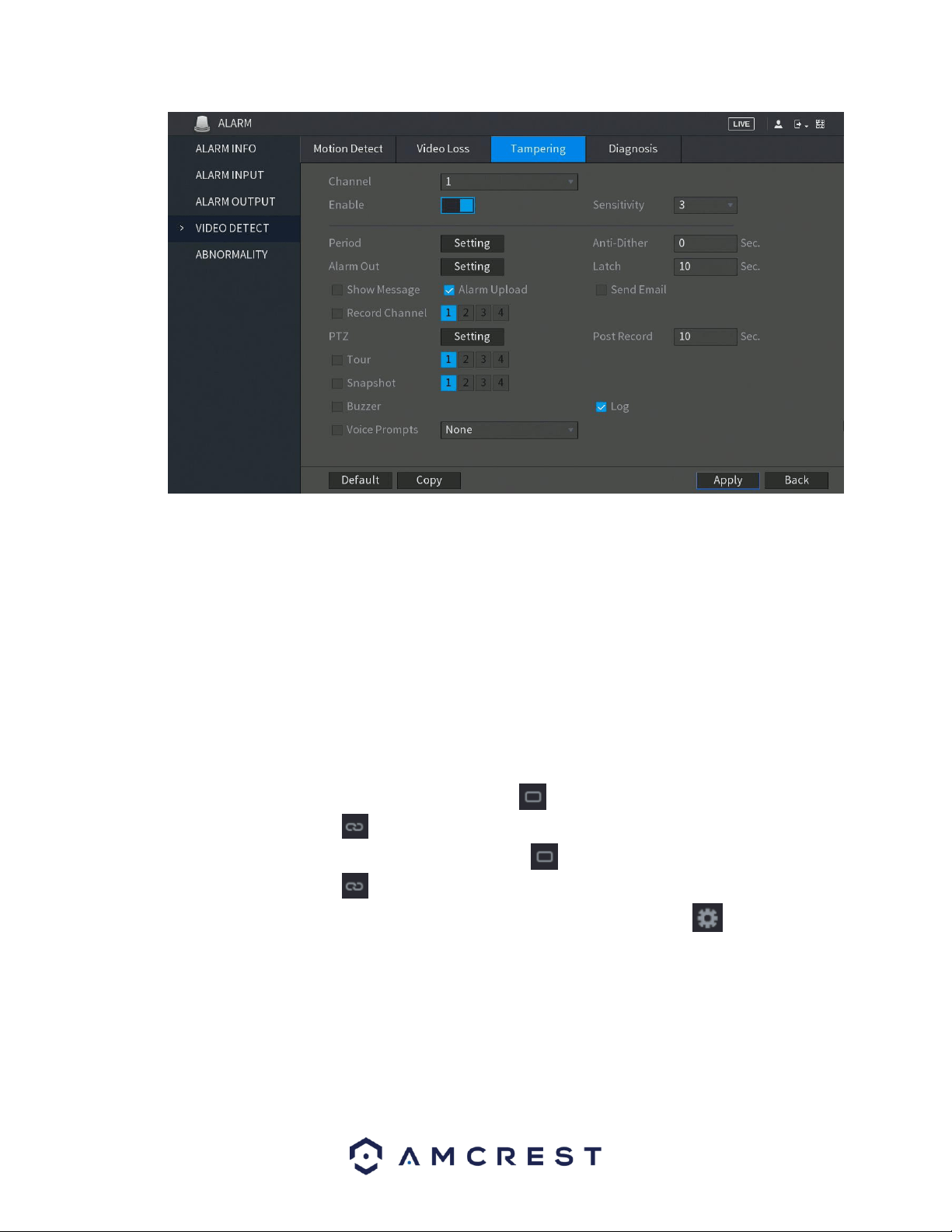
60
Below is a description of the fields on the Tampering settings page:
• Enable: This checkbox allows the user to enable the motion detection function for a specific channel. To
select a channel, click on the drop-down menu provided on the right.
• Sensitivity – Allows the user to set a preset sensitivity setting for motion detected events.
• Period: This setup button takes the user to the tampering period settings screen. Below is a screenshot
of the motion detection period settings screen.
In this menu, you will define the tampering period for the selected channel. By default, it is it is active to
record 24/7. You can define the period, or schedule,
• Define a period for a specified day of the week by clicking the half-hour clocks you wish to
enable.
• Define several days of the week by clicking the icon before each day. The icon selected will
then switch to the icon which indicates it is linked.
• Define for all days of the week by clicking on the icon located by the All option. Each day will
then switch to the icon and all days of the week will be selected.
• Define the period by editing. In this example, we will use Sunday. Click the icon to access the
Period interface.
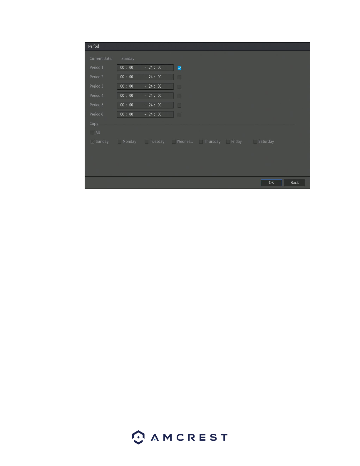
61
In the period interface, enter the time frame you would like to set as your period and select the
checkbox to enable the settings. There are a total of six periods that you can set for each day.
Under the Copy menu, you can apply these settings to all days of the week by checking the All
option or you can also select specific days as well. To save the settings in this menu, click OK to
continue.
• CAM Anti-Dither: This field allows the user to set the anti-dither time. The values in this field can range
from 5 to 600 seconds. This time value controls how long the alarm signal lasts. Based on motion
detection, a buzzer can go off, a tour can begin, PTZ can be activated, a snapshot can be taken, or a
channel can begin recording.
For example, if the anti-dither time is set to 10 seconds, each alarm may last 10 seconds if the local alarm
is activated. During the process, if the system detects another local alarm signal at the fifth second, the
buzzer, tour, PTZ activation, snapshot, record channel functions will begin another 10 seconds while the
screen prompt, alarm upload, email will not be activated again. After 10 seconds, if system detects
another alarm signal, it can generate a new alarm since the anti-dither time has expired.
• Show Message: This checkbox allows the user to enable the system to show an on-screen message
when a motion detection alarm is triggered.
• Alarm Upload: This checkbox allows the user to enable the system to upload alarm information when a
motion detection alarm is triggered.
• Send Email: This checkbox allows the user to enable the system to send an email when a motion
detection alarm is triggered.
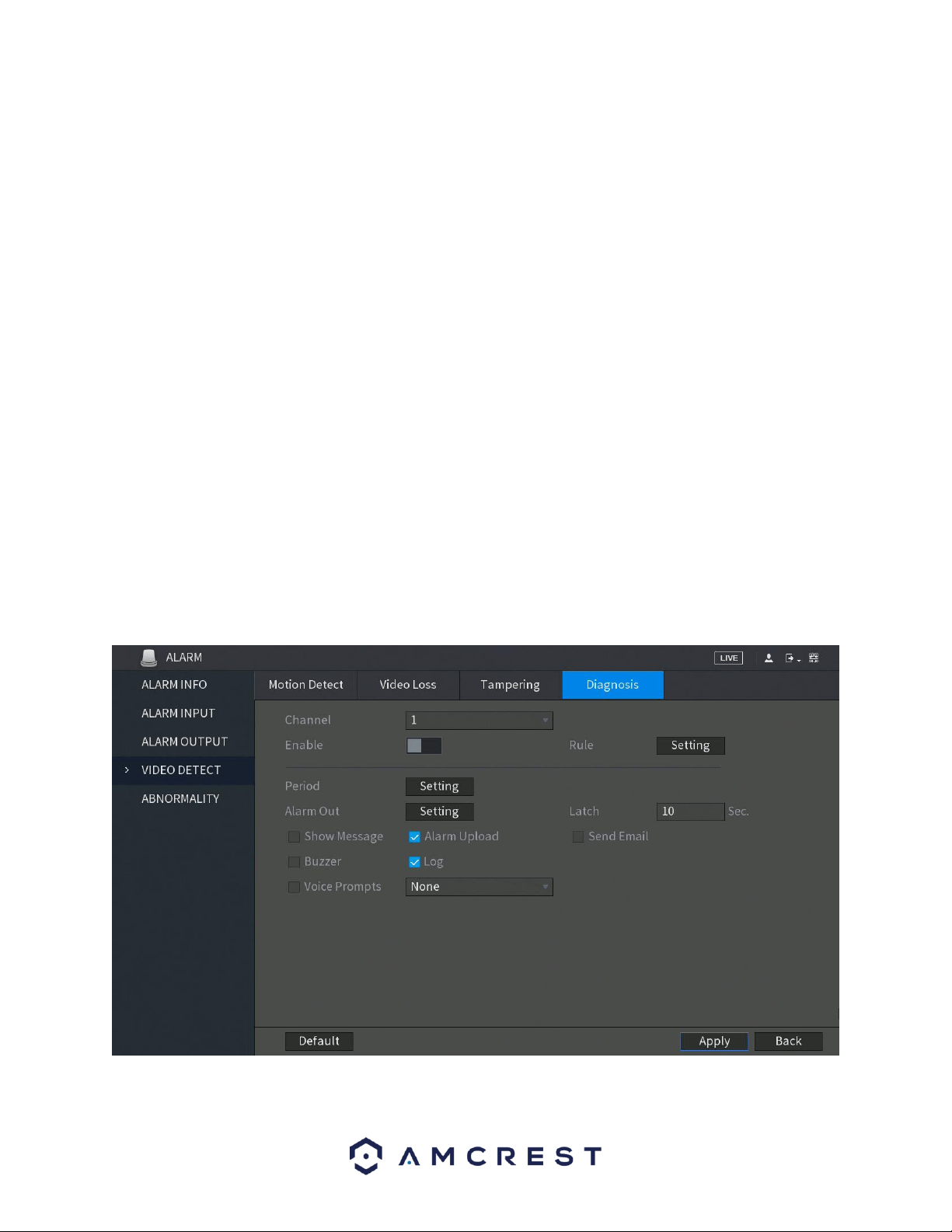
62
• Record Channel: This checkbox allows the user to enable the system to record video for that channel
when a motion detection alarm is triggered. Delay is also associated with this tab, it is the This field
specifies in seconds how long the delay between alarm activation and recording should be.
• PTZ: Allows the user to active PTZ functionality to applicable PTZ DVRs.
• Tour: Allows the user to enable the camera to activate a PTZ tour when a motion detection
alarm is triggered.
• Snapshot: Allows the user to enable the camera to take a snapshot when a motion detection
alarm is triggered.
• Buzzer: Allows the user to trigger a buzzer once a motion event is detected.
• Log: Allows the user to log all motion detected events that are triggered in the DVR.
• Voice Prompts (N/A): Allows the user to customize voice prompts for motion detected events.
• Log: Allows the user to log all motion detected events that are triggered in the DVR.
Note: When you have completed setting the tampering settings for your DVR, click on Apply to complete the
process.
4.8.5. Diagnosis
This menu allows you to enable or disable diagnosis settings. These settings include features such as,
overexposure from the camera, out of focus, or other related quality issues.
To enable this setting, toggle the Enable switch to the on position.
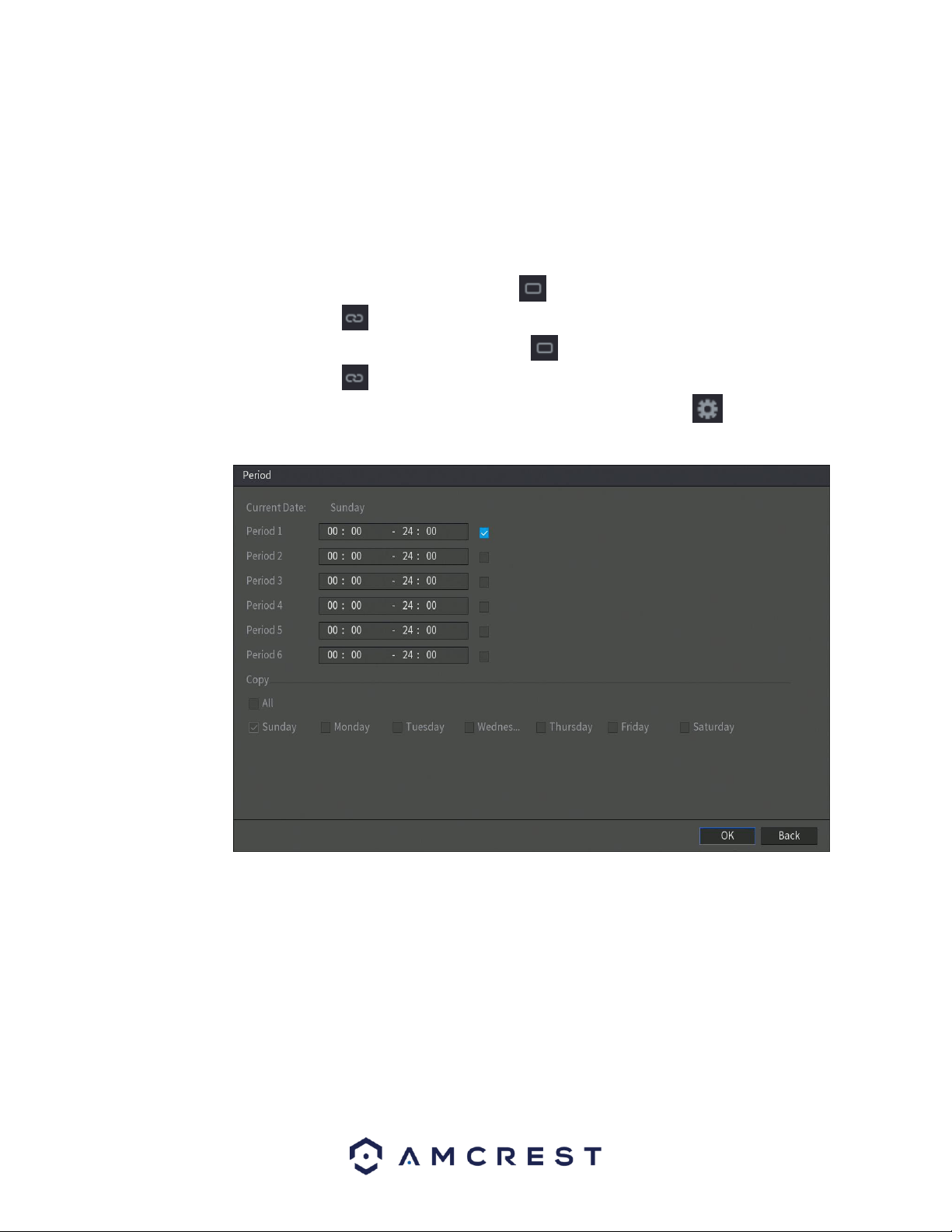
63
• Rule: This setting allows you to set diagnosis types to specific targets. For more information on this
setting, refer to section 4.8.5.1. Setting Types of Diagnosis Targets.
• Period: This setup button takes the user to the tampering period settings screen. Below is a screenshot
of the motion detection period settings screen.
In this menu, you will define the tampering period for the selected channel. By default, it is it is active to
record 24/7. You can define the period, or schedule,
• Define a period for a specified day of the week by clicking the half-hour clocks you wish to
enable.
• Define several days of the week by clicking the icon before each day. The icon selected will
then switch to the icon which indicates it is linked.
• Define for all days of the week by clicking on the icon located by the All option. Each day will
then switch to the icon and all days of the week will be selected.
• Define the period by editing. In this example, we will use Sunday. Click the icon to access the
Period interface.
In the period interface, enter the time frame you would like to set as your period and select the
checkbox to enable the settings. There are a total of six periods that you can set for each day.
Under the Copy menu, you can apply these settings to all days of the week by checking the All
option or you can also select specific days as well. To save the settings in this menu, click OK to
continue.
4.8.5.1. Setting Types of Diagnoses Targets
This menu allows you to set the specific features or rules, of the features listed in the diagnosis screen.
To set a diagnosis type, click on the Setting button next to the Rule field to access the Diagnosis interface.
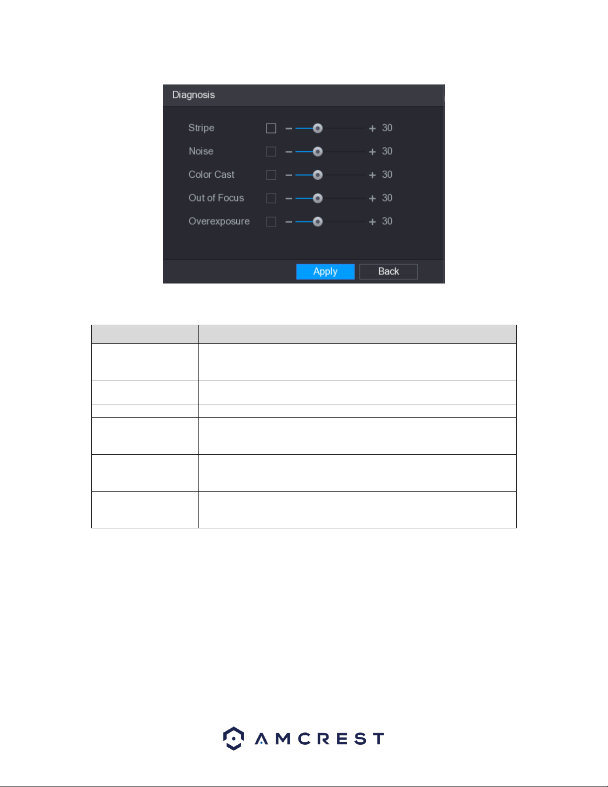
64
Select the items that you want to diagnose and set the threshold for these settings. For more information
on the settings list in this menu, refer to the table below.
Parameter
Description
Stripe
A horizontal, vertical or diagonal stripe that might appear in the video
because of DVR aging or electronic interruption. Such stripe brings visual
interruption.
Noise
Video noises such as blurriness or quality reduction that is caused by optical
distortion or DVR problem during camera shooting.
Color Cast
Variances in the normal proportions of RGB colors.
Out of Focus
Blurry video is caused during camera shooting, transferring and processing.
Such condition is a common image quality reduction problem and defined
as out of focus.
Overexposure
The video brightness refers to the intensity of image pixel. The range is
between 0 (the darkest black) and 255 (the brightest white). If the
brightness exceeds the threshold, the image is over exposed.
Threshold
The range is from 1 through 100. If the value after diagnosing is higher than
what you set, the system activates the alarm to the corresponding
diagnosing types such as stripe.
When you have finished setting your diagnosis rules, click on OK in the diagnosis interface to save the settings. The
system will then return to the Diagnosis menu. To complete the process, Click Apply to save the settings for your
system.
Note: To return the DVR to its default diagnosis settings, click on the Default button. The default rules in the
diagnosis screen will always be defaulted to 30.
4.8.6. Abnormality
This screen is used to specify system actions in the case the device experiences any abnormalities including hard
drive, network, or user abnormalities.
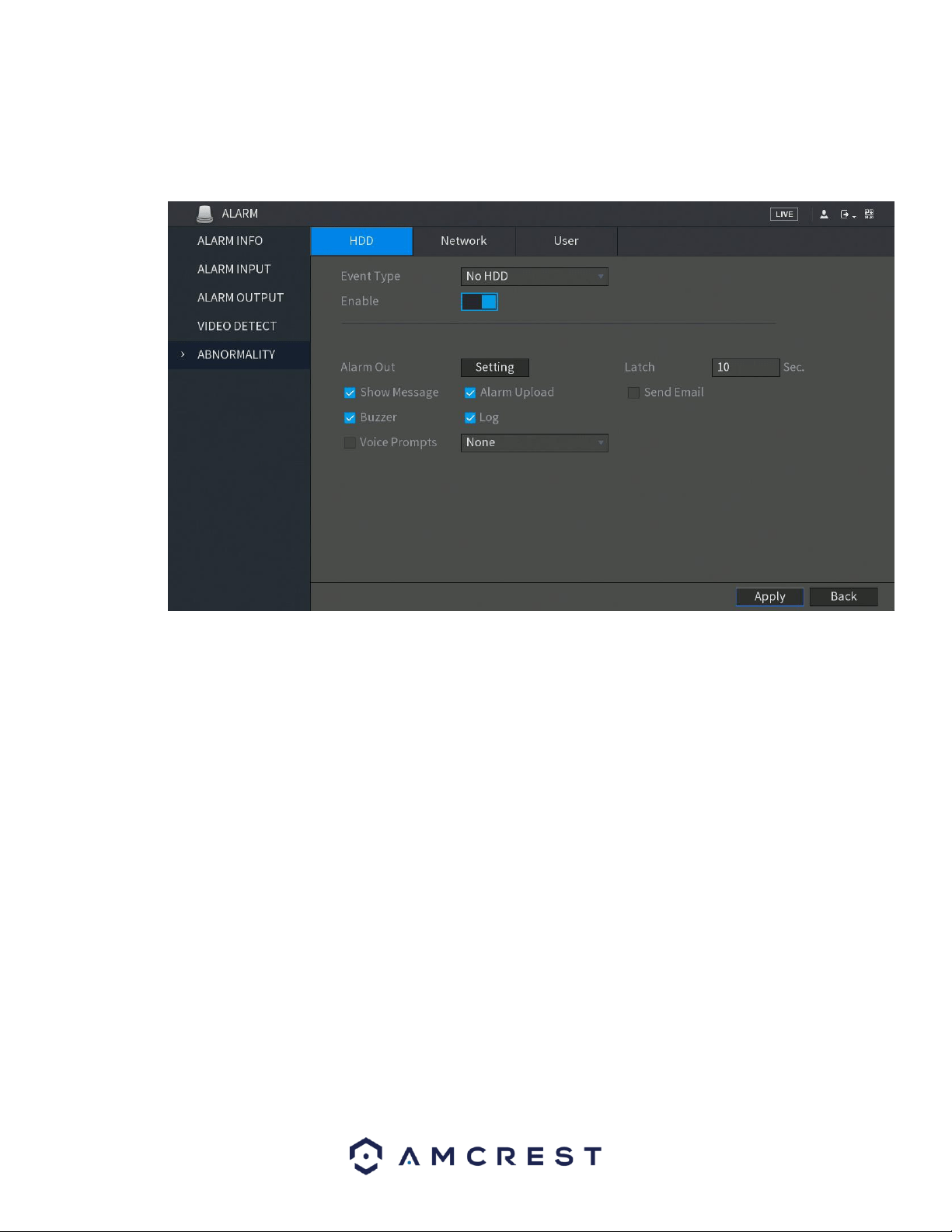
65
4.8.6.1. HDD
This screen allows the user to specify actions that occur when there is an abnormality with the DVR’s hard
disk drive (HDD). Below is a screenshot of the HDD Abnormality settings screen:
Below is an explanation of the fields on the HDD Abnormality settings screen:
• Event Type: This field allows the user to specify which HDD abnormality event type they would like to
configure settings for.
o No HDD: No hard drive is detected.
o HDD Error: The hard drive has an error.
o HDD No Space: The hard drive is about to or has run out of space.
• Enable: This checkbox allows the user to enable the features below for the specified event type.
• Alarm Out: Click Setting to display setting interface.
◼ General Alarm: Enable alarm activation through the alarm DVRs connected to the
selected output port.
◼ External Alarm: Enable alarm activation through the connected alarm box.
◼ Wireless Siren: Enable alarm activation through DVRs connected by USB gateway or
camera gateway.
• Show Message: This checkbox allows the user to enable the system to show an on-screen message
when an HDD abnormality occurs.
• Alarm Upload: This checkbox allows the user to enable the system to upload alarm information when a
motion detection alarm is triggered.
• Send Email: This checkbox allows the user to enable the system to send an email when an HDD
abnormality occurs.
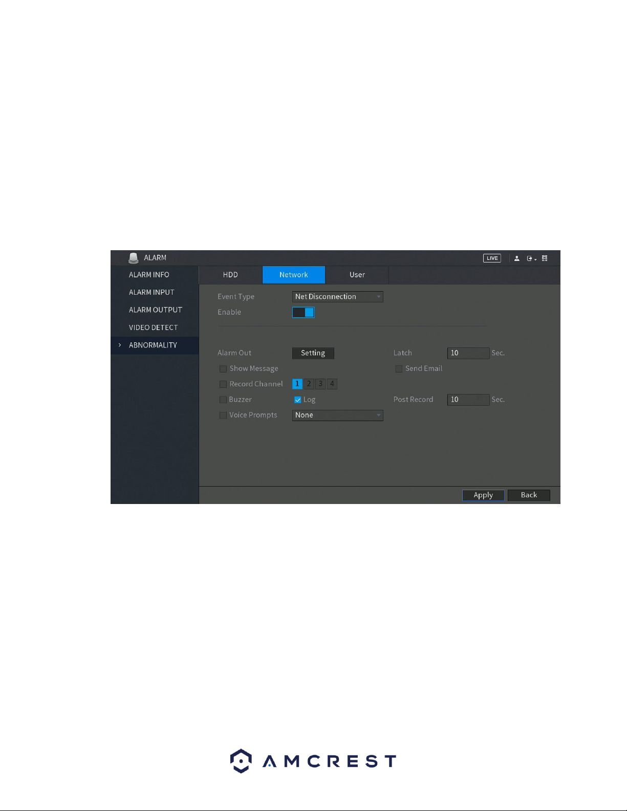
66
• Buzzer: This checkbox allows the user to enable the system to activate a buzzer when an HDD
abnormality occurs.
• Log: Allows the user to log all motion detected events that are triggered in the DVR.
• Voice Prompts (N/A): Allows the user to customize voice prompts for motion detected events.
To save settings, click the Apply button. To cancel any modifications, click the Cancel button near the
bottom right hand corner. To apply the settings, click the Apply button near the bottom right hand
corner.
4.8.6.2. Network
This screen allows the user to specify actions that occur when there is an abnormality with the DVR’s
network connection. Below is a screenshot of the Network Abnormality settings screen:
• Event Type: This field allows the user to specify which Network abnormality event type they would like
to configure settings for.
o Net Disconnection: Network is disconnected.
o IP Conflicted: The IP has a connection conflict.
o MAC Conflicted: The MAC address the DVR has a conflict.
• Enable: This checkbox allows the user to enable the features below for the specified event type.
• Alarm Out: Click Setting to display setting interface.
◼ General Alarm: Enable alarm activation through the alarm DVRs connected to the
selected output port.
◼ External Alarm: Enable alarm activation through the connected alarm box.
◼ Wireless Siren: Enable alarm activation through DVRs connected by USB gateway or
camera gateway.

67
• Show Message: This checkbox allows the user to enable the system to show an on-screen message
when an HDD abnormality occurs.
• Alarm Upload: This checkbox allows the user to enable the system to upload alarm information when a
motion detection alarm is triggered.
• Send Email: This checkbox allows the user to enable the system to send an email when an abnormality
occurs.
• Buzzer: This checkbox allows the user to enable the system to activate a buzzer when an abnormality
occurs.
• Log: Allows the user to log all motion detected events that are triggered in the DVR.
• Voice Prompts (N/A): Allows the user to customize voice prompts for motion detected events.
To save settings, click the Apply button. To cancel any modifications, click the Cancel button near the
bottom right hand corner. To apply the settings, click the Apply button near the bottom right hand
corner.
4.8.6.3. User
This screen allows the user to specify actions that occur when there is an abnormality with the DVR’s user
options. Below is a screenshot of the User Abnormality settings screen:
• Event Type: This field allows the user to specify which user abnormality event type they would like to
configure settings for.
o Login: DVR has reached limit of allowed login attempts.
• Enable: This checkbox allows the user to enable the features below for the specified event type.
• Attempts: This is the number of failed attempts set to the DVR before it is locked.
• Lock Time: Set a length of time you would like the DVR to lock to after several failed attempts
have occurred.
• Alarm Out: Click Setting to display setting interface.
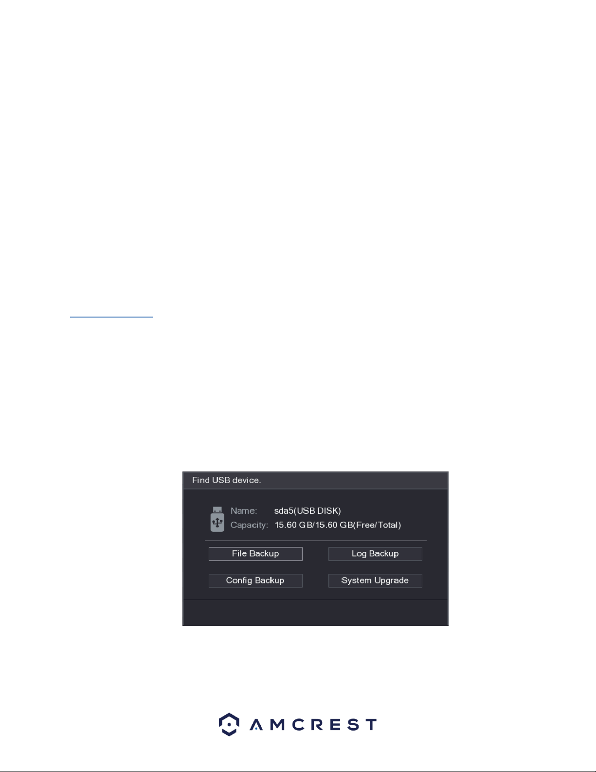
68
◼ General Alarm: Enable alarm activation through the alarm DVRs connected to the
selected output port.
◼ External Alarm: Enable alarm activation through the connected alarm box.
◼ Wireless Siren: Enable alarm activation through DVRs connected by USB gateway or
camera gateway.
• Latch: Set a length of time for the DVR to delay turning off alarm after the external alarm is
cancelled. The value ranges from 0 seconds to 300 seconds, and the default value is 10 seconds. If
you enter 0, there will be no delay.
• Buzzer: This checkbox allows the user to enable the system to activate a buzzer when an abnormality
occurs.
• Log: Allows the user to log all motion detected events that are triggered in the DVR.
• Send Email: This checkbox allows the user to enable the system to send an email when an abnormality
occurs.
• Voice Prompts (N/A): Allows the user to customize voice prompts for motion detected events.
To save settings, click the Apply button. To cancel any modifications, click the Cancel button near the
bottom right hand corner. To apply the settings, click the Apply button near the bottom right hand
corner.
4.10. Backup
The Backup function tile allows you to search and backup data to an external USB storage DVR. The DVR
has two USB ports, one in the front and one in the back to utilize this function.
4.10.1. Configuring Backup Settings
When you inset a USB storage DVR into the USB port of the DVR, the DVR will automatically detect the
USB storage DVR. A pop up will appear, "Find USB DVR" interface, which provides you a shortcut to
perform backup and upgrading operations. To access the Backup settings, click on File Backup from the
interface.
This will take you to the Backup menu:
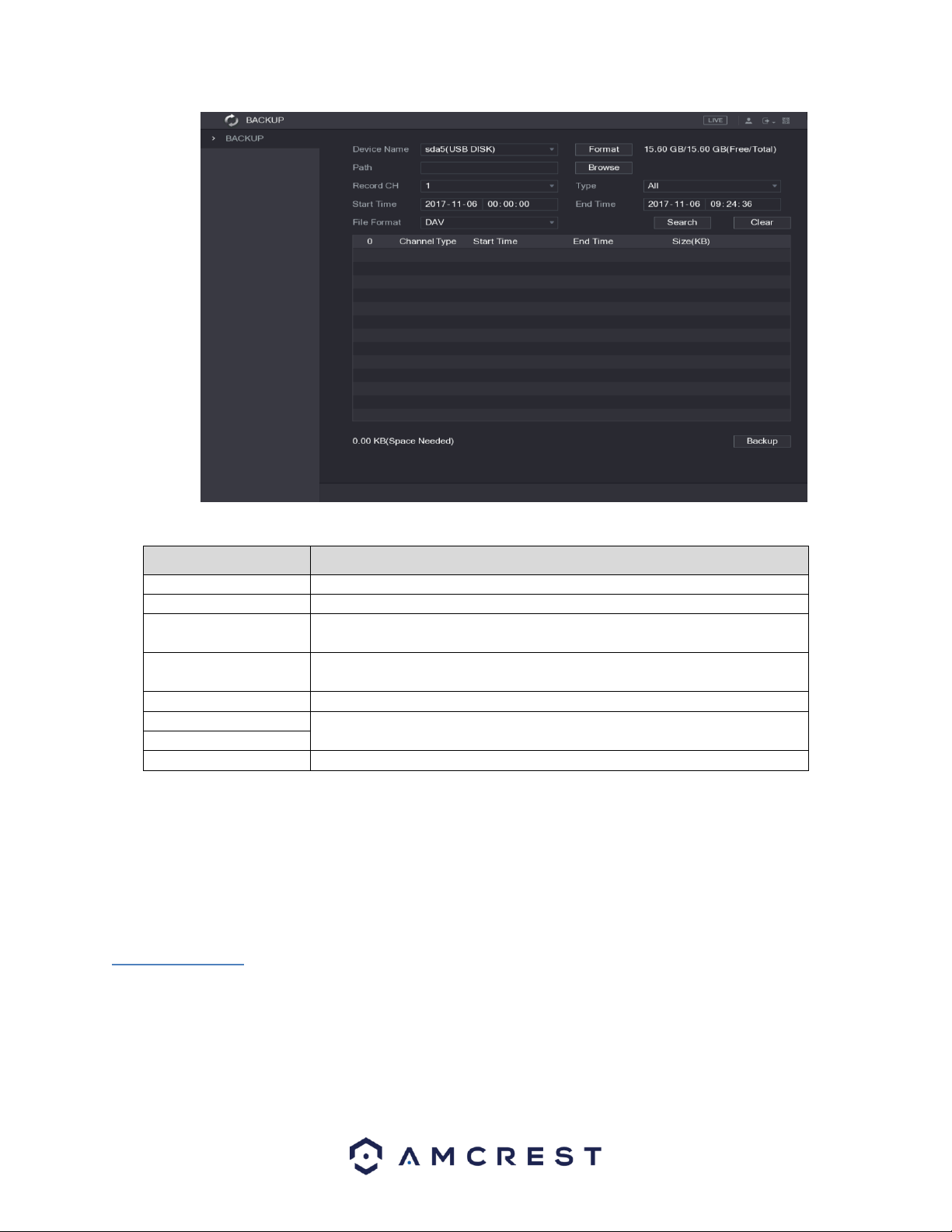
69
For a more information on the settings listed in this menu, refer to the table listed below.
Parameter
Description
DVR Name
In the DVR Name list, select the DVR that you want to back up the files to.
Format
Click Format to format the selected DVR.
Path
Click Browse, the Browse interface is displayed. Select the route where you
want to search for the files.
Record CH
In the Record CH list, select the channel where you want to search for the
files.
Type
In the Type list, select the file type that you want to search.
Start Time
Enter the start time and end time for the files that you want to search.
End Time
File Format
In the File Format list, select the file format that you want to search.
To begin backing up data to your external USB storage DVR, click on the Search button in the backup
menu to search for the indicated file. Select the file from the file list that you want to backup and click on
the Backup button to allow the data to transfer to your USB storage DVR.
Note: By default, video data will be in the file format, DAV, this can be modified in the File Format
dropdown menu to MP4 if necessary.
4.11. Display
This function tile allows you to configure resolution and display setting outputs from the DVR.
4.11.1. Configuring Display Settings
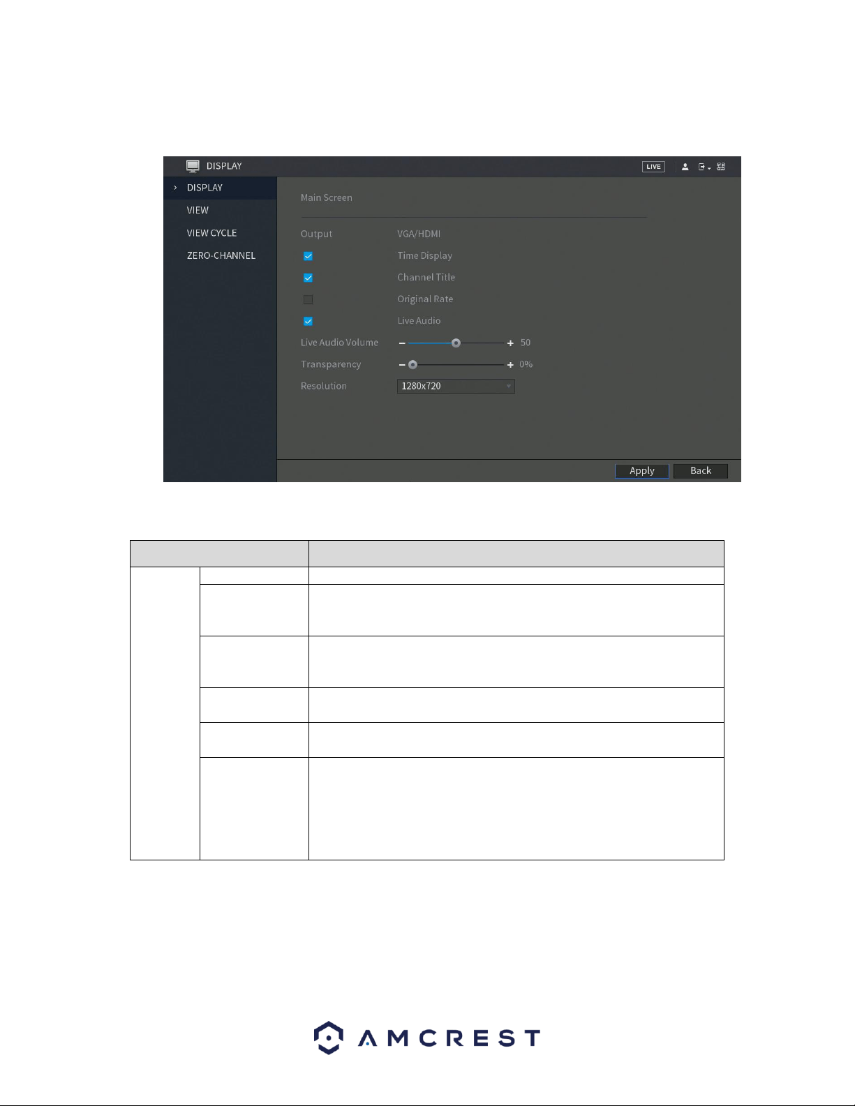
70
This menu provides you with quick access to your display and output information associated with your
DVR. You can configure the display effects such as, resolution, time delays, channel titles, etc.
For more information on the settings provided in this menu, refer to the table provided below.
Parameter
Description
Main
Screen
Out Port
Indicates the main screen port.
Time Title
Select the Time Title check box, the current system time displays in
each channel window in live view screen. To hide the time, clear the
check box.
Channel Title
Select the Channel Title check box, the channel name, channel
number and recording status display in each channel window in live
view screen. To hide the time, clear the check box.
Original Rate
Select the Original Rate check box, the video image displays in its
actual size in the channel window.
Transparency
Configure the transparency of the graphical user interface (GUI). The
higher the value, the more transparent the GUI becomes.
Resolution
Select resolution for the video. The default resolution for VGA port
and HDMI port is 1280×1024.
Note: Some of the resolution options might not be supported on the
HDMI port.
When you have successfully set your desired display settings, click on Apply to apply the settings to your
DVR. To return to the previous menu click Back.
Note: Make sure to select the correct resolution setting for your desired output DVR. If your VGA/HDMI
DVR is set to an incorrect resolution, you will not gain an accurate picture from the system.
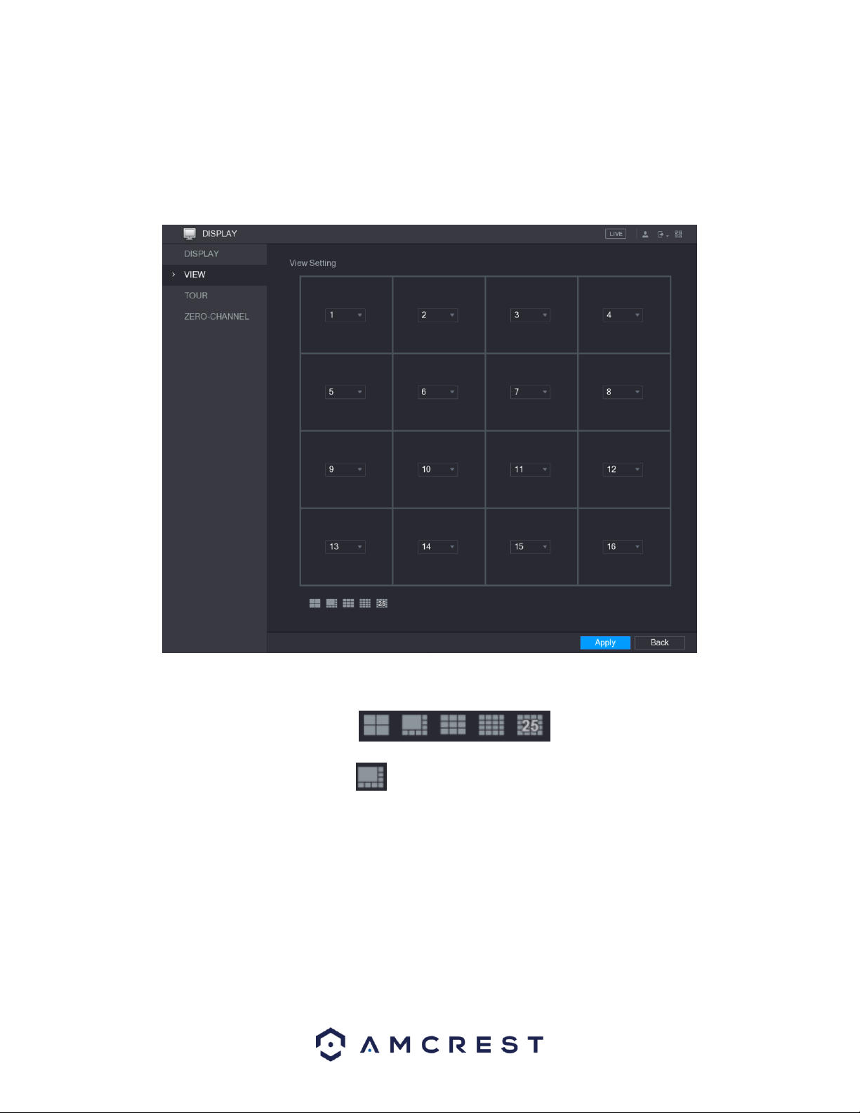
71
4.11.2. View
This menu allows you to configure the view layout of the live view screen. This section’s functionality and
layout will be dependent on the specific model DVR you have. When you access the View tab from the
Display function tile, you will be taken to the View Setting interface.
The view layout configuration can be set by clicking on the layout buttons in the bottom left-corner of the
interface.
For example, when you click on the icon, which is the 9-16 view layout, the live view layout will
change immediately as such:
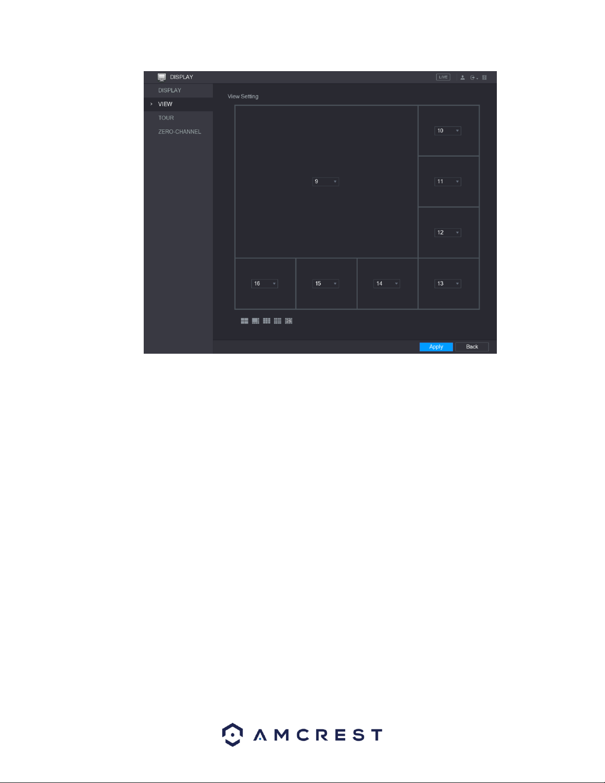
72
The same concept will apply for the other layout icons listed in the menu. Adjust the position of the
channels as needed. In the channel list, for example, in the channel 9 list, you can select 10 and the
channel 9 and channel 10 will exchange positions on the screen. When you have successfully configured
your view layout, click Apply to apply the configuration to your DVR. To return to the previous menu, click
on the Back button. When applied, the live view screen will reflect the same layout as displayed in this
menu.
4.11.3. View Cycle
This screen is used to activate tour functionality for the live preview. Below is a screenshot of the Main
Screen:
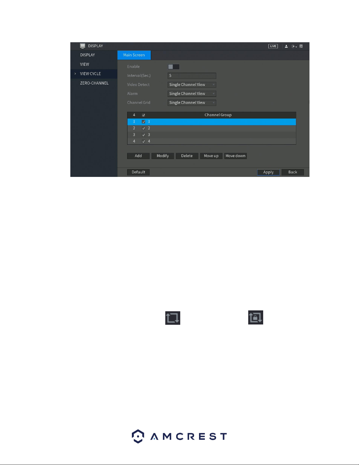
73
Below is an explanation of the fields on the Tour Setup settings screen:
• Enable: This checkbox allows the user to enable the tour functionality.
o An alternate way to enable or disable tour is by clicking on the navigation bar.
• Interval (Sec): Enter the amount of time that you want each channel group displays on the screen. The
value ranges from 5 seconds to 120 seconds, and the default value is 5 seconds.
• Video Detect: Select the View 1 or View 8 for Motion Detect tour and Alarm Tour (system alarm
events).
• Window Split: In the Window Split list, select View 1, View 4, View 8, or other modes that are
supported by the DVR.
o Add: This button allows the user to add a channel to the tour.
o Delete: This button allows the user to remove a channel from the tour.
o Move Up: This button allows the user to move a camera up in the tour queue.
o Move Down: This button allows the user to move a camera down in the tour queue.
Note: On the navigation bar, you can click to enable the tour and click to disable it.
4.11.3.1. Adding a Channel Group
This function provides you the ability for grouping together channels to more efficiently use the tour
options set up on the DVR. To utilize this function, enable the Enable toggle switch and click on the Add
button located in the Main Screen tab of the View Cycle menu. This will take you to the Add Group
interface.
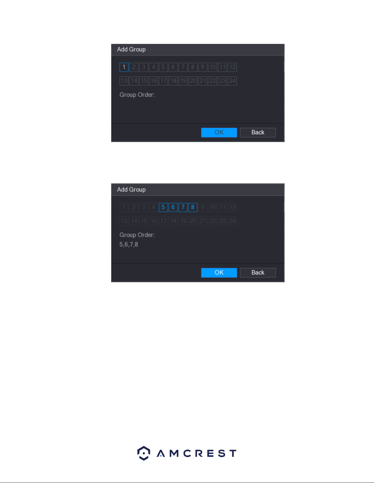
74
From the interface, select the channels that you want to group with the established tour settings.
Note: If you want to select more than one channel, in the Window Split list, do not select View1.
When you have finished selecting the appropriate group order, click OK to complete the process. If you do
not wish to proceed with the group function, click Back to exit the add group interface.
4.11.3.2. Modifying a Channel Group
To modify an established channel group, double-click on a channel group to access the Modify Channel
Group interface.
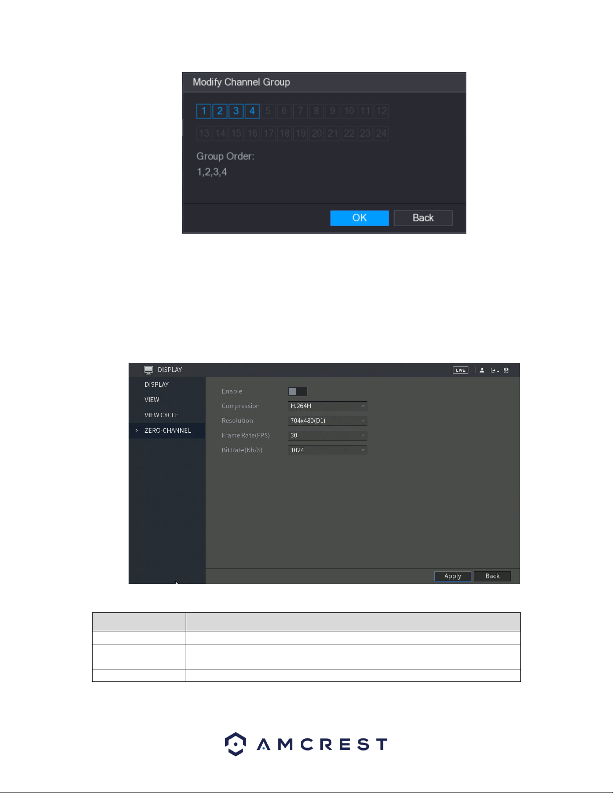
75
In the modify channel group interface, select the group order for your selected group and click OK to
complete the process. If you do not want to proceed with the modification, click the Back button to exit
the modify group interface.
4.11.4. Zero-Channel
This screen is used to configure zero channel encoding functionality. This feature allows for the preview of
several channels in one channel’s window. Below is a screenshot of the Zero-Channel Encoding settings
screen:
For more information on the settings listed in this menu, refer to the table listed below.
Parameter
Description
Enable
Enable zero-channel function.
Compression
In the Compression list, select the video compression standard according to the
DVR capability. The default is H.264.
Resolution
In the Resolution list, select the video resolution. The default is 704×576 (D1).
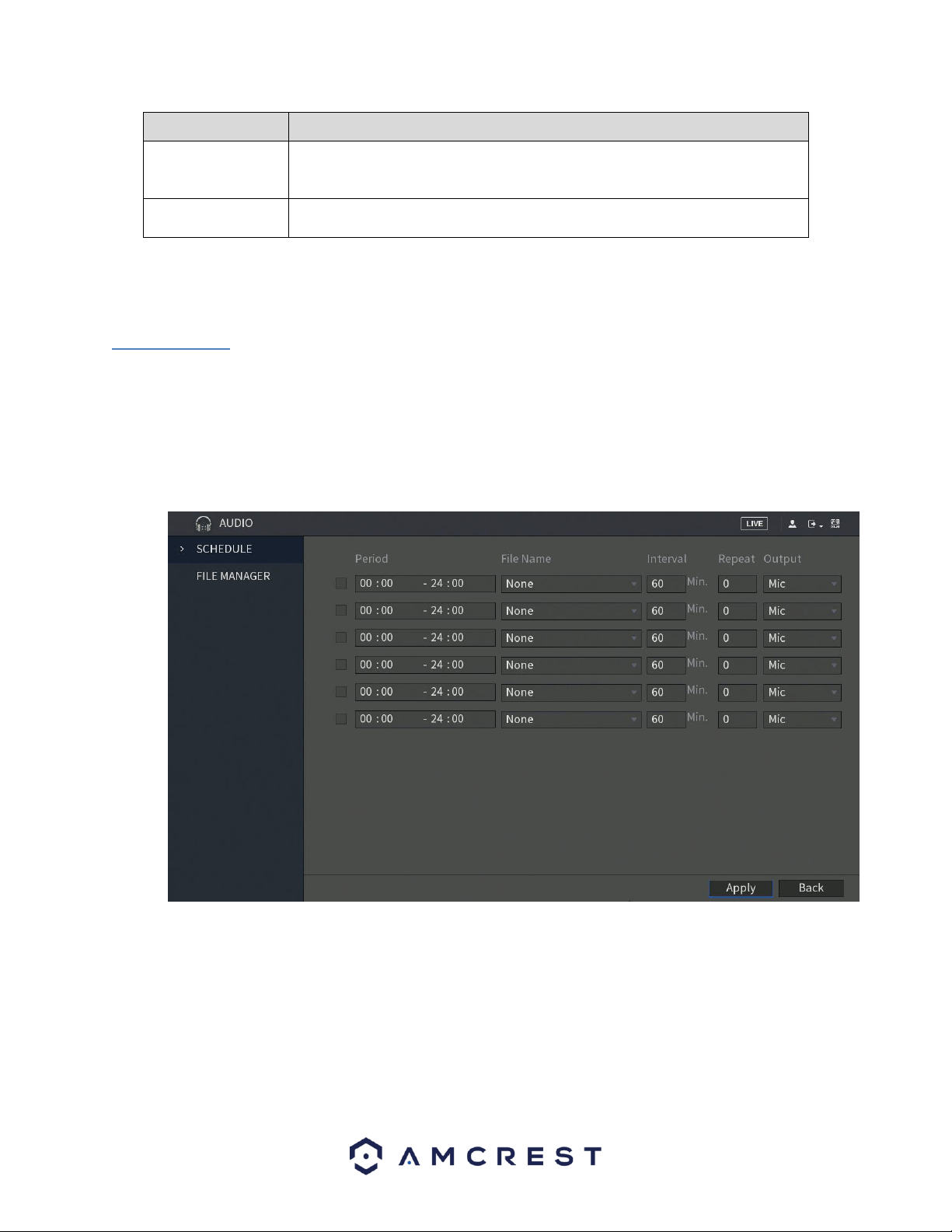
76
Parameter
Description
Frame Rate (FPS)
Select a value between 1 and 25 for PAL standard, and between 1 and 30 for
NTSC standard. The actual arrange is decided and selected dependent on the
DVR capability.
Bit Rate (Kb/S)
The default value is 1024Kb/S. The actual arrange is decided and selected
dependent on the DVR capability and frame rate.
When you are finished configuring your zero channel settings, click Apply to apply the settings to your
DVR. If you do not wish to proceed with the configuration, click the Back button to exit this screen.
4.12. Audio
This function tile allows you to manage audio functions such as, audio file management and configuring
audio playing schedules which can be associated with specific alarm events.
4.12.1. Schedule
The schedule tab allows you to schedule downloaded audio to specific alarms in the device. Here is a
screenshot of the schedule menu:
For more information on the features listed in this menu, refer to the table provided below.
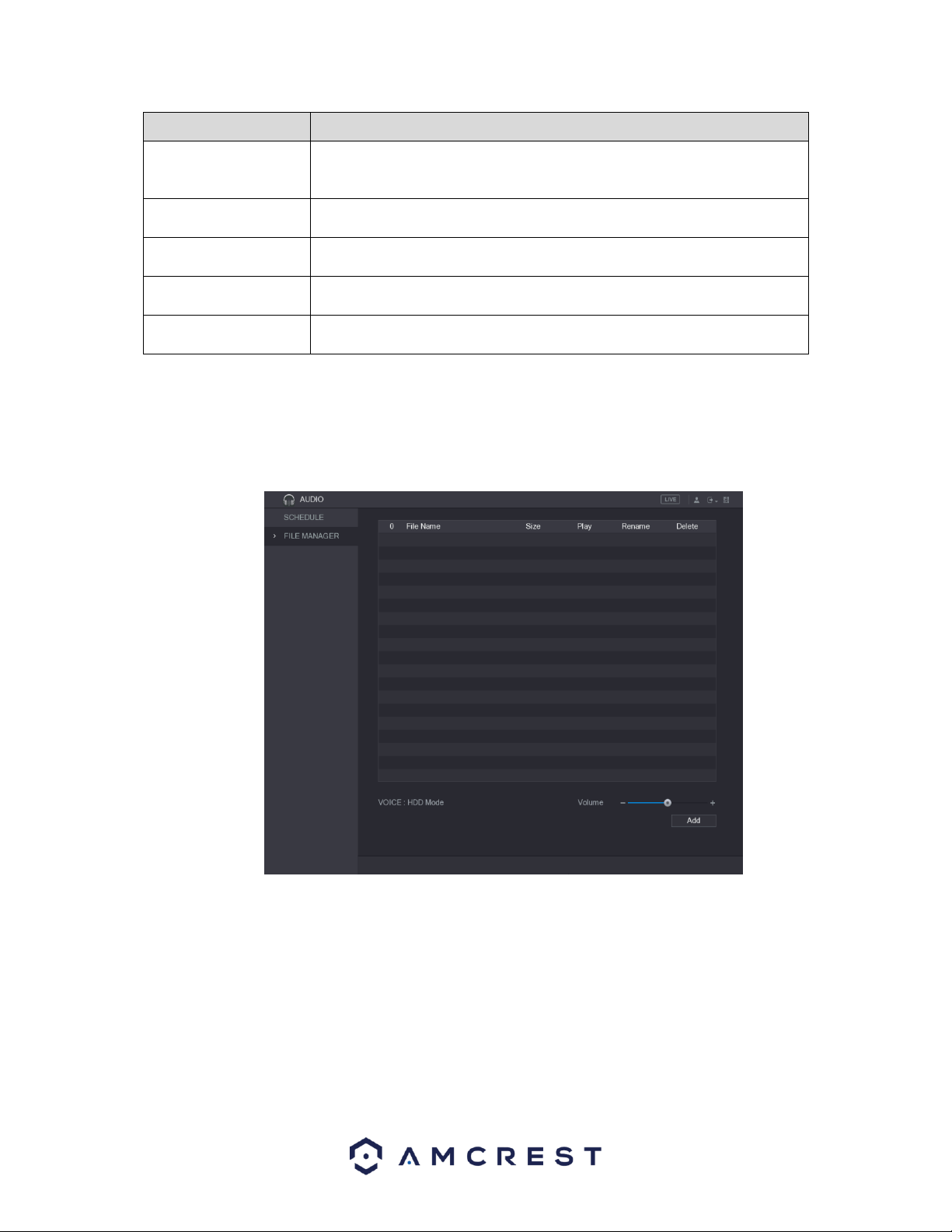
77
Parameter
Description
Period
In the Period box, enter the time. Select the check box to enable the
settings.
You can configure up to six periods.
File Name
In the File Name list, select the audio file that you want to play for this
configured period.
Interval
In the Interval box, enter the time in minutes for how often you want to
repeat the playing.
Repeat
Configure how many times you want to repeat the playing in the defined
period.
Output
Includes two options: MIC and Audio. It is MIC by default. The MIC function
shares the same port with talkback function and the latter has the priority.
Note: Use the file manager to configure audio files for your schedule.
4.12.2. File Manager
The file manager tab allows the user to configure audio files to a set schedule. Here is a screenshot of the
file manager screen:
To begin configuring audio files the user will have to import the audio files into the system via a flash
drive. After the USB flash drive with the audio files have been inserted into the device, click on Add and
select the audio files you wish to import. Click on OK to start importing the file.
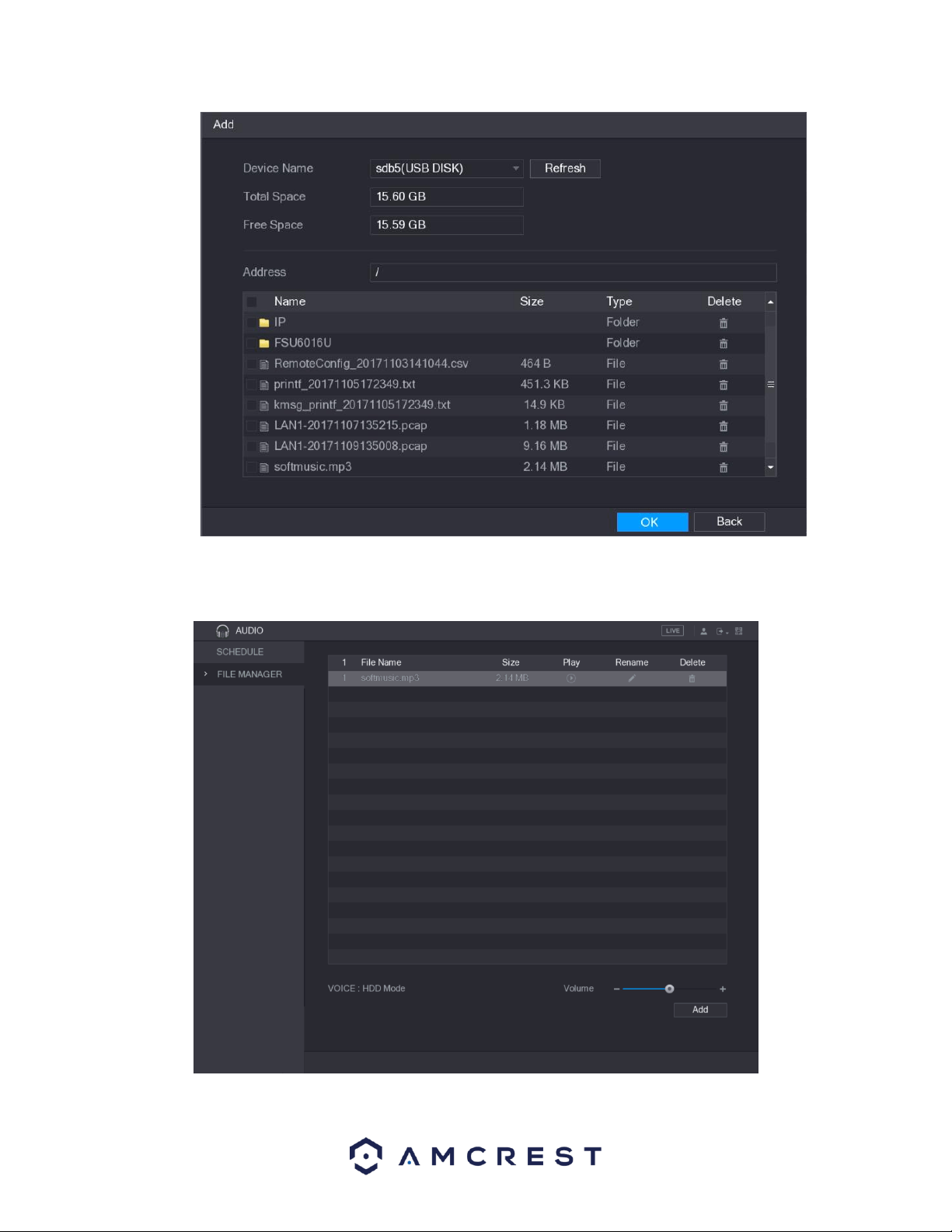
78
When the audio file has been imported successfully, you will see the file displayed in the file manager
interface:
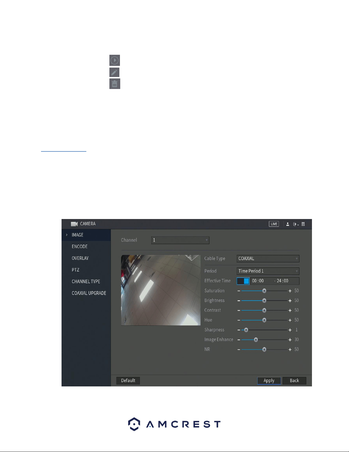
79
The imported audio files are automatically saved into the HDD, so you do not need to connect
to the USB storage device to get the file next time.
⚫ Click to play the audio file.
⚫ Click to rename the audio file.
⚫ Click to delete the audio file.
⚫ To decrease or increase the playing volume, move the slider to the left or to the right.
6. Management
This section of the main menu allows you to access camera, network, storage, system, account, and
information directly related to your DVR.
6.1. Camera
This section allows you to access and modify settings associated with connected cameras on your DVR. In
this section you can modify the image, encode, overlay, PTZ (if applicable), channel types, as well as
provide coaxial upgrades to your camera, if applicable.
6.1.1. Image
This menu allows you to access the image settings associated with a specific channel connected to your
DVR. For more information on the settings provided in this menu, refer to the table provided below.

80
Parameter
Description
Channel
In the Channel list, select the channel that you want to configure.
Cable Type
In the Cable Type list, select the cable type that the camera uses.
Note: Not all models support this function.
Period
In the Period list, select a time period for the image settings. The image settings
will be only used during the selected period.
Effective Time
Enable the effective function.
In the Effective Time box, enter the start time and end time for the period you
selected.
Saturation
Adjusts the color shades. The bigger the value, the lighter the color will
become. This value does not influence the general image lightness.
The value ranges from 0 to 100. The default value is 50. The recommended
range is between 40 and 60.
Contrast
Adjusts the image contrast. The bigger the value is, the more obvious the
contrast between the light area and dark area will become. You can adjust this
value when the contrast is not obvious. However, if the value is too big, the
dark area is likely to become darker and the light area over exposed. If the
value is too small, the image is likely to become dim.
The value ranges from 0 to 100. The default value is 50. The recommended
range is between 40 and 60.
Brightness
Adjusts the image brightness. The bigger the value is, the brighter the image
will become. You can adjust this value when the image as a whole looks dark or
bright. However, the image is likely to become dim if the value is too big.
The value ranges from 0 to 100. The default value is 50. The recommended
range is between 40 and 60.
Hue
Adjusts the hue of image. The value ranges from 0 to 100. The default value is
50.
Sharpness
Adjusts the sharpness of image edge. The bigger the value is, the more obvious
the image edge, and the noise is also greater.
The value ranges from 1 to 15. The default value is 1.
Image Enhance
Adjusts the image definition. The bigger the value is, the clearer the image will
become, but there will be more noises.
NR
Reduces the noises from image. The bigger the value is, the better the image
will become.
6.1.2. Encode
This tab is used to set the video encoding settings for each channel.
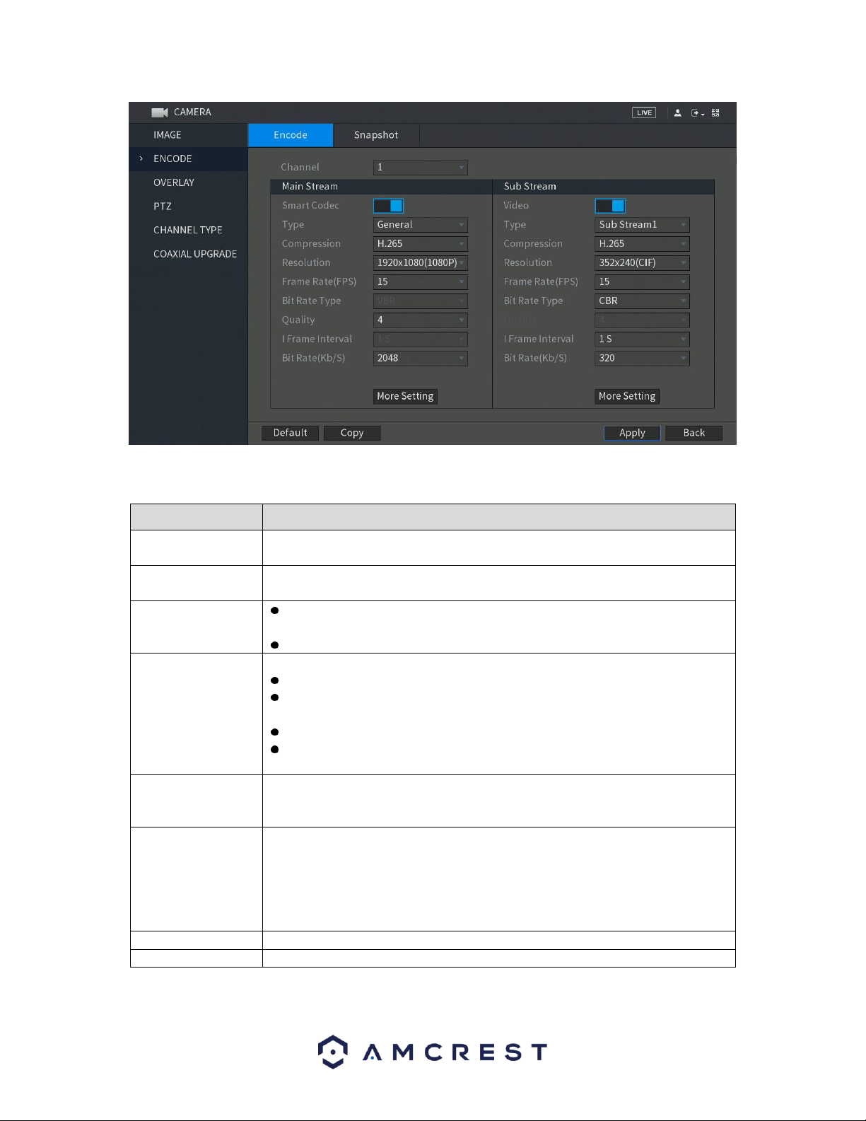
81
For more information on the settings listed in this menu, refer to the table provided below:
Parameter
Description
Channel
In the Channel list, select the channel that you want to configure the settings
for.
Smart Codec
Enable the smart codec function. This function can reduce the video bit stream
for non-important recorded video to maximize the storage space.
Type
Main Stream: In the Type list, select General, MD (Motion Detect), or
Alarm.
Sub Stream: This setting is not configurable.
Compression
In the Compression list, select the encode mode.
H.265: Main profile encoding.
H.264H: High profile encoding. Low bit stream with high definition. This
setting is recommended.
H.264: General profile encoding.
H.264B: Baseline profile encoding. This setting requires higher bit stream
compared with other settings for the same definition.
Resolution
In the Resolution list, select resolution for the video.
The maximum video resolution might be different dependent on your DVR
model.
Frame Rate (FPS)
Configure the frames per second for the video. The higher the value, the clearer
and smoother the image will become. Frame rate changes along with the
resolution.
Generally, in PAL format, you can select the value from 1 through 25; in NTSC
format, you can select the value from 1 through 30. However, the specific range
of frame rate that you can select depends on the capability of the DVR.
Quality
The higher the value, the better the image will become.
I Frame Interval
The interval between two reference frames.
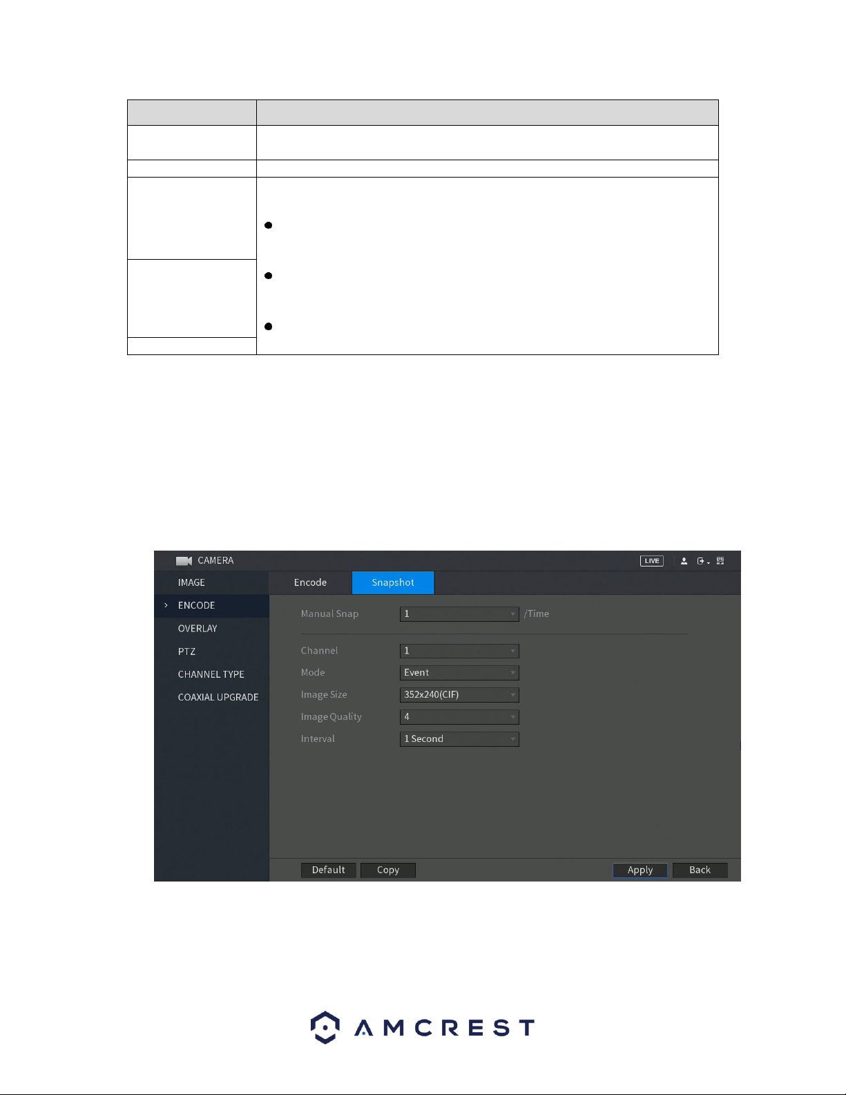
82
Parameter
Description
Bit Rate (Kb/S)
In the Bit Rate list, select a value or enter a customized value to change the
image quality. The bigger the value is, the better the image will become.
Video
Enable the function for sub stream.
Audio Encode
Click More Setting, the More Setting interface is displayed.
Audio Encode: This function is enabled by default for main stream. You
need to manually enable it for sub stream 1. Once this function is enabled,
the recorded video file is composite audio and video stream.
Audio Source: In the Audio Source list, you can select LOCAL and .
LOCAL: The audio signal is input from Audio input port.
: The audio signal is input from camera.
Audio Format: In the Audio Format list, select a format that you need.
Audio Source
Audio Format
When you have finished setting up your encode configuration settings, click on the Apply button to apply the
settings to your DVR. If you would like to revert the image back to its default setting, click on Default. To set the
encode settings to other channels on your DVR, click on the Copy button and select the channels that you wish to
apply the settings to, click OK when you have finished. To exit this screen, press the Back button.
6.1.2.1. Configuring Snapshot Settings
This tab located in the encode menu allows you to configure the encode settings for snapshot
parameters.
For more information on the settings provided in this menu, refer to the table below.
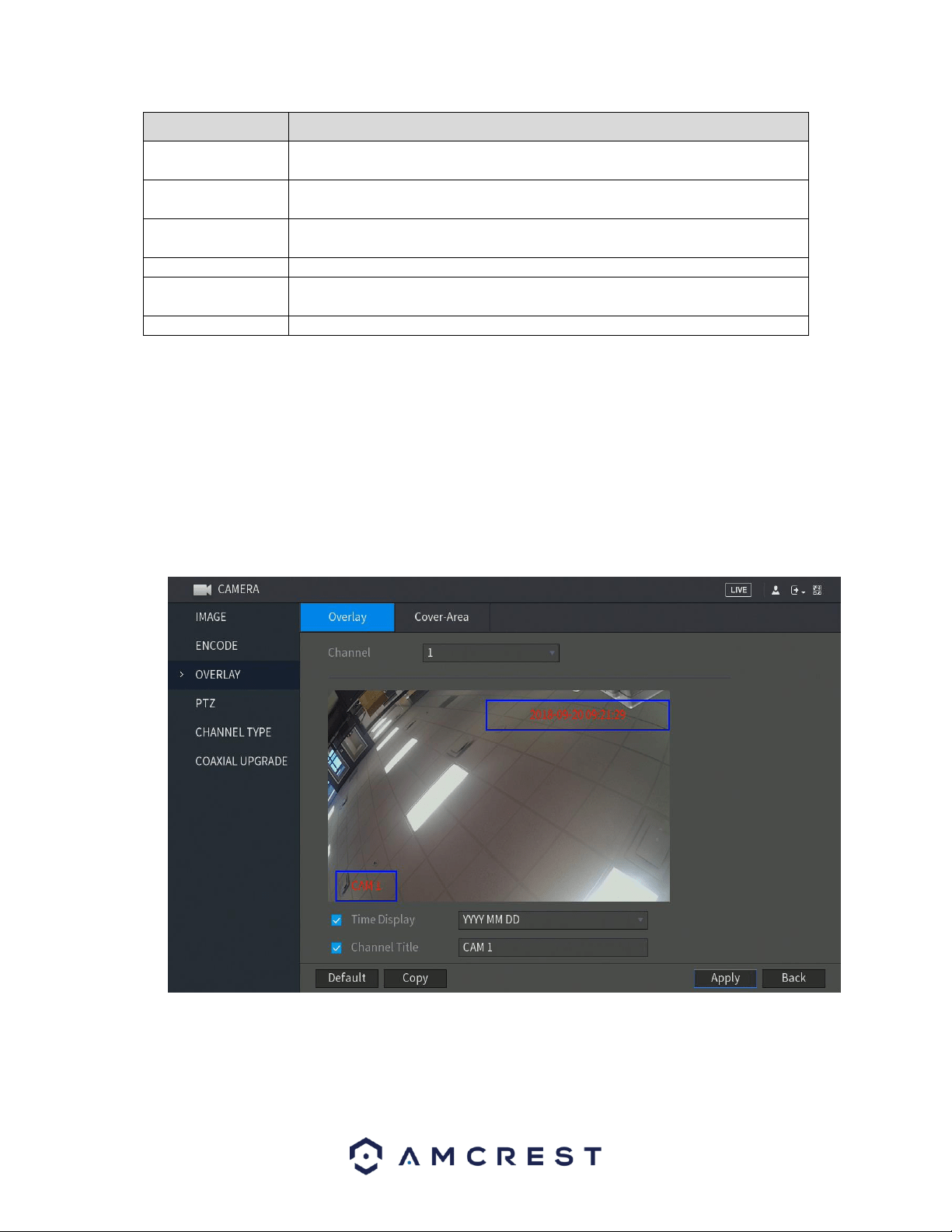
83
Parameter
Description
Manual Snap
In the Manual Snap list, select how many snapshots you want to take each
time.
Channel
In the Channel list, select the channel that you want to configure the settings
for.
Mode
In the Mode list, you can select Human Face, Event, or General as the event
type for which you want to take a snapshot.
Image Size
In the Image Size list, select a value for the image.
Image Quality
Configures the image quality by 6 levels. The higher the level, the better the
image will become.
Interval
Configures or customizes the snapshot frequency.
When you have finished setting up your configuration settings, click on the Apply button to apply the settings to
your DVR. If you would like to revert the settings back to default, click on Default. To apply these settings to other
channels on your DVR, click on the Copy button and select the channels that you wish to apply the settings to, click
OK when you have finished. To exit this screen, press the Back button.
6.1.3. Overlay
The overlay tab allows the user to change overlay settings for each channel. Below is a screenshot of the
overlay tab:
For more information on the settings listed in this menu, refer to the table below:
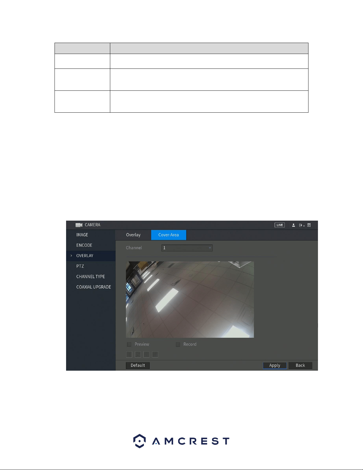
84
Parameter
Description
Channel
In the Channel list, select the channel that you want to configure the settings
for.
Time Display
Select the Time Display check box to display the system time on each channel
window in the live view screen.
In the Time Display list, select time display style.
Channel Title
Select the Channel Title check box to display the channel name on each
channel window in the live view screen.
In the Channel Title box, enter the name for the selected channel.
When you have finished setting up your overlay settings, click on the Apply button to apply the settings to
your DVR. If you would like to revert the settings back to default, click on Default. To apply these settings
to other channels on your DVR, click on the Copy button and select the channels that you wish to apply
the settings to, click OK when you have finished. To exit this screen, press the Back button
6.1.3.1. Cover-Area
The cover-area tab allows the user to set the cover area for specific channels in the system. The user can
set cover areas for either preview (live view) or for recordings.
To begin, drag the mouse to set the proper section size. The system supports a maximum of 4 zones in
one channel.
For more information on the settings listed in this menu, refer to the table below.
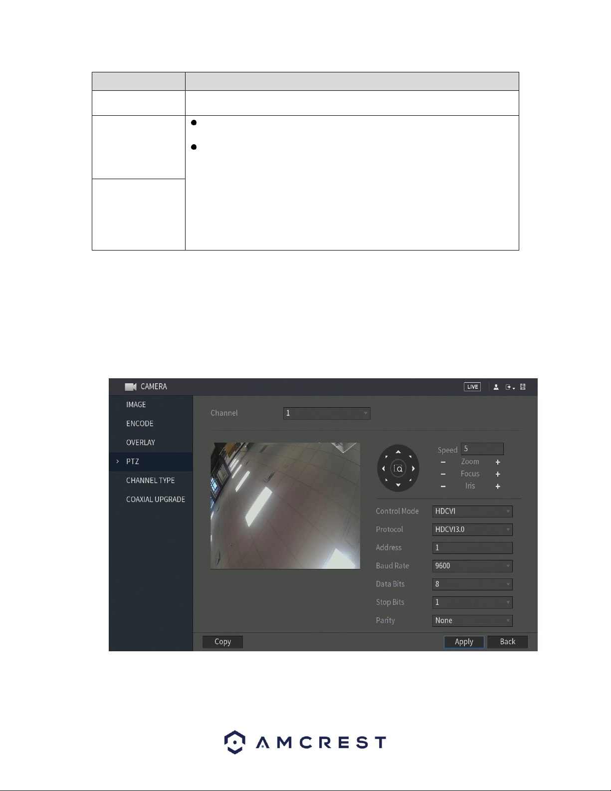
85
Parameter
Description
Channel
In the Channel list, select the channel that you want to configure the settings
for.
Preview
Preview: Select the Preview check box to apply the configured covered
block to the selected channel window in the live view screen.
Record: Select the Record check box to apply the configured covered block
to the selected channel window during recording.
To configure covering block, do the following:
1. Select the Preview check box or the Record check box, or select the both.
The "1, 2, 3, 4" buttons are activated.
2. Click the buttons to select blocks.
3. A triangle solid black block is displayed. You can drag the block to the area
that you want to cover and adjust the size of the block.
4. You can configure total 4 covered blocks.
Record
When you have finished setting up your cover-area settings, click on the Apply button to apply the
settings to your DVR. If you would like to revert the settings back to default, click on Default. To exit this
screen, press the Back button.
6.1.4. PTZ
This screen is used to configure Pan/Tilt/Zoom (PTZ) functionality. Below is a screenshot of the PTZ
settings screen:
For more information on the settings listed in this menu, refer to the table below.
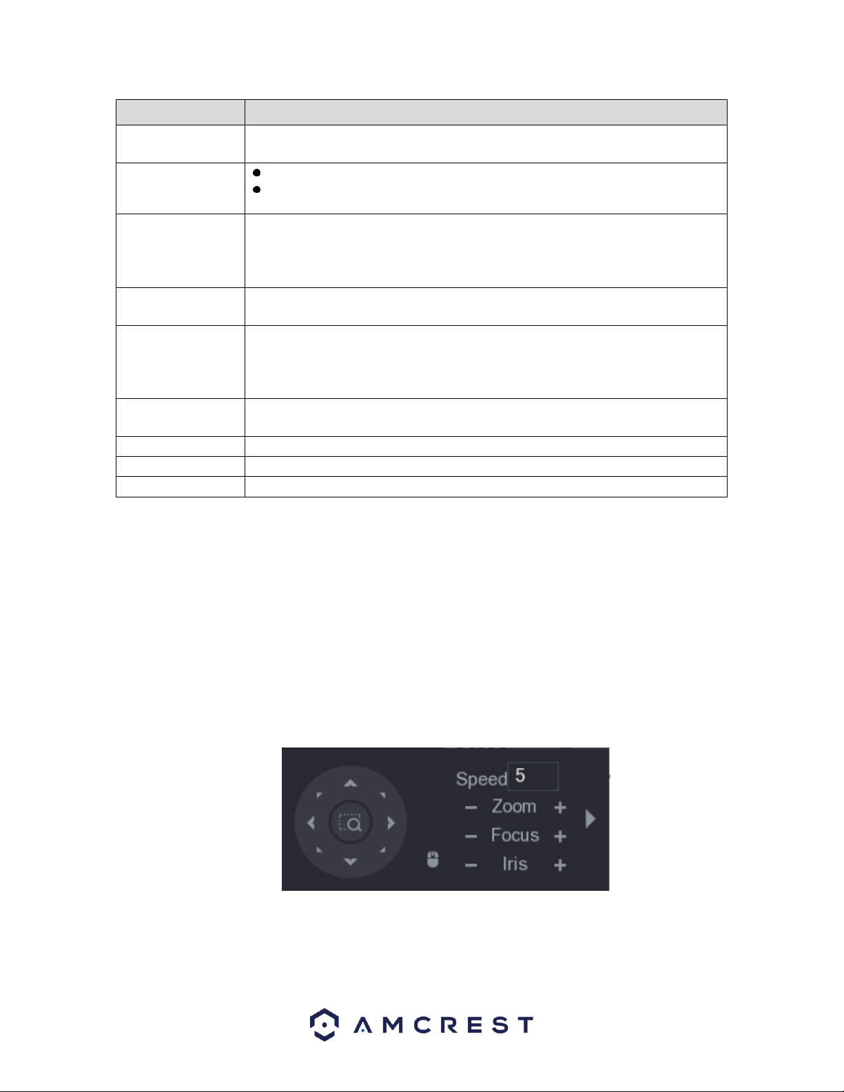
86
Parameter
Description
Channel
In the Channel list, select the channel that you want to connect
the PTZ camera to.
PTZ Type
Local: Connect through RS485 port or coaxial cable.
Remote: Connect through network by adding IP address of PTZ camera to the
DVR.
Control Mode
In the Control Mode list, select Serial or . For series product,
please select . The control signal is sent to the PTZ through the
coaxial cable. For the serial mode, the control signal is sent to the
PTZ through the RS485 port.
Protocol
In the Protocol list, select the protocol for the PTZ camera, for
example, select 3.0.
Address
In the Address box, enter the address for PTZ camera. The default is 1.
Note: The entered address must be the same as the address configured on the PTZ
camera. If not configured properly, the PTZ camera will not function in the DVR.
Baud Rate
In the Baud rate list, select the baud rate for the PTZ camera. The
default is 9600.
Data Bits
The default is 8.
Stop Bits
The default is 1.
Parity
The default is NONE.
When you have finished setting up your PTZ settings, click on the Apply button to apply the settings to
your DVR. If you would like to revert the settings back to default, click on Default. To apply these settings
to other channels on your DVR, click on the Copy button and select the channels that you wish to apply
the settings to, click OK when you have finished. To exit this screen, press the Back button.
6.1.4.1. PTZ Control Panel
The PTZ control panel is set to perform operations such as directing the camera, adjusting the zoom,
focus, iris, and quick positioning settings.
Note: The PTZ control bar can direct the camera in eight different directions. You can also view the PTZ
control panel by right-clicking on the live view screen.
For more information about the settings listed in the PTZ control bar, refer to the table provided below.
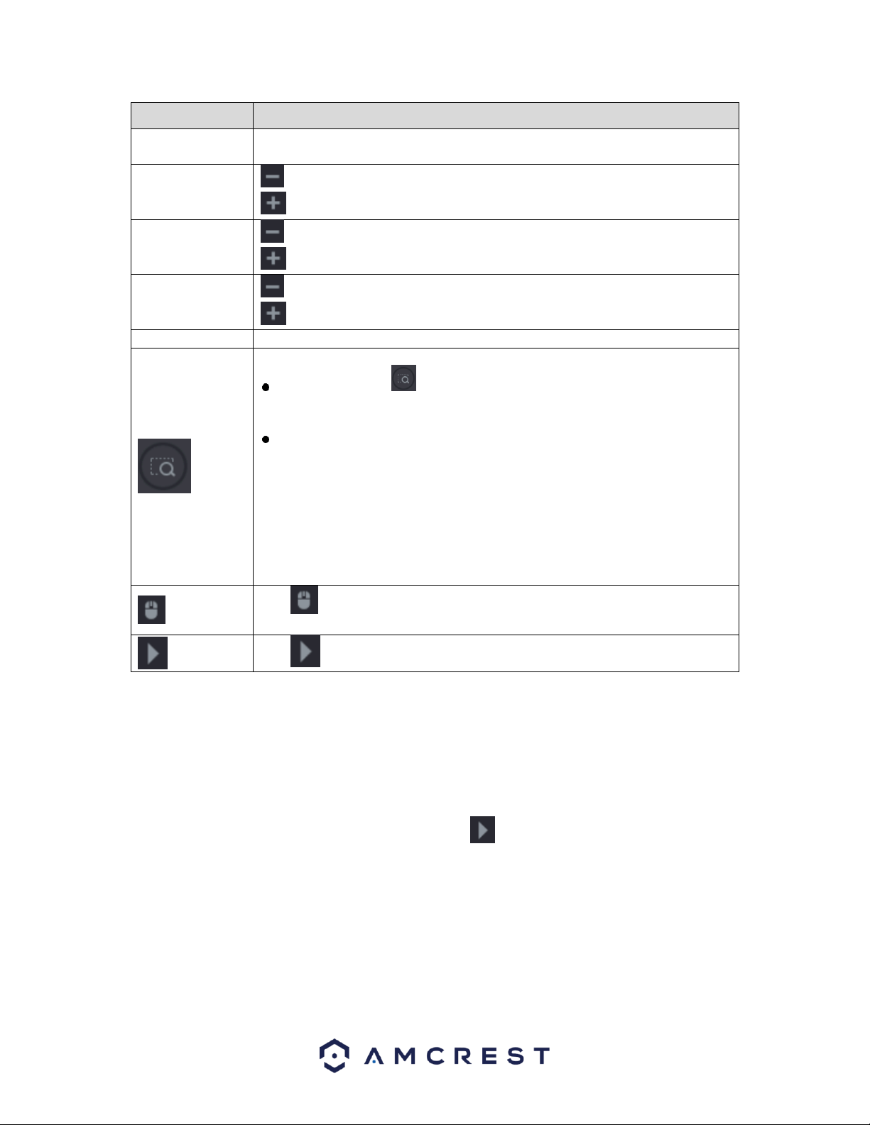
87
Parameter
Description
Speed
Controls the movement speed. The bigger the value is, the faster the movement
will be.
Zoom
: Wide angle.
: Long shot.
Focus
: Zoom in.
: Zoom out.
Iris
: Small.
: Large.
PTZ movement
Supports eight directions.
Fast positioning button.
Positioning: Click to enter the fast positioning screen, and then click
anywhere on the live view screen, the PTZ will turn to this point and move it
to the middle of the screen.
Zooming: On the fast positioning screen, drag to draw a square on the view.
The square supports zooming.
Dragging upward is to zoom out, and dragging downward is to zoom
in.
The smaller the square, the larger the zoom effect.
Note: Not all models support this function and can only be controlled manually.
Click , you can control the four directions (left, right, up, and down) PTZ
movement through mouse operation.
Click to open the expanded PTZ control panel.
Note: The functions with buttons that are greyed out will not be supported by the system.
6.1.4.2. Expanded PTZ Control Panel
The expanded PTZ control panel provided additional PTZ settings that are associated with the system.
To access the expanded PTZ control panel, click on the icon on the PTZ control panel to expand the
PTZ options.
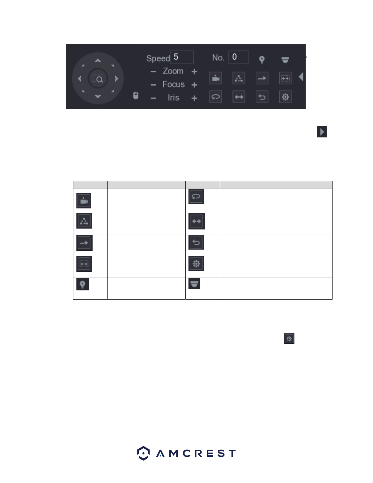
88
Note: The functions with buttons that are greyed out will not be supported by the system. To return to
live view screen right-click once on the interface. To exit the expanded PTZ control panel, click on the
icon.
For more information on the settings listed in the expanded PTZ control panel, refer to the table provided
below.
Icon
Function
Icon
Function
Preset
Auto Pan
Tour
Flip
Pattern
Reset
Autoscan
Click the AUX Config icon to open the PTZ
functions settings interface.
AUX Switch
Click the Enter Menu icon to open the
MENU OPERATION interface.
6.1.4.3. Configuring PTZ Presets
This function allows for the creation and editing of preset camera configurations.
To access the PTZ preset menu, navigate to the expanded control panel and click on the icon. On the
PTZ interface provided, click on the Preset tab.
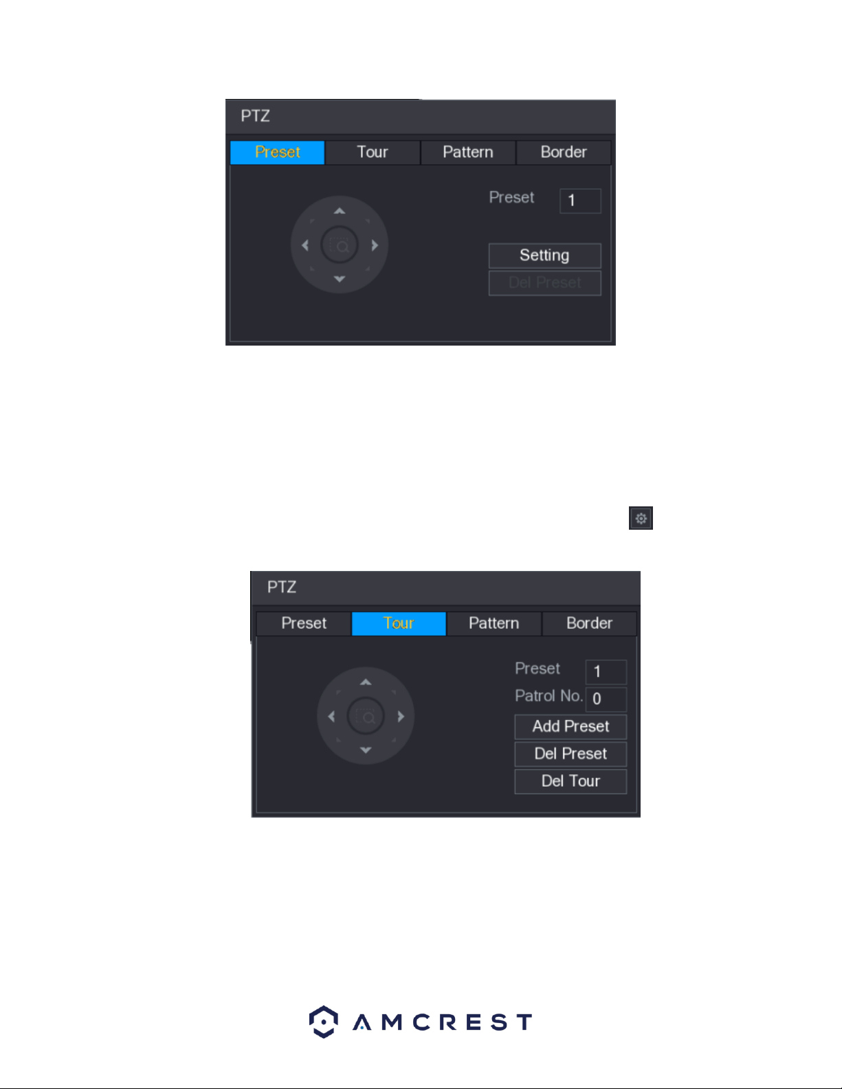
89
To create and manage preset camera configurations, follow the steps below:
• Configure the camera positioning as needed using the directional arrows.
• In the Preset box input the preset number you wish to set.
• Click the Setting button to save the current preset.
• Click Del Preset to delete the current preset.
6.1.4.4. Configuring PTZ Tour
The tour function allows for the use of multiple presets stringed together.
To access the PTZ tour menu, navigate to the expanded control panel and click on the icon. On the
PTZ interface provided, click on the Tour tab.
To create and manage tours, follow the steps below:
• Ensure you have more than 1 preset configured already.
• Input the tour value into the Patrol No.
• Click the Add Preset button to add another preset.
• Continue adding presets as needed.
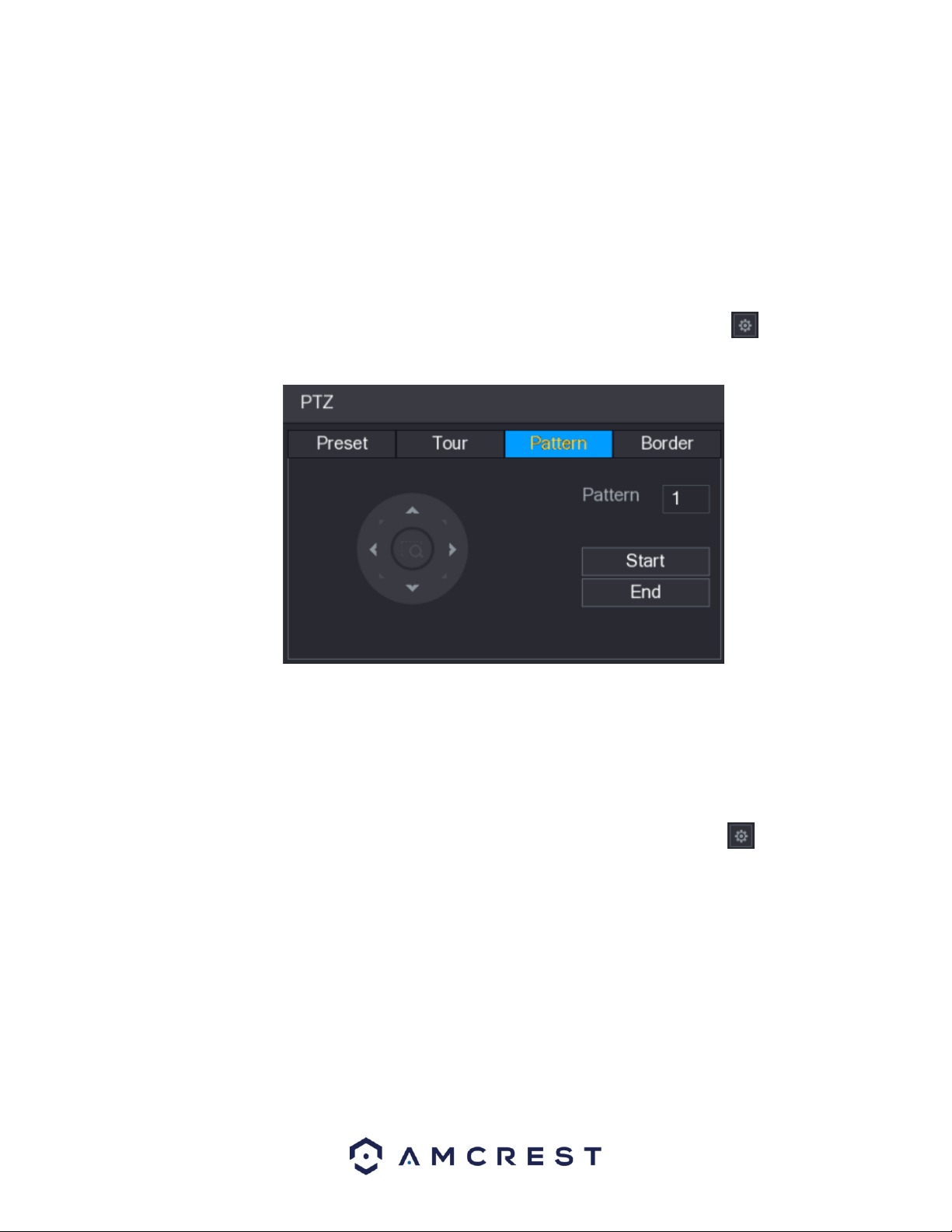
90
• Click Del Preset to remove a preset from the tour.
• Click Del Tour to delete the entire tour.
Note: You can repeat the process by adding more presets this this function. Some protocols set may not
support deleting.
6.1.4.5. Configuring PTZ Patterns
The pattern function allows for a custom tour to be created on the fly using the PTZ controls.
To access the PTZ pattern menu, navigate to the expanded control panel and click on the icon. On the
PTZ interface provided, click on the Pattern tab.
To create a pattern, click Begin, then use the PTZ controls to move the camera around. Once finished,
click End to end and save the pattern. During the use of pattern mode, zoom/focus/iris cannot be
modified.
6.1.4.6. Configuring PTZ Borders
The border function allows for constraining the area of movement for the cameras during any PTZ
function.
To access the PTZ border menu, navigate to the expanded control panel and click on the icon. On the
PTZ interface provided, click on the Border tab.
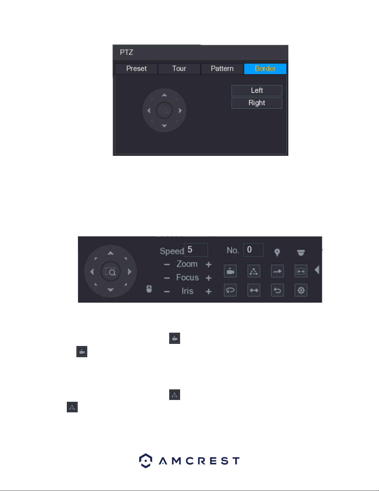
91
To set up borders, move the camera using the PTZ controls to the left limit, then click Left to designate
that position as the left limit. Then move the camera to the right limit, and then click Right to designate
that position as the right limit.
6.1.5. Calling PTZ Functions
After you have configured your PTZ settings, you can call the PTZ functions through the expanded PTZ
control panel.
6.1.5.1. Calling Presets
Using the expanded PTZ control panel, enter the value of the preset you wish to call in the No. box. Once
you have entered this value, click on the icon to access the preset. To stop calling the preset, click on
the icon to exit.
6.1.5.2. Calling Tours
Using the expanded PTZ control panel, enter the value of the tour you wish to call in the No. box. Once
you have entered this value, click on the icon to access the tour. To stop calling the tour, click on the
icon to exit.
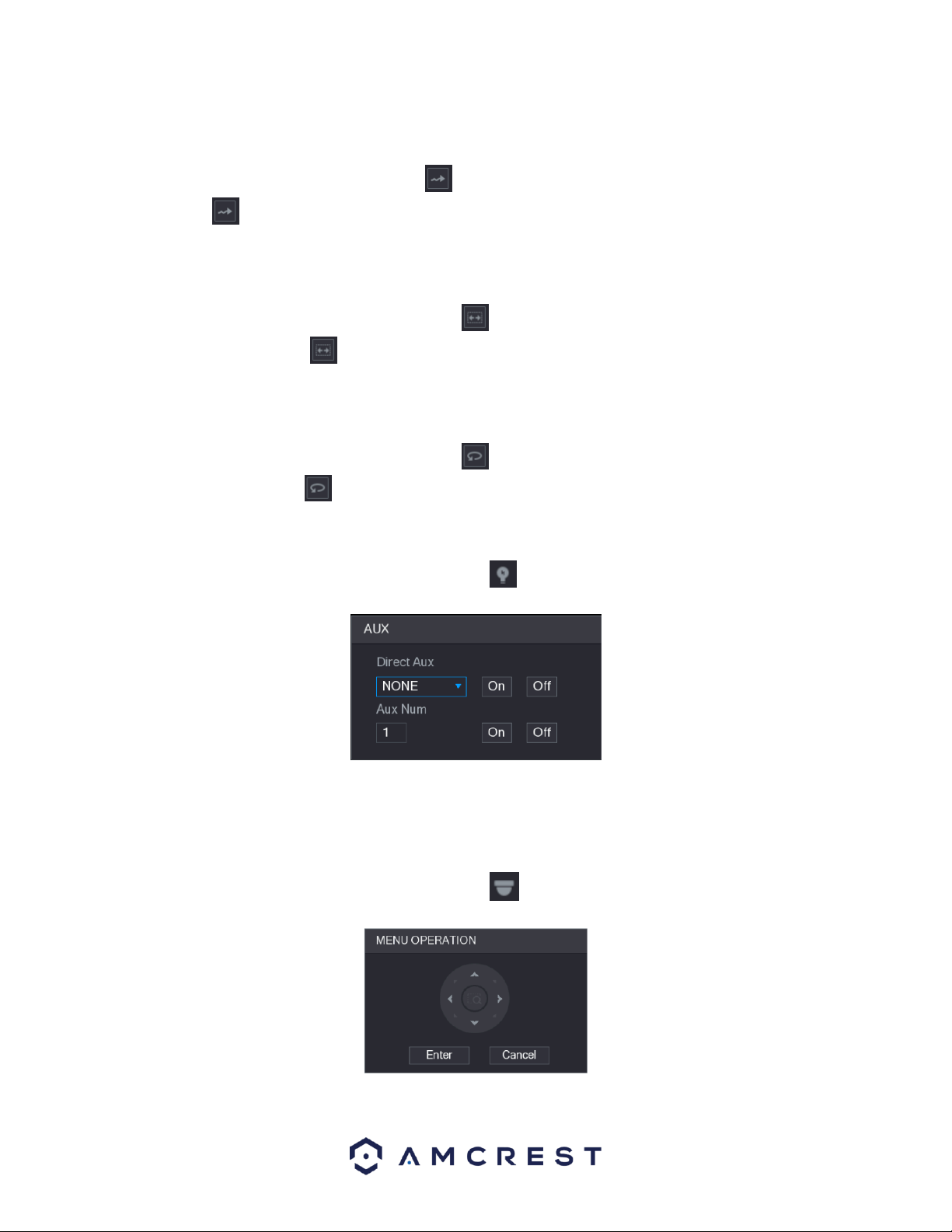
92
6.1.5.3. Calling Patterns
Using the expanded PTZ control panel, enter the value of the pattern you wish to call in the No. box. Once
you have entered this value, click on the icon to access the pattern. To stop calling the pattern, click
on the icon to exit.
6.1.5.4. Calling AutoScan
Using the expanded PTZ control panel, enter the value of the AutoScan you wish to call in the No. box.
Once you have entered this value, click on the icon to access the AutoScan. To stop calling the
AutoScan, click on the icon to exit.
6.1.5.5. Calling AutoPan
Using the expanded PTZ control panel, enter the value of the AutoPan you wish to call in the No. box.
Once you have entered this value, click on the icon to access the AutoPan. To stop calling the
AutoPan, click on the icon to exit.
6.1.6. Using AUX Button
Using the expanded PTZ control panel, click on the icon to access the AUX setting interface.
⚫ In the Direct Aux list, select the option that corresponds to the applied protocol.
⚫ In the Aux Num box, enter the number that corresponds to the AUX switch on the decoder.
6.1.7. Calling the OSD Menu
Using the expanded PTZ control panel, click on the icon to access the Menu Operation interface.
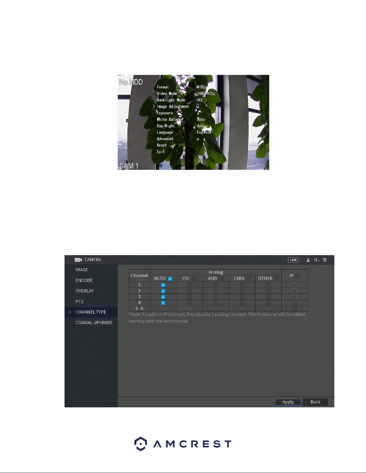
93
To enter the Main Menu of the OSD screen, click on the Enter button in the Main Operation interface.
The OSD screen will appear on the live view screen.
To navigate in the OSD screen, use the directional arrows provided in the main operation interface. To
select a setting, click on the Enter button in the main operation interface.
Note: This option may be available on only certain model cameras and may not apply to all models.
6.1.8. Channel Type
The channel type menu allows the user to configure specific channels types in the system. These channel
types include both Analog and IP channels configurations.
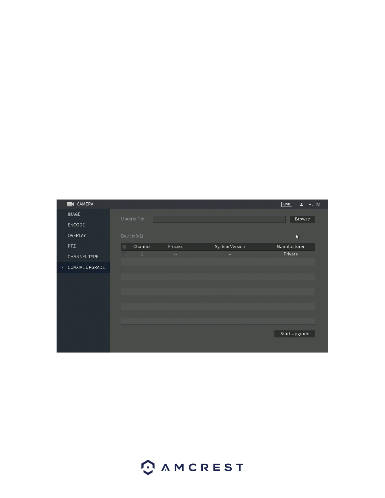
94
Configure the channels.
⚫ Analog Channel: Select the transmission medium such as CVI, CVBS, and then follow the
onscreen instructions to complete the settings.
⚫ IP Channel: Select a channel for IP camera from the last channel number. Select from the
5-6 check box. Then follow the onscreen instructions to complete the settings.
Note: The 5-6 channels are only for IP cameras and are dependent on the model you
purchased. The channel selection for analog cameras or IP cameras are in sequence. For
example, if you want to select channels for IP cameras, you need to select 5-6 first then
apply the analog channels.
Click Apply and follow the onscreen instructions to complete the settings. The device will
reboot. For more information on how to add an IP camera to your device, refer to section If
you do not wish to configure your channel types, click the Back button to exit.
6.1.10. Coaxial Upgrade
The coaxial upgrade screen provides a means of upgrading firmware, specifically for coaxial cameras. The
firmware upgrades in this menu are only related to coaxial connected cameras, not the system itself.
Note: Before continuing with the process, ensure to have an external USB storage device connected to
the system. The storage device should contain the .bin file for the upgrade. To access the .bin, please visit
amcrest.com/firmware and search for your DVR.
Once a USB storage device is input into the system, with the firmware file, click on the Browse button to
locate the file from the USB storage device and click OK. Select the checkbox next to the file and click on
Start Upgrade to begin updating your coaxial camera.
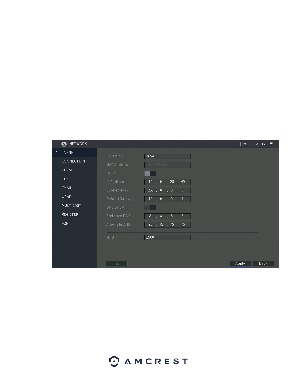
95
Note: If the upgrade is successful, the system will display a message indicating the upgrade is complete. If
the upgrade fails, please check the format of the file you are using.
6.2. Network
This menu controls all network related functions for the DVR and governs how the DVR interacts with the
network it is connected to.
6.2.1. TCP/IP
TCP/IP stands for Transmission Control Protocol/Internet Protocol and it is the language/protocol that
allows communication between internet connected DVRs, whether on a local network, or a on the
Internet at large. This screen allows for TCP/IP settings to be modified for the DVR to establish connection
to the network.
Below is a screenshot of the TCP/IP settings screen:
Below is an explanation of the fields on the TCP/IP settings screen:
• IP Version: This dropdown allows the user to select the IP version. The two options are IPV4 and IPV6.
• MAC address: This field shows the DVR’s MAC address, which is unique to this DVR. This number is read-
only and is used to access a local area network (LAN).
• Static vs DHCP: This check box allows the user to choose between a static IP address, and a dynamic IP
address. DHCP stands for Dynamic Host Configuration Protocol, and this enables the DVR to automatically
obtain an IP address from another network DVR such as a server or more commonly, a router. When the
DHCP function is enabled, the user cannot modify the IP address, Subnet Mask, or Gateway, as these
values are obtained from the DHCP function. To view the current IP address, DHCP needs to be disabled.

96
Note: When PPPoE is enabled, modification of IP Address, Subnet Mask, and Gateway becomes
prohibited.
• IP Address: This field allows the user to enter a custom IP address.
• Subnet Mask: This field allows the user to enter a custom subnet mask. The default subnet mask is
255.255.255.0. This number is used to determine which subnetwork the IP address belongs to.
• Default Gateway: This field allows the user to enter the default gateway for the network. The default
gateway should be on the same IP subnet as the DVR’s IP. That is to say, the specified length of the subnet
prefix should have the same string. For example, if the IP address is 192.168.0.25, the default gateway
should start with 192.168.0.X. The default gateway is usually the IP address of the router.
• MTU: MTU stands for Maximum Transmission Unit. This field allows the user to set the MTU value of
the network adapter. The value ranges from 1280-7200 bytes. The default value is 1500 bytes. Please
note MTU modification may result in network adapter reboot and the network turning off. That is to say,
MTU modification can affect the current network service. The system may pop up a dialog box to confirm
setup when the MTU value is changed. Click the OK button to confirm current value and reboot or can
click the Cancel button to terminate the current modification. Before the modification, you can check the
MTU of the gateway; the MTU of the DVR should be the same or lower than the MTU of the gateway. This
way, packets can be reduced, and the network transmission efficiency be enhanced. The following MTU
values are for reference only.
• 1500: Ethernet information packet maximum value and it is also the default value. It is the typical setup
when there is no PPPoE or VPN. It is the default setup of some routers, switches, and network adapters.
• 1492: Recommend value for PPPoE.
• 1468: Recommend value for DHCP. Preferred DNS server: This field allows the user to enter the DNS
server IP address.
• Alternate DNS server: This field allows the user to enter the Alternate DNS server IP address.
• LAN download: This checkbox allows the user to enable the user to process the downloaded data first.
The download speed is 1.5X or 2.0X compared to the normal streaming speed.
Note: To test the network connections set in this menu, click on the Test button. To apply the settings to your
DVR, click on Apply. If you wish to exit this menu, click on the Back button.
6.2.2. Connection
This screen allows users to configure port connections. It is important that the system is rebooted if any
changes are made to the settings on this screen. Also, ensure that port values do not conflict. Below is a
screenshot of the connection screen:

97
Below is an explanation of the fields on the Connection settings screen:
• Maximum Connection: This field represents the maximum number of users that can be connected to
the DVR at the same time. The maximum number of users the DVR can support at one time is 128.
• TCP Port: This field designates the Transmission Control Protocol (TCP) port number. The default value is
37777.
• UDP Port: This field designates the User Datagram Protocol (UDP) port number. The default value is
37778.
• HTTP Port: This field designates the Hypertext Transfer Protocol (HTTP) port number. The default value
is 80.
• RTSP Port: This field designates the Real Time Streaming Protocol (RTSP) port number. The default value
is 554.
• HTTPS Port: This field designates the Hypertext Transfer Protocol Secure (HTTPS) port number. The
default value is 443.
Note: To apply the settings to your DVR, click on Apply. If you wish to exit this menu, click on the Back
button.
6.2.3. PPPoE
PPPoE stands for Point-to-Point Protocol over Ethernet. This screen allows users to configure PPPoE
connections. Below is a screenshot of the PPPoE screen:
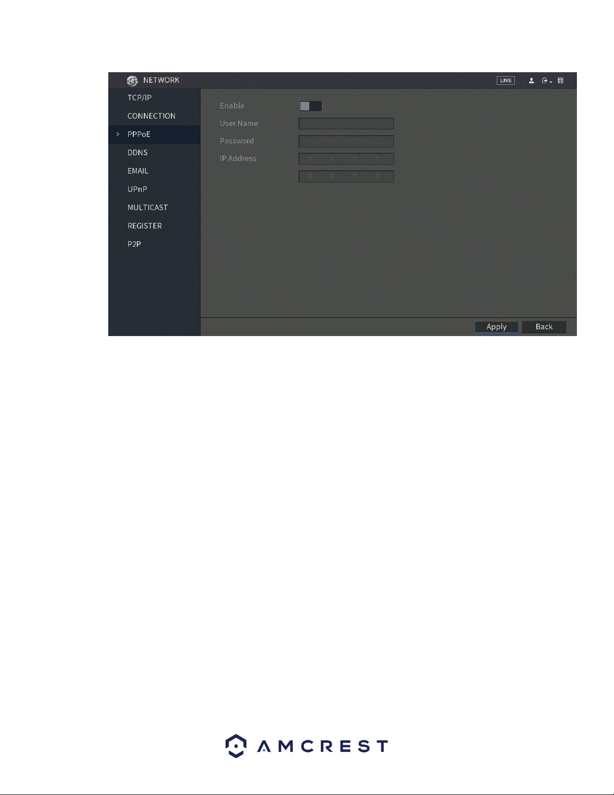
98
To apply the settings, click the Apply button near the bottom right hand corner. After completing the
setup please click the save button to go back to the previous menu.
6.2.4. DDNS
DDNS stands for Dynamic Domain Name Server. This technology is used to automatically update name
servers in real time to help the DVR maintain a persistent address despite changes in location or
configuration. What this means is that even when the DVR is restarted, moved, or reconfigured, it can
keep the same IP address, thus allowing remote users uninterrupted access to the DVR, rather than
having to request a new IP address to use for remote access anytime a change is made.
To use this feature, users will need to setup an account with a DDNS service. The DVR supports a variety
of DDNS services such as AMCREST DDNS, NO-IP DDNS, CN99 DDNS, Dyndns DDNS, and private DDNS
services. Based on which service is selected, different options may show on this screen. For purposes of
this guide, AMCREST DDNS will be used. To use AMCREST DDNS, go to http://www.quickddns.com and
register for an account. If the account is inactive for a year, AMCREST DDNS may take back the domain
name, but an email will be sent beforehand as a warning. Below is a screenshot of the DDNS settings
screen, configured to AMCREST DDNS:
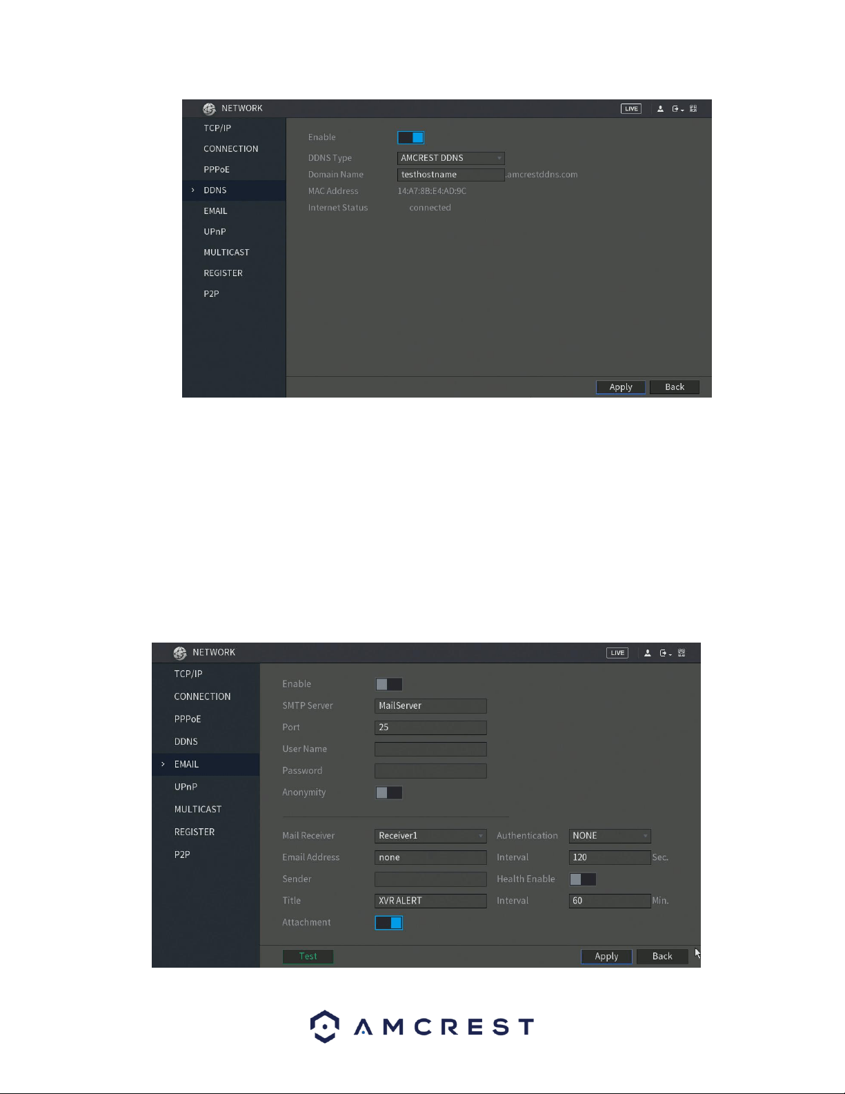
99
Below is an explanation of the fields that can be configured on DDNS settings screen when set to
AMCREST DDNS type.
• Enable: This switch allows the user to enable DDNS on the DVR.
• DDNS: Type: This dropdown box allows the user to select which DDNS service is being used on the DVR.
• Domain Name: This field allows the user to enter the domain name from the AMCREST DDNS service.
• MAC Address: The assigned MAC address for the DVR.
• Internet Status: The connection status of your DDNS connection from the DVR.
6.2.5. Email
This screen allows for the configuring of email settings to permit the DVR to send emails when the
connected cameras or alarms are triggered. Below is a screenshot of the email settings screen:

100
For more information about the settings listed in this menu, refer to the table below:
Parameter
Description
Enable
Enable the email function.
SMTP Server
Enter the address of SMTP server of sender’s email account.
Port
Enter the port value of SMTP server. The default value setting is 25. You can
enter the value according to your actual situation.
User Name
Enter the user name and password of sender’s email account.
Password
Anonymity
If enable the anonymity function, you can login as anonymity.
Mail Receiver
In the Mail Receiver list, select the number of receivers that you want to
receive the notification. The DVR supports up to three mail receivers.
Email Address
Enter the email address of mail receiver(s).
Sender
Enter the sender’s email address. It supports maximum three senders
separated by comma.
Title
Enter the email subject.
Supports Chinese, English and Arabic numerals. It supports maximum 64
characters.
Attachment
Enable the attachment function. When there is an alarm event, the system
can attach snapshots as an attachment to the email.
Authentication
Select the encryption type: NONE, SSL, or TLS.
Interval (Sec.)
This is the interval that the system sends an email for the same type of
alarm event, which means, the system does not send an email upon any
alarm event.
This setting helps to avoid the large amount of emails caused by frequent
alarm events.
The value ranges from 0 to 3600. 0 means that there is no interval.
Health Enable
Enable the health test function. The system can send a test email to check
the connection.
Interval (Min.)
This is the interval that the system sends a health test email.
The value ranges from 30 to 1440. 0 means that there is no interval.
Test
Click Test to test the email sending function. If the configuration is correct,
the receiver’s email account will receive the email.
Note: Before testing, click Apply to save the settings.
Popular Email Servers, Ports, and Encryptions

101
After you have enabled the email settings for your DVR, click on the Test button to test the connection. If the email
test fails, make sure your Email Account has 2-Step Verification turned off. Confirm your Internet settings on the
DVR are configured correctly.
2-Step Verification FAQ Gmail
After you login to your Gmail and you can view your inbox open a new tab and go to:
https://myaccount.google.com/security
Scroll down and find 2-Step Verification under Password & sign-in method, click the pencil icon and disable it. To
apply the settings, click Apply. To exit this menu, click on the Back button.
6.2.6. UPnP
UPnP stands for Universal Plug and Play, and it is a protocol used to easily connect DVRs to the internet. In
the case of this DVR, it allows the DVR to connect to the router in an easy manner to quickly allow for
remote connection. Below is a screenshot of the UPnP settings screen:
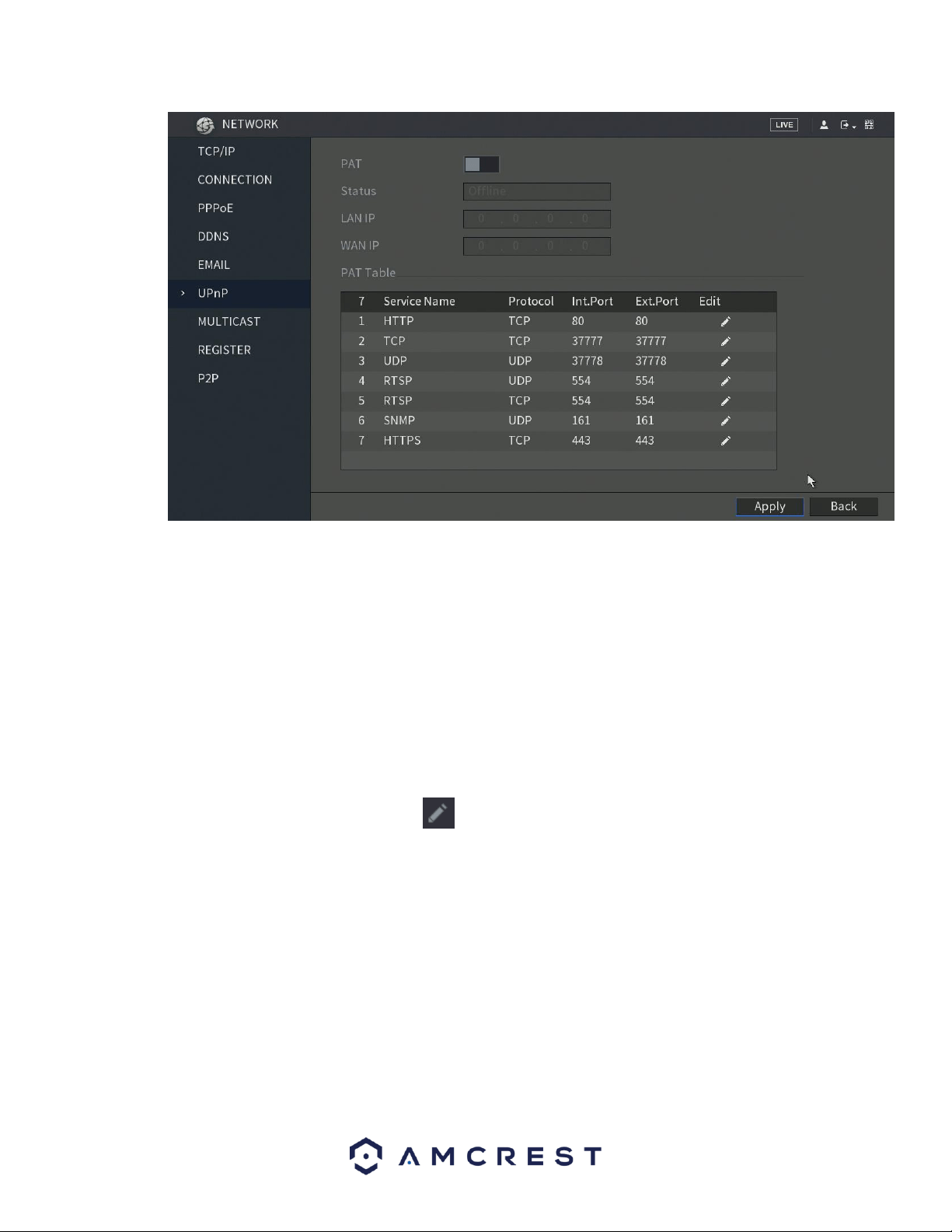
102
Below is an explanation of the fields in the UPnP settings screen:
• PAT: PAT stands for Port Address Translation, and it is something that the UPnP protocol handles. This
checkbox allows the user to enable UPnP on the DVR.
The settings in PAT table correspond to the UPnP PAT table on the router.
◼ Service Name: Name of network server.
◼ Protocol: Type of protocol.
◼ Int. Port: Internal port that is mapped on the DVR.
◼ Ext. Port: External port that is mapped on the router.
To modify the external port, click on the icon next to the protocol you wish to modify.
• UPnP Status: This field shows the UPnP status and has two options:
o Offline: This means that UPnP is offline.
o Successful: This means that UPnP is working.
• LAN IP: This field allows the user to enter the IP address of the router that the DVR is trying to connect
to.
• WAN IP: This field is where the DVR Wide Area Network (WAN) IP is populated. This IP address is what is
used to remotely access the DVR through web access. PAT Table: This table is used to show how the ports
for each protocol listed below have been remapped by the UPnP protocol.
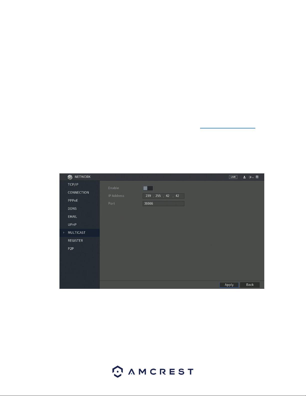
103
o The first column shows the order of the services.
o The second column shows the name of the services. To edit this, double click on the service line
item.
o The third column shows the name of the protocol used by that service. To edit this, double click
on the service line item.
o The fourth column shows the Internal Port used by that service. To edit this, double click on the
service line item.
o The fifth column shows the External Port used by that service. To edit this, double click on the
service line item.
To confirm settings, click the Apply button near the bottom right hand corner. To cancel any
modifications, click the Back button near the bottom right hand corner.
To view a video on how to remotely access your DVR using UPnP, go to http://amcrest.com/videos and
view the video titled “How to Gain Remote Access to Your DVR with Universal Plug and Play”.
6.2.7. Multicast
Multicast is a feature that enables the DVR to broadcast its live view to multiple computers on the same
network. Below is a screenshot of the multicast screen:
Below is an explanation of the fields in the Multicast settings screen:
• Enable: This checkbox allows the user to enable the Multicast feature for the
DVR.
• IP Address: This field allows the user to enter the multicast IP address.
• Port: This field allows the user to enter the port number for the multicast IP
address.

104
For more information on how to configure multicast, see the information below.
Multicast IP Address Range (IPV4): 224.0.0.0 through 239.255.255.255
Well-known IPv6 multicast addresses
Address
Description
ff02::1
All nodes on the local network segment
ff02::2
All routers on the local network segment
ff02::5
OSPFv3 All SPF routers
ff02::6
OSPFv3 All DR routers
ff02::8
IS-IS for IPv6 routers
ff02::9
RIP routers
ff02::a
EIGRP routers
ff02::d
PIM routers
ff02::16
MLDv2 reports (defined in RFC 3810)
ff02::1:2
All DHCP servers and relay agents on the local network segment (defined in RFC 3315)
ff02::1:3
All LLMNR hosts on the local network segment (defined in RFC 4795)
ff05::1:3
All DHCP servers on the local network site (defined in RFC 3315)
ff0x::c
Simple Service Discovery Protocol
ff0x::fb
Multicast DNS
ff0x::101
Network Time Protocol
ff0x::108
Network Information Service
ff0x::181
Precision Time Protocol (PTP) version 2 messages (Sync, Announce, etc.) except peer delay
measurement
ff02::6b
Precision Time Protocol (PTP) version 2 peer delay measurement messages
ff0x::114
Used for experiments
To confirm settings, click the Apply button near the bottom right hand corner. To cancel any
modifications, click the Back button near the bottom right hand corner.
6.2.8. Register
The register feature allows the DVR to register itself with a specified proxy, so that the DVR can be
remotely accessed via a proxy. A proxy is a computer server that acts as an intermediary between client
computers that are seeking resources from a server. Below is a screenshot of the Register settings screen:
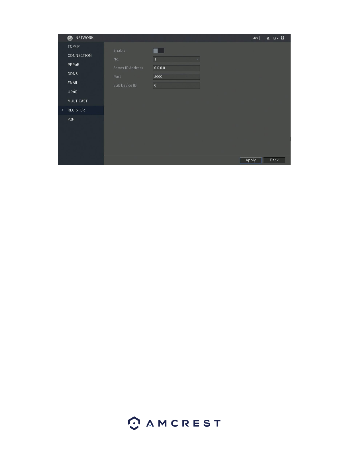
105
Below is an explanation of the fields on the Register settings screen:
• Enable: This checkbox allows the user to enable the Register feature for the
DVR.
• No: This dropdown box allows the user to select the proxy number.
Currently the DVR can only configure one proxy.
• Server IP Address: This field allows the user to enter the proxy server IP
address.
• Port: This field allows the user to enter the proxy port number.
• Sub Device ID: This field allows the user to enter the proxy ID number.
Note: Do not enter a network default port for this port number. It may result in a
port conflict.
To confirm settings, click the Apply button near the bottom right hand corner. To cancel any
modifications, click the Back button near the bottom right hand corner.
6.2.9. P2P
The P2P settings screen is where users can use a QR code to connect their smartphone or tablet to the
DVR. The device uses an app called Amcrest View, and it is available on both iOS and Android. Below is a
screenshot of the P2P settings screen:
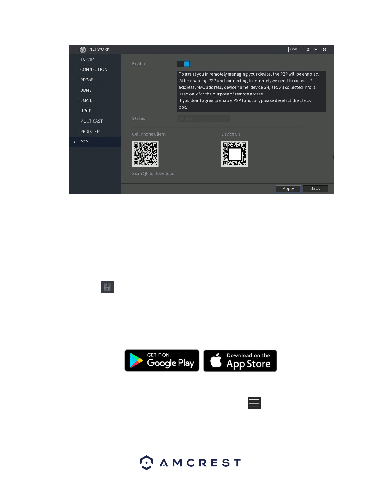
106
To begin, make sure that the Enable switch is in the on position. The status field will then say, Online.
When the P2P function is in online status, you can utilize the QR codes listed on the screen:
⚫ Cell Phone Client: Use your mobile phone to scan the QR code to add the DVR into the
Cell Phone Client, and then you can start accessing the DVR.
⚫ Platform: Obtain the DVR SN by scanning the QR code. Go to the P2P management
platform and add the DVR SN into the platform. Then you can access and manage the DVR
in the WAN.
Note: You can also enter the QR code of the Cell Phone Client and DVR SN by click clicking on the QR
Code icon in the top right of the interface. The icon can also be accessible via the main menu.
6.2.9.1. Using the Cell Phone Client
The P2P screen allows you to add your DVR into your cell phone client. The cell phone app you should use
for this process is Amcrest View Pro. You can access this cell phone app via the P2P menu directly by
scanning the QR Code labeled Cell Phone Client, or via the Google Play or Apple Store.
Once you have downloaded the Amcrest View Pro app from the following sources, please follow the step
by step instructions provided below to proceed.
Access the Amcrest View Pro app from your mobile DVR and tap on the icon to display the main
menu. From the main menu, click on Device Manager to begin adding the DVR to the application.
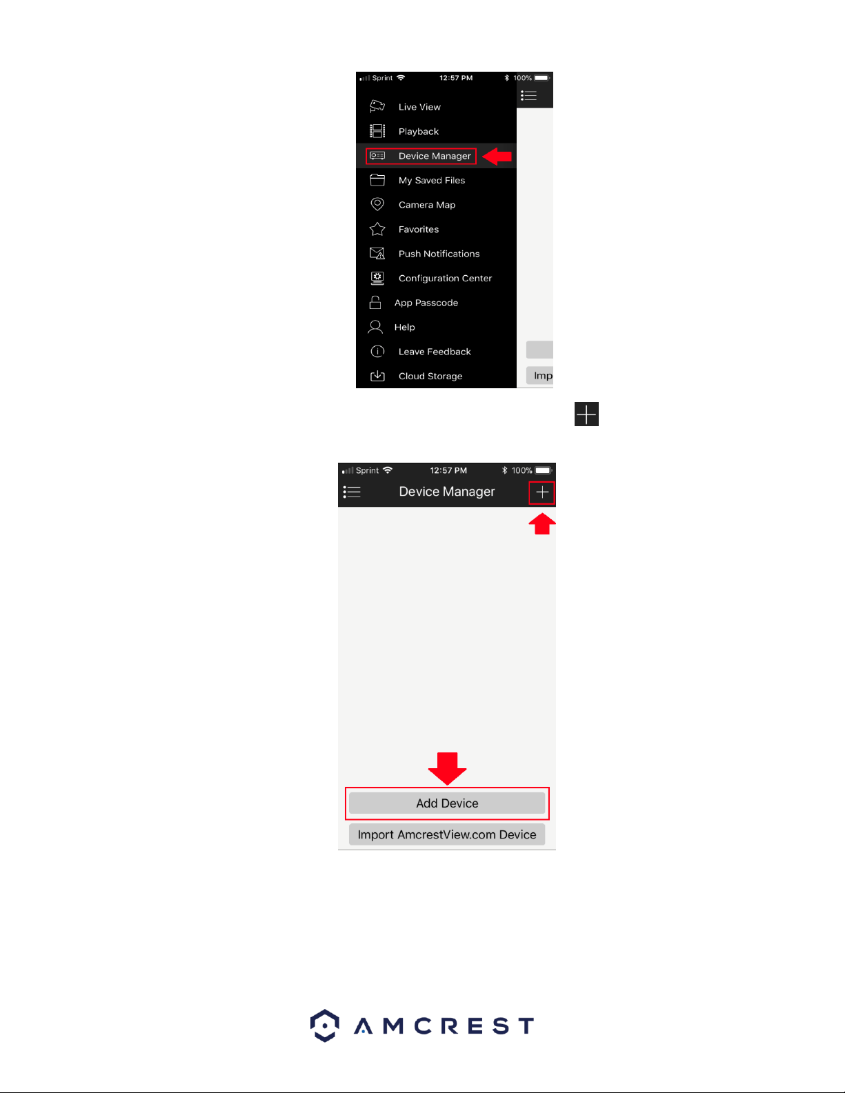
107
From the Device Manager screen, you can click on either Add Device or the icon in the upper right-
hand corner.
Next, you will need to select a DVR type from the Select Device Type menu. Since we are adding a
DVR to the application, click on the DVR/NVR option at the bottom of the menu.
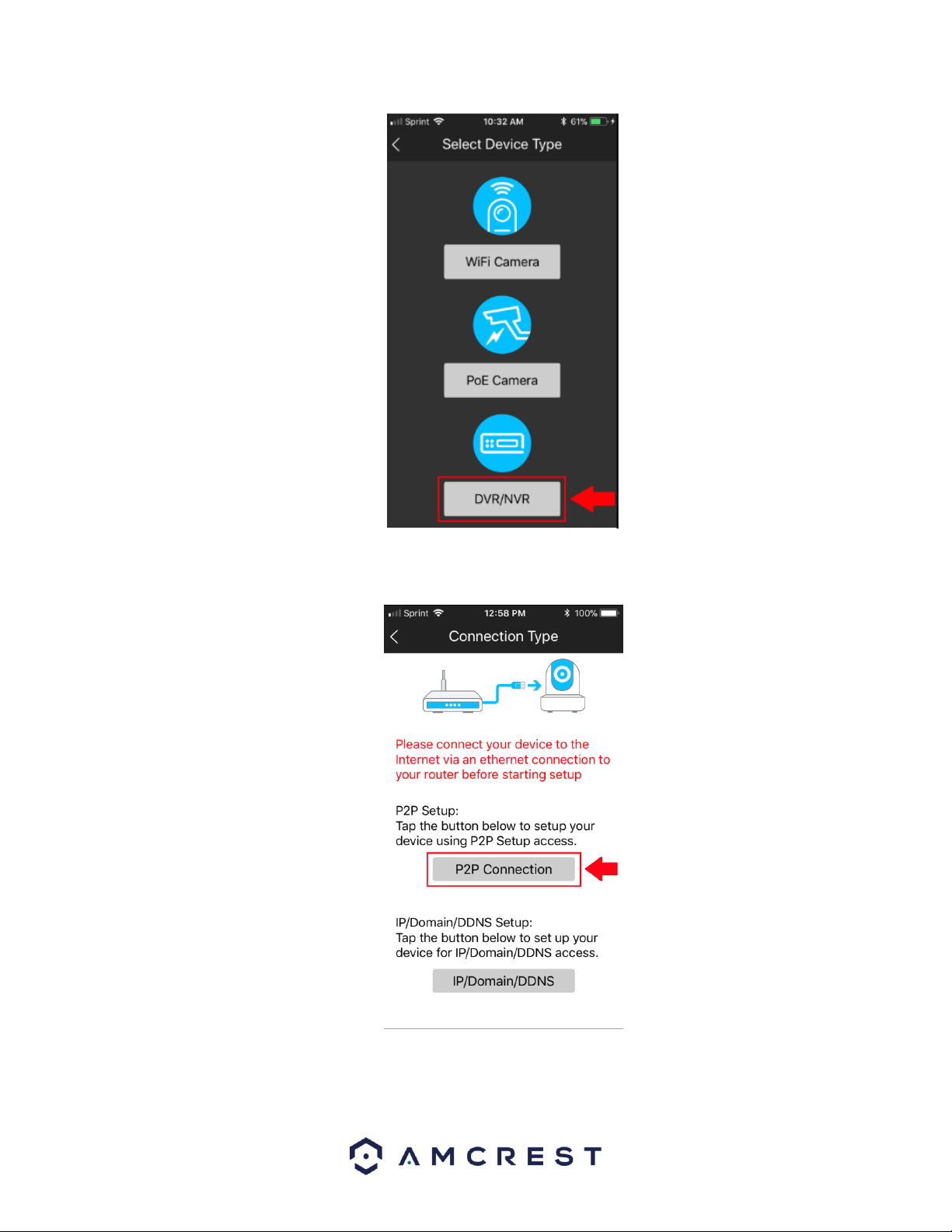
108
When the DVR type has been selected, you will be taken to a Connection Type screen. Since we
will be connecting via a P2P connection, select P2P Connection from this menu.
The app will then prompt you to scan the QR code for your DVR. In the P2P menu of the DVR, scan
the QR code labeled Device SN in the P2P screen
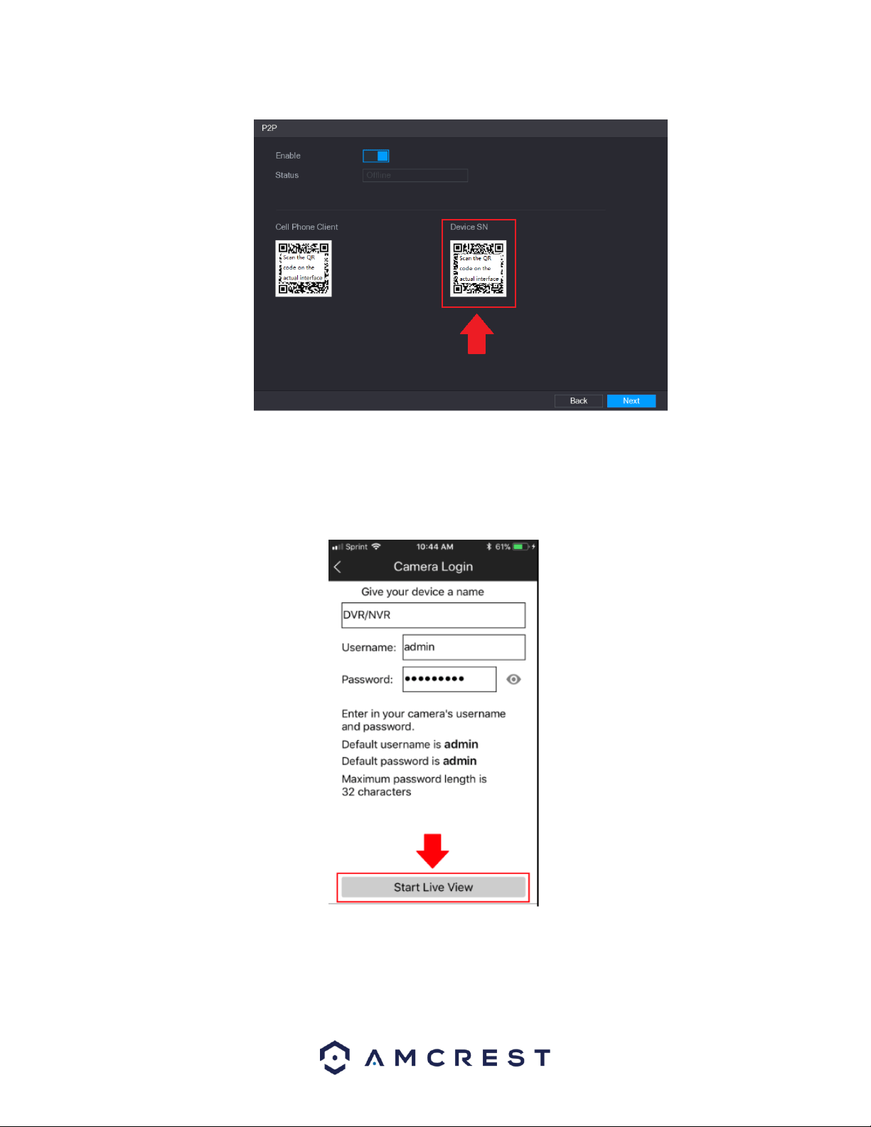
109
Once the Device SN QR code has been scanned, the app will direct you to a login screen. In this menu
you can create a name for your DVR. Also, you will need to enter in the username and password
associated with your DVR.
If this is your first time setting up your DVR, the default username and password is admin.
Once this information is entered, tap the Start Live View button and you should start seeing live video
from the DVR.
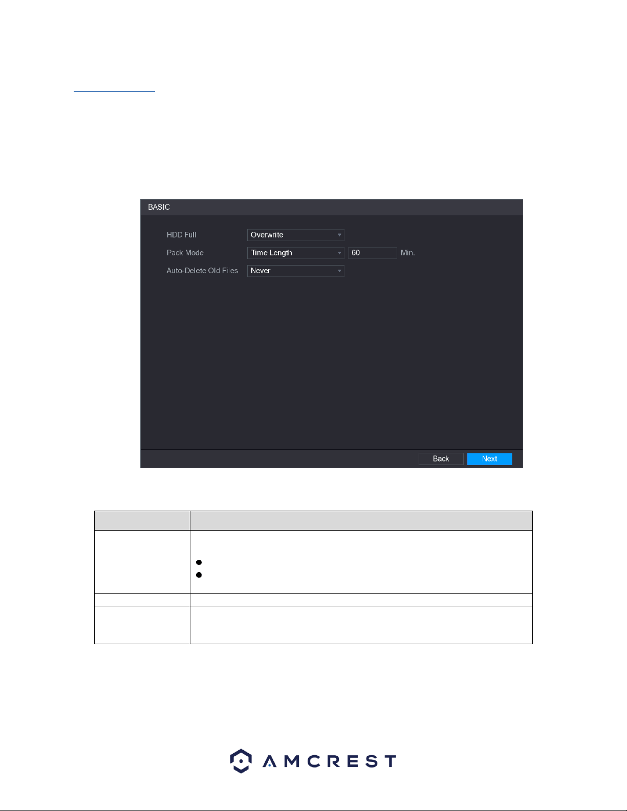
110
6.3. Storage
The sets of options listed in this menu deal with storage data related to the DVR.
6.3.1. Basic
This option allows you to configure the settings for an installed hard drive. For example, you can set
settings for when the hard drive is full, you can set the file length and time of a recorded video, or setup
auto-delete to auto delete old files from the system.
For more information on the settings listed in this menu, refer to the table below.
Parameter
Description
HDD Full
Configure the settings for the situation when all the read/write discs are full,
and there is no more free disc available.
Select Stop Record to stop recording
Select Overwrite to overwrite the recorded video files always from the
earliest time.
Pack Mode
Configure the time length and file length for each recorded video.
Auto-Delete Old
Files
Configure whether to delete the old files and if yes, in the Auto-Delete Old
Files list, select Customized to configure the time length for how long you want
to keep the old files.
6.3.2. Schedule
This screen is used to specify the recording schedule for both recorded video and snapshots.
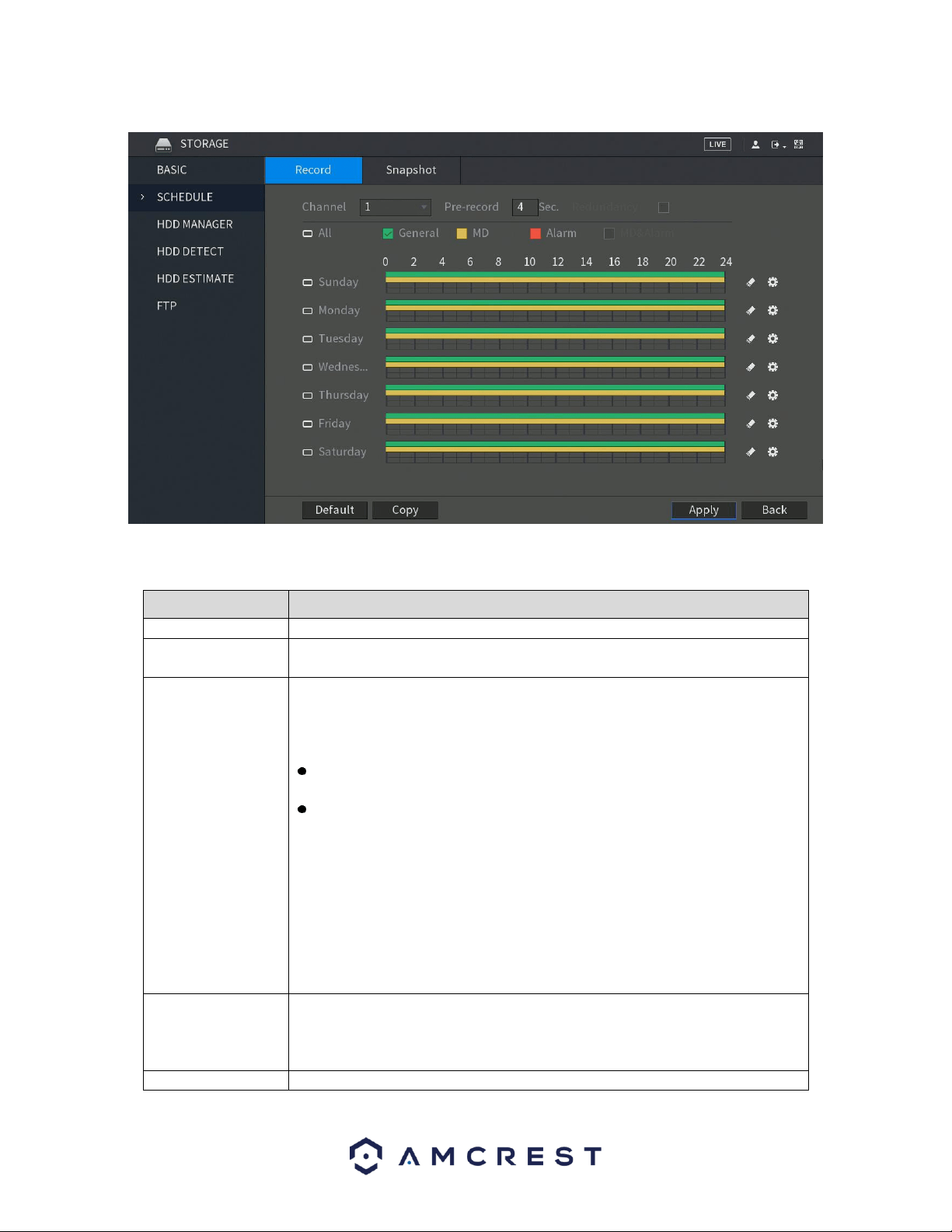
111
For more information on the settings listed in this menu, refer to the table below.
Parameter
Description
Channel
In the Channel list, select a channel to record the video.
Pre-record
In the Pre-record list, enter the amount of time that you want to start the
recording in advance.
Redundancy
If there are several HDDs installed to the DVR, you can set
one of the HDDs as the redundant HDD to save the recorded
files into different HDDs. In case one of the HDDs is damaged,
you can find the backup in the other HDD.
Select Main Menu > STORAGE > HDD MANAGER, and then set a HDD as
redundant HDD.
Select Main Menu > STORAGE > SCHEDUE > Record, and then select the
Redundancy check box.
If the selected channel is not recording, the redundancy function
takes effect next time you record no matter you select the check box
or not.
If the selected channel is recording, the current recorded files will be
packed, and then start recording according to the new schedule.
Note: Not all models support this function. If the option is greyed out on the
screen, it means it is not supported with your specific DVR. The redundant HDD
does not back up snapshots.
Event type
Select the check box of the event type which includes General, MD (motion
detect, video loss, tempering, diagnosis), Alarm (IoT alarms, local alarms,
alarms from alarm box, IPC external alarms, IPC Offline alarms), MD&Alarm,
Intel (IVS events, face detection), and POS.
Period
Define a period during which the configured recording setting is active.

112
Parameter
Description
Note: The system only activates the alarm in the defined period.
Copy
Click Copy to copy the settings to other channels.
There are 5 types of record types listed for this feature:
General: A general recording means that the DVR captures all footage for the specified time period. These
recordings are represented in green are typically tied to 24/7 recording.
MD: An MD recording relates to motion detection. With this setting, the DVR only captures footage when
a motion detection alarm is triggered. MD recordings are represented by the color yellow.
Alarm: An alarm recording means that the DVR captures only footage when an alarm is activated. Alarm
recording is represented by the color red.
MD & Alarm: This type of recording is a combination of motion detection and alarm footage, and records
when either a motion detection alarm or general alarm is activated. MD & Alarm recording is represented
by the color orange.
Intel*: An intel recording means that the DVR captures only footage when an intelligent alarm, such as IVS
triggers have been activated. Intel recordings are represented by the color blue.
Note: Intel events only apply to DVRs with IVS features. Not all model DVRs will have this feature
available.
The system allows for the configuration of up to 6 different time periods. To define a period for the whole
week, you can click on the icon next to All to apply the settings to all time periods. The icon for each
day will then be switched to the icon which means all days have been linked to the applied settings.
To define a period for specific days, click on the icon on the days you wish to choose. Once chosen,
the icon will switch to a icon indicating the applied settings have been linked to those specific days.
To set a recording schedule for your DVR, on the timeline, you can choose which record type you want to
set and drag the mouse over specific time frames, or you can click on the icon located on the right of
the day you wish to set the schedule to set configurations.
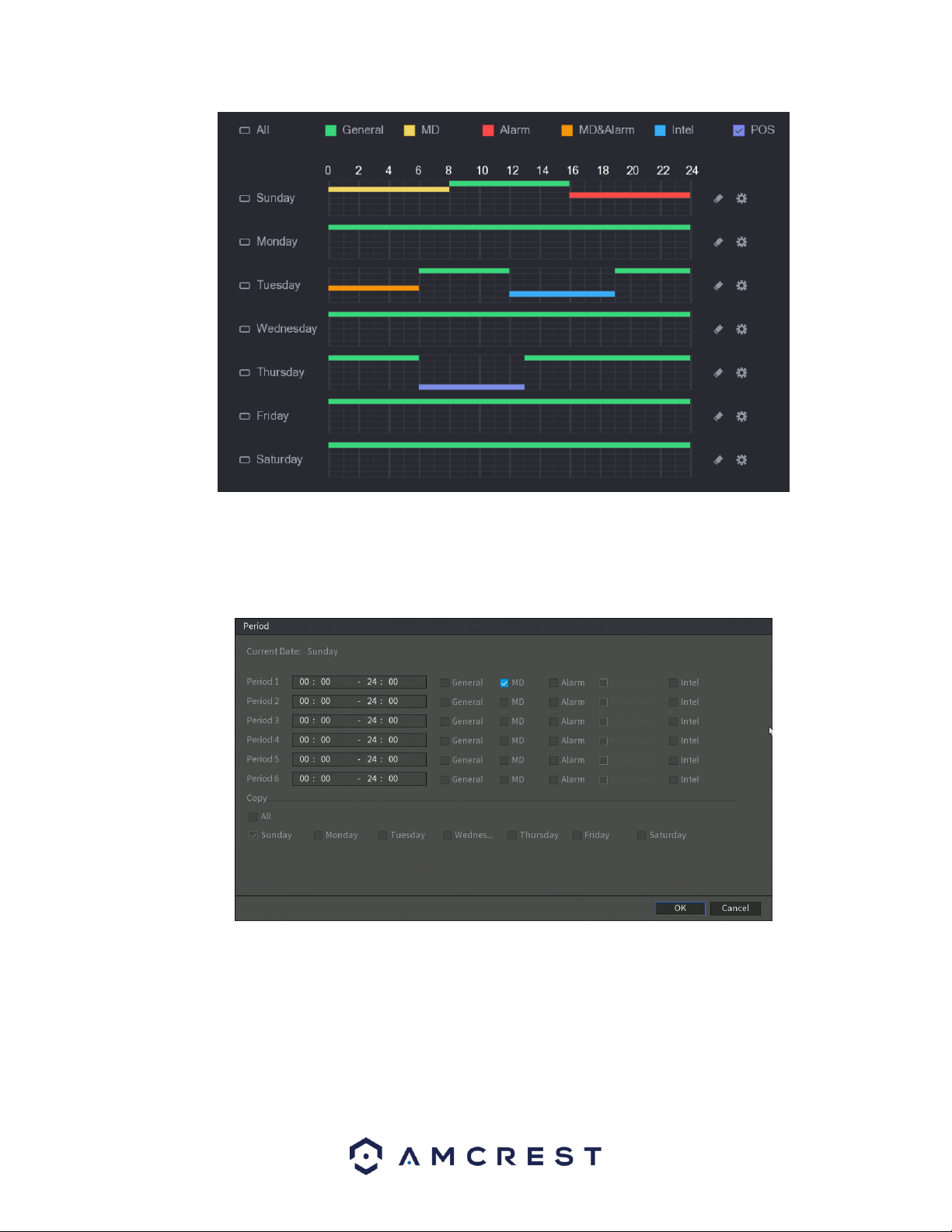
113
If you choose to set periods via the set Period menu, enter in the time frame for the period you want and
select the event checkbox you wish to apply. There are total of six periods. If you wish to copy these
settings and apply them to multiple days, you can do so in the Copy menu. To apply all settings for each
day, click on All. If you wish to apply these settings to activate on specific days, click on the day you wish
to choose from this menu. When you are finished, click OK to continue.
When you have finished applying your schedule settings, be sure to click Apply to apply the settings to
your DVR. To revert to default settings in this menu, click on Default. If you wish to apply these settings to
multiple channels on your DVR, click on the Copy button and select which channels you would like to be
configured. To select all channels, click on the All button in this menu. To exit the schedule menu, click on
Back button.

114
6.3.2.1. Snapshot
This tab is where snapshot recording settings are configured. Below is a screenshot of the Snapshot
settings screen:
For more information on the settings listed in this menu, refer to the table below.
Parameter
Description
Channel
In the Channel list, select a channel to record the video.
Pre-record
In the Pre-record list, enter the amount of time that you want to start the
recording in advance.
Redundancy
If there are several HDDs installed to the DVR, you can set
one of the HDDs as the redundant HDD to save the recorded
files into different HDDs. In case one of the HDDs is damaged,
you can find the backup in the other HDD.
Select Main Menu > STORAGE > HDD MANAGER, and then set a HDD as
redundant HDD.
Select Main Menu > STORAGE > SCHEDUE > Record, and then select the
Redundancy check box.
If the selected channel is not recording, the redundancy function
takes effect next time you record no matter you select the check box
or not.
If the selected channel is recording, the current recorded files will be
packed, and then start recording according to the new schedule.
Note: Not all models support this function. If the option is greyed out on the
screen, it means it is not supported with your specific DVR. The redundant HDD
does not back up snapshots.
Event type
Select the check box of the event type which includes General, MD (motion
detect, video loss, tempering, diagnosis), Alarm (IoT alarms, local alarms,
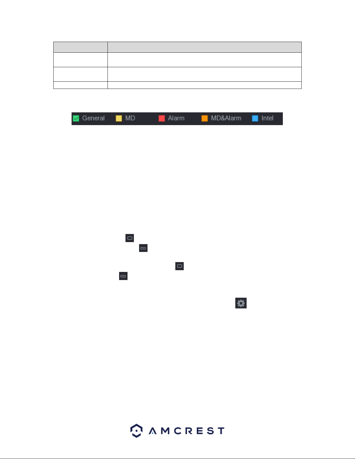
115
Parameter
Description
alarms from alarm box, IPC external alarms, IPC Offline alarms), MD&Alarm,
Intel (IVS events, face detection), and POS.
Period
Define a period during which the configured recording setting is active.
Note: The system only activates the alarm in the defined period.
Copy
Click Copy to copy the settings to other channels.
There are 5 types of record types listed for this feature:
General: A general recording means that the DVR captures all footage for the specified time period. These
recordings are represented in green are typically tied to 24/7 recording.
MD: An MD recording relates to motion detection. With this setting, the DVR only captures footage when
a motion detection alarm is triggered. MD recordings are represented by the color yellow.
Alarm: An alarm recording means that the DVR captures only footage when an alarm is activated. Alarm
recording is represented by the color red.
MD & Alarm: This type of recording is a combination of motion detection and alarm footage, and records
when either a motion detection alarm or general alarm is activated. MD & Alarm recording is represented
by the color orange.
Intel: An intel recording means that the DVR captures only footage when an intelligent alarm, such as IVS
triggers have been activated. Intel recordings are represented by the color blue.
The system allows for the configuration of up to 6 different time periods. To define a period for the whole
week, you can click on the icon next to All to apply the settings to all time periods. The icon for each
day will then be switched to the icon which means all days have been linked to the applied settings.
To define a period for specific days, click on the icon on the days you wish to choose. Once chosen,
the icon will switch to a icon indicating the applied settings have been linked to those specific days.
To set a recording schedule for your DVR, on the timeline, you can choose which record type you want to
set and drag the mouse over specific time frames, or you can click on the icon located on the right of
the day you wish to set the schedule to set configurations.
116
If you choose to set periods via the set Period menu, enter in the time frame for the period you want and
select the event checkbox you wish to apply. There are total of six periods. If you wish to copy these
settings and apply them to multiple days, you can do so in the Copy menu. To apply all settings for each
day, click on All. If you wish to apply these settings to activate on specific days, click on the day you wish
to choose from this menu. When you are finished, click OK to continue.
When you have finished applying your schedule settings, be sure to click Apply to apply the settings to
your DVR. To revert to default settings in this menu, click on Default. If you wish to apply these settings to
multiple channels on your DVR, click on the Copy button and select which channels you would like to be
configured. To select all channels, click on the All button in this menu. To exit the schedule menu, click on
Back button.
6.3.3. HDD Manager
This screen is meant to help the user monitor the DVR’s hard drives. Using this screen, the user can see
the current HDD type, status, and capacity. The user can also use this screen to format hard drives and
change hard drive properties. Below is a screenshot of the HDD Manage settings screen:
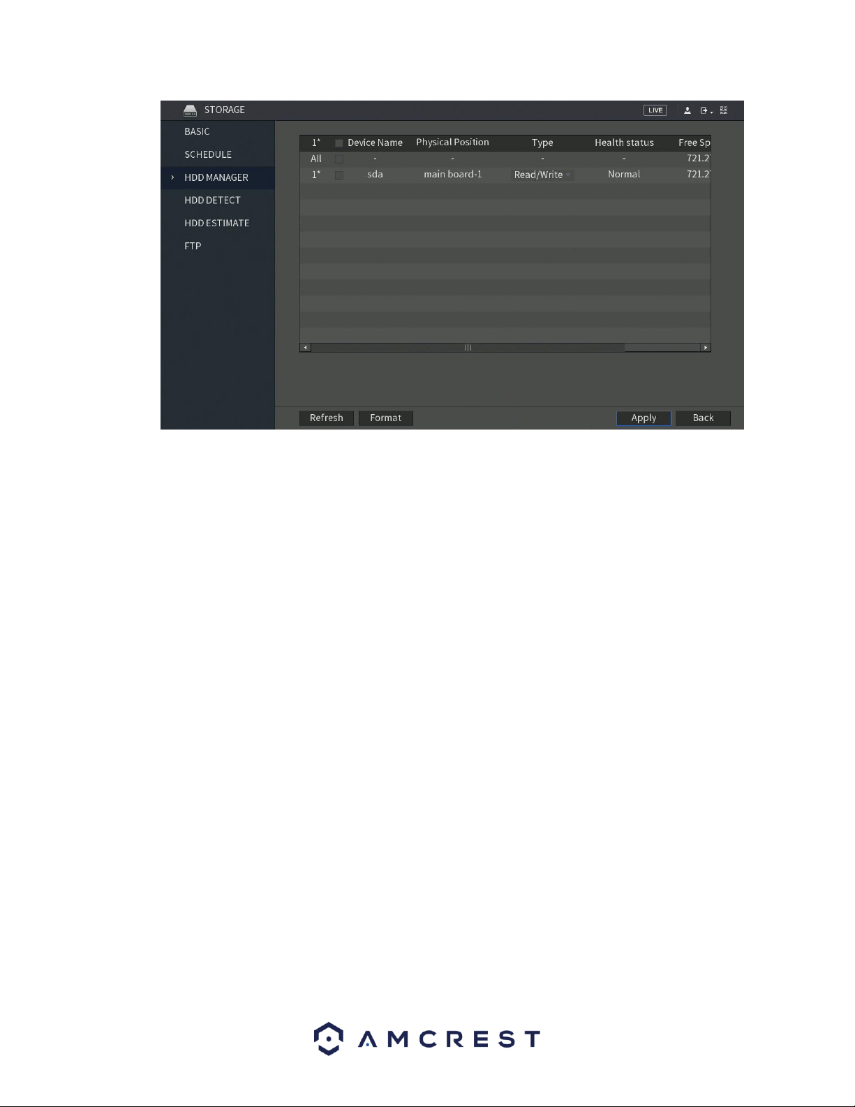
117
This menu shows what hard drives are currently connected to the DVR and displays information about
them.
• DVR Name: This column shows the names of the connected hard disk drives (HDD).
• Physical Position: This column shows the location of the board in relation to its connection.
• Type: This column shows the type of access the DVR has to the hard drive. To change a hard
drive’s type, click the downward arrow next to the HDD’s hard drive’s type and select the desired
type from this field. There are currently two types of possible settings.
▪ Read/Write: This allows the DVR to both read and write data on the HDD.
▪ Read-Only: This allows the DVR to only read data that is on the HDD.
• Health Status: This column shows the status of the connected hard drive. There are three types
of statuses associated with this DVR:
▪ Normal: This means the hard drive is operating normally.
▪ Error: This means the DVR is experiencing an error when attempting to access
the hard drive
▪ Disconnected: This means that the HDD has disconnected from the DVR.
Free Space/Total Space: This field shows the free space available on the hard drive compared to
its total capacity.
To refresh the hard drive list, click Refresh near the bottom left hand corner. To format a hard drive,
select a hard drive to format from the list, and then click Format near the bottom left hand corner. To
confirm settings, click the Apply button near the bottom right hand corner. To cancel any modifications,
click the Back button near the bottom right hand corner.
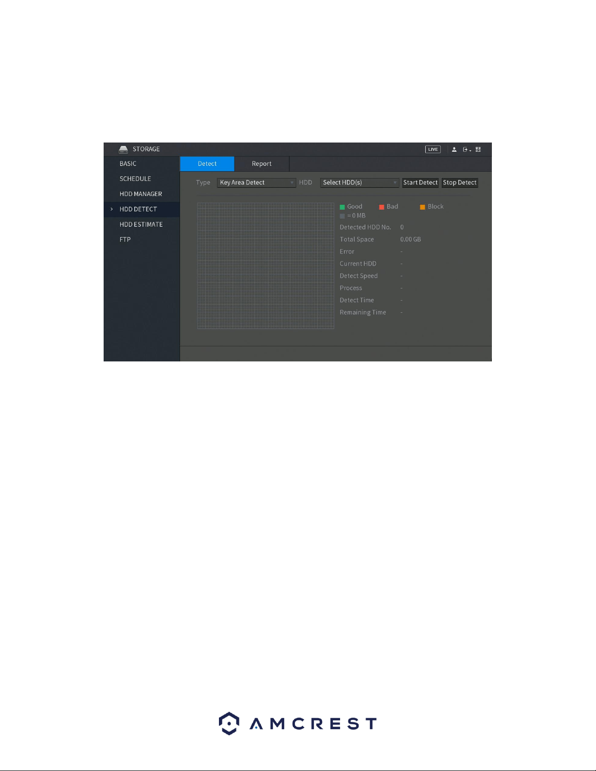
118
6.3.4. HDD Detect
This menu allows the user to detect the current status of an installed hard drive. This is useful in detecting
the performance of your hard drive as well as if it needs to be replaced or is defective. Below is a screen
shot of the HDD Detect menu:
The system allows you to detect a hard drive on your system via two types of settings:
• Key Area Detect: Which scans files saved in the HDD. The detected bad files can be repaired
by formatting the HDD. If there are no files present in the HDD, the system will not detect
any bad files associated with your system.
• Global Detect: Which scans the entire HDD for errors. This option may take longer and may
affect any recordings that are being applied to the system during operation.
To begin the process, in the Detect tab, click on the Type of detect you would like to perform and then in
the HDD drop down menu, select the HDD DVR you would like to scan. When selected, click on the Start
Detect button to begin scanning the HDD for errors.
Note: HDD detection may result in record file loss. If you would like to proceed, click OK. To cancel, press
Cancel.
When the process has completed, you will see the results of the scan on the screen. All good information
will be listed in green, the bad will be in red and any blocked data will be shown in orange.
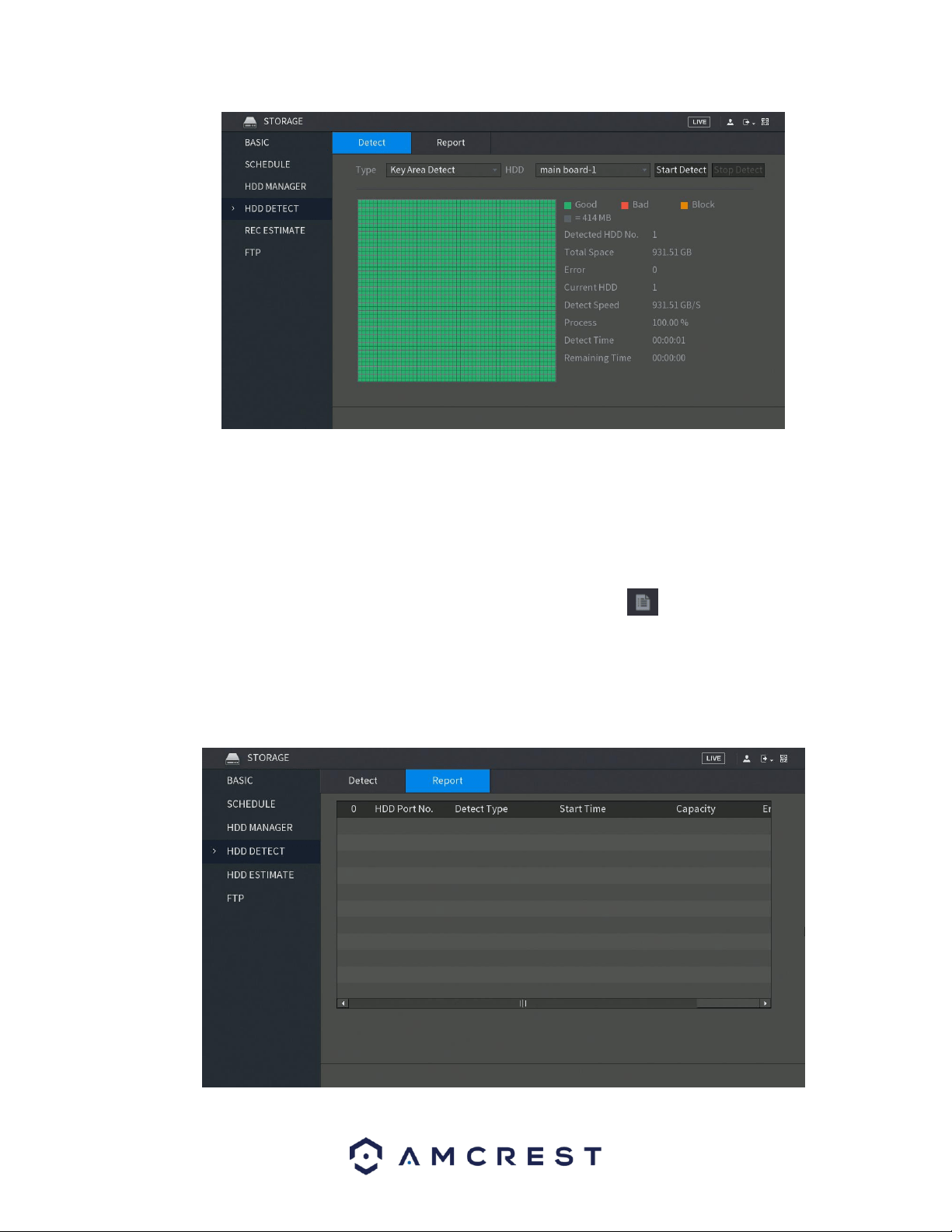
119
6.3.4.1. Report
The report tab in the HDD Detect menu allows the user to view a detailed report of the scan that was
previously executed in the detection menu.
The Report tab will show the HDD Port No. that was being scanned, the Detect Type that was used for
the scan, the Start Time of the scan, the Capacity of the hard drive, any Error present, and the physical
report can be accessed in the View field. To view the report, click on the icon in this field. When the
report is accessed you will notice two tabs:
• Detect Results: Which shows a basic overview of the scan.
• S.M.A.R.T. (Self-Monitoring-Analysis and Reporting Technology): Which shows more details of
the scan.
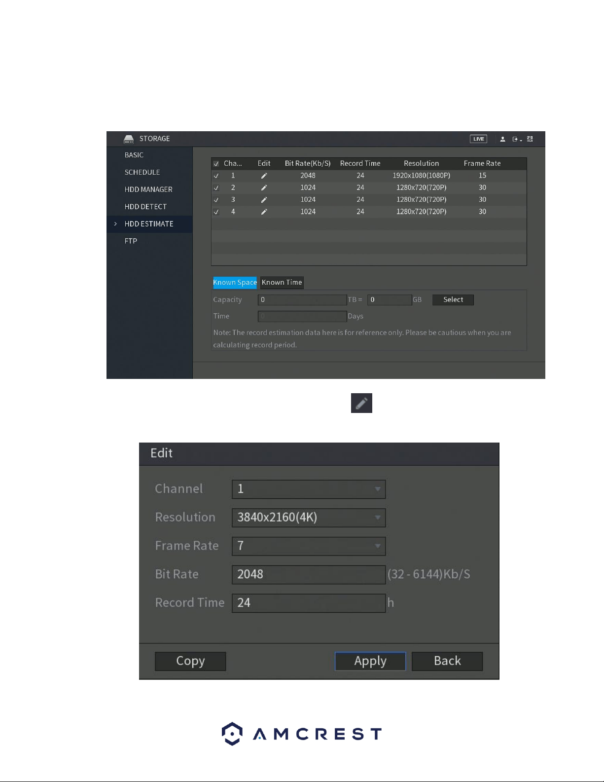
120
6.3.5. HDD Estimate
The record estimate menu allows the user to calculate how long you can record video for on the HDD
according to its capacity. This calculation can also be relevant to a known time of a recording period.
To edit a specific channel’s settings in this menu, click on the icon listed in the Edit field. You will be
taken to an edit interface.
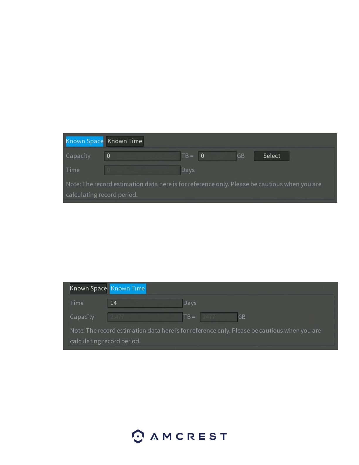
121
In this menu you can edit the resolution, frame rate, bit rate and record time, in hours, for the
specific channel in the calculation. To copy these settings to other channels in the system, click
on the Copy button to select the channels. When finished, click OK. To apply the settings, click on
Apply. To exit the edit menu, click on the Back button.
6.3.5.1. Calculating Recording Time
Calculating recording time in the REC ESTIMATE can be done through either a Known Space on the DVR or
via a Known Time.
To begin, click on the Select button and set the hard drive you would like to calculate. To set the hard
drive, select the HDD from the menu, and click on Apply. In the Capacity field, enter the capacity, in TB,
you would like to calculate. The approximate amount of time for the applied settings will be displayed in
the Time field. This will be the amount of time you will have to record on with this capacity of hard drive.
Similarly, you can make calculations based on a known time. Click on the Known Time tab, and then enter
the amount of time you would like to record for in the Time field. The time field will be calculated by days.
Once you enter the desired time, the capacity calculate, in TBs, will be displayed in the Capacity field.
6.3.6. FTP
FTP stands for File Transfer Protocol. This protocol allows for remote uploading of files to a server. This
feature requires the use of an FTP tool on a computer to enable the use of FTP features on the DVR.
Once an FTP tool has been acquired, installed, and configured to allow read, write, append, and delete
access, then the DVR can be configured to use FTP. Below is a screenshot of the FTP menu screen:
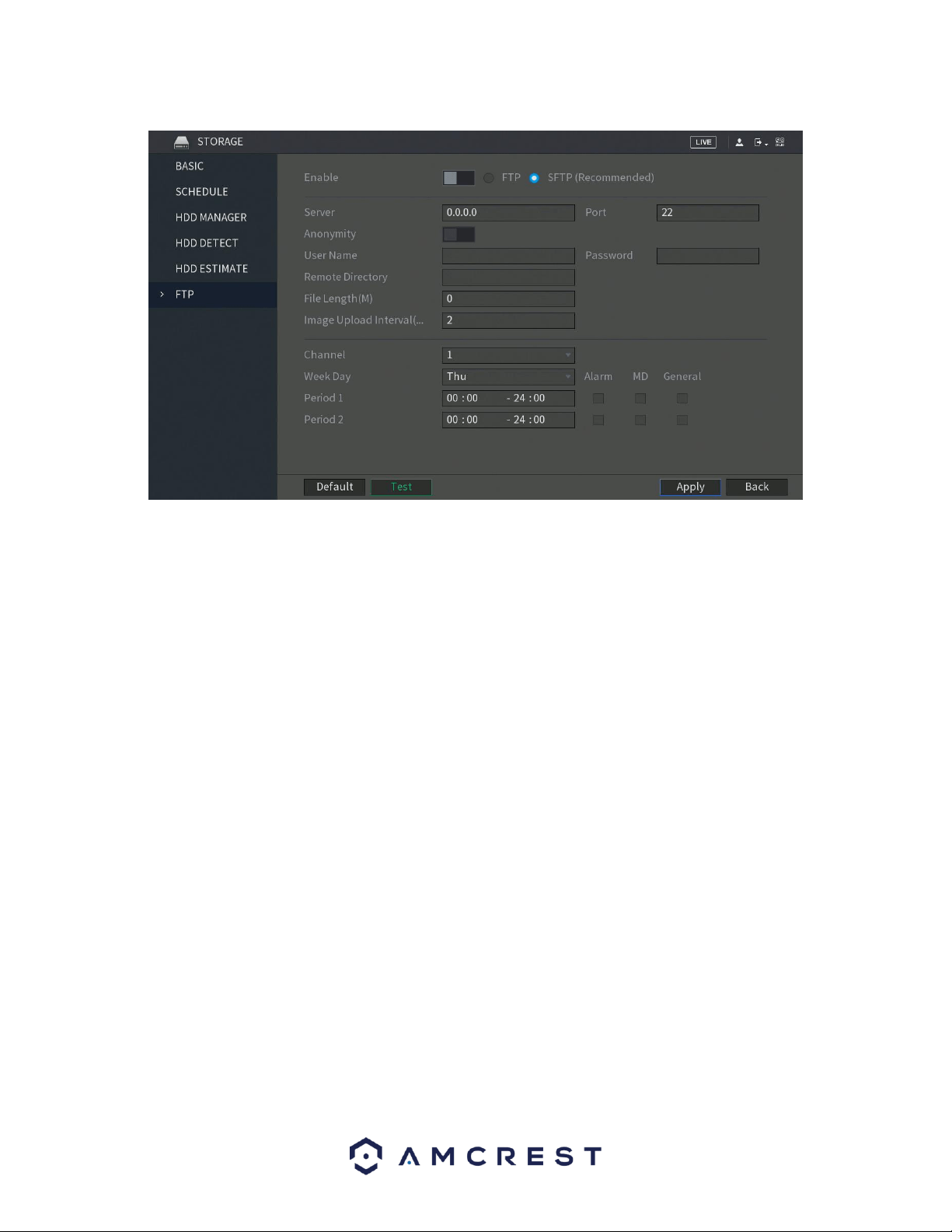
122
Below is an explanation of the fields on the FTP settings screen:
• Enable: This toggle switch allows the user to enable the FTP feature for
the DVR.
• Host IP: This field allows the user to enter the FTP server IP address and
port.
• User Name: This field allows the user to enter the FTP username.
• Password: This field allows the user to enter the FTP server password.
The checkbox next to this field enables anonymous access to the FTP.
• Remote Directory: This field allows the user to designate which folder
the DVR will upload files to.
• File Length: This field allows the user to dictate how large upload files
can be.
• Image Upload Interval: This field allows the user to define, in seconds,
how often images can be uploaded to the FTP server.
• Channel: This field allows the user to pick a channel to set FTP settings
for.
• Weekday: This field allows the user to pick a day of the week to set FTP
settings for.
Period 1: This field allows the user to specify a time period and what
types of files to upload (Alarm, Motion, Regular).
Period 2: This field allows the user to specify a time period and what
types of files to upload (Alarm, Motion, Regular).
To revert to default settings, click the Default button near the bottom left hand corner. To test the current
settings, click Test near the bottom left hand corner. To confirm settings, click the Apply button near the
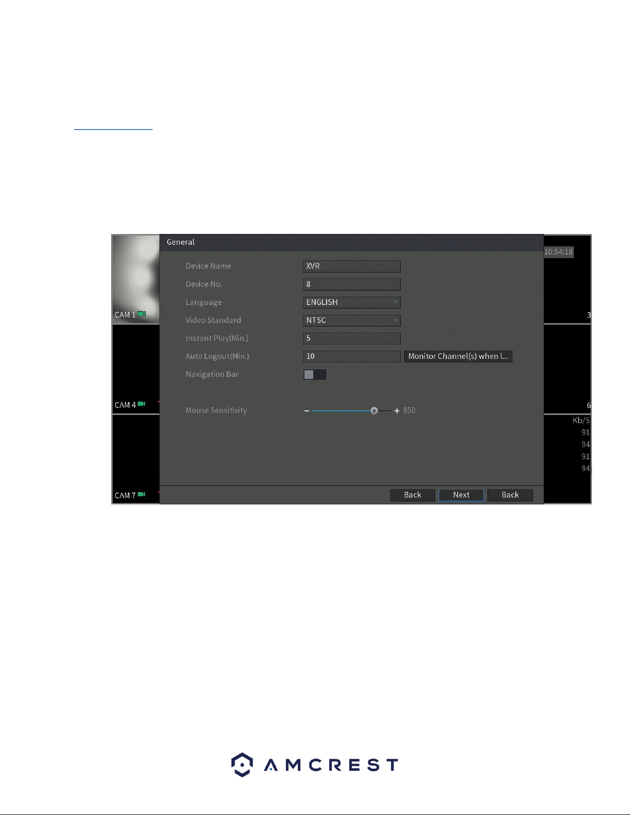
123
bottom right hand corner. To cancel any modifications, click the Back button near the bottom right hand
corner.
6.4. System
The systems menu allows you to access general information on your DVR as well as, view system
security settings, maintenance, import/export functions, default settings, and upgrades.
6.4.1. General
This menu allows you to set the name for your DVR as well as provides several general options associated
with your DVR.
6.4.1.1 Date&Time
The next screen that appears will be the Date & Time settings screen. This is where you can set the date
and time for your specific location. If you wish to utilize daylight savings time, toggle the DST toggle switch
to the on position. Once you have selected the proper date and time for your DVR, click the Next button
to continue.
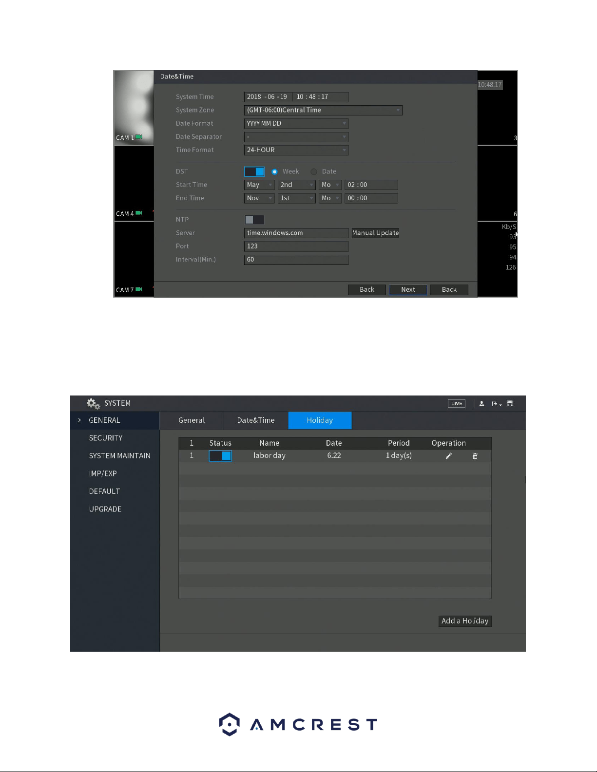
124
Note: Make sure to toggle the NTP toggle switch to the off position to avoid syncing your DVR to the NTP
server.
6.4.1.2. Holiday
This screen displays the holiday settings for the DVR. Below is a screenshot of the Holiday settings screen:
Below is an explanation of the fields on the Holiday settings screen:
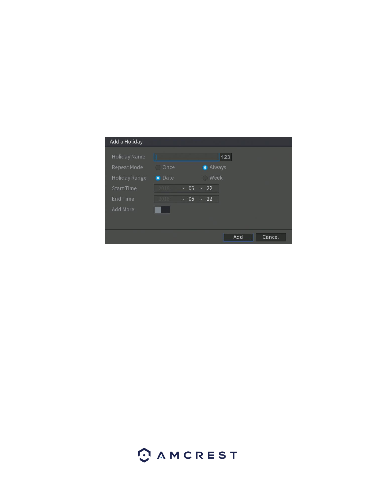
125
• 1: This number indicates how many holidays are in the system. Each line
item has a number to signify its place in the list.
• Status: This toggle switch indicates the status of the holiday.
• Name: This column is where the name of the holiday is displayed.
• Date: This column shows the date that the holiday occurs on.
• Period: This column shows the range in which the holiday occurs.
• Edit: This column has a button that allows for the editing of the holiday.
• Delete: This column has a button that allows for the deletion of the holiday.
Add New Holidays: This button allows the user to add a holiday. Below is screenshot of the Add New
Holidays screen.
To add a new holiday to this screen, enter the details of the holiday and press the Add button. If you do
not wish to add a new holiday in the system, click the Cancel button.
6.4.2. Security
This menu allows the user to modify basic security settings within the DVR. In this menu you can configure
access permissions from host IPs and set password reset guidelines.
6.4.2.1. Access Right
This tab allows the user to configure access permission from host IPs. These types of modifications can
include three of the following types:
⚫ White list includes the host IP that are permitted to access the DVR.
⚫ Back list includes the host IP that are not permitted to access the DVR.
⚫ Update time white list includes the host IP that are permitted to sync the DVR time.
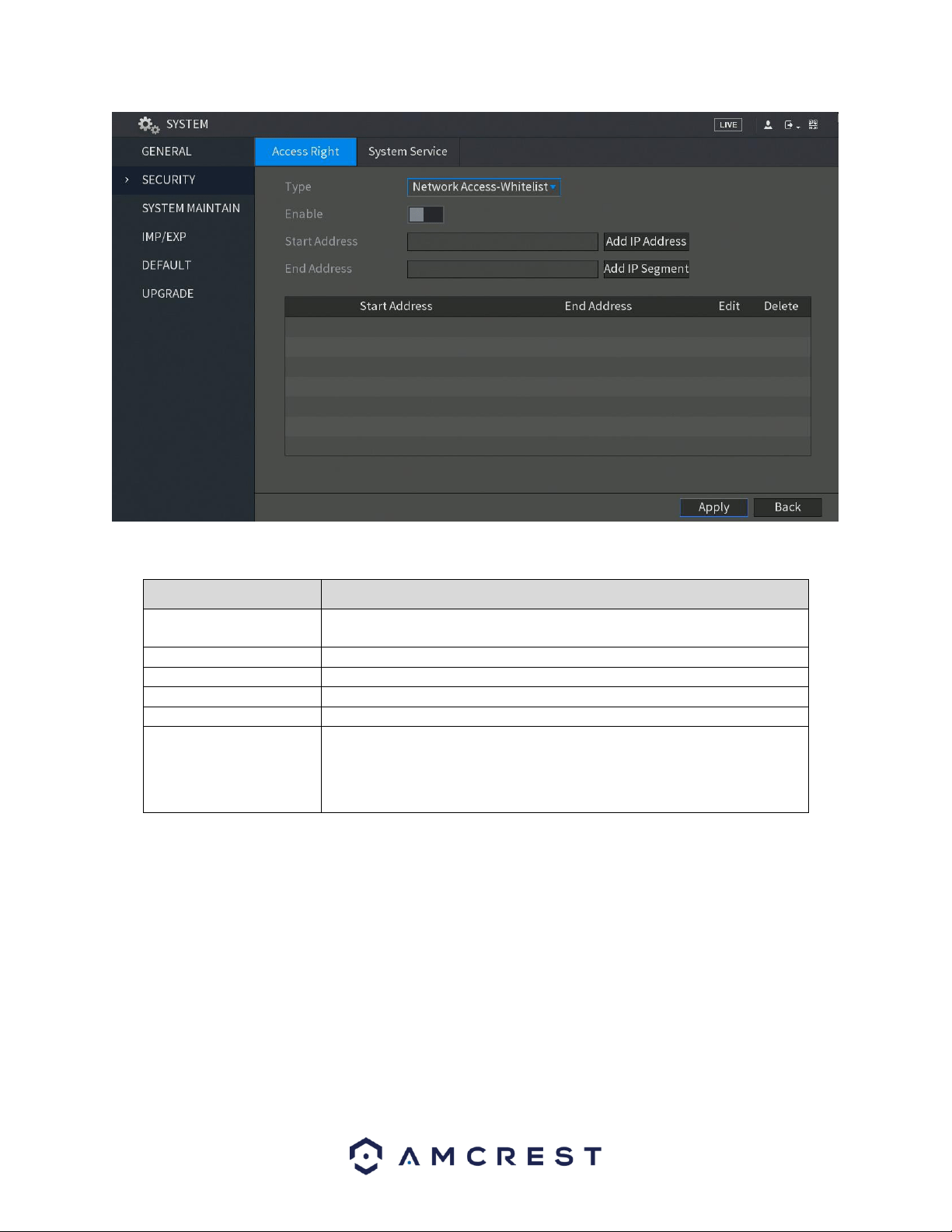
126
For more information on the settings provided in this menu, refer to the table listed below:
Parameter
Description
Type
In the Type list, you can select Limits of network-whitelist, Limits of
network-blacklist, or Update time-whitelist.
Enable
Enable the security settings.
Start Address
Enter a single IP address or a start IP address of a network segment.
Add IP Address
Click Add IP Address to add a single IP address.
End Address
Enter the end IP address of a network segment.
Add IP Segment
Click Add IP Segment to add the IP addresses from the start IP through
the end IP.
Note: The system supports up to 64 IP addresses.
When you have completed the access right settings for this menu, click on the Apply button to apply the
settings to your DVR. To cancel, click on the Back button.
6.4.2.2. System Service
This tab allows the user to enable or disable the additional password reset functions in the system.
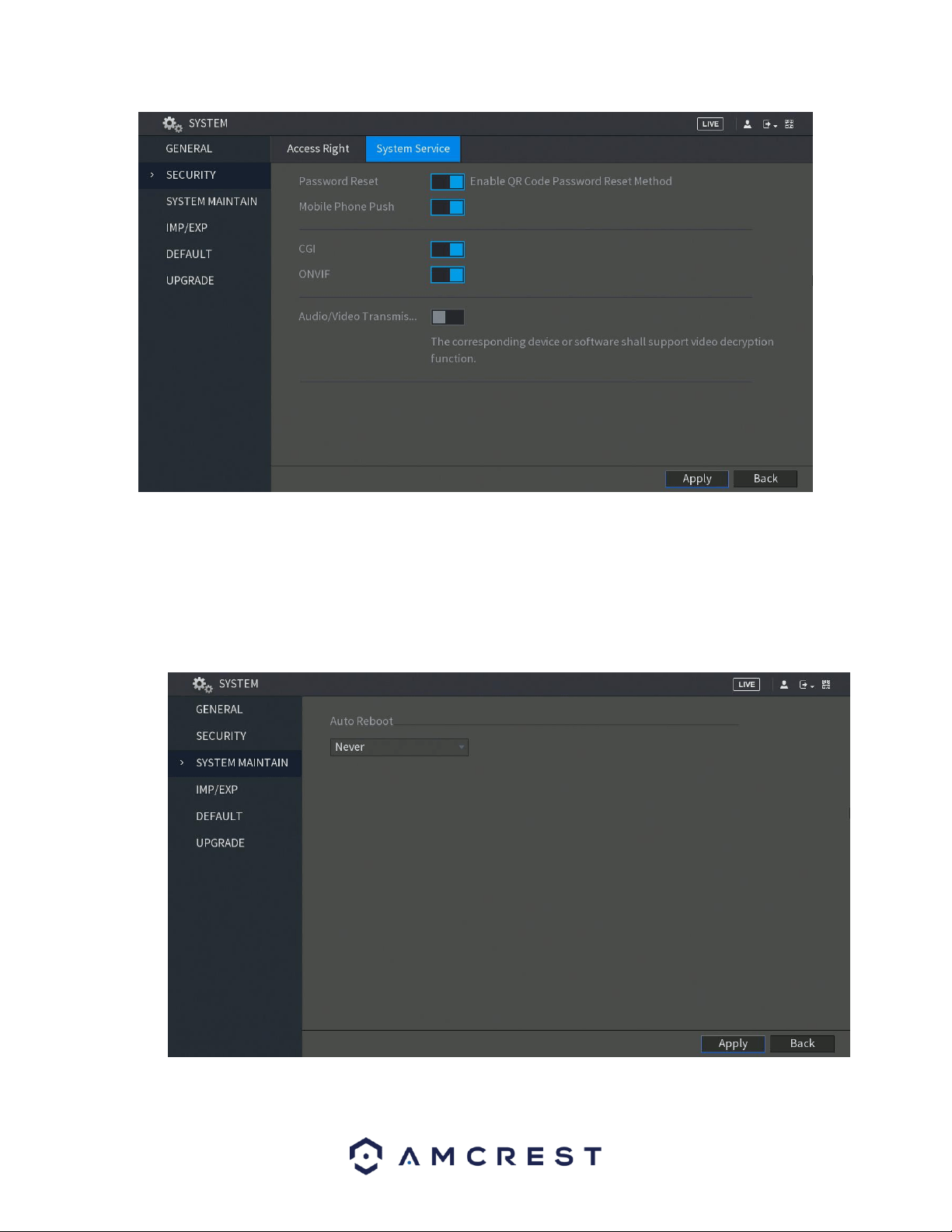
127
Note: If you clear the Enable toggle switch, you can only use the security questions to reset the password
for your DVR. Make sure you have set the security questions first before clearing the toggle switch.
6.4.3. System Maintain
This screen is used to configure system maintenance settings for the DVR. Below is a screenshot of the
System Maintain settings screen:
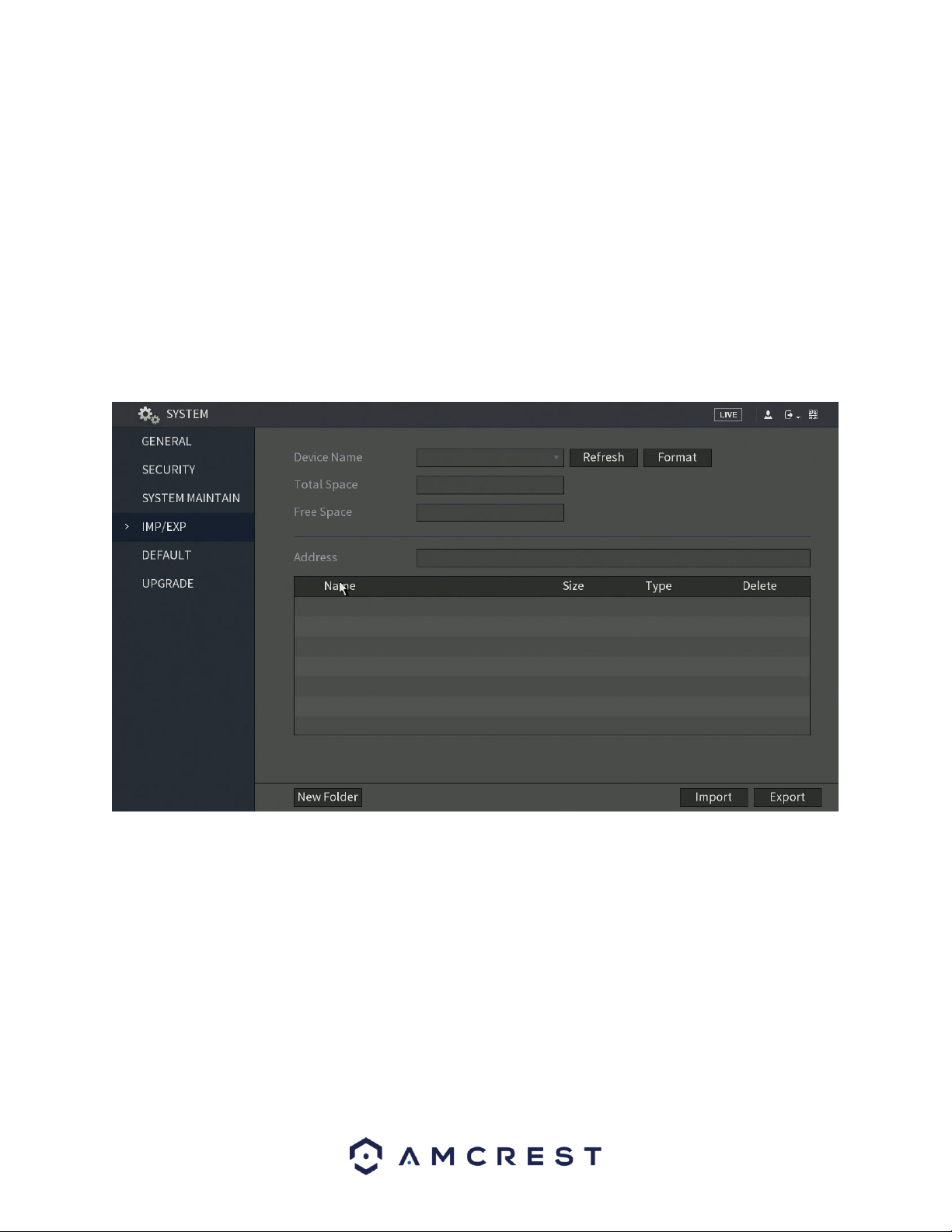
128
Below is an explanation of the fields on the Auto Maintain settings screen:
• Auto Reboot: This dropdown field allows the user to set a day of the week
and time to automatically reboot the system to keep the system healthy.
Note: Not all models will support this function. It is only supported on local
configurations.
To confirm settings, click the Apply button near the bottom right hand corner. To cancel any
modifications, click the Back button near the bottom right hand corner.
6.4.4. IMP/EXP
This screen is used to manage importing and exporting of system configurations. This feature can be used
to clone the settings from one DVR to another. Below is a screenshot of the IMP/EXP settings screen:
Below is an explanation of the fields on the Config Backup settings screen:
• DVR Name: This dropdown field allows the user to select a DVR to pull
configuration data from.
• Refresh: This button refreshes the list of DVRs connected to the DVR.
• Total Space: This field displays the total storage capacity on the selected
DVR.
• Free Space: This field displays the remaining storage capacity on the
selected DVR.
• New Folder: This button allows the user to create a new folder on the
selected DVR.
• Format: This button allows the user to format the selected DVR.
• Import: This button allows the user to import configuration data to the DVR.
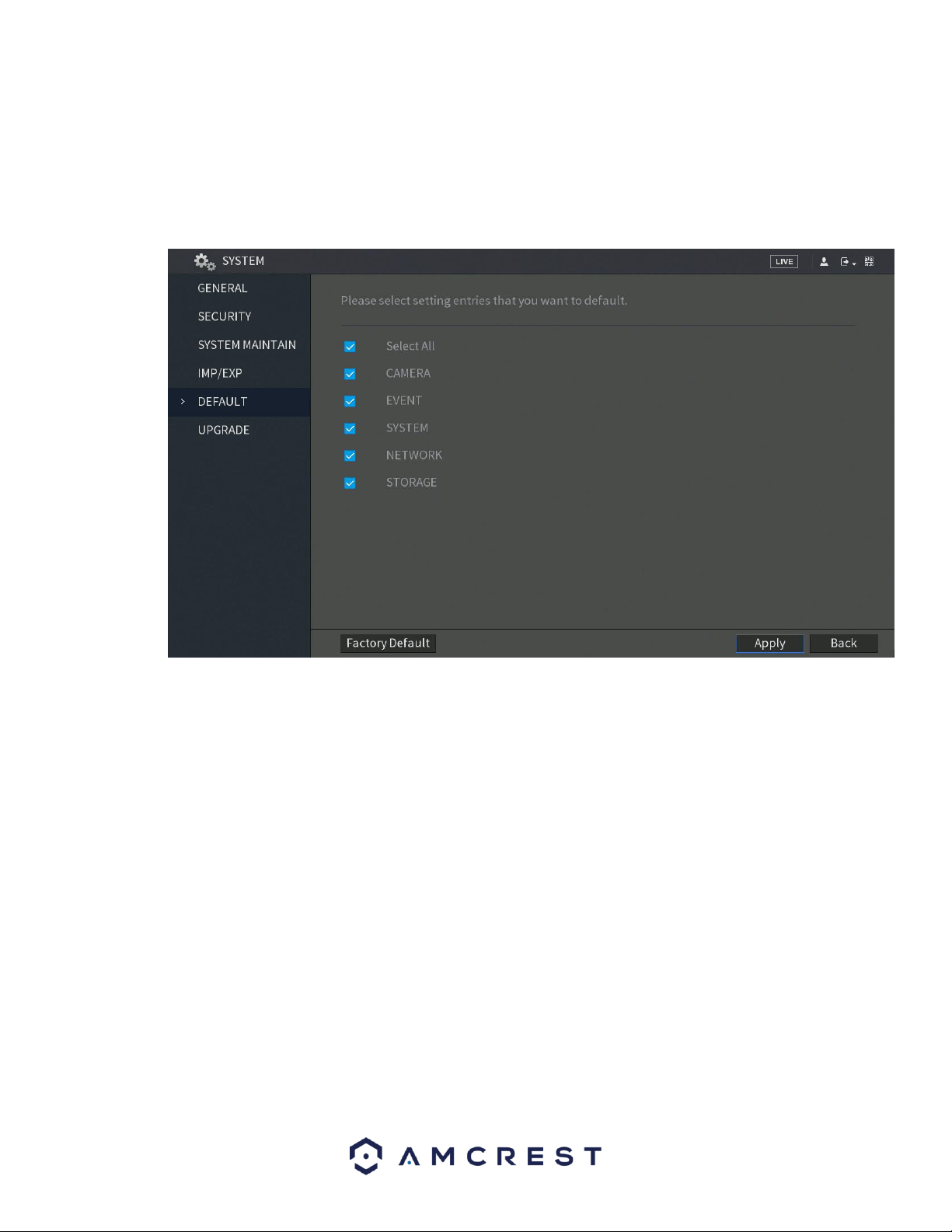
129
• Export: This button allows the user to export current configuration data to
another DVR.
6.4.5. Default
This screen is used to revert the DVR back to its default settings. This feature can be used to restore the
DVR to its factory setup conditions. Below is a screenshot of the Default settings screen:
There are six different setting areas that can be reset to default settings: Camera settings,
Event settings, Network settings, System settings, and Storage settings. All of these
settings can be reset by the use of the Select All check box.
The following settings are also reset with a factory reset:
• System Menu Color
• Language
• Time Display Mode
• Video Format
• IP Address
• User Accounts
To begin the factory reset process, click on the Factory Default button. To confirm settings, click the
Apply button near the bottom right hand corner. To cancel any modifications, click the Back button near
the bottom right hand corner.
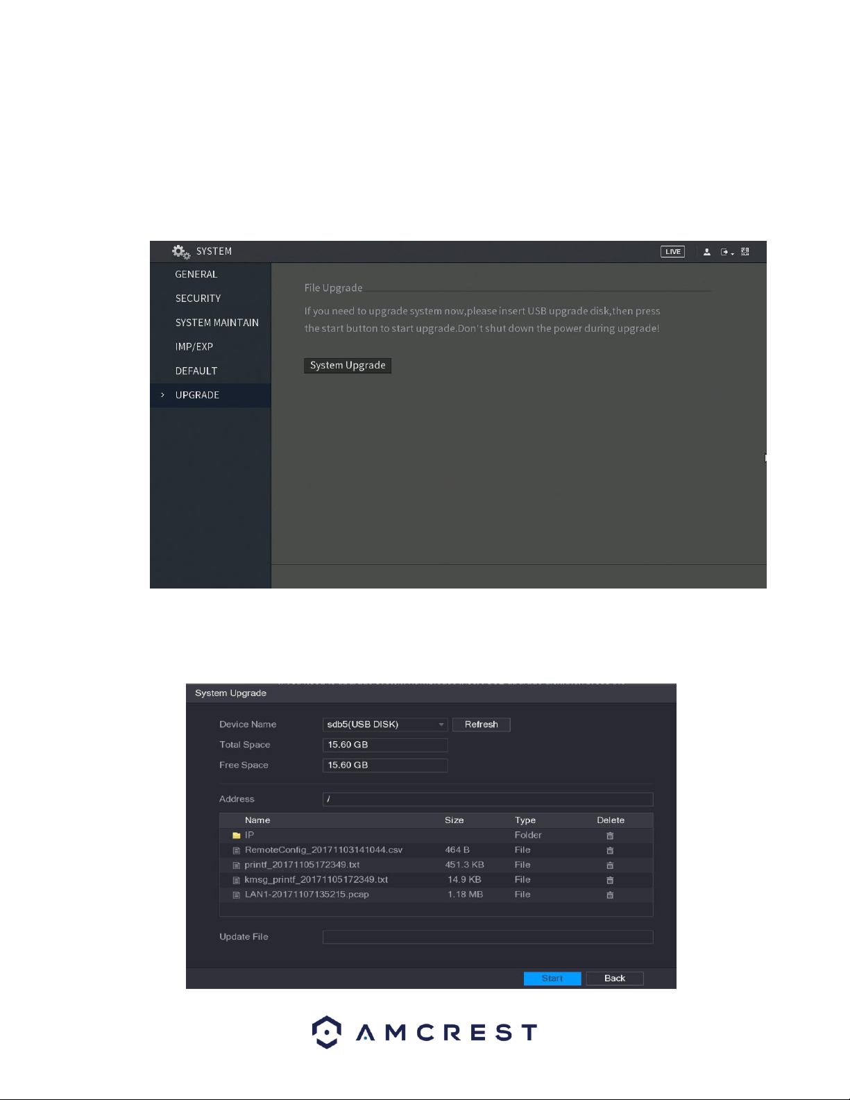
130
6.4.6. Upgrade
This screen is used to update the DVR's firmware to the latest version. To conduct a system update, it is
required to put an update file onto a USB storage DVR and plug it into the DVR. Ensure the update file is
named update.bin.
Below is a screenshot of the upgrade screen:
To begin, insert the USB storage DVR containing the firmware file into a USB on the DVR.
Once inserted, navigate back to the upgrade menu and click on UPGRADE. The system
upgrade interface will appear.
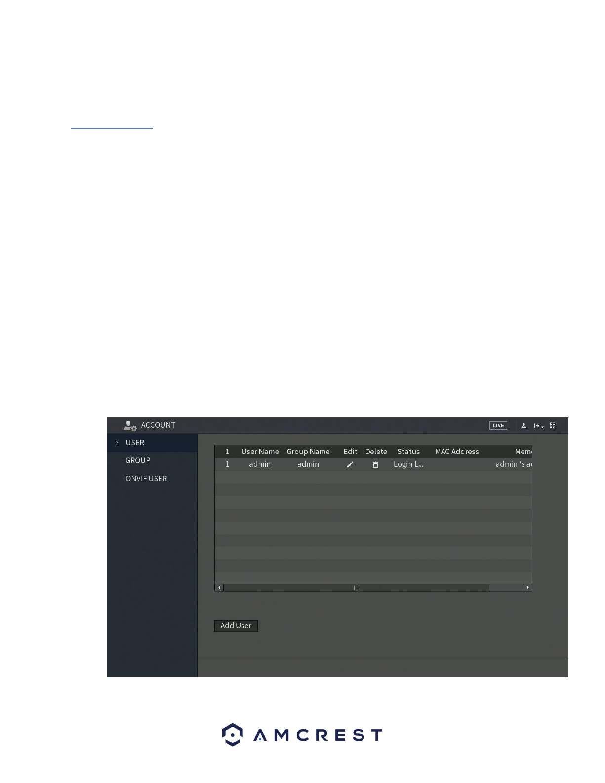
131
From the file list, locate the correct firmware file and click on it to import the file into
the Update File field. To initiate the upgrade process, click on the Start button.
6.5. Account
This menu is used to manage user accounts, user account passwords, and user groups. Below are a few
considerations to keep in mind when editing this information
• The DVR comes with a usernames by default:
o Username: admin Password: admin
o Username: default Password: default
• It is highly recommended to change the passwords for the admin and
default accounts.
• Each user name and user group name can only contain letters, numbers,
underline marks, dashes, or dots. No empty spaces are allowed.
• The maximum number of users is 64, and the maximum number of users
that can be in one group is 20.
• There are two levels for user management: administrator and user.
Administrator has more rights than a normal user and can modify key DVR
settings.
Each user can belong to only one group, and user rights cannot exceed group rights.
6.5.1. User
This screen is used to configure User Account settings. Below is a screenshot of the User Account settings
screen:
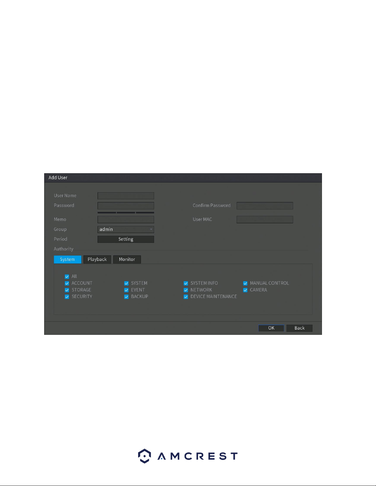
132
Below is an explanation of the fields on the User Account settings screen:
• 1: This number indicates how many users are in the system. Each line item
has a number to signify its place in the list.
• User Name: This column indicates an account's username.
• Group Name: This column shows which group the username belongs to.
• Edit: This column allows for the account's properties to be edited. Note:
You will need the MAC address for your device to proceed with
modifications. To access the MAC address go to Network>>TCP/IP.
• Delete: This column has a button that allows for the account's properties to
be deleted.
• Status: This column shows the status of a selected account.
• Add User: This button allows the user to add another user account. Below is
a screenshot of the Add User screen.
Note: It is recommended to give the general user fewer rights than an
administrative one.
When a new user is created, a MAC address can be entered for the user. This can
limit the user's ability to logon from another DVR. If left blank, the user can logon
from any MAC address.
There is a total of 98 rights that can be assigned to a user.
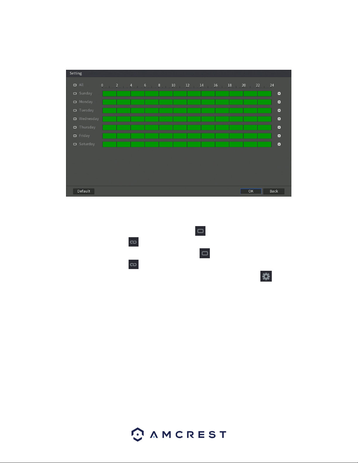
133
6.5.1.1. Settings Permitted Periods
This section is used to permit users to use certain period settings within the system. This feature can be
accessed in the Add User menu of the User interface by click on the Setting button in the period field.
. By default, it is it is active to record 24/7. You can define the period, or schedule,
• Define a period for a specified day of the week by clicking the half-hour clocks you wish to
enable.
• Define several days of the week by clicking the icon before each day. The icon selected will
then switch to the icon which indicates it is linked.
• Define for all days of the week by clicking on the icon located by the All option. Each day will
then switch to the icon and all days of the week will be selected.
• Define the period by editing. In this example, we will use Sunday. Click the icon to access the
Period interface.
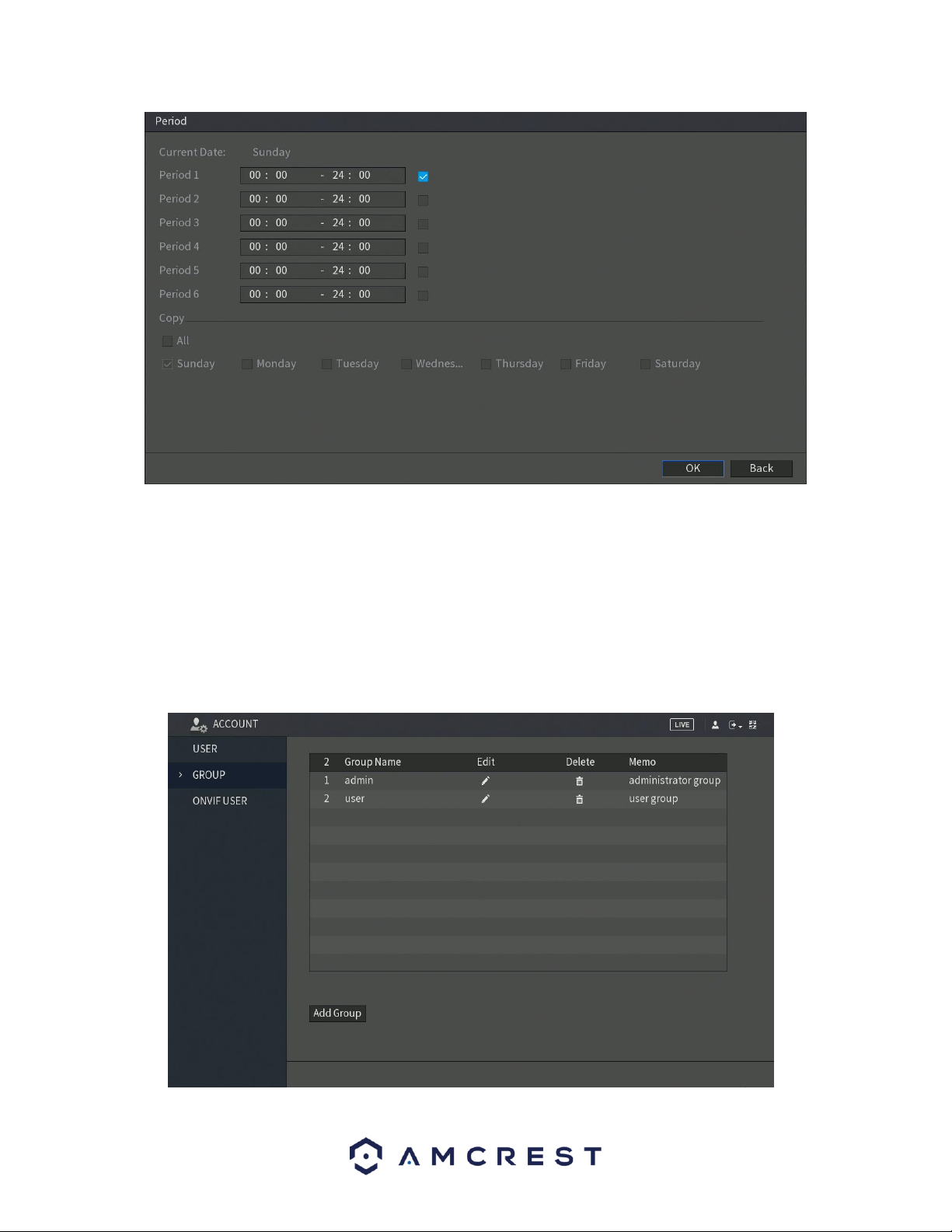
134
In the period interface, enter the time frame you would like to set as your period and select the checkbox to enable
the settings. There are a total of six periods that you can set for each day. Under the Copy menu, you can apply
these settings to all days of the week by checking the All option or you can also select specific days as well. To save
the settings in this menu, click OK to continue. For more information on setting periods, refer to section 6.3.2.
Schedule.
6.5.2. Group
This screen is used to configure Group Account settings. Below is a screenshot of the Group Account
settings screen:
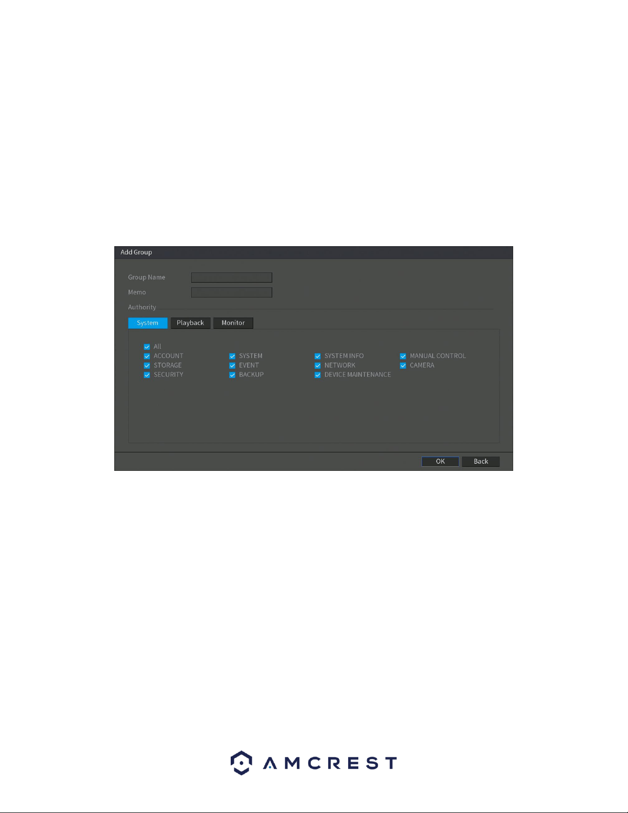
135
Below is an explanation of the fields on the User Group settings screen:
• Number: This number indicates how many groups are in the system. Each
line item has a number to signify its place in the list.
• Group Name: This column indicates an account's username.
• Edit: This column has a button that allows for the account's properties to be
edited.
• Delete: This column has a button that allows for the account's properties to
be deleted.
• Memo: This column indicates any notes about the user group.
Add Group: This button allows the user to add another user group. On the next page is a screenshot of
the Add Group screen.
Note:
• It is recommended to give the general user fewer rights than an
administrative one.
• There is a total of 98 rights that can be assigned to a user.
6.5.3. ONVIF User
The DVR manufactured by other companies can be connected to the DVR via an ONVIF protocol. This is
viable through an authorized ONVIF account. This menu allows the user to create or edit ONVIF users
associated with the system.
Note: The admin account is created for ONVIF users right after the DVR has been initialized.
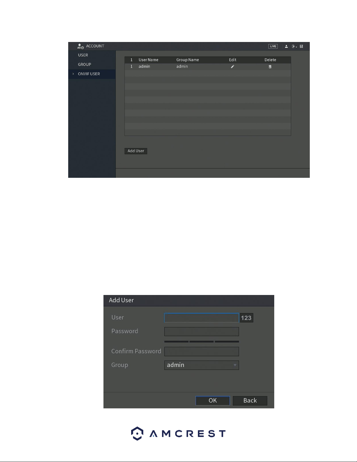
136
Below is an explanation of the fields on the User Group settings screen:
• Number: This number indicates how many groups are in the system. Each
line item has a number to signify its place in the list.
• Group Name: This column indicates an account's username.
• Edit: This column has a button that allows for the account's properties to be
edited.
• Delete: This column has a button that allows for the account's properties to
be deleted.
• Memo: This column indicates any notes about the user group.
Add User: This button allows the user to add another ONVIF user to the system. On the next page is a
screenshot of the Add User screen.
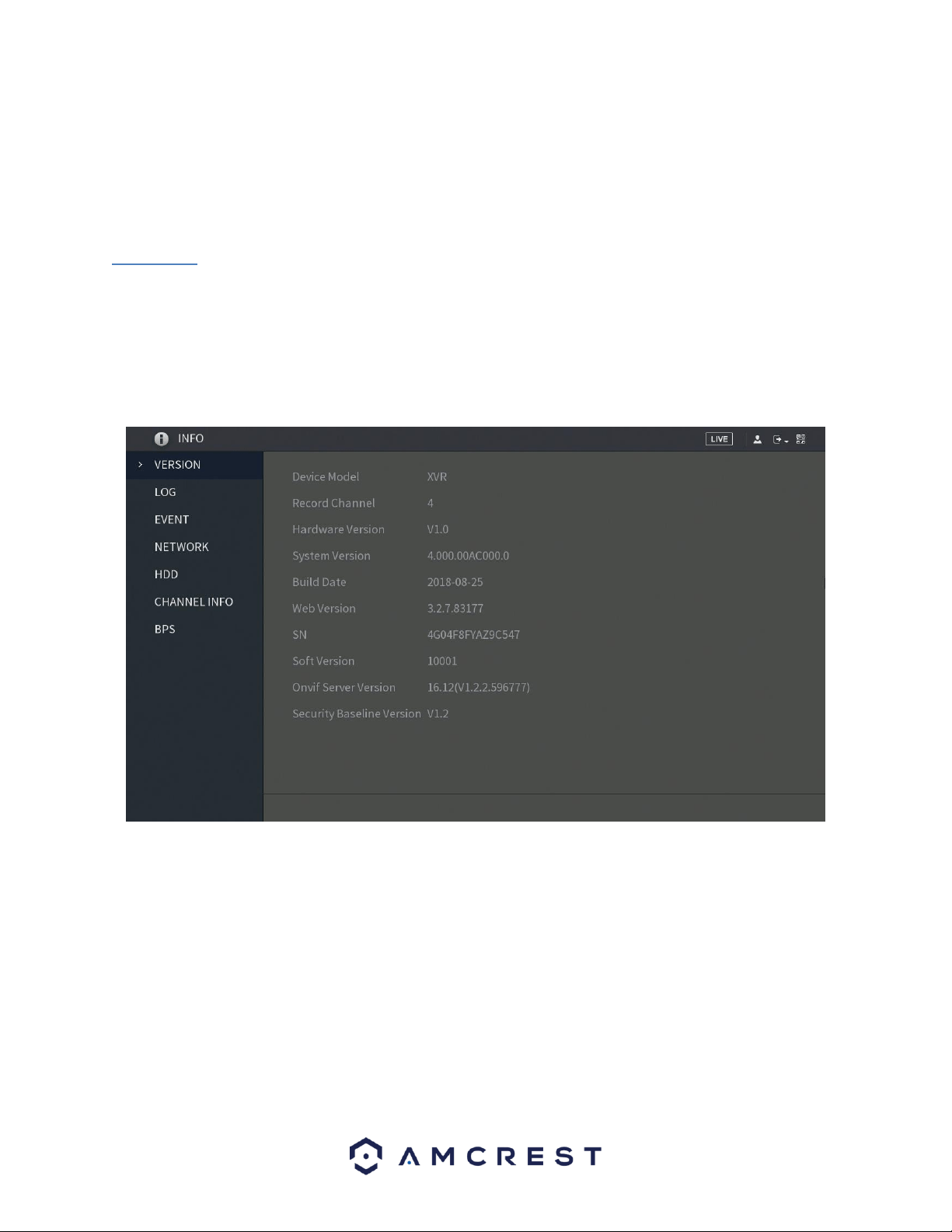
137
In the add user interface, enter the ONVIF user name and password into the system. Confirm the
password and from the Group drop down menu, select which group you would like to associate this
account with. There are three categories listed, admin, operator, and user. When you have finished the
process, click OK to continue. The ONVIF username entered will then be implemented into the user list.
6.6. Info
This menu allows the user to access information related to their system. This information includes options
such as, system version, log, event, network, HDD, channel info, and bps information.
6.6.1. Version
This menu allows the user to access general DVR information. This includes the DVR model, system
version, and build date. Below is a screen shot of the version menu.
6.6.2. Log
This screen is used to keep a log of all activity on the DVR. Below is a screenshot of the Log screen:
138
The system lists the following information:
• System Operation
• Account Manager
• Configuration Operation
• Log Clear
• Data Management
• File Operation
• Alarm Events
• Reboot Type
• Record Operation
• S.M.A.R.T Info
• User Login/Logged Out
• Search
Below is an explanation of the fields on the log screen:
Parameter
Function
Type
This dropdown box allows the user to select which type of log they want to
view. Log types include: system operation, configuration operation, data
operation, event operation, record operation, user management, and log
clear.
Start time
This field allows the user to set the start time of the requested log.
139
End time
This field allows the user to set the end time of the requested log.
Search
You can select the log type from the drop-down list and then click search
button to view the list.
You can click the stop button to terminate the current search operation.
Details
Double click a line item to open a more detailed view of that log item or click
the Details button.
Clear
This button deletes all log files that are currently displayed.
Backup
Click this button to backup log files to the PC.
6.6.3. Event
The event menu allows the user to access system related event information associated with specific
channels in the system. These events include errors such as, video loss, motion detect, network
disconnections, etc.
6.6.4. Network
The network menu allows users the ability to view online users, network data transmission (load) details,
and test network connectivity.
6.6.4.1. Online User
This tab allows the user to access and view online user’s information associated with the system. You can
also block any user off the system for a certain period of time.
140
To block an online user, click and then enter the time that you want to block this user. The maximum
value you can set is 65535.
The system detects every 5 seconds to check if there is any user added or deleted and update the user list
timely.
6.6.4.2. Network Load
This tab allows the user to view and track network load and data transfer information associated with the
system.
141
If there are multiple networks being viewed in this screen, click on the LAN name that you want to view.
The system will display the data sending and receiving speed of that network.
Note: The default display will always be LAN1 load. Only one LAN load can be displayed at one time.
6.6.4.3. Network Test
The network test tab allows the user to capture, resend, and edit network packets that are sent and
received during network transmissions. If there is a network abnormality, the user can perform packet
capturing and back up this information onto a USB storage device. This can be useful for detecting and
analyzing network conditions in the system. Here is a screen shot of the network test screen:
To perform the procedure, connect a USB storage device to the DVR and click Fresh. The DVR will begin
detecting the USB storage device and display its name in the Device Name box. Choose the route of the
data that you want to back up, then in the Network Sniffer Packet Backup menu, click Browse.
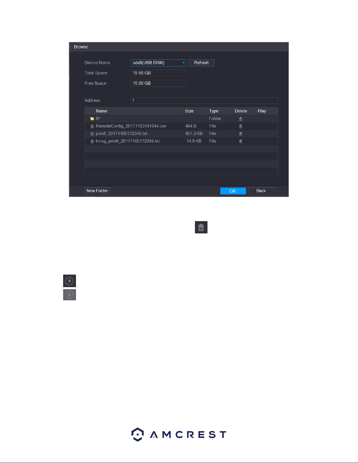
142
Note: If there are several USB storage devices connected to the DVR, you can select the device from the
Device Name list. Click Refresh to display the total space, free space, and file list for the selected USB
storage device. In case of insufficient capacity, click the icon to delete unnecessary files. If you
would like to create a new folder within the storage device, click the New Folder option. Click Apply to
return to the to the network test interface.
In the Network Test menu type the IP address of the address you would like to test in the Destination IP
box and click Test. The test will then be performed. To backup the test to the USB storage device, click the
icon located in the Sniffer Packet Backup menu. If you would like to stop the process, click the
to stop. The backup data is saved in the selected route under the naming style "LAN name-
time.pcap." The information can be opened as well using Wireeshark software.

143
6.6.4.3. HDD
The hard disk DVR (HDD) menu allows the user to view information such as, HDD quantity, HDD type, total
space, free space, status, and S.M.A.R.T. information. Here is a screenshot of the HDD menu screen:
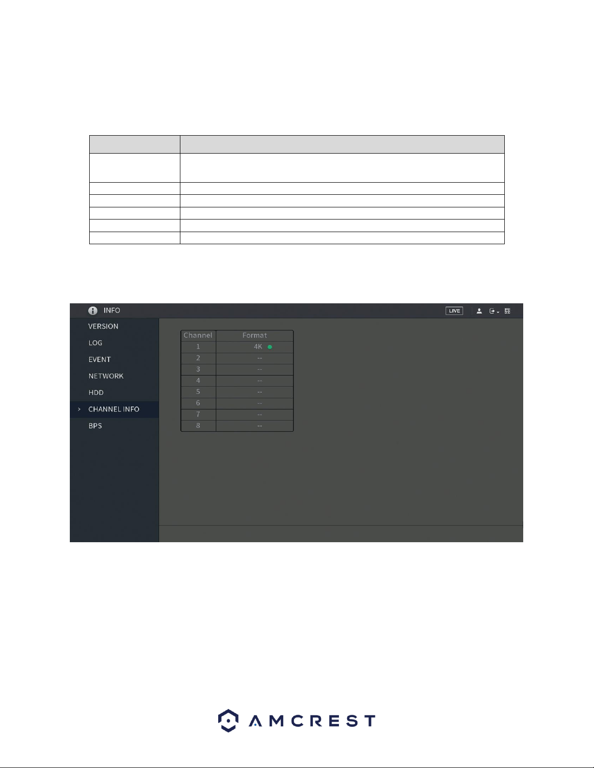
144
For more details on the information provided in this menu, refer to the provided below:
Parameter
Description
1*
Indicates the number of the currently connected HDD.
﹡means the current working HDD.
Type
Indicates HDD type.
Total Space
Indicates the total capacity of HDD.
Free Space
Indicates the usable capacity of HDD.
Status
Indicates the status of the HDD to show if it is working normally.
S.M.A.R.T
View the S.M.A.R.T reports from HDD detecting.
6.6.4.4. Channel Info
This menu allows the user to view camera information that is connected to each channel on the system.
Note: The number of channels listed in this screen will vary from DVR to DVR.
6.6.4.5. BPS
This menu allows the user to view, in real-time, the data stream rate and resolution of each channel
associated with the DVR.
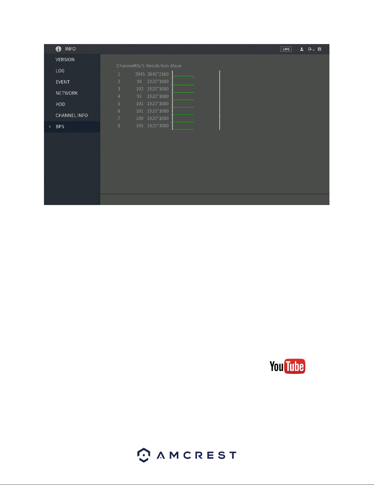
145
7. Web Operation
One of the main features of the Amcrest DVR is the ability to access the DVR and
its features through the web. Whether you want to view the live feed from
remote location, or you want the ability to display the live feed on multiple
computers on your local network, the Amcrest DVR can accommodate all those
needs.
To enable web client operation, ensure the following items are completed:
• The DVR is connected to the Network via an Ethernet cable.
• The DVR and the PC are on the same network OR the DVR has been
configured for remote access.
• Use one of the following web browsers: Safari, or Internet Explorer.
7.1 Local Web Access
To view a video on how to setup the DVR for Local Access go to
http://amcrest.com/videos and view the video titled “How to Setup
Amcrest HDCVI DVR for Local Access”.
Below is a step-by-step walkthrough that details how to setup the for Local Web
Access:

146
1. Login to your DVR, open the main menu then go to Management ->
Network.
2. Open the TCP/IP settings screen.
3. By default, the DVR has the mode set to Static. Click the radio button next
to DHCP to change this to DHCP.
The IP Address, Subnet Mask, Default Gateway, Preferred DNS, and
Alternate DNS should all change to 0s.
4. Click Save to save these settings. This should now open the main menu.
5. From the main menu, go to Management -> Network.
6. On the TCP/IP settings screen, the IP Address, Subnet Mask, Default
Gateway, Preferred DNS, and Alternate DNS should all be populated.
7. Click the radio button next to Static, to change the mode to Static.
8. Write down the IP Address that is currently in the IP address field.
9. Click the Save button.
10. Open an internet browser and type the IP address from step 8 into the
address bar and hit enter. Please only use Internet Explorer or Safari
throughout this process.
11. The browser may prompt you to install a plugin. Click install to download
the plugin, and then click on the plugin installation file to install the plugin.
12. If the browser prompts you to allow the plugin to work on the computer,
hit Allow to ensure the plugin can run successfully.
13. Enter in login details into the username and password fields.
14. Click the LAN option, and then click Login.
15. Once the main interface opens, click the plug icons next to each camera
on the list on the left-hand side, and activate the main stream for each of
them to enable the live feed.
If the process above is not working, please contact Amcrest Support via one of
the following options:
• Visit http://amcrest.com/contacts and use the email form
• Call Amcrest Support using one of the following numbers Toll Free:
(888) 212-7538
International Callers (Outside of US): +1-713-893-8956
USA: 713-893-8956
Canada: 437-888-0177
UK: 203-769-2757
• Email Amcrest Customer Support support@amcrest.com
7.2 Remote Web Access
There are two main methods for setting up remote access: UPnP/DDNS, and Port
Forwarding.

147
7.2.1 UPnP/DDNS Remote Access Setup
Using Universal Plug and Play (UPnP) and Dynamic Domain Name Server (DDNS)
functionality is the easiest way to setup stable remote access. For this method,
your router should support the uPnP networking protocol and the protocol
should be enabled. Please refer to your router manufacturer’s documentation to
learn how to enable uPnP on your router.
To view a video on how to setup the for UPnP/DDNS remote access go to
http://amcrest.com/videos and view the video titled
“How to Gain Remote Access to Your HDCVI DVR with Universal Plug and Play”.
Below is a step-by-step walkthrough that details how to setup the for Remote
Web Access using UPnP and DDNS:
1. Login to your DVR, open the main menu then go to Management ->
Network.
2. Using the left-hand menu, go to the Connection menu, and write down
the HTTP port. It is recommended to ensure the port number is at least
5 digits long to prevent any port conflicts. If need be, change the port
to a 5-digit number that is less than 65535, note the number down, and
click save before proceeding to the next step.
3. The system will prompt you to reset the DVR. Click OK and wait for the
DVR to restart.
4. Login to your DVR, open the main menu then go to Management ->
Network.
5. Click the Connections menu item on the left-hand menu and ensure
that the HTTP port has changed.
6. Click the DDNS menu item on the left-hand menu, click the enable
checkbox, and then click the Apply button on the bottom right.
7. Write down the entire Domain Name field, including the white text
that says.quickddns.com
8. Click the UPnP menu item on the left-hand menu and click the enable
radio button at the top.
9. While in the UPnP menu, double click the HTTP port, and change both
the internal and external HTTP ports to match the number that was
used in step 2.
10. Uncheck the last 4 checkboxes in the PAT table on the UPnP menu.
11. Click apply and ensure the UPnP status field says “Searching.”
12. Exit this menu to go back to the main menu, then re-enter the UPnP
menu, and ensure the UPnP status says “Success”.
13. Open a web browser and enter in the DDNS domain name address
from step 3, enter in a colon, then type the port number from step 4 on
to the end.

148
a. For example, if the DDNS domain name is
http://abc123456789.quickddns.com and your HTTP Port is
33333, the URL would be
http://abc123456789.quickddns.com:33333
14. The browser may prompt you to install a plugin. Click install to
download the plugin, and then click on the plugin installation file to
install the plugin.
15. If the browser prompts you to allow the plugin to work on the
computer, hit Allow to ensure the plugin can run successfully.
16. Enter in login details into the username and password fields.
17. Click the WAN option, and then click Login.
18. Once the main interface opens, click the plug icons next to each
camera on the list on the left-hand side, and activate the main stream
for each of them to enable the live feed.
If the process above is not working, please contact Amcrest Support via one of
the following options:
• Visit http://amcrest.com/contacts and use the email form
• Call Amcrest Support using one of the following numbers Toll Free:
(888) 212-7538
International Callers (Outside of US): +1-713-893-8956
USA: 713-893-8956
Canada: 437-888-0177
UK: 203-769-2757
• Email Amcrest Customer Support support@amcrest.com
7.2.2 Port Forwarding Remote Access Setup
Port Forwarding is an alternative method to setting up remote access for your DVR.
This method should only be used if the UPnP/DDNS Remote Access method did not
work.
To view a video on how to setup the for Port Forwarding remote access go to
http://amcrest.com/videos and view the video titled
“How to Gain Remote Access to Your DVR with Port Forwarding”.
Below is a step-by-step walkthrough that details how to setup the for Remote
Web Access using UPnP:
1. Login to your DVR, open the main menu then go to Management ->
Network.
2. Open the TCP/IP settings screen.
3. By default, the DVR has the mode set to Static. Click the radio button
next to DHCP to change this to DHCP. The IP Address, Subnet Mask,

149
Default Gateway, Preferred DNS, and Alternate DNS should all change
to 0s.
4. Click Save to save these settings. This should now open the main menu.
5. From the main menu, go to Management -> Network.
6. On the TCP/IP settings screen, the IP Address, Subnet Mask, Default
Gateway, Preferred DNS, and Alternate DNS should all be populated.
7. Click the radio button next to Static, to change the mode to Static.
8. Write down the IP Address that is currently in the IP address field.
9. Click the Save button.
10. Using the left-hand menu, go to the Connection menu, and write down
the TCP, UDP, and HTTP port number. It is recommended to ensure
that these port numbers are at least 5 digits long to prevent any port
conflicts. If need be, change each of these port numbers to a 5-digit
number that is less than 65535, note the numbers down, and click save
before proceeding to the next step.
11. Go to http://www.canyouseeme.org/ and check to ensure each of the
port numbers specified in step 10 are open.
12. Write down the manufacturer name, brand, and model name for the
router that the DVR is connected to, and then proceed to
portforward.com on your web browser.
13. Open the port forwarding guide section on the left-hand side menu.
14. Find the router brand name in the list and click it.
15. Find the router model number and click it.
16. Click the Default Guide link near the middle of the page.
17. This guide will help you take the step necessary to port forward on the
router. Follow these steps, and then return to the DVR.
18. Login to your DVR, open the main menu then go to Settings ->
Network.
19. Click the DDNS menu item on the left-hand menu, click the enable
checkbox, and then click the Apply button on the bottom right.
20. Write down the entire Domain Name field, including the white text
that says.quickddns.com
21. Open a web browser and enter in the DDNS domain name address
from step 20, enter in a colon, then type the HTTP port number from
step 10 on to the end.
a. For example, if the DDNS domain name is
http://abc123456789.quickddns.com and your HTTP Port is
33333, the URL would be
http://abc123456789.quickddns.com:33333
22. The browser may prompt you to install a plugin. Click install to
download the plugin, and then click on the plugin installation file to
install the plugin.
23. If the browser prompts you to allow the plugin to work on the
computer, hit Allow to ensure the plugin can run successfully.
24. Enter in login details into the username and password fields.
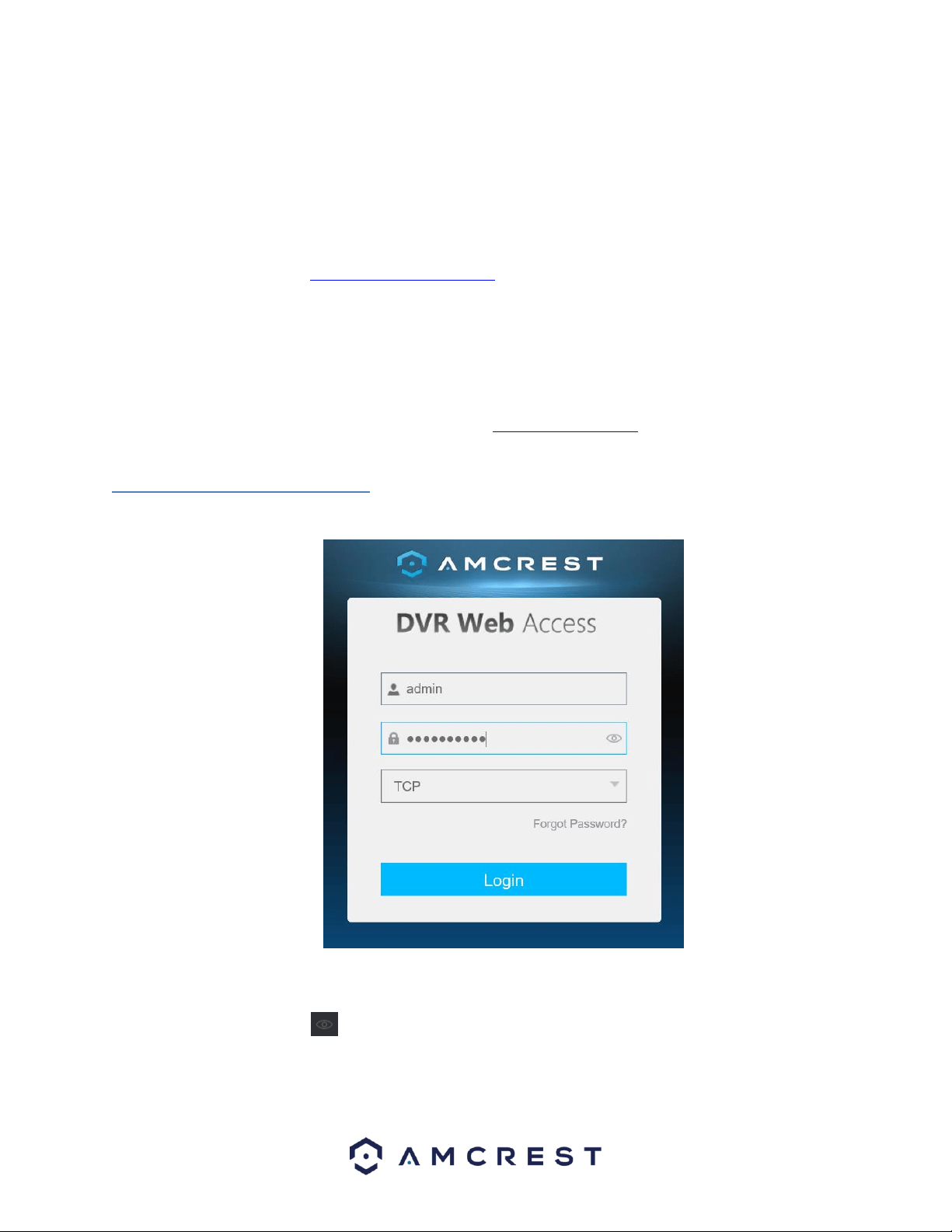
150
25. Click the TCP option, and then click Login.
26. Once the main interface opens, click the plug icons next to each
camera on the list on the left-hand side, and activate the main stream
for each of them to enable the live feed.
If the process above is not working, please contact Amcrest Support via one of
the following options:
• Visit http://amcrest.com/contacts and use the email form
• Call Amcrest Support using one of the following numbers Toll Free:
(888) 212-7538
International Callers (Outside of US): +1-713-893-8956
USA: 713-893-8956
Canada: 437-888-0177
UK: 203-769-2757
• Email Amcrest Customer Support support@amcrest.com
5.3 Web Access Interface
When you have accessed your DVR’s web UI successfully, you will be taken to the login menu.
Log into your DVR with the associated username and password to be taken to the main menu. If this is
your first-time logging into your DVR, the username and password will both be admin. To display the
password, click on the icon. If you have forgotten the password, click on Forgot Password.
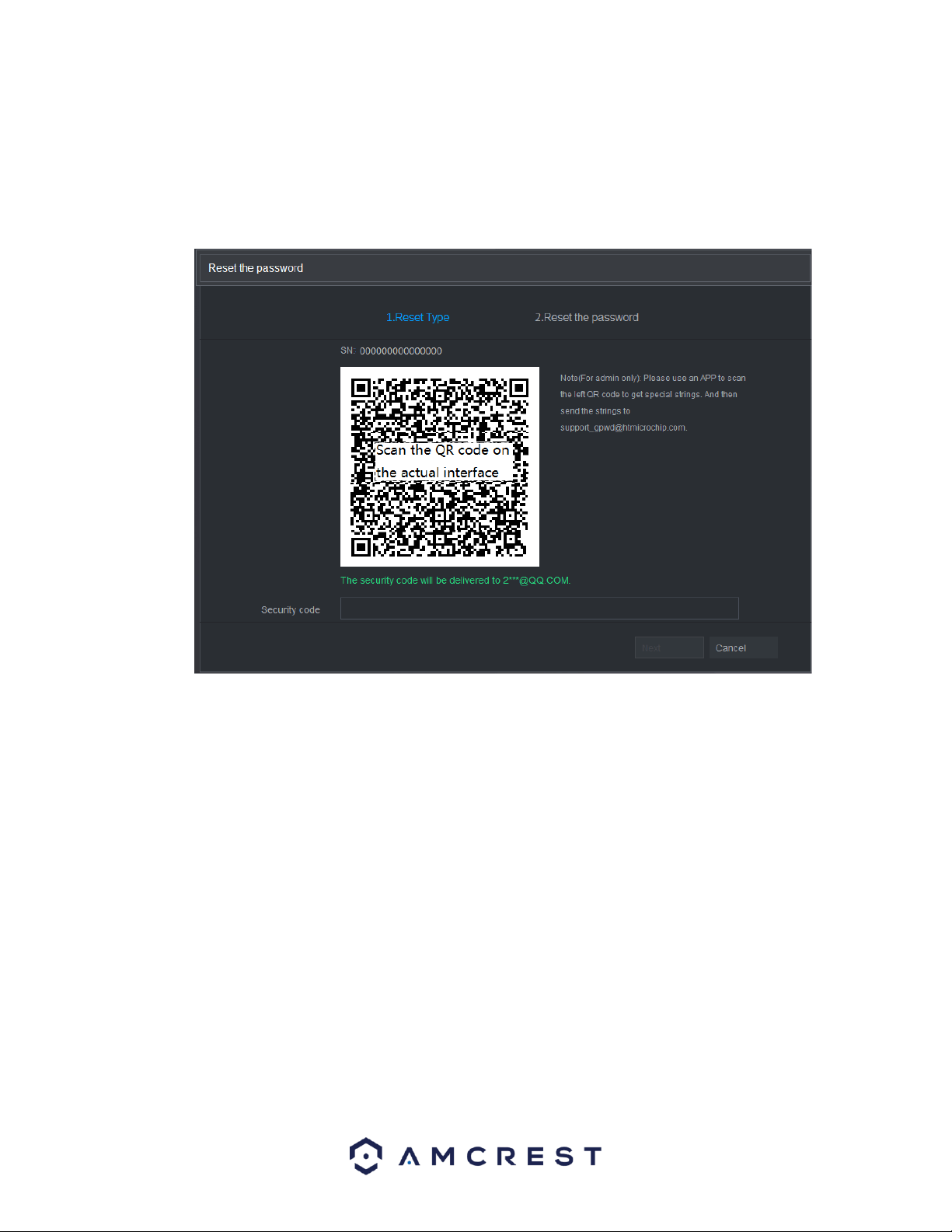
151
5.3.1. Resetting the Password
If you have forgotten your password, the Forgot Password option is there to help you. You can reset the
password for your DVR through a reserved email address.
To reset the password, click on Forgot Password? and proceed to the Reset the password interface.
Follow the on-screen instructions and scan the QR code to receive the security code. Once you have
received the security code, enter the code into the field label Security Code. Once you have successfully
entered your security code, click on the Next button to continue.
Note: Please use the security code delivered to your email within 24 hours. If the security code is not used
within the 24-hour period, it will be invalid. You will have five attempts to enter your security code
correctly otherwise the system will lock you out.
Next, you will need to enter a new password for the DVR. In the Password box, enter a new password for
your DVR and then confirm the password in the Confirm Password field. When you are done, click Save to
save the password.
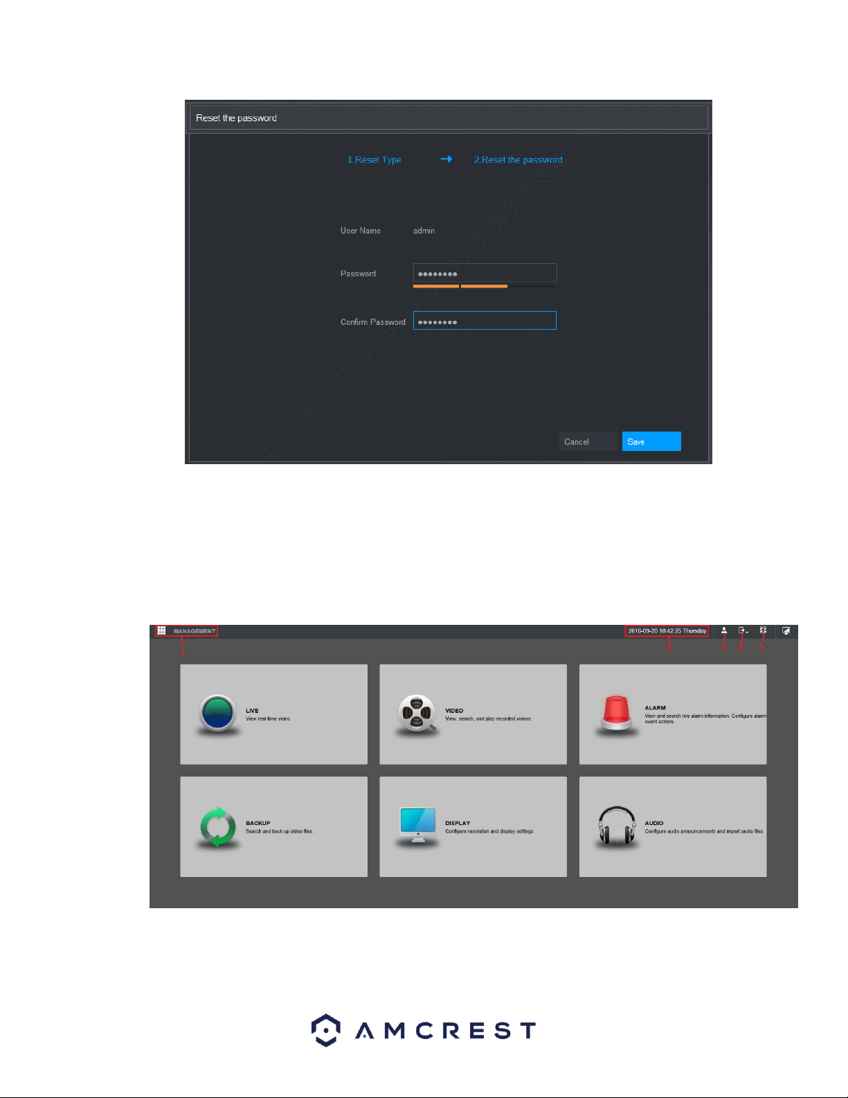
152
Note: The new password must contain a minimum of 8 characters and a maximum of 32 characters. The
password must also contain two types of letters, numbers, and special characters. These special
characters will exclude, “, “”, “;”. “:” and “&”.
5.3.2. Main Menu
The main menu web interface contains seven different options:
For more information on the options listed in this menu, refer to the table provided below:
153
No.
Icon
Description
1
Management: Includes configuration menu through which you can configure
camera settings, network settings, storage settings, system settings, account
settings, and view information. For more information on the settings listed in
this option, refer to 6. Management; pg. 89.
2
Date/Time
Displays system date and time.
3
When you point to , the current user account is displayed.
4
Click , select Logout, Reboot, or Shutdown according to your actual
situation.
5
Displays Cell Phone Client and DVR SN QR Code.
Cell Phone Client: Use your mobile phone to scan the QR code to add the
DVR into the Cell Phone Client, and then you can start accessing the DVR
from your cell phone.
DVR SN: Obtain the DVR SN by scanning the QR code. Go to the P2P
management platform and add the DVR SN into the platform. Then you
can access and manage the DVR in the WAN. For details, please refer to
the P2P operation manual. You can also configure P2P function in the
local configurations. See "Error! Reference source not found. Error!
Reference source not found.."
6
Displays the web main menu.
7
Function
Tiles
Includes eight function tiles: LIVE, VIDEO, ALARM, IVS, IoT, BACKUP, DISPLAY,
and AUDIO. Click each tile to open the configuration interface of the tile.
LIVE: You can perform the operations such as viewing real-time video,
configuring channel layout, setting PTZ controls, and using smart talk and
instant record functions if needed.
VIDEO: Search for and play back the recorded video saved on the DVR.
ALARM: Search for alarm information and configure alarm event actions.
BACKUP: Search and back up the video files to the local PC or external
storage DVR such as USB storage DVR.
DISPLAY: Configure the display effect such as displaying content, image
transparency, and resolution, and enable the zero-channel function.
AUDIO: Manage audio files and configure the playing schedule. The audio
file can be played in response to an alarm event if the voice prompts
function is enabled.
8. FAQs/Troubleshooting
1. The DVR does not boot up properly.
Below are a few possible reasons why this may be occurring:
• The power input is not correct voltage.
• The power cable connection is not secured correctly.
• The power button is damaged or malfunctioning.
• The firmware was upgraded incorrectly.

154
• There is an HDD malfunction, or something is wrong with the HDD cable.
• There is damage to the DVR's main motherboard.
2. DVR often shuts down and stops running.
Below are a few possible reasons why this may be occurring:
• The input voltage is too low or is not stable.
• There is an HDD malfunction, or something is wrong with the HDD cable.
• The power button is damaged or malfunctioning.
• Video output signal is not stable.
• The insides of the DVR have accumulated too much dust.
• The temperature is either too hot or too cold.
• The hardware is malfunctioning.
3. The system does not detect a hard drive.
Below are a few possible reasons why this may be occurring:
The hard drive is broken.
• The hard drive cable is damaged.
• The hard drive cable connection is loose.
• The DVR's main motherboard SATA port is broken.
4. There is no video output on any of the channels.
Below are a few possible reasons why this may be occurring:
• The DVR firmware is incompatible with the attached cameras. Upgrade to the latest firmware.
• The image brightness is set to 0. Change the brightness using the image settings or restore the
DVR to factory default settings.
• There is no video input signal, or the signal is too weak.
• A privacy mask or screensaver may be enabled.
• There might be a malfunction with the DVR hardware.
5. Real-time video color is distorted.
Below are a few possible reasons why this may be occurring:
• When using a BNC output, NTSC and PAL may be setup incorrectly. The real-time video may
become black and white.
• The DVR is not compatible with the monitor.
• The video transmission cable is too long, or signal degradation is too great.
• The DVR's color or brightness settings are not correctly configured.
6. Local Recordings are not searchable.
Below are a few possible reasons why this may be occurring:
• The hard drive cable is damaged.
• The hard drive is broken.
• The DVR's firmware is incompatible with the recorded video.
• The recorded files have been overwritten.
• The recording function has been disabled.

155
7. Local playback video is distorted.
Below are a few possible reasons why this may be occurring:
• The video quality setting is too low.
• The DVR software has a read error. Restart the DVR to solve this problem.
• The hard drive cable is damaged.
• The hard drive is malfunctioning.
• The DVR's hardware is malfunctioning.
8. There is no audio during real-time monitoring.
Below are a few possible reasons why this may be occurring:
• The microphone being used is not sufficiently powered.
• The speakers being used are not sufficiently powered.
• The audio cable is damaged.
• The DVR hardware is malfunctioning.
9. There is no audio during recorded video playback.
Below are a few possible reasons why this may be occurring:
• Audio may not be enabled for that channel.
The corresponding channel may not have any audio input.
10. The timestamp is not displaying the correct time.
Below are a few possible reasons why this may be occurring: •
The time and date settings may not be configured
correctly.
• The battery inside the DVR may be loose, or the battery is running low.
11. PTZ control is not working.
Below are a few possible reasons why this may be occurring: •
There may be an error with the PTZ front panel
buttons.
• The PTZ decoding settings aren't configured correctly.
• The PTZ connection may be loose or may not be installed correctly.
• An incorrect cable may be used to connect the PTZ enabled DVR to the DVR.
• The PTZ decoder and the DVR protocol are not compatible.
• The PTZ decoder and DVR address are not compatible.
• Multiple PTZ decoders are causing reverberation or impedance matching, causing PTZ signal
interference. Use a 120 Ohm resister between the PTZ cables to reduce interference.
• The PTZ cable is too long or signal degradation is too great.
12. Motion detection does not work.

156
Below are a few possible reasons why this may be occurring: •
The motion detection time period may be incorrectly
configured.
• Motion detection zone setup is not correctly configured.
• Motion detection sensitivity is too low.
13. Web Access isn't working.
Below are a few possible reasons why this may be occurring:
• Windows version is pre -Windows 2000 service pack 4. Use a more recent version of
Windows.
• ActiveX controls have been disabled.
• The PC is not using DirectX 8.1 or higher. Upgrade to a more recent version of DirectX.
• The DVR is having network connection errors.
• Web access may be setup incorrectly.
• The username or password may be incorrect.
• The client end computer is not compatible with the DVR's firmware.
14. Web Access live view is only displaying a static picture. Both live playback and recorded playback aren't
working.
Below are a few possible reasons why this may be occurring:
• The network speed is not sufficient to transfer video data via web access.
• The client PC may have limited resources.
• Multicast mode may be causing this issue.
• A privacy mask or screensaver may be enabled.
• The logged in user may not have sufficient rights to monitor real-time playback.
• The DVR's local video output quality is not sufficient.
15. Network connection is not stable.
Below are a few possible reasons why this may be occurring:
• The network is not stable.
• There may be an IP address conflict.
There may be a MAC address conflict.
• The PC or DVR network card may be defective.
16. Keyboard is not working with the DVR.
Below are a few possible reasons why this may be occurring:
• The DVR serial port is not setup correctly.
• The keyboard may be drawing too much power.
• The keyboard cable too long.
• The keyboard is not compatible with the DVR's firmware.
17. The alarm signal cannot be disarmed.
Below are a few possible reasons why this may be occurring:
• An alarm may be setup incorrectly.

157
• An alarm output may have been manually opened.
• The DVR may have an input DVR error, or the connection is not correctly configured.
• There may be an error in the DVR's firmware.
18. Alarms are not working.
Below are a few possible reasons why this may be occurring:
• The alarm is not setup correctly.
• The alarm cable is not connected correctly.
• The alarm input signal is not correctly configured.
• There are two loops connected to one alarm DVR.
19. The camera is not recording enough video.
Below are a few possible reasons why this may be occurring:
• The hard drive's capacity is not enough.
• The hard drive is damaged.
20. Downloaded files cannot be played back.
Below are a few possible reasons why this may be occurring:
• The media player software on the PC may not be able to read the file format.
• The PC may not have DirectX 8.1 or higher.
• The PC may not have Windows XP or higher.
To contact Amcrest support, please do one of the following:
• Visit http://amcrest.com/contacts and use the email form
• Call Amcrest Support using one of the following numbers Toll Free:
(888) 212-7538
International Callers (Outside of US): +1-713-893-8956
USA: 713-893-8956
Canada: 437-888-0177
UK: 203-769-2757
• Email Amcrest Customer Support support@amcrest.com
21. When I login via HTTPS, a dialogue says the certificate has expired or is not valid yet.
Ensure the PC has the same time as the DVR's system time.
Maintenance Tips:
• Please use a brush to clean the motherboard, socket connectors, and the DVR chassis and
keep it free of dust.
• The DVR should be soundly grounded in case there is an audio/video disturbance. Keep the
DVR away from static electricity or induced electricity.
• Please unplug the power cable before you remove audio/video signal cables, RS232 cables,
or RS485 cables.

158
• Always shut down the DVR properly. Please use the shutdown function in the menu or can
press the power button on the front panel for at least three seconds to shut down the DVR.
Incorrect shut down may result in a hard drive malfunction.
• Keep the DVR is away from direct sunlight or other heat sources and keep the DVR well
ventilated.
FCC Statement
1. This DVR complies with Part 15 of the FCC Rules. Operation is subject to the following two
conditions: (1) this DVR may not cause harmful interference, and (2) this DVR must accept any
interference received, including interference that may cause undesired operation.
2. The user’s manual or instruction manual for an intentional or unintentional radiator shall
caution the user that changes, or modifications not expressly approved by the party responsible for
compliance could void the user's authority to operate the equipment. In cases where the manual is
provided only in a form other than paper, such as on a computer disk or over the Internet, the information
required by this section may be included in the manual in that alternative form, provided the user can
reasonably be expected to have the capability to access information in that form.
3. (b) For a Class B digital DVR or peripheral, the instructions furnished the user shall include the
following or similar statement, placed in a prominent location in the text of the manual:
NOTE: This equipment has been tested and found to comply with the limits for a Class B digital DVR,
pursuant to Part 15 of the FCC Rules. These limits are designed to provide reasonable protection against
harmful interference in a residential installation. This equipment generates, uses and can radiate radio
frequency energy and, if not installed and used in accordance with the instructions, may cause harmful
interference to radio communications. However, there is no guarantee that interference will not occur in
a particular installation. If this equipment does cause harmful interference to radio or television
reception, which can be determined by turning the equipment off and on, the user is encouraged to try
to correct the interference by one or more of the following measures:
-- Reorient or relocate the receiving antenna.
-- Increase the separation between the equipment and receiver.
-- Connect the equipment into an outlet on a circuit different from that to which the receiver is
connected. -- Consult the dealer or an experienced radio/TV technician for help.
4. RF exposure warning
This equipment must be installed and operated in accordance with provided instructions and the
antenna(s) used for this transmitter must be installed to provide a separation distance of at least 20 cm
from all persons and must not be co-located or operating in conjunction with any other antenna or
transmitter. End-users and installers must be provided with antenna installation instructions and
transmitter operating conditions for satisfying RF exposure compliance.
IC Warning Statement
This DVR complies with Industry Canada’s licence-exempt RSSs. Operation is subject to the following two
conditions:

159
(1) This DVR may not cause interference; and
(2) This DVR must accept any interference, including interference that may cause undesired operation of the
DVR.
Le présent appareil est conforme aux CNR d'Industrie Canada applicables aux appareils
radio exempts de l icence. L'exploitation est autorisée aux deux conditions
suivantes : (1) apparel ne doit pas produire de brouillage, et (2) l'utilisateur de l'appareil
doit accepter tout brouillage radioélectrique subi, même si le brouillage est susceptible
d'en compromettre le fonctionnement.
This equipment complies with IC RSS-102 radiation exposure limits set forth for an uncontrolled environment.
This equipment should be installed and operated with a minimum distance of 20cm between the radiator and
any part of your body.
Pour se conformer aux exigences de conformité CNR 102 RF exposition, une distance de
séparation d'au moins 20 cm doit être maintenue entre l'antenne de cet appareil ettoutes les
personnes.
Appendix A: Toxic or Hazardous Materials or
Elements
Component
Name
Toxic or Hazardous Materials or Elements
Pb
Hg
Cd
Cr VI
PBB
PBDE
Sheet
Metal(Case)
○
○
○
○
○
○
Plastic Parts
(Panel)
○
○
○
○
○
○
Circuit Board
○
○
○
○
○
○
Fastener
○
○
○
○
○
○
Wire and
Cable/Ac
Adapter
○
○
○
○
○
○
Packing
Material
○
○
○
○
○
○
Accessories
○
○
○
○
○
○
Note
O: Indicates that the concentration of the hazardous substance in all homogeneous materials in
the parts is below the relevant threshold of the SJ/T11363-2006 standard.

160
X: Indicates that the concentration of the hazardous substance of at least one of all
homogeneous materials in the parts is above the relevant threshold of the SJ/T11363-2006
standard. During the environmental-friendly use period (EFUP) period, the toxic or hazardous
substance or elements contained in products will not leak or mutate so that the use of these
(substances or elements) will not result in any severe environmental pollution, any bodily injury
or damage to any assets. The consumer is not authorized to process such kind of substances or
elements, please return to the corresponding local authorities to process according to your local
government statutes.
Note:
• To view setup videos for many of the steps outlined in this guide, go to
http://amcrest.com/videos This quick start guide is for reference only. Slight
differences may be found in the user interface.
• All the designs and software here are subject to change without prior written notice.
• All trademarks and registered trademarks mentioned are the properties of their
respective owners.
• If you have any questions or concerns, please contact us at support@amcrest.com,
or call us at 888212-7538.
Copyright © Amcrest 2018