
Loading ...
Loading ...
Loading ...
1. GENERAL WARNINGS
We are constantly striving to improve product quality and as such may modify appliances to incorporate the latest technical
improvements.
Appliance complies with European Directives 73/23/EEC and 89/336/EEC, replaced by 2006/95/EC and
2004/108/EC, and subsequent amendments.
07 GB- IE
2. INSTALLATION
Installing a domestic appliance can be a complicated operation which if not carried out correctly, can seriously affect
consumer safety. It is for this reason that the task should be undertaken by a professionally qualified person who will carry it
out in accordance with the technical regulations in force. In the event that this advice is ignored and the installation is carried
out by an unqualified person, the manufacturer declines all responsibility for any technical failure of the product whether or
not it results in damage to goods or injury to individuals.
3.
BUILT-IN
The furniture in which your hob will be installed and all adjacent
furniture, should be made from materials that can withstand high
temperatures. In addition, all decorative laminates should be fixed
with heat-resistant glue.
Installation (Fig. B / D):
. A watertight seal is supplied with the hob.
Before fitting:
- turn the hob upside down, with the glass surface facing
downwards.
Make sure the glass is protected.
- fit the seal round the hob.
- make sure that it is correctly fitted to avoid any leakage into the
supporting cabinet.
. Leave a gap of at least 5 cm between the appliance and the
vertical sides of the adjacent furniture.
. If, when installing the hob, the lower hob face is adjacent to an
area normally accessible when handling or cleaning, fit a
partition 1 cm below the base of the hob to avoid any risk of
scorching or damage.
When installing the hood above a cooker top, please consult the
installation instructions advising on the correct distance required
from the cooker top.
If it is installed on a cabinet above a cooker top , the minimum
distance requires is 70 cm.
4. ELECTRICAL CONNECTION
"The installation must conform to the standard directives."
The manufacturer declines all responsibility for any damage that
may be caused by unsuitable or unreasonable use.
Warning:
we cannot be held responsible for any incident or its
consequences that may arise during the use of an appliance
not linked to the earth, or linked to an earth whose continuity
is defective.
. Always check before any electrical operation, the supply tension
shown on the electricity meter, the adjustment of the circuit-
breaker, the continuity of the connection to earth to the
installation and that the fuse is suitable.
. The electrical connection to the installation should be made via
a socket with a plug with earth, or via an omnipole cut-out switch.
If the appliance has a socket outlet, it must be installed so that
the socket outlet is accessible.
. The yellow/green wire of the power supply cable must be
connected to the earth of both power supply and appliance
terminals.
. Any queries regarding the power supply cord should be referred
to After Sales Service or a qualified technician.
The hob is fitted with a power supply cord which allows it to be
connected only to a power supply of 220-240 V between phases
or between phase and neutral.
. Connect to a socket.
It is however possible to connect the hob to :
. Three phase 220-240 V3~
. Three phase 380-415 V2N~
To proceed to the new connection, you must adhere the
following instructions.
- Before making the connection, make sure that the installation is
protected by a suitable fuse, and that it is fitted with wires of a
large enough section to supply the appliance normally.
- Turn over the hob, glass side against the work top, taking
care to protect the glass.
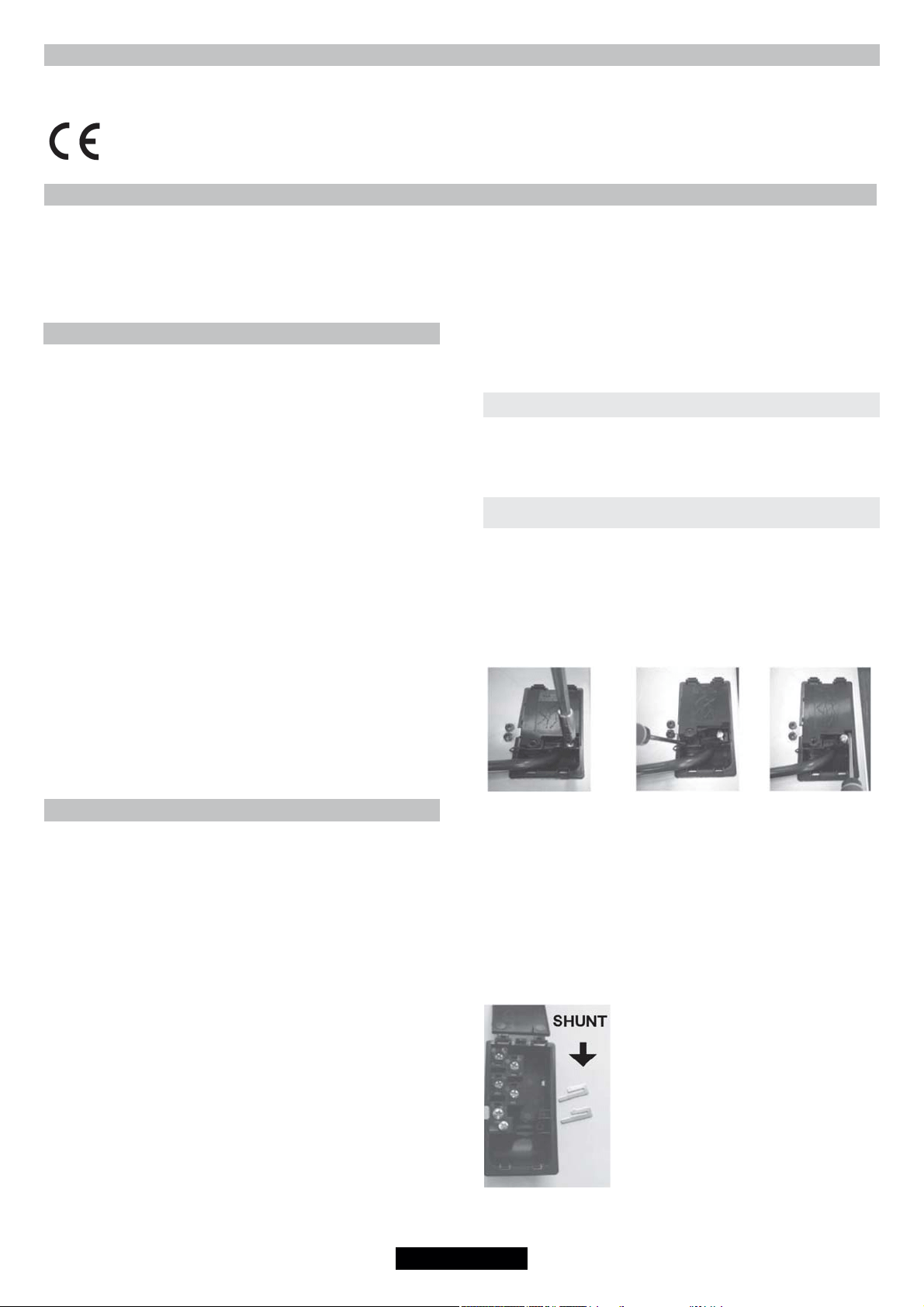
Open the cover in the following sequence:
1 2 3
. unscrew the cable clamp "1",
. find the two tabs located on the sides,
. put the blade of a flat screw-driver in front of each tab "2" e "3",
push in and press,
. remove the cover.
To release the power supplying cord.
. remove the screws retaining the terminal block which contains
the shunt bars and the conductors of the supply cord,
. Pull out the supply cord.
Operations to be carried out to make a new connection :
- Choose the power supply cable in
accordance with the recommendations in
the table.
- Pass the power supply cable into the
clamp.
- Strip the end of each conductor of the
supply cord on a 10 mm length, by taking in
account the requested length of the cord for
the connection to the terminal block.
- According to the installation and with the
help of shunt bars which you should have
recovered in the first operation, fix the
conductor as shown on the chart.
- Fix the cover.
- Screw the cable clamp.
Note: make sure the terminal board screws are tight.
Loading ...
Loading ...
Loading ...