Version 07/11 - Page 1
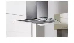
Tratto (electronic controls)
Wall Mount Canopy Rangehood
READ AND SAVE THESE INSTRUCTIONS
The Installer must leave these instructions with the homeowner. The
homeowner must keep these instructions for future reference and for
local electrical inspectors' use.
READ THESE INSTRUCTIONS BEFORE YOU START INSTALLING THIS RANGEHOOD
WARNING: - TO REDUCE THE RISK OF A RANGE TOP GREASE FIRE:
a) Never leave surface units unattended at high settings. Boilovers cause smoking and greasy spillovers that may ignite.
Heat oils slowly on low or medium setting.
b) Always turn hood ON when cooking at high heat or when ambeing food
(i.e. Crepes Suzette, Cherries Jubilee, Peppercorn Beef Flambé).
c) Clean ventilating fans frequently. Grease should not be allowed to accumulate on fan or lter.
d) Use proper pan size. Always use cookware appropriate for the size of the surface element.
WARNING: - TO REDUCE THE RISK OF INJURY TO PERSONS IN THE EVENT OF A RANGE TOP GREASE FIRE, OBSERVE
THE FOLLOWING (*):
a) SMOTHER FLAMES with a close-tting lid, cookie sheet, or metal tray, then turn off the burner. BE CAREFUL TO PRE-
VENT BURNS. If the ames do not go out immediately EVACUATE AND CALL THE FIRE DEPARTMENT.
b) NEVER PICK UP A FLAMING PAN - You may be burned.
c) DO NOT USE WATER, including wet dishcloths or towels - a violent steam explosion will result.
d) Use an extinguisher ONLY if:
1) You know you have a Class ABC extinguisher, and you already know how to operate it.
2) The re is small and contained in the area where it started.
3) The re department is being called.
4) You can ght the re with your back to an exit.
(*) Based on “Kitchen Firesafety Tips” published by NFPA.
This rangehood requires at least 24" of clearance between the bottom of the rangehood and the cooking surface or countertop.
This minimum clearance may be higher depending on local building code. For example, for gas ranges, a minimum of 30" is
recommened and may be required. Overhead cabinets on both sides of this unit must be a minimum of 18" above the cooking
cutouts.
LISEZ BIEN CETTE FICHE AVANT D'INSTALLER LA HOTTE
AVERTISSEMENT - POUR MINIMISER LE RISQUE D’UN FEU DE GRAISSE SUR LA TABLE DE CUISSON : a) Ne jamais laisser
un élément de la table de cuisson fonctionner sans surveillance à la puissance de chauffage maximale; un renversement/
débordement de matière graisseuse pourrait provoquer une inammation et le génération de fumée. Utiliser toujours une
puissance de chauffage moyenne ou basse pour le chauffage d’huile. b) Veiller à toujours faire fonctionner le ventilateur
de la hotte lors d’une cuisson avec une puissance de chauffage élevée ou lors de la cuisson d’un mets à amber (i.e.
Crepes Suzette, Cherries Jubilee, Peppercorn Beef Flambé). c) Nettoyer fréquemment les ventilateurs d’extraction. Veiller
à ne pas laisser de la graisse s’accumuler sur les surfaces du ventilateur ou des ltres. d) Utiliser toujours un ustensile
de taille appropriée. Utiliser toujours un ustensile de taille adapté à la taille de l’élément chauffant.
AVERTISSEMENT: - POUR PRÉVENIR LES BLESSURES EN CAS DE FEU SUIVRE LES RECOMMANDATIONS SUIVANTES
(*): a) ÉTOUFFEZ LE FEU avec un couvercle métallique et fermez le brûleur. Si le feu ne s'éteint pas tout de suite, QUIT-
TEZ LES LIEUX ET APPELEZ LES POMPIERS. b) NE TOUCHEZ JAMAIS UNE CASSEROLE EN FLAMMES. c) N'UTILISEZ
JAMAIS DE L'EAU ou un torchon mouillé pour éteindre le feu - ce qui pourrait causer une explosion de vapeur. d) N'utilisez
un extincteur que si: 1. Vous avez un modèle ABC et vous connaissez bien son mode d'emploi. 2. Le feu est petit et peu
répandu. 3. Les pompiers sont déjà prévenus. 4. Vous avez une sortie derrière vous. (*) Basé sur la "cuisine Firesafety
incline" édité par NFPA.
le code municipal. Par exemple, les cuisinières à gaz peuvent requérir 30 po. de hauteur. Les armoires au-dessus de chaque
armoires.
Version 07/11 - Page 2
VENTING REQUIREMENTS
Determine which venting method is best for your application.
Ductwork can extend either through the wall or the roof.
The length of the ductwork and the number of elbows should
size of the ductwork should be uniform. Do not install two
around the cap.
Flexible ductwork is not recommended. Flexible ductwork
creates back pressure and air turbulence that greatly
reduces performance.
cut, then a supporting frame must be constructed.
TO PAGE 4.
WARNING - To Reduce The Risk Of Fire, Use Only Metal
Ductwork.
ELECTRICAL REQUIREMENTS
separate 15 amp fused circuit. A time-delay fuse or circuit
breaker is recommended. The fuse must be sized per local
codes in accordance with the electrical rating of this unit as
must conform to the requirements of the National Electrical
ordinances. Wire size and connections must conform with the
may be obtained from:
National Fire Protection Association
Quincy, Massachusetts 02269
home.
other enclosed space.
ventilation air.
This appliance should be connected directly to the fused
or nonmetallic sheathed copper cable. Allow some slack
in the cable so the appliance can be moved if servicing
must be provided at each end of the power supply cable
When making the electrical connection, cut a 1 1/4" hole
in the wall. A hole cut through wood must be sanded until
smooth. A hole through metal must have a grommet.
WARNING - TO REDUCE THE RISK OF FIRE OR ELEC-
TRIC SHOCK, do not use this fan with any solid-state
speed control device.
WARNING - TO REDUCE THE RISK OF FIRE, ELECTRI-
CAL SHOCK, OR INJURY TO PERSONS, OBSERVE
THE FOLLOWING: Use this unit only in the manner
intended by the manufacturer. If you have any ques-
tions, contact the manufacturer.
Before servicing or cleaning unit, switch power off
at service panel and lock the service disconnecting
means to prevent power from being switched on ac-
cidentally. When the service disconnecting means
cannot be locked, securely fasten a prominent warning
device, such as a tag, to the service panel.
CAUTION: For General Ventilating Use Only. Do Not
Use To Exhaust Hazardous or Explosive Materials
and Vapors.
WARNING - TO REDUCE THE RISK OF FIRE, ELECTRI-
CAL SHOCK, OR INJURY TO PERSONS, OBSERVE
THE FOLLOWING: Installation Work And Electrical
Wiring Must Be Done By Qualied Person(s) In Ac-
cordance With All Applicable Codes And Standards,
Including Fire-Rated Construction.
Sufcient air is needed for proper combustion and
exhausting of gases through the ue (chimney) of
fuel burning equipment to prevent backdrafting. Fol-
low the heating equipment manufacturer's guideline
and safety standards such as those published by the
National Fire Protection Association (NFPA), and the
American Society for Heating, Refrigeration and Air
Conditioning Engineers (ASHRAE), and the local
code authorities.
When cutting or drilling into wall or ceiling, do not
damage electrical wiring and other hidden utilities.
Ducted fans must always be vented to the out-
doors.
WARNING
nonmetallic gaskets or other materials, DO NOT
use for grounding.
circuit. A fuse in the neutral or grounding circuit
could result in electrical shock.
doubt as to whether the rangehood is properly
grounded.
fan speed control device.
WARNING
For residential use only.
!
!
Cold Weather installations
An additional back draft damper should be installed to minimize
be installed to minimize conduction of outside temperatures
as part of the vent system. The damper should be on the cold
air side of the thermal break. The break should be as close as
possible to where the vent system enters the heated portion
of the house.
Version 07/11 - Page 3
RÈGLEMENTS D'ÉVACUATION
par le toit.
avec un ruban adhésif métallique à l'intérieur et scellez
bien le clapet extérieur avec du calfeutrage.
Utilisez un tuyau d'évacuation rigide lorsque possible.
Un tuyau exible égale deux fois plus qu'un tuyau
rigide, ce qui réduit la puissance d'évacuation.
Un conduit d'évacuation exible crée une contre-
pression et une turbulence de l'air qui réduisent
considérablement la performance.
Veillez à ce que l'espace pour le tuyau soit ample - ainsi
on n'aurait pas besoin de découper les supports de mur
intérieur. Si ce découpage est nécessaire, veillez bien
à ce qu'un renforcement soit mis en place.
PAGE 11
AVERTISSEMENT - Pour Ne Pas Risquer Un Feu,
Utilisez Seulement Les Matériaux Métalliques.
Veillez a ce qu'un contact d'un demi-pouce (1/2 po.) soit
boite à fusible).
Faites un trou de 1 1/4 po. dans le mur. S'il s'agit d'un trou
en bois - sablez-le bien, tandis qu'un trou passant par le
métal demande un bouche-trou.
AVERTISSEMENT - POUR RÉDUIRE LE RISQUE
D'INCENDIE OU DE CHOC ELECTRIQUE, ne pas utiliser
ce ventilateur en conjonction avec un dispositif de
réglage de vitesse à semi-conducteurs.
AVERTISSEMENT – POUR MINIMISER LES RISQUES
D’INCENDIE, CHOC ÉLECTRIQUE OU DOMMAGES
CORPORELS, OBSERVER LES PRESCRIPTIONS
SUIVANTES: Suivez les recommandations du fabricant
et entre en communication avec lui pour toute
information.
Fermez le courant avant tout entretien et veillez a
ce qu'il reste fermé. Si on ne peut pas verrouiller le
panneaux du service électrique, afchez un avis de
danger sur la porte.
AVIS: Pour L'évacuation Générale - Veillez à Ne Pas
Evacuer Des Matériaux Ou Vapeurs Explosif.
AVERTISSEMENT – POUR MINIMISER LES RISQUES
D’INCENDIE, CHOC ÉLECTRIQUE OU DOMMAGES
CORPORELS, OBSERVER LES PRESCRIPTIONS
SUIVANTES: L'installation Et Le Raccordement
Electrique Doivent Se Faire Par Un Technicien Qualié
Selon Tous Les Codes Municipaux.
An d'obtenir un rendement maximal en ce qui a
trait à la combustion ainsi qu'à l'évacuation des gaz
par la conduite de cheminée, une bonne aération est
nécessaire pour tous les appareils à combustion.
Suivez les conseils et mesures de sécurité du
fournisseur tels que ceux publiés par l'Association
Nationale de la Sauvegarde contre l'Incendie et
l'Association Américaine d'Ingénieurs de Chauffage,
Frigorifaction et Air Climatisé ainsi que les codes
municipaux.
En perçant un mur veillez à ne pas perforer un autre
l électrique.
Une ventilateur à évacuation extérieure doit être
raccordée à l'extérieur.
AVERTISSEMENT
mansarde soit dans un espace enfermé.
occasionner un feu.
FICHE TECHNIQUE ÉLECTRIQUE
Le raccordement électrique doit se faire avec un circuit
séparé de 15 ampères fusible à 120V, 60 Hz, courant
alternant. On recommande un coupe-circuit. La taille du
fusible doit se conformer aux codes municipaux suivant
du code national électrique, ANSI/NFPA 70 - ainsi qu'aux
On peut obtenir ces informations chez:
l'Association Nationale de la Prévention du Feu
Quincy, Massachusetts 02269
Raccordez cet appareil directement au coupe-circuit
de l'appareil.
métallique ou autre.
mise à terre - ce qui peut causer une secousse
électrique.
soit bien mise à terre.
occasionner un feu.
AVERTISSEMENT
Uniquement pour usage menager.
!
!
Installations pour régions à climat froid
thermique pour minimiser la conduction de chaleur par l'intermédiaire
du conduit d'évacuation, de l'intérieur de la maison à l'extérieur.
aussi proche que possible de l'endroit où le système d'évacuation
s'introduit dans la partie chauffée de la maison.
Version 07/11 - Page 4
For best results, use no more than three 90° elbows. Make sure that
there is a minimum of 24" of straight duct between elbows if more than
one is used. Do not install two elbows together. If you must elbow right
away, do it as far away from the hood's exhaust opening as possible.
9 Feet Straight Duct
Total System
9.0 feet
10.0 feet
0.0 feet
19.0 feet
FIGURE 3
3.0 feet
5.0 feet
12.0 feet
0.0 feet
FIGURE 2
PLAN THE INSTALLATION
This rangehood can be installed as either ducted or ductless. The blower
can be vented through the wall or ceiling. To vent through a wall, a 90° elbow
is used. When installed ductless, the rangehood vents out of grates on the
sides of the chimney. Ductless installations require a Ductless Conversion
Kit, available from your dealer.
WARNING!
TOOLS NEEDED FOR INSTALLATION
PARTS SUPPLIED FOR INSTALLATION
PARTS NEEDED FOR INSTALLATION
OPTIONAL ACCESSORIES AVAILABLE
High Ceiling Chimney Kit
One 40" upper chimney to replace 16
1/8" upper
chimney that came with hood
part # HIGHTRAT - Stainless
*Ductless Conversion Kit
For non-vented installations only
* it is highly recommended that professional style
cooking always be vented to the outside
Replacement Charcoal Filter
For non-vented installations only,
part # FILTER2
• CFM Reducer Kit
To reduce cfm to below 300 cfm for use in
make up air environments part # CFMRED
WARNING
canopy, two or more people are needed to move
and safely install the rangehood canopy.
Failure to properly lift rangehood could result in
CALCULATE THE DUCTRUN LENGTH
The ductrun should not exceed 35 equivalent feet if ducted with the required
the equivalent feet in FIGURE 2 for each piece of duct in the system. An
example is given in FIGURE 3.
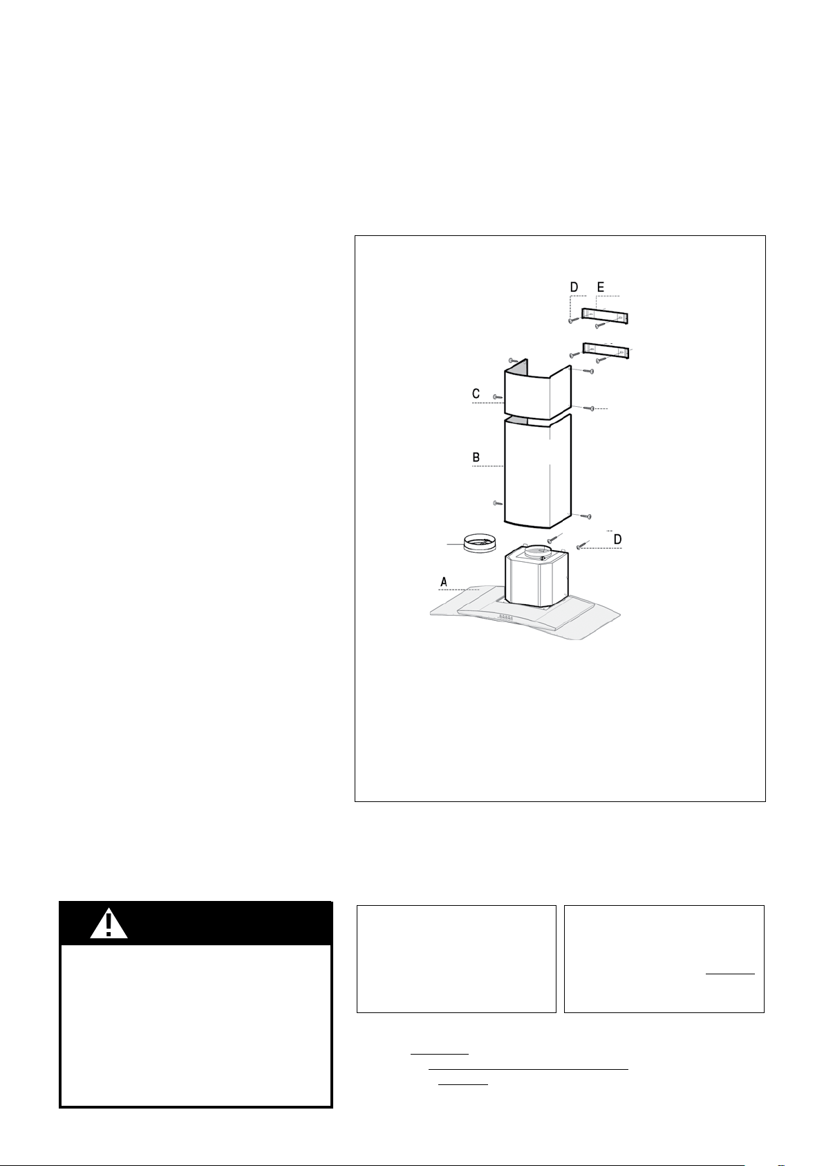
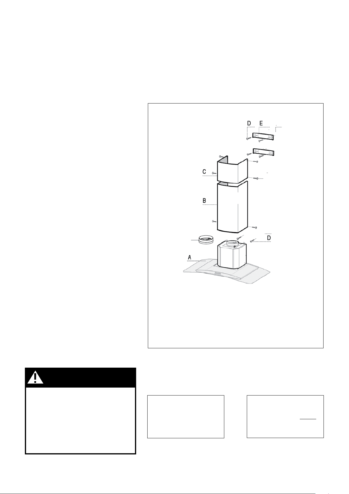
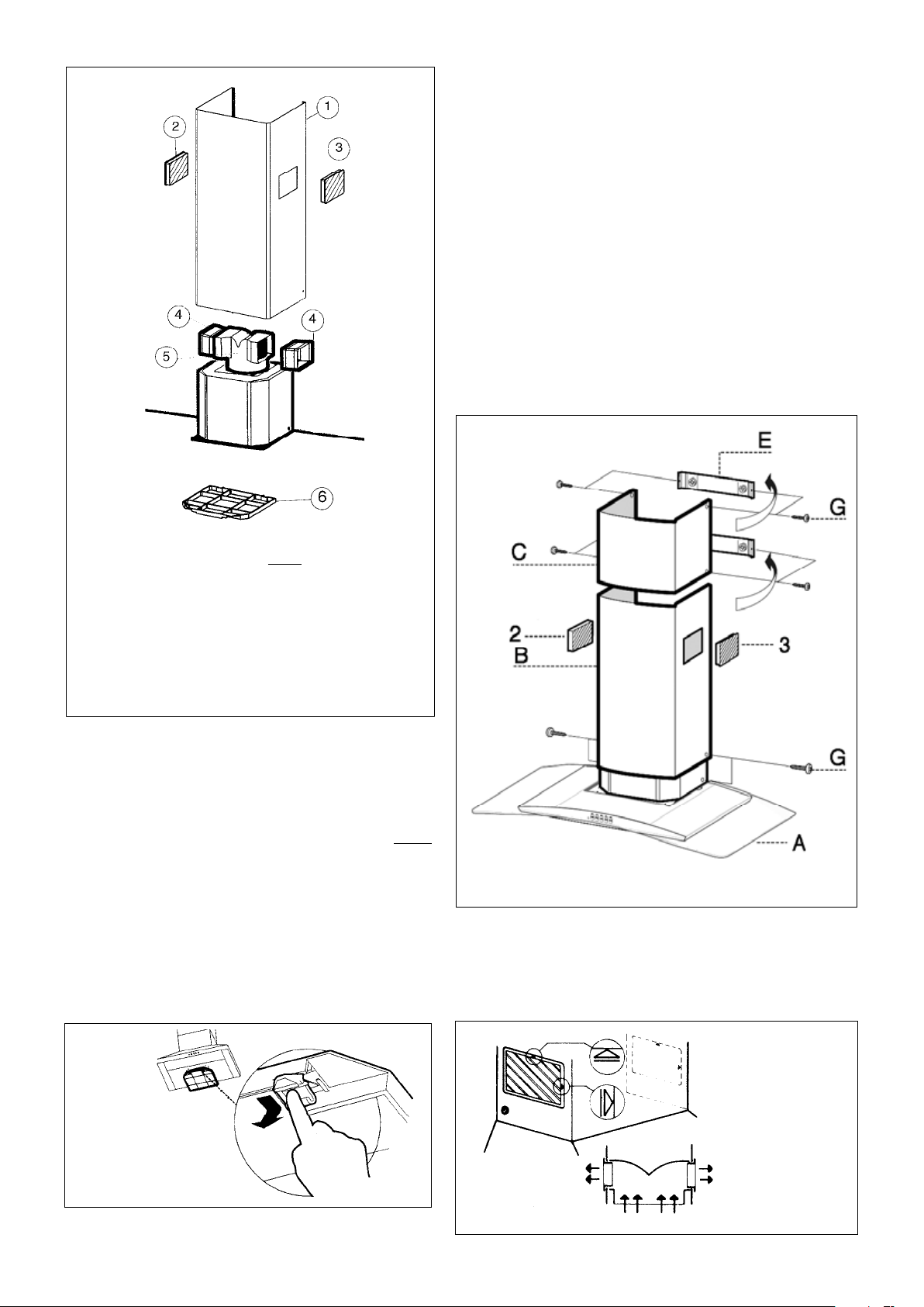
RANGEHOOD COMPONENTS
FIGURE 1
A. CANOPY SECTION
B. LOWER CHIMNEY COVER
C. UPPER CHIMNEY COVER
D. MOUNTING SCREWS
E. CHIMNEY MOUNTING
F. CHIMNEY SCREWS
G. DAMPER
BRACKETS
!
G
F
G
Version 07/11 - Page 5
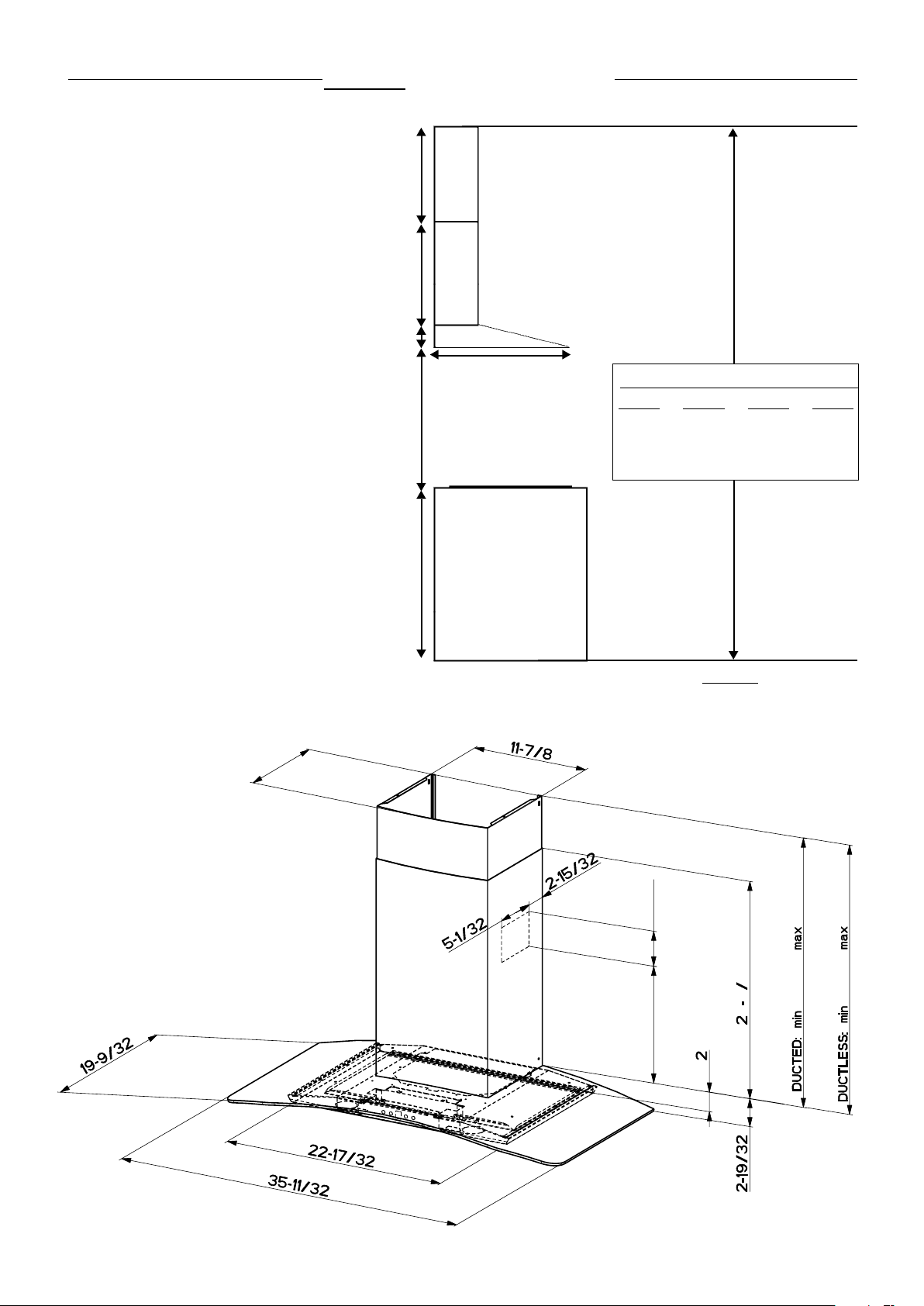
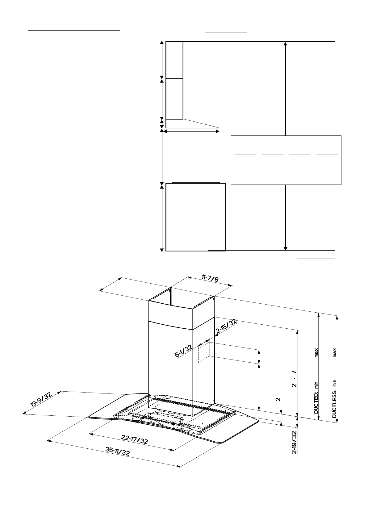
DUCTED INSTALLATION DIMENSIONS
designed to meet varying ceiling heights as
indicated in FIGURE 4A. The chimneys can
8' 9 3/8" depending on the distance between
the bottom of the hood and the cooktop
(distance x).
For shorter ceilings, have the chimney cover(s)
cut at a sheet metal shop. For higher ceiling
installations, the High Ceiling Chimney Kit
includes a new 40” upper chimney which would
replace the 16 1/8” upper chimney that came
with the hood.
upper
chimney
cover
lower
chimney
cover
canopy
x = distance from hood to cooktop
(varies depending on installation)
min - 24”, suggested max - 30”
cabinet base
5 1/8” min
16 1/8” max
21
1/4”
2"
36”
19 3/8"
x
also consult cooktop
manufacturer's recommendation
(vented to the outside)
FIGURE 4A DUCTED INSTALLATIONS
min & max ceiling height examples
x = 30"
min
7'
10 3/8"
max
8'
9 3/8"
x = 28"
min
7'
8 3/8"
max
8'
7 3/8"
x = 26"
min
7'
6 3/8"
max
8'
5 3/8"
x = 24"
min
7'
4 3/8"
max
8'
3 3/8"
10 7/16”
1 1
4
26 3/8”
37 3/8”
12 1/2”
3 1/2”
32 ”
38 1/8”
Version 07/11 - Page 6
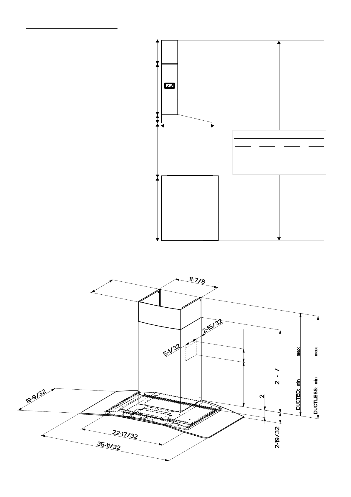
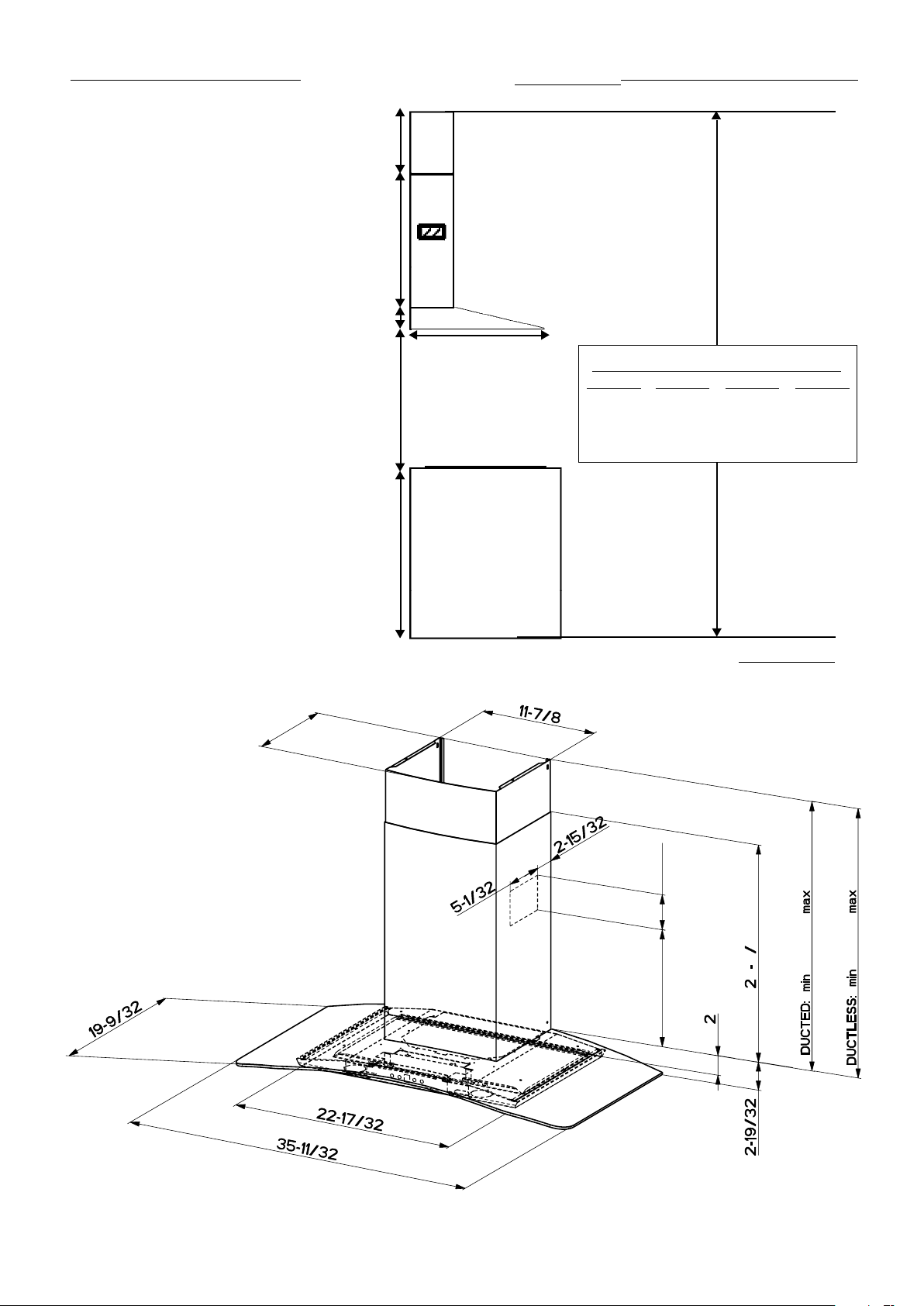
DUCTLESS INSTALLATION DIMENSIONS
upper
chimney
cover
ductless
lower
chimney
cover
canopy
x = distance from hood to cooktop
(varies depending on installation)
min - 24”, suggested max - 30”
cabinet base
10" min
16
1/8” max
21
1/4"
2"
36”
19 3/8"
x
also consult cooktop
manufacturer's recommendation
(not vented to the outside)
FIGURE 4B DUCTLESS INSTALLATIONS
designed to meet varying ceiling heights
as indicated in FIGURE 4B. For ductless
for ceilings between 7' 9 1/4" and 8' 9 3/8"
depending on the distance between the bottom
of the hood and the cooktop (distance x).
For shorter ceilings, have the chimney cover(s)
cut at a sheet metal shop. For higher ceiling
installations, the High Ceiling Chimney Kit
includes a new 40” upper chimney which would
replace the 16 1/8” upper chimney that came
with the hood.
min & max ceiling height examples
x = 30"
min
8'
3 1/4"
max
8'
9 3/8"
x = 28"
min
8'
1 1/4"
max
8'
7 3/8"
x = 26"
min
7'
11 1/4"
max
8'
5 3/8"
x = 24"
min
7'
9 1/4"
max
8'
3 3/8"
10 7/16”
1 1
4
26 3/8”
37 3/8”
12 1/2”
3 1/2”
32 ”
38 1/8”
Version 07/11 - Page 7
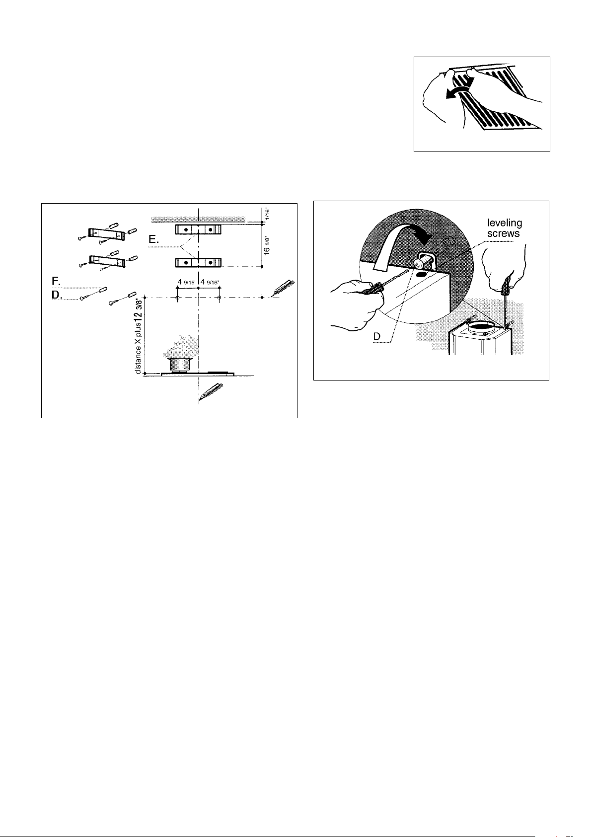
PREPARE THE WALL
1. Disconnect and move freestanding range from cabinet open-
ing to provide easier access to rear wall. Put a thick, protective
covering over cooktop, set-in range or countertop to protect from
damage or dirt.
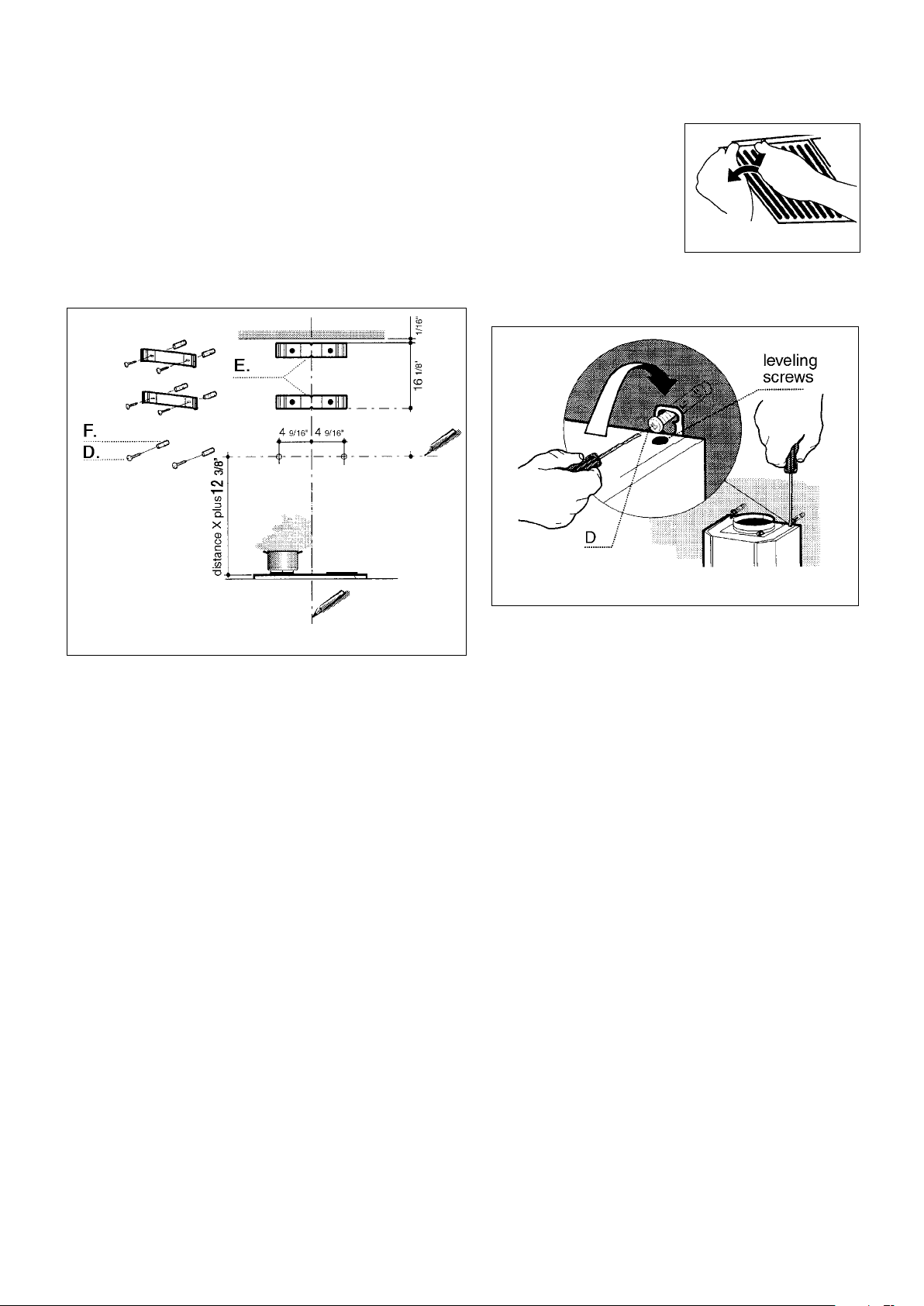
2. Determine and clearly mark with a pencil the center line on the
wall where the rangehood will be installed.
3.-
mine the distance you would like between the bottom of the hood
and the cooktop (distance X in FIGURE 4A OR 4B). Draw a
horizontal line the height of distance X plus 12 3/8" (as indicated
in FIGURE 5).
FIGURE 5
3. (D in FIG-
URE 7)
4. -
TION.
5. For ducted installations, the DAMPER (G in FIGURE 1)
must be attached to the exhaust opening on the top of the
connections with duct tape.
"FOR ALL INSTALLATIONS"
PAGE
FIGURE 6
7.(D)
(A in FIGURE 1) should be
installed into wood. Mark the wall along the horizontal line 4 9/16"
in from the center line on either side (as indicated in FIGURE 5A
or 5B)
about 1/4" gap between the wall and the head of the screw.
8. For ducted installations, determine and make all necessary
cuts in the wall for the ductwork. Install the ductwork before the
rangehood.
9.
making sure it:
1)
2) Does not have ductwork blocking your access to the Field Wiring
the power until installation is complete.
INSTALL THE RANGEHOOD
4. (E) on
the wall as shown 1/16" from the ceiling, aligning the center notch
with the vertical center line. Mark the wall at the centers of the
holes in the bracket.
5.(E) on
the wall as shown at 16 1/8" below the upper bracket, aligning
the center notch with the vertical center line. Mark the wall at the
centers of the holes in the bracket.
6. (E) on the wall
(D) provided.
1. Remove the grease
pulling the knob forward
while turning it to the
left, releasing the lock-
ing lever.
2.
points as indicated in FIGURE 7.
FIGURE 7

Version 07/11 - Page 8
FOR DUCTLESS INSTALLATIONS
Ductless installations require a Ductless Conversion Kit
whose components are pictured in FIGURE 8. Do not use
the DAMPER (G in FIGURE 1) for ductless installations.
(B in FIGURE 1) should
be discarded and replaced by a new one with holes (1 in
FIGURE 8).
1. As indicated in FIGURE 8
(5)
(4)
DIVERTER.
2(6) behind the center grease
in FIGURE 9.
1. LOWER CHIMNEY DUCTLESS
2. LEFT VENT GRID
3. RIGHT VENT GRID
4. DIVERTER EXTENSION HORIZONTAL (2 PIECES)
5. DUCTLESS DIVERTER
6. CHARCOAL FILTER
FOR ALL INSTALLATIONS
1.
-
green screw provided. Attach the White lead of the power supply
to the White lead of the rangehood with a twist-on type wire con-
Replace the cover.
2.(C in FIGURE 10) by slightly
(E)
(G).
3.(B) by slightly widening
(A) (G).
FIGURE 10
FIGURE 8
FOR DUCTLESS
INSTALLATIONS
Fit the LEFT AND RIGHT
VENT GRIDS (2 and 3)
sure that the directional
symbols are towards the top
and front of the hood and that
they connect snugly to the
FIGURE 9
FIGURE 11
Version 07/11 - Page 9
• This rangehood uses 20 watt, G4 Bi - Pin halogen lamps.
FOR ALL INSTALLATIONS
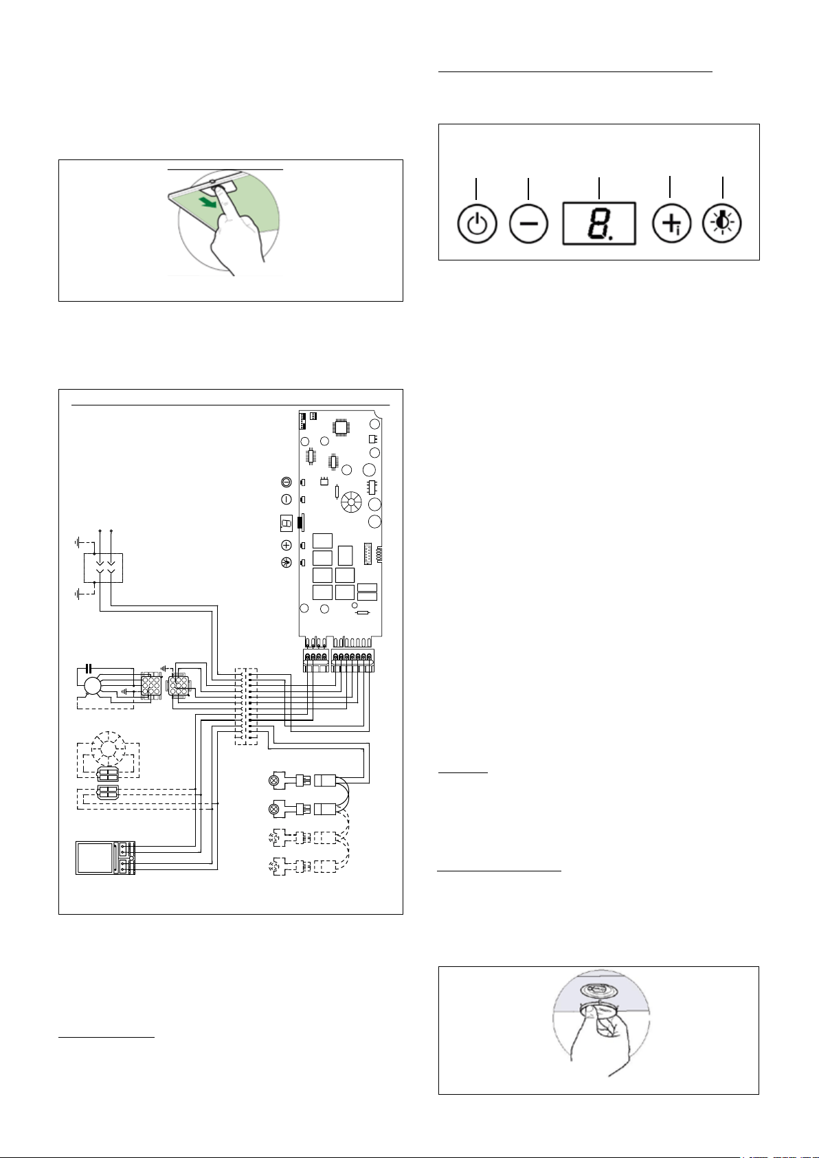
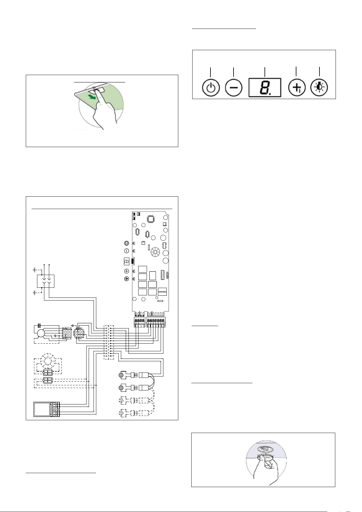
Rangehood Control Panel and Hood Operation
The control panel is located on the front edge of the rangehood
canopy. The position and function of each control button are
indicated in FIGURE 13.
Cleaning
hot detergent solution or washed in the dishwasher. Stainless
steel cleaner should be used on stainless rangehoods.
Abrasives and scouring agents can scratch stainless steel
FIGURE 12
2. Turn the power supply on. Turn on blower and lights. If the
rangehood does not operate, check that the circuit breaker is not
tripped or the house fuse blown. If the unit still does not operate,
disconnect the power supply and check that the wiring connec-
tions have been made properly.
WIRING DIAGRAM
FIGURE 13
USE AND CARE INFORMATION
This rangehood system is designed to remove smoke, cooking
vapors and odors from the cooktop area.
For Best Results
Start the rangehood several minutes before cooking to develop proper
complete to clear all smoke and odors from the kitchen.
Replacing the Lamps
levering it from under the metal ring, supporting it with one hand.
Remove the halogen lamp from the lamp holder by pulling gently.
Replace the lamp with a new one of the same type, making
sure that you insert the two pins properly into the housings on
the lamp holder. Replace the snap-on lamp cover.
FIGURE 16
1.
(FIGURE 12)
are properly positioned with the handles in front and visible.
0 1 2 3 4 5 6 7 8 9
Creato da.
Rev :
Ver :
DOLCE CORRADO
Materiali: non deveno contenere Pb, Cr6+, Hg, PBB, pbde, ai sensi della direttiva 2002/95 CE
SCHEMA ELETTRICO M8-4V ATL FARETTI
Non rilevare quote dal grafico non app ortare modifiche senza l'autorizzazione d'ufficio progettazione
a termini di legge ci riserviamo la propr ieta' del presente disegno con divieto di riprod uzione totale o parziale
Code :
Disegno N :
Data:
11.Nov.2010
436005191
H90_065
CN13
CN9
CN12
CN4
CN7
CN1
FASE
NEUTRO
COM
V1
V2
V3
V4
LUC.1 F.LUC.1 F.
LUC.1 N.
LUC.2 F.
LUC.2 N.
LINE IN
120Vac
60Hz ~
L
N
Y-G
WIRING BOX
Y-G
Faber ATL
1
2
3
4
5
7
6
1
2
3
4
BLU
BLK
L-B
RED
BLU
PNK
GRY
BRW
BLK
1
1
BLK
123
6 5 4
789
1 2 3
654
987
RED
M8 4V
120V ~
WHT
2
2
WHT
WHT
BRW
BRW
3
3
BRW
BLU
GRY
4
4
GRY
BLK
BLU
5
5
BLU
ORG
RED
6
6
RED
PNK
7
7
PNK
Y-G
VLT(ORG)
8
8
VLT(ORG)
RED(ORG)
9
9
RED(ORG)
RED
10
10
RED
VLT
11
11
VLT
12
12
TOROIDAL
TRANSFORMER
WHT
4
3
BLK
VLT
RED
2
1
BLK
RED
HALOGEN
LAMPS
ORG
2
1
ORG
4
3
RED
VLT
HALOGEN
LAMPS
HALOGEN
LAMPS
ORG
ORG
RED
HALOGEN
LAMPS
VLT
PRI.
SEC.
ELECTRONIC
TRNSFORMER
A
B
C
D
E
Button A.
Button B. Press to reduce fan speed to as low as speed
seconds to turn on 30 minute delay feature which runs the
hood for 30 minutes and automatically shuts the hood off.
a blinking light to indicate 30 minute mode. Shut off the 30
minute mode by holding down the button for 3 seconds
Button C. LED single digit readout display screen
Button D. Press button to increase fan speed up to speed 3.
Hold for 3 seconds to activate intensive speed mode which
operates hood on highest speed for 10 minutes and then
speed with an "H" and blinking light. Shut off the intensive
speed mode by holding down the button for 3 seconds
Button E. Press the button to turn on and off lighting. Press
once to turn the dimmer light on, press twice to turn the normal
light setting on, and press again to turn off the lighting.

Version 07/11 - Page 10
FABER WARRANTY & SERVICE (SAVE FOR YOUR RECORDS)
All Faber products are warranteed against any defect in materials or workmanship for the
original purchaser for a period of 1 year from the date of original purchase. This warranty
covers labor and replacement parts. To obtain warranty service, contact the dealer from
whom you purchased the rangehood, or the local Faber distributor. If you cannot identify
a local Faber distributor, contact us at (508) 358-5353 for the name of a distributor in your
area.
The Following is not covered by Faber's warranty:
1. Service calls to correct the installation of your range hood, to instruct you how to use your
range hood, to replace or repair house fuses or to correct house wiring or plumbing.
consumable parts are excluded from warranty coverage.
3. Repairs when your range hood is used for other than normal, single-family
household use.
improper installation, installation not in accordance with electrical or plumbing codes, or
use of products not approved by Faber.
rangehood.
7. Expenses for travel and transportation for product service in remote locations and pickup
and delivery charges. Faber range hoods should be serviced in the home.
Record Your Information Below:
Serial #: __________________________
Date of Purchase: ______________
Version 07/11 - Page 11
FIGURE 1
PLAN DE L’INSTALLATION
coude 90
o
est utilisé. Lorsque installé sans conduit, la ventilation s'effective
par une grille fournie avec la hotte. Les installations sans conduit requièrent
un nécessaire approprié disponible chez votre marchand (ACCESSOIRES
POUR L’INSTALLATION).
AVERTISSEMENT!
la FIGURE 2
donné à la FIGURE 3.
OUTILS NÉCESSAIRES À L’INSTALLATION
PIÈCES FOURNIES POUR L’INSTALLATION
PIÈCES NÉCESSAIRES POUR L’INSTALLATION
ACCESSOIRES POUR L’INSTALLATION
• Kit D'extension Pour La Cheminée Plafond Haut
part # HIGHTRAT - Acier Inoxydable
• *Kit Pour Conversion Du Conduit
Pour installation sans conduit
* Il est fortement recommandé que toute ventilation
• Filtre au Charbon
Pour installation sans conduit
part # FILTER2
ASSEMBLAGE DE LA HOTTE
AVERTISSEMENT
hotte, deux ou plusieurs personnes sont
nécessaires pour déplacer et installer la
hotte de façon sécuritaire.
appropriée, il peut en résulter des dommages
au produit ou des blessures.
CALCUL DE LONGUEUR DU CONDUIT
3,0 pi
5,0 pi
12,0 pi
0,0 pi
FIGURE 2
9 pi de conduit droit
Système total
9,0 pi
10,0 pi
0,0 pi
19,0 pi
FIGURE 3
Pour de meilleurs résultats, ne pas utiliser plus de trois coudes de 90
o
.
S’assurer qu’il y ait un minimum de 24 po de conduit droit entre les coudes
si l’on utilise plus d’un coude. Ne pas installer deux coudes ensemble.
A. HOTTE
B. CHEMINÉE INFÉRIEURE
C. CHEMINÉE SUPÉRIEURE
D. LES VIS DE FIXATIONS
E. FIXATIONS DE CHEMINÉE
F. LES VIS DE CHEMINÉE
G. LE REGISTRE
!
F
G
Version 07/11 - Page 12
DIMENSIONS D’INSTALLATION AVEC CONDUIT
couvercle cheminée
supérieure
couvercle cheminée
inférieure
hotte
x = distance entre la hotte et la
table de cuisson
min - 24 po, suggested max
- 30 po
FIGURE 4A INSTALLATIONS AVEC CONDUIT
5 1/8 po min
16 1/8 po max
21
1/4 po
2 po
36 po
x
19 3/8 po
La cheminée Tratto est réglable pour
différentes hauteurs de plafond, entre
7 pi 4 3/8 po et 8 pi 9 3/8 po (regardez
la distance entre la hotte et la table
de cuisson - X en FIGURE 4A).
moins du couvercle de la cheminé
supérieure.
Pour plafonds petit, coupez les
covercle cheminée(s). Pour plafonds
haut, utiliser Kit D'extension Pour La
Cheminée Plafond Haut.
min & max hauteurs de plafond
x = 30 po
min
7 pi
10 3/8 po
max
8 pi
9 3/8 po
x = 28 po
min
7 pi
8 3/8 po
max
8 pi
7 3/8 po
x = 26 po
min
7 pi
6 3/8 po
max
8 pi
5 3/8 po
x = 24 po
min
7 pi
4 3/8 po
max
8 pi
3 3/8 po
10 7/16”
1 1
4
26 3/8”
37 3/8”
12 1/2”
3 1/2”
32 ”
38 1/8”
Version 07/11 - Page 13
DIMENSIONS D’INSTALLATION SANS CONDUIT
couvercle cheminée
supérieure
couvercle cheminée inférieure
sans conduit
hotte
x = distance entre la hotte et la
table de cuisson
min - 24 po, suggested max
- 30 po
FIGURE 4B INSTALLATIONS SANS CONDUIT
10 po min
16 1/8 po max
21
1/4 po
2 po
36 po
19 3/8 po
x
Pour installations sans conduit, la cheminée
Tratto est réglable pour différentes hauteurs
de plafond, entre 7 pi 9 1/4 po et 8 pi 9 3/8
po (regardez la distance entre la hotte et la
table de cuisson - X en FIGURE 4B
couvercle de la cheminé supérieure.
Pour plafonds petit, coupez les covercle
cheminée(s). Pour plafonds haut, utiliser Kit
D'extension Pour La Cheminée Plafond
Haut.
min & max hauteurs de plafond
x = 30 po
min
8 pi
3 1/4 po
max
8 pi
9 3/8 po
x = 28 po
min
8 pi
1 1/4 po
max
8 pi
7 3/8 po
x = 26 po
min
7 pi
11 1/4 po
max
8 pi
5 3/8 po
x = 24 po
min
7 pi
9 1/4 po
max
8 pi
3 3/8 po
10 7/16”
1 1
4
26 3/8”
37 3/8”
12 1/2”
3 1/2”
32 ”
38 1/8”
Version 07/11 - Page 14
PRÉPARATION DU MUR
1.
au mur arrière. Placer un recouvrement épais sur la plaque de
cuisson, la cuisinière encastrée ou le dessus du comptoir pour
protéger des dommages et de la poussière.
2.
verticale centrale sur le mur où la hotte sera installée.
3. Déterminer la distance entre la hotte et la table de cuisson (distance
X de la FIGURE 4A ou 4B). Marquer la ligne horizontal la hauteur
de distance X plus 12 3/8 po (de la FIGURE 5).
FIGURE 5
3. (D de
la FIGURE 7)
4. Agir sur les vis pour niveler la HOTTE.
5. Pour les installations avec conduits, le REGISTRE (G de
la FIGURE 1)
les connexions avec du ruban à conduit.
"POUR TOUT LES INSTALLATIONS"
FIGURE 6
7.(D) pour la HOTTE (A de la FIGURE
1)
la ligne horizontal 4 9/16 po de la ligne centrale sur le mur où la
hotte sera installée (de la FIGURE 5A ou 5B) et installer les VIS
8. Pour les installations avec conduit, déterminer et faire toutes
les coupes nécessaires dans le mur pour les conduits. Installer les
conduits avant la hotte.
9.
Soyes sûr de:
1)
2) Le conduit ne pas bloquer le compartiment de câblage.
complétée.
INSTALLATION DE LA HOTTE
4.(E) sur le mur 1/16 po
du plafond. Aligner son centre (découpes) sur la ligne vertical
5.(E) sur le mur 16 1/8
(découpes) sur la ligne vertical de repère . Marquer les centres
6. (E) au mur en utilisant
(D) fournies.
1.
2. Avant d'accrocher la HOTTE, serrer les deux vis situées sur
les points d'accrochage de la HOTTE (de la FIGURE 7).
FIGURE 7
avec l'autre main pour qu'il
ne tombe pas sur la table
de cuisson. Tirer le bouton
vers l'avant de la hotte en le
tournant vers la guache (sens
antihoraire) pour débloquer le
levier de verrouillage.
Version 07/11 - Page 15
INSTALLATIONS SANS CONDUIT
Les installations sans conduit requièrent le Kit Pour Conver-
sion Du Conduit (FIGURE 8). N'utilisez pas le REGISTRE
ROND (G de la FIGURE 1) pour les Installations sans
SANS
(B de la FIGURE 1)(1 de
la FIGURE 8).
1.(5) ainsi
obtenue dans la sorte d'air (de la FIGURE 8). Appliquer les
(4) sur le
2(6) (de la FIGURE 9).
POUR TOUT LES INSTALLATIONS
1.
et vert) sous la vis de mise à la terre verte. Replacer le couvercle
du compartiment de câblage.
2.(C de la FIGURE 10).
Elargir légèrement les deux bords latériaux de la cheminée et les
(E); refermer
-
(E)(G).
3.(B). Elargir légèrement
les deux bords latériaux de la cheminée et les accrocher entre la
Fixer latéralement la partie inférieure au la HOTTE (A) à l'aide des
(G).
FIGURE 10
FIGURE 8
INSTALLATIONS SANS CONDUIT
Les VENT GRIDS (2 et 3)
est illustré à la FIGURE 11. S'assurer également qu'elles sont
pieces.
FIGURE 9
FIGURE 11
1. CHEMINÉE INFÉRIEURE AVEC TROUS
2. VENT GRID GAUCHE
3. VENT GRID DROIT
4. DIVERTER EXTENSION HORIZONTAL (DEUX)
5. DUCTLESS DIVERTER
6. FILTRE CHARBON
D'ECHAPPEMENT D'AIR
Version 07/11 - Page 16
POUR TOUT LES INSTALLATIONS
1.
FIGURE 12. Au mo-
Panneau de commandes
Le panneau de commandes est situé sur le devant de la hotte.
La position et la fonction de chaque bouton sont indiquées
à la FIGURE 13.
Nettoyage
fréquemment dans
inoxydable sur les hottes en acier inoxydable. Ne pas
utiliser de produits abrasifs ou de récurants, car ils peuvent
FIGURE 12
2.
si les connexions ont été effectuées correctement.
DIAGRAMME DE CÂBLAGE
FIGURE 13
UTILISATION ET ENTRETIEN
cuisson et les odeurs de la cuisine.
Pour de meilleurs résultats
Mettre la hotte en circuit avant de commencer la cuisson. Laisser
éliminer la fumée et les odeurs de la cuisine.
Remplacement Lampes
Enlever le dispositif métallique de blocage du verre par
lampe du support. Remplacer la lampe par une nouvelle
dispositif de blocage du verre par encliquetage.
FIGURE 16
0 1 2 3 4 5 6 7 8 9
Creato da.
Rev :
Ver :
DOLCE CORRADO
Materiali: non deveno contenere Pb, Cr6+, Hg, PBB, pbde, ai sensi della direttiva 2002/95 CE
SCHEMA ELETTRICO M8-4V ATL FARETTI
Non rilevare quote dal grafico non app ortare modifiche senza l'autorizzazione d'ufficio progettazione
a termini di legge ci riserviamo la propr ieta' del presente disegno con divieto di riprod uzione totale o parziale
Code :
Disegno N :
Data:
11.Nov.2010
436005191
H90_065
CN13
CN9
CN12
CN4
CN7
CN1
FASE
NEUTRO
COM
V1
V2
V3
V4
LUC.1 F.LUC.1 F.
LUC.1 N.
LUC.2 F.
LUC.2 N.
LINE IN
120Vac
60Hz ~
L
N
Y-G
WIRING BOX
Y-G
Faber ATL
1
2
3
4
5
7
6
1
2
3
4
BLU
BLK
L-B
RED
BLU
PNK
GRY
BRW
BLK
1
1
BLK
123
6 5 4
789
1 2 3
654
987
RED
M8 4V
120V ~
WHT
2
2
WHT
WHT
BRW
BRW
3
3
BRW
BLU
GRY
4
4
GRY
BLK
BLU
5
5
BLU
ORG
RED
6
6
RED
PNK
7
7
PNK
Y-G
VLT(ORG)
8
8
VLT(ORG)
RED(ORG)
9
9
RED(ORG)
RED
10
10
RED
VLT
11
11
VLT
12
12
TOROIDAL
TRANSFORMER
WHT
4
3
BLK
VLT
RED
2
1
BLK
RED
HALOGEN
LAMPS
ORG
2
1
ORG
4
3
RED
VLT
HALOGEN
LAMPS
HALOGEN
LAMPS
ORG
ORG
RED
HALOGEN
LAMPS
VLT
PRI.
SEC.
ELECTRONIC
TRNSFORMER
A
B
C
D
E
2, 3)
Tenez pendant 3 secondes pour allumer le dispositif minute du retard
30 qui court le capot pendant 30 minutes et ferme automatiquement
le capot au loin. La vitesse courante sur le retard 30 minute est
maintenant le bouton pendant 3 secondes.
de LED
activer le mode intensif de vitesse qui actionne le capot sur la vitesse
la plus élevée pendant 10 minutes et puis revient à l'arrangement
vitesse en maintenant le bouton pendant 3 secondes
faible, pressez deux fois pour allumer l'arrangement léger normal,

Version 07/11 - Page 17
FABER GARANTIE ET SERVICE (
ÉCONOMISER POUR VOS ENREGISTREMENTS
)
Les frais suivants ne sont pas couverts par la garantie Faber :
comment utiliser votre hotte de cuisinière, pour remplacer ou réparer les fusibles de votre maison ou
pour corriger votre câblage ou votre système de plomberie.
2. Les appels de service pour remplacer ou réparer les ampoules, les fusibles ou les
3. Les réparations lorsque votre hotte de cuisinière a été utilisée plus que la normale,
c'est-à-dire plus que pour une famille par foyer.
Enregistrez Votre Information Ci-dessous:
Séquentiel #: __________________________
Date d'achat: ______________