Loading ...
Loading ...
Loading ...
Installation Guide
Installation Manual 7
ENGLISH
Installation Steps
1. Connect CN_OUT with Outdoor Unit by the cable (provided)
2. Connect RS-485 BUS_A(+) and BUS_(B)(-) with other network products (ex.
Central Controller , I-Gateway.....)
3. In case of using Simple Central Controller, connect VCC(+10V) and GND.
No need to connect otherwise.
4. Select DIP Switch Configuration(Refer page 8)
5. Connect CN_PWR with Outdoor PCB Power connector (Refer page 9, 10)
6. After Power is ON, check the Communication LED
- LED1G(Red)
• Normal : LED blinks for 5 times and then gets OFF
This process is repeated after every 3 minutes
• Error : Check the Indoor Unit's address & wiring connections
- LED2G(Yellow), LED3G(Orange)
• Normal : LED blinks continuously
• Error : Check the DIP Switch setting & wiring connections
7. Check RS-485 Communication Status LED:
• Normal : LED's blinks 2 times in every 10~30 seconds
• Error : Check the wiring connections
8. Finally if all of the above steps are OK, then tie the cables by tie wraps & clamp
Installation Guide
6
8
1
7
9
4
5
2
3
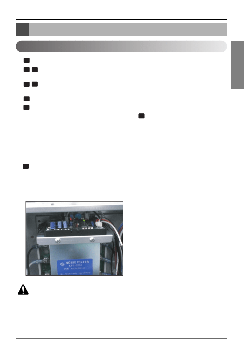
* Example about Multi V plus
CAUTION:
Install the PI485 on the Noise Filter in Multi V plus.
Install the PI485 after checking the hole for screw.
Loading ...
Loading ...
Loading ...