Loading ...
Loading ...
Loading ...
ENGLISH
Part Description
Installation Manual 5
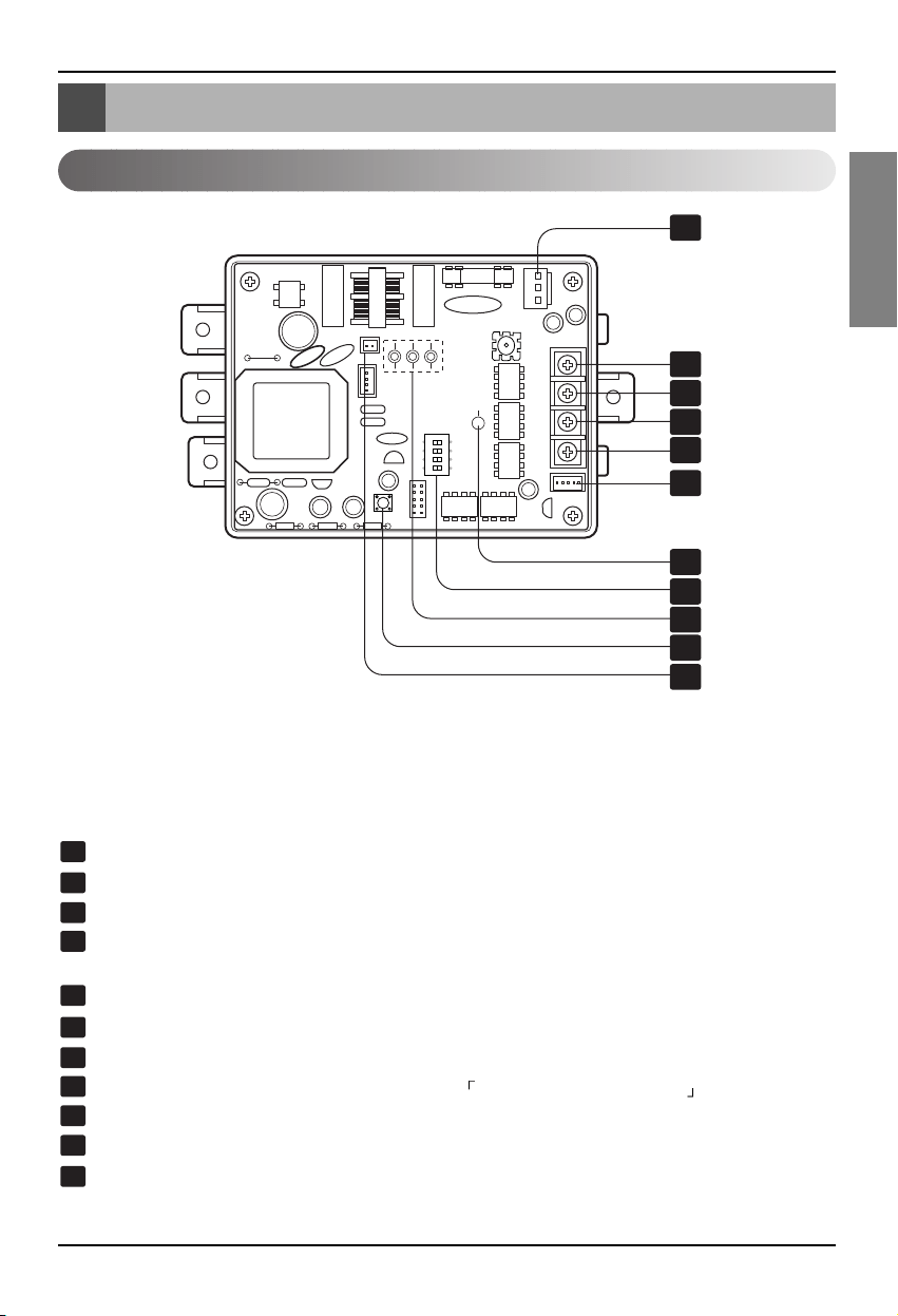
Part Description
PMNFP14A0 / PMNFP14A1 / PGNFP14A0
PI485 GATEWAY(M)
CN_PWR: AC 220V Connector
+10V: DC 10V Terminal
GND: Ground
BUS_A: *RS-485 (+) Terminal
(Refer to note)
BUS_B: RS-485 (-) Terminal
CN_OUT: Outdoor Unit Connector
LED1:RS-485 Status LED
DIP Switch: Product Selection (Refer to the
DIP Switch Configuration )
LED01G, 02G, 03G: Communication Status LED
Reset Switch: PI485(M) Reset
CN_DRY: DRY Contact
ON
L1 2 3 4
KSDO4H
1
2
3
4
5
6
7
8
9
10
11
1
2
3
4
5
6
7
8
9
10
11
✽ The location of parts might be different in case of PMNFP14A1.
PMNFP14A0 : For connecting 1 ~ 16 Indoor Units
PMNFP14A1 : For connecting 1 ~ 48 Indoor Units
PGNFP14A0 : For connecting only base controller
* Note : RS-485 is one of the international interface standards for serial communication.
Loading ...
Loading ...
Loading ...