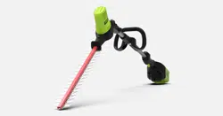
Loading ...

English (Original instructions)
EN
DE ES IT FR PT NL RU FI SV NO DA PL CS SK SL HR HU RO BG EL AR TR HE LT LV ET
SPECIFICATIONS
Model 2300107
Voltage 60V
No load speed 3000 (±10%) min
-1
Blade speed 3000 (±10%) min
-1
Blade length 508 mm
Cutting capacity 19 mm
Measuered sound
pressure level
80 dB (A), k=3.0
Guaranteed sound power
level
96 dB (A)
Vibration level <2.5 m/s², k=1.5 m/s²
Weight without battery
pack
4.29 kg
DESCRIPTION
See figure 1.
1. Blade cover
2. Blade
3. Seven-Position Pivoting Head
4. Pivot Button
5. Auxiliary Handle
6. Battery Compartment
7. Battery Release Button
8. Safety Lock Button
9. Trigger
10. Collar
ASSEMBLY
UNPACKING
This product requires assembly.
Carefully remove the product and any accessories
from the box. Make sure that all items listed in the
packing list are included.
Inspect the product carefully to make sure no
breakage or damage occurred during shipping.
Do not discard the packing material until you have
carefully inspected and satisfactorily operated the
product.
PACKING LIST
Hedge Trimmer Head
Handle Pole
Auxiliary Handle
Screws
Blade Cover
Operator’s Manual
WARNING
Do not insert the battery until assembly is complete.
Failure to comply could result in accidental starting
and possible serious personal injury.
ATTACHING THE HEDGE TRIMMER HEAD TO THE
HANDLE
See figure 2.
1. Align the arrow on the end of handle (1) with the
arrow on the trimmer head (2). Push the trimmer
head (2) onto the handle (1).
2. Fasten the trimmer head coupler (3).
WARNING
Periodically check the connections to ensure that
they are tightened securely.
REMOVING THE TRIMMER HEAD
See figure 3.
Rest the pole hedge trimmer on the ground, loosen the
trimmer head coupler, then take off the trimmer head.
ATTACHING THE AUXILIARY HANDLE
See figure 4.
1. Loosen the two screws (1) in the handle with a
philips screwdriver (not included) and remove the
screws from the handle.
2. Attach the auxiliary handle (2) and lower clamp (3)
on the shaft.
3. Adjust handle up or down, if necessary, to desired
operating position.
4. Insert and tighten the two screws so that the handle
cannot be rotated on the shaft.
ADJUSTING THE TRIMMER HEAD ANGLE
See figure 5.
The trimmer head pivots 135° and can be locked into 7
positions within that range.
1. Pull back on the pivot button (1).
2. While pulling the pivot button, move the head
forward or backward.
3. Release the pivot button once the trimmer head is in
the desired position.
4. The trimmer head should lock securely in place.
1
Loading ...
Loading ...
Loading ...
