INHC29SS600-B
INHC29SS400
Installation Instructions
Use and Care Information
Instructions d'installation
Utilisez et d'entretien
INCA HC

2
READ AND SAVE THESE INSTRUCTIONS BEFORE YOU START
INSTALLING THIS RANGEHOOD
WARNING: - TO REDUCE THE RISK OF A RANGE TOP GREASE FIRE:
a) Never leave surface units unattended at high settings. Boilovers cause smoking and
greasy spillovers that may ignite. Heat oils slowly on low or medium setting.
b)AlwaysturnhoodONwhencookingathighheatorwhenambeingfood(i.e.Crepes
Suzette, Cherries Jubilee, Peppercorn Beef Flambé).
c) Clean ventilating fans frequently. Grease should not be allowed to accumulate on fan
orlter.
d) Use proper pan size. Always use cookware appropriate for the size of the surface element.
WARNING: - TO REDUCE THE RISK OF INJURY TO PERSONS IN THE EVENT OF A
RANGE TOP GREASE FIRE, OBSERVE THE FOLLOWING*:
a)SMOTHERFLAMESwithaclose-ttinglid,cookiesheet,ormetaltray,thenturnofftheburner.
BECAREFULTOPREVENTBURNS.IftheamesdonotgooutimmediatelyEVACUATE
AND CALL THE FIRE DEPARTMENT.
b) NEVER PICK UP A FLAMING PAN - You may be burned.
c) DO NOT USE WATER, including wet dishcloths or towels - a violent steam explosion will
result.
d) Use an extinguisher ONLY if:
1. You know you have a Class ABC extinguisher, and you already know how to operate it.
2. Thereissmallandcontainedintheareawhereitstarted.
3. Theredepartmentisbeingcalled.
4. Youcanghttherewithyourbacktoanexit.
* Based on "Kitchen Firesafety Tips" published by NFPA
WARNING - TO REDUCE THE RISK OF FIRE OR ELECTRIC SHOCK, do not use this
fan with any solid-state speed control device.
WARNING - TO REDUCE THE RISK OF FIRE, ELECTRICAL SHOCK, OR INJURY TO
PERSONS, OBSERVE THE FOLLOWING:
1. Use this unit only in the manner intended by the manufacturer. If you have any
questions, contact the manufacturer.
2. Before servicing or cleaning unit, switch power off at service panel and lock the
service disconnecting means to prevent power from being switched on acciden-
tally. When the service disconnecting means cannot be locked, securely fasten a
prominent warning device, such as a tag, to the service panel.
CAUTION: For General Ventilating Use Only. Do Not Use To Exhaust Hazardous or
Explosive Materials and Vapors.
WARNING - TO REDUCE THE RISK OF FIRE, ELECTRICAL SHOCK, OR INJURY TO
PERSONS, OBSERVE THE FOLLOWING:
1. InstallationWorkAndElectricalWiringMustBeDoneByQualiedPerson(s)InAccor-
dance With All Applicable Codes And Standards, Including Fire-Rated Construction.
2. Sufcientairisneededforpropercombustionandexhaustingofgasesthrough
theue(chimney)offuelburningequipmenttopreventbackdrafting.Followthe
heating equipment manufacturer's guideline and safety standards such as those
publishedbytheNational FireProtectionAssociation(NFPA),andtheAmerican
SocietyforHeating,RefrigerationandAirConditioningEngineers(ASHRAE),and
the local code authorities.
3
ALL WALL AND FLOOR OPENINGS WHERE THE RANGEHOOD IS INSTALLED MUST
BE SEALED.
This rangehood requires at least 24" of clearance between the bottom of the rangehood
and the cooking surface or countertop. This hood has been approved by UL at this distance from
the cooktop.
This minimum clearance may be higher depending on local building codes. For gas cooktops and
combination ranges, a minimum of 30" is recommended and may be required.
The maximum depth of overhead cabinets is 13". Overhead cabinets on both sides of this unit
must be a minimum of 18" above the cooking surface or countertop. Consult the cooktop or range
installation instructions given by the manufacturer before making any cutouts.
MOBILE HOME INSTALLATION The installation of this rangehood must conform to the Manufactured
Home Construction and Safety Standards, Title 24 CFR, Part 3280 (formerly Federal Standard
for Mobile Home Construction and Safety, Title 24, HUD, Part 280). See Electrical Requirements.
• Venting system MUST terminate outside the home.
• DO NOT terminate the ductwork in an attic or other enclosed space.
• DO NOT use 4" laundry-type wall caps.
• Flexible-type ductwork is not recommended.
• DO NOT obstruct the ow of combustion and ventilation air.
• Failure to follow venting requirements may result in a re.
WARNING
!
Cold Weather installations
An additional back draft damper should be installed to minimize backward cold air ow and a
nonmetallic thermal break should be installed to minimize conduction of outside temperatures as
part of the vent system. The damper should be on the cold air side of the thermal break. The break
should be as close as possible to where the vent system enters the heated portion of the house.
VENTING REQUIREMENTS
Determine which venting method is best for your application. Ductwork can extend either through the
wall or the roof.
The length of the ductwork and the number of elbows should be kept to a minimum to provide efcient
performance. The size of the ductwork should be uniform. Do not install two elbows together. Use
duct tape to seal all joints in the ductwork system. Use caulking to seal exterior wall or oor opening
around the cap.
Flexible ductwork is not recommended. Flexible ductwork creates back pressure and air turbulence
that greatly reduces performance.
Make sure there is proper clearance within the wall or oor for exhaust duct before making cutouts.
Do not cut a joist or stud unless absolutely necessary. If a joist or stud must be cut, then a supporting
frame must be constructed.
WARNING - To Reduce The Risk Of Fire, Use Only Metal Ductwork.
CAUTION-Toreduceriskofreandtoproperlyexhaustair,besuretoductairoutside–Do
not vent exhaust air into spaces within walls or ceilings or into attics, crawl spaces, or garages.
3. When cutting or drilling into wall or ceiling, do not damage electrical wiring and
other hidden utilities.
4. Ducted fans must always be vented to the outdoors.

4
• Electrical ground is required on this rangehood.
• If cold water pipe is interrupted by plastic, nonmetallic gaskets or other materials, DO
NOT use for grounding.
• DO NOT ground to a gas pipe.
• DO NOT have a fuse in the neutral or grounding circuit. A fuse in the neutral or
grounding circuit could result in electrical shock.
• Check with a qualied electrician if you are in doubt as to whether the rangehood is
properly grounded.
• Failure to follow electrical requirements may result in a re.
WARNING
!

5
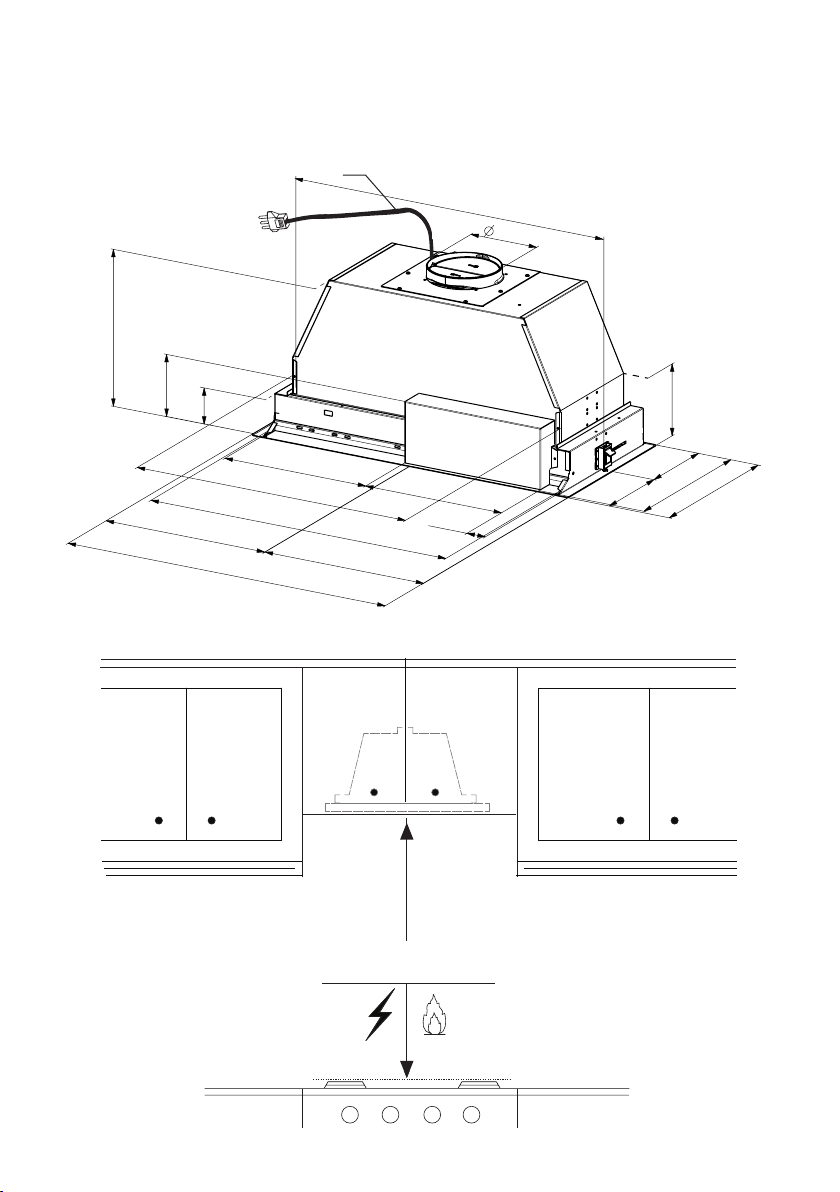
RANGEHOOD DIMENSIONS
Min. 24" - 30"
47 "
6
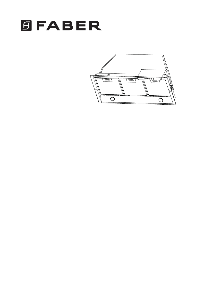
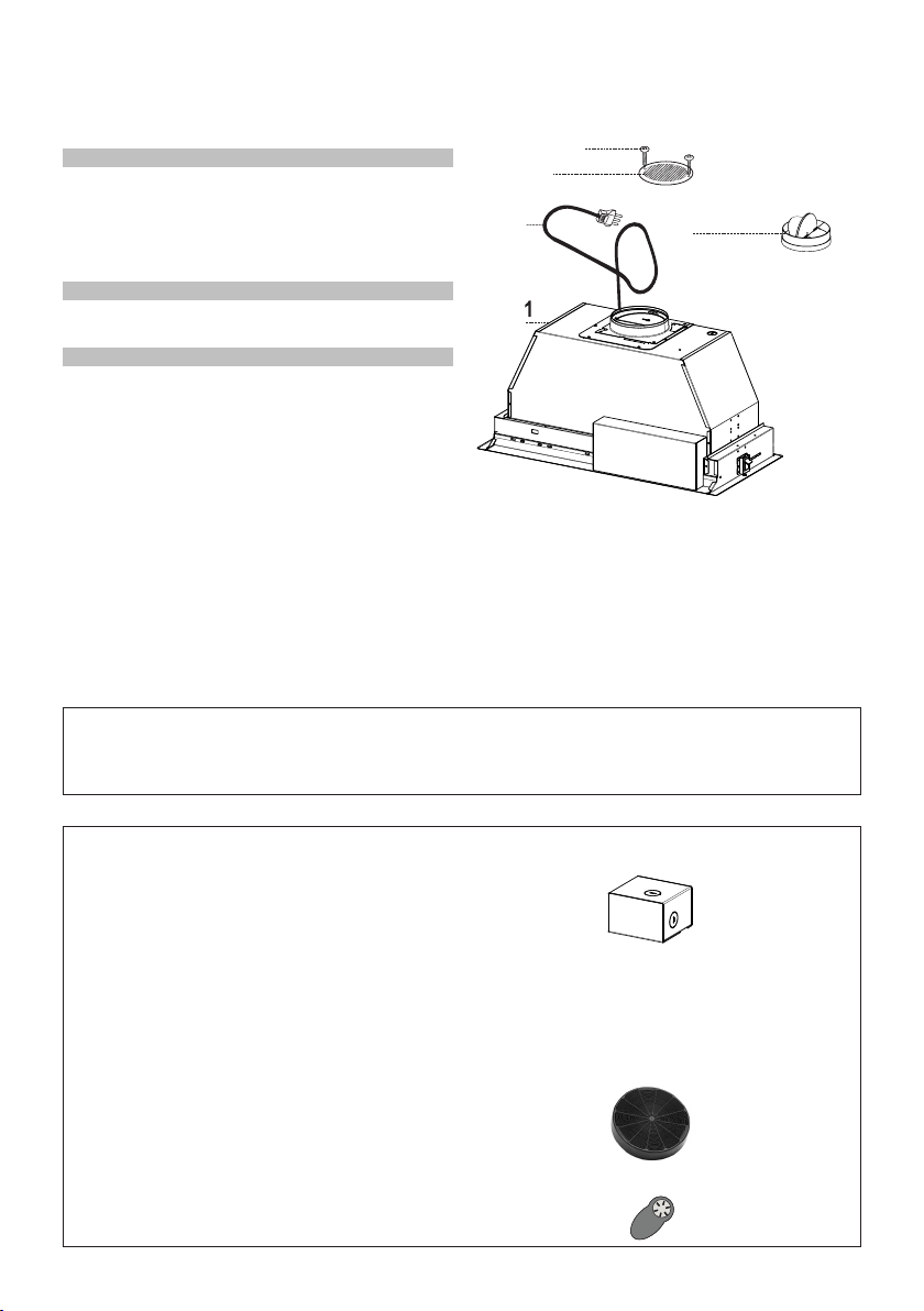
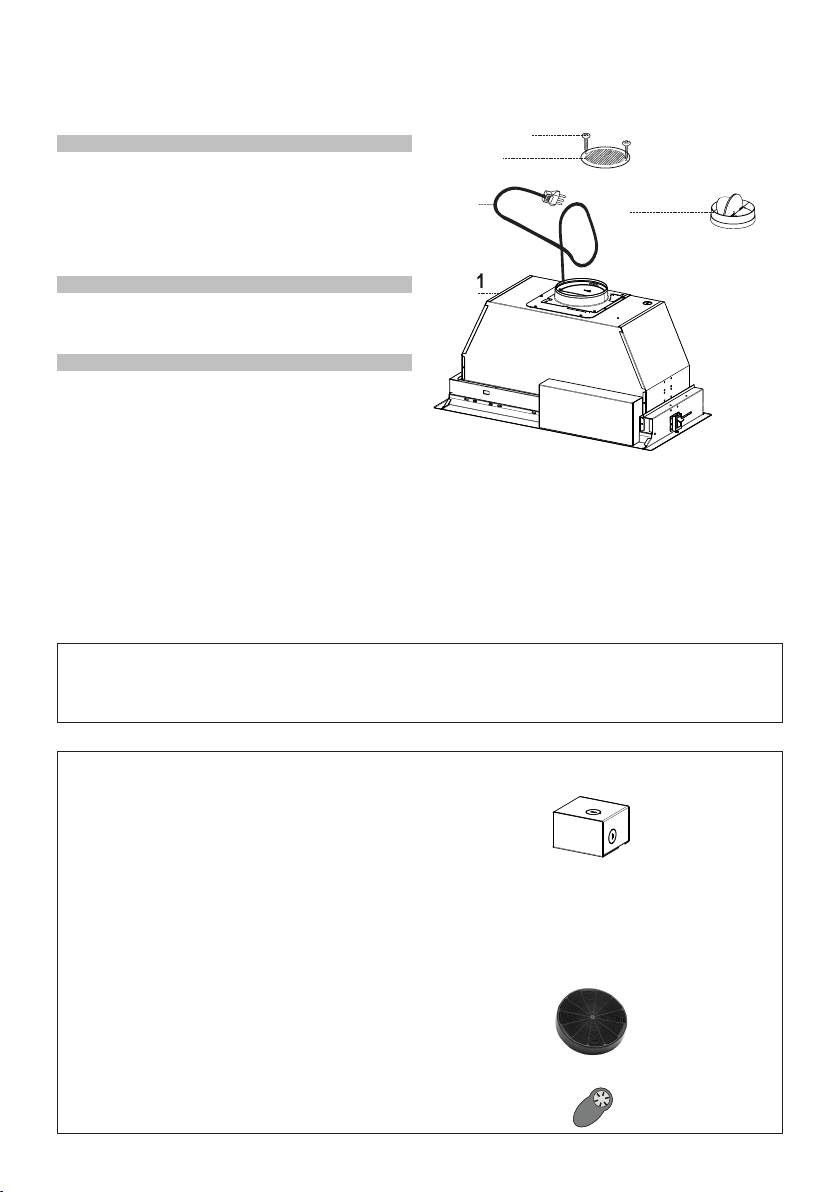
MAIN PARTS
Components
Ref. Qty. Product Components
1 1 Hood Body, complete with: Con-
trols, Light, Filters, Blower.
2 1 Power cord
8 1 Recirculation Vent Grill
10 1 Damper ø 5 7/8"
Ref. Qty. Installation Components
12e 2 Screws 1/8" x 3/8"
(for Recirculation Grill mounting)
Qty. Documentation
1 Instruction Manual
H
I
H
I
H
I
Available Accessories
Activated Charcoal Filter sku #; FILTER1
CFM Reducer Kit #CFMRED
Remote Control Accessory - REMCTRL
Parts needed
- 6" Round Metal ductwork .
Direct Connect Wiring Box sku # number: WIREBOX
Liner 30" Stainless #LINE30ST
Liner 36" Stainless #LINE36ST
6" Make-Up Air Damper Kit #MUDAMPER6
8" Make-Up Air Damper Kit #MUDAMPER8
Created by
-
Denomination
-
Lang EN
Sheet
1
/1
Modif.by
Approved by
Approval date
Doc. status
Drawing N.
NEW_DRAWING_BOX
Rev
01
H
I

7
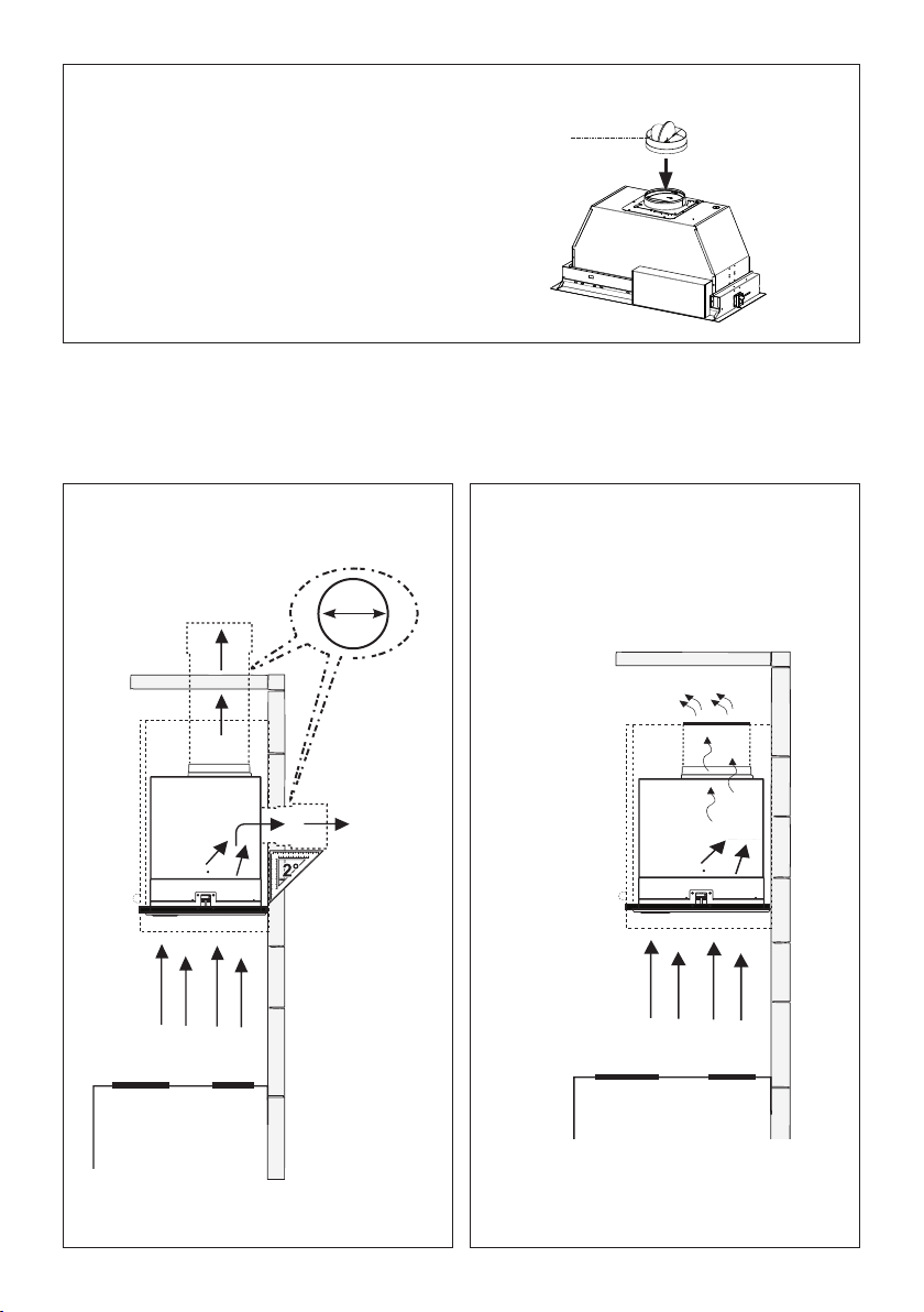
Choose your ducting method
Non Ducted - Recirculation OptionDucted Venting Options Installation
Requires
purchase of
Activated
Charcoal
Accessory
Horizontal
Vertical
6"
H
I
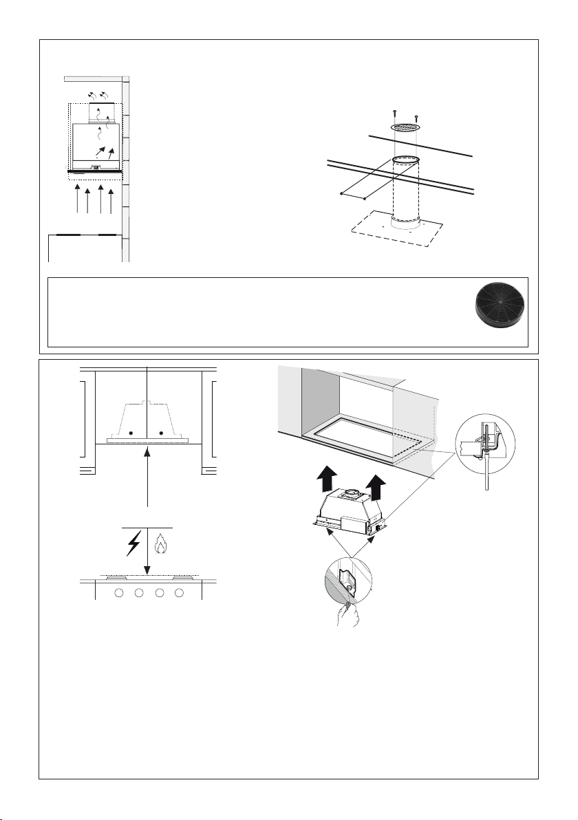
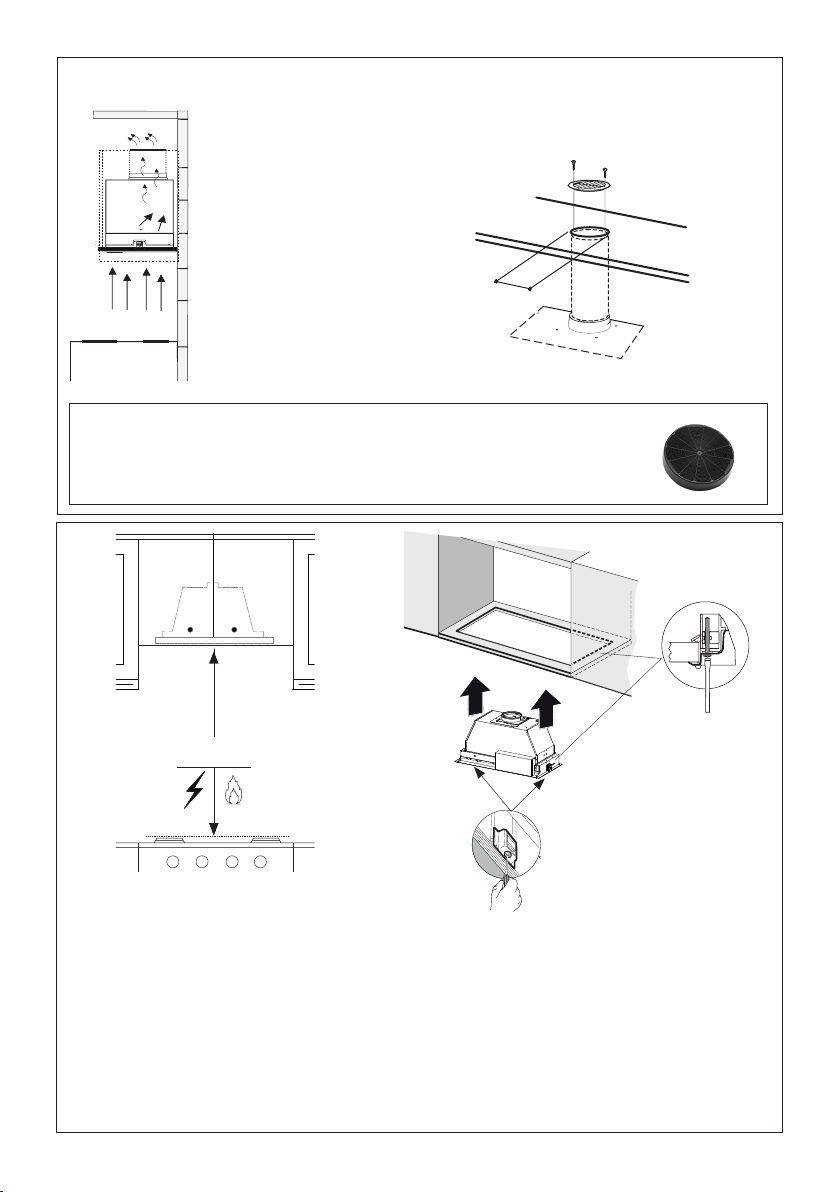
Install Damper that is included with the Hood
before connecting to the ductwork.
Only for Ducted Venting Installation

8
0LQ
´
´
´
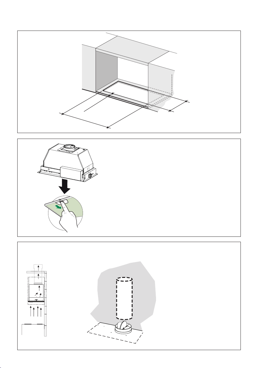
1
2
Cut out
the open-
ing in the
underside
of the
cabinet as
shown in
Figure 1.
Remove the three lters from the
Insert Hood before installing into
cabinet.
Installation Instructions
3.a
Install Roof or Wall Cap
purchased separately.
Connect the 6" metal
ductwork to the Roof or
Wall Cap and then attach
ductwork.
Vertical Ducting Installation
EN
7
7
INSTALLATION
Fitting the Hood canopy
BEFORE FITTING THE HOOD TO THE WALL UNIT, PROCEED AS FOLLOWS:
• Disconnect the wires to the Commands at the connectors.
• Disconnect the wires to the Light at the con-
nectors.
• The Hood can be installed directly on the
underside of
the wall unit (Minimum 650 mm
from the Cooker Hob).
• Create an opening in the bottom of the wall unit,
as shown.
• Insert the hood until the side supports snap into
place.
• Fasten using the 10 screws 12a provided.
• Lock in position by tightening the screws Vf from
underneath the hood.
• Open the suction panel by turning the specific knob.
• Disconnect the panel from the hood canopy by sliding the
fixing pin lever.
• Remove grease filters.
• Screw the Frame into place
using the 6 scr
ews 12f, re-
connect the wires to the
Commands and Light, re-
place the metal grease filter
and the Panel.
260
13
495 - 675

9
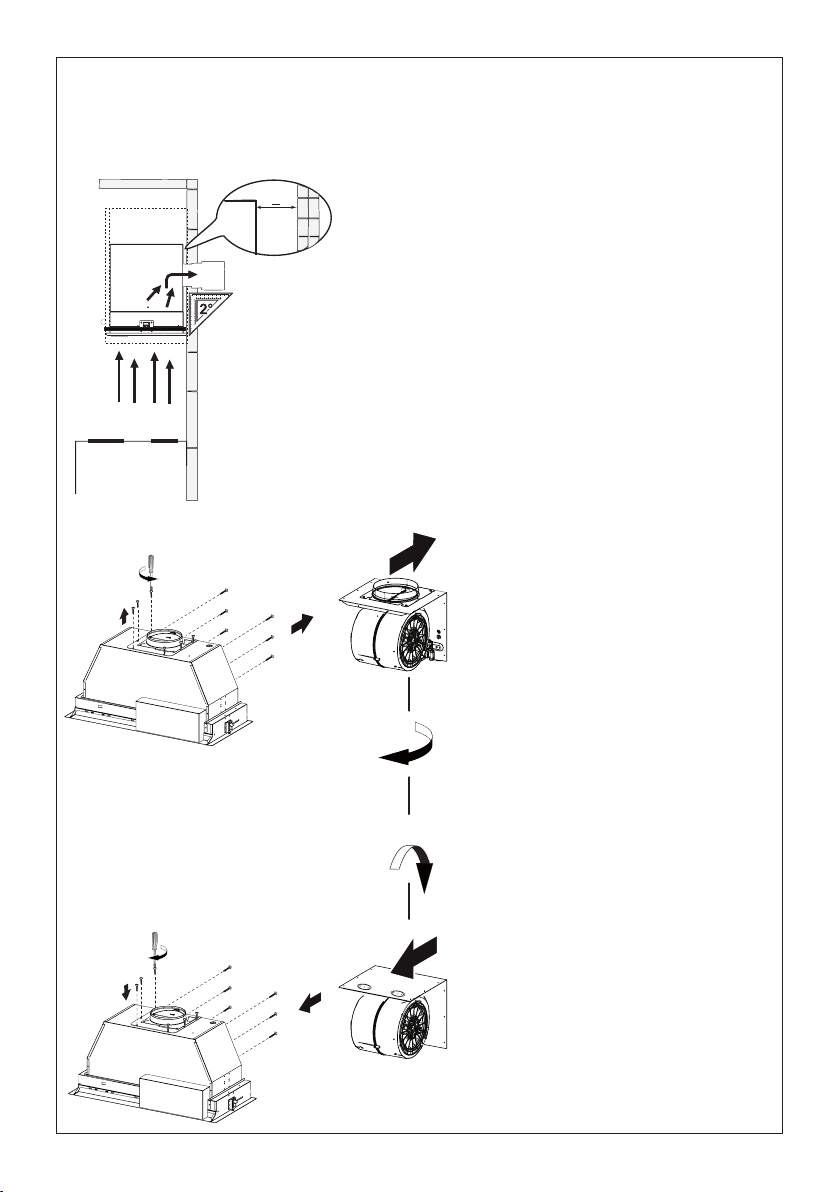
3.b
2 1/2”
>
For horizontal(rear) ducting there
must be a minimum of 2 1/2" of
space open between the back of the
Hood Insert and the wall.
For a horizontal ducting installation
the motor needs to be unsecured
by rst removing the 12 screws as
shown.
Once the screws are removed,
extract the blower from the body of
the Insert Hood and position it so the
transition opening is facing to the
rear wall (from the back remove and
rotate 180 degrees to the left, and
then ip it back 90 degrees as shown
in the diagram).
Once the blower is in place re-install
the 12 screws to fasten the motor to
the Insert Hood body.
Horizontal Ducting Installation
[
[
10
5
2x
2x
Install the Insert Hood through the cabinet cutout into the cabinet opening that has a minimum
height of 16 ". Allow for ducting.
The range hood is secured to the cabinet cutout by two spring loaded brackets, one on each
side of the range hood.
It is recommend that the Insert Hood is supported with a 3/4" wood base to insure proper align-
ment of the two side clips
After the Insert Hood is installed into the cabinet opening lock it into position by tightening the
indicated screws in each of the two side clips from underneath the Insert Hood.
4
´
For Non-Ducted Recirculation venting route the ductwork
to a location above the hood where the discharge is vented
back into the room.
Non-Ducted Recirculation Option
Use the included
Recirculation Vent Grill
to cover the opening.
Secure the grill with the
2 screws provided in the
Install Kit.
Required Activated Charcoal Filter Accessory - sku # - FILTER1 (purchased
separately)
See page 11 Section 7 for installation instructions of Activated Charcoal Filter Accessory.
Min. 24"
11
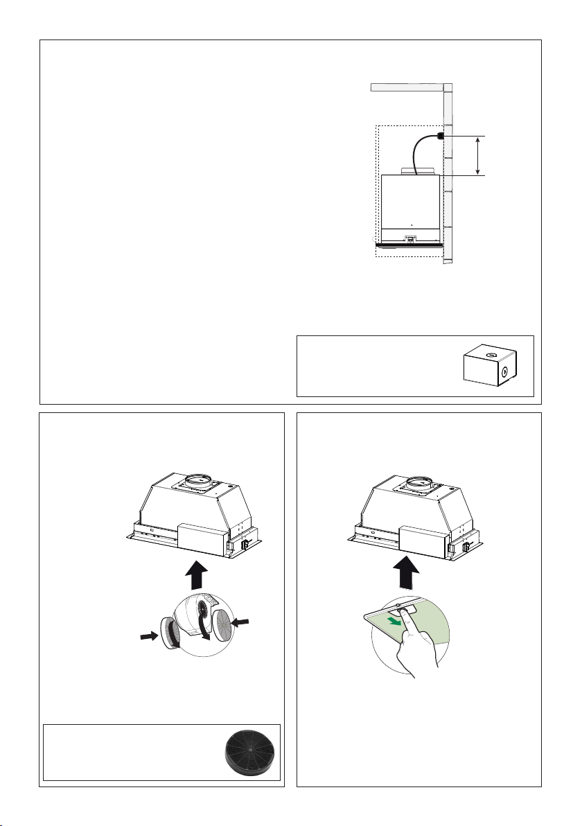
6
7 8
Attach each
charcoal
lter to the
black grid on
each side of
the blower.
Press the
charcoal
lter tightly
to the black
grid on the
blower side
and rotate
the lter
Replace the grease lters removed
previously.
Direct Connect Wiring Box
Accessory sku # WIREBOX
(purchased separately)
Created by
-
Denomination
-
Lang EN
Sheet
1
/1
Modif.by
Approved by
Approval date
Doc. status
Drawing N.
NEW_DRAWING_BOX
Rev
01
ELECTRICAL INSTALLATION WITH CONNECTION CABLE
ELECTRICAL INSTALLATION WITH
OPTIONAL WIRING BOX
For Permanent wiring Installation-Use only
with Listed rangehood Wiring Box kit
sku # WIREBOX, manufactured by Faber.
Max. 33 7/16”
For Non-Ducted Recirculation
Option
Required Activated Charcoal Filter
Accessory - sku # - FILTER1
(purchased separately)
clockwise (towards the front of the insert hood)
until it locks into place. Turn counterclockwise
(towards the back of the insert hood) to remove.
EN
7
7
INSTALLATION
Fitting the Hood canopy
BEFORE FITTING THE HOOD TO THE WALL UNIT, PROCEED AS FOLLOWS:
• Disconnect the wires to the Commands at the connectors.
• Disconnect the wires to the Light at the con-
nectors.
• The Hood can be installed directly on the
underside of
the wall unit (Minimum 650 mm
from the Cooker Hob).
• Create an opening in the bottom of the wall unit,
as shown.
• Insert the hood until the side supports snap into
place.
• Fasten using the 10 screws 12a provided.
• Lock in position by tightening the screws Vf from
underneath the hood.
• Open the suction panel by turning the specific knob.
• Disconnect the panel from the hood canopy by sliding the
fixing pin lever.
• Remove grease filters.
• Screw the Frame into place
using the 6 scr
ews 12f, re-
connect the wires to the
Commands and Light, re-
place the metal grease filter
and the Panel.
260
13
495 - 675
1
2
GROUNDING INSTRUCTIONS This appliance must
be grounded. In the event of an electrical short circuit,
grounding reduces the risk of electric shock by providing
an escape wire for the electric current. This appliance
is equipped with a cord having a grounding wire with a
grounding plug. The plug must be plugged into an outlet
that is properly installed and grounded.
WARNING - Improper grounding can result in a risk of
electric shock.
Consult a qualied electrician if the grounding instructions
are not completely understood, or if doubt exists as to
whether the appliance is properly grounded.
Do not use an extension cord. If the power supply cord
is too short, have a qualied electrician install an outlet
near the appliance.

12
Standard Liner 36 Stainless (LINE36ST)
designed for 36” wide installations
Cadre Standard 36 Axier Inoxydable (620000305)
peut être employée les hottes encastrable sur mesure de 36"
Standard Liner 30 Stainless (LINE30ST)
designed for 30” wide installations
Cadre Standard 30 Axier Inoxydable (620000304)
peut être employée les hottes encastrable sur mesure de 30"
Note: Standard Liners are pre-cut for installation of Inca Smart. For installations with
the Inca HC SS, remove the additional perforated section.
Note: Les Cadres Standard sont précoupés pour l'installation de l'Inca Smart. Pour
des installations avec L'Inca HC SS, enlevez la section perforée additionnelle.
LINER DIMENSIONS / DIMENSIONS DU CADRE
FIGURE 1
Pre-Planning Your Installation -
Important: The recommended height to install this hood o the
cooktop is a minimum of 24" and a maximum of 30” for maximum eectiveness. Also consult the cooktop
manufacturer’s recommendation.
Planiez votre installation - Important : La hauteur recommandée pour installer cette hotte au-des-
sus de la surface de cuisson est d’un minimum de 24” et d’un maximum de 30” pour un maximum
d’ecacité. De plus, nous vous recommandons consulter le manuel de recommandations du fabricant
de la surface de cuisson.
MOD. INCA BIG ESB
RIF. -
N.DIS. 352_731.1
DATA 24-Nov-10
LINER DIMENSIONS
Standard Liner 36 Stainless (LINE36ST)
designed for 36” wide installations
Cadre Standard 36 Axier Inoxydable (620000305)
peut être employée les hottes encastrable sur mesure de 36"
Standard Liner 30 Stainless (LINE30ST)
designed for 30” wide installations
Cadre Standard 30 Axier Inoxydable (620000304)
peut être employée les hottes encastrable sur mesure de 30"
Note: Standard Liners are pre-cut for installation of Inca Smart. For installations with
the Inca HC SS, remove the additional perforated section.
Note: Les Cadres Standard sont précoupés pour l'installation de l'Inca Smart. Pour
des installations avec L'Inca HC SS, enlevez la section perforée additionnelle.
LINER DIMENSIONS / DIMENSIONS DU CADRE
FIGURE 1
Pre-Planning Your Installation -
Important: The recommended height to install this hood o the
cooktop is a minimum of 24" and a maximum of 30” for maximum eectiveness. Also consult the cooktop
manufacturer’s recommendation.
Planiez votre installation - Important : La hauteur recommandée pour installer cette hotte au-des-
sus de la surface de cuisson est d’un minimum de 24” et d’un maximum de 30” pour un maximum
d’ecacité. De plus, nous vous recommandons consulter le manuel de recommandations du fabricant
de la surface de cuisson.
MOD. INCA BIG ESB
RIF. -
N.DIS. 352_731.1
DATA 24-Nov-10
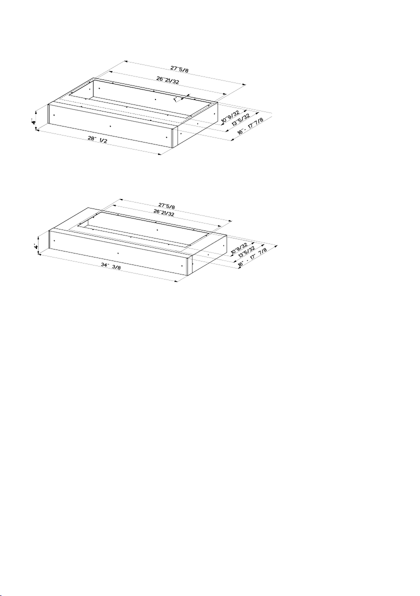
Standard Liner 30 Stainless
(LINE30ST)
designed for 30” wide installations.
Standard Liner 36 Stainless (LINE36ST)
designed for 36” wide installations.
Note: Standard Liners are pre-cut for installation of Inca Smart. For installations with the
Inca HC SS, remove the additional perforated section.
Pre-Planning Your Installation - Important: The recommended height to install
this hood off the cooktop is a minimum of 24" and a maximum of 30” for maximum
effectiveness. Also consult the cooktop manufacturer’s recommendation.
13
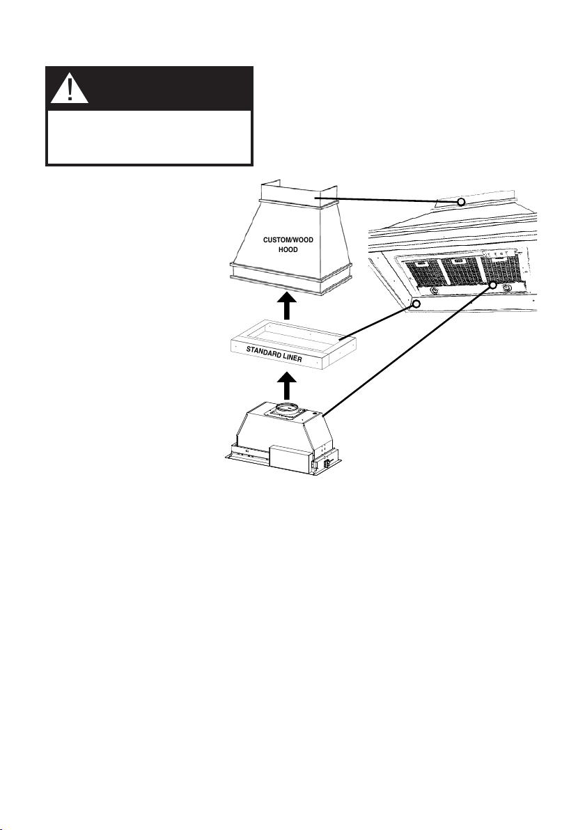
FOR INSTALLATIONS WITH LINERS
CUSTOM/WOOD
HOOD
STANDARD LINER
WARNING
!
When building a custom hood,
always follow all applicable
codes and standards.
1. The custom/wood hood must have a sturdy base (3/4" plywood recommended) to
accomodate the cut-out for the Inca HC SS. The base must be recessed to accomodate
the height of the Liner (see LINER DIMENSIONS on Page 4). The Liner attaches to the
bottom of the base using screws appropriate for the size and material of your custom/
wood hood. The Inca HC SS inserts into the cut-out in the Liner and base.
2. Position the rear section of the Liner so that it abuts the back edge of your custom/
wood hood. Using a pen, trace the outline of the pre-cut out. Remove the Liner and
proceed to MAKE YOUR CUT-OUTS on Page 7. Install both sections of the Liner and
proceed to INSTALL THE Range hood on Page 7.
INCA HC SS
The Inca HC SS can be used with
custom cabinetry and hoods 30"
wide and up. Choose either a
custom liner or our Standard Liner
designed for 30" and 36" wide
installations.
Liners create a perfectly-sealed,
non-combustible finish for the
underside of your custom/wood
hood.
The Standard Liners are made up of
two sections: a larger, rear section
(pre-cut out for insertion of the
Inca Smart) and a front section for
a total adjustable depth between
16" and 17
7/8"
.
!!! IMPORTANT NOTE: YOU
MUST REMOVE THE ADDITIONAL
PERFORATED SECTION AROUND
THE PRE-CUT-OUT WHEN
INSTALLING THE STANDARD
LINER WITH THE INCA HC SS
MODEL.
Consider the shape, size, and
weight of the Inca HC SS and Liner
to determine the conguration
of the custom/wood hood. See
Range hood AND CUT-OUT
DIMENSIONS AND LINER
DIMENSIONS on Page 4.
FOR INSTALLATION WITH LINERS
When building a custom hood,
always follow all applicable codes and
standards.
WARNING
!
The Inca HC SS can be used with
custom cabinetry and hoods 30"
wide and up. Choose either a
custom liner or our Standard Liner
designed for 30" and 36" wide
installations.
Liners create a perfectly-sealed,
non-combustible nish for the
underside of your custom/wood
hood.
The Standard Liners are made
up of two sections: a larger, rear
section (pre-cut out for insertion of
the Inca Smart) and a front section
for a total adjustable depth between
16" and 17 7/8".
!!! IMPORTANT NOTE: YOU
MUST REMOVE THE ADDITIONAL
PERFORATED SECTION
AROUND THE PRE-CUT-
OUT WHEN INSTALLING THE
STANDARD LINER WITH THE
INCA HC SS MODEL.
Consider the shape, size, and
weight of the Inca HC SS and Liner
to determine the conguration
of the custom/wood hood.
1. The custom/wood hood must have a sturdy base
(3/4" plywood recommended) to accomodate the cut-
out for the Inca HC SS. The base must be recessed
to accomodate the height of the Liner (see LINER
DIMENSIONS on Page 12). The Liner attaches to the
bottom of the base using screws appropriate for the
size and material of your custom/ wood hood. The Inca
HC SS inserts into the cut-out in the Liner and base.
2. Position the rear section of the Liner so that it abuts
the back edge of your custom/ wood hood. Using a
pen, trace the outline of the pre-cut out. Remove the
Liner and proceed to MAKE YOUR CUT-OUTS. Install
both sections of the Liner and proceed to INSTALL
THE Range hood.

14
USE AND CARE INFORMATION
T1. Fan Off Button:Turn the blower Off. The fan can be operated by pressing any of the fan setting
buttons.
Hold down this button for 2 seconds to activate Delay Off function which will keep the fan On for 15
minutes and automatically shut Off.
T2. Fan Settings Buttons: Low Speed.
T3. Fan Settings Buttons: Medium Speed.
T4. Fan Settings Buttons: High Speed / Intensive Speed.
Hold down the button for 2 seconds to activate the INTENSIVE SPEED, which is timed to run for 10
minutes. At the end of this time it will automatically return to the speed set before.Suitable to deal
with maximum levels of cooking fumes.
L. Light Button: On/Dim/Off switch for the halogen lights. Press the LIGHT button to turn the light on,
again to set the lights to dimmer, and again to turn off.
T1 T2 T3 T4 L
LT1 T2 T3 T4
For Best Results
Start the rangehood several minutes before cooking to develop proper airow. Allow the
rangehood to operate for several minutes after cooking is complete to clear all smoke and
odors from the kitchen.

15
Cleaningmetalgreaselters
The metal grease lters can be cleaned in hot detergent so-
lution or washed in the dishwasher. They should be cleaned
every 2 months, or more frequently if use is particularly heavy.
• Remove the lter, pushing the lever towards the back of
the unit and at the same time pulling downward.
• Wash the lter without bending it, leave it to dry thorou-
ghly before replacing (if the surface of the lter changes
color over time, this will have absolutely no effect on its
efciency).
• Replace, taking care to ensure that the handle
faces forward.
• Cleaning in dishwasher may dull the nish of the
metal grease lter.
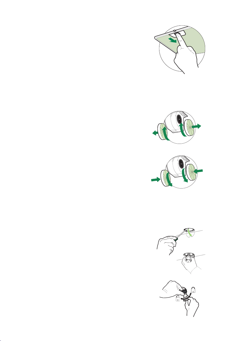
Replacing Activated Charcoal Filter
The Activated Charcoal Filters are not washable
and cannot be regenerated, and should be replaced
approximately every 4 months of operation, or more
frequently with heavy usage.
• Remove the charcoal lter by rotating it clockwise ( backwards)
until it unlocks from the motor housing and pull off sideways.
• To re-insert each charcoal lter, place up against the side
of the blower and push it inward. Then turn the charcoal
lter clockwise (forward) until it ts into place.
Replacing the two 35W Halogen GU10 bulbs
• Turn off electrical supply before replacing bulbs, and make
sure bulbs are cool to touch before proceeding.
• Carefully remove the snap-on lamp cover using a at
head screwdriver by levering it down from under the
metal ring.
• After the snap-on lamp cover is down remove the halogen
lamp at the base and turn slightly to the left and the pull
out from the connector and turn slightly to the left.
• Replace the lamp with a new one of the same type,
making sure that you insert the two pins properly into the
housings on the lamp holder.
• Replace the snap-on lamp cover.
• Once the bulb pins are in place turn slightly to the right
to secure.
EN
7
7
INSTALLATION
Fitting the Hood canopy
BEFORE FITTING THE HOOD TO THE WALL UNIT, PROCEED AS FOLLOWS:
• Disconnect the wires to the Commands at the connectors.
• Disconnect the wires to the Light at the con-
nectors.
• The Hood can be installed directly on the
underside of
the wall unit (Minimum 650 mm
from the Cooker Hob).
• Create an opening in the bottom of the wall unit,
as shown.
• Insert the hood until the side supports snap into
place.
• Fasten using the 10 screws 12a provided.
• Lock in position by tightening the screws Vf from
underneath the hood.
• Open the suction panel by turning the specific knob.
• Disconnect the panel from the hood canopy by sliding the
fixing pin lever.
• Remove grease filters.
• Screw the Frame into place
using the 6 scr
ews 12f, re-
connect the wires to the
Commands and Light, re-
place the metal grease filter
and the Panel.
260
13
495 - 675
16
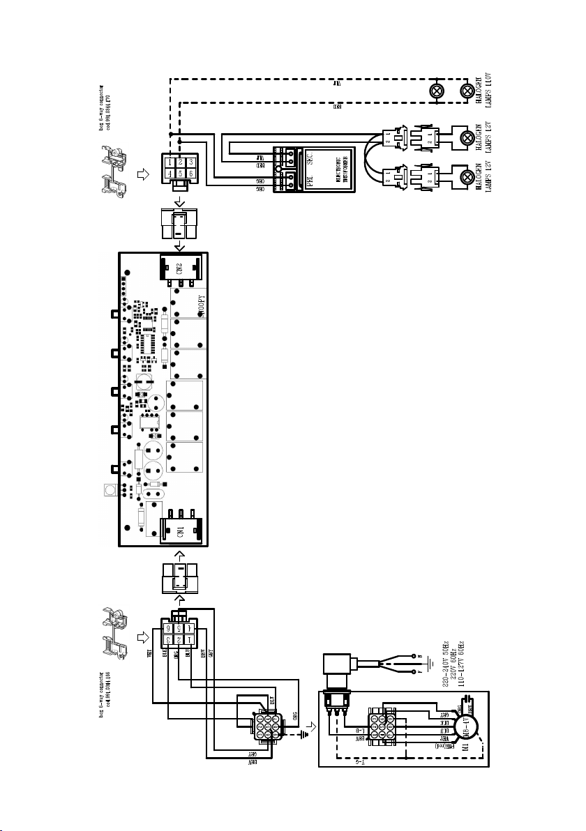
Wiring Diagram
991.0350.534 H90-254 r1 991.0350.534 H90-254 r1

17
January 4, 2016
FABER CONSUMER WARRANTY & SERVICE
All Faber products are warranted against any defect in materials or workmanship for the original purchaser
for a period of 1 year from the date of original purchase (requires proof of purchase). This warranty covers
labor and replacement parts. Faber, at its option, may repair or replace the product or components
necessary to restore the product to good working condition. To obtain warranty service, contact the dealer
from whom you purchased the range hood, or the local Faber distributor. If you cannot identify a local Faber
distributor, contact us at (508) 358-5353 for the name of a distributor in your area.
The following is not covered by Faber's warranty:
1. Service calls to correct the installation of your range hood, to instruct you how to use your range hood, to
replace or repair house fuses or to correct house wiring or plumbing.
2. Service calls to repair or replace range hood light bulbs, fuses or filters. Those consumable parts are
excluded from warranty coverage.
3. Repairs when your range hood is used for other than normal, single-family household use.
4. Damage resulting from accident, alteration, misuse, abuse, fire, flood, acts of God, improper installation,
installation not in accordance with electrical or plumbing codes or Faber documentation, or use of products
not approved by Faber.
5. Replacement parts or repair labor costs for units operated outside the United States or Canada, including
any non-UL or C-UL approved Faber range hoods.
6. Repairs to the hood resulting from unauthorized modifications made to the range hood.
7. Expenses for travel and transportation for product service in remote locations and pickup and delivery
charges. Faber range hoods should be serviced in the home.
THIS WARRANTY DOES NOT ALLOW RECOVERY OF INCIDENTAL OR CONSEQUENTIAL DAMAGES, INCLUDING, WITHOUT
LIMITATION, DIRECT, INDIRECT, INCIDENTAL, SPECIAL OR CONSEQUENTIAL DAMAGES, PERSONAL INJURY/WRONGFUL
DEATH OR LOST PROFITS FABER WARRANTY IS LIMITED TO THE ABOVE CONDITIONS AND TO THE WARRANTY PERIOD
SPECIFIED HEREIN AND IS EXCLUSIVE. EXCEPT AS EXPRESSLY SPECIFIED IN THIS AGREEMENT, FABER DISCLAIMS ALL
EXPRESS OR IMPLIED CONDITIONS, REPRESENTATIONS, AND WARRANTIES INCLUDING, WITHOUT LIMITATION, ANY
IMPLIED WARRANTIES OF MERCHANTABILITY OR FITNESS FOR A PARTICULAR PURPOSE
.
This warranty gives you specific legal rights that may vary from state to state.
Model#: ______________________________ Serial #: _____________________________

18
VEUILLEZ LIRE ET CONSERVER LA PRÉSENTE NOTICE AVANT DE
COMMENCER L'INSTALLATION DE LA HOTTE DE CUISINE
AVERTISSEMENT:-POUR RÉDUIRE LE RISQUE D'UN FEU DE GRAISSE SUR LA TABLE DE
CUISSON:
a) Ne laissez jamais sans surveillance les éléments de la surface de cuisson à température élevée.
Les bouillonnements excessifs peuvent provoquer de la fumée et les débordements de graisse
peuvents'enammer.L'huiledoitêtrechaufféelentement,àunetempératurebasseoumoyenne.
b) Assurez-vous de toujours mettre en marche le ventilateur de la hotte lorsque vous cuisinez
àtempératureélevéeoupréparezunmetsambé(p.ex.crêpesSuzette,cerisesjubilé,bœuf
ambé).
c) Nettoyez régulièrement les ventilateurs d'aspiration. Assurez-vous de ne pas laisser de la graisse
s'accumulersurleventilateurouleltre.
d)Utiliseztoujoursdespoêlesetcasserolesdelatailleappropriée.Utiliseztoujoursdesustensiles
de cuisine de la taille adaptée à celle de l'élément chauffant.
AVERTISSEMENT:-POURPRÉVENIRLESBLESSURESENCASDEFEUDEGRAISSESURLA
TABLEDECUISSON,SUIVEZLESRECOMMANDATIONSSUIVANTES*:
a) ÉTOUFFEZ LES FLAMMES à l'aide d'un couvercle hermétique, d'une plaque à biscuits ou d'un
plateau métallique, puis éteignez le brûleur. FAITES ATTENTION AUX BRÛLURES. Si le feu ne
s'éteint pas immédiatement, QUITTEZ LES LIEUX ET APPELEZ LES POMPIERS.
b) NE PRENEZ JAMAIS UNE CASSEROLE EN FLAMME - Vous pourriez vous brûler.
c) N'UTILISEZ JAMAIS DE L'EAU, ni un linge à vaisselle ou un torchon mouillé, pour éteindre le feu.
Cela pourrait provoquer une violente explosion de vapeur.
d)UtilisezunextincteurUNIQUEMENTsi:
1. Vousêtescertainqu'ils'agitd'unextincteurdeclasseABCetquevousconnaissezbienson
mode d'emploi.
2. Le feu est de faible intensité et se limite à l'endroit où il a démarré.
3. Les pompiers ont déjà été appelés.
4. Unevoiedesortiesetrouvederrièrevouspendantquevouséteignezlesammes
* D'après le guide «Kitchen Firesafety Tips» publié par la NFPA aux États-Unis
AVERTISSEMENT - POUR RÉDUIRE LE RISQUE D'INCENDIE OU DE CHOC ÉLECTRIQUE, n'utilisez
jamais ce ventilateur en association avec un dispositif de réglage de vitesse à semi-conducteurs.
AVERTISSEMENT - POUR RÉDUIRE LES RISQUES D'INCENDIE, DE CHOC ÉLECTRIQUE OU DE
BLESSURECORPORELLE,RESPECTEZLESINSTRUCTIONSSUIVANTES:
1. Utilisez cet appareil uniquement de la façon prévue par le fabricant. Pour toute question, com-
muniquez avec le fabricant.
2. Avant de procéder à l'entretien ou au nettoyage de l'appareil, coupez l'alimentation au niveau du
panneau électrique et verrouillez-le pour vous assurer que l'électricité n'est pas rétablie accidentel-
lement.S'iln'estpaspossibledeverrouillerledispositifd'interruptiondel'alimentation,afchezde
façon ferme et bien visible un avis de danger, par exemple à l'aide d'une étiquette sur le panneau.
ATTENTION:Destinéàunusagedeventilationgénéraleuniquement.N'utilisezpascedispositif
pour l'aspiration de vapeurs ou de matériaux dangereux ou explosifs.
AVERTISSEMENT - POUR RÉDUIRE LES RISQUES D'INCENDIE, DE CHOC ÉLECTRIQUE OU DE
BLESSURECORPORELLE,RESPECTEZLESINSTRUCTIONSSUIVANTES:
1. L'installationetlebranchement électriquedoiventêtreréalisésparun technicienqualiéet
conformément à tous les codes et normes en vigueur, incluant ceux concernant la construction
à l'épreuve du feu.
2. Andegarantirunecombustionetuneévacuationadéquatesdesgazparlesconduitesdela
cheminée des appareils à combustion, une bonne aération est nécessaire pour éviter le refou-
lement. Respectez les lignes directrices fournies par le fabricant du matériel chauffant, ainsi que
lesnormesdesécuritécommecellespubliéesparlaNationalFireProtectionAssociation(NFPA)
etlaAmericanSocietyforHeating,RefrigerationandAirConditioningEngineers(ASHRAE)aux
États-Unis, ainsi que les codes en vigueur dans votre région.

19
TOUTE OUVERTURE DANS LE MUR OU LE PLANCHER À PROXIMITÉ DE LA
HOTTE DOIT ÊTRE SCELLÉE.
Un espace libre d'au moins 24" est requis entre le bas de la hotte et la surface de cuisson
ou le comptoir. Cette hotte a été homologuée par l'UL à cette distance de la surface de cuisson.
L’espace libre minimal requis peut-être plus grand, selon la réglementation en matière de
construction de votre région. Pour les cuisinières à gaz et les cuisinières combinées, un espace
minimal de 30" est recommandé et pourrait être exigé.
La profondeur maximale des armoires suspendues est de 13". Les armoires suspendues de
chaque côté de l'appareil doivent se trouver à au moins 18" de la surface de cuisson ou du
comptoir. Consultez la notice d'installation de la surface de cuisson ou de la cuisinière fournie
par le fabricant avant de pratiquer des ouvertures.
INSTALLATION DANS UNE MAISON MOBILE L'installation de cette hotte doit être conforme
à la Partie 3280 de la norme Manufactured Home Construction and Safety Standards, Title 24
CFR (précédemment la partie 280 de la norme Federal Standard for Mobile Home Construction
and Safety, Title 24, HUD). Consultez la che technique électrique.
• Le système de ventilation DOIT déboucher à l'extérieur.
• NE FAITES PAS déboucher les conduits dans un grenier ou un autre endroit fermé.
• N'UTILISEZ PAS un clapet de sécheuse mural de 4po.
• Il n'est pas recommandé d'utiliser des conduits exibles.
• N'ENTRAVEZ PAS le ux de l'air de combustion et de ventilation.
• Le non-respect des exigences en matière de ventilation pourrait entraîner un incendie.
AVERTISSEMENT
!
Installation dans les climats froids
Le système de ventilation doit prévoir un registre antirefoulement supplémentaire pour réduire le
ux d'air froid inverse, ainsi qu'une barrière thermique non métallique pour réduire la conduction
des températures extérieures. Le registre doit être installé du côté air froid par rapport à la barrière
thermique. La barrière thermique doit être positionnée le plus près que possible de l'endroit où le
système de ventilation pénètre dans la partie chauffée de la maison.
CRITÈRES DE VENTILATION
Déterminez quelle méthode de ventilation est mieux adaptée à votre application. Les conduits peuvent
passer par le mur ou le toit.
Pour garantir une meilleure efcacité, la longueur des conduits et le nombre de coudes doivent être le plus
limités que possible. Le diamètre des conduits devrait être uniforme. N'installez pas deux coudes ensemble.
Utilisez un ruban pour canalisations an de sceller tous les joints du système de conduits. Utilisez un calfeu-
trage pour sceller les ouvertures dans le mur extérieur ou le plancher, autour du clapet.
Il n'est pas recommandé d'utiliser des conduits flexibles. Les conduits flexibles provoquent une contre-pression
et de la turbulence qui diminuent grandement l'efficacité de l'appareil.
Assurez-vous que l'espace libre dans le mur ou le plancher est sufsant pour le conduit d'évacuation avant de
pratiquer les ouvertures. Ne coupez jamais une poutre ou un chevron, sauf si c'est absolument nécessaire.
S'il s'avère nécessaire de couper une poutre ou un chevron, la construction d'un renforcement est requise.
AVERTISSEMENT - Pour réduire le risque d'incendie, utilisez uniquement des conduits métalliques.
ATTENTION - Pour réduire le risque d'incendie et pour évacuer adéquatement l'air, assurez-vous
deraccorderlesconduitsàl'extérieur–Nediffusezpasl'aird'évacuationdansdesespacesà
l'intérieur des murs ou du plafond, ou encore à l'intérieur d'un grenier, d'une galerie technique
ou d'un garage.
3. Lorsque vous faites une ouverture ou percez dans un mur ou le plafond, veillez à ne pas
endommagerleslsélectriquesoud'autresdispositifscachés.
4. Lesventilateurscanalisésdoiventtoujoursêtreraccordésàl'extérieur.
20
• Une mise à la terre électrique est requise pour cette hotte.
• N'UTILISEZ PAS un tuyau d'eau froide pour la mise à la terre si celui-ci est branché par des
joints en plastique, par des rondelles non métalliques ou d'autres matériaux.
• N'UTILISEZ PAS une conduite de gaz pour la mise à la terre.
• N'INSTALLEZ PAS un fusible sur le circuit neutre ou le circuit de mise à la terre. La présence
d'un fusible dans le circuit neutre ou de mise à la terre peut entraîner un choc électrique.
• Consultez un électricien qualié si vous n'êtes pas certain de la mise à la terre de la hotte.
• Le non-respect des exigences de la che technique électrique pourrait entraîner un incendie.
AVERTISSEMENT
!
21
Min. 24" - 30"
DIMENSIONS DE LA HOTTE
47 "
22
PIÈCES PRINCIPALES
Composants
Réf. Qté Composants du produit
1 1 Bâti de la hotte, avec : Com-
mandes,éclairages,ltres,ventila-
teur.
2 1 Câble d'alimentation
8 1 Grille d'évent de recirculation
10 1 Registre ø 5 7/8"
Réf. Qté Composants d'installation
12e 2 Vis 1/8" x 3/8"
(pour montage de la grille de recir-
culation)
Qté Documentation
1 Mode d'emploi
H
I
H
I
H
I
H
I
Accessoires disponibles
Filtre à charbon actif, no d'article FILTER1
Réducteur de débit, no CFMRED
Télécommande accessoire - REMCTRL
Pièces requises
- Conduit métallique 6" circulaire.
Boîtier de connexion directe, no d'article : WIREBOX
Caisse 30" acier inoxydable, no LINE30ST
Caisse 36" acier inoxydable, no LINE36ST
Dispositif d'apport d'air 6", no MUDAMPER6
Dispositif d'apport d'air 8", no MUDAMPER8
Created by
-
Denomination
-
Lang EN
Sheet
1
/1
Modif.by
Approved by
Approval date
Doc. status
Drawing N.
NEW_DRAWING_BOX
Rev
01
23
6"
H
I
Installez le registre inclus avec la hotte avant
de la raccorder aux conduits.
Pour installation avec ventilation canalisée uniquement
Choisissez la méthode de canalisation
Sans canalisation - Option de
recirculation
Options d'installation avec
ventilation canalisée
Exige
l'achat de
l'accessoire
à charbon
actif
Hori-
zontale
Verticale
24
0LQ
´
´
´
1
2
3.a
EN
7
7
INSTALLATION
Fitting the Hood canopy
BEFORE FITTING THE HOOD TO THE WALL UNIT, PROCEED AS FOLLOWS:
• Disconnect the wires to the Commands at the connectors.
• Disconnect the wires to the Light at the con-
nectors.
• The Hood can be installed directly on the
underside of
the wall unit (Minimum 650 mm
from the Cooker Hob).
• Create an opening in the bottom of the wall unit,
as shown.
• Insert the hood until the side supports snap into
place.
• Fasten using the 10 screws 12a provided.
• Lock in position by tightening the screws Vf from
underneath the hood.
• Open the suction panel by turning the specific knob.
• Disconnect the panel from the hood canopy by sliding the
fixing pin lever.
• Remove grease filters.
• Screw the Frame into place
using the 6 scr
ews 12f, re-
connect the wires to the
Commands and Light, re-
place the metal grease filter
and the Panel.
260
13
495 - 675
Pratiquez
l'ouverture
sur la face
inféri-
eure de
l'armoire,
comme il-
lustré à la
Figure 1.
Notice d'installation
Retirez les trois ltres de la hotte
encastrable avant de l'installer
dans l'armoire.
Installation avec canalisation verticale
Installez le clapet de
toiture ou le clapet mural
acheté séparément.
Raccordez le conduit
métallique de 6" au clapet
de toiture ou au clapet
mural, puis raccordez les
conduits.
25
3.b
2 1/2”
>
Horizontal Ducting Installation
[
[
Pour l'installation d'une canalisation
horizontale (à l'arrière), un espace
d'au moins 2 1/2" est requis entre
l'arrière de la hotte encastrable et le
mur.
Pour l'installation d'une canalisation
horizontale, le moteur doit d'abord
être détaché. Pour ce faire, retirez les
12 vis comme illustré.
Lorsque les vis sont enlevées,
dégagez le ventilateur du bâti de
la hotte encastrable et placez-le
de façon à ce que l'ouverture de
passage de l'air se trouve face au
mur arrière (dégagez-le de l'arrière
et faites-le tourner de 180 degrés
vers la gauche, puis inclinez-le de 90
degrés vers l'arrière, comme illustré
dans le diagramme).
Lorsque le ventilateur est en place,
posez les 12 vis pour xer le moteur
au bâti de la hotte encastrable.
26
5
2x
2x
4
´
Pour la ventilation avec recirculation sans canalisation,
dirigez les conduits à un emplacement au-dessus de la
hotte où l'air évacué est retourné dans la pièce.
Utilisez la grille d'évent
de recirculation pour
couvrir l'ouverture. Fixez
la grille à l'aide des 2 vis
fournies dans la trousse
d'installation.
Filtre à charbon actif accessoire requis - no d'article - FILTER1
(acheté séparément)
Consultez les instructions d'installation du ltre à charbon actif accessoire à la
page 11, Section 7.
Min. 24"
Option non canalisée avec recirculation d'air
Insérez la hotte encastrable à l'intérieur de l'armoire par l'ouverture de l'armoire. Sa hauteur
minimale doit être de 16". Prévoyez la canalisation.
La hotte est xée à l'ouverture de l'armoire par deux brides à ressort, une de chaque côté
de la hotte.
On recommande que la hotte encastrable s'appuie sur une base de bois de 3/4" pour
garantir un alignement correct des deux xations latérales.
Lorsque la hotte encastrable est installée dans l'ouverture de l'armoire, xez-la en serrant
sous la hotte encastrable les vis indiquées sur chacune des xations latérales.

27
6
7 8
Fixez les ltres à
charbon à la grille
noire de chaque
côté du ventilateur.
Pressez fermement
le ltre à charbon
contre la grille
noire de chaque
côté du ventilateur
et faites tourner
le ltre dans le
sens des aiguilles
d'une montre (vers
l'avant de la hotte
Created by
-
Denomination
-
Lang EN
Sheet
1
/1
Modif.by
Approved by
Approval date
Doc. status
Drawing N.
NEW_DRAWING_BOX
Rev
01
INSTALLATION ÉLECTRIQUE AVEC
BOÎTIER DE CONNEXION EN OPTION
Pour une installation avec connexion xe,
utilisez uniquement la trousse de boîtier de
connexion pour hotte indiquée,
no d'article WIREBOX, fabriquée par Faber.
Max. 33 7/16”
encastrable) jusqu'à ce qu'il soit verrouillé en
place. Faites tourner dans le sens contraire des
aiguilles d'une montre (vers l'arrière de la hotte
encastrable) pour l'enlever.
EN
7
7
INSTALLATION
Fitting the Hood canopy
BEFORE FITTING THE HOOD TO THE WALL UNIT, PROCEED AS FOLLOWS:
• Disconnect the wires to the Commands at the connectors.
• Disconnect the wires to the Light at the con-
nectors.
• The Hood can be installed directly on the
underside of
the wall unit (Minimum 650 mm
from the Cooker Hob).
• Create an opening in the bottom of the wall unit,
as shown.
• Insert the hood until the side supports snap into
place.
• Fasten using the 10 screws 12a provided.
• Lock in position by tightening the screws Vf from
underneath the hood.
• Open the suction panel by turning the specific knob.
• Disconnect the panel from the hood canopy by sliding the
fixing pin lever.
• Remove grease filters.
• Screw the Frame into place
using the 6 scr
ews 12f, re-
connect the wires to the
Commands and Light, re-
place the metal grease filter
and the Panel.
260
13
495 - 675
1
2
INSTALLATION ÉLECTRIQUE AVEC CÂBLE DE CONNEXION
INSTRUCTIONS DE MISE À LA TERRE Cet appareil doit
être mis à la terre. La mise à la terre réduit le risque de
choc électrique en cas de court-circuit, car elle fournit un l
d'évacuation au courant électrique. Cet appareil est muni
d'un cordon présentant un l de mise à la terre, avec une
che de mise à la terre. La che doit être insérée dans
une prise correctement installée et mise à la terre.
AVERTISSEMENT - Une mise à la terre inadéquate peut
entraîner un choc électrique.
Consultez un électricien qualié si vous ne comprenez pas
parfaitement les instructions de mise à la terre ou si vous
avez des doutes quant à la mise à la terre de l'appareil.
N'utilisez pas de rallonge. Si le cordon d’alimentation est
trop court, demandez à un électricien qualié d’installer
une prise à proximité de l'appareil.
Boîtier de connexion directe,
no d'article WIREBOX
(acheté séparément)
Pour option non canalisée
avec recirculation d'air
Replacez les ltres à graisse
enlevés précédemment.
Filtre à charbon actif accessoire
requis - no d'article - FILTER1
(acheté séparément)
28
Standard Liner 36 Stainless (LINE36ST)
designed for 36” wide installations
Cadre Standard 36 Axier Inoxydable (620000305)
peut être employée les hottes encastrable sur mesure de 36"
Standard Liner 30 Stainless (LINE30ST)
designed for 30” wide installations
Cadre Standard 30 Axier Inoxydable (620000304)
peut être employée les hottes encastrable sur mesure de 30"
Note: Standard Liners are pre-cut for installation of Inca Smart. For installations with
the Inca HC SS, remove the additional perforated section.
Note: Les Cadres Standard sont précoupés pour l'installation de l'Inca Smart. Pour
des installations avec L'Inca HC SS, enlevez la section perforée additionnelle.
LINER DIMENSIONS / DIMENSIONS DU CADRE
FIGURE 1
Pre-Planning Your Installation -
Important: The recommended height to install this hood o the
cooktop is a minimum of 24" and a maximum of 30” for maximum eectiveness. Also consult the cooktop
manufacturer’s recommendation.
Planiez votre installation - Important : La hauteur recommandée pour installer cette hotte au-des-
sus de la surface de cuisson est d’un minimum de 24” et d’un maximum de 30” pour un maximum
d’ecacité. De plus, nous vous recommandons consulter le manuel de recommandations du fabricant
de la surface de cuisson.
MOD. INCA BIG ESB
RIF. -
N.DIS. 352_731.1
DATA 24-Nov-10
DIMENSIONS DE LA CAISSE
Caisse standard 30", acier
inoxydable (LINE30ST),
conçue pour les installations d'une
largeur de 30”.
Caisse standard 36", acier inoxydable
(LINE36ST),
conçue pour les installations d'une
largeur de 36”.
Remarque : Les caisses standards sont précoupées pour l'installation du modèle Inca
Smart. Pour l'installation avec le modèle Inca HC SS, la section supplémentaire perforée
doit être retirée.
Planication préalable de l'installation - Important : Il est recommandé d'installer cette
hotte à une distance d'au moins 24" de la surface de cuisson et à une distance maximale
de 30” pour une efcacité optimale. Reportez-vous également aux recommandations du
fabricant de la surface de cuisson.

29
FOR INSTALLATIONS WITH LINERS
CUSTOM/WOOD
HOOD
STANDARD LINER
WARNING
!
When building a custom hood,
always follow all applicable
codes and standards.
1. The custom/wood hood must have a sturdy base (3/4" plywood recommended) to
accomodate the cut-out for the Inca HC SS. The base must be recessed to accomodate
the height of the Liner (see LINER DIMENSIONS on Page 4). The Liner attaches to the
bottom of the base using screws appropriate for the size and material of your custom/
wood hood. The Inca HC SS inserts into the cut-out in the Liner and base.
2. Position the rear section of the Liner so that it abuts the back edge of your custom/
wood hood. Using a pen, trace the outline of the pre-cut out. Remove the Liner and
proceed to MAKE YOUR CUT-OUTS on Page 7. Install both sections of the Liner and
proceed to INSTALL THE Range hood on Page 7.
INCA HC SS
The Inca HC SS can be used with
custom cabinetry and hoods 30"
wide and up. Choose either a
custom liner or our Standard Liner
designed for 30" and 36" wide
installations.
Liners create a perfectly-sealed,
non-combustible finish for the
underside of your custom/wood
hood.
The Standard Liners are made up of
two sections: a larger, rear section
(pre-cut out for insertion of the
Inca Smart) and a front section for
a total adjustable depth between
16" and 17
7/8"
.
!!! IMPORTANT NOTE: YOU
MUST REMOVE THE ADDITIONAL
PERFORATED SECTION AROUND
THE PRE-CUT-OUT WHEN
INSTALLING THE STANDARD
LINER WITH THE INCA HC SS
MODEL.
Consider the shape, size, and
weight of the Inca HC SS and Liner
to determine the conguration
of the custom/wood hood. See
Range hood AND CUT-OUT
DIMENSIONS AND LINER
DIMENSIONS on Page 4.
Lorsque vous construisez un habillage
de hotte sur mesure, assurez-vous de
toujours respecter les codes et normes
applicables.
AVERTISSEMENT
!
La hotte Inca HC SS peut être utilisée
avec des armoires et habillages sur
mesure d'une largeur de 30" et plus.
Vous pouvez choisir une caisse sur
mesure ou nos caisses standards
conçues pour occuper un espace de
30" ou de 36" de largeur.
Les caisses offrent une nition parfai-
tement étanche et incombustible sur la
partie inférieure de votre habillage de
hotte sur mesure/ en bois.
Les caisses standards sont formées
de deux sections : une section arrière
plus large (précoupée pour l'insertion
de la hotte Inca Smart) et une section
avant, permettant de régler la profon-
deur (entre 16" et 17 7/8").
!!! REMARQUE IMPORTANTE :
VOUS DEVEZ ENLEVER LA SEC-
TION SUPPLÉMENTAIRE PER-
FORÉE AUTOUR DE LA SECTION
PRÉCOUPÉE LORSQUE VOUS INS-
TALLEZ UNE CAISSE STANDARD
AVEC LE MODÈLE INCA HC SS.
Tenez compte de la forme, de la
dimension et du poids de la hotte Inca
HC SS et de la caisse pour déterminer
la conguration de l'habillage de hotte
sur mesure/en bois.
1. L'habillage de hotte sur mesure/en bois doit présenter
une base solide (contre-plaqué de 3/4" recommandé)
pour permettre l'ouverture pour la hotte Inca HC SS. La
base doit être amincie pour accueillir la hauteur de la
caisse (consultez DIMENSIONS DE LA CAISSE à la
page 12). La caisse se xe au bas de la base à l'aide
de vis adaptées à la dimension et au matériau de votre
habillage de hotte sur mesure/en bois. La hotte Inca HC
SS s'insère dans l'ouverture de la caisse et de la base.
2. Placez la section arrière de la caisse pour qu'elle
coïncide avec le bord arrière de l'habillage de hotte sur
mesure/en bois. À l'aide d'un stylo, tracez le contour de
l'ouverture précoupée. Retirez la caisse et PRATIQUEZ
VOS OUVERTURES. Installez les deux sections de la
caisse et INSTALLEZ LA hotte.
POUR L'INSTALLATION AVEC CAISSES

30
INFORMATIONS POUR L'UTILISATION ET L'ENTRETIEN
T1. Bouton Arrêt du ventilateur : éteint le ventilateur. Le ventilateur peut être allumé en ap-
puyant sur l'un ou l'autre des boutons de réglage.
Tenez ce bouton enfoncé pendant 2 secondes pour activer la fonction de désactivation
retardée, qui éteindra automatiquement le ventilateur après 15 minutes de marche.
T2. Boutons de réglage du ventilateur : Vitesse réduite.
T3. Boutons de réglage du ventilateur : Vitesse moyenne.
T4. Boutons de réglage du ventilateur : Vitesse élevée / Vitesse intensive.
Tenez le bouton enfoncé pendant environ 2 secondes pour activer la VITESSE INTENSIVE,
pour une durée de 10 minutes. Après ce délai, la vitesse retournera automatiquement à
la vitesse sélectionnée précédemment. Utile pour contrer les émanations maximales de
cuisson.
L. Bouton pour l'éclairage : Commutateur Marche/Intensité variable/Arrêt pour l'éclairage
halogène. Appuyez sur le bouton d'éclairage pour mettre l'éclairage en marche, de nou-
veau pour varier l'intensité et une nouvelle fois pour éteindre.
T1 T2 T3 T4 L
LT1 T2 T3 T4
Pour de meilleurs résultats
Activez la hotte quelques minutes avant de commencer à cuisiner pour créer un ux d'air
adéquat. Laissez la hotte fonctionner quelques minutes après avoir ni de cuisiner pour
absorber toute la fumée et les odeurs de la cuisine.
31
EN
7
7
INSTALLATION
Fitting the Hood canopy
BEFORE FITTING THE HOOD TO THE WALL UNIT, PROCEED AS FOLLOWS:
• Disconnect the wires to the Commands at the connectors.
• Disconnect the wires to the Light at the con-
nectors.
• The Hood can be installed directly on the
underside of
the wall unit (Minimum 650 mm
from the Cooker Hob).
• Create an opening in the bottom of the wall unit,
as shown.
• Insert the hood until the side supports snap into
place.
• Fasten using the 10 screws 12a provided.
• Lock in position by tightening the screws Vf from
underneath the hood.
• Open the suction panel by turning the specific knob.
• Disconnect the panel from the hood canopy by sliding the
fixing pin lever.
• Remove grease filters.
• Screw the Frame into place
using the 6 scr
ews 12f, re-
connect the wires to the
Commands and Light, re-
place the metal grease filter
and the Panel.
260
13
495 - 675
Nettoyagedesltresàgraissemétalliques
Les ltres à graisse métalliques peuvent être lavés dans une
solution d'eau chaude savonneuse ou dans le lave-vaisselle. Ils
devraient être nettoyés tous les 2 mois, ou plus fréquemment
en cas d'utilisation particulièrement intensive.
• Retirez le ltre, en poussant simultanément le levier vers
l'arrière de l'appareil et en le tirant vers le bas.
• Lavez le ltre sans le plier. Laissez-le sécher complètement
avant de le réinstaller (un changement de la couleur à la
surface du ltre au l du temps n'a aucun impact sur son
efcacité).
• Remettez-le en place, en vous assurant que la poignée se
trouve vers l'avant.
• Le lave-vaisselle pourrait ternir le ni du ltre à graisse
métallique.
Remplacementdultreàcharbonactif
Les ltres à charbon actif ne sont pas lavables et ne peuvent
être régénérés. Ils devraient être remplacés environ tous les
4 mois d'utilisation, ou plus souvent en cas d'utilisation inten-
sive.
• Enlevez le ltre à charbon en le faisant tourner dans le sens
des aiguilles d'une montre (vers l'arrière) jusqu'à ce qu'il se
dégage du carter du moteur, puis en le tirant vers le côté.
• Pour réinsérer les ltres, placez-les sur le côté du ventilateur
et poussez-les vers l'intérieur. Tournez ensuite le ltre à
charbon dans le sens des aiguilles d'une montre (vers l'avant)
jusqu'à ce qu'il soit bien installé.
Remplacementdesdeuxampouleshalogènes35Wde
type GU10
• Coupez l'alimentation électrique avant de remplacer les
ampoules et assurez-vous qu'elles sont froides au toucher
avant de commencer.
• Dégagez délicatement l'écran protecteur de la lampe en
faisant un effet de levier vers le bas à l'aide d'un tournevis à
lame plate sous l'anneau métallique.
• Une fois dégagé l'écran protecteur de la lampe, retirez l'am-
poule halogène de la base. Faites tourner légèrement vers
la gauche et retirez-la du socle.
• Remplacez l'ampoule avec une nouvelle du même type, en
vous assurant d'insérer correctement les deux connecteurs
dans leur logement sur le socle.
• Remettez l'écran protecteur de la lampe en place.
• Lorsque les connecteurs de l'ampoule sont en place, faites
tourner légèrement vers la droite pour verrouiller.

32
991.0350.534 H90-254 r1 991.0350.534 H90-254 r1
Schéma de câblage
33
4 janvier 2016
GARANTIE LIMITÉE ET SERVICE FABER
Tous les produits Faber font l'objet d'une garantie contre les défauts de matériel et de main-
d'œuvre,accordée à l'acheteur original pour une période d'un (1) an à compter de la date d'achat initiale
(preuve d'achat requise). Cette garantie couvre les frais de main-d'œuvre et les pièces de rechange. À sa
discrétion, Faber peut réparer ou remplacer le produit ou les composants nécessaires à remettre le produit
en bon état de marche. Pour bénéficier de services prévus par la garantie, veuillez communiquer avec le
détaillant auprès duquel vous avez acheté la hotte de cuisine, ou encore avec le distributeur Faber de votre
région. Si vous n'êtes pas en mesure de localiser un distributeur Faber dans votre région, veuillez
communiquer avec nous au 508-358-5353 pour connaître le nom d'un distributeur à proximité.
Les éléments suivants ne sont pas visés par la garantie Faber :
1. Les appels au service de réparation visant à corriger l'installation de la hotte de cuisine, à recevoir des
instructions sur l'utilisation de la hotte de cuisine, le remplacement ou la réparation des fusibles du domicile
ou la correction des câblages ou de la plomberie du domicile.
2. Les appels au service de réparation visant à réparer ou remplacer les ampoules électriques de hotte, les
fusibles ou les filtres. Ces pièces consommables ne sont pas couvertes par la garantie.
3. Les réparations si votre hotte de cuisine est employée à des fins autres que celles prévues, soit l'utilisation
résidentielle normale pour une famille.
4. Les dommages découlant d'un accident, d'une modification, de l'utilisation incorrecte ou abusive, d'un
incendie, d'une inondation, d'un cas de force majeure, d'une installation inadéquate, d'une installation non
conforme aux codes en matière d'électricité ou de plomberie ou à la documentation fournie par Faber, ou
encore d'une utilisation du produit non approuvée par Faber.
5. Les frais de main-d'œuvre ou de remplacement des pièces pour les appareils utilisés à l'extérieur des
États-Unis ou du Canada, y compris toutes les hottes de cuisine Faber non-UL ou C-UL homologuées.
6. Les réparations à la hotte découlant de modifications non autorisées apportées à la hotte de cuisine.
7. Les frais encourus pour les déplacements et le transport de produits en région éloignée et les frais de
cueillette et livraison. La réparation des hottes de cuisine Faber doit être réalisée à domicile.
LA PRÉSENTE GARANTIE NE PRÉVOIT AUCUNE FORME DE DÉDOMMAGEMENT EN CAS DE DOMMAGES ACCESSOIRES OU
CONSÉCUTIFS, Y COMPRIS, SANS TOUTEFOIS S'Y LIMITER, LES DOMMAGES DIRECTS, INDIRECTS, ACCESSOIRES,
PARTICULIERS OU CONSÉCUTIFS, LES LÉSIONS CORPORELLES/MORTELLES OU LA PERTE DE PROFITS. LA GARANTIE
OFFERTE PAR FABER EST LIMITÉE AUX CONDITIONS ÉNONCÉES CI-DESSUS ET À LA PÉRIODE DE GARANTIE INDIQUÉE
DANS LES PRÉSENTES ET EST EXCLUSIVE. SAUF DISPOSITIONS EXPRESSES CONTRAIRES DANS LE PRÉSENT ACCORD,
FABER DÉCLINE TOUTE CONDITION, REPRÉSENTATION OU GARANTIE EXPLICITE OU IMPLICITE, Y COMPRIS, SANS
TOUTEFOIS S'Y LIMITER, TOUTE GARANTIE IMPLICITE DE QUALITÉ MARCHANDE OU D'ADAPTATION À UN USAGE
PARTICULIER
.
Les droits qui vous sont conférés en vertu de la présente garantie peuvent varier d'une province ou d'un État
à l'autre.
N
o
de modèle : ______________________________ N
o
de série : _____________________________

34

35

991.0379.328_06 - 180109
D00001421_05