Loading ...
Loading ...
Loading ...
24
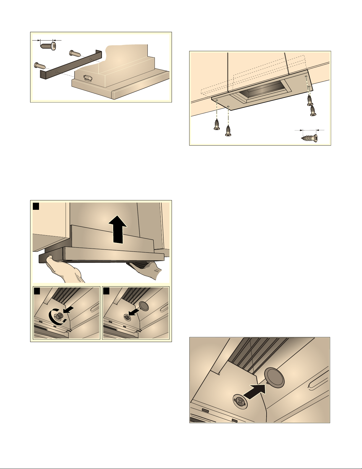
4 Fasten the filler strip in place.
5 Push in the fastening bolt and turn it 90°.
Note: The mounting pieces on the left and right
of the appliance must be able to move.
Final assembly
1 Mount the appliance. ¨
2 Tighten the left and right fastening bolts. ©
3 Fit the protective caps on the left and right. ª
4 Establish the electrical connection.
Note: The extractor hood housing can be concealed
within the top cabinet. In doing so, you must observe
the following:
‒ The false floor must not be placed on the
extractor hood housing.
‒ The front panel must not be secured to the
housing.
‒ Access must be available in order to change the
filter and for customer service.
Appliance width, 36" (90cm):
You must also screw the appliance onto the side top
cabinets.
Connecting the pipes
Note: If an aluminum pipe is used, smooth the
connection area beforehand.
Exhaust air pipe, 6" (150 mm) diameter
(recommended size)
Attach exhaust air pipe directly to the air-pipe
connector and seal.
Exhaust air pipe dia. 4¾" (120 mm)
1 Attach reducing connector directly to the air-
pipe connector.
2 Attach exhaust air pipe to the reducing
connector.
3 Seal both joints appropriately.
Removing the appliance
1 Disconnect the electrical connection.
2 Disconnect the pipes.
3 Remove the metal grease filter.
4 Remove the protective caps from the fastening
elements.
5 Remove the appliance see section entitled
"Removing the appliance".
PP
[
%
$
&
[
PP
Loading ...
Loading ...
Loading ...