Loading ...
Loading ...
Loading ...
28
Control Board Overview
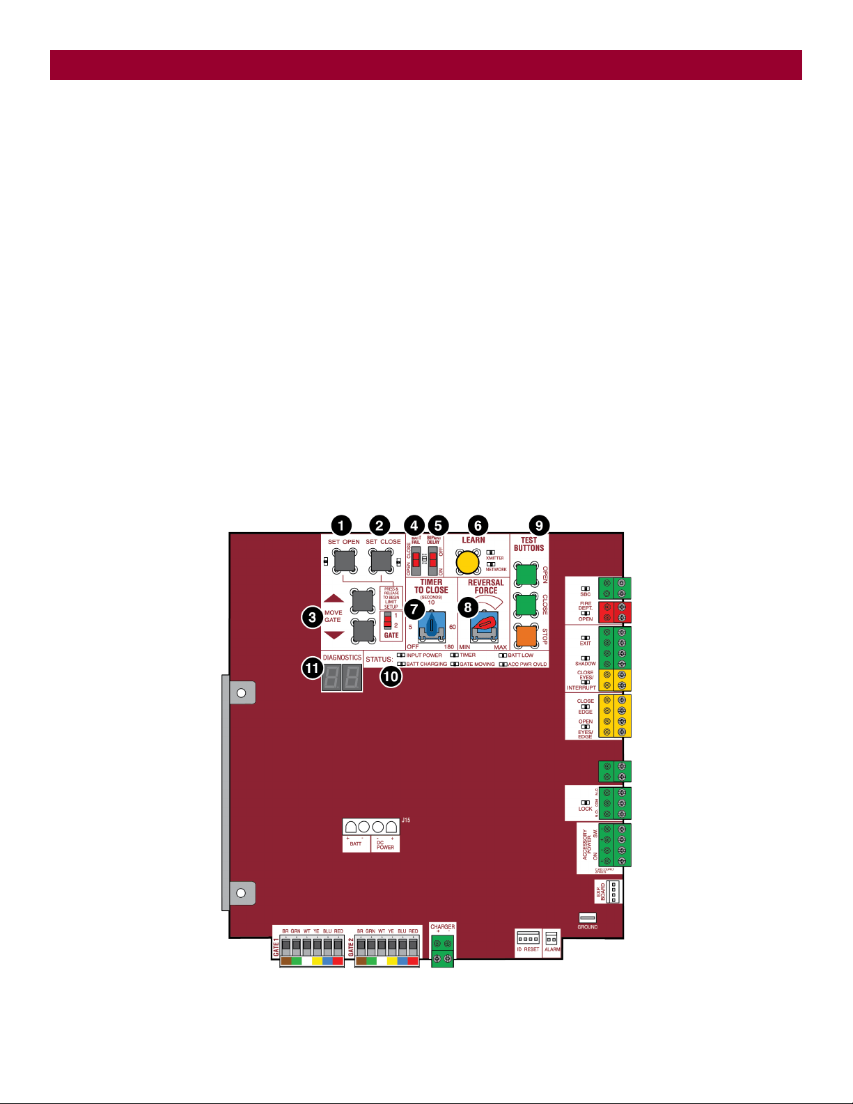
1 SET OPEN Button: The SET OPEN button sets the OPEN limit. See Adjust Limits section.
2 SET CLOSE Button: The SET CLOSE button sets the CLOSE limit. See Adjust Limits section.
3 MOVE GATE Buttons: The MOVE GATE buttons will either open or close the gate when the operator is in Limit setting mode. See Adjust Limits section.
4 BATT FAIL:
l When AC power is OFF and battery voltage is critically low the gate will latch at a limit until AC power is restored or batteries voltage increases.
l Option select switch set to OPEN forces gate to automatically open and then latch at the OPEN limit until AC power is restored or battery voltage
increases.
l Option select switch set to CLOSE forces gate to latch at CLOSE limit if at CLOSE limit or on next CLOSE command until AC power restored or battery
voltage increases.
l Constant pressure on a hard command input overrides to open or close the gate.
l Critically low battery is less than 23 V
5 BIPART DELAY Switch: The LOCK/BIPART DELAY switch is used only for dual gates. See Bipart Delay section.
6 LEARN Button: The LEARN button is for programming remote controls and the network.
7 TIMER-TO-CLOSE dial: The TIMER-TO-CLOSE (TTC) dial can be set to automatically close the gate after a specified time period. The TTC is factory set to
OFF. If the TTC is set to the OFF position, then the gate will remain open until the operator receives another command from a control. Rotate the TIMER-TO-
CLOSE dial to the desired setting. The range is 0 to 180 seconds, 0 seconds is OFF. NOTE: Any radio command, single button control, or CLOSE command
on the control board prior to the TTC expiring will close the gate. The TTC is reset by any signals from the open controls, loops, close edges, and close
photoelectric sensors (IR’s).
8 REVERSAL FORCE dial: The REVERSAL FORCE dial fine tunes the force. See Force Adjustment section.
9 TEST BUTTONS: The TEST BUTTONS will operate the gate (OPEN, STOP and CLOSE).
10 STATUS LEDs: The STATUS LEDs indicate the status of the operator. See Status LED Chart in the Troubleshooting section.
DIAGNOSTICS Display: The diagnostics display will show the operator type, firmware version, and codes. The operator type will display as "LA" followed
by a "40" which indicates the operator type as LA400DC. The firmware version will show after the operator type, example "1.2".
OPERATION
Loading ...
Loading ...
Loading ...