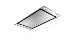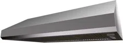
STRTIS36SS400-B
STRTIS48SS400-B
Installation Instructions
Use and Care Information
Instructions d'installation
Utilisez et d'entretien
STRATUS SS 36" - STRATUS SS 48"

2
READ AND SAVE THESE INSTRUCTIONS BEFORE YOU START
INSTALLING THIS RANGEHOOD
WARNING: - TO REDUCE THE RISK OF A RANGE TOP GREASE FIRE:
a) Never leave surface units unattended at high settings. Boilovers cause smoking and
greasy spillovers that may ignite. Heat oils slowly on low or medium setting.
b)AlwaysturnhoodONwhencookingathighheatorwhenambeingfood(i.e.Crepes
Suzette, Cherries Jubilee, Peppercorn Beef Flambé).
c) Clean ventilating fans frequently. Grease should not be allowed to accumulate on fan
orlter.
d) Use proper pan size. Always use cookware appropriate for the size of the surface element.
WARNING: - TO REDUCE THE RISK OF INJURY TO PERSONS IN THE EVENT OF A
RANGE TOP GREASE FIRE, OBSERVE THE FOLLOWING*:
a)SMOTHERFLAMESwithaclose-ttinglid,cookiesheet,ormetaltray,thenturnofftheburner.
BECAREFULTOPREVENTBURNS.IftheamesdonotgooutimmediatelyEVACUATE
AND CALL THE FIRE DEPARTMENT.
b) NEVER PICK UP A FLAMING PAN - You may be burned.
c) DO NOT USE WATER, including wet dishcloths or towels - a violent steam explosion will
result.
d) Use an extinguisher ONLY if:
1. You know you have a Class ABC extinguisher, and you already know how to operate it.
2. Thereissmallandcontainedintheareawhereitstarted.
3. Theredepartmentisbeingcalled.
4. Youcanghttherewithyourbacktoanexit.
* Based on "Kitchen Firesafety Tips" published by NFPA
WARNING - TO REDUCE THE RISK OF FIRE OR ELECTRIC SHOCK, do not use this
fan with any solid-state speed control device.
WARNING - TO REDUCE THE RISK OF FIRE, ELECTRICAL SHOCK, OR INJURY TO
PERSONS, OBSERVE THE FOLLOWING:
1. Use this unit only in the manner intended by the manufacturer. If you have any
questions, contact the manufacturer.
2. Before servicing or cleaning unit, switch power off at service panel and lock the
service disconnecting means to prevent power from being switched on acciden-
tally. When the service disconnecting means cannot be locked, securely fasten a
prominent warning device, such as a tag, to the service panel.
CAUTION: For General Ventilating Use Only. Do Not Use To Exhaust Hazardous or
Explosive Materials and Vapors.
WARNING - TO REDUCE THE RISK OF FIRE, ELECTRICAL SHOCK, OR INJURY TO
PERSONS, OBSERVE THE FOLLOWING:
1. InstallationWorkAndElectricalWiringMustBeDoneByQualiedPerson(s)InAccor-
dance With All Applicable Codes And Standards, Including Fire-Rated Construction.
2. Sufcientairisneededforpropercombustionandexhaustingofgasesthrough
theue(chimney)offuelburningequipmenttopreventbackdrafting.Followthe
heating equipment manufacturer's guideline and safety standards such as those
publishedbytheNationalFireProtectionAssociation(NFPA),and the American
SocietyforHeating,RefrigerationandAirConditioningEngineers(ASHRAE),and
the local code authorities.

3
3. When cutting or drilling into wall or ceiling, do not damage electrical wiring and
other hidden utilities.
4. Ducted fans must always be vented to the outdoors.
ALL WALL AND FLOOR OPENINGS WHERE THE RANGEHOOD IS INSTALLED MUST
BE SEALED.
This rangehood requires at least 35" of clearance between the bottom of the rangehood
and the cooking surface or countertop. This hood has been approved by UL at this distance
from the cooktop.
Consult the cooktop or range installation instructions given by the manufacturer before making
any cutouts. MOBILE HOME INSTALLATION The installation of this rangehood must conform
to the Manufactured Home Construction and Safety Standards, Title 24 CFR, Part 3280 (formerly
Federal Standard for Mobile Home Construction and Safety, Title 24, HUD, Part 280).
• Venting system MUST terminate outside the home.
• DO NOT terminate the ductwork in an attic or other enclosed space.
• DO NOT use 4" laundry-type wall caps.
• Flexible-type ductwork is not recommended.
• DO NOT obstruct the ow of combustion and ventilation air.
• Failure to follow venting requirements may result in a re.
WARNING
!
Cold Weather installations
An additional back draft damper should be installed to minimize backward cold air ow and a
nonmetallic thermal break should be installed to minimize conduction of outside temperatures as
part of the vent system. The damper should be on the cold air side of the thermal break. The break
should be as close as possible to where the vent system enters the heated portion of the house.
VENTING REQUIREMENTS
Determine which venting method is best for your application. Ductwork can extend either through the
wall or the roof.
The length of the ductwork and the number of elbows should be kept to a minimum to provide efcient
performance. The size of the ductwork should be uniform. Do not install two elbows together. Use
duct tape to seal all joints in the ductwork system. Use caulking to seal exterior wall or oor opening
around the cap.
Flexible ductwork is not recommended. Flexible ductwork creates back pressure and air turbulence
that greatly reduces performance.
Make sure there is proper clearance within the wall or oor for exhaust duct before making cutouts.
Do not cut a joist or stud unless absolutely necessary. If a joist or stud must be cut, then a supporting
frame must be constructed.
WARNING - To Reduce The Risk Of Fire, Use Only Metal Ductwork.
CAUTION-Toreduceriskofreandtoproperlyexhaustair,besuretoductairoutside–Do
not vent exhaust air into spaces within walls or ceilings or into attics, crawl spaces, or garages.
4
ELECTRICAL REQUIREMENTS
A 120 volt, 60 Hz AC-only electrical supply is required on a separate 15 amp fused circuit. A time-delay
fuse or circuit breaker is recommended. The fuse must be sized per local codes in accordance with
the electrical rating of this unit as specied on the serial/rating plate located inside the unit near the eld
wiring compartment.
ELECTRICAL INSTALLATION WITH WIRING BOX
THIS UNIT MUST BE CONNECTED WITH COPPER WIRE ONLY. Wire sizes must conform to the
requirements of the National Electrical Code, ANSI/NFPA 70 - latest edition, and all local codes and
ordinances. Wire size and connections must conform with the rating of the appliance. Copies of the
standard listed above may be obtained from:
National Fire Protection Association
Batterymarch Park
Quincy, Massachusetts 02269
This appliance should be connected directly to the fused disconnect (or circuit breaker) through
exible, armored or nonmetallic sheathed copper cable. Allow some slack in the cable so the
appliance can be moved if servicing is ever necessary. A UL Listed, 1/2" conduit connector must
be provided at each end of the power supply cable (at the appliance and at the junction box).
When making the electrical connection, cut a 1 1/4" hole in the wall. A hole cut through wood
must be sanded until smooth. A hole through metal must have a grommet.
• Electrical ground is required on this rangehood.
• If cold water pipe is interrupted by plastic, nonmetallic gaskets or other materials, DO
NOT use for grounding.
• DO NOT ground to a gas pipe.
• DO NOT have a fuse in the neutral or grounding circuit. A fuse in the neutral or
grounding circuit could result in electrical shock.
• Check with a qualied electrician if you are in doubt as to whether the rangehood is
properly grounded.
• Failure to follow electrical requirements may result in a re.
WARNING
!

5
RANGEHOOD DIMENSIONS
Min. 35" Max. 60"
6
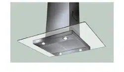
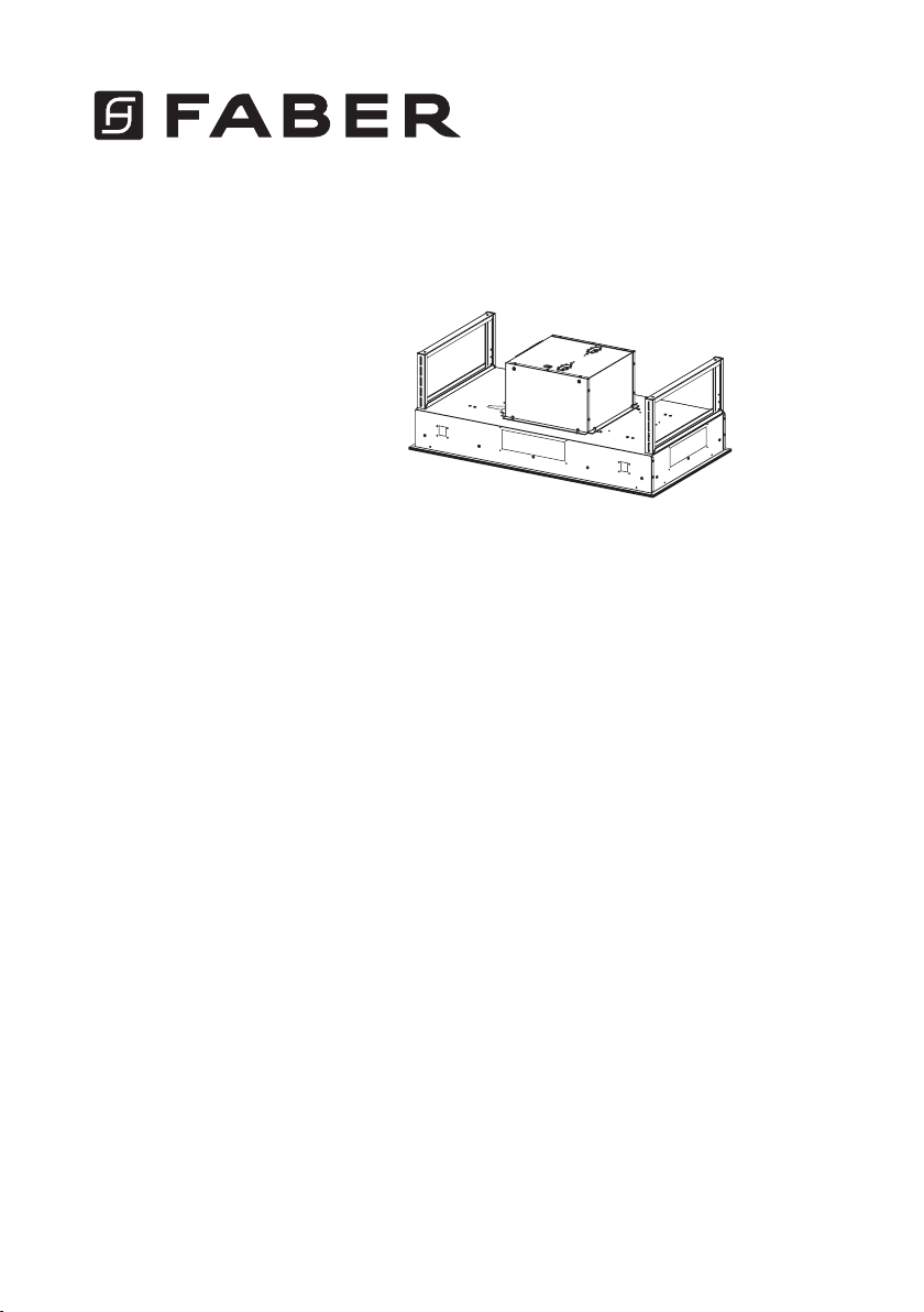
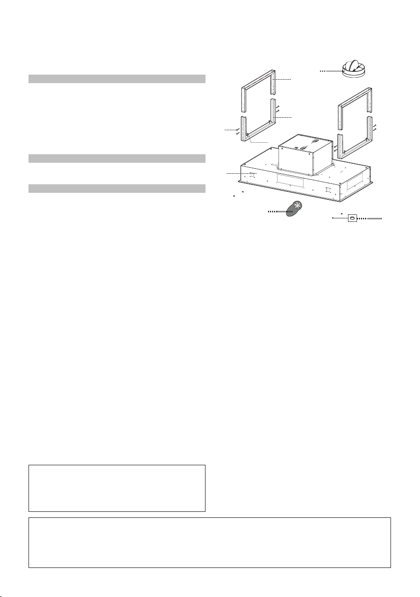
MAIN PARTS
Available Accessories
- Activated Charcoal Filter Accessory - sku# FILTER1
Parts needed
- 6" Round Metal ductwork
Components
Ref. Qty. Product Components
1 1 Hood Body, complete with: Con-
trols, Light, Filters, Blower.
2 2 UpperxingHoodBrackets
3 2 BottomxingHoodBrackets
6 4 Caps
10 1 Damperø57/8"
30 1 Remote Control
Ref. Qty. Installation Components
4 4 Srews1/4"x9/16"
5 8 Srews1/8"x3/8"
Qty. Documentation
1 InstructionManual
10
1
2
3
4
5
30
6
7
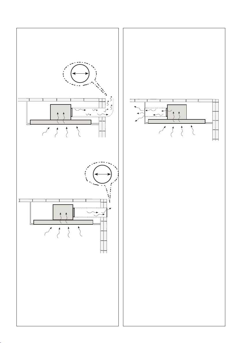
Choose your ducting method
Non Ducted - Recirculation OptionDucted Venting Options Installation
Requires Ductless Accessory Kit
(purchased separately)
6 "
6 "
When used in recirculation mode,
To Reduce the Risk of Fire and
Shock use only conversion kit
Model
FILTER1

8
1
Put a thick, protective covering over cooktop
to protect from damage or dirt.
Determine and clearly mark with a pencil on the
ceiling where the rangehood will be installed.
Determine and make necessary cuts for the
ductwork. The duct opening is shown on the
mounting template.
Install ductwork before mounting the hood.
Determine the proper location for the Power
Supply Cable as indicated on the template.
Use a 1 1/4" Drill Bit to make this hole. Run
the Power Supply Cable. Use caulking to seal
around the hole.
A knockout for threading through the Power
Supply from the ceiling is located on the top
of the frame. Do not connect the Power Cable
to the Wiring Box or power up the hood at this
time. Run enough power cable from the ceiling
to reach the wiring box on the hood.
Do not make any cutouts until you have decided whether this installation will be ducted or
non-duct and then plan accordingly.
DUE TO THE SIZE AND
WEIGHT OF THIS RANGE-
HOOD, THE SUPPORT MUST
BE FIRMLY ATTACHED TO
THE CEILING. For plaster or
sheet rock ceiling, the support
must be attached to the joists.
If this is not possible, a support
structure must be built behind
the plaster or sheet rock. The
manufacturer assumes no re-
sponsibility for injury or damage
caused by improper installa-
tions.
WARNING
!
9
Choose your ducting side
2
3
Unfastenthe4screwstodismountthe
blower.
Theblowercanbepositionedinfour
differentventingdirectionsasshown
to the left.
Remount the Blower with the same 4 screws
removed previously.

10
Ceiling Cutout
4
Seeimagewithdimensions
for ceiling cutout.
Ø 5/16”
x4
x4
475
878
15
3/4
”
23
5/8
” - 31
5/8
”
18
11/16
” - 26
9/16
”
23
5/8” - 31
5/8
”
Assemble the Brackets
$
PP
; $PP
;
%[
5
X = A - 5 1/16"
5 1/16"
5
Asshown,youhave
toaccommodate
for the height of the
hood body into your
spaceoverhead.After
determiningbracket
heightusethe#5
Screws from Component
Page6toassemble
brackets.
Hood X Y
36" 18 11/16" 34 9/16"
48" 18 11/16" 46 3/8"
X
Y
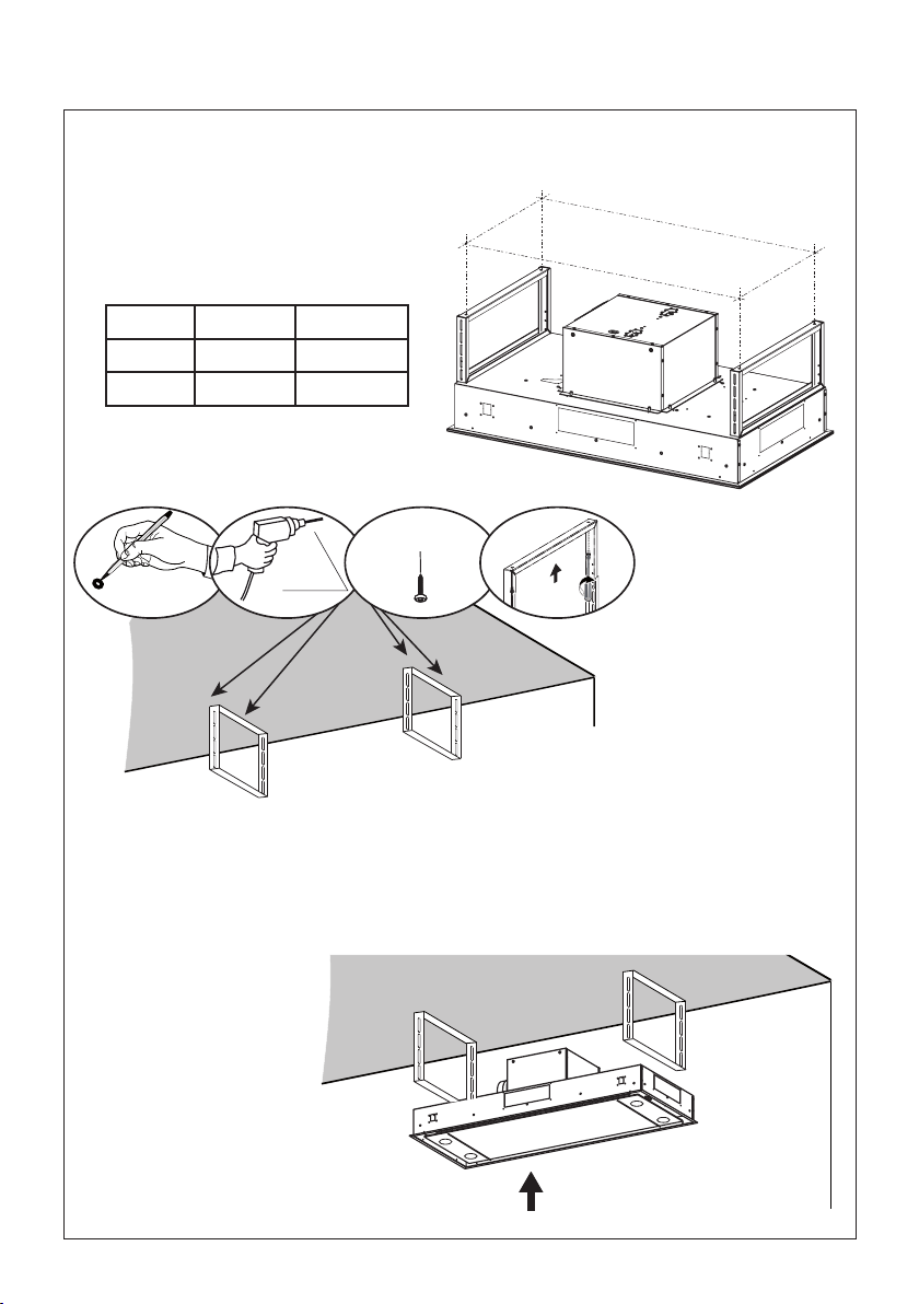
11
6
15
3/4
”
33
1/16
” - 44 7/8”
Seebelowforadetailedimageondrilling
theholesontothefasteningsurface(inside
ceilingorsoft)thatwillthenbeusedto
mountthebracketxtures.Thefasteners
usedmustbecompatiblewiththe5/16"hole
andarepurchasedseparately.
´
[
[
´
[
[
Usethebracketstomarkyourholesforlocationof
theceilingfasteners(purchasedseparately).
Usewallplugsorothersecuringhardwarein
con-junctionwiththeceilingfasteners(purchased
separately).
Ceiling Bracket Installatiion
´
[
[
Hood
36" 153/4" 33 1/16"
48" 153/4" 44 7/8"

12
7
Use the #4 Screws from the
ComponentlistonPage6toattach
thehoodtheceilingbrackets.
C (M6x15)
Installthehoodwiththecontrolpanelontherightasshownabove.
8
13
0LQFP
Choose your ducting method
Ducted Venting Installation
9
Non Ducted -
Recirculation Option
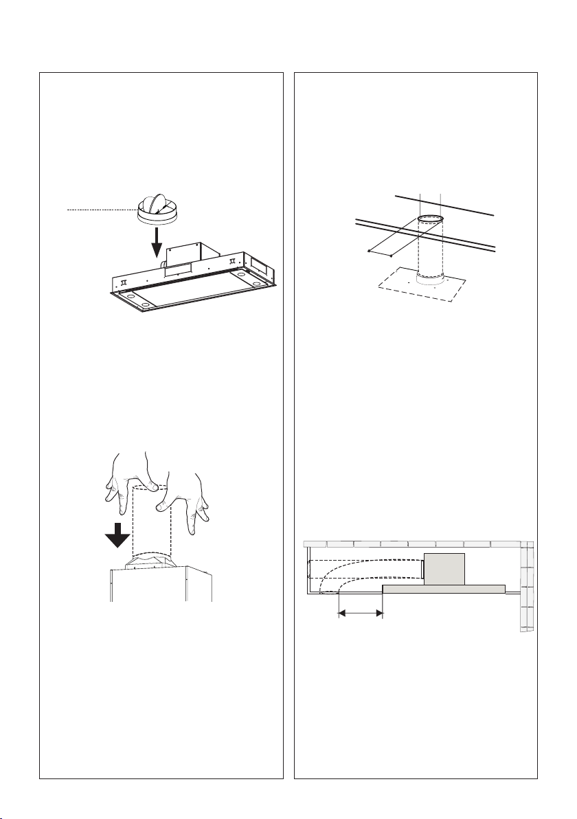
Install Damper that is included with the
Hood before connecting to the ductwork.
H
I
´
See the image above and below as two
duct venting options for non-ducted recircu-
lation back into the room.
Connect the hood to the pipe for air out-
let. Use duct tape to seal the joint.
keep the return air duct at least 40" away
from the side of the Stratus
40"

14
10 11
Opentheltercoverpanel.Theltercoverpanel
isheldbyamagnetcatch,pulldownwithenough
forcetoreleaseasshownabove.
Installation of wiring
connection
Remove the cover from the
eldwiringcompartment.
DO NOT turn on the power until
installationiscomplete!
Connect the Power Supply
Cabletotherangehood.
ConnecttheGreen(Greenand
Yellow)groundwireunderthe
Greengroundingscrew.Attach
theWhiteleadofthepower
supplytotheWhiteleadofthe
rangehoodwithatwist-ontype
wire connector.
AttachtheBlackleadofthe
powersupplytotheBlacklead
oftherangehoodwithatwist-
on type wire connector.
Replacetheeldwiringcompart-
mentcoverandthegreaselters.
A. Home power supply cable
B. Black wires
C. UL listed wire connectors
D. White wires
E. Green (or bare) ground wire from home power supply connected to green ground screw
F. Range hood power supply cable
E
A
F
D
C
B
12
Removethegreaseltersoneatatime,pushing
thetowardsthebackoftheunit,andatthesame
timepullingdownwardandsetaside.
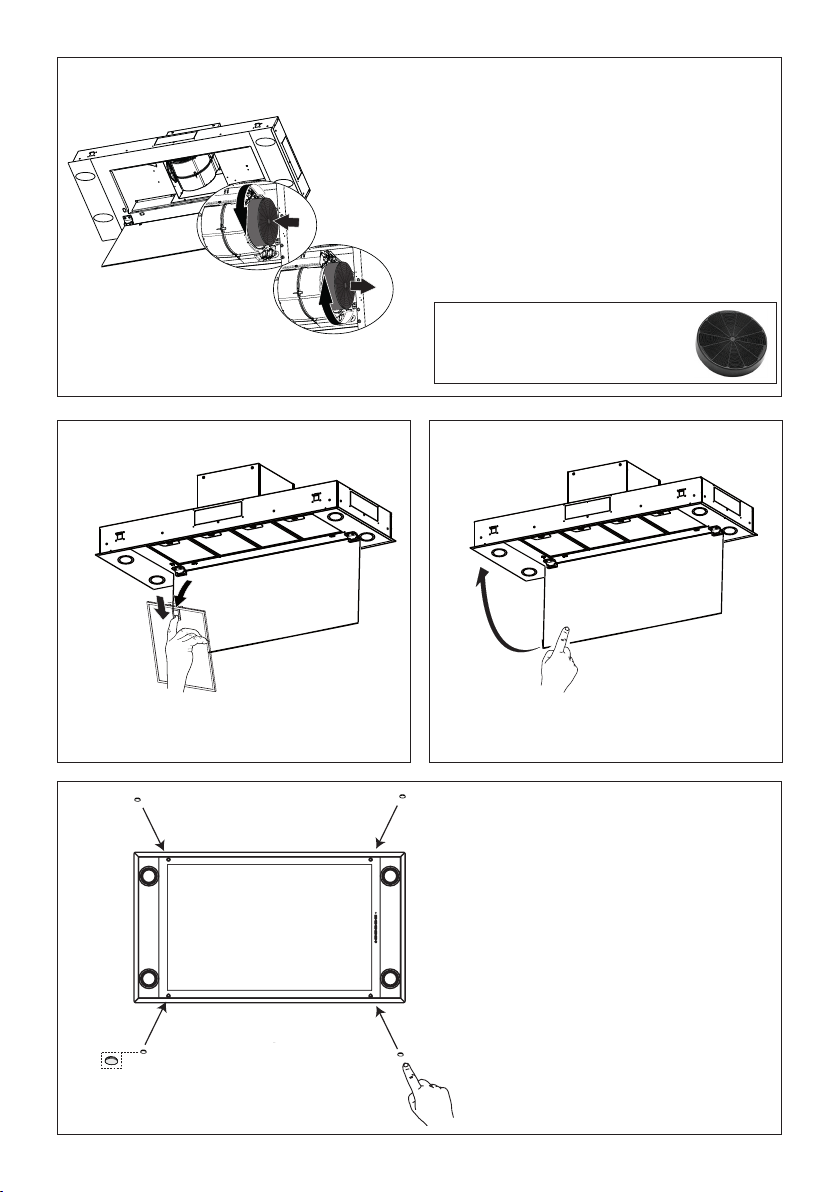
15
A
B
13
For Non-Ducted Recirculation Option
Attach each charcoal lter to the black
grid on each side of the blower. Press the
charcoal lter tightly to the black grid on the
blower side and rotate the lter clockwise
(towards the front of the insert hood) until it
locks into place (A). Turn counterclockwise
(towards the back of the insert hood) to
remove (B).
Required Activated Charcoal Filter
Accessory - sku # - FILTER1
(purchased separately)
1514
Closetheltercoverpanel.Replacethegreaselters.
16
Insertthe4Capsinthescrews
hole,asshown.
16
USE AND CARE INFORMATION
For Best Results
Start the rangehood several minutes before cooking to develop proper airow. Allow the rangehood to
operate for several minutes after cooking is complete to clear all smoke and odors from the kitchen.
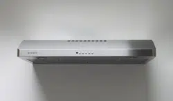
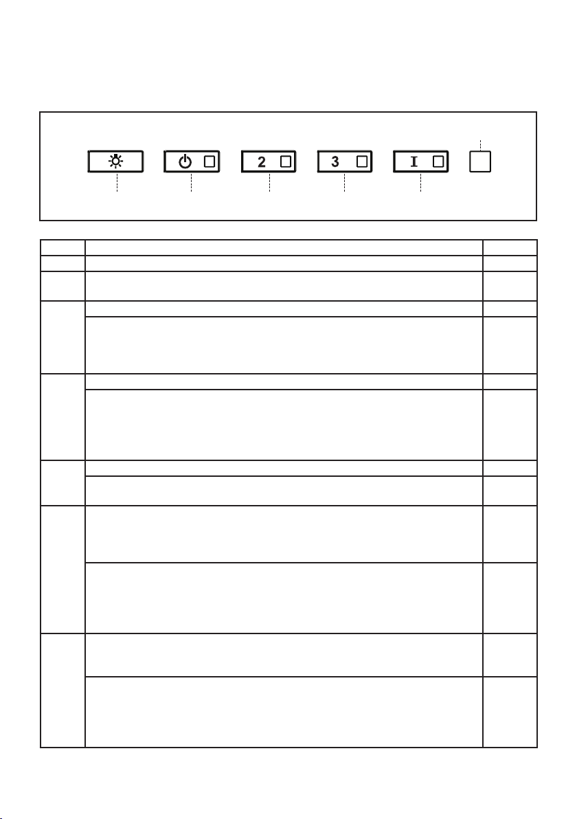
Button Function Led
L Turns the lights on/off at maximum strength. -
Press and hold the button for approximately 2 seconds to turn the Dimmer Lights
On/Off.
-
T1 Turns the motor on/off at speed one. ON
Delay function:
Press and hold the button for approx. 3 seconds to Activate/Deactivate the Delay
function (automatic switching off of the Motor, the Fans and the Lighting with a 30
min. delay). Cannot be enabled when Intensive is on.
T2 Turns the Motor on at speed two. ON
Activated Charcoal Filter Alarm -
Press and hold the button for approximately 5 seconds, with all the hood turned off
(Motor and Lights), to turn the alarm on. The relevant LED ashes twice to conrm.
To turn the alarm off, press the button again and hold for at least 5 seconds. The
relevant LED ashes once.
T3 Turns the Motor on at speed three. ON
Press and hold the button for approximately 3 seconds, with all the hood turned off
(Motor and Lights), to perform a reset. The LED S1 ashes three times.
T4 Turns the Motor on at INTENSIVE Speed.
This speed is timed to run for 6 minutes. At the end of this time, the system returns
automatically to the speed that was set before. If it is activated with the motor turned
off, the hood will switch to OFF at the end of the time.
ON
Remote Control Activation
Press and hold for 5 seconds to enable the remote control, indicated by the LED
ashing twice.
Press and hold for 5 seconds to disable the remote control, indicated by the LED
ashing just once.
S1 Signals the Metal Grease Filter saturation alarm, indicating that it is necessary to
wash the lters. The alarm is triggered after the Hood has been in operation for 100
working hours. (Refer to Page 18 for Cleaning Filters and Reset of Filter Alarm)
ON
When this is activated, it signals the Activated Charcoal Filter saturation alarm,
indicating that the lter must be changed; the Metal Grease Filters must also be
washed. The Activated Charcoal Filter saturation alarm comes into operation after
the Hood has been working for 200 hours. (Refer to Page 18 for Cleaning Filters
and Reset of Filter Alarm)
Flashing.

17
REMOTE CONTROL
The appliance can be controlled using a remote
control powered by a 1.5 V carbon-zinc alkaline
batteries of the standard LR03-AAA type (not
included).
• Do not place the remote control near to heat
sources.
• Used batteries must be disposed of in the
proper manner.
EN
1
19
REMOTE CONTROL
The appliance can be controlled using a remote control
powered by a 1.5 V carbon-zinc alkaline batteries of the
standard LR03-AAA type (not included).
• Do not place the remote control near to heat sources.
• Used batteries must be disposed of in the proper
manner.
Remote control panel
Motor Motor On / Off.
Decreases the working speed each time it is pressed.
Increases the working speed each time it is pressed.
Intensive Activates the Intensive function
Delay Activates / Deactivates the Delay function
Light Lights On / Off
Press for 2 seconds to modify the intensity of the Light.
Motor Motor On / Off
EN
1
19
REMOTE CONTROL
The appliance can be controlled using a remote control
powered by a 1.5 V carbon-zinc alkaline batteries of the
standard LR03-AAA type (not included).
• Do not place the remote control near to heat sources.
• Used batteries must be disposed of in the proper
manner.
Remote control panel
Motor Motor On / Off.
Decreases the working speed each time it is pressed.
Increases the working speed each time it is pressed.
Intensive Activates the Intensive function
Delay Activates / Deactivates the Delay function
Light Lights On / Off
Press for 2 seconds to modify the intensity of the Light.
Decreases the working speed each time it is pressed
EN
1
19
REMOTE CONTROL
The appliance can be controlled using a remote control
powered by a 1.5 V carbon-zinc alkaline batteries of the
standard LR03-AAA type (not included).
• Do not place the remote control near to heat sources.
• Used batteries must be disposed of in the proper
manner.
Remote control panel
Motor Motor On / Off.
Decreases the working speed each time it is pressed.
Increases the working speed each time it is pressed.
Intensive Activates the Intensive function
Delay Activates / Deactivates the Delay function
Light Lights On / Off
Press for 2 seconds to modify the intensity of the Light.
Increases the working speed each time it is pressed
EN
1
19
REMOTE CONTROL
The appliance can be controlled using a remote control
powered by a 1.5 V carbon-zinc alkaline batteries of the
standard LR03-AAA type (not included).
• Do not place the remote control near to heat sources.
• Used batteries must be disposed of in the proper
manner.
Remote control panel
Motor Motor On / Off.
Decreases the working speed each time it is pressed.
Increases the working speed each time it is pressed.
Intensive Activates the Intensive function
Delay Activates / Deactivates the Delay function
Light Lights On / Off
Press for 2 seconds to modify the intensity of the Light.
Intensive Activates/Deactivates the Intensive function
EN
1
19
REMOTE CONTROL
The appliance can be controlled using a remote control
powered by a 1.5 V carbon-zinc alkaline batteries of the
standard LR03-AAA type (not included).
• Do not place the remote control near to heat sources.
• Used batteries must be disposed of in the proper
manner.
Remote control panel
Motor Motor On / Off.
Decreases the working speed each time it is pressed.
Increases the working speed each time it is pressed.
Intensive Activates the Intensive function
Delay Activates / Deactivates the Delay function
Light Lights On / Off
Press for 2 seconds to modify the intensity of the Light.
Delay Activates/Deactivates the Delay function
EN
1
19
REMOTE CONTROL
The appliance can be controlled using a remote control
powered by a 1.5 V carbon-zinc alkaline batteries of the
standard LR03-AAA type (not included).
• Do not place the remote control near to heat sources.
• Used batteries must be disposed of in the proper
manner.
Remote control panel
Motor Motor On / Off.
Decreases the working speed each time it is pressed.
Increases the working speed each time it is pressed.
Intensive Activates the Intensive function
Delay Activates / Deactivates the Delay function
Light Lights On / Off
Press for 2 seconds to modify the intensity of the Light.
Light
Light On / Of
Press for 2 seconds to Activate Dimmer.

18
Cleaningmetalgreaselters
Thesecanbewashed inthedishwasher,andneedtobe
cleanedwhenevertheS1Ledcomesonoratleastonceevery2
monthsofuse,ormorefrequentlyifuseisparticularlyintensive.
Resetting the Grease Filter Alarm
• TurntheLightsandtheHoodoff.
• PressT3andholdforatleast3seconds,untilLEDashes
threetimesinconrmation.
Cleaning the Filters
• OpenthePanel.
• RemovetheFiltersoneatatime,pushingthemtowards
thebackoftheunitandatthesametimepullingdownward.
• WashtheFilterswithoutbendingthem,andleavethemto
drycompletelybeforereplacing.(Ifthesurfaceofthelter
changescolorastimegoesby,thiswillhaveabsolutelyno
effectontheefciencyofthelteritself.)
• Replacethegreaselters,takingcaretoensurethatthe
handlefacesforward
• ClosethePanel.
• 4 Filters - 48" model, 3 Filters - 36" model.
Replacing Activated Charcoal Filter
Theycannotbewashedorregenerated,andmustbechanged
whenledS1startstoash,oratleastonceevery6months.
TheAlarmsignal,ifithasbeenactivated,onlyappearswhen
the Hood Blower is turned on.
Resetting the alarm signal
• TurntheLightsandtheHoodBloweroff.
• PressT3andholdforatleast3seconds,untilLEDashes
threetimesinconrmation.
Cleaning the Filters
• OpenthePanel.
• RemovetheMetalGreaseFilter.
• Remove the saturated Activated Charcoal Filters, as
indicated(A).
• FitthenewFilters,asindicated(B).
• ReplacetheMetalgreaselters.
• ClosethePanel.
Lighting unit
• LEDlightsmustbereplacedbyFaberfactoryauthorized
service.
A
B
19
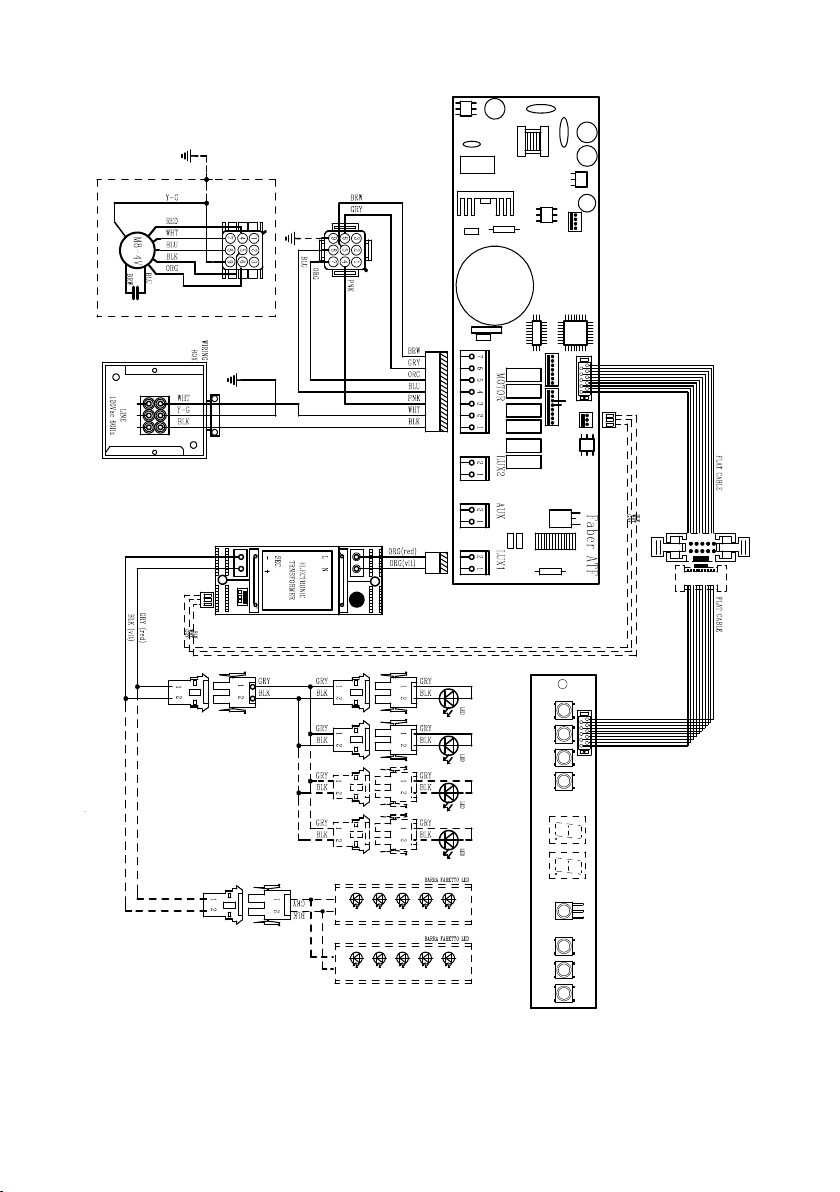
Wiring Diagram
991.0454.388 H90-309 r1
D002943_00
991.0454.388 H90-309 r1
D002943_00

20
January 4, 2016
FABER CONSUMER WARRANTY & SERVICE
All Faber products are warranted against any defect in materials or workmanship for the original purchaser
for a period of 1 year from the date of original purchase (requires proof of purchase). This warranty covers
labor and replacement parts. Faber, at its option, may repair or replace the product or components
necessary to restore the product to good working condition. To obtain warranty service, contact the dealer
from whom you purchased the range hood, or the local Faber distributor. If you cannot identify a local Faber
distributor, contact us at (508) 358-5353 for the name of a distributor in your area.
The following is not covered by Faber's warranty:
1. Service calls to correct the installation of your range hood, to instruct you how to use your range hood, to
replace or repair house fuses or to correct house wiring or plumbing.
2. Service calls to repair or replace range hood light bulbs, fuses or filters. Those consumable parts are
excluded from warranty coverage.
3. Repairs when your range hood is used for other than normal, single-family household use.
4. Damage resulting from accident, alteration, misuse, abuse, fire, flood, acts of God, improper installation,
installation not in accordance with electrical or plumbing codes or Faber documentation, or use of products
not approved by Faber.
5. Replacement parts or repair labor costs for units operated outside the United States or Canada, including
any non-UL or C-UL approved Faber range hoods.
6. Repairs to the hood resulting from unauthorized modifications made to the range hood.
7. Expenses for travel and transportation for product service in remote locations and pickup and delivery
charges. Faber range hoods should be serviced in the home.
THIS WARRANTY DOES NOT ALLOW RECOVERY OF INCIDENTAL OR CONSEQUENTIAL DAMAGES, INCLUDING, WITHOUT
LIMITATION, DIRECT, INDIRECT, INCIDENTAL, SPECIAL OR CONSEQUENTIAL DAMAGES, PERSONAL INJURY/WRONGFUL
DEATH OR LOST PROFITS FABER WARRANTY IS LIMITED TO THE ABOVE CONDITIONS AND TO THE WARRANTY PERIOD
SPECIFIED HEREIN AND IS EXCLUSIVE. EXCEPT AS EXPRESSLY SPECIFIED IN THIS AGREEMENT, FABER DISCLAIMS ALL
EXPRESS OR IMPLIED CONDITIONS, REPRESENTATIONS, AND WARRANTIES INCLUDING, WITHOUT LIMITATION, ANY
IMPLIED WARRANTIES OF MERCHANTABILITY OR FITNESS FOR A PARTICULAR PURPOSE
.
This warranty gives you specific legal rights that may vary from state to state.
Model#: ______________________________ Serial #: _____________________________

21
VEUILLEZ LIRE ET CONSERVER LA PRÉSENTE NOTICE AVANT DE
COMMENCER L'INSTALLATION DE LA HOTTE DE CUISINE
AVERTISSEMENT : POUR RÉDUIRE LE RISQUE D'UN FEU DE GRAISSE SUR LA TABLE DE
CUISSON:
a) Ne laissez jamais sans surveillance les éléments de la surface de cuisson à température élevée.
Les bouillonnements excessifs peuvent provoquer de la fumée et les débordements de graisse
peuvents'enammer.L'huiledoitêtrechaufféelentement,àunetempératurebasseoumoyenne.
b) Assurez-vous de toujours mettre en marche le ventilateur de la hotte lorsque vous cuisinez à
températureélevéeoupréparezunmetsambé(p.ex.crêpesSuzette,cerisesjubilé,bœufambé).
c) Nettoyez régulièrement les ventilateurs d'aspiration. Assurez-vous de ne pas laisser de la
graisses'accumulersurleventilateurouleltre.
d)Utiliseztoujoursdespoêlesetcasserolesdelatailleappropriée.Utiliseztoujoursdesustensiles
de cuisine de la taille adaptée à celle de l'élément chauffant.
AVERTISSEMENT:-POURPRÉVENIRLESBLESSURESENCASDEFEUDEGRAISSESURLA
TABLEDECUISSON,SUIVEZLESRECOMMANDATIONSSUIVANTES*:
a) ÉTOUFFEZ LES FLAMMES à l'aide d'un couvercle hermétique, d'une plaque à biscuits ou d'un
plateau métallique, puis éteignez le brûleur. FAITES ATTENTION AUX BRÛLURES. Si le feu ne
s'éteint pas immédiatement, QUITTEZ LES LIEUX ET APPELEZ LES POMPIERS.
b) NE PRENEZ JAMAIS UNE CASSEROLE EN FLAMME - Vous pourriez vous brûler.
c) N'UTILISEZ JAMAIS DE L'EAU, ni un linge à vaisselle ou un torchon mouillé, pour éteindre le
feu. Cela pourrait provoquer une violente explosion de vapeur.
d)UtilisezunextincteurUNIQUEMENTsi:
1. Vousêtescertainqu'ils'agitd'unextincteurdeclasseABCetquevousconnaissezbien
son mode d'emploi.
2. Le feu est de faible intensité et se limite à l'endroit où il a démarré.
3. Les pompiers ont déjà été appelés.
4. Unevoiedesortiesetrouvederrièrevouspendantquevouséteignezlesammes.
* D'après le guide «Kitchen Firesafety Tips» publié par la NFPA aux États-Unis
AVERTISSEMENT - POUR RÉDUIRE LE RISQUE D'INCENDIE OU DE CHOC ÉLECTRIQUE, n'utilisez
jamais ce ventilateur en association avec un dispositif de réglage de vitesse à semi-conducteurs.
AVERTISSEMENT - POUR RÉDUIRE LES RISQUES D'INCENDIE, DE CHOC ÉLECTRIQUE OU
DEBLESSURECORPORELLE,RESPECTEZLESINSTRUCTIONSSUIVANTES:
1. Utilisez cet appareil uniquement de la façon prévue par le fabricant. Pour toute question,
communiquez avec le fabricant.
2. Avant de procéder à l'entretien ou au nettoyage de l'appareil, coupez l'alimentation au
niveau du panneau électrique et verrouillez-le pour vous assurer que l'électricité n'est pas
rétablie accidentellement. S'il n'est pas possible de verrouiller le dispositif d'interruption de
l'alimentation,afchezdefaçonfermeetbienvisibleunavisdedanger,parexempleàl'aide
d'une étiquette sur le panneau.
ATTENTION:Destinéàunusagedeventilationgénéraleuniquement.N'utilisezpascedispositif
pour l'aspiration de vapeurs ou de matériaux dangereux ou explosifs.
AVERTISSEMENT - POUR RÉDUIRE LES RISQUES D'INCENDIE, DE CHOC ÉLECTRIQUE OU
DEBLESSURECORPORELLE,RESPECTEZLESINSTRUCTIONSSUIVANTES:
1. L'installationetlebranchementélectriquedoiventêtreréalisésparuntechnicienqualié
et conformément à tous les codes et normes en vigueur, incluant ceux concernant la con-
struction à l'épreuve du feu.
2. Andegarantirunecombustionetuneévacuationadéquatesdesgazparlesconduites
de la cheminée des appareils à combustion, une bonne aération est nécessaire pour éviter
le refoulement. Respectez les lignes directrices fournies par le fabricant du matériel chauf-
fant, ainsi que les normes de sécurité comme celles publiées par la National Fire Protection
Association(NFPA)etlaAmericanSocietyforHeating,RefrigerationandAirConditioning
Engineers(ASHRAE)auxÉtats-Unis,ainsiquelescodesenvigueurdansvotrerégion.
22
3. Lorsque vous faites une ouverture ou percez dans un mur ou le plafond, veillez à ne pas
endommagerleslsélectriquesoud'autresdispositifscachés.
4. Lesventilateurscanalisésdoiventtoujoursêtreraccordésàl'extérieur.
T
OUTE OUVERTURE DANS LE MUR OU LE PLANCHER À PROXIMITÉ DE LA HOTTE DOIT
ÊTRE SCELLÉE.
Un espace libre d'au moins 35" est requis entre le bas de la hotte et la surface de cuisson ou le
comptoir. Cette hotte a été homologuée par l'UL à cette distance de la surface de cuisson.
Consultez la notice d'installation de la surface de cuisson ou de la hotte fournie par le fabricant avant
de pratiquer des ouvertures. INSTALLATION DANS UNE MAISON MOBILE L'installation de cette
hotte doit être conforme à la Partie 3280 de la norme Manufactured Home Construction and Safety
Standards, Title 24 CFR (précédemment la partie 280 de la norme Federal Standard for Mobile Home
Construction and Safety, Title 24, HUD).
CRITÈRES DE VENTILATION
Déterminez quelle méthode de ventilation est mieux adaptée à votre application. Les conduits peuvent
passer par le mur ou le toit.
Pour garantir une meilleure efcacité, la longueur des conduits et le nombre de coudes doivent être le
plus limités que possible. Le diamètre des conduits devrait être uniforme. N'installez pas deux coudes
ensemble. Utilisez un ruban pour canalisations an de sceller tous les joints du système de conduits.
Utilisez un calfeutrage pour sceller les ouvertures dans le mur extérieur ou le plancher, autour du clapet.
Il n'est pas recommandé d'utiliser des conduits exibles. Les conduits exibles provoquent une con-
tre-pression et de la turbulence qui diminuent grandement l'efcacité de l'appareil.
Assurez-vous que l'espace libre dans le mur ou le plancher est sufsant pour le conduit d'évacuation
avant de pratiquer les ouvertures. Ne coupez jamais une poutre ou un chevron, sauf si c'est absolu-
ment nécessaire. S'il s'avère nécessaire de couper une poutre ou un chevron, la construction d'un
renforcement est requise.
AVERTISSEMENT - Pour réduire le risque d'incendie, utilisez uniquement des conduits métalliques.
ATTENTION - Pour réduire le risque d'incendie et pour évacuer adéquatement l'air, assu-
rez-vousderaccorderlesconduitsàl'extérieur–Nediffusezpasl'aird'évacuationdans
des espaces à l'intérieur des murs ou du plafond, ou encore à l'intérieur d'un grenier, d'une
galerie technique ou d'un garage.
Installation dans les climats froids
Le système de ventilation doit prévoir un registre antirefoulement supplémentaire pour réduire le ux
d'air froid inverse, ainsi qu'une barrière thermique pour réduire la conduction des températures ex-
térieures. Le registre doit être installé du côté air froid par rapport à la barrière thermique. La barrière
thermique doit être positionnée le plus près que possible de l'endroit où le système de ventilation
pénètre dans la partie chauffée de la maison.
• Le système de ventilation DOIT déboucher à l'extérieur.
• NE FAITES PAS déboucher les conduits dans un grenier ou un autre endroit fermé.
• N'UTILISEZ PAS un clapet de sécheuse mural de 4" .
• Il n'est pas recommandé d'utiliser des conduits exibles.
• N'ENTRAVEZ PAS le ux de l'air de combustion et de ventilation.
• Le non-respect des exigences en matière de ventilation pourrait entraîner un incendie.
AVERTISSEMENT
!

23
FICHE TECHNIQUE ÉLECTRIQUE
Une alimentation de courant alternatif de 120 volt à 60 Hz est requise sur un circuit à fusible distinct
de 15 ampères. Il est recommandé d'installer un fusible temporisé ou un disjoncteur. Le fusible doit
être calibré conformément aux codes en vigueur pour les caractéristiques nominales électriques de
l'appareil, indiquées sur la plaque signalétique située à l'intérieur de l'appareil, à proximité du com-
partiment des câblages externes.
INSTALLATION ÉLECTRIQUE AVEC BOÎTIER DE CÂBLAGES
CET APPAREIL DOIT ÊTRE UNIQUEMENT BRANCHÉ À L'AIDE DE FILS DE CUIVRE. Le calibre des
ls doit être conforme aux critères de la dernière édition du National Electrical Code, de l'ANSI/NFPA
70 et de l'ensemble des codes et réglementations en vigueur. Le calibre des ls et les connexions
doivent être adaptés aux caractéristiques nominales de l'appareil. Il est possible de se procurer un
exemplaire des normes indiquées ci-dessus en communiquant avec:
National Fire Protection Association
Batterymarch Park
Quincy, Massachusetts 02269 (États-Unis)
Cet appareil devrait être branché directement au sectionneur à fusible (ou au disjoncteur) par un câble
exible de cuivre avec blindage ou gaine non métallique. Laissez un peu de jeu dans le câble pour
permettre le déplacement de l'appareil si des travaux d'entretien s'avéraient nécessaires. Un raccord
de conduit homologué par l'UL de 1/2" doit être installé aux deux extrémités du câble d'alimentation
(au niveau de l'appareil et de la boîte de liaison).
Lors de la réalisation du branchement électrique, réalisez un trou de 11/4" dans le mur. S'il s'agit
d'un trou dans le bois, il doit être poncé pour le rendre lisse. S'il s'agit d'un trou dans le métal, un
passe-ls est requis.
• Une mise à la terre électrique est requise pour cette hotte.
• N'UTILISEZ PAS un tuyau d'eau froide pour la mise à la terre si celui-ci est branché par des
joints en plastique, par des rondelles non métalliques ou d'autres matériaux.
• N'UTILISEZ PAS une conduite de gaz pour la mise à la terre.
• N'INSTALLEZ PAS un fusible sur le circuit neutre ou le circuit de mise à la terre. La présence
d'un fusible dans le circuit neutre ou de mise à la terre peut entraîner un choc électrique.
• Consultez un électricien qualié si vous n'êtes pas certain de la mise à la terre de la hotte.
• Le non-respect des exigences de la che technique électrique pourrait entraîner un incendie.
AVERTISSEMENT
!

24
Min. 35" Max. 60"
DIMENSIONS DE LA HOTTE

25
PIÈCES PRINCIPALES
Accessoires disponibles
- Filtre à charbon actif accessoire - No d'article FILTER1
Pièces requises
- Conduit métallique 6" circulaire
Composants
Réf. Qté Composants du produit
1 1 Bâtidelahotte,avec:Commandes,
éclairages,ltres,ventilateur.
2 2 Bridesdexationdehottesupérieures
3 2 Bridesdexationdehotteinférieures
6 4 Chapeaux
10 1 Registreø57/8"
30 1 Télécommande
Réf. Qté Composants d'installation
4 4 Vis1/4"x9/16"
5 8 Vis1/8"x3/8"
Qté Documentation
1 Mode d'emploi
10
1
2
3
4
5
30
6

26
Choisissez la méthode de canalisation
Sans canalisation - Option de
recyclage
Options d'installation avec
ventilation canalisée
Exige la trousse d'accessoires
sans conduit (achetée
séparément)
Lorsque la hotte est utilisée en
modalité ltrante, an d'éviter tout
risque d'incendie et chock, utiliser
le kit de conversion FILTER 1
6 "
6 "
27
1
COMPTE TENU DE LA DIMENSION
ET DU POIDS DE CETTE HOTTE, LE
SOCLE DOIT ÊTRE SOLIDEMENT
ANCRÉ AU PLAFOND. Si le plafond
est en plâtre ou en plaque de plâtre,
le socle doit être ancré aux poutres. Si
cela n'est pas possible, une structure
de soutien doit être construite derrière
le plâtre ou la plaque de plâtre. Le
fabricant ne peut être tenu responsable
en cas de blessures ou de dommages
provoqués par une mauvaise installa-
tion.
AVERTISSEMENT
!
Placez une protection épaisse sur la surface de
cuisson, pour éviter qu'elle soit endommagée
ou salie.
Déterminez l'endroit où la hotte sera installée
et marquez-la clairement sur le plafond à l'aide
d'un crayon.
Déterminez les ouvertures nécessaires pour
les conduits et pratiquez-les. L'ouverture pour
la canalisation est représentée sur le gabarit
de montage.
Installez les conduits avant de monter la hotte.
Déterminez l'emplacement adéquat pour le
câble d'alimentation, comme indiqué sur le
gabarit. Utilisez une mèche de 1 1/4" pour percer
ce trou. Faites passer le câble d'alimentation.
Utiliser un calfeutrage pour sceller autour du trou.
Une pièce à défoncer pour le passage de
l'alimentation électrique du plafond est située
au sommet du châssis. Ne branchez pas le
câble d'alimentation au boîtier de connexion et
n'alimentez pas la hotte à ce moment. Acheminez
une longueur de câble électrique du plafond
sufsante pour atteindre le boîtier de connexion
sur la hotte.
Ne pratiquez aucune ouverture avant d'avoir décidé si l'installation sera canalisée ou non,
puis planiez en conséquence.

28
Choisissez le côté de la canalisation
2
3
Dévissezles4vispourdémonterle
ventilateur.
Faitestournerleventilateurdansla
positiondesoricesdesortied'air.
Remontezleventilateuràl'aidedes4visenlevées
précédemment.

29
4
$
PP
; $PP
;
%[
5
X = A - 5 1/16"
5 1/16"
5
Ouverture au plafond
Consultezl'image
ci-dessous pour
connaîtreles
dimensions de
l'ouvertureau
plafond.
Assemblezles
brides supérieures et
inférieures ensemble,
pourunehauteurtotale
de " X ".
Insérezlesvis5'
comme illustré pour
naliserl'assemblage
des brides.
Assemblez les brides
Ø 5/16”
x4
x4
475
878
15
3/4
”
23
5/8
” - 31
5/8
”
18
11/16
” - 26
9/16
”
23
5/8” - 31
5/8
”
Hotte X Y
36" 18 11/16" 34 9/16"
48" 18 11/16" 46 3/8"
X
Y

30
6
15
3/4
”
33
1/16
” - 44 7/8”
´
[
[
´
[
[
Consultezl'imageci-dessouspourplusde
détailssurlesoricesàpratiquerdansla
surfacedemontage(plafondintérieurou
parement)quiservirontaumontagedes
xationsdesbrides.Lesélémentsdexation
utilisésdoiventêtreadaptésauxoricesde
5/16"etsontachetésséparément.
Installation des brides au plafond
Utilisezlesbridespourtracerlesrepèresdes
oricesdéterminantl'emplacementdeséléments
dexationauplafond(achetésséparément).
Utilisezdeschevillesoud'autresélémentsde
renfortenassociationaveclesélémentsde
xationauplafond(achetéesséparément).
Hotte
36" 153/4" 33 1/16"
48" 153/4" 44 7/8"

31
8
Installezlahotteaveclepanneaudecommandeàdroite,commeillustréci-dessus.
7
C (M6x15)
Utilisezles4visdelalistede
composantsauparagraphe
« PIÈCES PRINCIPALES »
pourxerlahotteauxbridesinstallées
auplafond.

32
0LQFP
Choisissez la méthode de canalisation
Installation avec
ventilation canalisée
9
Sans canalisation -
Option de recyclage
H
I
´
40"
Installez le registre inclus avec la hotte
avant de la raccorder aux conduits.
Pour la ventilation avec recyclage sans
canalisation, dirigez les conduits à un em-
placement au-dessus de la hotte où l'air
évacué est retourné dans la pièce.
Raccordez la hotte à la conduite de la
sortie d'air. Utilisez du ruban adhésif pour
sceller l'articulation.
maintenez le conduit de retour d'air à
une distance d'au moins 40" du côté du
Stratus

33
10 11
Ouvrez le panneau de
protectiondultre.
Retirezlesltresàgraisseetmettez-
lesàpart.
E
A
F
D
C
B
12
Réalisation des
branchements
Retirezlecouvercleducomparti-
mentdescâblagesexternes.
NEMETTEZPASl'alimentation
soustensionavantd'avoirterminé
l'installation!
Branchezlecâbled'alimentation
àlahotte.
Branchezlelvert(vertetjaune)
demiseàlaterresouslavisde
miseàlaterreverte.Branchez
lelblancdel'alimentationaul
blancdelahotteàl'aided'uncon-
necteurverrouilléparrotation.
Branchezlelnoirde
l'alimentationaulnoirdelahotte
àl'aided'unconnecteurverrouillé
parrotation.
Remettezlecouvercleducompar-
timentdescâblagesexternesetles
ltresàgraisseenplace.
A. Câble d'alimentation du réseau domestique
B. Fils noirs
C. Serre-ls homologué UL
D. Fils blancs
E. Fil de mise à la terre vert (ou l nu) de l'alimentation domestique branché à la vis de
mise à la terre verte
F. Câble d'alimentation de la hotte

34
A
B
13
Pour option non canalisée avec
recyclage d'air
Fixez les ltres à charbon à la grille noire de
chaque côté du ventilateur. Pressez fermement
le ltre à charbon contre la grille noire sur le côté
du ventilateur et faites tourner le ltre dans le
sens des aiguilles d'une montre (vers l'avant de
la hotte encastrable) jusqu'à ce qu'il soit verrouillé
en place (A). Faites tourner dans le sens
contraire des aiguilles d'une montre (vers l'arrière
de la hotte encastrable) pour l'enlever (B).
Filtre à charbon actif accessoire
requis - no d'article - FILTER1
(acheté séparément)
1514
Refermezlepanneaudeprotectiondultre.
Remettezenplacecesltresàgraisse.
16
Insérezles4chapeauxdans
les trous de vis, comme illustré.
35
INFORMATIONS POUR L'UTILISATION ET L'ENTRETIEN
Pour de meilleurs résultats
Activez la hotte quelques minutes avant de commencer à cuisiner pour créer un ux d'air adéquat.
Laissez la hotte fonctionner quelques minutes après avoir ni de cuisiner pour absorber toute la fumée
et les odeurs de la cuisine.
Bouton Fonction DEL
L Allume/Éteint l'éclairage à la puissance maximale. -
Appuyez sur ce bouton et tenez-le enfoncé pendant environ 2 secondes pour
allumer/éteindre la veilleuse.
-
T1 Allume et éteint le moteur à la vitesse un. Fixe.
Fonction retardée :
Appuyez sur ce bouton et tenez-le enfoncé pendant environ 3 secondes pour
activer/désactiver la fonction retardée (désactivation automatique du moteur, des
ventilateurs et de l'éclairage après un délai de 30 minutes). Ne peut être activée si la
modalité Intensive est activée.
T2 Allume le moteur à la vitesse deux. Fixe.
Appuyez sur ce bouton et tenez-le enfoncé pendant environ 5 secondes, lorsque
tous les dispositifs sont éteints (moteur et éclairage), pour activer l'alarme du ltre
à charbon actif. Le témoin DEL approprié clignote deux fois pour conrmer. Pour
éteindre l'alarme, appuyez de nouveau sur le bouton et tenez-le enfoncé pendant
au moins 5 secondes. Le témoin DEL approprié clignote une fois.
T3 Allume le moteur à la vitesse trois. Fixe.
Appuyez sur ce bouton et tenez-le enfoncé pendant environ 3 secondes, lorsque
tous les dispositifs sont éteints (moteur et éclairage), pour réinitialiser. Le témoin
DEL S1 clignote trois fois.
T4 Allume le moteur à la vitesse INTENSIVE.
Cette vitesse est programmée pour fonctionner pendant 6 minutes. Après ce délai,
le système retournera automatiquement à la vitesse sélectionnée précédemment.
Si cette modalité est activée tandis que le moteur est éteint, la hotte s'éteindra après
le délai.
Fixe.
Appuyez sur ce bouton et tenez-le enfoncé pendant 5 secondes pour activer la
télécommande; le témoin DEL clignotera deux fois.
Appuyez sur ce bouton et tenez-le enfoncé pendant 5 secondes pour désactiver la
télécommande; le témoin DEL clignotera une seule fois.
S1 L'alarme de saturation du ltre à graisse métallique signale qu'il est nécessaire
de nettoyer les ltres. L'alarme s'active lorsque la hotte a été en fonction pendant
100 heures. (Pour la réinitialisation, consultez le parag. Entretien).
Fixe.
Lorsqu'il est activé, l'alarme de saturation du ltre à charbon actif signale que le ltre
doit être changé; les ltres à graisse métalliques doivent également être nettoyés.
L'alarme de saturation du ltre à charbon actif s'active lorsque la hotte a été en
fonction pendant 200 heures. (Pour l'activation et la réinitialisation, consultez le
parag. Entretien)
Clignotant.
36
EN
1
19
REMOTE CONTROL
The appliance can be controlled using a remote control
powered by a 1.5 V carbon-zinc alkaline batteries of the
standard LR03-AAA type (not included).
• Do not place the remote control near to heat sources.
• Used batteries must be disposed of in the proper
manner.
Remote control panel
Motor Motor On / Off.
Decreases the working speed each time it is pressed.
Increases the working speed each time it is pressed.
Intensive Activates the Intensive function
Delay Activates / Deactivates the Delay function
Light Lights On / Off
Press for 2 seconds to modify the intensity of the Light.
Moteur Moteur allumé/éteint
EN
1
19
REMOTE CONTROL
The appliance can be controlled using a remote control
powered by a 1.5 V carbon-zinc alkaline batteries of the
standard LR03-AAA type (not included).
• Do not place the remote control near to heat sources.
• Used batteries must be disposed of in the proper
manner.
Remote control panel
Motor Motor On / Off.
Decreases the working speed each time it is pressed.
Increases the working speed each time it is pressed.
Intensive Activates the Intensive function
Delay Activates / Deactivates the Delay function
Light Lights On / Off
Press for 2 seconds to modify the intensity of the Light.
Réduit la vitesse à chaque pression
EN
1
19
REMOTE CONTROL
The appliance can be controlled using a remote control
powered by a 1.5 V carbon-zinc alkaline batteries of the
standard LR03-AAA type (not included).
• Do not place the remote control near to heat sources.
• Used batteries must be disposed of in the proper
manner.
Remote control panel
Motor Motor On / Off.
Decreases the working speed each time it is pressed.
Increases the working speed each time it is pressed.
Intensive Activates the Intensive function
Delay Activates / Deactivates the Delay function
Light Lights On / Off
Press for 2 seconds to modify the intensity of the Light.
Augmente la vitesse à chaque pression
EN
1
19
REMOTE CONTROL
The appliance can be controlled using a remote control
powered by a 1.5 V carbon-zinc alkaline batteries of the
standard LR03-AAA type (not included).
• Do not place the remote control near to heat sources.
• Used batteries must be disposed of in the proper
manner.
Remote control panel
Motor Motor On / Off.
Decreases the working speed each time it is pressed.
Increases the working speed each time it is pressed.
Intensive Activates the Intensive function
Delay Activates / Deactivates the Delay function
Light Lights On / Off
Press for 2 seconds to modify the intensity of the Light.
Intensive Active/Désactive la fonction Intensive
EN
1
19
REMOTE CONTROL
The appliance can be controlled using a remote control
powered by a 1.5 V carbon-zinc alkaline batteries of the
standard LR03-AAA type (not included).
• Do not place the remote control near to heat sources.
• Used batteries must be disposed of in the proper
manner.
Remote control panel
Motor Motor On / Off.
Decreases the working speed each time it is pressed.
Increases the working speed each time it is pressed.
Intensive Activates the Intensive function
Delay Activates / Deactivates the Delay function
Light Lights On / Off
Press for 2 seconds to modify the intensity of the Light.
Délai Active/Désactive la fonction retardée
EN
1
19
REMOTE CONTROL
The appliance can be controlled using a remote control
powered by a 1.5 V carbon-zinc alkaline batteries of the
standard LR03-AAA type (not included).
• Do not place the remote control near to heat sources.
• Used batteries must be disposed of in the proper
manner.
Remote control panel
Motor Motor On / Off.
Decreases the working speed each time it is pressed.
Increases the working speed each time it is pressed.
Intensive Activates the Intensive function
Delay Activates / Deactivates the Delay function
Light Lights On / Off
Press for 2 seconds to modify the intensity of the Light.
Éclairage
Éclairage allumé/éteint
Appuyez pendant 2 secondes pour modier l'intensité de l'éclairage
TÉLÉCOMMANDE
Il est possible de commander l'appareil à l'aide
d'une télécommande alimentée par une pile
carbone/zinc alcaline 1,5 V du type standard
LR03-AAA (non incluse).
• Ne déposez pas la télécommande à proximité
de sources de chaleur.
• Les piles usées doivent être éliminées de la
façon adéquate.

37
A
B
Nettoyagedesltresàgraissemétalliques
Ilspeuventêtrelavésdanslelave-vaisselleetdoiventêtre
nettoyéslorsqueletémoinDELS1s'allumeouaumoinsune
foistousles2moisd'usage,ouencoreplusfréquemment
encasd'utilisationparticulièrementintensive.
Réinitialiser le signal d'alarme
• Éteintl'éclairageetlemoteurd'aspiration.
• AppuyezsurT3ettenez-leenfoncépendantaumoins
3secondes,jusqu'àcequeletémoinDELclignotetrois
foispourconrmer.
Nettoyage des ltres
• Ouvrezlepanneau.
• Retirezlesltresunàun,enlespoussantversl'arrière
del'appareiletenlestirantverslebassimultanément.
• Lavezlesltressanslesplieretlaissez-lesséchercom-
plètementavantdelesremettreenplace.(Silasurface
dultrechangedecouleurauldutemps,celan'aura
aucunimpactsurl'efcacitédultremême.)
• Remettez-lesenplace,envousassurantquelapoignée
setrouveversl'avant.
• Refermezlepanneau.
• 4Filtres-modèle48",3ltres-modèle36".
Remplacementdultreàcharbonactif
Ilnepeutêtrelavénirégénéré,etdoitêtrechangélorsque
letémoinDELS1commenceàclignoter,ouaumoinsune
foistousles6mois.Silesignald'alarmeaétéactivé,ilap-
paraîtuniquementlorsquelemoteurd'aspirationestactivé.
Réinitialiser le signal d'alarme
• Éteignezl'éclairageetlemoteurd'aspiration.
• AppuyezsurT3ettenez-leenfoncépendantaumoins
3secondes,jusqu'àcequeletémoinDELclignote3
foispourconrmer.
Nettoyage des ltres
• Ouvrezlepanneau.
• Retirezleltreàgraissemétallique.
• Retirez les ltres à charbon actif saturés comme
indiqué(A).
• Posezlesnouveauxltres,commeindiqué(B).
• Remettezenplacelesltresàgraissemétalliques.
• Refermezlepanneau.
Système d'éclairage
• Les ampoules DEL doivent être remplacées par un
serviced'entretienautoriséFaber.

38
Schéma de câblage
991.0454.388 H90-309 r1
D002943_00
991.0454.388 H90-309 r1
D002943_00

39
4 janvier 2016
GARANTIE LIMITÉE ET SERVICE FABER
Tous les produits Faber font l'objet d'une garantie contre les défauts de matériel et de main-
d'œuvre,accordée à l'acheteur original pour une période d'un (1) an à compter de la date d'achat initiale
(preuve d'achat requise). Cette garantie couvre les frais de main-d'œuvre et les pièces de rechange. À sa
discrétion, Faber peut réparer ou remplacer le produit ou les composants nécessaires à remettre le produit
en bon état de marche. Pour bénéficier de services prévus par la garantie, veuillez communiquer avec le
détaillant auprès duquel vous avez acheté la hotte de cuisine, ou encore avec le distributeur Faber de votre
région. Si vous n'êtes pas en mesure de localiser un distributeur Faber dans votre région, veuillez
communiquer avec nous au 508-358-5353 pour connaître le nom d'un distributeur à proximité.
Les éléments suivants ne sont pas visés par la garantie Faber :
1. Les appels au service de réparation visant à corriger l'installation de la hotte de cuisine, à recevoir des
instructions sur l'utilisation de la hotte de cuisine, le remplacement ou la réparation des fusibles du domicile
ou la correction des câblages ou de la plomberie du domicile.
2. Les appels au service de réparation visant à réparer ou remplacer les ampoules électriques de hotte, les
fusibles ou les filtres. Ces pièces consommables ne sont pas couvertes par la garantie.
3. Les réparations si votre hotte de cuisine est employée à des fins autres que celles prévues, soit l'utilisation
résidentielle normale pour une famille.
4. Les dommages découlant d'un accident, d'une modification, de l'utilisation incorrecte ou abusive, d'un
incendie, d'une inondation, d'un cas de force majeure, d'une installation inadéquate, d'une installation non
conforme aux codes en matière d'électricité ou de plomberie ou à la documentation fournie par Faber, ou
encore d'une utilisation du produit non approuvée par Faber.
5. Les frais de main-d'œuvre ou de remplacement des pièces pour les appareils utilisés à l'extérieur des
États-Unis ou du Canada, y compris toutes les hottes de cuisine Faber non-UL ou C-UL homologuées.
6. Les réparations à la hotte découlant de modifications non autorisées apportées à la hotte de cuisine.
7. Les frais encourus pour les déplacements et le transport de produits en région éloignée et les frais de
cueillette et livraison. La réparation des hottes de cuisine Faber doit être réalisée à domicile.
LA PRÉSENTE GARANTIE NE PRÉVOIT AUCUNE FORME DE DÉDOMMAGEMENT EN CAS DE DOMMAGES ACCESSOIRES OU
CONSÉCUTIFS, Y COMPRIS, SANS TOUTEFOIS S'Y LIMITER, LES DOMMAGES DIRECTS, INDIRECTS, ACCESSOIRES,
PARTICULIERS OU CONSÉCUTIFS, LES LÉSIONS CORPORELLES/MORTELLES OU LA PERTE DE PROFITS. LA GARANTIE
OFFERTE PAR FABER EST LIMITÉE AUX CONDITIONS ÉNONCÉES CI-DESSUS ET À LA PÉRIODE DE GARANTIE INDIQUÉE
DANS LES PRÉSENTES ET EST EXCLUSIVE. SAUF DISPOSITIONS EXPRESSES CONTRAIRES DANS LE PRÉSENT ACCORD,
FABER DÉCLINE TOUTE CONDITION, REPRÉSENTATION OU GARANTIE EXPLICITE OU IMPLICITE, Y COMPRIS, SANS
TOUTEFOIS S'Y LIMITER, TOUTE GARANTIE IMPLICITE DE QUALITÉ MARCHANDE OU D'ADAPTATION À UN USAGE
PARTICULIER
.
Les droits qui vous sont conférés en vertu de la présente garantie peuvent varier d'une province ou d'un État
à l'autre.
N
o
de modèle : ______________________________ N
o
de série : _____________________________

991.0471.387_05 - 170926
D002987_04