Installation
Microwave Oven
Instructions
Built-In Trim Kits
1
❒ BEFORE YOU BEGIN
Read these instructions completely and carefully.
•
IMPORTANT — Save these instructions
for local inspector’s use.
•
IMPORTANT — Observe all governing codes and
ordinances.
•
Note to Installer – Be sure to leave these instructions with
the Consumer.
• Note to Consumer – Keep these instructions for future
reference.
• Skill level – Installation of this appliance requires basic
mechanical and electrical skills.
• Completion time –
1 to 3 hours
• Properinstallationistheresponsibilityoftheinstaller.
• Productfailureduetoimproperinstallationisnotcovered
undertheWarranty.
• Thiskitisforuseonmodels:
PEM10SFC,PEM10BFC,PEM10WFCandCEM11SFC
• Donotalterormodifyanypartofthiskitortheoven.
• Foreasierinstallationandpersonalsafety,we
recommend that two people install this microwave oven.
• Unplugthemicrowaveovenbeforeattemptinginstallation
of this kit.
WARNING —Thisovenmustbepluggedintoa
properlygrounded3-hole,120voltreceptacleasrequiredby
theNationalElectricalCode.
Questions? Call 1-800-561-3344 or Visit our Website at: GEAppliances.ca
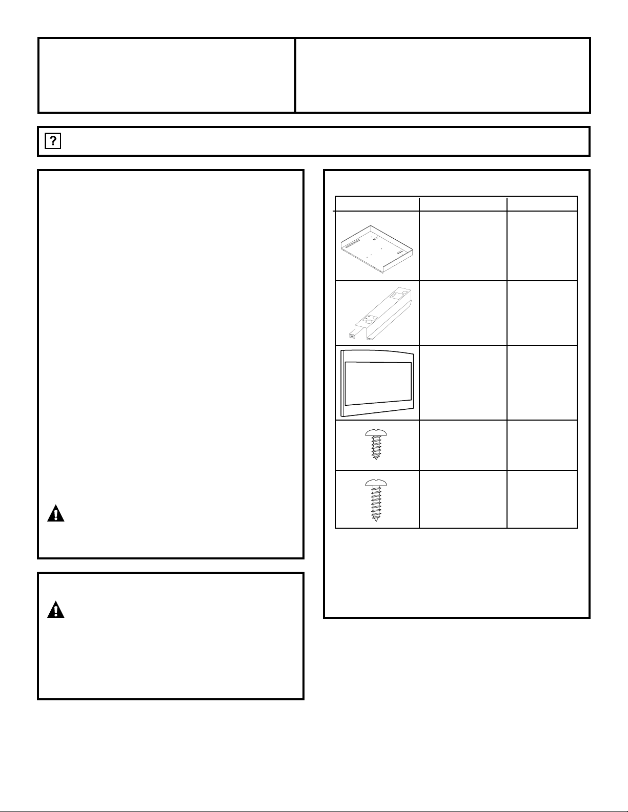
PARTS INCLUDED
PART QUANTITY
❒ BasePan 1
❒ Rail 2
❒ TrimKit 1
❒ 4mmx10mm 11required
Screw A 3 extra
❒ 4 mm x 16 mm 4 required
ScrewB 2extra
NOTE: Thiskithasextrascrewstopreventthetechnician
from spending extra time locating a replacement in case
theyloseoneduringinstallation.
FOR YOUR SAFETY:
WARNING —Beforebeginningtheinstallation,
switch power off at service panel and lock the service
disconnecting means to prevent power from being switched
onaccidentally.Whentheservicedisconnectingmeans
cannotbelocked,securelyfastenaprominentwarning
device,suchasatag,totheservicepanel.
JX827 and JX830
1”2.5cm;1’=0.3m
❒
1
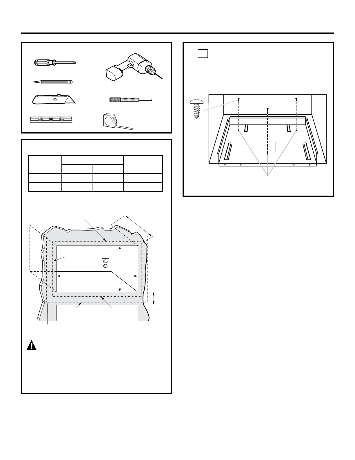
LOCATE AND INSTALL THE BASE PAN
SetBasePanintothefrontcabinetmicrowaveoven
cutoutandcenteritrightandleft.Pushbackuntilthe
frontflangeisagainstthecabinetfrontwall.Mount
theBasePanusing3screws(A).
❒ CUTOUT DIMENSIONS
WARNING — This trim kit uses air flow from the
top, bottom and sides of the trim frame. Blocking the air flow
can cause the microwave to function improperly and may
cause damage to the microwave.
Allow a 1” clearance beyond the edge of the trim frame to
provide proper air flow.
2
Installation Instructions
Min.depthwithreceptacleoutsidecutout–16
”
Min.depthwithreceptacleinsidecutout–18
”
120volt–60Hertzgroundedpowerreceptacle.
Screw A
TOOLS YOU WILL NEED
❒
2PhillipsScrewdrivers(#1)
❒
Drillwith3/32”DrillBit
❒
Centerpunch or nail
❒
Pencil
❒
Knife
❒
Level
❒
TapeMeasure
Depth
Height
5/8”Overlap
Width
7/8”Overlap
1”Clearancebeyond
trim frame
(onallsides)
3”Min.
27”models:1”overlap
30”models:2
1
/2” overlap
Bottom of trim kit must be
minimum of 36” from floor
Dimension
Trim Kit
Cutout
27” 30”
Height 16
1
/2” 16
1
/2” 15±
1
/16”
Width 26
7
/8” 29
7
/8” 24
7
/8 ±
1
/16”
BasePlan
MountingHoles
1”2.5cm;1’=0.3m
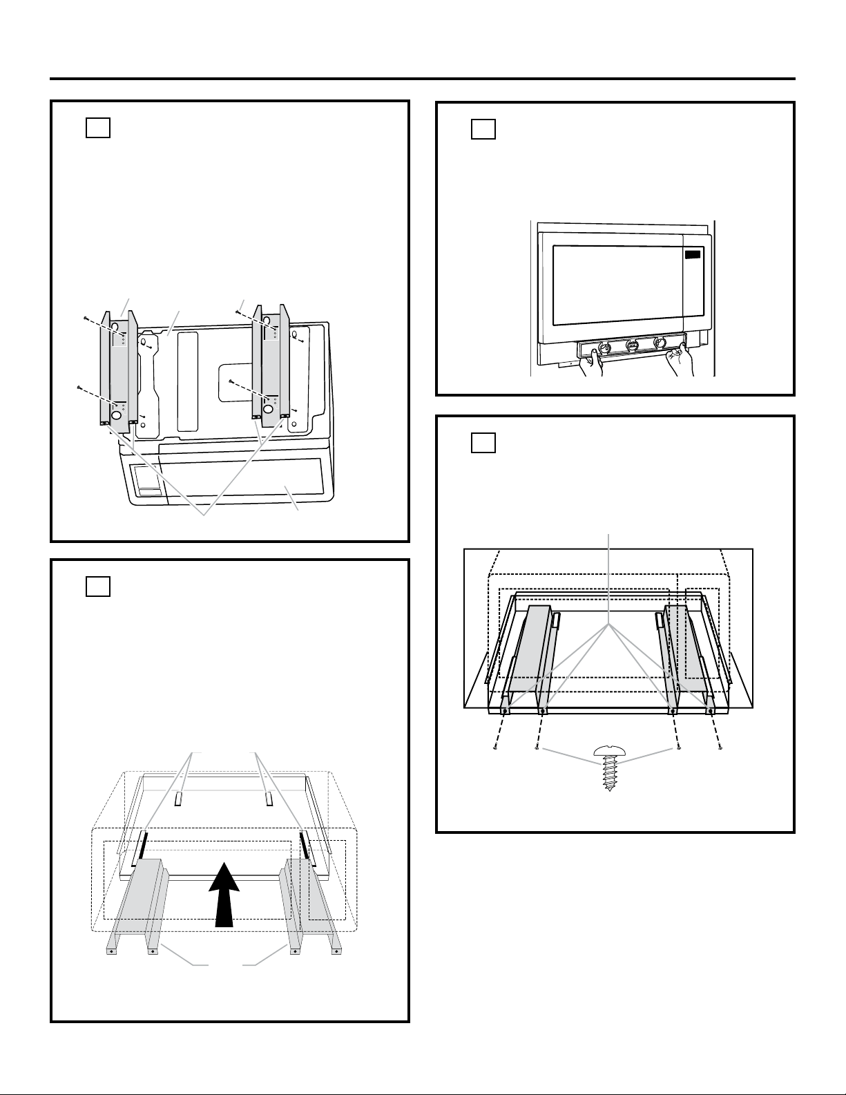
❒
3
INSTALL THE MICROWAVE OVEN
Plugthepowercordintothewallreceptacle.Slidethe
microwaveovenassemblygentlyintothecabinet,using
care not to pinch the power cord. Be sure to keep the
assemblycenteredasitslidesbacktowherethetongueof
therailsgoesthroughtheslotsonBasePlan.Thetopedges
oftheBasePlanshouldnowbecenteredrighttoleftinthe
opening.TheBaseshouldbetightagainstthecabinet.
❒
2
INSTALL THE RAILS
Disconnectthemicrowaveovenfromthereceptacle.
Removeeverythingoutofthemicrowaveoven,including
packing,Owner’sManuals,turntableandturntablesupport.
A protective film has been applied to some microwave
ovenandtrimkits.Ifapplied,removethefilm.Turnoverthe
microwaveovenandsecuretherailstoovenBasePlate
byinserting4screws(A).Becarefulnottoscratchthe
microwave oven.
3
Installation Instructions
❒
5
SECURE THE RAILS TO THE CABINET
EnsuretheBasePanandBottomBracketfrontflangesare
tightagainstthecabinet,andthatthescrewsholesare
aligned.Drive4screws(A)throughtheBasePanandRails
into the cabinet
Screw A
❒
4
CHECK LEVELING
Checkthelevelingbyplacingalevelatthefrontandsides
ofthemicrowave.Itmaybenecessarytoaddwoodshims
underthebasepantolevelthemicrowavefront-to-backor
side-to-side.
Microwave
Oven Bottom
Rail
Screw(A)
Flanges
Door
Rail
Guides
Rails
MountingHoles
1”2.5cm;1’=0.3m
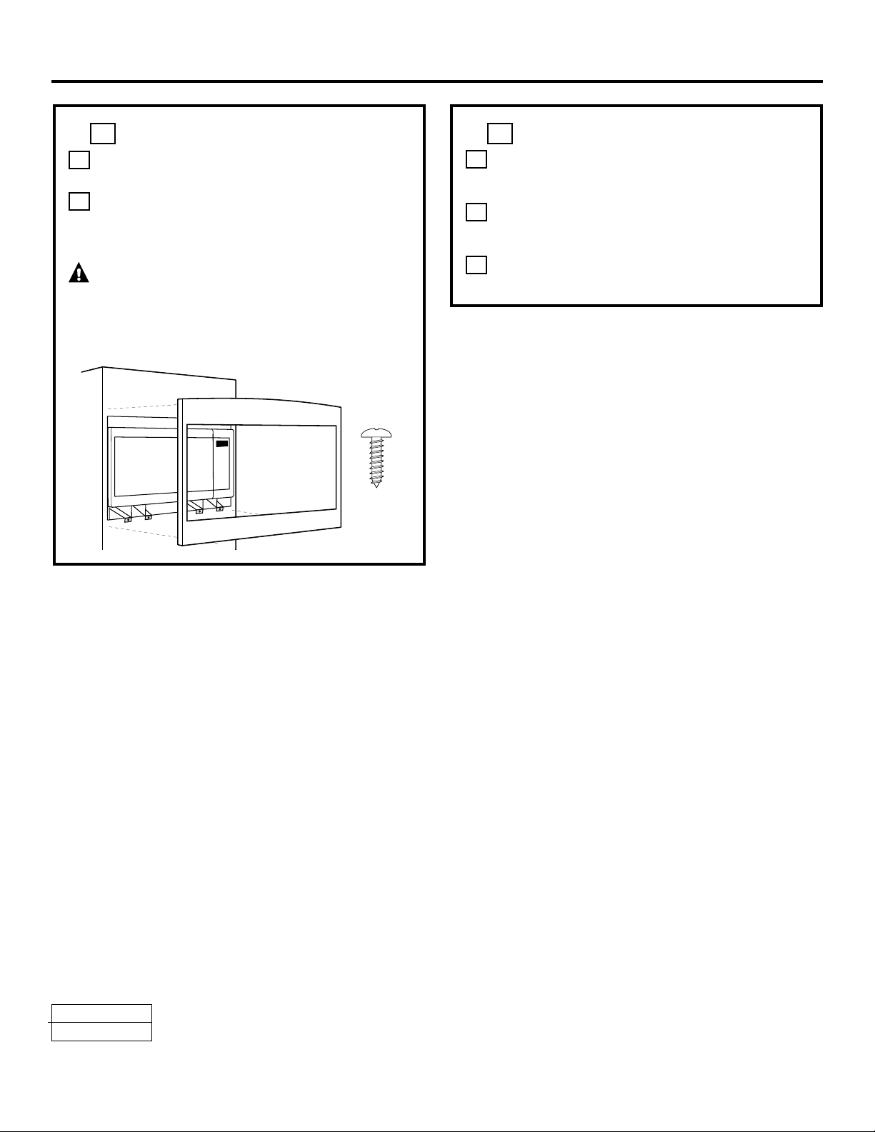
❒
6
INSTALL THE TRIM KIT FRAME
A
PositiontheassembledTrimKitframearoundthe
oven.
B
SecuretheTrimKitbydrivingfourscrews(B)through
the trim kit into the cabinet.
CAUTION — Start all screws before tightening
any one screw. Do not overtighten screws since it can
cause misalignment of top/side strips.
DE68-03364A
350A4502P745
4
Installation Instructions
08-13ATS
PrintedinChina
Screw B
READ CAREFULLY. KEEP THESE INSTRUCTIONS.
❒
7
REPLACE ANY LOOSE ITEMS
A
Yourtrimkitisnowfullyinstalled.Replace
the turntable and turntable support that was removed
from inside the microwave oven.
B
Keep these installation instructions and extra screws
forfuturereferenceandneed.Donotplacethemin
the microwave oven.
C
Replacethehousefuse,orclosethecircuitbreakerto
restore power at the service panel.
1”2.5cm;1’=0.3m