Foreword
Congratulations on choosing a SUBARU vehicle. This Owner’s
Manual has all the information necessary to keep your SUBARU in
excellent condition and to properly maintain the emission control
system for minimizing emission pollutants. We urge you to read
this manual carefully so that you may understand your vehicle and
its operation. For information not found in this Owner’s Manual,
such as details concerning repairs or adjustments, please contact
the dealer from whom you purchased your SUBARU or the nearest
SUBARU dealer.
The information, specifications and illustrations found in this man-
ual are those in effect at the time of printing. FUJI HEAVY INDUS-
TRIES LTD. reserves the right to change specifications and de-
signs at any time without prior notice and without incurring any ob-
ligation to make the same or similar changes on vehicles previous-
ly sold. This Owner’s Manual applies to all models and covers all
equipment, including factory installed options. Some explanations,
therefore may be for equipment not installed in your vehicle.
Please leave this manual in the vehicle at the time of resale. The
next owner will need the information found herein.
FUJI HEAVY INDUSTRIES LTD., TOKYO, JAPAN
is a registered trademark of FUJI HEAVY INDUSTRIES LTD.
© copyright 2005 FUJI HEAVY INDUSTRIES LTD.
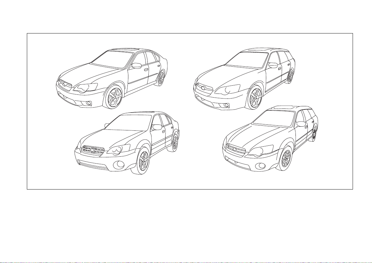
This manual describes the following types of the Legacy series.
1) Legacy Sedan
2) Legacy Station wagon
3) OUTBACK Sedan
4) OUTBACK Station wagon
1
2
3
4
000138

1
– CONTINUED –
Warranties
Warranties for U.S.A.
All SUBARU vehicles distributed by
Subaru of America, Inc. and sold at retail
by an authorized SUBARU dealer in the
United States come with the following
warranties:
y SUBARU Limited Warranty
y Emission Control Systems Warranty
y Emissions Performance Warranty
All warranty information, including details
of coverage and exclusions, is in the
“Warranty and Maintenance Booklet”.
Please read these warranties carefully.
T Warranties for Canada
All SUBARU vehicles distributed by
Subaru Canada, Inc. and sold at retail by
an authorized SUBARU dealer in Canada
come with the following warranties:
y SUBARU Limited Warranty
y Anti-Corrosion Warranty
y Emission Control Warranty
All warranty information, including details
of coverage and exclusions, is in the
“Warranty and Service Booklet”. Please
read these warranties carefully.
How to use this owner’s man-
ual
Using your Owner’s manual
Before you operate your vehicle, carefully
read this manual. To protect yourself and
extend the service life of your vehicle, fol-
low the instructions in this manual. Failure
to observe these instructions may result in
serious injury and damage to your vehicle.
This manual is composed of fourteen
chapters. Each chapter begins with a brief
table of contents, so you can usually tell at
a glance if that chapter contains the infor-
mation you want.
Chapter 1: Seat, seatbelt and SRS air-
bags
This chapter informs you how to use the
seat and seatbelt and contains precau-
tions for the SRS airbags.
Chapter 2: Keys and doors
This chapter informs you how to operate
the keys, locks and windows.
Chapter 3: Instruments and controls
This chapter informs you about the opera-
tion of instrument panel indicators and
how to use the instruments and other
switches.
Chapter 4: Climate control
This chapter informs you how to operate
If your vehicle is equipped with a
navigation system, the display con-
tains mercury. Therefore, the dis-
play of the navigation system must
be removed before vehicle disposal.
Once the display has been removed,
please reuse, recycle or dispose of
them as hazardous waste.
2
the climate control.
Chapter 5: Audio
This chapter informs you how to operate
your audio system.
Chapter 6: Interior equipment
This chapter informs you how to operate
interior equipment.
Chapter 7: Starting and operating
This chapter informs you how to start and
operate your SUBARU.
Chapter 8: Driving tips
This chapter informs you how to drive your
SUBARU in various conditions and ex-
plains some safety tips on driving.
Chapter 9: In case of emergency
This chapter informs you what to do if you
have a problem while driving, such as a
flat tire or engine overheating.
Chapter 10: Appearance care
This chapter informs you how to keep your
SUBARU looking good.
Chapter 11: Maintenance and service
This chapter informs you when you need
to take your SUBARU to the dealer for
scheduled maintenance and informs you
how to keep your SUBARU running prop-
erly.
Chapter 12: Specifications
This chapter informs you about dimension
and capacities of your SUBARU.
Chapter 13: Consumer information and
Reporting safety defects
This chapter informs you about Tire infor-
mation, Uniform tire quality grading stan-
dards and Reporting safety defects.
Chapter 14: Index
This is an alphabetical listing of all that’s in
this manual. You can use it to quickly find
something you want to read.
Safety warnings
You will find a number of WARNINGs,
CAUTIONs and NOTEs in this manual.
These safety warnings alert you to poten-
tial hazards that could result in injury to
you or others.
Please read these safety warnings as well
as all other portions of this manual careful-
ly in order to gain a better understanding
of how to use your SUBARU vehicle safe-
ly.
NOTE
A NOTE gives information or sugges-
tions how to make better use of your
vehicle.
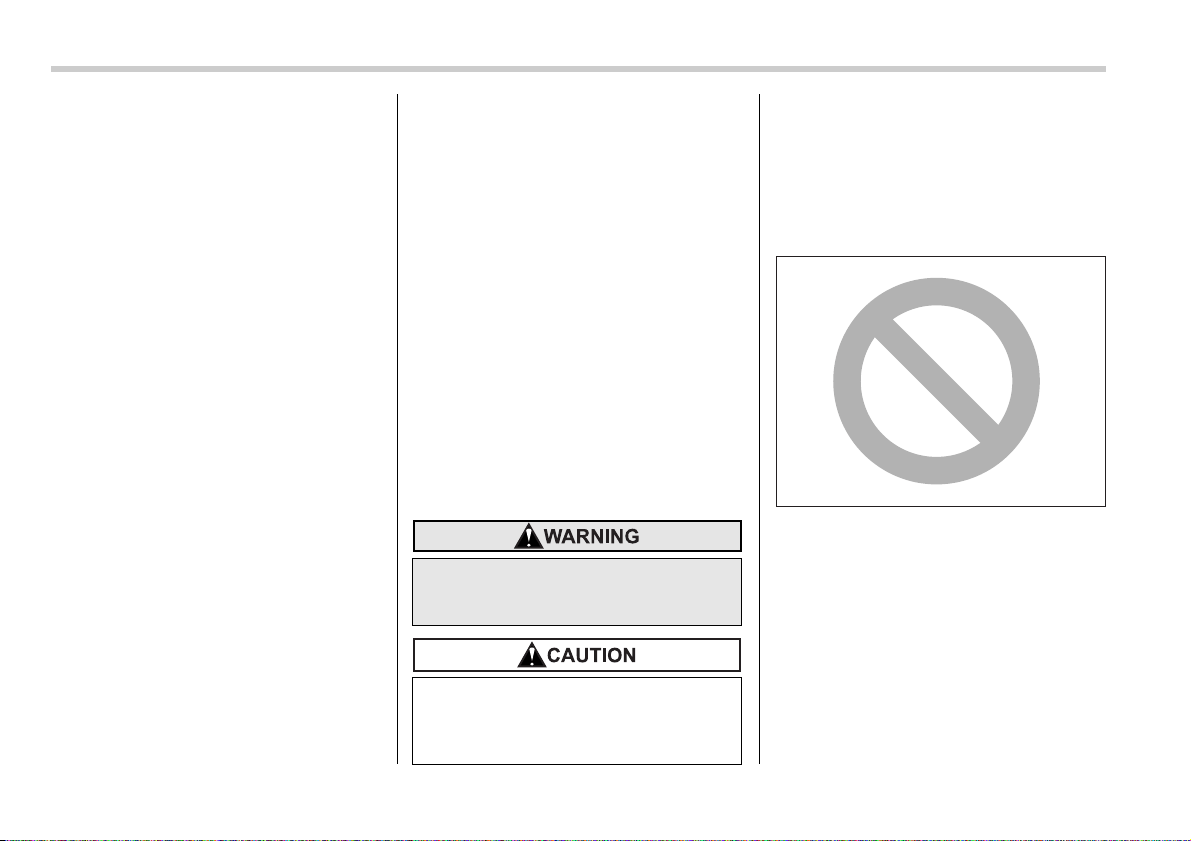
Safety symbol
You will find a circle with a slash through it
in this manual. This symbol means “Do
not”, “Do not do this”, or “Do not let this
happen”, depending upon the context.
A WARNING indicates a situation in
which serious injury or death could
result if the warning is ignored.
A CAUTION indicates a situation in
which injury or damage to your vehi-
cle, or both, could result if the cau-
tion is ignored.
000013
3
– CONTINUED –
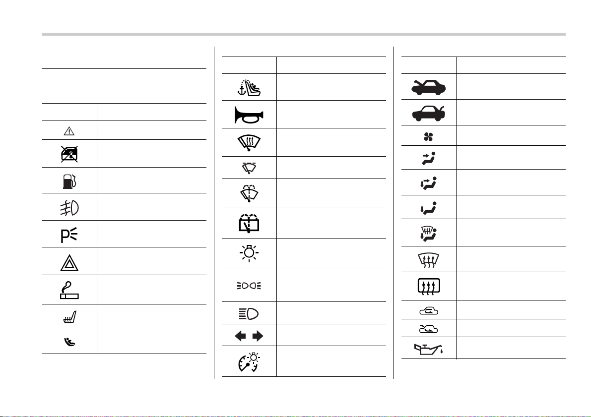
Vehicle symbols
There are some of the symbols you may
see on your vehicle.
Mark Name
CAUTION
Passengers’ windows lock
Fuel
Front fog lights
Parking lights
Hazard warning flasher
Cigarette lighter
Seat heater
Child restraint lower anchor-
ages
Child restraint top tether an-
chorages
Horn
Windshield wiper deicer
Wiper intermittent
Windshield wiper and wash-
er
Rear window wiper and
washer
Lights
Parking lights, tail lights, li-
cense plate lights and instru-
ment panel illumination
Head lights
Turn signal
Illumination brightness
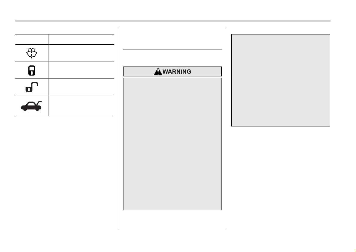
Mark Name
Engine hood
Trunk lid (Sedan)
Fan speed
Instrument panel outlets
Instrument panel outlets and
foot outlets
Foot outlets
Windshield defroster and
foot outlets
Windshield defroster
Rear window defogger/Out-
side mirror defogger
Air recirculation
Outside air
Engine oil
Mark Name
4
Safety precautions when
driving
Seatbelt and SRS airbag
Carefully read the sections “Seat, seatbelt
and SRS airbags” in chapter 1 of this own-
er’s manual for instructions and precau-
tions concerning the seatbelt system and
SRS airbag system.
Washer
Door lock (Transmitter)
Door unlock (Transmitter)
Trunk lid (Sedan) or rear
gate (Station wagon) (Trans-
mitter)
Mark Name
y All persons in the vehicle should
fasten their seatbelts BEFORE the
vehicle starts to move. Otherwise,
the possibility of serious injury
becomes greater in the event of a
sudden stop or accident.
y To obtain maximum protection in
the event of an accident, the driv-
er and all passengers in the vehi-
cle should always wear seatbelts
when the vehicle is moving. The
SRS (Supplemental Restraint Sys-
tem) airbag does not do away with
the need to fasten seatbelts. In
combination with the seatbelts, it
offers the best combined protec-
tion in case of a serious accident.
Not wearing a seatbelt increases
the chance of severe injury or
death in a crash even when the ve-
hicle has the SRS airbag.
y The SRS airbags deploy with con-
siderable speed and force. Occu-
pants who are out of proper posi-
tion when the SRS airbag deploys
could suffer very serious injuries.
Because the SRS airbag needs
enough space for deployment, the
driver should always sit upright
and well back in the seat as far
from the steering wheel as practi-
cal while still maintaining full ve-
hicle control and the front passen-
ger should move the seat as far
back as possible and sit upright
and well back in the seat.
5
– CONTINUED –
Child safety
y Never hold a child on your lap or
in your arms while the vehicle is
moving. The passenger cannot
protect the child from injury in a
collision, because the child will be
caught between the passenger
and objects inside the vehicle.
y While riding in the vehicle, infants
and small children should always
be placed in the REAR seat in an
infant or child restraint system
which is appropriate for the
child’s age, height and weight. If a
child is too big for a child restraint
system, the child should sit in the
REAR seat and be restrained us-
ing the seatbelts. According to ac-
cident statistics, children are saf-
er when properly restrained in the
rear seating positions than in the
front seating positions. Never al-
low a child to stand up or kneel on
the seat.
y Put children aged 12 and under in
the REAR seat properly restrained
at all times in a child restraint de-
vice or in a seatbelt. The SRS air-
bag deploys with considerable
speed and force and can injure or
even kill children, especially if
they are 12 years of age and under
and are not restrained or improp-
erly restrained. Because children
are lighter and weaker than
adults, their risk of being injured
from deployment is greater.
y NEVER INSTALL A REARWARD
FACING CHILD SAFETY SEAT IN
THE FRONT SEAT. DOING SO
RISKS SERIOUS INJURY OR
DEATH TO THE CHILD BY PLAC-
ING THE CHILD’S HEAD TOO
CLOSE TO THE SRS AIRBAG.
y Always use the child safety locks
whenever a child rides in the rear
seat. Serious injury could result if
a child accidentally opened the
door and fell out. Refer to the
“Door locks” section in chapter 2.
y Always lock the passenger’s win-
dows using the lock switch when
children are riding in the vehicle.
Failure to follow this procedure
could result in injury to a child op-
erating the power window. Refer
to the “Power windows” section
in chapter 2.
y Never leave unattended children
in the vehicle. They could acci-
dentally injure themselves or oth-
ers through inadvertent operation
of the vehicle. Also, on hot or sun-
ny days, temperature in a closed
vehicle could quickly become
high enough to cause severe or
possibly fatal injuries to them.
y Help prevent young children from
locking themselves in the trunk.
When leaving the vehicle, either
close all windows and lock all
doors or cancel the inside trunk
lid release. Also make certain that
the trunk is closed. On hot or sun-
ny days, the temperature in a
trunk could quickly become high
enough to cause death or serious
heat-related injuries including
brain damage to anyone locked
inside, particularly for small chil-
dren.
6
Carefully read the sections “Child restraint
systems”,“*SRS airbag (Supplemental
Restraint System airbag)”, and “Seatbelts”
in chapter 1 of this owner’s manual for in-
structions and precautions concerning the
child restraint system, seatbelt system
and SRS airbag system.
Engine exhaust gas (carbon
monoxide)
Drinking and driving
Drunken driving is one of the most fre-
quent causes of accidents. Since alcohol
affects all people differently, you may
have consumed too much alcohol to drive
safely even if the level of alcohol in your
blood is below the legal limit. The safest
thing you can do is never drink and drive.
However if you have no choice but to
drive, stop drinking and sober up com-
pletely before getting behind the wheel.
y Never inhale engine exhaust gas.
Engine exhaust gas contains car-
bon monoxide, a colorless and
odorless gas which is dangerous,
or even lethal, if inhaled.
y Always properly maintain the en-
gine exhaust system to prevent
engine exhaust gas from entering
the vehicle.
y Never run the engine in a closed
space, such as a garage, except
for the brief time needed to drive
the vehicle in or out of it.
y Avoid remaining in a parked vehi-
cle for a lengthy time while the en-
gine is running. If that is unavoid-
able, then use the ventilation fan
to force fresh air into the vehicle.
y Always keep the front ventilator
inlet grille free from snow, leaves
or other obstructions to ensure
that the ventilation system always
works properly.
y If at any time you suspect that ex-
haust fumes are entering the vehi-
cle, have the problem checked
and corrected as soon as possi-
ble. If you must drive under these
conditions, drive only with all win-
dows fully open.
y Keep the trunk lid or rear gate
closed while driving to prevent ex-
haust gas from entering the vehi-
cle.
Drinking and then driving is very
dangerous. Alcohol in the blood-
stream delays your reaction and im-
pairs your perception, judgment and
attentiveness. If you drive after
drinking – even if you drink just a lit-
tle – it will increase the risk of being
involved in a serious or fatal acci-
dent, injuring or killing yourself,
your passengers and others. In ad-
dition, if you are injured in the acci-
dent, alcohol may increase the se-
verity of that injury.
Please don’t drink and drive.
7
– CONTINUED –
Drugs and driving
If you are taking any drugs, check with
your doctor or pharmacist or read the liter-
ature that accompanies the medication to
determine if the drug you are taking can
impair your driving ability. Do not drive af-
ter taking any medications that can make
you drowsy or otherwise affect your ability
to safely operate a motor vehicle. If you
have a medical condition that requires you
to take drugs, please consult with your
doctor.
Never drive if you are under the influence
of any illicit mind-altering drugs. For your
own health and well-being, we urge you
not to take illegal drugs in the first place
and to seek treatment if you are addicted
to those drugs.
Driving when tired or sleepy
Please do not continue to drive but in-
stead find a safe place to rest if you are
tired or sleepy. On long trips, you should
make periodic rest stops to refresh your-
self before continuing on your journey.
When possible, you should share the driv-
ing with others.
Car phone/cell phone and
driving
Modification of your vehicle
Driving with pets
Unrestrained pets can interfere with your
driving and distract your attention from
There are some drugs (over the
counter and prescription) that can
delay your reaction time and impair
your perception, judgment and at-
tentiveness. If you drive after taking
them, it may increase your, your
passengers’ and other persons’ risk
of being involved in a serious or fa-
tal accident.
When you are tired or sleepy, your
reaction will be delayed and your
perception, judgment and attentive-
ness will be impaired. If you drive
when tired or sleepy, your, your pas-
sengers’ and other persons’ chanc-
es of being involved in a serious ac-
cident may increase.
Do not use a car phone/cell phone
while driving; it may distract your at-
tention from driving and can lead to
an accident. If you use a car phone/
cell phone, pull off the road and park
in the a place before using your
phone. In some States/Provinces,
only hands-free phones may legally
be used while driving.
Your vehicle should not be modi-
fied. Modification could affect its
performance, safety or durability,
and may even violate governmental
regulations. In addition, damage or
performance problems resulting
from modification may not be cov-
ered under warranties.
8
driving. In a collision or sudden stop, unre-
strained pets or cages can be thrown
around inside the vehicle and hurt you or
your passengers. Besides, the pets can
be hurt under these situations. It is also for
their own safety that pets should be prop-
erly restrained in your vehicle. Restrain a
pet with a special traveling harness which
can be secured to the rear seat with a
seatbelt or use a pet carrier which can be
secured to the rear seat by routing a seat-
belt through the carrier’s handle. Never re-
strain pets or pet carriers in the front pas-
senger’s seat. For further information,
consult your veterinarian, local animal
protection society or pet shop.
Tire pressures
Check and, if necessary, adjust the pres-
sure of each tire (including the spare) at
least once a month and before any long
journey.
Check the tire pressure when the tires are
cold.
Use a pressure gauge to adjust the tire
pressures to the values shown on the tire
placard.
Refer to the “Tires and wheels” section in
chapter 11 for detailed information.
California proposition 65
warning
Driving at high speeds with exces-
sively low tire pressures can cause
the tires to deform severely and to
rapidly become hot. A sharp in-
crease in temperature could cause
tread separation, and destruction of
the tires. The resulting loss of vehi-
cle control could lead to an acci-
dent.
Engine exhaust, some of its constit-
uents, and certain vehicle compo-
nents contain or emit chemicals
known to the State of California to
cause cancer and birth defects or
other reproductive harm. In addi-
tion, certain fluids in vehicles and
certain components of product wear
contain or emit chemicals known to
the State of California to cause can-
cer and birth defects or other repro-
ductive harm.

1
2
3
4
5
6
7
8
9
10
11
12
13
14
Table of contents
Seat, seatbelt and SRS airbags
Keys and doors
Instruments and controls
Climate control
Audio
Interior equipment
Starting and operating
Driving tips
In case of emergency
Appearance care
Maintenance and service
Specifications
Consumer information and Reporting safety defects
Index
10
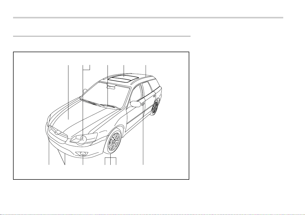
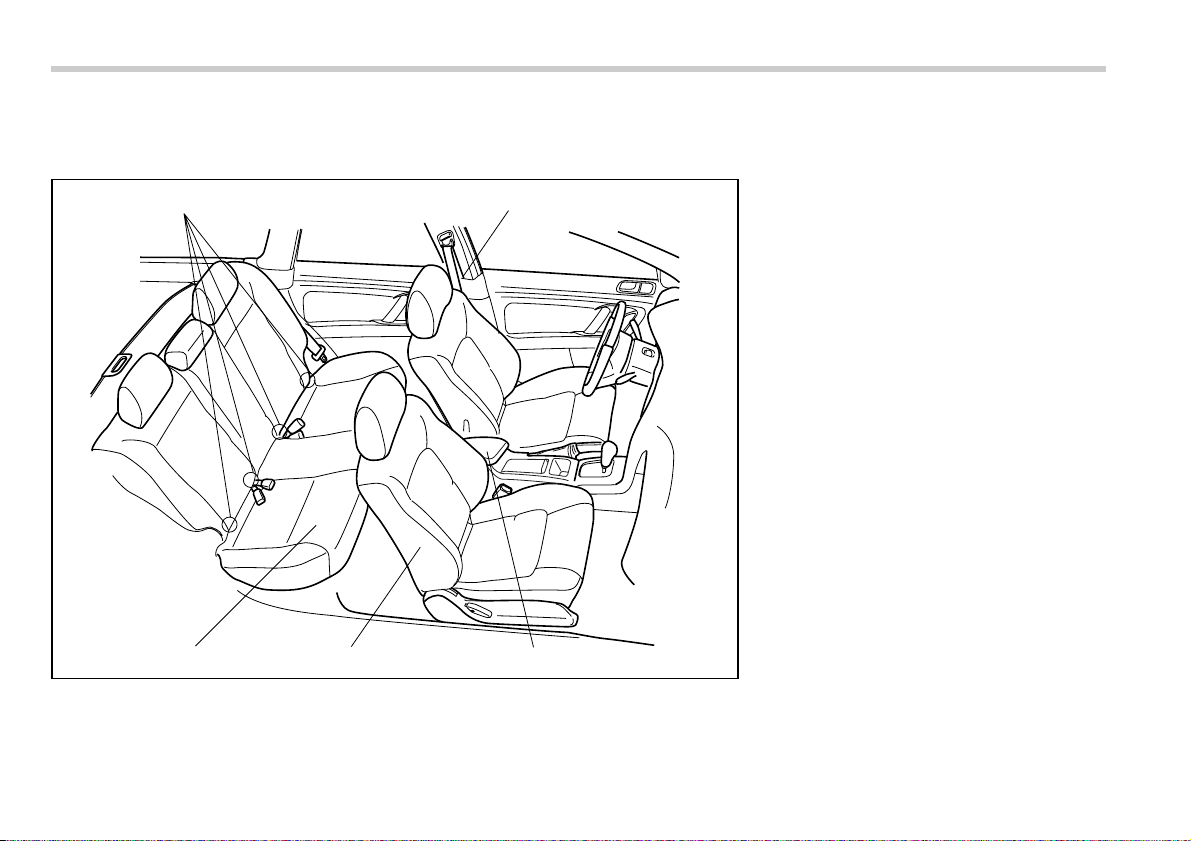
Illustrated index
Exterior
123 5 64
13 1112 8910 7
000139
1) Engine hood lock release (page 11-4)
2) Headlight switch (page 3-31)
3) Bulb replacement (page 11-49)
4) Wiper switch (page 3-35)
5) Moonroof (page 2-25)
6) Roof rail (page 8-14)
7) Door locks (page 2-4)
8) Tire pressure (page 11-35)
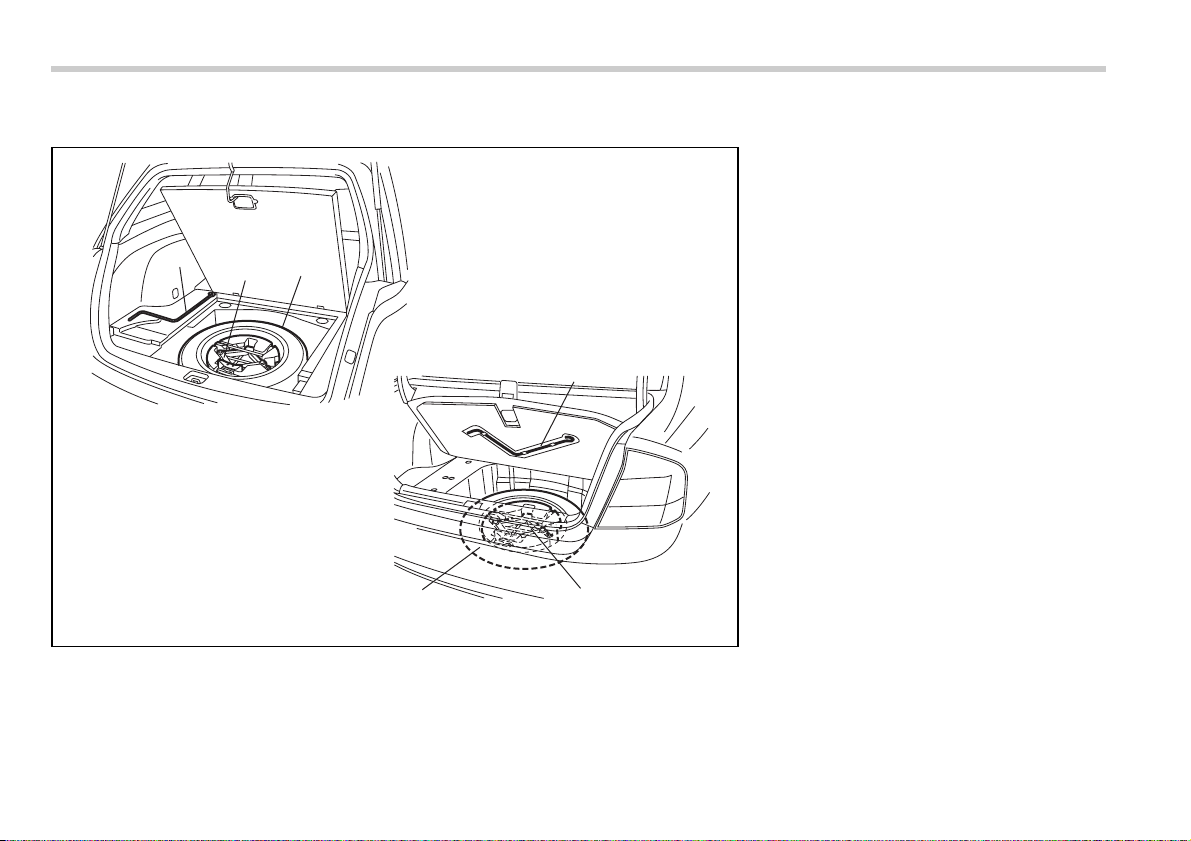
9) Flat tires (page 9-4)
10) Tire chains (page 8-11)
11) Fog light switch (page 3-34)
12) Tie-down hooks (page 9-13)
13) Towing hook (page 9-13)
11
– CONTINUED –
685
4
123
75984
123
000140
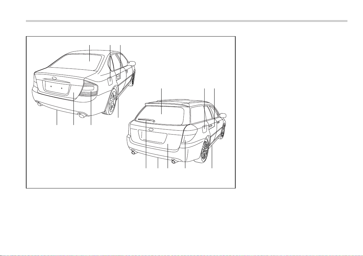
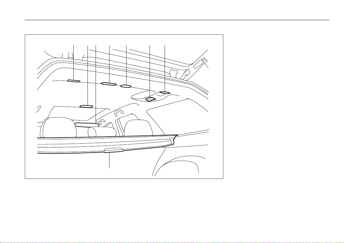
1) Rear window defogger button (page
3-38)
2) Fuel filler lid and cap (page 7-4)
3) Child safety locks (page 2-18)
4) Tie-down hooks (page 9-13)
5) Towing hook (page 9-13)
6) Trunk lid (page 2-21)
7) Rear gate (page 2-24)
8) Bulb replacement (page 11-51)
9) Rear wiper blade assembly and rub-
ber replacement (page 3-37)
14
1
15 14 13 12 11 10 9 8
23 4567
000047
1) Parking brake lever (page 7-35)
2) Gear shift lever (MT) (page 7-9)
3) Select lever (AT) (page 7-11)
4) Information display (page 3-26)
5) Clock (page 3-25)
6) Dashboard storage compartment
(page 6-4)
7) Navigation system (if equipped) (See
navigation system instruction manu-
al.)
8) Glove box (page 6-4)
9) Hazard warning flasher switch (page
3-5)
10) Audio (page 5-1)
11) Climate control (page 4-1)
12) Ashtray (page 6-9)
13) Accessory power outlet (page 6-8)
14) Tilt steering(page 3-43)
15) Cup holder (page 6-7/page 6-7)
15
– CONTINUED –
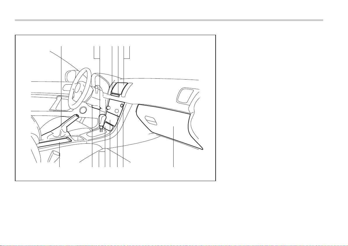
Instrument panel
000176
123456 7 8
9
1011121314
1) Door locks (page 2-4)
2) Illumination brightness control (page
3-33)
3) Remote control mirror (page 3-41)
4) Windshield wiper deicer (page 3-38)
5) Vehicle Dynamics Control OFF
switch (page 7-32)
6) Light control lever (page 3-31)
7) Combination meter (page 3-5/page
3-10)
8) Wiper control lever (page 3-34)
9) Cruise control (page 7-36)
10) Horn (page 3-43)
11) SRS airbag (page 1-38)
12) Fuse box (page 11-45)
13) Hood lock release knob (page 11-4)
14) Power windows (page 2-19)
16
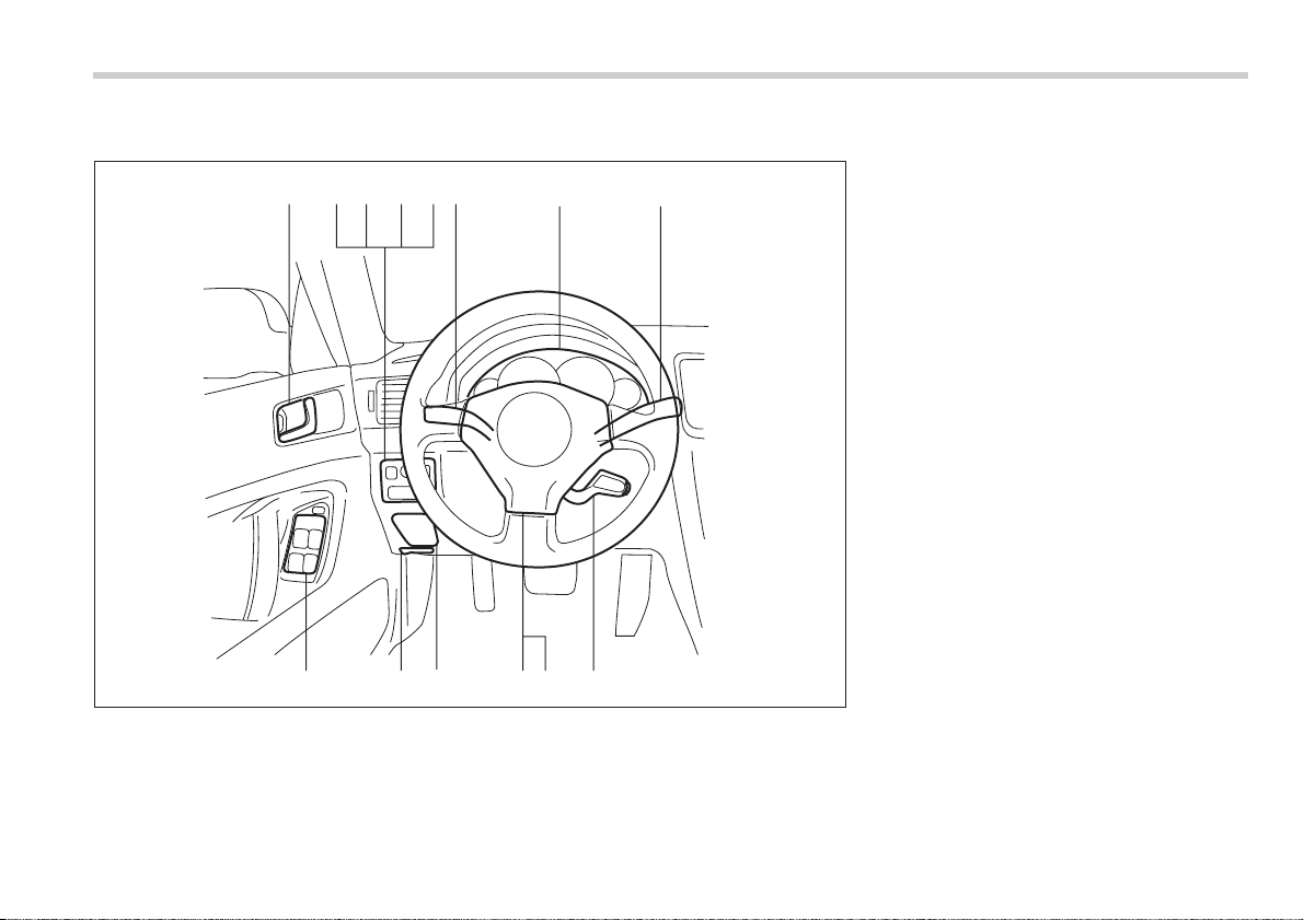
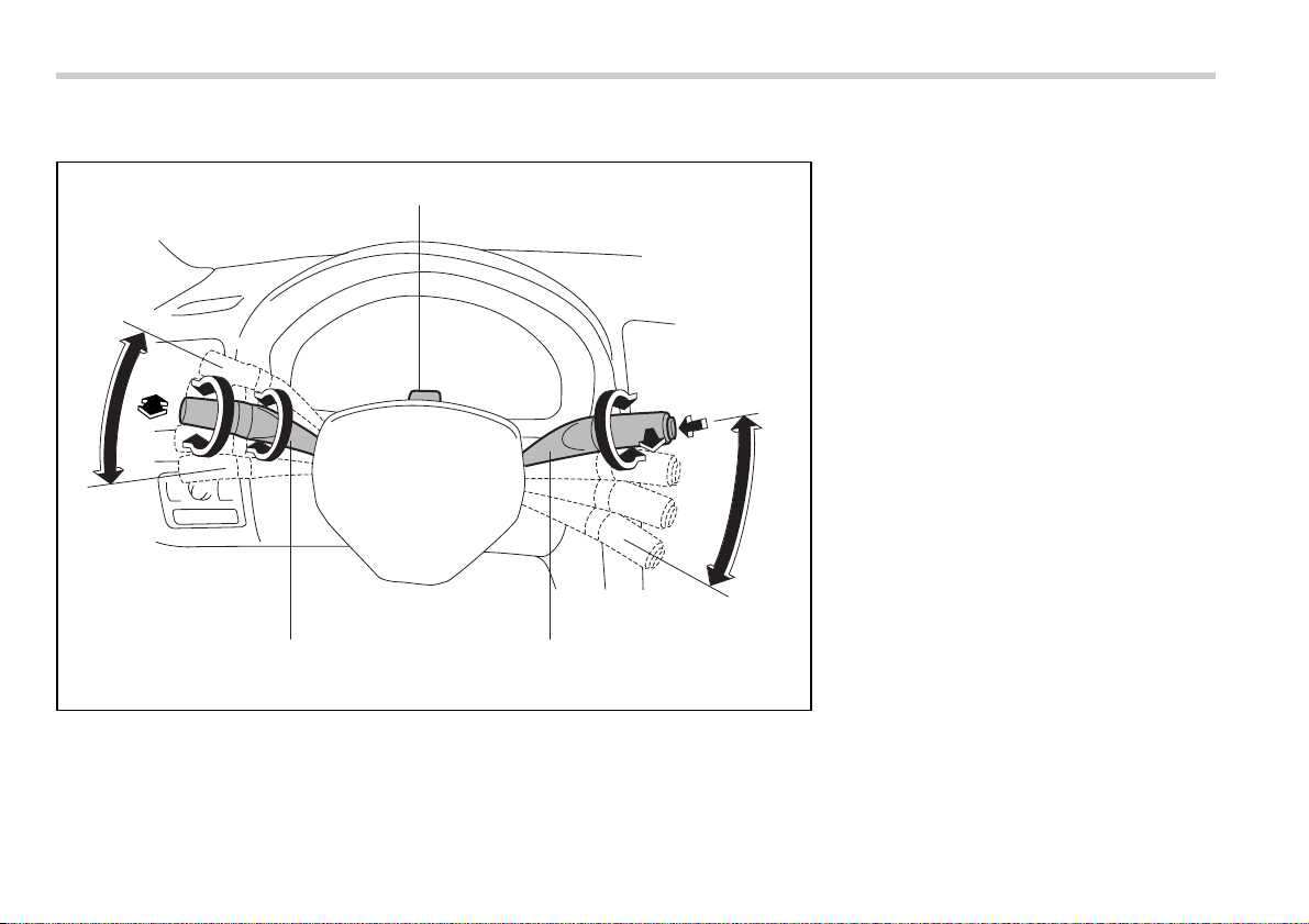
Light control and wiper control levers/switches
1
67
11
10
9
8
2
3
4
5
000074
1) Parking light switch (page 3-33)
2) Windshield wiper (page 3-34)
3) Mist (page 3-36)
4) Windshield washer (page 3-35)
5) Rear window wiper and washer
switch (page 3-37)
6) Wiper control lever (page 3-35)
7) Light control lever (page 3-31)
8) Fog light switch (page 3-34)
9) Headlight ON/OFF (page 3-31)
10) Headlight flasher High/Low beam
change (page 3-31)
11) Turn signal (page 3-32)
17
– CONTINUED –
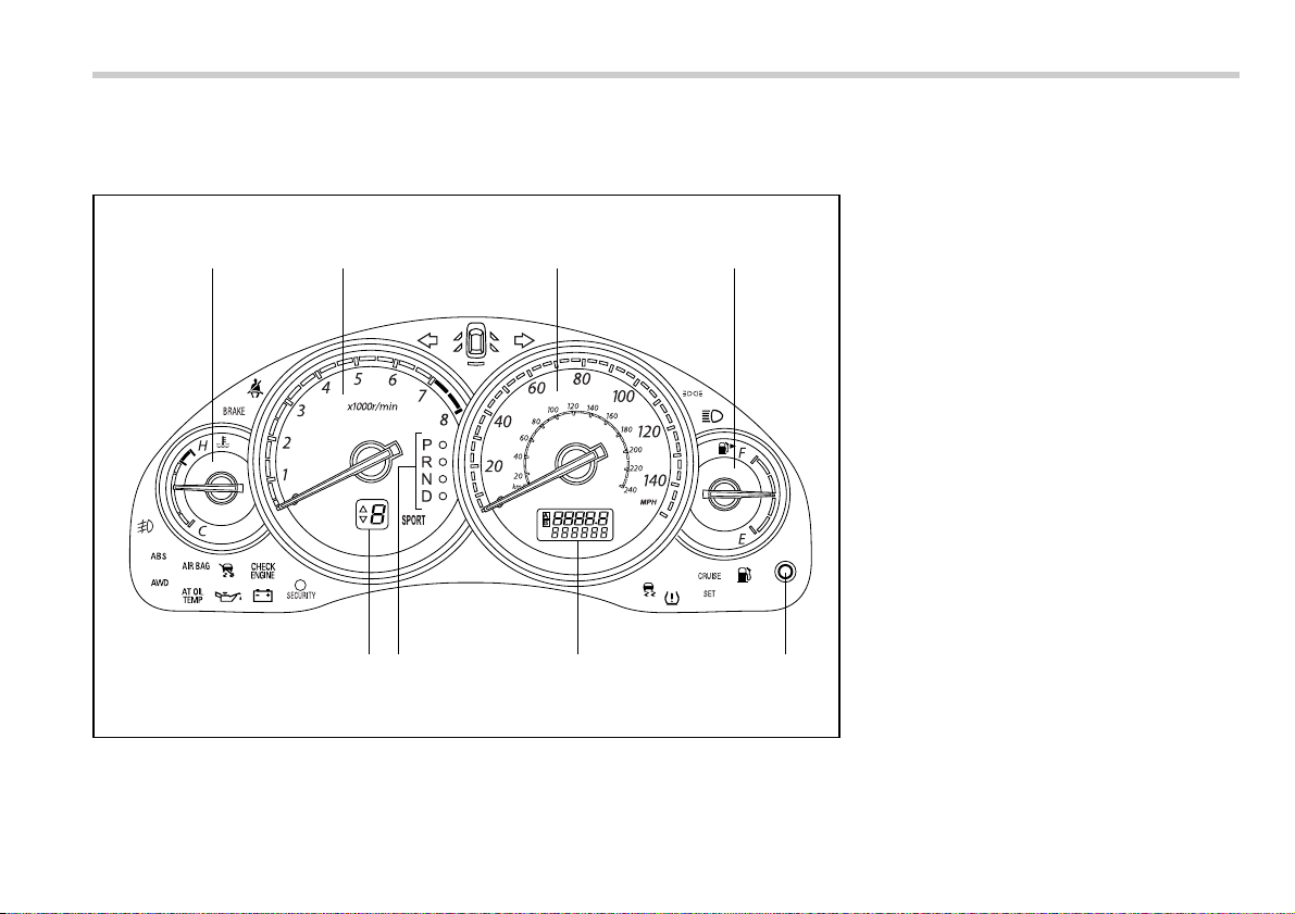
Combination meter
T U.S.-spec. vehicles
000141
12 3
56
4
87
1) Temperature gauge (page 3-9/page
3-13)
2) Tachometer (page 3-8/page 3-12)
3) Speedometer (page 3-6/page 3-10)
4) Fuel gauge (page 3-8/page 3-12)
5) Trip meter A/B selection and trip
meter reset knob (page 3-7/page 3-
11)
6) Trip meter and odometer (page 3-7/
page 3-11)
7) Selector lever position indicator
(page 3-24)
8) Gear position indicator (page 3-24)
18
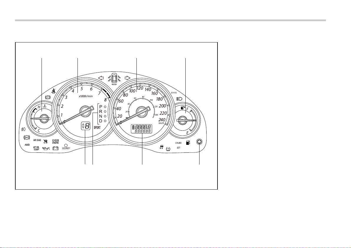
T Canada-spec. vehicles
12 3
56
4
87
000142
1) Temperature gauge (page 3-9/page
3-13)
2) Tachometer (page 3-8/page 3-12)
3) Speedometer (page 3-6/page 3-10)
4) Fuel gauge (page 3-8/page 3-12)
5) Trip meter A/B selection and trip
meter reset knob (page 3-7/page 3-
11)
6) Trip meter and odometer (page 3-7/
page 3-11)
7) Selector lever position indicator
(page 3-24)
8) Gear position indicator (page 3-24)
19
– CONTINUED –
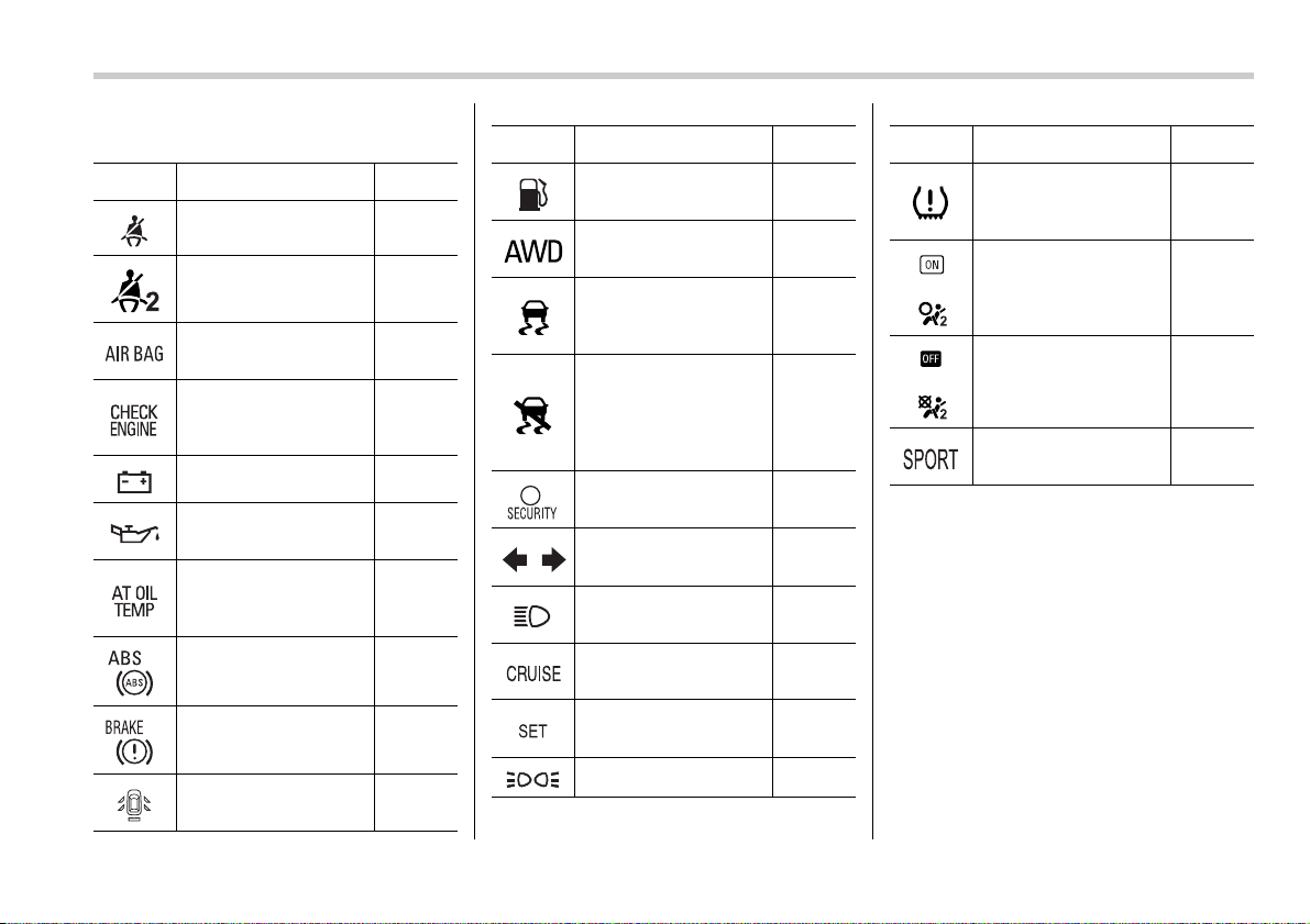
Warning and indicator light
Mark Name Page
Seatbelt warning light 3-14
Front passenger’s
seatbelt warning light
3-14
SRS airbag system
warning light
3-16
CHECK ENGINE
warning light/Malfunc-
tion indicator lamp
3-17
Charge warning light 3-18
Oil pressure warning
light
3-18
AT OIL temperature
warning light (if
equipped)
3-18
or
ABS warning light 3-20
or
Brake system warning
light
3-20
Door open warning
light
3-22
Low fuel warning light 3-21
All-Wheel Drive warn-
ing light (if equipped)
3-22
Vehicle Dynamics
Control operation indi-
cator light (if equipped)
3-22
Vehicle Dynamics
Control warning light/
Vehicle Dynamics
Control OFF indicator
light (if equipped)
3-22
Security indicator light 3-23
Turn signal indicator
lights
3-24
High beam indicator
light
3-25
Cruise control indica-
tor light (if equipped)
3-25
Cruise control set indi-
cator light (if equipped)
3-25
Light indicator light 3-25
Mark Name Page
Low tire pressure
warning light (if
equipped)
3-18
or
Passenger airbag ON
indicator light
3-17
or
Passenger airbag OFF
indicator light
3-17
SPORT mode indica-
tor light (if equipped)
3-24
Mark Name Page

21
Function settings
A SUBARU dealer can change the settings of the functions shown in the following table to meet your personal requirements. Contact
the nearest SUBARU dealer for details. If your vehicle is equipped with navigation system, the settings for some of these functions can
be changed using the monitor. For details, please refer to the Owner’s Manual supplement for the monitor.
Item Function Possible settings Default setting Page
Alarm system Alarm system Operation / Non-operation Operation 2-14
Monitoring start delay time (after closure of
doors)
0 second / 30 seconds 30 seconds 2-16
Impact sensor operation (only vehicles
with shock sensors (dealer option))
Operation / Non-operation Non-operation 2-18
Passive arming Operation / Non-operation Non-operation 2-17
Remote keyless entry system Hazard warning flasher Operation / Non-operation Operation 2-7
Audible signal Operation / Non-operation Operation 2-10
Key lock-in prevention Key lock-in prevention Operation / Non-operation Operation 2-6
Rear window defogger Rear window defogger Operation for 15 min. / Continuous opera-
tion
Operation for
15 min.
3-38
Windshield wiper deicer (if
equipped)
Windshield wiper deicer Operation for 15 min. / Continuous opera-
tion
Operation for
15 min.
3-38
Dome light Operation in interlock with remote keyless
entry system
OFF / Short / Normal / Long Normal 6-2
Battery drainage prevention func-
tion
Battery drainage prevention function Operation / Non-operation Operation 2-6


1
Seat, seatbelt and SRS airbags
Front seats .......................................................... 1-2
Manual seat ............................................................. 1-3
Power seat (if equipped) ........................................ 1-4
Reclining the seatback ........................................... 1-4
Head restraint adjustment ..................................... 1-5
Active head restraint .............................................. 1-6
Lumbar support (if equipped) ................................ 1-6
Seat heater (if equipped) ................................... 1-7
Rear seats ........................................................... 1-7
Folding down the rear seat – Station wagon ....... 1-8
Head restraint adjustment ..................................... 1-8
Armrest (if equipped) ......................................... 1-10
Loading long objects (Sedan) ............................... 1-10
Seatbelts ............................................................. 1-11
Seatbelt safety tips ................................................. 1-11
Emergency Locking Retractor (ELR) .................... 1-12
Automatic/Emergency Locking Retractor
(A/ELR) .................................................................. 1-13
Seatbelt warning light and chime .......................... 1-13
Fastening the seatbelt ............................................ 1-15
Seatbelt maintenance ............................................. 1-21
Front seatbelt pretensioners ............................. 1-21
System monitors .................................................... 1-22
System servicing .................................................... 1-23
Precautions against vehicle modification ............ 1-24
Child restraint systems ..................................... 1-25
Where to place a child restraint system ............... 1-26
Choosing a child restraint system ........................ 1-27
Installing child restraint systems with A/ELR
seatbelt .................................................................. 1-28
Installing a booster seat ......................................... 1-31
Installation of child restraint systems by use of
lower and tether anchorages (LATCH) ............... 1-32
Top tether anchorages ........................................... 1-36
*SRS airbag (Supplemental Restraint System
airbag) .............................................................. 1-38
Vehicle with SRS airbags and lap/shoulder
restraints for driver, front passenger, and
window-side rear passengers ............................. 1-38
Subaru advanced frontal airbag system .............. 1-43
SRS side airbag and SRS curtain airbag .............. 1-53
SRS airbag system monitors ................................. 1-59
SRS airbag system servicing ................................ 1-60
Precautions against vehicle modification ............ 1-61
1-2 Seat, seatbelt and SRS airbags
Seat, seatbelt and SRS airbags
Front seats
y Never adjust the seat while driv-
ing to avoid the possibility of loss
of vehicle control and of personal
injury.
y Before adjusting the seat, make
sure the hands and feet of rear
seat passengers are clear of the
adjusting mechanism.
y Seatbelts provide maximum re-
straint when the occupant sits
well back and upright in the seat.
To reduce the risk of sliding under
the seatbelt in a collision, the
front seatbacks should be always
used in the upright position while
the vehicle is running. If the front
seatbacks are not used in the up-
right position in a collision, the
risk of sliding under the lap belt
and of the lap belt sliding up over
the abdomen will increase, and
both can result in serious internal
injury or death.
y The SRS airbags deploy with con-
siderable speed and force. Occu-
pants who are out of proper posi-
tion when the SRS airbag deploys
could suffer very serious injuries.
Because the SRS airbag needs
enough space for deployment, the
driver should always sit upright
and well back in the seat as far
from the steering wheel as practi-
cal while still maintaining full ve-
hicle control and the front passen-
ger should move the seat as far
back as possible and sit upright
and well back in the seat.
100082
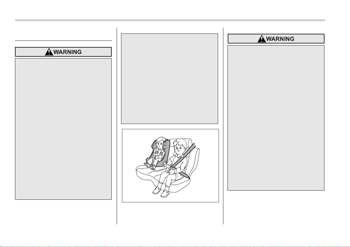
Put children aged 12 and under in
the rear seat properly restrained at
all times. The SRS airbag deploys
with considerable speed and force
and can injure or even kill children,
especially if they are 12 years of age
and under and are not restrained or
improperly restrained. Because chil-
dren are lighter and weaker than
adults, their risk of being injured
from deployment is greater. Conse-
quently, we strongly recommend
that ALL children (including those in
child seats and those that have out-
grown child restraint devices) sit in
the REAR seat properly restrained
at all times in a child restraint device
or in a seatbelt, whichever is appro-
priate for the child’s age, height and
weight.
Secure ALL types of child restraint
devices (including forward facing
child seat) in the REAR seats at all
times.
Seat, seatbelt and SRS airbags 1-3
– CONTINUED –
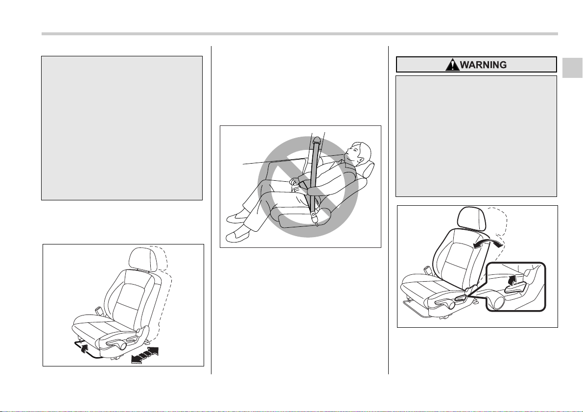
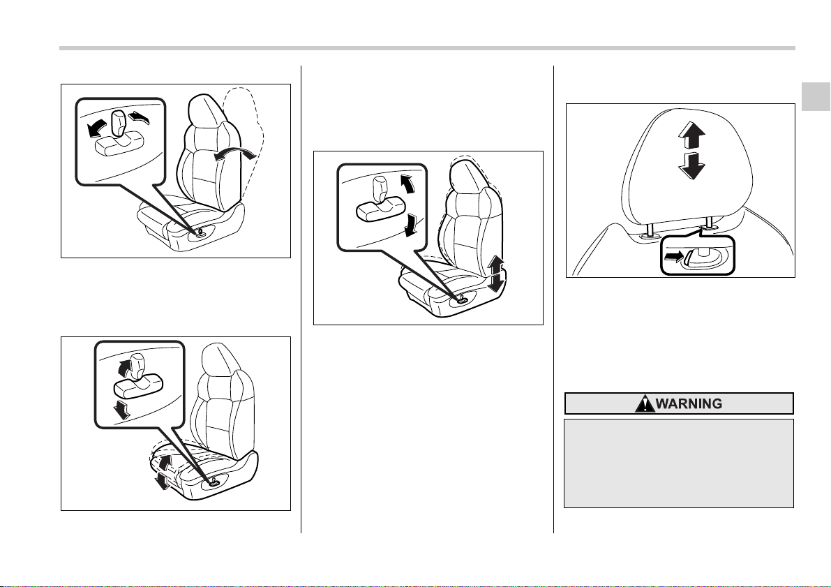
Manual seat
T Fore and aft adjustment
Pull the lever upward and slide the seat to
the desired position. Then release the le-
ver and move the seat back and forth to
make sure that it is securely locked into
place.
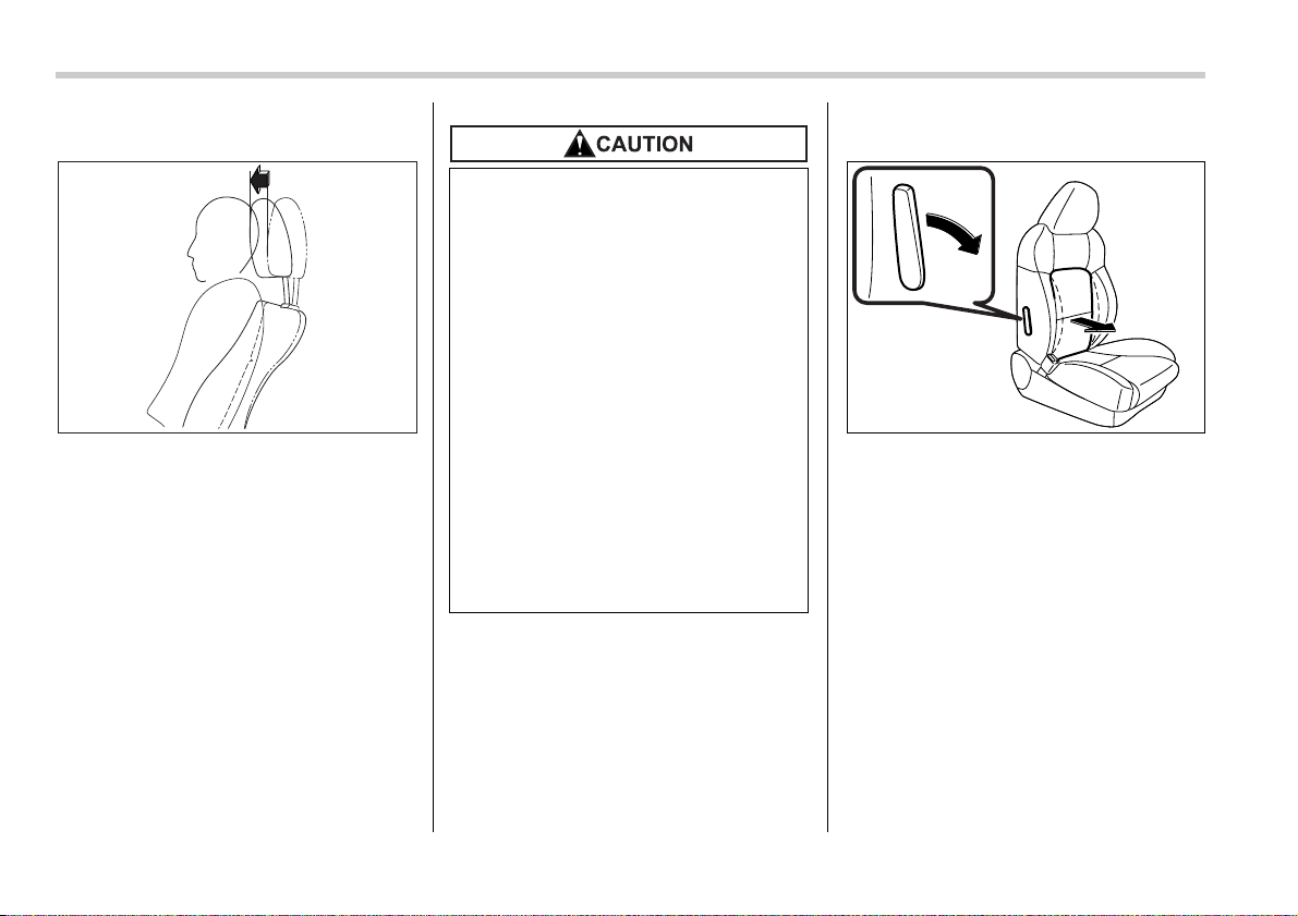
T Reclining the seatback
Pull the reclining lever up and adjust the
seatback to the desired position. Then re-
lease the lever and make sure the seat is
securely locked into place.
NEVER INSTALL A REARWARD
FACING CHILD SEAT IN THE FRONT
SEAT. DOING SO RISKS SERIOUS
INJURY OR DEATH TO THE CHILD
BY PLACING THE CHILD’S HEAD
TOO CLOSE TO THE SRS AIRBAG.
According to accident statistics,
children are safer when properly re-
strained in the rear seating posi-
tions than in the front seating posi-
tions. For instructions and precau-
tions concerning child restraint sys-
tems, see the “Child restraint sys-
tems” section in this chapter.
100244
100085
To prevent the passenger from slid-
ing under the seatbelt in the event of
a collision, always put the seatback
in the upright position while the ve-
hicle is in motion. Also, do not place
objects such as cushions between
the passenger and the seatback. If
you do so, the risk of sliding under
the lap belt and of the lap belt sliding
up over the abdomen will increase,
and both can result in serious inter-
nal injury or death.
100245
1-4 Seat, seatbelt and SRS airbags
The seatback placed in a reclined position
can spring back upward with force when
released. When operating the reclining le-
ver to return the seatback, hold it lightly so
that it may be raised back gradually.
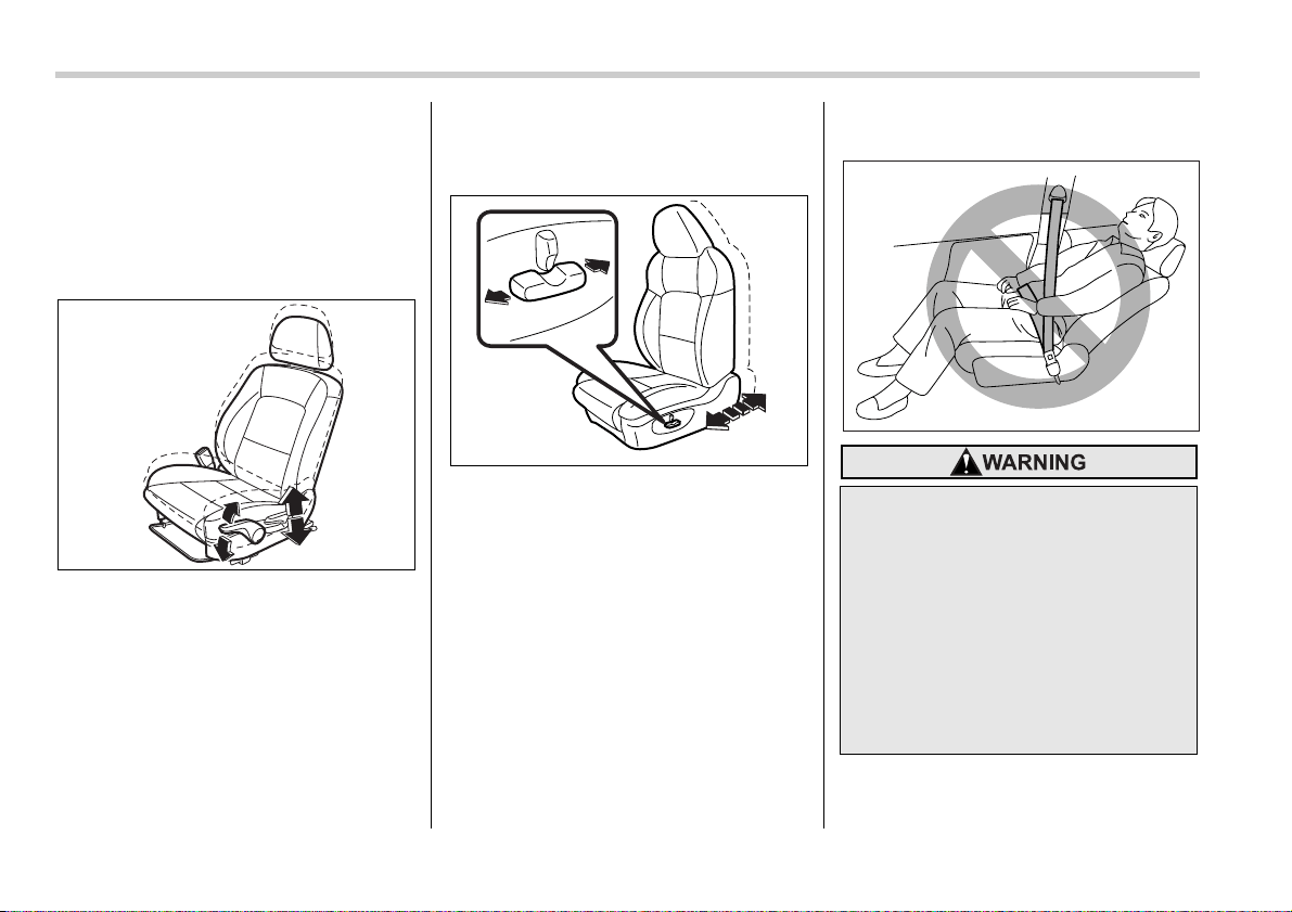
T Seat cushion height adjustment
(driver’s seat)
The height of the seat can be adjusted by
moving the seat cushion adjustment lever
up and down.
When the lever is pushed down, the seat
is lowered.
When the lever is pulled up, the seat rises.
Power seat (if equipped)
T Fore and aft adjustment
To adjust the seat forward or backward,
move the control switch forward or back-
ward.
NOTE
During backward-forward adjustment
of the seat, you cannot adjust the seat
cushion angle or seat height.
Reclining the seatback
100246
100247
To prevent the passenger from slid-
ing under the seatbelt in the event of
a collision, always put the seatback
in the upright position while the ve-
hicle is in motion. Also, do not place
objects such as cushions between
the passenger and the seatback. If
you do so, the risk of sliding under
the lap belt and of the lap belt sliding
up over the abdomen will increase,
and both can result in serious inter-
nal injury or death.
100085
Seat, seatbelt and SRS airbags 1-5
– CONTINUED –
To adjust the angle of the seatback, move
the control switch.
T Seat cushion angle adjustment
(Driver’s seat only)
To adjust the seat cushion angle, pull up
or push down the front end of the control
switch.
T Seat height adjustment (Driver’s
seat only)
To adjust the seat height, pull up or push
down the rear end of the control switch.
Head restraint adjustment
To raise the head restraint, pull it up. To
lower it, push the head restraint down
while pressing the release button on the
top of the seatback.
The head restraint should be adjusted so
that the center of the head restraint is clos-
est to the top of the occupant’s ears.
100250
100248
100249
Never drive the vehicle with the
head restraints removed because
they are designed to reduce the risk
of serious neck injury in the event
that the vehicle is struck from the
rear.
200282
1-6 Seat, seatbelt and SRS airbags
Active head restraint
The front seats of your vehicle are
equipped with active head restraints. They
automatically tilt forward slightly in the
event the vehicle is struck from the rear,
decreasing the amount of rearward head
movement and thus reducing the risk of
whiplash. For maximum effectiveness the
head restraint should be adjusted so that
the center of the head restraint is closest
to the top of the occupant’s ears.
Lumbar support (if equipped)
Pull the lever forward or backward.
Pulling the lever forward will increase the
amount of support for your lower back.
100089
y Each active head restraint is ef-
fective only when its height is
properly adjusted and the driver/
passenger sits in the correct posi-
tion on the seat.
y If your vehicle is involved in a
rear-end collision, have an autho-
rized SUBARU dealer inspect the
active head restraints.
y The active head restraints may
not operate in the event the vehi-
cle experiences only a slight im-
pact in the rear.
y The active head restraints may be
damaged if they are pushed hard
from behind or subjected to
shock. As a result, they may not
function if the vehicle suffers a
rear impact.
100252
Seat, seatbelt and SRS airbags 1-7
– CONTINUED –
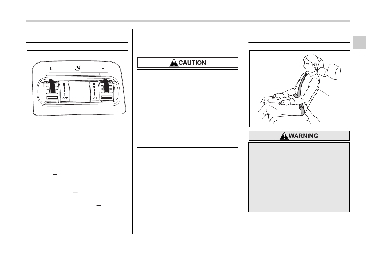
Seat heater (if equipped)
The seat heater operates when the igni-
tion switch is either in the “ACC” or “ON”
position.
Each seat heater has four levels of adjust-
ment. To use the heater in the right-hand
seat, turn the “R” adjustment knob forward
until the “ ” mark reaches the desired
position. To activate the heater in the left-
hand seat, turn the “L” adjustment knob
forward until the “ ” mark reaches the
desired position. Each heater warms the
seat most quickly with the “ ” mark on
the adjustment knob in the furthest-for-
ward position. An indicator light on the ad-
justment knob for each seat heater comes
on when that seat heater is activated.
When the vehicle’s interior is warmed
enough or before you leave the vehicle,
be sure to turn the switch off.
NOTE
Use of the seat heater for a long period
of time while the engine is not running
can cause battery discharge.
Rear seats
100661
y There is a possibility that people
with delicate skin may suffer
slight burns even at low tempera-
tures if they use the seat heater
for a long period of time. When us-
ing the heater, always be sure to
warn the persons concerned.
y Do not put anything on the seat
which insulates against heat,
such as a blanket, cushion, or
similar items. This may cause the
seat heater to overheat.
Seatbelts provide maximum re-
straint when the occupant sits well
back and upright in the seat. Do not
put cushions or any other materials
between occupants and seatbacks
or seat cushions. If you do so, the
risk of sliding under the lap belt and
of the lap belt sliding up over the ab-
domen will increase, and both can
result in serious internal injury or
death.
100253
1-8 Seat, seatbelt and SRS airbags
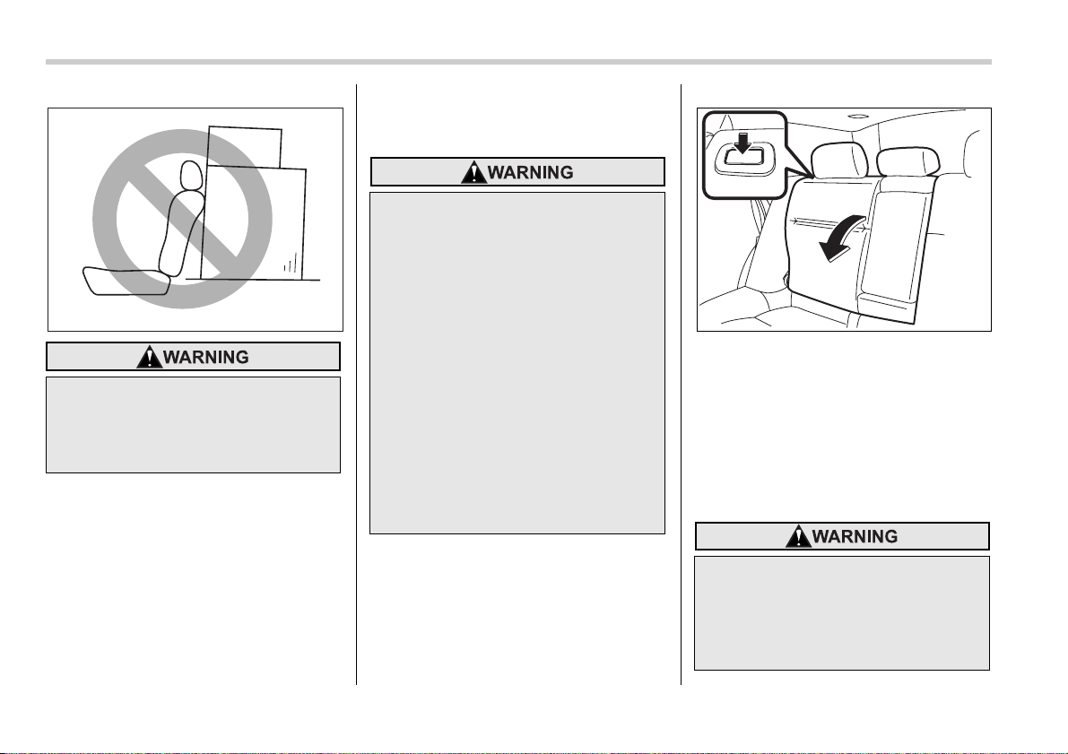
Folding down the rear seat –
Station wagon
Unlock the seatback by pushing the re-
lease button and then fold the seatback
down.
To return the seatback to its original posi-
tion, raise the seatback until it locks into
place and make sure that it is securely
locked.
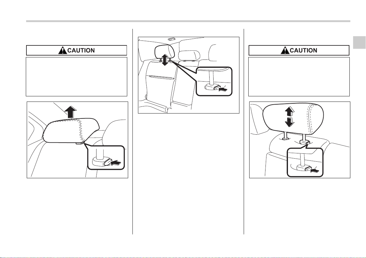
Head restraint adjustment
Never stack luggage or other cargo
higher than the top of the seatback
because it could tumble forward and
injure passengers in the event of a
sudden stop or accident.
100094
y After returning the rear seat to its
original position, be certain to
place all of the seatbelts and the
tab attached to the seat cushion
above the seat cushion. And make
certain that the shoulder belts are
fully visible.
y Never allow passengers to ride on
the folded rear seatback or in the
cargo area. Doing so may result in
serious injury or death.
y Secure skis and other lengthy
items properly to prevent them
from being thrown around inside
the vehicle and causing serious
injury during a sudden stop, a
sudden steering maneuver or a
rapid acceleration.
Never drive the vehicle with the
head restraints removed because
they are designed to reduce the risk
of serious neck injury in the event
that the vehicle is struck from the
rear.
200288
Seat, seatbelt and SRS airbags 1-9
– CONTINUED –
T Rear windows side seating position
Sedan
Station wagon
To raise the head restraint, pull it up.
To lower it, push the head restraint down
while pressing the release button on the
top of the seatback.
The head restraint should be adjusted so
that the center of the head restraint is clos-
est to the top of the occupant’s ears.
When the seats are not occupied, lower
the head restraints to improve rearward
visibility.
T Rear center seating position
To raise the head restraint, pull it up.
To lower it, push the head restraint down
while pressing the release button on the
top of the seatback.
When the rear center seating position is
occupied, place the head restraint in its
highest position. When the rear center
seating position is not occupied, lower the
The head restraint is not intended to
be used at the lowest position. Be-
fore sitting on the seat, raise the
head restraint to an appropriate po-
sition depending on your sitting
height.
200290
200284
The head restraint is not intended to
be used at the lowest position. Be-
fore sitting on the seat, raise the
head restraint to an appropriate po-
sition depending on your sitting
height.
200285
1-10 Seat, seatbelt and SRS airbags
head restraint to improve rearward visibil-
ity.
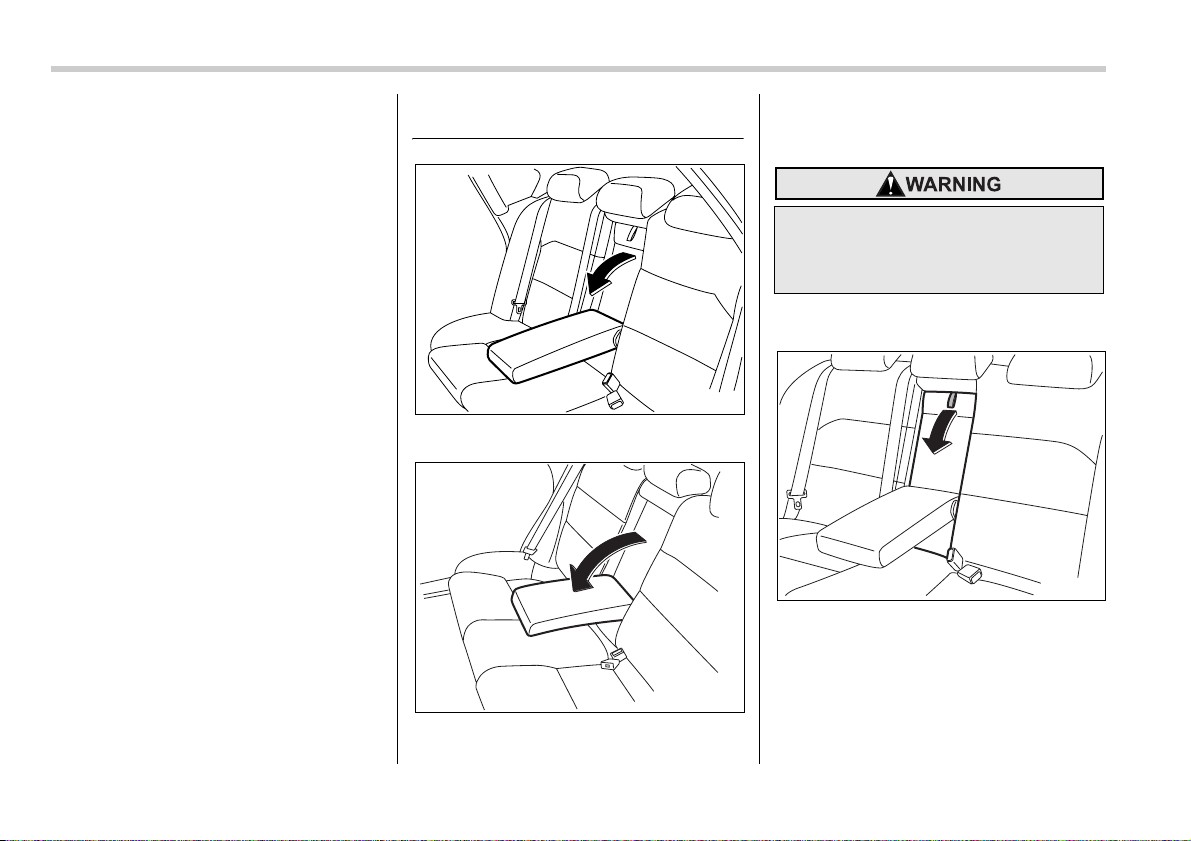
Armrest (if equipped)
Sedan
Station wagon
To lower the armrest, pull on the top edge
of the armrest.
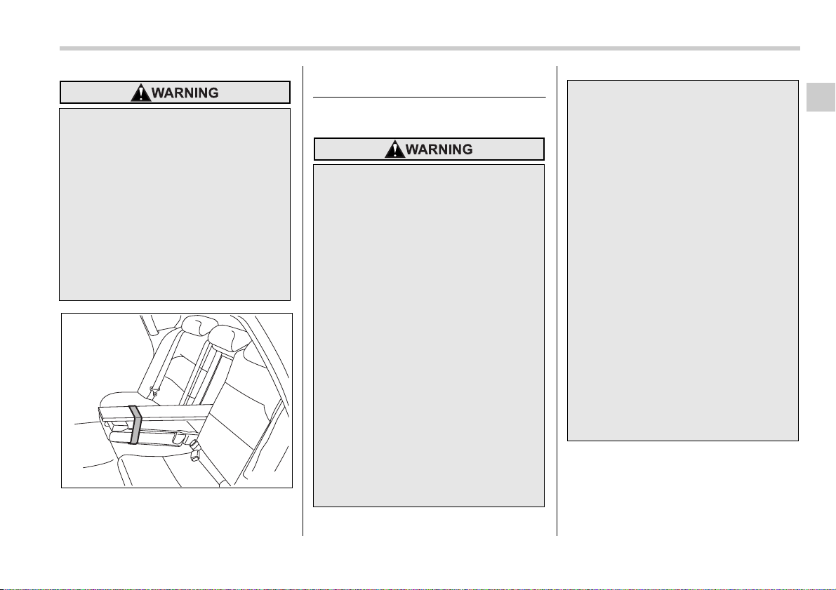
Loading long objects (Sedan)
Folding down the armrest and opening the
seatback panel affords a loading space for
long objects.
To open the seatback panel, pull the panel
down while pressing the release tab
down.
200291
200286
To avoid the possibility of serious
injury, passengers must never be al-
lowed to sit on the center armrest
while the vehicle is in motion.
200292
Seat, seatbelt and SRS airbags 1-11
– CONTINUED –
Seatbelts
Seatbelt safety tips
y Secure long objects properly to
prevent them from shooting for-
ward and causing serious injury
during a sudden stop or sharp
cornering. Tie long objects down
with a rope or something equiva-
lent.
y Avoid loading objects longer than
6.6 ft (2 m) and heavier than 55 lbs
(25 kg). Such objects can interfere
with the driver’s proper operation
of the vehicle, possibly causing
an accident and serious injury.
200293
y All persons in the vehicle should
fasten their seatbelts BEFORE the
vehicle starts to move. Otherwise,
the possibility of serious injury
becomes greater in the event of a
sudden stop or accident.
y All belts should fit snugly in order
to provide full restraint. Loose fit-
ting belts are not as effective in
preventing or reducing injury.
y Each seatbelt is designed to sup-
port only one person. Never use a
single belt for two or more per-
sons – even children. Otherwise,
in an accident, serious injury or
death could result.
y Replace all seatbelt assemblies
including retractors and attaching
hardware worn by occupants of a
vehicle that has been in a serious
accident. The entire assembly
should be replaced even if dam-
age is not obvious.
y Put children aged 12 and under in
the rear seat properly restrained
at all times. The SRS airbag de-
ploys with considerable speed
and force and can injure or even
kill children, especially if they are
12 years of age and under and are
not restrained or improperly re-
strained. Because children are
lighter and weaker than adults,
their risk of being injured from de-
ployment is greater. Consequent-
ly, we strongly recommend that
ALL children (including those in
child seats and those that have
outgrown child restraint devices)
sit in the REAR seat properly re-
strained at all times in a child re-
straint device or in a seatbelt,
whichever is appropriate for the
child’s height and weight.
Secure ALL types of child re-
straint devices (including forward
facing child seats) in the REAR
seats at all times.
1-12 Seat, seatbelt and SRS airbags
Your vehicle is equipped with a crash
sensing and diagnostic module, which will
record the use of the seatbelt(s) by the
driver and front passenger when any of
the SRS frontal, side and curtain airbags
deploys.
T Infants or small children
Use a child restraint system that is suit-
able for your vehicle. See information on
“Child restraint systems” section in this
chapter.
T Children
If a child is too big for a child restraint sys-
tem, the child should sit in the rear seat
and be restrained using the seatbelts. Ac-
cording to accident statistics, children are
safer when properly restrained in the rear
seating positions than in the front seating
positions. Never allow a child to stand up
or kneel on the seat.
If the shoulder portion of the belt crosses
the face or neck, adjust the shoulder belt
anchor height (window-side seating posi-
tions only) and then if necessary move the
child closer to the belt buckle to help pro-
vide a good shoulder belt fit. Care must be
taken to securely place the lap belt as low
as possible on the hips and not on the
child’s waist. If the shoulder portion of the
belt cannot be properly positioned, a child
restraint system should be used. Never
place the shoulder belt under the child’s
arm or behind the child’s back.
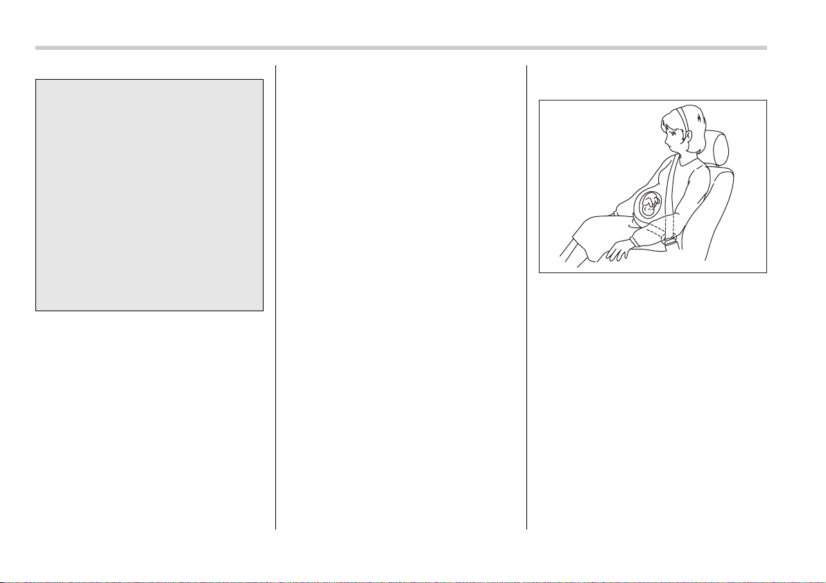
T Expectant mothers
Expectant mothers also need to use the
seatbelts. They should consult their doctor
for specific recommendations. The lap
belt should be worn securely and as low
as possible over the hips, not over the
waist.
Emergency Locking Retrac-
tor (ELR)
The driver’s seatbelt has an Emergency
Locking Retractor (ELR).
The emergency locking retractor allows
normal body movement but the retractor
locks automatically during a sudden stop,
impact or if you pull the belt very quickly
out of the retractor.
NEVER INSTALL A REARWARD
FACING CHILD SEAT IN THE
FRONT SEAT. DOING SO RISKS
SERIOUS INJURY OR DEATH TO
THE CHILD BY PLACING THE
CHILD’S HEAD TOO CLOSE TO
THE SRS AIRBAG.
According to accident statistics,
children are safer when properly
restrained in the rear seating posi-
tions than in the front seating po-
sitions. For instructions and pre-
cautions concerning the child re-
straint system, see the “Child re-
straint systems” section in this
chapter.
100100
Seat, seatbelt and SRS airbags 1-13
– CONTINUED –
Automatic/Emergency Lock-
ing Retractor (A/ELR)
Each passenger’s seatbelt has an Auto-
matic/Emergency Locking Retractor (A/
ELR). The Automatic/Emergency Locking
Retractor normally functions as an Emer-
gency Locking Retractor (ELR). The A/
ELR has an additional locking mode “Au-
tomatic Locking Retractor (ALR) mode” in-
tended to secure a child restraint system.
When the seatbelt is once drawn out com-
pletely and is then retracted even slightly,
the retractor locks the seatbelt in that po-
sition and the seatbelt cannot be extend-
ed. As the belt is rewinding, clicks will be
heard which indicate the retractor func-
tions as ALR. When the seatbelt is retract-
ed fully, ALR mode is released.
When securing a child restraint system on
the passengers’ seats, the seatbelt must
be changed over to the Automatic Locking
Retractor (ALR) mode.
When the child restraint system is re-
moved, make sure that the retractor is re-
stored to the Emergency Locking Retrac-
tor (ELR) function by allowing the seatbelt
to retract fully.
For instructions on how to convert the re-
tractor to the ALR mode and restore it to
the ELR mode, see the “Child restraint
systems” section in this chapter.
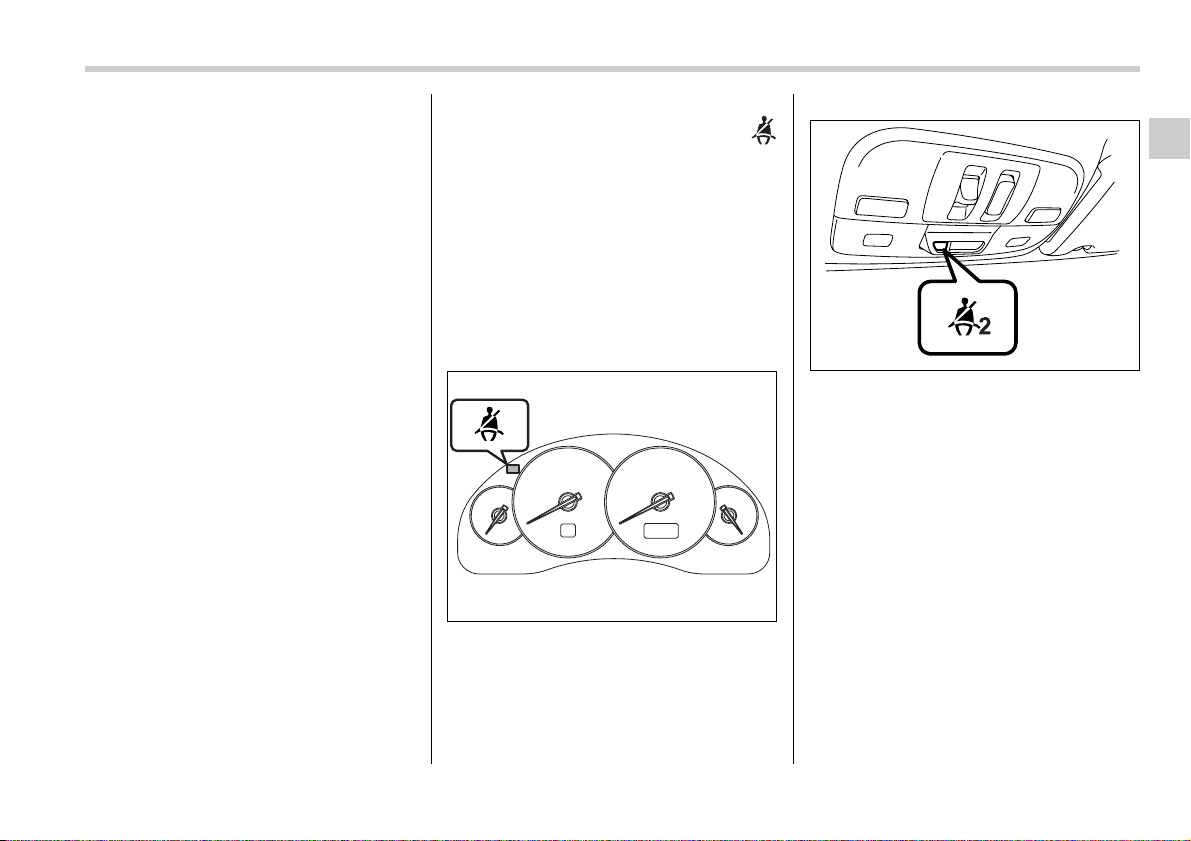
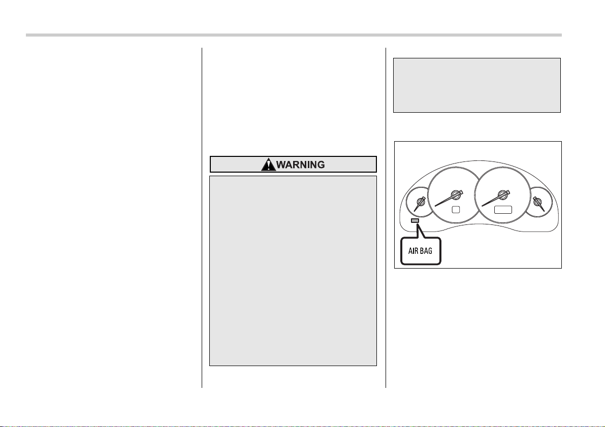
Seatbelt warning light
and chime
Your vehicle is equipped with a seatbelt
warning device at the driver’s and front
passenger’s seat, as required by current
safety standards.
With the ignition switch turned to the “ON”
position, this device reminds the driver
and front passenger to fasten their seat-
belts by illuminating the warning lights in
the locations indicated in the following il-
lustration and sounding a chime.
Driver’s warning light
Front passenger’s warning light
T Operation
If the driver and/or front passenger have/
has not yet fastened the seatbelt(s) when
the ignition switch is turned to the “ON” po-
sition, the seatbelt warning light(s) will
flash for 6 seconds, to warn that the seat-
belt(s) is/are unfastened. If the driver’s
seatbelt is not fastened, a chime will also
sound simultaneously.
If the driver’s and/or front passenger’s
seatbelt(s) are/is still not fastened 6 sec-
onds later, both warning lights or the
warning light for the unfastened seatbelt
will remain lit for 15 seconds. If the driver’s
and/or front passenger’s seatbelt(s) are/is
still not fastened even 15 seconds later
(21 seconds after turning ON the ignition
100254
100662

1-14 Seat, seatbelt and SRS airbags
switch), the warning lights will alternate
between flashing and steady illumination
at 15-second intervals, and the chime will
sound while the warning light(s) is/are
flashing.
Alternate flashing and steady illumination
of the warning lights and sounding of the
chime will continue until both driver and
front passenger fasten their seatbelts.
NOTE
y If the driver and/or front passenger
unfasten(s) the seatbelt(s) after fasten-
ing, the seatbelt warning device oper-
ates as follows according to the vehi-
cle speed.
y At speeds lower than approximate-
ly 9 mph (15 km/h)
The warning light(s) for unfastened
seatbelt(s) will alternate between
flashing and steady illumination at
15-second intervals. The chime will
not sound.
y At speeds higher than approxi-
mately 9 mph (15 km/h)
The warning light(s) for unfastened
seatbelt(s) will alternate between
flashing and steady illumination at
15-second intervals and the chime
will sound while the warning light(s)
is/are flashing.
y It is possible to cancel the warning
operation that follows the 6-second
warning after turning ON the ignition
switch by unfastening and refastening
the driver’s seatbelt. When the ignition
switch is turned ON next time, howev-
er, the complete sequence of the warn-
ing operation resumes. For further de-
tails about canceling the warning oper-
ation, please contact your SUBARU
dealer.
If there is no passenger on the front pas-
senger’s seat, the seatbelt warning device
for the front passenger’s seat will be deac-
tivated. The front passenger’s occupant
detection system monitors whether or not
there is a passenger on the front passen-
ger’s seat.
Observe the following precautions. Failure
to do so may prevent the device from func-
tioning correctly or cause the device to
fail.
y Do not install any accessory such as a
table or TV onto the seatback.
y Do not store a heavy load in the seat-
back pocket.
y Do not allow the rear seat occupant to
place his/her hands or legs on the front
passenger’s seatback, or allow him/her to
pull the seatback.
y Do not use front seats with their back-
ward-forward position and seatback not
being locked into place securely. If any of
them are not locked securely, adjust them
again. For adjusting procedure, refer to
the “Manual seat” in the front seats sec-
tion in Chapter 1 in this owner’s manual.
(Models equipped with manual seats only)
If the seatbelt warning device for the front
passenger’s seat does not function cor-
rectly (e.g., it is activated even when the
front passenger’s seat is empty or it is de-
activated even when the front passenger
has not fastened his/her seatbelt), take
the following actions.
y Ensure that no article is placed on the
seat other than a child restraint system
and the child occupant.
y Ensure that there is no article left in the
seatback pocket.
y Ensure that the backward-forward posi-
tion and seatback of front passenger’s
seat are locked into place securely by
moving the seat back and forth. (Models
equipped with manual seats only)
If the seatbelt warning device for front
passenger’s seat still does not function
correctly after taking relevant corrective
actions described above, immediately
contact your SUBARU dealer for an in-
spection.
Seat, seatbelt and SRS airbags 1-15
– CONTINUED –
Fastening the seatbelt
T Front seatbelts
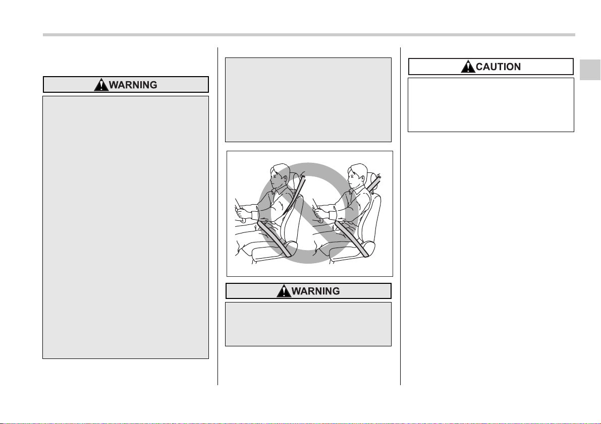
1. Adjust the seat position:
Driver’s seat: Adjust the seatback to the
upright position. Move the seatback as far
from the steering wheel as practical while
still maintaining full vehicle control.
Front passenger’s seat: Adjust the seat-
back to the upright position. Move the seat
as far back as possible.
2. Sit well back in the seat.
3. Pick up the tongue plate and pull the
belt out slowly. Do not let it get twisted. If
the belt stops before reaching the buckle,
return the belt slightly and pull it out more
slowly. If the belt still cannot be unlocked,
let the belt retract slightly after giving it a
strong pull, then pull it out slowly again.
y Never use a belt that is twisted or
reversed. In an accident, this can
increase the risk or severity of in-
jury.
y Keep the lap belt as low as possi-
ble on your hips. In a collision,
this spreads the force of the lap
belt over stronger hip bones in-
stead of across the weaker abdo-
men.
y Seatbelts provide maximum re-
straint when the occupant sits
well back and upright in the seat.
To reduce the risk of sliding under
the seatbelt in a collision, the
front seatbacks should be always
used in the upright position while
the vehicle is running. If the front
seatbacks are not used in the up-
right position in a collision, the
risk of sliding under the lap belt
and of the lap belt sliding up over
the abdomen will increase, and
both can result in serious internal
injury or death.
y Do not put cushions or any other
materials between occupants and
seatbacks or seat cushions. If you
do so, the risk of sliding under the
lap belt and of the lap belt sliding
up over the abdomen will in-
crease, and both can result in se-
rious internal injury or death.
Never place the shoulder belt under
the arm or behind the back. If an ac-
cident occurs, this can increase the
risk or severity of injury.
100101
Metallic parts of the seatbelt can be-
come very hot in a vehicle that has
been closed up in sunny weather;
they could burn an occupant. Do not
touch such hot parts until they cool.
1-16 Seat, seatbelt and SRS airbags
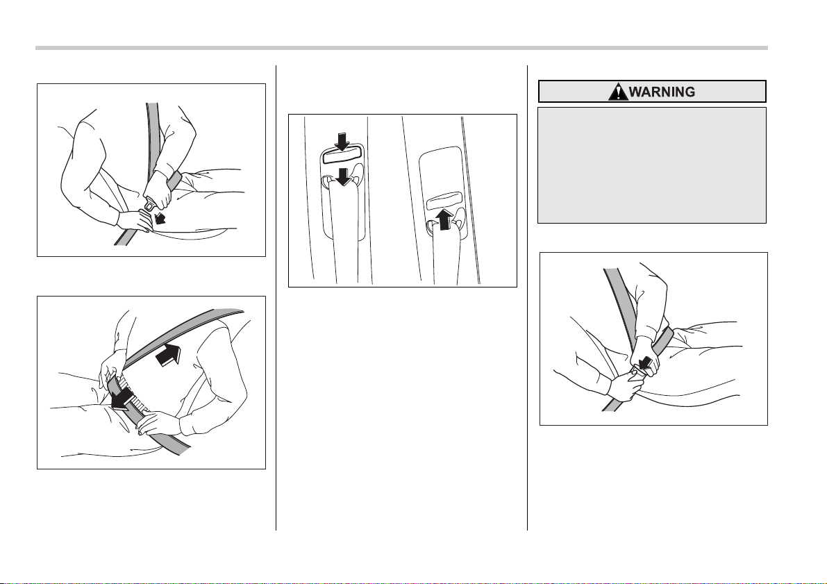
4. Insert the tongue plate into the buckle
until you hear a click.
5. To make the lap part tight, pull up on
the shoulder belt.
6. Place the lap belt as low as possible on
your hips, not on your waist.
V Adjusting the front seat shoulder
belt anchor height
The shoulder belt anchor height should be
adjusted to the position best suited for the
driver/front passenger. To lower the an-
chor height, push the release button and
slide the anchor down. To raise the an-
chor height, slide the anchor up. Pull down
on the anchor to make sure that it is
locked in place.
Always adjust the anchor height so that
the shoulder belt passes over the middle
of the shoulder without touching the neck.
V Unfastening the seatbelt
Push the button on the buckle.
Before closing the door, make sure that
the belts are retracted properly to avoid
catching the belt webbing in the door.
100102
100103
100258
When wearing the seatbelts, make
sure the shoulder portion of the
webbing does not pass over your
neck. If it does, adjust the seatbelt
anchor to a lower position. Placing
the shoulder belt over the neck may
result in neck injury during sudden
braking or in a collision.
100105
Seat, seatbelt and SRS airbags 1-17
– CONTINUED –
T Rear seatbelts (except rear center
seatbelt on Station wagon)
1. Sit well back in the seat.
2. Pick up the tongue plate and pull the
belt out slowly. Do not let it get twisted. If
the belt stops before reaching the buckle,
return the belt slightly and pull it out more
slowly. If the belt still cannot be unlocked,
let the belt retract slightly after giving a
strong pull on it, then pull it out slowly
again.
3. Insert the tongue plate into the buckle
until you hear a click.
4. To make the lap part tight, pull up on
the shoulder belt.
5. Place the lap belt as low as possible on
your hips, not on your waist.
V Unfastening the seatbelt
Push the button on the buckle.
Before closing the door, make sure that
the belts are retracted properly to avoid
catching the belt webbing in the door.
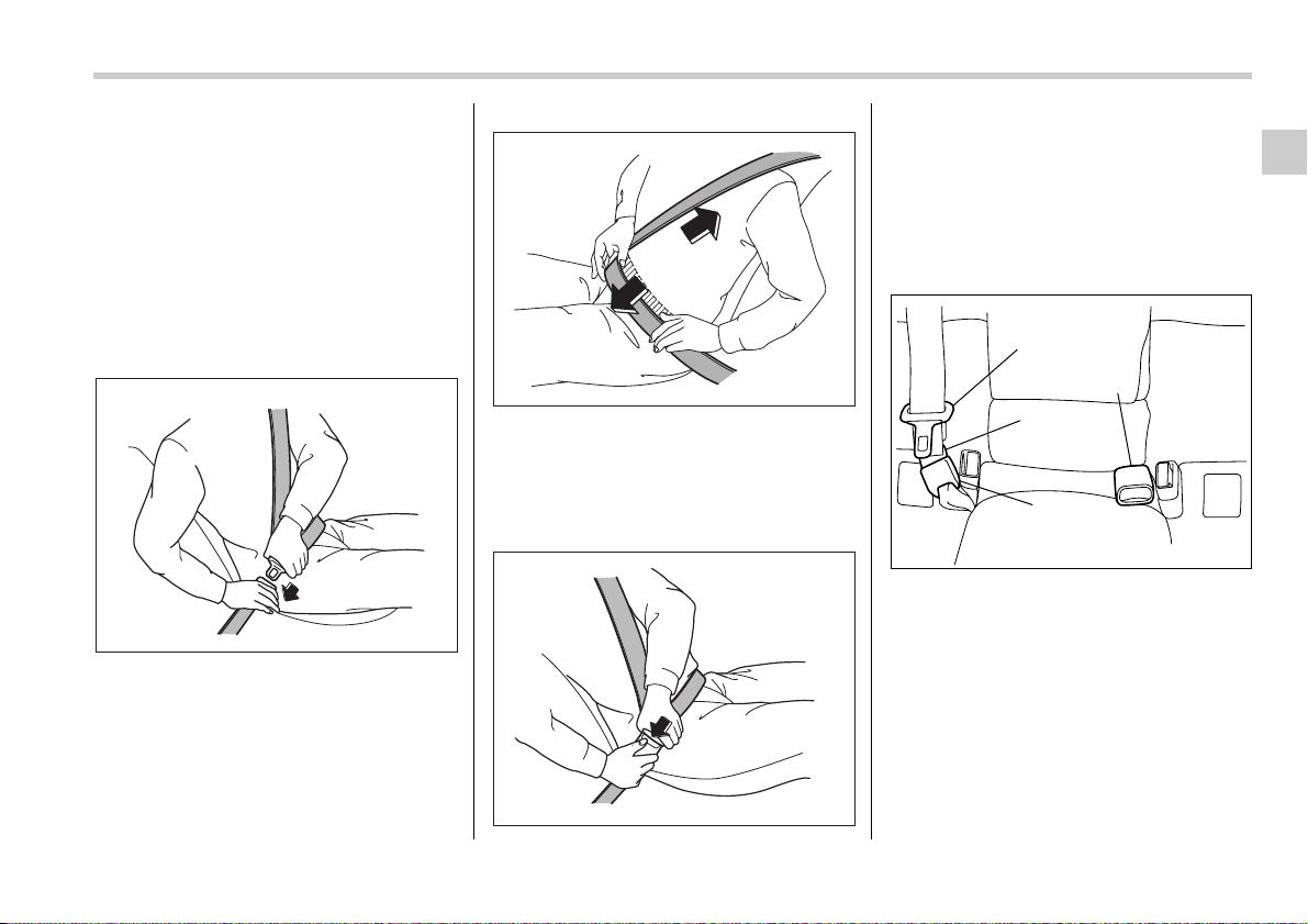
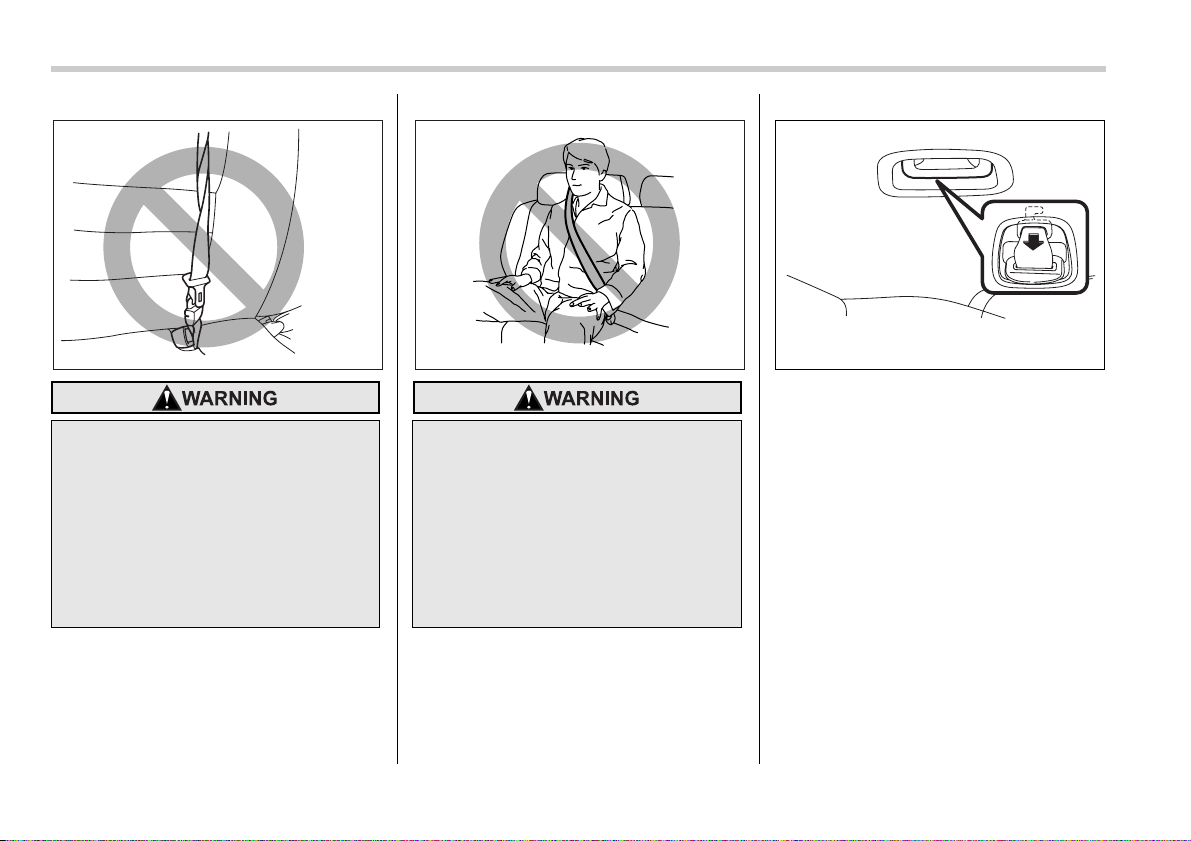
T Rear center seatbelt on Station wag-
on model
1) Center seatbelt tongue plate
2) Connector (tongue)
3) Connector (buckle)
4) Center seatbelt buckle
100102
100103
100105
1
2
3
4
100651
1-18 Seat, seatbelt and SRS airbags
Rear center seatbelt is stowed in the re-
cess of the ceiling.
1. Remove the connector (tongue) plate
from the slot located at the front of the re-
cess by pulling the connector (tongue)
plate rearward.
Fastening the seatbelt with the web-
bing twisted can increase the risk or
severity of injury in an accident.
When fastening the belt after it is
pulled out from the retractor, espe-
cially when inserting the connec-
tor’s tongue plate into the mating
buckle (on right-hand side), always
check that the webbing is not twist-
ed.
100108
Be sure to fasten both tongue plates
to the respective buckles. If the
seatbelt is used only as a shoulder
belt (with the connector’s tongue
plate not fastened to the connec-
tor’s buckle on the right-hand side),
it cannot properly restrain the wear-
er in position in an accident, possi-
bly resulting in serious injury or
death.
100109
100734
Seat, seatbelt and SRS airbags 1-19
– CONTINUED –
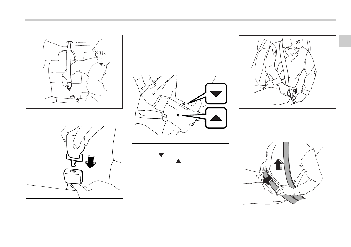
2. Pull out the seatbelt slowly from the
overhead retractor.
3. After confirming that the webbing is not
twisted, insert the connector (tongue) at-
tached at the webbing end into the buckle
on the right-hand side until a click is heard.
If the belt stops before reaching the buck-
le, return the belt slightly and pull it out
more slowly. If the belt still cannot be un-
locked, let the belt retract slightly after giv-
ing it a strong pull, then pull it out slowly
again.
4. After fastening the seatbelt, make sure
that the “ ” mark on the connector
(tongue) and the “ ” mark on the buck-
le face outwards.
5. Insert the center seatbelt tongue plate
in the center seatbelt buckle marked
“CENTER” on the left-hand side until it
clicks.
6. To make the lap part tight, pull up on
the shoulder belt. And place the lap belt as
100735
100309
200298
100114
100310
1-20 Seat, seatbelt and SRS airbags
low as possible on your hips, not on your
waist.
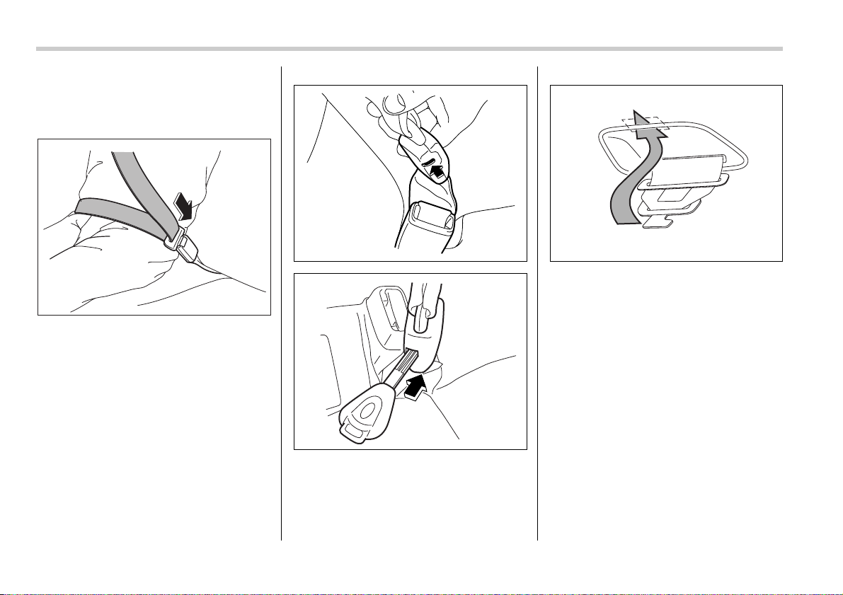
V Unfastening the seatbelt
Push the release button of the center
seatbelt buckle (on the left-hand side) to
unfasten the seatbelt.
0
1. Insert a key or other hard pointed ob-
ject into the slot in the connector (buckle)
on the right-hand side and push it in, and
the connector (tongue) plate will discon-
nect from the buckle.
2. Allow the retractor to roll up the belt.
You should hold the webbing end and
guide it back into the retractor while it is
rolling up. Neatly store the tongue plate in
the recess on the ceiling and then insert
the connector (tongue) plate into the slot
located at the front of the recess.
100116
100381
100382
200300
Seat, seatbelt and SRS airbags 1-21
– CONTINUED –
Seatbelt maintenance
To clean the seatbelts, use a mild soap
and lukewarm water. Never bleach or dye
the belts because this could seriously af-
fect their strength.
Inspect the seatbelts and attachments in-
cluding the webbing and all hardware pe-
riodically for cracks, cuts, gashes, tears,
damage, loose bolts or worn areas. Re-
place the seatbelts even if only minor
damage is found.
Front seatbelt pretensioners
The driver’s and front passenger’s seat-
belts have a seatbelt pretensioner. The
seatbelt pretensioners are designed to be
activated in the event of an accident in-
volving a moderate to severe frontal colli-
sion.
The pretensioner sensor also serves as a
SRS frontal airbag sensor. If the sensor
detects a certain predetermined amount
of force during a frontal collision, the front
seatbelt is quickly drawn back in by the re-
tractor to take up the slack so that the belt
more effectively restrains the front seat
occupant.
When a seatbelt pretensioner is activated,
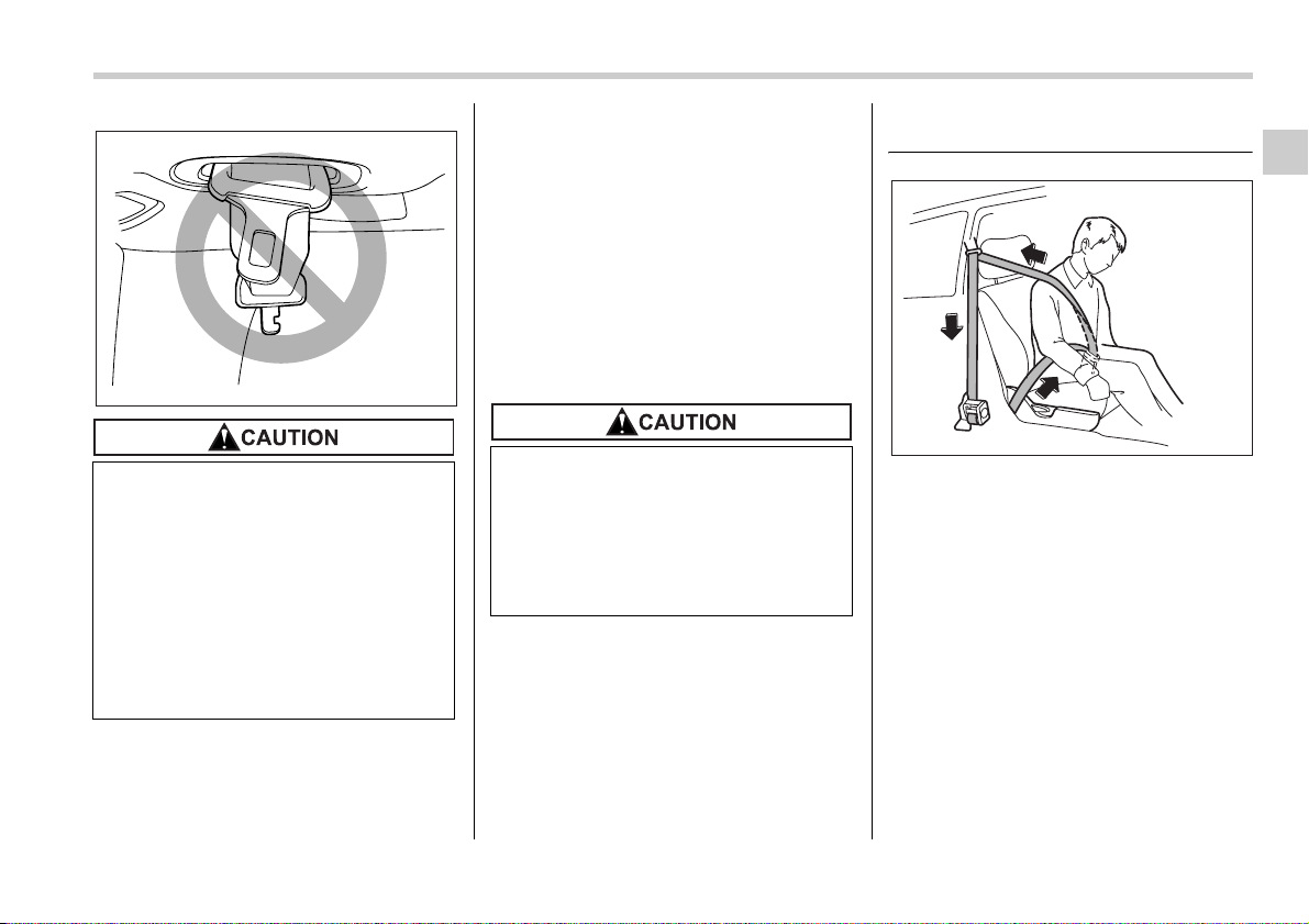
y Do not allow the retractor to roll
up the seatbelt too quickly. Other-
wise, the metal tongue plates may
hit against the trim, resulting in
damaged trim.
y Have the seatbelt fully rolled up
so that the tongue plates are neat-
ly stored. A hanging tongue plate
can swing and hit against the trim
during driving, causing damage to
the trim.
100736
y Keep the belts free of polishes,
oils, chemicals and particularly
battery acid.
y Never attempt to make modifica-
tions or changes that will prevent
the seatbelt from operating prop-
erly.
100121
1-22 Seat, seatbelt and SRS airbags
an operating noise will be heard and a
small amount of smoke will be released.
These occurrences are normal and not
harmful. This smoke does not indicate a
fire in the vehicle.
Once the seatbelt pretensioner has been
activated, the seatbelt retractor remains
locked. Consequently, the seatbelt can
not be pulled out and retracted and there-
fore must be replaced.
NOTE
y Seatbelt pretensioners are not de-
signed to activate in minor frontal im-
pacts, in side or rear impacts or in roll-
over accidents.
y The driver’s seat and passenger’s
seat pretensioners and frontal airbag
operate simultaneously.
y Pretensioners are designed to func-
tion on a one-time-only basis. In the
event that a pretensioner is activated,
both the driver’s and front passenger’s
seatbelt retractor assemblies must be
replaced and only by an authorized
SUBARU dealer. When replacing seat-
belt retractor assemblies, use only
genuine SUBARU parts.
y If either front seatbelt does not re-
tract or cannot be pulled out due to a
malfunction or activation of the preten-
sioner, contact your SUBARU dealer as
soon as possible.
y If the front seatbelt retractor assem-
bly or surrounding area has been dam-
aged, contact your SUBARU dealer as
soon as possible.
y When you sell your vehicle, we urge
you to explain to the buyer that it has
seatbelt pretensioners by alerting him
to the contents of this section.
System monitors
SRS airbag system warning light
A diagnostic system continually monitors
the readiness of the seatbelt pretensioner
while the vehicle is being driven. The seat-
belt pretensioners share the control mod-
ule with the airbag system. Therefore, if
any malfunction occurs in a seatbelt pre-
tensioner, the SRS airbag system warning
light will illuminate. The SRS airbag sys-
tem warning light will show normal system
y To obtain maximum protection,
occupants should sit in an upright
position with their seatbelts prop-
erly fastened. Refer to “Seatbelts”
section in this chapter.
y Do not modify, remove or strike
the front seatbelt retractor assem-
blies or surrounding area. This
could result in accidental activa-
tion of the seatbelt pretensioners
or could make the system inoper-
ative, possibly resulting in seri-
ous injury. Seatbelt pretensioners
have no user-serviceable parts.
For required servicing of front
seatbelt retractors equipped with
seatbelt pretensioners, see your
nearest SUBARU dealer.
y When discarding front seatbelt re-
tractor assemblies or scrapping
the entire vehicle due to collision
damage or for other reasons, con-
sult your SUBARU dealer.
200326
Seat, seatbelt and SRS airbags 1-23
– CONTINUED –
operation by lighting for approximately 6
seconds when the ignition switch is turned
to the “ON” position.
The following components are monitored
by the indicator:
y Front sub sensor (Right-hand side)
y Front sub sensor (Left-hand side)
y Airbag control module (including impact
sensors)
y Frontal airbag module (Driver’s side)
y Frontal airbag module (Front passen-
ger’s side)
y Side airbag sensor (Center pillar right-
hand side)
y Side airbag sensor (Center pillar left-
hand side)
y Side airbag module (Driver’s side)
y Side airbag module (Front passenger’s
side)
y Curtain airbag sensor (Rear wheel
house right-hand side)
y Curtain airbag sensor (Rear wheel
house left-hand side)
y Curtain airbag module (Right side)
y Curtain airbag module (Left side)
y Seatbelt pretensioner (Driver’s side)
y Seatbelt pretensioner (Front passen-
ger’s side)
y Seatbelt buckle switch (Driver’s side)
y Seatbelt buckle switch (Front passen-
ger’s side)
y Driver’s seat position sensor
y Front passenger’s seatbelt tension sen-
sor
y Front passenger’s occupant detection
system weight sensor
y Front passenger’s occupant detection
control module
y Front passenger’s frontal airbag ON
and OFF indicator
y All related wiring
System servicing
If the warning light exhibits any of
the following conditions, there may
be a malfunction in the seatbelt pre-
tensioners and/or SRS airbag sys-
tem. Immediately take your vehicle
to your nearest SUBARU dealer to
have the system checked. Unless
checked and properly repaired, the
seatbelt pretensioners and/or SRS
airbags will operate improperly (e.g.
SRS airbags may inflate in a very mi-
nor collision or not inflate in a se-
vere collision), which may increase
the risk of injury.
y Flashing or flickering of the warn-
ing light
y No illumination of the warning
light when the ignition switch is
first turned to the “ON” position
y Continuous illumination of the
warning light
y Illumination of the warning light
while driving
y When discarding a seatbelt retrac-
tor assembly or scrapping the en-
tire vehicle damaged by a colli-
sion, consult your SUBARU deal-
er.
1-24 Seat, seatbelt and SRS airbags
NOTE
If the front part of the vehicle is dam-
aged in an accident to the extent that
the seatbelt pretensioner does not op-
erate, contact your SUBARU dealer as
soon as possible.
Precautions against vehicle
modification
Always consult your SUBARU dealer if
you want to install any accessory parts to
your vehicle.
y Tampering with or disconnecting
the system’s wiring could result in
accidental activation of the seat-
belt pretensioner and/or airbag or
could make the system inopera-
tive, which may result in serious
injury. The wiring harnesses of
the seatbelt pretensioner and SRS
airbag systems are covered with
yellow insulation and the connec-
tors of the system are yellow for
easy identification. Do not use
electrical test equipment on any
circuit related to the seatbelt pre-
tensioner and airbag systems. For
required servicing of the seatbelt
pretensioner, see your nearest
SUBARU dealer.
The front sub sensors are located in
both front fenders and the airbag
control module including the impact
sensors is located under the center
console. If you need service or re-
pair in those areas or near the front
seatbelt retractors, have an autho-
rized SUBARU dealer perform the
work.
Do not perform any of the following
modifications. Such modifications
can interfere with proper operation
of the seatbelt pertensioners.
y Attachment of any equipment
(bush bar, winches, snow plow,
skid plate, etc.) other than genu-
ine SUBARU accessory parts to
the front end.
y Modification of the suspension
system or front end structure.
y Installation of a tire of different
size and construction from the
tires specified on the vehicle plac-
ard attached to the door pillar or
specified for individual vehicle
models in this Owner’s Manual.
Seat, seatbelt and SRS airbags 1-25
– CONTINUED –
Child restraint systems
Infants and small children should always
be placed in an infant or child restraint
system in the rear seat while riding in the
vehicle. You should use an infant or child
restraint system that meets Federal Motor
Vehicle Safety Standards or Canada Mo-
tor Vehicle Safety Standards, is compati-
ble with your vehicle and is appropriate for
the child’s age and size. All child restraint
systems are designed to be secured in ve-
hicle seats by lap belts or the lap belt por-
tion of a lap/shoulder belt (except those
covered under the section in this manual,
entitled “Installation of child restraint sys-
tems by use of lower and tether anchorag-
es (LATCH)”).
Children could be endangered in an acci-
dent if their child restraints are not proper-
ly secured in the vehicle. When installing
the child restraint system, carefully follow
the manufacturer’s instructions.
According to accident statistics, children
are safer when properly restrained in the
rear seating positions than in the front
seating positions.
All U.S. states and Canadian provinces
require that infants and small children be
restrained in an approved child restraint
system at all times while the vehicle is
moving.
100124
100125
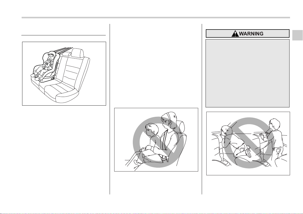
Never let a passenger hold a child
on his or her lap while the vehicle is
moving. The passenger cannot pro-
tect the child from injury in a colli-
sion, because the child will be
caught between the passenger and
objects inside the vehicle. Addition-
ally, holding a child in your lap or
arms in the front seat exposes that
child to another serious danger.
Since the SRS airbag deploys with
considerable speed and force, the
child could be injured or even killed.
100126
1-26 Seat, seatbelt and SRS airbags
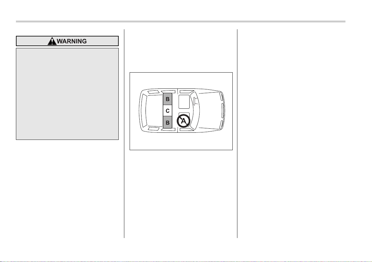
Where to place a child re-
straint system
The following are SUBARU’s recommen-
dations on where to place a child restraint
system in your vehicle.
A: Front passenger’s seat
You should not install a child restraint sys-
tem (including a booster seat) due to the
hazard to children posed by the passen-
ger’s airbag.
B: Rear seat, window-side seating po-
sitions
Recommended positions for all types of
child restraint systems.
In these positions, Automatic/Emergency
Locking Retractor (A/ELR) seatbelts and
lower anchorages (bars) are provided for
installing a child restraint system.
Some types of child restraints might not
be able to be secured firmly due to projec-
tion of the seat cushion.
In this seating position, you should use
only a child restraint system that has a
bottom base that fits snugly against the
contours of the seat cushion and can be
securely retained using the seatbelt.
C: Rear seat, center seating position
Installing a child restraint system is not
recommended, although the A/ELR seat-
belt and an upper anchorage (tether an-
chorage) are provided in this position.
Some types of child restraints might not
be able to be secured firmly due to projec-
tion of the seat cushion.
In this seating position, you should use
only a child restraint system that has a
bottom base that fits snugly against the
contours of the seat cushion and can be
securely retained using the seatbelt.
Children should be properly re-
strained at all times. Never allow a
child to stand up, or to kneel on any
seat. Unrestrained children will be
thrown forward during sudden stop
or in an accident and can be injured
seriously.
Additionally, children standing up
or kneeling on or in front of the front
seat are exposed another serious
danger. Since the SRS airbag de-
ploys with considerable speed and
force, the child could be injured or
even killed.
100127
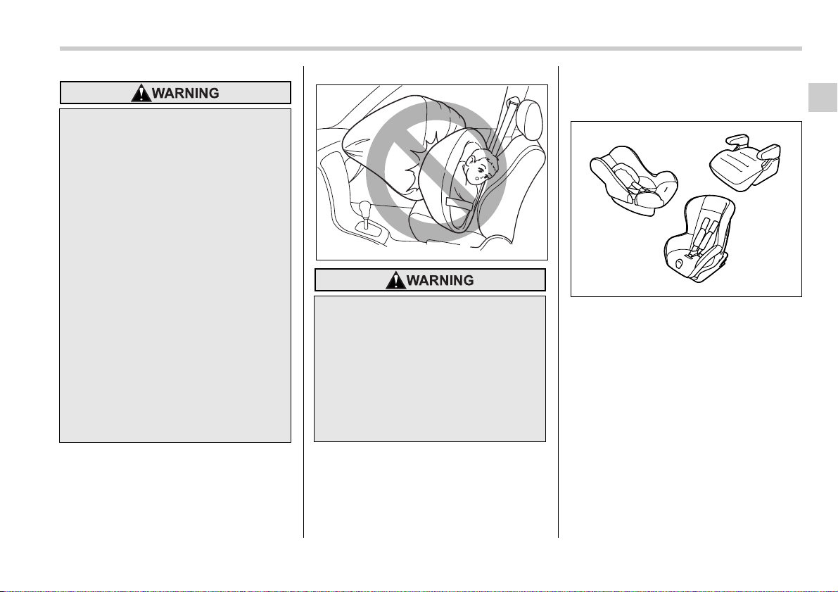
Seat, seatbelt and SRS airbags 1-27
– CONTINUED –
Choosing a child restraint
system
Choose a child restraint system that is ap-
propriate for the child’s age and size
(weight and height) in order to provide the
child with proper protection. The child re-
straint system should meet all applicable
requirements of Federal Motor Vehicle
Safety Standards for United States or
Canada Motor Vehicle Safety Standards
for Canada. It can be identified by looking
for the label on the child restraint system
or the manufacture’s statement of compli-
ance in the document attached to the sys-
tem. Also it is important for you to make
sure that the child restraint system is com-
patible with the vehicle in which it will be
used.
Put children aged 12 and under in
the rear seat properly restrained at
all times. The SRS airbag deploys
with considerable speed and force
and can injure or even kill children,
especially if they are 12 years of age
and under and are not restrained or
improperly restrained. Because chil-
dren are lighter and weaker than
adults, their risk of being injured
from deployment is greater.
For that reason, be sure to secure
ALL types of child restraint devices
(including forward facing child
seats) in the REAR seats at all times.
You should choose a restraint de-
vice which is appropriate for the
child’s age, height and weight. Ac-
cording to accident statistics, chil-
dren are safer when properly re-
strained in the rear seating posi-
tions than in the front seating posi-
tions.
SINCE YOUR VEHICLE IS
EQUIPPED WITH A PASSENGER’S
SRS AIRBAG, DO NOT INSTALL A
REARWARD FACING CHILD SAFE-
TY SEAT IN THE FRONT PASSEN-
GER’S SEAT. DOING SO RISKS SE-
RIOUS INJURY OR DEATH TO THE
CHILD BY PLACING THE CHILD’S
HEAD TOO CLOSE TO THE SRS
AIRBAG.
100261
100502

1-28 Seat, seatbelt and SRS airbags
Installing child restraint sys-
tems with A/ELR seatbelt
T Installing a rearward facing child re-
straint
1. Place the child restraint system in the
rear seating position.
2. Run the lap and shoulder belt through
or around the child restraint system follow-
ing the instructions provided by its manu-
facturer.
3. Insert the tongue plate into the buckle
until you hear a click.
4. Take up the slack in the lap belt.
5. Pull out the seatbelt fully from the re-
tractor to change the retractor over from
the Emergency Locking Retractor (ELR)
to the Automatic Locking Retractor (ALR)
function. Then, allow the belt to rewind
into the retractor. As the belt is rewinding,
clicks will be heard which indicate the re-
tractor functions as ALR.
y Child restraint systems and seat-
belts can become hot in a vehicle
that has been closed up in sunny
weather; they could burn a small
child. Check the child restraint
system before you place a child in
it.
y Do not leave an unsecured child
restraint system in your vehicle.
Unsecured child restraint sys-
tems can be thrown around inside
of the vehicle in a sudden stop,
turn or accident; they can strike
and injure vehicle occupants as
well as result in serious injuries or
death to the child.
When you install a child restraint
system, follow the manufacturer’s
instructions supplied with it. After
installing the child restraint system,
check to ensure that it is held se-
curely in position. If it is not held
tight and secure, the danger of your
child suffering personal injury in the
event of an accident may be in-
creased.
100503
100504
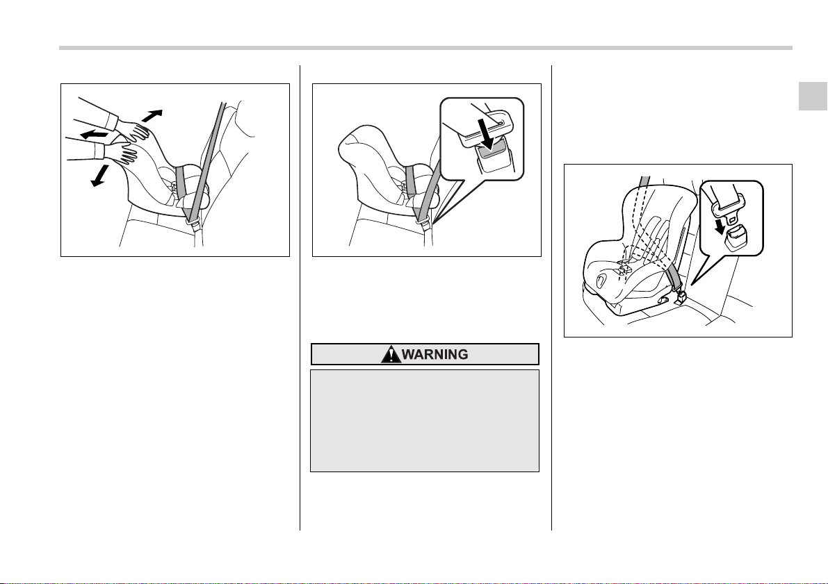
Seat, seatbelt and SRS airbags 1-29
– CONTINUED –
6. Push and pull the child restraint system
forward and from side to side to check if it
is firmly secured.
Sometimes a child restraint can be more
firmly secured by pushing it down into the
seat cushion and then tightening the seat-
belt.
7. Pull at the shoulder portion of the belt
to confirm that it cannot be pulled out (ALR
properly functioning).
8. To remove the child restraint system,
press the release button on the seatbelt
buckle and allow the belt to retract com-
pletely. The belt will return to the ELR
mode.
NOTE
When the child restraint system is no
longer in use, remove it and restore the
ELR function of the retractor. That
function is restored by retracting the
seatbelt fully.
T Installing forward facing child re-
straint
1. Place the child restraint system in the
seating position.
2. Run the lap and shoulder belt through
or around the child restraint system follow-
ing the instructions provided by its manu-
facturer.
3. Insert the tongue plate into the buckle
until you hear a click.
100505
NEVER INSTALL A REARWARD
FACING CHILD SEAT IN THE FRONT
PASSENGER’S SEAT. DOING SO
RISKS SERIOUS INJURY OR DEATH
TO THE CHILD BY PLACING THE
CHILD’S HEAD TOO CLOSE TO THE
SRS AIRBAG.
100506
100136
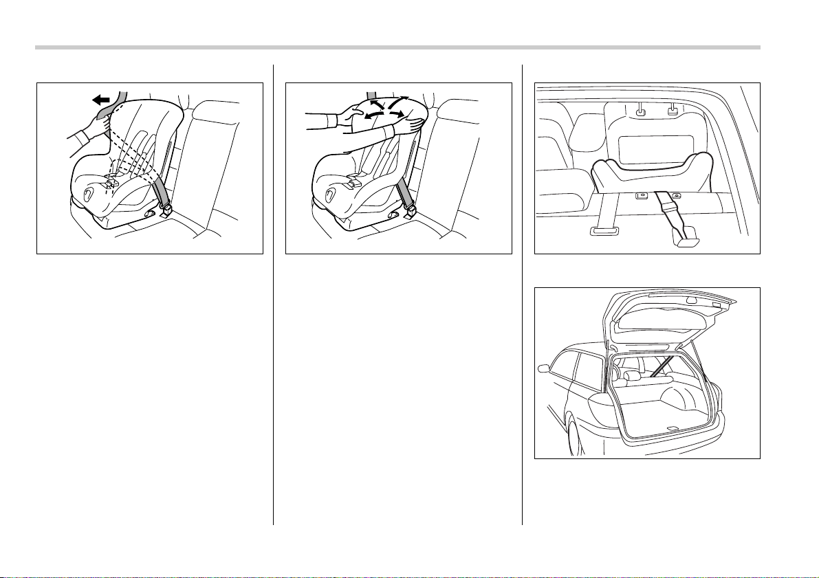
1-30 Seat, seatbelt and SRS airbags
4. Take up the slack in the lap belt.
5. Pull out the seatbelt fully from the re-
tractor to change the retractor over from
the Emergency Locking Retractor (ELR)
to the Automatic Locking Retractor (ALR)
function. Then, allow the belt to rewind
into the retractor. As the belt is rewinding,
clicks will be heard which indicate the re-
tractor functions as ALR.
6. Before having a child sit in the child re-
straint system, move it back and forth and
right and left to check if it is firmly secured.
Sometimes a child restraint can be more
firmly secured by pushing it down into the
seat cushion and then tightening the seat-
belt.
7. Pull at the shoulder portion of the belt
to confirm that it cannot be pulled out (ALR
properly functioning).
Sedan
Station wagon
8. If the child restraint system requires a
top tether, latch the hook onto the top teth-
100137 100138 100262
100263
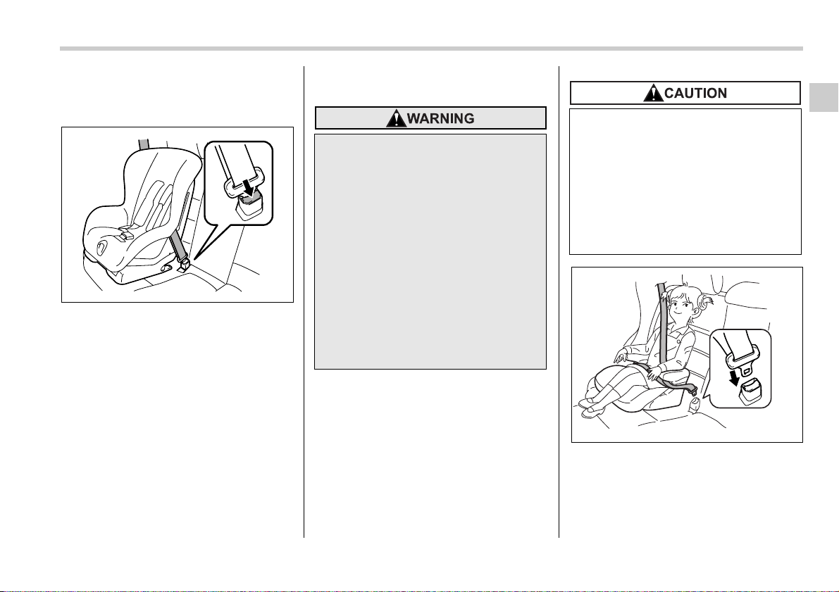
Seat, seatbelt and SRS airbags 1-31
– CONTINUED –
er anchor and tighten the top tether. See
the “Top tether anchorages” for additional
instructions.
9. To remove the child restraint system,
press the release button on the seatbelt
buckle and allow the belt to retract com-
pletely. The belt will return to the ELR
mode.
NOTE
When the child restraint system is no
longer in use, remove it and restore the
ELR function of the retractor. That
function is restored by allowing the
seatbelt to retract fully.
Installing a booster seat
1. Place the booster seat in the rear seat-
ing position and sit the child on it. The
child should sit well back on the booster
seat.
2. Run the lap and shoulder belt through
or around the booster seat and the child
100140
y Child restraint systems and seat-
belts can become hot in a vehicle
that has been closed up in sunny
weather; they could burn a small
child. Check the child restraint
system before you place a child in
it.
y Do not leave an unsecured child
restraint system in your vehicle.
Unsecured child restraint sys-
tems can be thrown around inside
of the vehicle in a sudden stop,
turn or accident; they can strike
and injure vehicle occupants as
well as result in serious injuries or
death to the child.
When you install a child restraint
system, follow the manufacturer’s
instructions supplied with it. After
installing the child restraint system,
check to ensure that it is held se-
curely in position. If it is not held
tight and secure, the danger of your
child suffering personal injury in the
event of an accident may be in-
creased.
100141
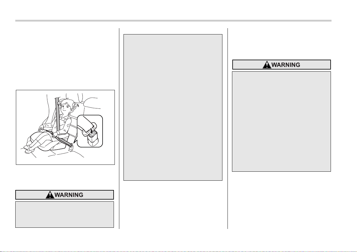
1-32 Seat, seatbelt and SRS airbags
following the instructions provided by its
manufacturer.
3. Insert the tongue plate into the buckle
until you hear a click. Take care not to
twist the seatbelt.
Make sure the shoulder belt is positioned
across the center of child’s shoulder and
that the lap belt is positioned as low as
possible on the child’s hips.
4. To remove the booster seat, press the
release button on the seatbelt buckle and
allow the belt to retract.
Installation of child restraint
systems by use of lower and
tether anchorages (LATCH)
y Never use a belt that is twisted or
reversed. In an accident, this can
increase the risk or severity of in-
jury to the child.
100142
y Never place the shoulder belt un-
der the child’s arm or behind the
child’s back. If an accident oc-
curs, this can increase the risk or
severity of injury to the child.
y The seatbelt should fit snugly in
order to provide full restraint.
Loose fitting belts are not as ef-
fective in preventing or reducing
injury.
y Place the lap belt as low as possi-
ble on the child’s hips. A high-po-
sitioned lap belt will increase the
risk of sliding under the lap belt
and of the lap belt sliding up over
the abdomen, and both can result
in serious internal injury or death.
y Make sure the shoulder belt is po-
sitioned across the center of
child’s shoulder. Placing the
shoulder belt over the neck may
result in neck injury during sud-
den braking or in a collision.
y Child restraint systems and seat-
belts can become hot in a vehicle
that has been closed up in sunny
weather; they could burn a small
child. Check the child restraint
system before you place a child in
it.
y Do not leave an unsecured child
restraint system in your vehicle.
Unsecured child restraint sys-
tems can be thrown around inside
of the vehicle in a sudden stop,
turn or accident; they can strike
and injure vehicle occupants as
well as result in serious injuries or
death to the child.
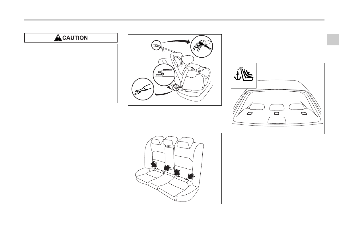
Seat, seatbelt and SRS airbags 1-33
– CONTINUED –
Some types of child restraint systems can
be installed on the rear seat of your vehi-
cle without use of the seatbelts. Such child
restraint systems are secured to the dedi-
cated anchorages provided on the vehicle
body.
The lower and tether anchorages are
sometimes referred to as the LATCH sys-
tem (Lower Anchors and Tethers for CHil-
dren).
Your vehicle is equipped with four lower
anchorages (bars) and three upper an-
chorages (tether anchorages) for accom-
modating such child restraint systems.
The lower anchorages (bars) are used for
installing a child restraint system only on
the rear seat window-side seating posi-
tions. For each window-side seating posi-
tion, two lower anchorages are provided.
Each lower anchorage is located where
the seat cushion meets the seatback.
Sedan
When you install a child restraint
system, follow the manufacturer’s
instructions supplied with it. After
installing the child restraint system,
check to ensure that it is held se-
curely in position. If it is not held
tight and secure, the danger of your
child suffering personal injury in the
event of an accident may be in-
creased.
100652
100311
TOP TETHER
100268
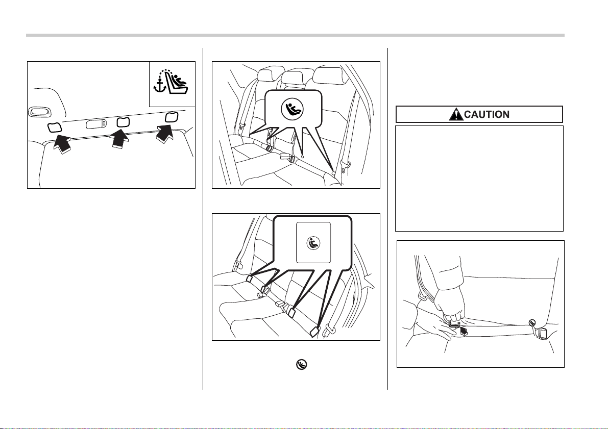
1-34 Seat, seatbelt and SRS airbags
Station wagon
The tether anchorages (upper anchorag-
es) are provided for all the seating posi-
tions (middle and both window-side ones)
of the rear seat.
Sedan
Station wagon
You will find marks “ ” at the bottom of
the rear seat seatbacks. These marks in-
dicate the positions of the lower anchorag-
es (bars).
Each lower anchorage is located where
the seat cushion meets the seatback.
0
1. Sedan: Make the clearance between
TOP TETHER
100269
100653
100654
When you install a child restraint
system, follow the manufacturer’s
instructions supplied with it. After
installing the child restraint system,
check to ensure that it is held se-
curely in position. If it is not held
tight and secure, the danger of your
child suffering personal injury in the
event of an accident may be in-
creased.
100519
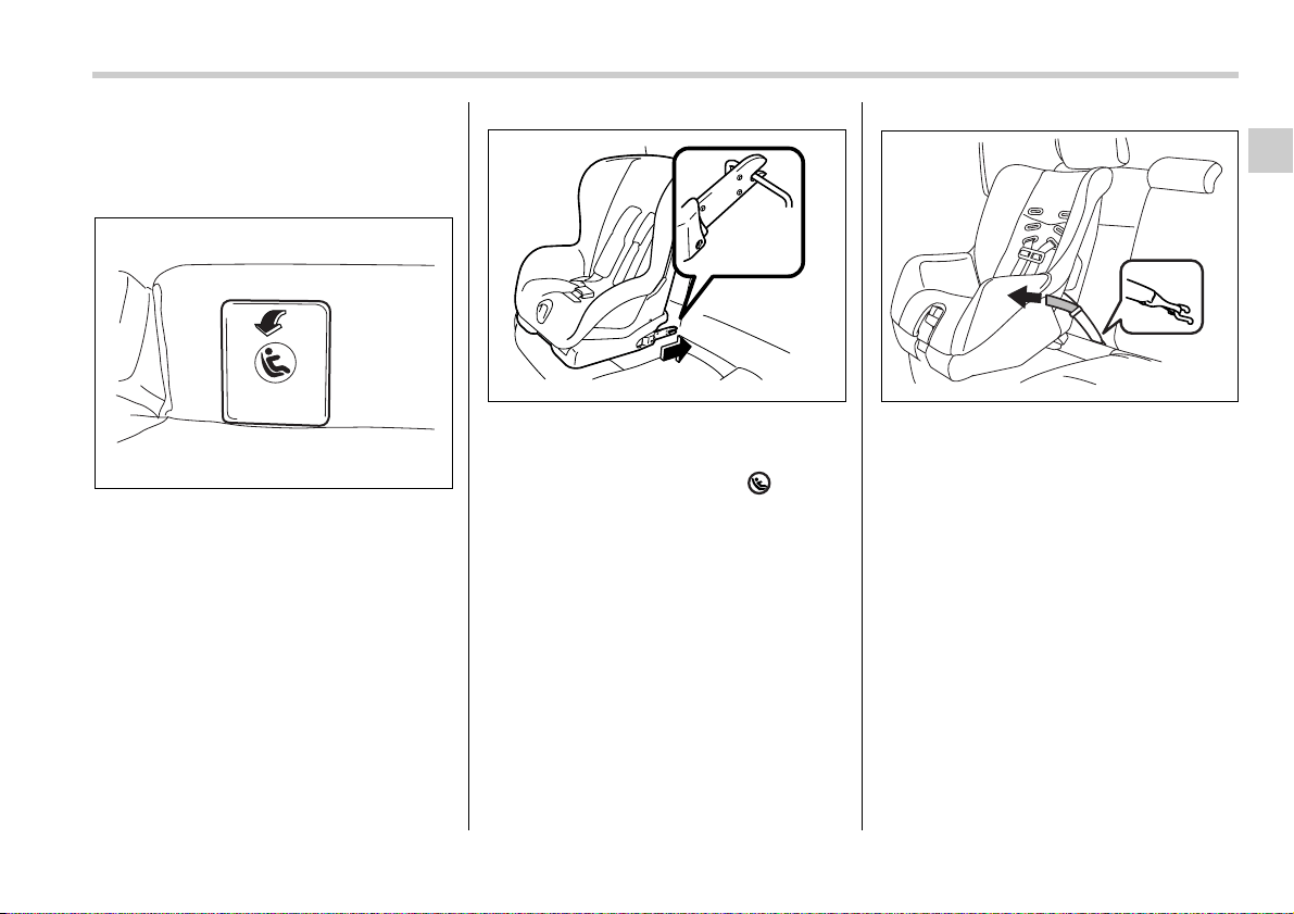
Seat, seatbelt and SRS airbags 1-35
– CONTINUED –
the seat cushion and seatback a little wid-
er to locate the two anchorages (bars) for
the position where you want to install the
child restraint system.
Station wagon: Remove the two covers
from the selected side of the rear seat-
back to expose the anchorages (bars) to
be used for installation of the child re-
straint system.
2. While following the instructions sup-
plied by the child restraint system manu-
facturer, connect the lower hooks onto the
lower anchorages located at “ ” marks
on the bottom of the rear seatback. When
the hooks are connected, make sure the
adjacent seatbelts are not caught.
3. [If your child restraint system is of a
flexible attachment type (which uses teth-
er belts to connect the child restraint sys-
tem properly to the lower anchorages)]
While pushing the child restraint into the
seat cushion, pull both left and right lower
tether belts up to secure the child restraint
system firmly by taking up the slack in the
belt.
4. Connect the top tether hook to the teth-
er anchorage and firmly tighten the tether.
For information on how to set the top teth-
er, read the following “Top tether anchor-
ages”.
100655
100520
100656
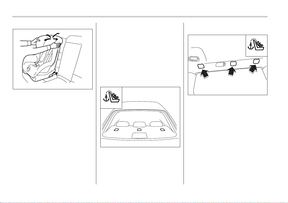
1-36 Seat, seatbelt and SRS airbags
5. Before seating a child in the child re-
straint system, try to move seat back and
forth and left and right to verify that it is
held securely in position.
6. To remove the child restraint system,
follow the reverse procedures of installa-
tion.
If you have any question concerning this
type of child restraint system, ask your
SUBARU dealer.
Top tether anchorages
Your vehicle is equipped with three top
tether anchorages so that a child restraint
system having a top tether can be in-
stalled in the rear seat. When installing a
child restraint system using top tether,
proceed as follows, while observing the in-
structions by the child restraint system
manufacturer.
Since a top tether can provide additional
stability by offering another connection
between a child restraint system and the
vehicle, we recommend that you use a top
tether whenever one is required or avail-
able.
T Tether anchorage location
V Sedan
Three tether anchorages are installed on
the rear shelf behind the rear seat head
restraint. Open the cover flap to use each
anchorage.
V Station wagon
Three tether anchorages, i.e., ones for the
right, center and left positions, are already
installed on the rear edge of the roof.
Open the cover flap to use each anchor-
age.
100657
TOP TETHER
100268
TOP TETHER
100269
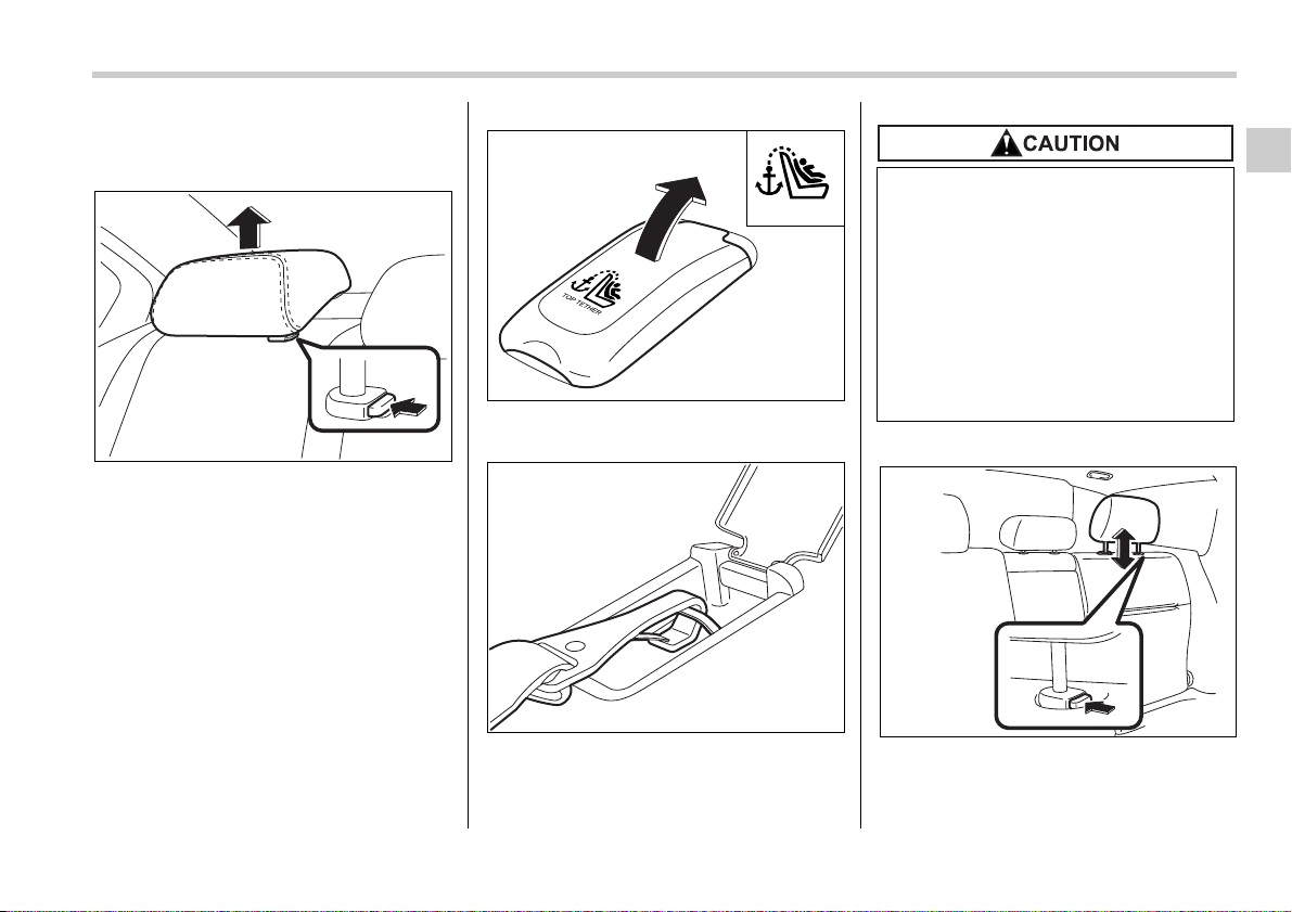
Seat, seatbelt and SRS airbags 1-37
– CONTINUED –
T To hook the top tether
V Sedan
1. Remove the head restraint at the seat-
ing position where the child seat has been
installed with the seatbelt or lower anchor-
ages; lift up the head restraint while press-
ing the release button.
Store the head restraint in the trunk. Avoid
placing the head restraint in the passen-
ger compartment to prevent it from being
thrown around in the passenger compart-
ment in a sudden stop or a sharp turn.
2. Open the cover flaps to use the an-
chorages.
3. Fasten the top tether hook of the child
restraint system to the appropriate upper
anchorage.
4. Tighten the top tether securely.
V Station wagon
0
1. Remove the head restraint at the seat-
ing position where the child restraint sys-
tem has been installed with the seatbelt or
200290
TOP TETHER
200309
200310
Do not route the top tether over the
head restraint. It may happen that
the top tether cannot be fastened
tightly.
When the child restraint system is to
be secured using the top tether,
pass the top tether under the head
restraint between the head restraint
stay posts. If the top tether still can-
not be fastened tightly, remove the
head restraint.
100270
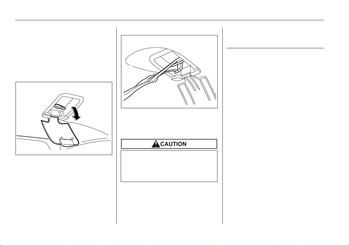
1-38 Seat, seatbelt and SRS airbags
lower anchorages; lift up the head re-
straint while pressing the release button.
Store the head restraint in the cargo area.
Avoid placing the head restraint in the
passenger compartment to prevent it from
being thrown around in the passenger
compartment in a sudden stop or a sharp
turn.
2. Open the cover flaps to use the an-
chorages.
3. Fasten the top tether hook of the child
restraint system to the appropriate upper
anchorage.
4. Tighten the top tether securely.
*SRS airbag (Supplemental
Restraint System airbag)
*SRS: This stands for supplemental re-
straint system. This name is used be-
cause the airbag system supplements the
vehicle’s seatbelts.
Your vehicle is equipped with a crash
sensing and diagnostic module, which will
record the use of the seatbelt(s) by the
driver and/or front passenger when any of
the SRS frontal, side and curtain airbags
deploys.
Vehicle with SRS airbags and
lap/shoulder restraints for
driver, front passenger, and
window-side rear passengers
Your vehicle is equipped with a supple-
mental restraint system in addition to a
lap/shoulder belt at each front seating po-
sition and each rear window-side seating
positions. The supplemental restraint sys-
tem (SRS) consists of six airbags.
The configurations are as follows:
y Driver’s and front passenger’s frontal
airbags
y Driver’s and front passenger’s side air-
bags
y Curtain airbags (for driver, front pas-
100271
Always remove the head restraint
when mounting a child restraint sys-
tem with a top tether. Otherwise, it
may happen that the top tether can-
not be fastened tightly.
200308
Seat, seatbelt and SRS airbags 1-39
– CONTINUED –
senger, and window-side rear passen-
gers)
These SRS airbags are designed only
as a supplement to the primary protec-
tion provided by the seatbelt.
The system also controls front seatbelt
pretensioners. For operation instructions
and precautions concerning the seatbelt
pretensioner, see the “Front seatbelt pre-
tensioners” section in this chapter.
y To obtain maximum protection in
the event of an accident, the driv-
er and all passengers in the vehi-
cle should always wear seatbelts
when the vehicle is moving. The
SRS airbag is designed only as a
supplement to the primary protec-
tion provided by the seatbelt. It
does not do away with the need to
fasten seatbelts. In combination
with the seatbelts, it offers the
best combined protection in case
of a serious accident.
Not wearing a seatbelt increases
the chance of severe injury or
death in a crash even when the ve-
hicle has the SRS airbag.
For instructions and precautions
concerning the seatbelt system,
see the “Seatbelts” section in this
chapter.
y Do not sit or lean unnecessarily
close to the SRS airbag. Because
the SRS airbag deploys with con-
siderable speed – faster than the
blink of an eye – and force to pro-
tect in high speed collisions, the
force of an airbag can injure an
occupant whose body is too close
to SRS airbag.
It is also important to wear your
seatbelt to help avoid injuries that
can result when the SRS airbag
contacts an occupant not in prop-
er position such as one thrown
forward during pre-accident brak-
ing.
Even when properly positioned,
there remains a possibility that an
occupant may suffer minor injury
such as abrasions and bruises to
the face or arms because of the
SRS airbag deployment force.
y The SRS airbags deploy with con-
siderable speed and force. Occu-
pants who are out of proper posi-
tion when the SRS airbag deploys
could suffer very serious injuries.
Because the SRS airbag needs
enough space for deployment, the
driver should always sit upright
and well back in the seat as far
from the steering wheel as practi-
cal while still maintaining full ve-
hicle control and the front passen-
ger should move the seat as far
back as possible and sit upright
and well back in the seat.
y Do not place any objects over or
near the SRS airbag cover or be-
tween you and the SRS airbag. If
the SRS airbag deploys, those ob-
jects could interfere with its prop-
er operation and could be pro-
pelled inside the vehicle and
cause injury.
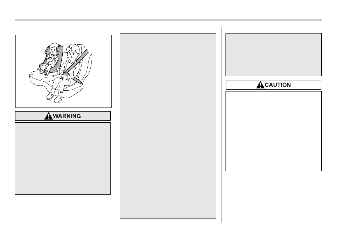
1-40 Seat, seatbelt and SRS airbags
NOTE
When you sell your vehicle, we urge
you to explain to the buyer that it is
equipped with SRS airbags by alerting
him or her to the applicable section in
this owner’s manual.
y Put children aged 12 and under in
the rear seat properly restrained
at all times. The SRS airbag de-
ploys with considerable speed
and force and can injure or even
kill children, especially if they are
12 years of age and under and are
not restrained or improperly re-
strained. Because children are
lighter and weaker than adults,
their risk of being injured from de-
ployment is greater.
100082
Consequently, we strongly rec-
ommend that ALL children (in-
cluding those in child seats and
those that have outgrown child re-
straint devices) sit in the REAR
seat properly restrained at all
times in a child restraint device or
in a seatbelt, whichever is appro-
priate for the child’s age, height
and weight.
Secure ALL types of child re-
straint devices (including forward
facing child seats) in the REAR
seats at all times.
According to accident statistics,
children are safer when properly
restrained in the rear seating posi-
tions than in the front seating po-
sitions.
For instructions and precautions
concerning the child restraint sys-
tem, see the “Child restraint sys-
tems” section in this chapter.
y NEVER INSTALL A REARWARD
FACING CHILD SEAT IN THE
FRONT SEAT. DOING SO RISKS
SERIOUS INJURY OR DEATH TO
THE CHILD BY PLACING THE
CHILD’S HEAD TOO CLOSE TO
THE SRS AIRBAG.
y Never allow a child to stand up, or
to kneel on the front passenger’s
seat, or never hold a child on your
lap or in your arms. The SRS air-
bag deploys with considerable
force and can injure or even kill
the child.
y When the SRS airbag deploys,
some smoke will be released. This
smoke could cause breathing
problems for people with a history
of asthma or other breathing trou-
ble. If you or your passengers
have breathing problems after
SRS airbag deploys, get fresh air
promptly.
y A deploying SRS airbag releases
hot gas. Occupants could get
burned if they come into direct
contact with the hot gas.
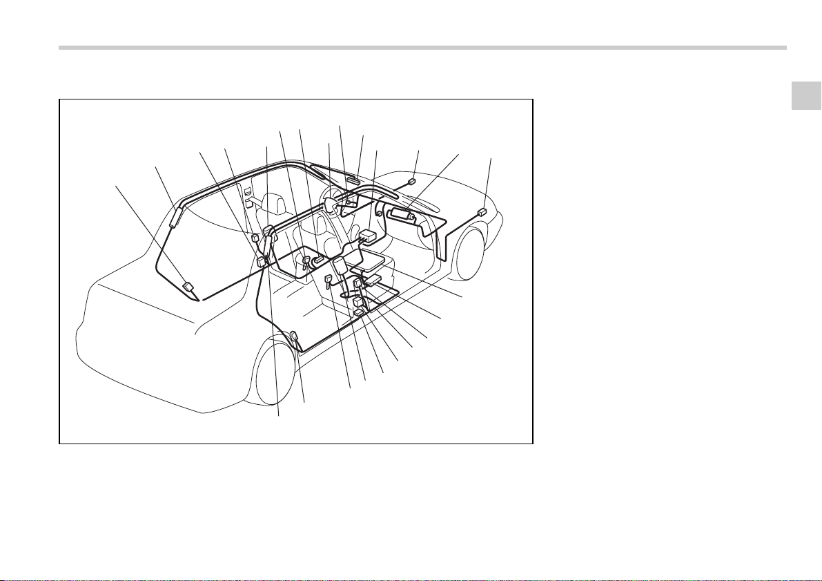
Seat, seatbelt and SRS airbags 1-41
– CONTINUED –
T Components
Sedan
1
2
3
4
5
6
18
19
24
23
8
11
13
14
16
15
21
22
9
7
10
12
20
17
100669
1) Airbag control module (including impact
sensors)
2) Frontal airbag module (driver’s side)
3) Frontal airbag module (front passen-
ger’s side)
4) Front sub sensor (left-hand side)
5) Front sub sensor (right-hand side)
6) Side airbag module (driver’s side)
7) Side airbag module (front passenger’s
side)
8) Side airbag sensor (center pillar left-
hand side)
9) Side airbag sensor (center pillar right-
hand side)
10)Airbag wiring (yellow)
11)Seatbelt pretensioner (driver’s side)
12)Seatbelt pretensioner (front passenger’s
side)
13)Curtain airbag sensor (rear wheel house
right-hand side)
14)Curtain airbag sensor (rear wheel house
left-hand side)
15)Curtain airbag module (right side)
16)Curtain airbag module (left side)
17)Seatbelt buckle switch (front passen-
ger’s side)
18)Seatbelt buckle switch (driver’s side)
19)Driver’s seat position sensor
20)Front passenger’s seatbelt tension sen-
sor
21)Front passenger’s occupant detection
system weight sensor
22)Front passenger’s occupant detection
control module
23)Front passenger’s frontal airbag ON and
OFF indicator
24)SRS airbag system warning light
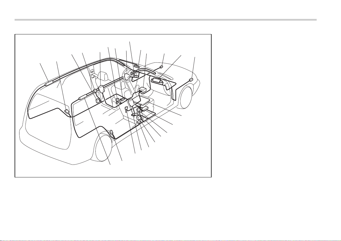
1-42 Seat, seatbelt and SRS airbags
Station wagon
1
2
3
4
5
13
6
18
19
24
23
8
11
14
15
16
21
22
9
7
10
12
20
17
100700
1) Airbag control module (including impact
sensors)
2) Frontal airbag module (driver’s side)
3) Frontal airbag module (front passen-
ger’s side)
4) Front sub sensor (left-hand side)
5) Front sub sensor (right-hand side)
6) Side airbag module (driver’s side)
7) Side airbag module (front passenger’s
side)
8) Side airbag sensor (center pillar left-
hand side)
9) Side airbag sensor (center pillar right-
hand side)
10)Airbag wiring (yellow)
11)Seatbelt pretensioner (driver’s side)
12)Seatbelt pretensioner (front passenger’s
side)
13)Curtain airbag sensor (rear wheel house
right-hand side)
14)Curtain airbag sensor (rear wheel house
left-hand side)
15)Curtain airbag module (right side)
16)Curtain airbag module (left side)
17)Seatbelt buckle switch (front passen-
ger’s side)
18)Seatbelt buckle switch (driver’s side)
19)Driver’s seat position sensor
20)Front passenger’s seatbelt tension sen-
sor
21)Front passenger’s occupant detection
system weight sensor
22)Front passenger’s occupant detection
control module
23)Front passenger’s frontal airbag ON and
OFF indicator
24)SRS airbag system warning light
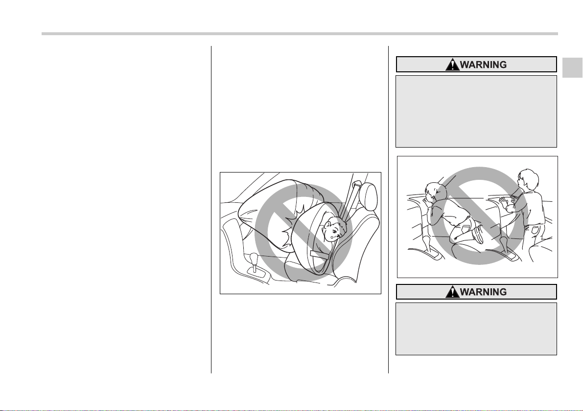
Seat, seatbelt and SRS airbags 1-43
– CONTINUED –
Subaru advanced frontal air-
bag system
Your vehicle is equipped with a Subaru
advanced frontal airbag system that com-
plies with the new advanced frontal airbag
requirements in the amended Federal Mo-
tor Vehicle Safety Standard (FMVSS) No.
208.
The Subaru advanced frontal airbag sys-
tem automatically determines the deploy-
ment force of the driver’s SRS frontal air-
bag at the time of deployment as well as
whether or not to activate the front pas-
senger’s SRS frontal airbag and, if activat-
ed, the deployment force of the SRS fron-
tal airbag at the time of deployment.
Your vehicle has warning labels on the
driver’s and front passenger’s sun visors
beginning with the phrase “EVEN WITH
ADVANCED AIR BAGS” and a tag at-
tached to the glove box lid beginning with
the phrase “Even with Advanced Air
Bags”. Make sure that you carefully read
the instructions on the warning labels and
tag.
Always wear your seatbelt. The subaru
advanced frontal airbag system is a sup-
plemental restraint system and must be
used in combination with a seatbelt. All
occupants should wear a seatbelt or be
seated in an appropriate child restraint
system.
The driver’s SRS frontal airbag is stowed
in the center portion of the steering wheel.
The front passenger’s SRS frontal airbag
is stowed near the top of the dashboard
under an “SRS AIRBAG” mark.
In a moderate to severe frontal collision,
the driver’s and front passenger’s SRS
frontal airbags deploy and supplement the
seatbelts by reducing the impact on the
driver’s and front passenger’s head and
chest.
100261
NEVER INSTALL A REARWARD
FACING CHILD SAFETY SEAT IN
THE FRONT SEAT. DOING SO
RISKS SERIOUS INJURY OR DEATH
TO THE CHILD BY PLACING THE
CHILD’S HEAD TOO CLOSE TO THE
SRS AIRBAG.
Never allow a child to stand up, or to
kneel on the front passenger’s seat.
The SRS airbag deploys with con-
siderable force and can injure or
even kill the child.
100126
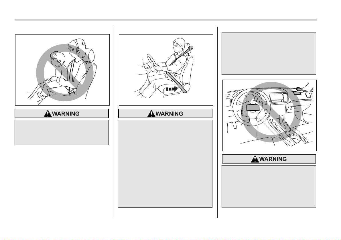
1-44 Seat, seatbelt and SRS airbags
Never hold a child on your lap or in
your arms. The SRS airbag deploys
with considerable force and can in-
jure or even kill the child.
100125
The SRS airbag deploys with con-
siderable speed and force. Occu-
pants who are out of proper position
when the SRS airbag deploys could
suffer very serious injuries. Be-
cause the SRS airbag needs enough
space for deployment, the driver
should always sit upright and well
back in the seat as far from the
steering wheel as practical while
still maintaining full vehicle control
and the front passenger should
move the seat as far back as possi-
ble and sit upright and well back in
the seat.
100155
It is also important to wear your
seatbelt to help avoid injuries that
can result when the SRS airbag con-
tacts an occupant not in proper po-
sition such as one thrown toward
the front of the vehicle during pre-
accident braking.
Do not put any objects over the
steering wheel pad and dashboard.
If the SRS frontal airbag deploys,
those objects could interfere with its
proper operation and could be pro-
pelled inside the vehicle and cause
injury.
100274
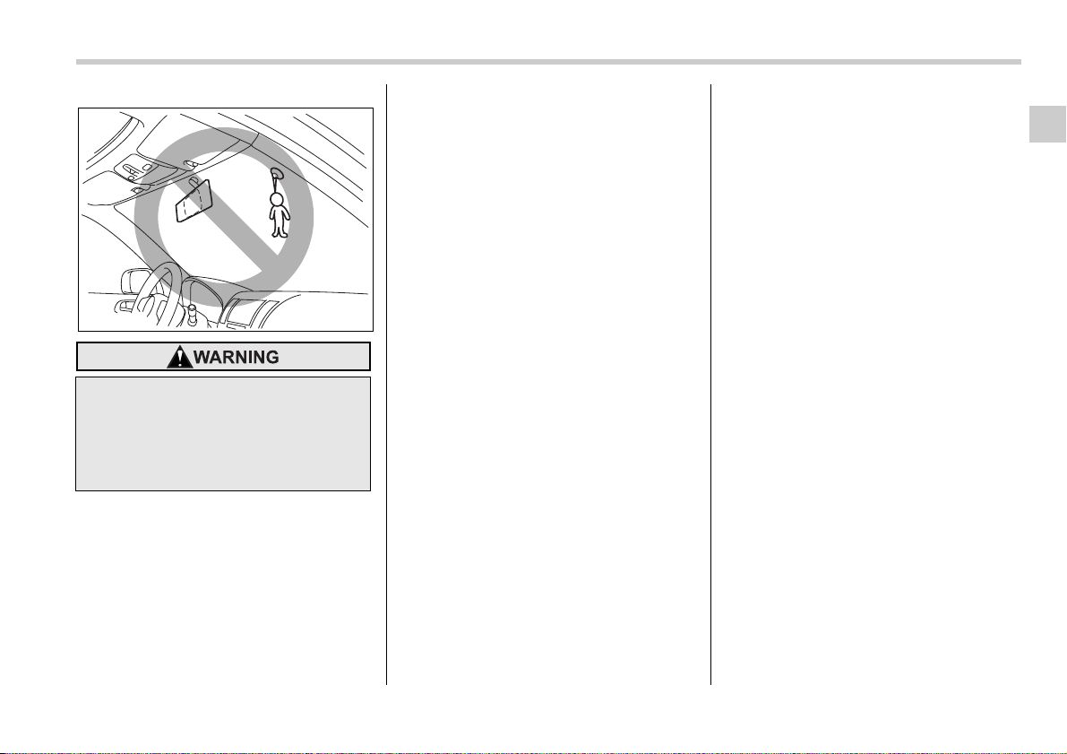
Seat, seatbelt and SRS airbags 1-45
– CONTINUED –
T Driver’s SRS frontal airbag
The driver’s SRS frontal airbag uses a
dual stage inflator. The inflator operates in
different ways depending on the severity
of impact, backward-forward adjustment
of the driver’s seat position and whether or
not he/she is wearing the seatbelt.
The backward-forward adjustment of the
driver’s seat position is monitored by the
driver’s seat position sensor under the
driver’s seat.
Whether or not the driver is wearing the
seatbelt is monitored by the seatbelt buck-
le switch.
Observe the following precautions. Failure
to do so may cause the seatbelt buckle
switch and/or the seat position sensor to
malfunction, preventing the Subaru ad-
vanced frontal airbag system from func-
tioning correctly or causing the system to
fail.
y Do not place articles/metal objects or in-
stall any accessory other than a genuine
SUBARU accessory under the driver’s
seat. Do not allow the rear seat occupant
to kick the driver’s seat or push up its bot-
tom surface with his/her feet.
y Do not place a magnet near the seatbelt
buckle or under the driver’s seat.
If the seatbelt buckle switch and/or the
driver’s seat position sensor have failed,
the SRS airbag system warning light will il-
luminate. Although the driver’s SRS fron-
tal airbag can deploy regardless of the
backward-forward adjustment of the driv-
er’s seat position even when the warning
light is on, have the system inspected by
your SUBARU dealer immediately if the
SRS airbag system warning light comes
on.
NOTE
The driver’s SRS side airbag, SRS cur-
tain airbag and seatbelt pretensioner
are not controlled by the Subaru ad-
vanced frontal airbag system.
T Front passenger’s SRS frontal air-
bag
The front passenger’s SRS frontal airbag
uses a dual stage inflator. The inflator op-
erates in different ways depending on the
severity of impact.
The total load on the seat is monitored by
the passenger’s occupant detection sys-
tem weight sensor under the seat.
The system has another sensor that mon-
itors the tension of the front passenger
seatbelt. Using the total seat load and
seatbelt tension data from the sensors,
the occupant detection system deter-
mines whether the front passenger’s SRS
frontal airbag should or should not be in-
flated.
The occupant detection system may not
inflate the front passenger’s SRS frontal
airbag even when the driver’s SRS frontal
airbag deploys. This is normal.
Observe the following precautions. Failure
to do so may prevent the Subaru ad-
vanced frontal airbag system from func-
tioning correctly or cause the system to
fail.
Do not attach accessories to the
windshield, or fit an extra-wide mir-
ror over the rear view mirror. If the
SRS airbag deploys, those objects
could become projectiles that could
seriously injure vehicle occupants.
100275
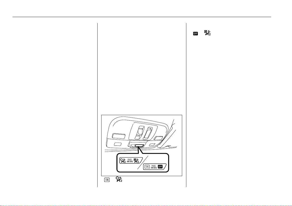
1-46 Seat, seatbelt and SRS airbags
y Do not apply any strong impact to the
front passenger’s seat such as by kicking.
y Do not spill liquid on the front passen-
ger’s seat. If liquid is spilled, wipe it off im-
mediately.
y Do not disassemble the front passen-
ger’s seat.
y Do not install any accessory (such as
an audio amplifier) other than a genuine
SUBARU accessory under the front pas-
senger’s seat.
y Do not place anything (shoes, umbrella,
etc.) under the front passenger’s seat.
y The front passenger’s seat must not be
used with the head restraint removed.
y Do not leave any article including a child
restraint system on the front passenger’s
seat or the seatbelt tongue and buckle en-
gaged when you leave your vehicle.
y Do not place a magnet near the seatbelt
buckle and the seatbelt retractor.
y Do not use front seats with their back-
ward-forward position and seatback not
being locked into place securely. If any of
them are not locked securely, adjust them
again. For adjusting procedure, refer to
the “Manual seat” in the front seats sec-
tion in Chapter 1 in this owner’s manual.
(Models equipped with manual seats only)
If the seatbelt buckle switch and/or front
passenger’s occupant detection system
have failed, the SRS airbag system warn-
ing light will illuminate. Have the system
inspected by your SUBARU dealer imme-
diately if the SRS airbag system warning
light comes on.
If your vehicle has sustained impact, this
may affect the proper function of the
Subaru advanced frontal airbag system.
Have your vehicle inspected at your
SUBARU dealer.
NOTE
The front passenger’s SRS side airbag,
SRS curtain airbag and seatbelt preten-
sioner are not controlled by the Subaru
advanced frontal airbag system.
T Passenger’s frontal airbag ON and
OFF indicators
or : Front passenger’s frontal air-
bag ON indicator
or : Front passenger’s frontal air-
bag OFF indicator
The front passenger’s frontal airbag ON
and OFF indicators show you the status of
the front passenger’s SRS frontal airbag.
The indicators are located between the
map lights.
When the ignition switch is turned to the
“ON” position, both the ON and OFF indi-
cators illuminate for 6 seconds during
which time the system is checked. Follow-
ing the system check, both indicators ex-
tinguish for 2 seconds. After that, one of
the indicators illuminates depending on
the status of the front passenger’s SRS
frontal airbag determined by the Subaru
advanced frontal airbag system monitor-
ing.
If the front passenger’s SRS frontal airbag
is activated, the passenger’s frontal airbag
ON indicator will illuminate while the OFF
indicator will remain extinguished.
If the front passenger’s SRS frontal airbag
is deactivated, the passenger’s frontal air-
bag ON indicator will remain extinguished
while the OFF indicator will illuminate.
If both the ON and OFF indicators remain
lit or extinguished simultaneously, the sys-
tem is faulty. Contact your SUBARU deal-
er immediately for an inspection.
100663
Seat, seatbelt and SRS airbags 1-47
– CONTINUED –
T Conditions in which front passen-
ger’s SRS frontal airbag is not acti-
vated
The front passenger’s SRS frontal airbag
will not be activated when any of the fol-
lowing conditions are met regarding the
front passenger’s seat:
y The seat is empty.
y The seat is equipped with a rearward
facing child restraint system and an infant
is restrained with it. (See WARNING that
follows.)
y The seat is equipped with a forward fac-
ing child restraint system and a small child
is restrained with it. (See WARNING that
follows.)
y The seat is equipped with a booster
seat and a small child is in the booster
seat. (See WARNING that follows.)
y The seat is relieved of the occupant
load for a time exceeding the predeter-
mined monitoring time period.
y The seat is occupied by a child who has
outgrown a child restraint system (See
WARNING that follows.) or by a small
adult.
y The front passenger’s occupant detec-
tion system is faulty.
When the front passenger’s seat is occu-
pied by a child, observe the following pre-
cautions. Failure to do so may increase
the load on the front passenger’s seat, ac-
tivating the front passenger’s SRS frontal
airbag even though that seat is occupied
by a child.
y Do not place any article on the seat oth-
er than the child occupant and a child re-
straint system.
y Do not place more than one child on the
seat.
y Do not install any accessory such as a
table or TV onto the seatback.
y Do not store a heavy load in the seat-
back pocket.
y Do not allow the rear seat occupant to
place his/her hands or legs on the front
passenger’s seatback, or allow him/her to
pull the seatback.
V If the front passenger’s frontal air-
bag ON indicator illuminates and the
OFF indicator extinguishes even
when an infant or a small child is in
a child restraint system (including
booster seat)
Turn the ignition switch to the “OFF” posi-
tion if the front passenger’s frontal airbag
ON indicator illuminates and the OFF indi-
cator extinguishes even when an infant or
a small child is in a child restraint system
(including booster seat). Remove the child
restraint system from the seat. By refer-
ring to the child restraint manufacturer’s
recommendations as well as the child re-
straint system installation procedures in
the “Child restraint systems” section in this
chapter, correctly install the child restraint
system. Turn the ignition switch to the
“ON” position and make sure that the front
passenger’s frontal airbag ON indicator
NEVER INSTALL A REARWARD
FACING CHILD SEAT IN THE FRONT
PASSENGER’S SEAT EVEN IF THE
FRONT PASSENGER’S SRS FRON-
TAL AIRBAG IS DEACTIVATED. Be
sure to install it in the REAR seat in
a correct manner. Also, it is strongly
recommended that any forward fac-
ing child seat or booster seat be in-
stalled in the REAR seat, and that
even children who have outgrown a
child restraint system be also seat-
ed in the REAR seat. This is because
children sitting in the front passen-
ger’s seat may be killed or severely
injured should the front passenger’s
SRS frontal airbag deploy. REAR
seats are the safest place for chil-
dren.

1-48 Seat, seatbelt and SRS airbags
goes out and the OFF indicator comes on.
If still the ON indicator remains illuminated
while the OFF indicator extinguishes, take
the following actions.
y Ensure that no article is placed on the
seat other than the child restraint system
and the child occupant.
y Ensure that there is no article left in the
seatback pocket.
y Ensure that the backward-forward posi-
tion and seatback of front passenger’s
seat are locked into place securely by
moving the seat back and forth. (Models
equipped with manual seats only)
If the ON indicator still illuminates while
the OFF indicator extinguishes after tak-
ing relevant corrective actions described
above, relocate the child restraint system
to the rear seat and immediately contact
your SUBARU dealer for an inspection.
NOTE
When a child who has outgrown a child
restraint system or a small adult is
seated in the front passenger’s seat,
the Subaru advanced frontal airbag
system may or may not activate the
front passenger’s SRS frontal airbag
depending on the occupant’s seating
posture. If the front passenger’s SRS
frontal airbag is activated (the ON indi-
cator illuminates while the OFF indica-
tor extinguishes), take the following
actions.
y Ensure that no article is placed on
the seat other than the occupant.
y Ensure that there is no article left in
the seatback pocket.
If the ON indicator still illuminates
while the OFF indicator extinguishes
despite the fact that the actions noted
above have been taken, seat the child/
small adult in the rear seat and immedi-
ately contact your SUBARU dealer for
an inspection. Even if the system has
passed the dealer inspection, it is rec-
ommended that on subsequent trips
the child/small adult always take the
rear seat.
Children who have outgrown a child re-
straint system should always wear the
seatbelt irrespective of whether the airbag
is deactivated or activated.
T Conditions in which front passen-
ger’s SRS frontal airbag is activated
The front passenger’s SRS frontal airbag
will be activated for deployment upon im-
pact when any of the following conditions
is met regarding the front passenger’s
seat.
y When the seat is occupied by an adult.
y When a heavy article is placed on the
seat.
When the front passenger’s seat is occu-
pied by an adult, observe the following
precautions. Failure to do so may lessen
the load on the front passenger’s seat, de-
activating the front passenger’s SRS fron-
tal airbag despite the fact that the seat is
occupied by an adult.
y Do not allow the rear seat occupant to
lift the front passenger’s seat cushion us-
ing his/her feet.
y Do not place any article under the front
passenger’s seat, or squeeze any article
from behind and under the seat. This may
lift the seat cushion.
y Do not squeeze any article between the
front passenger’s seat and side trim/pillar,
door or center console box. This may lift
the seat cushion.
V If the passenger’s frontal airbag
OFF indicator illuminates and the
ON indicator extinguishes even
when the front passenger’s seat is
occupied by an adult
This can be caused by the adult incorrect-
ly sitting in the front passenger’s seat.
Turn the ignition switch to the “OFF” posi-
tion. Ask the front passenger to set the
seatback to the upright position, sit up
straight in the center of the seat cushion,

Seat, seatbelt and SRS airbags 1-49
– CONTINUED –
correctly fasten the seatbelt, position his/
her legs out forward, and adjust the seat
to the rearmost position. Turn the ignition
switch to the “ON” position. If the OFF in-
dicator remains illuminated while the ON
indicator remains extinguished, take the
following actions.
y Turn the ignition switch to the “OFF” po-
sition.
y Ensure that there is no article, book,
shoe, or other object trapped under the
seat, at the rear of the seat, or on the side
of the seat.
y Ensure that the backward-forward posi-
tion and seatback of front passenger’s
seat are locked into place securely by
moving the seat back and forth. (Models
equipped with manual seats only)
y Next, turn the ignition switch to the “ON”
position and wait 6 seconds to allow the
system to complete self-checking. Follow-
ing the system check, both indicators ex-
tinguish for 2 seconds. Now, the ON indi-
cator should illuminate while the OFF indi-
cator remains extinguished.
If the OFF indicator still illuminates while
the ON indicator remains extinguished,
ask the occupant to move to the rear seat
and immediately contact your SUBARU
dealer for an inspection.
T Effect vehicle modifications made
for persons with disabilities may
have on Subaru advanced frontal
airbag system operation (U.S. only)
Changing or moving any parts of the front
seats, seat belts, front bumper, front side
frame, instrument panel, combination
meter, steering wheel, steering column,
tire, suspension or floor panel can affect
the operation of the Subaru advanced air-
bag system. If you have any questions,
you may contact the following Subaru dis-
tributors:
<Continental U.S., Alaska and the District
of Columbia>
Subaru of America, Inc.
Customer Dealer Services Department
P.O. Box 6000
Cherry Hill, NJ 08034-6000
1-800-SUBARU3 (1-800-782-2783)
<Hawaii>
Schuman Carriage Motors, Inc.
1234 South Beretania Street, Honolulu, HI
96814
808-592-4497
<Guam>
Triple J Enterprises, Inc.
P.O. Box 6066, Tamuning, Guam 96931
671-646-9126
<Puerto Rico>
Trebol Subaru of Puerto Rico, Inc.
P.O. Box 11204, San Juan, Puerto Rico
00910
787-793-2828
There are currently no Subaru distributors
in any other U.S. territories. If you are in
such an area, please contact the Subaru
distributor or dealer from which you
bought your vehicle.
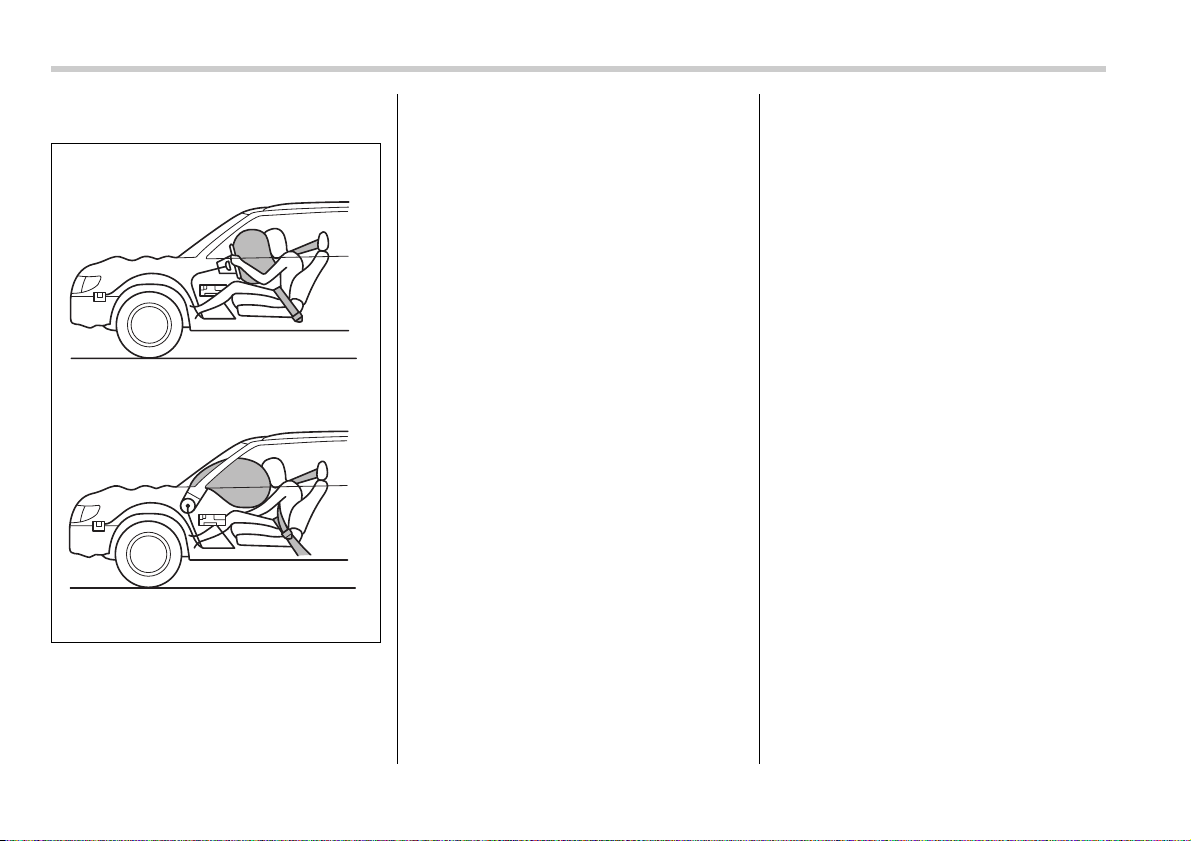
1-50 Seat, seatbelt and SRS airbags
T Operation
1) Driver’s side
2) Passenger’s side
The SRS airbag can function only when
the ignition switch is in the “ON” position.
The Subaru advanced frontal airbag sys-
tem is designed to determine the activa-
tion or deactivation condition of the front
passenger’s SRS frontal airbag depend-
ing on the total load on the front passen-
ger’s seat monitored by the front passen-
ger’s occupant detection system weight
sensor. For this reason, only the driver’s
SRS frontal airbag may deploy in the
event of a collision, but this does not mean
failure of the system.
If the front sub sensors inside both front
fenders and the impact sensors in the air-
bag control module detect a predeter-
mined amount of force during a frontal col-
lision, the control module sends signals to
the airbag module(s) (only driver’s module
or both driver’s and front passenger’s
modules) instructing the module(s) to in-
flate the SRS frontal airbag(s). The driv-
er’s and front passenger’s SRS frontal air-
bags use dual stage inflators. The two in-
flators of each airbag are triggered either
sequentially or simultaneously, depending
on the severity of impact, backward-for-
ward adjustment of the driver’s seat posi-
tion and fastening/unfastening of the seat-
belt in the case of the driver’s SRS frontal
airbag and depending on the severity of
impact and the total load on the seat in the
case of the front passenger’s SRS frontal
airbag. After deployment, the SRS airbag
immediately starts to deflate so that the
driver’s vision is not obstructed. The time
required from detecting impact to the de-
flation of the SRS airbag after deployment
is shorter than the blink of an eye.
Both when only the driver’s SRS frontal
airbag deploys and the driver’s and front
passenger’s SRS frontal airbags deploy,
the driver’s and front passenger’s seatbelt
pretensioners operate at the same time.
Although it is highly unlikely that the SRS
airbag would activate in a non-accident
situation, should it occur, the SRS airbag
will deflate quickly, not obscuring vision
and will not interfere with the driver’s abil-
ity to maintain control of the vehicle.
When the SRS airbag deploys, a sudden,
fairly loud inflation noise will be heard and
some smoke will be released. These oc-
currences are a normal result of the de-
ployment. This smoke does not indicate a
fire in the vehicle.
1
2
100534
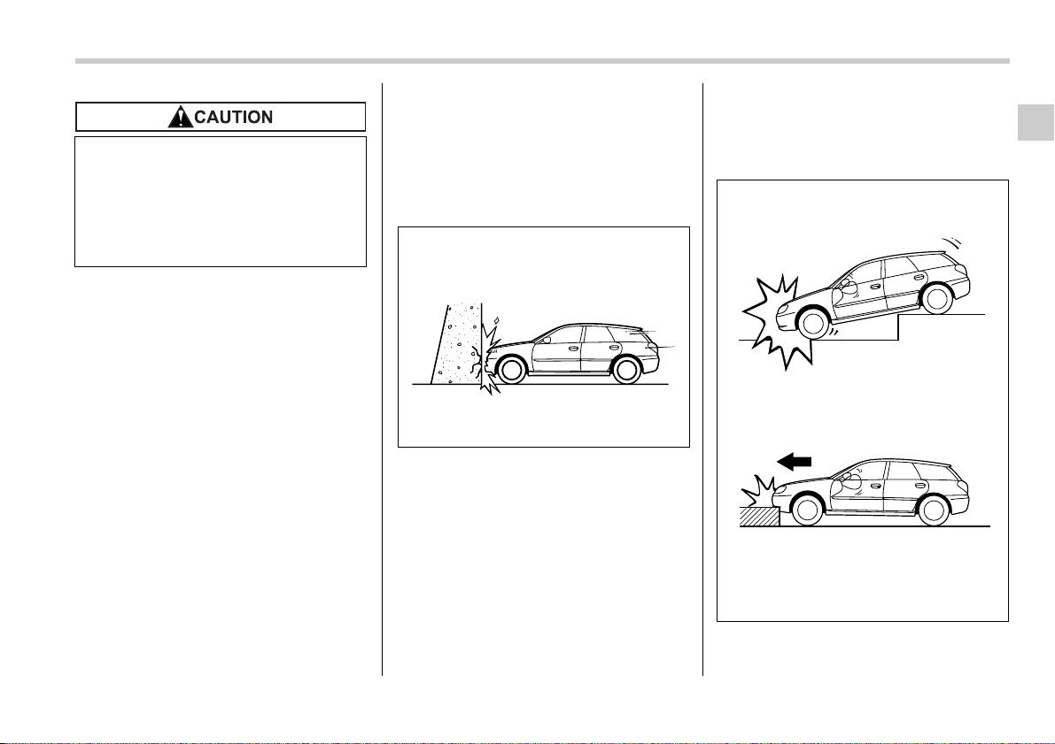
Seat, seatbelt and SRS airbags 1-51
– CONTINUED –
The driver’s SRS frontal airbag and front
passenger’s SRS frontal airbag are de-
signed to deploy in the event of an acci-
dent involving a moderate to severe fron-
tal collision. It is basically not designed to
deploy in lesser frontal impacts because
the necessary protection can be achieved
by the seatbelt alone. Also, they are basi-
cally not designed to deploy in side or rear
impacts or in roll-over accidents because
deployment of only the driver’s SRS fron-
tal airbag or both driver’s and front pas-
senger’s SRS frontal airbags would not
help the occupant in those situations. The
driver’s and front passenger’s SRS frontal
airbags are designed to function on a one-
time-only basis.
SRS airbag deployment depends on the
level of force experienced in the passen-
ger compartment during a collision. That
level differs from one type of collision to
another, and it may have no bearing on
the visible damage done to the vehicle it-
self.
V Examples of accident in which the
driver’s/driver’s and front passen-
ger’s SRS frontal airbag(s) will most
likely deploy.
A head-on collision against a thick con-
crete wall at a vehicle speed of 12 to 19
mph (20 to 30 km/h) or higher activates
only the driver’s SRS frontal airbag or both
driver’s and front passenger’s SRS frontal
airbags. The airbag(s) will also be activat-
ed when the vehicle is exposed to a frontal
impact similar in fashion and magnitude to
the collision described above.
V Examples of the types of accidents
in which it is possible that the driv-
er’s/driver’s and front passenger’s
SRS frontal airbag(s) will deploy.
The only the driver’s SRS frontal airbag or
both driver’s and front passenger’s SRS
Do not touch the SRS airbag system
components around the steering
wheel and dashboard with bare
hands right after deployment. Doing
so can cause burns because the
components can be very hot as a re-
sult of deployment.
200312
100277
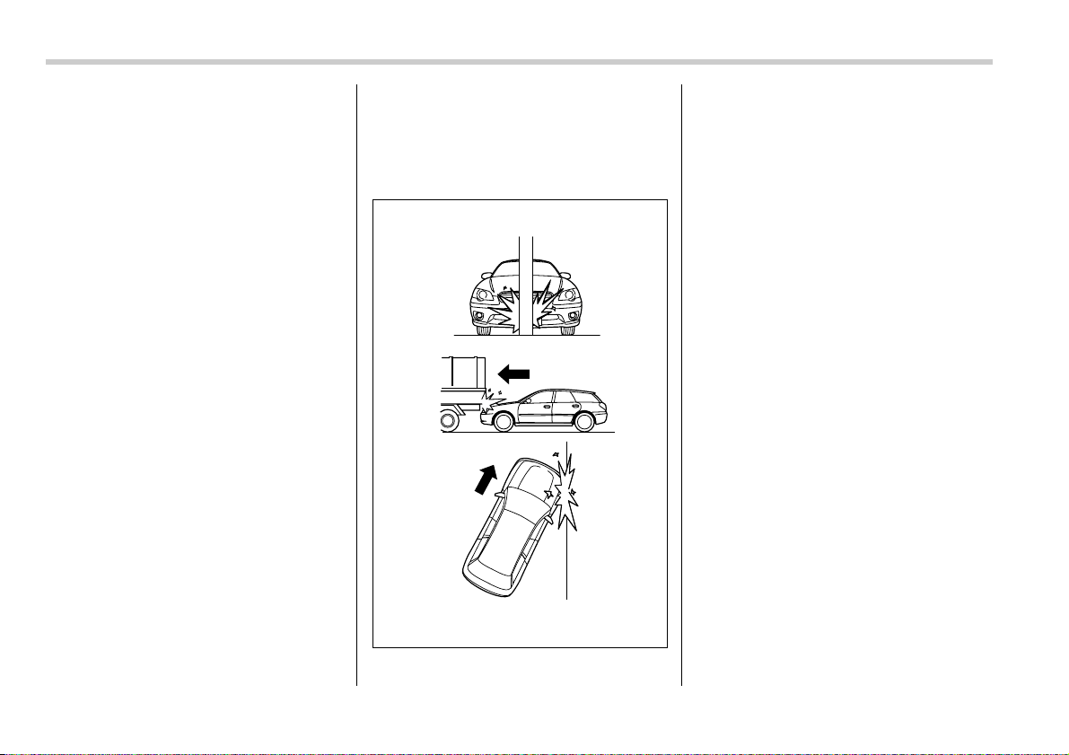
1-52 Seat, seatbelt and SRS airbags
frontal airbags may be activated when the
vehicle sustains a hard impact in the un-
dercarriage area from the road surface
(such as when the vehicle plunges into a
deep ditch, is severely impacted or
knocked hard against an obstacle on the
road such as a curb).
V Examples of the types of accidents
in which deployment of the driver’s/
driver’s and front passenger’s SRS
frontal airbag(s) is unlikely to de-
ploy.
There are many types of collisions which
might not necessarily require deployment
of driver’s/driver’s and front passenger’s
SRS frontal airbag(s). If the vehicle strikes
an object, such as a telephone pole or
sign pole, or if it slides under a truck’s load
bed, or if it sustains an oblique offset fron-
tal impact, the driver’s/driver’s and front
passenger’s SRS frontal airbag(s) may
not deploy depending on the level of acci-
dent forces involved.
100278
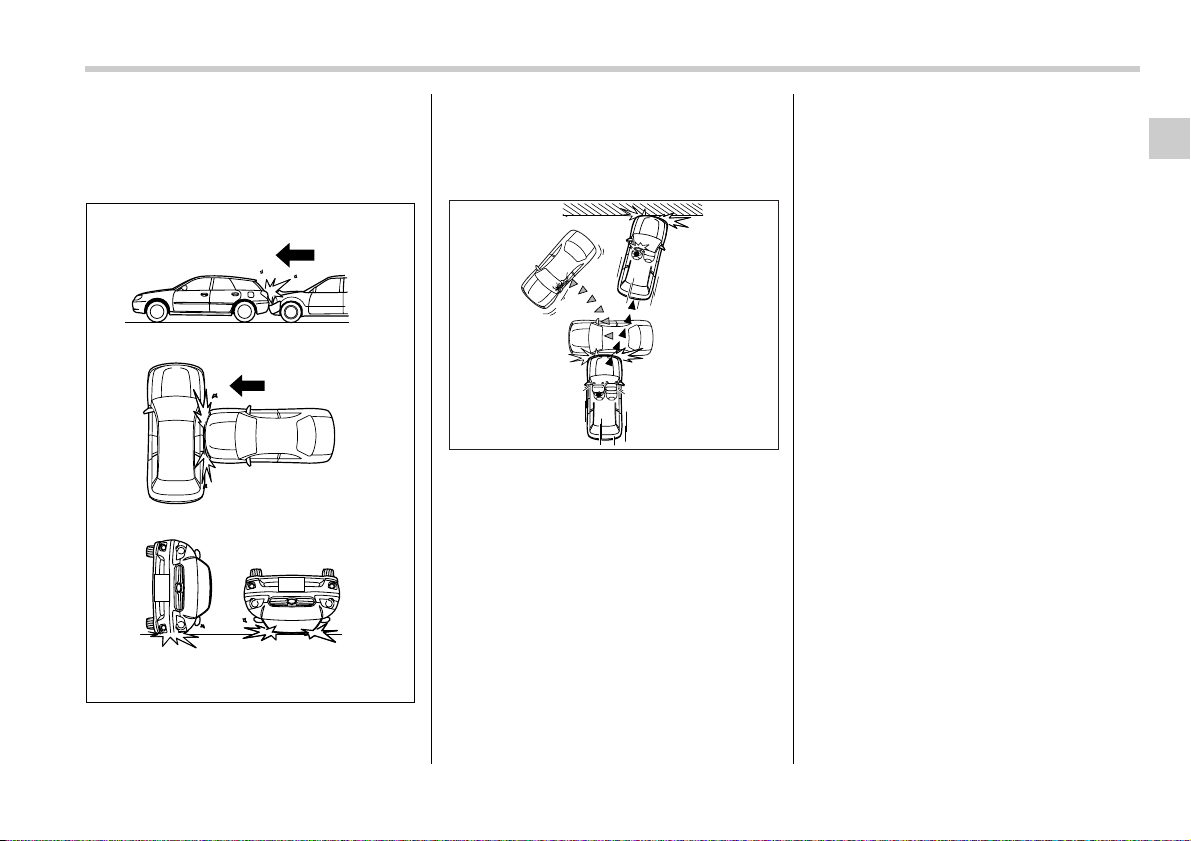
Seat, seatbelt and SRS airbags 1-53
– CONTINUED –
V Examples of the types of accidents
in which the driver’s/driver’s and
front passenger’s SRS frontal air-
bag(s) will basically not deploy.
The driver’s and front passenger’s SRS
frontal airbags are designed basically not
to deploy if the vehicle is struck from the
side or from behind, or if it rolls onto its
side or roof, or if it is involved in a low-
speed frontal collision.
1) First impact
2) Second impact
In an accident where the vehicle is impact-
ed more than once, the driver’s and/or
front passenger’s SRS frontal airbag(s)
will deploy only once on the first impact.
Example: In the case of a double collision,
first with another vehicle, then against a
concrete wall in immediate succession,
once either or both of the driver’s and front
passenger’s SRS frontal airbags is/are ac-
tivated on the first impact, it/they will not
be activated on the second impact.
SRS side airbag and SRS cur-
tain airbag
The SRS side airbag is stored in the door
side of each front seat seatback, which
bears an “SRS AIRBAG” label.
In a moderate to severe side impact colli-
sion, the SRS side airbag on the impacted
side of the vehicle deploys between the
occupant and the door panel and supple-
ments the seatbelt by reducing the impact
on the occupant’s chest and waist. The
SRS side airbag operates only for front
seat occupants.
The SRS curtain airbag on each side of
the cabin is stored in the roof side (be-
tween the front pillar and a point over the
rear seat). An “SRS AIRBAG” mark is lo-
cated at the top of each center pillar.
In a moderate to severe side impact colli-
sion, the SRS curtain airbag on the im-
pacted side of the vehicle deploys be-
tween the occupant and the side window
and supplements the seatbelt by reducing
the impact on the occupant’s head.
100279
2
1
100539
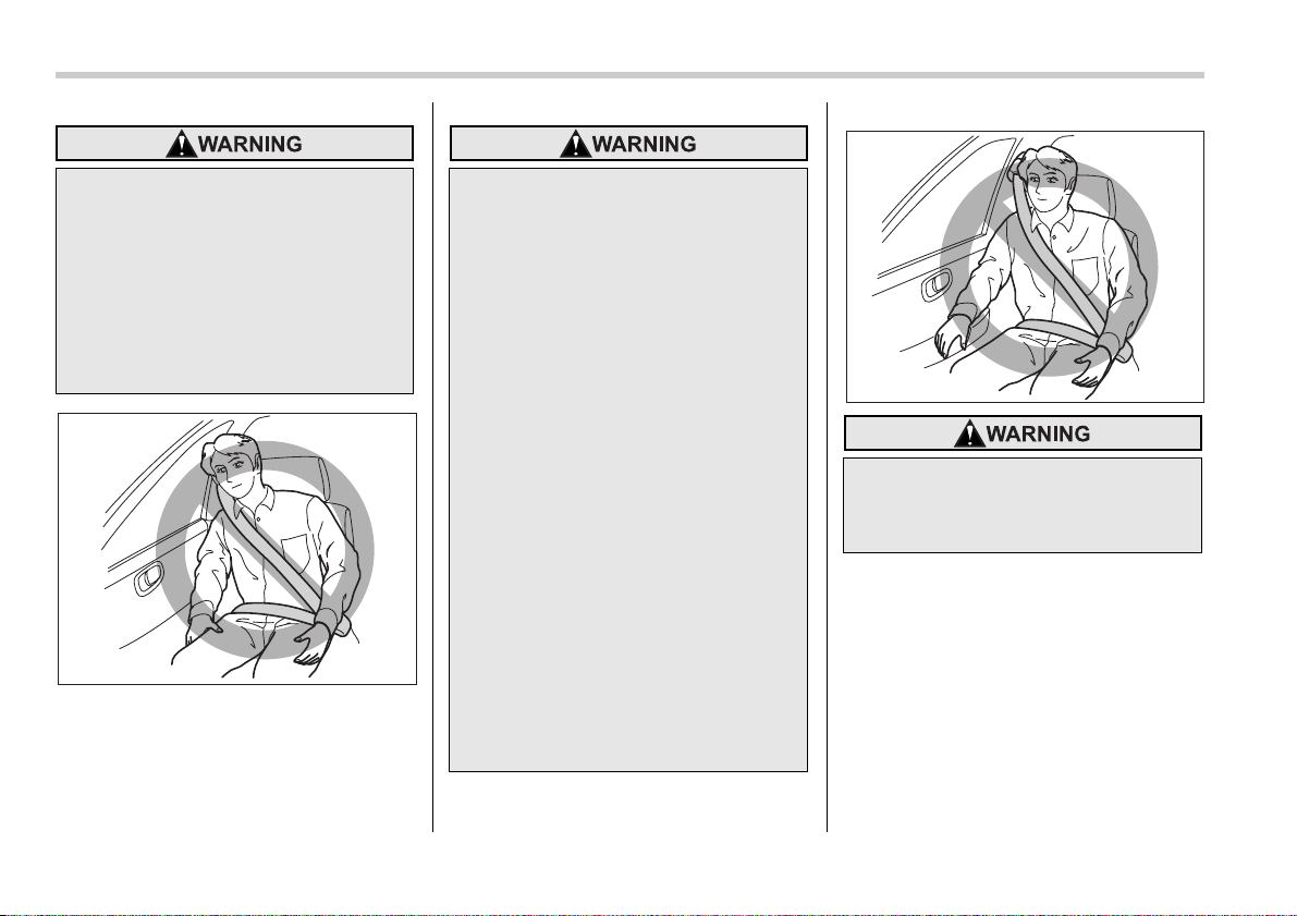
1-54 Seat, seatbelt and SRS airbags
The SRS side airbag and SRS cur-
tain airbag are designed as only a
supplement to the primary protec-
tion provided by the seatbelt. They
do not do away with the need to fas-
ten seatbelts. It is also important to
wear your seatbelt to help avoid in-
juries that can result when an occu-
pant is not seated in a proper up-
right position.
100164
y Do not sit or lean unnecessarily
close to either front door. The
SRS side airbag is stored in both
front seat seatbacks next to the
door, and it provides protection
by deploying rapidly (faster than
the blink of an eye) in the event of
a side impact collision. However,
the force of SRS side airbag de-
ployment may cause injuries if
your head or other parts of the
body are too close to the SRS side
airbag.
y Since your vehicle is equipped
with SRS curtain airbags, do not
sit or lean unnecessarily close to
the front or rear door on either
side. The SRS curtain airbag on
each side of the cabin is stored in
the roof side (between the front
pillar and a point over the rear
seat), and it provides protection
by deploying rapidly (faster than
the blink of an eye) in the event of
a side impact. However, the force
of its deployment may cause inju-
ries if your head is too close to it.
Do not rest your arm on either front
door or its internal trim. It could be
injured in the event of SRS side air-
bag deployment.
100165
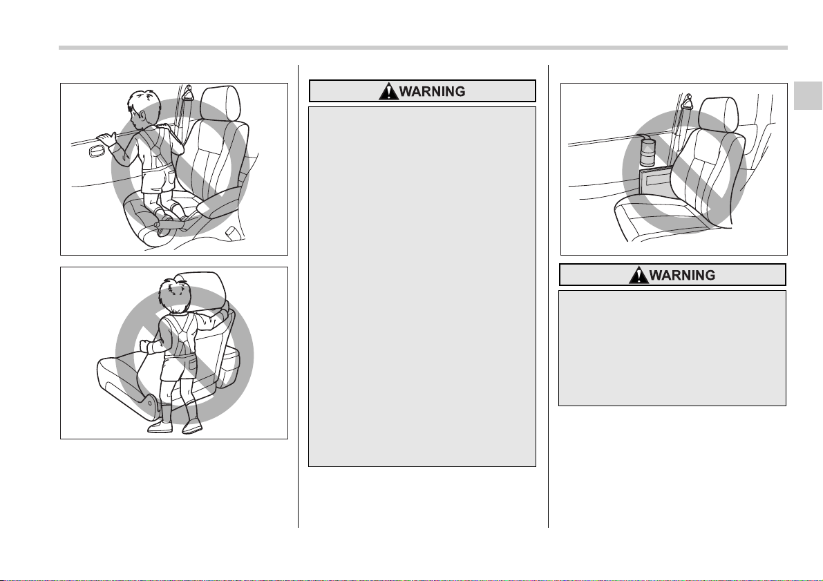
Seat, seatbelt and SRS airbags 1-55
– CONTINUED –
100166
100167
y Never allow a child to kneel on the
front passenger’s seat facing the
side window or to wrap his/her
arms around the front seat seat-
back. In the event of an accident,
the force of the SRS side airbag
deployment could injure the child
seriously because his/her head or
arms or other parts of the body
are too close to the SRS side air-
bag.
Since your vehicle is also
equipped with a front passenger’s
SRS frontal airbag, children aged
12 and under should be placed in
the rear seat anyway and should
be properly restrained at all times.
y Never allow a child to kneel on the
front and rear passenger’s seat
facing the side window. In the
event of an accident, the force of
the SRS curtain airbag deploy-
ment could injure the child seri-
ously because his/her head is
close to the SRS curtain airbag.
y Do not attach accessories to the
door trim or near either SRS side
airbags and do not place objects
near the SRS side airbags. In the
event of the SRS side airbag de-
ployment, they could be propelled
dangerously toward the vehicle’s
occupants and cause injuries.
100168
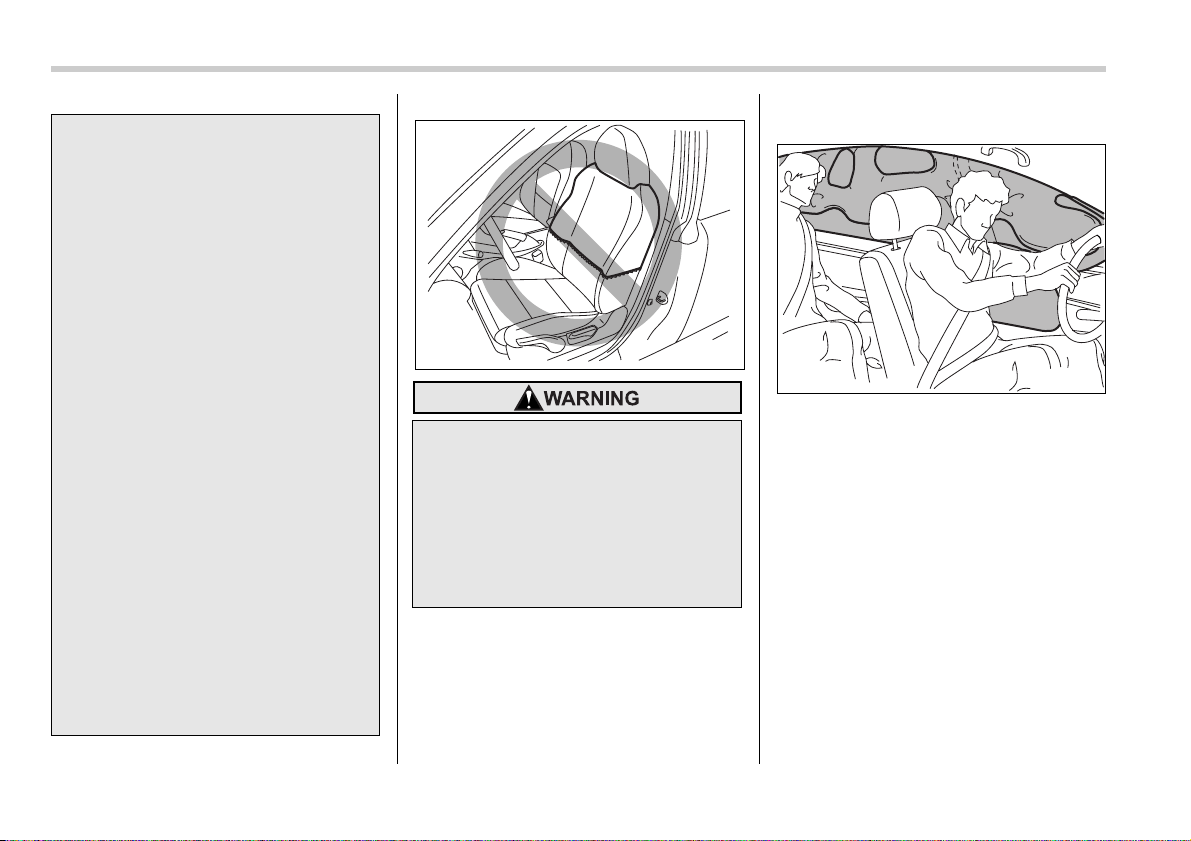
1-56 Seat, seatbelt and SRS airbags
T Operation
The SRS side airbag and SRS curtain air-
bag can function only when the ignition
switch is in the “ON” position.
The driver’s and front passenger’s SRS
side airbags and SRS curtain airbags de-
ploy independently of each other since
each has its own impact sensor. There-
fore, they may not both deploy in the same
accident. Also, the SRS side airbag and
SRS curtain airbag deploys independently
of the driver’s and front passenger’s SRS
frontal airbags in the steering wheel and
instrument panel.
An impact sensor is located in each of the
left and right center pillars and rear wheel
houses. If a center pillar impact sensor
y Do not attach a hands-free micro-
phone or any other accessory to a
front pillar, a center pillar, a rear
pillar, the windshield, a side win-
dow, an assist grip, or any other
cabin surface that would be near a
deploying SRS curtain airbag. A
hands-free microphone or other
accessory in such a location
could be propelled through the
cabin with great force by the cur-
tain airbag, or it could prevent
correct deployment of the curtain
airbag. In either case, the result
could be serious injuries.
y Do not hang coat hangers or other
hard or pointed objects on the
coat hooks. If such items were
hanging on the coat hooks during
deployment of the SRS curtain air-
bags, they could cause serious in-
juries by coming off the coat
hooks and being thrown through
the cabin or by preventing deploy-
ment of the curtain airbags.
Before hanging clothing on the
coat hooks, make sure there are
no sharp objects in the pockets.
Hang clothing directly on the coat
hooks without using hangers.
Do not put any kind of cover or
clothes or other objects over either
front seatback and do not attach la-
bels or stickers to the front seat sur-
face on or near the SRS side airbag.
They could prevent proper deploy-
ment of the SRS side airbag, reduc-
ing protection available to the front
seat’s occupant.
100280
100281
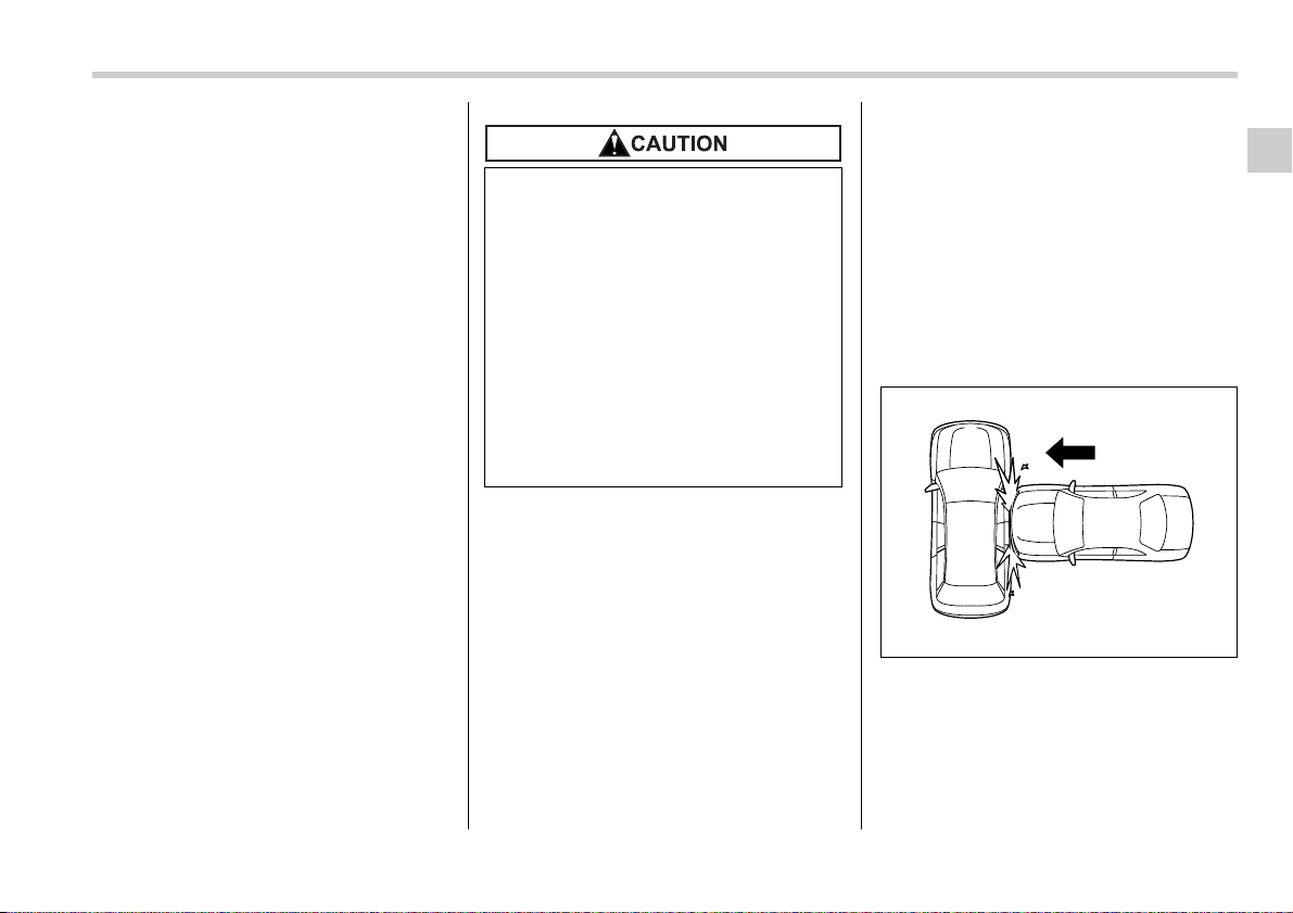
Seat, seatbelt and SRS airbags 1-57
– CONTINUED –
senses an impact force above a predeter-
mined level in a side collision, the control
module causes both the SRS side airbag
and curtain airbag on the impacted side to
inflate regardless of whether the rear
wheel house impact sensor on the same
side senses an impact. If it is a rear wheel
house impact sensor alone that senses a
sufficiently strong impact force, the control
module causes only the SRS curtain air-
bag on the impacted side to inflate. After
the deployment, the SRS side airbag im-
mediately starts to deflate. The time re-
quired from detection of an impact to de-
flation of an SRS side airbag after deploy-
ment is shorter than the blink of an eye.
The SRS curtain airbag remains inflated
for a while following deployment then
slowly deflates.
The SRS side airbag and SRS curtain air-
bag deploy even when no one occupies
the seat on the side on which an impact is
applied.
When the SRS side airbag and SRS cur-
tain airbag deploy, a sudden, fairly loud in-
flation noise will be heard and some
smoke will be released. These occurrenc-
es are a normal result of the deployment.
This smoke does not indicate a fire in the
vehicle.
The SRS side airbag and SRS curtain air-
bag are designed to deploy in the event of
an accident involving a moderate to se-
vere side impact collision. It is basically
not designed to deploy in a lesser side im-
pact. Also, it is basically not designed to
deploy in frontal or rear impacts because
SRS side airbag and SRS curtain airbag
deployment would not help the occupant
in those situations.
Each SRS side airbag and SRS curtain
airbag are designed to function on a one-
time-only basis.
SRS side airbag and SRS curtain airbag
deployment depend on the level of force
experienced in the passenger compart-
ment during a side impact collision. That
level differs from one type of collision to
another, and it may have no bearing on
the visible damage done to the vehicle it-
self.
V Example of the type of accident in
which the SRS side airbag and SRS
curtain airbag will most likely de-
ploy.
A severe side impact near the front seat
activates the SRS side airbag and SRS
curtain airbag.
Do not touch the SRS side airbag
system components around the
front seat seatback with bare hands
right after deployment. Doing so can
cause burns because the compo-
nents can be very hot as a result of
deployment.
After deployment, do not touch any
part of the SRS curtain airbag sys-
tem (from the front pillar to the part
of the roof side over the rear seat).
Doing so can cause burns because
the components can be very hot as
a result of deployment.
200320
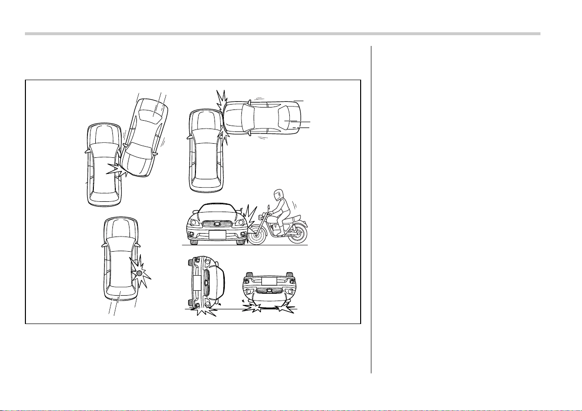
1-58 Seat, seatbelt and SRS airbags
V Examples of the types of accidents in which the SRS side airbag and SRS cur-
tain airbag are unlikely to deploy.
1
2
3
4
5
100658
1) The vehicle is involved in an oblique
side-on impact.
2) The vehicle is involved in a side-on
impact in an area outside the vicinity
of the passenger compartment.
3) The vehicle strikes a telephone pole
or similar object.
4) The vehicle is involved in a side-on
impact from a motorcycle.
5) The vehicle rolls onto its side or roof.
There are many types of collisions which
might not necessarily require SRS side
airbag and SRS curtain airbag deploy-
ment. In the event of accidents like those
illustrated, the SRS side airbag and SRS
curtain airbag may not deploy depending
on the level of accident forces involved.
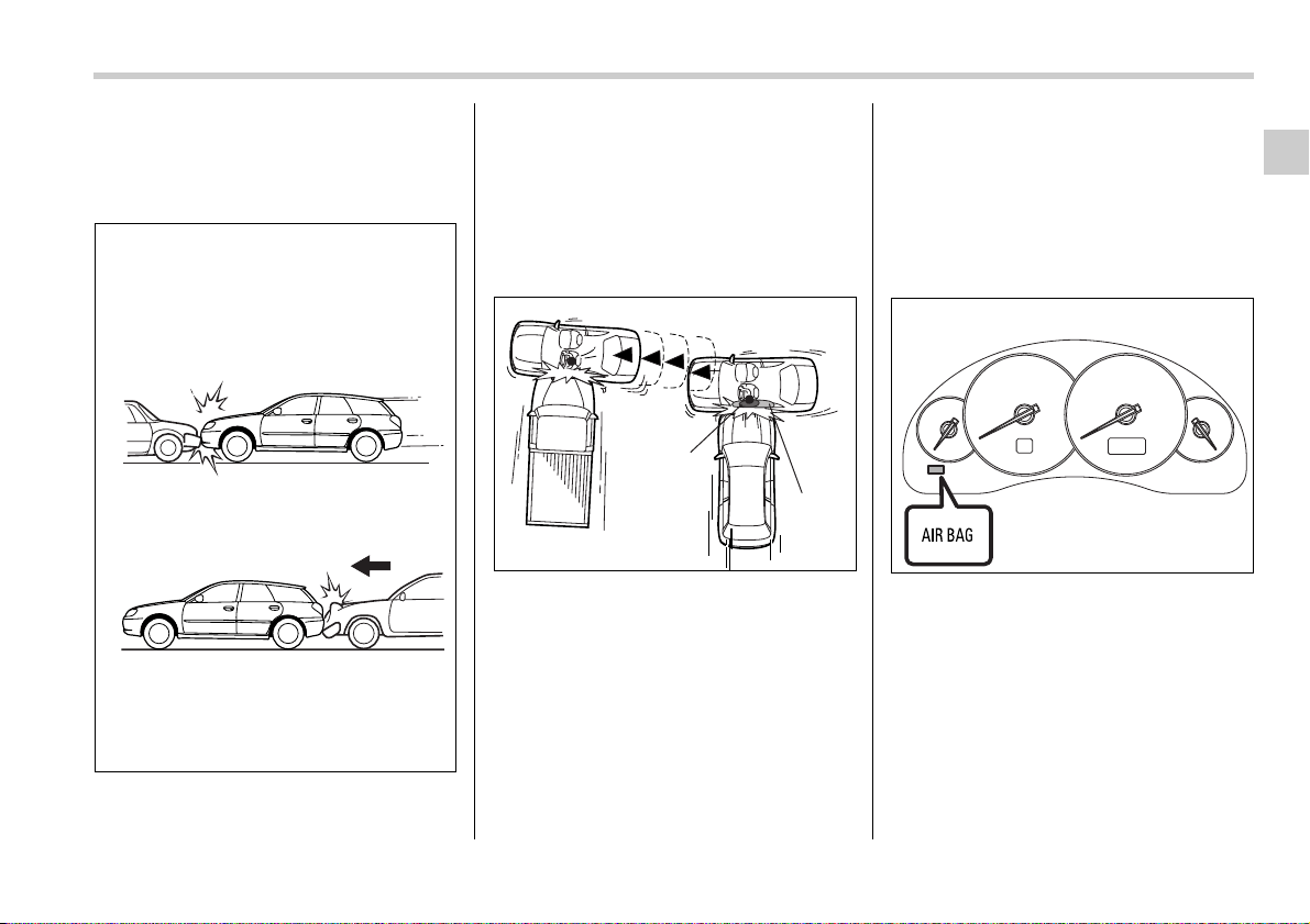
Seat, seatbelt and SRS airbags 1-59
– CONTINUED –
V Examples of the types of accidents
in which the SRS side airbag and
SRS curtain airbag will basically not
deploy.
1) The vehicle is involved in frontal collision
with another vehicle (moving or station-
ary).
2) The vehicle is struck from behind.
The SRS side airbag and SRS curtain air-
bag are basically not designed to deploy if
the vehicle is involved in a frontal collision
or is struck from behind. Examples of such
accidents are illustrated.
1) First impact
2) Second impact
A) SRS curtain airbag
B) SRS side airbag
In an accident where the vehicle is struck
from the side more than once, the SRS
side airbag and SRS curtain airbag deploy
only once on the first impact.
Example: In the case of a double side im-
pact collision, first with one vehicle and
immediately followed by another from the
same direction, once the SRS side airbag
and SRS curtain airbag are activated on
the first impact, they will not be activated
on the second.
SRS airbag system monitors
A diagnostic system continually monitors
the readiness of the SRS airbag system
(including front seatbelt pretensioners)
while the vehicle is being driven. The SRS
airbag system warning light “AIRBAG” will
show normal system operation by lighting
for approximately 6 seconds when the ig-
nition switch is turned to the “ON” position.
The following components are monitored
by the indicator:
y Front sub sensor (Right-hand side)
1
2
100659
1
A
B
2
100660
200326
1-60 Seat, seatbelt and SRS airbags
y Front sub sensor (Left-hand side)
y Airbag control module (including impact
sensors)
y Frontal airbag module (Driver’s side)
y Frontal airbag module (Front passen-
ger’s side)
y Side airbag sensor (Center pillar right-
hand side)
y Side airbag sensor (Center pillar left-
hand side)
y Side airbag module (Driver’s side)
y Side airbag module (Front passenger’s
side)
y Curtain airbag sensor (Rear wheel
house right-hand side)
y Curtain airbag sensor (Rear wheel
house left-hand side)
y Curtain airbag module (Right side)
y Curtain airbag module (Left side)
y Seatbelt pretensioner (Driver’s side)
y Seatbelt pretensioner (Front passen-
ger’s side)
y Seatbelt buckle switch (Driver’s side)
y Seatbelt buckle switch (Front passen-
ger’s side)
y Driver’s seat position sensor
y Front passenger’s seatbelt tension sen-
sor
y Front passenger’s occupant detection
system weight sensor
y Front passenger’s occupant detection
control module
y Front passenger’s frontal airbag ON
and OFF indicator
y All related wiring
SRS airbag system servicing
If the warning light exhibits any of
the following conditions, there may
be a malfunction in the seatbelt pre-
tensioners and/or SRS airbag sys-
tem. Immediately take your vehicle
to your nearest SUBARU dealer to
have the system checked. Unless
checked and properly repaired, the
seatbelt pretensioners and/or SRS
airbags will operate improperly (e.g.
SRS airbags may inflate in a very mi-
nor collision or not inflate in a se-
vere collision), which may increase
the risk of injury.
y Flashing or flickering of the warn-
ing light
y No illumination of the warning
light when the ignition switch is
first turned to the “ON” position
y Continuous illumination of the
warning light
y Illumination of the warning light
while driving
y When discarding an airbag mod-
ule or scrapping the entire vehicle
damaged by a collision, consult
your SUBARU dealer.
y The SRS airbag has no user-ser-
viceable parts. Do not use electri-
cal test equipment on any circuit
related to the SRS airbag system.
For required servicing of the SRS
airbag, see your nearest SUBARU
dealer. Tampering with or discon-
necting the system’s wiring could
result in accidental inflation of the
SRS airbag or could make the sys-
tem inoperative, which may result
in serious injury. The wiring har-
nesses of the SRS airbag system
are covered with yellow insulation
and system connectors are yellow
for easy identification.
Seat, seatbelt and SRS airbags 1-61
– CONTINUED –
In the event that the SRS airbag is de-
ployed, replacement of the system
should be performed only by an autho-
rized SUBARU dealer. When the com-
ponents of the SRS airbag system are
replaced, use only genuine SUBARU
parts.
NOTE
In the following cases, contact your
SUBARU dealer as soon as possible.
y The front part of the vehicle was in-
volved in an accident in which the only
the driver’s SRS frontal airbag or both
driver’s and front passenger’s SRS
frontal airbags did not deploy.
y The pad of the steering wheel, the
cover over the front passenger’s SRS
frontal airbag, or either roof side (from
the front pillar to a point over the rear
seat) is scratched, cracked, or other-
wise damaged.
y Either center pillar and rear wheel
house or a nearby area of the vehicle
was involved in an accident in which
the SRS side airbag and SRS curtain
airbag did not deploy.
y The fabric or leather of either front
seatback is cut, frayed, or otherwise
damaged.
Precautions against vehicle
modification
If you need service or repair in areas
listed in the following, have an au-
thorized SUBARU dealer perform
the work. The SRS airbag control
module, impact sensors and airbag
modules are stored in these areas.
y Under the center console
y Inside each front fender
y Steering wheel and column and
nearby areas
y Top of the dashboard on front
passenger’s side and nearby ar-
eas
y Each front seat and nearby area
y Inside each center pillar
y In each roof side (from the front
pillar to a point over the rear seat)
y Between the rear seat cushion
and rear wheel house on each
side
y To avoid accidental activation of
the system or rendering the sys-
tem inoperative, which may result
in serious injury, no modifications
should be made to any compo-
nents or wiring of the SRS airbag
system.
This includes following modifica-
tions:
y Installation of custom steering
wheels
y Attachment of additional trim
materials to the dashboard
y Installation of custom seats
y Replacement of seat fabric or
leather
y Installation of additional fabric
or leather on the front seat
1-62 Seat, seatbelt and SRS airbags
Always consult your SUBARU dealer if
you want to install any accessory parts on
your vehicle.
y Attachment of a hands-free mi-
crophone or any other accesso-
ry to a front pillar, a center pillar,
a rear pillar, the windshield, a
side window, an assist grip, or
any other cabin surface that
would be near a deploying SRS
curtain airbag.
y Installation of additional electri-
cal/electronic equipment such
as a mobile two-way radio on or
near the SRS airbag system
components and/or wiring is
not advisable. This could inter-
fere with proper operation of the
SRS airbag system.
Do not perform any of the following
modifications. Such modifications
can interfere with proper operation
of the SRS airbag system.
y Attachment of any equipment
(bush bar, winches, snow plow,
skid plate, etc.) other than genu-
ine SUBARU accessory parts.
y Modification of the suspension
system or front end structure.
y Installation of a tire of different
size and construction from the
tires specified on the vehicle plac-
ard attached to the driver’s door
pillar or specified for individual
vehicle models in this Owner’s
Manual.
y Attachment of any equipment
(side steps or side sill protectors,
etc.) other than genuine SUBARU
accessory parts to the side body.

2
Keys and doors
Keys ..................................................................... 2-2
Key number ............................................................. 2-2
Immobilizer ......................................................... 2-3
Security ID plate ..................................................... 2-3
Security indicator light ........................................... 2-4
Key replacement ..................................................... 2-4
Door locks ........................................................... 2-4
Locking and unlocking from the outside ............. 2-4
Locking and unlocking from the inside ................ 2-5
Battery drainage prevention function ................... 2-6
Power door locking switches ............................ 2-6
Key lock-in prevention function ............................ 2-7
Remote keyless entry system ........................... 2-7
Locking the doors .................................................. 2-8
Unlocking the doors ............................................... 2-9
Unlocking the trunk lid/rear gate ........................... 2-9
Illuminated entry ..................................................... 2-9
Vehicle finder function ........................................... 2-9
Sounding a panic alarm ......................................... 2-10
Selecting audible signal operation ....................... 2-10
Replacing the battery ............................................. 2-10
Replacing lost transmitters ................................... 2-11
Alarm system ...................................................... 2-14
System alarm operation ......................................... 2-14
Activating and deactivating the alarm system ..... 2-14
If you have accidentally triggered the alarm
system ................................................................... 2-15
Arming the system ................................................. 2-15
Disarming the system ............................................ 2-16
Valet mode ............................................................... 2-16
Passive arming ....................................................... 2-17
Tripped sensor identification ................................ 2-18
Shock sensors (dealer option) .............................. 2-18
Child safety locks ............................................... 2-18
Windows .............................................................. 2-19
Power windows ....................................................... 2-19
Trunk lid (Sedan) ................................................ 2-21
To open and close the trunk lid from outside ...... 2-21
To open the trunk lid from inside .......................... 2-22
To lock and unlock the trunk lid release lever ..... 2-22
Internal trunk lid release handle ............................ 2-22
Rear gate (Station wagon) ................................. 2-24
Moonroof (if equipped) ...................................... 2-25
Tilting/sliding moonroof (Sedan) .......................... 2-26
Moonroof (Station wagon) ..................................... 2-27
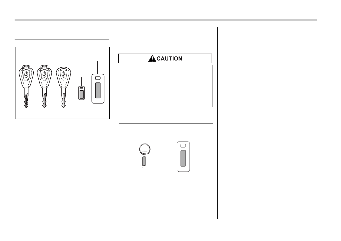
2-2 Keys and doors
Keys and doors
Keys
1) Master key
2) Submaster key
3) Valet key
4) Key number plate
5) Security ID plate
Three types of keys are provided for your
vehicle.
Master key, submaster key and valet key.
The master key and submaster key fit all
locks on your vehicle.
y Ignition switch
y Driver’s door
y Glove box
y Trunk lid release lever
The valet key fits only the ignition switch
and door locks. You can keep the trunk
and glove box locked when you leave your
vehicle and valet key at a parking facility.
Key number
1) Key number plate
2) Security ID plate
The key number is stamped on the key
number plate attached to the key set.
Write down the key number and keep it in
another safe place, not in the vehicle. This
number is needed to make a replacement
key if you lose your key or lock it inside the
vehicle.
For information on making replacement
keys for vehicles with the immobilizer sys-
tem, refer to the “Immobilizer” section in
this chapter.
4
5321
200700
Do not attach a large key holder or
key case to either key. If it bangs
against your knees while you are
driving, it could turn the ignition
switch from the ON position to the
ACC or OFF position, thereby stop-
ping the engine.
12
200701
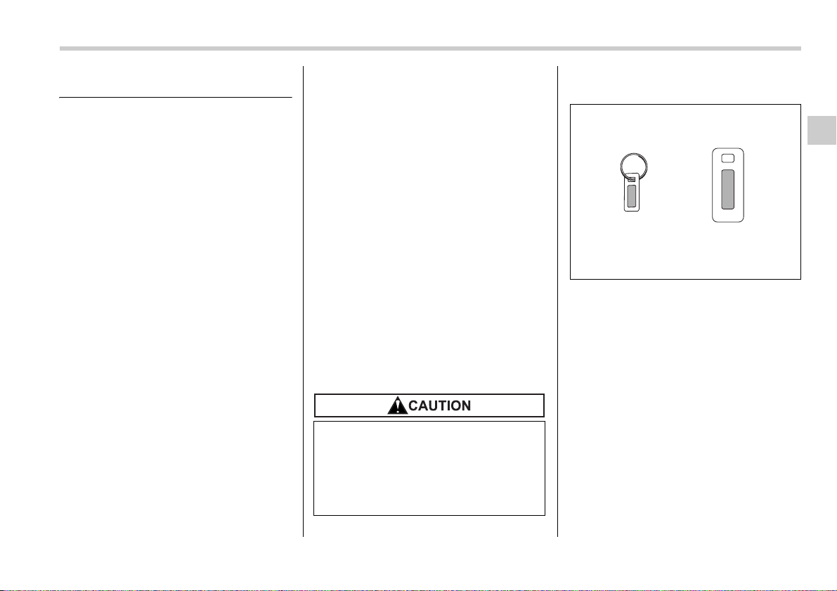
Keys and doors 2-3
– CONTINUED –
Immobilizer
The immobilizer system is designed to
prevent an unauthorized person from
starting the engine. Only keys registered
with your vehicle’s immobilizer system
can be used to operate your vehicle. Even
if an unregistered key fits into the ignition
switch and can be turned to the “START”
position, the engine will automatically stop
after several seconds.
Each immobilizer key contains a tran-
sponder in which the key’s ID code is
stored. When a key is inserted into the ig-
nition switch and turned to the “ON” posi-
tion, the transponder transmits the key’s
ID code to the immobilizer system’s re-
ceiver. If the transmitted ID code matches
the ID code registered in the immobilizer
system, the system allows the engine to
be started. Since the ID code is transmit-
ted and acted upon almost instantly, the
immobilizer system does not impede nor-
mal starting of the engine.
If the engine fails to start, pull out the key
once before trying again. (Refer to the “Ig-
nition switch” section [chapter 3].)
This device complies with Part 15 of
the FCC Rules and with RSS-210 of In-
dustry Canada. Operation is subject to
the following two conditions: (1) This
device may not cause harmful interfer-
ence, and (2) this device must accept
any interference received, including in-
terference that may cause undesired
operation.
Changes or modifications not express-
ly approved by the party responsible
for compliance could void the user’s
authority to operate the equipment.
NOTE
To protect your vehicle from theft,
please pay close attention to the fol-
lowing security precautions:
y Never leave your vehicle unattended
with its keys inside.
y Before leaving your vehicle, close all
windows and lock the doors and rear
gate (Station wagon).
y Do not leave spare keys or any
record of your key number in the vehi-
cle.
Security ID plate
1) Key number plate
2) Security ID plate
The security ID is stamped on the security
ID plate attached to the key set. Write
down the security ID and keep it in another
safe place, not in the vehicle. This number
is needed to make a replacement key if
you lose your key or lock it inside the vehi-
cle.
This number is also needed for replace-
ment or repair of the engine control unit,
integrated unit, and combination meter.
y Do not place the key under direct
sunlight or anywhere it may be-
come hot.
y Do not get the key wet. If the key
gets wet, wipe it dry with a cloth
immediately.
12
200701
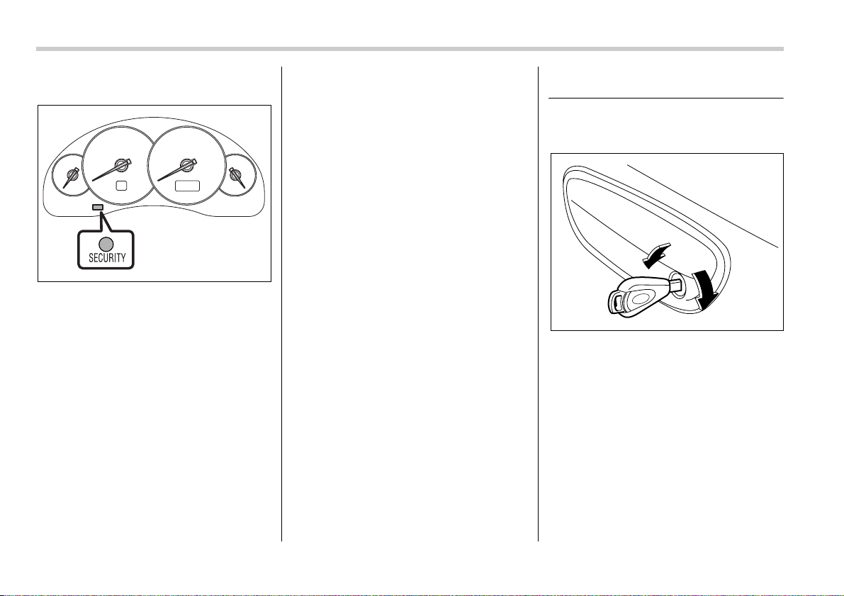
2-4 Keys and doors
Security indicator light
The security indicator light deters potential
thieves by indicating that the vehicle is
equipped with an immobilizer system. It
begins flashing approximately 60 seconds
after the ignition switch is turned from the
“ON” position to the “ACC” or “LOCK” po-
sition or immediately after the key is pulled
out.
If the security indicator light does not
flash, the immobilizer system may be
faulty. If this occurs, contact your
SUBARU dealer as soon as possible.
In case an unauthorized key is used (e.g.
an imitation key), the security indicator
light comes on.
NOTE
Even if the security indicator light
flashes irregularly or its fuse blows
(the light does not flash if its fuse is
blown), the immobilizer system will
function normally.
Key replacement
Your key number plate and security ID
plate will be required if you ever need a re-
placement key made. Any new key must
be registered for use with your vehicle’s
immobilizer system before it can be used.
Up to four keys can be registered for use
with one vehicle.
For security, all the keys registered with
your vehicle’s immobilizer system will
have their ID codes erased and re-regis-
tered when a new key is made. Therefore,
all of your vehicle’s keys must be present-
ed when a new key is registered. Any key
that is not re-registered when a new key is
made cannot be used after the other keys
are re-registered. For information on re-
placement keys and on the registration of
keys with your immobilizer system, con-
tact your SUBARU dealer.
Door locks
Locking and unlocking from
the outside
To lock the driver’s door from the outside
with the key, turn the key toward the rear.
To unlock the door, turn the key toward
the front.
Lift the outside door handle to open an un-
locked door.
200835
200836
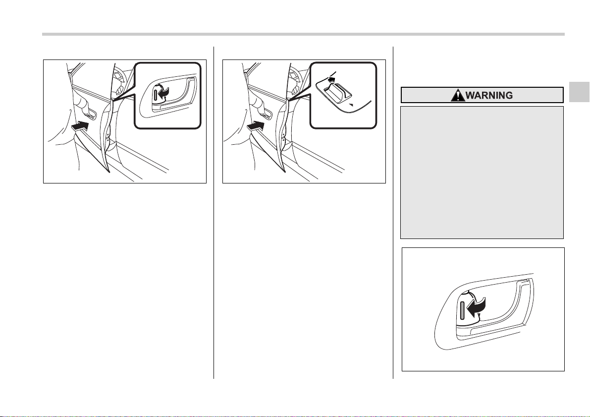
Keys and doors 2-5
– CONTINUED –
Locking without the key
1) Rotate the lock lever rearward.
2) Close the door.
To lock the door from the outside without
the key, rotate the lock lever rearward and
then close the door.
Locking without the key
1) Push the power door locking switch for-
ward.
2) Close the door.
To lock the door from the outside using the
power door locking switch, push the
switch forward (“LOCK” side) and then
close the door. In this case, all closed
doors and the rear gate (Station wagon)
are locked at the same time.
Always make sure that all doors and the
rear gate are locked before leaving your
vehicle.
NOTE
Make sure that you do not leave the key
inside the vehicle before locking the
doors from the outside without the key.
Locking and unlocking from
the inside
2
1
200837
LOCK
2
1
200838
Keep all doors locked when you
drive, especially when small chil-
dren are in your vehicle.
Along with the proper use of seat-
belts and child restraints, locking
the doors reduces the chance of be-
ing thrown out of the vehicle in an
accident.
It also helps prevent passengers
from falling out if a door is acciden-
tally opened, and intruders from un-
expectedly opening doors and en-
tering your vehicle.
200384
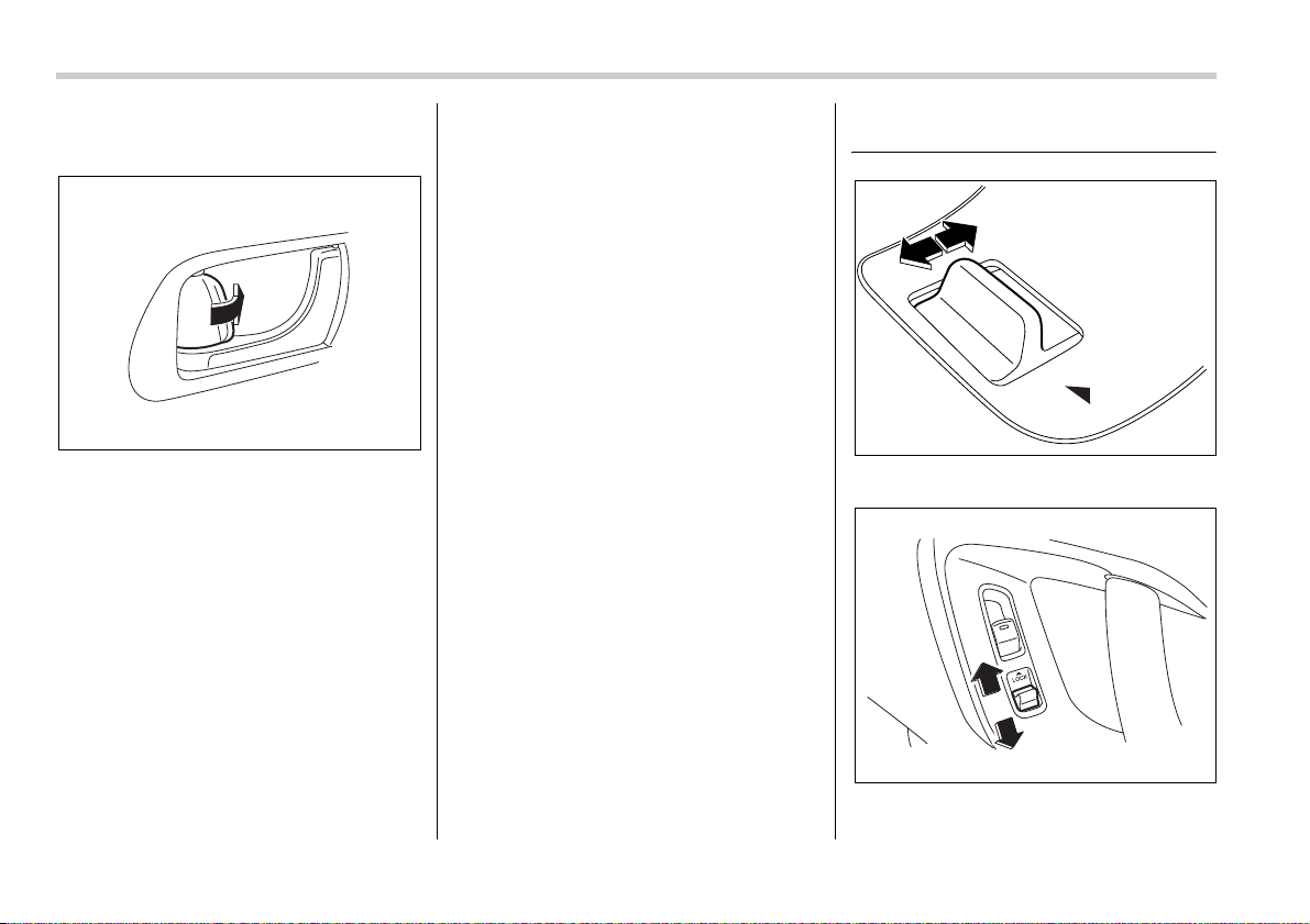
2-6 Keys and doors
To lock the door from the inside, rotate the
lock lever rearward.
To unlock the door from the inside, rotate
the lock lever forward.
The red mark on the lock lever appears
when the door is unlocked.
Pull the inside door handle to open an un-
locked door.
Always make sure that all doors and the
rear gate (Station wagon) are closed and
locked before starting to drive.
Battery drainage prevention
function
When a door or the rear gate (Station
wagon) is not completely closed and the
dome light, ignition switch light, and door
open warning light remain illuminated as a
result, the lights are automatically turned
off by the battery drainage prevention
function after 10 minutes of illumination to
prevent the battery from going dead. The
operational/non-operational setting of this
function can be changed by a SUBARU
dealer. Contact the nearest SUBARU
dealer if you would like to change the set-
ting.
NOTE
y When leaving the vehicle, please
make sure that all doors and the rear
gate (Station wagon) are completely
closed.
y The battery drainage prevention
function does not operate while the key
is in the ignition switch.
Power door locking switches
Driver’s switch
Front passenger’s switch
200385
LOCK
200386
200839
Keys and doors 2-7
– CONTINUED –
All doors and the rear gate (Station wag-
on) can be locked and unlocked by the
power door locking switches located at the
driver’s side and the front passenger’s
side doors.
To lock all doors (including the rear gate of
a Station wagon), push the switch to the
front (“LOCK”) position.
To unlock all doors (including the rear
gate of a Station wagon), pull the switch to
the rear position.
When you close the doors after you set
the door locks, the doors remain locked.
NOTE
Make sure that you do not leave the key
inside the vehicle before locking the
doors from the outside using the pow-
er door locking switches.
Key lock-in prevention func-
tion
This function prevents the doors from be-
ing locked with the key still in the ignition
switch.
T Behavior with key lock-in preven-
tion function operative
With the driver’s door open, the doors are
automatically kept unlocked even if the
door locking switch is pushed to the front
(“LOCK”) position.
T Behavior with key lock-in preven-
tion function non-operative
y If the lock lever is turned to the rear
(“LOCK”) position with the driver’s door
open and the driver’s door is then closed
with the lock lever in that position, the driv-
er’s door is locked.
y If the spare key is used to lock the driv-
er’s door from the outside of the vehicle,
the door is locked.
This function’s operative/non-operative
setting can be changed by a SUBARU
dealer. Contact a SUBARU dealer for de-
tails.
NOTE
When leaving the vehicle, make sure
you are holding the key before locking
the doors.
Remote keyless entry sys-
tem
This device complies with Part 15 of
the FCC Rules and with RSS-210 of In-
dustry Canada. Operation is subject to
the following two conditions: (1) This
device may not cause harmful interfer-
ence, and (2) this device must accept
any interference received, including in-
terference that may cause undesired
operation.
Changes or modifications not express-
ly approved by the party responsible
for compliance could void the user’s
authority to operate the equipment.
Two transmitters are provided for your ve-
y Do not expose the transmitter to
severe shocks, such as those ex-
perienced as a result of dropping
or throwing.
y Do not take the transmitter apart
except when replacing the bat-
tery.
y Do not get the transmitter wet. If it
gets wet, wipe it dry with a cloth
immediately.
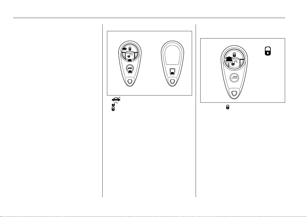
2-8 Keys and doors
hicle.
The keyless entry system has the follow-
ing functions.
y Locking and unlocking the doors (and
rear gate on the Station wagon) without a
key
y Locking and unlocking the doors (and
trunk lid on the Sedan) without key
y Unlocking the rear gate on the Station
wagon without key
y Unlocking the trunk lid on the Sedan
without key
y Sounding a panic alarm
y Arming and disarming the alarm sys-
tem. See the next section “Alarm system”
for detailed information.
The operable distance of the keyless entry
system is approximately 30 feet (10
meters). However, this distance will vary
depending on environmental conditions.
The system’s operable distance will be
shorter in areas near a facility or electronic
equipment emitting strong radio waves
such as a power plant, broadcast station,
TV tower, or remote controller of home
electronic appliances.
The keyless entry system does not oper-
ate when the key is inserted in the ignition
switch.
: Trunk lid/rear gate unlock button
: Unlock/disarm button
: Lock/arm button
A: Panic button
1) Front
2) Back
Locking the doors
Press the “ ” button to lock all doors
and rear gate (Station wagon). An elec-
tronic chirp will sound once and the turn
signal lights will flash once.
If any of the doors (or the rear gate/trunk
lid) is not fully closed, an electronic chirp
will sound five times and the turn signal
lights will flash five times to alert you that
the doors (or the rear gate/trunk lid) are
not properly closed. When you close the
door, it will automatically lock and then an
electronic chirp will sound once and the
turn signal lights will flash once.
200898
A
12
200899
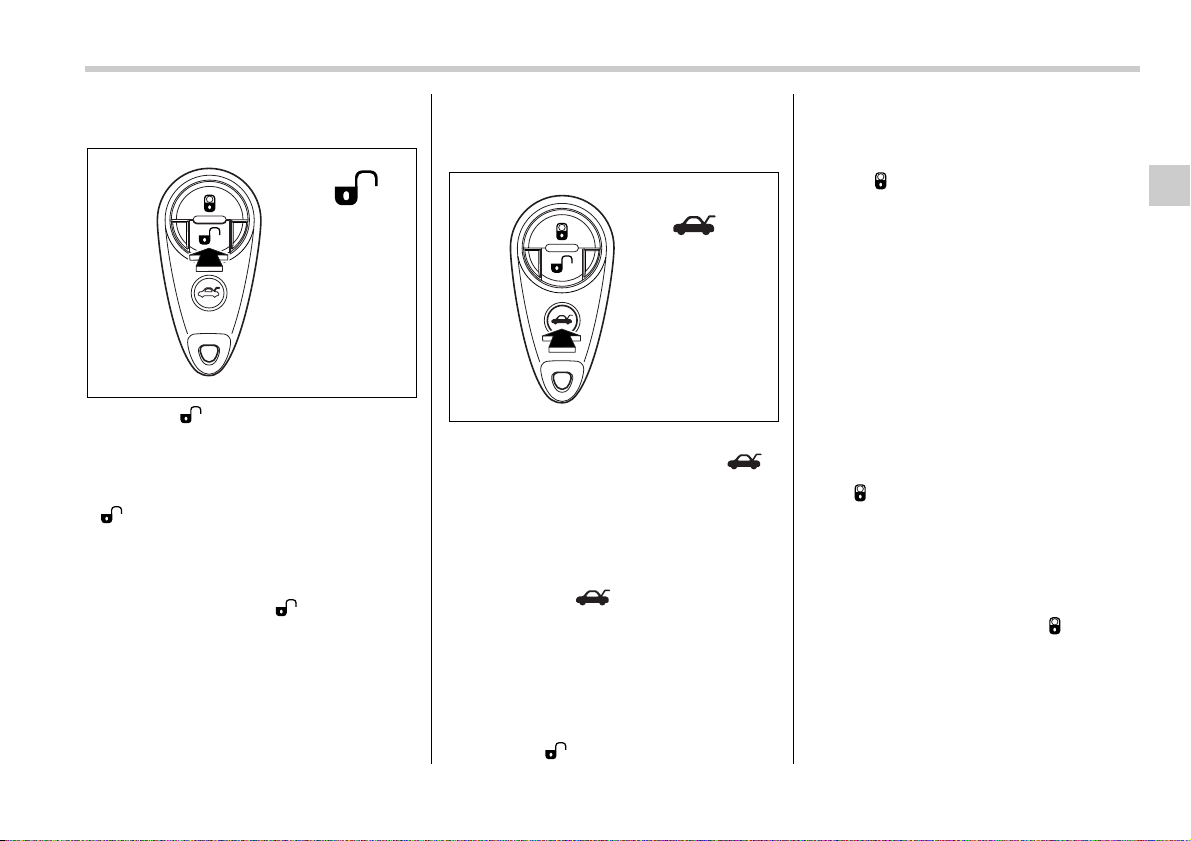
Keys and doors 2-9
– CONTINUED –
Unlocking the doors
Press the “ ” button to unlock the driv-
er’s door. An electronic chirp will sound
twice and the turn signal lights will flash
twice. To unlock all doors and the rear
gate (Station wagon), briefly press the
“ ” button a second time within 5 sec-
onds.
NOTE
If the interval between the first and sec-
ond presses of the “ ” button (for
unlocking of all of the doors and the
rear gate) is extremely short, the sys-
tem may not respond.
Unlocking the trunk lid/rear
gate
T Sedan
The trunk lid unlocks when the “ ”
button is pressed continuously for at least
2 seconds. An electronic chirp will sound
twice and the turn signal lights will flash
twice.
T Station wagon
Pressing the “ ” button opens the
rear gate.
An electronic chirp will sound twice and
the turn signal lights will flash twice.
Illuminated entry
The interior (dome) light will illuminate
when the “ ” button is pressed. This
light stays illuminated for approximately
30 seconds if any of the doors or the rear
gate (Station wagon) is not opened.
If the “ ” button is pressed before 30
seconds have elapsed, this light will go
out. The interior light must be set to the
middle position in order for this function
to operate.
A SUBARU dealer can change the illumi-
nation period setting of the interior light in
accordance with your preference. Contact
the nearest SUBARU dealer for details.
Vehicle finder function
Use this function to find your vehicle
parked among many vehicles in a large
parking lot. Provided you are within 30
feet (10 meters) of the vehicle, pressing
the “ ” button three times in a five-sec-
ond period will cause your vehicle’s horn
to sound once and its turn signal lights to
flash three times.
NOTE
If the interval between presses is too
short when you press the “ ” button
three times, the system may not re-
spond to the signals from the remote
transmitter.
200900
200901
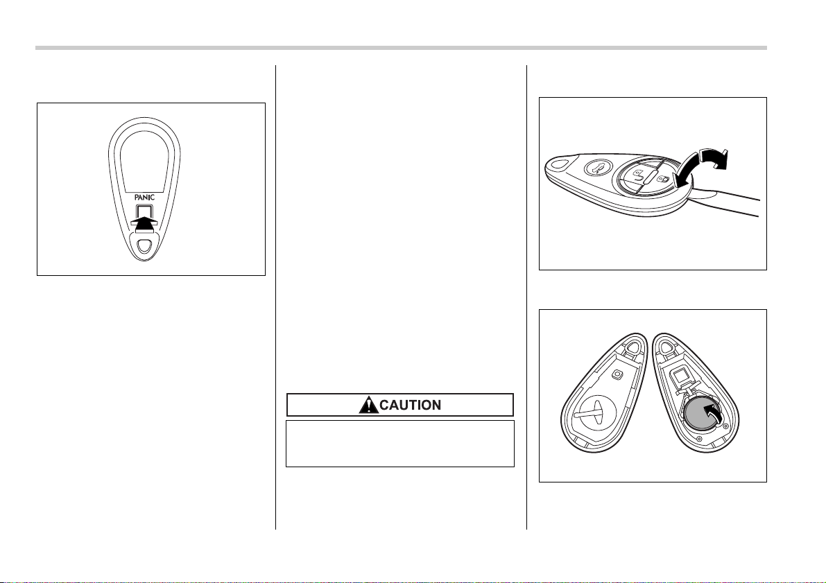
2-10 Keys and doors
Sounding a panic alarm
A “PANIC” button is located on the back of
the transmitter.
To activate the alarm, press the “PANIC”
button once.
The horn will sound and the turn signal
lights will flash.
To deactivate the panic alarm, press any
button on the remote transmitter. Unless a
button on the remote is pressed, the alarm
will be deactivated after approximately 30
seconds.
Selecting audible signal op-
eration
Using an electronic chirp, the system will
give you an audible signal when the doors
lock and unlock. If desired, you may turn
the audible signal off.
Do the following to deactivate the audible
signal. You can also use the same steps
to restore the function.
1. Sit in the driver’s seat and shut all
doors and the rear gate.
2. Hold down the UNLOCK side of the
power door locking switch.
3. While holding down the “UNLOCK”
side of the power door locking switch, pull
the key out and re-insert it into the ignition
switch at least 6 times within 10 seconds
after Step 2.
4. Open and close the driver’s door once
within 10 seconds after Step 3.
5. The turn signal lights flash 3 times to in-
dicate completion of the setting.
You may have the above settings done by
your SUBARU dealer.
Replacing the battery
When the transmitter battery begins to get
weak, transmitter range will begin to de-
crease. Replace the battery as soon as
possible.
To replace the battery:
1. Open the transmitter case using a flat-
head screwdriver.
2. Remove the old battery from the hold-
er.
200714
Do not let dust, oil or water get on or
in the transmitter when replacing
the battery.
200902
200716
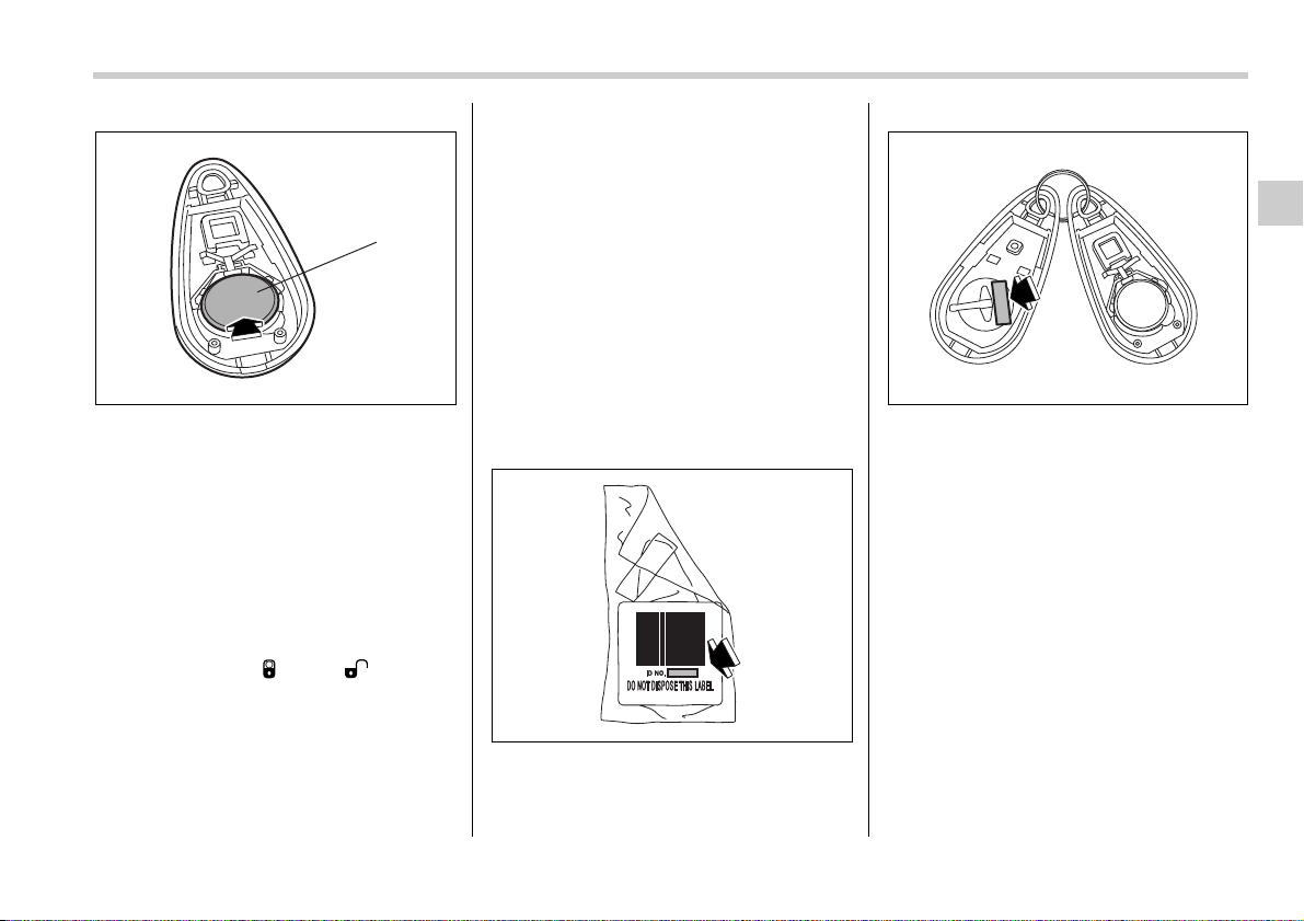
Keys and doors 2-11
– CONTINUED –
1) Negative (–) side facing up
3. Replace with a new battery (Type
CR2025 or equivalent) making sure to in-
stall the new battery with the negative (–)
side facing up.
4. Refit the removed half of the transmit-
ter case.
After the battery is replaced, the trans-
mitter must be synchronized with the
keyless entry system’s control unit.
Press either the “ ” or “ ” button
six times to synchronize the unit.
Replacing lost transmitters
If you lose a transmitter or want to pur-
chase additional transmitters (up to four
can be programmed), you should re-pro-
gram all of your transmitters for security
reasons. It is recommended that you have
your dealer program all of your transmit-
ters into your system.
T Programming the transmitters
The keyless entry system is equipped with
a special code learning feature that allows
you to program new transmitter codes into
the system or to delete old ones. The sys-
tem can learn up to four unique transmitter
codes. The four transmitter codes may be
the same or different.
Programming transmitter codes into
system:
Bag containing transmitter
Transmitter circuit board
To register a new transmitter with the key-
less entry system, it is necessary to pro-
gram the transmitter’s code (identification
number) into the system. A label showing
the code is affixed to the bag containing
the transmitter, and another is affixed to
the circuit board inside the transmitter. If
there is no bag, open the transmitter case
and make a note of the eight-digit number.
Program the number into the system in
accordance with the following procedure:
1. Firmly close the doors and the rear
gate (Station wagon) or trunk lid (Sedan).
2. Open the driver’s door, sit on the driv-
er’s seat, and close the door.
3. Perform the following steps within 45
seconds.
1
200717
200718
200719
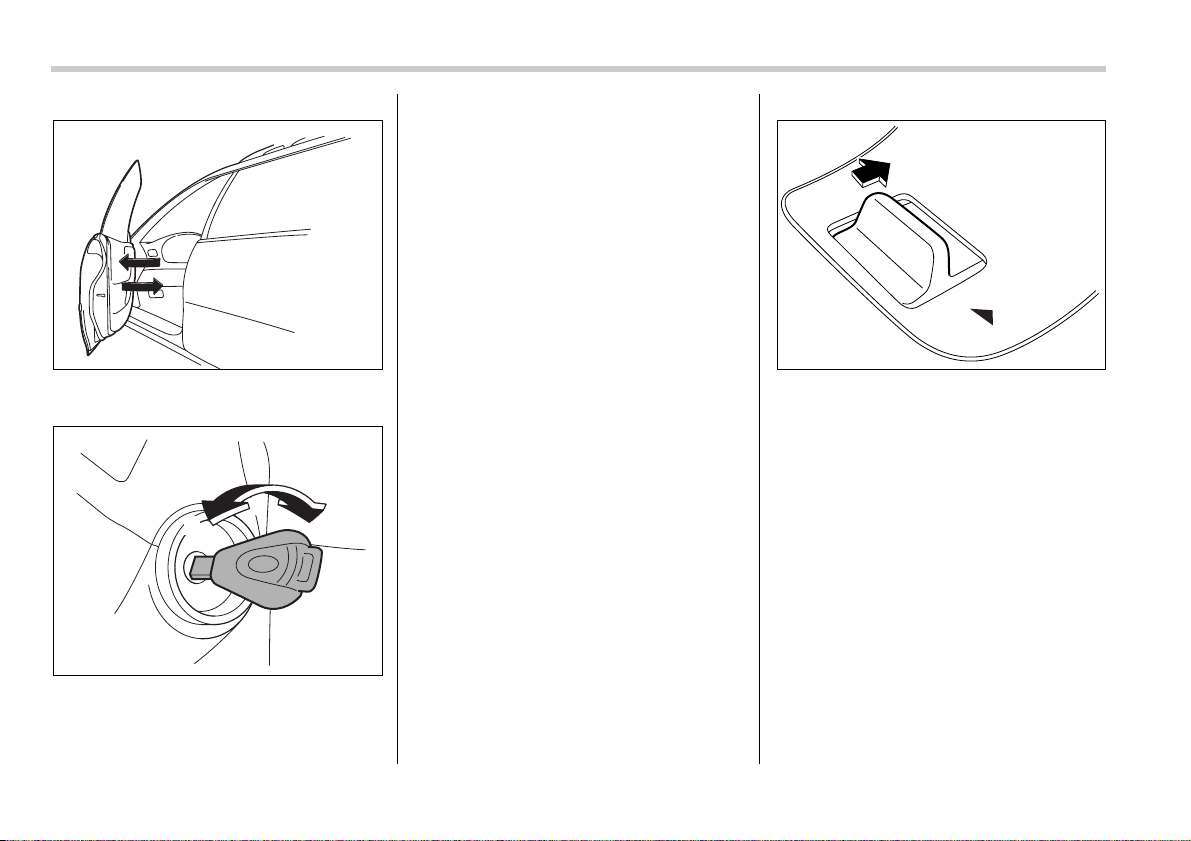
2-12 Keys and doors
1)Open and close the driver’s door
once.
1) LOCK
2) ON
2)Insert the key into the ignition switch,
then turn it from the “LOCK” position to
the “ON” position 10 times within 15
seconds.
NOTE
y When you complete step 2), an elec-
tronic tone will sound once.
y If you do not perform steps 1) and 2)
within 45 seconds, an error will occur.
An electronic tone will not sound. In
this event, perform the whole proce-
dure again beginning with part 1.
4. Open and close the door once within
15 seconds.
NOTE
y When part 4 of the procedure is com-
pleted, an electronic tone will sound
for 30 seconds.
y If you do not perform the operations
in part 4 within 15 seconds, an error
will occur and the electronic tone will
not sound. In this event, perform the
registration steps again beginning with
part 3 of the procedure.
5. Before the electronic tone stops sound-
ing, press the power door lock knob to the
“LOCK” side the same number of times as
the leftmost digit of the transmitter code.
For example, press the lock knob eight
times if the leftmost digit of the code is 8.
NOTE
y The electronic tone will stop sound-
ing when you start entering the num-
ber.
y If you do not start entering the num-
ber using the lock knob before the
electronic tone stops sounding, an er-
ror will occur. In this event, perform the
registration steps again beginning with
part 3 of the procedure.
y If the interval between one push of
the knob and the next exceeds five sec-
200840
2
1
200721
LOCK
200841
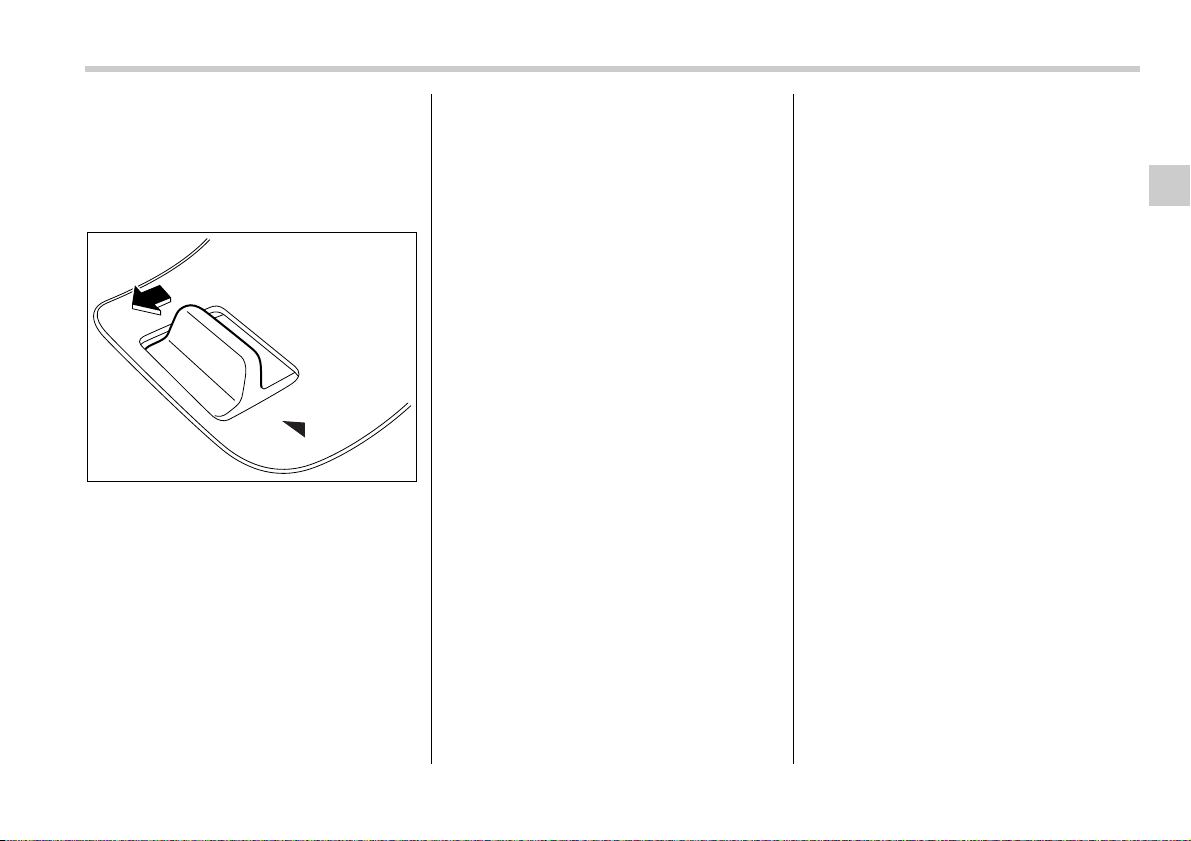
Keys and doors 2-13
– CONTINUED –
onds, an error will occur. In this event,
perform the procedure again beginning
with part 4. If an error occurs six times,
perform the procedure again starting
with part 3.
6. When you have finished entering the
number, pull the lock knob to the “UN-
LOCK” side within five seconds.
NOTE
y An electronic tone will sound.
y If you pull the lock knob to the “UN-
LOCK” side when more than five sec-
onds have passed, an error will occur.
In this event, perform the procedure
again beginning with part 4. If an error
occurs six times, perform the proce-
dure again starting with part 3.
7. Perform parts 5 and 6 of the procedure
for each of the remaining digits of the
transmitter code beginning with the sec-
ond digit (counting from the left) and fin-
ishing with the eighth digit.
NOTE
y When you finish entering the eighth
digit, an electronic tone will sound for
30 seconds.
y If the interval between one push of
the knob and the next exceeds five sec-
onds, an error will occur. In this event,
perform the procedure again beginning
with part 4. If an error occurs six times,
perform the procedure again starting
with part 3.
8. Before the electronic tone stops sound-
ing, use the power door lock knob to again
enter the transmitter code beginning with
the leftmost digit.
NOTE
If you do not start entering the number
using the lock knob before the elec-
tronic tone stops sounding, an error
will occur. In this event, perform the
procedure again beginning with part 3.
9. When you have finished entering the
code a second time, an electronic tone will
sound for one second to indicate comple-
tion of registration, provided the code en-
tered the second time is identical to that
entered the first time.
NOTE
If the code entered the second time is
not identical to the code entered the
first time, an error will occur. In this
event, perform the procedure again be-
ginning with part 5. If an error occurs
five times, perform the procedure
again starting with part 3.
10.If you wish to program another trans-
mitter code into the system (up to four
transmitter codes can be programmed
into the system), perform the procedure
beginning with part 4. When you have fin-
ished programming all of the necessary
transmitter codes into the system, remove
the key from the ignition switch.
11.Test every registered transmitter to
confirm correct operation.
T Deleting old transmitter codes
The control unit of the keyless entry sys-
tem has four memory locations to store
transmitter codes, giving it the ability to
operate with up to four transmitters. When
you lose a transmitter, the lost transmit-
ter’s code remains in the memory. For se-
curity reasons, lost transmitter codes
should be deleted from the memory.
To delete old transmitter codes, program
LOCK
200842

2-14 Keys and doors
four transmitter codes into the system. If
you have only one current transmitter,
program it four times. If you have two cur-
rent transmitters, program each one twice.
If you have three current transmitters, pro-
gram two of them once and the third one
twice. This process will leave only current
transmitter codes in the system’s memory.
NOTE
Make sure no one else is operating
their keyless entry system within range
of your vehicle when programming
transmitters. If someone else were to
operate their remote transmitter while
you are programming your transmit-
ters, it is possible that their transmitter
code will be programmed into your
system, allowing them unauthorized
access to your vehicle.
Alarm system
The alarm system helps to protect your
vehicle and valuables from theft. The horn
sounds and the turn signal lights flash if
someone attempts to break into your vehi-
cle.
The system can be armed and disarmed
with the remote transmitter.
The system does not operate when the
key is inserted into the ignition switch.
Your vehicle’s alarm system has been set
for activation at the time of shipment from
the factory. You can set the system for de-
activation yourself or have it done by your
SUBARU dealer.
System alarm operation
The alarm system will give the following
alarms when triggered:
y The vehicle’s horn will sound and the
turn signal lights will flash for 30 seconds.
y If any door (or the rear gate/trunk lid) re-
mains open after the 30-second period,
the horn will continue to sound for a maxi-
mum of 3 minutes. If the door (or the rear
gate/trunk lid) is closed while the horn is
sounding, the horn will stop sounding with
a delay of up to 30 seconds.
The alarm is triggered by:
y Opening a door, the rear gate or trunk
lid
y Physical impact to the vehicle, such as
forced entry (only vehicles with shock sen-
sors (dealer option))
Activating and deactivating
the alarm system
To change the setting of your vehicle’s
alarm system for activation or deactiva-
tion, do the following.
1. Disarm the alarm system (see “Disarm-
ing the system” in this section).
2. Sit in the driver’s seat and shut all
doors (and the rear gate if your vehicle is
a Station wagon).
3. Turn the ignition switch to the “ON” po-
sition.
4. Hold down the UNLOCK side of the
driver’s power door locking switch, open
the driver’s door within the following 1 sec-
ond, and wait 10 seconds without releas-
ing the switch. The setting will then be
changed as follows:
If the system was previously activated:
The odometer/trip meter screen displays
“AL oF” and the horn sounds twice, indi-
cating that the system is now deactivated.
If the system was previously deactivated:
The odometer/trip meter screen displays
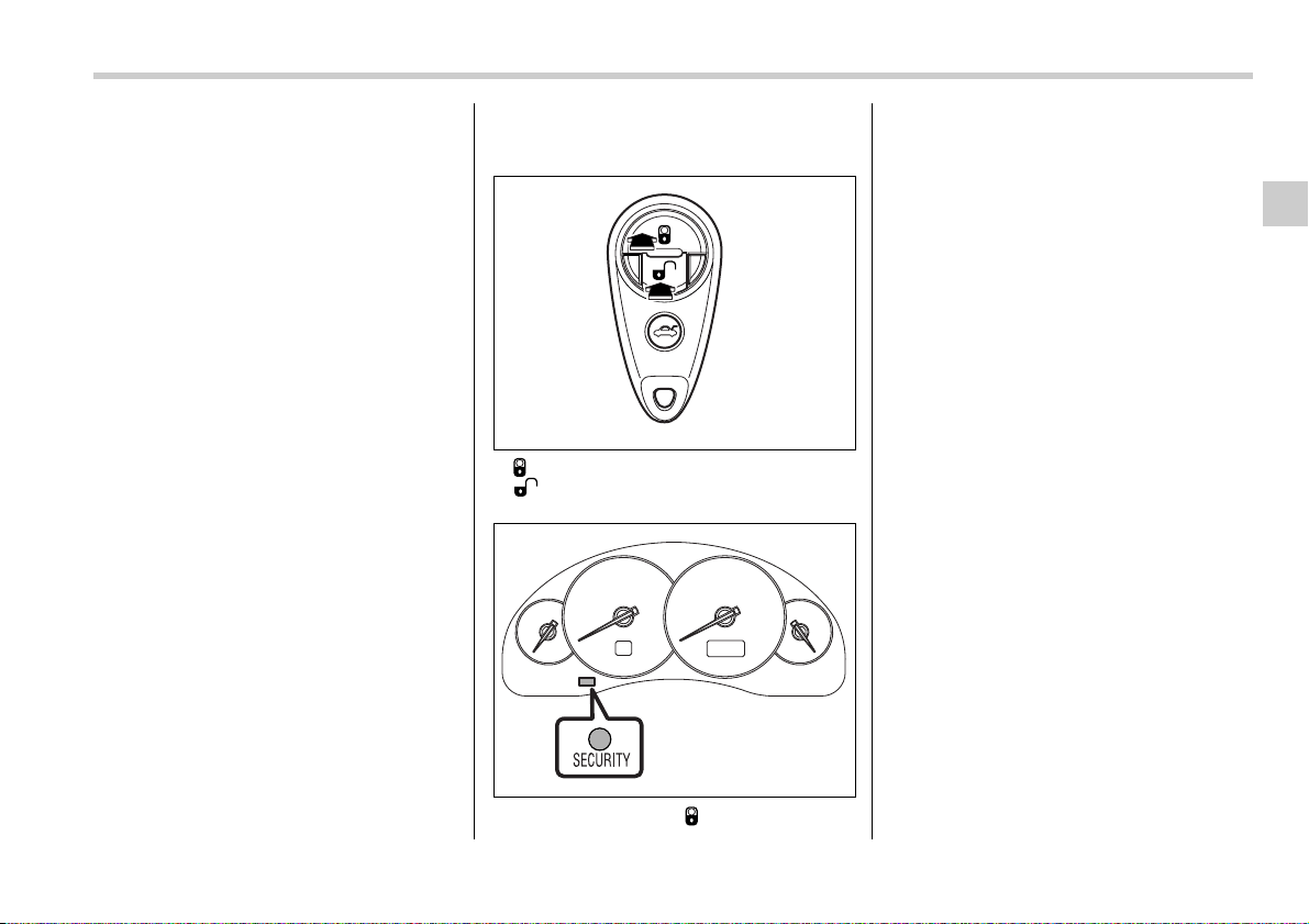
Keys and doors 2-15
– CONTINUED –
“AL on” and the horn sounds once, indi-
cating that the system is now activated.
NOTE
You may have the above setting
change done by your SUBARU dealer.
If you have accidentally trig-
gered the alarm system
T To stop the alarm
Do any of the following operations:
y Insert the key in the door lock of the
driver’s door and turn it to the unlock posi-
tion.
y Press any button on the remote trans-
mitter.
y Turn the ignition switch to the “ON” po-
sition.
Arming the system
T To arm the system using remote
transmitter
1. Close all windows and the moonroof (if
so equipped).
2. Remove the key from the ignition
switch.
3. Open the doors and get out of the vehi-
cle.
4. Make sure that the engine hood (and
the trunk lid on the Sedan) are locked.
5. Close all doors (and the rear gate on
the Station wagon).
: Press to Arm the system.
: Press to Disarm the system.
6. Briefly press the “ ” button (for less
than two seconds). All doors (and the rear
gate on the Station wagon) will lock, an
electronic chirp will sound once, the turn
signal lights will flash once, and the indica-
tor lights will start flashing rapidly. After
rapid flashing for 30 seconds (standby
time), the indicator lights will then flash
slowly (twice approximately every two
seconds), indicating that the system has
been armed for surveillance.
If any of the doors, (rear gate or trunk lid)
is not fully closed, an electronic chirp
sounds five times, the turn signal lights
flash five times to alert you that the doors
(or the rear gate) are not properly closed.
When you close the door, the system will
automatically arm and doors will automat-
ically lock.
T To arm the system using power
door locking switches
1. Close all windows.
2. Remove the key from the ignition
switch.
3. Open the doors and get out of the vehi-
cle.
4. Make sure that the engine hood is
locked.
5. Close the doors (and the rear gate on
the station wagon) but leave only the driv-
er’s door or the front passenger’s door
open.
200918
200835
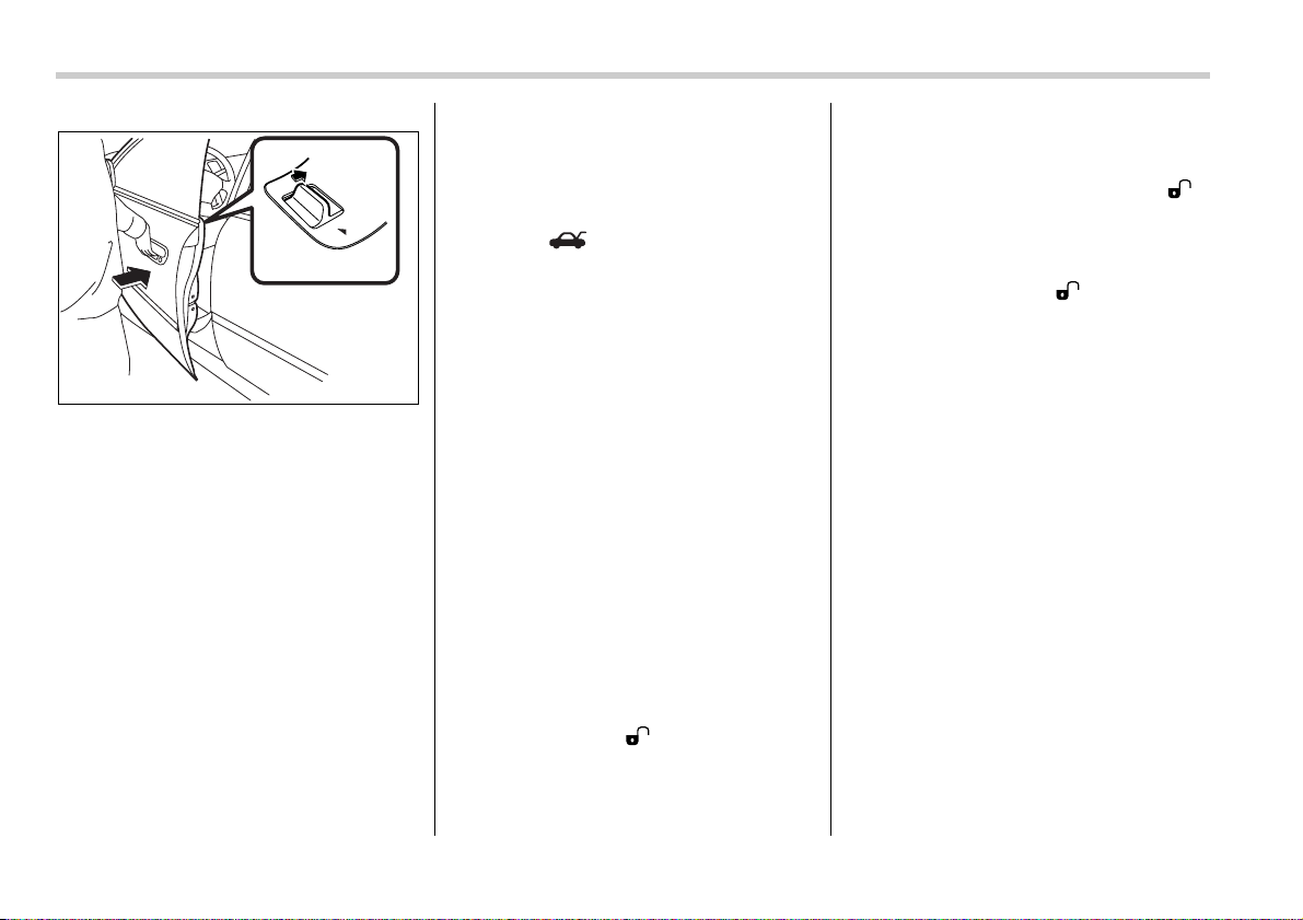
2-16 Keys and doors
6. Push the front side (“LOCK” side) of
the power door locking switch to set the
door locks.
7. Close the door. An electronic chirp will
sound once, the turn signal lights will flash
once and the indicator lights will start
flashing rapidly. After rapid flashing for 30
seconds (standby time), the indicator
lights will then flash slowly (twice approxi-
mately every two seconds), indicating that
the system has been armed for surveil-
lance.
NOTE
y The system can be armed even if the
engine hood, the windows and/or
moonroofs are opened. Always make
sure that they are fully closed before
arming the system.
y The 30-second standby time can be
eliminated if you prefer. Have it per-
formed by your SUBARU dealer.
y If your vehicle is a Sedan and you un-
lock the trunk using the remote trans-
mitter’s “ ” button with the alarm
system armed, the system will be tem-
porarily placed in a standby state. The
system will go back to the surveillance
state upon locking the trunk.
y The system is in the standby mode
for a 30-second period after locking the
doors with the remote transmitter. The
security indicator light will flash at
short intervals during this period.
y If any of the following actions is done
during the standby period, the system
will not switch to the surveillance state.
y Doors are unlocked using the re-
mote transmitter.
y Any door (including the rear gate
of a Station wagon or the trunk of a
Sedan) is opened.
y Ignition switch is turned to the
“ON” position.
Disarming the system
Briefly press the “ ” button (for less
than two seconds) on the remote transmit-
ter. The driver’s door will unlock, an elec-
tronic chirp will sound twice, the turn sig-
nal lights will flash twice and the indicator
light will go off.
To unlock all other doors and the rear gate
(Station wagon), briefly press the “ ”
button a second time within 5 seconds.
NOTE
If the interval between the first and sec-
ond presses of the “ ” button (for
unlocking of all of the doors and the
rear gate) is extremely short, the sys-
tem may not respond.
Or the system can be disarmed by the
following method, too.
y Insert the key in the door lock of the
driver’s door and turn it to the unlock
position.
T Emergency disarming
If you cannot disarm the system using the
transmitter (i.e. the transmitter is lost, bro-
ken or the transmitter battery is too weak),
you can disarm the system without using
the transmitter.
The system can be disarmed if you turn
the ignition switch from the “LOCK” to the
“ON” position with a registered key.
Insert the key in the door lock of the driv-
er’s door and turn it to the unlock position.
Valet mode
When you choose the valet mode, the
alarm system does not operate. In valet
200897
LOCK
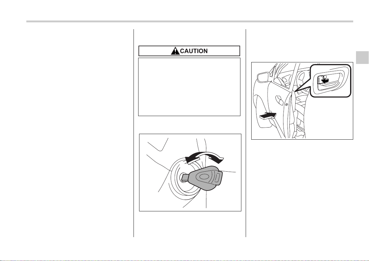
Keys and doors 2-17
– CONTINUED –
mode, the remote transmitter is used only
for locking and unlocking the doors and
rear gate (Station wagon) and panic acti-
vation.
To enter the valet mode, change the set-
ting of your vehicle’s alarm system for de-
activation mode. (Refer to “Activating and
deactivating the alarm system” in this sec-
tion.) The security indicator light will con-
tinue to flash once every three seconds in-
dicating that the system is in the valet
mode.
To exit valet mode, change the setting of
your vehicle’s alarm system for activation
mode. (Refer to “Activating and deactivat-
ing the alarm system” in this section.)
Passive arming
When passive arming mode has been
programmed by the dealer, arming of the
system is automatically accomplished
without using the remote transmitter. Note
that in this mode, DOORS MUST BE
MANUALLY LOCKED.
T To enter the passive mode
If you wish to program the passive arming
mode, have it done by your SUBARU
dealer.
T Arming the system
1. Turn the ignition switch to the “ON” po-
sition.
1) LOCK
2) ON
2. Turn the ignition switch from “ON” to
“LOCK” position and remove the key from
the ignition switch.
3. Open the doors and get out of the vehi-
cle.
4. Before closing the doors, lock all doors
with the inside door lock levers.
5. Close the doors. The system will auto-
matically arm after one minute.
In the passive mode, the system can also
be armed with the remote transmitter or
with the power door locking switches. If
the remote transmitter or power door lock-
ing switch is used to lock the vehicle, arm-
ing will take place immediately regardless
of whether or not the passive mode has
been selected.
In passive mode, the system will au-
tomatically activate the alarm but
WILL NOT automatically lock the
doors. In order to lock the doors you
must either lock them as indicated
in step 4 below or with the key once
they have been closed. Failure to
lock the doors manually will result
in a higher security risk.
2
1
200721
200704
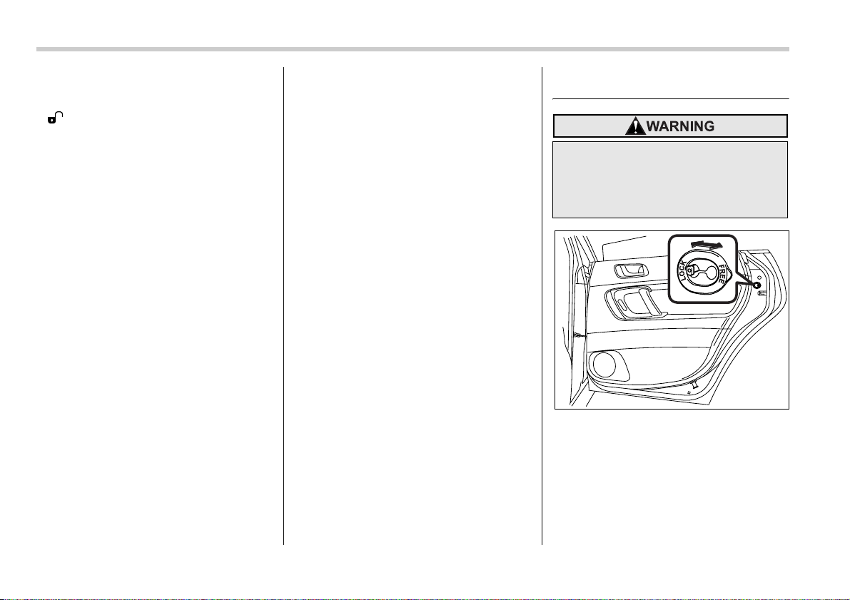
2-18 Keys and doors
T Disarming the system
To disarm the system, briefly press the
“ ” button on the transmitter.
Tripped sensor identification
The security indicator light flashes when
the alarm system has been triggered. Al-
so, the number of flashes indicates the lo-
cation of unauthorized intrusion or the se-
verity of impact on the vehicle.
y When the ignition switch is turned to the
“ON” position, the indicator light will light
for 1 second and then flash as follows:
When a door or rear gate (Station wag-
on) was opened: 5 times
When the trunk (Sedan) was opened: 4
times
When a strong impact or multiple im-
pacts were sensed: twice (only vehicles
with shock sensors (dealer option))
When a light impact was sensed: once
(only vehicles with shock sensors (deal-
er option))
Shock sensors (dealer op-
tion)
The shock sensors trigger the alarm sys-
tem when they sense impacts applied to
the vehicle and when any of their electric
wires is cut. The alarm system causes the
horn to sound and the turn signal lights to
flash for a short time when the sensed im-
pact is weak, but it warns of a strong im-
pact or multiple impacts by sounding the
horn and flashing the turn signal lights,
both lasting approximately 30 seconds.
If you desire, your SUBARU dealer can
connect them and set them for activation
or deactivation.
NOTE
y The shock sensors are not always
able to sense impacts caused by
breaking in, and cannot sense an im-
pact that does not cause vibration
(such as breaking the glass using a
rescue hammer).
y The shock sensors may sense vibra-
tion like those shown in the following
and trigger the alarm system. Select
the settings of the alarm system and
shock sensors appropriately depend-
ing on where you usually park your ve-
hicle.
Example:
Vibration from construction site
Vibration in multistory car park
Vibration from trains
y You can have the sensitivity of the
shock sensors adjusted to your prefer-
ence by your SUBARU dealer.
Child safety locks
Each rear door has a child safety lock that
prevents the doors from being opened
even if the inside door handle is pulled.
When the child safety lock lever is in the
lock position, the door cannot be opened
from inside regardless of the position of
the inner door handle lock lever. The door
can only be opened from the outside.
Always use the child safety lock
whenever a child rides in the rear
seat. Serious injury could result if a
child accidentally opened the door
and fell out.
200247
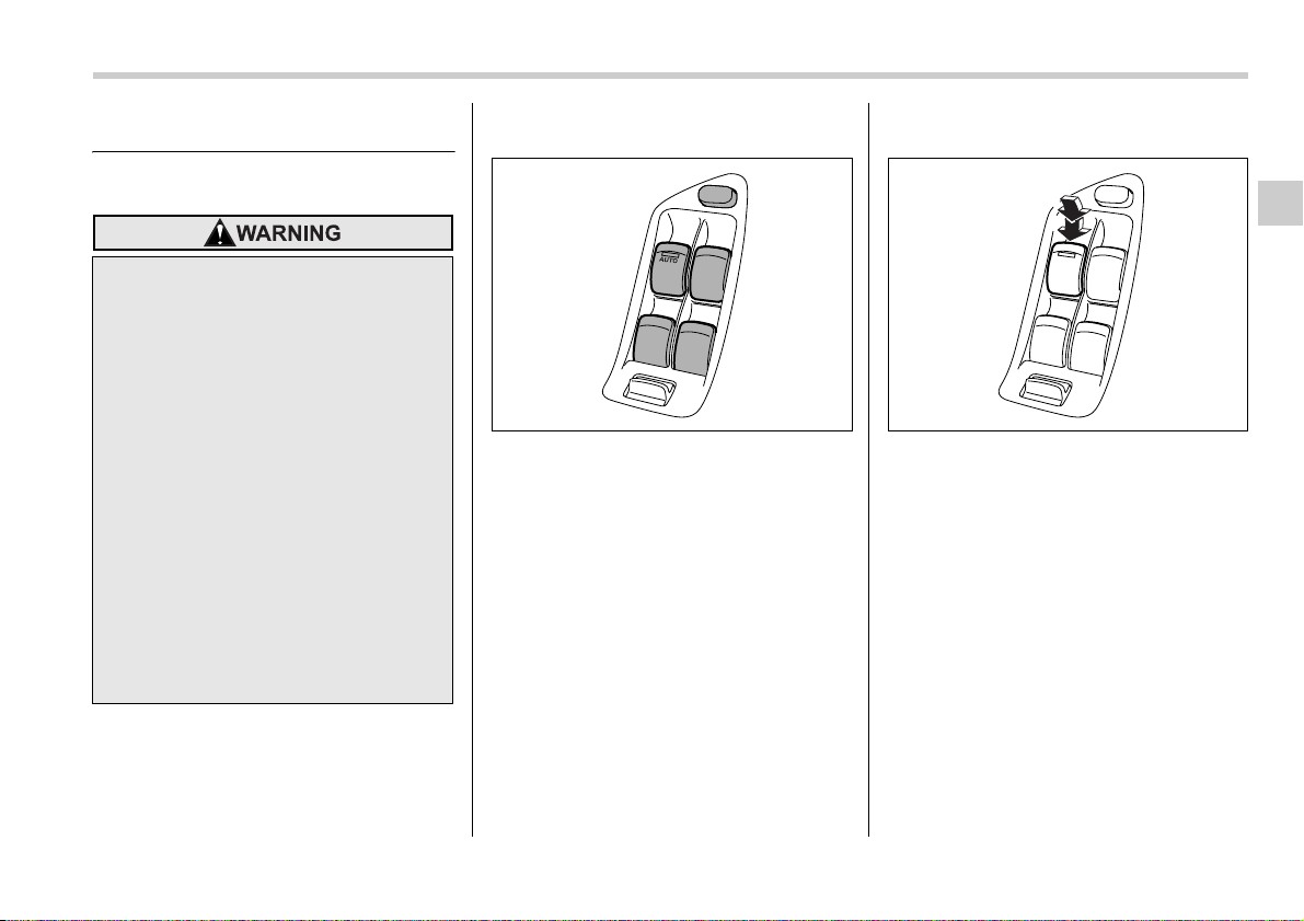
Keys and doors 2-19
– CONTINUED –
Windows
Power windows
The power windows operate only when
the ignition switch is in the “ON” position.
T Driver’s side switches
1) Lock switch
2) For driver’s window
3) For front passenger’s window
4) For rear left passenger’s window
5) For rear right passenger’s window
All door windows can be controlled by the
power window switch cluster at the driver
side door.
V Operating the driver’s window
1) Open
2) Automatically open
To open:
Push the switch down lightly and hold it.
The window will open as long as the
switch is held.
This switch also has a one-touch auto
down feature that allows the window to be
opened fully without holding the switch.
Push the switch down until it clicks and re-
lease it, and the window will fully open. To
stop the window halfway, pull the switch
up lightly.
To avoid serious personal injury
caused by entrapment, you must do
the following.
y When operating the power win-
dows, be extremely careful to pre-
vent anyone’s fingers, arms, neck
or head from being caught in the
window.
y Always lock the passengers’ win-
dows using the lock switch when
children are riding in the vehicle.
y Before leaving the vehicle, always
remove the key from the ignition
switch for safety and never allow
an unattended child to remain in
the vehicle. Failure to follow this
procedure could result in injury to
a child operating the power win-
dow.
1
3
5
4
2
200843
1
2
200844
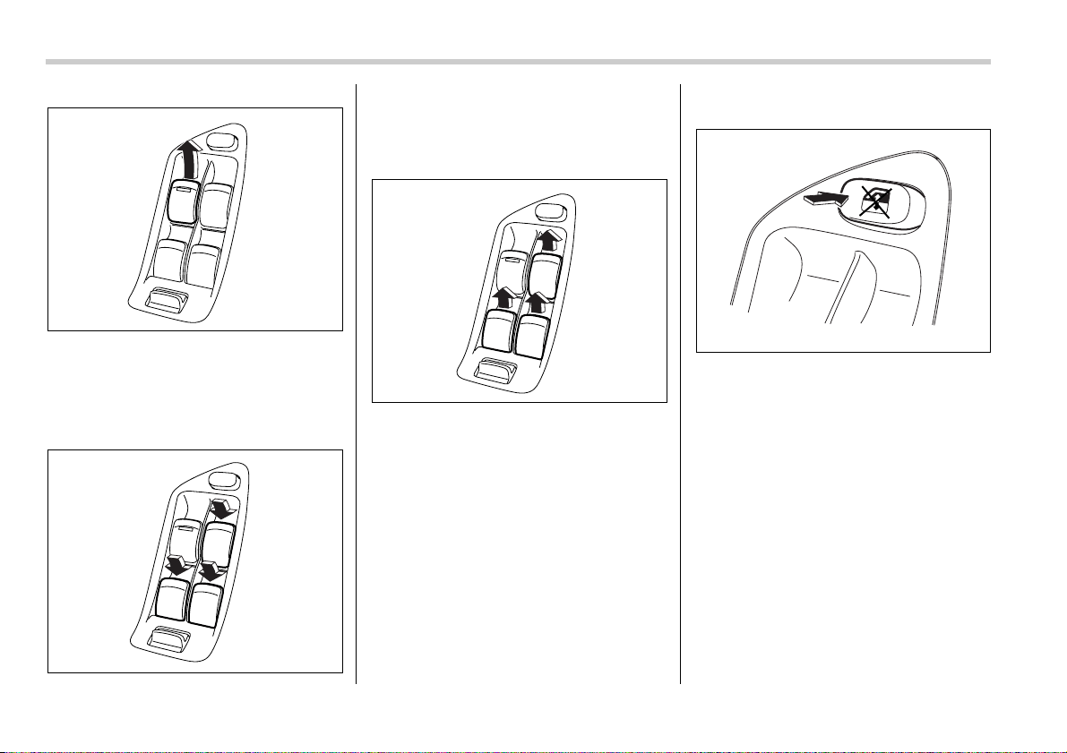
2-20 Keys and doors
To close:
Pull the switch up lightly and hold it. The
window will close as long as the switch is
held.
V Operating the passengers’ windows
To open the passengers’ windows, push
the appropriate switch down and hold it
until the window reaches the desired posi-
tion.
To close the window, pull the switch up
and hold it until it reaches the desired po-
sition.
V Locking the passengers’ windows
To lock the passengers’ windows, push
the lock switch. When the lock switch is in
the “LOCK” position, the passengers’ win-
dows cannot be opened or closed.
Press the switch again to cancel the pas-
sengers’ window locking.
200845
200846
200847
200398
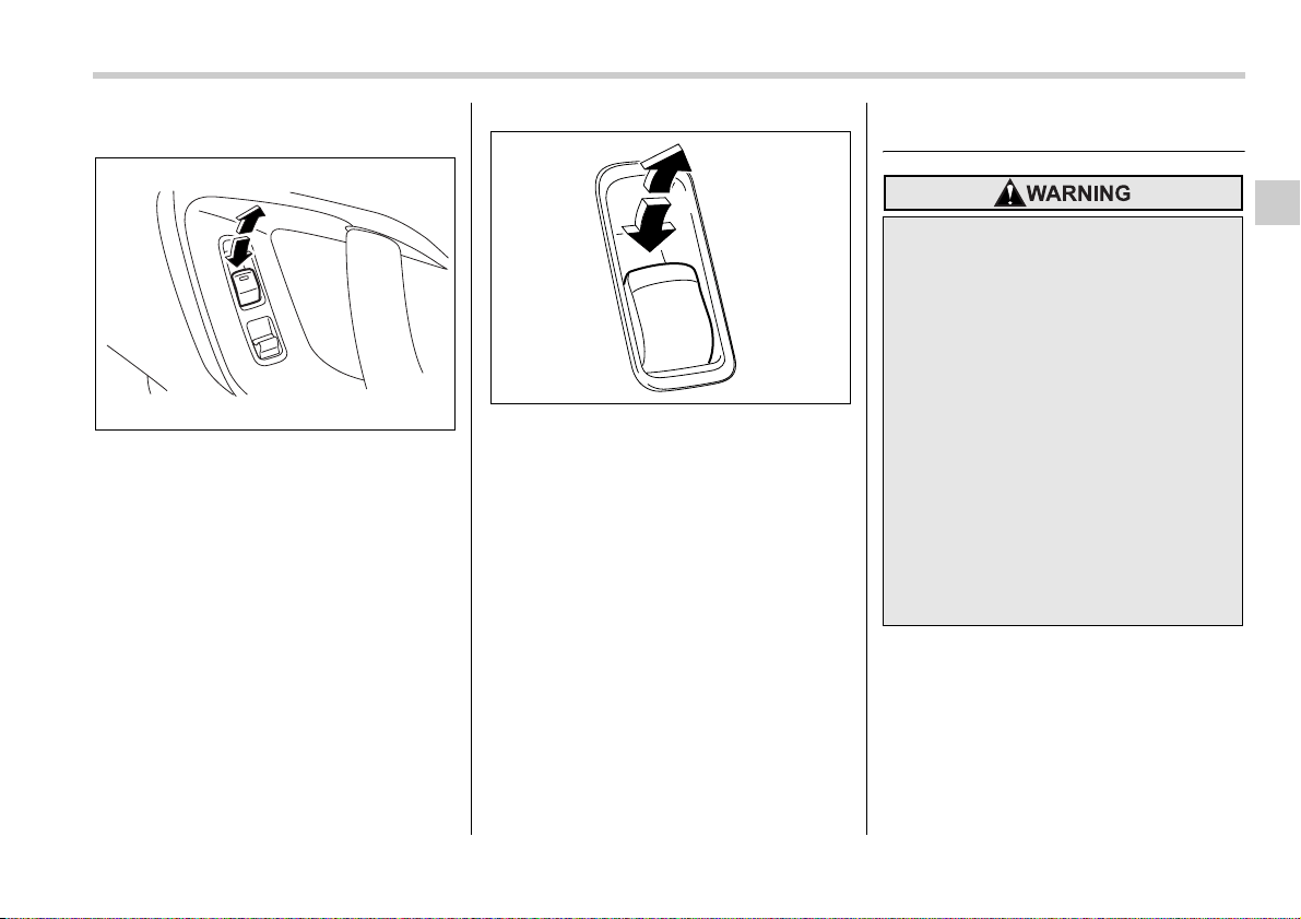
Keys and doors 2-21
– CONTINUED –
T Passengers’ side switches
Front passenger’s window switch
1) Open
2) Close
To open the window, push the switch
down and hold it until the window reaches
the desired position.
Rear passengers’ window switches
1) Open
2) Close
To close the window, pull the switch up
and hold it until the window reaches the
desired position.
When the lock switch on the power win-
dow switch cluster, located on the driver’s
side door, is in the “LOCK” position, the
passengers’ windows cannot be operated
with the passengers’ switches.
Trunk lid (Sedan)
To open and close the trunk
lid from outside
The trunk lid can be opened using the re-
mote keyless entry system. Refer to “Re-
mote keyless entry system” section in this
chapter.
To close the trunk lid, lightly press the
2
1
200848
1
2
200849
y To prevent dangerous exhaust
gas from entering the vehicle, al-
ways keep the trunk lid closed
while driving.
y Help prevent young children from
locking themselves in the trunk.
When leaving the vehicle, either
close all windows and lock all
doors or cancel the inside trunk
lid release. Also make certain that
the trunk is closed. On hot or sun-
ny days, the temperature in the
trunk could quickly become high
enough to cause death or serious
heat-related injuries including
brain damage to anyone locked
inside, particularly for small chil-
dren.
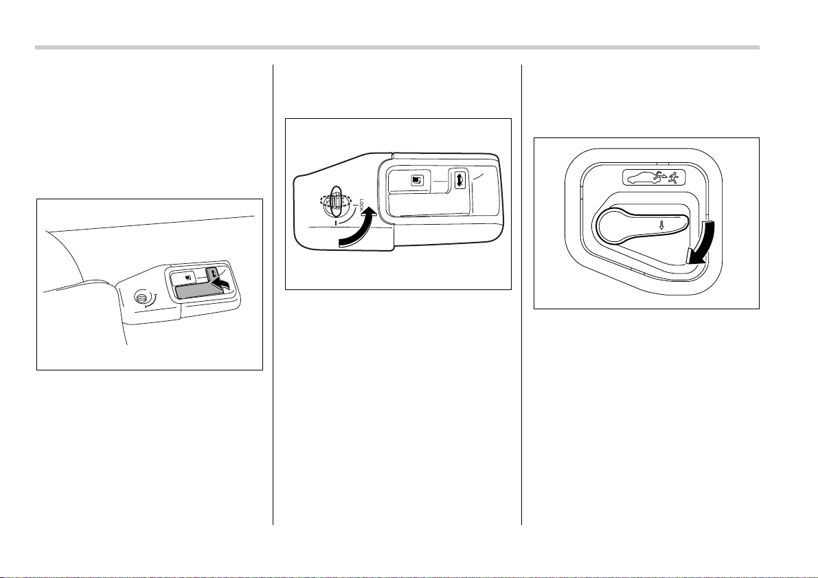
2-22 Keys and doors
trunk lid down until the latch engages.
NOTE
Do not leave your valuables in the
trunk when you leave your vehicle.
To open the trunk lid from in-
side
Pull the trunk lid release lever upward.
To lock and unlock the trunk
lid release lever
When you entrust your vehicle key to an-
other person, you can lock the trunk lid re-
lease lever to prevent luggage in the trunk
from being stolen. To lock the trunk lid re-
lease lever, insert the master key or sub
key into the key cylinder at the rear of the
release lever and turn it counterclockwise.
To unlock the trunk lid release lever, turn
the key clockwise.
Internal trunk lid release han-
dle
The internal trunk lid release handle is a
device designed to open the trunk lid from
inside the trunk. In the event children or
adults become locked inside the trunk, the
handle allows them to open the lid. The
handle is located on the inside of the trunk
lid.
To open the trunk lid from inside the trunk,
press the yellow handle downward as indi-
cated by the arrow on the handle. This op-
eration unlocks the trunk lid. Then, push
up the lid.
The handle is made of material that re-
mains luminescent for approximately an
hour in the dark trunk space after it is ex-
posed to ambient light even for a short
time.
LOCK
200850
200851
200852
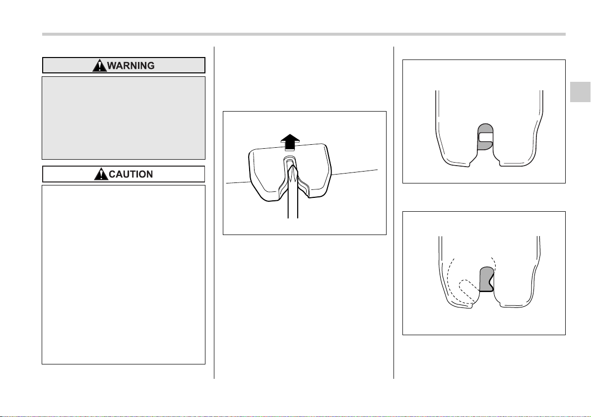
Keys and doors 2-23
– CONTINUED –
T Inspection
Perform the following steps at least twice
a year to check the release handle for cor-
rect operation.
1. Open the trunk lid.
2. Use a screwdriver with a thin blade.
Slide the screwdriver blade from the slit
aperture of the lock assembly fully to the
end until you hear a click.
This places the latch in the locked posi-
tion.
3. Move the release handle, from outside
the vehicle, in the direction of the arrow to
check if the latch is released.
If the latch is not released, contact your
Never allow any child to get in the
trunk and play with the release han-
dle. If the driver starts the vehicle
without knowing that a child is in-
side the trunk and the child opens
the lid using the release handle, the
child could fall out and be killed or
seriously injured.
y Do not close the lid while gripping
the release handle. The handle
may be damaged.
y Do not use the handle as a hook to
fasten straps or ropes to secure
your cargo in the trunk. Such use
may result in damage of the han-
dle.
y Load the trunk so that cargo can
not strike the release handle. If the
cargo hits the handle while the ve-
hicle is being driven, the handle
may be pushed down and the
trunk lid may open. That may
cause cargo to fall out of the
trunk, which could create a traffic
safety hazard.
200853
200854
200855
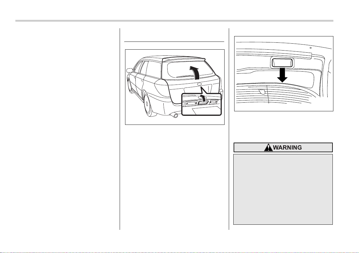
2-24 Keys and doors
SUBARU dealer.
In that case, use the key to release the
latch, then close the trunk lid.
Also, if the movement of the release han-
dle feels restricted or not entirely smooth
during operation, or the handle and/or
handle base is cracked, contact your
SUBARU dealer.
Rear gate (Station wagon)
The rear gate can be locked and unlocked
using either the keyless entry system or
the power door locking switch.
Refer to the “Power door locking switches”
and “Remote keyless entry system” sec-
tions in this chapter.
To open the rear gate, first unlock the rear
gate lock then pull the outside handle up.
To close the rear gate, lower it slowly and
push down firmly until the latch engages.
The rear gate can be lowered easily if you
pull it down holding the recessed grip.
200260
y To prevent dangerous exhaust
gas from entering the vehicle, al-
ways keep the rear gate closed
while driving.
y Do not attempt to shut the rear
gate while holding the recessed
grip. Also avoid closing the rear
gate by pulling on the recessed
grip from inside the cargo space.
There is a danger of your hand be-
ing caught and injured.
200401
Keys and doors 2-25
– CONTINUED –
NOTE
Should the rear gate be unable to be
unlocked due to a discharged battery,
a fault in the door locking/unlocking
system or other causes, you can un-
lock it by manually operating the rear
gate lock release lever.
For the procedure, refer to “Rear gate
(Station wagon) – if the rear gate can-
not be unlocked” section in chapter 9.
Moonroof (if equipped)
The moonroof has both tilting and sliding
functions.
The moonroofs operate only when the ig-
nition switch is in the “ON” position.
y Do not jam a plastic bag in or
place cellophane tape on the rear
gate stays or scratch the stays
while loading or unloading cargo.
That could cause leakage of gas
from the stays, which may result
in their inability to hold the rear
gate open.
y Be careful not to hit your head or
face on the rear gate when open-
ing or closing the rear gate and
when loading or unloading cargo.
y Never let anyone’s hands, arms,
head or any objects protrude from
the moonroof. A person could be
seriously injured if the vehicle
stops suddenly or turns sharply
or if the vehicle is involved in an
accident.
To avoid serious personal injury
caused by entrapment, you must
do the following.
y Before closing the moonroof,
make sure that no one’s hands,
arms, head or other objects will be
accidentally caught in the moon-
roof.
y Before leaving the vehicle, always
remove the key from the ignition
switch for safety and never allow
an unattended child to remain in
the vehicle. Failure to follow this
procedure could result in injury to
a child operating the moonroof.
y Never try to check the anti-entrap-
ment function by deliberately
placing part of your body in the
moonroof.
y Do not sit on the edge of the open
moonroof.
y Do not operate the moonroof if
falling snow or extremely cold
conditions have caused it to
freeze shut.
y The anti-entrapment function
does not operate when the moon-
roof is being tilted down. Be sure
to confirm that it is safe to do so
before tilting the moonroof down.
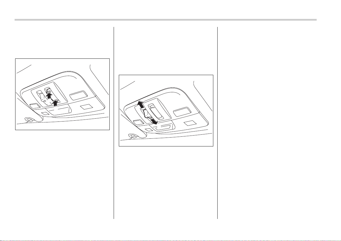
2-26 Keys and doors
Tilting/sliding moonroof (Se-
dan)
T Tilt function
1) Tilt up
2) Tilt down
The tilting function will only operate when
the moonroof is fully closed.
Push the rear side of the “Tilt” switch to
raise the moonroof.
Push the front side of the “Tilt” switch to
lower the moonroof.
Release the switch after the moonroof has
been raised or has been lowered com-
pletely. Pushing the switch continuously
may cause damage to the moonroof.
NOTE
One-touch operation does not take
place when the moonroof is tilted up
and down. Push the switch continu-
ously to tilt the moonroof up and down.
T Sliding function
1) Open
2) Close
Push the “Open/Close” switch rearward to
open the moonroof. The sun shade will
also be opened together with the moon-
roof.
Push the “Open/Close” switch forward to
close the moonroof. The moonroof will
stop halfway if you continue to press on
the switch. Release the switch once and
push it again to close the moonroof com-
pletely.
To stop the moonroof at a selected mid-
way position while opening or closing it,
momentarily push the switch to the
“OPEN” or “CLOSE” side.
After washing the vehicle or after it rains,
wipe away water on the roof prior to open-
ing the moonroof to prevent drops of water
from falling into the passenger compart-
ment.
T Anti-entrapment function
When the moonroof senses an object
trapped between its glass and the vehi-
cle’s roof during closure, it automatically
moves back to either of the following posi-
tions according to the point at which it
senses the object:
y When the moonroof senses the object
at a point between the halfway stop posi-
tion and fully closed position, it moves
back to the halfway stop position and
stops there.
y When the moonroof senses the object
at a point between the halfway stop posi-
tion and fully open position, it moves back
to the fully open position and stops there.
The anti-entrapment function may also be
activated by a strong shock on the moon-
roof even when there is nothing trapped.
1
2
200856
1
2
200857
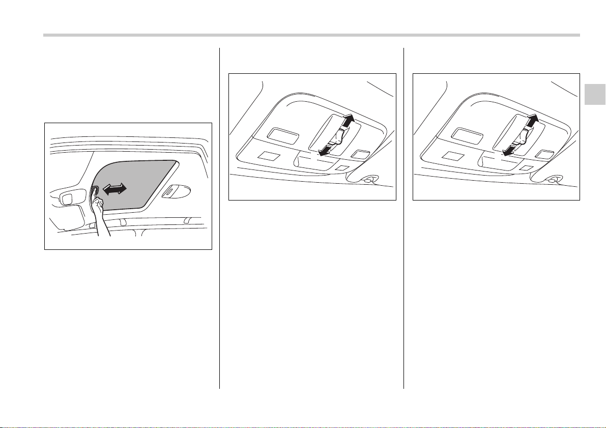
Keys and doors 2-27
– CONTINUED –
NOTE
For the sake of safety, it is recommend-
ed that you avoid driving with the
moonroof fully opened.
T Sun shades
The sun shade can be slid forward or
backward by hand while the moonroof is
closed.
If the moonroof is opened, the sun shade
also moves back.
Moonroof (Station wagon)
The front moonroof has a tilting function
and the rear moonroof has a sliding func-
tion.
Both moonroofs operate only when the ig-
nition switch is in the “ON” position.
T Tilting moonroof
1) Open
2) Close
To tilt up the front moonroof, open the sun
shade and pull the switch to the “OPEN”
side.
To tilt down the front moonroof, push the
switch to the “CLOSE” side, then quickly
release it. If you wish to stop the tilting-
down motion of the front moonroof part-
way, either pull the switch to the “OPEN”
side or push it to the “CLOSE” side.
T Sliding moonroof
1) Open
2) Close
To fully open the rear moonroof, tilt up the
front moonroof then pull the switch to the
“OPEN” side and quickly release it. The
rear moonroof will stop at a position ap-
proximately 6.7 in (17 cm) from its fully
closed position.
After confirming safety, pull the switch to
the “OPEN” side again and quickly re-
lease it. The rear moonroof will open to its
fully open position. To stop the rear moon-
roof at some selected mid-way point while
it is moving toward its fully open position,
momentarily push the switch to the
“CLOSE” or “OPEN” side.
To fully close the rear moonroof, push the
200404
1
2
200858
1
2
200858
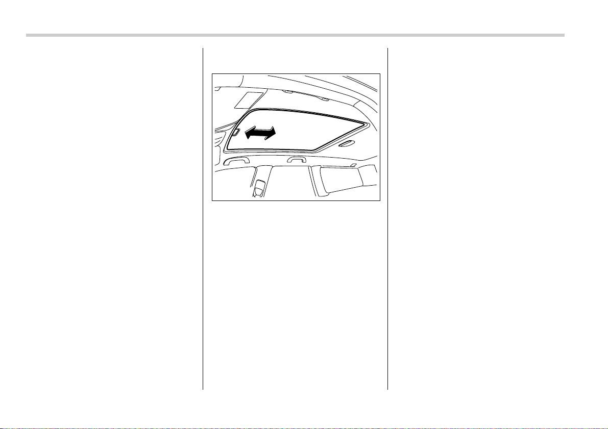
2-28 Keys and doors
switch to the “CLOSE” side then quickly
release it.
The rear moonroof will stop at a position
approximately 5.9 in (15 cm) before its ful-
ly closed position. After confirming safety,
pull the switch to the “CLOSE” side again
and quickly release it. The rear moonroof
will fully close. The front moonroof can
then be fully closed.
T Anti-entrapment function
When the moonroof senses an object
trapped between its glass and during clo-
sure, it automatically moves back by 5.9 in
(15 cm) from that point and then stops.
The anti-entrapment function may also be
activated by a strong shock on the moon-
roof even when there is nothing trapped.
NOTE
y For the sake of safety, it is recom-
mended that you avoid driving with the
moonroof fully opened.
y Driving with the moonroof fully open
can cause an annoying sound to gen-
erate at high speeds. If such a condi-
tion has been encountered, use the
moonroof at the initial stop position of
6.7 in (17 cm).
T Sun shades
The sun shade can be slid forward or
backward by hand while the moonroof is
closed.
If the moonroof is opened, the sun shade
also moves back.
200406

3
Instruments and controls
Ignition switch .................................................... 3-3
LOCK ....................................................................... 3-3
ACC .......................................................................... 3-4
ON ............................................................................ 3-4
START ...................................................................... 3-4
Key reminder chime ............................................... 3-5
Ignition switch light ................................................ 3-5
Hazard warning flasher ...................................... 3-5
Meters and gauges (Turbo models) ................. 3-5
Combination meter illumination ............................ 3-5
Canceling the function for meter/gauge needle
movement and combination meter sequential
illumination upon turning on the ignition
switch .................................................................... 3-6
Speedometer ........................................................... 3-6
Odometer ................................................................. 3-7
Double trip meter .................................................... 3-7
Tachometer ............................................................. 3-8
Fuel gauge ............................................................... 3-8
Temperature gauge ................................................ 3-9
Meters and gauges (Non-turbo models) .......... 3-10
Combination meter illumination ............................ 3-10
Canceling the function for meter/gauge needle
movement upon turning on the ignition
switch .................................................................... 3-10
Speedometer ........................................................... 3-10
Odometer ................................................................. 3-11
Double trip meter .................................................... 3-11
Tachometer ............................................................. 3-12
Fuel gauge ............................................................... 3-12
Temperature gauge ................................................ 3-13
Warning and indicator lights ............................. 3-14
Seatbelt warning light and chime .......................... 3-14
SRS airbag system warning light .......................... 3-16
Front passenger’s frontal airbag ON and OFF
indicators .............................................................. 3-17
CHECK ENGINE warning light/Malfunction
indicator lamp ....................................................... 3-17
Charge warning light .............................................. 3-18
Oil pressure warning light ..................................... 3-18
AT OIL TEMPerature warning light (AT
vehicles) ................................................................ 3-18
Low tire pressure warning light (if equipped) ...... 3-18
ABS warning light ................................................... 3-20
Brake system warning light ................................... 3-20
Low fuel warning light ............................................ 3-21
Door open warning light ........................................ 3-22
All-Wheel Drive warning light (AT vehicles) ......... 3-22
Vehicle Dynamics Control operation indicator
light (if equipped) ................................................. 3-22
Vehicle Dynamics Control warning light (if
equipped)/Vehicle Dynamics Control OFF
indicator light (if equipped) ................................. 3-22
Security indicator light ........................................... 3-23
SPORT mode indicator light (AT vehicles) ........... 3-24
Selector lever position indicator (AT vehicles) .... 3-24
Gear position indicator (AT vehicles) ................... 3-24
Turn signal indicator lights .................................... 3-24
High beam indicator light ....................................... 3-25
Cruise control indicator light ................................. 3-25

Instruments and controls
Cruise control set indicator light .......................... 3-25
Headlight indicator light ........................................ 3-25
Front fog light indicator light ................................ 3-25
Clock .................................................................... 3-25
Information display (Vehicle without
Navigation System) ......................................... 3-26
Outside temperature indicator .............................. 3-27
Current fuel consumption ...................................... 3-28
Average fuel consumption .................................... 3-28
Driving range on remaining fuel ........................... 3-29
Journey time ........................................................... 3-30
Light control switch ........................................... 3-31
Headlights ............................................................... 3-31
High/low beam change (dimmer) .......................... 3-31
Headlight flasher .................................................... 3-32
Daytime running light system ............................... 3-32
Turn signal lever ................................................. 3-32
Illumination brightness control ......................... 3-33
Parking light switch ........................................... 3-33
Front fog light switch (if equipped) .................. 3-34
Wiper and washer ............................................... 3-34
Windshield wiper and washer switches ............... 3-35
Rear window wiper and washer switch (Station
wagon) .................................................................. 3-37
Windshield wiper deicer (if equipped) .............. 3-38
Rear window defogger button ........................... 3-38
Mirrors ................................................................. 3-40
Inside mirror ........................................................... 3-40
Auto-dimming mirror/compass (if equipped) ...... 3-40
Outside mirrors ....................................................... 3-41
Tilt steering wheel .............................................. 3-43
Horn ..................................................................... 3-43
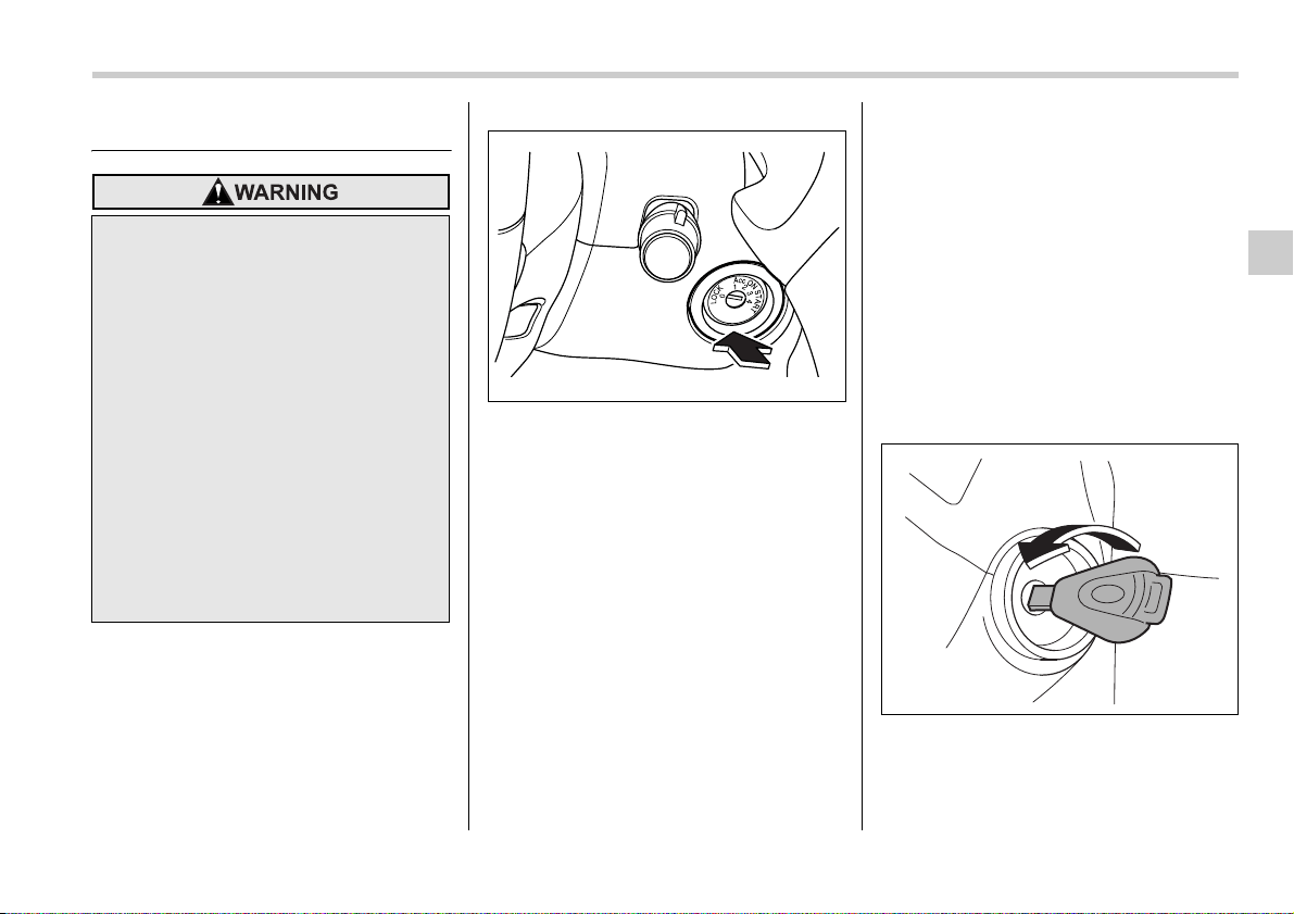
Instruments and controls 3-3
– CONTINUED –
Instrumen ts and contro ls
Ignition switch
The ignition switch has four positions:
LOCK, ACC, ON and START.
NOTE
y Keep the ignition switch in the
“LOCK” position when the engine is
not running.
y Using electrical accessories for a
long time with the ignition switch in the
“ON” or “ACC” position can cause the
battery to go dead.
If the ignition switch will not move from
the “LOCK” position to the “ACC” po-
sition, turn the steering wheel slightly
to the left and right as you turn the ig-
nition switch.
y If the key is attached to a keyholder
or to a large bunch of other keys, cen-
trifugal force may act on it as the vehi-
cle moves, resulting in unwanted turn-
ing of the ignition switch. Also, if a
large keyholder is attached to the key,
your knees or hands may accidentally
touch it in a way that turns the ignition
switch.
LOCK
The key can only be inserted or removed
in this position. The ignition switch will lock
the steering wheel when you remove the
key.
If turning the key is difficult, turn the steer-
ing wheel slightly to the right and left as
you turn the key.
T Automatic transmission vehicles
The key can be turned from “ACC” to
“LOCK” only when the selector lever is in
the “P” position.
y Never turn the ignition switch to
“LOCK” while the vehicle is being
driven or towed because that will
lock the steering wheel, prevent-
ing steering control. And when
the engine is turned off, it takes a
much greater effort than usual to
steer.
y Before leaving the vehicle, always
remove the key from the ignition
switch for safety and never allow
an unattended child to remain in
the vehicle. Failure to follow this
procedure could result in injury to
a child or others. Children could
operate the power windows, the
sunroof or other controls or even
make the vehicle move.
300259
300501
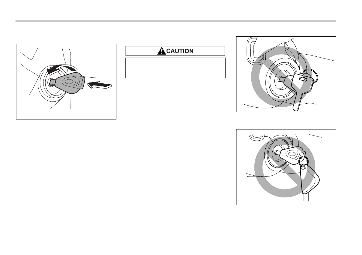
3-4 Instruments and controls
T Manual transmission vehicles
The key can be turned from “ACC” to
“LOCK” only when the key is pushed in
while turning it.
ACC
In this position the electrical accessories
(radio, accessory power outlet, etc.) can
be used.
ON
This is the normal operating position after
the engine is started.
START
The engine is started in this position. The
starter cranks the engine to start it. When
the key is released (after the engine has
started), the key automatically returns to
the “ON” position.
If your registered key fails to start the en-
gine, pull out the key once (the security in-
dicator light will blink), and then insert the
key in the ignition switch and turn it to the
“START” position and again try to start the
engine.
NOTE
The engine may not start in the follow-
ing cases:
y The key grip is touching another key
or a metallic key holder.
y The key is near another key that con-
tains an immobilizer transponder.
300591
Do not turn the ignition switch to the
“START” position while the engine
is running.
300502
300503
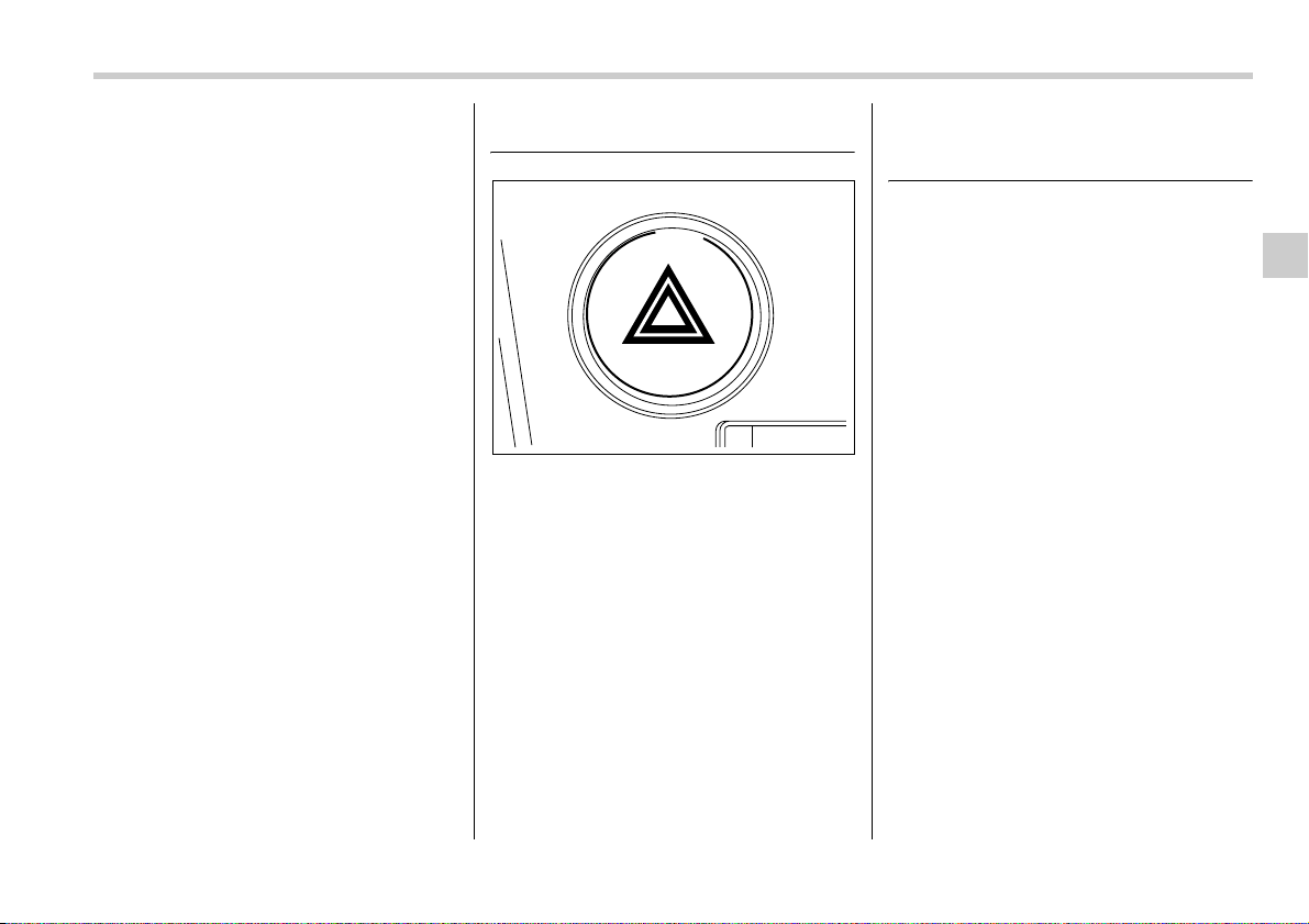
Instruments and controls 3-5
– CONTINUED –
Key reminder chime
The reminder chime sounds when the
driver’s door opens and the key is in the
“LOCK” or “ACC” positions. The chime
stops when the key is removed from the
ignition switch.
Ignition switch light
For easy access to the ignition switch in
the dark, the ignition switch light comes on
when any of the doors are opened. The
light remains on for a several seconds and
gradually goes out after all doors are
closed or if the key is inserted in the igni-
tion switch.
Hazard warning flasher
The hazard warning flasher is used to
warn other drivers when you have to park
your vehicle under emergency conditions.
The hazard warning flasher works with the
ignition switch in any position.
To turn on the hazard warning flasher,
push the hazard warning button on the in-
strument panel. To turn off the flasher,
push the button again.
NOTE
When the hazard warning flasher is on,
the turn signals do not work.
Meters and gauges (Turbo
models)
NOTE
Liquid-crystal displays are used in
some of the meters and gauges in the
combination meter. You will find their
indications hard to see if you wear po-
larized glasses.
Combination meter illumina-
tion
When the ignition switch is turned to the
“ON” position, the various parts of the
combination meter are illuminated in the
following sequence:
1. Meter rims, gauge rims, warning lights,
and indicator lights light up.
2. Meter needles and gauge needles light
up.
3. Meter needles and gauge needles
each show MAX position.
4. Meter needles and gauge needles
each show MIN position.
5. Dials in meters and gauges light up.
6. Regular illumination (for driving) be-
gins.
300177
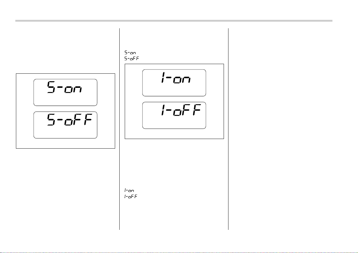
3-6 Instruments and controls
Canceling the function for
meter/gauge needle move-
ment and combination meter
sequential illumination upon
turning on the ignition switch
It is possible to activate or deactivate the
movement of the meter needles and
gauge needles and sequential illumination
of the combination meter that take place
when the ignition switch is turned to the
“ON” position.
Turn the ignition switch to the “ACC” posi-
tion. With the A trip meter indication se-
lected, briefly press the trip knob twice.
You can now establish the activated/deac-
tivated setting for movement of the meter
needles and gauge needles when the ig-
nition switch is turned to the “ON” position.
To change the current setting, press the
trip knob for at least two seconds.
: Activated
: Deactivated
Briefly press the trip knob again. You can
now establish the activated/deactivated
setting for sequential illumination of the
combination meter when the ignition
switch is turned to the “ON” position. To
change the current setting, press the trip
knob for at least two seconds.
: Activated
: Deactivated
Briefly press the knob to return to the A trip
meter indication.
If you turn the ignition switch to the
“LOCK” position, turn the ignition switch to
the “ON” position, or open and close the
driver’s door during the setting procedure,
the new setting will be canceled.
Also, if you do not press the trip knob for a
period of 10 seconds, the new setting will
be canceled.
NOTE
It is not possible to cancel sequential
illumination of the combination meter
while sequential illumination is actual-
ly taking place. Cancel sequential illu-
mination when regular illumination (for
driving) has begun.
Speedometer
The speedometer shows the vehicle
speed.
300185
300186

Instruments and controls 3-7
– CONTINUED –
Odometer
This meter displays the odometer when
the ignition switch is in the “LOCK”, “ACC”
or “ON” position.
The odometer shows the total distance
that the vehicle has been driven.
If you press the trip knob when the ignition
switch is in the “LOCK” position, the
odometer/trip meter will light up. If you do
not press the trip knob within 10 seconds
of illumination of the odometer/trip meter,
the odometer/trip meter will go off.
The odometer/trip meter will also go off if
you open and close the driver’s door with-
in 10 seconds of illumination of the odom-
eter/trip meter.
Double trip meter
This meter display two trip meters when
the ignition switch is in the “LOCK”, “ACC”
or “ON” position.
The trip meter shows the distance that the
vehicle has been driven since you last set
it to zero.
To change the mode indication, briefly
push the knob.
Each press of the knob changes the mode
indication alternately.
To set the trip meter to zero, select the A
trip or B trip meter by pushing the knob
and keep the knob pushed for more than
2 seconds.
If you press the trip knob when the ignition
switch is in the “LOCK” position, the
odometer/trip meter will light up. It is pos-
sible to switch between the A trip meter
and B trip meter indications while the
odometer/trip meter is lit up. If you do not
press the trip knob within 10 seconds of il-
lumination of the odometer/trip meter, the
odometer/trip meter will go off. Also, if you
open and close the driver’s door within 10
seconds of illumination of the odometer/
trip meter, the odometer/trip meter will go
off.
NOTE
If the connection between the combi-
nation meter and battery is broken for
any reason such as vehicle mainte-
nance or fuse replacement, the data re-
corded on the trip meter will be lost.
300261 300258
A trip meter
B trip meter
To ensure safety, do not attempt to
change the function of the indicator
during driving, as an accident could
result.
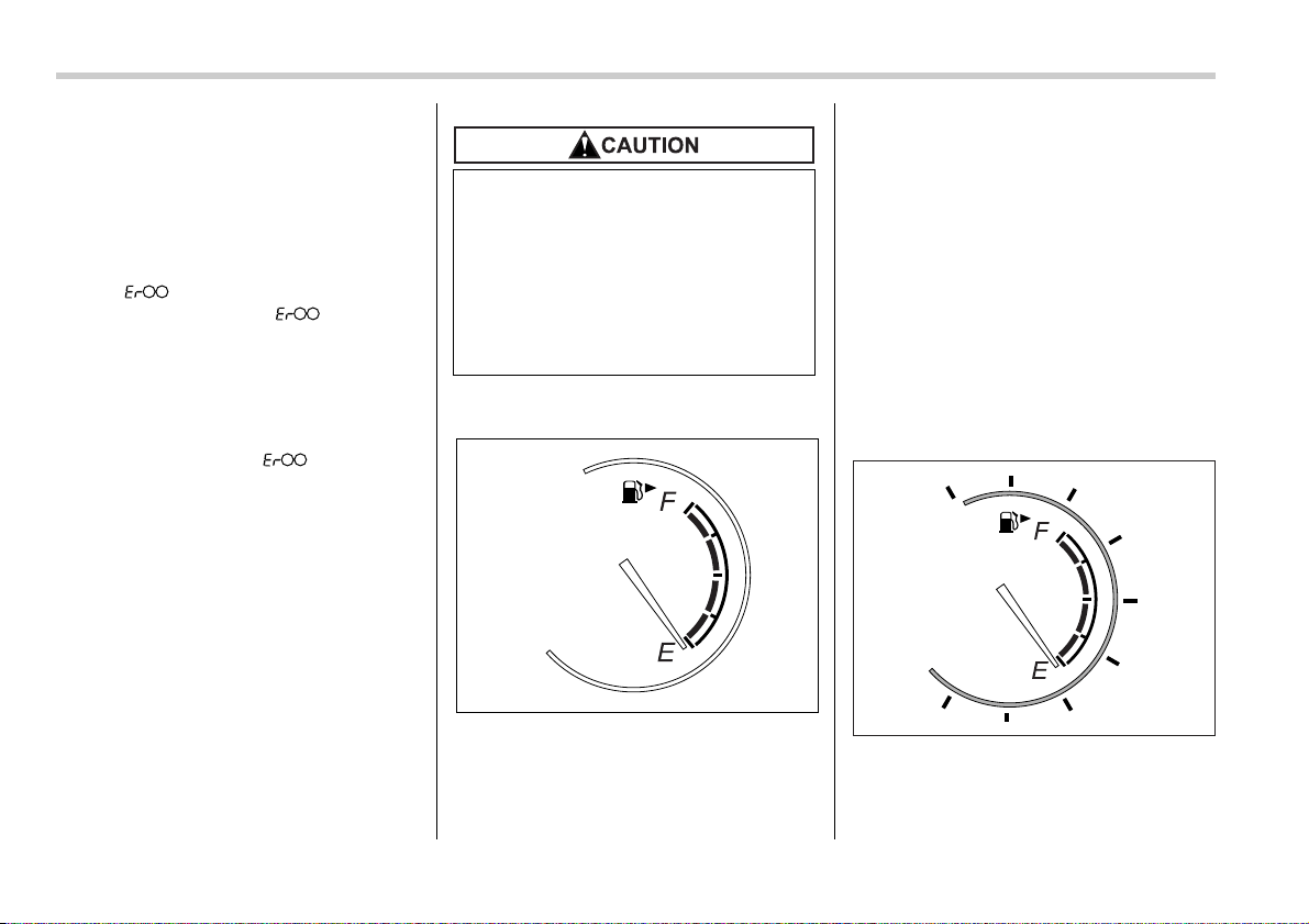
3-8 Instruments and controls
T Vehicle communication system
fault indication
The vehicle communication system car-
ries various types of information (vehicle
speed, running conditions, etc.) to control
modules. In the event of a fault in this
communication system, the trip meter will
show “ ”.
If the trip meter shows “ ”, immedi-
ately contact the nearest SUBARU dealer
and have the vehicle communication sys-
tem inspected.
NOTE
If you press the trip knob while the trip
meter is showing “ ”, the trip
meter indication will appear for 10 sec-
onds.
Tachometer
The tachometer shows the engine speed
in thousands of revolutions per minute.
Fuel gauge
The fuel gauge shows the approximate
amount of fuel remaining in the tank.
When the ignition switch is in the “LOCK”
or “ACC” position, the fuel gauge shows
“E” even if the fuel tank contains fuel.
The gauge may move slightly during brak-
ing, turning or acceleration due to fuel lev-
el movement in the tank.
If you press the trip knob while the ignition
switch is in the “LOCK” position, the fuel
gauge’s dial, needle, and rim will light up
and the needle will indicate the amount of
fuel remaining in the tank.
If, while the fuel gauge needle is indicating
the amount of fuel remaining in the tank,
you (a) do not press the trip knob for 10
seconds or (b) open and close the driver’s
door, the fuel gauge needle will drop to the
“E” position and the dial, needle, and rim
will go off.
The rim of the fuel gauge flashes five
times when the amount of remaining fuel
reaches 2.6 US gal (10 liters, 2.2 lmp gal).
If you turn the ignition switch to the
Do not operate the engine with the
pointer of the tachometer in the red
zone. In this range, fuel injection will
be cut by the engine control module
to protect the engine from overrev-
ving. The engine will resume run-
ning normally after the engine
speed is reduced below the red
zone.
300638
300639
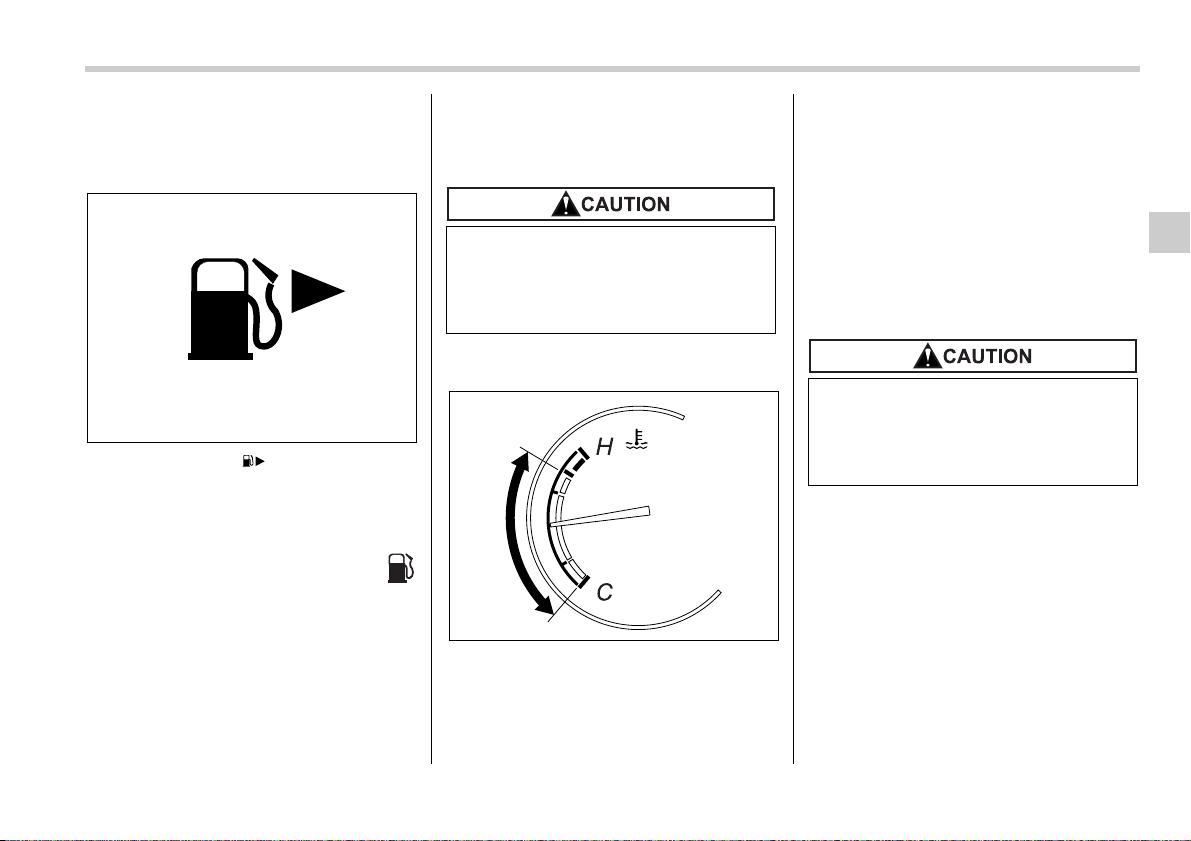
Instruments and controls 3-9
“LOCK” position and back to the “ON” po-
sition, the rim will again flash five times.
NOTE
You will see the “ ” sign in the fuel
gauge.
This indicates that the fuel filler door
(lid) is located on the right side of the
vehicle.
T Low fuel warning light
The low fuel warning light comes on when
the tank is nearly empty [Approximately
2.6 US gal (10 liters, 2.2 lmp gal)].
It only operates when the ignition switch is
in the “ON” position.
NOTE
This light does not go out unless the
tank is replenished up to an internal
fuel quantity of approximately 4.0 US
gal (15 liters, 3.3 lmp gal).
Temperature gauge
1) Normal operating range
The temperature gauge shows engine
coolant temperature when the ignition
switch is in the “ON” position.
The coolant temperature will vary in ac-
cordance with the outside temperature
and driving conditions.
We recommend that you drive moderately
until the pointer of the temperature gauge
reaches near the middle of the range. En-
gine operation is optimum with the engine
coolant at this temperature range and high
revving operation when the engine is not
warmed up enough should be avoided.
200253
Promptly put fuel in the tank when-
ever the low fuel warning light
comes on. Engine misfires as a re-
sult of an empty tank could cause
damage to the engine.
1
300592
If the pointer exceeds the normal
operating range, safely stop the ve-
hicle as soon as possible.
See the “In case of emergency” in
chapter 9.
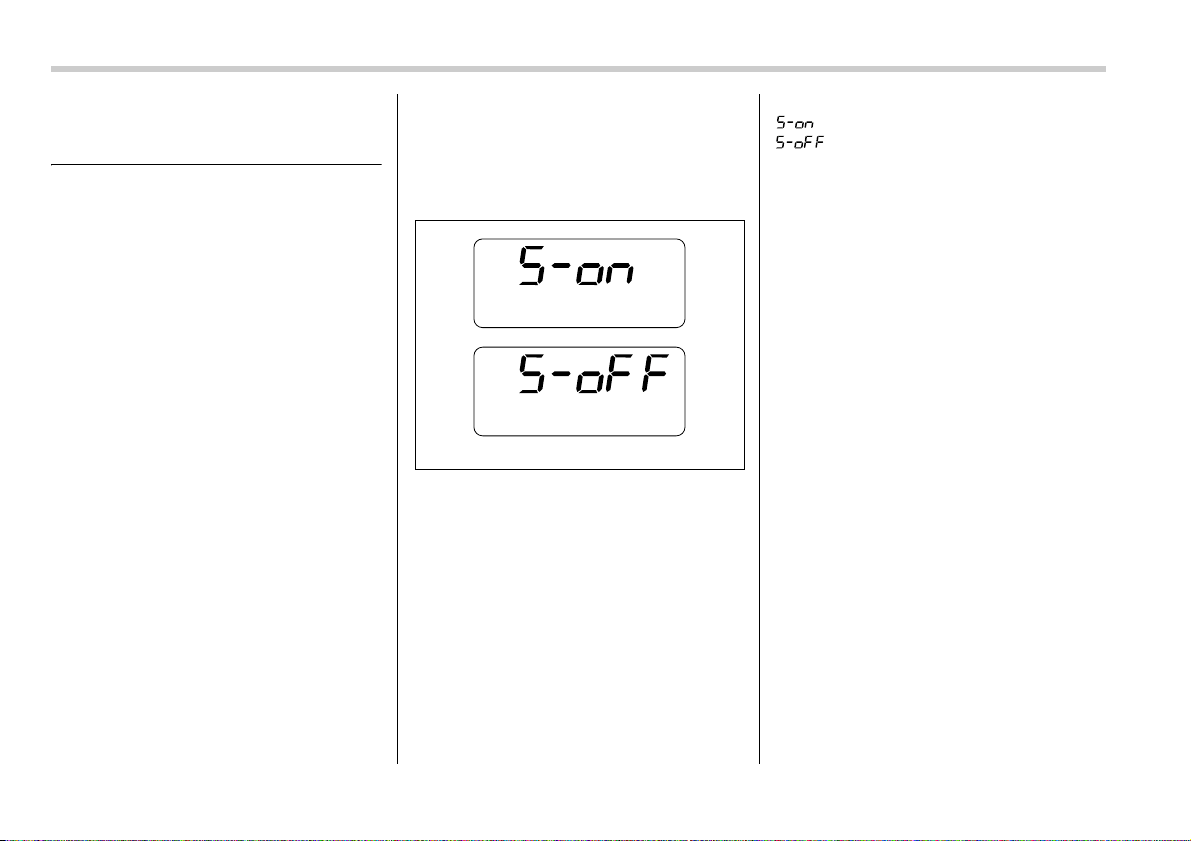
3-10 Instruments and controls
Meters and gauges (Non-tur-
bo models)
NOTE
Liquid-crystal displays are used in
some of the meters and gauges in the
combination meter. You will find their
indications hard to see if you wear po-
larized glasses.
Combination meter illumina-
tion
When the ignition switch is turned to the
“ON” position, the various parts of the
combination meter are illuminated in the
following sequence:
1. Combination meter dials light up.
2. Meter needles and gauge needles
each show MAX position.
3. Meter needles and gauge needles
each show MIN position.
4. Regular illumination (for driving) be-
gins.
Canceling the function for
meter/gauge needle move-
ment upon turning on the ig-
nition switch
It is possible to activate or deactivate the
movement of the meter needles and
gauge needles that takes place when the
ignition switch is turned to the “ON” posi-
tion.
Turn the ignition switch to the “ACC” posi-
tion. With the A trip meter indication se-
lected, briefly press the trip knob twice.
You can now establish the activated/deac-
tivated setting for movement of the meter
needles and gauge needles. To change
the current setting, press the trip knob for
at least two seconds.
: Activated
: Deactivated
Briefly press the knob to return to the A trip
meter indication.
If you turn the ignition switch to the
“LOCK” position, turn the ignition switch to
the “ON” position, or open and close the
driver’s door during the setting procedure,
the new setting will be canceled. Also, if
you do not press the trip knob for a period
of 10 seconds, the new setting will be can-
celed.
NOTE
It is not possible to cancel sequential
illumination of the combination meter
while sequential illumination is actual-
ly taking place. Cancel sequential illu-
mination when regular illumination (for
driving) has begun.
Speedometer
The speedometer shows the vehicle
speed.
300185
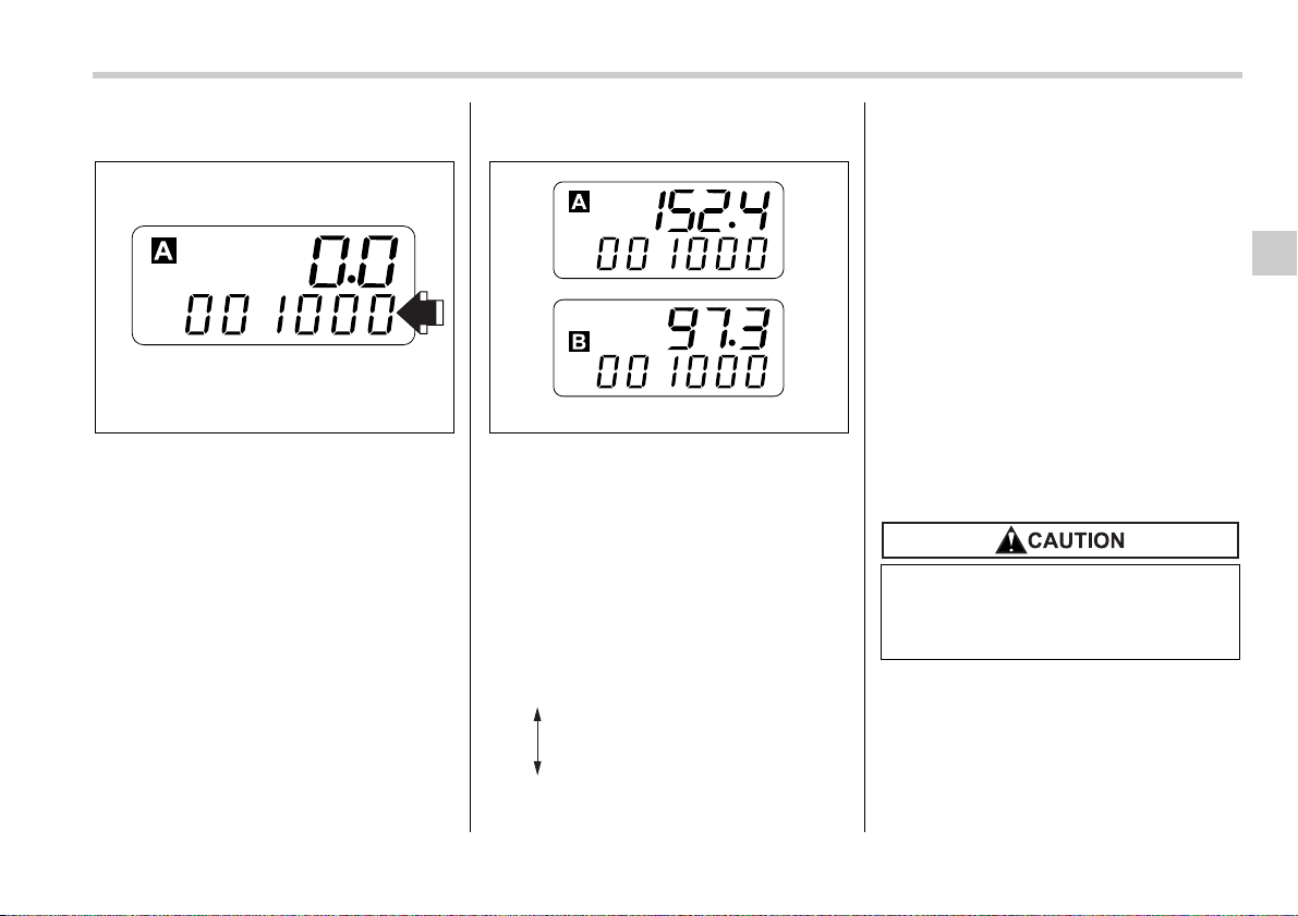
Instruments and controls 3-11
– CONTINUED –
Odometer
This meter displays the odometer when
the ignition switch is in the “LOCK”, “ACC”
or “ON” position.
The odometer shows the total distance
that the vehicle has been driven.
If you press the trip knob when the ignition
switch is in the “LOCK” position, the
odometer/trip meter will light up. If you do
not press the trip knob within 10 seconds
of illumination of the odometer/trip meter,
the odometer/trip meter will go off.
Also, if you open and close the driver’s
door within 10 seconds of illumination of
the odometer/trip meter, the odometer/trip
meter will go off.
Double trip meter
This meter displays the two trip meters
when the ignition switch is in the “LOCK”,
“ACC” or “ON” position.
The trip meter shows the distance that the
vehicle has been driven since you last set
it to zero.
To change the mode indication, briefly
push the knob.
Each press of the knob changes the mode
indication alternately.
To set the trip meter to zero, select the A
trip or B trip meter by pushing the knob
and keep the knob pushed for more than
2 seconds.
If you press the trip knob when the ignition
switch is in the “LOCK” position, the
odometer/trip meter will light up. It is pos-
sible switch between the A trip meter and
B trip meter indications while the odome-
ter/trip meter is lit up. If you do not press
the trip knob within 10 seconds of illumina-
tion of the odometer/trip meter, the odom-
eter/trip meter will go off.
Also, if you open and close the driver’s
door within 10 seconds of illumination of
the odometer/trip meter, the odometer/trip
meter will go off.
NOTE
If the connection between the combi-
nation meter and battery is broken for
any reason such as vehicle mainte-
nance or fuse replacement, the data re-
corded on the trip meter will be lost.
300261 300258
A trip meter
B trip meter
To ensure safety, do not attempt to
change the function of the indicator
during driving, as an accident could
result.
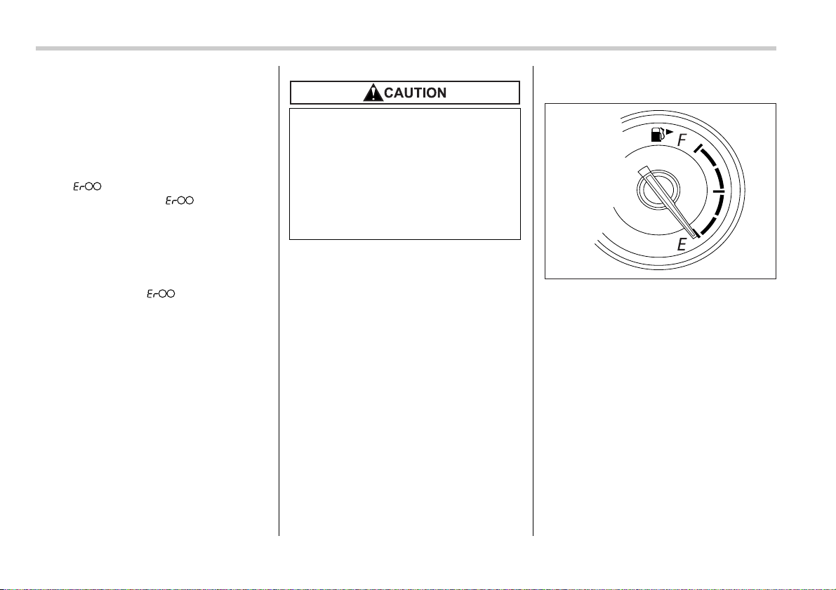
3-12 Instruments and controls
T Vehicle communication system
fault indication
The vehicle communication system car-
ries various types of information (vehicle
speed, running conditions, etc.) to control
modules. In the event of a fault in this
communication system, the trip meter will
show “ ”.
If the trip meter shows “ ”, immediate-
ly contact the nearest SUBARU dealer
and have the vehicle communication sys-
tem inspected.
NOTE
If you press the trip knob while the trip
meter is showing “ ”, the trip meter
indication will appear for 10 seconds.
Tachometer
The tachometer shows the engine speed
in thousands of revolutions per minute.
NOTE (3.0-liter models only)
To protect the engine while the “P” or
“N” position is selected, the engine is
controlled such that the engine speed
does not become too high even if the
accelerator pedal is pressed hard.
Fuel gauge
The fuel gauge shows the approximate
amount of fuel remaining in the tank.
The gauge does not return to “E” even
though the ignition switch is in the “ACC”
or “LOCK” position.
The gauge may move slightly during brak-
ing, turning or acceleration due to fuel lev-
el movement in the tank.
If you press the trip knob while the ignition
switch is in the “LOCK” position, the fuel
gauge’s dial will light up and the needle
will indicate the amount of fuel remaining
in the tank.
If, while the fuel gauge needle is indicating
the amount of fuel remaining in the tank,
you (a) do not press the trip knob for 10
seconds or (b) open and close the driver’s
Do not operate the engine with the
pointer of the tachometer in the red
zone. In this range, fuel injection will
be cut by the engine control module
to protect the engine from overrev-
ving. The engine will resume run-
ning normally after the engine
speed is reduced below the red
zone.
300640
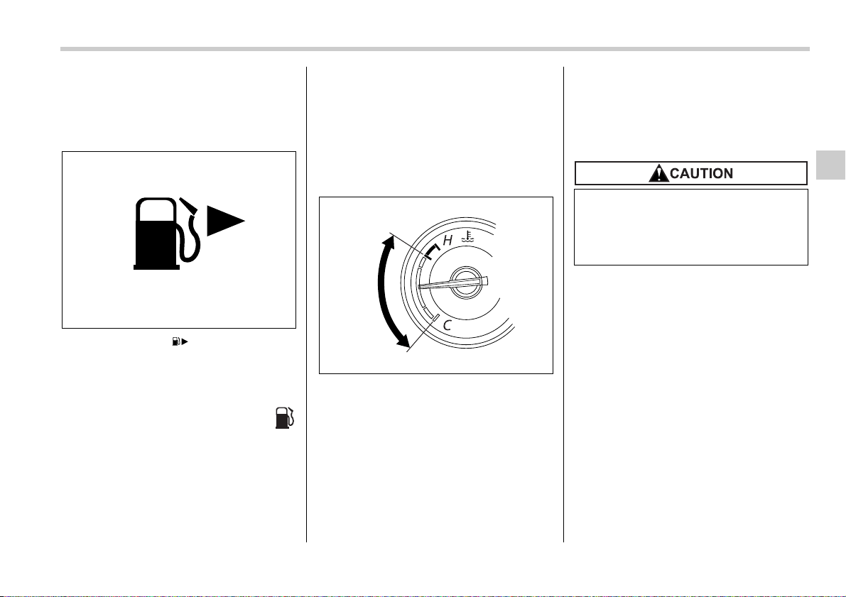
Instruments and controls 3-13
door, the fuel gauge needle will drop to the
“E” position and the dial, needle, and rim
will go off.
NOTE
You will see the “ ” sign in the fuel
gauge.
This indicates that the fuel filler door
(lid) is located on the right side of the
vehicle.
T Low fuel warning light
The low fuel warning light comes on when
the tank is nearly empty [Approximately
2.6 US gal (10 liters, 2.2 lmp gal)].
It only operates when the ignition switch is
in the “ON” position.
NOTE
This light does not go out unless the
tank is replenished up to an internal
fuel quantity of approximately 4.0 US
gal (15 liters, 3,3 lmp gal).
Temperature gauge
1) Normal operating range
The temperature gauge shows engine
coolant temperature when the ignition
switch is in the “ON” position.
The coolant temperature will vary in ac-
cordance with the outside temperature
and driving conditions.
We recommend that you drive moderately
until the pointer of the temperature gauge
reaches near the middle of the range. En-
gine operation is optimum with the engine
coolant at this temperature range and high
revving operation when the engine is not
warmed up enough should be avoided.
200253
1
300593
If the pointer exceeds the normal
operating range, safely stop the ve-
hicle as soon as possible.
See the “In case of emergency” in
chapter 9.
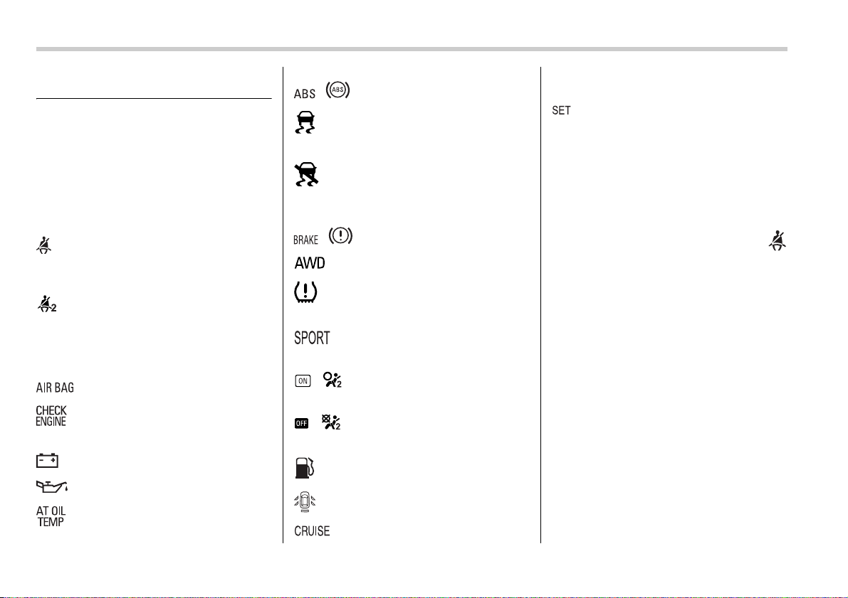
3-14 Instruments and controls
Warning and indicator lights
Several of the warning and indicator lights
come on momentarily and then go out
when the ignition switch is initially turned
to the “ON” position. This permits check-
ing the operation of the bulbs.
Apply the parking brake and turn the igni-
tion switch to the “ON” position. The fol-
lowing lights come on:
: Seatbelt warning light
(The seatbelt warning light goes out only
when the driver fastens the seatbelt.)
: Front passenger’s seatbelt warning
light
(The seatbelt warning light goes out only
when the front seat passenger fastens the
seatbelt.)
: SRS airbag system warning light
: CHECK ENGINE warning light /
Malfunction indicator lamp
: Charge warning light
: Oil pressure warning light
: AT OIL temperature warning light
(AT vehicles)
/ : ABS warning light
: Vehicle Dynamics Control operation
indicator light (if equipped)
: Vehicle Dynamics Control warning
light (if equipped)/Vehicle Dynamics Con-
trol OFF indicator light (if equipped)
/ : Brake system warning light
: AWD warning light (AT vehicles)
: Low tire pressure warning light (if
equipped)
: SPORT mode indicator light (AT
vehicles)
/ : Front passenger’s frontal airbag
ON indicator light
/ : Front passenger’s frontal airbag
OFF indicator light
: Low fuel warning light
: Door open warning light
: Cruise control indicator light (if
equipped)
: Cruise control set indicator light (if
equipped)
If any lights fail to come on, it indicates a
burned-out bulb or a malfunction of the
corresponding system.
Consult your authorized SUBARU dealer
for repair.
Seatbelt warning light
and chime
Your vehicle is equipped with a seatbelt
warning device at the driver’s and front
passenger’s seat, as required by current
safety standards.
With the ignition switch turned to the “ON”
position, this device reminds the driver
and front passenger to fasten their seat-
belts by illuminating the warning lights in
the locations indicated in the following il-
lustration and sounding a chime.
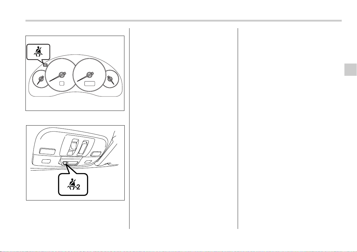
Instruments and controls 3-15
– CONTINUED –
Driver’s warning light
Front passenger’s warning light
T Operation
If the driver and/or front passenger have/
has not yet fastened the seatbelt(s) when
the ignition switch is turned to the “ON” po-
sition, the seatbelt warning light(s) will
flash for 6 seconds, to warn that the seat-
belt(s) is/are unfastened. If the driver’s
seatbelt is not fastened, a chime will also
sound simultaneously.
If the driver’s and/or front passenger’s
seatbelt(s) are/is still not fastened 6 sec-
onds later, both warning lights or the
warning light for the unfastened seatbelt
will remain lit for 15 seconds. If the driver’s
and/or front passenger’s seatbelt(s) are/is
still not fastened even 15 seconds later
(21 seconds after turning ON the ignition
switch), the warning lights will alternate
between flashing and steady illumination
at 15-second intervals, and the chime will
sound while the warning light(s) is/are
flashing.
Alternate flashing and steady illumination
of the warning lights and sounding of the
chime will continue until both driver and
front passenger fasten their seatbelts.
NOTE
y If the driver and/or front passenger
unfasten(s) the seatbelt(s) after fasten-
ing, the seatbelt warning device oper-
ates as follows according to the vehi-
cle speed.
y At speeds lower than approximate-
ly 9 mph (15 km/h)
The warning light(s) for unfastened
seatbelt(s) will alternate between
flashing and steady illumination at
15-second intervals. The chime will
not sound.
y At speeds higher than approxi-
mately 9 mph (15 km/h)
The warning light(s) for unfastened
seatbelt(s) will alternate between
flashing and steady illumination at
15-second intervals and the chime
will sound while the warning light(s)
is/are flashing.
y If you unfasten and refasten the driv-
er’s seatbelt three times within six sec-
onds after turning ON the ignition
switch, the warning operation that fol-
lows the 6-second warning after turn-
ing ON the ignition switch is canceled.
When the ignition switch is turned ON
next time, however, the complete se-
quence of warning operations re-
sumes.
If there is no passenger on the front pas-
senger’s seat, the seatbelt warning device
for the front passenger’s seat will be deac-
tivated. The front passenger’s occupant
detection system monitors whether or not
there is a passenger on the front passen-
ger’s seat. Observe the following precau-
tions. Failure to do so may prevent the de-
vice from functioning correctly or cause
100254
100662
3-16 Instruments and controls
the device to fail.
y Do not install any accessory such as a
table or TV onto the seatback.
y Do not store a heavy load in the seat-
back pocket.
y Do not allow the rear seat occupant to
place his/her hands or legs on the front
passenger’s seatback, or allow him/her to
pull the seatback.
y Do not use front seats with their back-
ward-forward position and seatback not
being locked into place securely. If any of
them are not locked securely, adjust them
again. For adjusting procedure, refer to
the “Manual seat” in the front seats sec-
tion in chapter 1 in this owner’s manual.
(Models equipped with manual seats only)
If the seatbelt warning device for the front
passenger’s seat does not function cor-
rectly (e.g., it is activated even when the
front passenger’s seat is empty or it is de-
activated even when the front passenger
has not fastened his/her seatbelt), take
the following actions.
y Ensure that no article is placed on the
seat other than a child restraint system
and its child occupant.
y Ensure that there is no article left in the
seatback pocket.
y Ensure that the backward-forward posi-
tion and seatback of front passenger’s
seat are locked into place securely by
moving the seat back and forth. (Models
equipped with manual seats only)
If still the seatbelt warning device for front
passenger’s seat does not function cor-
rectly after taking relevant corrective ac-
tions described above, immediately con-
tact your SUBARU dealer for an inspec-
tion.
SRS airbag system
warning light
When the ignition switch is turned to the
“ON” position, the SRS airbag system
warning light will come on for approxi-
mately seven seconds and go out. This
shows the SRS frontal airbag and SRS
side airbag and SRS curtain airbag and
seatbelt pretensioners are in normal oper-
ation.
If the warning light exhibits any of
the following conditions, there may
be a malfunction in the seatbelt pre-
tensioners and/or SRS airbag sys-
tem. Immediately take your vehicle
to your nearest SUBARU dealer to
have the system checked. Unless
checked and properly repaired, the
seatbelt pretensioners and/or SRS
airbags will operate improperly (e.g.
SRS airbags may inflate in a very mi-
nor collision or not inflate in a se-
vere collision), which may increase
the risk of injury.
y Flashing or flickering of the warn-
ing light
y No illumination of the warning
light when the ignition switch is
first turned to the “ON” position
y Continuous illumination of the
warning light
y Illumination of the warning light
while driving
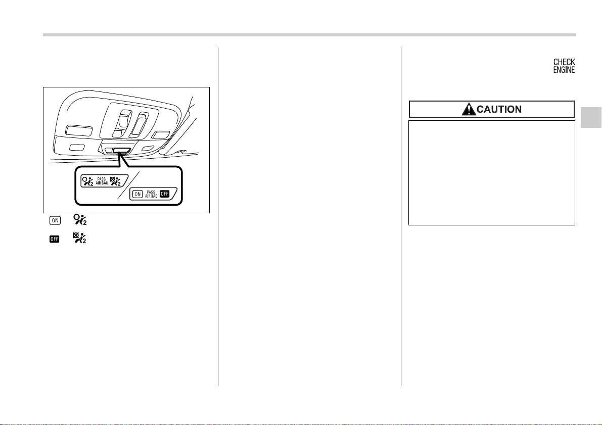
Instruments and controls 3-17
– CONTINUED –
Front passenger’s frontal air-
bag ON and OFF indicators
or : Front passenger’s frontal air-
bag ON indicator
or : Front passenger’s frontal air-
bag OFF indicator
The front passenger’s frontal airbag ON
and OFF indicators show you the status of
the front passenger’s SRS frontal airbag.
The indicators are located between the
map lights.
When the ignition switch is turned to the
“ON” position, both the ON and OFF indi-
cators illuminate for 6 seconds during
which time the system is checked. Follow-
ing the system check, both indicators ex-
tinguish for 2 seconds. After that, one of
the indicators illuminates depending on
the status of the front passenger’s SRS
frontal airbag determined by the Subaru
advanced frontal airbag system monitor-
ing.
If the front passenger’s SRS frontal airbag
is activated, the passenger’s frontal airbag
ON indicator will illuminate while the OFF
indicator will remain extinguished.
If the front passenger’s SRS frontal airbag
is deactivated, the passenger’s frontal air-
bag ON indicator will remain extinguished
while the OFF indicator will illuminate.
If both the ON and OFF indicators remain
lit or extinguished simultaneously, the sys-
tem is faulty. Contact your SUBARU deal-
er immediately for an inspection.
CHECK ENGINE warn-
ing light/Malfunction in-
dicator lamp
If this light comes on steadily or blinks
while the engine is running, it may indicate
that there is a problem or potential prob-
lem somewhere in the emission control
system.
T If the light comes on steadily:
If the light comes on steadily while driving
or does not go out after the engine starts,
an emission control system malfunction
has been detected.
You should have your vehicle checked by
an authorized SUBARU dealer immedi-
ately.
100663
If the CHECK ENGINE light comes
on while you are driving, have your
vehicle checked/repaired by your
SUBARU dealer as soon as possi-
ble. Continued vehicle operation
without having the emission control
system checked and repaired as
necessary could cause serious
damage, which may not be covered
by your vehicle’s warranty.
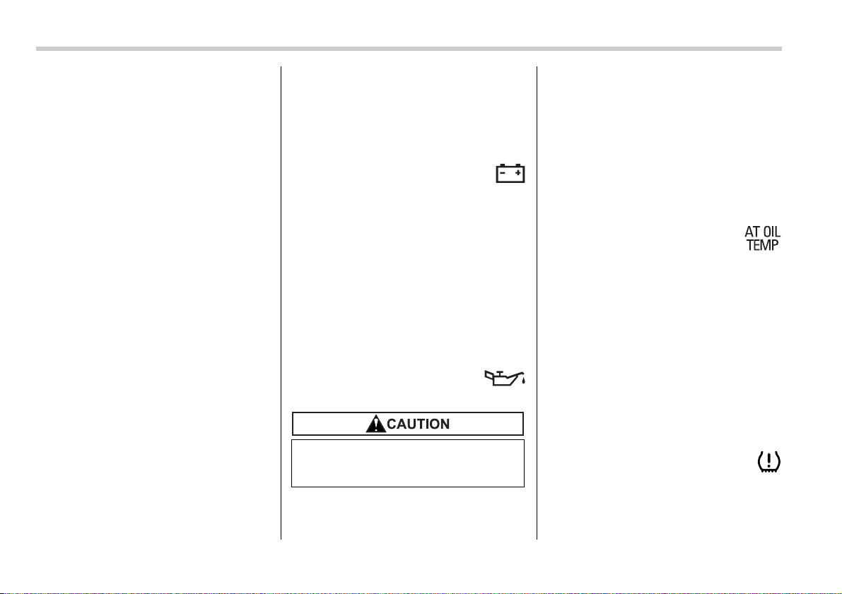
3-18 Instruments and controls
NOTE
This light also comes on when the fuel
filler cap is not tightened until it clicks.
If you have recently refueled your vehicle,
the cause of the CHECK ENGINE warning
light/malfunction indicator lamp coming on
could be a loose or missing fuel filler cap.
Remove the cap and retighten it until it
clicks. Make sure nothing is interfering
with the sealing of the cap. Tightening the
cap will not make the CHECK ENGINE
warning light turn off immediately. It may
take several driving trips. If the light does
not go out, take your vehicle to your au-
thorized SUBARU dealer immediately.
T If the light is blinking:
If the light is blinking while driving, an en-
gine misfire condition has been detected
which may damage the emission control
system.
To prevent serious damage to the emis-
sion control system, you should do the fol-
lowing.
y Reduce vehicle speed.
y Avoid hard acceleration.
y Avoid steep uphill grades.
y Reduce the amount of cargo, if possi-
ble.
y Stop towing a trailer as soon as possi-
ble.
The CHECK ENGINE warning light may
stop blinking and come on steadily after
several driving trips. You should have
your vehicle checked by an authorized
SUBARU dealer immediately.
Charge warning light
If this light comes on when the engine is
running, it may indicate that the charging
system is not working properly.
If the light comes on while driving or does
not go out after the engine starts, stop the
engine at the first safe opportunity and
check the alternator belt. If the belt is
loose, broken or if the belt is in good con-
dition but the light remains on, contact
your nearest SUBARU dealer immediate-
ly.
Oil pressure warning
light
If this light comes on when the engine is
running, it may indicate that the engine oil
pressure is low and the lubricating system
is not working properly.
If the light comes on while driving or does
not go out after the engine starts, stop the
engine at the first safe opportunity and
check the engine oil level. If the oil level is
low, add oil immediately. If the engine oil
is at the proper level but the light remains
on, contact your nearest SUBARU dealer
immediately.
AT OIL TEMPerature
warning light (AT vehi-
cles)
The AT oil temperature warning light
comes on when the ignition switch is
turned to the “ON” position and goes out
after approximately two seconds.
If this light comes on when the engine is
running, it may indicate that the automatic
transmission fluid temperature is too hot.
If the light comes on while driving, it is un-
necessary to stop the vehicle, but avoid
driving up steep grades or in stop and go
traffic.
Low tire pressure warn-
ing light (if equipped)
When the ignition switch is turned to the
“ON” position, the low tire pressure warn-
ing light will come on for approximately 2
Do not operate the engine with the
oil pressure warning light on. This
may cause serious engine damage.
Instruments and controls 3-19
– CONTINUED –
seconds to check that the tire pressure
monitoring system (TPMS) is functioning
properly. If there is no problem and all tires
are properly inflated, the light will go out.
Each tire, including the spare (if provided),
should be checked monthly when cold
and inflated to the inflation pressure rec-
ommended by the vehicle manufacturer
on the vehicle placard or tire inflation pres-
sure label. (If your vehicle has tires of a
different size than the size indicated on
the vehicle placard or tire inflation pres-
sure label, you should determine the prop-
er inflation pressure for those tires.) As an
added safety feature, your vehicle has
been equipped with a tire pressure moni-
toring system (TPMS) that illuminates a
low tire pressure telltale when one or more
of your tires is significantly under-inflated.
Accordingly, when the low tire pressure
telltale illuminates, you should stop and
check your tires as soon as possible, and
inflate them to the proper pressure. Driv-
ing on a significantly under-inflated tire
causes the tire to overheat and can lead to
tire failure. Under-inflation also reduces
fuel efficiency and tire tread life, and may
affect the vehicle’s handling and stopping
ability. Please note that the TPMS is not a
substitute for proper tire maintenance,
and it is the driver’s responsibility to main-
tain correct tire pressure, even if under-in-
flation has not reached the level to trigger
illumination of the TPMS low tire pressure
telltale.
The TPMS gives warning both when a tire
is significantly under-inflated and when
there is a problem in the TPMS. The low
tire pressure warning light operates differ-
ently according to these conditions as fol-
lows:
When a tire is significantly under-inflat-
ed: Steady illumination
When there is a problem in the TPMS:
Flashing
Should the warning light flash, have the
system inspected by your nearest
SUBARU dealer as soon as possible.
If this light does not come on briefly
after the ignition switch is turned
ON or the light is flashing, you
should have your Tire Pressure
Monitoring System checked at a
SUBARU dealer as soon as possi-
ble.
If this light comes on while driving,
never brake suddenly and keep driv-
ing straight ahead while gradually
reducing speed. Then slowly pull off
the road to a safe place. Otherwise
an accident involving serious vehi-
cle damage and serious personal in-
jury could occur.
If this light still comes on while driv-
ing after adjusting the tire pressure,
a tire may have significant damage
and a fast leak that causes the tire to
lose air rapidly. If you have a flat
tire, replace it with a spare tire as
soon as possible.
When a spare tire is mounted or a
wheel rim is replaced without the
original pressure sensor/transmitter
being transferred, the Low tire pres-
sure warning light will flash. This in-
dicates the TPMS is unable to moni-
tor all four road wheels. Contact
your SUBARU dealer as soon as
possible for tire and sensor replace-
ment and/or system resetting. If the
light flashes, promptly contact a
SUBARU dealer to have the system
inspected.
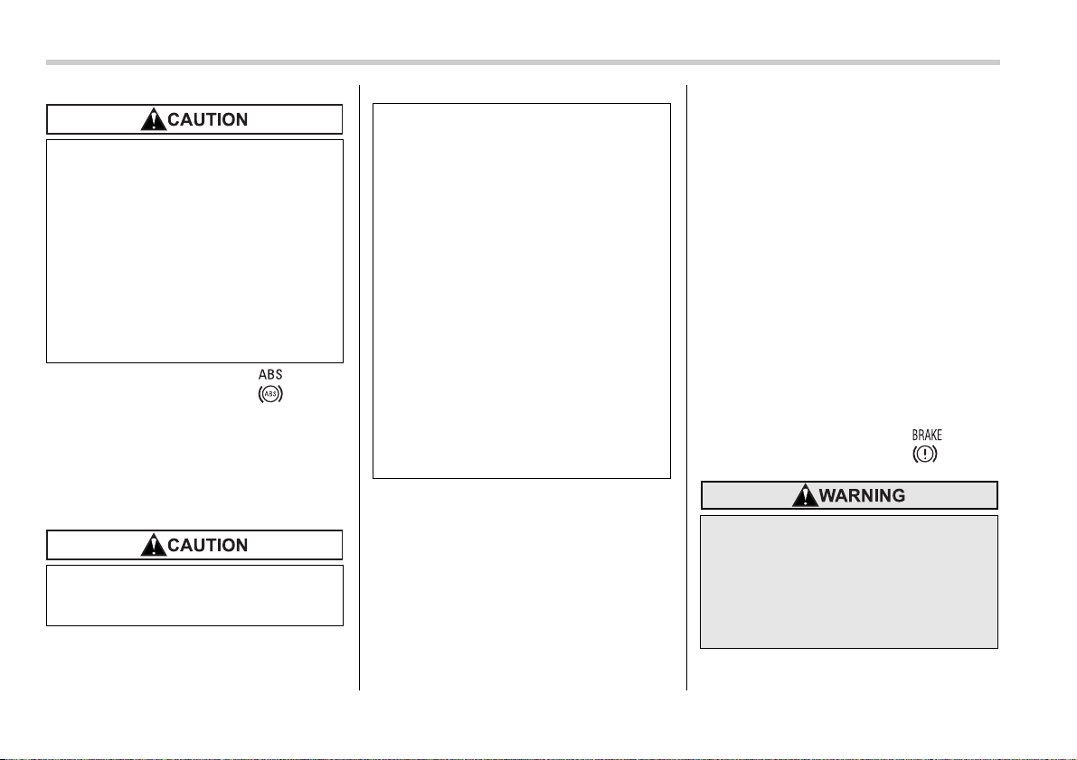
3-20 Instruments and controls
ABS warning light
The ABS warning light comes on when the
ignition switch is turned to the “ON” posi-
tion and goes out after approximately two
seconds.
This is an indication that the ABS system
is working properly.
The ABS warning light comes on together
with the brake system warning light if the
EBD system becomes faulty. For further
details of the EBD system fault warning,
refer to “Brake system warning light”.
NOTE
If the warning light behavior is as de-
scribed in the following, the ABS sys-
tem may be considered normal.
y The warning light comes on right af-
ter the engine is started but goes out
immediately, remaining off.
y The warning light remains on after
the engine has been started, but it goes
out when the vehicle speed reaches
approximately 8 mph (12 km/h).
y The warning light comes on during
driving, but it goes out immediately
and remains off.
When driving with an insufficient battery
voltage such as when the engine is jump
started, the ABS warning light may come
on. This is due to the low battery voltage
and does not indicate a malfunction.
When the battery becomes fully charged,
the light will go out.
Brake system
warning light
The tire pressure monitoring system
is NOT a substitute for manually
checking tire pressure. The tire
pressure should be checked period-
ically (at least monthly) using a tire
gauge. After any change to tire pres-
sure(s), the tire pressure monitoring
system will not re-check tire infla-
tion pressures until the vehicle is
first driven more than 20 mph (32
km/h). Be sure to install the speci-
fied size for the front and rear tires.
If the warning light behaves as fol-
lows, the ABS system may not work
properly.
(U.S.)
(Canada)
When the warning light is on, the
ABS function shuts down; however,
the conventional brake system con-
tinues to operate normally.
y The warning light does not come
on when the ignition switch is
turned to the “ON” position.
y The warning light comes on when
the ignition switch is turned to the
“ON” position, but it does not go
out even when the vehicle speed
exceeds approximately 8 mph (12
km/h).
y The warning light comes on dur-
ing driving.
If any of these conditions occur,
have the ABS system repaired at
the first available opportunity by
your SUBARU dealer.
y Driving with the brake system
warning light on is dangerous.
This indicates your brake system
may not be working properly. If
the light remains on, have the
brakes inspected by a SUBARU
dealer immediately.
(U.S.)
(Canada)

Instruments and controls 3-21
– CONTINUED –
This light has the following three func-
tions:
T Parking brake warning
The light comes on with the parking brake
applied while the ignition switch is in the
“ON” position. It goes out when the park-
ing brake is fully released.
T Brake fluid level warning
This light comes on when the brake fluid
level has dropped to near the “MIN” level
of the brake fluid reservoir with the ignition
switch in the “ON” position and with the
parking brake fully released.
If the brake system warning light should
come on while driving (with the parking
brake fully released and with the ignition
switch positioned in “ON”), it could be an
indication of leaking of brake fluid or worn
brake pads. If this occurs, immediately
stop the vehicle at the nearest safe place
and check the brake fluid level. If the fluid
level is below the “MIN” mark in the reser-
voir, do not drive the vehicle. Have the ve-
hicle towed to the nearest SUBARU deal-
er for repair.
T Electronic Brake Force Distribution
(EBD) system warning
The brake system warning light also illu-
minates if a malfunction occurs in the EBD
system. In that event, it comes on together
with the ABS warning light.
The EBD system may be faulty if the brake
system warning light and ABS warning
light illuminate simultaneously during driv-
ing.
Even if the EBD system fails, the conven-
tional braking system will still function.
However, the rear wheels will be more
prone to locking when the brakes are ap-
plied harder than usual and the vehicle’s
motion may therefore become somewhat
harder to control.
If the brake system warning light and ABS
warning light illuminate simultaneously,
take the following steps:
1. Stop the vehicle in the nearest safe, flat
place.
2. Shut down the engine, then restart it.
3. Release the parking brake. If both
warning lights go out, the EBD system
may be faulty.
Drive carefully to the nearest SUBARU
dealer and have the system inspected.
4. If both warning lights come on again
and stay illuminated after the engine has
been restarted, shut down the engine
again, apply the parking brake, and check
the brake fluid level.
5. If the brake fluid level is not below the
“MIN” mark, the EBD system may be
faulty. Drive carefully to the nearest
SUBARU dealer and have the system in-
spected.
6. If the brake fluid level is below the
“MIN” mark, DO NOT drive the vehicle. In-
stead, have the vehicle towed to the near-
est SUBARU dealer for repair.
Low fuel warning light
The low fuel warning light comes on when
the tank is nearly empty approximately 2.6
US gal (10.0 liters, or 2.2 Imp gal). It only
operates when the ignition switch is in the
“ON” position.
NOTE
This light does not go out unless the
tank is replenished up to an internal
fuel quantity of approximately 3.7 US
gal (14 liters, 3.1 Imp gal).
y If at all in doubt about whether the
brakes are operating properly, do
not drive the vehicle. Have your
vehicle towed to the nearest
SUBARU dealer for repair.
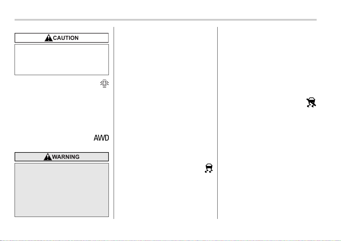
3-22 Instruments and controls
Door open warning light
When any of the doors or the rear gate
(Station wagon) or trunk lid (Sedan) is not
fully closed, it is indicated by the corre-
sponding part of the door warning light.
Always make sure this light is out before
you start to drive.
All-Wheel Drive warn-
ing light (AT vehicles)
The All-Wheel Drive warning light comes
on when the ignition switch is turned to the
“ON” position and goes out after the en-
gine has started.
T For 5-speed automatic transmission
vehicles
This light flashes if the vehicle is driven
with tires of different diameters fitted on its
wheels or with the air pressure excessive-
ly low in any of its tires.
T For 4-speed automatic transmission
vehicles
This light comes on when All-Wheel Drive
is disengaged and the drive mechanism is
switched to Front Wheel Drive for mainte-
nance or similar purposes.
This light flashes if the vehicle is driven
with tires of different diameters fitted on its
wheels or with the air pressure excessive-
ly low in any of its tires.
Vehicle Dynamics Con-
trol operation indicator
light (if equipped)
This light comes on when the ignition
switch is ON and goes out approximately
2 seconds later.
It blinks when the skid suppression func-
tion is activated. It illuminates when only
the traction control function is operating.
The Vehicle Dynamics Control system is
probably faulty under any of the following
conditions. Have your vehicle checked at
a SUBARU dealer immediately.
y The light does not come on when the ig-
nition switch is turned to the “ON” position.
y The light does not go out even after a
period of approximately 2 seconds after
the ignition switch has been turned to the
“ON” position.
Vehicle Dynamics Con-
trol warning light (if
equipped)/Vehicle Dy-
namics Control OFF indicator
light (if equipped)
This warning light has both the function of
indicating faults in the Vehicle Dynamics
Control system and the function of indicat-
ing that the Vehicle Dynamics Control sys-
tem has been deactivated.
It comes on in the event of a fault in the
system and is on when the system is not
operating.
This warning light comes on when the ig-
nition switch is turned to the “ON” position
and goes out after the engine has started.
It indicates that the Vehicle Dynamics
Control system is in normal operation.
(Turbo model only) Promptly put
fuel in the tank whenever the low
fuel warning light comes on. Engine
misfires as a result of an empty tank
could cause damage to the engine.
Continued driving with the AWD
warning light flashing can lead to
powertrain damage. If the AWD
warning light flashes, promptly park
in a safe place then check whether
all four tires are the same diameter
and whether any of the tires has a
puncture or has lost air pressure for
some other reason.

Instruments and controls 3-23
– CONTINUED –
T Vehicle Dynamics Control warning
light
The Vehicle Dynamics Control system is
probably inoperative under any of the fol-
lowing conditions. Have your vehicle
checked at a SUBARU dealer immediate-
ly.
y The warning light does not come on
when the ignition switch is turned to the
“ON” position.
y The warning light comes on while the
vehicle is running.
y If the electrical circuit of the Vehicle Dy-
namics Control system itself becomes
faulty, the warning light only comes on. At
this time, the ABS (Anti-lock Brake Sys-
tem) remains fully operational.
y The warning light comes on when the
electronic control system of the ABS/Vehi-
cle Dynamics Control system becomes
faulty.
The Vehicle Dynamics Control system
provides its ABS control through the elec-
trical circuit of the ABS system. Accord-
ingly, if the ABS is inoperative, the Vehicle
Dynamics Control system becomes un-
able to provide ABS control. As a result,
the Vehicle Dynamics Control system also
becomes inoperative, causing the warning
light to come on. Though both the Vehicle
Dynamics Control and ABS systems are
inoperative in this case, the ordinary func-
tions of the brake system are still avail-
able. You will be safe while driving with
this condition, but have your vehicle
checked at a SUBARU dealer as soon as
possible.
NOTE
If the warning light behavior is as
shown in the following, the Vehicle Dy-
namics Control system may be consid-
ered normal.
y The warning light comes on right af-
ter the engine is started but goes out
immediately, remaining off.
y The warning light comes on after en-
gine startup and goes off while the ve-
hicle is subsequently being driven.
y The warning light comes on during
driving, but it goes out immediately
and remains off.
T Vehicle Dynamics Control OFF indi-
cator light
y It comes on when the Vehicle Dynamics
Control OFF switch is pressed.
y It also comes on when the Vehicle Dy-
namics Control system is deactivated.
NOTE
y The light may stay on for a while after
the engine has been started, especially
in cold weather. This does not indicate
the existence of a problem. The light
should go out as soon as the engine
has warmed up.
y The indicator light comes on when
the engine has developed a problem
and the Malfunction indicator light is
on.
The Vehicle Dynamics Control system is
probably faulty under the following condi-
tion. Have your vehicle checked at a
SUBARU dealer as soon as possible.
y The light does not go out even after the
lapse of several minutes (the engine has
warmed up) after the engine has started.
Security indicator light
This indicator light shows the status of the
alarm system. It also indicates operation
of the immobilizer system.
T Alarm system
It blinks to show the driver the operational
status of the alarm system. For detailed
information, refer to the “Alarm system”
section in chapter 2.
T Immobilizer system
This light blinks approximately 60 seconds
after the ignition switch is turned from
“ON” position to the “ACC” or “LOCK” po-
sition or immediately after the key is pulled
out. (Refer to the “Door locks” section in
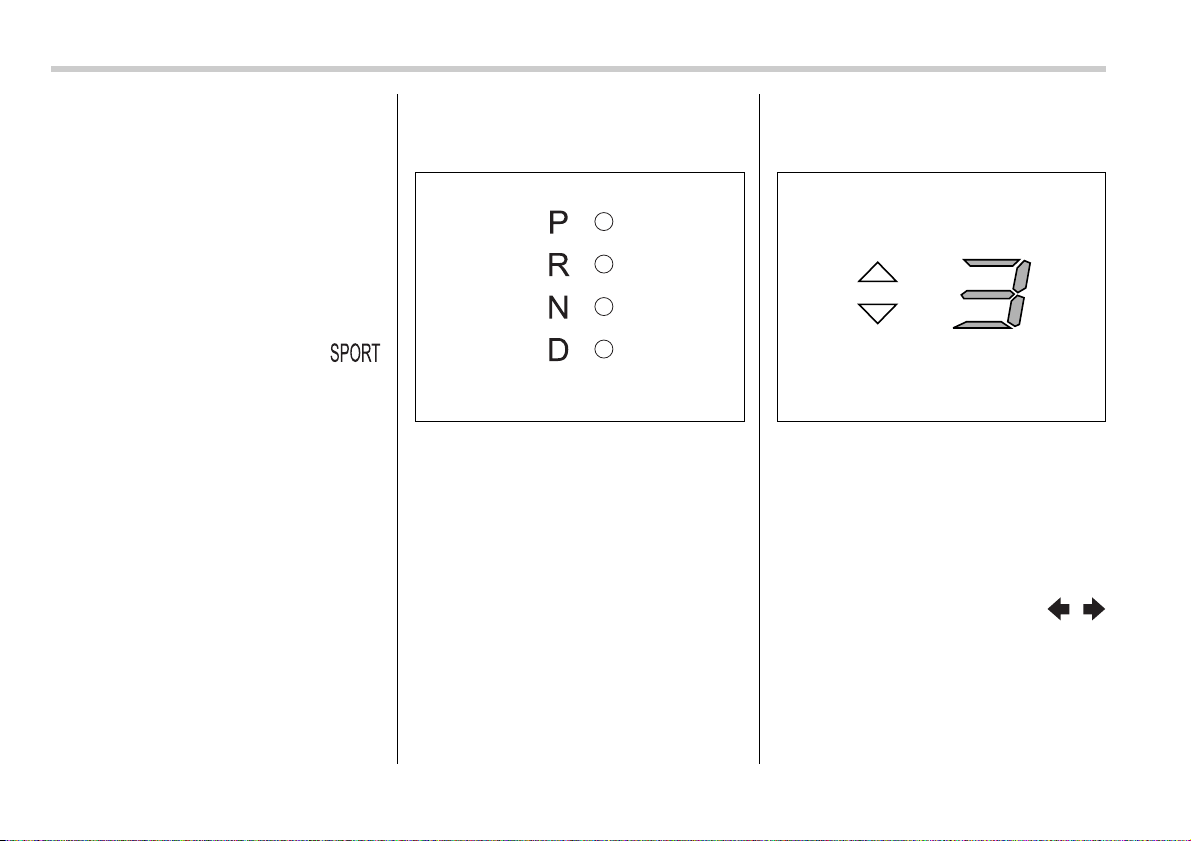
3-24 Instruments and controls
chapter 2.)
If the indicator light does not flash, it may
indicate that immobilizer system may be
faulty. Contact your nearest SUBARU
dealer immediately.
In the event that an unauthorized key (for
example, an unauthorized duplicate) is
used, the security indicator light comes
on.
SPORT mode indicator
light (AT vehicles)
This light comes on when the ignition
switch is turned to the “ON” position and
goes out after the engine has started.
When the selector lever is moved to the
manual gate, the SPORT mode is select-
ed and the indicator light comes on. (Refer
to the “Automatic transmission – 4-speed”
or “Automatic transmission – 5-speed”
section in chapter 7.)
T Automatic transmission control
system warning
If the light flashes after the engine starts,
it may indicate that the automatic trans-
mission control system is not working
properly. Contact your nearest SUBARU
dealer for service immediately.
Selector lever position indi-
cator (AT vehicles)
This indicator shows the position of the
selector lever.
Gear position indicator (AT
vehicles)
When the manual mode is selected, the
gear position indicator (which shows the
current gear selection) and the upshift/
downshift indicator light up. (Refer to the
“Automatic transmission – 4-speed” or
“Automatic transmission – 5-speed” sec-
tion in chapter 7.)
Turn signal indicator
lights
These lights show the operation of the
turn signal or lane change signal.
If the indicator lights do not blink or blink
rapidly, the turn signal bulb may be
burned out. Replace the bulb as soon as
300192 300266
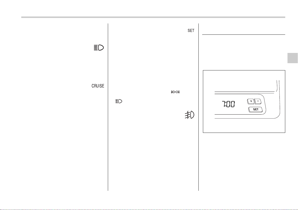
Instruments and controls 3-25
– CONTINUED –
possible. Refer to the “Replacing bulbs”
section in chapter 11.
High beam indicator
light
This light shows that the headlights are in
the high beam mode.
This indicator light also comes on when
the headlight flasher is operated.
Cruise control indica-
tor light
The cruise control indicator light comes on
when the ignition switch is turned to the
“ON” position and goes out after approxi-
mately three seconds.
This light comes on when the “CRUISE”
main switch is pressed.
NOTE
If you move the cruise control lever or
press the main switch button while
turning the ignition switch “ON”, the
cruise control function is deactivated
and the “CRUISE” indicator light flash-
es. To reactivate the cruise control
function, turn the ignition switch back
to the “ACC” or “LOCK” position, and
then turn it again to the “ON” position.
Cruise control set indica-
tor light
The cruise control set indicator light
comes on when the ignition switch is
turned to the “ON” position and goes out
after approximately three seconds.
This light comes on when vehicle speed
has been set.
Headlight indicator light
This indicator light comes on when the
light switch is turned to the “ ” posi-
tion (to turn on the parking lights) or to the
“ ” position (to turn on the headlights).
Front fog light indicator
light
This indicator light is on while the front fog
lights are on.
Clock
NOTE
If your vehicle is equipped with a navi-
gation system, refer to the separate
“Operating Instructions for Monitor
System”.
The clock shows the time while the igni-
tion switch is in the “ACC” or “ON” posi-
tion.
400257
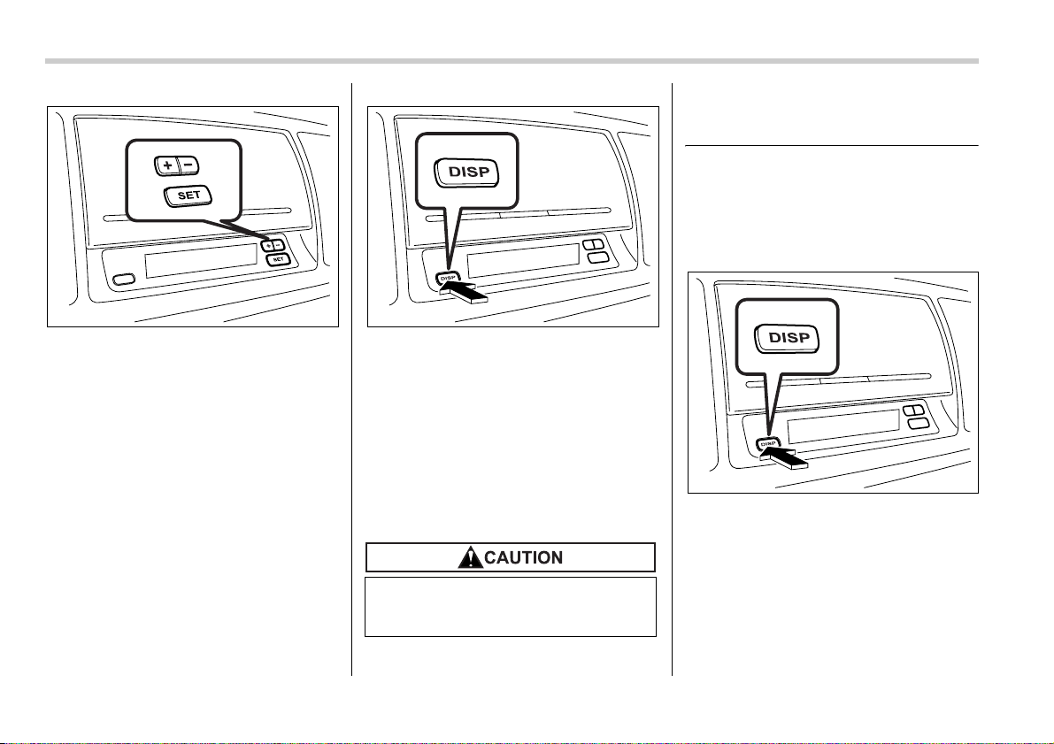
3-26 Instruments and controls
To adjust the time shown by the clock,
press the “+” button or the “–” button. The
indicated time will change in one-minute
increments. If you keep the button
pressed, the rate at which the indicated
time changes will speed up.
To reset the minutes to “00” with a radio
time signal, push the “SET” button.
The clock will also show the time if you
press the “DISP” button while the ignition
switch is in the “LOCK” position. It is pos-
sible to adjust the time setting while the
time is being shown. If you do not press
the “+” button or “–” button for 10 seconds
while the time is being shown, the time in-
dication will go off.
Also, the time indication will go off if you
open and close the driver’s door while the
time is being shown.
Information display (Vehicle
without Navigation System)
NOTE
If your vehicle is equipped with a navi-
gation system, refer to the separate
“Operating Instructions for Monitor
System”.
With the ignition switch in the “ON” posi-
tion, each successive push of the “DISP”
button toggles the display in the following
sequence:
300599
To ensure safety, do not attempt to
set the time during driving, as an ac-
cident could result.
300600
300600
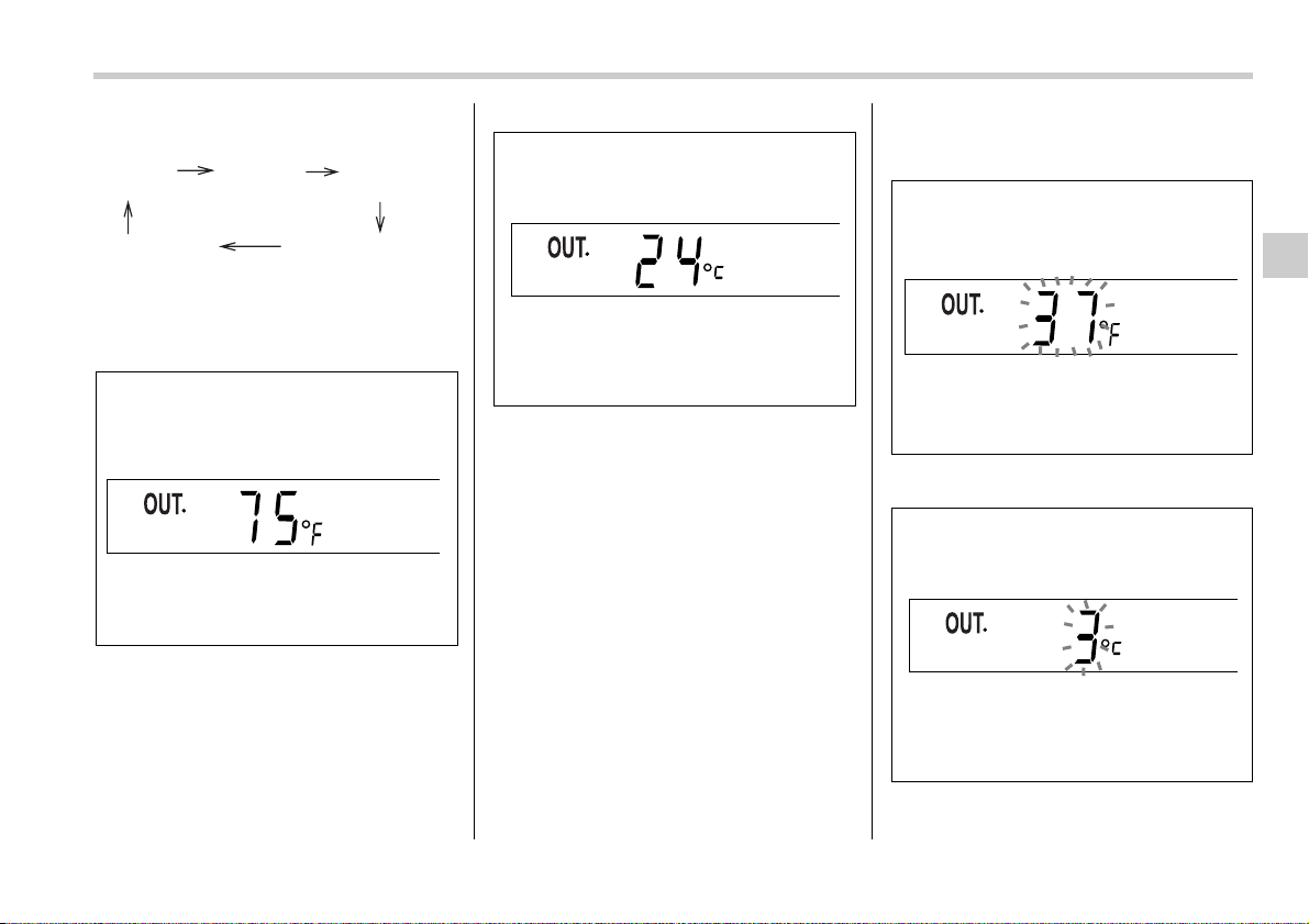
Instruments and controls 3-27
– CONTINUED –
Outside temperature indica-
tor
U.S.-spec. vehicles
Canada-spec. vehicles
The outside temperature indicator shows
the outside temperature in a range from –
22 to 122°F (–30 to 50°C).
The indicator can give a false reading un-
der any of the following conditions:
y When there is too much sun.
y During idling; while running at low
speeds in a traffic jam; when the engine is
restarted immediately following a shut-
down.
y When the actual outside temperature
falls outside the specified indicator range.
T Road surface freeze warning indica-
tion
U.S.-spec. vehicles
Canada-spec. vehicles
Outside
tempera-
ture
Current
fuel con-
sumption
Average
fuel con-
sumption
Driving range
on remaining fuel
Journey time
300594
300267
300595
300268
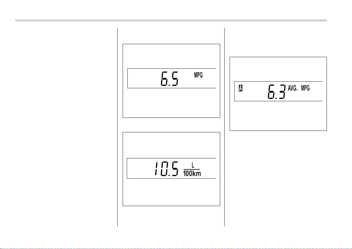
3-28 Instruments and controls
When the outside temperature drops to
37°F (3°C) or lower, the temperature indi-
cation flashes to show that the road sur-
face may be frozen.
If the outside temperature drops to 37°F
(3°C) or lower while the display is giving
an indication other than the outside tem-
perature, the display switches to the out-
side temperature indication and flashes
for five seconds before returning to its
original indication.
If the display is already indicating an out-
side temperature of 37°F (3°C) or lower
when the ignition switch is turned to the
“ON” position, the indication does not
flash.
NOTE
The outside temperature indication
may differ from the actual outside tem-
perature. The road surface freeze warn-
ing indication should be treated only
as a guide. Be sure to check the condi-
tion of the road surface before driving.
Current fuel consumption
U.S.-spec. vehicles
Canada-spec. vehicles
This indication shows the rate of fuel con-
sumption at the present moment.
Average fuel consumption
U.S.-spec. vehicles
300270
300596
300272
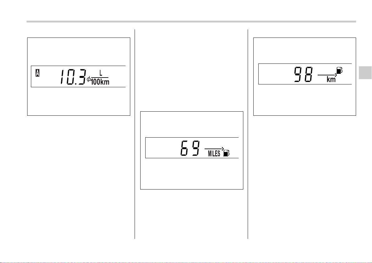
Instruments and controls 3-29
– CONTINUED –
Canada-spec. vehicles
This indication shows the average rate of
fuel consumption since the trip meter was
last reset.
Pressing the trip knob toggles the indica-
tion between the average fuel consump-
tion corresponding to the A trip meter indi-
cation and the average fuel consumption
corresponding to the B trip meter indica-
tion.
When either of the trip meter indications is
reset, the corresponding average fuel
consumption value is also reset.
NOTE
y The indicated values vary in accor-
dance with changes in the vehicle’s
running conditions. Also, the indicated
values may differ slightly from the ac-
tual values and should thus be treated
only as a guide.
y When either trip meter indication is
reset, the average fuel consumption
corresponding to that trip meter indica-
tion is not shown until the vehicle has
subsequently covered a distance of 1
mile (or 1 km).
Driving range on remaining
fuel
U.S.-spec. vehicles
Canada-spec. vehicles
The driving range indicates the distance
that can be driven taking into account the
amount of fuel remaining in the tank and
the average rate of fuel consumption.
When the low fuel warning light comes on,
the driving range indication flashes for five
seconds. (The display first switches to the
driving range indication if it was originally
giving some other indication.)
300597
300274
300273
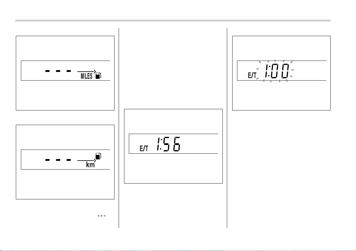
3-30 Instruments and controls
U.S.-spec. vehicles
Canada-spec. vehicles
If the driving range is shown as “ ”,
there is only a tiny amount of fuel left in the
tank. You must refuel the vehicle immedi-
ately.
NOTE
The driving range on remaining fuel is
only a guide. The indicated value may
differ from the actual driving range on
remaining fuel, so you must immedi-
ately fill the tank when the low fuel
warning light comes on.
Journey time
The journey time shows the time that has
elapsed since the ignition switch was
turned to the “START” position.
The journey time indication flashes each
time a complete hour has elapsed. If the
display is giving an indication other than
the journey time, the display switches to
the journey time, flashes for five seconds,
and returns to its original indication each
time a complete hour has elapsed.
NOTE
The journey time is reset when the igni-
tion switch is turned to the “OFF” posi-
tion. It is also reset if the ignition
switch is turned to the “LOCK” or
“ACC” position prior to restarting of
the engine.
300275
400265
400266
400267
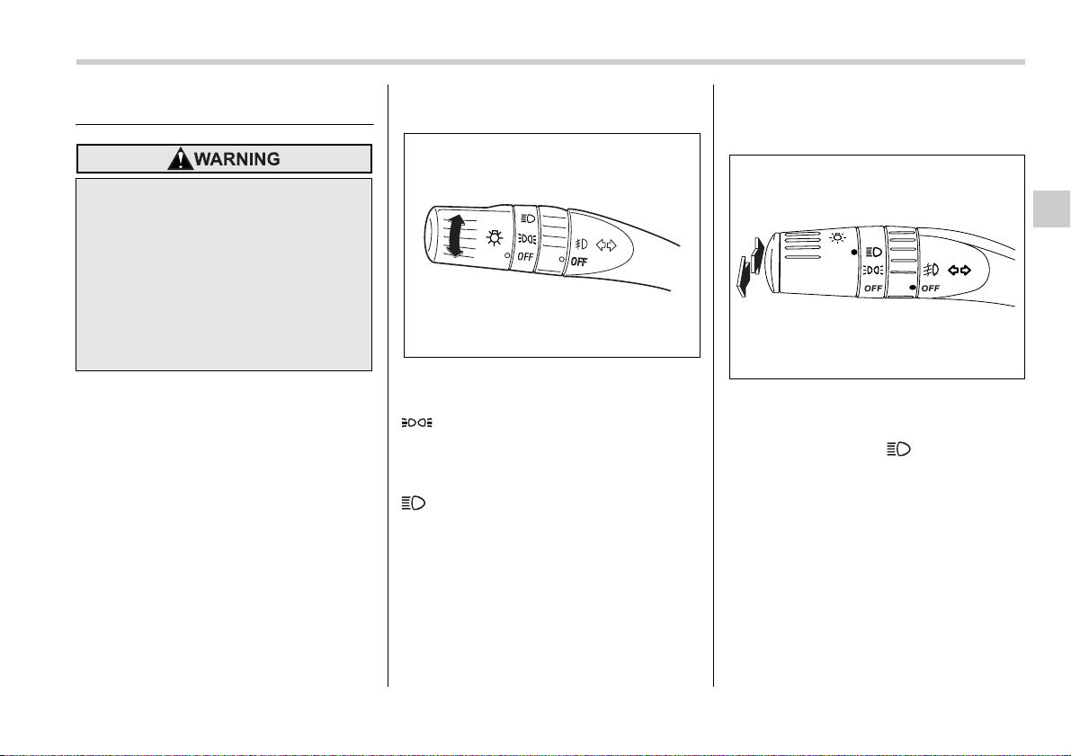
Instruments and controls 3-31
– CONTINUED –
Light control switch
The light switch operates only when the
ignition switch is in the “ON” position.
Headlights
To turn on the headlights, turn the knob on
the end of the turn signal lever.
first position
Parking lights, instrument panel illumina-
tion, tail lights and license plate light are
on.
second position
Headlights, parking lights, instrument pan-
el illumination, tail lights, and license plate
light are on.
High/low beam change (dim-
mer)
To change from low beam to high beam,
push the turn signal lever forward. When
the headlights are on high beam, the high
beam indicator light “ ” on the instru-
ment panel is also on.
To switch back to low beam, pull the lever
back to the detent position.
To prevent battery discharge result-
ing from accidentally leaving your
lights on when your vehicle is
parked, the light switch operates
only when the ignition switch is in
the “ON” position. In any other posi-
tion, the vehicle’s lights will be out.
If you park your vehicle on a road-
side at night, use the hazard warn-
ing flasher to alert the other drivers.
300506
300507
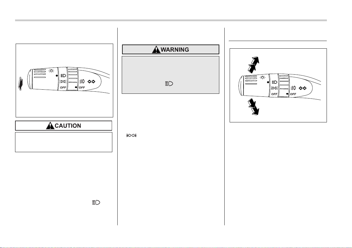
3-32 Instruments and controls
Headlight flasher
To flash the headlights, pull the lever to-
ward you and then release it. The high
beam will stay on for as long as you hold
the lever. The headlight flasher works
even though the lighting switch is in the
“OFF” position.
When the headlights are on high beam,
the high beam indicator light “ ” on
the instrument panel also comes on.
Daytime running light system
The low beam headlights will automatical-
ly come on at reduced brightness when
the engine has started, under the follow-
ing conditions:
y The parking brake is fully released.
y The light switch is in the “OFF” or
“ ” position.
Turn signal lever
To activate the right turn signal, push the
turn signal lever up. To activate the left
turn signal, push the turn signal lever
down. When the turn is finished, the lever
will return automatically. If the lever does
not return after cornering, return the lever
to the neutral position by hand.
To signal a lane change, push the turn sig-
nal lever up or down slightly and hold it
during the lane change. The turn signal in-
dicator lights will flash in the direction of
the turn or lane change. The lever will re-
turn automatically to the neutral position
when you release it.
Do not hold the lever in the flashing
position for more than just a few
seconds.
300508
The tail lights, parking lights, and
side marker lights are not turned on
by the daytime running light system.
The light switch must always be
turned to the “ ” position when
it is dark outside.
300509
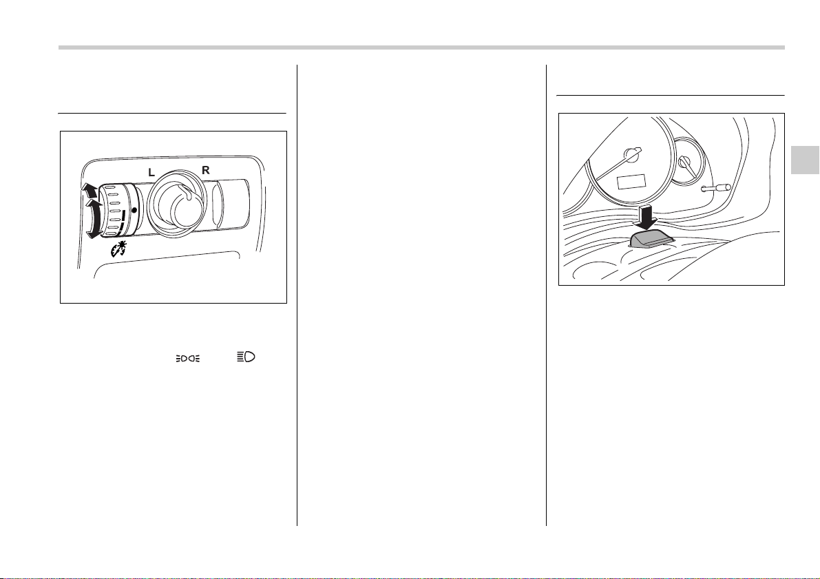
Instruments and controls 3-33
Illumination brightness con-
trol
The brightness of clock display, audio, air
conditioner, information display and in-
strument panel illumination dims when the
light switch is in the “ ” or “ ” po-
sitions. You can adjust brightness of the
instrument panel illumination for better
visibility.
In turbo models, you can also adjust the
brightness of the instrument panel illumi-
nation when the lighting switch is in the
OFF position.
To brighten, turn the control dial upward.
To darken, turn the control dial downward.
NOTE
When the control dial is turned fully up-
ward, the illumination brightness be-
comes the maximum and the automatic
dimming function does not work at all.
Parking light switch
The parking light switch operates regard-
less of the ignition switch position.
By pushing the front end of this switch, fol-
lowing lights will come on.
– Parking lights
– Front and rear side marker lights
– Tail lights
– License plate lights
To turn off, push the rear end of the park-
ing light switch.
Avoid leaving these lights on for a long
time because that will run down the bat-
tery.
300510
300178
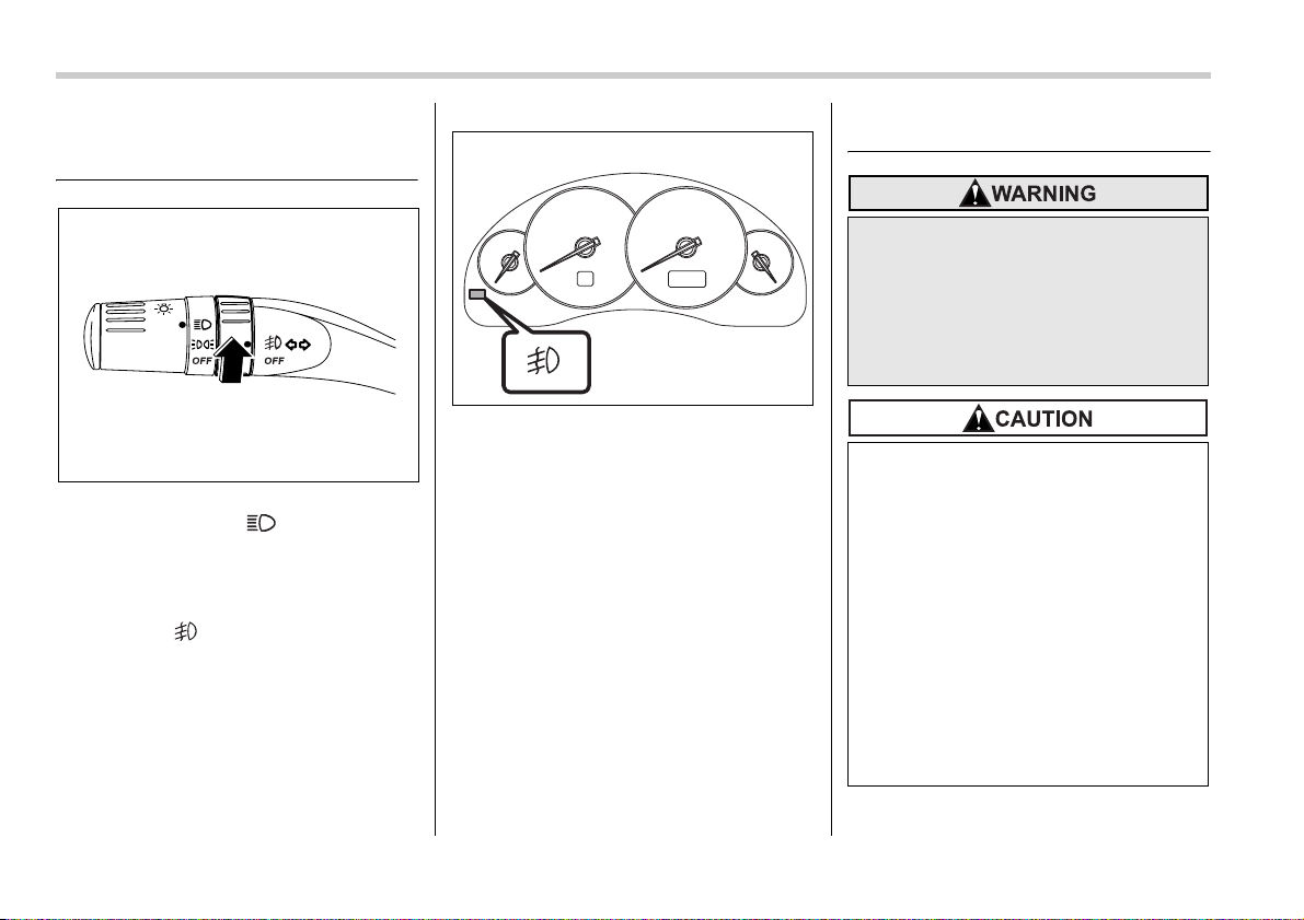
3-34 Instruments and controls
Front fog light switch (if
equipped)
The front fog lights operate only when the
light switch is in the “ ” position.
However, the front fog lights turn off when
the headlights are switched to high beam.
To turn on the front fog lights, turn the front
fog light switch on the turn signal lever up-
ward to the “ ” position. To turn off the
front fog lights, turn the switch back down
to the “OFF” position.
The indicator light located on the combi-
nation meter will illuminate when the front
fog lights are on.
Wiper and washer
300512
300282
In freezing weather, do not use the
windshield washer until the wind-
shield is sufficiently warmed by the
defroster.
Otherwise the washer fluid can
freeze on the windshield, blocking
your view.
y Do not operate the washer contin-
uously for more than ten seconds,
or when the washer fluid tank is
empty. This may cause overheat-
ing of the washer motor. Check
the washer fluid level frequently,
such as at fuel stops.
y Do not operate the wipers when
the windshield or rear window is
dry. This may scratch the glass,
damage the wiper blades and
cause the wiper motor to burn out.
Before operating the wiper on a
dry windshield or rear window, al-
ways use the windshield washer.

Instruments and controls 3-35
– CONTINUED –
NOTE
y The front wiper motor is protected
against overloads by a circuit breaker.
If the motor operates continuously un-
der an unusually heavy load, the circuit
breaker may trip to stop the motor tem-
porarily. If this happens, park your ve-
hicle in a safe place, turn off the wiper
switch, and wait for approximately 10
minutes. The circuit breaker will reset
itself, and the wipers will again operate
normally.
y Clean your wiper blades and window
glass periodically with a washer solu-
tion to prevent streaking, and to re-
move accumulations of road salt or
road film. Keep the washer button de-
pressed at least for 1 second so that
washer solution will be sprinkled all
over the windshield or rear window.
y Grease, wax, insects or other materi-
al on the windshield or the wiper
blades results in jerky wiper operation
and streaking on the glass. If you can-
not remove those streaks after operat-
ing the washer or if the wiper operation
is jerky, clean the outer surface of the
windshield or rear window and the wip-
er blades using a sponge or soft cloth
with a neutral detergent or mild-abra-
sive cleaner. After cleaning, rinse the
window glass and wiper blades with
clean water. The glass is clean if no
beads form on the glass when you
rinse with water.
y If you cannot eliminate the streaking
even after following this procedure, re-
place the wiper blades with new ones.
Refer to the “Replacement of wiper
blades” section (chapter 11) for re-
placement instructions.
Windshield wiper and washer
switches
The wiper operates only when the ignition
switch is in the “ON” or “ACC” position.
y In freezing weather, be sure that
the wiper blades are not frozen to
the windshield or rear window be-
fore switching on the wipers. At-
tempting to operate the wiper with
the blades frozen to the window
glass could cause not only the
wiper blades to be damaged but
also the wiper motor to burn out. If
the wiper blades are frozen to the
window glass, be sure to operate
the defroster, wiper deicer (if
equipped) or rear window defog-
ger before turning on the wiper.
y If the wipers stop during opera-
tion because of ice or some other
obstruction on the window, the
wiper motor could burn out even if
the wiper switch is turned off. If
this occurs, promptly stop the ve-
hicle in a safe place, turn the igni-
tion switch to the “LOCK” posi-
tion and clean the window glass
to allow proper wiper operation.
y Use clean water if windshield
washer fluid is unavailable. In ar-
eas where water freezes in winter,
use SUBARU Windshield Washer
Fluid or the equivalent. (See
“Windshield washer fluid” section
in chapter 11.)
Also, when driving the vehicle
when there are freezing tempera-
tures, use non-freezing type wiper
blades.
y Do not clean the wiper blades with
gasoline or a solvent, such as
paint thinner or benzene. This will
cause deterioration of the wiper
blades.
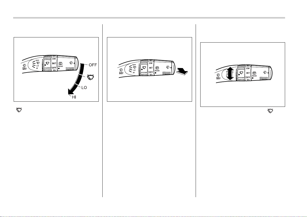
3-36 Instruments and controls
T Windshield wipers
OFF: Park
: Intermittent
LO: Low speed
HI: High speed
To turn the wipers on, push the wiper con-
trol lever down.
To turn the wipers off, return the lever to
the “OFF” position.
T Mist (for a single wipe)
For a single wipe of the wipers, pull the le-
ver toward you. The wipers operate until
you release the lever.
T Wiper intermittent time control (if
equipped)
When the wiper switch is in the “ ” po-
sition, turn the dial to adjust the operating
interval of the wiper.
The operating interval can be adjusted
continuously from the shortest interval to
the longest.
Two click stop positions of the dial may
help you to aim at your desired interval.
The operating interval can be adjusted in
nine steps.
300286 300288
300287
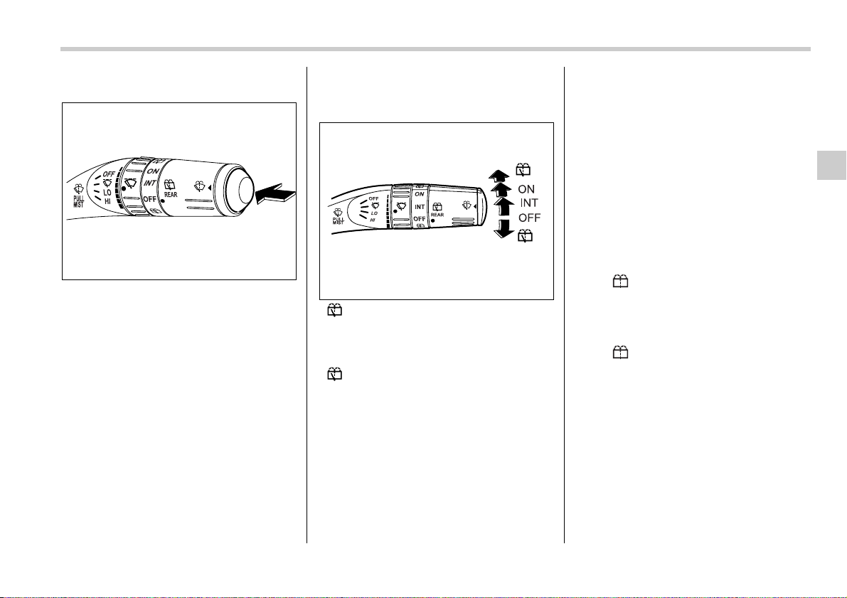
Instruments and controls 3-37
T Washer
To wash the windshield, push the washer
button at the end of the wiper control le-
ver. The washer fluid sprays until you re-
lease the washer button. The wipers oper-
ate while you push the button.
Rear window wiper and wash-
er switch (Station wagon)
: Washer (accompanied by wiper opera-
tion)
ON: Continuous
INT: Intermittent
OFF: Park
: Washer
T Rear wiper
To turn the rear wiper on, turn the knob on
the end of the wiper control lever upward
to the “INT” or “ON” position.
To turn the wiper off, return the knob on
the end of the lever to the “OFF” position.
With the switch turned to the “INT” posi-
tion, the rear wiper will operate intermit-
tently at intervals corresponding to the ve-
hicle speed (longer when the vehicle
speed is low; shorter when the vehicle
speed is high).
When you subsequently move the selec-
tor lever of the automatic transmission to
the “R” position, the rear wiper will switch
to continuous operation. When you move
the selector lever from the “R” position to
some other position, the rear wiper will re-
turn to intermittent operation.
T Washer
To wash the rear window while the rear
wiper is operating, turn the knob on the
end of the wiper control lever upward to
the “ ” position. The washer fluid
sprays until you release the knob.
To wash the rear window when the rear
wiper is not in use, turn the knob on the
end of the wiper control lever downward to
the “ ” position. The washer fluid
sprays and the wiper operates until you
release the knob.
300289
300290
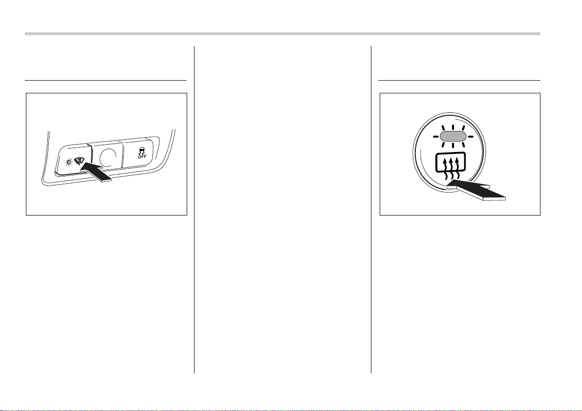
3-38 Instruments and controls
Windshield wiper deicer (if
equipped)
The windshield wiper deicer operates only
when the ignition switch is in the “ON” po-
sition.
Before turning on the windshield wiper de-
icer, remove any snow from the wind-
shield. To turn on the windshield wiper de-
icer, push the button. The indicator light
located on the button lights up while the
windshield wiper deicer is operating.
The windshield wiper deicer will automati-
cally shut off after approximately 15 min-
utes. If the windshield wiper blades have
been deiced completely before that time,
push the button to turn it off. It also turns
off when the ignition switch is turned to the
“ACC” or “LOCK” position. If deicing is not
complete, you have to push the button to
turn the deicer on again.
Your SUBARU dealer can set your wind-
shield wiper deicer for continuous opera-
tion. Contact your SUBARU dealer for de-
tails.
Once the windshield wiper deicer has
been set for continuous operation, press-
ing the button results in continuous opera-
tion. The windshield wiper deicer automat-
ically stops operating if any one of the fol-
lowing conditions occurs during continu-
ous operation.
y The outside temperature becomes 41°F
(5°C) or higher.
y The vehicle speed remains at 9 mph (15
km/h) or lower for 15 minutes.
y The battery voltage decreases below
the permissible level.
Rear window defogger but-
ton
Vehicle with manual climate control sys-
tem
300515 300291
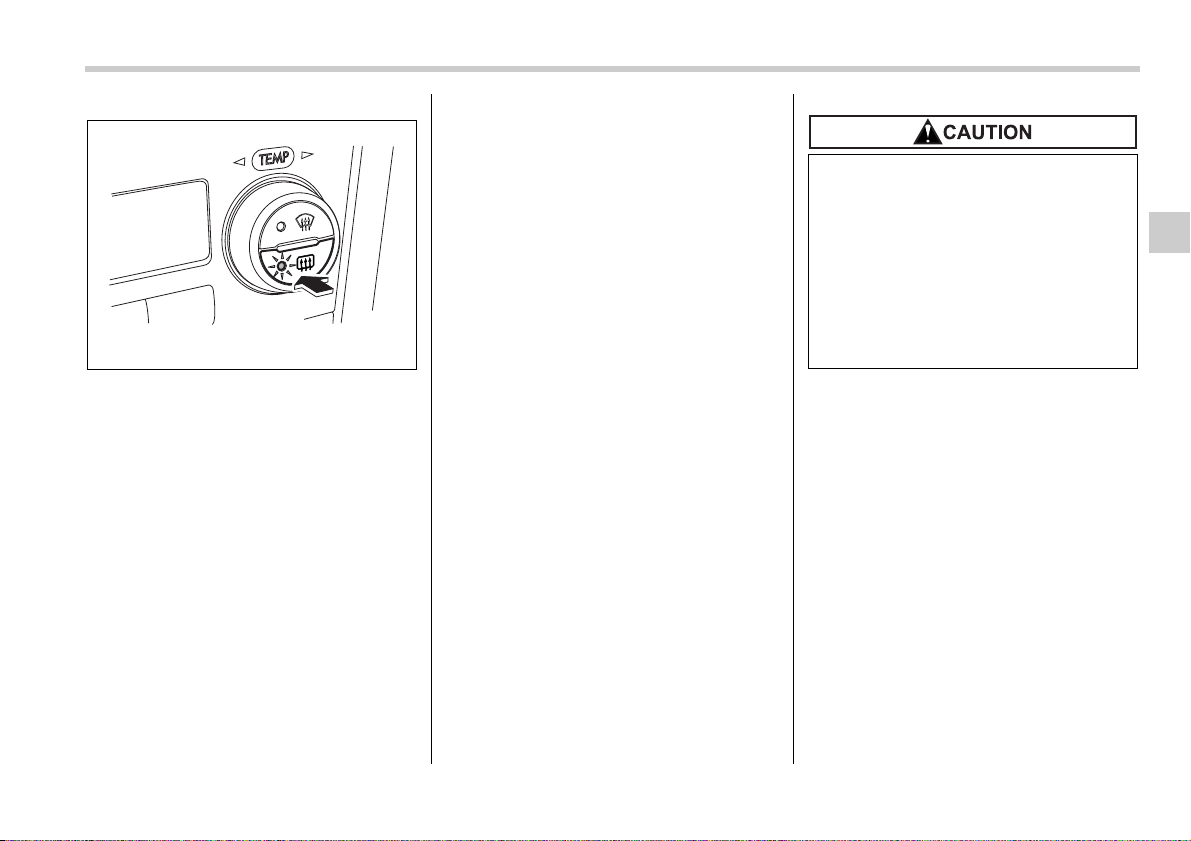
Instruments and controls 3-39
Vehicle with automatic climate control
system
The rear window defogger operates only
when the ignition switch is in the “ON” po-
sition.
The rear window defogger button is locat-
ed on the climate control panel.
To turn on the defogger, push the button.
To turn it off, push the button again.
The indicator light located on the button
lights up while the rear window defogger is
operating.
The defogger will automatically shut off af-
ter approximately 15 minutes. If the win-
dow clears before that time, push the but-
ton to turn it off. It also turns off when the
ignition switch is turned to the “ACC” or
“LOCK” position. If defrosting or defogging
is desired when you restart your vehicle,
you have to push the button to turn it on
again.
Your SUBARU dealer can set your rear
window defogger for continuous opera-
tion. Contact your SUBARU dealer for de-
tails.
Once the rear window defogger has been
set for continuous operation, the rear win-
dow defogger repeatedly operates for 15
minutes, stops for two minutes, and again
operates for 15 minutes. If the battery volt-
age drops below the permissible level,
continuous operation is canceled and op-
eration stops as described in the follow-
ing.
y If the battery voltage drops below the
permissible level within 15 minutes of de-
pression of the button, continuous opera-
tion is canceled and the rear window de-
fogger stops operating 15 minutes later.
y If the battery voltage drops below the
permissible level after the rear window de-
fogger has, following depression of the
button, operated for 15 minutes, stopped
operating for two minutes, and started op-
erating again, the rear window defogger
immediately stops operating.
NOTE
If your vehicle is equipped with the out-
side mirror defogger, the outside mir-
ror defogger operates while the rear
window defogger is operating.
300598
y Do not use sharp instruments or
window cleaner containing abra-
sives to clean the inner surface of
the rear window. They may dam-
age the conductors printed on the
window.
y To prevent the battery from being
discharged, do not operate the de-
fogger continuously for any long-
er than necessary.
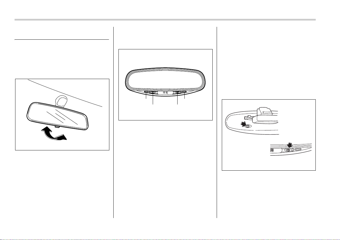
3-40 Instruments and controls
Mirrors
Always check that the inside and outside
mirrors are properly adjusted before you
start driving.
Inside mirror
The inside mirror has a day and night po-
sition. Pull the tab at the bottom of the mir-
ror toward you for the night position. Push
it away for the day position. The night po-
sition reduces glare from headlights.
Auto-dimming mirror/com-
pass (if equipped)
1) Left button
2) Auto dimming indicator
3) Photosensor
4) Right button
The auto-dimming mirror/compass has an
anti-glare feature which automatically re-
duces glare coming from headlights of ve-
hicles behind you. It also contains a built-
in compass.
y By pressing and releasing the left but-
ton, the automatic dimming function is tog-
gled on or off. When the automatic dim-
ming function is on, the auto dimming indi-
cator light (green) located to the right of
the button will illuminate.
y By pressing and releasing the right but-
ton, the compass display is toggled on or
off. When the compass is on, an illuminat-
ed compass reading will appear in the
lower part of the mirror.
Even with the mirror in anti-glare mode,
the mirror surface turns bright if the trans-
mission is shifted into reverse. This is to
ensure good rearward visibility during re-
versing.
T Photosensors
The mirror has a photosensor attached on
both the front and back sides. If the glare
from the headlights of vehicles behind you
strikes the mirror, these sensors detect it
and make the reflection surface of the mir-
ror dimmer to help prevent you from being
blinded. For this reason, use care not to
300293
1
23
4
300517
300518
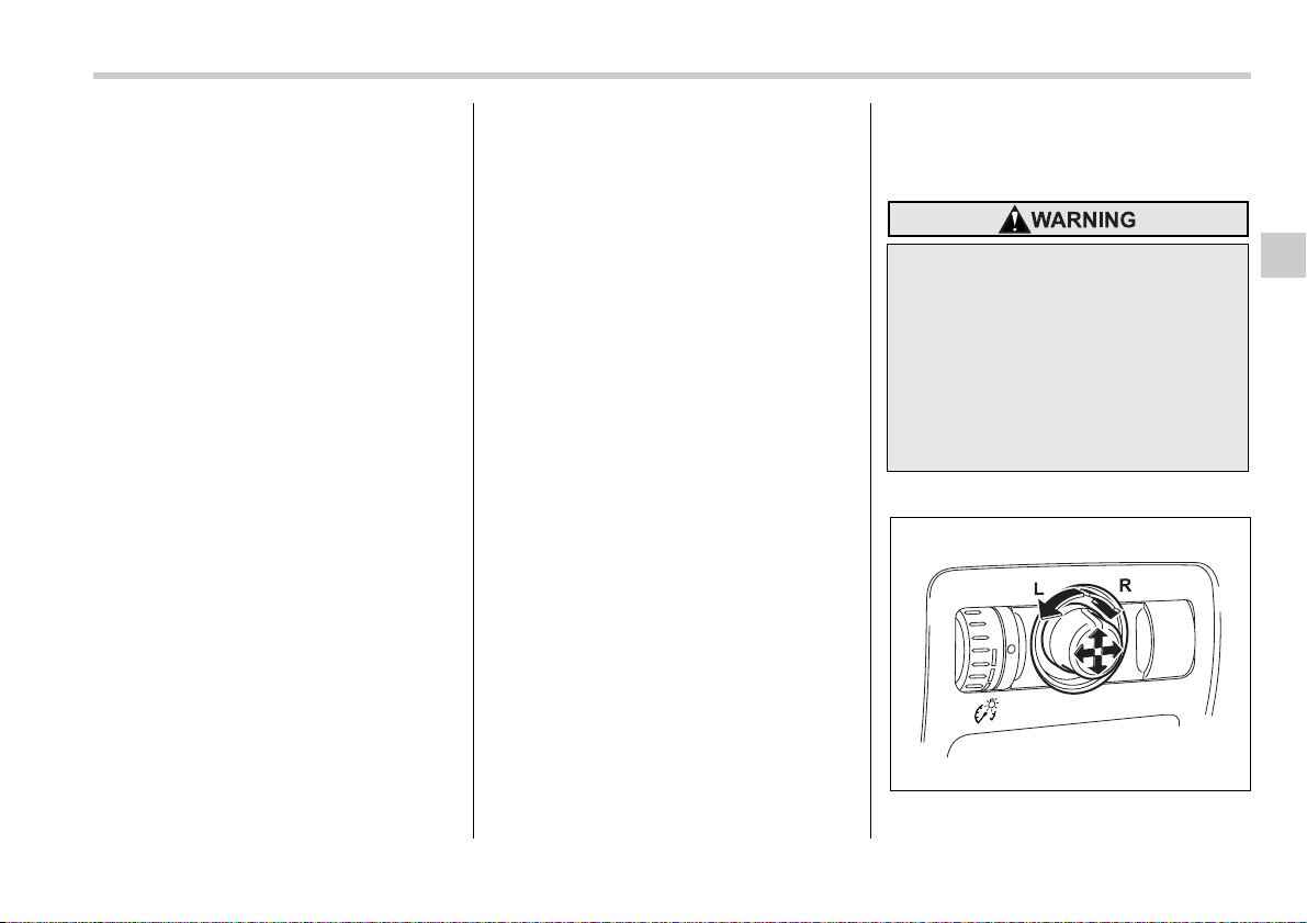
Instruments and controls 3-41
– CONTINUED –
cover the sensors with stickers, or other
similar items. Periodically wipe the sen-
sors clean using a piece of dry soft cotton
cloth or an applicator.
T Compass calibration
1. For optimum calibration, switch off all
nonessential electrical accessories (rear
window defogger, heater/air conditioning
system, spotlight, etc.) and ensure all
doors are shut.
2. Drive to an open, level area away from
large metallic objects or structures and
make certain the ignition switch is in the
“ON” position.
3. Press and hold the left button for 3 sec-
onds then release, and the compass will
enter the calibration mode. “CAL” and di-
rection will be displayed.
4. Drive slowly in a circle until “CAL” dis-
appears from the display (approximately
two or three circles). The compass is now
calibrated.
5. Further calibration may be necessary
should outside influences cause the mirror
to read inaccurately. You will know that
this has occurred if your compass begins
to read in only limited directions. Should
you encounter this situation, return to step
one of the above procedure and recali-
brate the mirror.
T Compass zone adjustment
1. The zone setting is factory preset to
Zone 8. Refer to the “Compass calibration
zone” map attached to the end of this
manual to verify that the compass zone
setting is correct for your geographical lo-
cation.
2. Press and hold the right button for 3
seconds then release, and the word
“ZONE” will briefly appear and then the
zone number will be displayed.
3. Press the right-hand button repeatedly
to cycle the display through all possible
zone settings. Stop cycling when the cor-
rect zone setting for your location is dis-
played.
4. Releasing the button for 3 seconds will
exit the zone setting mode.
Outside mirrors
T Convex mirror (Passenger side)
T Remote control mirror switch
The remote control mirrors operate only
Objects look smaller in a convex
mirror and farther away than when
viewed in a flat mirror. Do not use
the convex mirror to judge the dis-
tance of vehicles behind you when
changing lanes. Use the inside mir-
ror (or glance backwards) to deter-
mine the actual size and distance of
objects that you view in convex mir-
ror.
300519
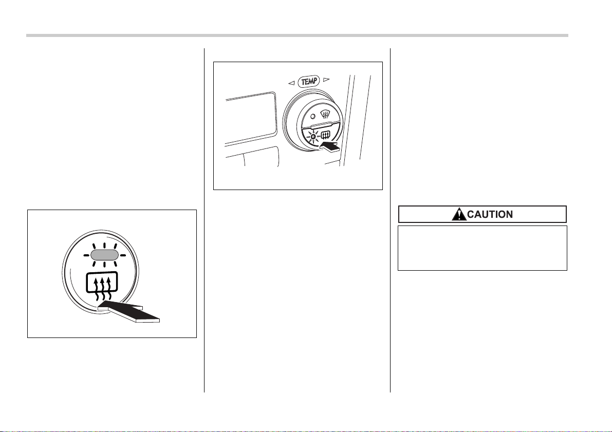
3-42 Instruments and controls
when the ignition switch is in the “ON” or
“ACC” position.
1. Turn the knob to the “L” side to adjust
the left-hand mirror or to the “R” side to ad-
just the right-hand mirror.
2. Move the knob in the direction you
want to move the mirror.
3. Return the knob to the neutral position
to prevent unintentional operation.
The mirrors can also be adjusted manual-
ly.
T Outside mirror defogger (if
equipped)
Vehicle with manual climate control sys-
tem
Vehicle with automatic climate control
system
The outside mirror defogger shares the
button with rear window defogger.
The outside mirror defogger operates only
when the ignition switch is in the “ON” po-
sition.
To turn on the outside mirror defogger,
push the button.
To turn it off, push the button again. The
indicator light located on the button lights
up while the outside mirror defogger is op-
erating.
The defogger will automatically shut off af-
ter approximately 15 minutes. If the mirror
clears before that time, push the button to
turn it off. It also turns off when the ignition
switch is turned to the “ACC” or “LOCK”
position. If defrosting or defogging is de-
sired when you restart your vehicle, you
have to push the button to turn it on again.
NOTE
y While the outside mirror defogger is
operating, the rear window defogger
also operates.
y When the rear window defogger has
been set for continuous operation, the
outside mirror defogger also operates
continuously. Refer to the “Rear win-
dow defogger button” section in this
chapter.
300291
300598
To prevent the battery from being
discharged, do not operate the de-
fogger continuously for any longer
than necessary.
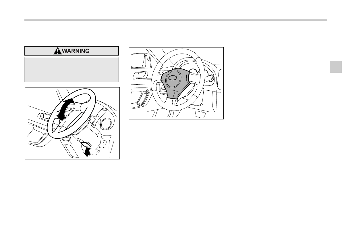
Instruments and controls 3-43
Tilt steering wheel
1. Adjust the seat position. Refer to the
“Front seats” section (chapter 1).
2. Pull the tilt lock lever down.
3. Move the steering wheel to the desired
level.
4. Push the lever up to lock the steering
wheel in place.
5. Make sure that the steering wheel is
securely locked by moving it up and down.
Horn
To sound the horn, push the horn pad.
Do not adjust the steering wheel tilt
position while driving. This may
cause loss of vehicle control and re-
sult in personal injury.
300295
300296


4
Climate control
Ventilator ............................................................. 4-2
Air flow selection .................................................... 4-2
Center and side ventilators .................................... 4-3
Manual climate control system (if equipped) ... 4-3
Control panel ........................................................... 4-3
Heater operation ..................................................... 4-5
Air conditioner operation ....................................... 4-7
Automatic climate control system (if
equipped) ......................................................... 4-7
Control panel ........................................................... 4-8
Temperature sensors ............................................. 4-11
Operating tips for heater and air conditioner .. 4-12
Cleaning ventilator grille ........................................ 4-12
Efficient cooling after parking in direct
sunlight ................................................................. 4-12
Lubrication oil circulation in the refrigerant
circuit ..................................................................... 4-12
Checking air conditioning system before summer
season ................................................................... 4-12
Cooling and dehumidifying in high humidity and
low temperature weather condition .................... 4-12
Air conditioner compressor shut-off when engine
is heavily loaded ................................................... 4-12
Refrigerant for your climate control system ........ 4-12
Air filtration system (if equipped) ..................... 4-13
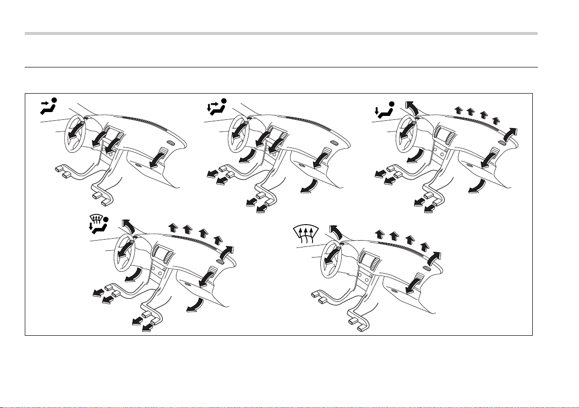
4-2 Climate control
Climate control
Ventilator
Air flow selection
400341
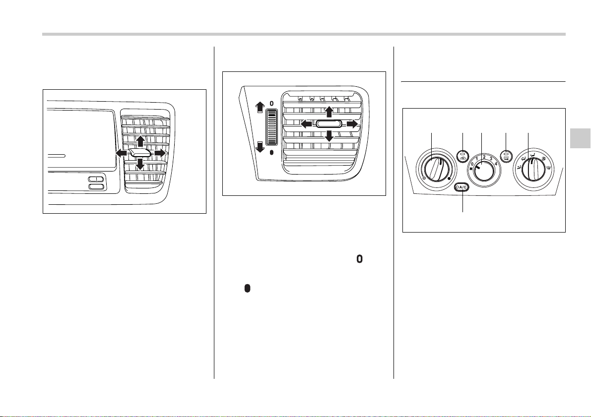
Climate control 4-3
– CONTINUED –
Center and side ventilators
T Center ventilators
Move the tab up and down or right and left
to adjust the flow direction.
T Side ventilators
1) Open
2) Close
Move the tab up and down or right and left
to adjust the flow direction.
To open the ventilator, turn the side grille
open/close wheel upward to the “ ” po-
sition.
To close it, turn the wheel downward to
the “ ” position.
Manual climate control sys-
tem (if equipped)
Control panel
1) Temperature control dial
2) Fan speed control dial
3) Air flow control dial
4) Air conditioner button
5) Air inlet selection button
6) Rear window defogger button (Refer to
the “Rear window defogger button” sec-
tion in chapter 3.)
400343
1
2
400578
1265
4
3
400579
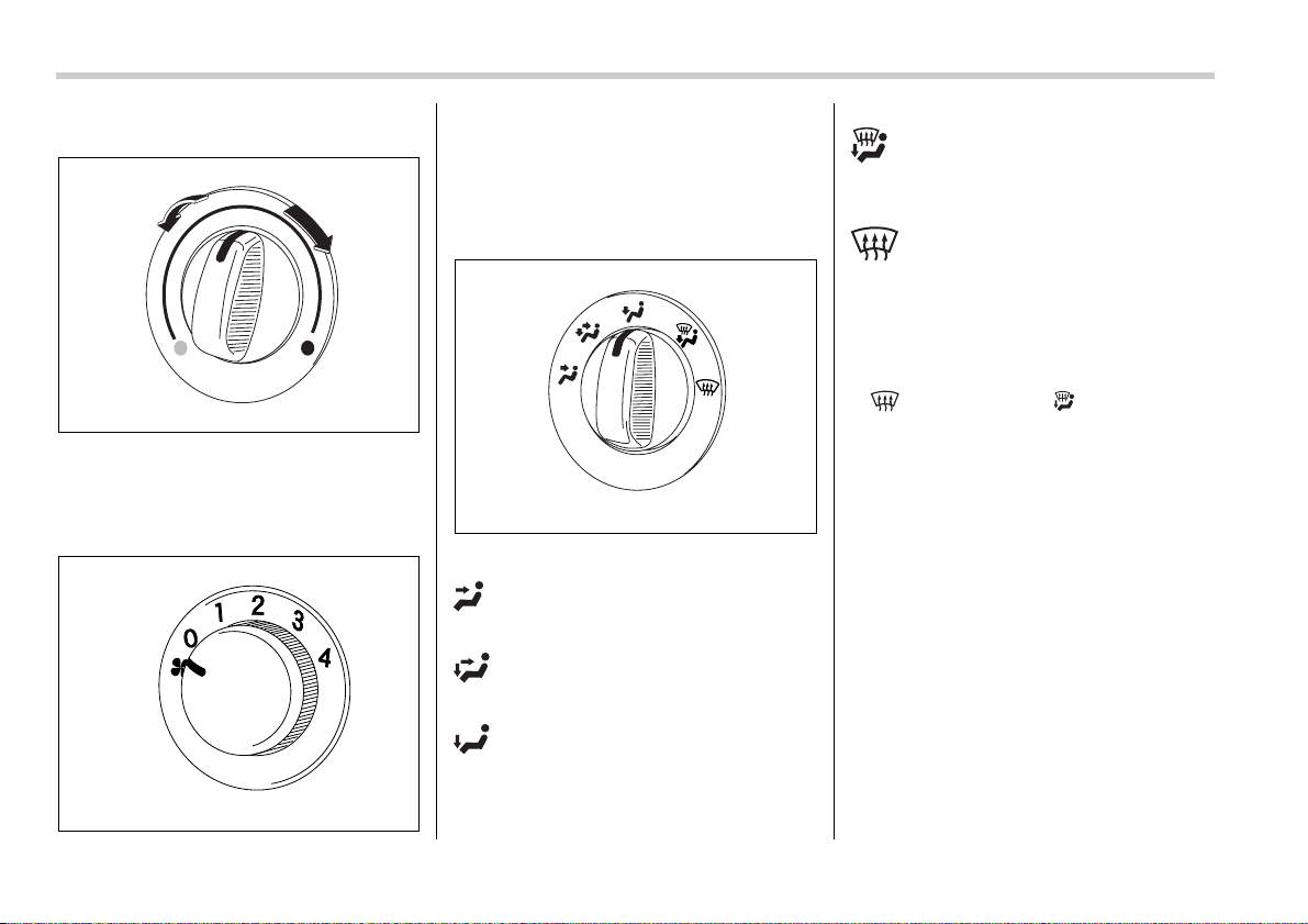
4-4 Climate control
T Temperature control dial
This dial regulates the temperature of air
flow from the air outlets over a range from
the blue side (cool) to red side (warm).
T Fan speed control dial
The fan operates only when the ignition
switch is turned to the “ON” position. The
fan speed control dial is used to select four
fan speeds.
T Air flow control dial
This dial has the following five positions:
: Air flows through the instrument pan-
el outlets.
: Air flows through the instrument pan-
el outlets and the foot outlets.
: Air flows through the instrument pan-
el outlets, the foot outlets, and some
through the windshield defroster outlets.
: Air flows through the instrument pan-
el outlets, the windshield defroster outlets,
and the foot outlets.
: Air flows through the instrument
panel outlets and the windshield defroster
outlets.
NOTE
In a vehicle equipped with an air condi-
tioner, when the dial is placed in the
“ ” position or “ ” position the
air conditioner compressor automati-
cally operates to quickly defog the
windshield. However the indicator on
the air conditioner button will not come
on. At the same time, the air inlet selec-
tion is automatically set to “outside
air” mode.
In this state, you cannot select “recir-
culation” mode by manually pressing
the air inlet selection button.
Also, you cannot stop the air condi-
tioner compressor by pressing the air
conditioner button.
400346
400347
400348
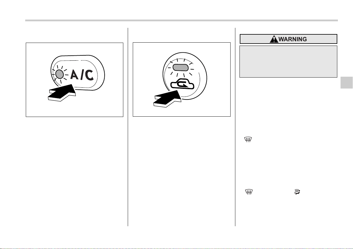
Climate control 4-5
– CONTINUED –
T Air conditioner button
The air conditioner operates only when
the engine is running.
Push the air conditioner button while the
fan is in operation to turn on the air condi-
tioner. The indicator light will come on.
Push it again to turn off the air conditioner.
T Air inlet selection button
ON position (Recirculation): Interior air is
recirculated inside the vehicle.
Push the air inlet button to the ON posi-
tion. The indicator light will come on.
Place this button in the ON position when
you wish to cool the cabin quickly (in a ve-
hicle with an air conditioner) or are driving
on a dusty road.
OFF position (Outside air): Outside air is
drawn into the passenger compartment.
Push the air inlet button again to the OFF
position. The indicator light will go off.
Place this button in the OFF position when
you reach a road that is not dusty and
when you wish to achieve a comfortable
temperature in the cabin.
Heater operation
T Defrosting or defogging the wind-
shield
To direct warm air to the windshield and
front door windows:
1. Set the air inlet selection button to the
OFF position.
2. Set the air flow control dial to the
“ ” position.
3. Turn the temperature control dial all the
way to the right.
4. Set the fan speed control dial to the
highest speed.
NOTE
y In a vehicle equipped with an air con-
ditioner, when the dial is placed in the
“ ” position or “ ” position the
air conditioner compressor automati-
cally operates to quickly defog the
windshield. However the indicator on
the air conditioner button will not come
on. At the same time, the air inlet selec-
400349
400350
Continued operation in the ON posi-
tion may fog up the windows.
Switch to the OFF position as soon
as the outside dusty condition
clears.
4-6 Climate control
tion is automatically set to “outside
air” mode.
In this state, you cannot select “recir-
culation” mode by manually pressing
the air inlet selection button.
Also, you cannot stop the air condi-
tioner compressor by pressing the air
conditioner button.
y Warm air also comes out from the
right and left air outlets. To stop warm
air flow from these outlets, turn the
corresponding wheel to the “ ” po-
sition.
T Heating and defrosting
To direct warm air toward the floor and the
windshield:
1. Set the air inlet selection lever to the
“OFF” position.
2. Set the air flow control dial to the
“ ”position.
3. Set the temperature control dial to the
most comfortable level.
4. Set the fan speed control dial to the de-
sired speed.
NOTE
y In a vehicle equipped with an air con-
ditioner, when the dial is placed in the
“ ” position or “ ” position the
air conditioner compressor automati-
cally operates to quickly defog the
windshield. However the indicator on
the air conditioner button will not come
on. At the same time, the air inlet selec-
tion is automatically set to “outside
air” mode.
In this state, you cannot select “recir-
culation” mode by manually pressing
the air inlet selection button.
Also, you cannot stop the air condi-
tioner compressor by pressing the air
conditioner button.
y Warm air also comes out from the
right and left air outlets. To stop warm
air flow from these outlets, turn the
corresponding wheel to the “ ” po-
sition.
T Heating
To direct warm air toward the floor:
1. Set the air inlet selection button to the
OFF position.
2. Set the air flow control dial to the
“ ” position.
3. Set the temperature control dial to the
most comfortable level.
4. Set the fan speed control dial to the de-
sired speed.
NOTE
Warm air also comes out from the right
and left air outlets. To stop warm air
flow from these outlets, turn the corre-
sponding wheel to the “ ” position.
T Bi-level heating
This setting allows you to direct air of dif-
ferent temperatures from the instrument
panel and foot outlets. The air from the
foot outlets is slightly warmer than from
the instrument panel outlets.
1. Set the air inlet selection button to the
OFF position.
2. Set the air flow control dial to the
“ ” position.
3. Set the temperature control dial to the
desired temperature level.
4. Set the fan speed control dial to the de-
sired speed.
Setting the temperature control dial fully
turned to the red area or blue area de-
creases the temperature difference be-
tween the air from the instrument panel
outlets and the air from the foot outlets.
T Ventilation
To force outside air through the instru-
ment panel outlets:
1. Set the air inlet selection button to the
OFF position.
2. Set the air flow control dial to the “ ”
position.
3. Set the temperature control dial all the
way left.
4. Set the fan speed control dial to the de-
sired speed.
Climate control 4-7
– CONTINUED –
When driving on a dusty road, set the air
inlet control button to the ON position.
Air conditioner operation
T Cooling or dehumidifying
For cooling and dehumidification of the
passenger compartment, air flows through
the instrument panel outlets:
1. Set the air inlet selection button to the
OFF position.
2. Set the air flow control dial to the “ ”
position.
3. Set the air conditioner button to the
“ON” position.
4. Set the temperature control dial to the
blue side.
5. Set the fan speed control dial at the de-
sired speed.
T Defrosting or defogging
To direct warm air to the windshield and
front door windows:
1. Set the air outlet control dial to the
“ ” position.
2. Set the temperature control dial to the
red side.
3. Set the fan speed control dial at the
highest speed.
NOTE
In a vehicle equipped with an air condi-
tioner, when the dial is placed in the
“ ” position or “ ” position the
air conditioner compressor automati-
cally operates to quickly defog the
windshield. However the indicator on
the air conditioner button will not come
on. At the same time, the air inlet selec-
tion is automatically set to “outside
air” mode.
In this state, you cannot select “recir-
culation” mode by manually pressing
the air inlet selection button.
Also, you cannot stop the air condi-
tioner compressor by pressing the air
conditioner button.
Automatic climate control
system (if equipped)
NOTE
y Operate the automatic climate con-
trol system when the engine is run-
ning.
y The blower fan rotates at a low speed
when the engine coolant temperature
is low.
For efficient defogging or dehumidify-
ing in cold weather, press the “A/C”
button.
y Even when cooling is not necessary,
setting the temperature much lower
than the current outlet air temperature
turns on the air conditioner compres-
sor automatically and the “A/C” indica-
tor light on the control panel comes on.
The automatic climate control system au-
tomatically controls outlet air temperature,
fan speed, air flow distribution air-inlet
control, and air conditioner compressor
operation. It activates when the “AUTO”
button is pressed, and is used to maintain
a constant, comfortable climate within the
passenger compartment.
The temperature can be set within a range
of 65 to 85°F (18 to 32°C).
Continued operation in the ON posi-
tion may fog up the windows.
Switch to the OFF position as soon
as the outside dusty condition
clears.
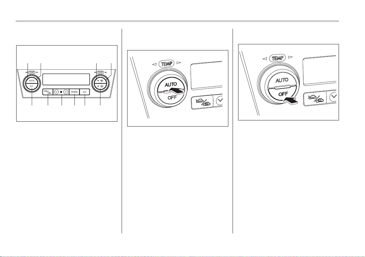
4-8 Climate control
Control panel
1) AUTO button
2) Temperature control dial (driver’s side)
3) Defroster button
4) Temperature control dial (passenger’s
side)
5) Rear window defogger button (Refer to
the “Rear window defogger button” sec-
tion in chapter 3.)
6) Air conditioner button
7) Air flow mode selection button
8) Fan speed control button
9) Air inlet selection button
10)OFF button
T AUTO button
AUTO mode operation:
When the “AUTO” button is pressed, the
indicator light “AUTO” on the display
comes on. In this state, fan speed, air flow
distribution, air-inlet control, and air condi-
tioner compressor operation are automat-
ically controlled.
Manual mode operation:
If you operate any of the buttons on the
control panel other than the “OFF” button
and temperature control dial during auto-
matic mode operation, the indicator light
“AUTO” on the control panel will go out.
You can then manually control the system
as desired using the button you operated.
To change the system back to the AUTO
mode, press the “AUTO” button.
T OFF button
The Automatic Climate Control system
turns off (the air conditioner compressor
and fan turn off) when the “OFF” button is
pressed.
When the “OFF” button is pressed, the
outside air introduction mode (air inlet se-
lection OFF) is automatically selected.
12
10 9 8 7 6 5
34
400580
400581
400582
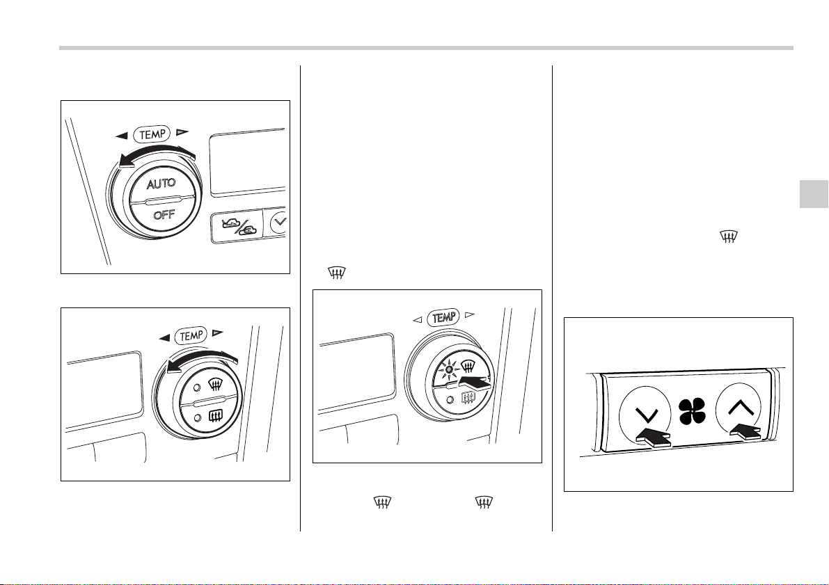
Climate control 4-9
– CONTINUED –
T Temperature control dial
Driver’s side
Passenger’s side
It is possible to make separate tempera-
ture settings for the driver’s side and pas-
senger’s side. Each temperature setting is
shown on the display. With the dial set at
your desired temperature, the system au-
tomatically adjusts the temperature of air
supplied from the outlets such that the de-
sired temperature is achieved and main-
tained.
If the dial is turned fully counterclockwise,
the system gives maximum cooling perfor-
mance. If the dial is turned fully clockwise,
the system gives maximum heating per-
formance.
T – Defroster button
To defrost or dehumidify the windshield
and front door windows, push the defrost-
er button “ ”. When the “ ” button
is pushed, regardless whether the air con-
ditioner is operating or not, outside air is
drawn into the passenger compartment,
the air conditioner compressor turns on,
air flow is directed towards the windshield
and front door windows, and the indicator
light on the button comes on.
After eliminating the fogging from the
windshield, return the climate control sys-
tem to the AUTO mode by pushing the
“AUTO” button or turn off by pushing the
“OFF” button.
Alternatively, push the “ ” button
again to return the system to the setting
that was selected before you activated the
defroster.
T Fan speed control button
The fan speed control button has 6 differ-
ent fan speed positions.
400583
400584
400585
400357
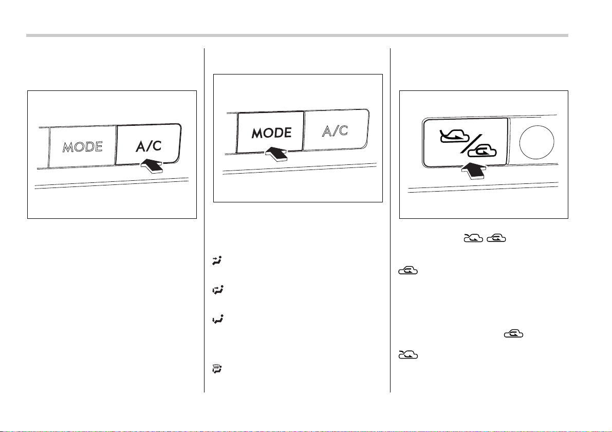
4-10 Climate control
The fan speed is shown by the display.
T A/C – Air conditioner button
If the windshield starts to fog when the cli-
mate control system is operated in the
AUTO mode, push the air conditioner but-
ton “A/C” to defog and dehumidify.
When this button is pushed, the air condi-
tioner compressor turns on and the indica-
tor light “A/C” on the display comes on. Af-
ter eliminating the fogging from the wind-
shield, set the system back to the AUTO
mode by pushing the “AUTO” button.
NOTE
The air conditioner compressor does
not operate when the outside air tem-
perature is below 32°F (0°C).
T Air flow mode selection button
Select the desired air flow mode by push-
ing the air flow mode selection button. The
selected air flow mode is shown by the
display.
(Ventilation): Air flows through the in-
strument panel outlets.
(Bi-level): Air flows through the instru-
ment panel outlets and the foot outlets.
(Heat): Air flows through the instru-
ment panel outlets, the foot outlets, and
some through the windshield defroster
outlets.
(Heat-def): Air flows through the instru-
ment panel outlets, the windshield defrost-
er outlets, and the foot outlets.
T Air inlet selection button
Select air flow by pushing the air inlet se-
lection button “ / ”.
The selected air inlet setting is shown on
the control panel.
(Recirculation): Interior air recircu-
lates inside the passenger compartment.
Use this position when quickly cooling
down the passenger compartment or to
prevent outside air from entering the pas-
senger compartment. When the recircula-
tion mode is selected, a “ ” indicator
light appears on the display.
(Outside air): Outside air is drawn
into the passenger compartment. When
the climate control system is operated in
the “AUTO” mode, this position is selected
400586
400587
400588
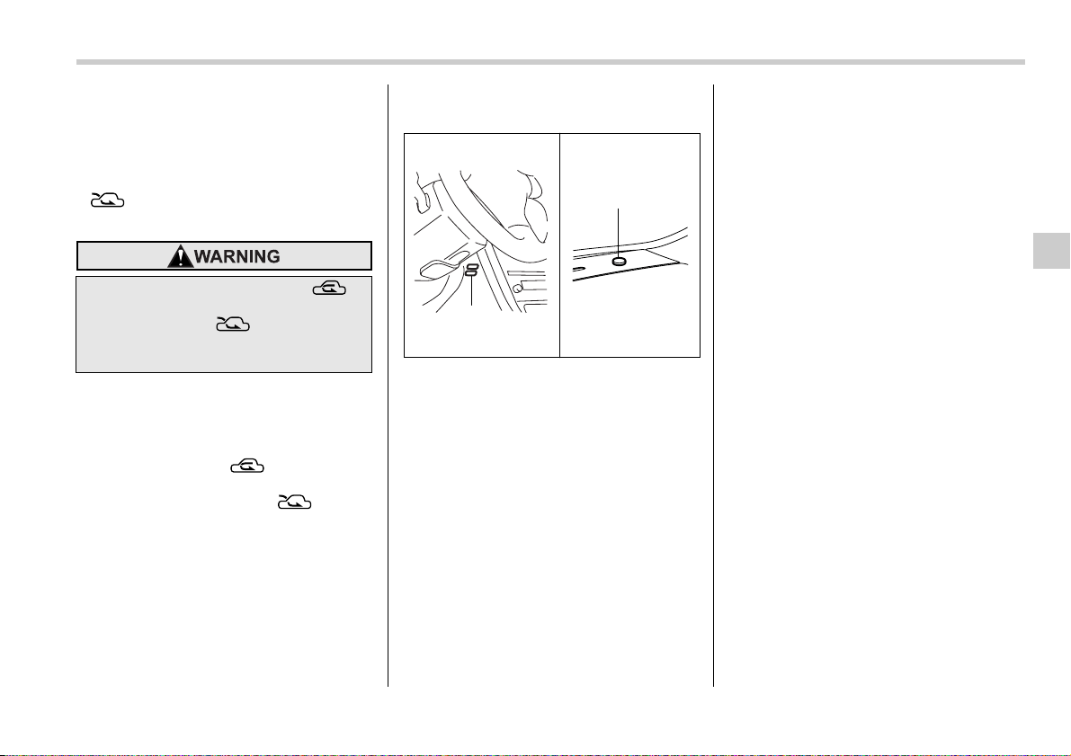
Climate control 4-11
automatically. (There is one exception:
When the temperature control dial is
turned fully counterclockwise, the recircu-
lation mode is automatically selected.)
When the outside air mode is selected, a
“ ” indicator light appears on the
display.
NOTE
When driving on a dusty road or be-
hind a vehicle that emits unpleasant
exhaust gases, set the air inlet selec-
tion button to the “ ” position.
From time to time, return the air inlet
selection button to the “ ” posi-
tion to draw outside air into the pas-
senger compartment.
Temperature sensors
1) Solar sensor
2) Interior air temperature sensor
The automatic climate control system em-
ploys several sensors. These sensors are
delicate. If they are treated incorrectly and
become damaged, the system may not be
able to control the interior temperature
correctly. To avoid damaging the sensors,
observe the following precautions:
– Do not subject the sensors to impact.
– Keep water away from the sensors.
– Do not cover the sensors.
The sensors are located as follows:
– Solar sensor: beside windshield de-
froster grille
– Interior air temperature sensor: on the
side of the driver-side part of the center
panel
– Outside temperature sensor: behind
front grille.
Continued operation in the “ ”
position may fog up the windows.
Switch to the “ ” position as
soon as the outside dusty condition
clears.
1
2
400589
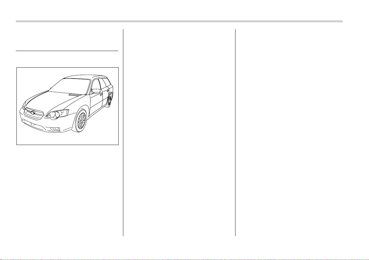
4-12 Climate control
Operating tips for heater and
air conditioner
Cleaning ventilator grille
Always keep the front ventilator inlet grille
free of snow, leaves, or other obstructions
to ensure efficient heating and defrosting.
Since the condenser is located in front of
the radiator, this area should be kept
clean because cooling performance is im-
paired by any accumulation of insects and
leaves on the condenser.
Efficient cooling after parking
in direct sunlight
After parking in direct sunlight, drive with
the windows open for a few minutes to al-
low outside air to circulate into the heated
interior. This results in quicker cooling by
the air conditioner. Keep the windows
closed during the operation of the air con-
ditioner for maximum cooling efficiency.
Lubrication oil circulation in
the refrigerant circuit
Operate the air conditioner compressor at
a low engine speed (at idle or low driving
speeds) a few minutes each month during
the off-season to circulate its oil.
Checking air conditioning
system before summer sea-
son
Check the air conditioner unit for refriger-
ant leaks, hose conditions, and proper op-
eration each spring. Have your SUBARU
dealer perform this check.
Cooling and dehumidifying in
high humidity and low tem-
perature weather condition
Under certain weather conditions (high
relative humidity, low temperatures, etc.)
a small amount of water vapor emission
from the air outlets may be noticed. This
condition is normal and does not indicate
any problem with the air conditioning sys-
tem.
Air conditioner compressor
shut-off when engine is
heavily loaded
To improve acceleration and gas mileage,
the air conditioner compressor is de-
signed to temporarily shut off during air
conditioner operation whenever the accel-
erator is fully depressed such as during
rapid acceleration or when driving on a
steep upgrade.
Refrigerant for your climate
control system
Your air conditioner uses ozone friendly
refrigerant HFC134a. Therefore, the
method of adding, changing or checking
the refrigerant is different from the method
for CFC12 (freon). Consult your SUBARU
dealer for service. Repairs needed as a
result of using the wrong refrigerant are
not covered under warranty.
400590
Climate control 4-13
Air filtration system (if
equipped)
If your vehicle’s air conditioning system is
equipped with an air filtration system, re-
place the filter element according to the
replacement schedule shown in the fol-
lowing. This schedule should be followed
to maintain the filter’s dust collection abili-
ty. Under extremely dusty conditions, the
filter should be replaced more frequently.
Have your filter checked or replaced by
your SUBARU dealer. For replacement,
we recommend the use of a genuine
SUBARU air filter kit.
Replacement schedule:
Every 12 months or 9,300 miles (15,000
km) whichever comes first
NOTE
The filter can influence the air condi-
tioning, heating and defroster perfor-
mance if not properly maintained.
Contact your SUBARU dealer if the
following occurs, even if it is not yet
time to change the filter:
– Reduction of the air flow through
the vents.
– Windshield gets easily fogged or
misted.


5
Audio
Antenna system .................................................. 5-2
Printed antenna ....................................................... 5-2
FM reception ........................................................... 5-2
Installation of accessories ................................ 5-2
Audio set ............................................................. 5-3
Type A audio set ..................................................... 5-3
Type B audio set ..................................................... 5-3
Type C audio set ..................................................... 5-3
Type A audio set (if equipped) .......................... 5-4
Radio operation ...................................................... 5-5
Compact disc player operation ............................. 5-9
Type B audio set (if equipped) .......................... 5-13
Radio operation ...................................................... 5-14
Built-in CD changer operation ............................... 5-18
Type C audio set (if equipped) .......................... 5-26
Radio operation ...................................................... 5-27
Built-in CD changer operation ............................... 5-31
Audio control buttons (if equipped) ................. 5-39
Precautions to observe when handling a
compact disc ................................................... 5-40
MP3 audio ........................................................... 5-42
What is MP3? .......................................................... 5-42
Creating MP3 files ................................................... 5-42
Saving MP3 files on a disc ..................................... 5-42
Supported file systems .......................................... 5-43
Compression format ............................................... 5-43
Numbers of folders and files ................................. 5-43
Copyright issues ..................................................... 5-43
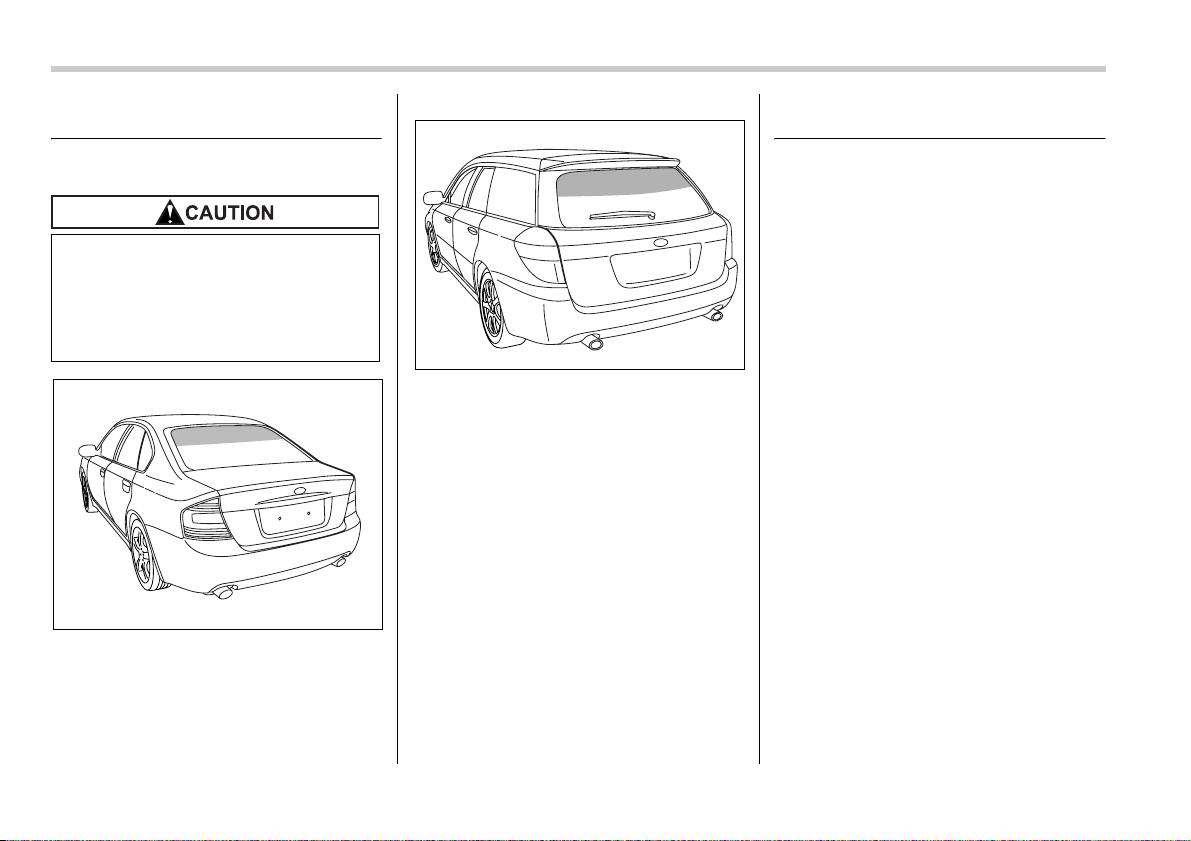
5-2 Audio
Audio
Antenna system
Printed antenna
Sedan
Station wagon
The antenna is printed on the inner sur-
face of the rear window glass.
FM reception
Although FM is normally static free, recep-
tion can be affected by the surrounding ar-
ea, atmospheric conditions, station
strength and transmitter distance. Build-
ings or other obstructions may cause mo-
mentary static, flutter or station interfer-
ence. If reception continues to be unsatis-
factory, switch to a stronger station.
Installation of accessories
Always consult your SUBARU dealer be-
fore installing a citizen band radio or other
transmitting device in your vehicle. Such
devices may cause the electronic control
system to malfunction if they are incorrect-
ly installed or if they are not suited for the
vehicle.
Do not use sharp instruments or
window cleaner containing abra-
sives to clean the inner surface of
the window on which the antenna is
printed. Doing so may damage the
antenna printed on the window.
500035
500223
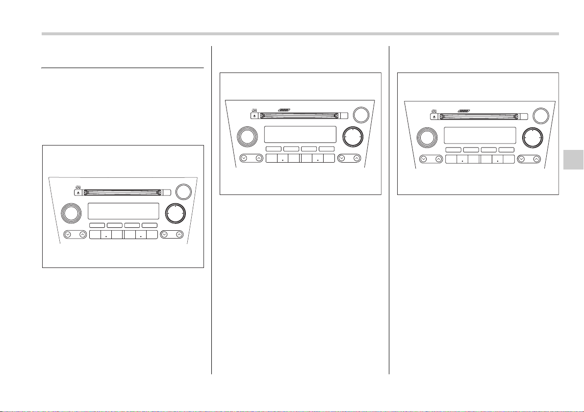
Audio 5-3
Audio set
Your SUBARU may be equipped with one
of the following audio sets. See the pages
indicated in this section for operating de-
tails.
Type A audio set
y Radio operation: refer to page 5-5
y CD (compact disc) player operation: re-
fer to page 5-9
Type B audio set
y Radio operation: refer to page 5-14
y Built-in CD changer operation: refer to
page 5-18
Type C audio set
y Radio operation: refer to page 5-27
y Built-in CD changer operation: refer to
page 5-31
PUSH POWER-VOL
SEEK
SCAN
TUNE
TRACK
AUDIO
P-201UN
BAL RPT RDM
FM AM
CD
123 456
500224
500225
PUSH POWER-VOL
SEEK
SCAN
TUNE
TRACK
AUDIO
6 CD CHANGER P-203UH
BAL RPT RDM
LOAD
FM AM
CD
123 456
500226
PUSH POWER-VOL
SEEK
SCAN
FOLDER
TUNE
TRACK
AUDIO
MP3
6 CD CHANGER P-203UE
BAL RPT
RDM
TEXT
LOAD
FM AM
CD
123 456
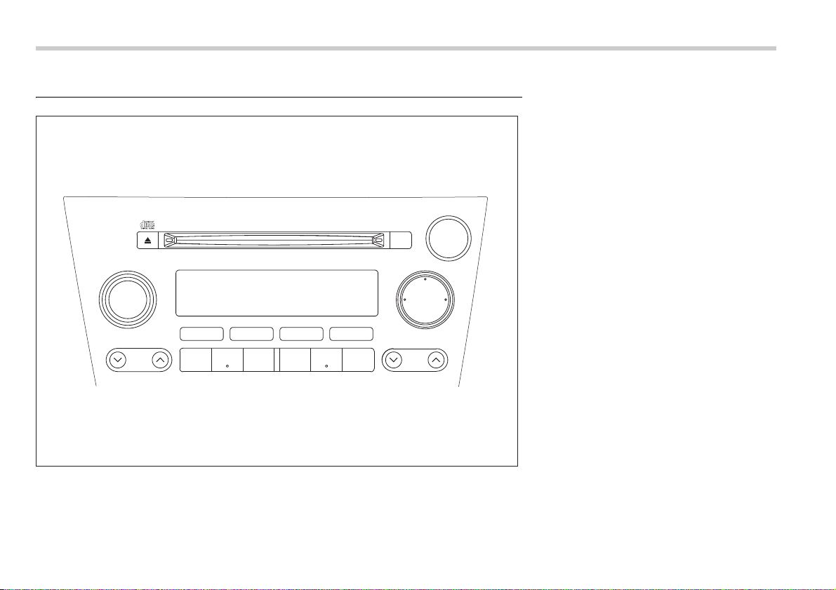
5-4 Audio
Type A audio set (if equipped)
The audio set will operate only when the ignition switch is in the “ACC” or “ON” position.
PUSH POWER-VOL
SEEK
SCAN
TUNE
TRACK
AUDIO
P-201UN
BAL RPT RDM
FM AM
CD
123 456
500227
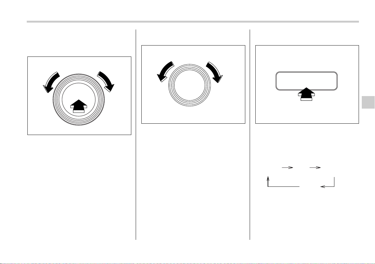
Audio 5-5
– CONTINUED –
Radio operation
T Power switch and volume control
The dial is used for both power (ON/OFF)
and volume control. The radio is turned
ON and OFF by pushing the dial and the
volume is controlled by turning the dial.
The dial can also be used for tone and bal-
ance adjustment.
T Tone and balance control
The volume control dial normally functions
as a volume control. This dial becomes a
control for Bass, Midrange, Treble, Fader
or Balance when you select the appropri-
ate tone and balance control mode.
Choose desired volume level for each
mode by turning the volume control dial.
The control function returns to volume
control mode after approximately 5 sec-
onds.
V To change tone control modes
Each brief press of the “AUDIO” button
changes control modes in the following
sequence starting from volume control
mode. (When the radio is first turned on,
the control mode is in the volume control.)
The “AUDIO” button is used for selecting
the following control modes:
PUSH POWER-VOL
500228
PUSH ON/VOL
500045
AUDIO
500229
Volume
(VOLUME)
Bass
(BASS)
Midrange
(MIDDLE)
Treble
(TREBLE)
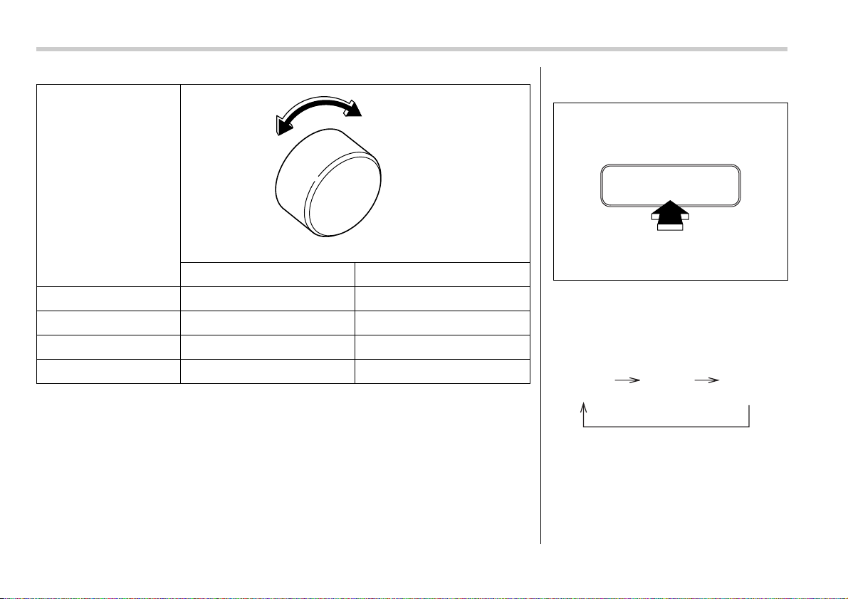
5-6 Audio
Control mode (Range of
levels)
Turn counterclockwise Turn clockwise
Bass control (–6 to +6) For less bass sound For more bass sound
Midrange control (–6 to +6) For less midrange sound For more midrange sound
Treble control (–6 to +6) For less treble sound For more treble sound
Volume control (0 to 40) For less volume For more volume
500009
V To change balance control mode
Each brief press of the “BAL” button
changes control modes in the following
sequence starting from volume control
mode. (When the radio is first turned on,
the control mode is in the volume control.)
The “BAL” button is used for selecting the
following control modes:
BAL
500230
Volume
(VOLUME)
Balance
(BALANCE)
Fader
(FADER)

Audio 5-7
– CONTINUED –
Control mode (Range of
levels)
Turn counterclockwise Turn clockwise
Fader control (R9 to F9) To increase rear speaker volume
and decrease front speaker vol-
ume
To increase front speaker volume
and decrease rear speaker vol-
ume
Balance control (L9 to R9) To increase left speaker volume
and decrease right speaker vol-
ume
To increase right speaker volume
and decrease left speaker vol-
ume
Volume control (0 to 40) For less volume For more volume
500009
T FM/AM selection button
Push the “FM” or “AM” button when the ra-
dio is off to turn on the radio.
Push the “FM” or “AM” button when the ra-
dio is on to select FM1, FM2 or AM recep-
tion.
T Stereo indicator
The stereo indicator “ST” will come on
when an FM stereo broadcast is received.
FM AM
CD
500231

5-8 Audio
T Tuning
V Manual tuning
Press the “ ” side of the TUNE/TRACK
button to increase the tuning frequency
and press the “ ” side of the button to
decrease it.
Each time the button is pressed, the fre-
quency interval can be changed between
10 kHz in the AM mode and 0.2 MHz in the
FM mode.
If you hold down the “ ” side of the but-
ton, the tuning frequency will increase
continuously, and if you hold down the
“ ” side of the button, the tuning fre-
quency will decrease continuously. Re-
lease the button when your desired fre-
quency is reached.
NOTE
While you are holding down either side
of the TUNE/TRACK button, the tuning
frequency will not stop changing even
if the frequency of a receivable station
is reached.
V Seek tuning
If you press the “ ” or “ ” side of the
SEEK/SCAN button and release it within
1.5 second, the radio will automatically
search for a receivable station and stop at
the first one it finds. This function may not
be available, however, when radio signals
are weak. In such a situation, perform
manual tuning to select the desired sta-
tion.
V Automatic tuning (SCAN)
If you press the “ ” or “ ” side of the
SEEK/SCAN button for 1.5 second or
longer, the radio will switch to scan mode.
In this mode, the radio scans through the
radio band until a station is found. The ra-
dio will stop at the station for five seconds
while displaying the frequency, after which
scanning will continue until the entire band
has been scanned.
Press the “ ” or “ ” side of the button
again to cancel the scan mode and to stop
on any displayed frequency.
If you hold down the “ ” side of the but-
ton, the radio will scan up the frequency
band (from low frequencies to high fre-
quencies). If you hold down the “ ” side
of the button, the radio will scan down the
frequency band (from high frequencies to
TUNE
TRACK
500049
SEEK
SCAN
500232
SEEK
SCAN
500232
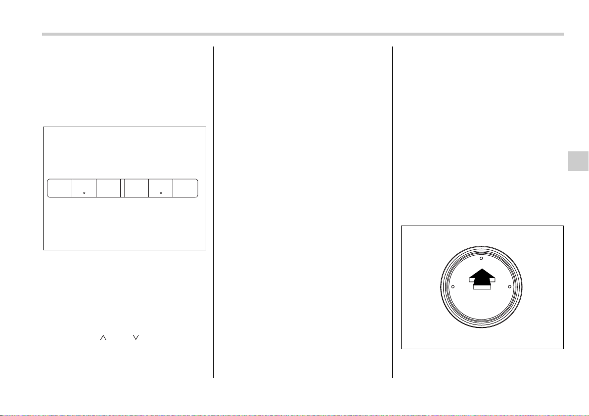
Audio 5-9
– CONTINUED –
low frequencies).
Automatic tuning may not function proper-
ly if the station reception is weakened by
distance from the station or proximity to
tall buildings and hills.
T Selecting preset stations
Presetting a station with a “preset button”
allows you to select that station in a single
operation. Up to six, AM, FM1 and FM2
stations each may be preset.
T How to preset stations
1. Press the “FM” or “AM” button to select
FM1, FM2, or AM reception.
2. Press the “ ” or “ ” side of the but-
ton or tune the radio manually until the de-
sired station frequency is displayed.
3. Press one of the preset buttons for
more than 1.5 seconds to store the fre-
quency. If the button is pressed for less
than 1.5 seconds, the preceding selection
will remain in memory.
NOTE
y If the connection between the radio
and battery is broken for any reason
such as vehicle maintenance or radio
removal, all stations stored in the pre-
set buttons are cleared. If this occurs,
it is necessary to reset the preset but-
tons.
y If a cell phone is placed near the ra-
dio, it may cause the radio to emit
noise when it receives calls. This noise
does not indicate a radio fault.
Compact disc player opera-
tion
T To playback a compact disc
V When CD is not in the player
Hold a disc with a finger in the center hole
while gripping the edge of the disc, then
insert it in to the slot (with the label side
up) and the player will automatically pull
the disc into position.
NOTE
y DO NOT INSERT TWO DISCS INTO
THE DISC INSERTION SLOT AT A
TIME.
y Be sure to always insert a disc with
the label side up. If a disc is inserted
with the label side down, it might be
ejected or the player might shut off.
y After the last song finishes, the play-
er will automatically return to track 1
(the first song on the disc).
y If you insert a disc that the player
cannot read, the player will eject the
disc and revert to its previous mode.
y The player is designed to be able to
play music CD-Rs and music CD-RWs,
but it may not be able to play certain
ones.
V When CD is in the player
When the “CD” button is pressed, the
player will start playback.
123 456
500233
FM AM
CD
500234
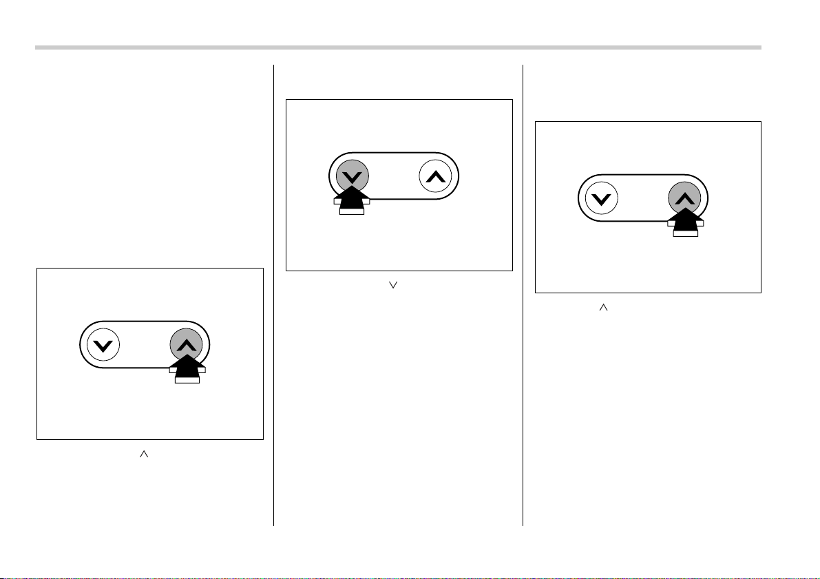
5-10 Audio
NOTE
After the last song finishes, the player
will automatically return to track 1 (the
first song on the disc).
T To stop playback of a CD
When the “POWER-VOL” button is
pressed during playback of a CD, the CD
stops playing temporarily. To let the CD
resume playing, press the button again.
T To select a song from its beginning
V Forward direction
Briefly press the “ ” side of the TUNE/
TRACK button to skip to the beginning of
the next track. Each time this side of the
button is pressed, the indicated track
number will increase.
V Backward direction
Briefly press the “ ” side of the TUNE/
TRACK button to skip to the beginning of
the current track. Each time this side of the
button is pressed, the indicated track
number will decrease.
T Fast-forwarding and fast-reversing
V Fast-forwarding
Press the “ ” side of the TUNE/TRACK
button continuously to fast-forward the
disc.
Release the button to stop fast-forward-
ing.
NOTE
If you fast-forward past the last track
on the disc, the player will select the
first track on the disc and start playing
it.
TUNE
TRACK
500056
TUNE
TRACK
500057
TUNE
TRACK
500056
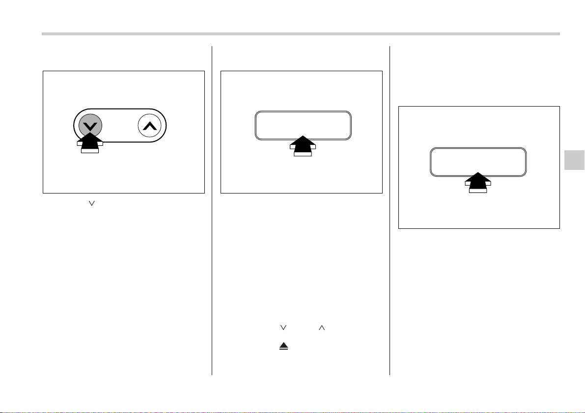
Audio 5-11
– CONTINUED –
V Fast-reversing
Press the “ ” side of the TUNE/TRACK
button continuously to fast-reverse the
disc.
Release the button to stop fast-reversing.
NOTE
If you fast-reverse to the beginning of
the first track on the disc, the fast-re-
versing will stop and the player will
start playing the first track on the disc.
T Repeat playback
Use this to play a certain track repeatedly.
During playback, press the “RPT” button.
The “RPT” indicator will come on and the
track will be played continuously. To can-
cel the repeat mode, press the button
again. Then the “RPT” indicator goes out,
and normal playback mode is restored.
NOTE
The repeat-playback mode will be can-
celled if you perform any of the follow-
ing operations:
y Press the “RDM” button
y Press the “ ” or “ ” side of the
SEEK/SCAN button
y Press the “ ” button
y Select the radio mode
y Turn off the power of the audio
equipment.
y Turn the ignition switch to the “OFF”
position.
T Random playback
Use this to play the tracks on the disc in
random order. During playback, press the
“RDM” button. The “RDM” indicator will
come on and all songs on the disc will be
played in a random order.
To cancel the random mode, press the
button again. Then the “RDM” indicator
goes out, and normal playback mode is
restored.
NOTE
The random-playback mode will be
cancelled if you perform any of the fol-
lowing operations:
TUNE
TRACK
500057
RPT
500235
RDM
500236
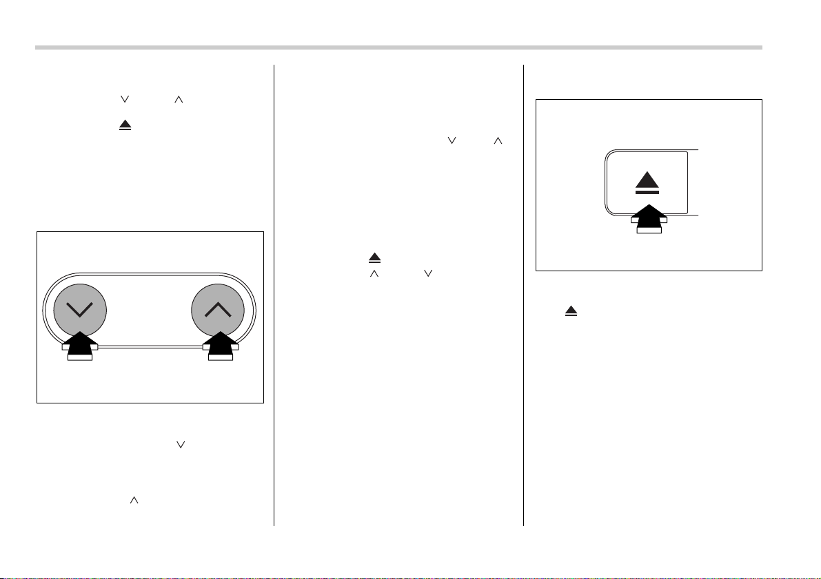
5-12 Audio
y Press the “RPT” button
y Press the “ ” or “ ” side of the
SEEK/SCAN button
y Press the “ ” button
y Select the radio mode
y Turn off the power of the audio
equipment.
y Turn the ignition switch to the “OFF”
position.
T Scan
The scan mode lets you listen to the first
10 seconds of each track on the disc in
succession. Press the “ ” side of the
SEEK/SCAN button to start scanning
through all tracks upward beginning with
the track following the currently selected
one. Press the “ ” side of the button to
start scanning through all tracks down-
ward beginning with the track preceding
the currently selected one. After all tracks
on the disc has been scanned, normal
playback mode is restored.
To cancel a scan, press the “ ” or “ ”
side of the button again.
NOTE
The scan mode will be cancelled if you
perform any of the following opera-
tions:
y Press the “RPT” button
y Press the “RDM” button
y Press the “ ” button
y Press the “ ” or “ ” side of the
TUNE/TRACK button
y Select the radio mode
y Turn off the power of the audio
equipment.
y Turn the ignition switch to the “OFF”
position.
T To eject a disc from the player
When a disc is being played back or when
a disc is in the player, press the eject but-
ton “ ”. The disc will be ejected.
NOTE
y Avoid driving the vehicle with a CD
sticking out, because vibration might
make it fall out.
y If the disc is left ejected for more
than approximately 15 seconds after
the ignition switch is turned to the
“OFF” position, a disc protection func-
tion will operate, automatically reload-
ing the disc. In this case, the disc is not
played.
SEEK
SCAN
500232
500237
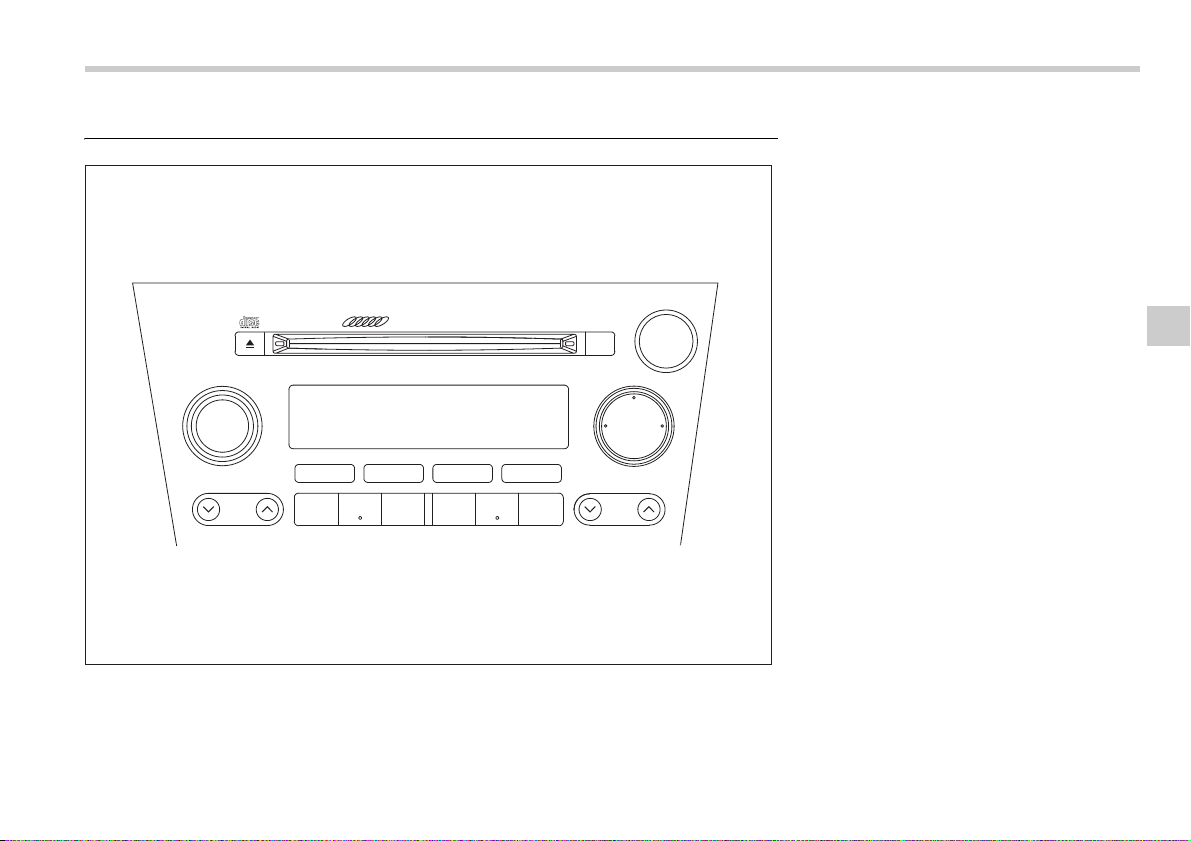
Audio 5-13
– CONTINUED –
Type B audio set (if equipped)
The radio will operate only when the ignition switch is in the “ACC” or “ON” position.
500238
PUSH POWER-VOL
SEEK
SCAN
TUNE
TRACK
AUDIO
6 CD CHANGER P-203UH
BAL RPT RDM
LOAD
FM AM
CD
123 456
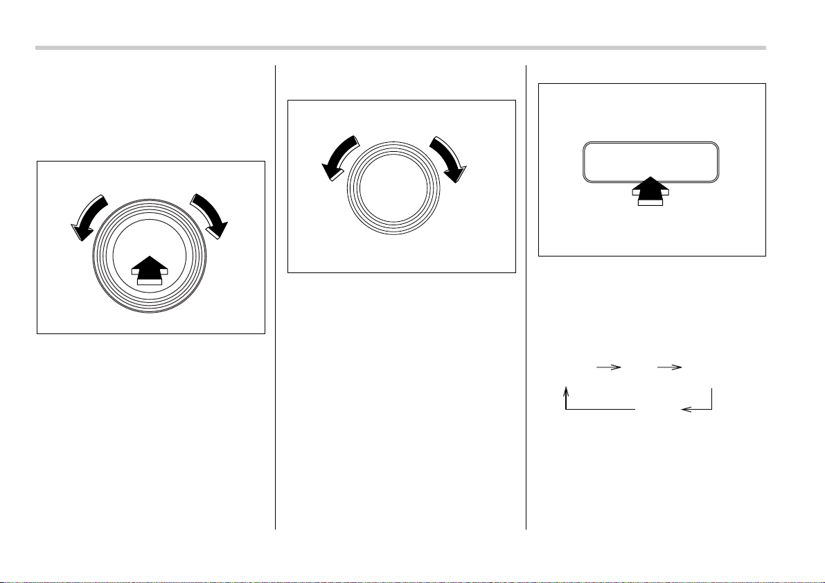
5-14 Audio
Radio operation
T Power switch and volume/bass/tre-
ble/fader/balance control
V Power switch and volume control
The dial is used for both power (ON/OFF)
and volume control. The radio is turned
ON and OFF by pushing the dial and the
volume is controlled by turning the dial.
V Tone and balance control
The volume control dial normally functions
as a volume control. This dial becomes a
control for Bass, Midrange, Treble, Fader
or Balance when you select the appropri-
ate tone and balance control mode.
Choose desired volume level for each
mode by turning the volume control dial.
The control function returns to volume
control mode after approximately 5 sec-
onds.
To change tone control modes: Each
brief press of the “AUDIO” button changes
control modes in the following sequence
starting from volume control mode. (When
the radio is first turned on, the control
mode is in the volume control.)
The “AUDIO” button is used for selecting
the following control modes:
PUSH POWER-VOL
500228
PUSH ON/VOL
500045
AUDIO
500229
Volume
(VOLUME)
Bass
(BASS)
Midrange
(MIDDLE)
Treble
(TREBLE)
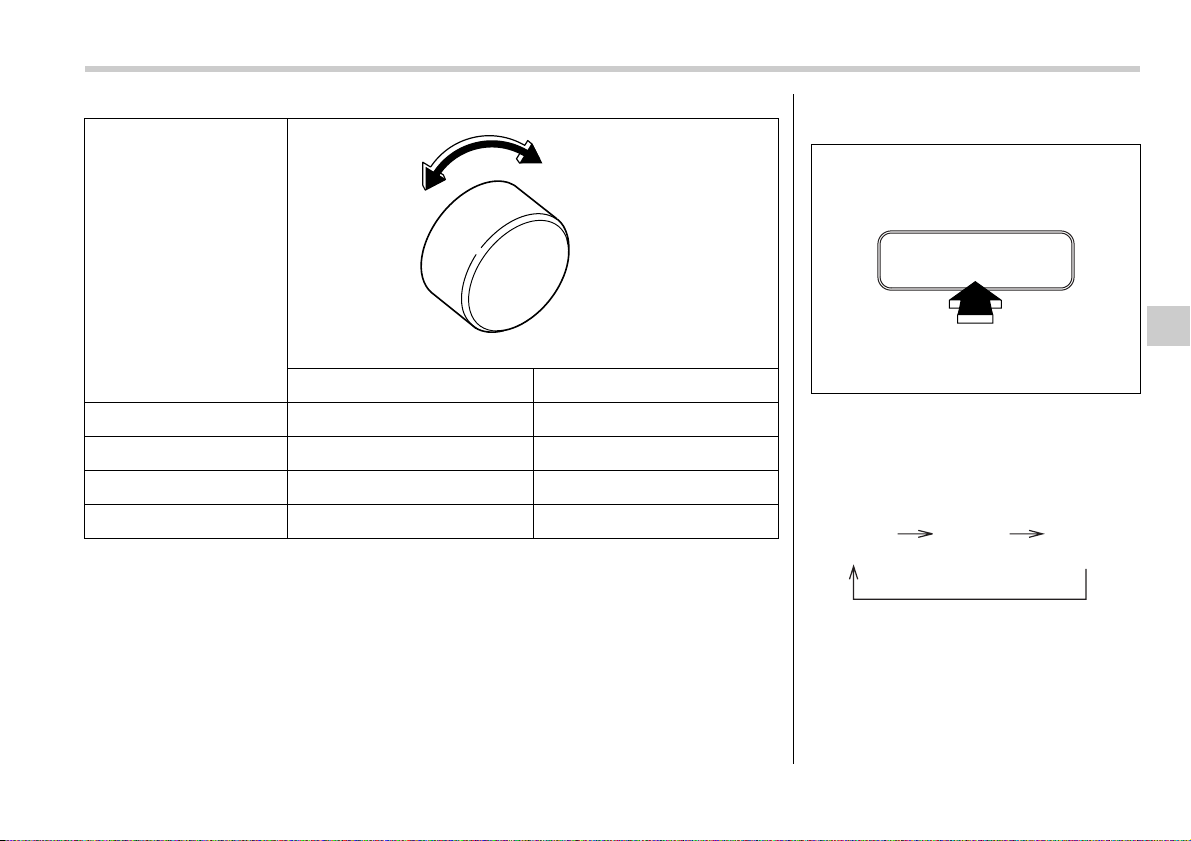
Audio 5-15
– CONTINUED –
Control mode (Range of
levels)
Turn counterclockwise Turn clockwise
Bass control (–6 to +6) For less bass sound For more bass sound
Midrange control (–6 to +6) For less midrange sound For more midrange sound
Treble control (–6 to +6) For less treble sound For more treble sound
Volume control (0 to 40) For less volume For more volume
500009
V To change balance control modes
Each brief press of the “BAL” button
changes control modes in the following
sequence starting from volume control
mode. (When the radio is turned on, the
control mode is in the volume control.)
The “BAL” button is used for selecting the
following control modes:
BAL
500230
Volume
(VOLUME)
Balance
(BALANCE)
Fader
(FADER)
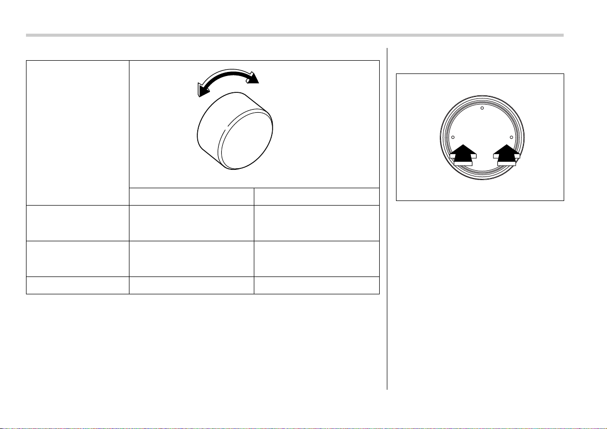
5-16 Audio
Control mode (Range of
levels)
Turn counterclockwise Turn clockwise
Fader control (R9 to F9) To increase rear speaker volume
and decrease front speaker vol-
ume
To increase front speaker volume
and decrease rear speaker vol-
ume
Balance control (L9 to R9) To increase left speaker volume
and decrease right speaker vol-
ume
To increase right speaker volume
and decrease left speaker vol-
ume
Volume control (0 to 40) For less volume For more volume
500009
T FM/AM selection button (FM/AM)
Push the “FM” or “AM” button when the ra-
dio is off to turn on the radio.
Push the “FM” or “AM” button when the ra-
dio is on to select FM1, FM2 or AM recep-
tion.
T Stereo indicator
The stereo indicator “ST” will come on
when an FM stereo broadcast is received.
FM AM
CD
500231
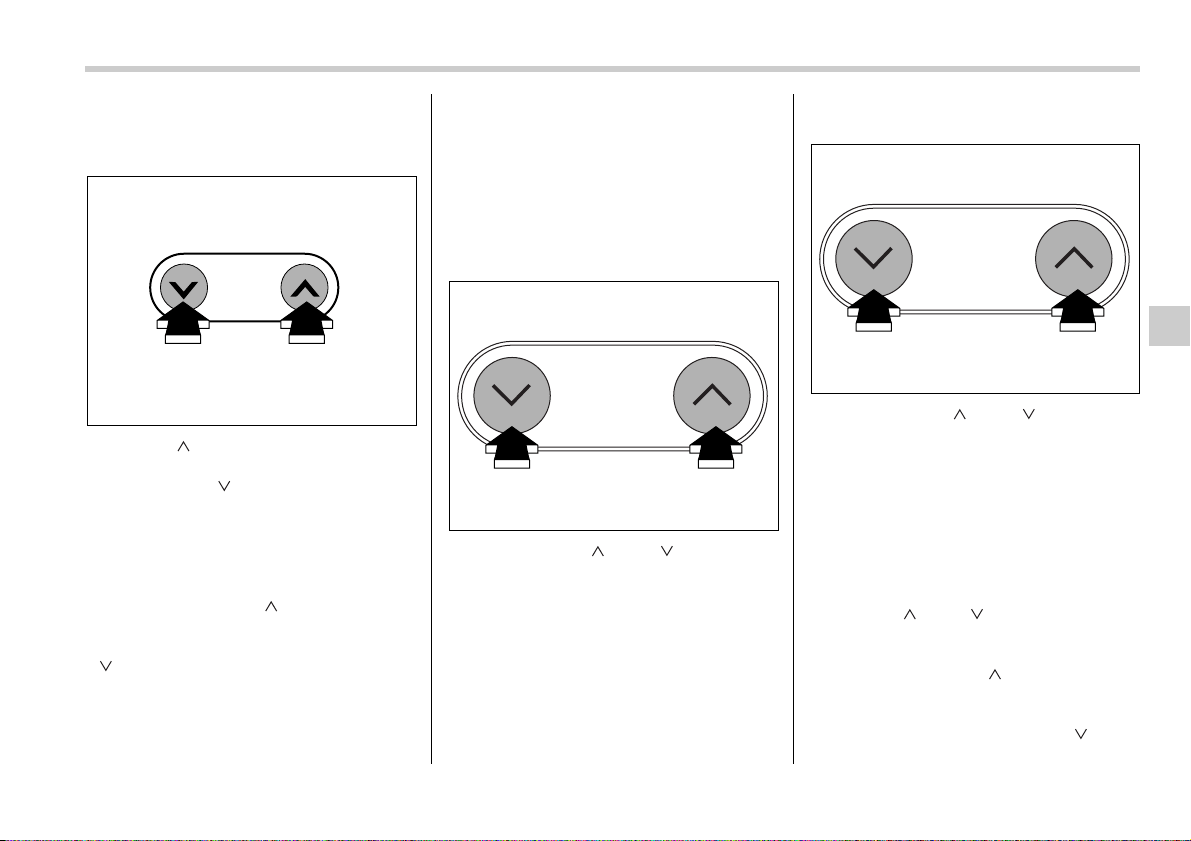
Audio 5-17
– CONTINUED –
T Tuning
V Manual tuning
Push the “ ” side of the TUNE/TRACK
button to increase the tuning frequency
and press the “ ” side of the button to
decrease it.
Each time the button is pressed, the fre-
quency interval can be changed between
10 KHz in the AM mode and 0.2 MHz in
the FM mode.
If you hold down the “ ” side of the but-
ton, the tuning frequency will increase
continuously, and if you hold down the
“ ” side of the button, the tuning fre-
quency will decrease continuously. Re-
lease the button when your desired fre-
quency is reached.
NOTE
While you are holding down either side
of the TUNE/TRACK button, the tuning
frequency will not stop changing even
if the frequency of a receivable station
is reached.
V Seek tuning
If you press the “ ” or “ ” side of the
SEEK/SCAN button and release it within
1.5 second, the radio will automatically
search for a receivable station and stop at
the first one it finds. This function may not
be available, however, when radio signals
are weak. In such a situation, perform
manual tuning to select the desired sta-
tion.
V Automatic tuning (SCAN)
If you press the “ ” or “ ” side of the
SEEK/SCAN button for 1.5 second or
longer, the radio will switch to scan mode.
In this mode, the radio scans through the
radio band until a station is found. The ra-
dio will stop at the station for five seconds
while displaying the frequency, after which
scanning will continue until the entire band
has been scanned from the low end to the
high end.
Press the “ ” or “ ” side of the button
again to cancel the scan mode and to stop
on any displayed frequency.
If you hold down the “ ” side of the but-
ton, the radio will scan up the frequency
band (from low frequencies to high fre-
quencies). If you hold down the “ ” side
of the button, the radio will scan down the
TUNE
TRACK
500049
SEEK
SCAN
500232
SEEK
SCAN
500232
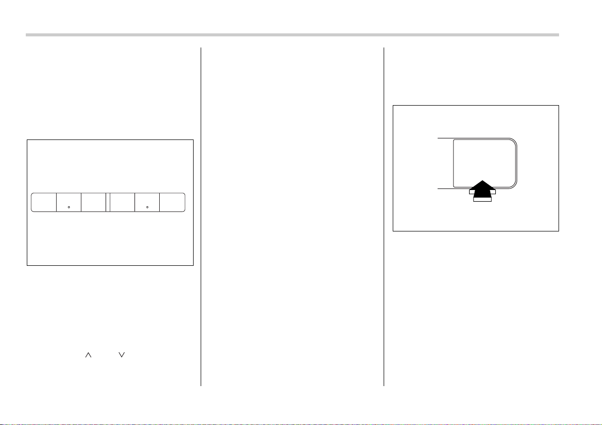
5-18 Audio
frequency band (from high frequencies to
low frequencies).
Automatic tuning may not function proper-
ly if the station reception is weakened by
distance from the station or proximity to
tall buildings and hills.
T Selecting preset stations
Presetting a station with a preset button
allows you to select that station in a single
operation. Up to six AM, FM1 and FM2
stations each may be preset.
T How to preset stations
1. Press the “FM” or “AM” selection but-
ton to select AM, FM1 or FM2 reception.
2. Press the “ ” or “ ” side of the but-
ton or tune the radio manually until the de-
sired station frequency is displayed.
3. Press one of the preset buttons for at
least 1.5 seconds to store the frequency.
The frequency of the station will flash
once on the display at this time. If the but-
ton is pressed for less than 1.5 seconds,
the preceding selection will remain in
memory.
NOTE
y If the connection between the radio
and battery is broken for any reason
such as vehicle maintenance or radio
removal, all stations stored in the pre-
set buttons are cleared. If this occurs,
it is necessary to reset the preset but-
tons.
y If a cell phone is placed near the ra-
dio, it may cause the radio to emit
noise when it receives calls. This noise
does not indicate a radio fault.
Built-in CD changer opera-
tion
NOTE
y Make sure to always insert a disc
with the label side up. If a disc is insert-
ed with the label side down, it might be
ejected or the player might shut off.
y The player is designed to be able to
play music CD-Rs and music CD-RWs,
but it may not be able to play certain
ones.
T How to insert a CD(s)
V Inserting a CD
0
1. Briefly press the “LOAD” button. If the
magazine in the player has an idle posi-
tion where you can insert a disc, the disc
number indicator associated with the idle
position will blink.
If no indicator blinks, it means that there is
no idle position in the magazine.
2. When the “LOAD” indicator flashes, in-
sert the disc. Once you have inserted the
disc, the “LOAD” indicator will go off. The
disc will then be automatically drawn in,
and the player will begin to play the first
track on the disc.
y To insert more discs in succession, re-
123 456
500233
LOAD
500239
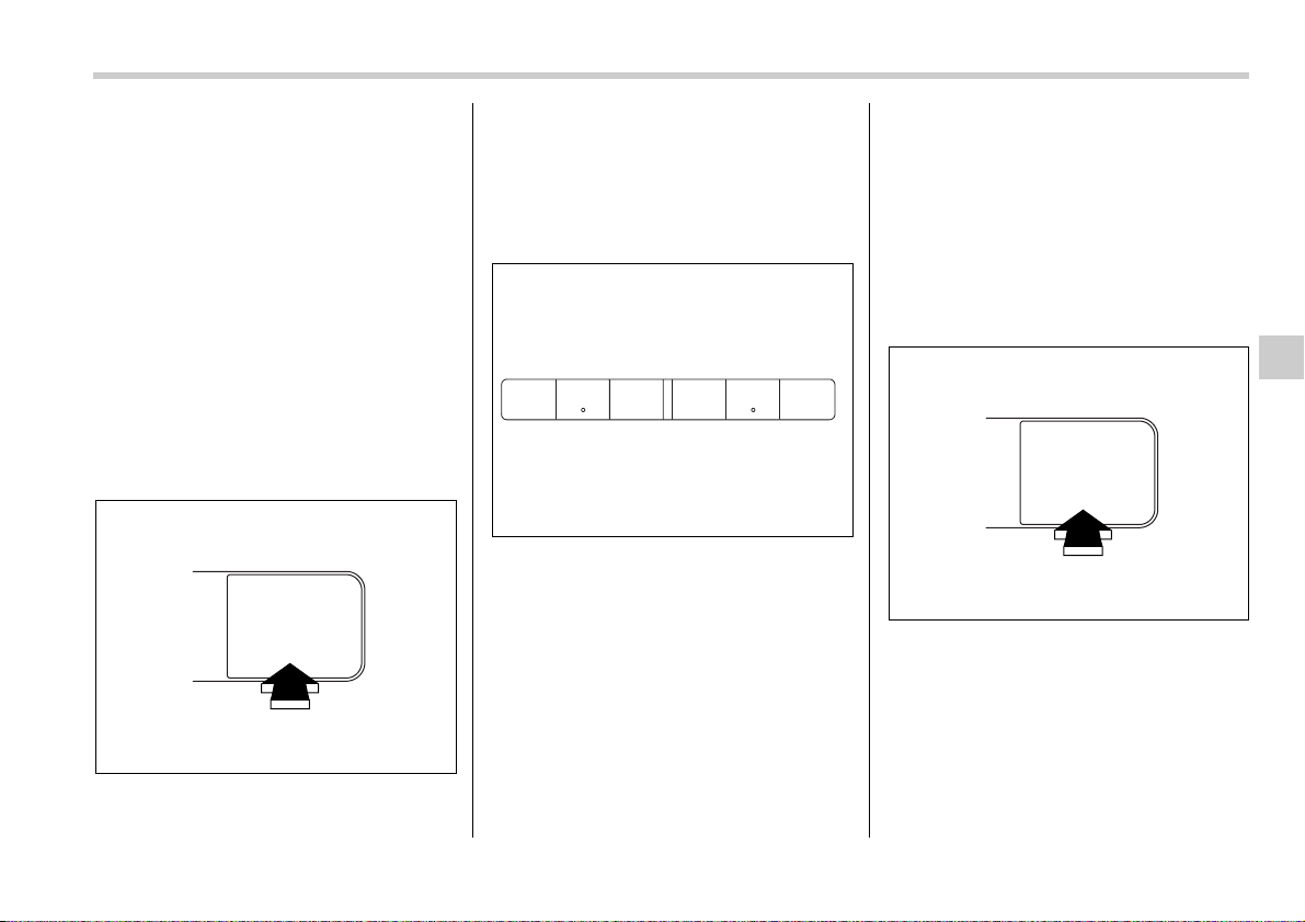
Audio 5-19
– CONTINUED –
peat Steps 1 and 2. The magazine will be
loaded with discs in the ascending order
of position number.
If you do not insert any disc in 15 seconds
after you have pressed the “LOAD” but-
ton, the player will begin to play back the
first track of the last disc you have insert-
ed.
y The disc indicator steadily lights up if a
disc is already inserted in the correspond-
ing position of the magazine.
y While the player is in the loading mode,
if you press the “FM” or “AM” button, the
player will enter the standby mode. Press
the “CD” button to start playback.
V Inserting a disc in a desired position
1. Briefly press the “LOAD” button. If the
magazine in the player has an idle posi-
tion where you can insert a disc, the disc
number indicator associated with the idle
position will blink.
The positions in the magazine the indica-
tor of which steadily lights up are already
loaded with discs.
2. Press the “Disc select” button at the
position where you want to insert a disc.
3. When the “LOAD” indicator flashes, in-
sert the disc. Once you have inserted the
disc, the “LOAD” indicator will go off. The
disc will then be automatically drawn in,
and the player will begin to play the first
track on the disc.
y If you wish to insert another disc, repeat
the procedure beginning with step 1.
If you do not insert any disc in 15 seconds
after you have pressed the “LOAD” but-
ton, the player will begin to play back the
first track of the last disc you have insert-
ed.
y While the player is in the loading mode,
if you press the “FM” or “AM” button, the
player will enter standby mode. Press the
“CD” button to start playback.
V Loading all the magazine (Full disc
loading mode)
0
1. If you continue to press the “LOAD”
button for more than 1.5 seconds, the
player will produce beep sound and will
enter the full disc loading mode.
2. When the disc number indicator and
“ALL LOAD” indicator start flashing, insert
a disc within 15 seconds. If a disc is suc-
cessfully loaded during this period, the
disc number indicator will stop blinking
LOAD
500239
123 456
500233
LOAD
500239
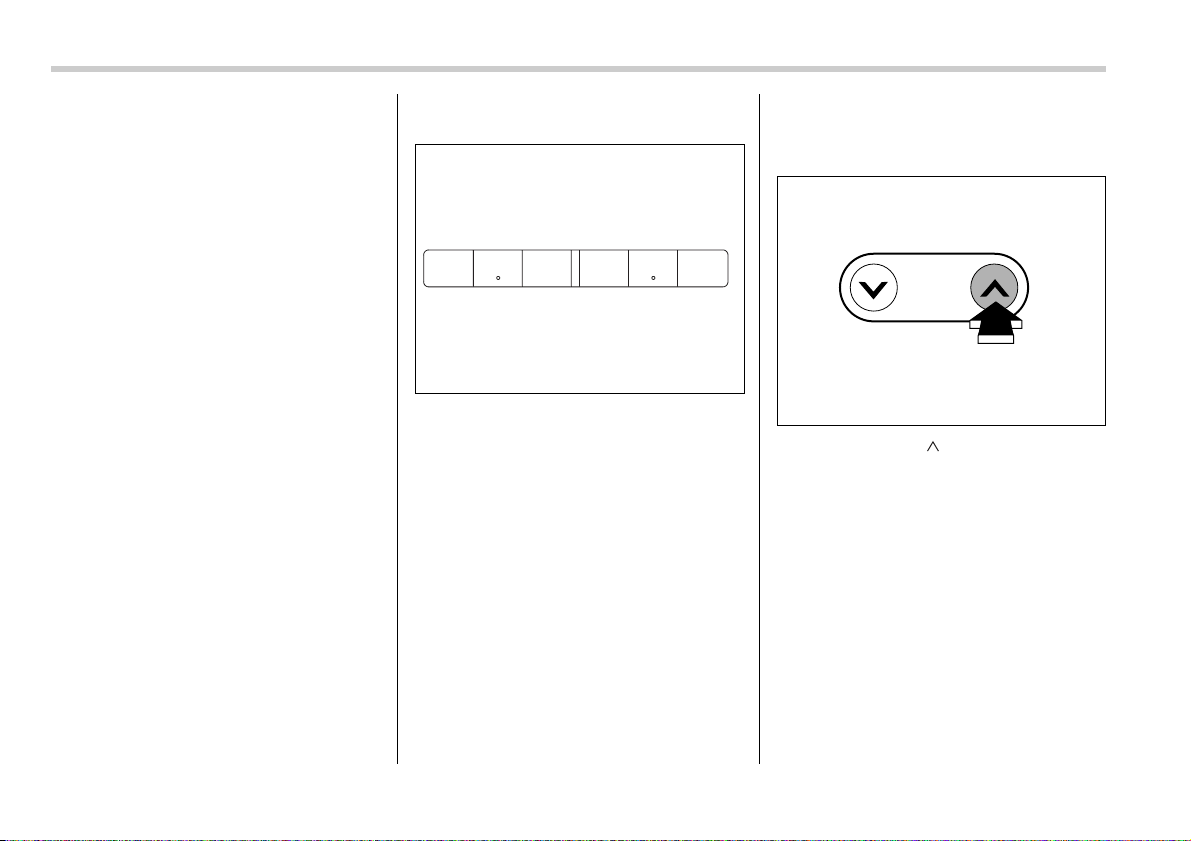
5-20 Audio
and will steadily light.
3. When the loading of a disc is complete,
the next disc number indicator will blink.
Then repeat Step 2.
4. When the magazine is filled with discs
by repeating Steps 2 and 3, the player will
start playback of the discs, beginning with
the one inserted first.
If you fail to insert any disc during each 15-
second interval, the full disc loading mode
will be canceled, and the player will start
playback of the disc inserted first.
T How to play back a CD or make a
pause
V When there is no CD inserted:
Insert a CD by referring to “How to insert a
CD(s)”.
When a CD is loaded, the player will start
playback of the CD, beginning with the
first track.
V When there are CDs loaded:
Press a desired one of the “Disc select”
buttons the disc number indicator of which
steadily lights up. The player will then start
playback of the selected CD, beginning
with the first track.
If you have inserted a disc that the player
cannot read, the player will show the
elapsed time but will not produce any
sound.
T To select a song from its beginning
V Forward direction
Briefly press the “ ” side of the TUNE/
TRACK button to skip to the beginning of
the next track. Each time this side of the
button is pressed, the indicated track
number will increase.
123 456
500233
TUNE
TRACK
500056
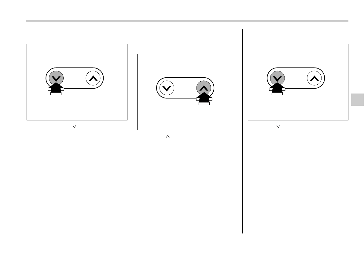
Audio 5-21
– CONTINUED –
V Backward direction
Briefly press the “ ” side of the TUNE/
TRACK button to skip to the beginning of
the current track. Each time the button is
pressed, the indicated track number will
decrease.
T Fast-forwarding and fast-reversing
V Fast-forwarding
Press the “ ” side of the TUNE/TRACK
button continuously to fast-forward the
disc.
Release the button to stop fast-forward-
ing.
NOTE
If you fast-forward past the last track
on the disc, the player will select the
first track on the disc and start playing
it.
V Fast-reversing
Press the “ ” side of the TUNE/TRACK
button continuously to fast-reverse the
disc.
Release the button to stop fast-reversing.
NOTE
If you fast-reverse to the beginning of
the first track on the disc, the fast-re-
versing will stop and the player will
start playing the first track on the disc.
TUNE
TRACK
500057
TUNE
TRACK
500056
TUNE
TRACK
500057
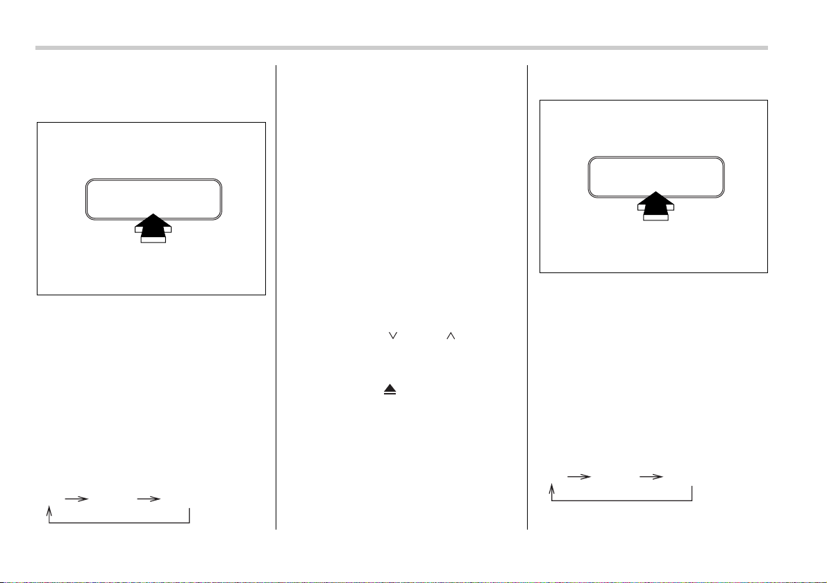
5-22 Audio
T Repeat playback
V To repeat the currently playing track
To repeat a track, press the “RPT” button
while the track is playing. The display will
show “RPT”, and the track will be repeat-
ed.
To cancel the track-repeat-play mode,
press the “RPT” button twice. The “RPT”
indication will go off, and the normal play-
back mode will be resumed.
NOTE
y Each time you press the button, the
mode will change to the next one in the
following sequence.
If you accidentally press the button
and cancel the track-repeat-play mode,
press it again to reselect the repeat
play mode.
y If you perform a fast-forward or fast-
reverse operation while the player is in
repeat-play mode, the repeat-play
mode will remain active even after you
skip tracks.
y If you perform a forward-direction or
backward-direction skip operation
while the player is in repeat-play mode,
the player will jump to the following/
previous track but the repeat-play
mode will remain active.
y The repeat-play mode will be can-
celled if you perform any of the follow-
ing steps:
y Press the “ ” or “ ” side of
the SEEK/SCAN button
y Press the “RPT” button.
y Press the “RDM” button
y Press the “ ” button
y Press the disc select button
y Select the radio mode
y Turn off the power of the audio
equipment.
y Turn the ignition switch to the
“OFF” position.
V To repeat the currently playing disc
To repeat the currently playing CD, press
the “RPT” button twice while a track is
playing. The display will show “D-RPT”,
and the CD will be played repeatedly.
To cancel the disc repeat-play mode,
press the “RPT” button once more. The
“D-RPT” indication will go off, and the nor-
mal playback mode will be resumed.
NOTE
y Each time you briefly press the but-
ton, the mode will change to the next
one in the following sequence.
If you accidentally press the button
RPT
500235
RPT D-RPT CANCEL
RPT
500235
RPT D-RPT CANCEL
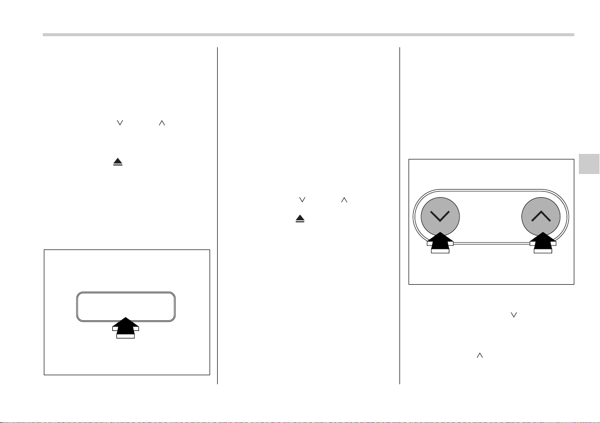
Audio 5-23
– CONTINUED –
and cancel the disc-repeat-play mode,
press it again to reselect the disc-re-
peat-play mode.
y The disc-repeat-play mode will be
cancelled if you perform any of the fol-
lowing steps:
y Press the “ ” or “ ” side of
the SEEK/SCAN button
y Press the “RPT” button.
y Press the “RDM” button
y Press the “ ” button
y Press the disc select button
y Select the radio mode
y Turn off the power of the audio
equipment.
y Turn the ignition switch to the
“OFF” position.
T Random playback
Press the “RDM” button while a disc is be-
ing played back to play all of the tracks on
the disc in a random order. The “RDM” in-
dicator will come on and all songs on the
disc will be played in a random order.
To cancel the random mode, press the
button again. Then the “RDM” indicator
goes out, and normal playback mode is
restored.
NOTE
y Random playback will be cancelled if
you perform any of the following steps:
y Press the “RPT” button
y Press the “ ” or “ ” side of
the SEEK/SCAN button
y Press the “ ” button
y Press the disc select button
y Select the radio mode
y Turn off the power of the audio
equipment.
y Turn the ignition switch to the
“OFF” position.
y If you fast-forward the disc during
random playback, the player will can-
cel the fast-forwarding when the end of
the last track on the disc is reached
and will then return to the random play-
back mode. If you fast-reverse the disc
during random playback, the fast-re-
versing will be canceled as soon as the
beginning of the track being played is
reached. The player will then return to
the random playback mode.
y If you perform a forward direction
skip while a track is being played in the
random playback mode, the player will
random select another track and play
it. If you perform a backward direction
skip, the disc will return to the begin-
ning of the currently playing track.
T Scan
The scan mode lets you listen to the first
10 seconds of each track on the disc in
succession. Press the “ ” side of the
SEEK/SCAN button to start scanning
through all tracks upward beginning with
the track following the currently selected
one. Press the “ ” side of the button to
start scanning through all tracks down-
ward beginning with the track preceding
RDM
500236
SEEK
SCAN
500232
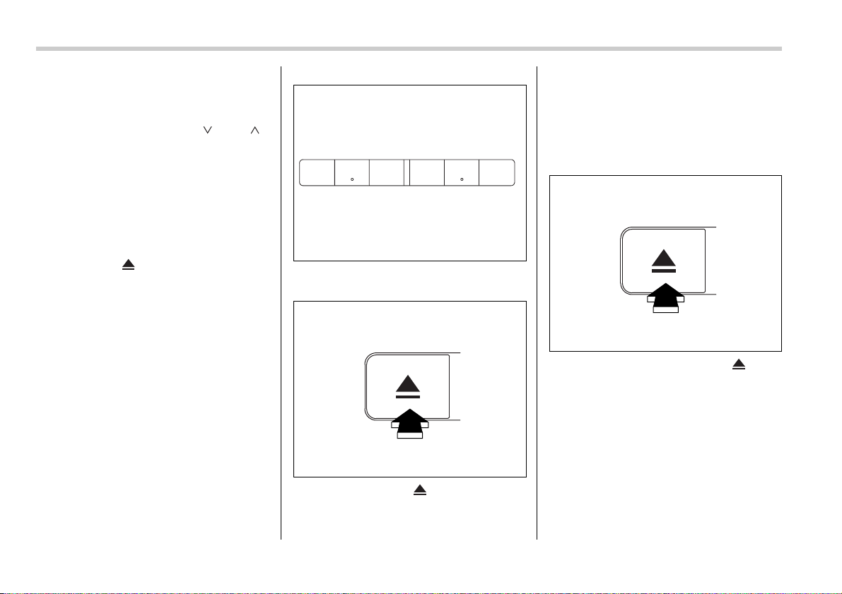
5-24 Audio
the currently selected one. After all tracks
on the disc have been scanned, normal
playback mode is restored.
To cancel a scan, press the “ ” or “ ”
side of the button again.
NOTE
The scan mode will be cancelled if you
perform any of the following steps:
y Press the “RPT” button
y Press the “RDM” button
y Select the radio mode
y Press the disc select button
y Press the “ ” button
y Turn off the power of the audio
equipment.
y Turn the ignition switch to the “OFF”
position.
T How to unload CDs from the player
V Ejecting a CD from the player
Of the discs loaded, you can select and re-
move only one disc.
0
1. Use the disc select button to select the
disc to be ejected.
2. Briefly press the “ ” button. The se-
lected disc will be ejected. The disc num-
ber indicator will flash at this time. When
you remove the ejected disc, the disc
number indicator will go off.
To remove more discs in succession, re-
peat Steps 1 and 2.
V Ejecting all discs from the player
(All disc ejection mode)
0
1. If you continue to press the “ ” but-
ton, the player will produce beep sound
and will enter the all disc ejection mode. At
this time, the disc number indicator and
“ALL EJECT” indicator will flash.
2. Remove the disc that has been eject-
ed. The other discs loaded will then be
ejected one after another. If you do not re-
move the disc that has been ejected, the
“All disc ejection mode” will be canceled.
NOTE
y Avoid driving the vehicle with a CD
123 456
500233
500237
500237

Audio 5-25
sticking out, because vibration might
make it fall out.
y If you press the “ ” button while
the player is in all disc ejection mode,
the mode will be cancelled following
ejection of the disc that is currently be-
ing ejected.
y If you press the “CD” button while
the player is in all disc ejection mode,
the player will draw in the discs that
have been ejected and play them.
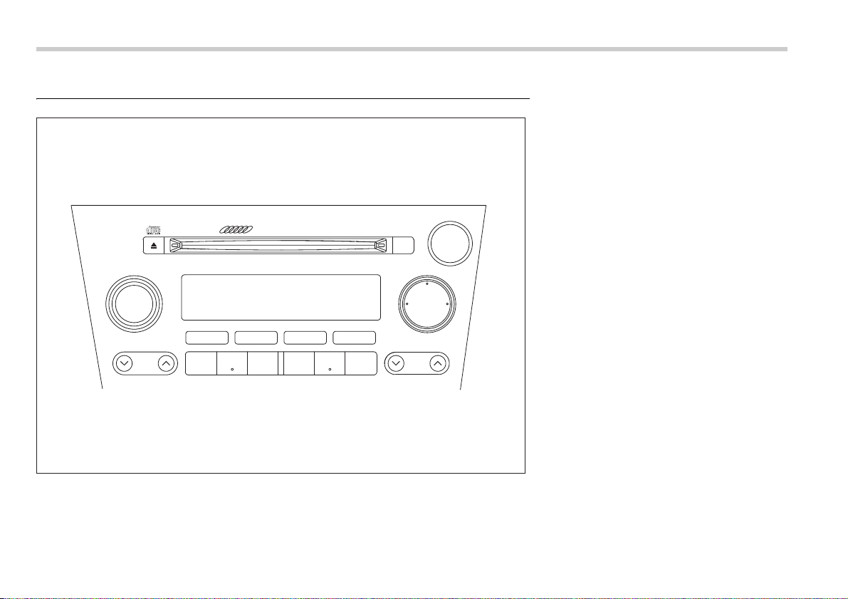
5-26 Audio
Type C audio set (if equipped)
The audio set will operate only when the ignition switch is in the “ACC” or “ON” positions.
500240
PUSH POWER-VOL
SEEK
SCAN
FOLDER
TUNE
TRACK
AUDIO
MP3
6 CD CHANGER P-203UE
BAL RPT
RDM
TEXT
LOAD
FM AM
CD
123 456

Audio 5-27
– CONTINUED –
Radio operation
T Power switch and volume control
The dial is used for both power (ON/OFF)
and volume control. The radio is turned
ON and OFF by pushing the dial and the
volume is controlled by turning the dial.
The dial can also be used for tone and bal-
ance adjustment.
T Tone and balance control
The volume control dial normally functions
as a volume control. This dial becomes a
control for Bass, Midrange, Treble, Fader
or Balance when you select the appropri-
ate tone and balance control mode.
Choose desired volume level for each
mode by turning the volume control dial.
The control function returns to volume
control mode after approximately 5 sec-
onds.
V To change tone control modes
Each brief press of the “AUDIO” button
changes control modes in the following
sequence starting from volume control
mode. (When the radio is first turned on,
the control mode is in the volume control.)
The “AUDIO” button is used for selecting
the following control modes:
PUSH POWER-VOL
500228
PUSH ON/VOL
500045
AUDIO
500229
Volume
(VOLUME)
Bass
(BASS)
Midrange
(MIDDLE)
Treble
(TREBLE)

5-28 Audio
Control mode (Range of
levels)
Turn counterclockwise Turn clockwise
Bass control (–6 to +6) For less bass sound For more bass sound
Midrange control (–6 to +6) For less midrange sound For more midrange sound
Treble control (–6 to +6) For less treble sound For more treble sound
Volume control (0 to 40) For less volume For more volume
500009
V To change balance control modes
Each brief press of the “BAL” button
changes control modes in the following
sequence starting from volume control
mode. (When the radio is first turned on,
the control mode is in the volume control.)
The “BAL” button is used for selecting the
following control modes:
BAL
500230
Volume
(VOLUME)
Balance
(BALANCE)
Fader
(FADER)
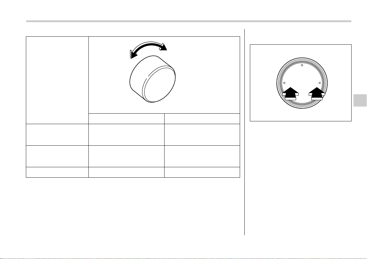
Audio 5-29
– CONTINUED –
Control mode (Range of
levels)
Turn counterclockwise Turn clockwise
Fader control (R9 to F9) To increase rear speaker volume
and decrease front speaker vol-
ume
To increase front speaker volume
and decrease rear speaker vol-
ume
Balance control (L9 to R9) To increase left speaker volume
and decrease right speaker vol-
ume
To increase right speaker volume
and decrease left speaker vol-
ume
Volume control (0 to 40) For less volume For more volume
500009
T FM/AM selection button
Push the “FM” or “AM” button when the ra-
dio is off to turn on the radio.
Push the “FM” or “AM” button when the ra-
dio is on to select FM1, FM2 or AM recep-
tion.
T Stereo indicator
The stereo indicator “ST” will come on
when an FM stereo broadcast is received.
FM AM
CD
500231
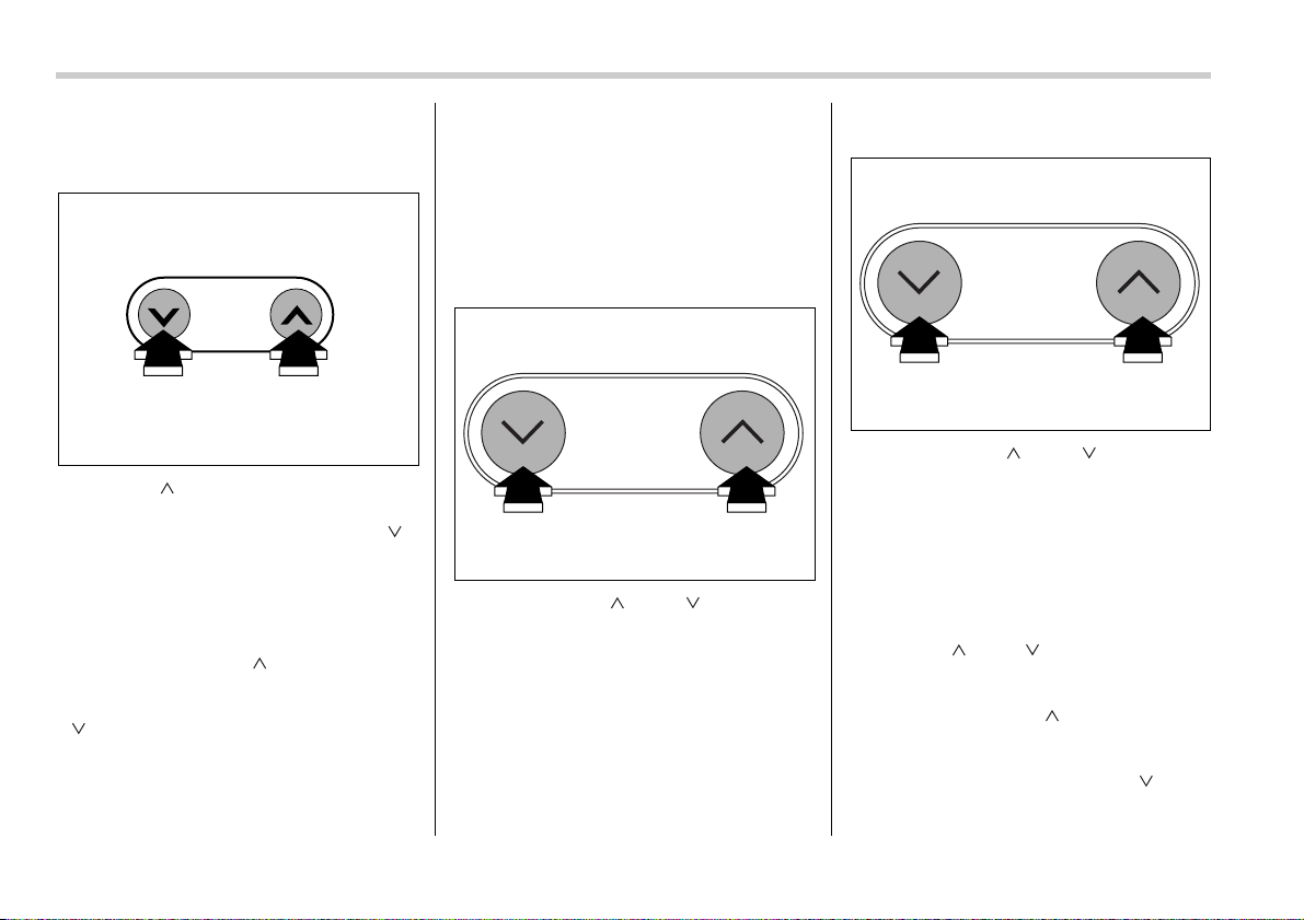
5-30 Audio
T Tuning
V Manual tuning
Press the “ ” side of the TUNE/TRACK
button to increase the tuning frequency
and press the tuning button marked “ ”
to decrease it.
Each time the button is pressed, the fre-
quency interval can be changed between
10 kHz in the AM mode and 0.2 MHz in the
FM mode.
If you hold down the “ ” side of the but-
ton, the tuning frequency will increase
continuously, and if you hold down the
“ ” side of the button, the tuning fre-
quency will decrease continuously. Re-
lease the button when your desired fre-
quency is reached.
NOTE
While you are holding down either side
of the TUNE/TRACK button, the tuning
frequency will not stop changing even
if the frequency of a receivable station
is reached.
V Seek tuning (SEEK)
If you press the “ ” or “ ” side of the
SEEK/SCAN button and release it within
1.5 second, the radio will automatically
search for a receivable station and stop at
the first one it finds. This function may not
be available, however, when radio signals
are weak. In such a situation, perform
manual tuning to select the desired sta-
tion.
V Scan tuning (SCAN)
If you press the “ ” or “ ” side of the
SEEK/SCAN button for 1.5 second or
longer, the radio will switch to scan mode.
In this mode, the radio scans through the
radio band until a station is found. The ra-
dio will stop at the station for five seconds
while displaying the frequency, after which
scanning will continue until the entire band
has been scanned.
Press the “ ” or “ ” side of the button
again to cancel the scan mode and to stop
on any displayed frequency.
If you hold down the “ ” side of the but-
ton, the radio will scan up the frequency
band (from low frequencies to high fre-
quencies). If you hold down the “ ” side
of the button, the radio will scan down the
frequency band (from high frequencies to
TUNE
TRACK
500049
SEEK
SCAN
500232
SEEK
SCAN
500232
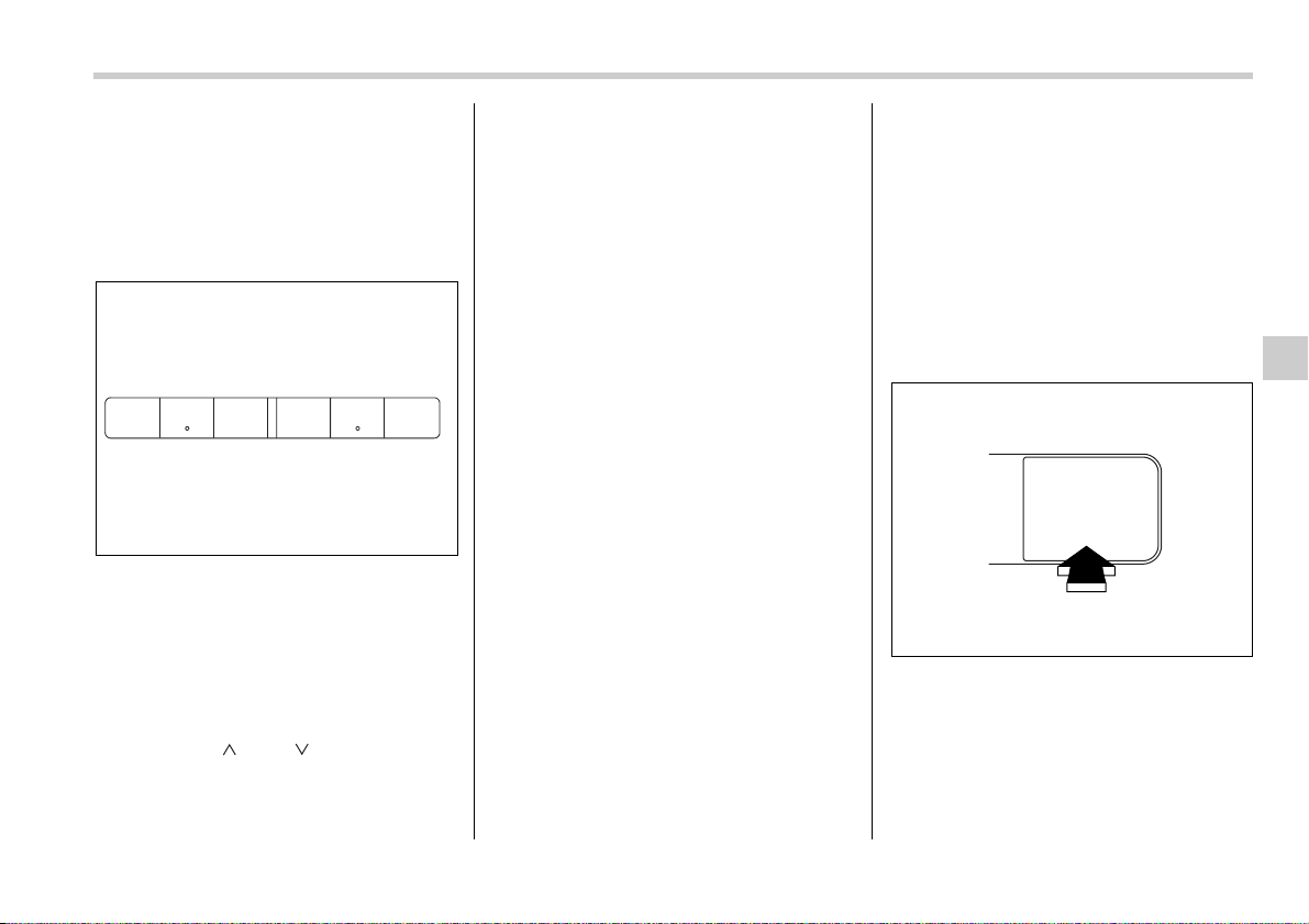
Audio 5-31
– CONTINUED –
low frequencies).
Automatic tuning may not function proper-
ly if the station reception is weakened by
distance from the station or proximity to
tall buildings and hills.
T Selecting preset stations
Presetting a station with a “preset button”
allows you to select that station in a single
operation. Up to six AM, FM1 and FM2
stations each may be preset.
T How to preset stations
1. Press the “FM” or “AM” button to select
FM1, FM2 or AM reception.
2. Press the “ ” or “ ” side of the but-
ton or tune the radio manually until the de-
sired station frequency is displayed.
3. Press one of the preset buttons for
more than 1.5 seconds to store the fre-
quency. If the button is pressed for less
than 1.5 seconds, the preceding selection
will remain in memory.
NOTE
y If the connection between the radio
and battery is broken for any reason
such as vehicle maintenance or radio
removal, all stations stored in the pre-
set buttons are cleared. If this occurs,
it is necessary to reset the preset but-
tons.
y If a cell phone is placed near the ra-
dio, it may cause the radio to emit
noise when it receives calls. This noise
does not indicate a radio fault.
Built-in CD changer opera-
tion
NOTE
y Make sure to always insert a disc
with the label side up. If a disc is insert-
ed with the label side down, it might be
ejected or the player might shut off.
y If a disc is inserted during a radio
broadcast, the disc will interrupt the
broadcast.
y After the last song finishes, the disc
will automatically return to track 1 (the
first song on the disc) and will auto-
matically play back.
y The player is designed to be able to
play music CD-Rs and music CD-RWs,
but it may not be able to play certain
ones.
y Single CDs (i.e., 8 cm/3 inch CDs) are
not supported, and if inserted, they will
be immediately ejected.
T How to insert a CD(s)
V Inserting a CD
0
1. Briefly press the “LOAD” button. If the
magazine in the player has an idle posi-
tion where you can insert a disc, the disc
number indicator associated with the idle
position will blink.
If no indicator blinks, it means that there is
no idle position in the magazine.
123 456
500233
LOAD
500239
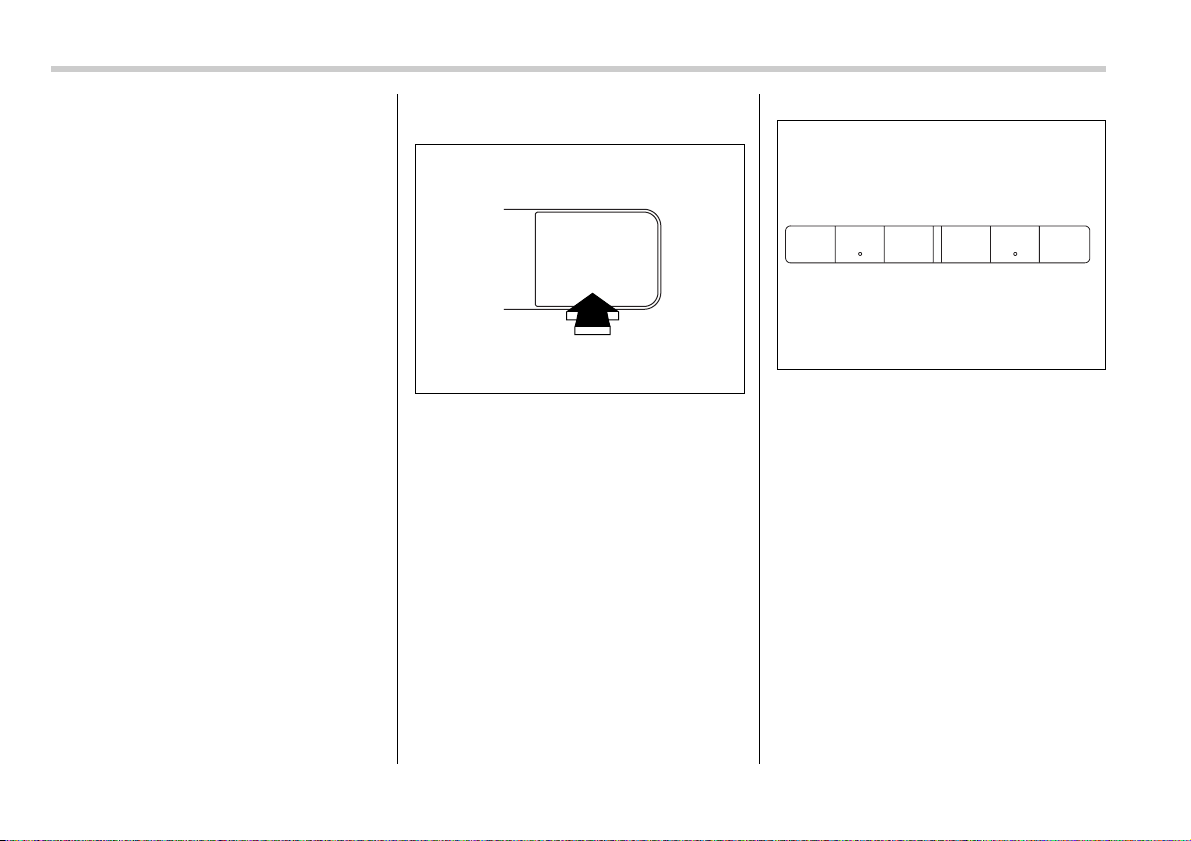
5-32 Audio
2. When the “LOAD” indicator flashes, in-
sert the disc. Once you have inserted the
disc, the “LOAD” indicator will go off. The
disc will then be automatically drawn in,
and the player will begin to play back the
first track of the disc.
y To insert more discs in succession, re-
peat Steps 1 and 2. The magazine will be
loaded with discs in the ascending order
of position number.
If you do not insert any disc in 15 seconds
after you have pressed the “LOAD” but-
ton, the player will begin to play back the
first track of the last disc you have insert-
ed.
y The disc indicator steadily lights up if a
disc is already inserted in the correspond-
ing position of the magazine.
y While the player is in the loading mode,
if you press “FM” or “AM” button, the play-
er will enter the standby mode. Press the
“CD” button to start playback.
V Inserting a disc in a desired position
0
1. Briefly press the “LOAD” button. If the
magazine in the player has an idle posi-
tion where you can insert a disc, the disc
number indicator associated with the idle
position will blink.
The positions in the magazine the indica-
tor of which steadily lights up are already
loaded with discs.
2. Press the “Disc select” button at the
position where you want to insert a disc.
3. When the “LOAD” indicator flashes, in-
sert the disc. Once you have inserted the
disc, the “LOAD” indicator will go off. The
disc will then be automatically drawn in,
and the player will begin to play the first
track on the disc.
y If you wish to insert another disc, repeat
the procedure beginning with step 1.
If you do not insert any disc in 15 seconds
after you have pressed the “LOAD” but-
ton, the player will begin to play back the
first track of the last disc you have insert-
ed.
y While the player is in the loading mode,
if you press “FM” or “AM” button, the play-
er will enter standby mode. Press the “CD”
LOAD
500239
123 456
500233
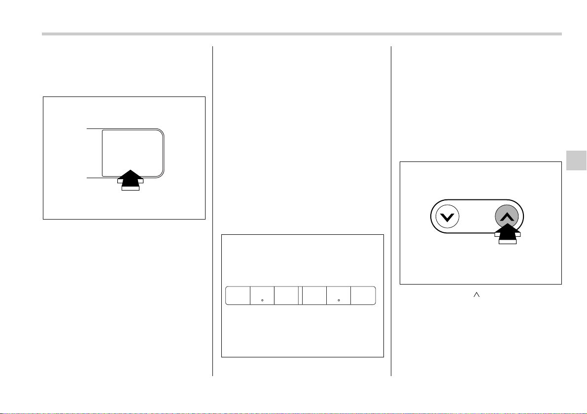
Audio 5-33
– CONTINUED –
button to start playback.
V Loading all the magazine (Full disc
loading mode)
0
1. If you continue to press the “LOAD”
button for more than 1.5 seconds, the
player will produce beep sound and will
enter the full disc loading mode.
2. When the disc number indicator and
“ALL LOAD” indicator start flashing, insert
a disc within 15 seconds. If a disc is suc-
cessfully loaded during this period, the
disc number indicator will stop blinking
and will steadily light.
3. When the loading of a disc is complete,
the next disc number indicator will blink.
Then repeat Step 2.
4. When the magazine is filled with discs
by repeating Steps 2 and 3, the player will
start playback of the discs, beginning with
the one inserted first.
If you fail to insert any disc during each 15
seconds interval, the full disc loading
mode will be canceled, and the player will
start playback of the disc inserted first.
T How to play back a CD or make a
pause
V When there is no CD inserted:
Insert a CD by referring to “How to insert a
CD(s)”.
When a CD is loaded, the player will start
playback of the CD, beginning with the
first track.
V When there are CDs loaded:
Press a desired one of the “Disc select”
buttons the disc number indicator of which
steadily lights up. The player will then start
playback of the selected CD, beginning
with the first track.
If a disc that the player cannot read has
been loaded, the player will eject that disc
and proceed to the next disc.
T To select a song from its beginning
V Forward direction
Briefly press the “ ” side of the TUNE/
TRACK button to skip to the beginning of
the next track/file (track). Each time the
button is pressed, the indicated track/file
(track) number will increase.
NOTE
In an MP3 folder, skipping past the last
track/file (track) will take you back to
LOAD
500239
123 456
500233
TUNE
TRACK
500056
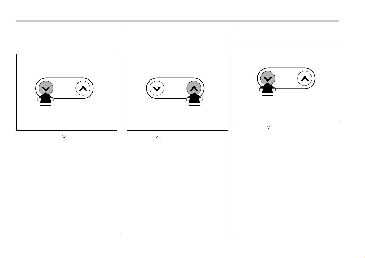
5-34 Audio
the first track/file (track) in the folder.
V Backward direction
Briefly press the “ ” side of the TUNE/
TRACK button to skip to the beginning of
the current track/file (track). Each time the
button is pressed, the indicated track/file
(track) number will decrease.
NOTE
In an MP3 folder, skipping past the first
track/file (track) will take you to the last
track/file (track) in the folder.
T Fast-forwarding and fast-reversing
V Fast-forwarding
Press the “ ” side of the TUNE/TRACK
button continuously to fast-forward the
disc/folder.
Release the button to stop fast-forward-
ing.
NOTE
If you fast-forward to the end of the last
track/file (track), fast-forwarding will
stop and the player will start playback
beginning with the first track/file
(track).
V Fast-reversing
Press the “ ” side of the TUNE/TRACK
button continuously to fast-reverse the
disc/folder.
Release the button to stop fast-reversing.
NOTE
If you fast-reverse to the beginning of
the first track/file (track), fast-reversing
will stop and the player will start play-
back.
TUNE
TRACK
500057
TUNE
TRACK
500056
TUNE
TRACK
500057
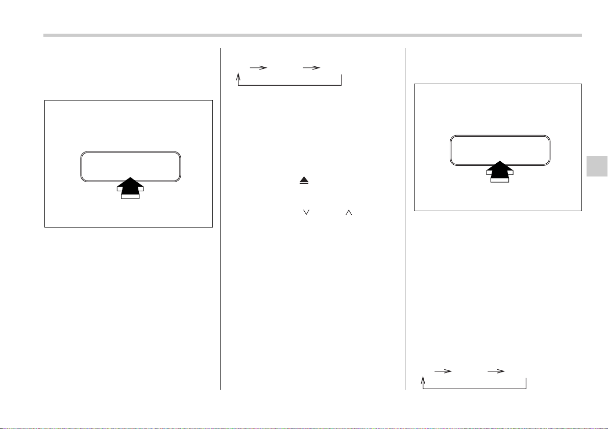
Audio 5-35
– CONTINUED –
T Repeating
V To repeat the currently playing
track/file (track)
To repeat a track/file (track), briefly press
the “RPT” button while the track/file (track)
is playing. The display will show “RPT”,
and the track/file (track) will be repeated.
To cancel the track/file (track) repeat-play
mode, briefly press the “RPT” button
twice. The “RPT” indication will go off, and
the normal playback mode will be re-
sumed.
NOTE
y Each time you briefly press the but-
ton, the mode will change to the next
one in the following sequence.
If you accidentally press the button
and cancel the track/file (track) repeat-
play mode, press it again to reselect
the repeat-play mode.
y The repeat-play mode will be can-
celled if you perform any of the follow-
ing steps:
y Press the “RPT” button
y Press the “ ” button
y Press the disc select button
y Select the radio mode
y Press the “ ” or “ ” side of
the SEEK/SCAN button
y Turn off the power of the audio
equipment.
y Turn the ignition switch to the
“OFF” position.
V To repeat the currently playing disc/
folder
To repeat the currently playing disc/folder,
press the “RPT” button twice while a track/
file (track) is playing. The display will show
“D-RPT”, and the disc/folder will be played
repeatedly.
To cancel the disc/folder repeat play
mode, press the “RPT” button once more.
The “D-RPT” indication will go off, and the
normal playback mode will be resumed.
NOTE
y Each time you briefly press the but-
ton, the mode will change to the next
one in the following sequence.
RPT
RDM
500241
RPT D-RPT CANCEL
RPT
RDM
500241
RPT D-RPT CANCEL
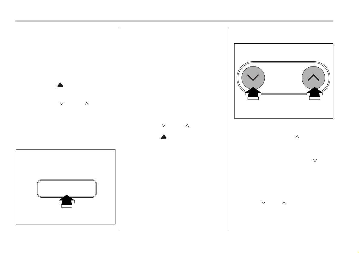
5-36 Audio
If you accidentally press the button
and cancel the disc/folder repeat-play
mode, press it again to reselect the
disc/folder repeat-play mode.
y The disc/folder repeat-play mode will
be cancelled if you perform any of the
following steps:
y Press the “RPT” button
y Press the “ ” button
y Press the disc select button
y Select the radio mode
y Press the “ ” or “ ” side of
the SEEK/SCAN button
y Turn off the power of the audio
equipment.
y Turn the ignition switch to the
“OFF” position.
T Random playback
Press the “RPT” button briefly during disc/
folder playback to play all of the tracks/
files (tracks) on the disc/folder in a random
order. The display will show “RDM”, and
all of the tracks on the disc/folder will be
played in a random order.
To cancel random playback, press the
“RPT” button again for at least 1.5 second.
The “RDM” indication will go off, and the
normal playback mode will be resumed.
NOTE
Random playback will be cancelled if
you perform any of the following steps:
y Press the “RPT” button
y Press the “ ” or “ ” side of the
SEEK/SCAN button
y Press the “ ” button
y Press the disc select button
y Select the radio mode
y Turn off the power of the audio
equipment.
y Turn the ignition switch to the “OFF”
position.
T Auto tuning (scan mode)
The scan mode lets you listen to the first
10 seconds of each track/file (track) in
succession. Press the “ ” side of the
SEEK/SCAN button for 1.5 second or
longer to start scanning upward beginning
with the track/file (track) following the cur-
rently selected one. Press the “ ” side
of the button to start scanning downward
beginning with the track/file (track) pre-
ceding the currently selected one. When
all tracks/files (tracks) in the disk/folder
have been scanned, normal playback will
be resumed. To cancel the scan mode,
press the “ ” or “ ” side of the button
for 1.5 second or longer.
NOTE
The scan mode will be cancelled if you
RPT
RDM
500241
SEEK
SCAN
500232
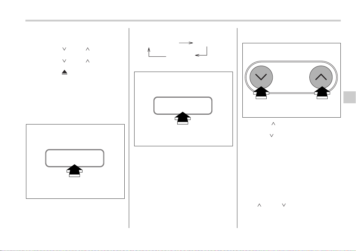
Audio 5-37
– CONTINUED –
perform any of the following steps:
y Press the “RPT” button
y Press the “ ” or “ ” side of the
TUNE/TRACK button
y Press the “ ” or “ ” side of the
SEEK/SCAN button
y Press the “ ” button
y Press the disc select button
y Select the radio mode
y Turn off the power of the audio
equipment.
y Turn the ignition switch to the “OFF”
position.
T Display selection
If you press the “TEXT” button for 0.5 sec-
ond or longer during playback, the indica-
tion will change to the next one in the fol-
lowing sequence.
T Page (track/folder title) scroll
If, having pressed the “TEXT” button to
select track title or folder title display, you
press the “TEXT” button again for less
than 0.5 second, the title will be scrolled
so you can see all of it. You will see eight
characters at a time.
NOTE
The display is designed to show titles
for up to eight pages (64 characters in
total). However, it may in some cases
show titles for only up to four pages (32
characters in total).
T Folder selection
Press the “ ” side of the SEEK/SCAN
button briefly to select the next folder.
Press the “ ” side of the button briefly to
go back to the previous folder. The folder
title will be shown each time you press one
of the buttons.
NOTE
y Selecting folders in this way is possi-
ble only within a single disc.
y Only MP3 folders are recognized
when an attempt to select the next or
previous folder is made. If no appropri-
ate folder exists on the disc, pressing
the “ ” or “ ” side of the SEEK/
SCAN button has no effect.
TEXT
500242
Folder number/file
(track) number
Track title
Folder title
TEXT
500242
SEEK
SCAN
500232
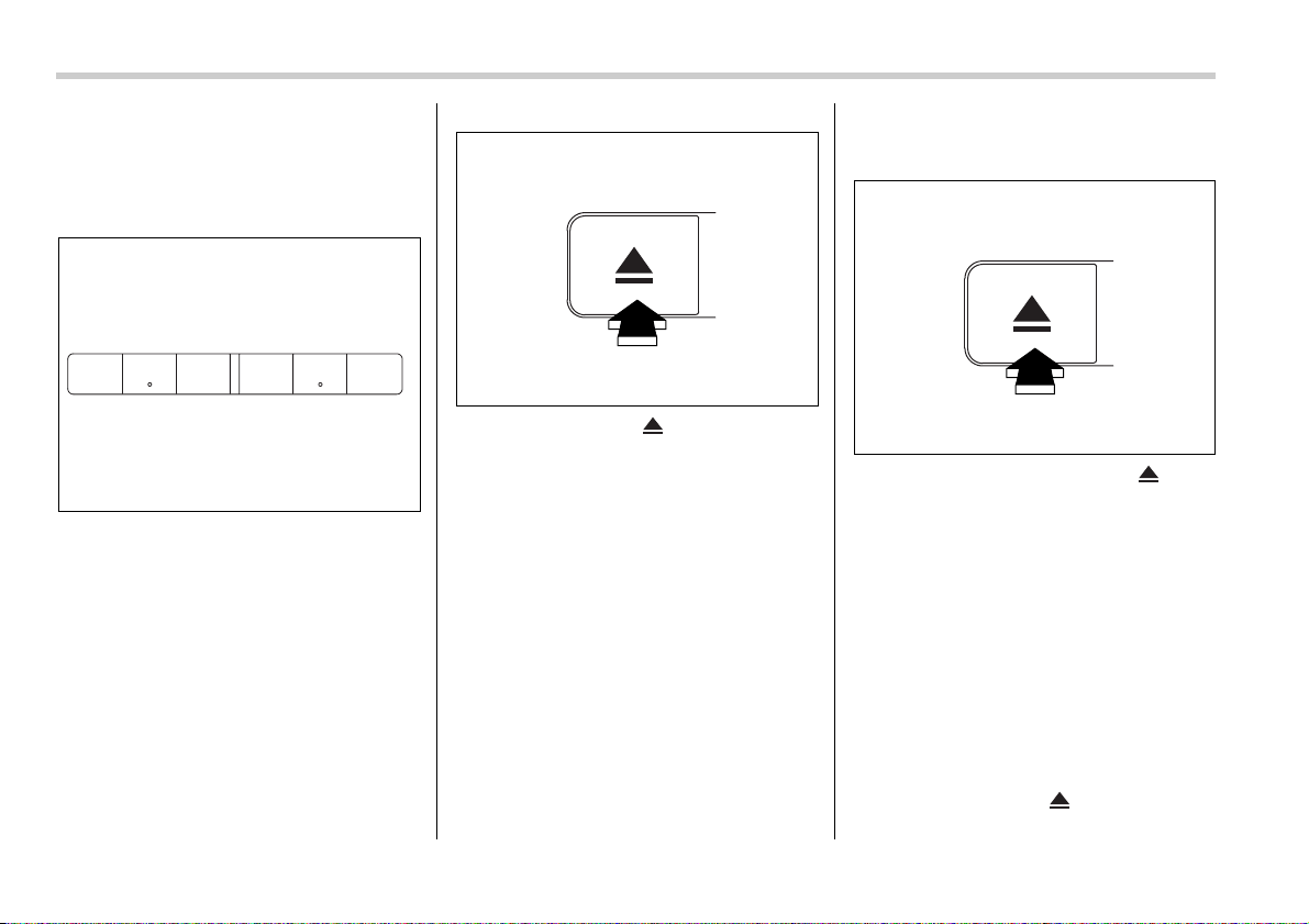
5-38 Audio
T How to unload CDs from the player
V Ejecting a CD from the player
Of the discs loaded, you can select and re-
move only one disc.
0
1. Use the disc select button to select the
disc to be ejected.
2. Briefly press the “ ” button. The se-
lected disc will be ejected. The disc num-
ber indicator will flash at this time. When
you remove the ejected disc, the disc
number indicator will go off.
To remove more discs in succession, re-
peat Steps 1 and 2.
V Ejecting all discs from the player
(All disc ejection mode)
0
1. If you continue to press the “ ” but-
ton, the player will produce beep sound
and will enter the all disc ejection mode. At
this time, the disc number indicator and
“ALL EJECT” indicator will flash.
2. Remove the disc that has been eject-
ed. The other discs loaded will then be
ejected one after another. If you do not re-
move the disc that has been ejected, the
“All disc ejection mode” will be canceled.
NOTE
y Avoid driving the vehicle with a CD
sticking out, because vibration might
make it fall out.
y If you press the “ ” button while
the player is in all disc ejection mode,
123 456
500233
500237
500237

Audio 5-39
– CONTINUED –
the mode will be cancelled following
ejection of the disc that is currently be-
ing ejected.
y If you press the “CD” button while
the player is in all disc ejection mode,
the player will draw in the discs that
have been ejected and play them.
Audio control buttons (if
equipped)
These buttons are located on the spokes
of the steering wheel. They allow the driv-
er to control audio functions without taking
his/her hands off the steering wheel.
T MODE button
This button is used to select the desired
audio mode. Each time it is pressed, the
mode changes to the next one in the fol-
lowing sequence:
*: The frequency last received in the selected
waveband will be displayed.
T “ ” and “ ” buttons
V With radio mode selected
Press the “ ” button or “ ” button.
The radio will seek the next receivable
station and stop on it.
That station’s frequency will be shown on
the audio display.
V With CD mode selected
Press the “ ” button to skip forward in
the track/file (track) order. Press the “ ”
button to skip backward in the track/file
(track) order.
The track/file (track) number will be shown
on the audio display.
400216
FM* AM*
CD
400217
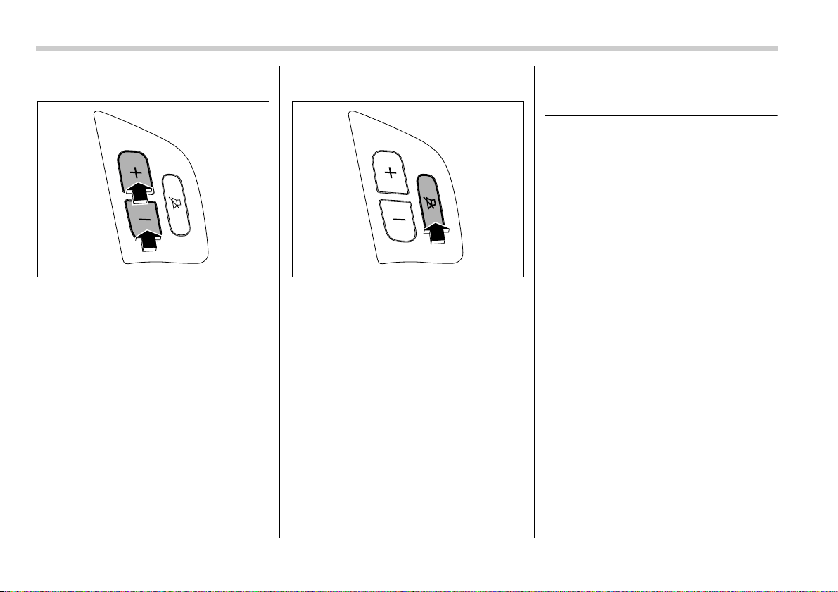
5-40 Audio
T Volume control buttons
Press the “+” button to increase the vol-
ume. Press the “–” button to reduce the
volume.
A number indicating the volume will be
shown on the audio display.
T MUTE button
Press this button if you wish to immediate-
ly cut the volume to zero.
The audio display will show “MUTE”.
If you press the button again, the original
sound volume will return and “MUTE”
goes off.
Precautions to observe when
handling a compact disc
Use only compact discs (CDs, CD-Rs and
CD-RWs) that have the mark shown in the
following. Also, some compact discs can-
not be played.
400218 400219
Audio 5-41
– CONTINUED –
y You cannot use a DualDisc in the CD
player. If you insert a DualDisc into the
player, the disc may not come out again,
possibly causing the player to malfunc-
tion.
y In cold and/or rainy weather, dew can
form inside the CD player, preventing nor-
mal operation. If this happens, eject the
CD and wait for the player to dry out.
y Skipping may occur when the CD player
is subjected to severe vibration (for exam-
ple, when the vehicle is driven on a rough
surface).
y To remove a disc from the case, press
the center of the case and hold both edg-
es of the disc. If the disc surface is
touched directly, contamination could
cause poor tone quality. Do not touch the
disc surface.
y Use a clean disc whenever possible. If
there are deposits, wipe the disc surface
from the center outward with a dry, soft
cloth. Be sure not to use a hard cloth, thin-
ner, benzene, alcohol, etc.
y Do not use any disc that is scratched,
deformed, or cracked. Also, do not use
any disc that has a non-standard shape
(for example, a heart shape). Malfunctions
or problems might result.
y A disc is vulnerable to heat. Never keep
it either in places exposed to direct sun-
light, near heaters or in vehicles parked in
the sun or on hot days.
500090
500253
TM
DualDisc
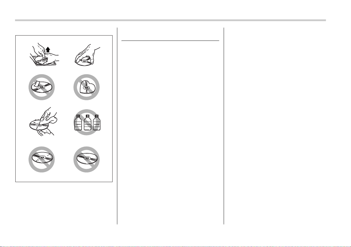
5-42 Audio
MP3 audio
What is MP3?
MP3 (the name is an abbreviation of
‘MPEG Audio Layer 3’) is a compression
format for digital audio. It was developed
by the Motion Picture Experts Group. It
permits audio data to be shrunk by a factor
of approximately 10 with no loss of sound
quality, meaning that the audio on 10 con-
ventional CDs can be fitted onto a single
CD-R or CD-RW (assuming a bit rate of
128 kbps and a sampling frequency of
44.1 kHz).
NOTE
y MP3 encoding and writing software
is not supplied with the audio system.
y CD writing software is not supplied
with the audio system.
Creating MP3 files
y To create a high-quality MP3 file, it is
advisable to have a high bit rate (128 kbps
or higher) and a high sampling frequency.
y If a file is created with a variable bit rate
(VBR), the elapsed time during playback
may not be displayed correctly and the
sound may skip.
y The sound quality during playback de-
pends upon the encoder and bit rate. De-
tailed information can be found in the us-
er’s manuals for encoder software and
writing software.
y A fixed bit rate of 128 kbps or higher is
recommended.
Saving MP3 files on a disc
y Do not save any non-MP3 file on a disc.
Also, do not save any unnecessary folder
on a disc.
y If many folders and/or non-MP3 files are
saved on a disc, a delay will be caused be-
fore playback begins.
y If a disc contains both Compact Disc-
Digital Audio (CD-DA) files and MP3 files,
the system will play only the CD-DA files.
y Add the extension ‘.MP3’ to the name of
every MP3 file. The system will not play
any file that has either no extension or an
extension other than ‘.MP3’.
y Do not add the extension ‘.MP3’ to the
name of any non-MP3 file. Doing so could
lead to speaker damage.
y The system supports multi-session re-
cording, so disc-at-once recording is rec-
ommended.
y The system does not support packet
writing software.
y The system does not have a playlist
function.
y The system may not be able to display
and play certain MP3 files depending on
500034

Audio 5-43
the writing software and CD recorder.
y Recording must be performed using a
file system supported by the audio sys-
tem. Otherwise, the audio system may not
play the MP3 files and may not display
folder titles and file titles.
Supported file systems
The audio system supports the following
file systems:
y ISO 9660 Level 1/Level 2
y Apple Extension to ISO 9660
y Joliet
y Romeo
NOTE
The audio system does not support the
following file systems:
y Apple HFS
y UDF 1.50
y Mix CD (CD Extra)
Compression format
y MPEG 1 audio layer 3 (MP3)
Bit rate: 32 kbps – 320 kbps
Sampling frequency: 32, 44.1, 48 kHz
y MPEG 2 audio layer 3 (MP3)
Bit rate: 8 kbps – 160 kbps
Sampling frequency: 16, 22.05, 24 kHz
Numbers of folders and files
y Maximum number of folders: 255 (in-
cluding root folder)
y Maximum number of files: 999 (maxi-
mum number in one folder: 255)
y Maximum number of layers: 8
NOTE
y Not all of the discs stored in MP3
files may be able to be played back.
y Even if a folder contains no MP3
files, it is counted as a folder.
y Writing software can rearrange fold-
ers and files such that the playback or-
der is different from the desired one.
y The playback order for a given disc
can be different with different players.
Copyright issues
Except with respect to copies made for
personal use, duplication, distribution, and
transmission of music and other copy-
righted material on a disc without permis-
sion from the copyright holder is illegal.


6
Interior equipment
Interior light ........................................................ 6-2
Dome light ............................................................... 6-2
Cargo area light (Station wagon) .......................... 6-2
Map light ............................................................. 6-2
Sun visors ........................................................... 6-3
Sun visor extension plate ...................................... 6-3
Vanity mirror with light ........................................... 6-4
Storage compartment ........................................ 6-4
Glove box ................................................................ 6-4
Center console box ................................................ 6-5
Center panel compartment (if equipped) .............. 6-6
Overhead console (if equipped) ............................ 6-6
Cup holder .......................................................... 6-7
Front passenger’s cup holder ............................... 6-7
Rear passenger’s cup holder ................................ 6-7
Accessory power outlets ................................... 6-8
Ashtray ................................................................ 6-9
Front ashtray ........................................................... 6-9
Coat hook ............................................................ 6-10
Rear passenger area .............................................. 6-10
Shopping bag hook ............................................ 6-11
Floor mat ............................................................. 6-12
Cargo area cover (Station wagon) .................... 6-12
Using the cover ....................................................... 6-12
To remove the cover housing ................................ 6-13
To remove the rear gate board .............................. 6-13
Stowage of the cargo area cover and rear gate
board ..................................................................... 6-13
To install the cover housing .................................. 6-14
To install the rear gate board ................................ 6-14
Stowage boxes (Station wagon) ....................... 6-15
Convenient tie-down hooks (if equipped) ........ 6-15
Under-floor storage compartment .................... 6-16
HomeLink® Wireless Control System
(if equipped) ..................................................... 6-17
Garage door opener programming in the
U.S.A. ..................................................................... 6-18
Programming rolling-code-protected garage door
openers in the U.S.A. ........................................... 6-19
Programming for entrance gates and garage door
openers in Canada ............................................... 6-20
Programming other devices .................................. 6-20
Operating the HomeLink® Wireless Control
System ................................................................... 6-20
Reprogramming a single HomeLink® button ...... 6-20
Erasing HomeLink® button memory .................... 6-21
In case a problem occurs ....................................... 6-21
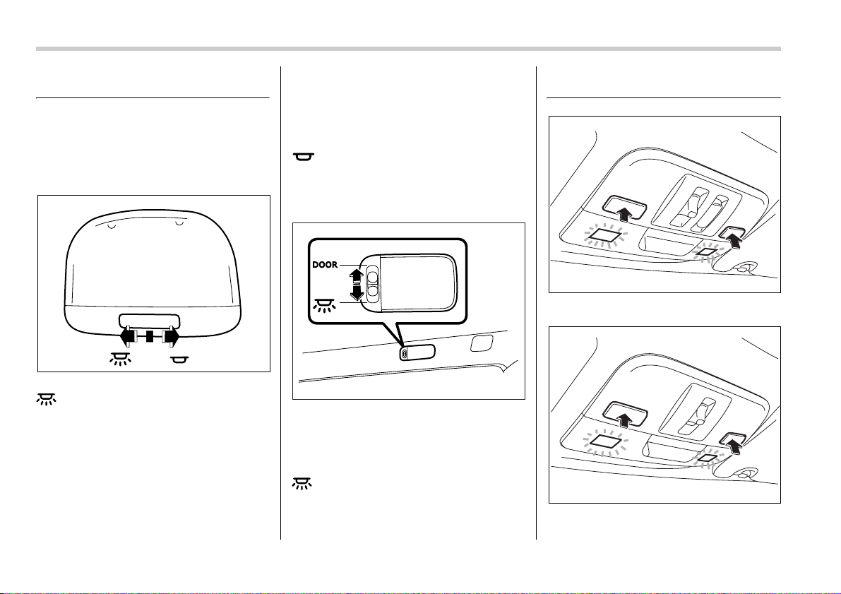
6-2 Interior equipment
Interior equipm ent
Interior light
When leaving your vehicle, make sure the
light is turned off to avoid battery dis-
charge.
Dome light
The light switch has three positions:
: The light stays on continuously.
Middle position: The light comes on when
any door is opened. The light remains on
for several seconds and gradually goes
out after all doors are closed.
The light also can be turned on by use of
the remote keyless entry transmitter. See
the “Remote keyless entry system” sec-
tion in chapter 2 for detailed information.
The setting of the period for which the light
stays on can be changed by a SUBARU
dealer.
Contact the nearest SUBARU dealer for
details.
: The light stays off.
Cargo area light (Station wag-
on)
The cargo area light switch has three po-
sitions:
DOOR: The light comes on only when the
rear gate is opened.
Middle position: The light stays off.
: The light stays on continuously.
Map light
Vehicle with moonroof (Sedan)
Vehicle with moonroof (Station wagon)
400254
600536
600494
600495
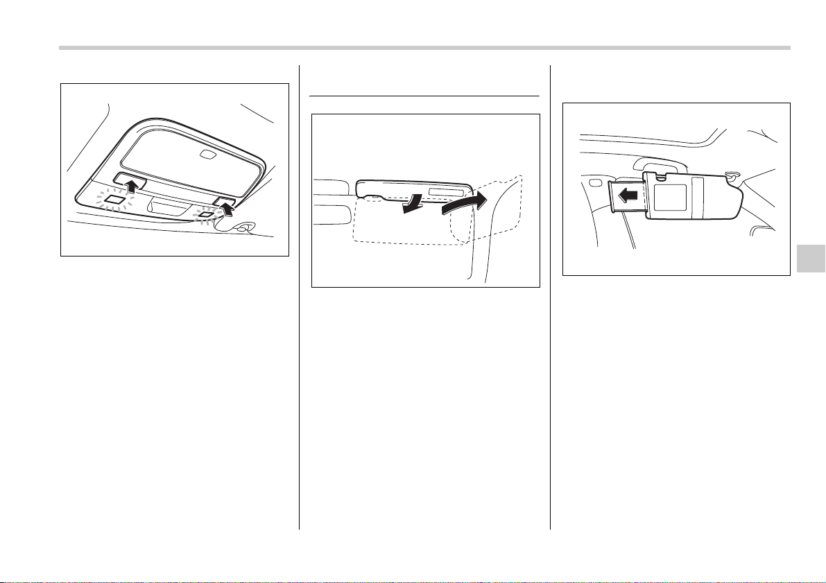
Interior equipment 6-3
– CONTINUED –
Vehicle without moonroof
To turn on the map light, push the switch.
To turn it off, push the switch again.
When leaving the vehicle, make sure the
light is turned off to avoid battery dis-
charge.
Sun visors
To block out glare, swing down the visors.
To use the sun visor at a side window,
swing it down and move it sideways.
Sun visor extension plate
With the sun visor positioned over the side
window, you can use the sun visor exten-
sion plate to prevent glare through the gap
between the sun visor and center pillar. To
use the extension plate, pull it toward the
rear of the vehicle. When you have fin-
ished using it, stow it by pushing it toward
the front of the vehicle.
600496
400228
600407
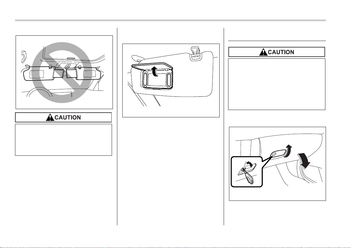
6-4 Interior equipment
Vanity mirror with light
To use the vanity mirror, swing down the
sun visor and open the vanity mirror cov-
er.
The light beside the vanity mirror comes
on when the ignition switch is either in the
“ACC” or “ON” position and the mirror cov-
er is opened.
Storage compartment
Glove box
1) Lock
2) Unlock
To open the glove box, pull the handle. To
Do not pull out the extension plate
with the sun visor positioned over
the windshield. The extension plate
would obstruct your view of the
rearview mirror.
600408
600498
y Always keep the storage compart-
ment closed while driving to re-
duce the risk of injury in the event
of sudden stops or an accident.
y Do not store spray cans, contain-
ers with flammable or corrosive
liquids or any other dangerous
items in the storage compartment.
1
2
600499
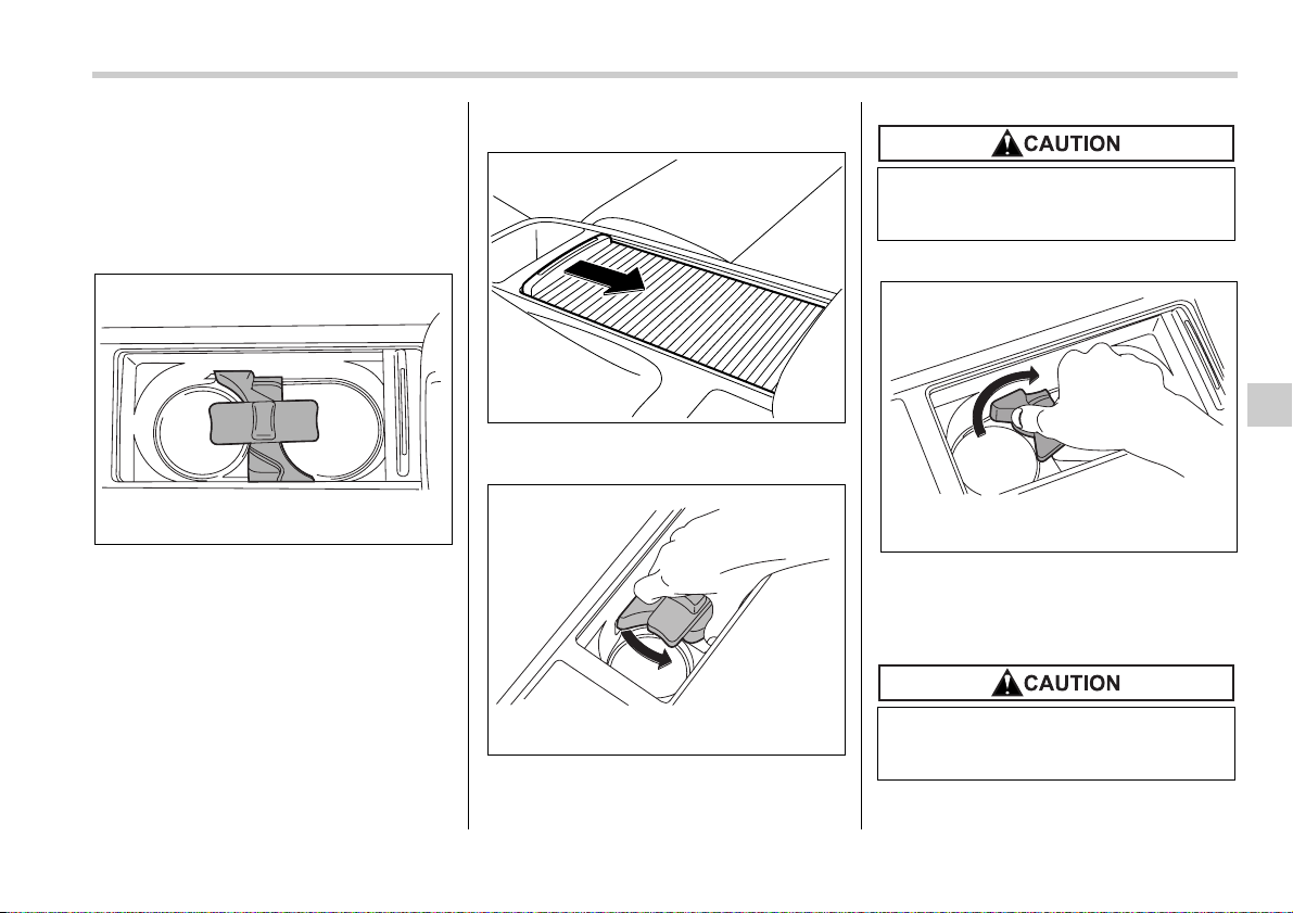
Interior equipment 6-5
– CONTINUED –
close it, push the lid firmly upward.
To lock the glove box, insert the key and
turn it clockwise.
Center console box
Center console box (front)
If you remove the divider plate from the
dual cupholders, you can use the center
console box as a storage space.
To use as storage space:
Slide the sliding lid (near the parking
brake lever) toward the rear.
Grasp the dual cupholders’ divider plate at
the base. Turn it counterclockwise to re-
move it.
To use again as cupholders:
Insert the protrusion on the back of the di-
vider plate into the hole in the center of the
console box. Grasp the divider plate at the
base, and turn it clockwise to fit it.
600500
600206
600501
If you hold the divider plate at the
top while turning it counterclock-
wise, it may break.
If you hold the divider plate at the
top while turning it clockwise, it may
break.
600502
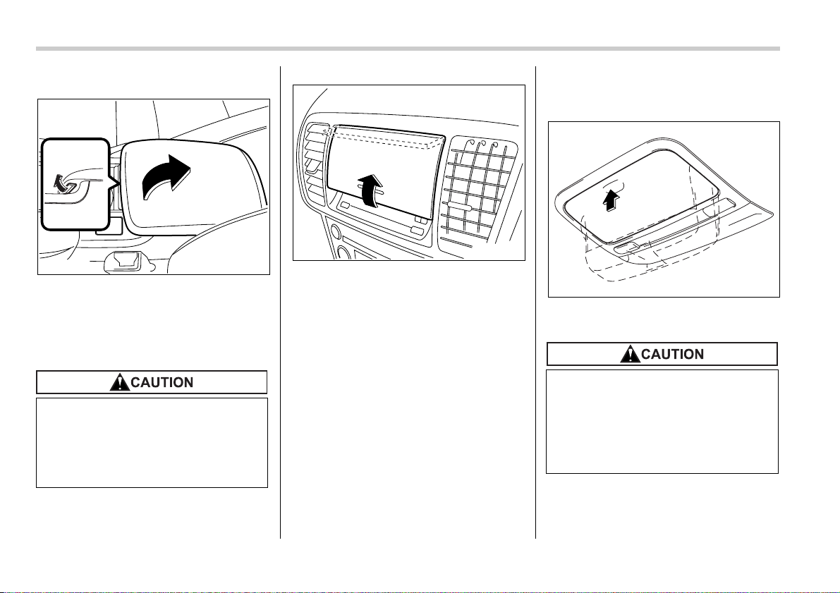
6-6 Interior equipment
Center console box (rear)
Pull up the lock release knob at the bottom
of the front edge of the lid.
Center panel compartment (if
equipped)
To open the center panel compartment,
pull up the edge of the bottom of the panel
lid.
Overhead console (if
equipped)
To open the console, push on the lid light-
ly and it will automatically open.
When your vehicle is parked in the
sun or a warm day, the inside of the
center panel heats up. Avoid storing
plastic or other heat-vulnerable or
flammable articles such as a lighter
in the center panel.
600201
600503
When your vehicle is parked in the
sun or on a warm day, the inside of
the overhead console heats up.
Avoid storing plastic or other heat-
vulnerable or flammable articles
such as a lighter in the overhead
console.
400233
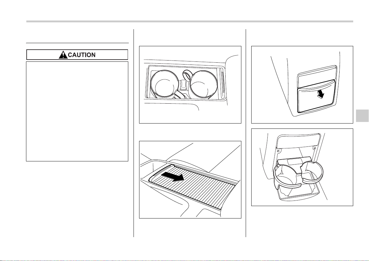
Interior equipment 6-7
Cup holder
Front passenger’s cup holder
The dual cup holder is built into the center
console near the parking brake lever.
To access the cup holder, pull the lid to-
ward the rear.
Rear passenger’s cup holder
The rear passenger’s cup holder is locat-
ed on the lower side of the back of the
center console. To use the cup holder,
open the lid by pulling its upper edge.
y When not in use, always keep the
cup holder stored while driving to
reduce the risk of injury in the
event of a sudden stop or an acci-
dent.
y Do not pick up a cup from the cup
holder or put a cup in the holder
while you are driving, as this may
distract you and lead to an acci-
dent.
y Take care to avoid spills. Bever-
ages, if hot, might burn you or
your passengers. Spilled bever-
ages may also damage upholstery
or carpets.
600504
600206
600505
600506
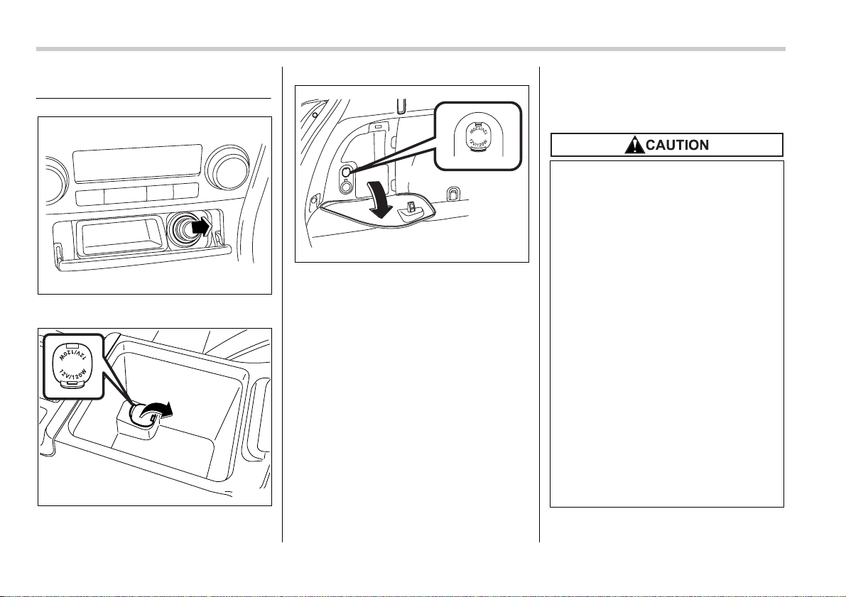
6-8 Interior equipment
Accessory power outlets
Outlet beside front ashtray
Outlet in center console
Outlet in cargo area
Accessory power outlets are provided be-
side the front ashtray, in the center con-
sole and in the cargo area. Electrical pow-
er (12V DC) from the battery is available at
any of the outlets when the ignition switch
is in either the “ACC” or “ON” position.
You can use an in-car electrical appliance
by connecting it to an outlet.
The maximum power rating of an appli-
ance that can be connected varies among
outlets as shown in the following. Do not
use an appliance which exceeds the indi-
cated wattage for each outlet.
Outlet beside front ashtray: 80W or less
Outlets in center console and cargo area:
120W or less
When using appliances connected to two
or more outlets simultaneously, the total
power consumed by them must not ex-
ceed 120W.
600509
600209
600507
y Do not attempt to use a cigarette
lighter in the accessory power
outlet.
y Do not place any foreign objects,
especially metal ones such as
coins or aluminum foil, into the
accessory power outlet. That
could cause a short circuit. Al-
ways put the cap on the accesso-
ry power outlet when it is not in
use.
y Use only electrical appliances
which are designed for 12V DC.
The maximum power rating of an
appliance that can be connected
varies among outlets as shown in
the following. Do not use an appli-
ance which exceeds the indicated
wattage for each outlet.
Outlet beside front ashtray: 80W
or less
Outlets in center console and car-
go area: 120W or less
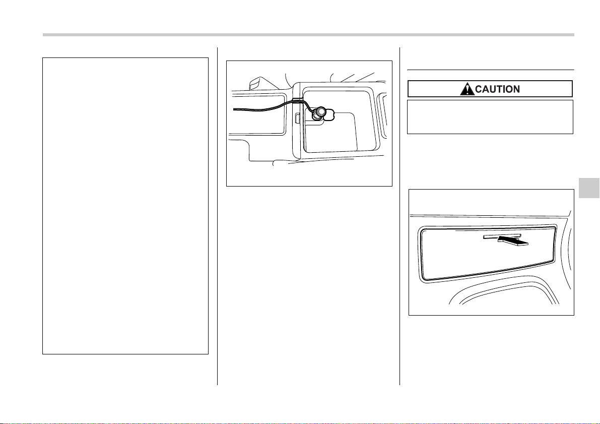
Interior equipment 6-9
– CONTINUED –
NOTE
When the lid of the center console is
closed, a gap remains between the
center console and the lid to allow the
power outlet in the center console to
be used. Pass the electrical appli-
ance’s cord through this gap.
Ashtray
Fully close the ashtray after using it to help
reduce residual smoke.
Front ashtray
To open the ashtray, push lightly on the lid
below the climate controls.
Fully close the lid after using it to help re-
duce residual smoke.
When using appliances connect-
ed to two or more outlets simulta-
neously, the total power con-
sumed by them must not exceed
120W. Overloading the accessory
power outlet can cause a short
circuit. Do not use double adapt-
ers or more than one electrical ap-
pliance.
y If the plug on your electric appli-
ance is either too loose or too
tight for the accessory power out-
let, this can result in a poor con-
tact or cause the plug to get stuck.
Only use plugs that fit properly.
y Use of an electric appliance in the
accessory power outlet for a long
period of time while the engine is
not running can cause battery dis-
charge.
y Before driving your vehicle, make
sure that the plug and the cord on
your electrical appliance will not
interfere with your shifting gears
and operating the accelerator and
brake pedals. If they do, do not
use the electrical appliance while
driving.
600508
Do not use ashtrays as waste recep-
tacles or leave a lighted cigarette in
an ashtray. This could cause a fire.
400220
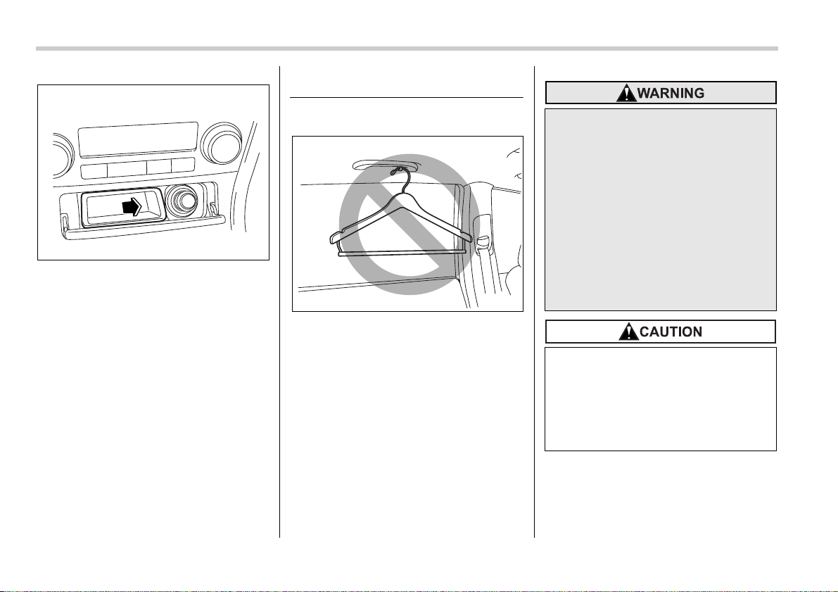
6-10 Interior equipment
To remove the ashtray for cleaning, hold
the right and left sides of the ashtray and
pull it out.
Coat hook
Rear passenger area
600512
600516
Do not hang coat hangers or other
hard or pointed objects on the coat
hooks. If such items were hanging
on the coat hooks during deploy-
ment of the SRS curtain airbags,
they could cause serious injuries by
coming off the coat hooks and being
thrown through the cabin or by pre-
venting correct airbag deployment.
Before hanging clothing on the coat
hooks, make sure there are no
pointed objects in the pockets.
Hang clothing directly on the coat
hooks without using hangers.
Never hang anything on the coat
hook that might obstruct the driv-
er’s view or that could cause injury
in sudden stops or in a collision.
And do not hang items on the coat
hook that weigh 11 lbs (5 kg) or
more.
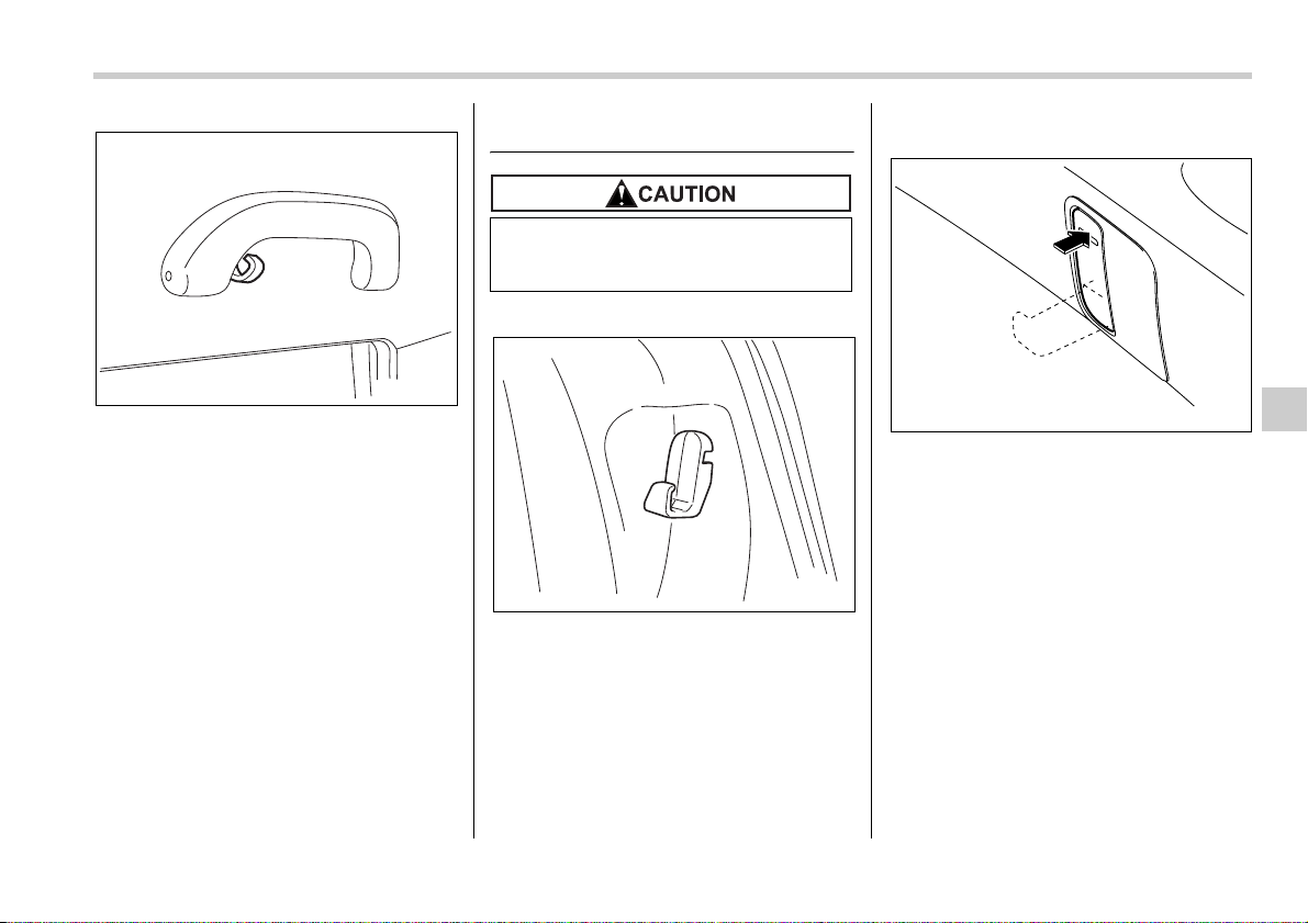
Interior equipment 6-11
The coat hook is attached to each rear
passenger’s hand grip.
Shopping bag hook
T For Sedan models
A shopping bag hook is attached to each
inner side wall of the trunk near the trunk
lid opening.
T For Station wagon models
A shopping bag hook is attached to each
side of the cargo area.
To use the hook, push the upper portion
and the shopping bag hook will appear.
400249
Do not hang items on the shopping
bag hook that weigh 11 lbs (5 kg) or
more.
400253
600215
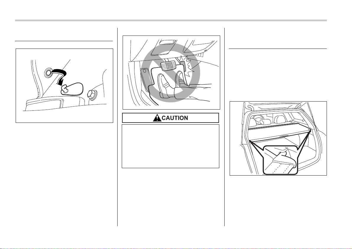
6-12 Interior equipment
Floor mat
A retaining pin is located on the driver’s
side of the vehicle next to the fuel filler
door release. Fit the grommet in the car-
pet onto the pin to prevent the carpet from
moving.
Cargo area cover (Station
wagon)
The cargo area cover is provided for cov-
ering the cargo area and to protect its con-
tents from direct sunlight. This cover is de-
tachable to make room for additional car-
go.
Using the cover
To extend the cover, pull the end of the
cover out of the housing, then insert its
hooks into the catches as shown. To re-
wind it, unhook it from the catches and it
will rewind automatically. You should hold
on to the cover and guide it back into the
cover housing while it is rewinding.
600513
Make sure the driver’s floor mat is
placed back in its proper location
and correctly secured on its retain-
ing pin. If the floor mat slips forward
and interferes with the movement of
the pedals during driving, it could
cause an accident.
600514
400237
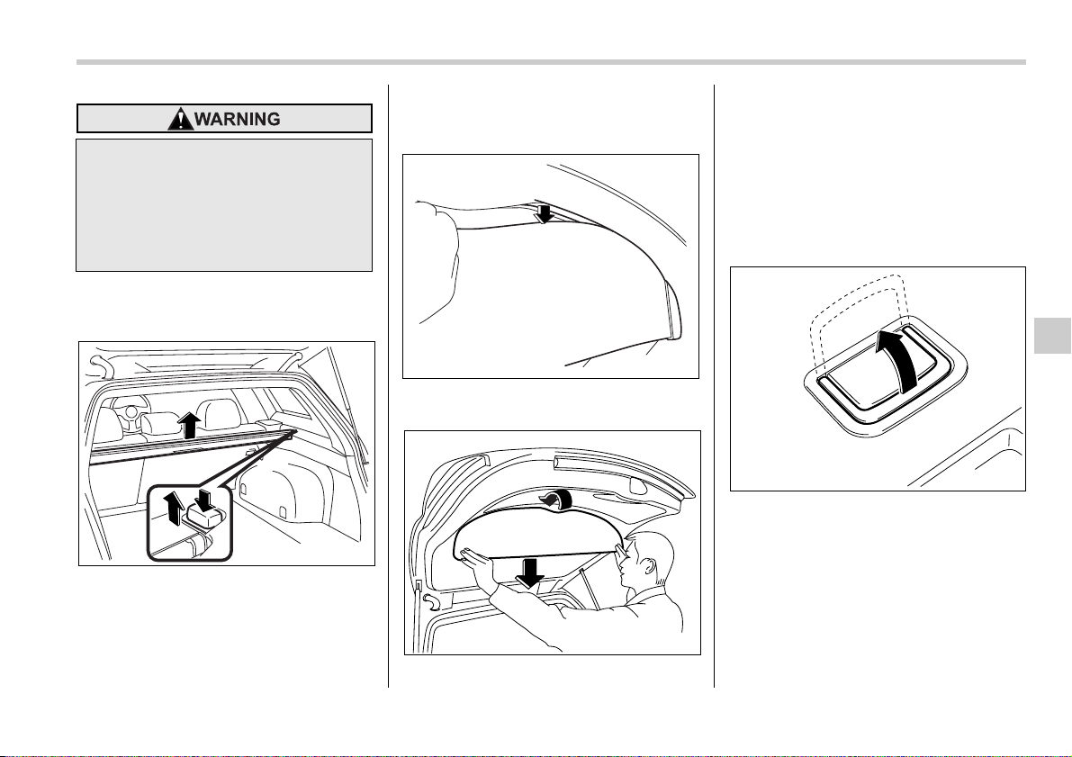
Interior equipment 6-13
– CONTINUED –
To remove the cover housing
1. Rewind the cover.
2. Hold down the button on the right-hand
rear quarter panel and lift up the right-
hand cover housing.
3. Remove the cover housing.
To remove the rear gate
board
0
1. Remove the top of the rear gate board
from the groove in the rear gate panel.
2. Hold both sides of the bottom edge of
the rear gate board, rotate the rear gate
board toward you, and pull it out down-
ward.
Stowage of the cargo area
cover and rear gate board
The cargo area cover and rear gate board
can be stowed in under the cargo floor.
1. To open the lid, pull the handle up.
Do not place anything on the ex-
tended cover. Putting excessive
weight on the extended cover can
break it and an object on the cover
could tumble forward in the event of
a sudden stop or collision. This
could cause serious injury.
400239
400240
400241
600214
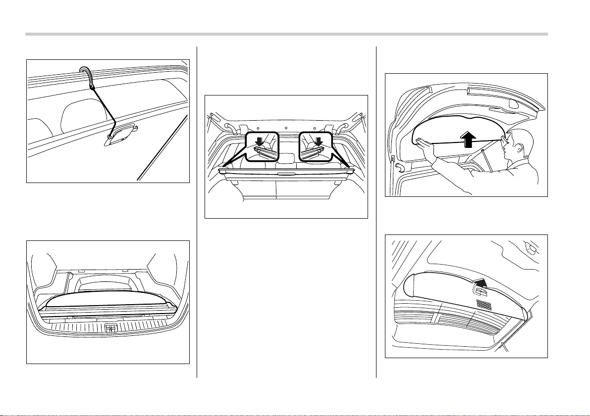
6-14 Interior equipment
2. To keep the lid open, hang the hook
(provided on the back of the lid) on the
rear edge of the roof.
3. Remove the left and right parts of the
cargo floor lid.
4. Stow the cover housing and rear gate
board in the cargo area end.
To install the cover housing
To install the cover housing, insert both
ends of the cover housing into the retain-
ers.
To install the rear gate board
Insert (tipped at an angle) the hooks on
the rear gate board into the holes in the
rear gate panel.
Rotate the rear gate board toward you un-
600110
400235
400336
400242
600515
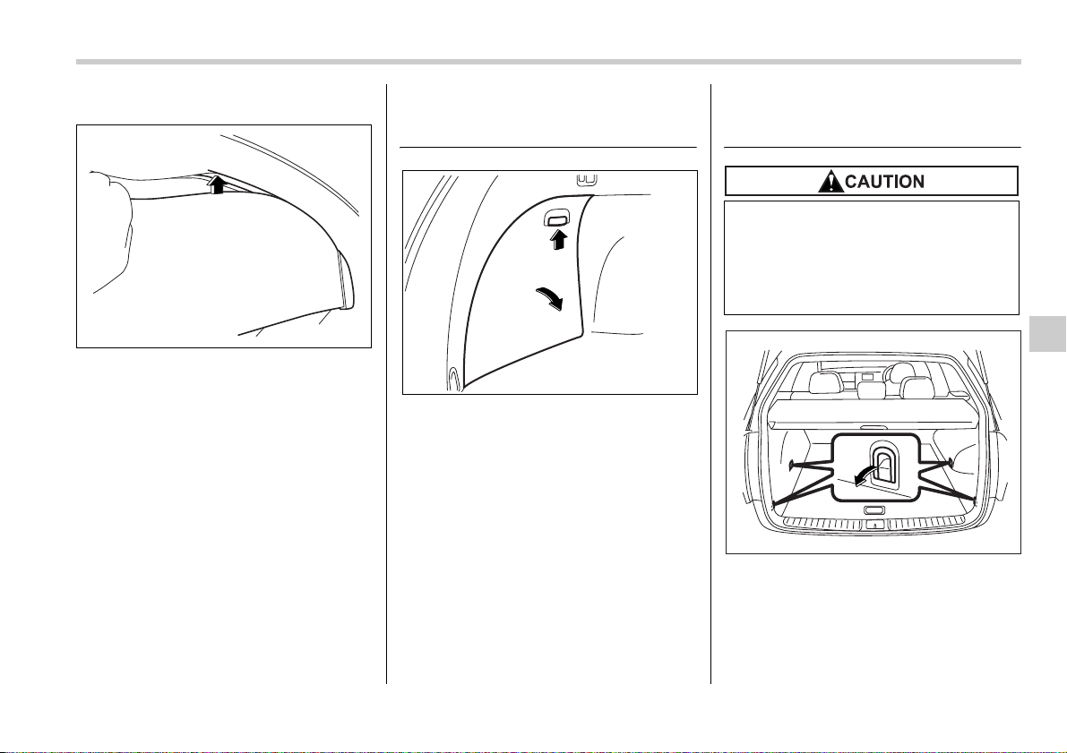
Interior equipment 6-15
– CONTINUED –
til its top touches the rear gate panel.
Fit the top of the rear gate board into the
groove in the rear gate panel.
Stowage boxes (Station wag-
on)
A stowage box is located on each side of
the cargo area. You can access each one
by pushing up and pulling the knob on the
lid.
Convenient tie-down hooks
(if equipped)
The cargo area is equipped with four tie-
down hooks so that cargo can be secured
with a luggage net or ropes.
When using the tie-down hooks, turn them
down out of the storing recesses. When
not in use, put the hooks up into the stor-
400243
600216
The convenient tie-down hooks are
designed only for securing light car-
go. Never try to secure cargo that
exceeds the capacity of the hooks.
The maximum load capacity is 44
lbs (20 kg) per hook.
600535
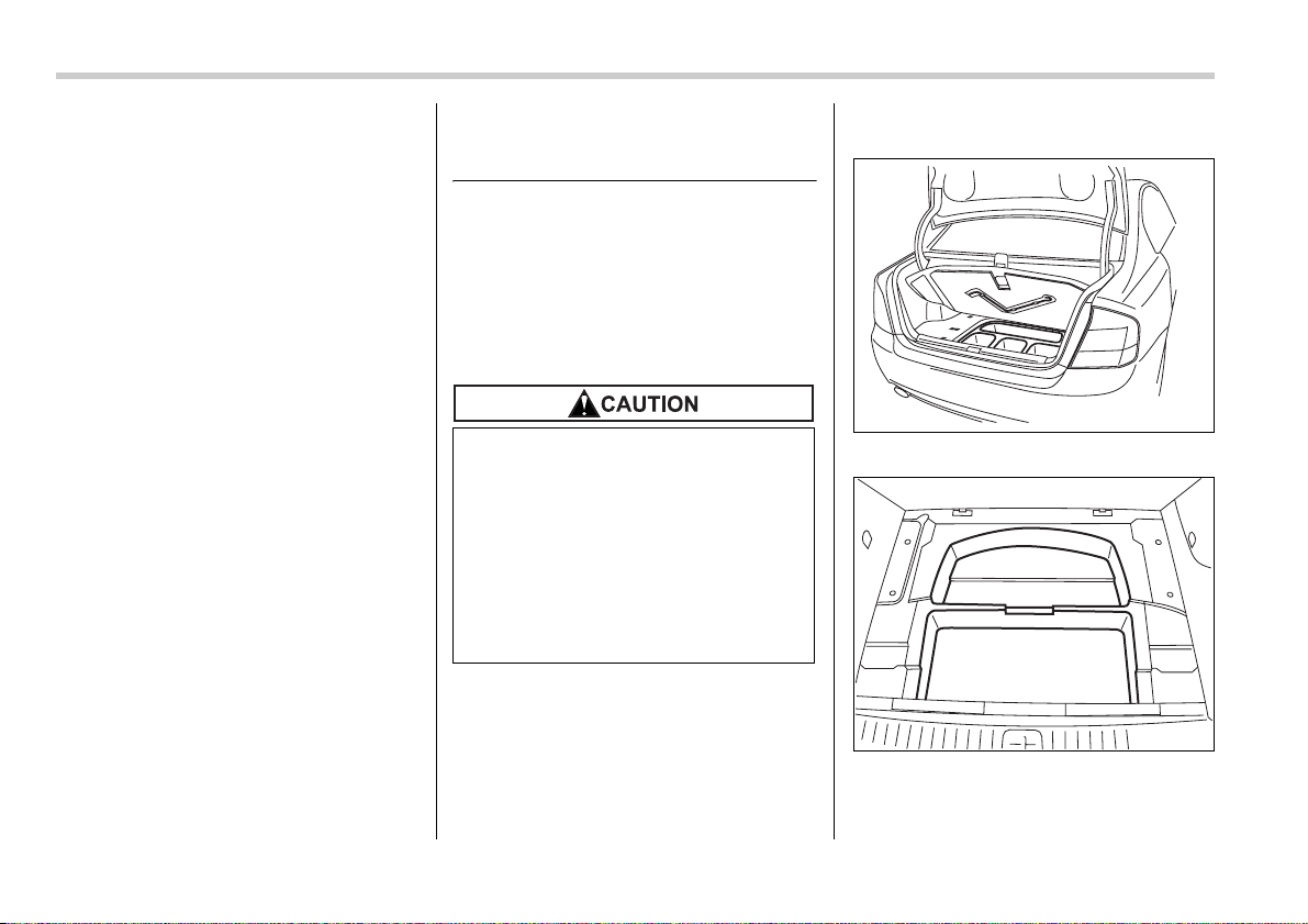
6-16 Interior equipment
ing recesses.
Under-floor storage compart-
ment
The subfloor storage compartment is lo-
cated under the floor of the trunk or cargo
area and can be used to store small items.
To open the lid, pull the tab or handle up.
NOTE
When storing a flat tire, put the sub-
floor storage in the trunk or cargo area.
T Sedan
T Station wagon
Hang the hook provided on the underside
of the lid on the rear edge of the roof to
keep the lid open.
y Always keep the lid of the sub-
floor storage compartment closed
while driving to reduce the risk of
injury in the event of sudden stop
or an accident.
y Do not store spray cans, contain-
ers with flammable or corrosive
liquids or any other dangerous
items in the subfloor storage com-
partment.
600115
600111
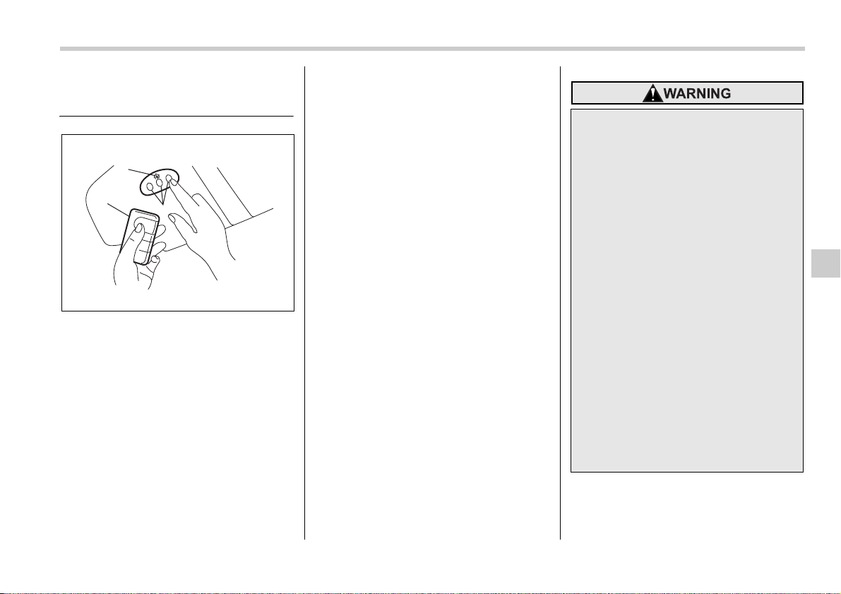
Interior equipment 6-17
– CONTINUED –
HomeLink® Wireless Control
System (if equipped)
1) HomeLink® buttons
2) Indicator light
3) Hand-held transmitter*
* Not part of your vehicle’s keyless entry
system but of a HomeLink®-compatible
device.
The HomeLink® Wireless Control Sys-
tem, located on the driver’s sun visor, is a
handy way to operate, from inside of your
vehicle, up to three remote-controlled in-
door and outdoor devices, such as garage
door openers, entrance gates, door locks,
home lighting, and security systems.
There are three HomeLink® buttons on
the sun visor, each of which you can pro-
gram for operation of one desired device.
For details on the device types which can
be operated by this system, consult the
HomeLink website at www.homelink.com
or call 1-800-355-3515.
Note the following about this system:
If your vehicle is equipped with the
HomeLink® Wireless Control System, it
complies with Part 15 of the Federal Com-
munication Commission Rules in the U.S.
and the RSS-210 of Industry Canada in
Canada. Its operation is subject to the fol-
lowing two conditions:
(1) this device may not cause harmful in-
terference, and (2) this device must ac-
cept any interference received, including
interference that may cause undesired op-
eration.
Changes and modifications to this system
by anyone other than an authorized ser-
vice facility could void authorization to use
this equipment.
HomeLink and the HomeLink house are
registered trademarks of Johnson Con-
trols, Inc.
1
2
3
600429
y When programming the
HomeLink® Wireless Control Sys-
tem, you may be operating a ga-
rage door opener or other device.
Make sure that people and objects
are out of the way of the garage
door opener or other device to
prevent potential harm or dam-
age.
y Do not use the HomeLink® Wire-
less Control System with any ga-
rage door opener that lacks the
safety stop and reverse feature as
required by applicable safety
standards. A garage door opener
which cannot detect an object,
signaling the door to stop and re-
verse, does not meet these safety
standards. Using a garage door
opener without these features in-
creases risk of serious injury or
death. For more information, con-
sult the HomeLink website at
www.homelink.com or call 1-800-
355-3515.
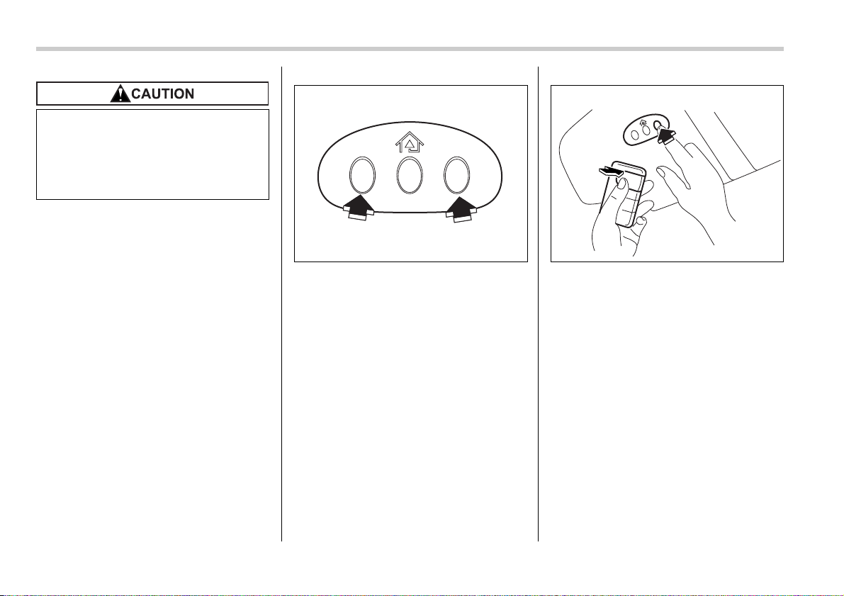
6-18 Interior equipment
NOTE
y After programming your HomeLink®
Wireless Control System for the de-
sired devices, retain the hand-held
transmitters for further programming
or device testing in the event of a prob-
lem.
y It is recommended that you insert a
new battery in the hand-held transmit-
ter of a device to ensure correct pro-
gramming.
Garage door opener pro-
gramming in the U.S.A.
NOTE
When programming the HomeLink®
Wireless Control System for a garage
door opener, it is suggested that you
park the vehicle outside the garage.
1. Unplug the motor of the garage door
opener from the outlet.
2. Press and hold the two outside
HomeLink® buttons until the indicator light
begins to flash (after 20 seconds). Re-
lease both buttons.
NOTE
If any of the HomeLink® buttons are al-
ready programmed for other devices,
skip step 2 because it clears the mem-
ory of all the three buttons.
3. Hold the end of the garage door open-
er’s hand-held transmitter between 1 and
3 inches (25 and 76 mm) away from the
HomeLink® buttons on the driver’s sun vi-
sor, keeping the indicator light in view.
4. Using both hands, simultaneously
push the hand-held transmitter button and
the desired HomeLink® button. DO NOT
release the buttons until step 5 has been
completed.
5. Hold down both buttons until the
HomeLink® indicator light flashes, first
slowly then rapidly. When the indicator
light flashes rapidly, both buttons may be
released. (The rapidly flashing light indi-
cates successful programming of the new
frequency signal.)
6. Press and hold the programmed button
and check the HomeLink® indicator light.
If the indicator light stays on continuously,
your garage door should activate and the
programming is completed.
If the indicator light flashes rapidly for two
seconds and then stays on continuously,
When programming the HomeLink®
Wireless Control System to operate
a garage door opener or an entrance
gate, unplug the device’s motor
from the outlet during programming
to prevent motor burnout.
600430 600431
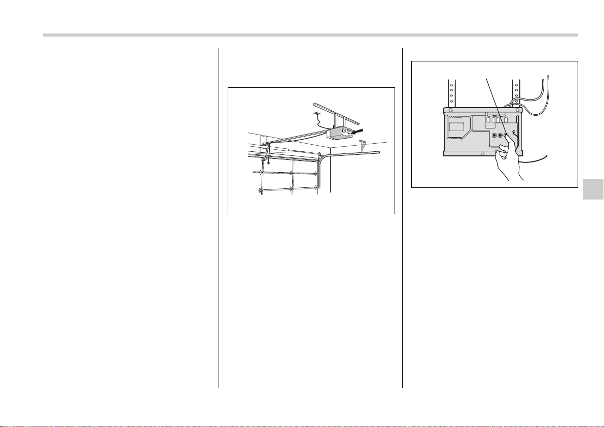
Interior equipment 6-19
– CONTINUED –
your garage door opener may be protect-
ed by a rolling code feature. In this case
you need to perform the additional steps
for “Programming rolling-code-protected
garage door openers in the U.S.A.” de-
scribed in the following.
NOTE
Rolling-code-protected garage door
openers are manufactured after 1996.
See the instruction manual of your ga-
rage opener for confirmation.
7. Reconnect the motor of your garage
door opener to the outlet.
8. Test your garage door opener by
pressing the programmed HomeLink®
button.
Programming rolling-code-
protected garage door open-
ers in the U.S.A.
If your garage door opener has a rolling
code feature, program the HomeLink®
Wireless Control System for it by following
steps 1 through 5 in the “Programming ga-
rage door openers in the U.S.A.” section
above and then continuing with the follow-
ing steps.
NOTE
The assistance of a second person
may make the programming quicker
and easier.
1. Locate the training button on the ga-
rage door opener motor head unit. The ex-
act location and color of the button may
vary by brand of garage door opener. If it
is difficult to locate the training button, re-
fer to your garage door opener’s instruc-
tion manual.
1) Training button
2. Press the training button on the garage
door opener motor head unit (which acti-
vates the “training light” on the unit). Pro-
ceed to step 3 within 30 seconds.
3. Inside the vehicle, firmly press and re-
lease the HomeLink® button that was pro-
grammed in the section above. Press and
release the button a second time to com-
plete the programming procedure.
NOTE
Some garage door openers may re-
quire you to do the above procedure a
third time to complete the program-
ming.
4. The garage door opener should now
recognize the HomeLink® Wireless Con-
600432
1
600433
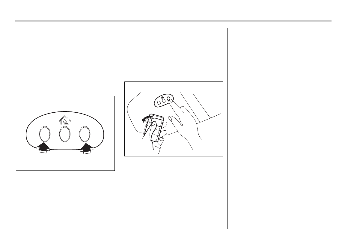
6-20 Interior equipment
trol System and your garage door opener
should activate when the HomeLink® but-
ton is pressed.
Programming for entrance
gates and garage door open-
ers in Canada
1. Unplug the motor of the entrance gate
or garage door opener from the outlet.
2. Press and hold the two outside buttons
until the HomeLink® indicator light begins
to flash (after 20 seconds). Release both
buttons.
NOTE
If any of the HomeLink® buttons are al-
ready programmed for other devices,
skip step 2 because it clears the mem-
ory of all three buttons.
3. Hold the end of the entrance gate’s/ga-
rage door opener’s hand-held transmitter
between 1 and 3 inches (25 and 76 mm)
away from the HomeLink® buttons on the
driver’s sun visor, keeping the indicator
light in view.
4. Press and hold the desired
HomeLink® button.
5. Press and release (“cycle”) the hand-
held transmitter button every two seconds
until step 6 is complete.
6. When the indicator light flashes slowly
and then rapidly after several seconds, re-
lease both buttons.
7. Plug the motor of the entrance gate/ga-
rage door opener to the outlet.
8. Test your entrance gate/garage door
opener by pressing the programmed
HomeLink® button.
Programming other devices
To program other devices such as door
locks, home lighting and security systems,
contact HomeLink at www.homelink.com
or call 1-800-355-3515.
Operating the HomeLink®
Wireless Control System
Once programmed, the HomeLink® Wire-
less Control System can be used to re-
mote-control the devices to which its but-
tons are programmed. To activate a de-
vice, simply press the appropriate button.
The indicator light illuminates, indicating
that the signal is being transmitted.
Reprogramming a single
HomeLink® button
1. Press and hold the HomeLink® button
you wish to reprogram. DO NOT release
the button until step 4 has been complet-
ed.
2. When the HomeLink® indicator light
begins to flash slowly (after 20 seconds),
position the hand-held transmitter of the
device for which you wish to program the
button at 1 to 3 inches (25 to 76 mm) away
600430
600434

Interior equipment 6-21
from the HomeLink® button surface.
3. Press and hold the hand-held transmit-
ter button. The HomeLink® indicator light
will flash, first slowly and then rapidly.
4. When the indicator light begins to flash
rapidly, release both buttons.
The programming for the previous device
is now erased and the new device can be
operated by pushing the HomeLink® but-
ton.
Erasing HomeLink® button
memory
NOTE
y Performing this procedure erases
the memory of all the preprogrammed
buttons simultaneously. The memory
of individual buttons cannot be erased.
y It is recommended that upon the sale
of the vehicle, the memory of all pro-
grammed HomeLink® buttons be
erased for security purposes.
1. Press and hold the two outside buttons
until the indicator light begins to flash (af-
ter 20 seconds).
2. Release both buttons.
In case a problem occurs
If you cannot activate a device using the
corresponding HomeLink® button after
programming, contact HomeLink at
www.homelink.com or call 1-800-355-
3515 for assistance.


7
Starting and operating
Fuel ...................................................................... 7-2
Fuel requirements .................................................. 7-2
Fuel filler lid and cap .............................................. 7-4
State emission testing (U.S. only) .................... 7-6
Preparing to drive .............................................. 7-7
Starting the engine ............................................. 7-8
Manual transmission vehicle ................................. 7-8
Automatic transmission vehicle ............................ 7-8
Stopping the engine ........................................... 7-9
Manual transmission ......................................... 7-9
Shifting speeds ....................................................... 7-10
Driving tips .............................................................. 7-11
Automatic transmission – 4-speed ................... 7-11
Selector lever .......................................................... 7-12
Selector lever reverse inhibiting function ............ 7-13
Selection of manual mode ..................................... 7-14
Maximum speeds .................................................... 7-15
Driving tips .............................................................. 7-16
SPORT mode ........................................................... 7-16
Shift lock release .................................................... 7-16
Automatic transmission – 5-speed ................... 7-17
Selector lever .......................................................... 7-18
Selector lever reverse inhibiting function ............ 7-19
Selection of manual mode ..................................... 7-20
Maximum speeds .................................................... 7-22
Driving tips .............................................................. 7-23
SPORT mode ........................................................... 7-23
Shift lock release .................................................... 7-23
Rear viscous limited slip differential (LSD)
(if equipped) ..................................................... 7-24
Power steering .................................................... 7-25
Braking ................................................................ 7-25
Braking tips ............................................................. 7-25
Brake system .......................................................... 7-25
Disc brake pad wear warning indicators .............. 7-26
ABS (Anti-lock Brake System) .......................... 7-26
ABS system self-check .......................................... 7-26
ABS warning light ................................................... 7-27
Electronic Brake Force Distribution (EBD)
system .............................................................. 7-28
Steps to take if EBD system fails .......................... 7-28
Vehicle Dynamics Control system
(if equipped) ..................................................... 7-29
Vehicle Dynamics Control system monitor .......... 7-31
Vehicle Dynamics Control OFF switch ................. 7-32
Tire pressure monitoring system (TPMS)
(if equipped) ..................................................... 7-33
Parking your vehicle .......................................... 7-35
Cruise control ..................................................... 7-36
To set cruise control .............................................. 7-37
To temporarily cancel the cruise control ............. 7-37
To turn off the cruise control ................................. 7-38
To change the cruising speed ............................... 7-38
Cruise control indicator light ................................. 7-39
Cruise control set indicator light .......................... 7-39
7-2 Starting and operating
Starting an d operating
Fuel
Fuel requirements
T 2.5-liter non-turbo models
The 2.5-liter non-turbo engine is designed
to operate using unleaded gasoline with
an octane rating of 87 AKI or higher.
T 2.5-liter turbo models and 3.0-liter
models
The 2.5-liter turbo engine and 3.0-liter en-
gine are designed to operate using premi-
um unleaded gasoline with an octane rat-
ing of 91 AKI or higher. If premium unlead-
ed gasoline is not available, regular un-
leaded gasoline with an octane rating of
87 AKI or higher may be temporarily used.
For optimum engine performance and
driveability, it is required (for 2.5-liter turbo
models), and recommended (for 3.0-liter
models) that you use premium grade un-
leaded gasoline.
NOTE
Be sure to use premium unleaded gas-
oline of 91 AKI or higher for a 2.5-liter
turbo engine model. If other gasoline
(lower than 91 AKI) is used, knocking,
reduced output and poor accelerator
response will result.
T Fuel octane rating
This octane rating is the average of the
Research Octane and Motor Octane num-
bers and is commonly referred to as the
Anti Knock Index (AKI).
Using a gasoline with a lower octane rat-
ing can cause persistent and heavy
knocking, which can damage the engine.
Do not be concerned if your vehicle some-
times knocks lightly when you drive up a
hill or when you accelerate. See your
dealer or a qualified service technician if
you use a fuel with the specified octane
rating and your vehicle knocks heavily or
persistently.
T Unleaded gasoline
The neck of the fuel filler pipe is designed
to accept only an unleaded gasoline filler
nozzle. Under no circumstances should
leaded gasoline be used because it will
damage the emission control system and
may impair driveability and fuel economy.
T California fuel
If your vehicle was certified to California
Emission Standards as indicated on the
underhood tune-up label, it is designed to
optimize engine and emission control sys-
tem performance with gasoline that meets
the clean burning low-sulfur California
gasoline specifications. If you live in any
other state than California, your vehicle
will operate on gasoline meeting Federal
specifications. Gasoline sold outside Cali-
fornia is permitted to have higher sulfur
levels, which may affect the performance
of your vehicle’s catalytic converter and
may produce a sulfur exhaust odor or
smell. SUBARU recommends that you try
a different brand of unleaded gasoline
having lower sulfur to determine if the
problem is fuel related before returning
your vehicle to an authorized dealer for
service. The CHECK ENGINE warning
light/Malfunction indicator lamp may also
turn on. If this occurs, return to your autho-
rized SUBARU dealer for diagnosis. If it is
determined that the condition is caused by
the type of fuel used, repairs may not be
covered by your warranty.
T MMT
Some gasoline contains an octane-en-
hancing additive called MMT (Methylcy-
clopentadienyl Manganese Tricarbonyl). If
you use such fuels, your emission control
system performance may deteriorate and
the CHECK ENGINE warning light/Mal-
Use of a fuel which is low in quality
or use of an inappropriate fuel addi-
tive may cause engine damage.
Starting and operating 7-3
– CONTINUED –
function indicator lamp may turn on. If this
happens, return to your authorized
SUBARU Dealer for service. If it is deter-
mined that the condition is caused by the
type of fuel used, repairs may not be cov-
ered by your warranty.
T Gasoline for cleaner air
Your use of gasoline with detergent addi-
tives will help prevent deposits from form-
ing in your engine and fuel system. This
helps keep your engine in tune and your
emission control system working properly,
and is a way of doing your part for cleaner
air. If you continuously use a high quality
fuel with the proper detergent and other
additives, you should never need to add
any fuel system cleaning agents to your
fuel tank.
Many gasolines are now blended with ma-
terials called oxygenates. Use of these fu-
els can also help keep the air cleaner. Ox-
ygenated blend fuels, such as MTBE (Me-
thyl Tertiary Butyl ether) or ethanol (ethyl
or grain alcohol) may be used in your ve-
hicle, but should contain no more than
15% MTBE or 10% ethanol for the proper
operation of your SUBARU.
In addition, some gasoline suppliers are
now producing reformulated gasolines,
which are designed to reduce vehicle
emissions. SUBARU approves the use of
reformulated gasoline.
If you are not sure what the fuel contains,
you should ask your service station oper-
ators if their gasolines contain detergents
and oxygenates and if they have been re-
formulated to reduce vehicle emissions.
As additional guidance, only use fuels
suited for your vehicle as explained in the
following.
y Fuel should be unleaded and have an
octane rating no lower than that specified
in this manual.
y Methanol (methyl or wood alcohol) is
sometimes mixed with unleaded gasoline.
Methanol can be used in your vehicle
ONLY if it does not exceed 5% of the fuel
mixture AND if it is accompanied by suffi-
cient quantities of the proper cosolvents
and corrosion inhibitors required to pre-
vent damage to the fuel system. Do not
use fuel containing methanol EXCEPT un-
der these conditions.
y If undesirable driveability problems are
experienced and you suspect they may be
fuel related, try a different brand of gaso-
line before seeking service at your
SUBARU dealer.
y Fuel system damage or driveability
problems which result from the use of im-
proper fuel are not covered under the
SUBARU Limited Warranty.
Do not let fuel spill on the exterior
surfaces of the vehicle. Fuels con-
taining alcohol may cause paint
damage, which is not covered under
the SUBARU Limited Warranty.
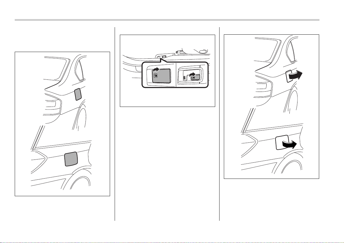
7-4 Starting and operating
Fuel filler lid and cap
T Refueling
0
1. To open the fuel filler lid, pull the lid re-
lease lever. The lever is on the floor at the
left of the driver’s seat.
2. Open the fuel filler lid.
700342
700343
200255
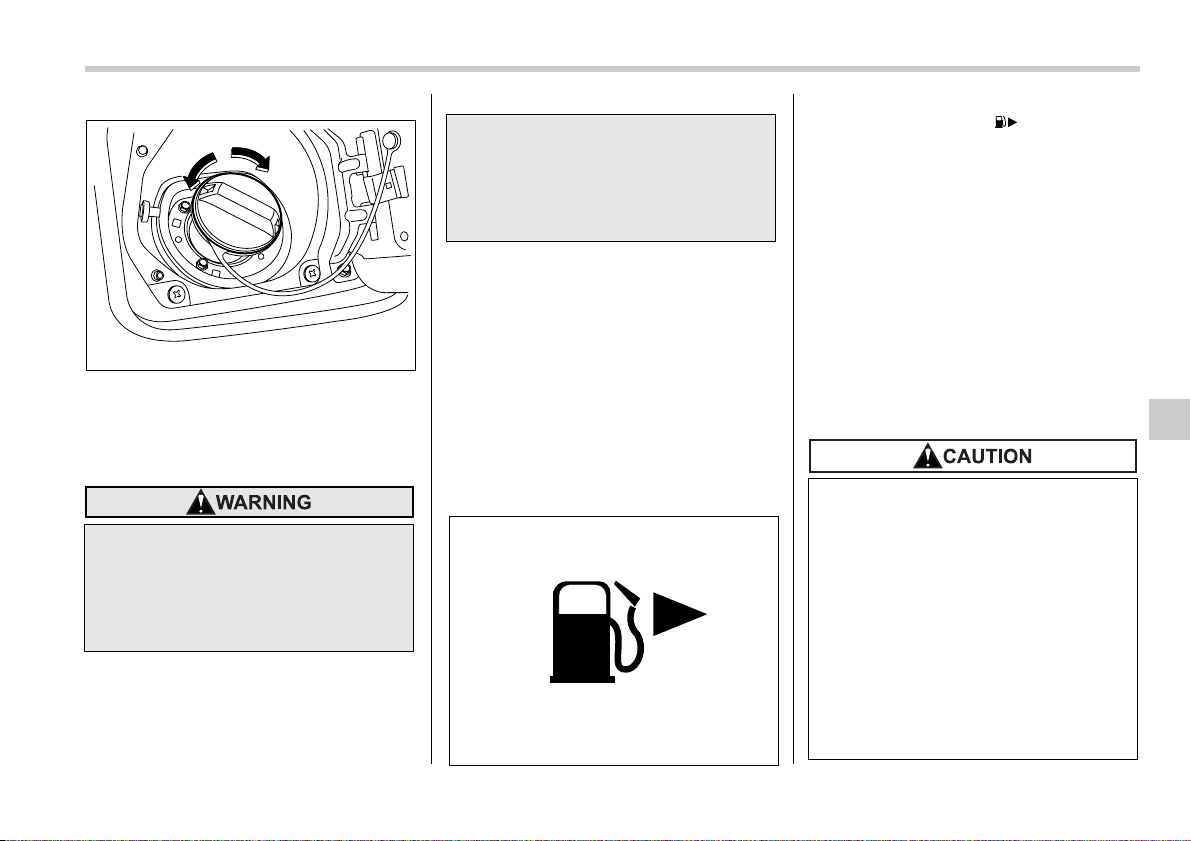
Starting and operating 7-5
– CONTINUED –
1) Open
2) Close
3. Remove the fuel filler cap by turning it
slowly counterclockwise.
4. Stop filling the tank after the fuel filler
pump automatically clicks off. Do not add
any more fuel.
5. Put the cap back on, turn it clockwise
until you hear a clicking noise. Be certain
not to catch the tether under the cap while
tightening.
6. Close the fuel filler lid completely.
If you spill any fuel on the painted surface,
rinse it off immediately. Otherwise, the
painted surface could be damaged.
NOTE
y You will see the “ ” sign in the
fuel gauge. This indicates that the fuel
filler door (lid) is located on the right
side of the vehicle.
y If the fuel filler cap is not tightened
until it clicks or if the tether is caught
under the cap, the CHECK ENGINE
warning light may come on. Refer to
the “Warning and indicator lights” sec-
tion located in chapter 3.
(Turbo model only) Promptly put fuel in
the tank whenever the low fuel warning
light comes on. Engine misfires as a re-
sult of an empty tank could cause dam-
age to the engine.
y Gasoline vapor is highly flamma-
ble. Before refueling, always first
stop the engine and make sure
that there are no lighted ciga-
rettes, open flames or electrical
sparks in the adjacent area.
1
2
700344
y When opening the cap, do not re-
move the cap quickly. Fuel may be
under pressure and spray out of
the fuel filler neck especially in
hot weather, which may cause in-
jury.
200253
y Never add any cleaning agents to
the fuel tank. The addition of a
cleaning agent may cause dam-
age to the fuel system.
y Make sure that the cap is tight-
ened until it clicks to prevent fuel
spillage in the event of an acci-
dent.
y Do not let fuel spill on the exterior
surfaces of the vehicle. Fuels may
cause paint damage, which is not
covered under the SUBARU Limit-
ed Warranty.
7-6 Starting and operating
State emission testing (U.S.
only)
At state inspection time, remember to
tell your inspection or service station
in advance not to place your SUBARU
AWD vehicle on a two-wheel dyna-
mometer. Otherwise, serious transmis-
sion damage will result.
Some states have started using dyna-
mometers in their state inspection pro-
grams in order to meet their obligation un-
der federal law to implement stricter vehi-
cle emission standards to reduce air pollu-
tion from vehicles. A dynamometer is a
treadmill or roller-like testing device that
allows your vehicle’s wheels to turn while
the vehicle remains in one place. Depend-
ing on the severity of a state’s air pollution
problems, the states must adopt either a
“basic” or “enhanced” vehicle emission in-
spection test. Normally, a portion of the
basic emission test consists of an emis-
sion inspector inserting an analyzer probe
into the exhaust pipe of an idling vehicle
for a short period of time. States with more
severe air pollution problems are required
to adopt an enhanced vehicle emission
test. This test simulates actual driving
conditions on a dynamometer and permits
more accurate measurement of tailpipe
emitted pollution than the basic emission
test.
The U.S. Environmental Protection Agen-
cy (EPA) and states using two-wheel dy-
namometers in their emission testing pro-
grams have EXEMPTED SUBARU AWD
vehicles from the portion of the testing
program that involves a two-wheel dyna-
mometer.
There are some states that use four-wheel
dynamometers in their testing programs.
When properly used, that equipment will
not damage an AWD SUBARU vehicle.
y Always use a genuine SUBARU
fuel filler cap. If you use the wrong
cap, it may not fit or have proper
venting, and your fuel tank and
emission control system might be
damaged.
Testing of an All-Wheel Drive vehi-
cle must NEVER be performed on a
single two-wheel dynamometer. At-
tempting to do so will result in un-
controlled vehicle movement and
may cause an accident or injuries to
persons nearby.
Resultant vehicle damage due to im-
proper testing is not covered under
the SUBARU Limited Warranty and
is the responsibility of the state in-
spection program or its contractors
or licensees.

Starting and operating 7-7
Under no circumstances should the rear
wheels be jacked off the ground, nor
should the driveshaft be disconnected for
state emission testing.
The EPA has issued regulations for in-
specting the On-Board Diagnostic (OBD)
system as part of the state emissions in-
spection. The OBD system is designed to
detect engine and transmission problems
that might cause vehicle emissions to ex-
ceed allowable limits. These inspections
apply to all 1996 model year and newer
passenger cars and light trucks. Over 30
states plus the District of Columbia have
implemented the OBD system inspection.
y The inspection of the OBD system con-
sists of a visual operational check of the
“CHECK ENGINE” warning light/malfunc-
tion indicator lamp (MIL) and an examina-
tion of the OBD system with an electronic
scan tool while the engine is running.
y A vehicle passes
the OBD system in-
spection if proper the “CHECK ENGINE”
warning light/MIL illumination is observed,
there is no stored diagnostic trouble
codes, and the OBD system readiness
monitors are complete.
y A vehicle fails
the OBD inspection if the
“CHECK ENGINE” warning light/MIL is
not properly operating or there is one or
more diagnostic trouble codes stored in
vehicle’s computer with the “CHECK EN-
GINE” warning light/MIL illuminated.
y A state emission inspection may reject
(not pass or fail) a vehicle if the number of
OBD system readiness monitors “Not
Ready” is greater than one. Under this
condition, the vehicle operator should be
instructed to drive his/her vehicle for a few
days to set the monitors and return for an
emission re-inspection.
y Owners of rejected or failing vehicles
should contact their SUBARU Dealer for
service.
Preparing to drive
You should perform the following checks
and adjustments every day before you
start driving.
1. Check that all windows, mirrors, and
lights are clean and unobstructed.
2. Check the appearance and condition of
the tires. Also check tires for proper infla-
tion.
3. Look under the vehicle for any sign of
leaks.
4. Check that the hood, trunk (Sedan)
and rear gate (Station wagon) are fully
closed.
5. Check the adjustment of the seat.
6. Check the adjustment of the inside and
outside mirrors.
7. Fasten your seatbelt. Check that your
passengers have fastened their seatbelts.
8. Check the operation of the warning and
indicator lights when the ignition switch is
turned to the “ON” position.
9. Check the gauges, indicator and warn-
ing lights after starting the engine.
NOTE
Engine oil, engine coolant, brake fluid,
washer fluid and other fluid levels
should be checked daily, weekly or at
fuel stops.
7-8 Starting and operating
Starting the engine
Manual transmission vehicle
1. Apply the parking brake.
2. Turn off unnecessary lights and acces-
sories.
3. Press the clutch pedal to the floor and
shift the shift lever into neutral.
Hold the clutch pedal to the floor while
starting the engine. The starter motor will
only operate when the clutch pedal is
pressed fully to the floor.
4. Turn the ignition switch to the “ON” po-
sition and check the operation of the warn-
ing and indicator lights. Refer to the
“Warning and indicator lights” section
(chapter 3).
5. Turn the ignition switch to the “START”
position without depressing the accelera-
tor pedal. Release the key immediately af-
ter the engine has started.
If the engine does not start, try the follow-
ing.
1)Turn the ignition switch to the “OFF”
position and wait for at least 10 sec-
onds. After checking that the parking
brake is firmly set, turn the ignition
switch to the “START” position while de-
pressing the accelerator pedal slightly
(approximately a quarter of the full
stroke). Release the accelerator pedal
as soon as the engine starts.
2)If this fails to start the engine, turn the
ignition switch back to the “OFF” posi-
tion and wait for at least 10 seconds.
Then fully depress the accelerator ped-
al and turn the ignition switch to the
“START” position. If the engine starts,
quickly release the accelerator pedal.
3)If this fails to start the engine, turn the
ignition switch again to the “OFF” posi-
tion. After waiting for 10 seconds or
longer, turn the ignition switch to the
“START” position without depressing
the accelerator pedal.
4)If the engine still refuses to start, con-
tact your nearest SUBARU dealer for
assistance.
6. Confirm that all warning and indicator
lights have gone off after the engine has
started. The fuel injection system auto-
matically lowers the idle speed as the en-
gine warms up.
Automatic transmission vehi-
cle
1. Apply the parking brake.
2. Turn off unnecessary lights and acces-
sories.
3. Shift the selector lever to the “P” or “N”
position (preferably “P” position). The
starter will only operate when the select
lever is at the “P” or “N” position.
4. Turn the ignition switch to the “ON” po-
sition and check the operation of the warn-
ing and indicator lights. Refer to the
“Warning and indicator lights” section
(chapter 3).
5. Turn the ignition switch to the “START”
position without depressing the accelera-
tor pedal. Release the key immediately af-
ter the engine has started.
If the engine does not start, try the follow-
ing.
1)Turn the ignition switch to the “OFF”
position and wait for at least 10 sec-
Do not operate the starter motor
continuously for more than ten sec-
onds. If the engine fails to start after
operating the starter for five to ten
seconds, wait for ten seconds or
more before trying again.
If you restart the engine while the
vehicle is moving, shift the selector
lever into the “N” position. Do not
attempt to place the selector lever of
a moving vehicle into the “P” posi-
tion.
Starting and operating 7-9
– CONTINUED –
onds. After checking that the parking
brake is firmly set, turn the ignition
switch to the “START” position while de-
pressing the accelerator pedal slightly
(approximately a quarter of the full
stroke). Release the accelerator pedal
as soon as the engine starts.
2)If this fails to start the engine, turn the
ignition switch back to the “OFF” posi-
tion and wait for at least 10 seconds.
Then fully depress the accelerator ped-
al and turn the ignition switch to the
“START” position. If the engine starts,
quickly release the accelerator pedal.
3)If this fails to start the engine, turn the
ignition switch again to the “OFF” posi-
tion. After waiting for 10 seconds or
longer, turn the ignition switch to the
“START” position without depressing
the accelerator pedal.
4)If the engine still refuses to start, con-
tact your nearest SUBARU dealer for
assistance.
6. Confirm that all warning and indicator
lights have gone out after the engine has
started. The fuel injection system auto-
matically lowers the idle speed as the en-
gine warms up.
While the engine is warming up, make
sure that the selector lever is at the “P” or
“N” position and that the parking brake is
applied.
Stopping the engine
The ignition switch should be turned off
only when the vehicle is stopped and the
engine is idling.
Manual transmission
The manual transmission is a fully syn-
chromeshed, 5-forward-speed and 1-re-
verse-speed transmission.
Do not stop the engine when the ve-
hicle is moving. This will cause loss
of power to the power steering and
the brake booster, making steering
and braking more difficult. It could
also result in accidental activation
of the “LOCK” position on the igni-
tion switch, causing the steering
wheel to lock.
Do not drive the vehicle with the
clutch disengaged (i.e., when the
clutch pedal is depressed) or with
the shift lever in the neutral posi-
tion. Engine braking has no effect in
either of these conditions and the
risk of an accident is consequently
increased.
Shift into reverse ONLY when the
vehicle has completely stopped. It
may cause damage to the transmis-
sion to try shifting into reverse
when the vehicle is moving.
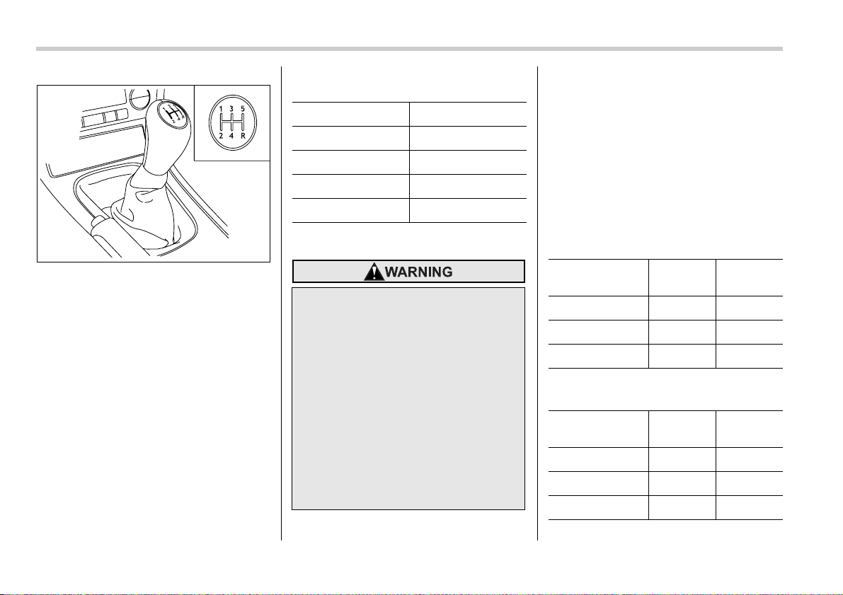
7-10 Starting and operating
The shift pattern is shown on the shift le-
ver knob. When shifting from 5th gear to
reverse gear, first return the shift lever to
the neutral position then shift into reverse
gear.
To change gears, fully depress the clutch
pedal, move the shift lever, and gradually
let up on the clutch pedal.
If it is difficult to shift into gear, put the
transmission in neutral, release the clutch
pedal momentarily, and then try again.
Shifting speeds
T Recommended shifting speeds
The best compromise between fuel econ-
omy and vehicle performance during nor-
mal driving is ensured by shifting up at the
speeds listed in the following table.
T Maximum allowable speeds
The following table shows the maximum
speeds that are possible with each differ-
ent gear.
Never exceed the speed limit below for
each gear position except for brief accel-
eration in an emergency. The tachome-
ter’s needle (if so equipped) will enter the
red area if these speeds are exceeded.
Failure to observe this precaution can
lead to excessive engine wear and poor
fuel economy.
Non-turbo models
mph (km/h)
Turbo models
mph (km/h)
700101
Shift up mph (km/h)
1st to 2nd 15 (24)
2nd to 3rd 25 (40)
3rd to 4th 40 (65)
4th to 5th 45 (73)
When shifting down a gear, ensure
that the vehicle is not travelling at a
speed exceeding the Maximum Al-
lowable Speed for the gear which is
about to be selected. Failure to ob-
serve this precaution can lead to en-
gine over-revving and this in turn
can result in engine damage.
In addition, sudden application of
engine brakes when the vehicle is
travelling on a slippery surface can
lead to wheel locking; as a conse-
quence, control of the vehicle may
be lost and the risk of an accident in-
creased.
Gear Except
OUTBACK
OUTBACK
1st 30 (48) 30 (48)
2nd 50 (81) 52 (82)
3rd 71 (116) 71 (116)
Gear Except
OUTBACK
OUTBACK
1st 32 (52) 32 (52)
2nd 54 (88) 54 (88)
3rd 80 (129) 78 (127)
Starting and operating 7-11
– CONTINUED –
Never exceed posted speed limits.
Driving tips
Do not drive with your foot resting on the
clutch pedal and do not use the clutch to
hold your vehicle at a standstill on an up-
grade. Either of those actions may cause
clutch damage.
Do not drive with your hand resting on the
shift lever. This may cause wear on the
transmission components.
When it is necessary to reduce vehicle
speed due to slow traffic, turning corners,
or driving up steep hills, downshift to a
lower gear before the engine starts to la-
bor.
y On steep downgrades, downshift the
transmission to 4th, 3rd or 2nd gear as
necessary; this helps to maintain a safe
speed and to extend brake pad life.
In this way, the engine provides a braking
effect. Remember, if you “ride” (over use)
the brakes while descending a hill, they
may overheat and not work properly.
y The engine may, on rare occasions,
knock when the vehicle rapidly acceler-
ates or rapidly pulls away from a standstill.
This phenomenon does not indicate a
fault.
y A slight reduction in output torque may
occur in the models with a 2.5-liter turbo
engine before the engine warms up.
Automatic transmission – 4-
speed
The automatic transmission is electroni-
cally controlled and provides 4 forward
speeds and 1 reverse speed. Also, it has
a manual mode and a SPORT mode.
Do not shift from the “P” or “N” po-
sition into the “D” or “R” position
while depressing the accelerator
pedal. This may cause the vehicle to
jump forward or backward.
y Shift into the “P” or “R” position
only after the vehicle is complete-
ly stopped. Shifting while the ve-
hicle is moving may cause dam-
age to the transmission.
y Do not race the engine for more
than five seconds in any position
except the “N” or “P” position
when the brake is set or when
chocks are used in the wheels.
This may cause the automatic
transmission fluid to overheat.
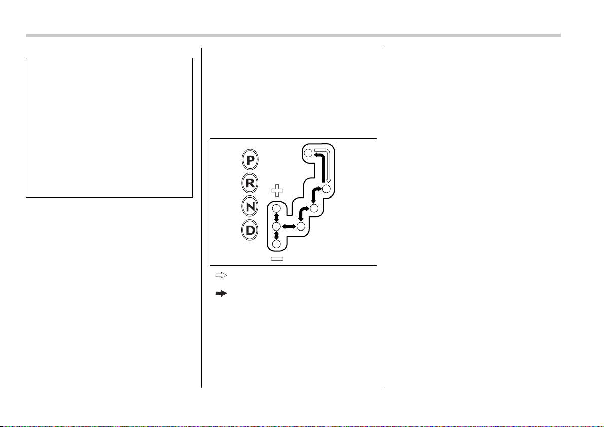
7-12 Starting and operating
NOTE
y When the engine coolant tempera-
ture is still low, your vehicle’s automat-
ic transmission will up-shift at higher
engine speeds than when the coolant
temperature is sufficiently high in or-
der to shorten the warm-up time and
improve driveability. The gearshift tim-
ing will automatically shift to the nor-
mal timing after the engine has warmed
up.
y Immediately after ATF (automatic
transmission fluid) is replaced, you
may feel that the automatic transmis-
sion operation is somewhat unusual.
This results from invalidation of data
which the on-board computer has col-
lected and stored in memory to allow
the transmission to shift at the most
appropriate times for the current con-
dition of your vehicle. Optimized shift-
ing will be restored as the vehicle con-
tinues to be driven for a while.
Selector lever
: Shift possible with brake pedal de-
pressed
: Shift possible with brake pedal not
depressed
The selector lever has four positions, “P”,
“R”, “N”, “D” and also has manual gate for
using “SPORT” mode or manual mode.
T P (Park)
This position is for parking the vehicle and
starting the engine.
In this position, the transmission is me-
chanically locked to prevent the vehicle
from rolling freely.
When you park the vehicle, first set the
parking brake fully, then shift into the “P”
position. Do not hold the vehicle with only
the transmission.
To shift the selector lever from the “P” to
any other position, you should depress the
brake pedal fully then move the selector
lever. This prevents the vehicle from
lurching when it is started.
T R (Reverse)
This position is for backing the vehicle.
To shift from the “N” to “R” position, stop
the vehicle completely then move the le-
ver to the “R” position.
T N (Neutral)
This position is for restarting a stalled en-
gine.
In this position the wheels and transmis-
sion are not locked. In this position, the
transmission is neutral; the vehicle will roll
freely, even on the slightest incline unless
the parking brake or foot brake is on.
Avoid coasting with the transmission neu-
tral.
During coasting, there is no engine brak-
ing effect.
y Avoid shifting from one of the for-
ward driving positions into the
“R” position or vice versa until the
vehicle has completely stopped.
Such shifting may cause damage
to the transmission.
y When parking the vehicle, first se-
curely apply the parking brake
and then place the selector lever
in the “P” position. Avoid parking
for a long time with the selector le-
ver in any other position as doing
so could result in a dead battery.
700107
Starting and operating 7-13
– CONTINUED –
NOTE
If the selector lever is in the “N” posi-
tion when you stop the engine for park-
ing, you may not subsequently be able
to move it to the “R” and “P” positions.
If this happens, turn the ignition switch
to the “ON” position. You will then be
able to move the selector lever to the
“P” position.
T D (Drive)
This position is for normal driving.
The transmission automatically shifts into
a suitable gear from 1st to 4th according to
the vehicle speed and the acceleration
you require.
When more acceleration is required in this
position, press the accelerator pedal fully
to the floor and hold that position. The
transmission will automatically downshift
to 3rd, 2nd or 1st gear. When you release
the pedal, the transmission will return to
the original gear position.
To use the “SPORT” mode, move the le-
ver from this position into the manual gate.
To use the manual mode, move the lever
from this position into the manual gate
then move it toward the “+” and “–” ends.
V While climbing a grade
When driving up a hill, undesired upshift to
4th gear is prevented from taking place
when the accelerator is released. This
minimizes the chance of subsequent
downshifting to a lower gear when accel-
erating again. This prevents repeated up-
shifting and downshifting resulting in a
smoother operation of the vehicle.
NOTE
The transmission may downshift to
2nd or 1st gear, depending on the way
the accelerator pedal is pressed to ac-
celerate the vehicle again.
V While going down a hill
When you are descending a hill or any
other slope while braking with the
“SPORT” mode selected, the transmis-
sion may downshift to 3rd or 2nd gear de-
pending on how hard you depress the
brake pedal, causing engine braking to
work. Reacceleration for a short time will
cause the transmission to upshift normal-
ly.
NOTE
y A 4th-to-3rd automatic downshift will
not occur at speeds above 50 mph (80
km/h) and a 3rd-to-2nd automatic
downshift will not occur at speeds
above 24 mph (38 km/h).
y Automatic downshifts to 3rd or 2nd
may occur even when driving on a level
road depending on conditions, such as
how hard you depress the brake pedal.
Selector lever reverse inhibit-
ing function
This function prevents accidental move-
ment of the selector lever to the “R” posi-
tion while the vehicle is moving.
The function becomes operational when
the vehicle reaches a speed of approxi-
mately 6 mph (10 km/h). Once operation-
al, it prevents the selector lever from being
moved from the “N” position to the “R” po-
sition. When the vehicle speed drops be-
low 6 mph (10 km/h), the function is can-
celed. The selector lever can then be
moved to the “R” and “P” positions.
When the ignition switch has been turned
to the “OFF” position, movement of the se-
lector lever from the “N” position to the “R”
position is possible for a limited time peri-
od and then becomes impossible. Also,
the selector lever cannot be moved to the
Do not drive the vehicle with the se-
lector lever in the “N” (neutral) posi-
tion. Engine braking has no effect in
this condition and the risk of an ac-
cident is consequently increased.

7-14 Starting and operating
“R” position when it has been placed in the
“P” position and then placed again in the
“N” position. When movement of the se-
lector lever from the “N” position to the “R”
position has become impossible, turn the
ignition switch back to the “ON” position
then move the selector lever to the “P” po-
sition. Pressing the selector lever release
button also makes it possible to move the
selector lever to the “P” position at this
time.
T Selector lever release button
If you inadvertently have turned the igni-
tion switch to the “OFF” position with the
selector lever in the “N” position, proceed
as follows. By referring to the “Shift lock
release” section in this chapter, remove
the shift lock release cover. Then, with the
screwdriver inserted into the hole, move
the selector lever to the “P” position. If the
selector lever reverse inhibiting function
fails, have the vehicle inspected by the
nearest SUBARU dealer.
Selection of manual mode
With the vehicle either moving or station-
ary, move the selector lever from the “D”
position to the manual gate then move it to
the “+” end or “–” end of the manual gate
to select manual mode.
1) Upshift indicator
2) Downshift indicator
3) Gear position indicator
When the manual mode is selected, the
gear position indicator and upshift indica-
tor and/or downshift indicator in the ta-
chometer come on. The gear position indi-
cator shows the currently selected gear in
the 1st-to-4th-gear range. The upshift and
downshift indicators show when a gear-
shift is possible. When the upshift indica-
tor “ ” is on, upshifting is possible.
When the downshift indicator “ ” is on,
downshifting is possible. When both indi-
cators are on, upshifting and downshifting
are both possible. When the vehicle stops
(for example, at traffic signals), the down-
shift indicator goes off.
700345
700109
1
2
3
700308
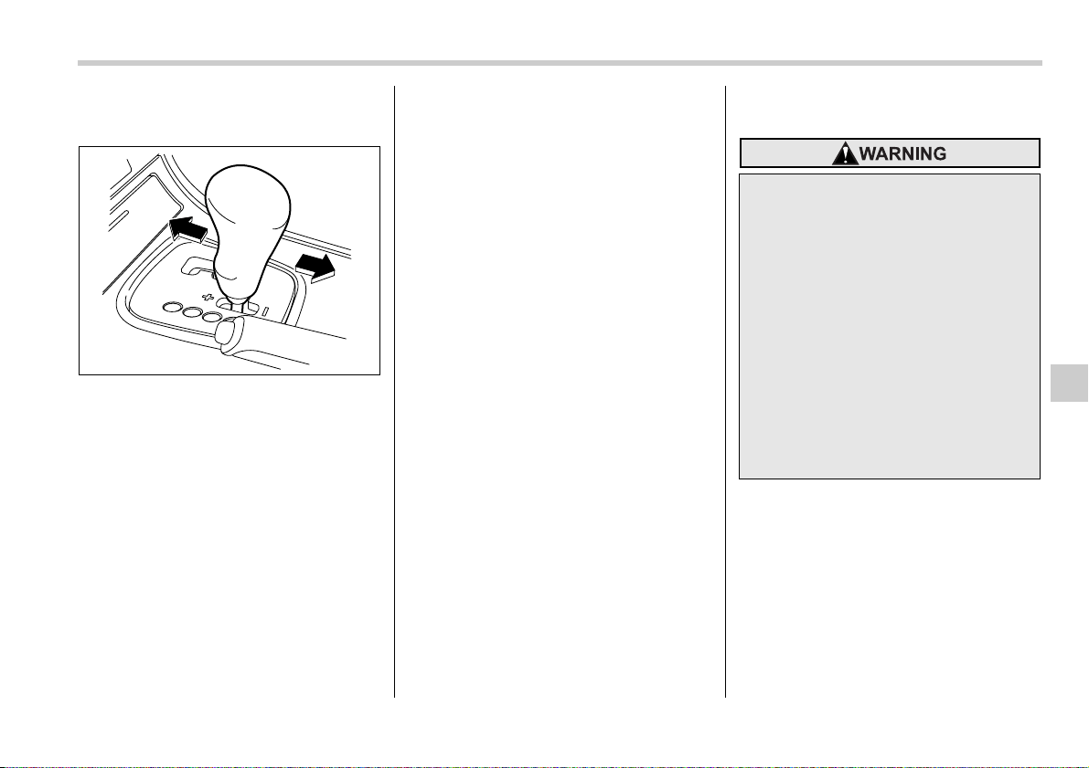
Starting and operating 7-15
– CONTINUED –
Gearshifts can be performed using the se-
lector lever.
Using the selector lever
Shift to the next-higher gear by briefly
pushing the selector lever toward the “+”
end of the manual gate.
Shift to the next-lower gear by briefly pull-
ing the selector lever toward the “–” end of
the manual gate.
NOTE
Please read the following points care-
fully and bear them in mind when using
the manual mode.
y The transmission does not automati-
cally shift up in the manual mode. Per-
form gearshifts in accordance with
road conditions so that the tachometer
needle does not enter the red zone. If
the engine speed reaches a predeter-
mined level, a fuel-cut function will op-
erate. Shift up if this happens.
y If you attempt to shift down when the
engine speed is too high, i.e., when a
downshift would push the tachometer
needle beyond the red zone, beeps will
be emitted to warn you that the down-
shift is not possible.
y If you attempt to shift up when the
vehicle speed is too low, the transmis-
sion will not respond.
y You can perform a skip-shift (for ex-
ample, from 4th to 2nd) by operating
the selector lever twice in rapid suc-
cession.
y The transmission automatically se-
lects 1st gear when the vehicle stops
moving.
y If the temperature of the automatic
transmission fluid becomes too high,
the “AT OIL TEMP” warning light will
come on and upshifts to 4th gear will
not be possible. Immediately stop the
vehicle in a safe place and let the en-
gine idle until the warning light goes
off.
Maximum speeds
The following tables show the maximum
speeds that are possible with each differ-
ent gear.
When down shifting, it is important to con-
firm that the current vehicle speed is not in
excess of the Maximum Allowable Speed
of the gear which is about to be selected.
700111
When down shifting, ensure that the
vehicle is not travelling at a speed
exceeding the Maximum Allowable
Speed for the gear which is about to
be selected. Failure to observe this
precaution can lead to engine over-
revving and this in turn can result in
engine damage.
In addition, sudden application of
engine braking caused by down
shifting when the vehicle is travel-
ling on a slippery surface can lead to
wheel locking; as a consequence,
control of the vehicle may be lost
and the risk of an accident in-
creased.
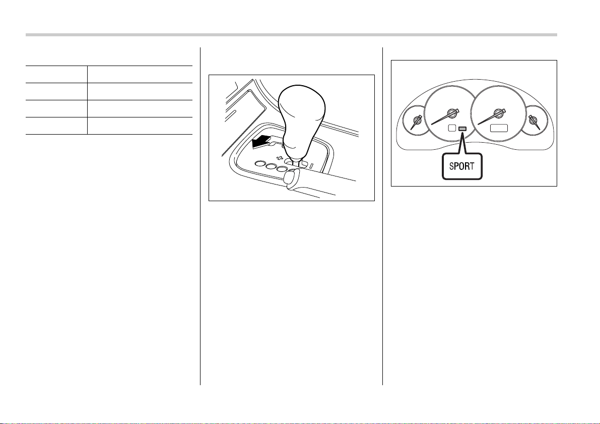
7-16 Starting and operating
mph (km/h)
Never exceed posted speed limits.
Driving tips
y On a road surface where there is a risk
of wheelspin (for example, a snow- or
gravel-covered road), you can pull away
from a standstill (safely and easily) by first
selecting the 2nd gear of the manual
mode.
y Always apply the foot or parking brake
when the vehicle is stopped in the “D” or
“R” position.
y Always set the parking brake when
parking your vehicle. Do not hold the vehi-
cle with only the transmission.
y Do not keep the vehicle in a stationary
position on an uphill grade by using the
“D” position. Use the brake instead.
y The engine may, on rare occasions,
knock when the vehicle rapidly acceler-
ates or rapidly pulls away from a standstill.
This phenomenon does not indicate a
fault.
SPORT mode
SPORT mode is used when power is
needed for rapid acceleration or for uphill
driving. To select this mode, move the se-
lector lever from the “D” position to the
manual gate.
When selected, the SPORT mode indica-
tor light on the instrument panel will turn
on.
To deselect SPORT mode, move the se-
lector lever to the “D” position or select
manual mode.
To subsequently reselect SPORT mode,
move the selector lever to the “D” position
and from there to the manual gate.
In this mode, the transmission shifts up at
higher vehicle speeds and shifts down
more responsively than in normal mode.
Shift lock release
If the selector lever does not move from
the “P” position with the brake pedal de-
pressed and the ignition switch in the “ON”
position, perform the following steps:
Position 2.5-liter non-turbo models
1 34 (55)
2 64 (103)
3 99 (160)
700112
700113
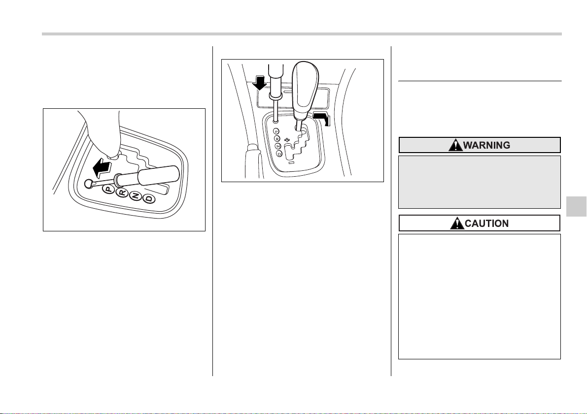
Starting and operating 7-17
– CONTINUED –
To override the shift lock:
1. Set the parking brake and stop the en-
gine.
2. Take out the screwdriver from the tool
bucket.
3. Remove the cover by prying on the
edge with a flat-head screwdriver.
4. Insert the key into the hole.
5. Push down on the screwdriver and
move the selector lever from the “P” to the
“N” position.
6. Remove the screwdriver from the hole.
Depress the brake pedal and start the en-
gine.
Take your vehicle to the nearest SUBARU
dealer immediately to have the system re-
paired.
Automatic transmission – 5-
speed
The automatic transmission is electroni-
cally controlled and provides 5 forward
speeds and 1 reverse speed. Also, it has
a manual mode and a SPORT mode.
700346
700347
Do not shift from the “P” or “N” po-
sition into the “D” or “R” position
while depressing the accelerator
pedal. This may cause the vehicle to
jump forward or backward.
y Shift into the “P” or “R” position
only after the vehicle is complete-
ly stopped. Shifting while the ve-
hicle is moving may cause dam-
age to the transmission.
y Do not race the engine for more
than five seconds in any position
except the “N” or “P” position
when the brake is set or when
chocks are used in the wheels.
This may cause the automatic
transmission fluid to overheat.

7-18 Starting and operating
NOTE
y When the engine coolant tempera-
ture is still low, your vehicle’s automat-
ic transmission will up-shift at higher
engine speeds than when the coolant
temperature is sufficiently high in or-
der to shorten the warm-up time and
improve driveability. The gearshift tim-
ing will automatically shift to the nor-
mal timing after the engine has warmed
up.
y Immediately after ATF (automatic
transmission fluid) is replaced, you
may feel that the automatic transmis-
sion operation is somewhat unusual.
This results from invalidation of data
which the on-board computer has col-
lected and stored in memory to allow
the transmission to shift at the most
appropriate times for the current con-
dition of your vehicle. Optimized shift-
ing will be restored as the vehicle con-
tinues to be driven for a while.
Selector lever
: Shift possible with brake pedal de-
pressed
: Shift possible with brake pedal not
depressed
The selector lever has four positions, “P”,
“R”, “N”, “D” and also has manual gate for
using “SPORT” mode or manual mode.
T P (Park)
This position is for parking the vehicle and
starting the engine.
In this position, the transmission is me-
chanically locked to prevent the vehicle
from rolling freely.
When you park the vehicle, first set the
parking brake fully, then shift into the “P”
position. Do not hold the vehicle with only
the transmission.
To shift the selector lever from the “P” to
any other position, you should depress the
brake pedal fully then move the selector
lever. This prevents the vehicle from
lurching when it is started.
NOTE (3.0-liter models only)
To protect the engine while the “P” po-
sition is selected, the engine is con-
trolled such that the engine speed
does not become too high even if the
accelerator pedal is pressed hard.
T R (Reverse)
This position is for backing the vehicle.
To shift from the “N” to “R” position, stop
the vehicle completely then move the le-
ver to the “R” position.
T N (Neutral)
This position is for restarting a stalled en-
gine.
In this position the wheels and transmis-
sion are not locked. In this position, the
y Avoid shifting from one of the for-
ward driving positions into the
“R” position or vice versa until the
vehicle has completely stopped.
Such shifting may cause damage
to the transmission.
y When parking the vehicle, first se-
curely apply the parking brake
and then place the selector lever
in the “P” position. Avoid parking
for a long time with the selector le-
ver in any other position as doing
so could result in a dead battery.
700107
Starting and operating 7-19
– CONTINUED –
transmission is neutral; the vehicle will roll
freely, even on the slightest incline unless
the parking brake or foot brake is on.
Avoid coasting with the transmission neu-
tral.
During coasting, there is no engine brak-
ing effect.
NOTE (3.0-liter models only)
To protect the engine while the “N” po-
sition is selected, the engine is con-
trolled such that the engine speed
does not become too high even if the
accelerator pedal is pressed hard.
NOTE
If the selector lever is in the “N” posi-
tion when you stop the engine for park-
ing, you may not subsequently be able
to move it to the “R” and “P” positions.
If this happens, turn the ignition switch
to the “ON” position. You will then be
able to move the selector lever to the
“P” position.
T D (Drive)
This position is for normal driving.
The transmission automatically shifts into
a suitable gear from 1st to 5th according to
the vehicle speed and the acceleration
you require.
When more acceleration is required in this
position, press the accelerator pedal fully
to the floor and hold that position. The
transmission will automatically downshift
to 4th, 3rd, 2nd or 1st gear. When you re-
lease the pedal, the transmission will re-
turn to the original gear position.
To use the SPORT mode, move the lever
from this position into the manual gate.
To use the manual mode, move the lever
from this position into the manual gate
then move it toward the “+” and “–” ends.
V While climbing a grade
When driving up a hill, undesired upshift to
4th or 5th gear is prevented from taking
place when the accelerator is released.
This minimizes the chance of subsequent
downshifting to a lower gear when accel-
erating again. This prevents repeated up-
shifting and downshifting resulting in a
smoother operation of the vehicle.
NOTE
The transmission may downshift to
2nd or 1st gear, depending on the way
the accelerator pedal is pressed to ac-
celerate the vehicle again.
V While going down a hill
When you are descending a hill or any
other slope while braking with the
“SPORT” mode selected, the transmis-
sion may downshift to 4th or 3rd gear de-
pending on how hard you depress the
brake pedal, causing engine braking to
work. Reacceleration for a short time will
cause the transmission to upshift normal-
ly.
NOTE
y A 5th-to-4th automatic downshift will
not occur at speeds above 78 mph (126
km/h) and a 4th-to-3rd automatic down-
shift will not occur at speeds above 53
mph (86 km/h).
y Automatic downshifts to 4th or 3rd
may occur even when driving on a level
road depending on conditions, such as
how hard you depress the brake pedal.
Selector lever reverse inhibit-
ing function
This function prevents accidental move-
ment of the selector lever to the “R” posi-
tion while the vehicle is moving.
The function becomes operational when
the vehicle reaches a speed of approxi-
Do not drive the vehicle with the se-
lector lever in the “N” (neutral) posi-
tion. Engine braking has no effect in
this condition and the risk of an ac-
cident is consequently increased.
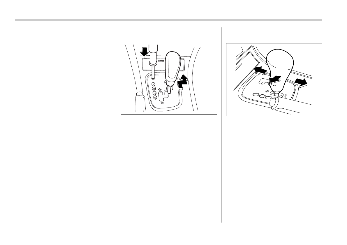
7-20 Starting and operating
mately 6 mph (10 km/h). Once operation-
al, it prevents the selector lever from being
moved from the “N” position to the “R” po-
sition. When the vehicle speed drops be-
low 6 mph (10 km/h), the function is can-
celed. The selector lever can then be
moved to the “R” and “P” positions.
When the ignition switch has been turned
to the “OFF” position, movement of the se-
lector lever from the “N” position to the “R”
position is possible for a limited time peri-
od and then becomes impossible. Also,
the selector lever cannot be moved to the
“R” position when it has been placed in the
“P” position and then placed again in the
“N” position. When movement of the se-
lector lever from the “N” position to the “R”
position has become impossible, turn the
ignition switch back to the “ON” position
then move the selector lever to the “P” po-
sition. Pressing the selector lever release
button also makes it possible to move the
selector lever to the “P” position at this
time.
T Selector lever release button
If you inadvertently have turned the igni-
tion switch to the “OFF” position with the
selector lever in the “N” position, proceed
as follows. By referring to the “Shift lock
release” section in this chapter, remove
the shift lock release cover. Then, with the
screwdriver inserted into the hole, move
the selector lever to the “P” position. If the
selector lever reverse inhibiting function
fails, have the vehicle inspected by the
nearest SUBARU dealer.
Selection of manual mode
With the vehicle either moving or station-
ary, move the selector lever from the “D”
position to the manual gate then move it to
the “+” end or “–” end of the manual gate
to select manual mode.
700345
700109
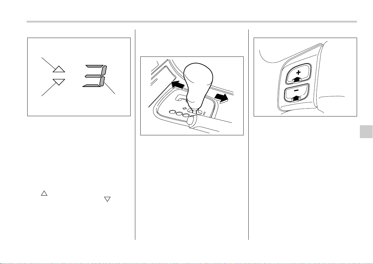
Starting and operating 7-21
– CONTINUED –
1) Upshift indicator
2) Downshift indicator
3) Gear position indicator
When the manual mode is selected, the
gear position indicator and upshift indica-
tor and/or downshift indicator in the ta-
chometer come on. The gear position indi-
cator shows the currently selected gear in
the 1st-to-5th-gear range. The upshift and
downshift indicators show when a gear-
shift is possible. When the upshift indica-
tor “ ” is on, upshifting is possible.
When the downshift indicator “ ” is on,
downshifting is possible. When both indi-
cators are on, upshifting and downshifting
are both possible. When the vehicle stops
(for example, at traffic signals), the down-
shift indicator goes off.
Gearshifts can be performed using the se-
lector lever or the shift switch on the steer-
ing wheel (turbo model only).
Using the selector lever
Shift to the next-higher gear by briefly
pushing the selector lever toward the “+”
end of the manual gate.
Shift to the next-lower gear by briefly pull-
ing the selector lever toward the “–” end of
the manual gate.
Using the shift switch (turbo models)
Shift to the next-higher gear by briefly
pressing the “+” button of the shift switch.
Shift to the next-lower gear by briefly
pressing the “–” button of the shift switch.
To deselect the manual mode, return the
selector lever to the “D” position from the
manual gate.
If you press the “+” button or “–” button of
the shift switch while driving with the se-
lector lever in the “D” position, the manual
mode will be selected. At this time, the
currently selected gear will be shown by
the gear position indicator and the upshift
indicator and downshift indicator will come
on.
If you subsequently ease off the accelera-
tor pedal and then accelerate again, the
1
2
3
700308
700111
300106
7-22 Starting and operating
transmission will automatically switch
back from manual mode to normal mode.
NOTE
Please read the following points care-
fully and bear them in mind when using
the manual mode.
y When the temperature of the auto-
matic transmission fluid is higher than
normal, warning beeps are emitted and
the shift position indicator shows “–”.
If these warnings are issued, deselect
the manual mode to protect the auto-
matic transmission from damage.
y When the temperature of the engine
oil is higher than normal, warning
beeps are emitted and the shift posi-
tion indicator shows “–”. If these warn-
ings are issued, deselect the manual
mode to protect the engine from dam-
age. (3.0-liter models only)
y The transmission does not automati-
cally shift up in the manual mode. Per-
form gearshifts in accordance with
road conditions so that the tachometer
needle does not enter the red zone. If
the engine speed reaches a predeter-
mined level, a fuel-cut function will op-
erate. Shift up if this happens. (Also, in
the case of a 3.0-liter model, the trans-
mission may automatically shift up to
protect the engine.)
y If you attempt to shift down when the
engine speed is too high, i.e., when a
downshift would push the tachometer
needle beyond the red zone, beeps will
be emitted to warn you that the down-
shift is not possible.
y If you attempt to shift up when the
vehicle speed is too low, the transmis-
sion will not respond.
y You can perform a skip-shift (for ex-
ample, from 4th to 2nd) by operating
the selector lever or a steering-wheel
switch twice in rapid succession.
y The transmission automatically se-
lects 1st gear when the vehicle stops
moving.
y If the temperature of the automatic
transmission fluid becomes too high,
the “AT OIL TEMP” warning light will
come on and upshifts to 5th gear will
not be possible. Immediately stop the
vehicle in a safe place and let the en-
gine idle until the warning light goes
off.
Maximum speeds
The following tables show the maximum
speeds that are possible with each differ-
ent gear.
When down shifting, it is important to con-
firm that the current vehicle speed is not in
excess of the Maximum Allowable Speed
of the gear which is about to be selected.
When down shifting, ensure that the
vehicle is not travelling at a speed
exceeding the Maximum Allowable
Speed for the gear which is about to
be selected. Failure to observe this
precaution can lead to engine over-
revving and this in turn can result in
engine damage.
In addition, sudden application of
engine braking caused by down
shifting when the vehicle is travel-
ling on a slippery surface can lead to
wheel locking; as a consequence,
control of the vehicle may be lost
and the risk of an accident in-
creased.
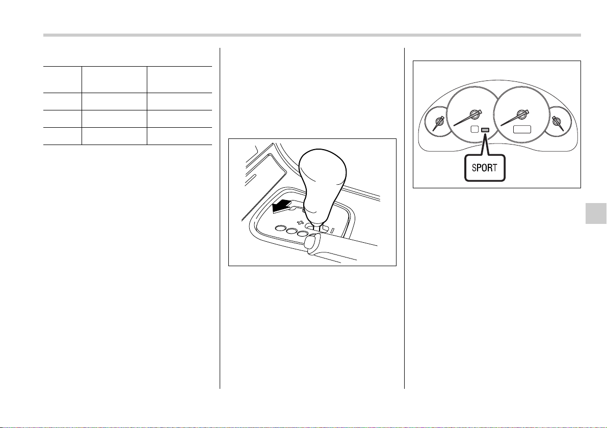
Starting and operating 7-23
– CONTINUED –
mph (km/h)
Never exceed posted speed limits.
Driving tips
y On a road surface where there is a risk
of wheelspin (for example, a snow- or
gravel-covered road), you can pull away
from a standstill safely and easily by first
selecting the 2nd gear of the manual
mode.
y Always apply the foot or parking brake
when the vehicle is stopped in the “D” or
“R” position.
y Always set the parking brake when
parking your vehicle. Do not hold the vehi-
cle with only the transmission.
y Do not keep the vehicle in a stationary
position on an uphill grade by using the
“D” position. Use the brake instead.
y The engine may, on rare occasions,
knock when the vehicle rapidly acceler-
ates or rapidly pulls away from a standstill.
This phenomenon does not indicate a
fault.
y A slight reduction in output torque may
occur in the models with a 3.0-liter or 2.5-
liter turbo engine before the engine warms
up.
SPORT mode
SPORT mode is used when power is
needed for rapid acceleration or for uphill
driving. To select this mode, move the se-
lector lever from the “D” position to the
manual gate.
When selected, the SPORT mode indica-
tor light on the instrument panel will turn
on.
To deselect SPORT mode, move the se-
lector lever to the “D” position or select
manual mode. To subsequently reselect
SPORT mode, move the selector lever to
the “D” position and from there to the man-
ual gate.
In this mode, the transmission shifts up at
higher vehicle speeds and shifts down
more responsively than in normal mode.
Shift lock release
If the selector lever does not move from
the “P” position with the brake pedal de-
pressed and the ignition switch in the “ON”
position, perform the following steps:
Position 2.5-liter turbo
models
3.0-liter models
1 35 (57) 27 (43)
2 59 (95) 61 (98)
3 94 (151) 96 (154)
700112
700113
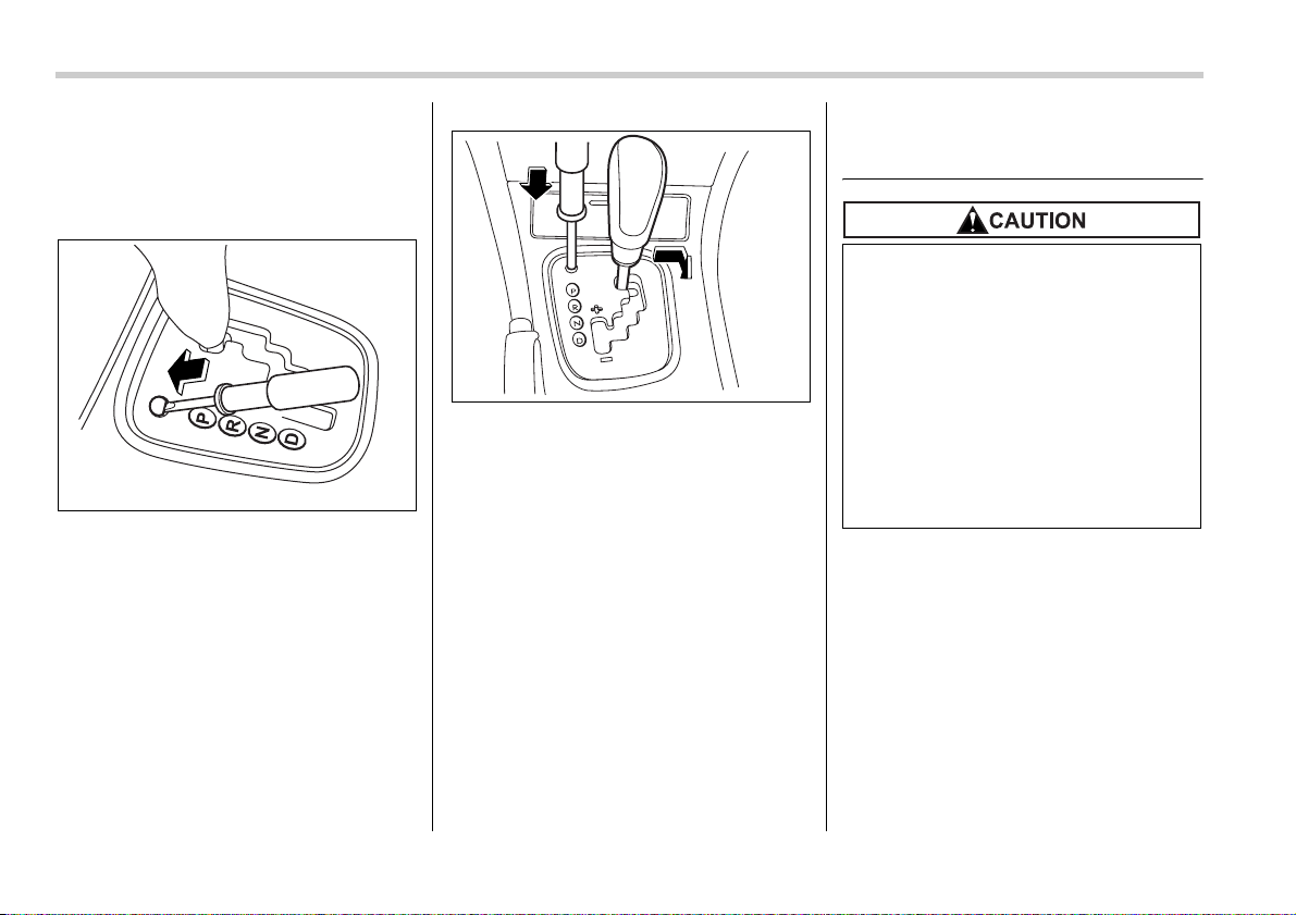
7-24 Starting and operating
To override the shift lock:
1. Set the parking brake and stop the en-
gine.
2. Take out the screwdriver from the tool
bucket.
3. Remove the cover by prying on the
edge with a flat-head screwdriver.
4. Insert the screwdriver into the hole.
5. Push down on the screwdriver and
move the selector lever from the “P” to the
“N” position.
6. Remove the screwdriver from the hole.
Depress the brake pedal and start the en-
gine.
Take your vehicle to the nearest SUBARU
dealer immediately to have the system re-
paired.
Rear viscous limited slip dif-
ferential (LSD) (if equipped)
The LSD provides optimum distribution of
power according to the difference in revo-
lutions between the right and left rear
wheels that may be caused by certain
driving conditions, thereby improving driv-
ing stability on snow-covered, muddy or
other slippery roads.
700346
700347
y Never start the engine while a tire
on one side is jacked up, as the
vehicle may move.
y If one rear tire is spinning in mud,
avoid continued spinning at high
speed as this could adversely af-
fect the LSD.
y If a different size rear tire is tem-
porarily used (as in an emergen-
cy), it will adversely affect the
LSD. Always replace it with a reg-
ular size tire as soon as possible.
Starting and operating 7-25
– CONTINUED –
Power steering
The power steering system operates only
when the engine is running.
If you lose power steering assist because
the engine stops or the system fails to
function, you can steer but it will take
much more effort.
NOTE
Right after the engine has been started
and before it has warmed up, you may
hear a noise coming from areas adja-
cent to the power steering pump which
is located at the right-front area of the
engine compartment. This noise is nor-
mal. It does not indicate power steering
system trouble.
Braking
Braking tips
T When the brakes get wet
When driving in rain or after washing the
vehicle, the brakes may get wet. As a re-
sult, brake stopping distance will be long-
er. To dry the brakes, drive the vehicle at
a safe speed while lightly depressing the
brake pedal to heat up the brakes.
T Use of engine braking
Remember to make use of engine braking
in addition to foot braking. When descend-
ing a grade, if only the foot brake is used,
the brakes may start working improperly
because of brake fluid overheating,
caused by overheated brake pads. To
help prevent this, shift into a lower gear to
get stronger engine braking.
T Braking when a tire is punctured
Do not depress the brake pedal suddenly
when a tire is punctured. This could cause
a loss of control of the vehicle. Keep driv-
ing straight ahead while gradually reduc-
ing speed. Then slowly pull off the road to
a safe place.
Brake system
T Two separate circuits
Your vehicle has a dual circuit brake sys-
tem. Each circuit works diagonally across
the vehicle. If one circuit of the brake sys-
tem should fail, the other half of the sys-
tem still works. If one circuit fails, the
brake pedal will go down much closer to
the floor than usual and you will need to
press it down much harder. And a much
longer distance will be needed to stop the
vehicle.
T Brake booster
The brake booster uses engine manifold
vacuum to assist braking force. Do not
turn off the engine while driving because
that will turn off the brake booster, result-
ing in poor braking power.
The brakes will continue to work even
when the brake booster completely stops
functioning. If this happens, however, you
will have to push the pedal much harder
than normal and the braking distance will
increase.
Do not hold the steering wheel at the
fully locked position left or right for
more than five seconds. This may
damage the power steering pump.
Never rest your foot on the brake
pedal while driving. This can cause
dangerous overheating of the
brakes and needless wear on the
brake pads and linings.
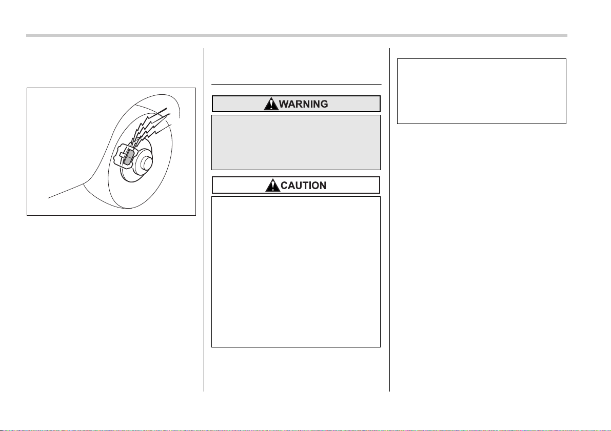
7-26 Starting and operating
Disc brake pad wear warning
indicators
The disc brake pad wear warning indica-
tors on the disc brakes give a warning
noise when the brake pads are worn.
If a squeaking or scraping noise is heard
from the disc brakes while braking, imme-
diately have your vehicle inspected by the
nearest SUBARU dealer.
ABS (Anti-lock Brake Sys-
tem)
The ABS system prevents the lock-up of
wheels which may occur during sudden
braking or braking on slippery road surfac-
es. This helps prevent the loss of steering
control and directional stability caused by
wheel lock-up.
When the ABS system is operating, you
may hear a chattering noise or feel a slight
vibration in the brake pedal. This is normal
when the ABS operates.
The ABS system will not operate when the
vehicle speed is below approximately 6
mph (10 km/h).
ABS system self-check
You may feel a slight shock in the brake
pedal and hear the operating sound of
ABS from the engine compartment just af-
ter the vehicle is started. This is caused by
an automatic functional test of the ABS
system being carried out and does not in-
dicate any abnormal condition.
700040
Always use the utmost care in driv-
ing – overconfidence because you
are driving with an ABS equipped
vehicle could easily lead to a seri-
ous accident.
y The ABS system does not always
decrease stopping distance. You
should always maintain a safe fol-
lowing distance from other vehi-
cles.
y When driving on badly surfaced
roads, gravel roads, icy road, or
over deep newly fallen snow,
stopping distances may be longer
for a vehicle with the ABS system
than one without. When driving
under these conditions, therefore,
reduce your speed and leave am-
ple distance from other vehicles.
y When you feel the ABS system
operating, you should maintain
constant brake pedal pressure.
Do not pump the brake pedal
since doing so may defeat the op-
eration of the ABS system.
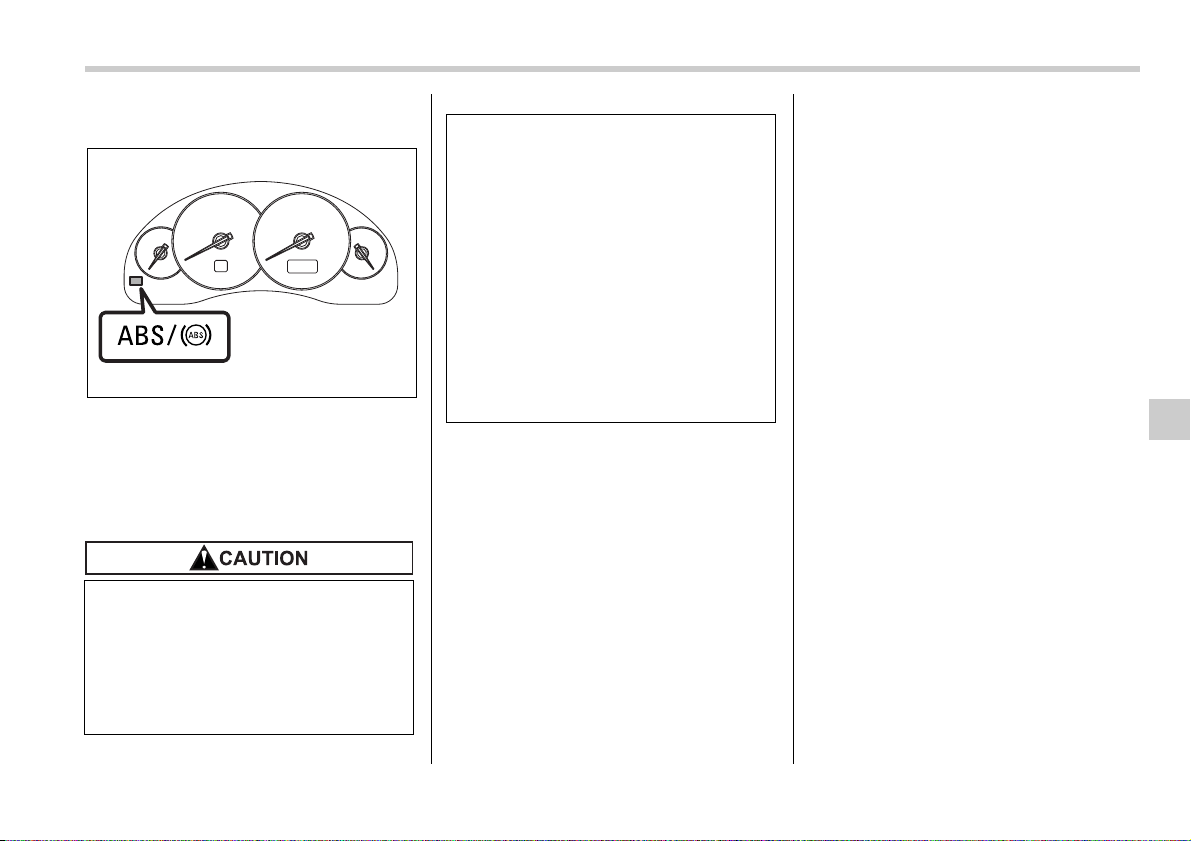
Starting and operating 7-27
ABS warning light
The ABS warning light comes on when the
ignition switch is turned to the “ON” posi-
tion and goes out after approximately two
seconds.
This is an indication that the ABS system
is working properly.
NOTE
If the warning light behavior is as de-
scribed in the following, the ABS sys-
tem may be considered normal.
y The warning light comes on right af-
ter the engine is started but goes out
immediately, remaining off.
y The warning light remains on after
the engine has been started, but it goes
out when the vehicle speed reaches
approximately 8 mph (12 km/h).
y The warning light comes on during
driving, but it goes out immediately
and remains off.
When driving with an insufficient battery
voltage such as when the engine is jump
started, the ABS warning light may come
on. This is due to the low battery voltage
and does not indicate a malfunction.
When the battery becomes fully charged,
the light will go out.
If the warning light behaves as fol-
lows, the ABS system may not be
working properly.
When the warning light is on, the
ABS function shuts down; however,
the conventional brake system con-
tinues to operate normally.
700348
y The warning light does not come
on when the ignition switch is
turned to the “ON” position.
y The warning light comes on when
the ignition switch is turned to the
“ON” position, but it does not go
out even when the vehicle speed
exceeds approximately 8 mph (12
km/h).
y The warning light comes on dur-
ing driving.
If these occur, have the ABS system
repaired at the first available oppor-
tunity by your SUBARU dealer.
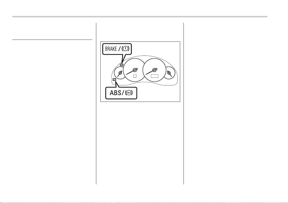
7-28 Starting and operating
Electronic Brake Force Dis-
tribution (EBD) system
The EBD system maximizes the effective-
ness of the brakes by allowing the rear
brakes to supply a greater proportion of
the braking force. It functions by adjusting
the distribution of braking force to the rear
wheels in accordance with the vehicle’s
loading condition and speed.
The EBD system is an integral part of the
ABS system and uses some of the ABS
system’s components to perform its func-
tion of optimizing the distribution of brak-
ing force. If any of the ABS components
used by the EBD function fails, the EBD
system also stops working.
When the EBD system is operating, you
may hear a chattering noise or feel a slight
vibration in the brake pedal. This is normal
and does not indicate a malfunction.
Steps to take if EBD system
fails
If a malfunction occurs in the EBD system,
the system stops working and the brake
system warning light and ABS warning
light come on simultaneously.
The EBD system may be faulty if the brake
system warning light and ABS warning
light illuminate simultaneously during driv-
ing.
Even if the EBD system fails, the conven-
tional braking system will still function.
However, the rear wheels will be more
prone to locking when the brakes are ap-
plied harder than usual and the vehicle’s
motion may therefore become somewhat
harder to control.
If the brake system warning light and ABS
warning light illuminate simultaneously,
take the following steps:
1. Stop the vehicle in the nearest safe, flat
place.
2. Shut down the engine, then restart it.
3. Release the parking brake. If both
warning lights go out, the EBD system
may be faulty.
Drive carefully to the nearest SUBARU
dealer and have the system inspected.
4. If both warning lights come on again
and stay illuminated after the engine has
been restarted, shut down the engine
again, apply the parking brake, and check
the brake fluid level.
5. If the brake fluid level is not below the
“MIN” mark, the EBD system may be
faulty. Drive carefully to the nearest
SUBARU dealer and have the system in-
spected.
6. If the brake fluid level is below the
“MIN” mark, DO NOT drive the vehicle. In-
stead, have the vehicle towed to the near-
est SUBARU dealer for repair.
700349
Starting and operating 7-29
– CONTINUED –
Vehicle Dynamics Control
system (if equipped)
y Driving with the brake system
warning light on is dangerous.
This indicates your brake system
may not be working properly. If
the light remains on, have the
brakes inspected by a SUBARU
dealer immediately.
y If at all in doubt about whether the
brakes are operating properly, do
not drive the vehicle. Have your
vehicle towed to the nearest
SUBARU dealer for repair.
Always use the utmost care in driv-
ing – overconfidence because you
are driving with a Vehicle Dynamics
Control system equipped vehicle
could easily lead to a serious acci-
dent.
y Even if your vehicle is equipped
with Vehicle Dynamics Control,
winter tires or snow chains
should be used when driving on
snow-covered or icy roads; in ad-
dition, vehicle speed should be re-
duced considerably. Simply hav-
ing a Vehicle Dynamics Control
system does not guarantee that
the vehicle will be able to avoid
accidents in any situation.
y Activation of the Vehicle Dynam-
ics Control system is an indica-
tion that the road being travelled
on has a slippery surface; since
having Vehicle Dynamics Control
is no guarantee that full vehicle
control will be maintained at all
times and under all conditions, its
activation should be seen as a
sign that the speed of the vehicle
should be reduced considerably.
y Whenever suspension compo-
nents, steering components, or an
axle are removed from a vehicle
equipped with Vehicle Dynamics
Control, have an authorized
SUBARU dealer perform an in-
spection of that system.
y The following precautions should
be observed in order to ensure
that the Vehicle Dynamics Control
system is operating properly:
– All four wheels should be fitted
with tires of the same size, type,
and brand. Furthermore, the
amount of wear should be the
same for all four tires.

7-30 Starting and operating
In the event of wheelspin and/or skidding
on a slippery road surface and/or during
cornering and/or an evasive maneuver,
the Vehicle Dynamics Control system ad-
justs the engine’s output and the wheels’
respective braking forces to help maintain
traction and directional control.
y Traction Control Function
The traction control function is designed to
prevent spinning of the driving wheels on
slippery road surfaces, thereby helping to
maintain traction and directional control.
Activation of this function is shown by
steady illumination of the Vehicle Dynam-
ics Control operation indicator light.
y Skid Suppression Function
The skid suppression function is designed
to help maintain directional stability by
suppressing the wheels’ tendency to slide
sideways during steering operations. Acti-
vation of this function is shown by flashing
of the Vehicle Dynamics Control operation
indicator light.
NOTE
y Slight twitching of the brake pedal
may be felt when the Vehicle Dynamics
Control system operates; a small de-
gree of vehicle or steering wheel shak-
ing may also be noticed in this situa-
tion. These are normal characteristics
of Vehicle Dynamics Control operation
and are no cause for alarm.
y When driving off immediately after
starting the engine, a short-lived oper-
ation noise may be noticed coming
from the engine compartment. This
noise is generated as a result of a
check being performed on the Vehicle
Dynamics Control system and is nor-
mal.
y Depending on the timing of activa-
tion of the brakes, certain situations
may occur just after driving off where
the brake pedal seems to exhibit a jolt-
ing motion. This too is a consequence
of the Vehicle Dynamics Control opera-
tional check and is normal.
y In the circumstances listed in the fol-
lowing, the vehicle may be more unsta-
ble than it feels to the driver. The Vehi-
cle Dynamics Control System may
therefore operate. Such operation does
not indicate a system fault.
y on gravel-covered or rutted roads
y on unfinished roads
y when the vehicle is towing a trailer
y when the vehicle is fitted with
snow tires or winter tires
y Activation of the Vehicle Dynamics
Control system will cause operation of
the steering wheel to feel slightly dif-
ferent compared to that for normal con-
ditions.
y Even if the vehicle is equipped with a
Vehicle Dynamics Control system, it is
important that winter tires be used
when driving on snow-covered or icy
roads. (All four wheels should be fitted
with tires of the same size and brand).
Furthermore, if snow chains are to be
used, they should be fitted on the front
wheels. When a vehicle is fitted with
snow chains, however, the effective-
ness of the Vehicle Dynamics Control
system is reduced and this should be
taken into account when driving the ve-
hicle in such a condition.
y It is always important to reduce
speed when approaching a corner,
even if the vehicle is equipped with Ve-
hicle Dynamics Control.
y All four wheels should be fitted with
tires of the same size, type, and brand;
furthermore, the amount of wear
should be the same for all four tires. If
these precautions are not observed
and non-matching tires are used, it is
quite possible that the Vehicle Dynam-
ics Control system will be unable to op-
– Keep the tire pressure at the
proper level as shown on the
vehicle placard attached to the
driver’s side door pillar.
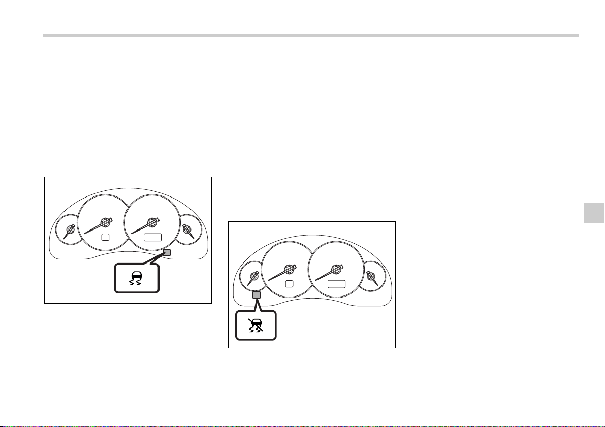
Starting and operating 7-31
– CONTINUED –
erate correctly as intended.
y Always turn off the engine before re-
placing a tire as failure to do so may
render the Vehicle Dynamics Control
system unable to operate correctly.
Vehicle Dynamics Control
system monitor
T Vehicle Dynamics Control operation
indicator light
The indicator light turns on when the igni-
tion switch is turned to the ON position; it
turns off approximately two seconds later.
This indicator light flashes during activa-
tion of the skid suppression function and is
illuminated steadily during activation of
the traction control function.
The following two situations could indicate
a malfunction of the Vehicle Dynamics
Control system; if either should occur,
have an authorized SUBARU dealer carry
out an inspection of that system at the first
available opportunity.
y The indicator light does not turn on
when the ignition switch is turned to the
ON position.
y The indicator light does not turn off ap-
proximately two seconds after the ignition
switch has been turned to the ON position.
T Vehicle Dynamics Control warning
light/Vehicle Dynamics Control OFF
indicator light
This single light has the function of indicat-
ing malfunctions in the Vehicle Dynamics
Control system and the function of indicat-
ing that the Vehicle Dynamics Control sys-
tem is not operating. It comes on in the
event of a malfunction in the system and is
illuminated whenever the system is not
operating.
V Vehicle Dynamics Control warning
The warning light comes on when the igni-
tion switch is turned to the “ON” position
and goes off several seconds after engine
startup. This lighting pattern indicates that
the Vehicle Dynamics Control system is
operating normally.
The following situations could indicate a
malfunction of the Vehicle Dynamics Con-
trol system; if any should occur, have an
authorized SUBARU dealer carry out an
inspection of the system at the first avail-
able opportunity.
y The warning light does not turn on when
the ignition switch is turned to the ON po-
sition.
y The warning light turns on while the ve-
hicle is being driven.
y When a malfunction has occurred in the
Vehicle Dynamics Control electrical sys-
tem, only the warning light will turn on. In
such an event, the ABS will still be operat-
ing normally.
y The warning light will also turn on when
a problem occurs with the ABS or Vehicle
Dynamics Control electronic control sys-
700350
700351
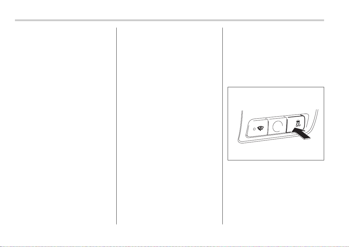
7-32 Starting and operating
tems.
Because the Vehicle Dynamics Control
system controls each brake through the
ABS, whenever the ABS stops operating
due to a malfunction in that electrical sys-
tem, the Vehicle Dynamics Control will
also become unable to control all four
brakes. Thus Vehicle Dynamics Control
system operation halts and the warning
light turns on. Although both the Vehicle
Dynamics Control system and the ABS
will be inoperable in this situation, it will
still be possible to stop the vehicle using
normal braking. The Vehicle Dynamics
Control system and the ABS do not ad-
versely affect operation of the vehicle in
any way when they are inoperable; how-
ever should such a situation occur, drive
with care and have an authorized
SUBARU dealer carry out an inspection of
those systems at the first available oppor-
tunity.
NOTE
When the warning light turns on and
off in the following way, it indicates
that the Vehicle Dynamics Control sys-
tem is operating normally.
y Although turning on after the engine
has been started, the warning light
quickly turns off and stays off.
y The warning light turns on when the
vehicle is being driven; it then turns off
and stays off.
V Vehicle Dynamics Control OFF indi-
cator light
This light comes on to indicate that the Ve-
hicle Dynamics Control system is in non-
operation mode. This does not constitute
failure of the Vehicle Dynamics Control
system.
NOTE
y The indicator light may stay on for a
while after the engine has been started,
especially in cold weather. This occurs
because the engine has not yet
warmed up and is completely normal.
The light will turn off when the engine
has reached a suitable operating tem-
perature.
y When an engine problem occurs and
the malfunction indicator lamp turns
on, the indicator light will also come
on.
The following two situations could indicate
malfunction of the Vehicle Dynamics Con-
trol system; if either should occur, have an
authorized SUBARU dealer carry out an
inspection of that system at the first avail-
able opportunity.
y The indicator light does not turn on
when the ignition switch is turned to the
ON position.
y The indicator light fails to turn off after
the engine is started, even when several
minutes have passed to allow the engine
to heat up sufficiently.
Vehicle Dynamics Control
OFF switch
Pressing the switch to deactivate the Ve-
hicle Dynamics Control system can facili-
tate the following operations:
y a standing start on a steeply sloping
road with a snowy, gravel-covered, or oth-
erwise slippery surface
y extrication of the vehicle when its
wheels are stuck in mud or deep snow
When the switch is pressed during engine
operation, the indicator light illuminates.
700114
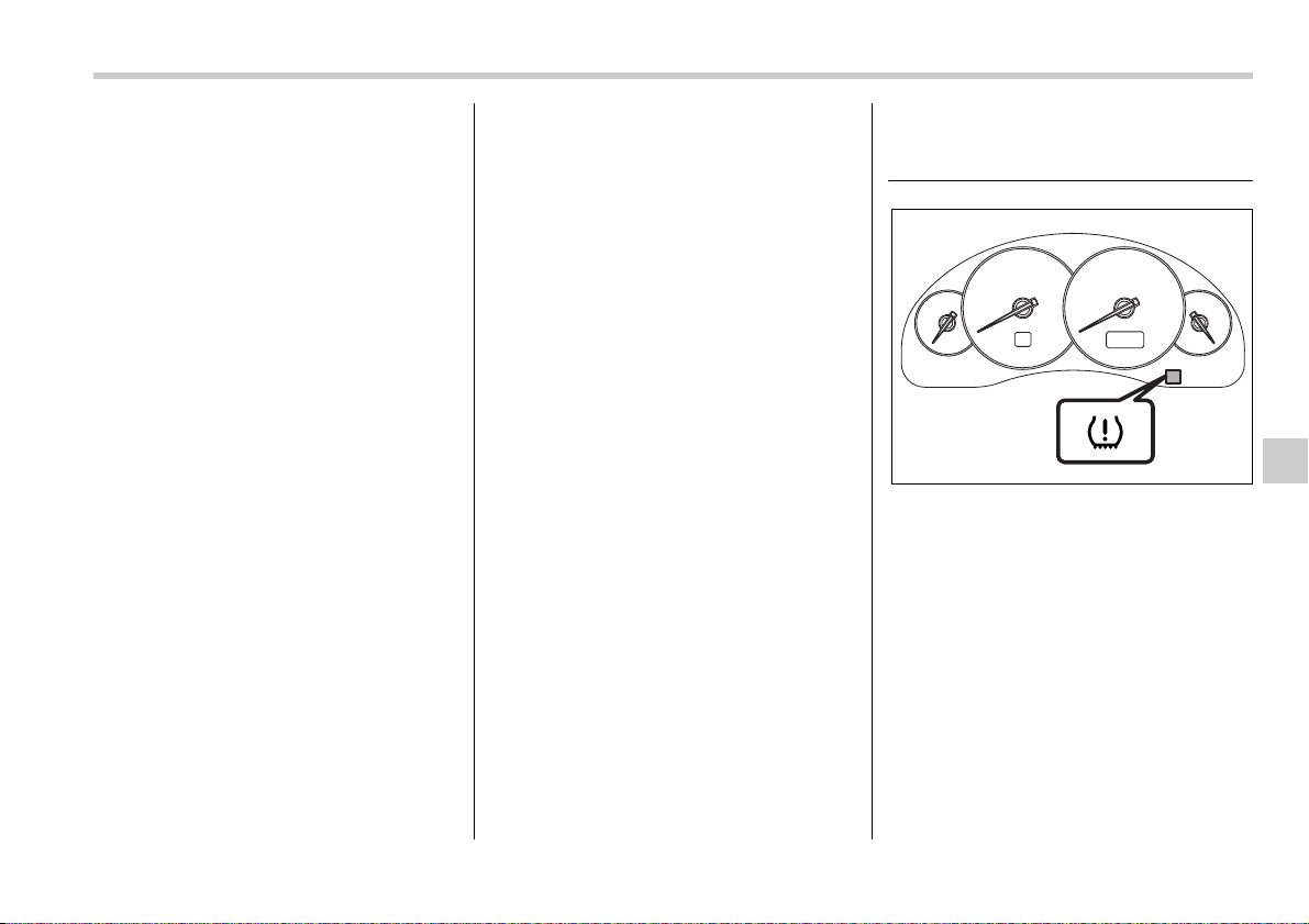
Starting and operating 7-33
– CONTINUED –
The Vehicle Dynamics Control system will
be deactivated and the vehicle will behave
like a model not equipped with the Vehicle
Dynamics Control system. When the
switch is pressed again to reactivate the
Vehicle Dynamics Control system, the in-
dicator light goes off.
With the Vehicle Dynamics Control sys-
tem deactivated, traction and stability en-
hancement offered by Vehicle Dynamics
Control system is unavailable. Therefore
you should not deactivate the Vehicle Dy-
namics Control system except under
above-mentioned situations.
NOTE
y When the switch has been pressed
to deactivate the Vehicle Dynamics
Control system, the Vehicle Dynamics
Control system automatically reacti-
vates itself the next time the ignition
switch is turned to the OFF position
and the engine is restarted.
y If the switch is held down for 10 sec-
onds or longer, the indicator light goes
off, the Vehicle Dynamics Control sys-
tem is activated, and the system ig-
nores any further pressing of the
switch. To make the switch usable
again, turn the ignition switch to the
OFF position and restart the engine.
y When the switch is pressed to deac-
tivate the Vehicle Dynamics Control
system, the vehicle’s running perfor-
mance is comparable with that of a ve-
hicle that does not have a Vehicle Dy-
namics Control system. Do not deacti-
vate the Vehicle Dynamics Control sys-
tem except when absolutely neces-
sary.
Tire pressure monitoring
system (TPMS) (if equipped)
The tire pressure monitoring system pro-
vides the driver with a warning message
by sending a signal from a sensor that is
installed in each wheel when tire pressure
is severely low.
The tire pressure monitoring system will
activate only when the vehicle is driven at
speeds above 20 mph (32 km/h). Also,
this system may not react immediately to
a sudden drop in tire pressure (for exam-
ple, a blow-out caused by running over a
sharp object).
700352
7-34 Starting and operating
If the low tire pressure warning light
comes on while driving, never brake
suddenly and keep driving straight
ahead while gradually reducing
speed. Then slowly pull off the road
to a safe place. Otherwise an acci-
dent involving serious vehicle dam-
age and serious personal injury
could occur.
Check the pressure for all four tires
and adjust the pressure to the COLD
tire pressure shown on the tire plac-
ard on the door pillar on the driver’s
side.
Even when the vehicle is driven a
very short distance, the tires get
warm and their pressures increase
accordingly. Be sure to let the tires
cool thoroughly before adjusting
their pressures to the standard val-
ues shown on the tire placard. (Re-
fer to the “Tires and wheels” section
in chapter 11.) The tire pressure
monitoring system does not func-
tion when the vehicle is stationary.
After adjusting the tire pressures,
increase the vehicle speed to at
least 20 mph (32 km/h) to start the
TPMS re-checking of the tire infla-
tion pressures. If the tire pressures
are now above the severe low pres-
sure threshold, the low tire pressure
warning light should go off a few
minutes later.
If this light still comes on while driv-
ing after adjusting the tire pressure,
a tire may have significant damage
and a fast leak that causes the tire to
lose air rapidly. If you have a flat tire,
replace it with a spare tire as soon
as possible. When a spare tire is
mounted or a wheel rim is replaced
without the original pressure sen-
sor/transmitter being transferred,
the low tire pressure warning light
will flash. This indicates the TPMS is
unable to monitor all four road
wheels. Contact your SUBARU deal-
er as soon as possible for tire and
sensor replacement and/or system
resetting.
Do not inject any tire liquid or aero-
sol tire sealant into the tires, as this
may cause a malfunction of the tire
pressure sensors. If the light flash-
es, promptly contact a SUBARU
dealer to have the system inspect-
ed.
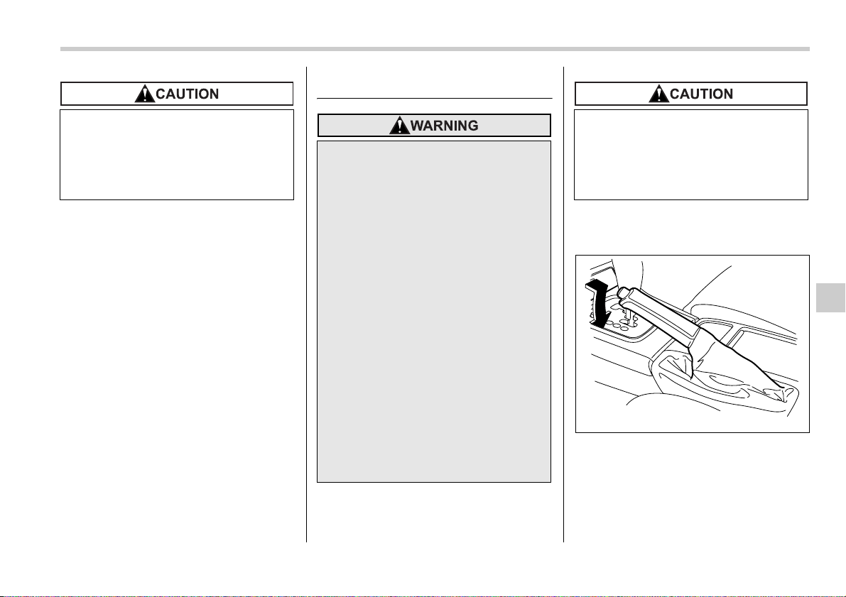
Starting and operating 7-35
– CONTINUED –
NOTE
This device complies with Part 15 of
the FCC Rules and with RSS-210 of In-
dustry Canada. Operation is subject to
the following two conditions: (1) This
device may not cause harmful interfer-
ence, and (2) this device must accept
any interference received, including in-
terference that may cause undesired
operation.
Changes or modifications not express-
ly approved by the party responsible
for compliance could void the user’s
authority to operate the equipment.
Parking your vehicle
To set the parking brake, press the brake
pedal firmly and hold it down while fully
pulling up the parking brake lever.
To release the parking brake, pull the le-
ver up slightly, press the release button,
then lower the lever while keeping the but-
ton pressed.
When the parking brake is set while the
engine is running, the parking brake warn-
ing light comes on. After starting the vehi-
Do not place metal film or any metal
parts under the driver’s seat. This
may cause poor reception of the sig-
nals from the tire pressure sensors,
and the tire pressure monitoring
system will not function properly.
y Never leave unattended children
or pets in the vehicle. They could
accidentally injure themselves or
others through inadvertent opera-
tion of the vehicle. Also, on hot or
sunny days, the temperature in a
closed vehicle could quickly be-
come high enough to cause se-
vere or possibly fatal injuries to
them.
y Do not park the vehicle over flam-
mable materials such as dry
grass, waste paper or rags, as
they may burn easily if they come
near hot engine or exhaust sys-
tem parts.
y Be sure to stop the engine if you
take a nap in the vehicle. If engine
exhaust gas enters the passenger
compartment, occupants in the
vehicle could die from carbon
monoxide (CO) contained in the
exhaust gas.
Never drive while the parking brake
is set because this will cause unnec-
essary wear on the brake linings.
Before starting to drive, always
make sure that the parking brake
has been fully released.
700116
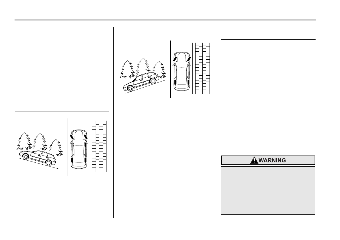
7-36 Starting and operating
cle, be sure that the warning light has
gone out before the vehicle is driven. Re-
fer to the “Warning and indicator lights”
section (chapter 3).
When parking your vehicle, always set the
parking brake firmly and put the shift lever
in the “1” (1st) for an upgrade or “R” (Re-
verse) for a downgrade for manual trans-
mission vehicles, or in the “P” (Park) posi-
tion for automatic transmission vehicles.
Always set the parking brake firmly when
parking your vehicle. Never rely on the
transmission alone to hold the vehicle.
When parking on a hill, always turn the
steering wheel. When the vehicle is head-
ed up the hill, the front wheels should be
turned away from the curb.
When facing downhill, the front wheels
should be turned into the curb.
Cruise control
Cruise control enables you to maintain a
constant vehicle speed without holding
your foot on the accelerator pedal and it is
operative when the vehicle speed is 25
mph (40 km/h) or more. Make sure the
main switch is turned “OFF” when the
cruise control is not in use to avoid unin-
tentionally setting the cruise control.
NOTE
If you move the cruise control lever or
press the main switch button while
turning the ignition switch “ON”, the
cruise control function is deactivated
and the “CRUISE” indicator light flash-
es. To reactivate the cruise control
function, turn the ignition switch back
to the “ACC” or “LOCK” position, and
then turn it again to the “ON” position.
700117
700118
Do not use the cruise control under
any of the following conditions. This
may cause loss of vehicle control:
y driving up or down a steep grade
y driving on slippery or winding
roads
y driving in heavy traffic
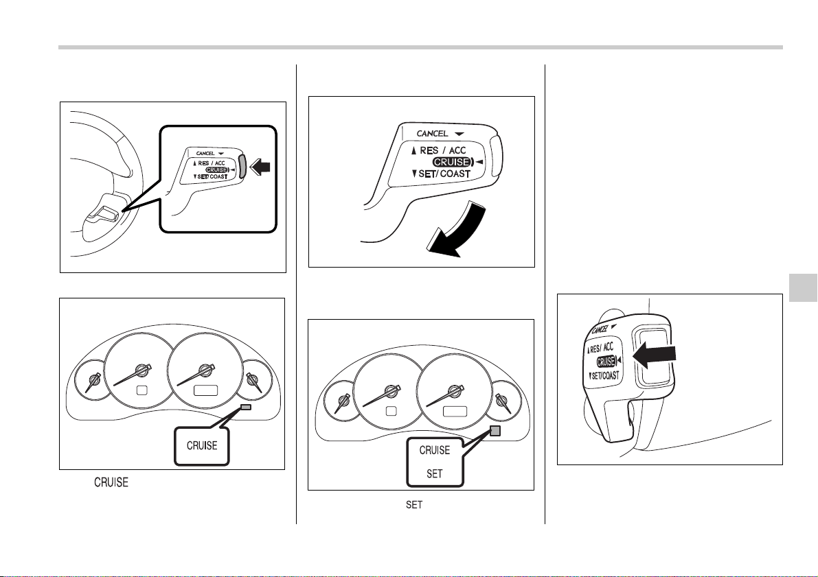
Starting and operating 7-37
– CONTINUED –
To set cruise control
0
1. Push the main switch button.
The “ ” indicator light on the com-
bination meter will come on.
2. Depress the accelerator pedal until the
vehicle reaches the desired speed.
3. Push the control lever downward in the
“SET/COAST” direction and release it.
Then release the accelerator pedal.
At this time, the “ ” indicator light is il-
luminated in the combination meter.
The vehicle will maintain the desired
speed.
Vehicle speed can be temporarily in-
creased while driving with the cruise con-
trol activated. Simply depress the acceler-
ator pedal to accelerate the vehicle. When
the accelerator pedal is released, the ve-
hicle will return to and maintain the previ-
ous cruising speed.
To temporarily cancel the
cruise control
There are five ways to cancel the cruise
control temporarily:
y Pull the control lever in the “CANCEL”
direction.
y Depress the brake pedal.
300332
300210
300333
300212
700161
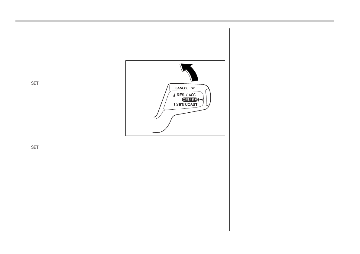
7-38 Starting and operating
y Depress the clutch pedal (manual trans-
mission vehicles only).
y Shift the selector lever into the “N” posi-
tion (automatic transmission vehicles
only).
y Shift the shift lever into neutral position
(manual transmission vehicles only).
The “ ” indicator light in the combina-
tion meter goes off when the cruise control
is cancelled.
To resume the cruise control after it has
been temporarily canceled and with vehi-
cle speed of approximately 20 mph (32
km/h) or more, push the control lever up-
ward in the “RES/ACC” direction to return
to the original cruising speed automatical-
ly.
The “ ” indicator light in the combina-
tion meter will automatically come on at
this time.
To turn off the cruise control
There are two ways to turn off the cruise
control:
y Push the main switch again.
y Turn the ignition switch to the “ACC” or
“LOCK” position (but only when the vehi-
cle is completely stopped).
To change the cruising speed
T To increase the speed (by control le-
ver)
Push the control lever upward in the
“RES/ACC” direction and hold it until the
vehicle reaches the desired speed. Then,
release the control lever. The vehicle
speed at that moment will be memorized
and treated as the new set speed.
When the difference between the actual
vehicle speed and the set speed is less
than 4 mph (6.8 km/h), the set speed can
be increased 1 mph (1.6 km/h) each time
by pressing the control lever upward in the
“RES/ACC” direction quickly within 0.25
second.
T To increase the speed (by accelera-
tor pedal)
1. Depress the accelerator pedal to accel-
erate the vehicle to the desired speed.
2. Push the control lever downward in the
“SET/COAST” direction once. Now the
desired speed is set and the vehicle will
keep running at that speed without de-
pressing the accelerator pedal.
NOTE
If the difference between the actual ve-
hicle speed when the control lever is
pushed downward and the speed last
time you set is less than 4 mph (6.8 km/
h), the vehicle speed will be lowered by
1 mph (1.6 km/h). This occurs because
the cruise control system unit regards
this lever operation as that intended to
decrease the vehicle speed.
300334
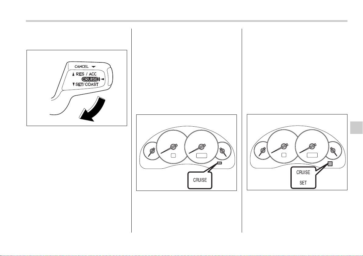
Starting and operating 7-39
T To decrease the speed (by control
lever)
Push the control lever downward in the
“SET/COAST” direction and hold it until
the vehicle reaches the desired speed.
Then, release the control lever. The vehi-
cle speed at that moment will be memo-
rized and treated as the new set speed.
When the difference between the actual
vehicle speed and the set speed is less
than 4 mph (6.8 km/h), the set speed can
be lowered 1 mph (1.6 km/h) each time by
pressing the control lever downward in the
“SET/COAST” direction quickly within
0.25 second.
T To decrease the speed (by brake
pedal)
1. Depress the brake pedal to release
cruise control temporarily.
2. When the speed decreases to the de-
sired speed, press the control lever down-
ward in the “SET/COAST” direction once.
Now the desired speed is set and the ve-
hicle will keep running at that speed with-
out depressing the accelerator pedal.
Cruise control indicator light
The cruise control indicator light comes on
when the ignition switch is turned to the
“ON” position and goes out after approxi-
mately three seconds.
The light comes on when the “CRUISE”
main switch is pressed.
If you move the cruise control lever or
press the main switch button while turning
the ignition switch “ON”, the cruise control
function is deactivated and the “CRUISE”
indicator light flashes. To reactivate the
cruise control function, turn the ignition
switch back to the “ACC” or “LOCK” posi-
tion, and then turn it again to the “ON” po-
sition.
Cruise control set indicator
light
The cruise control set indicator light
comes on when the ignition switch is
turned to the “ON” position and goes out
after approximately three seconds.
The light comes on when vehicle speed
has been set.
300333
300210
300212


8
Driving tips
New vehicle break-in driving – the first 1,000
miles (1,600 km) .............................................. 8-2
Fuel economy hints ........................................... 8-2
Engine exhaust gas (Carbon monoxide) ......... 8-2
Catalytic converter ............................................. 8-3
Periodic inspections .......................................... 8-4
Driving in foreign countries .............................. 8-4
Driving tips for AWD vehicles ........................... 8-5
Off road driving .................................................. 8-6
Winter driving ..................................................... 8-7
Operation during cold weather .............................. 8-7
Driving on snowy and icy roads ............................ 8-9
Corrosion protection .............................................. 8-10
Snow tires ............................................................... 8-10
Tire chains ............................................................... 8-11
Rocking the vehicle ................................................ 8-12
Loading your vehicle ......................................... 8-12
Vehicle capacity weight ......................................... 8-13
GVWR and GAWR (Gross Vehicle Weight Rating
and Gross Axle Weight Rating) ........................... 8-14
Roof rail and crossbar (if equipped) ..................... 8-14
Trailer hitch (if equipped) .................................. 8-18
Connecting a trailer ................................................ 8-19
When you do not tow a trailer ............................... 8-20
Trailer towing ...................................................... 8-20
Warranties and maintenance ................................. 8-20
Maximum load limits .............................................. 8-21
Trailer hitches ......................................................... 8-24
Connecting a trailer ................................................ 8-25
Trailer towing tips ................................................... 8-26
8-2 Driving tips
Driving tips
New vehicle break-in driving
– the first 1,000 miles (1,600
km)
The performance and long life of your ve-
hicle are dependent on how you handle
and care for your vehicle while it is new.
Follow these instructions during the first
1,000 miles (1,600 km):
y Do not race the engine. And do not al-
low engine speed to exceed 4,000 rpm ex-
cept in an emergency.
y Do not drive at one constant engine or
vehicle speed for a long time, either fast or
slow.
y Avoid starting suddenly and rapid accel-
eration, except in an emergency.
y Avoid hard braking, except in an emer-
gency.
The same break-in procedures should be
applied to a newly installed or overhauled
engine or when brake pads or brake lin-
ings are replaced with new ones.
Fuel economy hints
The following suggestions will help to
save your fuel.
y Select the proper gear position for the
speed and road conditions.
y Avoid sudden acceleration or decelera-
tion. Always accelerate gently until you
reach the desired speed. Then try to main-
tain that speed for as long as possible.
y Do not pump the accelerator and avoid
racing the engine.
y Avoid unnecessary engine idling.
y Keep the engine properly tuned.
y Keep the tires inflated to the correct
pressure shown on the tire placard, which
is located under the door latch on the driv-
er’s side. Low pressure will increase tire
wear and fuel consumption.
y Use the air conditioner only when nec-
essary.
y Keep the front and rear wheels in prop-
er alignment.
y Avoid carrying unnecessary luggage or
cargo.
Engine exhaust gas (Carbon
monoxide)
y Never inhale engine exhaust gas.
Engine exhaust gas contains car-
bon monoxide, a colorless and
odorless gas which is dangerous,
or even lethal, if inhaled.
y Always properly maintain the en-
gine exhaust system to prevent
engine exhaust gas from entering
the vehicle.
y Never run the engine in a closed
space, such as a garage, except
for the brief time needed to drive
the vehicle in or out of it.
y Avoid remaining in a parked vehi-
cle for a lengthy time while the en-
gine is running. If that is unavoid-
able, then use the ventilation fan
to force fresh air into the vehicle.
y Always keep the front ventilator
inlet grille free from snow, leaves
or other obstructions to ensure
that the ventilation system always
works properly.
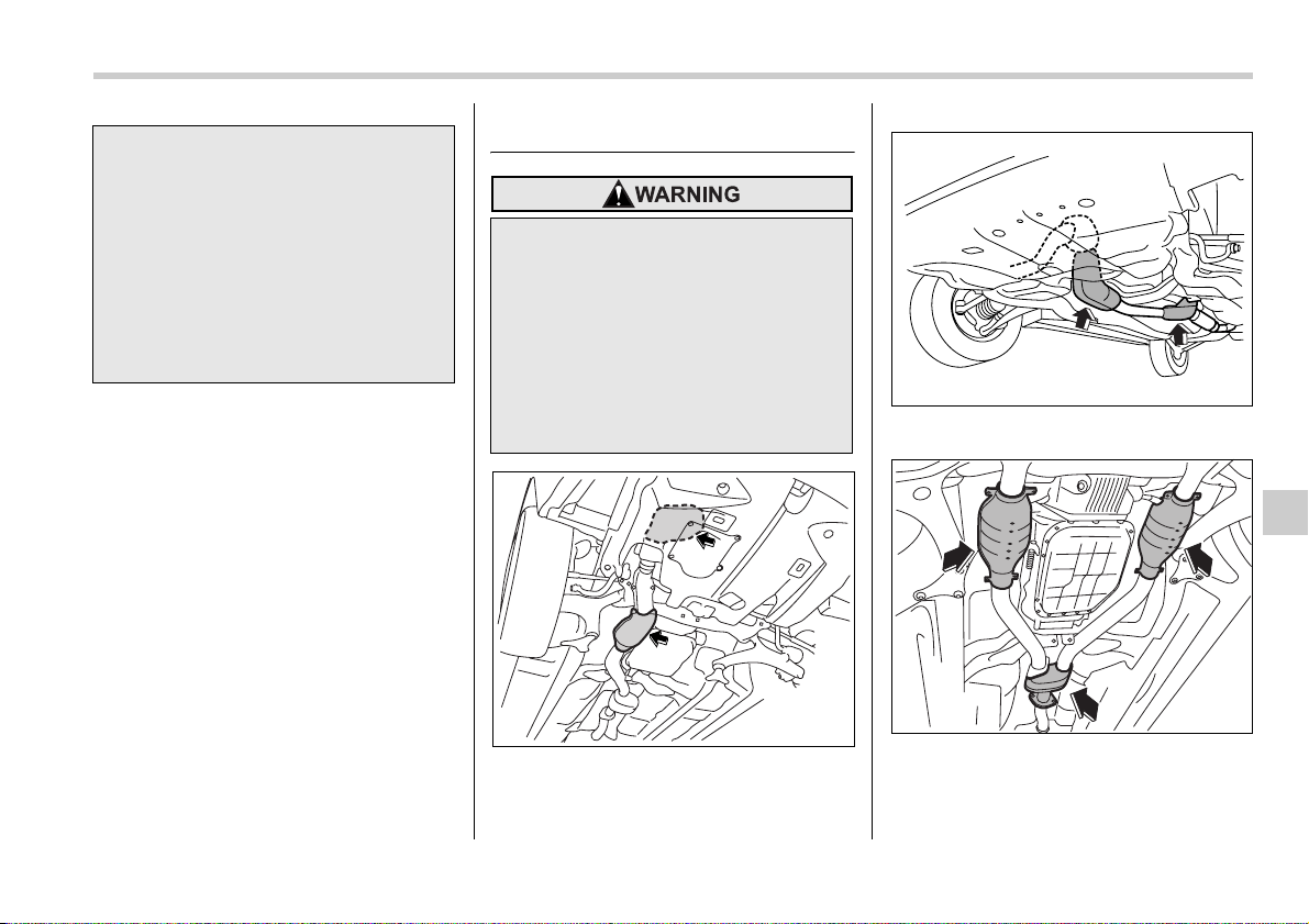
Driving tips 8-3
– CONTINUED –
NOTE
Due to the expansion and contraction
of the metals used in the manufacture
of the exhaust system, you may hear a
crackling sound coming from the ex-
haust system for a short time after the
engine has been shut off. This sound is
normal.
Catalytic converter
2.5-liter non-turbo models
2.5-liter turbo models
3.0-liter models
The catalytic converter is installed in the
exhaust system. It serves as catalyst to
y If at any time you suspect that ex-
haust fumes are entering the vehi-
cle, have the problem checked
and corrected as soon as possi-
ble. If you must drive under these
conditions, drive only with all win-
dows fully open.
y Keep the trunk lid (Sedan) or rear
gate (Station wagon) closed while
driving to prevent exhaust gas
from entering the vehicle.
y Avoid fire hazards. Do not drive or
park the vehicle anywhere near
flammable materials (e.g. grass,
paper, rags or leaves), because
the catalytic converter operates at
very high temperatures.
y Keep everyone and flammable
materials away from the exhaust
pipe while the engine is running.
The exhaust gas is very hot.
800235
800013
800014

8-4 Driving tips
reduce HC, CO and NOx in exhaust gas-
es, thus providing cleaner exhaust.
To avoid damage to the catalytic convert-
er:
y Use only unleaded gasoline. Even a
small amount of leaded gasoline will dam-
age the catalytic converter.
y Never start the engine by pushing or
pulling the vehicle.
y Avoid racing the engine.
y Never turn off the ignition switch while
the vehicle is moving.
y Keep your engine tuned-up. If you feel
the engine running rough (misfiring, back-
firing or incomplete combustion), have
your vehicle checked and repaired by an
authorized SUBARU dealer.
y Do not apply undercoating or rust pre-
vention treatment to the heat shield of cat-
alytic converter and the exhaust system.
Periodic inspections
To keep your vehicle in the best condition
at all times, always have the recommend-
ed maintenance services listed in the
maintenance schedule in the “Warranty
and Maintenance Booklet” performed at
the specified time or mileage intervals.
Driving in foreign countries
When planning to use your vehicle in an-
other country:
y Confirm the availability of the correct fu-
el. (Refer to the “Fuel requirements” sec-
tion in chapter 7.)
y Comply with all regulations and require-
ments of each country.
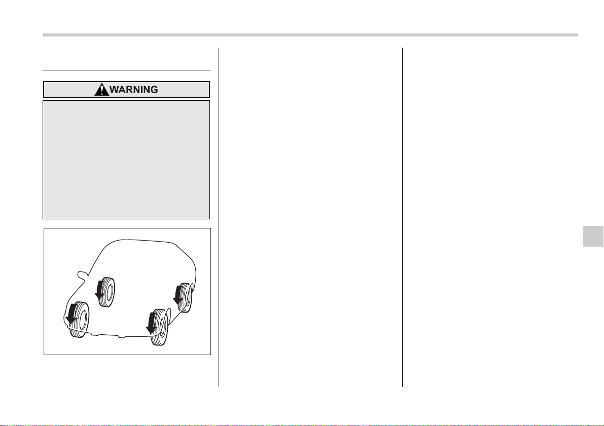
Driving tips 8-5
Driving tips for AWD vehicles
All-Wheel Drive distributes the engine
power to all four wheels. AWD vehicles
provide better traction when driving on
slippery, wet or snow-covered roads and
when moving out of mud, dirt and sand. By
shifting power between the front and rear
wheels, SUBARU AWD can also provide
added traction during acceleration, and
added engine braking force during decel-
eration.
Therefore, your SUBARU AWD vehicle
may handle differently than an ordinary
two wheel drive vehicle and it contains
some features unique to AWD. For safety
purposes as well as to avoid damaging
the AWD system, you should keep the fol-
lowing tips in mind:
y An AWD vehicle is better able to climb
steeper roads under snowy or slippery
conditions than a two wheel drive vehicle.
There is little difference in handling, how-
ever, during extremely sharp turns or sud-
den braking. Therefore, when driving
down a slope or turning corners, be sure
to reduce your speed and maintain an am-
ple distance from other vehicles.
y When replacing a tire, make sure you
use only the same size, circumference,
construction, brand, and load range as the
original tires listed on the tire placard. Us-
ing other sizes, circumferences or con-
struction may result in severe mechanical
damage to the drive train of your vehicle
and may affect ride, handling, braking,
speedometer/odometer calibration, and
clearance between the body and tires. It
also may be dangerous and lead to loss of
vehicle control.
y If you use a temporary spare tire to re-
place a flat tire, be sure to use the original
temporary spare tire stored in the vehicle.
Using other sizes may result in severe
mechanical damage to the drive train of
your vehicle.
y Always check the cold tire pressure be-
fore starting to drive. The recommended
tire pressure is provided on the tire plac-
ard, which is located under the door latch
on the driver’s side.
y Tire chains should always be placed on
the front wheels only.
y There are some precautions that you
must observe when towing your vehicle.
For detail information, see “Towing” sec-
tion in chapter 9.
y Always maintain a safe driving
speed according to the road and
weather conditions in order to
avoid having an accident on a
sharp turn, during sudden braking
or under other similar conditions.
y Always use the utmost care in
driving – overconfidence because
you are driving an All-Wheel Drive
vehicle could easily lead to a seri-
ous accident.
800004
8-6 Driving tips
Off road driving
T All AWD models except OUTBACK
Your AWD vehicle is neither a convention-
al off-road vehicle nor an all terrain vehi-
cle. It is a passenger car designed prima-
rily for on-road use. The AWD feature
gives it some limited off-road capabilities
in situations in which driving surfaces a
relatively level, obstruction-free and other-
wise similar to on-road driving conditions.
Operating it under other than those condi-
tions could subject the vehicle to exces-
sive stress which might result in damage
not eligible for repair under warranty. If
you do take your SUBARU off road, you
should review the common sense precau-
tions in the next section (applicable to the
OUTBACK) for general guidance. But
please keep in mind that your vehicle’s
off-road capabilities are more limited than
those of the OUTBACK.
Never attempt to drive through pools and
puddles, or roads flooded with water. Wa-
ter entering the engine air intake or the ex-
haust pipe or water splashing onto electri-
cal parts may damage your vehicle and
may cause it to stall.
T OUTBACK
Because of the AWD feature and higher
ground clearance, your SUBARU can be
driven on ordinary roads or off-road. But
please keep in mind that an AWD
SUBARU is a passenger car and is nei-
ther a conventional off-road vehicle nor an
all-terrain vehicle. If you do take your
SUBARU off-road, certain common sense
precautions such as the following should
be taken:
y Make certain that you and all of your
passengers are wearing seatbelts.
y Carry some emergency equipment,
such as a towing rope or chain, a shovel,
wheel blocks, first aid kit and cell phone or
citizens band radio.
y Drive carefully. Do not take unneces-
sary risks by driving in dangerous areas or
over rough terrain.
y Slow down and employ extra caution at
all times. When driving off-road, you will
not have the benefit of marked traffic
lanes, banked curves, traffic signs and the
like.
y Do not drive across steep slopes. In-
stead, drive either straight up or straight
down the slopes. A vehicle can much
more easily tip over sideways than it can
end over end. Avoid driving straight up or
down slopes that are too steep.
y Avoid sharp turning maneuvers, espe-
cially at higher speeds.
y Do not grip the inside or spokes of the
steering wheel. A bad bump could jerk the
wheel and injure your hands. Instead drive
with your fingers and thumbs on the out-
side of the rim.
y If driving through water, such as when
crossing shallow streams, first check the
depth of the water and the bottom of the
stream bed for firmness and ensure that
the bed of the stream is flat. Drive slowly
and completely through the stream. The
water should be shallow enough that it
does not reach the vehicle’s undercar-
riage. Water entering the engine air intake
or the exhaust pipe or water splashing
onto electrical parts may damage your ve-
hicle and may cause it to stall. Never at-
tempt to drive through rushing water; re-
gardless of its depth, it can wash away the
y Always maintain a safe driving
speed according to the road and
weather conditions in order to
avoid having an accident on a
sharp turn, during sudden braking
or under other similar conditions.
y Always use the utmost care in
driving – overconfidence because
you are driving an All-Wheel Drive
vehicle could easily lead to a seri-
ous accident.
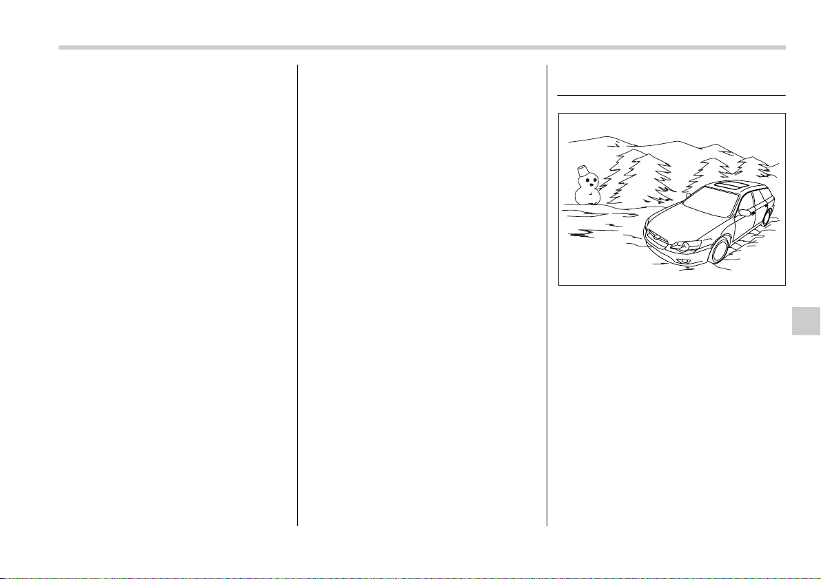
Driving tips 8-7
– CONTINUED –
ground from under your tires, resulting in
possible loss of traction and even vehicle
rollover.
y Always check your brakes for effective-
ness immediately after driving in sand,
mud or water. Do this by driving slowly
and stepping on the brake pedal. Repeat
that process several times to dry out the
brake discs and brake pads.
y Do not drive or park over or near flam-
mable materials such as dry grass or fall-
en leaves, as they may burn easily. The
exhaust system is very hot while the en-
gine is running and right after engine
stops. This could create a fire hazard.
y After driving through tall grass, mud,
rocks, sand, rivers, etc., check that there
is no grass, bush, paper, rags, stones,
sand, etc. adhering to or trapped on the
underbody. Clear off any such matter from
the underbody. If the vehicle is used with
these materials trapped or adhering to the
underbody, a mechanical breakdown or
fire could occur.
y Secure all cargo carried inside the vehi-
cle and make certain that it is not piled
higher than the seatbacks. During sudden
stops or jolts, unsecured cargo could be
thrown around in the vehicle and cause in-
jury. Do not pile heavy loads on the roof.
Those loads raise the vehicle’s center of
gravity and make it more prone to tip over.
y If you must rock the vehicle to free it
from sand or mud, depress the accelera-
tor pedal slightly and move the selector le-
ver back and forth between “D” and “R” re-
peatedly. Do not race the engine. For the
best possible traction, avoid spinning the
wheels when trying to free the vehicle.
y When the road surface is extremely
slippery, you can obtain better traction by
starting the vehicle with the transmission
in 2nd than 1st (both for MT and AT).
y Never equip your vehicle with tires larg-
er than those specified in this manual.
y Wash the vehicle’s underbody after off-
road driving. Suspension components are
particularly prone to dirt buildup, so they
need to be washed thoroughly.
y Frequent driving of an AWD vehicle un-
der hard-driving conditions such as rough
roads or off roads will necessitate more
frequent replacement of engine oil, brake
fluid and transmission oil than that speci-
fied in the maintenance schedule de-
scribed in the “Warranty and Maintenance
Booklet”.
Remember that damage done to your
SUBARU while operating it off-road and
not using common sense precautions
such as those listed above is not eligible
for warranty coverage.
Winter driving
Operation during cold weath-
er
Carry some emergency equipment, such
as tire chains, a window scraper, a bag of
sand, flares, a small shovel, and jumper
cables.
Check the battery and cables. Cold tem-
peratures reduce battery capacity. The
battery must be in good condition to pro-
vide enough power for cold winter starts.
Use an engine oil of proper grade and vis-
cosity for cold weather. Heavy summer oil
will cause harder starting.
Keep the door locks from freezing by
800015
8-8 Driving tips
squirting them with deicer or glycerin.
Forcing a frozen door open may damage
or separate the rubber weather strips
around the door. If the door is frozen, use
hot water to melt the ice, and afterwards
thoroughly wipe the water away.
Use a windshield washer fluid that con-
tains an antifreeze solution. Do not use
engine antifreeze or other substitutes be-
cause they may damage the paint of the
vehicle.
SUBARU Windshield Washer Fluid con-
tains 58.5% methyl alcohol and 41.5%
surfactant, by volume. Its freezing temper-
ature varies according to how much it is di-
luted, as indicated in the following table.
In order to prevent freezing of washer flu-
id, check the freezing temperatures in the
table above when adjusting the fluid con-
centration to the outside temperature.
If you fill the reservoir tank with a fluid with
a different concentration from the one
used previously, purge the old fluid from
the piping between the reservoir tank and
washer nozzles by operating the washer
for a certain period of time. Otherwise, if
the concentration of the fluid remaining in
the piping is too low for the outside tem-
perature, it may freeze and block the noz-
zles.
T Before driving your vehicle
Before entering the vehicle, remove any
snow or ice from your shoes because that
could make the pedals slippery and dan-
gerous.
While warming up the vehicle before driv-
ing, check that the accelerator pedal,
brake pedal, and all other controls operate
smoothly.
Clear away ice and snow that has accu-
mulated under the fenders to avoid mak-
ing steering difficult. During severe winter
driving, stop when and where it is safe to
do so and check under the fenders period-
ically.
T Parking in cold weather
Do not use the parking brake when park-
ing for long periods in cold weather since
it could freeze in that position. Instead, ob-
serve the following.
1. Place the shift lever in “1” or “R” for
manual transmission vehicles, and in “P”
for automatic transmission vehicles.
2. Use tire stops under the tires to prevent
the vehicle from moving.
When the vehicle is parked in snow or
when it snows, raise the wiper blades off
the glass to prevent damage to them.
When the vehicle has been left parked af-
ter use on roads heavily covered with
snow, or has been left parked during a
snowstorm, icing may develop on the
brake system, which could cause poor
braking action. Check for snow or ice
Washer Fluid
Concentration
Freezing
Temperature
30% 10.4°F (–12°C)
50% –4°F (–20°C)
100% –49°F (–45°C)
Adjust the washer fluid concentra-
tion appropriately for the outside
temperature. If the concentration is
inappropriate, sprayed washer fluid
may freeze on the windshield and
obstruct your view, and the fluid
may freeze in the reservoir tank.
Snow can trap dangerous exhaust
gases under your vehicle. Keep
snow clear of the exhaust pipe and
from around your vehicle if you park
the vehicle in snow with the engine
running.
Driving tips 8-9
– CONTINUED –
buildup on the suspension, disc brakes
and brake hoses underneath the vehicle.
If there is caked snow or ice, remove it,
being careful not to damage the disc
brakes and brake hoses and ABS har-
ness.
T Refueling in cold weather
To help prevent moisture from forming in
the fuel system and the risk of its freezing,
use of an antifreeze additive in the fuel
tank is recommended during cold weath-
er.
Use only additives that are specifically de-
signed for this purpose. When an anti-
freeze additive is used, its effect lasts
longer if the tank is refilled whenever the
fuel level reaches half empty.
If your SUBARU is not going to be used for
an extended period, it is best to have the
fuel tank filled to capacity.
Driving on snowy and icy
roads
To prevent skidding and slipping, avoid
sudden braking, abrupt acceleration, high-
speed driving, and sharp turning when
driving on snowy or icy roads.
Always maintain ample distance between
your vehicle and the vehicle ahead of you
to avoid the need for sudden braking.
To supplement the foot brake, use the en-
gine brake effectively to control the vehi-
cle speed. (Shift into a lower gear when
necessary.)
Avoid shifting down abruptly. Such behav-
ior can cause the wheels to lock, possibly
leading to loss of vehicle control.
An anti-lock brake system (ABS) enhanc-
es your vehicle’s braking performance on
snowy and icy roads. Refer to the “ABS
(Anti-lock Brake System)” and “Vehicle
Dynamics Control system (if equipped)”
section in chapter 7 for information on
braking on slippery surfaces.
T Wiper operation when snowing
Before driving in cold weather, make sure
the wiper blades are not frozen to the
windshield or rear window. If the wiper
blades are frozen to the windshield or rear
window, use the defroster with the airflow
control button/dial in the “ ” position
and the temperature control dial set for
maximum warmth until the wiper blades
are completely thawed out. If your vehicle
is equipped with a wiper deicer, it is helpful
to thaw the windshield wiper blades. To
thaw out the rear wiper blade, use the rear
window defogger.
When driving in snow, if frozen snow
starts to stick on the surface of the wind-
shield despite wiper operation, use the de-
froster with the airflow control button/dial
in “ ” and the temperature control dial
set for maximum warmth. After the wind-
shield gets warmed enough to melt the
frozen snow on it, wash it away using the
windshield washer.
Snow stuck on the wiper arm prevents the
wiper from working effectively. If snow is
stuck on the wiper arm, pull off the road to
a safe place, then remove it. If you stop
the vehicle at road side, use the hazard
warning flasher to alert other drivers.
We recommend use of non-freezing type
Do not use the cruise control on
slippery roads such as snowy or icy
roads. This may cause loss of vehi-
cle control.
Avoid prolonged continuous driving
in snowstorms. Snow will enter the
engine’s intake system and may
hinder the air flow, which could re-
sult in engine shutdown or even
breakdown.
8-10 Driving tips
wiper blades (winter blades) during the
seasons you could have snow and sub-
zero temperatures. Blades of this type
give superior wiping performance in
snowy conditions. Be sure to use blades
that are suitable for your vehicle.
NOTE
When the season requiring non-freez-
ing type wiper blades is over, replace
them with standard wiper blades.
Corrosion protection
Refer to the “Corrosion protection” section
(chapter 10).
Snow tires
T All models except OUTBACK
Your vehicle is equipped with “all season
tires” which are designed to provide an
adequate measure of traction, handling
and braking performance in year-round
driving. In winter, it may be possible to en-
hance performance through use of tires
designed specifically for winter driving
conditions.
If you choose to install winter tires on your
vehicle, be sure to use the correct tire size
and type. You must install four winter tires
that are of the same size, construction,
brand and load range and you should nev-
er mix radial, belted bias or bias tires since
this may result in dangerous handling
characteristics. When you choose a tire,
make sure that there is enough clearance
between the tire and vehicle body.
Remember to drive with care at all times
regardless of the type of tires on your ve-
hicle.
During high-speed driving, non-
freezing type wiper blades may not
perform as well as standard wiper
blades. If this happens, reduce the
vehicle speed.
y When replacing original tires with
winter (snow) tires, make sure you
use only the same size, construc-
tion and load range as the original
tires listed on the tire placard. Us-
ing other sizes and construction
may affect speedometer/odome-
ter calibration and clearance be-
tween the body and tires. It also
may be dangerous and lead to
loss of vehicle control.
y You must install four winter tires
that are of the same size, circum-
ferences, construction, brand,
and load range. Mixing other siz-
es, circumferences or construc-
tions may result in severe me-
chanical damage to the drive train
of your vehicle and may affect
ride, handling, braking and speed-
ometer/odometer calibration. It
also may be dangerous and lead
to loss of vehicle control.
y Do not use a combination of radi-
al, belted bias or bias tires since it
may cause dangerous handling
characteristics and lead to an ac-
cident.
Driving tips 8-11
– CONTINUED –
T OUTBACK models only Your vehicle is equipped with “all season
tires” which are designed to provide an
adequate measure of traction, handling
and braking performance in year-round
driving. In winter, it may be possible to en-
hance performance through use of tires
designed specifically for winter driving
conditions.
If you choose to install winter tires on your
vehicle, be sure to use the correct tire size
and type. You must install four winter tires
that are of the same size, construction,
brand and load range and you should nev-
er mix radial, belted bias or bias tires since
this may result in dangerous handling
characteristics. When you choose a tire,
make sure that there is enough clearance
between the tire and vehicle body.
Remember to drive with care at all times
regardless of the type of tires on your ve-
hicle.
Your OUTBACK comes with P225/
55R17 “all season tires” as original
equipment. You should be aware that
some winter tires with that same size
designation may actually be too large
for the vehicle and may cause rubbing
on sharp turns. Listed in the following
is the winter tire size that we recom-
mend.
Recommended winter (snow) tire size
OUTBACK models: P215/55R17,
P225/60R16 or P215/60R16 Studless
Tire chains
Driving on snowy grades or icy roads may
y When replacing original tires with
winter (snow) tires, make sure you
use only the same size and con-
struction as recommended. Using
other sizes or construction may
affect speedometer/odometer cal-
ibration and clearance between
the body and tires. It also may be
dangerous and lead to loss of ve-
hicle control.
y You must install four winter tires
that are of the same size, circum-
ferences, construction, brand,
and load range. Mixing other siz-
es, circumferences or construc-
tions may result in severe me-
chanical damage to the drive train
of your vehicle and may affect
ride, handling, braking and speed-
ometer/odometer calibration. It
also may be dangerous and lead
to loss of vehicle control.
y Do not use a combination of radi-
al, belted bias or bias tires since it
may cause dangerous handling
characteristics and lead to an ac-
cident.
Tire chains cannot be used on tires
listed in the following because of
lack of clearance between the tires
and vehicle body.
y 2.5-liter non-turbo models (except
OUTBACK): P205/50R17 tires
y 2.5-liter turbo models (except
OUTBACK): 215/45ZR17 tires
y OUTBACK models: P225/55R17
tires
y 2.5-liter non-turbo and 3.0-liter
models (OUTBACK): P225/60R16
winter (snow) tires
y 2.5-liter non-turbo and 3.0-liter
models (OUTBACK): P215/60R16
winter (snow) tires
y 2.5-liter turbo and 3.0-liter models
(OUTBACK): P215/55R17 winter
(snow) tires
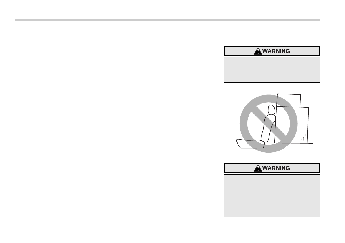
8-12 Driving tips
require the use of tire chains, in which
case put the chains on the front wheels
only. Use only SAE class S type chains
that are of the correct size for your tires so
as not to damage the vehicle body or sus-
pension.
When driving with tire chains, drive at
speeds below 19 mph (30 km/h). When a
temporary spare tire is on a front wheel,
replace the temporary spare tire with the
rear tire on the same side of the vehicle,
and then fit chains on the front tires.
Always use the utmost care when driving
with tire chains – overconfidence because
you are driving with tire chains could eas-
ily lead to a serious accident.
Rocking the vehicle
If you must rock the vehicle to free it from
snow, sand, or mud, depress the acceler-
ator pedal slightly and move the selector
lever back and forth between “D” and “R”
repeatedly. Do not race the engine. For
the best possible traction, avoid spinning
the wheels when trying to free the vehicle.
When the road surface is extremely slip-
pery, you can obtain better traction by
starting the vehicle with the transmission
in 2nd than 1st (both for MT and AT).
Refer to the “Automatic transmission – 4-
speed” and “Automatic transmission – 5-
speed” section in chapter 7 for information
on holding the transmission in 2nd posi-
tion.
Loading your vehicle
Never allow passengers to ride on a
folded rear seatback, in the trunk or
in the cargo area. Doing so may re-
sult in serious injury.
y Never stack luggage or other car-
go higher than the top of the seat-
back because it could tumble for-
ward and injure passengers in the
event of a sudden stop or acci-
dent. Keep luggage or cargo low,
as close to the floor as possible.
100094
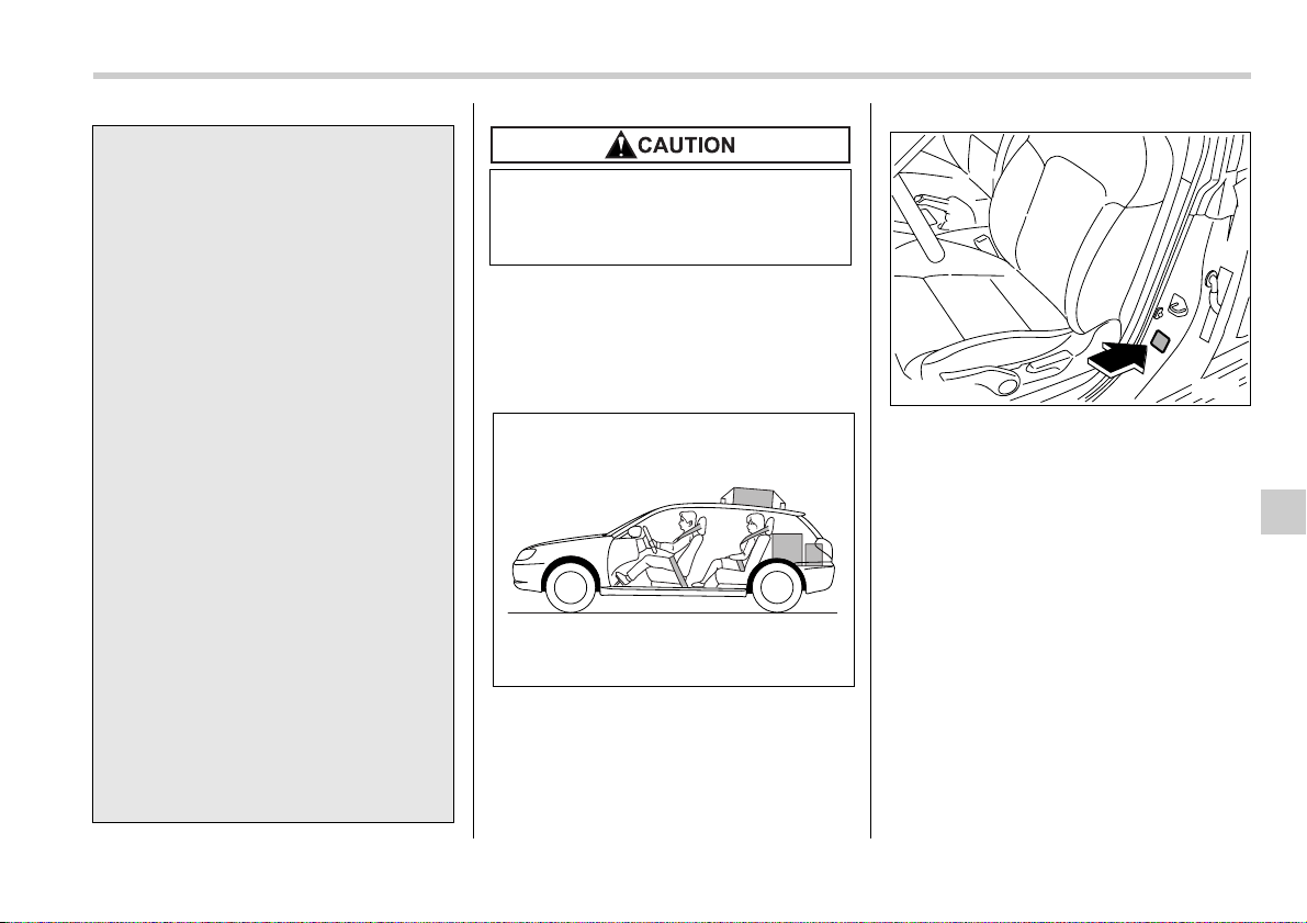
Driving tips 8-13
– CONTINUED –
NOTE
For better fuel economy, do not carry
unneeded cargo.
Vehicle capacity weight
The load capacity of your vehicle is deter-
mined by weight, not by available cargo
space. The maximum load you can carry
in your vehicle is shown on the vehicle
placard attached to the driver’s side door
pillar. It includes the total weight of the
driver and all passengers and their be-
longings, any optional equipment such as
a trailer hitch, roof rack or bike carrier,
etc., and the tongue load of a trailer.
y When you carry something inside
the vehicle, secure it whenever
you can to prevent it from being
thrown around inside the vehicle
during sudden stops, sharp turns
or in an accident.
y Do not pile heavy loads on the
roof. These loads raise the vehi-
cle’s center of gravity and make it
more prone to tip over.
y Secure lengthy items properly to
prevent them from shooting for-
ward and causing serious injury
during a sudden stop.
y Never exceed the maximum load
limit. If you do, some parts on
your vehicle can break, or it can
change the way your vehicle han-
dles. This could result in loss of
control and cause personal injury.
Also, overloading can shorten the
life of your vehicle.
y Do not place anything on the rear
shelf behind the rear seatback (for
Sedan) or the extended luggage
cover (for Station wagon). Such
items could tumble forward in the
event of a sudden stop or a colli-
sion. This could cause serious in-
jury.
Do not carry spray cans, containers
with flammable or corrosive liquids
or any other dangerous items inside
the vehicle.
800236
B00128
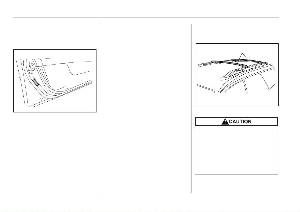
8-14 Driving tips
GVWR and GAWR (Gross Ve-
hicle Weight Rating and
Gross Axle Weight Rating)
Certification label
The certification label attached to the driv-
er’s side door shows GVWR (Gross Vehi-
cle Weight Rating) and GAWR (Gross
Axle Weight Rating).
The GVW (Gross Vehicle Weight) must
never exceed the GVWR. GVW is the
combined total of weight of the vehicle, fu-
el, driver, all passengers, luggage, any
optional equipment and trailer tongue
load. Therefore, the GVW changes de-
pending on the situation.
In addition, the total weight applied to
each axle (GAW) must never exceed the
GAWR. The front and rear GAWs can be
adjusted by relocating luggage inside the
vehicle.
Even if the total weight of your luggage is
lower than the vehicle capacity weight, ei-
ther front or rear GAW may exceed the
GAWR, depending on the distribution of
the luggage.
When possible, the load should be evenly
distributed throughout the vehicle.
If you carry heavy loads in the vehicle, you
should confirm that GVW and front and
rear GAWs are within the GVWR and
GAWR by putting your vehicle on a vehi-
cle scale, found at a commercial weighing
station.
Do not use replacement tires with a lower
load range than the originals because
they may lower the GVWR and GAWR
limitations. Replacement tires with a high-
er load range than the originals do not in-
crease the GVWR and GAWR limitations.
Roof rail and crossbar (if
equipped)
1) Crossbar kit
800237
y For cargo carrying purposes, the
roof rail must be used together
with a roof crossbar kit and the
appropriate carrying attachment.
The roof rail must never be used
alone to carry cargo. Otherwise,
damage to the roof or paint or a
dangerous road hazard due to
loss of cargo could result.
1
800238
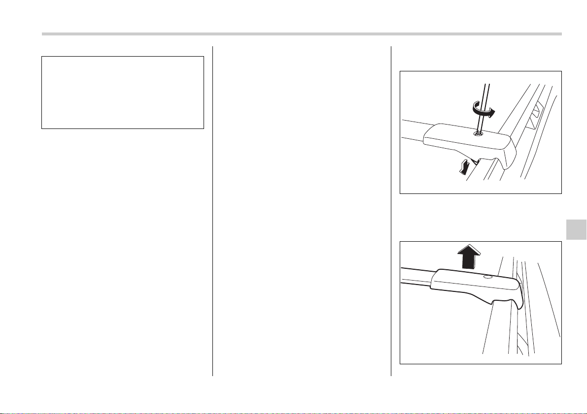
Driving tips 8-15
– CONTINUED –
The roof rail is not designed to carry cargo
by itself. Cargo can be carried after secur-
ing the roof crossbar kit to the roof rail and
installing the appropriate carrying attach-
ment. When installing the roof crossbar
kit, follow the manufacturer’s instructions.
When you carry cargo on the roof using
the roof crossbar kit and a carrying attach-
ment, never exceed the maximum load
limit explained in the following. You should
also be careful that your vehicle does not
exceed the Gross Vehicle Weight Rating
(GVWR) and front and rear Gross Axle
Weight Rating (GAWR). See the “Loading
your vehicle” section in this chapter for in-
formation on loading cargo into or onto
your vehicle. The maximum load limit of
the cargo, crossbars and carrying attach-
ment must not exceed 100 lbs (45 kg).
Place the heaviest load at the bottom,
nearest the roof, and evenly distribute the
cargo. Always properly secure all cargo.
T Installing carrying attachments on
the crossbars
When installing any carrying attachment
such as a bike carrier, ski carrier, kayak
carrier, cargo basket, etc. on the cross-
bars, follow the manufacturer’s instruc-
tions and make sure that the attachment is
securely fixed to the crossbars. Use only
attachments designed specifically for the
crossbars. A set of the crossbars is de-
signed to carry loads (cargo and attach-
ment) of not more than 100 lbs (45 kg).
Before operating the vehicle, make sure
that the cargo is properly secured on the
attachment.
NOTE
Remember that the vehicle’s center of
gravity is altered with the weight of the
load on the roof, thus affecting the
driving characteristics.
Drive carefully. Avoid rapid starts, hard
cornering and abrupt stops. Crosswind
effects will be increased.
T Removal and installation of the
crossbars
The crossbars can be removed when you
do not use the roof to carry cargo.
V To remove the crossbar
1. Loosen and remove the T-30 torx®
head screw from the top of each crossbar
end support.
Loosen the lower clamps.
y When using the roof crossbar kit,
make sure that the total weight of
the crossbars, carrying attach-
ment and cargo does not exceed
the maximum load limit. Overload-
ing may cause damage to the ve-
hicle and create a safety hazard.
800239
800240
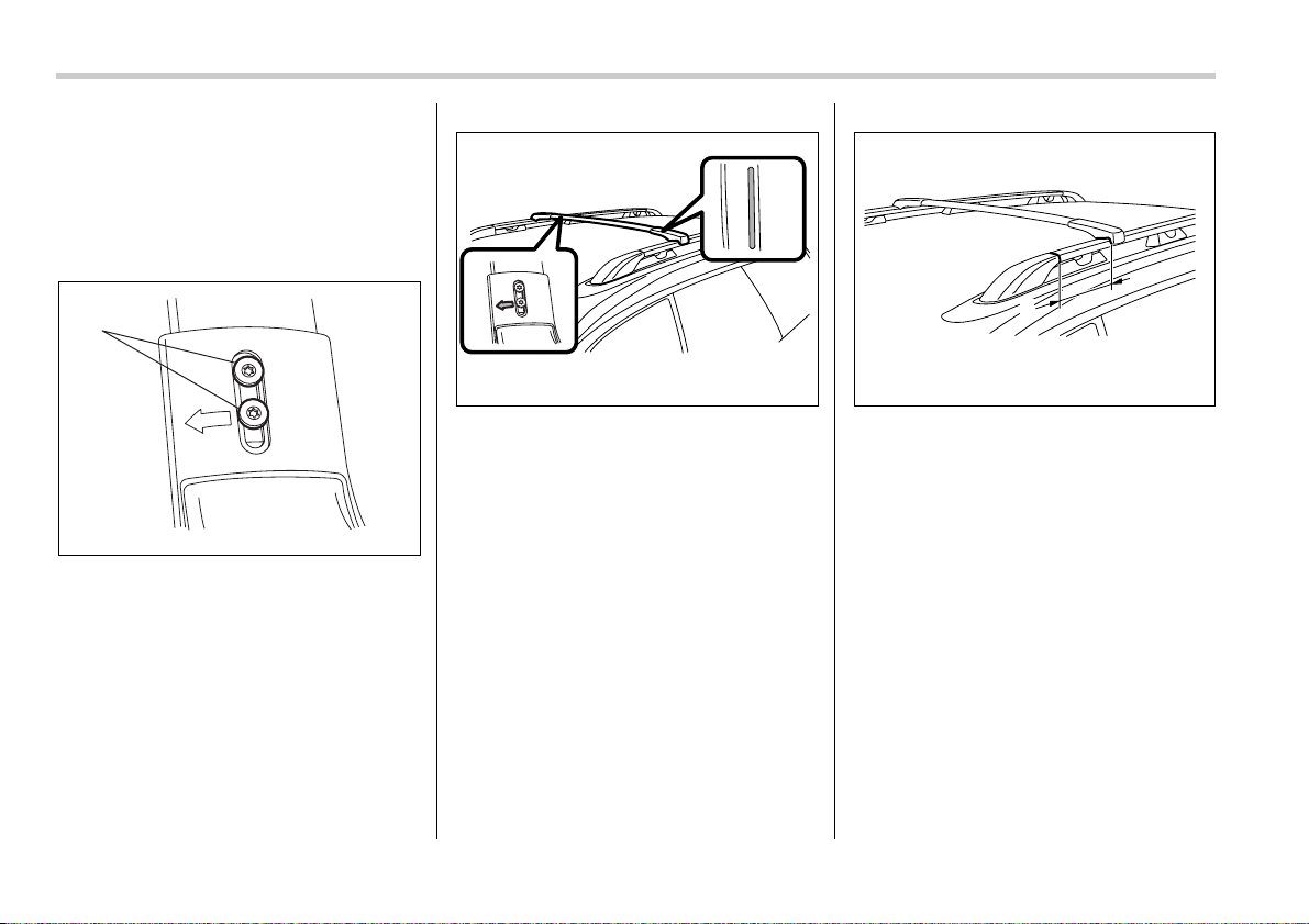
8-16 Driving tips
2. Carefully raise the crossbar from roof
rails.
V To install the front crossbar
Front crossbar:
Front crossbar has 100 LBS Load Label
on left-hand side.
1) T-25 torx® head screw
1. Make sure that the T-25 torx® head
screw on the back of each crossbar end
support is tightened correctly.
2. Before placing the crossbar on the roof
rails, make sure that the T-30 torx® head
screw is removed from the top of each
crossbar end support.
3. The crossbar with the 100 LBS Load
Label attached onto it is the front cross-
bar. An arrow is marked on the back of the
front crossbar for correct installation. In-
stall the front crossbar so that the arrow
faces the front of the vehicle.
1) 10 in (250 mm)
4. Install the front crossbar so that the
crossbar end supports are located ap-
proximately 10 in (250 mm) rearward from
the joints between the roof rails and the
front roof rail supports.
1
800241
800242
1
800243
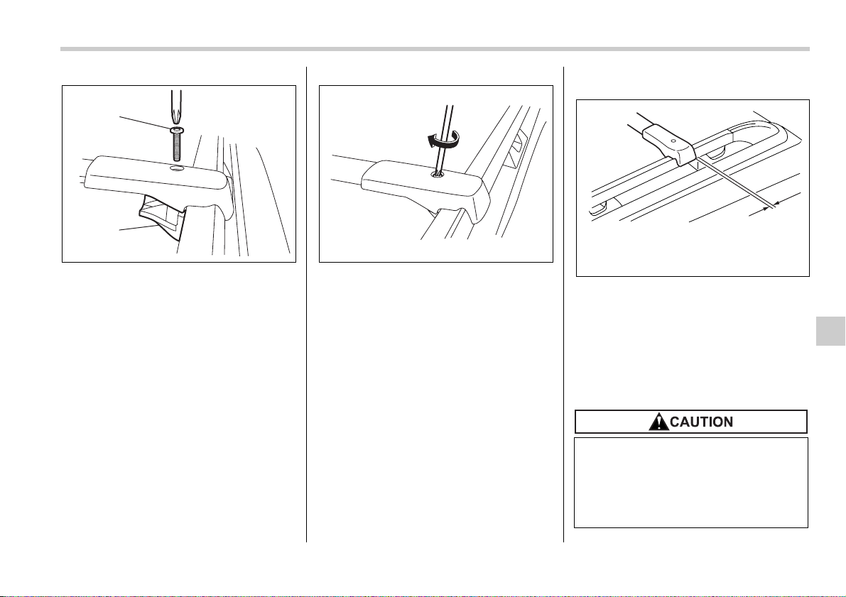
Driving tips 8-17
– CONTINUED –
1) Lower clamp
2) T-30 torx® head screw
5. Tighten the lower clamps onto the
crossbar. Using a torque wrench, loosely
tighten the T-30 torx® head screws.
NOTE
It may be necessary to squeeze the
lower clamp and the end support to-
gether to compress the pads and gain
a better alignment of the pieces while
trying to start the screw. Use care not
to crossthread the screw in the insert.
6. Adjust the alignment of the crossbar on
the roof rails, and if available, use a T-30
torx® bit and torque wrench and tighten
the T-30 torx® head screws to 30 to 35
lbf·in (3.4 to 4.0 N·m, 0.35 to 0.41 kgf·m)
of torque (or tighten securely with the
torx® wrench provided).
Rear crossbar:
1) Zero gap
Install the rear cross bar so that the rear
edges of both crossbar end supports are
aligned (zero gap) with the front edges of
both rear roof rail supports.
Install the rear crossbar in the same man-
ner as the front crossbar.
1
2
800244 800245
Do not carry cargo on the roof when
the crossbars are removed. Lug-
gage on the roof will be thrown for-
ward or backward in sudden stops
or rapid accelerations, resulting in a
dangerous road hazard.
1
800246
8-18 Driving tips
NOTE
Before each use of the roof crossbar,
make sure the four T-30 crossbar
clamp screws have been checked, and
retightened if necessary to 35 lbf·in (4.0
N·m, 0.41 kgf·m), as outlined in Step #5
above.
Trailer hitch (if equipped)
The trailer hitch is designed to tow a Class
1 rated load. The maximum gross trailer
weight and maximum gross tongue weight
are indicated in the following table.
When you tow a trailer, follow the instruc-
tions in the next section “Trailer towing”.
y Never exceed the maximum
weight specified for the trailer
hitch. Exceeding the maximum
weight could cause an accident
resulting in serious personal inju-
ries. Permissible trailer weight
changes depending on the situa-
tion. Refer to the next section
“Trailer towing” for possible rec-
ommendations and limitations.
y Trailer brakes are required when
the towing load exceeds 1,000 lbs
(453 kg). Be sure your trailer has
safety chains and that each chain
will hold the trailer’s maximum
gross weight. Towing trailers
without safety chains could create
a traffic safety hazard if the trailer
separates from the hitch due to
coupling damage or hitch ball
damage.
y Be sure to check the hitch pin and
safety pin for positive locking
placement before towing a trailer.
If the ball mount comes off the
hitch receiver, the trailer could get
loose and create a traffic safety
hazard.
y Use only the ball mount supplied
with this hitch. Use the hitch only
as a weight carrying hitch. Do not
use with any type of weight dis-
tributing hitch.
Maximum
gross trailer
weight
Maximum
gross tongue
weight
3.0-liter
models
3,000 lbs
(1,360 kg)
200 lbs
(90 kg)
All models
other than
3.0-liter
models
2,700 lbs
(1,224 kg)
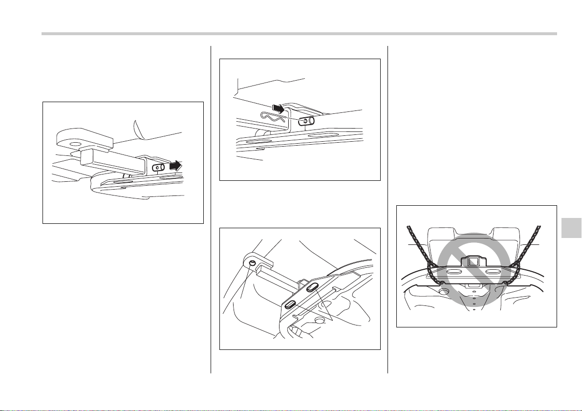
Driving tips 8-19
– CONTINUED –
Connecting a trailer
1. Remove the receiver cover from the
hitch receiver tube. Then insert the ball
mount into the hitch receiver tube.
2. Insert the hitch pin into the hole on the
hitch receiver tube so that the pin passes
through the ball mount.
3. Insert the safety pin into the hitch pin
securely.
4. Pull the ball mount to make sure it does
not come off the hitch receiver.
1) Hitch ball installation point
2) Hooks for safety chains
5. Use only a hitch ball that is appropriate
for the ball mount and your trailer. The
hitch ball must be securely installed on the
ball mount.
6. Connect your trailer to the hitch ball.
7. Connect the trailer and the hitch with
safety chains that will hold the trailer’s
maximum gross weight. The chains
should cross under the trailer tongue to
prevent the tongue from dropping onto the
ground in case it should disconnect from
the hitch ball. Allow sufficient slack in the
chains taking tight-turn situations into ac-
count; however, be careful not to let them
drag on the ground.
800206
800207
1
2
800208
800209
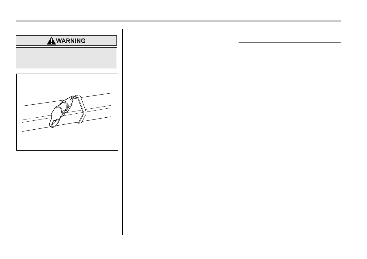
8-20 Driving tips
Hitch harness connector
8. Connect the hitch wire harness’s black
four-pin wire connector to the towing trail-
er’s wire harness.
9. Confirm proper function of the hitch
wire harness by individually activating the
brake, right turn signal, left turn signal,
stop, and parking lights on the trailer.
NOTE
Always disconnect the trailer wire har-
ness before launching or retrieving a
watercraft.
When you do not tow a trailer
y Remove the ball mount from the hitch
receiver tube and insert the receiver cover
onto the hitch receiver tube.
y Place the dust cap over the four-pin
connector of the hitch wire harness to pro-
tect against possible damage.
y Occasionally lubricate terminals of the
four-pin connector using the terminal
grease.
Trailer towing
Your vehicle is designed and intended to
be used primarily as a passenger-carrying
vehicle. Towing a trailer puts additional
loads on your vehicle’s engine, drivetrain,
brakes, tires and suspension and has an
adverse effect on fuel economy.
If you do decide to tow a trailer, your safe-
ty and satisfaction depend upon proper
use of correct equipment and cautious op-
eration of your vehicle. Seek the advice of
your SUBARU dealer to assist you in pur-
chasing a hitch and other necessary tow-
ing equipment appropriate for your vehi-
cle. In addition, be sure to follow the in-
structions on correct installation and use
provided by the trailer and other towing
equipment manufacturers.
SUBARU assumes no responsibility for in-
juries or vehicle damage that result from
trailer towing equipment, or from any er-
rors or omissions in the instructions ac-
companying such equipment or for your
failure to follow the proper instructions.
Warranties and maintenance
SUBARU warranties do not apply to vehi-
cle damage or malfunction caused by trail-
er towing. If you use your vehicle to tow a
trailer, more frequent maintenance will be
Do not connect safety chains to part
of the vehicle other than the safety
chain hooks.
800210
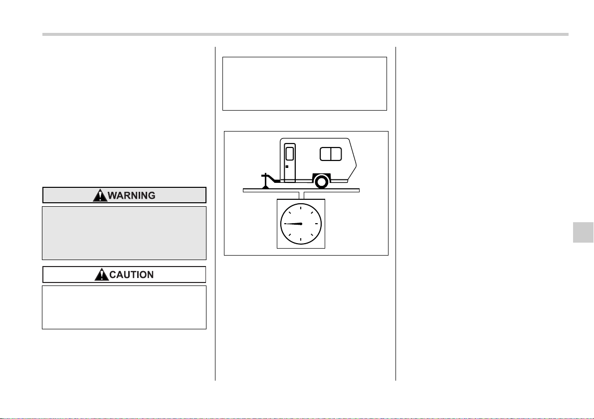
Driving tips 8-21
– CONTINUED –
required due to the additional load. (Refer
to “Maintenance schedule under severe
driving conditions” in the “Warranty and
Maintenance Booklet”.)
Under no circumstances should a trailer
be towed with a new vehicle or a vehicle
with any new powertrain component (en-
gine, transmission, differential, wheel
bearings, etc.) for the first 1,000 miles
(1,600 km) of driving.
Maximum load limits
T Total trailer weight
Total trailer weight
The total trailer weight (trailer weight plus
its cargo load) must never exceed the
maximum weight indicated in the following
table.
Never exceed the maximum load
limits explained in the following. Ex-
ceeding the maximum load limits
could cause personal injury and/or
vehicle damage.
y Adequate size trailer brakes are
required when the trailer and its
cargo exceed 1,000 lbs (453 kg)
total weight.
y Before towing a trailer, check the
trailer total weight, GVW, GAWs
and tongue load. Make sure the
load and its distribution in your
vehicle and trailer are acceptable.
800211
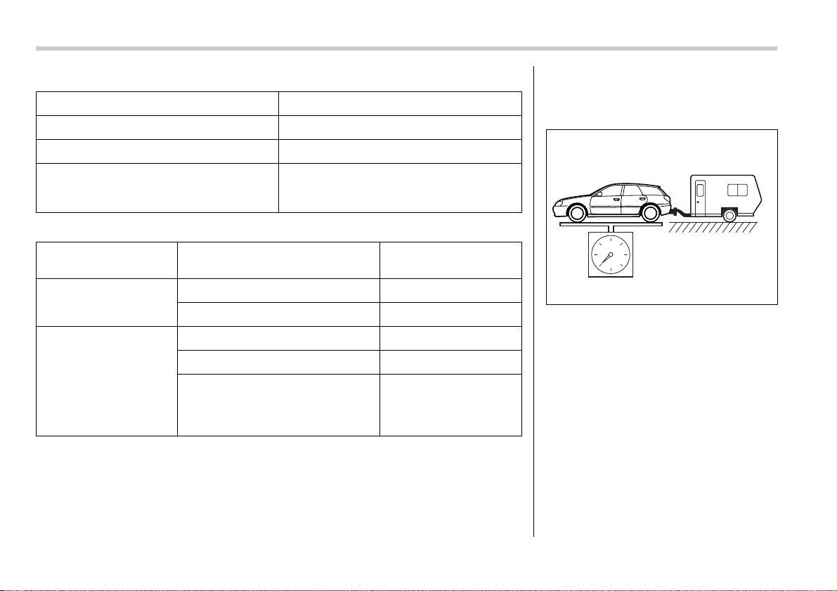
8-22 Driving tips
3,0-liter models
All models other than 3.0-liter models
Conditions Maximum total trailer weight
When towing a trailer without brakes. 1,000 lbs (453 kg)
When towing a trailer with brakes. 3,000 lbs (1,360 kg)
When towing a trailer on a long uphill grade con-
tinuously for over 5 miles (8 km) with an outside
temperature of 104°F (40°C) or above.
1,500 lbs (680 kg)
Model Conditions Maximum total trailer
weight
MT models When towing a trailer without brakes. 1,000 lbs (453 kg)
When towing a trailer with brakes. 2,700 lbs (1,224 kg)
AT models When towing a trailer without brakes. 1,000 lbs (453 kg)
When towing a trailer with brakes. 2,700 lbs (1,224 kg)
When towing a trailer on a long uphill
grade continuously for over 5 miles (8
km) with an outside temperature of
104°F (40°C) or above.
1,350 lbs (612 kg)
T Gross Vehicle Weight (GVW) and
Gross Vehicle Weight Rating
(GVWR)
Gross Vehicle Weight
The Gross Vehicle Weight (GVW) must
never exceed the Gross Vehicle Weight
Rating (GVWR).
Gross Vehicle Weight (GVW) is the com-
bined total of the weight of the vehicle,
driver, passengers, luggage, trailer hitch,
trailer tongue load and any other optional
equipment installed on your vehicle.
Therefore, the GVW changes depending
on the situation. Determine the GVW each
time before going on a trip by putting your
vehicle and trailer on a vehicle scale.
GVWR is shown on the certification label
located on the driver’s door of your vehi-
800247
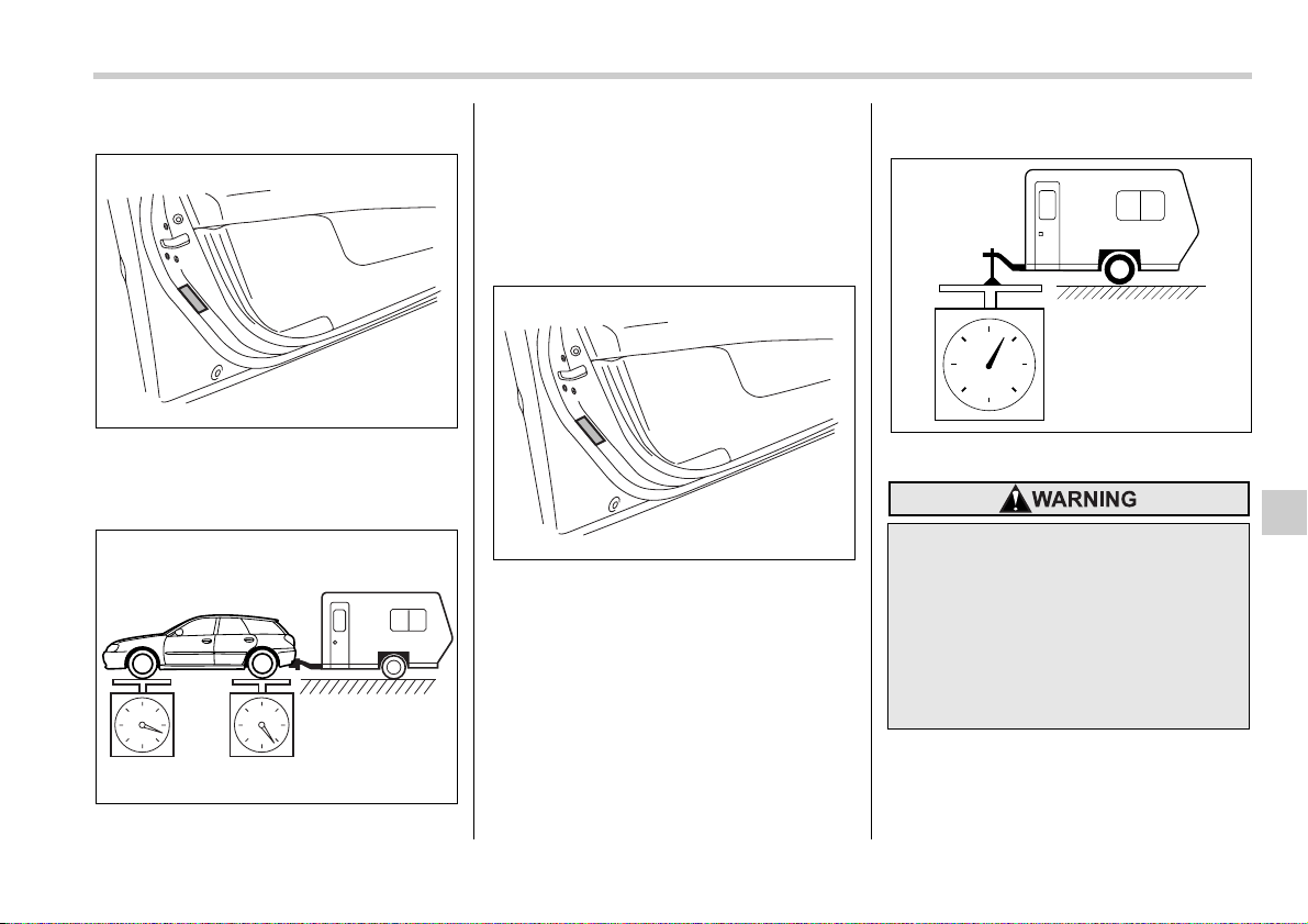
Driving tips 8-23
– CONTINUED –
cle.
Certification label
T Gross Axle Weight (GAW) and
Gross Axle Weight Rating (GAWR)
Gross Axle Weight
The total weight applied to each axle
(GAW) must never exceed the Gross Axle
Weight Rating (GAWR). The front and
rear GAWs can be adjusted by relocating
passengers and luggage inside the vehi-
cle. The front and rear GAWR are also
shown on the certification label.
Certification label
To check both GVWR and GAWR and to
confirm that the total weight and weight
distribution are within safe driving limits,
you should have your vehicle and trailer
weighed at a commercial weighing sta-
tion.
Be sure that all cargo is firmly secured to
prevent a change in weight distribution
while driving.
T Tongue load
Tongue load
Ensure that the trailer tongue load is from
8 to 11 percent of the total trailer weight
and does not exceed the maximum value
of 200 lbs (90 kg).
800237
800249
800237
If the trailer is loaded with more
weight in the back of trailer’s axle
than in the front, the load is taken off
the rear axle of the towing vehicle.
This may cause the rear wheels to
skid, especially during braking or
when vehicle speed is reduced dur-
ing cornering, resulting in over-
steer, spin out and/or jackknifing.
800214
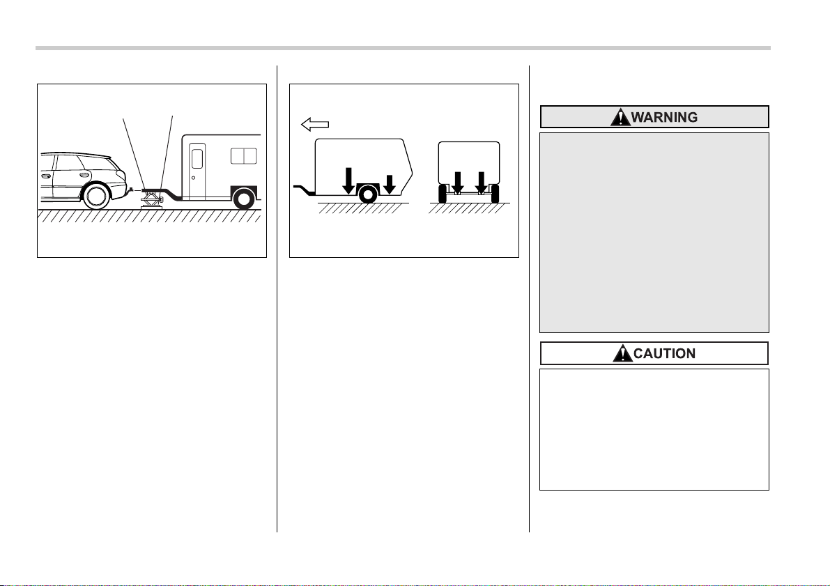
8-24 Driving tips
1) Jack
2) Bathroom scale
The tongue load can be weighed with a
bathroom scale as shown in the following
illustration. When weighing the tongue
load, be sure to position the towing cou-
pler at the height at which it would be dur-
ing actual towing, using a jack as shown.
F: Front
The tongue load can be adjusted by prop-
er distribution of the load in the trailer.
Never load the trailer with more weight in
the back than in the front; approximately
60 percent of the trailer load should be in
the front and approximately 40 percent in
the rear. Also, distribute the load as even-
ly as possible on both the left and right
sides.
Be sure that all cargo is firmly secured to
prevent a change in weight distribution
while driving.
Trailer hitches
Choose a proper hitch for your vehicle and
trailer.
1
2
800250
F
60%
40%
50%
50%
800216
Never drill the frame or under-body
of your vehicle to install a commer-
cial trailer hitch. If you do, danger-
ous exhaust gas, water or mud may
enter the passenger compartment
through the drilled hole. Exhaust
gas contains carbon monoxide, a
colorless and odorless gas which is
dangerous, or even lethal, if inhaled.
Also, drilling the frame or under-
body of your vehicle could cause
deterioration of strength of your ve-
hicle and cause corrosion around
the drilled hole.
y Do not modify the vehicle exhaust
system, brake system, or other
systems when installing a hitch or
other trailer towing equipment.
y Do not use axle-mounted hitches
as they can cause damage to the
axle housing, wheel bearings,
wheels or tires.

Driving tips 8-25
– CONTINUED –
T OUTBACK wagon
The use of a genuine SUBARU trailer
hitch is recommended. A genuine
SUBARU hitch is available from your
SUBARU dealer.
If use of a non-genuine hitch is unavoid-
able, be sure the hitch is suited to your ve-
hicle and trailer. Consult with a profes-
sional hitch supplier to assist you in
choosing an appropriate hitch for your ve-
hicle. Be sure to follow all of the hitch man-
ufacturer’s instructions for installation and
use.
Never use a hitch that mounts only to the
rear bumper. The bumper is not designed
to handle that type of load.
For all types of hitches, regularly check
that the hitch mounting bolts and nuts are
tight.
T All vehicles except OUTBACK wag-
on
SUBARU does not offer accessory trailer
hitches. Consult with a professional hitch
supplier to assist you in choosing an ap-
propriate hitch for your vehicle. Be sure to
follow all of the hitch manufacturer’s in-
structions for installation and use.
Never use a hitch that mounts only to the
rear bumper. The bumper is not designed
to handle that type of load.
Regularly check that the hitch mounting
bolts and nuts are tight.
Connecting a trailer
T Trailer brakes
If your trailer’s total weight (trailer weight
plus its cargo weight) exceeds 1,000 lbs
(453 kg), the trailer is required to be
equipped with its own brake system. Elec-
tric brakes or surge brakes are recom-
mended, and must be installed properly.
Check that your trailer’s brakes conform
with Federal, state/province and/or other
applicable regulations. Your SUBARU’s
brake system is not designed to be tapped
into the trailer’s hydraulic brake system.
Please ask your SUBARU dealer and pro-
fessional trailer supplier for more informa-
tion about the trailer’s brake system.
T Trailer safety chains
In case the trailer hitch connector or hitch
ball should break or become disconnect-
ed, the trailer could get loose and create a
traffic safety hazard.
For safety, always connect the towing ve-
hicle and trailer with trailer safety chains.
Pass the chains crossing each other un-
der the trailer tongue to prevent the trailer
from dropping onto the ground in case the
trailer tongue should disconnect from the
hitch ball. Allow sufficient slack in the
chains taking tight-turn situations into ac-
count; however, be careful not to let them
drag on the ground.
For more information about the safety
chain connection, refer to the instructions
for your hitch and trailer.
y Adequate size trailer brakes are
required when the trailer and its
cargo exceed 1,000 lbs (453 kg)
total weight.
y Do not directly connect your trail-
er’s hydraulic brake system to the
hydraulic brake system in your
vehicle. Direct connection would
cause the vehicle’s brake perfor-
mance to deteriorate and could
lead to an accident.
Always use safety chains between
your vehicle and the trailer. Towing
trailer without safety chains could
create a traffic safety hazard if the
trailer separates from the hitch due
to coupling damage or hitch ball
damage.
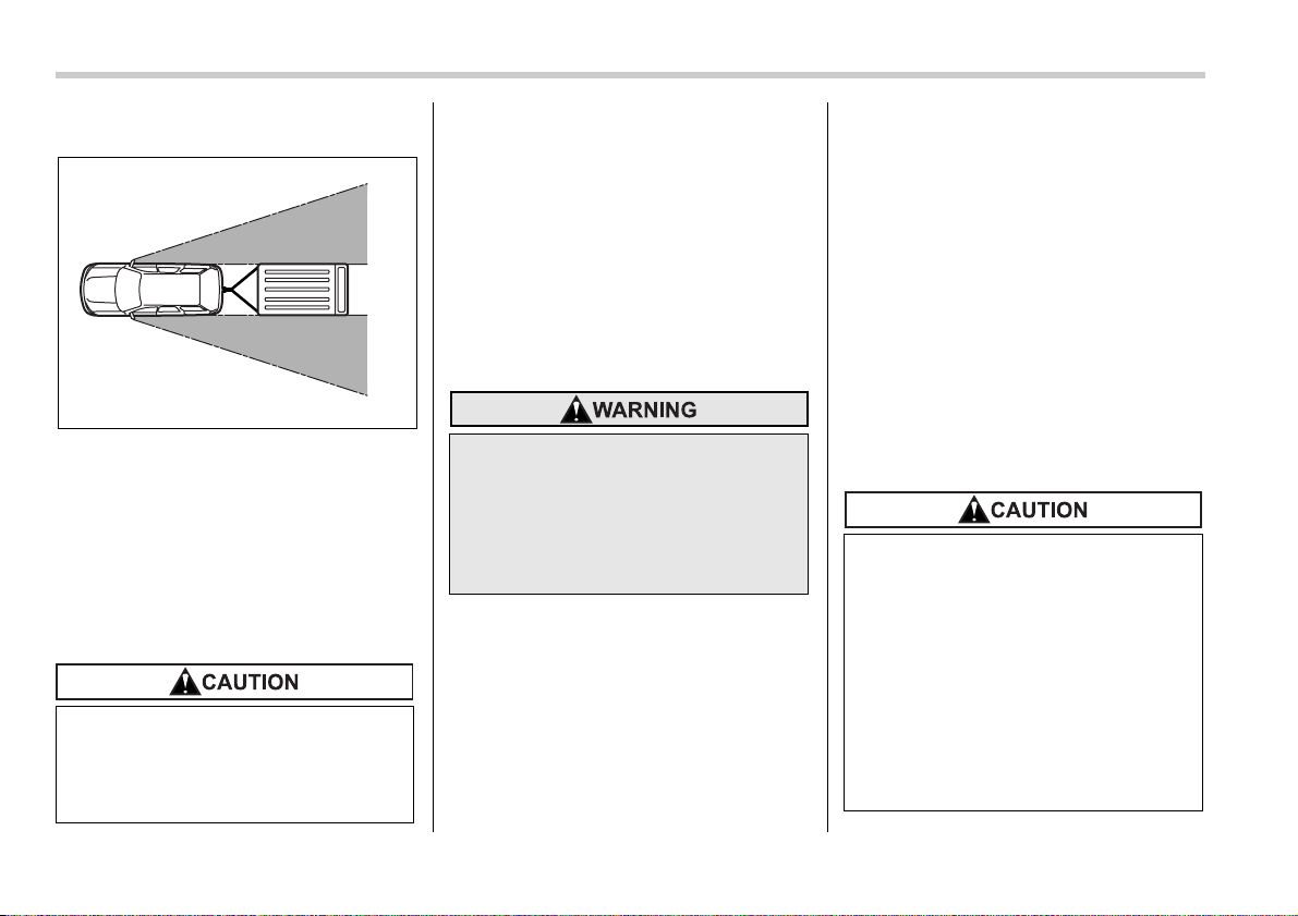
8-26 Driving tips
T Side mirrors
After hitching a trailer to your vehicle,
check that the standard side mirrors pro-
vide a good rearward field of view without
significant blind spots. If significant blind
spots occur with the vehicle’s standard
side mirrors, use towing mirrors that con-
form with Federal, state/province and/or
other applicable regulations.
T Trailer lights
Connection of trailer lights to your vehi-
cle’s electrical system requires modifica-
tions to the vehicle’s lighting circuit to in-
crease its capacity and accommodate wir-
ing changes. To ensure the trailer lights
are connected properly, please consult
your SUBARU dealer. Check for proper
operation of the turn signals, the brake
lights and parking lights each time you
hitch up.
T Tires
Make sure that all the tires on your vehicle
are properly inflated.
The recommended cold tire pressure un-
der trailer towing conditions is shown in
chapter 12, “Specifications” and in “GAS
STATION REFERENCE” at the end of this
manual. Adjust the rear tire pressure to
the recommended pressure when the tires
are cold. Normal pressure should be
maintained in the front tires.
Trailer tire condition, size, load rating and
proper inflation pressure should be in ac-
cordance with the trailer manufacturer’s
specifications.
In the event your vehicle gets a flat tire
when towing a trailer, ask a commercial
road service to repair the flat tire.
If you carry a regular size spare tire in your
vehicle or trailer as a precaution against
getting a flat tire, be sure that the spare
tire is firmly secured.
Trailer towing tips
Direct splicing or other improper
connection of trailer lights may
damage your vehicle’s electrical
system and cause a malfunction of
your vehicle’s lighting system.
800018
Never tow a trailer when the tempo-
rary spare tire is used. The tempo-
rary spare tire is not designed to
sustain the towing load. Use of the
temporary spare tire when towing
can result in failure of the spare tire
and/or less stability of the vehicle.
y Never exceed 45 mph (72 km/h)
when towing a trailer in hilly coun-
try on hot days.
y When towing a trailer, steering,
stability, stopping distance and
braking performance will be dif-
ferent from normal operation. For
safety’s sake, you should employ
extra caution when towing a trail-
er and you should never speed.
You should also keep the follow-
ing tips in mind:
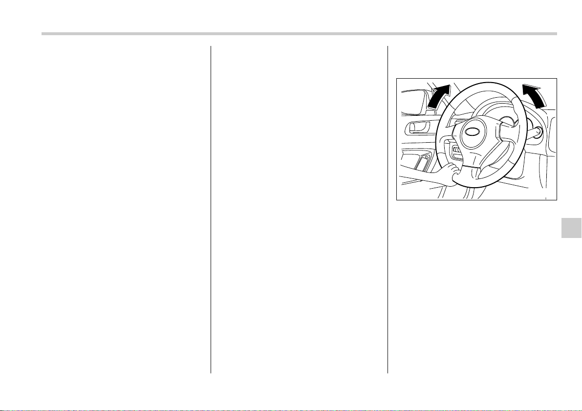
Driving tips 8-27
– CONTINUED –
T Before starting out on a trip
y Check that the vehicle and vehicle-to-
hitch mounting are in good condition. If
any problems are apparent, do not tow the
trailer.
y Check that the vehicle sits horizontally
with the trailer attached. If the vehicle is
tipped sharply up at the front and down at
the rear, check the total trailer weight,
GVW, GAWs and tongue load again, then
confirm that the load and its distribution
are acceptable.
y Check that the tire pressures are cor-
rect.
y Check that the vehicle and trailer are
connected properly. Confirm that
– the trailer tongue is connected prop-
erly to the hitch ball.
– the trailer lights connector is connect-
ed properly and trailer’s brake lights illu-
minate when the vehicle’s brake pedal
is pressed, and that the trailer’s turn sig-
nal lights flash when the vehicle’s turn
signal lever is operated.
– the safety chains are connected prop-
erly.
– all cargo in the trailer is secured safe-
ty in position.
– the side mirrors provide a good rear-
ward field of view without a significant
blind spot.
y Sufficient time should be taken to learn
the “feel” of the vehicle/trailer combination
before starting out on a trip. In an area free
of traffic, practice turning, stopping and
backing up.
T Driving with a trailer
y You should allow for considerably more
stopping distance when towing a trailer.
Avoid sudden braking because it may re-
sult in skidding or jackknifing and loss of
control.
y Avoid abrupt starts and sudden acceler-
ations. If your vehicle has a manual trans-
mission, always start out in first gear and
release the clutch at moderate engine rev-
olution.
y Avoid uneven steering, sharp turns and
rapid lane changes.
y Slow down before turning. Make a long-
er than normal turning radius because the
trailer wheels will be closer than the vehi-
cle wheels to the inside of the turn. In a
tight turn, the trailer could hit your vehicle.
y Crosswinds will adversely affect the
handling of your vehicle and trailer, caus-
ing sway. Crosswinds can be due to
weather conditions or the passing of large
trucks or buses. If swaying occurs, firmly
grip the steering wheel and slow down im-
mediately but gradually.
y When passing other vehicles, consider-
able distance is required because of the
added weight and length caused by at-
taching the trailer to your vehicle.
1) Left turn
2) Right turn
y Backing up with a trailer is difficult and
takes practice. When backing up with a
trailer, never accelerate or steer rapidly.
When turning back, grip the bottom of the
steering wheel with one hand and turn it to
the left for a left turn, and turn it to the right
for a right turn.
y If the ABS warning light illuminates
while the vehicle is in motion, stop towing
the trailer and have repairs performed im-
mediately by the nearest SUBARU dealer.
T Driving on grades
y Before going down a steep hill, slow
down and shift into lower gear (if neces-
1
2
800251

8-28 Driving tips
sary, use 1st gear) in order to utilize the
engine braking effect and prevent over-
heating of your vehicle’s brakes. Do not
make sudden downshifts.
y When driving uphill in hot weather, the
air conditioner may turn off automatically
to protect the engine from overheating.
y When driving uphill in hot weather, pay
attention to the water temperature gauge
pointer (for all vehicles) and AT OIL TEMP
warning light (for AT vehicles) since the
engine and transmission are relatively
prone to overheating under these condi-
tions. If the water temperature gauge
pointer approaches the OVERHEAT zone
or the AT OIL TEMP warning light illumi-
nates, immediately switch off the air con-
ditioner and stop the vehicle at the nearest
safe place. Refer to the “Engine overheat-
ing” section in chapter 9, and “Warning
and indicator lights” section in chapter 3.
NOTE
With AT vehicles, the temperature of
engine coolant is less likely to rise to
the OVERHEAT zone in the “D” posi-
tion than in the manual mode position.
y If your vehicle has an automatic trans-
mission, avoid using the accelerator pedal
to stay stationary on an uphill slope in-
stead of using the parking brake or foot
brake. That may cause the transmission
fluid to overheat.
T Parking on a grade
Always block the wheels under both vehi-
cle and trailer when parking. Apply the
parking brake firmly. You should not park
on a hill or slope. But if parking on a hill or
slope cannot be avoided, you should take
the following steps:
1. Apply the brakes and hold the pedal
down.
2. Have someone place wheel blocks un-
der both the vehicle and trailer wheels.
3. When the wheel blocks are in place, re-
lease the regular brakes slowly until the
blocks absorb the load.
4. Apply the regular brakes and then ap-
ply the parking brake; slowly release the
regular brakes.
5. Shift into 1st or reverse gear (manual
transmission) or “P” (automatic transmis-
sion) and shut off the engine.

9
In case of emergency
If you park your vehicle in an emergency ........ 9-2
Temporary spare tire .......................................... 9-2
Flat tires .............................................................. 9-4
Changing a flat tire ................................................. 9-4
Tire pressure monitoring system (TPMS)
(if equipped) .......................................................... 9-9
Jump starting ...................................................... 9-10
How to jump start ................................................... 9-10
Engine overheating ............................................ 9-12
If steam is coming from the engine
compartment ......................................................... 9-12
If no steam is coming from the engine
compartment ......................................................... 9-12
Towing ................................................................. 9-13
Towing and tie-down hooks .................................. 9-13
Using a flat-bed truck ............................................. 9-16
Towing with all wheels on the ground .................. 9-16
Rear gate (Station wagon) – if the rear gate
cannot be unlocked ........................................ 9-17
Maintenance tools .............................................. 9-18
Jack .......................................................................... 9-18
Jack handle ............................................................. 9-18
Other maintenance tools ........................................ 9-19
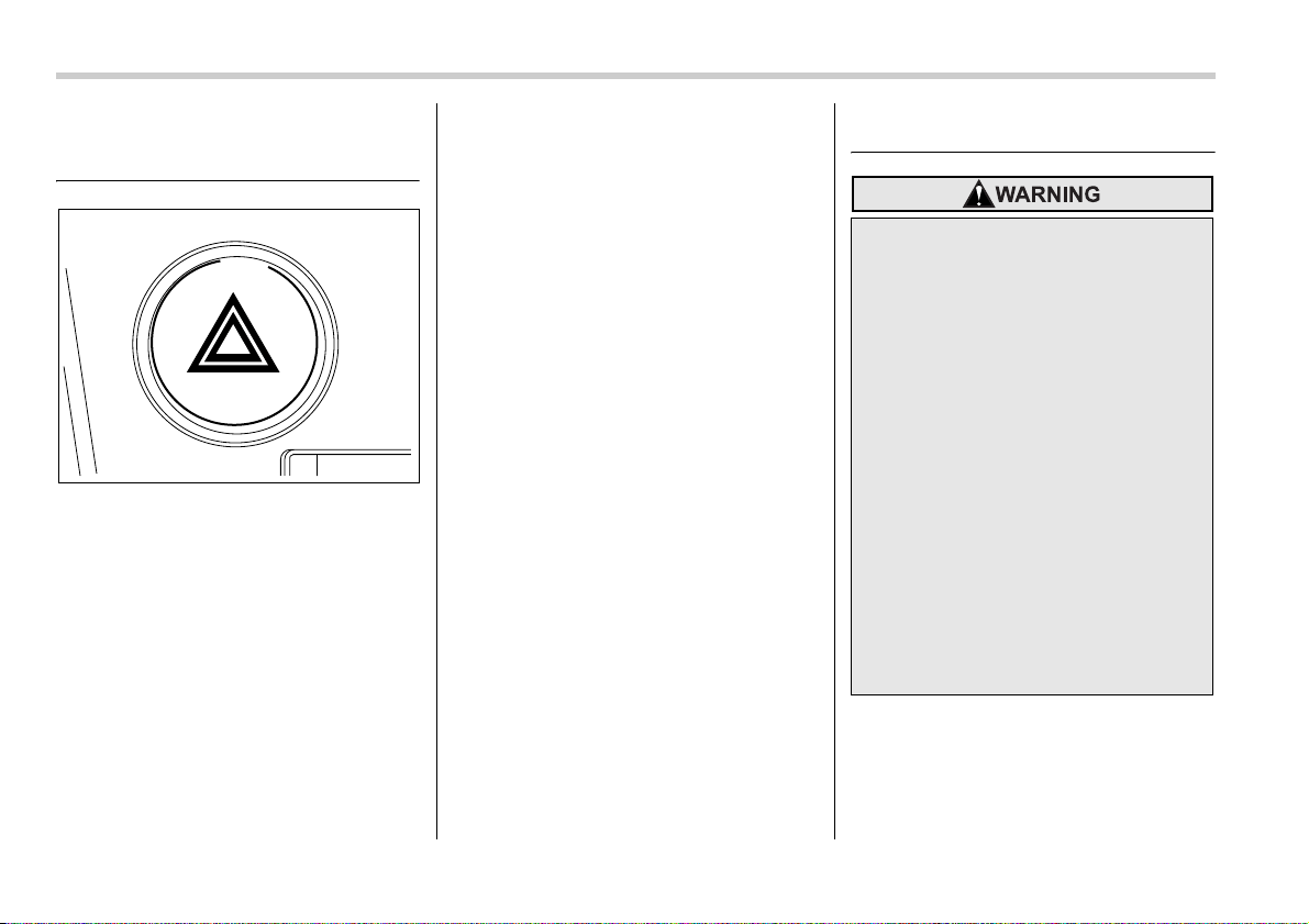
9-2 In case of emergency
In case of emergency
If you park your vehicle in an
emergency
The hazard warning flasher should be
used in day or night to warn other drivers
when you have to park your vehicle under
emergency conditions.
Avoid stopping on the road. It is best to
safely pull off the road if a problem occurs.
The hazard warning flasher can be acti-
vated regardless of the ignition switch po-
sition.
Turn on the hazard warning by pushing
the hazard warning flasher switch. Turn it
off by pushing the switch again.
NOTE
When the hazard warning flasher is on,
the turn signals do not work.
Temporary spare tire
300177
y Never tow a trailer when the tem-
porary spare tire is used. The tem-
porary spare tire is not designed
to sustain the towing load. Use of
the temporary spare tire when
towing can result in failure of the
spare tire and/or less stability of
the vehicle and may lead to an ac-
cident.
y When a spare tire is mounted or a
wheel rim is replaced without the
original pressure sensor/trans-
mitter being transferred, the low
tire pressure warning light will
flash. This indicates the tire pres-
sure monitoring system (TPMS) is
unable to monitor all four road
wheels. Contact your SUBARU
dealer as soon as possible for tire
and sensor replacement and/or
system resetting.
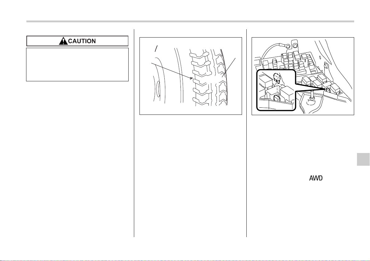
In case of emergency 9-3
The temporary spare tire is smaller and
lighter than a conventional tire and is de-
signed for emergency use only. Remove
the temporary spare tire and re-install the
conventional tire as soon as possible be-
cause the spare tire is designed only for
temporary use.
Check the inflation pressure of the tempo-
rary spare tire periodically to keep the tire
ready for use. The correct pressure is 60
psi (420 kPa, 4.2 kgf/cm
2
).
When using the temporary spare tire, note
the following.
y Do not exceed 50 mph (80 km/h).
y Do not put a tire chain on the temporary
spare tire. Because of the smaller tire
size, a tire chain will not fit properly.
y Do not use two or more temporary
spare tires at the same time.
y Do not drive over obstacles. This tire
has a smaller diameter, so road clearance
is reduced.
1) Tread wear indicator bar
2) Indicator location mark
y When the wear indicator appears on the
tread, replace the tire.
y The temporary spare tire must be used
only on a rear wheel. If a front wheel tire
gets punctured, replace the wheel with a
rear wheel and install the temporary spare
tire in place of the removed rear wheel.
NOTE
If your vehicle is an AWD type with an
automatic transmission but is neither a
Turbo model nor a 3.0-liter model, de-
activate its All-Wheel-Drive capability
as follows: Before driving your vehicle
with the temporary spare tire, put a
spare fuse inside the FWD connector
located in the engine compartment and
confirm that the “ ” warning
light comes on. The All-Wheel-Drive
capability of the vehicle has now been
deactivated. After re-installing the con-
ventional tire, remove the spare fuse
from the FWD connector in order to re-
activate All-Wheel Drive.
Never use any temporary spare tire
other than the original. Using other
sizes may result in severe mechani-
cal damage to the drive train of your
vehicle.
1
2
900209
600121
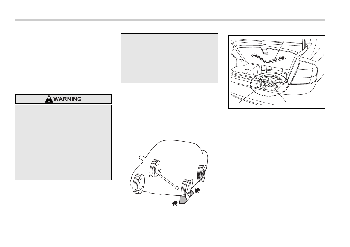
9-4 In case of emergency
Flat tires
If you have a flat tire while driving, never
brake suddenly; keep driving straight
ahead while gradually reducing speed.
Then slowly pull off the road to a safe
place.
Changing a flat tire
1. Park on a hard, level surface, whenev-
er possible, then stop the engine.
2. Set the parking brake securely and
shift a manual transmission vehicle in re-
verse or an automatic transmission vehi-
cle in the “P” (Park) position.
3. Turn on the hazard warning flasher and
have everyone get out of the vehicle.
4. Put wheel blocks at the front and rear
of the tire diagonally opposite the flat tire.
Sedan
1) Jack handle
2) Spare tire
3) Jack and tool bucket
y Do not jack up the vehicle on an
incline or a loose road surface.
The jack can come out of the jack-
ing point or sink into the ground
and this can result in a severe ac-
cident.
y Use only the jack provided with
your vehicle. The jack supplied
with the vehicle is designed only
for changing a tire. Never get un-
der the vehicle while supporting
the vehicle with this jack.
y Always turn off the engine before
raising the flat tire off the ground
using the jack. Never swing or
push the vehicle supported with
the jack. The jack can come out of
the jacking point due to a jolt and
this can result in a severe acci-
dent.
600122
2
3
1
900242
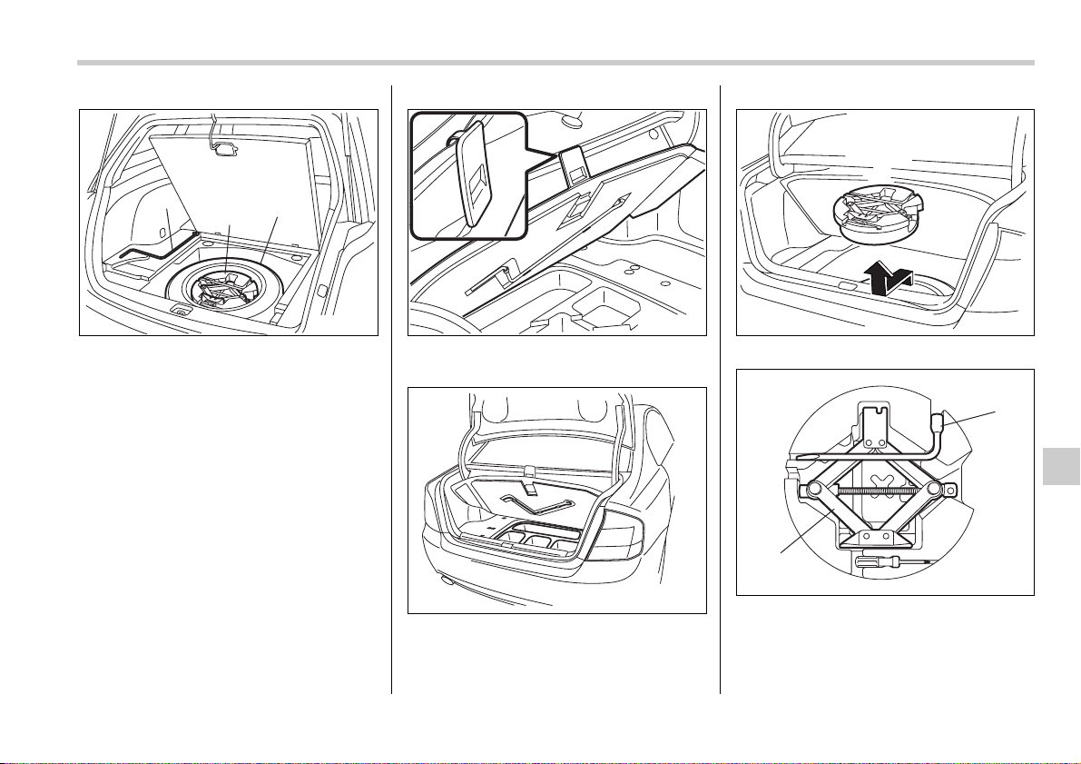
In case of emergency 9-5
– CONTINUED –
Station wagon
1) Jack handle
2) Jack and tool bucket
3) Spare tire
5. Take out the spare tire, jack, and jack
handle.
The spare tire and jack are stored under
the floor of the trunk or cargo area.
To remove the spare tire and jack, pro-
ceed as follows:
Sedan:
1. Lift the handle of the floor cover and
hook the handle onto the trunk edge.
2. Remove the jack handle from the back
of the floor cover.
3. Take out the storage tray.
4. Take out the jack and tool bucket.
1) Wheel nut wrench
2) Jack
5. Take the wheel nut wrench and jack
out of the tool bucket.
1
3
2
900243
600114
600115
900244
1
2
900245
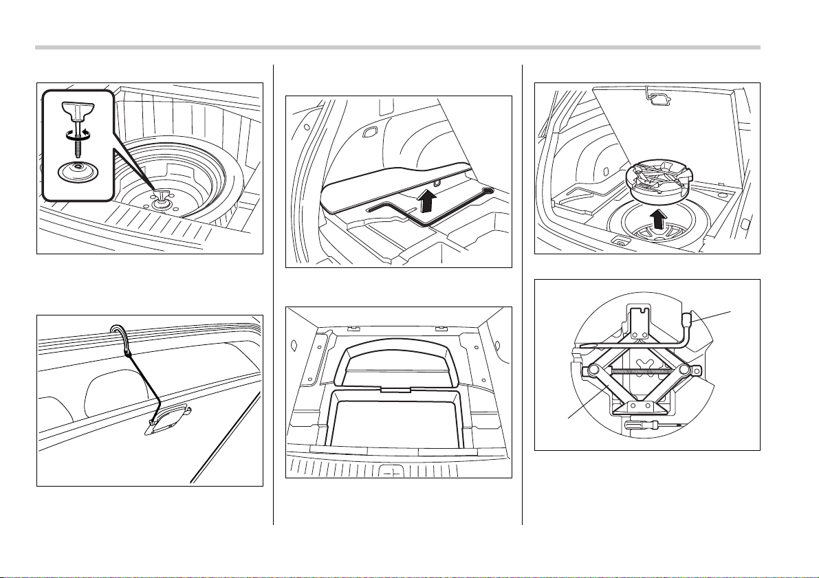
9-6 In case of emergency
6. Turn the attaching bolt counterclock-
wise, then take the spare tire out.
Station wagon:
1. Open the lid and hang the hook provid-
ed on the under side of the lid on the rear
edge of the roof to keep the lid open.
2. Remove the left-hand part of the lid
and take out the jack handle.
3. Take out the storage tray.
4. Take out the jack and tool bucket.
1) Wheel nut wrench
2) Jack
5. Take the wheel nut wrench and jack
out of the tool bucket.
600113
600110
600117
600111
900257
1
2
900245
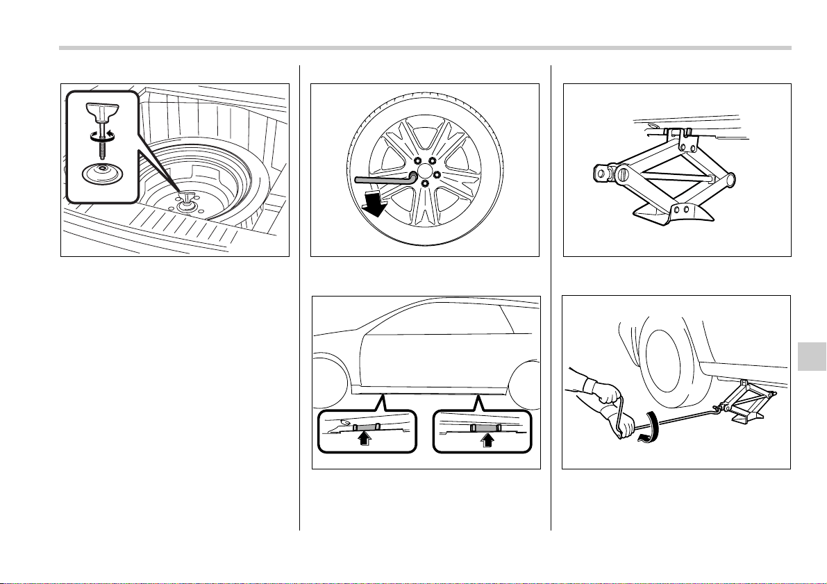
In case of emergency 9-7
– CONTINUED –
6. Turn the attaching bolt counterclock-
wise, then take spare tire out.
If the spare tire provided in your vehicle is
a temporary spare tire, carefully read the
section “Temporary spare tire” in this
chapter and strictly follow the instructions.
NOTE
Make sure the jack is well lubricated
before using it.
7. Loosen the wheel nuts using the wheel
nut wrench but do not remove the nuts.
8. Place the jack under the side sill at the
front or rear jack-up point closest to the flat
tire.
Turn the jackscrew by hand until the jack
head engages firmly into the jack-up point.
9. Insert the jack handle into the jack-
screw, and turn the handle until the tire
clears the ground. Do not raise the vehicle
higher than necessary.
600113
600197
600123
600124
600198
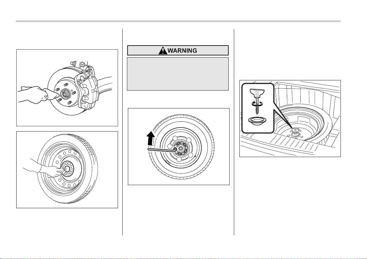
9-8 In case of emergency
10.Remove the wheel nuts and the flat
tire.
11.Before putting the spare tire on, clean
the mounting surface of the wheel and
hub with a cloth.
12.Put on the spare tire. Replace the
wheel nuts. Tighten them by hand.
13.Turn the jack handle counterclockwise
to lower the vehicle.
14.Use the wheel nut wrench to securely
tighten the wheel nuts to the specified
torque, following the tightening order in
the illustration.
The torque for tightening the nuts is 74 to
89 lbf·ft (100 to 120 N·m, 10 to 12 kgf·m).
This torque is equivalent to applying ap-
proximately 88 to 110 lbs (40 to 50 kg) at
the top of the wheel nut wrench. Never
use your foot on the wheel nut wrench or
a pipe extension on the wrench because
you may exceed the specified torque.
Have the wheel nut torque checked at the
nearest automotive service facility.
15.Store the flat tire in the spare tire com-
partment.
Put the spacer and tighten the attaching
bolt firmly.
Also store the jack and jack handle in their
storage locations.
900009
600162
Do not use oil or grease on the
wheel studs or nuts when the spare
tire is installed. This could cause the
nuts to become loose and lead to an
accident.
1
4
2
5
3
600192
600126
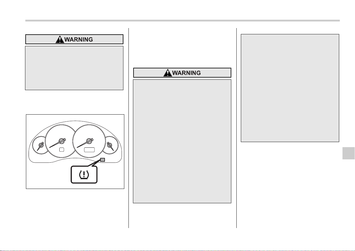
In case of emergency 9-9
Tire pressure monitoring sys-
tem (TPMS) (if equipped)
The tire pressure monitoring system pro-
vides the driver with the warning message
indicated by sending a signal from a sen-
sor that is installed in each wheel when
tire pressure is severely low.
The tire pressure monitoring system will
activate only when the vehicle is driven.
Also, this system may not react immedi-
ately to a sudden drop in tire pressure (for
example, a blow-out caused running over
a sharp object).
Never place a tire or tire changing
tools in the passenger compartment
after changing wheels. In a sudden
stop or collisions, loose equipment
could strike occupants and cause
injury. Store the tire and all tools in
the proper place.
700352
If the low tire pressure warning light
comes on while driving, never brake
suddenly and keep driving straight
ahead while gradually reducing
speed. Then slowly pull off the road
to a safe place. Otherwise an acci-
dent involving serious vehicle dam-
age and serious personal injury
could occur.
Check the pressure for all four tires
and adjust the pressure to the COLD
tire pressure shown on the vehicle
placard on the door pillar on the
driver’s side. If this light still comes
on while driving after adjusting the
tire pressure, a tire may have signif-
icant damage and a fast leak that
causes the tire to lose air rapidly. If
you have a flat tire, replace it with a
spare tire as soon as possible.
When a spare tire is mounted or a
wheel rim is replaced without the
original pressure sensor/transmitter
being transferred, the low tire pres-
sure warning light will flash. This in-
dicates the TPMS is unable to moni-
tor all four road wheels. Contact
your SUBARU dealer as soon as
possible for tire and sensor replace-
ment and/or system resetting.
Do not inject any tire liquid or aero-
sol tire sealant into the tires, as this
may cause a malfunction of the tire
pressure sensors.
If the light flashes, promptly contact
a SUBARU dealer to have the sys-
tem inspected.
9-10 In case of emergency
Jump starting
When your vehicle does not start due to a
run down (discharged) battery, the vehicle
may be jump started by connecting your
battery to another battery (called the
booster battery) with jumper cables.
How to jump start
1. Make sure the booster battery is 12
volts and the negative terminal is ground-
ed.
2. If the booster battery is in another vehi-
cle, do not let the two vehicles touch.
3. Turn off all unnecessary lights and ac-
cessories.
4. Connect the jumper cables exactly in
the sequence illustrated.
y Battery fluid is SULFURIC ACID.
Do not let it come in contact with
the eyes, skin, clothing or the ve-
hicle.
If battery fluid gets on you, thor-
oughly flush the exposed area
with water immediately. Get medi-
cal help if the fluid has entered
your eyes.
If battery fluid is accidentally
swallowed, immediately drink a
large amount of milk or water, and
obtain immediate medical help.
Keep everyone including children
away from the battery.
y The gas generated by a battery ex-
plodes if a flame or spark is
brought near it. Do not smoke or
light a match while jump starting.
y Never attempt jump starting if the
discharged battery is frozen. It
could cause the battery to burst or
explode.
y Whenever working on or around a
battery, always wear suitable eye
protectors, and remove metal ob-
jects such as rings, bands or oth-
er metal jewelry.
y Be sure the jumper cables and
clamps on them do not have loose
or missing insulation.
Do not jump start unless cables in
suitable condition are available.
y A running engine can be danger-
ous. Keep your fingers, hands,
clothing, hair and tools away from
the cooling fan, belts and any oth-
er moving engine parts. Remov-
ing rings, watches and ties is ad-
visable.
y Jump starting is dangerous if it is
done incorrectly. If you are unsure
about the proper procedure for
jump starting, consult a compe-
tent mechanic.
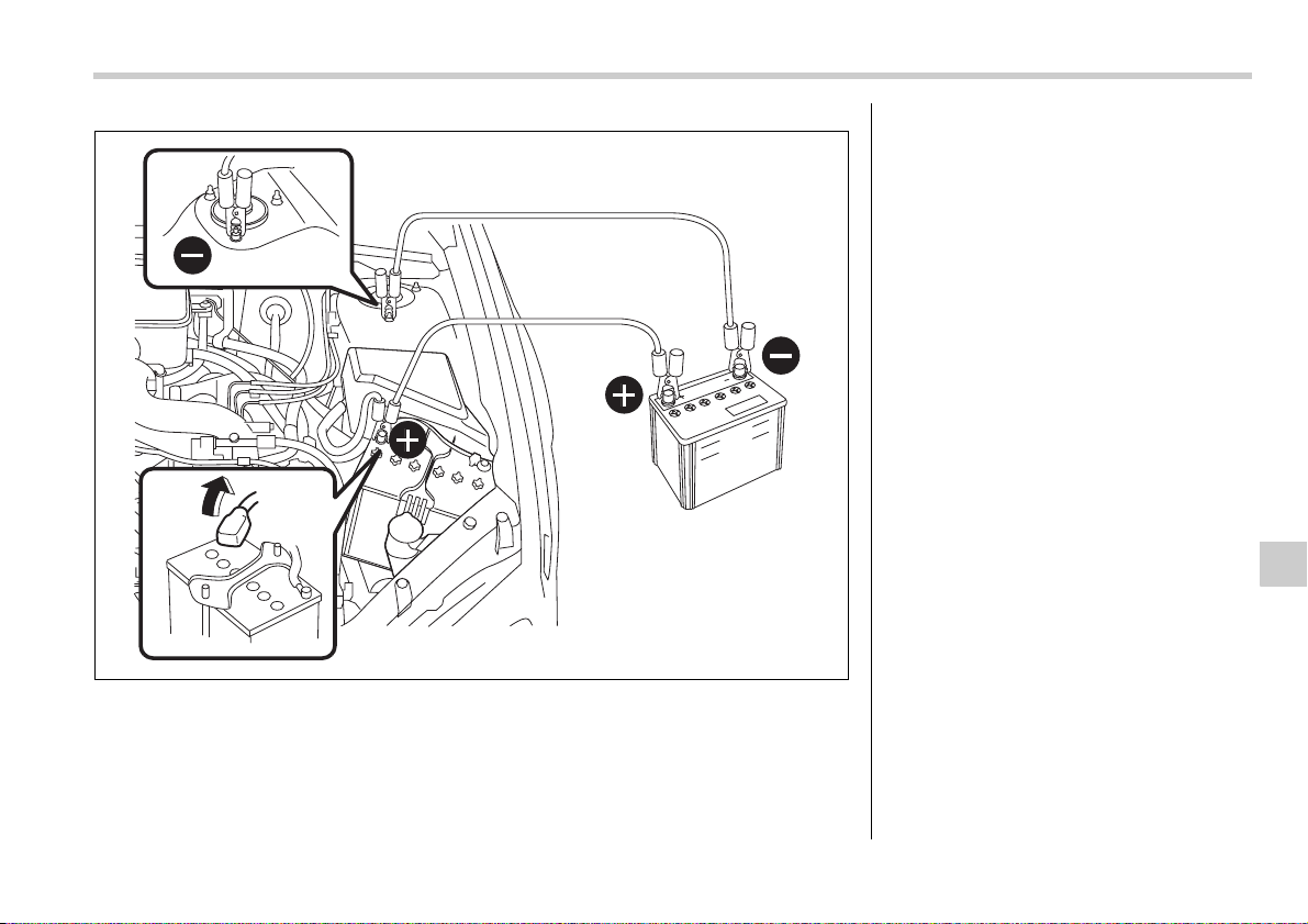
In case of emergency 9-11
– CONTINUED –
(1)
(4)
(2)
(3)
600155
1)Connect one jumper cable to the pos-
itive (+) terminal on the discharged bat-
tery.
2)Connect the other end of the jumper
cable to the positive (+) terminal of the
booster battery.
3)Connect one end of the other cable to
the negative (–) terminal of the booster
battery.
4)Connect the other end of the cable to
the strut mounting nut.
Make sure that the cables are not near
any moving parts and that the cable
clamps are not in contact with any other
metal.
9-12 In case of emergency
5. Start the engine of the vehicle with the
booster battery and run it at moderate
speed. Then start the engine of the vehi-
cle that has the discharged battery.
6. When finished, carefully disconnect the
cables in exactly the reverse order.
Engine overheating
If the engine overheats, pull off the road
safely and stop the vehicle in a safe place.
If steam is coming from the
engine compartment
Turn off the engine and get everyone
away from the vehicle until it cools down.
If no steam is coming from
the engine compartment
1. Keep the engine running at idling
speed.
2. Open the hood to ventilate the engine
compartment.
Confirm that the cooling fan is turning. If
the fan is not turning, immediately turn off
the engine and contact your authorized
dealer for repair.
3. After the engine coolant temperature
has dropped, turn off the engine.
If the temperature gauge stays at the
overheated zone, turn off the engine.
4. After the engine has fully cooled down,
check the coolant level in the reserve
tank.
If the coolant level is below the “MIN”
mark, add coolant up to the “MAX” mark.
5. If there is no coolant in the reserve
tank, add coolant to the reserve tank.
Then remove the radiator cap and fill the
radiator with coolant.
If you remove the radiator cap from a hot
radiator, first wrap a thick cloth around the
radiator cap, then turn the cap counter-
clockwise slowly without pressing down
until it stops. Release the pressure from
the radiator. After the pressure has been
fully released, remove the cap by pressing
down and turning it.
Never attempt to remove the radia-
tor cap until the engine has been
shut off and has fully cooled down.
When the engine is hot, the coolant
is under pressure. Removing the
cap while the engine is still hot
could release a spray of boiling hot
coolant, which could burn you very
seriously.
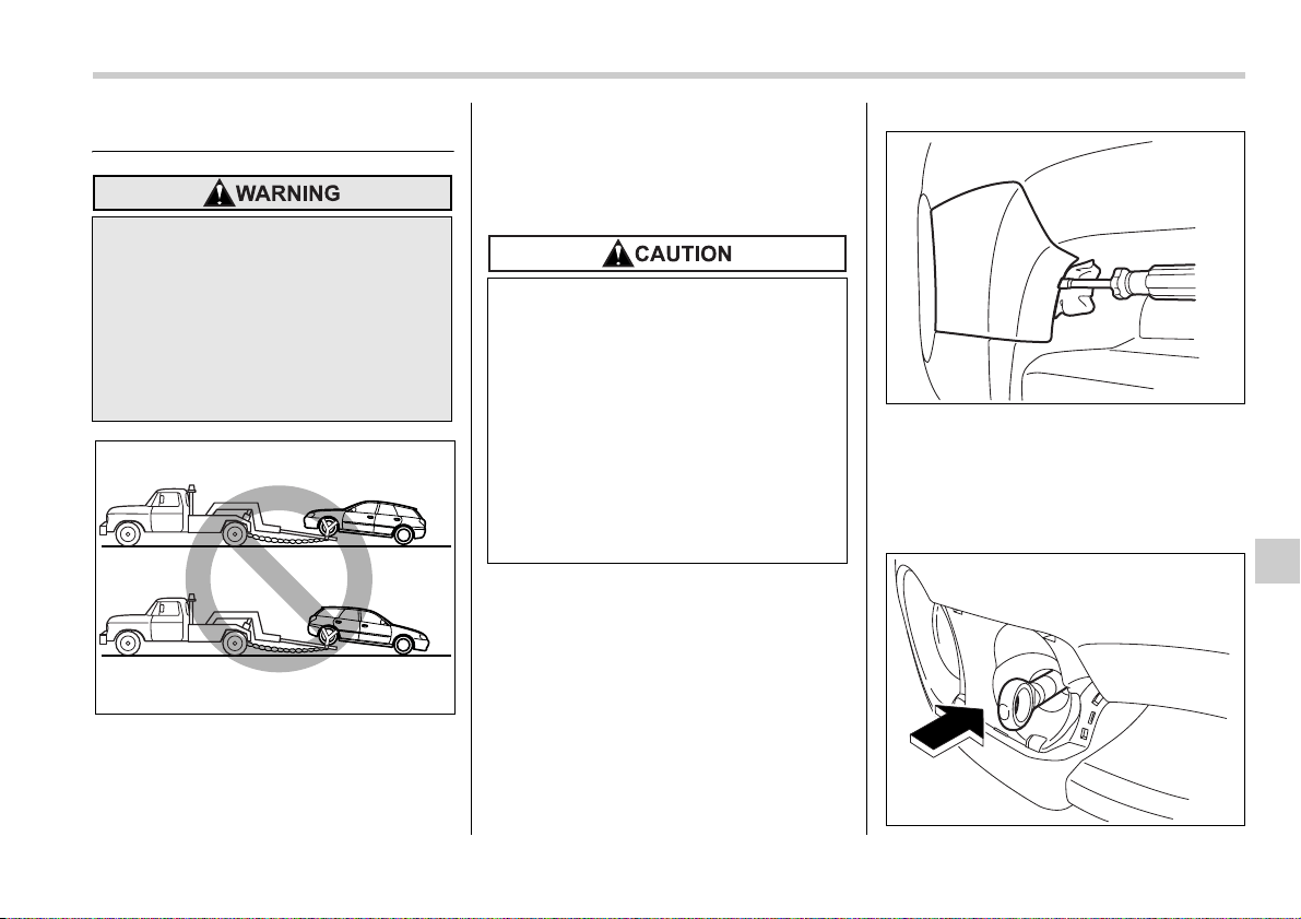
In case of emergency 9-13
– CONTINUED –
Towing
If towing is necessary, it is best done by
your SUBARU dealer or a commercial
towing service. Observe the following pro-
cedures for safety.
Towing and tie-down hooks
The towing hooks should be used only in
an emergency (e.g., to free a stuck vehicle
from mud, sand or snow).
Front towing hook (OUTBACK models):
1. Take out the towing hook, screwdriver
and wheel nut wrench from the on board
tool bucket.
2. Wrap a flat-head screwdriver in a vinyl
tape or cloth, insert it into the gap between
the cover and the front bumper, and use it
to lever the cover open.
3. Pull the entire front fog light cover to-
ward you.
Never tow AWD vehicles (both AT
and MT) with the front wheels raised
off the ground while the rear wheels
are on the ground, or with the rear
wheels raised off the ground while
the front wheels are on the ground.
This will cause the vehicle to spin
away due to the operation or deteri-
oration of the center differential.
900030
y Use only the specified towing
hooks and tie-down hooks. Never
use suspension parts or other
parts of the body for towing or tie-
down purposes.
y Never use the tie-down hook clos-
est to the muffler under the vehi-
cle for towing purposes.
y To prevent deformation to the
bumper and the towing hook, do
not apply excessive lateral load to
the towing hooks.
900246
900247
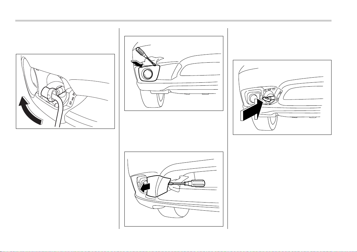
9-14 In case of emergency
4. Screw the towing hook into the thread
hole until the threads can no longer be
seen.
5. Tighten the towing hook securely using
a wheel nut wrench.
After towing, remove the towing hook from
the vehicle and stow it in the tool bag.
Fit the towing hook cover on the bumper.
Front towing hook (except OUTBACK
models):
1. Take out the towing hook, screwdriver
and wheel nut wrench from the on board
tool bag.
2. Wrap a flat-head screwdriver with cloth
or vinyl. Then, insert the screwdriver into
the gap between the front fog light cover
and the bumper, and pry out the cover.
3. Pull the entire front fog light cover to-
ward you.
4. Likewise, insert the screwdriver still
wrapped with cloth or vinyl into the cutout
between the towing hook cover and the
bumper. Pry out the cover.
5. Screw the towing hook into the thread
hole until the threads can no longer be
seen.
900248
900249
900250
900251
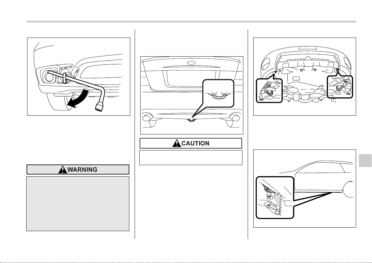
In case of emergency 9-15
– CONTINUED –
6. Tighten the towing hook securely using
a wheel nut wrench.
After towing, remove the towing hook from
the vehicle and stow it in the tool bag.
Fit the fog light cover and towing hook
cover on the bumper.
Rear towing hook:
The rear towing hook is located below the
center of the rear bumper.
Front tie-down hooks:
The front tie-down hooks are located be-
tween each of the front tires and the front
bumper.
Rear tie-down hooks:
The rear tie-down hooks are located near
y Do not use the towing hook ex-
cept when towing your vehicle.
y Be sure to remove the towing
hook after towing. Leaving the
towing hook mounted on the vehi-
cle could interfere with proper op-
eration of the SRS airbag system
in a frontal collision.
900252
Never use the rear towing hook to tie
the vehicle down.
600150
900253
900032
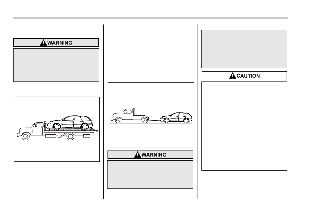
9-16 In case of emergency
each of the jack-up reinforcements.
Using a flat-bed truck
This is the best way to transport your vehi-
cle. Use the following procedures to en-
sure safe transportation.
1. Shift the selector lever into the “P” po-
sition for automatic transmission vehicles
or “1st” for manual transmission vehicles.
2. Pull up the parking brake lever firmly.
3. Secure the vehicle onto the carrier
properly with safety chains. Each safety
chain should be equally tightened and
care must be taken not to pull the chains
so tightly that the suspension bottoms out.
Towing with all wheels on the
ground
1. Check the transmission and differential
oil levels and add oil to bring it to the upper
level if necessary.
2. Release the parking brake and put the
transmission in neutral.
Use the rear tie-down hooks only for
downward anchoring. If they are
used to anchor the vehicle in any
other direction, cables may slip off
the hooks, possibly causing a dan-
gerous situation.
900033
y Never turn the ignition switch to
the “LOCK” position while the ve-
hicle is being towed because the
steering wheel and the direction
of the wheels will be locked.
900254
y Remember that the brake booster
and power steering do not func-
tion when the engine is not run-
ning. Because the engine is
turned off, it will take greater ef-
fort to operate the brake pedal and
steering wheel.
y If transmission failure occurs,
transport your vehicle on a flat-
bed truck.
y Do not run the engine while being
towed using this method. Trans-
mission damage could result if
the vehicle is towed with the en-
gine running.
y For vehicles with automatic trans-
mission, the traveling speed must
be limited to less than 20 mph (30
km/h) and the traveling distance
to less than 31 miles (50 km). For
greater speeds and distances,
transport your vehicle on a flat-
bed truck.
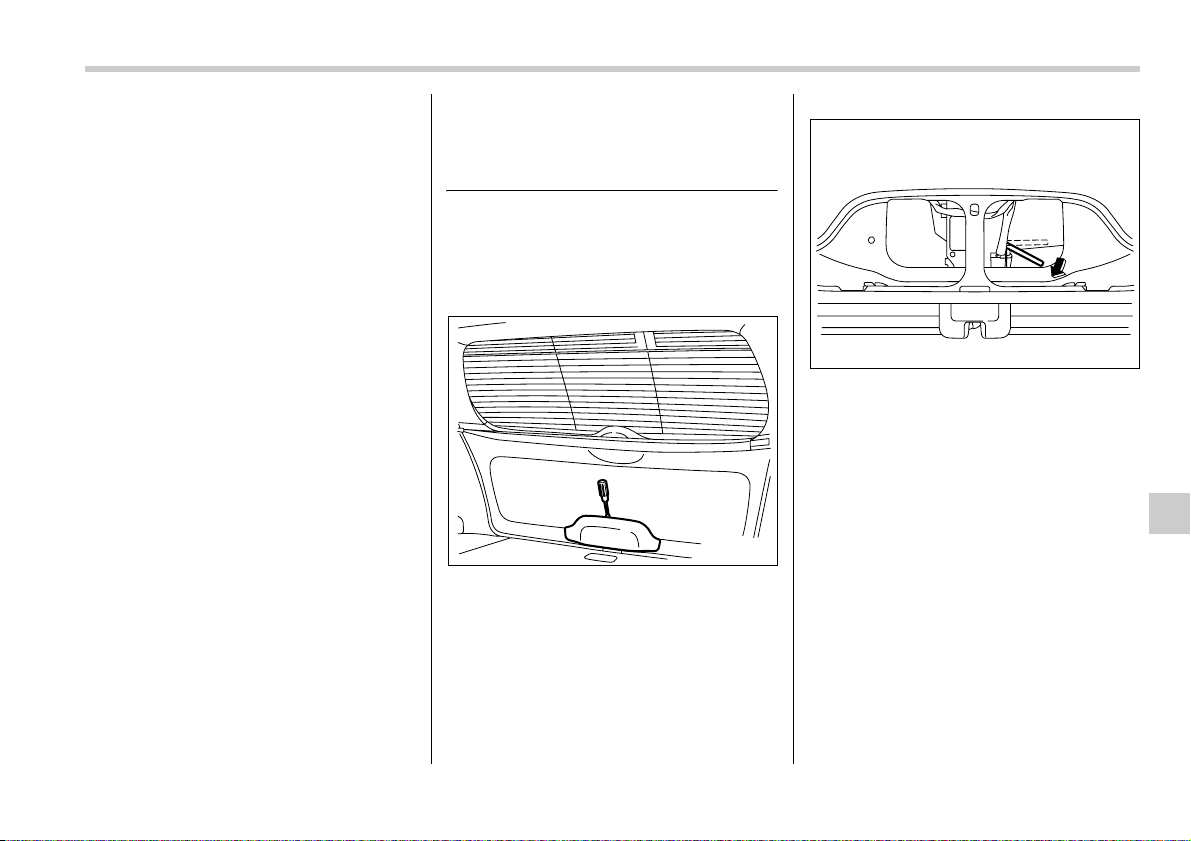
In case of emergency 9-17
3. The ignition switch should be in the
“ACC” position while the vehicle is being
towed.
4. Take up slack in the towline slowly to
prevent damage to the vehicle.
Rear gate (Station wagon) – if
the rear gate cannot be un-
locked
In the event that you cannot unlock the
rear gate by operating the power door
locking switches or the remote keyless en-
try system, you can unlock it from inside
the cargo area.
0
1. Remove the access cover at the bot-
tom-center of the rear gate trim using flat-
head screwdriver.
2. Locate the rear gate lock release lever
behind the rear gate trim panel.
3. Unlock the rear gate by pressing the le-
ver inside the trim downward.
4. Open the rear gate from outside by
raising the rear gate handle.
200261
200262
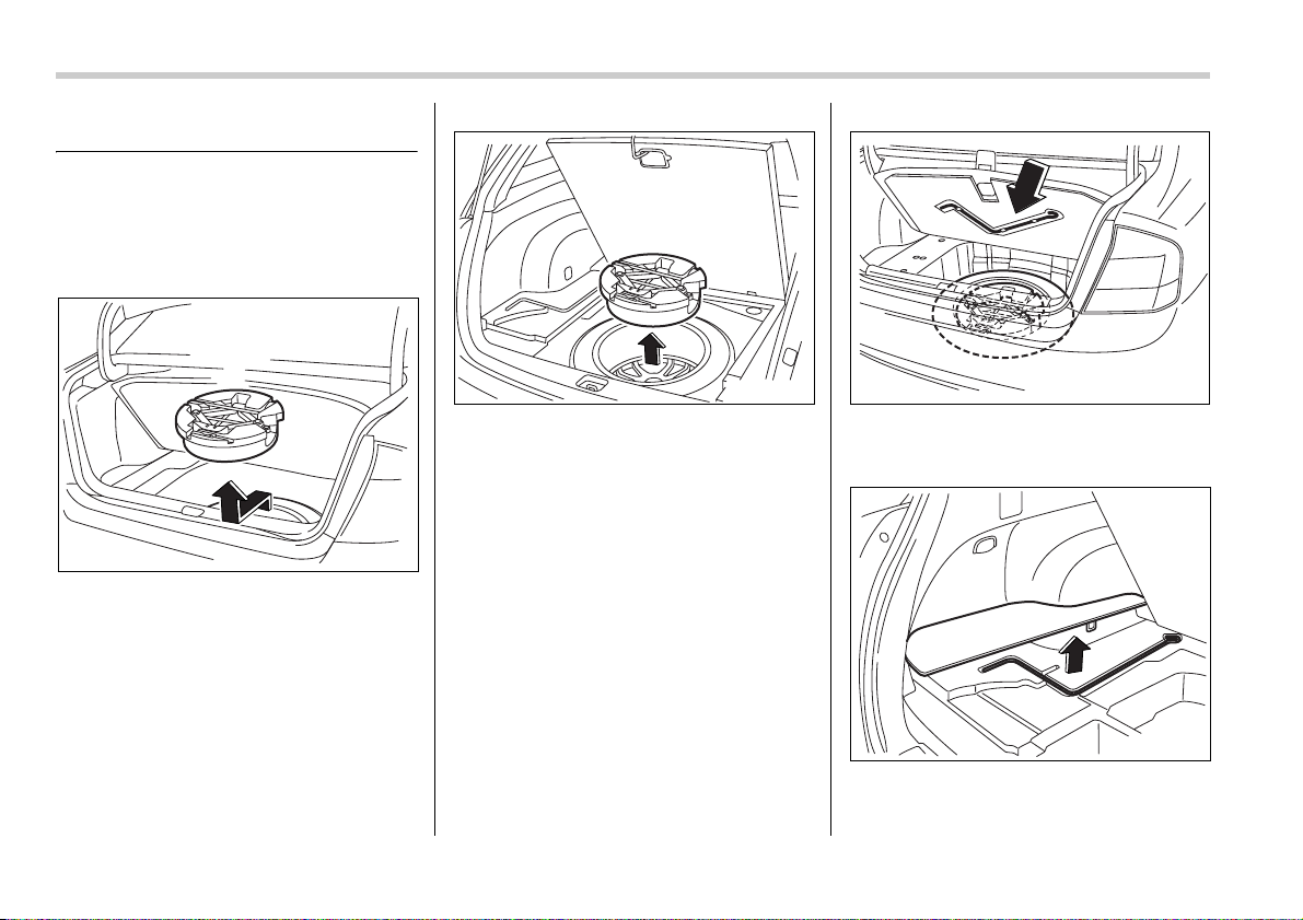
9-18 In case of emergency
Maintenance tools
Jack
A jack and other maintenance tools are
stored in the tool bucket in the center of
the spare tire located in the trunk or in the
cargo area.
Sedan: To take out the jack and mainte-
nance tools, open the floor cover and re-
move the bucket from the center of the
spare tire. Then, take the jack out of the
bucket.
Station wagon: To take out the jack and
maintenance tools, open the center lid
and remove the bucket from the center of
the spare tire. Then, take the jack out of
the bucket.
Jack handle
The jack handle is stowed on the back of
the floor cover of the trunk or on the back
of the center lid of the cargo area.
Sedan: Open the floor cover and remove
the jack handle from the back of the floor
cover.
Station wagon: Open the center lid, re-
move the left-hand part of the lid, and take
out the jack handle.
900244
900257 900258
600117
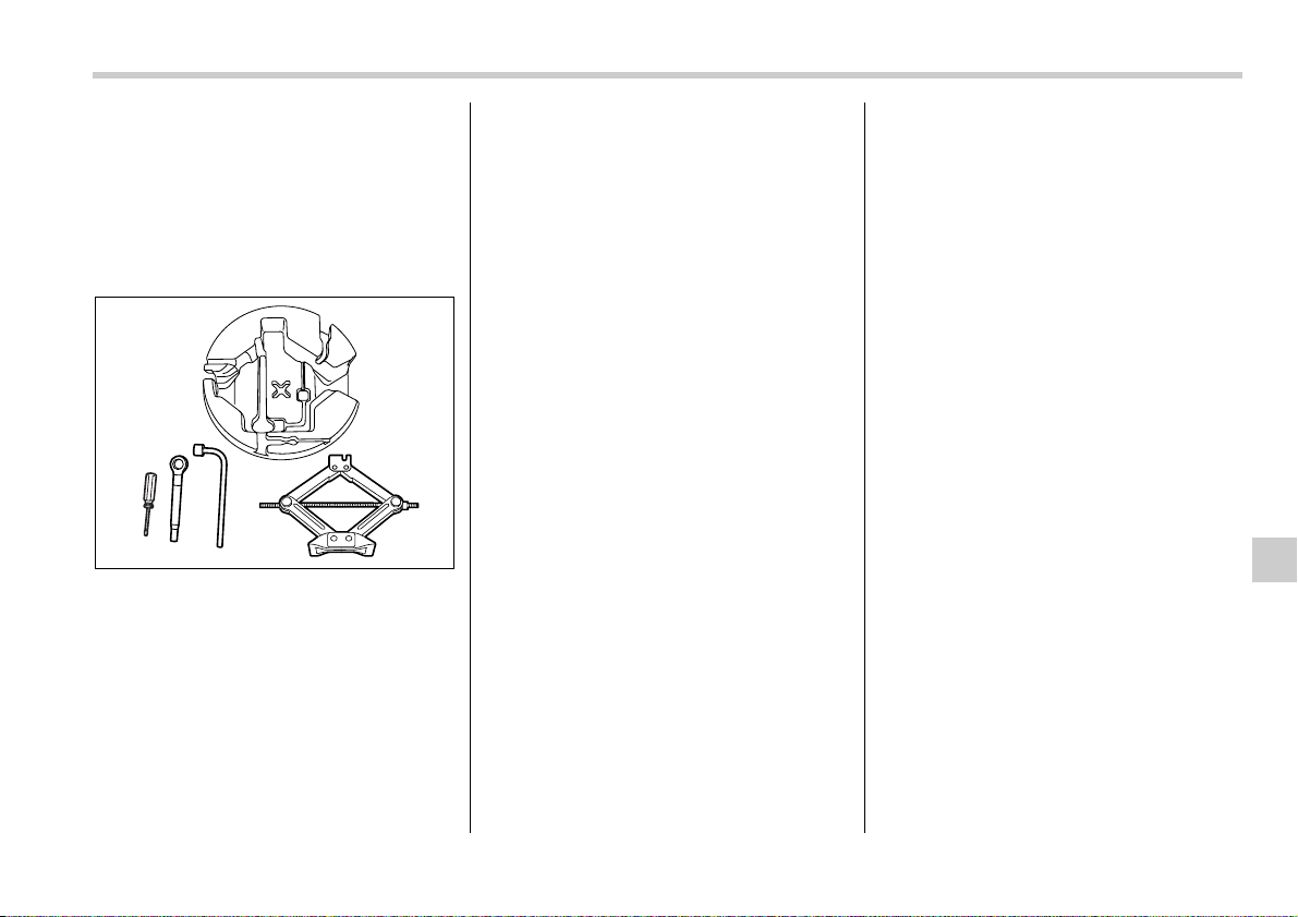


10
Appearance care
Exterior care ....................................................... 10-2
Washing ................................................................... 10-2
Waxing and polishing ............................................. 10-3
Cleaning aluminum wheels .................................... 10-3
Corrosion protection .......................................... 10-4
Most common causes of corrosion ...................... 10-4
To help prevent corrosion ..................................... 10-4
Cleaning the interior .......................................... 10-5
Seat fabric ............................................................... 10-5
Leather seat materials ............................................ 10-5
Synthetic leather upholstery ................................. 10-5
Climate control panel, audio panel, instrument
panel, console panel, switches, combination
meter, and other plastic surface ......................... 10-5
10-2 Appearance care
Appearance care
Exterior care
Washing
NOTE
When having your vehicle washed in
an automatic car wash, make sure be-
forehand that the car wash is of suit-
able type.
The best way to preserve your vehicle’s
beauty is frequent washing. Wash the ve-
hicle at least once a month to avoid con-
tamination by road grime.
Wash dirt off with a wet sponge and plenty
of lukewarm or cold water. Do not wash
the vehicle with hot water and in direct
sunlight.
Salt, chemicals, insects, tar, soot, tree
sap, and bird droppings should be washed
off by using a light detergent, as required.
If you use a light detergent, make certain
that it is a neutral detergent. Do not use
strong soap or chemical detergents. All
cleaning agents should be promptly
flushed from the surface and not allowed
to dry there. Rinse the vehicle thoroughly
with plenty of lukewarm water. Wipe the
remaining water off with a chamois or soft
cloth.
T Washing the underbody
Chemicals, salts and gravel used for deic-
ing road surfaces are extremely corrosive,
accelerating the corrosion of underbody
components, such as the exhaust system,
fuel and brake lines, brake cables, floor
pan and fenders, and suspension.
Thoroughly flush the underbody and in-
side of the fenders with lukewarm or cold
water at frequent intervals to reduce the
harmful effects of such agents.
Mud and sand adhering to the underbody
components may accelerate their corro-
sion.
After driving off-road or muddy or sandy
roads, wash the mud and sand off the un-
derbody.
Carefully flush the suspension and axle
parts, as they are particularly prone to
mud and sand buildup. Do not use a
sharp-edged tool to remove caked mud.
y When washing the vehicle, the
brakes may get wet. As a result,
the brake stopping distance will
be longer. To dry the brakes, drive
the vehicle at a safe speed while
lightly pressing the brake pedal to
heat up the brakes.
y Do not wash the engine compart-
ment and areas adjacent to it. If
water enters the engine air intake,
electrical parts or the power steer-
ing fluid reservoir, it will cause en-
gine trouble or faulty power steer-
ing respectively.
y Since your vehicle is equipped
with a rear wiper, automatic car-
wash brushes could become tan-
gled around it, damaging the wip-
er arm and other components.
Ask the automatic car-wash oper-
ator not to let the brushes touch
the wiper arm or to fix the wiper
arm on the rear window glass with
adhesive tape before operating
the machine. (Station wagon mod-
els only)

Appearance care 10-3
NOTE
Be careful not to damage brake hoses,
sensor harnesses, and other parts
when washing suspension compo-
nents.
T Using a warm water washer
y Keep a good distance of 12 in (30 cm)
or more between the washer nozzle and
the vehicle.
y Do not wash the same area continuous-
ly.
y If a stain will not come out easily, wash
by hand. Some warm water washers are
of the high temperature, high pressure
type, and they can damage or deform the
resin parts such as mouldings, or cause
water to leak into the vehicle.
Waxing and polishing
Always wash and dry the vehicle before
waxing and polishing.
Use a good quality polish and wax and ap-
ply them according to the manufacturer’s
instructions. Wax or polish when the paint-
ed surface is cool.
Be sure to polish and wax the chrome trim,
as well as the painted surfaces. Loss of
wax on a painted surface leads to loss of
the original luster and also quickens the
deterioration of the surface. It is recom-
mended that a coat of wax be applied at
least once a month, or whenever the sur-
face no longer repels water.
If the appearance of the paint has dimin-
ished to the point where the luster or tone
cannot be restored, lightly polish the sur-
face with a fine-grained compound. Never
polish just the affected area, but include
the surrounding area as well. Always pol-
ish in only one direction. A No. 2000 grain
compound is recommended. Never use a
coarse-grained compound. Coarser
grained compounds have a smaller grain-
size number and could damage the paint.
After polishing with a compound, coat with
wax to restore the original luster. Frequent
polishing with a compound or an incorrect
polishing technique will result in removing
the paint layer and exposing the under-
coat. When in doubt, it is always best to
contact your SUBARU dealer or an auto
paint specialist.
NOTE
Be careful not to block the windshield
washer nozzles with wax when waxing
the vehicle.
Cleaning aluminum wheels
y Promptly wipe the aluminum wheels
clean of any kind of grime or agent. If dirt
is left on too long, it may be difficult to
clean off.
y Do not use soap containing grit to clean
the wheels. Be sure to use a neutral clean-
ing agent, and later rinse thoroughly with
water. Do not clean the wheels with a stiff
brush or expose them to a high-speed
washing device.
y Clean the vehicle (including the alumi-
num wheels) with water as soon as possi-
ble when it has been splashed with sea
water, exposed to sea breezes, or driven
on roads treated with salt or other agents.

10-4 Appearance care
Corrosion protection
Your SUBARU has been designed and
built to resist corrosion. Special materials
and protective finishes have been used on
most parts of the vehicle to help maintain
fine appearance, strength, and reliable
operation.
Most common causes of cor-
rosion
The most common causes of corrosion
are:
1. The accumulation of moisture retaining
dirt and debris in body panel sections,
cavities, and other areas.
2. Damage to paint and other protective
coatings caused by gravel and stone
chips or minor accidents.
Corrosion is accelerated on the vehicle
when:
1. It is exposed to road salt or dust control
chemicals, or used in coastal areas where
there is more salt in the air, or in areas
where there is considerable industrial pol-
lution.
2. It is driven in areas of high humidity, es-
pecially when temperatures range just
above freezing.
3. Dampness in certain parts of the vehi-
cle remains for a long time, even though
other parts of the vehicle may be dry.
4. High temperatures will cause corrosion
to parts of the vehicle which cannot dry
quickly due to lack of proper ventilation.
To help prevent corrosion
Wash the vehicle regularly to prevent cor-
rosion of the body and suspension com-
ponents. Also, wash the vehicle promptly
after driving on any of the following surfac-
es:
y roads that have been salted to prevent
them from freezing in winter
y mud, sand, or gravel
y coastal roads
After the winter has ended, it is recom-
mended that the underbody be given a
very thorough washing.
Before the beginning of winter, check the
condition of underbody components, such
as the exhaust system, fuel and brake
lines, brake cables, suspension, steering
system, floor pan, and fenders. If any of
them are found to be rusted, they should
be given an appropriate rust prevention
treatment or should be replaced. Contact
your SUBARU dealer to perform this kind
of maintenance and treatment if you need
assistance.
Repair chips and scratches in the paint as
soon as you find them.
Check the interior of the vehicle for water
and dirt accumulation under the floor mats
because that could cause corrosion. Oc-
casionally check under the mats to make
sure the area is dry.
Keep your garage dry. Do not park your
vehicle in a damp, poorly ventilated ga-
rage. In such a garage, corrosion can be
caused by dampness. If you wash the ve-
hicle in the garage or put the vehicle into
the garage when wet or covered with
snow, that can cause dampness.
If your vehicle is operated in cold weather
and/or in areas where road salts and other
corrosive materials are used, the door
hinges and locks, trunk lid lock, and hood
latch should be inspected and lubricated
periodically.

Appearance care 10-5
Cleaning the interior
Use a soft, damp cloth to clean the climate
control panel, audio equipment, instru-
ment panel, center console, combination
meter panel, and switches. (Do not use or-
ganic solvents.)
Seat fabric
Remove loose dirt, dust or debris with a
vacuum cleaner. If the dirt is caked on the
fabric or hard to remove with a vacuum
cleaner, use a soft blush then vacuum it.
Wipe the fabric surface with a tightly
wrung cloth and dry the seat fabric thor-
oughly. If the fabric is still dirty, wipe using
a solution of mild soap and lukewarm wa-
ter then dry thoroughly.
If the stain does not come out, try a com-
mercially-available fabric cleaner. Use the
cleaner on a hidden place and make sure
it does not affect the fabric adversely. Use
the cleaner according to its instructions.
NOTE
When cleaning the seat, do not use
benzine, paint thinner, or any similar
materials.
Leather seat materials
The leather used by SUBARU is a high
quality natural product which will retain its
distinctive appearance and feel for many
years with proper care.
Allowing dust or road dirt to build up on the
surface can cause the material to become
brittle and to wear prematurely. Regular
cleaning with a soft, moist, natural fiber
cloth should be performed monthly, taking
care not to soak the leather or allow water
to penetrate the stitched seams.
A mild detergent suitable for cleaning
woolen fabrics may be used to remove dif-
ficult dirt spots, rubbing with a soft, dry
cloth afterwards to restore the luster. If
your SUBARU is to be parked for a long
time in bright sunlight, it is recommended
that the seats and headrests be covered,
or the windows shaded, to prevent fading
or shrinkage.
Minor surface blemishes or bald patches
may be treated with a commercial leather
spray lacquer. You will discover that each
leather seat section will develop soft folds
or wrinkles, which is characteristic of gen-
uine leather.
Synthetic leather upholstery
The synthetic leather material used on the
SUBARU may be cleaned using mild soap
or detergent and water, after first vacuum-
ing or brushing away loose dirt. Allow the
soap to soak in for a few minutes and wipe
off with a clean, damp cloth. Commercial
foam-type cleaners suitable for synthetic
leather materials may be used when nec-
essary.
NOTE
Strong cleaning agents such as sol-
vents, paint thinners, window cleaner
or gasoline must never be used on
leather or synthetic interior materials.
Climate control panel, audio
panel, instrument panel, con-
sole panel, switches, combi-
nation meter, and other plas-
tic surface
Use a soft, damp cloth to clean the climate
control panel, audio equipment, instru-
ment panel, center console, combination
meter panel, and switches.
NOTE
Do not use organic solvents such as
paint thinners or gasoline, or strong
cleaning agents that contain those sol-
vents.


11
Maintenance and service
Maintenance schedule ....................................... 11-3
Maintenance precautions .................................. 11-3
Before checking or servicing in the engine
compartment ........................................................ 11-4
When you do checking or servicing in the engine
compartment while the engine is running ......... 11-4
Engine hood ....................................................... 11-4
Engine compartment overview ......................... 11-6
2.5-liter non-turbo models ..................................... 11-6
2.5-liter turbo models ............................................. 11-7
3.0-liter models ....................................................... 11-8
Engine oil ............................................................ 11-9
Checking the oil level ............................................. 11-9
Changing the oil and oil filter ................................ 11-10
Recommended grade and viscosity ..................... 11-12
Recommended grade and viscosity under severe
driving conditions ................................................ 11-13
Cooling system .................................................. 11-13
Hose and connections ........................................... 11-14
Engine coolant ........................................................ 11-14
Air cleaner element ............................................ 11-17
Replacing the air cleaner element ......................... 11-17
Spark plugs ......................................................... 11-19
Recommended spark plugs ................................... 11-19
Drive belts ........................................................... 11-20
2.5-liter models ....................................................... 11-20
3.0-liter models ....................................................... 11-20
Manual transmission oil .................................... 11-20
Checking the oil level ............................................. 11-20
Recommended grade and viscosity ..................... 11-21
Automatic transmission fluid ............................ 11-22
Checking the fluid level .......................................... 11-22
Recommended fluid ............................................... 11-23
Front differential gear oil (AT vehicles) ............ 11-23
Checking the oil level ............................................. 11-23
Recommended grade and viscosity ..................... 11-24
Rear differential gear oil .................................... 11-24
Checking the gear oil level .................................... 11-24
Recommended grade and viscosity ..................... 11-26
Power steering fluid ........................................... 11-27
Checking the fluid level .......................................... 11-27
Recommended fluid ............................................... 11-27
Brake fluid ........................................................... 11-28
Checking the fluid level .......................................... 11-28
Recommended brake fluid ..................................... 11-28
Clutch fluid (MT vehicles) .................................. 11-29
Checking the fluid level .......................................... 11-29
Recommended clutch fluid .................................... 11-29
Brake booster ..................................................... 11-30
Brake pedal ......................................................... 11-30
Checking the brake pedal free play ...................... 11-30
Checking the brake pedal reserve distance ......... 11-30
Clutch pedal (Manual transmission
vehicles) ........................................................... 11-31
Checking the clutch function ................................ 11-31
Checking the clutch pedal free play ..................... 11-31

Maintenance and service
Replacement of brake pad and lining ............... 11-31
Breaking-in of new brake pads and linings ......... 11-32
Parking brake stroke .......................................... 11-32
Tires and wheels ................................................ 11-33
Types of tires .......................................................... 11-33
Tire pressure monitoring system (TPMS)
(if equipped) .......................................................... 11-33
Tire inspection ........................................................ 11-34
Tire pressures and wear ........................................ 11-35
Wheel balance ........................................................ 11-37
Wear indicators ....................................................... 11-37
Tire rotation ............................................................. 11-37
Tire replacement ..................................................... 11-38
Wheel replacement ................................................. 11-38
Aluminum wheels ............................................... 11-39
Windshield washer fluid .................................... 11-39
Replacement of wiper blades ............................ 11-41
Windshield wiper blade assembly ........................ 11-41
Windshield wiper blade rubber ............................. 11-42
Rear window wiper blade assembly ..................... 11-42
Rear window wiper blade rubber .......................... 11-43
Battery ................................................................. 11-44
Fuses ................................................................... 11-45
Main fuse ............................................................. 11-47
Installation of accessories ................................ 11-47
Replacing bulbs .................................................. 11-48
Headlight ................................................................. 11-49
Parking light ............................................................ 11-50
Front turn signal light ............................................ 11-50
Front fog light (if equipped) ................................... 11-50
Rear combination lights ......................................... 11-51
Backup light (Station wagon) ................................ 11-52
License plate light .................................................. 11-53
Dome light ............................................................... 11-53
Map light .................................................................. 11-54
Door step light ........................................................ 11-54
Cargo area light (Station wagon) .......................... 11-55
Trunk light (Sedan) ................................................. 11-55
High mount stop light (Sedan) .............................. 11-56
Maintenance and service 11-3
– CONTINUED –
Maintenance a nd service
Maintenance schedule
The scheduled maintenance items re-
quired to be serviced at regular intervals
are shown in the “Warranty and Mainte-
nance Booklet”.
For details of your maintenance schedule,
read the separate “Warranty and Mainte-
nance Booklet”.
Maintenance precautions
When maintenance and service are re-
quired, it is recommended that all work be
done by an authorized SUBARU dealer.
If you perform maintenance and service
by yourself, you should familiarize your-
self with the information provided in this
section on general maintenance and ser-
vice for your SUBARU.
Incorrect or incomplete service could
cause improper or unsafe vehicle opera-
tion. Any problems caused by improper
maintenance and service performed by
you are not eligible for warranty coverage.
y Testing of an All-Wheel Drive ve-
hicle must NEVER be performed
on a single two-wheel dynamome-
ter or similar apparatus. Attempt-
ing to do so will result in transmis-
sion damage and in uncontrolled
vehicle movement and may cause
an accident or injuries to persons
nearby.
y Always select a safe area when
performing maintenance on your
vehicle.
y Always be very careful to avoid in-
jury when working on the vehicle.
Remember that some of the mate-
rials in the vehicle may be hazard-
ous if improperly used or handled,
for example, battery acid.
y Your vehicle should only be ser-
viced by persons fully competent
to do so. Serious personal injury
may result to persons not experi-
enced in servicing vehicles.
y Always use the proper tools and
make certain that they are well
maintained.
y Never get under the vehicle sup-
ported only by a jack. Always use
a safety stands to support the ve-
hicle.
y Never keep the engine running in
a poorly ventilated area, such as a
garage or other closed areas.
y Do not smoke or allow open
flames around the fuel or battery.
This will cause a fire.
y Because the fuel system is under
pressure, replacement of the fuel
filter should be performed only by
your SUBARU dealer.
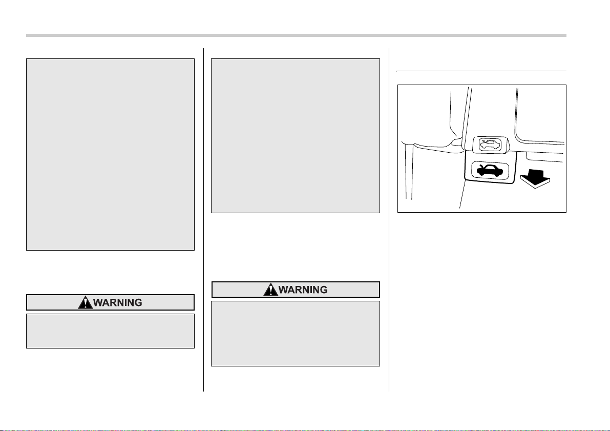
11-4 Maintenance and service
Before checking or servicing
in the engine compartment
When you do checking or ser-
vicing in the engine compart-
ment while the engine is run-
ning
Engine hood
To open the hood:
1. If the wiper blades are lifted off the
windshield, return them to their original
positions.
2. Pull the hood release knob under the
instrument panel.
y Wear adequate eye protection to
guard against getting oil or fluids
in your eyes. If something does
get in your eyes, thoroughly wash
them out with clean water.
y Do not tamper with the wiring of
the SRS airbag system or seatbelt
pretensioner system, or attempt
to take its connectors apart, as
that may activate the system or it
can render it inoperative. The wir-
ing and connectors of these sys-
tems are yellow for easy identifi-
cation. NEVER use a circuit tester
for these wiring.
If your SRS airbag or seatbelt pre-
tensioner needs service, consult
your nearest SUBARU dealer.
y Always stop the engine and set
the parking brake firmly to pre-
vent the vehicle from moving.
y Always let the engine cool down.
Engine parts become very hot
when the engine is running and
remain hot for some time after the
engine is stopped.
y Do not spill engine oil, engine
coolant, brake fluid or any other
fluid on hot engine components.
This may cause a fire.
y Always remove the key from the
ignition switch. When the ignition
switch is in the “ON” position, the
cooling fan may operate suddenly
even when the engine is stopped.
A running engine can be dangerous.
Keep your fingers, hands, clothing,
hair and tools away from the cooling
fan, belts and any other moving en-
gine parts. Removing rings, watch-
es and ties is advisable.
B00099
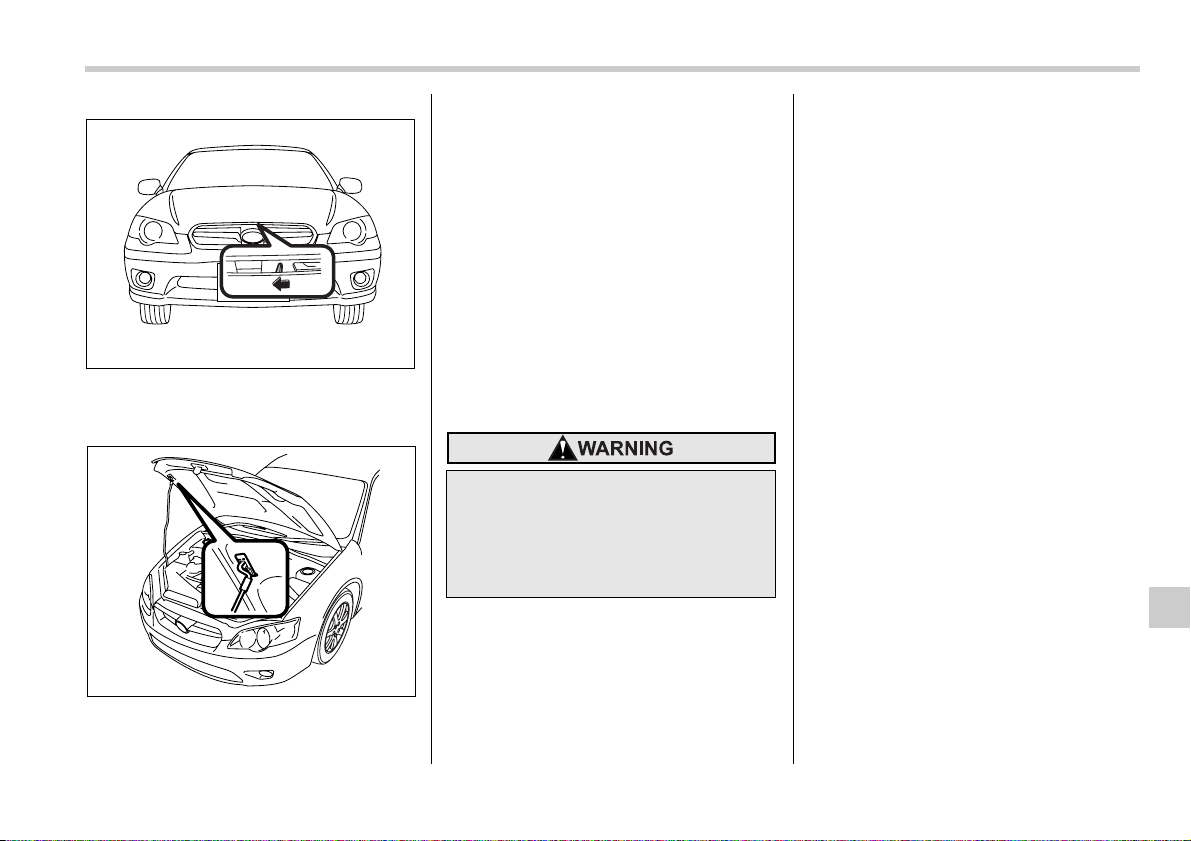
Maintenance and service 11-5
3. Release the secondary hood release
located under the front grille by moving
the lever toward the left.
4. Lift up the hood, release the hood prop
from its retainer and put the end of the
hood prop into the slot in the hood.
To close the hood:
1. Lift the hood slightly and remove the
hood prop from the slot in the hood and re-
turn the prop to its retainer.
2. Lower the hood until it approaches ap-
proximately 12 in (30 cm) from the closed
position and let it drop.
3. After closing the hood, be sure the
hood is securely locked.
If this does not close the hood, release it
from a slightly higher position. Do not
push the hood forcibly to close it. It could
deform the metal.
200258
200259
Always check that the hood is prop-
erly locked before you start driving.
If it is not, it might fly open while the
vehicle is moving and block your
view, which may cause an accident
and serious bodily injury.
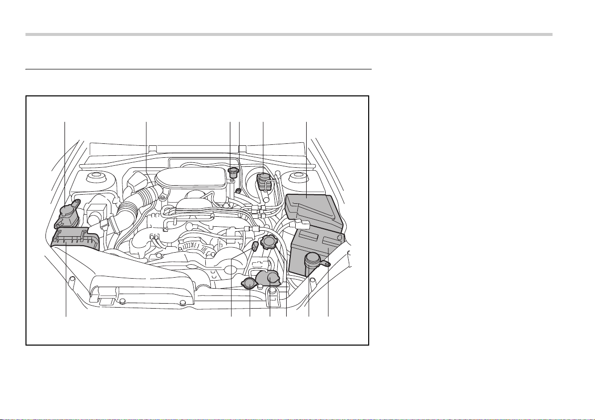
11-6 Maintenance and service
Engine compartment overview
2.5-liter non-turbo models
12 3456
7891011
13
12
B00414
1) Power steering fluid reservoir (page
11-27)
2) Manual transmission oil level gauge
(MT) (page 11-20) or Differential gear
oil level gauge (AT) (page 11-23)
3) Clutch fluid reservoir (page 11-29)
4) Automatic transmission fluid level
gauge (page 11-22)
5) Brake fluid reservoir (page 11-28)
6) Fuse box (page 11-45)
7) Battery (page 11-44)
8) Windshield washer tank (page 11-39)
9) Engine oil filler cap (page 11-9)
10) Engine coolant reservoir (page 11-
14)
11) Radiator cap (page 11-14)
12) Engine oil level gauge (page 11-9)
13) Air cleaner element (page 11-17)
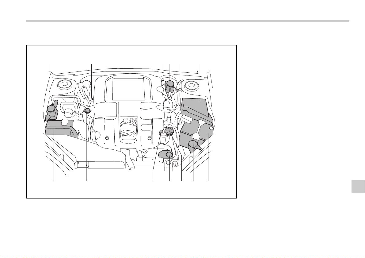
Maintenance and service 11-7
– CONTINUED –
2.5-liter turbo models
12 4635
13 12 11 10 9 8 7
B00416
1) Power steering fluid reservoir (page
11-27)
2) Manual transmission oil level gauge
(MT) (page 11-20) or Differential gear
oil level gauge (AT) (page 11-23)
3) Clutch fluid reservoir (page 11-29)
4) Brake fluid reservoir (page 11-28)
5) Automatic transmission fluid level
gauge (page 11-22)
6) Fuse box (page 11-45)
7) Battery (page 11-44)
8) Windshield washer tank (page 11-39)
9) Engine oil filler cap (page 11-9)
10) Engine coolant reservoir (page 11-
14)
11) Engine oil level gauge (page 11-9)
12) Radiator cap (page 11-14)
13) Air cleaner element (page 11-17)
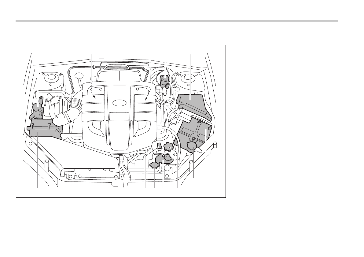
11-8 Maintenance and service
3.0-liter models
B00502
12 345
12 1011 9 8
76
1) Power steering fluid reservoir (page
11-27)
2) Differential gear oil level gauge (AT)
(page 11-23)
3) Automatic transmission fluid level
gauge (page 11-22)
4) Brake fluid reservoir (page 11-28)
5) Fuse box (page 11-45)
6) Battery (page 11-44)
7) Windshield washer tank (page 11-39)
8) Engine oil filler cap (page 11-9)
9) Engine coolant reservoir (page 11-
14)
10) Radiator cap (page 11-14)
11) Engine oil level gauge (page 11-9)
12) Air cleaner element (page 11-17)
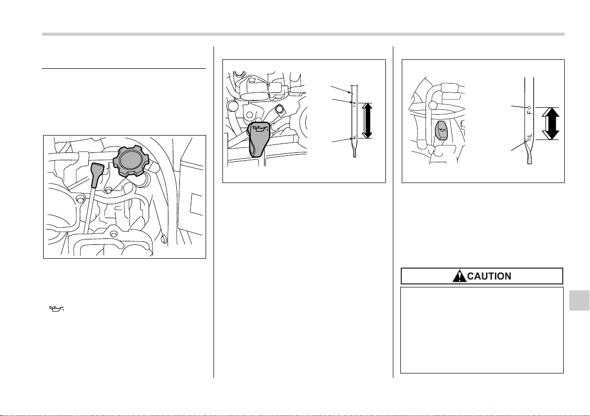
Maintenance and service 11-9
– CONTINUED –
Engine oil
Checking the oil level
Check the engine oil level at each fuel
stop.
1. Park the vehicle on a level surface and
stop the engine.
2. Pull out the dipstick, wipe it clean, and
insert it again.
3. Be sure the dipstick is correctly insert-
ed until it stops with the graphic symbol
“ ” on its top appearing as shown in
the illustration.
2.5-liter models
1) Notch
2) Upper level
3) Lower level
3.0-liter models
1) Upper level
2) Lower level
4. Pull out the dipstick again and check
the oil level on it. If it is below the lower
level, add oil to bring the level up to the up-
per level.
B00104
1
2
3
B00418
y Use only engine oil with the rec-
ommended grade and viscosity.
y Be careful not to spill engine oil
when adding it. If oil touches the
exhaust pipe, it may cause a bad
smell, smoke, and/or a fire. If en-
gine oil gets on the exhaust pipe,
be sure to wipe it off.
1
2
B00417
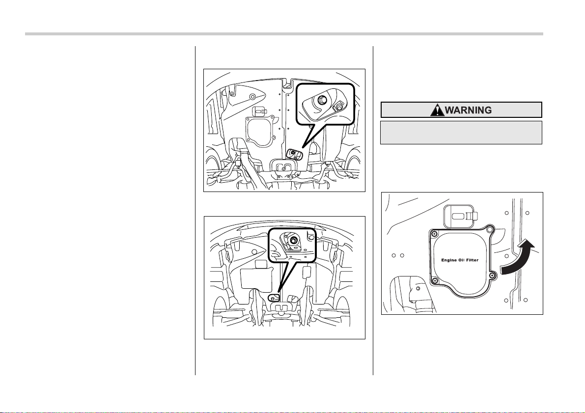
11-10 Maintenance and service
If you check the oil level just after stopping
the engine, wait a few minutes for the oil to
drain back into the oil pan before checking
the level.
To prevent overfilling the engine oil, do not
add any additional oil above the upper lev-
el when the engine is cold.
In 2.5-liter-engine models, the dipstick has
a notch above the upper level.
Just after driving or while the engine is
warm, the engine oil level reading may be
in a range between the upper level and
the notch mark. This is caused by thermal
expansion of the engine oil.
Changing the oil and oil filter
Change the oil and oil filter according to
the maintenance schedule in the “Warran-
ty and Maintenance Booklet”.
The engine oil and oil filter must be
changed more frequently than listed in the
maintenance schedule when driving on
dusty roads, when short trips are frequent-
ly made, or when driving in extremely cold
whether.
1. Warm up the engine by letting the en-
gine idle for approximately 10 minutes to
ease draining the engine oil.
2. Park the vehicle on a level surface and
stop the engine.
3. Remove the oil filler cap.
2.5-liter models
3.0-liter models
4. Drain out the engine oil by removing
the drain plug while the engine is still
warm. The used oil should be drained into
an appropriate container and disposed of
properly.
5. Wipe the seating surface of the drain
plug with a clean cloth and tighten it se-
curely with a new sealing washer after the
oil has completely drained out.
2.5-liter models
B00419
B00305
Be careful not to burn yourself with
hot engine oil.
B00420
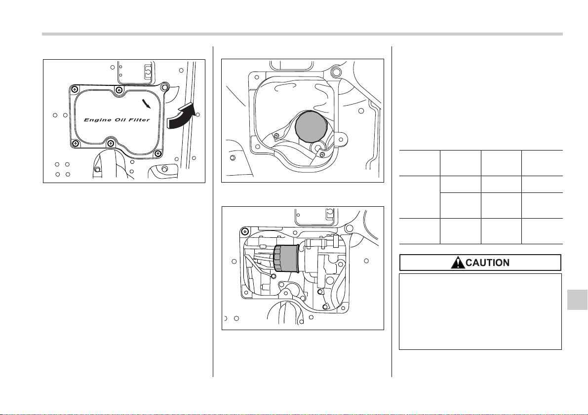
Maintenance and service 11-11
– CONTINUED –
3.0-liter models
6. Open the access cover by removing
the clips and turning the access cover
counterclockwise. The oil filter will be ex-
posed.
2.5-liter models
3.0-liter models
7. Remove the oil filter with an oil filter
wrench.
8. Before installing a new oil filter, apply a
thin coat of engine oil to the seal.
9. Clean the rubber seal seating area of
the bottom of engine and install the oil fil-
ter by hand turning. Be careful not to twist
or damage the seal.
10.Tighten the oil filter by the amount indi-
cated in the following table after the seal
makes contact with the bottom of engine.
11.Reinstall the cover under the oil filter.
12.Pour engine oil through the filler neck.
B00306
B00421
B00307
Model Oil filter
color
Part num-
ber
Amount of
rotation
2.5-liter
models
Black
15208AA100
1 rotation
White
15208AA09A
2/3 – 3/4
rotation
3.0-liter
models
Black
15208AA031
3/4
rotation
y Never over tighten the oil filter be-
cause that can result in an oil leak.
y Thoroughly wipe off any engine
oil that has spilled over the ex-
haust pipe and/or under-cover. If
left unremoved, the oil could
catch fire.
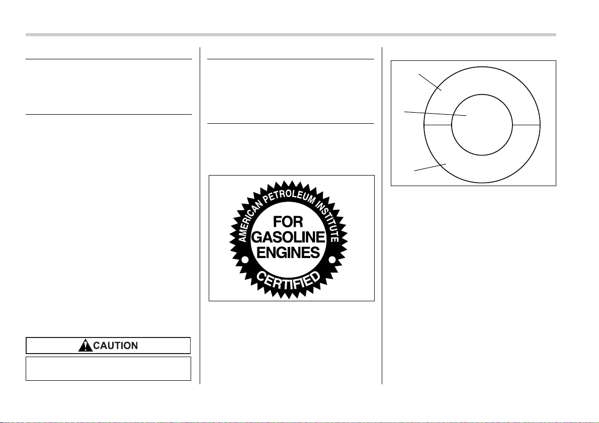
11-12 Maintenance and service
Oil capacity (Guideline):
2.5-liter models: 4.2 US qt (4.0 liters, 3.5
Imp qt)
3.0-liter models: 5.8 US qt (5.5 liters, 4.8
Imp qt)
The oil quantity indicated above is only a
guideline. The necessary quantity of oil
depends on the quantity of oil that has
been drained. The quantity of drained oil
differs slightly depending on the tempera-
ture of the oil and the time the oil is left
flowing out. After refilling the engine with
oil, therefore, you must use the dipstick to
confirm that the level is correct.
13.Start the engine and make sure that no
oil leaks appear around the filter’s rubber
seal and drain plug.
14.Run the engine until it reaches the nor-
mal operating temperature. Then stop the
engine and wait a few minutes to allow the
oil drain back. Check the oil level again
and if necessary, add more engine oil.
Recommended grade and
viscosity
Oil grade:
ILSAC GF-4, which can be identified
with the ILSAC certification mark
(Starburst mark)
or API classification SM with the
words “ENERGY CONSERVING”
These recommended oil grades can be
identified by looking for either or both of
the following marks displayed on the oil
container.
ILSAC Certification Mark (Starburst
Mark)
API Service label
1) Indicates the oil quality by API designa-
tions
2) Indicates the SAE oil viscosity grade
3) Indicates that the oil has fuel saving ca-
pabilities
In choosing an oil, you want the proper
quality and viscosity, as well as one that
will add to fuel economy. The following ta-
ble lists the recommended viscosities and
applicable temperatures.
When adding oil, different brands may be
used together as long as they are the
same API classification and SAE viscosity
as those recommended by SUBARU.
Use only engine oil with the recom-
mended grade and viscosity.
B00014
A
P
I
S
E
R
V
I
C
E
S
M
E
N
E
R
G
Y
C
O
N
S
E
R
V
I
N
G
SAE
5W-30
1
2
3
B00446
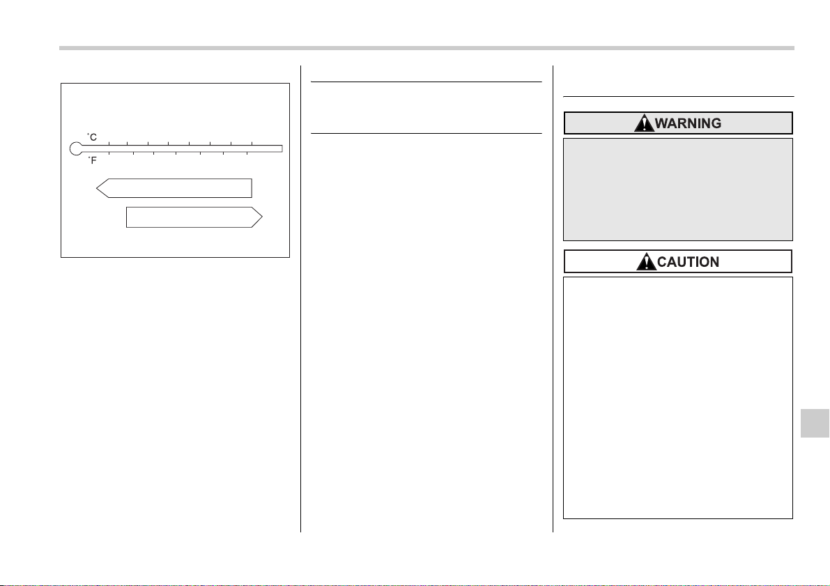
Maintenance and service 11-13
– CONTINUED –
SAE viscosity number and applicable
temperature
*: 5W-30 is preferred.
Engine oil viscosity (thickness) affects fuel
economy. Oils of lower viscosity provide
better fuel economy. However, in hot
weather, oil of higher viscosity is required
to properly lubricate the engine.
Recommended grade and
viscosity under severe driv-
ing conditions
If the vehicle is used in desert areas, in ar-
eas with very high temperatures, or used
for heavy-duty applications such as tow-
ing a trailer, use of oil with the following
grade and viscosities is recommended.
API classification SM (or SL):
SAE viscosity No.:
30, 40, 10W-50, 20W-40, 20W-50
Cooling system
B00503
5W-30*
10W-30, 10W-40
-30 -20 -10 0 10 20 30 40
-20
06020 80 10040
Never attempt to remove the radia-
tor cap until the engine has been
shut off and has cooled down com-
pletely. Since the coolant is under
pressure, you may suffer serious
burns from a spray of boiling hot
coolant when the cap is removed.
y The cooling system has been
filled at the factory with a high
quality, corrosion-inhibiting, year-
around coolant which provides
protection against freezing down
to –33°F (–36°C). For adding, use
genuine SUBARU coolant or an
equivalent: a mixture of 50% soft
water and 50% ethylene-glycol ba-
sis coolant. Use of improper cool-
ants may result in corrosion in the
cooling system. It is important to
maintain protection against freez-
ing and corrosion, even if freezing
temperatures are not expected.
Never mix different kinds of cool-
ant.
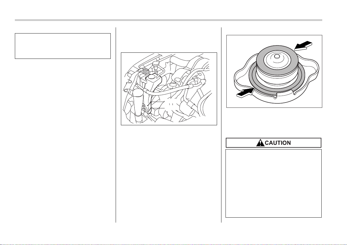
11-14 Maintenance and service
Hose and connections
Your vehicle employs an electric cooling
fan which is thermostatically controlled to
operate when the engine coolant reaches
a specific temperature.
If the radiator cooling fan does not operate
even when the engine coolant tempera-
ture gauge exceeds the normal operating
range, the cooling fan circuit may be de-
fective. Check the fuse and replace it if
necessary. If the fuse is not blown, have
the cooling system checked by your
SUBARU dealer.
If frequent addition of coolant is neces-
sary, there may be a leak in the engine
cooling system. It is recommended that
the cooling system and connections be
checked for leaks, damage, or looseness.
Engine coolant
T Checking the coolant level
Check the coolant level at each fuel stop.
1. Check the coolant level on the outside
of the reservoir while the engine is cool.
2. If the level is close to or lower than the
“LOW” level mark, add coolant up to the
“FULL” level mark. If the reserve tank is
empty, remove the radiator cap and refill
as required.
3. After refilling the reserve tank and the
radiator, reinstall the caps and check that
the rubber gaskets inside the radiator cap
are in the proper position.
y Do not splash the engine coolant
over painted parts. The alcohol
contained in the engine coolant
may damage the paint surface.
FULL
LOW
600151
y Be careful not to spill engine cool-
ant when adding it. If coolant
touches the exhaust pipe, it may
cause a bad smell, smoke, and/or
a fire. If engine coolant gets on the
exhaust pipe, be sure to wipe it
off.
y Do not splash the engine coolant
over painted parts. The alcohol
contained in the engine coolant
may damage the paint surface.
B00018
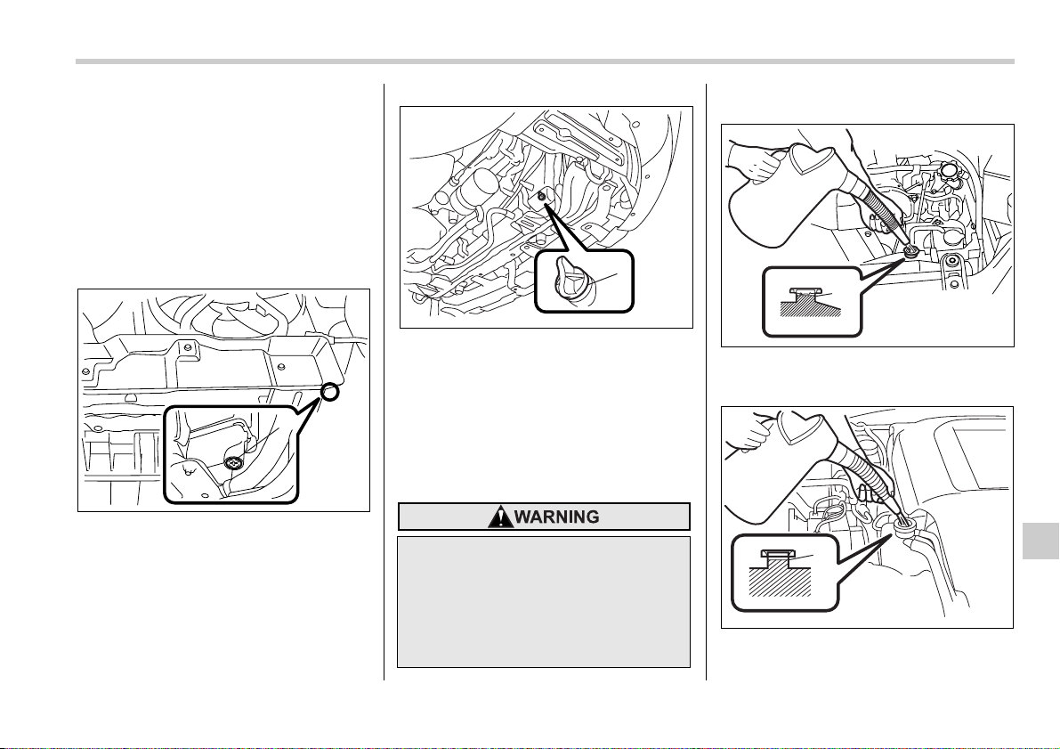
Maintenance and service 11-15
– CONTINUED –
T Changing the coolant
Always add genuine Subaru cooling sys-
tem conditioner whenever the coolant is
replaced.
Change the engine coolant and add gen-
uine Subaru cooling system conditioner
using the following procedures according
to the maintenance schedule in the “War-
ranty and Maintenance Booklet”.
1. Remove the under cover.
2.5-liter models
1) Drain plug
3.0-liter models
1) Drain plug
2. Place a proper container under the
drain plug and loosen the drain plug.
3. Loosen the radiator cap to drain the
coolant from the radiator. Then drain the
coolant from the reserve tank. Tighten the
drain plug securely.
4. Install the under cover.
Non-turbo models
1) Fill up to here
Turbo models
1) Fill up to here
1
B00422
Never attempt to remove the radia-
tor cap until the engine has been
shut off and has cooled down com-
pletely. Since the coolant is under
pressure, you may suffer serious
burns from a spray of boiling hot
coolant when the cap is removed.
B00423
1
1
B00424
1
B00425
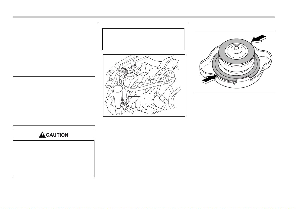
11-16 Maintenance and service
5. Slowly pour the coolant and fill up to
just below the filler neck, allowing enough
room to add genuine Subaru cooling sys-
tem conditioner in the radiator. Add genu-
ine Subaru cooling system conditioner un-
til the coolant level reaches the filler neck.
Do not pour the coolant too quickly, as this
may lead to insufficient air bleeding and
trapped air in the system.
Coolant capacity (Guideline):
2.5-liter non-turbo models:
MT. 6.8 US qt (6.4 liters, 5.6 Imp qt)
AT. 6.7 US qt (6.3 liters, 5.5 Imp qt)
2.5-liter turbo models:
MT. 7.7 US qt (7.3 liters, 6.4 Imp qt)
AT. 7.6 US qt (7.2 liters, 6.3 Imp qt)
3.0-liter models:
7.6 US qt (7.2 liters, 6.3 Imp qt)
6. Pour the coolant and fill to the reservoir
tank’s “FULL” level mark.
7. Put the radiator cap back on and tight-
en firmly. At this time, make sure that the
rubber gasket in the radiator cap is cor-
rectly in place.
8. Start and run the engine for more than
five minutes at 2,000 to 3,000 rpm.
9. Stop the engine and wait until the cool-
ant cools down (122 to 140°F [50 to
60°C]). If there is any loss of coolant, add
coolant to the radiator’s filler neck and to
the reserve tank’s “FULL” level.
10.Put the radiator cap and reservoir cap
back on and tighten firmly.
y Be careful not to spill engine cool-
ant when adding it. If coolant
touches the exhaust pipe, it may
cause a bad smell, smoke, and/or
a fire. If engine coolant gets on the
exhaust pipe, be sure to wipe it
off.
y Do not splash the engine coolant
over painted parts. The alcohol
contained in the engine coolant
may damage the paint surface.
FULL
LOW
600151
B00018
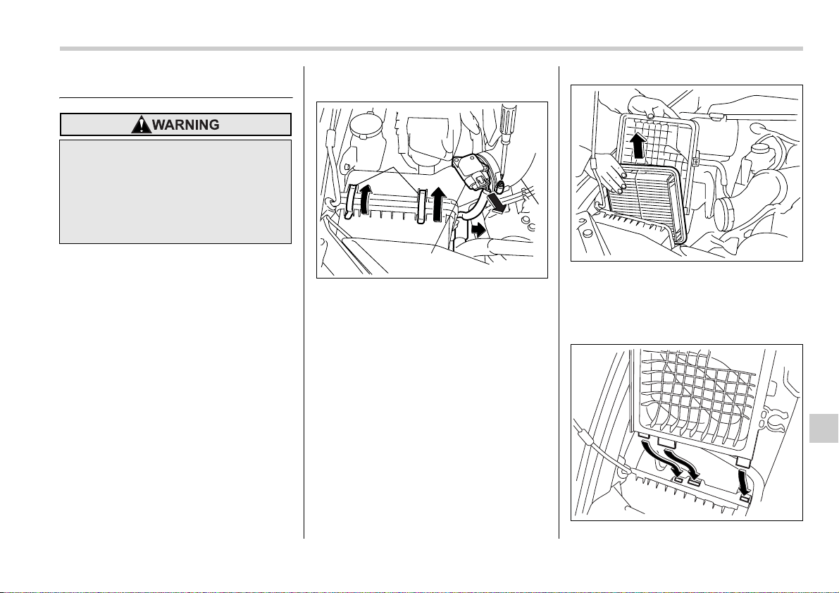
Maintenance and service 11-17
– CONTINUED –
Air cleaner element
The air cleaner element functions as a fil-
ter screen. When the element is perforat-
ed or removed, engine wear will be exces-
sive and engine life shortened.
The air cleaner element is a dry type. It is
unnecessary to clean or wash the ele-
ment.
Replacing the air cleaner ele-
ment
Replace the air cleaner element according
to the maintenance schedule in the “War-
ranty and Maintenance Booklet”. Under
extremely dusty conditions, replace it
more frequently. It is recommended that
you always use genuine SUBARU parts.
T Non-turbo models
0
1) Connector
2) Duct
3) Clamp
1. Unplug the connector that is attached
to the top of the air cleaner case.
2. Remove the hose that is located at the
bottom of the side surface of the air clean-
er case.
3. Undo the screw and pull the air duct
out of the air cleaner case.
4. Unsnap the two clamps holding the air
cleaner case cover.
5. Open the air cleaner case cover and
remove the air cleaner element.
6. Clean the inside of the air cleaner cov-
er and case with a damp cloth and install
a new air cleaner element.
Do not operate the engine with the
air cleaner element removed. The air
cleaner element not only filters in-
take air but also stops flames if the
engine backfires. If the air cleaner
element is not installed when the en-
gine backfires, you could be burned.
1
3
2
B00426
B00114
B00115
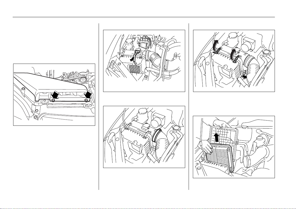
11-18 Maintenance and service
7. To install the air cleaner case cover, in-
sert the three projections on the air clean-
er case cover into the slits on the air clean-
er case and then snap the two clamps on
the air cleaner case cover.
T Turbo models
0
1. Use a screwdriver to undo the clips on
the air intake duct, then remove the air in-
take duct.
2. Unplug the connector that is attached
to the top of the air cleaner case.
3. Use a screwdriver to remove the duct
that is connected to the air cleaner case
cover.
4. Unsnap the two clamps holding the air
cleaner case cover.
At the same time, pull the hose from the
clamp that runs next to the case cover.
5. Open the air cleaner case cover and
B00116
B00206
B00207
B00201
B00114
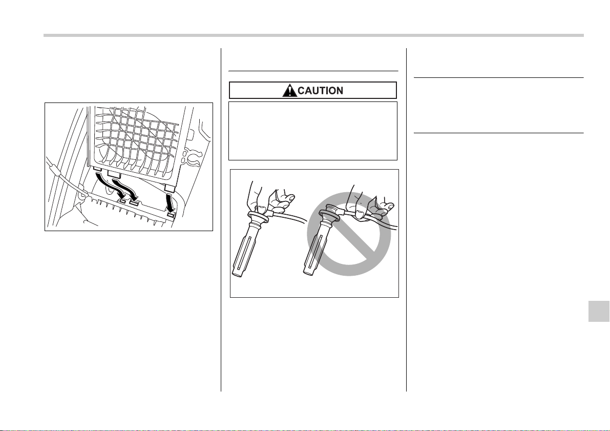
Maintenance and service 11-19
remove the air cleaner element.
6. Clean the inside of the air cleaner cov-
er and case with a damp cloth and install
a new air cleaner element.
7. To install the air cleaner case cover, in-
sert the three projections on the air clean-
er case cover into the slits on the air clean-
er case and then snap the two clamps on
the air cleaner case cover.
Spark plugs
It may be difficult to replace the spark
plugs. It is recommended that you have
the spark plugs replaced by your
SUBARU dealer.
The spark plugs should be replaced ac-
cording to the maintenance schedule in
the “Warranty and Maintenance Booklet”.
Recommended spark plugs
2.5-liter non-turbo models:
FR5AP-11 (NGK)
2.5-liter turbo and 3.0-liter models:
ILFR6B (NGK)
B00115
y When disconnecting the spark
plug cables, always grasp the
spark plug cap, not the cables.
y Make sure the cables are replaced
in the correct order.
B00027
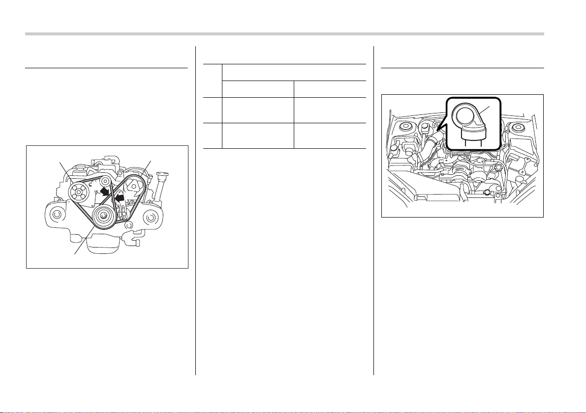
11-20 Maintenance and service
Drive belts
The alternator, power steering pump, and
air conditioner compressor depend on
drive belts. Satisfactory performance re-
quires that belt tension be correct.
2.5-liter models
1) Power steering pump pulley
2) Air conditioner compressor pulley
3) Crank pulley
in (mm)
To check belt tension, place a straight-
edge (ruler) across two adjacent pulleys
and apply a force of 22 lbs (98 N, 10 kg)
midway between the pulleys by using a
spring scale. Belt deflection should be the
amount specified.
3.0-liter models
It is unnecessary to check belt tension pe-
riodically because your engine is
equipped with an automatic belt tension
adjuster. However, replacement of the
belt should be done according to the
maintenance schedule in the “Warranty
and Maintenance Booklet”. Consult your
SUBARU dealer for replacement.
If a belt is loose, cracked, or worn, contact
your SUBARU dealer.
Manual transmission oil
Checking the oil level
Non-turbo models
1) Yellow handle
A
B
2
3
1
B00365
Deflection
New belt Used belt
A
0.28 – 0.35
(7.0 – 9.0)
0.35 – 0.43
(9.0 – 11.0)
B
0.30 – 0.33
(7.5 – 8.5)
0.35 – 0.40
(9.0 – 10.0)
1
B00427
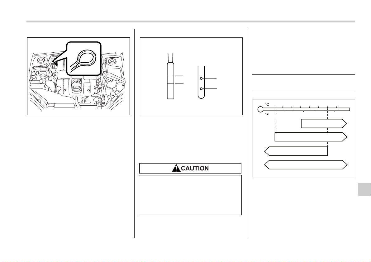
Maintenance and service 11-21
Turbo models
1. Park the vehicle on a level surface and
stop the engine.
2. Pull out the dipstick, wipe it clean, and
insert it again.
1) Upper level
2) Lower level
3. Pull out the dipstick again and check
the oil level on it. If it is below the lower
level, add oil through the dipstick hole to
bring the level up to the upper level.
Recommended grade and
viscosity
Each oil manufacturer has its own base
oils and additives. Never use different
brands together.
Oil grade:
API classification GL-5
SAE viscosity No. and applicable tem-
perature
B00196
Be careful not to spill manual trans-
mission oil when adding it. If oil
touches the exhaust pipe, it may
cause a bad smell, smoke, and/or a
fire. If oil gets on the exhaust pipe,
be sure to wipe it off.
L
F
FL
1
2
1
2
B00368
-30 -20 -10 0 10 20 30 40
-20 0 6020
80W
75W/90
80 10040
85W
90
B00032
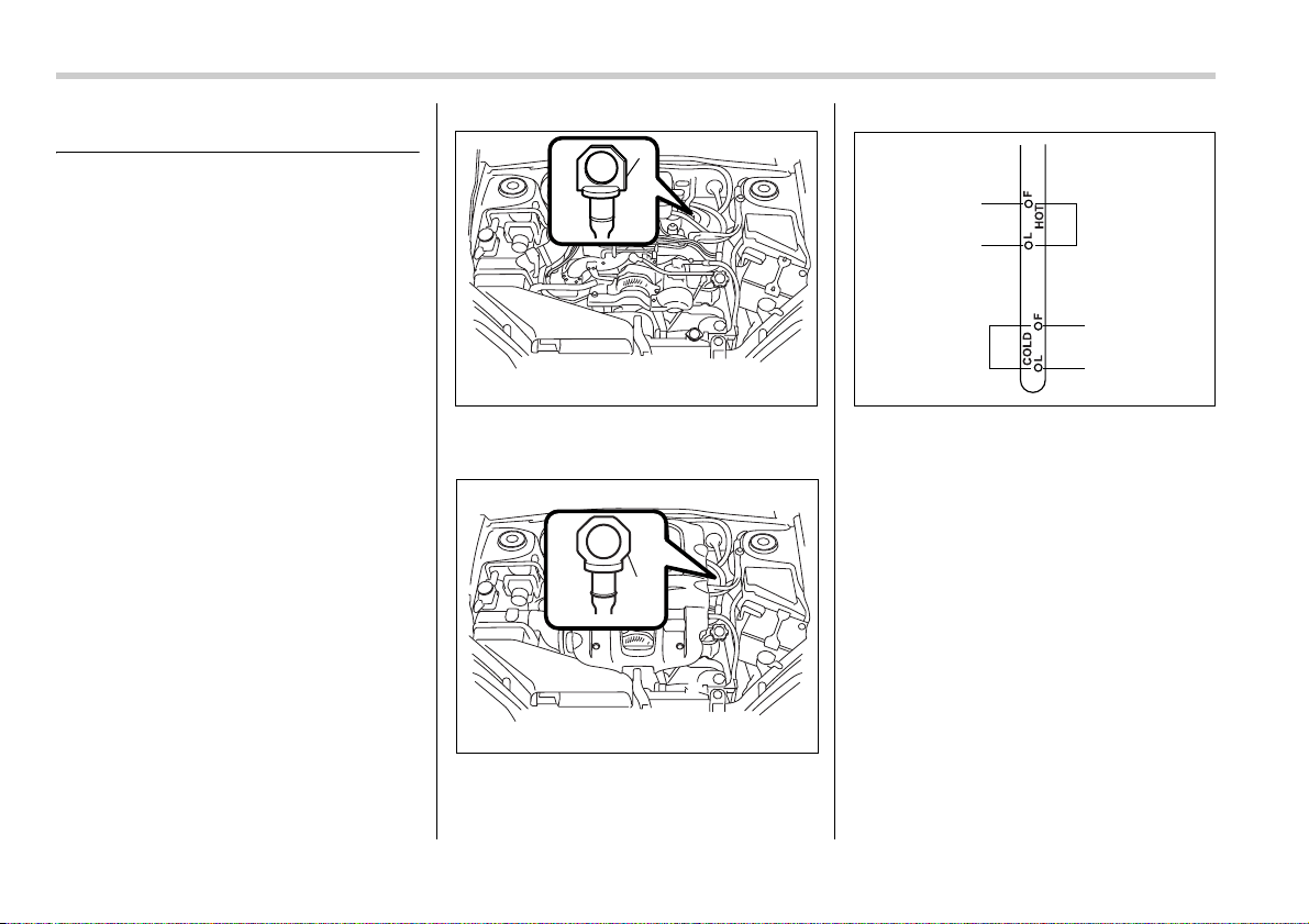
11-22 Maintenance and service
Automatic transmission fluid
Checking the fluid level
The automatic transmission fluid expands
largely as its temperature rises; the fluid
level differs according to fluid tempera-
ture. Therefore, there are two different
scales for checking the level of hot fluid
and cold fluid on the dipstick.
Though the fluid level can be checked
without warming up the fluid on the
“COLD” range, we recommend checking
the fluid level when the fluid is at operating
temperature.
T Checking the fluid level when the
fluid is hot
Check the fluid level monthly.
1. Drive the vehicle several miles to raise
the temperature of the transmission fluid
up to normal operating temperature; 158
to 176°F (70 to 80°C) is normal.
2. Park the vehicle on a level surface and
set the parking brake.
3. First shift the selector lever in each po-
sition. Then shift it in the “P” position, and
run the engine at idling speed.
4-speed automatic transmission
1) Yellow handle
5-speed automatic transmission
1) Yellow handle
1) HOT range
2) COLD range
3) Upper level
4) Lower level
4. Pull out the dipstick and check the fluid
level on the gauge. If it is below the lower
level on the “HOT” range, add the recom-
mended automatic transmission fluid up to
the upper level.
T Checking the fluid level when the
fluid is cold
When the fluid level has to be checked
without time to warm up the automatic
transmission, check to see that the fluid
level is between the lower level and upper
level on the “COLD” range. If it is below
that range, add fluid up to the upper level.
Be careful not to overfill.
1
B00428
1
B00429
3
4
3
4
2
1
B00370
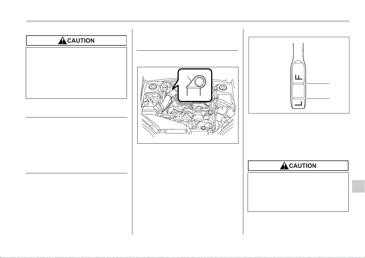
Maintenance and service 11-23
– CONTINUED –
Recommended fluid
Use one of the following types of automat-
ic transmission fluid.
Genuine Subaru Automatic Transmis-
sion Fluid Type-HP
IDEMITSU ATF HP
Castrol Transmax J
Pennzoil ATF-J*
* Available only in the USA (except
Alaska and Hawaii)
NOTE
Using any non-specified type of auto-
matic transmission fluid could result in
damage inside the transmission. When
replacing the automatic transmission
fluid, be sure to use the kind specified
above.
Front differential gear oil (AT
vehicles)
Checking the oil level
1) Yellow handle
1. Park the vehicle on a level surface and
stop the engine.
2. Pull out the dipstick, wipe it clean, and
insert it again.
1) Upper level
2) Lower level
3. Pull out the dipstick again and check
the oil level on it. If it is below the lower
level, add oil to bring the level up to the up-
per level.
Be careful not to spill automatic
transmission fluid when adding it. If
automatic transmission fluid touch-
es the exhaust pipe, it may cause a
bad smell, smoke, and/or a fire. If au-
tomatic transmission fluid gets on
the exhaust pipe, be sure to wipe it
off.
1
B00430
Be careful not to spill front differen-
tial gear oil when adding it. If oil
touches the exhaust pipe, it may
cause a bad smell, smoke, and/or a
fire. If oil gets on the exhaust pipe,
be sure to wipe it off.
1
2
B00372
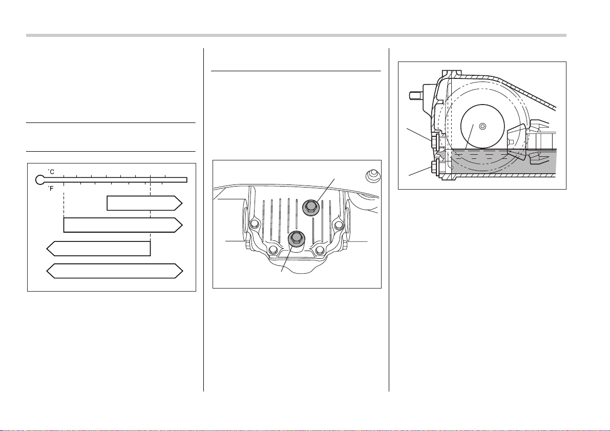
11-24 Maintenance and service
Recommended grade and
viscosity
Each oil manufacturer has its own base
oils and additives. Never use different
brands together.
Oil grade:
API classification GL-5
SAE viscosity No. and applicable tem-
perature
Rear differential gear oil
Checking the gear oil level
Your vehicle may be equipped with a rear
differential protector. The differential pro-
tector provides protection to the rear dif-
ferential assembly during off-road use.
Removal of the rear differential protector
is not required when checking the oil level.
2.5i (AT)
1) Filler plug
2) Drain plug
2.5i (AT)
1) Filler hole
2) Drain hole
3) Oil level
-30 -20 -10 0 10 20 30 40
-20 0 6020
80W
75W/90
80 10040
85W
90
B00032
1
2
B00410
1
2
3
B00411
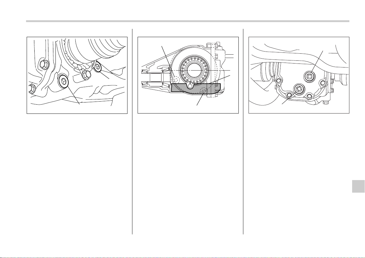
Maintenance and service 11-25
– CONTINUED –
2.5-liter turbo and 3.0-liter models (AT)
1) Filler plug
2) Drain plug
2.5-liter turbo and 3.0-liter models (AT)
1) Filler hole
2) Drain hole
3) Oil level
Others
1) Filler plug
2) Drain plug
1
2
B00433
1
2
3
B00320
2
1
B00373
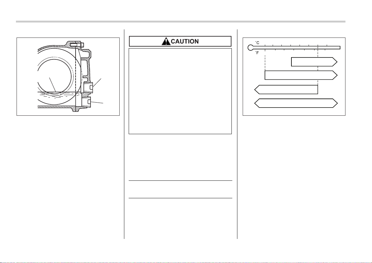
11-26 Maintenance and service
Others
1) Filler hole
2) Drain hole
3) Oil level
Remove the plug from the filler hole and
check the oil level. The oil level should be
kept even with the bottom of the filler hole.
If the oil level is below the bottom edge of
the hole, add oil through the filler hole to
raise the level.
Recommended grade and
viscosity
Each oil manufacturer has its own base
oils and additives. Never use different
brands together.
Oil grade:
API classification GL-5
SAE viscosity No. and applicable tem-
perature
3
1
2
B00434
y Be careful not to spill rear differ-
ential gear oil when adding it. If
rear differential gear oil touches
the exhaust pipe, it may cause a
bad smell, smoke, and/or a fire. If
rear differential gear oil gets on
the exhaust pipe, be sure to wipe
it off.
y If the vehicle requires frequent re-
filling, there may be an oil leak. If
you suspect a problem, have the
vehicle checked at your SUBARU
dealer.
-30 -20 -10 0 10 20 30 40
-20 0 6020
80W
75W/90
80 10040
85W
90
B00032
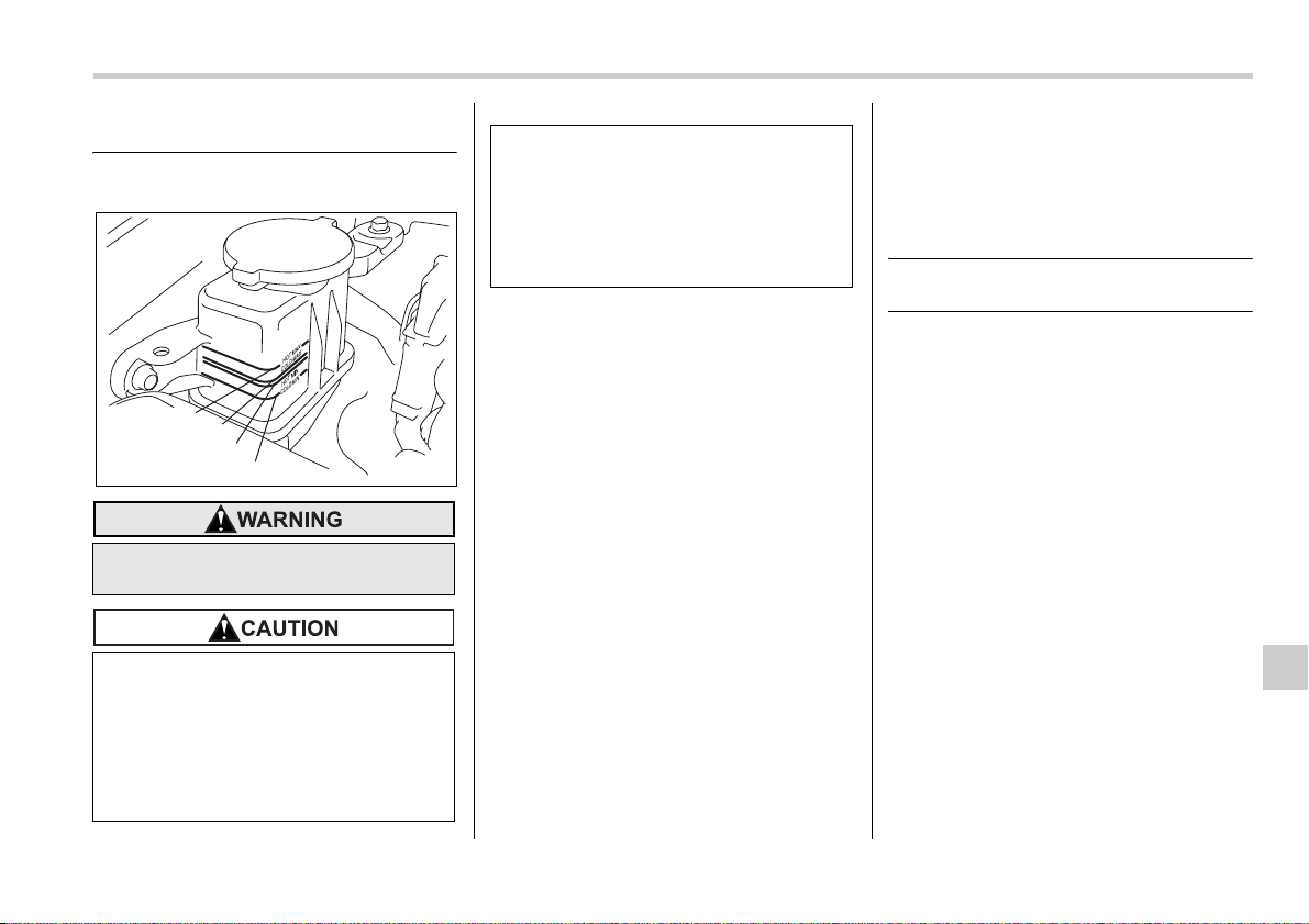
Maintenance and service 11-27
Power steering fluid
Checking the fluid level
The power steering fluid expands greatly
as its temperature rises; the fluid level dif-
fers according to fluid temperature. There-
fore, the reservoir tank has two different
checking ranges for hot and cold fluids.
Check the power steering fluid level
monthly.
1. Park the vehicle on a level surface, and
stop the engine.
2. Check the fluid level of the reservoir
tank.
When the fluid is hot after the vehicle has
been run: Check that the oil level is be-
tween “HOT MIN” and “HOT MAX” on the
surface of the reservoir tank.
When the fluid is cool before the vehicle is
run: Check that the oil level is between
“COLD MIN” and “COLD MAX” on the sur-
face of the reservoir tank.
3. If the fluid level is lower than the appli-
cable “MIN” line, add the recommended
fluid as necessary to bring the level be-
tween the “MIN” and “MAX” line.
If the fluid level is extreme low, it may indi-
cate possible leakage. Consult your
SUBARU dealer for inspection.
Recommended fluid
“Dexron III” Type Automatic Transmis-
sion Fluid
Be careful not to burn yourself be-
cause the fluid may be hot.
y When power steering fluid is be-
ing added, use only clean fluid,
and be careful not to allow any dirt
into the tank. And never use dif-
ferent brands together.
y Avoid spilling fluid when adding it
in the tank.
HOT MAX
COLD MAX
HOT MIN
COLD MIN
B00124
y Be careful not to spill power steer-
ing fluid when adding it. If power
steering fluid touches the exhaust
pipe, it may cause a bad smell,
smoke, and/or a fire. If power
steering fluid gets on the exhaust
pipe, be sure to wipe it off.
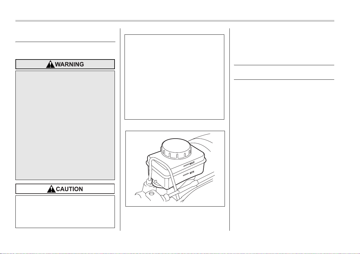
11-28 Maintenance and service
Brake fluid
Checking the fluid level
Check the fluid level monthly.
Check the fluid level on the outside of the
reservoir. If the level is below “MIN”, add
the recommended brake fluid to “MAX”.
Use only brake fluid from a sealed con-
tainer.
Recommended brake fluid
FMVSS No. 116, fresh DOT 3 or 4 brake flu-
id
y Never let brake fluid contact your
eyes because brake fluid can be
harmful to your eyes. If brake fluid
gets in your eyes, immediately
flush them thoroughly with clean
water. For safety, when perform-
ing this work, wearing eye protec-
tion is advisable.
y Brake fluid absorbs moisture from
the air. Any absorbed moisture
can cause a dangerous loss of
braking performance.
y If the vehicle requires frequent re-
filling, there may be a leak. If you
suspect a problem, have the vehi-
cle checked at your SUBARU
dealer.
y Never use different brands of
brake fluid together. Also, avoid
mixing DOT 3 and DOT 4 brake flu-
ids even if they are of the same
brand.
y When adding brake fluid, be care-
ful not to allow any dirt into the
reservoir.
y Never splash the brake fluid over
painted surfaces or rubber parts.
Alcohol contained in the brake flu-
id may damage them.
y Be careful not to spill brake fluid
when adding it. If brake fluid
touches the exhaust pipe, it may
cause a bad smell, smoke, and/or
a fire. If brake fluid gets on the ex-
haust pipe, be sure to wipe it off.
B00125
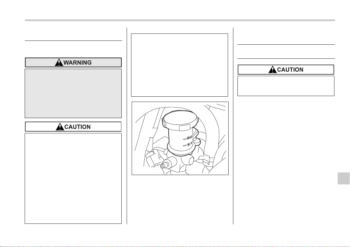
Maintenance and service 11-29
Clutch fluid (MT vehicles)
Checking the fluid level
Check the fluid level on the outside of the
reservoir. If the level is below “MIN” level
mark, add the recommended clutch fluid
to “MAX” level mark.
Use only clutch fluid from a sealed con-
tainer.
Recommended clutch fluid
FMVSS No. 116, fresh DOT 3 or 4 brake flu-
id
Never let clutch fluid contact your
eyes because clutch fluid can be
harmful to your eyes. If clutch fluid
gets in your eyes, immediately flush
them thoroughly with clean water.
For safety, when performing this
work, wearing eye protection is ad-
visable.
y Clutch fluid absorbs moisture
from the air. Any absorbed mois-
ture can cause improper clutch
operation.
y If the vehicle requires frequent re-
filling, there may be a leak. If you
suspect a problem, have the vehi-
cle checked at your SUBARU
dealer.
y Never use different brands of
clutch fluid together.
y When clutch fluid is added, be
careful not to allow any dirt into
the tank.
y Never splash the clutch fluid over
painted surfaces or rubber parts.
Alcohol contained in the clutch
fluid may damage them.
y Be careful not to spill clutch fluid
when adding it. If clutch fluid
touches the exhaust pipe, it may
cause a bad smell, smoke, and/or
a fire. If clutch fluid gets on the ex-
haust pipe, be sure to wipe it off.
B00126
Avoid mixing DOT 3 and DOT 4
brake fluids even if they are of the
same brand.
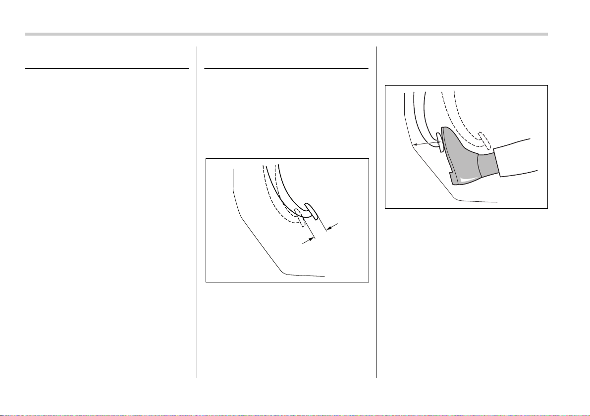
11-30 Maintenance and service
Brake booster
If the brake booster does not operate as
described in the following, have it checked
by your SUBARU dealer.
1. With the engine off, depress the brake
pedal several times, applying the same
pedal force each time. The distance the
pedal travels should not vary.
2. With the brake pedal depressed, start
the engine. The pedal should move slight-
ly down to the floor.
3. With the brake pedal depressed, stop
the engine and keep the pedal depressed
for 30 seconds. The pedal height should
not change.
4. Start the engine again and run for ap-
proximately one minute then turn it off.
Depress the brake pedal several times to
check the brake booster. The brake boost-
er operates properly if the pedal stroke de-
creases with each depression.
Brake pedal
Check the brake pedal free play and re-
serve distance according to the mainte-
nance schedule in the “Warranty and
Maintenance Booklet”.
Checking the brake pedal free
play
1) 0.02 – 0.08 in (0.5 – 2.0 mm)
Stop the engine and firmly depress the
brake pedal several times. Lightly pull the
brake pedal up with one finger to check
the free play with a force of less than 2 lbs
(10 N, 1 kg).
If the free play is not within proper specifi-
cation, contact your SUBARU dealer.
Checking the brake pedal re-
serve distance
1) More than 2.56 in (65 mm)
Depress the pedal with a force of approxi-
mately 66 lbs (294 N, 30 kg) and measure
the distance between the upper surface of
the pedal pad and the floor.
When the measurement is smaller than
the specification, or when the pedal does
not operate smoothly, contact with your
SUBARU dealer.
1
B00323
1
B00324
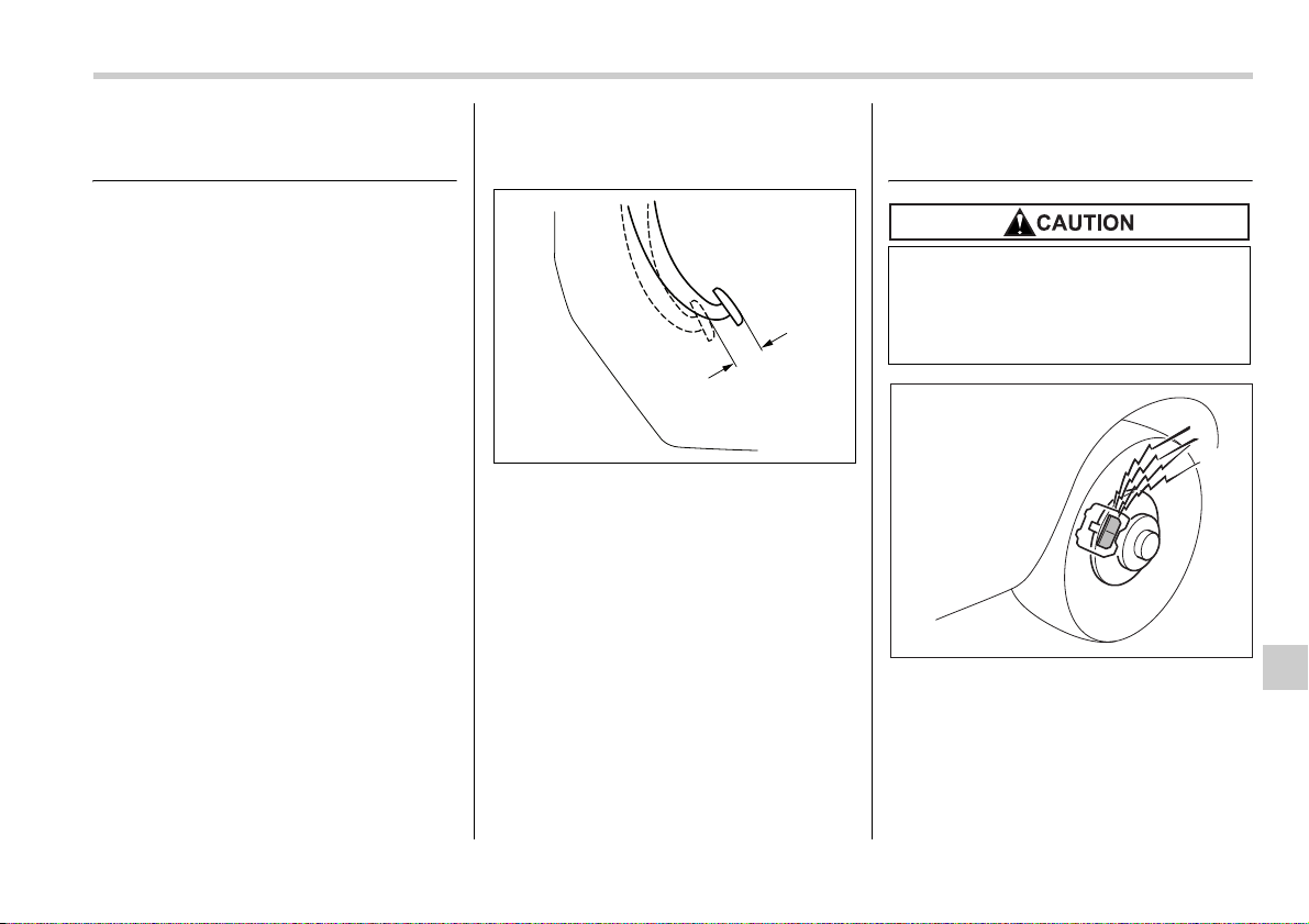
Maintenance and service 11-31
– CONTINUED –
Clutch pedal (Manual trans-
mission vehicles)
Check the clutch pedal free play and re-
serve distance according to the mainte-
nance schedule in the “Warranty and
Maintenance Booklet”.
Checking the clutch function
Check the clutch engagement and disen-
gagement.
1. With the engine idling, check that there
are no abnormal noises when the clutch
pedal is depressed, and that shifting into
1st or reverse feels smooth.
2. Start the vehicle by releasing the pedal
slowly to check that the engine and trans-
mission smoothly couple without any sign
of slippage.
Checking the clutch pedal
free play
1) 0.16 – 0.51 in (4.0 – 13.0 mm)
Lightly press the clutch pedal down with
your finger until you feel resistance, and
check the free play.
If the free play is not within proper specifi-
cation, contact your SUBARU dealer.
Replacement of brake pad
and lining
The right front disc brake and the right rear
disc brake have audible wear indicators
on the brake pads. If the brake pads wear
close to their service limit, the wear indica-
tor makes a very audible scraping noise
when the brake pedal is applied.
If you hear this scraping noise each time
1
B00323
If you continue to drive despite the
scraping noise from the audible
brake pad wear indicator, it will re-
sult in the need for costly brake ro-
tor repair or replacement.
700040
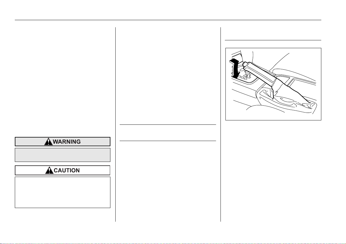
11-32 Maintenance and service
you apply the brake pedal, have the brake
pads serviced by your SUBARU dealer as
soon as possible.
Breaking-in of new brake
pads and linings
When replacing the brake pad or lining,
use only genuine SUBARU parts. After re-
placement, the new parts must be broken
in as follows:
T Brake pad and lining
While maintaining a speed of 30 to 40 mph
(50 to 65 km/h), step on the brake pedal
lightly. Repeat this five or more times.
T Parking brake lining
1. Drive the vehicle at a speed of approx-
imately 22 mph (35 km/h).
2. With the parking brake release button
pushed in, pull the parking brake lever
SLOWLY and GENTLY. (Pulling with a
force of approximately 33 lbs [147 N, 15
kg].)
3. Drive the vehicle for approximately 220
yards (200 meters) in this condition.
4. Wait 5 to 10 minutes for the parking
brake to cool down. Repeat this proce-
dure.
5. Check the parking brake stroke. If the
parking brake stroke is out of the specified
range, adjust it by turning the adjusting nut
located on the parking brake lever.
Parking brake stroke:
5 – 6 notches / 44 lbs (196 N, 20 kg)
Parking brake stroke
Check the parking brake stroke according
to the maintenance schedule in the “War-
ranty and Maintenance Booklet”. When
the parking brake is properly adjusted,
braking power is fully applied by pulling
the lever up five to six notches gently but
firmly (approximately 44 lbs, 196 N, 20
kg). If the parking brake lever stroke is not
within the specified range, have the brake
system checked and adjusted at your
SUBARU dealer.
A safe location and situation should
be selected for break-in driving.
Pulling the parking brake lever too
forcefully may cause the rear
wheels to lock. To avoid this, be cer-
tain to pull the lever up slowly and
gently.
B00127

Maintenance and service 11-33
– CONTINUED –
Tires and wheels
Types of tires
You should be familiar with type of tires
present on your vehicle.
T All season tires
The factory-installed tires on your new ve-
hicle are all season tires.
All season tires are designed to provide
an adequate measure of traction, handling
and braking performance in year-round
driving including snowy and icy road con-
ditions. However all season tires do not of-
fer as much traction performance as win-
ter (snow) tires in heavy or loose snow or
on icy roads.
All season tires are identified by “ALL
SEASON” and/or “M+S” (Mud & Snow) on
the tire sidewall.
T Summer tires
Summer tires are high-speed capability
tires best suited for highway driving under
dry conditions.
Summer tires are inadequate for driving
on slippery roads such as on snow-cov-
ered or icy roads.
If you drive your vehicle on snow-covered
or icy roads, we strongly recommend the
use of winter (snow) tires.
When installing winter tires, be sure to re-
place all four tires.
T Winter (snow) tires
Winter tires are best suited for driving on
snow-covered and icy roads. However
winter tires do not perform as well as sum-
mer tires and all season tires on roads oth-
er than snow-covered and icy roads.
Tire pressure monitoring sys-
tem (TPMS) (if equipped)
The tire pressure monitoring system pro-
vides the driver with a warning message
by sending a signal from a sensor that is
installed in each wheel when tire pressure
is severely low. The tire pressure monitor-
ing system will activate only when the ve-
hicle is driven. Also, this system may not
react immediately to a sudden drop in tire
pressure (for example, a blow-out caused
by running over a sharp object).
If you adjust the tire pressures in a warm
garage and will then drive the vehicle in
cold outside air, the resulting drop in tire
pressures may cause the low tire pressure
warning light to come on. To avoid this
problem when adjusting the tire pressures
in a warm garage, inflate the tires to pres-
sures higher than those shown on the tire
placard. Specifically, inflate them by an
extra 1 psi (6.9 kPa, 0.07 kgf/cm
2
) for ev-
ery difference of 10°F (5.6°C) between the
temperature in the garage and the tem-
perature outside. By way of example, the
following table shows the required tire
pressures that correspond to various out-
side temperatures when the temperature
in the garage is 60°F (15.6°C).
Standard tire pressures:
Front: 32 psi (220 kPa, 2.2 kgf/cm
2
)
Rear: 30 psi (210 kPa, 2.1 kgf/cm
2
)
Garage temperature: 60°F (15.6°C)
If the low tire pressure warning light
comes on when you drive the vehicle in
cold outside air after adjusting the tire
pressures in a warm garage, re-adjust the
tire pressures using the method described
above. Then, increase the vehicle speed
to at least 20 mph (32 km/h) and check to
see that the low tire pressure warning light
Outside
temperature
Adjusted pressure
[psi (kPa, kgf/cm
2
)]
front rear
30°F (–1°C) 35 (240, 2.4) 33 (230, 2.3)
10°F (–12°C) 37
(255, 2.55)
35
(245, 2.45)
–10°F
(–23°C)
39 (270, 2.7) 37 (260, 2.6)
11-34 Maintenance and service
goes off a few minutes later. If the low tire
pressure warning light does not go off, the
tire pressure monitoring system may not
be functioning normally. In this event, go
to a SUBARU dealer to have the system
inspected as soon as possible.
While the vehicle is driven, friction be-
tween tires and the road surface causes
the tires to warm up. After illumination of
the low tire pressure warning light, any in-
crease in the tire pressures caused by an
increase in the outside air temperature or
by an increase in the temperature in the
tires can cause the low tire pressure warn-
ing light to go off.
System resetting is necessary when the
wheels are changed (for example, a
switch to snow tires) and new TPMS
valves are installed on the newly fitted
wheels. Have this work performed by a
SUBARU dealer following wheel replace-
ment.
It may not be possible to install TPMS
valves on certain wheels that are on the
market. Therefore, if you change the
wheels (for example, a switch to snow
tires), use wheels that have the same part
number as the standard-equipment
wheels. Without four operational TPMS
valve/sensors on the wheels, the TPMS
will not fully function and the warning light
in the instrument panel will flash.
When a tire is replaced, adjustments are
necessary to ensure continued normal op-
eration of the tire pressure monitoring sys-
tem. As with wheel replacement, there-
fore, you should have the work performed
by a SUBARU dealer.
Tire inspection
Check on a daily basis that the tires are
free from serious damage, nails, and
stones. At the same time, check the tires
for abnormal wear.
Contact your SUBARU dealer immediate-
ly if you find any problem.
NOTE
y When the wheels and tires strike
If the low tire pressure warning light
does not come on briefly after the ig-
nition switch is turned ON or the
light is flashing, you should have
your Tire Pressure Monitoring Sys-
tem checked at a SUBARU dealer as
soon as possible.
If this light comes on while driving,
never brake suddenly and keep driv-
ing straight ahead while gradually
reducing speed. Then slowly pull off
the road to a safe place. Otherwise
an accident involving serious vehi-
cle damage and serious personal in-
jury could occur.
If this light still comes on while driv-
ing after adjusting the tire pressure,
a tire may have significant damage
and a fast leak that causes the tire to
lose air rapidly. If you have a flat tire,
replace it with a spare tire as soon
as possible.
When a spare tire is mounted or a
wheel rim is replaced without the
original pressure sensor/transmitter
being transferred, the low tire pres-
sure warning light will flash. This in-
dicates the TPMS is unable to moni-
tor all four road wheels. Contact
your SUBARU dealer as soon as
possible for tire and sensor replace-
ment and/or system resetting. If the
light flashes, promptly contact a
SUBARU dealer to have the system
inspected.
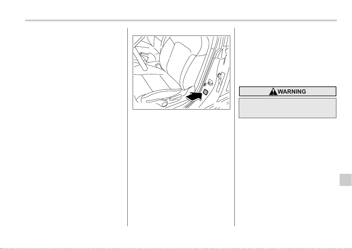
Maintenance and service 11-35
– CONTINUED –
curbs or are subjected to harsh treat-
ment as when the vehicle is driven on a
rough surface, they can suffer damage
that cannot be seen with the naked eye.
This type of damage does not become
evident until time has passed. Try not
to drive over curbs, potholes or on oth-
er rough surfaces. If doing so is un-
avoidable, keep the vehicle’s speed
down to a walking pace or less, and ap-
proach the curbs as squarely as possi-
ble. Also, make sure the tires are not
pressed against the curb when you
park the vehicle.
y If you feel unusual vibration while
driving or find it difficult to steer the ve-
hicle in a straight line, one of the tires
and/or wheels may be damaged. Drive
slowly to the nearest authorized
SUBARU dealer and have the vehicle
inspected.
Tire pressures and wear
Maintaining the correct tire pressures
helps to maximize the tires’ service lives
and is essential for good running perfor-
mance. Check and, if necessary, adjust
the pressure of each tire (including the
spare) at least once a month (for example,
during a fuel stop) and before any long
journey.
Check the tire pressures when the tires
are cold. Use a pressure gauge to adjust
the tire pressures to the values shown on
the tire placard. The tire placard is located
on the door pillar on the driver’s side.
Driving even a short distance warms up
the tires and increases the tire pressures.
Also, the tire pressures are affected by the
outside temperature. It is best to check tire
pressure outdoors before driving the vehi-
cle.
When a tire becomes warm, the air inside
it expands, causing the tire pressure to in-
crease. Be careful not to mistakenly re-
lease air from a warm tire to reduce its
pressure.
NOTE
y The air pressure in a tire increases
by approximately 4.3 psi (30 kPa, 0.3
kgf/cm
2
) when the tire becomes warm.
y The tires are considered cold when
the vehicle has been parked for at least
three hours or has been driven less
than one mile (1.6 km).
Incorrect tire pressures detract from con-
trollability and ride comfort, and they
cause the tires to wear abnormally.
B00128
Do not let air out of warm tires to ad-
just pressure. Doing so will result in
low tire pressure.
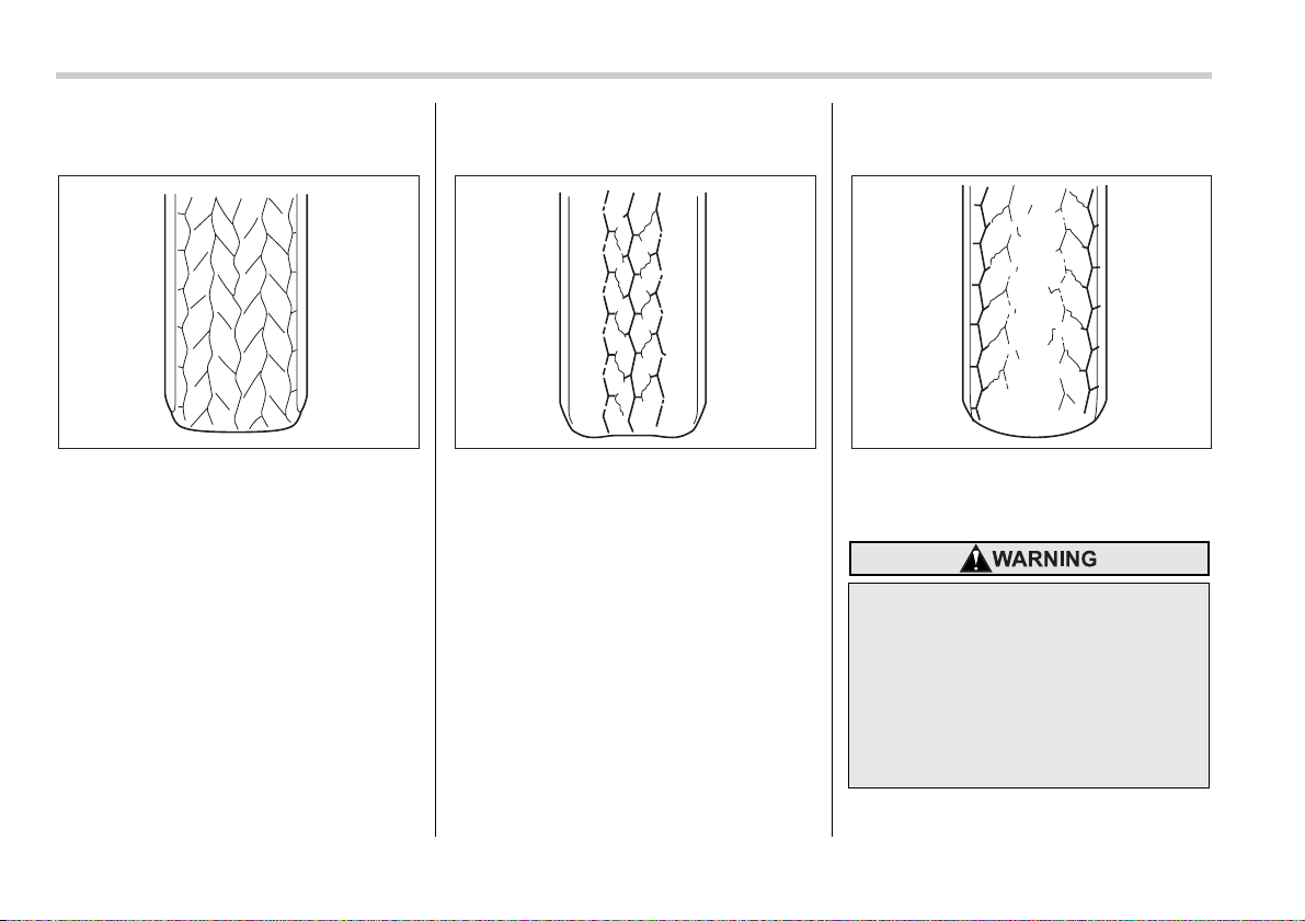
11-36 Maintenance and service
y Correct tire pressure (tread worn
evenly)
Roadholding is good, and steering is re-
sponsive. Rolling resistance is low, so fuel
consumption is also lower.
y Abnormally low tire pressure (tread
worn at shoulders)
Rolling resistance is high, so fuel con-
sumption is also higher.
y Abnormally high tire pressure (tread
worn in center)
Ride comfort is poor. Also, the tire magni-
fies the effects of road-surface bumps and
dips, possibly resulting in vehicle damage.
B00050 B00051
Driving at high speeds with exces-
sively low tire pressures can cause
the tires to deform severely and to
rapidly become hot. A sharp in-
crease in temperature could cause
tread separation, and destruction of
the tires. The resulting loss of vehi-
cle control could lead to an acci-
dent.
B00052
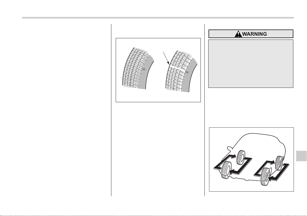
Maintenance and service 11-37
– CONTINUED –
Wheel balance
Each wheel was correctly balanced when
your vehicle was new, but the wheels will
become unbalanced as the tires become
worn during use. Wheel imbalance caus-
es the steering wheel to vibrate slightly at
certain vehicle speeds and detracts from
the vehicle’s straight-line stability. It can
also cause steering and suspension sys-
tem problems and abnormal tire wear. If
you suspect that the wheels are not cor-
rectly balanced, have them checked and
adjusted by your SUBARU dealer. Also
have them adjusted after tire repairs and
after tire rotation.
NOTE
Loss of correct wheel alignment* caus-
es the tires to wear on one side and re-
duces the vehicle’s running stability.
Contact your SUBARU dealer if you no-
tice abnormal tire wear.
*: The suspension system is designed to hold
each wheel at a certain alignment (relative to
the other wheels and to the road) for optimum
straight-line stability and cornering perfor-
mance.
Wear indicators
1) New tread
2) Worn tread
3) Tread wear indicator
Each tire incorporates a tread wear indica-
tor, which becomes visible when the depth
of the tread grooves decreases to 0.063 in
(1.6 mm). A tire must be replaced when
the tread wear indicator appears as a solid
band across the tread.
NOTE
For safety, inspect the tire tread regu-
larly and replace the tires before their
tread wear indicators become visible.
Tire rotation
123
B00327
When a tire’s tread wear indicator
becomes visible, the tire is worn be-
yond the acceptable limit and must
be replaced immediately. With a tire
in this condition, driving at high
speeds in wet weather can cause
the vehicle to hydroplane. The re-
sulting loss of vehicle control can
lead to an accident.
B00054
11-38 Maintenance and service
Tire wear varies from wheel to wheel. To
maximize the life of each tire and ensure
that the tires wear uniformly, it is best to
rotate the tires every 7,500 miles (12,500
km). Rotating the tires involves switching
the front and rear tires on the right-hand
side of the vehicle and similarly switching
the front and rear tires on the left-hand
side of the vehicle. (Each tire must be kept
on its original side of the vehicle.)
Replace any damaged or unevenly worn
tire at the time of rotation. After tire rota-
tion, adjust the tire pressures and make
sure the wheel nuts are correctly tight-
ened.
After driving approximately 600 miles
(1,000 km), check the wheel nuts again
and retighten any nut that has become
loose.
Tire replacement
The wheels and tires are important and in-
tegral parts of your vehicle’s design; they
cannot be changed arbitrarily. The tires fit-
ted as standard equipment are optimally
matched to the characteristics of the vehi-
cle and were selected to give the best pos-
sible combination of running performance,
ride comfort, and service life. It is essential
for every tire to have a size and construc-
tion matching those shown on the tire
placard and to have a speed symbol and
load index matching those shown on the
tire placard.
Using tires of a non-specified size detracts
from controllability, ride comfort, braking
performance, speedometer accuracy and
odometer accuracy. It also creates incor-
rect body-to-tire clearances and inappro-
priately changes the vehicle’s ground
clearance.
All four tires must be the same in terms of
manufacturer, brand (tread pattern), con-
struction, and size. You are advised to re-
place the tires with new ones that are
identical to those fitted as standard equip-
ment.
For safe vehicle operation, SUBARU rec-
ommends replacing all four tires at the
same time.
Wheel replacement
When replacing wheels due, for example,
to damage, make sure the replacement
wheels match the specifications of the
wheels that are fitted as standard equip-
ment. Replacement wheels are available
from SUBARU dealers.
y All four tires must be the same in
terms of manufacturer, brand
(tread pattern), construction, de-
gree of wear, speed symbol, load
index and size. Mixing tires of dif-
ferent types, sizes or degrees of
wear can result in damage to the
vehicle’s power train. Use of dif-
ferent types or sizes of tires can
also dangerously reduce control-
lability and braking performance
and can lead to an accident.
y Use only radial tires. Do not use
radial tires together with belted
bias tires and/or bias-ply tires. Do-
ing so can dangerously reduce
controllability, resulting in an ac-
cident.
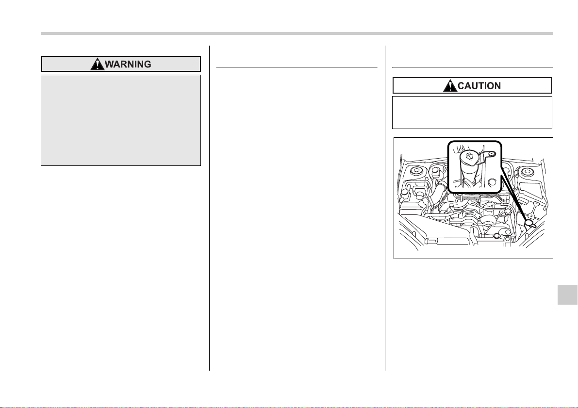
Maintenance and service 11-39
– CONTINUED –
Aluminum wheels
Aluminum wheels can be scratched and
damaged easily. Handle them carefully to
maintain their appearance, performance,
and safety.
y When any of the wheels is removed and
replaced for tire rotation or to change a
flat, always check the tightness of the
wheel nuts after driving approximately 600
miles (1,000 km). If any nut is loose, tight-
en it to the specified torque.
y Never apply oil to the threaded parts,
wheel nuts, or tapered surface of the
wheel.
y Never let the wheel rub against sharp
protrusions or curbs.
y Be sure to fit tire chains on uniformly
and completely around the tire, otherwise
the chains may scratch the wheel.
y When wheel nuts, balance weights, or
the center cap is replaced, be sure to re-
place them with genuine SUBARU parts
designed for aluminum wheels.
Windshield washer fluid
If you spray washer fluid on the windshield
but the supply of washer fluid appears to
diminish, check the level of washer fluid in
the tank.
Use only those wheels that are
specified for your vehicle. Wheels
not meeting specifications could in-
terfere with brake caliper operation
and may cause the tires to rub
against the wheel well housing dur-
ing turns. The resulting loss of vehi-
cle control could lead to an acci-
dent.
Never use engine coolant as washer
fluid because it could cause paint
damage.
B00199
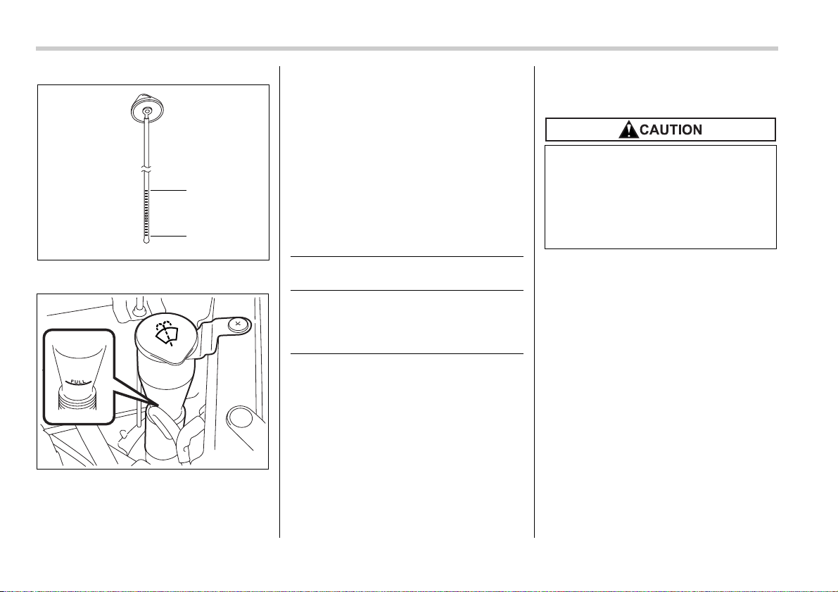
11-40 Maintenance and service
Washer fluid level gauge
Remove the washer tank filler cap, then
check the fluid level indicated by the level
gauge (attached to the inside of the cap).
If the level is near the “Low” mark, add flu-
id until it reaches the “Hi” level on the level
gauge or the “Full” mark on the tank.
Use windshield washer fluid. If windshield
washer fluid is unavailable use clean wa-
ter.
In areas where water freezes in winter,
use an anti-freeze type windshield washer
fluid. SUBARU Windshield Washer Fluid
contains 58.5% methyl alcohol and 41.5%
surfactant, by volume. Its freezing temper-
ature varies according to how much it is di-
luted, as indicated in the following table.
In order to prevent freezing of washer flu-
id, check the freezing temperatures in the
table above when adjusting the fluid con-
centration to the outside temperature.
If you fill the reservoir tank with a fluid with
a different concentration from the one
used previously, purge the old fluid from
the piping between the reservoir tank and
washer nozzles by operating the washer
for a certain period of time. Otherwise, if
the concentration of the fluid remaining in
the piping is too low for the outside tem-
perature, it may freeze and block the noz-
zles.
Hi
Low
300172
300173
Washer Fluid
Concentration
Freezing
Temperature
30% 10.4°F (–12°C)
50% –4°F (–20°C)
100% –49°F (–45°C)
Adjust the washer fluid concentra-
tion appropriately for the outside
temperature. If the concentration is
inappropriate, sprayed washer fluid
may freeze on the windshield and
obstruct your view, and the fluid
may freeze in the reservoir tank.
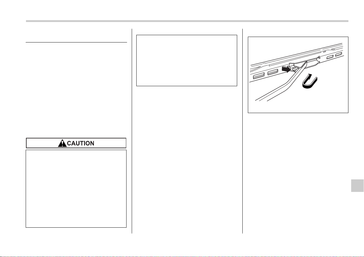
Maintenance and service 11-41
– CONTINUED –
Replacement of wiper blades
Grease, wax, insects, or other materials
on the windshield or the wiper blade re-
sults in jerky wiper operation and streak-
ing on the glass. If you cannot remove the
streaks after operating the windshield
washer or if the wiper operation is jerky,
clean the outer surface of the windshield
(or rear window) and the wiper blades us-
ing a sponge or soft cloth with a neutral
detergent or mild-abrasive cleaner. After
cleaning, rinse the windshield and wiper
blades with clean water. The windshield is
clean if beads do not form when you rinse
the windshield with water.
If you cannot eliminate the streaking even
after following this method, replace the
wiper blades using the following proce-
dures:
Windshield wiper blade as-
sembly
1. Raise the windshield wiper arm on the
driver’s side.
2. Next, raise the windshield wiper arm on
the passenger’s side.
1) Stopper
3. Remove the wiper blade assembly by
holding its pivot area and pushing it in the
direction shown by the arrow while de-
pressing the wiper blade stopper.
4. Install the wiper blade assembly to the
wiper arm. Make sure that it locks in place.
5. Lower the windshield wiper arm on the
passenger’s side slowly while supporting
it by hand.
6. Next, lower the windshield wiper arm
on the driver’s side slowly while support-
ing it by hand.
y Do not clean the wiper blades with
gasoline or a solvent, such as
paint thinner or benzene. This will
cause deterioration of the wiper
blades.
y When you wish to raise the pas-
senger-side wiper arm, first raise
the driver-side wiper arm. Other-
wise, the passenger-side wiper
assembly and driver-side wiper
assembly will touch each other,
possibly resulting in scratches.
y Return the passenger-side wiper
arm to its original position before
returning the driver-side wiper
arm to its original position. Other-
wise, the passenger-side wiper
assembly and driver-side wiper
assembly will touch each other,
possibly resulting in scratches.
1
B00380
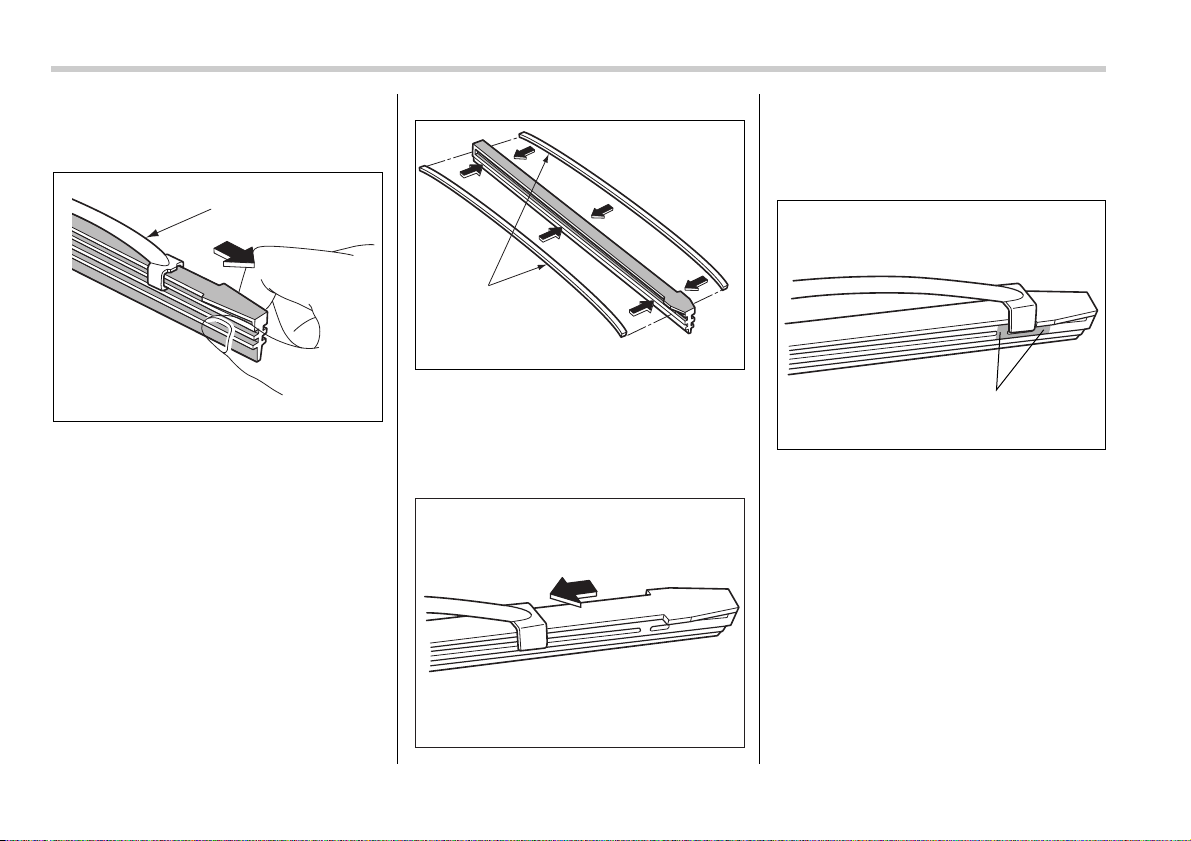
11-42 Maintenance and service
Windshield wiper blade rub-
ber
1) Metal support
1. Grasp the locked end of the blade rub-
ber assembly and pull it firmly until the
stoppers on the rubber are free of the met-
al support.
1) Metal spines
2. If the new blade rubber is not provided
with two metal spines, remove the metal
spines from the old blade rubber and in-
stall them in the new blade rubber.
3. Align the claws of the metal support
with the grooves in the rubber and slide
the blade rubber assembly into the metal
support until it locks.
1) Stopper
4. Be sure to position the claws at the end
of the metal support between the stoppers
on the rubber as shown. If the rubber is
not retained properly, the wiper blade may
scratch the windshield.
Rear window wiper blade as-
sembly
1. Raise the wiper arm off the rear win-
dow.
1
B00330
B00504
1
B00059
1
B00332
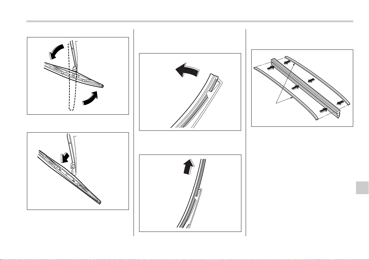
Maintenance and service 11-43
– CONTINUED –
2. Turn the wiper blade assembly coun-
terclockwise.
3. Pull the wiper blade assembly toward
you to remove it from the wiper arm.
Rear window wiper blade rub-
ber
1. Pull out the end of the blade rubber as-
sembly to unlock it from the plastic sup-
port.
2. Pull the blade rubber assembly out of
the plastic support.
1) Metal spines
3. If the new blade rubber is not provided
with two metal spines, remove the metal
spines from the old blade rubber and in-
stall them in the new blade rubber.
700063
700064
700017
B00064
B00505
1
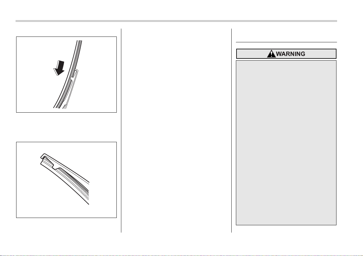
11-44 Maintenance and service
4. Align the claws of the plastic support
with the grooves in the blade rubber as-
sembly, then slide the blade rubber as-
sembly into place.
Securely retain both ends of the rubber
with the stoppers on the plastic support
ends. If the rubber is not retained properly,
the wiper may scratch the rear window
glass.
5. Install the wiper blade assembly to the
wiper arm. Make sure that it locks in place.
6. Hold the wiper arm by hand and slowly
lower it in position.
Battery
B00066
B00067
y Before beginning work on or near
any battery, be sure to extinguish
all cigarettes, matches, and light-
ers. Never expose a battery to an
open flame or electric sparks. Bat-
teries give off a gas which is high-
ly flammable and explosive.
y For safety, in case an explosion
does occur, wear eye protection
or shield your eyes when working
near any battery. Never lean over
a battery.
y Do not let battery fluid contact
eyes, skin, fabrics, or paint be-
cause battery fluid is a corrosive
acid. If battery fluid gets on your
skin or in your eyes, immediately
flush the area with water thor-
oughly. Seek medical help imme-
diately if acid has entered the
eyes.
If battery fluid is accidentally
swallowed, immediately drink a
large amount of milk or water, and
seek medical attention immediate-
ly.
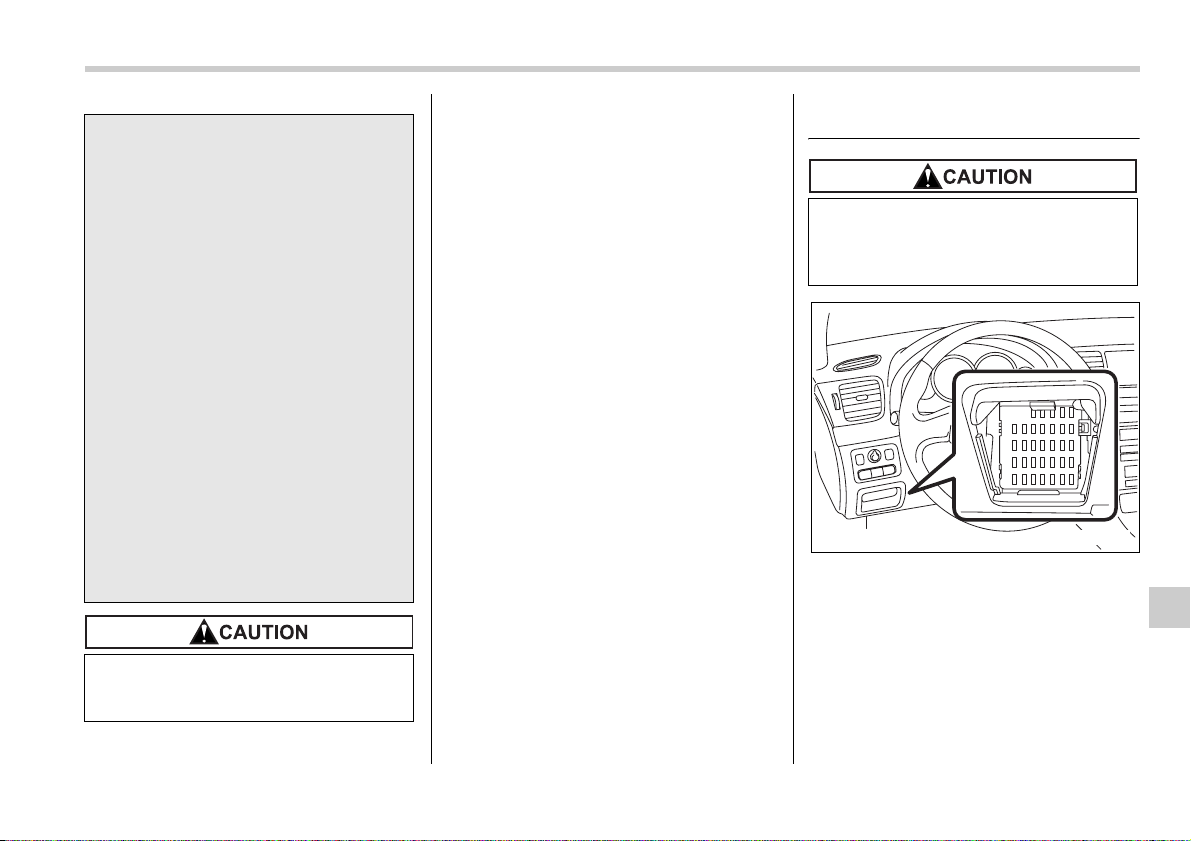
Maintenance and service 11-45
– CONTINUED –
It is unnecessary to periodically check the
battery fluid level or periodically refill with
distilled water.
Fuses
The fuses are designed to melt during an
overload to prevent damage to the wiring
harness and electrical equipment. The
fuses are located in two fuse boxes. One
is located under the instrument panel be-
hind the fuse box cover on the driver’s
seat side.
y To lessen the risk of sparks, re-
move rings, metal watchbands,
and other metal jewelry. Never al-
low metal tools to contact the pos-
itive battery terminal and anything
connected to it WHILE you are at
the same time in contact with any
other metallic portion of the vehi-
cle because a short circuit will re-
sult.
y Keep everyone including children
away from the battery.
y Charge the battery in a well-venti-
lated area.
y Battery posts, terminals, and re-
lated accessories contain lead
and lead compounds, chemicals
known to the State of California to
cause cancer and reproductive
harm. Batteries also contain other
chemicals known to the State of
California to cause cancer. Wash
hands after handling.
Never use more than 10 amperes
when charging the battery because
it will shorten battery life.
Never replace a fuse with one hav-
ing a higher rating or with material
other than a fuse because serious
damage or a fire could result.
B00130
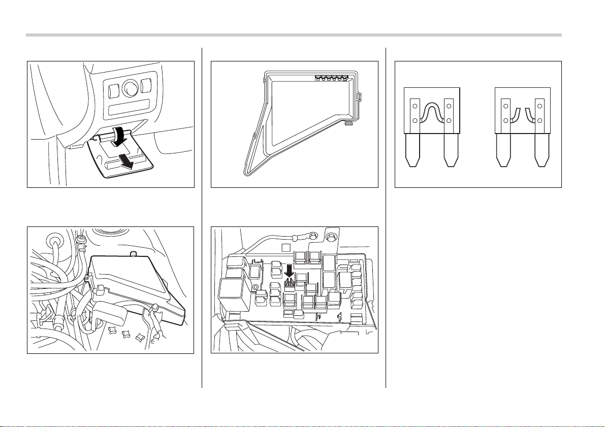
11-46 Maintenance and service
Open the lid that is located above the
hood release knob and pull it toward you
to remove it.
The other one is housed in the engine
compartment.
The spare fuses are stored in the main
fuse box cover in the engine compart-
ment.
The fuse puller is stored in the main fuse
box in the engine compartment.
1) Good
2) Blown
If any lights, accessories or other electri-
cal controls do not operate, inspect the
corresponding fuse. If a fuse has blown,
replace it.
1. Turn the ignition switch to the “LOCK”
position and turn off all electrical accesso-
ries.
2. Remove the cover.
3. Determine which fuse may be blown.
The back side of each fuse box cover and
the “Fuses and circuits” section in chapter
12 in this manual show the circuit for each
fuse.
B00131
600120
B00198
600159
12
B00338
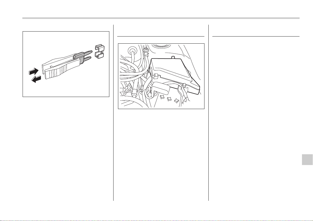
Maintenance and service 11-47
4. Pull out the fuse with the fuse puller.
5. Inspect the fuse. If it has blown, re-
place it with a spare fuse of the same rat-
ing.
6. If the same fuse blows again, this indi-
cates that its system has a problem. Con-
tact your SUBARU dealer for repairs.
Main fuse
Main fuse box
The main fuses are designed to melt dur-
ing an overload to prevent damage to the
wiring harness and electrical equipment.
Check the main fuses if any electrical
component fails to operate (except the
starter motor) and other fuses are good. A
melted main fuse must be replaced. Use
only replacements with the same speci-
fied rating as the melted main fuse. If a
main fuse blows after it is replaced, have
the electrical system checked by your
nearest SUBARU dealer.
Installation of accessories
Always consult your SUBARU dealer be-
fore installing fog lights or any other elec-
trical equipment in your vehicle. Such ac-
cessories may cause the electronic sys-
tem to malfunction if they are incorrectly
installed or if they are not suited for the ve-
hicle.
600160
600120
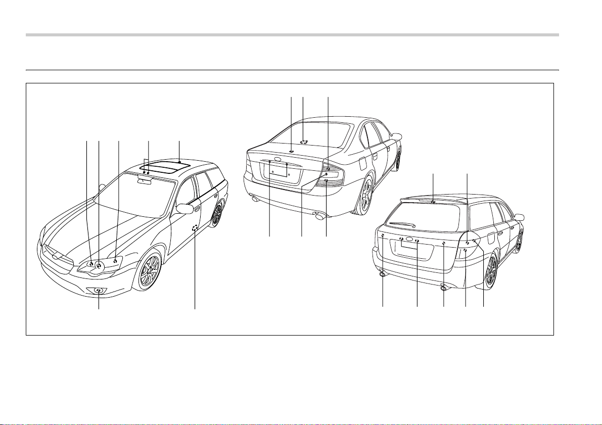
11-48 Maintenance and service
Replacing bulbs
8109
45321
67
1817 16 1517
13 14
11 1218
B00435
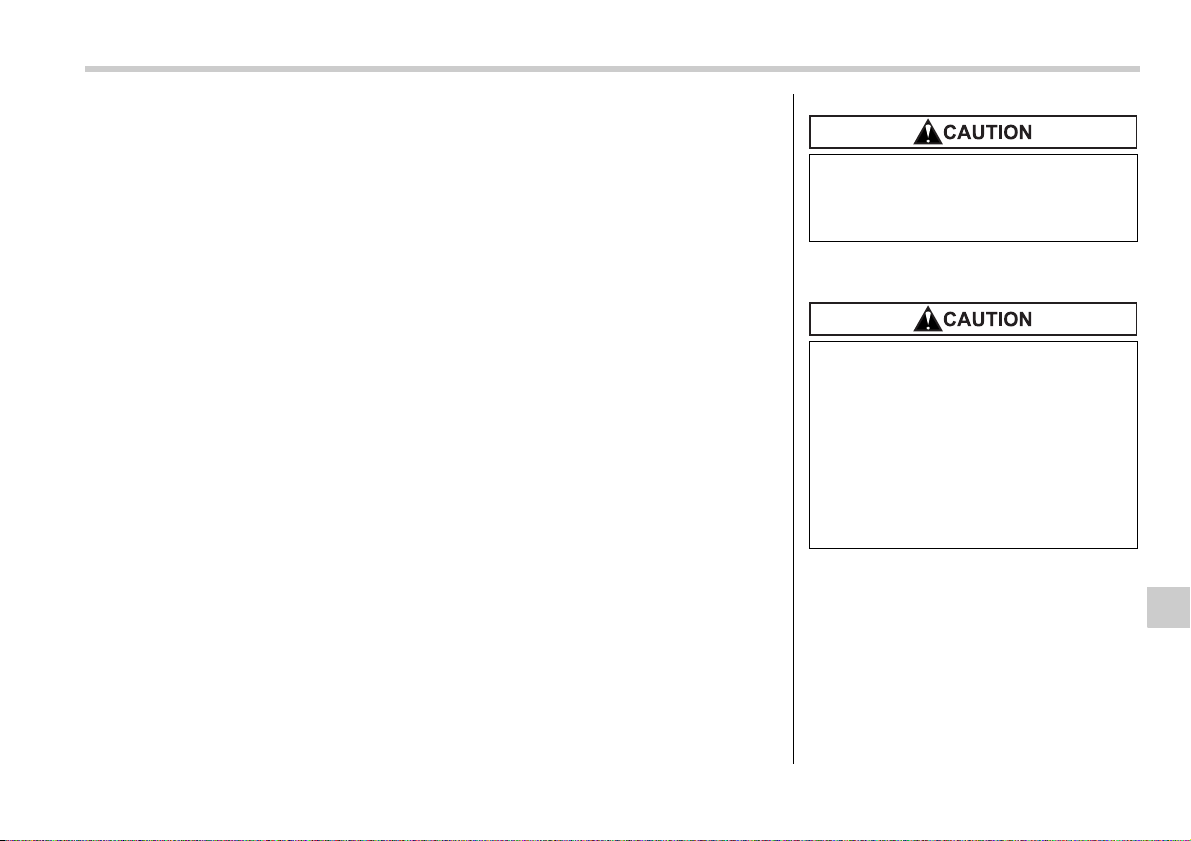
Maintenance and service 11-49
– CONTINUED –
Wattage Bulb No.
1) High beam headlight 12V-60W 9005 (HB3)
2) Low beam headlight 12V-55W H7
3) Front turn signal/Parking and front
side marker light
12V-27/8W 3157A
4) Map light 12V-8W –
5) Dome light 12V-8W –
6) Door step light 12V-3.5W –
7) Front fog light
Except OUTBACK 12V-55W H3
OUTBACK 12V-51W 9006 (HB4)
8) Trunk room light (Sedan) 12V-5W –
9) High mount stop light (Sedan) 12V-21W (W21W)
10) Rear turn signal light (Sedan) 12V-21W (W21W)
11) Backup light (Sedan) 12V-16W 921
12) Brake/tail and rear side marker
light (Sedan)
12V-21/5W (W21/5W)
13) Cargo area light 12V-13W –
14) Brake/tail light (Station wagon) 12V-21/5W (W21/5W)
15) Rear side marker light (Station
wagon)
12V-5W 168
16) Rear turn signal light (Station wag-
on)
12V-21W (W21W)
17) Backup light (Station wagon) 12V-16W 921
18) Licence plate light 12V-5W 168
Headlight
NOTE
y If headlight aiming is required, con-
sult your SUBARU dealer for proper
adjustment of the headlight aim.
y It may be difficult to replace the
bulbs. Have your SUBARU dealer re-
place the bulbs if necessary.
Replace any bulb only with a new
bulb of the specified wattage. Using
a bulb of different wattage could re-
sult in a fire.
Halogen headlight bulbs become
very hot while in use. If you touch
the bulb surface with bare hands or
greasy gloves, finger prints or
grease on the bulb surface develop
into hot spots, causing the bulb to
break. If there are finger prints or
grease on the bulb surface, wipe
them away with a soft cloth mois-
tened with alcohol.
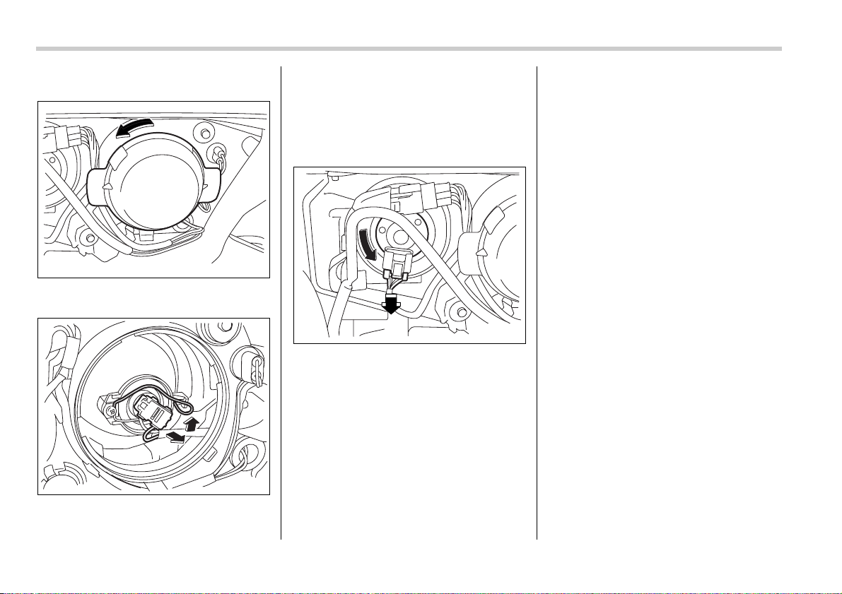
11-50 Maintenance and service
T Low beam light bulbs
1. Remove the bulb cover, by turning it
counterclockwise.
2. Disconnect the electrical connector.
3. Remove the retainer spring.
4. Replace the bulb, then set the retainer
spring securely.
5. Reconnect the electrical connector.
6. Install the bulb cover.
T High beam light bulbs
1. Disconnect the electrical connector
from the bulb.
2. Remove the bulb from the headlight
assembly by turning it counterclockwise.
3. Replace the bulb with new one.
4. Reconnect the electrical connector. At
this time, use care not to touch the bulb
surface.
5. To install the bulb to the headlight as-
sembly, turn it clockwise until it clicks.
Parking light
It may be difficult to replace the bulbs.
Have your SUBARU dealer replace the
bulbs if necessary.
Front turn signal light
It may be difficult to replace the bulbs.
Have your SUBARU dealer replace the
bulbs if necessary.
Front fog light (if equipped)
It may be difficult to replace the bulbs.
Have your SUBARU dealer replace the
bulbs if necessary.
700067
700068
700069
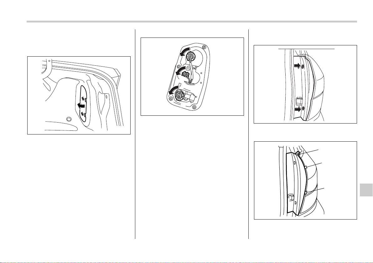
Maintenance and service 11-51
– CONTINUED –
Rear combination lights
T Sedan
1. Push the knobs of the cover to open
the cover.
1) Rear turn signal light
2) Backup light
3) Brake/tail and rear side marker light
2. Remove the bulb holder from the rear
combination light assembly by turning it
counterclockwise.
3. Pull the bulb out of the bulb holder and
replace it with a new one.
4. Set the bulb holder into the rear combi-
nation light assembly and turn it clockwise
until it locks.
5. Securely lock the cover against the
trunk trim by using the screwdriver to turn
the top knob clockwise.
T Station wagon
1. Using a Phillips screwdriver, remove
the upper and lower screws.
2. Wrap tape around a flat-head screw-
driver, then insert the screwdriver into the
B00436
1
2
3
B00437
B00134
3
2
1
B00438
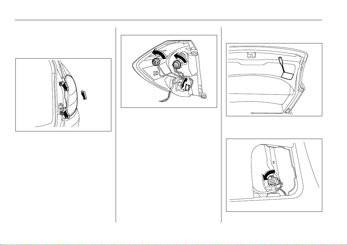
11-52 Maintenance and service
gap A between the side cover and rear
combination lamp and use it as a lever to
undo the clip. Undo clips C and D in the
same way, then remove the side cover.
3. Remove the upper and lower screws.
Then, slide the rear combination lamp as-
sembly to the rear and remove it from the
vehicle.
1) Brake/tail light
2) Rear turn signal light
3) Rear side marker light
4. Remove the bulb holder from the rear
combination light assembly by turning it
counterclockwise.
5. Pull the bulb out of the bulb holder and
replace it with a new one.
6. Set the bulb holder into the rear combi-
nation light assembly and turn it clockwise
until it locks.
7. Close the cover and latch the lock.
8. Reinstall the rear combination light as-
sembly and its side cover.
Backup light (Station wagon)
1. Use a flat-head screwdriver to remove
the light cover from the top of the left-hand
rear gate trim.
2. Turn the bulb socket counterclockwise
B00136
3
1
2
B00439
B00138
B00139
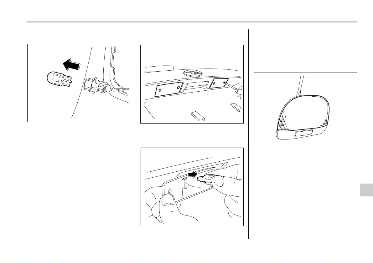
Maintenance and service 11-53
– CONTINUED –
and remove it.
3. Pull the bulb out of the bulb socket and
replace it with a new one.
4. Install the bulb socket by turning it
clockwise. Install the light cover on the
rear gate.
License plate light
T Sedan
It may be difficult to replace the bulbs.
Have your SUBARU dealer replace the
bulbs if necessary.
T Station wagon
0
1. Remove the mounting screws using a
Phillips screwdriver.
2. Remove the lens.
3. Pull the bulb out of the socket. Install a
new bulb.
4. Reinstall the lens and cover.
5. Tighten the mounting screws.
Dome light
1. Remove the lens by prying the edge of
the lens with a flat-head screwdriver.
700075
700076
700077
700083
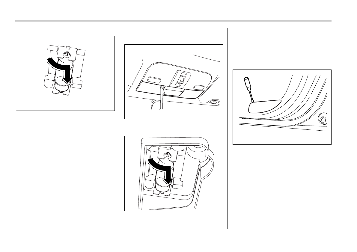
11-54 Maintenance and service
2. Turn the bulb until the flat surfaces at
its ends are aligned vertically. Pull the
bulb straight downward to remove it. In-
stall a new bulb.
3. Reinstall the lens.
Map light
0
1. Remove the lens by prying the edge of
the lens with a flat-head screwdriver.
2. Turn the bulb until the flat surfaces at
its ends are aligned vertically. Pull the
bulb straight downward to remove it.
3. Install a new bulb.
4. Reinstall the lens.
Door step light
1. Remove the lens by prying the edge of
the lens with a flat-head screwdriver.
700084
B00440
700086
700081
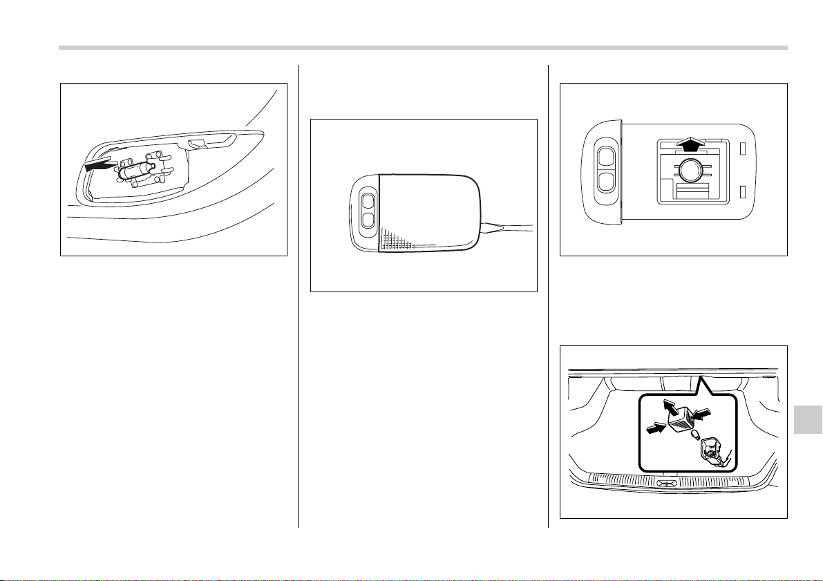
Maintenance and service 11-55
– CONTINUED –
2. Pull the bulb out of the socket. Install a
new bulb.
3. Reinstall the lens.
Cargo area light (Station wag-
on)
1. Remove the cargo area light assembly
by prying the edge of the light with a flat-
head screwdriver.
2. Remove the lens from the cargo area
light assembly.
3. Pull the bulb out of the socket. Install a
new bulb.
4. Reinstall the lens.
Trunk light (Sedan)
700082
700078
700079
700080

11-56 Maintenance and service
1. Remove the cover by pulling it out.
2. Pull the bulb out of the socket. Install a
new bulb.
3. Reinstall the cover.
High mount stop light (Se-
dan)
It may be difficult to replace the bulbs.
Have your SUBARU dealer replace the
bulbs if necessary.

12
Specifications
Specifications ..................................................... 12-2
Dimensions ............................................................. 12-2
Engine ...................................................................... 12-3
Electrical system .................................................... 12-3
Capacities ................................................................ 12-4
Tires ......................................................................... 12-5
Wheel alignment ..................................................... 12-5
Fuses and circuits .............................................. 12-6
Fuse panel located in the passenger
compartment ......................................................... 12-6
Fuse panel located in the engine
compartment ......................................................... 12-8
Bulb chart ............................................................ 12-9
Vehicle identification ......................................... 12-10
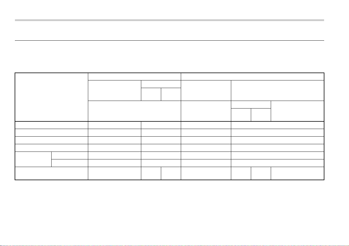
12-2 Specifications
Specifications
Specifications
These specifications are subject to change without notice.
Dimensions
in (mm)
Item Legacy OUTBACK
Sedan Station wagon Sedan Station wagon
Non-
turbo
Turbo
2.5-liter 3.0-liter 2.5-liter 3.0-liter
Non-
turbo
Turbo
Overall length 186.2 (4,730) 188.8 (4,795) 186.2 (4,730) 188.8 (4,795)
Overall width 68.1 (1,730) 68.1 (1,730) 69.7 (1,770) 69.7 (1,770)
Overall height 56.1 (1,425) 58.1 (1,475) 59.6 (1,515) 63.2 (1,605)
Wheel base 105.1 (2,670) 105.1 (2,670) 105.1 (2,670) 105.1 (2,670)
Tread Front 58.9 (1,495) 58.9 (1,495) 58.9 (1,495) 58.9 (1,495)
Rear 58.5 (1,485) 58.5 (1,485) 58.7 (1,490) 58.7 (1,490)
Ground clearance 5.9 (150) 5.9
(150)
6.1
(155)
8.44 (214.6) 8.5
(215)
8.7
(220)
8.5 (215)

Specifications 12-3
– CONTINUED –
Engine
Electrical system
Engine model EJ253
(2.5-liter, SOHC, non-turbo)
EJ255
(2.5-liter, DOHC, turbo)
EZ30D
(3.0-liter, DOHC, non-turbo)
Engine type Horizontally opposed, liquid cooled 4 cylinder,
4 stroke gasoline engine
Horizontally opposed, liquid cooled 6 cylinder,
4 stroke gasoline engine
Displacement cu-in (cc) 150 (2,457) 183 (3,000)
Bore × Stroke in (mm) 3.92 × 3.11 (99.5 × 79.0) 3.51 × 3.15 (89.2 × 80.0)
Compression ratio 10.0 : 1 8.2 : 1 10.7 : 1
Firing order 1 – 3 – 2 – 4 1 – 6 – 3 – 2 – 5 – 4
Battery type and capacity (5HR) 2.5-liter models MT 55D23L (12V-48AH)
AT 75D23L (12V-52AH)
3.0-liter models 75D23L (12V-52AH)
Alternator 12V-110A
Spark plugs 2.5-liter non-turbo models FR5AP-11 (NGK)
2.5-liter turbo and 3.0-liter models ILFR6B (NGK)

12-4 Specifications
Capacities
Fuel tank 16.9 US gal (64 liters, 14.1 Imp gal)
Engine oil 2.5-liter models 4.2 US qt (4.0 liters, 3.5 Imp qt)
3.0-liter models 5.8 US qt (5.5 liters, 4.8 Imp qt)
Transmission oil (MT) 3.7 US qt (3.5 liters, 3.1 Imp qt)
Transmission fluid (AT) 2.5-liter non-turbo models 9.8 US qt (9.3 liters, 8.2 Imp qt)
2.5-liter turbo and 3.0-liter models 10.4 US qt (9.8 liters, 8.6 Imp qt)
AT differential gear oil 2.5-liter non-turbo models 1.3 US qt (1.2 liters, 1.1 Imp qt)
2.5-liter turbo and 3.0-liter models 1.5 US qt (1.4 liters, 1.2 Imp qt)
Rear differential gear oil 0.8 US qt (0.8 liter, 0.7 Imp qt)
Power steering fluid 0.7 US qt (0.7 liter, 0.6 Imp qt)
Engine coolant 2.5-liter non-turbo models MT 6.8 US qt (6.4 liters, 5.6 Imp qt)
AT 6.7 US qt (6.3 liters, 5.5 Imp qt)
2.5-liter turbo models MT 7.7 US qt (7.3 liters, 6.4 Imp qt)
AT 7.6 US qt (7.2 liters, 6.3 Imp qt)
3.0-liter models 7.6 US qt (7.2 liters, 6.3 Imp qt)
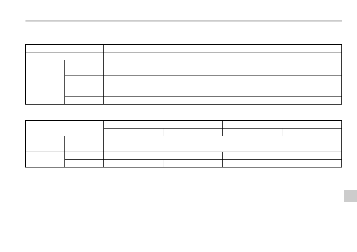
Specifications 12-5
Tires
Wheel alignment
Tire size P205/50R17 88V 215/45ZR17 P225/55R17 95V
Wheel size 17 × 7 JJ
Pressure Front 33 psi (230 kPa, 2.3 kgf/cm
2
) 35 psi (240 kPa, 2.4 kgf/cm
2
) 32 psi (220 kPa, 2.2 kgf/cm
2
)
Rear 32 psi (220 kPa, 2.2 kgf/cm
2
) 33 psi (230 kPa, 2.3 kgf/cm
2
) 30 psi (210 kPa, 2.1 kgf/cm
2
)
Rear at trailer
towing
– 32 psi (220 kPa, 2.2 kgf/cm
2
)
Temporary
spare tire
Size T135/80R16 T135/70D17 T155/70D17
Pressure 60 psi (420 kPa, 4.2 kgf/cm
2
)
Item Legacy OUTBACK
Sedan Station wagon Sedan Station wagon
Toe Front 0 in (0 mm)
Rear 0 in (0 mm)
Camber Front –0°15’ 0°40’
Rear –0°40’ –0°30’ –0°10’
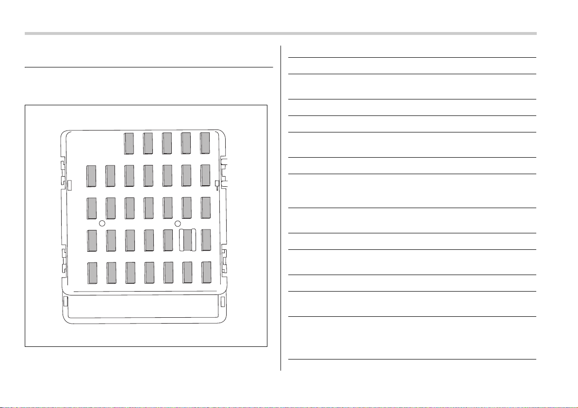
12-6 Specifications
Fuses and circuits
Fuse panel located in the passenger compart-
ment
27 28 29 30 31 32 33
20 21 22 23 24 25 26
13 14 15 16 17 18 19
6789101112
12345
C00004
Fuse panel Fuse rating Circuit
1 20A y Cargo fan
y Trailer hitch connector
2 Empty
3 15A y Door locking
4 15A y Front wiper deicer relay
y Moonroof
5 15A y Combination meter
6 7.5A y Remote control rear view mirrors
y Seat heater relay
y Vanity mirror light
7 15A y Combination meter
y Integrated unit
8 20A y Stop light
9 20A y Mirror heater
y Front wiper deicer
10 7.5A y Power supply (Battery)
11 7.5A y Turn signal unit
y Clock
12 15A y Automatic transmission unit
y SRS airbag system (Sub)
y Engine control unit
y Integrated unit

Specifications 12-7
– CONTINUED –
13 20A y Cargo socket
14 15A y Position light
y Tail light
y Rear combination light
15 Empty
16 15A y Illumination
17 15A y Seat heaters
18 10A y Backup light
19 7.5A y Headlight right side relay
20 10A y Cigarette lighter socket
21 7.5A y Starter relay
22 15A y Air conditioner
y Rear window defogger relay coil
23 15A y Rear wiper
y Rear window washer
24 15A y Audio unit
y Clock
25 15A y SRS airbag system (Main)
26 15A y Power window relay
27 15A y Blower fan
Fuse panel Fuse rating Circuit
28 15A y Blower fan
29 15A y Fog light
30 30A y Front wiper
y Front wiper washer
31 7.5A y Auto air conditioner unit
y Integrated unit
32 7.5A y Headlight left side relay
33 7.5A y ABS/Vehicle dynamics control unit
Fuse panel Fuse rating Circuit
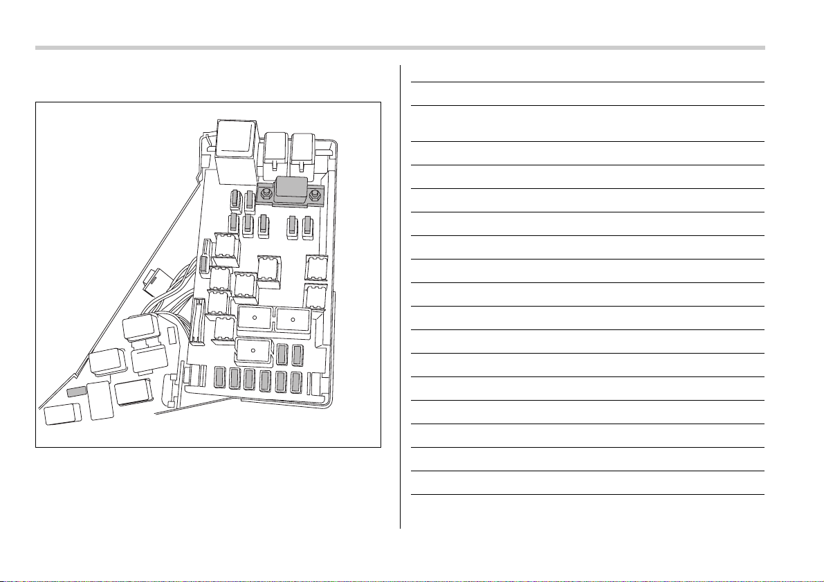
12-8 Specifications
Fuse panel located in the engine compartment
A) FWD socket (AT vehicles – except Turbo models and 3.0-liter
models)
B) Main fuse
1
2
B
3
4
5
6
7
8
9
10
11
A
12
13
14
15
16
C00005
Fuse panel Fuse rating Circuit
1 30A y ABS unit
y Vehicle dynamics control unit
2 25A y Main fan (3.0-liter models)
3 25A y Sub fan (Except 3.0-liter models)
4 25A y Main fan
5 20A y Audio
6 15A y Headlight (right side)
7 15A y Headlight (left side)
8 20A y Backup light
9 15A y Horn
10 25A y Rear window defogger
11 15A y Fuel pump
12 15A y Automatic transmission control unit
13 7.5A y Engine control unit
14 15A y Turn and hazard warning flasher
15 20A y Parking switch
16 7.5A y Alternator

Specifications 12-9
Bulb chart
Description Wattage Bulb No.
Headlight
Low beam 12V-55W H7
High beam 12V-60W 9005 (HB3)
Front fog light
Except OUTBACK 12V-55W H3
OUTBACK 12V-51W 9006 (HB4)
Front turn signal/park-
ing and front side mark-
er
12V-27/8W 3157A
Rear combination light
Rear turn signal
light (Sedan)
12V-21W (W21W)
Brake/tail and rear
side marker (Se-
dan)
12V-21/5W (W21/5W)
Brake/tail (Station
wagon)
12V-21/5W (W21/5W)
Rear side marker
(Station wagon)
12V-5W 168
Rear turn signal
light (Station wag-
on)
12V-21W (W21W )
Backup light 12V-16W 921
High mount stop light
(Sedan)
12V-21W (W21W)
License plate light 12V-5W 168
Trunk room light 12V-5W W5W
Cargo area light 12V-13W –
Front ashtray light 12V-1.4W –
Dome light 12V-8W –
Map light 12V-8W –
Door step light 12V-3.5W –
Description Wattage Bulb No.
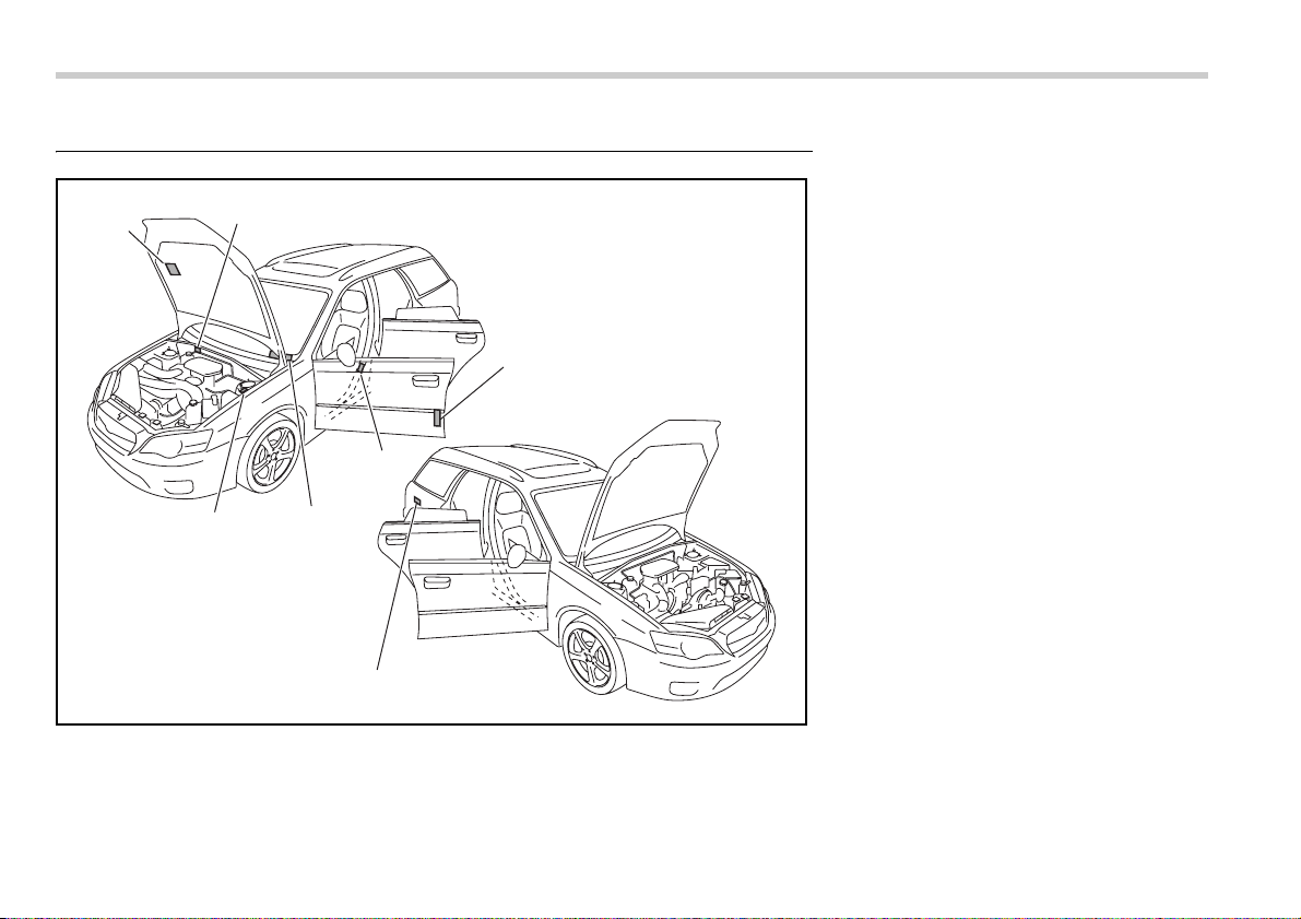
12-10 Specifications
Vehicle identification
C00104
1
2
7
6
5
4
3
1) Emission control label
2) Vehicle identification number
3) Certification and bar code label
4) Tire inflation pressure label
5) Vehicle identification number plate
6) Model number plate
7) Fuel label

13
Consumer information and Reporting safety defects
Tire information .................................................. 13-2
Tire labeling ............................................................. 13-2
Recommended tire inflation pressure .................. 13-5
Glossary of tire terminology .................................. 13-6
Tire care – maintenance and safety practices ..... 13-7
Vehicle load limit – how to determine ................... 13-8
Determining compatibility of tire and vehicle
load capacities ...................................................... 13-10
Adverse safety consequences of overloading on
handling and stopping and on tires ................... 13-11
Steps for Determining Correct Load Limit ........... 13-11
Uniform tire quality grading standards ............ 13-12
Treadwear ................................................................ 13-12
Traction AA, A, B, C ................................................ 13-12
Temperature A, B, C ............................................... 13-12
Reporting safety defects (USA) ......................... 13-13

13-2 Consumer information and Reporting safety defects
Consumer inf ormation and Re porting safet y defects
For U.S.A.
The following information has been com-
piled according to Code of Federal Regu-
lations “Title 49, Part 575”.
Tire information
Tire labeling
Many markings (e.g. Tire size, Tire
Identification Number or TIN) are
placed on the sidewall of a tire by tire
manufacturers. These marking can
provide you with useful information on
the tire.
T Tire size
Your vehicle comes equipped with P-
Metric tire size. It is important to un-
derstand the sizing system in select-
ing the proper tire for your vehicles.
Here is a brief review of the tire sizing
system with a breakdown of its indi-
vidual elements.
V P Metric
With the P-Metric system, Section
Width is measured in millimeters. To
convert millimeters into inches, divide
by 25.4. The Aspect Ratio (Section
Height divided by Section Width)
helps provide more dimensional infor-
mation about the tire size.
Example:
(1) P = Certain tire type used on light
duty vehicles such as passenger cars
(2) Section Width in millimeters
(3) Aspect Ratio (= section height ÷
section width).
(4) R = Radial Construction
(5) Rim diameter in inches
(6) ZR = Speed category above 149
mph (240 km/h)
V Load and Speed Rating Descrip-
tions
The load and speed rating descrip-
tions will appear following the size
designation.
They provide two important facts
about the tire. First, the number des-
ignation is its load index. Second, the
letter designation indicates the tire’s
speed rating.
P 205 / 50 R 17
(1)
(2)
(3) (4) (5)
215 / 45 ZR 17
(2)
(3) (6) (5)
Consumer information and Reporting safety defects 13-3
– CONTINUED –
Example:
(6) Load Index: A numerical code
which specifies the maximum load a
tire can carry at the speed indicated
by its speed symbol, at maximum in-
flation pressure.
For example, “88” means 1,234 lbs
(560 kg), “87” means 1,201 lbs (545
kg), “86” means 1,168 lbs (530 kg)
(7) Speed Rating: An alphabetical
system describing a tire’s capability to
travel at established and predeter-
mined speeds.
For example, “V” means 149 mph
(240 km/h)
T Tire Identification Number (TIN)
Tire Identification Number (TIN) is
marked on the intended outboard
sidewall. The TIN is composed of four
groups. Here is a brief review of the
TIN with a breakdown of its individual
elements.
(1) Manufacturer’s Identification Mark
(2) Tire Size
(3) Tire Type Code
(4) Date of Manufacture
The first two figures identify the week,
starting with “01” to represent the first
full week of the calendar year; the
second two figures represent the
year. For example, 0101 means the
1st week of 2001.
T Other markings
The following makings are also
placed on the sidewall.
V Maximum permissible inflation
pressure
The maximum cold inflation pressure
to which this tire may be inflated. For
example, “300 kpa (44 PSI) MAX.
PRESS”
V Maximum load rating
The load rating at the maximum per-
missible weight load for this tire. For
example, “MAX. LOAD 730 kg (1609
LBS) @ 300 kpa (44 PSI) MAX.
PRESS.”
Load indices apply only to the
tire, not to the vehicle. Putting a
load rated tire on any vehicle
does not mean the vehicle can
be loaded up to the tire’s rated
load.
P 205 / 50 R 17 88 V
Size designation
(6) (7)
y Speed ratings apply only to
the tire, not to the vehicle. Put-
ting a speed rated tire on any
vehicle does not mean the ve-
hicle can be operated at the
tire’s rated speed.
y The speed rating is void if the
tires are worn out, damaged,
repaired, retreaded, or other-
wise altered from their original
condition. If tires are repaired,
retreaded, or otherwise al-
tered, they may not be suitable
for original equipment tire de-
signed loads and speeds.
DOT XX XX XXX XXXX
(1) (2)
(3)
(4)
13-4 Consumer information and Reporting safety defects
V Construction type
Applicable construction of this tire.
For example, “TUBELESS STEEL
BELTED RADIAL”
V Construction
The generic name of each cord mate-
rial used in the plies (both sidewall
and tread area) of this tire.
For example, “PLIES: TREAD 2
STEEL + 2 POLYESTER + 1 NYLON
SIDEWALL 2 POLYESTER”
V Uniform Tire Quality Grading
(UTQG)
For details, refer to “Uniform tire qual-
ity grading standards” in this chapter.
Maximum load rating applies
only to the tire, not to the vehi-
cle. Putting a load rated tire on
any vehicle does not mean the
vehicle can be loaded up to the
tire’s rated load.

Consumer information and Reporting safety defects 13-5
– CONTINUED –
Recommended tire inflation pressure
T Recommended cold tire inflation pressure
Recommended cold tire inflation pressure for your vehicle’s tires is as follows,
Tire size P205/50R17 88V 215/45ZR17 P225/55R17 95V
Wheel size 17 × 7 JJ
Pressure Front 33 psi (230 kPa, 2.3 kgf/cm
2
) 35 psi (240 kPa, 2.4 kgf/cm
2
) 32 psi (220 kPa, 2.2 kgf/cm
2
)
Rear 32 psi (220 kPa, 2.2 kgf/cm
2
) 33 psi (230 kPa, 2.3 kgf/cm
2
) 30 psi (210 kPa, 2.1 kgf/cm
2
)
Rear at trailer
towing
– 32 psi (220 kPa, 2.2 kgf/cm
2
)
Temporary
spare tire
Size T135/80R16 T135/70D17 T155/70D17
Pressure 60 psi (420 kPa, 4.2 kgf/cm
2
)
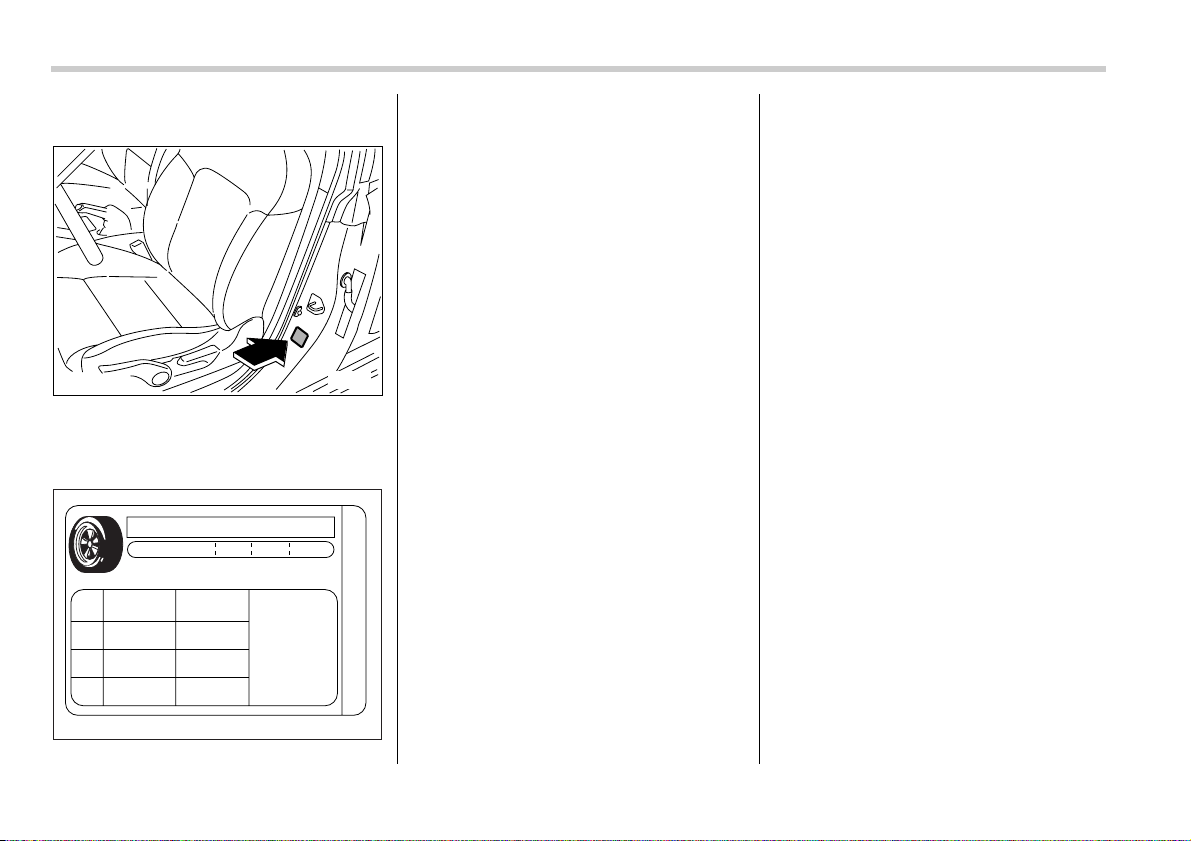
13-6 Consumer information and Reporting safety defects
T Vehicle placard
The vehicle placard is affixed to the
driver’s side B-pillar.
Example:
The vehicle placard shows original
tire size, recommended cold tire infla-
tion pressure on each tire at maxi-
mum loaded vehicle weight, seating
capacity and loading information.
T Adverse safety consequences
of under-inflation
Driving at high speeds with exces-
sively low tire pressures can cause
the tires to flex severely and to rapidly
become hot. A sharp increase in tem-
perature could cause tread separa-
tion, and failure of the tire(s). Possi-
ble resulting loss of vehicle control
could lead to an accident.
T Measuring and adjusting air
pressure to achieve proper infla-
tion
Check and, if necessary, adjust the
pressure of each tire (including the
spare) at least once a month and be-
fore any long journey. Check the tire
pressures when the tires are cold.
Use a pressure gauge to adjust the
tire pressures to the specific values.
Driving even a short distance warms
up the tires and increases the tire
pressures. Also, the tire pressures
are affected by the outside tempera-
ture. It is best to check tire pressure
outdoors before driving the vehicle.
When a tire becomes warm, the air in-
side it expands, causing the tire pres-
sure to increase. Be careful not to
mistakenly release air from a warm
tire to reduce its pressure.
Glossary of tire terminology
y Cold tire pressure
The pressure in a tire that has been
driven less than 1 mile or has been
standing for three hours or more.
y Maximum inflation pressure
The maximum cold inflation pressure
to which a tire may be inflated.
y Recommended inflation pres-
sure
The cold inflation pressure recom-
mended by a vehicle manufacturer.
y Intended outboard sidewall
1)The sidewall that contains a
whitewall, bears white lettering or
bears manufacturer, brand, and/or
model name molding that is higher
or deeper than the same molding
on the other sidewall of the tire, or
2)The outward facing sidewall of an
B00128
D00124
TIRE AND LOADING INFORMATION
SEATING CAPACITY TOTAL 5 FRONT 2 REAR 3
The combined weight of occupants and cargo
should never exceed 385kg or 850lbs.
TIRE SISE
FRONT P205/50R17
P205/50R17
T135/80R16
230KPA.33PSI
220KPA.32PSI
420KPA.60PSI
REAR
SPARE
COLD TIRE
PRESSURE
SEE OWNER’S
MANUAL FOR
ADDITIONAL
INFORMATION
SF

Consumer information and Reporting safety defects 13-7
– CONTINUED –
asymmetrical tire that has a particu-
lar side that must always face out-
ward when mounting on a vehicle.
y Accessory weight
The combined weight (in excess of
those standard items which may be
replaced) of floor mats, leather seats
and cross bars to the extent that these
items are available as factory-in-
stalled equipment (whether installed
or not).
y Curb weight
The weight of a motor vehicle with
standard equipment including the
maximum capacity of fuel, oil, and
coolant and air conditioning.
y Maximum loaded vehicle weight
The sum of curb weight, accessory
weight, vehicle capacity weight and
production options weight.
y Normal occupant weight
150 lbs (68 kg) times the number of
occupants (3 occupants).
y Occupant distribution
Distribution of occupants in a vehicle,
2 in front, 1 in rear seat.
y Production options weight
The combined weight of those in-
stalled regular production options
weighing over 5.1 lbs (2.3 kg) in ex-
cess of those standards items which
they replace, not previously consid-
ered in curb weight or accessory
weight.
y Vehicle capacity weight
The total weight of cargo, luggage
and occupants that can be added to
the vehicle.
y Vehicle maximum load on a tire
Load on an individual tire that is deter-
mined by distributing to each axle its
share of the maximum loaded vehicle
weight and dividing by two.
y Vehicle normal load on a tire
Load on an individual tire that is deter-
mined by distributing to each axle its
share of the curb weight, accessory
weight, and normal occupant weight
and dividing by two.
Tire care – maintenance and
safety practices
y Check on a daily basis that the tires
are free from serious damage, nails,
and stones. At the same time, check
the tires for abnormal wear.
y Inspect the tire tread regularly and
replace the tires before their tread
wear indicators become visible. When
a tire’s tread wear indicator becomes
visible, the tire is worn beyond the ac-
ceptable limit and must be replaced
immediately. With a tire in this condi-
tion, driving at even low speeds in wet
weather can cause the vehicle to hy-
droplane. Possible resulting loss of
vehicle control can lead to an acci-
dent.
y To maximize the life of each tire and
ensure that the tires wear uniformly, it
is best to rotate the tires every 7,500
miles (12,500 km). Rotating the tires
involves switching the front and rear
tires on the right-hand side of the ve-
hicle and similarly switching the front
and rear tires on the left-hand side of
the vehicle. (Each tire must be kept on
its original side of the vehicle.) Re-
place any damaged or unevenly worn
tire at the time of rotation. After tire ro-
tation, adjust the tire pressures and
make sure the wheel nuts are correct-
ly tightened. A tightening torque spec-
ification and a tightening sequence
specification for the wheel nuts can be
found “Flat tires” section in chapter 9.
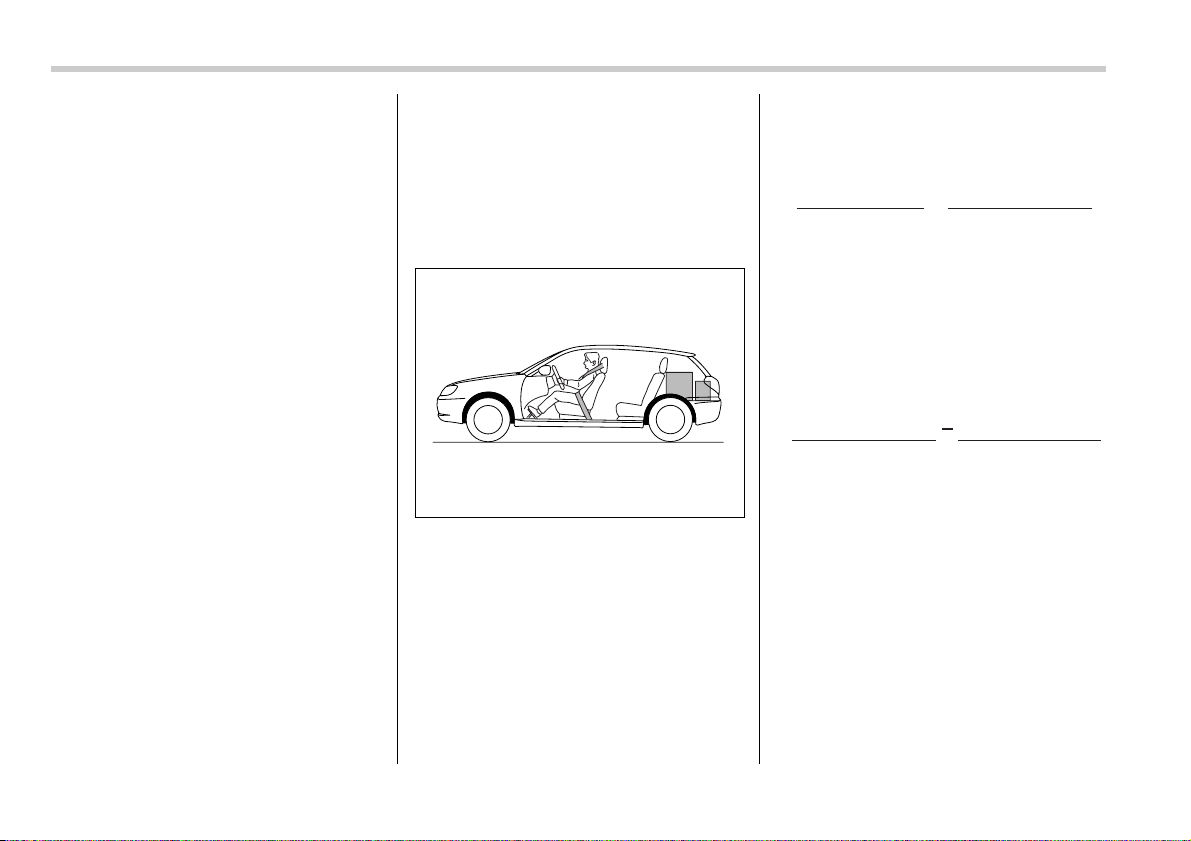
13-8 Consumer information and Reporting safety defects
Vehicle load limit – how to de-
termine
The load capacity of your vehicle is
determined by weight, not by avail-
able cargo space. The load limit of
your vehicle is shown on the vehicle
placard attached to the driver’s side
B-pillar. Locate the statement “The
combined weight of occupants and
cargo should never exceed XXX kg or
XXX lbs” on your vehicle’s placard.
The vehicle placard also shows seat-
ing capacity of your vehicle.
The total load capacity includes the
total weight of driver and all passen-
gers and their belongings, any cargo,
any optional equipment such as a
trailer hitch, roof rack or bike carrier,
etc., and the tongue load of a trailer.
Therefore cargo capacity can be cal-
culated by the following method.
Cargo capacity = Load limit – (total
weight of occupants + total weight of
optional equipment + tongue load of a
trailer (if applicable))
For towing capacity information and
weight limits, refer to “Trailer towing”
section in chapter 8.
T Calculating total and load capac-
ities varying seating configura-
tions
Calculate the available load capacity
as shown in the following examples:
Example 1A
Vehicle capacity weight of the vehicle
is 800 lbs (363 kg), which is indicated
on the vehicle placard with the state-
ment “The combined weight of occu-
pants and cargo should never exceed
363 kg or 800 lbs”.
For example, if the vehicle has one
occupant weighing 154 lbs (70 kg)
plus cargo weighing 551 lbs (250 kg).
1. Calculate the total weight.
2. Calculate the available load capac-
ity by subtracting the total weight from
the vehicle capacity weight of 800 lbs
(363 kg).
3. The result of step 2 shows that a
further 95 lbs (43 kg) of cargo can be
carried.
D00111
Total weight
= 154 lbs (70 kg) + 551 lbs (250 kg)
= 705 lbs (320 kg)
(Occupant) (Cargo)
Available Load Capacity
= 800 lbs (363 kg) 705 lbs (320 kg)
= 95 lbs (43 kg)
(Vehicle
capacity weight)
(Total weight)
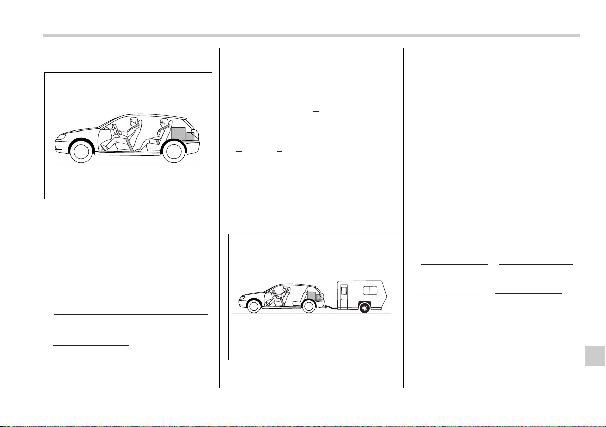
Consumer information and Reporting safety defects 13-9
– CONTINUED –
Example 1B
For example, if a person weighing 176
lbs (80 kg) now enters the same vehi-
cle (bringing the number of occupants
to two), the calculations are as fol-
lows:
1. Calculate the total weight.
2. Calculate the available load capac-
ity.
3. The total weight now exceeds the
capacity weight by 81 lbs (37 kg), so
the cargo weight must be reduced by
81 lbs (37 kg) or more.
Example 2A
Vehicle capacity weight of the vehicle
is 800 lbs (363 kg), which is indicated
on the vehicle placard with the state-
ment “The combined weight of occu-
pants and cargo should never exceed
363 kg or 800 lbs”.
For example, the vehicle has one oc-
cupant weighing 165 lbs (75 kg) plus
cargo weighing 265 lbs (120 kg). In
addition, the vehicle is fitted with a
trailer hitch weighing 22 lbs (10 kg), to
which is attached a trailer weighing
1,764 lbs (800 kg). 10% of the trailer
weight is applied to the trailer tongue
(i.e. Tongue load = 176 lbs (80 kg)).
1. Calculate the total weight.
2. Calculate the available load capac-
ity.
D00112
Total weight
= 154 lbs (70 kg) + 176 lbs (80 kg)
+ 551 lbs (250 kg)
= 881 lbs (400 kg)
(Occupant)
(Cargo)
Available Load Capacity
= 800 lbs (363 kg) 881 lbs (400 kg)
= 81 lbs ( 37 kg)
(Vehicle
capacity weight)
(Total weight)
D00113
Total weight
= 165 lbs (75 kg) + 265 lbs (120 kg)
+ 22 lbs (10 kg) + 176 lbs (80 kg)
= 628 lbs (285 kg)
(Occupant) (Cargo)
(Trailer hitch)
(Tongue load)
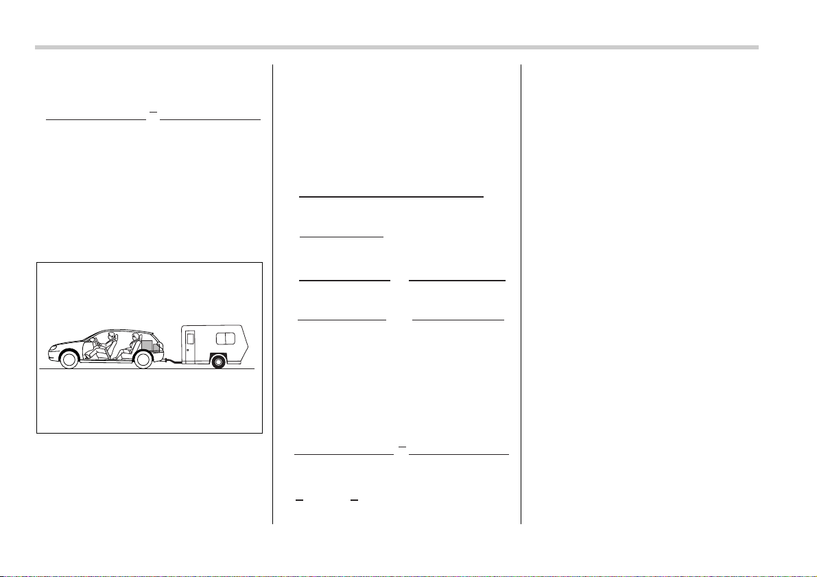
13-10 Consumer information and Reporting safety defects
3. The result of step 2 shows that a
further 172 lbs (78 kg) of cargo can be
carried.
Example 2B
For example, if a person weighing 143
lbs (65 kg) and a child weighing 40 lbs
(18 kg) now enter the same vehicle
(bringing the number of occupants to
three), and a child restraint system
weighing 11 lbs (5 kg) is installed in
the vehicle for the child to use, the cal-
culations are as follows:
1. Calculate the total weight.
2. Calculate the available load capac-
ity.
3. The total weight now exceeds the
capacity weight by 22 lbs (10 kg), so
the cargo weight must be reduced by
22 lbs (10 kg) or more.
Determining compatibility of
tire and vehicle load capaci-
ties
The sum of four tires’ maximum load
ratings must exceed the maximum
loaded vehicle weight (“GVWR”). In
addition, sum of the maximum load
ratings of two front tires and of two
rear tires must exceed each axle’s
maximum loaded capacity (“GAWR”).
Original equipment tires are designed
to fulfill those conditions.
The maximum loaded vehicle weight
is referred to Gross Vehicle Weight
Rating (GVWR). And each axle’s
maximum loaded capacity is referred
to Gross Axle Weight Rating
(GAWR). The GVWR and each axle’s
GAWR are shown on the vehicle cer-
tification label affixed to the driver’s
door.
The GVWR and front and rear
GAWRs are determined by not only
the maximum load rating of tires but
Available Load Capacity
= 800 lbs (363 kg) 628 lbs (285 kg)
= 172 lbs (78 kg)
(Vehicle
capacity weight)
(Total weight)
D00114
Total weight
= 165 lbs (75 kg) + 143 lbs (65 kg)
+ 40 lbs (18 kg)
+ 11 lbs (5 kg) + 265 lbs (120 kg)
+ 22 lbs (10 kg) + 176 lbs (80 kg)
= 822 lbs (373 kg)
(Occupant)
(Cargo)
(Trailer hitch)
(Child restraint)
(Tongue load)
(Occupant)
Available Load Capacity
= 800 lbs (363 kg) 822 lbs (373 kg)
= 22 lbs ( 10 kg)
(Vehicle
capacity weight)
(Total weight)

Consumer information and Reporting safety defects 13-11
also loaded capacities of the vehicle’s
suspension, axles and other parts of
the body.
Therefore, this means that the vehicle
cannot necessarily be loaded up to
the tire’s maximum load rating on the
tire sidewall.
Adverse safety consequenc-
es of overloading on handling
and stopping and on tires
Overloading could affect vehicle han-
dling, stopping distance, vehicle and
tire as shown in the following. This
could lead to an accident and possibly
result in severe personal injury.
y Vehicle stability will deteriorate.
y Heavy and/or high-mounted loads
could increase the risk of rollover.
y Stopping distance will increase.
y Brakes could overheat and fail.
y Suspension, bearings, axles and
other parts of the body could break or
experience accelerated wear that will
shorten vehicle life.
y Tires could fail.
y Tread separation could occur.
y Tire could separate from its rim.
Steps for Determining Cor-
rect Load Limit
1. Locate the statement “The com-
bined weight of occupants and cargo
should never exceed XXX pounds” on
your vehicle’s placard.
2. Determine the combined weight of
the driver and passengers that will be
riding in your vehicle.
3. Subtract the combined weight of
the driver and passengers from XXX
kilograms or XXX pounds.
4. The resulting figure equals the
available amount of cargo and lug-
gage load capacity. For example, if
the “XXX” amount equals 1,400 lbs
(635kg). and there will be five- 150 lbs
(68 kg) passengers in your vehicle,
the amount of available cargo and
luggage load capacity is 650 lbs.
(1,400 – 750 (5 × 150) = 650 lbs.)
5. Determine the combined weight of
luggage and cargo being loaded on
the vehicle. That weight may not safe-
ly exceed the available cargo and lug-
gage load capacity calculated in Step
4.
6. If your vehicle will be towing a trail-
er, load from your trailer will be trans-
ferred to your vehicle. Consult this
manual to determine how this reduc-
es the available cargo and luggage
load capacity of your vehicle.
13-12 Consumer information and Reporting safety defects
Uniform tire quality grading
standards
This information indicates the relative
performance of passenger car tires in
the area of treadwear, traction, and
temperature resistance. This is to aid
the consumer in making an informed
choice in the purchase of tires.
Quality grades can be found where
applicable on the tire sidewall be-
tween tread shoulder and maximum
section width. For example:
Treadwear 200 Traction AA Tem-
perature A
The quality grades apply to new pneu-
matic tires for use on passenger cars.
However, they do not apply to deep
tread, winter type snow tires, space-
saver or temporary use spare tires,
tires with nominal rim diameters of 12
inches or less, or to some limited pro-
duction tires.
All passenger car tires must confirm
to Federal Safety Requirements in
addition to these grades.
Treadwear
The treadwear grade is a comparative
rating based on the wear rate of the
tire when tested under controlled con-
ditions on a specified government test
course.
For example, a tire graded 150 would
wear one and one-half (1-1/2) times
as well on the government course as
a tire graded 100. The relative perfor-
mance of tires depends upon the ac-
tual conditions of their use, however,
and may depart significantly from the
norm due to variations in driving hab-
its, service practices and differences
in road characteristics and climate.
Traction AA, A, B, C
The traction grades, from highest to
lowest, are AA, A, B and C. Those
grades represent the tire’s ability to
stop on wet pavement as measured
under controlled conditions on speci-
fied government test surfaces of as-
phalt and concrete. A tire marked C
may have poor traction performance.
Temperature A, B, C
The temperature grades are A (the
highest), B, and C, representing the
tire’s resistance to the generation of
heat and its ability to dissipate heat
when tested under controlled condi-
tions on a specified indoor laboratory
test wheel. Sustained high tempera-
ture can cause the material of the tire
to degenerate and reduce tire life, and
excessive temperature can lead to
sudden tire failure. The grade C corre-
sponds to a level of performance
which all passenger car tires must
meet under the Federal Motor Vehicle
Safety Standards No. 109. Grades B
and A represent higher levels of per-
formance on the laboratory test wheel
than the minimum required by law.
The traction grade assigned to
this tire is based on straight-
ahead braking traction tests,
and does not include accelera-
tion, cornering, hydroplaning, or
peak traction characteristics.
Consumer information and Reporting safety defects 13-13
Reporting safety defects
(USA)
If you believe that your vehicle has
a defect which could cause a
crash or could cause injury or
death, you should immediately in-
form the National Highway Traffic
Safety Administration (NHTSA) in
addition to notifying Subaru of
America, Inc.
If NHTSA receives similar com-
plaints, it may open an investiga-
tion, and if it finds that a safety de-
fect exists in a group of vehicles, it
may order a recall and remedy
campaign. However, NHTSA can-
not become involved in individual
problems between you, your deal-
er, or Subaru of America, Inc. To
contact NHTSA, you may either
call the Auto Safety Hotline toll-
free at 1-800-424-9393 (or 366-
0123 in the Washington D.C. area)
or write to: NHTSA, U.S. Depart-
ment of Transportation, Washing-
ton, D.C. 20590. You can also ob-
tain other information about motor
vehicle safety from the Hotline.
The temperature grade for this
tire is established for a tire that
is properly inflated and not over-
loaded. Excessive speed, under-
inflation, or excessive loading,
either separately or in combina-
tion, can cause heat buildup and
possible tire failure.


Index
14

14-2 Index
A
ABS (Anti-lock Brake System) .......................................... 7-26
Warning light ....................................................... 3-20, 7-27
Accessories .................................................................... 11-47
Accessory power outlet ...................................................... 6-8
Active head restraint ........................................................... 1-6
Air cleaner element ........................................................ 11-17
Air conditioner .................................................................... 4-7
Air filtration system ........................................................... 4-13
Air flow selection ................................................................ 4-2
Alarm system .................................................................... 2-14
All-Wheel Drive warning light (AT vehicles) ..................... 3-22
Aluminum wheels ........................................................... 11-39
Antenna system ................................................................. 5-2
Anti-lock Brake System (ABS) .......................................... 7-26
Arming the system ............................................................ 2-15
Armrest ............................................................................. 1-10
Ashtray ............................................................................... 6-9
AT OIL TEMPerature warning light .................................. 3-18
Audio control button ......................................................... 5-39
Audio set ............................................................................ 5-3
Auto-dimming mirror/compass ......................................... 3-40
Automatic climate control system ....................................... 4-7
Automatic transmission
4-speed ....................................................................... 7-11
5-speed ....................................................................... 7-17
Capacities .................................................................... 12-4
Fluid ........................................................................... 11-22
Manual mode ...................................................... 7-14, 7-20
Selector lever ...................................................... 7-12, 7-18
Shift lock release ................................................ 7-16, 7-23
Temperature warning light (AT OIL TEMP) ................. 3-18
Automatic/Emergency Locking Retractor (A/ELR) ............ 1-13
B
Battery ............................................................................ 11-44
Jump starting ............................................................... 9-10
Replacement (Remote keyless entry system) ............... 2-7
Brake
Booster ...................................................................... 11-30
Fluid ........................................................................... 11-28
Pad and lining ............................................................ 11-32
Pedal .......................................................................... 11-30
Brake pedal
Free play .................................................................... 11-30
Reserve distance ....................................................... 11-30
Brake system .................................................................... 7-25
Warning light ................................................................ 3-20
Braking ............................................................................. 7-25
Tips .............................................................................. 7-25
Breaking
Breaking-in of new brake pads and linings ................ 11-32
Bulb
Chart ............................................................................ 12-9
Replacing ................................................................... 11-48
C
Capacities ......................................................................... 12-4
Cargo area
Cover ........................................................................... 6-12
Light ............................................................................... 6-2
Tie-down hooks ........................................................... 6-15
Catalytic converter .............................................................. 8-3

Index 14-3
Center
Console ......................................................................... 6-5
Ventilators ...................................................................... 4-3
Changing
Flat tire ........................................................................... 9-4
Oil and oil filter ........................................................... 11-10
Charge warning light ........................................................ 3-18
CHECK ENGINE warning light/Malfunction indicator
lamp .............................................................................. 3-17
Checking
Brake pedal free play ................................................. 11-30
Brake pedal reserve distance .................................... 11-30
Clutch function ........................................................... 11-31
Clutch pedal free play ................................................ 11-31
Engine oil level ............................................................ 11-9
Fluid level ................................. 11-22, 11-27, 11-28, 11-29
Gear oil level .............................................................. 11-24
Child restraint systems ..................................................... 1-25
Installation with seatbelt .............................................. 1-28
Lower and tether anchorages ...................................... 1-32
Child safety ............................................................................ 5
Locks ........................................................................... 2-18
Chime
Key ................................................................................ 3-5
Seatbelt ....................................................................... 1-13
Cleaning
Aluminum wheels ........................................................ 10-3
Interior ......................................................................... 10-5
Ventilator grille ............................................................. 4-12
Climate control system
Automatic ....................................................................... 4-7
Manual ........................................................................... 4-3
Clock ................................................................................. 3-25
Clutch
Fluid ........................................................................... 11-29
Pedal .......................................................................... 11-31
Coat hook ......................................................................... 6-10
Cooling system ............................................................... 11-13
Corrosion protection ................................................ 8-10, 10-4
Cruise control .................................................................... 7-36
Set indicator light ......................................................... 3-25
Cup holder
Front passengers ........................................................... 6-7
Rear passengers ............................................................ 6-7
D
Daytime running light system ............................................ 3-32
Differential gear oil
Front ........................................................................... 11-23
Rear ........................................................................... 11-24
Dimensions ....................................................................... 12-2
Disarming the system ....................................................... 2-16
Disc brake pad wear warning indicators ........................... 7-26
Dome light ................................................................ 6-2, 11-53
Door locks ........................................................................... 2-4
Door open warning light .................................................... 3-22
Drive belts ....................................................................... 11-20
Driving
All-Wheel Drive vehicle ................................................ 3-22
Car phone/cell phone ........................................................ 7
Drinking ............................................................................. 6
Drugs ................................................................................ 7
Foreign countries ........................................................... 8-4
Pets ................................................................................... 7

14-4 Index
Snowy and icy roads ..................................................... 8-9
Tips ..................................................... 7-11, 7-16, 7-23, 8-5
Tired or sleepy ................................................................... 7
E
Electrical system .............................................................. 12-3
Electronic Brake Force Distribution (EBD) system ........... 7-28
Emergency Locking Retractor (ELR) ................................ 1-12
Engine
Compartment overview ................................................ 11-6
Coolant ...................................................................... 11-14
Exhaust gas (Carbon monoxide) ................................... 8-2
Hood ............................................................................ 11-4
Oil ................................................................................ 11-9
Overheating ................................................................. 9-12
Starting .......................................................................... 7-8
Stopping ........................................................................ 7-9
Exterior care ..................................................................... 10-2
F
Flat tires ............................................................................. 9-4
Floor mat .......................................................................... 6-12
Fluid level
Automatic transmission ............................................. 11-22
Brake ......................................................................... 11-28
Clutch ........................................................................ 11-29
Power steering ........................................................... 11-27
Fog light switch ................................................................. 3-34
Front
Differential gear oil ..................................................... 11-23
Fog light ..................................................................... 11-50
Seatbelt pretensioners ................................................. 1-21
Seats .............................................................................. 1-2
Fuel ..................................................................................... 7-2
Economy hints ............................................................... 8-2
Filler lid and cap ............................................................. 7-4
Gauge ................................................................... 3-8, 3-12
Requirements ................................................................ 7-2
Fuses .............................................................................. 11-45
Fuses and circuits ............................................................. 12-6
G
GAWR (Gross Axle Weight Rating) .................................. 8-14
Glove box ........................................................................... 6-4
GVWR (Gross Vehicle Weight Rating) ............................. 8-14
H
Hazard warning flasher ....................................................... 3-5
Head restraint adjustment (Front) ....................................... 1-5
Headlight
Flasher ......................................................................... 3-32
Indicator light ............................................................... 3-25
Headlights .............................................................. 3-31, 11-49
Heater operation ................................................................. 4-5
High beam indicator light .................................................. 3-25
High mount stop light ...................................................... 11-56
Horn .................................................................................. 3-43
Hose and connections .................................................... 11-14
I
Ignition switch ..................................................................... 3-3
Light ............................................................................... 3-5

Index 14-5
Illuminated entry ................................................................. 2-9
Illumination brightness control .......................................... 3-33
Immobilizer system ............................................................. 2-3
Indicator light ............................................................... 3-23
Indicator light
Cruise control .............................................................. 3-25
Cruise control set ......................................................... 3-25
Front fog ...................................................................... 3-25
Headlight ..................................................................... 3-25
High beam ................................................................... 3-25
Selector lever position ................................................. 3-24
Turn signal ................................................................... 3-24
Information display ........................................................... 3-26
Inside mirror ..................................................................... 3-40
Interior light ......................................................................... 6-2
Internal trunk lid release handle ....................................... 2-22
J
Jack .................................................................................. 9-18
Jack handle ...................................................................... 9-18
Jump starting .................................................................... 9-10
K
Key
Keyless entry system ..................................................... 2-7
Number .......................................................................... 2-2
Reminder chime ............................................................ 3-5
Keys ................................................................................... 2-2
L
Leather seat materials ...................................................... 10-5
Light
Cargo area ..................................................................... 6-2
Control switch .............................................................. 3-31
Dome ............................................................................. 6-2
Map ................................................................................ 6-2
Light control switch ........................................................... 3-31
Limited slip differential (LSD) ............................................ 7-24
Loading your vehicle ......................................................... 8-12
Low fuel warning light ...................................... 3-9, 3-13, 3-21
LSD (Limited slip differential) ............................................ 7-24
Lumbar support ................................................................... 1-6
M
Main fuse ........................................................................ 11-47
Maintenance
Precautions .................................................................. 11-3
Schedule ...................................................................... 11-3
Seatbelt ........................................................................ 1-21
Tools ............................................................................ 9-18
Manual
Climate control system ................................................... 4-3
Mode ................................................................... 7-14, 7-20
Seat ................................................................................ 1-3
Transmission .................................................................. 7-9
Transmission oil ......................................................... 11-20
Map light .................................................................. 6-2, 11-54
Maximum load limits ......................................................... 8-21
Meters and gauges .................................................... 3-5, 3-10
Mirrors ............................................................................... 3-40
Moonroof ........................................................................... 2-25

14-6 Index
N
New vehicle break-in driving the first 1,000 miles
(1,600 km) ...................................................................... 8-2
O
Odometer .................................................................. 3-7, 3-11
Off road driving ................................................................... 8-6
Oil filter ........................................................................... 11-10
Oil level
Engine ......................................................................... 11-9
Front differential gear (AT vehicles) .......................... 11-23
Manual transmission .................................................. 11-20
Rear differential ......................................................... 11-24
Oil pressure warning light ................................................. 3-18
Outside mirrors ................................................................. 3-41
Outside temperature indicator .......................................... 3-27
Overheating engine .......................................................... 9-12
P
Parking
Brake stroke .............................................................. 11-32
Light switch .................................................................. 3-33
Periodic inspection ............................................................. 8-4
Power
Door locking switches .................................................... 2-6
Seat ............................................................................... 1-4
Steering fluid ............................................................. 11-27
Windows ...................................................................... 2-19
Precautions against vehicle modification ................ 1-24, 1-61
Preparing to drive ............................................................... 7-7
Printed antenna .................................................................. 5-2
R
Rear
Combination lights ..................................................... 11-51
Differential gear oil ..................................................... 11-24
Gate ............................................................................. 2-24
Seats .............................................................................. 1-7
Rear seat
Folding down (Station wagon) ....................................... 1-8
Rear window
Defogger button ........................................................... 3-38
Wiper and washer switch ............................................. 3-37
Recommended
Automatic transmission fluid ...................................... 11-23
Brake fluid .................................................................. 11-28
Clutch fluid ................................................................. 11-29
OIL grade and viscosity ...................... 11-12, 11-13, 11-21,
11-24, 11-26
Power steering fluid ................................................... 11-27
Spark plugs ................................................................ 11-19
Remote keyless entry system ............................................. 2-7
Replacement
Brake pad and lining .................................................. 11-31
Wiper blades .............................................................. 11-41
Replacing
Air cleaner element .................................................... 11-17
Battery (remote keyless entry system) ........................... 2-7
Lost transmitters (keyless entry system) ...................... 2-11
Replacing bulbs .............................................................. 11-48
Cargo area light ......................................................... 11-55
Dome light .................................................................. 11-53
Door step light ............................................................ 11-54
Front fog light ............................................................. 11-50

Index 14-7
Front turn signal light ................................................. 11-50
Headlight ................................................................... 11-49
High mount stop light ................................................. 11-56
License plate light ...................................................... 11-53
Map light .................................................................... 11-54
Parking light ............................................................... 11-50
Rear combination light ............................................... 11-51
Trunk light .................................................................. 11-55
Rocking the vehicle .......................................................... 8-12
Roof rail and crossbar ...................................................... 8-14
S
Safety
Precautions when driving ................................................. 4
Symbol .............................................................................. 2
Warnings .......................................................................... 2
Seat
Fabric ........................................................................... 10-5
Heater ............................................................................ 1-7
Seatbelt ................................................................................. 4
Maintenance ................................................................ 1-21
Pretensioners .............................................................. 1-21
Safety tips .................................................................... 1-11
Warning light and chime .............................................. 1-13
Seatbelts .......................................................................... 1-11
Selector lever .......................................................... 7-12, 7-18
Position indicator ......................................................... 3-24
Shift lock release ..................................................... 7-16, 7-23
Snow tires ......................................................................... 8-10
Sounding a panic alarm .................................................... 2-10
Spark plugs .................................................................... 11-19
Specifications ................................................................... 12-2
Speedometer ............................................................. 3-6, 3-10
SRS
Curtain airbag .............................................................. 1-53
Frontal airbag ............................................................... 1-43
Side airbag ................................................................... 1-53
SRS airbag (Supplemental Restraint System
airbag) ....................................................................... 4, 1-38
SRS airbag system warning light ...................................... 3-16
Starting the engine .............................................................. 7-8
State emission testing (U.S. only) ....................................... 7-6
Steering wheel
Power ........................................................................... 7-25
Tilt ................................................................................ 3-43
Stopping the engine ............................................................ 7-9
Storage compartment ......................................................... 6-4
Sun shades ....................................................................... 2-27
Sun visors ........................................................................... 6-3
Supplemental Restraint System airbag (SRS) .................. 1-38
Synthetic leather upholstery ............................................. 10-5
T
Tachometer ................................................................ 3-8, 3-12
Temperature gauge ................................................... 3-9, 3-13
Temperature warning light (AT OIL TEMP) ...................... 3-18
Temporary spare tire .......................................................... 9-2
Tie-down hooks ................................................................ 9-13
Tilt steering wheel ............................................................. 3-43
Tire
Chains .......................................................................... 8-11
Inspection ................................................................... 11-34
Pressures and wear ................................................... 11-35
Replacement .............................................................. 11-38

14-8 Index
Rotation ..................................................................... 11-37
Tires ................................................................................. 12-5
Types ......................................................................... 11-33
Tires and wheels ............................................................ 11-33
Top tether anchorages ..................................................... 1-36
Towing .............................................................................. 9-13
All wheels on the ground ............................................. 9-16
Flat-bed truck ............................................................... 9-16
Tie-down hooks ........................................................... 9-13
Weight ......................................................................... 8-21
Trailer
Hitch ............................................................................ 8-18
Hitches ........................................................................ 8-24
Towing ......................................................................... 8-20
Towing tips .................................................................. 8-26
Trip meter .................................................................. 3-7, 3-11
Trunk lid ........................................................................... 2-21
Release handle ........................................................... 2-22
Trunk light ...................................................................... 11-55
Turn signal
Indicator lights ............................................................. 3-24
Lever ........................................................................... 3-32
U
Under-floor storage compartment .................................... 6-16
V
Valet mode ....................................................................... 2-16
Vanity mirror ....................................................................... 6-4
Vehicle
Capacity weight ........................................................... 8-13
Identification ............................................................... 12-10
Vehicle Dynamics Control
OFF indicator light ....................................................... 3-22
OFF switch ................................................................... 7-32
Operation indicator light ............................................... 3-22
System ......................................................................... 7-29
Warning light ................................................................ 3-22
Ventilator ............................................................................ 4-2
W
Warning and indicator lights ............................................. 3-14
Warning lights
ABS .............................................................................. 3-20
All-Wheel Drive ............................................................ 3-22
Anti-lock Brake System ................................................ 3-20
AT OIL TEMPerature ................................................... 3-18
Brake system ............................................................... 3-20
Charge ......................................................................... 3-18
CHECK ENGINE ......................................................... 3-17
Door open .................................................................... 3-22
Low fuel ....................................................... 3-9, 3-13, 3-21
Oil pressure ................................................................. 3-18
Seatbelt ........................................................................ 3-14
SRS airbag system ...................................................... 3-16
Vehicle Dynamics Control ................................... 3-22, 7-31
Warranties and maintenance ............................................ 8-20
Washing ............................................................................ 10-2
Waxing and polishing ....................................................... 10-3
Wear indicators ............................................................... 11-37
Wheel
Alignment ..................................................................... 12-5
Balance ...................................................................... 11-37

Index 14-9
Replacement ............................................................. 11-38
Windows ........................................................................... 2-19
Windshield
Washer fluid ............................................................... 11-39
Wiper and washer switches ......................................... 3-35
Wiper deicer ................................................................ 3-38
Winter driving ..................................................................... 8-7
Wiper and washer ............................................................ 3-34

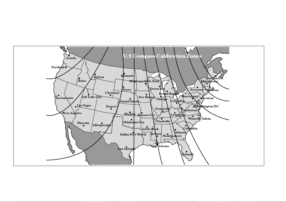
10
9
8
7
6
5
4
3
11
12
13
000134

GAS STATION REFERENCE
Fuel:
T 2.5-liter non-turbo models
Use only unleaded gasoline with an octane rating of 87 AKI or
higher.
T 2.5-liter turbo models and 3.0-liter models
Use premium unleaded gasoline with an octane rating of 91 AKI or
higher. For temporary purposes if premium unleaded gasoline is
not available, you may use regular unleaded gasoline with an oc-
tane rating of 87 AKI or higher. For optimum engine performance
and driveability, it is required (for 2.5-liter turbo models), and rec-
ommended (for 3.0-liter models) that you use premium grade un-
leaded gasoline.
Fuel octane rating
This octane rating is the average of the Research Octane and Mo-
tor Octane numbers and is commonly referred to as the Anti Knock
Index (AKI). Refer to “Fuel” section in this manual.
Fuel capacity:
16.9 US gal (64 liters, 14.1 Imp gal)
Engine oil:
Use only API classification SM with the words “ENERGY CON-
SERVING” and the ILSAC certification mark (starburst mark) dis-
played on the container.
Engine oil capacity:
2.5-liter models: 4.2 US qt (4.0 liters, 3.5 Imp qt)
3.0-liter models: 5.8 US qt (5.5 liters, 4.8 Imp qt)
Cold tire pressure:
Tire size P205/50R17 88V 215/45ZR17 P225/55R17 95V
Wheel size 17 x 7 JJ
Pressure Front 33 psi (230 kPa, 2.3 kgf/cm
2
) 35 psi (240 kPa, 2.4 kgf/cm
2
) 32 psi (220 kPa, 2.2 kgf/cm
2
)
Rear 32 psi (220 kPa, 2.2 kgf/cm
2
) 33 psi (230 kPa, 2.3 kgf/cm
2
) 30 psi (210 kPa, 2.1 kgf/cm
2
)
Rear at trailer
towing
– 32 psi (220 kPa, 2.2 kgf/cm
2
)
Temporary
spare tire
Size T135/80R16 T135/70D17 T155/70D17
Pressure 60 psi (420 kPa, 4.2 kgf/cm
2
)