1
2
3
4
5
6
7
8
9
10
Owner’s Manual_USA_M6740B_en
Pictorial index
Search by illustration
For safety
and security
Make sure to read through them
(Main topics: Child seat, theft deterrent system)
Electric Vehicle
system
Reading charging-related information
(Main topics: Electric Vehicle system, charging methods)
Vehicle status
information and
indicators
Reading driving-related information
(Main topics: Meters, multi-information display)
Before driving
Opening and closing the doors and windows,
adjustment before driving
(Main topics: Keys, doors, seats)
Driving
Operations and advice which are necessary for driving
(Main topics: Starting Electric Vehicle system, driving
support systems)
Interior features
Usage of the interior features
(Main topics: Air conditioner, storage features)
Maintenance
and care
Caring for your vehicle and maintenance
procedures
(Main topics: Interior and exterior, light bulbs)
When trouble
arises
What to do in case of malfunction and emergency
(Main topics: 12-volt battery discharge, flat tire)
Vehicle
specifications
Vehicle specifications, customizable features
(Main topics: Fluids, tire inflation pressure)
For owners
Reporting safety defects for U.S. owners, and seat
belt, SRS airbag and headlight aim instructions for
Canadian owners
Index
Search by symptom
Search alphabetically
SOLTERRA_OM_USA_A6740BE.book 1 ページ 2025年5月23日 金曜日 午後1時18分

2
Owner’s Manual_USA_M6740B_en
TABLE OF CONTENTS
For your information...................
8
Reading this manual ................14
How to search..........................15
Pictorial index ..........................16
1-1. For safe use
Before driving...................
26
For safe driving ................27
Seat belts .........................29
SRS airbags.....................33
Front passenger occupant
classification system ......
41
1-2. Child safety
Riding with children..........
46
Child restraint systems.....47
1-3. Emergency assistance
SubaruConnect ................
61
1-4. Theft deterrent system
Immobilizer system ..........
65
Alarm................................66
2-1. Electric vehicle system
Electric Vehicle system fea-
tures ...............................
70
Electric Vehicle system pre-
cautions ..........................
74
Battery Electric Vehicle driv-
ing tips ............................
79
Driving range....................81
2-2. Charging
Charging equipment.........
83
Locking and unlocking the
AC charging connector...
85
Charging methods............88
Charging tips ....................90
Things to know before
charging..........................
92
How to use AC charging...95
How to use DC charging 100
Using the charging schedule
function........................
106
Using Battery Precondition-
ing................................
113
Using My Room Mode... 117
When charging cannot be
carried out ...................
120
Plug & Charge system... 132
How to use Plug & Charge
system .........................
132
When Plug & Charge system
cannot be used normally
....................................
134
1
For safety and security
2
Electric Vehicle system
SOLTERRA_OM_USA_A6740BE.book 2 ページ 2025年5月23日 金曜日 午後1時18分
3
TABLE OF CONTENTS
Owner’s Manual_USA_M6740B_en
1
2
3
4
5
6
7
8
9
10
3-1. Instrument cluster
Warning lights and indicators
....................................
138
Gauges and meters ...... 142
Multi-information display 145
Displayed content ......... 147
Electricity consumption . 151
4-1. Key information
Keys ..............................
154
Digital key ..................... 157
4-2. Opening, closing and lock-
ing the doors
Side doors.....................
159
Back door...................... 164
Smart key system ......... 177
4-3. Adjusting the seats
Front seats ....................
183
Rear seats..................... 184
Head restraints.............. 186
4-4. Adjusting the steering
wheel and mirrors
Steering wheel ..............
190
Inside rear view mirror .. 191
Digital inner mirror......... 192
Outside rear view mirrors
....................................
200
4-5. Opening, closing the win-
dows
Power windows .............
204
4-6. Favorite settings
Driving position memory
207
My Settings.................... 210
5-1. Before driving
Driving the vehicle.........
215
Cargo and luggage........ 222
Vehicle load limits.......... 227
Trailer towing................. 228
Dinghy towing................ 228
5-2. Driving procedures
Power (ignition) switch ..
229
Shift position.................. 233
Turn signal lever............ 240
Parking brake ................ 241
Brake Hold..................... 245
5-3. Operating the lights and
wipers
Headlight switch ............
247
AHB (Automatic High Beam)
....................................
249
Windshield wipers and
washer.........................
253
Headlight cleaner switch256
3
Vehicle status
information and
indicators
4
Before driving
5
Driving
SOLTERRA_OM_USA_A6740BE.book 3 ページ 2025年5月23日 金曜日 午後1時18分

4
TABLE OF CONTENTS
Owner’s Manual_USA_M6740B_en
5-4. Using the driving support
systems
SUBARU Safety Sense/Traf-
fic Jam Assist software
update .........................
257
SUBARU Safety Sense. 259
Driver monitor ............... 267
PCS (Pre-Collision System)
....................................
270
LTA (Lane Tracing Assist)
....................................
282
LCA (Lane Change Assist)
....................................
287
LDA (Lane Departure Alert)
....................................
290
PDA (Proactive driving
assist)..........................
295
FCTA (Front Cross Traffic
Alert)............................
301
RSA (Road Sign Assist) 303
Dynamic radar cruise control
....................................
306
Cruise control................ 317
Emergency Driving Stop Sys-
tem ..............................
321
Traffic Jam Assist .......... 324
BSM (Blind Spot Monitor)
....................................
330
Safe Exit Assist ............. 335
SUBARU Parking Assist 340
RCTA (Rear Cross Traffic
Alert) function ..............
351
RCD (Rear Camera Detec-
tion) .............................
356
PKSB (Parking Support
Brake)..........................
360
Parking Support Brake func-
tion (static objects front and
rear of the vehicle/static
objects around the vehicle)
....................................
365
Parking Support Brake func-
tion (moving vehicles rear of
the vehicle) ..................
370
Parking Support Brake func-
tion (pedestrians rear of the
vehicle) ........................
371
Advanced Park .............. 373
Multi-terrain Monitor ...... 401
Drive mode select switch470
Snow mode ................... 471
X-MODE........................ 471
Driving assist systems... 476
5-5. Driving tips
Winter driving tips..........
482
Utility vehicle precautions
....................................
485
SOLTERRA_OM_USA_A6740BE.book 4 ページ 2025年5月23日 金曜日 午後1時18分
5
TABLE OF CONTENTS
Owner’s Manual_USA_M6740B_en
1
2
3
4
5
6
7
8
9
10
6-1. Using the air conditioning
system and defogger
ALL AUTO (ECO) control
....................................
490
Automatic air conditioning
system.........................
492
Remote Air Conditioning Sys-
tem ..............................
501
Heated steering wheel/seat
heaters/seat ventila-
tors/radiant heaters ..... 503
6-2. Using the interior lights
Interior lights list ............
507
6-3. Using the storage features
List of storage features .
510
Luggage compartment fea-
tures ............................
513
6-4. Using the other interior fea-
tures
Electronic sunshade......
517
Other interior features ... 518
Power outlet (1500 W) .. 530
When the power outlet (1500
W) cannot be used properly
....................................
536
Garage door opener...... 538
7-1. Maintenance and care
Cleaning and protecting the
vehicle exterior ............
548
Cleaning and protecting the
vehicle interior .............
551
7-2. Maintenance
Maintenance requirements
....................................
555
General maintenance.... 556
7-3. Do-it-yourself maintenance
Do-it-yourself service precau-
tions.............................
559
Hood.............................. 561
Positioning a floor jack .. 563
Motor compartment ....... 564
Tires .............................. 571
Replacing the tire .......... 583
Tire inflation pressure.... 588
Wheels .......................... 590
Air conditioning filter...... 592
Electronic key battery .... 594
Checking and replacing fuses
....................................
596
Headlight aim ................ 598
Light bulbs..................... 599
6
Interior features
7
Maintenance and care
SOLTERRA_OM_USA_A6740BE.book 5 ページ 2025年5月23日 金曜日 午後1時18分
6
TABLE OF CONTENTS
Owner’s Manual_USA_M6740B_en
8-1. Essential information
Emergency flashers ......
602
If your vehicle has to be
stopped in an emergency
....................................
602
If the vehicle is submerged or
water on the road is rising
....................................
603
8-2. Steps to take in an emer-
gency
If your vehicle needs to be
towed........................... 605
If you think something is
wrong ..........................
609
If a warning light turns on or a
warning buzzer sounds
611
If a warning message is dis-
played..........................
621
If you have a flat tire...... 628
If the EV system will not start
....................................
640
If you lose your keys ..... 641
If the electronic key does not
operate properly ..........
642
If the 12-volt battery is dis-
charged .......................
644
If your vehicle overheats648
If the vehicle becomes stuck
....................................
650
9-1. Specifications
Maintenance data..........
654
Tire information ............. 662
9-2. Customization
Customizable features...
671
9-3. Initialization
Items to initialize............
686
9-4. Free/open source software
Free/open source software
information...................
687
10-1.For owners
Reporting safety defects for
U.S. owners.................
690
Reporting safety defects for
Canadian owners ........
690
Seat belt instructions for
Canadian owners (in
French) ........................
691
SRS airbag instructions for
Canadian owners (in
French) ........................ 692
Headlight aim instructions for
Canadian owners (in
French) ........................
698
8
When trouble arises
9
Vehicle specifications
10
For owners
SOLTERRA_OM_USA_A6740BE.book 6 ページ 2025年5月23日 金曜日 午後1時18分
7
TABLE OF CONTENTS
Owner’s Manual_USA_M6740B_en
1
2
3
4
5
6
7
8
9
10
What to do if... (Troubleshoot-
ing) ..............................
702
Alphabetical Index......... 708
Index
SOLTERRA_OM_USA_A6740BE.book 7 ページ 2025年5月23日 金曜日 午後1時18分
8
Owner’s Manual_USA_M6740B_en
Please note that this manual
applies to all models and
explains all equipment, including
options. Therefore, you may find
explanations for equipment not
installed on your vehicle and the
illustrations used may differ from
your vehicle.
All specifications provided in this
manual are current at the time of
printing. Over time, your vehicle
may receive updates that modify
the vehicle and make material in
this manual incomplete and/or
inaccurate. Because of SUB-
ARU’s interest in continual prod-
uct improvement, SUBARU
reserves the right to make
changes to this manual at any
time without notice.
If SUBARU chooses to update
the manual, updated versions
can be viewed by selecting your
vehicle by model and year at the
following URL or on your mobile
device if you have access to the
SUBARU app.
SUBARU of America
https://www.subaru.com/
owners/vehicle-resources.html
SUBARU Canada English
https://www.subaru.ca/manuals
SUBARU Canada French
https://www.subaru.ca/manuals
Installing electronic devices and
radios increases the risk of
cyber attacks through the
installed parts, which may lead
to unexpected accidents and
leakage of personal informa-
tion. SUBARU does not make
any guarantees for problems
caused by installing non-genu-
ine SUBARU products.
A wide variety of non-genuine
spare parts and accessories for
SUBARU vehicles are currently
available in the market. You
should know that SUBARU does
not warrant these products and
is not responsible for their per-
formance, repair, or replace-
ment, or for any damage they
may cause to, or adverse effect
they may have on, your SUB-
ARU vehicle.
For your information
Main Owner’s Manual
Cyber Attack Risk
Accessories, spare parts
and modification of your
SUBARU
SOLTERRA_OM_USA_A6740BE.book 8 ページ 2025年5月23日 金曜日 午後1時18分
9
Owner’s Manual_USA_M6740B_en
This vehicle should not be modi-
fied with non-genuine SUBARU
products. Modification with non-
genuine SUBARU products
could affect its performance,
safety or durability, and may
even violate governmental regu-
lations. In addition, damage or
performance problems resulting
from the modification may not
be covered under warranty.
Also, remodeling like this will
have an effect on advanced
safety equipment such as SUB-
ARU Safety Sense and there is
a danger that it will not work
properly or the danger that it
may work in situations where it
should not be working.
The installation of a mobile two-
way radio system in your vehicle
could affect electronic systems
such as:
EV system
SUBARU Safety Sense
Anti-lock brake system
SRS airbag system
Seat belt pretensioner system
Be sure to check with your SUB-
ARU dealer for precautionary
measures or special instructions
regarding installation of a mobile
two-way radio system.
High voltage parts and cables
on the battery electric vehicles
emit approximately the same
amount of electromagnetic
waves as the conventional gas-
oline powered vehicles or home
electronic appliances despite of
their electromagnetic shielding.
Unwanted noise may occur in
the reception of the mobile two-
way radio.
The vehicle is equipped with
sophisticated computers that will
record certain data, such as:
• Electric motor speed (traction
motor speed)
• Accelerator status
• Brake status
• Vehicle speed
• Operation status of the driving
assist systems
• Images from the cameras
Your vehicle is equipped with
cameras. Contact your SUB-
ARU dealer for the location of
recording cameras.
The recorded data varies
according to the vehicle grade
level and options with which it is
equipped.
These computers do not record
conversations or sounds, and
only record images outside of
the vehicle in certain situations.
Installation of a mobile
two-way radio system
Vehicle data recording
SOLTERRA_OM_USA_A6740BE.book 9 ページ 2025年5月23日 金曜日 午後1時18分
10
Owner’s Manual_USA_M6740B_en
Data Transmission
Your vehicle may transmit the data
recorded in these computers to
SUBARU without requiring notifica-
tion to you.
Data usage
SUBARU may use the data
recorded in this computer to diag-
nose malfunctions, conduct
research and development, and
improve quality.
SUBARU will not disclose the
recorded data to a third party
except:
• With the consent of the vehicle
owner or with the consent of the
lessee if the vehicle is leased
• In response to an official request
by the police, a court of law or a
government agency
• For use by SUBARU in a lawsuit
• For research purposes where the
data is not tied to a specific vehi-
cle or vehicle owner
Recorded image information
can be erased by your SUB-
ARU dealer.
The image recording function can
be disabled. However, if the func-
tion is disabled, data from when the
system operates will not be avail-
able.
To learn more about the vehi-
cle data collected, used and
shared by SubaruConnect,
please visit www.toyota.com/
privacyvts/.
If your SUBARU has SubaruCo-
nnect and if you have sub-
scribed to those services,
please refer to the SubaruCon-
nect Telematics Subscription
Service Agreement for informa-
tion on data collected and its
usage.
To learn more about the vehi-
cle data collected, used and
shared by SubaruConnect,
please visit www.toyota.com/
privacyvts/.
The content on the website also
applies to the SubaruConnect.
The Magnuson-Moss Warranty
Act, 15 U.S.C. s.2301 et seq.,
makes it illegal for motor vehicle
manufacturers to void a motor
vehicle warranty or deny war-
ranty coverage solely because
an aftermarket or recycled part
has been used to repair the
vehicle or someone other than
the authorized service provider
performed service on the vehi-
cle. This provision does not
apply to a new motor vehicle
purchased solely for commercial
Usage of data collected
through SubaruConnect
(U.S.mainland only)
Statement on Warranty
Coverage for Aftermarket
and Recycled Parts (For
U.S. Owners)
SOLTERRA_OM_USA_A6740BE.book 10 ページ 2025年5月23日 金曜日 午後1時18分

11
Owner’s Manual_USA_M6740B_en
or industrial use.
Under federal law, a manufac-
turer may deny warranty cover-
age and charge for repairs to a
vehicle if it is discovered that an
aftermarket or recycled part
installed on the vehicle is defec-
tive or was installed incorrectly
and caused damage to another
part of the vehicle otherwise
covered under warranty. The
Federal Trade Commission
requires that a manufacturer
demonstrate that an aftermar-
ket or recycled part or service
performed by a person other
than an authorized service pro-
vider caused damage to another
part of the vehicle otherwise
covered under warranty before
denying warranty coverage.
Additionally, federal law allows a
manufacturer to void a motor
vehicle warranty or deny war-
ranty coverage if the manufac-
turer provides the article or
service to consumers free of
charge under the warranty or
the manufacturer has secured a
waiver from the Federal Trade
Commission.
This vehicle is equipped with an
event data recorder (EDR). The
main purpose of an EDR is to
record, in certain crash or near
crash-like situations, such as an
air bag deployment or hitting a
road obstacle, data that will
assist in understanding how a
vehicle’s systems performed.
The EDR is designed to record
data related to vehicle dynamics
and safety systems for a short
period of time, typically 30 sec-
onds or less.
The EDR in this vehicle is
designed to record such data
as:
• How various systems in your
vehicle were operating;
• Whether or not the driver and
passenger safety belts were
buckled/fastened;
• How far (if at all) the driver
was depressing the accelera-
tor and/or brake pedal; and,
• How fast the vehicle was trav-
eling.
These data can help provide a
better understanding of the cir-
cumstances in which crashes
and injuries occur.
NOTE: EDR data are recorded
by your vehicle only if a non-triv-
ial crash situation occurs; no
data are recorded by the EDR
under normal driving conditions
and no personal data (e.g.
Event data recorder
SOLTERRA_OM_USA_A6740BE.book 11 ページ 2025年5月23日 金曜日 午後1時18分
12
Owner’s Manual_USA_M6740B_en
name, gender, age, and crash
location) are recorded. How-
ever, other parties, such as law
enforcement, could combine the
EDR data with the type of per-
sonally identifying data rou-
tinely acquired during a crash
investigation.
To read data recorded by an
EDR, special equipment is
required, and access to the
vehicle or the EDR is needed. In
addition to the vehicle manufac-
turer, other parties, such as law
enforcement, that have the spe-
cial equipment, can read the
information if they have access
to the vehicle or the EDR.
Disclosure of the EDR data
SUBARU will not disclose the data
recorded in an EDR to a third party
except when:
• An agreement from the vehicle’s
owner (or the lessee for a leased
vehicle) is obtained
• In response to an official request
by the police, a court of law or a
government agency
• For use by SUBARU in a lawsuit
However, if necessary, SUBARU
may:
• Use the data for research on
vehicle safety performance
• Disclose the data to a third party
for research purposes without
disclosing information about the
specific vehicle or vehicle owner
The SRS airbag and seat belt
pretensioner devices in your
SUBARU contain explosive
chemicals. If the vehicle is
scrapped with the airbags and
seat belt pretensioners left as
they are, this may cause an
accident such as fire. Be sure to
have the systems of the SRS
airbag and seat belt preten-
sioner removed and disposed of
by a qualified service shop or by
your SUBARU dealer before
you scrap your vehicle.
Special handling may apply,
See www.dtsc.ca.gov/
hazardouswaste/perchlorate.
Your vehicle has components
that may contain perchlorate.
These components may include
the airbags, seat belt preten-
sioners, wireless remote control
batteries, and the batteries in
the tire pressure warning valve
(if equipped) and transmitters (if
equipped).
The word “QR Code” is regis-
tered trademark of DENSO
WAVE INCORPORATED in
Japan and other countries.
Scrapping of your SUBA-
RU
Perchlorate Material
“QR Code”
SOLTERRA_OM_USA_A6740BE.book 12 ページ 2025年5月23日 金曜日 午後1時18分
13
Owner’s Manual_USA_M6740B_en
High voltage components, such
as the power control unit, may
have labels attached indicating
care required.
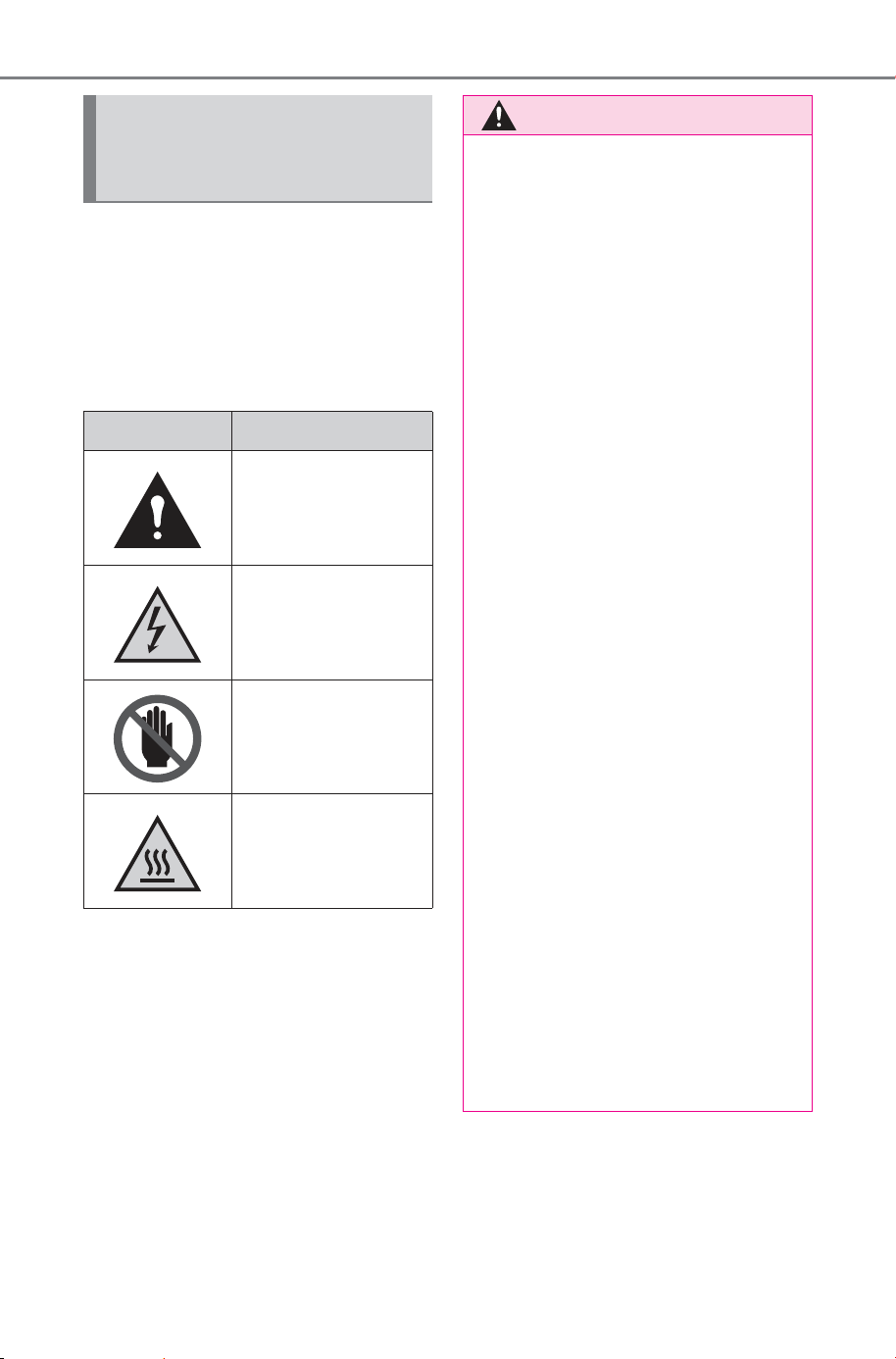
Each caution symbol indicates
the following:
Caution symbols attached
to the high voltage com-
ponents
Symbols Meanings
Indicates danger
Indicates high volt-
age part
Indicates not to
touch
Indicates high tem-
perature part
WARNING
■ General precautions while
driving
Driving under the influence: Never
drive your vehicle when under the
influence of alcohol or drugs that
have impaired your ability to oper-
ate your vehicle. Alcohol and cer-
tain drugs delay reaction time,
impair judgment and reduce coor-
dination, which could lead to an
accident that could result in death
or serious injury.
Defensive driving: Always drive
defensively. Anticipate mistakes
that other drivers or pedestrians
might make and be ready to avoid
accidents.
Driver distraction: Always give
your full attention to driving. Any-
thing that distracts the driver, such
as adjusting controls, talking on a
cellular phone or reading can
result in a collision with resulting
death or serious injury to you,
your occupants or others.
■ General precaution regarding
children’s safety
Never leave children unattended
in the vehicle, and never allow
children to have or use the key.
Children may be able to start the
vehicle or shift the vehicle into
neutral. There is also a danger
that children may injure them-
selves by playing with the side
windows, or other features of the
vehicle. In addition, heat build-up
or extremely cold temperatures
inside the vehicle can be fatal to
children.
SOLTERRA_OM_USA_A6740BE.book 13 ページ 2025年5月23日 金曜日 午後1時18分
14
Owner’s Manual_USA_M6740B_en
Reading this manual
Explains symbols used in
this manual
Symbols in this manual
Symbols Meanings
WARNING:
Explains something
that, if not obeyed,
could cause death or
serious injury to people.
NOTICE:
Explains something
that, if not obeyed,
could cause damage to
or a malfunction in the
vehicle or its equip-
ment.
Indicates operating or
working procedures.
Follow the steps in
numerical order.
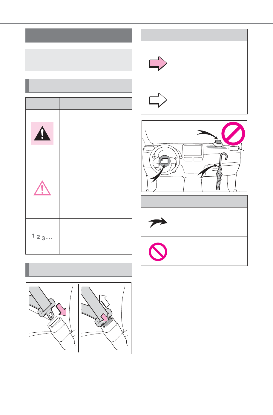
Symbols in illustrations
Symbols Meanings
Indicates the action
(pushing, turning, etc.)
used to operate
switches and other
devices.
Indicates the outcome
of an operation (e.g. a
lid opens).
Symbols Meanings
Indicates the compo-
nent or position being
explained.
Means Do not, Do not
do this, or Do not let
this happen.
SOLTERRA_OM_USA_A6740BE.book 14 ページ 2025年5月23日 金曜日 午後1時18分
15
Owner’s Manual_USA_M6740B_en
■ Searching by name
Alphabetical index: P.708
■ Searching by installation
position
Pictorial index: P. 16
■ Searching by symptom or
sound
What to do if... (Troubleshoot-
ing): P.702
■ Searching by title
Table of contents: P.2
How to search
SOLTERRA_OM_USA_A6740BE.book 15 ページ 2025年5月23日 金曜日 午後1時18分
16
Pictorial index
Owner’s Manual_USA_M6740B_en
Pictorial index
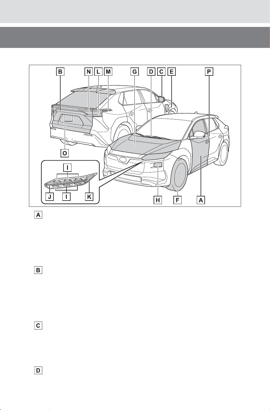
■Exterior
Side doors .......................................................................... P.159
Locking/unlocking ................................................................ P.159
Opening/closing the side windows....................................... P.204
Locking/unlocking by using the mechanical key .................. P.642
Warning messages .............................................................. P.621
Back door ........................................................................... P.164
Locking/unlocking ................................................................ P.165
Opening/closing the back door ............................................ P.166
Power back door .................................................................. P.166
Warning messages .............................................................. P.621
Outside rear view mirrors ................................................. P.200
Adjusting the mirror angle .................................................... P.200
Folding the mirrors ............................................................... P.201
Defogging the mirrors .......................................................... P.496
Windshield wipers.............................................................. P.253
Precautions against winter season ...................................... P.482
SOLTERRA_OM_USA_A6740BE.book 16 ページ 2025年5月23日 金曜日 午後1時18分
17
Pictorial index
Owner’s Manual_USA_M6740B_en
To prevent freezing (windshield wiper de-icer)..................... P.496
Precautions against car wash
(Rain-sensing windshield wipers) ........................................ P.549
Charging port ....................................................................... P.83
Charging method ................................................................... P.88
Tires..................................................................................... P.571
Tire size/inflation pressure ................................................... P.661
Winter tires/tire chain ........................................................... P.482
Checking/rotation/tire pressure warning system ..................P.571
Coping with flat tires............................................................. P.628
Hood.................................................................................... P.561
Opening ............................................................................... P.561
Coping with overheat ........................................................... P.648
Warning messages .............................................................. P.621
Headlights........................................................................... P.247
Parking lights/daytime running lights.............................. P.247
Turn signal lights ............................................................... P.240
Front side marker lights .................................................... P.247
Tail lights............................................................................. P.247
Turn signal lights ............................................................... P.240
Stop lights
Rear side marker lights ..................................................... P.247
Tail lights............................................................................. P.247
Back-up light
Shifting the shift position to R .............................................. P.233
License plate lights............................................................ P.247
Side turn signal lights ....................................................... P.240
Light bulbs of the exterior lights for driving
(Replacing method: P.599)
SOLTERRA_OM_USA_A6740BE.book 17 ページ 2025年5月23日 金曜日 午後1時18分
18
Pictorial index
Owner’s Manual_USA_M6740B_en
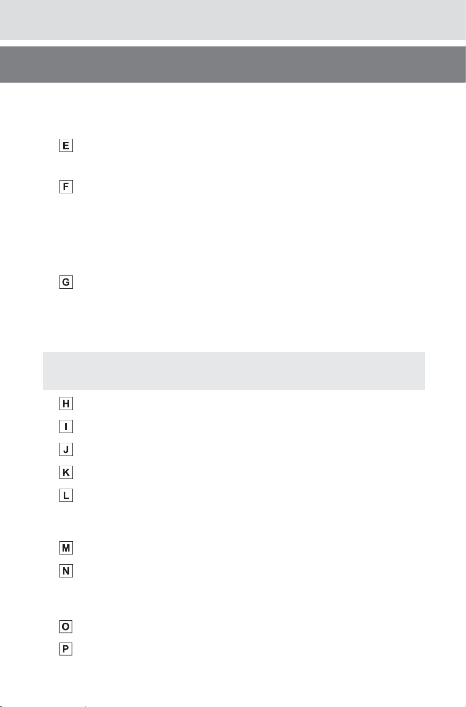
■Instrument panel
Power switch ...................................................................... P.229
Starting the EV system/changing the modes ............... P.229, 232
Emergency stop of the EV system....................................... P.602
When the EV system will not start ....................................... P.640
Warning messages .............................................................. P.621
Rotary shifter...................................................................... P.234
Changing the shift position................................................... P.234
Precautions against towing .................................................. P.605
Meters ................................................................................. P.142
Reading the meters/
adjusting the instrument panel light ............................. P.142, 145
Warning lights/indicator lights .............................................. P.138
When the warning lights come on........................................ P.611
Multi-information display .................................................. P.145
Display ................................................................................. P.145
When the warning messages are displayed ........................ P.621
SOLTERRA_OM_USA_A6740BE.book 18 ページ 2025年5月23日 金曜日 午後1時18分
19
Pictorial index
Owner’s Manual_USA_M6740B_en
Turn signal lever................................................................. P.240
Headlight switch ................................................................ P.247
Headlights/parking lights/tail lights/license plate lights/
daytime running lights .......................................................... P.247
Windshield wiper and washer switch............................... P.253
Usage................................................................................... P.253
Adding washer fluid.............................................................. P.570
Headlight cleaners ............................................................... P.256
Warning messages .............................................................. P.621
Emergency flasher switch................................................. P.602
Hood lock release lever..................................................... P.561
Tilt and telescopic steering lock release lever................ P.190
Adjustment ........................................................................... P.190
Air conditioning system .................................................... P.492
Usage................................................................................... P.492
Rear window defogger ......................................................... P.496
Multimedia system
*
*
: Refer to “MULTIMEDIA OWNER’S MANUAL”.
SOLTERRA_OM_USA_A6740BE.book 19 ページ 2025年5月23日 金曜日 午後1時18分
20
Pictorial index
Owner’s Manual_USA_M6740B_en
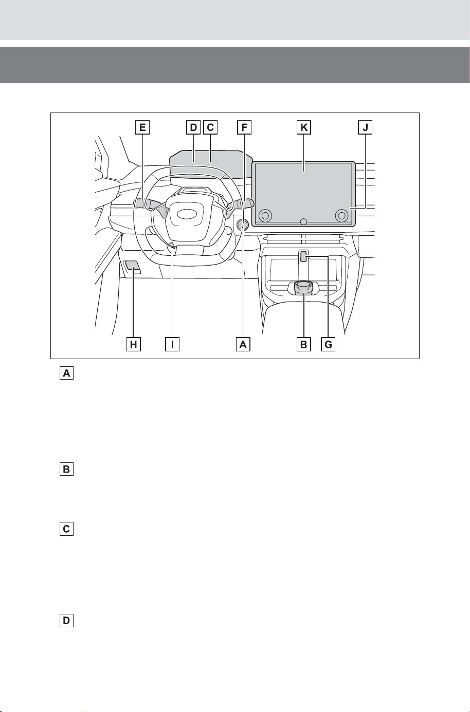
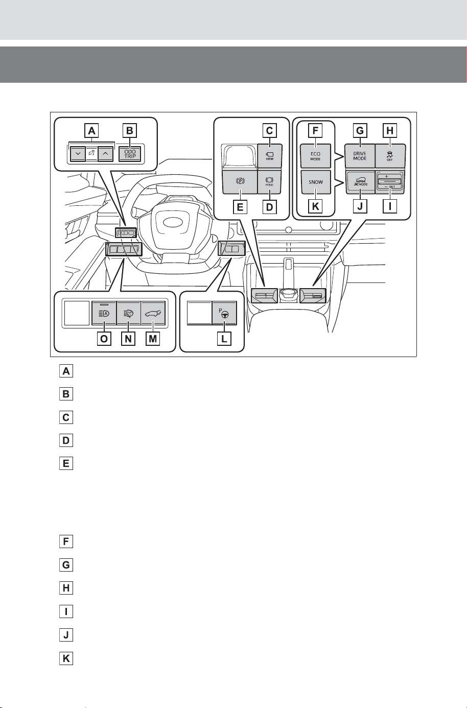
■Switches
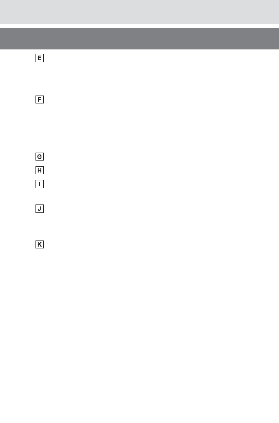
Instrument panel light control switches ..........................P.145
“ODO TRIP” switch............................................................ P.144
Camera switch
*1, 2
.............................................................. P.406
Brake hold switch .............................................................. P.245
Parking brake switch ......................................................... P.241
Applying/releasing................................................................ P.241
Precautions against winter season ...................................... P.483
Warning buzzer/message ............................................ P.243, 621
“ECO MODE” switch
*1
....................................................... P.238
Drive mode select switch
*1
............................................... P.470
VSC (Vehicle Stability Control) off switch ....................... P.478
Grip control switch
*1
.......................................................... P.471
“X-MODE” switch
*1
............................................................ P.471
“SNOW” mode switch
*1
..................................................... P.471
SOLTERRA_OM_USA_A6740BE.book 20 ページ 2025年5月23日 金曜日 午後1時18分
21
Pictorial index
Owner’s Manual_USA_M6740B_en
Advanced Park (parking assist system) main switch
*1
..P.373
Power back door switch.................................................... P.166
Headlight cleaner switch................................................... P.256
Automatic High Beam switch ........................................... P.249
*1
:If equipped
*2
:Vehicles with panoramic view monitor, refer to “MULTIMEDIA OWNER’S
MANUAL”.
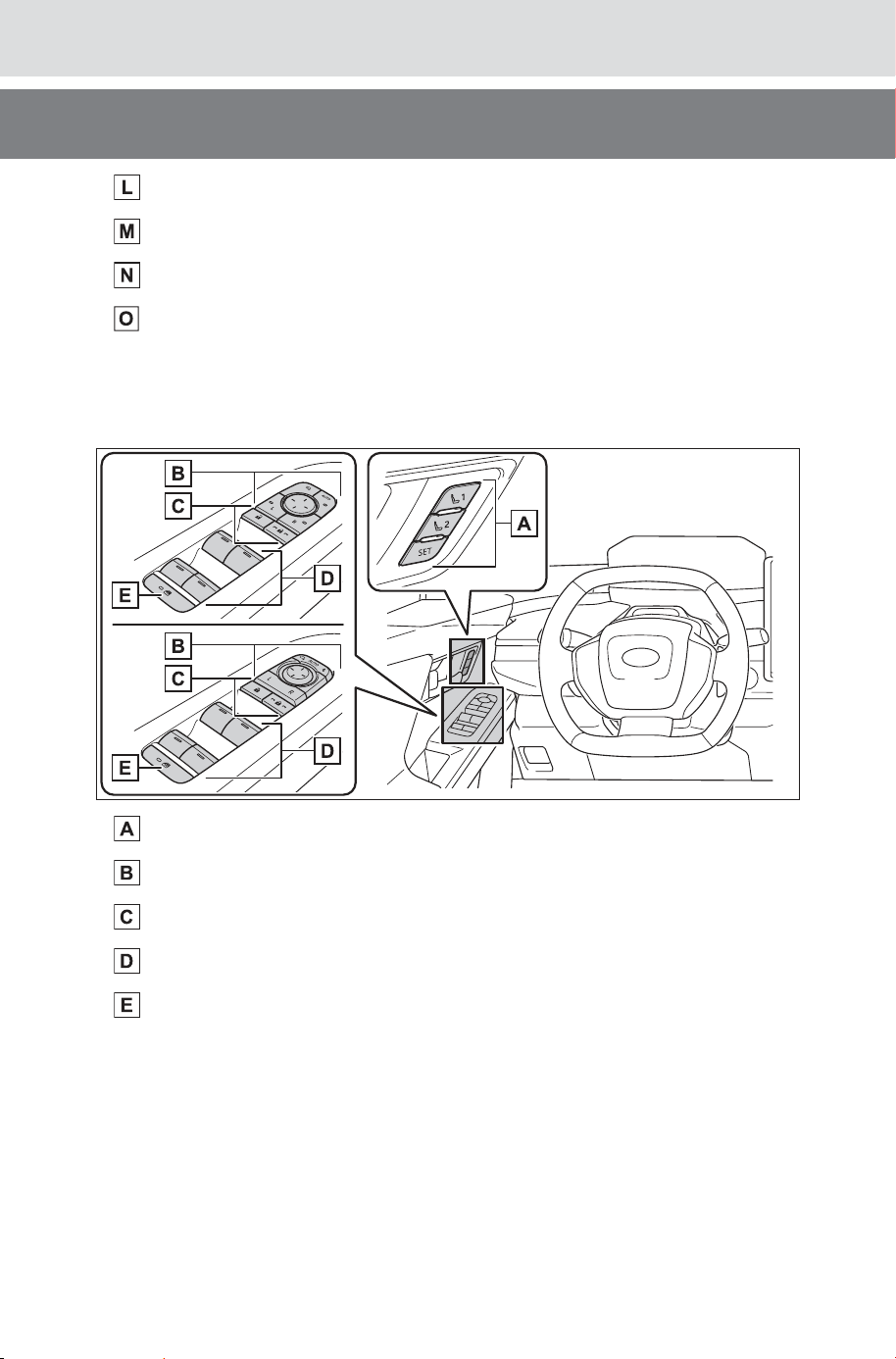
Position memory switches
*
............................................... P.207
Outside rear view mirror switches ................................... P.200
Door lock switches ............................................................ P.162
Power window switches.................................................... P.204
Window lock switch........................................................... P.206
*
: If equipped
SOLTERRA_OM_USA_A6740BE.book 21 ページ 2025年5月23日 金曜日 午後1時18分
22
Pictorial index
Owner’s Manual_USA_M6740B_en
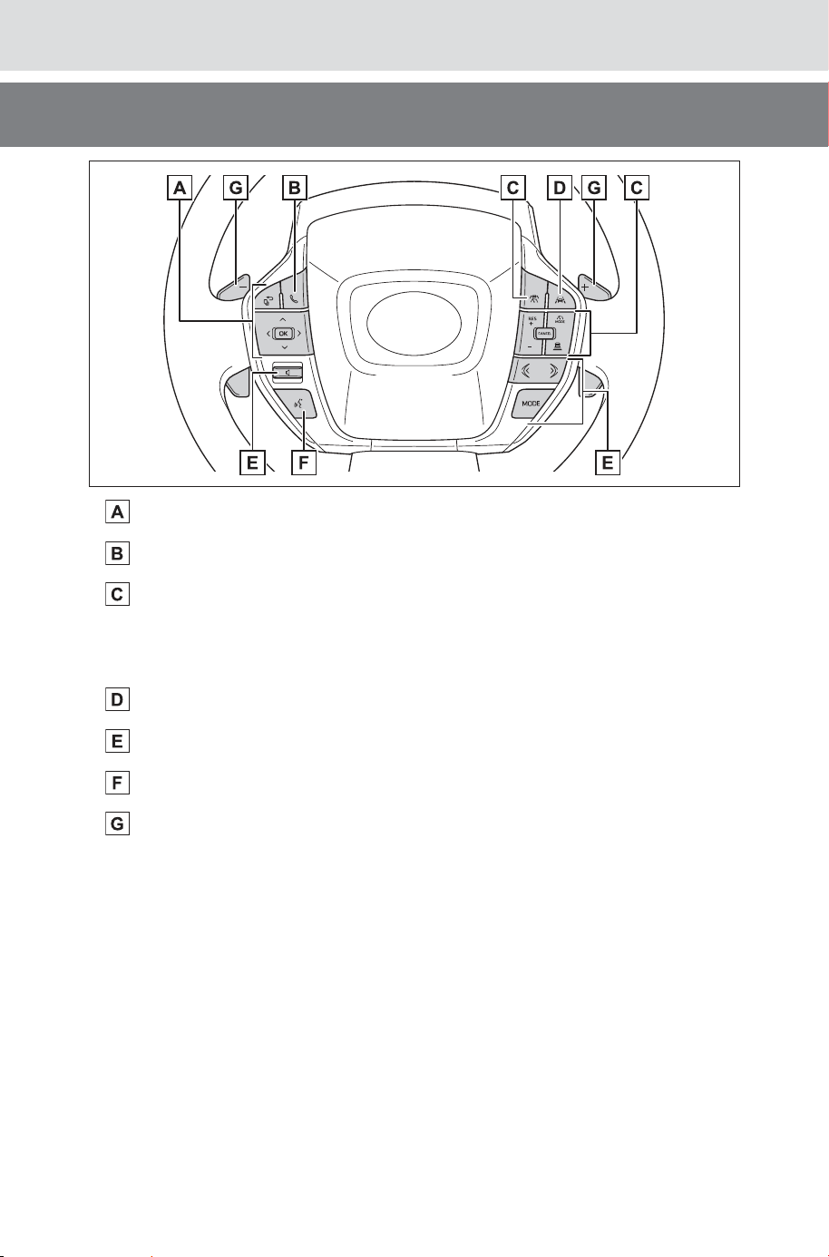
Meter control switches ...................................................... P.147
TEL switch
*
......................................................................... P.147
Cruise control switch
Dynamic radar cruise control ............................................... P.306
Cruise control....................................................................... P.317
LTA (Lane Tracing Assist) switch ..................................... P.282
Audio remote control switches
*
Talk switch
*
Paddle switches ................................................................. P.239
*
: Refer to “MULTIMEDIA OWNER’S MANUAL”.
SOLTERRA_OM_USA_A6740BE.book 22 ページ 2025年5月23日 金曜日 午後1時18分
23
Pictorial index
Owner’s Manual_USA_M6740B_en
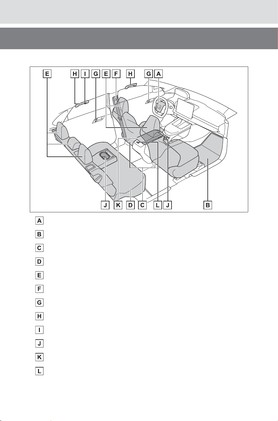
■Interior
SRS airbags.......................................................................... P.33
Floor mats............................................................................. P.26
Front seats.......................................................................... P.183
Rear seats........................................................................... P.184
Head restraints................................................................... P.186
Seat belts .............................................................................. P.29
Inside lock buttons ............................................................ P.162
Assist grips ........................................................................ P.530
Coat hooks ......................................................................... P.529
Cup holders ........................................................................ P.511
Console box ....................................................................... P.511
Rear seat heater switches
*
................................................ P.504
*
: If equipped
SOLTERRA_OM_USA_A6740BE.book 23 ページ 2025年5月23日 金曜日 午後1時18分
24
Pictorial index
Owner’s Manual_USA_M6740B_en
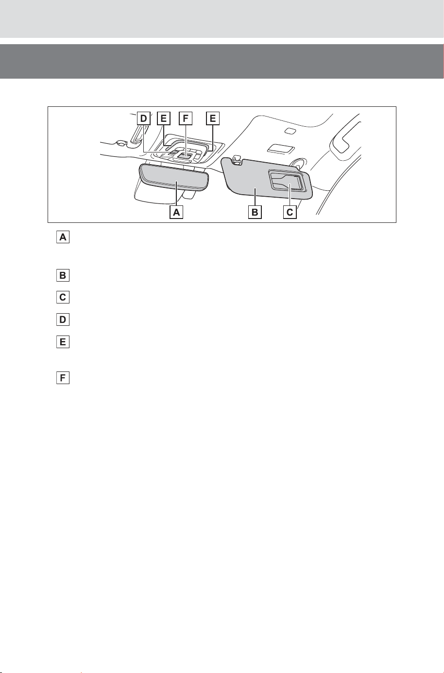
■Ceiling
Inside rear view mirror
*1
.................................................... P.191
Digital inner mirror
*1
.......................................................... P.192
Sun visors........................................................................... P.518
Vanity mirrors..................................................................... P.518
Electronic sunshade switches
*1
....................................... P.517
Interior lights
*2
................................................................... P.508
Personal lights ................................................................... P.509
“SOS” button........................................................................ P.61
*1
:If equipped
*2
:The illustration shows the front, but they are also equipped in the rear.
SOLTERRA_OM_USA_A6740BE.book 24 ページ 2025年5月23日 金曜日 午後1時18分

25
Owner’s Manual_USA_M6740B_en
1
1
For safety and security
For safety and security
1-1. For safe use
Before driving.................
26
For safe driving ..............27
Seat belts .......................29
SRS airbags...................33
Front passenger occupant
classification system ....
41
1-2. Child safety
Riding with children........
46
Child restraint systems...47
1-3. Emergency assistance
SubaruConnect ..............61
1-4. Theft deterrent system
Immobilizer system ........65
Alarm..............................66
SOLTERRA_OM_USA_A6740BE.book 25 ページ 2025年5月23日 金曜日 午後1時18分
26
1-1. For safe use
Owner’s Manual_USA_M6740B_en
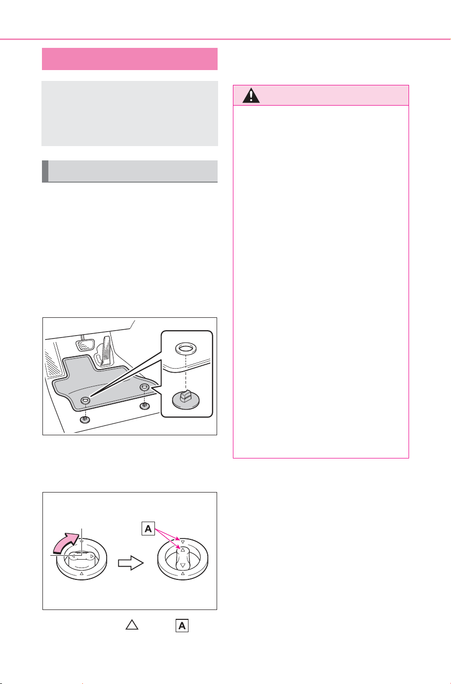
1-1.Fo r safe use
Use only floor mats designed
specifically for vehicles of the
same model and model year as
your vehicle. Fix them securely
in place onto the carpet.
1 Insert the retaining hooks
(clips) into the floor mat eye-
lets.
2 Turn the upper knob of each
retaining hook (clip) to secure
the floor mats in place.
Always align the marks .
The shape of the retaining hooks
(clips) may differ from that shown in
the illustration.
Before driving
Observe the following
before starting off in the
vehicle to ensure safety of
driving.
Installing floor mats
WARNING
Observe the following precau-
tions.
Failure to do so may cause the
driver’s floor mat to slip, possibly
interfering with the pedals while
driving. An unexpectedly high
speed may result or it may
become difficult to stop the vehi-
cle. This could lead to an acci-
dent, resulting in death or serious
injury.
■ When installing the driver’s
floor mat
● Do not use floor mats designed
for other models or different
model year vehicles, even if
they are SUBARU Genuine
floor mats.
● Only use floor mats designed
for the driver’s seat.
● Always install the floor mat
securely using the retaining
hooks (clips) provided.
● Do not use two or more floor
mats on top of each other.
● Do not place the floor mat bot-
tom-side up or upside-down.
SOLTERRA_OM_USA_A6740BE.book 26 ページ 2025年5月23日 金曜日 午後1時18分
27
1-1. For safe use
Owner’s Manual_USA_M6740B_en
1
For safety and security
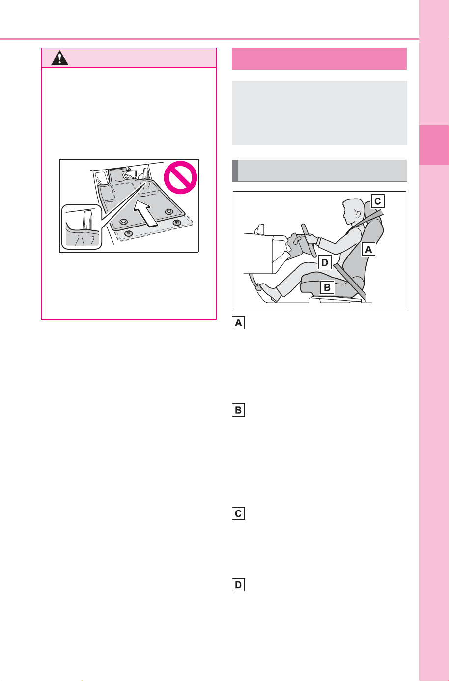
Adjust the angle of the seat-
back so that you are sitting
straight up and so that you do
not have to lean forward to
steer. (P.183)
Adjust the seat so that you
can depress the pedals fully
and so that your arms bend
slightly at the elbow when
gripping the steering wheel.
(P.183)
Lock the head restraint in
place with the center of the
head restraint closest to the
top of your ears. (P.186)
Wear the seat belt correctly.
(P.30)
WARNING
■ Before driving
● Check that the floor mat is
securely fixed in the correct
place with all the provided
retaining hooks (clips). Be espe-
cially careful to perform this
check after cleaning the floor.
● With the EV system stopped
and the shift position in P, fully
depress each pedal to the floor
to make sure it does not inter-
fere with the floor mat.
For safe driving
For safe driving, adjust the
seat and mirror to an appro-
priate position before driv-
ing.
Correct driving posture
SOLTERRA_OM_USA_A6740BE.book 27 ページ 2025年5月23日 金曜日 午後1時18分
28
1-1. For safe use
Owner’s Manual_USA_M6740B_en
Make sure that all occupants are
wearing their seat belts before
driving the vehicle. (P. 3 0)
Use a child restraint system
appropriate for the child until the
child becomes large enough to
properly wear the vehicle’s seat
belt. (P. 47 )
Make sure that you can see the
rear of the vehicle clearly by
adjusting the inside rear view
mirror (if equipped), Digital inner
mirror (if equipped) and outside
rear view mirrors properly.
(P.191, 192, 200)
WARNING
Observe the following precau-
tions.
Failure to do so may result in
death or serious injury.
● Do not adjust the position of the
driver’s seat while driving.
Doing so could cause the driver
to lose control of the vehicle.
● Do not place a cushion between
the driver or passenger and the
seatback. A cushion may pre-
vent correct posture from being
achieved, and reduce the effec-
tiveness of the seat belt and
head restraint.
● Do not place anything under the
front seats.
Objects placed under the front
seats may become jammed in
the seat tracks and stop the
seat from locking in place. This
may lead to an accident and the
adjustment mechanism may
also be damaged.
● Always observe the legal speed
limit when driving on public
roads.
● When driving over long dis-
tances, take regular breaks
before you start to feel tired.
Also, if you feel tired or sleepy
while driving, do not force your-
self to continue driving and take
a break immediately.
Correct use of the seat
belts
Adjusting the mirrors
SOLTERRA_OM_USA_A6740BE.book 28 ページ 2025年5月23日 金曜日 午後1時18分
29
1-1. For safe use
Owner’s Manual_USA_M6740B_en
1
For safety and security
Seat belts
Make sure that all occu-
pants are wearing their seat
belts before driving the
vehicle.
WARNING
Observe the following precautions
to reduce the risk of injury in the
event of sudden braking, sudden
swerving or an accident.
Failure to do so may cause death
or serious injury.
■ Wearing a seat belt
● Ensure that all passengers wear
a seat belt.
● Always wear a seat belt prop-
erly.
● Each seat belt should be used
by one person only. Do not use
a seat belt for more than one
person at once, including chil-
dren.
● SUBARU recommends that chil-
dren be seated in the rear seat
and always use a seat belt
and/or an appropriate child
restraint system.
● To achieve a proper seating
position, do not recline the seat
more than necessary. The seat
belt is most effective when the
occupants are sitting up straight
and well back in the seats.
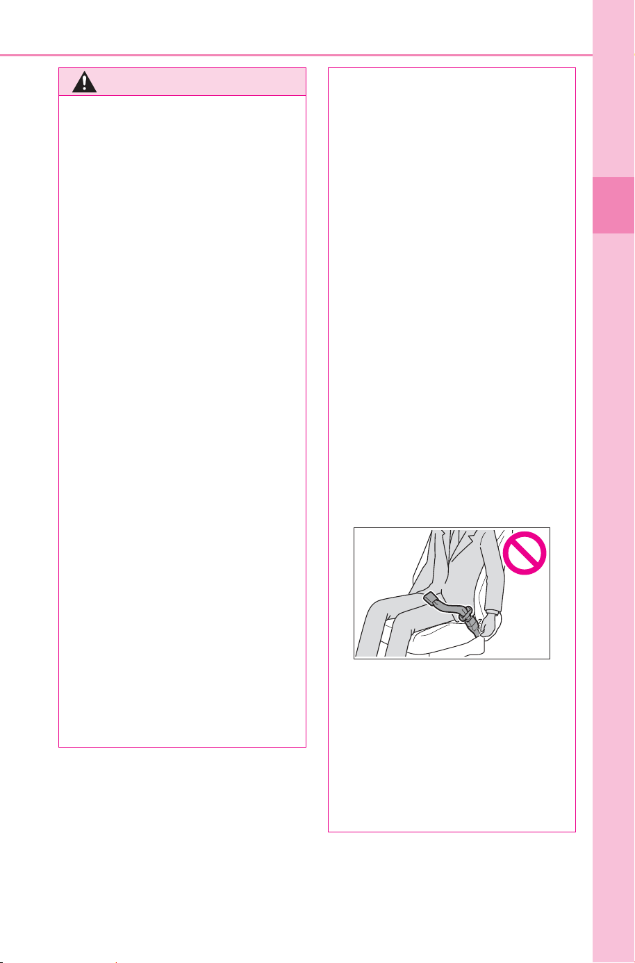
● Do not wear the shoulder belt
under your arm.
● Always wear your seat belt low
and snug across your hips.
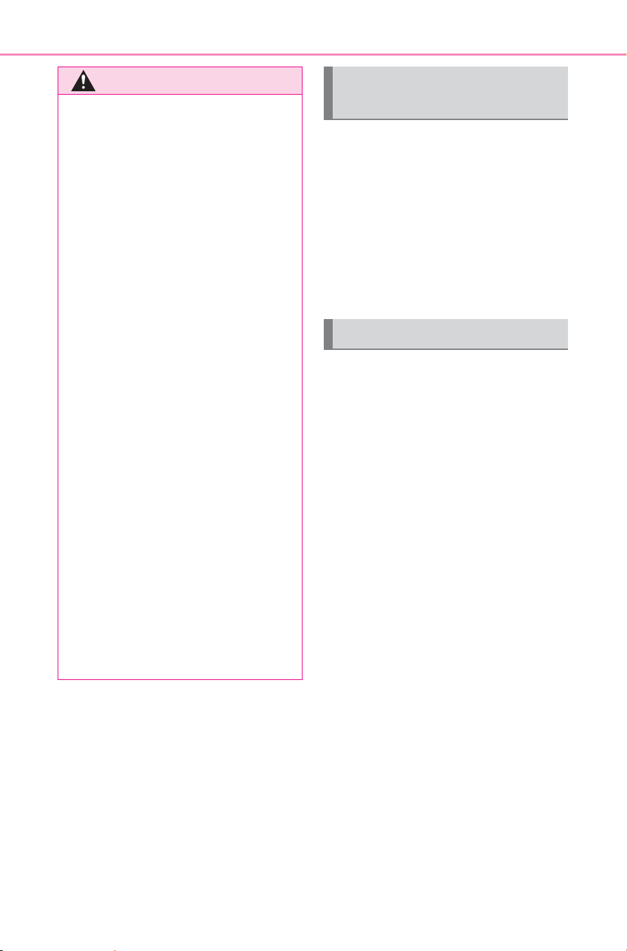
■ Pregnant women
Obtain medical advice and wear
the seat belt in the proper way.
(P.30)
Women who are pregnant should
position the lap belt as low as
possible over the hips in the same
manner as other occupants,
extending the shoulder belt com-
pletely over the shoulder and
avoiding belt contact with the
rounding of the abdominal area.
If the seat belt is not worn prop-
erly, not only the pregnant
woman, but also the fetus could
suffer death or serious injury as a
result of sudden braking or a colli-
sion.
■ People suffering illness
Obtain medical advice and wear
the seat belt in the proper way.
(P.30)
■ When children are in the vehi-
cle
P.5 5
■ Seat belt damage and wear
● Do not damage the seat belts
by allowing the belt, plate, or
buckle to be jammed in the
door.
SOLTERRA_OM_USA_A6740BE.book 29 ページ 2025年5月23日 金曜日 午後1時18分
30
1-1. For safe use
Owner’s Manual_USA_M6740B_en
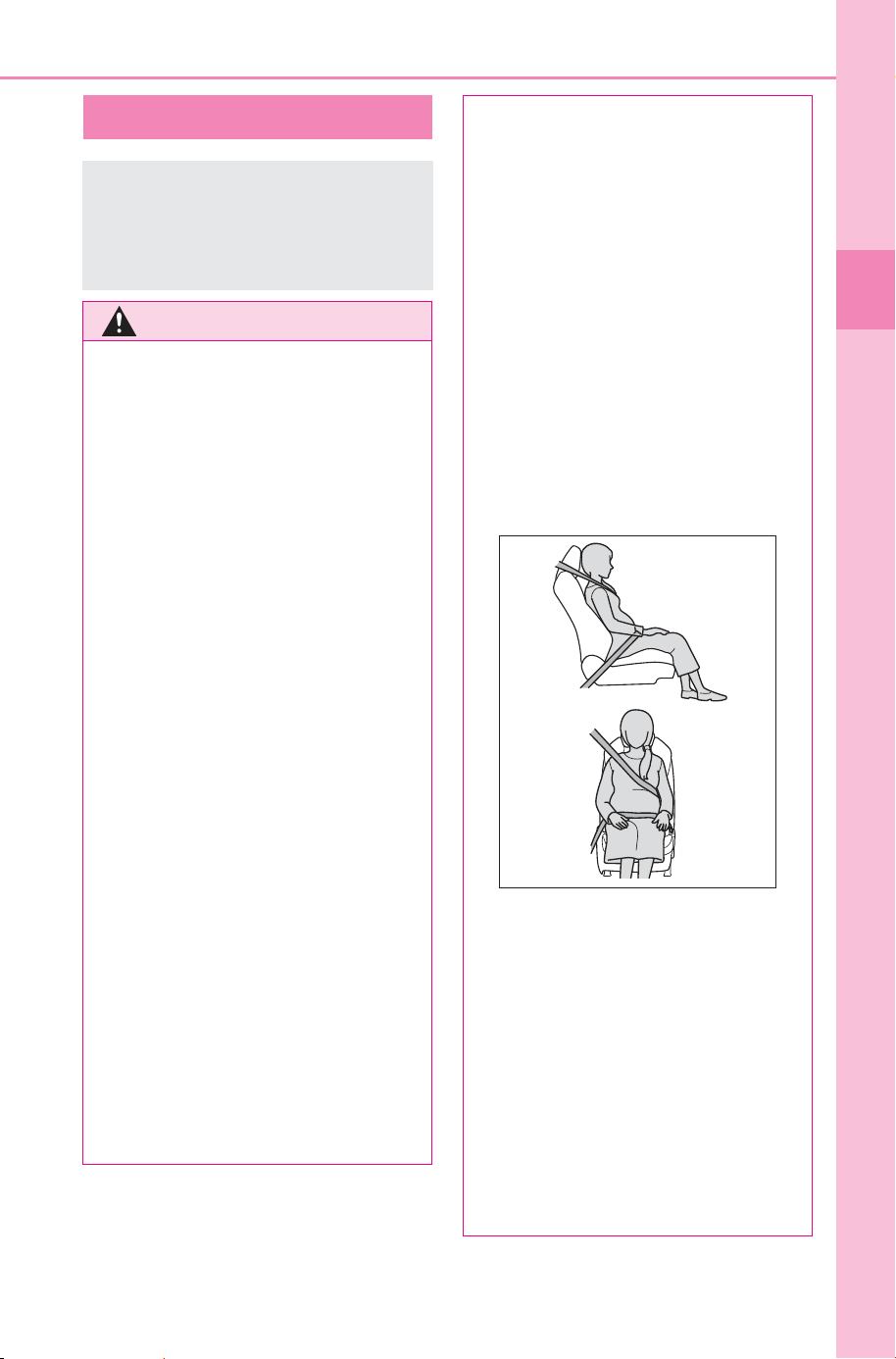
Extend the shoulder belt so
that it comes fully over the
shoulder, but does not come
into contact with the neck or
slide off the shoulder.
Position the lap belt as low as
possible over the hips.
Adjust the position of the
seatback.
Sit up straight and well back
in the seat.
Do not twist the seat belt.
■ Child seat belt usage
The seat belts of your vehicle were
principally designed for persons of
adult size.
● Use a child restraint system
appropriate for the child, until the
child becomes large enough to
properly wear the vehicle’s seat
belt. (P.47)
● When the child becomes large
enough to properly wear the vehi-
cle’s seat belt, follow the instruc-
tions regarding seat belt usage.
(P. 29)
WARNING
● Inspect the seat belt system
periodically. Check for cuts,
fraying, and loose parts. Do not
use a damaged seat belt until it
is replaced. Damaged seat belts
cannot protect an occupant
from death or serious injury.
● Ensure that the belt and plate
are locked and the belt is not
twisted.
If the seat belt does not function
correctly, immediately contact
your SUBARU dealer.
● Replace the seat assembly,
including the belts, if your vehi-
cle has been involved in a seri-
ous accident, even if there is no
obvious damage.
● Do not attempt to install,
remove, modify, disassemble or
dispose of the seat belts. Have
any necessary repairs carried
out by your SUBARU dealer.
Inappropriate handling may lead
to incorrect operation.
Correct use of the seat
belts
SOLTERRA_OM_USA_A6740BE.book 30 ページ 2025年5月23日 金曜日 午後1時18分
31
1-1. For safe use
Owner’s Manual_USA_M6740B_en
1
For safety and security
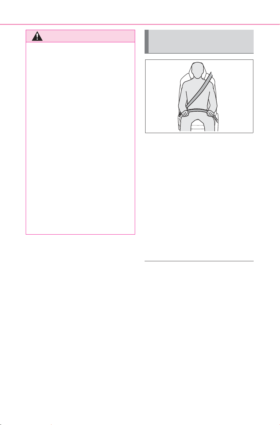
1 To fasten the seat belt, push
the plate into the buckle until
a click sound is heard.
2 To release the seat belt,
press the release button .
■ Emergency locking retractor
(ELR)
The retractor will lock the belt during
a sudden stop or on impact. It may
also lock if you lean forward too
quickly. A slow, easy motion will
allow the belt to extend so that you
can move around fully.
■ Automatic locking retractor
(ALR)
When a passenger’s shoulder belt is
completely extended and then
retracted even slightly, the belt is
locked in that position and cannot
be extended. This feature is used to
hold a child restraint system (CRS)
firmly. To free the belt again, fully
retract the belt and then pull the belt
out once more.
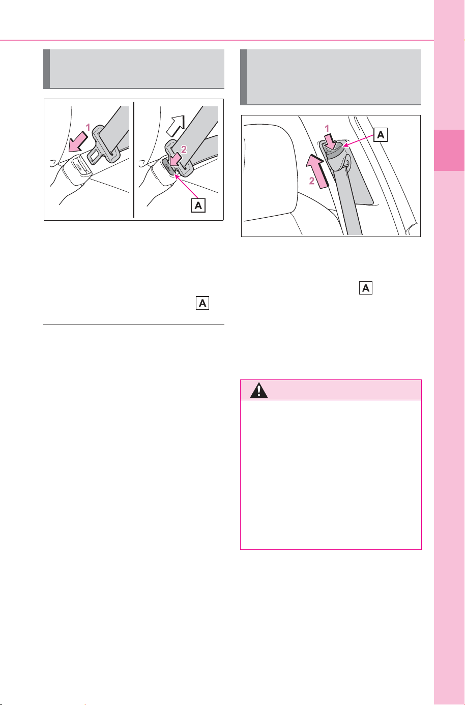
1 Push the seat belt shoulder
anchor down while pressing
the release button .
2 Push the seat belt shoulder
anchor up.
Move the height adjuster up and
down as needed until you hear a
click.
Fastening and releasing
the seat belt
Adjusting the seat belt
shoulder anchor height
(front seats)
WARNING
■ Adjustable shoulder anchor
Always make sure the shoulder
belt is positioned across the cen-
ter of your shoulder. The belt
should be kept away from your
neck, but not falling off your shoul-
der. Failure to do so could reduce
the amount of protection in an
accident and cause death or seri-
ous injuries in the event of a sud-
den stop, sudden swerve or
accident.
SOLTERRA_OM_USA_A6740BE.book 31 ページ 2025年5月23日 金曜日 午後1時18分
32
1-1. For safe use
Owner’s Manual_USA_M6740B_en
When the vehicle is subjected to
a severe frontal or side impact
or rollover, the pretensioners
retract the seat belts of the front
seats and rear outer seats to
securely restrain the occupants.
The pretensioners will not operate
in minor frontal or side impacts, or
rear impacts.
■ Replacing the belt after the pre-
tensioner has been activated
If the vehicle is involved in multiple
collisions, the pretensioner will acti-
vate for the first collision, but will not
activate for the second or subse-
quent collisions.
■ PCS-linked control
If the PCS (Pre-Collision System)
determines that the possibility of a
collision with a vehicle is high, the
seat belt pretensioners will be pre-
pared to operate.
Seat belt pretensioners
WARNING
■ Seat belt pretensioners
Observe the following precautions
to reduce the risk of injury in the
event of sudden braking or an
accident.
Failure to do so may result in
death or serious injury.
● Do not place anything, such as
a cushion, on the front passen-
ger’s seat.
Doing so will disperse the pas-
senger’s weight, which prevents
the sensor from detecting the
passenger’s weight properly. As
a result, the seat belt preten-
sioner for the front passenger’s
seat may not operate in the
event of a collision.
● If a pretensioner has operated,
the SRS warning light will illumi-
nate. In this situation, the seat
belt cannot be used and must
be replaced by your SUBARU
dealer.
SOLTERRA_OM_USA_A6740BE.book 32 ページ 2025年5月23日 金曜日 午後1時18分
33
1-1. For safe use
Owner’s Manual_USA_M6740B_en
1
For safety and security
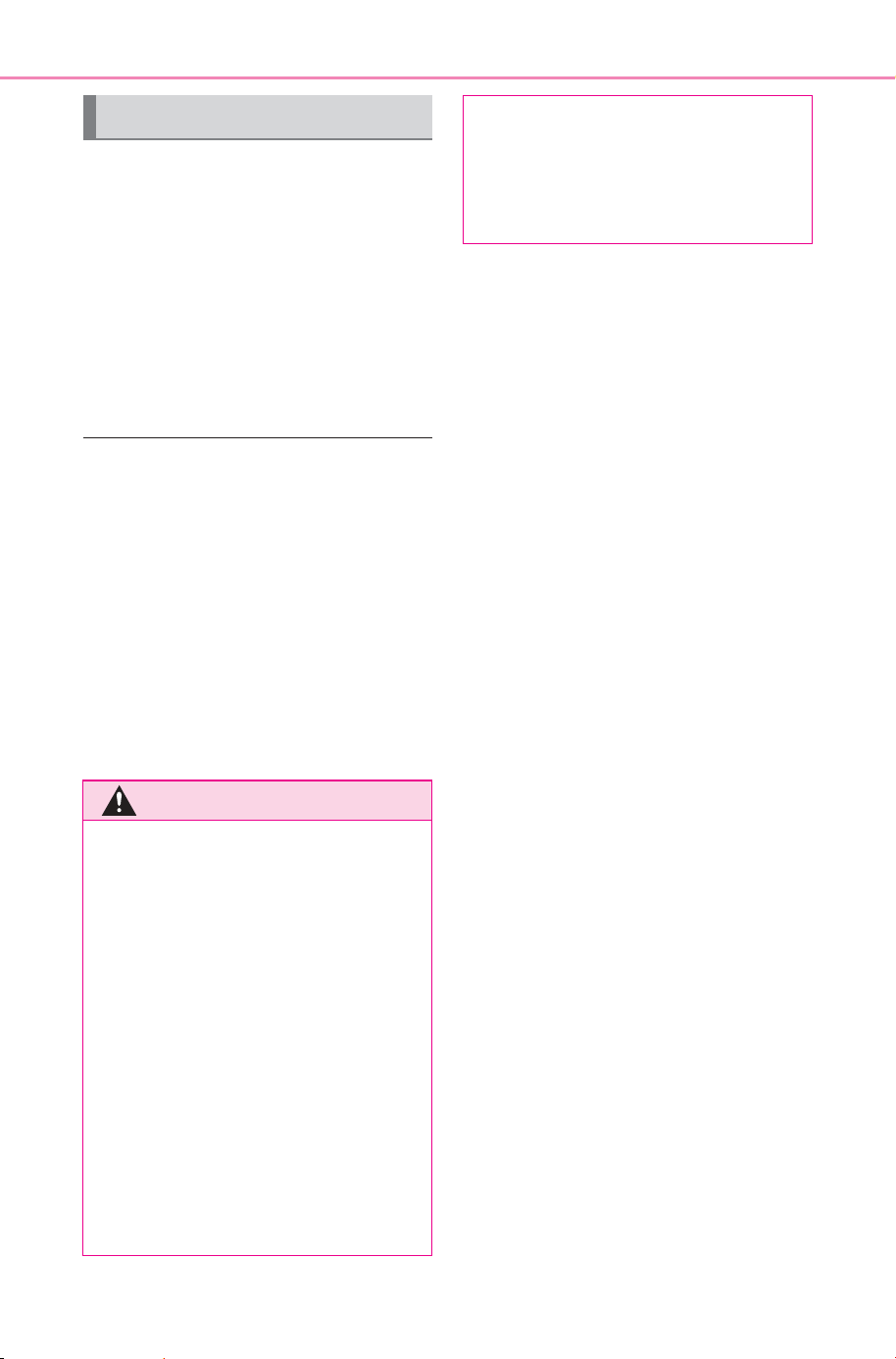
SRS front airbags (SRS driver airbag/SRS front passenger air-
bag)
Help reduce impact to the head and chest of the driver and front passenger
SRS knee airbags
Help reduce impact to the driver and front passenger
SRS side airbags
Help reduce impact to the chest of the occupants of the front seats
SRS curtain shield airbags
• Help reduce impact to the heads of the occupants of the front and rear
outer seats
• Can help prevent the occupants from being thrown from the vehicle in the
event of a vehicle rollover
SRS airbags
The SRS airbags deploy when the vehicle is subjected to cer-
tain types of severe impact that may cause significant injury
to the occupants. The airbags work together with the seat
belts to help reduce the risk of death or serious injury.
SRS airbag system
SOLTERRA_OM_USA_A6740BE.book 33 ページ 2025年5月23日 金曜日 午後1時18分

34
1-1. For safe use
Owner’s Manual_USA_M6740B_en
Your vehicle is equipped with ADVANCED AIRBAGS designed
based on US motor vehicle safety standards (FMVSS208). The air-
bag sensor assembly (ECU) controls airbag deployment based on
information obtained from the sensors, etc., shown in the system
components diagram above. This information includes crash sever-
ity and occupant information. As the airbags deploy, a chemical
reaction in the inflators quickly fills the airbags with non-toxic gas to
help restrain the motion of the occupants.
■ If the SRS airbags deploy
(inflate)
● Slight abrasions, burns, bruising,
etc., may be sustained from SRS
airbags, due to the extremely high
speed of deployment (inflation) by
hot gases.
● A loud noise and white powder will
be emitted.
● Parts of the airbag module (steer-
ing wheel hub, airbag cover and
inflator) as well as the parts
around the airbags may be hot for
several minutes. The airbag itself
may also be hot.
● The windshield may crack.
● The EV system will be stopped.
(P. 78)
● All of the doors will be unlocked.
(P.160)
● The brakes and stop lights will be
controlled automatically. (P.477)
● The interior lights will turn on auto-
matically. (P.508)
● The emergency flashers will turn
on automatically. (P.602)
■ Emergency call
● For SubaruConnect subscribers, if
any of the following situations
occur, the system is designed to
send an emergency call to the
response center.
• When an SRS airbag has been
deployed
• When a seat belt pretensioner has
operated
• When the vehicle received an
impact exceeding a certain level
Emergency services may be dis-
patched even if there is no response
to calls from the agent.
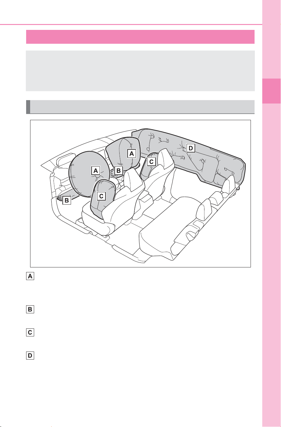
■ The SRS airbags deploy in a
frontal impact when
● The following SRS airbags will
deploy in the event of an impact
that exceeds a threshold level
(level of force corresponding to an
approximately 12 - 18 mph [20 -
30 km/h] frontal collision with a
fixed wall that does not move or
deform):
• SRS front airbags
• SRS knee airbags
● The threshold level at which the
SRS airbags will deploy will be
higher than normal in the following
situations:
• When the vehicle collides with an
object, such as a parked vehicle
or sign pole, which moves or
deforms on impact
• If the vehicle is involved in an
underride collision, such as a colli-
sion in which the front of the vehi-
cle “underrides”, or goes under,
the bed of a truck
● Depending on the type of collision,
only the following may deploy:
• Seat belt pretensioners
● The SRS airbags for the front pas-
senger’s seat will not deploy if
there is no passenger in the front
passenger seat. However, the
SRS airbags for the front passen-
ger’s seat may deploy, even if the
seat is unoccupied, if luggage is
put on the seat.
SOLTERRA_OM_USA_A6740BE.book 34 ページ 2025年5月23日 金曜日 午後1時18分
35
1-1. For safe use
Owner’s Manual_USA_M6740B_en
1
For safety and security
● In the event of an especially
severe frontal collision, the left
and right SRS curtain shield air-
bags may also deploy.
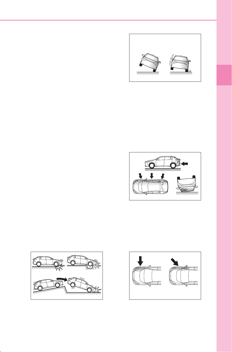
■ The SRS airbags deploy in a
side impact when
● The following SRS airbags will
deploy in the event of an impact
that exceeds the set threshold
level (level of force corresponding
to the impact force produced by
an approximately 3300 lb. [1500
kg] vehicle colliding with the pas-
senger compartment at a perpen-
dicular angle at an approximate
speed of 12 - 18 mph [20 - 30
km/h]):
• SRS side airbags
• SRS curtain shield airbags
● In the event of a side collision,
regardless of the impacted side,
both the left and right SRS curtain
shield airbags will deploy.
● If the vehicle is involved in a roll-
over, the following SRS airbags
will deploy:
• Both left and right SRS curtain
shield airbags
■ The SRS airbags deploy in an
underside impact when
● The following airbags may deploy
if the underside of the vehicle col-
lides with a hard object:
• SRS front airbags
• SRS knee airbags
• SRS side airbags
• SRS curtain shield airbags
● The following airbags may deploy
if the vehicle becomes signifi-
cantly tilted or is strongly impacted
by skidding into a curb, etc.:
• SRS curtain shield airbags
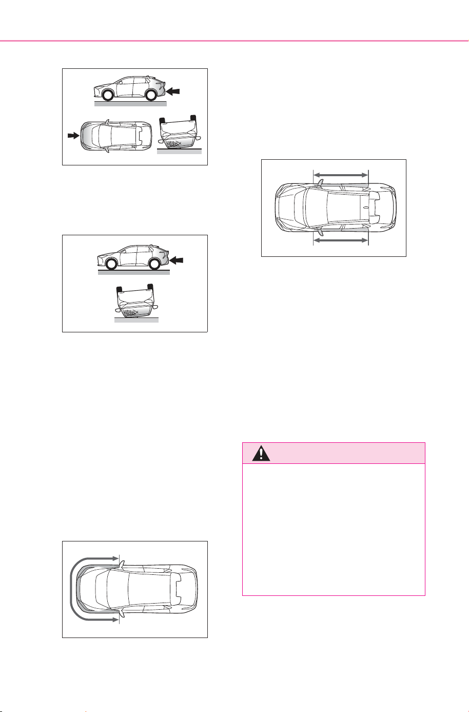
■ The SRS airbags will not deploy
when
● The following SRS airbags will not
normally deploy in side or rear col-
lisions, vehicle rollovers, or low
speed frontal collisions. However,
if such a collision causes sufficient
sudden deceleration, the SRS air-
bags may deploy.
• SRS front airbags
• SRS knee airbags
● The following SRS airbags may
not deploy if the vehicle is collided
with at a certain angle or in a side
collision where an area of the
vehicle other than the passenger
compartment is collided with:
• SRS side airbags
• SRS curtain shield airbags
● The following SRS airbags will not
normally deploy in front or rear
collisions, vehicle rollovers, or low
speed side collisions:
SOLTERRA_OM_USA_A6740BE.book 35 ページ 2025年5月23日 金曜日 午後1時18分
36
1-1. For safe use
Owner’s Manual_USA_M6740B_en
• SRS side airbags
● The following SRS airbags will not
normally deploy in rear collisions,
end over end vehicle rollovers, or
low speed front or side collisions:
• SRS curtain shield airbags
■ When to contact your SUBARU
dealer
In the following situations, the vehi-
cle will require inspection and/or
repair. Contact your SUBARU
dealer as soon as possible.
● When any of the SRS airbags
have been deployed
● When the front of the vehicle is
damaged or deformed, or was
involved in a collision that was not
severe enough to cause any of
the following SRS airbags to
deploy:
• SRS front airbags
• SRS knee airbags
● When a door or its surrounding
area is damaged, deformed or has
had a hole made in it, or was
involved in a collision that was not
severe enough to cause any of
the following SRS airbags to
deploy:
• SRS side airbags
• SRS curtain shield airbags
● When the pad section of the steer-
ing wheel, the dashboard near the
front SRS passenger airbag or the
lower side of the instrument panel
is scratched, cracked, or other-
wise damaged.
● When the surface of a seat with a
SRS side airbag is scratched,
cracked, or otherwise damaged.
● When the part of a front pillar, rear
pillar or roof side rail garnish (pad-
ding) which covers a SRS curtain
shield airbag is scratched,
cracked, or otherwise damaged.
WARNING
■ SRS airbag precautions
Observe the following precau-
tions. Failure to do so may result
in death or serious injury.
● The driver and all passengers
must wear their seat belts cor-
rectly.
The SRS airbags are supple-
mental devices to be used with
the seat belts.
SOLTERRA_OM_USA_A6740BE.book 36 ページ 2025年5月23日 金曜日 午後1時18分
37
1-1. For safe use
Owner’s Manual_USA_M6740B_en
1
For safety and security
WARNING
● The SRS driver airbag deploys
with considerable force, and
can cause death or serious
injury, especially if the driver is
very close to the airbag. The
National Highway Traffic Safety
Administration (NHTSA)
advises:
Since the risk zone for the driver’s
airbag is the first 2 - 3 in. (50 - 75
mm) of inflation, placing yourself
10 in. (250 mm) from your driver
airbag provides you with a clear
margin of safety. This distance is
measured from the center of the
steering wheel to your breast-
bone. If your current driving posi-
tion places you less than 10 in.
(250 mm) away from the driver
airbag, you can change your driv-
ing position in several ways:
• Move your seat to the rear as
far as possible while still being
able to reach the pedals com-
fortably.
• Slightly recline the seatback.
Although vehicle designs vary,
many drivers can achieve the
10 in. (250 mm) distance, even
with the driver seat all the way
forward, simply by reclining the
seatback somewhat. If reclining
the seatback makes it hard to
see the road, raise yourself by
using a firm, non-slippery cush-
ion, or raise the seat if your
vehicle has that feature.
• If your steering wheel is adjust-
able, tilt it downward. This
points the airbag toward your
chest instead of your head and
neck. The seat should be
adjusted as recommended by
the NHTSA, while still being
able to control the vehicle with
the pedals and steering wheel,
and maintaining your view of the
instrument panel controls.
● If a seat belt extender has been
connected to the front passen-
ger seat belt buckle but the
latch plate of the front passen-
ger seat belt has not been fas-
tened to the seat belt extender,
the SRS airbag system will
judge that the front passenger is
wearing the seat belt even
though the seat belt has not
been fastened. In this case, the
SRS front airbags for the front
passenger may not deploy cor-
rectly in a collision, resulting in
death or serious injury. Be sure
to wear the seat belt correctly
when using a seat belt extender.
● The SRS front passenger air-
bag deploys with considerable
force, and can cause death or
serious injury, especially if the
front passenger is very close to
the airbag. The front passenger
seat should be positioned as far
possible from the airbag with
the seatback adjusted so that
the passenger is sat upright.
SOLTERRA_OM_USA_A6740BE.book 37 ページ 2025年5月23日 金曜日 午後1時18分
38
1-1. For safe use
Owner’s Manual_USA_M6740B_en
WARNING
● Improperly seated and/or
restrained infants and children
can be killed or seriously injured
by a deploying airbag. An infant
or child who is too small to use
a seat belt should be properly
secured using a child restraint
system. SUBARU strongly rec-
ommends that all infants and
children be placed in the rear
seats of the vehicle and prop-
erly restrained. The rear seats
are safer for infants and children
than the front passenger seat.
(P.47)
● Do not sit on the edge of the
seat or lean against the dash-
board.
● Front seat occupants should
never hold items on their lap.
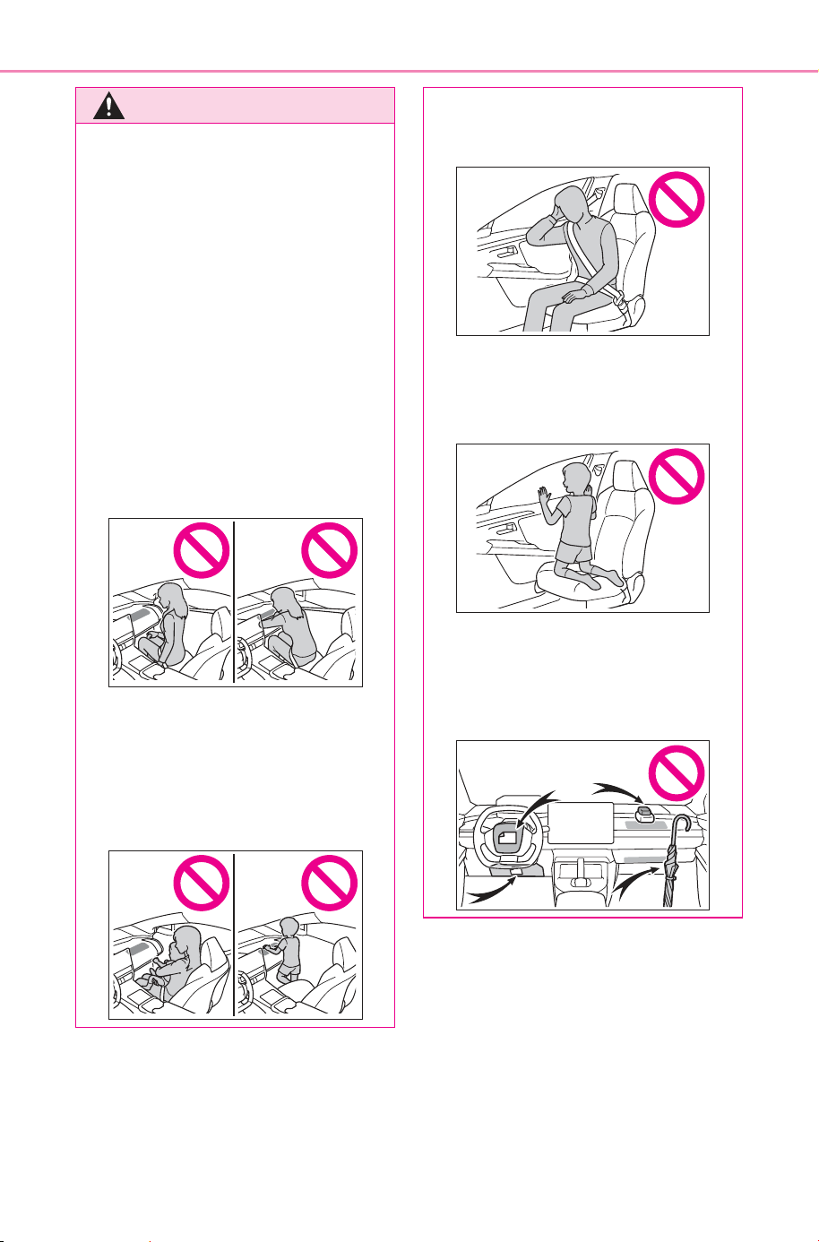
● Do not allow a child to stand in
front of the SRS front passenger
airbag or sit on the lap of a front
passenger.
● Do not lean against the door,
roof side rail, or front, side, or
rear pillar.
● Do not allow anyone to kneel on
a seat toward the door or put
their head or hands outside the
vehicle.
● Do not attach anything to or
lean anything against areas
such as the dashboard, steering
wheel pad and lower portion of
the instrument panel.
SOLTERRA_OM_USA_A6740BE.book 38 ページ 2025年5月23日 金曜日 午後1時18分
39
1-1. For safe use
Owner’s Manual_USA_M6740B_en
1
For safety and security
WARNING
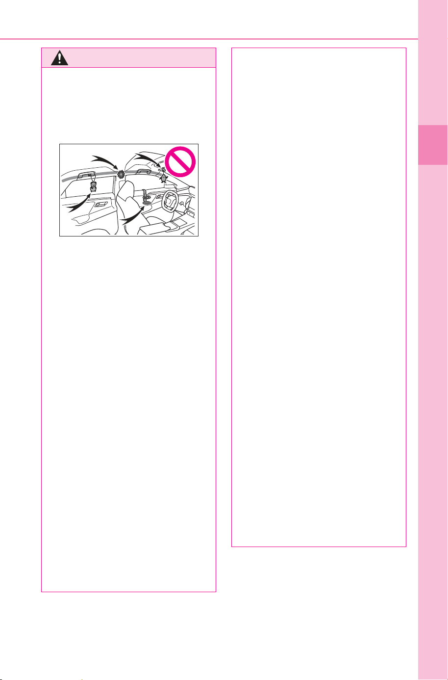
● Do not attach anything to areas
such as the doors, windshield,
side windows, front or rear pil-
lars, roof side rails and assist
grips. (With the exception of the
speed limit label P.633)
● Do not hang coat hangers or
other hard objects on the coat
hooks. These items could
become projectiles if the SRS
curtain shield airbags deploy,
possibly leading to death or
serious injury.
● If a vinyl cover is attached to the
area where the SRS knee air-
bag deploys, be sure to remove
it.
● Do not use seat accessories
which cover the parts from
which the SRS airbags deploy,
as they may interfere with infla-
tion of the SRS airbags. Such
accessories may prevent the
SRS airbags from deploying
correctly, may disable the sys-
tem or cause the SRS airbags
to inflate unintentionally, possi-
bly resulting in death or serious
injury.
● Do not strike or apply significant
force to the SRS airbag system
components, front doors or their
surrounding area.
Doing so may cause the SRS
airbags to malfunction.
● Do not touch any components
of the SRS airbags immediately
after the SRS airbags have
deployed (inflated) as they may
be hot.
● If breathing becomes difficult
after the SRS airbags have
deployed, open a door or win-
dow to allow fresh air in, or
leave the vehicle if it is safe to
do so. Wash off any residue as
soon as possible to prevent skin
irritation.
● If a part where an SRS airbag is
stored is damaged or cracked,
have it replaced by your SUB-
ARU dealer.
● Do not place anything, such as
a cushion, on the front passen-
ger’s seat. Doing so will
disperse the passenger’s
weight, which prevents the sen-
sor from detecting the passen-
ger’s weight properly. As a
result, the SRS front airbags for
the front passenger’s seat may
not deploy in the event of a colli-
sion.
■ Modification and disposal of
SRS airbag system compo-
nents
Do not dispose of your vehicle or
perform any of the following modi-
fications without consulting your
SUBARU dealer. The SRS air-
bags may malfunction or deploy
unintentionally, possibly leading to
death or serious injury.
● Removal, installation, disas-
sembly or repair of the SRS air-
bags
SOLTERRA_OM_USA_A6740BE.book 39 ページ 2025年5月23日 金曜日 午後1時18分

40
1-1. For safe use
Owner’s Manual_USA_M6740B_en
WARNING
● Repair, removal or modification
of the following parts or their
surrounding
• Steering wheel
• Instrument panel
• Dashboard
• Seats
• Seat upholstery
• Front pillars
• Side pillars
• Rear pillars
• Roof side rails
• Front door panels
• Front door trim
• Front door speakers
● Modifications to the front door
panels (such as making holes in
them)
● Repair or modification of the fol-
lowing parts or their surrounding
• Front fender
• Front bumper
• Sides of the vehicle interior
● Installation of the following parts
or accessories
• Bull bars or kangaroo bars
• Snow plows
•Winches
• Roof luggage carriers
● Modifications to the vehicle’s
suspension
● Installation of electronic devices
such as mobile two-way radios
(RF-transmitter) and CD players
● Modifications to your vehicle for
a persons with a physical dis-
ability
SOLTERRA_OM_USA_A6740BE.book 40 ページ 2025年5月23日 金曜日 午後1時18分
41
1-1. For safe use
Owner’s Manual_USA_M6740B_en
1
For safety and security
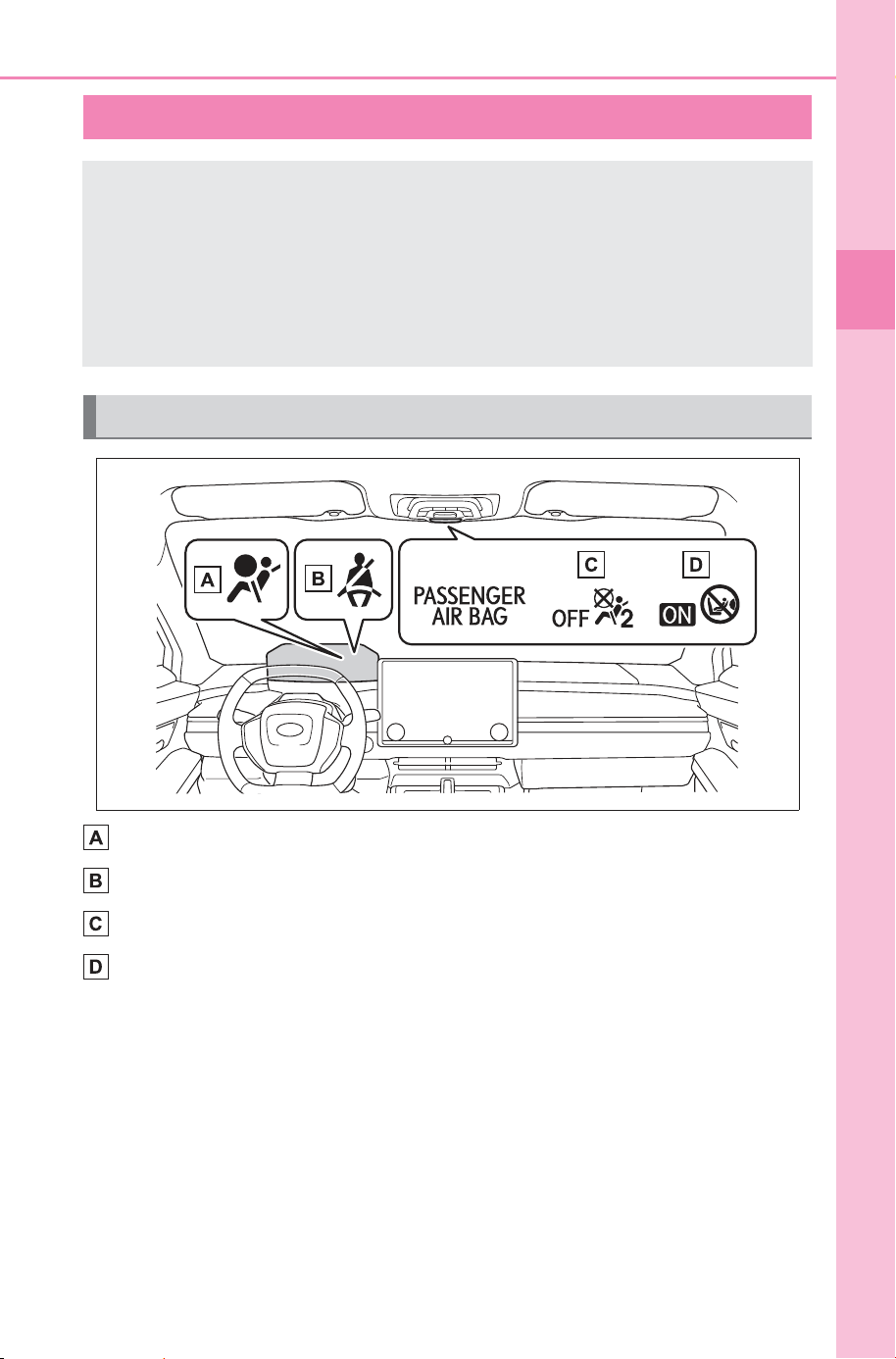
SRS warning light
Front passenger’s seat belt reminder light
“AIR BAG OFF” indicator light
“AIR BAG ON” indicator light
Front passenger occupant classification system
Your vehicle is equipped with a front passenger occupant
classification system. This system detects the conditions of
the front passenger seat and activates or deactivates the fol-
lowing SRS airbags.
SRS front passenger airbag
SRS front passenger knee airbag
System components
SOLTERRA_OM_USA_A6740BE.book 41 ページ 2025年5月23日 金曜日 午後1時18分
42
1-1. For safe use
Owner’s Manual_USA_M6740B_en
■ Adult
*1
■ Child
*4
■ Child restraint system with infant
*5
Front passenger occupant classification system condi-
tions and operation
Indicators/warn-
ing lights
“AIR BAG ON” and “AIR BAG OFF”
indicator lights
“AIR BAG ON”
SRS warning light Off
Front passenger’s seat belt reminder
light
Off
*2
or flashing
*3
Devices
Front passenger airbag
Activated
Front passenger knee airbag
Indicators/warn-
ing lights
“AIR BAG ON” and “AIR BAG OFF”
indicator lights
“AIR BAG OFF”
or “AIR BAG
ON”
*4
SRS warning light Off
Front passenger’s seat belt reminder
light
Off
*2
or flashing
*3
Devices
Front passenger airbag
Deactivated or
activated
*4
Front passenger knee airbag
Deactivated or
activated
*4
Indicators/warn-
ing lights
“AIR BAG ON” and “AIR BAG OFF”
indicator lights
“AIR BAG OFF”
*6
SRS warning light Off
Front passenger’s seat belt reminder
light
Off
*2
or flashing
*3
Devices
Front passenger airbag
Deactivated
Front passenger knee airbag
SOLTERRA_OM_USA_A6740BE.book 42 ページ 2025年5月23日 金曜日 午後1時18分
43
1-1. For safe use
Owner’s Manual_USA_M6740B_en
1
For safety and security
■ Unoccupied
■ System malfunction
*1
:The system judges a person of adult size as an adult. When a smaller
adult sits in the front passenger seat, the system may not recognize them
as an adult depending on their physique and posture.
*2
:In the event the front passenger is wearing a seat belt.
*3
:In the event the front passenger does not wear a seat belt.
*4
:For some children, child in seat, child in booster seat or child in convert-
ible seat, the system may not recognize them as a child. Factors which
may affect this can be the physique or posture.
*5
:Never install a rear-facing child restraint system on the front passenger
seat. A forward-facing child restraint system should only be installed on
the front passenger seat when it is unavoidable. (P.50)
*6
:In case the indicator light is not illuminated, consult this manual on how
to install the child restraint system properly. (P.47)
Indicators/warn-
ing lights
“AIR BAG ON” and “AIR BAG OFF”
indicator lights
“AIR BAG OFF”
SRS warning light
Off
Front passenger’s seat belt reminder
light
Devices
Front passenger airbag
Deactivated
Front passenger knee airbag
Indicators/warn-
ing lights
“AIR BAG ON” and “AIR BAG OFF”
indicator lights
“AIR BAG OFF”
SRS warning light
On
Front passenger’s seat belt reminder
light
Devices
Front passenger airbag
Deactivated
Front passenger knee airbag
SOLTERRA_OM_USA_A6740BE.book 43 ページ 2025年5月23日 金曜日 午後1時18分
44
1-1. For safe use
Owner’s Manual_USA_M6740B_en
WARNING
■ Front passenger occupant
classification system precau-
tions
Observe the following precautions
regarding the front passenger
occupant classification system.
Failure to do so may cause death
or serious injury.
● Wear the seat belt properly.
● Make sure the front passenger’s
seat belt plate has not been left
inserted into the buckle before
someone sits in the front pas-
senger seat.
● Make sure the “AIR BAG OFF”
indicator light is not illuminated
when using the seat belt
extender for the front passenger
seat. If the “AIR BAG OFF” indi-
cator light is illuminated, discon-
nect the extender tongue from
the seat belt buckle, and recon-
nect the seat belt. Reconnect
the seat belt extender after
making sure the “AIR BAG ON”
indicator light is illuminated. If
you use the seat belt extender
while the “AIR BAG OFF” indi-
cator light is illuminated, the
SRS airbags for the front pas-
senger will not activate, which
could cause death or serious
injury in the event of a collision.
● Do not apply a heavy load to the
front passenger seat or equip-
ment (e.g. seatback pocket).
● Do not put weight on the front
passenger seat by putting your
hands or feet on the front pas-
senger seat seatback from the
rear passenger seat.
● Do not let a rear passenger lift
the front passenger seat with
their feet or press on the seat-
back with their legs.
● Do not put objects under the
front passenger seat.
● Do not recline the front passen-
ger seatback so far that it
touches a rear seat. This may
cause the “AIR BAG OFF” indi-
cator light to be illuminated,
which indicates that the SRS
airbags for the front passenger
will not activate in the event of a
severe accident. If the seatback
touches the rear seat, return the
seatback to a position where it
does not touch the rear seat.
Keep the front passenger seat-
back as upright as possible
when the vehicle is moving.
Reclining the seatback exces-
sively may lessen the effective-
ness of the seat belt system.
● If an adult sits in the front pas-
senger seat, the “AIR BAG ON”
indicator light is illuminated. If
the “AIR BAG OFF” indicator is
illuminated, ask the passenger
to sit up straight, well back in
the seat, feet on the floor, and
with the seat belt worn correctly.
If the “AIR BAG OFF” indicator
still remains illuminated, either
ask the passenger to move to
the rear seat, or if that is not
possible, move the front pas-
senger seat fully rearward.
● When it is unavoidable to install
a forward-facing child restraint
system on the front passenger
seat, install the child restraint
system on the front passenger
seat in the proper order.
(P.50)
● Do not modify or remove the
front seats.
SOLTERRA_OM_USA_A6740BE.book 44 ページ 2025年5月23日 金曜日 午後1時18分
45
1-1. For safe use
Owner’s Manual_USA_M6740B_en
1
For safety and security
WARNING
● Do not kick the front passenger
seat or subject it to severe
impact. Otherwise, the SRS
warning light may come on to
indicate a malfunction of the
front passenger occupant clas-
sification system. In this case,
contact your SUBARU dealer
immediately.
● Child restraint systems installed
on the rear seat should not con-
tact the front seatbacks.
● Do not use a seat accessory,
such as a cushion and seat
cover, that covers the seat
cushion surface.
● Do not modify or replace the
upholstery of the front seat.
SOLTERRA_OM_USA_A6740BE.book 45 ページ 2025年5月23日 金曜日 午後1時18分
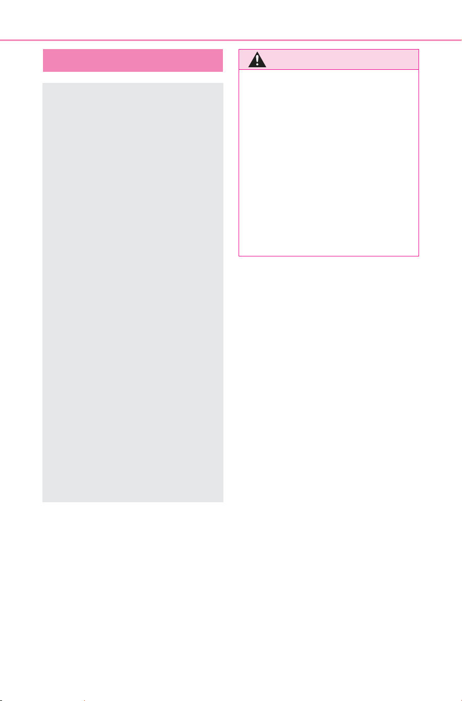
46
1-2. Child safety
Owner’s Manual_USA_M6740B_en
1-2.Ch ild safety
Riding with children
Observe the following pre-
cautions when children are
in the vehicle.
Use a child restraint system
appropriate for the child,
until the child becomes
large enough to properly
wear the vehicle’s seat belt.
It is recommended that chil-
dren sit in the rear seats to
avoid accidental contact
with the steering wheel,
wiper switch, etc.
Use the rear door child-pro-
tector lock or the window
lock switch to avoid children
opening the door while driv-
ing or operating the power
window accidentally.
(P.163, 206)
Do not let small children
operate equipment which
may catch or pinch body
parts, such as the power
window, hood, back door,
seats, etc.
WARNING
■ When children are in the vehi-
cle
Never leave children unattended
in the vehicle, and never allow
children to have or use the key.
Children may be able to start the
vehicle or shift the vehicle into
neutral. There is also a danger
that children may injure them-
selves by playing with the side
windows or other features of the
vehicle. In addition, heat build-up
or extremely cold temperatures
inside the vehicle can be fatal to
children.
SOLTERRA_OM_USA_A6740BE.book 46 ページ 2025年5月23日 金曜日 午後1時18分

47
1-2. Child safety
Owner’s Manual_USA_M6740B_en
1
For safety and security
Points to remember: P.47
Child restraint system: P.49
When using a child restraint sys-
tem: P.50
Child restraint system installa-
tion method
• Fixed with a seat belt: P.52
• Fixed with a child restraint
LATCH anchor: P.56
• Using an anchor bracket (for
top tether strap): P.59
The laws of all 50 states of the
U.S.A. as well as Canada now
require the use of child restraint
systems.
Prioritize and observe the
warnings, as well as the laws
and regulations for child
restraint systems.
Use a child restraint system
until the child becomes large
enough to properly wear the
vehicle’s seat belt.
Choose a child restraint sys-
tem that suits your vehicle
and is appropriate to the age
and size of the child.
Child restraint sys-
tems
Before installing a child
restraint system in the vehi-
cle, there are precautions
that need to be observed,
different types of child
restraint systems, as well
as installation methods,
etc., written in this manual.
Use a child restraint system
when riding with a small child
that cannot properly use a
seat belt. For the child’s
safety, install the child
restraint system to a rear seat.
Be sure to follow the installa-
tion method that is in the oper-
ation manual enclosed with
the restraint system.
Table of contents
Points to remember
WARNING
■ When a child is riding
Observe the following precau-
tions.
Failure to do so may result in
death or serious injury.
● For effective protection in auto-
mobile accidents and sudden
stops, a child must be properly
restrained, using a seat belt or
child restraint system which is
correctly installed. For installa-
tion details, refer to the opera-
tion manual enclosed with the
child restraint system. General
installation instructions are pro-
vided in this manual.
SOLTERRA_OM_USA_A6740BE.book 47 ページ 2025年5月23日 金曜日 午後1時18分
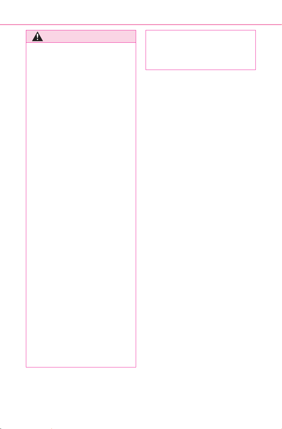
48
1-2. Child safety
Owner’s Manual_USA_M6740B_en
WARNING
● SUBARU strongly urges the use
of a proper child restraint sys-
tem that conforms to the weight
and size of the child, installed
on the rear seat. According to
accident statistics, the child is
safer when properly restrained
in the rear seat than in the front
seat.
● Holding a child in your or some-
one else’s arms is not a substi-
tute for a child restraint system.
In an accident, the child can be
crushed against the windshield
or between the holder and the
interior of the vehicle.
■ Handling the child restraint
system
If the child restraint system is not
properly fixed in place, the child or
other passengers may be seri-
ously injured or even killed in the
event of sudden braking, sudden
swerving, or an accident.
● If the vehicle were to receive a
strong impact from an accident,
etc., it is possible that the child
restraint system has damage
that is not readily visible. In
such cases, do not reuse the
restraint system.
● Make sure you have complied
with all installation instructions
provided with the child restraint
system manufacturer and that
the system is properly secured.
● Keep the child restraint system
properly secured on the seat
even if it is not in use. Do not
store the child restraint system
unsecured in the passenger
compartment.
● If it is necessary to detach the
child restraint system, remove it
from the vehicle or store it
securely in the luggage com-
partment.
SOLTERRA_OM_USA_A6740BE.book 48 ページ 2025年5月23日 金曜日 午後1時18分
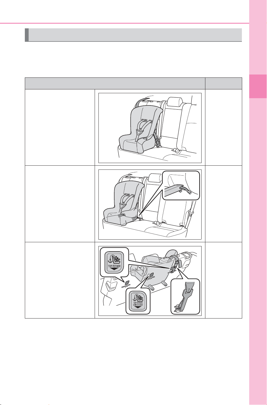
49
1-2. Child safety
Owner’s Manual_USA_M6740B_en
1
For safety and security
■ Types of child restraint system installation methods
Confirm with the operation manual enclosed with the child restraint
system about the installation of the child restraint system.
Child restraint system
Installation method Page
Seat belt attachment P.52
Child restraint LATCH
anchors attachment
P.56
Anchor brackets (for
top tether strap) attach-
ment
P.59
SOLTERRA_OM_USA_A6740BE.book 49 ページ 2025年5月23日 金曜日 午後1時18分
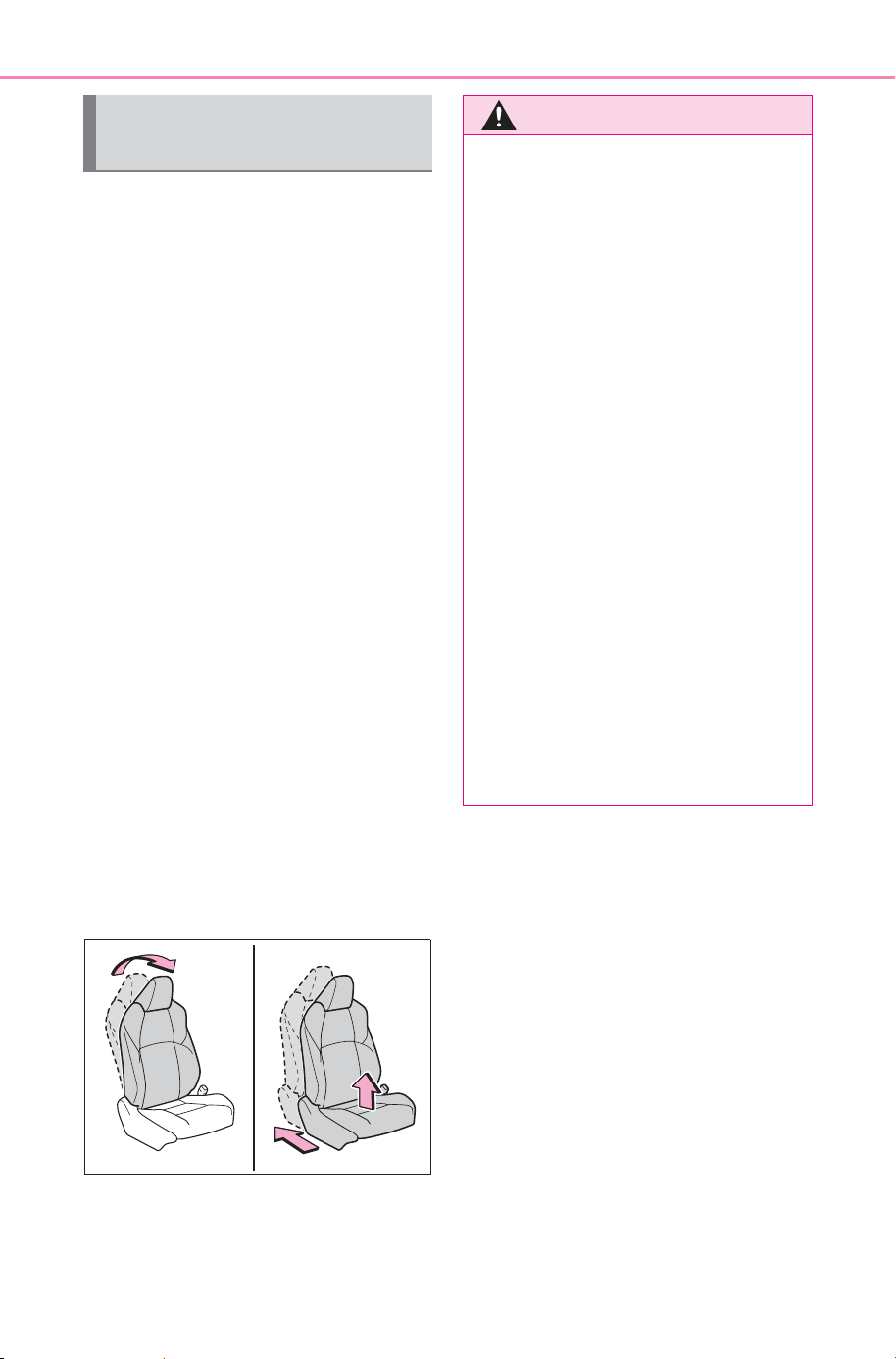
50
1-2. Child safety
Owner’s Manual_USA_M6740B_en
■ When installing a child
restraint system to a front
passenger seat
For the safety of a child, install a
child restraint system to a rear
seat. When installing the child
restraint system to a front pas-
senger seat is unavoidable,
adjust the seat as follows and
install the child restraint system.
Adjust the seatback angle to
the most upright position.
Move the front seat fully rear-
ward. If the passenger seat
height can be adjusted, move
it to the upper most position.
If the head restraint interferes
with the child restraint system
installation and the head
restraint can be removed,
remove the head restraint.
Otherwise, put the head
restraint in the upper most
position.
When using a child
restraint system
WARNING
■ When using a child restraint
system
Observe the following precau-
tions.
Failure to do so may result in
death or serious injury.
● Never install a rear-facing child
restraint system on the front
passenger seat even if the “AIR
BAG OFF” indicator light is illu-
minated. In the event of an acci-
dent, the force of the rapid
inflation of the front passenger
airbag can cause death or seri-
ous injury to the child if the rear-
facing child restraint system is
installed on the front passenger
seat.
● A forward-facing child restraint
system may be installed on the
front passenger seat only when
it is unavoidable. A child
restraint system that requires a
top tether strap should not be
used in the front passenger seat
since there is no top tether strap
anchor for the front passenger
seat.
SOLTERRA_OM_USA_A6740BE.book 50 ページ 2025年5月23日 金曜日 午後1時18分
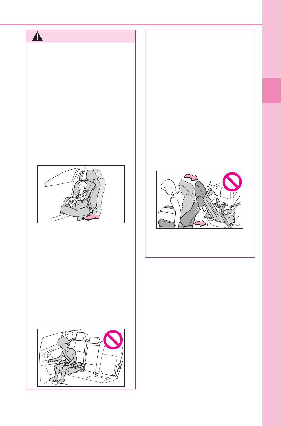
51
1-2. Child safety
Owner’s Manual_USA_M6740B_en
1
For safety and security
WARNING
● A forward-facing child restraint
system may be installed on the
front passenger seat only when
it is unavoidable. When install-
ing a forward-facing child
restraint system on the front
passenger seat, adjust the seat-
back angle to the most upright
position, move the seat to the
rearmost position, even if the
“AIR BAG OFF” indicator light is
illuminated.
If the head restraint interferes
with the child restraint system
installation and the head
restraint can be removed,
remove the head restraint.
● Do not allow the child to lean
his/her head or any part of
his/her body against the door or
the area of the seat, front or rear
pillars, or roof side rails from
which the SRS side airbags or
SRS curtain shield airbags
deploy even if the child is
seated in the child restraint sys-
tem. It is dangerous if the SRS
side and curtain shield airbags
inflate, and the impact could
cause death or serious injury to
the child.
● When a booster seat is
installed, always ensure that the
shoulder belt is positioned
across the center of the child’s
shoulder. The belt should be
kept away from the child’s neck,
but not so that it could fall off the
child’s shoulder.
● Use a child restraint system
suitable to the age and size of
the child and install it to the rear
seat.
● If the driver’s seat interferes
with the child restraint system
and prevents it from being
attached correctly, attach the
child restraint system to the
right-hand rear seat.
● Adjust the front passenger seat
so that it does not interfere with
the child restraint system.
SOLTERRA_OM_USA_A6740BE.book 51 ページ 2025年5月23日 金曜日 午後1時18分
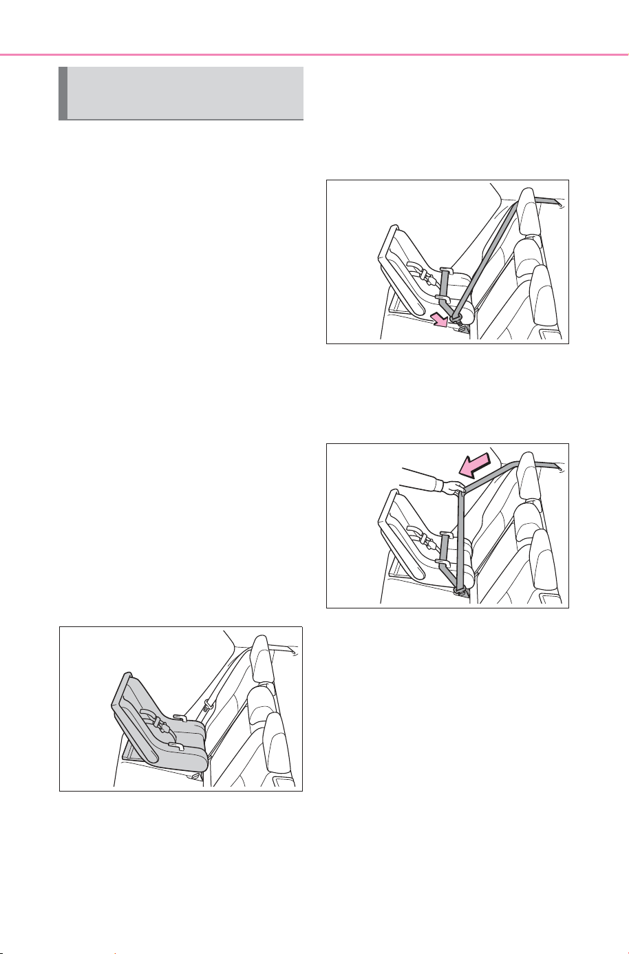
52
1-2. Child safety
Owner’s Manual_USA_M6740B_en
A child restraint system for a
small child or baby must itself be
properly restrained on the seat
with the lap portion of the
lap/shoulder belt.
■ Installing child restraint
system using a seat belt
(child restraint lock func-
tion belt)
Install the child restraint system
in accordance to the operation
manual enclosed with the child
restraint system.
■ Rear-facing Infant
seat/convertible seat
1 Adjust the rear seat.
If there is a gap between the child
restraint system and the seatback,
adjust the seatback angle until
good contact is achieved.
2 Place the child restraint sys-
tem on the rear seat facing
the rear of the vehicle.
3 Run the seat belt through the
child restraint system and
insert the plate into the
buckle. Make sure that the
belt is not twisted.
4 Fully extend the shoulder belt
and allow it to retract to put it
in lock mode. In lock mode,
the belt cannot be extended.
5 While pushing the child
restraint system down into
the rear seat, allow the shoul-
der belt to retract until the
child restraint system is
securely in place.
After the shoulder belt has
retracted to a point where there is
no slack in the belt, pull the belt to
check that it cannot be extended.
Child restraint system
fixed with a seat belt
SOLTERRA_OM_USA_A6740BE.book 52 ページ 2025年5月23日 金曜日 午後1時18分
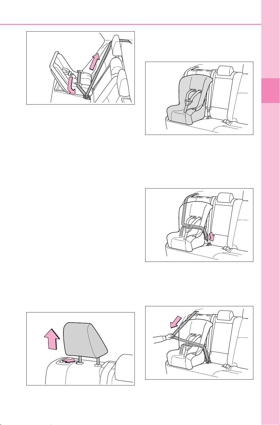
53
1-2. Child safety
Owner’s Manual_USA_M6740B_en
1
For safety and security
6 After installing the child
restraint system, rock it back
and forth to ensure that it is
installed securely. (P. 5 5)
■ Forward-facing Convert-
ible seat
1 Adjust the seat.
When using the front passenger
seat: If installing the child restraint
system to the front passenger seat
is unavoidable, refer to P.50 for
front passenger seat adjustment.
When using the rear seat: If there is
a gap between the child restraint
system and the seatback, adjust
the seatback angle until good con-
tact is achieved.
2 If the head restraint interferes
with the child restraint system
installation and the head
restraint can be removed,
remove the head restraint.
(P.187)
3 Place the child restraint sys-
tem on the seat facing the
front of the vehicle.
4 Run the seat belt through the
child restraint system and
insert the plate into the
buckle. Make sure that the
belt is not twisted.
5 Fully extend the shoulder belt
and allow it to retract to put it
in lock mode. In lock mode,
the belt cannot be extended.
SOLTERRA_OM_USA_A6740BE.book 53 ページ 2025年5月23日 金曜日 午後1時18分
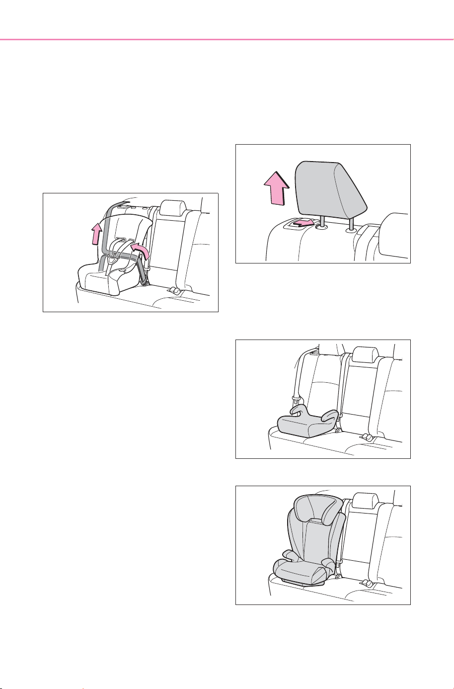
54
1-2. Child safety
Owner’s Manual_USA_M6740B_en
6 While pushing the child
restraint system into the rear
seat, allow the shoulder belt
to retract until the child
restraint system is securely in
place.
After the shoulder belt has
retracted to a point where there is
no slack in the belt, pull the belt to
check that it cannot be extended.
7 If the child restraint has a top
tether strap, follow the child
restraint manufacturer’s
operation manual regarding
the installation, using the top
tether strap to latch onto the
top tether strap anchor.
(P. 59 )
8 After installing the child
restraint system, rock it back
and forth to ensure that it is
installed securely. (P. 5 5)
■ Booster seat
1 If installing the child restraint
system to the front passen-
ger seat is unavoidable, refer
to P.50 for front passenger
seat adjustment.
2 High back type: If the head
restraint interferes with your
child restraint system, and
the head restraint can be
removed, remove the head
restraint. (P.187)
3 Place the child restraint sys-
tem on the seat facing the
front of the vehicle.
Booster type
High back type
SOLTERRA_OM_USA_A6740BE.book 54 ページ 2025年5月23日 金曜日 午後1時18分
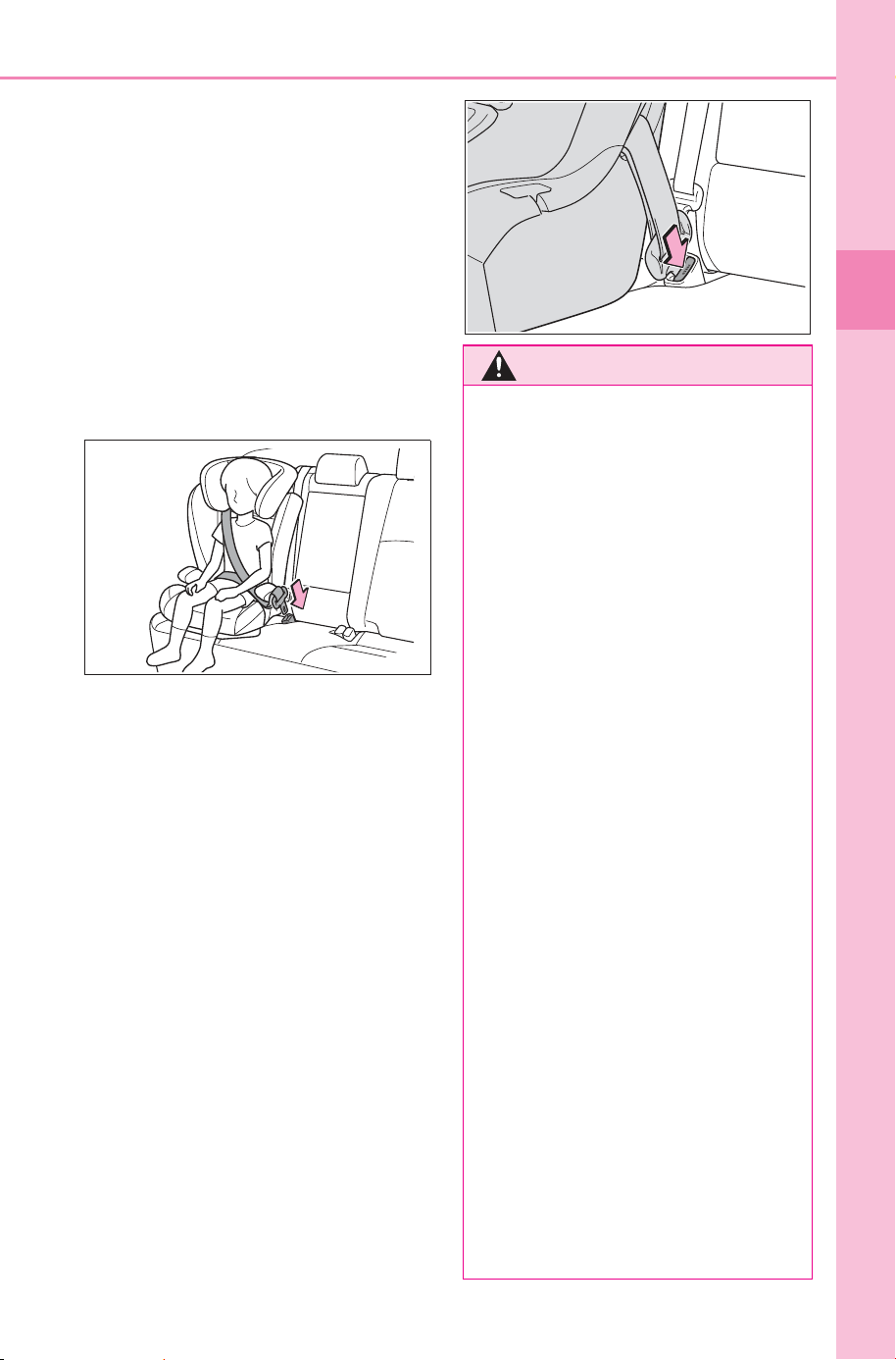
55
1-2. Child safety
Owner’s Manual_USA_M6740B_en
1
For safety and security
4 Sit the child in the child
restraint system. Fit the seat
belt to the child restraint sys-
tem according to the manu-
facturer’s instructions and
insert the plate into the
buckle. Make sure that the
belt is not twisted.
Check that the shoulder belt is cor-
rectly positioned over the child’s
shoulder and that the lap belt is as
low as possible. (P. 2 9 )
■ Removing a child restraint
system installed with a seat
belt
Press the buckle release button
and fully retract the seat belt.
When releasing the buckle, the
child restraint system may spring
up due to the rebound of the seat
cushion. Release the buckle while
holding down the child restraint
system.
Since the seat belt automatically
reels itself, slowly return it to the
stowing position.
WARNING
■ When installing a child
restraint system
Observe the following precau-
tions.
Failure to do so may result in
death or serious injury.
● Do not allow children to play
with the seat belt. If the seat belt
becomes twisted around a
child’s neck, it may lead to
choking or other serious injuries
that could result in death.
If this occurs and the buckle
cannot be unfastened, scissors
should be used to cut the belt.
● Ensure that the belt and plate
are securely locked and the
seat belt is not twisted.
● Shake the child restraint system
left and right, and forward and
backward to ensure that it has
been securely installed.
● After securing a child restraint
system, never adjust the seat.
● When a booster seat is
installed, always ensure that the
shoulder belt is positioned
across the center of the child’s
shoulder. The belt should be
kept away from the child’s neck,
but not so that it could fall off the
child’s shoulder.
● Follow all installation instruc-
tions provided by the child
restraint system manufacturer.
SOLTERRA_OM_USA_A6740BE.book 55 ページ 2025年5月23日 金曜日 午後1時18分
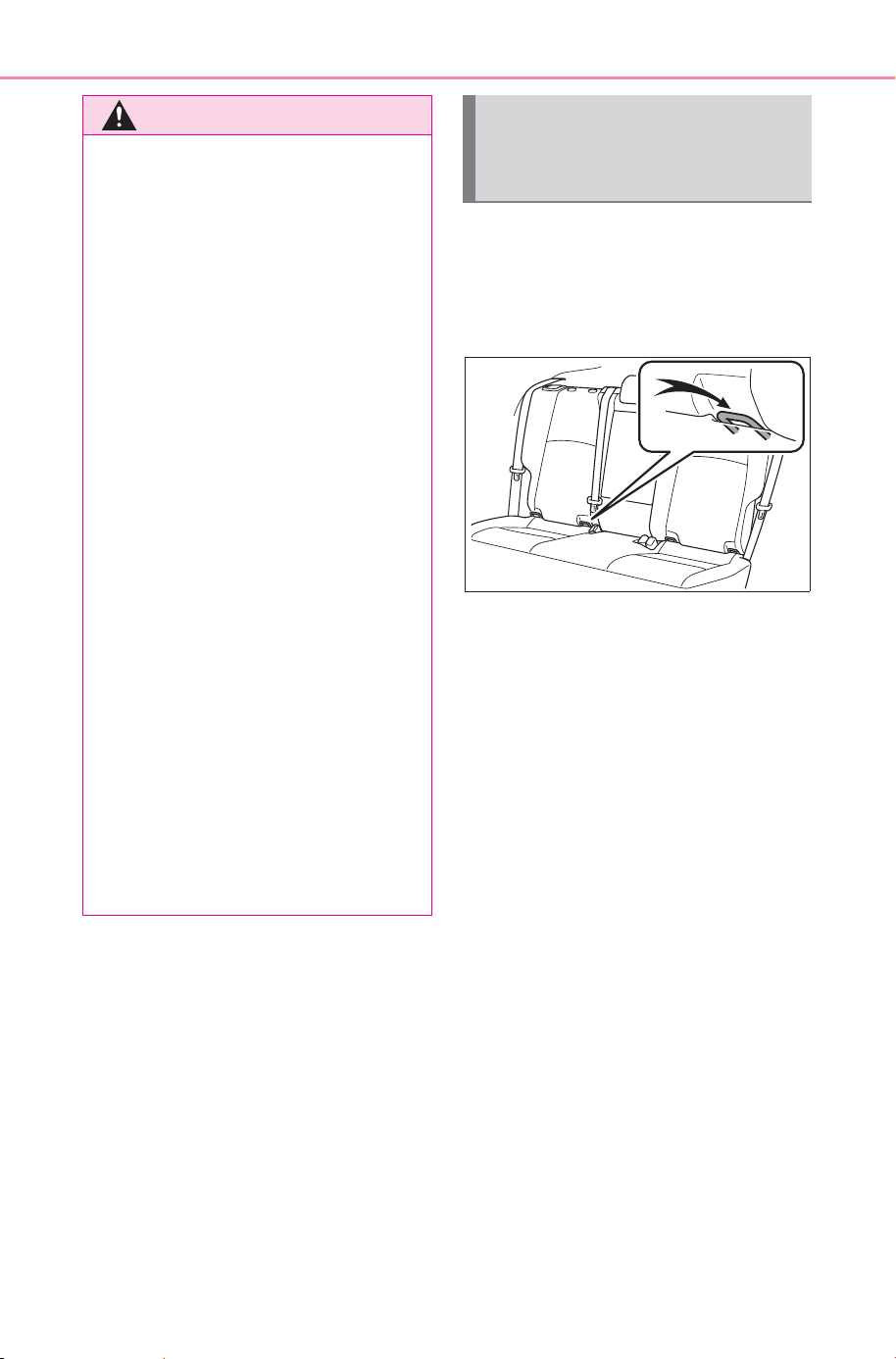
56
1-2. Child safety
Owner’s Manual_USA_M6740B_en
■ Child restraint LATCH
anchors
LATCH anchors are provided for
the outboard rear seats.
■ When installing in the rear
outboard seats
Install the child restraint system
in accordance to the operation
manual enclosed with the child
restraint system.
1 Adjust the seat.
If there is a gap between the child
restraint system and the seatback,
adjust the seatback angle until
good contact is achieved.
2 If the head restraint interferes
with the child restraint system
installation and the head
restraint can be removed,
remove the head restraint.
(P.187)
WARNING
● When securing some types of
child restraint systems in rear
seats, it may not be possible to
properly use the seat belts in
positions next to the child
restraint without interfering with
it or affecting seat belt effective-
ness. Be sure your seat belt fits
snugly across your shoulder
and low on your hips. If it does
not, or if it interferes with the
child restraint, move to a differ-
ent position. Failure to do so
may result in death or serious
injury.
● When installing a child restraint
system in the rear center seat,
adjust both seatbacks at the
same angle. Otherwise, the
child restraint system cannot be
securely restrained and this
may cause death or serious
injuries in the event of sudden
braking, sudden swerving or an
accident.
■ When installing a booster
seat
To prevent the belt from going into
ALR lock mode, do not fully
extend the shoulder belt. ALR
mode causes the belt to tighten
only. This could cause injury or
discomfort to the child. (P. 3 1 )
Child restraint system
fixed with a child restraint
LATCH anchor
SOLTERRA_OM_USA_A6740BE.book 56 ページ 2025年5月23日 金曜日 午後1時18分
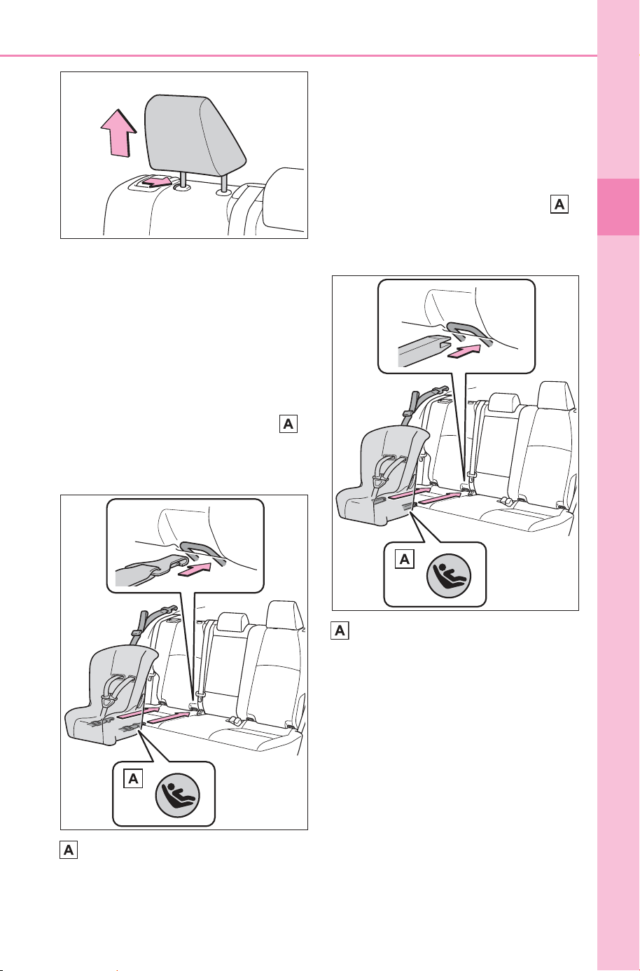
57
1-2. Child safety
Owner’s Manual_USA_M6740B_en
1
For safety and security
With flexible lower attach-
ments
3 Latch the hooks of the lower
attachments onto the LATCH
anchors.
For owners in Canada:
The symbol on a child
restraint system indicates
the presence of a lower con-
nector system.
Canada only
With rigid lower attachments
3 Latch the buckles onto the
LATCH anchors.
For owners in Canada:
The symbol on a child
restraint system indicates
the presence of a lower con-
nector system.
Canada only
4 If the child restraint has a top
tether strap, follow the child
restraint manufacturer’s
operation manual regarding
the installation, using the top
tether strap to latch onto the
top tether strap anchor.
(P.59)
5 After installing the child
restraint system, rock it back
and forth to ensure that it is
installed securely. (P. 55 )
SOLTERRA_OM_USA_A6740BE.book 57 ページ 2025年5月23日 金曜日 午後1時18分
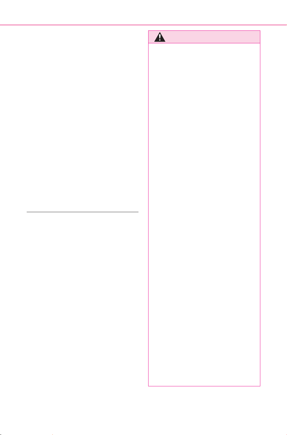
58
1-2. Child safety
Owner’s Manual_USA_M6740B_en
■ When installing in the rear
center seat
There are no LATCH anchors
behind the rear center seat.
However, the inboard LATCH
anchors of the outboard seats,
which are 16.54 in. (420 mm)
apart, can be used if the child
restraint system manufacturer’s
instructions permit use of those
anchors with the anchor spacing
stated.
Child restraint systems with rigid
lower attachments cannot be
installed in the center seat. This
type of child restraint system
can only be installed in the out-
board seat.
■ Laws and regulations pertain-
ing to anchors
The LATCH system conforms to
FMVSS225 or CMVSS210.2.
Child restraint systems conforming
to FMVSS213 or CMVSS213 speci-
fications can be used.
This vehicle is designed to conform
to SAE J1819.
WARNING
■ When installing a child
restraint system
Observe the following precau-
tions.
Failure to do so may result in
death or serious injury.
● When using the LATCH
anchors, be sure that there are
no foreign objects around the
anchors and that the seat belt is
not caught behind the child
restraint system.
● Follow all installation instruc-
tions provided by the child
restraint system manufacturer.
● Never attach two child restraint
system attachments to the
same anchor. In a collision, one
anchor may not be strong
enough to hold two child
restraint system attachments
and may break.
If the LATCH anchors are
already in use, use the seat belt
to install a child restraint system
in the center seat.
● When securing some types of
child restraint systems in rear
seats, it may not be possible to
properly use the seat belts in
positions next to the child
restraint without interfering with
it or affecting seat belt effective-
ness. Be sure your seat belt fits
snugly across your shoulder
and low on your hips. If it does
not, or if it interferes with the
child restraint, move to a differ-
ent position. Failure to do so
may result in death or serious
injury.
● If the seat is adjusted, reconfirm
the security of the child restraint
system.
SOLTERRA_OM_USA_A6740BE.book 58 ページ 2025年5月23日 金曜日 午後1時18分
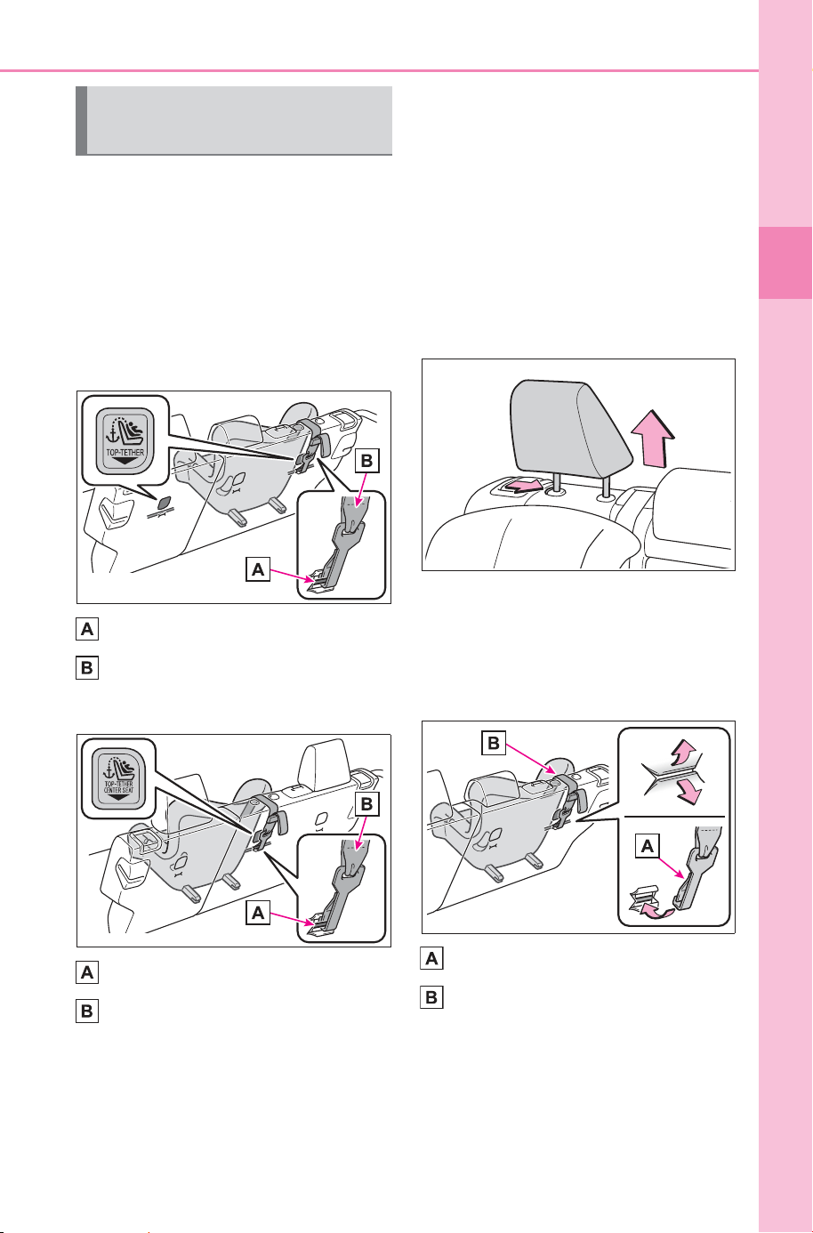
59
1-2. Child safety
Owner’s Manual_USA_M6740B_en
1
For safety and security
■ Anchor brackets (for top
tether strap)
Anchor brackets are provided
for each rear seat.
Use anchor brackets when fix-
ing the top tether strap.
Outboard rear seats
Anchor brackets
Top tether strap
Rear center seat
Anchor bracket
Top tether strap
■ Fixing the top tether strap
to the anchor bracket
Install the child restraint system
in accordance to the operation
manual enclosed with the child
restraint system.
Outboard rear seats
1 Remove the head restraint.
(P.187)
2 Latch the hook onto the
anchor bracket and tighten
the top tether strap.
Make sure the top tether strap is
securely latched. (P. 55)
Hook
Top tether strap
Using an anchor bracket
(for top tether strap)
SOLTERRA_OM_USA_A6740BE.book 59 ページ 2025年5月23日 金曜日 午後1時18分
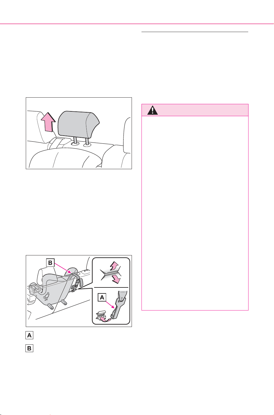
60
1-2. Child safety
Owner’s Manual_USA_M6740B_en
Rear center seat
1 Adjust the head restraint to
the upmost position.
If the head restraint interferes with
your child restraint system, and the
head restraint can be removed,
remove the head restraint.
(P.187)
2 Latch the hook onto the
anchor bracket and tighten
the top tether strap.
Make sure the top tether strap is
securely latched.
When installing the child restraint
system with the head restraint
being raised, be sure to have the
top tether strap pass underneath
the head restraint.
Hook
Top tether strap
■ Laws and regulations pertain-
ing to anchors
The LATCH system conforms to
FMVSS225 or CMVSS210.2.
Child restraint systems conforming
to FMVSS213 or CMVSS213 speci-
fications can be used.
This vehicle is designed to conform
to SAE J1819.
WARNING
■ When installing a child
restraint system
Observe the following precau-
tions.
Failure to do so may result in
death or serious injury.
● Firmly attach the top tether
strap and make sure that the
belt is not twisted.
● Do not attach the top tether
strap to anything other than the
anchor bracket.
● After securing a child restraint
system, never adjust the seat.
● Follow all installation instruc-
tions provided by the child
restraint system manufacturer.
● Rear center seat: When install-
ing the child restraint system
with the head restraint being
raised, after the head restraint
has been raised and then the
anchor bracket has been fixed,
do not lower the head restraint.
SOLTERRA_OM_USA_A6740BE.book 60 ページ 2025年5月23日 金曜日 午後1時18分
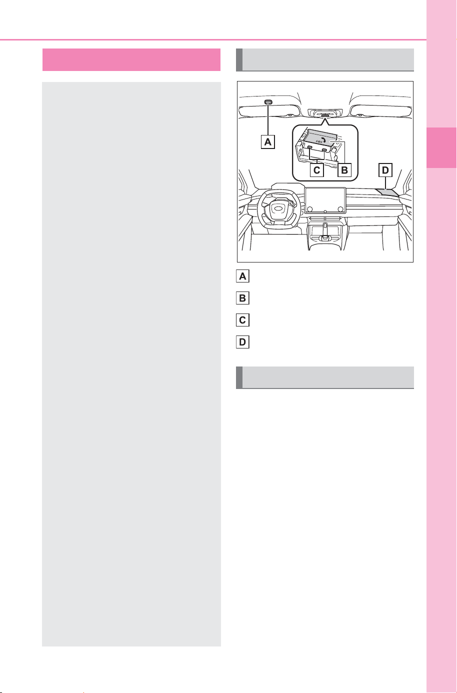
61
1-3. Emergency assistance
Owner’s Manual_USA_M6740B_en
1
For safety and security
1-3.Emer gency assistance
Microphone
“SOS” button
LED light indicators
Speaker
Subscribers have the following
SubaruConnect services avail-
able:
Automatic Collision Notifica-
tion
*
Helps drivers receive necessary
response from emergency service
providers. (
P. 63)
*
: U.S. Patent No. 7,508,298 B2
Stolen Vehicle Location
Helps drivers in the event of vehicle
theft. (
P.6 3 )
SubaruConnect
SubaruConnect is a sub-
scription-based telematics
service that uses Global
Positioning System (GPS)
data and embedded cellular
technology to provide
safety and security fea-
tures to subscribers. Sub-
aruConnect is supported by
SUBARU’s designated
response center, which
operates 24 hours per day, 7
days per week.
SubaruConnect service tri-
als are available for your
convenience.
By using the SubaruCon-
nect service, you are agree-
ing to be bound by the
Telematics Subscription
Service Agreement and its
Terms and Conditions, as in
effect and amended from
time to time, a current copy
of which is available at
www.Toyota.com/
privacyvts. All use of the
SubaruConnect service is
subject to such then appli-
cable Terms and Condi-
tions.
If you wish to deactivate
services, please contact a
SubaruConnect customer
care advisor by pushing the
in-vehicle SOS button.
System components
Services
SOLTERRA_OM_USA_A6740BE.book 61 ページ 2025年5月23日 金曜日 午後1時18分

62
1-3. Emergency assistance
Owner’s Manual_USA_M6740B_en
Emergency Assistance Button
(“SOS”)
Connects drivers to response-cen-
ter support. (
P. 63)
Enhanced Roadside Assis-
tance
Provides drivers various on-road
assistance. (
P.64)
After you have signed the
Telematics Subscription Service
Agreement and are enrolled,
you can begin receiving ser-
vices.
A variety of subscription terms
are available for purchase. Con-
tact your SUBARU dealer, call
the following or push the “SOS”
button in your vehicle for further
subscription details.
The United States
(866) 384-3574
Canada
(800) 263-8802
■ SubaruConnect Services infor-
mation
● Phone calls using the vehicles
Bluetooth
®
technology will not be
possible during SubaruConnect.
● SubaruConnect is available begin-
ning May 2022 on select SUBARU
models (in the contiguous United
States only). Contact with the
SubaruConnect response center
is dependent upon the telematics
device being in operative condi-
tion, cellular connection availabil-
ity, and GPS satellite signal
reception, which can limit the abil-
ity to reach the response center or
receive emergency service sup-
port. Enrollment and Telematics
Subscription Service Agreement
are required. A variety of subscrip-
tion terms are available; charges
vary by subscription term selected
and location.
● Automatic Collision Notification,
Emergency Assistance and Stolen
Vehicle Location are available in
the United States, including
Hawaii and Alaska, as well as
Canada, and Enhanced Road-
side Assistance are available in
the United States and Canada.
● Automatic Collision Notification,
Emergency Assistance, Stolen
Vehicle and Enhanced Road
Assistance will not function in the
United States Virgin Islands. For
vehicles first sold in the USVI, no
SubaruConnect services will func-
tion in and outside the United
States Virgin Islands.
● SubaruConnect services are not
subject to section 255 of the Tele-
communications Act and the
device is not TTY compatible.
■ Languages
The SubaruConnect response cen-
ter will offer support in multiple lan-
guages. The SubaruConnect
system will offer voice prompts in
English, Spanish, and French.
Please indicate your language of
choice when enrolling.
■ When contacting the response
center
You may be unable to contact the
response center if the network is
busy.
Subscription
SOLTERRA_OM_USA_A6740BE.book 62 ページ 2025年5月23日 金曜日 午後1時18分

63
1-3. Emergency assistance
Owner’s Manual_USA_M6740B_en
1
For safety and security
When the power switch is turned
to ON, the red indicator light
comes on for 2 seconds then
turns off. Afterward, the green
indicator light comes on, indicat-
ing that the service is active.
The following indicator light pat-
terns indicate specific system
usage conditions:
Green indicator light on =
Active service
Green indicator light flashing
= SubaruConnect call in pro-
cess
Red indicator light (except at
vehicle start-up) = System
malfunction (contact your
SUBARU dealer)
No indicator light (off) = Sub-
aruConnect service not active
■ Automatic Collision Notifi-
cation
In case of either airbag deploy-
ment or severe rear-end colli-
sion, the system is designed to
automatically call the response
center. The responding agent
receives the vehicle’s location
and attempts to speak with the
vehicle occupants to assess the
level of emergency. If the occu-
pants are unable to communi-
cate, the agent automatically
treats the call as an emergency,
contacts the nearest emer-
gency services provider to
describe the situation, and
requests that assistance be sent
to the location.
■ Stolen Vehicle Location
If your vehicle is stolen, Subaru-
Connect can work with local
authorities to assist them in
locating and recovering the
vehicle. After filing a police
report, call the Customer Experi-
ence Center at (866) 384-3574
in the United States or (800)
263-8802 in Canada, and follow
the prompts for SubaruConnect
to initiate this service.
In addition to assisting law
enforcement with recovery of a
stolen vehicle, SubaruConnect
vehicle location data may, under
certain circumstances, be
shared with third parties to
locate your vehicle. Further
information is available at Toy-
ota.com.
■ Emergency Assistance But-
ton (“SOS”)
In the event of an emergency on
the road, push the “SOS” button
to reach the SubaruConnect
response center. The answer-
ing agent will determine your
vehicle’s location, assess the
emergency, and dispatch the
necessary assistance required.
SubaruConnect LED light
Indicators
SubaruConnect services
SOLTERRA_OM_USA_A6740BE.book 63 ページ 2025年5月23日 金曜日 午後1時18分

64
1-3. Emergency assistance
Owner’s Manual_USA_M6740B_en
If you accidentally press the “SOS”
button, tell the response-center
agent that you are not experiencing
an emergency.
■ Enhanced Roadside Assis-
tance
Enhanced Roadside Assistance
adds GPS data to the already
included warranty-based SUB-
ARU road side assistance.
Subscribers can press the
“SOS” button to reach a Subaru-
Connect response-center agent,
who can help with a wide range
of needs, such as: towing, flat
tire etc. For a description of the
Enhanced Roadside Assistance
services and their limitations,
please see the SubaruConnect
Terms and Conditions, which
are available at Toyota.com.
Important! Read this informa-
tion about exposure to radio fre-
quency signals before using
SubaruConnect;
The SubaruConnect system
installed in your vehicle is a low-
power radio transmitter and
receiver. It receives and also
sends out radio frequency (RF)
signals.
In August 1996, the Federal
Communications Commission
(FCC) adopted RF exposure
guidelines with safety levels for
mobile wireless phones. Those
guidelines are consistent with
the safety standards previously
set by the following U.S. and
international standards bodies.
ANSI (American National
Standards Institute) C95.1
[1992]
NCRP (National Council on
Radiation Protection and
Measurement) Report 86
[1986]
ICNIRP (International Com-
mission on Non-Ionizing Radi-
ation Protection) [1996]
Those standards were based on
comprehensive and periodic
evaluations of the relevant sci-
entific literature. Over 120 scien-
tists, engineers, and physicians
from universities, and govern-
ment health agencies and
industries reviewed the avail-
able body of research to
develop the ANSI Standard
(C95.1).
The design of SubaruConnect
complies with the FCC guide-
lines in addition to those stan-
dards.
Safety information for
SubaruConnect
SOLTERRA_OM_USA_A6740BE.book 64 ページ 2025年5月23日 金曜日 午後1時18分
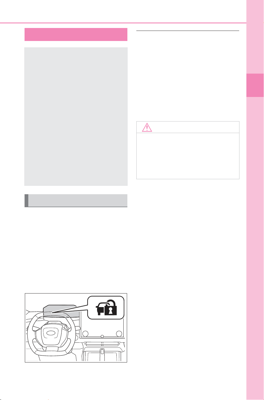
65
1-4. Theft deterrent system
Owner’s Manual_USA_M6740B_en
1
For safety and security
1-4.Th eft deterrent system
The indicator light flashes after
the power switch has been
turned to OFF to indicate that
the system is operating.
The indicator light goes off after
the power switch has been
turned to ACC or ON to indicate
that the system has been can-
celed.
■ System maintenance
The vehicle has a maintenance-free
type immobilizer system.
■ Conditions that may cause the
system to malfunction
● If the grip portion of the key is in
contact with a metallic object
● If the key is in close proximity to or
touching a key to the security sys-
tem (key with a built-in transpon-
der chip) of another vehicle
Immobilizer system
The vehicle’s keys have
built-in transponder chips
that prevent the EV system
from starting if a key has
not been previously regis-
tered in the vehicle’s on-
board computer.
Never leave the keys inside
the vehicle when you leave
the vehicle.
This system is designed to
help prevent vehicle theft but
does not guarantee absolute
security against all vehicle
thefts.
Operating the system
NOTICE
■ To ensure the system oper-
ates correctly
Do not modify or remove the sys-
tem. If modified or removed, the
proper operation of the system
cannot be guaranteed.
SOLTERRA_OM_USA_A6740BE.book 65 ページ 2025年5月23日 金曜日 午後1時18分
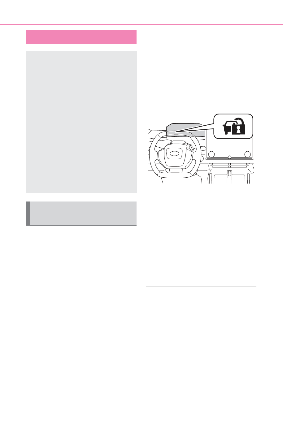
66
1-4. Theft deterrent system
Owner’s Manual_USA_M6740B_en
■ Items to check before lock-
ing the vehicle
To prevent unexpected trigger-
ing of the alarm and vehicle
theft, make sure of the following:
Nobody is in the vehicle.
The windows are closed
before the alarm is set.
No valuables or other per-
sonal items are left in the
vehicle.
■ Setting
Close the doors, back door and
hood, and lock all doors. The
system will be set automatically
after 30 seconds.
The indicator light changes from
being on to flashing when the sys-
tem is set.
■ Deactivating or stopping
Do one of the following to deac-
tivate or stop the alarms:
Unlock the doors.
Turn the power switch to ACC
or ON, or start the EV system.
(The alarm will be deactivated
or stopped after a few sec-
onds.)
■ Setting the alarm
The alarm can be set if all the doors
are closed even with the hood open.
■ System maintenance
The vehicle has a maintenance-free
type alarm system.
■ Triggering of the alarm
The alarm may be triggered in the
following situations:
(Stopping the alarm deactivates the
alarm system.)
Alarm
The alarm uses light and
sound to give an alert when
an intrusion is detected.
The alarm is triggered in the
following situations when
the alarm is set:
A locked door or back door
is unlocked or opened in
any way other than using
the entry function or wire-
less remote control. (The
doors will lock again auto-
matically.)
The hood is opened.
Setting/deactivating/stop-
ping the alarm system
SOLTERRA_OM_USA_A6740BE.book 66 ページ 2025年5月23日 金曜日 午後1時18分
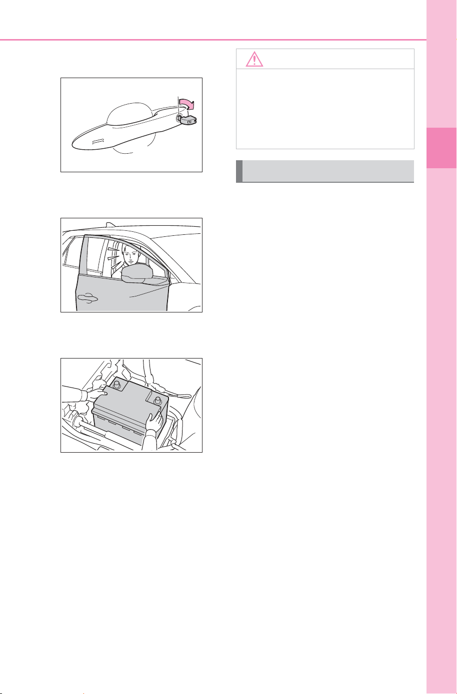
67
1-4. Theft deterrent system
Owner’s Manual_USA_M6740B_en
1
For safety and security
● The doors are unlocked using the
mechanical key.
● A person inside the vehicle opens
a door, the back door or hood, or
unlocks the vehicle.
● The 12-volt battery is recharged or
replaced when the vehicle is
locked. (P.646)
■ Alarm-operated door lock
In the following cases, depending
on the situation, the door may auto-
matically lock to prevent improper
entry into the vehicle:
● When a person remaining in the
vehicle unlocks the door and the
alarm is activated.
● While the alarm is activated, a
person remaining in the vehicle
unlocks the door.
● When recharging or replacing the
12-volt battery.
If a door is unlocked with the
mechanical key while the alarm
is being set, the pre-alarm will
sound for 10 seconds.
If either the door is locked again
or the pre-alarm is stopped
within those 10 seconds, an
alarm will sound.
Do any of the following in order
to deactivate or stop the pre-
alarm:
Close the doors, and lock all
doors by entry function or
wireless remote control.
Turn the power switch to ACC
or ON, or start the EV system.
(The alarm will be deactivated
and stop after a few seconds.)
NOTICE
■ To ensure the system oper-
ates correctly
Do not modify or remove the sys-
tem. If modified or removed, the
proper operation of the system
cannot be guaranteed.
Pre-alarm
SOLTERRA_OM_USA_A6740BE.book 67 ページ 2025年5月23日 金曜日 午後1時18分

68
1-4. Theft deterrent system
Owner’s Manual_USA_M6740B_en
SOLTERRA_OM_USA_A6740BE.book 68 ページ 2025年5月23日 金曜日 午後1時18分

69
Owner’s Manual_USA_M6740B_en
2
2
Electric Vehicle system
Electric Vehicle system
2-1. Electric vehicle system
Electric Vehicle system fea-
tures .............................
70
Electric Vehicle system pre-
cautions........................
74
Battery Electric Vehicle driv-
ing tips..........................
79
Driving range..................81
2-2. Charging
Charging equipment.......83
Locking and unlocking the
AC charging connector.
85
Charging methods..........88
Charging tips..................90
Things to know before
charging .......................
92
How to use AC charging 95
How to use DC charging
..................................
100
Using the charging schedule
function......................
106
Using Battery Precondition-
ing .............................
113
Using My Room Mode 117
When charging cannot be
carried out .................
120
Plug & Charge system 132
How to use Plug & Charge
system.......................
132
When Plug & Charge sys-
tem cannot be used nor-
mally.......................... 134
SOLTERRA_OM_USA_A6740BE.book 69 ページ 2025年5月23日 金曜日 午後1時18分
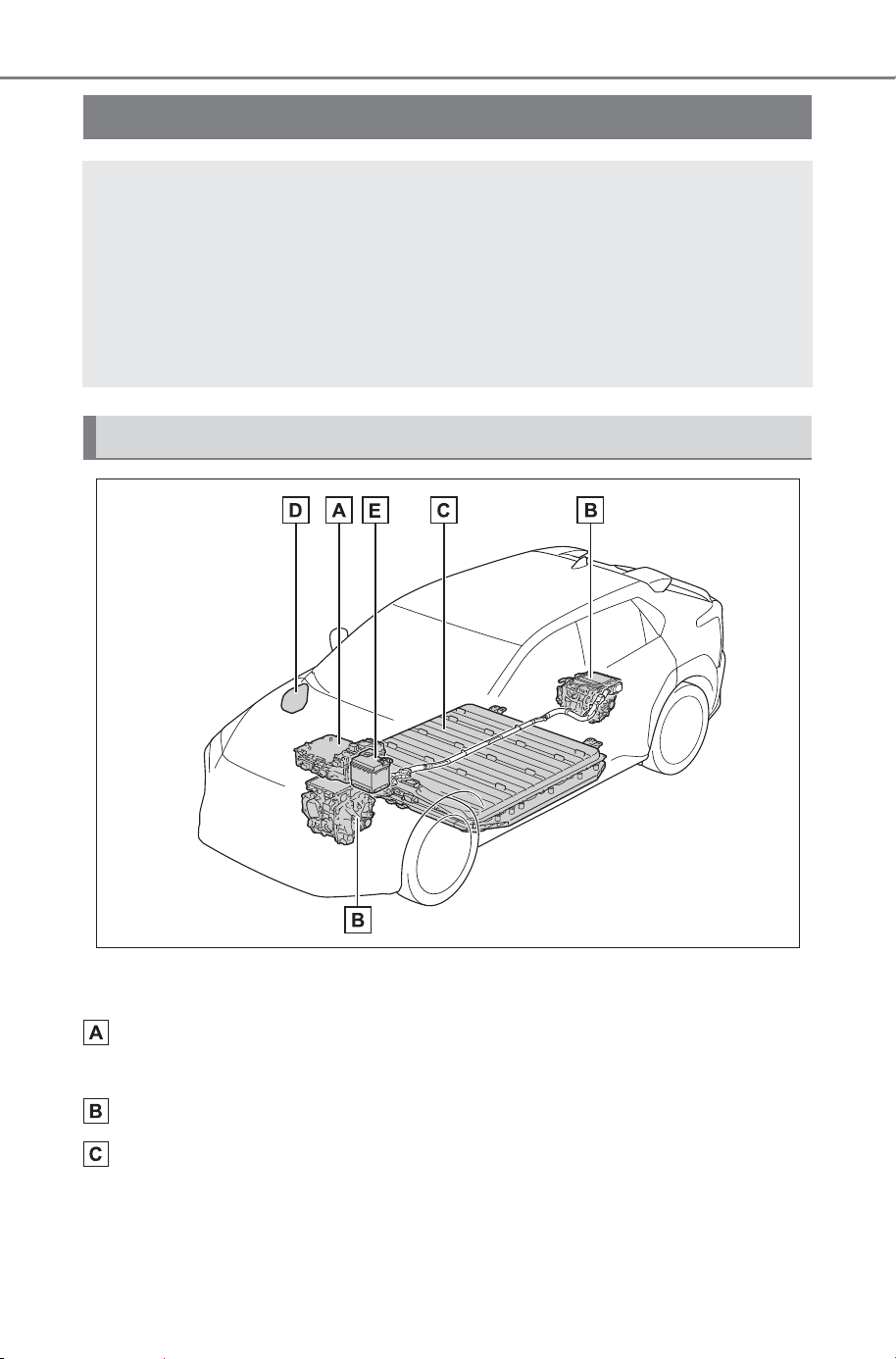
70
2-1. Electric vehicle system
Owner’s Manual_USA_M6740B_en
2-1.Elec tric vehic le system
The illustration is an example for explanation and may differ from the actual
item.
ESU: Electricity Supply Unit (built in onboard traction battery
charger/DC-DC converter)
eAxle (Traction motor/Inverter/Trans axle) (front/rear
*
)
Traction battery
Provides electricity to the electric motor.
Electric Vehicle system features
Battery electric vehicles are considerably different from con-
ventional vehicles.
They use electricity charged in a traction battery, to drive the
electric motor. Since battery electric vehicles are driven using
electricity, they do not emit any emissions such as CO
2
(Car-
bon Dioxide) and NOx (Nitrogen Oxides). Battery electric
vehicles are environmentally friendly vehicles.
System components
SOLTERRA_OM_USA_A6740BE.book 70 ページ 2025年5月23日 金曜日 午後1時18分
71
2-1. Electric vehicle system
Owner’s Manual_USA_M6740B_en
2
Electric Vehicle system
Charging port
12-volt battery
Provides electricity to various vehicle systems such as the SRS airbags,
headlights, wipers, etc.
*
: AWD models only
■ When braking (regenera-
tive braking)
The electric motor (traction
motor) charges the traction bat-
tery.
The driving range can be
extended by actively using this
regenerative braking to store
electricity in the traction battery.
The battery electric vehicle is
driven using electricity, which is
received from an external power
source and stored in the traction
battery. Not only public charging
stations, but also household out-
lets can be used for charging.
Procedures are different from
refueling a conventional vehi-
cle. Therefore, make sure to
read the following thoroughly.
Charging equipment (P.8 3 )
Things to know before
charging (P.92 )
How to charge your vehicle
(P.95, 100)
When charging cannot be
performed normally (P.120)
■ Regenerative braking
In the following situations, kinetic
energy is converted to electric
energy and deceleration force can
be obtained in conjunction with the
recharging of the traction battery.
● The accelerator pedal is released
while driving with the shift position
in D.
● The brake pedal is depressed
while driving with the shift position
in D.
■ Charging the 12-volt battery
The 12-volt battery is charged from
the traction battery when the EV
system is operated or while the trac-
tion battery is being charged.
If the vehicle has not been used for
a long time, the 12-volt battery may
become low due to self-discharge. If
this occurs, follow the correct proce-
dures. (P.644)
■ When not using the vehicle for
an extended period of time
● When the vehicle will not be used
for an extended period of time,
charge the traction battery once a
month.
This protects the traction battery
from extreme voltage decline due
to self discharging.
● When the vehicle will not be used
for an extended period of time, the
12-volt battery will be charged
from the traction battery to reduce
the risk of the 12-volt battery dis-
charged. In this case, the cooling
fan may operate, however it is not
a malfunction.
Charging
SOLTERRA_OM_USA_A6740BE.book 71 ページ 2025年5月23日 金曜日 午後1時18分

72
2-1. Electric vehicle system
Owner’s Manual_USA_M6740B_en
● To prevent the 12-volt battery from
being discharged, do not leave the
charging port lid open or the
charging cable connected to the
vehicle.
■ Charging the traction battery
Be sure to maintain the traction bat-
tery charge level suitable for your
driving needs.
If the traction battery fully dis-
charges, the vehicle cannot be
driven at all. When the battery
becomes low, charge it as soon as
possible.
■ If the traction battery becomes
low
● If the traction battery becomes
low, the traction battery charge
warning light comes on or flashes
and a message will be displayed
on the multi-information display.
(P.613)
● If the traction battery is completely
discharged, the EV system cannot
be started and driving will not be
possible. When the traction bat-
tery becomes low, charge it as
soon as possible.
■ Sounds and vibrations specific
to a battery electric vehicle
Because there is no engine sound
or vibration, it is easy to mistake the
battery electric vehicle for being off
when it is actually still running, as
indicated by the “READY” indicator
being illuminated. For safety, make
sure to always shift the shift position
to P and apply the parking brake
when parked.
Before and after the EV system is
started, the following sounds and
vibrations may occur. However,
these sounds and/or vibrations are
not signs of malfunctions:
● The brake system operation
sound may be heard from the
front of the vehicle when the
driver’s door is opened.
● Motor sounds may be heard from
the motor compartment or lug-
gage compartment.
● Electrical relay sounds may be
heard from the motor compart-
ment when the EV system starts
or stops.
● Relay operating sounds such as a
snap or soft clank will be emitted
from the traction battery in the fol-
lowing situations:
• When the EV system is started or
stopped
• When charging starts or com-
pletes
• When the vehicle is driven the first
time after the traction battery has
been charged using DC charging
● Sounds may be heard due to
regenerative braking when the
brake pedal is depressed or as
the accelerator pedal is released.
● Cooling fan operating sounds
from the radiator.
● The operation sound of the air
conditioning system (air condition-
ing compressor, blower motor).
■ Maintenance, repair, recycling,
and disposal
Contact your SUBARU dealer
regarding maintenance, repair, recy-
cling and disposal. Do not dispose
of the vehicle yourself.
SOLTERRA_OM_USA_A6740BE.book 72 ページ 2025年5月23日 金曜日 午後1時18分
73
2-1. Electric vehicle system
Owner’s Manual_USA_M6740B_en
2
Electric Vehicle system
A sound which changes in
accordance with the driving
speed, will be played in order to
warn people nearby of the vehi-
cle’s approach. This sound may
be heard inside the vehicle. The
sound will stop when the vehicle
speed exceeds approximately
23 mph (37 km/h).
■ Acoustic Vehicle Alerting Sys-
tem
In the following cases, the Acoustic
Vehicle Alerting System may be dif-
ficult for surrounding people to hear.
● In very noisy areas
● In the wind or the rain
Also, as the Acoustic Vehicle Alert-
ing System is installed on the front
of the vehicle, it may be more diffi-
cult to hear from the rear of the vehi-
cle compared to the front.
■ When the multi-information dis-
play shows “Acoustic Vehicle
Alerting System Malfunction
Visit your Dealer.”
There is a possibility that there is an
abnormality in the Acoustic Vehicle
Alerting System. Please contact
your SUBARU dealer.
Acoustic Vehicle Alerting
System
SOLTERRA_OM_USA_A6740BE.book 73 ページ 2025年5月23日 金曜日 午後1時18分
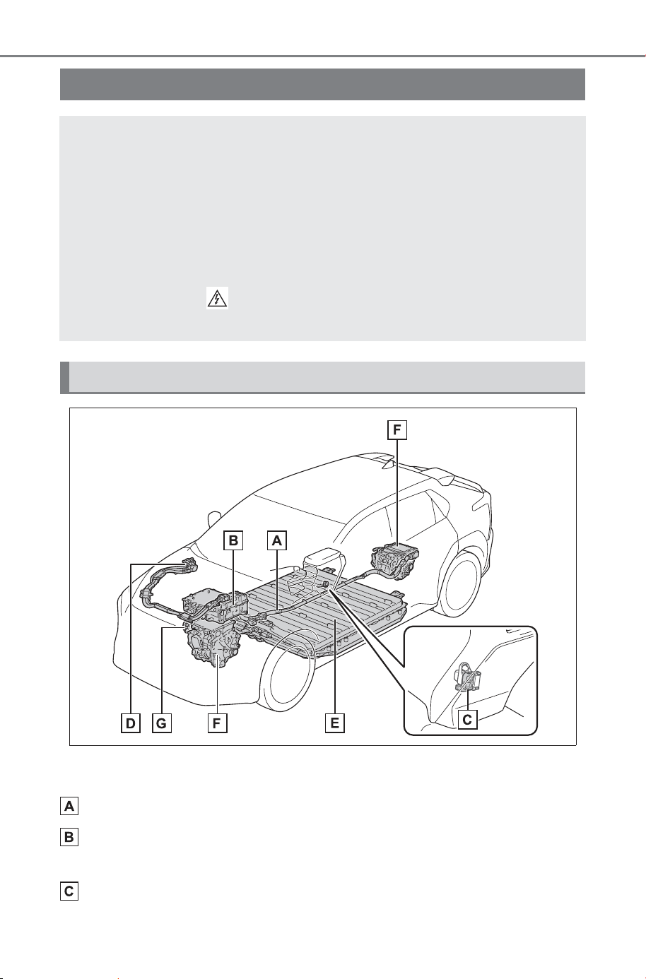
74
2-1. Electric vehicle system
Owner’s Manual_USA_M6740B_en
The illustration is an example for explanation and may differ from the actual
item.
High voltage cables (orange)
ESU: Electricity Supply Unit (built in onboard traction battery
charger/DC-DC converter)
Service plug
Electric Vehicle system precautions
Be careful of the high voltage components (approximately
300 V or more), such as the traction battery, electricity supply
unit, orange colored high voltage cables, and electric motor,
as well as high temperature components such as the cooling
radiator, which are provided on the battery electric vehicle.
Read the following descriptions carefully before using the EV
system, and handle the EV system correctly. Note that warn-
ing labels with a mark are attached to the high voltage
components, to remind you of careful handling required.
System components
SOLTERRA_OM_USA_A6740BE.book 74 ページ 2025年5月23日 金曜日 午後1時18分
75
2-1. Electric vehicle system
Owner’s Manual_USA_M6740B_en
2
Electric Vehicle system
Charging inlet
Traction battery
eAxle (Traction motor/Inverter/Trans axle) (front/rear
*
)
Air conditioning compressor
*
: AWD models only
■ Electromagnetic waves
● High-voltage parts and cables on
the battery electric vehicles incor-
porate electro-magnetic shield-
ing, and therefore emit
approximately the same amount
of electromagnetic waves as con-
ventional gasoline-powered vehi-
cles or home electronic
appliances.
● Your vehicle may cause sound
interference in some third party-
produced radio parts.
■ Traction battery (Lithium-ion
battery)
The traction battery has a limited
service life.
The traction battery capacity (the
ability to store energy) reduces with
time and use in the same way as
other rechargeable batteries. The
extent at which capacity reduces
changes drastically depending on
the environment (outside tempera-
ture, etc.) and usage conditions,
such as how the vehicle is driven
and how the traction battery is
charged.
This is a natural characteristic of
lithium-ion batteries, and is not a
malfunction. Also, even though the
driving range decreases when the
traction battery capacity reduces,
vehicle performance does not sig-
nificantly become worse. In order to
reduce the possibility of the capacity
reducing, follow the directions listed
on P.93, “Capacity reduction of the
traction battery”.
■ Starting the EV system in an
extremely cold environment
When the traction battery is
extremely cold (below approxi-
mately -22°F [-30°C]) due to the
temperature outside of the vehicle, it
may not be possible to start the EV
system. In this case, try to start the
EV system again after the tempera-
ture of the traction battery increases
due to the outside temperature
increasing, etc.
WARNING
■ High-voltage precautions
The vehicle has high voltage DC
and AC systems as well as a 12-
volt system.
DC and AC high voltage systems
are very dangerous and can
cause severe burns and electric
shock that may result in death or
serious injury.
● Never touch, disassemble,
remove, or replace the high volt-
age parts, cables (orange) or
their connectors.
● Do not touch the high voltage
components. They are
extremely hot, especially after
driving.
SOLTERRA_OM_USA_A6740BE.book 75 ページ 2025年5月23日 金曜日 午後1時18分
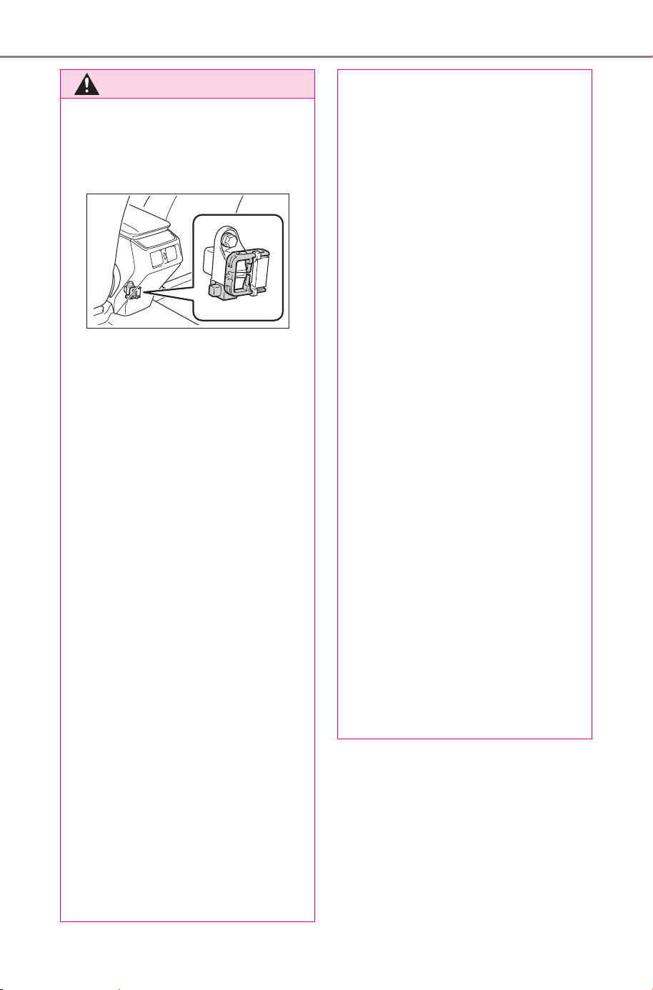
76
2-1. Electric vehicle system
Owner’s Manual_USA_M6740B_en
WARNING
● The service plug is located
under the console box. The ser-
vice plug is used only when the
vehicle is being serviced and is
subject to high voltage.
■ Road accident cautions
Observe the following precautions
to reduce the risk of death or seri-
ous injury:
● Stop the vehicle in a safe place
to prevent subsequent acci-
dents. While depressing the
brake pedal, apply the parking
brake and shift the shift position
to P to stop the EV system.
Then, slowly release the brake
pedal.
● Do not touch the high voltage
parts, cables (orange) and con-
nectors.
● If electric wires are exposed
inside or outside your vehicle,
an electric shock may occur.
Never touch exposed electric
wires.
● Do not touch the traction battery
if liquid is leaking from or
adhered to it. If electrolyte
(Organic Carbonate-based
electrolyte) from the traction
battery comes into contact with
the eyes or skin, it could cause
blindness or skin wounds. In the
unlikely event that it comes into
contact with the eyes or skin,
wash it off immediately with a
large amount of water, and seek
immediate medical attention.
● If electrolyte is leaking from the
traction battery, do not
approach the vehicle.
Even in the unlikely event that
the traction battery has been
damaged, the internal construc-
tion of the battery will prevent a
large amount of electrolyte from
leaking out. However, if electro-
lyte leaks, vapors will be emit-
ted. These vapors are an irritant
to skin and eyes and could
cause acute poisoning if
inhaled.
● Do not bring burning or high-
temperature items close to the
electrolyte. The electrolyte may
ignite and cause a fire.
● If a fire occurs in the battery
electric vehicle, leave the vehi-
cle as soon as possible. Never
use a fire extinguisher that is
not meant for electrical fires.
Using even a small amount of
water may be dangerous.
● If your vehicle needs to be
towed, be sure to transport the
vehicle with the front wheels
(FWD models) or four wheels
(AWD models) raised. If the
vehicle is towed with the wheels
which are connected to the
electric motor (traction motor)
contacting the ground, electric-
ity generated by the operation of
the motor may cause a fire to
occur depending on the nature
of the damage or malfunction.
(P.605)
SOLTERRA_OM_USA_A6740BE.book 76 ページ 2025年5月23日 金曜日 午後1時18分
77
2-1. Electric vehicle system
Owner’s Manual_USA_M6740B_en
2
Electric Vehicle system
WARNING
● Carefully inspect the ground
under the vehicle. If leaked liq-
uid (other than water from the
air conditioning) is found on the
ground, the traction battery may
have been damaged. Leave the
vehicle as soon as possible.
In addition, contact your SUB-
ARU dealer with regard to the
leakage found on the ground.
Even in the event of a minor
accident, the traction battery
and surrounding parts may be
damaged. In case of an acci-
dent, have the traction battery
inspected at a SUBARU dealer.
■ Traction battery
● Your vehicle contains a sealed
lithium-ion battery.
● Never resell, hand over or mod-
ify the traction battery. To pre-
vent accidents, traction
batteries that have been
removed from a disposed vehi-
cle are collected through your
SUBARU dealer. Do not dis-
pose of the battery yourself.
Unless the battery is properly
collected, the following may
occur, resulting in death or seri-
ous injury:
• Do not illegally dispose of or
dump the traction battery, and it
is hazardous to the environment
or someone may touch a high
voltage part, resulting in an
electric shock.
• The traction battery is intended
to be used exclusively with your
battery electric vehicle. If the
traction battery is used outside
of your vehicle or modified in
any way, accidents such as
electric shock, heat generation,
smoke generation, an explo-
sion and electrolyte leakage
may occur. When reselling or
handing over your vehicle, the
possibility of an accident is
extremely high because the per-
son receiving the vehicle may
not be aware of the dangers
from these modifications.
● If your vehicle is disposed of
without the traction battery hav-
ing been removed, there is a
danger of serious electric shock
if high voltage parts, cables and
their connectors are touched. In
the event that your vehicle must
be disposed of, the traction bat-
tery must be disposed of by
your SUBARU dealer or a quali-
fied service shop. If the traction
battery is not disposed of prop-
erly, it may cause electric shock
that can result in death or seri-
ous injury.
● For information about traction
battery collection locations, con-
tact information, or the recycling
process, contact your SUBARU
dealer.
■ Caution while driving
● Pay special attention to the area
around the vehicle. Because
there is no engine noise, pedes-
trians, people riding bicycles or
other people and vehicles in the
area may not be aware of the
vehicle starting off or approach-
ing them, so take extra care
while driving. Therefore, take
extra care while driving even if
the Acoustic Vehicle Alerting
System is active.
SOLTERRA_OM_USA_A6740BE.book 77 ページ 2025年5月23日 金曜日 午後1時18分
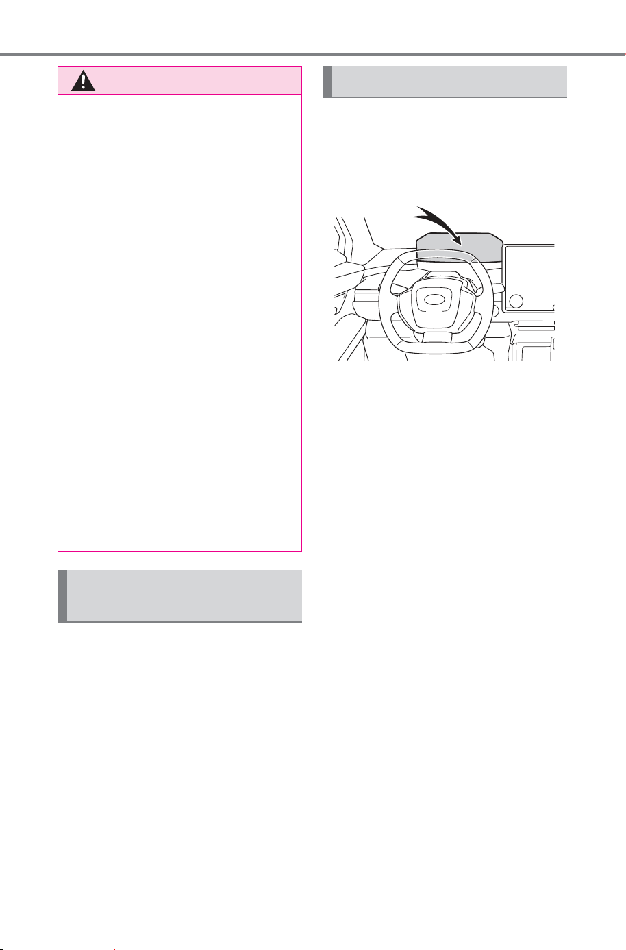
78
2-1. Electric vehicle system
Owner’s Manual_USA_M6740B_en
When a certain level of impact is
detected by the impact sensors,
the emergency shut off system
turns off the EV system and
blocks the high voltage current.
If the emergency shut off system
activates, your vehicle will not
restart. To restart the EV sys-
tem, contact your SUBARU
dealer.
A message is automatically dis-
played when a malfunction
occurs in the EV system or an
improper operation is attempted.
If a warning message is shown
on the multi-information display,
read the message and follow the
instructions. (P.127, 621)
■ If a warning light comes on, a
warning message is displayed,
or the 12-volt battery is discon-
nected
The EV system may not start.
In that case, try to start the system
again. If the “READY” indicator does
not come on, contact your SUBARU
dealer.
■ When the traction battery is
completely discharged
When the EV system cannot be
started due to the traction battery
being completely discharged, restart
the system after AC charging or DC
charging. When charging, it is rec-
ommended to charge the traction
battery until the traction battery
charge warning light turns off in
order to ensure sufficient driving dis-
tance.
WARNING
● If the vehicle under floor area
receives strong shock or impact
while driving, stop the vehicle in
a safe place and check around
the bottom of the vehicle. If
there is damage to the traction
battery or liquid leakage, it may
lead to a vehicle fire, etc. Do not
touch the vehicle and immedi-
ately contact your SUBARU
dealer.
Even if no damage can be seen
under the floor, the traction bat-
tery may be damaged. If the
vehicle received an impact
under the floor, have the traction
battery inspected at a SUBARU
dealer.
■ Modifications
Do not make modifications that
lower the height of the vehicle.
The traction battery in the under
floor area may come into contact
with the ground when the height
of vehicle is lowered. If the trac-
tion battery is damaged, a vehicle
fire may occur, possibly resulting
in death or serious injury.
Emergency shut off sys-
tem
Warning message
SOLTERRA_OM_USA_A6740BE.book 78 ページ 2025年5月23日 金曜日 午後1時18分

79
2-1. Electric vehicle system
Owner’s Manual_USA_M6740B_en
2
Electric Vehicle system
Shift the shift position to D when
stopped at a traffic light, or driv-
ing in heavy traffic, etc. Shift the
shift position to P when parking.
When shifting the shift position
to N while driving, there is no
positive effect on electricity con-
sumption. In the N, the traction
battery cannot be charged. Also,
when using the air conditioning
system, etc., the traction battery
electricity is consumed.
(P.234)
Repeated acceleration and
deceleration due to traffic con-
gestion, long waits at traffic
lights, and driving on steep
inclines will lead to poor electric-
ity consumption. In order to
avoid those situations as much
as possible, check traffic reports
before leaving. If the vehicle is
driven in traffic congestion, gen-
tly release the brake pedal to
allow the vehicle to move for-
ward slightly, avoid overuse of
the accelerator pedal. Doing so
can help minimize unnecessary
electricity consumption.
Make sure to operate the brakes
gently and a timely manner. A
greater amount of electrical
energy can be regenerated
when slowing down.
Battery Electric Vehi-
cle driving tips
Unlike the conventional
vehicles, the electricity con-
sumption efficiency of bat-
tery electric vehicles will
decline if they continue
driving on highways (or
freeways) or at high aver-
age speeds, causing the
possible driving distance to
reduce. Therefore, if the
remaining charge of the
traction battery is low, avoid
relying on the displayed
possible driving distance
too much as well as driving
on highways (or freeways).
Driving the vehicle at mod-
erate speeds, the traction
battery’s electricity con-
sumption can be controlled.
The following driving tips
will contribute to reduction
in the battery consumption
and increase in the driving
range.
Shift position operation
Delays
When braking
SOLTERRA_OM_USA_A6740BE.book 79 ページ 2025年5月23日 金曜日 午後1時18分
80
2-1. Electric vehicle system
Owner’s Manual_USA_M6740B_en
Control and maintain the vehicle
at a constant speed. Before
stopping at a toll booth or simi-
lar, allow plenty of time to
release the accelerator and gen-
tly apply the brakes. A greater
amount of electrical energy can
be regenerated when slowing
down.
Use the air conditioning only
when necessary. Doing so
can help reduce excessive
electricity consumption.
In summer: When the ambient tem-
perature is high, use the recircu-
lated air mode. Doing so will help to
reduce the burden on the air condi-
tioning system and reduce electric-
ity consumption as well.
In winter: Excessive or unneces-
sary heating should be avoided.
Also, electricity consumption can
be improved by avoiding overuse of
the heater.
When the ALL AUTO (ECO)
switch on the air conditioner
operation switch is turned ON,
the air conditioning system
prioritizes the use of direct
heating such as seat heaters
to warm the surroundings of
the occupants and reduce
electricity consumption by the
air conditioner.
When using the Remote Air
Conditioning System
(P.501) while the AC
charging cable is connected
to the vehicle, electricity con-
sumption immediately after
starting off will be reduced
because air conditioning is
operated mainly using elec-
tricity from an external power
source.
Make sure to check the tire infla-
tion pressure frequently.
Improper tire inflation pressure
can cause poor electricity con-
sumption.
Also, as snow tires can cause
large amounts of friction, their
use on dry roads will lead to
poor electricity consumption.
Use tires that are appropriate for
the season.
Carrying heavy luggage will lead
to poor electricity consumption.
Avoid carrying unnecessary lug-
gage.
Highway (or freeways)
driving
Air conditioning
Checking tire inflation
pressure
Luggage
SOLTERRA_OM_USA_A6740BE.book 80 ページ 2025年5月23日 金曜日 午後1時18分
81
2-1. Electric vehicle system
Owner’s Manual_USA_M6740B_en
2
Electric Vehicle system
A value for which a sufficient
level of driving performance can
be provided is estimated based
on the remaining charge of the
traction battery, the state of the
traction battery, the outside tem-
perature, etc., and is displayed
on the multi-information display.
(P.142)
When the outside temperature
is low, the traction battery output
may be decreased, causing the
possible driving distance to be
shorter. However, this is not a
malfunction. Charge the trac-
tion battery earlier than usual.
Possible driving distance varies
significantly depending on how
the vehicle is driven, road condi-
tions, the weather, the outside
temperature, usage conditions
of electrical components and the
number of occupants.
Possible driving distance could
be extended if the followings are
performed:
Maintain a safe distance from
the vehicle in front and avoid
unnecessary acceleration and
deceleration
Accelerate and decelerate the
vehicle as smoothly as possi-
ble
Drive at moderate speeds as
much as possible and main-
tain a constant speed
Set the air conditioning sys-
tem to a moderate tempera-
ture and avoid using the
heating and cooling functions
excessively.
Use tires of the specified size
and maintain the specified tire
pressure
Do not add unnecessary
weight to the vehicle
Driving range
The driving range dis-
played on the multi-informa-
tion display, etc., shows the
reference distance that driv-
ing is possible, and the
actual distance that can be
driven may differ from that
displayed.
Displayed value
Tips for extending the
driving range
SOLTERRA_OM_USA_A6740BE.book 81 ページ 2025年5月23日 金曜日 午後1時18分

82
2-1. Electric vehicle system
Owner’s Manual_USA_M6740B_en
The followings indicate that
charging has been carried out
properly.
The AC charging indicator
turns off
“Charging Complete” is dis-
played on the multi-informa-
tion display when a door is
opened while the power
switch is off. (P.91)
Regardless of the type of power
source or whether the charging
schedule function is used,
charging is completed if the
above can be confirmed.
Charging-related messages:
P. 1 27
Display when charging is
completed
SOLTERRA_OM_USA_A6740BE.book 82 ページ 2025年5月23日 金曜日 午後1時18分
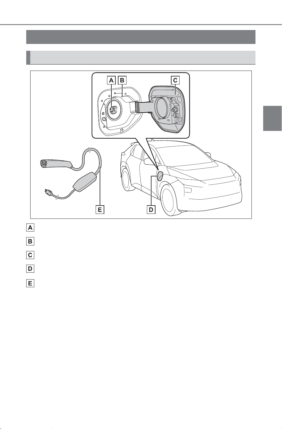
83
2-2. Charging
Owner’s Manual_USA_M6740B_en
2
Electric Vehicle system
2-2.Charging
Charging inlet
Charging indicator (P.85) and Charging inlet light
Charging port lid (P. 84 )
Charging port
AC charging cable
*
*
: It is an example for explanation and may differ from the actual item. The
AC charging cable can be purchased at your SUBARU dealer.
Charging equipment
Charging equipment and names
SOLTERRA_OM_USA_A6740BE.book 83 ページ 2025年5月23日 金曜日 午後1時18分
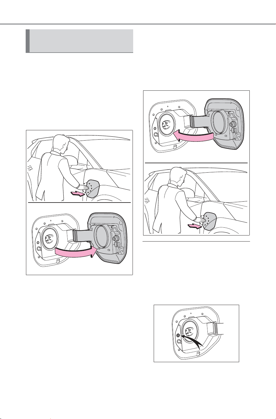
84
2-2. Charging
Owner’s Manual_USA_M6740B_en
■ Open
Slightly open the charging port
lid by pressing the rear edge of
it. (the position shown in the
illustration)
Fully open the charging port lid
by hand.
■ Close
Move the charging port lid to the
slightly open position and then
press the rear edge (the position
shown in the illustration) to close
it.
■ About the charging port lid
open/close detection switch
When the charging port lid is open,
be careful not to touch the charging
port lid open/close detection switch
(position shown in the figure). If you
accidentally touch the switch, the
vehicle may incorrectly indicate that.
Opening/closing the
charging port lid
SOLTERRA_OM_USA_A6740BE.book 84 ページ 2025年5月23日 金曜日 午後1時18分
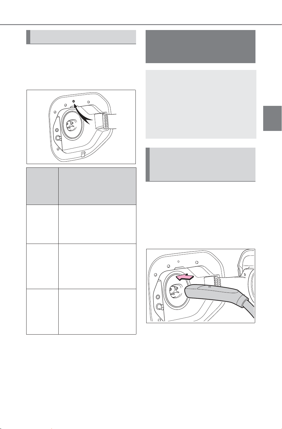
85
2-2. Charging
Owner’s Manual_USA_M6740B_en
2
Electric Vehicle system
The illumination/flashing pattern
changes to inform the user of
the charging status in the follow-
ing ways.
*1
:The indicator is dimmed when
the charging is done
*2
:Flashes for a certain period of
time, and then turns off.
■ Locking the AC charging
connector
The AC charging connector will
be automatically locked when
inserting it into the charging
inlet.
■ Unlocking the AC charging
connector
The AC charging connector will
be unlocked when the release
button is pressed while carrying
the electronic key on your per-
son or when the doors are
unlocked.
Charging indicator
Illumina-
tion/flashi
ng pat-
tern
Vehicle condition
Illumi-
nated
Charging is in prog-
ress
*1
Traction battery heater
(P.88) is operating
Flashes
nor-
mally
*2
When charging sched-
ule is registered
(P.106) and AC
charging cable is con-
nected to vehicle
Flashes
rapidly
*2
When charging cannot
be carried out due to
malfunction in a power
source or the vehicle,
etc. (P.121)
Locking and unlock-
ing the AC charging
connector
Helps to prevent the AC
charging connector from
being disconnected while
charging or tampering such
as someone other than the
user taking away the
charging cable.
Locking and unlocking
the AC charging connec-
tor
SOLTERRA_OM_USA_A6740BE.book 85 ページ 2025年5月23日 金曜日 午後1時18分
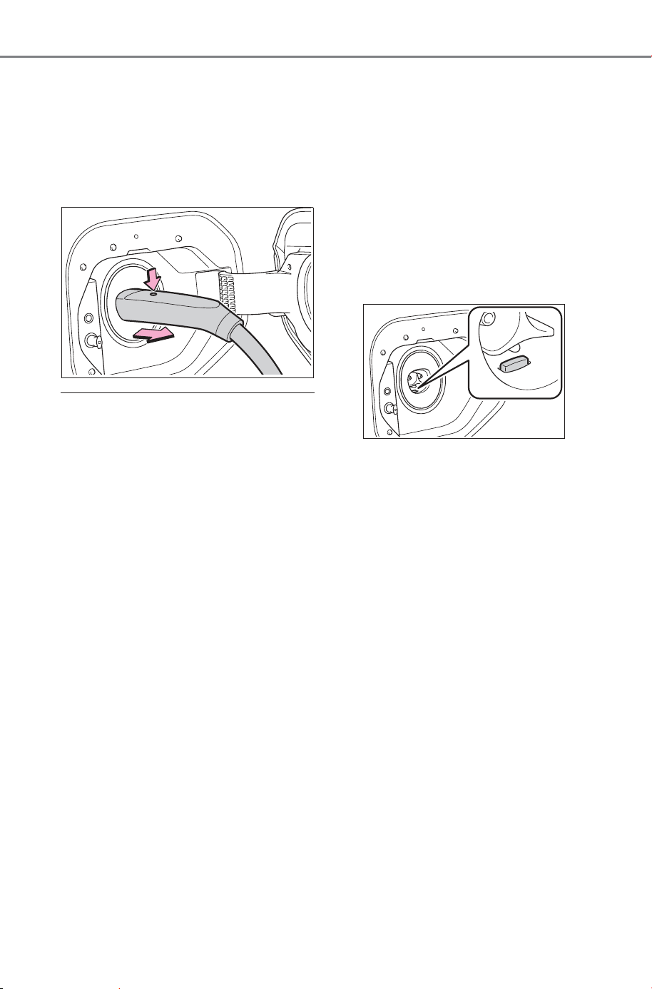
86
2-2. Charging
Owner’s Manual_USA_M6740B_en
While charging is stopped, the
AC charging connector will be
unlocked when the doors are
unlocked using the smart key
system or wireless remote con-
trol.
■ AC charging connector lock
function
If the AC charging connector is
locked/unlocked repeatedly, it may
not work temporary due to protect
the system by AC charging system.
In this case, wait for a while before
connecting the AC charging connec-
tor to charging inlet again.
● The connector lock pin may move
when the vehicle is driven or when
the AC charging connector is
removed, however, this is not a
malfunction.
● The AC charging connector lock
function does not guarantee that
theft of the AC charging cable will
be prevented, and is not neces-
sarily effective for all mischiefs.
■ Security function for unlocking
After the doors are unlocked, if the
doors are locked again or approxi-
mately 180 seconds elapse before
removing the AC charging connec-
tor, the AC charging connector will
be locked again.
■ When the AC charging connec-
tor cannot be inserted into the
charging inlet
Check that the connector lock pin is
not extended.
If the connector lock pin is
extended, the connector lock is
operating.
Unlock the doors using the smart
key system or wireless remote con-
trol and unlock the AC charging con-
nector lock and check that the
connector lock pin is not extended.
■ If the AC charging connector
cannot be unlocked
● If the AC charging connector can-
not be unlocked by normal opera-
tions, or if the release button has a
malfunction and the AC charging
connector cannot be unlocked,
the AC charging connector can be
unlocked using one of the follow-
ings.
• Perform the unlock operations of
the doors 3 times using the wire-
less remote control or door lock
switches.
• Stop charging on the meter dis-
play (P.99).
If the AC charging connector can-
not be unlocked even after per-
forming the above, the AC
charging connector can be
unlocked by operating the emer-
gency release wire.
Do not unlock the AC charging
connector this way unless it is an
emergency.
If the problem is not solved, have
the vehicle inspected by your
SUBARU dealer immediately.
SOLTERRA_OM_USA_A6740BE.book 86 ページ 2025年5月23日 金曜日 午後1時18分
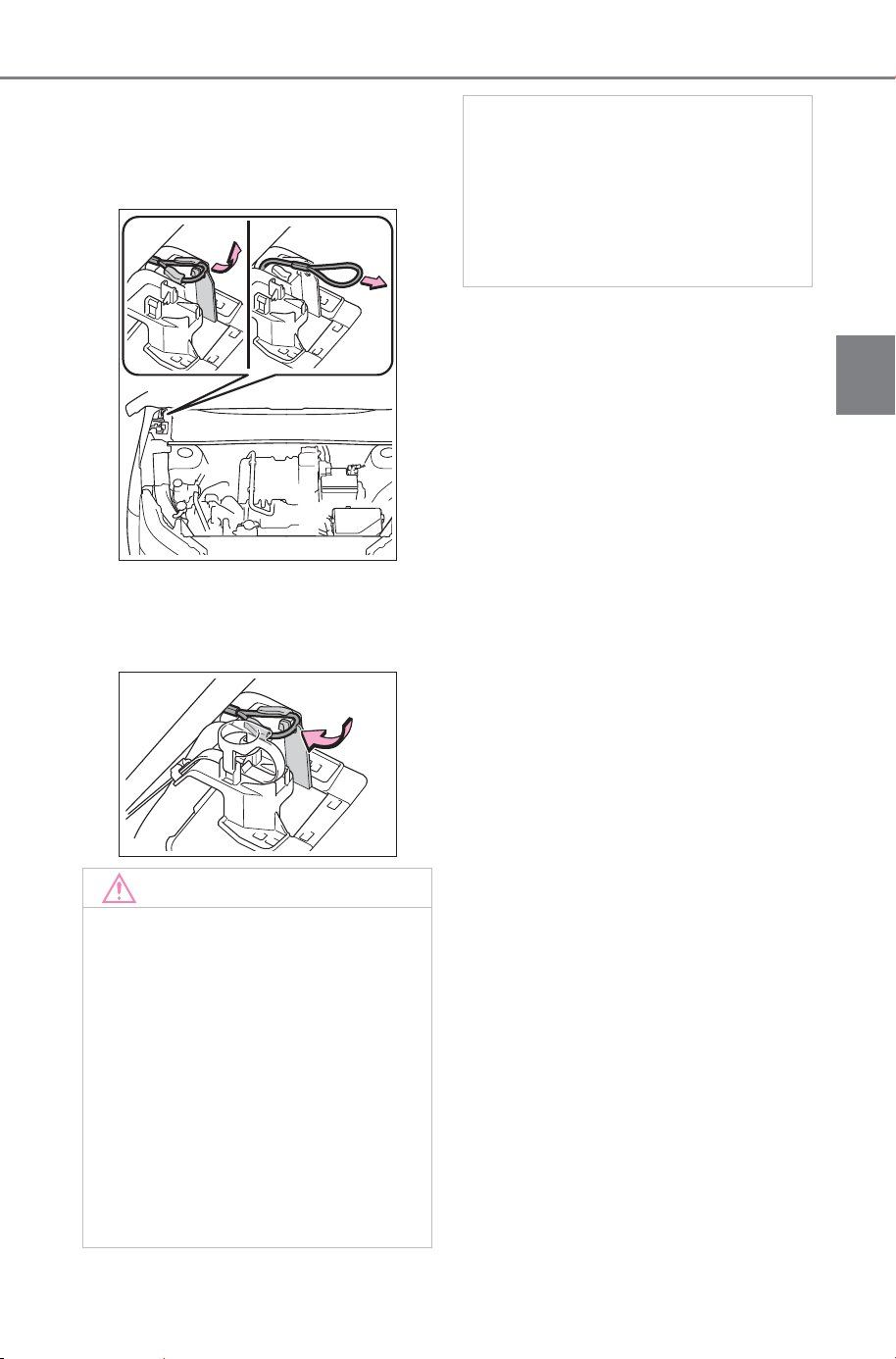
87
2-2. Charging
Owner’s Manual_USA_M6740B_en
2
Electric Vehicle system
1 Open the hood. (P.561)
2 Pull the emergency release wire.
The AC charging connector is
unlocked and can be removed.
3 After unlocking the AC charging
connector, fix the handle of the
emergency release wire to the
attachment.
NOTICE
■ When locking the AC
charging connector
Observe the following precau-
tions. Failure to do so may cause
a malfunction in the AC charging
connector locking system.
● Check that the AC charging
connector is compatible with
this vehicle.
An AC charging connector of
the different type or a charging
connector with damaged or
deformed insertion part may not
be locked.
● Do not apply excessive force to
the AC charging connector after
the AC charging connector is
inserted.
When removing the AC
charging connector, make sure
to unlock the AC charging con-
nector.
SOLTERRA_OM_USA_A6740BE.book 87 ページ 2025年5月23日 金曜日 午後1時18分

88
2-2. Charging
Owner’s Manual_USA_M6740B_en
■ AC charging (P.95 )
This is a charging method used
when charging from an AC out-
let with the AC charging cable or
charging that use an AC char-
ger.
By setting charging schedule, it is
also possible to charge at the
desired date and time. (P.106)
■ DC charging (P.100)
This is a charging method that
uses a DC charger that com-
plies with SAE J 3400. The trac-
tion battery can be charged in a
shorter time than AC charging.
SAE is an abbreviation for an
industrial standard issued by the
Society of Automotive Engi-
neers.
This is a charging method that
uses a DC charger that com
plies with SAE J 3400. The trac-
tion battery can be charged in a
shorter time than AC charging.
This vehicle is equipped with
several functions that are linked
with charging.
■ My Room Mode (P.11 7 )
When the charging cable is con-
nected to the vehicle, electrical
components such as the air con-
ditioning system and audio sys-
tem can be used by the power
supply from an external power
source
*
.
*
: Depending on the situation, elec-
tricity of the traction battery may
be consumed.
■ Traction battery heater
When the outside temperature
is low and the charging cable is
connected to the vehicle, this
function automatically warms
the traction battery until it
reaches or exceeds a certain
temperature.
The operation of this function
is stopped automatically when
the charging cable is discon-
nected or if the charging cable
is left connected to the vehicle
for approximately 3 days.
When the timer is charging
(P.106), it operates accord-
ing to the charging start time.
Charging methods
The following methods can
be used to charge the trac-
tion battery.
Types of charging meth-
ods
Charging-linked functions
SOLTERRA_OM_USA_A6740BE.book 88 ページ 2025年5月23日 金曜日 午後1時18分

89
2-2. Charging
Owner’s Manual_USA_M6740B_en
2
Electric Vehicle system
■ Traction battery warming
control
This control operates after the
charging cable remains con-
nected to the vehicle for approx-
imately 3 days and the traction
battery heater automatically
stops. It automatically insulates
the traction battery in extremely
low temperatures.
This control stops 31 days
after the charging cable is
connected, even if it is still
connected to the vehicle.
When this control operates,
charging schedule settings
are ignored and charging
starts.
■ Traction battery cooler
When the traction battery is hot
and the AC charging cable is
connected to the vehicle, this
function cools the traction bat-
tery to protect it.
The function may operate when
continuously driving at high
speeds such as driving on high-
ways or freeways, or during DC
charging.
■ Using My Room Mode during
DC charging
P. 11 7
■ Traction battery heater
● Traction battery heater may oper-
ate when charging is not being
performed.
● When traction battery heater is
operating, the charging indicator
illuminates.
● When traction battery heater is
operating during charging, the
charging may take longer than
normal.
● The remaining charge of the trac-
tion battery declines when the
traction battery heater operates, it
might be necessary to recharge
the traction battery again in order
to supplement the remaining
charge.
■ Traction battery cooler
● The charging indicator is illumi-
nated while traction battery cooler
is on standby or operating.
● When the charge level of the trac-
tion battery is low, the traction bat-
tery cooler may not operate, even
if the temperature of the traction
battery is high.
● When the following conditions are
met while the traction battery
cooler is operating, the cooling
operation will stop.
• The hood is opened
• The power switch is turned to
ACC or ON.
• The shift position is changed to
any position other than P
• The Remote Air Conditioning Sys-
tem is operated (P.501)
• The remaining charge of the trac-
tion battery drops below a certain
amount
SOLTERRA_OM_USA_A6740BE.book 89 ページ 2025年5月23日 金曜日 午後1時18分
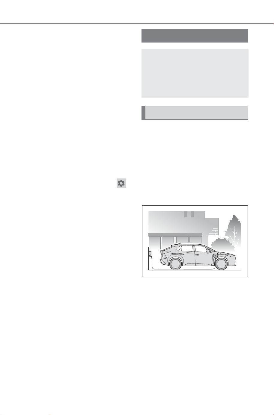
90
2-2. Charging
Owner’s Manual_USA_M6740B_en
● The traction battery cooler oper-
ates using power supplied by the
traction battery and an external
power source.
• While the traction battery cooler is
operating, the charge of the trac-
tion battery will increase and
decrease within a certain range,
and will not increase as during AC
charging.
• When the traction battery cooler
operates, charger will recognize it
as the battery being charged. If
this function operates while a
charger which charges a charging
fee is connected to the vehicle,
AC charging fees will apply.
■ Changing of the traction battery
cooler setting
Setting can be changed on the mul-
timedia.
Use the multimedia and select ,
“Vehicle customize”, “Charging”,
“Battery cooling”, and change the
setting.
When selecting to off, the traction
battery output may be restricted
depending on the driving situation.
To enable the use of battery
electric vehicle, we recommend
systematically charging the
vehicle.
■ Before leaving home
In order to use the Electric Vehi-
cle, charge the traction battery
at home before leaving.
■ On the way to the destina-
tion or at the destination
When the remaining charge of
the traction battery gets low,
recharge the battery at the near-
est charging station.
Charging tips
This section explains meth-
ods for using the charging
function for this vehicle and
checking information
related to charging.
Systematically charging
SOLTERRA_OM_USA_A6740BE.book 90 ページ 2025年5月23日 金曜日 午後1時18分
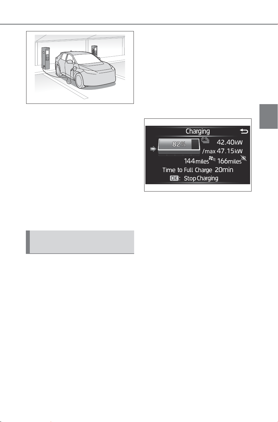
91
2-2. Charging
Owner’s Manual_USA_M6740B_en
2
Electric Vehicle system
■ After returning home
In order to drive the next time,
charge the traction battery.
Settings the charging schedule
allows you to charge the traction
battery at the desired time such
as late at night or early in the
morning. Furthermore, the
charging schedule can be set to
automatically charge the traction
battery every day or at the same
time on certain days. (P.106)
Information related to charging
is displayed and can be checked
on the multi-information display.
■ While charging
When any door is opened during
charging with the power switch
off, the current charging condi-
tion and approximate time
remaining until charging is com-
plete are displayed for a certain
period of time.
The actual charging time may
differ depending on conditions
such as the remaining capacity
of the traction battery, outside
temperature, and specifications
of the charger.
The time until charging com-
pleted may not be displayed if
the charging current to the trac-
tion battery becomes smaller
and the charging time becomes
longer.
■ After charging is complete
When any door is opened with
the power switch off after
charging is complete, a mes-
sage detailing the results of the
charging is displayed for a while.
Also, a message is displayed if
an operation that stops charging
is performed or a situation
where charging cannot be per-
formed occurs.
When a message is displayed,
follow the instructions displayed
on the screen. (P.127)
Checking information
related to charging
SOLTERRA_OM_USA_A6740BE.book 91 ページ 2025年5月23日 金曜日 午後1時18分
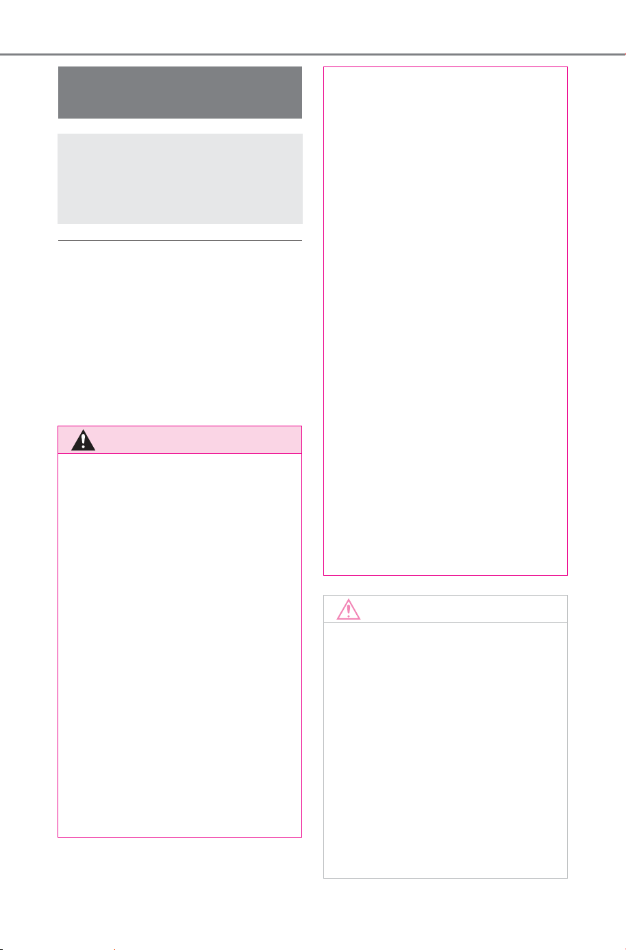
92
2-2. Charging
Owner’s Manual_USA_M6740B_en
■ Safety functions
● The EV system will not start while
the charging cable is attached to
the vehicle, even if the power
switch is operated.
● If the charging cable is connected
while the “READY” indicator is illu-
minated, the EV system will stop
automatically and driving will not
be possible.
Things to know before
charging
Make sure to read the fol-
lowing precautions before
charging the traction bat-
tery.
WARNING
■ Cautions when charging
People with implantable cardiac
pacemakers or cardiac resynchro-
nization therapy-pacemakers
should not carry out the charging
procedure. Ask someone else to
do it.
● Do not approach the charger
and charging cable during
charging.
Charging procedure may affect
the operation of pacemakers.
● Do not remain in the vehicle
during charging.
Charging procedure may affect
the operation of pacemakers.
● Do not enter the vehicle (includ-
ing the luggage compartment)
to retrieve something from it, or
for any purpose.
Charging procedure may affect
the operation of pacemakers.
■ When the charging cable is
connected to the vehicle
Do not change the shift position
from P.
In the unlikely event that the
charging cable has been dam-
aged, the shift position may
change from P to another position
and the vehicle could move, pos-
sibly leading to an accident.
■ Charging precautions
This vehicle has been designed to
allow charging from an external
power source using an AC
charging cable for exclusive use
with standard household AC out-
lets. However, the vehicle differs
greatly from standard household
electrical goods in the following
ways, and incorrect usage could
cause fire or electric shock, possi-
bly leading to death or serious
injury.
● When charging, a large amount
of current will flow for a long
time.
● Depending on the charging
environment, perform charging
outdoors.
NOTICE
■ Charging precautions
To charge properly, follow the pro-
cedure after reading the explana-
tion below. Charging is intended
to be carried out by licensed driv-
ers only who properly understand
the charging procedure.
● Do not allow people who is not
used to charging, such as chil-
dren, to perform charging with-
out supervision.
● When charging with a charger,
follow the procedures for using
each charger.
SOLTERRA_OM_USA_A6740BE.book 92 ページ 2025年5月23日 金曜日 午後1時18分
93
2-2. Charging
Owner’s Manual_USA_M6740B_en
2
Electric Vehicle system
Before charging, always check
the following items.
The parking brake is applied.
(P.241)
The power switch is turned to
OFF. (P. 22 9)
Lights such as the headlights,
emergency flashers and inte-
rior lights, etc. are turned off.
If these light switches are turned
on, then these features will con-
sume electricity, and charging time
will increase.
■ During charging
● The charging starting time may
differ depending on the state of
the vehicle, but this does not indi-
cate a malfunction.
● During charging, sounds may be
heard from near the traction bat-
tery in accordance with the opera-
tion of the air conditioning system
or traction battery cooler (P. 8 9 ) .
● Depending on radio wave condi-
tions, interference may be heard
on the radio.
■ When charging using a public
charging facility, check the set-
ting of the charging schedule
function.
● When the charging schedule is
registered, temporarily turn off the
function or turn “Charge Now” on.
(P.106)
● When the charging schedule is set
to on, charging will not start even
if the AC charging cable is con-
nected. Also, charging fee may
occur due to connection of the AC
charging cable.
■ Capacity reduction of the trac-
tion battery
The capacity of the traction battery
will decline gradually when the trac-
tion battery is in use. The rate at
which it declines will differ in accor-
dance with environmental conditions
and the way in which the vehicle is
used. Observing the following can
help suppress the decline in the
traction battery capacity.
● Avoid parking the vehicle in high
temperature areas, under direct
sunlight when the traction battery
is fully charged.
● Avoid accelerating and decelerat-
ing frequently and suddenly.
● Avoid frequent driving at high
speed.
● Use the charging schedule func-
tion as much as possible in order
to fully charged the traction bat-
tery before starting off. (P.106)
● Avoid frequent DC charging
Also, if the capacity of the traction
battery capacity reduces, the dis-
tance that can be driven decreases.
However, vehicle performance does
not significantly become worse.
■ When the remaining charge of
the traction battery is low after
charging
In the following situations, the
remaining charge of the traction bat-
tery after charging completes may
be less than normal in order to pro-
tect the traction battery (the driving
range after the battery is fully
charged may be shorter).
*
● Charging is performed when the
outside temperature is low or high
● Charging is performed immedi-
ately after high-load driving or in
extreme heat
In any other situation, if the remain-
ing charge of the traction battery is
significantly lower than normal after
Confirm the following
before charging
SOLTERRA_OM_USA_A6740BE.book 93 ページ 2025年5月23日 金曜日 午後1時18分

94
2-2. Charging
Owner’s Manual_USA_M6740B_en
charging completes, have the vehi-
cle inspected by your SUBARU
dealer.
*
: When this occurs, even if the
remaining charge display of the
traction battery shows that it is
fully charged, the remaining
charge rapidly decreases faster
than normal.
■ When the charging amount sent
to the traction battery
decreases
When the charging power to the
traction battery becomes low due to
the use of the air conditioner or the
operation of the battery heater, the
charging amount to the traction bat-
tery or the remaining charge of the
traction battery may decrease.
■ Certification
This device complies with Part 15 of
the FCC Rules. Operation is subject
to the following two conditions:
(1) this device may not cause harm-
ful interference, and (2) this device
must accept any interference
received, including interference that
may cause undesired operation.
■ Charging time may increase
In the following situations, charging
time may become longer than nor-
mal:
● In very hot or very cold tempera-
tures.
● When the traction battery
becomes hot, such as immedi-
ately after high-load driving.
● The vehicle is consuming a lot of
electricity, for example, when the
headlights are on, etc.
● When using “My Room Mode”.
(P.117)
● When opening the hood while
charging
● There is a power outage during
charging.
● When adjusting the power supply
with the charger.
● There is a drop in the voltage of
external power source.
● The charge in the 12-volt battery
is low, for example due to the
vehicle being left unused for a
long period of time.
● When the upper limit of charging
current is changed in the charging
current setting of the vehicle
(P. 97)
● When the traction battery heater
operates. (P. 8 9 )
● When the traction battery cooler is
operated before charging.
(P. 89)
● When the plug generates heat
due to a loose outlet connection,
etc.
● When frequently and repeatedly
using DC charging.
● When selecting “DC charging
power” setting other than “Max”.
● When the temperature of
charging-related parts is high.
■ AC charging electricity
This vehicle can be charged up to
approximately 11 kW.
However, depending on the used
AC charger or AC charging cable,
charging electricity may be limited.
SOLTERRA_OM_USA_A6740BE.book 94 ページ 2025年5月23日 金曜日 午後1時18分
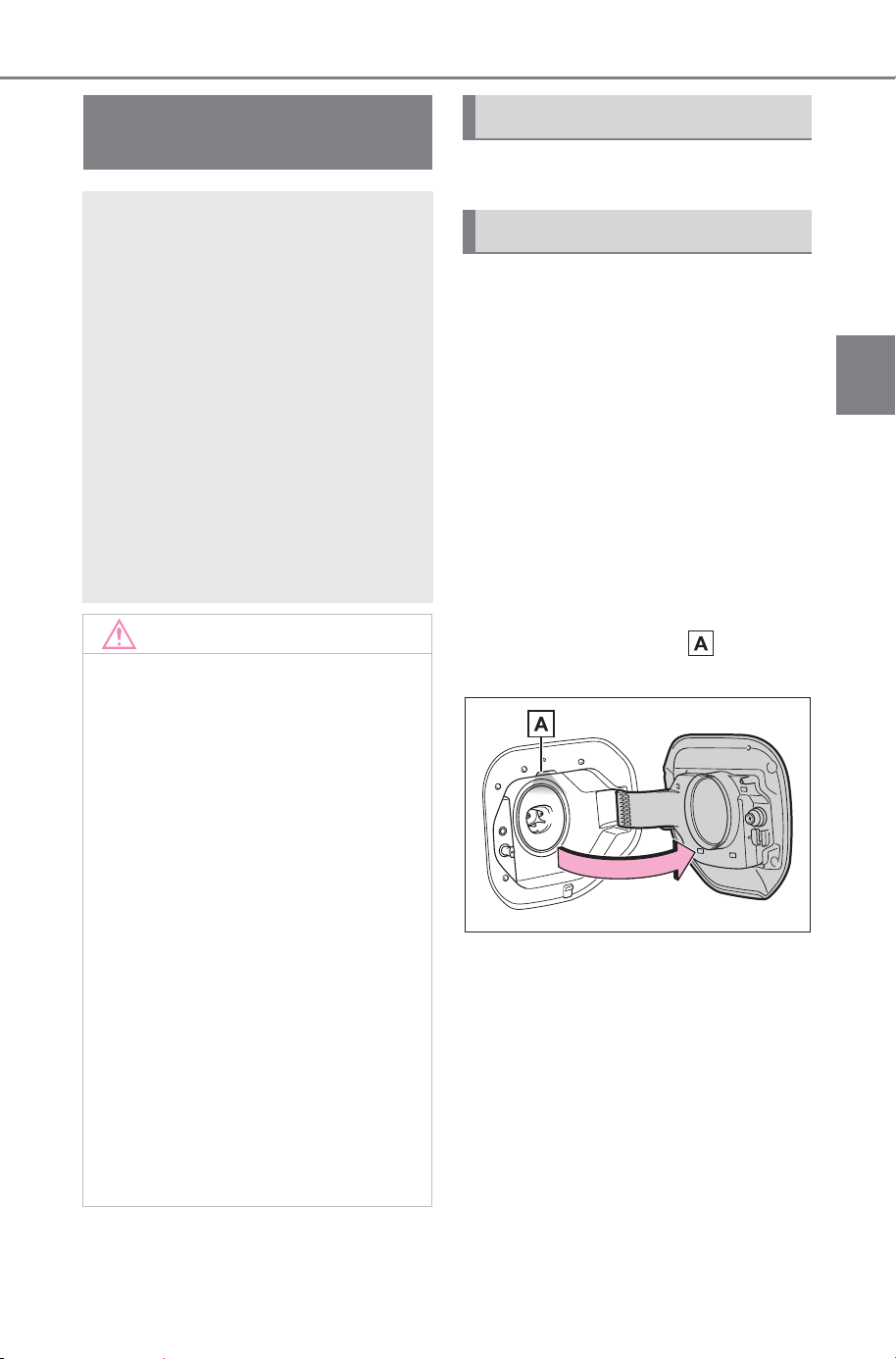
95
2-2. Charging
Owner’s Manual_USA_M6740B_en
2
Electric Vehicle system
P. 92
1 Prepare the AC charging
cable.
2 Insert the plug of the AC
charging cable into the outlet
of the external power source.
Make sure to hold the body of the
plug and insert it firmly into the out-
let.
When the remote switch is
equipped, turn it on.
3 Open the charging port lid.
(P.83)
The charging inlet light will illu-
minate.
4 Insert the AC charging con-
nector into the charging inlet.
Align the guide position on the bot-
tom of the AC charging connector,
and push the AC charging connec-
tor straight into the charging inlet as
far as possible.
When the AC charging connector is
inserted straight as far as possible,
it will automatically lock. (P. 85)
How to use AC
charging
This section explains the
procedure for charging the
traction battery with an AC
charging cable.
When using an AC charger,
make sure to check the
operation instructions on
the AC charger.
When the charging sched-
ule is registered, make sure
“Charge Now” is turned on
before charging. (P.108,
112)
NOTICE
■ When using the AC charging
related parts
To prevent damage to the AC
charging related parts, observe
the following precautions.
● When removing the AC
charging cable, check that the
AC charging connector is
unlocked.
● Do not apply a vibration to the
AC charging connector while
charging. Charging may be
stopped.
● Do not insert anything but the
AC charging connector into the
charging inlet.
● Do not disassemble, repair or
modify the charging inlet. When
the charging inlet needs to be
repaired, consult your SUB-
ARU dealer.
Charging precautions
When charging
SOLTERRA_OM_USA_A6740BE.book 95 ページ 2025年5月23日 金曜日 午後1時18分
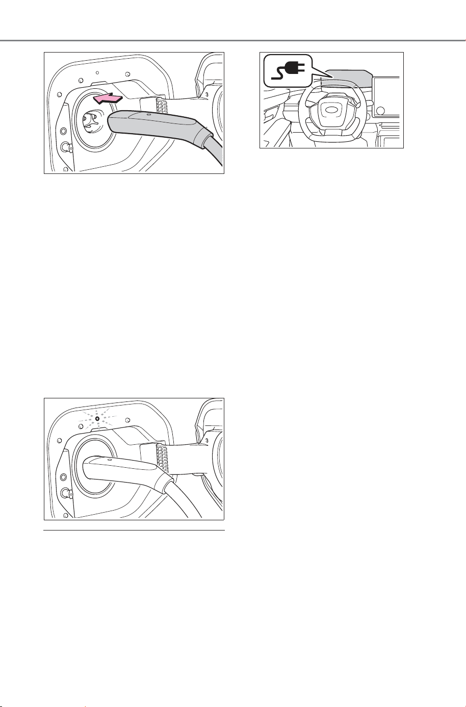
96
2-2. Charging
Owner’s Manual_USA_M6740B_en
5 Confirm that the charging
indicator of the charging port
is illuminated.
Charging will not start if the
charging indicator does not illumi-
nate when the AC charging con-
nector is inserted. (P.120)
If the charging indicator is flashing,
the charging schedule is registered.
(P. 9 6 )
The charging indicator will turn off
when charging is completed.
The charging indicator will also turn
off when charging is stopped for
some reason before completion. In
this case, refer to P.120
■ When connecting the AC
charging connector
If the door is opened or the power
switch is turned to ON with the AC
charging connector connected, the
charging cable indicator turns on to
notify that the AC charging connec-
tor is connected.
■ If the charging indicator of the
charging port flashes after con-
necting the AC charging cable
The charging schedule (P.106) is
registered and charging cannot be
performed. To cancel charging using
the charging schedule and start
charging, perform any of the follow-
ing procedures.
● Turn “Charge Now” on (P.108,
112)
● While the charging indicator is
flashing, remove and reconnect
the AC charging connector imme-
diately
● While the charging indicator is
flashing, remove and reconnect
the AC charging connector imme-
diately. The setting of charging
current and the upper limit of the
electric current will be temporarily
initialized (P.97).
■ When the AC charging connec-
tor cannot be inserted into the
charging inlet
P. 8 5
■ Safety function
If the release button is pressed,
charging will not begin even if the
AC charging cable is connected.
Also, charging will be stopped if the
AC charging connector is unlocked
during charging. When restarting
charging, do one of the followings,
and check that the charging indica-
tor of the charging port illuminates.
● Remove and reinsert the AC
charging connector
● Lock the doors
SOLTERRA_OM_USA_A6740BE.book 96 ページ 2025年5月23日 金曜日 午後1時18分
97
2-2. Charging
Owner’s Manual_USA_M6740B_en
2
Electric Vehicle system
■ Charging time may increase
P.94
■ To charge using the AC
charging connector that com-
plies with SAE J 1772
Use a conversion adapter provided
by SUBARU.
When using, follow the instructions
in the manual provided with the con-
version adapter and perform the
operation safely.
If a conversion adapter is connected
between the charging inlet and AC
charging connector, the AC
charging connector cannot be
locked.
■ When your circuit breaker trips
during charging
The upper limit of the charging cur-
rent can be changed on the multi-
media.
1 Select .
2 Select “Vehicle customize”.
3 Select “Charging”.
4 Select “Charging current”.
5 Select “32A”, “24A”, “16A” or
“8A”.
*1
During charging, the maximum
charging current will be restricted to
the set current or lower.
*2
If the breaker still trips while
charging, even after changing the
upper limit of the charging current,
check if the connected power
source meets the specified charging
conditions. (P. 86)
Although the charging current set-
ting can be changed even while
charging, it may take some time for
the change to become effective.
If changing the charging current set-
ting while charging, it may cause
house lights to flicker or trip a circuit
breaker.
*1
:Even if the charging current set-
ting is changed on the customize
menu, charging is performed at
12 A or less when charging at
120 V.
*2
:Restricting the charging current
will lengthen the charging time.
■ Changing the “Charging limit”
settings
The upper limit of the charge capac-
ity can be changed in “Vehicle cus-
tomize” on the multimedia.
The selected upper limit value is
common to AC charging and DC
charging.
1 Select .
2 Select “Vehicle customize”.
3 Select “Charging”.
4 Select “Charging limit”.
5 Select “Full”, “90%”, “80%”,
“70%”, “60%” or “50%”.
If the setting is changed during DC
charging, charging may stop due to
the operation of the DC charger
timer and the traction battery cannot
be fully charged.
■ To initialize the setting of
charging current and the upper
limit of the electric current tem-
porarily
Remove the AC charging connector
within 15 seconds after connect it,
and then reconnect it immediately.
The setting of charging current and
the upper limit of the electric current
will be temporarily initialized.
Also, if the procedure above is per-
formed while the charging indicator
is flashing normally and the
charging schedule is registered,
“Charge Now” is turned on. (P. 96)
SOLTERRA_OM_USA_A6740BE.book 97 ページ 2025年5月23日 金曜日 午後1時18分
98
2-2. Charging
Owner’s Manual_USA_M6740B_en
WARNING
■ When charging
Observe the following precau-
tions.
Failure to do so may cause an
unexpected accident, resulting in
death or serious injury.
● Before charging, check that the
charging inlet is not deformed,
damaged or corroded, and
check that the inlet is free of for-
eign matter such as dirt, snow
and ice.
If there is dirt or dust in these
areas, remove completely
before inserting the AC
charging connector.
● Do not touch the terminals of
the AC charging connector and
charging inlet with a sharp metal
objects (needles, etc.) or hands,
or short them with foreign
objects.
● In order to stop charging at the
charging station, follow the
instructions of the AC charger.
● If any heat, smoke, odors, noise
or other abnormalities are
noticed during charging, stop
charging immediately.
● Do not charge the vehicle
during a lightning storm.
● Prevent the AC charging cable
from being caught in the door or
back door.
● Make sure to connect the AC
charging cable to a socket
within reach and do not use an
extension cord.
● Close the hood before using the
charging system.
The cooling fan may start oper-
ating suddenly. Touching or get-
ting close to rotating parts such
as the fan may cause your
hands or clothes (especially a
necktie or scarf) to become
caught and result in a serious
injury.
■ Onboard traction battery
charger
The onboard traction battery char-
ger is located in the motor com-
partment. Make sure to observe
the following precautions regard-
ing the onboard traction battery
charger. Failure to observe these
precautions may result in death or
serious injury such as burns and
electric shocks.
● The onboard traction battery
charger is hot during charging.
Do not touch the onboard trac-
tion battery charger, as doing so
may result in burns.
● Do not disassemble, repair or
modify the onboard traction bat-
tery charger. When the onboard
traction battery charger needs
to be repaired, consult your
SUBARU dealer.
SOLTERRA_OM_USA_A6740BE.book 98 ページ 2025年5月23日 金曜日 午後1時18分
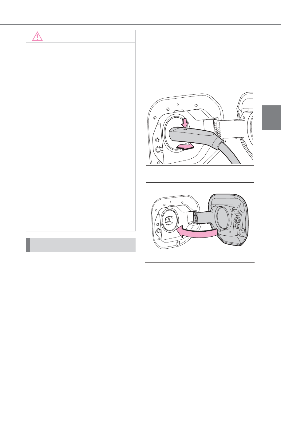
99
2-2. Charging
Owner’s Manual_USA_M6740B_en
2
Electric Vehicle system
1 Stop charging on the meter
display, or unlock the AC
charging connector by press-
ing the release button.
(P. 85 )
If the AC charging connector is
removed and then immediately
reconnected, charging will no lon-
ger able to be stopped on the meter
display. In this case, if the AC
charging connector is removed,
charging can be stopped on the
meter display next time.
If the release button is pressed
during charging (while the charging
indicator is illuminated), charging
will be interrupted.
2 Make sure to hold the body of
the AC charging connector
and pull it towards you.
If the charging stop switch is
pressed during charging (while the
charging indicator is illuminated),
charging will be interrupted.
3 Close the charging port lid.
■ When the outside temperature
is low or high
The level shown on the SOC (State
of Charge) gauge (P.142) may
drop slightly when the power switch
is turned to ON, even if charging
has been completed and the trac-
tion battery is fully charged. How-
ever, this does not indicate a
malfunction.
■ When stopping charging on the
meter display
1 While the charging status is dis-
played on the multi-information
display, press “OK” of the meter
control switches.
2 Select “Yes”.
Charging will stop.
NOTICE
■ When charging
Do not insert the plug into the
charging inlet.
The charging inlet may be dam-
aged.
■ Using private power genera-
tor
Do not use private power genera-
tors as a power source for
charging.
Doing so may make charging
unstable, the voltage may be
insufficient, and the charging
operation may stop.
Noise may be heard from around
the motor room, even if charging
can be continued.
■ Charging station
Due to the environment in which
the power equipment is located,
charging may be unstable due to
noise, the voltage may be insuffi-
cient, and the charging operation
may stop.
After charging
SOLTERRA_OM_USA_A6740BE.book 99 ページ 2025年5月23日 金曜日 午後1時18分
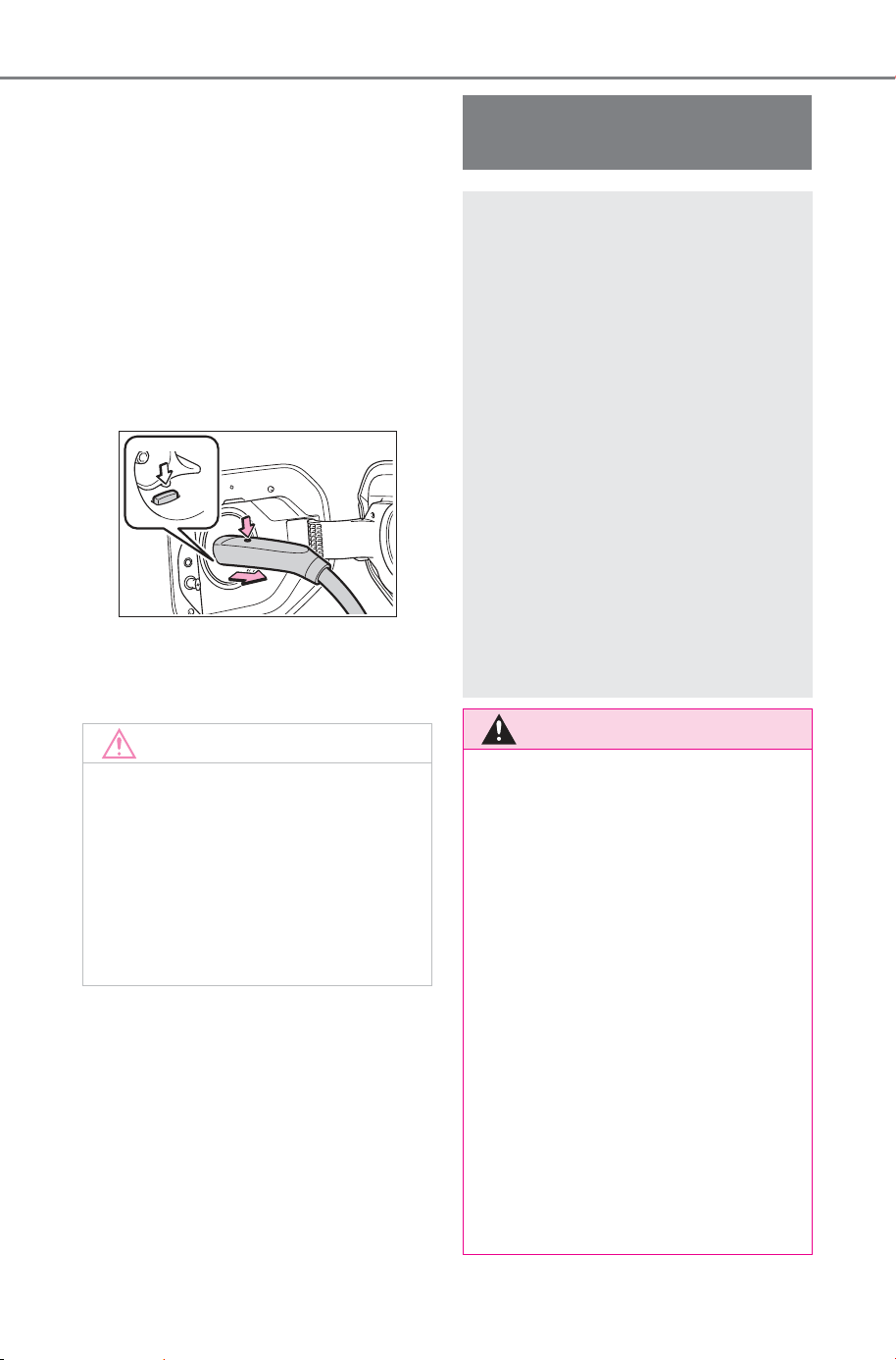
100
2-2. Charging
Owner’s Manual_USA_M6740B_en
■ When removing the AC
charging connector
Press the release button to unlock
the AC charging connector, and
after making sure it is unlocked, pull
the AC charging connector towards
you.
If the lever does not down even if
the release button is pressed, the
AC charging connector is locked. In
this case, unlock the door using the
smart key system or wireless
remote control, and unlock the AC
charging connector. (P. 8 5 )
■ If the AC charging connector
cannot be unlocked
P.86
NOTICE
■ After charging
After removing the AC charging
connector from the charging inlet,
make sure to close the charging
port lid.
If the charging port lid is left open,
water or foreign objects may enter
the charging inlet, which could
lead to vehicle damage.
How to use DC
charging
This section explains the
DC charging procedure for
the traction battery.
When using a DC charger,
make sure to check the
operation instructions of
the DC charger.
Using “Battery Precondi-
tioning” adjusts the traction
battery temperature to the
optimum state during DC
charging. By keeping the
traction battery at the opti-
mum temperature, charging
time can be shortened.
(P. 11 3)
WARNING
■ When using a DC charger
Observe the following precau-
tions.
Failure to do so may cause an
unexpected accident, resulting in
death or serious injury.
● Use a DC charger that complies
with SAE J 3400.
● By using a conversion adapter,
a DC charger that complies with
SAE J 1772 can be used.
Use only a conversion adapter
provided by SUBARU.
When using a DC charger, fol-
low the instructions in the man-
ual provided with the DC
charger and perform the opera-
tion safely.
● Do not use the charging cable
longer than 30 meters.
SOLTERRA_OM_USA_A6740BE.book 100 ページ 2025年5月23日 金曜日 午後1時18分
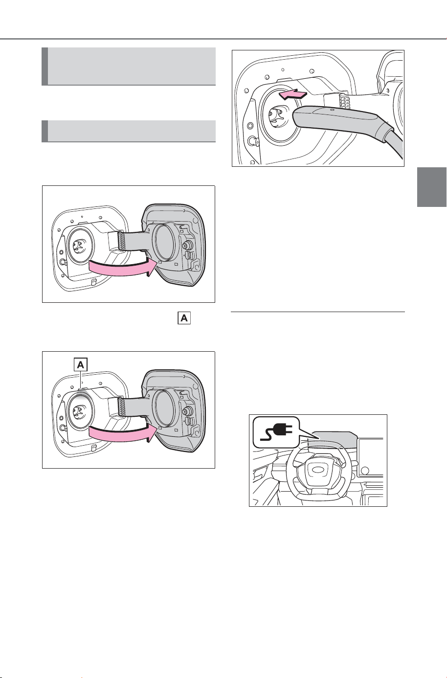
101
2-2. Charging
Owner’s Manual_USA_M6740B_en
2
Electric Vehicle system
P. 9 2
1 Open the charging port lid.
(P. 84 )
2 The charging inlet light will
illuminate.
3 Insert the DC charging con-
nector into the charging inlet.
Insert the DC charging connector
and it will lock automatically.
The DC charging connector shape
and treatment will differ depending
on the type of DC charger. Perform
the operations in accordance to
handling procedures of the DC
charger.
4 Operate the DC charger and
start the charging.
Follow the handling procedures of
the DC charger to start charging.
Charging starts after a system
check is done.
Stop the charging in accordance to
the handling procedures of the DC
charger when it is desired to inter-
rupt the DC charging.
■ When connecting the DC
charging connector
If the door is opened or the power
switch is turned to ON with the DC
charging connector connected, the
charging cable indicator turns on to
notify that the DC charging connec-
tor is connected.
■ Charging time may increase
P. 9 4
■ When the DC charging connec-
tor cannot be inserted into the
charging inlet
P. 8 6
Confirm the following
before charging
When charging
SOLTERRA_OM_USA_A6740BE.book 101 ページ 2025年5月23日 金曜日 午後1時18分
102
2-2. Charging
Owner’s Manual_USA_M6740B_en
■ If a message indicating vehicle
error on the DC charger side is
displayed
Even if a message indicating vehicle
error on the DC charger side (ex.
vehicle error found, vehicle error
occurred, etc.) is displayed, there is
no vehicle fault but possibly a com-
munication error between the DC
charger and vehicle. In this case,
there may be a terminal damage
(bad contact) in the DC charging
connector.
If there is no error with the vehicle,
contact the facility manager of the
DC charger.
■ During DC charging
● The current charging condition
can be checked on the multi-infor-
mation display.
● The actual charging time may dif-
fer from that displayed on the DC
charger during charging.
● There may be occasions the radio
cannot be heard due to noise
occurrence during DC charging.
● As the battery approaches full
charge, the charging speed will
decrease and it will take longer to
complete charging.
● Depending on the specifications
of the charger, charging will stop
before fully charging.
● The time to complete charging
may change, or charging may
stop before reaching the upper
limit of the charge capacity, due to
the remaining charge of the trac-
tion battery, the outside tempera-
ture, the specifications of the
charger, etc.
● When DC charging using an
adapter, protection functions may
activate depending on the outside
temperature or the usage, result-
ing in longer charging times, DC
charging suspensions, or charging
not starting.
● It is recommended to avoid fre-
quent DC charging to prevent a
decline in the traction battery
capacity.
● Quickly move from the DC
charging space for other users
after the DC charging is com-
pleted.
● If DC charging is performed while
the traction battery is extremely
cold, such as in cold weather,
steam may come out of the motor
compartment or dew may be
formed on the hood. This is
because the heat, generated
while the traction battery is
warmed, causes snow, ice, or
frost to evaporate. This is not a
malfunction.
● The charge amount is corrected
when the traction battery is fully
charged, so 100% remaining the
traction battery may not be dis-
played.
■ How to set the DC charging
power
You can change the DC charging
power limit on the multimedia.
● Setting operations on multimedia
1 Select .
2 Select “Vehicle customize”.
3 Select “Charging”.
4 Select “DC charging power”.
5 Select from “Max”, “125kW”,
“100kW”, “75kW”, “50kW”.
The maximum power when charging
is limited to the selected power or
less. If “Max” is selected, the vehicle
will be charged with the maximum
power that can be charged.
■ Changing the “Charging limit”
settings
P. 9 7
SOLTERRA_OM_USA_A6740BE.book 102 ページ 2025年5月23日 金曜日 午後1時18分
103
2-2. Charging
Owner’s Manual_USA_M6740B_en
2
Electric Vehicle system
■ If the DC charging power limit
and “Charging limit” settings
cannot be changed
Remove the DC charging connec-
tor and immediately reinsert it while
the charging indicator is flashing in
green. The settings will be changed
to the default settings.
The settings will be return to the
customized setting next time the
charging is performed.
If the DC charging connector is
locked immediately after inserting it,
press the unlocks all the doors
switch of the wireless remote control
or the door unlock switch on the
driver’s side 3 times at intervals of
about one second to stop DC
charging, and then remove the DC
charging connector.
WARNING
■ Warnings for DC charging
Be sure to observe the following
when using DC charging.
Failure to do so may cause an
accident that could lead to death
or serious injury.
● Check that the DC charger and
the charging inlet are not dam-
aged.
If there is any damage to the
charging inlet, do not perform a
DC charge and have it
inspected immediately at your
SUBARU dealer.
● Do not touch the terminals of
the DC charging connector or
inlet with metallic sharp tips
(wires and needles), or allow a
short circuit to occur with foreign
objects.
● Do not insert anything other
than the DC charging connector
into the charging inlet.
● Check that the DC charging
cable is not coiled up or pinned
underneath heavy objects.
● Do not connect conversion
adapters, extension cords, etc.
other than those provided by
SUBARU, between the DC
charging connector and
charging inlet.
● When DC charging is inter-
rupted, follow the handling pro-
cedures of the DC charger.
Immediately stop the DC
charging when there is an out-
break of heat, smoke, strange
noises or smells, etc., during
charging.
● Check that the DC charging
connector and the charging inlet
do not have foreign objects or
snow or ice attached to it.
If anything is attached to the
inlet, be sure to completely
remove the material before con-
necting the DC charging con-
nector.
● Do not charge the vehicle when
there is a possibility of lightning.
If you notice lightning while
charging the vehicle, do not
touch the vehicle and the DC
charging cable.
● Do not get the charging inlet ter-
minals wet.
● Close the hood when using DC
charging.
The cooling fan may suddenly
start to run. Keep hands and
clothing (especially a tie, a scarf
or a muffler) away from the fan.
Failure to do so may cause the
hands or clothing to be caught,
resulting in serious injury.
SOLTERRA_OM_USA_A6740BE.book 103 ページ 2025年5月23日 金曜日 午後1時18分
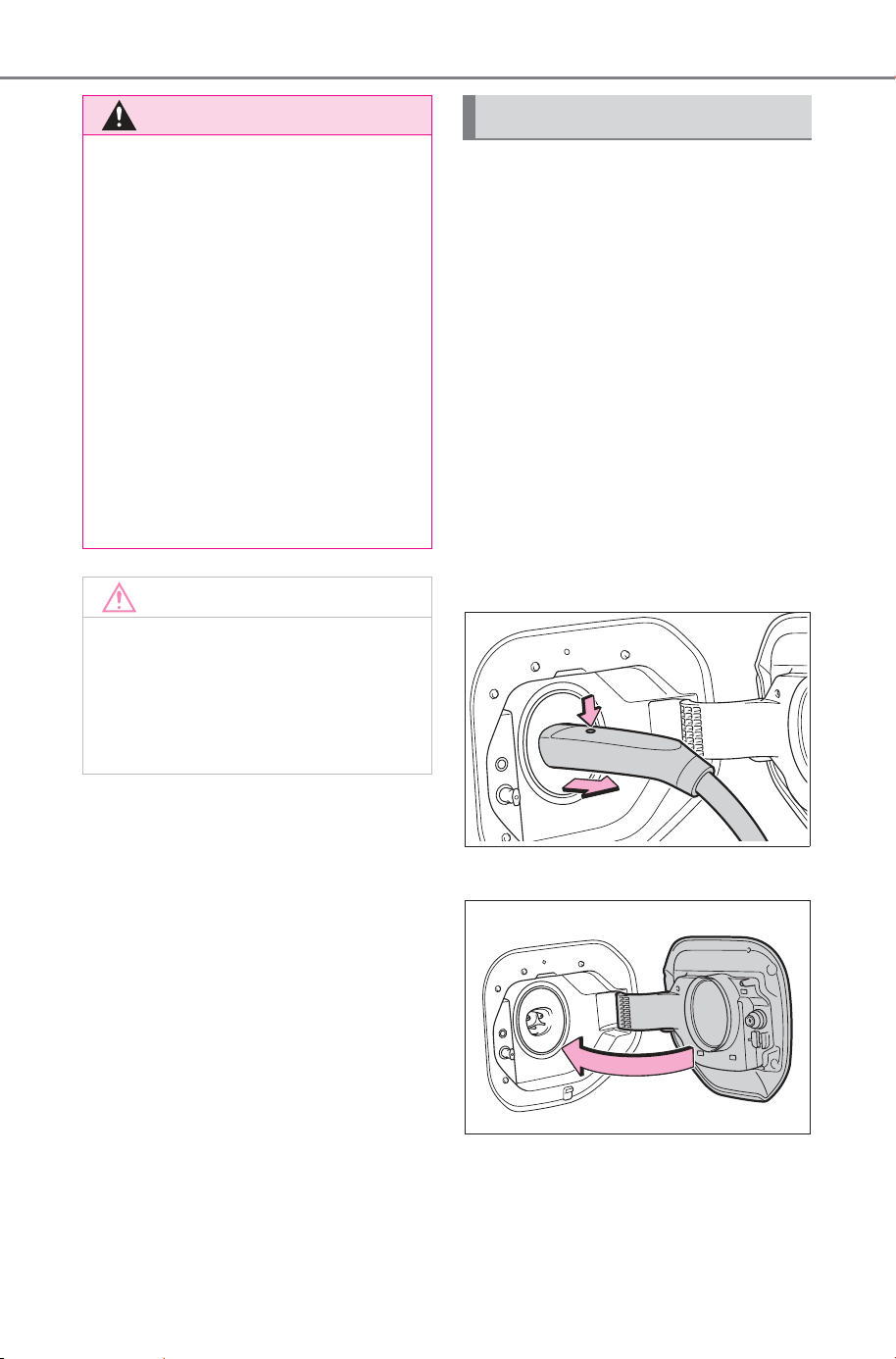
104
2-2. Charging
Owner’s Manual_USA_M6740B_en
1 Operate the DC charger and
stop the charging.
The DC charging connector will be
unlocked when charging is com-
pleted, while carrying the elec-
tronic key on your person or when
the doors are unlocked.
2 Remove the DC charging
connector.
The DC charging connector shape
and treatment will differ depending
on the type of the DC charger.
Perform the operations in accor-
dance to handling procedures of
the DC charger.
Return the removed DC charging
connector to its original position.
3 Close the charging port lid.
WARNING
■ When connecting the DC
charging connector
● Follow the handling procedures
of the DC charger to connect
the DC charging connector. If
the connector is not connected
properly, the system cannot rec-
ognize the connection, and it
may be possible to start the EV
system.
● Do not remove the DC charging
connector from the charging
inlet during DC charging. After
operating the DC charger to
stop charging, remove the DC
charging connector from the
charging inlet.
NOTICE
■ When using DC charging
Make sure to follow the handling
procedures of the DC charger. If
the procedures are not followed
properly, the vehicle and the DC
charger may be damaged.
After charging
SOLTERRA_OM_USA_A6740BE.book 104 ページ 2025年5月23日 金曜日 午後1時18分
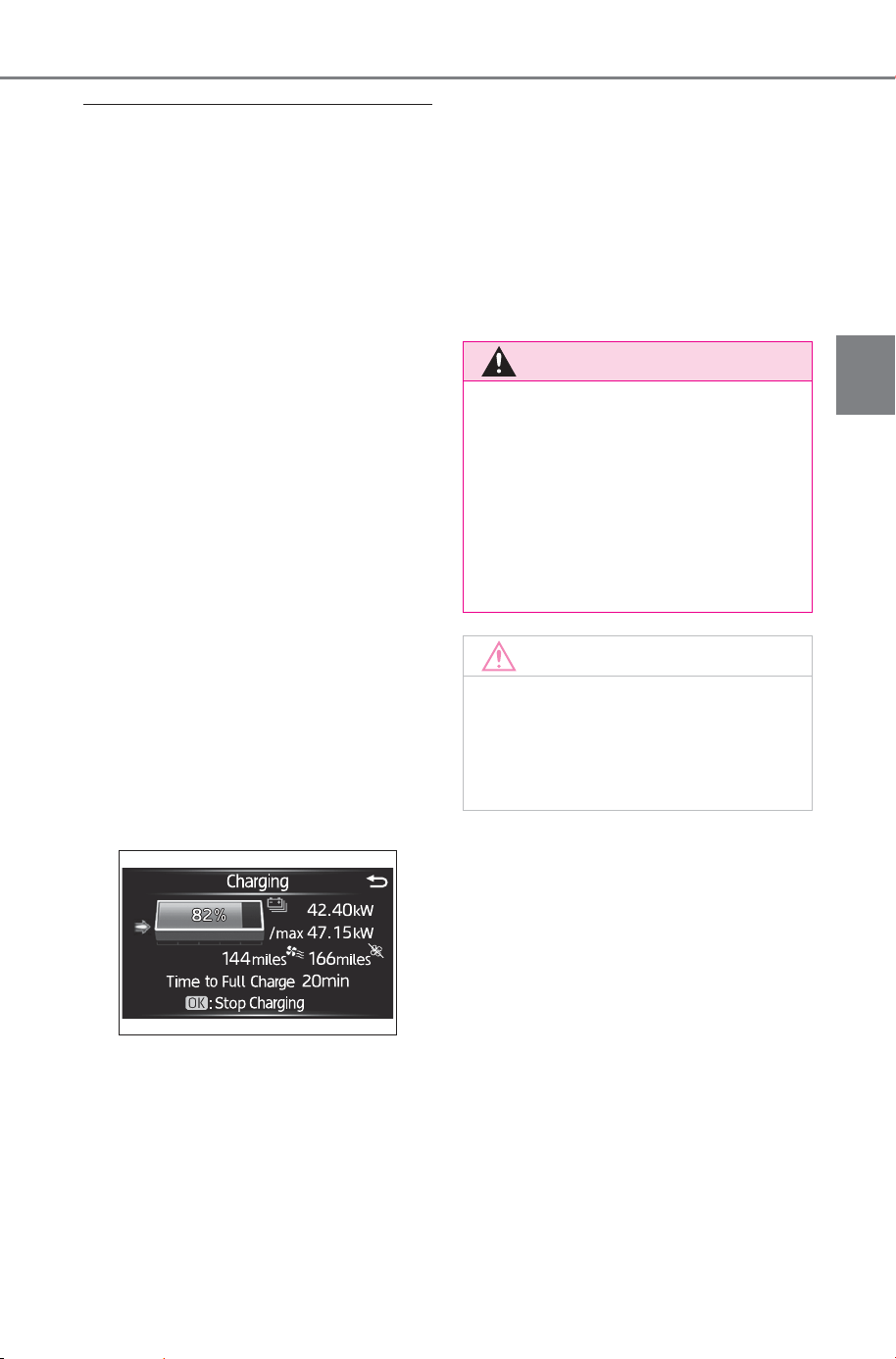
105
2-2. Charging
Owner’s Manual_USA_M6740B_en
2
Electric Vehicle system
■ If the EV system was not started
after DC charging and the EV
system has been started by
pressing the power switch
If the system check after DC
charging does not finish properly,
the EV system may not start even if
the power switch is pressed with the
brake pedal depressed.
If the EV system is started when the
power switch is pressed again, this
is not a malfunction.
■ When DC charging cannot be
stopped
If charging cannot be stopped from
the DC charger side due to a mal-
function, etc.
Door unlock button on the wireless
remote control, or next to the
driver’s seat.
You can also stop DC charging by
pressing the door unlock switch
three times at about 1 second inter-
vals.
■ When stopping charging using
the charging stop button
1 Press “OK” of the meter control
switches while the charging sta-
tus is displayed on the multi-
information display.
2 Select “Yes” and press “OK” to
stop charging.
If the DC charging connector is
removed and immediately rein-
serted while the charging indicator
is flashing in green, charging cannot
be stopped using “Stop Charging”
To stop charging, remove the DC
charging connector.
■ If the DC charging connector
cannot be unlocked
P. 8 6
■ After DC charging
Even if the traction battery is
charged to the upper limit value that
is set, the level of charge displayed
on the DC charger may be lower
than the actual one.
WARNING
■ Cautions after DC charging
After charging is completed, make
sure to remove the DC charging
connector from the charging inlet
before starting the EV system.
If the vehicle is started off with the
connector still connected, it could
lead to an accident, possibly
resulting in death or serious injury.
NOTICE
■ Precautions after DC
charging
Be sure to close the charging port
lid after removing the DC charging
connector from the inlet.
SOLTERRA_OM_USA_A6740BE.book 105 ページ 2025年5月23日 金曜日 午後1時18分

106
2-2. Charging
Owner’s Manual_USA_M6740B_en
■ Schedule settings
Charging schedule is performed
according to the day and time
shown on the multimedia. For
details, refer to the “MULTIMEDIA
OWNER’S MANUAL”.
When registering the charging
schedule, the following settings
can be changed.
■ Select the charging mode
One of the two following
charging modes can be
selected.
“Start”
Starts charging at the set time
*
and finishes charging when fully
charged.
“Start and stop”
AC charging is performed
according to the set start time
and stop time.
*
*
: There might be a slight error in
the timing when charging starts
due to the state of the traction
battery.
■ Repeated setting
The periodic charging schedule
can be set by selecting your
desired day of the week. Select
one or more day of the week to
do the charging schedule.
■ Turning “Charge Now” on
and off
To start charging without chang-
ing the charging schedule set-
ting, turn “Charge Now” on to
temporarily cancel the charging
schedule and enable charging
after connecting the AC
charging connector.
*
*
: If the AC charging connector is
removed while the charging
schedule is registered and
“Charge Now” is on, “Charge
Now” turns off.
■ “Next Event”
Of the registered charging
schedules, the closest charging
schedule after the current time
is called the “Next Event”.
For charging schedule, AC
charging will be performed
according to the Next Event.
Using the charging
schedule function
AC charging can be carried
out at the desired time by
registering the charging
schedule.
Settings of the charging
schedule function
SOLTERRA_OM_USA_A6740BE.book 106 ページ 2025年5月23日 金曜日 午後1時18分
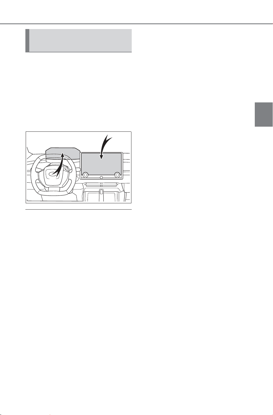
107
2-2. Charging
Owner’s Manual_USA_M6740B_en
2
Electric Vehicle system
The charging schedule can be
registered on the multimedia.
Only “Charge Now” can be set
on the multi-information display.
Multi-information display
operation: P.108
Multimedia operation: P.109
■ Charging schedule function
● The charging schedule cannot be
set while driving.
● A maximum of 15 charging sched-
ules can be registered.
If the charging mode is set to “Start
and stop” and the start time and end
time are set to the same time,
charging will be performed for 24
hours from the start time.
The charging schedule function can
not be used when using DC
charging.
■ To make sure that the charging
schedule function operates cor-
rectly
Check the following items.
● Adjust the clock to the correct time
For details, refer to the “MULTIME-
DIA OWNER’S MANUAL”.
● The day of the week is set cor-
rectly
For details, refer to the “MULTIME-
DIA OWNER’S MANUAL”.
● Check that the power switch is
turned off
● After registering the charging
schedule, connect the AC
charging connector
The charging start time is deter-
mined based on the charging
schedule at the time that the AC
charging connector was connected.
● Connect the AC charging connec-
tor before the start time
When the charging mode is set to
“Start”, if you connect the AC
charging connector after the set
start time, the next charging sched-
ule will be referenced.
When the charging mode is “Start
and stop”, if you connect the AC
charging connector after the start
time, charging will start immediately
and charging will be performed until
the stop time.
● After connecting the AC charging
connector, check that the charging
indicator of the charging port
flashes (P. 85)
● Do not use an outlet that has a
power cut off function (including a
charging schedule function)
Use an outlet that constantly sup-
plies electricity. For outlets where
the power is cut off due to a
charging schedule function, etc.,
charging may not be carried out
according to plan if the power is cut
off during the set time.
Registering the charging
schedule
SOLTERRA_OM_USA_A6740BE.book 107 ページ 2025年5月23日 金曜日 午後1時18分
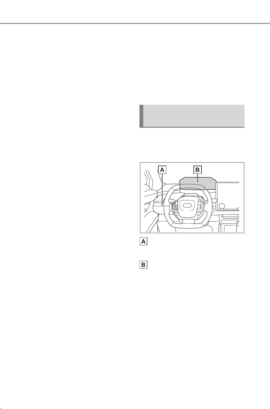
108
2-2. Charging
Owner’s Manual_USA_M6740B_en
■ When the AC charging connec-
tor remains connected to the
vehicle
● When the charging mode is set to
“Start”, even if multiple consecu-
tive charging schedules are regis-
tered, the next charge will not be
carried out according to the
charging schedule until the AC
charging connector is removed
and reconnected after charging
completes. Also, when the traction
battery is fully charged, charging
according to the charging sched-
ule will not be carried out.
● If the charging stop time is
reached before the traction bat-
tery is fully charged and the
charging mode is set to “Start and
stop”, the nearest charging sched-
ule after the stop time is updated
as the next charging schedule,
and charging is repeated until the
battery is fully charged.
■ Smartphone-linked operation
After applying to SubaruConnect
App, it is possible to use the smart-
phone application to change
charging schedule settings.
■ When charging schedules are
ignored
When the following operations are
performed while the charging
schedule is on standby, charging
schedule is temporarily canceled
and charging is started.
● When the Remote Air Condition-
ing System (P.501) is operated
● When turning “My Room Mode”
on (P. 11 7)
● When turning “Charge Now” on
(P.108, 112)
● When an operation that temporar-
ily cancel charging using the
charging schedule (P.96)
■ Traction battery heater
(P.89)/Traction battery cooler
(P. 89)
Depending on the temperature of
the traction battery, the traction bat-
tery heater or traction battery cooler
may be activated and the charging
indicator may light up while the
charging schedule is waiting for
charging.
When operating charging
schedule, use the meter control
switches.
Meter control switches
(P.147)
Multi-information display
■ Setting “Charge Now” to on
Operation on “Closing Dis-
play” screen
1 Turn the power switch off.
The “Closing Display” screen will
be displayed on the multi-informa-
tion display.
(If the door is opened while waiting
for charging schedule, the same
screen will be displayed.)
Setting operations on
multi-information display
SOLTERRA_OM_USA_A6740BE.book 108 ページ 2025年5月23日 金曜日 午後1時18分
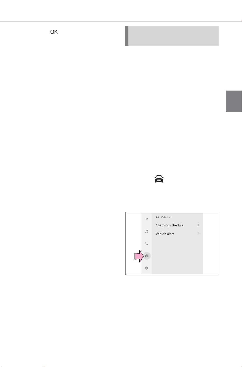
109
2-2. Charging
Owner’s Manual_USA_M6740B_en
2
Electric Vehicle system
2 Press to set “Charge
Now” to on.
Each time “OK” is pressed, “Charge
Now” switches between on and off.
After setting operations are
complete, charging starts when
the AC charging connector is
connected.
*
*
: If the AC charging connector is
removed while the charging
schedule is registered and
“Charge Now” is on, “Charge
Now” turns off.
If “Charge Now” cannot be set to
on even when performing the
operations above, remove the
AC charging connector while the
charging indicator is flashing at
the normal speed and then
immediately reconnect it.
If this operation is performed,
the setting of charging current
and the upper limit of the electric
current will be temporarily initial-
ized (P. 97 ).
For details on how to operate
the audio system screen, refer
to “MULTIMEDIA OWNER’S
MANUAL”.
Setting operations related to the
charging schedule are per-
formed on the “Charging sched-
ule” screen.
■ Displaying the “Charging
schedule” screen
1 Turn the power switch ON
and display the menu screen.
It is not possible to control the
Charging Schedule settings in
Accessory Mode.
2 Select and “Charging
schedule”, in that order.
The “Charging schedule” screen
will be displayed.
Setting operations on
multimedia
SOLTERRA_OM_USA_A6740BE.book 109 ページ 2025年5月23日 金曜日 午後1時18分
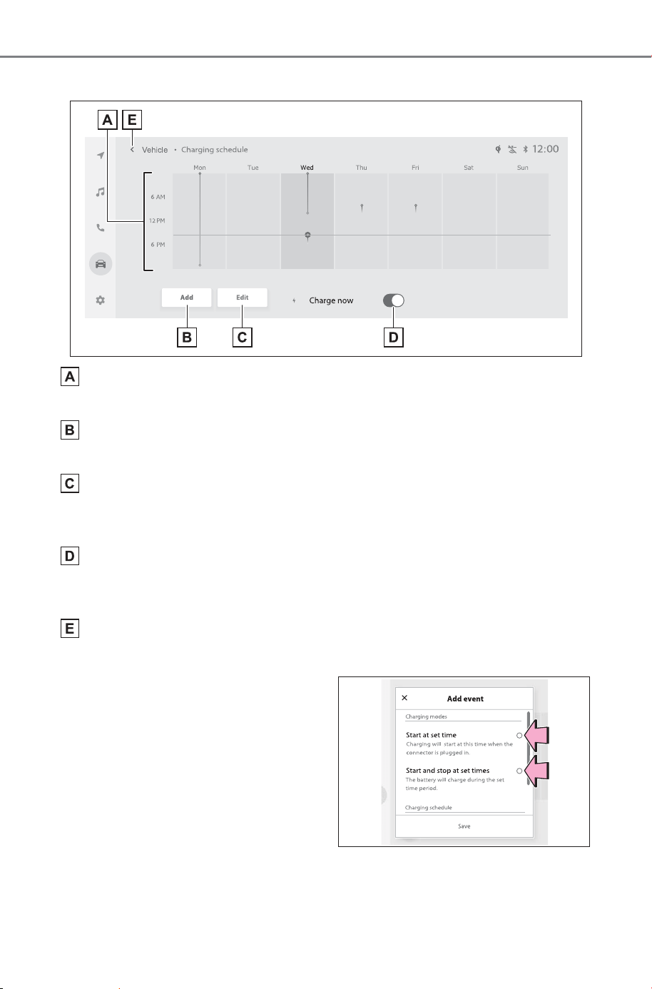
110
2-2. Charging
Owner’s Manual_USA_M6740B_en
■ How to read the “Charging schedule” screen
Charging schedules
Displays the week-long registered charging schedule in a list using icons.
“Add” button
Press to add a new item to the charging schedule. (P.110)
“Edit” button
Press to change or delete registered items on the charging schedule.
(P.111)
“Charge now” button
Each time the button is pressed, “Charge now” switches between on and
off. (P.112)
Return button
Press to close the “Charging schedule” screen.
■ Registering the charging
schedule
1 Display the “Charging sched-
ule” screen. (P.109)
2 Press “Add”.
The “Add event” screen will be dis-
played on the screen.
3 Select the charging mode.
Select the button in the row of the
“Start at set time” or “Start and stop
at set times”.
SOLTERRA_OM_USA_A6740BE.book 110 ページ 2025年5月23日 金曜日 午後1時18分
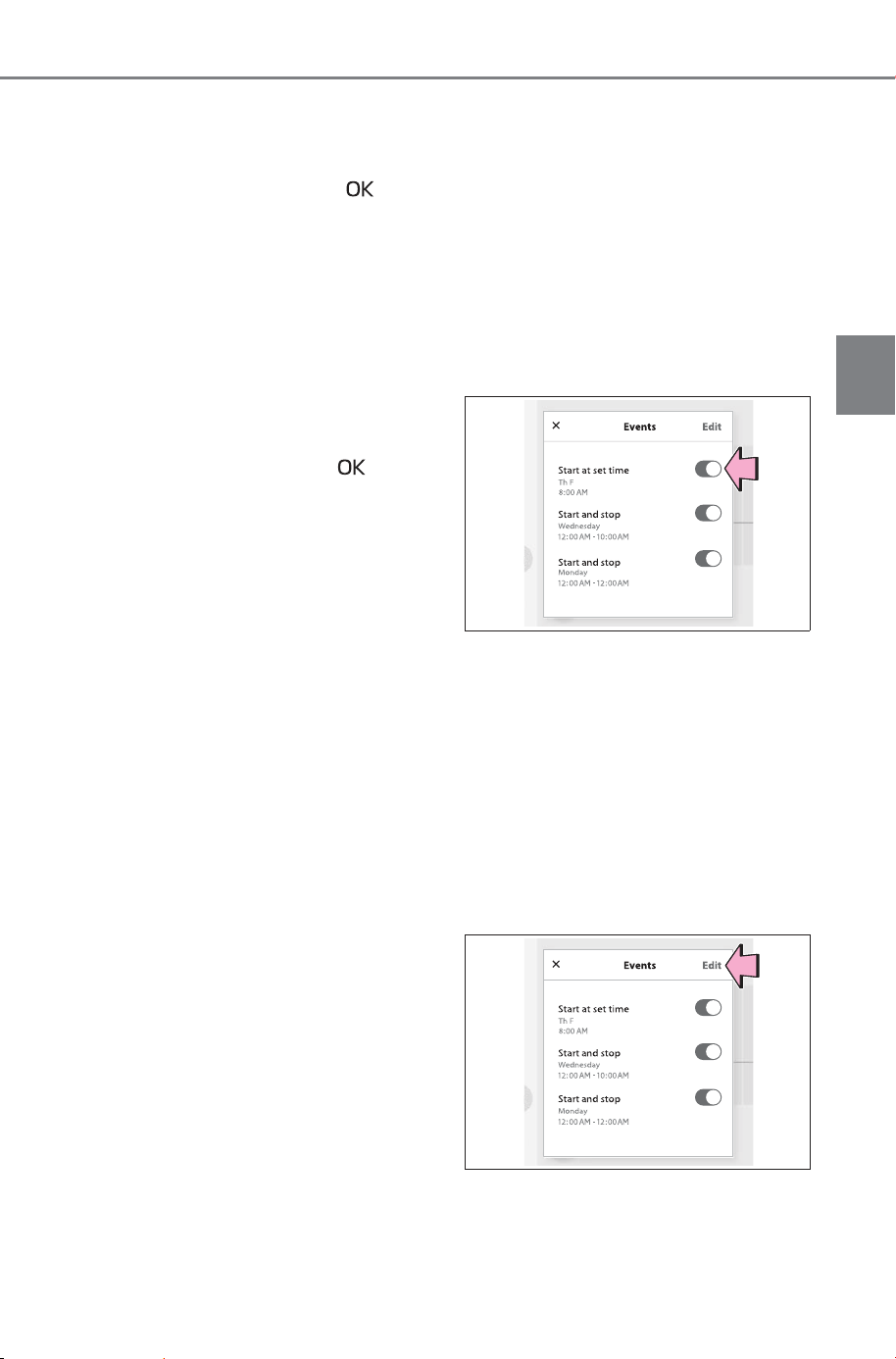
111
2-2. Charging
Owner’s Manual_USA_M6740B_en
2
Electric Vehicle system
4 Operate “Start at set time”
screen and select desired
time, and then select .
When the charging mode is “Start
at set time”, set the charging start
time.
When the charging mode is “Start
and stop at set times”, also set the
charging stop time.
5 When activating the repeated
settings, select the desired
day, and then select .
Each time the day is selected, the
repeated setting for the selected
day switches between on and off.
When turned on, the check box is
highlighted and the charging sched-
ule is repeated on that day. It is
possible to turn more than one day
on.
6 After setting operations are
complete, press “Save”.
The charging schedule is added to
the list and an icon is added to the
“Charging schedule” screen.
■ Switching charging sched-
ules between on and off
1 Display the “Charging sched-
ule” screen. (P.109)
2 Press “Edit”.
The “Events” screen will be dis-
played on the screen.
3 From the items displayed on
the screen, press on or off in
the row of the charging
schedule you wish to change.
If the charging schedule you wish to
change is not displayed on the
screen, scroll the list up and down
to display it.
Each time the button is pressed,
the charging schedule switches
between on and off.
■ Changing the registered
charging schedules
1 Display the “Charging sched-
ule” screen. (P.109)
2 Press “Edit”.
The “Events” screen will be dis-
played on the screen.
3 Press “Edit” on the “Events”
screen.
SOLTERRA_OM_USA_A6740BE.book 111 ページ 2025年5月23日 金曜日 午後1時18分
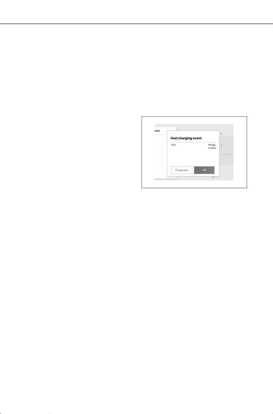
112
2-2. Charging
Owner’s Manual_USA_M6740B_en
4 From the items displayed on
the screen, press “Edit” in the
row of the charging schedule
you wish to change.
Changing registered items:
Change the desired settings as
described starting from step
3 of
the “Registering the charging
schedule” procedure. (P.110)
When a setting is changed, its icon
on the calendar also changes.
Deleting registered items:
Press “Delete”.
A deletion confirmation message
will be displayed.
Press “Delete” to delete the
selected charging schedule.
When a charging schedule is
deleted, its icon is also deleted from
the “Charging schedule” screen.
■ Turning “Charge now” on
1 Display the “Charging sched-
ule” screen. (P.109)
2 Press “Charge now”.
Each time the button is pressed,
“Charge now” switches between
on and off.
After setting operations are com-
plete, charging starts when the AC
charging connector is connected.
If “Charge now” cannot be set to on
even when performing the opera-
tions above, remove the AC
charging connector while the
charging indicator is flashing at the
normal speed and then immediately
reconnect it.
If this operation is performed, the
setting of charging current and the
upper limit of the electric current will
be temporarily initialized. (P.97)
■ Displaying next event
Turn the power switch off.
Next event will be displayed
according to the charging schedule
settings.
*
*
: If the multimedia customize con-
tent “ACC customize” is not set to
OFF, the ending screen will not
be displayed. If it is this case,
check the settings of the multime-
dia.
When press “OK”, close Next
charging event screen.
When press “Charge now”,
charge now is turned on.
SOLTERRA_OM_USA_A6740BE.book 112 ページ 2025年5月23日 金曜日 午後1時18分
113
2-2. Charging
Owner’s Manual_USA_M6740B_en
2
Electric Vehicle system
■ When all charging schedules
are turned off
The icon is not displayed on the
“Charging schedule” screen.
The icon will be displayed by turning
it ON on the “Events” screen.
■ When charging schedule set-
ting operations are canceled
When the vehicle is in the following
conditions, charging schedule set-
ting operations are canceled.
● The power switch is turned off
before the settings are confirmed
● The vehicle starts off
● A display with a higher priority
than that of the charging schedule
setting is shown
■ When charging schedule are
changed while charging
If the charging schedule is changed,
Next Event will be updated and
charging may stop. After changing
the charging schedule, please
check Next Event.
If you want to continue charging,
turn on “Charge now”.
Battery preconditioning settings
allow you to configure the fol-
lowing features:
Battery preconditioning can be
setup via the Multimedia.
“Battery preconditioning”
(P.114)
When turned ON, “Battery pre-
conditioning” starts and adjusts
the temperature of the traction
battery.
NOTICE
■ While performing the setting
operation
When performing the setting
operation while the EV system is
stopped, be careful that the
12-volt battery will not be dis-
charged.
Using Battery Precon-
ditioning
By setting battery precondi-
tioning in advance before
DC charging, the tempera-
ture of the traction battery is
adjusted to the optimal state
for charging. Charging time
can be shortened by bring-
ing the traction battery to
the optimal temperature for
charging.
The cruising distance may
be shortened as electric
power is used to adjust the
temperature of the traction
battery.
Battery preconditioning may
not be available when the
traction battery charge level
is low.
What can be done with
battery preconditioning
settings.
SOLTERRA_OM_USA_A6740BE.book 113 ページ 2025年5月23日 金曜日 午後1時18分
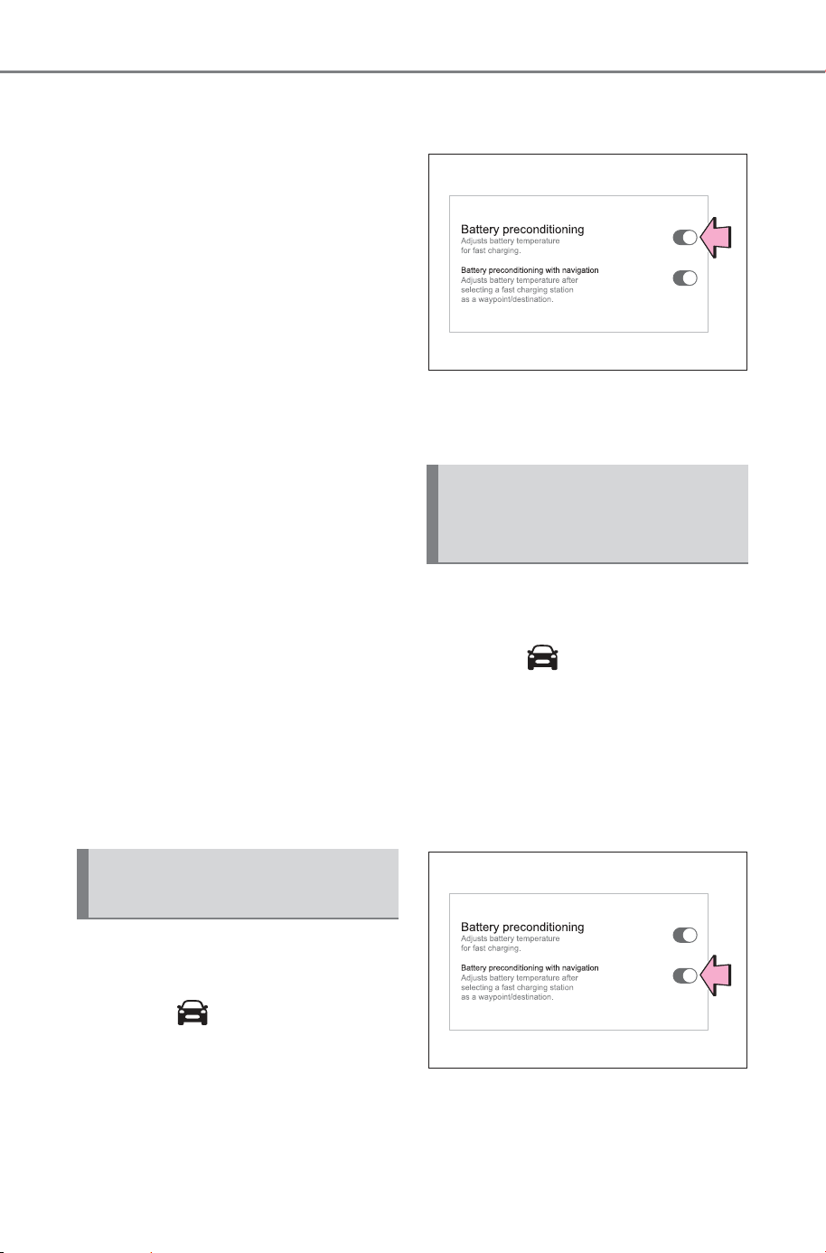
114
2-2. Charging
Owner’s Manual_USA_M6740B_en
“Battery preconditioning with
navigation” (P. 11 4)
When a DC charging station is
set as a destination in the navi-
gation system, “Battery precon-
ditioning” is automatically turned
on according to the estimated
arrival time.
• It may not work depending on
how the destination on the
navigation system or the DC
charging station is set.
• Depending on traffic condi-
tions and driving style, tem-
perature adjustment may not
be completed by the arrival
time.
“Scheduled battery precondi-
tioning” (P.11 5 )
By setting the departure time,
the temperature of the drive bat-
tery will be adjusted in advance
according to the departure time.
This feature helps allow the bat-
tery to be ready to accept faster
charging speeds.
1 Turn the power switch ON
and display the menu screen.
2 Select .
3 Select “Battery precondition-
ing”.
4 Select “General”.
5 Select “Battery precondition-
ing”.
“Battery preconditioning” switches
between ON and OFF with each
touch of the button.
1 Turn the power switch ON
and display the menu screen.
2 Select .
3 Select “Battery precondition-
ing”.
4 Select “General”.
5 Select “Battery precondition-
ing with navigation”.
“Battery preconditioning with navi-
gation” switches between ON and
OFF with each touch of the button.
When “Battery preconditioning with
Switching “Battery pre-
conditioning” ON-OFF
Switching “Battery pre-
conditioning with naviga-
tion” ON-OFF
SOLTERRA_OM_USA_A6740BE.book 114 ページ 2025年6月26日 木曜日 午前10時40分
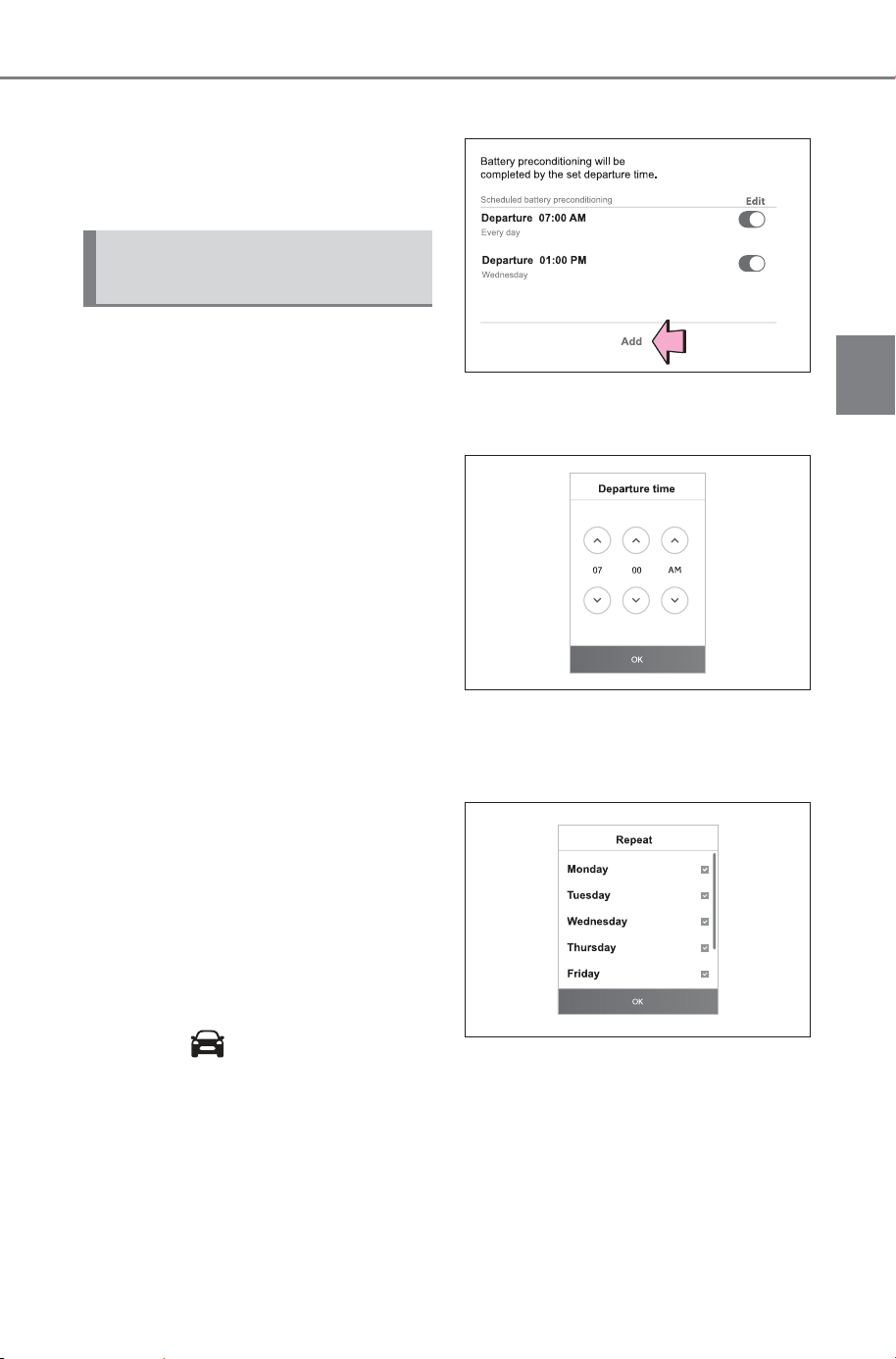
115
2-2. Charging
Owner’s Manual_USA_M6740B_en
2
Electric Vehicle system
navigation” is set to ON and a DC
charging station is set as a destina-
tion in the navigation system, “Bat-
tery preconditioning” will
automatically be set to ON.
■ Schedule Setup
Departure preconditioning, will
be performed according to the
day and time displayed in the
multimedia.
When attempting to set up
departure preconditioning, make
sure to check the schedule set-
tings to make sure it is set to the
correct day and correct them if it
is incorrect.
If the schedule contents are
incorrect, departure precondi-
tioning will not work properly.
For details on how to operate
the multimedia screen, refer to
“MULTIMEDIA OWNER’S MAN-
UAL”
■ Registering “Scheduled
battery preconditioning”
1 Turn the power switch ON
and display the menu screen.
2 Select on the multimedia
screen to display the menu
screen.
3 Select “Schedule”.
4 Select “Add”.
5 Operate the screen to set the
desired time and touch “OK”.
6 Select the desired day of the
week to enable the repeat
setting and touch “OK”.
Each time the check box is
selected, the repeat setting for the
selected day of the week will be
turned on or off.
7 When all settings are com-
plete, touch “Save”.
Setting “Scheduled bat-
tery preconditioning”
SOLTERRA_OM_USA_A6740BE.book 115 ページ 2025年5月23日 金曜日 午後1時18分
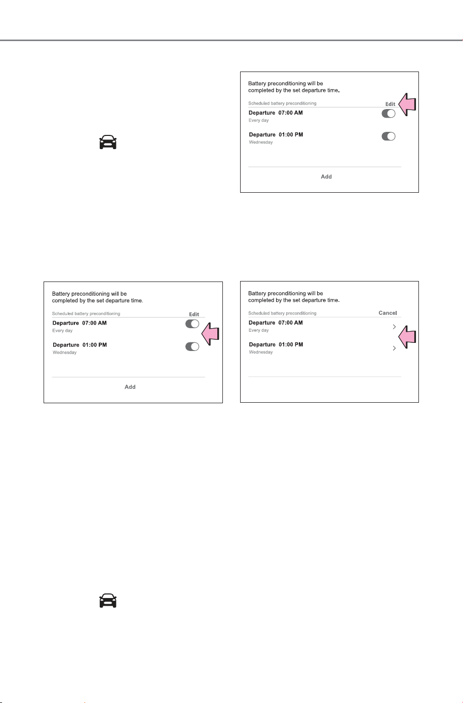
116
2-2. Charging
Owner’s Manual_USA_M6740B_en
■ Switching the settings of
“Scheduled battery precon-
ditioning”
1 Turn the power switch ON
and display the menu screen.
2 Select .
3 Select “Battery precondition-
ing”.
4 Select “Schedule”.
5 From the displayed list, touch
the button for the precondi-
tioning setting desired to turn
ON/OFF.
If the preconditioning setting
desired to turn ON/OFF is not dis-
played on the screen, scroll the list
display up or down to display the
preconditioning setting.
Each time the button is selected,
the preconditioning setting will
switch between ON and OFF.
■ Changing the registered
contents of “Scheduled bat-
tery preconditioning”
1 Turn the power switch ON
and display the menu screen.
2 Select .
3 Select “Schedule”.
4 Select “Edit”.
5 From the list displayed on the
screen, touch the precondi-
tioning settings in which it is
desired to change the regis-
tered contents.
When changing the registered
contents:
Change the settings to the desired
settings by following the steps from
step
5 of “Registering Scheduled
preconditioning”.
When deleting the registered
contents:
Touch “Delete”
A message appears to confirm the
deletion.
Touch “Delete” to delete the
selected charging schedule.
SOLTERRA_OM_USA_A6740BE.book 116 ページ 2025年5月23日 金曜日 午後1時18分
117
2-2. Charging
Owner’s Manual_USA_M6740B_en
2
Electric Vehicle system
1 Connect the charge cable to
the vehicle to start charging.
AC Charging: P.95
DC Charging: P. 100
2 Turn the power switch to ON
while charging.
My Room Mode settings is auto-
matically displayed on the multime-
dia
3 Select the “Yes”.
My Room Mode is started and it is
possible to use the air conditioning
system, audio system, etc.
Select “No” and press when
My Room Mode is not being used.
To disable My Room Mode, turn the
power switch off.
My Room Mode will automatically
be off when DC charging is com-
pleted.
■ Multimedia display while
charging
After turning the power switch to ON
while charging, the power switch
automatically turns off if My Room
Mode is not selected within approxi-
mately 100 seconds.
■ When using My Room Mode the
following may occur
● When the remaining charge of the
traction battery drops to the lower
limit, the air conditioning system
automatically stops. In that case,
the air conditioning system can
not operate until the remaining
charge of the traction battery
increases. Turn off the power
switch once, then use My Room
Mode after the remaining charge
of the traction battery increases.
● The charging time of the traction
battery gets longer.
● Noise may be heard from the
radio depending on conditions of
the radio wave.
● The surrounding area of the
onboard traction battery charger
in the motor compartment may
become hot.
● The electric power steering sys-
tem warning light (yellow) may
turn on, but this is not a malfunc-
tion.
● When charging the battery in nor-
mal mode, the amount of charge
is controlled so that the battery is
not fully recharged in order to
maintain the My Room Mode.
■ Using My Room Mode during
DC charging
● When using My Room mode
during DC charging, the amount of
charge at the time of charge com-
pletion will be lower than when not
using it. In addition, when DC
charging during low outdoor tem-
peratures and a high humidity
environment, the windows may
fog up. Turning on the cooling and
Using My Room Mode
When the charging cable is
connected to the vehicle,
electrical components such
as the air conditioning sys-
tem and audio system can
be used by the power sup-
ply from an external power
source.
Starting My Room Mode
SOLTERRA_OM_USA_A6740BE.book 117 ページ 2025年5月23日 金曜日 午後1時18分
118
2-2. Charging
Owner’s Manual_USA_M6740B_en
dehumidification functions
(P.494) will dehumidify the vehi-
cle interior and remove fogging
from the windows. In this case, the
temperature control of the traction
battery will be stopped and the
amount of charge may decrease.
● When the battery is fully charged,
the system will exit the My Room
Mode.
■ When “My Room Mode” is used
while the traction battery is fully
charged
When “My Room Mode” is used
while the traction battery is fully
charged, the electric power of the
traction battery may be consumed.
In this case, charging may be per-
formed again.
■ Warning message display
When trying to start My Room Mode or My Room Mode is being used, if a
message is displayed on the multi-information display, refer to the corre-
sponding table and perform the appropriate correction procedures.
*
: During My Room Mode, the information for electric power balance can be
checked on the multimedia.
Message Correction procedure
“Traction Battery is too
Low for “My Room
Mode””
There is no remaining charge of the traction bat-
tery to start My Room Mode. Wait until the
remaining charge of the traction battery
increases, start My Room Mode.
““My Room Mode” has
stopped due to low trac-
tion battery”
The remaining charge of the traction battery is
insufficient. Stop using My Room Mode and
charge the traction battery.
““My Room Mode” will
stop when traction bat-
tery is too low Reduce
power usage to continue
using “My Room Mode””
When My Room mode electricity consumption
exceeds the charge amount, the traction battery
charge level becomes too low.
*
• If the electricity consumption of the vehicle can
not be improved, My Room Mode will be off.
• When My Room Mode continuation is desired,
turn off the air conditioning system, audio sys-
tem, etc., to increase the remaining charge of
the traction battery.
SOLTERRA_OM_USA_A6740BE.book 118 ページ 2025年5月23日 金曜日 午後1時18分
119
2-2. Charging
Owner’s Manual_USA_M6740B_en
2
Electric Vehicle system
WARNING
■ Warnings for using My Room
Mode
Observe the following precau-
tions.
Failure to do so may result in
death or a serious health hazard.
● Do not leave children, people
who need care, or pets inside
the vehicle. The temperature
inside the vehicle may become
high or low due to features such
as the automatic shut-off. The
children, people who need care,
or pets left inside the vehicle
may suffer heatstroke dehydra-
tion or hypothermia. Also, since
the wipers, etc., can be oper-
ated, there may be accidental
operation, possibly leading to
an accident.
● Use the mode after sufficiently
checking the vicinity of the vehi-
cle for safety hazards.
SOLTERRA_OM_USA_A6740BE.book 119 ページ 2025年5月23日 金曜日 午後1時18分

120
2-2. Charging
Owner’s Manual_USA_M6740B_en
Refer to the following table and carry out the appropriate correction
procedure.
■ Charging indicator of the charging port does not illuminate,
even though AC charging connector is connected.
When charging cannot be carried out
When charging does not start, even though the normal proce-
dure is followed, check each of the following items. If a mes-
sage is shown on the multi-information display, also refer to
P.127.
When charging cannot be carried out
Likely cause Correction procedure
AC charging connector is not
securely connected to charging inlet
Check the connection status of the
AC charging connector.
• When connecting the AC charging
connector, insert the AC charging
connector securely.
• After connecting the AC charging
connector, check that the charging
indicator of the charging port is
turned on.
If the charging indicator of the
charging port does not illuminate,
even though the AC charging con-
nector is securely connected, there
may be a malfunction in the system.
Immediately stop charging and con-
tact your SUBARU dealer.
Traction battery is already fully
charged
When the traction battery is fully
charged, charging is not performed.
The remaining charge of the traction
battery exceeds the set upper limit of
the charge capacity
Change to a higher upper limit set-
ting than the current remaining
charge capacity and perform
charging again.
The AC charger does not operate
Please contact the facility manager
when there is a problem with AC
charger.
SOLTERRA_OM_USA_A6740BE.book 120 ページ 2025年5月23日 金曜日 午後1時18分
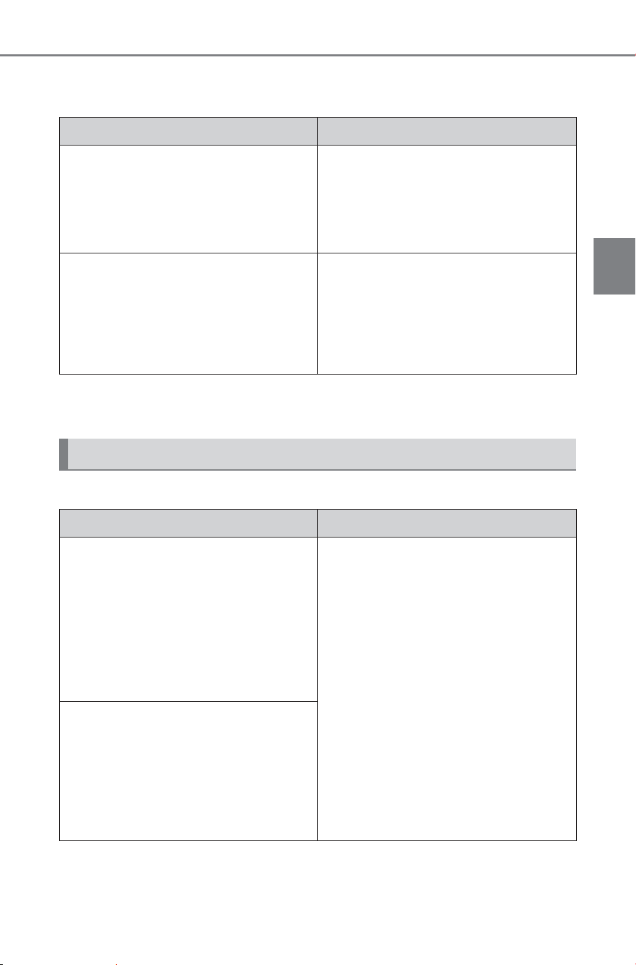
121
2-2. Charging
Owner’s Manual_USA_M6740B_en
2
Electric Vehicle system
■ Charging indicator of the charging port flashes and charging
cannot be carried out.
*
: Refer to P.85 for details regarding charging indicator of the charging port
illumination and flashing.
■ DC charging does not start
Likely cause Correction procedure
When charging indicator of the
charging port flashes normally
*
:
Charging schedule is registered
When you wish to charge according
to the charging schedule, wait until
the set time.
To start charging, set “Charge Now”
to on. (P.108, 112)
When charging indicator of the
charging port rapidly flashes
*
: Mal-
function occurred in an external
power source or the vehicle
When a door is opened while the
power switch is off, a message will
be displayed on the multi-information
display. Follow the instructions dis-
played on the multi-information dis-
play.
When DC charging cannot be performed normally
Likely cause Correction procedure
The DC charging connector is not
properly connected to the vehicle.
Check the connection status of the
DC charging connector and be sure
that it is locked.
If the DC charging does not start,
even though the DC charging con-
nector is securely connected, there
may be a malfunction with the DC
charger or charging system.
The DC charging connector is not
securely locked.
• If there is a malfunction with the
DC charger, contact the charging
station manager.
• If there is not a malfunction with
the DC charger, there may be a
malfunction in the system. Contact
your SUBARU dealer.
SOLTERRA_OM_USA_A6740BE.book 121 ページ 2025年5月23日 金曜日 午後1時18分

122
2-2. Charging
Owner’s Manual_USA_M6740B_en
Error is detected by the DC charger
or vehicle’s system check.
There may be a malfunction with the
DC charger or charging system.
• If there is a malfunction with the
DC charger, contact the charging
station manager.
• If there is not a malfunction with
the DC charger, there may be a
malfunction in the system. Contact
your SUBARU dealer.
• If the EV system can not be
started, contact your SUBARU
dealer.
The DC charger power goes off.
Contact the charging station man-
ager and check the power status.
Traction battery is already fully
charged
When the traction battery is fully
charged, DC charging cannot be per-
formed.
The EV system is started.
When the EV system is started, DC
charging cannot be started.
Also, if the shift position is not in P,
DC charging cannot be performed.
The upper limit of the charge capac-
ity is lower than the remaining
charge of the traction battery
Set the upper limit of the charge
capacity to a value higher than the
current remaining charge of the trac-
tion battery, and then perform the
charging procedure again.
DC charging was repeatedly per-
formed
After waiting a few minutes after
starting the EV system, stop the EV
system and perform charging again.
Likely cause Correction procedure
SOLTERRA_OM_USA_A6740BE.book 122 ページ 2025年5月23日 金曜日 午後1時18分
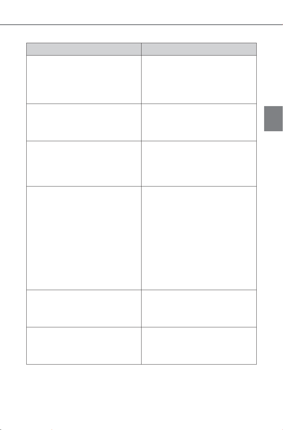
123
2-2. Charging
Owner’s Manual_USA_M6740B_en
2
Electric Vehicle system
■ When DC charging is interrupted
Likely cause Correction procedure
The timer for the DC charger oper-
ates.
Depending on the type of the DC
charger, the timer may be set to stop
charging after a certain time.
Check with the charging station man-
ager.
The power for the DC charger is off.
Check the power status of the DC
charger. If there are uncertainties
with the power status, contact the
charging station manager.
The temperature of the traction bat-
tery is extremely high or low.
DC charging may not be performed
in extremely high or extremely low
temperature environments. Charge
the traction battery after the tem-
perature has been stabilized.
Error is detected by the DC charger
or vehicle’s system check.
There may be a malfunction with the
DC charger or charging system.
• If there is a malfunction with the
DC charger, contact the facility
manager.
• If there is not a malfunction with
the DC charger, there may be a
malfunction in the system. Contact
your SUBARU dealer.
• If the EV system can not be
started, contact your SUBARU
dealer.
High temperature of charging related
parts
If the temperature of charging related
parts is high, DC charging may not
be possible. Wait for a while and
then charge again.
The electrical components such as
the air conditioning system stop
operating while the traction battery is
approximately fully charged.
Keep the electrical components such
as the air conditioning system in the
OFF state, and then perform the DC
charging procedure again.
SOLTERRA_OM_USA_A6740BE.book 123 ページ 2025年5月23日 金曜日 午後1時18分

124
2-2. Charging
Owner’s Manual_USA_M6740B_en
■ EV system does not start after DC charging
Likely cause Correction procedure
Charging system check is not com-
pleted properly after DC charging.
Do a system check following the pro-
cedures on P.105. If the system
check can not be completed properly
even after these procedures are per-
formed, contact your SUBARU
dealer.
The DC charging connector is still
connected.
For safety, the EV system can not be
started when the DC charging con-
nector is connected. (P. 92)
Remove the DC charging connector
immediately after the charging is
completed.
The DC charging system is malfunc-
tioning
• Depending on the type of malfunc-
tion, the EV system can be started
after the charging system check is
completed. (P.105)
• If the EV system can not be
started, contact your SUBARU
dealer.
SOLTERRA_OM_USA_A6740BE.book 124 ページ 2025年5月23日 金曜日 午後1時18分
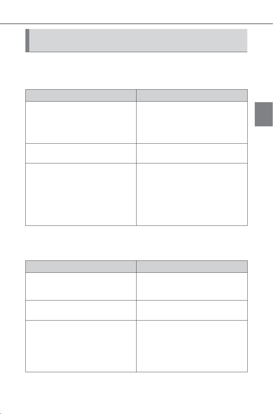
125
2-2. Charging
Owner’s Manual_USA_M6740B_en
2
Electric Vehicle system
Refer to the following table and carry out the appropriate correction
procedure.
■ Charging does not start at desired time
*
: For details on setting the clock, refer to the separate “MULTIMEDIA
OWNER’S MANUAL”.
■ Charging starts, even though charging schedule is registered
When charging schedule function does not operate nor-
mally
Likely cause Correction procedure
The vehicle calendar and clock is not
set correctly.
Check the calendar setting and set it
to the correct date.
*
Check the clock setting and set to
the proper time.
*
AC charging connector is not con-
nected to vehicle
Before using the charging schedule,
connect the AC charging connector.
AC charging connector was con-
nected after set time
Connect the AC charging connector
before the time set in “Start”.
When the charging mode is set to
“Start and stop”, the traction battery
will charge even if the start time has
passed, if the AC charging connector
is connected before the stop time.
Likely cause Correction procedure
“Charge Now” is set to on
When charging according to the
charging schedule, set “Charge
Now” to off. (P.108, 112)
Charging schedule is set to off
Check that charging schedule is not
set to off. (P.106)
The charging mode is set to “Start
and stop” and the AC charging con-
nector was connected between the
start time and stop time
When the charging mode is “Start
and stop”, connecting the AC
charging connector after the start
time will perform charging until the
stop time. Check the charging
schedule.
SOLTERRA_OM_USA_A6740BE.book 125 ページ 2025年5月23日 金曜日 午後1時18分

126
2-2. Charging
Owner’s Manual_USA_M6740B_en
AC charging connector was removed
and reinserted while charging indica-
tor of the charging port was flashing
If the AC charging connector is
removed and reinserted while the
charging indicator is flashing, the
charging schedule is canceled. Tem-
porarily remove the AC charging
connector, and then reconnect it.
The Remote Air Conditioning Sys-
tem was operated
When the Remote Air Conditioning
System is operated, the system will
start charging, even if the charging
schedule is registered. To carry out
charging using the charging sched-
ule, stop the Remote Air Condition-
ing System, and then reconnect the
AC charging connector.
Outside temperature is low and trac-
tion battery warming control (P.89)
operated (Alaska and Canada only)
• When traction battery warming
control operates, the charging
schedules are ignored and
charging starts. In order to protect
the traction battery, allow charging
to continue.
• After the 12-volt battery is removed
and reconnected, the charging
schedule setting may be disabled
due to the initial setting of the tem-
perature control system for the
drive battery, even when the out-
side temperature is not low. In this
case, after driving a few times, the
system initial settings will be com-
pleted and the charging schedule
settings will be enabled when the
outside temperature is not low.
Likely cause Correction procedure
SOLTERRA_OM_USA_A6740BE.book 126 ページ 2025年5月23日 金曜日 午後1時18分
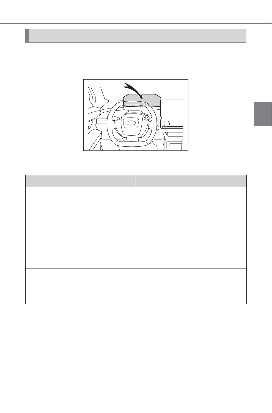
127
2-2. Charging
Owner’s Manual_USA_M6740B_en
2
Electric Vehicle system
When a door is opened with the power switch off, after charging, a
message is displayed in the multi-information display.
When this occurs, follow the instructions displayed on the screen.
■ If “Charging Stopped Due to Pulled Charging Connector” is
shown
*
: Electricity is consumed when operating traction battery heater (P.8 9),
the Remote Air Conditioning System (P.501).
When charging related message is displayed
Likely cause Correction procedure
AC charging connector is removed
while AC charging
When the AC charging connector is
removed while AC charging,
charging stops. If you want to fully
charge the traction battery, recon-
nect the AC charging connector.
After the traction battery is fully
charged, the AC charging connector
is removed while the traction battery
is being recharged again because
electricity-consuming functions
*
have
been used and the remaining charge
is now reduced.
The release button of the AC
charging connector was pressed
while AC charging
When the release button is pressed
while AC charging, charging stops.
To continue charging, reconnect the
AC charging connector.
SOLTERRA_OM_USA_A6740BE.book 127 ページ 2025年5月23日 金曜日 午後1時18分
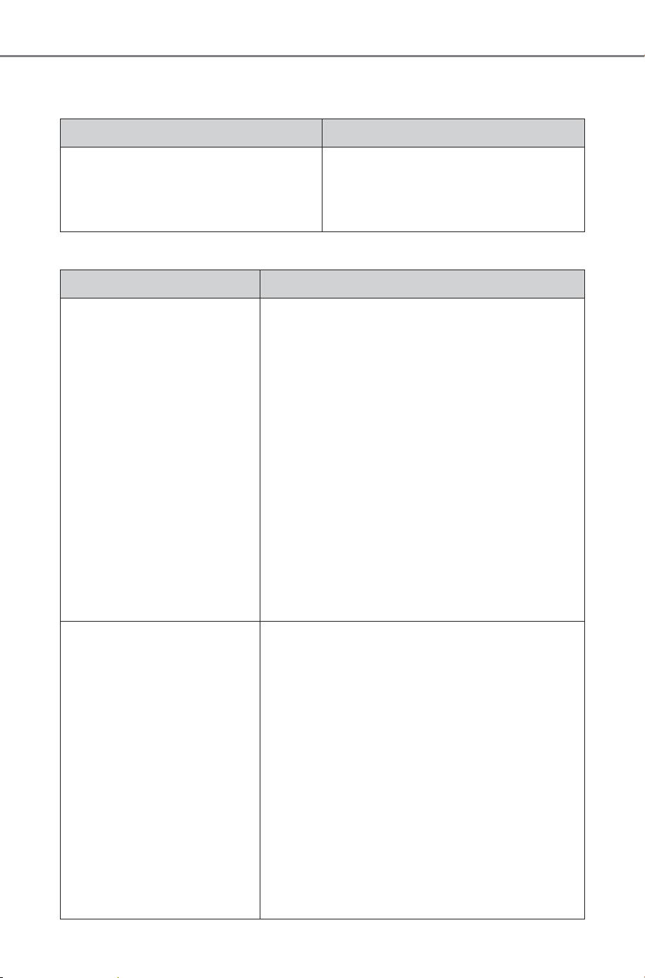
128
2-2. Charging
Owner’s Manual_USA_M6740B_en
■ If “Charging Complete Limited Charge Due to Battery Temp”
is shown
■ If “Charging Stopped Check Charging Source” is shown
Likely cause Correction procedure
Charging was stopped to protect the
traction battery as it continued to
remain hot for a certain period of
time.
Allow the traction battery to cool
down and perform charging again if
the charging amount has not
reached the desired amount.
Likely cause Correction procedure
Problem in power supply
from external power source
Check the following items.
• The plug is securely inserted.
• Extension cord is not used and electrical
outlet is not overloaded.
• The remote switch is not off.
• Connected to a dedicated power line.
• Power outage has occurred or not.
• The circuit breakers have not tripped.
If all of the above conditions are met, the out-
let may be malfunctioning. Contact an electri-
cian and request an inspection.
If charging cannot be performed, even though
there is no problem with the power source
path, there may be a malfunction in the sys-
tem. Have the vehicle inspected by your SUB-
ARU dealer.
AC charging is stopped by
AC charger
Depending on the specifications of AC char-
ger, charging may be canceled by an interrup-
tion of power supply. Charging may be
stopped by the following.
Refer to AC charger handling methods.
• The charging stop button of charger is
pressed.
• AC charger with off charging schedule func-
tion canceled charging
• AC charger that is not compatible with the
charging schedule function of the vehicle
• Check if it can be charged with another AC
charger. If charging cannot be carried out
even when using another AC charger, con-
tact your SUBARU dealer.
SOLTERRA_OM_USA_A6740BE.book 128 ページ 2025年5月23日 金曜日 午後1時18分
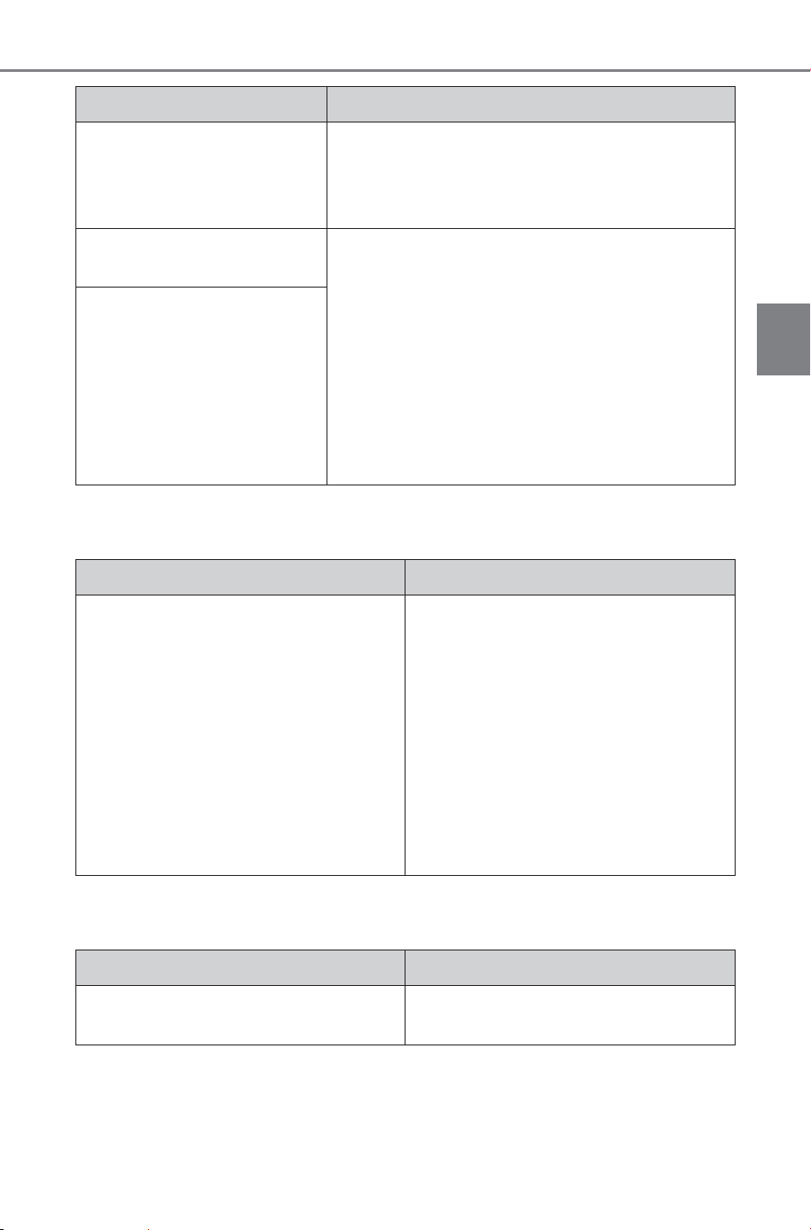
129
2-2. Charging
Owner’s Manual_USA_M6740B_en
2
Electric Vehicle system
■ If “Charging Stopped High Energy Use See Owner’s Manual”
is shown
■ If “Charging System Malfunction See Owner’s Manual” is
shown
The AC charger is not com-
patible with the vehicle
Check if it can be charged with another AC
charger. If charging cannot be carried out
even when using another AC charger, contact
your SUBARU dealer.
The DC charger is malfunc-
tioning.
If the message above is displayed when DC
charging has not stopped operations, the DC
charger may be damaged, so do not use that
DC charger. Check if it is possible to charge
with another DC charger.
If the message is still displayed and charging
cannot be performed even though another DC
charger is used, drive the vehicle for several
kilometers and then charge the traction bat-
tery with different DC charger.
The DC charger is not com-
patible with the vehicle.
Likely cause Correction procedure
Likely cause Correction procedure
Power is being consumed by electri-
cal components of vehicle
Check the following items, and then
carry out charging again.
• If the headlights and audio are
turned on, turn them off.
• Turn the power switch off.
If charging cannot be carried out,
even after performing the above, the
12-volt battery may not be suffi-
ciently charged. Operate the EV sys-
tem for approximately 15 minutes or
more to charge the 12-volt battery.
Likely cause Correction procedure
Malfunction occurred in charging
system
Have the vehicle inspected by your
SUBARU dealer.
SOLTERRA_OM_USA_A6740BE.book 129 ページ 2025年5月23日 金曜日 午後1時18分
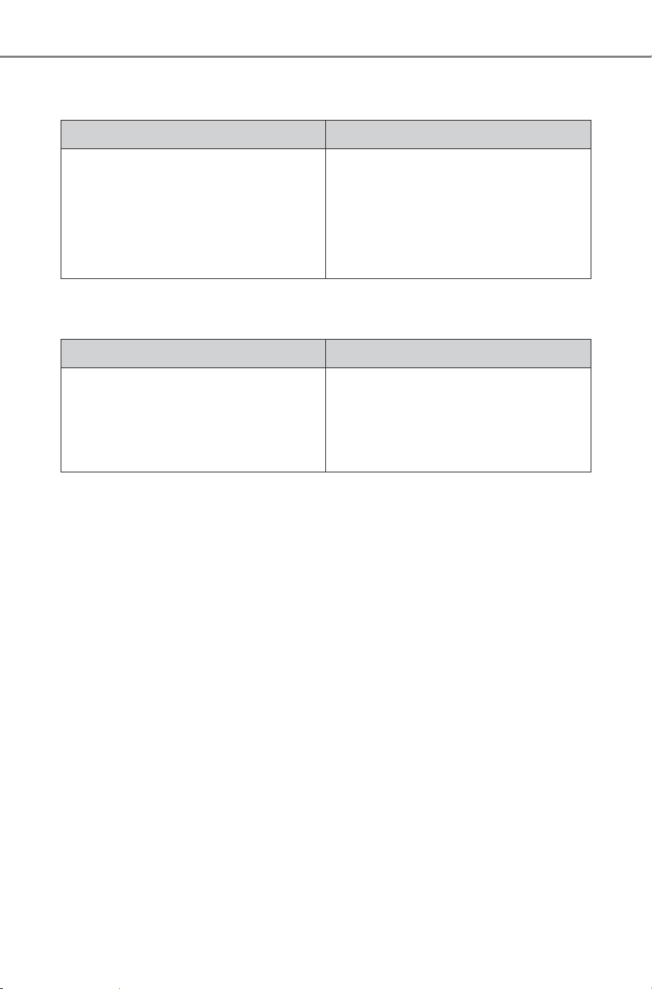
130
2-2. Charging
Owner’s Manual_USA_M6740B_en
■ If “The Traction Battery Temp is low System put priority on
charging to preserve battery condition” is shown
■ If “Check Charging System Close Charging Port Lid See
Owner’s Manual” is shown
Likely cause Correction procedure
The traction battery warming control
is operated (P.89)
When the traction battery warming
control operates, the charging
schedule is not used and charging is
performed.
This is a control to protect the trac-
tion battery, and not a malfunction.
Likely cause Correction procedure
Charging system check is not com-
pleted properly after DC charging.
The EV system can not be started
until the charging system check is
completed properly. Perform a
charging system check following the
procedures on P.105.
SOLTERRA_OM_USA_A6740BE.book 130 ページ 2025年5月23日 金曜日 午後1時18分
131
2-2. Charging
Owner’s Manual_USA_M6740B_en
2
Electric Vehicle system
■ If “Charging Stopped Time Limit Reached” is shown
■ If “Charging Stopped Check Charging Source or Vehicle” is
shown
Likely cause Correction procedure
The DC charging is not completed
within the restricted time with DC
charger.
• Depending on the type of DC char-
ger, the timer may be set to stop
charging after a certain time.
Check with the charging station
manager.
Depending on the condition of the
vehicle, the charging time may
become longer than normal, and the
DC charging may not be completed
within the restricted time.
• When the A/C, headlights, audio
system, etc., are turned on, the
electricity consumption of the vehi-
cle will be increased. Perform the
DC charging after turning off all of
the above.
• The temperature of the traction
battery may be low. Perform the
DC charging after warming up the
traction battery.
Likely cause Correction procedure
Malfunction occurred in connector
locking system.
Have the vehicle inspected by your
SUBARU dealer.
SOLTERRA_OM_USA_A6740BE.book 131 ページ 2025年5月23日 金曜日 午後1時18分
132
2-2. Charging
Owner’s Manual_USA_M6740B_en
The system simplify the
charging fee payment (billing
authentication) procedure,
allowing payment being made
automatically and rapid charging
beginning simply by inserting
the DC charging connector.
To use this system, a DC char-
ger
*
is required (a DC charger is
not equipped to the vehicle).
*
: Use a DC charger that supports
the Plug & Charge system con-
forming to ISO 15118.
Make sure to confirm the follow-
ing.
SUBARU remote service app
is contracted.
Plug & Charge is set to ON.
(P.133)
P.101
Operating the DC charger is
unnecessary.
A payment is automatically pro-
cessed using the contract infor-
mation stored in the vehicle.
Plug & Charge system
Before using the system,
read the following informa-
tion for proper use.
Plug & Charge system
How to use Plug &
Charge system
Before using the Plug &
Charge system, read the fol-
lowing information for
proper use.
Confirm the following
before Plug & Charge
Start charging using Plug
& Charge
SOLTERRA_OM_USA_A6740BE.book 132 ページ 2025年5月23日 金曜日 午後1時18分
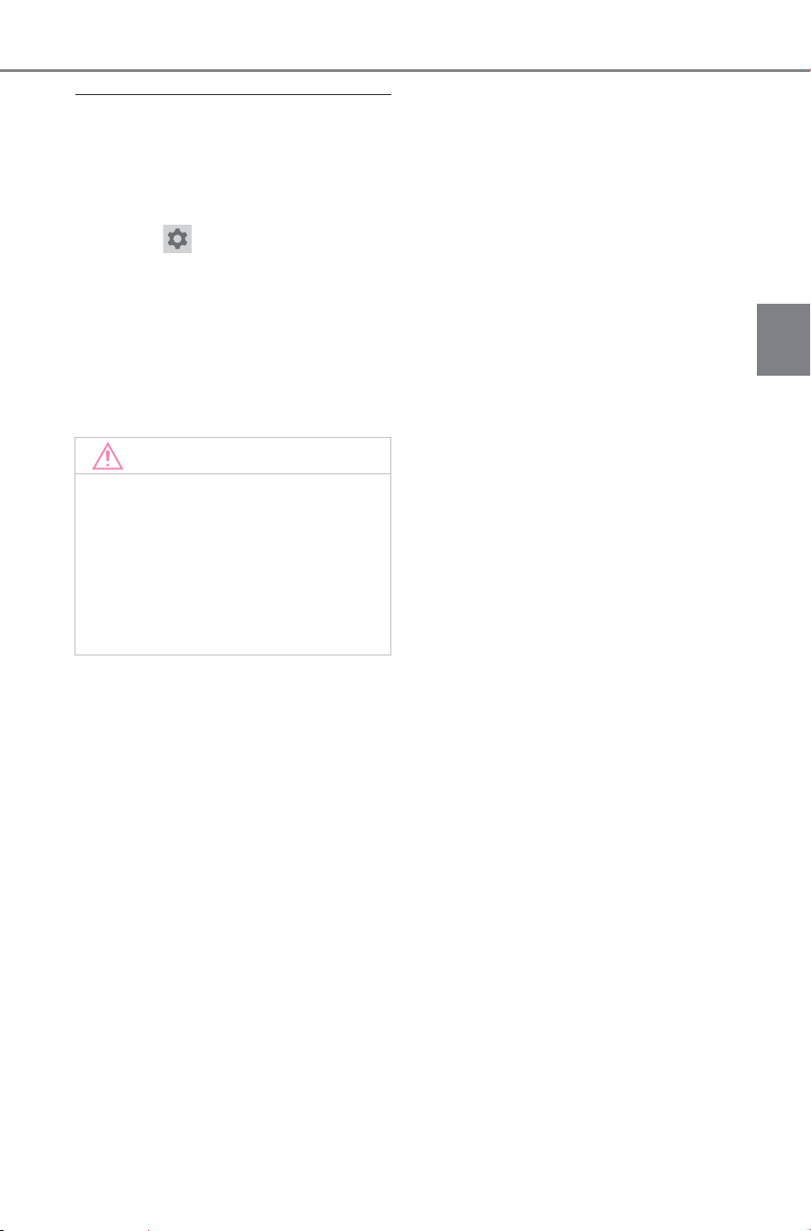
133
2-2. Charging
Owner’s Manual_USA_M6740B_en
2
Electric Vehicle system
■ Setting operations on the Multi-
media
The Plug & Charge settings can be
set on the Multimedia
● Operation on the Multimedia:
1 Select
2 Select “Plug & Charge”
The charging/power supply mode
selection screen will be displayed.
3 Select the ON/OFF button of
“Plug & Charge”.
To turn it off, touch the button once
again.
NOTICE
■ When reselling the vehicle
If the Plug & Charge contract has
not yet expired, the features may
be used by someone else, for
example if the vehicle is reselled.
To prevent this, the contract data
should be erased from the vehi-
cle.
SOLTERRA_OM_USA_A6740BE.book 133 ページ 2025年5月23日 金曜日 午後1時18分
134
2-2. Charging
Owner’s Manual_USA_M6740B_en
Refer to the following table and perform the appropriate correction
procedure.
■ Charging with Plug & Charge cannot be started
Refer to the following table and perform the appropriate correction
procedure.
■ Settings cannot be changed on the multimedia, multi-infor-
mation display, or smartphone app
When Plug & Charge system cannot be used nor-
mally
When charging does not start, even though the normal proce-
dure is followed, or an error message is displayed, check
each of the following items.
When DC charging cannot be performed normally
Likely cause Correction procedure
Plug & Charge is not set
Set up Plug & Charge on the Multi-
media (P.133).
Plug & Charge contract data has
been erased from the vehicle
Check the contract status and install
the contract certificate using the
smartphone app.
When Plug & Charge cannot be set normally
Likely cause Correction procedure
The DC charging connector is con-
nected
Remove the DC charging connector
and try changing the setting.
SOLTERRA_OM_USA_A6740BE.book 134 ページ 2025年5月23日 金曜日 午後1時18分
135
2-2. Charging
Owner’s Manual_USA_M6740B_en
2
Electric Vehicle system
When a door is opened while the power switch is off after charging, a
message will be displayed on the multi-information display.
If any of the following messages is displayed, follow the message
and perform the appropriate correction procedures.
■ If “Plug & Charge System Failure See Owner’s Manual” is
shown
When Plug & Charge related message is displayed
Likely cause Correction procedure
Authentication with Plug & Charge
has failed
If this message is displayed, recon-
nected the charging plug and try
charging.
If charging still does not start, turn
the Plug & Charge setting off and
start charging again.
If charging still does not start, contact
the facility manager.
To use Plug & Charge again, turn the
Plug & Charge setting on.
SOLTERRA_OM_USA_A6740BE.book 135 ページ 2025年5月23日 金曜日 午後1時18分

136
2-2. Charging
Owner’s Manual_USA_M6740B_en
SOLTERRA_OM_USA_A6740BE.book 136 ページ 2025年5月23日 金曜日 午後1時18分

137
Owner’s Manual_USA_M6740B_en
3
3
Vehicle status information and indicators
Vehicle status informa-
tion and indicators
3-1. Instrument cluster
Warning lights and indica-
tors ............................
138
Gauges and meters .... 142
Multi-information display
..................................
145
Displayed content ....... 147
Electricity consumption 151
SOLTERRA_OM_USA_A6740BE.book 137 ページ 2025年5月23日 金曜日 午後1時18分
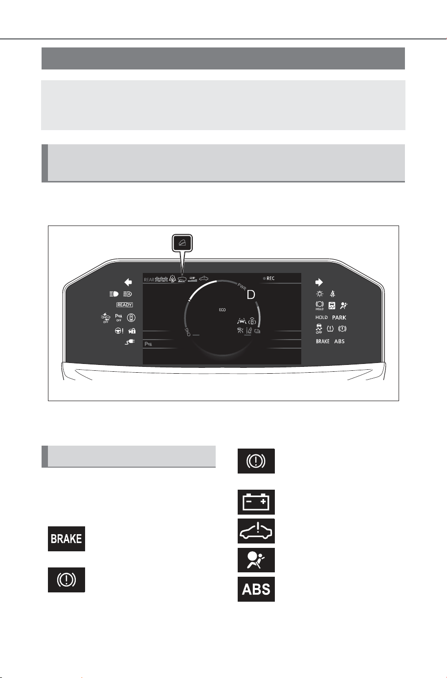
138
3-1. Instrument cluster
Owner’s Manual_USA_M6740B_en
3-1.Instrument cluster
For the purpose of explanation, the following illustrations display all
warning lights and indicators illuminated.
The units used on the meters and some indicators may differ depending on
the target region.
Warning lights inform the driver
of malfunctions in the indicated
vehicle’s systems.
Warning lights and indicators
The warning lights and indicators on the instrument cluster
and outside rear view mirrors inform the driver of the status
of the vehicle’s various systems.
Warning lights and indicators displayed on the instru-
ment cluster
Warning lights
(U.S.A.)
Brake system warning
light
*1
(P. 611)
(Canada)
(Red)
Brake system warning
light
*1
(P. 611)
(Yellow)
Brake system warning
light
*1
(P.611)
Charging system warning
light
*2
(P.611)
EV system malfunction
indicator lamp
*1
(P.612)
SRS warning light
*1
(P.612)
(U.S.A.)
ABS warning light
*1
(P.612)
SOLTERRA_OM_USA_A6740BE.book 138 ページ 2025年5月23日 金曜日 午後1時18分
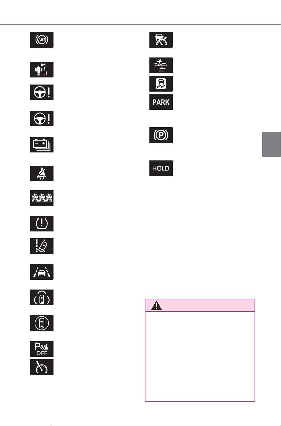
139
3-1. Instrument cluster
Owner’s Manual_USA_M6740B_en
3
Vehicle status information and indicators
*1
:These lights come on when the
power switch is turned to ON to
indicate that a system check is
being performed. They will turn
off after the EV system is started,
or after a few seconds. There
may be a malfunction in a sys-
tem if the lights do not come on,
or turn off. Have the vehicle
inspected by your SUBARU
dealer.
*2
:This light illuminates on the
multi-information display.
(Canada)
ABS warning light
*1
(P.612)
Inappropriate pedal oper-
ation warning light
*2
(P.613)
(Red)
Electric power steering
system warning light
*1
(P.613)
(Yellow)
Electric power steering
system warning light
*1
(P.613)
(Yellow)
Traction battery charge
warning light (P.613)
Driver’s and front passen-
ger’s seat belt reminder
light (P.614)
Rear passengers’ seat
belt reminder lights
(P.614)
Tire pressure warning
light
*1
(if equipped)
(P.615)
(Yellow)
LDA indicator (P.615)
(Yellow)
LTA indicator (P.615)
(Yellow)
PDA indicator (P. 615)
(Yellow)
Driving assist information
indicator
*1
(P.616)
SUBARU Parking Assist
OFF indicator
*1
(P.616)
(Yellow)
Cruise control indicator
(P.617)
(Yellow)
Dynamic radar cruise con-
trol indicator (P.617)
PCS warning light
*1
(P.617)
Slip indicator
*1
(P. 617)
(U.S.A.)
(Flashes)
Parking brake indicator
(P.618)
(Canada)
(Flashes)
Parking brake indicator
(P.618)
(Flashes)
Brake hold operated indi-
cator
*1
(P.618)
WARNING
■ If a safety system warning
light does not come on
Should a safety system light such
as the ABS and SRS warning light
not come on when you start the
EV system, this could mean that
these systems are not available to
help protect you in an accident,
which could result in death or seri-
ous injury. Have the vehicle
inspected by your SUBARU
dealer immediately if this occurs.
SOLTERRA_OM_USA_A6740BE.book 139 ページ 2025年5月23日 金曜日 午後1時18分
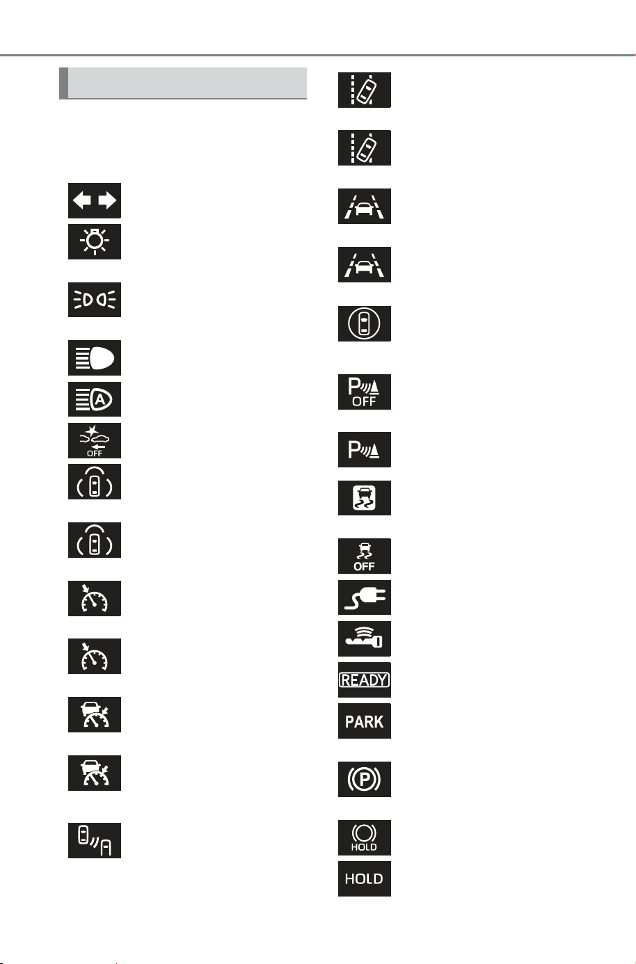
140
3-1. Instrument cluster
Owner’s Manual_USA_M6740B_en
The indicators inform the driver
of the operating state of the
vehicle’s various systems.
Indicators
Turn signal indicator
(P.240)
(U.S.A.)
Headlight indicator
(P.247)
(Canada)
Tail light indicator
(P.247)
Headlight high beam indi-
cator (P.249)
AHB indicator (P.249)
PCS warning light
*1, 2
(P.270)
(Green)
PDA indicator (P. 295)
(White)
PDA indicator (P. 295)
(Green)
Cruise control indicator
(P.317)
(White)
Cruise control indicator
(P.317)
(Green)
Dynamic radar cruise con-
trol indicator (P.306)
(White)
Dynamic radar cruise con-
trol indicator (P.306)
Outside rear view mirror
indicators
*3
(P.330, 335,
351)
(Green)
LDA indicator (P.294)
(White)
LDA indicator (P.294)
(Green)
LTA indicator (P. 29 4)
(White)
LTA indicator (P. 29 4)
(Yellow)
Driving assist information
indicator
*1, 2
(P.330,
335, 351, 356, 360)
SUBARU Parking Assist
OFF indicator
*1, 2
(P.340)
SUBARU Parking Assist
detection indicator (if
equipped) (P.340)
(Flashes)
Slip indicator
*1
(P. 477)
VSC OFF indicator
*1, 2
(P.478)
Charging cable indicator
(P.91)
Smart key system indica-
tor
*4
(P.229)
“READY” indicator
(P.229)
(U.S.A.)
Parking brake indicator
(P.241)
(Canada)
Parking brake indicator
(P.241)
Brake hold standby indi-
cator
*1
(P.245)
Brake hold operated indi-
cator
*1
(P.245)
SOLTERRA_OM_USA_A6740BE.book 140 ページ 2025年5月23日 金曜日 午後1時18分
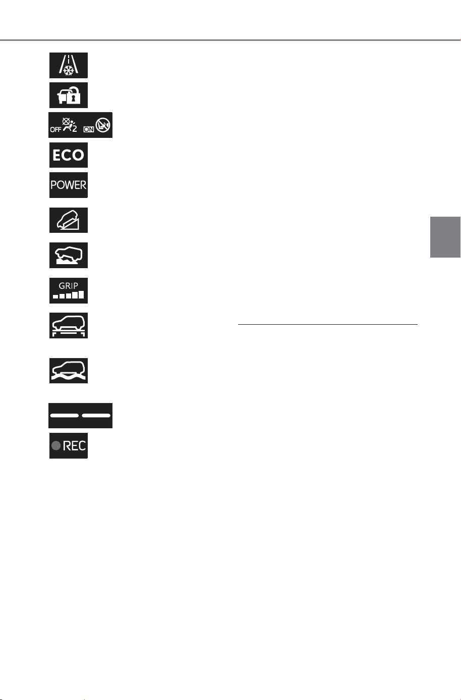
141
3-1. Instrument cluster
Owner’s Manual_USA_M6740B_en
3
Vehicle status information and indicators
*1
:These lights come on when the
power switch is turned to ON to
indicate that a system check is
being performed. They will turn
off after the EV system is started,
or after a few seconds. There
may be a malfunction in a sys-
tem if the lights do not come on,
or turn off. Have the vehicle
inspected by your SUBARU
dealer.
*2
:This light comes on when the
system is turned off.
*3
:This light illuminates on the out-
side rear view mirrors.
*4
:This light illuminates on the
multi-information display with a
message.
*5
:When the outside temperature is
approximately 37°F (3°C) or
lower, the indicator will flash for
approximately 10 seconds, then
stay on.
*6
:This light illuminates on the over-
head console.
*7
:Depending on the operating con-
dition, the color of the light
change.
*8
:This light comes on when the
stop lights are illuminated by the
operation of the brake pedal or
the driving assist system.
■ SUBARU Parking Assist OFF
indicator
Vehicles without multimedia display:
The indicators turn off when the shift
position is changed to R regardless
of whether the SUBARU Parking
Assist function is turned on or off.
Low outside temperature
indicator
*5
(P.144)
Security indicator (P. 6 5 ,
66)
“AIR BAG ON/OFF”
indicator
*1, 6
(P. 41 )
Eco drive mode indicator
(P.470)
Power mode indicator (if
equipped) (P.470)
Downhill assist control
system indicator (if
equipped) (P.471)
Grip control indicator (if
equipped) (P.471)
Grip control set speed
indicator (if equipped)
(P.474)
(
*7
)
SNOW/DIRT mode indi-
cator (if equipped)
(P.472)
(
*7
)
D.SNOW/MUD mode indi-
cator (if equipped)
(P.472)
Stop lights indicator
*8
REC indicator (P.329)
SOLTERRA_OM_USA_A6740BE.book 141 ページ 2025年5月23日 金曜日 午後1時18分
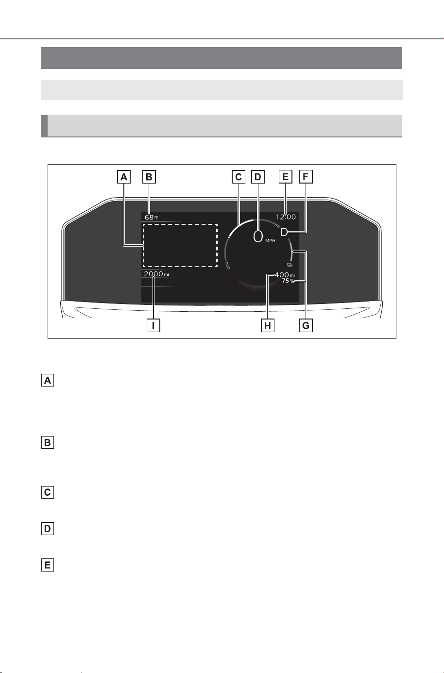
142
3-1. Instrument cluster
Owner’s Manual_USA_M6740B_en
■ Locations of gauges and meters
The units of measure may differ depending on the intended destination of
the vehicle.
Multi-information display
Presents the driver with a variety of vehicle data. (P.145)
Displays warning messages if a malfunction occurs. (P.621)
Display/hide for the multi-information display can be changed. (P.144)
Outside temperature
Displays the outside temperature within the range of -40°F (-40°C) to 140°F
(60°C).
Power meter (P.143)
Displays EV system output or regeneration level.
Speedometer
Displays the vehicle speed.
Clock
Automatically adjusts the time by using the GPS time information (GPS
clock). For details, refer to the “MULTIMEDIA OWNER’S MANUAL”.
Gauges and meters
The meters display various drive information.
Meter display
SOLTERRA_OM_USA_A6740BE.book 142 ページ 2025年5月23日 金曜日 午後1時18分
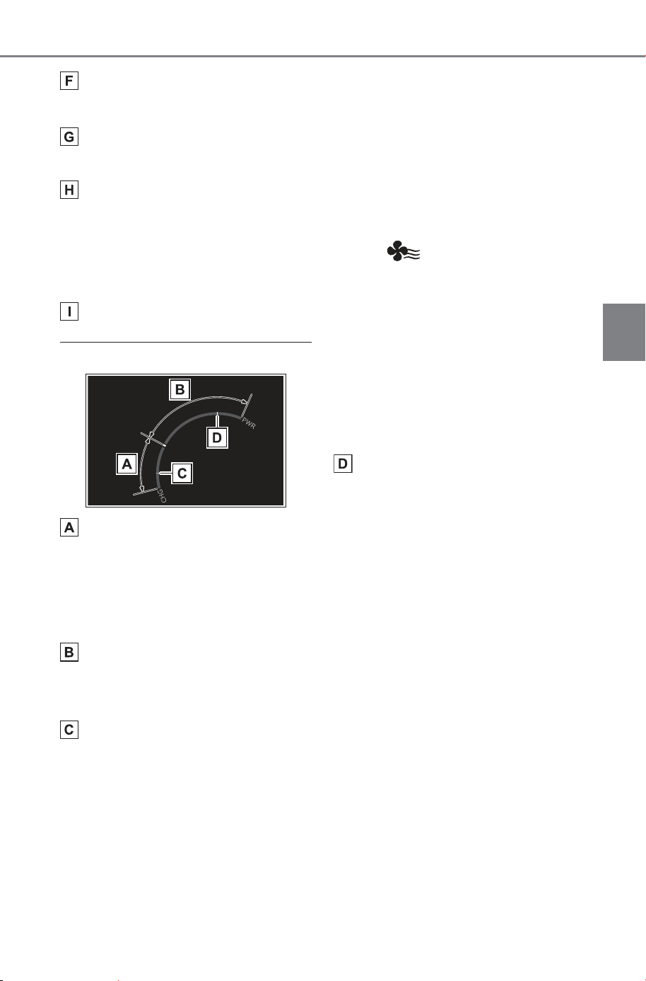
143
3-1. Instrument cluster
Owner’s Manual_USA_M6740B_en
3
Vehicle status information and indicators
Shift position indicator/regenerative braking power indicator.
(P.233)
SOC (State of Charge) gauge
Displays the amount of charge remaining in the traction battery.
Driving range
Displays driving range with remaining charge. (P. 233)
When the air conditioning system is operating, and the driving range
with the air conditioning system on are displayed.
Odometer and trip meter display (P.144)
■ Power meter
Charge area
Shows regeneration
*1
status.
Regenerated energy will be used to
charge the EV battery (traction bat-
tery).
Power area
Displays the EV system output
(acceleration force) while driving.
Regeneration
*1
restrictions refer-
ence display
*2
In the following situations, regenera-
tive braking is restricted, and the ref-
erences for those restrictions are
displayed in the charge area.
• When the traction battery has a
large amount of charge and can
no longer be regenerated
• When the temperature of the trac-
tion battery is extremely high or
extremely low
Output restrictions reference dis-
play
*2
In the following situations, the out-
put is restricted, and the references
for those restrictions are displayed
in the power area.
• When the traction battery has a
low amount of charge and can no
longer output power
• When the temperature of the trac-
tion battery is extremely high or
extremely low
*1
:The meaning of “Regeneration”
here means converting kinetic
energy into electrical energy.
*2
:The actual restrictions may differ
depending on the vehicle condi-
tion.
SOLTERRA_OM_USA_A6740BE.book 143 ページ 2025年5月23日 金曜日 午後1時18分
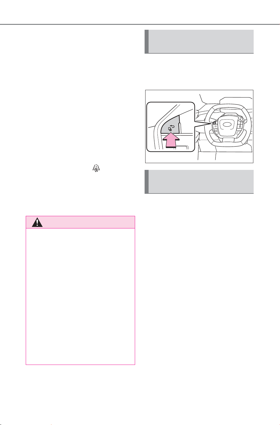
144
3-1. Instrument cluster
Owner’s Manual_USA_M6740B_en
■ Outside temperature display
● In the following situations, the cor-
rect outside temperature may not
be displayed, or the display may
take longer than normal to
change:
• When stopped, or driving at low
speeds (less than 16 mph [25
km/h])
• When the outside temperature
has changed suddenly (at the
entrance/exit of a garage, tunnel,
etc.)
● When “--” is displayed, the system
may be malfunctioning. Take your
vehicle to your SUBARU dealer.
● When the outside temperature is
approximately 37°F (3°C) or
lower, the indicator will flash
for approximately 10 seconds,
then stay on.
■ Liquid crystal display
P.146
The Multi-Information display
can be switched between dis-
play and hidden.
■ Display items
Odometer
Displays the total distance the vehi-
cle has been driven.
Trip meter A/Trip meter B
Displays the distance the vehicle
has been driven since the meter
was last reset. Trip meters A and B
can be used to record and display
different distances independently.
■ Switching the display
The display switches each time
the switch is pressed. Also,
when the switch is continuously
pressed during the trip meter
display, the driving distance can
be changed to “0”.
WARNING
■ The information display at
low temperatures
Allow the interior of the vehicle to
warm up before using the liquid
crystal information display. At
extremely low temperatures, the
information display monitor may
respond slowly, and display
changes may be delayed.
For example, there is a lag
between the driver’s shifting and
the regenerative braking power
appearing on the display. This lag
could cause the driver to down-
shift again, causing rapid and
excessive regenerative braking
and possibly an accident resulting
in death or injury.
Switching the meter dis-
play
Odometer and trip meter
display
SOLTERRA_OM_USA_A6740BE.book 144 ページ 2025年5月23日 金曜日 午後1時18分
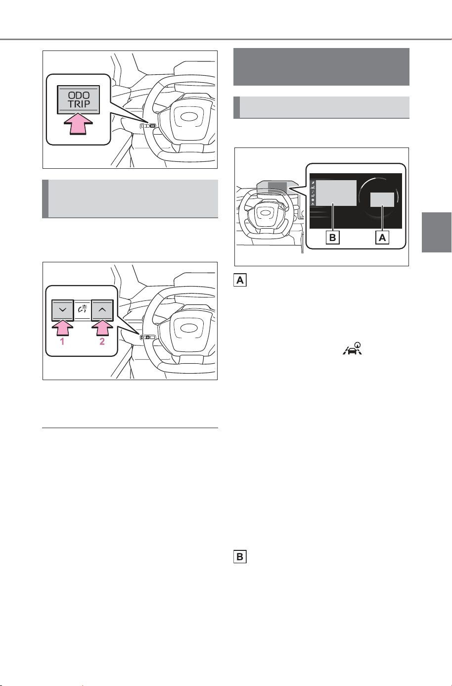
145
3-1. Instrument cluster
Owner’s Manual_USA_M6740B_en
3
Vehicle status information and indicators
The brightness of the instrument
panel lights can be adjusted.
1 Darker
2 Brighter
■ Instrument panel illumination
adjustment
The brightness level can be
adjusted when the surroundings are
bright (daytime, etc.) or dark (night-
time, etc.).
■ Display
Driving support system status
display area
Displays an image when the follow-
ing systems are operating and a
menu icon other than is
selected:
• LDA (Lane Departure Alert)
(P.290)
• LTA (Lane Tracing Assist)
(P.282)
• LCA (Lane Change Assist)
(P.287)
• RSA (Road Sign Assist)
(P.303)
• Dynamic radar cruise control
(P.306)
• Cruise control (P.317)
• PDA (Proactive driving assist)
(P.295)
Content display area
By selecting menu icons on the
multi-information display, a variety
of driving-related information can
be displayed. The multi-information
display can also be used to change
Adjusting the instrument
panel light control
Multi-information dis-
play
Display and menu icons
SOLTERRA_OM_USA_A6740BE.book 145 ページ 2025年5月23日 金曜日 午後1時18分
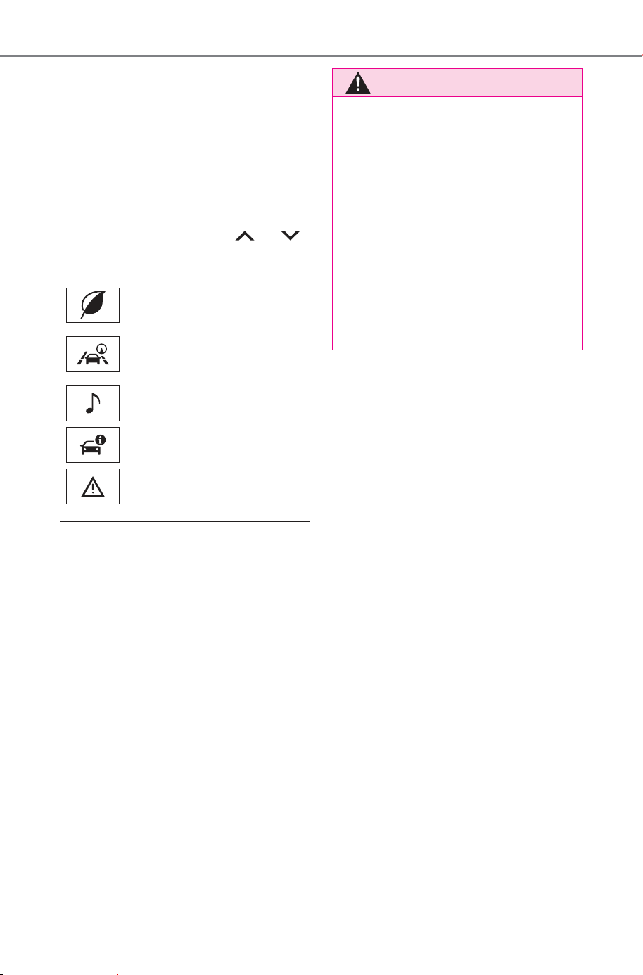
146
3-1. Instrument cluster
Owner’s Manual_USA_M6740B_en
display settings and other vehicle
settings.
Warning or advice pop-up displays
are also displayed in certain situa-
tions.
■ Menu icons
The menu icons will be dis-
played by pressing the or
meter control switch.
■ Liquid crystal display
Small spots or light spots may
appear on the display. This phenom-
enon is characteristic of liquid crys-
tal displays, and there is no problem
continuing to use the display.
Driving information display
(P.147)
Driving support system
information display
(P.148)
Audio system-linked dis-
play (P.149)
Vehicle information dis-
play (P.149)
Warning message display
(P.621)
WARNING
■ Caution for use while driving
● When operating the multi-infor-
mation display while driving,
pay extra attention to the safety
of the area around the vehicle.
● Do not look continuously at the
multi-information display while
driving as you may fail to see
pedestrians, objects on the
road, etc., ahead of the vehicle.
■ The information display at
low temperatures
P.1 44
SOLTERRA_OM_USA_A6740BE.book 146 ページ 2025年5月23日 金曜日 午後1時18分
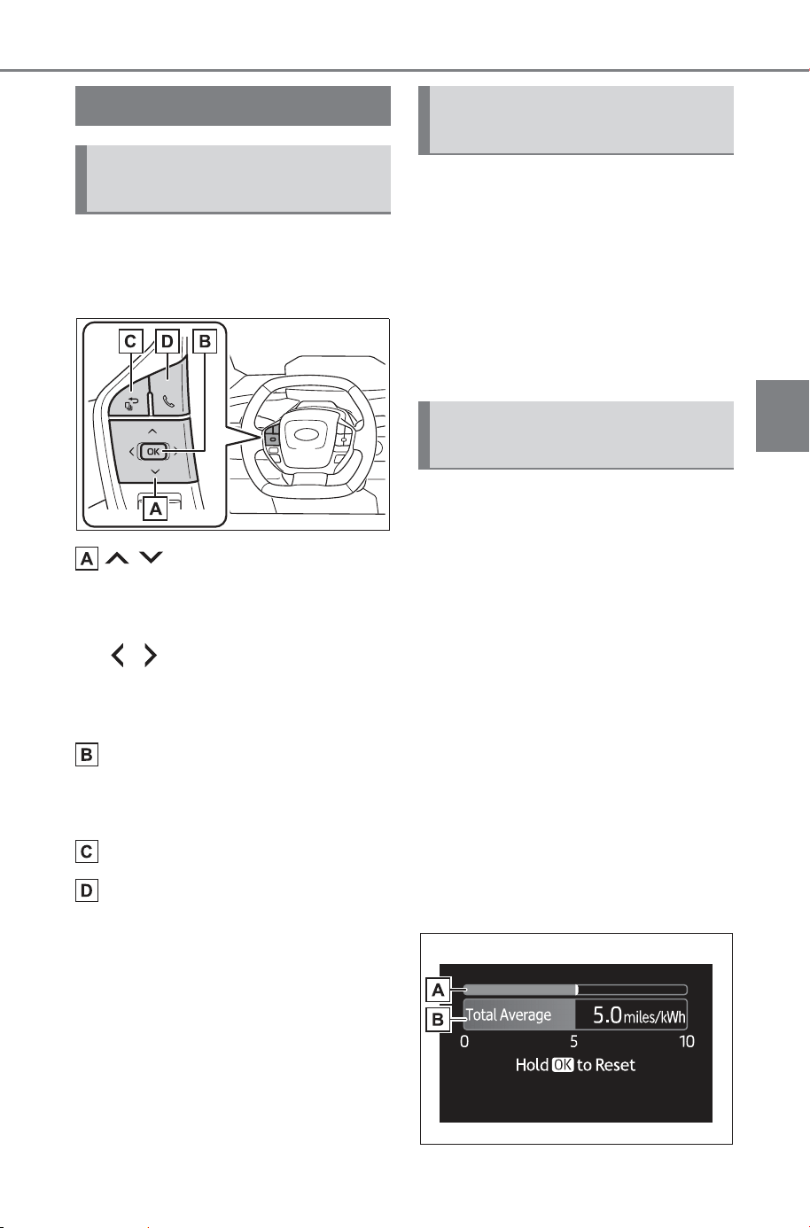
147
3-1. Instrument cluster
Owner’s Manual_USA_M6740B_en
3
Vehicle status information and indicators
The multi-information display is
operated using the meter control
switches.
/ : Select menu icons,
scroll the screen and move
the cursor
/ : Change displayed
content, scroll the screen and
move the cursor
Press: Enter/Set
Press and hold: Reset/Dis-
play customizable items
Return to the previous screen
Call sending/receiving and
history display
Linked with the hands-free system,
sending or receiving call is dis-
played. For details regarding the
hands-free system, refer to the
“MULTIMEDIA OWNER’S MAN-
UAL”.
Driving related information is
displayed on the following dis-
plays.
Multi-information display
Multimedia display
The items displayed will differ
depending on the display.
■ Display items
Total average (Average elec-
tricity consumption [after
reset])
Trip average (Average elec-
tricity consumption [after
start])
■ Total average (Average
electricity consumption
[after reset])
Displays the average electricity
consumption since the vehicle
was reset.
Use the displayed values as a
reference only.
Displayed content
Changing the meter dis-
play
Display of drive informa-
tion
Content of driving infor-
mation
SOLTERRA_OM_USA_A6740BE.book 147 ページ 2025年5月23日 金曜日 午後1時18分
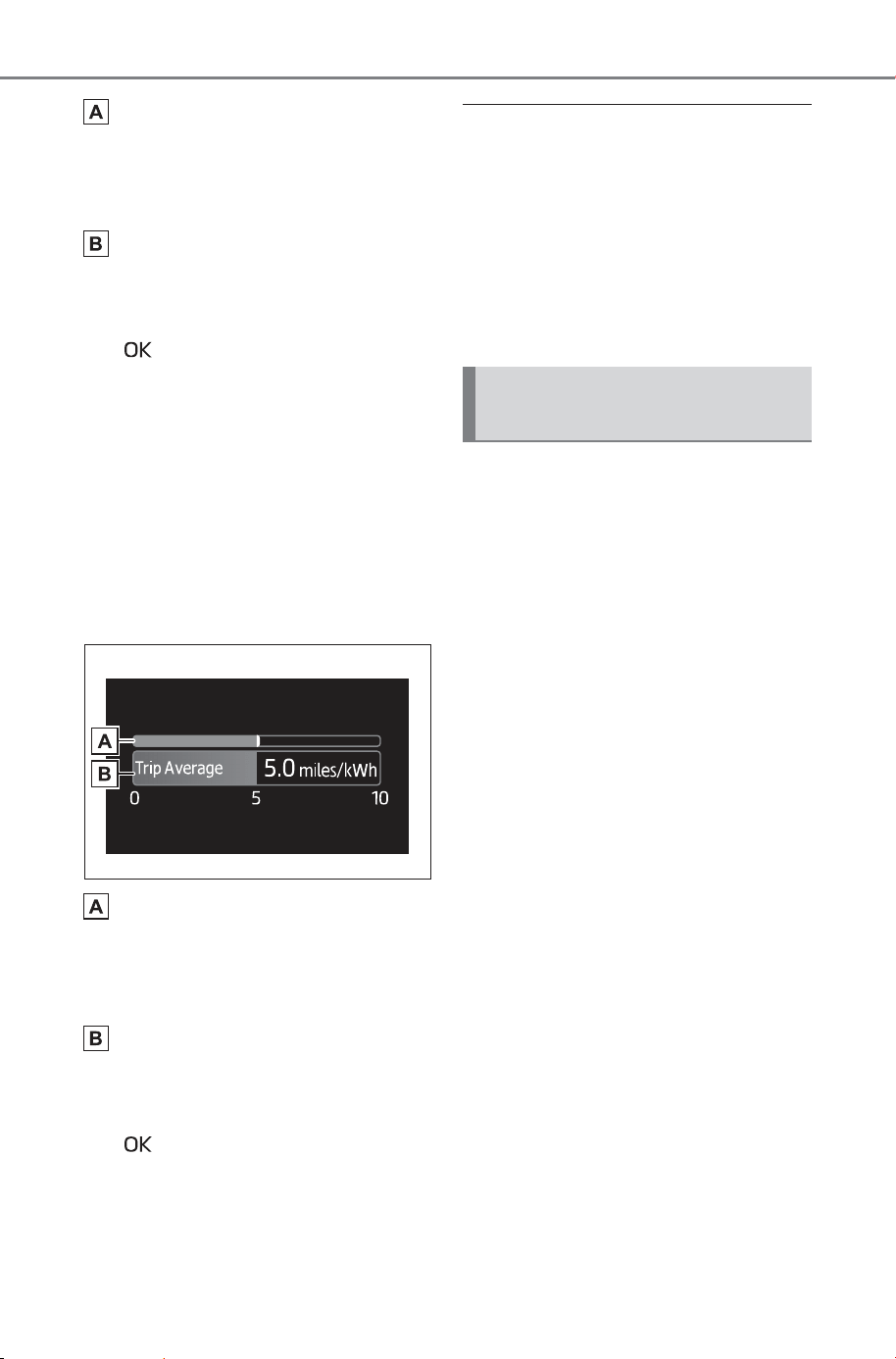
148
3-1. Instrument cluster
Owner’s Manual_USA_M6740B_en
Current electricity consump-
tion
Displays instantaneous current
electricity consumption.
Total Average
To reset the average electricity con-
sumption display, press and hold
the meter control switch.
■ Trip average (Average elec-
tricity consumption [after
start])
Displays the average electricity
consumption since EV system
start.
Use the displayed values as a ref-
erence only.
Current electricity consump-
tion
Displays instantaneous current
electricity consumption.
Trip Average
To reset the average electricity con-
sumption display, press and hold
the meter control switch.
■ Electricity consumption
It is a numerical value that rep-
resents the electricity consumption
rate and corresponds to the fuel
consumption rate of gasoline engine
vehicles. In this car, the number of
miles traveled (miles/kWh) per kilo-
watt hour of electricity (1 kWh) is
displayed on each screen as “elec-
tricity cost”.
■ Driving support system
information
Select to display the operational
status of the following systems:
LDA (Lane Departure Alert)
(P.290)
LTA (Lane Tracing Assist)
(P.282)
LCA (Lane Change Assist)
(P.287)
RSA (Road Sign Assist)
(P.303)
Dynamic radar cruise control
(P.306)
Cruise control (P.317)
PDA (Proactive driving assist)
(P.295)
Driving support system
information display
SOLTERRA_OM_USA_A6740BE.book 148 ページ 2025年5月23日 金曜日 午後1時18分
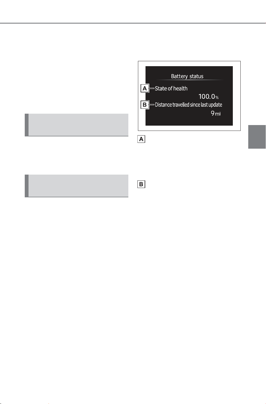
149
3-1. Instrument cluster
Owner’s Manual_USA_M6740B_en
3
Vehicle status information and indicators
■ Navigation system-linked
display
Select to display the following
navigation system-linked infor-
mation:
Route guidance to destination
Compass display (heading-up
display)
The operating conditions of the
audio system can be displayed
on the multi-information display.
■ Driving information
The following items can be dis-
played on the multi-information
display.
Use the displayed information
as a reference only.
“Average Speed”: Displays
the average vehicle speed
since the display was reset
“Total Time”: Displays elapsed
time since the display was
reset
■ Battery status display
Displays the battery degradation
status.
State of health
The current health of the traction
battery displayed as the measured
charge capacity compared to the
initial full charge capacity.
Distance traveled since last
update
At vehicle delivery or after repair at
the dealer, “Distance traveled since
last updated” may display its
default value (40727 miles/65535
km).
This value will be reset after the
State of Health is updated.
Audio system-linked dis-
play
Vehicle information dis-
play
SOLTERRA_OM_USA_A6740BE.book 149 ページ 2025年6月5日 木曜日 午後2時22分
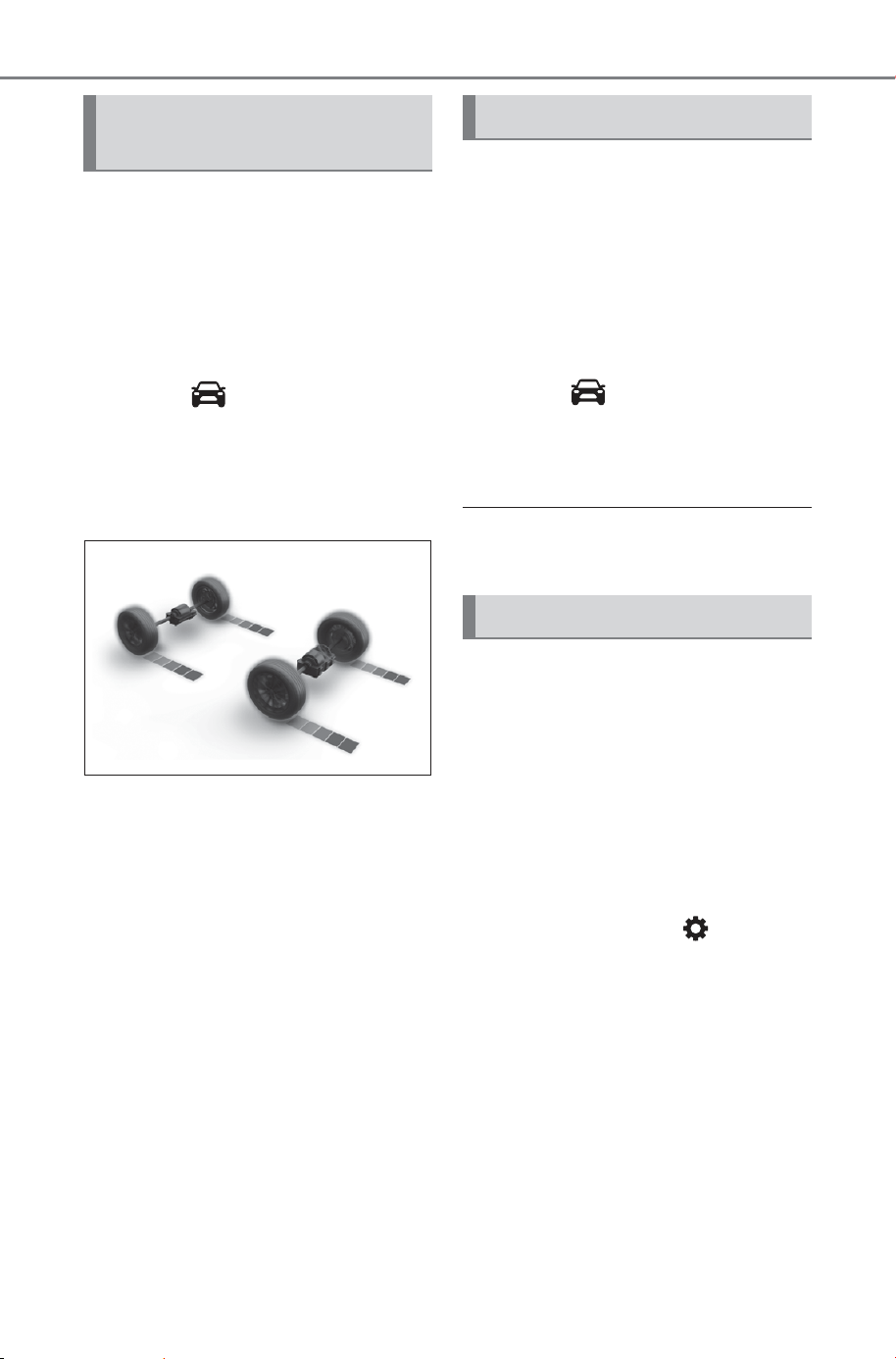
150
3-1. Instrument cluster
Owner’s Manual_USA_M6740B_en
AWD operation status display
can be displayed on the Multi-
media display.
■ Displaying AWD operation
status display on the Multi-
media display
1 Select on the main
menu.
2 Select “All wheel drive”.
■ AWD operation status
Torque distribution display: Dis-
plays the drive status of each
wheel in 6 steps from 0 to 5.
The illustration used is intended
as an example, and may differ
from the image that is actually
displayed on the multi-informa-
tion display or Multimedia dis-
play.
The tire pressure detected by
the tire pressure warning sys-
tem can be displayed on the
Multimedia display.
■ Displaying the tire pres-
sure on the Multimedia dis-
play
1 Select on the main
menu.
2 Select “Tire pressure”.
■ Tire inflation pressure
P.588
Displays suggestions to the
driver in the following situations.
To select a response to a dis-
played suggestion, use the
meter control switches.
■ Suggestion to enable the
power back door
If the power back door system is
disabled (setting on set to
off) and the power back door
switch on the instrument panel
is operated, a suggestion mes-
sage will be displayed asking if
you wish to enable the power
back door system. To enable the
power back door system, select
“Yes”.
AWD operation status dis-
play (AWD models)
Tire pressure
Suggestion function
SOLTERRA_OM_USA_A6740BE.book 150 ページ 2025年5月23日 金曜日 午後1時18分
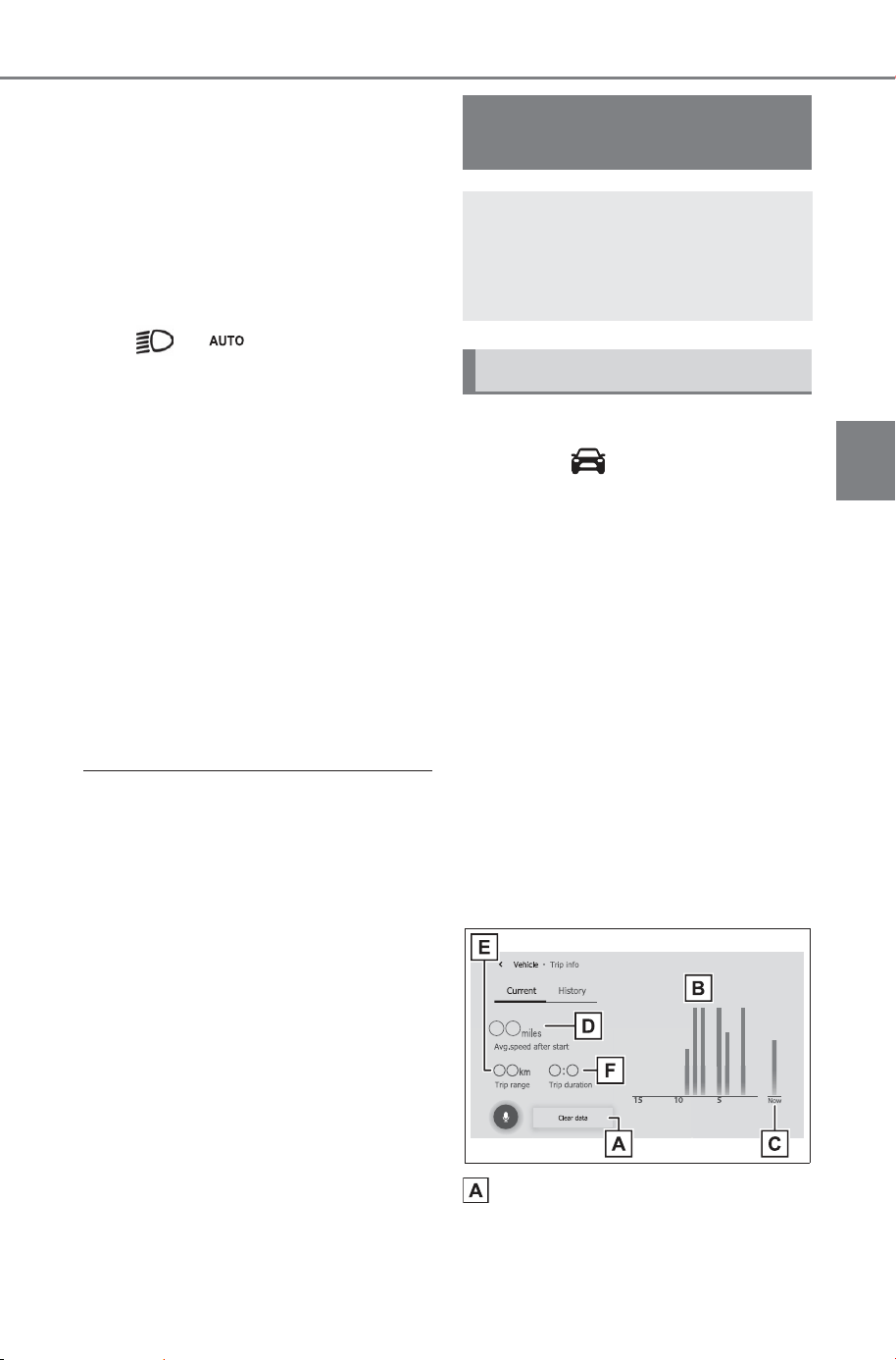
151
3-1. Instrument cluster
Owner’s Manual_USA_M6740B_en
3
Vehicle status information and indicators
After enabling the power back
door system, press the power
back door switch again to open
or close the power back door.
■ Suggestion to turn on the
headlights
If the headlight switch is in other
than or , and the vehicle
speed is 3 mph (5 km/h) or
higher for a certain amount of
time when the surroundings are
dark, a suggestion message will
be displayed.
■ Suggestion to turn off the
headlights
If the headlights are left on for a
certain amount of time after the
power switch has been turned
off, a suggestion message will
be displayed.
■ Customization
The suggestion function can be
turned on/off. (Customizable fea-
tures: P.671)
■ Display procedure
1 Select on the main
menu.
2 Select the “Trip information”.
■ Current electricity con-
sumption screen
If a screen other than current
electricity consumption screen is
displayed, touch “Current”.
Use the displayed average elec-
tricity consumption as a refer-
ence.
The image is an example only,
and may vary slightly from
actual conditions.
Resetting the consumption
data
Electricity consump-
tion
Electricity consumption
information can be dis-
played on the multimedia
system.
Consumption
SOLTERRA_OM_USA_A6740BE.book 151 ページ 2025年5月23日 金曜日 午後1時18分
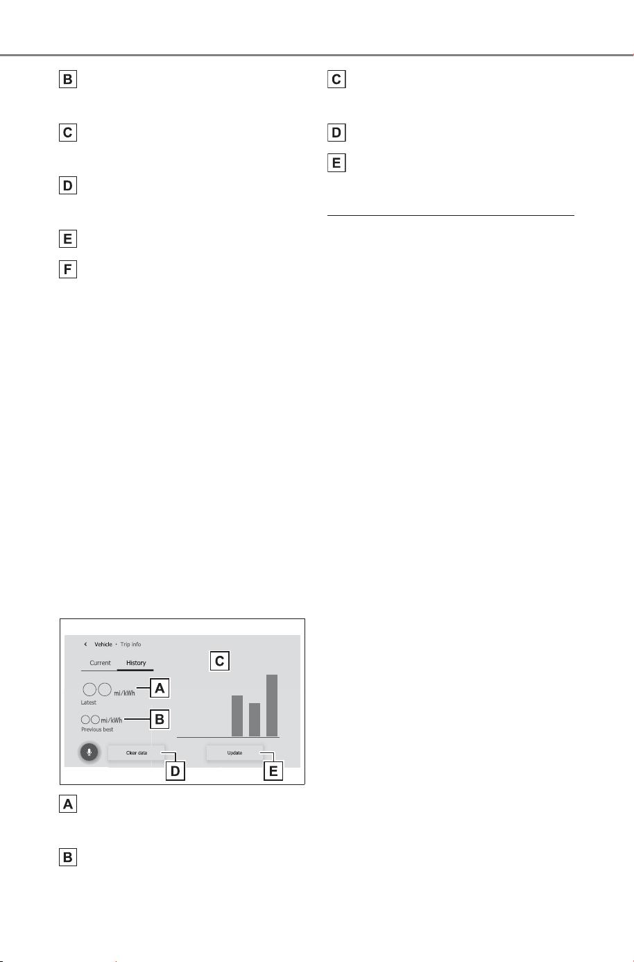
152
3-1. Instrument cluster
Owner’s Manual_USA_M6740B_en
Electricity consumption in the
past 15 minutes
Current electricity consump-
tion
Average vehicle speed since
the EV system was started.
Trip range
Elapsed time since the EV
system was started.
Use the displayed average elec-
tricity consumption as a refer-
ence.
■ History screen
If a screen other than history
screen is displayed, press “His-
tory”.
Use the displayed average elec-
tricity consumption as a refer-
ence.
The image is an example only,
and may vary slightly from
actual conditions.
Latest electricity consump-
tion
Best recorded electricity con-
sumption
Previous electricity consump-
tion record
Resetting the history data
Updating the latest average
electricity consumption data
■ Updating the history data
Update the latest electricity con-
sumption by selecting “Update” to
measure the current electricity con-
sumption again.
■ Resetting the data
The electricity consumption data
can be deleted by selecting “Clear
data”.
■ Cruising range
Displays the estimated maximum
distance that can be driven with the
quantity of electricity remaining.
This distance is computed based on
your average electricity consump-
tion.
As a result, the actual distance that
can be driven may differ from that
displayed.
SOLTERRA_OM_USA_A6740BE.book 152 ページ 2025年5月23日 金曜日 午後1時18分

153
Owner’s Manual_USA_M6740B_en
4
4
Before driving
Before driving
4-1. Key information
Keys ............................
154
Digital key ................... 157
4-2. Opening, closing and
locking the doors
Side doors...................
159
Back door.................... 164
Smart key system ....... 177
4-3. Adjusting the seats
Front seats .................. 183
Rear seats................... 184
Head restraints............ 186
4-4. Adjusting the steering
wheel and mirrors
Steering wheel ............
190
Inside rear view mirror 191
Digital inner mirror....... 192
Outside rear view mirrors
..................................
200
4-5. Opening, closing the win-
dows
Power windows ...........
204
4-6. Favorite settings
Driving position memory
..................................
207
My Settings ................. 210
SOLTERRA_OM_USA_A6740BE.book 153 ページ 2025年5月23日 金曜日 午後1時18分

154
4-1. Key information
Owner’s Manual_USA_M6740B_en
4-1.Ke y informa tion
The following keys are provided
with the vehicle.
Electronic keys
• Operating the smart key system
(P.177)
• Operating the wireless remote
control function (P.156)
• Operating the Remote Air Condi-
tioning System (P.501)
Mechanical keys
Key number plate
■ When riding in an aircraft
When bringing an electronic key
onto an aircraft, make sure you do
not press any buttons on the elec-
tronic key while inside the aircraft
cabin. If you are carrying an elec-
tronic key in your bag, etc., ensure
that the buttons are not likely to be
pressed accidentally. Pressing a
button may cause the electronic key
to emit radio waves that could inter-
fere with the operation of the air-
craft.
■ Electronic key battery depletion
● The standard battery life is 1 to 2
years.
● If the battery becomes low, an
alarm will sound in the cabin and a
message will be displayed on the
multi-information display when the
EV system stops.
● To reduce key battery depletion
when the electronic key is to not
be used for long periods of time,
set the electronic key to the bat-
tery-saving mode. (P.179)
● As the electronic key always
receives radio waves, the battery
will become depleted even if the
electronic key is not used. The fol-
lowing symptoms indicate that the
electronic key battery may be
depleted. Replace the battery
when necessary.
• The smart key system or the wire-
less remote control does not oper-
ate.
• The detection area becomes
smaller.
• The LED indicator on the key sur-
face does not turn on.
You can replace the battery by your-
self (P.594). However, as there is
a danger that the electronic key may
be damaged, it is recommended
that replacement is carried out by
your SUBARU dealer.
● To avoid serious deterioration, do
not leave the electronic key within
3 ft. (1 m) of the following electri-
cal appliances that produce a
magnetic field:
•TVs
• Personal computers
• Cellular phones, cordless phones
and battery chargers
• Recharging cellular phones or
cordless phones
• Table lamps
• Induction cookers
Keys
Key types
SOLTERRA_OM_USA_A6740BE.book 154 ページ 2025年5月23日 金曜日 午後1時18分
155
4-1. Key information
Owner’s Manual_USA_M6740B_en
4
Before driving
■ Replacing the battery
P.594
■ Confirmation of the registered
key number
The number of keys already regis-
tered to the vehicle can be con-
firmed. Ask your SUBARU dealer
for details.
■ If a message regarding the state
of the electronic key or power
switch mode, etc. is shown
To prevent trapping the electronic
key inside the vehicle, leaving the
vehicle carrying the electronic key
on your person without turning the
power switch to OFF or other pas-
sengers from unintentionally taking
the key out of the vehicle, etc., a
message that prompts the user to
confirm the state of the electronic
key or power switch mode may be
shown on the multi-information dis-
play. In those cases, follow the
instructions on the display immedi-
ately.
■ If “Key Battery Low Replace
Key Battery” is displayed on
the multi-information display
The electronic key has a low battery.
Replace the electronic key battery.
(P.594)
■ If “A New Key has been Regis-
tered Contact Your Dealer for
Details” is displayed on the
multi-information display
This message will be displayed
each time the driver’s door is
opened when the doors are
unlocked from the outside for
approximately 10 days after a new
electronic key has been registered.
If this message is displayed but you
have not had a new electronic key
registered, ask your SUBARU
dealer to check if an unknown elec-
tronic key (other than those in your
possession) has been registered.
NOTICE
■ To prevent key damage
● Do not drop the keys, subject
them to strong shocks, or bend
them.
● Do not expose the keys to high
temperatures for long periods of
time.
● Do not get the keys wet or wash
them in an ultrasonic washer,
etc.
● Do not attach metallic or mag-
netic materials to the keys or
place the keys close to such
materials.
● Do not disassemble the keys.
● Do not attach a sticker or any-
thing else to the surface of the
electronic key.
● Do not place the keys near
objects that produce magnetic
fields, such as TVs, audio sys-
tems and induction cookers.
● Do not place the keys near
medical electrical equipment
such as low-frequency therapy
equipment or microwave ther-
apy equipment, and do not
receive medical attention with
the keys on your person.
■ Carrying the electronic key
on your person
Carry the electronic key 3.9 in.
(10 cm) or more away from elec-
tric appliances that are turned on.
Radio waves emitted from electric
appliances within 3.9 in. (10 cm)
of the electronic key may interfere
with the key, causing the key to
not function properly.
SOLTERRA_OM_USA_A6740BE.book 155 ページ 2025年5月23日 金曜日 午後1時18分
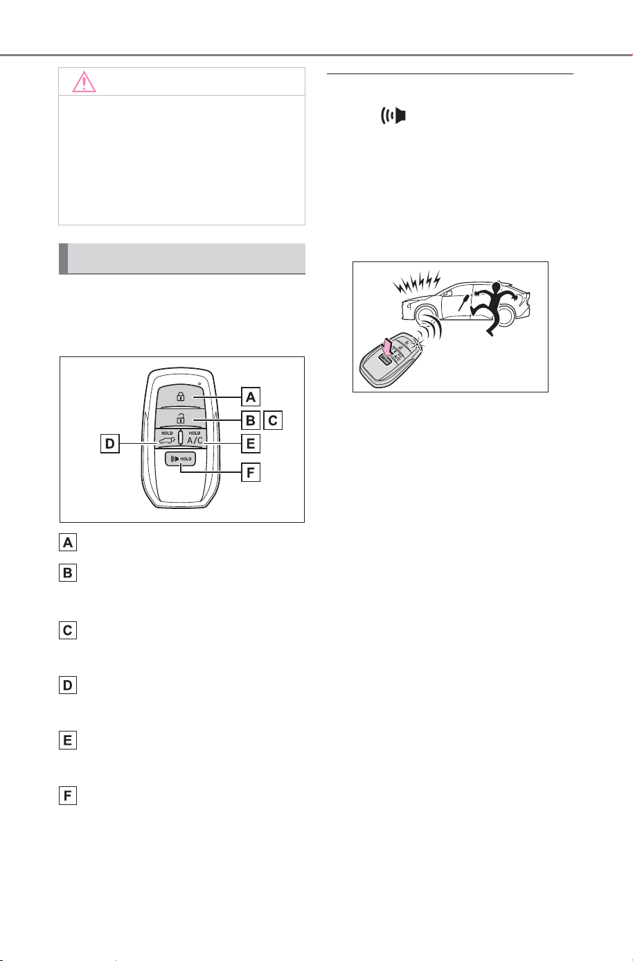
156
4-1. Key information
Owner’s Manual_USA_M6740B_en
The electronic keys are
equipped with the following
wireless remote control:
Locks all the doors (P.159)
Unlocks all the doors
(P.159)
Opens the side windows
*
(P.159)
Opens and closes the power
back door (P.166)
Operates Remote Air Condi-
tioning System (P.501)
Sounds the alarm (P.156)
*
: These settings must be custom-
ized at your SUBARU dealer.
■ Theft deterrent panic mode
When is pressed for longer
than about 1 second, an alarm will
sound intermittently and the vehicle
lights will flash to deter any person
from trying to break into or damage
your vehicle.
To stop the alarm, press any button
on the electronic key.
NOTICE
■ In case of a smart key system
malfunction or other key-
related problems
P.6 42
■ When an electronic key is lost
P.6 41
Wireless remote control
SOLTERRA_OM_USA_A6740BE.book 156 ページ 2025年5月23日 金曜日 午後1時18分
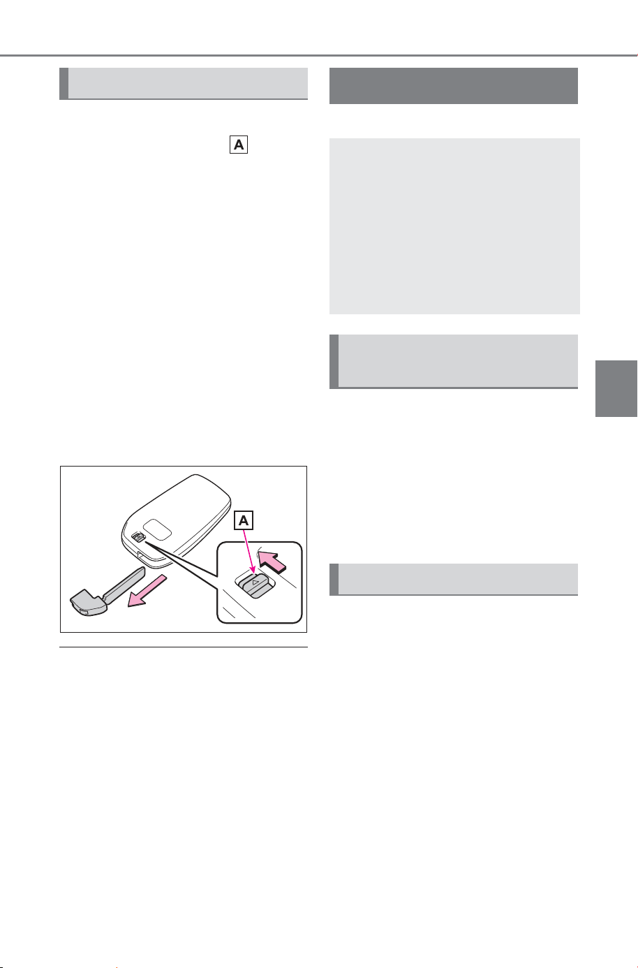
157
4-1. Key information
Owner’s Manual_USA_M6740B_en
4
Before driving
To take out the mechanical key,
slide the release lever and
take the key out.
The mechanical key can only be
inserted in one direction, as the key
only has grooves on one side. If the
key cannot be inserted in a lock cyl-
inder, turn it over and re-attempt to
insert it.
After using the mechanical key,
store it in the electronic key. Carry
the mechanical key together with
the electronic key. If the electronic
key battery is depleted or the entry
function does not operate properly,
you will need the mechanical key.
(P.642)
■ If you lose your mechanical
keys
P.641
■ If a wrong key is used
The key cylinder rotates freely to
isolate inside mechanism.
*
: If equipped
In order to use the Digital Key,
you need to install the Subaru-
Connect App, Register the Vehi-
cle to the customer’s
SubaruConnect App profile, and
subscribe to Remote Services,
and enroll in Digital Key.
A Digital Key can be used
when the smartphone and
server can communicate. The
Digital Key may become
unusable if the smartphone is
not connected to the Internet.
Be sure to carry the electronic
key of the vehicle if traveling
to a location with unreliable
communications.
Using the mechanical key
Digital key
*
A smartphone can be used
instead of the electronic key
of the vehicle by installing
the dedicated Digital Key
App on a smartphone. Also,
Digital Key can be shared
with your family or friends
using the Digital Key App.
Digital key usage condi-
tions
Digital key precautions
SOLTERRA_OM_USA_A6740BE.book 157 ページ 2025年5月23日 金曜日 午後1時18分

158
4-1. Key information
Owner’s Manual_USA_M6740B_en
If the smartphone battery is
depleted, the smartphone
cannot be used as Digital Key.
If the battery level is low, be
sure to charge the smart-
phone prior to going out.
The Digital Key system is
related to the Smart key sys-
tem. If the Smart key system
has been deactivated in the
vehicle customization setting,
the Digital Key will also be
disabled.
Depending on the radio wave
environment, the Digital Key
may not be able to be used.
P.179
When transferring vehicle
ownership, make sure to
delete the Digital Keys.
If the vehicle is not operated
for 14 days or more, the Digi-
tal Key will not connect auto-
matically. Therefore, it may
take some time before the
system operates after a door
handle is touched.
A part of the services may be
stopped for a certain period of
time due to server mainte-
nance. However, registered
Digital Keys can be used
during the maintenance.
A smartphone with the Digital
Key App enabled will be able
to lock and unlock the doors,
start the EV system and per-
form any other operations as
same as the electronic key of
the vehicle. Be especially
careful not to lose the smart-
phone or allow it to be stolen.
If the smartphone is lost or
stolen, contact your SUBARU
dealer immediately.
When taking your vehicle to a
SUBARU dealer for an
inspection or repairs, make
sure to bring an electronic
key.
With the Digital Key alone, no
vehicle lights will illuminate
when approached to the vehi-
cle. Also, with the digital key
alone, some functions, such
as the power back door’s
close & lock function, etc.,
cannot be used.
SOLTERRA_OM_USA_A6740BE.book 158 ページ 2025年5月23日 金曜日 午後1時18分
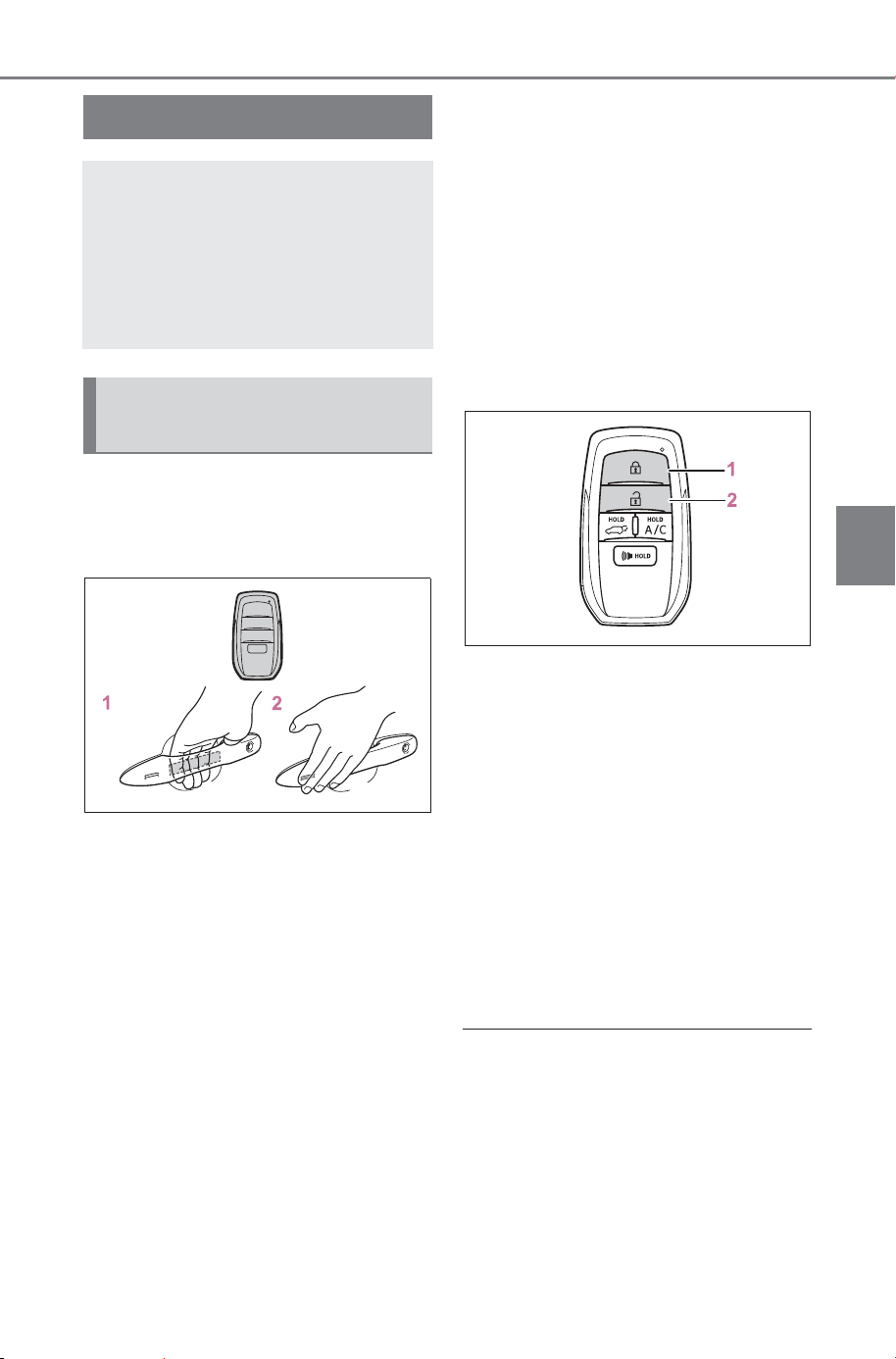
159
4-2. Opening, closing and locking the doors
Owner’s Manual_USA_M6740B_en
4
Before driving
4-2.Opening, closing and locking the door s
■ Using the entry function
Carry the electronic key to
enable this function.
1 Grip the driver’s door handle
to unlock the door. Holding
the driver’s door handle for
approximately 2 seconds
unlocks all the doors.
Grip the front passenger’s
door handle to unlock all the
doors
*
.
Make sure to touch the sensor on
the back of the handle.
The doors cannot be unlocked for 3
seconds after the doors are locked.
2 Touch the lock sensor (the
indentation on the side of the
door handle) to lock the
doors.
Check that the door is securely
locked.
*
: The door unlock settings can be
changed.
■ Using the wireless remote
control
1 Locks all the doors
Check that the door is securely
locked.
2 Unlocks all the doors
Pressing the button unlocks the
driver’s door. Pressing the button
again within 5 seconds unlocks the
other doors.
Press and hold to open the side
windows.
*
*
: This setting must be customized
at your SUBARU dealer.
■ Switching the door unlock func-
tion
It is possible to set which doors the
entry function unlocks using the
wireless remote control. Perform the
switching operation in the vehicle or
within approximately 3.2 ft. (1 m) of
the vehicle.
1 Turn the power switch to OFF.
Side doors
The vehicle can be locked
and unlocked using the
entry function, wireless
remote control, door lock
switches or inside lock but-
tons.
Unlocking and locking the
doors from the outside
SOLTERRA_OM_USA_A6740BE.book 159 ページ 2025年5月23日 金曜日 午後1時18分
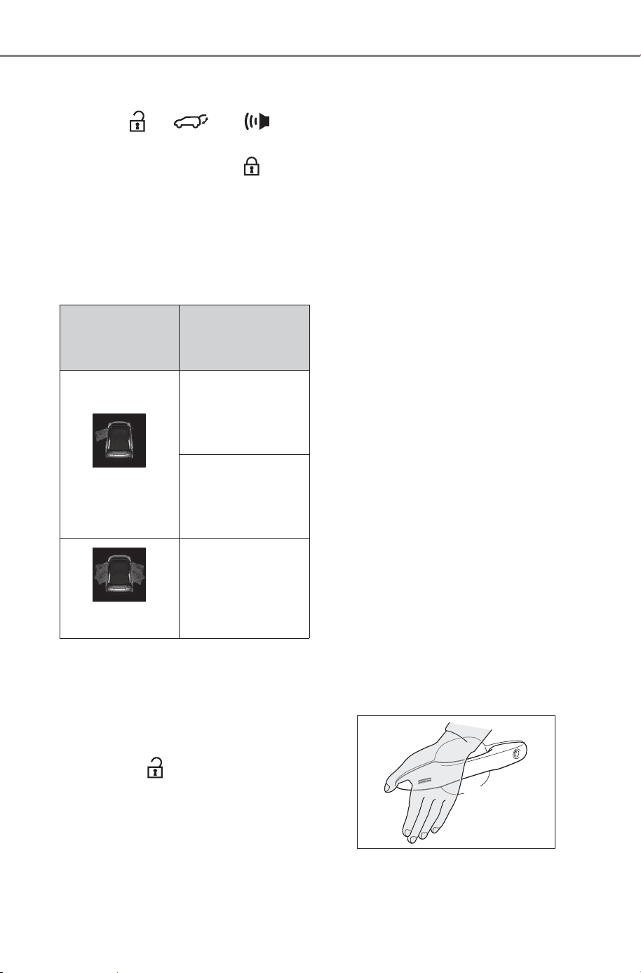
160
4-2. Opening, closing and locking the doors
Owner’s Manual_USA_M6740B_en
2 When the indicator light on the
key surface is not on, press and
hold , or for
approximately 5 seconds while
pressing and holding .
The setting changes each time an
operation is performed, as shown
below. (When changing the setting
continuously, release the buttons,
wait for at least 5 seconds, and
repeat step
2.)
To prevent unintended triggering of
the alarm, unlock the doors using
the wireless remote control and
open and close a door once after
the settings have been changed. (If
a door is not opened within 60 sec-
onds after is pressed, the
doors will be locked again and the
alarm will automatically be set.)
In a case that the alarm is triggered,
immediately stop the alarm. (P.66)
■ Impact detection door lock
release system
In the event that the vehicle is sub-
ject to a strong impact, all the doors
are unlocked. Depending on the
force of the impact or the type of
accident, however, the system may
not operate.
■ Operation signals
Doors: A buzzer sounds and the
emergency flashers flash to indicate
that the doors have been
locked/unlocked. (Locked: Once;
Unlocked: Twice)
Side windows: A buzzer sounds to
indicate that the side windows are
operating.
■ Security feature
If a door is not opened within
approximately 60 seconds after the
vehicle is unlocked, the security fea-
ture automatically locks the vehicle
again. (However, depending on the
location of the electronic key, the
key may be detected as being in the
vehicle. In this case, vehicle may be
unlocked.)
■ When the door cannot be
locked by the lock sensor on
the surface of the door handle
When the door cannot be locked
even if the lock sensor on the sur-
face of the door handle is touched
by a finger, touch the lock sensor
with the palm.
When gloves are being worn,
remove the gloves.
Multi-informa-
tion dis-
play/Beep
Unlocking func-
tion
Exterior: Beeps 3
times
Holding the
driver’s door han-
dle unlocks only
the driver’s door.
Holding the front
passenger door
handle unlocks all
the doors.
Exterior: Beeps
twice
Holding a front
door handle
unlocks all the
doors.
SOLTERRA_OM_USA_A6740BE.book 160 ページ 2025年5月23日 金曜日 午後1時18分
161
4-2. Opening, closing and locking the doors
Owner’s Manual_USA_M6740B_en
4
Before driving
■ Open door warning buzzer
If an attempt to lock the doors is
made when a door is not fully
closed, a buzzer sounds continu-
ously for 5 seconds.
Fully close the door to stop the
buzzer, and lock the vehicle once
more.
■ Setting the alarm
Locking the doors will set the alarm
system. (P. 6 6 )
■ Conditions affecting the opera-
tion of the smart key system or
wireless remote control
P.179
■ If the smart key system or the
wireless remote control does
not operate properly
● Use the mechanical key to lock
and unlock the doors. (P. 64 2)
● Replace the key battery with a
new one if it is depleted. (P.594)
■ If the 12-volt battery is dis-
charged
The doors cannot be locked and
unlocked using the smart key sys-
tem or wireless remote control. Lock
or unlock the doors using the
mechanical key. (P.642)
■ Rear seat reminder function
● In order to remind you not to for-
get luggage, etc., in the rear seat,
when the power switch is turned to
OFF after any of the following con-
ditions are met, a buzzer will
sound and a message will be dis-
played on the multi-information
display for approximately 6 sec-
onds.
• The EV system is started within 10
minutes after opening and closing
a rear door.
• A rear door has been opened and
closed after the EV system was
started.
However, if a rear door is opened
and then closed within approxi-
mately 2 seconds, the rear seat
reminder function may not operate.
● The rear seat reminder function
determines that luggage, etc., has
been placed in a rear seat based
on opening and closing of a rear
door. Therefore, depending on the
situation, the rear seat reminder
function may not operate and you
may still forget luggage, etc., in
the rear seat, or it may operate
unnecessarily.
● The rear seat reminder function
can be enabled/disabled.
(P.671)
■ Customization
Settings (e.g. unlocking function
using a key) can be changed.
(Customizable features: P.673)
WARNING
■ To prevent an accident
Observe the following precautions
while driving the vehicle.
Failure to do so may result in a
door opening and an occupant
could be thrown out of the vehicle,
resulting in death or serious injury.
● Ensure that all doors are prop-
erly closed and locked.
● Do not pull the inside handle of
the doors while driving.
Be especially careful for the
front doors, as the doors may
be opened even if the inside
lock buttons are in locked posi-
tion.
● Set the rear door child-protector
locks when children are seated
in the rear seats.
SOLTERRA_OM_USA_A6740BE.book 161 ページ 2025年5月23日 金曜日 午後1時18分
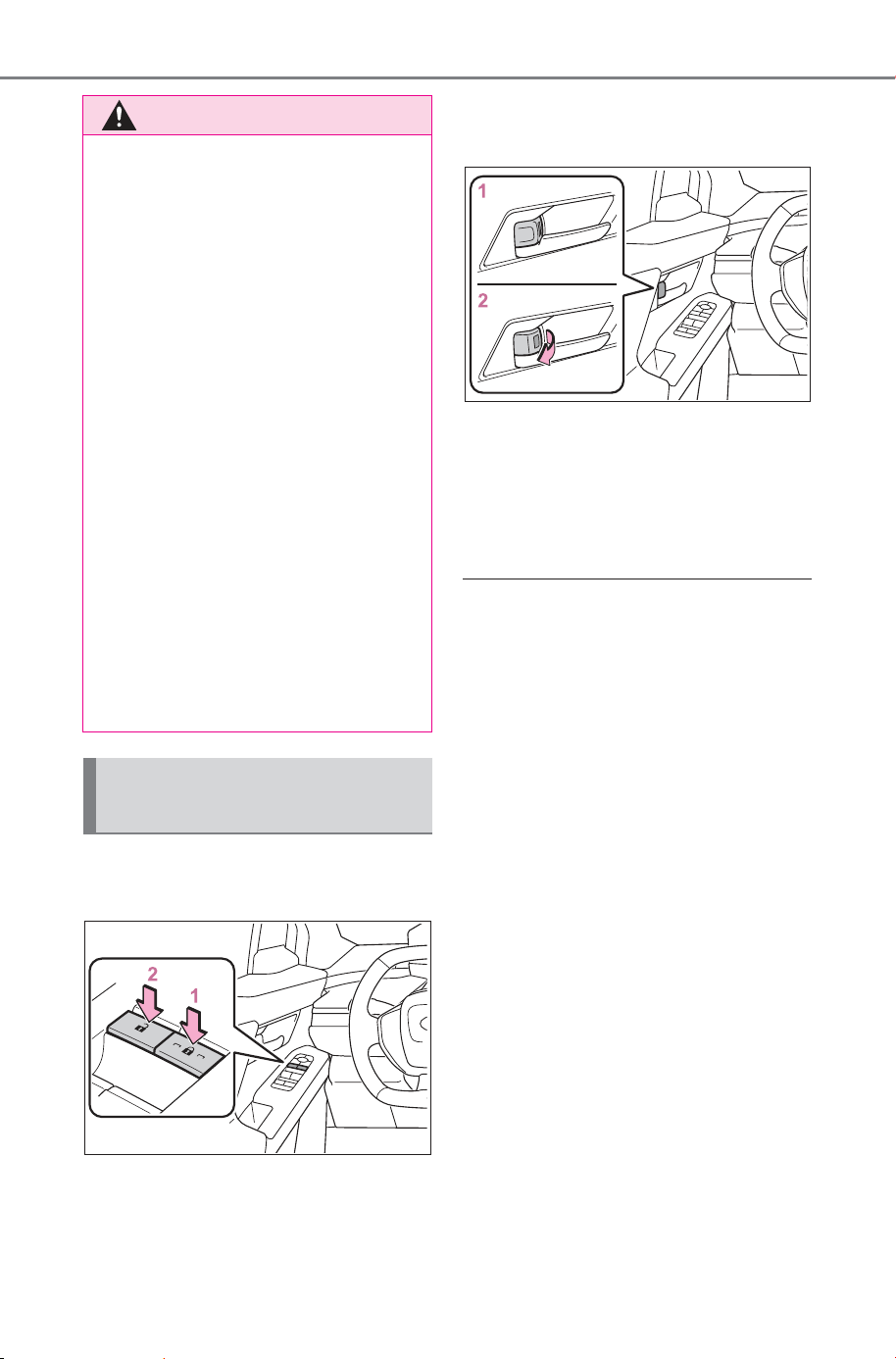
162
4-2. Opening, closing and locking the doors
Owner’s Manual_USA_M6740B_en
■ Using the door lock
switches
1 Locks all the doors
2 Unlocks all the doors
■ Using the inside lock but-
tons
1 Locks the door
2 Unlocks the door
The front doors can be opened by
pulling the inside handle even if the
lock buttons are in the lock position.
■ Locking the front doors from
the outside without a key
1 Move the inside lock button to
the lock position. (P.162)
2 Close the door.
The door cannot be locked if the
power switch is in ACC or ON, or
the electronic key is left inside the
vehicle.
Depending on the position of the
electronic key, the key may not be
detected correctly and the door may
be locked.
■ Open door warning buzzer
If the vehicle speed reaches 3 mph
(5 km/h), a buzzer sounds to indi-
cate that the door(s) or the hood is
not fully closed.
The open door(s) or hood is dis-
played on the multi-information dis-
play.
■ When all the doors are locked
with the entry function or wire-
less remote control
● The doors cannot be unlocked
with the door lock switch.
WARNING
■ When opening or closing a
door
Check the surroundings of the
vehicle such as whether the vehi-
cle is on an incline, whether there
is enough space for a door to
open and whether a strong wind
is blowing. When opening or clos-
ing the door, hold the door handle
tightly to prepare for any unpre-
dictable movement.
■ When using the wireless
remote control or mechanical
key and operating the power
windows
Operate the power window after
checking to make sure that there
is no possibility of any passenger
having any of their body parts
caught in the side window. Also,
do not allow children to operate
the wireless remote control or
mechanical key. It is possible for
children and other passengers to
get caught in the side window.
Unlocking and locking the
doors from the inside
SOLTERRA_OM_USA_A6740BE.book 162 ページ 2025年5月23日 金曜日 午後1時18分
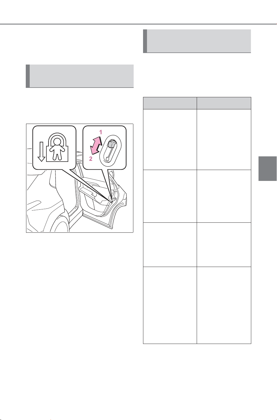
163
4-2. Opening, closing and locking the doors
Owner’s Manual_USA_M6740B_en
4
Before driving
● The door lock switches can be
reset by unlocking all the doors
with the entry function or wireless
remote control.
The door cannot be opened
from inside the vehicle when the
lock is set.
1 Unlock
2 Lock
These locks can be set to prevent
children from opening the rear
doors. Push down on each rear
door switch to lock both rear doors.
The following functions can be
set or canceled:
For instructions on customizing,
refer to P.671.
Rear door child-protector
lock
Automatic door locking
and unlocking systems
Function Operation
Speed linked
door locking
function
All doors are
automatically
locked when
vehicle speed is
approximately
12mph (20 km/h)
or higher.
Shift position
linked door lock-
ing function
All doors are
automatically
locked when
shifting the shift
position other
than P.
Shift position
linked door
unlocking func-
tion
All doors are
automatically
unlocked when
shifting the shift
position to P.
Driver’s door
linked door
unlocking func-
tion
All doors are
automatically
unlocked when
driver’s door is
opened within
approximately 45
seconds after
turning the power
switch off.
SOLTERRA_OM_USA_A6740BE.book 163 ページ 2025年5月23日 金曜日 午後1時18分
164
4-2. Opening, closing and locking the doors
Owner’s Manual_USA_M6740B_en
Back door
The back door can be
locked/unlocked and
opened/closed by the fol-
lowing procedures.
WARNING
Observe the following precau-
tions.
Failure to do so may result in
death or serious injury.
■ Before driving
● Make sure that the back door is
fully closed.
If the back door is not fully
closed, it may open unexpect-
edly while driving and hit near-
by objects or luggage in the lug-
gage compartment may be
thrown out, causing an acci-
dent.
● Do not allow children to play in
the luggage compartment.
If a child is accidentally locked
in the luggage compartment,
they could get heat exhaustion
or other injuries.
● Do not allow a child to open or
close the back door.
Doing so may cause the back
door to operate unexpectedly,
or cause the child’s hands,
head, or neck to be caught by
the closing back door.
■ Important points while driving
● Keep the back door closed
while driving.
If the back door is left open, it
may hit near-by objects or lug-
gage in the luggage compart-
ment may be thrown out,
causing an accident.
● Never let anyone sit in the lug-
gage compartment.
In the event of sudden braking,
sudden swerving or a collision,
they are susceptible to death or
serious injury.
■ Back door handles
Do not hang any object to the
back door handles.
If any object is hung, the back
door may suddenly shut, causing
parts of the body to be caught,
resulting in death or serious injury.
■ Operating the back door
Observe the following precau-
tions.
Failure to do so may cause parts
of the body to be caught, resulting
in death or serious injury.
● Remove any heavy loads, such
as snow and ice, from the back
door before opening it. Failure
to do so may cause the back
door to suddenly shut again
after it is opened.
● When opening or closing the
back door, thoroughly check to
make sure the surrounding area
is safe.
● If anyone is in the vicinity, make
sure they are safe and let them
know that the back door is
about to open or close.
● Use caution when opening or
closing the back door in windy
weather as it may move
abruptly in strong wind.
● The back door may suddenly
shut if it is not opened fully,
while on a steep incline. Make
sure that the back door is
secured before using the lug-
gage compartment.
SOLTERRA_OM_USA_A6740BE.book 164 ページ 2025年5月23日 金曜日 午後1時18分
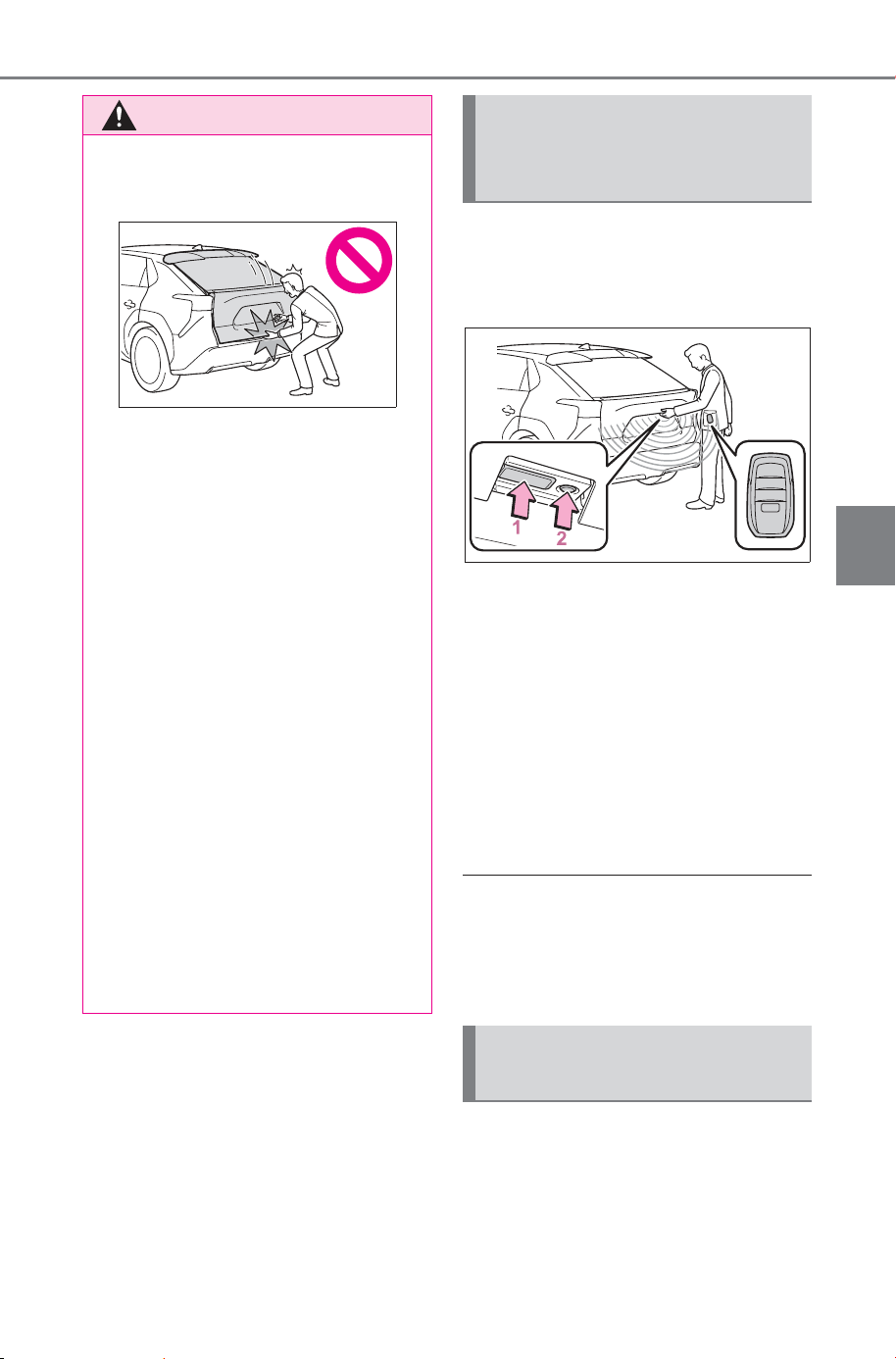
165
4-2. Opening, closing and locking the doors
Owner’s Manual_USA_M6740B_en
4
Before driving
■ Using the entry function
Carry the electronic key to
enable this function.
1 Unlocks all the doors
The doors cannot be unlocked for 3
seconds after the doors are locked.
2 Locks all the doors
Check that the door is securely
locked.
■ Using the wireless remote
control
P.159
■ Operation signals
P.160
■ Security feature
P.160
■ Using the door lock
switches
P.162
WARNING
● When closing the back door,
take extra care to prevent your
fingers, etc., from being caught.
● When closing the back door,
make sure to press it lightly on
its outer surface. If the back
door handle is used to fully
close the back door, it may
result in hands or arms being
caught.
● Do not pull on the back door
spindle (P.174) to close the
back door, and do not hang on
the back door spindle.
Doing so may cause hands to
be caught or the back door spin-
dle to break, causing an acci-
dent.
● If a bicycle carrier or similar
heavy object is attached to the
back door, it may suddenly shut
again after being opened, caus-
ing someone’s hands, head or
neck to be caught and injured.
When installing an accessory
part to the back door, using a
genuine SUBARU part is rec-
ommended.
Unlocking and locking the
back door from the out-
side
Unlocking and locking the
back door from the inside
SOLTERRA_OM_USA_A6740BE.book 165 ページ 2025年5月23日 金曜日 午後1時18分
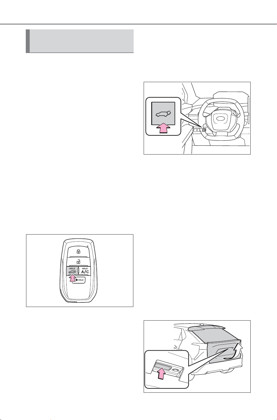
166
4-2. Opening, closing and locking the doors
Owner’s Manual_USA_M6740B_en
■ Using the wireless remote
control
Press and hold the switch for
approximately 1 second.
The power back door automatically
opens/closes.
The power back door can be oper-
ated when it is locked
*
.
Pressing the switch while the power
back door is opening/closing will
stop the operation. Pressing and
holding the switch again for approx-
imately 1 second will operate the
power back door in the opposite
direction.
*
: Opening of the power back door
when it is locked can be disabled
by a customized setting.
(P.675)
■ Using the power back door
switch on the instrument
panel
Press and hold the switch.
The power back door automatically
opens/closes.
Unlock the back door before oper-
ating.
Pressing the switch while the power
back door is opening/closing stops
the operation. When the switch is
pressed and held again during the
halted operation, the back door will
perform the reverse operation.
■ Opening the back door
using the back door opener
switch
When the back door is
unlocked: Press the back door
opener switch.
When the back door is locked:
While carrying the electronic key
on your person, press and hold
the back door opener switch.
The power back door automatically
opens.
Pressing the switch while the power
back door is opening stops the
operation. Pressing the switch
again will open the back door auto-
matically.
Opening/closing the back
door
SOLTERRA_OM_USA_A6740BE.book 166 ページ 2025年5月23日 金曜日 午後1時18分
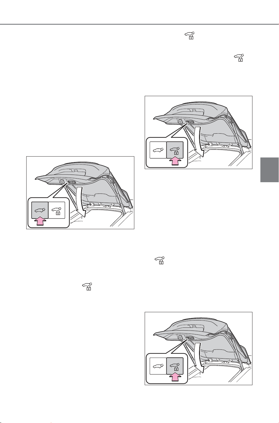
167
4-2. Opening, closing and locking the doors
Owner’s Manual_USA_M6740B_en
4
Before driving
■ Using the power back door
switch on the back door
Close
Press the switch.
The power back door automatically
closes.
Pressing the switch while the power
back door is operating will stop the
operation.
When the switch is pressed again
during the halted operation, the
back door will perform the reverse
operation.
Close the back door and lock
all doors (close & lock func-
tion)
Close all of the doors except the
back door, carrying an electronic
key and press the switch on
the lower part of the back door.
A different buzzer than the normal
one will sound and the power back
door will begin closing automati-
cally. When the power back door is
closed, all of the doors will lock
simultaneously and operation sig-
nals will indicate that all of the
doors have been locked. (P.160)
Pressing the switch while the
power back door is operating will
stop the operation. When the
switch is pressed again during the
halted operation, the back door will
be closed.
Close the back door and lock
all doors (close & lock [Walk-
Away] function)
*
*
: This setting must be customized
at your SUBARU dealer.
1 Close all of the doors except
the back door, carrying an
electronic key and press the
switch on the lower part
of the back door.
A different buzzer than the normal
one will sound and the close & lock
(Walk-Away) function will go into
standby.
SOLTERRA_OM_USA_A6740BE.book 167 ページ 2025年5月23日 金曜日 午後1時18分
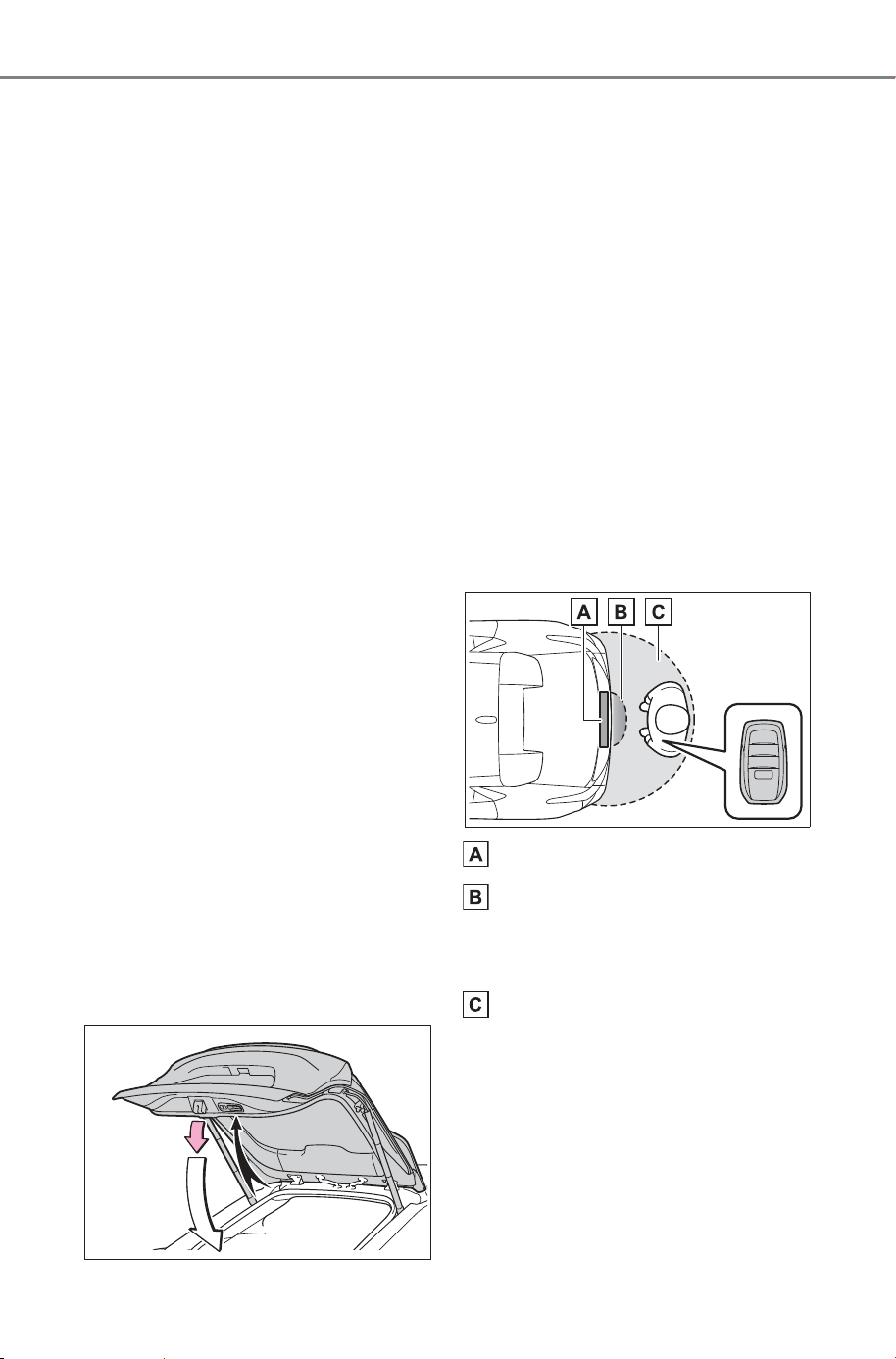
168
4-2. Opening, closing and locking the doors
Owner’s Manual_USA_M6740B_en
2 While the buzzer is sounding,
move away from the back
door.
When the sensor detects that you
are away from the back door, the
emergency flashers will flash, and
the buzzer will sound. Depending
on the direction of moving away
from the back door, the location and
how to hold the electronic key or
circumstances, it may not be
detected properly.
All the doors other than the back
door will be locked, and after the
back door is closed, the back door
will also be locked. When all the
doors have been closed and
locked, the buzzer will sound and
the emergency flashers will flash.
The standby state is canceled if you
do not move away from the back
door for 30 seconds. To operate the
function again, perform the proce-
dure again from the beginning.
If the switch is pressed after the
back door operation has stopped,
the close & lock (Walk- Away) func-
tion will go into standby again.
■ Using the back door han-
dles
Lower the back door using the
back door handle.
The back door closing assist
(P.170) will be activated, and the
power back door will fully close
automatically.
■ Using the kick sensor (vehi-
cles with Hands Free Power
Back Door)
When operating the Hands Free
Power Back Door, make sure
that the power switch is in OFF,
the Hands Free Power Back
Door operation is enabled
(P.171) and you are carrying
an electronic key.
1 While carrying an electronic
key, stand within the smart
key system operation range,
approximately 11.8 to 19.7 in.
(30 to 50 cm) from the rear
bumper.
Kick sensor
Hands Free Power Back
Door operation detection
area
Smart key system operation
detection area (P.178)
2 Perform a kick operation by
moving your foot to within
approximately 3.9 in. (10 cm)
of the rear bumper and then
pulling it back.
SOLTERRA_OM_USA_A6740BE.book 168 ページ 2025年5月23日 金曜日 午後1時18分
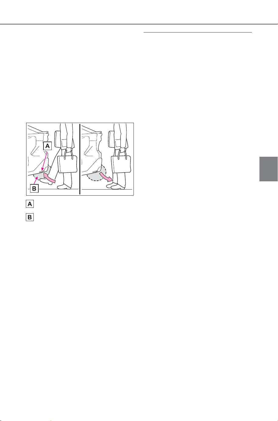
169
4-2. Opening, closing and locking the doors
Owner’s Manual_USA_M6740B_en
4
Before driving
Perform the entire kick operation
within 1 second.
The back door will not start operat-
ing while a foot is detected under
the rear bumper.
Operate the Hands Free Power
Back Door without contacting the
rear bumper with your foot.
If another electronic key is in the
cabin or luggage compartment, it
may take slightly longer than nor-
mal for the operation to occur.
Kick sensor
Hands Free Power Back
Door operation detection
area
3 When the kick sensor detects
a kicking motion with the foot,
the buzzer sounds, and when
the foot being pulled is
detected, the back door auto-
matically fully opens or fully
closes.
The buzzer can be turned off with
the customize function. (P.675)
If a foot is moved under the rear
bumper while the back door is
opening/closing, the back door will
stop moving.
If a foot is moved under the rear
bumper again during the halted
operation, the back door will per-
form the reverse operation.
■ Luggage compartment light
● The luggage compartment light
turns on when the back door is
opened.
● When the power switch is turned
to OFF, the light will go off auto-
matically after 20 minutes.
■ Back door closer
In the event that the back door is left
slightly open, the back door closer
will automatically close it to the fully
closed position.
Whatever the state of the power
switch, the back door closer oper-
ates.
■ Power back door operating con-
ditions
The power back door can automati-
cally open and close under the fol-
lowing conditions:
● When the power back door sys-
tem is enabled. (P.176)
● When the power switch is in ON,
in addition to the above for the
opening operations, the back door
operates for any of the following
conditions:
• Parking brake is engaged
• The brake pedal is depressed
• The shift position is in P.
■ Operation of the power back
door
● A buzzer sounds and the emer-
gency flashers flash twice to indi-
cate that the back door is
opening/closing.
● When the power back door sys-
tem is disabled, the power back
door does not operate but it can
be opened and closed by hand.
● When the power back door auto-
matically opens, if an abnormality
due to people or objects is
detected, operation will stop.
SOLTERRA_OM_USA_A6740BE.book 169 ページ 2025年5月23日 金曜日 午後1時18分
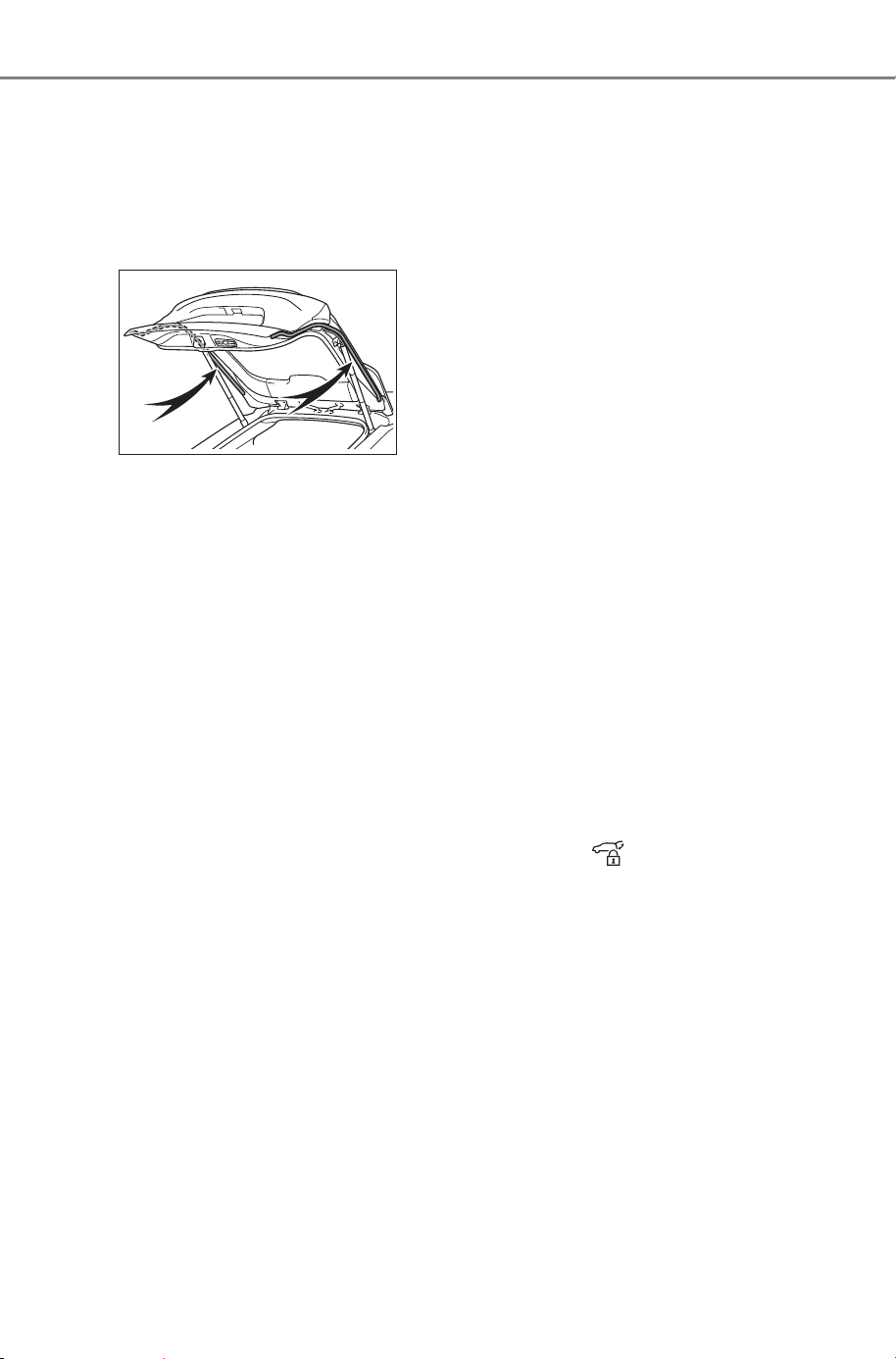
170
4-2. Opening, closing and locking the doors
Owner’s Manual_USA_M6740B_en
■ Jam protection function
Sensors are equipped on both sides
of the power back door. If anything
obstructs the power back door while
it is closing, the back door will auto-
matically operate in the opposite
direction or stop.
■ Fall-down protection function
While the power back door is open-
ing automatically, applying exces-
sive force to it will stop the opening
operation to prevent the power back
door from suddenly shutting.
■ Back door closing assist
If the back door is lowered manually
when the back door is stopped at an
open position, the back door will
fully close automatically.
■ Back door reserve lock function
This function is a function which
reserves locking of all doors, before-
hand, when the power back door is
open.
When the following procedure is
performed, all the doors except the
power back door are locked and
then power back door will also be
locked at the same time it is closed.
1 Close all doors, except the back
door.
2 During the power back door clos-
ing operation, lock the doors
using the smart key system from
the side doors (P.159) or the
wireless remote control.
(P.159)
Operation signals will indicate that
all the doors have been closed and
locked (P.160).
● If the electronic key is placed
inside the vehicle after starting a
close operation via the door
reserve lock function, the elec-
tronic key may become locked
inside the vehicle.
● If the power back door does not
fully close due to the operation of
the jam protection function, etc.,
while the back door is automati-
cally closing after a door reserve
lock operation is performed, the
door reserve lock function is can-
celed and all the doors will unlock.
● Before leaving the vehicle, make
sure that all the doors are closed
and locked.
■ Close & lock function
When the power back door is open,
this function closes the power back
door and then locks all of the doors
simultaneously.
When the following procedures are
performed and there are no elec-
tronic keys for the vehicle within the
vehicle, all of the doors will lock
when the power back door is com-
pletely closed.
1 Close all of the doors except the
power back door.
2 While carrying an electronic key,
press the switch on the
lower part of the power back
door (P.167).
A different buzzer than the normal
one will sound and then the power
back door will begin closing auto-
matically. When the power back
door is closed, all of the doors will
lock simultaneously and operation
signals will indicate that all of the
doors have been locked.
■ Situations in which the close &
lock function may not operate
properly
In the following situations, the close
& lock function may not operate
properly:
SOLTERRA_OM_USA_A6740BE.book 170 ページ 2025年5月23日 金曜日 午後1時18分
171
4-2. Opening, closing and locking the doors
Owner’s Manual_USA_M6740B_en
4
Before driving
● If the switch on the lower part
of the power back door (P.167)
is pressed by a hand which is
holding an electronic key
● If the switch on the lower part
of the power back door (P.167)
is pressed when the electronic key
is in a bag, etc., that is placed on
the ground
● If the switch on the lower part
of the power back door (P.167)
is pressed with the electronic key
not near the vehicle.
■ Hands Free Power Back Door
operating conditions (vehicles
with Hands Free Power Back
Door)
The Hands Free Power Back Door
will open/close automatically when
the following conditions are met:
● The Hands Free Power Back Door
operation is enabled (P.176)
● The power switch is in OFF.
● The electronic key is within the
operational range. (P.171)
● A foot is put near the lower center
part of the rear bumper and
moved away from the rear
bumper.
The power back door may also be
operated by putting a hand, an
elbow, a knee, etc. near the lower
center part of the rear bumper and
moving it away from the rear
bumper. Make sure to put it close
enough to the center part of the
rear bumper.
■ Situations in which the Hands
Free Power Back Door may not
operate properly (vehicles with
Hands Free Power Back Door)
In the following situations, the
Hands Free Power Back Door may
not operate properly:
● When a foot remains under the
rear bumper
● If the rear bumper is strongly hit
with a foot or is touched for a while
If the rear bumper has been touched
for a while, wait for a short time
before attempting to operate the
Hands Free Power Back Door
again.
● When operated while a person is
too close to the rear bumper
● When an external radio wave
source interferes with the commu-
nication between the electronic
key and the vehicle (P.179)
● When charging from an external
power source or connecting the
AC charging cable
● When the vehicle is parked near
an electrical noise source which
affects the sensitivity of the Hands
Free Power Back Door, such as a
pay parking spot, gas station,
electrically heated road, or fluo-
rescent light
● When the vehicle is near a TV
tower, electric power plant, radio
station, large display, airport or
other facility that generates strong
radio waves or electrical noise
● When a large amount of water is
applied to the rear bumper, such
as when the vehicle is being
washed or in heavy rain
● When mud, snow, ice, etc. is
attached to the rear bumper
● When the vehicle has been
parked for a while near objects
that may move and contact the
rear bumper, such as plants
● When an accessory is installed to
the rear bumper
If an accessory has been installed,
turn the Hands Free Power Back
Door operation setting off.
SOLTERRA_OM_USA_A6740BE.book 171 ページ 2025年5月23日 金曜日 午後1時18分
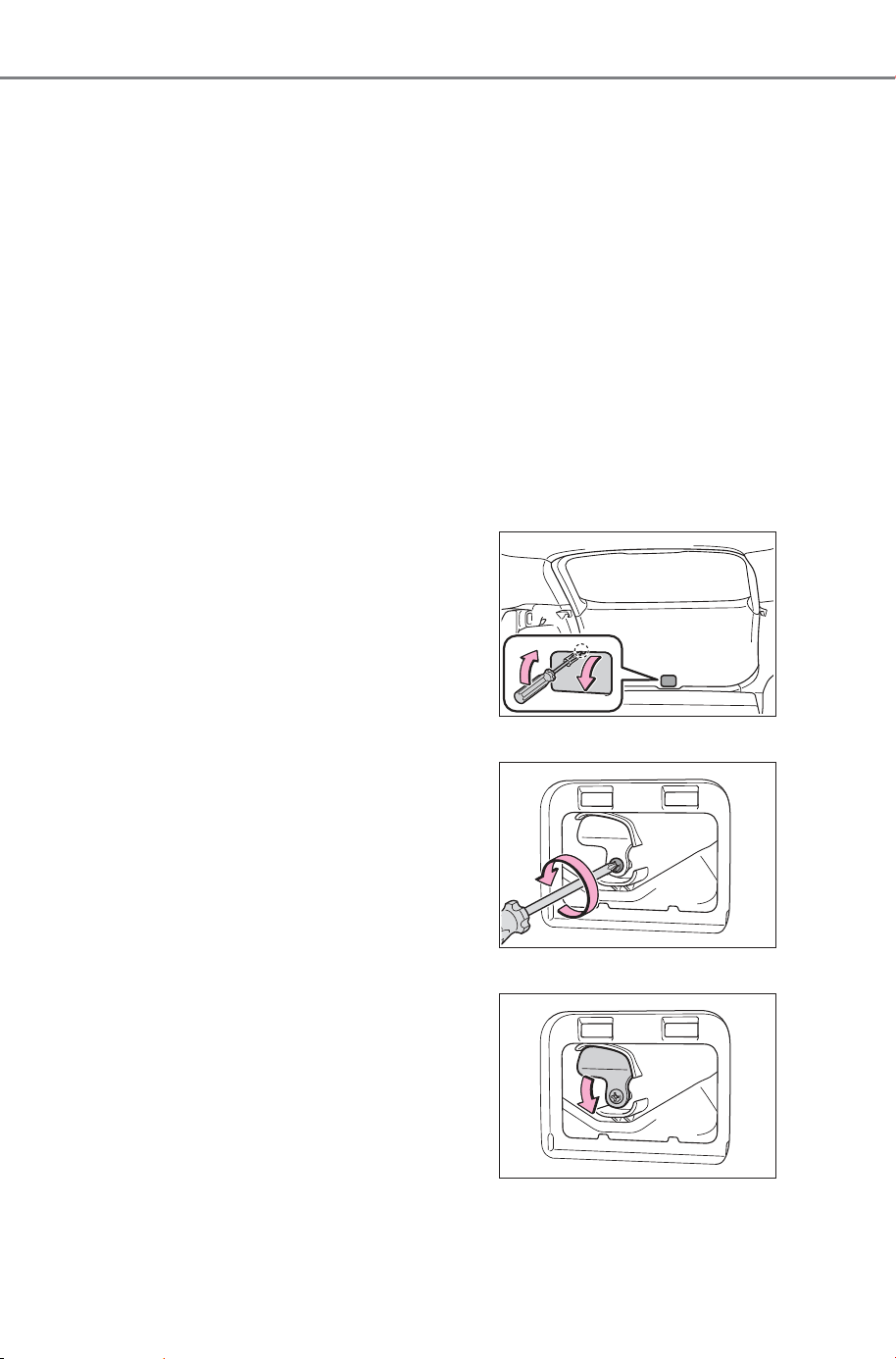
172
4-2. Opening, closing and locking the doors
Owner’s Manual_USA_M6740B_en
■ Preventing unintentional opera-
tion of the Hands Free Power
Back Door (vehicles with Hands
Free Power Back Door)
When an electronic key is in the
operation range, the Hands Free
Power Back Door may operate unin-
tentionally, so be careful in the fol-
lowing situations.
● When a large amount of water is
applied to the rear bumper, such
as when the vehicle is being
washed or in heavy rain
● When dirt is wiped off the rear
bumper
● When a small animal or small
object, such as a ball, moves
under the rear bumper
● When an object is moved from
under the rear bumper
● If someone is swinging their legs
while sitting on the rear bumper
● If the legs or another part of some-
one’s body contacts the rear
bumper while passing by the vehi-
cle
● When the vehicle is parked near
an electrical noise source which
affects the sensitivity of the Hands
Free Power Back Door, such as a
pay parking spot, gas station,
electrically heated road, or fluo-
rescent light
● When the vehicle is near a TV
tower, electric power plant, radio
station, large display, airport or
other facility that generates strong
radio waves or electrical noise
● When the vehicle is parked in a
place where objects such as
plants are near the rear bumper
● If luggage, etc. is set near the rear
bumper
● If accessories or a vehicle cover is
installed/removed near the rear
bumper
● When the vehicle is being towed
To prevent unintentional operation,
turn the Hands Free Power Back
Door operation setting off. (P.176)
■ When reconnecting the 12-volt
battery
To enable the power back door to
operate properly, close the back
door manually.
■ If the back door opener is inop-
erative
The back door can be unlocked
from the inside.
1 Remove the cover.
To prevent damage, cover the tip of
the screwdriver with a rag.
2 Loose the screw.
3 Move the cover.
SOLTERRA_OM_USA_A6740BE.book 172 ページ 2025年5月23日 金曜日 午後1時18分
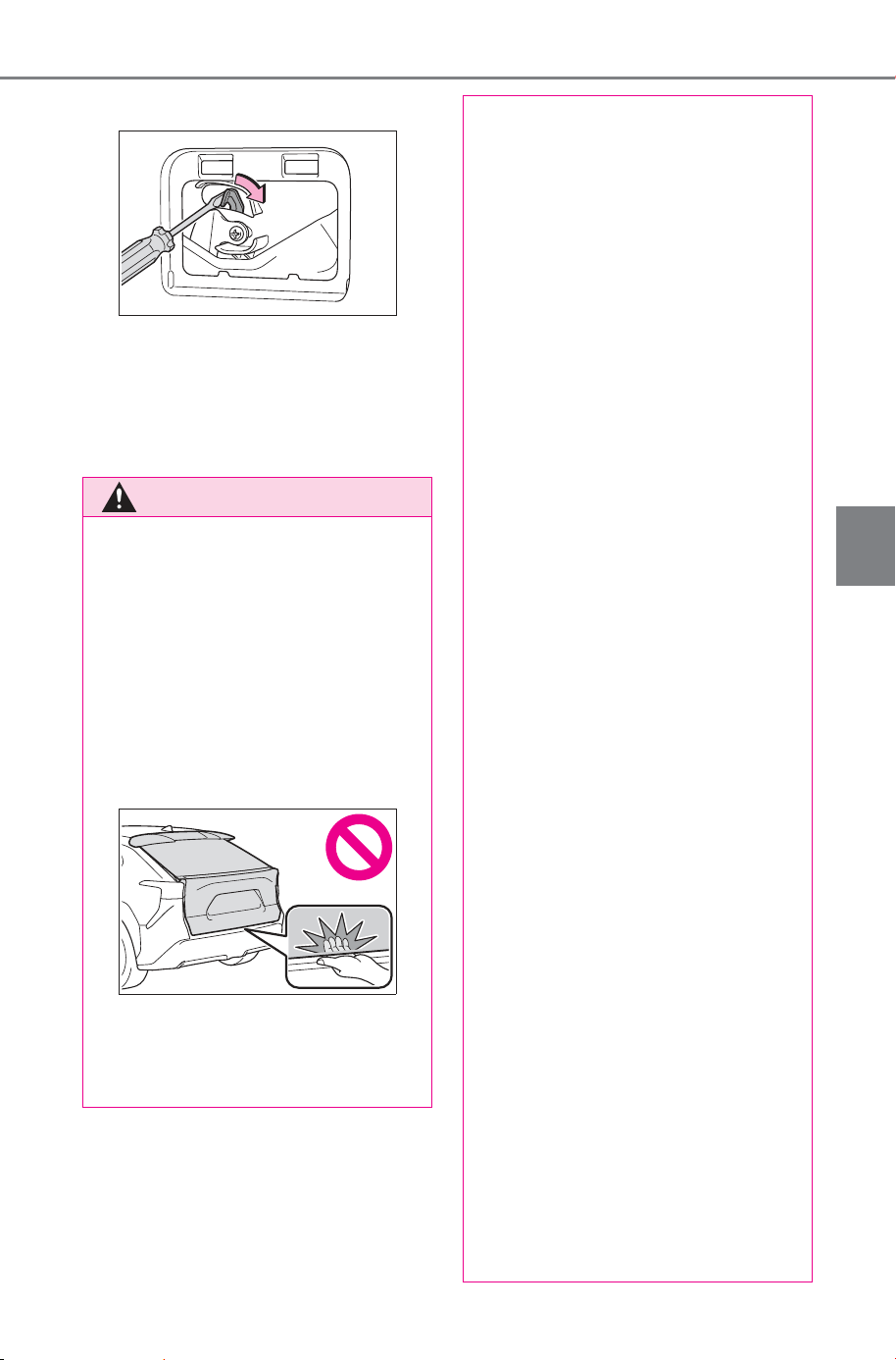
173
4-2. Opening, closing and locking the doors
Owner’s Manual_USA_M6740B_en
4
Before driving
4 Move the lever.
5 When installing, reverse the
steps listed.
■ Customization
Some functions can be customized.
(Customizable features: P.675)
WARNING
■ Back door closer
● In the event that the back door
is left slightly open, the back
door closer will automatically
close it to the fully closed posi-
tion. It takes several seconds
before the back door closer
begins to operate. Be careful
not to catch fingers or anything
else in the back door, as this
may cause bone fractures or
other serious injuries.
● Use caution when using the
back door closer as it still oper-
ates when the power back door
system is canceled.
■ Power back door
Observe the following precautions
when operating the power back
door.
Failure to do so may cause death
or serious injury.
● Check the safety of the sur-
rounding area to make sure
there are no obstacles or any-
thing that could cause any of
your belongings to get caught.
● If anyone is in the vicinity, make
sure they are safe and let them
know that the back door is
about to open or close.
● If the power back door system is
turned off while the back door is
operating automatically, the
automatic operation is stopped.
The back door then has to be
operated manually. Take extra
care when on an incline, as the
back door may open or close
unexpectedly.
● If the operating conditions of the
power back door are no longer
met, a buzzer may sound and
the back door may stop opening
or closing. The back door then
has to be operated manually.
Take extra care when on an
incline, as the back door may
open or close abruptly.
● On an incline, the back door
may suddenly shut after it
opens. Make sure the back door
is fully open and secure.
● In the following situations, the
power back door may detect an
abnormality and automatic
operation may be stopped. In
this case, the back door has to
be operated manually. Take
extra care when on an incline,
as the back door may open or
close abruptly.
• When the back door contacts an
obstacle
SOLTERRA_OM_USA_A6740BE.book 173 ページ 2025年5月23日 金曜日 午後1時18分
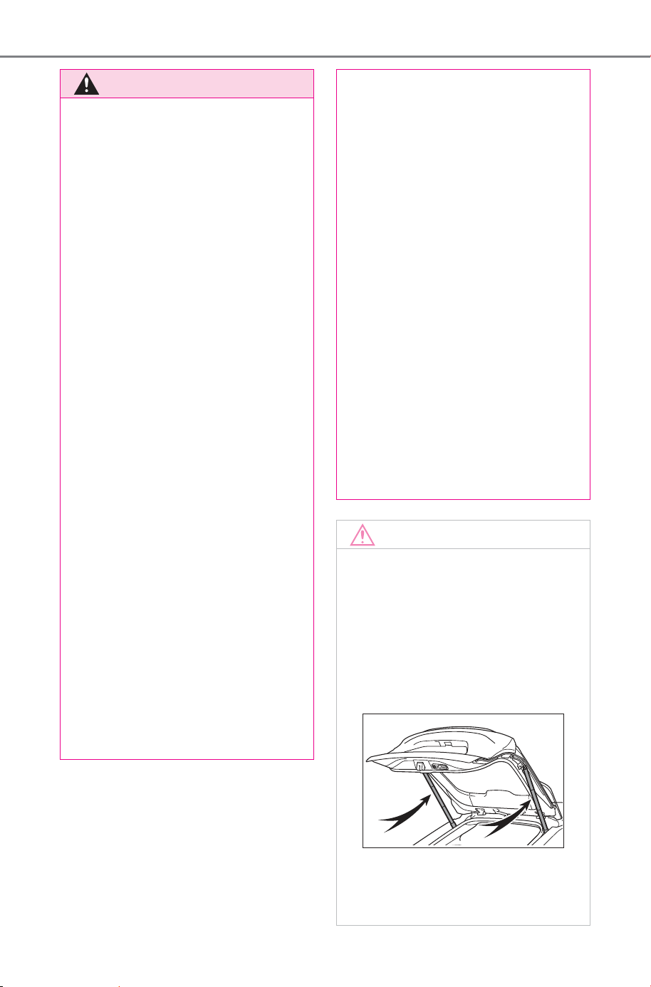
174
4-2. Opening, closing and locking the doors
Owner’s Manual_USA_M6740B_en
WARNING
• When the 12-volt battery volt-
age suddenly drops, such as
when the power switch is turned
to ON or the EV system is
started during automatic opera-
tion
● If a bicycle carrier or similar
heavy object is attached to the
back door, the power back door
may not operate, causing itself
to malfunction, or the back door
may suddenly shut again after
being opened, causing some-
one’s hands, arms, head or
neck to be caught and injured.
When installing an accessory
part to the back door, using a
genuine SUBARU part is rec-
ommended.
■ Jam protection function
Observe the following precau-
tions.
Failure to do so may cause death
or serious injury.
● Never use any part of your body
to intentionally activate the jam
protection function.
● The jam protection function may
not work if something gets
caught just before the back door
fully closes. Be careful not to
catch fingers or anything else.
● The jam protection function may
not work depending on the
shape of the object that is
caught. Be careful not to catch
fingers or anything else.
■ Hands Free Power Back Door
(if equipped)
Observe the following precautions
when operating the Hands Free
Power Back Door.
Failure to do so may cause death
or serious injury.
● Check the safety of the sur-
rounding area to make sure
there are no obstacles or any-
thing that could cause any of
your belongings to get caught.
● When putting your foot near the
lower center part of the rear
bumper and moving it from the
rear bumper, be careful not to
touch the exhaust pipes until
they have cooled down suffi-
ciently, as touching hot exhaust
pipes can cause burns.
● Do not leave the electronic key
within the effective range
(detection area) of the luggage
compartment.
NOTICE
■ Back door spindles
The back door is equipped with
spindles that hold the back door in
place.
Observe the following precau-
tions.
Failure to do so may cause dam-
age to the back door spindle,
resulting in malfunction.
● Do not attach any foreign
objects, such as stickers, plastic
sheets, or adhesives to the
spindle rod.
SOLTERRA_OM_USA_A6740BE.book 174 ページ 2025年5月23日 金曜日 午後1時18分

175
4-2. Opening, closing and locking the doors
Owner’s Manual_USA_M6740B_en
4
Before driving
NOTICE
● Do not touch the spindle rod
with gloves or other fabric items.
● Do not attach any accessories
other than genuine SUBARU
parts to the back door.
● Do not place your hand on the
spindle or apply lateral forces to
it.
■ To prevent back door closer
malfunction
Do not apply excessive force to
the back door while the back door
closer is operating. Applying
excessive force may cause the
back door closer to malfunction.
■ To prevent damage to the
power back door
● Make sure that there is no ice
between the back door and
frame that would prevent move-
ment of the back door. Operat-
ing the power back door when
excessive load is present on the
back door may cause a mal-
function.
● Do not apply excessive force to
the back door while the power
back door is operating.
● Take care not to damage the
sensors (installed on the right
and left edges of the power
back door) with a knife or other
sharp object. If the sensor is
disconnected, the power back
door will not close automatically.
■ Close & lock function
When closing the power back
door using the close & lock func-
tion, a different buzzer than the
normal one will sound before the
operation begins.
To check that the operation has
started correctly, check that a dif-
ferent buzzer than the normal one
has sounded.
Additionally, when the power back
door is fully closed and locked,
operation signals will indicate that
all of the doors have been locked.
Before leaving the vehicle, make
sure that the operation signals
have operated and that all of the
doors are locked.
■ Hands Free Power Back Door
precautions (if equipped)
The kick sensor is located behind
lower center part of the rear
bumper. Observe the following to
ensure that the Hands Free
Power Back Door function oper-
ates properly:
● Keep the lower center part of
the rear bumper clean at all
times.
If the lower center part of the
rear bumper is dirty or covered
with snow, the kick sensor may
not operate. In this situation,
clean off the dirt or snow, move
the vehicle from the current
position and then check if the
kick sensor operates.
If it does not operate, have the
vehicle inspected by your SUB-
ARU dealer.
● Do not apply coatings that have
a rain clearing (hydrophilic)
effect, or other coatings, to the
lower center part of the rear
bumper.
SOLTERRA_OM_USA_A6740BE.book 175 ページ 2025年5月23日 金曜日 午後1時18分
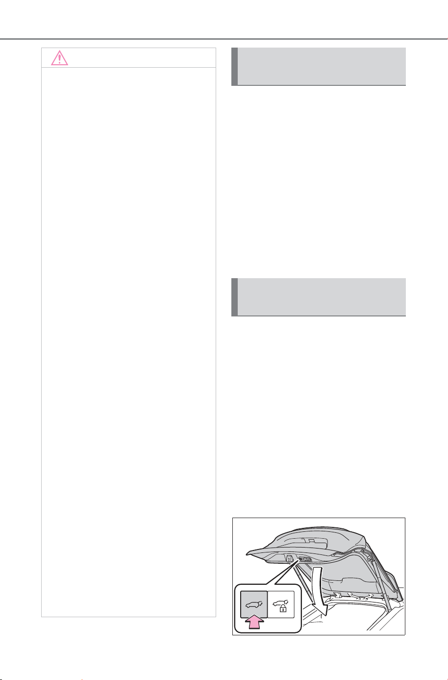
176
4-2. Opening, closing and locking the doors
Owner’s Manual_USA_M6740B_en
The settings for the power back
door can be changed from the
settings screen of the multime-
dia display. (P.671)
When the power back door settings
have been changed, they will not
be reset even if the power switch is
turned OFF.
To return the settings to their previ-
ous values, it is necessary to use
the settings screen of the multime-
dia display again.
The open position of the power
back door can be adjusted.
1 Stop the back door in the
desirable position. (P.166)
2 Press and hold the power
back door switch on the back
door for approximately 2 sec-
onds.
When the settings are completed,
the buzzer sounds 4 times.
When opening the back door the
next time, the back door will stop at
that position.
NOTICE
● Do not park the vehicle near
objects that may move and con-
tact the lower center part of the
rear bumper, such as grass or
trees.
If the vehicle has been parked
for a while near objects that
may move and contact the
lower center part of the rear
bumper, such as grass or trees,
the kick sensor may not oper-
ate. In this situation, move the
vehicle from the current position
and then check if the kick sen-
sor operates. If it does not oper-
ate, have the vehicle inspected
by your SUBARU dealer.
● Do not subject the kick sensor
or its surrounding area to a
strong impact.
If the kick sensor or its sur-
rounding area has been sub-
jected to a strong impact, the
kick sensor may not operate
properly. If the kick sensor does
not operate in the following situ-
ations, have the vehicle
inspected by your SUBARU
dealer.
• The kick sensor or its surround-
ing area has been subjected to
a strong impact.
• The lower center part of the rear
bumper is scratched or dam-
aged.
● Do not disassemble the rear
bumper.
● Do not attach stickers to the
rear bumper.
● Do not paint the rear bumper.
● If a bicycle carrier or similar
heavy object is attached to the
power back door, disable the
Hands Free Power Back Door.
Changing settings of the
power back door system
Adjusting the open posi-
tion of the back door
SOLTERRA_OM_USA_A6740BE.book 176 ページ 2025年5月23日 金曜日 午後1時18分
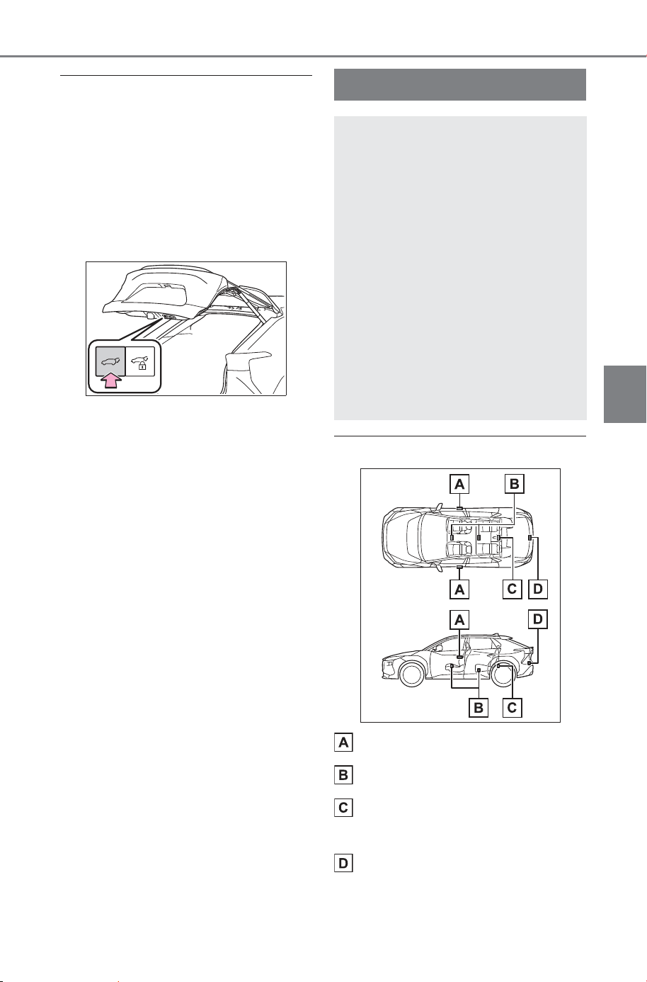
177
4-2. Opening, closing and locking the doors
Owner’s Manual_USA_M6740B_en
4
Before driving
■ Canceling the adjusted open
position of the back door
Press and hold the power back door
switch on the back door for approxi-
mately 7 seconds.
After the buzzer sounds 4 times, it
sounds twice more. When the
power back door does the opening
operation the next time, the door will
open to the initial settings position.
■ Customization
The automatic opening stop position
for the power back door can also be
changed from the multimedia dis-
play. (P.675)
When the stop position has been set
by both the vehicle side power back
door open/close switch and the mul-
timedia display, priority will be given
to whichever one was set most
recently.
■ Antenna location
Antennas outside the cabin
Antennas inside the cabin
Antennas inside the luggage
compartment
Antenna outside the luggage
compartment
Smart key system
The following operations
can be performed simply by
carrying the electronic key
on your person, for example
in your pocket. The driver
should always carry the
electronic key.
Locks and unlocks the
doors (P.159)
Locks and unlocks the back
door (P.165)
Starts the EV system
(P.229)
SOLTERRA_OM_USA_A6740BE.book 177 ページ 2025年5月23日 金曜日 午後1時18分
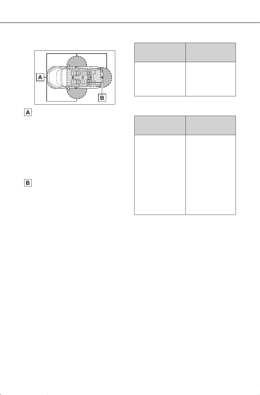
178
4-2. Opening, closing and locking the doors
Owner’s Manual_USA_M6740B_en
■ Effective range (areas within
which the electronic key is
detected)
When locking or unlocking the
doors
The system can be operated when
the electronic key is within about 2.3
ft. (0.7 m) of the front door handles
and back door opener switch. (Only
the doors detecting the key can be
operated.)
When starting the EV system or
changing power switch modes
The system can be operated when
the electronic key is inside the vehi-
cle.
■ If an alarm sounds or a warning
message is displayed
An alarm sounds and warning mes-
sage displays shown on the multi-
information display are used to pro-
tect against unexpected accidents
or theft of the vehicle resulting from
erroneous operation. When a warn-
ing message is displayed, take
appropriate measures based on the
displayed message.
When only an alarm sounds, cir-
cumstances and correction proce-
dures are as follows.
● When an exterior alarm sounds
once for 5 seconds
● When an interior alarm pings con-
tinuously
■ If “Key Detected in Vehicle” is
shown on the multi-information
display
An attempt was made to lock the
doors using the smart key system
while the electronic key was still
inside the vehicle. Retrieve the elec-
tronic key from the vehicle and lock
the doors again.
■ Battery-saving function
The battery-saving function will be
activated in order to prevent the
electronic key battery and the 12-
volt battery from being discharged
while the vehicle is not in operation
for a long time.
Situation
Correction pro-
cedure
An attempt was
made to lock the
vehicle while a
door was open.
Close all of the
doors and lock
the doors again.
Situation
Correction pro-
cedure
The power
switch was
turned to ACC
while the driver’s
door was open
(or the driver’s
door was opened
while the power
switch was in
ACC).
Turn the power
switch to OFF
and close the
driver’s door.
SOLTERRA_OM_USA_A6740BE.book 178 ページ 2025年5月23日 金曜日 午後1時18分
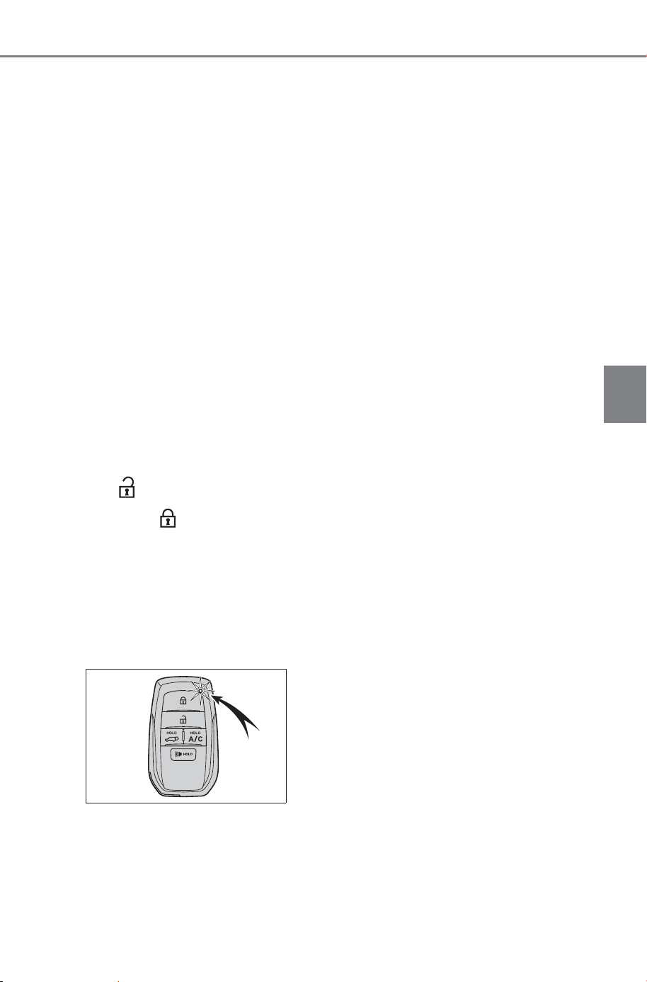
179
4-2. Opening, closing and locking the doors
Owner’s Manual_USA_M6740B_en
4
Before driving
● In the following situations, the
smart key system may take some
time to unlock the doors.
• The electronic key has been left in
an area of approximately 11.5 ft.
(3.5 m) of the outside of the vehi-
cle for 2 minutes or longer.
• The smart key system has not
been used for 5 days or longer.
● If the smart key system has not
been used for 14 days or longer,
the doors cannot be unlocked at
any doors except the driver’s door.
In this case, take hold of the
driver’s door handle, or use the
wireless remote control or the
mechanical key, to unlock the
doors.
■ Turning an electronic key to
battery-saving mode
● When battery-saving mode is set,
battery depletion is minimized by
stopping the electronic key from
receiving radio waves.
Press twice while pressing
and holding .
Confirm that the electronic key indi-
cator flashes 4 times.
While the battery-saving mode is
set, the smart key system cannot be
used. To cancel the function, press
any of the electronic key buttons.
● Electronic keys that will not be
used for long periods of time can
be set to the battery-saving mode
in advance.
■ When electronic key function
stops
If the position of the electronic key
has not changed for a certain
amount of time such as when the
electronic key is left somewhere, the
function of the electronic key stops
to reduce depletion of the battery.
In this case, function can automati-
cally be restored by moving the
position of the key such as by lifting
it up.
■ Conditions affecting operation
The smart key system uses weak
radio waves. In the following situa-
tions, the communication between
the electronic key and the vehicle
may be affected, preventing the
smart key system, wireless remote
control and immobilizer system from
operating properly.
● When the electronic key battery is
depleted
● Near a TV tower, electric power
plant, gas station, radio station,
large display, airport or other facil-
ity that generates strong radio
waves or electrical noise
● When the electronic key is in con-
tact with, or is covered by the fol-
lowing metallic objects
• Cards to which aluminum foil is
attached
• Cigarette boxes that have alumi-
num foil inside
• Metallic wallets or bags
• Coins
• Hand warmers made of metal
• Media such as CDs and DVDs
● When another wireless key (that
emits radio waves) is being used
nearby
● When carrying the electronic key
together with the following devices
that emit radio waves
• Portable radio, cellular phone,
cordless phone or other wireless
communication devices
SOLTERRA_OM_USA_A6740BE.book 179 ページ 2025年5月23日 金曜日 午後1時18分

180
4-2. Opening, closing and locking the doors
Owner’s Manual_USA_M6740B_en
• Another electronic key or a wire-
less key that emits radio waves
• Personal computers or personal
digital assistants (PDAs)
• Digital audio players
• Portable game systems
● If window tint with a metallic con-
tent or metallic objects are
attached to the rear window
● When the electronic key is placed
near a battery charger or elec-
tronic devices
● When the vehicle is parked in a
pay parking spot where radio
waves are emitted.
■ Note for the entry function
● Even when the electronic key is
within the effective range (detec-
tion areas), the system may not
operate properly in the following
cases:
• The electronic key is too close to
the window or outside door han-
dle, near the ground, or in a high
place when the doors are locked
or unlocked.
• The electronic key is on the instru-
ment panel, luggage cover or
floor, or in the door pockets or
glove box when the EV system is
started or power switch modes are
changed.
• The electronic key is blocked by a
body between the electronic key
and the vehicle when the door is
unlocked.
● Do not leave the electronic key on
top of the instrument panel, near
the door pockets or glove box
when exiting the vehicle. Depend-
ing on the radio wave reception
conditions, it may be detected by
the antenna outside the cabin and
the door will become lockable
from the outside, possibly trapping
the electronic key inside the vehi-
cle.
● As long as the electronic key is
within the effective range, the
doors may be locked or unlocked
by anyone. However, only the
doors detecting the electronic key
can be used to lock or unlock the
vehicle.
● Even if the electronic key is not
inside the vehicle, it may be possi-
ble to start the EV system if the
electronic key is near the window.
● The doors may unlock if a large
amount of water splashes on the
door handle, such as in the rain or
in a car wash when the electronic
key is within the effective range.
(The doors will automatically be
locked after approximately 60 sec-
onds if the doors are not opened
and closed.)
● If the wireless remote control is
used to lock the doors when the
electronic key is near the vehicle,
there is a possibility that the door
may not be unlocked by the entry
function. (Use the wireless remote
control to unlock the doors.)
● Touching the door lock sensor
while wearing gloves may delay or
prevent lock operation. Remove
the gloves and touch the lock sen-
sor again.
● When the lock operation is per-
formed using the lock sensor, rec-
ognition signals will be shown up
to two consecutive times. After
this, no recognition signals will be
given.
● If the door handle becomes wet
while the electronic key is within
the effective range, the door may
lock and unlock repeatedly. In that
case, follow the following correc-
tion procedures to wash the vehi-
cle:
• Place the electronic key in a loca-
tion 6 ft. (2 m) or more away from
the vehicle. (Take care to ensure
that the key is not stolen.)
• Set the electronic key to battery-
saving mode to disable the smart
key system. (P.179)
SOLTERRA_OM_USA_A6740BE.book 180 ページ 2025年5月23日 金曜日 午後1時18分

181
4-2. Opening, closing and locking the doors
Owner’s Manual_USA_M6740B_en
4
Before driving
● If the electronic key is inside the
vehicle and a door handle
becomes wet during a car wash, a
message may be shown on the
multi-information display and a
buzzer will sound outside the vehi-
cle. To turn off the alarm, lock all
the doors.
● The lock sensor may not work
properly if it comes into contact
with ice, snow, mud, etc. Clean
the lock sensor and attempt to
operate it again.
● A sudden approach to the effec-
tive range or door handle may pre-
vent the doors from being
unlocked. In this case, return the
door handle to the original position
and check that the doors unlock
before pulling the door handle
again.
● If there is another electronic key in
the detection area, it may take
slightly longer to unlock the doors
after the door handle is gripped.
■ When the vehicle is not driven
for extended periods
● To prevent theft of the vehicle, do
not leave the electronic key within
6 ft. (2 m) of the vehicle.
● The smart key system can be
deactivated in advance. (P.674)
● Battery-saving mode can reduce
the power consumption of elec-
tronic keys. (P.179)
■ To operate the system properly
Make sure to carry the electronic
key when operating the system. Do
not get the electronic key too close
to the vehicle when operating the
system from the outside of the vehi-
cle.
Depending on the position and hold-
ing condition of the electronic key,
the key may not be detected cor-
rectly and the system may not oper-
ate properly. (The alarm may go off
accidentally, or the door lock pre-
vention may not operate.)
■ If the smart key system does
not operate properly
● If the doors cannot be locked or
unlocked, perform the following.
• Bring the electronic key close to
the door handle and perform a
lock or unlock operation.
• Use the wireless remote control.
If the doors cannot be locked or
unlocked by perform the above, use
the mechanical key. (P.642)
However, if the mechanical key is
used while the alarm system is set,
the warning will sound. (P.66)
● If the EV system cannot be
started, refer to P.643
■ Customization
Settings (e.g. smart key system)
can be changed.
(Customizable features: P.674)
If the smart key system has been
deactivated in a customized setting,
refer to the explanations for the fol-
lowing operations.
● Locking and unlocking the doors:
Use the wireless remote control or
mechanical key. (P.159, 642)
● Starting the EV system and
changing power switch modes:
P.6 43
● Stopping the EV system: P.231
SOLTERRA_OM_USA_A6740BE.book 181 ページ 2025年5月23日 金曜日 午後1時18分

182
4-2. Opening, closing and locking the doors
Owner’s Manual_USA_M6740B_en
WARNING
■ Caution regarding interfer-
ence with electronic devices
● People with implantable car-
diac pacemakers, cardiac
resynchronization therapy-
pacemakers or implantable car-
dioverter defibrillators should
keep away from the smart key
system antennas. (P. 17 7)
The radio waves may affect the
operation of such devices. If
necessary, the entry function
can be disabled. Ask your SUB-
ARU dealer for details, such as
the frequency of radio waves
and timing of the emitted radio
waves. Then, consult your doc-
tor to see if you should disable
the entry function.
● User of any electrical medical
device other than implantable
cardiac pacemakers, cardiac
resynchronization therapy-
pacemakers or implantable car-
dioverter defibrillators should
consult the manufacturer of the
device for information about its
operation under the influence of
radio waves.
Radio waves could have unex-
pected effects on the operation
of such medical devices.
Ask your SUBARU dealer for
details for disabling the entry
function.
SOLTERRA_OM_USA_A6740BE.book 182 ページ 2025年5月23日 金曜日 午後1時18分
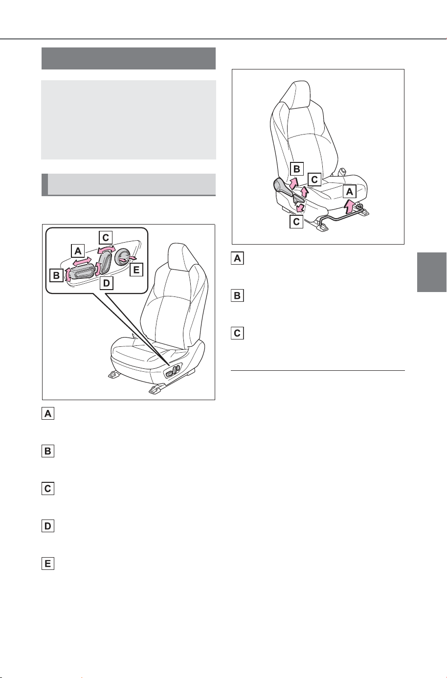
183
4-3. Adjusting the seats
Owner’s Manual_USA_M6740B_en
4
Before driving
4-3.Adjusting the seats
Power seat (if equipped)
Seat position adjustment
switch
Seat cushion (front) angle
adjustment switch
Seatback angle adjustment
switch
Vertical height adjustment
switch
Lumbar support adjustment
switch (driver seat only)
Manual seat (passenger seat)
Seat position adjustment
lever
Seatback angle adjustment
lever
Vertical height adjustment
lever
■ When adjusting the seat
● Make sure that any surrounding
passengers or objects are not
contact the seat.
● Take care when adjusting the seat
so that the head restraint does not
touch the ceiling and sun visor.
■ Power easy access system (if
equipped)
The driver’s seat move in accor-
dance with power switch mode and
the driver’s seatbelt condition.
(P.207)
Front seats
The seats can be adjusted
(longitudinally, vertically,
etc.). Adjust the seat to
ensure the correct driving
posture.
Adjustment procedure
SOLTERRA_OM_USA_A6740BE.book 183 ページ 2025年5月23日 金曜日 午後1時18分
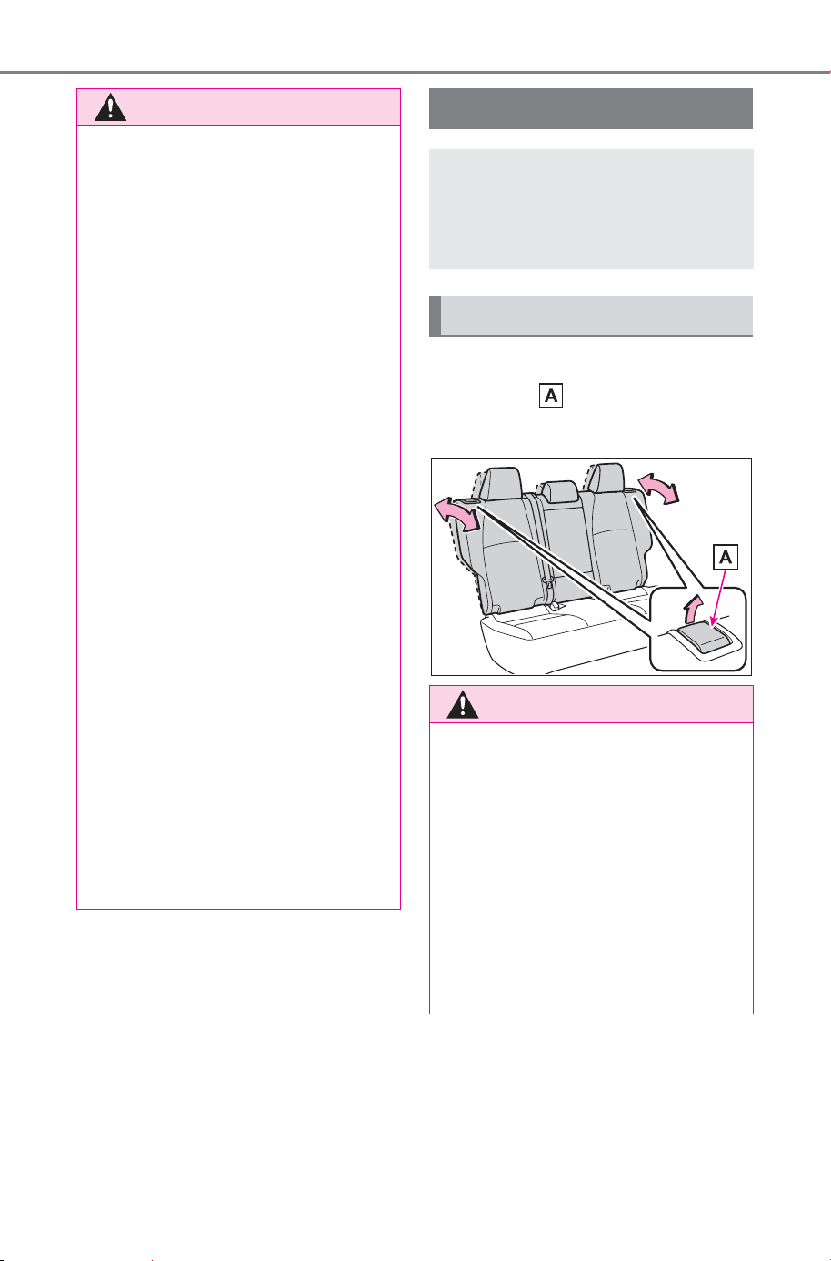
184
4-3. Adjusting the seats
Owner’s Manual_USA_M6740B_en
Pull the seatback angle adjust-
ment lever , and adjust the
seatback angle.
WARNING
■ When adjusting the seat posi-
tion
● Take care when adjusting the
seat position to ensure that
other passengers are not
injured by the moving seat.
● Do not put your hands under the
seat or near the moving parts to
avoid injury.
Fingers or hands may become
jammed in the seat mechanism.
● Make sure to leave enough
space around the feet so they
do not get stuck.
● Manual seat only: After adjust-
ing the seat, make sure that the
seat is locked in position.
■ Seat adjustment
To reduce the risk of sliding under
the lap belt during a collision, do
not recline the seat more than
necessary.
If the seat is too reclined, the lap
belt may slide past the hips and
apply restraint forces directly to
the abdomen, or your neck may
contact the shoulder belt, increas-
ing the risk of death or serious
injury in the event of an accident.
Adjustments should not be made
while driving as the seat may
unexpectedly move and cause
the driver to lose control of the
vehicle.
Rear seats
Reclining adjustments and
folding the seatbacks can
be done with lever opera-
tion.
Adjustment procedure
WARNING
■ When operating the seatback
Observe the following precau-
tions.
Failure to do so may cause death
or serious injury.
● Keep other passengers from
being hit with the seatback.
● Do not bring your hands close
to the moving parts or between
the seats, as well as do not let
any part of your body get
caught.
SOLTERRA_OM_USA_A6740BE.book 184 ページ 2025年5月23日 金曜日 午後1時18分
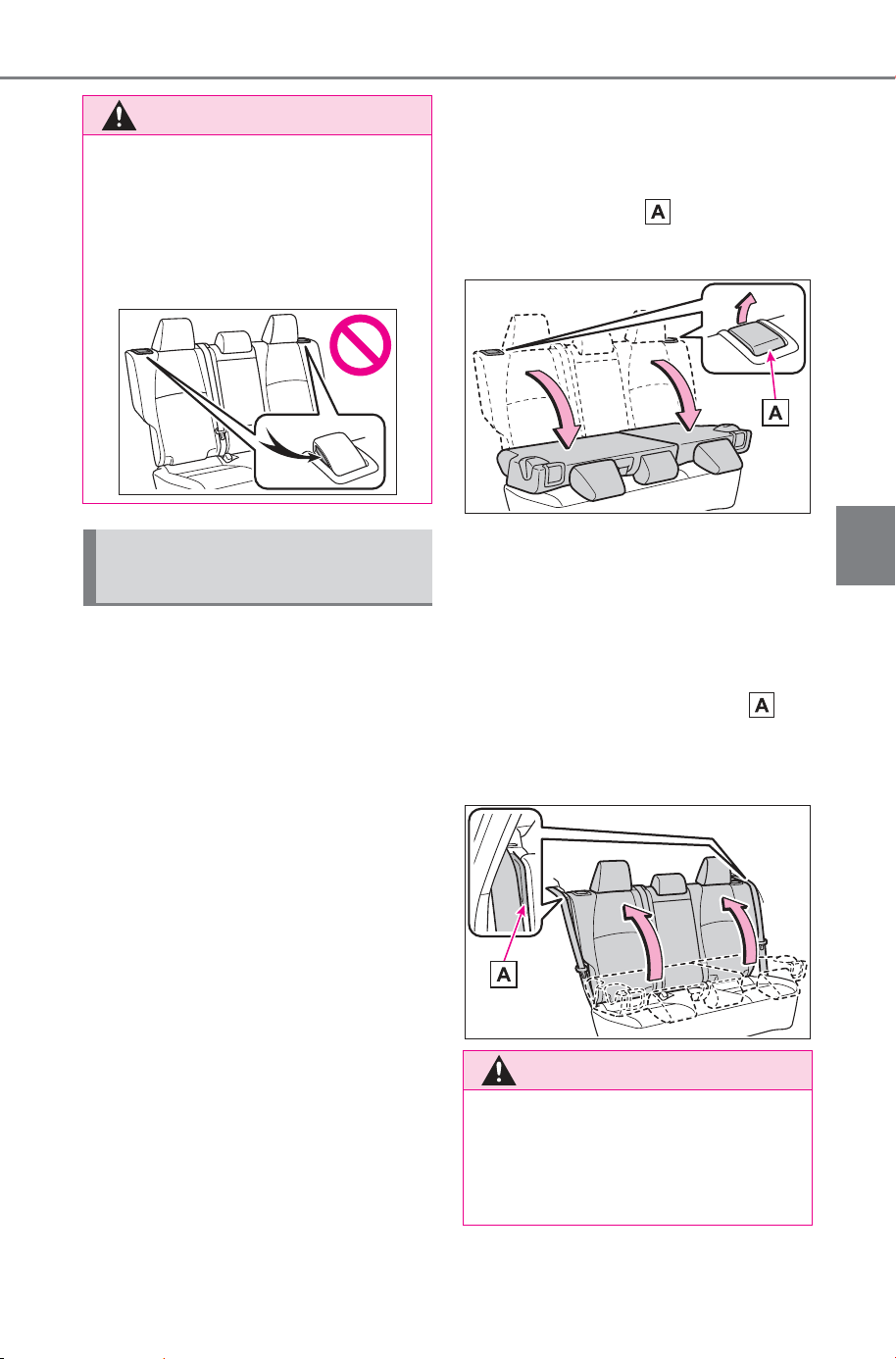
185
4-3. Adjusting the seats
Owner’s Manual_USA_M6740B_en
4
Before driving
■ Before folding down the
seatbacks
1 Park the vehicle in a safe
place.
Apply the parking brake (P.241)
and shift the shift position to P.
(P.234)
2 Adjust the position of the
front seat and the angle of
the seatback. (P.183)
Depending on the position of the
front seat, if the seatback is folded
backward, it may interfere with the
operation of the rear seat.
3 Lower the head restraint of
the rear center seat.
(P.187)
4 Stow the armrest of the rear
seat if it is pulled out.
(P.529)
This step is not necessary when
operating the left side seat only.
■ Folding down the rear seat-
backs
While pulling the seatback angle
adjustment lever , fold the
seatback down.
■ Returning the rear seat-
backs
To avoid trapping the seat belt
between the seat and the inside
of the vehicle, pass the seat belt
outside the seat belt guide
and then return the seatback
securely to the locked position.
WARNING
● After adjusting the seat, make
sure that the seat is locked in
position.
If the seatback is not securely
locked, the red marking will be
visible. Make sure that the red
marking is not visible.
Folding down the rear
seatbacks
WARNING
■ When folding the rear seat-
backs down
Observe the following precau-
tions. Failure to do so may result
in death or serious injury.
SOLTERRA_OM_USA_A6740BE.book 185 ページ 2025年5月23日 金曜日 午後1時18分
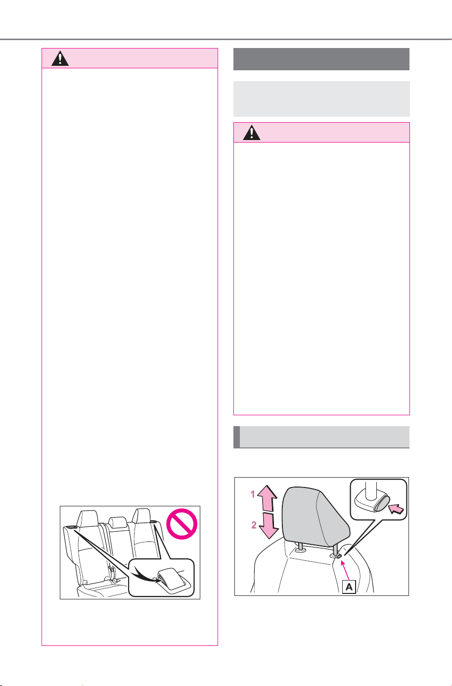
186
4-3. Adjusting the seats
Owner’s Manual_USA_M6740B_en
■ Front seats
1 Up
Pull the head restraints up.
WARNING
● Do not attempt to fold the seat-
backs down while driving.
● Stop the vehicle on level
ground, set the parking brake
and shift the shift position to P.
● Do not allow anyone to sit on a
folded seatback or in the lug-
gage compartment while driv-
ing.
● Do not allow children to enter
the luggage compartment.
● Do not operate the rear seat if it
is occupied.
● Be careful not to get feet or
hands caught in the moving
parts or joints of the seats
during operation.
● Do not allow children to operate
the seat.
■ After returning the rear seat-
back to the upright position
Observe the following precau-
tions. Failure to do so may result
in death or serious injury.
● Make sure that the seatback is
securely locked in position by
lightly pushing it back and forth.
If the seatback is not securely
locked, the red marking will be
visible on the seatback lock
release lever. Make sure that
the red marking is not visible.
● Check that the seat belts are
not twisted or caught in the
seatback.
Head restraints
Head restraints are pro-
vided for all seats.
WARNING
■ Head restraint precautions
Observe the following precautions
regarding the head restraints.
Failure to do so may result in
death or serious injury.
● Use the head restraints
designed for each respective
seat.
● Adjust the head restraints to the
correct position at all times.
● After adjusting the head
restraints, push down on them
and make sure they are locked
in position.
● Do not drive with the head
restraints removed.
● Make sure the rear seat head
restraints are locked by pushing
them up and down before using
the head restraints.
Vertical adjustment
SOLTERRA_OM_USA_A6740BE.book 186 ページ 2025年5月23日 金曜日 午後1時18分
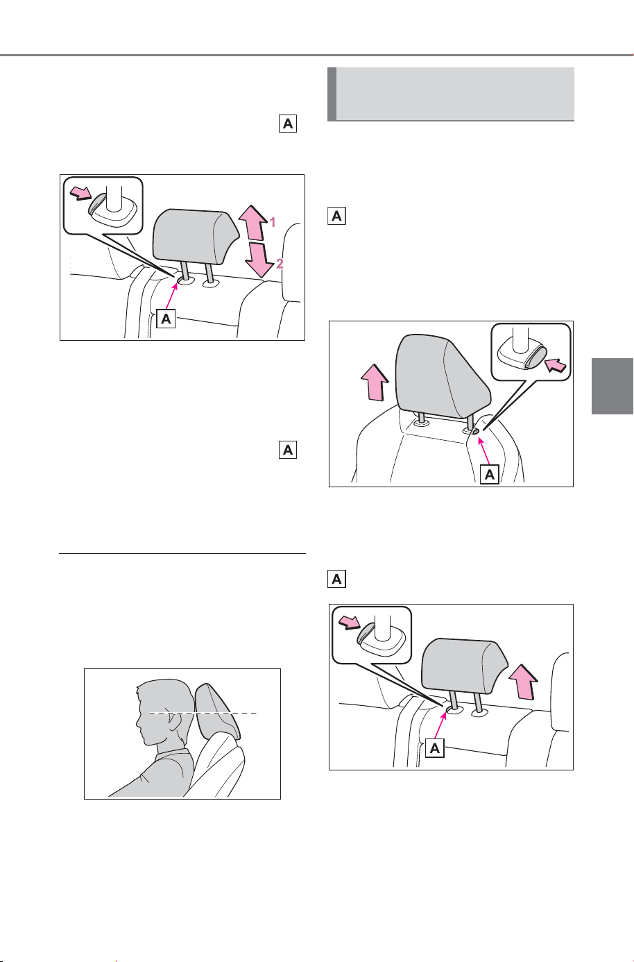
187
4-3. Adjusting the seats
Owner’s Manual_USA_M6740B_en
4
Before driving
2 Down
Push the head restraint down while
pressing the lock release button .
■ Rear center seat
1 Up
Pull the head restraints up.
2 Down
Push the head restraint down while
pressing the lock release button .
■ Rear outer seats
Head restraints cannot be
adjusted.
■ Adjusting the height of the head
restraints (front seats)
Make sure that the head restraints
are adjusted so that the center of
the head restraint is closest to the
top of your ears.
■ Adjusting the rear center seat
head restraint
Always raise the head restraint one
level from the stowed position when
using.
■ Front seats
Pull the head restraint up while
pressing the lock release button
.
If the head restraint touches the
ceiling, making the removal difficult,
change the seat height or angle.
(P.183)
■ Rear center seat
Pull the head restraint up while
pressing the lock release button
.
Removing the head
restraints
SOLTERRA_OM_USA_A6740BE.book 187 ページ 2025年5月23日 金曜日 午後1時18分
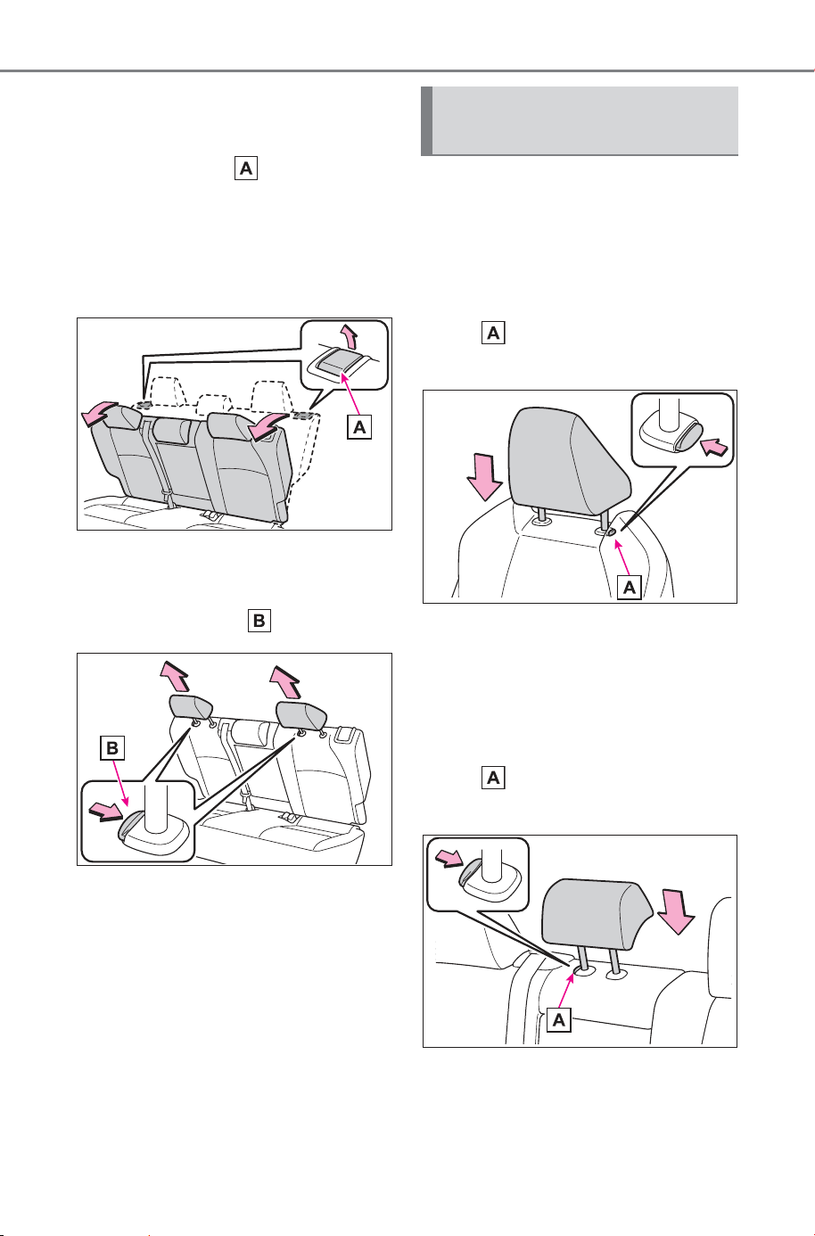
188
4-3. Adjusting the seats
Owner’s Manual_USA_M6740B_en
■ Rear outer seats
1 Pull the seatback lock
release lever and fold
down the seatback until it
reaches the position where
the head restraints can be
removed.
2 Pull the head restraint up
while pressing the lock
release button .
■ Front seats
Align the head restraint with the
installation holes and push it
down to the lock position.
Press and hold the lock release
button when lowering the head
restraint.
■ Rear center seat
Align the head restraint with the
installation holes and push it
down to the lock position.
Press and hold the lock release
button when lowering the head
restraint.
Installing the head
restraints
SOLTERRA_OM_USA_A6740BE.book 188 ページ 2025年5月23日 金曜日 午後1時18分
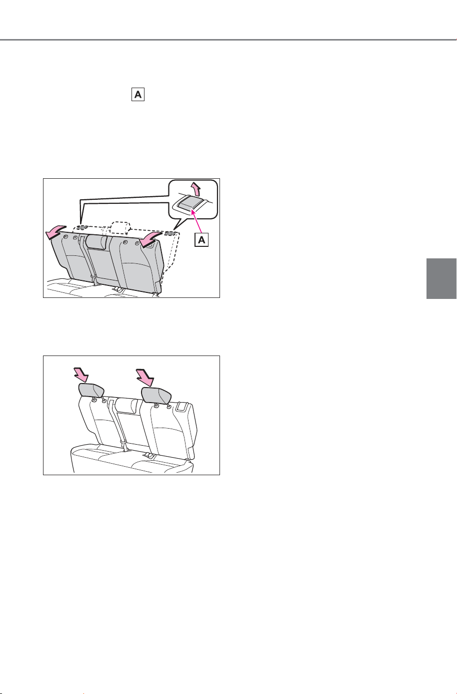
189
4-3. Adjusting the seats
Owner’s Manual_USA_M6740B_en
4
Before driving
■ Rear outer seats
1 Pull the seatback lock
release lever and fold
down the seatback until it
reaches the position where
the head restraints can be
installed.
2 Align the head restraint with
installation holes and push it
down to the lock position.
SOLTERRA_OM_USA_A6740BE.book 189 ページ 2025年5月23日 金曜日 午後1時18分
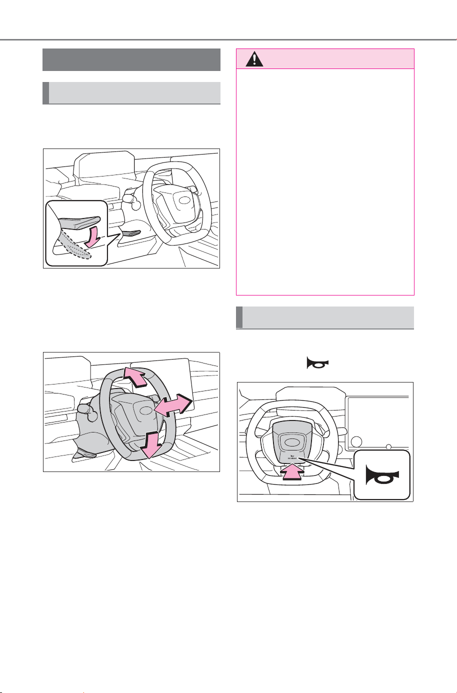
190
4-4. Adjusting the steering wheel and mirrors
Owner’s Manual_USA_M6740B_en
4-4.Adjusting the steering wheel and m irrors
1 Hold the steering wheel and
push the lever down.
2 Adjust to the ideal position by
moving the steering wheel
horizontally and vertically.
After adjustment, pull the lever up
to secure the steering wheel.
To sound the horn, press on or
close to the mark.
Steering wheel
Adjustment procedure
WARNING
■ Caution while driving
Do not adjust the steering wheel
while driving.
Doing so may cause the driver to
mishandle the vehicle and cause
an accident, resulting in death or
serious injury.
■ After adjusting the steering
wheel
Make sure that the steering wheel
is securely locked.
Otherwise, the steering wheel
may move suddenly, possibly
causing an accident, and resulting
in death or serious injury. Also,
the horn may not sound if the
steering wheel is not securely
locked.
Sounding the horn
SOLTERRA_OM_USA_A6740BE.book 190 ページ 2025年5月23日 金曜日 午後1時18分
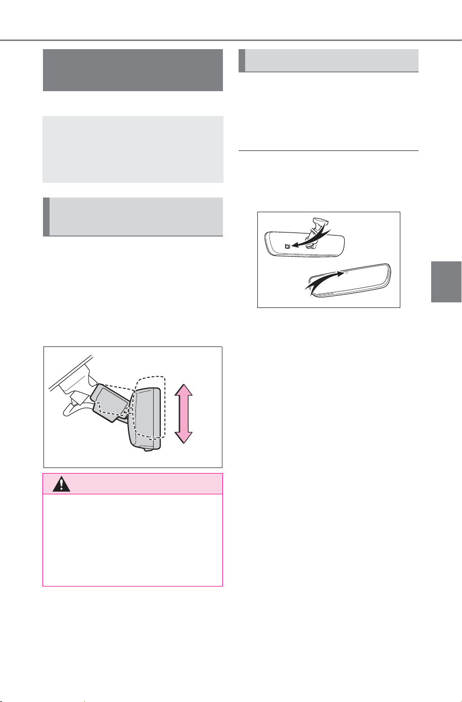
191
4-4. Adjusting the steering wheel and mirrors
Owner’s Manual_USA_M6740B_en
4
Before driving
*
: If equipped
The height of the rear view mir-
ror can be adjusted to suit your
driving posture.
Adjust the height of the rear
view mirror by moving it up and
down.
Responding to the level of
brightness of the headlights of
vehicles behind, the reflected
light is automatically reduced.
■ To prevent sensor error
To ensure that the sensors operate
properly, do not touch or cover
them.
Inside rear view mir-
ror
*
The rear view mirror’s posi-
tion can be adjusted to
enable sufficient confirma-
tion of the rear view.
Adjusting the height of
rear view mirror
WARNING
■ Caution while driving
Do not adjust the position of the
mirror while driving.
Doing so may lead to mishandling
of the vehicle and cause an acci-
dent, resulting in death or serious
injury.
Anti-glare function
SOLTERRA_OM_USA_A6740BE.book 191 ページ 2025年5月23日 金曜日 午後1時18分
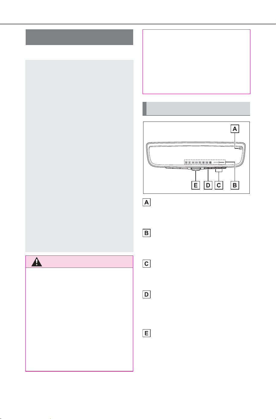
192
4-4. Adjusting the steering wheel and mirrors
Owner’s Manual_USA_M6740B_en
*
: If equipped
Camera indicator
Indicates that the camera is operat-
ing normally.
Icon display area
Displays icons, adjusting gauge,
etc. (P.194)
Select/adjust button
Press to change the setting of the
item you want to adjust.
Menu button
Press to display the icon display
area and select the item you want
to adjust.
Lever
Operate to change between digital
mirror mode and optical mirror
mode.
Digital inner mirror
*
The Digital inner mirror is a
system that uses the cam-
era on the rear of the vehi-
cle and displays its image
on the display of the Digital
inner mirror.
The Digital inner mirror can
be changed between optical
mirror mode and digital mir-
ror mode by operating the
lever.
The Digital inner mirror
allows the driver to see the
rear view despite obstruc-
tions, such as the head
restraints or luggage,
ensuring rear visibility.
Also, the rear seats are not
displayed and privacy of the
passengers is enhanced.
WARNING
Observe the following precau-
tions.
Failure to do so may result in
death or serious injury.
■ Before using the Digital inner
mirror
● Make sure to adjust the mirror
before driving. (P. 194)
• Change to optical mirror mode
and adjust the position of the
Digital inner mirror so that the
area behind your vehicle can be
viewed properly.
• Change to digital mirror mode
and adjust the display settings.
● As the range of the image dis-
played by the Digital inner mir-
ror is different from that of the
optical mirror, make sure to
check this difference before
driving.
System components
SOLTERRA_OM_USA_A6740BE.book 192 ページ 2025年5月23日 金曜日 午後1時18分
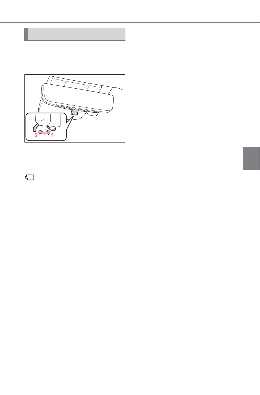
193
4-4. Adjusting the steering wheel and mirrors
Owner’s Manual_USA_M6740B_en
4
Before driving
Operate the lever to change
between digital mirror mode and
optical mirror mode.
1 Digital mirror mode
Displays an image of the area
behind the vehicle.
will illuminate in this mode.
2 Optical mirror mode
Turns off the display of the Digital
inner mirror allows it to be used as
an optical mirror.
■ Digital mirror mode operating
condition
The power switch is turned to ON.
When the power switch is changed
from ON to OFF or ACC, the image
will disappear after several seconds.
■ When using the Digital inner
mirror in digital mirror mode
● If it is difficult to see the Digital
inner mirror image because water,
snow, mud, etc. is stuck to the
camera lens, operate the Digital
inner mirror camera washer
(P.253) or change to optical mir-
ror mode.
● When the back door is open, the
Digital inner mirror image may not
display properly. Before driving,
make sure the back door is
closed.
● If the display is difficult to see due
to reflected light, close the elec-
tronic sunshade for the panoramic
moon roof (if equipped).
● Any of the following conditions
may occur when driving in the
dark, such as at night. None of
them indicates that a malfunction
has occurred.
• Colors of objects in the displayed
image may differ from their actual
color.
• Depending on the height of the
lights of the vehicle behind, the
area around the vehicle may
appear white and blurry.
• Automatic image adjustment for
brighter surrounding image may
cause flickering.
If it is difficult to see the displayed
image or flickering bothers you,
change to optical mirror mode.
● The Digital inner mirror may
become hot while it is in digital
mirror mode.
This is not a malfunction.
● Depending on your physical con-
dition or age, it may take longer
than usual to focus on the dis-
played image. In this case,
change to optical mirror mode.
● Do not let passengers stare at the
displayed image when the vehicle
is being driven, as doing so may
cause motion sickness.
■ When the system malfunctions
If the symbol shown in the illustra-
tion is displayed when using the
Digital inner mirror in digital mirror
mode, the system may be malfunc-
tioning. The symbol will disappear in
a few seconds. Operate the lever,
change to optical mirror mode and
have the vehicle inspected by your
SUBARU dealer.
Changing modes
SOLTERRA_OM_USA_A6740BE.book 193 ページ 2025年5月23日 金曜日 午後1時18分
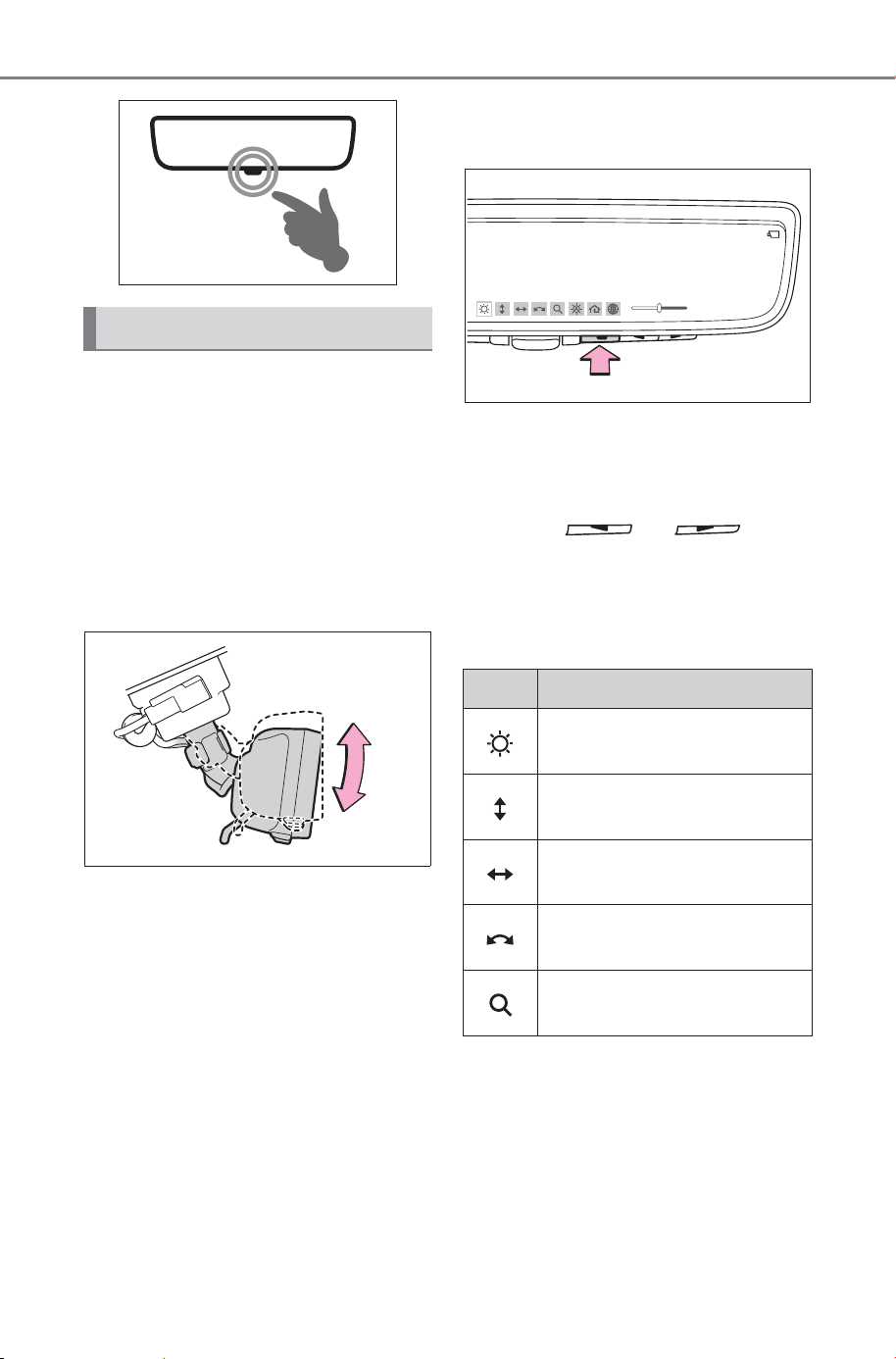
194
4-4. Adjusting the steering wheel and mirrors
Owner’s Manual_USA_M6740B_en
■ Adjusting the mirror height
The height of the rear view mir-
ror can be adjusted to suit your
driving posture.
Change to optical mirror mode,
adjusting the height of the rear
view mirror by moving it up and
down.
■ Display settings (digital mir-
ror mode)
Settings of the display in the dig-
ital mirror mode, on/off operation
of the automatic anti-glare func-
tion, etc. can be changed.
1 Press the menu button.
The icons will be displayed.
2 Press the menu button
repeatedly and select the
item you want to adjust.
3 Press or to
change the setting.
The icons will disappear if a button
is not operated for approximately 5
seconds or more.
Adjusting the mirror
Icons Settings
Select to adjust the bright-
ness of the display.
Select to adjust the area
displayed up/down.
Select to adjust the area
displayed to the left/right.
Select to adjust the angle of
the displayed image.
Select to zoom in/out the
displayed image.
SOLTERRA_OM_USA_A6740BE.book 194 ページ 2025年5月23日 金曜日 午後1時18分
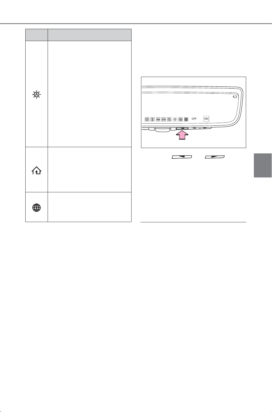
195
4-4. Adjusting the steering wheel and mirrors
Owner’s Manual_USA_M6740B_en
4
Before driving
*
: This is a function for the optical
mirror mode, however, the setting
can also be changed while using
the digital mirror mode.
■ Enabling/disabling the
automatic anti-glare func-
tion (optical mirror mode)
The automatic anti-glare func-
tion in the optical mirror mode
can be enabled/disabled. The
setting can be changed in both
the digital mirror mode and the
optical mirror mode.
When using the digital mirror
mode
P. 1 94
When using the optical mirror
mode
1 Press the menu button.
The setting display will be dis-
played.
2 Press or to
enable (“ON”)/disable
(“OFF”) the automatic anti-
glare function.
The icons will disappear if a button
is not operated for approximately 5
seconds or more.
■ Adjusting the display (digital
mirror mode)
● The icons will disappear if a button
is not operated for approximately
5 seconds or more.
● If the displayed image is adjusted,
it may appear distorted. This is not
a malfunction.
● If the brightness of the Digital
inner mirror is set too high, it may
cause eye strain. Adjust the Digi-
tal inner mirror to an appropriate
brightness. If your eyes become
tired, change to optical mirror
mode.
● The brightness of the Digital inner
mirror will change automatically
according to the brightness of the
area in front of your vehicle.
Select to enable/disable the
automatic anti-glare func-
tion.
*
Responding to the bright-
ness of the headlights of
vehicles behind, the
reflected light is automati-
cally adjusted.
The automatic anti-glare
function is enabled each
time the power switch is
changed to ON.
Select to display Home-
Link
®
Training Tutorial to
assist customers to train
their Garage Door Opener
System. (P.539)
Select to change the lan-
guage of the Homelink
®
Training Tutorial.
Icons Settings
SOLTERRA_OM_USA_A6740BE.book 195 ページ 2025年5月23日 金曜日 午後1時18分
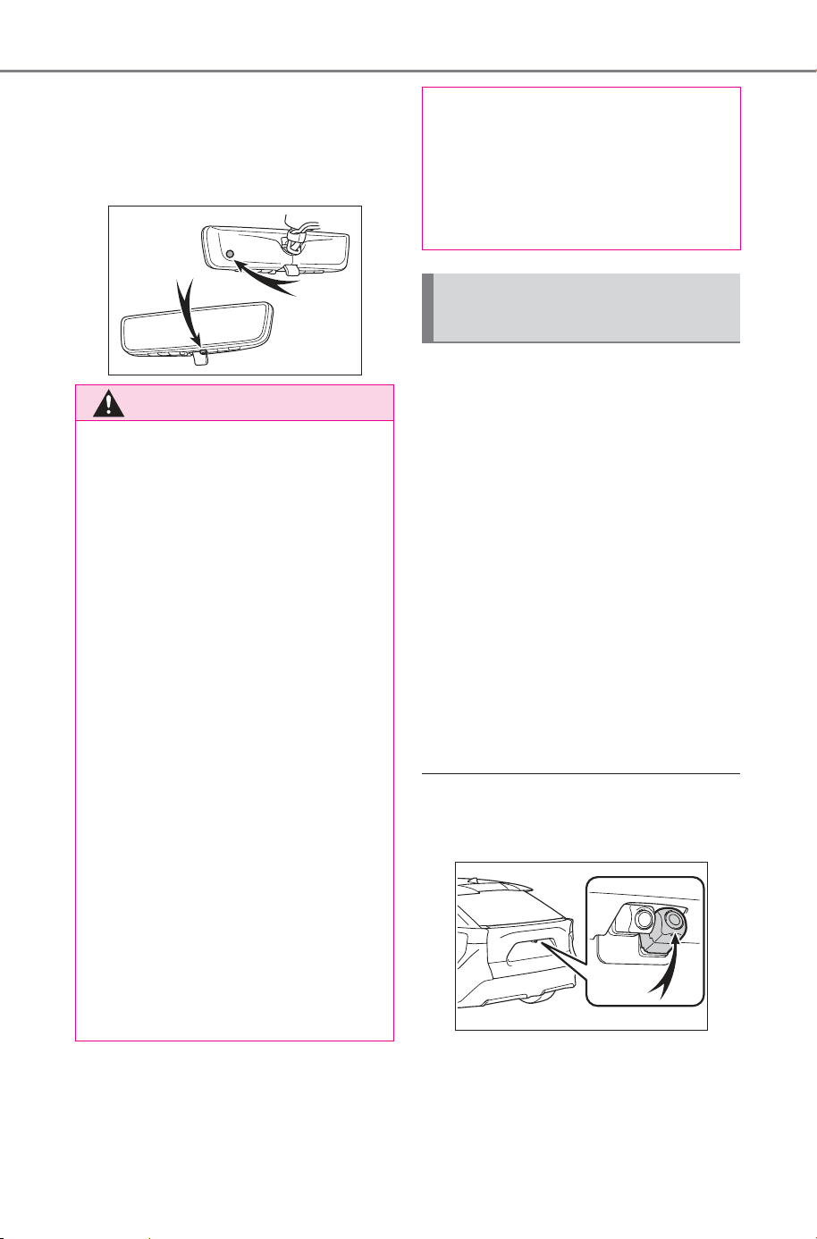
196
4-4. Adjusting the steering wheel and mirrors
Owner’s Manual_USA_M6740B_en
■ To prevent the light sensors
from malfunctioning
To prevent the light sensors from
malfunctioning, do not touch or
cover them.
■ Cleaning the mirror surface
If the mirror surface is dirty, the
image on the display may be dif-
ficult to see.
Clean the mirror surface gently
using a soft dry cloth.
■ Cleaning the camera
If it is difficult to see the Digital
inner mirror image because
water, snow, mud, etc. is stuck
to the camera lens, operate the
Digital inner mirror camera
washer or change to optical mir-
ror mode. (P.253)
■ The camera
The camera for the Digital inner mir-
ror is located as shown.
■ Cleaning the camera with
washer fluid
● When cleaning the camera, it may
be difficult to see the image due to
the washer fluid. Therefore, take
care in the surrounding area while
WARNING
Observe the following precau-
tions. Failure to do so may result
in death or serious injury.
■ While driving
● Do not adjust the position of the
Digital inner mirror or adjust the
display settings while driving.
Stop the vehicle and operate
the Digital inner mirror control
switches.
Failure to do so may cause a
steering wheel operation error,
resulting in an unexpected acci-
dent.
● Always pay attention to the
vehicle’s surroundings.
The size of the vehicles and other
objects may look different when in
digital mirror mode and optical
mirror mode.
When backing up, make sure to
directly check the safety of the
area around your vehicle, espe-
cially behind the vehicle.
Additionally, if a vehicle
approaches from the rear in the
dark, such as at night, the sur-
rounding area may appear dim.
■ To prevent causes of fire
If the driver continues using the
Digital inner mirror while smoke or
odor comes from the mirror, it
may result in fire. Stop using the
system immediately and contact
your SUBARU dealer.
Cleaning the Digital inner
mirror
SOLTERRA_OM_USA_A6740BE.book 196 ページ 2025年5月23日 金曜日 午後1時18分
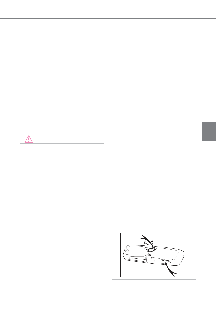
197
4-4. Adjusting the steering wheel and mirrors
Owner’s Manual_USA_M6740B_en
4
Before driving
driving.
● If washer fluid remains on the
camera lens surface after clean-
ing, the image may be difficult to
see at night due to the height or
inclination of the headlights of the
vehicle behind. In this case,
change to optical mirror mode.
● Some dirts may not be removed
completely after cleaning. In this
case, rinse the camera lens with a
large quantity of water and then
wipe it clean with a soft cloth
dampened with water.
● Washer fluid is sprayed onto the
camera lens surface. Therefore,
the ice, snow, etc. adhering
around the camera cannot be
removed.
NOTICE
■ To prevent the Digital inner
mirror from malfunctioning
● Do not use detergents, such as
thinner, benzene, and alcohol to
clean the mirror. They may dis-
color, deteriorate or damage the
mirror surface.
● Do not smoke, use matches,
use cigarette lighters or allow
open flames near the mirror. It
may damage the mirror or
cause a fire.
● Do not remove, disassemble or
modify the mirror.
■ To prevent the camera from
malfunctioning
● Observe the following precau-
tions, otherwise the Digital inner
mirror may not operate properly.
• Do not strike or hit the camera
or subject it to a strong impact,
as the camera installation posi-
tion and angle may be changed.
• Do not remove, disassemble or
modify the camera.
• When washing the camera,
rinse it with a large quantity of
water and then wipe it clean
with a soft cloth dampened with
water.
Do not strongly rub the camera
lens, as it may be scratched and
will not be able to transmit a
clear image.
• Do not allow organic solvent,
car wax, window cleaner or
glass coat to adhere to the cam-
era cover. If this happens, wipe
it off as soon as possible.
• Do not apply hot water to the
camera in cold weather, as the
sudden change of temperature
may cause the camera to not
operate properly.
• When using a high pressure
washer to wash the vehicle, do
not directly spray the camera
and its surrounding area, as
doing so may cause the camera
to not operate properly.
● Do not subject the camera to a
strong impact as this could
cause a malfunction.
If this happens, have the vehicle
inspected by your SUBARU
dealer as soon as possible.
● Do not block the vent holes of
the mirror. Otherwise, the mirror
may be hot, leading to a mal-
function or a fire.
SOLTERRA_OM_USA_A6740BE.book 197 ページ 2025年5月23日 金曜日 午後1時18分
198
4-4. Adjusting the steering wheel and mirrors
Owner’s Manual_USA_M6740B_en
If you notice any of the following symptoms, refer to the following
table for the likely cause and the solution.
If the symptom is not resolved by the solution, have the vehicle
inspected by your SUBARU dealer.
If you notice any symptoms
Symptom Likely cause Solution
The image is
difficult to see.
The mirror surface is dirty.
Clean the mirror surface
gently, using a soft dry
cloth.
Sunlight or headlights are shin-
ing directly into the Digital inner
mirror.
Change to optical mirror
mode.
(If the light is coming
through the panoramic
moon roof [if equipped],
close the electronic sun-
shade.)
• The vehicle is in a dark area.
• The vehicle is near a TV
tower, broadcasting station,
electric power plant, or other
location where strong radio
waves or electrical noise may
be present.
• The temperature around the
camera is extremely high/low.
• The ambient temperature is
extremely low.
• It is raining or humid.
• Sunlight or headlights are
shining directly into the cam-
era lens.
• The vehicle is under fluores-
cent lights, sodium lights,
mercury lights, etc.
Change to optical mirror
mode.
(Change back to digital
mirror mode when the
conditions have
improved.)
Foreign matters such as water
droplets or dust is on the cam-
era lens.
• Operate the dedicated
camera cleaning
washer and clean the
camera lens. (P.253)
• Change to optical mirror
mode.
SOLTERRA_OM_USA_A6740BE.book 198 ページ 2025年5月23日 金曜日 午後1時18分
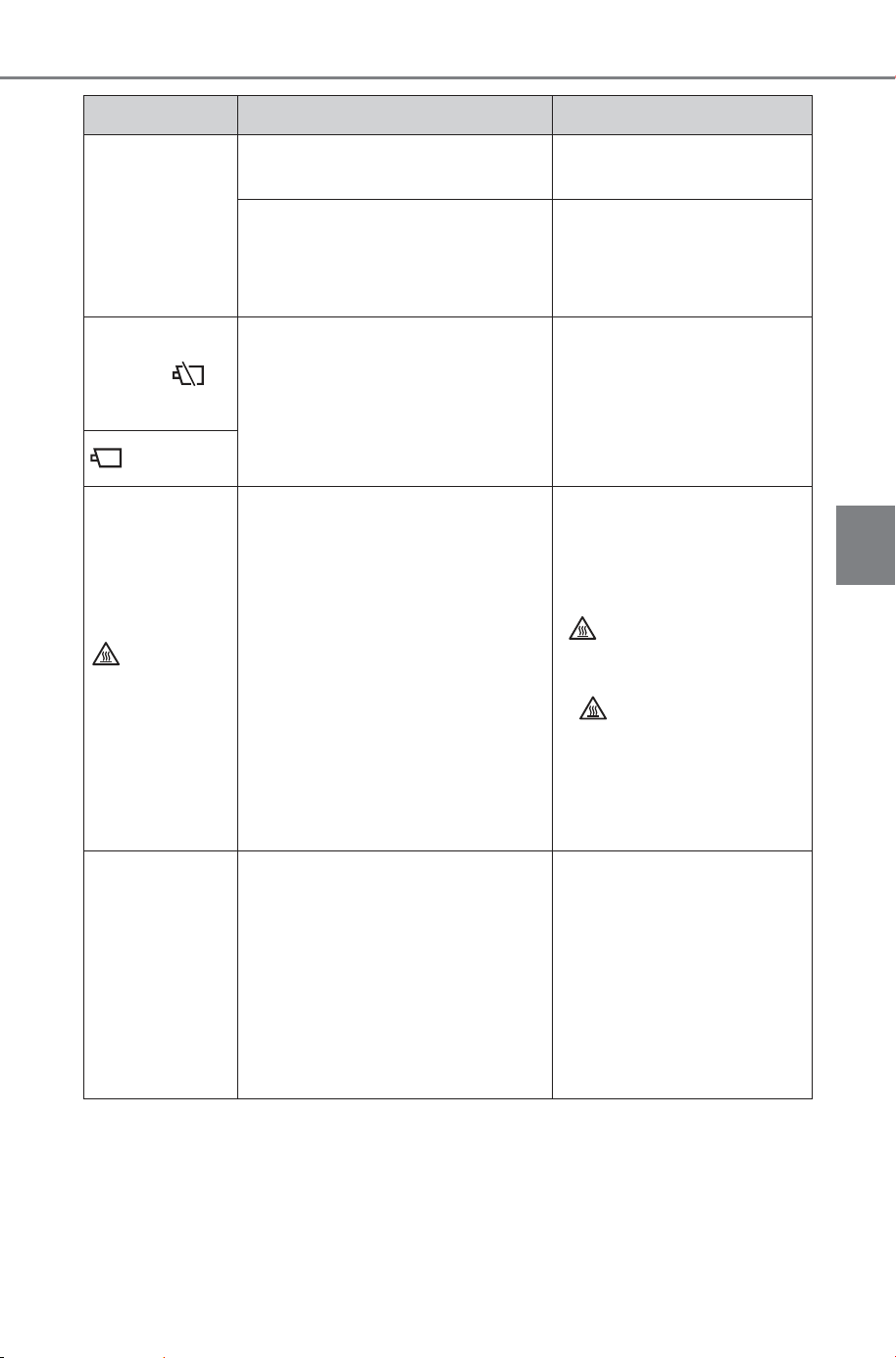
199
4-4. Adjusting the steering wheel and mirrors
Owner’s Manual_USA_M6740B_en
4
Before driving
The image is
out of align-
ment.
The back door is not fully
closed.
Fully close the back door.
The camera or its surrounding
area has received a strong
impact.
Change to optical mirror
mode and have the vehi-
cle inspected by your
SUBARU dealer.
The display is
dim and is
displayed.
The system may be malfunc-
tioning.
Change to optical mirror
mode and have the vehi-
cle inspected by your
SUBARU dealer.
goes off.
is dis-
played.
The Digital inner mirror is
extremely hot.
(The display will gradually
become more dim. If the tem-
perature continues to increase,
the Digital inner mirror will turn
off.)
Reducing the cabin tem-
perature is recom-
mended to reduce the
temperature of the mirror.
( will disappear when
the mirror becomes cool.)
If does not disappear
even though the mirror is
cool, have the vehicle
inspected by your SUB-
ARU dealer.
The lever can-
not be oper-
ated properly.
The lever may be malfunction-
ing.
Change to optical mirror
mode and have the vehi-
cle inspected by your
SUBARU dealer.
(To change to optical mir-
ror mode, press and hold
the menu button for
approximately 10 sec-
onds.)
Symptom Likely cause Solution
SOLTERRA_OM_USA_A6740BE.book 199 ページ 2025年5月23日 金曜日 午後1時18分
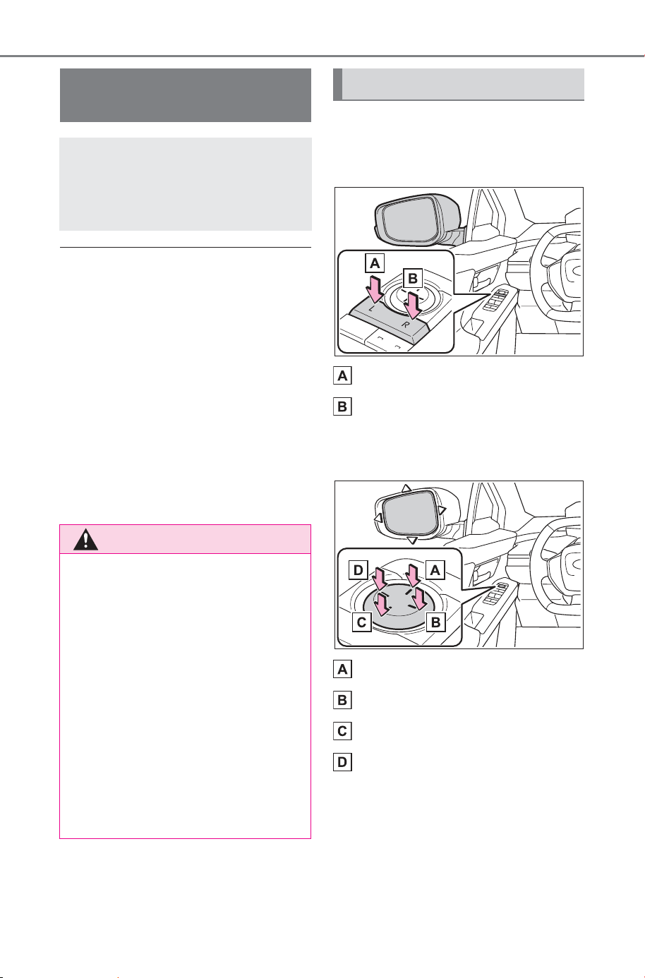
200
4-4. Adjusting the steering wheel and mirrors
Owner’s Manual_USA_M6740B_en
■ When using the outside rear
view mirrors in a cold weather
When it is cold and the outside rear
view mirrors are frozen, it may not
be possible to fold/extend them or
adjust the mirror surface. Remove
the ice, snow, etc. covering the out-
side rear view mirrors.
■ Defogging the mirrors
The outside rear view mirrors can
be cleared using the mirror defog-
gers. Turn on the rear window
defogger to turn on the outside rear
view mirror defoggers.
(P.496)
Type A
1 To select a mirror to adjust,
press the switch.
Left
Right
2 To adjust the mirror, press
the switch.
Up
Right
Down
Left
Outside rear view mir-
rors
The rear view mirror’s posi-
tion can be adjusted to
enable sufficient confirma-
tion of the rear view.
WARNING
■ Important points while driving
Observe the following precautions
while driving.
Failing to do so may result in loss
of control of the vehicle and cause
an accident, resulting in death or
serious injury.
● Do not adjust the mirrors while
driving.
● Do not drive with the mirrors
folded.
● Both the driver and passenger
side mirrors must be extended
and properly adjusted before
driving.
Adjustment procedure
SOLTERRA_OM_USA_A6740BE.book 200 ページ 2025年5月23日 金曜日 午後1時18分
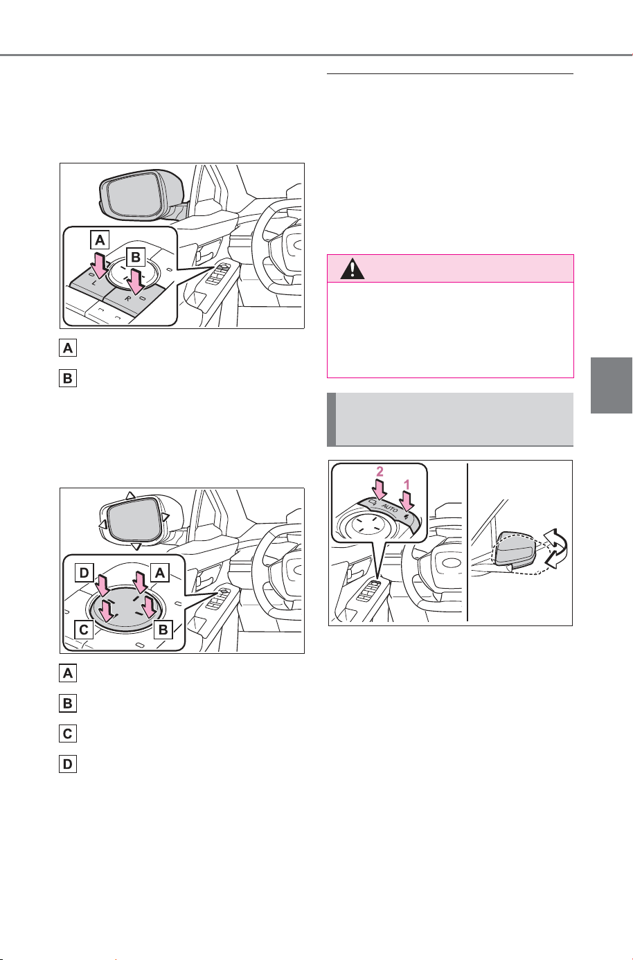
201
4-4. Adjusting the steering wheel and mirrors
Owner’s Manual_USA_M6740B_en
4
Before driving
Type B
1 When selecting the mirror to
adjust, the indicator on the
switch illuminates.
Left
Right
Pressing the same switch again will
put the switch in neutral.
2 To adjust the mirror, press
the switch.
Up
Right
Down
Left
■ Mirror angle can be adjusted
when
The power switch is in ACC or ON.
■ Automatic adjustment of the
mirror angle (if equipped)
A desired mirror face angle can be
entered to memory and recalled
automatically by the driving position
memory. (P.207)
1 Fold
2 Extend
Putting the outside rear view
mirror folding switch in the neu-
tral position sets the mirrors to
automatic mode. Automatic
mode allows the folding or
extending of the mirrors to be
linked to locking/unlocking of the
doors.
WARNING
■ When the mirror defoggers
are operating
Do not touch the rear view mirror
surfaces, as they can become
very hot and burn you.
Folding and extending the
mirrors (Type A)
SOLTERRA_OM_USA_A6740BE.book 201 ページ 2026年1月6日 火曜日 午後2時47分
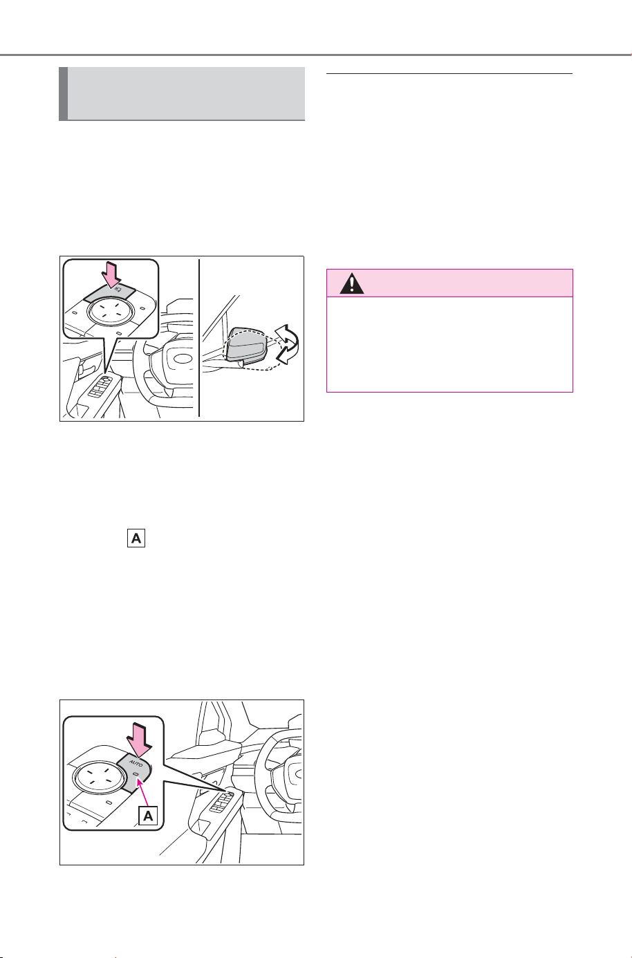
202
4-4. Adjusting the steering wheel and mirrors
Owner’s Manual_USA_M6740B_en
■ Using the switch
Press the switch to fold the mir-
rors.
Press it again to extend them to
the original position.
■ Setting automatic mode
Press the “AUTO” switch to set
automatic mode.
When in automatic mode, the
indicator will come on.
Automatic mode allows the fold-
ing or extending of the mirrors to
be linked to locking/unlocking of
the doors.
Pressing the switch once more
will return to manual mode.
■ When disconnecting and recon-
necting 12-volt battery termi-
nals
The automatic folding/extending
mirror function will return to off as
default. To turn the function on,
press the switch again to select on.
■ Customization
Some functions can be customized.
(Customizable features: P.676)
Folding and extending the
mirrors (Type B)
WARNING
■ When a mirror is moving
To avoid personal injury and mir-
ror malfunction, be careful not to
get your hand caught by the mov-
ing mirror.
SOLTERRA_OM_USA_A6740BE.book 202 ページ 2025年5月23日 金曜日 午後1時18分

203
4-4. Adjusting the steering wheel and mirrors
Owner’s Manual_USA_M6740B_en
4
Before driving
When the mirror select switch is
in the “L” or “R” position, the out-
side rear view mirrors will auto-
matically angle downwards
when the vehicle is reversing in
order to give a better view of the
ground.
To disable this function, move
the mirror select switch to the
neutral position (between “L” or
“R”)
■ Adjusting the mirror angle
when the vehicle is revers-
ing
With the shift position in R,
adjust the mirror angle at a
desired position.
The adjusted angle will be mem-
orized and the mirror will auto-
matically tilt to the memorized
angle whenever the shift posi-
tion is shifted to R from next
time.
The memorized downward tilt posi-
tion of the mirror is linked to the
normal position (angle adjusted
with the shift position in other than
R). Therefore, if the normal position
is changed after adjustment, the tilt
position will also change.
When the normal position is
changed, readjust the angle in
reversing.
Linked mirror function
when reversing (If
equipped)
SOLTERRA_OM_USA_A6740BE.book 203 ページ 2025年5月23日 金曜日 午後1時18分
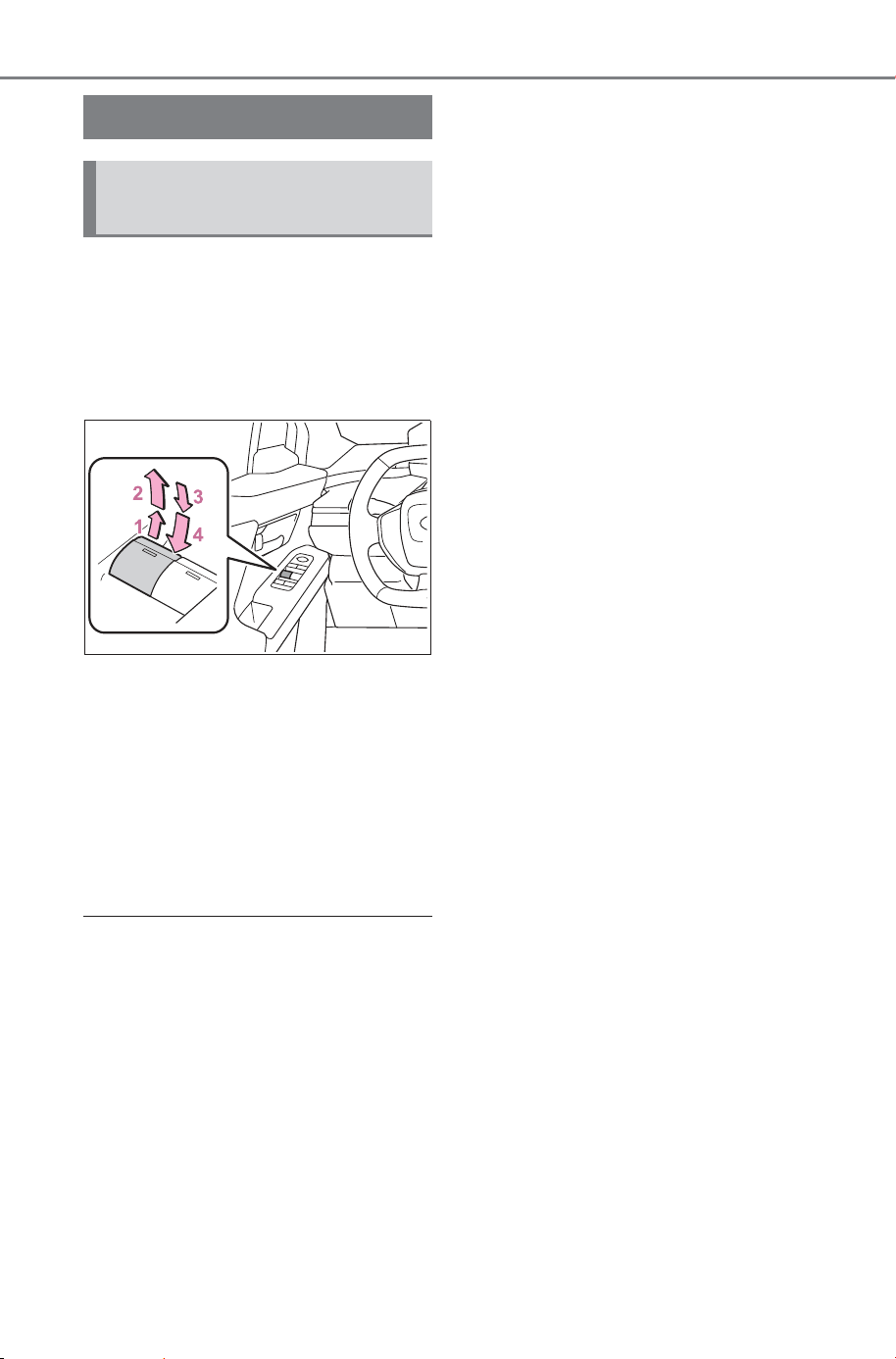
204
4-5. Opening, closing the windows
Owner’s Manual_USA_M6740B_en
4-5.Opening, closing the windows
The power windows can be
opened and closed using the
switches.
Operating the switch moves the
side windows as follows:
1 Closing
2 One-touch closing
*
3 Opening
4 One-touch opening
*
*
: To stop the side window partway,
operate the switch in the opposite
direction.
■ The power windows can be
operated when
The power switch is in ON.
■ Operating the power windows
after turning the EV system off
The power windows can be oper-
ated for approximately 45 seconds
even after the power switch is
turned to ACC or OFF. They cannot,
however, be operated once either
front door is opened.
■ Jam protection function
If an object becomes jammed
between the side window and the
window frame while the side window
is closing, side window movement is
stopped and the side window is
opened slightly.
■ Catch protection function
If an object becomes caught
between the door and side window
while the side window is opening,
side window movement is stopped.
■ When the power window cannot
be opened or closed
When the jam protection function or
catch protection function operates
unusually and the side window can-
not be opened and closed, perform
the following operations with the
power window switch of that door.
● Stop the vehicle. With the power
switch in ON, within 4 seconds of
the jam protection function or
catch protection function activat-
ing, continuously operate the
power window switch in the one-
touch closing direction or one-
touch opening direction so that the
side window can be opened and
closed.
● If the side window cannot be
opened and closed even when
performing the above operations,
perform the following procedure
for function initialization.
1 Turn the power switch to ON.
2 Pull and hold the power window
switch in the one-touch closing
direction and completely close
the side window.
3 Release the power window
switch for a moment, resume
pulling the switch in the one-
touch closing direction, and hold
it there for approximately 6 sec-
onds or more.
Power windows
Opening and closing the
power windows
SOLTERRA_OM_USA_A6740BE.book 204 ページ 2025年5月23日 金曜日 午後1時18分
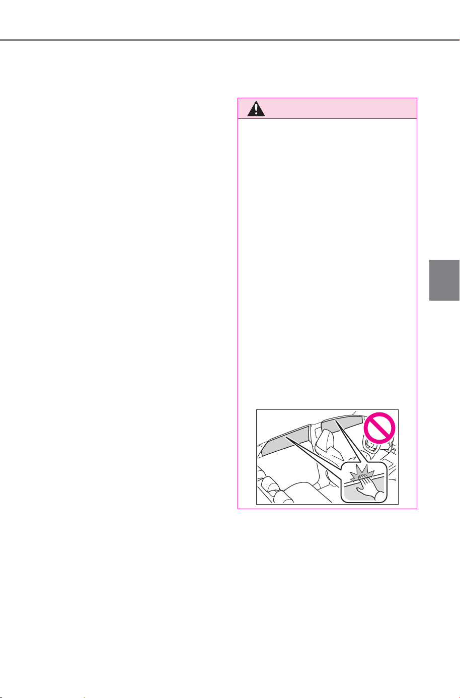
205
4-5. Opening, closing the windows
Owner’s Manual_USA_M6740B_en
4
Before driving
4 Press and hold the power win-
dow switch in the one-touch
opening direction. After the side
window is completely opened,
continue holding the switch for
an additional 1 second or more.
5 Release the power window
switch for a moment, resume
pushing the switch in the one-
touch opening direction, and
hold it there for approximately 4
seconds or more.
6 Pull and hold the power window
switch in the one-touch closing
direction again. After the side
window is completely closed,
continue holding the switch for a
further 1 second or more.
If you release the switch while the
side window is moving, start again
from the beginning.
If the side window reverses and
cannot be fully closed or opened,
have the vehicle inspected by your
SUBARU dealer.
■ Door lock linked power window
operation
● The power windows can be
opened and closed using the
mechanical key.
*
(P.642)
● The power windows can be
opened using the wireless remote
control.
*
(P.159)
● The alarm may be triggered if the
alarm is set and the power window
is closed using the door lock
linked power window operation
function. (P. 66)
*
: These settings must be custom-
ized at your SUBARU dealer.
■ Power window open reminder
function
The buzzer sounds and a message
is shown on the multi-information
display when the power switch is
turned to OFF and the driver’s door
is opened with the power windows
open.
■ Customization
Some functions can be customized.
(Customizable features: P.676)
WARNING
Observe the following precau-
tions.
Failing to do so may result in
death or serious injury.
■ Closing the power windows
● The driver is responsible for all
the power window operations,
including the operation for the
passengers. In order to prevent
accidental operation, especially
by a child, do not let a child
operate the power windows. It is
possible for children and other
passengers to have body parts
caught in the power window.
Also, when riding with a child, it
is recommended to use the win-
dow lock switch. (P.206)
● Check to make sure that all pas-
sengers do not have any part of
their body in a position where it
could be caught when a power
window is being operated.
SOLTERRA_OM_USA_A6740BE.book 205 ページ 2025年5月23日 金曜日 午後1時18分
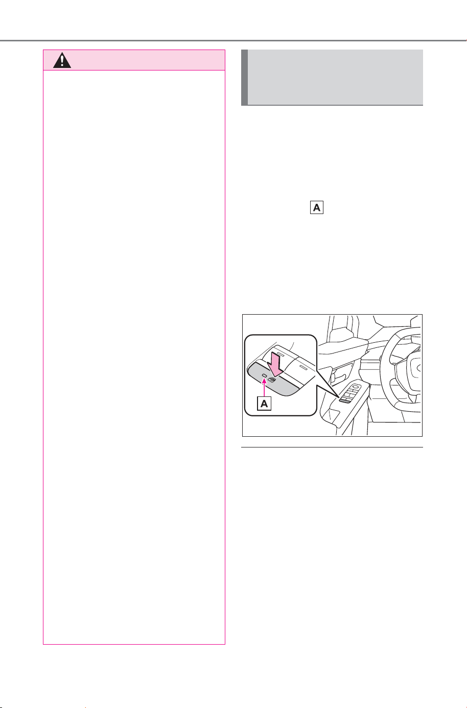
206
4-5. Opening, closing the windows
Owner’s Manual_USA_M6740B_en
This function can be used to
prevent children from acciden-
tally opening or closing a pas-
senger window.
Press the switch.
The indicator will come on and
the passenger windows will be
locked.
The passenger windows can still be
opened and closed using the
driver’s switch even if the lock
switch is on.
■ The window lock switch can be
operated when
The power switch is in ON.
■ When the 12-volt battery is dis-
connected
The window lock switch is disabled.
If necessary, press the window lock
switch after reconnecting the 12-volt
battery.
WARNING
● When using the wireless remote
control or mechanical key and
operating the power windows,
operate the power window after
checking to make sure that
there is no possibility of any
passenger having any of their
body parts caught in the side
window. Also, do not let a child
operate the power window by
the wireless remote control or
mechanical key. It is possible for
children and other passengers
to get caught in the power win-
dow.
● When exiting the vehicle, turn
the power switch to OFF, carry
the key and exit the vehicle
along with the child. There may
be accidental operation, due to
mischief, etc., that may possibly
lead to an accident.
■ Jam protection function
● Never use any part of your body
to intentionally activate the jam
protection function.
● The jam protection function may
not work if something gets
jammed just before the side
window is fully closed. Be care-
ful not to get any part of your
body jammed in the side win-
dow.
■ Catch protection function
● Never use any part of your body
or clothing to intentionally acti-
vate the catch protection func-
tion.
● The catch protection function
may not work if something gets
caught just before the side win-
dow is fully opened. Be careful
not to get any part of your body
or clothing caught in the side
window.
Preventing accidental
operation (window lock
switch)
SOLTERRA_OM_USA_A6740BE.book 206 ページ 2025年5月23日 金曜日 午後1時18分
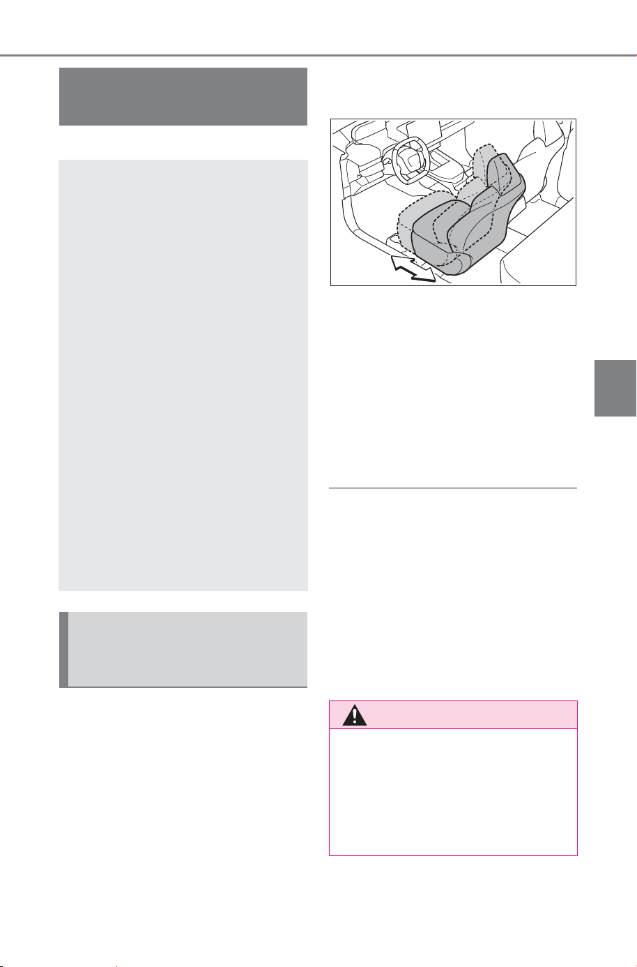
207
4-6. Favorite settings
Owner’s Manual_USA_M6740B_en
4
Before driving
4-6.Favorite settings
*
: If equipped
When all of the following have
been performed, the driver’s
seat is automatically adjusted to
a position that allows driver to
enter and exit the vehicle easily.
The shift position has been
shifted to P.
The power switch has been
turned to OFF.
The driver’s seat belt has
been unfastened.
When any of the following has
been performed, the driver’s
seat automatically return to it
original position.
The power switch has been
turned to ACC or ON.
The driver’s seat belt has
been fastened.
■ Operation of the power easy
access system
When exiting the vehicle, the power
easy access system may not oper-
ate if the seat is already close to the
rearmost position, etc.
■ Customization
The seat movement amount set-
tings of the power easy access sys-
tem can be customized.
(Customizable features: P.676)
Driving position mem-
ory
*
This feature automatically
adjusts the positions of the
driver’s seat and outside
rear view mirrors to make
entering and exiting the
vehicle easier or to suit
your preferences.
Driving positions can be
recorded for 3 drivers that
has been registered for My
Settings.
When electronic key assign-
ment is registered for My
Settings, the driving posi-
tion for each driver can be
recalled (memory recall
function).
For details about My Set-
tings, please refer to P.210.
Enabling easier driver
entry and exit (power easy
access system)
WARNING
■ While the power easy access
system is operating the seat
is moving
Be careful not to get body parts or
luggage caught. Failure to do so
may cause an injury or damage to
the luggage.
SOLTERRA_OM_USA_A6740BE.book 207 ページ 2025年5月23日 金曜日 午後1時18分
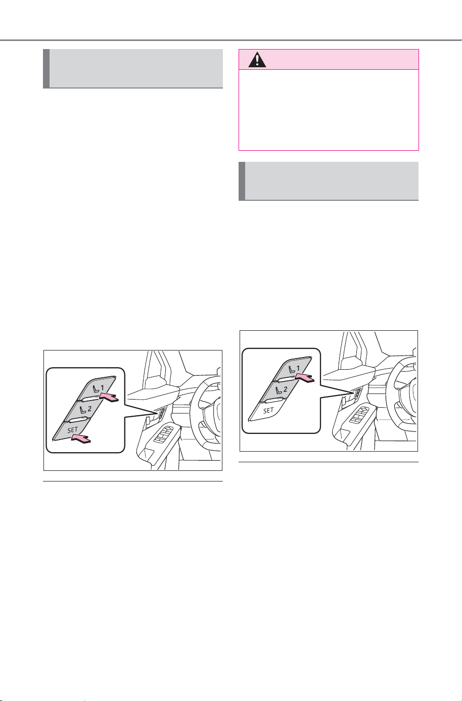
208
4-6. Favorite settings
Owner’s Manual_USA_M6740B_en
■ Recording procedure
1 Check that the shift position
is in P.
2 Turn the power switch to ON.
3 Adjust the driver’s seat and
outside rear view mirrors to
the desired positions.
4 While pressing the “SET” but-
ton, or within 3 seconds after
the “SET” button is pressed,
press button “1” or “2” until
the buzzer sounds.
If the selected button has already
been preset, the previously
recorded position will be overwrit-
ten.
■ Seat position that can be mem-
orized (P.183)
The adjusted positions other than
the position adjusted by lumbar sup-
port switch can be recorded.
■ In order to correctly use the
driving position memory func-
tion
If a seat position is already in the
furthest possible position and the
seat is operated in the same direc-
tion, the recorded position may be
slightly different when it is recalled.
1 Check that the shift position
is in P.
2 Turn the power switch to ON.
3 Press one of the buttons for
the driving position you want
to recall until the buzzer
sounds.
■ To stop the position recall oper-
ation part-way through
Perform any of the following:
● Press the “SET” button.
● Press button “1” or “2”.
● Operate any of the seat adjust-
ment switches.
■ Using the voice control system
(if equipped)
The following operations can be
performed using the voice control
system:
● Driving position registration
Recording a driving posi-
tion into memory button
WARNING
■ Seat adjustment caution
Take care during seat adjustment
so that the seat does not strike
the rear passenger or squeeze
your body against the steering
wheel.
Recalling a driving posi-
tion
SOLTERRA_OM_USA_A6740BE.book 208 ページ 2025年5月23日 金曜日 午後1時18分

209
4-6. Favorite settings
Owner’s Manual_USA_M6740B_en
4
Before driving
● Driving position recall (only when
the shift position is in P)
For details, refer to the “MULTIME-
DIA OWNER’S MANUAL”.
■ Operating the driving position
memory after turning the power
switch to OFF
Recorded seat positions can be
activated up to 180 seconds after
the driver’s door is opened and
another 60 seconds after it is closed
again.
■ When recalling the driving posi-
tion
Take care so that a head restraint
does not contact the ceiling or a sun
visor.
■ If the 12-volt battery is discon-
nected
The memorized positions are
erased.
■ When the recorded seat posi-
tion cannot be recalled
The seat position may not be
recalled in some situations when the
seat position is recorded in a certain
range. For details, contact your
SUBARU dealer.
■ Jam protection function
While the driving position is recalled
or the power easy access system is
operating, if an object is stuck
behind the front seat, the front seat
will stop and then slightly move for-
ward. When the jam protection func-
tion operates, the seat stops at a
position other than the set seat posi-
tion. Check the seat position.
■ When an individual is iden-
tified using My Settings:
The driving positions can be
automatically recalled for each
driver registered in My Settings.
(P.210)
Driving position registration
procedure
When the shift position is shifted to
P after driving the vehicle, the cur-
rent driving position will be
recorded.
Driving position recall proce-
dure
1 Carry only the key that has
been assigned and regis-
tered in My Settings, and
then unlock and open the
driver’s door using the smart
key system or wireless
remote control.
The driving position will move to the
recorded position.
If the driving position is in a position
that has already been recorded, the
seat will not move.
2 Turn the power switch to
ACC or ON.
The seat will move to the recorded
position.
Recalling a driving posi-
tion automatically when
getting in the vehicle
(memory recall function)
(driver’s seat only)
SOLTERRA_OM_USA_A6740BE.book 209 ページ 2025年5月23日 金曜日 午後1時18分

210
4-6. Favorite settings
Owner’s Manual_USA_M6740B_en
Memory recall function can-
celation procedure
How to cancel the memory call
function varies depending on the
authentication device.
For details, refer to the “MULTIME-
DIA OWNER’S MANUAL”.
■ Recalling the driving position
using the memory recall func-
tion
● The timing of operation may differ
depending on the device used to
identify an individual.
● As a driving position can be regis-
tered to each electronic key, if 2 or
more keys are carried, the recall
driving position may different.
My Settings
Drivers are identified using
devices such as electronic
keys to store the driving
position and vehicle set-
tings for each. Then the
information can be recalled
the next time the vehicle is
driven.
Authentication devices can
be assigned in advance to
drivers so that they can
drive using their preferred
settings.
Settings for 3 drivers can be
stored in My Settings.
For information on authenti-
cation devices registra-
tion/deletion, changing the
driver’s name, initializing
driver registered settings,
manually switching drivers
and deleting drivers regis-
tration, refer to the “MULTI-
MEDIA OWNER’S
MANUAL”.
SOLTERRA_OM_USA_A6740BE.book 210 ページ 2025年5月23日 金曜日 午後1時18分
211
4-6. Favorite settings
Owner’s Manual_USA_M6740B_en
4
Before driving
An individual can be identified
using the following authentica-
tion devices.
Electronic key
An individual is identified when the
smart key system detects their
electronic key.
Face identification
Individuals are identified by detect-
ing the face from the driver monitor.
Bluetooth
®
devices
An individual can be identified if the
same Bluetooth
®
device that was
used as a hands-free phone the
last time the vehicle was entered is
connected to the multimedia sys-
tem.
For information on how to connect
Bluetooth
®
devices, refer to the
“MULTIMEDIA OWNER’S MAN-
UAL”.
If an individual is identified by
detecting an electronic key, identifi-
cation by Bluetooth
®
device will not
be performed.
When an individual is identified
from an authentication device,
settings for the following func-
tions are recalled.
Driving position (memory
recall function)
*1
After an individual is identified, the
driving position that was set when
driving was last completed is
recalled when the either of follow-
ing operations is performed.
Identification using electronic key:
The driver’s door is unlocked and
opened using the smart key system
or wireless remote control.
Vehicle settings that can be
set using the multimedia dis-
play
*2
When an individual is identified, the
vehicle settings used when the
power switch was last turned off are
recalled.
Safe driving support func-
tion
*2
When an individual is identified, the
vehicle settings used when the
power switch was last turned off are
recalled.
*1
:If equipped
*2
:Some settings are excluded
Types of assigned
authentication devices
Recalled functions
SOLTERRA_OM_USA_A6740BE.book 211 ページ 2025年5月23日 金曜日 午後1時18分

212
4-6. Favorite settings
Owner’s Manual_USA_M6740B_en
SOLTERRA_OM_USA_A6740BE.book 212 ページ 2025年5月23日 金曜日 午後1時18分

213
Owner’s Manual_USA_M6740B_en
5
5
Driving
Driving
5-1. Before driving
Driving the vehicle.......
215
Cargo and luggage ..... 222
Vehicle load limits ....... 227
Trailer towing............... 228
Dinghy towing ............. 228
5-2. Driving procedures
Power (ignition) switch 229
Shift position ............... 233
Turn signal lever.......... 240
Parking brake.............. 241
Brake Hold .................. 245
5-3. Operating the lights and
wipers
Headlight switch..........
247
AHB (Automatic High
Beam)........................
249
Windshield wipers and
washer.......................
253
Headlight cleaner switch
..................................
256
5-4. Using the driving support
systems
SUBARU Safety
Sense/Traffic Jam Assist
software update.........
257
SUBARU Safety Sense259
Driver monitor.............. 267
PCS (Pre-Collision System)
..................................
270
LTA (Lane Tracing Assist)
..................................
282
LCA (Lane Change Assist)
..................................
287
LDA (Lane Departure Alert)
..................................
290
PDA (Proactive driving
assist)........................
295
FCTA (Front Cross Traffic
Alert)..........................
301
RSA (Road Sign Assist)
..................................
303
Dynamic radar cruise con-
trol .............................
306
SOLTERRA_OM_USA_A6740BE.book 213 ページ 2025年5月23日 金曜日 午後1時18分

214
Owner’s Manual_USA_M6740B_en
Cruise control.............. 317
Emergency Driving Stop
System ......................
321
Traffic Jam Assist ........ 324
BSM (Blind Spot Monitor)
..................................
330
Safe Exit Assist ........... 335
SUBARU Parking Assist
..................................
340
RCTA (Rear Cross Traffic
Alert) function............
351
RCD (Rear Camera Detec-
tion) ...........................
356
PKSB (Parking Support
Brake)........................
360
Parking Support Brake func-
tion (static objects front
and rear of the vehi-
cle/static objects around
the vehicle)................
365
Parking Support Brake func-
tion (moving vehicles rear
of the vehicle)............
370
Parking Support Brake func-
tion (pedestrians rear of
the vehicle)................ 371
Advanced Park............ 373
Multi-terrain Monitor .... 401
Drive mode select switch
..................................
470
Snow mode ................. 471
X-MODE...................... 471
Driving assist systems. 476
5-5. Driving tips
Winter driving tips........ 482
Utility vehicle precautions
..................................
485
SOLTERRA_OM_USA_A6740BE.book 214 ページ 2025年5月23日 金曜日 午後1時18分
215
5-1. Before driving
Owner’s Manual_USA_M6740B_en
5
Driving
5-1.Be fore driving
■ Before starting the EV sys-
tem
Check that the charging cable is
disconnected. (P.95, 100)
■ Starting the EV system
P. 2 29
■ Driving
1 With the brake pedal
depressed, shift the shift
position to D. (P.234)
Check that the shift position indica-
tor shows D.
2 If the parking brake is set,
release the parking brake.
(P.241)
If the parking brake is in automatic
mode, the parking brake will be
released automatically. (P.241)
3 Gradually release the brake
pedal and gently depress the
accelerator pedal to acceler-
ate the vehicle.
■ Stopping
1 Depress the brake pedal.
2 If necessary, set the parking
brake. (P.241)
If the vehicle is to be stopped for an
extended period of time, shift the
shift position to P. (P.234)
■ Parking the vehicle
1 Depress the brake pedal to
stop the vehicle completely.
2 If the parking brake is
released, set the parking
brake. (P.241)
Make sure the parking brake indi-
cator light is on.
3 Shift the shift position to P.
(P.234)
Check that the shift position indica-
tor shows P.
4 Press the power switch to
stop the EV system.
5 Slowly release the brake
pedal.
6 Lock the door, making sure
that you have the electronic
key on your person.
If parking on a hill, block the wheels
as needed.
■ Starting off on a steep
uphill
1 Firmly depress the brake
pedal and shift the shift posi-
tion to D.
The hill-start assist control will be
activated.
2 Set the parking brake.
(P.241)
3 Release the brake pedal and
gently depress the accelera-
tor pedal to accelerate the
vehicle.
4 Release the parking brake.
(P.241)
Driving the vehicle
The following procedures
should be observed to
ensure safe driving:
Driving procedure
SOLTERRA_OM_USA_A6740BE.book 215 ページ 2025年5月23日 金曜日 午後1時18分

216
5-1. Before driving
Owner’s Manual_USA_M6740B_en
■ When starting off on a uphill
The hill-start assist control will acti-
vate. (P.477)
■ Driving in the rain
● Drive carefully when it is raining,
because visibility will be reduced,
the windows may become fogged-
up, and the road will be slippery.
● Drive carefully when it starts to
rain, because the road surface will
be especially slippery.
● Refrain from high speeds when
driving on an expressway in the
rain, because there may be a
layer of water between the tires
and the road surface, preventing
the steering and brakes from
operating properly.
■ Restraining the EV system out-
put (Brake Override System)
● When the accelerator and brake
pedals are depressed at the same
time, the EV system output may
be restrained.
● A warning message is displayed
on the multi-information display
while the system is operating.
■ Breaking in your new SUBARU
To extend the life of the vehicle,
observing the following precautions
is recommended:
● For the first 200 miles (300 km):
Avoid sudden stops.
● For the first 600 miles (1000 km):
• Do not drive at extremely high
speeds.
• Avoid sudden acceleration.
• Do not drive at a constant speed
for extended periods.
WARNING
Observe the following precau-
tions.
Failure to do so may result in
death or serious injury.
■ When starting the vehicle
Always keep your foot on the
brake pedal while stopped with
the “READY” indicator is illumi-
nated. This prevents the vehicle
from creeping.
■ When driving the vehicle
● Do not drive if you are unfamil-
iar with the location of the brake
and accelerator pedals to avoid
depressing the wrong pedal.
• Accidentally depressing the
accelerator pedal instead of the
brake pedal will result in sudden
acceleration that may lead to an
accident.
• When backing up, you may twist
your body around, leading to dif-
ficulty in operating the pedals.
Make sure to operate the pedals
properly.
• Make sure to keep a correct
driving posture even when mov-
ing the vehicle only slightly. This
allows you to depress the brake
and accelerator pedals properly.
• Depress the brake pedal using
your right foot. Depressing the
brake pedal using your left foot
may delay response in an emer-
gency, resulting in an accident.
SOLTERRA_OM_USA_A6740BE.book 216 ページ 2025年5月23日 金曜日 午後1時18分

217
5-1. Before driving
Owner’s Manual_USA_M6740B_en
5
Driving
WARNING
● The driver should pay extra
attention to pedestrians. As
there is no engine noise, the
pedestrians may misjudge the
vehicle’s movement. Even
though the vehicle is equipped
with the Acoustic Vehicle Alert-
ing System, drive with care as
pedestrians in the vicinity may
still not notice the vehicle if the
surrounding area is noisy.
● During normal driving, do not
turn off the EV system. Turning
the EV system off while driving
will not cause loss of steering or
braking control, however, power
assist to the steering will be lost.
This will make it more difficult to
steer smoothly, so you should
pull over and stop the vehicle as
soon as it is safe to do so.
In the event of an emergency,
such as if it becomes impossible
to stop the vehicle in the normal
way: P.602
● Use regenerative braking to
maintain a safe speed when
driving down a steep hill.
Using the brakes continuously
may cause the brakes to over-
heat and lose effectiveness.
(P.239)
● If “Regenerative braking lim-
ited. Press brake to decelerate.”
appears on the multi-informa-
tion display, firmly depress the
brake pedal to decelerate the
vehicle. (P.621)
● Do not adjust the position of the
steering wheel, the seat, or the
inside or outside rear view mir-
rors while driving.
Doing so may result in a loss of
vehicle control.
● Always check that all passen-
gers’ arms, heads or other parts
of their body are not outside the
vehicle.
● AWD models: Do not drive the
vehicle off-road.
This is not a Symmetrical AWD
vehicle designed for off-road
driving. Proceed with all due
caution if it becomes unavoid-
able to drive off-road.
● Do not drive across a river or
through other bodies of water.
This may cause electric/elec-
tronic components to short cir-
cuit, damage the EV system or
cause other serious damage to
the vehicle.
● Do not drive in excess of the
speed limit. Even if the legal
speed limit permits it, do not
drive over 85 mph (140 km/h)
unless your vehicle has high-
speed capability tires. Driving
over 85 mph (140 km/h) may
result in tire failure, loss of con-
trol and possible injury. Be sure
to consult a tire dealer to deter-
mine whether the tires on your
vehicle are high-speed capabil-
ity tires or not before driving at
such speeds.
■ When driving on slippery
road surfaces
● Sudden braking, acceleration
and steering may cause tire
slippage and reduce your ability
to control the vehicle.
● Sudden acceleration or regen-
erative braking due to shift
changing could cause the vehi-
cle to skid, resulting in an acci-
dent.
SOLTERRA_OM_USA_A6740BE.book 217 ページ 2025年5月23日 金曜日 午後1時18分

218
5-1. Before driving
Owner’s Manual_USA_M6740B_en
WARNING
● After driving through a puddle,
lightly depress the brake pedal
to make sure that the brakes
are functioning properly. Wet
brake pads may prevent the
brakes from functioning prop-
erly. If the brakes on only one
side are wet and not functioning
properly, steering control may
be affected.
■ When shifting the shift posi-
tion
● Do not let the vehicle roll back-
ward while a forward driving
position is selected, or roll for-
ward while the shift position is in
R.
Doing so may result in an acci-
dent or damage to the vehicle.
● Do not shift the shift position to
P while the vehicle is moving.
Doing so can damage the trans-
mission and may result in a loss
of vehicle control.
● Do not shift the shift position to
R while the vehicle is moving
forward.
Doing so can damage the trans-
mission and may result in a loss
of vehicle control.
● Do not shift the shift position to
a driving position while the vehi-
cle is moving backward.
Doing so can damage the trans-
mission and may result in a loss
of vehicle control.
● Changing the shift position to N
while the vehicle is moving will
disengage the EV system.
Regenerative braking is not
available with the EV system
disengaged.
● Be careful not to change the
shift position with the accelera-
tor pedal depressed.
Changing the shift position to
any positions other than P or N
may lead to unexpected rapid
acceleration of the vehicle that
may cause an accident and
result in death or serious injury.
After changing the shift position,
make sure to confirm the cur-
rent shift position displayed on
the shift position indicator inside
the meter.
■ If you hear a squealing or
scraping noise (brake pad
wear limit indicators)
Have the brake pads checked and
replaced by your SUBARU dealer
as soon as possible.
Rotor damage may result if the
pads are not replaced when
needed.
It is dangerous to drive the vehicle
when the wear limits of the brake
pads and/or those of the brake
discs are exceeded.
■ When the vehicle is stopped
● Do not depress the accelerator
pedal unnecessarily.
If the shift position is in any
position other than P or N, the
vehicle may accelerate sud-
denly and unexpectedly, caus-
ing an accident.
● In order to prevent accidents
due to the vehicle rolling away,
always keep depressing the
brake pedal while stopped with
the “READY” indicator is illumi-
nated, and apply the parking
brake as necessary.
● If the vehicle is stopped on an
incline, in order to prevent acci-
dents caused by the vehicle roll-
ing forward or backward, always
depress the brake pedal and
securely apply the parking
brake as needed.
SOLTERRA_OM_USA_A6740BE.book 218 ページ 2025年5月23日 金曜日 午後1時18分

219
5-1. Before driving
Owner’s Manual_USA_M6740B_en
5
Driving
WARNING
■ When the vehicle is parked
● Do not leave glasses, cigarette
lighters, spray cans, or soft
drink cans in the vehicle when it
is in the sun.
Doing so may result in the fol-
lowing:
• Gas may leak from a cigarette
lighter or spray can, and may
lead to a fire.
• The temperature inside the
vehicle may cause the plastic
lenses and plastic material of
glasses to deform or crack.
• Soft drink cans may fracture,
causing the contents to spray
over the interior of the vehicle,
and may also cause a short cir-
cuit in the vehicle’s electrical
components.
● Do not leave cigarette lighters in
the vehicle. If a cigarette lighter
is in a place such as the glove
box or on the floor, it may be lit
accidentally when luggage is
loaded or the seat is adjusted,
causing a fire.
● Do not attach adhesive discs to
the windshield or windows. Do
not place containers such as air
fresheners on the instrument
panel or dashboard. Adhesive
discs or containers may act as
lenses, causing a fire in the
vehicle.
● Do not leave a door or window
open if the curved glass is
coated with a metallized film
such as a silver-colored one.
Reflected sunlight may cause
the glass to act as a lens, caus-
ing a fire.
● Always apply the parking brake,
shift the shift position to P, stop
the EV system and lock the
vehicle.
Do not leave the vehicle unat-
tended while the “READY” indi-
cator is illuminated.
If the vehicle is parked with the
shift position in P but the park-
ing brake is not set, the vehicle
may start to move, possibly
leading to an accident.
■ When taking a nap in the vehi-
cle
Always turn the EV system off.
Otherwise, you may accidentally
move the shift position or depress
the accelerator pedal, causing the
vehicle to unintentionally move,
which can lead to an accident,
resulting in death or serious injury.
■ When braking
● When the brakes are wet, drive
more cautiously.
Braking distance increases
when the brakes are wet, and
this may cause one side of the
vehicle to brake differently than
the other side. Also, the parking
brake may not securely hold the
vehicle.
● If the electronically controlled
brake system does not operate,
do not follow other vehicles
closely and avoid hills or sharp
turns that require braking.
In this case, braking is still pos-
sible, but the brake pedal
should be depressed more
firmly than usual. Also, the brak-
ing distance will increase. Have
your brakes fixed immediately.
SOLTERRA_OM_USA_A6740BE.book 219 ページ 2025年5月23日 金曜日 午後1時18分
220
5-1. Before driving
Owner’s Manual_USA_M6740B_en
WARNING
● The brake system consists of 2
or more individual hydraulic sys-
tems; if one of the systems fails,
the other(s) will still operate. In
this case, the brake pedal
should be depressed more
firmly than usual and the brak-
ing distance will increase. Have
your brakes fixed immediately.
■ If the vehicle becomes stuck
(AWD models)
Do not spin the wheels exces-
sively when any of the tires is up
in the air, or the vehicle is stuck in
sand, mud, etc. This may damage
the driveline components or pro-
pel the vehicle forward or back-
ward, causing an accident.
NOTICE
■ When driving the vehicle
● Do not depress the accelerator
and brake pedals at the same
time during driving, as this may
restrain the EV system output.
● Do not use the accelerator
pedal or depress the accelera-
tor and brake pedals at the
same time to hold the vehicle on
a hill.
■ Avoiding damage to vehicle
parts
● Do not turn the steering wheel
fully in either direction and hold
it there for an extended period
of time.
Doing so may damage the
power steering.
● When driving over bumps in the
road, drive as slowly as possible
to avoid damaging the wheels,
underside of the vehicle, etc.
■ If you get a flat tire while driv-
ing
A flat or damaged tire may cause
the following situations. Hold the
steering wheel firmly and gradu-
ally depress the brake pedal to
slow down the vehicle.
● It may be difficult to control your
vehicle.
● The vehicle will make abnormal
sounds or vibrations.
● The vehicle will lean abnor-
mally.
Information on what to do in case
of a flat tire (P.628)
■ When encountering flooded
roads
Do not drive on a road that has
flooded after heavy rain, etc.
Doing so may cause the following
serious damage to the vehicle:
● Short in electrical components
● Traction battery caused by
water immersion
In the event that you drive on a
flooded road and the vehicle is
flooded, be sure to have your
SUBARU dealer check the follow-
ing:
● Brake function
● Changes in quantity and quality
of transmission fluid, etc.
● Lubricant condition for the bear-
ings and suspension joints
(where possible), and the func-
tion of all joints, bearings, etc.
● Components connected to the
traction battery.
SOLTERRA_OM_USA_A6740BE.book 220 ページ 2025年5月23日 金曜日 午後1時18分
221
5-1. Before driving
Owner’s Manual_USA_M6740B_en
5
Driving
When the following unusual
operation is performed with the
accelerator pedal depressed,
the EV system output may be
restrained.
• When the shift position is
shifted to R
*
.
• When the shift position is
shifted from P or R to forward
drive shift position such as D
*
.
When the system operates, a mes-
sage appears on the multi-informa-
tion display. Read the message and
follow the instruction.
*
: Depending on the situation, the
shift position may not be
changed.
■ Drive-Start Control (DSC)
● When the TRAC is turned off
(P.478), sudden start restraint
control also does not operate. If
your vehicle have trouble escap-
ing from the mud or fresh snow
due to sudden start restraint con-
trol operation, deactivate TRAC
(P.478) so that the vehicle may
become able to escape from the
mud or fresh snow.
Also, sudden start restraint control
will not operate in the following con-
ditions:
When the “X-MODE” is selected (if
equipped)
NOTICE
If the shift control system is dam-
aged by flooding, it may not be
possible to shift the shift position
to P, or from P to other positions.
In this case, contact your SUB-
ARU dealer.
■ When parking the vehicle
Always set the parking brake, and
shift the shift position to P. Failure
to do so may cause the vehicle to
move or the vehicle may acceler-
ate suddenly if the accelerator
pedal is accidentally depressed.
■ When involved in a minor
accident
Damage to the traction battery or
battery peripheral components
could cause malfunctions. Even if
it is a minor accident, have the
vehicle inspected by your SUB-
ARU dealer.
Sudden start restraint
control (Drive-Start Con-
trol [DSC])
SOLTERRA_OM_USA_A6740BE.book 221 ページ 2025年6月26日 木曜日 午前10時42分
222
5-1. Before driving
Owner’s Manual_USA_M6740B_en
Cargo capacity depends on the
total weight of the occupants.
(Cargo capacity) = (Total load
capacity) - (Total weight of occu-
pants)
Steps for Determining Cor-
rect Load Limit
(1) Locate the statement “The
combined weight of occupants
and cargo should never exceed
XXX kg or XXX lbs.” on your
vehicle’s placard.
(2) Determine the combined
weight of the driver and passen-
gers that will be riding in your
vehicle.
(3) Subtract the combined
weight of the driver and passen-
gers from XXX kg or XXX lbs.
Cargo and luggage
Take notice of the following
information about storage
precautions, cargo capac-
ity and load.
WARNING
■ Things that must not be car-
ried in the luggage compart-
ment
The following things may cause a
fire if loaded in the luggage com-
partment:
● Receptacles containing gaso-
line
● Aerosol cans
■ Storage precautions
Observe the following precau-
tions.
Failure to do so may prevent the
pedals from being depressed
properly, may block the driver’s
vision, or may result in items hit-
ting the driver or passengers, pos-
sibly causing an accident.
● Stow cargo and luggage in the
luggage compartment when-
ever possible.
● Do not stack cargo and luggage
in the luggage compartment
higher than the seatbacks.
● Do not place cargo or luggage
in or on the following locations.
• At the feet of the driver
• On the front passenger or rear
seats (when stacking items)
• On the luggage cover (if
equipped)
• On the instrument panel
• On the dashboard
• In front of the instrument cluster
● Secure all items in the occupant
compartment.
● When you fold down the rear
seats, long items should not be
placed directly behind the front
seats.
● Never allow anyone to ride in
the luggage compartment. It is
not designed for passengers.
They should ride in their seats
with their seat belts properly
fastened.
Capacity and distribution
SOLTERRA_OM_USA_A6740BE.book 222 ページ 2025年5月23日 金曜日 午後1時18分
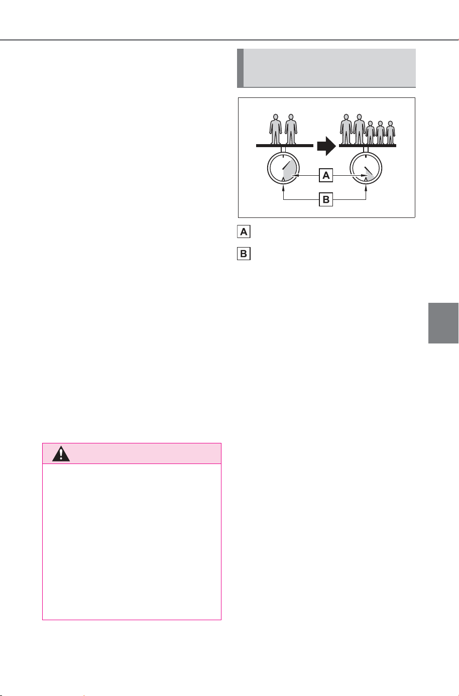
223
5-1. Before driving
Owner’s Manual_USA_M6740B_en
5
Driving
(4) The resulting figure equals
the available amount of cargo
and luggage load capacity.
For example, if the “XXX”
amount equals 1400 lbs. and
there will be five 150 lb passen-
gers in your vehicle, the amount
of available cargo and luggage
load capacity is 650 lbs. (1400 -
750 (5 150) = 650 lbs.)
(5) Determine the combined
weight of luggage and cargo
being loaded on the vehicle.
That weight may not safely
exceed the available cargo and
luggage load capacity calcu-
lated in Step 4.
(6) If your vehicle will be towing
a trailer, load from your trailer
will be transferred to your vehi-
cle. Consult this manual to
determine how this reduces the
available cargo and luggage
load capacity of your vehicle.
(P.227)
Cargo capacity
Total load capacity (vehicle
capacity weight) (P.654)
When 2 people with the com-
bined weight of A lb. (kg) are rid-
ing in your vehicle, which has a
total load capacity (vehicle
capacity weight) of B lb. (kg),
the available amount of cargo
and luggage load capacity will
be C lb. (kg) as follows:
B
*2
lb. (kg) - A
*1
lb. (kg) = C
*3
lb.
(kg)
*1
:A = Weight of people
*2
:B = Total load capacity
*3
:C = Available cargo and luggage
load
In this condition, if 3 more passen-
gers with the combined weight of D
lb. (kg) get on, the available cargo
and luggage load will be reduced E
lb. (kg) as follows:
C lb. (kg) - D
*4
lb. (kg) = E
*5
lb.
(kg)
WARNING
■ Capacity and distribution
● Do not exceed the maximum
axle weight rating or the total
vehicle weight rating.
● Even if the total load of occu-
pant’ weight and the cargo load
is less than the total load capac-
ity, do not apply the load
unevenly. Improper loading may
cause deterioration of steering
or braking control which may
cause death or serious injury.
Calculation formula for
your vehicle
SOLTERRA_OM_USA_A6740BE.book 223 ページ 2025年5月23日 金曜日 午後1時18分
224
5-1. Before driving
Owner’s Manual_USA_M6740B_en
*4
:D = Additional weight of people
*5
:E = Available cargo and luggage
load
As shown in the example above,
if the number of occupants
increases, the cargo and lug-
gage load will be reduced by an
amount that equals the
increased weight due to the
additional occupants. In other
words, if an increase in the num-
ber of occupants causes an
excess of the total load capacity
(combined weight of occupants
plus cargo and luggage load),
you must reduce the cargo and
luggage on your vehicle.
WARNING
■ When loading cargo on the
roof luggage carrier (if
equipped)
Observe the following precau-
tions:
● Place the cargo so that its
weight is distributed evenly
between the front and rear
axles.
● If loading long or wide cargo,
never exceed the vehicle overall
length or width. (P.654)
● Before driving, make sure the
cargo is securely fastened on
the roof luggage carrier.
● Loading cargo on the roof lug-
gage carrier will make the cen-
ter of gravity of the vehicle
higher. Avoid high speeds, sud-
den starts, sharp turns, sudden
braking or abrupt maneuvers,
otherwise it may result in loss of
control or vehicle rollover due to
failure to operate this vehicle
correctly and result in death or
serious injury.
● If driving for a long distance, on
rough roads, or at high speeds,
stop the vehicle now and then
during the trip to make sure the
cargo remains in its place.
● The maximum load limit of the
cargo, roof luggage carrier kit
and carrying attachments must
not exceed 176 lb. (80 kg).
NOTICE
■ When loading cargo (vehi-
cles with panoramic moon
roof)
Be careful not to scratch the sur-
face of the panoramic moon roof.
SOLTERRA_OM_USA_A6740BE.book 224 ページ 2026年1月6日 火曜日 午後2時16分
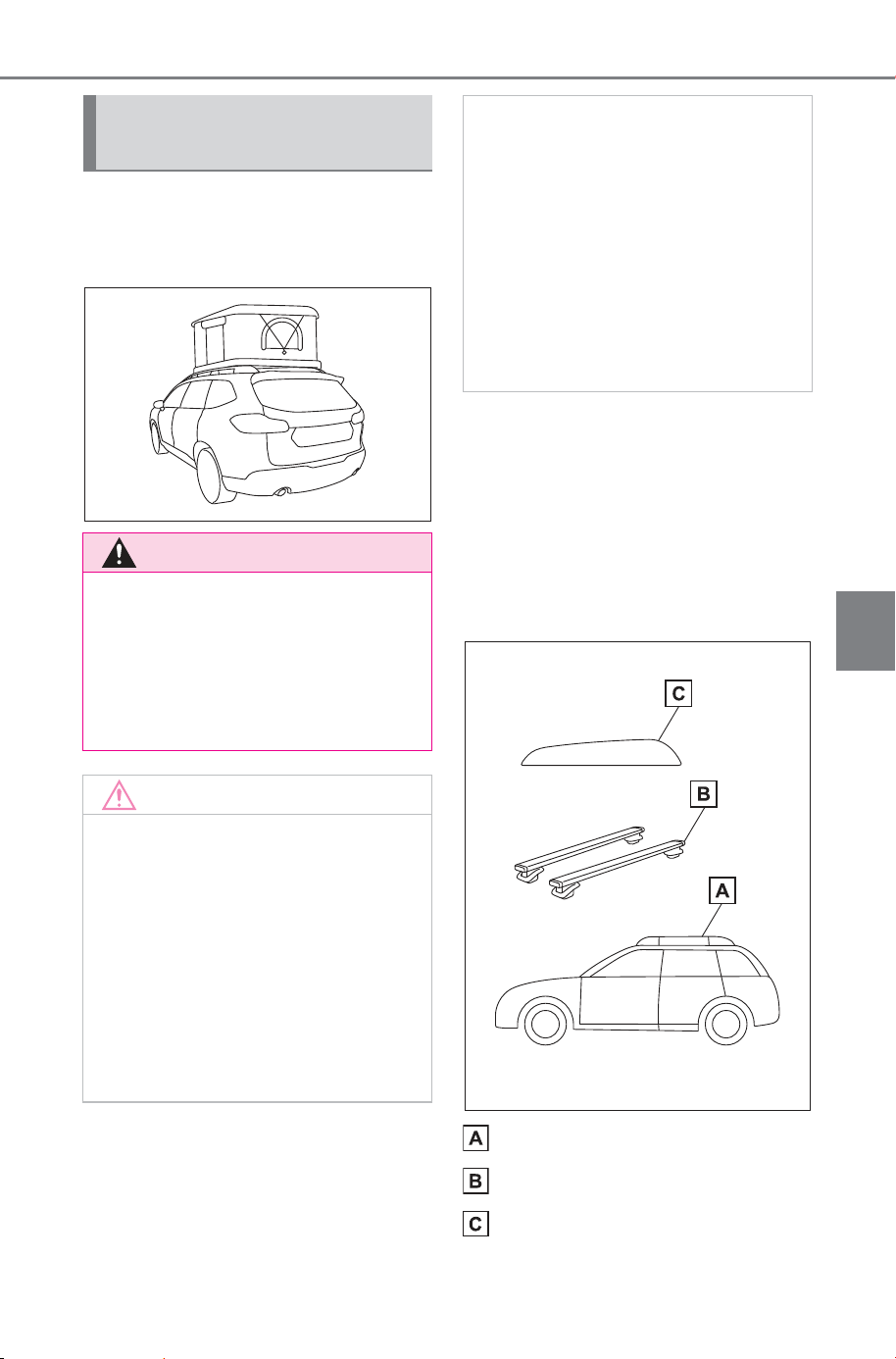
225
5-1. Before driving
Owner’s Manual_USA_M6740B_en
5
Driving
Roof tents may be used under
certain conditions at your own
risk.
■ When driving the vehicle
The total weight on the roof
rails, including the roof cross-
bars and roof tent, must not
exceed the vehicle’s roof rail
load of 176 lb. (80 kg), evenly
distributed.
Roof rails
Roof crossbars
Roof tent
B + C < 176 lb. (80 kg)
Roof tent (models with
roof rails)
WARNING
■ For safe use
Adding weight to the vehicle’s roof
can adversely affect handling,
braking, and rollover resistance.
The vehicle must never be driven
with a total roof rail load in excess
of 176 lb. (80 kg).
NOTICE
■ When loading cargo on the
roof luggage carrier
● The roof rail load limit for sta-
tionary vehicles (700 lb. [317
kg]) applies only when the vehi-
cle is parked and the load is
evenly distributed left/right and
front/rear and the roof crossbars
and roof tent are tightly secured
to the vehicle. If these condi-
tions are not met, the load limit
will be lower.
● The maximum load limit of the
roof crossbars must be obtained
from the manufacturer or
retailer of the roof rack. When
driving the vehicle, the maxi-
mum roof rail load is 176 lb. (80
kg) or the crossbar load limit
(whichever is lower).
● Roof tents can only be used on
vehicles originally equipped with
roof rails. Otherwise, damage to
the vehicle’s roof may occur.
SOLTERRA_OM_USA_A6740BE.book 225 ページ 2026年1月14日 水曜日 午後1時5分
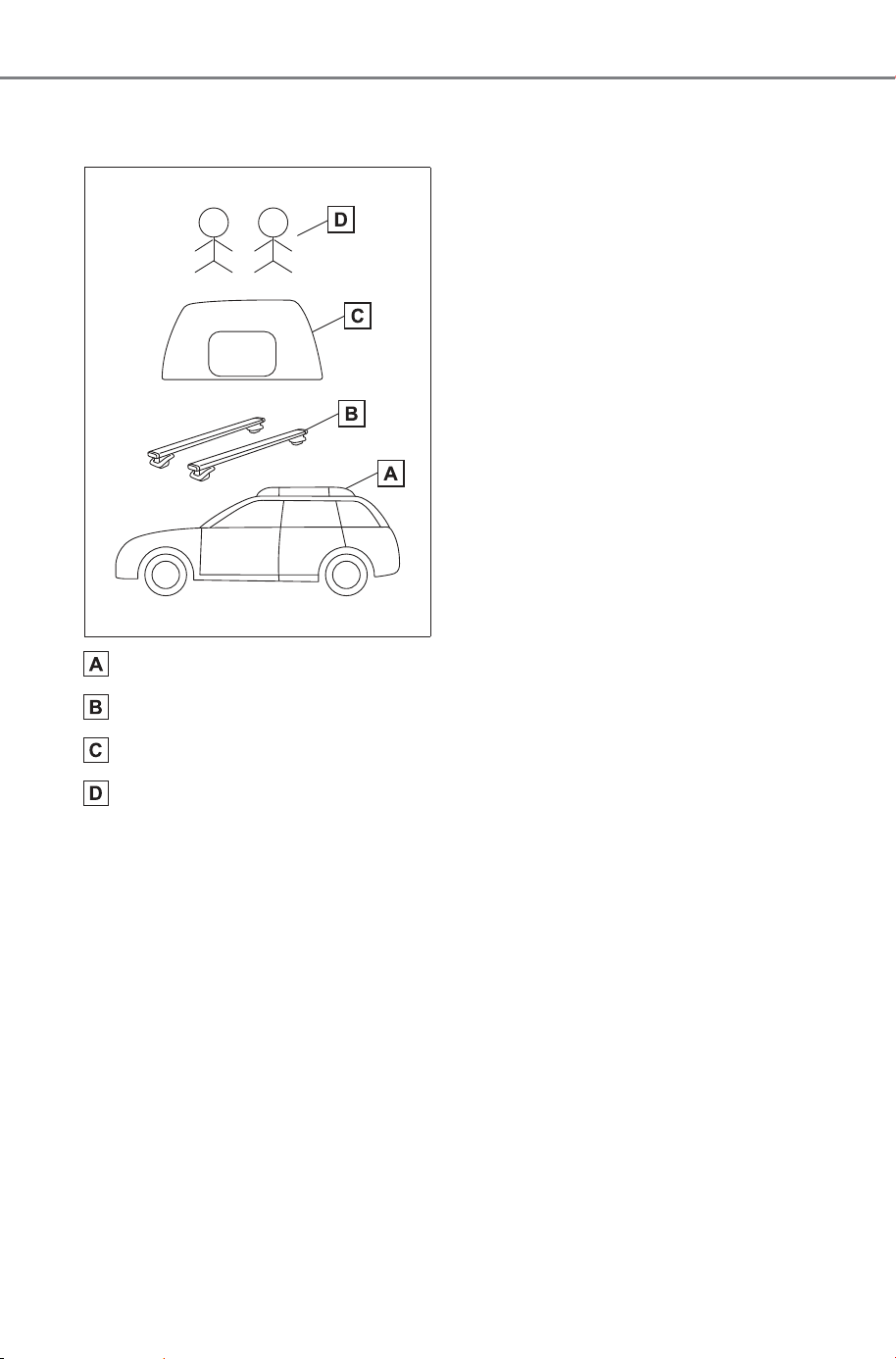
226
5-1. Before driving
Owner’s Manual_USA_M6740B_en
■ When the vehicle is parked
on level ground
Roof rails
Roof crossbars
Roof tent
Occupants in the roof tent
The total weight on the roof
rails – including the roof
crossbars, roof tent, and all
occupants and contents in the
roof tent – must not exceed
either the vehicle’s roof rail
load limit (700 lb. [317 kg]),
evenly distributed, or the load
limit of the roof crossbars,
whichever is lower.
Load limit of the roof rail (A).
B + C + D < 700 lb. (317 kg)
Exceeding this load limit could
cause damage to the vehicle
or racking system. The vehi-
cle must never be driven with
occupants in the roof tent.
Before the vehicle is driven,
occupants and cargo must be
removed from the roof tent
and the roof rail load must be
restored to within the roof rail
load limit of 176 lb. (80 kg).
Refer to the user manual that
accompanied the roof tent for
important safety information
and instructions on the proper
installation and use of the
tent.
SOLTERRA_OM_USA_A6740BE.book 226 ページ 2026年1月6日 火曜日 午後2時16分
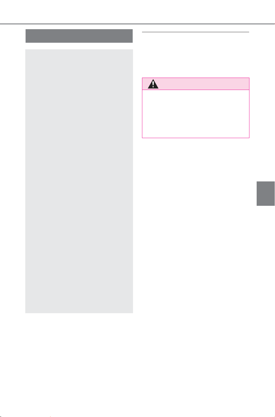
227
5-1. Before driving
Owner’s Manual_USA_M6740B_en
5
Driving
■ Total load capacity and seating
capacity
These details are also described on
the tire and loading information
label. (P.588)
Vehicle load limits
Vehicle load limits include
total load capacity, seating
capacity, TWR (Trailer
Weight Rating) and cargo
capacity.
Total load capacity (vehicle
capacity weight): P.654
Total load capacity means the
combined weight of occu-
pants, cargo and luggage.
Seating capacity: P. 654
Seating capacity means the
maximum number of occu-
pants whose estimated aver-
age weight is 150 lb. (68 kg)
per person.
TWR (Trailer Weight Rat-
ing)
SUBARU does not recom-
mend towing a trailer with
your vehicle.
Cargo capacity
Cargo capacity may increase
or decrease depending on the
weight and the number of
occupants.
WARNING
■ Overloading the vehicle
Do not overload the vehicle. It
may not only cause damage to
the tires, but also degrade steer-
ing and braking ability, resulting in
an accident.
SOLTERRA_OM_USA_A6740BE.book 227 ページ 2025年5月23日 金曜日 午後1時18分
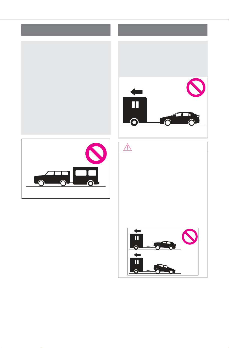
228
5-1. Before driving
Owner’s Manual_USA_M6740B_en
Trailer towing
SUBARU does not recom-
mend towing a trailer with
your vehicle. SUBARU also
does not recommend the
installation of a tow hitch or
the use of a tow hitch car-
rier for a wheelchair,
scooter, bicycle, etc. Your
vehicle is not designed for
trailer towing or for the use
of tow hitch mounted carri-
ers.
Dinghy towing
Your vehicle is not designed
to be dinghy towed (with 4
wheels on the ground)
behind a motor home.
NOTICE
■ To avoid serious damage to
your vehicle
Do not tow your vehicle with 4
wheels on the ground.
■ To prevent causing serious
damage to the transmission
and AWD system
Never tow this vehicle with any of
the wheels on the ground. This
may cause serious damage to the
transmission and AWD system.
SOLTERRA_OM_USA_A6740BE.book 228 ページ 2025年5月23日 金曜日 午後1時18分
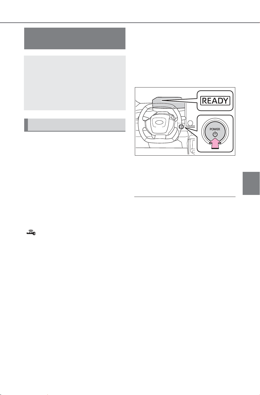
229
5-2. Driving procedures
Owner’s Manual_USA_M6740B_en
5
Driving
5-2.Driving procedures
1 Check that the charging
cable is disconnected.
(P.95, 100)
2 Pull the parking brake switch
to check that the parking
brake is set. (P.241)
The parking brake indicator will
come on.
3 Firmly depress the brake
pedal.
and a message will be dis-
played on the multi-information dis-
play.
If it is not displayed, the EV system
cannot be started.
When the shift position is N, the EV
system cannot start. Shift the shift
position to P when starting the EV
system. (P.234)
4 Press the power switch
shortly and firmly.
When operating the power switch,
one short, firm press is enough. It is
not necessary to press and hold the
switch.
If the “READY” indicator turns on,
the EV system will operate nor-
mally.
Continue depressing the brake
pedal until the “READY” indicator is
illuminated.
The EV system can be started from
any power switch mode.
5 Check that the “READY” indi-
cator is illuminated.
The vehicle cannot be driven if the
“READY” indicator is off.
■ Power switch illumination
According to the situation, the
power switch illumination operates
as follows.
● When driver’s door or front pas-
senger’s door is opened, the
power switch illumination illumi-
nates.
● When the power switch is in OFF
and depressing the brake pedal
with carrying the electronic key on
your person, the power switch illu-
mination blinks.
● When the power switch is in ACC
or ON, the power switch illumina-
tion illuminates.
● When the power switch mode is
changed from ACC or ON to OFF,
the power switch illumination illu-
minates for a certain amount of
time. Afterwards, the power switch
illumination turns off.
Power (ignition)
switch
Performing the following
operations when carrying
the electronic key on your
person starts the EV system
or changes power switch
modes.
Starting the EV system
SOLTERRA_OM_USA_A6740BE.book 229 ページ 2025年5月23日 金曜日 午後1時18分

230
5-2. Driving procedures
Owner’s Manual_USA_M6740B_en
■ If the EV system does not start
● The immobilizer system may not
have been deactivated. (P.65)
Contact your SUBARU dealer.
● The charging cable may be con-
nected to the vehicle. (P. 9 2 )
● If a message related to start-up is
shown on the multi-information
display, read the message and fol-
low the instructions.
● The Smart key system may not be
operating properly. (P.643)
● If the door is unlocked with the
mechanical key, the EV system
cannot be started using the smart
key system. Refer to P.643 to start
the EV system. However, if the
electronic key is carried inside the
vehicle and the doors are locked
(P.162), the EV system can be
started.
■ When the ambient temperature
is low, such as during winter
driving conditions
● When starting the EV system, the
flashing time of the “READY” indi-
cator may be long. Leave the
vehicle as it is until the “READY”
indicator is steady on, as steady
means the vehicle is able to move.
● When the traction battery is
extremely cold (below approxi-
mately -22°F [-30°C]) under the
influence of the outside tempera-
ture, it may not be possible to start
the EV system. In this case, try to
start the EV system again after the
temperature of the traction battery
increases due to the outside tem-
perature increase, etc.
■ Sounds and vibrations specific
to a battery electric vehicle
P.72
■ If the 12-volt battery is dis-
charged
The EV system cannot be started
using the smart key system. Refer
to P.644 to restart the EV system.
■ Electronic key battery depletion
P.154
■ Conditions affecting operation
P.179
■ Note for the entry function
P.180
■ If “Smart Key System Malfunc-
tion See Owner’s Manual” is
displayed on the multi-informa-
tion display
The system may be malfunctioning.
Have the vehicle inspected by your
SUBARU dealer immediately.
■ If the “READY” indicator does
not come on
In the event that the “READY” indi-
cator does not come on even after
performing the proper procedures
for starting the vehicle, contact your
SUBARU dealer immediately.
■ If the EV system is malfunction-
ing
P. 7 8
■ Electronic key battery
P.594
■ Operation of the power switch
● If the switch is not pressed shortly
and firmly, the power switch mode
may not change or the EV system
may not start.
● If attempting to restart the EV sys-
tem immediately after turning the
power switch to OFF, the EV sys-
tem may not start in some cases.
After turning the power switch to
OFF, please wait a few seconds
before restarting the EV system.
■ Customization
If the smart key system has been
deactivated in a customized setting,
refer to P.643.
SOLTERRA_OM_USA_A6740BE.book 230 ページ 2025年5月23日 金曜日 午後1時18分
231
5-2. Driving procedures
Owner’s Manual_USA_M6740B_en
5
Driving
1 Stop the vehicle completely.
2 Set the parking brake.
(P.241)
3 Press the P position switch.
(P.234)
Check that the shift position indica-
tor shows P and the parking brake
indicator is illuminated.
4 Press the power switch.
The EV system will stop, and the
meter display will be extinguished
(the shift position indicator will be
extinguished a few seconds after
the meter display).
5 Release the brake pedal and
check that “ACCESSORY” or
“POWER ON” is not shown
on the meter.
■ Automatic EV system shut off
feature
● The vehicle is equipped with a
feature that automatically shuts off
the EV system when the shift posi-
tion is in P with the EV system
operating for an extended period.
● The EV system will automatically
shut off after approximately 1 hour
if it has been left operating while
the shift position is in P.
● The timer for the automatic EV
system shut off feature will reset if
the brake pedal is depressed or if
the shift position is in a position
other than P.
● After the vehicle is parked, if the
door is locked with the door lock
switch (P.162) from the inside or
the mechanical key (P.642) from
the outside, the automatic EV sys-
tem shut off feature will be dis-
abled. The timer for the automatic
EV system shut off feature will be
re-enabled if the driver’s door is
opened.
■ When the shift control system
malfunctions
If the shift control system is malfunc-
tioning, when attempting to turn the
power switch off, it may not be able
to be turned off. In this situation, it
may be possible to turn the power
switch off by applying the parking
brake and then operating the power
switch.
If there is a malfunction in the sys-
tem, have the vehicle inspected by
your SUBARU dealer immediately.
■ Automatic P position selection
function
P.236
WARNING
■ When starting the EV system
Always start the EV system while
sitting in the driver’s seat. Do not
depress the accelerator pedal
while starting the EV system
under any circumstances.
Doing so may cause an accident
resulting in death or serious injury.
NOTICE
■ When starting the EV system
If the EV system becomes difficult
to start, have your vehicle
checked by your SUBARU dealer
immediately.
■ Symptoms indicating a mal-
function with the power
switch
If the power switch seems to be
operating somewhat differently
than usual, such as the switch
sticking slightly, there may be a
malfunction. Contact your SUB-
ARU dealer immediately.
Stopping the EV system
SOLTERRA_OM_USA_A6740BE.book 231 ページ 2025年5月23日 金曜日 午後1時18分
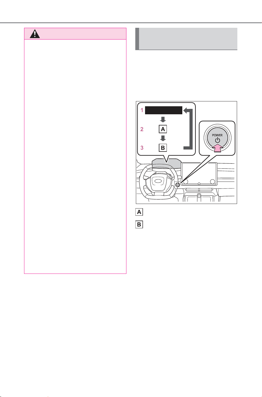
232
5-2. Driving procedures
Owner’s Manual_USA_M6740B_en
Modes can be changed by
pressing the power switch with
the brake pedal released. (The
mode changes each time the
switch is pressed.)
“ACCESSORY”
“POWER ON”
1 OFF
The emergency flashers can be
used.
2 ACC
*
Some electrical components such
as the audio system can be used.
“ACCESSORY” will be displayed
on the multi-information display.
3 ON
All electrical components can be
used.
“POWER ON” will be displayed on
the multi-information display.
*
: ACC mode can be enabled/dis-
abled on the customize menu.
(P.677)
WARNING
■ Stopping the EV system in an
emergency
● If you want to stop the EV sys-
tem in an emergency while driv-
ing the vehicle, press and hold
the power switch for more than
2 seconds, or press it briefly 3
times or more in succession.
(P.602)
However, do not touch the
power switch while driving
except in an emergency. Turn-
ing the EV system off while driv-
ing will not cause a loss of
steering or braking control.
However, power assist for the
steering wheel may be lost mak-
ing it difficult to steer smoothly
before stopping the vehicle
depending on the remaining
charge in the 12-volt battery or
usage conditions. In this situa-
tion, you should pull over and
stop the vehicle as soon as it is
safe to do so.
● If the power switch is operated
while the vehicle is running, a
warning message will be shown
on the multi-information display
and a buzzer sounds.
● When restarting the EV system
after an emergency shutdown,
press the power switch shortly
and firmly.
Changing power switch
modes
SOLTERRA_OM_USA_A6740BE.book 232 ページ 2025年5月23日 金曜日 午後1時18分
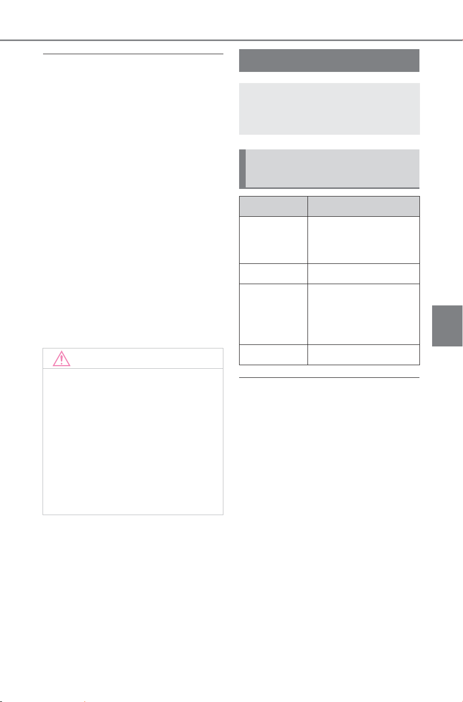
233
5-2. Driving procedures
Owner’s Manual_USA_M6740B_en
5
Driving
■ When ACC customization is in
off
● With the power switch is turned
off, the multimedia system can still
be used for a certain time until the
battery saving function starts
operating.
● When the safe exit assist is oper-
ating, a buzzer will sound and a
voice guidance will be given.
■ Auto power off function
If the vehicle is left in ACC for more
than 20 minutes or ON (the EV sys-
tem is not operating) for more than
20 minutes with the shift position in
P, the power switch will automati-
cally turn off. However, this function
cannot entirely prevent the 12-volt
battery discharge. Do not leave the
vehicle with the power switch in
ACC or ON for long periods of time
when the EV system is not operat-
ing.
■ Restraining sudden start (Drive-
Start Control)
P.221
■ If a message about a shift oper-
ation is shown
To prevent the shift position from
being selected incorrectly or the
vehicle from moving unexpectedly,
the shift position may be changed
automatically or operating the shift-
ing operation may be required. In
this case, change the shift position
following the messages on the
multi-information display.
■ After recharging/reconnecting
the 12-volt battery
P.569
NOTICE
■ To prevent 12-volt battery dis-
charge
● Do not leave the power switch
in ACC or ON for long periods of
time without the EV system on.
● If “ACCESSORY” or “POWER
ON” is displayed on the multi-
information display, the power
switch is not in OFF. Exit the
vehicle after turning the power
switch to OFF.
Shift position
Select the shift position
depending on your pur-
pose and situation.
Shift position purpose
and functions
Shift position Objective or function
P
Parking the vehi-
cle/starting the EV
system
R Reversing
N
Neutral
(Condition in which
the power is not
transmitted)
D Normal driving
SOLTERRA_OM_USA_A6740BE.book 233 ページ 2025年5月23日 金曜日 午後1時18分
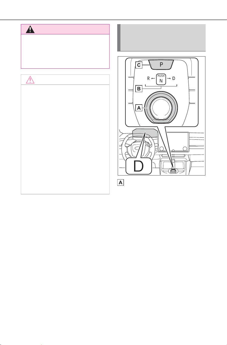
234
5-2. Driving procedures
Owner’s Manual_USA_M6740B_en
Rotary shifter
Operate the rotary shifter slowly
and securely.
To switch to N, hold down the rotary
shifter and hold it for a while.
To switch to R or D, hold down the
rotary shifter and turn left or right
according to the arrow on the shift
position indicator.
Release the rotary shifter after each
shifting operation to allow it to
return to its regular position.
When shifting from P to N, D or R,
from N, D or R to P, from D to R, or
from R to D, ensure that the brake
pedal is being depressed and the
vehicle is stationary.
WARNING
■ When driving on slippery
road surfaces
Be careful of sudden acceleration,
as this could result in the vehicle
skidding to the side or spinning.
NOTICE
■ Situations where shift control
system malfunctions are pos-
sible
If any of the following situations
occurs, shift control system mal-
functions are possible.
Immediately stop the vehicle in a
safe place on level ground, apply
the parking brake, and then con-
tact your SUBARU dealer.
● When the warning message
indicating the shift control sys-
tem appears on the multi-infor-
mation display. (P.621)
● The display indicates that no
shift position is selected for
more than a few seconds.
Shift position display and
how to change the shift
position
SOLTERRA_OM_USA_A6740BE.book 234 ページ 2025年5月23日 金曜日 午後1時18分

235
5-2. Driving procedures
Owner’s Manual_USA_M6740B_en
5
Driving
Shift position indicator
Meter display:
The current shift position is illumi-
nated.
Rotary shifter display:
The current shift position is illumi-
nated.
When selecting the shift position,
make sure that the shift position
has been changed to the desired
position by checking the shift posi-
tion indicator provided on the
instrument cluster.
P position switch
Fully stop the vehicle and set the
parking brake, and then press the P
position switch.
When the shift position is changed
to P, the switch illuminates.
Check that the shift position indica-
tor shows P.
■ Changing the shift position in
each power switch mode
● The shift position cannot be
changed when the power switch is
in ACC or off.
● When the power switch is in ON, if
the “READY” indicator is not illu-
minated, the shift position can
only be changed to N.
● When the “READY” indicator is
illuminated, the shift position can
be changed from P to D, N, or R.
● When the “READY” indicator is
flashing, the shift position cannot
be changed from P to any other
position, even if the rotary shifter
is operated. Operate the rotary
shifter again after the “READY”
indicator changes from flashing to
illuminated.
■ Shifting the shift position from
P to other positions
● While depressing the brake pedal
firmly, operate the rotary shifter. If
the rotary shifter is operated with-
out depressing the brake pedal,
the buzzer will sound and the
shifting operation will be disabled.
● When selecting the shift position,
make sure that the shift position
has been changed to the desired
position by checking the shift posi-
tion indicator provided on the
instrument cluster.
■ The shift position cannot be
changed when
In the following situations, a buzzer
will sound to inform you that the shift
position cannot be changed. Use
the appropriate operation to attempt
to change the shift position again.
● When attempting to change the
shift position from P with the brake
pedal not depressed
● When attempting to change the
shift position from P with the
accelerator pedal depressed
● When attempting to change the
shift position from N while stopped
or driving at an extremely low
speed with the brake pedal not
depressed
● When attempting to change the
shift position from N while stopped
or driving at an extremely low
speed with the accelerator pedal
depressed
● When the P position switch is
pressed while driving
When driving at an extremely low
speed, the shift position may
change to P.
SOLTERRA_OM_USA_A6740BE.book 235 ページ 2025年5月23日 金曜日 午後1時18分

236
5-2. Driving procedures
Owner’s Manual_USA_M6740B_en
■ The shift position automatically
changes to N when
In the following situations, a buzzer
will sound to inform you that the shift
position has been changed to N.
Use the appropriate operation to
attempt to change the shift position
again.
● When attempting to change the
shift position to R while the vehicle
is moving forward
When driving at a low speed, the
shift position may change to R.
● When attempting to change the
shift position to D while the vehicle
is moving backward
When driving at a low speed, the
shift position may change to D.
■ If the N shift position is selected
while driving
If the rotary shifter is moved to N
while driving above a certain speed,
the shift position will change to N
without holding the rotary shifter in
the N position. In this situation, a
buzzer will sound and a message
will be displayed on the multi-infor-
mation display to inform you that the
shift position has been changed to
N.
■ Reverse warning buzzer
When shifting into R, a buzzer will
sound to inform the driver that the
shift position is in R.
■ Automatic P position selection
function
In the following situations, the shift
position is automatically changed to
P.
● When pressing the power switch
with the vehicle stopped while the
power switch is in ON and the shift
position is in a position other than
P (after the shift position has
changed to P, the power switch
will turn off)
*
● If the driver’s door is opened and
all of the following conditions are
met, while the shift position is in a
position other than P:
• The power switch is in ON.
• The driver is not wearing the seat
belt.
• The brake pedal is not depressed.
To start off the vehicle after the shift
position is changed to P, operate the
rotary shifter again.
● When the vehicle is stopped after
the EV system has been stopped
in an emergency while driving.
● When voltage of the 12-volt bat-
tery drops while the shift position
is in a position other than P.
*
: When the power switch is pressed
while driving at extremely slow
speeds, such as immediately
before stopping the vehicle, the
shift position may automatically
change to P. Make sure that the
vehicle is completely stopped
before pressing the power switch.
■ If the shift position cannot be
shifted from P
There is a possibility that the 12-volt
battery is discharged. Check the 12-
volt battery in this situation.
(P.644)
■ Customization
Some functions can be customized.
(P.677)
SOLTERRA_OM_USA_A6740BE.book 236 ページ 2025年5月23日 金曜日 午後1時18分
237
5-2. Driving procedures
Owner’s Manual_USA_M6740B_en
5
Driving
By performing the following
operation, the shift position
can be held in N until the shift
position switches to P without
activating the automatic P
position selection function.
1 Stop the vehicle completely.
2 Turn off the brake hold sys-
tem. (P.245)
3 Press and hold the parking
brake switch until a message
is shown on the multi-infor-
mation display. (Turn auto-
matic mode off)
4 Operate the rotary shifter and
change the shift position to N
when the EV system is oper-
ating.
5 Return the rotary shifter to its
regular position.
6 Operate the rotary shifter to
N and hold it there until the
buzzer sounds.
7 Press the power switch within
5 seconds after the buzzer
sounds.
The EV system stops with the shift
position in N
*
.
Make sure to check that the buzzer
sounds and “Holding N Push P
Switch When Done” is displayed on
the multi-information display.
WARNING
■ For the rotary shifter
● Do not remove the rotary shifter
knob or use anything but a gen-
uine SUBARU rotary shifter
knob. Also, do not hang any-
thing on the rotary shifter. Doing
so could prevent the rotary
shifter from returning to posi-
tion, causing unexpected acci-
dents to occur when the vehicle
is in motion.
● In order to prevent the shift
position from accidentally being
changed, do not touch the
rotary shifter when not using
them.
■ P position switch
● Do not press the P position
switch while the vehicle is mov-
ing.
If the P position switch is
pressed when driving at very
low speeds (for example,
directly before stopping the
vehicle), the vehicle may stop
suddenly when the shift position
switches to P, which could lead
to an accident.
● In order to prevent the shift
position from accidentally being
changed, do not touch the P
position switch when not using
them.
NOTICE
■ When exiting the vehicle
(driver’s seat only)
Check that the shift position indi-
cator shows P and that the park-
ing brake indicator is illuminated
before opening the door and exit-
ing the vehicle.
Keeping the shift position
in N without activating the
automatic P position
selection function
SOLTERRA_OM_USA_A6740BE.book 237 ページ 2025年5月23日 金曜日 午後1時18分
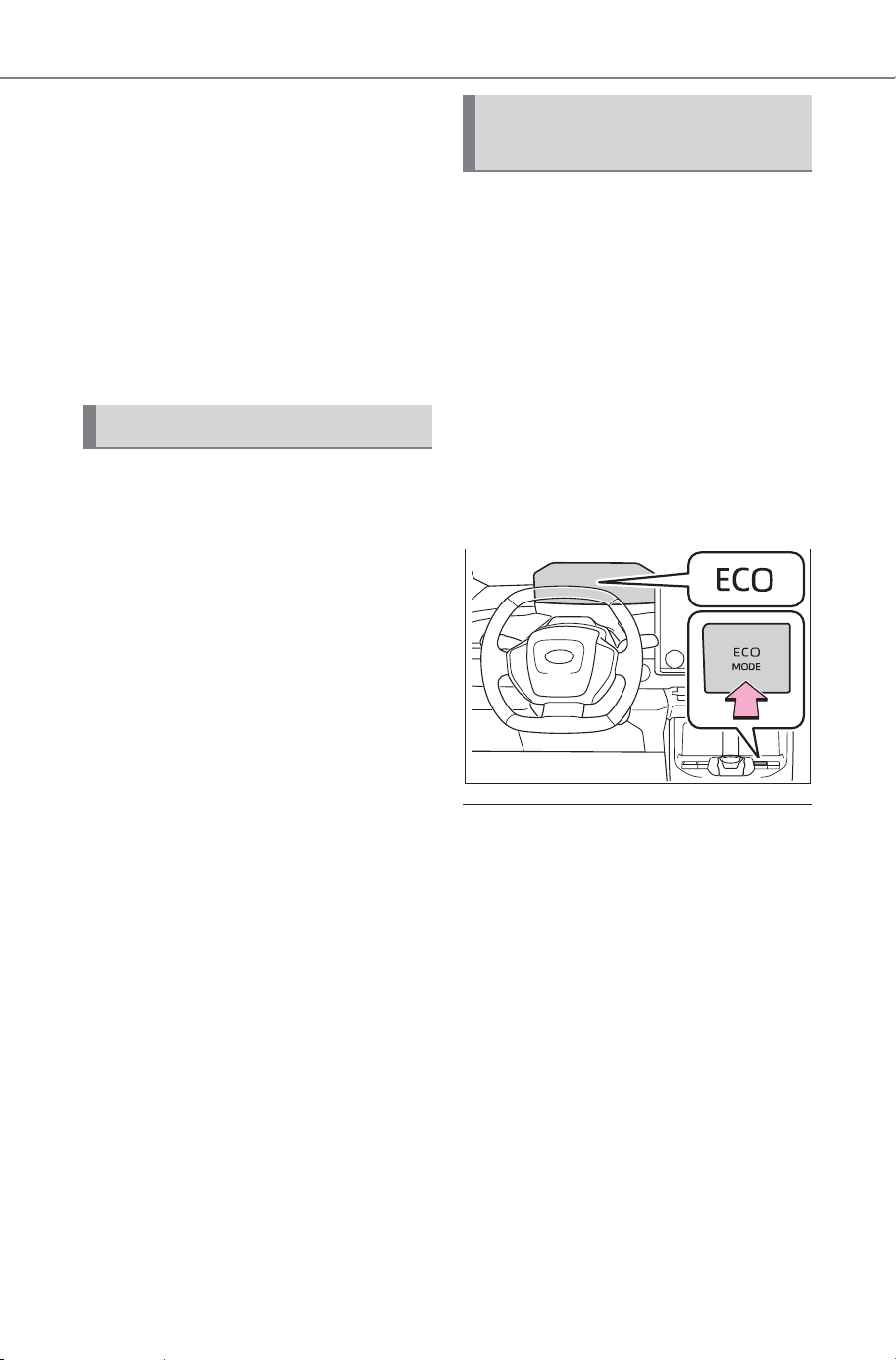
238
5-2. Driving procedures
Owner’s Manual_USA_M6740B_en
In order to shift to a position
other than N, first press the P
position switch to change the
shift position to P.
*
: To keep this state, do not operate
the power switch. If the power
switch is operated repeatedly, the
power switch will turn off after the
shift position has automatically
changed to P.
■ Drive mode select switch
P. 4 70
■ “X-MODE”
P. 4 71
It is suited for driving that sup-
press vehicle driving power and
improves electricity consump-
tion.
Press the switch to switch over
to Eco mode.
Press the switch again to return
to Normal driving mode.
The Eco mode ON state is
memorized even if the power
switch is turned OFF.
■ Eco mode drive automatic can-
cellation
Eco mode is automatically can-
celed when snow mode or “X-
MODE” is selected and the vehicle
returns to normal mode. (If
equipped)
■ When Eco mode is not available
Eco mode cannot be activated when
“X-MODE” is selected. (If equipped)
Selecting the drive mode
Selecting Eco mode (if
equipped)
SOLTERRA_OM_USA_A6740BE.book 238 ページ 2025年5月23日 金曜日 午後1時18分
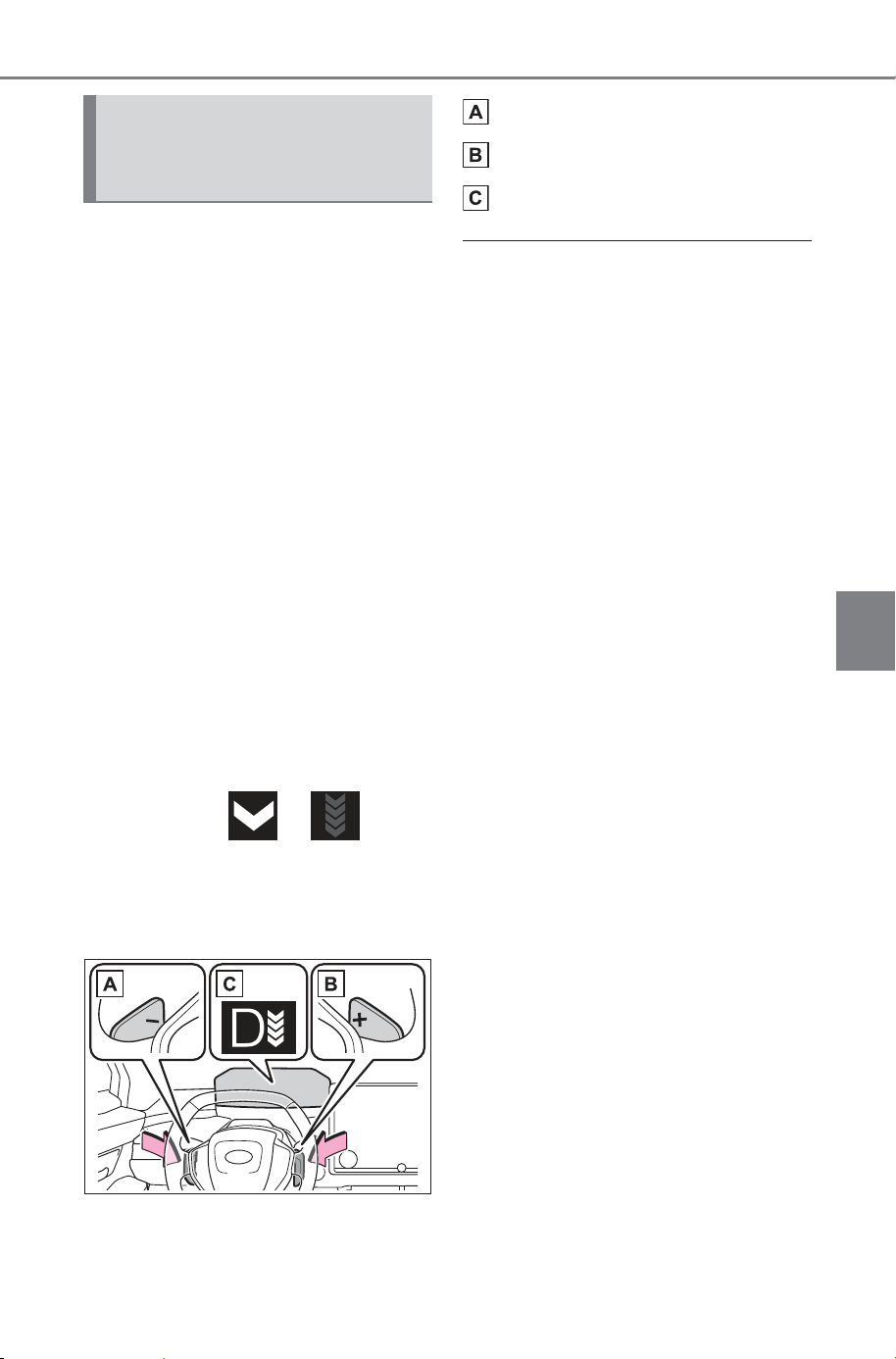
239
5-2. Driving procedures
Owner’s Manual_USA_M6740B_en
5
Driving
By setting the shift position to D
and operating the paddle
switches, the vehicle can drive
with the regenerative braking
force fixed when the accelerator
pedal is released.
The regenerative braking force
can be selected from 5 levels.
By operating the “-” side of the
paddle switch, the regenerative
braking force can be made
stronger than the current one.
By operating the “+” side of the
paddle switch, the regenerative
braking force can be made
weaker than the current one.
The regenerative braking power
becomes strong as the number
of the arrows of
(regenerative braking power
indicator) on the multi-informa-
tion display increases.
Paddle switch “-”
Paddle switch “+”
Indicator
■ How to cancel the regenerative
braking force selection mode
In the following conditions, the
regenerative braking force selection
mode is canceled.
● The shift position is shifted to a
position other than D
● The “+” paddle switch is pressed
and held
● When “X-MODE” is activated (If
equipped)
■ Using regenerative brake
● When driving at a high speed, the
feeling of deceleration with regen-
erative braking is less than that on
conventional vehicles.
● If “Regenerative braking limited.
Press brake to decelerate.”
appears on the multi-information
display, firmly depress the brake
pedal to decelerate the vehicle.
How to operation the
regenerative braking
force selection mode
SOLTERRA_OM_USA_A6740BE.book 239 ページ 2025年5月23日 金曜日 午後1時18分
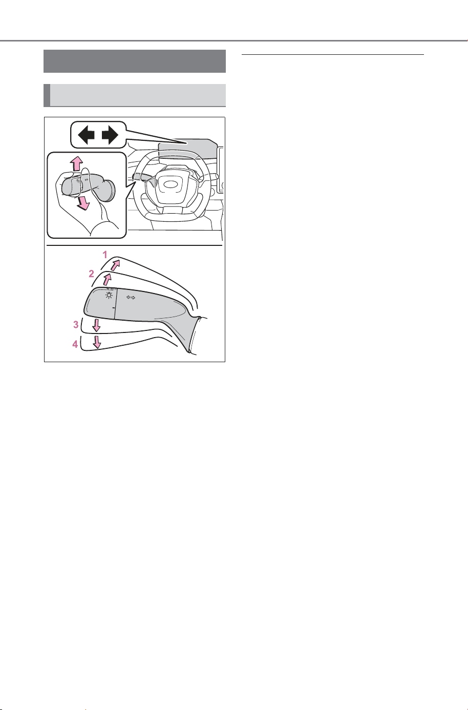
240
5-2. Driving procedures
Owner’s Manual_USA_M6740B_en
1 Right turn
2 Lane change to the right
(move the lever partway and
release it)
The right hand signals will flash 3
times.
3 Lane change to the left
(move the lever partway and
release it)
The left hand signals will flash 3
times.
4 Left turn
■ Turn signals can be operated
when
The power switch is in ON.
■ If the indicator flashes faster
than usual
Have the vehicle inspected by your
SUBARU dealer.
■ If the turn signals stop flashing
before a lane change has been
performed
Operate the lever again.
Turn signal lever
Operating instructions
SOLTERRA_OM_USA_A6740BE.book 240 ページ 2025年5月23日 金曜日 午後1時18分
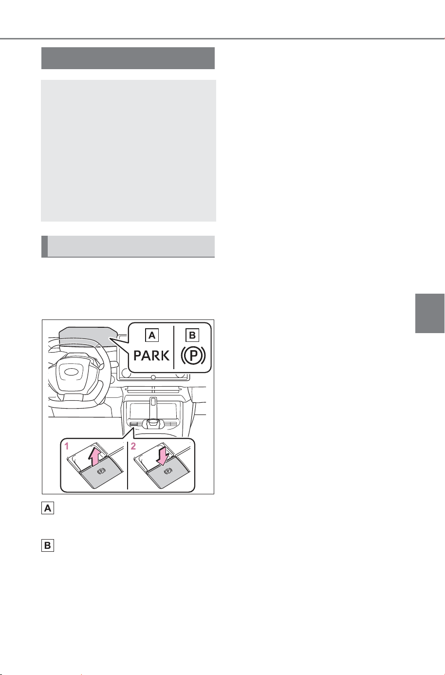
241
5-2. Driving procedures
Owner’s Manual_USA_M6740B_en
5
Driving
■ Using the manual mode
The parking brake can be set
and released manually.
Parking brake indicator light
(U.S.A.)
Parking brake indicator light
(Canada)
1 Pull the switch to set the
parking brake
The parking brake indicator light
will turn on.
Pull and hold the parking brake
switch if an emergency occurs and
it is necessary to operate the park-
ing brake while driving.
2 Press the switch to release
the parking brake
• Operate the parking brake switch
while depressing the brake pedal.
• Using the parking brake auto-
matic release function, the park-
ing brake can be released by
depressing the accelerator pedal.
When using this function, slowly
depress the accelerator pedal.
(P.242)
Make sure that the parking brake
indicator light turn off.
If the parking brake indicator light
flash, operate the switch again.
(P.618)
■ Turning the automatic
mode on
While the vehicle is stopped,
pull and hold the parking brake
switch until a buzzer sounds and
a message is shown on the
multi-information display.
When the automatic mode is
turned on, the parking brake
operates as follows.
When the shift position is
shifted from P, the parking
brake will be released, and
the parking brake indicator
light will turn off.
Parking brake
The parking brake can be
set or released automati-
cally or manually.
In automatic mode, the
parking brake can be set or
released automatically.
Also, even in automatic
mode, the parking brake can
be set or released manually.
Operating instructions
SOLTERRA_OM_USA_A6740BE.book 241 ページ 2025年5月23日 金曜日 午後1時18分

242
5-2. Driving procedures
Owner’s Manual_USA_M6740B_en
When the shift position is
shifted to P, the parking brake
will be set, and the parking
brake indicator light will turn
on.
Operate the shift position and P
position switch with the vehicle
stopped and the brake pedal
depressed.
The auto function may not operate
if the shift position is moved
extremely quickly or the brake
pedal is not firmly depressed. In
this situation, apply the parking
brake manually. (P.241)
■ Turning the automatic
mode off
While the vehicle is stopped and
depressing the brake pedal,
press and hold the parking
brake switch until a buzzer
sounds and a message is
shown on the multi-information
display.
■ Parking brake operation
● When the power switch is not in
ON, the parking brake cannot be
released using the parking brake
switch.
● When the power switch is not in
ON, automatic mode (automatic
brake setting and releasing) is not
available.
■ Parking brake automatic
release function
When all of the following conditions
are met, the parking brake can be
released by depressing the acceler-
ator pedal.
● The driver’s door is closed
● The driver is wearing the seat belt
● The shift position is in a forward
driving position or reverse driving
position
● The brake system warning light
(Yellow) is not illuminated.
When depressing the accelerator
pedal, depress it slowly.
If the parking brake is not released
when the accelerator pedal is
depressed, release the parking
brake manually.
When the shift position is shifted
from P, the parking brake will be
released automatically.
■ Parking brake automatic lock
function when EV system is off
The parking brake will be set auto-
matically under the following condi-
tions:
● The EV system is off
● Automatic mode ON
● The brake system warning light
(Yellow) are not illuminated
■ Parking brake automatic lock
function when exiting the vehi-
cle
The parking brake will be set auto-
matically under the following condi-
tions:
● The brake pedal is not depressed
● The driver’s door is open
● The driver’s seat belt is not fas-
tened
● The brake system warning light
(Yellow) are not illuminated.
SOLTERRA_OM_USA_A6740BE.book 242 ページ 2025年5月23日 金曜日 午後1時18分

243
5-2. Driving procedures
Owner’s Manual_USA_M6740B_en
5
Driving
■ When the parking brake is not
automatically set in the shift
position N, such as when using
car wash.
“Parking brake automatic lock func-
tion when exiting the vehicle” will be
disabled by doing the following:
1 Stop the vehicle.
2 Turn off the brake hold system.
3 Press and hold the parking brake
switch until a buzzer sounds and
a message is shown on the
multi-information display.
4 The shift position to N
5 Press and hold the parking brake
switch until a buzzer sounds and
a message is shown on the
multi-information display.
The parking brake indicator light will
flash.
6 Disable the automatic P position
selection function. Refer
to P.237.
When any of the following condi-
tions are met, the vehicle will return
to automatic mode ON.The parking
brake indicator light will turn off or
light up.
● The shift position other than N
● The parking brake switch is pulled
● The EV system is turned off and
then started again
■ If “Parking Brake Temporarily
Unavailable” is displayed on
the multi-information display
If the parking brake is operated
repeatedly over a short period of
time, the system may restrict opera-
tion to prevent overheating. If this
happens, refrain from operating the
parking brake. Normal operation will
return after about 1 minute.
■ If “Parking Brake Unavailable”
is displayed on the multi-infor-
mation display
Operate the parking brake switch. If
the message does not disappear
after operating the switch several
times, the system may be malfunc-
tioning. Have the vehicle inspected
by your SUBARU dealer.
■ Parking brake operation sound
When the parking brake operates, a
motor sound (whirring sound) may
be heard.
This does not indicate a malfunc-
tion.
■ Parking brake indicator light
● Depending on the power switch
mode, the parking brake indicator
light will turn on and stay on as
described below:
ON: Comes on until the parking
brake is released.
Not in ON: Stays on for approxi-
mately 15 seconds.
● When the power switch is turned
off with the parking brake set, the
parking brake indicator light will
stay on for about 15 seconds.
This does not indicate a malfunc-
tion.
■ When the parking brake switch
malfunctions
Automatic mode (automatic brake
setting and releasing) will be turned
on automatically.
■ Parking the vehicle
P.215
■ Parking brake engaged warning
buzzer
A buzzer will sound if the vehicle is
driven with the parking brake
engaged. “Parking Brake ON” is dis-
played on the multi-information dis-
play. (with the vehicle reaching a
speed of 3 mph [5 km/h])
SOLTERRA_OM_USA_A6740BE.book 243 ページ 2025年5月23日 金曜日 午後1時18分
244
5-2. Driving procedures
Owner’s Manual_USA_M6740B_en
■ If the brake system warning
light (Yellow) comes on
P.611
■ Usage in winter time
P.483
WARNING
■ When parking the vehicle
Do not leave a child in the vehicle
alone. The parking brake may be
released unintentionally by a child
and there is the danger of the
vehicle moving that may lead to
an accident resulting in death or
serious injury.
■ Parking brake switch
Do not set any objects near the
parking brake switch.
Objects may interfere with the
switch and may lead the parking
brake to unexpectedly operate.
■ Parking brake automatic lock
function
Never use the automatic parking
brake engagement function in
place of normal parking brake
operation. This function is
designed to reduce the risk of a
collision due to the driver forget-
ting to engage the parking brake.
Over-reliance on this function to
park the vehicle safely may lead
to an accident resulting in death
or serious injury.
NOTICE
■ When parking the vehicle
Before you leave the vehicle, shift
the shift position to P, set the park-
ing brake and make sure that the
vehicle does not move.
■ When the system malfunc-
tions
Stop the vehicle in a safe place
and check the warning messages.
■ When the vehicle 12-volt bat-
tery is discharged
The parking brake system cannot
be activated. (P.644)
■ When the parking brake can-
not be released due to a mal-
function
Driving the vehicle with the park-
ing brake set will lead to brake
components overheating, which
may affect braking performance
and increase brake wear. Have
the vehicle inspected by your
SUBARU dealer immediately if
this occurs.
SOLTERRA_OM_USA_A6740BE.book 244 ページ 2025年5月23日 金曜日 午後1時18分
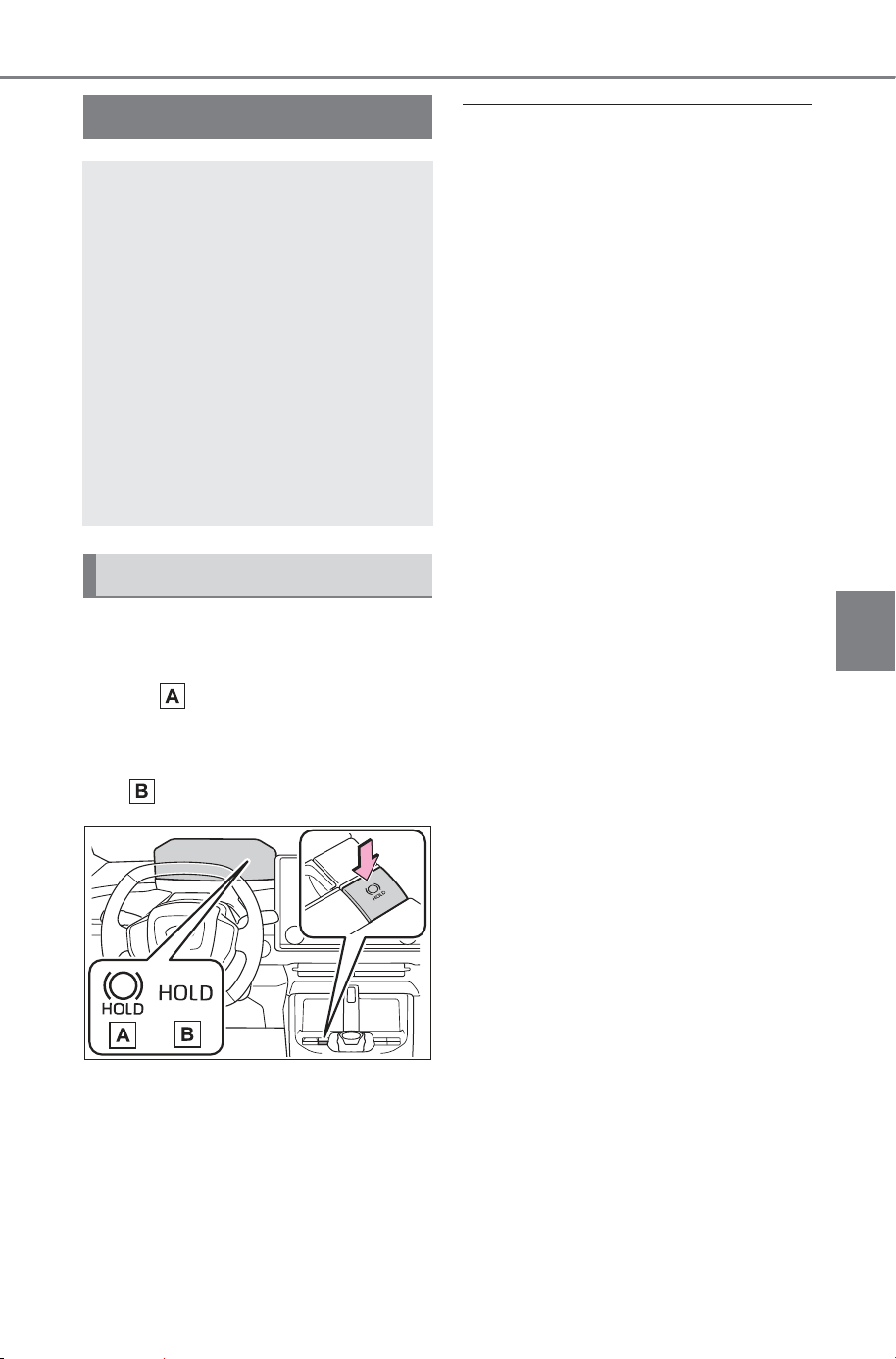
245
5-2. Driving procedures
Owner’s Manual_USA_M6740B_en
5
Driving
Turns the brake hold system on
The brake hold standby indicator
(green) comes on. While the
system is holding the brake, the
brake hold operated indicator (yel-
low) comes on.
■ Brake hold system operating
conditions
The brake hold system cannot be
turned on in the following condi-
tions:
● The driver’s door is not closed.
● The driver is not wearing the seat
belt.
● “Parking Brake Unavailable” or
“Parking Brake Malfunction Visit
Your Dealer” is displayed on the
multi-information display.
If any of the conditions above are
detected when the brake hold sys-
tem is enabled, the system will turn
off and the brake hold standby indi-
cator light will go off. In addition, if
any of the conditions are detected
while the system is holding the
brake, a warning buzzer will sound
and a message will be shown on the
multi-information display. The park-
ing brake will then be set automati-
cally.
■ Brake hold function
● If the brake pedal is left released
for a period of about 3 minutes
after the system has started hold-
ing the brake, the parking brake
will be set automatically. In this
case, a warning buzzer sounds
and a message is shown on the
multi-information display.
● To turn the system off while the
system is holding the brake, firmly
depress the brake pedal and
press the button again.
● The brake hold function may not
hold the vehicle when the vehicle
is on a steep incline. In this situa-
tion, it may be necessary for the
driver to apply the brakes. A warn-
ing buzzer will sound and the
multi-information display will
inform the driver of this situation. If
a warning message is shown on
the multi-information display, read
the message and follow the
instructions.
Brake Hold
The brake hold system
keeps the brake applied
when the shift position is in
D, N or P with the system on
and the brake pedal has
been depressed to stop the
vehicle. The system
releases the brake when the
accelerator pedal is
depressed with the shift
position in D to allow
smooth start off.
Enabling the system
SOLTERRA_OM_USA_A6740BE.book 245 ページ 2025年5月23日 金曜日 午後1時18分
246
5-2. Driving procedures
Owner’s Manual_USA_M6740B_en
● When do not wish for the parking
brake to operate automatically,
press and hold the brake hold
switch until the standby indicator
(green) turns off, and then turn the
power switch off.
■ When the parking brake is set
automatically while the system
is holding the brakes
Perform any of the following opera-
tions to release the parking brake:
● Depress the accelerator pedal.
(The parking brake will not be
released automatically if the seat
belt is not fastened.)
● Operate the parking brake switch
with the brake pedal depressed.
Make sure that the parking brake
indicator light goes off. (P.241)
■ When an inspection at your
SUBARU dealer is necessary
When the brake hold standby indi-
cator (green) does not illuminate
even when the brake hold switch is
pressed with the brake hold system
operating conditions met, the sys-
tem may be malfunctioning. Have
the vehicle inspected at your SUB-
ARU dealer.
■ If “Brake Hold Malfunction
Press Brake to Deactivate Visit
Your Dealer” or “Brake Hold
Malfunction Visit Your Dealer”
is displayed on the multi-infor-
mation display
The system may be malfunctioning.
Have the vehicle inspected by your
SUBARU dealer.
■ Warning messages and buzzers
Warning messages and buzzers are
used to indicate a system malfunc-
tion or to inform the driver of the
need for caution. If a warning mes-
sage is shown on the multi-informa-
tion display, read the message and
follow the instructions.
■ If the brake hold operated indi-
cator flashes
P.618
WARNING
■ When the vehicle is on a
steep incline
Take care when using the brake
hold system on a steep incline,
exercise caution. The brake hold
function may not hold brakes in
such situations.
Also, the system may not activate
depending on the angle of the
slope.
■ When stopped on a slippery
road
The system cannot stop the vehi-
cle when the gripping ability of the
tires has been exceeded. Do not
use the system when stopped on
a slippery road.
NOTICE
■ When parking the vehicle
The brake hold system is not
designed for use when parking
the vehicle for a long period of
time. Turning the power switch off
while the system is holding the
brake may release the brake,
which would cause the vehicle to
move. When operating the power
switch, depress the brake pedal,
shift the shift position to P and set
the parking brake.
SOLTERRA_OM_USA_A6740BE.book 246 ページ 2025年5月23日 金曜日 午後1時18分
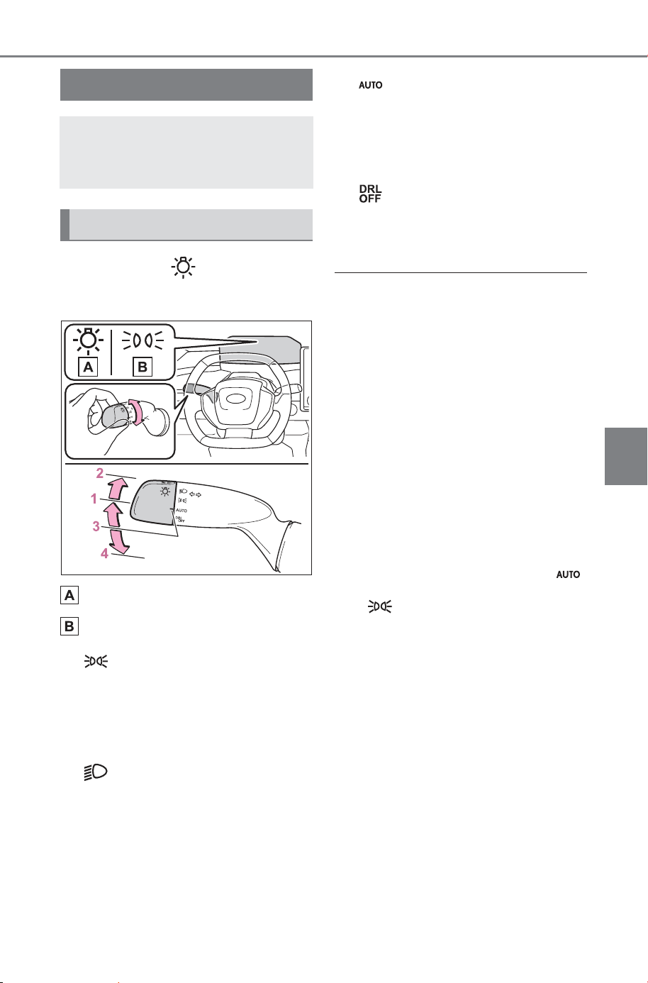
247
5-3. Operating the lights and wipers
Owner’s Manual_USA_M6740B_en
5
Driving
5-3.Operating the lights and wipers
Operating the switch turns
on the lights as follows:
U.S.A.
Canada
1 The side marker, parking,
tail, license plate, instrument
panel lights, daytime running
lights (P.247) turn on.
2 The headlights and all
lights listed above (except
daytime running lights) turn
on.
3 The headlights, daytime
running lights (P.247) and
all the lights listed above turn
on and off automatically.
4 The daytime running
lights turn off. (for the U.S.A.
only)
■ AUTO mode can be used when
The power switch is in ON.
■ Daytime running light system
● The daytime running lights illumi-
nate using the same lights as the
parking lights and illuminate but at
a higher intensity.
● To make your vehicle more visible
to other drivers during daytime
driving, the daytime running lights
turn on automatically when all of
the following conditions are met.
(The daytime running lights are
not designed for use at night.)
• The EV system is operating
• The parking brake is released
• The headlight switch is in the
or position
• The surroundings are bright
The daytime running lights remain
on after they illuminate, even if the
parking brake is set again.
● For the U.S.A.: Daytime running
lights can be turned off by operat-
ing the switch.
● Compared to turning on the head-
lights, the daytime running light
system offers greater durability
and consumes less electricity, so
it can help improve electricity con-
sumption.
Headlight switch
The headlights can be oper-
ated manually or automati-
cally.
Turning on the headlights
SOLTERRA_OM_USA_A6740BE.book 247 ページ 2025年5月23日 金曜日 午後1時18分
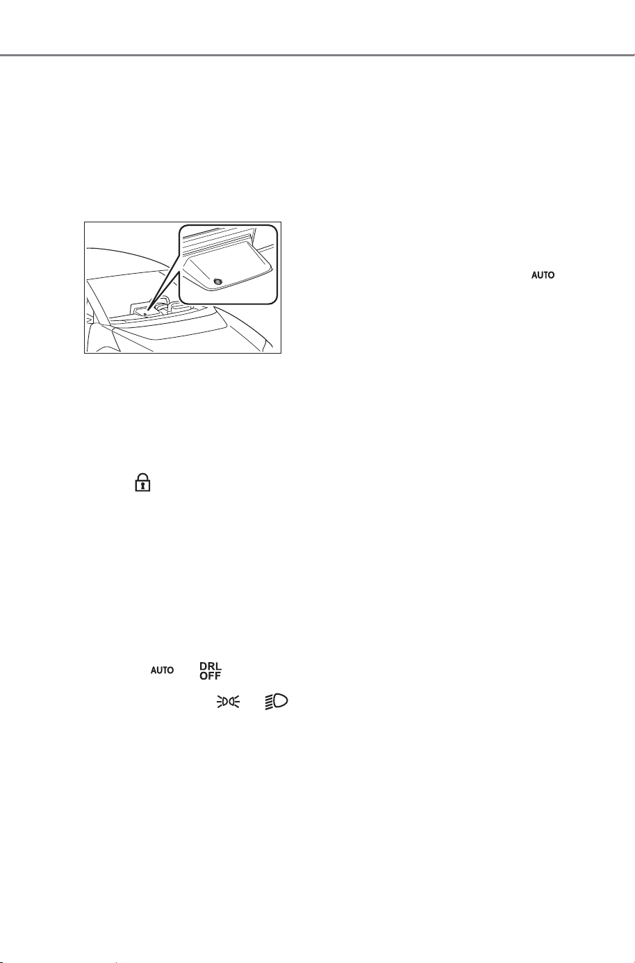
248
5-3. Operating the lights and wipers
Owner’s Manual_USA_M6740B_en
■ Headlight control sensor
The sensor may not function prop-
erly if an object is placed on the sen-
sor, or anything that blocks the
sensor is affixed to the windshield.
Doing so interferes with the sensor
detecting the level of ambient light
and may cause the automatic head-
light system to malfunction.
■ Automatic light off system
● When the headlights are on: The
lights turn off 30 seconds after the
power switch is turned to ACC or
OFF and a door is opened and
closed. (The lights turn off immedi-
ately if on the key is
pressed after all the doors are
closed.)
● When only the tail lights are on:
The tail lights turn off automati-
cally if the power switch is turned
to ACC or OFF and the driver’s
door is opened.
To turn the lights on again, turn the
power switch to ON, or turn the light
switch to the or position
once and then back to or
position.
■ Light reminder buzzer
A buzzer sounds when the power
switch is turned to OFF and the
driver’s door is opened while the
lights are turned on.
■ Automatic headlight leveling
system
The level of the headlights is auto-
matically adjusted according to the
number of passengers and the load-
ing condition of the vehicle to
ensure that the headlights do not
interfere with other road users.
■ Windshield wiper linked head-
light illumination
When driving during daytime with
the headlight switch turned to , if
the windshield wipers are used, the
headlights will turn on automatically
after several seconds to help
enhance the visibility of your vehi-
cle.
■ 12-volt battery-saving function
In order to prevent the 12-volt bat-
tery of the vehicle from discharging,
if the headlights and/or tail lights are
on when the power switch is turned
to OFF, the battery saving function
will operate and automatically turn
off all the lights after approximately
20 minutes.
When any of the following are per-
formed, the 12-volt battery-saving
function is canceled once and then
reactivated. All the lights will turn off
automatically 20 minutes after the
12-volt battery-saving function has
been reactivated:
● When the headlight switch is oper-
ated
● When a door is opened or closed
■ If “Headlight System Malfunc-
tion Visit Your Dealer” is dis-
played on the multi-information
display
The system may be malfunctioning.
Have the vehicle inspected by your
SUBARU dealer.
SOLTERRA_OM_USA_A6740BE.book 248 ページ 2025年5月23日 金曜日 午後1時18分
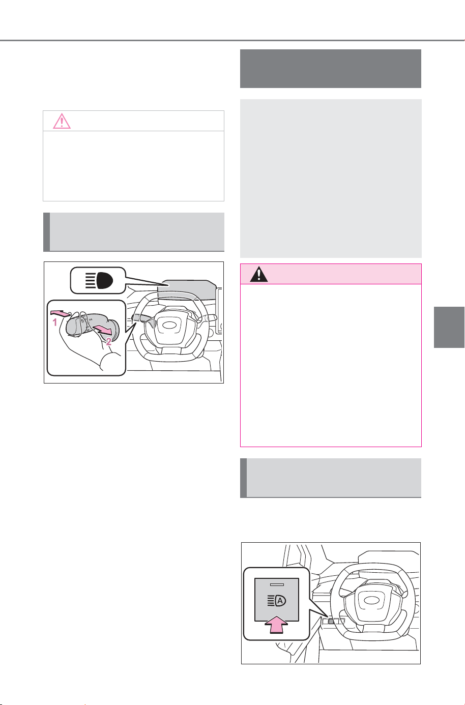
249
5-3. Operating the lights and wipers
Owner’s Manual_USA_M6740B_en
5
Driving
■ Customization
Settings (e.g. light sensor sensitiv-
ity) can be changed.
(Customizable features: P.677)
1 With the headlights on, push
the lever away from you to
turn on the high beams.
Pull the lever toward you to the
center position to turn the high
beams off.
2 Pull the lever toward you and
release it to flash the high
beams once.
You can flash the high beams with
the headlights on or off.
1 Press the Automatic High
Beam switch.
NOTICE
■ To prevent 12-volt battery dis-
charge
Do not leave the lights on longer
than necessary when the EV sys-
tem is not operating.
Turning on the high beam
headlights
AHB (Automatic High
Beam)
The Automatic High Beam
uses a front camera located
on the upper portion of the
windshield to detect the
brightness of the lights of
vehicles ahead, street-
lights, etc., and automati-
cally changes the head
lights between the high
beams and low beams.
WARNING
■ For safe use
Do not overly rely on the Auto-
matic High Beam. Always drive
safely, taking care to observe your
surroundings and turning the high
beams on or off manually if nec-
essary.
■ To prevent unintentional
operation of the Automatic
High Beam System
● When it is necessary to disable
the system: P. 25 9
Using the Automatic High
Beam System
SOLTERRA_OM_USA_A6740BE.book 249 ページ 2025年5月23日 金曜日 午後1時18分
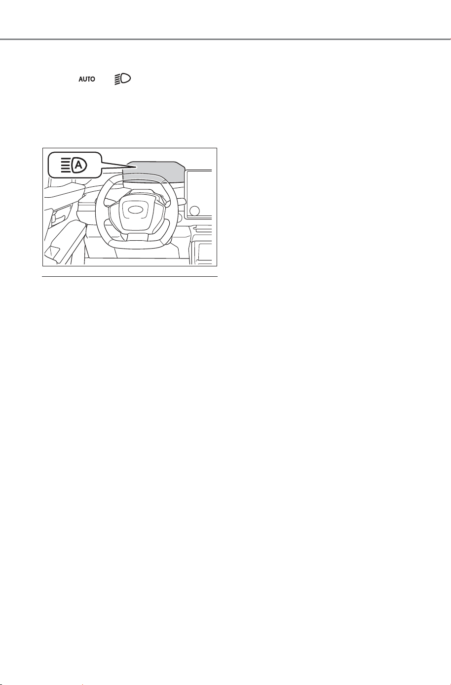
250
5-3. Operating the lights and wipers
Owner’s Manual_USA_M6740B_en
2 Turn the headlight switch to
the or position.
When the headlight switch lever is
in the low beam position, the AHB
system will be enabled and the
AHB indicator will illuminate.
■ Automatic operating condi-
tions of the high beams
● When all of the following condi-
tions are met, the high beams will
illuminate automatically:
• The vehicle speed is approxi-
mately 21 mph (34 km/h) or more.
• The area ahead of the vehicle is
dark.
• There are no vehicles ahead with
lights on.
• There are few streetlights or other
lights on the road ahead.
● If any of the following conditions
are met, the headlights will
change to the low beams:
• Vehicle speed drops below
approximately 17 mph (27 km/h).
• The area ahead of the vehicle is
not dark.
• There is a vehicle ahead with
lights on.
• There are many streetlights or
other lights on the road ahead.
■ Front camera detection
● In the following situations, the high
beams may not be automatically
changed to the low beams:
• When a vehicle cuts in front of
your vehicle
• When another vehicle crosses in
front of the vehicle
• When vehicles ahead are repeat-
edly detected and then hidden
due to repeated curves, road
dividers or roadside trees
• When a vehicle ahead
approaches from a far lane
• When a vehicle ahead is far away
• When a vehicle ahead has no
lights
• When the lights of a vehicle ahead
are dim
• When a vehicle ahead is reflecting
strong light, such as own head-
lights
• Situations in which the sensors
may not operate properly: P.264
● The headlights may change to the
low beams if a vehicle ahead that
is using fog lights without its head-
lights turned on is detected.
● House lights, street lights, traffic
signals, and illuminated billboards
or signs may cause the high
beams to change to the low
beams, or the low beams to
remain on.
● The following may change the tim-
ing at which the headlights
change to the low beams:
• The brightness of lights of vehi-
cles ahead
• The movement and direction of
vehicles ahead
• The distance between the vehicle
and a vehicle ahead
• When a vehicle ahead only has
lights illuminated on one side
• When a vehicle ahead is a two-
wheeled vehicle
SOLTERRA_OM_USA_A6740BE.book 250 ページ 2025年5月23日 金曜日 午後1時18分
251
5-3. Operating the lights and wipers
Owner’s Manual_USA_M6740B_en
5
Driving
• The condition of the road (gradi-
ent, curve, condition of the road
surface, etc.)
• The number of passengers and
amount of luggage
● The headlights may change
between the high beams and low
beams unexpectedly.
● Bicycles and other small vehicles
may not be detected.
● In the following situations, the sys-
tem may not be able to correctly
detect the brightness of the sur-
roundings. This may cause the
low beams to remain on or the
high beams to flash or dazzle
pedestrians or vehicles ahead. In
such a case, it is necessary to
manually change between the
high beams and low beams.
• When there are lights similar to
headlights or tail lights in the sur-
rounding area
• When headlights or tail lights of
vehicles ahead are turned off,
dirty, changing color, or not aimed
properly
• When the headlights are repeat-
edly changing between the high
beams and low beams.
• When use of the high beams is
inappropriate or when the high
beams may be flashing or daz-
zling pedestrians or other drivers.
• When the vehicle is used in an
area in which vehicles travel on
the opposite side of the road of
the country for which the vehicle
was designed, for example using
a vehicle designed for right-hand
traffic in a left-hand traffic area, or
vice versa
• When it is necessary to disable
the system: P.259
• Situations in which the sensors
may not operate properly: P.264
■ Temporarily reducing front
camera sensitivity
The sensitivity of the front camera
can be temporarily reduced.
1 Turn the power switch off with
the following conditions met.
● The headlight switch is in the
or position.
● The headlight switch lever is in the
low beam position.
● The Automatic High Beam switch
is on.
2 Turn the power switch to ON.
3 Within 60 seconds after perform-
ing step
2, push the headlight
switch lever to the high beam
position then pull it to the original
position quickly 10 times, then
leave the lever in its original posi-
tion.
4 If the sensitivity is changed, the
Automatic High Beam indicator
will blink 3 times.
SOLTERRA_OM_USA_A6740BE.book 251 ページ 2025年5月23日 金曜日 午後1時18分
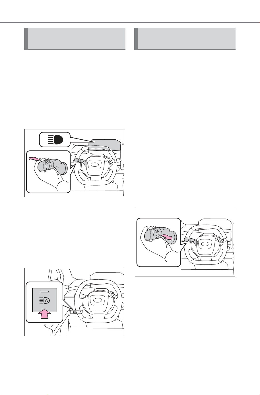
252
5-3. Operating the lights and wipers
Owner’s Manual_USA_M6740B_en
■ Changing to the high
beams
Push the lever forward.
The AHB indicator will turn off and
the high beam indicator will turn on.
Pull the lever to its original position
to enable the Automatic High Beam
system again.
■ Changing to the low beams
Press the Automatic High Beam
switch.
The AHB indicator will turn off.
Press the switch to enable the
Automatic High Beam system
again.
It is recommended to switch to
the low beams when use of the
high beams is inappropriate or
when the high beams may
cause problems or distress to
other drivers or pedestrians
nearby.
Pull the lever rearward and then
return it to its original position.
The high beams will illuminate
while the lever is pulled, how-
ever, after the lever is returned
to its original position, the low
beams will remain on for a cer-
tain amount of time. After this,
the Automatic High Beam sys-
tem will operate.
Turning the high beams
on/off manually
Temporarily changing to
the low beams
SOLTERRA_OM_USA_A6740BE.book 252 ページ 2025年5月23日 金曜日 午後1時18分
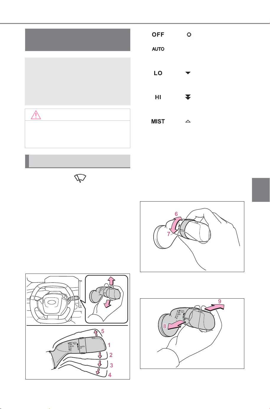
253
5-3. Operating the lights and wipers
Owner’s Manual_USA_M6740B_en
5
Driving
Operating the lever oper-
ates the wipers or washer as fol-
lows:
When “AUTO” is selected, the
wipers will operate automatically
when the sensor detects falling
rain. The system automatically
adjusts wiper timing in accor-
dance with rain volume and
vehicle speed.
1
*1
or
*2
Off
2 Rain-sensing opera-
tion
3
*1
or
*2
Low speed
operation
4
*1
or
*2
High speed
operation
5
*1
or
*2
Temporary
operation
*1
:For the U.S.A.
*2
:For Canada
When “AUTO” is selected, the
sensor sensitivity can be
adjusted by turning the switch
ring.
6 Increases the sensitivity
7 Decreases the sensitivity
Windshield wipers and
washer
Operating the lever can
switch between automatic
operation and manual oper-
ation, or can use the
washer.
NOTICE
■ When the windshield is dry
Do not use the wipers, as they
may damage the windshield.
Operating the wiper lever
SOLTERRA_OM_USA_A6740BE.book 253 ページ 2025年5月23日 金曜日 午後1時18分
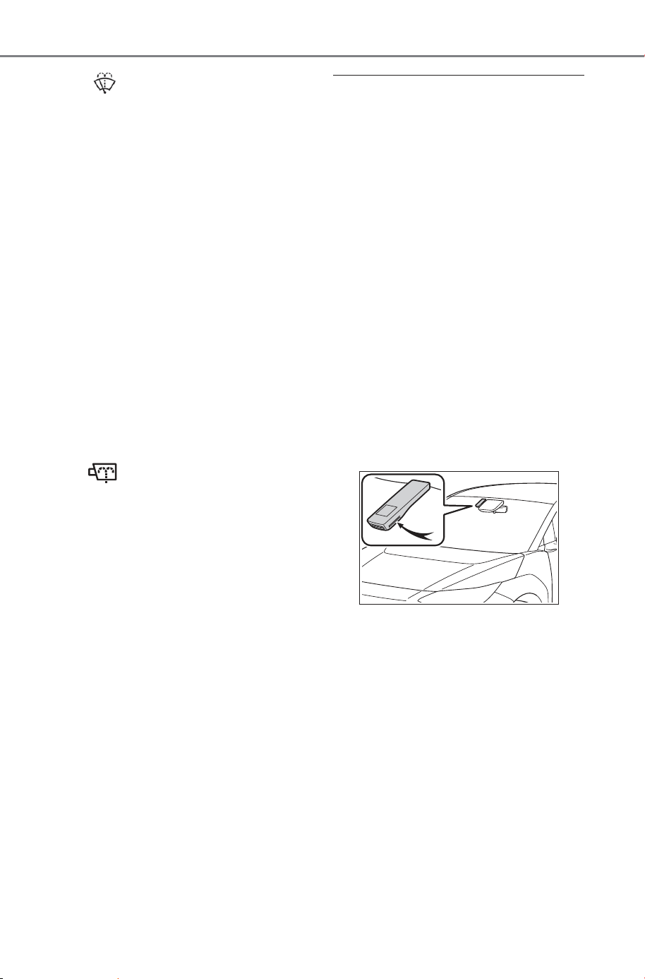
254
5-3. Operating the lights and wipers
Owner’s Manual_USA_M6740B_en
8 Washer/wiper dual
operation
Pulling the lever operates the wip-
ers and washer.
The wipers will automatically oper-
ate a couple of times after the
washer squirts.
(After operating several times, the
wipers operate once more time
after a short delay to prevent drip-
ping. However, the dripping preven-
tion does not operate while the
vehicle is moving.)
When the power switch is in ON
and the headlights are on, if the
lever is pulled, the headlight clean-
ers will operate once. After this, the
headlight cleaners will operate
every 5th time the lever is pulled.
9
*
Washer operation
Pushing the lever operates the
washer and cleans the camera for
the Digital inner mirror.
*
: Vehicles with Digital inner mirror
■ The windshield wipers and
washer can be operated when
The power switch is in ON.
■ Effects of vehicle speed on
wiper operation
With low speed windshield wiper
operation selected, wiper operation
will be switched from low speed to
intermittent wiper operation when
the vehicle is stationary. (However,
when the sensor sensitivity is
adjusted to the highest level, the
mode will not switch.)
■ Raindrop sensor
● The raindrop sensor judges the
amount of raindrops. An optical
sensor is adopted. It may not
operate properly when sunlight
from the rising or setting of the
sun intermittently strikes the wind-
shield, or if bugs, etc., are present
on the windshield.
● If the wiper switch is turned to the
“AUTO” position while the power
switch is in ON, the wipers will
operate once to show that “AUTO”
mode is activated.
● If the wiper sensitivity is adjusted
to higher, the wiper may operate
once to indicate the change of
sensitivity.
● If the temperature of the raindrop
sensor is 185°F (85°C) or higher,
or 5°F (-15°C) or lower, the auto-
matic operation may not occur. In
this case, operate the wipers in
any mode other than “AUTO”.
SOLTERRA_OM_USA_A6740BE.book 254 ページ 2025年5月23日 金曜日 午後1時18分
255
5-3. Operating the lights and wipers
Owner’s Manual_USA_M6740B_en
5
Driving
■ If no windshield washer fluid
sprays
Check that the washer nozzles are
not blocked if there is washer fluid in
the windshield washer fluid reser-
voir.
■ Using the voice control system
The following operations can be
performed using the voice control
system:
● Operating the windshield wipers
only once
● Operating the windshield clean-
ing washer (it can be performed
only when the vehicle is stopped)
For details regarding the voice con-
trol system, refer to “MULTIMEDIA
OWNER’S MANUAL”.
WARNING
■ Caution regarding the use of
windshield wipers in “AUTO”
mode
The windshield wipers may oper-
ate unexpectedly if the sensor is
touched or the windshield is sub-
ject to vibration in “AUTO” mode.
Take care that your fingers or any-
thing else does not become
caught in the windshield wipers.
■ Caution regarding the use of
washer fluid
When it is cold, do not use the
washer fluid until the windshield
becomes warm. The fluid may
freeze on the windshield and
cause low visibility. This may lead
to an accident, resulting in death
or serious injury.
NOTICE
■ When the washer fluid tank is
empty
Do not operate the switch continu-
ally as the washer fluid pump may
overheat.
■ When a nozzle becomes
blocked
In this case, contact your SUB-
ARU dealer.
Do not try to clear it with a pin or
other object. The nozzle will be
damaged.
■ To prevent 12-volt battery dis-
charge
Do not leave the wipers on longer
than necessary when the EV sys-
tem is off.
SOLTERRA_OM_USA_A6740BE.book 255 ページ 2025年5月23日 金曜日 午後1時18分
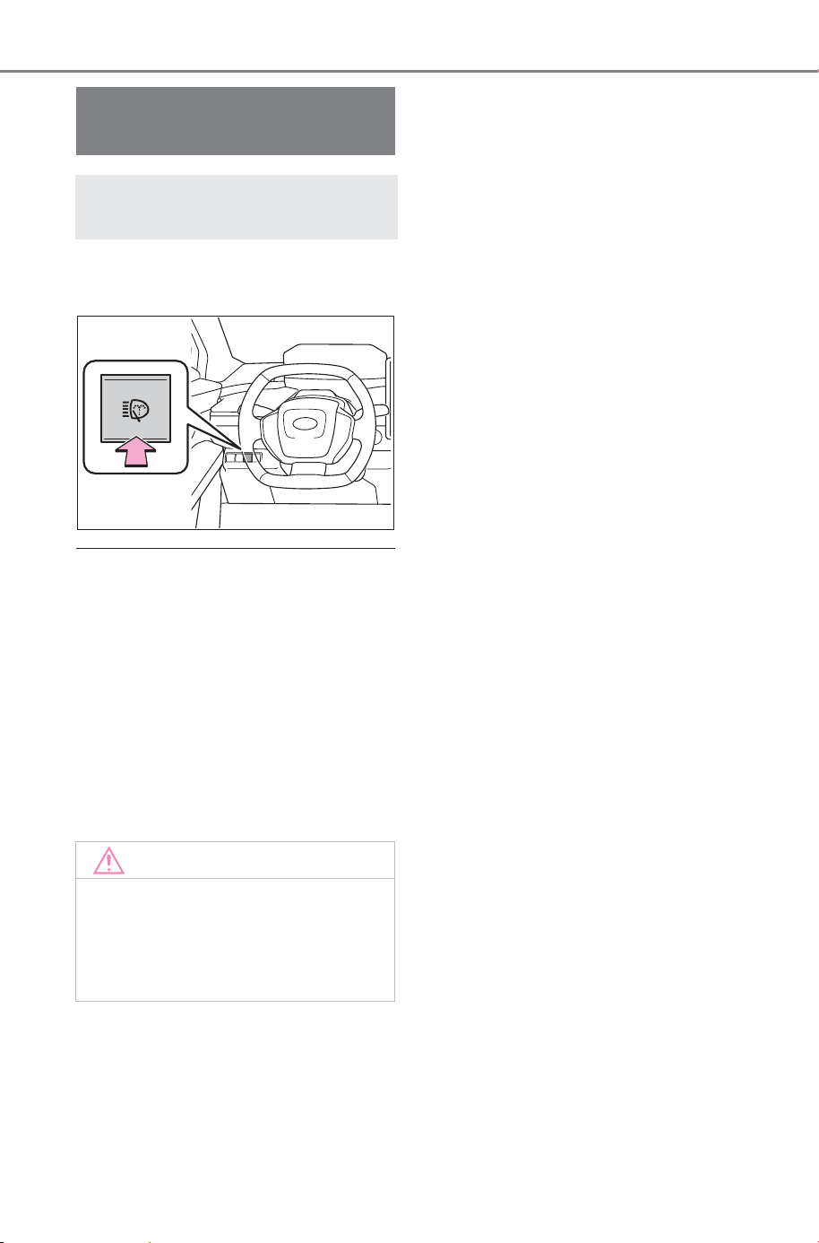
256
5-3. Operating the lights and wipers
Owner’s Manual_USA_M6740B_en
Press the switch to clean the
headlights.
■ The headlight cleaners can be
operated when
The power switch is in ON and the
headlight switch is turned on.
■ Windshield washer linked oper-
ation
When the power switch is in ON and
the headlights are on, if the lever is
pulled, the headlight cleaners will
operate once. After this, the head-
light cleaners will operate every 5th
time the lever is pulled. (P.253)
Headlight cleaner
switch
Washer fluid can be sprayed
on the headlights.
NOTICE
■ When the washer fluid tank is
empty
Do not press the switch continu-
ally as the washer fluid pump may
overheat.
SOLTERRA_OM_USA_A6740BE.book 256 ページ 2025年5月23日 金曜日 午後1時18分
257
5-4. Using the driving support systems
Owner’s Manual_USA_M6740B_en
5
Driving
5-4.Us ing the driving support systems
This Owner’s Manual contains
information for Ver. 3. For the
latest information about the con-
trols, use, warnings/precautions,
etc., of each function of SUB-
ARU Safety Sense/Traffic Jam
Assist, refer to the Digital
Owner’s Manual at the Owner’s
Manual website.
Before using this system, be
sure to read the Owner’s Man-
ual which corresponds to the
software version of the system.
■ Precautions for use
● Be aware that some functions
may temporarily be disabled if a
legal or safety related issue
occurs.
● If a connected services contract
has not been entered or has
expired, software updates will not
be able to be performed wire-
lessly.
To access the appropriate
Owner’s Manual, it is necessary
to check the software version of
the system and then visit the
Owner’s Manual website.
■ Checking the version using
SubaruConnect App
The software version of the sys-
tem can be checked using Sub-
aruConnect App.
SUBARU Safety
Sense/Traffic Jam
Assist software
update
It is necessary to enter a
connected services con-
tract, provided by SUB-
ARU, to use these
functions. For details, con-
tact your SUBARU dealer.
WARNING
■ For safe use
When the SUBARU Safety
Sense/Traffic Jam Assist software
is updated, the operating methods
of functions may change. Using
this system without knowing the
correct operating methods may
lead to an accident resulting in
death or serious injury.
● Make sure to read the Digital
Owner’s Manual which corre-
sponds to the software version
of the system, available at the
Owner’s Manual website,
before using this system.
Content of the SUBARU
Safety Sense/Traffic Jam
Assist Owner’s Manual
Checking your vehicle’s
SUBARU Safety
Sense/Traffic Jam Assist
version
SOLTERRA_OM_USA_A6740BE.book 257 ページ 2025年5月23日 金曜日 午後1時18分
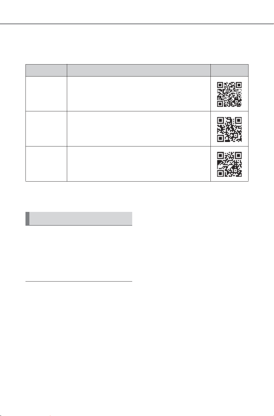
258
5-4. Using the driving support systems
Owner’s Manual_USA_M6740B_en
■ Selecting your vehicle’s SUBARU Safety Sense/Traffic Jam
Assist version
1 Access the following URL using a computer or smartphone:
2 Select the file which includes the previously checked system ver-
sion.
If a software update is available,
a notification will be displayed
by SubaruConnect App. Follow
the instructions displayed on the
screen.
■ Software update precautions
● After a software update has been
performed, it will not be possible
to revert to a previous version.
● Depending on the communication
environment and the content of an
update, a software update may
take several hours. Although an
update will be suspended when
the power switch is turned off, it
will resume when the power
switch is changed back to ON.
● SUBARU Safety Sense/Traffic
Jam Assist can still be used while
a software update is being per-
formed.
■ What can be checked using the
SubaruConnect App
The following items can be checked
or performed.
● Software version, update details,
precautions, use methods, etc.
● Software update
Country URL QR code
U.S.A.
SUBARU of America
https://www.subaru.com/owners/
vehicle-resources.html
Canada
SUBARU Canada English
https://www.subaru.ca/manuals
Canada
SUBARU Canada French
https://www.subaru.ca/manuels
Updating the software
SOLTERRA_OM_USA_A6740BE.book 258 ページ 2025年5月23日 金曜日 午後1時18分
259
5-4. Using the driving support systems
Owner’s Manual_USA_M6740B_en
5
Driving
SUBARU Safety Sense
The SUBARU Safety Sense
consists of the driving
assist systems and contrib-
utes to a safe and comfort-
able driving experience:
WARNING
■ SUBARU Safety Sense
The SUBARU Safety Sense oper-
ates under the assumption that
the driver will drive safely, and is
designed to help reduce the
impact to the occupants in a colli-
sion and assist the driver under
normal driving conditions.
As there is a limit to the degree of
recognition accuracy and control
performance that this system can
provide, do not overly rely on this
system. The driver is solely
responsible for paying attention to
the vehicle’s surroundings and
driving safely.
■ For safe use
● Do not overly rely on this sys-
tem. The driver is solely respon-
sible for paying attention to the
vehicle’s surroundings and driv-
ing safely. This system may not
operate in all situations and pro-
vided assistance is limited.
Over-reliance on this system to
drive the vehicle safely may
lead to an accident resulting in
death or serious injury.
● Do not attempt to test the oper-
ation of the system, as it may
not operate properly, possibly
leading to an accident.
● If attention is necessary while
performing driving operations or
a system malfunction occurs, a
warning message or warning
buzzer will be operated. If a
warning message is displayed
on the display, follow the
instructions displayed.
● Depending on external noise,
the volume of the audio system,
etc., it may be difficult to hear
the warning buzzer. Also,
depending on the road condi-
tions, it may be difficult to recog-
nize the operation of the
system.
■ When it is necessary to dis-
able the system
In the following situations, make
sure to disable the system.
Failure to do so may lead to the
system not operating properly,
possibly leading to an accident
resulting in death or serious injury.
● When the vehicle is tilted due to
being overloaded or having a
flat tire
● When driving at extremely high
speeds
● When towing another vehicle
● When the vehicle is being trans-
ported by a truck, ship, train,
etc.
● When the vehicle is raised on a
lift and the tires are allowed to
rotate freely
● When inspecting the vehicle
using a drum tester such as a
chassis dynamometer or speed-
ometer tester, or when using an
on vehicle wheel balancer
● When the vehicle is driven in a
sporty manner or off-road
SOLTERRA_OM_USA_A6740BE.book 259 ページ 2025年5月23日 金曜日 午後1時18分
260
5-4. Using the driving support systems
Owner’s Manual_USA_M6740B_en
■ AHB (Automatic High
Beam)
P.249
■ PCS (Pre-Collision System)
P.270
■ LTA (Lane Tracing Assist)
P.282
■ LDA (Lane Departure Alert)
P.290
■ LCA (Lane Change Assist)
P.287
■ FCTA (Front Cross Traffic
Alert)
P.301
■ PDA (Proactive driving
assist)
P.295
■ RSA (Road Sign Assist)
P.303
■ Dynamic radar cruise con-
trol
P.306
■ Cruise control
P.317
■ Emergency Driving Stop
System
P.321
■ Traffic Jam Assist
P.324
■ Driver monitor
P.267
WARNING
● When using an automatic car
wash
● When a sensor is misaligned or
deformed due to a strong
impact being applied to the sen-
sor or the area around the sen-
sor
● When accessories which
obstruct a sensor or light are
temporarily installed to the vehi-
cle
● When a compact spare tire or
tire chains are installed to the
vehicle or an emergency tire
puncture repair kit has been
used
● When the tires are excessively
worn or the inflation pressure of
the tires is low
● When tires other than the manu-
facturer specified size are
installed
● When the vehicle cannot be
driven stably, due to a collision,
malfunction, etc.
Driving assist systems
SOLTERRA_OM_USA_A6740BE.book 260 ページ 2025年5月23日 金曜日 午後1時18分
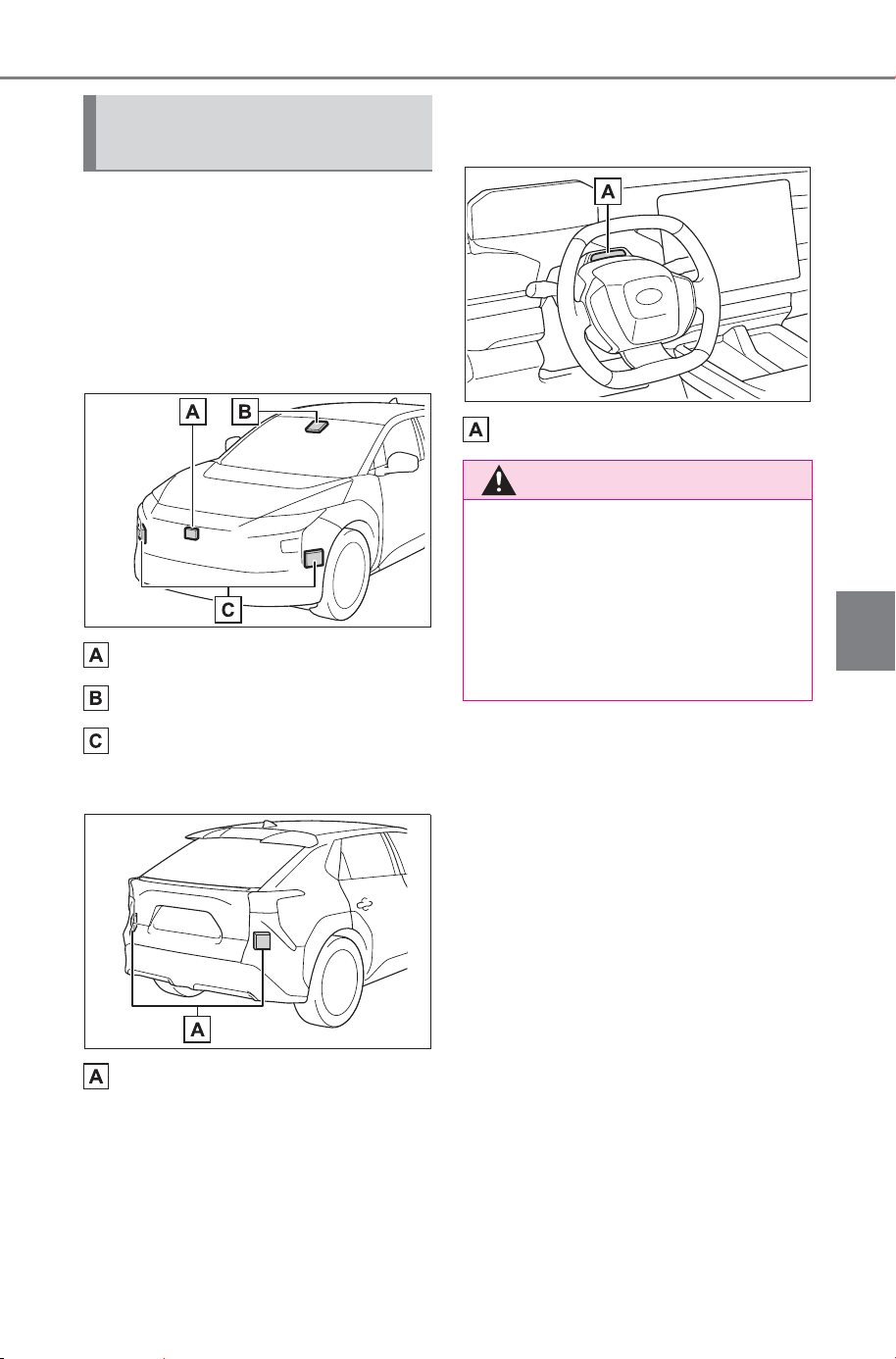
261
5-4. Using the driving support systems
Owner’s Manual_USA_M6740B_en
5
Driving
Various sensors are used to
obtain the necessary informa-
tion for system operation.
■ Sensors which detect the
surrounding conditions
Front
Front radar sensor
Front camera
Front side radar sensors
Rear
Rear side radar sensors
■ Sensors which detect the
driver condition
Driver monitor camera
Sensors used by SUB-
ARU Safety Sense
WARNING
■ To prevent malfunction of the
radar sensors
Observe the following precau-
tions. Failure to do so may lead to
a radar sensor not operating prop-
erly, possibly leading to an acci-
dent resulting in death or serious
injury.
SOLTERRA_OM_USA_A6740BE.book 261 ページ 2025年5月23日 金曜日 午後1時18分
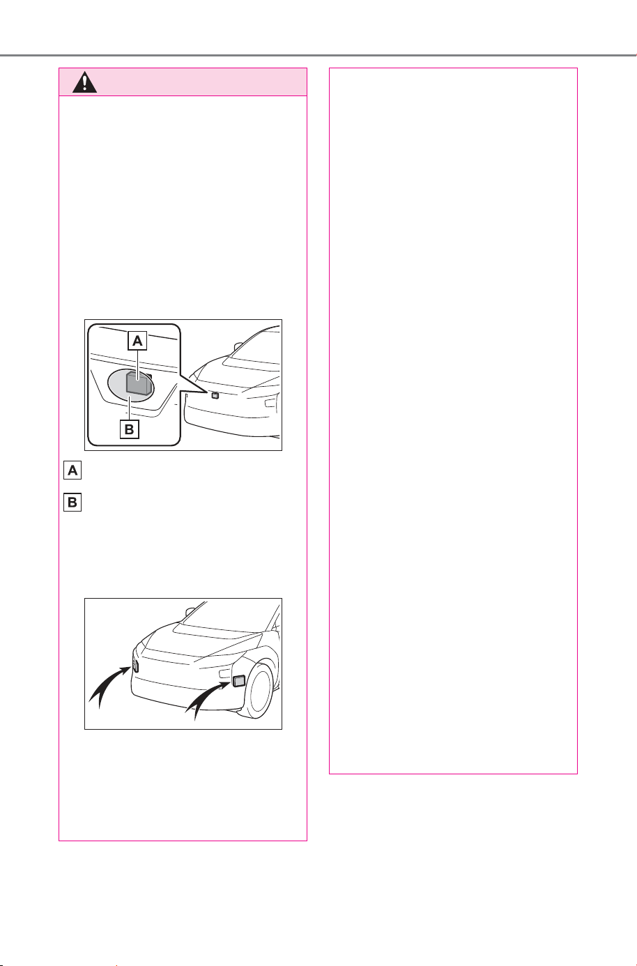
262
5-4. Using the driving support systems
Owner’s Manual_USA_M6740B_en
WARNING
● Keep the radar sensors and
radar sensor covers clean at all
times.
Clean the front of a radar sensor
or the front or back of a radar sen-
sor cover if it is dirty or covered
with water droplets, snow, etc.
When cleaning the radar sensor
and radar sensor cover, use a soft
cloth to remove dirt so as to not
damage them.
Radar sensor
Radar sensor cover
● Keep the surrounding area of
the front side radar sensors on
the front bumper clean at all
times.
● Do not attach accessories,
stickers (including transparent
stickers), aluminum tape, etc.,
to a radar sensor or radar sen-
sor cover and their surrounding
area.
● Do not subject a radar sensor or
its surrounding area to impact.
If a radar sensor, the front grille,
or front bumper has been sub-
jected to a impact, have the
vehicle inspected by your SUB-
ARU dealer.
● Do not disassemble the radar
sensors.
● Do not modify or paint the radar
sensors or radar sensor cover,
or replace them with anything
other than SUBARU genuine
parts.
● In the following situations, recal-
ibration of the radar sensors will
be necessary. For details, con-
tact your SUBARU dealer.
• When a radar sensor is
removed and installed, or
replaced
• When the front bumper or the
front grille has been replaced
■ To prevent malfunction of the
front camera
Observe the following precau-
tions.
Failure to do so may lead to the
front camera not operating prop-
erly, possibly leading to an acci-
dent resulting in death or serious
injury.
● Always keep the windshield
clean.
• If the windshield is dirty or cov-
ered with an oily film, water
droplets, snow, etc., clean the
windshield.
SOLTERRA_OM_USA_A6740BE.book 262 ページ 2025年5月23日 金曜日 午後1時18分
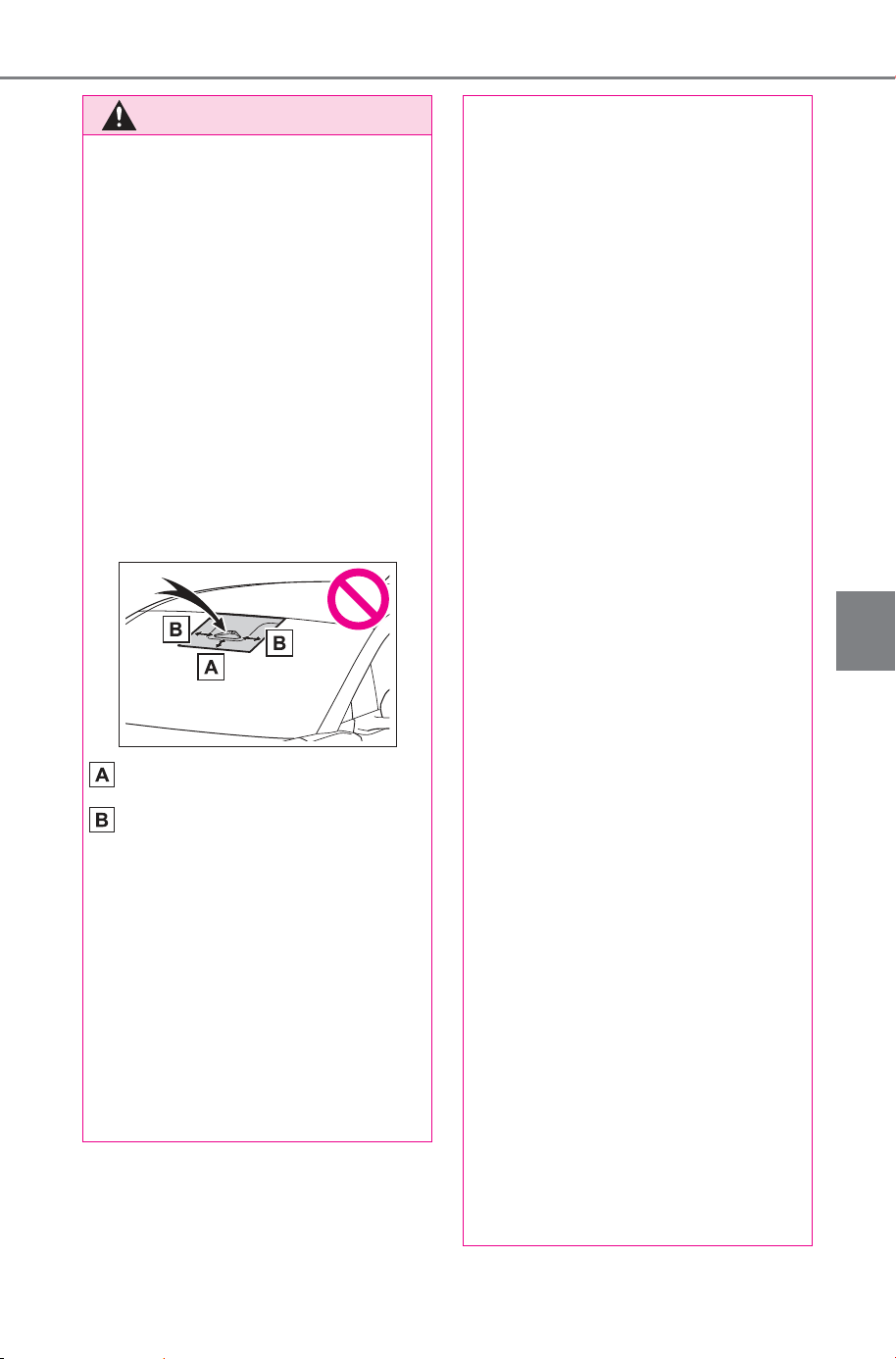
263
5-4. Using the driving support systems
Owner’s Manual_USA_M6740B_en
5
Driving
WARNING
• Even if a glass coating agent is
applied to the windshield, it will
still be necessary to use the
windshield wipers to remove
water droplets, etc., from the
area of the windshield in front of
the front camera.
• If the inner side of the wind-
shield where the front camera is
installed is dirty, contact your
SUBARU dealer.
● Do not attach stickers (including
transparent stickers) or other
items to the area of the wind-
shield in front of the front cam-
era (shaded area in the
illustration).
Approximately 1.6 in. (4 cm)
Approximately 1.6 in. (4 cm)
● If the part of the windshield in
front of the front camera is
fogged up or covered with con-
densation or ice, use the wind-
shield defogger to remove the
fog, condensation, or ice.
● If water droplets cannot be
properly removed from the area
of the windshield in front of the
front camera by the windshield
wipers, replace the wiper insert
or wiper blade.
● Do not attach window tint to the
windshield.
● Replace the windshield if it is
damaged or cracked.
If the windshield has been
replaced, recalibration of the
front camera will be necessary.
For details, contact your SUB-
ARU dealer.
● Do not allow liquids to contact
the front camera.
● Do not allow bright lights to
shine into the front camera.
● Do not damage the lens of the
front camera or allow it to
become dirty.
When cleaning the inside of the
windshield, do not allow glass
cleaner to contact the lens of
the front camera. Do not touch
the lens of the front camera.
If the lens of the front camera is
dirty or damaged, contact your
SUBARU dealer.
● Do not subject the front camera
to a strong impact.
● Do not change the position or
orientation of the front camera
or remove it.
● Do not disassemble the front
camera.
● Do not modify any parts around
the front camera, such as the
inside rear view mirror or ceil-
ing.
● Do not attach accessories
which may obstruct the front
camera to the hood, front grille,
or front bumper. For details,
contact your SUBARU dealer.
● If a surfboard or other long
object is to be mounted on the
roof, make sure that it will not
obstruct the front camera.
SOLTERRA_OM_USA_A6740BE.book 263 ページ 2025年5月23日 金曜日 午後1時18分
264
5-4. Using the driving support systems
Owner’s Manual_USA_M6740B_en
■ Situations in which the sensors
and the systems may not oper-
ate properly
● When the height or inclination of
the vehicle has been changed due
to modifications
● When the windshield is dirty,
fogged up, cracked or damaged
● When the ambient temperature is
high or low
● When mud, water, snow, dead
insects, foreign matter, etc., is
attached to the front of the sensor
● When in inclement weather such
as heavy rain, fog, snow, or a
sandstorm
● When water, snow, dust, etc., is
thrown up in front of the vehicle, or
when driving through mist or
smoke
● When the headlights are not illu-
minated while driving in the dark,
such as at night or when in a tun-
nel
● When the lens of a headlight is
dirty and illumination is weak
WARNING
● Do not modify or change the
headlights and other lights.
■ Front camera installation area
on the windshield
If the system determines that the
windshield may be fogged up, it
will automatically operate the
heater to defog the part of the
windshield around the front cam-
era. When cleaning, etc., be care-
ful not to touch the area around
the front camera until the wind-
shield has cooled sufficiently, as
touching it may cause burns.
■ Precautions for the driver
monitor camera
Observe the following precau-
tions.
Failure to do so may lead to mal-
function of the driver monitor cam-
era and the systems not operating
properly, possibly leading to an
accident resulting in death or seri-
ous injury.
● Do not subject the driver moni-
tor camera or its surrounding
area to strong impact.
If subjected to a strong impact,
the driver monitor camera may
move out of alignment and the
driver may no longer be detected
correctly. In this case, have the
vehicle inspected by your SUB-
ARU dealer.
● Do not disassemble or modify
the driver monitor camera.
● Do not attach accessories,
stickers (including transparent
stickers), etc. to the driver moni-
tor camera or its surrounding
area.
● Do not allow the driver monitor
camera or its surrounding area
to get wet.
● Do not cover the driver monitor
camera or place anything in
front of it.
● Keep the lens of the driver mon-
itor camera free from damage.
● Do not touch the lens of the
driver monitor camera or allow it
to become dirty.
When there is dirt or fingerprints
on the camera lens, clean it with a
dry, soft cloth so as to not mark or
damage it.
● When cleaning the lens, do not
use detergents or organic sol-
vents that may damage plastic.
SOLTERRA_OM_USA_A6740BE.book 264 ページ 2025年5月23日 金曜日 午後1時18分
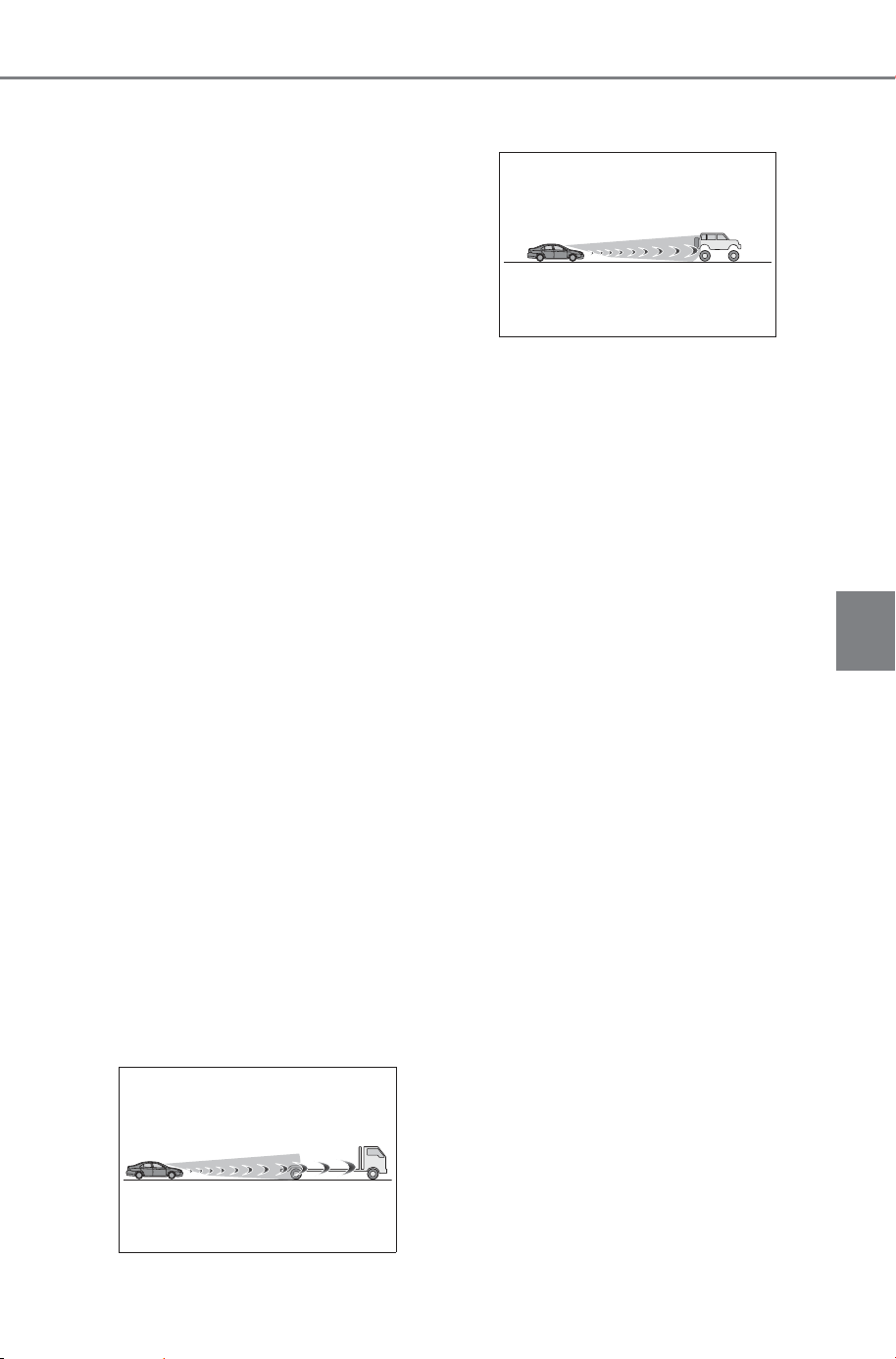
265
5-4. Using the driving support systems
Owner’s Manual_USA_M6740B_en
5
Driving
● When the headlights are mis-
aligned
● When a headlight is malfunction-
ing
● When the headlights of another
vehicle, sunlight, or reflected light
shines directly into the front cam-
era
● When the brightness of the sur-
rounding area changes suddenly
● When driving near a TV tower,
broadcasting station, electric
power plant, radar equipped vehi-
cles, etc., or other location where
strong radio waves or electrical
noise may be present
● When a wiper blade is blocking
the front camera
● When in a location or near objects
which strongly reflect radio waves,
such as the following:
• Tunnels
• Truss bridges
• Gravel roads
• Rutted, snow-covered roads
•Walls
• Large trucks
• Manhole covers
• Guardrail
•Metal plates
● When near a step or protrusion
● When a detectable vehicle is nar-
row, such as a small mobility vehi-
cle
● When a detectable vehicle has a
small front or rear end, such as an
unloaded truck
● When a detectable vehicle has a
low front or rear end, such as a
low bed trailer
● When a detectable vehicle has
extremely high ground clearance
● When a detectable vehicle is car-
rying a load which protrudes from
its cargo area
● When a detectable vehicle has lit-
tle exposed metal, such as a vehi-
cle which is partially covered with
cloth, etc.
● When a detectable vehicle is
irregularly shaped, such as a trac-
tor, sidecar, etc.
● When the distance between the
vehicle and a detectable vehicle
has become extremely short
● When a detectable vehicle is at an
angle
● When snow, mud, etc., is attached
to a detectable vehicle
● When driving on the following
kinds of roads:
• Roads with sharp curves or wind-
ing roads
• Roads with changes in grade,
such as sudden inclines or
declines
• Roads which is sloped to the left
or right
• Roads with deep ruts
• Roads which are rough and
unmaintained
• Roads which frequently undulate
or are bumpy
● When the steering wheel is being
operated frequently or suddenly
● When the vehicle is not in a con-
stant position within a lane
● When parts related to this system,
the brakes, etc., are cold or
extremely hot, wet, etc.
SOLTERRA_OM_USA_A6740BE.book 265 ページ 2025年5月23日 金曜日 午後1時18分

266
5-4. Using the driving support systems
Owner’s Manual_USA_M6740B_en
● When the wheels are misaligned
● When driving on slick road sur-
faces, such as when it is covered
with ice, snow, gravel, etc.
● When the course of the vehicle
differs from the shape of a curve
● When the vehicle speed is exces-
sively high when entering a curve
● When entering/exiting a parking
lot, garage, car elevator, etc.
● When driving in a parking lot
● When driving through an area
where there are obstructions
which may contact your vehicle,
such as tall grass, tree branches,
a curtain, etc.
● When driving in strong wind
■ Situations in which the lane
may not be detected
● When the lane is extremely wide
or narrow
● Immediately after changing lanes
or passing through an intersection
● When driving in a temporary lane
or lane regulated by construction
● When there are structures, pat-
terns, shadows which are similar
to lane lines in the surrounding
● When there are multiple white
lines for a lane line
● When the lane lines are not clear
or driving on a wet road surface
● When a lane line is on a curb
● When driving on a bright, reflec-
tive road surface, such as con-
crete
■ Situations in which some or all
of the functions of the system
cannot operate
● When a malfunction is detected in
this system or a related system,
such as the brakes, steering, etc.
● When the VSC, TRAC, or other
safety related system is operating
● When the VSC, TRAC, or other
safety related system is off
■ Changes in brake operation
sound and pedal response
● When the brakes have been oper-
ated, brake operation sounds may
be heard and the brake pedal
response may change, but this
does not indicate a malfunction.
● When the system is operating, the
brake pedal may feel stiffer than
expected or sink. In either situa-
tion the brake pedal can be
depressed further. Further
depress the brake pedal as nec-
essary.
■ Situations in which the driver
monitor may not operate prop-
erly
In situations such as the following,
the driver monitor camera may not
be able to detect the driver’s face,
and the function may not operate
properly.
● When the inside of the vehicle is
hot, such as after the vehicle has
been parked in the sun
● When a very bright light, such as
the sun or the headlights of follow-
ing vehicle, shines onto the driver
monitor camera
● When the brightness inside the
vehicle changes frequently due to
the shadows of surrounding struc-
tures, etc.
● When a very bright light, such as
the sun or the headlights of an
oncoming vehicle, is shining onto
the driver’s face
● When light, either inside or out-
side of the vehicle, is being
reflected from the lenses of eye-
glasses or sunglasses
● When there are multiple faces in
the detection range of the driver
monitor camera, such as when a
front or rear passenger is leaning
toward the driver’s seat
SOLTERRA_OM_USA_A6740BE.book 266 ページ 2025年5月23日 金曜日 午後1時18分
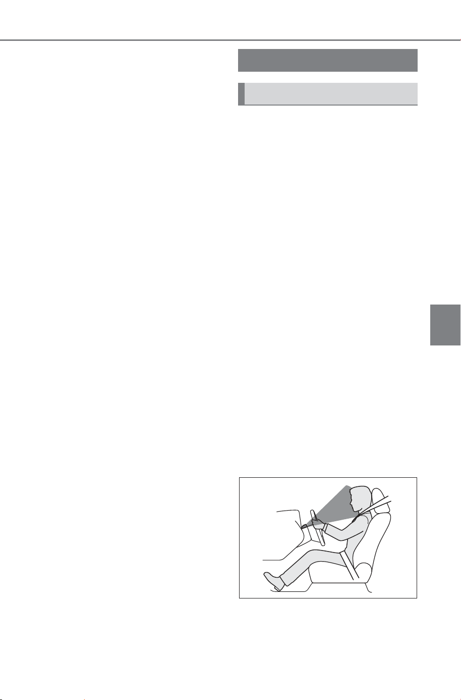
267
5-4. Using the driving support systems
Owner’s Manual_USA_M6740B_en
5
Driving
● When the driver’s face is outside
of the detection range of the driver
monitor camera, such as when
leaned forward or when their head
is outside of the window
● When the driver monitor camera is
being blocked by the steering
wheel, a hand holding the steering
wheel, an arm, etc.
● When the driver is wearing a hat
● When the driver is wearing an
eyepatch
● When the driver is wearing eye-
glasses or sunglasses that do not
easily transmit infrared rays
● When the driver is wearing con-
tact lenses
● When the driver is wearing a face
mask
● When the driver is laughing or the
driver’s eyes are only slightly open
● When the driver’s eyes, nose,
mouth, or shape of their face is
blocked
● When the driver is wearing
makeup which makes it difficult to
detect their eyes, nose, mouth, or
shape of their face
● When the driver’s eyes are
blocked by the frame of eye-
glasses, sunglasses, hair, etc.
● When there is a device inside the
vehicle that radiates near infrared
rays, such as a non-genuine
driver monitoring system.
■ Certification
P.732
During controlled driving, the
driver monitor camera detects
the position and direction the
driver is facing, and whether
their eyes are opened or closed.
Through this, the system deter-
mines if the driver is checking
their surroundings and if the
driver can perform driving oper-
ations.
In order to operate properly, the
driver monitor camera requires
an unobstructed view of the
driver’s face.
If the steering column or seat
position is either too high or too
low, or if any other condition is
present that obstructs the driver
monitor camera’s view of the
driver’s face, some driving sup-
port systems may not operate
properly, or a warning message
may be displayed.
Driver monitor
Basic functions
SOLTERRA_OM_USA_A6740BE.book 267 ページ 2025年5月23日 金曜日 午後1時18分
268
5-4. Using the driving support systems
Owner’s Manual_USA_M6740B_en
■ Warning function
In situations such as the follow-
ing, a buzzer will sound and a
message will be displayed to
warn the driver.
When the system determines
that the driver is not paying
attention to the road or their
eyes are closed.
When the driver’s face cannot
be detected or the system
determines that the driver has
poor driving posture.
When the position of the steering
wheel/driver’s seat is too high or
too low, the driver monitor camera
may not be able to recognize the
whole face of the driver which can
limit feature functionality and possi-
bly trigger an alarm. Adjust the
steering wheel/seat position to
achieve a proper seating position
where the whole meter is visible.
Confirm proper seat belt routing,
head restraint positioning, and
appropriate distance from the steer-
ing wheel and frontal airbag as
described in this manual. If the
alarm continues even after making
the recommended adjustments,
contact your SUBARU dealer.
■ Face identification
The driver monitor is used as a
device to identify faces in order
to identify an individual.
For information about how to
use the face identification func-
tion, priorities among other
devices of individual identifica-
tion, and linked vehicle settings,
see “My Settings”. (P.210)
WARNING
■ For safe use
● The driver monitor is not
designed to prevent the driver
from driving carelessly or hav-
ing a poor driving posture.
Pay careful attention to the sur-
rounding conditions in order to
ensure safe driving.
● The driver monitor cannot
reduce drowsiness. If you feel
unable to concentrate or
drowsy, take a break and sleep
as necessary in order to ensure
safe driving.
SOLTERRA_OM_USA_A6740BE.book 268 ページ 2025年5月23日 金曜日 午後1時18分
269
5-4. Using the driving support systems
Owner’s Manual_USA_M6740B_en
5
Driving
■ Warning function
These functions may not operate
when the vehicle speed is low.
■ Face identification
Face identification starts when the
door is opened then closed.
In face identification, facial traits are
digitized and stored in a built-in
computer, to be used for identifica-
tion in My Settings.
● Face image or video are not
stored. Voice is not stored either.
● Digitized face information is not
used for any purpose other than
identification in My Settings. Addi-
tionally, face information cannot
be decoded and will not be dis-
closed or provided to a third party.
● Face information can be deleted
by yourself.
● For the handling of face informa-
tion, please consent to the follow-
ing before using it:
• Face identification does not guar-
antee a complete identity authen-
tication, collation, or identification.
• When face information registration
fails frequently or face identifica-
tion fails frequently, the driver
cameras should be cleaned or
face information should be regis-
tered again.
• Face information stored in the
vehicle computer cannot be
decoded or moved to another
media. Therefore, it is necessary
to register face information again
once it is deleted or relevant parts
are replaced.
• Once deleted, face information
cannot be restored. It is necessary
to register face information again.
■ Situations where face identifi-
cation may not be performed
correctly
This system is designed for use to
identify facial traits. In the following
situations, face information may not
be able to be registered or identified
correctly:
● When a part of the driver’s face
(eyebrows, eyes, nose, or mouth)
is not visible
● When the driver is wearing
glasses/sun glasses, a face mask,
muffler, etc.
● When the driver is not facing front
● When part of driver’s face is cov-
ered with hair, beard, a hand,
clothes, jewelry, etc.
● When the driver is closing eyes
● When a non-registered driver is a
twin, etc. with a registered driver,
whose face looks quite alike with
each other
■ Situations in which the driver
monitor may not operate prop-
erly
P.266
The Warning function of Driver
monitor can be enabled/dis-
abled through the customize
setting. (P.680)
Changing Driver monitor
settings
SOLTERRA_OM_USA_A6740BE.book 269 ページ 2025年5月23日 金曜日 午後1時18分
270
5-4. Using the driving support systems
Owner’s Manual_USA_M6740B_en
PCS (Pre-Collision Sys-
tem)
The pre-collision system
uses sensors to detect
objects (P.271) in the path
of the vehicle. When the
system determines that the
possibility of a frontal colli-
sion with a detectable
object is high, a warning
operates to urge the driver
to take evasive action and
the potential brake pressure
is increased to help the
driver avoid the collision. If
the system determines that
the possibility of a collision
is extremely high, the
brakes are automatically
applied to help avoid the
collision or help reduce the
impact of the collision.
The pre-collision system can
be disabled/enabled and the
warning timing can be
changed. (P.281)
WARNING
■ For safe use
● Driving safely is solely the
responsibility of the driver. Pay
careful attention to the sur-
rounding conditions in order to
ensure safe driving.
Never use the pre-collision sys-
tem in place of normal braking
operations. This system cannot
help avoid or reduce the impact
of a collision in every situation.
Over-reliance on this system to
drive the vehicle safely may
lead to an accident resulting in
death or serious injury.
● Although the pre-collision sys-
tem is designed to help avoid or
help reduce the impact of a col-
lision, its effectiveness may
change according to various
conditions. Therefore, it may not
always be able to achieve the
same level of performance.
Read the following items care-
fully. Do not overly rely on this
system and always drive care-
fully.
• For safe use: P. 259
■ When to disable the pre-colli-
sion system
When it is necessary to disable
the system: P.259
SOLTERRA_OM_USA_A6740BE.book 270 ページ 2025年5月23日 金曜日 午後1時18分
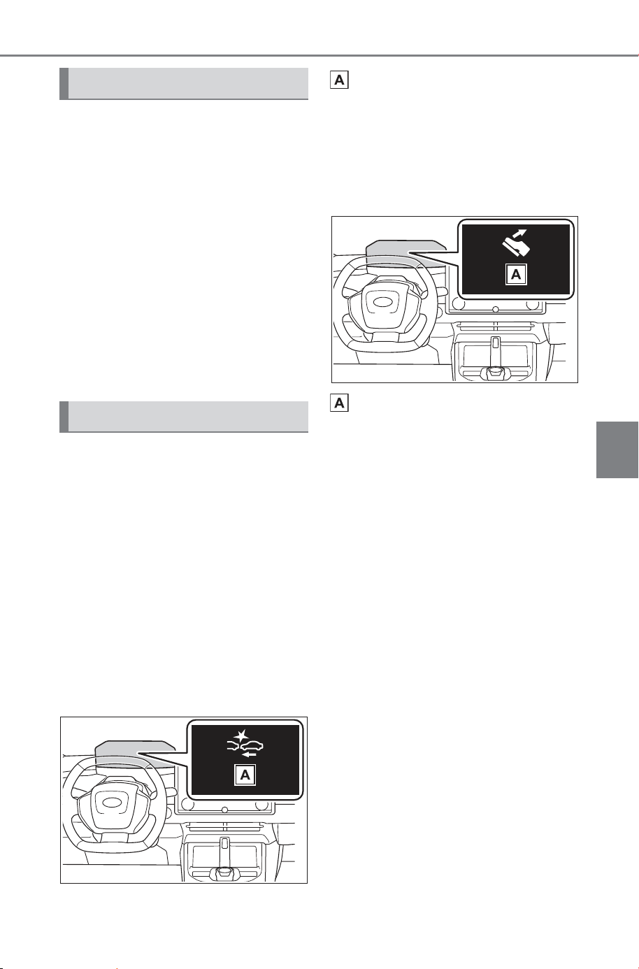
271
5-4. Using the driving support systems
Owner’s Manual_USA_M6740B_en
5
Driving
The system can detect the fol-
lowing as detectable objects.
(Detectable objects differ
depending on the function.)
Vehicles
Bicycles
*
Pedestrians
Motorcycles
*
Walls
*
: Detected as a detectable object
only when being ridden.
■ Pre-collision warning
When the system determines
that the possibility of a collision
is high, a buzzer will sound and
an icon and warning message
will be displayed on the multi-
information display to urge the
driver to take evasive action.
If the detectable object is a vehi-
cle, there may be cases where
moderate braking will be per-
formed with the warning.
“Pre-Collision System”
If the system determines that
the accelerator pedal is strongly
depressed, the following icon
and message will be displayed
on the multi-information display.
“Accelerator Pedal is
Pressed”
■ Pre-collision brake assist
If the system determines that
the possibility of a collision is
high and the brake operation by
the driver is insufficient, the
braking power will be increased.
■ Pre-collision brake control
If the system determines that
the possibility of a collision is
extremely high, the brakes are
automatically applied to help
avoid the collision or reduce the
impact of the collision.
Detectable objects
System functions
SOLTERRA_OM_USA_A6740BE.book 271 ページ 2025年5月23日 金曜日 午後1時18分
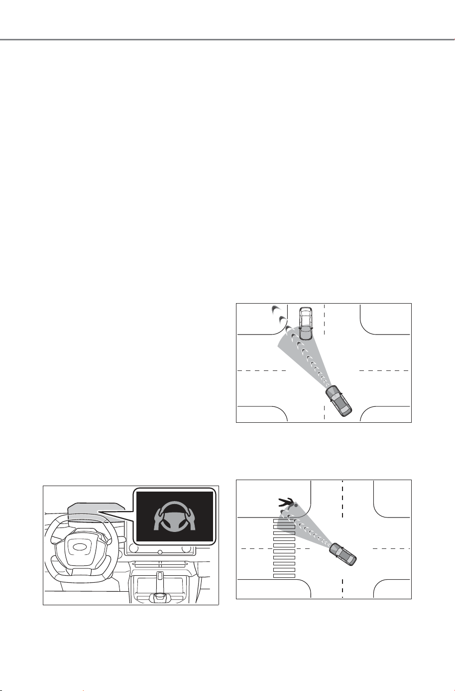
272
5-4. Using the driving support systems
Owner’s Manual_USA_M6740B_en
■ Emergency steering assist
If the system determines that
the following conditions are met,
assistance will be provided to
help enhance vehicle stability
and prevent lane departure.
During assistance, in addition to
the pre-collision warning, the fol-
lowing icon will be displayed on
the multi-information display.
The possibility of a collision is
high
There is sufficient space
within the lane to perform
evasive steering maneuvers
The driver is operating the
steering wheel
The brakes and steering are
controlled to help avoid a colli-
sion or reduce the impact of a
collision, regardless of the eva-
sive steering maneuvers per-
formed by the driver.
During assistance, the pre-colli-
sion warning will operate and a
message will be displayed to
warn the driver.
■ Intersection collision avoid-
ance support (left/right
turn)
In situations such as the follow-
ing, if the system determines
that the possibility of a collision
is high, the pre-collision warning
and pre-collision braking will
operate.
Depending on the intersection,
assistance may not operate cor-
rectly.
When turning left/right at an
intersection and crossing the
path of an oncoming vehi-
cle/motorcycle
When turning left/right and a
pedestrian or bicycle is
detected
SOLTERRA_OM_USA_A6740BE.book 272 ページ 2025年5月23日 金曜日 午後1時18分
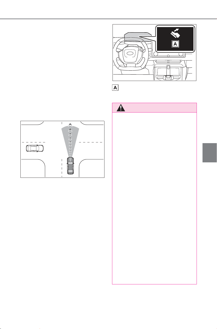
273
5-4. Using the driving support systems
Owner’s Manual_USA_M6740B_en
5
Driving
■ Intersection collision avoid-
ance support (crossing
vehicles)
At an intersection, etc., if the
system determines that the pos-
sibility of a collision with an
approaching vehicle or motorcy-
cle is high, the pre-collision
warning and pre-collision brak-
ing will operate.
Depending on the intersection,
assistance may not operate cor-
rectly.
■ Acceleration Suppression
at Low Speed
When driving at a low speed, if
the accelerator pedal is strongly
depressed and the system
determines that there is a possi-
bility of a collision, EV system
output will be restrained or the
brakes will be applied weakly to
restrict acceleration. During
operation, a buzzer will sound
and a warning indicator and
message will be displayed on
the multi-information display.
“Accelerator Pedal is
Pressed”
WARNING
■ Pre-collision braking
● When the pre-collision braking
function is operating, a large
amount of braking force will be
applied.
● The pre-collision braking func-
tion is not designed to hold the
vehicle stopped. If the vehicle is
stopped by pre-collision brake
control, the driver should oper-
ate the brakes immediately as
necessary.
● The pre-collision braking func-
tion may not operate if certain
operations are performed by the
driver. If the accelerator pedal is
being depressed strongly or the
steering wheel is being turned,
the system may determine that
the driver is taking evasive
action and possibly prevent the
pre-collision braking function
from operating.
● If the brake pedal is being
depressed, the system may
determine that the driver is tak-
ing evasive action and possibly
delay the operation timing of the
pre-collision brake control.
SOLTERRA_OM_USA_A6740BE.book 273 ページ 2025年5月23日 金曜日 午後1時18分

274
5-4. Using the driving support systems
Owner’s Manual_USA_M6740B_en
WARNING
■ Acceleration Suppression at
Low Speed
If the steering wheel is being
turned, the system may determine
that the driver is taking evasive
action and possibly prevent the
Acceleration Suppression at Low
Speed function from operating or
possibly causing its operation to
be canceled.
■ Emergency steering assist
● The emergency steering assist
will be canceled when the sys-
tem determines that lane depar-
ture prevention control has
completed.
● Depending on operations per-
formed by the driver, emer-
gency steering assist may not
operate or operation may be
canceled.
• If the accelerator pedal is
depressed strongly, the steering
wheel is turned heavily, the
brake pedal is depressed, or the
turn signal lever is operated, the
system may determine that the
driver is taking evasive action
and the emergency steering
assist may not operate.
• While the emergency steering
assist is operating, if the accel-
erator pedal is depressed
strongly, the steering wheel is
turned heavily, or the brake
pedal is depressed, the system
may determine that the driver is
taking evasive action and emer-
gency steering assist operation
may be canceled.
• While the emergency steering
assist is operating, if the steer-
ing wheel is held or turned in the
opposite direction of system
operation, emergency steering
assist operation will be can-
celed.
SOLTERRA_OM_USA_A6740BE.book 274 ページ 2025年5月23日 金曜日 午後1時18分
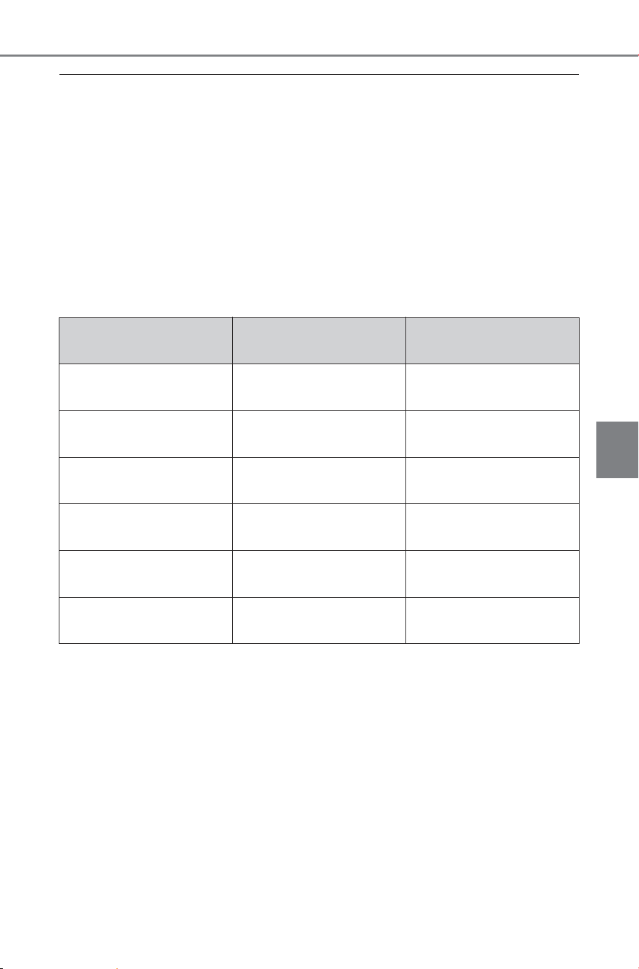
275
5-4. Using the driving support systems
Owner’s Manual_USA_M6740B_en
5
Driving
■ Operating conditions of each function of the pre-collision system
The pre-collision system is enabled and the system determines that the pos-
sibility of a frontal collision with a detected object is high.
However, the system will not operate in the following situations:
● When the vehicle has not been driven a certain amount after a terminal of
the 12-volt battery has been disconnected and reconnected
● When the shift position is in R
● When the VSC OFF indicator is illuminated (only the pre-collision warning
function will be operational)
The following are the operational speeds and cancelation conditions of each
function:
● Pre-collision warning
While the pre-collision warning is operating, if the steering wheel is operated
heavily or suddenly, the pre-collision warning may be canceled.
Detectable objects Vehicle speed
Relative speed between
your vehicle and object
Preceding vehicles,
stopped vehicles
Approximately 3 to 110
mph (5 to 180 km/h)
Approximately 3 to 110
mph (5 to 180 km/h)
Oncoming vehicles
Approximately 20 to 110
mph (30 to 180 km/h)
Approximately 50 to 130
mph (80 to 220 km/h)
Bicycles
Approximately 3 to 50
mph (5 to 80 km/h)
Approximately 3 to 50
mph (5 to 80 km/h)
Pedestrians
Approximately 3 to 50
mph (5 to 80 km/h)
Approximately 3 to 50
mph (5 to 80 km/h)
Preceding motorcycles,
stopped motorcycles
Approximately 3 to 110
mph (5 to 180 km/h)
Approximately 3 to 50
mph (5 to 80 km/h)
Oncoming motorcycles
Approximately 20 to 110
mph (30 to 180 km/h)
Approximately 20 to 110
mph (30 to 180 km/h)
SOLTERRA_OM_USA_A6740BE.book 275 ページ 2025年5月23日 金曜日 午後1時18分
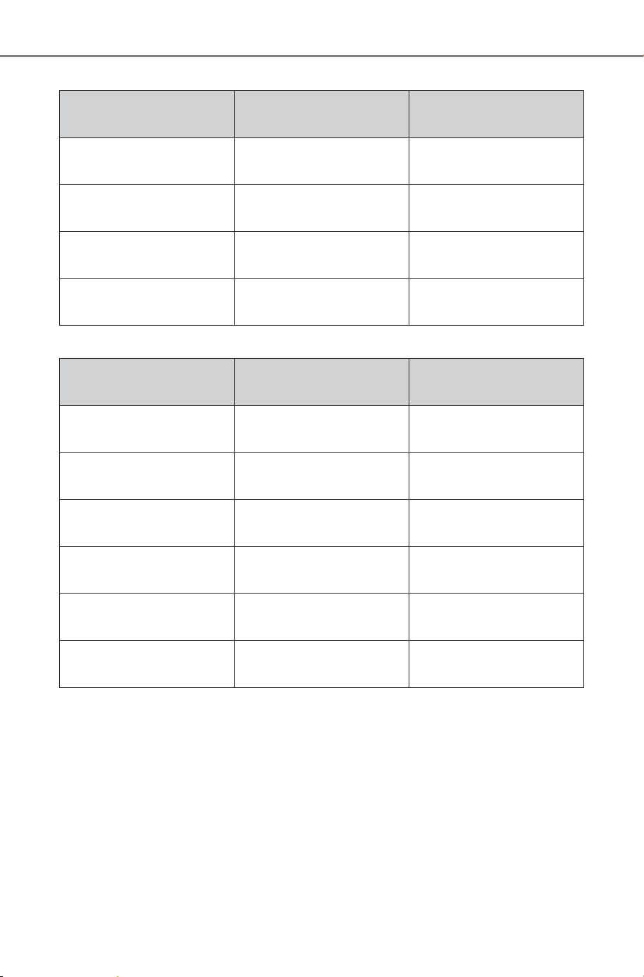
276
5-4. Using the driving support systems
Owner’s Manual_USA_M6740B_en
● Pre-collision brake assist
● Pre-collision braking
If either of the following occur while the pre-collision braking function is oper-
ating, it will be canceled:
• The accelerator pedal is strongly depressed
• The steering wheel is operated heavily or suddenly
Detectable objects Vehicle speed
Relative speed between
your vehicle and object
Preceding vehicles,
stopped vehicles
Approximately 20 to 110
mph (30 to 180 km/h)
Approximately 7 to 110
mph (10 to 180 km/h)
Bicycles
Approximately 20 to 50
mph (30 to 80 km/h)
Approximately 20 to 50
mph (30 to 80 km/h)
Pedestrians
Approximately 20 to 50
mph (30 to 80 km/h)
Approximately 20 to 50
mph (30 to 80 km/h)
Preceding motorcycles,
stopped motorcycles
Approximately 20 to 110
mph (30 to 180 km/h)
Approximately 7 to 50
mph (10 to 80 km/h)
Detectable objects Vehicle speed
Relative speed between
your vehicle and object
Preceding vehicles,
stopped vehicles
Approximately 3 to 110
mph (5 to 180 km/h)
Approximately 3 to 110
mph (5 to 180 km/h)
Oncoming vehicles
Approximately 20 to 110
mph (30 to 180 km/h)
Approximately 50 to 130
mph (80 to 220 km/h)
Bicycles
Approximately 3 to 50
mph (5 to 80 km/h)
Approximately 3 to 50
mph (5 to 80 km/h)
Pedestrians
Approximately 3 to 50
mph (5 to 80 km/h)
Approximately 3 to 50
mph (5 to 80 km/h)
Preceding motorcycles,
stopped motorcycles
Approximately 3 to 110
mph (5 to 180 km/h)
Approximately 3 to 50
mph (5 to 80 km/h)
Oncoming motorcycles
Approximately 20 to 110
mph (30 to 180 km/h)
Approximately 20 to 110
mph (30 to 180 km/h)
SOLTERRA_OM_USA_A6740BE.book 276 ページ 2025年5月23日 金曜日 午後1時18分
277
5-4. Using the driving support systems
Owner’s Manual_USA_M6740B_en
5
Driving
● Emergency steering assist
The emergency steering assist will not operate when the turn signal lights
are flashing.
*
: Minimum vehicle speed: Vehicle speed at which evasion using pre-colli-
sion brake control is difficult
While the emergency steering assist is operating, if any of the following are
performed, emergency steering assist operation may be canceled:
• The accelerator pedal is strongly depressed
• The steering wheel is operated heavily or suddenly
• The brake pedal is depressed
● Intersection collision avoidance support (left/right turn)
The intersection collision avoidance support (for left/right turning vehicles)
will not operate when the turn signal lights are not flashing.
Detectable objects Vehicle speed
Relative speed between
your vehicle and object
Preceding vehicles,
stopped vehicles, bicy-
cles, pedestrians,
motorcycles
Approximately 25 to 50
mph (40 to 80 km/h)
Approximately 25 to 50
mph (40 to 80 km/h)
Preceding vehicles,
stopped vehicles, bicy-
cles, pedestrians,
motorcycles
Active steering func-
tion:
*
to 50 mph
(
*
to 80 km/h)
Active steering func-
tion:
*
to 50 mph
(
*
to 80 km/h)
Detectable
objects
Vehicle speed
Oncoming vehicle
speed
Relative speed
between your
vehicle and object
Oncoming vehi-
cles
Approximately 3
to 25 mph (5 to
40 km/h)
Approximately 3
to 45 mph (5 to
75 km/h)
Approximately 7
to 70 mph (10 to
115 km/h)
Pedestrians
Approximately 3
to 20 mph (5 to
30 km/h)
-
Approximately 3
to 25 mph (5 to
40 km/h)
Bicycles
Approximately 3
to 20 mph (5 to
30 km/h)
-
Approximately 3
to 30 mph (5 to
50 km/h)
Oncoming motor-
cycles
Approximately 3
to 25 mph (5 to
40 km/h)
Approximately 3
to 45 mph (5 to
75 km/h)
Approximately 7
to 70 mph (10 to
115 km/h)
SOLTERRA_OM_USA_A6740BE.book 277 ページ 2025年5月23日 金曜日 午後1時18分
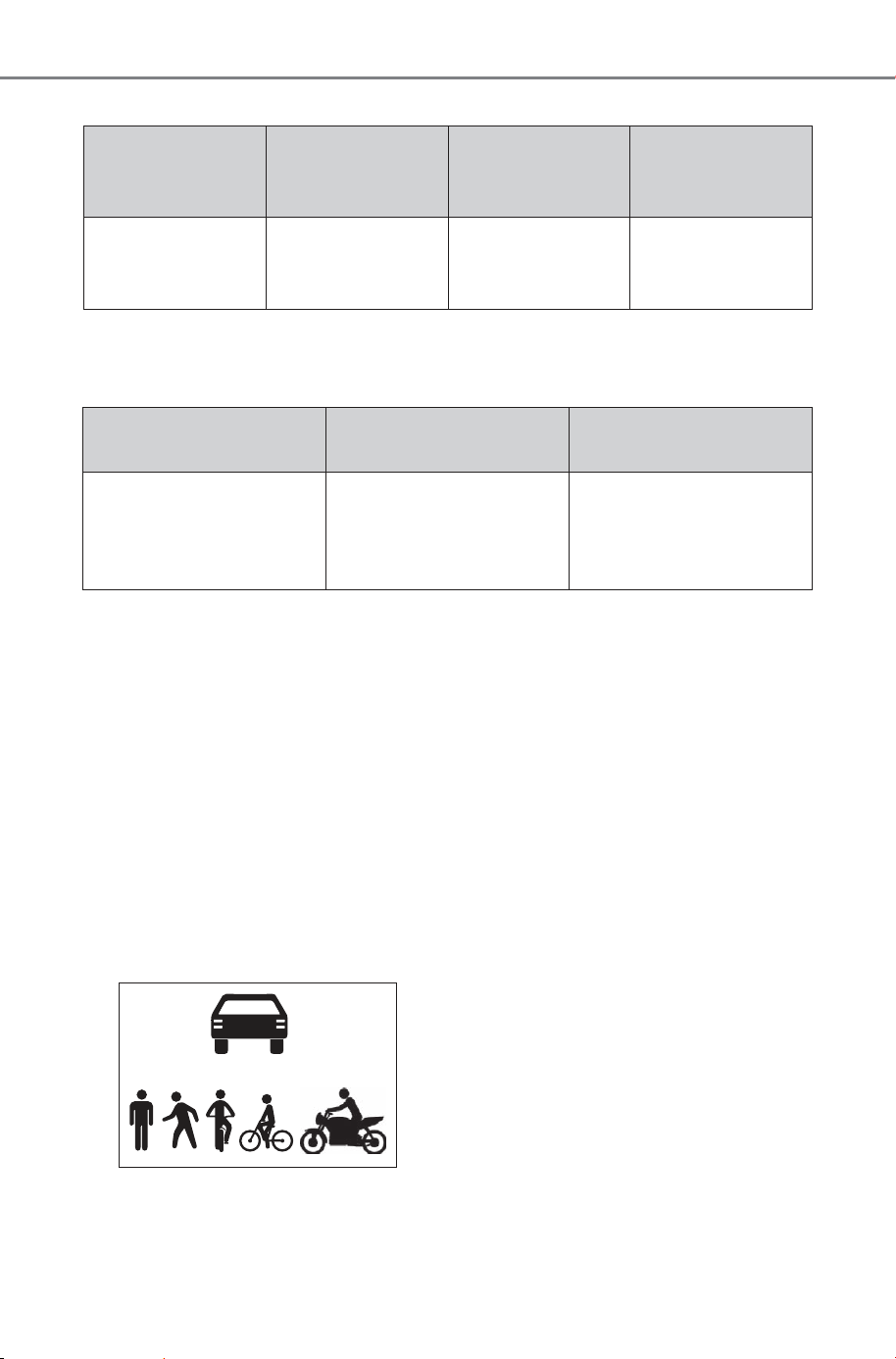
278
5-4. Using the driving support systems
Owner’s Manual_USA_M6740B_en
● Intersection collision avoidance support (crossing vehicles)
● Acceleration Suppression at Low Speed
The Acceleration Suppression at Low Speed function will not operate when
the turn signal lights are flashing.
While the Acceleration Suppression at Low Speed function is operating, if
any of the following are performed, the low speed sudden acceleration sup-
pression function operation will be canceled:
• The accelerator pedal is released.
• The steering wheel is operated heavily or suddenly
■ Detection of detectable objects
Objects are detected based on their
size, shape, and movement.
Depending on the ambient bright-
ness, movement, posture and direc-
tion of a detectable object, it may
not be detected and the system may
not operate properly.
The system detects shapes, such as
the following, as detectable objects.
■ Situations in which the system
may operate even though the
possibility of a collision is not
high
● In certain situations, such as the
following, the system may deter-
mine that the possibility of a colli-
sion is high and operate:
• When passing a detectable object
• When changing lanes while over-
taking a detectable object
• When suddenly approaching a
detectable object
• When approaching a detectable
object or other object on the road-
side, such as guardrails, utility
poles, trees, walls, etc.
• When there is a detectable object
or other object by the roadside of
a curve
Detectable
objects
Vehicle speed
Crossing vehicle
speed
Relative speed
between your
vehicle and object
Vehicles, Motor-
cycles (side)
Approximately 3
to 38 mph (5 to
60 km/h)
Approximately 31
mph or less (50
km/h or less)
Approximately 3
to 38 mph (5 to
60 km/h)
Detectable objects Vehicle speed
Relative speed between
your vehicle and object
Preceding vehicles,
stopped vehicles,
Pedestrians, Bicycles,
Wall
Approximately 0 to 9
mph (0 to 15 km/h)
Approximately 0 to 9
mph (0 to 15 km/h)
SOLTERRA_OM_USA_A6740BE.book 278 ページ 2025年5月23日 金曜日 午後1時18分
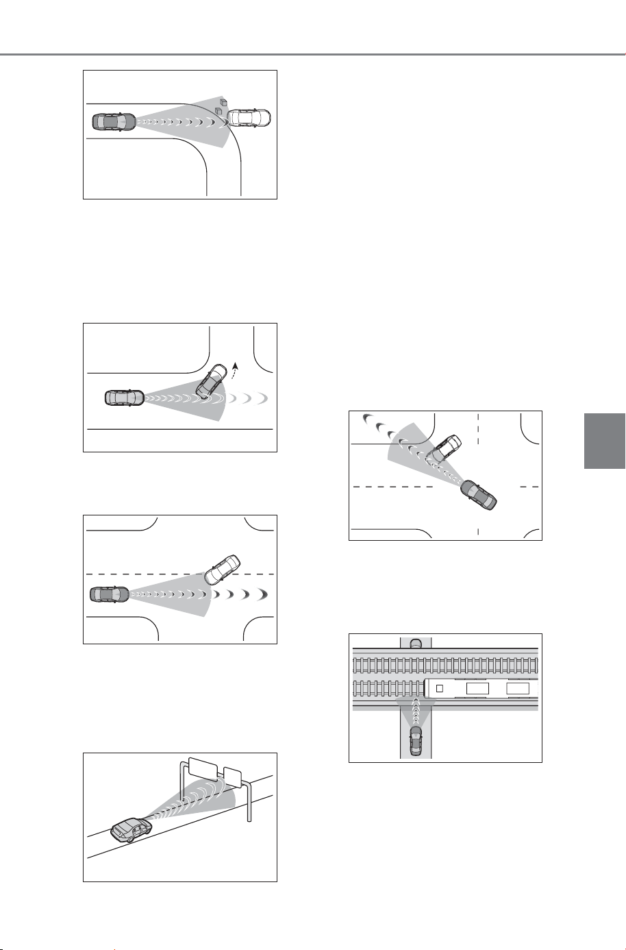
279
5-4. Using the driving support systems
Owner’s Manual_USA_M6740B_en
5
Driving
• When there are patterns or a
painting ahead of the vehicle that
may be mistaken for a detectable
object
• When passing a detectable object
that is changing lanes or turning
left/right
• When passing a detectable object
which is stopped to make a
left/right turn
• When a detectable object stops
immediately before entering the
path of the vehicle
• When passing through a location
with a structure above the road
(traffic sign, billboard, etc.)
• When approaching an electric toll
gate barrier, parking lot barrier, or
other barrier that opens and
closes
• When turning left/right and an
oncoming vehicle, oncoming
motorcycle, pedestrian or bicycle
crosses in front of the vehicle
• When attempting to turn left/right
in front of an oncoming vehicle,
oncoming motorcycle, pedestrian
or bicycle
• When turning left/right and an
oncoming vehicle, oncoming
motorcycle, pedestrian or bicycle
stops or changes course immedi-
ately before entering the path of
the vehicle
• When turning left/right and an
oncoming vehicle/motorcycle
turns left/right in front of the vehi-
cle
• When the steering wheel is oper-
ated toward the path of an oncom-
ing vehicle
• When there is an object moving
above or under the road
SOLTERRA_OM_USA_A6740BE.book 279 ページ 2025年5月23日 金曜日 午後1時18分
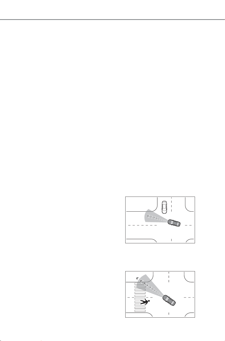
280
5-4. Using the driving support systems
Owner’s Manual_USA_M6740B_en
■ Situations in which the system
may not operate properly
● In certain situations, such as the
following, a detectable object may
not be detected by the front sen-
sors, and the system may not
operate properly:
• When a detectable object is
approaching your vehicle
• When your vehicle or a detectable
object is wandering
• When a detectable object makes
an abrupt maneuver (such as sud-
den swerving, acceleration or
deceleration)
• When suddenly approaching a
detectable object
• When the detectable object is
near a wall, fence, guardrail, man-
hole cover, steel plate on the road
surface, or another vehicle
• When there is a structure above a
detectable object
• When part of a detectable object
is hidden by another object (large
luggage, umbrella, guardrail, etc.)
• When multiple detectable objects
are overlapping
• When a bright light, such as the
sun, is reflecting off of a detect-
able object
• When a detectable object is white
and looks extremely bright
• When the color or brightness of a
detectable object causes it to
blend in with its surroundings
• When a detectable object cuts in
front of or suddenly emerges in
front of your vehicle
• When approaching a vehicle
which is diagonal
• If a bicycle is a child sized bicycle,
is carrying a large load, is carrying
an extra passenger, is carrying a
forward leaning rider, or has an
unusual shape (bicycles equipped
with a child seat, tandem bicycles,
etc.)
• If a pedestrian or bicycle is shorter
than approximately 3.2 ft. (1 m) or
taller than approximately 6.5 ft. (2
m).
• When the silhouette of a pedes-
trian or bicycle is unclear (such as
when they are wearing a raincoat,
long skirt, etc.)
• When a pedestrian is bending for-
ward or squatting
• When a pedestrian or bicycle is
moving at high speed
• When a pedestrian is pushing a
stroller, wheelchair, bicycle or
other vehicle
• When a detectable object blends
in with the surrounding area, such
as when it is dim (at dawn or dusk)
or dark (at night or in a tunnel)
• When the vehicle has not been
driven for a certain amount of time
after the EV system was started
• While turning left/right or a few
seconds after turning left/right
• While driving around a curve and
a few seconds after driving around
a curve
• When turning left/right and an
oncoming vehicle/motorcycle is
driving in a lane 3 or more lanes
from the vehicle
• When turning left/right and the
direction of the vehicle differs
greatly from the direction traffic
flows in the oncoming lane
• When turning left/right, a pedes-
trian or bicycle behind the vehicle
comes in front of it as if it over-
takes the vehicle
SOLTERRA_OM_USA_A6740BE.book 280 ページ 2025年5月23日 金曜日 午後1時18分

281
5-4. Using the driving support systems
Owner’s Manual_USA_M6740B_en
5
Driving
• When at an intersection, the
approaching crossing vehicle is
long in overall length, such as a
large truck, towing trailer, etc.
● In addition to the preceding, in
certain situations, such as the fol-
lowing, the emergency steering
assist may not operate properly:
• When a detectable object is too
close to the vehicle
• When there is insufficient space to
perform evasive steering maneu-
vers or an obstruction exists in the
evasion direction
• When there is an oncoming vehi-
cle
● In addition to the preceding, in
certain situations, such as the fol-
lowing, walls may not be detected
as a target object and the Acceler-
ation Suppression at Low Speed
function may not operate properly:
• When scenery behind the wall is
visible, such as a glass door, grid
fence, etc.
• When the wall is slanted or low
• When the wall is narrow, such as
a pole, etc.
• When the wall is made of plants,
such as a hedge, etc.
• When the road, etc. is reflected on
the wall
• When the vehicle is approaching
the wall at an angle
The pre-collision system can
be enabled/disabled through
a customize setting. (P.678)
The system is enabled each time
the power switch is turned to ON.
When the system is disabled,
the PCS warning light will illu-
minate and a message will be
displayed on the multi-infor-
mation display.
The pre-collision setting can
be changed on the customize
settings. (P.678)
When the pre-collision warn-
ing timing is changed, the
emergency steering assist
timing will also be changed.
When “Later” is selected, the emer-
gency steering assist (excluding the
active steering function) will not
operate in most cases.
When the system determines
that the driver is not facing
forward, the pre-collision
warning and emergency
steering assist will operate at
the “Earlier” timing, regard-
less of the user setting.
When the dynamic radar
cruise control is operating, the
pre-collision warning will
operate at the “Earlier” timing,
regardless of the user setting.
When the Traffic Jam Assist is
operating, the pre-collision
warning will operate at the
“Earlier” timing, regardless of
the user setting.
Changing the pre-colli-
sion setting
SOLTERRA_OM_USA_A6740BE.book 281 ページ 2025年5月23日 金曜日 午後1時18分
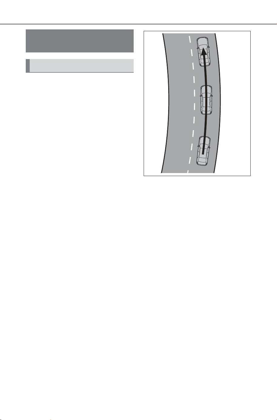
282
5-4. Using the driving support systems
Owner’s Manual_USA_M6740B_en
When driving on a road with
clear lane lines with the
dynamic radar cruise control
operating, lane lines and pre-
ceding and surrounding vehi-
cles are detected using the
front camera and radar sen-
sor, and the steering wheel is
operated to maintain the vehi-
cle’s lane position.
Use the this function only on high-
ways and expressways.
If the dynamic radar cruise control
is not operating, the function will not
operate.
In situations where the lane lines
are difficult to see or are not visible,
such as when in a traffic jam, sup-
port will be provided using the path
of preceding and surrounding vehi-
cles.
If the system determines that the
steering wheel has not been oper-
ated for a certain amount of time or
the steering wheel is not being
firmly gripped, the driver will be
alerted and this function will be
temporarily canceled.
If the steering wheel is firmly
gripped, the function will begin
operating again.
When the function is operat-
ing, if the vehicle is likely to
depart from its lane, the driver
will be alerted via a display
and buzzer.
When the buzzer sounds, check
the area around the vehicle and
carefully operate the steering wheel
to move the vehicle back to the
center of the lane.
LTA (Lane Tracing
Assist)
LTA functions
SOLTERRA_OM_USA_A6740BE.book 282 ページ 2025年5月23日 金曜日 午後1時18分
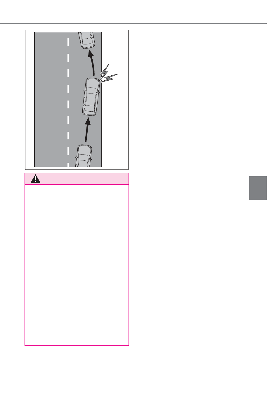
283
5-4. Using the driving support systems
Owner’s Manual_USA_M6740B_en
5
Driving
■ Operating conditions of func-
tion
This function is operable when all of
the following conditions are met:
● The LTA system detects lane lines
or the path of preceding or sur-
rounding vehicles.
● The dynamic radar cruise control
is operating.
● The lane width is approximately
10 to 13 ft. (3 to 4 m).
● The turn signal lever is not being
operated.
● The vehicle is not being driven
around a sharp curve.
● The vehicle is not accelerating or
decelerating more than a certain
amount.
● The steering wheel is not being
turned with a large force.
● The hands off steering wheel
warning (P.284) is not operat-
ing.
● The vehicle is being driven in the
center of a lane.
■ Temporary cancelation of func-
tions
● When the operating conditions are
no longer met, a function may be
temporarily canceled. However,
when the operation conditions are
met again, operation of the func-
tion will automatically be restored.
(P.283)
● If the operating conditions of a
function are no longer met while
the function is operating, a buzzer
may sound to indicate that the
function has been temporarily
canceled.
● The steering assist operation of
the function can be overridden by
the steering wheel operation of
the driver.
WARNING
■ Before using the LTA system
● Do not overly rely on the LTA
system. The LTA system is not a
system which provides auto-
mated assistance in driving and
it is not a system which reduces
the amount of attention neces-
sary for safe driving. The driver
is solely responsible for paying
attention to their surroundings
and operating the steering
wheel as necessary to ensure
safety. Also, the driver is
responsible for taking adequate
breaks when fatigued, such as
when driving for a long time.
● Failure to perform appropriate
driving operations and pay care-
ful attention may lead to an
accident.
● When not using the LTA system,
turn it off using the LTA switch.
SOLTERRA_OM_USA_A6740BE.book 283 ページ 2025年5月23日 金曜日 午後1時18分

284
5-4. Using the driving support systems
Owner’s Manual_USA_M6740B_en
■ Lane departure warning func-
tion when the LTA is operating
● Even if the LDA warning method is
changed to vibration of the steer-
ing wheel, if the vehicle deviates
from the lane while the LTA is
operating, the warning buzzer will
sound to alert the driver.
● If steering wheel operation equiv-
alent to that necessary for a lane
change is detected, the system
will determine the vehicle is not
deviating from the lane and the
warning will not operate.
■ Hands off steering wheel warn-
ing operation
● When the system determines the
driver is not holding the steering
wheel, a message urging the
driver to grip the steering wheel
and the icon shown in the illustra-
tion will be displayed on the multi-
information display to warn the
driver. If the system detects that
the steering wheel is held, the
warning will be canceled. When
using the system, make sure to
grip the steering wheel firmly,
regardless of whether the warn-
ing is operating or not.
● If no operations are detected for a
certain amount of time, the warn-
ing will operate and the function
will be temporarily canceled. This
warning may also operate if the
driver only operates steering
wheel a small amount continu-
ously.
■ Situations in which the hands
off steering wheel warning may
not operate properly
● Depending on the condition of the
vehicle, handle control condition
and road surface, the warning
function may not operate.
● In the following situations, the sys-
tem may not be able to detect
when the driver’s hands are off
the steering wheel.
• When a steering wheel cover is
installed
• When the driver is wearing gloves
• When foreign matter is attached to
the steering wheel
• When the driver is gripping the
wood trim, seam of the leather,
spokes, or other part of the steer-
ing wheel that does not have sen-
sors
● In the following situations, the
hands off steering wheel warning
may not operate and the LTA func-
tion may continue operating even
though the driver’s hands are off
the steering wheel:
• When something other than a
hand is contacting the steering
wheel
• When a wide object or arms are
held across the steering wheel
SOLTERRA_OM_USA_A6740BE.book 284 ページ 2025年5月23日 金曜日 午後1時18分
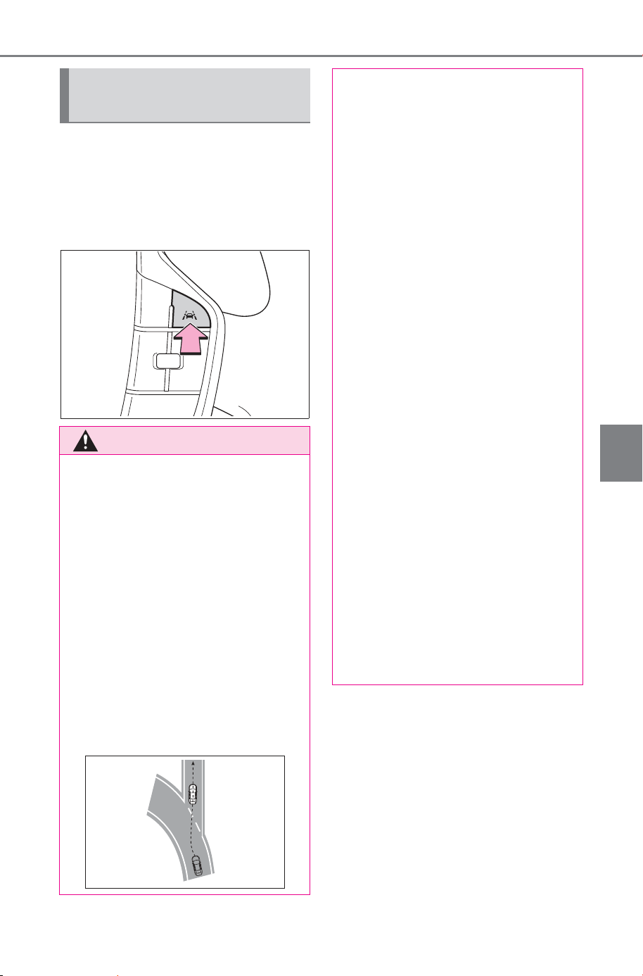
285
5-4. Using the driving support systems
Owner’s Manual_USA_M6740B_en
5
Driving
The LTA will change between
ON/OFF each time the LTA
switch is pressed.
When the LTA is ON, the LTA indi-
cator will illuminate.
Enabling/disabling the
system
WARNING
■ Situations in which the func-
tions may not operate prop-
erly
In the following situations, the
functions may not operate prop-
erly and the vehicle may depart
from its lane. Do not overly rely on
these functions. The driver is
solely responsible for paying
attention to their surroundings
and operating the steering wheel
as necessary to ensure safety.
● When a preceding or surround-
ing vehicle changes lanes (Your
vehicle may follow the preced-
ing or surrounding vehicle and
also change lanes)
● When a preceding or surround-
ing vehicle is swaying (Your
vehicle may sway accordingly
and depart from the lane)
● When a preceding or surround-
ing vehicle departs from a lane
(Your vehicle may follow the
preceding or surrounding vehi-
cle and also depart from the
lane)
● When a preceding or surround-
ing vehicle is being driven
extremely close to the left/right
lane line (Your vehicle may fol-
low the preceding or surround-
ing vehicle accordingly and
depart from the lane)
● When there are moving objects
or structures in the surrounding
area (Depending on the position
of the moving object or structure
relative to your vehicle, your
vehicle may sway)
● When the vehicle is struck by a
crosswind or the turbulence of
other nearby vehicles
● Situations in which the sensors
may not operate properly:
P.26 4
● Situations in which the lane may
not be detected: P.266
● When it is necessary to disable
the system: P. 25 9
SOLTERRA_OM_USA_A6740BE.book 285 ページ 2025年5月23日 金曜日 午後1時18分
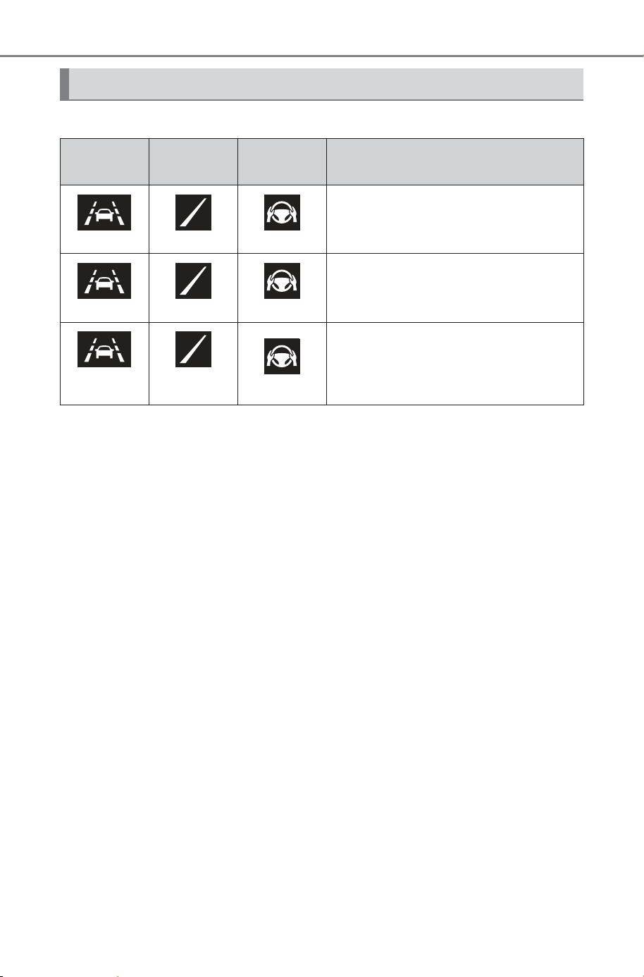
286
5-4. Using the driving support systems
Owner’s Manual_USA_M6740B_en
The operating state of the LTA system is indicated.
Operation display of steering wheel operation support
Indicator
Lane dis-
play
Steering
icon
Situation
White Gray/White Gray
LTA is on standby
Green Green Green
LTA is operating
Yellow
Flashing
Yellow
Flashing
Green
The vehicle is departing the lane
toward the side which the lane dis-
play is flashing
SOLTERRA_OM_USA_A6740BE.book 286 ページ 2025年5月23日 金曜日 午後1時18分
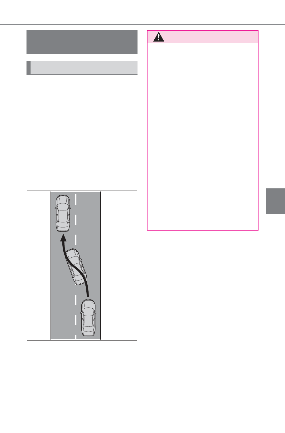
287
5-4. Using the driving support systems
Owner’s Manual_USA_M6740B_en
5
Driving
This function is linked to the LTA
and provides assistance in per-
forming lane changes through
steering wheel operations.
Use this function only on highways
and expressways.
The steering assist operation can
be overridden by the steering wheel
operation of the driver.
The lane change assist function is
not designed to operate when
changing lanes at a junction.
■ Operating conditions of func-
tion
This function is operable when all of
the following conditions are met:
● The LTA is operating.
● The lane change assist function is
enabled by a customize setting.
● The vehicle speed is between
approximately 55 and 85 mph (90
and 140 km/h).
● The system detects a broken
white line on the side which the
lane change is to be performed.
● A vehicle is not detected in the
lane toward which the turn signal
is operated.
● The steering wheel is not being
turned with a large force.
LCA (Lane Change
Assist)
LCA functions
WARNING
■ Before using the LCA system
● Do not overly rely on the LCA
system.
The LCA system is not a system
which provides automated
assistance in driving and it is
not a system which reduces the
need for checking an adjacent
lane for other vehicles,
approaching vehicles, etc. when
changing lanes. The driver is
solely responsible for paying
attention to their surroundings
and operating the steering
wheel as necessary to ensure
safety.
Also, do not use the LCA to
change lanes into which a lane
change should not be per-
formed (oncoming lanes, road
shoulders, etc.).
● Failure to perform appropriate
driving operations and pay care-
ful attention may lead to an
accident.
SOLTERRA_OM_USA_A6740BE.book 287 ページ 2025年5月23日 金曜日 午後1時18分
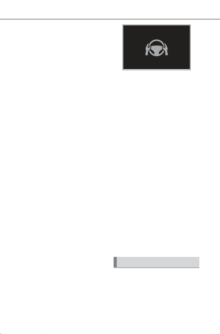
288
5-4. Using the driving support systems
Owner’s Manual_USA_M6740B_en
● The hands off steering wheel
warning (P.284) is not operat-
ing.
■ Cancelation of functions
In the following situations, opera-
tion of the LCA may be canceled
with the display and buzzer:
● When the operating conditions
(P.287) are no longer met
● When the system can no longer
detect lane lines
● When the turn signal lever is oper-
ated to the second position
(P.288)
● When the turn signal lever is oper-
ated in the opposite direction of
the lane change
● When the system detects opera-
tion of the steering wheel, brake
pedal or accelerator pedal by the
driver.
If the system detects that a vehicle
is quickly approaching in the lane
toward which the turn signal is oper-
ated, a buzzer will sound and a
message will be displayed to alert
the driver. At the same time the
steering wheel may be slightly oper-
ated to help keep the vehicle away
from the approaching vehicle.
■ Hands off steering wheel warn-
ing operation
When the system determines the
driver is not holding the steering
wheel, a message urging the driver
to grip the steering wheel and the
icon shown in the illustration will be
displayed on the multi-information
display to warn the driver. If the sys-
tem detects that the steering wheel
is held, the warning will be can-
celed. When using the system,
make sure to grip the steering wheel
firmly, regardless of whether the
warning is operating or not.
■ Situations in which the hands
off steering wheel warning may
not operate properly
● Depending on the condition of the
vehicle, handle control condition
and road surface, the warning
function may not operate.
● In the following situations, the sys-
tem may not be able to detect
when the driver’s hands are off
the steering wheel.
• When a steering wheel cover is
installed
• When the driver is wearing gloves
• When foreign matter is attached to
the steering wheel
• When the driver is gripping the
wood trim, seam of the leather,
spokes, or other part of the steer-
ing wheel that does not have sen-
sors
● In the following situations, the
hands off steering wheel warning
may not operate and the LCA
function may continue operating
even though the driver’s hands
are off the steering wheel:
• When something other than a
hand is contacting the steering
wheel
• When a wide object or arms are
held across the steering wheel
If the turn signal lever is held in
the lane change position (
1)
until a buzzer sounds, the lane
change direction will be dis-
played and the function will
operate.
Operating the LCA
SOLTERRA_OM_USA_A6740BE.book 288 ページ 2025年5月23日 金曜日 午後1時18分
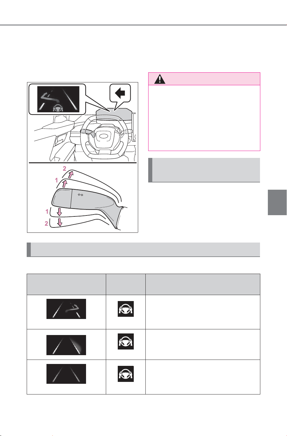
289
5-4. Using the driving support systems
Owner’s Manual_USA_M6740B_en
5
Driving
To change lanes by holding the
turn signal lever in the first posi-
tion without using the LCA, turn
the customize setting of the LCA
off.
1 First position: LCA is opera-
tional
2 Second position: LCA is not
operational
LCA can be enabled/disabled
through a customize setting.
(P.680)
The operating state of the LCA system is indicated.
WARNING
■ Situations in which the LCA
should not be used
● When driving on a one lane
road
● When there is no broken white
line between the current lane
and the lane to be changed to
Enabling/disabling the
system
Displays and system operation
LCA display
Steering
icon
Condition
Blue arrow and white line
Green
LCA is operating
Gray
Approaching vehicle detected while
LCA is operating
Gray line
Gray
Lane line no longer detected while
LCA is operating
SOLTERRA_OM_USA_A6740BE.book 289 ページ 2025年5月23日 金曜日 午後1時18分
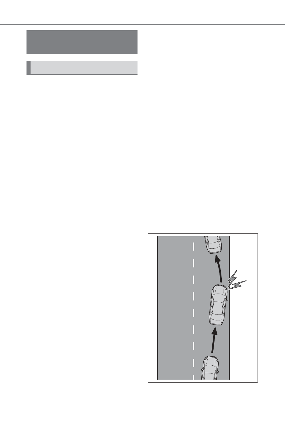
290
5-4. Using the driving support systems
Owner’s Manual_USA_M6740B_en
The LDA system warns the
driver if the vehicle may deviate
from the current lane or course
*
,
and also can slightly operate the
steering wheel to help avoid
deviation from the lane or
course
*
.
The front camera is used to
detect lane lines or a course
*
.
*
: Boundary between the asphalt
and grass, soil, etc., or structures,
such as a curb, guardrail, etc.
■ Lane departure alert func-
tion
When the system determines
that the vehicle might depart
from its lane or course
*
, a warn-
ing is displayed on a display,
and either a warning buzzer will
sound or the steering wheel will
vibrate to alert the driver.
Check the area around your vehicle
and carefully operate the steering
wheel to move the vehicle back to
the center of the lane or course
*
.
If the system determines that the
vehicle may collide with a vehicle in
an adjacent lane, the lane depar-
ture alert will operate even if the
turn signals are operating.
*
: Boundary between the asphalt
and grass, soil, etc., or structures,
such as a curb, guardrail, etc.
LDA (Lane Departure
Alert)
Basic functions
SOLTERRA_OM_USA_A6740BE.book 290 ページ 2025年5月23日 金曜日 午後1時18分
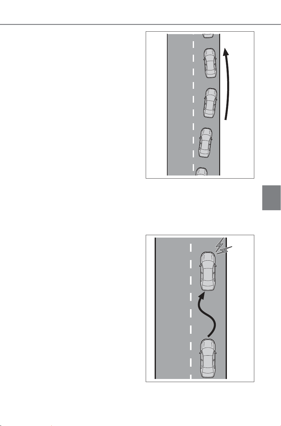
291
5-4. Using the driving support systems
Owner’s Manual_USA_M6740B_en
5
Driving
■ Lane departure prevention
function
If the system determines that
the vehicle is likely to depart
from its lane or course
*
, it pro-
vides assistance through steer-
ing wheel operations to help
avoid deviation from the lane or
course.
If the system determines that the
steering wheel has not been oper-
ated for a certain amount of time or
the steering wheel is not being
firmly gripped, a warning message
may be displayed and a warning
buzzer may sound to alert the
driver.
If the system determines that the
vehicle may collide with a vehicle in
an adjacent lane, the lane depar-
ture prevention function will operate
even if the turn signals are operat-
ing.
*
: Boundary between the asphalt
and grass, soil, etc., or structures,
such as a curb, guardrail, etc.
■ Break suggestion function
If the vehicle is swaying, a mes-
sage will be displayed and a
buzzer will sound to urge the
driver to take a break.
SOLTERRA_OM_USA_A6740BE.book 291 ページ 2025年5月23日 金曜日 午後1時18分
292
5-4. Using the driving support systems
Owner’s Manual_USA_M6740B_en
■ Operating conditions of each
function
● Lane departure alert/prevention
function
This function is operable when all of
the following conditions are met:
• The vehicle speed is approxi-
mately 30 mph (50 km/h) or more.
Operation may be possible when
the vehicle speed is approximately
25 mph (40 km/h) or more if vehi-
cles, motorcycles, bicycles, or
pedestrians are detected near the
lane.
• The system recognizes a lane or
course
*
. (When recognized on
only one side, the system will
operate only for the recognized
side.)
• The lane width is approximately
9.8 ft. (3 m) or more.
• The turn signal lever is not being
operated.
(Except when a vehicle is
detected in the direction that the
turn signal lever is operated.)
• The vehicle is not being driven
around a sharp curve.
• The vehicle is not accelerating or
decelerating more than a certain
amount.
• The steering wheel is not being
turned sufficiently to perform a
lane change.
• The VSC or TRAC system is not
turned off
*
: Boundary between the asphalt
and grass, soil, etc., or structures,
such as a curb, guardrail, etc.
■ Temporary cancelation of func-
tions
When the operating conditions are
no longer met, a function may be
temporarily canceled. However,
when the operation conditions are
met again, operation of the function
will automatically be restored.
(P.292)
■ Operation of the lane departure
alert function/lane departure
prevention function
● Depending on the vehicle speed,
road conditions, lane departure
angle, etc., operation of the lane
departure prevention function may
not be felt or the function may not
operate.
● Depending on the conditions, the
warning buzzer may operate even
if vibration is selected through a
customize setting.
● If a course
*
is not clear or straight,
the lane departure alert function or
lane departure prevention function
may not operate.
● The lane departure alert function
or lane departure prevention func-
tion may not operate if the system
judges that the vehicle is inten-
tionally being steered to avoid a
pedestrian or parked vehicle.
● It may not be possible for the sys-
tem to judge if there is danger of a
collision with a vehicle in an adja-
cent lane.
WARNING
■ Before using the LDA system
● Do not overly rely on the LDA
system. The LDA system is not
a system which provides auto-
mated assistance in driving.
However, as it is not a system
which reduces the amount of
attention necessary for safe
driving. The driver is solely
responsible for paying attention
to their surroundings and oper-
ating the steering wheel as nec-
essary to ensure safety. Also,
the driver is responsible for tak-
ing adequate breaks when
fatigued, such as when driving
for a long time.
● Failure to perform appropriate
driving operations and pay care-
ful attention may lead to an
accident.
SOLTERRA_OM_USA_A6740BE.book 292 ページ 2025年5月23日 金曜日 午後1時18分
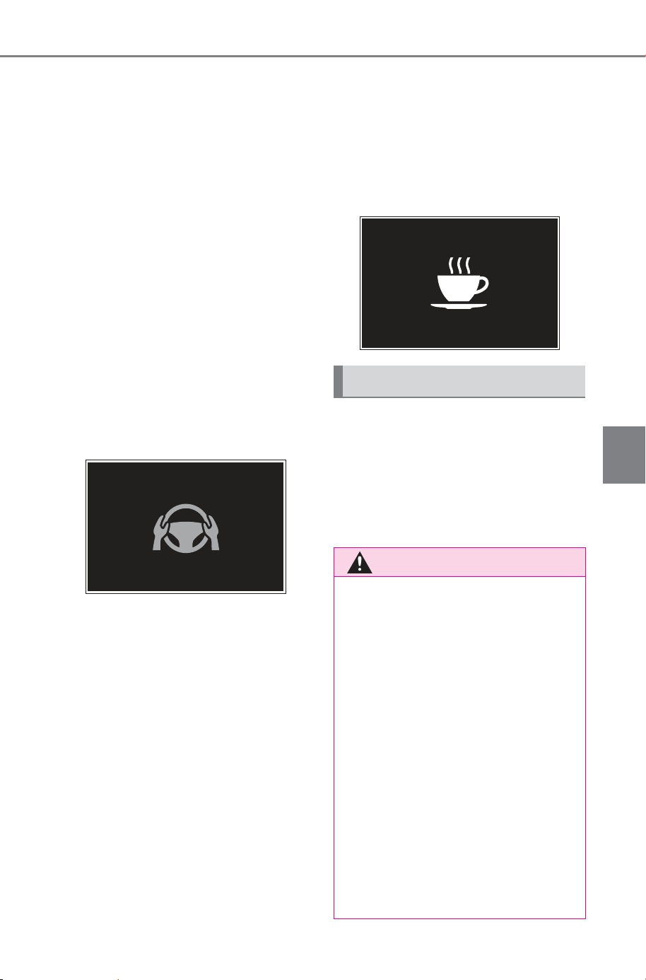
293
5-4. Using the driving support systems
Owner’s Manual_USA_M6740B_en
5
Driving
● Depending on the driver condition,
the lane departure alert function or
lane departure prevention function
changes the timing of operation.
● The steering assist operation of
the lane departure prevention
function can be overridden by the
steering wheel operation of the
driver.
*
: Boundary between the asphalt
and grass, soil, etc., or structures,
such as a curb, guardrail, etc.
■ Hands off steering wheel warn-
ing operation
In the following situations, a mes-
sage urging the driver to operate the
steering wheel and an icon will be
displayed and a buzzer will sound to
warn the driver. When using the sys-
tem, make sure to grip the steering
wheel firmly, regardless of whether
the warning is operating or not.
● When the system determines that
the driver is not securely holding
the steering wheel, or the steering
wheel is not being operated when
the steering assist operation of the
lane departure prevention function
is operating
The length of time that the warning
buzzer operates will become longer
as the frequency of the steering
assist operating increases. If the
system judges that the steering
wheel has been operated, the warn-
ing buzzer will stop.
■ Break suggestion function
This function is operable when all of
the following conditions are met:
● The vehicle speed is approxi-
mately 32 mph (50 km/h) or more.
● The lane width is approximately
9.8 ft. (3 m) or more.
Depending on the condition of the
vehicle and road surface, the break
suggestion function may not oper-
ate.
The LDA system can be
enabled/disabled through a
customize setting. (P.678)
The settings of the LDA can
be changed on the customize
settings. (P.678)
Changing LDA settings
WARNING
■ Situations in which the sys-
tem may not operate properly
In the following situations, the
system may not operate properly
and the vehicle may depart from
its lane. Do not overly rely on
these functions. The driver is
solely responsible for paying
attention to their surroundings
and operating the steering wheel
as necessary to ensure safety.
● When the boundary between
the asphalt and grass, soil, etc.,
or structures, such as a curb,
guardrail, etc. is not clear or
straight
● When the vehicle is struck by a
crosswind or the turbulence of
other nearby vehicles
SOLTERRA_OM_USA_A6740BE.book 293 ページ 2025年5月23日 金曜日 午後1時18分
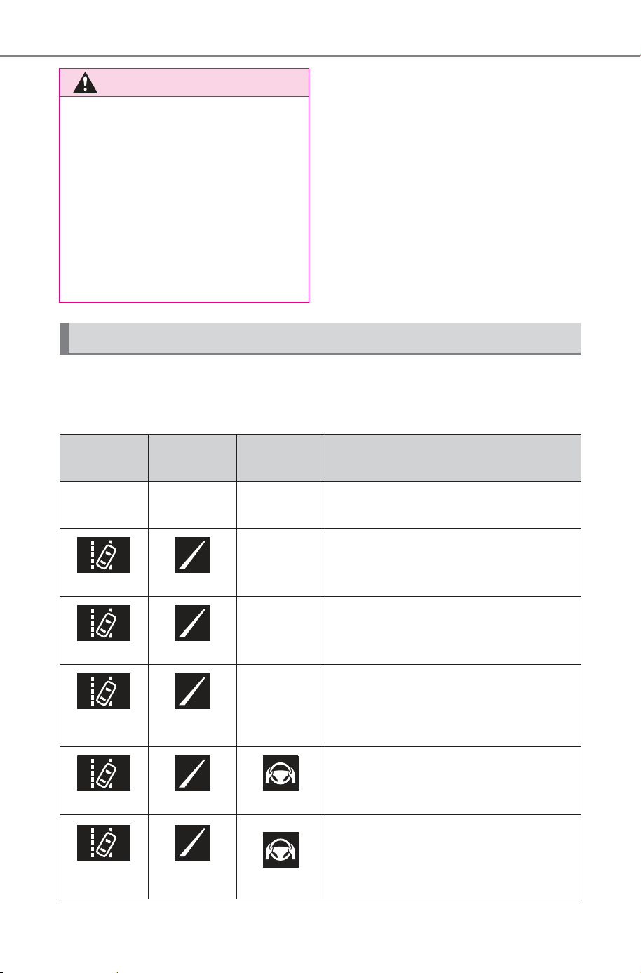
294
5-4. Using the driving support systems
Owner’s Manual_USA_M6740B_en
The operating state of the lane departure alert function and steering
assist operation of the lane departure prevention function are indi-
cated.
WARNING
● Situations in which the lane may
not be detected: P.266
● Situations in which the sensors
may not operate properly:
P.2 64
● Situations in which some or all
of the functions of the system
cannot operate: P. 2 66
● When it is necessary to disable
the system: P.259
Displays and system operation
Indicator
Lane dis-
play
Steering
icon
Condition
Not illumi-
nated
Not illumi-
nated
Not illumi-
nated
System disabled
White Gray
Not illumi-
nated
Lane lines are not detected by the
system
White White
Not illumi-
nated
Lane lines are detected by the sys-
tem
Yellow
Flashing
Yellow
Flashing
Not illumi-
nated
Lane departure alert function is
operating for the side which the lane
display is flashing
Green Green Green
Lane departure prevention function
is operating for the side which the
lane display is illuminated
Yellow
Flashing
Yellow
Flashing
Green
Lane departure alert function/lane
departure prevention function is
operating for the side which the lane
display is flashing
SOLTERRA_OM_USA_A6740BE.book 294 ページ 2025年5月23日 金曜日 午後1時18分
295
5-4. Using the driving support systems
Owner’s Manual_USA_M6740B_en
5
Driving
PDA (Proactive driv-
ing assist)
When a detectable object
(P.296) is detected, the
proactive driving assist
operates the brakes and
steering wheel to help pre-
vent the vehicle from
approaching too close to
the object.
WARNING
■ For safe use
Driving safely is solely the respon-
sibility of the driver.
● The proactive driving assist is
designed to provide some
assistance for regular braking
and steering operations, as well
as helping to prevent the vehicle
from approaching too close to a
detectable object. However, the
scope of this assistance is lim-
ited.
The driver should perform brake
and steering operations as neces-
sary. Read the following items
carefully. Do not overly rely on the
proactive driving assist and
always drive carefully. (P.297)
● The proactive driving assist is
not a system which reduces the
amount of attention necessary
for safe driving. Even if the sys-
tem is operating correctly, the
surrounding conditions as rec-
ognized by the driver and
detected by the system may dif-
fer. It is necessary for the driver
to pay attention, assess risks,
and ensure safety. Over-reli-
ance on this system to drive the
vehicle safely may lead to an
accident resulting in death or
serious injury.
● Proactive driving assist is not a
system which allows for inatten-
tive driving and is not a system
which assists in poor visibility
conditions. The driver is solely
responsible for paying attention
to their surroundings and driving
safely.
■ When turning proactive driv-
ing assist off
● Situations in which the sensors
may not operate properly:
P.26 4
● When it is necessary to disable
the system: P. 25 9
SOLTERRA_OM_USA_A6740BE.book 295 ページ 2025年5月23日 金曜日 午後1時18分
296
5-4. Using the driving support systems
Owner’s Manual_USA_M6740B_en
According to the driving conditions, the operation and detectable
objects of the proactive driving assist will change as follows.
System operating conditions and detectable objects
Function Conditions Operation
Detectable
objects
Obstacle
Anticipa-
tion Assist
(OAA)
A detectable
object is detected
crossing the road
Assistance with some
brake operations is
provided in order to
reduce the possibility of
a collision.
Pedestrians
Bicyclists
A detectable
object is detected
on the side of the
road
Assistance with some
brake and steering
wheel operations are
provided according to
the surrounding condi-
tions to help prevent
the vehicle from
approaching too close
to a detected object.
Assistance with steer-
ing wheel operations is
provided within a range
that the vehicle will not
deviate from its current
lane.
Pedestrians
Bicyclists
Parked vehi-
cles
Decelera-
tion Assist
(DA)
A preceding vehi-
cle or an adjacent
vehicle cutting in
front of the vehicle
is detected
The vehicle is gently
decelerated so that the
vehicle-to-vehicle dis-
tance will not be exces-
sively short.
Preceding
vehicles
Motorcycles
A curve is
detected ahead of
the vehicle
The vehicle is gently
decelerated if the vehi-
cle speed is deter-
mined to be too high for
the curve ahead.
None
SOLTERRA_OM_USA_A6740BE.book 296 ページ 2025年5月23日 金曜日 午後1時18分
297
5-4. Using the driving support systems
Owner’s Manual_USA_M6740B_en
5
Driving
■ Vehicle speeds at which the
system can operate
● Detectable object crossing the
road assistance
Approximately 20 to 35 mph (30 to
60 km/h)
● Detectable object on the side of
the road assistance
Approximately 20 to 35 mph (30 to
60 km/h)
● Preceding vehicle deceleration
assistance
Approximately 15 mph (20 km/h) or
more
● Curve deceleration assistance
Approximately 15 mph (20 km/h) or
more
■ System operation will be can-
celed when
● In the following situations, system
operation will be canceled:
• When the dynamic radar cruise
control or cruise control is operat-
ing
• When the PCS is off
• Situations in which some or all of
the functions of the system cannot
operate: P. 266
• When the P, R or N shift position is
selected
• The driver’s seat belt is unfas-
tened
● In the following situations, the
brake operation assist will be can-
celed:
• Approximately 9 mph (15 km/h) or
less
• When a certain vehicle speed has
been reached, as judged by the
system, according to the sur-
rounding conditions
● In the following situations, system
operation may be canceled:
• When the brake control or output
restriction control of a driving sup-
port system operates
(For example: PCS, drive-start
control)
• When the system determines that
a detected object has moved
away from the vehicle
• When lane lines can no longer be
detected
• When the brake pedal has been
depressed
• When the accelerator pedal has
been depressed
• When the steering wheel has
been operated with more than a
certain amount of force
• When the turn signal lever is oper-
ated to the left/right turn position
WARNING
■ Situations in which the sys-
tem may not operate properly
● Situations in which the lane may
not be detected: P.266
● When a detectable object stops
immediately before entering the
path of the vehicle
● When passing extremely close
to a detectable object behind a
guardrail, fence, etc.
● When changing lanes while
overtaking a detectable object
● When passing a detectable
object that is changing lanes or
turning left/right
● When there are objects (guard-
rails, power poles, trees, walls,
fences, poles, traffic cones,
mailboxes, etc.) in the surround-
ing area
● When there are patterns or a
painting ahead of the vehicle
that may be mistaken for a
detectable object
SOLTERRA_OM_USA_A6740BE.book 297 ページ 2025年5月23日 金曜日 午後1時18分
298
5-4. Using the driving support systems
Owner’s Manual_USA_M6740B_en
WARNING
● When passing through a place
with a low structure above the
road (tunnel with a low ceiling,
traffic sign, signboard, etc.)
● When driving on snowy, icy, or
rutted roads
● When a detectable object is
approaching your vehicle
● When your vehicle or a detect-
able object is wandering
● When the movement of a
detectable object changes
(change in direction, sudden
acceleration or deceleration,
etc.)
● When suddenly approaching a
detectable object
● When a preceding vehicle or
motorcycle is not directly in front
of your vehicle
● When there is a structure above
a detectable object
● When part of a detectable
object is hidden by another
object (large luggage, umbrella,
guardrail, etc.)
● When multiple detectable
objects are overlapping
● When a bright light, such as the
sun or headlights of another
vehicle, is reflecting off of the
detectable object
● When the detectable object is
white and looks extremely bright
● When the color or brightness of
the detectable object causes it
to blend in with its surroundings
● When a detectable object cuts
in front of or emerges from
beside a vehicle
● When approaching a vehicle
ahead which is perpendicular or
at an angle to the vehicle, or is
facing the vehicle
● If a parked vehicle is perpendic-
ular or at an angle to the vehicle
● When a bicycle is a child sized
bicycle, is carrying a large load,
is carrying an extra passenger,
or has an unusual shape (bicy-
cles equipped with a child seat,
tandem bicycles, etc.)
● When a pedestrian or bicyclist is
shorter than approximately 3.2
ft. (1 m) or taller than approxi-
mately 6.5 ft. (2 m)
● When the silhouette of a pedes-
trian or bicyclist is unclear (such
as when they are wearing a
raincoat, long skirt, etc.)
● When a pedestrian or bicyclist is
bending forward or squatting
● When a pedestrian or bicyclist is
moving at high speed
● When a pedestrian is pushing a
stroller, wheelchair, bicycle or
other vehicle
● When a detectable object
blends in with the surrounding
area, such as when it is dim (at
dawn or dusk) or dark (at night,
in a tunnel, etc.)
● When the lane width is 13.1 ft.
(4 m) or more
● When the lane width is 8.2 ft.
(2.5 m) or less
● When the vehicle has not been
driven for a certain amount of
time after the EV system was
started
● While turning left or right or a
few seconds after turning left or
right
SOLTERRA_OM_USA_A6740BE.book 298 ページ 2025年5月23日 金曜日 午後1時18分
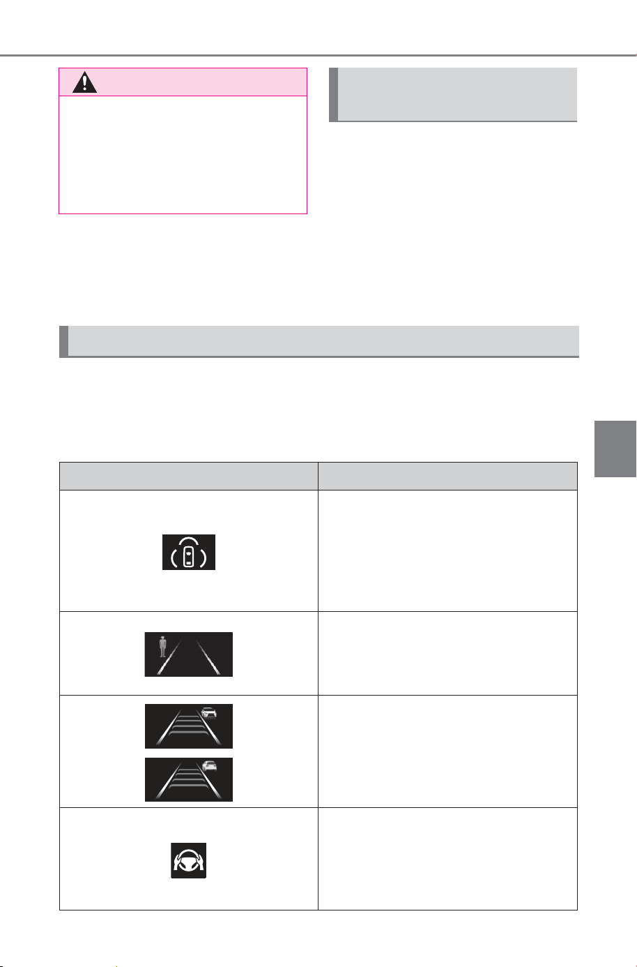
299
5-4. Using the driving support systems
Owner’s Manual_USA_M6740B_en
5
Driving
The proactive driving assist
can be enabled/disabled
through a customize setting.
(P.678)
The following settings of the
proactive driving assist can be
changed through customize
settings. (P.678)
Depending on the situation, the following indicators or icons will be
displayed.
Some icons cannot be displayed unless the display is changed to
the driving safety support function information screen.
WARNING
● While changing lanes or a few
seconds after changing lanes
● When entering a curve, driving
around a curve and a few sec-
onds after driving around a
curve
Changing proactive driv-
ing assist settings
System operation display
Icon Meaning
White: Monitoring for detectable
objects
Green: Detectable object crossing
the road or detectable object on
the side of the road assistance
operating
A pedestrian has been detected as
crossing the road or on the side of
the road and brake or steering assis-
tance is operating
A vehicle has been detected on the
side of the road and brake or steer-
ing operation assistance is being
performed
Steering operation assistance is
being performed to prevent the vehi-
cle from approaching too close to a
detectable object on the side of the
road
SOLTERRA_OM_USA_A6740BE.book 299 ページ 2025年5月23日 金曜日 午後1時18分
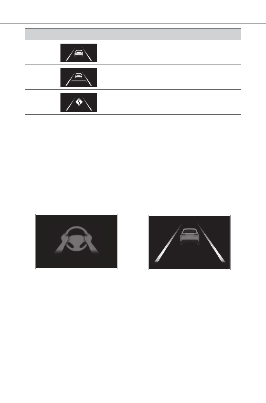
300
5-4. Using the driving support systems
Owner’s Manual_USA_M6740B_en
■ Hands off steering wheel warn-
ing operation
In the following situations, a mes-
sage urging the driver to grip the
steering wheel and the icon shown
in the illustration will be displayed on
the display to warn the driver. If the
system detects that the steering
wheel is held, the warning will be
canceled. When using the system,
make sure to grip the steering wheel
firmly, regardless of whether the
warning is operating or not.
● When assistance to a detectable
object crossing the road or assis-
tance to a detectable object on the
side of the road is performed and
the system determines the driver
is not holding the steering wheel
If no operations are detected for a
certain amount of time, a buzzer will
sound, the warning will operate.
This warning may also operate if the
driver only operates steering wheel
a small amount continuously.
■ Warning operation after preced-
ing vehicle deceleration assis-
tance has ended
After preceding vehicle decelera-
tion assistance has ended, if the
driver does not operate the brake
pedal or accelerator pedal and the
vehicle approaches the preceding
vehicle, the display will flash and a
buzzer will sound to urge the driver
to decelerate. If the system deter-
mines that the driver is operating the
brake pedal or accelerator pedal,
the warning will be canceled.
Preceding vehicle deceleration
assistance is being performed
Warning to maintain appropriate
vehicle-to-vehicle distance
Curve deceleration assistance is
being performed
Icon Meaning
SOLTERRA_OM_USA_A6740BE.book 300 ページ 2025年5月23日 金曜日 午後1時18分
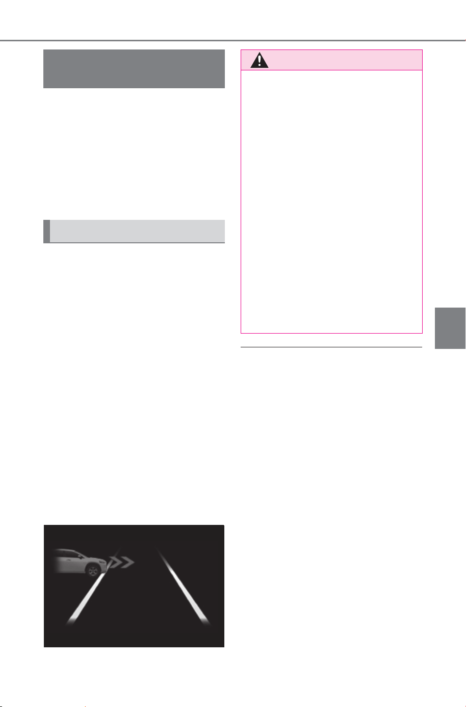
301
5-4. Using the driving support systems
Owner’s Manual_USA_M6740B_en
5
Driving
When approaching an intersec-
tion, etc., at a low speed, vehi-
cles approaching from the left
and right of the front of the vehi-
cle can be detected and the
driver informed of these vehi-
cles.
When the system detects a
vehicle approaching from the
left or right in front of your
vehicle when approaching an
intersection, a notification will
be displayed.
When the system determines
that your vehicle may be
about to enter an intersection
even though a vehicle is
approaching from the left or
right in front of your vehicle, a
buzzer will sound and a mes-
sage will be displayed to urge
you to depress the brake
pedal.
• Multi-information display
■ FCTA system operating condi-
tions
The system will operate when all of
the following conditions are met:
● A shift position other than P or R is
selected
● The vehicle speed is approxi-
mately 10 mph (15 km/h) or less
● A vehicle is approaching from the
left or right in front of your vehicle
at a speed between approximately
7 to 37 mph (10 to 60 km/h)
● There are no vehicles in front of
your vehicle
● The accelerator pedal is not being
strongly depressed
● The brake pedal is not being
strongly depressed
FCTA (Front Cross
Traffic Alert)
FCTA system control
WARNING
■ For safe use
Driving safely is solely the respon-
sibility of the driver. Pay careful
attention to the surrounding con-
ditions in order to ensure safe
driving. The FCTA system is a
supplementary system that
informs the driver of vehicles
approaching from the left and
right of the front of the vehicle.
Over-reliance on this system may
lead to an accident resulting in
death or serious injury. The
details of the warning display may
differ from the actual traffic condi-
tions. Although the warning dis-
play will stop being displayed after
a certain amount of time, this
does not necessarily indicate that
there are no longer any vehicles
or pedestrians around your vehi-
cle.
SOLTERRA_OM_USA_A6740BE.book 301 ページ 2025年5月23日 金曜日 午後1時18分
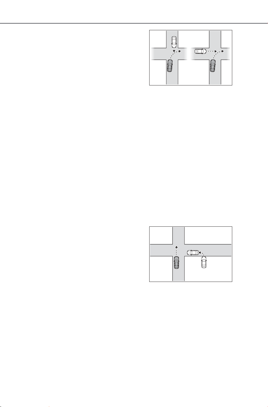
302
5-4. Using the driving support systems
Owner’s Manual_USA_M6740B_en
■ Situations in which the system
may operate even though no
vehicles are approaching
In certain situations, such as the fol-
lowing, the system may operate
even though no vehicles are
approaching:
● When approaching objects on the
roadside, such as guardrails, traf-
fic signs, utility poles, street lights,
trees, tall grass, walls, etc.
● When passing an object on the
side of the road, such as a parked
vehicle
● When a vehicle or pedestrian is
approaching from the left or right
in front of your vehicle in the dis-
tance
● When a vehicle or pedestrian is
moving within a parking spot, etc.,
next to the lane your vehicle is in
● When a pedestrian or bicyclist is
approaching on a sidewalk
● When a vehicle or pedestrian is
moving away from your vehicle
● When an approaching vehicle is
decelerating or stops
● When an approaching vehicle
makes a left/right turn immediately
in front of your vehicle
● When a pedestrian is approaching
your vehicle
● When an oncoming vehicle makes
a right/left turn
● When your vehicle enters an inter-
section before a vehicle
approaching from the left or right
in front of your vehicle
● When stopped at traffic light and a
vehicle approaches from the left
or right in front of your vehicle
● When making a left/right turn in
front of an approaching vehicle
● When an oncoming vehicle
approaches and passes
● When being overtaken by another
vehicle
● When driving next to another vehi-
cle or a pedestrian
● When a vehicle or pedestrian
approaches the side of your vehi-
cle
■ Situations in which the system
may not operate properly
In situations such as the following, a
vehicle may not be detected by a
front side radar sensor and the sys-
tem may not operate properly:
● If an approaching vehicle moves
suddenly (sudden steering, accel-
eration, deceleration, etc.)
● If a vehicle is approaching from
the left or right of the front of your
vehicle diagonally
● When a vehicle is approaching
from the left or right in front of your
vehicle in the distance
● When there is an object between
your vehicle and an approaching
vehicle
● When several vehicles are
approaching with little space
between them
SOLTERRA_OM_USA_A6740BE.book 302 ページ 2025年5月23日 金曜日 午後1時18分
303
5-4. Using the driving support systems
Owner’s Manual_USA_M6740B_en
5
Driving
● Situations in which the sensors
may not operate properly: P.264
● Situations in which some or all of
the functions of the system cannot
operate: P. 266
The FCTA can be
enabled/disabled through a
customize setting. (P.680)
The following settings of the
FCTA can be changed
through customize settings.
(P.680)
Changing FCTA settings
RSA (Road Sign
Assist)
The RSA system detects
specific road signs using
the front camera and/or
navigation system (if
equipped) (when speed limit
information is available)
and warns the driver via dis-
plays and buzzers.
WARNING
■ For safe use
● Driving safely is solely the
responsibility of the driver. Pay
careful attention to the sur-
rounding conditions in order to
ensure safe driving.
● Do not rely solely upon the
RSA. The RSA assists the
driver by providing road sign
information, but it is not a
replacement for the driver’s own
vision and awareness. Driving
safely is solely the responsibility
of the driver. Pay careful atten-
tion to the surrounding condi-
tions in order to ensure safe
driving.
■ Situations in which the RSA
should not be used
When it is necessary to disable
the system: P.259
■ Situations in which the sys-
tem may not operate properly
Situations in which the sensors
may not operate properly: P. 264
SOLTERRA_OM_USA_A6740BE.book 303 ページ 2025年5月23日 金曜日 午後1時18分

304
5-4. Using the driving support systems
Owner’s Manual_USA_M6740B_en
When the front camera
detects a sign or information
of a sign is available from the
navigation system, the sign
will be displayed on the dis-
play.
Multiple signs can be dis-
played.
Depending on the specifications of
the vehicle, the number of dis-
played signs may be limited.
■ Operating conditions of sign
display
Signs will be displayed when the fol-
lowing conditions are met:
● The system has detected a sign
In the following situations, a dis-
played sign may stop being dis-
played:
● When a new sign has not been
detected for a certain distance
● When the system determines that
the road being driven on has
changed, such as after a left or
right turn
■ Situations in which the display
function may not operate prop-
erly
In the following situations, the RSA
system may not operate properly
and may not detect signs or may
display the incorrect sign. However,
this does not indicate a malfunction.
● When a sign is dirty, faded, tilted
or bent
● When the contrast of an electronic
sign is low
● When all or part of a sign is hidden
by a tree, utility pole, etc.
● When a sign is detected by the
front camera for a short amount of
time
● When the driving state (turning,
changing lanes, etc.) is judged
incorrectly
● When a sign is immediately after a
freeway junction or in an adjacent
lane just before merging
● When stickers are attached to the
rear of a preceding vehicle
● When a sign similar to a system
compatible sign is detected as a
system compatible sign
● When a speed limit sign for a
frontage road is within detection
range of the front camera
● When driving around a round-
about
● When a sign intended for trucks,
etc. is detected
● When a sign has a supplemental
sign (end point, day of week, time
of day, etc.)
● When there is a sign within a traf-
fic restricted area, such as a road-
works area
● When the navigation system map
data is out of date
● When the navigation system can-
not be used
In this case, the speed limit signs
displayed on the multi-information
display and navigation system dis-
play may differ.
Display Function
SOLTERRA_OM_USA_A6740BE.book 304 ページ 2025年5月23日 金曜日 午後1時18分
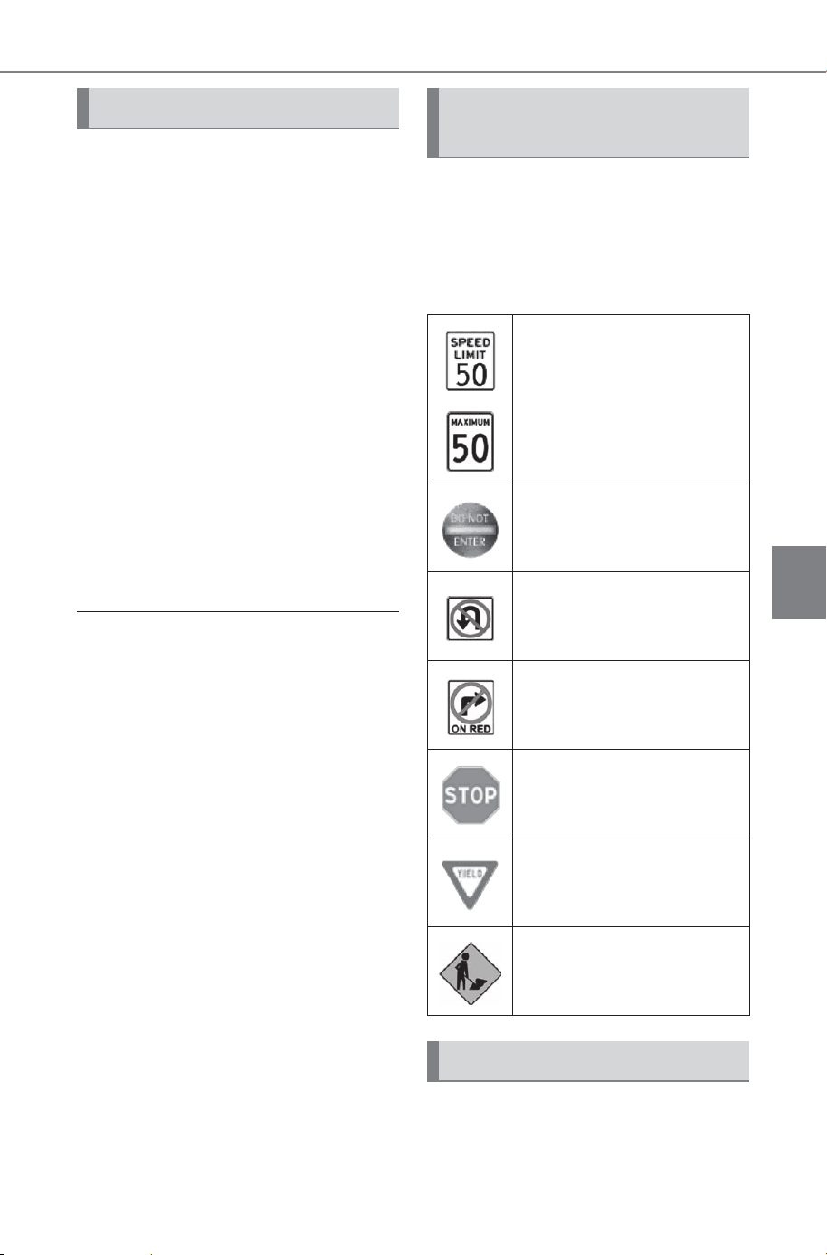
305
5-4. Using the driving support systems
Owner’s Manual_USA_M6740B_en
5
Driving
In the following situations, the
RSA system will output a warn-
ing to notify the driver.
If the vehicle speed exceeds
the speed warning threshold
of the speed limit sign dis-
played on the display, the sign
display will be emphasized
and a buzzer will sound.
When the RSA system
detects a do not enter sign
and determines that the vehi-
cle has entered a no-entry
area, the do not enter sign
displayed on the display will
flash and a buzzer will sound.
■ Operating conditions of the
notification functions
● Excess speed notification function
This function will operate when the
following condition is met:
• A speed limit road sign is recog-
nized by the system.
● No entry notification function
This function will operate when all of
the following conditions are met:
• More than one no entry road signs
are recognized by the system
simultaneously.
• The vehicle is passing between no
entry road signs recognized by the
system.
The following types of road
signs can be displayed.
However, non-standard or recently
introduced traffic signs may not be
displayed.
The following settings of the
RSA can be changed through
customize settings. (P.679)
Notification function Types of road signs sup-
ported
Speed limit
Do Not Enter
No U-turn
No Turn On Red
Stop
Yield
Warning
Changing RSA settings
SOLTERRA_OM_USA_A6740BE.book 305 ページ 2025年5月23日 金曜日 午後1時18分
306
5-4. Using the driving support systems
Owner’s Manual_USA_M6740B_en
Dynamic radar cruise
control
This dynamic radar cruise
control detects the pres-
ence of vehicles ahead,
determines the current vehi-
cle-to-vehicle distance, and
operates to maintain a suit-
able distance from the vehi-
cle ahead. The desired
vehicle-to-vehicle distance
can be set by operating the
vehicle-to-vehicle distance
switch.
Use the dynamic radar
cruise control only on high-
ways and expressways.
WARNING
■ For safe use
● Driving safely is solely the
responsibility of the driver. Do
not overly rely on this system,
and pay careful attention to the
surrounding conditions in order
to ensure safe driving.
● The dynamic radar cruise con-
trol provides driving assistance
to reduce the driver’s burden.
However, there are limitations to
the assistance provided.
Read the following items care-
fully. Do not overly rely on this
system and always drive care-
fully.
Conditions under which the sys-
tem may not operate correctly:
P.3 13
● Set the speed appropriately
according to the speed limit,
traffic flow, road conditions,
weather conditions, etc. The
driver is responsible for confirm-
ing the set speed.
● Even if the system is operating
correctly, the condition of a pre-
ceding vehicle as recognized by
the driver and detected by the
system may differ. Therefore, it
is necessary for the driver to
pay attention, assess risks, and
ensure safety. Over-reliance on
this system to drive the vehicle
safely may lead to an accident
resulting in death or serious
injury.
■ Precautions for the driving
assist systems
Observe the following precau-
tions, as there are limitations to
the assistance provided by the
system. Over-reliance on this sys-
tem may lead to an accident
resulting in death or serious injury.
SOLTERRA_OM_USA_A6740BE.book 306 ページ 2025年5月23日 金曜日 午後1時18分
307
5-4. Using the driving support systems
Owner’s Manual_USA_M6740B_en
5
Driving
WARNING
● Details of support provided for
the driver’s vision
The dynamic radar cruise con-
trol is only intended to help the
driver in determining the dis-
tance between the driver’s own
vehicle and a designated pre-
ceding vehicle. It is not a sys-
tem which allows for careless or
inattentive driving, and is not a
system which assists in poor
visibility conditions.
The driver must pay attention to
their surroundings, even when
the vehicle stops.
● Details of support provided for
the driver’s judgement
The dynamic radar cruise con-
trol determines whether the dis-
tance between the driver’s own
vehicle and a designated pre-
ceding vehicle is within a set
range. It is not capable of mak-
ing any other type of judgement.
Therefore, it is absolutely nec-
essary for the driver to remain
vigilant and to determine
whether or not there is a possi-
bility of danger.
● Details of support provided for
the driver’s operation
The dynamic radar cruise con-
trol does not include functions
which will prevent or avoid colli-
sions with vehicles ahead of
your vehicle. Therefore, if there
is ever any possibility of danger,
the driver must take immediate
and direct control of the vehicle
and act appropriately in order to
ensure safety.
■ Situations in which the
dynamic radar cruise control
should not be used
Do not use the dynamic radar
cruise control in the following situ-
ations. As the system will not be
able to provide appropriate con-
trol, using it may lead to an acci-
dent resulting in death or serious
injury.
● Roads where there are pedes-
trians, cyclists, etc.
● When driving on a highway or
expressway entrance or exit
● When the approach warning
sounds frequently
● Situations in which the sensors
may not operate properly:
P.26 4
● When it is necessary to disable
the system: P. 25 9
SOLTERRA_OM_USA_A6740BE.book 307 ページ 2025年5月23日 金曜日 午後1時18分
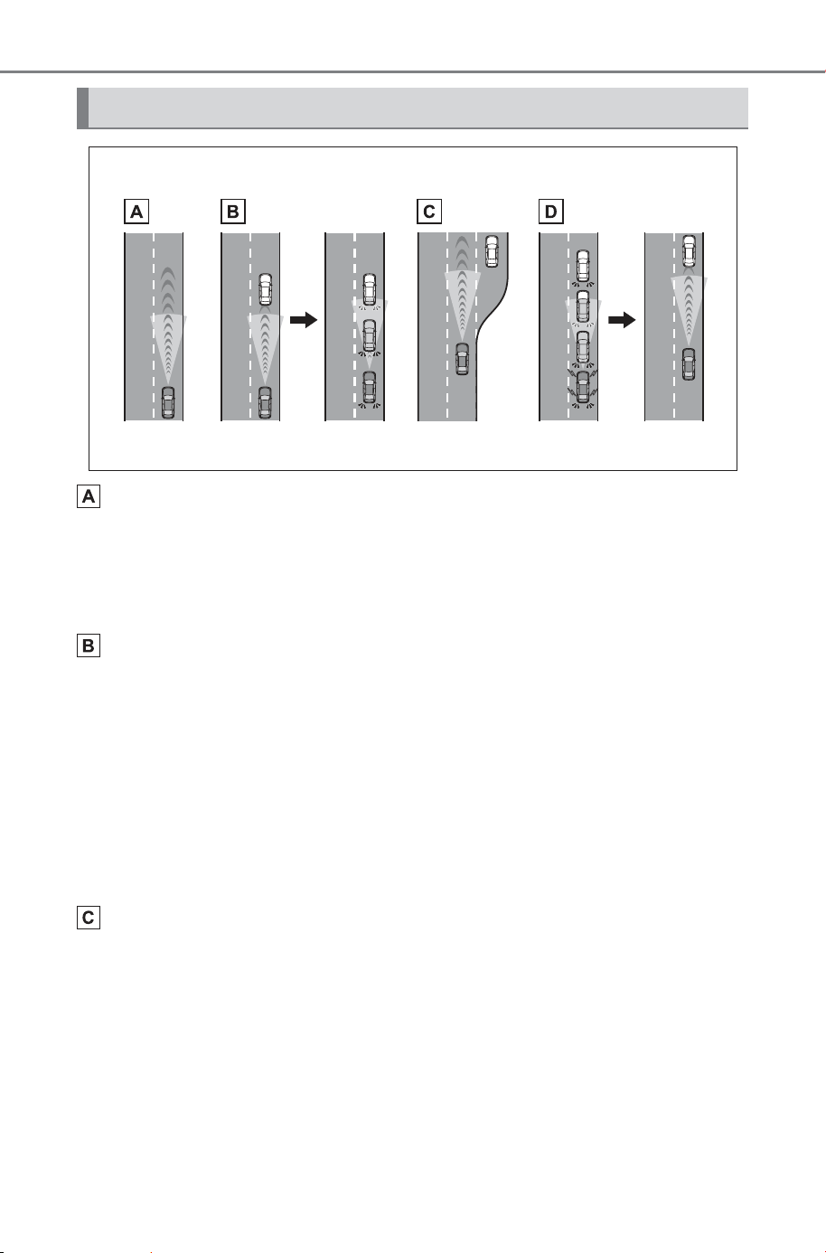
308
5-4. Using the driving support systems
Owner’s Manual_USA_M6740B_en
Constant speed cruising:
When there are no vehicles ahead
The vehicle drives at the speed set by the driver.
If the set vehicle speed is exceeded while driving down a hill, the set vehicle
speed display will blink and a buzzer will sound.
Deceleration and follow-up cruising:
When a preceding vehicle driving slower than the set vehicle
speed is detected
When a vehicle is detected driving ahead of your vehicle, the vehicle auto-
matically decelerates and if a greater reduction in vehicle speed is neces-
sary, the brakes are applied (the stop lights will come on at this time). The
vehicle is controlled to maintain the vehicle-to-vehicle distance set by the
driver, in accordance with changes in the speed of the preceding vehicle. If
vehicle deceleration is not sufficient and the vehicle approaches the vehicle
ahead, the approach warning will sound.
Acceleration:
When there are no longer any preceding vehicles driving slower
than the set vehicle speed
The vehicle accelerates until the set vehicle speed is reached and then
resumes constant speed cruising.
Basic functions
SOLTERRA_OM_USA_A6740BE.book 308 ページ 2025年5月23日 金曜日 午後1時18分
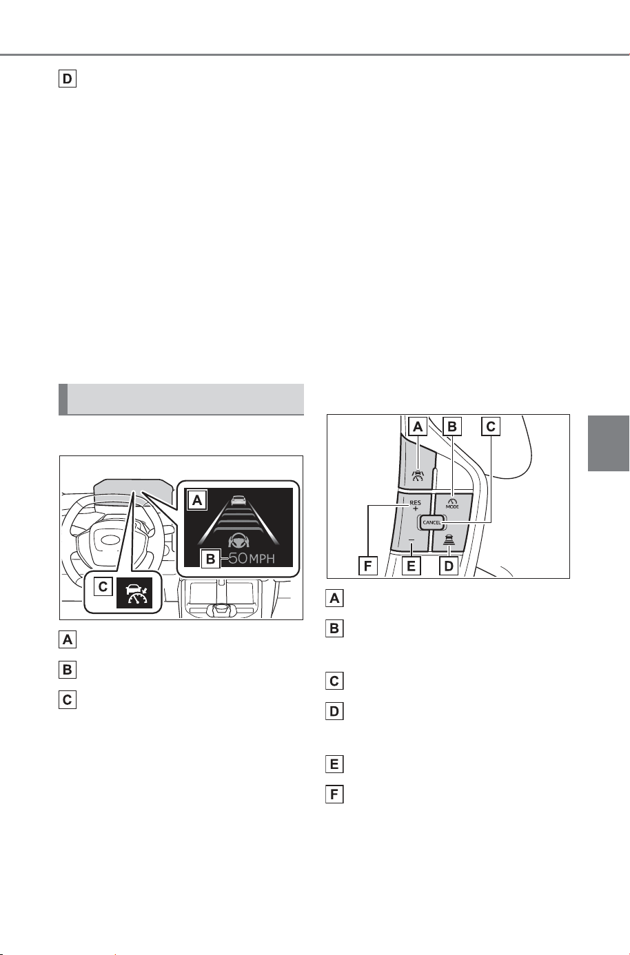
309
5-4. Using the driving support systems
Owner’s Manual_USA_M6740B_en
5
Driving
Starting off:
If a preceding vehicle stops, the vehicle will also stop (controlled
stop). After the preceding vehicle starts off, pressing the “RES”
switch or depressing the accelerator pedal will resume follow-up
cruising (start off operation). If a start off operation is not per-
formed, the controlled stop will continue.
While driving on a highway or expressway, if a preceding vehicle
stops, your vehicle will stop accordingly. On some highways and
expressways, if the system determines that the preceding vehicle
starts off within approximately 3 minutes of stopping, a buzzer will
sound and a message will be displayed on the multi-information
display to notify the driver, and your vehicle will start off accord-
ingly following the preceding vehicle. (Extended resume time)
■ Meter display
Multi-information display
Set vehicle speed
Indicators
■ Switches
Driving assist switch
Driving assist mode select
switch
Cancel switch
Vehicle-to-vehicle distance
switch
“-” switch
“+” switch/“RES” switch
System components
SOLTERRA_OM_USA_A6740BE.book 309 ページ 2025年5月23日 金曜日 午後1時18分
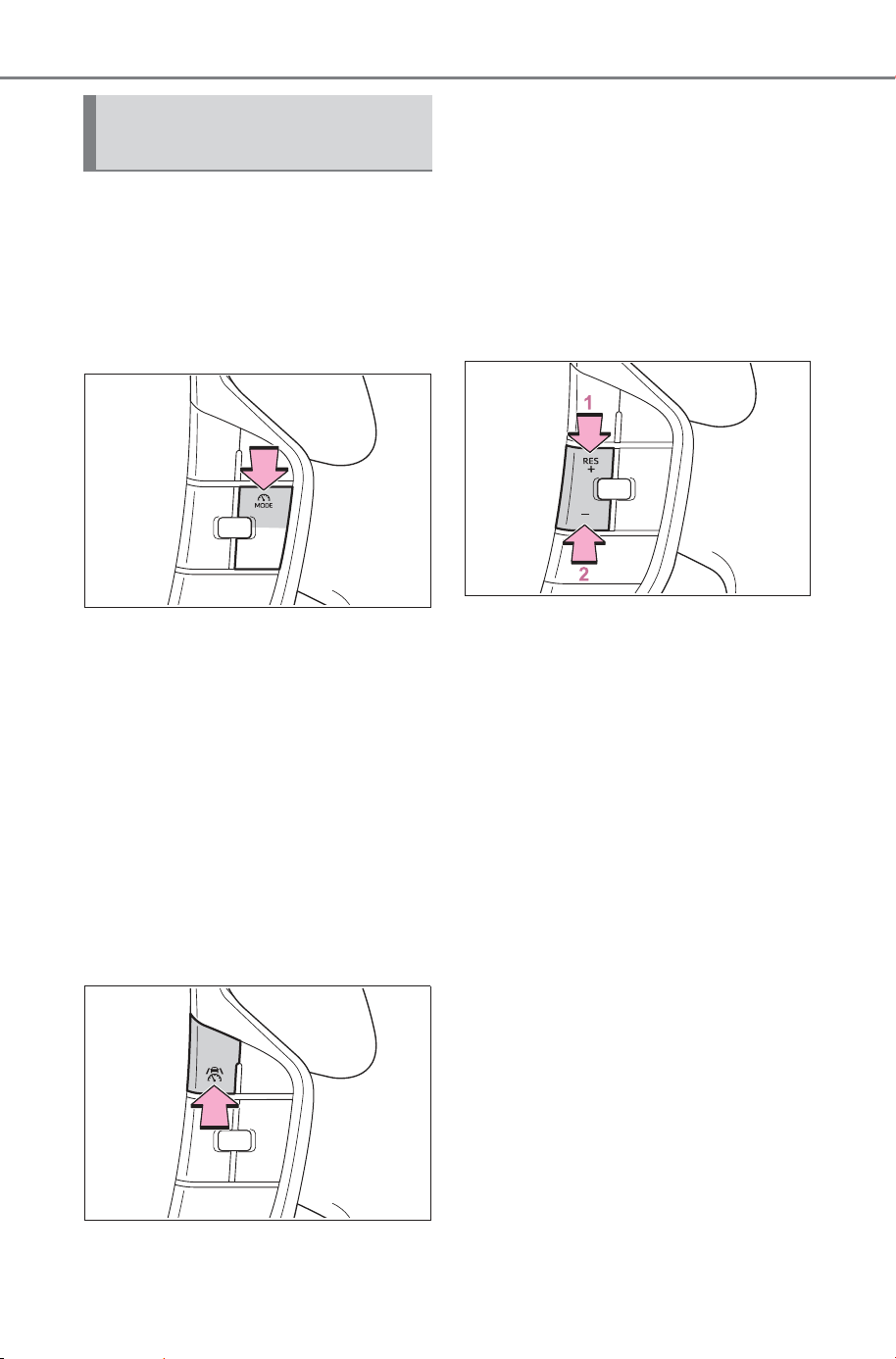
310
5-4. Using the driving support systems
Owner’s Manual_USA_M6740B_en
■ Setting the vehicle speed
1 Press the driving assist mode
select switch to select Adap-
tive Cruise Mode.
The dynamic radar cruise control
indicator will illuminate.
2 Using the accelerator pedal,
accelerate or decelerate to
the desired vehicle speed
(approximately 20 mph [30
km/h] or more), and press the
driving assist switch to set
the set vehicle speed.
The set vehicle speed will be dis-
played on the multi-information dis-
play.
The vehicle speed at the moment
the switch is released will be the set
vehicle speed.
■ Adjusting the set vehicle
speed
Adjusting the set vehicle
speed using the switches
To change the set vehicle
speed, press the “+” switch or “-”
switch until the desired speed is
displayed.
1 Increase set vehicle speed
2 Decrease set vehicle speed
Short press adjustment: Press the
switch
Long press adjustment: Press and
hold the switch until the desired set
vehicle speed is reached.
The set vehicle speed will
increase or decrease as follows:
Except for Canada
Short press adjustment: Increases
or decreases by 1 mph (1.6 km/h)
each time the switch is pressed
Long press adjustment: Increases
or decreases in 1 mph (1.6 km/h)
increments continuously while the
switch is pressed and held
Using the dynamic radar
cruise control
SOLTERRA_OM_USA_A6740BE.book 310 ページ 2025年5月23日 金曜日 午後1時18分
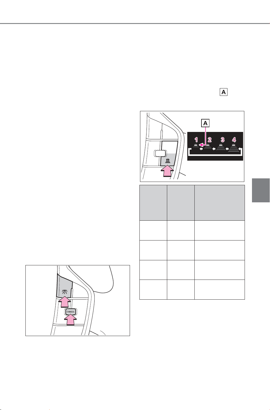
311
5-4. Using the driving support systems
Owner’s Manual_USA_M6740B_en
5
Driving
For Canada
Short press adjustment: By 1 km/h
(0.6 mph) or 1 mph (1.6 km/h) each
time the switch is pressed
Long press adjustment: Increases
or decreases in 5 km/h (3.1 mph) or
5 mph (8 km/h) increments continu-
ously while the switch is pressed
and held
Increasing the set vehicle
speed using the accelerator
pedal
1 Depress the accelerator
pedal to accelerate the vehi-
cle to the desired vehicle
speed.
2 Press the “+” switch.
■ Canceling/resuming control
1 Press the cancel switch or
driving assist switch to cancel
control.
Control will also be canceled if the
brake pedal is depressed.
(If the vehicle has been stopped by
system control, depressing the
brake pedal will not cancel control.)
2 Press the “RES” switch to
resume control.
■ Changing the vehicle-to-
vehicle distance
Each time the switch is pressed,
the vehicle-to-vehicle distance
setting will change as follows:
If a preceding vehicle is detected,
the preceding vehicle mark will
be displayed.
The actual vehicle-to-vehicle dis-
tance varies in accordance with the
vehicle speed. Also, when the vehi-
cle is stopped by system control, it
will be stopped at a certain distance
from the preceding vehicle,
depending on the situation, regard-
less of the setting.
Illustra-
tion
Number
Vehicle-
to-vehi-
cle dis-
tance
Approximate
Distance (Vehi-
cle Speed: 60
mph [100 km/h])
1 Short
Approximately
85 ft. (25 m)
2 Medium
Approximately
100 ft. (30 m)
3 Long
Approximately
145 ft. (45 m)
4
Extra
long
Approximately
200 ft. (60 m)
SOLTERRA_OM_USA_A6740BE.book 311 ページ 2025年5月23日 金曜日 午後1時18分

312
5-4. Using the driving support systems
Owner’s Manual_USA_M6740B_en
■ Operating conditions
● The D shift position is selected.
● The desired set speed can be set
when the vehicle speed is approx-
imately 20 mph (30 km/h) or more.
• If the vehicle speed is set while
driving at below approximately 20
mph (30 km/h), the set vehicle
speed will be approximately 20
mph (30 km/h).
• If the vehicle speed is set while
driving at a speed that exceeds
the system’s upper limit, the set
vehicle speed will be the system’s
upper limit.
■ Accelerating after setting the
vehicle speed
As with normal driving, acceleration
can be performed by depressing the
accelerator pedal. After accelerat-
ing, the vehicle will return to the set
vehicle speed. However, while in
vehicle-to-vehicle distance control
mode, the vehicle speed may
decrease to below the set vehicle
speed in order to maintain the dis-
tance from the preceding vehicle.
■ When the vehicle is stopped by
system control during follow-up
cruising
● When the “RES” switch is pressed
while the vehicle is stopped by
system control, if the preceding
vehicle starts off within approxi-
mately 3 seconds, follow-up cruis-
ing will resume.
● If the preceding vehicle starts off
within approximately 3 seconds of
the vehicle being stopped by sys-
tem control, follow-up cruising will
resume.
■ Automatic cancelation of vehi-
cle-to-vehicle distance control
mode
In the following situations, vehicle-
to-vehicle distance control mode will
be canceled automatically:
● When the brake control or output
restriction control of a driving sup-
port system operates
(For example: Pre-Collision Sys-
tem, drive-start control)
● When the parking brake has been
operated
● When the driver’s seat belt is
unfastened while driving
● When the Pre-Collision System is
disabled
● When the vehicle is stopped by
system control on a steep incline
● When any of the following are
detected while the vehicle is
stopped by system control:
• The driver’s seat belt is unfas-
tened
• The driver’s door is opened
• Approximately 3 minutes have
elapsed since the vehicle was
stopped
The parking brake may be activated
automatically.
● Situations in which some or all of
the functions of the system cannot
operate: P. 266
■ Dynamic radar cruise control
system warning messages and
buzzers
For safe use: P.259
■ Preceding vehicles that the sen-
sor may not detect correctly
In the following situations, depend-
ing on the conditions, if the system
cannot provide sufficient decelera-
tion or acceleration is necessary,
operate the brake pedal or accelera-
tor pedal.
As the sensor may not be able to
correctly detect these types of vehi-
cles, the approach warning
(P.313) may not operate.
● When a vehicle cuts in front of
your vehicle or changes lanes
away from your vehicle extremely
slowly or quickly
SOLTERRA_OM_USA_A6740BE.book 312 ページ 2025年5月23日 金曜日 午後1時18分
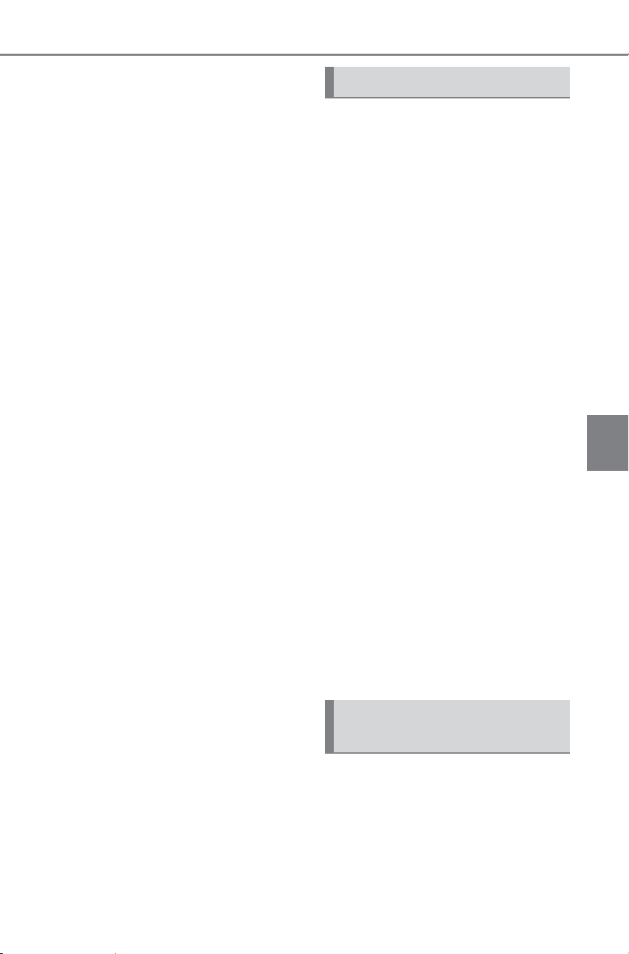
313
5-4. Using the driving support systems
Owner’s Manual_USA_M6740B_en
5
Driving
● When changing lanes
● When a preceding vehicle is driv-
ing at a low speed
● When a vehicle is stopped in the
same lane as the vehicle
● When a motorcycle is traveling in
the same lane as the vehicle
■ Conditions under which the
system may not operate cor-
rectly
In the following situations, operate
the brake pedal (or accelerator
pedal, depending on the situation)
as necessary.
As the sensor may not be able to
correctly detect a vehicle, the sys-
tem may not operate properly.
● When a preceding vehicle brakes
suddenly
● When changing lanes at low
speeds, such as in a traffic jam
■ Conditions for extended
resume time
Extended resume time is activated
when all of the following conditions
are satisfied:
● Vehicles with an active trial or sub-
scription to connected navigation.
Contact your SUBARU dealer for
details.
● The vehicle is driving on a vehicle-
only road, such as an expressway.
● There is a preceding vehicle and
the system is able to detect it.
● No vehicle interruptions occur.
● The preceding vehicle has not
been replaced.
● Clearance sonar and FCTA are
not detecting the object in front of
you.
● The driver monitor judges that the
driver is looking forward.
● The steering wheel has not been
operated.
● The brake pedal has not been
operated.
In situations where the vehicle
approaches a preceding vehicle
and the system cannot provide
sufficient deceleration, such as
if a vehicle cuts in front of the
vehicle, a warning display will
flash and a buzzer will sound to
alert the driver. Depress the
brake pedal to ensure appropri-
ate vehicle-to-vehicle distance.
■ Warnings may not occur
when
In the following situations, the
warning may not operate even
though the vehicle-to-vehicle
distance is short.
When the preceding vehicle is
traveling at the same speed
or faster than your vehicle
When the preceding vehicle is
traveling at an extremely low
speed
Immediately after the vehicle
speed has been set
When the accelerator pedal is
depressed
When a curve is detected, the
vehicle speed will begin being
reduced. When the curve ends,
the vehicle speed reduction will
end.
Approach warning
Curve speed reduction
function
SOLTERRA_OM_USA_A6740BE.book 313 ページ 2025年5月23日 金曜日 午後1時18分
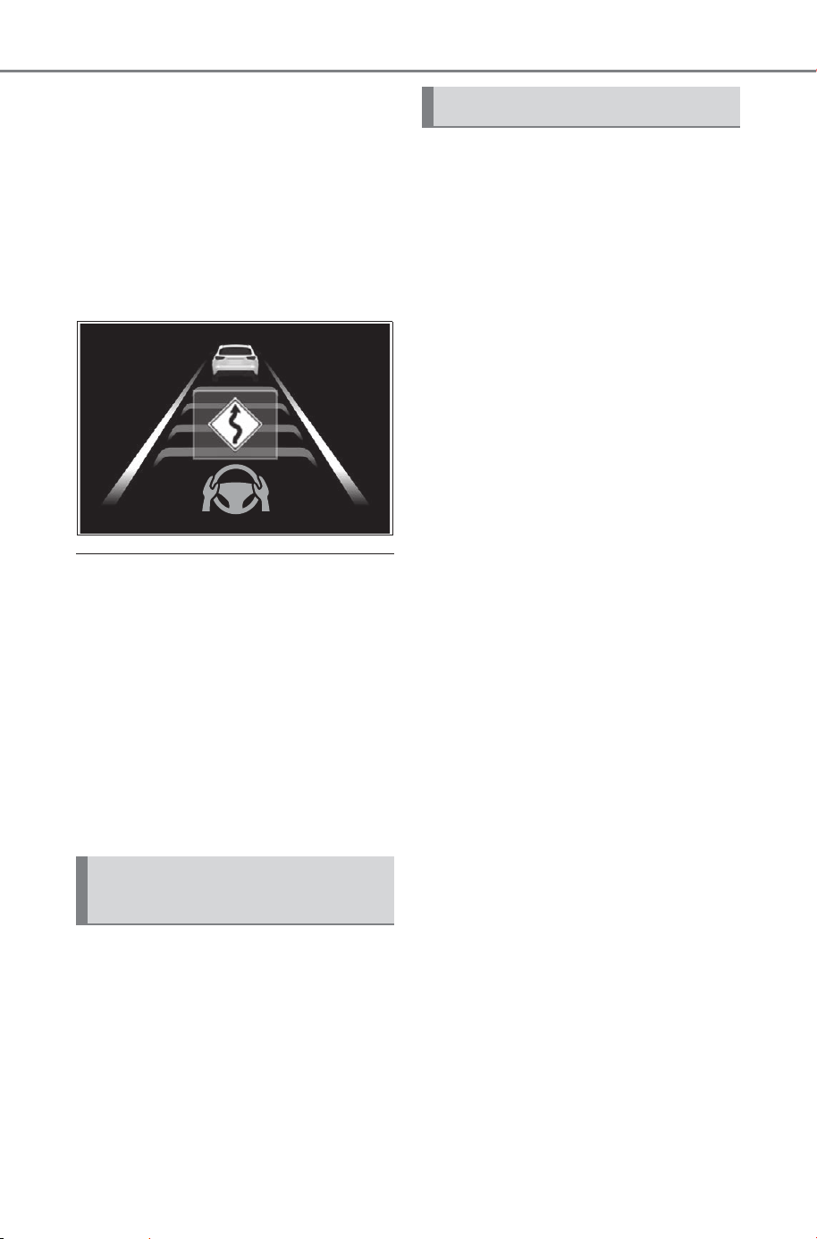
314
5-4. Using the driving support systems
Owner’s Manual_USA_M6740B_en
Depending on the situation, the
vehicle speed will then return to the
set vehicle speed.
In situations where vehicle-to-vehi-
cle distance control needs to oper-
ate, such as when a preceding
vehicle cuts in front of your vehicle,
the curve speed reduction function
will be canceled.
■ Situations in which the curve
speed reduction function may
not operate
In situations such as the following,
the curve speed reduction function
may not operate:
● When the vehicle is being driven
around a gentle curve
● When the accelerator pedal is
being depressed
● When the vehicle is being driven
around an extremely short curve
While a warning of the driver
monitor is being displayed, the
vehicle acceleration will be
restrained.
When the warning of the driver
monitor disappears, the
restrained acceleration control
will end.
If your vehicle is being driven at
approximately 50 mph (80 km/h)
or more and a lane change to
the passing lane is performed,
when the turn signal lever is
operated and the lane is
changed, the vehicle will accel-
erate up to the set speed to
assist in overtaking.
The system’s recognition of which
lane is the passing lane may be
based solely on the location of the
steering wheel in the vehicle (left-
hand drive/right-hand drive). If the
vehicle is driven in a location where
the passing lane is on the opposite
side of that where the vehicle was
originally sold, the vehicle may
accelerate when the turn signal
lever is operated away from the
passing lane. (e.g. The vehicle was
manufactured for a right-hand traf-
fic location, but is being driven in a
left-hand traffic location. The vehi-
cle may accelerate when the turn
signal lever is operated to the right.)
If your vehicle is being driven at
approximately 50 mph (80 km/h) or
more and the lane is changed to
that with a vehicle traveling slower
than your vehicle, when the turn
signal lever is operated the vehicle
will gradually decelerate to assist in
changing lanes.
Driver Monitor support
function
Support for lane change
SOLTERRA_OM_USA_A6740BE.book 314 ページ 2025年5月23日 金曜日 午後1時18分
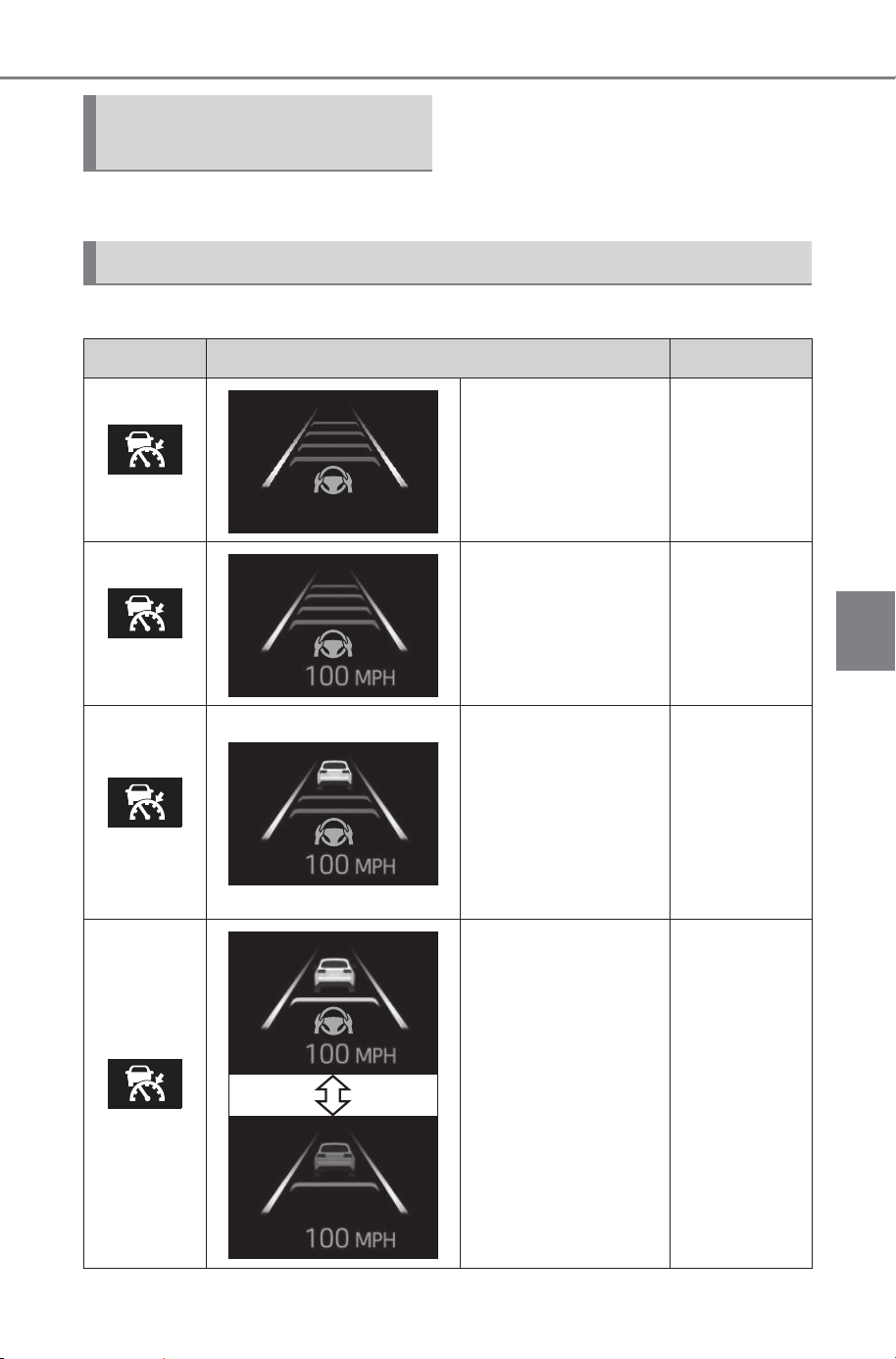
315
5-4. Using the driving support systems
Owner’s Manual_USA_M6740B_en
5
Driving
The settings of Dynamic radar
cruise control can be changed
through customize settings.
(P.679)
The operating state of Dynamic radar cruise control is indicated.
Changing Dynamic radar
cruise control settings
Display and system operation state
Indicator Multi-information display Situation
White
Vehicle-to-vehicle
distance setting:
Gray
Dynamic
radar cruise
control being
OFF
Green
Vehicle-to-vehicle
distance setting:
Blue
Set vehicle speed:
Green
Constant
speed cruis-
ing
Green
Vehicle-to-vehicle
distance setting:
Blue
Set vehicle speed:
Green
Preceding vehicle:
White
Follow-up
cruising
Green
Vehicle-to-vehicle
distance setting:
Orange flashing
Set vehicle speed:
Green
Preceding vehicle:
Orange flashing
Approach
warning
SOLTERRA_OM_USA_A6740BE.book 315 ページ 2025年5月23日 金曜日 午後1時18分
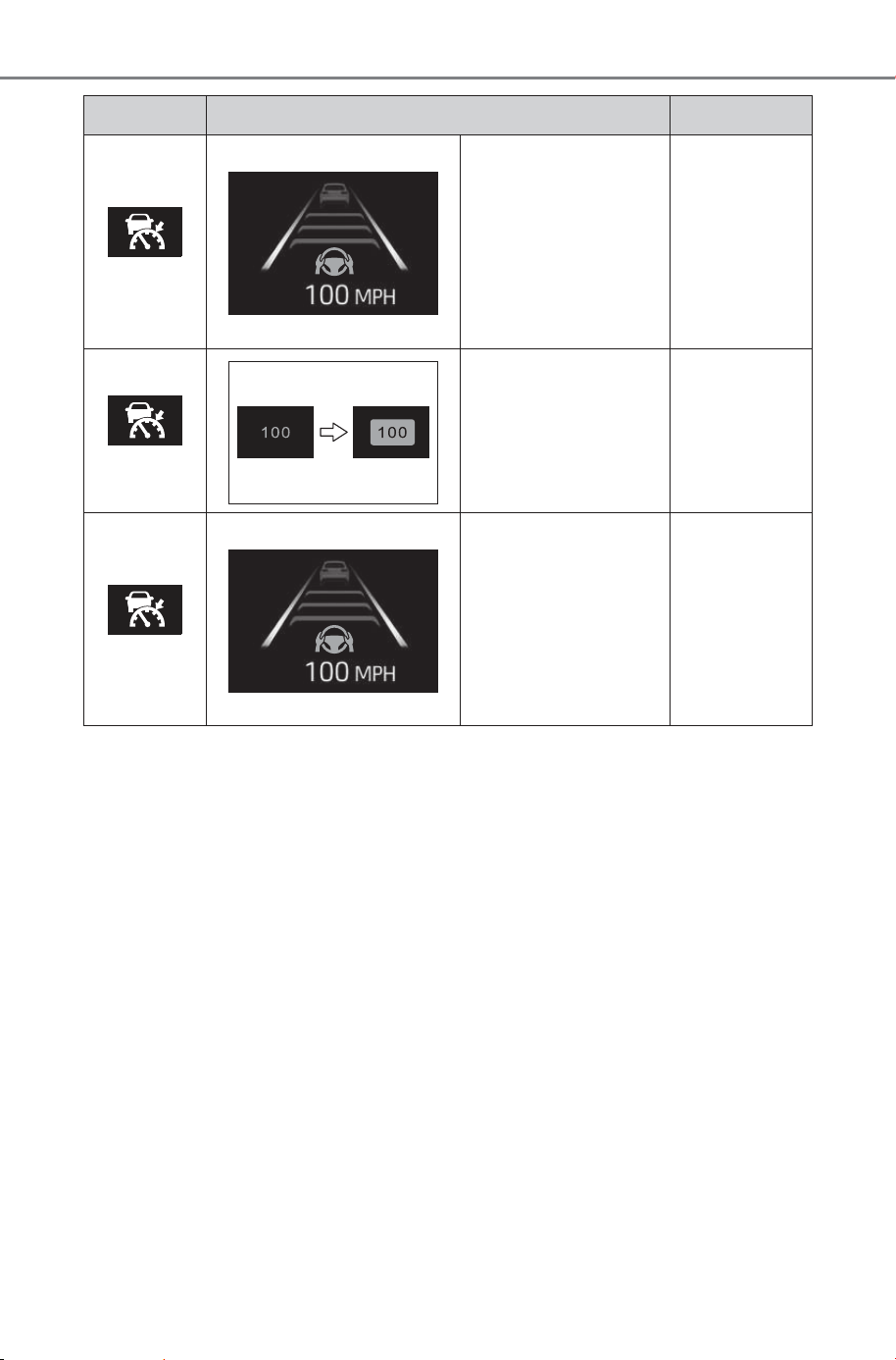
316
5-4. Using the driving support systems
Owner’s Manual_USA_M6740B_en
Green
Vehicle-to-vehicle
distance setting:
Gray
Set vehicle speed:
White
Preceding vehicle:
Gray
Accelerating
with the
accelerator
pedal
Green
Set vehicle speed:
Green in reverse
display
Set vehicle
speed being
exceeded
Green
Vehicle-to-vehicle
distance setting:
Gray
Set vehicle speed:
White
Preceding vehicle:
Gray
Vehicle in
controlled
stop
Indicator Multi-information display Situation
SOLTERRA_OM_USA_A6740BE.book 316 ページ 2025年5月23日 金曜日 午後1時18分
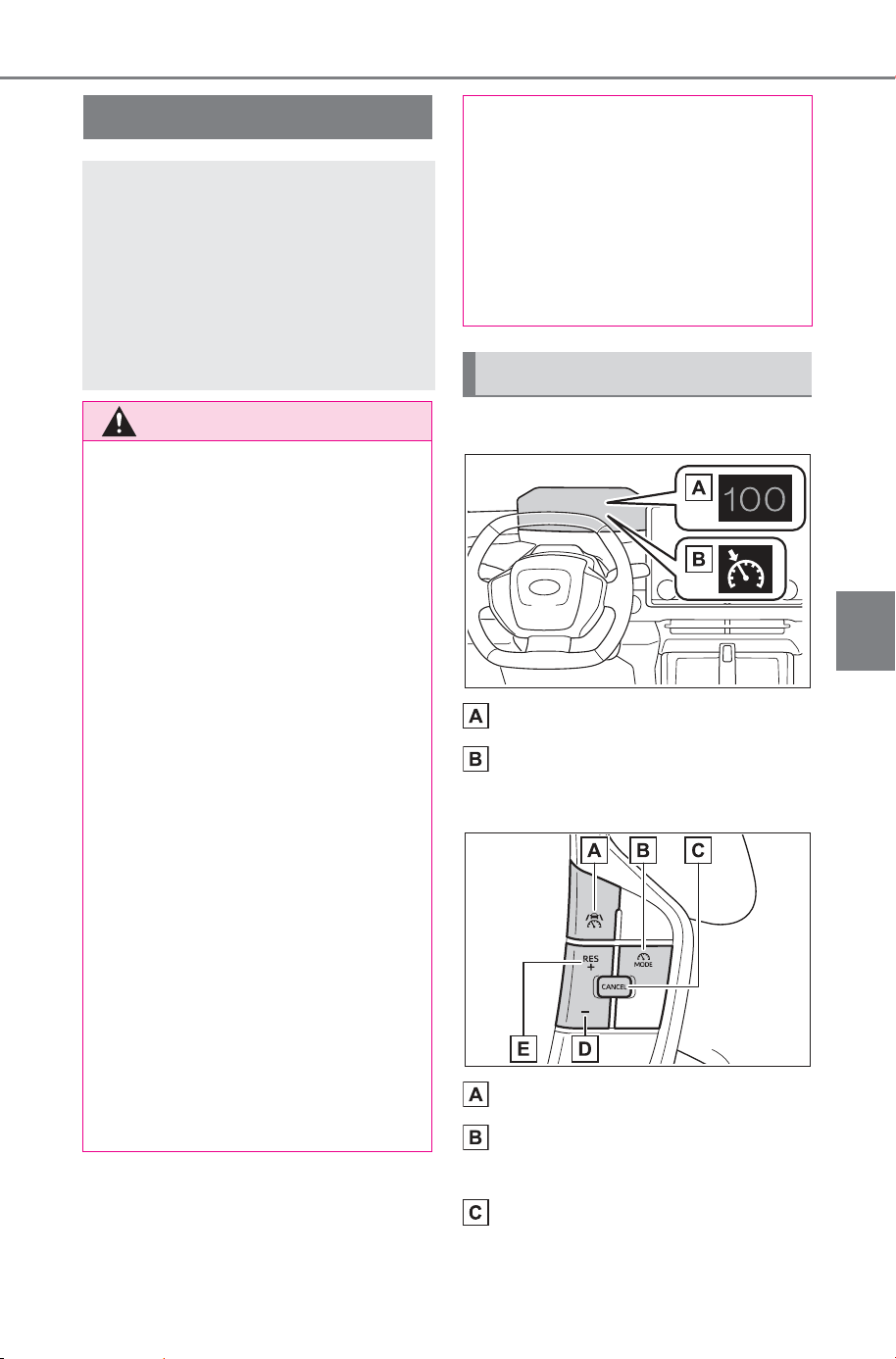
317
5-4. Using the driving support systems
Owner’s Manual_USA_M6740B_en
5
Driving
■ Meter display
Set vehicle speed
Cruise control indicator
■ Switches
Driving assist switch
Driving assist mode select
switch
Cancel switch
Cruise control
The vehicle can be driven at
a set speed even if the
accelerator pedal is not
depressed.
Use the cruise control only
on highways and express-
ways.
WARNING
■ For safe use
● Driving safely is solely the
responsibility of the driver.
Therefore, do not overly rely on
this system. The driver is solely
responsible for paying attention
to the vehicle’s surroundings
and driving safely.
● Set the speed appropriately
according to the speed limit,
traffic flow, road conditions,
weather conditions, etc. The
driver is responsible for confirm-
ing the set speed.
■ Situations in which cruise
control should not be used
Do not use the cruise control in
the following situations. As the
system will not be able to provide
appropriate control, using it may
lead to an accident resulting in
death or serious injury.
● On roads with sharp bends
● On winding roads
● On slippery roads, such as
those covered with rain, ice or
snow
● On steep downhills, or where
there are sudden changes
between sharp up and down
gradients
Vehicle speed may exceed the
set speed when driving down a
steep hill.
● When it is necessary to disable
the system: P. 25 9
System components
SOLTERRA_OM_USA_A6740BE.book 317 ページ 2025年5月23日 金曜日 午後1時18分
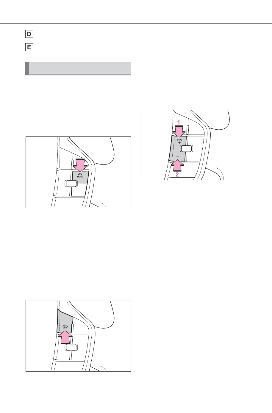
318
5-4. Using the driving support systems
Owner’s Manual_USA_M6740B_en
“-” switch
“+” switch/“RES” switch
■ Setting the vehicle speed
1 Press the driving assist mode
select switch to select Cruise
Control Mode.
The cruise control indicator will illu-
minate.
2 Using the accelerator pedal,
accelerate to the desired
vehicle speed (approxi-
mately 20 mph [30 km/h] or
more), and press the driving
assist switch to set the set
vehicle speed.
The vehicle speed at the moment
the switch is released will be the set
vehicle speed.
■ Adjusting the set vehicle
speed
Adjusting the set vehicle
speed using the switches
To change the set vehicle
speed, press the “+” or “-” switch
until the desired speed is dis-
played.
1 Increase set vehicle speed
2 Decrease set vehicle speed
The set vehicle speed will
increase or decrease as follows:
Fine adjustment: By 1 mph (1.6
km/h) or 1 km/h (0.6 mph) each
time the switch is pressed
Large adjustment: Increases con-
tinuously while the switch is
pressed and held
Increasing the set vehicle
speed using the accelerator
pedal
1 Depress the accelerator
pedal to accelerate the vehi-
cle to the desired vehicle
speed.
2 Press the “+” switch.
Using the cruise control
SOLTERRA_OM_USA_A6740BE.book 318 ページ 2025年5月23日 金曜日 午後1時18分
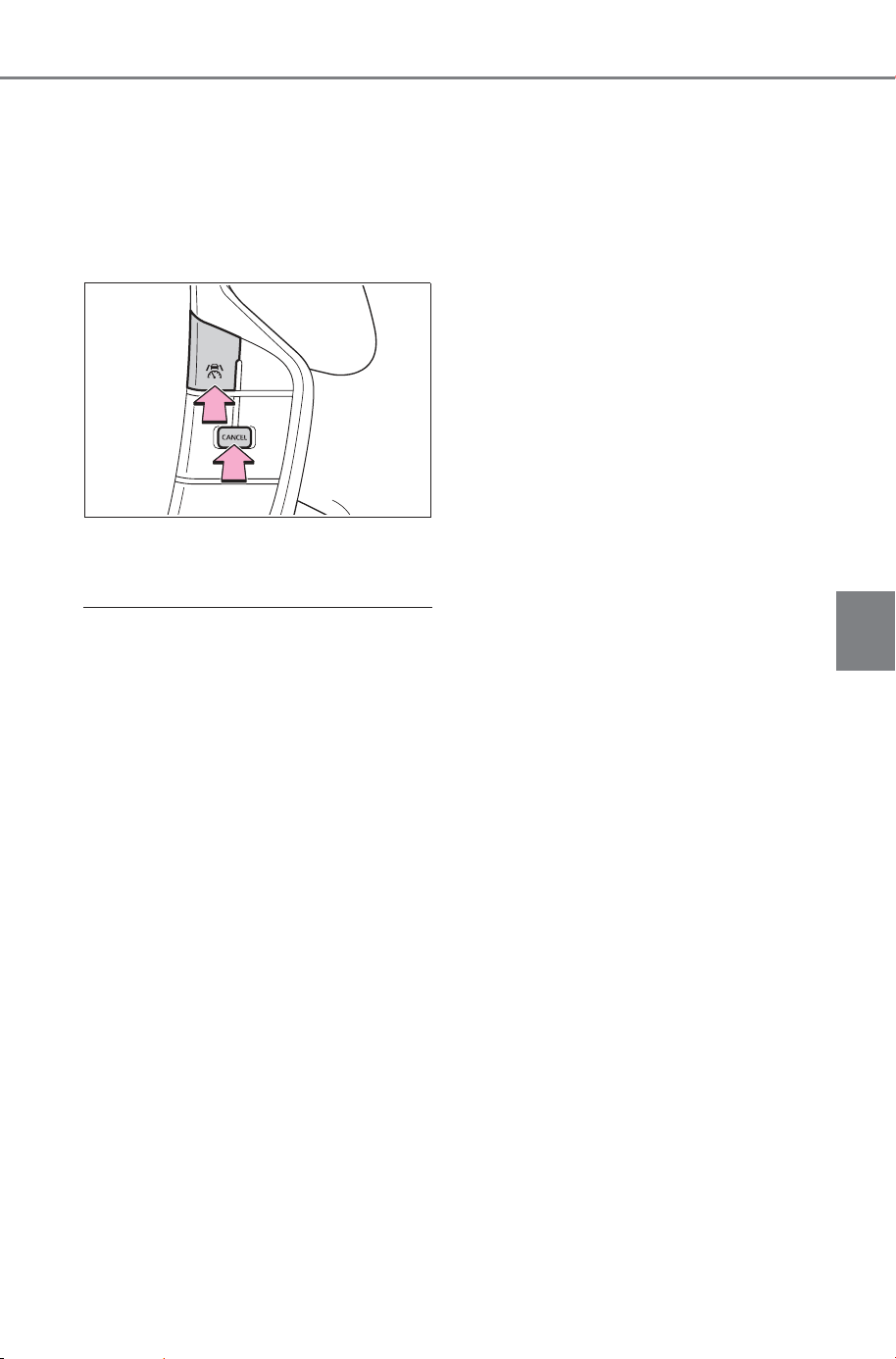
319
5-4. Using the driving support systems
Owner’s Manual_USA_M6740B_en
5
Driving
■ Canceling/resuming control
1 Press the cancel switch or
driving assist switch to cancel
control.
Control will also be canceled if the
brake pedal is depressed.
2 Press the “RES” switch to
resume control.
■ Automatic cancelation of the
cruise control
In the following situations, the cruise
control will be canceled automati-
cally:
● When the vehicle speed drops
approximately 10 mph (16 km/h)
or more below the set vehicle
speed
● When the vehicle speed drops
below approximately 20 mph (30
km/h)
● When the brake control or output
restriction control of a driving sup-
port system operates (For exam-
ple: PCS, drive-start control)
● When the parking brake has been
operated
● When the driver’s seat belt is
unfastened
● Situations in which some or all of
the functions of the system cannot
operate: P. 266
SOLTERRA_OM_USA_A6740BE.book 319 ページ 2025年5月23日 金曜日 午後1時18分
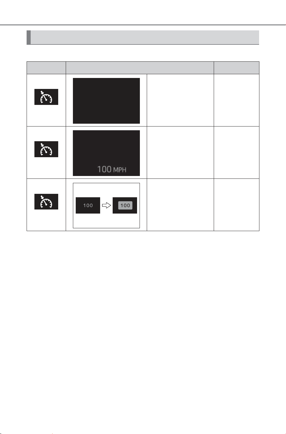
320
5-4. Using the driving support systems
Owner’s Manual_USA_M6740B_en
The operating state of cruise control is indicated.
Display and system operation state
Indicator Multi-information display Situation
White
Blank
Cruise con-
trol being
OFF
Green
Set vehicle speed:
Green
Constant
speed cruis-
ing
Green
Set vehicle speed:
Green in reverse
display
Set vehicle
speed being
exceeded
SOLTERRA_OM_USA_A6740BE.book 320 ページ 2025年5月23日 金曜日 午後1時18分
321
5-4. Using the driving support systems
Owner’s Manual_USA_M6740B_en
5
Driving
Emergency Driving
Stop System
The emergency driving stop
system is a system which
automatically decelerates
and stops the vehicle within
its lane if the driver
becomes unable to con-
tinue driving the vehicle,
such as if they have suf-
fered a medical emergency,
etc.
During LTA (Lane Tracing
Assist) control, if the sys-
tem does not detect driving
operations, such as if the
driver is not holding the
steering wheel, and deter-
mines the driver is not
responsive, the vehicle will
be decelerated and stopped
within its current lane to
help avoid a collision or
reduce the impact of a colli-
sion.
The vehicle will also decel-
erate/stop during the Traf-
fic Jam Assist controls,
when no driver’s response
to the vehicle’s warning to
hold the steering wheel is
detected.
WARNING
■ For safe use
● Driving safely is solely the
responsibility of the driver. Pay
careful attention to the sur-
rounding conditions in order to
ensure safe driving. The emer-
gency driving stop system is
designed to provide support in
an emergency where it is diffi-
cult for the driver to continue
driving, such as if they have had
a medical emergency. It is not
designed to support driving
while drowsy or in poor physical
health, or inattentive driving.
● Although the emergency driv-
ing stop system is designed to
decelerate the vehicle within its
lane to help avoid or help
reduce the impact of a collision
if the system determines that it
is difficult for the driver to con-
tinue driving, its effectiveness
may change according to vari-
ous conditions. Therefore, it
may not always be able to
achieve the same level of per-
formance. Also, if the operating
conditions are not met, this
function will not operate.
● After the emergency driving
stop system operates, if driving
becomes possible again, imme-
diately begin driving again or, if
necessary, park the vehicle on
the shoulder of the road and set
a warning reflector and flare to
warn other drivers of your
stopped vehicle.
● After this system operates, pas-
sengers should attend to the
driver as necessary and take
appropriate hazard prevention
measures, such as moving to a
place where safety can be
ensured, such as the shoulder
of the road or behind a guard-
rail.
SOLTERRA_OM_USA_A6740BE.book 321 ページ 2025年5月23日 金曜日 午後1時18分
322
5-4. Using the driving support systems
Owner’s Manual_USA_M6740B_en
Operation of this system is sep-
arated into 4 control states.
Through control state “warning
phase 1” and “warning phase 2”,
the system determines if the
driver is aware and responsive
while outputting a warning and
controlling the vehicle speed. If
the system determines the
driver is not responsive, it will
operate in control state “deceler-
ation stop phase” and “stop hold
phase” and decelerate and stop
the vehicle. It will then operate
continuously in “stop hold
phase”.
■ Operating conditions
This system operates when all of
the following conditions are met:
● When the LTA is on
Or during the Traffic Jam Assist con-
trols
● When the vehicle speed is
approximately 30 mph (50 km/h)
or more
During the Traffic Jam Assist con-
trols, the system may operate at
below 30 mph (50 km/h).
■ Operation cancelation condi-
tions
In the following situations, system
operation will be canceled:
● When LTA control has been can-
celed (the LTA switch has been
pressed, etc.)
● When the dynamic radar cruise
control has been canceled
● When driver operations are
detected (the steering wheel is
held, the brake pedal, accelerator
pedal, parking brake, hazard light
switch, or turn signal lever is oper-
ated)
● When the driving assist switch is
pressed while in the stop and hold
phase
● When the power switch has been
turned from ON to OFF
● Situations in which some or all of
the functions of the system cannot
operate: P. 266
■ LTA control when operation is
canceled
When emergency driving stop sys-
tem operation is canceled, LTA con-
trol may also be canceled.
WARNING
● This system detects the condi-
tion of the driver through the
operation of the steering wheel.
This system may operate if the
driver is aware but intentionally
and continuously does not oper-
ate the vehicle. Also, the system
may not operate if it cannot
determine that the driver is not
responsive, such as if they are
leaning on the steering wheel.
● Situations in which the driver
monitor may not operate prop-
erly: P.266
Summary of the system
SOLTERRA_OM_USA_A6740BE.book 322 ページ 2025年5月23日 金曜日 午後1時18分
323
5-4. Using the driving support systems
Owner’s Manual_USA_M6740B_en
5
Driving
If driving operations are not
detected after the hands off
steering wheel warning oper-
ates, a buzzer will sound inter-
mittently and a message will be
displayed to warn the driver, and
the system will judge if the driver
is responsive or not. If driving
operations, such as holding the
steering wheel, are not per-
formed within a certain amount
of time, the system will enter
warning phase 2.
Depending on the type of detec-
tion of the driver’s unrespon-
siveness, the system may skip
warning phase 1 and start the
control of warning phase 2.
After entering warning phase 2,
a buzzer will sound in short
intervals and a message will be
displayed to warn the driver, and
the vehicle will slowly deceler-
ate. If driving operations, such
as holding the steering wheel,
are not performed within a cer-
tain amount of time, the system
will determine that the driver is
not responsive and enter the
deceleration stop phase.
When the vehicle is decelerating,
the brake lights may illuminate,
depending on the road conditions,
etc.
After entering the deceleration
stop phase, a buzzer will sound
continuously and a message will
be displayed to warn the driver,
and the vehicle will slowly decel-
erate and stop. After the vehicle
stops, the system will enter the
stop and hold phase.
After the vehicle is stopped, the
parking brake will be applied
automatically. After entering the
stop and hold phase, the buzzer
will continue sounding continu-
ously and the emergency flash-
ers (hazard lights) will flash to
warn other drivers of the emer-
gency.
■ Restricted functions after the
operation is canceled
After shifting to the deceleration
stop phase, the following functions
will not be available until the EV sys-
tem is re-started even though the
emergency driving stop system is
canceled:
● LTA
● LCA
● Traffic Jam Assist
Warning phase 1
Warning phase 2
Deceleration stop phase
Stop hold phase
SOLTERRA_OM_USA_A6740BE.book 323 ページ 2025年5月23日 金曜日 午後1時18分
324
5-4. Using the driving support systems
Owner’s Manual_USA_M6740B_en
Traffic Jam Assist is a system
which, through confirmation of
the conditions by the driver, pro-
vides lane keeping, accelerat-
ing/decelerating, stopping, and
starting off support on some
highways and expressways.
Also, in an emergency, the sys-
tem can decelerate and stop, to
help avoid a collision or help
reduce the impact of a collision.
Sensors which detect the sur-
rounding conditions (P.261)
Sensors which detect the
driver condition (P.261)
■ Situations in which some or all
of the functions of the system
cannot operate
P.266
■ Changes in brake operation
sound and pedal response
P.266
■ Situations in which the driver
monitor may not operate prop-
erly
P.266
P.321
P.313
The Traffic Jam Assist function,
through confirmation of the con-
ditions by the driver, provides
lane keeping, accelerat-
ing/decelerating and stopping
support on some highways and
expressways.
This function is operable when
all of the operation conditions
are met. When this function is
operating, it is possible to take
your hands off of the steering
wheel.
Before using the Traffic Jam Assist
function, familiarize yourself with
the content of the dynamic radar
cruise control and the LTA (Lane
Tracing Assist).
Make sure that the driver steers the
vehicle when entering a service
area/parking area or toll gate, or
when changing lanes.
Traffic Jam Assist
Function Outline
Sensors that support the
Traffic Jam Assist
Emergency Driving Stop
System
Extended resume time of
Dynamic radar cruise
control
Traffic Jam Assist Func-
tion
SOLTERRA_OM_USA_A6740BE.book 324 ページ 2025年5月23日 金曜日 午後1時18分
325
5-4. Using the driving support systems
Owner’s Manual_USA_M6740B_en
5
Driving
When the operation of Traffic
Jam Assist is started, the follow-
ing message will be displayed:
“Allow Driver Monitor Camera
Recording?”
When recording is approved, the
system records images of the area
around the driver in certain crash or
near crash-like situations, such as
an SRS airbag being deployed or
the vehicle hitting an object on the
road. (P. 9 )
Driver monitor camera
recording
WARNING
■ For safe use
● Driving safely is solely the
responsibility of the driver. Do
not overly rely on this system,
and pay careful attention to the
surrounding conditions in order
to ensure safe driving.
● The Traffic Jam Assist function
is not an automated driving sys-
tem. This function provides the
driver with information and driv-
ing assistance according to the
road shape and conditions, traf-
fic conditions, and the condition
of the driver themself. Always
pay careful attention to the sur-
rounding conditions as use of
the system is the responsibility
of the driver.
● Depending on the condition of
the surrounding area, the road,
or the driver, the Traffic Jam
Assist function may not operate
or operation may be sus-
pended. Also, it may not always
be able to achieve the same
level of performance. Read the
operating conditions of the func-
tion carefully. Do not overly rely
on this function and always
drive carefully.
● As the recognition performance
and control performance of the
Traffic Jam Assist function are
limited, driver operation is nec-
essary to ensure safety while
the system is operating. Also,
the steering assist of this sys-
tem is designed to operate only
for slow steering operations
during a traffic jam. While this
function is operating, the lane
deviation control function of the
LDA will not operate. If, for
some reason, the vehicle is
about to deviate the lane, it is
the driver’s responsibility to
drive properly.
● Even if Traffic Jam Assist is
operating properly, the sur-
rounding conditions as recog-
nized by the driver and detected
by the system may differ. There-
fore, it is necessary for the
driver to pay attention, assess
risks, and ensure safety. Over-
reliance on this system to drive
the vehicle safely may lead to
an accident resulting in death or
serious injury.
SOLTERRA_OM_USA_A6740BE.book 325 ページ 2025年5月23日 金曜日 午後1時18分
326
5-4. Using the driving support systems
Owner’s Manual_USA_M6740B_en
WARNING
● While the Traffic Jam Assist
function is operating, as driver
operation may become neces-
sary, the driver must ensure
they have clear visibility of their
surroundings.
● In certain situations, a message
urging the driver to hold the
steering wheel may be dis-
played by the Traffic Jam Assist
function. In this case, hold the
steering wheel and drive the
vehicle manually to ensure
safety.
● The Traffic Jam Assist function
cannot detect the following
objects. Operate the steering
wheel, accelerator pedal, or
brake pedal as necessary to
avoid a collision. As the function
will not be able to provide
appropriate control, using it may
lead to an accident resulting in
death or serious injury.
• Objects on the road surface
• Vehicles outside of a lane (such
as on the shoulder of the road)
• Potholes, cracks, ruts, or other
road damage
• Road construction zones
• Vehicles running in parallel with
your vehicle or nearby walls
•Animals
■ Situations in which Traffic
Jam Assist Function should
not be used
Do not use Traffic Jam Assist
Function in situations such as the
following. As the system will not
be able to provide appropriate
control, using it may lead to an
accident resulting in death or seri-
ous injury.
■ When it is necessary to dis-
able the system
P.2 59
■ Situations in which the sen-
sors may not operate prop-
erly
P.2 64
■ Situations in which the lane
may not be detected
P.2 66
■ Situations in which the func-
tion may not operate properly
In situations such as the following,
the Traffic Jam Assist function
may not operate properly. Manu-
ally operate the vehicle as neces-
sary.
● When a sensor is splashed by
water
● When the ambient temperature
is high or low
● When a vehicle cuts in front of
your vehicle
● When another lane merges into
the lane in the same traveling
direction as your vehicle
SOLTERRA_OM_USA_A6740BE.book 326 ページ 2025年5月23日 金曜日 午後1時18分
327
5-4. Using the driving support systems
Owner’s Manual_USA_M6740B_en
5
Driving
■ Operating conditions of the
function
This function is operable when all of
the following conditions are met:
● The system detects lane lines and
the path of preceding or surround-
ing vehicles.
● The dynamic radar cruise control
and the lane tracing assist are
operating.
● The turn signal lever is not being
operated.
● The vehicle is not being driven
around a sharp curve.
● The vehicle is being driven in the
center of a lane.
● The driver monitor camera is
detecting that the driver is facing
front of the vehicle.
● The vehicle is driving in traffic jam
on a highway or expressway at
approximately 25 mph (40 km/h)
or less. (In some situations, such
as when a traffic jam starts, this
function may be operational at
approximately 20 mph [30 km/h]
or less.)
● Drive Connect is being subscribed
to.
● The driver’s door is closed.
● The driver’s seat belt is fastened.
● Customized setting of the Traffic
Jam Assist is not set to off.
● Functions and components com-
posing the system are in proper
condition.
● Customized setting of the PCS
(Pre-Collision System) is not set
to off.
● Customized setting of the dynamic
radar cruise control (re-start time
extension) is not set to off.
WARNING
● When driving in low visibility
conditions
● When the vehicle posture is
changing
● When the traction on the road
surface differs greatly between
the left and right side tires
● When driving on an expressway
with no median strips or when
driving on an expressway
equipped with temporary
median markers, such as poles.
● When there is a significant dif-
ference in speed between your
vehicle and the other vehicle
● The map data has not been
updated properly.
■ To prevent malfunction of the
radar sensors
P.2 61
■ To prevent malfunction of the
front camera
P.2 62
■ Front camera installation area
on the windshield
P.2 64
SOLTERRA_OM_USA_A6740BE.book 327 ページ 2025年5月23日 金曜日 午後1時18分
328
5-4. Using the driving support systems
Owner’s Manual_USA_M6740B_en
■ Temporary cancelation of the
function
● When the operating conditions are
no longer met, a function may be
temporarily canceled. However,
when the operation conditions are
met again, operation of the func-
tion will automatically be restored.
● If the operating conditions of a
function are no longer met while
the function is operating, a buzzer
may sound with a display to indi-
cate that the function has been
temporarily canceled. If no driver’s
responses to the indication are
detected, the driver emergency
stop assist function may operate.
For types of display and action to
be taken, see the page mentioned
below. (P.329)
■ Driving operations during con-
trolled driving:
● Accelerator pedal
As with normal driving, acceleration
can be performed by depressing the
accelerator pedal. When the accel-
erator pedal is depressed at approx-
imately 6 mph (10 km/h) or more,
this function will be canceled.
● Brake pedal
As with normal driving, deceleration
can be performed by depressing the
brake pedal. However, controlled
driving will be cancelled.
● Steering wheel
As with normal driving, the steering
wheel can be operated. If the steer-
ing wheel is operated more than a
certain amount, controlled driving
will be cancelled.
■ When a warning message is
displayed
● “Traffic Jam Asst System Malfunc-
tion Visit Your Dealer”
The Traffic Jam Assist function may
not be operating properly.
● “Traffic Jam Asst Unavailable Stop
Assist Activated”
The system temporarily cannot be
used as the driver emergency stop
assist function has operated.
The setting of Traffic Jam
Assist can be enabled/dis-
abled through a customize
setting. (P.680)
The setting of driver monitor
camera recording can be
enabled/disabled through a
customize setting. (P.680)
Changing Traffic Jam
Assist settings
SOLTERRA_OM_USA_A6740BE.book 328 ページ 2025年5月23日 金曜日 午後1時18分
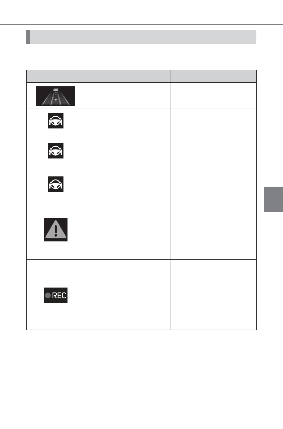
329
5-4. Using the driving support systems
Owner’s Manual_USA_M6740B_en
5
Driving
The following displays indicate the operating status of the Traffic
Jam Assist function:
Displays and system operation
Display Status Action to be taken
Traffic Jam Assist function
is operating
(Gray)
Traffic Jam Assist function
is about to end
Hold the steering wheel.
(Orange)
Traffic Jam Assist function
has ended
Hold the steering wheel.
(Red)
Operation of either or both
of dynamic radar cruise
control /LTA (Lane Tracing
Assist) ended
Manually operate the
steering wheel immedi-
ately.
(Yellow)
Indicates that driving
actions are necessary to
cope with cut-in or other
behavior of surrounding
vehicles
The driver must operate
the steering wheel, accel-
erator pedal and brake
pedal in accordance with
the surrounding environ-
ment.
Indicates that the recording
function of the driver moni-
tor camera is operational
(Blinking of this icon indi-
cates that recording is
undergoing, and constant
illumination indicates ready
for recording.)
SOLTERRA_OM_USA_A6740BE.book 329 ページ 2025年5月23日 金曜日 午後1時18分
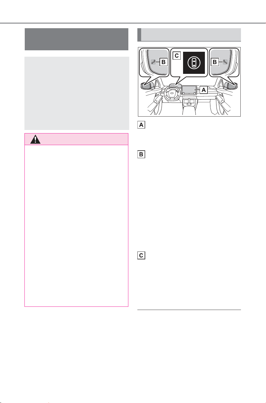
330
5-4. Using the driving support systems
Owner’s Manual_USA_M6740B_en
Multimedia display
Turning the Blind Spot Monitor
on/off.
Outside rear view mirror indi-
cators
When a vehicle is detected in a
blind spot of the outside rear view
mirrors or approaching rapidly from
behind into a blind spot, the outside
rear view mirror indicator (P.140)
on the detected side will illuminate.
If the turn signal lever is operated
toward the detected side, the out-
side rear view mirror indicator will
flash and a buzzer will sound.
Driving assist information
indicator
Illuminates when the Blind Spot
Monitor is turned off. At this time, a
message will be displayed on the
multi-information display.
■ Outside rear view mirror indica-
tor visibility
In strong sunlight, the outside rear
view mirror indicator may be difficult
to see.
BSM (Blind Spot Moni-
tor)
The Blind Spot Monitor is a
system that uses rear side
radar sensors installed on
the inner side of the rear
bumper on the left and right
side to assist the driver in
confirming safety when
changing lanes.
WARNING
■ Cautions regarding the use of
the system
● The driver is solely responsible
for safe driving. Always drive
safely, taking care to observe
your surroundings.
● The Blind Spot Monitor is a sup-
plementary function which alerts
the driver that a vehicle is in a
blind spot of the outside rear
view mirrors or is approaching
rapidly from behind into a blind
spot. Do not overly rely on the
Blind Spot Monitor. As the func-
tion cannot judge if it is safe to
change lanes, over reliance
could lead to an accident result-
ing in death or serious injury.
As the system may not function
correctly under certain condi-
tions, the driver’s own visual
confirmation of safety is neces-
sary.
System components
SOLTERRA_OM_USA_A6740BE.book 330 ページ 2025年5月23日 金曜日 午後1時18分
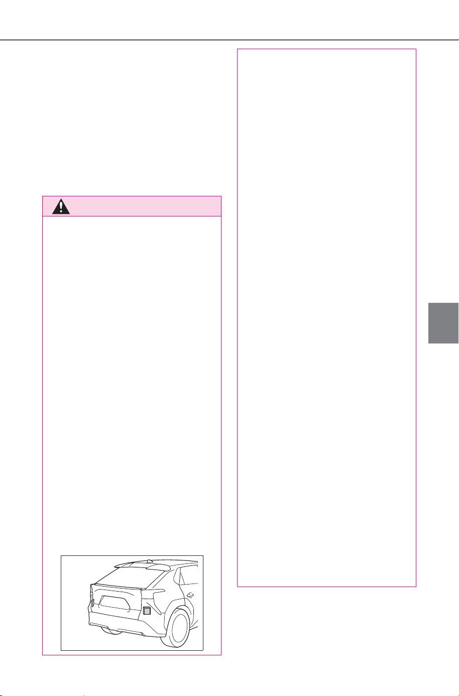
331
5-4. Using the driving support systems
Owner’s Manual_USA_M6740B_en
5
Driving
■ Buzzer
If the volume setting of the audio
system is high or the surrounding
area is loud, it may be difficult to
hear the buzzer.
■ Customization
Some functions can be customized.
(P.681)
■ Certification
P.733
WARNING
■ To ensure the system can
operate properly
Blind Spot Monitor sensors are
installed behind the left and right
sides of the rear bumper respec-
tively. Observe the following to
ensure the Blind Spot Monitor can
operate correctly.
● Keep the sensors and the sur-
rounding areas on the rear
bumper clean at all times.
If a sensor or its surrounding area
on the rear bumper is dirty or cov-
ered with snow, the Blind Spot
Monitor may not operate and a
warning message will be dis-
played. In this situation, clear off
the dirt or snow and drive the
vehicle with the operation condi-
tions of the BSM function
(P.333) satisfied for approxi-
mately 10 minutes. If the warning
message does not disappear,
have the vehicle inspected by
your SUBARU dealer.
● Do not attach accessories,
stickers (including transparent
stickers), aluminum tape, etc.,
to a sensor or its surrounding
area on the rear bumper.
● Do not paint the surrounding
area of a sensor on the rear
bumper.
● Do not subject a sensor or its
surrounding area on the rear
bumper to a strong impact.
If a sensor is moved even
slightly off position, the system
may malfunction and vehicles
may not be detected correctly.
In the following situations, have
your vehicle inspected by your
SUBARU dealer.
• A sensor or its surrounding area
is subject to a strong impact.
• If the surrounding area of a sen-
sor is scratched or dented, or
part of them has become dis-
connected.
● Do not disassemble the sensor.
● Do not modify the sensor or sur-
rounding area on the rear
bumper.
● If a sensor or the rear bumper
needs to be removed/installed
or replaced, contact your SUB-
ARU dealer.
● The sensors are likely to be
affected by paint on the rear
bumper. If the rear bumper is
not repaired correctly, the Blind
Spot Monitor may not operate
with a warning message dis-
played. If any paint repair is
needed, contact your SUBARU
dealer.
SOLTERRA_OM_USA_A6740BE.book 331 ページ 2025年5月23日 金曜日 午後1時18分
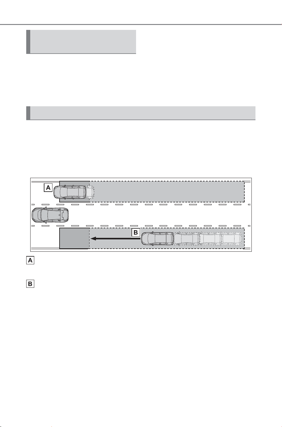
332
5-4. Using the driving support systems
Owner’s Manual_USA_M6740B_en
The Blind Spot Monitor can be
enabled/disabled through a cus-
tomize setting. (P.681)
When the Blind Spot Monitor is
off, the driving assist information
indicator (P.140) will illuminate
and a message will be displayed
on the multi-information display.
Each time the power switch is
turned to ON, the Blind Spot
Monitor is enabled.
■ Objects that can be detected while driving
The Blind Spot Monitor uses rear side radar sensors to detect the fol-
lowing vehicles traveling in adjacent lanes and advises the driver of
the presence of such vehicles via the indicators on the outside rear
view mirrors.
Vehicles that are traveling in areas that are not visible using the
outside rear view mirrors (the blind spots)
Vehicles that are approaching rapidly from behind in areas that
are not visible using the outside rear view mirrors (the blind spots)
Turning the Blind Spot
Monitor on/off
Blind Spot Monitor operation
SOLTERRA_OM_USA_A6740BE.book 332 ページ 2025年5月23日 金曜日 午後1時18分
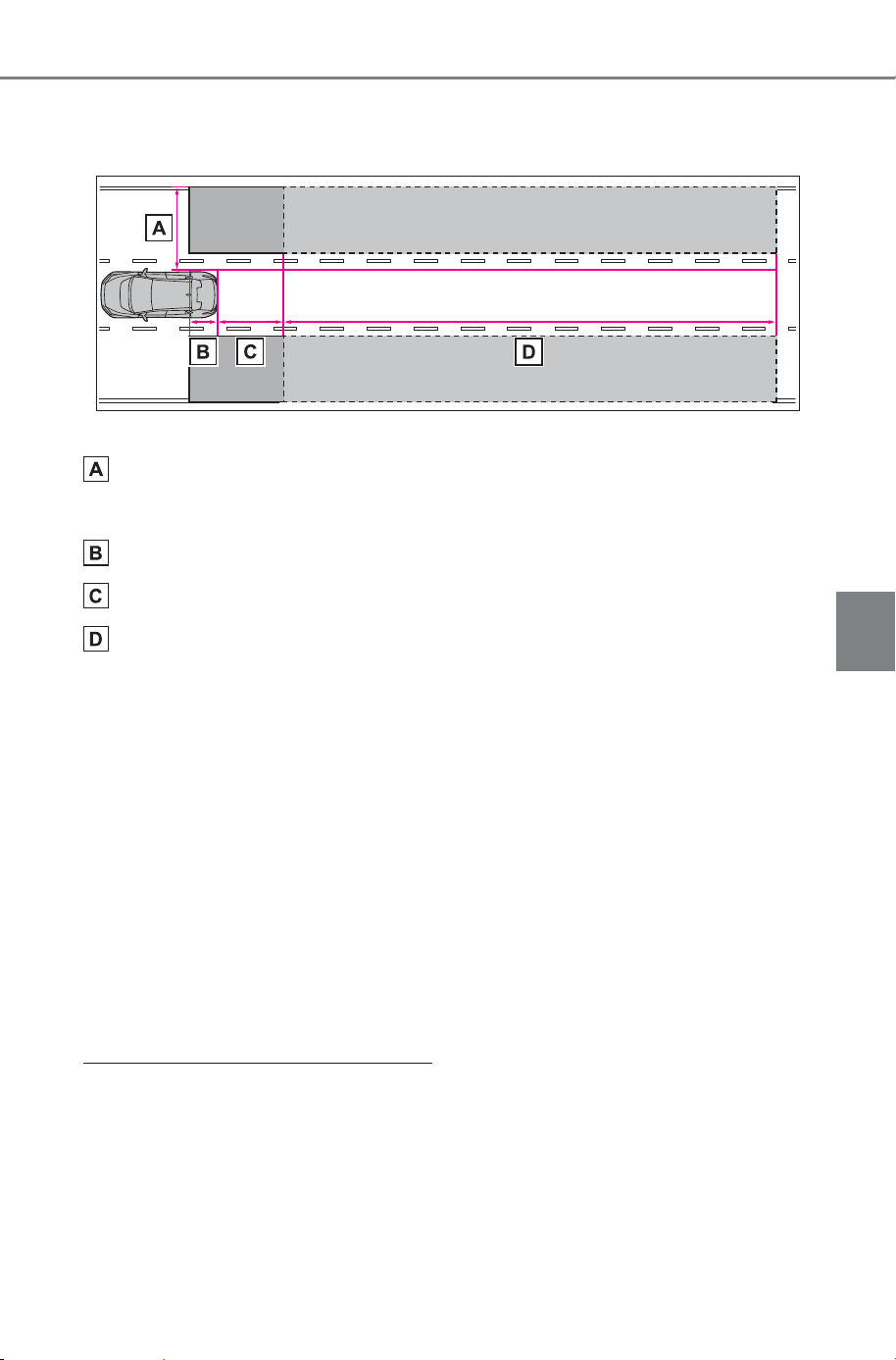
333
5-4. Using the driving support systems
Owner’s Manual_USA_M6740B_en
5
Driving
■ Detection range while driving
The areas that vehicles can be detected in are outlined below.
The range of each detection area is:
Approximately 1.6 ft. (0.5 m) to 11.5 ft. (3.5 m) from either side of
the vehicle
*1
Approximately 3.3 ft. (1 m) forward of the rear bumper
*2
Approximately 9.8 ft. (3 m) from the rear bumper
Approximately 9.8 ft. (3 m) to 230 ft. (70 m) from the rear
bumper
*3
*1
:The area between the side of the vehicle and 1.6 ft. (0.5 m) from the side
of the vehicle cannot be detected.
*2
:While the vehicle is to being overtaken, up to approximately 9.8 ft. (3 m)
forward of the rear bumper will be detected.
*3
:The greater the difference in speed between your vehicle and the
detected vehicle is, the farther away the vehicle will be detected, causing
the outside rear view mirror indicator to illuminate or flash.
■ The Blind Spot Monitor linked function
The LDA (Lane Departure Alert) has a function that uses information
of detected vehicles driving in an adjacent lane. For details about the
function and its operating conditions, P.290.
■ The Blind Spot Monitor is oper-
ational when
The Blind Spot Monitor is opera-
tional when all of the following con-
ditions are met:
● The power switch is in ON.
● The Blind Spot Monitor is on.
● The shift position is in a position
other than R.
● The vehicle speed is approxi-
mately 7 mph (10 km/h) or more.
SOLTERRA_OM_USA_A6740BE.book 333 ページ 2025年5月23日 金曜日 午後1時18分

334
5-4. Using the driving support systems
Owner’s Manual_USA_M6740B_en
■ The Blind Spot Monitor will
detect a vehicle when
The Blind Spot Monitor will detect a
vehicle present in the detection area
in the following situations:
● A vehicle in an adjacent lane over-
takes your vehicle.
● You overtake a vehicle in an adja-
cent lane slowly.
● Another vehicle enters the detec-
tion area when it changes lanes.
■ Situations in which the Blind
Spot Monitor cannot detect
vehicles.
The Blind Spot Monitor cannot
detect the following vehicles and
other objects:
● Small motorcycles, bicycles,
pedestrians, etc.
*
● Vehicles traveling in the opposite
direction
● Guardrails, walls, signs, parked
vehicles and similar stationary
objects
*
● Following vehicles that are in the
same lane
*
● Vehicles traveling 2 lanes away
from your vehicle
*
● Vehicles which are being over-
taken rapidly by your vehicle
*
*
: Depending on the conditions,
detection of a vehicle and/or
object may occur.
■ Conditions in which a buzzer
may not sound
In situations such as the following,
while the turn signal lever is being
operated, the indicator will flash but
a buzzer may not sound.
● When a second vehicle is
detected while the turn signal
lever is being held
● When overtaking a vehicle in the
adjacent lane at a much higher
speed than it
*
*
: Depending on the situations, a
buzzer may sound.
■ Conditions under which the
system may not function cor-
rectly
● The Blind Spot Monitor may not
detect vehicles correctly in the fol-
lowing situations:
• When the sensor is misaligned
due to a strong impact to the sen-
sor or its surrounding area
• When mud, snow, ice, a sticker,
etc., is covering the sensor or sur-
rounding area on the rear bumper
• When driving on a wet road sur-
face, such as in a puddle, while in
inclement weather, such as heavy
rain, snow, fog, etc.
• When multiple vehicles are
approaching with only a small gap
between each vehicle
• When the distance between your
vehicle and a following vehicle is
short
• When there is a significant differ-
ence in speed between your vehi-
cle and the vehicle that enters the
detection area
• When the difference in speed
between your vehicle and another
vehicle is changing
• When a vehicle enters a detection
area traveling at about the same
speed as your vehicle
• As your vehicle starts from a stop,
a vehicle remains in the detection
area
• When driving up and down con-
secutive steep inclines, such as
hills, dips in the road, etc.
• When driving on roads with sharp
bends, consecutive curves, or
uneven surfaces
• When vehicle lanes are wide, or
when driving on the edge of a
lane, and the vehicle in an adja-
cent lane is far away from your
vehicle
SOLTERRA_OM_USA_A6740BE.book 334 ページ 2025年5月23日 金曜日 午後1時18分
335
5-4. Using the driving support systems
Owner’s Manual_USA_M6740B_en
5
Driving
• When an accessory (such as a
bicycle carrier) is installed to the
rear of the vehicle
• When there is a significant differ-
ence in height between your vehi-
cle and the vehicle that enters the
detection area
• Immediately after the Blind Spot
Monitor is turned on
• When towing with the vehicle
● Instances of the Blind Spot Moni-
tor unnecessarily detecting a vehi-
cle and/or object may increase in
the following situations:
• When the sensor is misaligned
due to a strong impact to the sen-
sor or its surrounding area
• When the distance between your
vehicle and a guardrail, wall, etc.,
that enters the detection area is
short
• When driving up and down con-
secutive steep inclines, such as
hills, dips in the road, etc.
• When vehicle lanes are narrow, or
when driving on the edge of a
lane, and a vehicle traveling in a
lane other than the adjacent lanes
enters the detection area
• When driving on roads with sharp
bends, consecutive curves, or
uneven surfaces
• When the tires are slipping or
spinning
• When the distance between your
vehicle and a following vehicle is
short
• When an accessory (such as a
bicycle carrier) is installed to the
rear of the vehicle
• When towing with the vehicle
Safe Exit Assist
The safe exit assist is a sys-
tem that uses rear side
radar sensors installed on
the inner side of the rear
bumper to help occupants
judge if an approaching
vehicle or bicycle may col-
lide with a door when exit-
ing, to help reduce the
possibility of a collision.
WARNING
■ Cautions regarding the use of
the system
● The driver is solely responsible
for safe driving. Always drive
safely, taking care to observe
your surroundings.
● The safe exit assist is a supple-
mentary system that, when the
vehicle is stopped, informs
occupants of the existence of
approaching vehicles and bicy-
cles. As this system alone can-
not be used to judge safety,
over-reliance on this system
may lead to an accident result-
ing in death or serious injury.
In certain situations, this system
may not function to its fullest
extent. Therefore it is necessary
for the occupants to visually
check for safety directly and
using the mirrors.
SOLTERRA_OM_USA_A6740BE.book 335 ページ 2025年5月23日 金曜日 午後1時18分
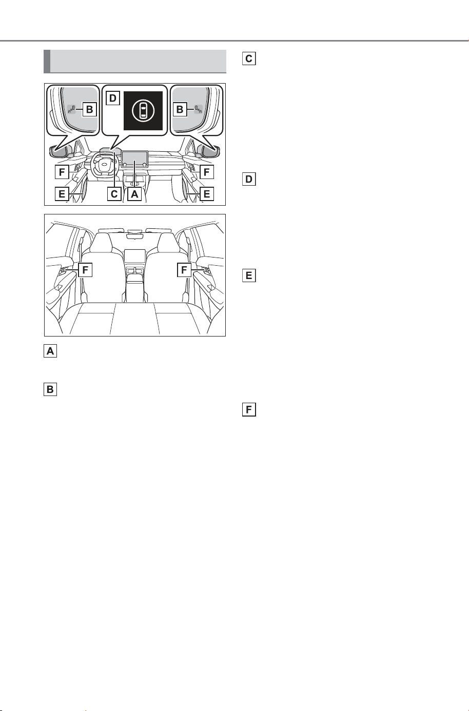
336
5-4. Using the driving support systems
Owner’s Manual_USA_M6740B_en
Multimedia display
Turning the safe exit assist on/off.
Outside rear view mirror indi-
cators
When a vehicle or bicycle which
may collide with a door (other than
the back door) when opened is
detected, the outside rear view mir-
ror indicator (P.140) on the
detected side will illuminate. If the
door on the detected side is
opened, the outside rear view mir-
ror indicator will blink.
Multi-information display
If collision with a door is likely and
the door is opened, the door will be
displayed on the multi-information
display. Also, if a door is opened
when an outside rear view mirror
indicator is illuminated, a buzzer
will sound as a warning.
Driving assist information
indicator
Illuminates when the safe exit
assist is turned off. At this time, a
message will be displayed on the
multi-information display.
Speakers
When the outside rear view mirror
indicator blinks, the driver is
informed through voice guidance
that the system has operated. After
the notification through voice guid-
ance is made, no more voice guid-
ance notifications will be made
again until the door is fully closed.
Door Illumination
When a vehicle or bicycle which
may collide with a door (other than
the back door) when opened is
detected, the door Illumination (red)
on the detected side will illuminate.
If the door on the detected side is
opened, the door Illumination (red)
will blink.
System components
SOLTERRA_OM_USA_A6740BE.book 336 ページ 2025年5月23日 金曜日 午後1時18分
337
5-4. Using the driving support systems
Owner’s Manual_USA_M6740B_en
5
Driving
■ Outside rear view mirror indica-
tor visibility
In strong sunlight, the outside rear
view mirror indicator may be difficult
to see.
■ Buzzer
If the volume setting of the audio
system is high or the surrounding
area is loud, it may be difficult to
hear the buzzer.
■ Voice notifications
In the following situations, voice
notifications will not be output:
● When it is estimated that no occu-
pants are on board
*
● After opening a door and entering
the vehicle, until the EV system is
started
● When 3 minutes or more have
elapsed since the EV system was
stopped
● When the language setting of the
multimedia display has been set
to a language that does not sup-
port voice notifications
● When all of the doors have been
locked from outside the vehicle
● When a door remains open for 1
minute or more after the EV sys-
tem is stopped
● When the ACC mode (P. 677)
has been enabled through a cus-
tomize setting on the multimedia
display and the EV system has
been stopped
● When the parking assist volume
setting on the multimedia display
has been set to off
*
: For each seating position, judg-
ment is made based on the open-
ing and closing of a door, before
driving for ingress and after driv-
ing for egress.
■ Customization
Some functions can be customized.
(P.681)
The safe exit assist system can
be enabled/disabled through a
customize setting. (P.681)
When the safe exit assist is off,
the driving assist information
indicator will illuminate and a
message will be displayed on
the multi-information display.
Each time the power switch is
turned to ON, the safe exit
assist is enabled.
*
*
: When the power switch is turned
off and then to ON immediately
after that, the safe exit assist may
not be enabled.
WARNING
■ To ensure the system can
operate properly
P.33 1
Turning the safe exit
assist system ON/OFF
SOLTERRA_OM_USA_A6740BE.book 337 ページ 2025年5月23日 金曜日 午後1時18分
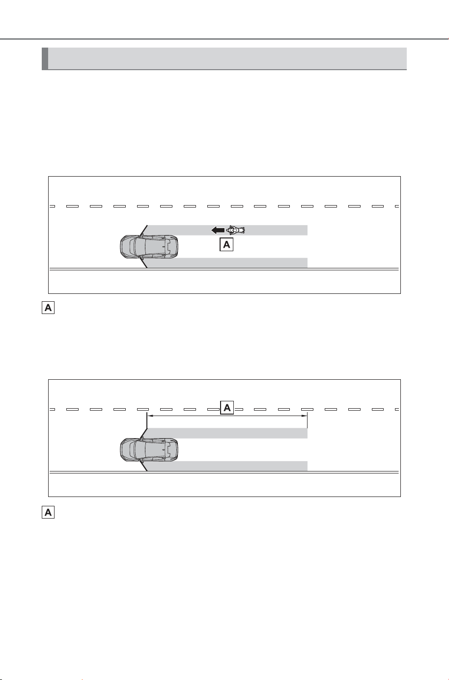
338
5-4. Using the driving support systems
Owner’s Manual_USA_M6740B_en
■ Objects that can be detected by the safe exit assist
When the safe exit assist detects the following vehicles or bicycles
behind your vehicle using a rear side radar sensor, the occupants of
the vehicle are informed through an outside rear view mirror indica-
tor, door Illumination (red), buzzer, multi-information display, and
voice notification.
Vehicle or bicycle which has a high possibility of colliding with a
door (other than the back door) when opened
■ The safe exit assist detection areas
The areas that vehicles can be detected in are outlined below.
Approximately 145 ft. (45 m) rearward from the front door
*
*
: The faster a vehicle or bicycle is approaching, the distance at which an
outside rear view mirror indicator and door Illumination (red) will illuminate
or blink will become further.
Safe exit assist operation
SOLTERRA_OM_USA_A6740BE.book 338 ページ 2025年5月23日 金曜日 午後1時18分

339
5-4. Using the driving support systems
Owner’s Manual_USA_M6740B_en
5
Driving
■ The safe exit assist is opera-
tional when
The safe exit assist is operational
when all of the following conditions
are met:
● When the power switch is ON,
less than 3 minutes have elapsed
since the EV system was off, or
less than 3 minutes have elapsed
since a door was opened and
someone has entered the vehicle
(the time which operation is possi-
ble may be extended if a door is
opened and closed)
● Safe exit assist is on
● The vehicle is stopped.
● The shift position is in a position
other than R.
■ The safe exit assist will detect a
vehicle when
The safe exit assist will detect a
vehicle present in the detection area
in the following situations:
When the vehicle is stopped and a
vehicle or bicycle, which is traveling
parallel to the vehicle, is approach-
ing within the area that a door opens
(other than the back door)
■ Conditions under which the
system will not detect a vehicle
● Safe exit assist does not detect
the following objects, vehicles,
and bicycles:
• Vehicles or bicycles which are
approaching slowly
*
• Vehicles or bicycles which are
determined to have a low possibil-
ity of colliding with a door (other
than the back door) when opened
*
• Vehicles or bicycles which are
approaching from directly behind
*
• Vehicles or bicycles which are
approaching from the front
*
• Guardrails, walls, signs, parked
vehicles, and other stationary
objects
*
• Pedestrians, animals, etc.
*
*
: Depending on the conditions,
detection of a vehicle and/or
object may occur.
● In situations such as the following,
safe exit assist will not operate:
• When 3 minutes or more have
elapsed since the EV system off
(the time which operation is possi-
ble may be extended if a door is
opened and closed)
• When your vehicle is not com-
pletely stopped
■ Conditions under which the
system may not function cor-
rectly
● The safe exit assist may not
detect vehicles correctly in the fol-
lowing situations:
• When the sensor is misaligned
due to a strong impact to the sen-
sor or its surrounding area
• When mud, snow, ice, a sticker,
etc., is covering the sensor or sur-
rounding area on the rear bumper
• When the vehicle is stopped on a
wet road surface, such as in a
puddle, while in inclement
weather, such as heavy rain,
snow, fog, etc.
• When a vehicle or bicycle
approaches from behind a nearby
parked vehicle
• When an approaching vehicle or
bicycle suddenly changes direc-
tion
• Immediately after a vehicle or
bicycle starts moving
• When the back door is open
• When a bicycle carrier, ramp, or
other accessory is installed to the
back of the vehicle
• When a parked vehicle, wall, sign,
person or other stationary object
is behind the vehicle
• When the vehicle is stopped at an
angle to the road
• When a vehicle is traveling near
an approaching vehicle or bicycle
• When an approaching vehicle or
bicycle is traveling along a station-
ary object, such a wall or sign
SOLTERRA_OM_USA_A6740BE.book 339 ページ 2025年5月23日 金曜日 午後1時18分
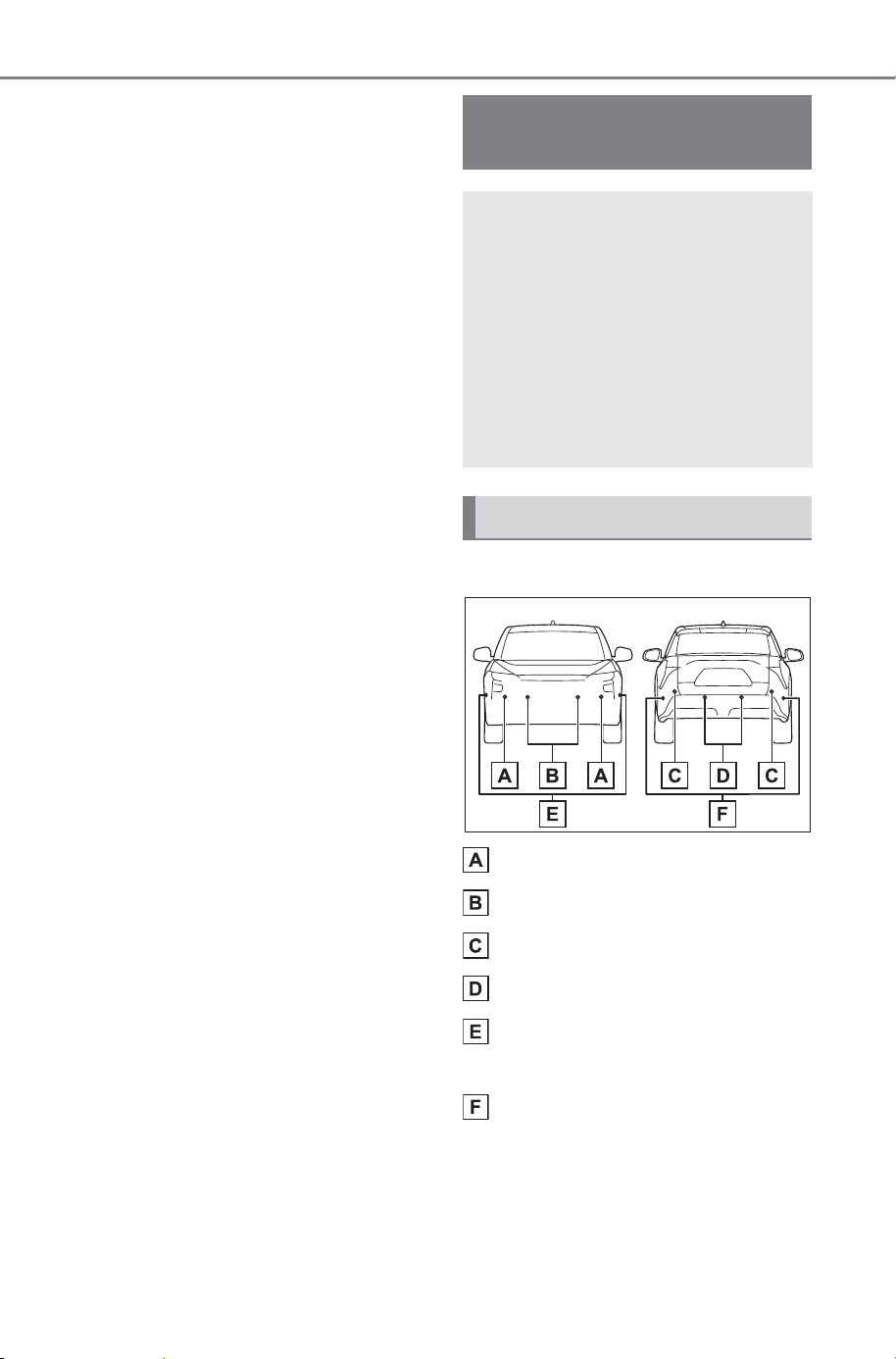
340
5-4. Using the driving support systems
Owner’s Manual_USA_M6740B_en
• When a vehicle or bicycle is
approaching at high speed
• When towing with the vehicle
• When stopped on a steep slope
• When stopped on a curve or at the
exit of a curve
● Instances of the safe exit assist
unnecessarily detecting a vehicle
and/or object may increase in the
following situations:
• When the sensor is misaligned
due to a strong impact to the sen-
sor or its surrounding area
• When a vehicle or bicycle
approaches your vehicle from
directly behind in an offset posi-
tion
• When the vehicle is stopped at an
angle to the road
• When a vehicle or bicycle
approaches from behind a parked
vehicle at an angle
• When a parked vehicle, wall, sign,
person or other stationary object
is behind the vehicle
• When an approaching vehicle or
bicycle suddenly changes direc-
tion
• When an approaching vehicle or
bicycle is traveling along a station-
ary object, such a wall or sign
• When the back door is open
• When a bicycle carrier, ramp, or
other accessory is installed to the
back of the vehicle
• When a vehicle or bicycle is
approaching at high speed
• When towing with the vehicle
• When stopped on a steep slope
• When stopped on a curve or at the
exit of a curve
• When a vehicle or bicycle
approaches from behind a vehicle
stopped in an adjacent lane
■ Type of sensors
Front corner sensors
Front center sensors
Rear corner sensors
Rear center sensors
Front side sensors (vehicles
with Advanced Park)
Rear side sensors (vehicles
with Advanced Park)
SUBARU Parking
Assist
The SUBARU Parking
Assist function detects the
approximate distance from
the vehicle and an object
such as a wall using ultra-
sonic sensors and informs
the driver with the multime-
dia display distance display
and buzzer.
System components
SOLTERRA_OM_USA_A6740BE.book 340 ページ 2025年5月23日 金曜日 午後1時18分
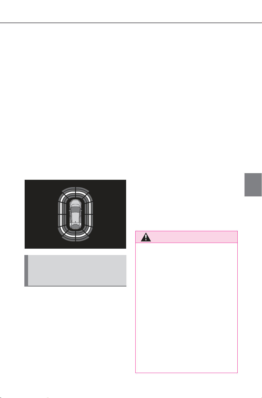
341
5-4. Using the driving support systems
Owner’s Manual_USA_M6740B_en
5
Driving
■ Display
When the sensors detect an
object, such as a wall, a graphic
is shown on the multimedia dis-
play depending on the position
and distance to the object.
Vehicles without multimedia dis-
play or rear camera: When
detecting a stationary object, the
SUBARU Parking Assist detec-
tion indicator illuminates.
(P.140)
The illustration is an example for
explanation and may differ
depending on the specifications.
Multimedia display
The SUBARU Parking Assist
function can be enabled/dis-
abled through a customize set-
ting. (P.682)
When the SUBARU Parking
Assist function is disabled, the
SUBARU Parking Assist OFF
indicator (P.140) illuminates
on the multi-information display.
If the system switches to OFF
(disabled) and the SUBARU
Parking Assist is stopped, the
SUBARU Parking Assist will not
be re-enabled until ON
(enabled) is selected again from
the customize setting (P.682).
(It remains off even if the power
switch is turned to ON again
after the power switch has been
turned off.)
Vehicles without the multimedia
display or rear camera: How-
ever, the system will automati-
cally turn on (enabled) and the
SUBARU Parking Assist OFF
indicator will turn off if the shift
position is changed to R.
When the shift position is R, the
SUBARU Parking Assist cannot
be turned on or off.
The setting of SUBARU Parking
Assist itself will not change.
Turning the SUBARU
Parking Assist function
ON/OFF
WARNING
■ Cautions regarding the use of
the system
There is a limit to the degree of
recognition accuracy and control
performance that this system can
provide, do not overly rely on this
system. The driver is always
responsible for paying attention to
the vehicle’s surroundings and
driving safely.
■ To ensure the system can
operate properly
Make sure to observe the follow-
ing precautions. The system may
not operate properly and may
lead to an unexpected accident.
When these precautions cannot
be observed, turn the system off.
SOLTERRA_OM_USA_A6740BE.book 341 ページ 2025年5月23日 金曜日 午後1時18分
342
5-4. Using the driving support systems
Owner’s Manual_USA_M6740B_en
■ The system can be operated
when
● The power switch is in ON.
● The SUBARU Parking Assist is
on.
● The vehicle speed is less than
about 6 mph (10 km/h).
● Front corner sensors:
The shift position is in a position
other than P.
● Front center sensors:
The shift position is in a position
other than P or R.
● Rear corner and rear center sen-
sors:
The shift position is in R.
● Side sensors: (vehicles with
Advanced Park)
• The vehicle is moving about 23.0
ft. (7 m) after the EV system was
started.
• The vehicle is moving about 23.0
ft. (7 m) after the shift position was
changed from R to D.
• The shift position is in R.
• switch has been pressed and
the multimedia display is dis-
played.
• The front or rear sensor detects a
stationary object.
● Vehicles without the multimedia
display or rear camera: The sys-
tem will automatically turn on
(enabled) and the SUBARU Park-
ing Assist OFF indicator will turn
off if the shift position is changed
to R.
The setting of SUBARU Parking
Assist itself will not change.
■ Sensor detection information
● The sensor’s detection areas are
limited to the areas around the
vehicle’s front and rear bumpers.
WARNING
● Do not damage the sensors,
and always keep them clean.
● Do not attach a sticker or install
a component, such as a backlit
license plate (especially fluores-
cent type), fog lights, fender
pole or wireless antenna near a
radar sensor.
● Do not subject the surrounding
area of the sensor to a strong
impact. If subjected to an
impact, have the vehicle
inspected by your SUBARU
dealer. If the front or rear
bumper needs to be
removed/installed or replaced,
contact your SUBARU dealer.
● Do not modify, disassemble or
paint the sensors.
● Do not attach a license plate
cover.
● Keep your tires properly
inflated.
● Do not install a suspension
other than a genuine suspen-
sion.
■ Notes when washing the vehi-
cle
● When using a high pressure
washer to wash the vehicle, do
not spray the sensors directly,
as doing so may cause a sensor
to malfunction.
● When using steam to clean the
vehicle, do not direct steam too
close to the sensors, as doing
so may cause a sensor to mal-
function.
SOLTERRA_OM_USA_A6740BE.book 342 ページ 2025年5月23日 金曜日 午後1時18分
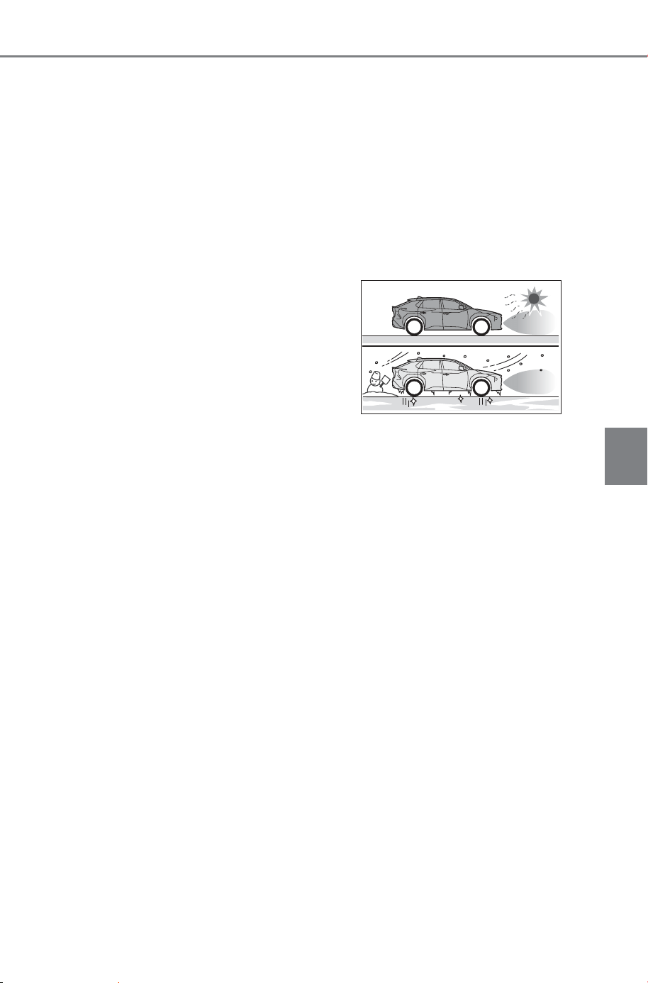
343
5-4. Using the driving support systems
Owner’s Manual_USA_M6740B_en
5
Driving
● Certain vehicle conditions and the
surrounding environment may
affect the ability of a sensor to cor-
rectly detect an object.
● Objects may not be detected if
they are too close to the sensor.
● There will be a short delay
between object detection and dis-
play.
Even at low speeds, there is a
possibility that the object will come
within the sensor’s detection
areas before the display is shown
and the warning beep sounds.
● It might be difficult to hear the
buzzer due to the volume of the
audio system or air flow noise of
the air conditioning system.
● It may be difficult to hear the
sound of this system due to the
buzzers of other systems.
● If the meter malfunctions, the
buzzer may not sound.
■ Objects which the system may
not be properly detected
The shape of the object may pre-
vent the sensor from detecting it.
Pay particular attention to the follow-
ing objects:
● Wires, fences, ropes, etc.
● Cotton, snow and other materials
that absorb sound waves
● Sharply-angled objects
● Low objects
● Tall objects with upper sections
projecting outwards in the direc-
tion of your vehicle
People may not be detected if they
are wearing certain types of cloth-
ing.
■ Situations in which the system
may not operate properly
Certain vehicle conditions and the
surrounding environment may affect
the ability of a sensor to correctly
detect objects. Particular instances
where this may occur are listed
below.
● There is dirt, snow, water drops or
ice on a sensor. (Cleaning the
sensors will resolve this problem.)
● A sensor is frozen. (Thawing the
area will resolve this problem.)
In especially cold weather, if a
sensor is frozen the sensor dis-
play may be displayed abnormally,
or objects, such as a wall, may not
be detected.
● When a sensor or the area around
a sensor is extremely hot or cold.
● On an extremely bumpy road, on
an incline, on gravel, or on grass.
● When vehicle horns, vehicle
detectors, motorcycle engines, air
brakes of large vehicles, the clear-
ance sonar of other vehicles or
other devices which produce ultra-
sonic waves are near the vehicle
● A sensor is coated with a sheet of
spray or heavy rain
● If objects draw too close to the
sensor.
● When a pedestrian is wearing
clothing that does not reflect ultra-
sonic waves (ex. skirts with gath-
ers or frills).
● When objects that are not perpen-
dicular to the ground, not perpen-
dicular to the vehicle traveling
direction, uneven, or waving are in
the detection range.
● When strong winds are blowing
● When driving in inclement weather
such as fog, snow or a sandstorm
● When an object that cannot be
detected is between the vehicle
and a detected object
SOLTERRA_OM_USA_A6740BE.book 343 ページ 2025年5月23日 金曜日 午後1時18分
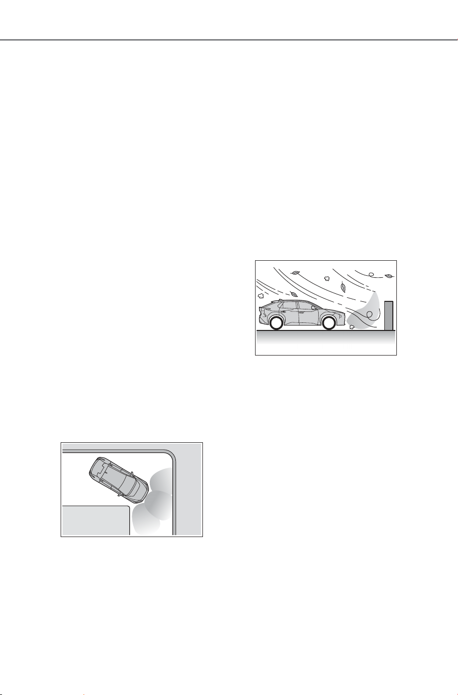
344
5-4. Using the driving support systems
Owner’s Manual_USA_M6740B_en
● If an object such as a vehicle,
motorcycle, bicycle or pedestrian
cuts in front of the vehicle or runs
out from the side of the vehicle
● If the orientation of a sensor has
been changed due to a collision or
other impact
● When equipment such as a towing
eyelet, transport hook, bumper
protector, bumper trim, bicycle
carrier or snow-removal device
(snow plow) is installed near the
sensor
● If the front of the vehicle is raised
or lowered due to the carried load
● If the vehicle cannot be driven in a
stable manner, such as when the
vehicle has been in an accident or
is malfunctioning
● When tire chains, compact spare
tire or an emergency tire puncture
repair kit are used
● When towing with the vehicle
■ Situations in which the system
may operate even if there is no
possibility of a collision
In some situations, such as the fol-
lowing, the system may operate
even though there is no possibility of
a collision.
● When driving on a narrow road
● When driving toward a banner,
flag, low-hanging branch or boom
barrier (such as those used at rail-
road crossings, toll gates and
parking lots)
● When there is a rut or hole in the
surface of the road
● When driving on a metal cover
(grating), such as those used for
drainage ditches
● When driving up or down a steep
slope
● If a sensor is hit by a large amount
of water, such as when driving on
a flooded road
● There is dirt, snow, water drops or
ice on a sensor. (Cleaning the
sensors will resolve this problem.)
● A sensor is coated with a sheet of
spray or heavy rain
● When driving in inclement weather
such as fog, snow or a sandstorm
● When strong winds are blowing
● When vehicle horns, vehicle
detectors, motorcycle engines, air
brakes of large vehicles, the clear-
ance sonar of other vehicles or
other devices which produce ultra-
sonic waves are near the vehicle
● If the front of the vehicle is raised
or lowered due to the carried load
● If the orientation of a sensor has
been changed due to a collision or
other impact
● The vehicle is approaching a tall
or curved curb
● Driving close to columns (H-
shaped steel beams, etc.) in multi-
story parking garages, construc-
tion sites, etc.
● If the vehicle cannot be driven in a
stable manner, such as when the
vehicle has been in an accident or
is malfunctioning
● On an extremely bumpy road, on
an incline, on gravel, or on grass
SOLTERRA_OM_USA_A6740BE.book 344 ページ 2025年5月23日 金曜日 午後1時18分
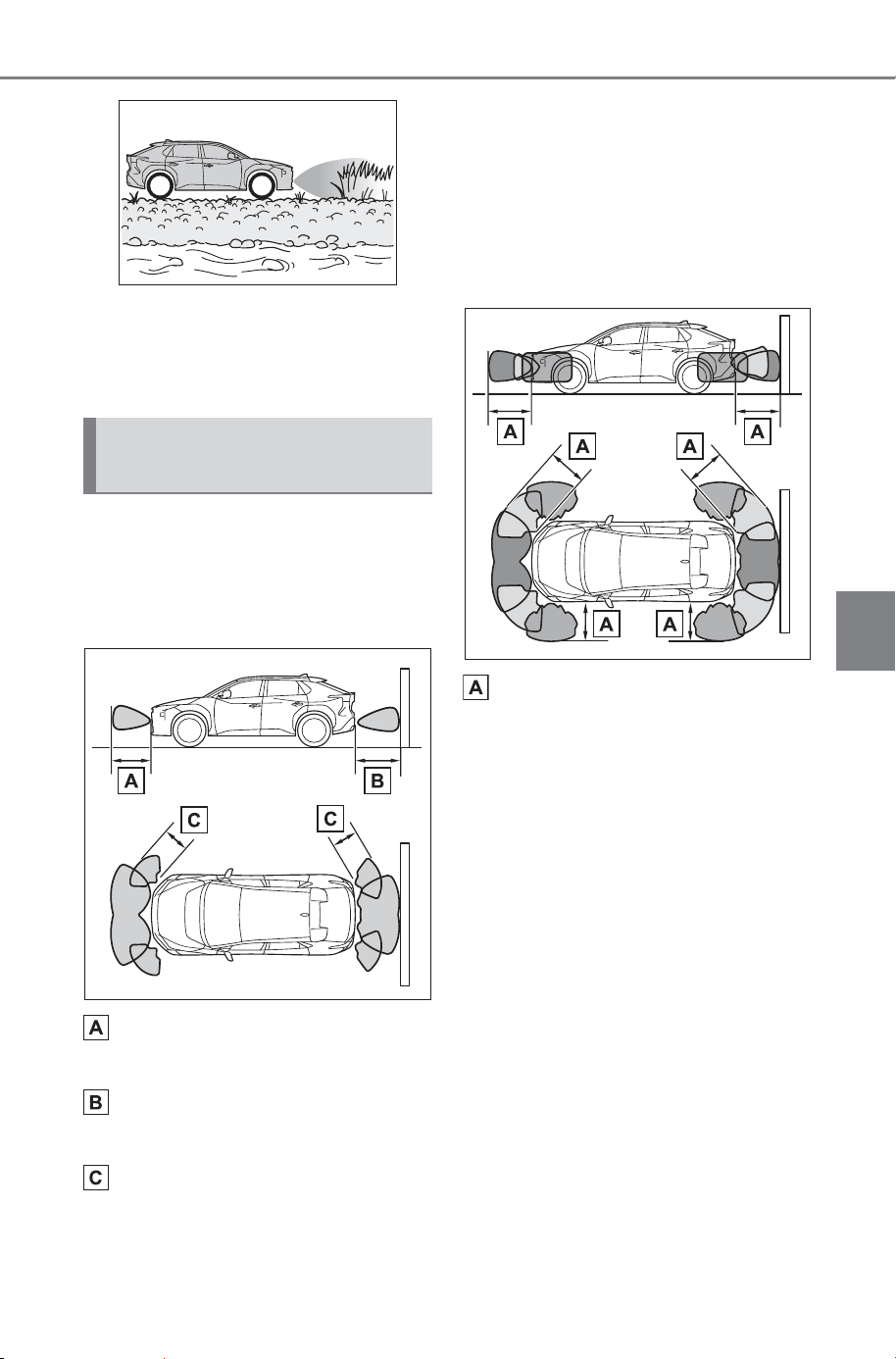
345
5-4. Using the driving support systems
Owner’s Manual_USA_M6740B_en
5
Driving
● When tire chains, compact spare
tire or an emergency tire puncture
repair kit are used
● When towing with the vehicle
■ Detection range of the sen-
sors
Vehicles without Advanced
Park
Approximately 3.3 ft. (100
cm)
Approximately 4.9 ft. (150
cm)
Approximately 2.0 ft. (60 cm)
The diagram shows the detection
range of the sensors.
Note that the sensors cannot detect
objects that are extremely close to
the vehicle.
The range of the sensors may
change depending on the shape of
the object, etc.
Vehicles with Advanced Park
Approximately 6.6 ft. (200
cm)
The diagram shows the detection
range of the sensors. Note that the
sensors cannot detect objects that
are extremely close to the vehicle.
The range of the sensors may
change depending on the shape of
the object, etc.
Sensor detection display,
object distance
SOLTERRA_OM_USA_A6740BE.book 345 ページ 2025年5月23日 金曜日 午後1時18分
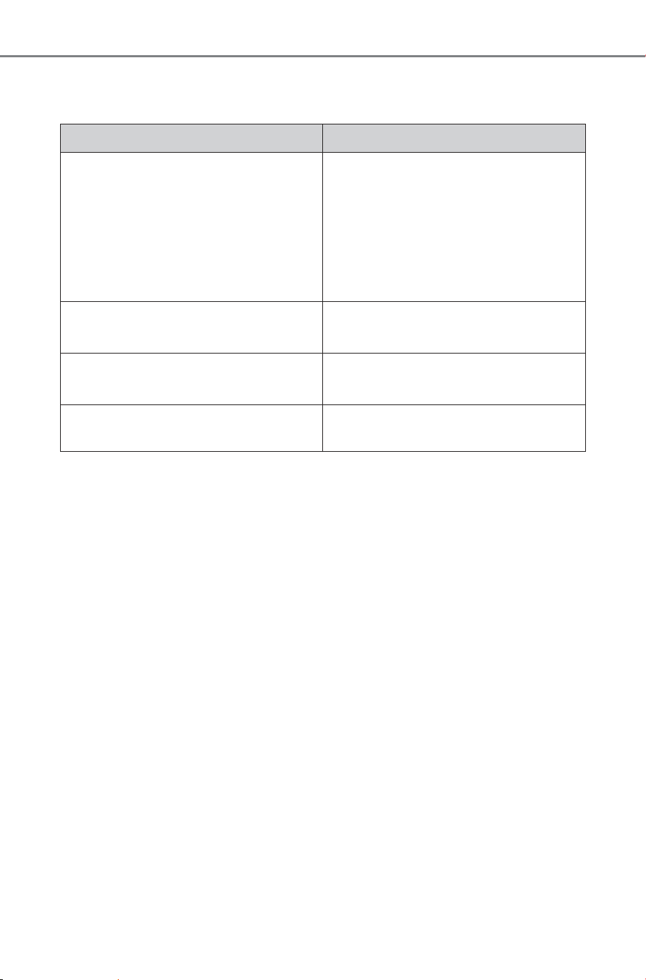
346
5-4. Using the driving support systems
Owner’s Manual_USA_M6740B_en
■ The distance and buzzer
Vehicles without Advanced Park
*
: Automatic buzzer mute function is enabled. (P.348)
Approximate distance to obstacle Buzzer
Front center sensor:
Approximately 3.3 ft. (100 cm) to 2.0
ft. (60 cm)
*
Rear center sensor:
Approximately 4.9 ft. (150 cm) to 2.0
ft. (60 cm)
*
Slow
Approximately 2.0 ft. (60 cm) to 1.5
ft. (45 cm)
*
Medium
Approximately 1.5 ft. (45 cm) to 1.0
ft. (30 cm)
*
Fast
Approximately less than 1.0 ft. (30
cm)
Continuous
SOLTERRA_OM_USA_A6740BE.book 346 ページ 2025年5月23日 金曜日 午後1時18分
347
5-4. Using the driving support systems
Owner’s Manual_USA_M6740B_en
5
Driving
Vehicles with Advanced Park
*
: Automatic buzzer mute function is enabled. (P.348)
Approximate distance to obstacle Buzzer
Front center sensor:
Approximately 6.6 ft. (200 cm) to 3.3
ft. (100 cm)
Rear center sensor:
Approximately 6.6 ft. (200 cm) to 4.9
ft. (150 cm)
Corner sensor:
Approximately 6.6 ft. (200 cm) to 2.0
ft. (60 cm)
Does not sound (Display only)
Front center sensor:
Approximately 3.3 ft. (100 cm) to 2.0
ft. (60 cm)
*
Rear center sensor:
Approximately 4.9 ft. (150 cm) to 2.0
ft. (60 cm)
*
Slow
Front/Rear center sensor and Corner
sensor:
Approximately 2.0 ft. (60 cm) to 1.5
ft. (45 cm)
*
Medium
Front/Rear center sensor and Corner
sensor:
Approximately 1.5 ft. (45 cm) to 1.0
ft. (30 cm)
*
Fast
Approximately less than 1.0 ft. (30
cm)
Continuous
SOLTERRA_OM_USA_A6740BE.book 347 ページ 2025年5月23日 金曜日 午後1時18分
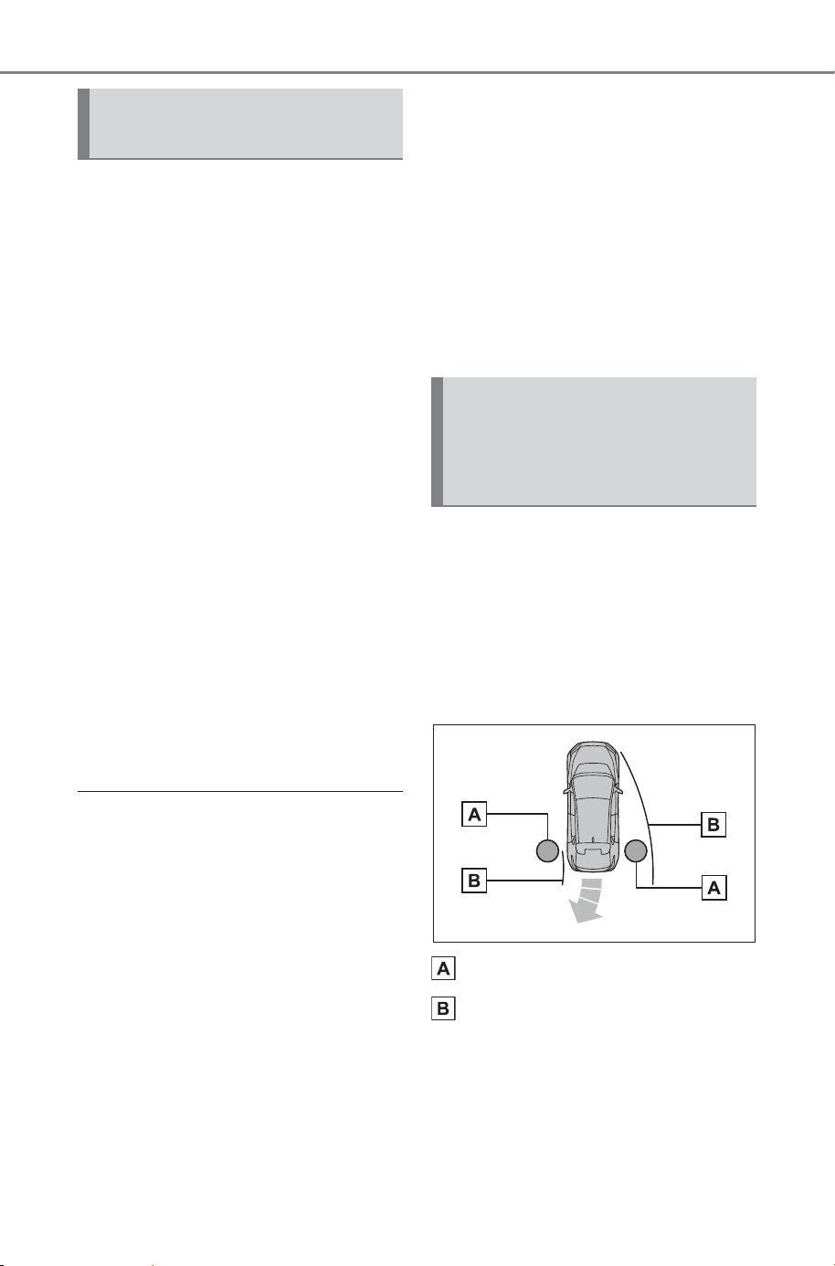
348
5-4. Using the driving support systems
Owner’s Manual_USA_M6740B_en
A buzzer sounds when the sen-
sors are operating.
The buzzer beeps faster as
the vehicle approaches a
static object. When the vehi-
cle comes within the approxi-
mately 1.0 ft. (30 cm) of the
object, the buzzer will sound
continuously.
When 2 or more sensors
simultaneously detect a static
object, the buzzer sounds for
the nearest object.
After an intermittent buzzer
begins sounding, if the dis-
tance between the vehicle
and the detected a static
object does not become
shorter, the buzzer will be
muted automatically. (auto-
matic buzzer mute function)
■ Adjusting the buzzer volume
The buzzer volume of the SUBARU
Parking Assist, RCTA, and RCD can
all be changed at once from the cus-
tomize settings. (P.682)
■ Muting a buzzer
When the temporary mute switch is
displayed on the multimedia display,
this switch can be pressed to tem-
porarily mute the buzzer.
Select the switch to mute a buzzer
of the SUBARU Parking Assist,
RCTA, and RCD all together.
● Mute will be automatically can-
celed in the following situations:
• When the shift position is
changed.
• When the vehicle speed exceeds
a certain speed.
• When there is a malfunction in a
sensor or the system is temporar-
ily unavailable.
• When the operating function is
disabled manually.
• When the power switch is turned
off.
The object warning function
informs the driver of the exis-
tence of objects along the side
of the vehicle, using a display
and buzzer, if the objects are
within the estimated path of the
vehicle.
Object
Calculated vehicle route
SUBARU Parking Assist
buzzer
SUBARU Parking Assist
object warning function
(vehicles with Advanced
Park)
SOLTERRA_OM_USA_A6740BE.book 348 ページ 2025年5月23日 金曜日 午後1時18分
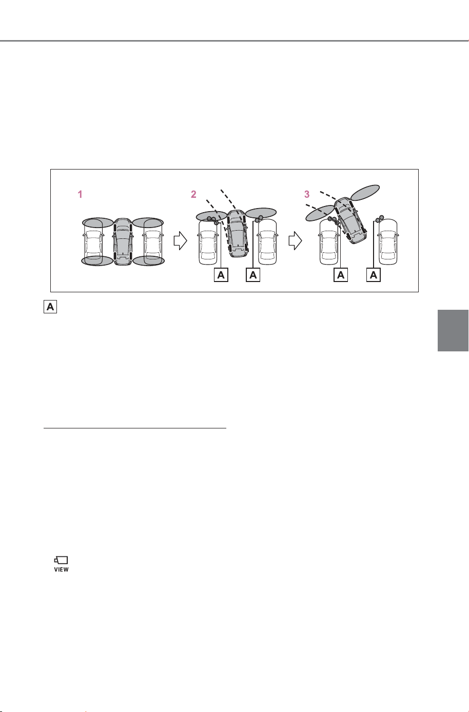
349
5-4. Using the driving support systems
Owner’s Manual_USA_M6740B_en
5
Driving
When the vehicle is moving, the side sensors or side cameras can
detect objects.
While the vehicle is moving, if a detected object can no longer be
detected by the side sensors or side cameras, the location of the
object relative to the vehicle is estimated. If the object is determined
to be in the estimated path of the vehicle, the object warning function
will operate.
Object detected by side sensors or side cameras
1 The vehicle is stopped and objects along the sides of the vehicle
are not detected.
2 Objects are detected as the vehicle is moving.
3 Even though the objects are outside of the detection area of the
side sensors or side cameras, a warning is displayed and a
buzzer sounds.
■ Object warning function operat-
ing conditions
● The vehicle moves about 23.0 ft.
(7 m) after the EV system is
started.
● After the D shift position has been
selected, the vehicle has moved
23.0 ft. (7 m) or less.
● The R shift position is selected.
● switch has been pressed and
the multimedia display is dis-
played.
● The front or rear sensor detects a
stationary object.
■ Detection of objects along the
sides of the vehicle
● Objects along the sides of the
vehicle are not instantaneously
detected. The location of objects
in relation to the vehicle is esti-
mated after they are first detected
by the front or rear side sensors,
or side cameras. Therefore, after
the power switch is changed to
ON, even if an object is along the
side of the vehicle, it may not be
detected until the vehicle has
been driven a small amount and
the side sensors or side cameras
completely scan the areas along
the sides of the vehicle.
SOLTERRA_OM_USA_A6740BE.book 349 ページ 2025年5月23日 金曜日 午後1時18分
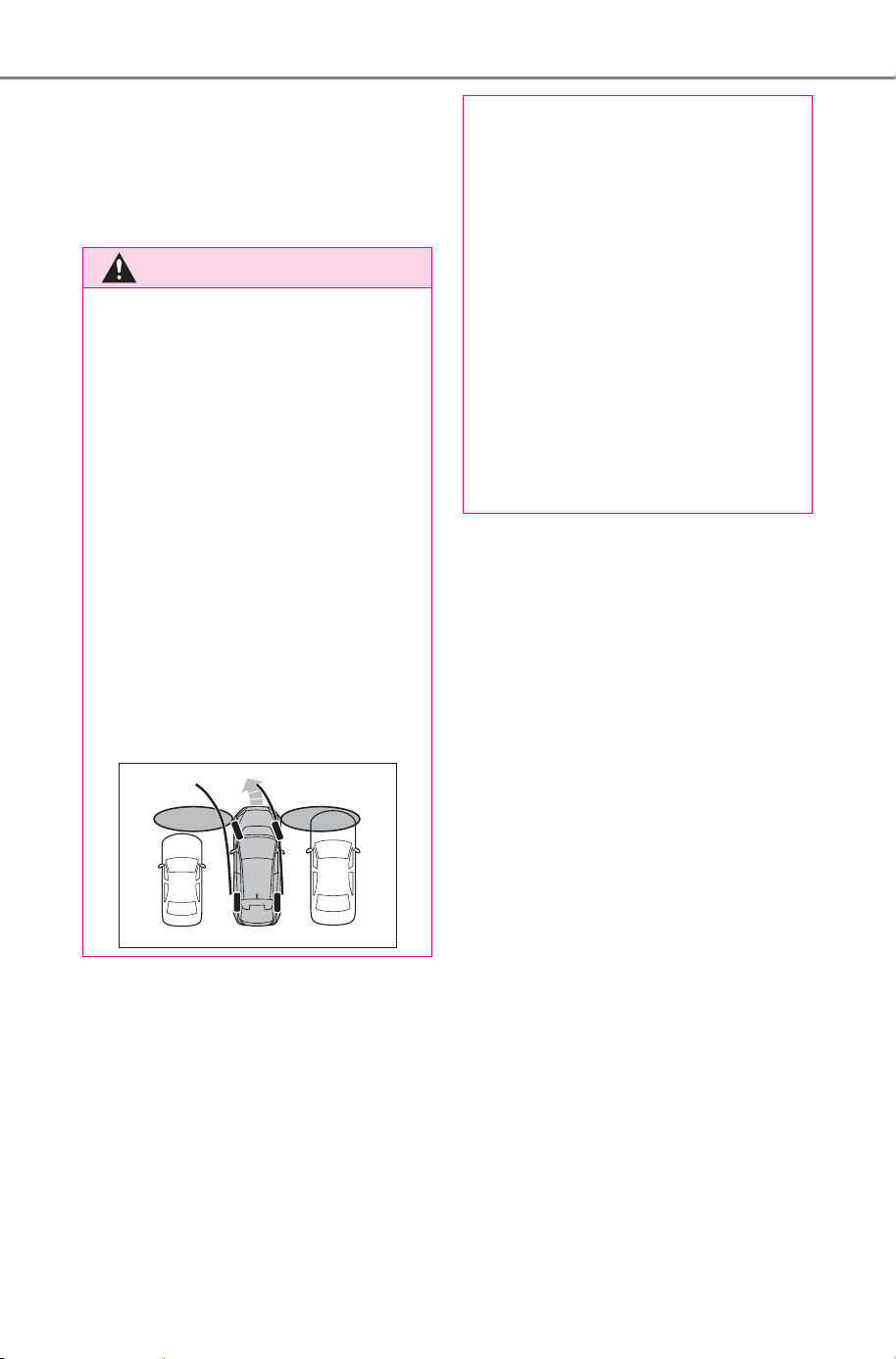
350
5-4. Using the driving support systems
Owner’s Manual_USA_M6740B_en
● If a vehicle, person, animal, etc., is
detected by a side sensors or side
cameras, but then leaves the
detection area of the side sensors
or side cameras, the system will
assume the object has not moved.
WARNING
■ Side sensors and side cam-
eras
In situations such as the following,
the function may not operate cor-
rectly, possibly leading to an acci-
dent. Proceed carefully.
● When starting off shortly after
the power switch is turned to
ON and a small vehicle or other
object which cannot be detected
by a front side sensor is next to
the vehicle.
In the situation shown in the fol-
lowing illustration, even if the
vehicle starts off, the vehicle on
the left will not be detected and
the object warning function will
not operate.
● When an object or person is in a
position which cannot be
detected by the side sensors or
side cameras.
● When a vehicle, person, or
other object approaches the
side of the vehicle after the side
sensors have completed scan-
ning the areas along the sides
of the vehicle.
● When the outside rear view mir-
ror is folded.
● If the 12-volt battery was dis-
charged or has been removed
and installed, fold and extend
the outside rear view mirrors.
SOLTERRA_OM_USA_A6740BE.book 350 ページ 2025年5月23日 金曜日 午後1時18分
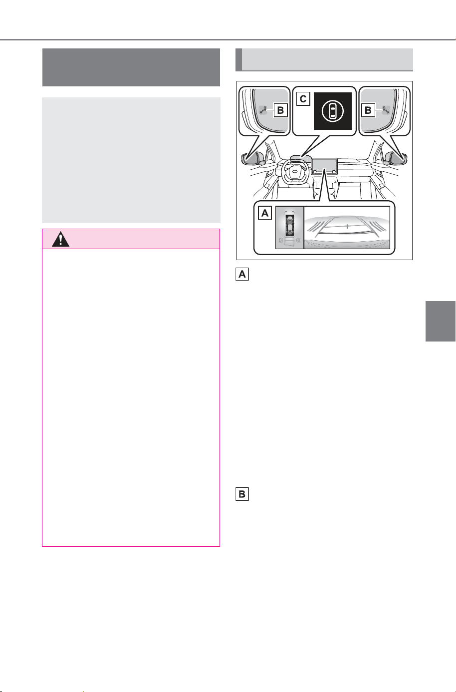
351
5-4. Using the driving support systems
Owner’s Manual_USA_M6740B_en
5
Driving
Multimedia display
Turning the RCTA function on/off in
multimedia display.
If a vehicle approaching from the
right or left at the rear of the vehicle
is detected, the RCTA icon
(P.352) for the detected side will
be displayed on the multimedia dis-
play. This illustration
*
shows an
example of a vehicle approaching
from both sides of the vehicle.
*
: Depending on the vehicle grade
and equipped options, the actual
screen may be different from this
illustration.
Outside rear view mirror indi-
cators
If a vehicle is detected as
approaching from the left or right
behind the vehicle, both outside
rear view mirror indicators
(P.140) will blink and a buzzer will
sound.
RCTA (Rear Cross Traf-
fic Alert) function
The RCTA function uses the
BSM rear side radar sen-
sors installed behind the
rear bumper. This function
is intended to assist the
driver in checking areas
that are not easily visible
when backing up.
WARNING
■ Cautions regarding the use of
the system
The driver is solely responsible for
safe driving. Always drive safely,
taking care to observe your sur-
roundings.
The RCTA function is only a sup-
plementary function which alerts
the driver that a vehicle is
approaching from the right or left
at the rear of the vehicle.
As the RCTA function may not
function correctly under certain
conditions, the driver’s own visual
confirmation of safety is neces-
sary.
Over reliance on this function may
lead to an accident resulting
death or serious injury.
■ To ensure the system can
operate properly
P.3 31
System components
SOLTERRA_OM_USA_A6740BE.book 351 ページ 2025年5月23日 金曜日 午後1時18分
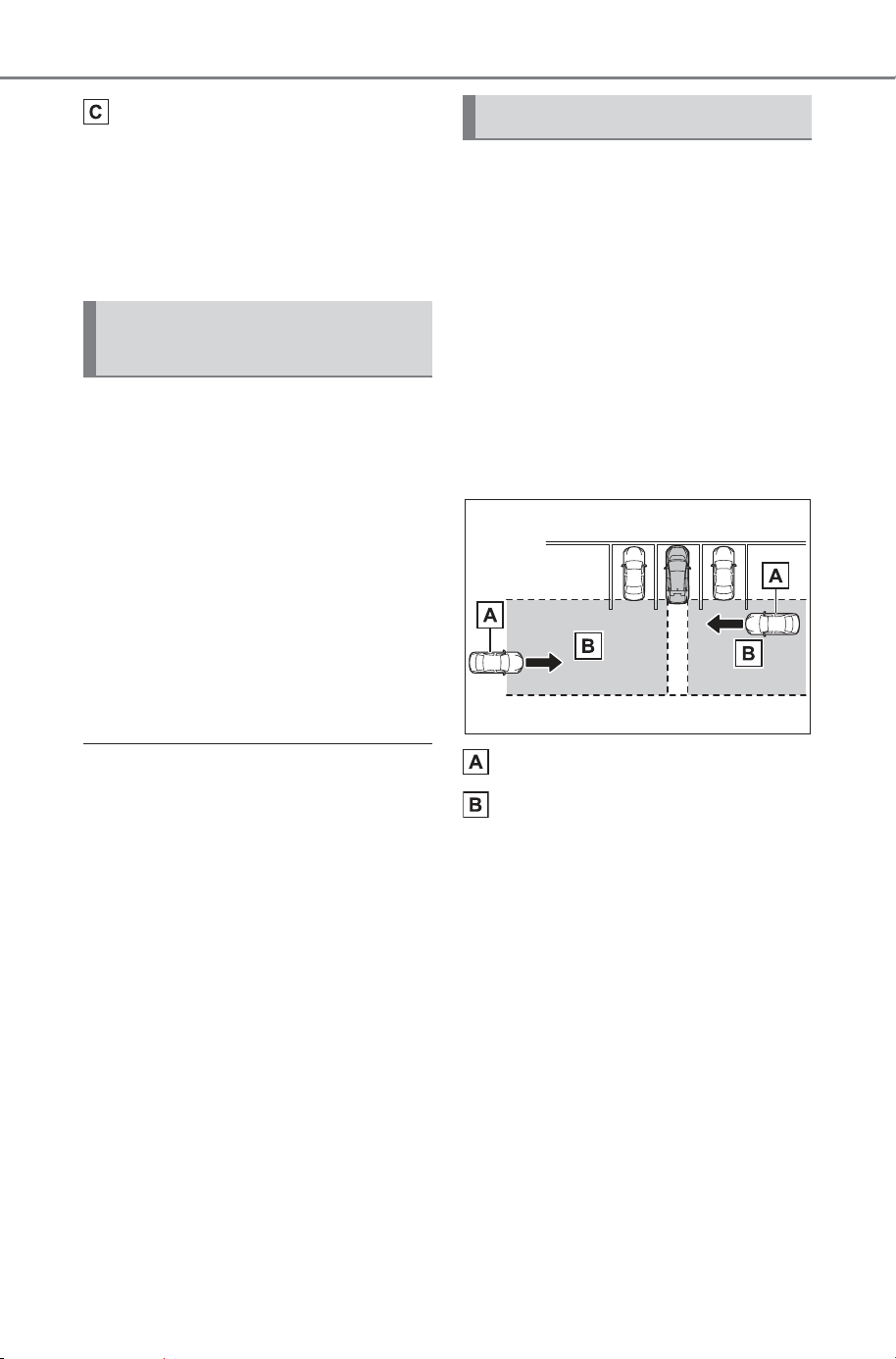
352
5-4. Using the driving support systems
Owner’s Manual_USA_M6740B_en
Driving assist information
indicator
Illuminates when the RCTA is
turned off. At this time, a message
will be displayed on the multi-infor-
mation display.
The RCTA can be enabled/dis-
abled through a customize set-
ting. (P.681)
When the RCTA function is off,
the driving assist information
indicator (P.140) will illuminate
and a message will be displayed
on the multi-information display.
Each time the power switch is
turned to ON, the RCTA function
is enabled.
■ Outside rear view mirror indica-
tor visibility
In strong sunlight, the outside rear
view mirror indicator may be difficult
to see.
■ Hearing the RCTA buzzer
The RCTA buzzer may be difficult to
hear over loud noises, such as if the
audio system volume is high.
■ Rear side radar sensors
P.331
■ Operation of the RCTA
function
The RCTA function uses rear
side radar sensors to detect
vehicles approaching from the
right or left at the rear of the
vehicle and alerts the driver of
the presence of such vehicles
by flashing the outside rear view
mirror indicators and sounding a
buzzer.
Approaching vehicles
Detection areas of approach-
ing vehicles
■ RCTA icon display
When a vehicle approaching
from the right or left at the rear
of the vehicle is detected, the
following will be displayed on
the multimedia display.
Example: Vehicles are
approaching from both sides of
the vehicle
Turning the RCTA func-
tion on/off
RCTA function
SOLTERRA_OM_USA_A6740BE.book 352 ページ 2025年5月23日 金曜日 午後1時18分
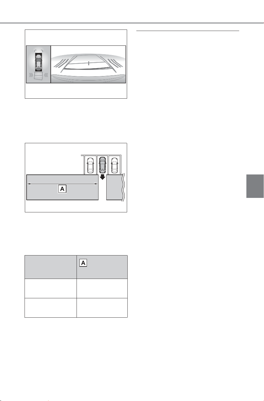
353
5-4. Using the driving support systems
Owner’s Manual_USA_M6740B_en
5
Driving
■ RCTA function detection
areas
The areas that vehicles can be
detected in are outlined below.
The buzzer can alert the driver
of faster vehicles approaching
from farther away.
Example:
■ The RCTA function is opera-
tional when
The RCTA function operates when
all of the following conditions are
met:
● The power switch is in ON.
● The RCTA function is on.
● The shift position is in R.
● The vehicle speed is less than
approximately 9 mph (15 km/h).
● The approaching vehicle speed is
between approximately 5 mph (8
km/h) and 34 mph (56 km/h).
■ Setting the buzzer volume
The buzzer volume of the RCTA,
SUBARU Parking Assist, and RCD
can be adjusted all together through
a customize setting. (P.681)
■ Muting a buzzer temporarily
When an object is detected, the
temporary mute switch is displayed
on the multimedia display.
Select the switch to mute the buzzer
of the SUBARU Parking Assist,
RCTA, and RCD all together.
Mute will be canceled automatically
in the following situations:
● When the shift position is
changed.
● When the vehicle speed exceeds
a certain speed.
● When there is a malfunction in a
sensor or the system is temporar-
ily unavailable.
● When the operating function is
disabled manually.
● When the power switch is turned
off
■ Conditions under which the
system will not detect a vehicle
The RCTA function is not designed
to detect the following types of vehi-
cles and/or objects:
● Vehicles approaching from directly
behind
Approaching
vehicle speed
Approximate
alert distance
34 mph (56
km/h) (fast)
98 ft. (30 m)
5 mph (8 km/h)
(slow)
13 ft. (4 m)
SOLTERRA_OM_USA_A6740BE.book 353 ページ 2025年5月23日 金曜日 午後1時18分
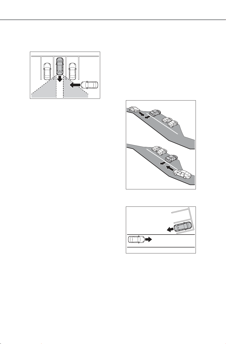
354
5-4. Using the driving support systems
Owner’s Manual_USA_M6740B_en
● Vehicles backing up in a parking
space next to your vehicle
● Vehicles that the sensors cannot
detect due to obstructions
● Guardrails, walls, signs, parked
vehicles and similar stationary
objects
*
● Small motorcycles, bicycles,
pedestrians, etc.
*
● Vehicles moving away from your
vehicle
● Vehicles approaching from the
parking spaces next to your vehi-
cle
*
● The distance between the sensor
and approaching vehicle gets too
close
*
: Depending on the conditions,
detection of a vehicle and/or
object may occur.
■ Situations in which the system
may not operate properly
The RCTA function may not detect
vehicles correctly in the following
situations:
● When the sensor is misaligned
due to a strong impact to the sen-
sor or its surrounding area
● When mud, snow, ice, a sticker,
etc., is covering the sensor or sur-
rounding area on the position
above the rear bumper
● When driving on a wet road sur-
face, such as in a puddle, while in
inclement weather, such as heavy
rain, snow, fog, etc.
● When multiple vehicles are
approaching with only a small gap
between each vehicle
● When a vehicle is approaching at
high speed
● When equipment that may
obstruct a sensor is installed, such
as a towing eyelet, bumper pro-
tector (an additional trim strip,
etc.), bicycle carrier, or snow plow
● When backing up on a slope with
a sharp change in grade
● When backing out of a sharp
angle parking spot
● Immediately after the RCTA func-
tion is turned on
● Immediately after the EV system
is started with the RCTA function
on
● When the sensors cannot detect a
vehicle due to obstructions
● When towing with the vehicle
SOLTERRA_OM_USA_A6740BE.book 354 ページ 2025年5月23日 金曜日 午後1時18分
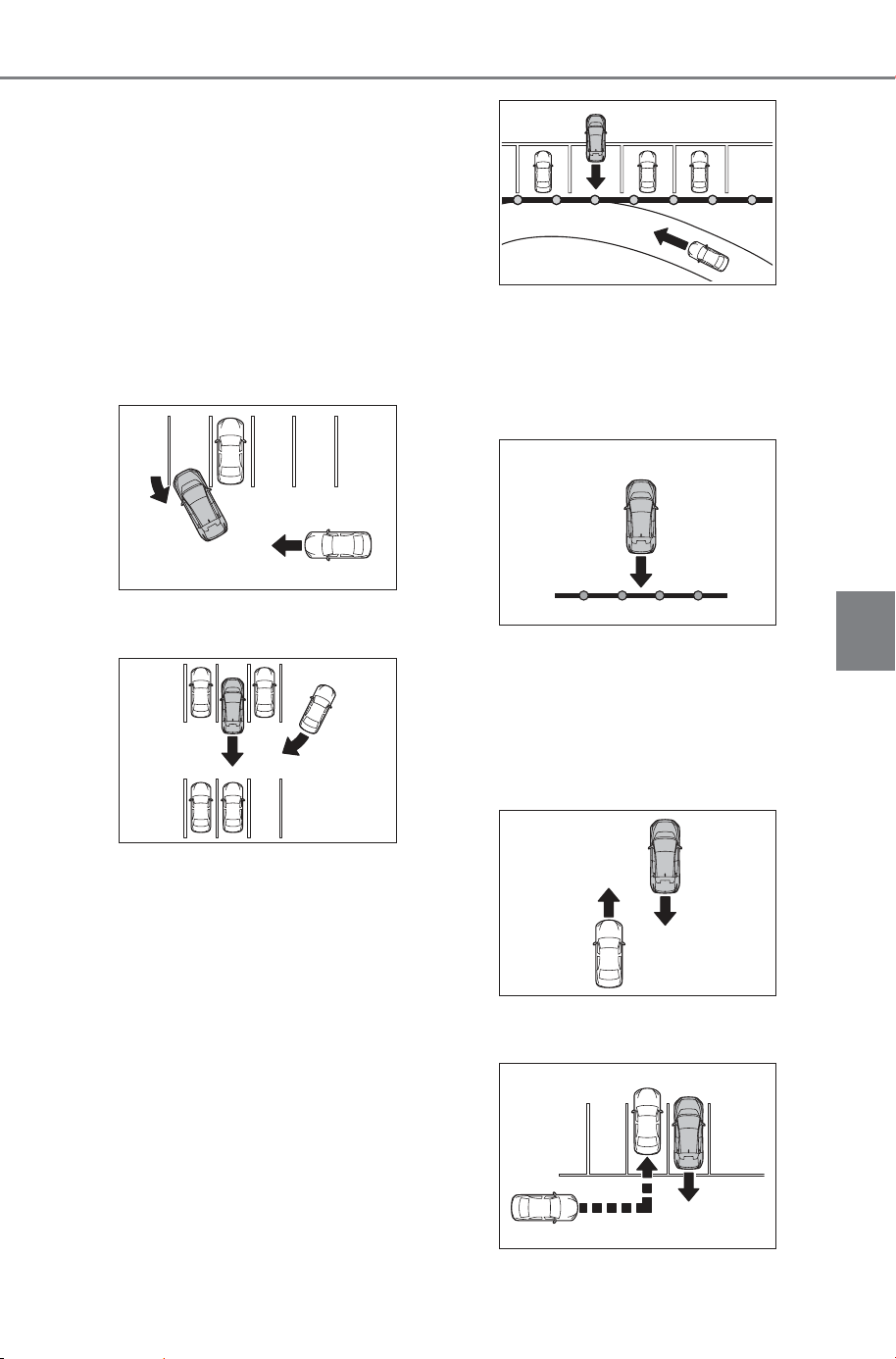
355
5-4. Using the driving support systems
Owner’s Manual_USA_M6740B_en
5
Driving
● When there is a significant differ-
ence in height between your vehi-
cle and the vehicle that enters the
detection area
● When a sensor or the area around
a sensor is extremely hot or cold
● If the suspension has been modi-
fied or tires of a size other than
specified are installed
● If the front of the vehicle is raised
or lowered due to the carried load
● When turning while backing up
● When a vehicle turns into the
detection area
■ Situations in which the system
may operate even if there is no
possibility of a collision
Instances of the RCTA function
unnecessary detecting a vehicle
and/or object may increase in the
following situations:
● When the parking space faces a
street and vehicles are being
driven on the street
● When the distance between your
vehicle and metal objects, such as
a guardrail, wall, sign, or parked
vehicle, which may reflect electri-
cal waves toward the rear of the
vehicle, is short
● When equipment that may
obstruct a sensor is installed, such
as a towing eyelet, bumper pro-
tector (an additional trim strip,
etc.), bicycle carrier, or snow plow
● When a vehicle passes by the
side of your vehicle
● When a detected vehicle turns
while approaching the vehicle
SOLTERRA_OM_USA_A6740BE.book 355 ページ 2025年5月23日 金曜日 午後1時18分
356
5-4. Using the driving support systems
Owner’s Manual_USA_M6740B_en
● When there are spinning objects
near your vehicle such as the fan
of an air conditioning unit
● When water is splashed or
sprayed toward the rear bumper,
such as from a sprinkler
● Moving objects (flags, exhaust
fumes, large rain droplets or
snowflakes, rain water on the road
surface, etc.)
● When the distance between your
vehicle and a guardrail, wall, etc.,
that enters the detection area is
short
● Gratings and gutters
● When a sensor or the area around
a sensor is extremely hot or cold
● If the suspension has been modi-
fied or tires of a size other than
specified are installed
● If the front of the vehicle is raised
or lowered due to the carried load
● When towing with the vehicle.
RCD (Rear Camera
Detection)
When the vehicle is backing
up, the rear camera detec-
tion function can detect
pedestrians in the detec-
tion area behind the vehicle.
If a pedestrian is detected, a
buzzer will sound and an
icon will be displayed on
the multimedia display to
inform the driver of the
pedestrian.
WARNING
■ Cautions regarding the use of
the system
The recognition and control capa-
bilities for this system are limited.
The driver should always drive
safely by always being responsi-
ble without over relying on the
system and have a understanding
of the surrounding situations.
■ To ensure the system can
operate properly
Observe the following, otherwise
there is the danger that could lead
to an accident.
● Always clean the camera with-
out damaging it.
● Do not install market electronic
parts (such as Illuminated
license plate, fog lamps, etc.) in
the camera vicinity.
● Do not subject the camera vicin-
ity to strong impacts. If the vicin-
ity is subjected to a strong
impact, have the vehicle
inspected by your SUBARU
dealer.
SOLTERRA_OM_USA_A6740BE.book 356 ページ 2025年5月23日 金曜日 午後1時18分
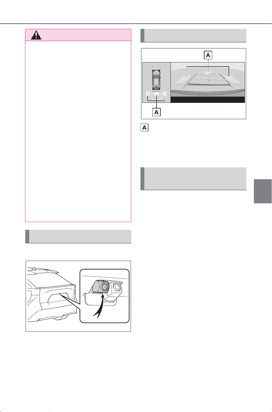
357
5-4. Using the driving support systems
Owner’s Manual_USA_M6740B_en
5
Driving
Location of the rear camera
Pedestrian detection icon
Displayed automatically when a
pedestrian is detected behind the
vehicle.
The RCD function can be
enabled/disabled through a cus-
tomize setting. (P.682)
When the RCD function is dis-
abled, the driving assist informa-
tion indicator (P.140)
illuminates, and a message is
displayed on the multi-informa-
tion display.
Each time the power switch is
turned off then changed to ON, the
RCD function will be enabled auto-
matically.
WARNING
● Do not disassemble, remodel or
paint the camera.
● Do not attach accessories or
stickers to the camera.
● Do not install market protection
parts (bumper trim, etc.) to the
rear bumper.
● Maintain suitable tire air pres-
sure.
● Make sure the back door is
completely closed.
■ When to disable the RCD
function
In the following situations, disable
the system. The RCD function
may not operate properly, possi-
bly leading to an accident.
● The contents mentioned above
are not observed
● Suspensions other than the
genuine parts are installed
System component
RCD display
Turning the RCD function
on/off
SOLTERRA_OM_USA_A6740BE.book 357 ページ 2025年5月23日 金曜日 午後1時18分
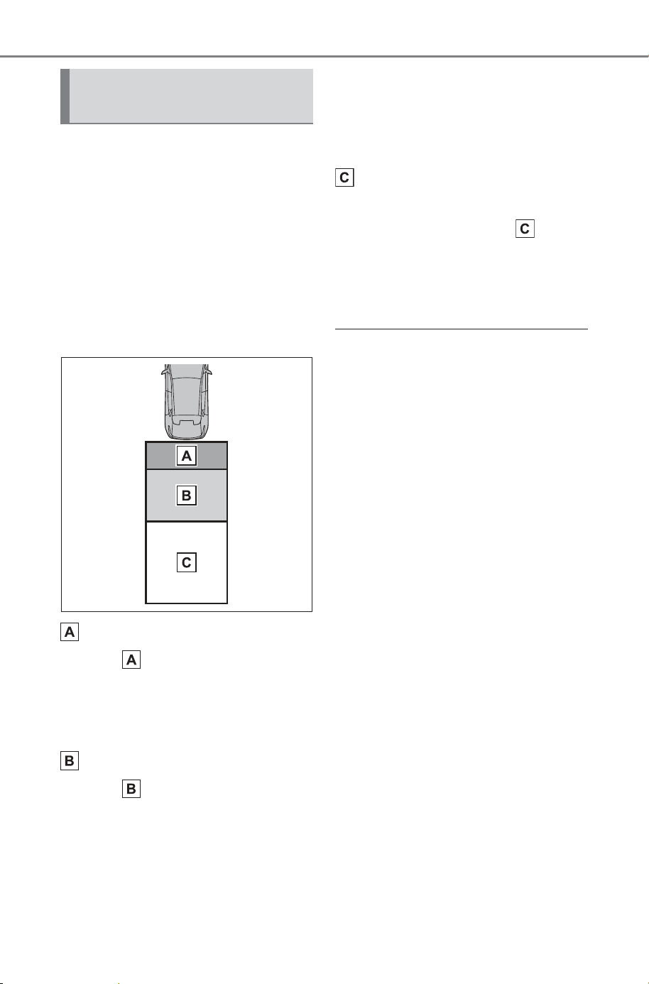
358
5-4. Using the driving support systems
Owner’s Manual_USA_M6740B_en
If a pedestrian is in the area
behind the vehicle or if the rear
camera detected that a pedes-
trian is approaching the vehicle
from behind, the system urges
caution from the driver by
sounding the buzzer and dis-
playing the detection of a pedes-
trian on the multimedia display
as follows:
If a pedestrian is detected in
area
Buzzer: Sounds repeatedly
Pedestrian detection icon:
Blinks
If a pedestrian is detected in
area
Buzzer (When the vehicle is
stationary): Sounds 3 times
Buzzer (When the vehicle is
backing up, when a pedes-
trian approaches the rear of
the vehicle): Sounds repeat-
edly
Pedestrian detection icon:
Blinks
If the system determines that
your vehicle may collide with
a pedestrian in area
Buzzer: Sounds repeatedly
Pedestrian detection icon:
Blinks
■ The rear camera detection func-
tion is operational when
● The power switch is in ON.
● RCD function is on.
● The shift position is in R.
● Advanced Park is not operating.
■ Setting the buzzer volume
The buzzer volume of the SUBARU
Parking Assist, RCTA, and RCD can
all be changed at once from the cus-
tomize settings. (P.682)
■ Muting a buzzer temporarily
When an object is detected, the
temporary mute switch is displayed
on the multimedia display. Select
the switch to mute a buzzer of the
SUBARU Parking Assist, RCTA,
and RCD all together.
Mute will be automatically canceled
in the following situations:
● When the shift position is
changed.
● When the vehicle speed exceeds
a certain speed.
● When there is a malfunction in a
sensor or the system is temporar-
ily unavailable.
● When the operating function is
disabled manually.
● When the power switch is turned
off.
When a pedestrian is
detected
SOLTERRA_OM_USA_A6740BE.book 358 ページ 2025年5月23日 金曜日 午後1時18分

359
5-4. Using the driving support systems
Owner’s Manual_USA_M6740B_en
5
Driving
■ Situations in which the system
may not operate properly
● Some pedestrians, such as the
following, may not be detected by
the rear camera detection func-
tion, preventing the function from
operating properly:
• Pedestrians who are bending for-
ward or squatting
• Pedestrians who are lying down
• Pedestrians who are running
• Pedestrians who suddenly appear
from the shadow of the vehicle or
a building
• Pedestrians who are riding mov-
ing objects such as a bicycle or
skateboard
• Pedestrians wearing oversized
clothing such as a rain coat, long
skirt, etc., making their silhouette
obscure
• Pedestrians whose body is par-
tially hidden by an object, such as
a cart or umbrella
• Pedestrians which are obscured
by darkness, such as at night
● In some situations, such as the
following, pedestrians may not be
detected by the rear camera
detection function, preventing the
function from operating properly:
• When backing up in inclement
weather (rain, snow, fog, etc.)
• The lens is dirty (by dirt or snow-
melting agent, etc.) or scratched
• When a very bright light, such as
the sun, or the headlights of
another vehicle, shines directly
into the rear camera
• When backing up in a place where
the surrounding brightness
changes suddenly, such as at the
entrance or exit of a garage or
underground parking lot
• When backing up in a dim envi-
ronment such as during dusk or in
an underground parking lot
• When the camera position and
direction are deviated
• When a towing hook is attached
• When water droplets are flowing
on the camera lens
• When the vehicle height is
extremely changed (nose up,
nose down, etc.).
• When tire chains or an emergency
tire puncture repair kit are used
• When the suspension has been
lowered or tires that have a differ-
ent size than the genuine tires are
installed
• When an aftermarket electronic
part (backlit license plate, fog
light, etc.) is installed near the rear
camera
• If a bumper protector, such as an
additional trim strip, is installed to
the rear bumper
• When towing with the vehicle
■ Situations in which the system
may operate unexpectedly
● Even though there are no pedes-
trians in the detection area, some
objects, such as the following,
may be detected, possibly caus-
ing the rear camera detection
function to operate.
• Three dimensional objects, such
as a pole, traffic cone, fence, or
parked vehicle
• Moving objects, such as a car or
motorcycle
• Objects moving toward your vehi-
cle when backing up, such as
flags or puddles (or airborne mat-
ter, such as smoke, steam, rain, or
snow)
• Cobblestone or gravel roads, tram
rails, road repairs, white lines,
pedestrian crossings or fallen
leaves on the road
• Metal covers (gratings), such as
those used for drainage ditches
• Objects reflected in a puddle or on
a wet road surface
• Shadows on the road
● In some situations, such as the
following, the rear camera detec-
tion function may operate even
though there are no pedestrians in
the detection area.
• When backing up toward the road-
side or a bump on the road
• When backing up toward an
incline/decline
SOLTERRA_OM_USA_A6740BE.book 359 ページ 2025年5月23日 金曜日 午後1時18分
360
5-4. Using the driving support systems
Owner’s Manual_USA_M6740B_en
• When the vehicle height is
extremely changed (nose up,
nose down, etc.)
• When an aftermarket electronic
part (backlit license plate, fog
light, etc.) is installed near the rear
camera
• If a bumper protector, such as an
additional trim strip, is installed to
the rear bumper
• If the orientation of the rear cam-
era has been changed due to a
collision or other impact, or
removal and installation
• If a towing eyelet is installed to the
rear of the vehicle
• When water is flowing over the
rear camera lens
• The lens is dirty (by dirt or snow-
melting agent, etc.)
• If there is a flashing light in the
detection area, such as the emer-
gency flashers of another vehicle
• When tire chains or an emergency
tire puncture repair kit are used
• When towing with the vehicle
● Situations in which the rear cam-
era detection function may be diffi-
cult to notice
• The buzzer may be difficult to hear
if the surrounding area is noisy or
the audio system volume is high.
• If the temperature in the cabin is
extremely high or low, the multi-
media display may not operate
correctly.
The system has detected the
following as operation targets.
(The operation targets vary
depending on the function.)
Parking Support Brake func-
tion (static objects front and
rear of the vehicle):
P.366
Parking Support Brake func-
tion (moving vehicles rear of
the vehicle):
P.370
Parking Support Brake func-
tion (pedestrians rear of the
vehicle):
P.371
Parking Support Brake func-
tion (static objects around the
vehicle) (vehicles with the
Advanced Park):
P.367
PKSB (Parking Sup-
port Brake)
The PKSB (Parking Sup-
port Brake) is a system that
issues warnings and auto-
matically performs braking
to help reduce collision
damage with operation tar-
gets that were detected
when traveling at a low
speed such as when park-
ing.
PKSB (Parking Support
Brake) system
SOLTERRA_OM_USA_A6740BE.book 360 ページ 2025年5月23日 金曜日 午後1時18分
361
5-4. Using the driving support systems
Owner’s Manual_USA_M6740B_en
5
Driving
WARNING
■ Cautions regarding the use of
the system
Do not overly rely on the system,
as doing so may lead to an acci-
dent.
Always drive while checking the
safety of the surroundings of the
vehicle.
Depending on the vehicle and
road conditions, weather, etc., the
system may not operate.
The detection capabilities of sen-
sors and radars are limited.
Always drive while checking the
safety of the surroundings of the
vehicle.
● The driver is solely responsible
for safe driving. Always drive
carefully, taking care to observe
your surroundings. The Parking
Support Brake system is
designed to provide support to
lessen the severity of collisions.
However, it may not operate in
some situations.
● The Parking Support Brake sys-
tem is not designed to stop the
vehicle completely. Additionally,
even if the system has stopped
the vehicle, it is necessary to
depress the brake pedal imme-
diately as brake control will be
canceled after approximately 2
seconds.
● It is extremely dangerous to
check the system operations by
intentionally driving the vehicle
into the direction of a wall, etc.
Never attempt such actions.
■ When to disable the Parking
Support Brake
In the following situations, disable
the Parking Support Brake as the
system may operate even though
there is no possibility of a colli-
sion.
● When inspecting the vehicle
using a chassis roller, chassis
dynamo or free roller
● When loading the vehicle onto a
boat, truck or other transport
vessel
● If the suspension has been
modified or tires of a size other
than specified are installed
● If the front of the vehicle is
raised or lowered due to the
carried load
● When equipment such as a tow-
ing hook, transport hook,
bumper protector, bumper trim,
bicycle carrier or snow-removal
device (snow plow) is installed
near the sensor
● When using automatic car
washing devices
● If the vehicle cannot be driven in
a stable manner, such as when
the vehicle has been in an acci-
dent or is malfunctioning
● When the vehicle is driven in a
sporty manner or off-road
● When the tires are not properly
inflated
● When the tires are very worn
● When tire chains, a compact
spare tire or an emergency tire
puncture repair kit are used.
● When towing with the vehicle
■ Precautions for the suspen-
sion
Do not modify the suspension of
the vehicle. If the height or tilt of
the vehicle is changed, the sen-
sors may not be able to detect
detectable objects and the system
may not operate correctly, possi-
bly leading to an accident.
SOLTERRA_OM_USA_A6740BE.book 361 ページ 2025年5月23日 金曜日 午後1時18分

362
5-4. Using the driving support systems
Owner’s Manual_USA_M6740B_en
The Parking Support Brake
function can be enabled/dis-
abled through a customize set-
ting. (P.682)
When the PKSB (Parking Sup-
port Brake) is disabled, the driv-
ing assist information indicator
(P.140) illuminates, and a
message is displayed on the
multi-information display.
If the system switches to OFF
(disabled) and the PKSB (Park-
ing Support Brake) is stopped,
the PKSB (Parking Support
Brake) will not be re-enabled
until ON (enabled) is selected
again from the customize setting
(P.682).
(It remains off even if the power
switch is turned to ON again
after the power switch has been
turned off.)
If the EV system output restric-
tion control or brake control
operates, a buzzer will sound
and a message that indicates
limited acceleration or prompts
the driver to brake will be dis-
played on the multimedia Dis-
play and multi-information
display, to alert the driver.
Depending on the situation, out-
put restriction control operates
to either limit acceleration or
restrict output as much as possi-
ble.
EV system output restriction
control is operating (accelera-
tion restriction)
Acceleration greater than a cer-
tain amount is restricted by the
system.
Multimedia display: No warning
displayed
Message example on the multi-
information display: “Object
Detected Acceleration
Reduced”
Driving assist information indica-
tor: Not illuminated
Buzzer: Does not sound
Enabling/Disabling the
Parking Support Brake
Display and buzzer for EV
system output restriction
control and brake control
SOLTERRA_OM_USA_A6740BE.book 362 ページ 2025年5月23日 金曜日 午後1時18分

363
5-4. Using the driving support systems
Owner’s Manual_USA_M6740B_en
5
Driving
EV system output restriction
control is operating (output
restricted as much as possi-
ble)
The system has determined that
stronger-than-normal brake
operation is necessary.
Message example on the multi-
media display (vehicles with
panoramic view monitor
*
, multi-
terrain monitor
*
or parking assist
monitor with RCD [Rear Camera
Detection]): “BRAKE!”
Message example on the multi-
information display: “BRAKE!”
Driving assist information indica-
tor: Not illuminated
Buzzer: Short beep
Brake control is operating
The system determined that
emergency braking is neces-
sary.
Message example on the multi-
media display (vehicles with
panoramic view monitor
*
, multi-
terrain monitor
*
or parking assist
monitor with RCD [Rear Camera
Detection]): “BRAKE!”
Driving assist information indica-
tor: Not illuminated
Buzzer: Short beep
Vehicle stopped by system
operation
The vehicle has been stopped
by brake control operation.
Message example on the multi-
media display (vehicles with
panoramic view monitor
*
, multi-
terrain monitor
*
or parking assist
monitor with RCD [Rear Camera
Detection]): “Switch to Brake”
Message example on the multi-
information display: “Accelerator
Pedal is Pressed Press Brake
Pedal”, “Press Brake Pedal”
Driving assist information indica-
tor: Illuminated
Buzzer: Sounds repeatedly
*
: This may not be displayed
depending on the specification of
the panoramic view monitor or
multi-terrain monitor.
If the Parking Support Brake
determines that a collision with a
detected object or pedestrian is
possible, the EV system output
will be restricted to restrain any
increase in the vehicle speed.
(EV system output restriction
control: See figure 2 below.)
Additionally, if the accelerator
pedal continues to be
depressed, the brakes will be
applied automatically to reduce
the vehicle speed. (Brake con-
trol: See figure 3.)
System overview
SOLTERRA_OM_USA_A6740BE.book 363 ページ 2025年5月23日 金曜日 午後1時18分
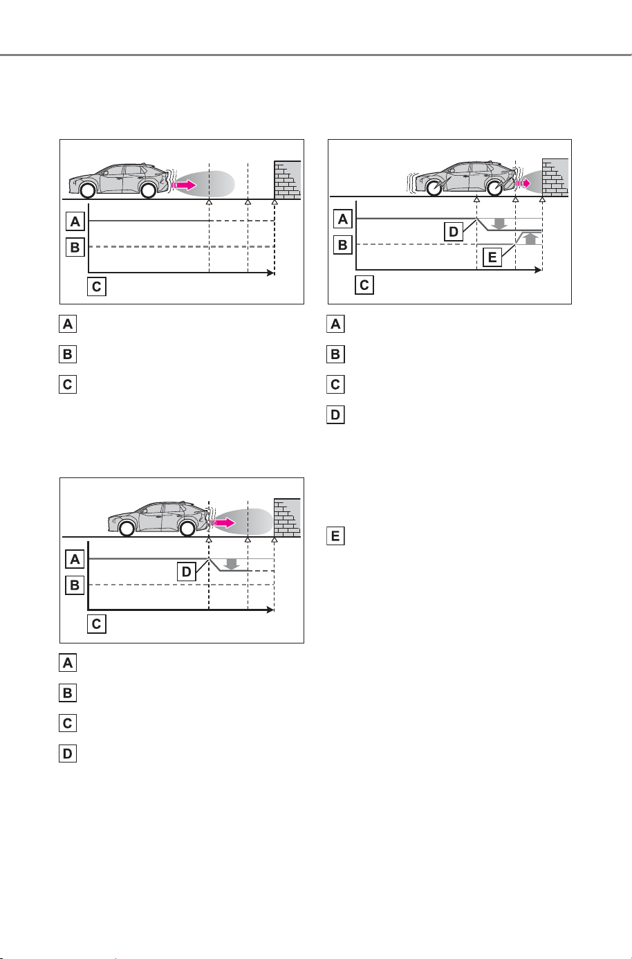
364
5-4. Using the driving support systems
Owner’s Manual_USA_M6740B_en
Figure 1: When the PKSB
(Parking Support Brake) is not
operating
EV system output
Braking force
Time
Figure 2: When EV system
output restriction control oper-
ates
EV system output
Braking force
Time
EV system output restriction
control begins operating
(System determines that pos-
sibility of collision with
detected object is high)
Figure 3: When EV system
output restriction control and
brake control operates
EV system output
Braking force
Time
EV system output restriction
control begins operating
(System determines that pos-
sibility of collision with
detected object is high)
Brake control begins operat-
ing (System determines that
possibility of collision with
detected object is extremely
high)
SOLTERRA_OM_USA_A6740BE.book 364 ページ 2025年5月23日 金曜日 午後1時18分

365
5-4. Using the driving support systems
Owner’s Manual_USA_M6740B_en
5
Driving
■ If the Parking Support Brake
has operated
If the vehicle is stopped due to oper-
ation of the Parking Support Brake,
the Parking Support Brake will be
disabled and the driving assist infor-
mation indicator will illuminate.
In addition, even when the PKSB
(Parking Support Brake) operates,
the brake control is canceled after
approximately 2 seconds to start off.
Furthermore, the brake control also
can be canceled by depressing the
brake pedal. Depressing the accel-
erator pedal again after that allows
the vehicle to start off.
■ Re-enabling the Parking Sup-
port Brake
To re-enable the Parking Support
Brake when it is disabled due to
operation of the PKSB (Parking
Support Brake), either enable the
system again, or turn the power
switch off and then back to ON.
Additionally, if any of the following
conditions are met, the system will
be re-enabled automatically and the
driving assist information indicator
will turn off (P.140):
● The P shift position is selected
● Drive with no operation targets in
the traveling direction of the vehi-
cle
● Change the traveling direction of
the vehicle
■ Buzzer
Regardless of whether the SUBARU
Parking Assist is enabled or not
(P.341), if the PKSB (Parking
Support Brake) system is enabled
(P.362), the buzzer will sound to
notify the driver of the approximate
distance to the object when the
brake control and the EV system
output restriction control are oper-
ated.
*
: If equipped
Parking Support Brake
function (static
objects front and rear
of the vehicle/static
objects around the
vehicle
*
)
If the sensors detect a static
object, such as a wall, in the
traveling direction of the
vehicle and the system
determines that a collision
may occur due to the vehi-
cle suddenly moving for-
ward due to an accidental
accelerator pedal operation,
the vehicle moving the
unintended direction due to
the wrong shift position
being selected, or while
parking or traveling at low
speeds, the system will
operate to lessen the impact
with the detected static
object and reduce the
resulting damage.
SOLTERRA_OM_USA_A6740BE.book 365 ページ 2025年5月23日 金曜日 午後1時18分
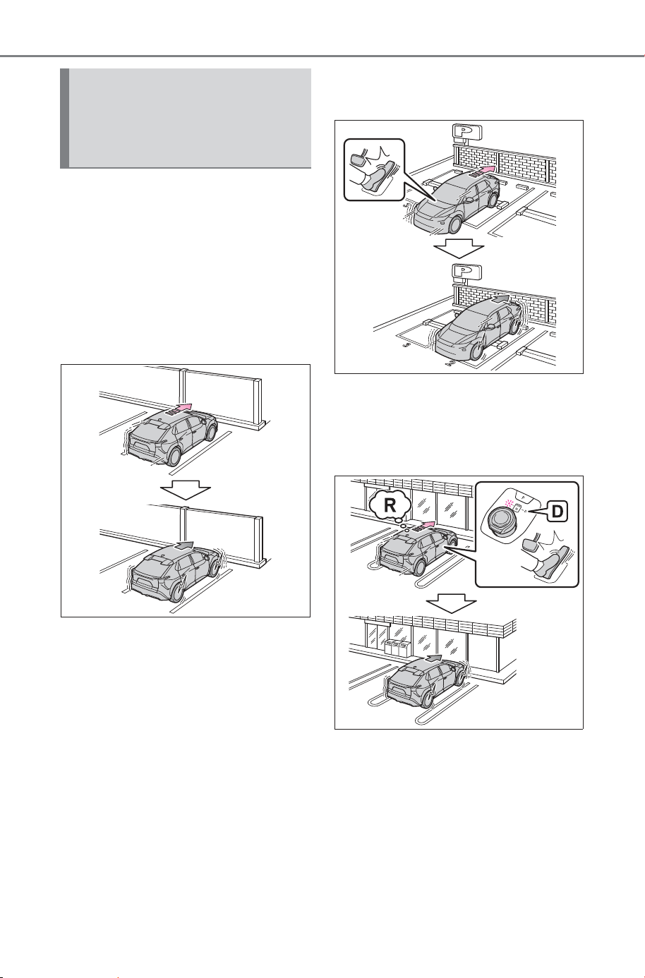
366
5-4. Using the driving support systems
Owner’s Manual_USA_M6740B_en
This function will operate in situ-
ations such as the following if an
object is detected in the travel-
ing direction of the vehicle.
■ When traveling at a low
speed and the brake pedal
is not depressed, or is
depressed late
■ When the accelerator pedal
is depressed excessively
■ When the vehicle moves
forward due to the incorrect
shift position being
selected
Examples of function
operation (static objects
front and rear of the vehi-
cle)
SOLTERRA_OM_USA_A6740BE.book 366 ページ 2025年5月23日 金曜日 午後1時18分
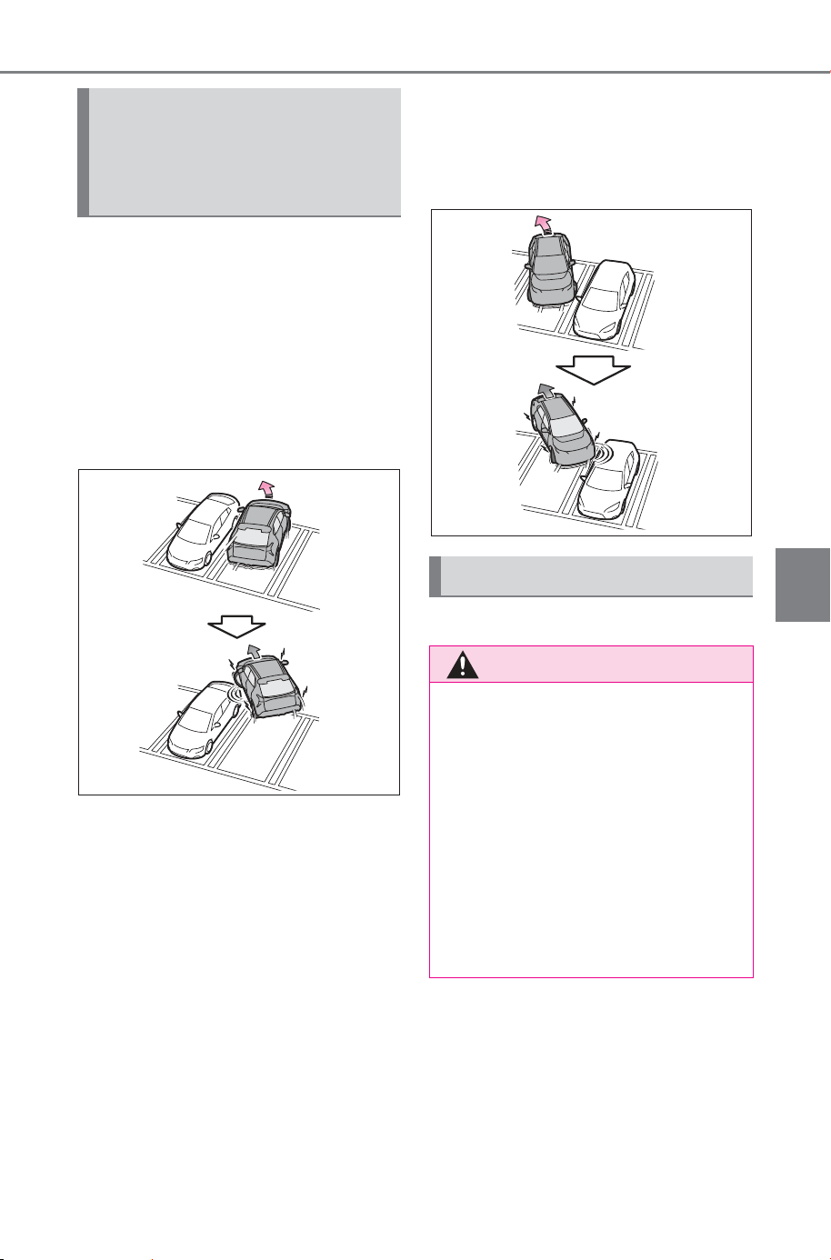
367
5-4. Using the driving support systems
Owner’s Manual_USA_M6740B_en
5
Driving
The system will operate in the
following situations when a sta-
tionary object is detected in the
surrounding area.
■ When moving forward and a
collision with a stationary
object on the inner side of a
turn is likely
■ When reversing and a colli-
sion with a stationary
object on the outer side of a
turn is likely
P.340
Examples of function
operation (static objects
around the vehicle) (Vehi-
cles with Advanced Park)
Types of sensors
WARNING
■ To ensure the system can
operate properly
P.3 41
■ If the Parking Support Brake
function operates unneces-
sarily, such as at a railroad
crossing
P.3 65
■ Notes when washing the vehi-
cle
P.3 42
SOLTERRA_OM_USA_A6740BE.book 367 ページ 2025年5月23日 金曜日 午後1時18分
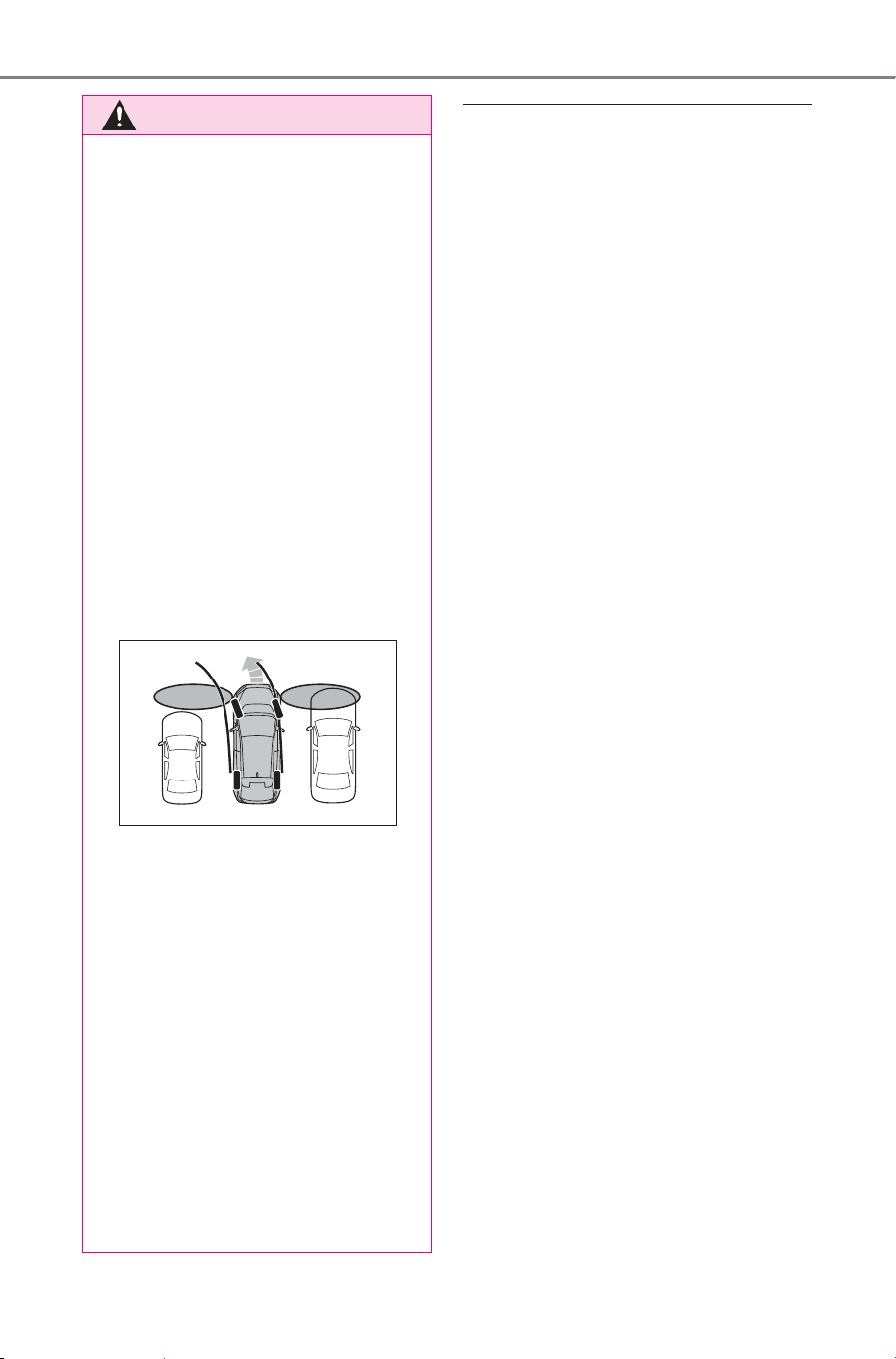
368
5-4. Using the driving support systems
Owner’s Manual_USA_M6740B_en
■ The Parking Support Brake
function (static objects front
and rear of the vehicle) will
operate when
The function will operate when the
driving assist information indicator is
not illuminated (P.138) and all of
the following conditions are met:
● EV system output restriction con-
trol
• The Parking Support Brake is
enabled.
• The vehicle speed is approxi-
mately 9 mph (15 km/h) or less.
• There is a static object in the trav-
eling direction of the vehicle and
approximately 6 to 13 ft. (2 to 4 m)
away.
• The Parking Support Brake deter-
mines that a stronger-than-nor-
mal brake operation is necessary
to avoid a collision.
● Brake control
• EV system output restriction con-
trol is operating.
• The Parking Support Brake deter-
mines that an immediate brake
operation is necessary to avoid a
collision.
■ The Parking Support Brake
function (static objects around
the vehicle) will operate when
(Vehicles with Advanced Park)
This function is operable when any
of the following conditions is met in
addition to the operating conditions
for static objects in front and rear of
the vehicle.
● After the EV system has been
started, the vehicle has moved
approximately 23.0 ft. (7 m) or
less
● The R shift position is selected
● After the shift position has been
changed from R to D, the vehicle
has moved approximately 23.0 ft.
(7 m) or less
WARNING
■ Side sensors and side cam-
eras (vehicles with Advanced
Park)
In situations such as the following,
Parking Support Brake function
(static objects around the vehicle)
may not operate correctly, possi-
bly leading to an accident. Pro-
ceed carefully.
● When starting off shortly after
the power switch is turned to
ON and a small vehicle or other
object which cannot be detected
by a front side sensor is next to
the vehicle.
In the situation shown in the fol-
lowing illustration, even if the
vehicle starts off, the vehicle on
the left will not be detected and
the object warning function will
not operate.
● When an object or person is in a
position which cannot be
detected by the side sensors or
side cameras.
● When a vehicle, person, or
other object approaches the
side of the vehicle after the side
sensors have completed scan-
ning the areas along the sides
of the vehicle.
● When the outside rear view mir-
ror is closed.
● If the 12-volt battery was dis-
charged or has been removed
and installed, fold and extend
the outside rear view mirrors.
SOLTERRA_OM_USA_A6740BE.book 368 ページ 2025年5月23日 金曜日 午後1時18分

369
5-4. Using the driving support systems
Owner’s Manual_USA_M6740B_en
5
Driving
■ The Parking Support Brake
function (static objects front
and rear of the vehicle/static
objects around the vehicle) will
stop operating when
The function will stop operating if
any of the following conditions are
met:
● EV system output restriction con-
trol
• The Parking Support Brake is dis-
abled.
• The system determines that the
collision has become avoidable
with normal brake operation.
• The static object is no longer
approximately 6 to 13 ft. (2 to 4 m)
away from the vehicle or in the
traveling direction of the vehicle.
● Brake control
• The Parking Support Brake is dis-
abled.
• Approximately 2 seconds have
elapsed since the vehicle was
stopped by brake control.
• The brake pedal is depressed
after the vehicle is stopped by
brake control.
• The static object is no longer
approximately 6 to 13 ft. (2 to 4 m)
away from the vehicle or in the
traveling direction of the vehicle.
■ Detection range of the Parking
Support Brake function (static
objects front and rear of the
vehicle/static objects around
the vehicle)
The detection range of the Parking
Support Brake function (static
objects front and rear of the vehi-
cle/static objects around the vehicle)
differs from the detection range of
the SUBARU Parking Assist
(P.345). Therefore, even if the
SUBARU Parking Assist detects an
object and provides a warning, the
Parking Support Brake function
(static objects front and rear of the
vehicle/static objects around the
vehicle) may not start operating.
■ Situations in which the system
may not operate properly
P.343
■ Situations in which the system
may operate even if there is no
possibility of a collision
P.344
■ Situations in which the system
may operate even though there
is no possibility of a collision
(static objects around the vehi-
cle) (vehicles with Advanced
Park)
In addition to the situations in which
static objects in front and rear of the
vehicle (P.368) may not be
detected, objects may not be
detected by the sensors in the fol-
lowing situations:
● When moving sideways, such as
when parallel parking (387)
■ Detection of objects along the
sides of the vehicle (static
objects around the vehicle)
(vehicles with Advanced Park)
● Objects along the sides of the
vehicle are not instantaneously
detected. The location of objects
in relation to the vehicle is esti-
mated after they are first detected
by the front or rear side sensors,
or side cameras. Therefore, after
the power switch is changed to
ON, even if an object is along the
side of the vehicle, it may not be
detected until the vehicle has
been driven a small amount and
the side sensors or side cameras
completely scan the areas along
the sides of the vehicle.
● If a vehicle, person, animal, etc., is
detected by a side sensors or side
cameras, but then leaves the
detection area of the side sensors
or side cameras, the system will
assume the object has not moved.
SOLTERRA_OM_USA_A6740BE.book 369 ページ 2025年5月23日 金曜日 午後1時18分
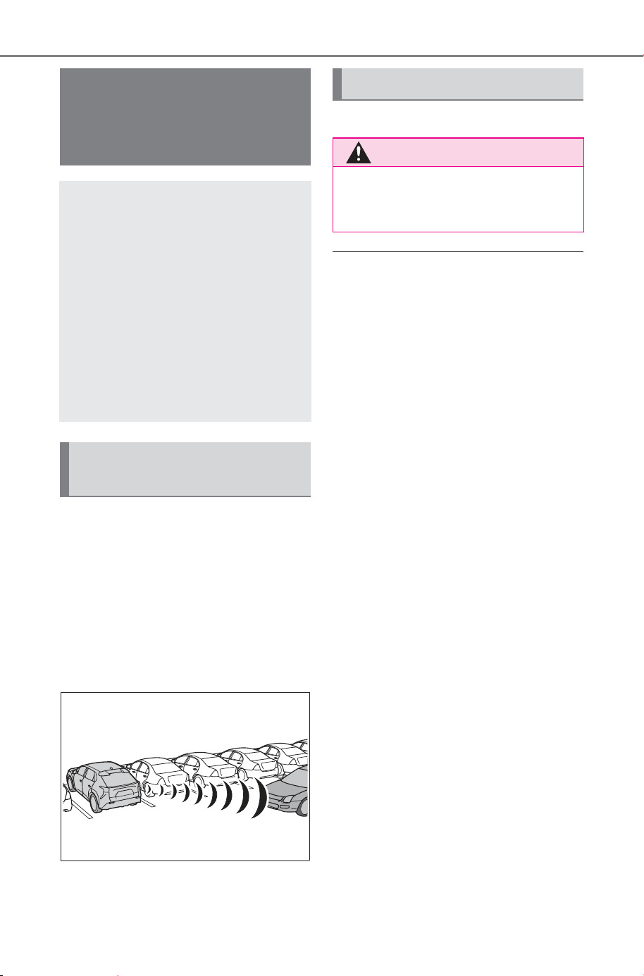
370
5-4. Using the driving support systems
Owner’s Manual_USA_M6740B_en
This function will operate in situ-
ations such as the following if a
vehicle is detected in the travel-
ing direction of the vehicle.
■ When reversing, a vehicle is
approaching and the brake
pedal is not depressed, or
is depressed late
P.331
■ The Parking Support Brake
function (moving vehicles rear
of the vehicle) will operate
when
The function will operate when the
driving assist information indicator is
not illuminated (P.138) and all of
the following conditions are met:
● EV system output restriction con-
trol
• The Parking Support Brake is
enabled.
• The vehicle speed is approxi-
mately 9 mph (15 km/h) or less.
• Vehicles are approaching from the
right or left at the rear of the vehi-
cle at a traveling speed of approx-
imately 5 mph (8 km/h) or more.
• The shift position is in R.
• The Parking Support Brake deter-
mines that a stronger than normal
brake operation is necessary to
avoid a collision with an approach-
ing vehicle.
● Brake control
• EV system output restriction con-
trol is operating.
• The Parking Support Brake deter-
mined that an emergency brake
operation was necessary to avoid
a collision with a vehicle
approaching from the rear.
Parking Support Brake
function (moving vehi-
cles rear of the vehi-
cle)
If a rear radar sensor
detects a vehicle approach-
ing from the right or left at
the rear of the vehicle and
the system determines that
the possibility of a collision
is high, this function will
perform brake control to
reduce the likelihood of an
impact with the approach-
ing vehicle.
Examples of the function
operation
Types of sensors
WARNING
■ To ensure the system can
operate properly
P.3 31
SOLTERRA_OM_USA_A6740BE.book 370 ページ 2025年5月23日 金曜日 午後1時18分
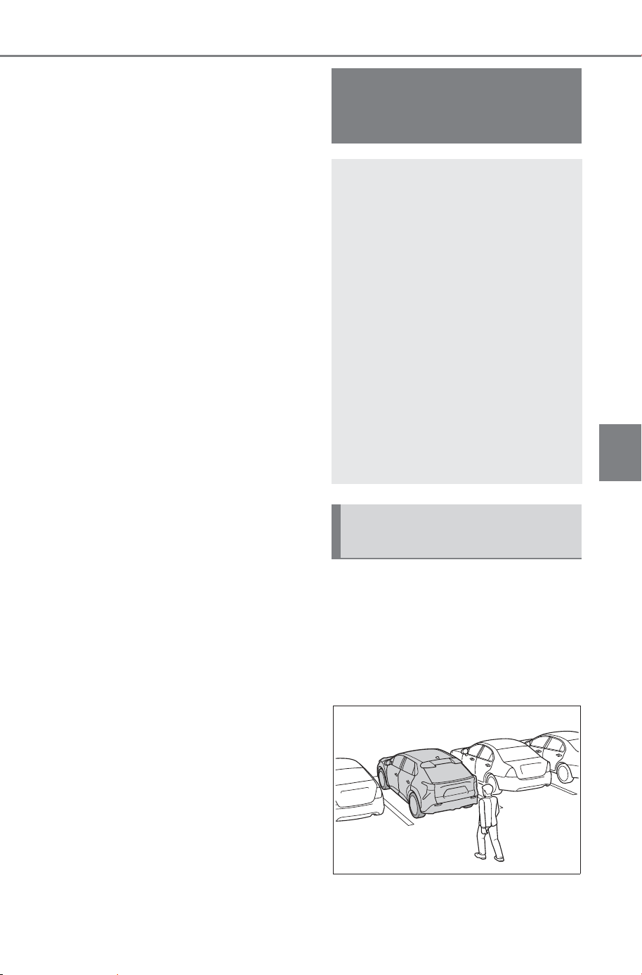
371
5-4. Using the driving support systems
Owner’s Manual_USA_M6740B_en
5
Driving
■ The Parking Support Brake
function (moving vehicles rear
of the vehicle) will stop operat-
ing when
The function will stop operating if
any of the following conditions are
met:
● EV system output restriction con-
trol
• The Parking Support Brake is dis-
abled.
• The collision becomes avoidable
with normal brake operation.
• A vehicle is no longer approaching
from the right or left at the rear of
the vehicle.
● Brake control
• The Parking Support Brake is dis-
abled.
• Approximately 2 seconds have
elapsed since the vehicle was
stopped by brake control.
• The brake pedal is depressed
after the vehicle is stopped by
brake control.
■ Situations in which the system
may not operate properly
P.354
■ Situations in which the system
may operate even if there is no
possibility of a collision
P.355
The system operates when an
approaching pedestrian is
detected behind the vehicle
while backing up, and when the
brake pedal is not depressed or
is depressed late.
Parking Support Brake
function (pedestrians
rear of the vehicle)
If the rear camera sensor
detects a pedestrian behind
the vehicle while backing
up and the system deter-
mines that the possibility of
colliding with the detected
pedestrian is high, a buzzer
will sound. If the system
determines that the possi-
bility of colliding with the
detected pedestrian is
extremely high, the brakes
will be applied automati-
cally to help reduce the
impact of the collision.
Examples of system oper-
ation
SOLTERRA_OM_USA_A6740BE.book 371 ページ 2025年5月23日 金曜日 午後1時18分
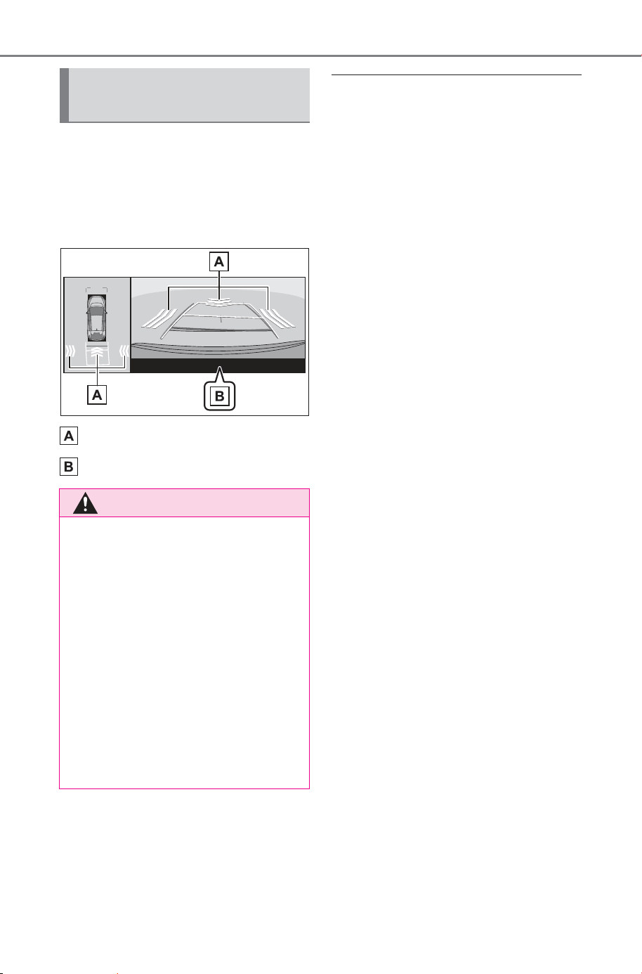
372
5-4. Using the driving support systems
Owner’s Manual_USA_M6740B_en
Displays a message to prompt
the driver to brake when a
pedestrian is detected in the
detection area behind the vehi-
cle.
Pedestrian detection icon
Example: “BRAKE!”
■ The Parking Support Brake
function (pedestrians rear of
the vehicle) will operate when
The function will operate when the
driving assist information indicator is
not illuminated (P.138) and all of
the following conditions are met:
● EV system output restriction con-
trol
• The Parking Support Brake is
enabled.
• The vehicle speed is 9 mph (15
km/h) or less.
• The shift position is in R.
• When a pedestrian is to the rear of
the vehicle
• The PKSB (Parking Support
Brake) determines that a stronger-
than-normal-brake operation is
necessary to avoid a collision.
● Brake control
• EV system output restriction con-
trol is operating.
• The Parking Support Brake deter-
mines that an emergency brake
operation is necessary to avoid a
collision with a pedestrian.
■ The Parking Support Brake
function (pedestrians rear of
the vehicle) will stop operating
when
The function will stop operating if
any of the following conditions are
met:
● EV system output restriction con-
trol
• The Parking Support Brake is dis-
abled.
• The collision becomes avoidable
with normal brake operation.
• The pedestrian is no longer
detected behind your vehicle.
● Brake control
• The Parking Support Brake is dis-
abled.
• Approximately 2 seconds have
elapsed since the vehicle was
stopped by brake control.
Screen display of pedes-
trians rear of the vehicle
WARNING
■ If the Parking Support Brake
function (pedestrians rear of
the vehicle) operates unnec-
essarily
Depress the brake pedal immedi-
ately after the Parking Support
Brake function (pedestrians rear
of the vehicle) operates. (Opera-
tion of the function is canceled by
depressing the brake pedal.)
■ Correct use of the Parking
Support Brake function
(pedestrians rear of the vehi-
cle)
P.3 56
SOLTERRA_OM_USA_A6740BE.book 372 ページ 2025年5月23日 金曜日 午後1時18分
373
5-4. Using the driving support systems
Owner’s Manual_USA_M6740B_en
5
Driving
• The brake pedal is depressed
after the vehicle is stopped by
brake control.
■ Re-enabling the Parking Sup-
port Brake function (pedestri-
ans rear of the vehicle)
P.365
■ Detection area of the Parking
Support Brake function (pedes-
trians rear of the vehicle)
The detection area of the Parking
Support Brake function (pedestrians
rear of the vehicle) differs from the
detection area of the RCD function
(P.358). Therefore, even if the
RCD function detects a pedestrian
and provides an alert, the Parking
Support Brake function (pedestrians
rear of the vehicle) may not start
operating.
■ Situations in which the system
may not operate properly
P.359
■ Situations in which the system
may operate unexpectedly
P.359
*
: If equipped
The Advanced Park is a system
which assists in a safe and
smooth parking or exiting from a
parking space by displaying the
blind spots around the vehicle
and the target parking spot
through a bird’s eye view, deliv-
ering operation guidance
through displays and buzzer
operation, and changing the
shift position, operating the
steering wheel, accelerator
pedal, and brake pedal.
Additionally, the panoramic view
monitor
*
can display the area in
front, behind, and from above
the vehicle, helping confirm the
condition of the area around the
vehicle.
The turn signal lights will blink
automatically when the parking
assistance starts until the vehi-
cle reaches the target parking
spot, to notify people around the
vehicle that parking is being per-
formed.
Depending on the condition of
the road surface or the vehicle,
the distance between the vehi-
cle and a parking space, etc., it
may not be possible to assist in
parking in the target space.
Advanced Park
*
Function description
SOLTERRA_OM_USA_A6740BE.book 373 ページ 2025年5月23日 金曜日 午後1時18分
374
5-4. Using the driving support systems
Owner’s Manual_USA_M6740B_en
Only use Advanced Park in
accordance with all local road
traffic laws and regulations.
*
: For details on the panoramic view
monitor refer to “MULTIMEDIA
OWNER’S MANUAL”.
■ Perpendicular parking (for-
ward/reverse) function
Assistance is provided from the
position the vehicle is stopped
near the target parking space
until the vehicle is in the parking
space. (P.382)
■ Perpendicular exiting (for-
ward/reverse) function
Assistance is provided from the
parked position until the vehicle
is in a position where you can
easily exit from the parking
space. (P.385)
■ Parallel parking function
Assistance is provided from the
position the vehicle is stopped
near the target parking space
until the vehicle is in the parking
space. (P.387)
■ Parallel exiting function
Assistance is provided from the
parked position until the vehicle
is in a position where you can
easily exit from the parking
space. (P.390)
■ Memory function
Assistance is provided until the
vehicle is guided into a previ-
ously registered parking space.
(P.392)
Functions
WARNING
■ Cautions regarding the use of
the system
The recognition and control capa-
bilities for this system are limited.
The driver should always drive
safety by always being responsi-
ble without over relying on the
system and have a understanding
of the surrounding situations.
● As with a normal vehicle, take
care to observe your surround-
ings while the vehicle is moving.
● Always pay attention to the
vehicle’s surroundings while the
system is operating and
depress the brake pedal as nec-
essary to slow or stop the vehi-
cle.
● When parking, make sure that
the vehicle can be parked in the
target parking space before
beginning operation.
● Depending on the condition of
the road surface or the vehicle,
the distance between the vehi-
cle and a parking space, etc., it
may not be possible to detect a
parking space or the system
may not be able to provide
assistance to the point the vehi-
cle is fully parked.
SOLTERRA_OM_USA_A6740BE.book 374 ページ 2025年5月23日 金曜日 午後1時18分

375
5-4. Using the driving support systems
Owner’s Manual_USA_M6740B_en
5
Driving
WARNING
● This system will guide the vehi-
cle to appropriate positions for
changing the direction of travel,
however, if you feel that the
vehicle is approaching too close
to an adjacent parked vehicle at
any time, depress the brake
pedal and change the shift posi-
tion. However, if this is per-
formed, the number of times the
vehicle changes direction may
increase, and the vehicle may
be parked at an angle.
● As certain objects or materials,
such as the following, may not
be detected, make sure to
check the safety of the area
around your vehicle and
depress the brake pedal to stop
the vehicle if it may collide with
an object.
• Thin objects (wires, fences,
ropes, poles, etc.) or objects
that appear like thin from a cer-
tain angle of approach (signs,
bicycles, etc.)
• Materials that absorb sound
waves (cotton, snow, etc.)
• Sharp-edged objects (block
walls/columns, wall corners,
etc.)
• Objects in lower places (curb
stones/blocks, stairs, parking
blocks, etc.)
• Tall objects with upper sections
that protrude outward (beams,
etc.)
• Objects which are not perpen-
dicular to the ground
• Objects to which the vehicle is
approaching diagonally
● Even if there is an object in the
target parking space, it may not
be detected and assistance
may be performed.
● If it is likely that your vehicle will
collide with a nearby vehicle,
object, or person, or go over the
top of a parking block, depress
the brake pedal to stop the vehi-
cle and press the Advanced
Park main switch to disable the
system.
● Never use only the multimedia
display to view the area behind
the vehicle. The image dis-
played may differ than the
actual situation. Using only the
screen when backing up may
lead to an accident, such as a
collision with another vehicle.
When backing up, make sure to
look directly or use the mirrors
to check the safety of the area
around your vehicle, especially
behind the vehicle.
● When the ambient temperature
is extremely low, the screen
may appear dark or the dis-
played image may become
unclear. Also, as moving objects
may appear distorted or may
not be able to be seen on the
screen, make sure to directly
check the safety of the area
around your vehicle.
● In the following situations, while
the vehicle is stopped and held
by Advanced Park, it may be
canceled and the vehicle may
start moving. Immediately
depress the brake pedal. Fail-
ure to do so may lead to an
accident.
• When the driver’s door is
opened
• When operations instructed by
the system are not performed
within a certain amount of time
SOLTERRA_OM_USA_A6740BE.book 375 ページ 2025年5月23日 金曜日 午後1時18分

376
5-4. Using the driving support systems
Owner’s Manual_USA_M6740B_en
WARNING
• When the brake pedal is
depressed and the vehicle is
stopped for a certain amount of
time
• When the system malfunctions
● As the steering wheel will turn
while this system is operating,
pay attention to the following.
• Be careful so that a necktie,
scarf, or arm does not get
caught. Keep your upper body
away from the steering wheel.
Also, keep children away from
the steering wheel.
• Long fingernails may be caught
and when the steering wheel is
rotating, leading to injury.
• In an emergency, depress the
brake pedal to stop the vehicle,
and then press the Advanced
Park main switch to disable the
system.
● Do not allow anyone to put their
hands outside of a window while
this system is operating.
■ To ensure correct operation
of the Advanced Park
Observe the following precau-
tions. Failing to do so may result
in the vehicle being unable to be
driven safely and possibly cause
an accident.
● Do not use this system in situa-
tions such as the following:
• When in areas other than com-
mon parking spaces
• When the surface of the parking
space is sand or gravel and is
not clearly defined with parking
space lines
• When the parking space is not
level, such as on a slope, or
having differences in height,
holes, or gutters
• Mechanical parking system
• Parking lot with a device which
raises to contact the bottom of
the vehicle
• When the road surface is fro-
zen, slick, or covered with snow
• When it is extremely hot and the
asphalt is melting
• When there are objects around
the vehicle
• When there is an object
between your vehicle and the
target parking spot or within the
target parking spot (within the
displayed blue box)
• When in high pedestrian or
vehicle traffic areas
• When the parking space is in a
location that is difficult to park in
(too narrow for your vehicle,
etc.)
• When images are unclear due
to dirt or snow attached to the
camera lens, light being shined
into the camera or shadows
• When tire chains or a compact
spare tire is installed to the vehi-
cle
• When the doors or back door
are not completely closed
• When an arm is held outside of
a window
• In inclement weather such as
heavy rain or snow
SOLTERRA_OM_USA_A6740BE.book 376 ページ 2025年5月23日 金曜日 午後1時18分
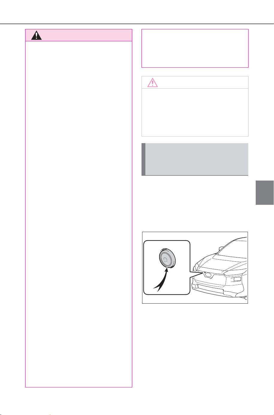
377
5-4. Using the driving support systems
Owner’s Manual_USA_M6740B_en
5
Driving
Cameras and sensors are used
to detect parked vehicles, mak-
ing it easier to identify parking
spaces.
Front camera
WARNING
● Make sure to use only standard
sized tires, such as those that
were installed to the vehicle
when it was shipped from the
factory. Otherwise, Advanced
Park may not operate properly.
Also, when the tires have been
replaced, the displayed position
of the lines or box displayed on
the screen may become incor-
rect. When replacing the tires,
contact your SUBARU dealer.
● In situations such as the follow-
ing, it may not be possible for
the system to provide assis-
tance to a registered parking
spot or to operate correctly:
• When the tires are extremely
worn or the tire inflation pres-
sure is low
• When carrying a heavy load
• When the vehicle is tilted due to
the carried load
• When a heater is installed in the
surface of the parking space
(road surface freeze prevention
heater)
• When the wheels are mis-
aligned, such after a wheel has
been subjected to a strong
impact
• When a pedestrian or passing
vehicle is detected during assis-
tance
• When a device, such as a tow-
ing hook, bumper protector,
bumper trim, bicycle carrier,
snow plow, etc., is installed
• When something is incorrectly
detected as a parking line (light,
reflections from a building, dif-
ference in height on the parking
surface, a gutter, painted road
lines, redrawn lines, etc.)
If the vehicle deviates greatly from
the set parking space in any situa-
tion other than the above, have
the vehicle inspected by your
SUBARU dealer.
NOTICE
■ Precautions for use
Advanced Park
If the 12-volt battery was dis-
charged or has been removed
and installed, fold and extend the
outside rear view mirrors.
Types of cameras and
sensors used for the
Advanced Park
SOLTERRA_OM_USA_A6740BE.book 377 ページ 2025年5月23日 金曜日 午後1時18分
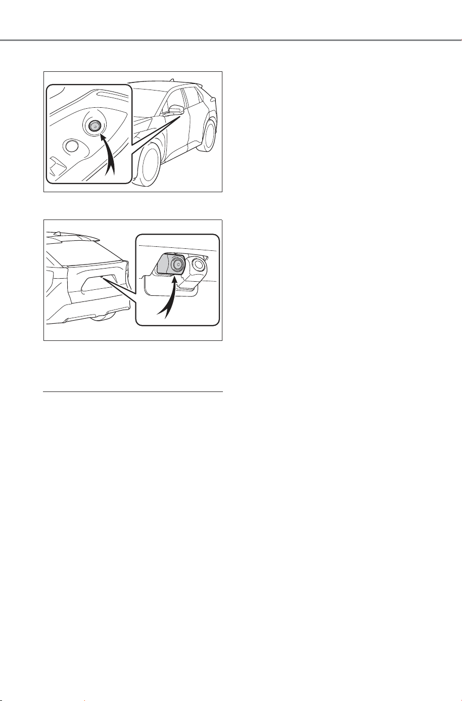
378
5-4. Using the driving support systems
Owner’s Manual_USA_M6740B_en
Side cameras
Rear camera
Sensors
P. 3 40
■ Camera images
As special cameras are used, the
colors in displayed images may dif-
fer from the actual color.
■ Precautions for use
For details on the following, refer to
the “MULTIMEDIA OWNER’S MAN-
UAL”.
● Displayable range of the screens
● Cameras
● Differences between displayed
images and the actual road
● Differences between displayed
images and the actual objects
■ Detection range of the cameras
and sensors
● If a parked vehicle is behind the
target parking space and the dis-
tance between it and the vehicle
becomes far, it may no longer be
able to be detected. Depending on
shape or condition of a parked
vehicle, the detection range may
become short or the vehicle may
not be detected.
● Objects other than parked vehi-
cles, such as columns, walls, etc.,
may not be detected. Also, if they
are detected, they may cause the
target parking space to be mis-
aligned.
■ Situations in which parking
space lines may not be recog-
nized properly
● In situations such as the following,
parking space lines on the road
surface may not be detected:
• When the parking space does not
use lines (parking space boundar-
ies are marked with rope, blocks,
etc.)
• When the parking space lines are
faded or dirty, making them
unclear
• When the road surface is bright,
such as concrete, and the contrast
between it and the white parking
space lines is small
• When the parking space lines are
any color other than yellow or
white
• When the area surrounding the
parking space is dark, such as at
night, in an underground parking
lot, parking garage, etc.
• When it is raining or has rained
and the road surface is wet and
reflective or there are puddles
• When the sun is shining directly
into a camera, such as in the early
morning or evening
• When the parking space is cov-
ered with snow or de-icing agent
SOLTERRA_OM_USA_A6740BE.book 378 ページ 2025年5月23日 金曜日 午後1時18分
379
5-4. Using the driving support systems
Owner’s Manual_USA_M6740B_en
5
Driving
• When there marks from repairs or
other marks on the road surface,
or there is a traffic bollard, or other
object on the road surface
• When the color or brightness of
the road surface is uneven
• When a camera has been
splashed by hot or cold water and
the lens has fogged up
• When the appearance of the park-
ing space is affected by the
shadow of the vehicle or trees
• When a camera lens is dirty or
covered with water droplets
● In situations such as the following,
the target parking space may not
be recognized correctly:
• When there marks from repairs or
other marks on the road surface,
or there is a parking block, traffic
bollard, or other object on the road
surface
• When it is raining or has rained
and the road surface is wet and
reflective or there are puddles
• When the area around the vehicle
is dark or backlit
• When the color or brightness of
the road surface is uneven
• When the parking space is on a
slope
• When there are diagonal lines
(access aisle) near the parking
space
• When the appearance of the park-
ing space is affected by the
shadow of a parked vehicle (such
as shadows from the grille, side
step, etc.)
• When accessories which obstruct
the view of the camera are
installed
• When the parking space lines are
faded or dirty, making them
unclear
• When the appearance of the park-
ing space is affected by the
shadow of the vehicle or trees
■ Sensor detection information
P.342
■ Objects which the sensor may
not be properly detected
P.343
■ Situations in which the sensor
may not operate properly
P.343
■ Situations in which parking
assistance may not operate
even if there is no possibility of
a collision
P.344
WARNING
■ Precautions for the cameras
and sensors
● Due to the characteristics of the
camera lens, the position of and
distance to people and objects
displayed on the screen may
differ from the actual situation.
For details, refer to “MULTIME-
DIA OWNER’S MANUAL”.
● Make sure to observe the pre-
cautions for using the SUBARU
Parking Assist, otherwise a sen-
sor may not operate correctly,
possibly leading to an accident.
(P.341)
● In situations such as the follow-
ing, the sensors may not oper-
ate correctly, possibly leading to
an accident. Proceed carefully.
• When there is a parked vehicle
next to the target parking space,
if the displayed target parking
space is far from the actual tar-
get parking space, a sensor
may be misaligned. Have the
vehicle inspected by your SUB-
ARU dealer.
• Do not install any accessories
near the detection area of the
sensors.
SOLTERRA_OM_USA_A6740BE.book 379 ページ 2025年5月23日 金曜日 午後1時18分
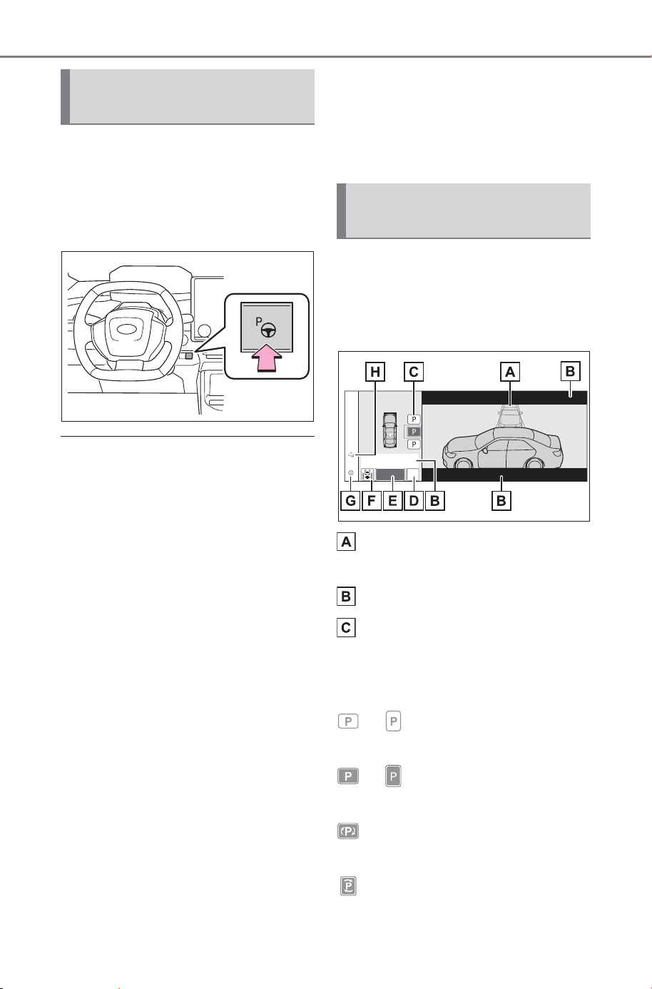
380
5-4. Using the driving support systems
Owner’s Manual_USA_M6740B_en
Press the Advanced Park main
switch.
If the switch is pressed while assis-
tance is being performed, the assis-
tance will be canceled.
■ Operating conditions of the
Advanced Park
Assistance will begin when all of the
following conditions are met:
● The brake pedal is depressed
● The vehicle is stopped
● The driver’s seat belt is fastened
● The steering wheel is not being
operated
● The accelerator pedal is not
depressed
● All of the doors and the back door
are closed
● The outside rear view mirrors are
not folded
● The parking brake is not engaged
● The dynamic radar cruise control
are not operating
● ABS, VSC, TRAC, PCS and
PKSB are not operating
● “X-MODE” is not operating
● The vehicle is not towing a trailer
or another vehicle
● The vehicle is not on a steep
slope
● The VSC and TRAC are not
turned off
If assistance cannot be started,
check the message displayed on
the multimedia display (P.400)
Guidance screens are displayed
on the multimedia display.
Guidance screen (When
assistance starts)
Target parking space box
(blue)
Advice display
Parking type change button
If multiple buttons are displayed,
depending on the condition of the
button its function differs as follows.
or : Change the target to
another parking space.
or : Select the current target
parking space.
: Select to change to the parallel
parking function
: Change the perpendicular
parking (forward/reverse) function
Turning the Advanced
Park system on/off
Advanced Park guidance
screens
SOLTERRA_OM_USA_A6740BE.book 380 ページ 2025年5月23日 金曜日 午後1時18分
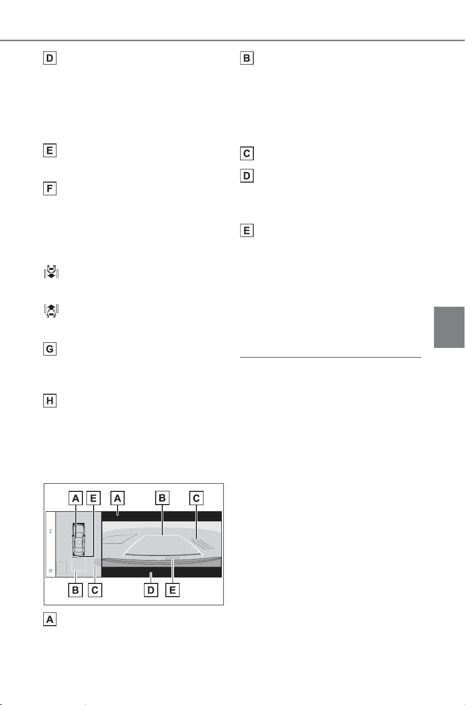
381
5-4. Using the driving support systems
Owner’s Manual_USA_M6740B_en
5
Driving
“MODE” button
Select to change between the
memory function and the perpen-
dicular parking (forward/reverse)
function and parallel parking func-
tion. (P.395)
“Start” button
Select to start parking assistance.
Perpendicular parking direc-
tion change button
Select to change between the park-
ing (forward) function and parking
(reverse) function
: Change the perpendicular
parking (forward) function
: Change the perpendicular
parking (reverse) function
Customize setting button
Select to display the Advanced
Park setting screen. (P.399)
Registration button
Select to begin registering a park-
ing space.
Guidance screen (When
reversing)
Operation icon
Displayed when the Advanced Park
is operating.
Guide lines (yellow and red)
Display points from the center of
the edge of the front or rear bumper
to the target stopping position (yel-
low)
*
and approximately 1 ft. (0.3
m) (red) from the vehicle.
Moving object warning icon
Emergency support brake
control operation display
“BRAKE!” is displayed.
SUBARU Parking Assist dis-
play
P.341
*
: The yellow lateral line is not dis-
played when the target stopping
position is approximately 8.2 ft.
(2.5 m) or more away from the
vehicle.
■ SUBARU Parking Assist pop-up
display
Regardless of whether the SUBARU
Parking Assist is off or on (P.341),
if an object is detected by the SUB-
ARU Parking Assist when the
Advanced Park is operating, the
SUBARU Parking Assist pop up dis-
play will automatically be displayed
over the guidance display.
■ Brake control operation when
Advanced Park is operating
While the Advanced Park is operat-
ing, if the system determines that
the possibility of collision with
detected moving or stationary object
is high, the EV system output
restriction control and brake control
will operate.
If brake control operates, Advanced
Park operation will be suspended
and a message will be displayed on
the multi-information display.
SOLTERRA_OM_USA_A6740BE.book 381 ページ 2025年5月23日 金曜日 午後1時18分
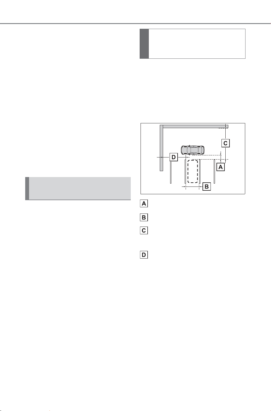
382
5-4. Using the driving support systems
Owner’s Manual_USA_M6740B_en
■ Buzzer
Depending on surrounding sounds
or sounds from other systems, it
may be difficult to hear the buzzer of
this system.
■ If a black screen is displayed on
the multimedia display when
the Advanced Park is operating
The system is being affected by
radio waves or may be malfunction-
ing. If a radio antenna is installed
near a camera, move it to a location
as far from the cameras as possible.
If a radio antenna is not installed
near a camera, and the screen does
not return to normal after turning the
power switch off and then starting
the EV system again, have the vehi-
cle inspected by your SUBARU
dealer.
The perpendicular parking (for-
ward/reverse) function can be
used if the target parking space
can be detected when the vehi-
cle is stopped close and perpen-
dicular to the center of the
parking space. Also, depending
on the condition of the parking
space, etc., if it is necessary to
change the direction of travel of
the vehicle, the shift position can
be changed by assistance con-
trol.
1 Stop the vehicle at a position
close and perpendicular to
the center of the target park-
ing space.
If there are parking space
lines
Approximately 3.3 ft. (1 m)
*
Approximately 8.2 ft. (2.5 m)
*
Approximately 19.7 ft. (6 m)
or more
*
Approximately 18.0 ft. (5.5 m)
or more
*
The system can operate even if
there is a parking space line on only
one side of the target parking
space.
*
: This is a reference measurement
for detection of a parking space.
Depending on the surrounding
environment, detection may not
be possible.
Perpendicular parking
(forward/reverse) function
Parking using the perpen-
dicular parking (for-
ward/reverse) function
SOLTERRA_OM_USA_A6740BE.book 382 ページ 2025年5月23日 金曜日 午後1時18分
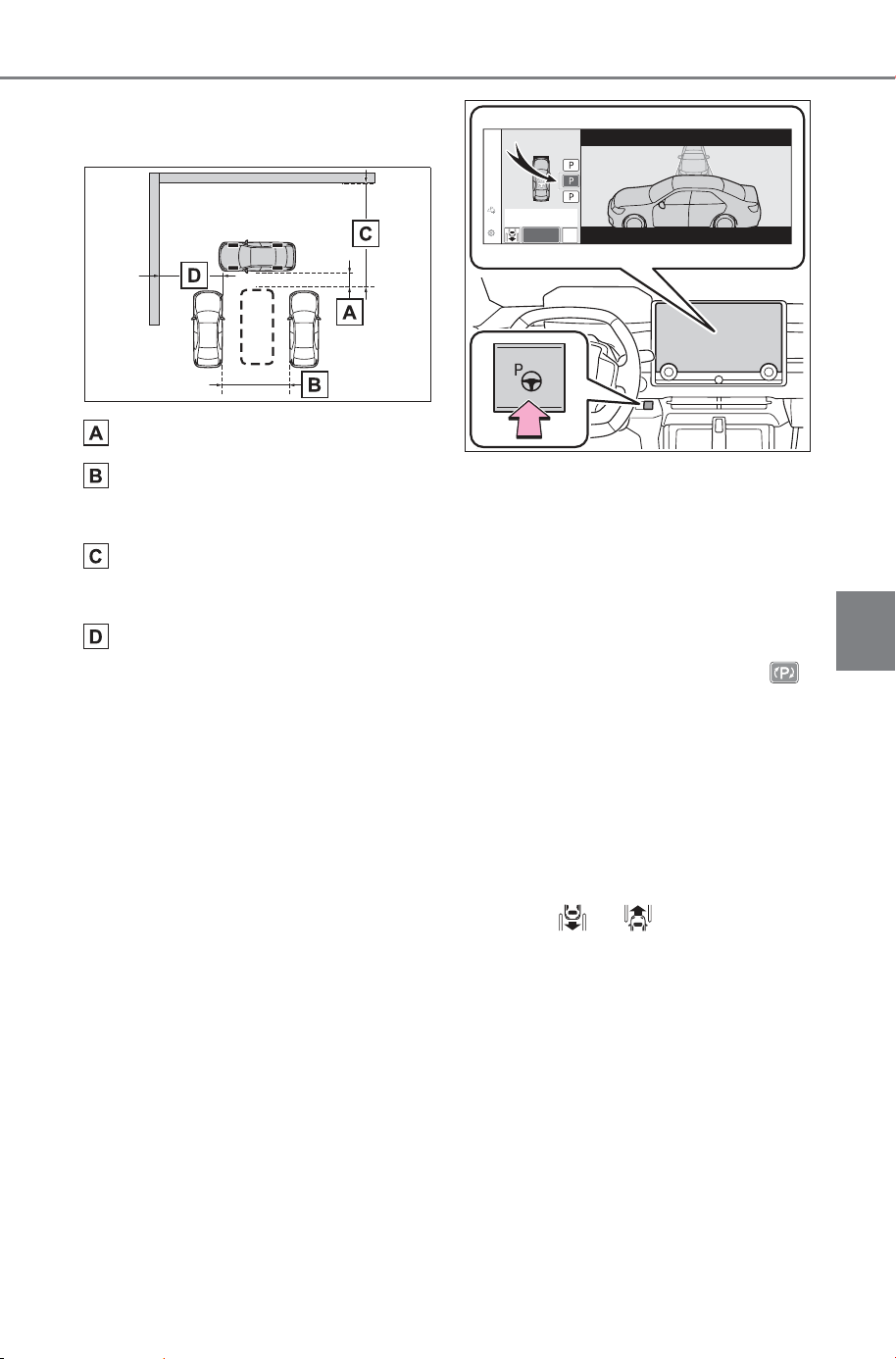
383
5-4. Using the driving support systems
Owner’s Manual_USA_M6740B_en
5
Driving
If there is an adjacent parked
vehicle
Approximately 3.3 ft. (1 m)
*
Approximately 9.8 ft. (3 m) or
more
*
Approximately 19.7 ft. (6 m)
or more
*
Approximately 18.0 ft. (5.5 m)
or more
*
The system can operate even if
there is a vehicle on only one side
of the target parking space.
*
: This is a reference measurement
for detection of a parking space.
Depending on the surrounding
environment, detection may not
be possible.
2 Press the Advanced Park
main switch and check that a
possible parking space is dis-
played on the multimedia dis-
play.
If a space which your vehicle
can be parked is detected, a
target parking space box will
be displayed.
If it is possible to parallel park
in the space, select the park-
ing space, and then select
to change to the parallel park-
ing function.
If it is possible to change the
direction which a parking
space is entered, select the
parking space, and then
select or change the
direction.
Depending on the surround-
ing environment, it may not be
possible to use this function.
According to the information
displayed on the multimedia
display, use the function on
another parking space.
SOLTERRA_OM_USA_A6740BE.book 383 ページ 2025年5月23日 金曜日 午後1時18分
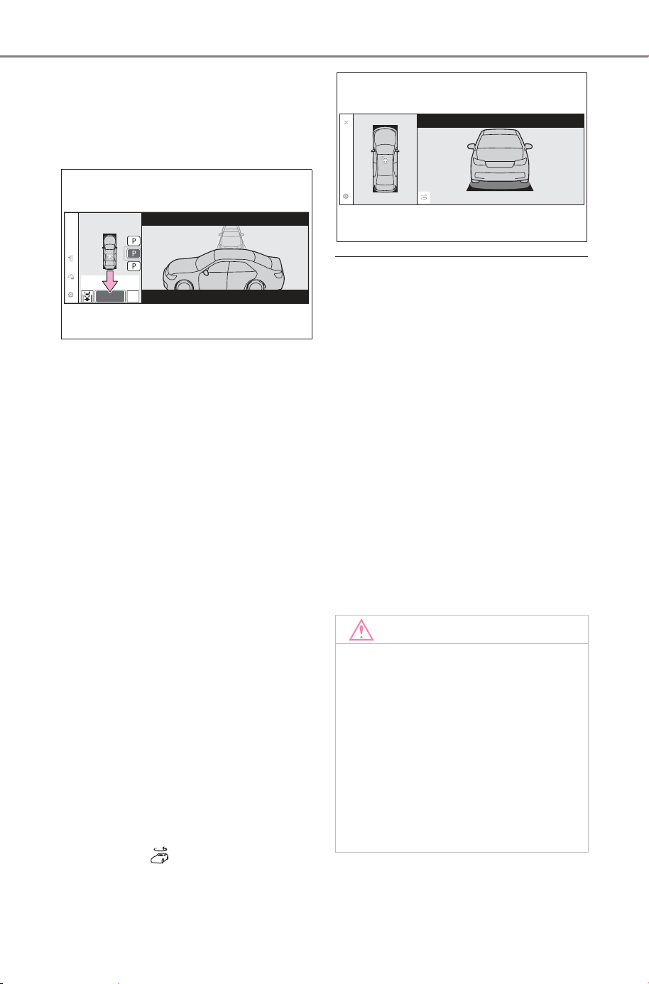
384
5-4. Using the driving support systems
Owner’s Manual_USA_M6740B_en
3 Select “Start” button.
A buzzer will sound, an operation
message will be displayed on the
multi-information display, and assis-
tance will begin operating.
When the brake pedal is
released, “Moving Forward...”,
“Backing Up...” will be dis-
played and the vehicle will
begin moving for-
ward/reverse.
To cancel assistance, press
the Advanced Park main
switch.
If assistance is canceled,
“Advanced Park Cancel” will be dis-
played.
If you feel that the vehicle is
approaching close to a surround-
ing vehicle, object, person, or gut-
ter: P. 384
4 Perform operations as indi-
cated by the advice displays
until the vehicle stops in the
target parking space.
When the vehicle stops, “Advanced
Park Finished” will be displayed
and parking assistance will end.
If you select on the multimedia
display, the vehicle displayed on
the parking assist completion
screen will rotate.
■ If you feel that the vehicle is
approaching close to a sur-
rounding vehicle, object, per-
son, or gutter
Depress the brake pedal to stop the
vehicle and then change the shift
position to change the direction of
travel of the vehicle. At this time,
assist will be suspended. However,
if the “Start” button is selected,
assist will resume and the vehicle
will move in the direction corre-
sponding to the selected shift posi-
tion.
■ When the brakes have been
operated
When the brakes have been oper-
ated, brake operation sound may be
heard. This does not indicate a mal-
function.
NOTICE
■ When using the perpendicu-
lar parking (forward/reverse)
function
● Make sure that there are no
obstructions within the yellow
guide lines and between the
vehicle and target parking spot.
If there are any obstructions
between the vehicle and the tar-
get parking space, or between
the yellow guide lines, cancel
the function.
SOLTERRA_OM_USA_A6740BE.book 384 ページ 2025年5月23日 金曜日 午後1時18分
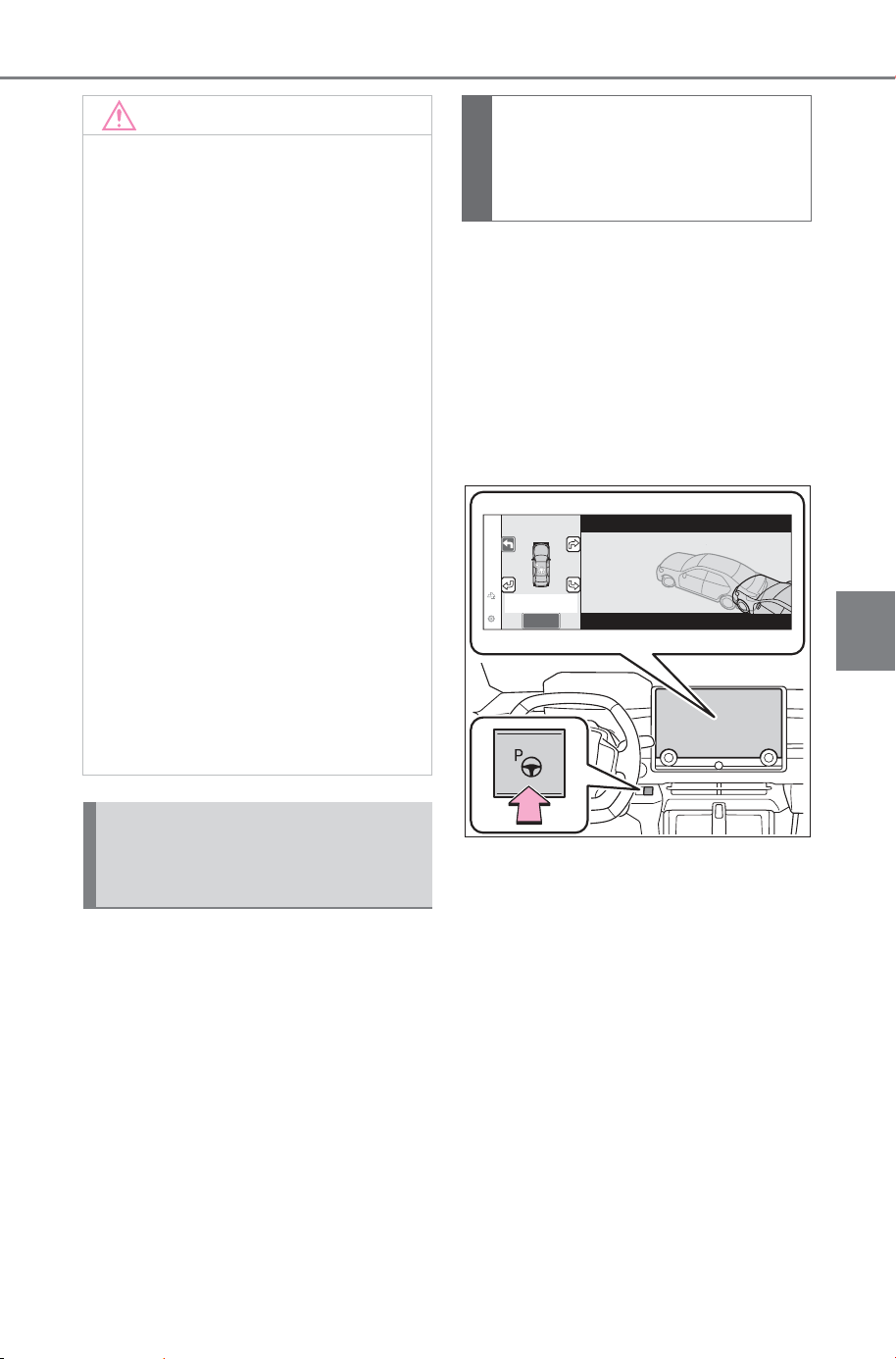
385
5-4. Using the driving support systems
Owner’s Manual_USA_M6740B_en
5
Driving
When exiting from a perpendic-
ular parking space, if the system
determines that exit is possible
the perpendicular exiting (for-
ward/reverse) function can be
used. Also, depending on the
surrounding environment, if it is
necessary to change the direc-
tion of travel of the vehicle, the
shift position can be changed by
assistance control.
1 With the brake pedal
depressed and P shift posi-
tion selected, press the
Advanced Park main switch
and check that the exit direc-
tion selection screen is dis-
played on the multimedia
display.
2 Select an arrow on the multi-
media display to select the
direction you wish to exit.
If the turn signal lever is operated,
only exit to the left or right can be
selected.
3 Depress the brake pedal and
select “Start” button.
A buzzer will sound, an operation
message will be displayed on the
multi-information display, and assis-
tance will begin operating.
NOTICE
● As the target parking space will
not be able to be set correctly if
the surface of the parking space
is on a slope or has differences
in height, the vehicle may stray
from the target parking space or
be slanted. Therefore, do not
use the function for this kind of
parking spot.
● When parking in a narrow park-
ing space, the vehicle may
closely approach an adjacent
parked vehicle. If a collision
seems likely, depress the brake
pedal to stop the vehicle.
● If a detected parked vehicle is
narrow or parked extremely
close to the curb, the position at
which assistance will park the
vehicle will also be close to the
curb. If it seems likely the vehi-
cle will collide with something or
drive off of the road, depress
the brake pedal to stop the vehi-
cle, and then press the Advance
Park main switch to disable the
system.
Advanced Park perpen-
dicular exiting (for-
ward/reverse) function
Leaving a parking space
using the perpendicular
exiting (forward/reverse)
function
SOLTERRA_OM_USA_A6740BE.book 385 ページ 2025年5月23日 金曜日 午後1時18分
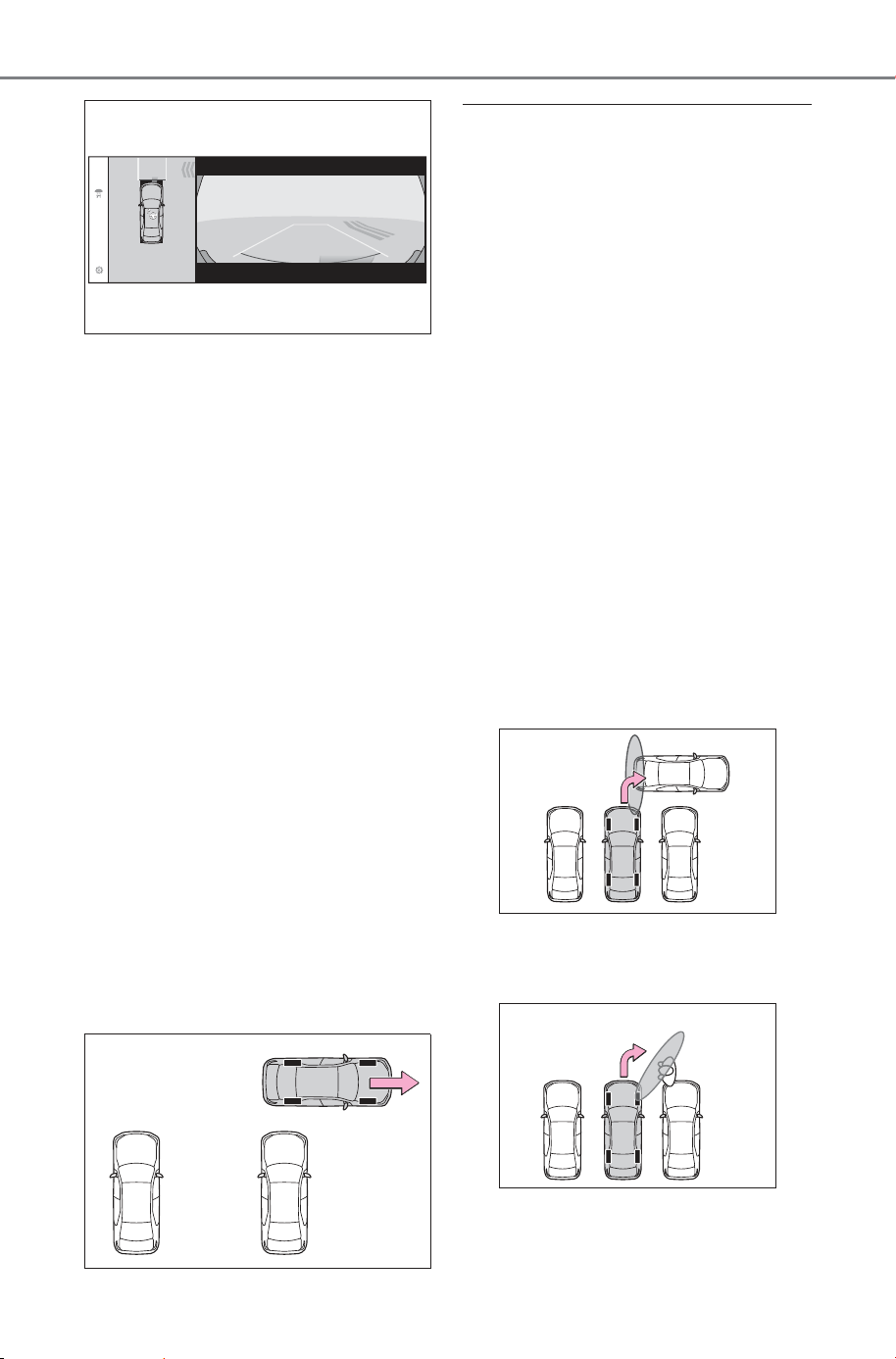
386
5-4. Using the driving support systems
Owner’s Manual_USA_M6740B_en
To cancel assistance, press the
Advanced Park main switch.
If assistance is canceled,
“Advanced Park Cancel” will be dis-
played.
If you feel that the vehicle is
approaching close to a surround-
ing vehicle, object, person, or gut-
ter: P. 386
4 Perform operations as indi-
cated by the advice displays
until the vehicle is in a posi-
tion where exit is possible.
When the vehicle reaches a posi-
tion where exit is possible, “You can
exit by moving the steering wheel”
will be displayed. If the steering
wheel is operated, “Advanced Park
Finished” will be displayed and
assistance will end.
As assistance will end while the
vehicle is moving, grip the steering
wheel and drive forward.
If the steering wheel is not oper-
ated, the vehicle will stop at the exit
position. Assistance can be ended
by depressing the accelerator pedal
or brake pedal.
■ If you feel that the vehicle is
approaching close to a sur-
rounding vehicle, object, per-
son, or gutter
P.384
■ Perpendicular exiting (for-
ward/reverse) function
Do not use perpendicular exiting
(forward/reverse) function in any sit-
uation other than when exiting a
perpendicular parking spot. If assis-
tance is started unintentionally,
depress the brake pedal and stop
the vehicle, then press the
Advanced Park main switch to can-
cel assistance.
■ Situations in which the perpen-
dicular exiting (forward/reverse)
function will not operate
In situations such as the following,
the perpendicular exiting (for-
ward/reverse) function will not oper-
ate:
● When a vehicle which is waiting to
park is in the exit direction
● When a wall, column, or person is
detected as near a front or rear
center or corner sensor
■ When the brakes have been
operated
P.384
SOLTERRA_OM_USA_A6740BE.book 386 ページ 2025年5月23日 金曜日 午後1時18分
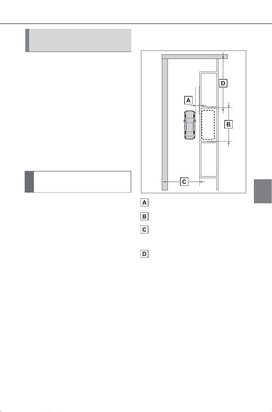
387
5-4. Using the driving support systems
Owner’s Manual_USA_M6740B_en
5
Driving
The parallel parking function can
be used if the target parking
space can be detected when the
vehicle is stopped close and
aligned with the center of the
parking space. Also, depending
on the condition of the parking
space, etc., if it is necessary to
change the direction of travel of
the vehicle, the shift position can
be changed by assistance con-
trol.
1 Stop the vehicle with it
aligned near the center of the
target parking space.
If there are parking space
lines
Approximately 3.3 ft. (1 m)
*
Approximately 19.7 ft. (6 m)
*
Approximately 14.8 ft. (4.5 m)
or more
*
Approximately 26.2 ft. (8 m)
or more
*
*
: This is a reference measurement
for detection of a parking space.
Depending on the surrounding
environment, detection may not
be possible.
Advanced Park Parallel
parking function
Parking using the parallel
parking function
SOLTERRA_OM_USA_A6740BE.book 387 ページ 2025年5月23日 金曜日 午後1時18分
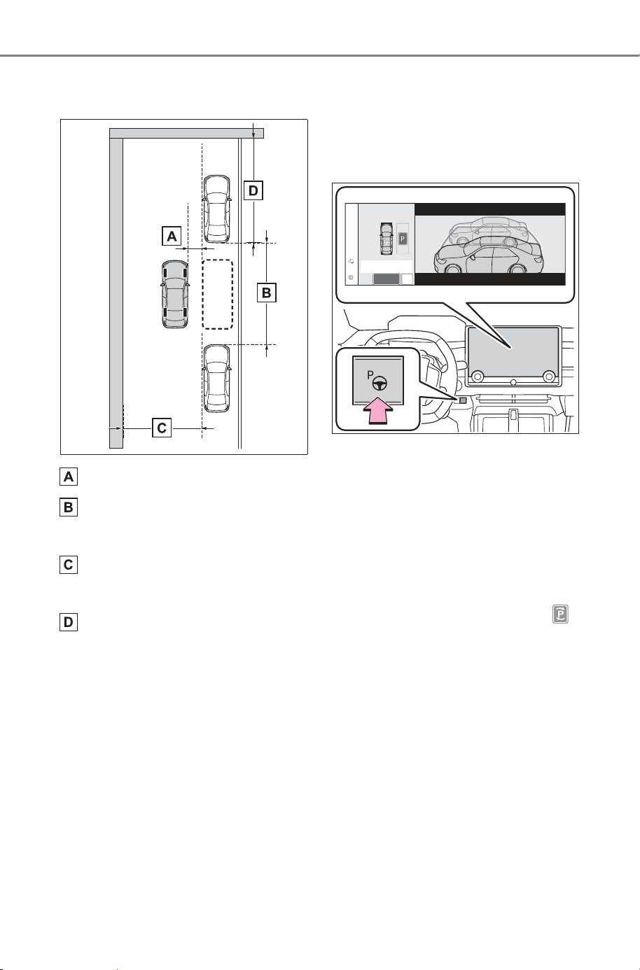
388
5-4. Using the driving support systems
Owner’s Manual_USA_M6740B_en
If there is an adjacent parked
vehicle
Approximately 3.3 ft. (1 m)
*
Approximately 23.0 ft. (7 m)
or more
*
Approximately 14.8 ft. (4.5 m)
or more
*
Approximately 26.2 ft. (8 m)
or more
*
*
: This is a reference measurement
for detection of a parking space.
Depending on the surrounding
environment, detection may not
be possible.
2 Press the Advanced Park
main switch and check that a
possible parking space is dis-
played on the multimedia dis-
play.
If a space which your vehicle
can be parked is detected, a
target parking space box will
be displayed.
If it is possible to perpendicu-
lar parking (forward/reverse)
in the space, select the park-
ing space, and then select
to change to the perpendicu-
lar parking (forward/reverse)
function.
Depending on the surround-
ing environment, it may not be
possible to use this function.
According to the information
displayed on the multimedia
display, use the function on
another parking space.
SOLTERRA_OM_USA_A6740BE.book 388 ページ 2025年5月23日 金曜日 午後1時18分
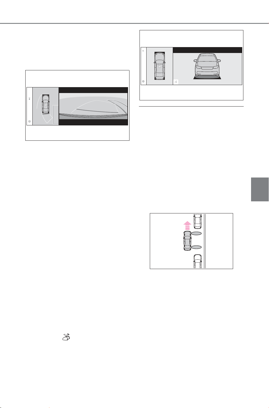
389
5-4. Using the driving support systems
Owner’s Manual_USA_M6740B_en
5
Driving
3 Select “Start” button.
A buzzer will sound, an operation
message will be displayed on the
multi-information display, and assis-
tance will begin operating.
When the brake pedal is
released, “Moving Forward...”
will be displayed and the vehi-
cle will begin moving forward.
To cancel assistance, press
the Advanced Park main
switch.
If assistance is canceled,
“Advanced Park Cancel” will be dis-
played.
If you feel that the vehicle is
approaching close to a surround-
ing vehicle, object, person, or gut-
ter: P. 389
4 Perform operations as indi-
cated by the advice displays
until the vehicle stops in the
target parking space.
When the vehicle stops, “Advanced
Park Finished” will be displayed
and parking assistance will end.
If you select on the multimedia
display, the vehicle displayed on
the parking assist completion
screen will rotate.
■ If you feel that the vehicle is
approaching close to a sur-
rounding vehicle, object, per-
son, or gutter
P.384
■ If “No available parking space”
is displayed
Even if the vehicle is stopped paral-
lel to a parking space, an adjacent
parked vehicle may not be detected.
In this case, if the vehicle is moved
to a position that a parked vehicle
can be detected, assistance can be
started.
■ When the brakes have been
operated
P.384
SOLTERRA_OM_USA_A6740BE.book 389 ページ 2025年5月23日 金曜日 午後1時18分
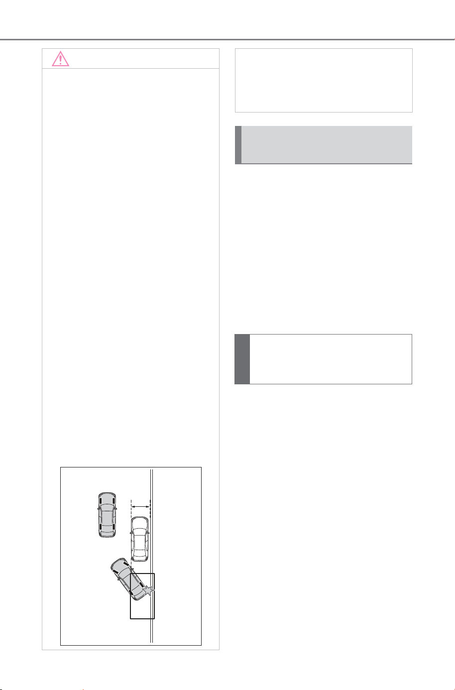
390
5-4. Using the driving support systems
Owner’s Manual_USA_M6740B_en
When exiting from a parallel
parking space, if the system
determines that exit is possible
the parallel exiting function can
be used. Also, depending on the
surrounding environment, if it is
necessary to change the direc-
tion of travel of the vehicle, the
shift position can be changed by
assistance control.
1 With the brake pedal
depressed and P shift posi-
tion selected, press the
Advanced Park main switch
and check that the exit direc-
tion selection screen is dis-
played on the multimedia
display.
NOTICE
■ When using the parallel park-
ing function
● Make sure that there are no
obstructions within the yellow
guide lines and between the
vehicle and target parking spot.
If any obstructions are detected
within the yellow guide lines or
between the vehicle and the tar-
get parking space, the parallel
parking function will be can-
celled or suspended.
● As the target parking space will
not be able to be set correctly if
the surface of the parking space
is on a slope or has differences
in height, the vehicle may stray
from the target parking space or
be slanted. Therefore, do not
use the parallel parking func-
tion for this kind of parking spot.
● If an adjacent parked vehicle is
narrow or parked extremely
close to the curb, the position at
which assistance will park the
vehicle will also be close to the
curb. If it seems likely the vehi-
cle will collide with the curb or
drive off of the road, depress
the brake pedal to stop the vehi-
cle, and then press the
Advanced Park main switch to
disable the system.
● If there is a wall or other barrier
on the inner side of the parking
space, the vehicle may stop at a
position slightly outside of the
set target parking space.
Advanced Park Parallel
exiting function
Leaving a parking space
using the parallel exiting
function
SOLTERRA_OM_USA_A6740BE.book 390 ページ 2025年5月23日 金曜日 午後1時18分
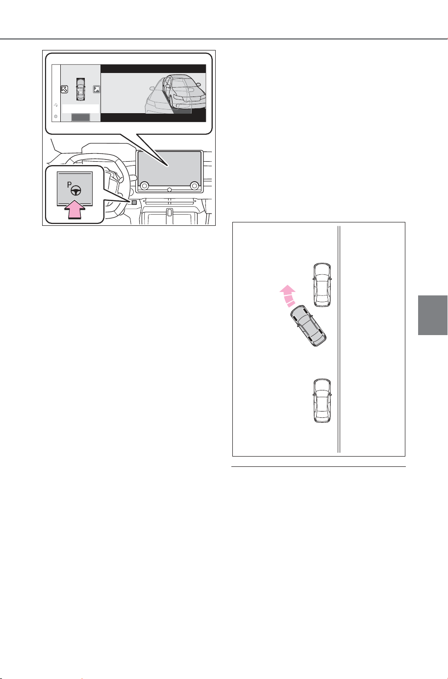
391
5-4. Using the driving support systems
Owner’s Manual_USA_M6740B_en
5
Driving
2 Select an arrow on the multi-
media display to select the
direction you wish to exit.
If the turn signal lever is operated,
only exit to the left or right can be
selected.
3 Depress the brake pedal and
select “Start” button.
A buzzer will sound, an operation
message will be displayed on the
multi-information display, and assis-
tance will begin operating.
To cancel assistance, press the
Advanced Park main switch.
If assistance is canceled,
“Advanced Park Cancel” will be dis-
played.
If you feel that the vehicle is
approaching close to a surround-
ing vehicle, object, person, or gut-
ter: P. 391
4 Perform operations as indi-
cated by the advice displays
until the vehicle is in a posi-
tion where exit is possible.
When the vehicle reaches a posi-
tion where exit is possible, “You can
exit by moving the steering wheel”
will be displayed. If the steering
wheel is operated, “Advanced Park
Finished” will be displayed and
assistance will end.
As assistance will end while the
vehicle is moving, grip the steering
wheel and drive forward.
If the steering wheel is not oper-
ated, the vehicle will stop at the exit
position. Assistance can be ended
by depressing the accelerator pedal
or brake pedal.
■ If you feel that the vehicle is
approaching close to a sur-
rounding vehicle, object, per-
son, or gutter
P.384
■ Parallel exiting function
Do not use parallel exiting function
in any situation other than when
exiting a parallel parking spot. If
assistance is started unintention-
ally, depress the brake pedal and
stop the vehicle, then press the
Advanced Park main switch to can-
cel assistance.
SOLTERRA_OM_USA_A6740BE.book 391 ページ 2025年5月23日 金曜日 午後1時18分
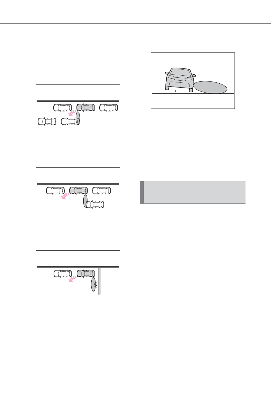
392
5-4. Using the driving support systems
Owner’s Manual_USA_M6740B_en
■ Situations in which the parallel
exiting function will not operate
In situations such as the following,
the parallel exiting function will not
operate:
● When vehicles waiting at a traffic
signal in the exit direction
● When a vehicle is stopped in the
area behind where the vehicle will
exit
● When a wall, column, or person is
detected as near a front or rear
side sensor
● When the vehicle has been
parked on a curb and a side sen-
sor detects the road surface
● When a vehicle is not parked in
front of the vehicle
● When there is excessive space
between the front of the vehicle
and a parked vehicle
■ When the brakes have been
operated
P.384
The memory function can be
used to park in a previously reg-
istered parking space, even if
there are no parking space lines
or adjacent parked vehicles.
Up to 3 parking spaces can be
registered.
Advanced Park memory
function
SOLTERRA_OM_USA_A6740BE.book 392 ページ 2025年5月23日 金曜日 午後1時18分
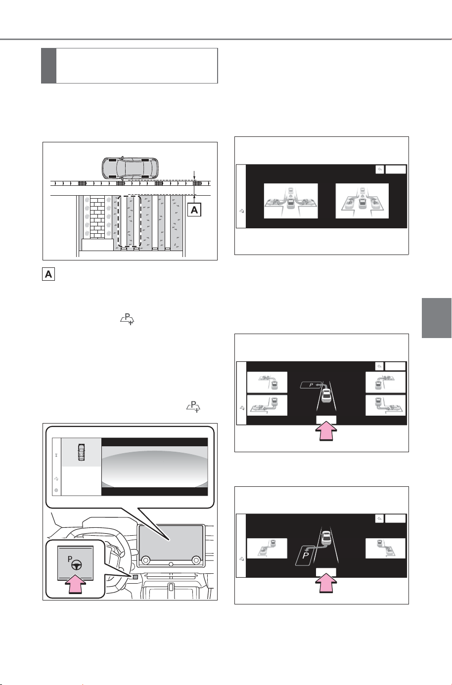
393
5-4. Using the driving support systems
Owner’s Manual_USA_M6740B_en
5
Driving
1 Stop the vehicle with it
aligned near the center of the
target parking space.
Approximately 3.3 ft. (1 m)
2 Press the main switch and
then select
If the Advanced Park main switch is
pressed at a parking space without
parking lines or any adjacent
parked vehicles, “No available
parking space” may be displayed.
Continuously select and hold .
3 Select perpendicular parking
(forward/reverse) function or
parallel parking function.
Only parking spaces for which
assist can be performed are dis-
played.
4 Select the parking direction,
and then select “OK” button.
When perpendicular parking (for-
ward/reverse) was selected in step
3:
When parallel parking was selected
in step
3:
Registering a parking
space
SOLTERRA_OM_USA_A6740BE.book 393 ページ 2025年5月23日 金曜日 午後1時18分
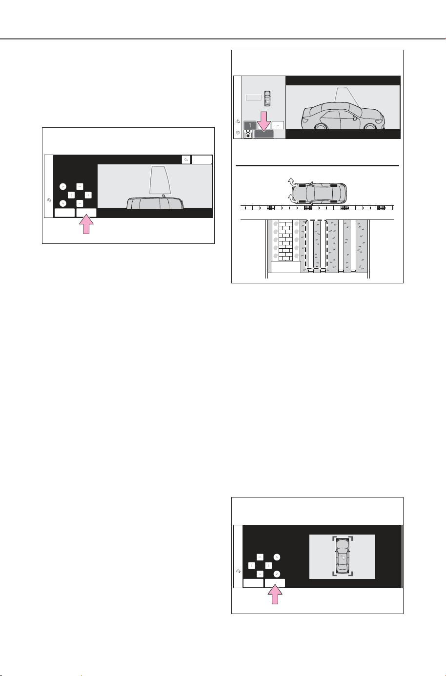
394
5-4. Using the driving support systems
Owner’s Manual_USA_M6740B_en
5 Using the arrow buttons,
adjust the position of the
parking space to be regis-
tered, and then select “OK”
button.
6 Select “Start” button.
A buzzer will sound, an operation
message will be displayed on the
multi-information display, and assis-
tance will begin operating.
When the brake pedal is released,
“Moving Forward...” will be dis-
played and the vehicle will begin
moving forward.
If you feel that the vehicle is
approaching close to a surround-
ing vehicle, object, person, or gut-
ter: P. 395
7 Perform operations as indi-
cated by the advice displays
until the vehicle stops in the
target parking space.
8 Check the position that the
vehicle has stopped. If nec-
essary, adjust the position of
the parking spot to be regis-
tered using the arrow but-
tons, and then select “Reg.”
button.
“Registration Completed” will be
displayed on the multimedia dis-
play.
SOLTERRA_OM_USA_A6740BE.book 394 ページ 2025年5月23日 金曜日 午後1時18分
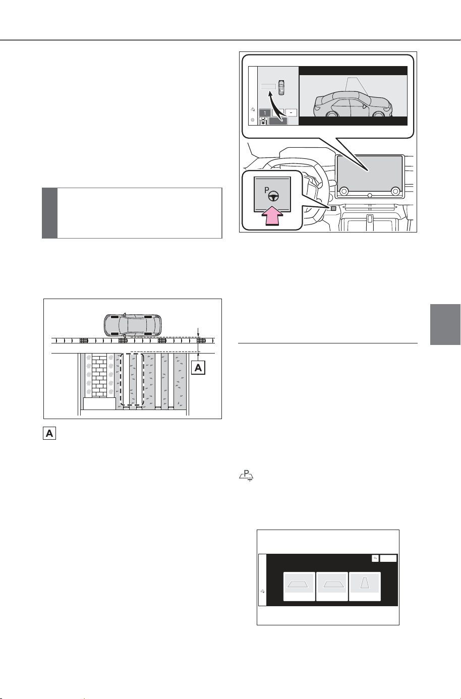
395
5-4. Using the driving support systems
Owner’s Manual_USA_M6740B_en
5
Driving
Register the parking space
only if there are no obstruc-
tions within the area shown by
the thick lines.
The amount that the position
of the parking spot to be reg-
istered can be adjusted is lim-
ited.
1 Stop the vehicle with it
aligned near the center of the
target parking space.
Approximately 3.3 ft. (1 m)
2 Press the Advanced Park
main switch and check that a
possible parking space is dis-
played on the multimedia dis-
play.
If the “MODE” button is displayed,
the button can be touched to
change between the memory func-
tion, perpendicular parking (for-
ward/reverse) function and parallel
parking function.
3 Select the desired parking
space, and then select “Start”
button.
Perform the procedure for the per-
pendicular parking (for-
ward/reverse) function from step
3.
(P.382)
■ If you feel that the vehicle is
approaching close to a sur-
rounding vehicle, object, per-
son, or gutter
P.384
■ When overwriting a registered
parking space
If the maximum number of parking
spaces have been registered and
is selected, a registered parking
space can be selected and then
overwritten with a new parking
space.
When parking in a parking
space registered to the
memory function
SOLTERRA_OM_USA_A6740BE.book 395 ページ 2025年5月23日 金曜日 午後1時18分
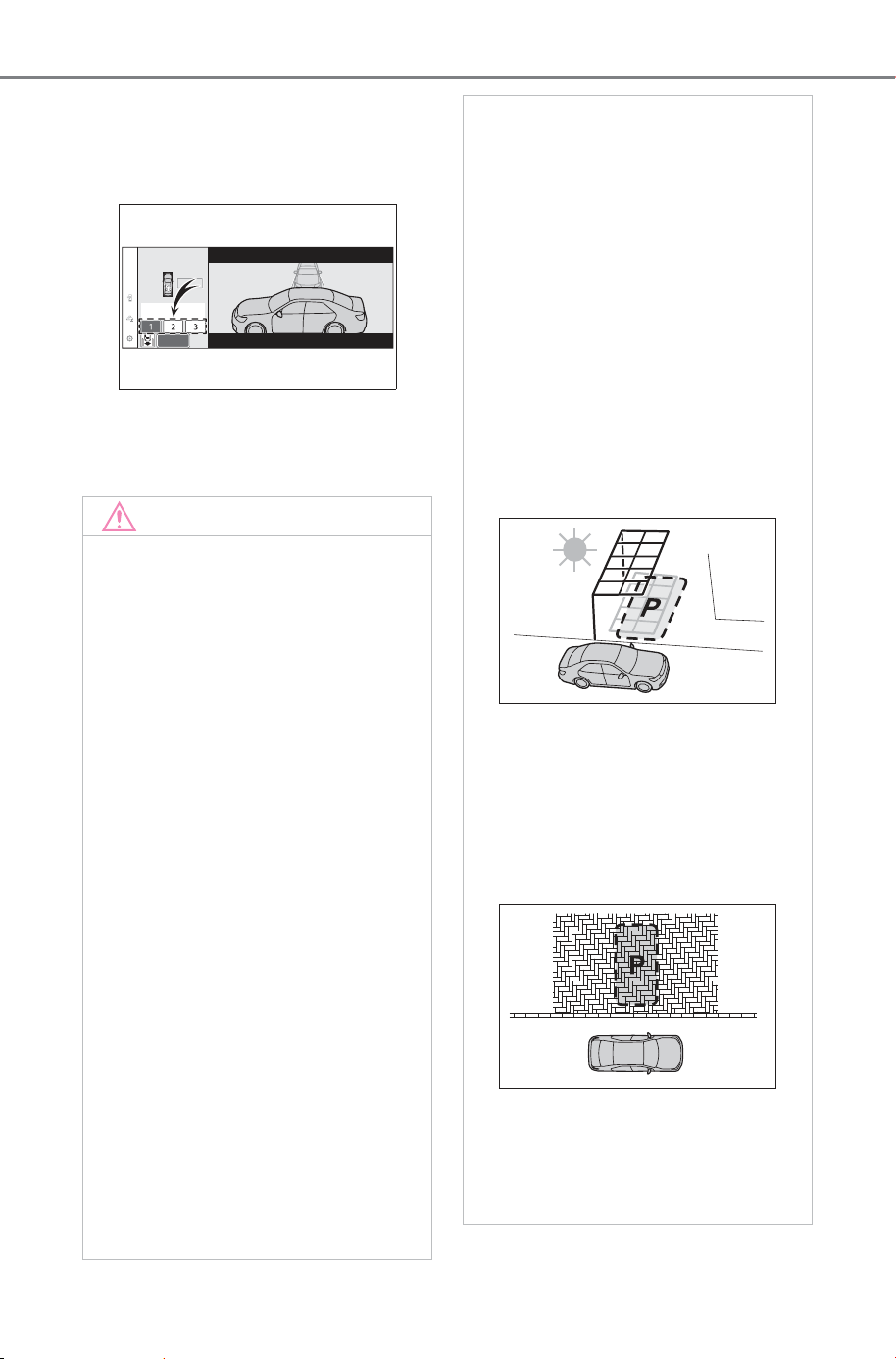
396
5-4. Using the driving support systems
Owner’s Manual_USA_M6740B_en
■ When multiple parking spaces
are registered
Select the desired parking space,
and then select “Start” button.
■ When the brakes have been
operated
P.384
NOTICE
■ When using the memory
function (P.384, 390)
● The memory function is a func-
tion which provides assistance
in parking in a previously regis-
tered parking space. If the con-
dition of the road surface,
vehicle, or surrounding area dif-
fers from when registration was
performed, the parking space
may not be able to be detected
correctly or assistance may not
be provided to the point that the
vehicle is fully parked.
● Do not register a parking space
in situations such as the follow-
ing, as the set parking space
may not be able to be registered
or assistance may not be possi-
ble later.
• When a camera lens is dirty or
covered with water droplets
• When it is raining or snowing
• When the surrounding area is
dark (at night, etc.)
● In situations such as the follow-
ing, it may not be possible to
register a parking space.
• When there is insufficient space
between the road and parking
space
• When the road surface around
the parking space does not
have any differences the sys-
tem can recognize
● If a parking space has been reg-
istered in situations such as the
following, assistance may not
be able to be started later or
assistance to the registered
position may not be possible.
• When shadows are cast on the
parking space (there is a carport
over the parking space, etc.)
• When there are leaves, gar-
bage, or other objects which will
likely move, in the parking
space
• When the road surface around
the parking space has the same
repeating pattern (brick, etc.)
● In situations such as the follow-
ing, it may not be possible for
the system to provide assis-
tance to a registered parking
spot:
SOLTERRA_OM_USA_A6740BE.book 396 ページ 2025年5月23日 金曜日 午後1時18分

397
5-4. Using the driving support systems
Owner’s Manual_USA_M6740B_en
5
Driving
NOTICE
• When the appearance of the
parking space is affected by the
shadow of the vehicle or trees
• When an object is detected in
the registered parking space
• When a pedestrian or passing
vehicle is detected during assis-
tance
• When the position the vehicle is
stopped when assistance is
started differs from the position
when registration was per-
formed
• When the registered parking
space cannot be reached due to
the existence of parking blocks,
etc.
• When the road surface around
the parking space has changed
(road surface has degraded or
been resurfaced)
• When the sunlight conditions
differ from when registration
was performed (due to weather
or time of day)
• When the sun is shining directly
into a camera, such as in the
early morning or evening
• When the color or brightness of
the road surface is uneven
• When a light is temporarily
shined on the parking space
(lights of another vehicle, secu-
rity light, etc.)
• When the road surface around
the parking space has the same
repeating pattern
• When there is a low protrusion
on the road surface near the
parking space
• When the parking space is on a
slope
• When a camera has been
splashed by hot or cold water
and the lens has fogged up
• When a camera lens is dirty or
covered with water droplets
• When accessories which
obstruct the view of the camera
are installed
If assistance is ended during reg-
istration, perform registration
again.
● When registering a parking
space to the memory function, if
the road surface cannot be
detected “No available parking
space to register” will be dis-
played.
● When using the memory func-
tion, make sure to stop immedi-
ately in front of the stop
position. Otherwise the parking
space may not be able to be
detected correctly or assis-
tance may not be provided to
the point that the vehicle is fully
parked.
● Do not use the memory function
if a camera has been subjected
to a strong impact or images of
the panoramic view monitor are
misaligned.
● If a camera has been replaced,
as the installation angle of the
camera will have changed, it will
be necessary to reregister park-
ing spaces of the memory func-
tion.
SOLTERRA_OM_USA_A6740BE.book 397 ページ 2025年5月23日 金曜日 午後1時18分

398
5-4. Using the driving support systems
Owner’s Manual_USA_M6740B_en
■ Assistance will be can-
celed when
In situations such as the follow-
ing, Advanced Park operation
will be canceled. Firmly hold the
steering wheel and depress the
brake pedal to stop the vehicle.
As system operation has been can-
celed, begin the operation again or
continue parking manually, using
the steering wheel.
The Advanced Park main
switch is pushed
The shift position has been
changed to P
The parking brake is engaged
A door or the back door is
opened
The driver’s seat belt is unfas-
tened
The outside rear view mirrors
are folded
The TRAC or VSC is turned
off
The TRAC, VSC or ABS oper-
ates
“X-MODE” switch is pushed
The vehicle is towing a trailer
or another vehicle
The power switch is pressed
The system determines assis-
tance cannot be continued in
the current parking environ-
ment
The system malfunctions
While the vehicle was
stopped, “Cancel” was
selected on the multimedia
display
■ Assistance will be sus-
pended when
In situations such as the follow-
ing, Advanced Park operation
will be suspended.
Assistance can be started again by
following the directions displayed
on the multimedia display.
Also, when assistance is sus-
pended, if the shift position is
changed twice with the brake pedal
depressed, assistance will be can-
celed in that shift position.
However, if assistance is sus-
pended by changing the shift posi-
tion, assistance will be canceled if
the shift position is changed once.
The steering wheel is oper-
ated
The accelerator pedal is
depressed
The shift position has been
changed
A moving object or stationary
object that may collide with
your vehicle has been
detected, resulting in the
operation of the EV system
output control/braking control.
Camera switch is pressed
Advanced Park cancel-
ation/suspension
SOLTERRA_OM_USA_A6740BE.book 398 ページ 2025年5月23日 金曜日 午後1時18分
399
5-4. Using the driving support systems
Owner’s Manual_USA_M6740B_en
5
Driving
Select on the multimedia dis-
play, and then select “Advanced
Park”.
■ Speed profile
The vehicle speed for when
assistance is performed can be
set.
This setting cannot be changed
when registering a parking space to
the memory function.
■ Obstacle detection range
The distance from which obsta-
cles will be avoided while assis-
tance is being performed can be
set.
■ Preferred parking method
The preferred parking direction
displayed when at a parking
space which perpendicular (for-
ward/reverse) or parallel parking
is possible can be set.
■ Preferred parking direction
The preferred parking direction
displayed when it is possible to
pull perpendicular forward or
reverse into a parking space can
be selected.
■ Preferred exit direction
(perpendicular)
The preferred exit direction dis-
played when it is possible to pull
forward or reverse to the left or
right out of a parking space can
be selected.
■ Preferred exit direction
(parallel)
The preferred exit direction dis-
played when it is possible to exit
to the left or right from a parallel
parking space can be selected.
■ Camera view when parking
The display angle of the camera
image when using the perpen-
dicular parking (for-
ward/reverse) function or
parallel parking function can be
set.
■ Camera view when exiting
The display angle of the camera
image when using the perpen-
dicular exiting (forward/reverse)
function or parallel parking exit
function can be set.
■ Parking path adjustment
The course for when parking
assistance is operating can be
adjusted inward or outward.
If the tires are worn, the path of
vehicle may be offset from the cen-
ter of the parking space. In this
case, use this setting to adjust the
parking course.
■ Road width adjustment
When parking assistance is
started, the amount of lateral
movement while the vehicle is
moving forward can be
adjusted.
Changing the Advanced
Park settings
SOLTERRA_OM_USA_A6740BE.book 399 ページ 2025年5月23日 金曜日 午後1時18分
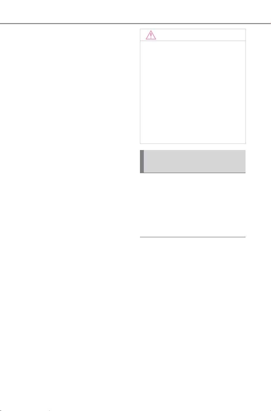
400
5-4. Using the driving support systems
Owner’s Manual_USA_M6740B_en
■ Park position adjustment
(forward)
The position at which perpendic-
ular parking (forward) is com-
pleted can be adjusted. (Except
when using the memory func-
tion.)
■ Park position adjustment
(reverse)
The position at which perpendic-
ular parking (reverse) is com-
pleted can be adjusted. (Except
when using the memory func-
tion.)
■ Rear accessory setting
If an accessory, such as a trailer
hitch, has been installed to the
rear of the vehicle, the length of
the rear of the vehicle can be
adjusted to help avoid colliding
with objects to the rear of the
vehicle.
■ Clear registered parking
space
The parking spaces registered
to the memory function can be
deleted. Parking space informa-
tion cannot be deleted when
assistance is being performed
or when registering parking
space information to the mem-
ory function.
The operating state, assistance
operation, etc. of the Advanced
Park is displayed on the multi-
media display. If a message is
displayed, respond according to
the content displayed.
■ If “No available parking space”
is displayed
Move the vehicle to a location where
a parking space or parking lines can
be detected.
■ If “Unavailable in current condi-
tion” is displayed
Move the vehicle to another location
and use the system.
■ If “Not enough space to exit” is
displayed
The parallel parking exit function
cannot be used due to a situation
such as the distance between your
vehicle and vehicles parked in front
of and behind your vehicle being
short, the existence of an object in
the exit direction, etc.
NOTICE
● Take care when using the park
position adjustment (forward) or
park position adjustment
(reverse) for adjusting because
the vehicle may collide with
parking blocks, curb stones, or
other low objects.
● If it is likely that your vehicle will
collide with a nearby vehi-
cle/object, parking block, curb
stone, etc., depress the brake
pedal to stop the vehicle and
press the Advanced Park main
switch to disable the system.
Advanced Park displayed
messages
SOLTERRA_OM_USA_A6740BE.book 400 ページ 2025年5月23日 金曜日 午後1時18分
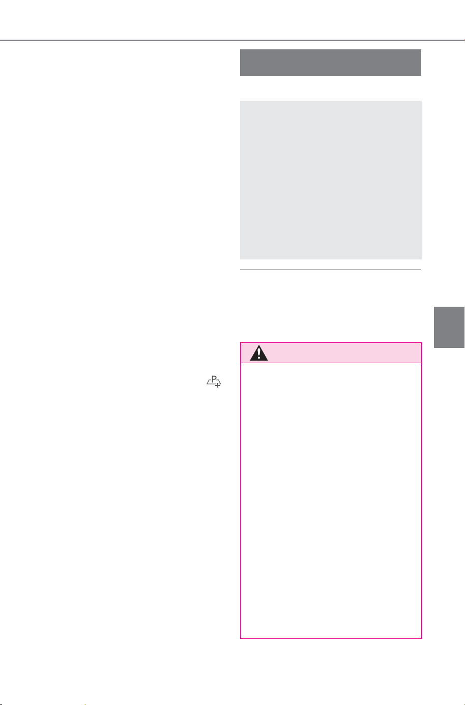
401
5-4. Using the driving support systems
Owner’s Manual_USA_M6740B_en
5
Driving
Check the conditions of the area
around your vehicle and exit from
the parking space manually.
■ If “Cannot control speed” is
displayed
The system judged that it cannot
adjust the speed of the vehicle when
using the system in an area with a
slope or step and assistance was
canceled.
Use the system in a level location.
■ If “Obstacle detected” is dis-
played
As a moving object or stationary
object that may collide with your
vehicle has been detected, the EV
system output control/braking con-
trol operates to suspend Advanced
Park assistance.
Check the condition of the surround-
ing area. To resume assistance,
select the “Start” button on the multi-
media display.
■ If “No available parking space
to register” is displayed
This message is displayed when
is selected at a parking space that
cannot be detected.
Operate the system at a parking
space where differences in the road
surface can be recognized.
(P.392)
*
: If equipped
● The screen illustrations used in
this text are intended as exam-
ples, and may differ from the
image that is actually displayed on
the screen.
Multi-terrain Monitor
*
The Multi-terrain Monitor
helps the driver to check
the vehicle surroundings. It
assists in determining the
conditions around the
driver in a variety of situa-
tions, such as when judging
conditions during off-road
driving or checking for
obstacles when parking.
WARNING
■ When using the Multi-terrain
Monitor system
Observe the following precautions
to avoid an accident that could
result in death or serious injuries.
● Never rely solely on the Multi-
terrain Monitor. As with
unequipped vehicles, drive
carefully while directly confirm-
ing the safety of your surround-
ings and the area to the rear of
the vehicle. Take particular care
to avoid parked cars and other
obstacles.
● Due to the characteristics of the
camera lens, the actual position
and distance of people and
other obstacles will differ from
those shown on the Multi-terrain
Monitor screen. Directly con-
firm the safety of your surround-
ings before driving.
SOLTERRA_OM_USA_A6740BE.book 401 ページ 2025年5月23日 金曜日 午後1時18分
402
5-4. Using the driving support systems
Owner’s Manual_USA_M6740B_en
WARNING
● Always make sure to visually
check behind you and your sur-
roundings while you are driving.
● Never drive while looking only at
the screen as the image on the
screen is different from actual
conditions. If you are driving
while looking only at the screen,
you may hit a person or an
object, resulting in an accident.
When driving, be sure to check
the vehicle’s surroundings with
your own eyes and the vehicle’s
mirrors.
● The position of the guide lines
displayed on the screen may
change due to factors such as
number of passengers, load
capacity, and road gradient.
Always make sure to visually
check behind you and your sur-
roundings while you are driving.
● In low temperatures, the screen
may darken or the images may
become faint.
Images of moving objects in
particular may distort or disap-
pear from the screen. There-
fore, make sure to drive
carefully while directly visually
confirming the safety of your
surroundings.
● If you replace your tires, the
position of the guide lines dis-
played on the screen may be
incorrect.
NOTICE
■ Multi-terrain Monitor
When the camera malfunctions,
the screen may be displayed as
follows:
● When the shift position is in any
position other than R, the cam-
era image continue to be dis-
played
● When the shift position is in R,
part or all of the screen may
appear black
● When the shift position is in R,
the screen may not change to
the camera image
● The guide lines are not dis-
played on the camera image,
and attention symbols and cau-
tion notices are displayed
SOLTERRA_OM_USA_A6740BE.book 402 ページ 2025年5月23日 金曜日 午後1時18分
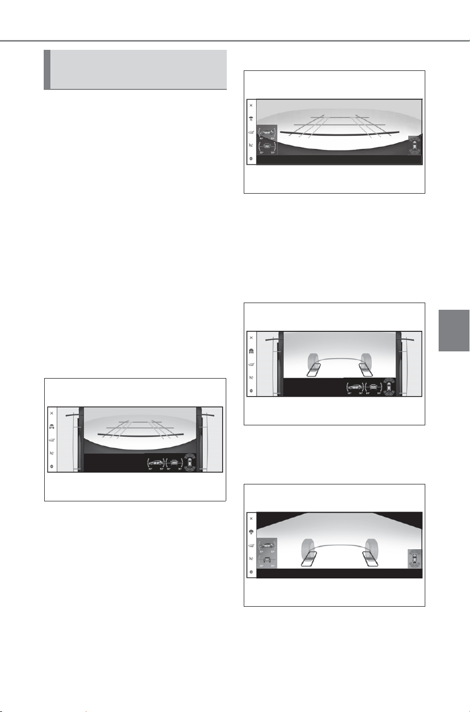
403
5-4. Using the driving support systems
Owner’s Manual_USA_M6740B_en
5
Driving
The following screens can be
selected according to driving
conditions.
• Screens that can be selected
vary depending on conditions
such as shift position and
vehicle speed. (P.407)
• Depending on the displayed
screen, the display can be
switched from normal to full
screen display.
■ Screens when the “X-
MODE” switch is in on.
When checking the area to
the front and sides of the vehi-
cle
Front view & dual side views
P.411
Front view (magnified)
P. 4 11
When checking the condition
of the road surface under the
vehicle
Under vehicle terrain view & dual
side views
P.415
Under vehicle terrain view (mag-
nified)
P.415
Multi-terrain Monitor
screens
SOLTERRA_OM_USA_A6740BE.book 403 ページ 2025年5月23日 金曜日 午後1時18分
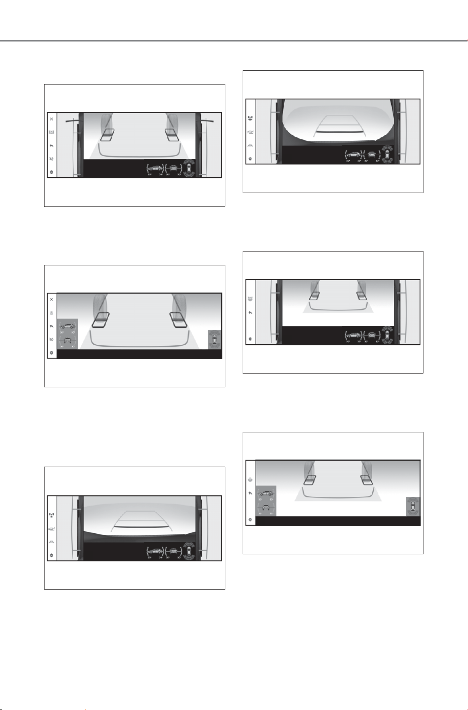
404
5-4. Using the driving support systems
Owner’s Manual_USA_M6740B_en
Under vehicle terrain view (rear
wheel) & dual side views
P.419
Under vehicle terrain view (rear
wheel) (magnified)
P.419
When checking the area to
the rear of the vehicle
Rear view & dual side views
P.422
Wide rear view & dual side views
P.422
Under vehicle terrain view (rear
side) & dual side views)
P.426
Under vehicle terrain view (rear
side) (magnified)
P.426
SOLTERRA_OM_USA_A6740BE.book 404 ページ 2025年5月23日 金曜日 午後1時18分
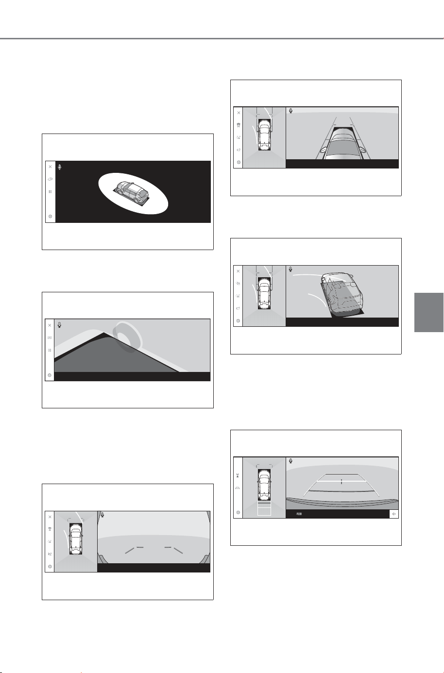
405
5-4. Using the driving support systems
Owner’s Manual_USA_M6740B_en
5
Driving
■ Screens when the “X-
MODE” switch is in on.
When checking the area to
the around of the vehicle
Moving view
P.429
See-through view
P.429
When checking the area to
the front of the vehicle
Wide front view & panoramic view
P.431
Side Clearance View & pan-
oramic view
P.431
Cornering View & panoramic view
P.431
When checking the area to
the rear of the vehicle
Rear view & panoramic view
P.441
SOLTERRA_OM_USA_A6740BE.book 405 ページ 2025年5月23日 金曜日 午後1時18分
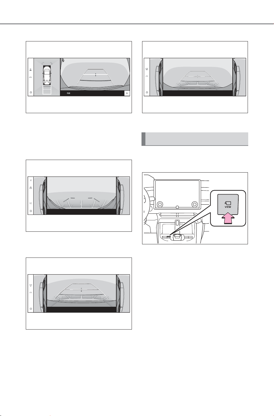
406
5-4. Using the driving support systems
Owner’s Manual_USA_M6740B_en
Wide rear view & panoramic view
P.441
When folding the outside rear
view mirrors
Side view & Wide front view
P.449
Side view & Rear view
P.449
Side view & Wide rear view
P.449
The camera switch is located as
shown in the illustration.
Camera switch
SOLTERRA_OM_USA_A6740BE.book 406 ページ 2025年5月23日 金曜日 午後1時18分
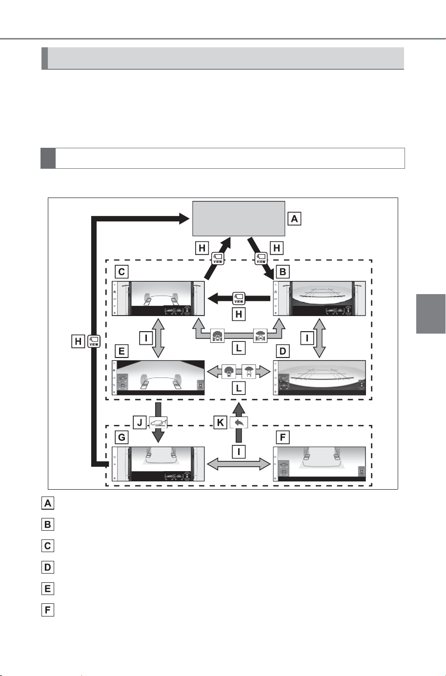
407
5-4. Using the driving support systems
Owner’s Manual_USA_M6740B_en
5
Driving
When you press the camera switch while the power switch is in ON,
the monitor display operates.
The monitor displays various views of the position of the vehicle.
(The following is an example)
■ When the shift position is in the P, D or N position
Audio screen, etc.
Front view & dual side views
Under vehicle terrain view & dual side views
Front view (magnified)
Under vehicle terrain view (magnified)
Under vehicle terrain view (rear wheel) (magnified)
How to switch the screen
“X-MODE” switch is in on
SOLTERRA_OM_USA_A6740BE.book 407 ページ 2025年5月23日 金曜日 午後1時18分
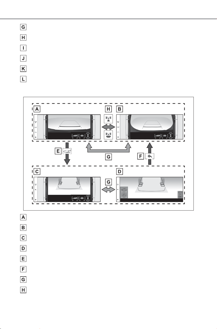
408
5-4. Using the driving support systems
Owner’s Manual_USA_M6740B_en
Under vehicle terrain view (rear wheel) & dual side views
Press the camera switch
Select the Multi-terrain Monitor screen
Select the under vehicle terrain view (rear wheel) button
Select the return button
Select the display mode button
■ When the shift position is in the R position
Rear view & dual side views
Wide rear view & dual side views
Under vehicle terrain view (rear side) & dual side views
Under vehicle terrain view (rear side) (magnified)
Select the under vehicle terrain view (rear side) button
Select the return button
Select the Multi-terrain Monitor screen
Select the display mode button
SOLTERRA_OM_USA_A6740BE.book 408 ページ 2025年5月23日 金曜日 午後1時18分
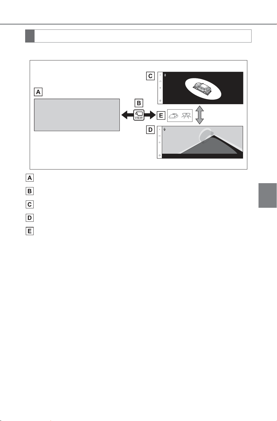
409
5-4. Using the driving support systems
Owner’s Manual_USA_M6740B_en
5
Driving
■ When the shift position is in the P position
Navigation screen, audio screen, etc.
Pressing the camera switch
Moving view
See-through view
Touch the display mode switching button
“X-MODE” switch is in off
SOLTERRA_OM_USA_A6740BE.book 409 ページ 2025年5月23日 金曜日 午後1時18分
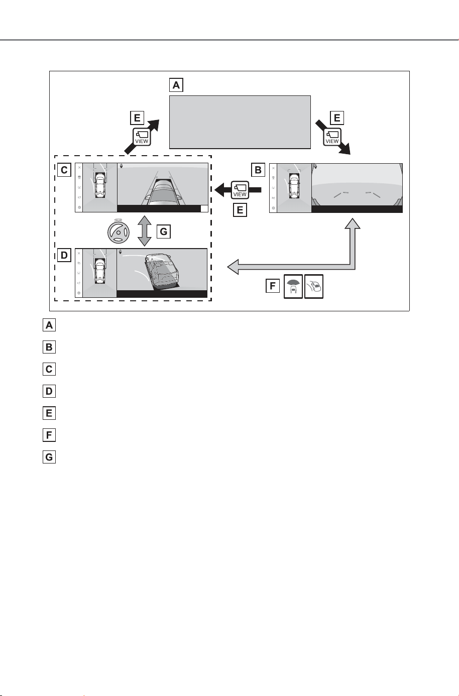
410
5-4. Using the driving support systems
Owner’s Manual_USA_M6740B_en
■ When the shift position is in the D or N position
Navigation screen, audio screen, etc.
Wide front view & panoramic view
Side clearance view & panoramic view
Cornering view & panoramic view
Pressing the camera switch
Touch the display mode switching button
When the steering wheel is turned by 180 degrees or more from
the center (straight-line) position
SOLTERRA_OM_USA_A6740BE.book 410 ページ 2025年5月23日 金曜日 午後1時18分
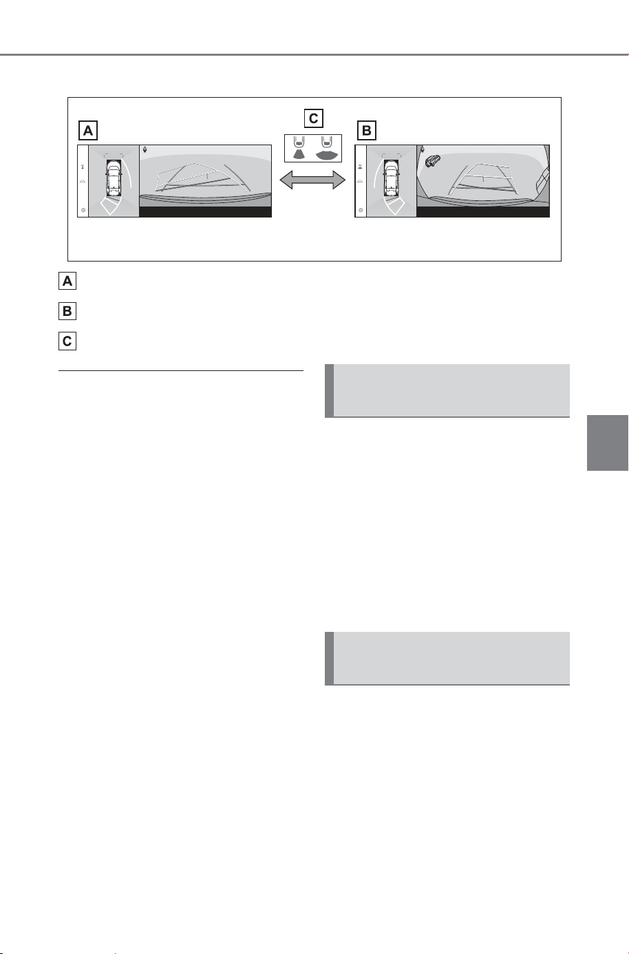
411
5-4. Using the driving support systems
Owner’s Manual_USA_M6740B_en
5
Driving
■ When the shift position is in the R position
Rear view & panoramic view
Wide rear view & panoramic view
Touch the display mode switching button
■ Multi-terrain Monitor screen
display
● The amount of time that the Multi-
terrain Monitor screen is displayed
changes as follows according to
the vehicle speed at the time the
camera switch was pressed.
● The Multi-terrain Monitor screen is
displayed if the vehicle speed is
approximately 7 mph (12 km/h) or
less when the camera switch is
pressed.
● If the vehicle speed exceeds
approximately 7 mph (12 km/h),
the Multi-terrain Monitor display is
canceled.
● Display settings such as guide
lines mode can be saved as the
my settings by registering a driver,
and then applied when entering
the vehicle.
● The Intelligent Assistant can be
used to display the panoramic
view monitor screen, change the
screen mode and for other opera-
tions.
When the “X-MODE” switch is in
on, the various screens display
information to support several
different driving situations, such
as when checking for obstacles
when moving forward or in
reverse, or when judging road
surface conditions during off-
road driving.
Front view & dual side views
can be used to check the area
around the front of the vehicle.
To display the screen, press the
camera switch when the shift
position is in the P, D or N posi-
tion.
Screen display and func-
tions
Front view & dual side
views
SOLTERRA_OM_USA_A6740BE.book 411 ページ 2025年5月23日 金曜日 午後1時18分
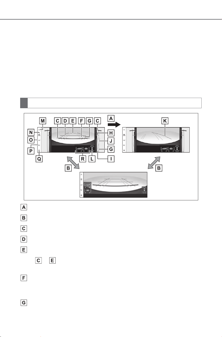
412
5-4. Using the driving support systems
Owner’s Manual_USA_M6740B_en
In addition to an image of the
front of the vehicle, guide
lines are displayed in a com-
posite view to provide refer-
ence for when deciding a
direction to move forward in.
If the front view display is
selected while the screen is
displayed, the screen
switches from normal to mag-
nified display. (Selecting the
display again returns the
screen to the normal display)
If the steering wheel is turned
270° or more, guide lines and
other features to support turn-
ing are automatically dis-
played.
If the steering wheel is turned 270° or more
Selecting the display
1.5 ft. (0.5 m) distance guide line (red)
3 ft. (1 m) distance guide line (blue)
6 ft. (2 m) distance guide line (blue)
Items to indicate the estimated distance from the front end of the
vehicle.
Front tire course line (yellow)
Indicates the estimated course of the front tires according to steering wheel
position.
Vehicle width lines (blue)
Indicate the width of the vehicle including the outside rear view mirrors.
Screen display
SOLTERRA_OM_USA_A6740BE.book 412 ページ 2025年5月23日 金曜日 午後1時18分

413
5-4. Using the driving support systems
Owner’s Manual_USA_M6740B_en
5
Driving
Front tire contact line (blue)
Rear tire contact line (blue)
Items and indicate estimated tire positions on the image.
Rear tire course line (yellow)
Indicates the estimated course of the rear tires.
Forward movement guide line (blue)
Indicates the estimated tire course of the tightest possible turn.
SUBARU Parking Assist/slip display
Indicates tire spinning by changing color and flashing the tire displayed. If
the SUBARU Parking Assist detects a static object when the system is
enabled, the indicator is displayed on the screen. (P.414)
Display off button
Changes the screen back to the previously displayed screen, such as the
audio screen.
Display mode switching button
Switches display mode every time touch the button.
Under vehicle terrain view (rear wheel) selection button
Switch the under vehicle terrain view (rear wheel) & dual side views
(P.419)
Automatic display mode selection button
P.414
Setting button
Changes settings, such as the automatically display cornering view, the
vehicle body color, the SUBARU Parking Assist detection distance.
(P.453)
Tilt meter
Displays the vehicle’s estimated degree of incline. (P.414)
SOLTERRA_OM_USA_A6740BE.book 413 ページ 2025年5月23日 金曜日 午後1時18分
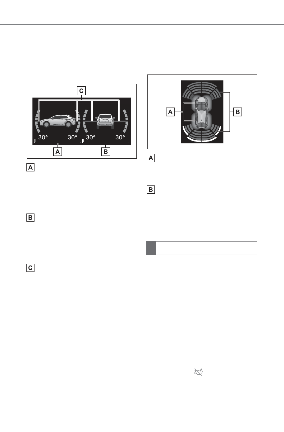
414
5-4. Using the driving support systems
Owner’s Manual_USA_M6740B_en
■ Tilt meter
Tilt meter displays the vehicle
inclination to the front, rear, left
and right within a range of 0° to
approximately 30°.
Degree markers of incline to
the front and rear
Indicates the vehicle inclination in
degrees in the front and rear direc-
tions.
Degree markers of incline to
the left and right
Indicates the vehicle inclination in
degrees in the left and right direc-
tions.
Pointer
Indicates the degree of the vehicle
inclination in comparison to a paral-
lel line.
■ SUBARU Parking
Assist/slip display
Indicates the tire that is spinning
when tire spinning is detected.
Tire icon
The tire that is spinning flashes in
orange.
SUBARU Parking Assist pop-
up display
Displayed if an obstacle is detected
while the SUBARU Parking Assist
is enabled.
In addition to screen switching
by operating the camera switch,
automatic display mode is avail-
able. In this mode, the screen is
switched automatically in
response to vehicle speed.
In automatic display mode, the
monitor will automatically dis-
play images in the following situ-
ations:
Touching the automatic dis-
play button turns on auto
display mode.
Automatic display mode
SOLTERRA_OM_USA_A6740BE.book 414 ページ 2025年5月23日 金曜日 午後1時18分

415
5-4. Using the driving support systems
Owner’s Manual_USA_M6740B_en
5
Driving
Turning on auto display mode
automatically displays the
views in the following situa-
tions:
When the shift position is in D
or N
The vehicle decelerates to
less than 6 mph (10 km/h)
(the shift position is in any
position other than R)
■ Front view & dual side views
display
The screen can be displayed when
the shift position is in P, D or N.
■ Tilt meter display
● The display indicates the incline of
the vehicle in degrees shown by
the movement of the pointer and
the rotation of the vehicle image.
● The color of the degree markers of
incline to the front, rear, left and
right changes according to the
current incline of the vehicle.
● After the power switch is turned to
ON, the degree of incline is not
displayed until such information is
determined
● The degree of incline showed on
the tilt meter is only an approxi-
mate indication, and may differ
from the degree of incline mea-
sured using other equipment.
● When the degree of incline is
larger than 30°, the pointer will be
displayed beyond 30°.
● If the system malfunctions, the
vehicle image and pointer are not
displayed. In this case, have the
vehicle inspected by your SUB-
ARU dealer.
■ Slip display
If the system malfunctions, the tire
icon is not displayed. In this case,
have the vehicle inspected by your
SUBARU dealer.
Lines indicating current vehicle and tire position are displayed in a
composite view on an image taken behind the current vehicle posi-
tion and assists the driver to check conditions underneath the vehi-
cle or determine the position of the front tires.
To display the screen, press the camera switch when the shift posi-
tion is in the P, D or N position.
It is necessary to drive a certain distance or more for the image to
be displayed.
If the under vehicle terrain view display is selected while the
screen is displayed, the screen switches from normal to magnified
display. (Selecting the display again returns the screen to the nor-
mal display)
Under vehicle terrain view & dual side views
SOLTERRA_OM_USA_A6740BE.book 415 ページ 2025年5月23日 金曜日 午後1時18分
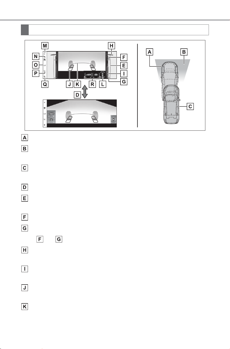
416
5-4. Using the driving support systems
Owner’s Manual_USA_M6740B_en
Current vehicle position
Image displayed in the under vehicle terrain view (image taken
behind the current vehicle position)
Vehicle position at the time the image was taken (behind the cur-
rent vehicle position)
Selecting the display
Vehicle width lines (blue)
Indicate the width of the vehicle including the outside rear view mirrors.
Front tire contact line (blue)
Rear tire contact line (blue)
Items and indicate estimated tire positions on the image.
1.5 ft. (0.5 m) distance guide line (red, black)
Indicate the estimated distance from the front end of the vehicle.
Rear tire course line (yellow)
Indicates the estimated course of the rear tires.
Tire position indicator lines (black, white)
Indicates the estimated position of the front tires.
Vehicle position indicator lines (blue)
Indicates the estimated position of the vehicle.
Screen display
SOLTERRA_OM_USA_A6740BE.book 416 ページ 2025年5月23日 金曜日 午後1時18分
417
5-4. Using the driving support systems
Owner’s Manual_USA_M6740B_en
5
Driving
SUBARU Parking Assist/slip display
Indicates tire spinning by changing color and flashing the tire displayed. If
the SUBARU Parking Assist detects a static object when the system is
enabled, the indicator is displayed on the screen. (P.414)
Display off button
Changes the screen back to the previously displayed screen, such as the
audio screen.
Display mode switching button
Switches display mode every time touch the button.
Under vehicle terrain view (rear wheel) selection button
Switch the under vehicle terrain view (rear wheel) & dual side views
(P.419)
Automatic display mode selection button
P.417
Setting button
Changes settings, such as the automatically display cornering view, the
vehicle body color, the SUBARU Parking Assist detection distance.
(P.453)
Tilt meter
Displays the vehicle’s estimated degree of incline. (P.414)
In addition to screen switching
by operating the camera switch,
automatic display mode is avail-
able. In this mode, the screen is
switched automatically in
response to vehicle speed.
In automatic display mode, the
monitor will automatically dis-
play images in the following situ-
ations:
Touching the automatic dis-
play button turns on auto
display mode.
Turning on auto display mode
automatically displays the
views in the following situa-
tions:
• When the shift position is in D or
N
• The vehicle decelerates to less
than 6 mph (10 km/h) (the shift
position is in any position other
than R)
■ Under vehicle terrain view &
dual side views
● The screen can be displayed
when the shift position is in P, D or
N.
● In the following situations, under
vehicle terrain view will disappear.
Automatic display mode
SOLTERRA_OM_USA_A6740BE.book 417 ページ 2025年5月23日 金曜日 午後1時18分
418
5-4. Using the driving support systems
Owner’s Manual_USA_M6740B_en
• When the vehicle is driven with
the steering wheel turned almost
all the way to one side
• After the EV system starts or the
system returns to normal, a fixed
distance or more has not yet been
driven
• When the tires are slipping or
spinning
• ABS is activated
• When there is a malfunction in the
system
● If the outside rear view mirrors are
folded while the under vehicle ter-
rain view is being displayed, a
separate screen is displayed.
● If the vehicle is driven with the
steering wheel turned to a certain
steering angle or greater, a part of
the screen may disappear. How-
ever, this is not a malfunction.
● In the following situations, the sys-
tem may not operate normally.
• The road is covered with snow
• When there are shadows due to
light sources such as sunlight or
illumination
• When driving on slippery roads or
tires are spinning
• Dirt or foreign matter is adhering
to the camera lens
• There is water in front of the vehi-
cle (a river, puddle, sea water,
etc.)
• Optional equipment has been
installed
• When the camera is covered or
there is an object in the image
capture range
• Tires have been replaced
• When the back door is open
• When the steering wheel is oper-
ated at or more than a specified
steering angle
• On roads that are not flat, such as
slopes
● As vision that was captured in the
past is being displayed, the
screen and the actual situation
may differ in the following cases:
• An obstacle appears or moves
after vision is captured.
• Sand or snow crumbles and
moves after vision is captured.
• Mud or puddles are in the display
range.
• When the vehicle slips.
WARNING
■ Guide lines
The tire position indicator lines
and vehicle position indicator
lines may differ from actual vehi-
cle positions depending on the
number of passengers, cargo
weight, road grade, road surface
conditions, brightness of the sur-
rounding environment, whether
tires or suspension parts other
than those specified are
equipped, etc. Always drive the
vehicle while confirming the
safety of your surroundings.
■ Under vehicle terrain view
display
The image displayed is one that
was previously taken at a point
behind the current vehicle posi-
tion. In cases such as when
objects move after the image is
taken, the image displayed on the
screen may differ from the actual
state. In addition, when driving in
the dark such as at night, there
are cases when obstacles cannot
be confirmed from the image.
SOLTERRA_OM_USA_A6740BE.book 418 ページ 2025年5月23日 金曜日 午後1時18分
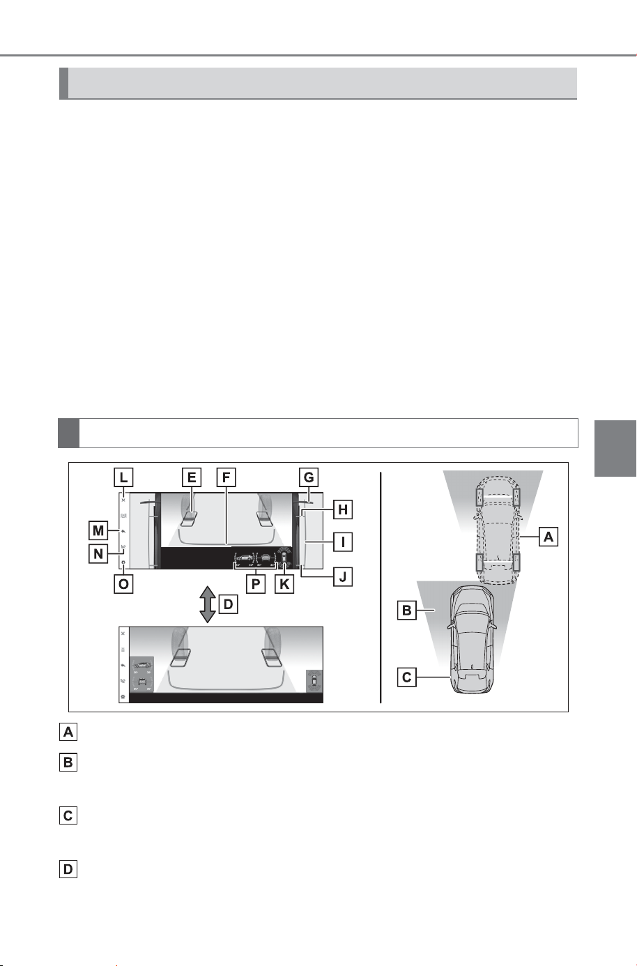
419
5-4. Using the driving support systems
Owner’s Manual_USA_M6740B_en
5
Driving
Lines indicating current vehicle and tire position are displayed in a
composite view on an image taken behind the current vehicle posi-
tion and assists the driver to check conditions underneath the vehi-
cle or determine the position of the rear tires.
To display the screen, press the camera switch when the shift posi-
tion is in the P, D or N position, select the under vehicle terrain view
(rear wheel) selection switch.
It is necessary to drive a certain distance or more for the image to
be displayed.
If the under vehicle terrain view display is selected while the
screen is displayed, the screen switches from normal to magnified
display. (Selecting the display again returns the screen to the nor-
mal display)
Current vehicle position
Image displayed in the under vehicle terrain view (rear wheel)
(image taken behind the current vehicle position)
Vehicle position at the time the image was taken (behind the cur-
rent vehicle position)
Selecting the display
Under vehicle terrain view (rear wheel) & dual side views
Screen display
SOLTERRA_OM_USA_A6740BE.book 419 ページ 2025年5月23日 金曜日 午後1時18分
420
5-4. Using the driving support systems
Owner’s Manual_USA_M6740B_en
Tire position indicator lines (black, white)
Indicates the estimated position of the rear tires.
Vehicle position indicator lines (blue)
Indicates the estimated position of the vehicle.
1.5 ft. (0.5 m) distance guide line (red, black)
Indicate the estimated distance from the front end of the vehicle.
Front tire contact line (blue)
Indicate estimated tire positions on the image.
Vehicle width lines (blue)
Indicate the width of the vehicle including the outside rear view mirrors.
Rear tire contact line (blue)
Indicate estimated tire positions on the image.
SUBARU Parking Assist/slip display
Indicates tire spinning by changing color and flashing the tire displayed. If
the SUBARU Parking Assist detects a static object when the system is
enabled, the indicator is displayed on the screen. (P.414)
Display off button
Changes the screen back to the previously displayed screen, such as the
audio screen.
Return button
Return to the previous screen
Automatic display mode selection button
P.421
Setting button
Changes settings, such as the automatically display cornering view, the
vehicle body color, the SUBARU Parking Assist detection distance.
(P.453)
Tilt meter
Displays the vehicle’s estimated degree of incline. (P.414)
SOLTERRA_OM_USA_A6740BE.book 420 ページ 2025年5月23日 金曜日 午後1時18分
421
5-4. Using the driving support systems
Owner’s Manual_USA_M6740B_en
5
Driving
In addition to screen switching
by operating the camera switch,
automatic display mode is avail-
able. In this mode, the screen is
switched automatically in
response to vehicle speed. In
automatic display mode, the
monitor will automatically dis-
play images in the following situ-
ations:
Touching the automatic dis-
play button turns on auto
display mode.
Turning on auto display mode
automatically displays the
views in the following situa-
tions:
• When the shift position is in D or
N
• The vehicle decelerates to less
than 6 mph (10 km/h) (the shift
position is in any position other
than R)
■ Under vehicle terrain view (rear
wheel)
● The screen can be displayed
when the shift position is in P, D or
N.
● In the following situations, the dis-
play of the under vehicle terrain
view (rear wheel) ends and the
screen automatically returns to the
most recently used camera
screen. In addition, the under
vehicle terrain view (rear wheel)
selection switch cannot be oper-
ated until the next screen can be
displayed.
• When vehicle speed reaches or
exceeds approximately 3 mph (5
km/h)
• When the vehicle is driven with
the steering wheel turned almost
all the way to one side
• When the tires are slipping or
spinning
• ABS is activated
• When there is a malfunction in the
system
• When the steering wheel is oper-
ated at or more than a specified
steering angle
● If the outside rear view mirrors are
folded while the under vehicle ter-
rain view (rear wheel) is being dis-
played, a separate screen is
displayed.
● If the vehicle is driven with the
steering wheel turned to a certain
steering angle or greater, a part of
the screen may disappear. How-
ever, this is not a malfunction.
● In the following situations, the sys-
tem may not operate normally or
may not be able to switch to the
under vehicle terrain view (rear
wheel). In addition, the under
vehicle terrain view (rear wheel)
selection switch cannot be oper-
ated until the next screen can be
displayed.
• The road is covered with snow
• When there are shadows due to
light sources such as sunlight or
illumination
• When driving on slippery roads or
tires are spinning
• Dirt or foreign matter is adhering
to the camera lens
• There is water in front of the vehi-
cle (a river, puddle, sea water,
etc.)
• Optional equipment has been
installed
• When the camera is covered or
there is an object in the image
capture range
• Tires have been replaced
• When the back door is open
Automatic display mode
SOLTERRA_OM_USA_A6740BE.book 421 ページ 2025年5月23日 金曜日 午後1時18分
422
5-4. Using the driving support systems
Owner’s Manual_USA_M6740B_en
• When the steering wheel is oper-
ated at or more than a specified
steering angle
• On roads that are not flat, such as
slopes
● As vision that was captured in the
past is being displayed, the
screen and the actual situation
may differ in the following cases:
• An obstacle appears or moves
after vision is captured.
• Sand or snow crumbles and
moves after vision is captured.
• Mud or puddles are in the display
range.
• When the vehicle slips.
The rear view & dual side views and the wide rear view & dual side
views screen provide support when checking the areas of behind the
vehicle and around the vehicle while backing up, for example while
parking.
The screens will be displayed when the shift position is in the R posi-
tion.
WARNING
■ Guide lines
The tire position indicator lines
and vehicle position indicator
lines may differ from actual vehi-
cle positions depending on the
number of passengers, cargo
weight, road grade, road surface
conditions, brightness of the sur-
rounding environment, whether
tires or suspension parts other
than those specified are
equipped, etc.
Always drive the vehicle while
confirming the safety of your sur-
roundings.
■ Under vehicle terrain view
(rear wheel) display
The image displayed is one that
was previously taken at a point
behind the current vehicle posi-
tion. In cases such as when
objects move after the image is
taken, the image displayed on the
screen may differ from the actual
state. In addition, when driving in
the dark such as at night, there
are cases when obstacles cannot
be confirmed from the image.
Rear view & dual side views/wide rear view & dual side
views
SOLTERRA_OM_USA_A6740BE.book 422 ページ 2025年5月23日 金曜日 午後1時18分
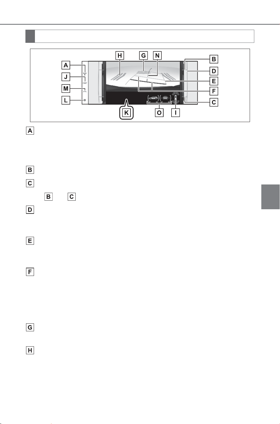
423
5-4. Using the driving support systems
Owner’s Manual_USA_M6740B_en
5
Driving
Display mode switching button
Each time the display mode switching button is selected, the mode will
change between the rear view & dual side views mode and the wide rear
view & dual side views mode.
Front tire contact line (blue)
Rear tire contact line (blue)
Items and indicate estimated tire positions on the image.
Vehicle width extension guide line (blue)
Indicates the estimated vehicle width including the outside rear view mir-
rors.
Projected course lines (yellow)
Indicate the estimated course of the vehicle according to steering opera-
tions.
Distance guide line
Shows the distance behind the vehicle when the steering wheel is turned.
• The guide lines move in conjunction with the estimated course lines.
• The guide lines display points approximately 1.5 ft. (0.5 m) (red) and
approximately 3 ft. (1 m) (yellow) from the center of the edge of the
bumper.
Rear Camera Detection
Displayed automatically when a pedestrian is detected.
Rear Cross Traffic Alert/Rear Camera Detection
The indicator is displayed on the screen in the following situations.
• When the rear radar detects an approaching vehicle or obstacle from the
rear
• When the rear camera detects a pedestrian to the rear
Screen display
SOLTERRA_OM_USA_A6740BE.book 423 ページ 2025年5月23日 金曜日 午後1時18分
424
5-4. Using the driving support systems
Owner’s Manual_USA_M6740B_en
SUBARU Parking Assist/slip display
Indicates tire spinning by changing color and flashing the tire displayed. If
the SUBARU Parking Assist detects a static object when the system is
enabled, the indicator is displayed on the screen. (P.414)
Under vehicle terrain view (rear side) selection button
Switch the under vehicle terrain view (rear side) & dual side views (P.426)
PKSB (Parking Support Brake)
When the system determines that the possibility of a collision with detected
target objects is high, a warning message is displayed. (P.362)
Setting button
Changes settings, such as the automatically display cornering view, the
vehicle body color, the SUBARU Parking Assist detection distance.
(P.453)
Guide line switching button
Each time the guide line switching button is selected, the mode will change
between the estimated course line mode and the vehicle center estimated
course line mode.
Vehicle center estimated course line
Shows a vehicle center estimated course when the steering wheel is
turned.
Tilt meter
Displays the vehicle’s estimated degree of incline. (P.414)
■ Rear view & dual side views/wide rear view & dual side views
● The monitor is canceled when the shift position is shifted into any position
other than the R position.
● For details about the SUBARU Parking Assist (P.340), Rear Cross Traf-
fic Alert function (P.351) and Parking Support Brake function. (P.360)
● The display position of the SUBARU Parking Assist and the position of
obstacles displayed in the camera image do not match.
■ Guide lines
If the back door is not closed, guide lines will not be displayed. If the guide
lines do not display even when the back door is closed, have the vehicle
inspected at your SUBARU dealer.
SOLTERRA_OM_USA_A6740BE.book 424 ページ 2025年5月23日 金曜日 午後1時18分
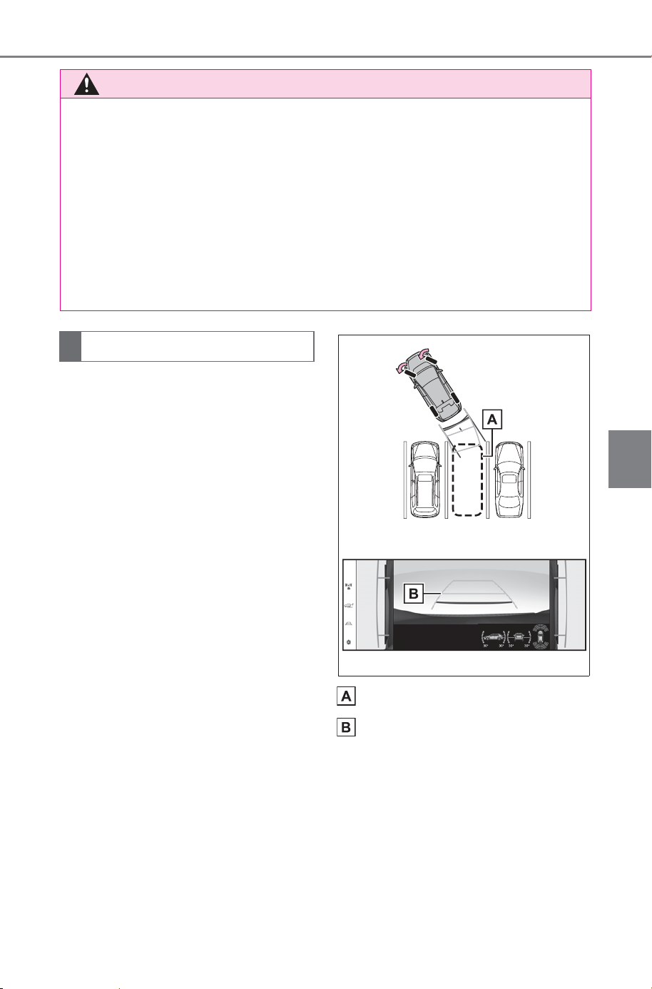
425
5-4. Using the driving support systems
Owner’s Manual_USA_M6740B_en
5
Driving
When parking in a space which
is in the reverse direction to the
space described in the proce-
dure below, the steering direc-
tions will be reversed.
1 Shift the shift position to the
R position.
2 Turn the steering wheel so
that the estimated course
lines are within the parking
space, and back up slowly.
Parking space
Estimated course lines
3 When the rear position of the
vehicle has entered the park-
ing space, turn the steering
wheel so that the vehicle
width guide lines are within
the left and right dividing lines
of the parking space.
WARNING
■ SUBARU Parking Assist display
When a sensor indicator on the SUBARU Parking Assist display illumi-
nates in red or a buzzer sounds continuously, be sure to check the area
around the vehicle immediately and do not proceed any further until safety
has been ensured, otherwise an unexpected accident may occur.
■ Rear view & dual side views/wide rear view & dual side views dis-
play
As the SUBARU Parking Assist display and Rear Cross Traffic Alert dis-
play are displayed over the camera view, it may be difficult to see the
SUBARU Parking Assist display and Rear Cross Traffic Alert display
depending on the color and brightness of the surrounding area.
Parking
SOLTERRA_OM_USA_A6740BE.book 425 ページ 2025年5月23日 金曜日 午後1時18分
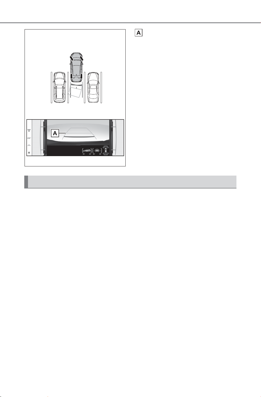
426
5-4. Using the driving support systems
Owner’s Manual_USA_M6740B_en
Estimated course lines
4 Once the estimated course
lines and the parking space
lines are parallel, straighten
the steering wheel and back
up slowly until the vehicle
has completely entered the
parking space.
5 Stop the vehicle in an appro-
priate place, and finish park-
ing.
Lines indicating current vehicle and tire position are displayed in a
composite view on an image taken in front of the current vehicle
position and assists the driver to check conditions underneath the
vehicle or determine the position of the rear tires.
To display the screen, when the shift position is in the R position,
select the under vehicle terrain view (rear side) selection switch.
It is necessary to drive a certain distance or more for the image to
be displayed.
If the under vehicle terrain view display is selected while the
screen is displayed, the screen switches from normal to magnified
display. (Selecting the display again returns the screen to the nor-
mal display)
Under vehicle terrain view (rear side) & dual side views
SOLTERRA_OM_USA_A6740BE.book 426 ページ 2025年5月23日 金曜日 午後1時18分
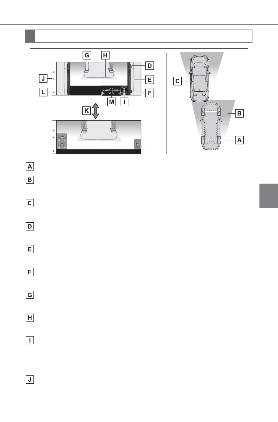
427
5-4. Using the driving support systems
Owner’s Manual_USA_M6740B_en
5
Driving
Current vehicle position
Image displayed in the under vehicle terrain view (rear side)
(image taken in front of the current vehicle position)
Vehicle position at the time the image was taken (in front of the
current vehicle position)
Front tire contact line (blue)
Indicate estimated tire positions on the image.
Vehicle width lines (blue)
Indicate the width of the vehicle including the outside rear view mirrors.
Rear tire contact line (blue)
Indicate estimated tire positions on the image.
Tire position indicator lines (black, white)
Indicates the estimated position of the rear tires.
Vehicle position indicator lines (blue)
Indicates the estimated position of the vehicle.
SUBARU Parking Assist/slip display
Indicates tire spinning by changing color and flashing the tire displayed. If
the SUBARU Parking Assist detects a static object when the system is
enabled, the indicator is displayed on the screen. (P.414)
Return switch
Return to the previous screen
Screen display
SOLTERRA_OM_USA_A6740BE.book 427 ページ 2025年5月23日 金曜日 午後1時18分
428
5-4. Using the driving support systems
Owner’s Manual_USA_M6740B_en
Selecting the display
Setting button
Changes settings, such as the automatically display cornering view, the
vehicle body color, the SUBARU Parking Assist detection distance.
(P.453)
Tilt meter
Displays the vehicle’s estimated degree of incline. (P.414)
■ Under vehicle terrain view (rear
side)
● The screen can be displayed
when the shift position is in R.
● While the under vehicle terrain
view (rear side) is displayed, if the
vehicle speed reaches or exceeds
approximately 3 mph (5 km/h), the
screen automatically returns to the
previous display.
● In the following situations, the dis-
play of the under vehicle terrain
view (rear side) ends and the
screen automatically returns to the
most recently used camera
screen. In addition, the under
vehicle terrain view (rear side)
selection switch cannot be oper-
ated until the next screen can be
displayed.
• When the tires are slipping or
spinning
• ABS is activated
• When there is a malfunction in the
system
• Rear Cross Traffic Alert, Rear
Camera Detection or Parking Sup-
port Brake is activated
• When the back door is open
● If the outside rear view mirrors are
folded while the under vehicle ter-
rain view (rear side) is being dis-
played, a separate screen is
displayed.
● If the vehicle is driven with the
steering wheel turned to a certain
steering angle or greater, a part of
the screen may disappear. How-
ever, this is not a malfunction.
● In the following situations, the sys-
tem may not operate normally or
may not be able to switch to the
under vehicle terrain view (rear
side). In addition, the under vehi-
cle terrain view (rear side) selec-
tion switch cannot be operated
until the next screen can be dis-
played.
• The road is covered with snow
• When there are shadows due to
light sources such as sunlight or
illumination
• When driving on slippery roads or
tires are spinning
• Dirt or foreign matter is adhering
to the camera lens
• There is water in front of the vehi-
cle (a river, puddle, sea water,
etc.)
• Optional equipment has been
installed
• When the camera is covered or
there is an object in the image
capture range
• Tires have been replaced
• When the back door is open
• When the steering wheel is oper-
ated at or more than a specified
steering angle
• On roads that are not flat, such as
slopes
SOLTERRA_OM_USA_A6740BE.book 428 ページ 2025年5月23日 金曜日 午後1時18分
429
5-4. Using the driving support systems
Owner’s Manual_USA_M6740B_en
5
Driving
When the “X-MODE” switch is in
off, the various screens display
information to support several
different driving situations, such
as when checking for obstacles
when moving forward
This is a mode that displays images combined from the cameras to
enable you to check obstacles around the vehicle. Images are dis-
played as if seen from the driver’s seat and on an angle from above
the vehicle.
WARNING
■ Guide lines
The tire position indicator lines
and vehicle position indicator
lines may differ from actual vehi-
cle positions depending on the
number of passengers, cargo
weight, road grade, road surface
conditions, brightness of the sur-
rounding environment, whether
tires or suspension parts other
than those specified are
equipped, etc.
Always drive the vehicle while
confirming the safety of your sur-
roundings.
■ Under vehicle terrain view
(rear side) display
● The image displayed is one that
was previously taken at a point
in front of the current vehicle
position. In cases such as when
objects move after the image is
taken, the image displayed on
the screen may differ from the
actual state. In addition, when
driving in the dark such as at
night, there are cases when
obstacles cannot be confirmed
from the image.
● The area covered by the cam-
era is limited. When driving, be
sure to check the vehicle’s sur-
roundings with your own eyes
and the vehicle’s mirrors.
Screen display and func-
tions
Display mode when the shift position is in P
SOLTERRA_OM_USA_A6740BE.book 429 ページ 2025年5月23日 金曜日 午後1時18分
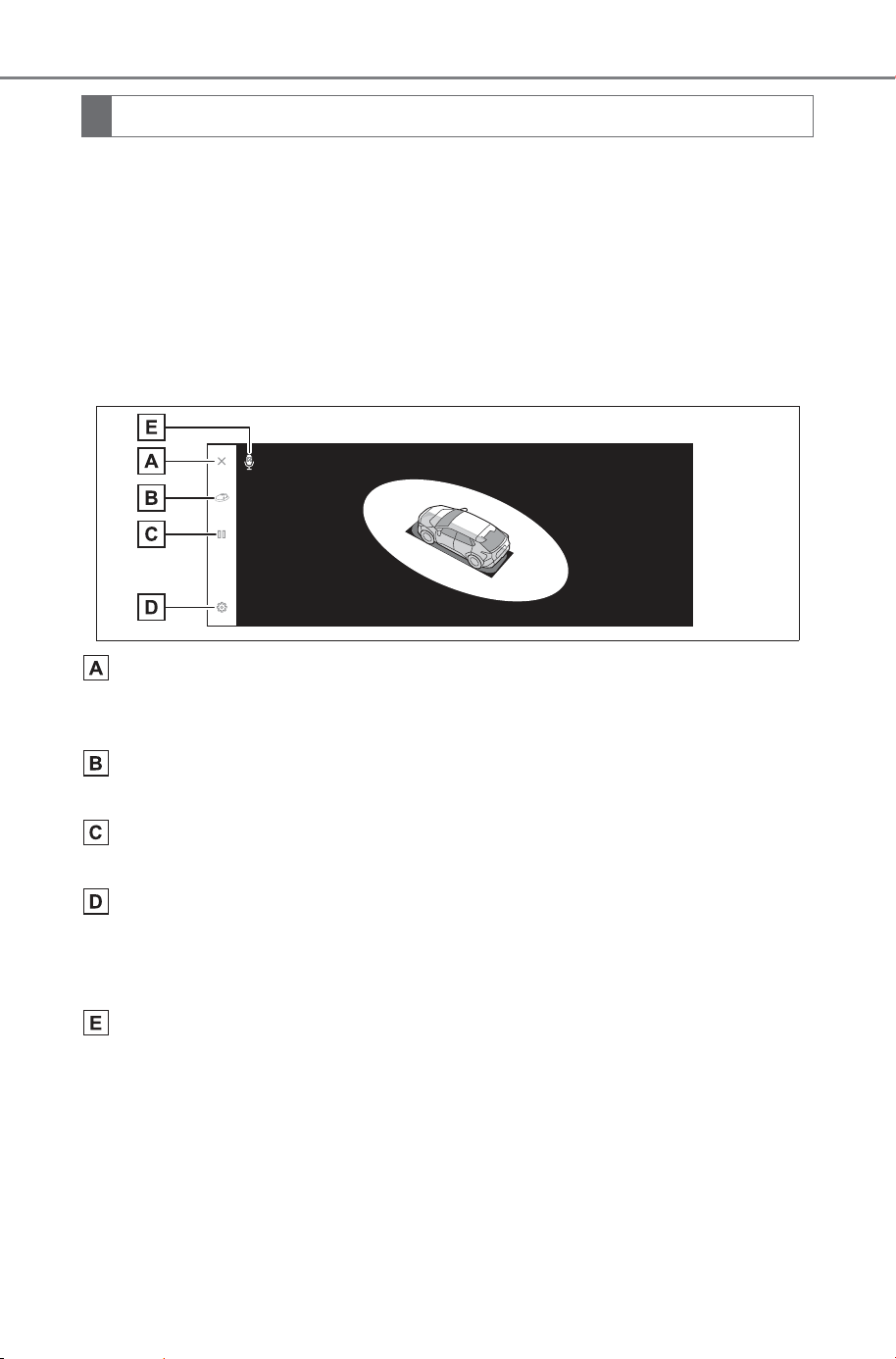
430
5-4. Using the driving support systems
Owner’s Manual_USA_M6740B_en
1 Shift the shift position to P.
2 Press the camera switch.
The mode changes every time the display mode switching button
is touched.
Pressing the camera switch again returns the display to the previ-
ous screen, such as the navigation screen.
Moving view
Screen off button
Turns off the camera screen and returns the previous screen, such as the
audio screen.
Display mode switching button
Switches between see-through view and moving view.
Rotation pause/resume button
Pauses and resumes the rotation of the display.
Customize settings button
Changes settings, such as the automatically display cornering view, the
vehicle body color, the SUBARU Parking Assist detection distance.
(P.453)
Voice recognition icon
This icon is displayed when the Intelligent Assistant is in operation.
Screen display
SOLTERRA_OM_USA_A6740BE.book 430 ページ 2025年5月23日 金曜日 午後1時18分
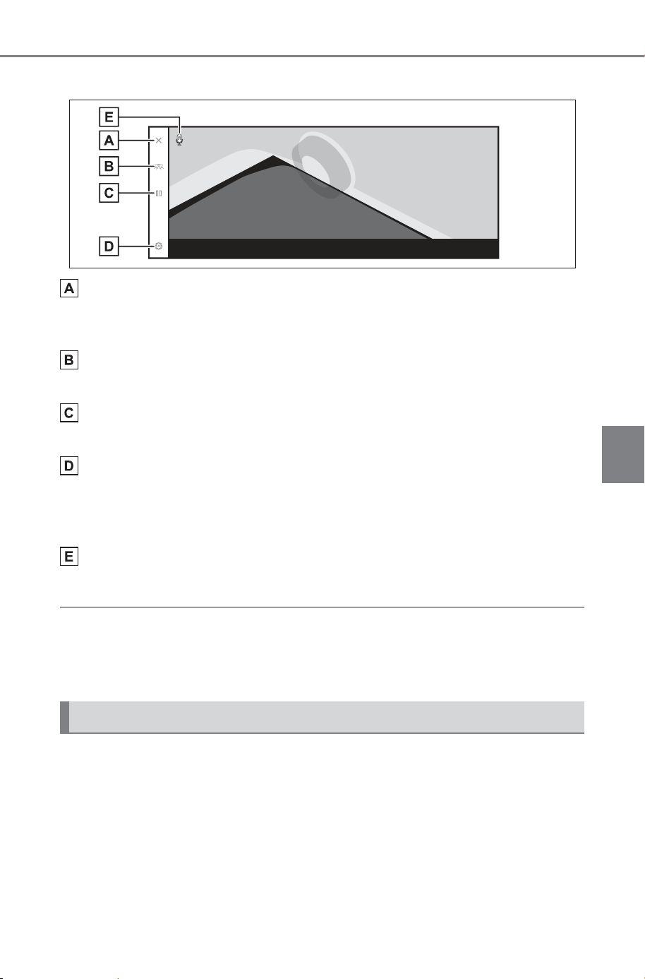
431
5-4. Using the driving support systems
Owner’s Manual_USA_M6740B_en
5
Driving
See-through view
Screen off button
Turns off the camera screen and returns the previous screen, such as the
audio screen.
Display mode switching button
Switches between see-through view and moving view.
Rotation pause/resume button
Pauses and resumes the rotation of the display.
Customize settings button
Changes settings, such as the automatically display cornering view, the
vehicle body color, the SUBARU Parking Assist detection distance.
(P.453)
Voice recognition icon
This icon is displayed when the Intelligent Assistant is in operation.
● When the SUBARU Parking Assist (P.340) is turned on, you can display
see-through view or moving view.
● You can also pause and resume the rotation of the see-through view and
moving view screen by touching any point on the screen.
You can check for nearby pedestrians, bicycles, and vehicles at
intersections with poor visibility and T-junctions by displaying vision
of your surroundings on the screen. This mode also provides support
to check both sides of the vehicle for safety, avoid collisions on nar-
row roads, and pulling over to the side of the road.
Display mode when the shift position is in D or N
SOLTERRA_OM_USA_A6740BE.book 431 ページ 2025年5月23日 金曜日 午後1時18分
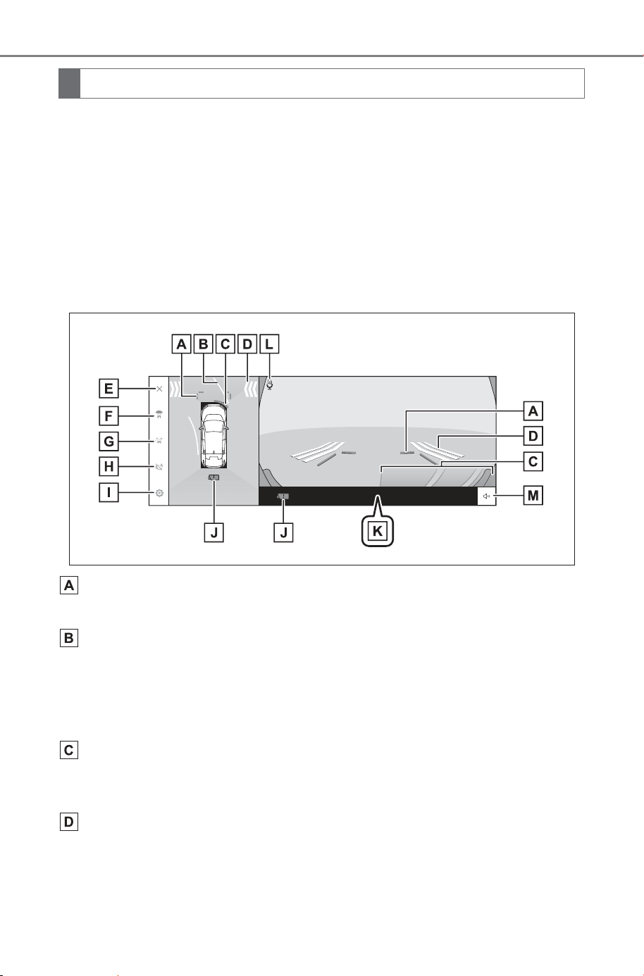
432
5-4. Using the driving support systems
Owner’s Manual_USA_M6740B_en
1 Shift the shift position to D or N.
2 Press the camera switch.
The mode changes every time you press the camera switch.
If the cornering view mode is on and you turn the steering wheel
more than 180 degrees from the straight position, the display will
change from side clearance view & panoramic view to cornering
view & panoramic view.
Wide front view & panoramic view
Front distance guide lines
Displays about 3 ft. (1 m) in front of the vehicle.
Forward estimated course lines
Displays course lines that are linked to operation of the steering wheel.
(Yellow)
These lines are displayed when the steering wheel is turned more than 90
degrees from the straight position.
SUBARU Parking Assist
Displays an indicator on the screen and sounds a buzzer when an object is
detected by a sensor.
FCTA (Front Cross Traffic Alert)
If FCTA detects nearby vehicles and/or obstacles from the front or side of
the vehicle, an indicator is displayed on the screen.
Screen display
SOLTERRA_OM_USA_A6740BE.book 432 ページ 2025年5月23日 金曜日 午後1時18分

433
5-4. Using the driving support systems
Owner’s Manual_USA_M6740B_en
5
Driving
Screen off button
Turns off the camera screen and returns the previous screen, such as the
navigation.
Display mode switching button
Switches display mode every time you touch the button.
Guide line switching button
Switches guide line mode every time you touch the button. (P.438)
Automatic display button
Turns the auto display mode on or off. When the shift position is in D or N,
wide front view & panoramic view or side clearance view/cornering view &
panoramic view will be automatically displayed in accordance with the vehi-
cle speed. (P.438)
Customize settings button
Changes settings, such as the automatically display cornering view, the
vehicle body color, the SUBARU Parking Assist detection distance.
(P.453)
Camera dirt detection icon
This icon is displayed when dirt is detected on the camera.
PKSB (Parking Support Brake)
If an obstacle that you may collide with is detected, a message is displayed
on the screen. (P.362)
Voice recognition icon
This icon is displayed when the Intelligent Assistant is in operation.
SUBARU Parking Assist mute button
This button temporarily mutes the SUBARU Parking Assist sound.
SOLTERRA_OM_USA_A6740BE.book 433 ページ 2025年5月23日 金曜日 午後1時18分
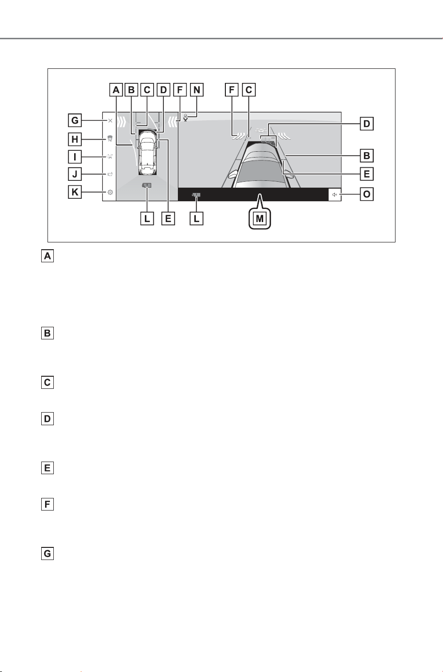
434
5-4. Using the driving support systems
Owner’s Manual_USA_M6740B_en
Side clearance view & panoramic view
Forward estimated course lines
Displays course lines that are linked to operation of the steering wheel.
(Yellow)
These lines are displayed when the steering wheel is turned more than 90
degrees from the straight position.
Vehicle width guide lines
Shows guide lines of the vehicle’s width including the outside rear view mir-
rors.
Front distance guide lines
Displays about 3 ft. (1 m) in front of the vehicle.
SUBARU Parking Assist
Displays an indicator on the screen and sounds a buzzer when an object is
detected by a sensor.
Front tire guide lines
Displays the position of the front tires.
FCTA (Front Cross Traffic Alert)
If FCTA detects nearby vehicles and/or obstacles from the front or side of
the vehicle, an indicator is displayed on the screen.
Screen off button
Turns off the camera screen and returns the previous screen, such as the
navigation.
SOLTERRA_OM_USA_A6740BE.book 434 ページ 2025年5月23日 金曜日 午後1時18分

435
5-4. Using the driving support systems
Owner’s Manual_USA_M6740B_en
5
Driving
Display mode switching button
Switches display mode every time you touch the button.
Guide line switching button
Switches guide line mode every time you touch the button. (P.438)
Automatic display button
Turns the auto display mode on or off. When the shift position is in D or N,
wide front view & panoramic view or side clearance view/cornering view &
panoramic view will be automatically displayed in accordance with the vehi-
cle speed.
Customize settings button
Changes settings, such as the automatically display cornering view, the
vehicle body color, the SUBARU Parking Assist detection distance.
(P.453)
Camera dirt detection icon
This icon is displayed when dirt is detected on the camera.
PKSB (Parking Support Brake)
If an obstacle that you may collide with is detected, a message is displayed
on the screen. (P.362)
Voice recognition icon
This icon is displayed when the Intelligent Assistant is in operation.
SUBARU Parking Assist mute button
This button temporarily mutes the SUBARU Parking Assist sound.
SOLTERRA_OM_USA_A6740BE.book 435 ページ 2025年5月23日 金曜日 午後1時18分
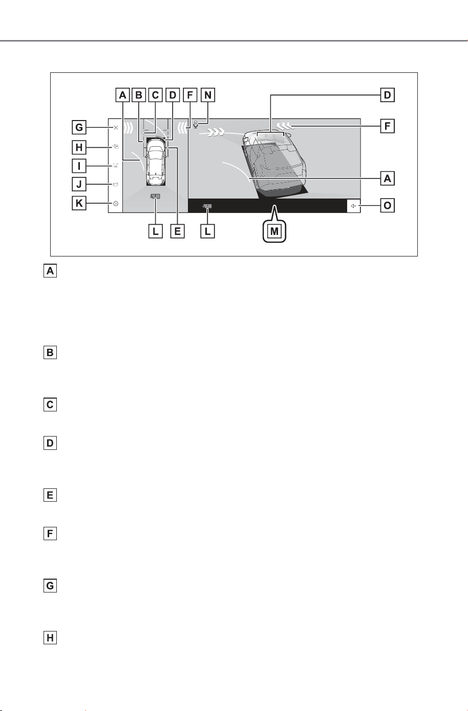
436
5-4. Using the driving support systems
Owner’s Manual_USA_M6740B_en
Cornering view & panoramic view
Forward estimated course lines
Displays course lines that are linked to operation of the steering wheel.
(Yellow)
These lines are displayed when the steering wheel is turned more than 90
degrees from the straight position.
Vehicle width guide lines
Shows guide lines of the vehicle’s width including the outside rear view mir-
rors.
Front distance guide lines
Displays about 3 ft. (1 m) in front of the vehicle.
SUBARU Parking Assist
Displays an indicator on the screen and sounds a buzzer when an object is
detected by a sensor.
Front tire guide lines
Displays the position of the front tires.
FCTA (Front Cross Traffic Alert)
If FCTA detects nearby vehicles and/or obstacles from the front or side of
the vehicle, an indicator is displayed on the screen.
Screen off button
Turns off the camera screen and returns the previous screen, such as the
navigation.
Display mode switching button
Switches display mode every time you touch the button.
SOLTERRA_OM_USA_A6740BE.book 436 ページ 2025年5月23日 金曜日 午後1時18分
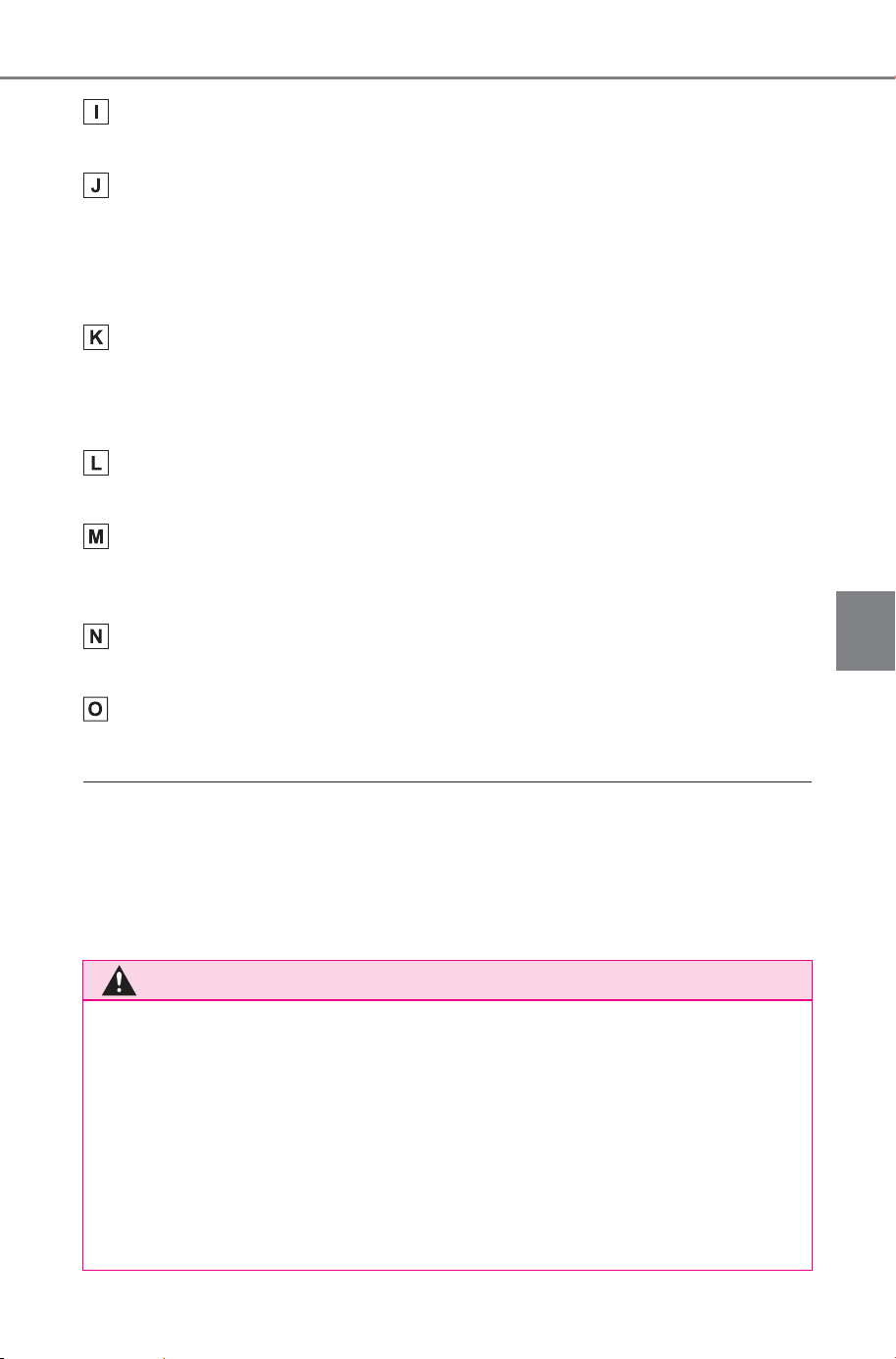
437
5-4. Using the driving support systems
Owner’s Manual_USA_M6740B_en
5
Driving
Guide line switching button
Switches guide line mode every time you touch the button. (P.438)
Automatic display button
Turns the auto display mode on or off. When the shift position is in D or N,
wide front view & panoramic view or side clearance view/cornering view &
panoramic view will be automatically displayed in accordance with the vehi-
cle speed.
Customize settings button
Changes settings, such as the automatically display cornering view, the
vehicle body color, the SUBARU Parking Assist detection distance.
(P.453)
Camera dirt detection icon
This icon is displayed when dirt is detected on the camera.
PKSB (Parking Support Brake)
If an obstacle that you may collide with is detected, a message is displayed
on the screen. (P.362)
Voice recognition icon
This icon is displayed when the Intelligent Assistant is in operation.
SUBARU Parking Assist mute button
This button temporarily mutes the SUBARU Parking Assist sound.
■ Side Clearance View & panoramic view screen/Cornering View &
panoramic view display
● When the SUBARU Parking Assist (P.340) is turned on, you can display
side clearance view & panoramic view/cornering view.
● The display position of the SUBARU Parking Assist may not match the
position of the obstacle displayed in the camera image.
WARNING
■ Guide line
The position of the guide lines displayed on the screen may change due
to factors such as number of passengers, load weight, and road gradient.
Always make sure to visually check behind you and your surroundings
while you are driving.
■ SUBARU Parking Assist and FCTA (Front Cross Traffic Alert) dis-
play
The SUBARU Parking Assist and Front Cross Traffic Alert (FCTA) dis-
plays are superimposed on the camera image, so it may be difficult to see
depending on the brightness of the surroundings and colors.
SOLTERRA_OM_USA_A6740BE.book 437 ページ 2025年5月23日 金曜日 午後1時18分
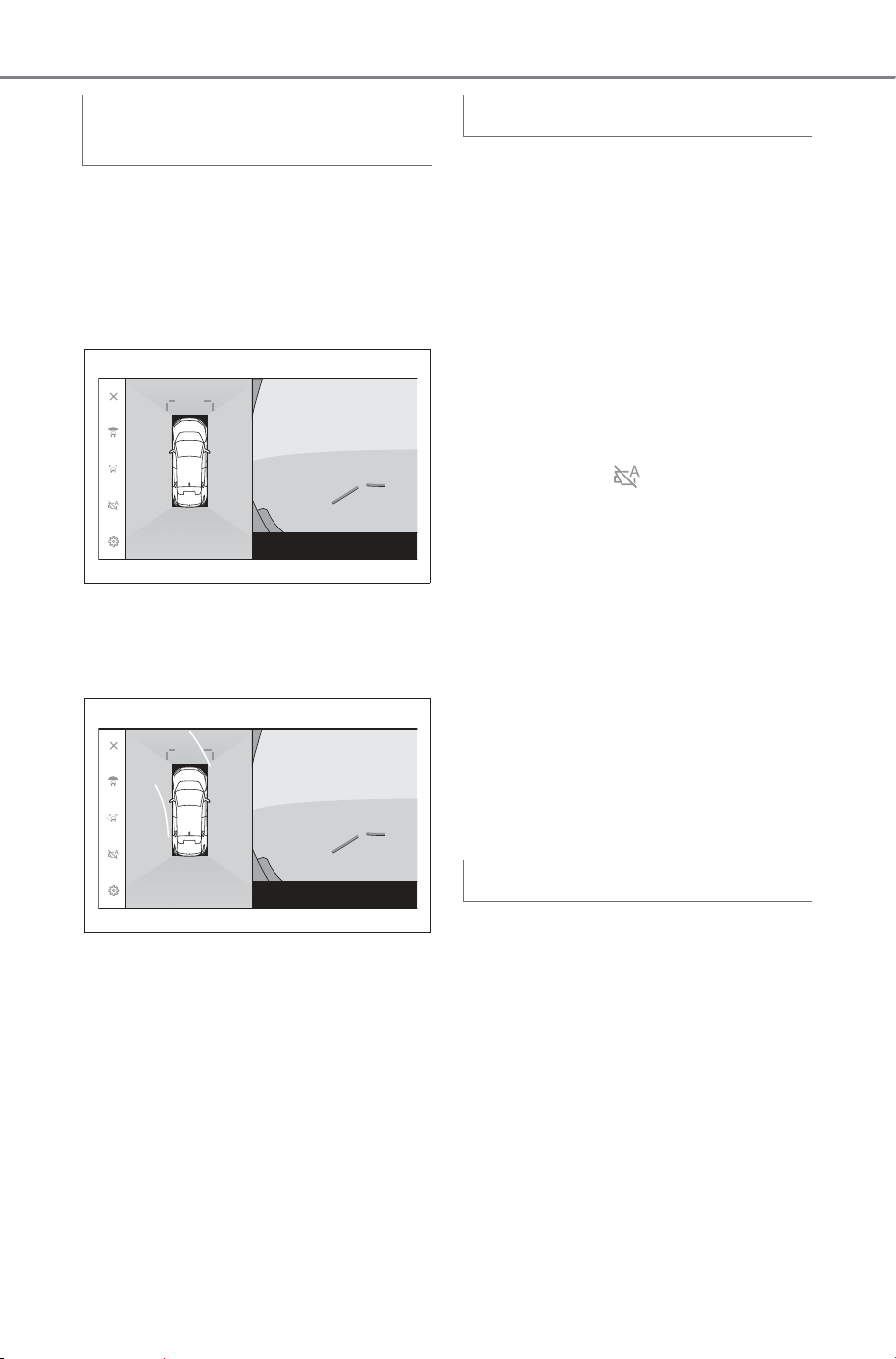
438
5-4. Using the driving support systems
Owner’s Manual_USA_M6740B_en
The guide line display mode
changes every time the guide
line display mode button is
touched.
Distance guide lines mode
Displays about 3 ft. (1 m) in front of
the vehicle. (blue)
Estimated course lines mode
Displays course lines that are
linked to operation of the steering
wheel. (Yellow) These lines are dis-
played when the steering wheel is
turned more than 90 degrees from
the straight position.
Although you can display wide
front view & panoramic view and
side clearance view & pan-
oramic view/cornering view by
pressing the camera switch, you
can also set auto display mode
to display the views automati-
cally in accordance with the
vehicle speed.
Touching the automatic dis-
play button turns on auto
display mode.
Turning on auto display mode
automatically displays the
views in the following situa-
tions:
• When the shift position is in D or
N
• The vehicle decelerates to less
than 6 mph (10 km/h) (the shift
position is in any position other
than R)
You can set the cornering view
auto display mode to automati-
cally display cornering view &
panoramic view in accordance
with the operation of the steer-
ing wheel.
Turning on cornering view
auto display mode automati-
cally displays cornering view
in the following situations:
Changing the guide line dis-
play mode
Auto display mode
Cornering view auto display
SOLTERRA_OM_USA_A6740BE.book 438 ページ 2025年5月23日 金曜日 午後1時18分
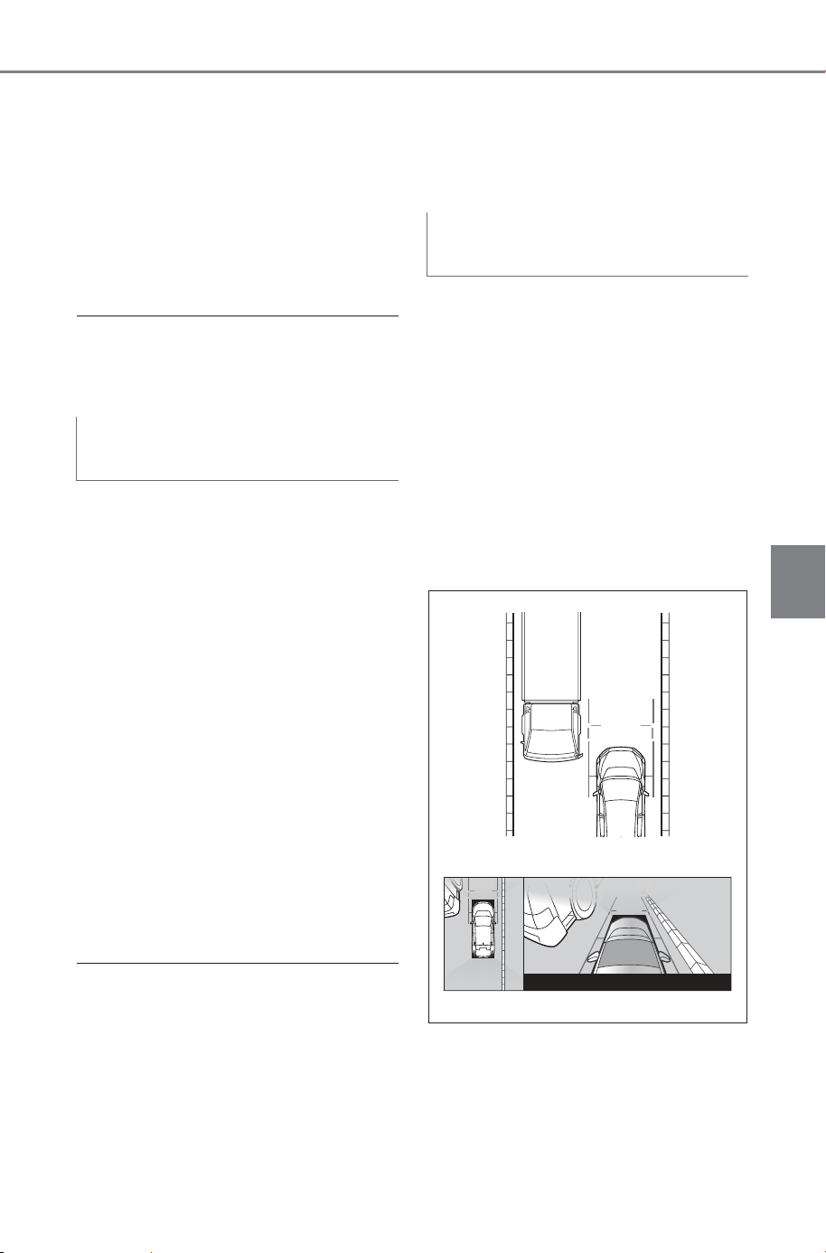
439
5-4. Using the driving support systems
Owner’s Manual_USA_M6740B_en
5
Driving
• When the shift position is in D or
N
• The vehicle decelerates to less
than 7 mph (12 km/h)
• When the steering wheel is
turned by 180 degrees or more
from the center (straight-line)
position
■ Cornering view auto display
You can change cornering view auto
mode in the custom settings.
Depending on the SUBARU
Parking Assist detection state,
wide front view & panoramic
view/Side clearance view/Cor-
nering view & panoramic view
will be displayed.
The views are displayed auto-
matically when the SUBARU
Parking Assist detects an
obstacle (when the shift posi-
tion is in D or N).
The display returns to the pre-
vious screen automatically
when the SUBARU Parking
Assist stops detecting an
obstacle.
■ SUBARU Parking Assist linked
display
● You can also return to the previ-
ous screen by pressing the cam-
era switch displayed on the
screen.
● If the panoramic view monitor
screen is canceled when an
obstacle is detected, the pan-
oramic view monitor screen can
be displayed again by touching
the SUBARU Parking Assist mark
shown on the multimedia system
screen.
■ Side Clearance View & pan-
oramic view
Check the positional relation-
ship between the vehicle
width guide lines and an
obstacle.
Turn the steering wheel and
drive forward so that the vehi-
cle width guide lines do not
overlap the actual obstacle.
Check the positional relation-
ship between the vehicle
width guide lines and an
object such as curbs on the
shoulder of a road.
SUBARU Parking Assist
linked display
Using the vehicle width
guide lines
SOLTERRA_OM_USA_A6740BE.book 439 ページ 2025年5月23日 金曜日 午後1時18分
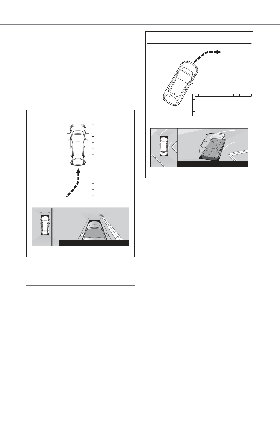
440
5-4. Using the driving support systems
Owner’s Manual_USA_M6740B_en
Pull the vehicle over so that
the vehicle width guide lines
do not overlap the obstacle as
shown in the figure.
By driving with the vehicle
width guide lines parallel to
the object, you can park
alongside the object.
■ Cornering View & pan-
oramic view
Check the positional relation-
ship between the forward esti-
mated course lines and an
obstacle.
Turn the steering wheel and
drive forward so that the for-
ward estimated course lines
do not overlap the actual
obstacle.
Using the forward estimated
course lines
SOLTERRA_OM_USA_A6740BE.book 440 ページ 2025年5月23日 金曜日 午後1時18分
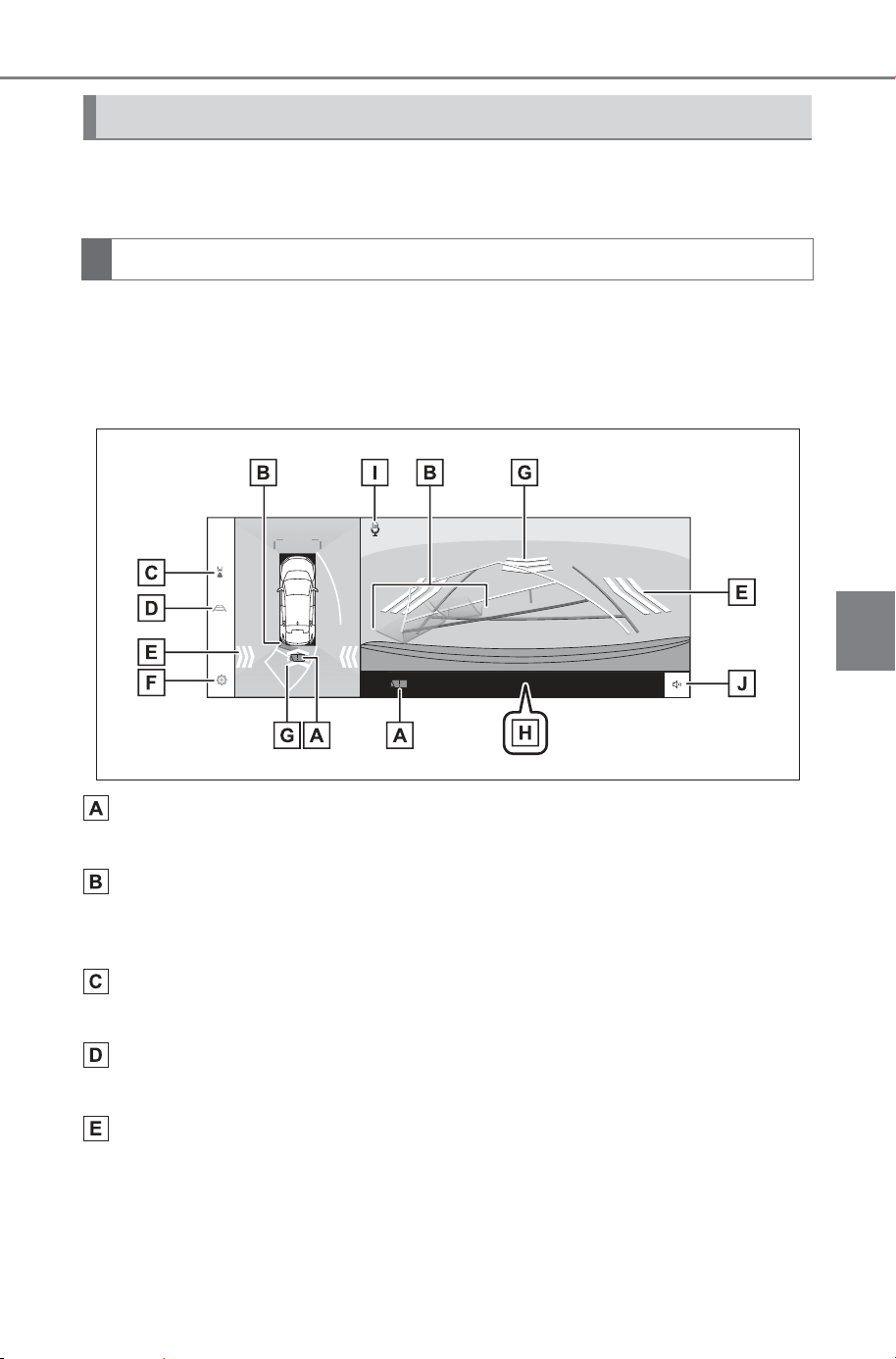
441
5-4. Using the driving support systems
Owner’s Manual_USA_M6740B_en
5
Driving
To check for safety when parking the vehicle, an image is displayed
from above the vehicle and from the rear camera.
1 Shift the shift position to R.
The mode changes every time you touch the display mode switching but-
ton.
Rear view & panoramic view
Camera dirt detection icon
This icon is displayed when dirt is detected on the camera.
SUBARU Parking Assist
Displays an indicator on the screen and sounds a buzzer when an object is
detected by a sensor.
Display mode switching button
Switches display mode every time you touch the button.
Guide line switching button
Switches guide line mode every time you touch the button. (P.444)
RCTA (Rear Cross Traffic Alert)/RCD (Rear Camera Detection)
The indicator is displayed on the screen in the following situations.
• When the rear radar detects an approaching vehicle or obstacle from the
rear
• When the rear camera detects a pedestrian to the rear
Display mode when the shift position is in R
Screen display
SOLTERRA_OM_USA_A6740BE.book 441 ページ 2025年5月23日 金曜日 午後1時18分
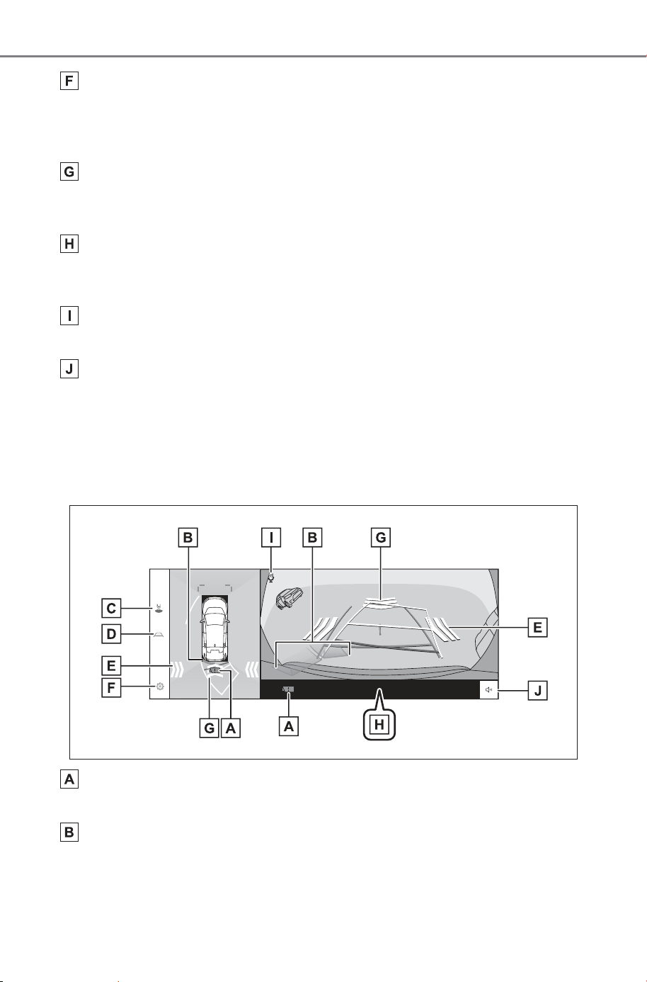
442
5-4. Using the driving support systems
Owner’s Manual_USA_M6740B_en
Customize settings button
Changes settings, such as the automatically display cornering view, the
vehicle body color, the SUBARU Parking Assist detection distance.
(P.453)
RCD (Rear Camera Detection)
If the rear camera detects a pedestrian behind the vehicle, an indicator is
displayed on the screen.
PKSB (Parking Support Brake)
If an obstacle that you may collide with is detected, a message is displayed
on the screen. (P.362)
Voice recognition icon
This icon is displayed when the Intelligent Assistant is in operation.
SUBARU Parking Assist/RCTA (Rear Cross Traffic Alert)/RCD
(Rear Camera Detection) mute button
This button temporarily mutes the SUBARU Parking Assist, RCTA (Rear
Cross Traffic Alert) and RCD (Rear Camera Detection) buzzer sound.
Operating the shift automatically cancels mute.
Wide rear view & panoramic view
Camera dirt detection icon
This icon is displayed when dirt is detected on the camera.
SUBARU Parking Assist
Displays an indicator on the screen and sounds a buzzer when an object is
detected by a sensor.
SOLTERRA_OM_USA_A6740BE.book 442 ページ 2025年5月23日 金曜日 午後1時18分

443
5-4. Using the driving support systems
Owner’s Manual_USA_M6740B_en
5
Driving
Display mode switching button
Switches display mode every time you touch the button.
Guide line switching button
Switches guide line mode every time you touch the button. (P.444)
RCTA (Rear Cross Traffic Alert)/RCD (Rear Camera Detection)
The indicator is displayed on the screen in the following situations.
• When the rear radar detects an approaching vehicle or obstacle from the
rear
• When the rear camera detects a pedestrian to the rear
Customize settings button
Changes settings, such as the automatically display cornering view, the
vehicle body color, the SUBARU Parking Assist detection distance.
(P.453)
RCD (Rear Camera Detection)
If the rear camera detects a pedestrian behind the vehicle, an indicator is
displayed on the screen.
PKSB (Parking Support Brake)
If an obstacle that you may collide with is detected, a message is displayed
on the screen. (P.362)
Voice recognition icon
This icon is displayed when the Intelligent Assistant is in operation.
SUBARU Parking Assist/RCTA (Rear Cross Traffic Alert)/RCD
(Rear Camera Detection) mute button
This button temporarily mutes the SUBARU Parking Assist, RCTA (Rear
Cross Traffic Alert) and RCD (Rear Camera Detection) buzzer sound.
Operating the shift automatically cancels mute.
■ Rear view & panoramic view/wide rear view & panoramic view dis-
play
● Pressing the camera switch when the shift position is in R enables you to
change to panoramic view & wide front view.
● The display position of the SUBARU Parking Assist (P.340) may not
match the position of the obstacle displayed in the camera image.
SOLTERRA_OM_USA_A6740BE.book 443 ページ 2025年5月23日 金曜日 午後1時18分
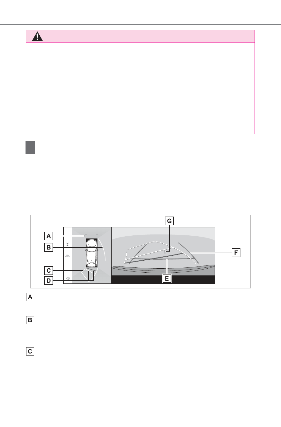
444
5-4. Using the driving support systems
Owner’s Manual_USA_M6740B_en
The guide line display mode changes every time you touch the guide
line switching button.
Estimated course lines mode
This mode displays estimated course lines that move in accordance
with the operation of the steering wheel.
Front distance guide lines
Displays about 3 ft. (1 m) (blue) in front of the vehicle.
Side estimated course lines
Displays course lines (yellow) that are linked to operation of the steering
wheel.
Reverse estimated course lines
Displays course lines (yellow) that are linked to operation of the steering
wheel.
WARNING
■ Guide line
The position of the guide lines displayed on the screen may change due
to factors such as number of passengers, load weight, and road gradient.
Always make sure to visually check behind you and your surroundings
while you are driving.
■ SUBARU Parking Assist, RCTA (Rear Cross Traffic Alert) and RCD
(Rear Camera Detection) display
The SUBARU Parking Assist, RCTA (Rear Cross Traffic Alert) and RCD
(Rear Camera Detection) displays are overlapped and displayed on the
camera image, so it may be difficult to see depending on the brightness of
the surroundings and colors.
Changing the guide line display mode
SOLTERRA_OM_USA_A6740BE.book 444 ページ 2025年5月23日 金曜日 午後1時18分
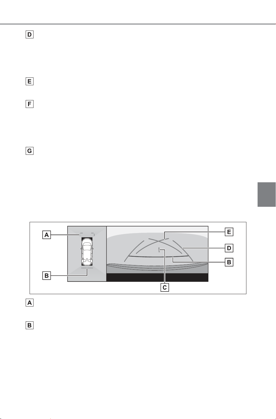
445
5-4. Using the driving support systems
Owner’s Manual_USA_M6740B_en
5
Driving
Rear distance guide lines
Displays the distance behind the vehicle.
• The distance guide line is linked to the estimated course lines.
• Displays about 1.5 ft. (0.5 m) (red) and 3 ft. (1 m) (yellow) from the center
end of the rear bumper.
Rear distance guide line
Displays about 1.5 ft. (0.5 m) (blue) from the end of the rear bumper.
Vehicle width guide lines
Displays course lines when the vehicle is being reversed in a straight line.
• The lines are wider than the actual width of the vehicle.
• When the vehicle is straight, the guide lines will overlap with the esti-
mated course lines.
Vehicle center guide line
Displays the center of the vehicle width guide lines.
Parking assist guide lines mode
This mode displays the steering wheel return points (parking assist
guide lines). This mode is recommended for those who have a
sense of the vehicle and can park the vehicle without the aid of the
estimated course lines.
Front distance guide lines
Displays about 3 ft. (1 m) (blue) in front of the vehicle.
Rear distance guide lines
Displays the distance behind the vehicle.
• Displays about 1.5 ft. (0.5 m) (red) from the center end of the rear
bumper.
SOLTERRA_OM_USA_A6740BE.book 445 ページ 2025年5月23日 金曜日 午後1時18分
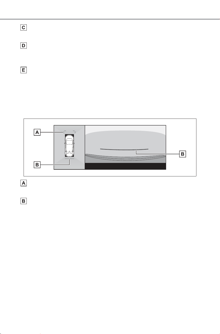
446
5-4. Using the driving support systems
Owner’s Manual_USA_M6740B_en
Vehicle center guide line
Displays the center of the vehicle width guide lines.
Vehicle width guide lines
Displays course lines when the vehicle is being reversed in a straight line.
• The lines are wider than the actual width of the vehicle.
Parking assist guide lines
Displays the course lines of the smallest turn possible behind the vehicle.
• Use the position of operating the steering wheel when parking as a guide.
Distance guide lines mode
This mode only displays the distance guide lines. It is recommended
for those who do not need the guide lines.
Front distance guide lines
Displays about 3 ft. (1 m) (blue) in front of the vehicle.
Rear distance guide lines
Displays the distance behind the vehicle.
• Displays about 1.5 ft. (0.5 m) (red) from the center end of the rear
bumper.
Estimated course center line mode
This mode displays estimated course lines and a vehicle center
guide line that move in accordance with the operation of the steering
wheel.
Use this mode when approaching a signpost or pole with the center
of the rear bumper.
SOLTERRA_OM_USA_A6740BE.book 446 ページ 2025年5月23日 金曜日 午後1時18分
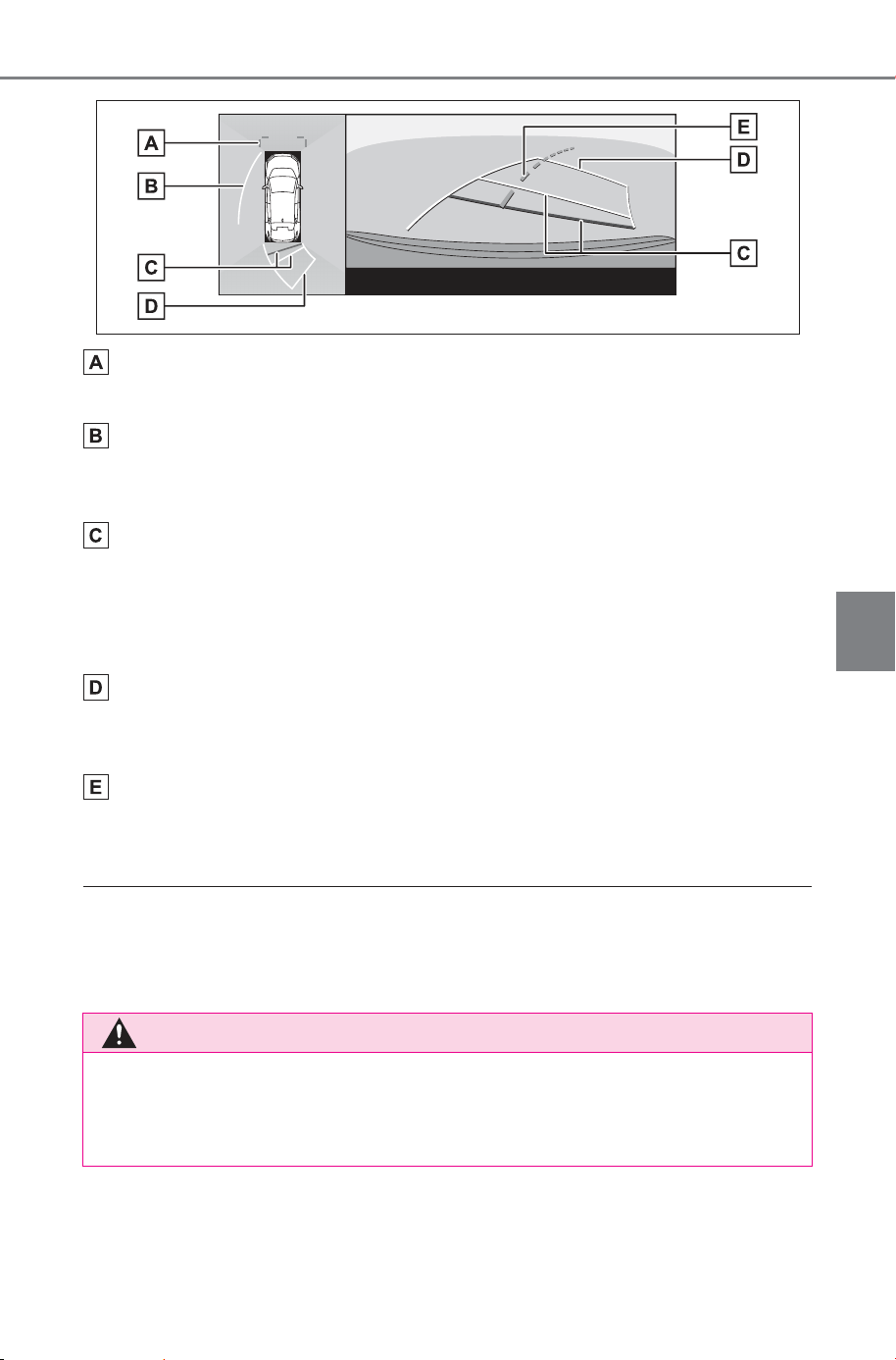
447
5-4. Using the driving support systems
Owner’s Manual_USA_M6740B_en
5
Driving
Front distance guide lines
Displays about 3 ft. (1 m) (blue) in front of the vehicle.
Side estimated course lines
Displays course lines (yellow) that are linked to operation of the steering
wheel.
Rear distance guide lines
Displays the distance behind the vehicle.
• The distance guide line is linked to the estimated course lines.
• Displays about 1.5 ft. (0.5 m) (red) and 3 ft. (1 m) (yellow) from the center
end of the rear bumper.
Reverse estimated course lines
Displays course lines (yellow) that are linked to operation of the steering
wheel.
Estimated course center line
Displays the vehicle center guide line (green) that is linked to operation of
the steering wheel.
■ Guide line display mode
The guide lines will not be displayed if the back door is not closed. If the
back door is closed but the guide lines are still not displayed, have the vehi-
cle inspected by your SUBARU dealer.
WARNING
■ Guide line display mode
The rear vehicle width guide lines are wider than the actual width of the
vehicle. Always make sure to visually check behind you and your sur-
roundings when you are reversing.
SOLTERRA_OM_USA_A6740BE.book 447 ページ 2025年5月23日 金曜日 午後1時18分
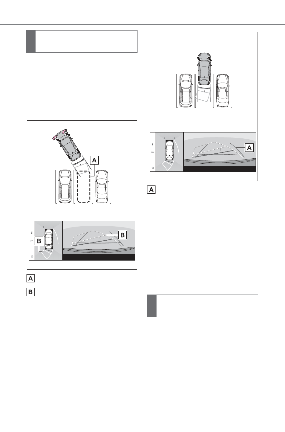
448
5-4. Using the driving support systems
Owner’s Manual_USA_M6740B_en
1 Shift the shift position to R.
2 Turn the steering wheel so
that the estimated course
lines are within the parking
space and then reverse
slowly.
Parking space
Estimated course lines
3 When the rear of the vehicle
has entered the parking
space, turn the steering
wheel so that the vehicle
width guide lines are within
the left and right dividing lines
of the parking space.
Vehicle width guide lines
4 Once the vehicle width guide
lines and the parking space
lines are parallel, straighten
the steering wheel and
reverse slowly until the vehi-
cle has completely entered
the parking space.
5 Stop the vehicle in an appro-
priate place to finish parking.
1 Shift the shift position to R.
2 Reverse until the parking
assist guide lines align with
the right-hand dividing line of
the parking space.
Parking using the esti-
mated course lines mode
Parking using the parking
assist guide lines mode
SOLTERRA_OM_USA_A6740BE.book 448 ページ 2025年5月23日 金曜日 午後1時18分
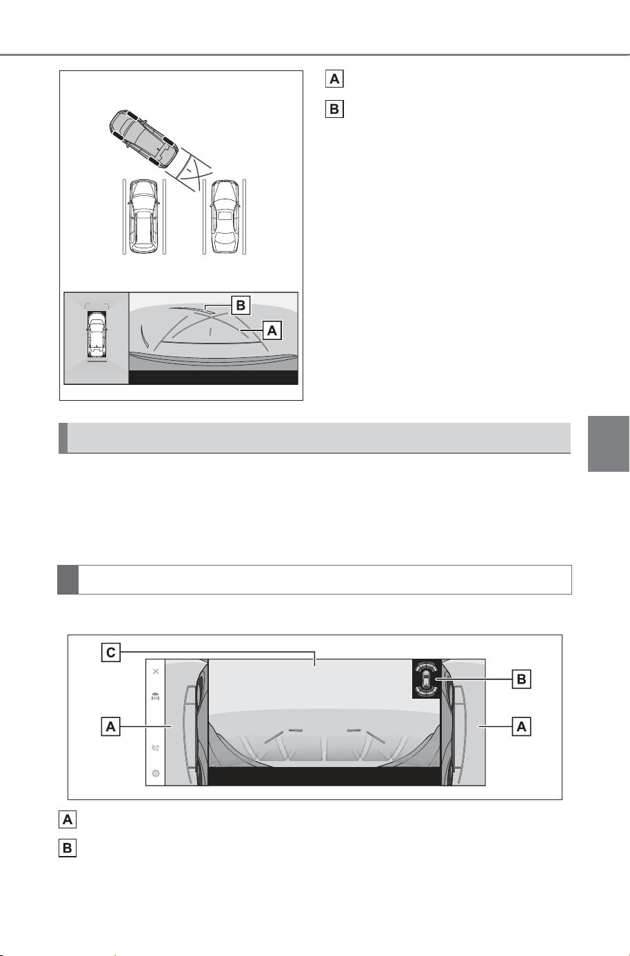
449
5-4. Using the driving support systems
Owner’s Manual_USA_M6740B_en
5
Driving
Parking assist guide lines
Parking space dividing lines
3 Turn the steering wheel all
the way to the left, and
reverse slowly.
4 Once the vehicle is parallel
with the parking space,
straighten the steering wheel
and reverse slowly until the
vehicle has completely
entered the parking space.
5 Stop the vehicle in an appro-
priate place to finish parking.
When the outside rear view mirrors are folded, an image from the
side cameras rather than panoramic view will be displayed. This can
assist you in confirming that the vicinity of the vehicle is safe when
you are parking in a narrow place.
Side view & Wide front view
Side views
SUBARU Parking Assist
Displays an indicator on the screen and sounds a buzzer when an object is
detected by a sensor.
The screen when the outside rear view mirrors are folded
Screen display
SOLTERRA_OM_USA_A6740BE.book 449 ページ 2025年5月23日 金曜日 午後1時18分
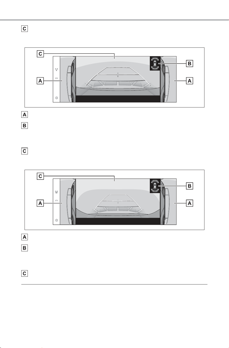
450
5-4. Using the driving support systems
Owner’s Manual_USA_M6740B_en
Wide front view
Side view & Rear view
Side views
SUBARU Parking Assist
Displays an indicator on the screen and sounds a buzzer when an object is
detected by a sensor.
Rear view
Side view & Wide rear view
Side views
SUBARU Parking Assist
Displays an indicator on the screen and sounds a buzzer when an object is
detected by a sensor.
Wide rear view
■ SUBARU Parking Assist display
The display position of the SUBARU Parking Assist (P.340) may not
match the position of the obstacle displayed in the camera image.
SOLTERRA_OM_USA_A6740BE.book 450 ページ 2025年5月23日 金曜日 午後1時18分
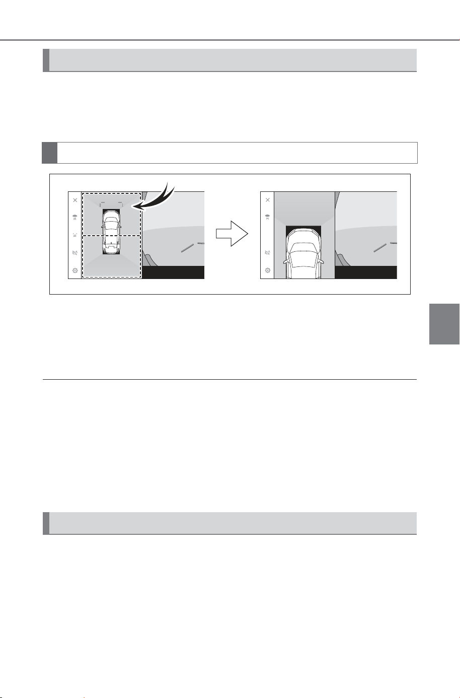
451
5-4. Using the driving support systems
Owner’s Manual_USA_M6740B_en
5
Driving
Zooming in on the screen can be done if the image on the screen is
too small and hard to see.
Touch the area that you want to zoom in on the panoramic view.
The selected area is zoomed in on.
You can zoom in on either the area in front of the vehicle or the
area behind it in panoramic view.
To cancel the zoom, touch the screen again.
■ Zooming in on the screen
● The zoom feature is enabled when all of the following conditions are met:
• The vehicle speed is below 7 mph (12 km/h)
• The SUBARU Parking Assist (P.340) is turned on
● In any of the following situations, the zoom feature will be canceled auto-
matically:
• The vehicle speed is above 7 mph (12 km/h)
• The SUBARU Parking Assist is turned off
● The guide lines will not be displayed when the panoramic view is zoomed.
A composite of camera vision captured in the past from the current
vehicle position to assist understanding of the situation under the
vehicle, tire positions, and so on can be displayed. The vision is dis-
played in panoramic view, side clearance view, or cornering view.
Zooming in on the screen
Screen display
Displaying transparent underfloor vision
SOLTERRA_OM_USA_A6740BE.book 451 ページ 2025年5月23日 金曜日 午後1時18分
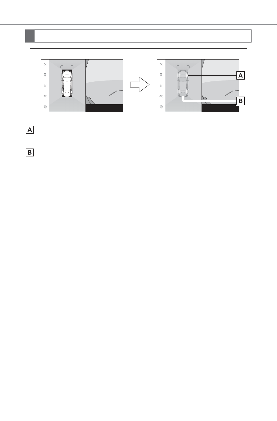
452
5-4. Using the driving support systems
Owner’s Manual_USA_M6740B_en
Tire tracks
Displays the tire position guides linked to the steering wheel.
Vehicle guide lines
Displays the exterior of the vehicle.
■ Transparent underfloor vision
● Transparent underfloor vision is displayed when the setting on the cus-
tomized setting screen is turned on and the vehicle is moving forward or
backward.
● Transparent underfloor vision is not displayed in the following cases:
• The vehicle speed is above 12 mph (20 km/h)
• The vehicle stops and a certain amount of time passes.
• If the vehicle does not move a certain distance after it is started.
• The side mirrors are folded.
• ABS is operating.
• The system is not functioning correctly.
● The system may not function correctly in the following situations:
• Snow covered roads.
• There are shadows from lights and so forth.
• There is dirt or a foreign object on the camera lens.
• Water (river, sea, etc.).
• Optional equipment has been installed.
• There is an obstacle in front of the camera.
• The tires were replaced.
• The back door is open and the camera is not in the correct position.
• The road surface is slippery or the wheels slip.
• The vehicle is on a hill or other steep roads.
● As vision that was captured in the past is being displayed, the screen and
the actual situation may differ in the following cases:
• An obstacle appears or moves after vision is captured.
• Sand or snow crumbles and moves after vision is captured.
• Mud or puddles are in the display range.
• When the vehicle slips.
Screen display
SOLTERRA_OM_USA_A6740BE.book 452 ページ 2025年5月23日 金曜日 午後1時18分
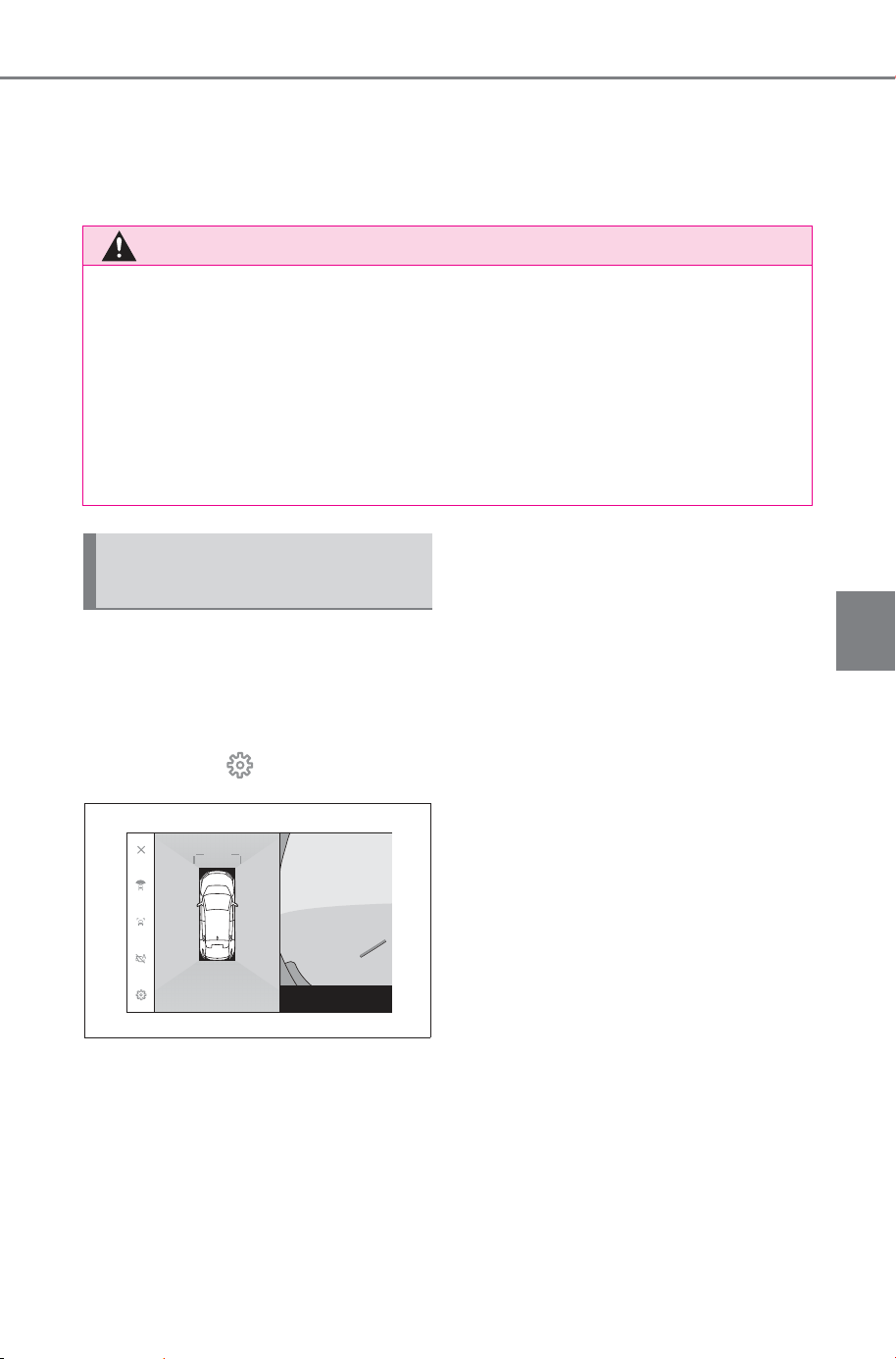
453
5-4. Using the driving support systems
Owner’s Manual_USA_M6740B_en
5
Driving
● Part or all of the transparent underfloor vision may appear black in the fol-
lowing cases:
• The vehicle starts moving with no captured vision.
• The steering wheel is turned more than a certain angle.
• The vehicle stops and a certain amount of time passes.
Settings related to Multi-terrain
Monitor such as the cornering
view auto display and vehicle
body color can be changed.
1 Touch the .
2 Select the desired item.
Cornering view
Automatically display the cornering
view.
View Under Vehicle
Turn the transparent underfloor
vision display setting on or off. Set-
ting it to on and moving the vehicle
forward or backwards displays a
composite of camera vision cap-
tured in the past from the current
vehicle position to assist under-
standing of the situation under the
vehicle, front tire positions, and so
on. The vision is displayed in pan-
oramic view, side clearance view,
or cornering view.
SUBARU Park Assist 3D Dis-
play
Show or hide the SUBARU Parking
Assist 3D display.
SUBARU Park Assist Dis-
tance
Change the distance that the SUB-
ARU Parking Assist starts detecting
obstacles.
Vehicle Body Color
Change the vehicle body color dis-
played on the screen.
WARNING
■ Transparent underfloor vision
● The tire and vehicle guide lines may not align correctly with the actual
vehicle position due to the number of passengers, vehicle load, road
gradient, road surface conditions, brightness of the surroundings,
optional equipment, tire replacements, and other reasons. Always make
sure to check your surroundings while you are driving.
● Displayed vision is vision that was captured in the past. Therefore, if
obstacles and other objects move after being captured, the transparent
underfloor vision and the actual situation may not always match.
Changing the Multi-terrain
Monitor settings
SOLTERRA_OM_USA_A6740BE.book 453 ページ 2025年5月23日 金曜日 午後1時18分
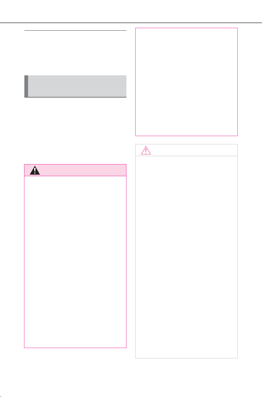
454
5-4. Using the driving support systems
Owner’s Manual_USA_M6740B_en
■ Suspension of the settings dis-
play
For safety purposes, you cannot
display the custom settings screen
while the vehicle is moving.
Observe the following precau-
tions. Failure to do so may result
in an unexpected accident. Also,
when driving, make sure to
directly confirm the safety of
your surroundings and the area
to the rear of the vehicle.
When using the Multi-ter-
rain Monitor
WARNING
■ Conditions under which the
Multi-terrain Monitor should
not be used
Do not use the Multi-terrain Moni-
tor in the following situations. The
system may not operate properly,
resulting in an unexpected acci-
dent.
● On icy or slick road surfaces, or
in snow
● When using tire chains or emer-
gency tires
● When the front door(s) or back
door are not closed completely
● On roads that are not flat, such
as hills
● If the tires of a size other than
specified by SUBARU are
installed
● If the suspension has been
modified
● If a non-SUBARU product is
installed on the area displayed
on the screen
■ Guide lines
The tire position indicator lines
and vehicle position indicator
lines may differ from actual vehi-
cle positions depending on the
number of passengers, cargo
weight, road grade, road surface
conditions, brightness of the sur-
rounding environment, etc.
Always drive the vehicle while
confirming the safety of your sur-
roundings.
NOTICE
■ Panoramic view
● See-through view, moving view,
panoramic view, side clearance
view, and cornering view pro-
duce an image that is a com-
posite of images captured by
the front camera, rear camera,
and side cameras. As there is a
limit to the displayable range
and content, make sure you
fully understand the features of
the panoramic view monitor
before you use it.
● The four corners of the see-
through view, moving view, pan-
oramic view, side clearance
view, and cornering view have a
video composition processing
region centered on borders of
the cameras, and image clarity
may decline. However this is not
a fault.
● Depending on lighting condi-
tions near each camera, bright
and dark patches may appear
on the see-through view, mov-
ing view, panoramic view, side
clearance view, and cornering
view.
SOLTERRA_OM_USA_A6740BE.book 454 ページ 2025年5月23日 金曜日 午後1時18分

455
5-4. Using the driving support systems
Owner’s Manual_USA_M6740B_en
5
Driving
NOTICE
● See-through view, moving view,
panoramic view, side clearance
view, and cornering view does
not extend higher than the
installation position and image
capture range of each camera.
● There are blind spots around
the vehicle and as such there
are regions not displayed on the
panoramic view monitor.
● Three-dimensional objects dis-
played in wide front view, rear
view, wide rear view or side
view may not be displayed in
see-through view, moving view,
panoramic view, side clearance
view, and cornering view.
● People and other three-dimen-
sional obstacles may appear
differently when displayed on
the panoramic view monitor.
(These differences include
cases in which displayed
objects appear to have fallen
over, disappear near image pro-
cessing regions, appear from
video composition processing
areas, or when the actual dis-
tance to an object differs from
the displayed position.)
● When the back door, which is
equipped with the rear camera,
or front doors, which are
equipped with side mirrors that
have the built-in side cameras,
are open, images will not be dis-
played properly on the pan-
oramic view monitor.
● The vehicle icon displayed in
see-through view, moving view,
panoramic view, side clearance
view, and cornering view is a
computer generated image, so
the color, shape and size will
differ from the actual vehicle.
Therefore, nearby three-dimen-
sional objects may appear to be
touching the vehicle, and actual
distances to three-dimensional
objects may differ from those
displayed.
SOLTERRA_OM_USA_A6740BE.book 455 ページ 2025年5月23日 金曜日 午後1時18分
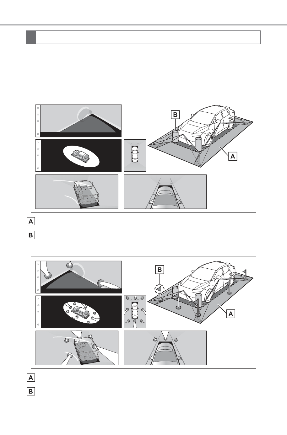
456
5-4. Using the driving support systems
Owner’s Manual_USA_M6740B_en
There are blind spots around the vehicle and as such there are
regions not displayed on the screen. Even if nothing around the vehi-
cle is displayed on the screen, there may actually be obstacles on
the road, which you may collide with. Always make sure to visually
check your surroundings.
Area displayed on the screen
Objects not displayed on the screen
Objects in the black areas do not appear on the screen.
Area displayed on the screen
Parts of objects not displayed on the screen
Parts higher than the road do not appear on the screen.
Area displayed on the screen
SOLTERRA_OM_USA_A6740BE.book 456 ページ 2025年5月23日 金曜日 午後1時18分
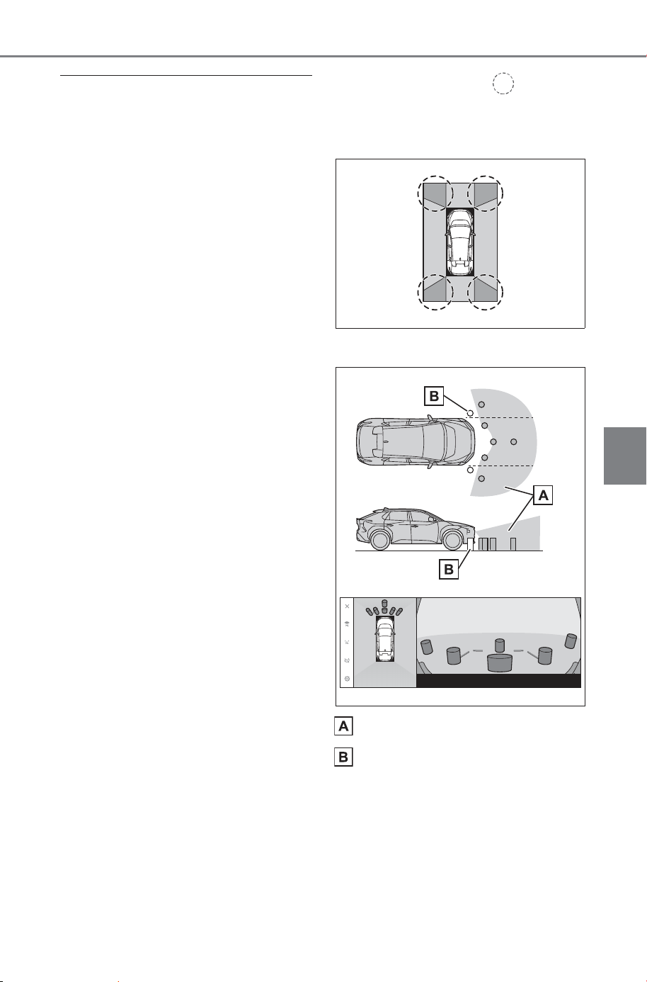
457
5-4. Using the driving support systems
Owner’s Manual_USA_M6740B_en
5
Driving
■ Area displayed on screen
● The black parts around the vehicle
icon are not displayed by the cam-
era. Visually check those areas.
● As the images are obtained from
four cameras are processed and
displayed on the standard of a flat
road surface, see-through view,
moving view, panoramic view
(including zoomed display), side
clearance view, and cornering
view may be displayed as follows:
• Objects may look collapsed; thin-
ner or bigger than usual.
• An object with a higher position
than the road surface may look
further away than it actually is or
may not appear at all.
• Tall objects may appear protruding
from the non-displayed areas of
the image.
● Variations in the brightness of the
image may appear for every cam-
era due to lighting conditions.
● The displayed image may be mis-
aligned due to inclination of the
vehicle body or change in vehicle
height caused by the number of
passengers, vehicle load.
● If the doors are not completely
closed, the image and the guide
lines may not be displayed cor-
rectly.
● The positional relationship of the
road surface and objects with the
vehicle icon displayed on see-
through view, moving view, pan-
oramic view (including zoomed
display), side clearance view, and
cornering view may differ to the
actual positions.
● Light from a back-lit license plate
may appear on the screen.
● Images indicated by in the fig-
ure are a composite, and hence
some areas may be difficult to
see.
■ Wide front view
Area displayed on the screen
Objects not displayed on the
screen
Areas close to both corners of the
bumpers will not appear on the
screen.
SOLTERRA_OM_USA_A6740BE.book 457 ページ 2025年5月23日 金曜日 午後1時18分
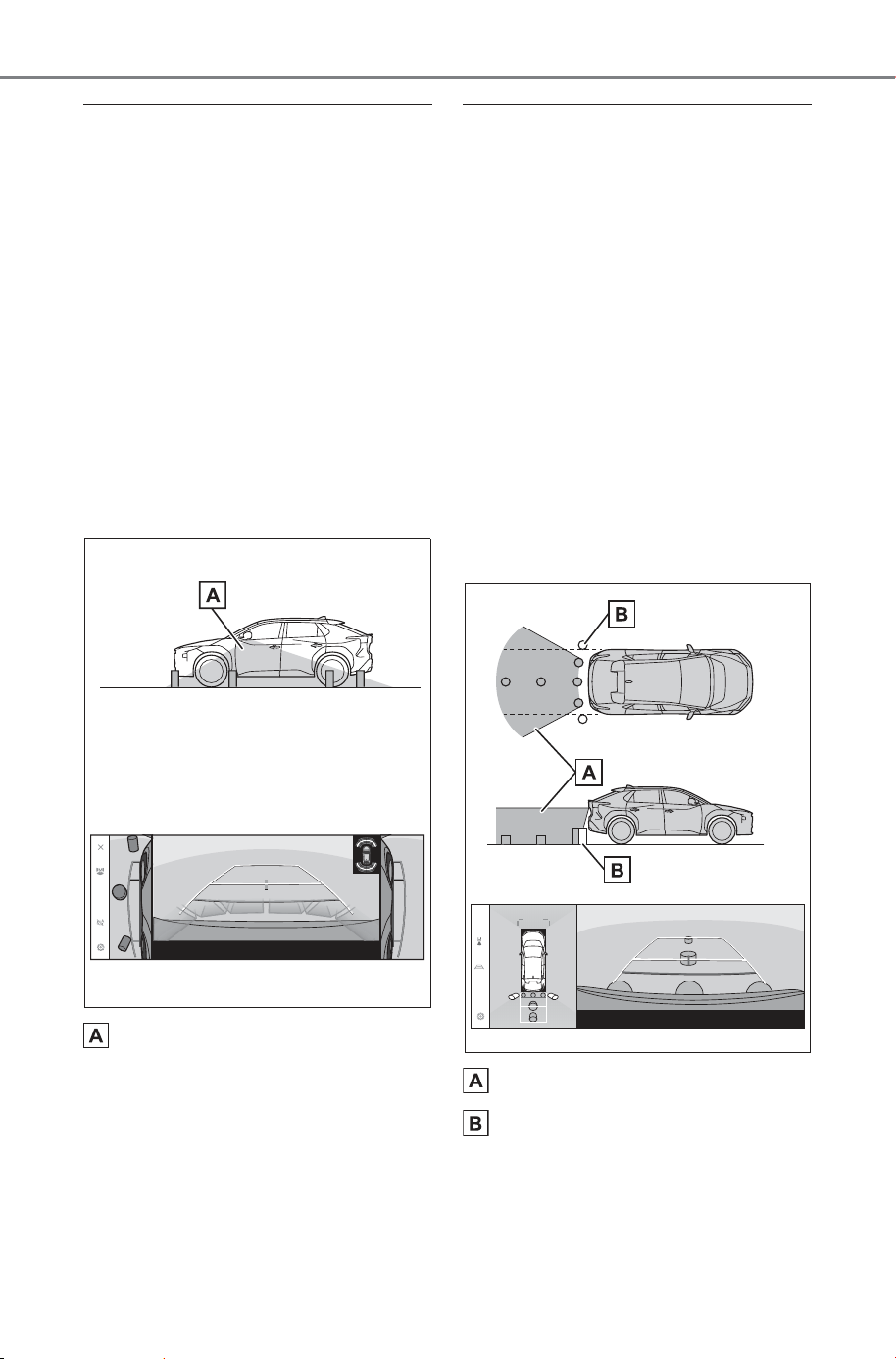
458
5-4. Using the driving support systems
Owner’s Manual_USA_M6740B_en
■ Display range
● The area covered by the camera
is limited. Objects that are close to
either corner of the bumper or
under the bumper cannot be dis-
played on the screen.
● The depth perception of the image
displayed on the screen differs to
the actual distance.
● The wide front view camera uses
a special lens, so the depth per-
ception of the image displayed on
the screen differs to the actual dis-
tance.
Side view & Rear view (when
the side mirrors are folded)
Area displayed on the screen
■ Display range
● The range that is displayed on the
screen may differ due to the state
of the vehicle and road surface.
● The area covered by the camera
is limited. Objects that are close to
the bumper on the passenger’s
side or under the bumper cannot
be displayed on the screen.
● The depth perception of the image
displayed on the screen differs to
the actual distance.
● The cameras on side view & rear
view use a special lens, so the
depth perception of the image dis-
played on the screen differs to the
actual distance.
Rear view
Area displayed on the screen
Objects not displayed on the
screen
Areas close to both corners of the
bumpers will not appear on the
screen.
SOLTERRA_OM_USA_A6740BE.book 458 ページ 2025年5月23日 金曜日 午後1時18分
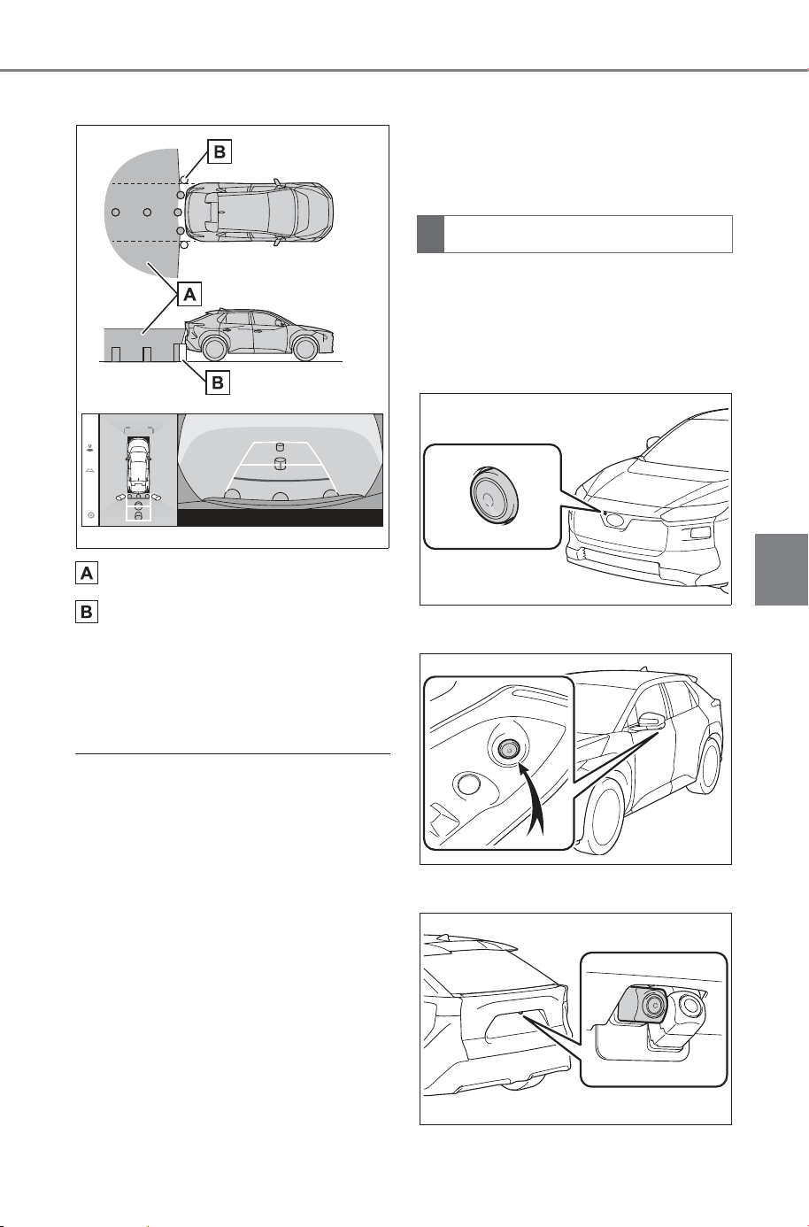
459
5-4. Using the driving support systems
Owner’s Manual_USA_M6740B_en
5
Driving
Wide rear view
Area displayed on the screen
Objects not displayed on the
screen
Areas close to both corners of the
bumpers will not appear on the
screen.
■ Display range
● The range that is displayed on the
screen may differ due to the state
of the vehicle and road surface.
● The area covered by the camera
is limited. Objects that are close to
either corner of the bumper or
under the bumper cannot be dis-
played on the screen.
● The depth perception of the image
displayed on the screen differs to
the actual distance.
● The rear view and wide rear view
cameras use a special lens, so the
depth perception of the image dis-
played on the screen differs to the
actual distance.
● Objects that are higher than the
rear camera may not appear in the
monitor.
● Light from a back-lit license plate
may appear on the screen.
The Multi-terrain Monitor cam-
eras are in the locations shown
in the figures.
■ Front camera
■ Side cameras
■ Rear camera
Camera position
SOLTERRA_OM_USA_A6740BE.book 459 ページ 2025年5月23日 金曜日 午後1時18分
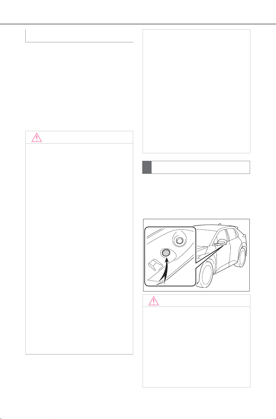
460
5-4. Using the driving support systems
Owner’s Manual_USA_M6740B_en
If dirt or foreign matter, such as
water droplets, snow, or mud,
has stuck to the camera, you will
not be able to see the image
clearly. If that happens, splash
the camera with a large amount
of water and then wipe the cam-
era lens clean with a soft, damp
cloth.
The parking assist lights of the
Multi-terrain Monitor system are
installed in the locations shown
in the figure.
Cleaning the camera
NOTICE
■ How to use the cameras
● The Multi-terrain Monitor may
stop functioning correctly. Take
note of the following items:
• Do not hit or apply a forceful
impact on the camera. Doing so
may change the position and
mounting angle of the camera.
• The camera is designed to be
waterproof. Do not detach, dis-
assemble, or modify it.
• When washing the camera lens,
splash the camera with a large
amount of water and then wipe
the camera lens clean with a
soft, damp cloth. Rubbing the
camera lens forcibly may
scratch the camera lens and
you may no longer be able to
see images clearly.
• The camera cover is made of
resin. Do not allow an organic
solvent, car wax, window
cleaner, or glass coating to
adhere to the camera. If this
happens, wipe it off immedi-
ately.
• Do not pour hot water on the
vehicle in cold weather or apply
other rapid changes of tempera-
ture.
• If you wash the vehicle with a
high pressure car washer, do
not point the hose directly at the
camera or camera area. Apply-
ing strong water pressure may
result in the camera malfunc-
tioning.
● If the camera is hit, it may cause
a camera malfunction. If this
happens, have the vehicle
inspected by your SUBARU
dealer as soon as possible.
Parking assist lights
NOTICE
■ Parking assist lights
● Make sure to observe the fol-
lowing precautions, otherwise
the Multi-terrain Monitor system
may not operate correctly:
• Do not apply excessive force to
a light or subject it to a strong
impact. Doing so may cause the
position or installation angle of
the light to deviate.
SOLTERRA_OM_USA_A6740BE.book 460 ページ 2025年5月23日 金曜日 午後1時18分
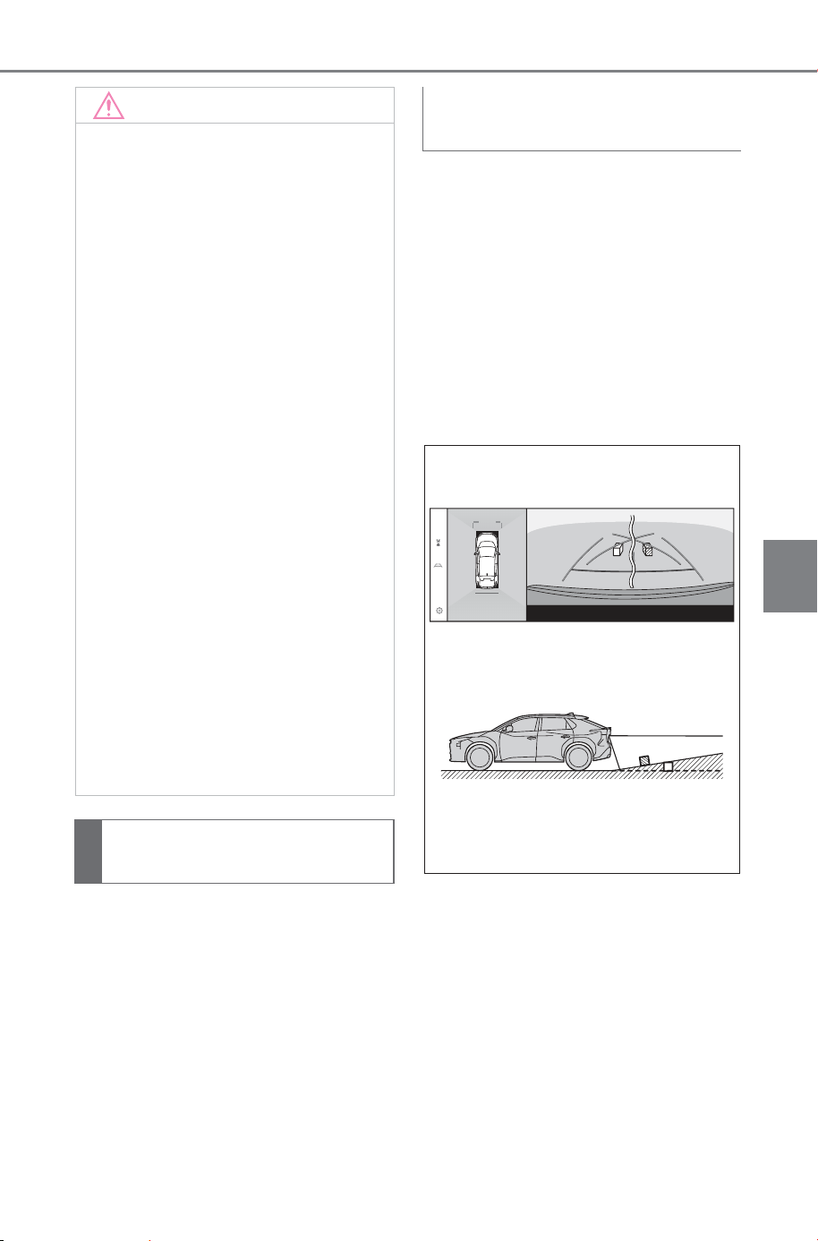
461
5-4. Using the driving support systems
Owner’s Manual_USA_M6740B_en
5
Driving
The composite images on the
Multi-terrain Monitor and guide
lines give a distance guide for
flat road surfaces. Therefore,
there is a margin of error
between the guide lines on the
screen and the actual distance
and course on the road.
The distance guide lines will
appear to be closer to the vehi-
cle than the actual distance.
Thus, objects on up-slopes will
appear to be farther away than
they actually are. In the same
way, there will be a margin of
error between the guidelines
and the actual distance and
course on the road.
NOTICE
• Do not remove, disassemble, or
modify the lights as they have a
waterproof construction.
• When cleaning the lights, wash
them with a large amount of
water, and then wipe them with
a soft wet cloth.
• Do not apply organic solvents,
waxes, oil removing solvents,
glass coatings, etc. to the cov-
ers of the lights, as they are
made of resin. If such is applied,
remove it immediately.
• Do not expose the lights to sud-
den temperature changes, such
as applying hot water to them
when it is cold.
• When washing the vehicle with
a high-pressure washer, do not
spray water directly on the lights
or their surrounding area. High-
pressure water can damage the
lights and cause them to not
operate correctly.
● If a light has been subjected to
a strong impact, it may be dam-
aged. Have the vehicle
inspected by your SUBARU
dealer as soon as possible.
Difference between the
screen and the actual road
When the ground behind the
vehicle slopes up sharply
SOLTERRA_OM_USA_A6740BE.book 461 ページ 2025年5月23日 金曜日 午後1時18分
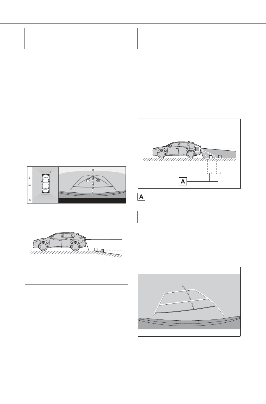
462
5-4. Using the driving support systems
Owner’s Manual_USA_M6740B_en
The distance guide lines will
appear to be further from the
vehicle than the actual distance.
Thus, objects on down-slopes
will appear to be closer than
they actually are. In the same
way, there will be a margin of
error between the guidelines
and the actual distance and
course on the road.
When any part of the vehicle
sags due to the number of pas-
sengers or the distribution of the
load, there is a margin of error
between the guide lines on the
screen and the actual distance
and course on the road.
Margin of error
As the guide lines are shown
midair near the rear bumper,
there are times that they may
look like they are off-center.
When the ground behind the
vehicle slopes down sharply
When any part of the vehicle
sags
Estimated course center line
SOLTERRA_OM_USA_A6740BE.book 462 ページ 2025年5月23日 金曜日 午後1時18分
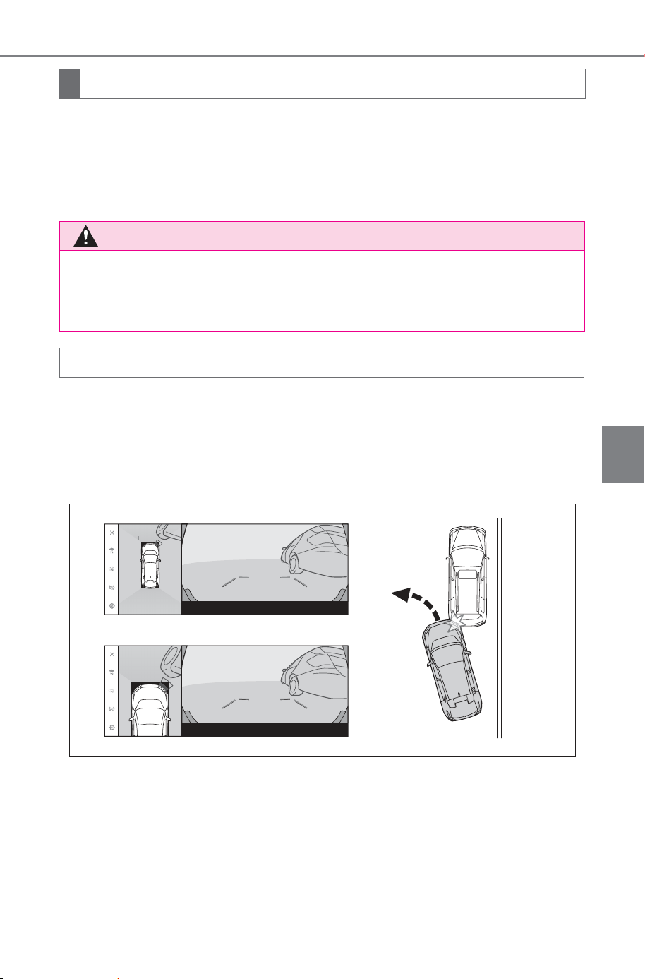
463
5-4. Using the driving support systems
Owner’s Manual_USA_M6740B_en
5
Driving
Since the guide lines displayed on the screen are for a flat road sur-
face, it is not possible to determine the position of three-dimensional
objects. When approaching a three-dimensional object that extends
outward (such as the flatbed of a truck), take note of the following
cautions.
On the screen, it appears that there is a gap between the vehicle’s
bumper and another object or vehicle, and it does not look as if the
vehicle will collide with the object or vehicle. However, the vehicle is
over the course lines, so the vehicle may collide with the object or
vehicle. Make sure to visually check your surroundings.
Differences between the screen and actual 3D objects
WARNING
■ SUBARU Parking Assist pop-up display
When the SUBARU Parking Assist display is red, make sure to visually
check before moving the vehicle any further. There is the danger that you
may collide with another vehicle or have some other unforeseen accident.
Displaying panoramic view (including zoom display)
SOLTERRA_OM_USA_A6740BE.book 463 ページ 2025年5月23日 金曜日 午後1時18分
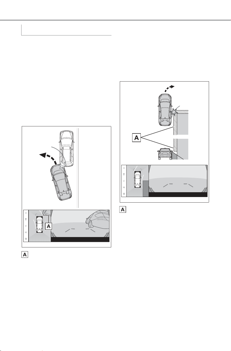
464
5-4. Using the driving support systems
Owner’s Manual_USA_M6740B_en
On the screen, it appears that
the vehicle’s bumper is out-
side of the estimated course
lines, and it does not look as if
the vehicle will collide with the
object or vehicle. However,
the vehicle is over the course
lines, so the vehicle may col-
lide with the object or vehicle.
Make sure to visually check
your surroundings.
Estimated course lines
Three-dimensional objects in
high positions (such as the
overhang of a wall or loading
platform of a truck) may not
appear on the screen. Make
sure to visually check your
surroundings.
Overhang of a wall
Estimated course lines
SOLTERRA_OM_USA_A6740BE.book 464 ページ 2025年5月23日 金曜日 午後1時18分
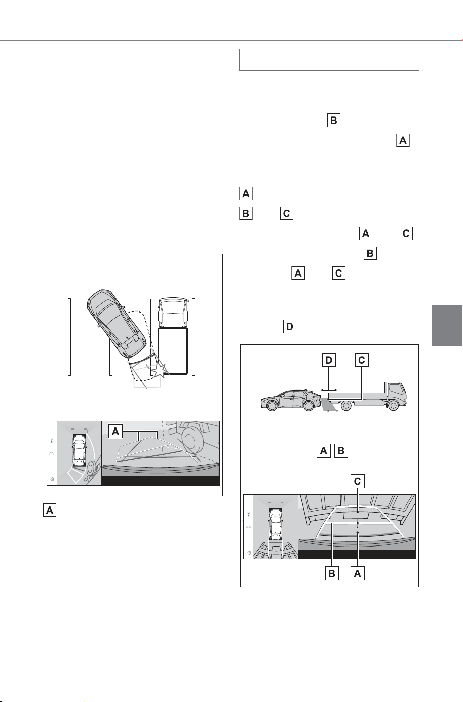
465
5-4. Using the driving support systems
Owner’s Manual_USA_M6740B_en
5
Driving
On the screen, a truck flatbed
may appear to be outside of
the estimated course lines
and the vehicle does not look
as if it will collide with the
truck. However, the flatbed
may actually cross over the
estimated course lines and if
you reverse as guided by the
estimated course lines, the
vehicle may hit the truck.
Make sure to visually check
your surroundings.
Estimated course lines
On the screen, the distance
guide lines shows that a truck is
parking at point . However, in
reality if you reverse to point ,
you will collide with the truck. On
the screen, it appears that point
is closest followed by points
and . However, in reality,
the distance to points and
is the same, and point is far-
ther than and . Make sure
to visually check behind you and
your surroundings. The distance
to point is about 3 ft. (1 m).
Distance guide lines
SOLTERRA_OM_USA_A6740BE.book 465 ページ 2025年5月23日 金曜日 午後1時18分
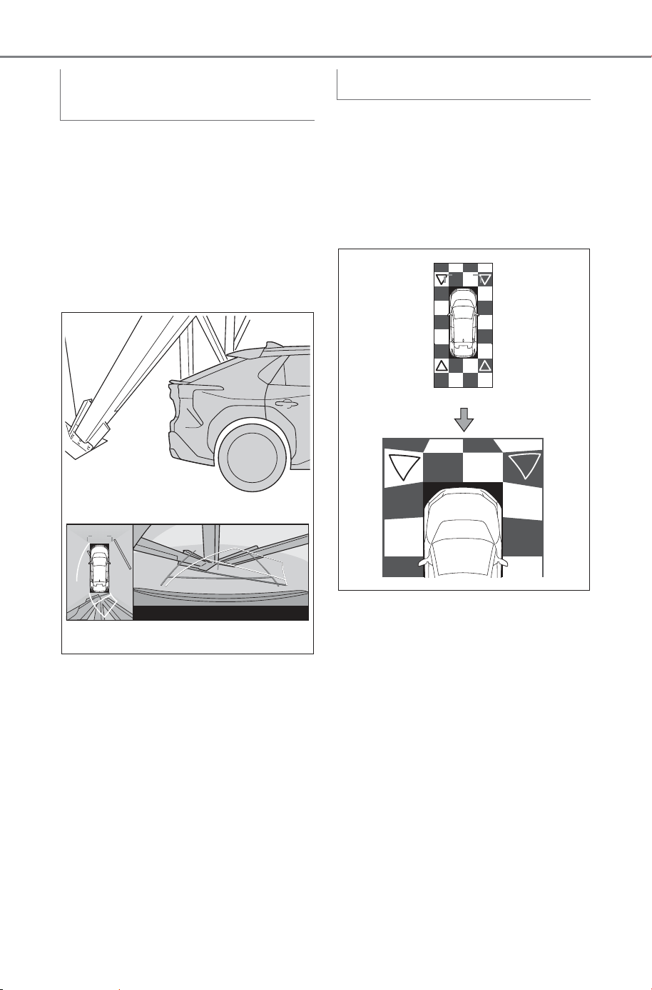
466
5-4. Using the driving support systems
Owner’s Manual_USA_M6740B_en
In panoramic view, a diagonal
beam may appear straight and
seems likely not to be struck,
however, since the top part of
the beam is actually overhang-
ing, the vehicle may hit it. Make
sure to visually check the rear
and surroundings.
Unlike the normal panoramic
view, the panoramic view mag-
nifying function zooms in on the
vehicle icon. Therefore, white
lines on the road, walls, and
other objects may look bent.
Overhang of a diagonal
beam
Magnifying function
SOLTERRA_OM_USA_A6740BE.book 466 ページ 2025年5月23日 金曜日 午後1時18分
467
5-4. Using the driving support systems
Owner’s Manual_USA_M6740B_en
5
Driving
The tire position indicator lines
and vehicle position indicator
lines may differ from actual vehi-
cle positions depending on the
number of passengers, weight
of the load, road grade, road
surface conditions, brightness of
the surrounding environment,
etc. Always drive the vehicle
while directly confirming the
safety of your surroundings
■ Using under vehicle terrain
view
● The images displayed were previ-
ously taken behind the current
vehicle position.
Therefore, actual conditions may
differ from those shown on the
screen in the following situations.
• When conditions changed such as
when an object moved or entered
the frame after the image was
taken.
• Loose material like sand or snow
has crumbled or shifted
• An obstacle has moved
• There is a puddle, tract of mud,
etc., within the display range
• The vehicle slips
● In the following situations, actual
tire positions and vehicle position
may differ from those indicated by
the tire position indicator lines and
vehicle position indicator lines.
• Tires have been replaced
• Optional equipment has been
installed
Under vehicle terrain view
WARNING
■ Guide lines
The displayed guide lines are
composed with the image that
was previously taken and may dif-
fer from the actual state. Always
drive the vehicle while confirming
the safety of your surroundings.
SOLTERRA_OM_USA_A6740BE.book 467 ページ 2025年5月23日 金曜日 午後1時18分
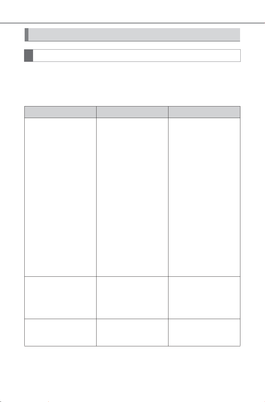
468
5-4. Using the driving support systems
Owner’s Manual_USA_M6740B_en
If you notice or are troubled by any of the symptoms below, check
the issue again referring to the likely cause and solution.
If the symptom is not resolved by the solution, have the vehicle
inspected by your SUBARU dealer.
Things you should know
If you notice any symptoms
Symptom Likely cause Solution
The screen is difficult to
see
The vehicle is in a
dark area or it is night.
The temperature
around the lens is
either high or low
The outside tempera-
ture is low
There are water drop-
lets on the camera
It is raining or humid
Foreign matter (mud,
etc.) is stuck to the
camera
Sunlight or headlights
are shining directly
into the camera
The vehicle is under
fluorescent lights,
sodium lights, mer-
cury lights, etc.
Visually check the vehi-
cle’s surroundings while
you are driving.
Use the Multi-terrain
Monitor again once the
camera and conditions
have improved.
The procedure for
adjusting the picture
quality of the Multi-ter-
rain Monitor system is
the same as the proce-
dure for adjusting the
screen display. Refer to
the “MULTIMEDIA
OWNER’S MANUAL”.
The image is blurry
Dirt or foreign matter,
such as water droplets,
snow, or mud, has stuck
to the camera lens.
Splash the camera with
a large amount of water
and then wipe the cam-
era lens clean with a
soft, damp cloth.
The screen is mis-
aligned
The camera has
received a strong
impact.
Have the vehicle
inspected by your SUB-
ARU dealer.
SOLTERRA_OM_USA_A6740BE.book 468 ページ 2025年5月23日 金曜日 午後1時18分

469
5-4. Using the driving support systems
Owner’s Manual_USA_M6740B_en
5
Driving
The guide lines are sig-
nificantly misaligned
The camera position is
misaligned.
Have the vehicle
inspected by your SUB-
ARU dealer.
The vehicle is tilted.
(There is a heavy load
on the vehicle, tire
pressure is low due to
a tire puncture, etc.)
The vehicle is on an
incline.
Visually check the vehi-
cle’s surroundings while
you are driving.
The estimated course
lines move even though
the steering wheel is
straight (the vehicle
width guide lines and
estimated course lines
are out of alignment).
There is a malfunction
in the signals being out-
put by the steering sen-
sor.
Have the vehicle
inspected by your SUB-
ARU dealer.
The guide lines are not
displayed
The back door is open.
Close the back door.
If this does not resolve
the symptom, have the
vehicle inspected by
your SUBARU dealer.
The panoramic view dis-
play cannot be
enlarged.
The see-through
view/moving view, side
clearance view, and cor-
nering view cannot be
displayed.
The SUBARU Parking
Assist may be malfunc-
tioning or dirty.
Follow the correction
procedures for malfunc-
tions of the SUBARU
Parking Assist.
(P.340)
Rear camera image is
difficult to see.
Foreign matters (such
as water droplets, mud,
snow and snow melting
agents.) is on the cam-
era lens.
Rinse the camera with a
large quantity of water,
wipe it clean with a soft
cloth dampened with
water.
Foreign matters (such
as Ice, snow and mud)
is attached to surround-
ing parts of the camera
lens.
Remove foreign mat-
ters.
Symptom Likely cause Solution
SOLTERRA_OM_USA_A6740BE.book 469 ページ 2025年5月23日 金曜日 午後1時18分
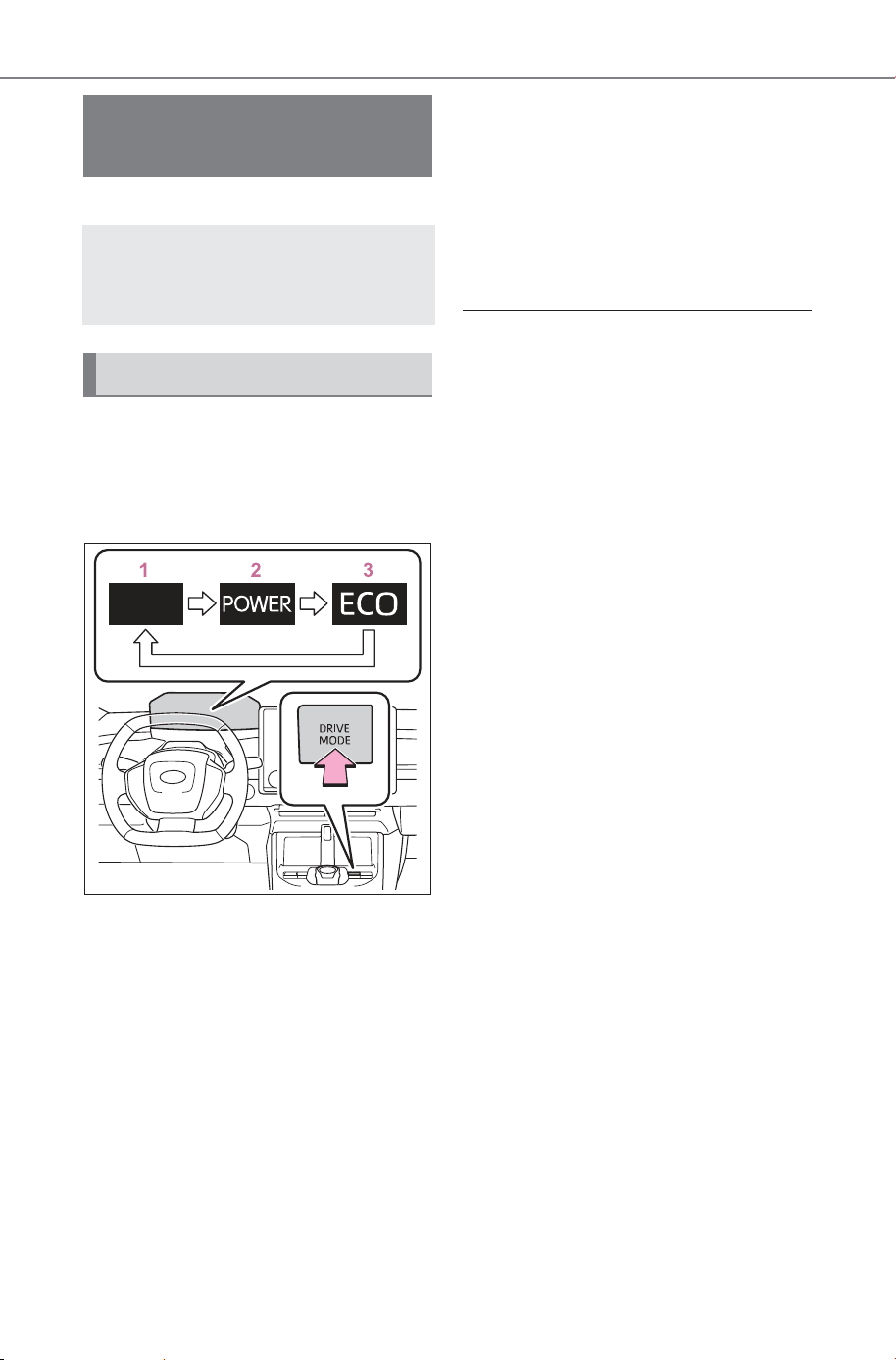
470
5-4. Using the driving support systems
Owner’s Manual_USA_M6740B_en
*
: If equipped
Each time the switch is pressed,
the system changes between
power mode, normal mode, and
Eco drive mode.
1 Normal mode
It has a good balance electrical
consumption performance, quiet-
ness, and drive performance, and
is suitable for normal driving.
2 Power mode
By controlling the EV system, it is
possible to speed up the reaction to
the accelerator operation and
accelerate powerfully.
3 Eco drive mode
It moderates the driving force for
accelerator operations. It is suited
for driving with an awareness of
improving electricity consumption.
The Eco drive mode indicator turns
on.
■ Drive mode cancellation
• Power mode is automatically can-
celed when the power switch is
turned off or “X-MODE” is
selected, and returns to normal
mode.
• Normal mode and Eco drive mode
are not canceled unless switched
to another driving mode or select
“X-MODE”. (Even if the power
switch is turned off, it will not be
canceled automatically)
● When drive mode select is not
available
When “X-MODE” is selected, it is
not possible to switch to power
mode and Eco drive mode.
Drive mode select
switch
*
The drive modes can be
selected to suit driving con-
dition.
Selecting a drive mode
SOLTERRA_OM_USA_A6740BE.book 470 ページ 2025年5月23日 金曜日 午後1時18分
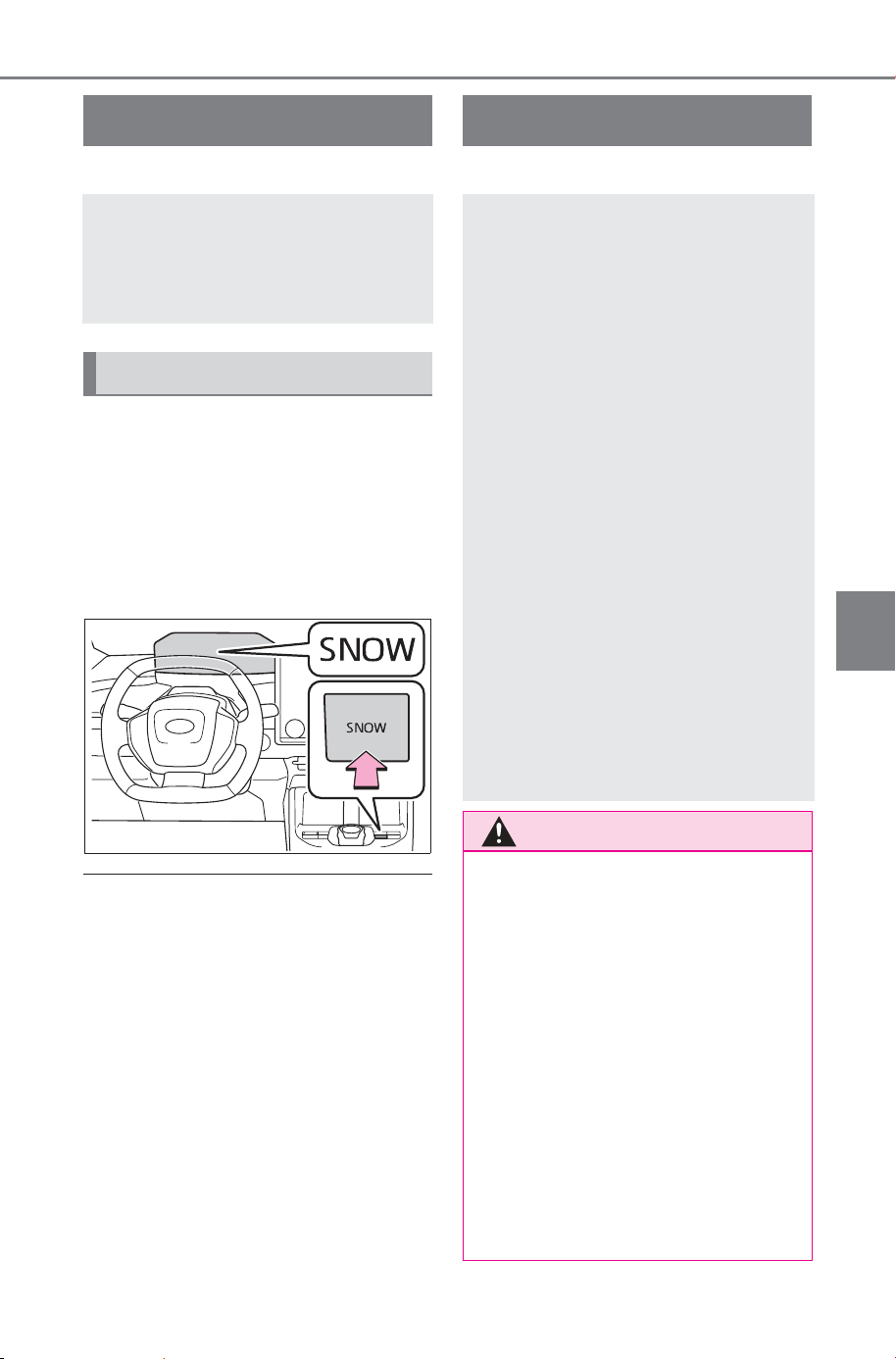
471
5-4. Using the driving support systems
Owner’s Manual_USA_M6740B_en
5
Driving
*
: If equipped
Press the snow mode switch
When the switch is pressed, snow
mode turns on and the snow mode
indicator illuminates on the multi-
information display. When the
switch is pressed again, the snow
mode indicator turns off.
■ Snow Mode Automatic Cancel-
lation
Snow mode is automatically can-
celed by turning off the power
switch.
*
: If equipped
Snow mode
*
Snow mode can be selected
to suit the conditions when
driving on slippery road
surfaces, such as on snow.
System operation
X-MODE
*
This mode has improved
road handling ability off
roads.
Select between the 2 types
of mode, SNOW/DIRT and
D.SNOW/MUD.
During “X-MODE”, the
downhill assist control will
control the brakes to main-
tain a constant vehicle
speed when driving on
steep descents.
Grip control supports the
driver’s operation by main-
taining a low vehicle speed
on steep inclines and slip-
pery roads without having
to step on the accelerator
pedal or brake pedal.
WARNING
■ Be sure to observe the follow-
ing before using “X-MODE”
If not observed, there is the dan-
ger that it may lead to an unex-
pected accident.
● Drive the vehicle after checking
that the SNOW/DIRT indica-
tor/D.SNOW/MUD indicator
turns on.
● “X-MODE” is not a device that
enhances the limited perfor-
mance of the vehicle. Carefully
check the road surface condi-
tions and the driving route in
advance, and then drive with
caution.
SOLTERRA_OM_USA_A6740BE.book 471 ページ 2025年5月23日 金曜日 午後1時18分
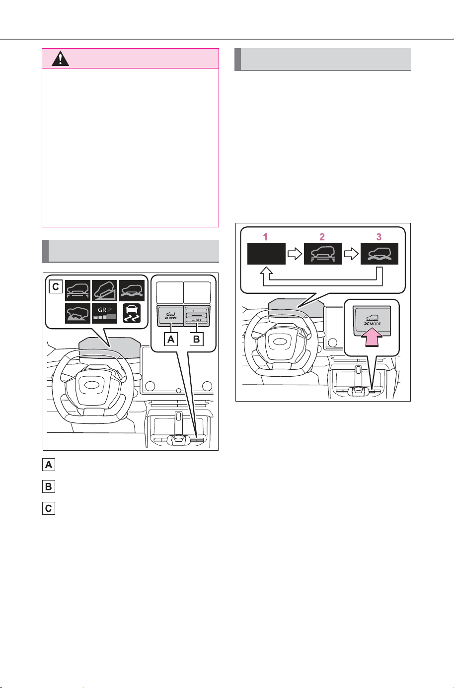
472
5-4. Using the driving support systems
Owner’s Manual_USA_M6740B_en
“X-MODE” switch
Grip control switch (P.474)
Indicators
Press the “X-MODE” switch
repeatedly until the system
switches to the desired driving
mode while the vehicle is
stopped or traveling at a speeds
less than approximately 13 mph
(20 km/h).
When the drive mode is
switched, the buzzer sounds.
1 Normal mode
Has a good balance of electrical
consumption performance, quiet-
ness, and driving performance, and
is suitable for driving in urban
areas.
2 SNOW/DIRT mode
When the tires are likely to slip or
slip on slippery roads such as
snowy roads, gravel roads, etc., the
tire spinning is reduced, making it
easier to drive.
At this time, the SNOW/DIRT mode
indicator lights up in green on the
meter.
WARNING
■ Conditions in which it may
not function correctly
When driving on the following
road surfaces, it may not be pos-
sible to maintain a constant speed
of the vehicle, which may lead to
an unexpected accident.
• Extremely steep inclines
• Rough road surfaces
• Slippery road surfaces such as
snowy roads and frozen road
surfaces
System Components
Selecting the Drive Mode
SOLTERRA_OM_USA_A6740BE.book 472 ページ 2025年5月23日 金曜日 午後1時18分

473
5-4. Using the driving support systems
Owner’s Manual_USA_M6740B_en
5
Driving
3 D.SNOW/MUD mode
In special cases such as the tires
being buried in deep snow or mud,
the TRAC (Traction Control) func-
tion is temporarily canceled, and
the tires are idled as needed to
make it easier to start.
At this time, the D.SNOW/MUD
mode indicator lights up in green on
the meter. In addition, the VSC OFF
indicator and PCS warning light will
be turned on in the meter.
■ When “X-MODE” is not avail-
able
In the following cases, the system
does not operate.
• When the EV system is not started
• When SNOW/DIRT mode or
D.SNOW/MUD mode is not
selected
• When Advanced Park is being
used (If equipped)
• When the EV system is malfunc-
tioning
■ About Dynamic Radar Cruise
Control or Cruise Control
Dynamic radar cruise control and
cruise control cannot be used during
“X-MODE”. If dynamic radar cruise
control or cruise control are being
used, it will be automatically can-
celed.
■ During “X-MODE”
• In “X-MODE”, VSC does not
switch ON/OFF even if the VSC
OFF switch is operated. It is fixed
as ON in SNOW/DIRT mode and
OFF in D.SNOW/MUD mode.
• During “X-MODE”, operating the
drive mode select switch will not
change the mode.
• The SNOW/DIRT and
D.SNOW/MUD modes control the
vehicle so that it can maximize the
drive force and improve the drive
force on rough roads. As a result,
electricity consumption may
diminish when compared to driv-
ing in normal mode.
■ “X-MODE” Automatic Release
• “X-MODE” is automatically can-
celed when the power switch is
turned OFF.
• When the vehicle speed exceeds
about 25 mph (40 km/h), the “X-
MODE” is canceled, the “X-
MODE” indicator on the meter
lights up in white, and switches to
the normal mode.
• When the vehicle speed is
approximately 22 mph (35 km/h)
or less, “X-MODE” indicator lights
up in green and switches to “X-
MODE” again.
■ Cautions regarding the use of
the system
For safety, the following operations
are not accepted when “X-MODE” is
ON.
• Drive mode select switch Opera-
tion
When the “X-MODE” switch is
pressed and SNOW/DIRT mode
or D.SNOW/MUD mode is
selected, the Downhill Assist
Control automatically enters the
standby state and operates
under the following conditions.
• When the vehicle speed is
approximately 18 mph (30
km/h) or less
• Neither the accelerator pedal
or brake pedal are not oper-
ated
When selecting “X-
MODE”, Downhill Assist
Control
SOLTERRA_OM_USA_A6740BE.book 473 ページ 2025年5月23日 金曜日 午後1時18分
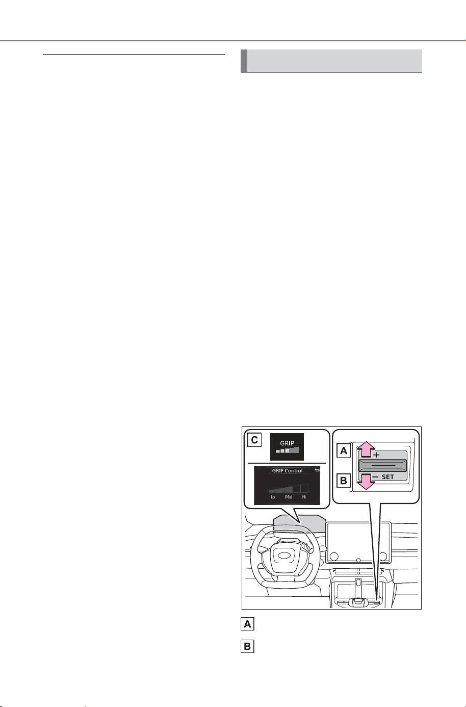
474
5-4. Using the driving support systems
Owner’s Manual_USA_M6740B_en
■ When changing the target vehi-
cle speed
When changing the target vehicle
speed, adjust it with the accelerator
pedal or the brake pedal. When the
foot is removed from the pedal, the
system will operate at the vehicle
speed at that time.
■ Downhill Assist Control during
“X-MODE”
• In SNOW/DIRT mode or
D.SNOW/MUD mode, the down-
hill assist control can be set to
standby state. The operation indi-
cator changes depending on the
operating status of the downhill
assist control.
• When the system is not operating,
the indicator turns on white.
■ When Downhill Assist Control
is not available when selecting
“X-MODE”
In the following cases, the system
does not operate.
• When SNOW/DIRT mode or
D.SNOW/MUD mode is not
selected
• When the shift position is in P
• When the Grip control is operating
• When the brake system or EV
system is malfunctioning
With SNOW/DIRT mode or
D.SNOW/MUD mode selected,
press down on the Grip control
switch.
At this time, the downhill assist
control system indicator turns off
and the Grip control indicator
turns on.
When the vehicle is stopped,
press the brake pedal firmly and
operate the switch. The vehicle
may start moving unintentionally
on an incline.
■ Set the speed of the Grip
control
Press the Grip control switch up
or down to set the desired
speed (approximately 2 to 6
mph [2 to 10 km/h]). The set
speed is shown on the multi-
information display.
Increase Speed
Decrease Speed
When using Grip control
SOLTERRA_OM_USA_A6740BE.book 474 ページ 2025年5月23日 金曜日 午後1時18分

475
5-4. Using the driving support systems
Owner’s Manual_USA_M6740B_en
5
Driving
Indicator Lights
■ Grip control Operations
During system operations, the
Grip control indicator turns on
green. If the Grip control indica-
tor is white, release the brake
pedal to activate the system.
While the system is operating,
the accelerator pedal and brake
pedal can be used to temporar-
ily accelerate or decelerate. If
operating the accelerator pedal
or brake pedal is stopped, the
speed will return to the set
speed.
■ When Grip control is
released
• Press the “X-MODE” Switch
When the Grip control is released,
the Grip control operation light
turns off, and after a while, the
downhill assist control system indi-
cator light turns on.
Drive carefully when releasing Grip
control while driving.
■ Grip control Operations Condi-
tions
• When in “X-MODE”
• When the shift position is in D
• When the parking brake has been
released
• When the driver side door is
closed
• When the vehicle is stopped by
stepping on the brake or the vehi-
cle speed is approximately 2 to 6
mph (2 to 10 km/h)
■ Automatic Releasing the Grip
control
In case of any of the following, the
Grip control is released.
• When the vehicle is stopped by
stepping on the brake pedal
• When the vehicle speed exceeds
more than 13 mph (20 km/h)
• When the shift position in a posi-
tion other than D
• When the parking brake is oper-
ated
• When the driver side door is
opened
• ABS/VSC is activated.
• When brake control and output
suppression by the driving support
device are activated (example:
Pre-Collision System, Parking
Support Brake)
• When the system determines it
cannot continue in the current
environment
• When the power switch is turned
OFF
■ When Grip control is not avail-
able
In the following conditions, Grip con-
trol is not available.
• When the brake system or EV
system is malfunctioning
• After the EV system is started and
until the vehicle has been running
for a while
■ Brake hold system
The brake hold system turns OFF
when the Grip control is being used.
Press the brake pedal firmly and
operate the switch.
When using the brake hold system
again, turn ON the brake hold sys-
tem after releasing the Grip control.
SOLTERRA_OM_USA_A6740BE.book 475 ページ 2025年5月23日 金曜日 午後1時18分
476
5-4. Using the driving support systems
Owner’s Manual_USA_M6740B_en
■ ECB (Electronically Con-
trolled Brake System)
The electronically controlled
system generates braking force
corresponding to the brake
operation
■ ABS (Anti-lock Brake Sys-
tem)
Helps to prevent wheel lock
when the brakes are applied
suddenly, or if the brakes are
applied while driving on a slip-
pery road surface
■ Brake assist
Generates an increased level of
braking force after the brake
pedal is depressed when the
system detects a panic stop sit-
uation
NOTICE
■ Long term usage
If used continuously for a long
periods of time, the temperature
of the brakes may rise the system
may temporarily stop.
■ Operation noises and vibra-
tions
• Operating noise may be heard
from motor room, however this
is not a malfunction.
• When the brake pedal is
depressed, it may become
harder than usual or it may feel
different from normal, but this is
not a malfunction.
■ When the operation indicator
does not turn on in the meter
even after operating the
switch
The system may not be working
properly. Have the vehicle
inspected at your SUBARU
dealer.
Driving assist systems
To keep driving safety and
performance, the following
systems operate automati-
cally in response to various
driving situations. Be
aware, however, that these
systems are supplementary
and should not be relied
upon too heavily when
operating the vehicle.
Summary of the driving
assist systems
SOLTERRA_OM_USA_A6740BE.book 476 ページ 2025年5月23日 金曜日 午後1時18分
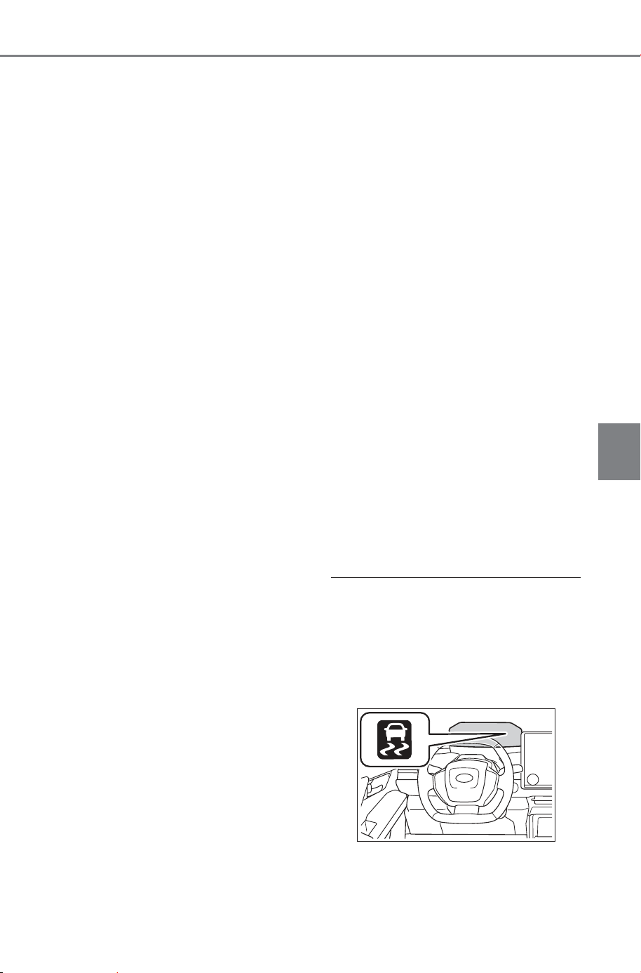
477
5-4. Using the driving support systems
Owner’s Manual_USA_M6740B_en
5
Driving
■ VSC (Vehicle Stability Con-
trol)
Helps the driver to control skid-
ding when swerving suddenly or
turning on slippery road sur-
faces.
■ Enhanced VSC (Enhanced
Vehicle Stability Control)
Provides cooperative control of
the ABS, TRAC, VSC and EPS.
Helps to maintain directional
stability when swerving on slip-
pery road surfaces by con-
trolling steering performance.
■ Trailer Sway Control
Helps the driver to control trailer
sway by selectively applying
brake pressure for individual
wheels and reducing driving
torque when trailer sway is
detected.
■ TRAC (Traction Control)
Helps to maintain drive power
and prevent the drive wheels
from spinning when starting the
vehicle or accelerating on slip-
pery roads
■ Active Cornering Assist
(ACA)
Helps to prevent the vehicle
from drifting to the outer side by
performing inner wheel brake
control when attempting to
accelerate while turning
■ Hill-start assist control
Helps to reduce the backward
movement of the vehicle when
starting on an uphill
■ EPS (Electric Power Steer-
ing)
Employs an electric motor to
reduce the amount of effort
needed to turn the steering
wheel.
■ The Secondary Collision
Brake (Secondary collision
reduction at the time of a
frontal collision)
When the SRS airbag sensor
detects a collision and the sys-
tem operates, the brakes and
brake lights are automatically
controlled to reduce the vehicle
speed and help reduce the pos-
sibility of further damage due to
a secondary collision.
■ When the
TRAC/VSC/ABS/Trailer Sway
Control systems are operating
The slip indicator light will flash
while the TRAC/VSC/ABS/Trailer
Sway Control systems are operat-
ing.
SOLTERRA_OM_USA_A6740BE.book 477 ページ 2025年5月23日 金曜日 午後1時18分
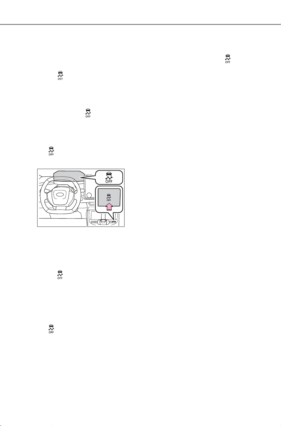
478
5-4. Using the driving support systems
Owner’s Manual_USA_M6740B_en
■ Disabling the TRAC system
If the vehicle gets stuck in mud, dirt
or snow, the TRAC system may
reduce power from the EV system to
the wheels.
Pressing to turn the system off
may make it easier for you to rock
the vehicle in order to free it.
To turn the TRAC system off, quickly
press and release .
The “Traction Control Turned OFF”
will be shown on the multi-informa-
tion display.
Press again to turn the system
back on.
■ Turning off both TRAC, VSC
and Trailer Sway Control sys-
tems
To turn the TRAC, VSC and Trailer
Sway Control systems off, press
and hold for more than 3 sec-
onds while the vehicle is stopped.
The VSC OFF indicator light will
come on and the “Traction Control
Turned OFF” will be shown on the
multi-information display.
*
Press again to turn the system
back on.
*
: PCS (Pre-Collision System) will
also be disabled (only pre-collision
warning is available). The PCS
warning light will come on and a
message will be displayed on the
multi-information display.
(P.275)
■ When the message is dis-
played on the multi-information
display showing that TRAC has
been disabled even if has
not been pressed
TRAC is temporary deactivated. If
the information continues to show,
contact your SUBARU dealer.
■ Operating conditions of hill-
start assist control
When all of the following conditions
are met, the hill-start assist control
will operate:
● The shift position is in a position
other than P or N (when starting
off forward/backward on an
upward incline)
● The vehicle is stopped
● The accelerator pedal is not
depressed
● The parking brake is not engaged
● Power switch is turned to ON
■ Automatic system cancelation
of hill-start assist control
The hill-start assist control will turn
off in any of the following situations:
● Shift the shift position to P or N
● The accelerator pedal is
depressed
● The brake pedal is depressed and
the parking brake is engaged
● A maximum of 2 seconds have
elapsed after the brake pedal is
released
● Power switch is turned to OFF
■ Sounds and vibrations caused
by the ABS, brake assist, VSC,
Trailer Sway Control, TRAC and
hill-start assist control systems
● A sound may be heard from the
motor compartment when the
brake pedal is depressed repeat-
edly, when the EV system is
started or just after the vehicle
begins to move. This sound does
not indicate that a malfunction has
SOLTERRA_OM_USA_A6740BE.book 478 ページ 2025年5月23日 金曜日 午後1時18分

479
5-4. Using the driving support systems
Owner’s Manual_USA_M6740B_en
5
Driving
occurred in any of these systems.
● Any of the following conditions
may occur when the above sys-
tems are operating. None of these
indicates that a malfunction has
occurred.
• Vibrations may be felt through the
vehicle body and steering.
• A motor sound may be heard also
after the vehicle comes to a stop.
■ ECB operating sound
ECB operating sound may be heard
in the following cases, but it does
not indicate that a malfunction has
occurred.
● Operating sound heard from the
motor compartment when the
brake pedal is operated.
● Motor sound of the brake system
heard from the front part of the
vehicle when the driver’s door is
opened.
● Operating sound heard from the
motor compartment when one or
two minutes passed after the stop
of the EV system.
■ Active Cornering Assist opera-
tion sounds and vibrations
When the Active Cornering Assist is
operated, operation sounds and
vibrations may be generated from
the brake system, but this is not a
malfunction.
■ Automatic reactivation of
TRAC, Trailer Sway Control and
VSC systems
After turning the TRAC, Trailer
Sway Control and VSC systems off,
the systems will be automatically re-
enabled in the following situations:
● When the power switch is turned
off
● If only the TRAC system is turned
off, the TRAC will turn on when
vehicle speed increases.
If both the TRAC and VSC sys-
tems are turned off, automatic re-
enabling will not occur when vehi-
cle speed increases
■ Operating conditions of Active
Cornering Assist
The system operates when the fol-
lowing occurs.
● TRAC/VSC can operate
● The driver is attempting to accel-
erate while turning
● The system detects that the vehi-
cle is drifting to the outer side
● The brake pedal is released
■ Reduced effectiveness of the
EPS system
The effectiveness of the EPS sys-
tem is reduced to prevent the sys-
tem from overheating when there is
frequent steering input over an
extended period of time. The steer-
ing wheel may feel heavy as a
result. Should this occur, refrain
from excessive steering input or
stop the vehicle and turn the EV
system off. The EPS system should
return to normal within 10 minutes.
■ Secondary Collision Brake
(Secondary collision reduction
at the time of a frontal collision)
operating conditions
The system operates when the SRS
airbag sensor detects a collision
while the vehicle is in motion. How-
ever, the system does not operate
when the components are dam-
aged.
■ Secondary Collision Brake
(Secondary collision reduction
at the time of a frontal collision)
automatic cancellation
The system is automatically can-
celed in any of the following situa-
tions.
● The vehicle speed drops to
approximately 0 mph (0 km/h)
● A certain amount of time elapses
during operation
● The accelerator pedal is
depressed a large amount
SOLTERRA_OM_USA_A6740BE.book 479 ページ 2025年5月23日 金曜日 午後1時18分
480
5-4. Using the driving support systems
Owner’s Manual_USA_M6740B_en
WARNING
■ The ABS does not operate
effectively when
● The limits of tire gripping perfor-
mance have been exceeded
(such as excessively worn tires
on a snow covered road).
● The vehicle hydroplanes while
driving at high speed on wet or
slick roads.
■ Stopping distance when the
ABS is operating may exceed
that of normal conditions
The ABS is not designed to
shorten the vehicle’s stopping dis-
tance. Always maintain a safe dis-
tance from the vehicle in front of
you, especially in the following sit-
uations:
● When driving on dirt, gravel or
snow-covered roads
● When driving with tire chains
● When driving over bumps in the
road
● When driving over roads with
potholes or uneven surfaces
■ TRAC/VSC may not operate
effectively when
Directional control and power may
not be achievable while driving on
slippery road surfaces, even if the
TRAC/VSC system is operating.
Drive the vehicle carefully in con-
ditions where stability and power
may be lost.
■ Active Cornering Assist does
not operate effectively when
● Do not overly rely on Active
Cornering Assist. Active Corner-
ing Assist may not operate
effectively when accelerating
down slopes or driving on slip-
pery road surfaces.
● When Active Cornering Assist
frequently operates, Active Cor-
nering Assist may temporarily
stop operating to ensure proper
operation of the brakes, TRAC
and VSC.
■ Hill-start assist control does
not operate effectively when
● Do not overly rely on hill-start
assist control. Hill-start assist
control may not operate effec-
tively on steep inclines and
roads covered with ice.
● Unlike the parking brake, hill-
start assist control is not
intended to hold the vehicle sta-
tionary for an extended period
of time. Do not attempt to use
hill-start assist control to hold
the vehicle on an incline, as
doing so may lead to an acci-
dent.
■ When the
TRAC/ABS/VSC/Trailer Sway
Control is activated
The slip indicator light flashes.
Always drive carefully. Reckless
driving may cause an accident.
Exercise particular care when the
indicator light flashes.
SOLTERRA_OM_USA_A6740BE.book 480 ページ 2025年5月23日 金曜日 午後1時18分

481
5-4. Using the driving support systems
Owner’s Manual_USA_M6740B_en
5
Driving
WARNING
■ When the TRAC/VSC/Trailer
Sway Control systems are
turned off
Be especially careful and drive at
a speed appropriate to the road
conditions. As these are the sys-
tems to help ensure vehicle stabil-
ity and driving force, do not turn
the TRAC/VSC/Trailer Sway Con-
trol systems off unless necessary.
Trailer Sway Control is part of the
VSC system and will not operate
if VSC is turned off or experiences
a malfunction.
■ Replacing tires
Make sure that all tires are of the
specified size, brand, tread pat-
tern and total load capacity. In
addition, make sure that the tires
are inflated to the recommended
tire inflation pressure level. The
ABS, TRAC Trailer Sway Control
and VSC systems will not function
correctly if different tires are
installed on the vehicle.
Contact your SUBARU dealer for
further information when replacing
tires or wheels.
■ Handling of tires and the sus-
pension
Using tires with any kind of prob-
lem or modifying the suspension
will affect the driving assist sys-
tems, and may cause a system to
malfunction.
■ Trailer Sway Control precau-
tion
The Trailer Sway Control system
is not able to reduce trailer sway
in all situations. Depending on
many factors such as the condi-
tions of the vehicle, trailer, road
surface and driving environment,
the Trailer Sway Control system
may not be effective. Refer to
your trailer owner’s manual for
information on how to tow your
trailer properly.
■ If trailer sway occurs
Observe the following precau-
tions.
Failing to do so may cause death
or serious injury.
● Firmly grip the steering wheel.
Steer straight ahead. Do not try
to control trailer sway by turning
the steering wheel.
● Begin releasing the accelerator
pedal immediately but very
gradually to reduce speed.
Do not increase speed. Do not
apply vehicle brakes.
If you make no extreme correction
with the steering or brakes, your
vehicle and trailer should stabi-
lize. (P.228)
■ Secondary Collision Brake
(Secondary collision reduc-
tion at the time of a frontal
collision)
Do not rely solely upon the Sec-
ondary Collision Brake (Second-
ary collision reduction at the time
of a frontal collision). This system
is designed to help reduce the
possibility of further damage due
to a secondary collision, however,
that effect changes according to
various conditions. Overly relying
on the system may result in death
or serious injury.
SOLTERRA_OM_USA_A6740BE.book 481 ページ 2025年5月23日 金曜日 午後1時18分
482
5-5. Driving tips
Owner’s Manual_USA_M6740B_en
5-5 .Driv ing t ips
Use fluids that are appropriate
to the prevailing outside tem-
peratures.
• Power control unit coolant
• Heater coolant
• Washer fluid
Have a service technician
inspect the condition of the
12-volt battery.
Have the vehicle fitted with
four snow tires or purchase a
set of tire chains for the front
tires.
Ensure that all tires are the same
size and brand, and that chains
match the size of the tires.
Winter driving tips
Carry out the necessary
preparations and inspec-
tions before driving the
vehicle in winter. Always
drive the vehicle in a man-
ner appropriate to the pre-
vailing weather conditions.
Pre-winter preparations
WARNING
■ Driving with snow tires
Observe the following precautions
to reduce the risk of accidents.
Failure to do so may result in a
loss of vehicle control and cause
death or serious injury.
● Use tires of the specified size.
● Maintain the recommended
level of air pressure.
● Do not drive in excess of 75
mph (120 km/h), regardless of
the type of snow tires being
used.
● Use snow tires on all, not just
some wheels.
■ Driving with tire chains
Observe the following precautions
to reduce the risk of accidents.
Failure to do so may result in the
vehicle being unable to be driven
safely, and may cause death or
serious injury.
● Do not drive in excess of the
speed limit specified for the tire
chains being used, or 30 mph
(50 km/h), whichever is lower.
● Avoid driving on bumpy road
surfaces or over potholes.
● Avoid sudden acceleration,
abrupt steering, sudden brak-
ing and shifting operations that
cause sudden regenerative
braking.
● Slow down sufficiently before
entering a curve to ensure that
vehicle control is maintained.
● Do not use LTA (Lane Tracing
Assist) system.
NOTICE
■ Repairing or replacing snow
tires (vehicle with the tire
pressure warning system)
Request repairs or replacement of
snow tires from your SUBARU
dealer or legitimate tire retailers.
This is because the removal and
attachment of snow tires affects
the operation of the tire pressure
warning valves and transmitters.
SOLTERRA_OM_USA_A6740BE.book 482 ページ 2025年5月23日 金曜日 午後1時18分
483
5-5. Driving tips
Owner’s Manual_USA_M6740B_en
5
Driving
Perform the following according
to the driving conditions:
Do not try to forcibly open a
window or move a wiper that
is frozen. Pour warm water
over the frozen area to melt
the ice. Wipe away the water
immediately to prevent it from
freezing.
To ensure proper operation of
the climate control system
fan, remove any snow that
has accumulated on the air
inlet vents in front of the wind-
shield.
Check for and remove any
excess ice or snow that may
have accumulated on the
exterior lights, outside rear
view mirrors, windows, vehi-
cle’s roof, chassis, around the
tires or on the brakes.
Remove any snow or mud
from the bottom of your shoes
before getting in the vehicle.
Accelerate the vehicle slowly,
keep a safe distance between
you and the vehicle ahead, and
drive at a reduced speed suit-
able to road conditions.
Turn automatic mode of the
parking brake off. Otherwise,
the parking brake may freeze
and not be able to be
released automatically.
Also, avoid using the following
as the parking brake may
operate automatically, even if
automatic mode is off.
• Brake hold system
• Remote parking function
Park the vehicle and shift the
shift position to P without set-
ting the parking brake. The
parking brake may freeze up,
preventing it from being
released. If the vehicle is
parked without setting the
parking brake, make sure to
block the wheels.
Failure to do so may be dan-
gerous because it may cause
the vehicle to move unexpect-
edly, possibly leading to an
accident.
If the vehicle is parked without
setting the parking brake,
confirm that the shift position
cannot be moved out of P.
If the vehicle is left parked
with the brakes damp in cold
temperatures, there is a pos-
sibility of the brakes freezing.
Before driving the vehicle
When driving the vehicle
When parking the vehicle
SOLTERRA_OM_USA_A6740BE.book 483 ページ 2025年5月23日 金曜日 午後1時18分
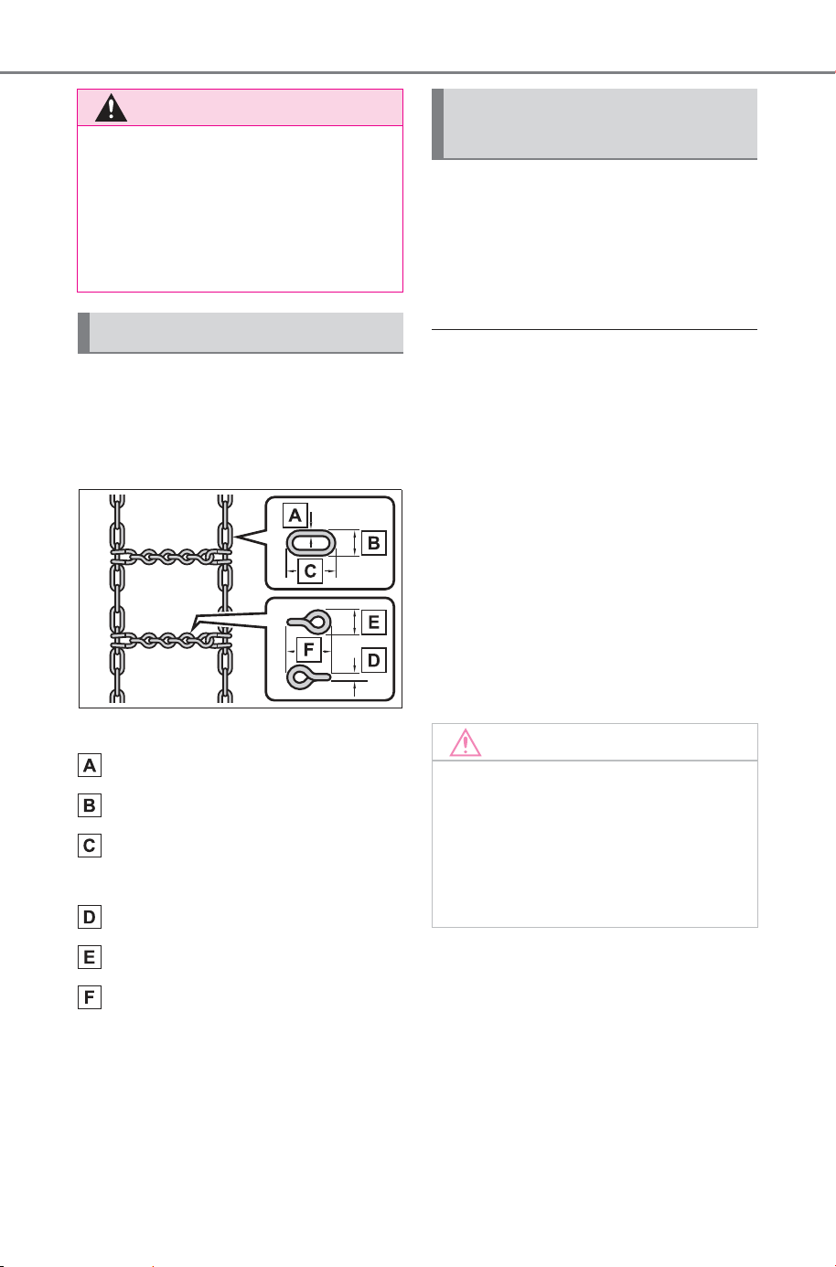
484
5-5. Driving tips
Owner’s Manual_USA_M6740B_en
Use the correct tire chain size
when mounting the tire chains.
Chain size is regulated for each
tire size.
Side chain:
0.12 in. (3 mm) in diameter
0.39 in. (10 mm) in width
1.18 in. (30 mm) in length
Cross chain:
0.16 in. (4 mm) in diameter
0.55 in. (14 mm) in width
0.98 in. (25 mm) in length
Regulations regarding the use
of tire chains vary depending on
location and type of road.
Always check local regulations
before installing chains.
■ Tire chain installation
Observe the following precautions
when installing and removing
chains:
● Install and remove tire chains in a
safe location.
● Install tire chains on the front tires
only. Do not install tire chains on
the rear tires.
● Install tire chains on front tires as
tightly as possible. Retighten
chains after driving 1/4 - 1/2 mile
(0.5 - 1.0 km).
● Install tire chains following the
instructions provided with the tire
chains.
WARNING
■ When parking the vehicle
When parking the vehicle without
applying the parking brake, make
sure to chock the wheels. If you
do not chock the wheels, the vehi-
cle may move unexpectedly, pos-
sibly resulting in an accident.
Selecting tire chains
Regulations on the use of
tire chains
NOTICE
■ Fitting tire chains (vehicle
with the tire pressure warning
system)
The tire pressure warning valves
and transmitters may not function
correctly when tire chains are fit-
ted.
SOLTERRA_OM_USA_A6740BE.book 484 ページ 2025年5月23日 金曜日 午後1時18分
485
5-5. Driving tips
Owner’s Manual_USA_M6740B_en
5
Driving
Specific design characteris-
tics give it a higher center of
gravity than ordinary passen-
ger cars. This vehicle design
feature causes this type of
vehicle to be more likely to
rollover. And, Utility vehicles
have a significantly higher
rollover rate than other types
of vehicles.
An advantage of the higher
ground clearance is a better
view of the road allowing you
to anticipate problems.
It is not designed for corner-
ing at the same speeds as
ordinary passenger cars any
more than low-slung sports
cars are designed to perform
satisfactorily under off-road
conditions. Therefore, sharp
turns at excessive speeds
may cause the vehicle to roll-
over.
Utility vehicle precau-
tions
This vehicle belongs to the
utility vehicle class, which
has higher ground clear-
ance and narrower tread in
relation to the height of its
center of gravity to make it
capable of performing in a
wide variety of off-road
applications.
Utility vehicle feature
WARNING
■ Utility vehicle precautions
Always observe the following pre-
cautions to minimize the risk of
death, serious injury or damage to
your vehicle:
● In a rollover crash, an unbelted
person is significantly more
likely to die than a person wear-
ing a seat belt. Therefore, the
driver and all passengers
should always fasten their seat
belts.
● Avoid sharp turns or abrupt
maneuvers, if at all possible.
Failure to operate this vehicle
correctly may result in loss of
control or vehicle rollover caus-
ing death or serious injury.
● Loading cargo on the roof lug-
gage carrier (if equipped) will
make the center of the vehicle
gravity higher. Avoid high
speeds, sudden starts, sharp
turns, sudden braking or abrupt
maneuvers, otherwise it may
result in loss of control or vehi-
cle rollover due to failure to
operate this vehicle correctly.
● Always slow down in gusty
crosswinds. Because of its pro-
file and higher center of gravity,
your vehicle is more sensitive to
side winds than an ordinary
passenger car. Slowing down
will allow you to have better
control.
● Do not drive horizontally across
steep slopes. Driving straight up
or straight down is preferred.
Your vehicle (or any similar off-
road vehicle) can tip over side-
ways much more easily than
forward or backward.
SOLTERRA_OM_USA_A6740BE.book 485 ページ 2025年5月23日 金曜日 午後1時18分
486
5-5. Driving tips
Owner’s Manual_USA_M6740B_en
When driving your vehicle off-
road, please observe the follow-
ing precautions to ensure your
driving enjoyment and to help
prevent the closure of areas to
off-road vehicles:
Drive your vehicle only in
areas where off-road vehicles
are permitted to travel.
Respect private property. Get
owner’s permission before
entering private property.
Do not enter areas that are
closed. Honor gates, barriers
and signs that restrict travel.
Stay on established roads.
When conditions are wet,
driving techniques should be
changed or travel delayed to
prevent damage to roads.
■ Additional information for off-
road driving
For owners in U.S. mainland and
Hawaii:
To obtain additional information per-
taining to driving your vehicle off-
road, consult the following organiza-
tions:
• State and Local Parks and Recre-
ation Departments
• State Motor Vehicle Bureau
• Recreational Vehicle Clubs
• U.S. Forest Service and Bureau of
Land Management
Off-road driving
WARNING
■ Off-road driving precautions
Always observe the following pre-
cautions to minimize the risk of
death, serious injury or damage to
your vehicle:
● Drive carefully when off the
road. Do not take unnecessary
risks by driving in dangerous
places.
● Do not grip the steering wheel
spokes when driving off-road. A
bad bump could jerk the wheel
and injure your hands. Keep
both hands and especially your
thumbs on the outside of the
rim.
● Always check your brakes for
effectiveness immediately after
driving in sand, mud, water or
snow.
● After driving through tall grass,
mud, rock, sand, rivers, etc.,
check that there is no grass,
bush, paper, rags, stone, sand,
etc. adhering or trapped on the
underbody. Clear off any such
matter from the underbody. If
the vehicle is used with these
materials trapped or adhering to
the underbody, a breakdown or
fire could occur.
● When driving off-road or in rug-
ged terrain, do not drive at
excessive speeds, jump, make
sharp turns, strike objects, etc.
This may cause loss of control
or vehicle rollover causing
death or serious injury. You are
also risking expensive damage
to your vehicle’s suspension
and chassis.
SOLTERRA_OM_USA_A6740BE.book 486 ページ 2025年5月23日 金曜日 午後1時18分

487
5-5. Driving tips
Owner’s Manual_USA_M6740B_en
5
Driving
NOTICE
■ To prevent the water damage
Take all necessary safety mea-
sures to ensure that water dam-
age to the traction battery, EV
system or other components does
not occur.
● Water entering the motor com-
partment may cause severe
damage to the EV system.
● Water entering the transmis-
sion will cause deterioration in
transmission quality. The mal-
function indicator may come on,
and the vehicle may not be driv-
able.
● Water can wash the grease
from wheel bearings, causing
rusting and premature failure,
and may also enter the tran-
saxle case, reducing the gear
oil’s lubricating qualities.
■ When you drive through
water
If driving through water, such as
when crossing shallow streams,
first check the depth of the water
and the bottom of the riverbed for
firmness. Drive slowly and avoid
deep water.
■ Inspection after off-road driv-
ing
● Sand and mud that has accu-
mulated around brake discs
may affect braking efficiency
and may damage brake system
components.
● Always perform a maintenance
inspection after each day of off-
road driving that has taken you
through rough terrain, sand,
mud, or water. For scheduled
maintenance information, refer
to the “Warranty and Mainte-
nance Booklet” or “Warranty
and Service Booklet”.
SOLTERRA_OM_USA_A6740BE.book 487 ページ 2025年5月23日 金曜日 午後1時18分

488
5-5. Driving tips
Owner’s Manual_USA_M6740B_en
SOLTERRA_OM_USA_A6740BE.book 488 ページ 2025年5月23日 金曜日 午後1時18分
489
Owner’s Manual_USA_M6740B_en
6
6
Interior features
Interior features
6-1. Using the air conditioning
system and defogger
ALL AUTO (ECO) control
..................................
490
Automatic air conditioning
system.......................
492
Remote Air Conditioning
System ......................
501
Heated steering wheel/seat
heaters/seat ventila-
tors/radiant heaters ... 503
6-2. Using the interior lights
Interior lights list ..........
507
6-3. Using the storage features
List of storage features
510
Luggage compartment fea-
tures ..........................
513
6-4. Using the other interior
features
Electronic sunshade....
517
Other interior features . 518
Power outlet (1500 W) 530
When the power outlet
(1500 W) cannot be used
properly ..................... 536
Garage door opener.... 538
SOLTERRA_OM_USA_A6740BE.book 489 ページ 2025年5月23日 金曜日 午後1時18分

490
6-1. Using the air conditioning system and defogger
Owner’s Manual_USA_M6740B_en
6-1.Using the air conditioning system and defogger
*
: If equipped
Select the “AUTO” switch.
The indicator on the AUTO
switch illuminates, and the auto-
matic air conditioning system,
seat heaters/radiant heaters
*
,
seat ventilators
*
, and heated
steering wheel
*
operate in auto-
matic mode.
If the fan speed control switch or
airflow mode control switch is
operated, the indicator turns off.
However, all other functions
continue to operate in automatic
mode.
Even if ALL AUTO (ECO) con-
trol is turned off, the air condi-
tioner, seat heaters/radiant
heaters
*
, seat ventilators
*
, and
heated steering wheel will not
be turned off.
Also, during ALL AUTO (ECO)
control operation, pressing the
ECO switch turns off the eco air
conditioning control.
If the front window glass
becomes cloudy due to a drop in
the outside air temperature
while the ALL AUTO (ECO) con-
trol is operating, you can
remove the cloudiness by
selecting the “A/C” switch or
windshield defogger switch on
the multimedia display.
*
: If equipped
ALL AUTO (ECO) con-
trol
The seat heaters/radiant
heaters
*
, seat ventilators
*
and heated steering wheel
*
are each automatically con-
trolled according to the set
temperature of the air condi-
tioning system, the outside
and cabin temperature, etc.
ALL AUTO (ECO) controls
the electricity consumption
in order to both extend the
cruising range and main-
tain comfortable conditions.
Turning on ALL AUTO
(ECO) control
SOLTERRA_OM_USA_A6740BE.book 490 ページ 2025年5月23日 金曜日 午後1時18分

491
6-1. Using the air conditioning system and defogger
Owner’s Manual_USA_M6740B_en
6
Interior features
■ Automatic air conditioning
system (P.492)
The temperature can be
adjusted independently for each
seat.
■ Seat heaters/radiant heat-
ers
*
and seat ventilators
*
(P.503)
Heating or ventilation is auto-
matically selected according to
the set temperature of the air
conditioning system, the out-
side temperature, etc.
*
: If equipped
■ Heated steering wheel
*
(P.503)
Heated steering wheel operates
automatically according to the
set temperature of the air condi-
tioning system, the outside tem-
perature, etc.
*
: If equipped
■ Passenger detection functions
When a passenger is detected in
the front passenger seat, the seat
heater/radiant heater
*
and seat ven-
tilator
*
will operate automatically.
■ Seat heaters/radiant heater
*
and
seat ventilators
*
operation
If the passenger side seat heat-
ers/radiant heaters
*
or seat ventila-
tor
*
is operating under ALL AUTO
(ECO) control when the power
switch is turned off, the seat
heater/radiant heaters
*
or seat ven-
tilator
*
will automatically turn on the
next time the power switch is turned
on. To detect the occupant again,
select the “AUTO” switch.
*
: If equipped
■ Rear seat heaters operation
*
The rear seat heaters are not con-
trolled by the ALL AUTO (ECO) con-
trol.
*
: If equipped
Operation of each system
SOLTERRA_OM_USA_A6740BE.book 491 ページ 2025年5月23日 金曜日 午後1時18分
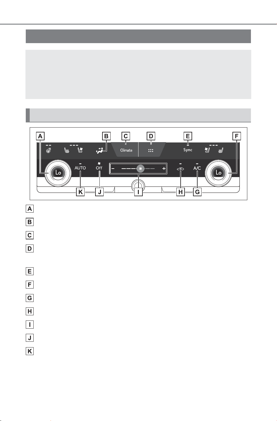
492
6-1. Using the air conditioning system and defogger
Owner’s Manual_USA_M6740B_en
Left-hand side temperature control switch
Airflow mode control switch
Option screen switch
Shortcut screen switch
Select to display shortcut icons for various functions.
“Sync” switch
Right-hand side temperature control switch
“A/C” switch
Outside/recirculated air mode switch
Fan speed control switch
“Off” switch
“AUTO” switch
Automatic air conditioning system
When the “AUTO” switch is on, the air outlets and fan speed
will automatically be changed according to the set tempera-
ture.
Also, the display and button positions will differ depending
on the type of the system.
Air conditioning controls
SOLTERRA_OM_USA_A6740BE.book 492 ページ 2025年5月23日 金曜日 午後1時18分
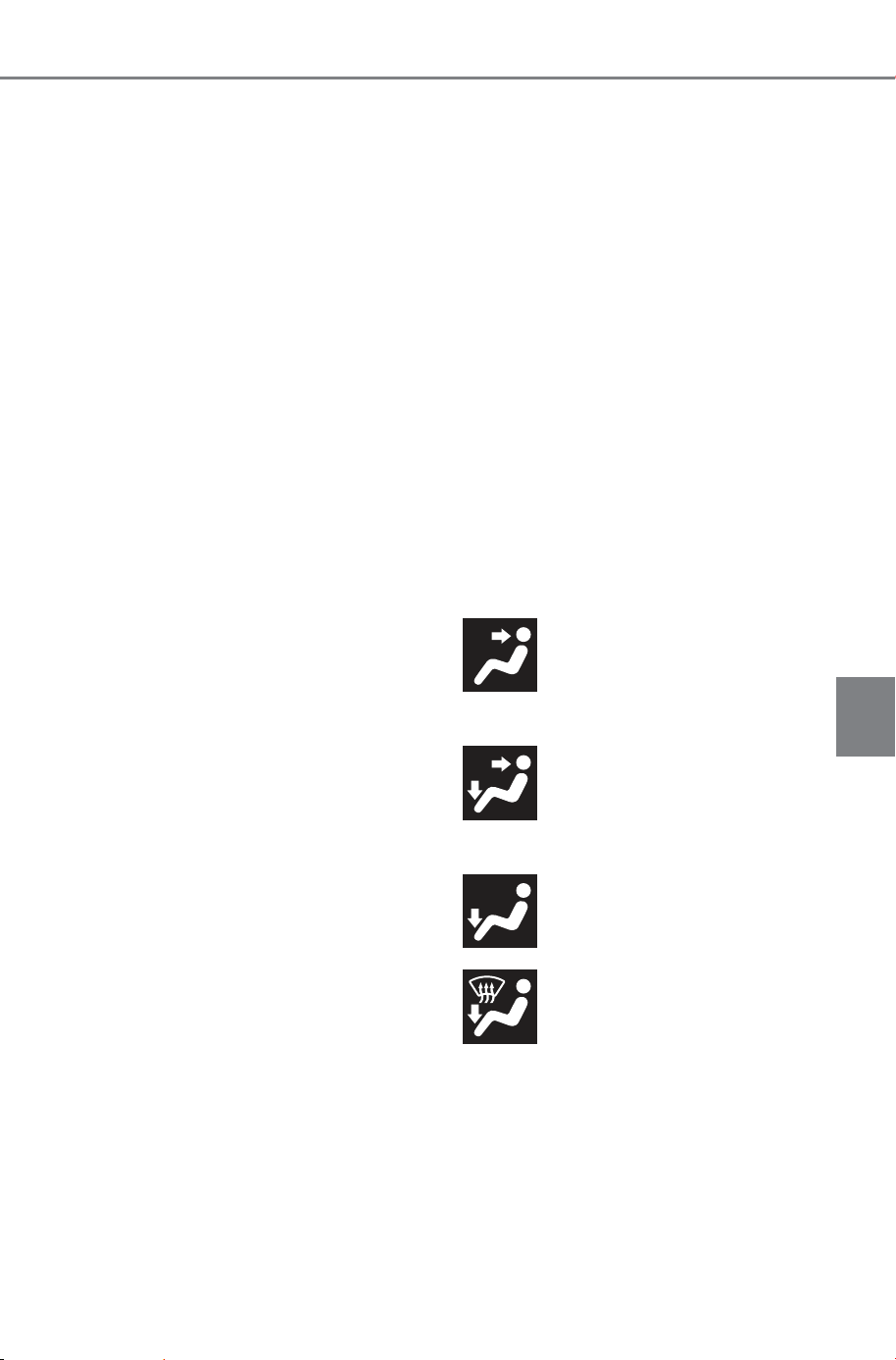
493
6-1. Using the air conditioning system and defogger
Owner’s Manual_USA_M6740B_en
6
Interior features
■ Adjusting the temperature
Turn temperature control switch
clockwise to increases the tem-
perature and turn the dial coun-
terclockwise to decreases the
temperature.
When the indicator on the
“Sync” switch is illuminated, the
temperature setting for the front
passenger’s side will match the
setting for the driver’s side.
When the indicator on the
“Sync” switch is off, turning the
“Sync” switch on will illuminate
the “Sync” switch indicator and
the temperature setting for the
front passenger’s side will
become the same as that for the
driver’s side.
When the front passenger’s side
temperature control switch is
operated, the indicator on the
“Sync” switch will turn off and
the temperature setting for the
front passenger’s side will be
able to be adjusted.
If the “A/C” indicator is turned
off, the system will blow ambient
temperature air or heated air.
■ Setting the fan speed
To increase the fan speed,
select the “+” fan speed adjust-
ment switch or slide the icon of
the fan speed adjustment switch
right. To decrease the fan
speed, select the “-” fan speed
adjustment switch or slide the
icon of the fan speed adjustment
switch left.
Select the “Off” switch to turn the
fan off.
The fan can also be stopped by
touching and holding the “-” fan
speed adjustment switch or sliding
the icon of the fan speed adjust-
ment switch to the leftmost position
and holding it.
■ Change the airflow mode
Select the airflow mode control
switch.
The airflow mode changes each
time the switch is selected.
The air outlets and air volume
changes according to the selected
air flow mode.
: Air flows to the upper
body
: Air flows to the upper
body and feet
: Air flows to the feet
: Air flows to the feet and
the windshield defogger oper-
ates
SOLTERRA_OM_USA_A6740BE.book 493 ページ 2025年5月23日 金曜日 午後1時18分

494
6-1. Using the air conditioning system and defogger
Owner’s Manual_USA_M6740B_en
■ Switching between outside
air and recirculated air
modes
Temporarily changing the air
mode to recirculated air mode is
recommended to prevent dirty
air from entering the vehicle,
such as when in a tunnel or
heavy traffic, and to help cool
the interior when the outside air
temperature is high.
Select the outside/recirculated
air mode switch.
The mode switches between out-
side air mode (the indicator is off)
and recirculated air mode (the indi-
cator is on) each time the switch is
selected.
The air mode may change automat-
ically depending on the tempera-
ture setting, temperature inside the
vehicle, etc.
■ Set cooling and dehumidifi-
cation function
Select the “A/C” switch.
When the function is on, the indica-
tor illuminates on the “A/C” switch.
■ Eco air conditioning mode
The air conditioning is controlled
with low electricity consumption
efficiency prioritized such as
reducing fan speed, etc.
1 Select the option screen
switch. (P. 49 2 )
2 Select the “Eco heat/cool”
switch.
In Eco air conditioning mode,
the air conditioning system is
controlled as follows to priori-
tize electricity consumption
efficiency. To improve air con-
ditioning performance, turn off
Eco air conditioning mode.
• Electric motor speed and com-
pressor operation controlled to
restrict heating/cooling capacity.
• Fan speed restricted when auto-
matic mode is selected.
When the driving mode is set
to Eco drive mode, the Eco air
conditioning mode will be
turned on automatically. Even
in this case, the Eco air condi-
tioning mode can be turned
off by selecting the “Eco
heat/cool”.
■ Warming the interior
quickly (Max heat)
When “Max heat” is turned on,
in order to warm the interior
quickly, the settings of the air
conditioning system will be
changed immediately.
1 Select the shortcut screen
switch. (P.492)
2 Select the “Max heat” switch.
The driver’s side temperature
setting of the air conditioning
system will be set to “Hi” and
the “AUTO” switch will be
turned on.
Driver’s side seat heater will
be set to Hi.
SOLTERRA_OM_USA_A6740BE.book 494 ページ 2025年5月23日 金曜日 午後1時18分
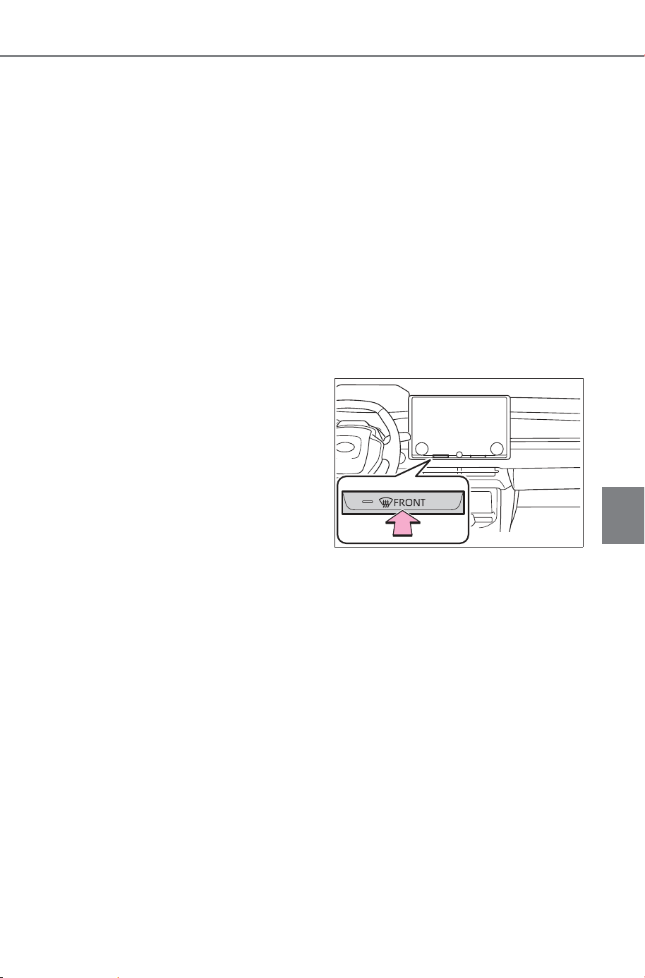
495
6-1. Using the air conditioning system and defogger
Owner’s Manual_USA_M6740B_en
6
Interior features
Heated steering wheel will be
set to Hi.
When the system determines
that a passenger is in the front
passenger seat, the front pas-
senger’s side seat heater/seat
ventilator
*
will be set to
“AUTO”.
When the indicator on the
“Sync” switch is illuminated,
the temperature setting for the
front passenger’s side will
also be set to “Hi”.
*
: If equipped
■ Cooling the interior quickly
(Max cool) (if equipped)
When “Max cool” is turned on, in
order to cool the interior quickly,
the settings of the air condition-
ing system will be changed
immediately.
1 Select the shortcut screen
switch. (P. 49 2 )
2 Select the “Max cool” switch.
The driver’s side temperature
setting of the air conditioning
system will be set to “Lo” and
the “AUTO” switch will be
turned on.
Driver’s side seat ventilator
will be set to Hi.
Heated steering wheel will be
set to “AUTO”.
When the system determines
that a passenger is in the front
passenger seat, the front pas-
senger’s side seat heater/seat
ventilator will be set to
“AUTO”.
When the indicator on the
“Sync” switch is illuminated,
the temperature setting for the
front passenger’s side will
also be set to “Lo”.
■ Defogging the windshield
Defoggers are used to defog the
windshield and front side win-
dows.
Press the windshield defogger
switch.
The dehumidification function will
operate and the air flow will
increase.
Set the outside/recirculated air
mode switch to outside air mode
if the recirculated air mode is
used. (It may switch automati-
cally.)
To defog the windshield and the
side windows quickly, turn the
air flow and temperature up.
To return to the previous mode,
press the windshield defogger
switch again when the wind-
shield is defogged.
SOLTERRA_OM_USA_A6740BE.book 495 ページ 2026年1月6日 火曜日 午後2時17分
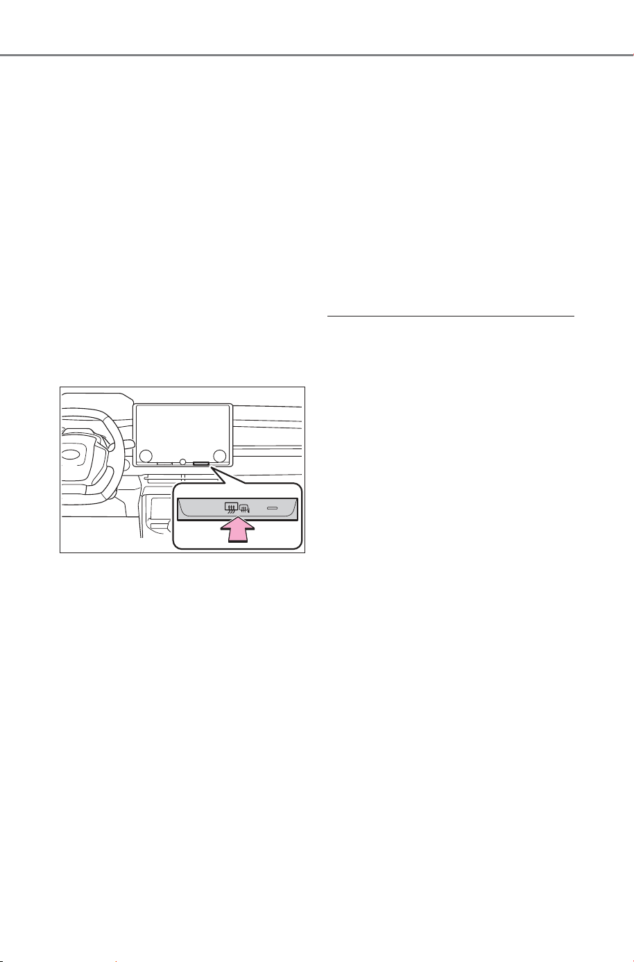
496
6-1. Using the air conditioning system and defogger
Owner’s Manual_USA_M6740B_en
When the windshield defogger
switch is on, the indicator illumi-
nates on the windshield defog-
ger switch.
■ Defogging the rear window
and outside rear view mir-
rors
Defoggers are used to defog the
rear window, and to remove
raindrops, dew and frost from
the outside rear view mirrors.
Press the rear window and out-
side rear view mirror defogger
switch.
The rear window defogger and out-
side rear view mirror defoggers will
operate and defog the rear window
and outside rear view mirrors.
When the rear window and outside
rear view mirror defoggers switch is
on, the indicator illuminates on the
rear window and outside rear view
mirror defoggers switch.
The defoggers will automati-
cally turn off after a period of
time.
■ Windshield wiper de-icer
Use the windshield wiper de-icer
to help prevent the windshield
wiper blades from freezing to
the windshield.
1 Select the option screen
switch. (P.492)
2 Select the “Deicer”.
The windshield wiper de-icer will
automatically turn off after a period
of time.
■ Fogging up of the windows
● The windows will easily fog up
when the humidity in the vehicle is
high. Turning “A/C” switch on will
dehumidify the air from the outlets
and defog the windshield effec-
tively.
● If you turn “A/C” switch off, the
windows may fog up more easily.
● The windows may fog up if the
recirculated air mode is used.
■ When driving on dusty roads
Close all windows. If dust thrown up
by the vehicle is still drawn into the
vehicle after closing the windows, it
is recommended that the air intake
mode be set to outside air mode and
the fan speed to any setting except
off.
■ Outside/recirculated air mode
● Setting to the recirculated air
mode temporarily is recom-
mended in preventing dirty air
from entering the vehicle interior
and helping to cool the vehicle
when the outside air temperature
is high.
● Outside/recirculated air mode may
automatically switch depending on
the temperature setting or the
inside temperature.
SOLTERRA_OM_USA_A6740BE.book 496 ページ 2025年5月23日 金曜日 午後1時18分

497
6-1. Using the air conditioning system and defogger
Owner’s Manual_USA_M6740B_en
6
Interior features
■ When the outside temperature
exceeds 75°F (24°C) and the air
conditioning system is on
● In order to reduce the air condi-
tioning electricity consumption,
the air conditioning system may
switch to recirculated air mode
automatically. This may also
reduce electricity consumption.
● Recirculated air mode is selected
as a default mode when the power
switch is turned to ON.
● It is possible to switch to outside
air mode at any time by selecting
the outside/recirculated air mode
switch.
■ When the outside temperature
is low
The dehumidification function may
not operate even when “A/C” switch
is selected.
■ “Max heat”
● The “Max heat” switch cannot be
used to turn the setting off.
● After the “Max heat” switch has
been operated, the temperature
setting can be adjusted using the
temperature control switches of
the air conditioning system.
● If the “AUTO” switch is turned on,
the seat heaters and seat ventila-
tors of the front seats, and the
heated steering wheel will be
operated automatically according
to the temperature setting.
● Each function can also be
adjusted to the desired setting.
■ “Max cool” (if equipped)
● The “Max cool” switch cannot be
used to turn the setting off.
● After the “Max cool” switch has
been operated, the temperature
setting can be adjusted using the
temperature control switches of
the air conditioning system.
● If the “AUTO” switch is turned on,
the seat heaters and seat ventila-
tors of the front seats, and the
heated steering wheel will be
operated automatically according
to the temperature setting.
● Each function can also be
adjusted to the desired setting.
■ Operation of the air condition-
ing system in the Eco drive
mode
● In the Eco drive mode, the air con-
ditioning system is controlled as
follows to prioritize electricity con-
sumption efficiency.
• Heating/cooling capacity is
restricted
• Fan speed restricted when auto-
matic mode is selected
● To improve air conditioning perfor-
mance, perform the following
operations:
• Adjust the fan speed
• Adjust the temperature setting
• Turn off Eco drive mode (P.238,
470)
● When the driving mode is set to
Eco drive mode, the air condition-
ing system may automatically
change to Eco mode. To cancel
eco mode, select “Eco heat/cool”.
■ Ventilation and air conditioning
odors
● To let fresh air in, set the air condi-
tioning system to the outside air
mode.
● During use, various odors from
inside and outside the vehicle may
enter into and accumulate in the
air conditioning system. This may
then cause odor to be emitted
from the vents.
● To reduce potential odors from
occurring:
• It is recommended that the air
conditioning system be set to out-
side air mode prior to turning the
vehicle off.
SOLTERRA_OM_USA_A6740BE.book 497 ページ 2026年1月6日 火曜日 午後2時22分
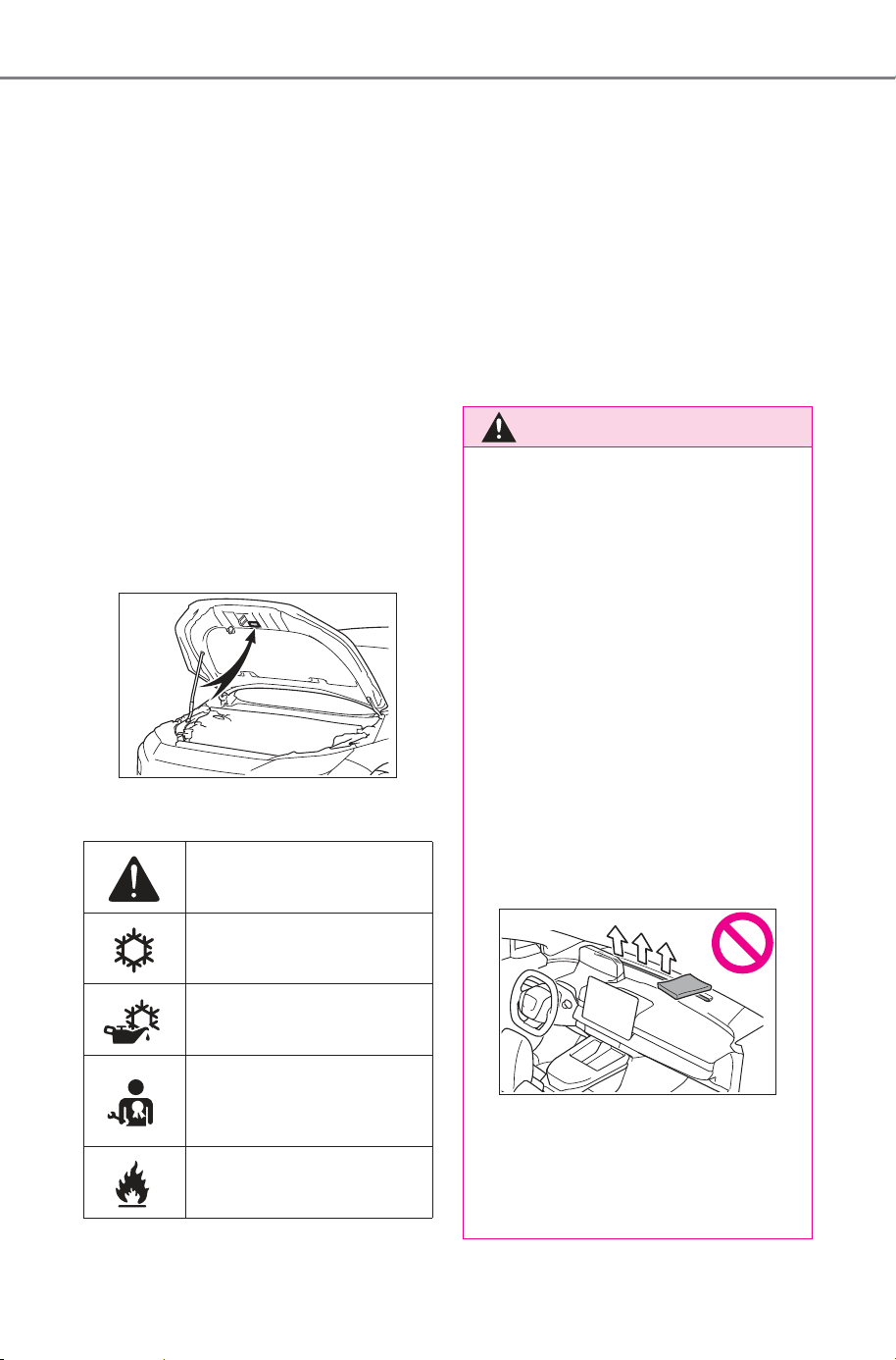
498
6-1. Using the air conditioning system and defogger
Owner’s Manual_USA_M6740B_en
• The start timing of the blower may
be delayed for a short period of
time immediately after the air con-
ditioning system is started in auto-
matic mode.
● When parking, the system auto-
matically switches to outside air
mode to encourage better air cir-
culation throughout the vehicle,
helping to reduce odors that occur
when starting the vehicle.
■ Air conditioning filter
P.592
■ Air conditioning system refrig-
erant
● A label regarding the refrigerant of
the air conditioning system is
attached to the hood at the loca-
tion shown in the following illustra-
tion.
● The meaning of each symbol on
the label are as follows:
■ Noise from air conditioning sys-
tem
Approximately 90 seconds after the
power switch turned to OFF, you
may hear sound coming from air
conditioning system. This is the
sound of a air conditioning system
initialize and, it does not indicate a
malfunction.
■ Customization
Some functions can be customized.
(Customizable features: P.684)
Caution
Air conditioning system
Air conditioning system
lubricant type
Requires registered
technician to service air
conditioning system
Flammable refrigerant
WARNING
■ To prevent the windshield
defogger from operating
improperly
● Do not use the windshield
defogger switch during cool air
operation in extremely humid
weather.
The difference between the
temperature of the outside air
and that of the windshield can
cause the outer surface of the
windshield to fog up, blocking
your vision.
● Do not place anything on the
instrument panel which may
cover the air outlets. Otherwise,
air flow may be obstructed, pre-
venting the windshield defog-
gers from defogging.
■ To prevent burns
● Do not touch the rear view mir-
ror surfaces when the outside
rear view mirror defoggers are
on.
SOLTERRA_OM_USA_A6740BE.book 498 ページ 2025年5月23日 金曜日 午後1時18分
499
6-1. Using the air conditioning system and defogger
Owner’s Manual_USA_M6740B_en
6
Interior features
1 Select the “AUTO” switch.
(P.492)
2 Adjust the temperature set-
ting.
3 To stop the operation, select
the “Off” switch.
If the fan speed setting or air
flow modes are operated, the
automatic mode indicator goes
off. However, automatic mode
for functions other than that
operated is maintained.
■ Using automatic mode
Fan speed is adjusted automati-
cally according to the temperature
setting and the ambient conditions.
Therefore, the fan may stop for a
while until warm or cool air is ready
to flow immediately after the auto-
matic mode switch is selected.
Cool air may blow around the upper
body even when the heater is on
due to sunlight.
This function automatically con-
trols the air conditioning airflow
so that priority is given to the
front seats. Unnecessary air
conditioning is suppressed, con-
tributing to increased electricity
consumption efficiency.
Front seat concentrated airflow
mode operates in the following
situations.
No passengers are detected
in the rear seats
The windshield defogger is
not operating
The “S-Flow” switch is (ON)
on the option screen.
In front seat concentrated air-
flow mode, directing airflow to
the front seats only and to all
seats can be switched via switch
operation. When the mode has
been switched manually, auto-
matic airflow control stops oper-
ating.
WARNING
● Do not touch the glass at lower
part of the windshield or to the
side of the front pillars when the
windshield wiper de-icer is on.
NOTICE
■ To prevent 12-volt battery dis-
charge
Do not leave the air conditioning
system on longer than necessary
when the EV system is off.
■ When repairing/replacing
parts of the air conditioning
system
Have repair/replacement per-
formed by your SUBARU dealer.
When a part of the air conditioning
system, such as the evaporator, is
to be replaced, it must be
replaced with a new one.
Using automatic mode
Front seat concentrated
airflow mode (S-FLOW)
SOLTERRA_OM_USA_A6740BE.book 499 ページ 2025年5月23日 金曜日 午後1時18分
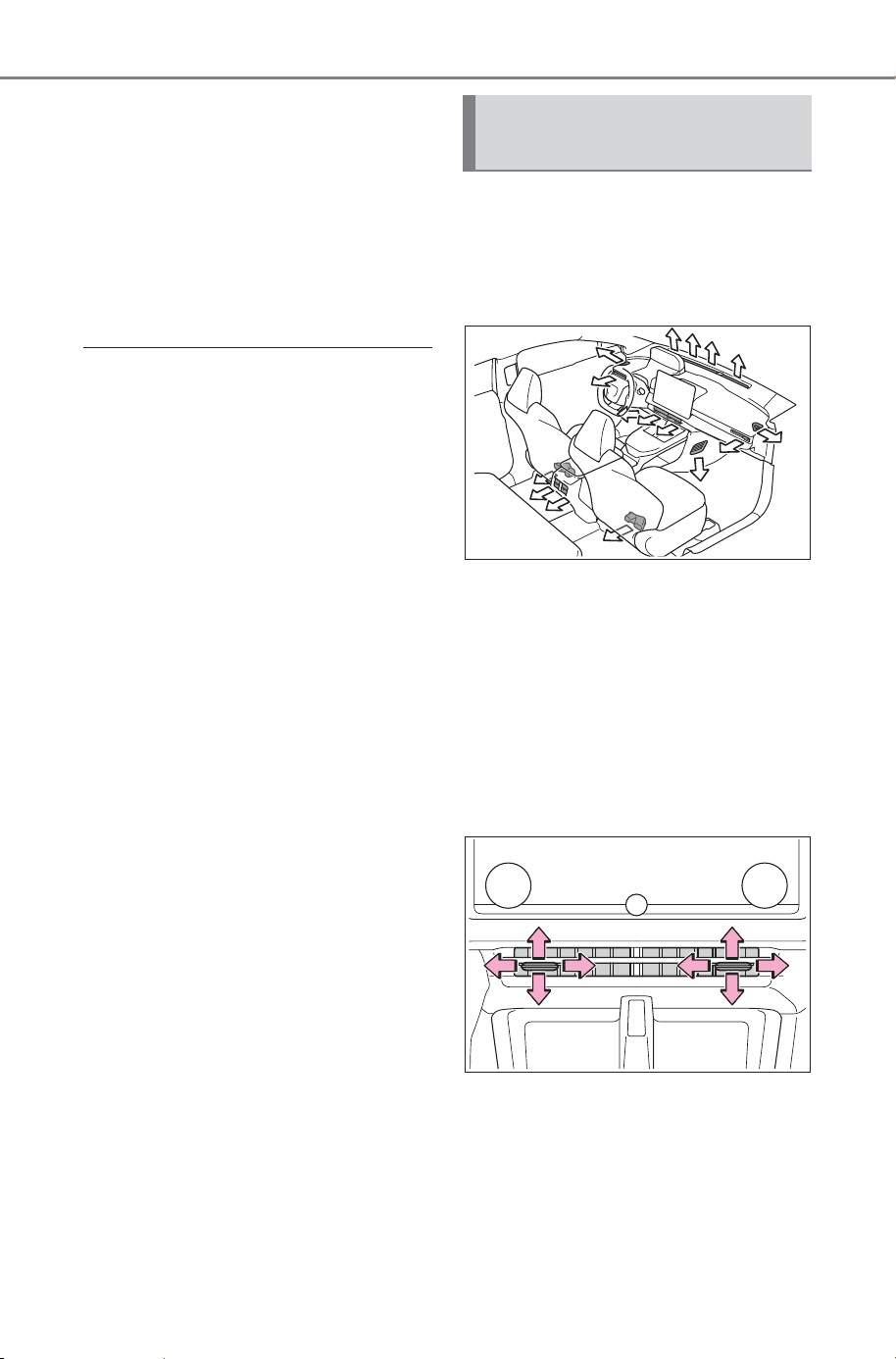
500
6-1. Using the air conditioning system and defogger
Owner’s Manual_USA_M6740B_en
1 Select the option screen
switch. (P. 49 2 )
2 Select the “S-Flow” switch.
Indicator illuminated: Airflow
to the front seats only
Indicator off: Airflow to all the
seats
■ Operation of automatic airflow
control
● In order to maintain a comfortable
interior, airflow may be directed to
seats without passengers immedi-
ately after the EV system is
started and at other times depend-
ing on the outside temperature.
● After the EV system is started, if
passengers move around inside
or enter/exit the vehicle, the sys-
tem cannot accurately detect the
presence of passengers and auto-
matic airflow control will not oper-
ate.
■ Operation of manual airflow
control
Even if the function is manually
switched to directing airflow to only
the front seats, when a rear seat is
occupied, it may automatically direct
airflow to all seats.
■ To return to automatic airflow
control
1 With the indicator off, turn the
power switch off.
2 After 60 minutes or more elapse,
turn the power switch to ON.
■ Location of air outlets
The air outlets and air volume
change according to the
selected air flow mode.
■ Adjusting the position of
and opening and closing
the air outlets
To adjust the position of and
opening and closing the air out-
lets, perform the following oper-
ations:
Front
Direct air flow to the left or right, up
or down
Move the knob fully to the inside
to close the vent.
Air outlet layout and oper-
ations
SOLTERRA_OM_USA_A6740BE.book 500 ページ 2025年5月23日 金曜日 午後1時18分
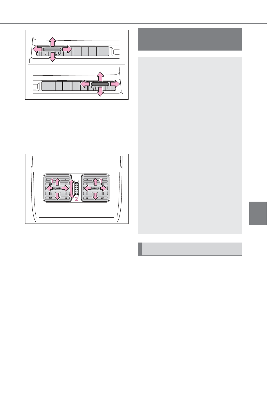
501
6-1. Using the air conditioning system and defogger
Owner’s Manual_USA_M6740B_en
6
Interior features
Direct air flow to the left or right, up
or down
Move the knob fully to the out-
side to close the vent.
Rear
1 Direct air flow to the left or
right, up or down
2 Turn the knob to open or
close the vent
Check the temperature setting
of the air conditioning system.
(P.492)
The Remote Air Conditioning Sys-
tem will operate in accordance with
the temperature settings of the air
conditioning system.
Remote Air Condition-
ing System
The Remote Air Condition-
ing System uses electrical
energy stored in the trac-
tion battery and allows the
air conditioning to be oper-
ated by remote control.
If the Remote Air Condition-
ing System is used while
the charging cable is con-
nected to the vehicle, the
reduction of charge in the
traction battery will be sup-
pressed to allow you to use
electricity from an external
power source.
Charging will be conducted
automatically after the
Remote Air Conditioning Sys-
tem is stopped.
Before leaving the vehicle
SOLTERRA_OM_USA_A6740BE.book 501 ページ 2025年5月23日 金曜日 午後1時18分
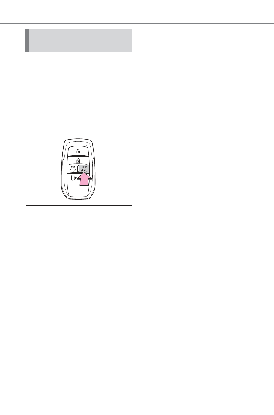
502
6-1. Using the air conditioning system and defogger
Owner’s Manual_USA_M6740B_en
Press and hold “A/C” on the
wireless remote control to oper-
ate the Remote Air Conditioning
System.
The system will shut off if a door is
opened.
The system can be stopped by
pressing “A/C” twice.
■ Operating conditions
The system will only operate if all of
the following conditions are met:
● The power switch is OFF.
● All doors are closed.
● The hood is closed.
■ Remote Air Conditioning Sys-
tem automatic shut-off
The system will automatically shut
off under the following conditions:
● About 20 minutes have passed
since operation began
● Any one of the operating condi-
tions is not met
The system may also shut off if the
charge level of the traction battery
drops to low.
■ Conditions affecting operation
The system may not start in the fol-
lowing situations:
● The charge level of the traction
battery is low
● When the EV system is cool (for
example, after being left for a long
time in low temperatures)
■ Windshield defogger
When defogging the windshield
using the Remote Air Conditioning
System, defogging may be insuffi-
cient due to the power being
restricted more than during normal
air conditioning operation. Also, the
outside of the windshield may fog up
due to the outside temperature,
humidity or air conditioning set tem-
perature.
■ Security feature
Any unlocked doors will be automat-
ically locked when the system is
operating. The emergency flashers
flash to indicate that the doors have
been locked.
■ Conditions affecting operation
P.179
■ While the Remote Air Condi-
tioning System is operating
● Depending on the operating con-
dition of the Remote Air Condition-
ing System, the electric fan may
spin and an operating noise may
be heard.
However, this does not indicate a
malfunction.
● The Remote Air Conditioning Sys-
tem may stop operating temporar-
ily if other features that use
electricity (for example, the seat
heaters, lights, windshield wipers)
are in operation or if the charge
level of the 12-volt battery
becomes low.
● The headlights, windshield wiper,
meter, etc. will not operate.
Activating the Remote Air
Conditioning System
SOLTERRA_OM_USA_A6740BE.book 502 ページ 2025年5月23日 金曜日 午後1時18分
503
6-1. Using the air conditioning system and defogger
Owner’s Manual_USA_M6740B_en
6
Interior features
■ Electronic key battery depletion
P.154
■ When the electronic key bat-
tery is fully depleted
P.594
*
: If equipped
WARNING
■ Precautions for the Remote
Air Conditioning System
● Do not use the system if people
are in the vehicle.
Even when the system is in use,
the internal temperature may
still reach a high or low level
due to features such as the
automatic shut-off. Children and
pets left inside the vehicle may
suffer heatstroke dehydration or
hypothermia, or could result in
death or serious injury.
● Depending on the surrounding
environment, signals from the
wireless switch may transmit
further than expected. Pay
appropriate attention to the
vehicle’s surroundings and use
the switch only when necessary.
● Do not operate “A/C” if the hood
is open. The air conditioning
may operate unintentionally and
objects may be drawn into the
electrical cooling fan.
NOTICE
■ To prevent the traction bat-
tery from being discharged
through incorrect operation
Use “A/C” only when necessary.
Heated steering
wheel
*
/seat heat-
ers/seat ventila-
tors
*
/radiant heaters
*
Heated steering wheel
Warms up the grip of the
steering wheel
Seat heaters
Warm up the seat upholstery
Seat ventilators
Maintain good airflow on the
seat upholstery by sucking air
into the seats
Radiant heaters
Warm up the feet of the front
seats
WARNING
■ To prevent minor burn inju-
ries
Care should be taken if anyone in
the following categories comes in
contact with the steering wheel,
seats or radiant heater when the
heater is on:
● Babies, small children, the
elderly, the sick and the physi-
cally challenged
● Persons with sensitive skin
● Persons who are fatigued
● Persons who have taken alco-
hol or drugs that induce sleep
(sleeping drugs, cold remedies,
etc.)
SOLTERRA_OM_USA_A6740BE.book 503 ページ 2025年5月23日 金曜日 午後1時18分
504
6-1. Using the air conditioning system and defogger
Owner’s Manual_USA_M6740B_en
Select on the multimedia dis-
play.
Each time the switch is selected,
the operation condition changes as
follows.
AUTO (lit) Hi (2 segments lit)
Lo (1 segment lit) Off
The level indicator (red) lights up
during operation. “AUTO” indicator
lights up during automatic opera-
tion.
■ The heated steering wheel can
be used when
The power switch is in ON.
■ Front
Vehicles without radiant heaters:
Select or on the multime-
dia display.
Vehicles with radiant heaters:
Select or on the multime-
dia display.
Each time the switch is selected,
the operation condition changes as
follows.
AUTO Hi (3 segments lit) Mid
(2 segments lit) Lo (1 segment
lit) Off
The level indicator (red) lights up
during operation. “AUTO” indicator
lights up during automatic opera-
tion.
■ Rear (outboard rear seats)
(if equipped)
Each time the switch is pressed,
the operation condition changes
as follows.
Hi (3 segments lit) Mid (2
segments lit) Lo (1 segment
lit) Off
When not in use, put the switch
in the neutral position. The indi-
cator will turn off.
NOTICE
■ To prevent damage to the
seat heaters/radiant heaters
and seat ventilators
Do not put heavy objects that
have an uneven surface on the
seat and do not stick sharp
objects (needles, nails, etc.) into
the seat.
■ To prevent 12-volt battery dis-
charge
Do not use the functions when the
EV system is off.
Heated steering wheel
Seat heaters
SOLTERRA_OM_USA_A6740BE.book 504 ページ 2025年5月23日 金曜日 午後1時18分
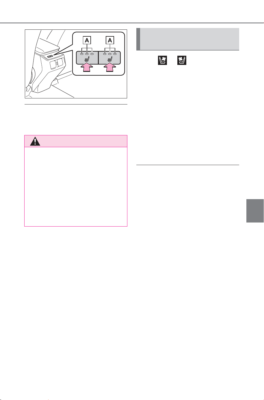
505
6-1. Using the air conditioning system and defogger
Owner’s Manual_USA_M6740B_en
6
Interior features
■ The seat heaters can be used
when
The power switch is in ON.
Select or on the multime-
dia display.
Each time the switch is selected,
the operation condition changes as
follows.
AUTO Hi (3 segments lit) Mid
(2 segments lit) Lo (1 segment
lit) Off
The level indicator (blue) lights up
during operation. “AUTO” indicator
lights up during automatic opera-
tion.
■ The seat ventilators can be
used when
The power switch is in ON.
■ Air conditioning system-linked
control mode
When the seat ventilators fan speed
level is Hi, the seat ventilators fan
speed becomes higher according to
the fan speed of the air conditioning
system.
WARNING
■ To prevent causes of over-
heating and minor burn inju-
ries
Observe the following precautions
when using a seat heaters
● Do not cover the seat with a
blanket or cushion when using
the seat heaters
● Do not use seat heaters more
than necessary.
Seat ventilators (front
seats)
SOLTERRA_OM_USA_A6740BE.book 505 ページ 2025年5月23日 金曜日 午後1時18分
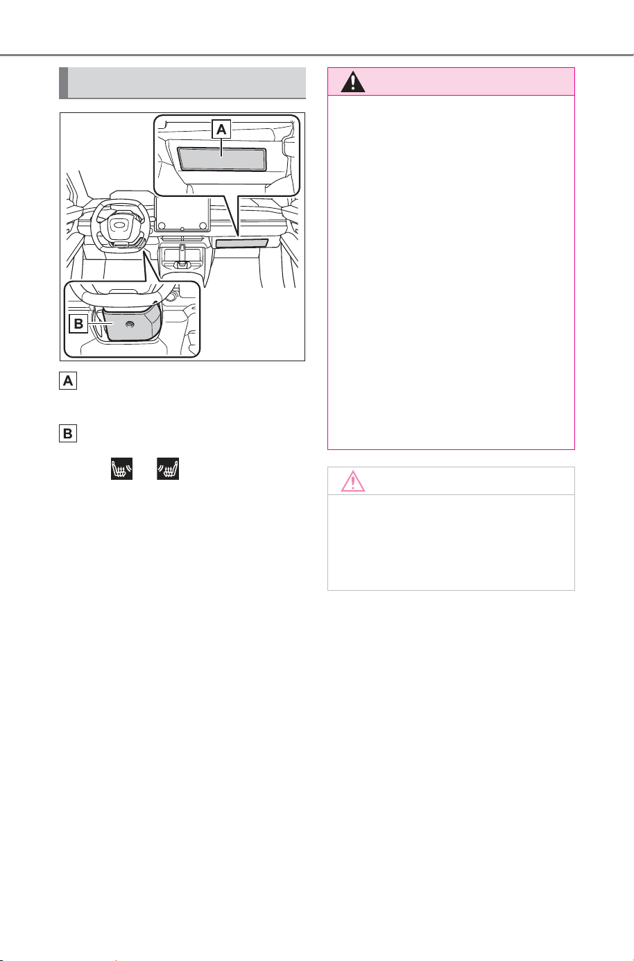
506
6-1. Using the air conditioning system and defogger
Owner’s Manual_USA_M6740B_en
Front passenger’s side radi-
ant heater
Driver’s side radiant heater
Select or on the multime-
dia display.
Each time the switch is selected,
the operation condition changes as
follows.
AUTO Hi (3 segments lit) Mid
(2 segments lit) Lo (1 segment
lit) Off
The level indicator (red) lights up
during operation. “AUTO” indicator
lights up during automatic opera-
tion.
Radiant heaters
WARNING
■ To prevent causes of over-
heating and minor burn inju-
ries
Observe the following precautions
when using a radiant heater
● Do not use radiant heaters more
than necessary.
● Do not let blankets, cushions,
luggage, etc., to touch the radi-
ant heaters.
■ Use while driving
Do not touch the radiant heaters
or hold your hand or foot over it by
releasing a hand from the handle
or a foot from the pedal.
Doing so may cause the driver to
mishandle the vehicle and cause
an accident, resulting in death or
serious injury.
NOTICE
■ To prevent damage to the
radiant heaters
Do not pierce with uneven objects
or sharp objects such as wires or
needles.
SOLTERRA_OM_USA_A6740BE.book 506 ページ 2025年5月23日 金曜日 午後1時18分
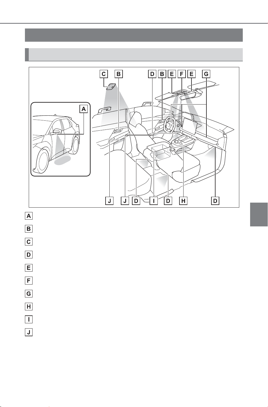
507
6-2. Using the interior lights
Owner’s Manual_USA_M6740B_en
6
Interior features
6-2.Using the in terior lights
Outer foot lights (if equipped)
Inside door handle lights
Rear interior light (P.509)
Footwell lights
Front interior lights/personal lights (P.508, 509)
Shift lights
Instrument panel ornament lights (P.509)
Center console light
Console box light
Door trim ornament lights
Interior lights list
Location of the interior lights
SOLTERRA_OM_USA_A6740BE.book 507 ページ 2025年5月23日 金曜日 午後1時18分
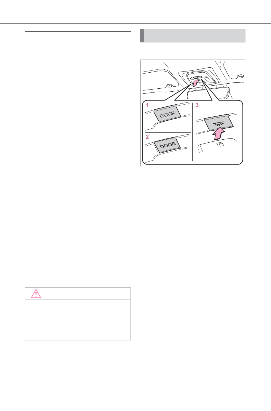
508
6-2. Using the interior lights
Owner’s Manual_USA_M6740B_en
■ Personal lights/interior lights
automatic on/off
● Illuminated entry system: The
lights automatically turn on/off
according to power switch mode,
the presence of the electronic key,
whether the doors are
locked/unlocked, and whether the
doors are opened/closed.
● If the interior lights remain on
when the power switch is turned
off, the lights will go off automati-
cally after 20 minutes.
■ Automatic illumination of the
interior lights
If any of the SRS airbags deploy
(inflate) or in the event of a strong
rear impact, the interior lights will
turn on automatically. The interior
lights will turn off automatically after
approximately 20 minutes.
The interior lights can be turned off
manually. However, in order to help
prevent further collisions, it is rec-
ommended that they be left on until
safety can be ensured.
(The interior lights may not turn on
automatically depending on the
force of the impact and conditions of
the collision.)
■ Customization
Setting (e.g. the time elapsed before
the lights turn off) can be changed.
(Customizable features: P.684)
■ Front interior lights
1 Turns the door-linked func-
tion off
2 Turns the door-linked func-
tion on (door position)
The lights turn on/off according to
the opening/closing of the doors.
3 Turns the lights on/off
Press the switch to turn on/off the
front interior lights/personal lights
and rear interior lights.
NOTICE
■ To prevent 12-volt battery dis-
charge
Do not leave the lights on longer
than necessary when the EV sys-
tem is off.
Operating interior lights
SOLTERRA_OM_USA_A6740BE.book 508 ページ 2025年5月23日 金曜日 午後1時18分
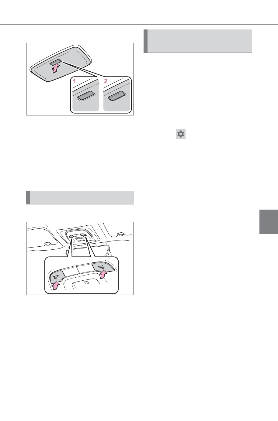
509
6-2. Using the interior lights
Owner’s Manual_USA_M6740B_en
6
Interior features
■ Rear interior light
1 Turns the light on
2 Turns the door-linked func-
tion on (door position)
The light turns on/off according to
the opening/closing of the doors.
The rear interior light turn on/off
together the front interior light.
Turns the lights on/off
Using the multimedia display,
the color and brightness of the
interior lights in the vehicle can
be changed.
Inside door handle lights
Instrument panel ornament
lights
1 Select .
2 Select “Vehicle customize”.
3 Select “Illumination”.
4 Select the desired color.
Operating personal lights
Changing the illumina-
tion color
SOLTERRA_OM_USA_A6740BE.book 509 ページ 2025年5月23日 金曜日 午後1時18分
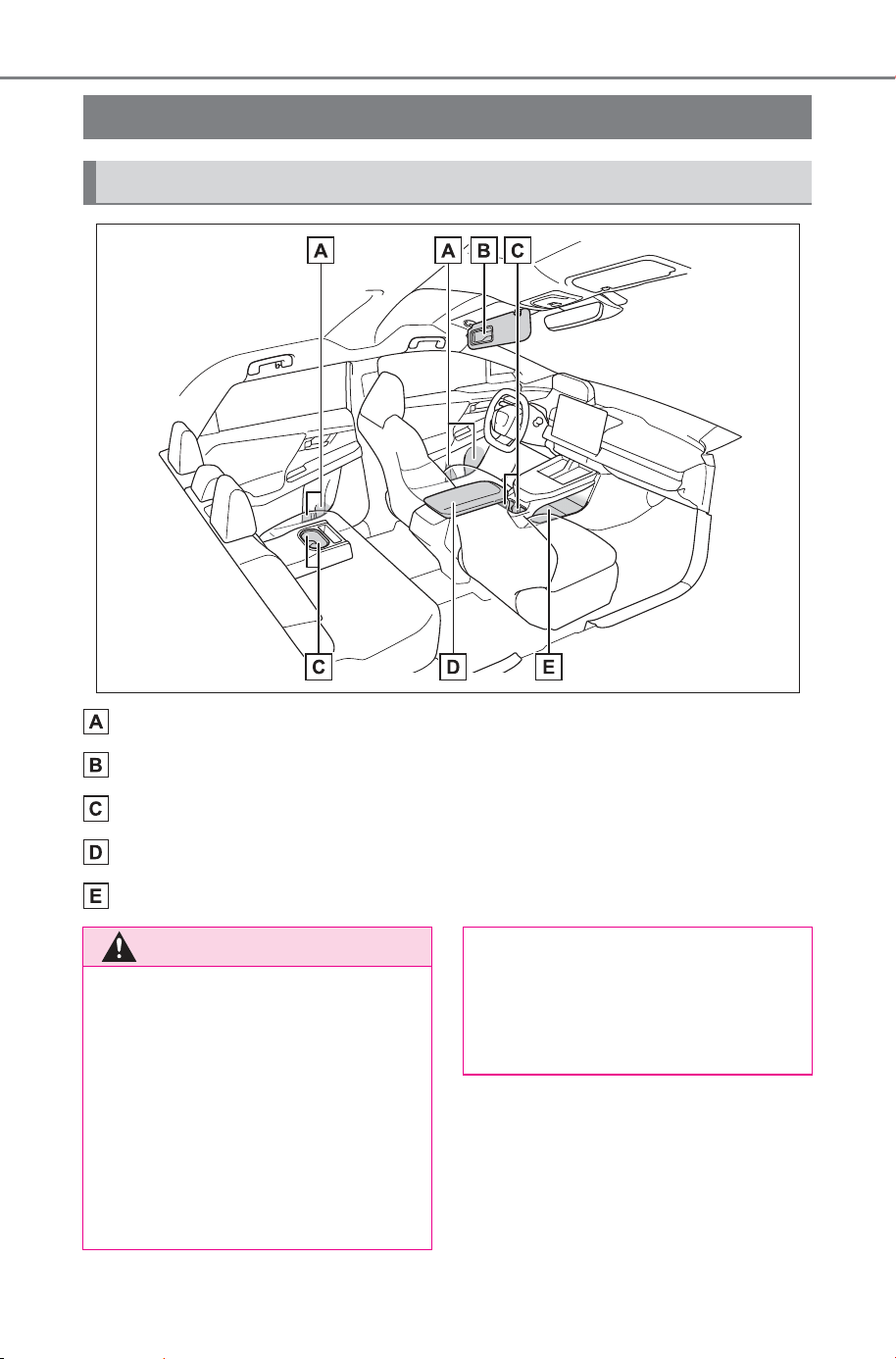
510
6-3. Using the storage features
Owner’s Manual_USA_M6740B_en
6-3.Us ing the storage featur es
Bottle holders (P. 51 2)
Ticket holders (P.512)
Cup holders (P. 511 )
Console box (P. 5 11)
Open tray (P.512)
List of storage features
Location of the storage features
WARNING
■ Items that should not be left
in the vehicle
Do not leave glasses, lighters or
spray cans in the storage spaces,
as this may cause the following
when cabin temperature becomes
high:
● Glasses may be deformed by
heat or cracked if they come
into contact with other stored
items.
● Lighters or spray cans may
explode. If they come into con-
tact with other stored items, the
lighter may catch fire or the
spray can may release gas,
causing a fire hazard.
SOLTERRA_OM_USA_A6740BE.book 510 ページ 2025年5月23日 金曜日 午後1時18分
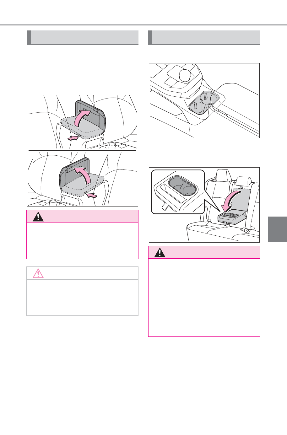
511
6-3. Using the storage features
Owner’s Manual_USA_M6740B_en
6
Interior features
Press a button to open the con-
sole box.
The console box can be opened
from either side.
■ Front
■ Rear
Pull down the armrest.
Console box
WARNING
■ Caution while driving
Keep the console box closed.
Injuries may result in the event of
an accident or sudden braking.
NOTICE
■ To prevent damage to the
console box
Do not apply excessive force to
the armrest.
Cup holders
WARNING
■ Items unsuitable for the cup
holders
Do not place anything other than
cups or aluminum cans in the cup
holders.
Other items may be thrown out of
the holders in the event of an
accident or sudden braking, caus-
ing injury. If possible, cover hot
drinks to prevent burns.
SOLTERRA_OM_USA_A6740BE.book 511 ページ 2025年5月23日 金曜日 午後1時18分
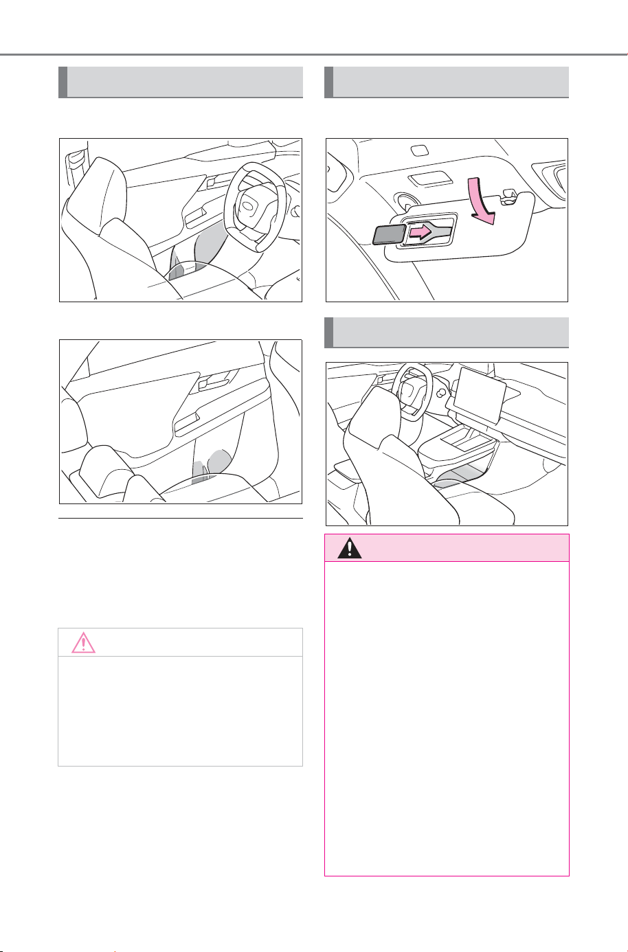
512
6-3. Using the storage features
Owner’s Manual_USA_M6740B_en
■ Front
■ Rear
■ Bottle holders
● When storing a bottle, close the
cap.
● The bottle may not be stored
depending on its size or shape.
Flip down the visor.
Bottle holders
NOTICE
■ Items that should be not
stowed in the bottle holders
Do not place open bottles or glass
and paper cups containing liquid
in the bottle holders. The contents
may spill and glasses may break.
Ticket holders
Open tray
WARNING
■ Caution while driving
Observe the following precautions
when putting items in the open
tray. Failure to do so may cause
items to be thrown out of the tray
in the event of sudden braking or
steering. In these cases, the items
may interfere with pedal operation
or cause driver distraction, result-
ing in an accident.
• Do not store items in the tray
that can easily shift or roll out.
• Do not stack items in the tray
higher than the edge of tray.
• Do not put items in the tray that
may protrude over the edge of
tray.
SOLTERRA_OM_USA_A6740BE.book 512 ページ 2025年5月23日 金曜日 午後1時18分
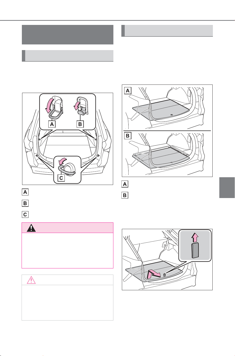
513
6-3. Using the storage features
Owner’s Manual_USA_M6740B_en
6
Interior features
Raise the hooks to use.
The cargo hooks are provided for
securing loose items.
Upper hook (rope hook)
Upper hook (utility hook)
Lower hook
■ Changing the deck board
positions
Height of the deck floor can be
changed by setting the deck
board under the floor.
Upper
Lower
1 Pull up the tab to raise the
deck board and move it
toward you to remove.
Luggage compart-
ment features
Cargo hooks
WARNING
■ When cargo hooks are not in
use
To avoid injury, always return the
hooks to their stowed positions
when not in use.
NOTICE
■ To prevent damage to the
upper hook (utility hook)
Do not hang any object heavier
than 8 lb. (4 kg) on the upper
hook (utility hook).
Deck board
SOLTERRA_OM_USA_A6740BE.book 513 ページ 2025年5月23日 金曜日 午後1時18分
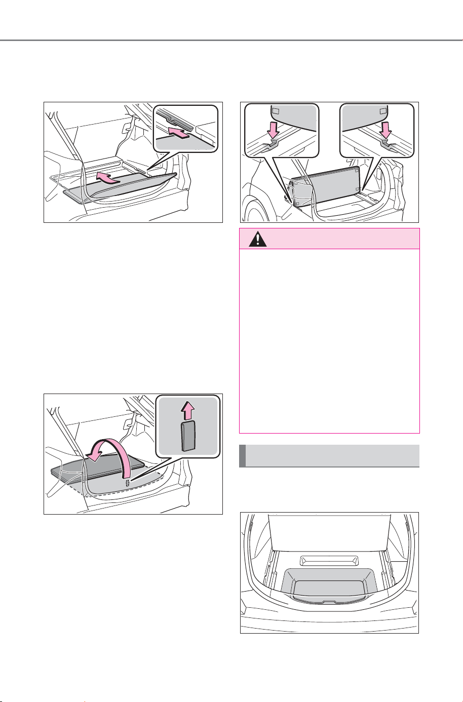
514
6-3. Using the storage features
Owner’s Manual_USA_M6740B_en
2 Place the deck board through
the groove and move for-
ward.
■ Setting the deck board
upright
When taking out the tools, the
deck board can be set upright.
When the back surface (resin sur-
face) of the deck board is facing up,
flip it back to the original position.
1 Pull up the tab to raise the
deck board and fold it for-
ward.
2 Deck board in a standing
state, put the edge into the
holes.
Pull up the tab to raise the deck
board and fold it forward.
WARNING
■ When operating the deck
board
Do not place anything on the deck
board when operating the board.
Otherwise, your fingers may be
caught or an accident may result
causing injuries.
■ Caution while driving
Keep the deck board closed.
In the event of sudden braking, an
accident may occur due to an
occupant being struck by the deck
board or the items stored under
the deck board.
Deck under tray
SOLTERRA_OM_USA_A6740BE.book 514 ページ 2025年5月23日 金曜日 午後1時18分
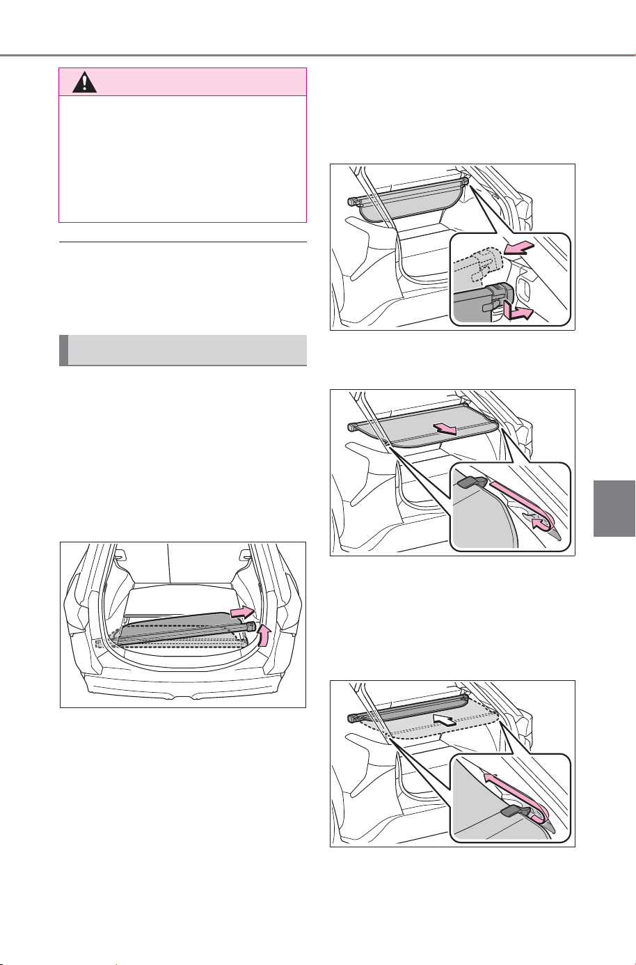
515
6-3. Using the storage features
Owner’s Manual_USA_M6740B_en
6
Interior features
■ Warning reflector
Depending on the size and shape of
the warning reflector case, you may
not be able to store it.
■ Removing the luggage
cover unit
1 Pull up the tab to raise the
deck board and fold it for-
ward. (P.514)
2 Take out the luggage cover
unit.
■ Installing the luggage cover
1 Compress the both ends of
the luggage cover and insert
into the recess to install.
2 Pull out the luggage cover
and hook it onto the anchors.
■ Removing the luggage
cover
1 Release the cover from the
left and right anchors and
allow it to retract.
WARNING
■ Caution while driving
Keep the deck board closed.
In the event of sudden braking, an
accident may occur due to an
occupant being struck by the deck
board or the items stored under
the deck board.
Luggage cover
SOLTERRA_OM_USA_A6740BE.book 515 ページ 2025年5月23日 金曜日 午後1時18分
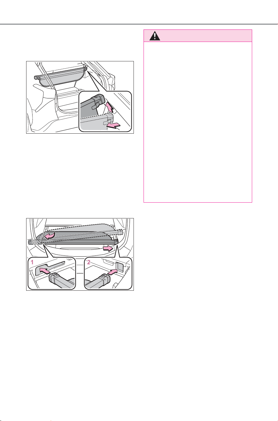
516
6-3. Using the storage features
Owner’s Manual_USA_M6740B_en
2 Compress the end of the lug-
gage cover and lift the lug-
gage cover up.
■ Stowing the luggage cover
unit
1 Pull up the tab to raise the
deck board and fold it for-
ward. (P.514)
2 To store the luggage cover
unit, compress both ends
until they lock.
1 Insert the left end of the lug-
gage cover unit into the
groove on the left side of the
deck.
2 Insert the right end of the lug-
gage cover unit into the
groove on the right side of
the deck side.
WARNING
■ Luggage cover
● When installing/stowing the lug-
gage cover, make sure that the
luggage cover is securely
installed/stowed. Failure to do
so may result in serious injury in
the event of sudden braking or a
collision.
● Do not place anything on the
luggage cover. In the event of
sudden braking or turning, the
item may go flying and strike an
occupant. This could lead to an
unexpected accident, resulting
in death or serious injury.
● Do not allow children to climb
on the luggage cover. Climbing
on the luggage cover could
result in damage to the luggage
cover, possibly causing death or
serious injury to the child.
SOLTERRA_OM_USA_A6740BE.book 516 ページ 2025年5月23日 金曜日 午後1時18分
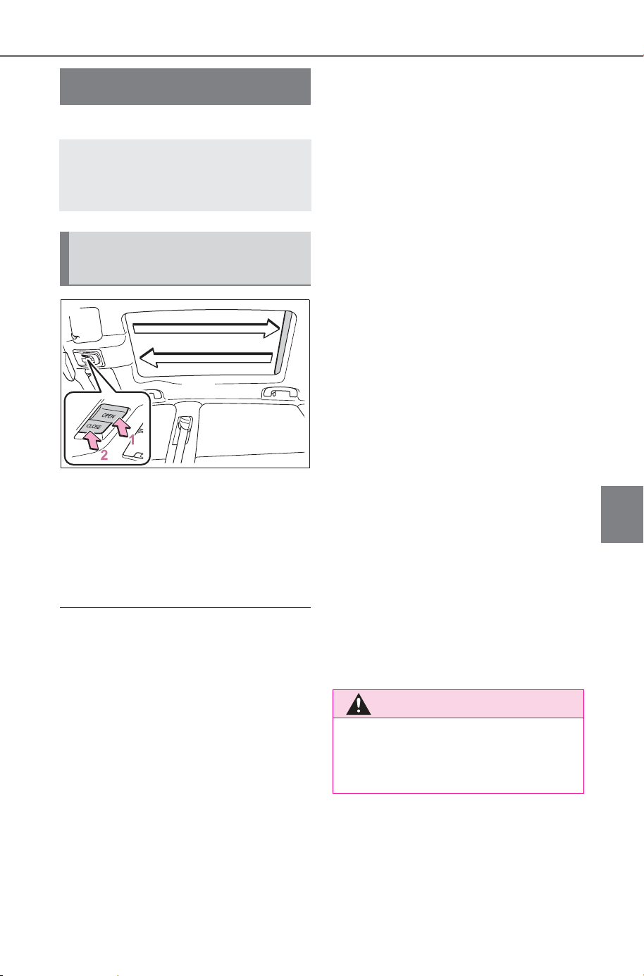
517
6-4. Using the other interior features
Owner’s Manual_USA_M6740B_en
6
Interior features
6-4.Using the ot her interior features
*
: If equipped
1 Open
*
2 Close
*
*
: To stop the electronic sunshade
partway, lightly press the either
end of the switch.
■ The electronic sunshade can be
operated when
The power switch is in ON.
■ Jam protection function for the
electronic sunshade
● If an object becomes jammed
between the electronic sunshade
and the sunshade frame while the
electronic sunshade is closing, the
electronic sunshade movement is
stopped and the electronic sun-
shade is opened slightly.
● When the jam protection function
has operated, even if the
“CLOSE” side of the switch is
pressed again, the electronic sun-
shade will not move in the close
direction until the reverse opera-
tion has stopped completely.
● The electronic sunshade may
operate in reverse if the electronic
sunshade is subject to an impact
due to the surroundings or the
driving conditions.
■ When the electronic sunshade
does not close normally
Perform the following initialization
procedure.
1 Turn the power switch to ON.
2 Press and hold the “CLOSE”
side of the switch.
It closes until it is near the fully
closed position and then stops. After
that, it operates in the opening
direction then closes to the fully
closed position.
If the switch is released at the incor-
rect time, the procedure will have to
be performed again from the begin-
ning.
If the automatic opening and closing
function does not work normally
even after performing the operations
above, have the vehicle inspected
by your SUBARU dealer.
Electronic sunshade
*
Use the overhead switches
to operate the electronic
sunshade.
Operating the electronic
sunshade
WARNING
Observe the following precau-
tions.
Failure to do so may result in
death or serious injury.
SOLTERRA_OM_USA_A6740BE.book 517 ページ 2025年5月23日 金曜日 午後1時18分
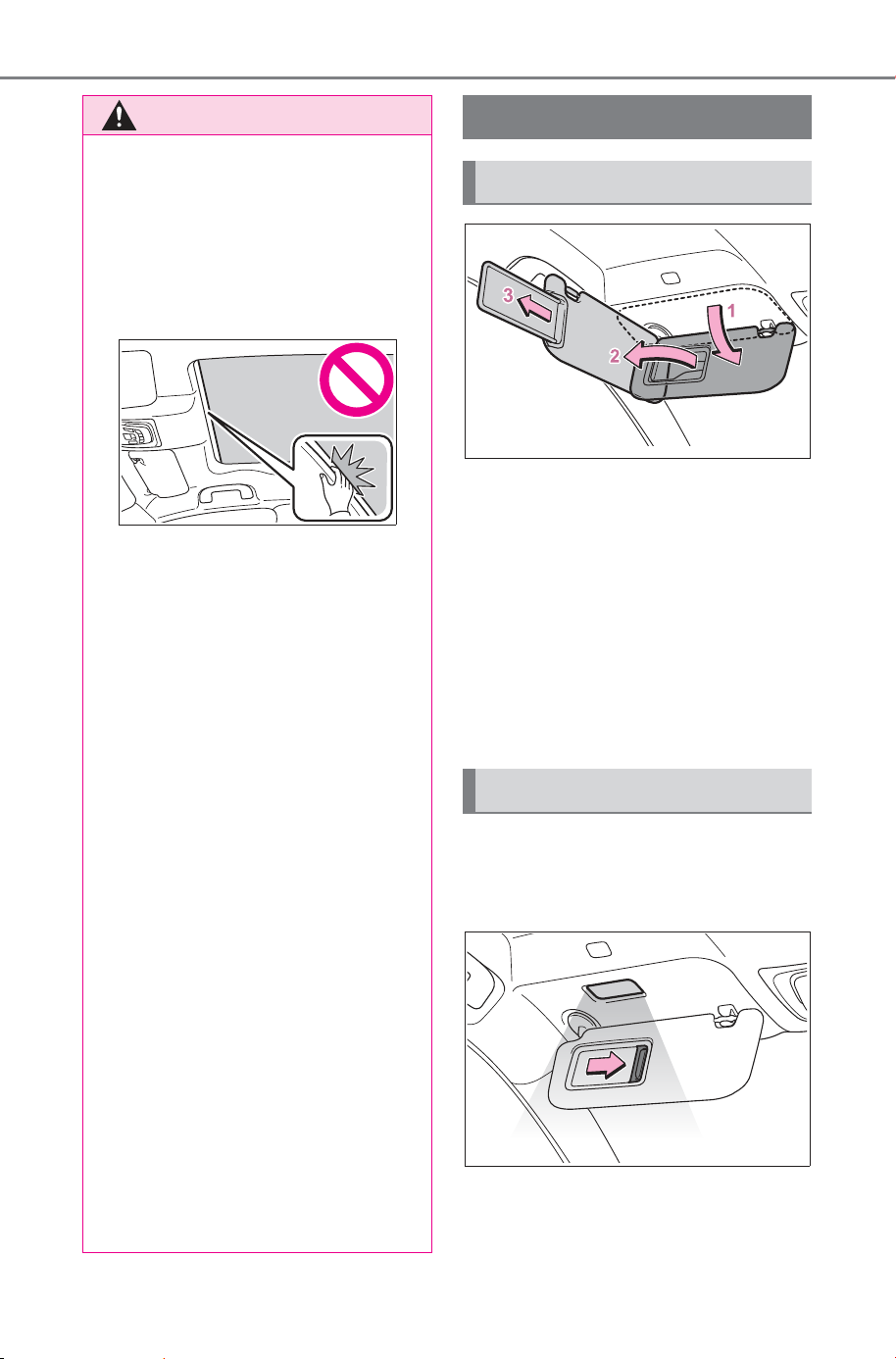
518
6-4. Using the other interior features
Owner’s Manual_USA_M6740B_en
1 To set the visor in the forward
position, flip it down.
2 To set the visor in the side
position, flip down, unhook,
and swing it to the side.
3 To use the side extender,
place the visor in the side
position, then slide it back-
ward.
Slide the cover to open.
The light turns on when the cover is
opened.
WARNING
■ Opening and closing the elec-
tronic sunshade
● Check to make sure that all pas-
sengers do not have any part of
their body in a position where it
could be caught when the elec-
tronic sunshade is being oper-
ated.
● Do not let a child operate the
electronic sunshade. Closing
the electronic sunshade on
someone can cause death or
serious injury.
■ Jam protection function
● Never use any part of your body
to intentionally activate the jam
protection function.
● The jam protection function may
not work if something gets
caught just before the electronic
sunshade is fully closed. Also,
the jam protection function is
not designed to operate while
the switch is being pressed.
Take care so that your fingers,
etc., do not get caught.
■ To prevent burns or injuries
Do not touch the area between
the underside of the glass roof
and the electronic sunshade. Your
hand may get caught and you
could injure yourself. Also, if the
vehicle is left in direct sunlight for
a long time, the underside of the
panoramic moon roof could
become very hot and could cause
burns.
Other interior features
Sun visors
Vanity mirrors
SOLTERRA_OM_USA_A6740BE.book 518 ページ 2025年5月23日 金曜日 午後1時18分
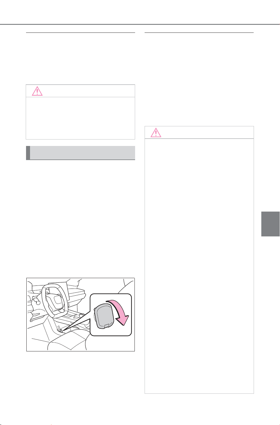
519
6-4. Using the other interior features
Owner’s Manual_USA_M6740B_en
6
Interior features
■ Vanity lights
If the vanity lights remain on when
the power switch is turned off, the
lights will go off automatically after
20 minutes.
Please use a power supply for
electronic goods that use less
than 12 VDC /10 A (power con-
sumption of 120 W).
When using electronic goods,
make sure that the power con-
sumption of all the connected
power outlets is less than 120
W.
■ Front
Open the lid.
■ The power outlet can be used
when
The power switch is in ACC or ON,
or the multimedia system is on.
■ When stopping the EV system
Disconnect electrical devices with
charging functions, such as mobile
battery packs.
If such devices are left connected,
the EV system may not stop nor-
mally.
NOTICE
■ To prevent 12-volt battery dis-
charge
Do not leave the vanity lights on
for extended periods while the EV
system is off.
Power outlet (12 VDC)
NOTICE
■ When power outlet is not in
use
To avoid damaging the power out-
let, close the power outlet lid
when the power outlet is not in
use.
Foreign objects or liquids that
enter the power outlet may cause
a short circuit.
■ To prevent 12-volt battery dis-
charge
Do not use the power outlet lon-
ger than necessary when the EV
system is off.
■ To prevent incorrect opera-
tion of the vehicle
When turning the power switch
off, make sure to disconnect
accessories designed for
charging, such as portable char-
gers, power banks, etc. from the
power outlets.
If such an accessory is left con-
nected, the following may occur:
● The doors will not be able to be
locked.
● The opening screen will be dis-
played on the multi-information
display.
● The interior lights, instrument
panel lights, etc. will illuminate.
SOLTERRA_OM_USA_A6740BE.book 519 ページ 2025年5月23日 金曜日 午後1時18分
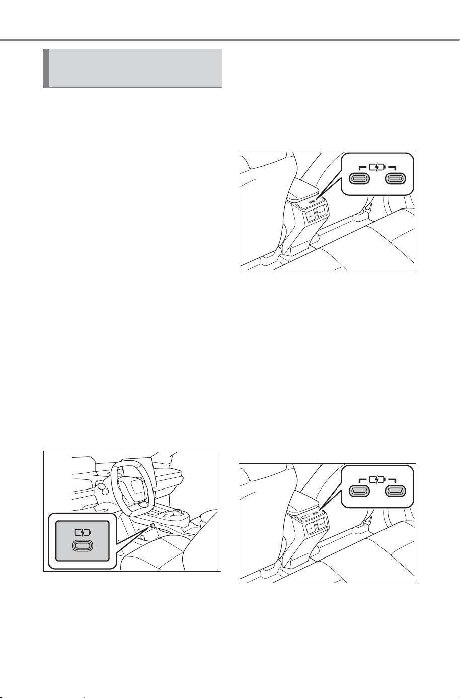
520
6-4. Using the other interior features
Owner’s Manual_USA_M6740B_en
The USB Type-C charging ports
are used to supply electricity to
external devices. Use the appro-
priate terminal for each charging
port type.
The USB Type-C charging ports
are for charging only.
They are not designed for data
transfer or other purposes.
Depending on the external
device, it may not charge prop-
erly.
Refer to the manual included
with the device before using a
USB Type-C charging port.
■ Using the USB Type-C
charging ports
Center console
The USB Type-C charging ports
are used to supply 3 A of elec-
tricity at 5 V to external devices.
Vehicles without rear seat
heaters
These USB Type-C charging
ports are capable of high power
output.
An output up to 60 W max on a
single port or 60 W combined
(shared) is possible.
The USB Type-C charging ports
operate at multiple voltage and
multiple wattage levels.
Vehicles with rear seat heat-
ers
These USB Type-C charging
ports are capable of high power
output.
An output up to 60 W max on a
single port or 60 W combined
(shared) is possible.
The USB Type-C charging ports
operate at multiple voltage and
multiple wattage levels.
USB Type-C charging
ports
SOLTERRA_OM_USA_A6740BE.book 520 ページ 2025年5月23日 金曜日 午後1時18分
521
6-4. Using the other interior features
Owner’s Manual_USA_M6740B_en
6
Interior features
■ The USB Type-C charging ports
can be used when
The power switch is in ACC or ON,
or the multimedia system is on.
■ Situations in which the USB
Type-C charging ports may not
operate correctly
● If a device which consumes more
than 3 A at 5 V is connected
(center console)
● If a device which consumes more
than 3 A at 20 V is connected
(rear)
● If a device designed to communi-
cate with a personal computer,
such as a USB memory device, is
connected
● If the connected external device is
turned off (depending on device)
● If the temperature inside the vehi-
cle is high, such as after the vehi-
cle has been parked in the sun
■ About connected external
devices
Depending on the connected exter-
nal device, charging may occasion-
ally be suspended and then start
again. This is not a malfunction.
A portable device can be
charged by just placing Qi stan-
dard wireless charge compatible
portable devices according to
the Wireless Power Consortium,
such as smartphones and
mobile batteries, etc., on the
charge area.
The compatible portable devices
can be found on the following
Wireless Power Consortium
website.
https://www.
wirelesspowerconsortium.com/
This function cannot be used
with portable devices that are
larger than the charging tray.
Also, depending on the portable
device, it may not operate as
normal. Please read the opera-
tion manual for portable devices
to be used.
NOTICE
■ To prevent damage to the
USB Type-C charging ports
● Do not insert foreign objects into
the ports.
● Do not spill water or other liq-
uids into the ports.
● Do not apply excessive force to
or impact the USB Type-C
charging ports.
● Do not disassemble or modify
the USB Type-C charging ports.
■ To prevent damage to exter-
nal devices
● Do not leave external devices in
the vehicle. The temperature
inside the vehicle may become
high, resulting in damage to an
external device.
● Do not push down on or apply
unnecessary force to an exter-
nal device or the cable of an
external device while it is con-
nected.
■ To prevent 12-volt battery dis-
charge
Do not use the USB Type-C
charging ports for a long period of
time with the EV system stopped.
Wireless charger
SOLTERRA_OM_USA_A6740BE.book 521 ページ 2026年1月13日 火曜日 午前9時32分
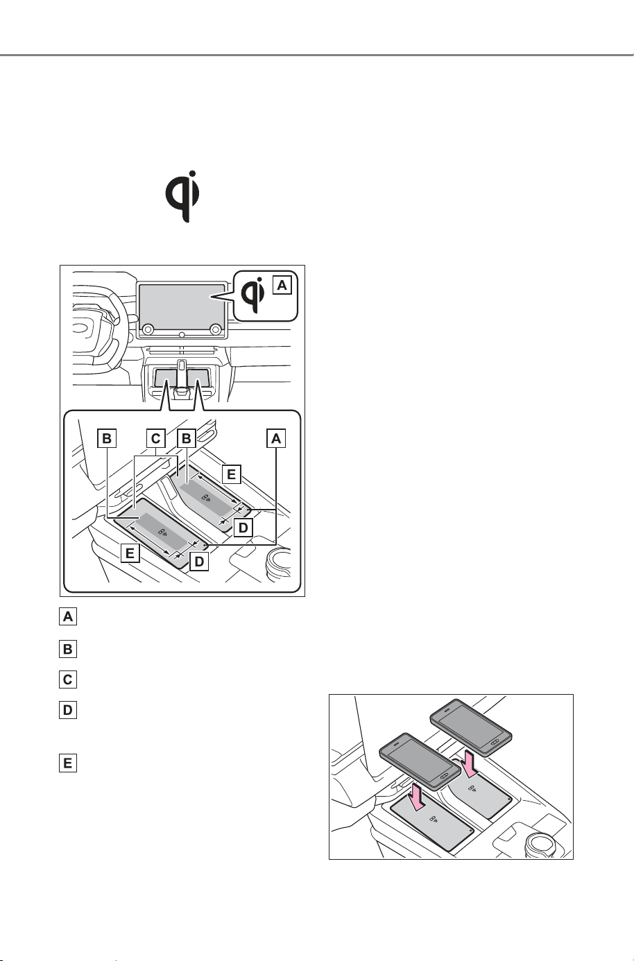
522
6-4. Using the other interior features
Owner’s Manual_USA_M6740B_en
■ The “Qi” logo
The “Qi” logo is a trademark of
the Wireless Power Consortium.
Qi ID: 11277
■ Name for all parts
Operation indicator light
Charging area
*
Charging tray
Approximately 1.0 in. (2.5
cm)
Approximately 3.9 in. (10 cm)
*
: Compatible portable devices and
the wireless charger contain
charging coils. The charging coil
in the wireless charger can be
moved within the charge area up
to the position of the charging coil
inside a portable device.
Charging is possible if the center
of the coil of the portable device
is placed within the charge area.
If 2 or more portable devices are
placed on the charging tray, their
charging coils may not be prop-
erly detected and they may not
be charged.
■ Using the wireless charger
Place the portable device on the
charging tray.
Place the charging side of the por-
table device down with the center of
the device in the center of the
charge area.
When charging, the operation indi-
cator light (orange) comes on.
If charging is not occurring, refer to
“Situations in which the function
may not operate normally”
(P.527).
When charging is complete, the
operation indicator light (green)
comes on.
SOLTERRA_OM_USA_A6740BE.book 522 ページ 2025年5月23日 金曜日 午後1時18分
523
6-4. Using the other interior features
Owner’s Manual_USA_M6740B_en
6
Interior features
■ Recharging function
When charging is complete
and after a fixed time in the
charge suspension state,
charging restarts.
When a portable device is
moved significantly in the
charge area, the charging coil
is disconnected and charging
is stopped momentarily. How-
ever, if there is a charging coil
in the charge area, the
charging coil inside the wire-
less charger will move toward
it and then charging restarts.
■ Rapid charging function
The following portable
devices support rapid
charging.
• Portable devices compliant with
WPC Ver1.3.2 and compatible
with rapid charging
• iPhone’s with an iOS version that
supports 7.5 W charging (iPhone
8 and later models)
• Portable devices compatible with
Galaxy original rapid charging
standard.
When a portable device that
supports rapid charging is
charged, charging automati-
cally switches to the rapid
charging function.
■ Lighting conditions of operation indicator light
*1
:Charging power will not be output during standby. A metallic object will
not be heated, if it is placed on the charging tray in this state.
*2
:Depending on the portable device, there are cases where the operation
indicator light will continue being lit up orange even after the charging is
complete.
Operation indicator light
Conditions
Charging tray side
Multimedia sys-
tem screen side
Turning off Disappear
When the Multimedia power supply
is off or power switch is off
Green (comes on) Gray
On Standby (charging possible
state)
*1
When charging is complete
*2
Orange (comes
on)
Blue Charging
SOLTERRA_OM_USA_A6740BE.book 523 ページ 2025年5月23日 金曜日 午後1時18分

524
6-4. Using the other interior features
Owner’s Manual_USA_M6740B_en
■ The wireless charger is not working properly
The following are situations in which the wireless charger does not
work properly and how to deal with the possible causes.
Operation indica-
tor light
Multimedia sys-
tem screen
Suspected causes/Handling
method
Orange (Flashing
repeatedly once
every second)
Gray
Vehicle to wireless charger com-
munication failure
If the EV system is operating,
stop and then restart the EV
system.
If the power switch is in ACC, start
the EV system. (P.229)
Green (Flashing
repeatedly once
every second)
Disappear
Wireless charger and multimedia
system communication failure
If the EV system is operating,
stop and then restart the EV
system.
If the power switch is in ACC, start
the EV system. (P.229)
Green (comes on) Blue
AM radio stations are being auto-
matically selected
Wait until the system has com-
pleted the automatic selection
of AM radio stations. In the
case that automatic selection
cannot be completed, stop
automatic selection.
The smart key system is detect-
ing the key
Wait until the key detection is
complete.
SOLTERRA_OM_USA_A6740BE.book 524 ページ 2025年5月23日 金曜日 午後1時18分
525
6-4. Using the other interior features
Owner’s Manual_USA_M6740B_en
6
Interior features
Green (comes on) Gray
Foreign substance detection:
A metallic foreign substance is in
the charge area, and so the
abnormal heating prevention
function of the metallic foreign
substance operated
Remove the foreign substance
from the charge area.
Portable device misaligned/dis-
tanced from charging surface:
The center of charging coil in the
portable device moved outside of
the charging area, or lens convex
is large, or case is thick so the
abnormal heating prevention
function operated
Remove the portable device
from the wireless charger, after
5 seconds, then place the por-
table device so that it is near
the center of the wireless char-
ger.
Also, if a case or cover is
installed to the portable
device, remove it.
Battery protection function of
portable device:
Before full charging, battery pro-
tection function of portable
device operated
Confirm the setting of portable
device.
Continued detection of an elec-
tronic key:
When a Multimedia function is
used through vehicle customiza-
tion, the electronic key is contin-
ually detected without being
confirmed.
In this case, turn the power
switch ACC or ON to confirm
the key.
Operation indica-
tor light
Multimedia sys-
tem screen
Suspected causes/Handling
method
SOLTERRA_OM_USA_A6740BE.book 525 ページ 2025年5月23日 金曜日 午後1時18分

526
6-4. Using the other interior features
Owner’s Manual_USA_M6740B_en
■ The wireless charger can be
operated when
The power switch is in ACC or ON,
or the multimedia system is on.
■ Usable portable devices
● Qi standard wireless charge stan-
dard can be used on compatible
devices. However, compatibility
with portable devices that comply
with Qi Ver. 1.0, 1.3.2 and later
versions, and Qi2 MPP (Magnet
Power Profile) is not guaranteed.
● Starting with mobile phones and
smartphones, it is aimed for low
power electrically supplied porta-
ble devices of no more than 5 W.
● However, charging exceeding 5 W
is supported by the following por-
table devices.
• Charging at 7.5 W or less is sup-
ported by iPhone’s that support
7.5 W charging.
• Charging at 10 W or less is sup-
ported by Galaxy device that sup-
port 10 W charging of original
standard.
• Charging at 15 W or less is sup-
ported by portable devices compli-
ant with EPP output as defined by
WPC standard Ver1.3.2.
■ Using the smart key system
If the smart key system detects the
electronic key while a device is
being charged, charging will be tem-
porarily stopped. When the elec-
tronic key is detected, charging will
automatically start again.
■ When covers and accessories
are attached to portable devices
Do not charge in situations where
cover and accessories not able to
handle Qi are attached to the porta-
ble device. Depending on the type
of cover (including for certain genu-
ine manufacturer parts) and acces-
sory, charging may not be possible.
In addition, Qi2 is not supported. As
a result, charging may not be possi-
ble when an accessory and cover
that comply with Qi2 are installed.
When charging is not performed
even with the portable device placed
on the charge area, remove the
cover and accessories.
■ AM radio cooperation function
during charging
● During charging, if noise occurs
when listening to the AM radio,
the charging frequency is auto-
matically changed to reduce the
noise.
Orange (Repeat-
edly flashes 4
times continu-
ously)
Gray
Safety shutdown resulting when
the temperature within the wire-
less charger exceeded the set
value
Stop charging, remove the por-
table device from the charging
tray, wait for the temperature
to drop, and then start
charging again.
Operation indica-
tor light
Multimedia sys-
tem screen
Suspected causes/Handling
method
SOLTERRA_OM_USA_A6740BE.book 526 ページ 2025年5月23日 金曜日 午後1時18分

527
6-4. Using the other interior features
Owner’s Manual_USA_M6740B_en
6
Interior features
● When automatically seeking AM
radio stations, charging will be
suspended to prevent charging
noise from being detected as a
radio station. Charging will
resume automatically when seek
tuning is stopped.
■ Important points of the wire-
less charger
● If the electronic key cannot be
detected within the vehicle inte-
rior, charging can not be done.
When the door is opened and
closed, charging may be tempo-
rarily suspended.
● When charging, the wireless
charging device and portable
device will get warmer, however
this is not a malfunction. When a
portable device gets warm while
charging, charging may stop due
to the protection function on the
portable device side. In this case,
when the temperature of the por-
table device drops significantly,
charge again.
The fan may start operating to
lower the temperature inside the
wireless charger, however this is
not a malfunction.
■ Operation sounds
A buzzing noise may be heard when
pressing the power switch to turn to
ACC or ON or when detecting a por-
table device. However, this is not a
malfunction.
■ Cleaning the wireless charger
P.551
■ Situations in which the function
may not operate normally
Devices may not be charged nor-
mally in the following situations.
● The portable device is fully
charged
● The portable device is being
charged with a cable connected
● There is foreign matter between
the charge area and portable
device
● Charging has caused the portable
device to heat up
● The temperature around the
charging tray is 95°F (35°C) or
higher, such as in extreme heat
● The portable device is placed with
its charging surface facing up
● The small portable device such as
foldable type is placed in an area
misaligned from the charge area
● The portable device is larger than
the charging tray
● The camera lens protrudes 0.12 in
(3 mm) or more from the surface
of the portal device
● The vehicle is in an area where
strong electrical waves or noise
are emitted, such as near a televi-
sion tower, power plant, gasoline
station, broadcasting station, large
display, airport, etc.
● The electronic key is not inside the
vehicle
● Any of the following objects is
stuck or installed between the
charging side of the portable
device and the charge area.
• Thick cases or covers
• A case or cover attached with an
uneven or tilted surface, so that
the charging side is not flat
• Thick decorations
• Accessories, such as finger
rings,a.straps, etc.
• Cover to protect camera lens
● When there is a gap between the
charging side of the portable
device and the charge area due to
a protrusion such as a camera on
the charging side of the portable
device.
● When the portable device is in
contact with, or is covered by any
of the following metallic objects:
• A card that has metal on it, such
as aluminum foil, etc.
• A pack of cigarettes that includes
aluminum foil
• A wallet or bag that is made of
metal
SOLTERRA_OM_USA_A6740BE.book 527 ページ 2025年5月23日 金曜日 午後1時18分
528
6-4. Using the other interior features
Owner’s Manual_USA_M6740B_en
•Coins
• A heating pad
• CDs, DVDs or other media
• A metal accessory
• A case or cover made of metal
• A flip type case with a magnet on
the charging side of the portable
device
● Electric wave type wireless
remote controls are being used
nearby
● 2 or more portable devices are
placed on the charging tray at the
same time
● If you use a device with a built-in
S-Pen (Galaxy Note series, etc.)
and the device with the S-Pen
inserted is on the tray.
If charging is abnormal or the opera-
tion indicator light continues to flash
for any other reason, the wireless
charger may be malfunctioning.
Contact your SUBARU dealer.
■ If the smartphone OS has been
updated
If the smartphone OS has been
updated to a newer version, its
charging specifications may have
changed significantly.For details,
check the information on the manu-
facturer’s website.
■ Trademark information
• iPhone is a trademark of Apple
Inc., registered in the U.S. and
other countries.
• “Galaxy” is a trademark or regis-
tered trademark of Samsung Elec-
tronics Co., Ltd.
■ Certification
P.735
WARNING
■ Caution while driving
When charging a portable device,
for safety reasons, the driver
should not operate the main part
of the portable device while driv-
ing.
■ Caution while in motion
Do not charge lightweight devices
such as wireless headphones
while in motion. These devices
are very light and may be ejected
from the charging tray, which may
lead to unforeseen accidents.
■ Caution regarding interfer-
ence with electronic devices
People with implantable cardiac
pacemakers, cardiac resynchroni-
zation therapy-pacemakers or
implantable cardioverters, as well
as any other electrical medical
device, should consult their physi-
cian about the usage of the wire-
less charger.
■ To prevent malfunctions or
burns
Observe the following precau-
tions. Failure to do so may result
in a equipment failure and dam-
age, catch fire, burns due to over-
heat or electric shock.
● Do not insert any metallic
objects between the charge
area and the portable device
while charging
● Do not attach an aluminum
sticker or other metallic object to
the charge area
● Do not attach an aluminum
sticker or other metallic object to
the side of the portable device
(or to its case or cover) that
touches the charge area
● Do not use the charging tray as
a small storage space
SOLTERRA_OM_USA_A6740BE.book 528 ページ 2025年5月23日 金曜日 午後1時18分
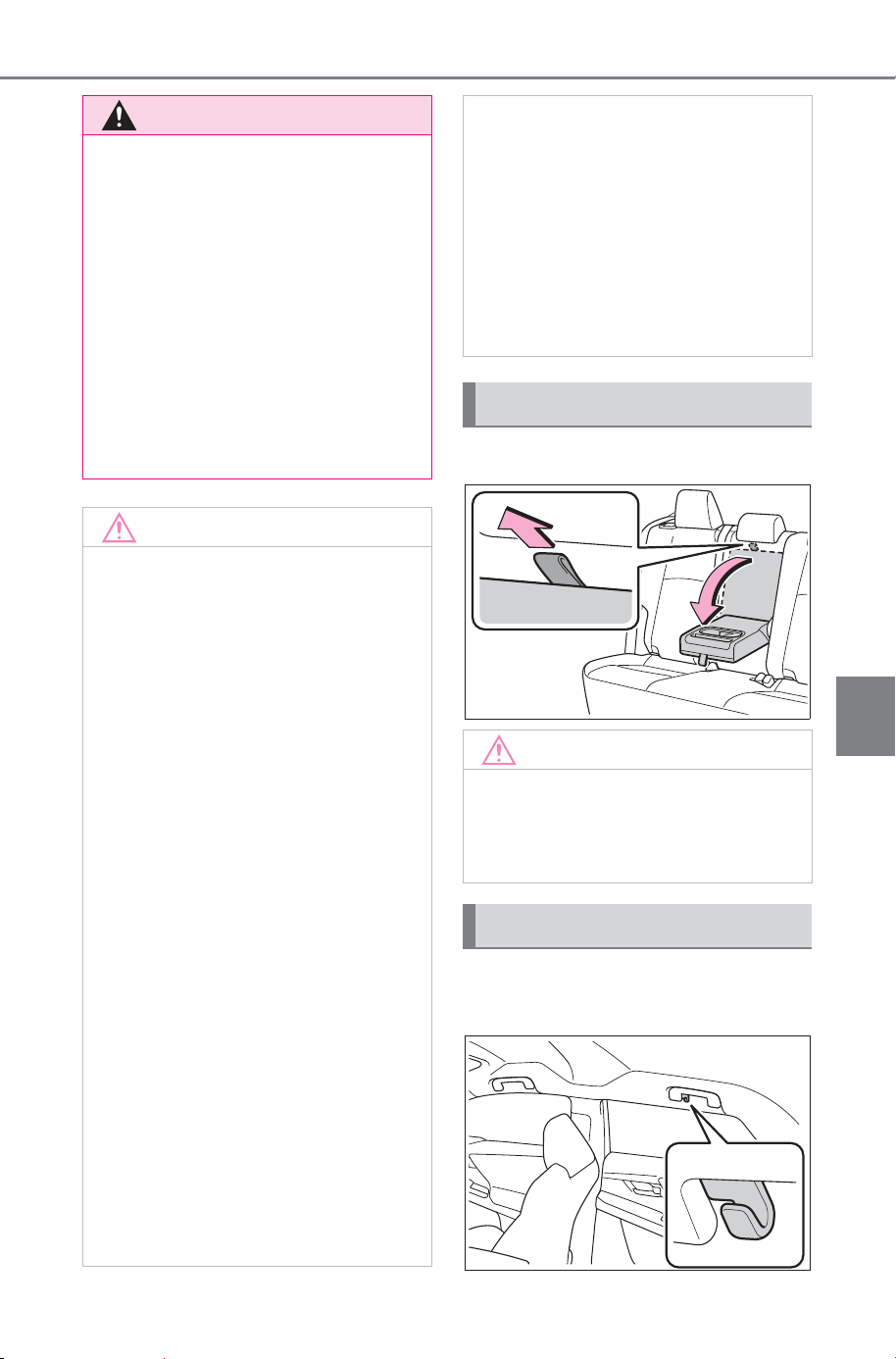
529
6-4. Using the other interior features
Owner’s Manual_USA_M6740B_en
6
Interior features
Fold down the armrest for use.
The coat hooks are provided
with the rear assist grips.
WARNING
● Do not subject to a strong force
or impact
● Do not disassemble, modify or
remove
● Do not charge devices other
than specified portable devices
● Keep away from magnetic items
● Do not perform charging if the
charging area is dirty
● Do not cover with a cloth or sim-
ilar material
NOTICE
■ To prevent malfunctions and
data corruptions
● When charging, bringing a
credit, or other magnetic card,
or magnetic storage media
close to the charge area may
clear any stored data due to
magnetic influence. Further-
more, the electronic key may
not operate due to magnetic
interference if the electronic key
for the vehicle is placed on the
mobile phone terminal while
charging or an open space.
Also, do not bring a wristwatch
or other precision instrument
close to the charge area since
doing so may cause it to mal-
function.
● Do not charge with a non-con-
tact IC card such as a transpor-
tation system IC card inserted
between the charging side of a
portable device and the charge
area. The IC chip may become
extremely hot and damage the
portable device or IC card. Be
especially careful not to charge
a portable device inside a case
or cover with a non-contact IC
card attached.
● Do not leave portable devices
inside the vehicle. The inside of
the vehicle can become hot in
extreme heat, which could
cause a malfunction.
■ To prevent 12-volt battery dis-
charge
Do not use the wireless charger
for a long period of time when the
EV system is stopped.
Armrest
NOTICE
■ To prevent damage to the
armrest
Do not apply too much load on the
armrest.
Coat hooks
SOLTERRA_OM_USA_A6740BE.book 529 ページ 2025年5月23日 金曜日 午後1時18分
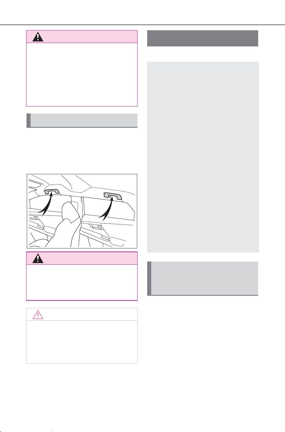
530
6-4. Using the other interior features
Owner’s Manual_USA_M6740B_en
An assist grip installed on the
ceiling can be used to support
your body while sitting on the
seat.
*
: If equipped
Observe the following precau-
tions before starting the power
supply:
Park the vehicle on a solid
and level place.
Block the wheels as needed.
Check that the hood is closed.
Check that the parking brake
is engaged.
WARNING
■ Items that must not be
hanged on the hook
Do not hang coat hangers or
other hard or sharp objects on the
hook. If the SRS curtain shield air-
bags deploy, these items may
become projectiles, causing death
or serious injury.
Assist grips
WARNING
■ Assist grips
Do not use the assist grip when
getting in or out of the vehicle or
rising from your seat.
NOTICE
■ To prevent damage to the
assist grip
Do not hang any heavy object or
put a heavy load on the assist
grip.
Power outlet (1500 W)
*
This system allows the use
of electrical devices with a
total power consumption of
1500 W at 120 VAC in the
vehicle. Supplying power to
electrical devices outside
the vehicle is not recom-
mended, as it may violate
the laws and regulations of
the country or region where
it is used. When supplying
power to electrical devices
outside the vehicle, check
the laws and regulations
with the relevant local gov-
ernment of each country or
region in advance. Also, be
careful not to drag electrical
devices and cords when
moving the vehicle.
Precautions for using the
power outlets while
parked
SOLTERRA_OM_USA_A6740BE.book 530 ページ 2025年5月23日 金曜日 午後1時18分
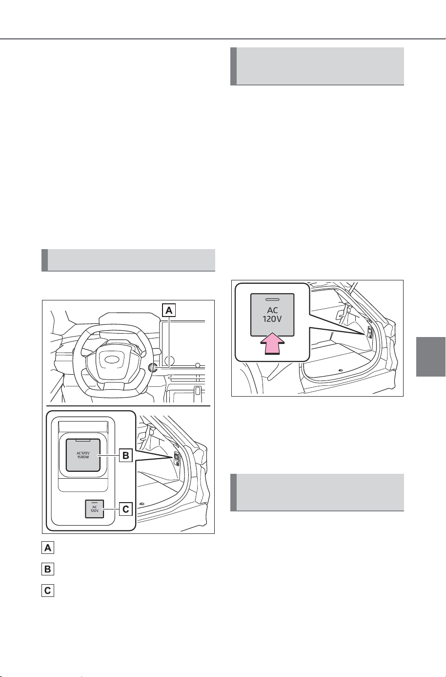
531
6-4. Using the other interior features
Owner’s Manual_USA_M6740B_en
6
Interior features
Check that the P shift position
is selected.
Check that the power switch
is off.
Note that the alarm system
cannot be enabled during the
power supply. For theft pre-
vention, do not leave valuable
items, etc. in the cabin or lug-
gage compartment.
Check that AC charging or
DC charging is not performed.
■ Switches
Power switch (P.229)
Power outlet
“AC 120 V” switch
1 Check that the parking brake
is engaged, securely depress
the brake pedal and press
the power switch. (P.229)
2 Check that the READY indi-
cator is illuminated, and
press the “AC 120 V” switch.
The power outlet can be used when
the indicator on the “AC 120 V”
switch is illuminated.
The power outlet are turned off/on
each time the “AC 120 V” switch is
pressed.
3 Open the lid, and fully and
securely insert the plug of the
device into the power outlet.
(P.532)
Follow the procedure described
below:
1 Turn the connected devices
off.
2 Press the “AC 120 V” switch
to turn the power outlet off.
Name for all parts
Using the power outlet
(1500 W)
Stopping the use of the
power outlet (1500 W)
SOLTERRA_OM_USA_A6740BE.book 531 ページ 2025年5月23日 金曜日 午後1時18分

532
6-4. Using the other interior features
Owner’s Manual_USA_M6740B_en
3 Disconnect each plug from
the power outlet.
4 Close the lid of the power
outlet.
■ When connecting a device
Make sure to read the instruc-
tion manual which came with a
device and observe warnings on
the device.
Before connecting a device to
the power outlet, make sure that
the power of the electrical
device is turned off.
1 Open the lid, and fully and
securely insert the plug of the
device into the power outlet.
Do not leave the plug halfway
inserted.
In the following situations, use
cable extension, etc. and con-
nect the plug securely to the
power outlet:
• When the plug of a device is
too large to allow it to be
inserted fully and securely
into the power outlet.
• When the plug of a device is
heavy, possibly causing it to
come off the power outlet.
If the device to be used has a
ground wire, use a conversion
adapter available on the market
and connect the ground wire to the
ground terminal of the conversion
adapter.
■ Power outlet
● With this power outlet, use
devices which operate on 120
VAC and have a combined maxi-
mum power consumption of 1500
W or less. If a device is connected
and the power consumption is
exceeded, a protection circuit may
be activated and the power supply
function may be stopped.
● Some of the devices that con-
sume a large amount of power,
such as an electric grille, may
require the exclusive use of the
power outlets. When such a
device is connected, do not con-
nect other device(s) to the power
outlets.
● When multiple devices are con-
nected, depending on the device,
a connected device may not oper-
ate properly. For such a device,
use exclusively the power outlets.
● When a power outlet is being
used, depending on the device to
be used, the current flow may be
high and the initial peak wattage
may exceed 1500 W. In this situa-
tion, the protection function may
activate and stop the power sup-
ply function.
● When a power outlet is being
used, depending on the device to
be used, it may cause interference
with TV and radio broadcasts.
● While a power outlet is being
used, a cooling fan sound may be
heard from near a motor compart-
ment. This does not indicate a
malfunction.
■ Devices which may not operate
correctly
The following devices may not oper-
ate properly even if the combined
power consumption is 1500 W or
less:
● Devices with high initial peak watt-
age
Connecting a device
SOLTERRA_OM_USA_A6740BE.book 532 ページ 2025年5月23日 金曜日 午後1時18分
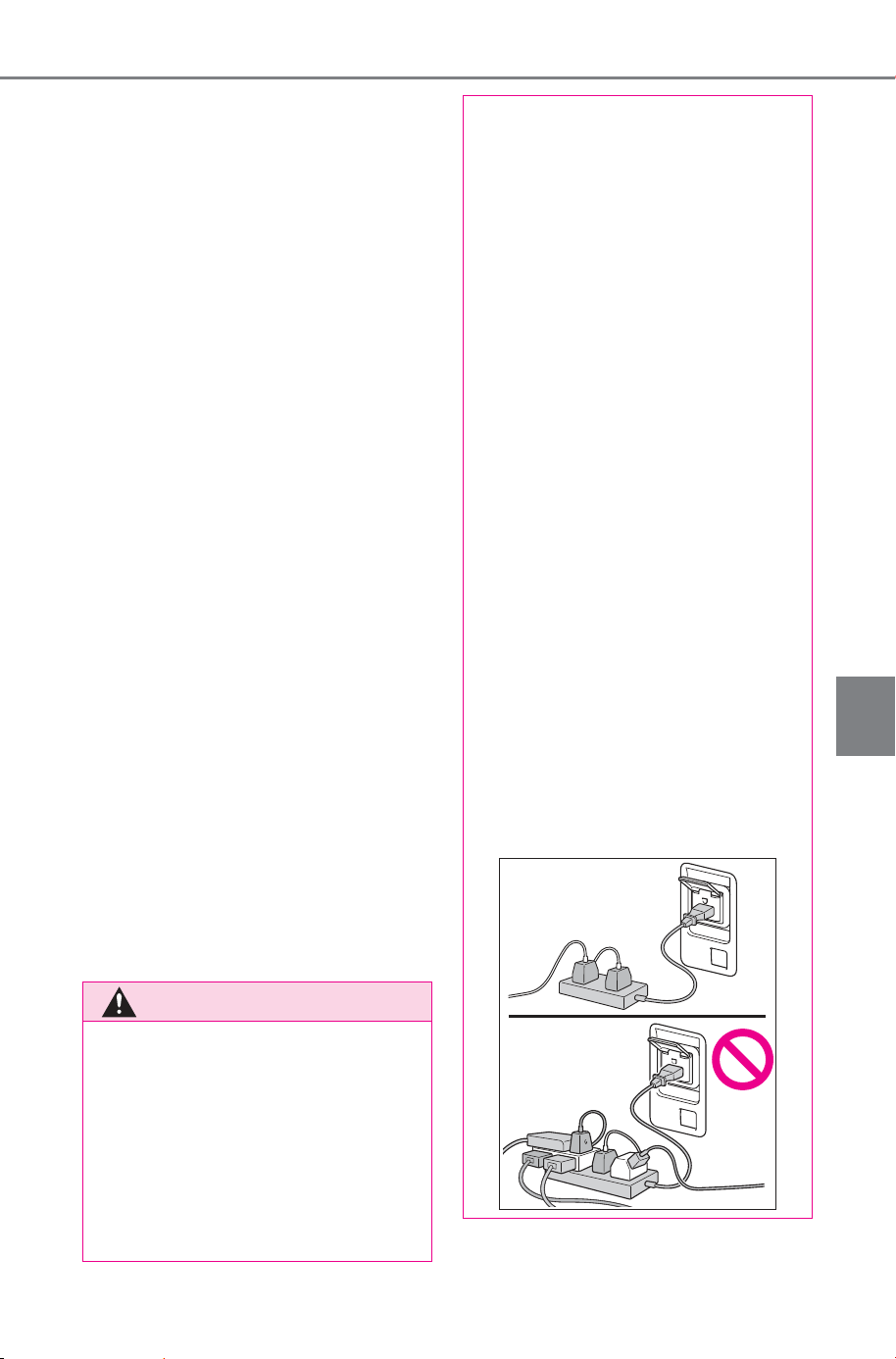
533
6-4. Using the other interior features
Owner’s Manual_USA_M6740B_en
6
Interior features
● Devices requiring larger amount of
power supply than the power con-
sumption specified in its instruc-
tion manual
● Measuring devices that process
precise data
● Devices that require an extremely
stable power supply
● Devices that require a constant
power supply from the power out-
let, such as a device with a timer.
■ When the power outlets are
used while the vehicle is parked
or stopped
● The doors cannot be
locked/unlocked using the smart
key system.
● The doors cannot be
locked/unlocked using an elec-
tronic key. The doors can only be
locked/unlocked using a mechani-
cal key.
● When a door is opened/closed, a
buzzer may sound or “Key Not
Detected Check Key Location”
may be displayed on the multi-
information display. Check that an
electronic key is carried with you.
● When the vehicle’s surroundings
become dark while supplying
power, the headlights etc. turn on
automatically. Refer to P.247 for
information about turning off the
lights.
● AC charging or DC charging can-
not be performed.
WARNING
■ For safe use
Observe the following precau-
tions. Failure to do so may lead to
an accident, resulting in death or
serious injury.
● Do not allow children or other
people not used to the opera-
tion to perform the power supply
by themselves.
● Do not disconnect the plug of a
device while your hands are wet
or insert a pin or other object
into the power outlet. Also, if a
liquid or snow is on the power
outlet, dry the outlet before
using it.
● Do not attempt to modify, disas-
semble or repair a power outlet.
For information on repairs, con-
tact your SUBARU dealer.
● Keep the power outlets free of
dust and foreign matter. Also,
make sure to clean the power
outlets periodically.
● Hold the plug body to plug in/out
of a power outlet. Do not touch
the plug blades. Do not pull on a
cord for unplugging, as other-
wise the plug or cord may be
damaged.
● Stop the use immediately if
abnormal heat is observed on a
cord or power outlet. To prevent
the cord or power outlet from
becoming hot, observe the fol-
lowing precautions:
• Do not connect 2 or more multi
point outlet adapters, such as
dual adapters.
SOLTERRA_OM_USA_A6740BE.book 533 ページ 2025年5月23日 金曜日 午後1時18分

534
6-4. Using the other interior features
Owner’s Manual_USA_M6740B_en
WARNING
• When an extension cord reel is
used, make sure to draw the
whole cord out of the reel.
● If the device to be used has a
ground wire, use a conversion
adapter available on the market
and connect the ground wire to
the ground terminal of the con-
version adapter.
● If the plug of a device fits
loosely in a power outlet, even
though it is fully inserted,
replace the power outlet. For
information on replacement,
contact your SUBARU dealer.
■ Devices to be connected
● Make sure to read any instruc-
tion manual which came with a
device and observe any warn-
ings on the device.
● Do not connect a device to a
power outlet if the device is mal-
functioning or its plug is dam-
aged.
● Otherwise, the device may be
further malfunctioning, espe-
cially when the outside tem-
perature is high or low.
● Devices requiring to be installed
on a level place may not oper-
ate properly.
● Do not use devices, other than
waterproof devices, in a place
where water, such as rain, is
splashed over or where it is
humid.
● Do not use a device that has
been or likely to have been
merged in water or absorbed
water within.
● Do not connect a medical
device, as depending on the
vehicle condition, the power
supply function may be tempo-
rarily stopped.
■ When the power outlets are
used while the vehicle is
parked or stopped
● The power outlets are designed
to be connected to electric
devices, such as lighting
devices. Do not use them as a
generator that supplies power to
a house, etc. Also, when they
are to be used on an emer-
gency power supply device for
homes, such as an exclusive
device having connection to an
external power source, or a
device whose power supply cir-
cuit for external power source is
separate from electric wiring of
power companies, consult with
the manufacturer or a retailer of
the device.
● When using a power outlet,
make sure to securely engage
the parking brake and shift the
shift position to P. Otherwise,
the vehicle may move, possibly
leading to an accident.
● When using a power outlet, do
not move away from the vehicle.
● Do not perform the power sup-
ply during weather when light-
ning may occur. Stop supplying
power if lightning is observed
during power supply.
● Do not use the power outlets if
the vehicle has a vehicle cover
installed.
● Do not use a power outlet when
the vehicle is parked on a
slanted place or a slope. When
a power outlet is being used, do
not move the vehicle or cause it
to be inclined.
SOLTERRA_OM_USA_A6740BE.book 534 ページ 2025年5月23日 金曜日 午後1時18分
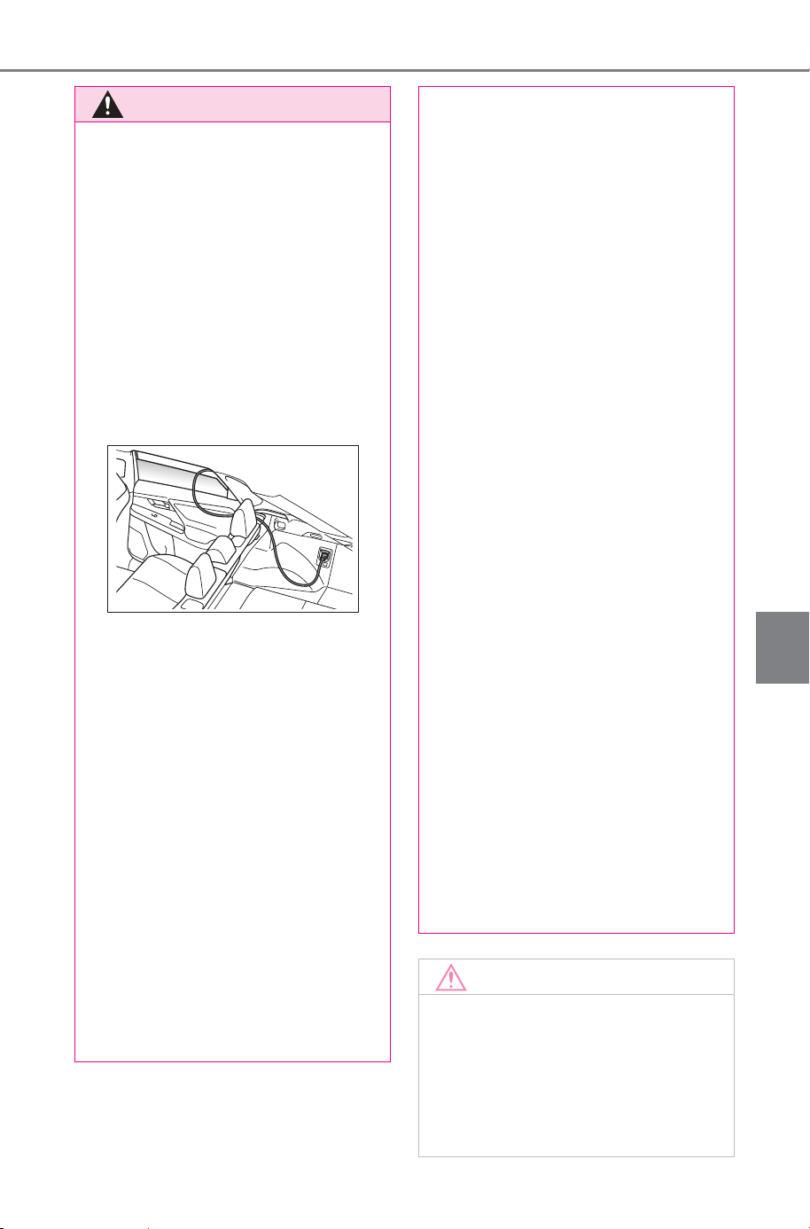
535
6-4. Using the other interior features
Owner’s Manual_USA_M6740B_en
6
Interior features
WARNING
● Observe the following precau-
tions when a connected cord is
to be brought outside the vehi-
cle:
• Take due care for not allowing
rain to enter. If the power outlet
is wet with raindrops, dry it
before use.
• Prevent the cord from being
caught in the window or door
• Allow slack in a connected cord.
Do not cause it to be extraordi-
nary tense.
• Do not start off the vehicle by
mistake.
● Do not wash the vehicle when
using a power outlet.
● Make sure that the hood is
closed.
Also, do not put your head or
hands anywhere inside the motor
compartment, as the cooling fan
may operate suddenly. Keep
hands and clothing (especially a
tie, scarf, etc.) away from the fan
as they may get caught in a fan.
● Do not stop the vehicle near
objects which burn easily.
● Do not use in places where cor-
rosive gases or fluids are gener-
ated.
■ Use of a power outlet while
driving
● In situations such as the follow-
ing, do not use an electric
device while driving. Also, do
not use a device if it cannot be
secured within the vehicle.
• When a device is likely to dis-
tract the driver and be a hin-
drance to safe driving, such as
a TV, video/DVD player, etc.
• When an inadequately secured
device is likely to fall over in
case of sudden braking or an
accident
• When a device is likely to cause
fire if it falls or generates heat
• When a device is likely to cause
burns, such as a toaster, micro-
wave, electric heater, electric
kettle, coffee maker, etc.
• When a device is likely to fall
under the pedals and prevent
the brake pedal from being
depressed, such as a hair dryer,
AC adapter, mouse, etc.
● Do not use devices which pro-
duce steam while the windows
are closed. Doing so may cause
the windows to fog up, reducing
visibility and making it difficult to
drive safely. Also, the steam
may damage or negatively
affect other devices. If the
device must be used, stop the
vehicle and open the windows
before use.
NOTICE
■ To avoid short circuit or mal-
function
Observe the following precau-
tions. Failure to do so may lead to
the power outlets not operating
correctly or damage to the vehicle
or a connected device.
SOLTERRA_OM_USA_A6740BE.book 535 ページ 2025年5月23日 金曜日 午後1時18分
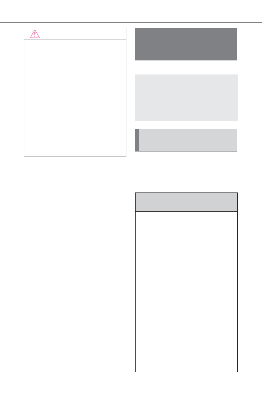
536
6-4. Using the other interior features
Owner’s Manual_USA_M6740B_en
*
: If equipped
When power supply does not
start, even though the normal
procedure is followed, check
each of the following items.
NOTICE
● Do not set a toaster or other
device which generates heat
near the interior components or
on a seat. Heat may cause
these parts to melt or burn.
● Do not use devices which are
sensitive to vibration or heat in
the vehicle. These devices may
malfunction due to vibration
while driving or heat while the
vehicle is parked in the sun.
● When not using a power outlet,
make sure to close the lid. If for-
eign matter or a liquid enters the
power outlet, it may cause a
malfunction or short circuit.
When the power outlet
(1500 W)
*
cannot be
used properly
When the power outlet can-
not be used, even though
the normal procedure is fol-
lowed, check the following
items.
When the power outlet
cannot be used properly
Likely cause
Correction pro-
cedure
AC charging is in
progress
Stop AC
charging, discon-
nect the charging
connector and
restart the proce-
dure from the
beginning.
When the out-
side tempera-
ture is especially
high or in similar
conditions, the
traction battery
becomes hot
Move the vehi-
cle to the shade
or other cooler
location, or use
the air condition-
ing to lower the
temperature
inside the vehi-
cle. Then, after
waiting for a
while, press the
“AC 120 V”
switch again.
SOLTERRA_OM_USA_A6740BE.book 536 ページ 2025年5月23日 金曜日 午後1時18分
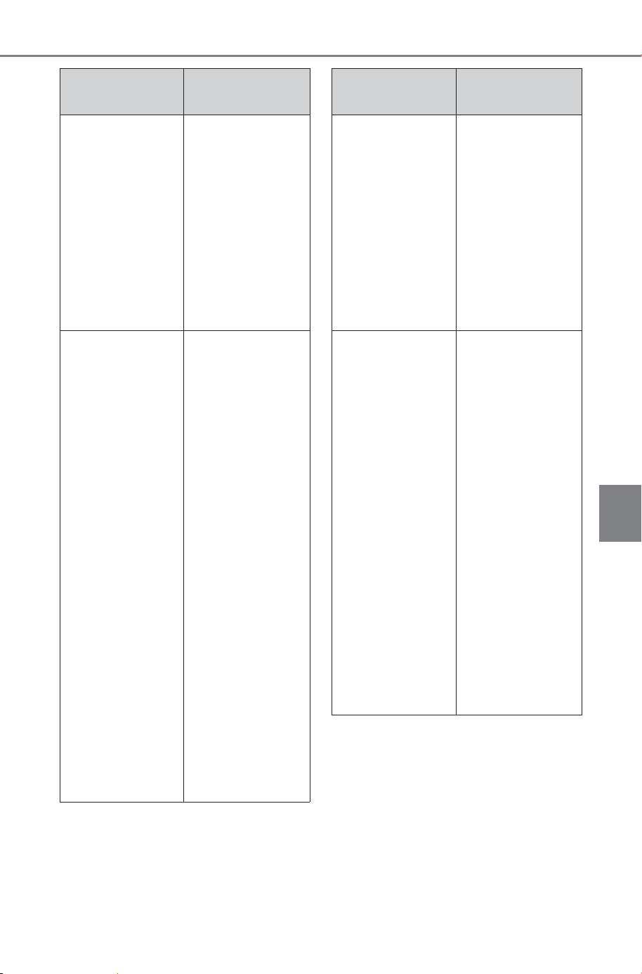
537
6-4. Using the other interior features
Owner’s Manual_USA_M6740B_en
6
Interior features
If the power outlet cannot be
used even after performing the
procedures above, have the
vehicle inspected by your SUB-
ARU dealer.
When the out-
side tempera-
ture is especially
low or in similar
conditions, the
traction battery
becomes cold
Drive for a while
or use the air
conditioning to
raise the tem-
perature inside
the vehicle.
Then, after wait-
ing for a while,
press the “AC
120 V” switch
again.
Electrical device
does not operate
Disconnect the
power source
plug of the elec-
trical device and
check that the
electrical device
itself is not mal-
functioning.
Then, press the
“AC 120 V”
switch again.
If the indicator on
the AC 120 V
switch does not
illuminate, turn
the power switch
off and restart
the procedure
from the begin-
ning.
Check the
instruction man-
ual of the electri-
cal device.
Likely cause
Correction pro-
cedure
Total power con-
sumption
exceeds 1500 W
Disconnect the
power source
plug of the elec-
trical device and
check that the
total power con-
sumption does
not exceed 1500
W. Then, press
the “AC 120 V”
switch again.
Short circuit in
the power outlet
Disconnect the
power source
plug of the elec-
trical device and
check the follow-
ing items. Then,
press the “AC
120 V” switch
again.
• No foreign
matter such as
a pin has been
inserted
• No substances
such as drink-
ing water, rain,
or snow are
adhered
• No dirt or dust
is adhered
Likely cause
Correction pro-
cedure
SOLTERRA_OM_USA_A6740BE.book 537 ページ 2025年5月23日 金曜日 午後1時18分
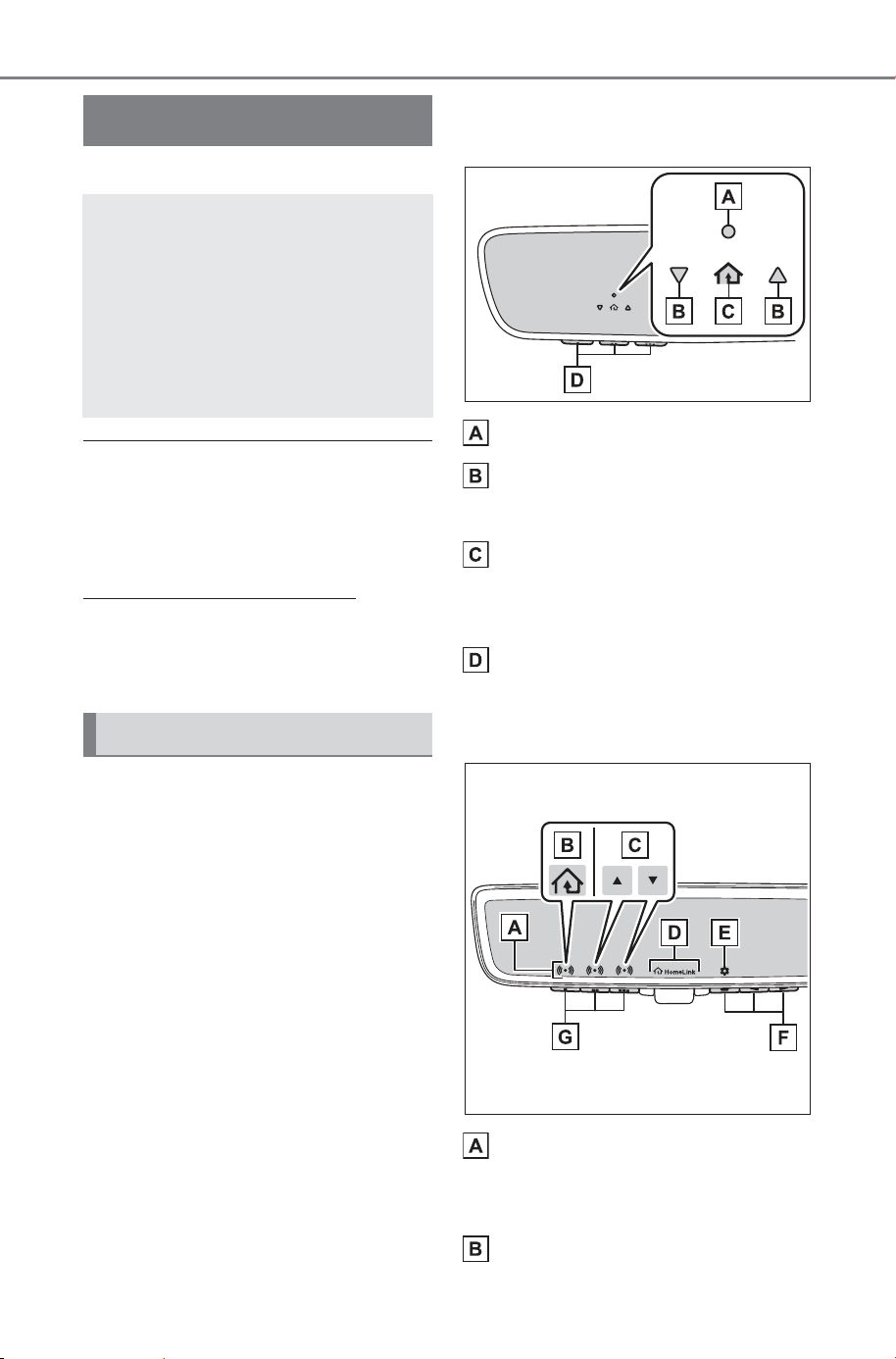
538
6-4. Using the other interior features
Owner’s Manual_USA_M6740B_en
*
: If equipped
■ HomeLink
®
programming pro-
cedure
The programming procedures can
also be found at the following URL.
Website:
https://homelink.com/subaru
For support, contact customer sup-
port at the following.
Help Line: 1-800-355-3515
The HomeLink
®
wireless control
system in your vehicle has 3
buttons which can be pro-
grammed to operate 3 different
devices. Refer to the program-
ming methods on the following
pages to determine the method
which is appropriate for the
device.
Vehicles with auto anti-glare
inside rear view mirror
HomeLink
®
indicator light
Garage door operation indi-
cators
HomeLink
®
icon
Illuminates while HomeLink
®
is
operating.
Buttons
Vehicles with Digital inner mir-
ror
HomeLink
®
indicator light
Illuminates above each button
selected.
HomeLink
®
icon
Garage door opener
*
The garage door opener can
be programmed using the
HomeLink
®
to operate
garage doors, gates, entry
doors, door locks, home
lighting systems, security
systems, and other devices.
System components
SOLTERRA_OM_USA_A6740BE.book 538 ページ 2025年5月23日 金曜日 午後1時18分
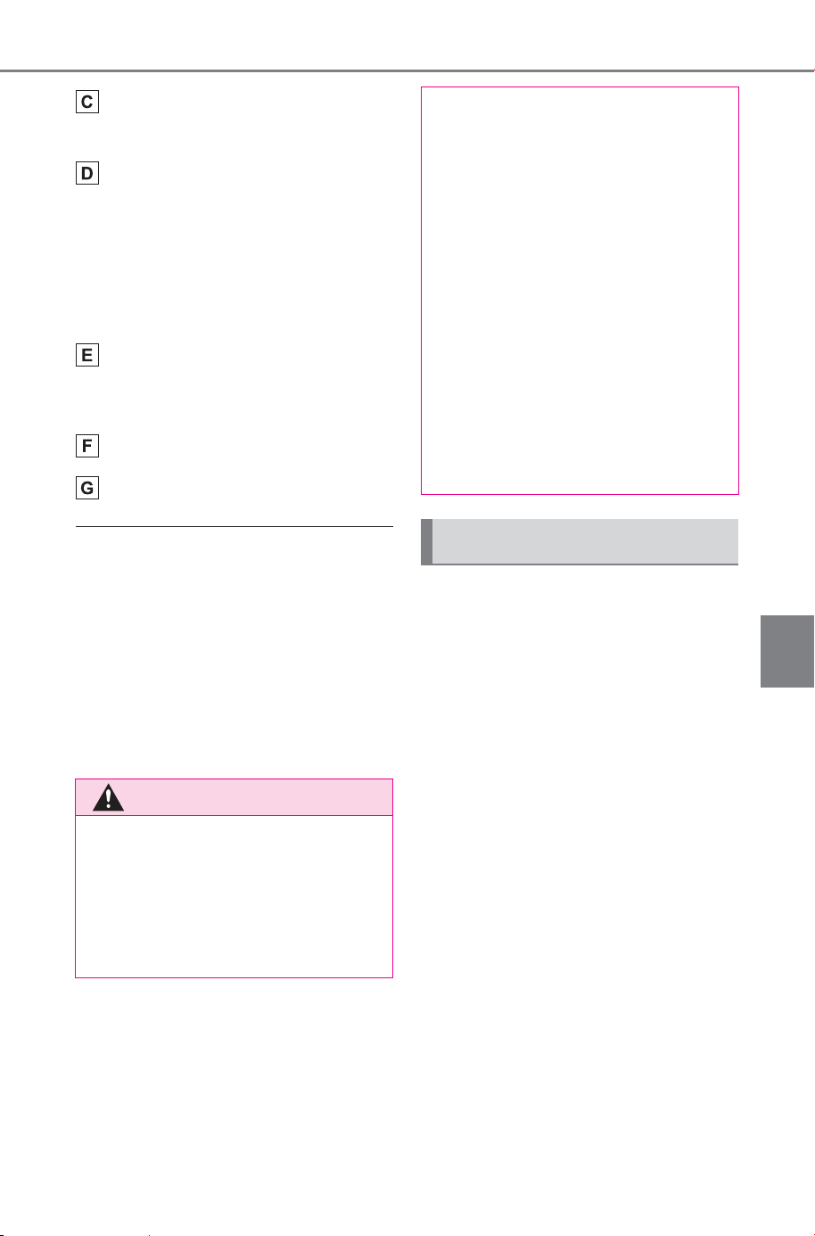
539
6-4. Using the other interior features
Owner’s Manual_USA_M6740B_en
6
Interior features
Garage door operation indi-
cators
HomeLink
®
logo
Appears while HomeLink
®
is oper-
ating.
When the HomeLink
®
button is
pressed, the logo disappears even
while the HomeLink
®
is operating.
Setting icon
Press the menu button to change
the setting.
Menu buttons
HomeLink
®
buttons
■ Codes stored in the Home-
Link
®
memory
● The registered codes are not
erased even if the 12-volt battery
cable is disconnected.
● If learning failed when registering
a different code to a HomeLink
®
button that already has a code
registered to it, the already regis-
tered code will not be erased.
■ Before programming Home-
Link
®
During programming, it is pos-
sible that garage doors,
gates, or other devices may
operate. For this reason,
make sure that people and
objects are clear of the
garage door or other devices
to prevent injury or other
potential harm.
It is recommended that a new
battery be placed in the
remote control transmitter for
successful programming.
Garage door opener motors
manufactured after 1995 may
be equipped with rolling code
protection. If this is the case,
you may need a stepladder or
other sturdy, safe device to
WARNING
■ When programming a garage
door or other remote control
device
The garage door or other device
may operate, so ensure people
and objects are out of danger to
prevent potential harm.
■ Conforming to federal safety
standards
Do not use the HomeLink
®
com-
patible transceiver with any
garage door opener or device that
lacks safety stop and reverse fea-
tures as required by federal safety
standards.
This includes any garage door
that cannot detect an interfering
object. A door or device without
these features increases the risk
of death or serious injury.
■ When operating or program-
ming HomeLink
®
Never allow a child to operate or
play with the HomeLink
®
buttons.
Programming HomeLink
®
SOLTERRA_OM_USA_A6740BE.book 539 ページ 2025年5月23日 金曜日 午後1時18分
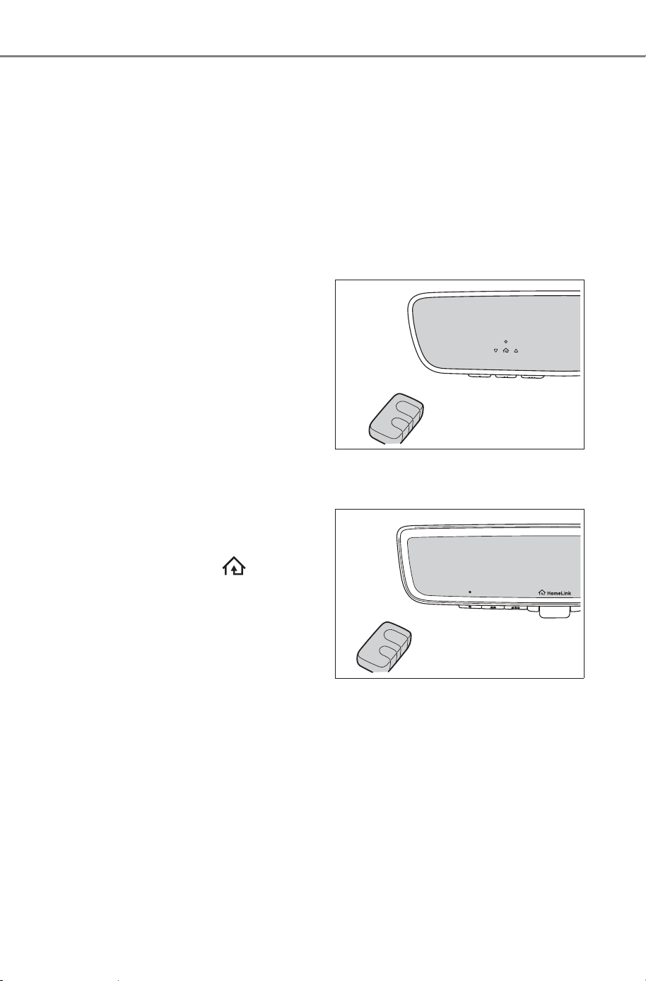
540
6-4. Using the other interior features
Owner’s Manual_USA_M6740B_en
reach the “Learn” or “Smart”
button on the garage door
opener motor.
■ Programming HomeLink
®
Steps
2 through 4 must be per-
formed within 60 seconds, oth-
erwise the HomeLink
®
indicator
light will stop flashing and pro-
gramming will not be success-
fully completed.
1 Vehicles with Digital inner
mirror: Press the HomeLink
®
button or menu button
When the HomeLink
®
button is
pressed:
Homelink
®
Training Tutorial will be
displayed to assist you program-
ming the HomeLink
®
.
When Homelink
®
Training Tutorial
is displayed, follow the instructions
displayed.
When the menu button is pressed:
Press the menu button and
select the “Set Up >”. Homelink
®
Training Tutorial will be displayed to
assist you programming the Home-
Link
®
.
When Homelink
®
Training Tutorial
is displayed, follow the instructions
displayed.
2 Press and release the Home-
Link
®
button you want to pro-
gram and check that the
HomeLink
®
indicator light
flashes (orange).
3 Point the remote control
transmitter for the device at
the rear view mirror, 1 to 3 in.
(25 to 75 mm) from the
HomeLink
®
buttons.
Keep the HomeLink
®
indicator light
in view while programming.
Vehicles with auto anti-glare
inside rear view mirror
Vehicles with Digital inner mir-
ror
SOLTERRA_OM_USA_A6740BE.book 540 ページ 2025年5月23日 金曜日 午後1時18分
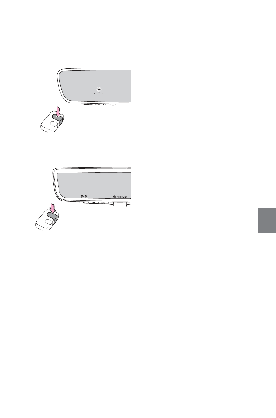
541
6-4. Using the other interior features
Owner’s Manual_USA_M6740B_en
6
Interior features
4 Program a device.
Vehicles with auto anti-glare
inside rear view mirror
Vehicles with Digital inner mir-
ror
Programming a device other
than an entry gate (for U.S.A.
owners)
Press and hold the remote con-
trol transmitter button until the
HomeLink
®
indicator light
changes from slowly flashing
orange to rapidly flashing green
(rolling code) or continuously lit
green (fixed code), then release
the button.
Programming an entry gate
(for U.S.A. owners)/Program-
ming a device in the Cana-
dian market
Press and release the remote
control transmitter button at 2
second intervals, repeatedly,
until the HomeLink
®
indicator
light changes from slowly flash-
ing orange to rapidly flashing
(green) (rolling code) or continu-
ously lit (green) (fixed code).
5 Test the HomeLink
®
opera-
tion by pressing the newly
programmed button and
observing the HomeLink
®
indicator light:
HomeLink
®
indicator light illu-
minates: Programming of a
fixed code device has com-
pleted. The garage door or
other device should operate
when a HomeLink
®
button is
pressed and released.
HomeLink
®
indicator light
flashes rapidly: The garage
door opener or other device is
equipped with a rolling code.
To complete programming,
firmly press and hold the
HomeLink
®
button for 2 sec-
onds then release it.
If the garage door or other
device does not operate, pro-
ceed to “Programming a roll-
ing code system”.
SOLTERRA_OM_USA_A6740BE.book 541 ページ 2025年5月23日 金曜日 午後1時18分
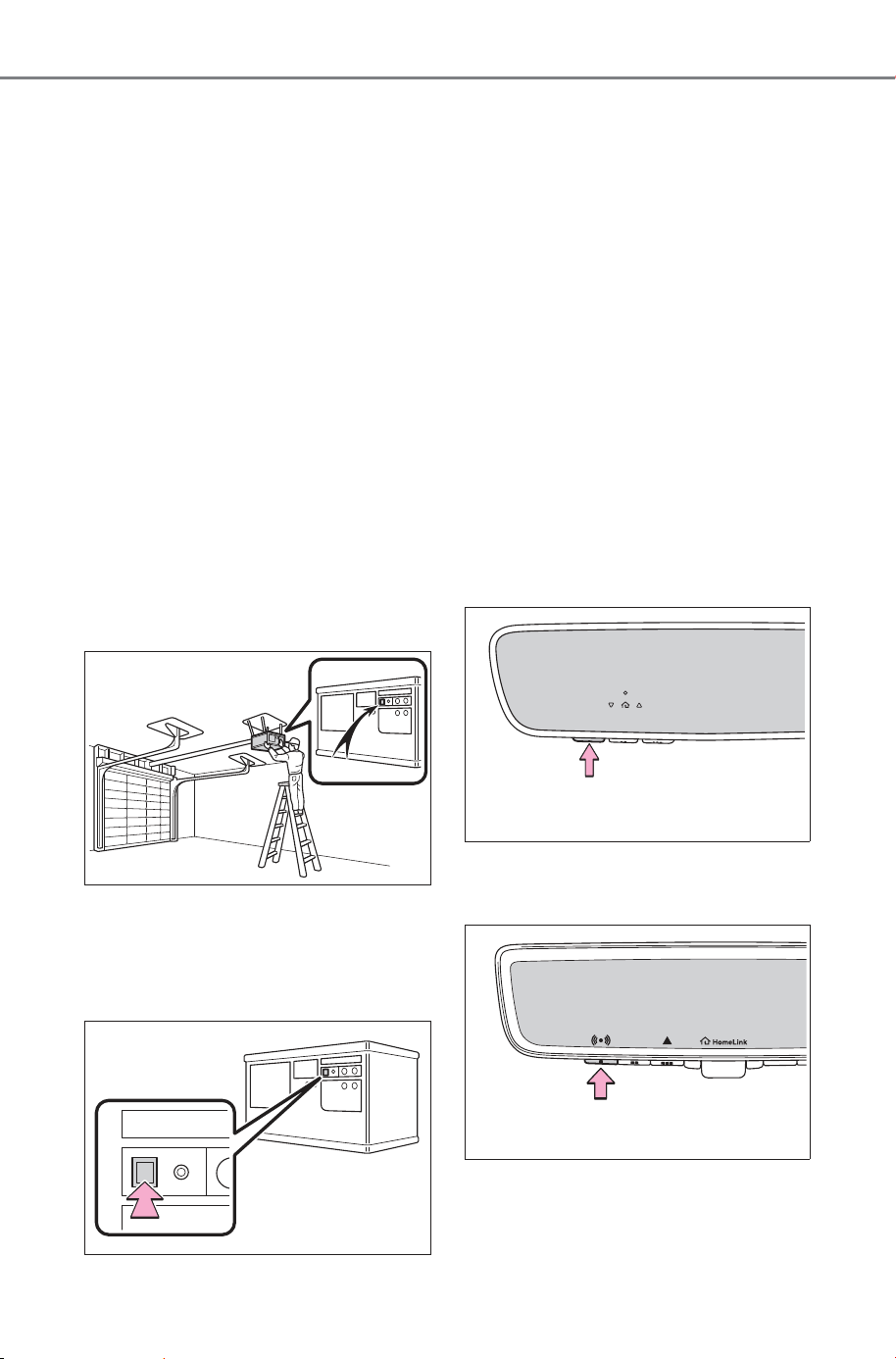
542
6-4. Using the other interior features
Owner’s Manual_USA_M6740B_en
6 Repeat the steps above to
program another device for
any of the remaining Home-
Link
®
buttons.
■ Programming a rolling code
system
Two or more people may be
needed to complete rolling code
programming.
1 Locate the “Learn” or “Smart”
button on the garage door
opener motor in the garage.
This button can usually be found
where the hanging antenna wire is
attached to the unit. The name and
color of the button may vary by
manufacturer. Refer to the owner’s
manual supplied with the garage
door opener motor for details.
2 Press and release the
“Learn” or “Smart” button.
Perform
3 within 30 seconds after
performing
2.
3 Press and hold the desired
HomeLink
®
button (inside the
vehicle) for 2 seconds and
release it. Repeat this
sequence
(press/hold/release) up to 3
times to complete program-
ming.
If the garage door opener
motor operates when the
HomeLink
®
button is
pressed, the garage door
opener motor recognizes the
HomeLink
®
signal.
Vehicles with auto anti-glare
inside rear view mirror
Vehicles with Digital inner mir-
ror
SOLTERRA_OM_USA_A6740BE.book 542 ページ 2025年5月23日 金曜日 午後1時18分

543
6-4. Using the other interior features
Owner’s Manual_USA_M6740B_en
6
Interior features
■ Enabling 2-way communi-
cation with a garage door
(only available for compati-
ble devices)
When enabled, 2-way communi-
cation allows you to check the
status of the opening and clos-
ing of a garage door through
indicators in your vehicle.
2-way communication is only
available if the garage door
opener motor used is a compati-
ble device. (To check device
compatibility, refer to
www.homelink.com.)
1 Within 5 seconds after pro-
gramming the garage door
opener has been completed,
if the garage door opener
motor is trained to Home-
Link
®
, both garage door
operation indicators will flash
rapidly (green) and the light
on the garage door opener
motor will blink twice, indicat-
ing that 2-way communica-
tion is enabled.
If the indicators do not flash, per-
form
2 and 3 within the first 10
presses of the HomeLink
®
button
after programming has been com-
pleted.
2 Press a programmed Home-
Link
®
button to operate a
garage door.
3 Within 1 minute of pressing
the HomeLink
®
button, after
the garage door operation
has stopped, press the
“Learn” or “Smart” button on
the garage door opener
motor. Within 5 seconds of
the establishment of 2-way
communication with the
garage door opener, both
garage door operation indica-
tors in the vehicle will flash
rapidly (green) and the light
on the garage door opener
motor will blink twice, indicat-
ing that 2-way communica-
tion is enabled.
■ Reprogramming a single
HomeLink
®
button
When the following procedure is
performed, buttons which
already have devices registered
to them can be overwritten:
1 Press and hold the desired
HomeLink
®
button.
2 When the HomeLink
®
indica-
tor starts flashing orange,
release the HomeLink
®
but-
ton and perform “Program-
ming HomeLink
®
”
1 (it takes
20 seconds for the Home-
Link
®
indicator to start flash-
ing).
SOLTERRA_OM_USA_A6740BE.book 543 ページ 2025年5月23日 金曜日 午後1時18分
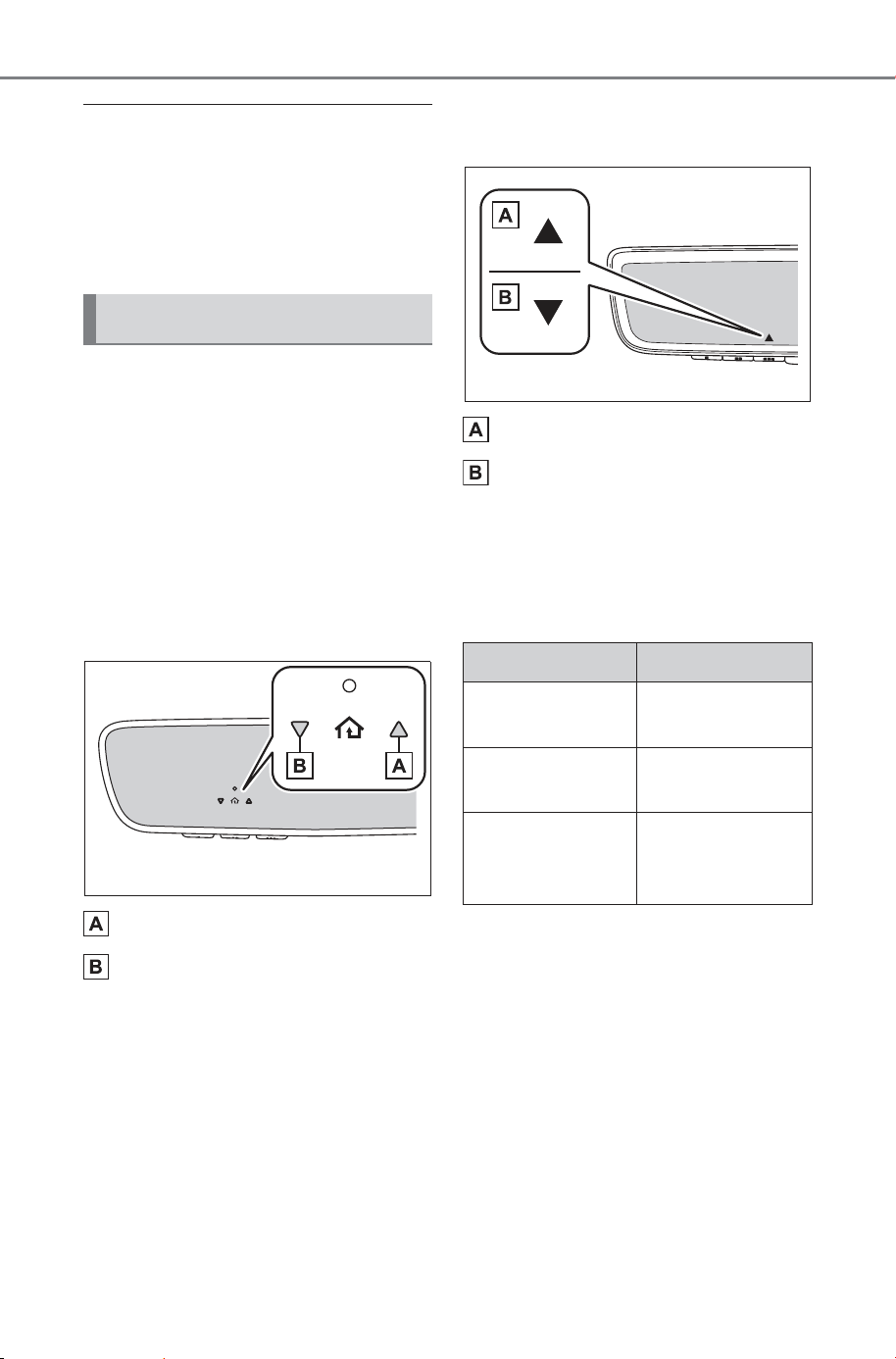
544
6-4. Using the other interior features
Owner’s Manual_USA_M6740B_en
■ Before programming
● Install a new battery in the trans-
mitter.
● The battery side of the transmitter
must be pointed away from the
HomeLink
®
buttons.
Press the appropriate Home-
Link
®
button. The HomeLink
®
indicator light should turn on.
The status of the opening and
closing of a garage door is
shown by the garage door oper-
ation indicators.
Vehicles with auto anti-glare
inside rear view mirror
Opening
Closing
Vehicles with Digital inner mir-
ror
Opening
Closing
This function is only available if the
garage door opener motor used is a
compatible device. (To check
device compatibility, refer to
www.homelink.com.)
The indicators can operate
within approximately 820 ft. (250
m) of the garage door. However,
if there are obstructions
between the garage door and
the vehicle, such as houses and
trees, feedback signals from the
garage door may not be
received.
To recall the previous door oper-
ation status, press and release
Operating HomeLink
®
Color Status
Orange (flash-
ing)
Currently open-
ing/closing
Green
Opening/closing
has completed
Red (flashing)
Feedback sig-
nals cannot be
received
SOLTERRA_OM_USA_A6740BE.book 544 ページ 2025年5月23日 金曜日 午後1時18分
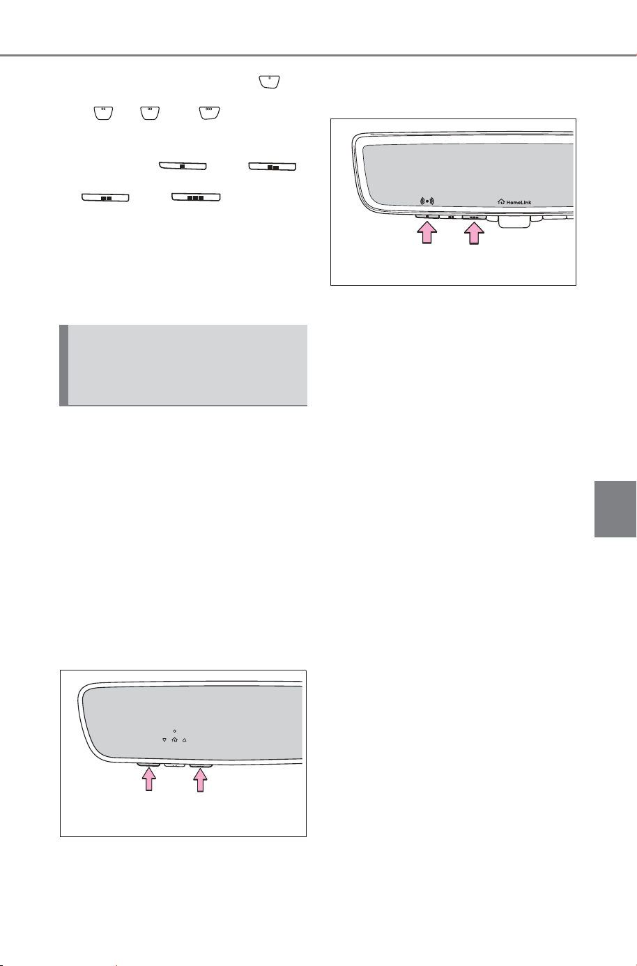
545
6-4. Using the other interior features
Owner’s Manual_USA_M6740B_en
6
Interior features
either HomeLink
®
buttons
and or and (vehicles
with auto anti-glare inside rear
view mirror), and
or and (vehicles
with Digital inner mirror) simulta-
neously. The last recorded sta-
tus will be displayed for 3
seconds.
Press and hold the 2 outside
buttons for 10 seconds until the
HomeLink
®
indicator light
changes from continuously lit
(orange) to rapidly flashing
(green).
If you sell your vehicle, be sure to
erase the programs stored in the
HomeLink
®
memory.
Vehicles with auto anti-glare
inside rear view mirror
Vehicles with Digital inner mir-
ror
Erasing the entire Home-
Link
®
memory (all three
codes)
SOLTERRA_OM_USA_A6740BE.book 545 ページ 2025年5月23日 金曜日 午後1時18分

546
6-4. Using the other interior features
Owner’s Manual_USA_M6740B_en
SOLTERRA_OM_USA_A6740BE.book 546 ページ 2025年5月23日 金曜日 午後1時18分

547
Owner’s Manual_USA_M6740B_en
7
7
Maintenance and care
Maintenance and care
7-1. Maintenance and care
Cleaning and protecting the
vehicle exterior ..........
548
Cleaning and protecting the
vehicle interior ...........
551
7-2. Maintenance
Maintenance requirements
..................................
555
General maintenance.. 556
7-3. Do-it-yourself mainte-
nance
Do-it-yourself service pre-
cautions..................... 559
Hood ........................... 561
Positioning a floor jack 563
Motor compartment..... 564
Tires ............................ 571
Replacing the tire ........ 583
Tire inflation pressure.. 588
Wheels ........................ 590
Air conditioning filter.... 592
Electronic key battery.. 594
Checking and replacing
fuses..........................
596
Headlight aim .............. 598
Light bulbs................... 599
SOLTERRA_OM_USA_A6740BE.book 547 ページ 2025年5月23日 金曜日 午後1時18分

548
7-1. Maintenance and care
Owner’s Manual_USA_M6740B_en
7-1.Maintenance and care
Working from top to bottom,
liberally apply water to the
vehicle body, wheel wells and
underside of the vehicle to
remove any dirt and dust.
Wash the vehicle body using
a sponge or soft cloth, such
as a chamois.
For hard-to-remove marks,
use car wash soap and rinse
thoroughly with water.
Wipe away any water.
Wax the vehicle when the
waterproof coating deterio-
rates.
If water does not bead on a clean
surface, apply wax when the vehi-
cle body is cool.
■ Self-restoring coat
The vehicle body has a self-restor-
ing coating that is resistant to small
surface scratches caused in a car
wash, etc.
● The coating lasts for 5 to 8 years
from when the vehicle is delivered
from the plant.
● The restoration time differs
depending on the depth of the
scratch and outside temperature.
The restoration time may become
shorter when the coating is
warmed by applying warm water.
● Deep scratches caused by keys,
coins, etc., cannot be restored.
● Do not use wax that contain abra-
sives.
■ Automatic car washes
● Before washing the vehicle:
• Fold the mirrors
• Turn off the power back door
Start washing from the front of the
vehicle. Make sure to extend the
mirrors before driving.
● Brushes used in automatic car
washes may scratch the vehicle
surface, parts (wheel, etc.) and
harm your vehicle’s paint.
● Rear spoiler (if equipped) may not
be washable in some automatic
car washes. There may also be an
increased risk of damage to vehi-
cle.
● When using an automatic car-
washes, etc. the shift position
needs to be held in N, refer to
P.237.
■ High pressure car washes
As water may enter the cabin, do
not bring the nozzle tip near the
gaps around the doors or perimeter
of the windows, or spray these
areas continuously.
■ Note for a smart key system
If the door handle becomes wet
while the electronic key is within the
effective range, the door may lock
and unlock repeatedly. In that case,
follow the following correction pro-
cedures to wash the vehicle:
● Place the key in a position 6 ft. (2
m) or more separate from the
vehicle while the vehicle is being
washed. (Take care to ensure that
the key is not stolen.)
Cleaning and protect-
ing the vehicle exte-
rior
Perform the following to
protect the vehicle and
maintain it in prime condi-
tion:
Cleaning instructions
SOLTERRA_OM_USA_A6740BE.book 548 ページ 2025年5月23日 金曜日 午後1時18分
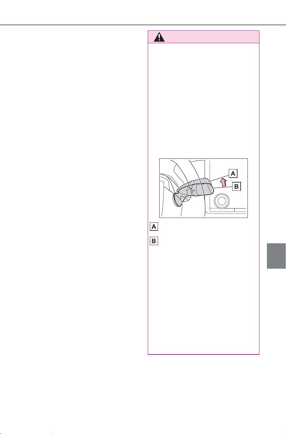
549
7-1. Maintenance and care
Owner’s Manual_USA_M6740B_en
7
Maintenance and care
● Set the electronic key to battery-
saving mode to disable the smart
key system. (P.178)
● If the electronic key is inside the
vehicle and a door handle
becomes wet during a car wash, a
buzzer may sound outside the
vehicle and “Key Detected in Vehi-
cle” may be shown on the multi-
information display. To turn off the
alarm, lock all the doors.
■ Wheels and wheel ornaments
● Remove any dirt immediately by
using a neutral detergent.
● Wash detergent off with water
immediately after use.
● To protect the paint from damage,
make sure to observe the follow-
ing precautions.
• Do not use acidic, alkaline or
abrasive detergent
• Do not use hard brushes
• Do not use detergent on the
wheels when they are hot, such
as after driving or parking in hot
weather
■ Brake pads and calipers
Rust may form if the vehicle is
parked with wet brake pads or disc
rotors, causing them to stick. Before
parking the vehicle after it is
washed, drive slowly and apply the
brakes several times to dry the
parts.
■ Bumpers
Do not scrub with abrasive cleaners.
■ Plated portions
If dirt cannot be removed, clean the
parts as follows:
● Use a soft cloth dampened with an
approximately 5% solution of neu-
tral detergent and water to clean
the dirt off.
● Wipe the surface with a dry, soft
cloth to remove any remaining
moisture.
● To remove oily deposits, use alco-
hol wet wipes or a similar product.
WARNING
■ When washing the vehicle
Do not apply water to the inside of
the motor compartment. Doing so
may cause the electrical compo-
nents, etc. to catch fire.
■ When cleaning the windshield
Set the wiper switch to off.
If the wiper switch is in “AUTO”,
the wipers may operate unexpect-
edly in the following situations,
and may result in hands being
caught or other serious injuries
and cause damage to the wiper
blades.
Off
“AUTO”
● When the upper part of the
windshield where the raindrop
sensor is located is touched by
hand
● When a wet rag or similar is
held close to the raindrop sen-
sor
● If something bumps against the
windshield
● If you directly touch the raindrop
sensor body or if something
bumps into the raindrop sensor
SOLTERRA_OM_USA_A6740BE.book 549 ページ 2025年5月23日 金曜日 午後1時18分
550
7-1. Maintenance and care
Owner’s Manual_USA_M6740B_en
WARNING
■ Precaution regarding the
front and rear bumpers
If the paint of the front or rear
bumper is chipped or scratched,
the following systems may not
function correctly. If this occurs,
consult your SUBARU dealer.
● SUBARU Safety Sense
● BSM
● RCTA
● SEA
● PKSB
● SUBARU Parking Assist
NOTICE
■ To prevent paint deteriora-
tion and corrosion on the
body and components (alumi-
num wheels, etc.)
● Wash the vehicle immediately in
the following cases:
• After driving near the sea coast
• After driving on salted roads
• If coal tar or tree sap is present
on the paint surface
• If dead insects, insect droppings
or bird droppings are present on
the paint surface
• After driving in an area contami-
nated with soot, oily smoke,
mine dust, iron powder or chem-
ical substances
• If the vehicle becomes heavily
soiled with dust or mud
• If liquids such as benzene and
gasoline are spilled on the paint
surface
● If the paint is chipped or
scratched, have it repaired
immediately.
● To prevent the wheels from cor-
roding, remove any dirt and
store in a place with low humid-
ity when storing the wheels.
■ Cleaning the exterior lights
● Wash carefully. Do not use
organic substances or scrub
with a hard brush.
This may damage the surfaces
of the lights.
● Do not apply wax to the sur-
faces of the lights.
Wax may cause damage to the
lenses.
■ When using an automatic car
wash
Set the wiper switch to off posi-
tion.
If the wiper switch is in “AUTO”,
the wipers may operate and the
wiper blades may be damaged.
■ When using a high pressure
car wash
● When washing the vehicle, do
not spray the camera or its sur-
rounding area directly with a
high pressure washer. Shock
applied from high pressure
water may cause the device to
not operate normally.
● Do not spray water directly on
the radar which is equipped
behind the radar sensor cover.
Otherwise it may cause the
device to be damaged.
● Do not bring the nozzle tip close
to boots (rubber or resin manu-
factured cover), or connectors
or the following parts.
The parts may be damaged if
they come into contact with
high-pressure water.
• Traction related parts
SOLTERRA_OM_USA_A6740BE.book 550 ページ 2025年5月23日 金曜日 午後1時18分
551
7-1. Maintenance and care
Owner’s Manual_USA_M6740B_en
7
Maintenance and care
Remove dirt and dust using a
vacuum cleaner. Wipe dirty
surfaces with a cloth damp-
ened with lukewarm water.
If dirt cannot be removed,
wipe it off with a soft cloth
dampened with neutral deter-
gent diluted to approximately
1%.
Wring out any excess water
from the cloth and thoroughly
wipe off remaining traces of
detergent and water.
■ Shampooing the carpets
There are several commercial foam-
ing-type cleaners available. Use a
sponge or brush to apply the foam.
Rub in overlapping circles. Do not
use water. Wipe dirty surfaces and
let them dry. Excellent results are
obtained by keeping the carpet as
dry as possible.
■ Handling the seat belts
Clean with mild soap and lukewarm
water using a cloth or sponge. Also
check the belts periodically for
excessive wear, fraying or cuts.
NOTICE
• Steering parts
• Suspension parts
• Brake parts
● Keep the cleaning nozzle at
least 11.9 in. (30 cm) away from
the vehicle body. Otherwise
resin section, such as moldings
and bumpers, may be deformed
and damaged. Also, do not con-
tinuously hold the nozzle in the
same place.
● Do not spray the lower part of
the windshield continuously. If
water enters the air conditioning
system intake located near the
lower part of the windshield, the
air conditioning system may not
operate correctly.
● Do not wash the underside of
the vehicle using a high pres-
sure car washer. If water enters
the traction battery, the EV sys-
tem may malfunction.
● Do not use the washer on the
area around the charging port
lid. Water could get into the
charging inlet and could dam-
age the vehicle.
■ Cleaning aluminum parts
When cleaning the hood, do not
push hard or put weight on it.
The aluminum part may be
dented.
Cleaning and protect-
ing the vehicle interior
Perform cleaning in a man-
ner appropriate to each
component and its material.
Protecting the vehicle
interior
SOLTERRA_OM_USA_A6740BE.book 551 ページ 2025年5月23日 金曜日 午後1時18分
552
7-1. Maintenance and care
Owner’s Manual_USA_M6740B_en
■ Front side windows with IR pro-
tective coating
The front side windows have IR pro-
tective coating. To prevent any dam-
age to the IR protective coating,
observe the following:
● If the windows are dirty, gently
wipe them with a cloth soaked in
water or lukewarm water as soon
as possible.
● If the windows are very dirty, do
not open and close them repeat-
edly.
WARNING
■ Water in the vehicle
● Do not splash or spill liquid in
the vehicle.
Doing so may cause the electri-
cal components, etc., to mal-
function or catch fire.
● Do not get any of the SRS com-
ponents or wiring in the vehicle
interior wet.
(P.33)
An electrical malfunction may
cause the airbags to deploy or
not function properly, resulting
in death or serious injury.
● Vehicles with wireless charger:
Do not let the wireless charger
(P.521) get wet. Failure to do
so may cause the charger to
become hot and cause burns or
could cause electric shock
resulting in death or serious
injury.
■ Cleaning the interior (espe-
cially instrument panel)
Do not use a polish wax or polish
cleaner. The instrument panel
may reflect off the windshield,
obstructing the driver’s view and
leading to an accident, resulting in
death or serious injury.
NOTICE
■ Cleaning detergents
● Do not use the following types
of detergent, as they may dis-
color the vehicle interior or
cause streaks or damage to
painted surfaces:
• Non-seat portions: Organic sub-
stances such as benzene or
gasoline, alkaline or acidic solu-
tions, dye, and bleach
• Seats: Alkaline or acidic solu-
tions, such as thinner, benzene,
and alcohol
● Do not use a polish wax or pol-
ish cleaner. The instrument
panel’s or other interior part’s
painted surface may be dam-
aged.
■ Water on the floor
Do not wash the vehicle floor with
water.
Vehicle systems such as the
audio system may be damaged if
water comes into contact with
electrical components such as the
audio system above or under the
floor of the vehicle. Water may
also cause the body to rust.
■ When cleaning the inside of
the windshield
Do not allow glass cleaner to con-
tact the lens. Also, do not touch
the lens. (P.259)
■ Cleaning the inside of the rear
window
● Do not use a glass cleaner to
clean the rear window, as this
may cause damage to the rear
window defogger heater wires.
Use a cloth dampened with
lukewarm water to gently wipe
the window clean. Wipe the win-
dow in strokes running parallel
to the heater wires.
SOLTERRA_OM_USA_A6740BE.book 552 ページ 2025年5月23日 金曜日 午後1時18分
553
7-1. Maintenance and care
Owner’s Manual_USA_M6740B_en
7
Maintenance and care
Remove dirt using a water
dampened soft cloth or syn-
thetic chamois.
Wipe the surface with a dry
soft cloth to remove any
remaining moisture.
■ Cleaning the areas with satin-
finish metal accents
The metal areas use a layer of real
metal for the surface. It is necessary
to clean them regularly. If dirty areas
are left uncleaned for long periods
of time, they may be difficult to
clean.
Remove dirt and dust using a
vacuum cleaner.
Wipe off any excess dirt and
dust with a soft cloth damp-
ened with diluted detergent.
Use a diluted water solution of
approximately 5% neutral wool
detergent.
Wring out any excess water
from the cloth and thoroughly
wipe off all remaining traces
of detergent.
Wipe the surface with a dry,
soft cloth to remove any
remaining moisture. Allow the
leather to dry in a shaded and
ventilated area.
■ Caring for leather areas
SUBARU recommends cleaning the
interior of the vehicle at least twice a
year to maintain the quality of the
vehicle’s interior.
NOTICE
● Be careful not to scratch or
damage the heater wires.
■ Cleaning the front side win-
dows
Do not use any compound or
abrasive product (e.g., glass
cleaner, detergent, wax) to clean
the windows. It may damage the
coating.
Cleaning the areas with
satin-finish metal accents
Cleaning the leather areas
NOTICE
■ Preventing damage to leather
surfaces
Observe the following precautions
to avoid damage to and deteriora-
tion of leather surfaces:
● Remove any dust or dirt from
leather surfaces immediately.
● Do not expose the vehicle to
direct sunlight for extended peri-
ods of time. Park the vehicle in
the shade, especially during
summer.
● Do not place items made of
vinyl, plastic, or containing wax
on the upholstery, as they may
stick to the leather surface if the
vehicle interior heats up signifi-
cantly.
SOLTERRA_OM_USA_A6740BE.book 553 ページ 2025年5月23日 金曜日 午後1時18分

554
7-1. Maintenance and care
Owner’s Manual_USA_M6740B_en
Remove dirt and dust using a
vacuum cleaner.
Wipe it off with a soft cloth
dampened with neutral deter-
gent diluted to approximately
1%.
Wring out any excess water
from the cloth and thoroughly
wipe off remaining traces of
detergent and water.
To remove dust from the fab-
ric, use a vacuum cleaner or
adhesive tape.
However, please remove the dust
near the passenger airbag orna-
ment by hand.
Use a cloth dampened with
water to gently wipe the fabric
clean.
Do not use detergents to clean the
fabric.
Remove dirt and dust using a
vacuum cleaner.
Wipe it off with a soft cloth
dampened with neutral deter-
gent diluted to approximately
1%.
Wring out any excess water
from the cloth and thoroughly
wipe off remaining traces of
detergent and water.
Cleaning the synthetic
leather areas
Cleaning fabric portions
Cleaning the instrument
panel surface
SOLTERRA_OM_USA_A6740BE.book 554 ページ 2025年5月23日 金曜日 午後1時18分
555
7-2. Maintenance
Owner’s Manual_USA_M6740B_en
7
Maintenance and care
7-2.Maintenance
■ Repair and replacement
It is recommended that genuine
SUBARU parts be used for repairs
to ensure performance of each sys-
tem. If non-SUBARU parts are used
in replacement or if a repair shop
other than a SUBARU dealer per-
forms repairs, confirm the warranty
coverage.
■ Allow inspection and repairs to
be performed by a SUBARU
dealer
● SUBARU technicians are well-
trained specialists and are kept up
to date with the latest service
information. They are well
informed about the operations of
all systems on your vehicle.
● Keep a copy of the repair order. It
proves that the maintenance that
has been performed is under war-
ranty coverage. If any problem
should arise while your vehicle is
under warranty, your SUBARU
dealer will promptly take care of it.
General maintenance should be
performed on a daily basis. This
can be done by yourself or by a
SUBARU dealer.
Scheduled maintenance should
be performed at specified inter-
vals according to the mainte-
nance schedule.
For details about maintenance
items and schedules, refer to the
“Warranty and Maintenance Book-
let” or “Warranty and Service Book-
let”.
Maintenance require-
ments
To ensure safe and econom-
ical driving, day-to-day care
and regular maintenance
are essential. It is the
owner’s responsibility to
perform regular checks.
SUBARU recommends the
following maintenance:
WARNING
■ If your vehicle is not properly
maintained
Improper maintenance could
result in serious damage to the
vehicle and possible death or seri-
ous injury.
■ Handling of the 12-volt bat-
tery
● Oils, fuels and fluids contained
in vehicles as well as waste pro-
duced by component wear con-
tain or emit chemicals known to
the State of California to cause
cancer and birth defects or
other reproductive harm. Avoid
exposure and wash any
affected area immediately.
● 12-volt battery posts, terminals
and related accessories con-
tain lead and lead compounds
which are known to cause brain
damage. Wash your hands after
handling. (P.568)
General maintenance
Scheduled maintenance
SOLTERRA_OM_USA_A6740BE.book 555 ページ 2025年5月23日 金曜日 午後1時18分
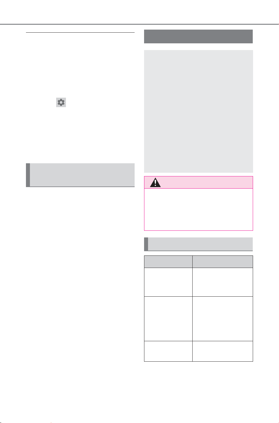
556
7-2. Maintenance
Owner’s Manual_USA_M6740B_en
■ Resetting the message indicat-
ing maintenance is required
After the required maintenance is
performed according to the mainte-
nance schedule, please reset the
message.
To reset the message, follow the
procedure described below:
1 Select on the multimedia dis-
play.
2 Select “Vehicle customize”.
3 Select “Utility”.
4 Select “Scheduled Mainte-
nance”.
5 Select “Reset”.
You can perform some mainte-
nance procedures by yourself.
Please be aware that do-it-your-
self maintenance may affect
warranty coverage.
The use of SUBARU Repair Manu-
als is recommended.
For details about warranty cover-
age, refer to the separate “Warranty
and Maintenance Booklet” or “War-
ranty and Service Booklet”.
Do-it-yourself mainte-
nance
General maintenance
Listed below are the general
maintenance items that
should be performed at the
intervals specified in the
“Warranty and Maintenance
Booklet” or “Warranty and
Service Booklet”. It is rec-
ommended that any prob-
lem you notice should be
brought to the attention of
your SUBARU dealer or
qualified service shop for
advice.
WARNING
■ If the EV system is running
Turn the EV system off and
ensure that there is adequate
ventilation before performing
maintenance checks.
Motor compartment
Items Check points
Brake fluid
Is the brake fluid at
the correct level?
(P.567)
Power control
unit/heater
coolant
Is the power con-
trol unit/heater
coolant at the cor-
rect level?
(P.565, 566)
12-volt battery
Check the connec-
tions. (P. 568)
SOLTERRA_OM_USA_A6740BE.book 556 ページ 2025年5月23日 金曜日 午後1時18分
557
7-2. Maintenance
Owner’s Manual_USA_M6740B_en
7
Maintenance and care
Radiator
The radiator
should be free from
foreign objects.
(P.565)
Washer fluid
Is there sufficient
washer fluid?
(P.570)
Vehicle interior
Items Check points
Accelerator
pedal
• The accelerator
pedal should
move smoothly
(without uneven
pedal effort or
catching).
Transmission
“Park” mecha-
nism
• When parked on
a slope and the
shift position is in
P, is the vehicle
securely
stopped?
Brake pedal
• Does the brake
pedal move
smoothly?
• Does the brake
pedal have
appropriate
clearance from
the floor?
• Does the brake
pedal have the
correct amount
of free play?
Items Check points
Brakes
• The vehicle
should not pull to
one side when
the brakes are
applied.
• The brakes
should work
effectively.
• The brake pedal
should not feel
spongy.
• The brake pedal
should not get
too close to the
floor when the
brakes are
applied.
Head
restraints
• Do the head
restraints move
smoothly and
lock securely?
Indica-
tors/buzzers
• Do the indica-
tors and buzzers
function prop-
erly?
Lights
• Do all the lights
come on?
• Are the head-
lights aimed cor-
rectly?
Parking brake
• Does the park-
ing brake oper-
ate normally?
• When parked on
a slope and the
parking brake is
on, is the vehicle
securely
stopped?
Items Check points
SOLTERRA_OM_USA_A6740BE.book 557 ページ 2025年5月23日 金曜日 午後1時18分
558
7-2. Maintenance
Owner’s Manual_USA_M6740B_en
Seat belts
• Do the seat belts
operate
smoothly?
• The seat belts
should not be
damaged.
Seats
• Do the seat con-
trols operate
properly?
Steering wheel
• Does the steer-
ing wheel rotate
smoothly?
• Does the steer-
ing wheel have
the correct
amount of free
play?
• There should not
be any strange
sounds coming
from the steer-
ing wheel.
Vehicle exterior
Items Check points
Doors
• Do the doors
operate
smoothly?
Hood
• Does the hood
lock system work
properly?
Fluid leaks
• There should not
be any signs of
fluid leakage
after the vehicle
has been parked.
Items Check points
Tires
• Is the tire infla-
tion pressure
correct?
• The tires should
not be damaged
or excessively
worn.
• Have the tires
been rotated
according to the
maintenance
schedule?
• The wheel nuts
should not be
loose.
Windshield
wipers
• The wiper blades
should not show
any signs of
cracking, split-
ting, wear, con-
tamination or
deformation.
• The wiper blades
should clear the
windshield with-
out streaking or
skipping.
Items Check points
SOLTERRA_OM_USA_A6740BE.book 558 ページ 2025年5月23日 金曜日 午後1時18分
559
7-3. Do-it-yourself maintenance
Owner’s Manual_USA_M6740B_en
7
Maintenance and care
7-3.Do -it-yourself maintenan ce
Do-it-yourself service
precautions
If you perform maintenance
by yourself, be sure to fol-
low the correct procedure
as given in these sections.
Maintenance
Items Parts and tools
12-volt bat-
tery condi-
tion (P.568)
•Warm water
• Baking soda
•Grease
• Conventional
wrench (for termi-
nal clamp bolts)
Brake fluid
level
(P.567)
• FMVSS No.116
DOT 3 or SAE
J1703 brake fluid
FMVSS No.116
DOT 4 or SAE
J1704 brake fluid
• Rag or paper
towel
• Funnel (used only
for adding brake
fluid)
Power control
unit coolant
level
(P.566)
• In order to ensure
maximum perfor-
mance of the trac-
tion battery
cooling system
and limit risks of
battery short cir-
cuit and other
damage to your
vehicle, SUBARU
recommends
using “Genuine
Traction Battery
Coolant” or simi-
lar high-quality
ethylene glycol-
based, low electric
conductivity cool-
ant, non-amine
and non-borate
coolant with azole
additives.
• Funnel (used only
for adding coolant)
Items Parts and tools
SOLTERRA_OM_USA_A6740BE.book 559 ページ 2025年5月23日 金曜日 午後1時18分
560
7-3. Do-it-yourself maintenance
Owner’s Manual_USA_M6740B_en
Heater cool-
ant level
(P.565)
• “GENUINE
SUPER LONG
LIFE COOLANT
(PINK)” or a simi-
lar high quality
ethylene glycol-
based non-sili-
cate, non-amine,
non-nitrite and
non-borate cool-
ant with long-life
hybrid organic
acid technology
“GENUINE
SUPER LONG
LIFE COOLANT
(PINK)” is pre-
mixed with 50%
coolant and 50%
deionized water.
• Funnel (used only
for adding coolant)
Fuses
(P.596)
• Fuse with same
amperage rating
as original
Headlight aim
(P.598)
Phillips-head
screwdriver
Radiator
(P.565)
Tire inflation
pressure
(P.588)
• Tire pressure
gauge
• Compressed air
source
Washer fluid
(P.570)
• Water or washer
fluid containing
antifreeze (for win-
ter use)
• Funnel (used only
for adding water or
washer fluid)
Items Parts and tools
WARNING
The motor compartment contains
many mechanisms and fluids that
may move suddenly, become hot,
or become electrically energized.
To avoid death or serious injury,
observe the following precautions.
■ When working on the motor
compartment
● Make sure that “POWER ON”
on the multi-information display
and the “READY” indicator are
both off.
● Keep hands, clothing and tools
away from the moving fan.
● Be careful not to touch the
motor, power control unit, radia-
tor, etc., right after driving as
they may be hot. Coolant and
other fluids may also be hot.
● Do not leave anything that may
burn easily, such as paper and
rags, in the motor compartment.
● Do not smoke, cause sparks or
expose an open flame to the 12-
volt battery. 12-volt battery
fumes are flammable.
● Be extremely cautious when
working on the 12-volt battery. It
contains poisonous and corro-
sive sulfuric acid.
● Never touch, disassemble,
remove or replace the high volt-
age parts, cables and their con-
nectors. It can cause severe
burns or electric shock that may
result in death or serious injury.
SOLTERRA_OM_USA_A6740BE.book 560 ページ 2025年5月23日 金曜日 午後1時18分
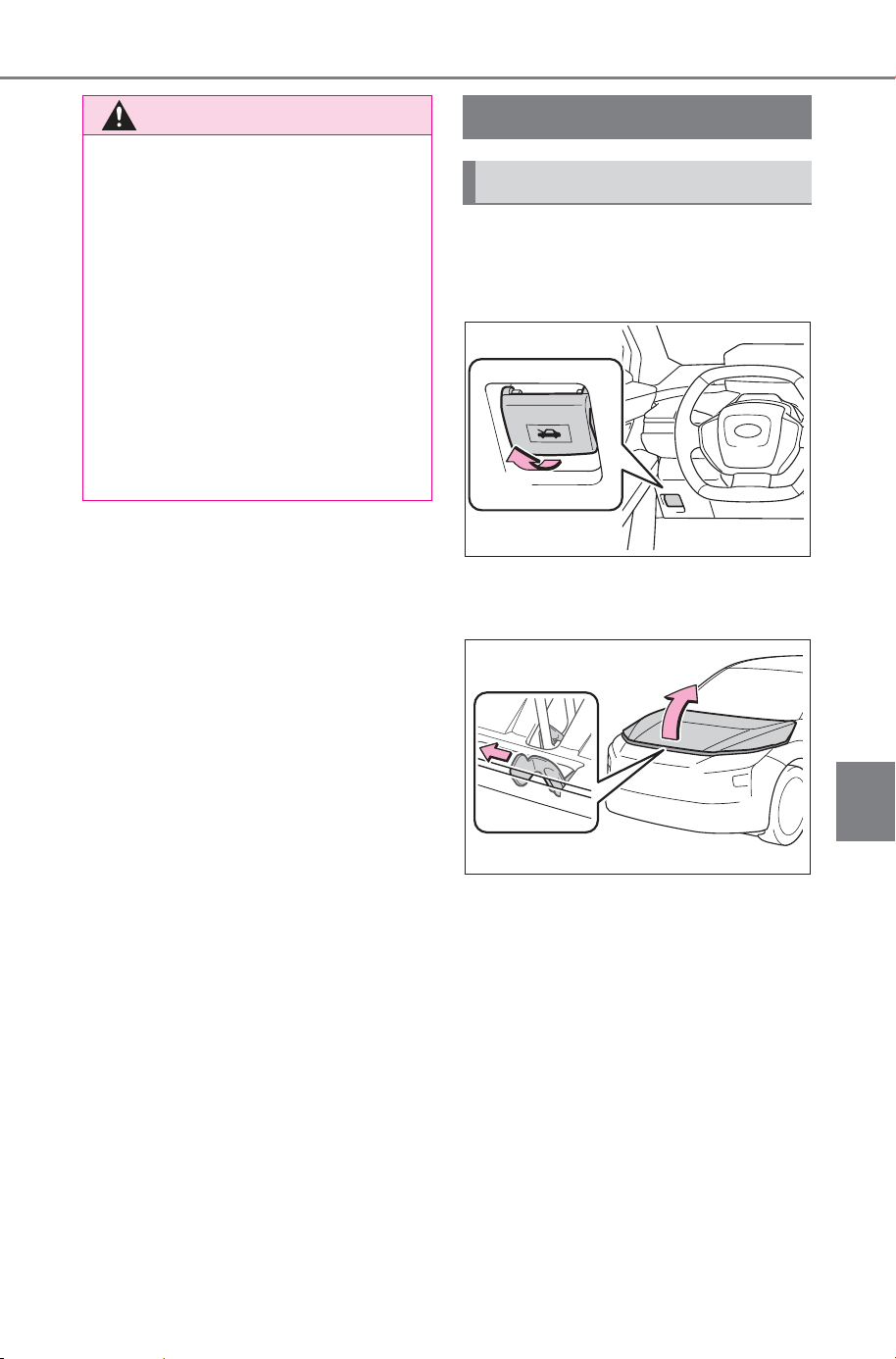
561
7-3. Do-it-yourself maintenance
Owner’s Manual_USA_M6740B_en
7
Maintenance and care
1 Pull the hood lock release
lever.
The hood will pop up slightly.
2 Push the auxiliary catch lever
to the left and lift the hood.
WARNING
■ When working near the elec-
tric cooling fan or radiator
grille
Be sure the power switch is OFF.
With the power switch in ON, the
electric cooling fan may automati-
cally start to run if the air condi-
tioning is on and/or the coolant
temperature is high. (P.565)
■ Safety glasses
Wear safety glasses to prevent
flying or falling material, fluid
spray, etc., from getting in your
eyes.
Hood
Opening the hood
SOLTERRA_OM_USA_A6740BE.book 561 ページ 2025年5月23日 金曜日 午後1時18分
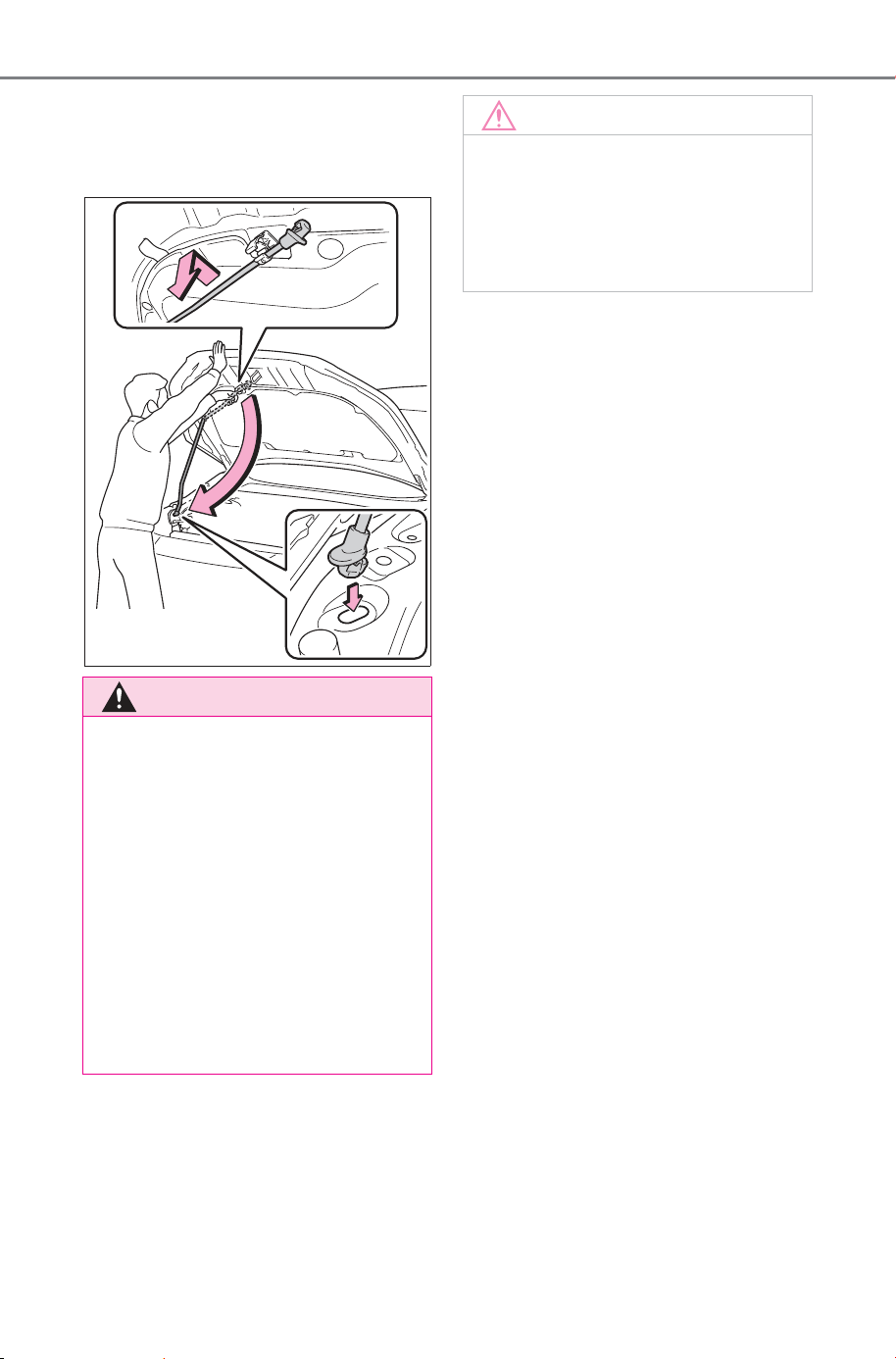
562
7-3. Do-it-yourself maintenance
Owner’s Manual_USA_M6740B_en
3 Hold the hood open by insert-
ing the supporting rod into
the slot.
WARNING
■ Pre-driving check
Check that the hood is fully closed
and locked.
If the hood is not locked properly,
it may open while the vehicle is in
motion and cause an accident,
which may result in death or seri-
ous injury.
■ After installing the support
rod into the slot
Make sure the rod is properly
inserted into the slot to prevent
the hood from shutting on your
head or body.
NOTICE
■ When closing the hood
Be sure to return the support rod
to its clip before closing the hood.
Closing the hood without return-
ing the support rod properly could
cause the hood to bend.
SOLTERRA_OM_USA_A6740BE.book 562 ページ 2025年5月23日 金曜日 午後1時18分
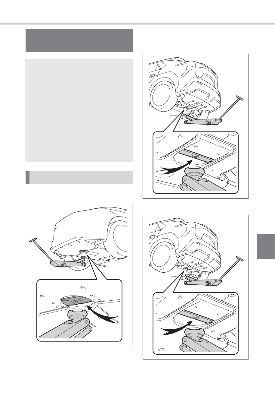
563
7-3. Do-it-yourself maintenance
Owner’s Manual_USA_M6740B_en
7
Maintenance and care
■ Front
■ Rear
FWD models
AWD models
Positioning a floor
jack
When using a floor jack, fol-
low the instructions in the
manual provided with the
jack and perform the opera-
tion safely.
When raising your vehicle
with a floor jack, position
the jack correctly.
Improper placement may
damage your vehicle or
cause injury.
Location of the jack point
SOLTERRA_OM_USA_A6740BE.book 563 ページ 2025年5月23日 金曜日 午後1時18分
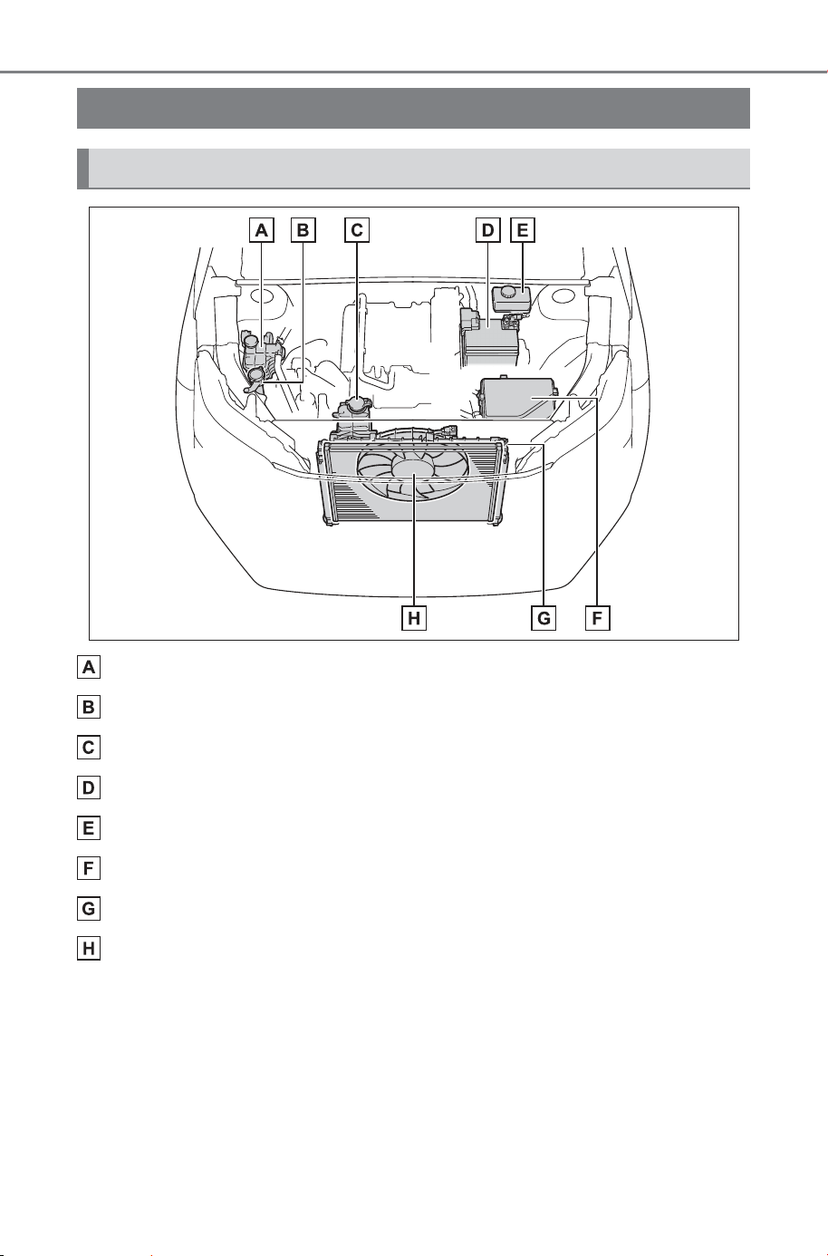
564
7-3. Do-it-yourself maintenance
Owner’s Manual_USA_M6740B_en
Heater coolant reservoir (P.565)
Washer fluid tank (P.570)
Power control unit coolant reservoir (P.566)
12-volt battery (P.568)
Brake fluid reservoir (P.567)
Fuse box (P.596)
Radiator (P.565)
Electric cooling fan
Motor compartment
Components
SOLTERRA_OM_USA_A6740BE.book 564 ページ 2025年5月23日 金曜日 午後1時18分
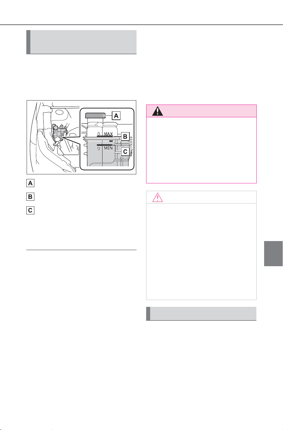
565
7-3. Do-it-yourself maintenance
Owner’s Manual_USA_M6740B_en
7
Maintenance and care
The coolant level is satisfactory
if it is between the “MAX” and
“MIN” lines on the reservoir
when the EV system is cold.
Reservoir cap
“MAX” line
“MIN” line
If the level is on or below the “MIN”
line, add coolant up to the “MAX”
line. (P.648)
■ Coolant selection
Only use “GENUINE SUPER LONG
LIFE COOLANT (PINK)” or a similar
high quality ethylene glycol-based
non-silicate, non-amine, non-nitrite,
and nonborate coolant with long-life
hybrid organic acid technology.
“GENUINE SUPER LONG LIFE
COOLANT (PINK)” is a mixture of
50% coolant and 50% deionized
water. (Minimum temperature: -31°F
[-35°C])
For more details about coolant, con-
tact your SUBARU dealer.
■ If the coolant level drops within
a short time of replenishing
Visually check the radiator, hoses,
power control unit coolant reservoir
caps and water pump.
If you cannot find a leak, have your
SUBARU dealer, test the cap and
check for leaks in the cooling sys-
tem.
Check the radiator and clear
away any foreign objects.
If either of the above parts is
extremely dirty or you are not
sure of their condition, have
your vehicle inspected SUBARU
dealer.
Checking the heater cool-
ant
WARNING
■ When the heater system is
hot
Do not remove the heater coolant
reservoir caps.
The heater system may be under
pressure and may spray hot cool-
ant if the cap is removed, causing
serious injuries, such as burns.
NOTICE
■ When adding coolant
Coolant is neither plain water nor
straight antifreeze. The correct
mixture of water and antifreeze
must be used to provide proper
lubrication, corrosion protection
and cooling. Be sure to read the
antifreeze or coolant label.
■ If you spill coolant
Be sure to wash it off with water to
prevent it from damaging parts or
paint.
Checking the radiator
SOLTERRA_OM_USA_A6740BE.book 565 ページ 2025年5月23日 金曜日 午後1時18分
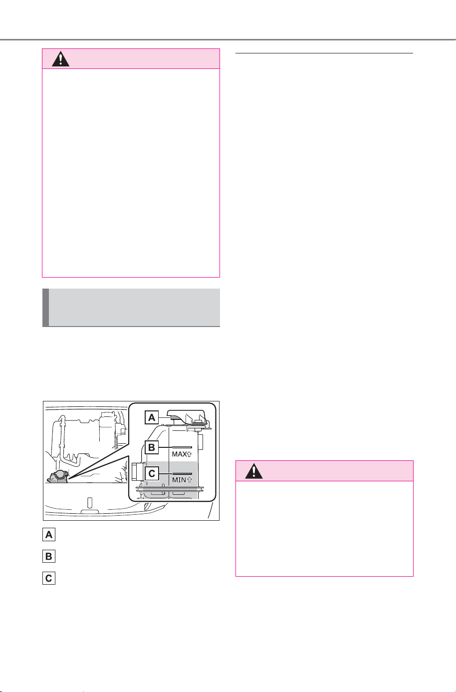
566
7-3. Do-it-yourself maintenance
Owner’s Manual_USA_M6740B_en
The coolant level is satisfactory
if it is between the “MAX” and
“MIN” lines on the reservoir
when the EV system is cold.
Reservoir cap
“MAX” line
“MIN” line
If the level is on or below the “MIN”
line, add coolant up to the “MAX”
line.
■ Coolant selection
In order to ensure maximum perfor-
mance of the traction battery cooling
system and limit risks of battery
short circuit and other damage to
your vehicle, SUBARU recom-
mends using “Genuine Traction Bat-
tery Coolant” or similar high-quality
ethylene glycol-based, low electric
conductivity coolant, non-amine and
non-borate coolant with azole addi-
tives.
SUBARU cannot guarantee that the
use of a product other than “Genu-
ine Traction Battery Coolant” will
prevent risks of battery short circuit
or other damage.
Never use water as it will cause
damage.
Do not reuse coolant that has been
removed from the radiator.
For more details about coolant, con-
tact your SUBARU dealer.
■ If the coolant level drops within
a short time of replenishing
Visually check the hoses, heater
coolant reservoir caps, drain cock
and water pump.
If you cannot find a leak, have your
SUBARU dealer, test the cap and
check for leaks in the cooling sys-
tem.
WARNING
■ When the EV system is hot
Do not touch the radiator as they
may be hot and cause serious
injuries, such as burns.
■ When the electric cooling fan
are operating
Do not touch the motor compart-
ment.
With the power switch in ON, the
electric cooling fan may automati-
cally start to run if the air condi-
tioning is on and/or the coolant
temperature is high. Be sure the
power switch is OFF when work-
ing near the electric cooling fan or
radiator grille.
Checking the power con-
trol unit coolant
WARNING
■ When the EV system is hot
Do not remove the power control
unit coolant reservoir caps.
The cooling system may be under
pressure and may spray hot cool-
ant if the cap is removed, causing
serious injuries, such as burns.
SOLTERRA_OM_USA_A6740BE.book 566 ページ 2025年5月23日 金曜日 午後1時18分
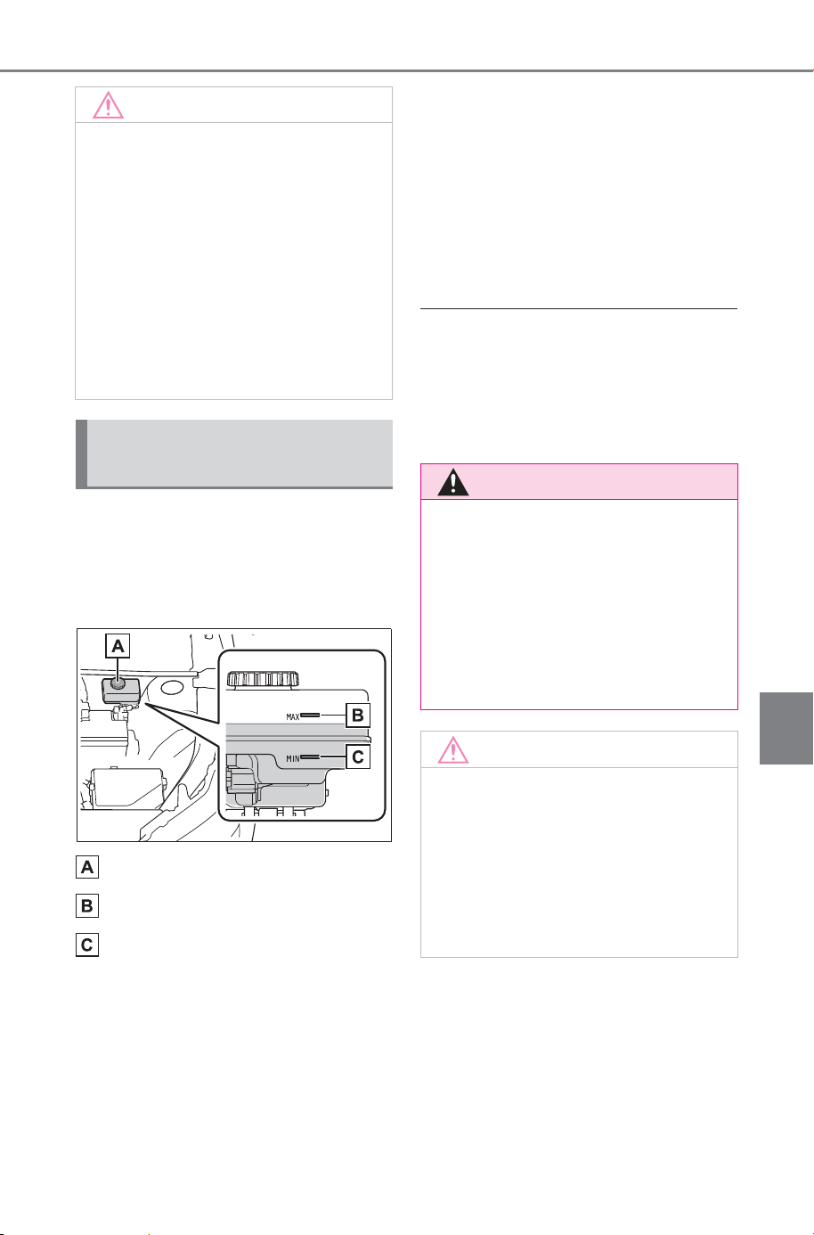
567
7-3. Do-it-yourself maintenance
Owner’s Manual_USA_M6740B_en
7
Maintenance and care
■ Checking fluid level
The brake fluid level should be
between the “MAX” and “MIN”
lines on the tank.
Reservoir cap
“MAX” line
“MIN” line
■ Adding fluid
Make sure to check the fluid
type and prepare the necessary
item.
Fluid type
FMVSS No.116 DOT 3 or SAE
J1703 brake fluid
FMVSS No.116 DOT 4 or SAE
J1704 brake fluid
Item
Clean funnel
■ Brake fluid can absorb moisture
from the air
Excess moisture in the brake fluid
can cause a dangerous loss of brak-
ing efficiency. Use only newly
opened brake fluid.
NOTICE
■ When adding coolant
Coolant is neither plain water nor
straight antifreeze. The correct
mixture of water and antifreeze
must be used to provide proper
lubrication, corrosion protection
and cooling. Be sure to read the
antifreeze or coolant label.
■ If you spill coolant
Be sure to wash it off with water to
prevent it from damaging parts or
paint.
Checking and adding the
brake fluid
WARNING
■ When filling the reservoir
Take care as brake fluid can harm
your hands and eyes and damage
painted surfaces.
If fluid gets on your hands or in
your eyes, flush the affected area
with clean water immediately. If
you still experience discomfort,
see a doctor.
NOTICE
■ If the fluid level is low or high
It is normal for the brake fluid level
to go down slightly as the brake
pads wear out or when the fluid
level in the accumulator is high.
If the reservoir needs frequent
refilling, there may be a serious
problem.
SOLTERRA_OM_USA_A6740BE.book 567 ページ 2025年5月23日 金曜日 午後1時18分
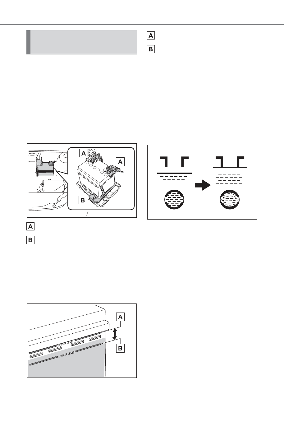
568
7-3. Do-it-yourself maintenance
Owner’s Manual_USA_M6740B_en
Check the 12-volt battery as fol-
lows.
■ 12-volt battery exterior
Make sure that the 12-volt bat-
tery terminals are not corroded
and that there are no loose con-
nections, cracks, or loose
clamps.
Terminals
Hold-down clamp
■ Checking 12-volt battery
fluid
Check that the level is between
the “UPPER LEVEL” and
“LOWER LEVEL” lines.
“UPPER LEVEL” line
“LOWER LEVEL” line
If the fluid level is at or below the
“LOWER LEVEL” line, add distilled
water.
■ Adding distilled water
1 Remove the vent plug.
2 Add distilled water.
If the “UPPER LEVEL” cannot be
seen, check the fluid level by look-
ing directly at the cell.
3 Put the vent plug back on
and close it securely.
■ Before recharging
When recharging, the 12-volt bat-
tery produces hydrogen gas which
is flammable and explosive. There-
fore, observe the following precau-
tions before recharging:
● If recharging with the 12-volt bat-
tery installed on the vehicle, be
sure to disconnect the ground
cable.
● Make sure the power switch on
the charger is off when connecting
and disconnecting the charger
cables to the 12-volt battery.
Checking the 12-volt bat-
tery
SOLTERRA_OM_USA_A6740BE.book 568 ページ 2025年5月23日 金曜日 午後1時18分
569
7-3. Do-it-yourself maintenance
Owner’s Manual_USA_M6740B_en
7
Maintenance and care
■ After recharging/reconnecting
the 12-volt battery
● The EV system may not start. Fol-
low the procedure below to initial-
ize the system.
1 Shift the shift position to P.
2 Open and close any of the doors.
3 Restart the EV system.
● Unlocking the doors using the
Smart key system may not be
possible immediately after recon-
necting the 12-volt battery. If this
happens, use the wireless remote
control or the mechanical key to
lock/unlock the doors.
● Start the EV system with the
power switch in ACC
*
. The EV
system may not start with the
power switch turned off. However,
the EV system will operate nor-
mally from the second attempt.
● The power switch mode is
recorded by the vehicle. If the 12-
volt battery is disconnected and
reconnected, the vehicle will
return the power switch mode to
the status it was in before the 12-
volt battery was disconnected.
Make sure to turn off the power
switch before disconnecting the
12-volt battery. Take extra care
when connecting the 12-volt bat-
tery if the power switch mode prior
to the 12-volt battery being dis-
connected is unknown.
If the EV system will not start even
after multiple attempts at all the
methods above, contact your SUB-
ARU dealer.
*
: ACC mode can be enabled/dis-
abled on the customize menu.
(P.672)
WARNING
■ Chemicals in the 12-volt bat-
tery
Batteries contain poisonous and
corrosive sulfuric acid and may
produce hydrogen gas which is
flammable and explosive. To
reduce the risk of death or serious
injury, take the following precau-
tions while working on or near the
12-volt battery:
● Do not cause sparks by touch-
ing the 12-volt battery terminals
with tools.
● Do not smoke or light a match
near the 12-volt battery.
● Avoid contact with eyes, skin
and clothes.
● Never inhale or swallow electro-
lyte.
● Wear protective safety glasses
when working near the 12-volt
battery.
● Keep children away from the
12-volt battery.
■ Where to safely charge the
12-volt battery
Always charge the 12-volt battery
in an open area. Do not charge
the 12-volt battery in a garage or
closed room where there is insuf-
ficient ventilation.
■ Emergency measures regard-
ing electrolyte
● If electrolyte gets in your eyes
Flush your eyes with clean
water for at least 15 minutes
and get immediate medical
attention. If possible, continue
to apply water with a sponge or
cloth while traveling to the near-
est medical facility.
SOLTERRA_OM_USA_A6740BE.book 569 ページ 2025年5月23日 金曜日 午後1時18分
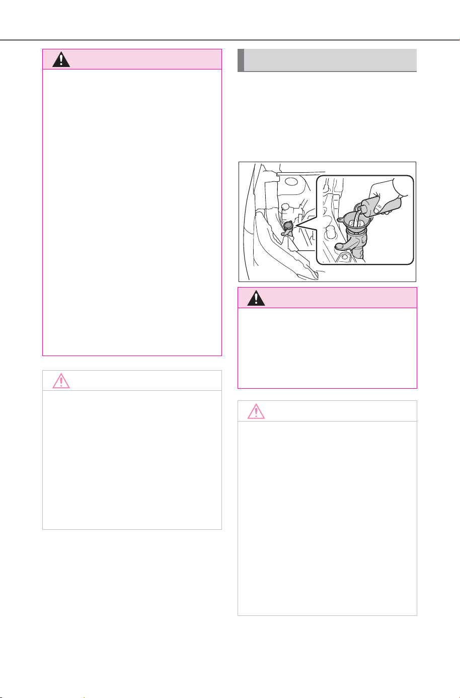
570
7-3. Do-it-yourself maintenance
Owner’s Manual_USA_M6740B_en
If any washer does not work or
the warning message appears
on the multi-information display,
the washer tank may be empty.
Add washer fluid.
WARNING
● If electrolyte gets on your skin
Wash the affected area thor-
oughly. If you feel pain or burn-
ing, get medical attention
immediately.
● If electrolyte gets on your
clothes
It can soak through clothing on
to your skin. Immediately take
off the clothing and follow the
procedure above if necessary.
● If you accidentally swallow elec-
trolyte
Drink a large quantity of water
or milk. Get emergency medical
attention immediately.
■ When there is insufficient 12-
volt battery fluid
Do not use if there is insufficient
fluid in the 12-volt battery. There
is a possible danger that the 12-
volt battery may explode.
NOTICE
■ When recharging the 12-volt
battery
Never recharge the 12-volt bat-
tery while the EV system is oper-
ating. Also, be sure all
accessories are turned off.
■ When adding distilled water
Avoid overfilling. Water spilled
during 12-volt battery recharging
may cause corrosion.
Adding the washer fluid
WARNING
■ When adding washer fluid
Do not add washer fluid when the
EV system is hot or operating as
washer fluid contains alcohol and
may catch fire if spilled on the
motor, etc.
NOTICE
■ Do not use any fluid other
than washer fluid
Do not use soapy water or anti-
freeze instead of washer fluid.
Doing so may cause streaking on
the vehicle’s painted surfaces, as
well as damaging the pump lead-
ing to problems of the washer
fluid not spraying.
■ Diluting washer fluid
Dilute washer fluid with water as
necessary.
Refer to the freezing tempera-
tures listed on the label of the
washer fluid bottle.
SOLTERRA_OM_USA_A6740BE.book 570 ページ 2025年5月23日 金曜日 午後1時18分
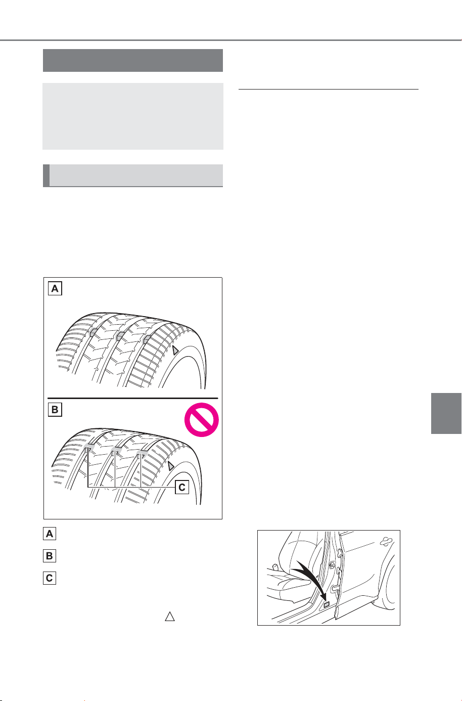
571
7-3. Do-it-yourself maintenance
Owner’s Manual_USA_M6740B_en
7
Maintenance and care
Check if the treadwear indica-
tors are showing on the tires.
Also check the tires for uneven
wear, such as excessive wear
on one side of the tread.
New tread
Worn tread
Treadwear indicator
The location of treadwear indicators
is shown by a “TWI” or “ ” mark,
etc., molded into the sidewall of
each tire.
Replace the tires if the treadwear
indicators are showing on a tire.
■ When to replace your vehicle’s
tires
Tires should be replaced if:
● The treadwear indicators are
showing on a tire.
● You have tire damage such as
cuts, splits, cracks deep enough
to expose the fabric, and bulges
indicating internal damage.
● A tire goes flat repeatedly or can-
not be properly repaired due to the
size or location of a cut or other
damage.
If you are not sure, consult with your
SUBARU dealer.
■ Tire life
Any tire over 6 years old must be
checked by a qualified technician
even if it has seldom or never been
used or damage is not obvious.
■ Maximum load of tire
Check that the number given by
dividing the maximum load by 1.10
of the replacement tire is greater
than 1/2 of the Gross Axle Weight
Ratings (GAWR) of either the front
axle or the rear axle, whichever is
greater.
For the GAWR, see the Certification
Regulation Label. For the maximum
load of the tire, see the load limit at
maximum cold tire inflation pressure
mentioned on the sidewall of the
tire. (P.662)
Tires
Replace or rotate tires in
accordance with mainte-
nance schedules and tread-
wear.
Checking tires
SOLTERRA_OM_USA_A6740BE.book 571 ページ 2025年5月23日 金曜日 午後1時18分
572
7-3. Do-it-yourself maintenance
Owner’s Manual_USA_M6740B_en
■ Tire types
● Summer tires
Summer tires are high-speed perfor-
mance tires best suited to highway
driving under dry conditions. Since
summer tires do not have the same
traction performance as snow tires,
summer tires are inadequate for
driving on snow-covered or icy
roads. For driving on snow-covered
roads or icy roads, the use of snow
tires is recommended. When install-
ing snow tires, be sure to replace all
four tires.
● All season tires
All season tires are designed to pro-
vide better traction in snow and to
be adequate for driving in most win-
ter conditions as well as for use
year-round. All season tires, how-
ever, do not have adequate traction
performance compared with snow
tires in heavy or loose snow. Also,
all season tires fall short in accelera-
tion and handling performance com-
pared with summer tires in highway
driving.
● Snow tires
For driving on snow-covered roads
or icy roads, we recommend using
snow tires. If you need snow tires,
select tires of the same size, con-
struction and load capacity as the
originally installed tires. Since your
vehicle has radial tires as original
equipment, make sure your snow
tires also have radial construction.
Do not install studded tires without
first checking local regulations for
possible restrictions. Snow tires
should be installed on all wheels.
(P.482)
■ If the tread on snow tires wears
down below 0.16 in. (4 mm)
The effectiveness of the tires as
snow tires is lost.
WARNING
■ When inspecting or replacing
tires
Observe the following precautions
to prevent accidents.
Failure to do so may cause dam-
age to parts of the drive train as
well as dangerous handling char-
acteristics, which may lead to an
accident resulting in death or seri-
ous injury.
● Do not mix tires of different
makes, models or tread pat-
terns.
Also, do not mix tires of remark-
ably different treadwear.
● Do not use tire sizes other than
those recommended by SUB-
ARU.
● Do not mix differently con-
structed tires (radial, bias-belted
or bias-ply tires).
● Do not mix summer, all season
and snow tires.
● Do not use tires that have been
used on another vehicle.
Do not use tires if you do not
know how they were used previ-
ously.
SOLTERRA_OM_USA_A6740BE.book 572 ページ 2025年5月23日 金曜日 午後1時18分
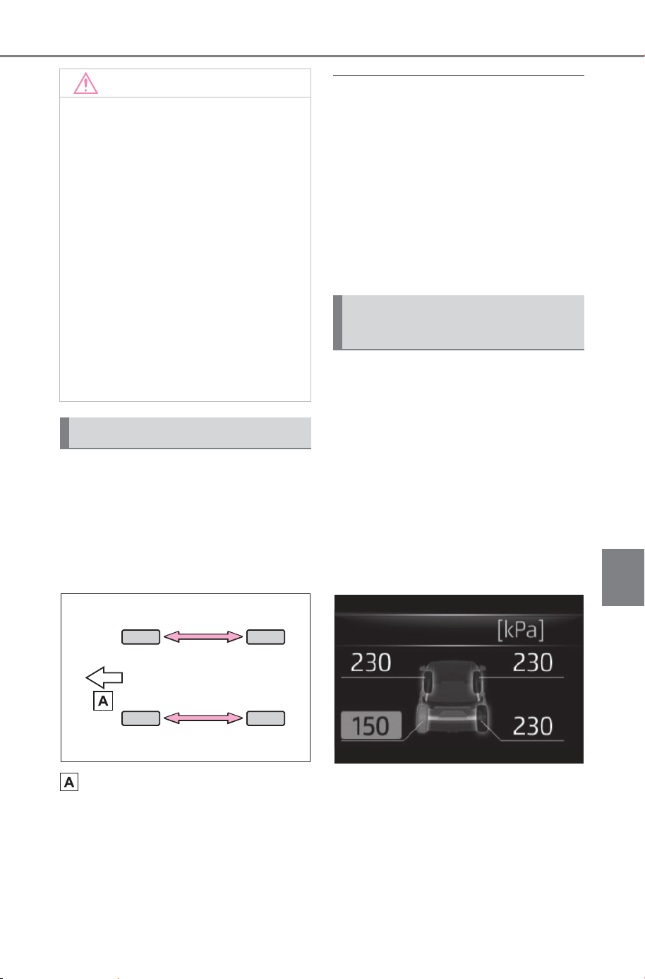
573
7-3. Do-it-yourself maintenance
Owner’s Manual_USA_M6740B_en
7
Maintenance and care
Rotate the tires in the order
shown.
To equalize tire wear and extend
tire life, SUBARU recommends that
tire rotation is carried out at the
same interval as tire inspection.
Front
■ When rotating the tires (vehicle
with the tire pressure warning
system)
Make sure that the power switch is
OFF. If the tires are rotated while the
power switch is in ON, the tire posi-
tion information will not be updated.
If this accidentally occurs, either turn
the power switch to OFF and then to
ON, or initialize the system after
checking that the tire pressure is
properly adjusted.
Your vehicle is equipped with a
tire pressure warning system
that uses tire pressure warning
valves and transmitters to detect
low tire inflation pressure before
serious problems arise.
The tire pressure warning sys-
tem of this vehicle adopts a 2-
type warning system. (P.615)
Multi-information display
NOTICE
■ Driving on rough roads
Take particular care when driving
on roads with loose surfaces or
potholes.
These conditions may cause
losses in tire inflation pressure,
reducing the cushioning ability of
the tires. In addition, driving on
rough roads may cause damage
to the tires themselves, as well as
the vehicle’s wheels and body.
■ If tire inflation pressure of
each tire becomes low while
driving
Do not continue driving, or your
tires and/or wheels may be
ruined.
Tire rotation
Tire pressure warning
system (if equipped)
SOLTERRA_OM_USA_A6740BE.book 573 ページ 2025年5月23日 金曜日 午後1時18分
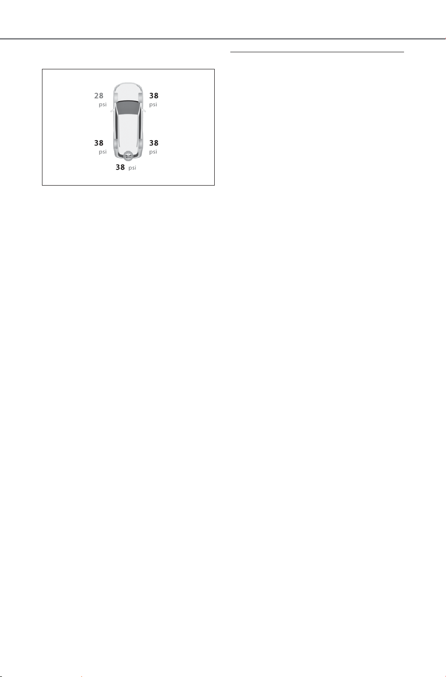
574
7-3. Do-it-yourself maintenance
Owner’s Manual_USA_M6740B_en
Multimedia display
When “Adjust Pressure” is
displayed (Normal Warning)
A warning with the tire pressure
warning light and warning buzzer
when there is an unknown level of
low tire pressure with the appear-
ance of the tire due to natural air
leakage as well as the pressure
lowering due to changes in the
pressure according to the outside
temperature.
When “Immediately Check
Tire when Safe” is displayed
(Emergency Warning)
A warning with the tire pressure
warning light and warning buzzer
when there is a known level of low
tire pressure with the appearance
of the tire due to pressure suddenly
lowering.
However, the system may not be
able to detect sudden tire ruptures
(bursting, etc.).
The tire pressure detected by
the tire pressure warning sys-
tem can be displayed on the
multimedia display.
■ Routine tire inflation pressure
checks
The tire pressure warning system
does not replace routine tire inflation
pressure checks. Make sure to
check tire inflation pressure as part
of your routine of daily vehicle
checks.
■ Tire inflation pressure
● It may take a few minutes to dis-
play the tire inflation pressure
after the power switch is turned to
ON. It may also take a few min-
utes to display the tire inflation
pressure after inflation pressure
has been adjusted.
● Tire inflation pressure changes
with temperature.
The displayed values may also be
different from the values mea-
sured using a tire pressure gauge.
■ Situations in which the tire
pressure warning system may
not operate properly
● In the following cases, the tire
pressure warning system may not
operate properly.
• If non-genuine SUBARU wheels
are used.
• A tire has been replaced with a
tire that is not an OE (Original
Equipment) tire.
• A tire has been replaced with a
tire that is not of the specified size.
• Tire chains etc. are equipped.
• If a window tint that affects the
radio wave signals is installed.
• If there is a lot of snow or ice on
the vehicle, particularly around the
wheels or wheel housings.
• If the tire inflation pressure is
extremely higher than the speci-
fied level.
• If wheels without tire pressure
warning valves and transmitters
are used.
• If the ID code on the tire pressure
warning valves and transmitters is
not registered in the tire pressure
warning computer.
SOLTERRA_OM_USA_A6740BE.book 574 ページ 2025年5月23日 金曜日 午後1時18分
575
7-3. Do-it-yourself maintenance
Owner’s Manual_USA_M6740B_en
7
Maintenance and care
● Performance may be affected in
the following situations.
• Near a TV tower, electric power
plant, gas station, radio station,
large display, airport or other facil-
ity that generates strong radio
waves or electrical noise
• When carrying a portable radio,
cellular phone, cordless phone or
other wireless communication
device
If tire position information is not cor-
rectly displayed due to the radio
wave conditions, the display may be
corrected by driving and changing
the radio wave conditions.
● When the vehicle is parked, the
time taken for the warning to start
or go off could be extended.
● When tire inflation pressure
declines rapidly for example when
a tire has burst, the warning may
not function.
When replacing tires or wheels,
tire pressure warning valves and
transmitters must also be
installed.
When new tire pressure warning
valves and transmitters are
installed, new ID codes must be
registered in the tire pressure warn-
ing computer and the tire pressure
warning system must be initialized.
(P.579)
■ When replacing the tires and
wheels
If the ID code of the tire pressure
warning valve and transmitter is not
registered, the tire pressure warning
system will not work properly. After
driving for about 10 minutes, the tire
pressure warning light blinks for 1
minute and stays on to indicate a
system malfunction.
Installing tire pressure
warning valves and trans-
mitters (Vehicles with tire
pressure warning system)
NOTICE
■ Repairing or replacing tires,
wheels, tire pressure warn-
ing valves, transmitters and
tire valve caps
● When removing or fitting the
wheels, tires or the tire pressure
warning valves and transmit-
ters, contact your SUBARU
dealer as the tire pressure
warning valves and transmit-
ters may be damaged if not
handled correctly.
● Make sure to install the tire
valve caps. If the tire valve caps
are not installed, water could
enter the tire pressure warning
valves and the tire pressure
warning valves could be bound.
● When replacing tire valve caps,
do not use tire valve caps other
than those specified. The cap
may become stuck.
■ To avoid damage to the tire
pressure warning valves and
transmitters
When a tire is repaired with liquid
sealants, the tire pressure warn-
ing valve and transmitter may not
operate properly. If a liquid seal-
ant is used, contact your SUB-
ARU dealer as soon as possible.
After use of liquid sealant, make
sure to replace the tire pressure
warning valve and transmitter
when repairing or replacing the
tire.
SOLTERRA_OM_USA_A6740BE.book 575 ページ 2025年5月23日 金曜日 午後1時18分
576
7-3. Do-it-yourself maintenance
Owner’s Manual_USA_M6740B_en
■ When to register the posi-
tion of each wheel
It is necessary to register the
position of each wheel after per-
forming a tire rotation.
Wheel position registration can
be performed by oneself. Wheel
position registration is per-
formed by driving forward with
moderate left and right turns.
However, depending on the driv-
ing conditions and driving envi-
ronment, registration may take
some time to complete.
■ Registering the position of
each wheel
1 Park the vehicle in a safe
place, turn the power switch
off and wait 15 minutes or
more.
2 Start the EV system.
The wheel position registration pro-
cedure cannot be performed while
the vehicle is moving.
3 Select on the multimedia
display.
4 Select “Vehicle customize”.
5 Select “Tire pressure”.
6 Select “Tire rotation”.
7 Select “Continue”.
A message indicating that wheel
position registration is being per-
formed will be displayed on the
multi-information display. “---” will
be displayed for the tire inflation
pressure of each tire and wheel
position registration will begin.
8 Drive straight (with occa-
sional left and right turns) at
approximately 25 mph (40
km/h) or more for approxi-
mately 10 to 30 minutes.
When wheel position registration is
complete, a message indicating
that registration has been com-
pleted and the inflation pressure of
each tire will be displayed on the
multi-information display.
Even if it is not possible to drive
continuously at approximately 25
mph (40 km/h) or more, registration
can be completed by driving for a
long time. However, if registration
does not complete after driving for
1 hour or more, park the vehicle in
a safe place and leave it with the
power switch in ON for approxi-
mately 15 minutes or more, and
then perform the driving procedure
again.
Registering the position
of each wheel
SOLTERRA_OM_USA_A6740BE.book 576 ページ 2025年5月23日 金曜日 午後1時18分

577
7-3. Do-it-yourself maintenance
Owner’s Manual_USA_M6740B_en
7
Maintenance and care
■ When performing wheel posi-
tion registration
● Normally, wheel position registra-
tion can be completed within
approximately 30 minutes.
● Wheel position registration is per-
formed while driving at a vehicle
speed of approximately 25 mph
(40 km/h) or more.
■ Wheel position registration pro-
cedure
● If the power switch is turned off
while registering the wheel posi-
tion, the next time the power
switch is turned to ON, the wheel
position registration will resume
and it will not be necessary to
restart the procedure.
● While the position of each wheel is
being determined and the inflation
pressures are not being dis-
played, if the inflation pressure of
a tire drops, the tire pressure
warning light will come on.
■ If the wheel position cannot be
registered easily
● In the following situations, wheel
position registration may take lon-
ger than usual to be completed or
may not be possible.
• Vehicle is not driven at approxi-
mately 25 mph (40 km/h) or more
• Vehicle is driven on unpaved
roads
● If wheel position registration does
not complete after driving for 1
hour or more, park the vehicle in a
safe place for approximately 15
minutes and then drive the vehicle
again.
● If the vehicle is reversed during
wheel position registration, all
data collected until then will be
cleared. Perform driving again.
■ When you need to setting
the tire pressure
In the following situations, it will
be necessary to perform the tire
inflation pressure setting proce-
dure of the tire pressure warning
system.
When the specified tire infla-
tion pressure has changed,
such as due to carried load,
etc.
When the tire inflation pres-
sure is changed such as
when the tire size is changed.
If the tire inflation pressure has
been adjusted to the specified
level, perform the tire inflation
setting procedure by selecting
specified inflation pressure on
the multimedia display.
(P.578)
When the tire inflation pressure
is to be other than specified,
such as when tires other than
the specified size are used, etc.,
set the tire inflation pressure
using the current pressure.
Make sure to adjust the tire
inflation pressure of each tire to
the appropriate level before per-
forming tire pressure setting.
The tire pressure warning sys-
tem operates based on this tire
inflation pressure. (P.578)
Setting the tire pressure
SOLTERRA_OM_USA_A6740BE.book 577 ページ 2025年5月23日 金曜日 午後1時18分
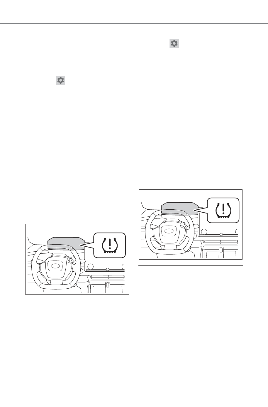
578
7-3. Do-it-yourself maintenance
Owner’s Manual_USA_M6740B_en
■ Setting by selecting a spec-
ified tire inflation pressure
1 Start the EV system.
The tire inflation pressure cannot
be set while the vehicle is moving.
2 Select on the multimedia
display.
3 Select “Vehicle customize”.
4 Select “Tire pressure”.
5 Select “Set indicated air pres-
sure” and then select the
desired front and rear tire
pressures.
6 Select “OK”.
The tire pressure warning light will
slowly blink 3 times.
After setting the tire inflation pres-
sure, a message indicating that set-
ting has been completed will be
displayed on the multi-information
display.
■ Setting using the current
tire inflation pressure
1 Adjust the tire inflation pres-
sure of each tire to the appro-
priate level.
Make sure to adjust the tire inflation
pressure with the tires cold.
2 Start the EV system.
The tire inflation pressure cannot
be set while the vehicle is moving.
3 Select on the multimedia
display.
4 Select “Vehicle customize”.
5 Select “Tire pressure”.
6 Select “Set current air pres-
sure”.
7 Select “Continue”.
The tire pressure warning light will
slowly blink 3 times and a message
indicating that tire inflation pressure
is being set will be displayed on the
multi-information display.
After setting the tire inflation pres-
sure, a message indicating that set-
ting has been completed will be
displayed on the multi-information
display.
■ Warning performance of the tire
pressure warning system (Set-
ting using the current tire infla-
tion pressure)
● When performing the tire pressure
setting using the current tire infla-
tion pressure, the warning timing
of the tire pressure warning sys-
tem will vary according to the con-
ditions under which tire pressure
setting was performed. Therefore,
a warning may be output even if
the tire inflation pressure drops
slightly or if the tire inflation pres-
sure increases above that when
the tire inflation pressure was set.
SOLTERRA_OM_USA_A6740BE.book 578 ページ 2025年5月23日 金曜日 午後1時18分
579
7-3. Do-it-yourself maintenance
Owner’s Manual_USA_M6740B_en
7
Maintenance and care
● Make sure to perform the tire
pressure setting procedure after
adjusting the tire inflation pres-
sure. Also, make sure the tires are
cold before performing the tire
pressure setting procedure or
adjusting the tire inflation pres-
sure.
■ Tire inflation pressure setting
procedure (Setting using the
current tire inflation pressure)
● If the power switch is turned off
while setting the tire inflation pres-
sure, the next time the power
switch is turned to ON, the setting
procedure will resume and it will
not be necessary to restart the
procedure.
● If the tire inflation pressure setting
procedure is started unnecessar-
ily, adjust the tire inflation pres-
sure to the specified level with the
tires cold and then perform setting
by selecting a specified tire infla-
tion pressure, or perform the tire
inflation pressure setting proce-
dure with the current tire inflation
pressure.
■ If the tire inflation pressure can-
not be set easily
● Normally, it takes approximately 3
minutes to complete the setting
procedure to the current tire infla-
tion pressure.
● If the tire pressure warning light
does not blink 3 times when start-
ing the tire inflation pressure set-
ting procedure, the procedure
may not have started. Perform the
procedure again from the begin-
ning.
● If tire inflation pressure setting
procedure cannot be completed
after performing the above proce-
dure, contact your SUBARU
dealer.
■ When to register ID codes
The tire pressure warning valve
and transmitter is equipped with
a unique ID code. When new
tire pressure warning valves and
transmitters are installed, new
ID codes must be registered in
the tire pressure warning com-
puter.
■ How to registration ID code
Before performing ID code reg-
istration, make sure that no
wheels with tire pressure warn-
ing valve and transmitters
installed are near the vehicle.
1 Park the vehicle in a safe
place, turn the power switch
off and wait 15 minutes or
more.
2 Start the EV system.
The ID code registration procedure
cannot be performed while the
vehicle is moving.
3 Select on the multimedia
display.
WARNING
■ When setting using the cur-
rent tire inflation pressure
Make sure to adjust the tire infla-
tion pressure of each tire to the
appropriate level before perform-
ing tire pressure setting. Other-
wise, the tire pressure warning
light may not illuminate even if the
tire inflation pressure drops or
may illuminate even though the
tire inflation pressure is normal.
Registering ID codes
SOLTERRA_OM_USA_A6740BE.book 579 ページ 2025年5月23日 金曜日 午後1時18分
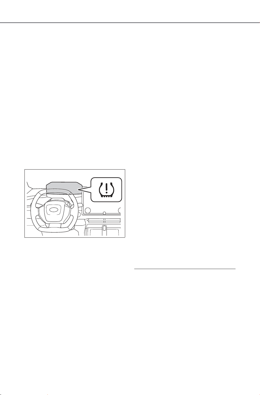
580
7-3. Do-it-yourself maintenance
Owner’s Manual_USA_M6740B_en
4 Select “Vehicle customize”.
5 Select “Tire pressure”.
6 Check if the desired wheel
set (“Set 1” or “Set 2”) is dis-
played.
ID codes will be registered to the
displayed wheel set.
To change the wheel set to be reg-
istered, select the displayed set,
and then select the wheel set you
wish to register.
If ID codes have already been reg-
istered for that wheel set, the tire
pressure warning light will slowly
blink 3 times, and a message indi-
cating that change is occurring will
be displayed on the multi-informa-
tion display.
7 Select “New tire registration”.
8 Select “Continue”.
The tire pressure warning light will
slowly blink 3 times and a message
indicating that ID code registration
is being performed will be displayed
on the multi-information display.
Wheel set changing will be can-
celed and registration will begin.
When registration is being per-
formed, the tire pressure warning
light will blink for approximately 1
minute then illuminate and “---” will
be displayed for the inflation pres-
sure of each tire on the multi-infor-
mation display.
9 Drive straight (with occa-
sional left and right turns) at
approximately 25 mph (40
km/h) or more for approxi-
mately 10 to 30 minutes.
When registration is complete, the
tire pressure warning light will turn
off and a message indicating that
registration has been completed
will be displayed on the multi-infor-
mation display.
Registration may take longer than
normal to complete if the vehicle
speed cannot be maintained at
approximately 25 mph (40 km/h) or
more. If registration cannot be com-
pleted after driving for 1 hour or
more, perform the registration pro-
cedure again from the beginning.
10If the tire inflation pressure of
the wheel set installed differs
from that of the previous set,
it will be necessary to per-
form the tire inflation pres-
sure setting procedure of the
tire pressure warning system.
(P.577)
If the specified tire inflation pres-
sure is the same, it will not be nec-
essary to perform the tire inflation
pressure setting procedure.
■ When registering ID codes
● Normally, wheel position registra-
tion can be completed within
approximately 30 minutes.
● ID code registration is performed
while driving at a vehicle speed of
approximately 25 mph (40 km/h)
or more.
● ID codes can be registered by
yourself, but depending on the
driving conditions and driving
environment, registration may
take some time to complete.
SOLTERRA_OM_USA_A6740BE.book 580 ページ 2025年6月5日 木曜日 午後2時26分
581
7-3. Do-it-yourself maintenance
Owner’s Manual_USA_M6740B_en
7
Maintenance and care
● When using a wheel set which all
of the ID codes have already been
registered, the wheel set can be
changed in a short amount of
time. (P.581)
■ If ID codes are not registered
easily
● In the following situations, ID code
registration may take longer than
usual to be completed or may not
be possible.
• When the vehicle has not been
parked for approximately 15 min-
utes or more before being driven
• Vehicle is not driven at approxi-
mately 25 mph (40 km/h) or more
• Vehicle is driven on unpaved
roads
• Vehicle is driven near other vehi-
cles and system cannot recog-
nize tire pressure warning valve
and transmitters of your vehicle
over those of other vehicles
• Wheel with tire pressure warning
valve and transmitter installed is
inside or near the vehicle
● If the vehicle is reversed during
registration, all data collected until
then will be cleared. Perform driv-
ing again.
● If registration does not complete
after driving for 1 hour or more,
perform the ID code registration
procedure again from the begin-
ning.
● If the tire pressure warning light
does not blink 3 times when start-
ing ID code registration proce-
dure, the procedure may not have
started. Perform the procedure
again from the beginning.
● If the ID codes cannot be regis-
tered even when performing the
above procedure, contact your
SUBARU dealer.
To cancel ID code registration
after it has been started, select
“New tire registration” again on
the multimedia display.
If ID code registration has been
canceled, the tire pressure warning
light will turn off.
If the warning light does not turn off,
ID code registration may not have
been cancelled correctly. To cancel
registration, select “New tire regis-
tration” again on the multimedia
display.
Your vehicle is equipped with a
tire pressure warning system
with a function to register two
sets of ID codes. This allows for
registration of a second wheel
set, for example a winter set.
The wheel set can be
changed only if a second
wheel set has been registered
to the system. If a second
wheel set has not been regis-
tered, “Set 2 (Unregistered)”
will be displayed and it will not
be possible to change to the
selected wheel set.
ID codes can be registered by your-
self. (P.579)
Only a change between both
registered wheel set is possi-
ble, mixing between these
wheel sets is not supported.
Canceling ID code regis-
tration
Selecting wheel set
SOLTERRA_OM_USA_A6740BE.book 581 ページ 2025年5月23日 金曜日 午後1時18分
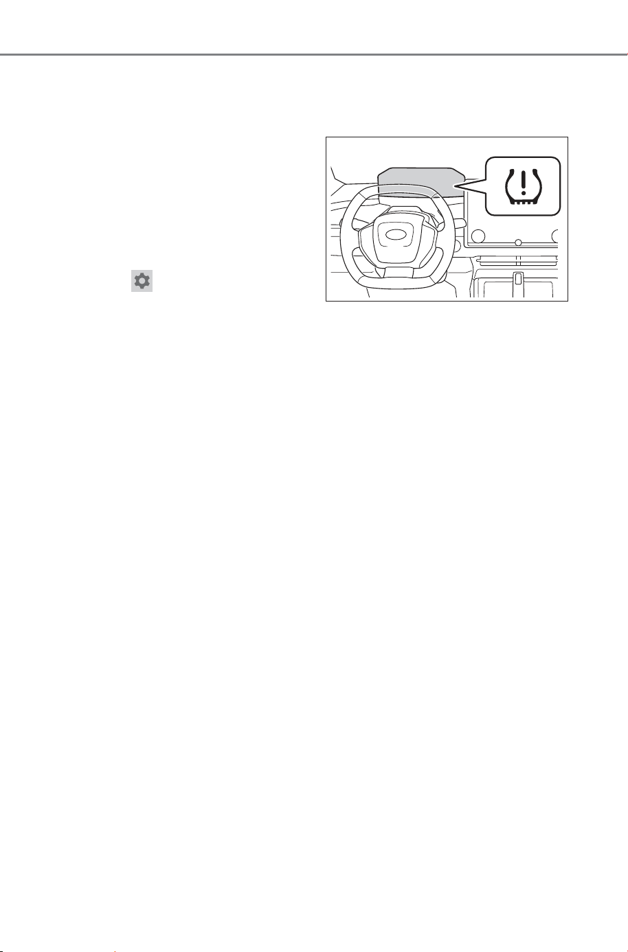
582
7-3. Do-it-yourself maintenance
Owner’s Manual_USA_M6740B_en
While registering ID codes, it
may not be possible to
change between wheel sets
normally. Cancel registration
before changing between
wheel sets.
■ Changing ID codes between
different wheel sets
1 Install the desired wheel set.
2 Select on the multimedia
display.
3 Select “Vehicle customize”.
4 Select “Tire pressure”.
5 Select the wheel set (“Set 1”
or “Set 2”) displayed for the
set selection setting.
6 Select the wheel set you wish
to register, and then select
“OK”.
The tire pressure warning light will
slowly blink 3 times, a message
indicating that change is occurring
will be displayed, and the wheel set
change will begin.
Wheel set change will begin and
the tire pressure warning light will
blink for 1 minute and then illumi-
nate. Also, while the change is
being performed, “---” will be dis-
played for the tire inflation pressure
of each tire on the multi-information
display.
After approximately 2 minutes, the
wheel set change will complete, the
tire pressure warning light will turn
off, and a completion message will
be displayed on the multi-informa-
tion display.
If changing does not complete after
approximately 4 minutes, a mes-
sage indicating that the change
could not be completed will be dis-
played.
Check which wheel set is installed
and perform the change procedure
again from the beginning.
7 If the specified tire inflation
pressure of the wheel set
installed differs from that of
the previous set, it will be
necessary to perform the tire
inflation pressure setting pro-
cedure of the tire pressure
warning system. (P.577)
If the specified tire inflation pres-
sure is the same, it will not be nec-
essary to perform the tire inflation
pressure setting procedure.
8 Register the position of each
wheel. (P.576)
SOLTERRA_OM_USA_A6740BE.book 582 ページ 2025年5月23日 金曜日 午後1時18分
583
7-3. Do-it-yourself maintenance
Owner’s Manual_USA_M6740B_en
7
Maintenance and care
Stop the vehicle in a safe
place on a hard, flat surface.
Set the parking brake.
Shift the shift position to P.
Stop the EV system.
Turn on the emergency flash-
ers.
Turn off the power back door
system. (P. 17 6)
■ Tools
As your vehicle is equipped with an
emergency tire puncture repair kit,
the following tools for replacing a
tire are not included with your vehi-
cle. They can be purchased your
SUBARU dealer.
● Jack
● Jack handle
● Wheel nut wrench
Replacing the tire
When replacing the tires
yourself, prepare the neces-
sary tools and a jack.
If necessary tire replace-
ment seems difficult to per-
form, contact your SUBARU
dealer.
Before jacking up the
vehicle
SOLTERRA_OM_USA_A6740BE.book 583 ページ 2025年5月23日 金曜日 午後1時18分
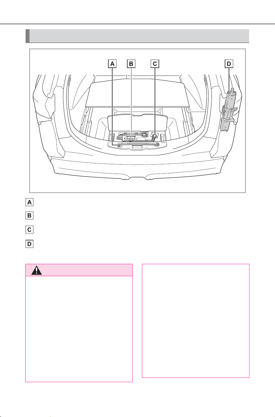
584
7-3. Do-it-yourself maintenance
Owner’s Manual_USA_M6740B_en
Jack handle
*
Towing eyelet
Wheel nut wrench
*
Jack
*
*
: They can be purchased your SUBARU dealer.
Location of the tools
WARNING
■ Using the tire jack
Observe the following precau-
tions.
Improper use of the tire jack may
cause the vehicle to suddenly fall
off the jack, leading to death or
serious injury.
● Do not use the tire jack for any
purpose other than replacing
tires or installing and removing
tire chains.
● Do not use other tire jacks for
replacing tires on this vehicle.
● Put the jack properly in its jack
point.
● Do not put any part of your body
under the vehicle while it is sup-
ported by the jack.
● Do not start the EV system or
drive the vehicle while the vehi-
cle is supported by the jack.
● Do not raise the vehicle while
someone is inside.
● When raising the vehicle, do not
put an object on or under the
jack.
SOLTERRA_OM_USA_A6740BE.book 584 ページ 2025年5月23日 金曜日 午後1時18分
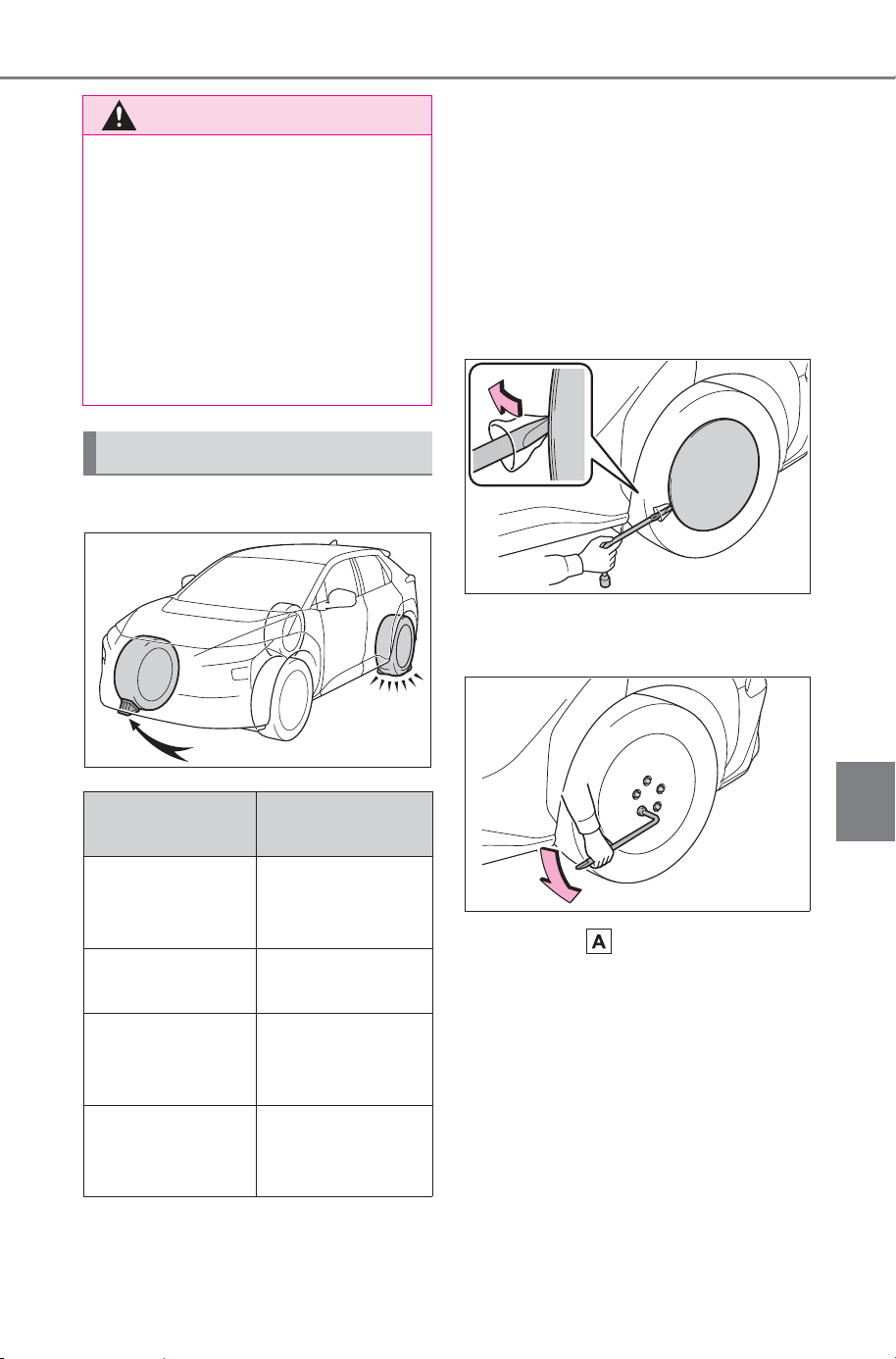
585
7-3. Do-it-yourself maintenance
Owner’s Manual_USA_M6740B_en
7
Maintenance and care
1 Chock the tires.
2 Vehicles with 20-inch tires:
Do not remove the wheel
ornament.
Vehicles with 18-inch tires:
Remove the wheel ornament
using the wrench.
To protect the wheel ornament,
place a rag between the wrench
and the wheel ornament.
3 Slightly loosen the wheel
nuts (one turn).
4 Turn the part of the jack by
hand and place the top of the
jack in the position shown in
the illustration.
WARNING
● Do not raise the vehicle to a
height greater than that required
to replace the tire.
● Use a jack stand if it is neces-
sary to get under the vehicle.
● When lowering the vehicle,
make sure that there is no-one
near the vehicle. If there are
people nearby, warn them
vocally before lowering.
Replacing a flat tire
Tire
Wheel chock
positions
Front left-hand
Behind the rear
right-hand side
tire
Front right-hand
Behind the rear
left-hand side tire
Rear left-hand
In front of the
front right-hand
side tire
Rear right-hand
In front of the
front left-hand
side tire
SOLTERRA_OM_USA_A6740BE.book 585 ページ 2025年5月23日 金曜日 午後1時18分
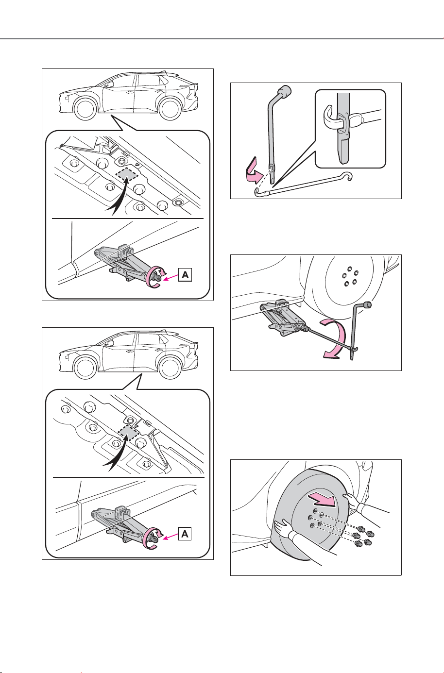
586
7-3. Do-it-yourself maintenance
Owner’s Manual_USA_M6740B_en
Front
Rear
5 Install the wheel nut wrench
in jack handle.
6 Raise the vehicle until the tire
is slightly raised off the
ground.
7 Remove all the wheel nuts
and the tire.
When resting the tire on the
ground, place the tire so that the
wheel design faces up to avoid
scratching the wheel surface.
SOLTERRA_OM_USA_A6740BE.book 586 ページ 2025年5月23日 金曜日 午後1時18分
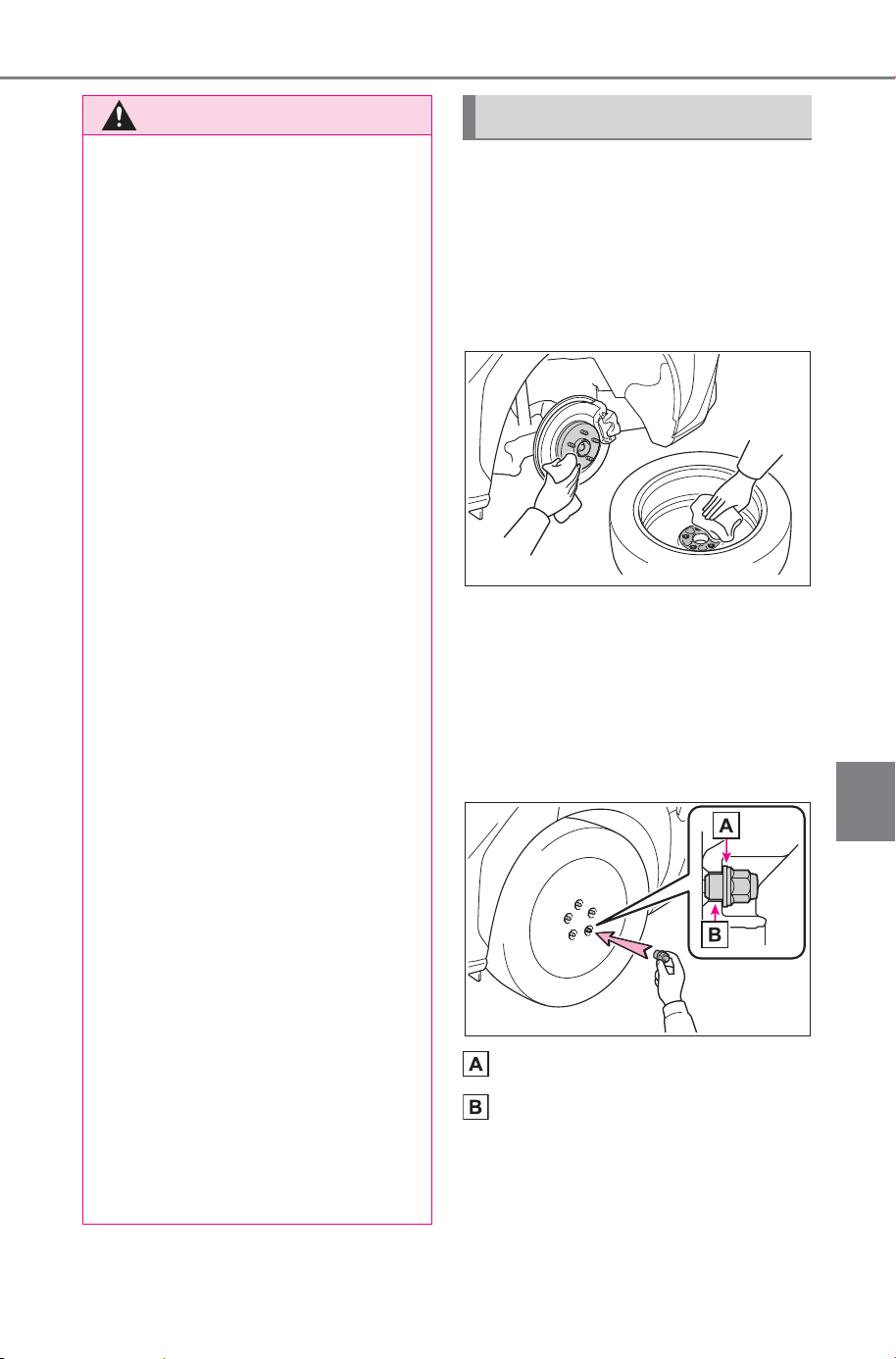
587
7-3. Do-it-yourself maintenance
Owner’s Manual_USA_M6740B_en
7
Maintenance and care
1 Remove any dirt or foreign
matter from the wheel con-
tact surface.
If foreign matter is on the wheel
contact surface, the wheel nuts
may loosen while the vehicle is in
motion, causing the tire to come off.
2 Install the tire and loosely
tighten each wheel nut by
hand by approximately the
same amount.
Turn the wheel nuts until the wash-
ers come into contact with the disc
wheel.
Washer
Disc wheel
WARNING
■ Replacing a flat tire
● Do not touch the disc wheels or
the area around the brakes
immediately after the vehicle
has been driven.
After the vehicle has been
driven the disc wheels and the
area around the brakes will be
extremely hot. Touching these
areas with hands, feet or other
body parts while changing a tire,
etc. may result in burns.
● Failure to follow these precau-
tions could cause the wheel
nuts to loosen and the tire to fall
off, resulting in death or serious
injury.
• Never use oil or grease on the
wheel bolts or wheel nuts.
Oil and grease may cause the
wheel nuts to be excessively
tightened, leading to bolt or disc
wheel damage. Remove any oil
or grease that has adhered
when installing the wheel nuts.
• After replacing a tire, check the
tightening torque as soon as
possible. If you cannot confirm
the tightening torque yourself,
have the vehicle inspected at
your SUBARU dealer.
• Do not attach a heavily dam-
aged wheel ornament, as it may
fly off the wheel while the vehi-
cle is moving.
• When installing a tire, only use
wheel nuts that have been spe-
cifically designed for that wheel.
• If there are any cracks or defor-
mations in the bolt screws, nut
threads or bolt holes of the
wheel, have the vehicle
inspected by your SUBARU
dealer.
Installing the tire
SOLTERRA_OM_USA_A6740BE.book 587 ページ 2025年5月23日 金曜日 午後1時18分
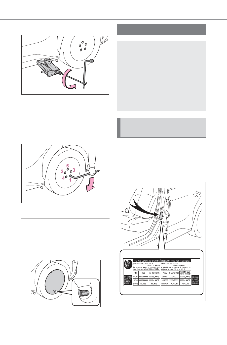
588
7-3. Do-it-yourself maintenance
Owner’s Manual_USA_M6740B_en
3 Lower the vehicle.
4 Securely tighten the wheel
nuts two or three times in the
order shown in the illustration
using a wheel nut wrench.
Tightening torque:
76 ft•lbf (103 N•m, 10.5 kgf•m)
5 Stow all the tools.
■ Vehicles with 18-inch tires:
When reinstalling the wheel
ornament
Align the cutout of the wheel orna-
ment with the valve stem as shown
in the illustration.
The recommended cold tire
inflation pressure and tire size
are displayed on the tire and
loading information label.
(P.661)
Tire inflation pressure
Make sure to maintain the
proper tire inflation pres-
sure. Tire inflation pressure
should be checked at least
once per month. However,
SUBARU recommends that
tire inflation pressure be
checked once every two
weeks. (P.6 61 )
Checking the specified
tire inflation pressure
SOLTERRA_OM_USA_A6740BE.book 588 ページ 2025年5月23日 金曜日 午後1時18分
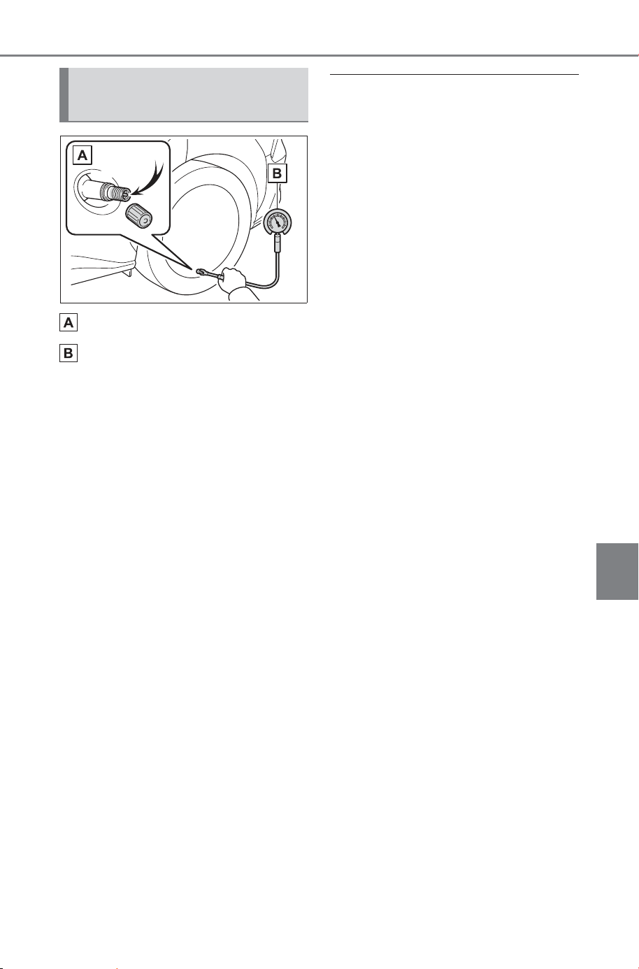
589
7-3. Do-it-yourself maintenance
Owner’s Manual_USA_M6740B_en
7
Maintenance and care
Tire valve
Tire pressure gauge
1 Remove the tire valve cap.
2 Press the tip of the tire pres-
sure gauge onto the tire
valve.
3 Read the pressure using the
gauge gradations.
4 If the tire inflation pressure is
not at the recommended
level, adjust the pressure. If
you add too much air, press
the center of the valve to
deflate.
5 After completing the tire infla-
tion pressure measurement
and adjustment, apply soapy
water to the valve and check
for leakage.
6 Put the tire valve cap back
on.
■ Tire inflation pressure check
interval
You should check tire inflation pres-
sure every two weeks, or at least
once a month.
■ Effects of incorrect tire inflation
pressure
Driving with incorrect tire inflation
pressure may result in the following:
● Reduced electricity consumption
● Reduced driving comfort and poor
handling
● Reduced tire life due to wear
● Reduced safety
● Damage to the drive train
If a tire needs frequent inflating,
have it checked by your SUBARU
dealer.
■ Instructions for checking tire
inflation pressure
When checking tire inflation pres-
sure, observe the following:
● Check only when the tires are
cold.
If your vehicle has been parked for
at least 3 hours or has not been
driven for more than 1 mile or 1.5
km, you will get an accurate cold
tire inflation pressure reading.
● Always use a tire pressure gauge.
It is difficult to judge if a tire is
properly inflated based only on its
appearance.
● It is normal for the tire inflation
pressure to be higher after driving
as heat is generated in the tire. Do
not reduce tire inflation pressure
after driving.
● Never exceed the vehicle capacity
weight. Passengers and luggage
weight should be placed so that
the vehicle is balanced.
Inspection and adjust-
ment procedure
SOLTERRA_OM_USA_A6740BE.book 589 ページ 2025年5月23日 金曜日 午後1時18分
590
7-3. Do-it-yourself maintenance
Owner’s Manual_USA_M6740B_en
When replacing wheels, care
should be taken to ensure that
they are equivalent to those
removed in load capacity, diam-
eter, rim width and inset
*
.
Replacement wheels are avail-
able at your SUBARU dealer.
*
: Conventionally referred to as off-
set.
SUBARU does not recommend
using the following:
Wheels of different sizes or
types
Used wheels
Bent wheels that have been
straightened
■ When replacing wheels (vehi-
cle with the tire pressure warn-
ing system)
The wheels of your vehicle are
equipped with tire pressure warning
valves and transmitters that allow
the tire pressure warning system to
provide advance warning in the
event of a loss in tire inflation pres-
sure. Whenever wheels are
replaced, tire pressure warning
valves and transmitters must be
installed. (P.575)
WARNING
■ Proper inflation is critical to
save tire performance
Keep your tires properly inflated.
If the tires are not properly
inflated, the following conditions
may occur which could lead to an
accident resulting in death or seri-
ous injury:
● Excessive wear
● Uneven wear
● Poor handling
● Possibility of blowouts resulting
from overheated tires
● Air leaking from between tire
and wheel
● Wheel deformation and/or tire
damage
● Greater possibility of tire dam-
age while driving (due to road
hazards, expansion joints,
sharp edges in the road, etc.)
NOTICE
■ When inspecting and adjust-
ing tire inflation pressure
Be sure to put the tire valve caps
back on.
If a valve cap is not installed, dirt
or moisture may get into the valve
and cause an air leak, resulting in
decreased tire inflation pressure.
Wheels
If a wheel is bent, cracked
or heavily corroded, it
should be replaced. Other-
wise, the tire may separate
from the wheel or cause a
loss of handling control.
Wheel selection
SOLTERRA_OM_USA_A6740BE.book 590 ページ 2025年5月23日 金曜日 午後1時18分
591
7-3. Do-it-yourself maintenance
Owner’s Manual_USA_M6740B_en
7
Maintenance and care
Use only SUBARU wheel nuts
and wheel nut wrenches
designed for use with your
aluminum wheels.
When rotating, repairing or
changing your tires, check
that the wheel nuts are still
tight after driving 1000 miles
(1600 km).
Be careful not to damage the
aluminum wheels when using
tire chains.
Use only SUBARU genuine
balance weights or equiva-
lent and a plastic or rubber
hammer when balancing your
wheels.
WARNING
■ When replacing wheels
● Do not use wheels that are a dif-
ferent size from those recom-
mended in the Owner’s Manual,
as this may result in a loss of
handling control.
● Never use an inner tube in a
leaking wheel which is designed
for a tubeless tire. Doing so may
result in an accident, causing
death or serious injury.
■ When installing the wheel
nuts
Never use oil or grease on the
wheel bolts or wheel nuts. Oil and
grease may cause the wheel nuts
to be excessively tightened, lead-
ing to bolt or disc wheel damage.
In addition, the oil or grease can
cause the wheel nuts to loosen
and the wheel may fall off, caus-
ing an accident and resulting in
death or serious injury. Remove
any oil or grease from the wheel
bolts or wheel nuts.
■ Use of defective wheels pro-
hibited
Do not use cracked or deformed
wheels.
Doing so could cause the tire to
leak air during driving, possibly
causing an accident.
NOTICE
■ Replacing tire pressure warn-
ing valves and transmitters
(vehicle with the tire pressure
warning system)
● Because tire repair or replace-
ment may affect the tire pres-
sure warning valves and
transmitters, make sure to have
tires serviced by your SUBARU
dealer or other qualified service
shop. In addition, make sure to
purchase your tire pressure
warning valves and transmit-
ters at your SUBARU dealer.
● Ensure that only genuine SUB-
ARU wheels are used on your
vehicle.
Tire pressure warning valves
and transmitters may not work
properly with non-genuine
wheels.
Aluminum wheel precau-
tions
SOLTERRA_OM_USA_A6740BE.book 591 ページ 2025年5月23日 金曜日 午後1時18分
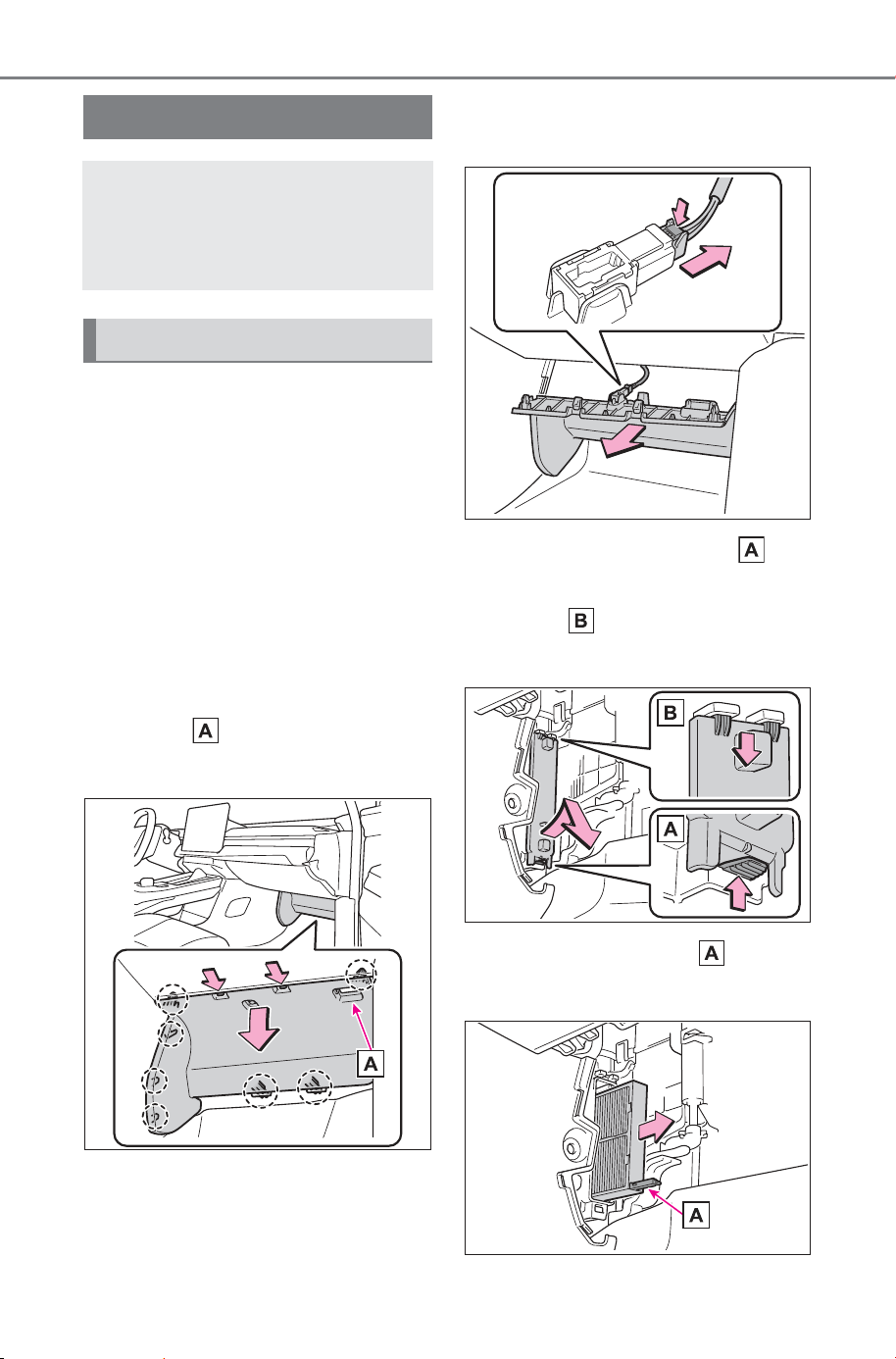
592
7-3. Do-it-yourself maintenance
Owner’s Manual_USA_M6740B_en
1 Turn the power switch off.
Confirm that the charging connec-
tor is not connected. Also, do not
use the Remote Air Conditioning
System during the procedure.
2 Open the front passenger’s
door.
By keeping the door open, unex-
pected operation of the Remote Air
Conditioning System can be pre-
vent. (P.501)
3 While pressing the claw, hold
handle and remove the
panel.
4 Vehicles with footwell lights:
Unplug the connector.
5 Unlock the filter cover ( ),
pull the filter cover out of the
claws ( ), and remove the
filter cover.
6 Hold the filter case and
remove the lower filter case.
Air conditioning filter
The air conditioning filter
must be changed regularly
to maintain air conditioning
efficiency.
Removal method
SOLTERRA_OM_USA_A6740BE.book 592 ページ 2025年5月23日 金曜日 午後1時18分
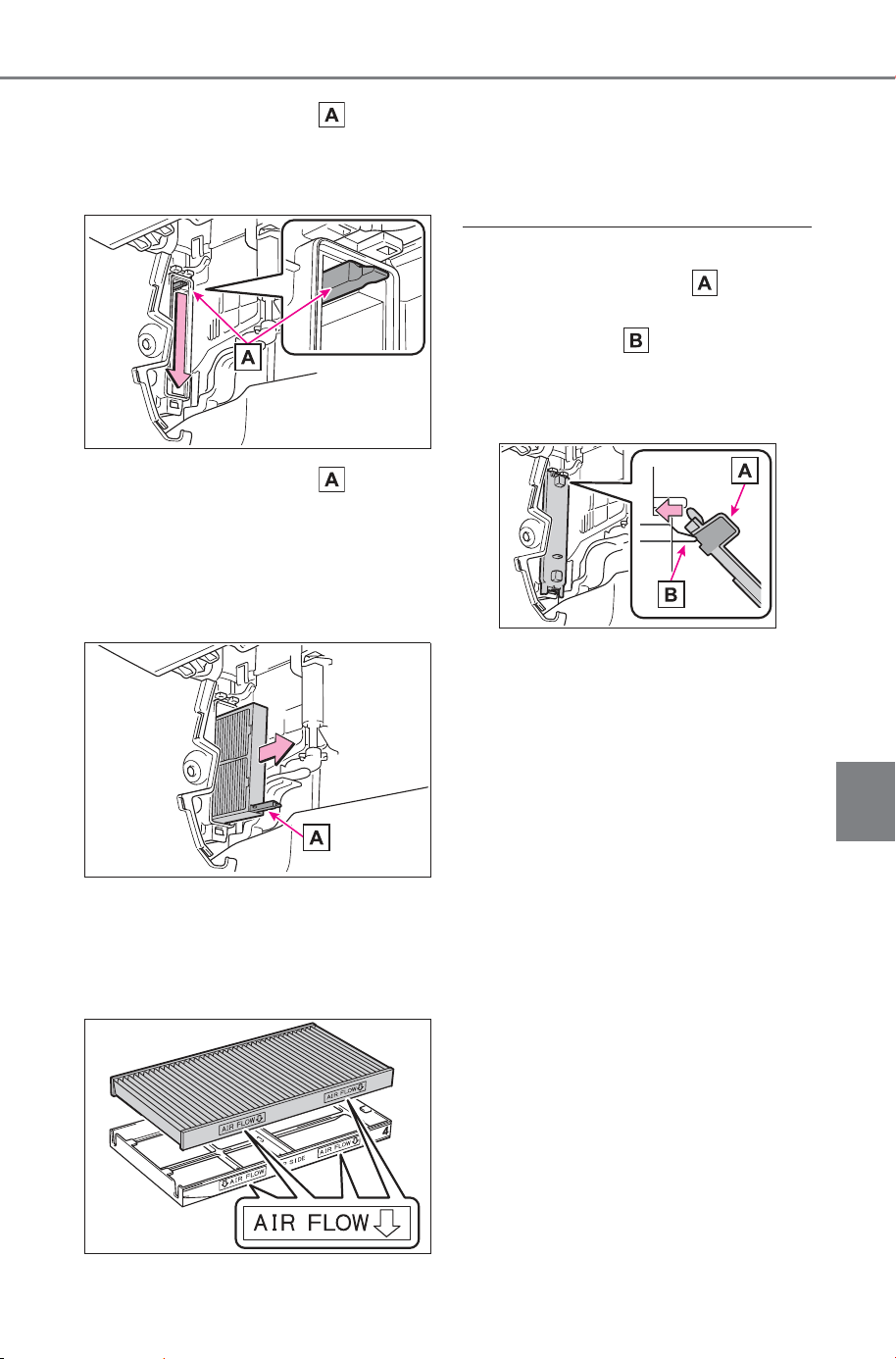
593
7-3. Do-it-yourself maintenance
Owner’s Manual_USA_M6740B_en
7
Maintenance and care
7 Hold the filter case and
pull down the upper filter
case.
8 Hold the filter case and
remove the upper filter case.
Dust and dirt (fallen leaves, etc.)
may have accumulated within the
bottom of the air conditioning unit,
so remove it with a vacuum cleaner.
9 Remove the air conditioning
filter from the upper and
lower filter case and replace
it with a new one.
Install so that the arrow points to
the rear of the vehicle.
10When installing, reverse the
steps listed.
■ When installing the filter cover
Slide the recessed part of the fil-
ter cover on the upper surface of the
upper filter case as shown in the
figure, and attach it so that it is lifted
toward the insertion part of the
cover attachment.
■ Checking interval
Inspect and replace the air condi-
tioning filter according to the mainte-
nance schedule. In dusty areas or
areas with heavy traffic flow, early
replacement may be required. (For
scheduled maintenance information,
please refer to the “Warranty and
Maintenance Booklet” or “Warranty
and Service Booklet”.)
■ If air flow from the vents
decreases dramatically
The filter may be clogged. Check
the filter and replace if necessary.
■ Air conditioning filter with
deodorizing function
When fragrances are placed in your
vehicle, the deodorizing effect may
become significantly weakened in a
short period.
When an air conditioning odor
comes out continuously, replace the
air conditioning filter.
SOLTERRA_OM_USA_A6740BE.book 593 ページ 2025年5月23日 金曜日 午後1時18分
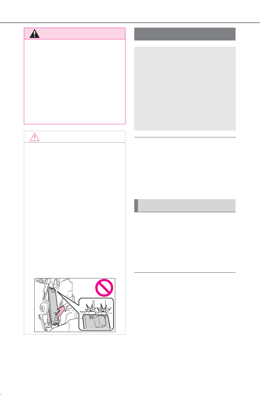
594
7-3. Do-it-yourself maintenance
Owner’s Manual_USA_M6740B_en
■ If the key battery is depleted
The following symptoms may occur:
● The smart key system and wire-
less remote control will not func-
tion properly.
● The operational range will be
reduced.
Prepare the following before
replacing the battery:
Flathead screwdriver
Small flathead screwdriver
Lithium battery CR2450
■ Use a CR2450 lithium battery
● Batteries can be purchased at
your SUBARU dealer, local electri-
cal appliance shops or camera
stores.
● Replace only with the same or
equivalent type recommended by
the manufacturer.
● Dispose of used batteries accord-
ing to the local laws.
WARNING
■ When replacing the air condi-
tioning filter
Observe the following precau-
tions. Failure to do so may result
in the air conditioning system
operating during the procedure,
possibly resulting in injury.
● Check that the charging con-
nector is not connected.
● Do not use the Remote Air Con-
ditioning System.
NOTICE
■ When using the air condition-
ing system
● Make sure that a filter is always
installed. Using the air condi-
tioning system without a filter
may cause damage to the sys-
tem.
● The filter is replaceable. When
cleaning the filter, do not clean
with water or an air gun.
■ To prevent damage to the fil-
ter cover
When moving the filter cover in
the direction of arrow to release
the fitting, pay attention not to
apply excessive force to the
claws. Otherwise, the claws may
be damaged.
Electronic key battery
Replace the battery with a
new one if it is depleted.
As the key may be damaged
if the following procedure is
not performed properly, it is
recommended that key bat-
tery replacement be per-
formed by your SUBARU
dealer.
Items to prepare
SOLTERRA_OM_USA_A6740BE.book 594 ページ 2025年5月23日 金曜日 午後1時18分
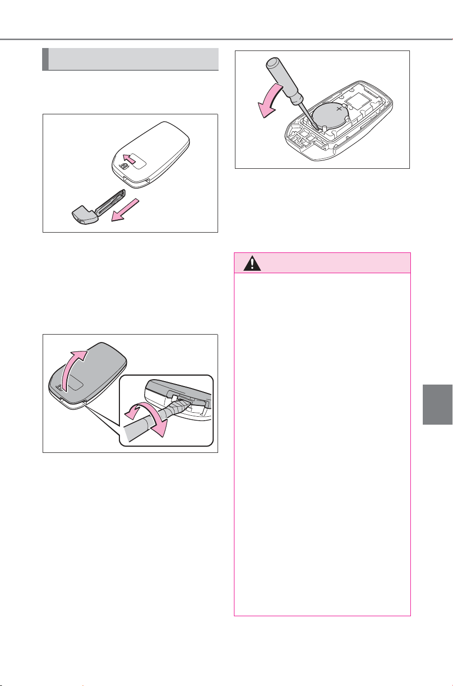
595
7-3. Do-it-yourself maintenance
Owner’s Manual_USA_M6740B_en
7
Maintenance and care
1 Release the lock and remove
the mechanical key.
2 Remove the key cover.
Use a screwdriver of an appropriate
size. Forcedly prying may cause
the cover damaged.
To prevent damage to the key,
cover the tip of the flathead screw-
driver with a tape.
3 Remove the depleted battery
using a small flathead screw-
driver.
When removing the cover, the elec-
tronic key module may stick to the
cover and the battery may not be
visible.
In this case, remove the electronic
key module in order to remove the
battery.
When removing the battery, use a
screwdriver of an appropriate size.
Insert a new battery with the “+” ter-
minal facing up.
4 When installing the key cover
and mechanical key, install
by conducting step 2 and
step 1 with the directions
reversed.
Replacing the battery
WARNING
■ Battery precautions
Observe the following precau-
tions. Failure to do so may result
in death or serious injury.
● Do not swallow the battery.
Doing so may cause chemical
burns.
● A coin battery or button battery
is used in the electronic key. If a
battery is swallowed, it may
cause severe chemical burns in
as little as 2 hours and may
result in death or serious injury.
● Keep away new and removed
batteries from children.
● If the cover cannot be firmly
closed, stop using the electronic
key and stow the key in the
place where children cannot
reach, and then contact your
SUBARU dealer.
● If you accidentally swallow a
battery or put a battery into a
part of your body, get emer-
gency medical attention imme-
diately.
SOLTERRA_OM_USA_A6740BE.book 595 ページ 2025年5月23日 金曜日 午後1時18分
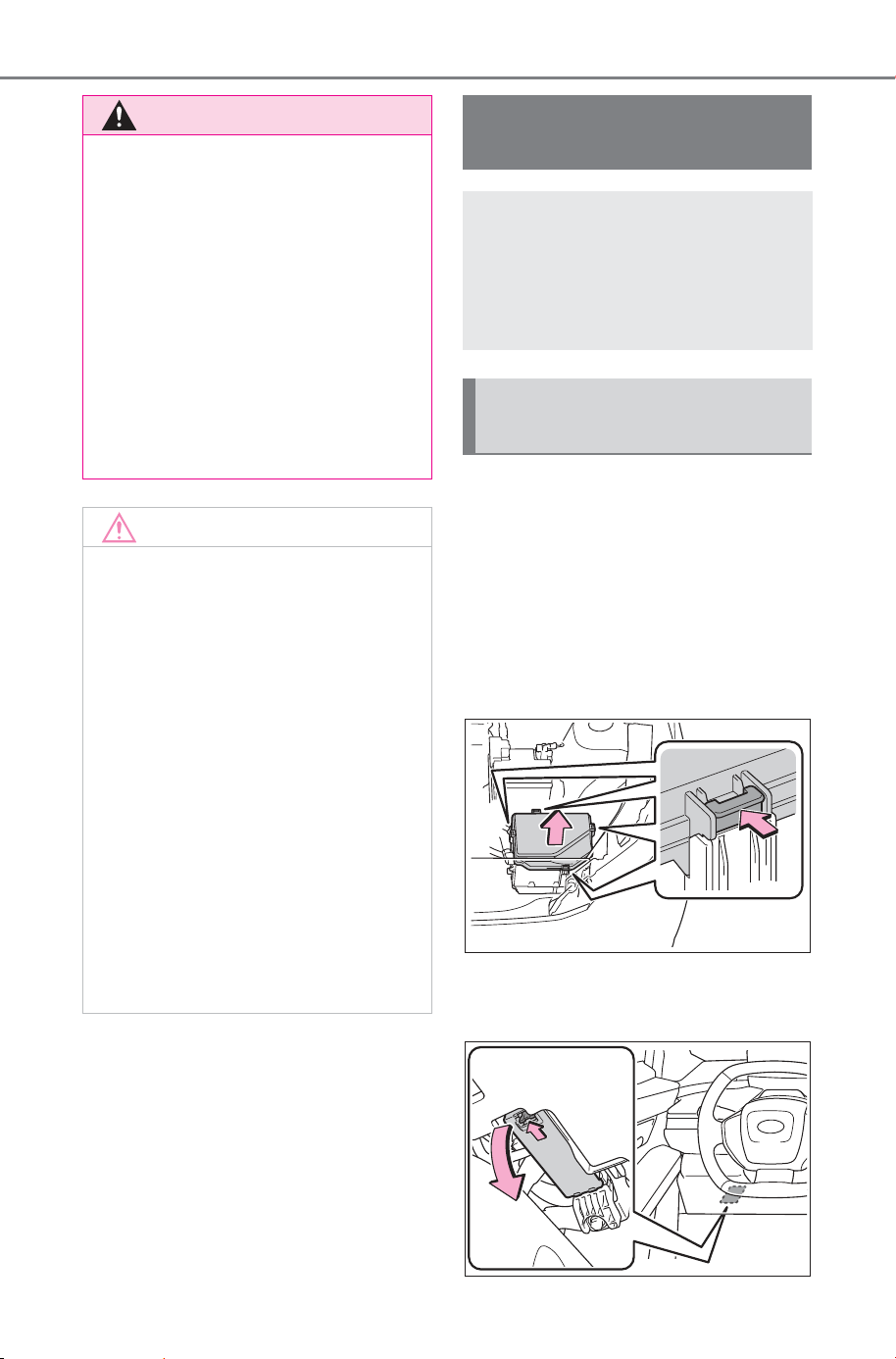
596
7-3. Do-it-yourself maintenance
Owner’s Manual_USA_M6740B_en
1 Turn the power switch off.
Confirm that the charging connec-
tor is not connected. Also, do not
use the Remote Air Conditioning
System during the procedure.
2 Open the fuse box cover.
Motor compartment
Push the tab in and lift the lid off.
Left side instrument panel
Remove the lid.
WARNING
■ To prevent battery explosion
or leakage of flammable liq-
uid or gas
● Replace the battery with a new
battery of the same type. If a
wrong type of battery is used, it
may explode.
● Do not expose batteries to
extremely low pressure due to
high altitude or extremely high
temperatures.
● Do not burn, break or cut a bat-
tery.
NOTICE
■ When replacing the battery
Use a flathead screwdriver of
appropriate size. Applying exces-
sive force may deform or damage
the cover.
■ For normal operation after
replacing the battery
Observe the following precautions
to prevent accidents:
● Always work with dry hands.
Moisture may cause the battery
to rust.
● Do not touch or move any other
component inside the remote
control.
● Do not bend either of the battery
terminals.
Checking and replac-
ing fuses
If any of the electrical com-
ponents do not operate, a
fuse may have blown. If this
happens, check and replace
the fuses as necessary.
Checking and replacing
fuses
SOLTERRA_OM_USA_A6740BE.book 596 ページ 2025年5月23日 金曜日 午後1時18分
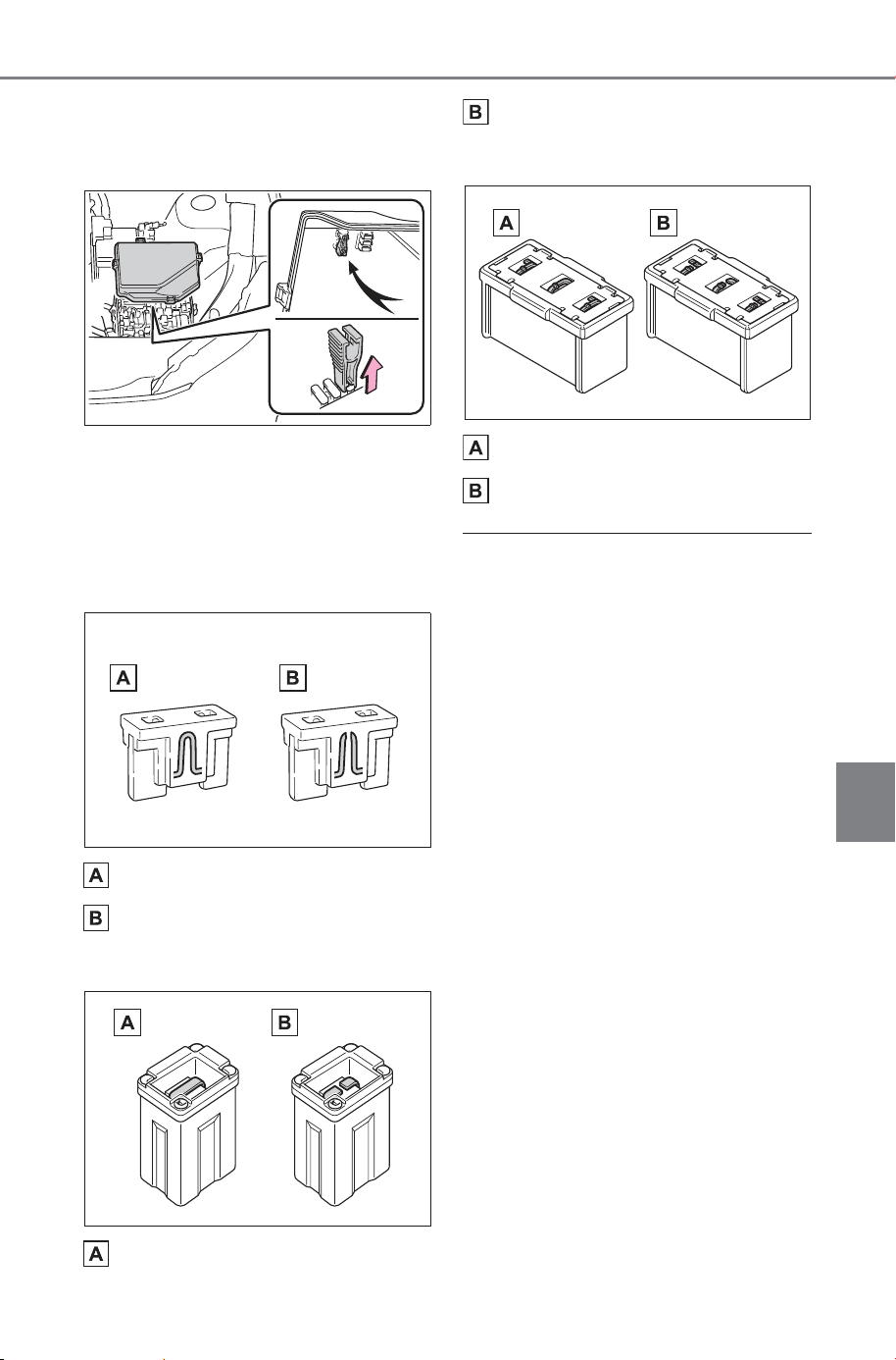
597
7-3. Do-it-yourself maintenance
Owner’s Manual_USA_M6740B_en
7
Maintenance and care
3 Remove the fuse.
Only type A fuse can be removed
using the pullout tool.
4 Check if the fuse is blown.
Replace the blown fuse with a new
fuse of an appropriate amperage
rating. The amperage rating can be
found on the fuse box lid.
Type A
Normal fuse
Blown fuse
Type B
Normal fuse
Blown fuse
Type C
Normal fuse
Blown fuse
■ After a fuse is replaced
● When installing the lid, make sure
that the tab is installed securely.
● If the lights do not turn on even
after the fuse has been replaced,
a bulb may need replacement.
● If the replaced fuse blows again,
have the vehicle inspected SUB-
ARU dealer.
■ If there is an overload in a cir-
cuit
The fuses are designed to blow, pro-
tecting the wiring harness from
damage.
■ When replacing an electronic
component, such as a lights,
etc.
SUBARU recommends that you use
genuine SUBARU products
designed for this vehicle. Because
certain bulbs are connected to cir-
cuits designed to prevent overload,
non-genuine parts or parts not
designed for this vehicle may be
unusable.
SOLTERRA_OM_USA_A6740BE.book 597 ページ 2025年5月23日 金曜日 午後1時18分

598
7-3. Do-it-yourself maintenance
Owner’s Manual_USA_M6740B_en
Adjustment bolt A
Adjustment bolt B
Park the vehicle on level
ground.
Make sure the tire inflation
pressure is at the specified
level.
Have someone sit in the
driver’s seat.
Bounce the vehicle several
times.
WARNING
■ To prevent system break-
downs and vehicle fire
Observe the following precau-
tions.
Failure to do so may cause dam-
age to the vehicle, and possibly a
fire or injury.
● Never use a fuse of a higher
amperage rating than that indi-
cated, or use any other object in
place of a fuse.
● Always use a genuine SUBARU
fuse or equivalent.
Never replace a fuse with a
wire, even as a temporary fix.
● Do not modify the fuses or fuse
boxes.
NOTICE
■ Before replacing fuses
Have the cause of electrical over-
load determined and repaired
SUBARU dealer as soon as pos-
sible.
Headlight aim
Vertical movement adjust-
ing bolts
Before checking the head-
light aim
SOLTERRA_OM_USA_A6740BE.book 598 ページ 2025年5月23日 金曜日 午後1時18分
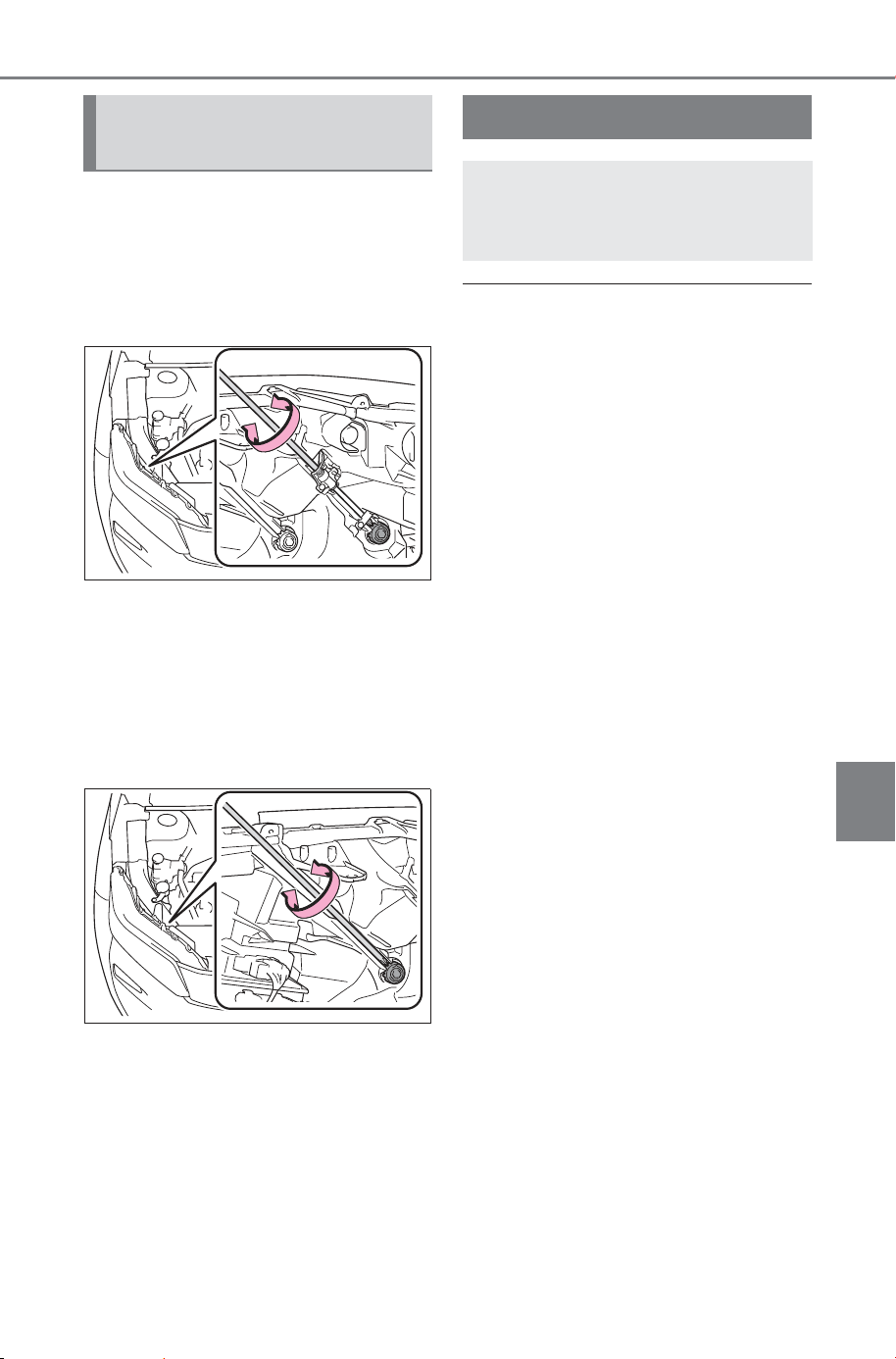
599
7-3. Do-it-yourself maintenance
Owner’s Manual_USA_M6740B_en
7
Maintenance and care
1 Using a Phillips-head screw-
driver, turn bolt A in either
direction.
Remember the turning direc-
tion and the number of turns.
2 Turn bolt B the same number
of turns and in the same
direction as step
1.
If the headlight cannot be adjusted
using this procedure, take the vehi-
cle to your SUBARU dealer to
adjust the headlight aim.
■ LED lights
The lights consist of a number of
LEDs. If any of the LEDs burn out,
take your vehicle to your SUBARU
dealer to have the light replaced.
■ Condensation build-up on the
inside of the lens
Temporary condensation build-up
on the inside of the headlight lens
does not indicate a malfunction.
Contact your SUBARU dealer for
more information in the following sit-
uations:
● Large drops of water have built up
on the inside of the lens.
● Water has built up inside the
headlight.
■ When replacing an electronic
component, such as a lights,
etc.
P.597
Adjusting the headlight
aim
Light bulbs
If any exterior light does not
turn on, have it replaced by
your SUBARU dealer.
SOLTERRA_OM_USA_A6740BE.book 599 ページ 2025年5月23日 金曜日 午後1時18分

600
7-3. Do-it-yourself maintenance
Owner’s Manual_USA_M6740B_en
SOLTERRA_OM_USA_A6740BE.book 600 ページ 2025年5月23日 金曜日 午後1時18分

601
Owner’s Manual_USA_M6740B_en
8
8
When trouble arises
When trouble arises
8-1. Essential information
Emergency flashers ....
602
If your vehicle has to be
stopped in an emergency
..................................
602
If the vehicle is submerged
or water on the road is ris-
ing .............................
603
8-2. Steps to take in an emer-
gency
If your vehicle needs to be
towed......................... 605
If you think something is
wrong ........................
609
If a warning light turns on or
a warning buzzer sounds
..................................
611
If a warning message is dis-
played........................
621
If you have a flat tire.... 628
If the EV system will not
start ...........................
640
If you lose your keys ... 641
If the electronic key does
not operate properly ..
642
If the 12-volt battery is dis-
charged .....................
644
If your vehicle overheats
..................................
648
If the vehicle becomes stuck
..................................
650
SOLTERRA_OM_USA_A6740BE.book 601 ページ 2025年5月23日 金曜日 午後1時18分
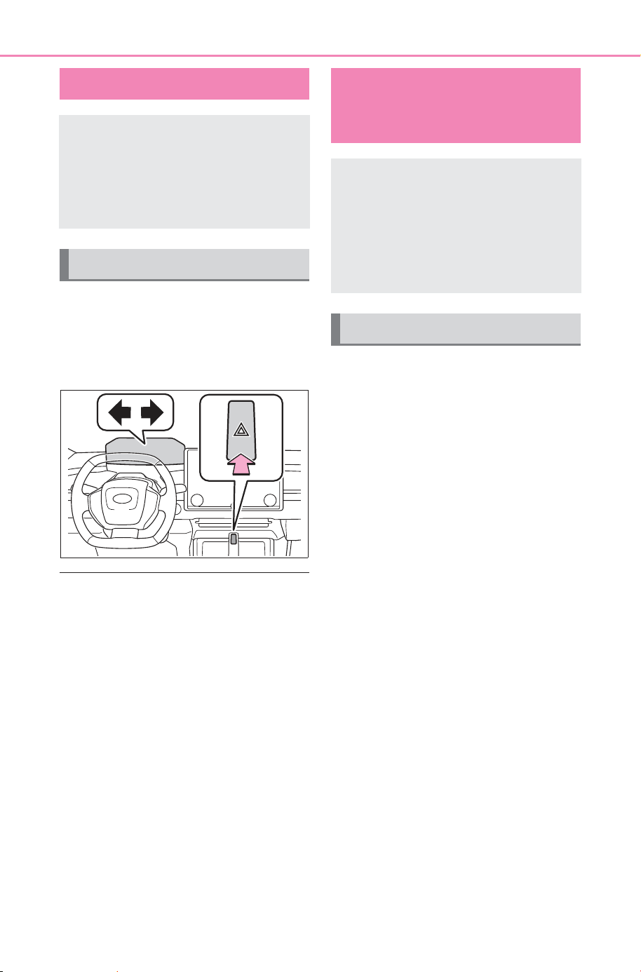
602
8-1. Essential information
Owner’s Manual_USA_M6740B_en
8-1.Es sential info rmation
Press the switch.
All the turn signal lights will flash.
To turn them off, press the switch
once again.
■ Emergency flashers
● If the emergency flashers are used
for a long time while the EV sys-
tem is not operating (while the
“READY” indicator is not illumi-
nated), the 12-volt battery may dis-
charge.
● If any of the SRS airbags deploy
(inflate) or in the event of a strong
rear impact, the emergency flash-
ers will turn on automatically.
The emergency flashers will turn
off automatically after operating for
approximately 20 minutes. To
manually turn the emergency
flashers off, press the switch twice.
(The emergency flashers may not
turn on automatically depending
on the force of the impact and con-
ditions of the collision.)
1 Steadily step on the brake
pedal with both feet and
firmly depress it.
Do not pump the brake pedal
repeatedly as this will increase the
effort required to slow the vehicle.
2 Shift the shift position to N.
If the shift position is shifted to
N
3 After slowing down, stop the
vehicle in a safe place by the
road.
4 Stop the EV system.
If the shift position cannot be
shifted to N
3 Keep depressing the brake
pedal with both feet to reduce
vehicle speed as much as
possible.
4 To stop the EV system: Press
and hold the power switch for
2 consecutive seconds or
more, or press it briefly 3
times or more in succession.
Emergency flashers
The emergency flashers are
used to warn other drivers
when the vehicle has to be
stopped in the road due to a
breakdown, etc.
Operating instructions
If your vehicle has to
be stopped in an emer-
gency
Only in an emergency, such
as if it becomes impossible
to stop the vehicle in the
normal way, stop the vehi-
cle using the following pro-
cedure:
Stopping the vehicle
SOLTERRA_OM_USA_A6740BE.book 602 ページ 2025年5月23日 金曜日 午後1時18分
603
8-1. Essential information
Owner’s Manual_USA_M6740B_en
8
When trouble arises
5 Stop the vehicle in a safe
place by the road.
■ If emergency stopped
The functions of the air conditioning,
etc., may be partially limited in order
to reduce the power consumption of
the 12-volt battery.
If the door can be opened,
open the door and exit the
vehicle.
If the door cannot be opened,
open the window using the
power window switch and
ensure an escape route.
If the window can be opened,
exit the vehicle through the
window.
If the door and window cannot
be opened due to the rising
water, remain calm, wait until
the water level inside the
vehicle rises to the point that
the water pressure inside of
the vehicle equals the water
pressure outside of the vehi-
cle and then open the door
after waiting for the rising
water to enter the vehicle, and
exit the vehicle.
WARNING
■ If the EV system has to be
turned off while driving
Turning the EV system off while
driving will not cause a loss of
steering or braking control. How-
ever, power assist for the steering
wheel may be lost making it diffi-
cult to steer smoothly before stop-
ping the vehicle depending on the
remaining charge in the 12-volt
battery or usage conditions.
Decelerate as much as possible
before turning off the EV system.
If the vehicle is sub-
merged or water on
the road is rising
This vehicle is not designed
to be able to drive on roads
that are deeply flooded with
water. Do not drive on roads
where the roads may be
submerged or the water
may be rising. It is danger-
ous to remain in the vehicle,
if it is anticipated that the
vehicle will be flooded or
set adrift. Remain calm and
follow the following.
SOLTERRA_OM_USA_A6740BE.book 603 ページ 2025年5月23日 金曜日 午後1時18分
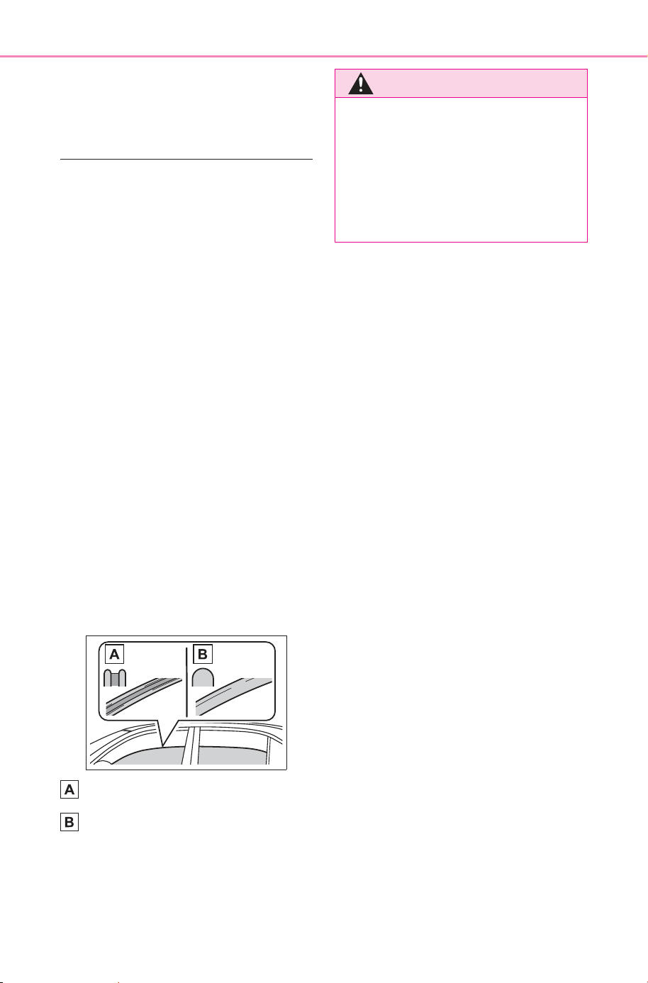
604
8-1. Essential information
Owner’s Manual_USA_M6740B_en
When the outside water level
exceeds half the height of the door,
the door cannot be opened from the
inside due to water pressure.
■ Water level exceeds the floor
When the water level exceeds the
floor and time has passed, the elec-
trical equipment will get damaged,
the power windows will not operate,
the motor stop, and the vehicle may
not be able to get moving.
■ Using an emergency escape
hammer
*1
Laminated glass
*2
is used in the
windshield and the windows on this
vehicle.
Laminated glass cannot be shat-
tered with an emergency hammer
*1
.
*1
:Contact your SUBARU dealer or
aftermarket accessory manufac-
turer for further information about
an emergency hammer.
*2
:If equipped
■ How to distinguish laminated
glass
When looking from the cross-sec-
tional view point, laminated glass is
two sheets of glass pasted together.
Laminated glass
Tempered glass
WARNING
■ Caution while driving
Do not drive on roads where the
roads may be submerged or the
water may be rising. Otherwise
the vehicle may be damaged and
cannot move, as well as become
flooded and set adrift, which may
lead to death.
SOLTERRA_OM_USA_A6740BE.book 604 ページ 2025年5月23日 金曜日 午後1時18分
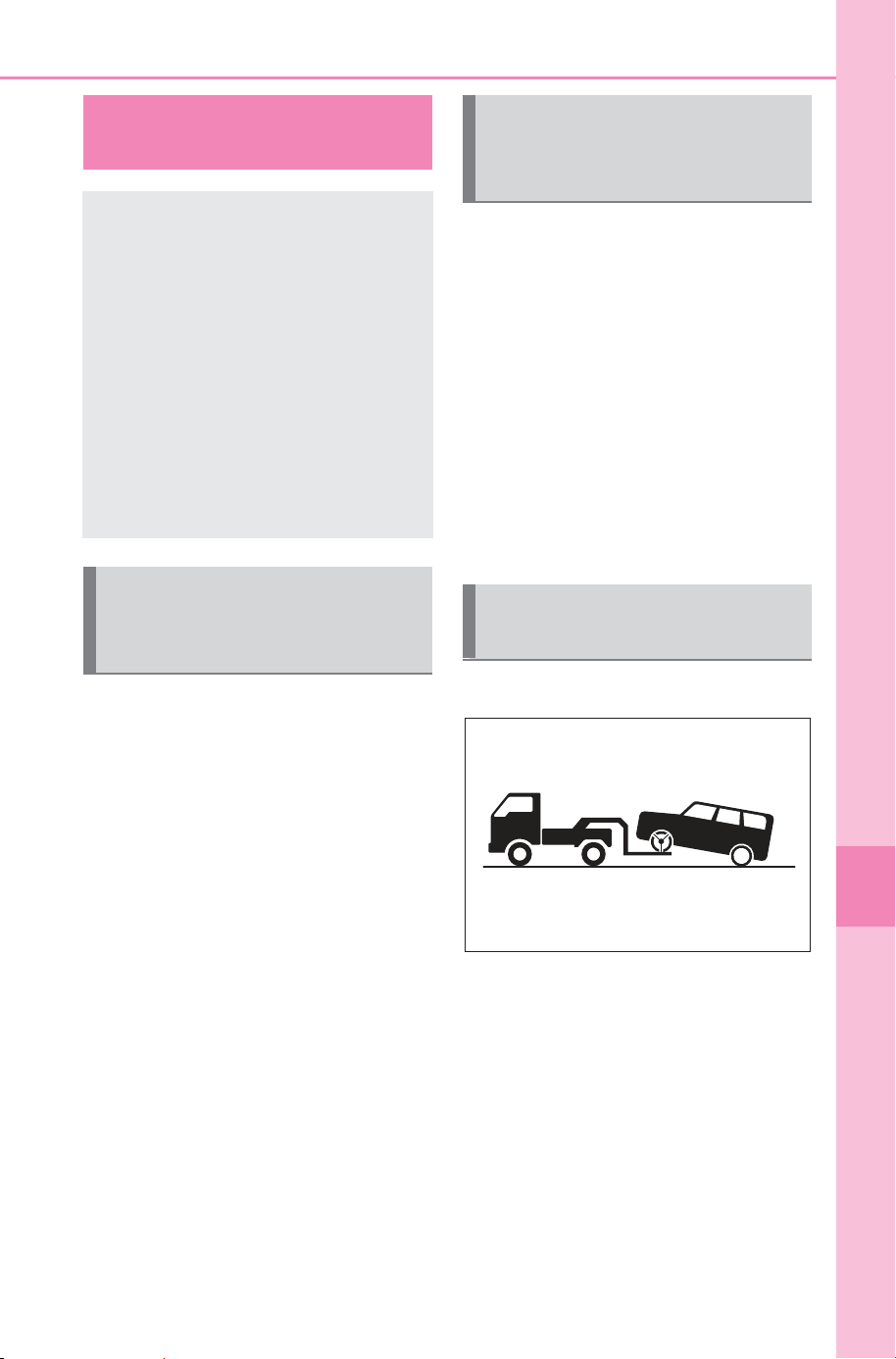
605
8-2. Steps to take in an emergency
Owner’s Manual_USA_M6740B_en
8
When trouble arises
8-2.Steps to take in an emer gency
In the following situations, it is
not possible to be towed by
another vehicle using cables or
chains, as the front wheels may
be locked due to the parking
lock. Contact your SUBARU
dealer or commercial towing
service.
There is a malfunction in the
shift control system. (P.231,
622)
There is a malfunction in the
immobilizer system. (P. 6 5)
There is a malfunction in the
smart key system. (P.642)
The 12-volt battery is dis-
charged. (P.644)
The following may indicate a
problem with your transmission.
Contact your SUBARU dealer or
commercial towing service
before towing.
The EV system warning mes-
sage is shown on the multi-
information display and the
vehicle does not move.
The vehicle makes an abnor-
mal sound.
From the front (FWD models)
Release the parking brake.
Turn automatic mode off.
(P.242)
If your vehicle needs
to be towed
If towing is necessary, we
recommend having your
vehicle towed by your SUB-
ARU dealer or commercial
towing service, using a
wheel-lift type truck or flat-
bed truck.
Use a safety chain system
for all towing, and abide by
all state/provincial and local
laws.
Situations when it is not
possible to be towed by
another vehicle
Situations when it is nec-
essary to contact dealers
before towing
Towing with a wheel-lift
type truck
SOLTERRA_OM_USA_A6740BE.book 605 ページ 2025年5月23日 金曜日 午後1時18分
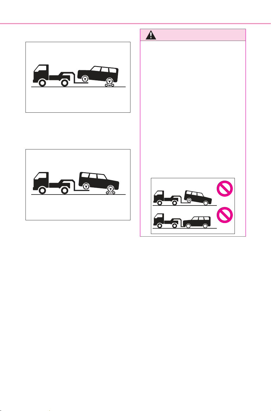
606
8-2. Steps to take in an emergency
Owner’s Manual_USA_M6740B_en
From the front (AWD models)
Use a towing dolly under the
rear wheels.
From the rear
Use a towing dolly under the
front wheels.
WARNING
Observe the following precau-
tions. Failure to do so may result
in death or serious injury.
■ When towing the vehicle
FWD models
Be sure to transport the vehicle
with the front wheels raised or
with all four wheels raised off the
ground. If the vehicle is towed
with the front wheels contacting
the ground, the drivetrain and
related parts may be damaged or
electricity generated by the opera-
tion of the motor may cause a fire
to occur depending on the nature
of the damage or malfunction.
SOLTERRA_OM_USA_A6740BE.book 606 ページ 2025年5月23日 金曜日 午後1時18分
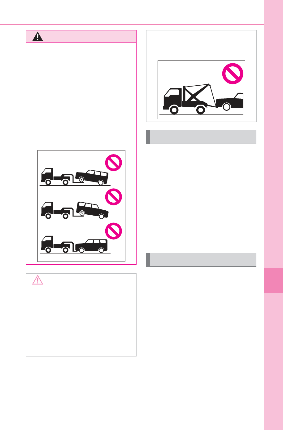
607
8-2. Steps to take in an emergency
Owner’s Manual_USA_M6740B_en
8
When trouble arises
When using a flatbed truck to
transport the vehicle, use tire
strapping belts. Refer to the
owner’s manual of the flatbed
truck for the tire strapping
method.
In order to suppress vehicle
movement during transporta-
tion, set the parking brake and
turn the power switch off.
If a tow truck is not available in
an emergency, your vehicle may
be temporarily towed using
cables or chains secured to the
emergency towing eyelet. This
should only be attempted on
hard surfaced roads for short
distances at under 18 mph (30
km/h).
A driver must be in the vehicle to
steer and operate the brakes.
The vehicle’s wheels, drive train,
axles, steering and brakes must
be in good condition.
WARNING
AWD models
Be sure to transport the vehicle
with all four wheels raised off the
ground. If the vehicle is towed
with the tires contacting the
ground, the drivetrain or related
parts may be damaged, the vehi-
cle may fly off the truck, or elec-
tricity generated by the operation
of the motor may cause a fire to
occur depending on the nature of
the damage or malfunction.
NOTICE
■ To prevent damage to the
vehicle when towing using a
wheel-lift type truck
When raising the vehicle, ensure
adequate ground clearance for
towing at the opposite end of the
raised vehicle. Without adequate
clearance, the vehicle could be
damaged while being towed.
■ Towing with a sling-type truck
Do not tow with a sling-type truck
to prevent body damage.
Using a flatbed truck
Emergency towing
SOLTERRA_OM_USA_A6740BE.book 607 ページ 2025年5月23日 金曜日 午後1時18分
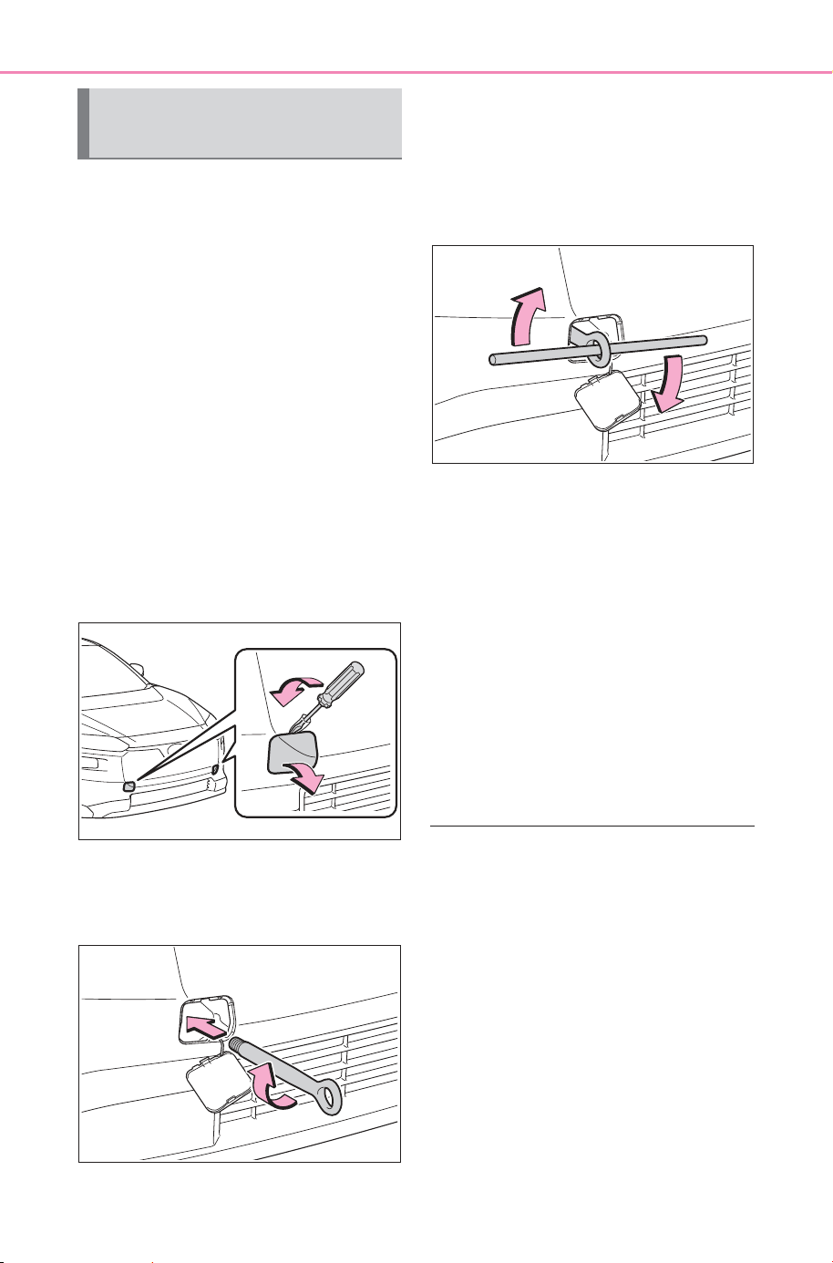
608
8-2. Steps to take in an emergency
Owner’s Manual_USA_M6740B_en
To have your vehicle towed by
another vehicle, the towing eye-
let must be installed to your
vehicle. Install the towing eyelet
using the following procedure.
1 Take out the wheel nut
wrench
*
and towing eyelet.
(P.584, 630)
*
: Wheel nut wrench can be pur-
chased at your SUBARU dealer.
2 Remove the eyelet cover
using a flathead screwdriver.
To protect the bodywork, place a
rag between the screwdriver and
the vehicle body as shown in the
illustration.
3 Insert the towing eyelet into
the hole and tighten partially
by hand.
4 Tighten down the towing eye-
let securely using a wheel nut
wrench
*
or hard metal bar.
*
: Wheel nut wrench can be pur-
chased at your SUBARU dealer.
5 Securely attach cables or
chains to the towing eyelet.
Take care not to damage the vehi-
cle body.
6 Enter the vehicle being towed
and start the EV system.
If the EV system does not start, turn
the power switch to ON.
7 Shift the shift position to N
and release the parking
brake.
Turn automatic mode off. (P.242)
■ While towing
If the EV system is off, the power
assist for the brakes and steering
will not function, making steering
and braking more difficult.
■ Wheel nut wrench
Wheel nut wrench can be pur-
chased at your SUBARU dealer.
Emergency towing proce-
dure
SOLTERRA_OM_USA_A6740BE.book 608 ページ 2025年5月23日 金曜日 午後1時18分
609
8-2. Steps to take in an emergency
Owner’s Manual_USA_M6740B_en
8
When trouble arises
Fluid leaks under the vehicle
(Water dripping from the air
conditioning after use is nor-
mal.)
Flat-looking tires or uneven
tire wear
Excessive tire squeal when
cornering
Strange noises related to the
suspension system
Other noises related to the EV
system
WARNING
Observe the following precau-
tions. Failure to do so may result
in death or serious injury.
■ While towing
● When towing using cables or
chains, avoid sudden starts,
etc., which place excessive
stress on the towing eyelet,
cables or chains. The towing
eyelet, cables or chains may
become damaged, broken
debris may hit people, and
cause serious damage.
● Do not perform any of the fol-
lowing as doing so may cause
the parking lock mechanism to
engage, locking the front
wheels and possibly leading to
an accident resulting in death or
serious injury:
• Unfasten the driver’s seat belt
and open the driver’s door.
• Turn the power switch off.
■ Installing towing eyelets to
the vehicle
Make sure that towing eyelets are
installed securely. If not securely
installed, towing eyelets may
come loose during towing.
NOTICE
■ To prevent damage to the
vehicle during emergency
towing
Do not secure cables or chains to
the suspension components.
If you think something
is wrong
If you notice any of the fol-
lowing symptoms, your
vehicle probably needs
adjustment or repair. Con-
tact your SUBARU dealer as
soon as possible.
Visible symptoms
Audible symptoms
SOLTERRA_OM_USA_A6740BE.book 609 ページ 2025年5月23日 金曜日 午後1時18分

610
8-2. Steps to take in an emergency
Owner’s Manual_USA_M6740B_en
Stumbling or running roughly
Appreciable loss of power
Vehicle pulls heavily to one
side when braking
Vehicle pulls heavily to one
side when driving on a level
road
Loss of brake effectiveness,
spongy feeling, pedal almost
touches the floor
Operational symptoms
SOLTERRA_OM_USA_A6740BE.book 610 ページ 2025年5月23日 金曜日 午後1時18分
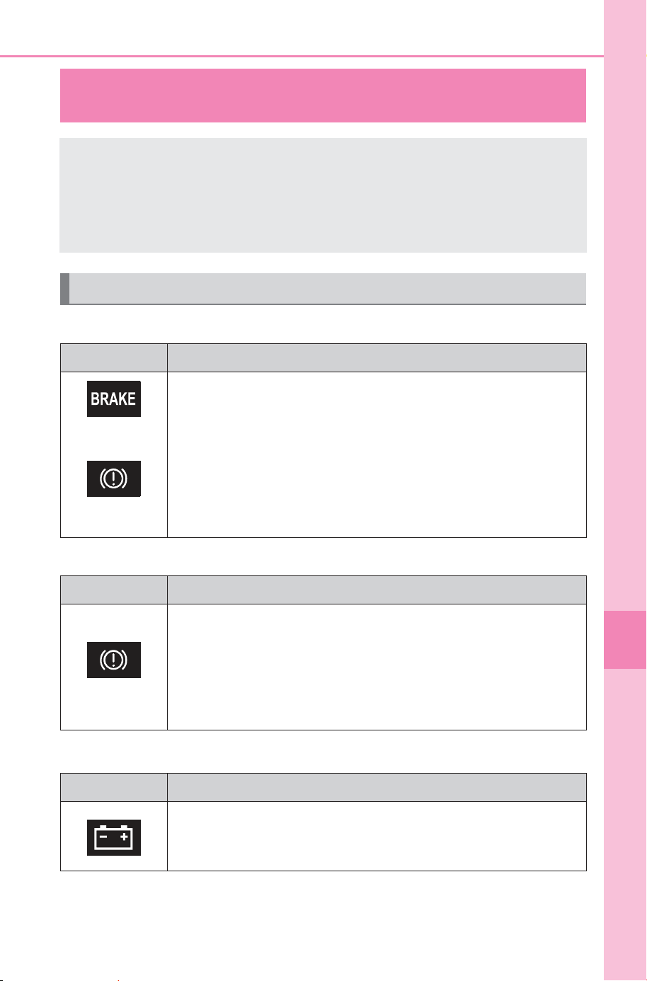
611
8-2. Steps to take in an emergency
Owner’s Manual_USA_M6740B_en
8
When trouble arises
■ Brake system warning light (warning buzzer)
■ Brake system warning light (warning buzzer)
■ Charging system warning light
*
*
: This light illuminates on the multi-information display.
If a warning light turns on or a warning buzzer
sounds
Calmly perform the following actions if any of the warning
lights comes on or flashes. If a light comes on or flashes, but
then goes off, this does not necessarily indicate a malfunc-
tion in the system. However, if this continues to occur, have
the vehicle inspected by your SUBARU dealer.
Actions to the warning lights or warning buzzers
Warning light Details/Actions
(U.S.A.)
or
(Canada)
(Red)
Indicates that:
The brake fluid level is low; or
The brake system is malfunctioning
Immediately stop the vehicle in a safe place and con-
tact your SUBARU dealer. Continuing to drive the
vehicle may be dangerous.
Warning light Details/Actions
(Yellow)
Indicates a malfunction in:
The regenerative braking system;
The electronically controlled brake system; or
The parking brake system
Have the vehicle inspected by your SUBARU dealer
immediately.
Warning light Details/Actions
Indicates a malfunction in the vehicle’s charging system
Immediately stop the vehicle in a safe place and con-
tact your SUBARU dealer.
SOLTERRA_OM_USA_A6740BE.book 611 ページ 2025年5月23日 金曜日 午後1時18分
612
8-2. Steps to take in an emergency
Owner’s Manual_USA_M6740B_en
■ EV system malfunction indicator lamp (warning buzzer)
■ SRS warning light (warning buzzer)
■ ABS warning light
Warning light Details/Actions
Indicates a malfunction in the EV system
Immediately stop the vehicle in a safe place and con-
tact your SUBARU dealer.
Warning light Details/Actions
Indicates a malfunction in:
The SRS airbag system;
The front passenger occupant classification system; or
The seat belt pretensioner system
Have the vehicle inspected by your SUBARU dealer
immediately.
Warning light Details/Actions
(U.S.A.)
or
(Canada)
Indicates a malfunction in:
The ABS; or
The brake assist system
Have the vehicle inspected by your SUBARU dealer
immediately.
SOLTERRA_OM_USA_A6740BE.book 612 ページ 2025年5月23日 金曜日 午後1時18分
613
8-2. Steps to take in an emergency
Owner’s Manual_USA_M6740B_en
8
When trouble arises
■ Inappropriate pedal operation warning light
*
(warning buzzer)
*
: This light illuminates on the multi-information display.
■ Electric power steering system warning light (warning
buzzer)
■ Traction battery charge warning light
Warning light Details/Actions
When a buzzer sounds:
Indicates a malfunction in:
Brake Override System is malfunctioning
Drive-Start Control is malfunctioning
Drive-Start Control is operating
Follow the instructions displayed on the multi-infor-
mation display.
When a buzzer does not sound:
Brake Override System is operating
Release the accelerator pedal and depress the brake
pedal.
Warning light Details/Actions
(Red)
or
(Yellow)
Indicates a malfunction in the EPS (Electric Power Steer-
ing) system
Have the vehicle inspected by your SUBARU dealer
immediately.
Warning light Details/Actions
(Yellow)
Indicates that the remaining charge of the traction battery is
low and charging is required
When the outside temperature is low, this light may turn on
earlier than usual to urge the driver to charge the traction
battery early.
Charge the traction battery. (P.88)
SOLTERRA_OM_USA_A6740BE.book 613 ページ 2025年5月23日 金曜日 午後1時18分
614
8-2. Steps to take in an emergency
Owner’s Manual_USA_M6740B_en
■ Driver’s and front passenger’s seat belt reminder light (warn-
ing buzzer
*
)
*
: Driver’s seat belt warning buzzer:
The driver’s seat belt warning buzzer sounds to alert the driver that his or
her seat belt is not fastened. Once the power switch is turned to ON, the
buzzer sounds. If the seat belt is still unfastened, the buzzer sounds inter-
mittently for a certain period of time after the vehicle reaches a certain
speed.
Front passenger’s seat belt warning buzzer:
The front passenger’s seat belt warning buzzer sounds to alert the front
passenger that his or her seat belt is not fastened. If the seat belt is unfas-
tened, the buzzer sounds intermittently for a certain period of time after the
vehicle reaches a certain speed.
■ Rear passengers’ seat belt reminder lights (warning buzzer
*
)
*
: Rear passengers’ seat belt warning buzzer:
The rear passengers’ seat belt warning buzzer sounds to alert the rear pas-
senger that his or her seat belt is not fastened. If the seat belt is unfas-
tened, the buzzer sounds intermittently for a certain period of time, after the
seat belt is fastened and unfastened and the vehicle reaches a certain
speed.
Warning light Details/Actions
Warns the driver and/or front passenger to fasten their seat
belts
Fasten the seat belt.
If the front passenger’s seat is occupied, the front
passenger’s seat belt also needs to be fastened to
make the warning light (warning buzzer) turn off.
Warning light Details/Actions
Warns the rear passengers to fasten their seat belts
Fasten the seat belt.
SOLTERRA_OM_USA_A6740BE.book 614 ページ 2025年5月23日 金曜日 午後1時18分
615
8-2. Steps to take in an emergency
Owner’s Manual_USA_M6740B_en
8
When trouble arises
■ Tire pressure warning light
■ LDA indicator (warning buzzer)
■ LTA indicator (warning buzzer)
■ PDA indicator (warning buzzer)
Warning light Details/Actions
(if equipped)
When the light comes on after blinking for approximately 1
minute (a buzzer does not sounds):
Malfunction in the tire pressure warning system
Have the system checked by your SUBARU dealer.
When the light comes on (a buzzer sounds):
Low tire inflation pressure from natural causes
After the temperature of the tires has lowered suffi-
ciently, check the inflation pressure of each tire and
adjust them to the specified level. (P.661)
Low tire inflation pressure from flat tire
Immediately stop the vehicle in a safe place and per-
form the necessary actions (P.619)
Warning light Details/Actions
(Yellow)
Indicates a malfunction in the LDA (Lane Departure Alert).
Follow the instructions displayed on the multi-infor-
mation display.
Warning light Details/Actions
(Yellow)
Indicates a malfunction in the LTA (Lane Tracing Assist)
Follow the instructions displayed on the multi-infor-
mation display.
Warning light Details/Actions
(Yellow)
Indicates a malfunction in the PDA (Proactive Driving
Assist).
Follow the instructions displayed on the multi-infor-
mation display.
SOLTERRA_OM_USA_A6740BE.book 615 ページ 2025年5月23日 金曜日 午後1時18分
616
8-2. Steps to take in an emergency
Owner’s Manual_USA_M6740B_en
■ Driving assist information indicator
■ SUBARU Parking Assist OFF indicator (warning buzzer)
Warning light Details/Actions
(Yellow)
Indicates either of the following systems may be malfunc-
tioning.
PCS (Pre-Collision System)
LDA (Lane Departure Alert)
Follow the instructions displayed on the multi-infor-
mation display.
Indicates any of the following systems are malfunctioning,
disabled, or turned off.
PKSB (Parking Support Brake)
RCD (Rear Camera Detection)
BSM (Blind Spot Monitor)
RCTA (Rear Cross Traffic Alert)
Safe Exit Assist
Follow the instructions displayed on the multi-infor-
mation display.
Warning light Details/Actions
When a buzzer sounds:
Indicates a malfunction in the SUBARU Parking Assist
function
Have the vehicle inspected by your SUBARU dealer
immediately.
When a buzzer does not sound:
Indicates that the system is temporarily unavailable, possi-
bly due to a sensor being dirty or covered with ice, etc.
Follow the instructions displayed on the multi-infor-
mation display. (P.624)
SOLTERRA_OM_USA_A6740BE.book 616 ページ 2025年5月23日 金曜日 午後1時18分
617
8-2. Steps to take in an emergency
Owner’s Manual_USA_M6740B_en
8
When trouble arises
■ Cruise control indicator (warning buzzer)
■ Dynamic radar cruise control indicator (warning buzzer)
■ PCS warning light (warning buzzer)
■ Slip indicator
Warning light Details/Actions
(Yellow)
Indicates a malfunction in the cruise control.
Follow the instructions displayed on the multi-infor-
mation display.
Warning light Details/Actions
(Yellow)
Indicates a malfunction in the dynamic radar cruise control.
Follow the instructions displayed on the multi-infor-
mation display.
Warning light Details/Actions
Indicates a malfunction in the PCS (Pre-Collision System).
Follow the instructions displayed on the multi-infor-
mation display.
If the PCS (Pre-Collision System) or VSC (Vehicle Stability
Control) system is disabled, the PCS warning light will illu-
minate.
Warning light Details/Actions
Indicates a malfunction in:
The VSC system;
The TRAC system;
Trailer Sway Control; or
The hill-start assist control system
Have the vehicle inspected by your SUBARU dealer
immediately.
SOLTERRA_OM_USA_A6740BE.book 617 ページ 2025年5月23日 金曜日 午後1時18分
618
8-2. Steps to take in an emergency
Owner’s Manual_USA_M6740B_en
■ Parking brake indicator
■ Brake hold operated indicator
■ Warning buzzer
In some cases, the buzzer may not
be heard due to being in a noisy
location or audio sound.
■ Front passenger detection sen-
sor, seat belt reminder and
warning buzzer
● If luggage is placed on the front
passenger seat, the front passen-
ger detection sensor may cause
the warning light to flash and the
warning buzzer to sound even if a
passenger is not sitting in the
seat.
● If a cushion is placed on the seat,
the sensor may not detect a pas-
senger, and the warning light may
not operate properly.
■ SRS warning light
This warning light indicates prob-
lems with the following:
● Airbag sensor assembly
● Front impact sensors
● Side impact sensors (front door)
● Side impact sensors (front)
● Front passenger occupant classifi-
cation sensors
● Driver’s seat position sensor
● Front passenger’s seat belt buckle
switch
● SRS warning light
● “AIR BAG ON” indicator light
● “AIR BAG OFF” indicator light
● SRS airbags
● SRS system related wiring har-
nesses and power sources
■ Electric power steering system
warning light (warning buzzer)
When the 12-volt battery charge
becomes insufficient or the voltage
temporarily drops, the electric power
steering system warning light may
come on and the warning buzzer
may sound.
Warning light Details/Actions
(U.S.A.)
(Flashes)
or
(Canada)
(Flashes)
It is possible that the parking brake is not fully engaged or
released
Operate the parking brake switch once again.
This light comes on the parking brake is not released. If the
light turns off after the parking brakes is fully released, the
system is operating normally.
Warning light Details/Actions
(Flashes)
Indicates a malfunction in the brake hold system
Have the vehicle inspected by your SUBARU dealer
immediately.
SOLTERRA_OM_USA_A6740BE.book 618 ページ 2025年5月23日 金曜日 午後1時18分
619
8-2. Steps to take in an emergency
Owner’s Manual_USA_M6740B_en
8
When trouble arises
■ When the tire pressure warning
light comes on (vehicle with the
tire pressure warning system)
Inspect the tires to check if a tire is
punctured.
If a tire is punctured: P.628
If none of the tires are punctured:
Turn the power switch off then turn it
to ON. Check if the tire pressure
warning light comes on or blinks.
If the tire pressure warning light
blinks for approximately 1 minute
then stays on
There may be a malfunction in the
tire pressure warning system. Have
the vehicle inspected by your SUB-
ARU dealer immediately.
If the tire pressure warning light
comes on
1 After the temperature of the tires
has lowered sufficiently, check
the inflation pressure of each tire
and adjust them to the specified
level.
2 If the warning light does not turn
off even after several minutes
have elapsed, check that the
inflation pressure of each tire is
at the specified level and perform
the tire inflation pressure setting
procedure. (P. 577)
If the warning light does not turn off
even after several minutes have
elapsed since performing the tire
inflation pressure setting proce-
dure, have the vehicle inspected by
your SUBARU dealer as soon as
possible.
■ The tire pressure warning light
may come on due to natural
causes (vehicle with the tire
pressure warning system)
The tire pressure warning light may
come on due to natural causes such
as natural air leaks and tire inflation
pressure changes caused by tem-
perature. In this case, adjusting the
tire inflation pressure will turn off the
warning light (after a few minutes).
■ Conditions that the tire pres-
sure warning system may not
function properly (if equipped)
P.573
WARNING
■ If both the ABS and the brake
system warning lights remain
on
Stop your vehicle in a safe place
immediately and contact your
SUBARU dealer.
The vehicle will become
extremely unstable during brak-
ing, and the ABS system may fail,
which could cause an accident
resulting in death or serious injury.
■ When the electric power
steering system warning light
comes on
When the light comes on yellow,
the assist to the power steering is
restricted. When the light comes
on red, the assist to the power
steering is lost and handling oper-
ations of the steering wheel
become extremely heavy.
When steering wheel operations
are heavier than usual, grip the
steering wheel firmly and operate
it using more force than usual.
■ If the tire pressure warning
light comes on (vehicle with
the tire pressure warning sys-
tem)
Be sure to observe the following
precautions.
Failure to do so could cause a
loss of vehicle control and result
in death or serious injury.
● Stop your vehicle in a safe place
as soon as possible. Adjust the
tire inflation pressure immedi-
ately.
SOLTERRA_OM_USA_A6740BE.book 619 ページ 2025年5月23日 金曜日 午後1時18分
620
8-2. Steps to take in an emergency
Owner’s Manual_USA_M6740B_en
WARNING
● If the tire pressure warning light
comes on even after tire infla-
tion pressure adjustment, it is
probable that you have a flat
tire. Check the tires. If a tire is
flat, repair the flat tire by using
emergency tire puncture repair
kit.
● Avoid abrupt maneuvering and
braking.
If the vehicle tires deteriorate,
you could lose control of the
steering wheel or the brakes.
■ If a blowout or sudden air
leakage should occur (vehicle
with the tire pressure warning
system)
The tire pressure warning system
may not activate immediately.
■ Maintenance of the tires
(vehicle with the tire pressure
warning system)
Each tire, including the spare (if
provided), should be checked
monthly when cold and inflated to
the inflation pressure recom-
mended by the vehicle manufac-
turer on the vehicle placard or tire
inflation pressure label (tire and
load information label). (If your
vehicle has tires of a different size
than the size indicated on the
vehicle placard or tire inflation
pressure label [tire and load infor-
mation label], you should deter-
mine the proper tire inflation
pressure for those tires.)
As an added safety feature, your
vehicle has been equipped with a
tire pressure monitoring system
(TPMS-tire pressure warning sys-
tem) that illuminates a low tire
pressure telltale (tire pressure
warning light) when one or more
of your tires is significantly under-
inflated. Accordingly, when the
low tire pressure telltale (tire pres-
sure warning light) illuminates,
you should stop and check your
tires as soon as possible, and
inflate them to the proper pres-
sure. Driving on a significantly
under-inflated tire causes the tire
to overheat and can lead to tire
failure. Under-inflation also
reduces fuel efficiency (for electric
vehicles, traction battery effi-
ciency) and tire tread life, and
may affect the vehicle’s handling
and stopping ability.
Please note that the TPMS (tire
pressure warning system) is not a
substitute for proper tire mainte-
nance, and it is the driver’s
responsibility to maintain correct
tire pressure, even if under-infla-
tion has not reached the level to
trigger illumination of the TPMS
low tire pressure telltale (tire pres-
sure warning light).
SOLTERRA_OM_USA_A6740BE.book 620 ページ 2025年5月23日 金曜日 午後1時18分
621
8-2. Steps to take in an emergency
Owner’s Manual_USA_M6740B_en
8
When trouble arises
■ Warning messages
The warning messages explained
below may differ from the actual
messages according to operation
conditions and vehicle specifica-
tions.
■ Warning buzzer
In some cases, the buzzer may not
be heard due to being in a noisy
location or audio sound.
WARNING
Your vehicle has also been
equipped with a TPMS (tire pres-
sure warning system) malfunc-
tion indicator to indicate when the
system is not operating properly.
The TPMS (tire pressure warning
system) malfunction indicator is
combined with the low tire pres-
sure telltale (tire pressure warning
light). When the system detects a
malfunction, the telltale will flash
for approximately one minute and
then remain continuously illumi-
nated. This sequence will con-
tinue upon subsequent vehicle
start-ups as long as the malfunc-
tion exists. When the malfunction
indicator is illuminated, the sys-
tem may not be able to detect or
signal low tire pressure as
intended.
TPMS (tire pressure warning sys-
tem) malfunctions may occur for a
variety of reasons, including the
installation of replacement or
alternate tires or wheels on the
vehicle that prevent the TPMS
(tire pressure warning system)
from functioning properly. Always
check the TPMS (tire pressure
warning system) malfunction tell-
tale after replacing one or more
tires or wheels on your vehicle to
ensure that the replacement or
alternate tires and wheels allow
the TPMS (tire pressure warning
system) to continue to function
properly.
NOTICE
■ To ensure the tire pressure
warning system operates
properly (if equipped)
Do not install tires with different
specifications or makers, as the
tire pressure warning system may
not operate properly.
If a warning message
is displayed
The multi-information dis-
play shows warnings of
system malfunctions, incor-
rectly performed opera-
tions, and messages that
indicate a need for mainte-
nance. When a message is
shown, perform the correc-
tion procedure appropriate
to the message.
If a warning message is dis-
played again after the
appropriate actions have
been performed, contact
your SUBARU dealer.
Additionally, if a warning
light comes on or flashes at
the same time that a warn-
ing message is displayed,
take the appropriate correc-
tive action for the warning
light. (P. 611 )
SOLTERRA_OM_USA_A6740BE.book 621 ページ 2025年5月23日 金曜日 午後1時18分

622
8-2. Steps to take in an emergency
Owner’s Manual_USA_M6740B_en
■ If “Traction Battery Tempera-
ture Very High Stop in a Safe
Place Now and Exit the Vehicle”
is displayed
This message may be displayed if
the drive battery temperature
becomes extremely high. Immedi-
ately stop the vehicle in a safe
place, exit the vehicle, and contact
your SUBARU dealer.
■ If “EV System Stopped Steering
Power Low” is displayed
This message is displayed if the EV
system is stopped while driving.
When steering wheel operations are
heavier than usual, grip the steering
wheel firmly and operate it using
more force than usual.
■ If “EV System overheated Out-
put power reduced” is dis-
played
This message may be displayed
when driving under severe operat-
ing conditions. (For example, when
driving up a long steep hill.)
Handling method: P.648
■ If “Shift System Malfunction
Shifting Unavailable Drive to a
Safe Place and Stop” or “Shift
System Malfunction Driving
Unavailable” is displayed
There is a malfunction in the shift
control system. Have the vehicle
inspected by your SUBARU dealer
immediately.
■ If “Shift is in N Release Acceler-
ator Before Shifting” is dis-
played
The accelerator pedal has been
depressed when the shift position is
in N.
Release the accelerator pedal and
shift the shift position to D or R.
■ If “Press brake when vehicle is
stopped EV system may over-
heat” is displayed
The message may be displayed
when the accelerator pedal is
depressed to hold the vehicle while
the vehicle is stopped on an incline,
etc. The EV system may overheat.
Release the accelerator pedal and
depress the brake pedal.
■ If “Auto Power OFF to Conserve
Battery” is displayed
Power was turned off due to the
automatic power off function. Next
time when starting the EV system,
operate the EV system for approxi-
mately 5 minutes to recharge the
12-volt battery.
■ If “Regenerative braking lim-
ited. Press brake to decelerate.”
is displayed
Regenerative braking may be
restricted in the following situations.
Firmly depress the brake pedal to
decelerate the vehicle.
● When electrical energy cannot be
regenerated any more as the trac-
tion battery is fully charged
● When the temperature of the trac-
tion battery is extremely high or
extremely low
● When the temperature of the elec-
tric motor or power control unit,
etc. is extremely high
■ If “High Power Consumption
Power to Climate Temporarily
Limited” is displayed
Turn off unnecessary electronic
equipment to reduce power con-
sumption.
Please wait until the power supply
returns to normal.
SOLTERRA_OM_USA_A6740BE.book 622 ページ 2025年5月23日 金曜日 午後1時18分

623
8-2. Steps to take in an emergency
Owner’s Manual_USA_M6740B_en
8
When trouble arises
■ If “Headlight System Malfunc-
tion Visit Your Dealer” is dis-
played
The following systems may be mal-
functioning. Have the vehicle
inspected by your SUBARU dealer
immediately.
● The LED headlight system
● AHB (Automatic High Beam)
■ If “Maintenance Required
Soon” is displayed
Indicates that all maintenance
according to the driven distance on
the maintenance schedule
*
should
be performed soon.
Comes on approximately 4500
miles (7200 km) after the message
has been reset.
If necessary, perform maintenance.
Please reset the message after the
maintenance is performed.
(P.556)
*
: Refer to the separate “Scheduled
Maintenance Guide” or “Owner’s
Manual Supplement” for the main-
tenance interval applicable to your
vehicle.
■ If “Maintenance Required Visit
Your Dealer” is displayed
Indicates that all maintenance is
required to correspond to the driven
distance on the maintenance sched-
ule
*
.
Comes on approximately 5000
miles (8000 km) after the message
has been reset. (The indicator will
not work properly unless the mes-
sage has been reset.)
Perform the necessary mainte-
nance.
Please reset the message after the
maintenance is performed.
(P.556)
*
: Refer to the separate “Scheduled
Maintenance Guide” or “Owner’s
Manual Supplement” for the main-
tenance interval applicable to your
vehicle.
■ If “Parking Assist Unavailable
Sensor Blocked” is displayed
A sensor may be covered with water
drops, ice, snow, dirt, etc. Remove
the water drops, ice, snow, dirt, etc.,
from the sensor to return the system
to normal.
Also, due to ice forming on a sensor
at low temperatures, a warning
message may be displayed or the
sensor may not be able to detect an
object. Once the ice melts, the sys-
tem will return to normal.
If a sensor is dirty, the position of the
dirty sensor will be shown on the
display.
If an abnormality is displayed even
though there are no water drops,
ice, snow or dirt, the sensor may be
operating abnormally. Have the
vehicle inspected by your SUBARU
dealer.
■ If “Parking Assist Unavailable
Low Visibility See Owner’s Man-
ual” is displayed
Indicates one of the following sys-
tems is disabled.
● RCD (Rear Camera Detec-
tion)
● PKSB (Parking Support
Brake)
Remove any dirt or foreign matter
from the rear camera.
■ If “System Stopped Check Side
Mirror Status Reopen Side Mir-
rors” is displayed (if equipped)
PKSB is temporarily unavailable
because the outside rear view mir-
rors are folded. Extend the outside
rear view mirrors. If the 12-volt bat-
tery was discharged or has been
removed and installed, fold and
extend the outside rear view mirrors.
SOLTERRA_OM_USA_A6740BE.book 623 ページ 2025年5月23日 金曜日 午後1時18分
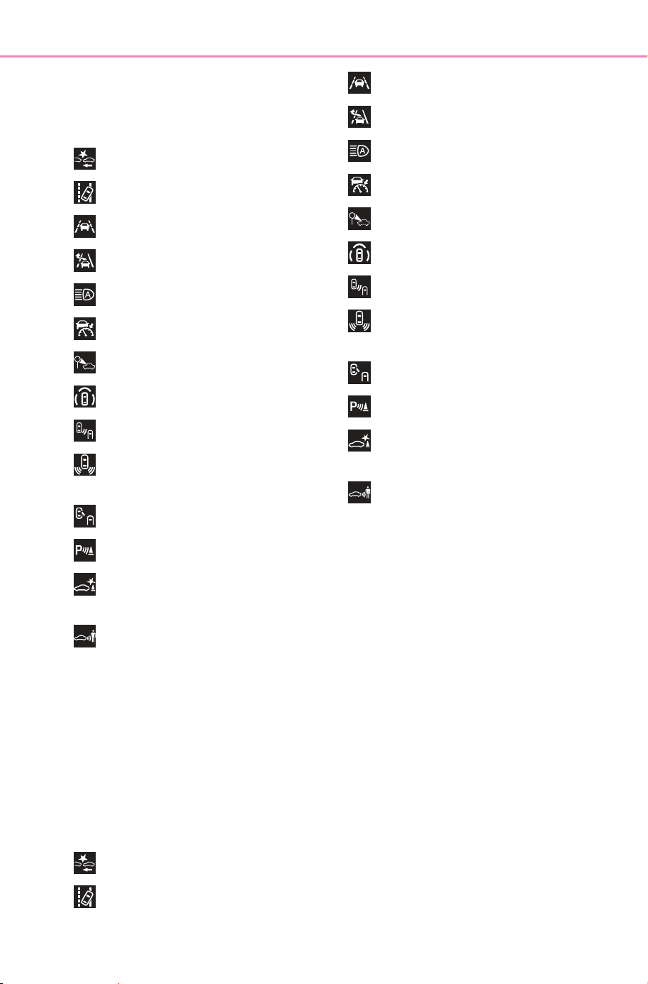
624
8-2. Steps to take in an emergency
Owner’s Manual_USA_M6740B_en
■ If “System Malfunction Visit
Your Dealer” is displayed
Indicates one of the following sys-
tems is disabled.
● PCS (Pre-Collision System)
● LDA (Lane Departure Alert)
● LTA (Lane Tracing Assist)
● LCA (Lane Change Assist)
● AHB (Automatic High Beam)
● Dynamic radar cruise control
● RSA (Road Sign Assist)
● PDA (Proactive Driving Assist)
● BSM (Blind Spot Monitor)
● RCTA (Rear Cross Traffic
Alert)
● Safe Exit Assist
● SUBARU Parking Assist
● PKSB (Parking Support
Brake)
● RCD (Rear Camera Detec-
tion)
Have the vehicle inspected by your
SUBARU dealer immediately.
■ If “System Stopped See
Owner’s Manual” is displayed
Indicates one of the following sys-
tems is disabled.
Check the icon displayed on the
screen and follow the following cor-
rection methods.
● PCS (Pre-Collision System)
● LDA (Lane Departure Alert)
● LTA (Lane Tracing Assist)
● LCA (Lane Change Assist)
● AHB (Automatic High Beam)
● Dynamic radar cruise control
● RSA (Road Sign Assist)
● PDA (Proactive Driving Assist)
● BSM (Blind Spot Monitor)
● RCTA (Rear Cross Traffic
Alert)
● Safe Exit Assist
● SUBARU Parking Assist
● PKSB (Parking Support
Brake)
● RCD (Rear Camera Detec-
tion)
Follow the following correction
methods.
• Check the voltage of the 12-volt
battery
• Check the sensors that the SUB-
ARU Safety Sense uses for for-
eign matter covering them.
Remove them if any. (P.261)
• Check if the back door is open.
• Check the situations in which the
sensors may not operate properly,
and improve the situation if appli-
cable. (P.334, 339, 354)
• Check the sensors including cam-
era sensors for foreign matter cov-
ering them. Remove them if any.
(P.340, 377)
• Check if there is any foreign mat-
ter attached to the rear bumper
near the radar sensor and remove
it if there is. (P.331)
When problems are solved and the
SOLTERRA_OM_USA_A6740BE.book 624 ページ 2025年5月23日 金曜日 午後1時18分
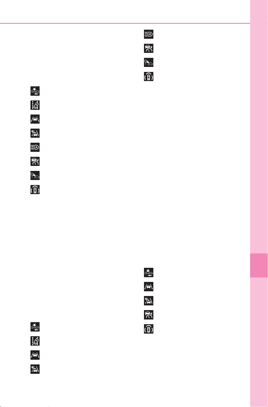
625
8-2. Steps to take in an emergency
Owner’s Manual_USA_M6740B_en
8
When trouble arises
sensors are operational, this indica-
tion may disappear by itself.
■ If “System Stopped Front Cam-
era Low Visibility See Owner’s
Manual” is displayed
Indicates one of the following sys-
tems is disabled.
● PCS (Pre-Collision System)
● LDA (Lane Departure Alert)
● LTA (Lane Tracing Assist)
● LCA (Lane Change Assist)
● AHB (Automatic High Beam)
● Dynamic radar cruise control
● RSA (Road Sign Assist)
● PDA (Proactive Driving Assist)
Follow the following correction
methods.
• Using the windshield wipers,
remove the dirt or foreign matter
from the windshield.
• Using the air conditioning system,
defog the windshield.
• Close the hood, remove any stick-
ers, etc. to clear the obstruction in
front of the front camera.
■ If “System Stopped Front Cam-
era Out of Temperature Range
Wait until Normal Temperature”
is displayed
Indicates one of the following sys-
tems is disabled.
● PCS (Pre-Collision System)
● LDA (Lane Departure Alert)
● LTA (Lane Tracing Assist)
● LCA (Lane Change Assist)
● AHB (Automatic High Beam)
● Dynamic radar cruise control
● RSA (Road Sign Assist)
● PDA (Proactive Driving Assist)
Follow the following correction
methods.
• If the front camera is hot, such as
after the vehicle is parked in the
sun, use the air conditioning sys-
tem to decrease the temperature
around the front camera.
• If a sunshade was used when the
vehicle was parked, depending on
its type, the sunlight reflected from
the surface of the sunshade may
cause the temperature of the front
camera to become excessively
high.
• If the front camera is cold, such
after the vehicle is parked in an
extremely cold environment, use
the air conditioning system to
increase the temperature around
the front camera.
■ If “System Stopped Front Radar
Sensor Blocked Clean Radar
Sensor” is displayed
Indicates one of the following sys-
tems is disabled.
● PCS (Pre-Collision System)
● LTA (Lane Tracing Assist)
● LCA (Lane Change Assist)
● Dynamic radar cruise control
● PDA (Proactive Driving Assist)
Follow the following correction
methods.
• Check if there is any foreign mat-
ter attached to the radar sensor or
radar sensor cover and clean
them if necessary. (P.261)
SOLTERRA_OM_USA_A6740BE.book 625 ページ 2025年5月23日 金曜日 午後1時18分
626
8-2. Steps to take in an emergency
Owner’s Manual_USA_M6740B_en
• This message may be displayed
when driving in an open area with
few nearby vehicles or structures,
such as a desert, grasslands, sub-
urbs, etc.
The message may be cleared by
driving the vehicle in an area with
structures, vehicles, etc., nearby.
■ If “System Stopped Front Radar
Sensor Out of Temperature
Range Wait until Normal Tem-
perature” is displayed
Indicates one of the following sys-
tems is disabled.
● PCS (Pre-Collision System)
● LTA (Lane Tracing Assist)
● LCA (Lane Change Assist)
● Dynamic radar cruise control
● PDA (Proactive Driving Assist)
Follow the following correction
methods.
• The temperature of the radar sen-
sor is outside of the operating
range. Wait for the temperature to
become appropriate.
■ If “System Stopped Front Radar
In Self Calibration See Owner’s
Manual” is displayed
Indicates one of the following sys-
tems is disabled.
● PCS (Pre-Collision System)
● LTA (Lane Tracing Assist)
● LCA (Lane Change Assist)
● Dynamic radar cruise control
● PDA (Proactive Driving Assist)
Follow the following correction
methods.
• Check if there is any foreign mat-
ter attached to the radar sensor or
radar sensor cover and clean
them if necessary (P.261)
• The radar sensor may be mis-
aligned and will be adjusted auto-
matically while driving. Continue
driving for a while.
■ If “Unavailable Activation Con-
dition not Satisfied See Owner’s
Manual” is displayed
The LCA function cannot be
used as the operating conditions
have not been met. (P.287)
Operate the turn signal lever again
after all of the operating conditions
are met.
■ If “Cruise Control Unavailable
See Owner’s Manual” is dis-
played
Indicates one of the following sys-
tems is disabled.
● Dynamic radar cruise control
● Cruise control
A message is displayed when the
driving assist switch is pushed
repeatedly.
Press the driving assist switch
quickly and firmly.
■ If “Driver Monitor Out of Tem-
perature Range Wait until Nor-
mal Temperature” is displayed
Indicates one of the following sys-
tems is disabled.
● Driver monitor
● Traffic Jam Assist
The temperature of the driver moni-
tor camera is outside of the operat-
ing range. Wait for the temperature
to become appropriate.
SOLTERRA_OM_USA_A6740BE.book 626 ページ 2025年5月23日 金曜日 午後1時18分
627
8-2. Steps to take in an emergency
Owner’s Manual_USA_M6740B_en
8
When trouble arises
■ If “Driver Monitor Unavailable
See Owner’s Manual” is dis-
played
The lens of the driver monitor cam-
era may be dirty.
When there is dirt on the camera
lens, clean it with a dry, soft cloth so
as to not damage it.
■ If a message that indicates the
need for visiting your SUBARU
dealer is displayed
The system or part shown on the
multi-information display is malfunc-
tioning. Have the vehicle inspected
by your SUBARU dealer immedi-
ately.
■ If a message that indicates the
need for the rotary shifter oper-
ation is displayed
To prevent the rotary shifter from
being operated incorrectly or the
vehicle from moving unexpectedly, a
message that requires shifting the
shift position may be displayed on
the multi-information display. In that
case, follow the instruction of the
message and shift the shift position.
■ If a message that indicates the
need for referring to Owner’s
Manual is displayed
● If any of the following messages
are shown on the multi-informa-
tion display, follow the instruc-
tions.
• “Check Charging System Close
Charging Port Lid” (P.127)
• “Charging system malfunction”
(P.127)
• “Charging stopped High energy
use” (P.127)
● If any of the following messages
are shown on the multi-informa-
tion display, it may indicate a mal-
function. Have the vehicle
inspected by your SUBARU
dealer immediately.
• “Smart Entry & Start System Mal-
function See Owner’s Manual”
• “Traction battery system malfunc-
tion”
• “Accelerator system malfunction”
• “Plug-in Charging System Mal-
function”
• “EV system malfunction”
• “Shift System Malfunction Apply
Parking Brake Securely When
Parking See Owner’s Manual”
• “Shift System Malfunction See
Owner’s Manual”
• “Shift System Malfunction Stop in
a Safe Place See Owner’s Man-
ual”
• “P Switch Malfunction Apply Park-
ing Brake Securely When Parking
See Owner’s Manual”
• “Shift System Unavailable Apply
Parking Brake Securely When
Parking See Owner’s Manual”
• “Battery Low Shifting Unavailable
See Owner’s Manual”
● If any of the following messages
are shown on the multi-informa-
tion display, it may indicate a mal-
function. Immediately stop the
vehicle and contact your SUBARU
dealer.
• “Braking Power Low”
NOTICE
■ If “High Power Consumption
Power to Climate Temporar-
ily Limited” is displayed fre-
quently
There is a possible malfunction
relating to the charging system or
the 12-volt battery may be deteri-
orating. Have the vehicle
inspected by your SUBARU
dealer.
■ If “Battery Low” is displayed
frequently
The 12-volt battery may have
deteriorated. As the 12-volt bat-
tery may discharge in this state
when left unattended, have the
battery inspected by your SUB-
ARU dealer.
SOLTERRA_OM_USA_A6740BE.book 627 ページ 2025年5月23日 金曜日 午後1時18分
628
8-2. Steps to take in an emergency
Owner’s Manual_USA_M6740B_en
NOTICE
■ If “Maintenance Required For
Traction Battery At Your
Dealer” is shown
The traction battery is scheduled
to be inspected or replaced. Have
the vehicle inspected by your
SUBARU dealer immediately.
● Continuing to drive the vehicle
without having the traction bat-
tery inspected will cause the EV
system not to start.
● If the EV system does not start,
contact your SUBARU dealer
immediately.
If you have a flat tire
Your vehicle is not
equipped with a spare tire,
but instead is equipped with
an emergency tire puncture
repair kit.
A puncture caused by a nail
or screw passing through
the tire tread can be
repaired temporarily using
the emergency tire puncture
repair kit.
(The kit contains a bottle of
sealant. The sealant can be
used only once to temporar-
ily repair one tire without
removing the nail or screw
from the tire.) Depending on
the damage condition of the
flat tire, it may not be able to
repaired with the emer-
gency tire puncture repair
kit.
After temporarily repairing
the tire with the kit, have the
tire repaired or replaced by
your SUBARU dealer.
WARNING
■ If you have a flat tire
Do not continue driving with a flat
tire.
Driving even a short distance with
a flat tire can damage the tire and
the wheel beyond repair, which
could result in an accident.
SOLTERRA_OM_USA_A6740BE.book 628 ページ 2025年5月23日 金曜日 午後1時18分
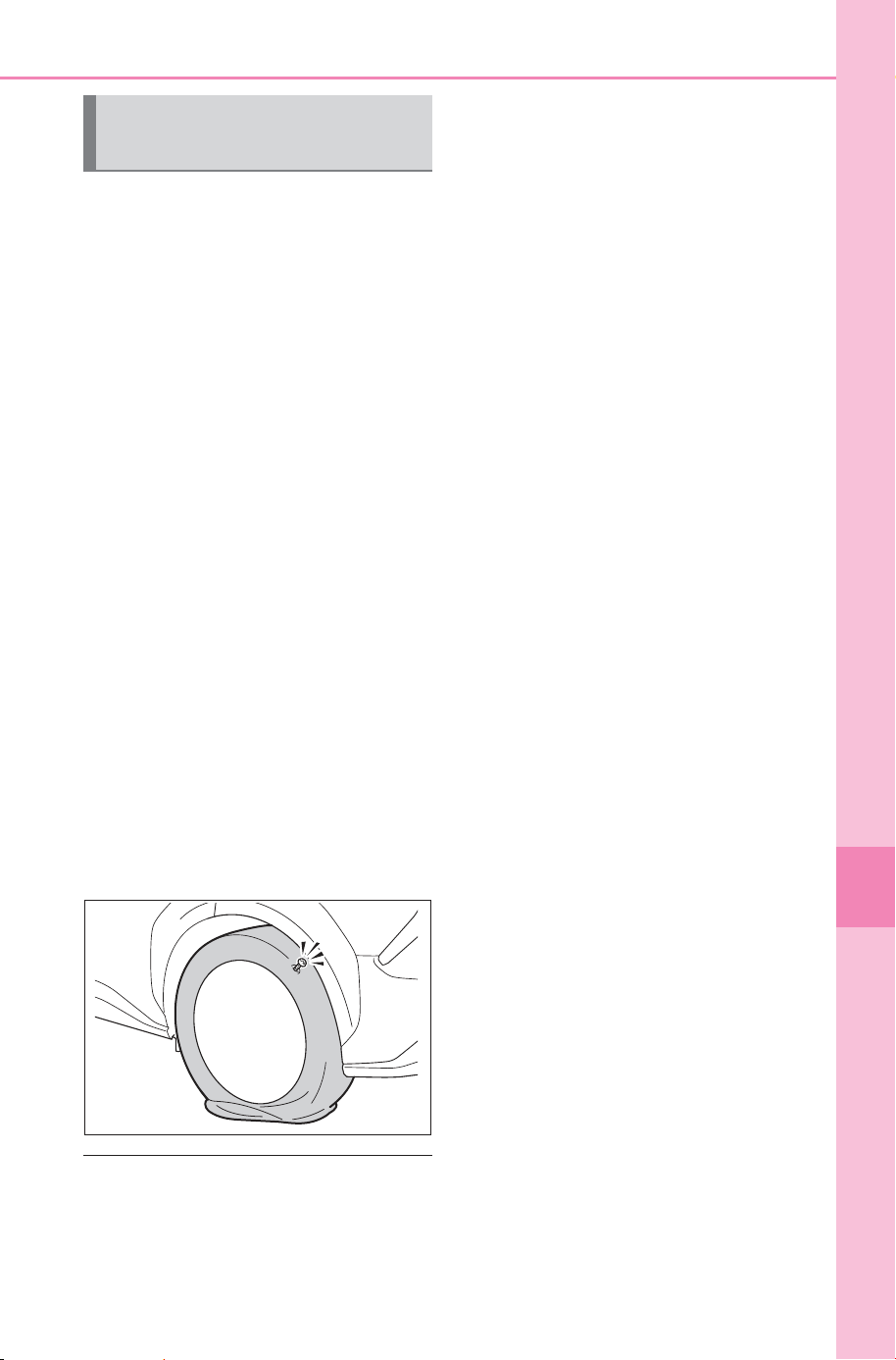
629
8-2. Steps to take in an emergency
Owner’s Manual_USA_M6740B_en
8
When trouble arises
Stop the vehicle in a safe
place on a hard, flat surface.
Set the parking brake.
Shift the shift position to P.
Stop the EV system.
Turn on the emergency flash-
ers.
Check the degree of the tire
damage.
A tire should only be repaired with
the emergency tire puncture repair
kit if the damage is caused by a nail
or screw passing through the tire
tread.
• Do not remove the nail or screw
from the tire. Removing the object
may widen the opening and make
emergency repair with the repair
kit impossible.
• To avoid sealant leakage, move
the vehicle until the area of the
puncture, if known, is positioned
at the top of the tire.
■ A flat tire that cannot be
repaired with the emergency
tire puncture repair kit
In the following cases, the tire can-
not be repaired with the emergency
tire puncture repair kit. Contact your
SUBARU dealer.
● When the tire is damaged due to
driving without sufficient air pres-
sure
● When there are any cracks or
damage at any location on the
tire, such as on the side wall,
except the tread
● When the tire is visibly separated
from the wheel
● When the cut or damage to the
tread is 0.16 in. (4 mm) long or
more
● When the wheel is damaged
● When two or more tires have been
punctured
● When more than one sharp
objects such as nails or screws
have passed through the tread on
a single tire
Before repairing the vehi-
cle
SOLTERRA_OM_USA_A6740BE.book 629 ページ 2025年5月23日 金曜日 午後1時18分
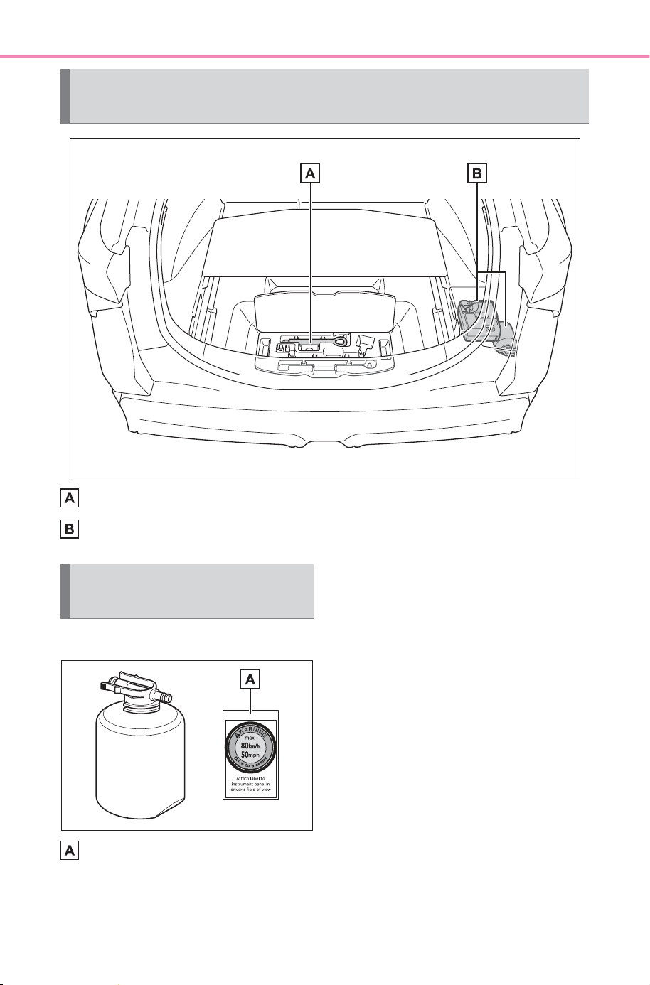
630
8-2. Steps to take in an emergency
Owner’s Manual_USA_M6740B_en
Towing eyelet
Emergency tire puncture repair kit
■ Bottle
Sticker
Location of the emergency tire puncture repair kit and
tools
Emergency tire puncture
repair kit components
SOLTERRA_OM_USA_A6740BE.book 630 ページ 2025年5月23日 金曜日 午後1時18分
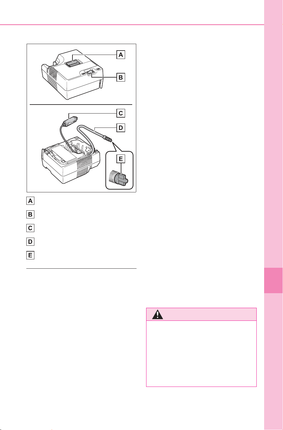
631
8-2. Steps to take in an emergency
Owner’s Manual_USA_M6740B_en
8
When trouble arises
■ Compressor
Air pressure gauge
Compressor switch
Power plug
Hose
Air release cap
■ Emergency tire puncture repair
kit
● The sealant stored in the emer-
gency tire puncture repair kit can
be used only once to temporarily
repair a single tire. If the sealant in
the bottle and other parts of the kit
have been used and need to be
replaced, contact your SUBARU
dealer.
● The compressor can be used
repeatedly.
● The sealant can be used when the
outside temperature is from -40°F
(-40°C) to 140°F (60°C).
● The kit is exclusively designed for
size and type of tires originally
installed on your vehicle. Do not
use it for tires that a different size
than the original ones, or for any
other purposes.
● If the sealant gets on your clothes,
it may stain.
● If the sealant adheres to a wheel
or the surface of the vehicle body,
the stain may not be removable if
it is not cleaned at once. Immedi-
ately wipe away the sealant with a
wet cloth.
● During operation of the repair kit,
a loud operation noise is pro-
duced. This does not indicate a
malfunction.
● Do not use to check or to adjust
the tire pressure.
■ Note for checking the emer-
gency tire puncture repair kit
● Check the sealant expiry date
occasionally. The expiry date is
shown on the bottle.
● Do not use sealant whose expiry
date has already passed. Other-
wise, repairs conducted using the
emergency tire puncture repair kit
may not be performed properly.
● The sealant has a limited life
span. The expiry date is marked
on the bottle. The sealant should
be replaced before the expiry
date. Contact your SUBARU
dealer for replacement.
WARNING
■ If you have a flat tire
Driving even a short distance with
a flat tire can damage the tire and
the wheel beyond repair.
Driving with a flat tire may cause a
circumferential groove on the side
wall. In such a case, the tire may
explode when using a repair kit.
SOLTERRA_OM_USA_A6740BE.book 631 ページ 2025年5月23日 金曜日 午後1時18分
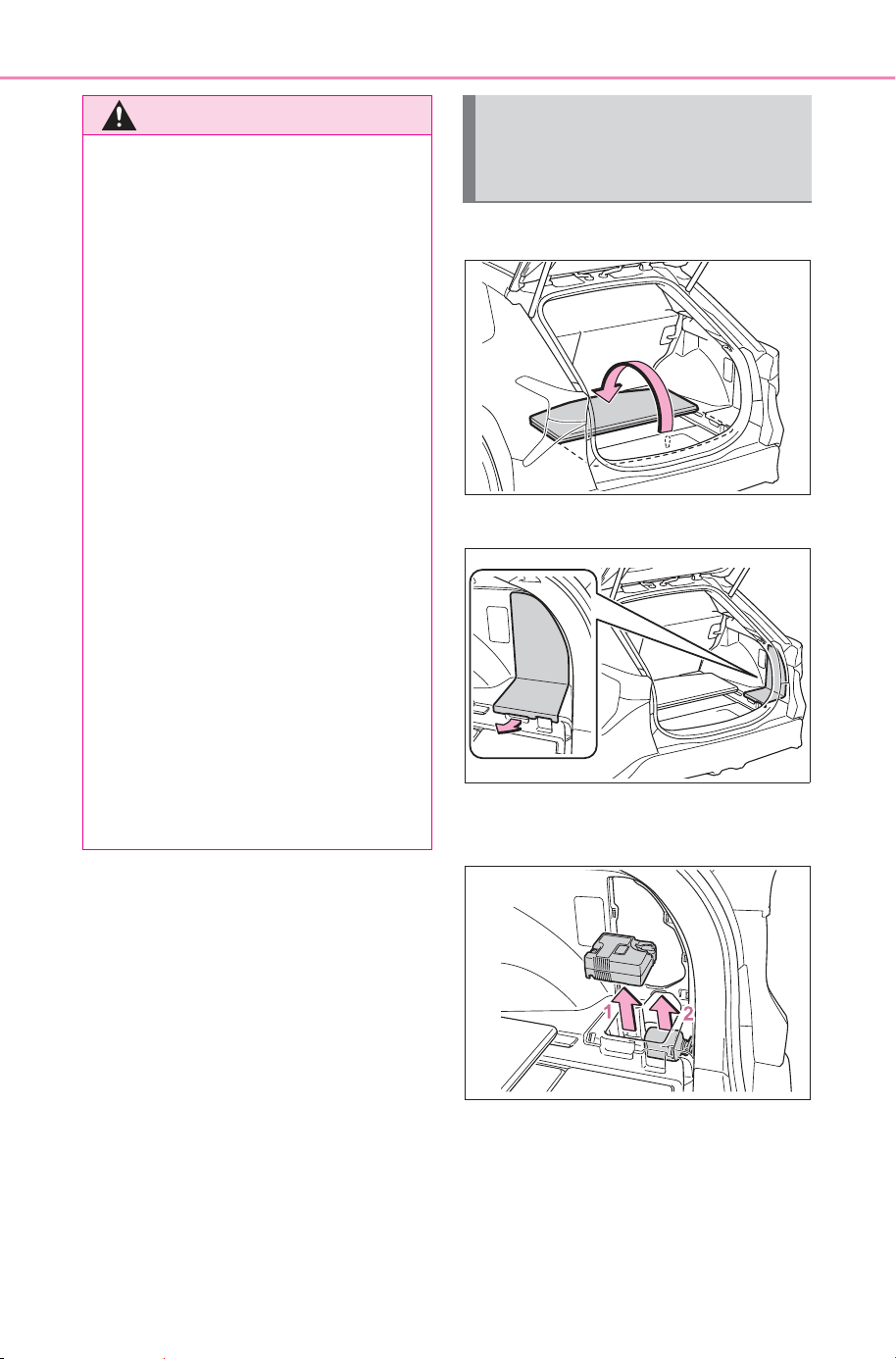
632
8-2. Steps to take in an emergency
Owner’s Manual_USA_M6740B_en
1 Open the deck board.
2 Remove the cover.
3 Take out the emergency tire
puncture repair kit.
1 Compressor
2 Bottle
WARNING
■ Caution while driving
● Store the repair kit in the lug-
gage compartment. Injuries may
result in the event of an acci-
dent or sudden braking.
● The repair kit is exclusively only
for your vehicle. Do not use
repair kit on other vehicles,
which could lead to an accident
causing death or serious injury.
● Do not use repair kit for tires
that are different size than the
original ones, or for any other
purpose. If the tires have not
been completely repaired, it
could lead to an accident caus-
ing death or serious injury.
■ Precautions for use of the
sealant
● Ingesting the sealant is hazard-
ous to your health. If you ingest
sealant, consume as much
water as possible, then immedi-
ately consult a doctor.
● If sealant gets in eyes or
adheres to skin, immediately
wash it off with water. If discom-
fort persists, consult a doctor.
Taking out the emer-
gency tire puncture repair
kit
SOLTERRA_OM_USA_A6740BE.book 632 ページ 2025年5月23日 金曜日 午後1時18分
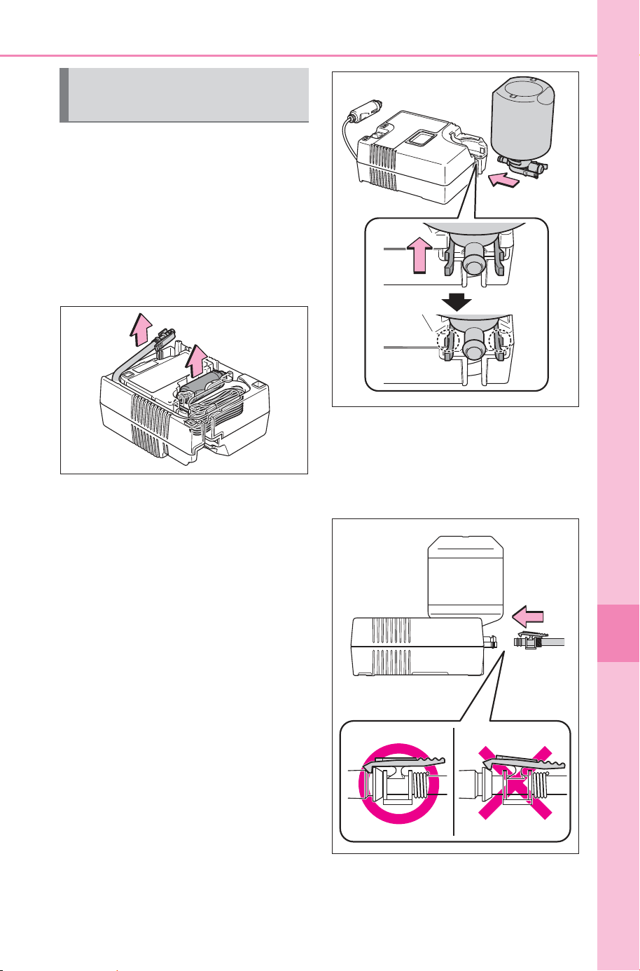
633
8-2. Steps to take in an emergency
Owner’s Manual_USA_M6740B_en
8
When trouble arises
1 Take out the repair kit from
the plastic bag.
Attach the sticker enclosed with the
bottle on the specified locations.
(See step
10.)
2 Remove the hose and take
out the power plug from the
compressor.
3 Connect the bottle to the
compressor.
Insert and connect the bottle
straight into the compressor as
shown in the illustration, and check
that the claws of the bottle are con-
cealed in the holes.
4 Connect the hose to the bot-
tle.
As shown in the illustration, make
sure the hose is connected
securely to the bottle.
Emergency repair proce-
dure
SOLTERRA_OM_USA_A6740BE.book 633 ページ 2025年5月23日 金曜日 午後1時18分
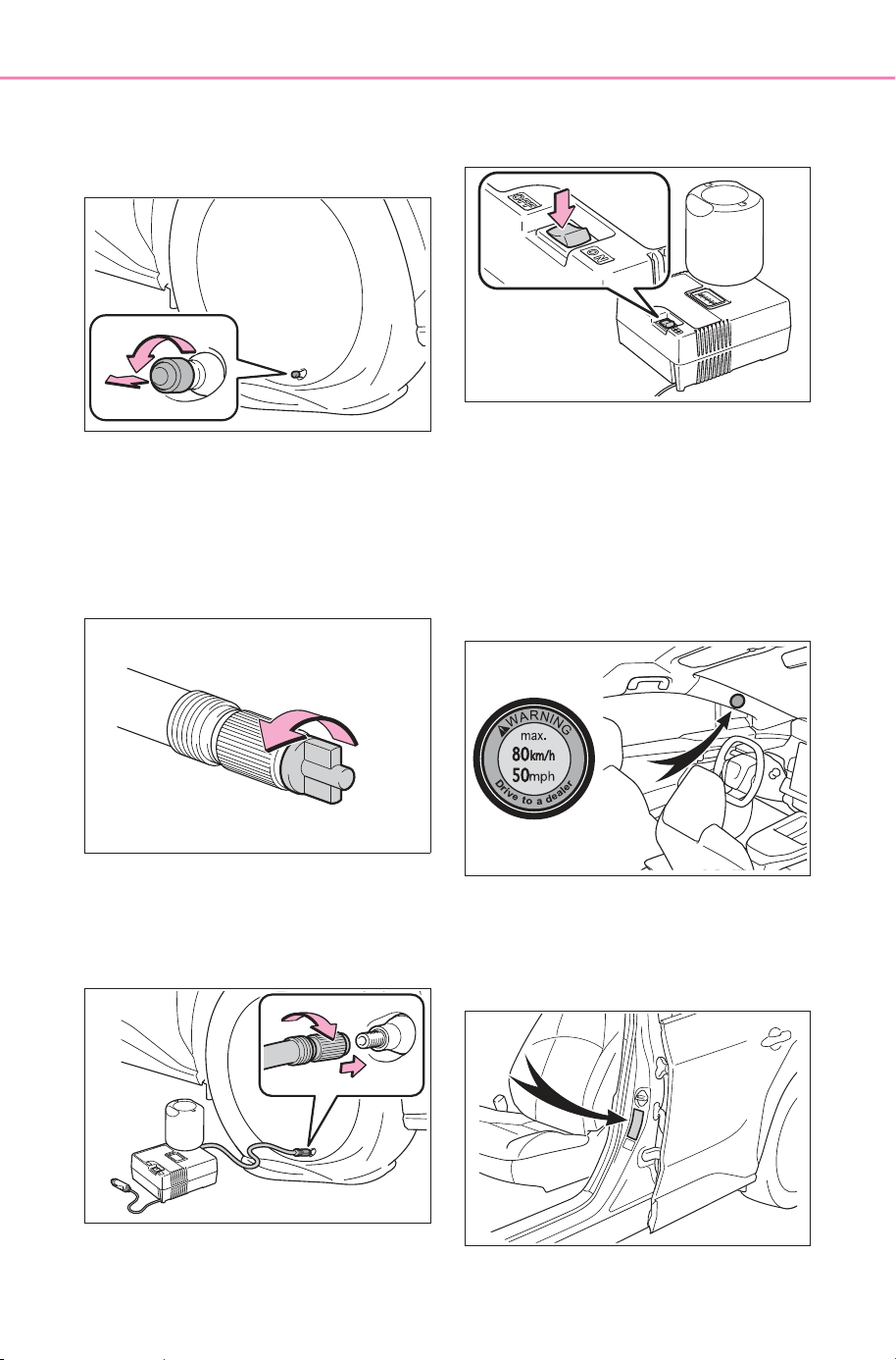
634
8-2. Steps to take in an emergency
Owner’s Manual_USA_M6740B_en
5 Remove the valve cap from
the valve of the punctured
tire.
6 Extend the hose. Remove
the air release cap from the
hose.
You will use the air release cap
again. Therefore keep it in a safe
place.
7 Connect the hose to the
valve.
Screw the end of the hose clock-
wise as far as possible.
8 Make sure that the compres-
sor switch is off.
9 Connect the power plug to
the power outlet socket.
(P.519)
10Attach the sticker provided
with the tire puncture repair
kit to a position easily seen
from the driver’s seat.
11Check the specified tire infla-
tion pressure.
Tire inflation pressure is specified
on the label as shown. (P.661)
SOLTERRA_OM_USA_A6740BE.book 634 ページ 2025年5月23日 金曜日 午後1時18分
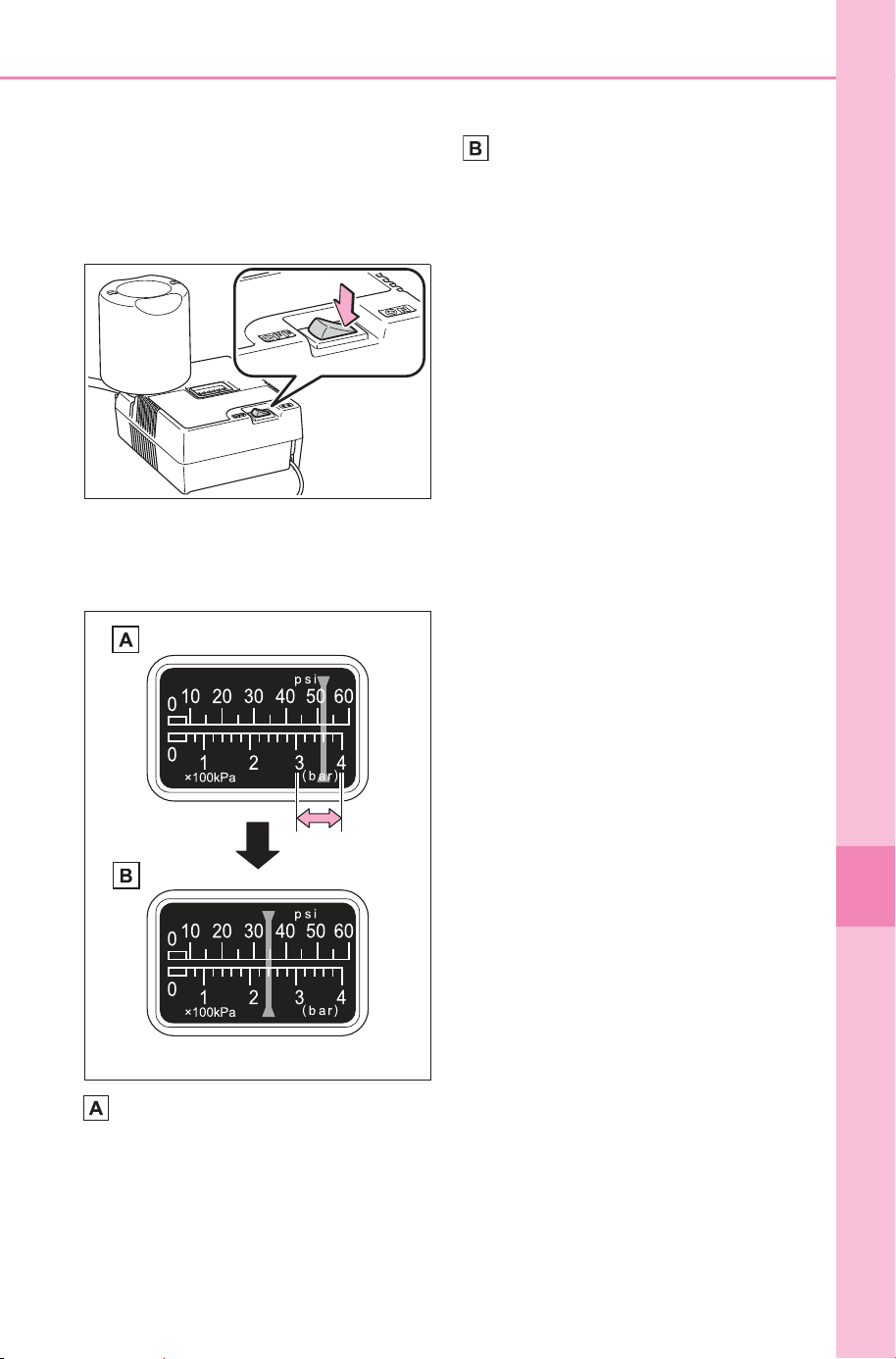
635
8-2. Steps to take in an emergency
Owner’s Manual_USA_M6740B_en
8
When trouble arises
12Start the EV system.
(P.229)
13To inject the sealant and
inflate the tire, turn the com-
pressor switch on.
14Inflate the tire until the rec-
ommended pressure is
reached.
The sealant will be injected
and the pressure will spike to
between 44 psi (300 kPa, 3.0
kgf/cm
2
or bar) and 58 psi
(400 kPa, 4.0 kgf/cm
2
or bar),
then gradually decrease.
The air pressure gauge will
display the actual tire inflation
pressure about 1 to 5 min-
utes after the switch is turned
on.
• Turn the compressor switch off
and then check the tire inflation
pressure. Being careful not to
over inflate, check and repeat the
inflation procedure until the speci-
fied tire inflation pressure is
reached.
• The tire can be inflated for about
5 to 20 minutes (depending on
the outside temperature). If the
tire inflation pressure is still lower
than the specified point after infla-
tion for 25 minutes, the tire is too
damaged to be repaired. Turn the
compressor switch off and con-
tact your SUBARU dealer.
• If the tire inflation pressure
exceeds the specified air pres-
sure, let out some air to adjust the
tire inflation pressure. (P.637)
15With the compressor switch
off, pull out the power plug
from the power outlet socket
and then disconnect the hose
from the valve on the tire.
Some sealant may leak when the
hose is removed.
16Install the valve cap onto the
valve of the emergency
repaired tire.
17Attach the air release cap to
the end of the hose.
If the air release cap is not
attached, the sealant may leak and
the vehicle may get dirty.
SOLTERRA_OM_USA_A6740BE.book 635 ページ 2025年5月23日 金曜日 午後1時18分
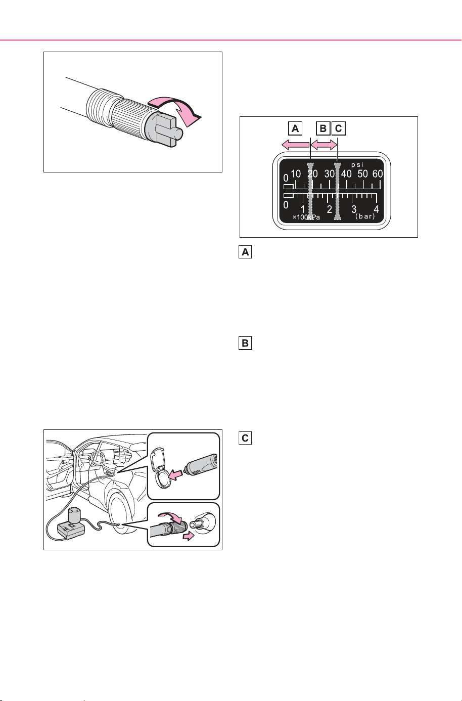
636
8-2. Steps to take in an emergency
Owner’s Manual_USA_M6740B_en
18Temporarily store the bottle
in the luggage compartment
while it is connected to the
compressor.
19To spread the liquid sealant
evenly within the tire, imme-
diately drive safely for about
3 miles (5 km) below 50 mph
(80 km/h).
20After driving, stop your vehi-
cle in a safe place on a hard,
flat surface and reconnect
the repair kit.
Remove the air release cap from
the hose before reconnecting the
hose.
21Turn the compressor switch
on and wait for several sec-
onds, then turn it off. Check
the tire inflation pressure.
If the tire inflation pressure is
under 19 psi (130 kPa, 1.3
kgf/cm
2
or bar): The puncture
cannot be repaired. Contact
your SUBARU dealer.
If the tire inflation pressure is
19 psi (130 kPa, 1.3 kgf/cm
2
or bar) or higher, but less
than the specified air pres-
sure: Proceed to step
22.
If the tire inflation pressure is
the specified air pressure
(P.661): Proceed to step
23.
22Turn the compressor switch
on to inflate the tire until the
specified air pressure is
reached. Drive for about 3
miles (5 km) and then per-
form step
20.
SOLTERRA_OM_USA_A6740BE.book 636 ページ 2025年5月23日 金曜日 午後1時18分
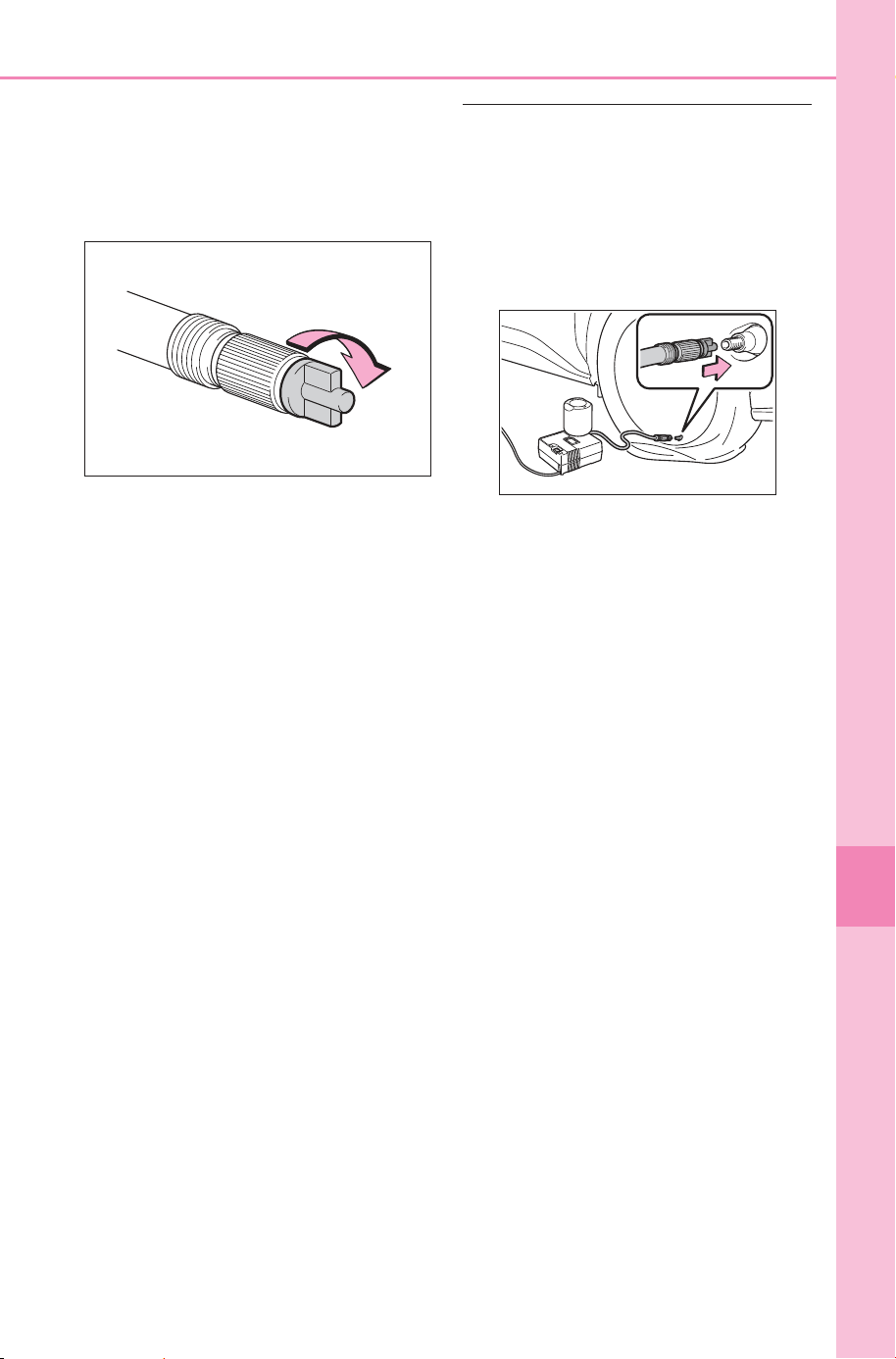
637
8-2. Steps to take in an emergency
Owner’s Manual_USA_M6740B_en
8
When trouble arises
23Attach the air release cap to
the end of the hose.
If the air release cap is not
attached, the sealant may leak and
the vehicle may get dirty.
24Store the bottle in the lug-
gage compartment while it is
connected to the compres-
sor.
25Taking precautions to avoid
sudden braking, sudden
acceleration and sharp turns,
drive carefully at under 50
mph (80 km/h) to the nearest
SUBARU dealer that is less
than 62 miles (100 km) away
for tire repair or replacement.
For repair and replacement of a tire
or disposal of the tire puncture
repair kit, contact your SUBARU
dealer.
When having the tire repaired or
replaced, make sure to tell the
SUBARU dealer that the sealant is
injected.
■ If the tire is inflated to more
than the specified air pressure
1 Disconnect the hose from the
valve.
2 Install the air release cap to the
end of the hose and push the
protrusion on the air release cap
into the valve to let some air out.
3 Disconnect the hose from the
valve, remove the air release cap
from the hose and then recon-
nect the hose.
4 Turn the compressor switch on
and wait for several seconds,
then turn it off. Check that the air
pressure indicator shows the
specified air pressure is reached.
(P.661)
If the air pressure is under the
designated pressure, turn the
compressor switch on again and
repeat the inflation procedure
until the specified air pressure is
reached.
■ After a tire is repaired with the
emergency tire puncture repair
kit (vehicle with the tire pres-
sure warning system)
● The tire pressure warning valve
and transmitter should be
replaced.
● Even if the tire inflation pressure is
at the recommended level, the tire
pressure warning light may come
on/flash.
SOLTERRA_OM_USA_A6740BE.book 637 ページ 2025年5月23日 金曜日 午後1時18分
638
8-2. Steps to take in an emergency
Owner’s Manual_USA_M6740B_en
WARNING
■ When fixing the flat tire
● Stop your vehicle in a safe and
flat area.
● Do not touch the wheels or the
area around the brakes immedi-
ately after the vehicle has been
driven. After the vehicle has
been driven, the wheels and the
area around the brakes may be
extremely hot. Touching these
areas with hands, feet or other
body parts may result in burns.
● Connect the valve and hose
securely with the tire installed
on the vehicle.
If the hose is not properly con-
nected to the valve, air leakage
may occur as sealant may be
sprayed out.
● If the hose comes off the valve
while inflating the tire, there is a
risk that the hose will move
abruptly due to air pressure.
● After inflation of the tire has
completed, the sealant may
splatter when the hose is dis-
connected or some air is let out
of the tire.
● Follow the operation procedure
to repair the tire. If the proce-
dure is not followed, the sealant
may spray out.
● Keep back from the tire while it
is being repaired, as there is a
chance of it bursting while the
repair operation is being per-
formed. If you notice any cracks
or deformation of the tire, turn
off the compressor switch and
stop the repair operation imme-
diately.
● The repair kit may overheat if
operated for a long period of
time. Do not operate the com-
pressor continuously for more
than 40 minutes.
● Parts of the repair kit become
hot during operation. Be careful
handling the repair kit during
and after operation. Do not
touch the metal part connecting
the bottle and the compressor. It
will be extremely hot.
● Do not attach the vehicle speed
warning sticker to an area other
than the one indicated. If the
sticker is attached to an area
where an SRS airbag is located,
such as the pad of the steering
wheel, it may prevent the SRS
air bag from operating properly.
■ Driving to spread the liquid
sealant evenly
Observe the following precautions
to reduce the risk of accidents.
Failing to do so may result in a
loss of vehicle control and cause
death or serious injury.
● Drive the vehicle carefully at a
low speed. Be especially careful
when turning and cornering.
● If the vehicle does not drive
straight or you feel a pull
through the steering wheel, stop
the vehicle and check the fol-
lowing:
• Tire condition. The tire may
have separated from the wheel.
• Tire inflation pressure. If the tire
inflation pressure is 19 psi (130
kPa, 1.3 kgf/cm
2
or bar) or less,
the tire may be severely dam-
aged.
SOLTERRA_OM_USA_A6740BE.book 638 ページ 2025年5月23日 金曜日 午後1時18分

639
8-2. Steps to take in an emergency
Owner’s Manual_USA_M6740B_en
8
When trouble arises
NOTICE
■ When performing an emer-
gency repair
● Perform the emergency repair
without removing the nail or
screw that has punctured the
tread of the tire. If the object
that has punctured the tire is
removed, repair by the emer-
gency tire puncture repair kit
may not be possible.
● The repair kit is not waterproof.
Make sure that the repair kit is
not exposed to water, such as
when it is being used in the rain.
● Do not put the repair kit directly
onto dusty ground such as sand
at the side of the road. If the
repair kit vacuums up dust, etc.,
a malfunction may occur.
● Make sure the sealant bottle of
the repair kit is in a vertical posi-
tion. The repair kit does not
operate properly when it is laid.
■ Precautions for the emer-
gency tire puncture repair kit
● The repair kit power source
should be 12 V DC suitable for
vehicle use. Do not connect the
repair kit to any other source.
● Place the repair kit in a storage
to prevent it from being exposed
to dirt or water.
● Store the repair kit in the lug-
gage compartment out of reach
of children.
● Do not disassemble or modify
the repair kit. Do not subject
parts such as the air pressure
indicator to impacts. This may
cause a malfunction.
■ To avoid damage to the tire
pressure warning valves and
transmitters (vehicle with the
tire pressure warning system)
When a tire is repaired with liquid
sealants, the tire pressure warn-
ing valve and transmitter may not
operate properly. If a liquid seal-
ant is used, contact your SUB-
ARU dealer or other qualified
service shop as soon as possible.
After use of liquid sealant, make
sure to replace the tire pressure
warning valve and transmitter
when repairing or replacing the
tire. (P.575)
SOLTERRA_OM_USA_A6740BE.book 639 ページ 2025年5月23日 金曜日 午後1時18分

640
8-2. Steps to take in an emergency
Owner’s Manual_USA_M6740B_en
One of the following may be the
cause of the problem:
The charging cable may be
connected to the vehicle.
(P. 9 2)
The electronic key may not be
functioning properly.
*
(P.642)
The traction battery may be
completely discharged.
Charge the traction battery.
(P. 8 8)
There may be a malfunction
in the immobilizer system.
*
(P. 6 5)
There may be a malfunction
in the shift control system.
*
(P.231, 627)
The EV system may be mal-
functioning due to an electri-
cal problem such as
electronic key battery deple-
tion or a blown fuse. However,
depending on the type of mal-
function, an interim measure
is available to start the EV
system. (P.641)
There is a possibility that the
temperature of the traction
battery is extremely low
(approximately below -22°F [-
30°C]). (P. 7 5, 230 )
*
: It may not be possible to shift the
shift position from P
One of the following may be the
cause of the problem:
The 12-volt battery may be
discharged. (P.644)
The 12-volt battery terminal
connections may be loose or
corroded. (P.568)
One of the following may be the
cause of the problem:
The 12-volt battery may be
discharged. (P.644)
If the EV system will
not start
Reasons for the EV system
not starting vary depending
on the situation. Check the
following and perform the
appropriate procedure:
Contact your SUBARU
dealer if the problem cannot
be repaired, or if repair pro-
cedures are unknown.
The EV system will not
start even though the cor-
rect starting procedure is
being followed (P.229)
The interior lights and
headlights are dim, or the
horn does not sound or
sounds at a low volume
The interior lights and
headlights do not turn on,
or the horn does not
sound
SOLTERRA_OM_USA_A6740BE.book 640 ページ 2025年5月23日 金曜日 午後1時18分
641
8-2. Steps to take in an emergency
Owner’s Manual_USA_M6740B_en
8
When trouble arises
One or both of the 12-volt bat-
tery terminals may be discon-
nected. (P.568)
Contact your SUBARU dealer if
the problem cannot be repaired,
or if repair procedures are
unknown.
When the EV system does not
start, the following steps can be
used as an interim measure to
start the EV system if the power
switch is functioning normally.
Do not use this starting proce-
dure except in cases of emer-
gency.
1 Set the parking brake.
2 Turn the power switch to
ACC
*1, 2
.
3 Press and hold the power
switch for about 15 seconds
while depressing the brake
pedal firmly.
Even if the EV system can be
started using the above steps,
the system may be malfunction-
ing. Have the vehicle inspected
by your SUBARU dealer.
*1
:ACC mode can be enabled/dis-
abled on the customize menu.
(P.677)
*2
:When ACC is disabled, turn the
power switch to ON then OFF,
and perform the following step
within 5 seconds.
Starting the EV system in
an emergency
If you lose your keys
New genuine keys can be
made by your SUBARU
dealer using the other key
and the key number
stamped on your key num-
ber plate. Keep the plate in
a safe place such as your
wallet, not in the vehicle.
NOTICE
■ When an electronic key is lost
If the electronic key remains lost,
the risk of vehicle theft increases
significantly. Visit your SUBARU
dealer immediately with all
remaining electronic keys that
were provided with your vehicle.
SOLTERRA_OM_USA_A6740BE.book 641 ページ 2025年5月23日 金曜日 午後1時18分
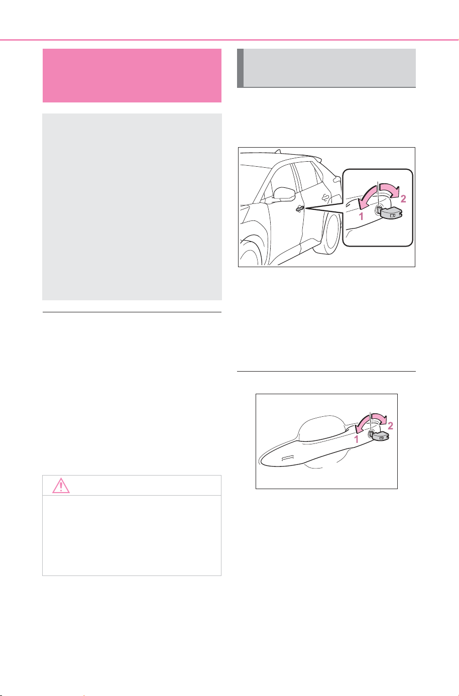
642
8-2. Steps to take in an emergency
Owner’s Manual_USA_M6740B_en
■ When the electronic key does
not work properly
● Make sure that the smart key sys-
tem has not been deactivated in
the customization setting. If it is
off, turn the function on.
(Customizable features: P.674)
● Check if battery-saving mode is
set. If it is set, cancel the function.
(P.179)
● The electronic key function may
have stopped. (P.179)
Use the mechanical key
(P.157) in order to perform the
following operations.
1 Locks all the doors
2 Unlocks the door
Turning the key rearward unlocks
the driver’s door. Turning the key
once again within 5 seconds
unlocks the other doors.
■ Key linked functions
1 Closes the windows (turn and
hold)
*
2 Opens the windows (turn and
hold)
*
*
: These settings must be custom-
ized at your SUBARU dealer.
If the electronic key
does not operate prop-
erly
If communication between
the electronic key and vehi-
cle is interrupted (P.179)
or the electronic key cannot
be used because the battery
is depleted, the smart key
system and wireless remote
control cannot be used. In
such cases, the doors can
be opened and the EV sys-
tem can be started by fol-
lowing the procedure below.
NOTICE
■ In case of a smart key system
malfunction, or other key
related problems
Take your vehicle with all the elec-
tronic keys provided with your
vehicle to your SUBARU dealer.
Locking and unlocking
the doors
SOLTERRA_OM_USA_A6740BE.book 642 ページ 2025年5月23日 金曜日 午後1時18分
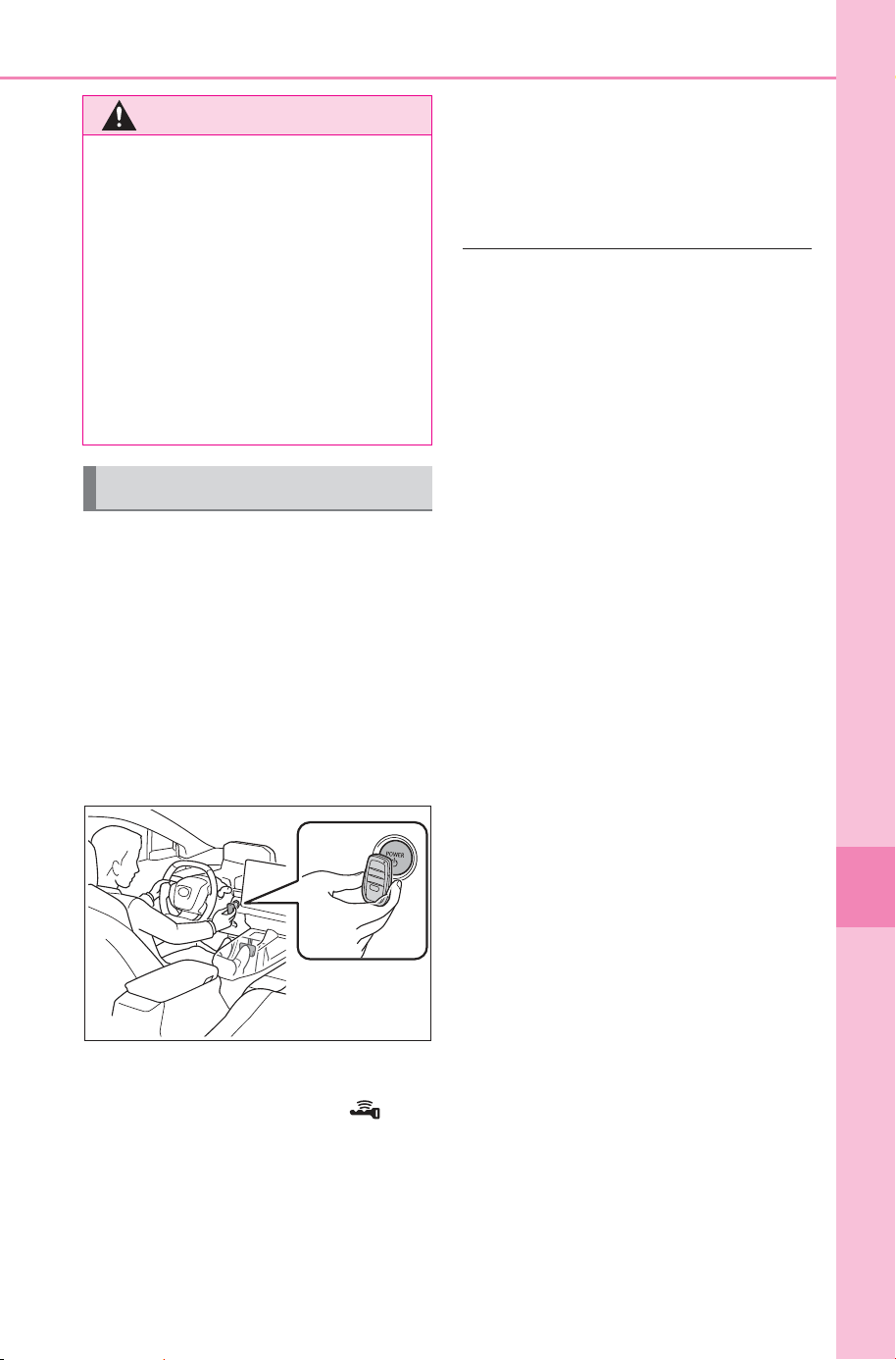
643
8-2. Steps to take in an emergency
Owner’s Manual_USA_M6740B_en
8
When trouble arises
1 Depress the brake pedal.
2 Touch the electronic key to
the power switch.
When the electronic key is
detected, a buzzer sounds and the
power switch will turn to ON.
When the smart key system is
deactivated in customization setting
and ACC customization is in on the
power switch will turn to ACC.
3 Firmly depress the brake
pedal and check that is
displayed on the multi-infor-
mation display.
4 Press the power switch
shortly and firmly.
In the event that the EV system still
cannot be started, contact your
SUBARU dealer.
■ Stopping the EV system
Shift the shift position to P, set the
parking brake and press the power
switch as you normally do when
stopping the EV system.
■ Replacing the key battery
As the above procedure is a tempo-
rary measure, it is recommended
that the electronic key battery be
replaced immediately when the bat-
tery is depleted. (P.594)
■ Alarm
If a door is unlocked using the
mechanical key when the alarm sys-
tem is set, the alarm may be trig-
gered. (P. 6 6 )
■ Changing power switch modes
Release the brake pedal and press
the power switch in step
3 above.
The EV system does not start and
modes will be changed each time
the switch is pressed. (P.232)
WARNING
■ When using the mechanical
key and operating the power
windows
Operate the power window after
checking to make sure that there
is no possibility of any passenger
having any of their body parts
caught in the window.
Also, do not allow children to
operate the mechanical key. It is
possible for children and other
passengers to get caught in the
power window.
Starting the EV system
SOLTERRA_OM_USA_A6740BE.book 643 ページ 2025年5月23日 金曜日 午後1時18分
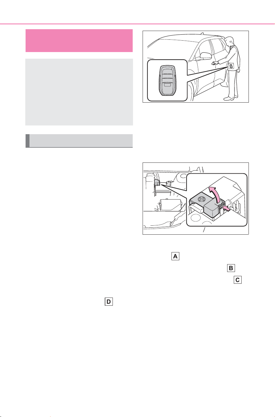
644
8-2. Steps to take in an emergency
Owner’s Manual_USA_M6740B_en
If you have a set of jumper (or
booster) cables and a second
vehicle with a 12-volt battery,
you can jump start your vehicle
by following the steps below.
1 Confirm that the electronic
key is being carried.
When connecting the jumper (or
booster) cables, depending on the
situation, the alarm may activate
and the doors locked. (P.67)
2 Open the hood (P.561).
3 Open the positive (+) battery
terminal cover.
While pressing on the claw, open
the cover as shown in the illustra-
tion.
4 Connect a positive jumper cable clamp to on your vehicle and
connect the clamp on the other end of the positive cable to on
the second vehicle. Then, connect a negative cable clamp to
on the second vehicle and connect the clamp at the other end of
the negative cable to .
Use jumper cables that can reach the specified terminals and connecting
point.
If the 12-volt battery is
discharged
The following procedures
may be used to start the EV
system if the vehicle’s 12-
volt battery is discharged.
You can also call your SUB-
ARU dealer or a qualified
repair shop.
Restarting the EV system
SOLTERRA_OM_USA_A6740BE.book 644 ページ 2025年5月23日 金曜日 午後1時18分
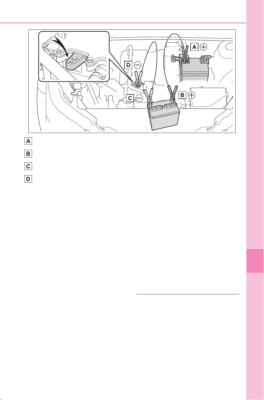
645
8-2. Steps to take in an emergency
Owner’s Manual_USA_M6740B_en
8
When trouble arises
Positive (+) battery terminal (your vehicle)
Positive (+) battery terminal (second vehicle)
Negative (-) battery terminal (second vehicle)
Metallic point shown in the illustration
5 Start the engine of the sec-
ond vehicle. Increase the
engine speed slightly and
maintain at that level for
approximately 5 minutes to
recharge the 12-volt battery
of your vehicle.
6 Open and close any of the
doors of your vehicle with the
power switch OFF.
7 Maintain the engine speed of
the second vehicle and start
the EV system of your vehi-
cle by turning the power
switch to ON.
8 Make sure the “READY” indi-
cator comes on. If the indica-
tor light does not come on,
contact your SUBARU
dealer.
9 Once the EV system has
started, remove the jumper
cables in the exact reverse
order from which they were
connected.
10Close the positive (+) battery
terminal cover.
Once the EV system starts,
have the vehicle inspected at
your SUBARU dealer as soon
as possible.
■ Starting the EV system when
the 12-volt battery is dis-
charged
The EV system cannot be started by
push-starting.
■ To prevent 12-volt battery dis-
charge
● Turn off the headlights, the air
conditioning system, the audio
system, etc. while the EV system
is off.
SOLTERRA_OM_USA_A6740BE.book 645 ページ 2025年5月23日 金曜日 午後1時18分

646
8-2. Steps to take in an emergency
Owner’s Manual_USA_M6740B_en
● Turn off any unnecessary electri-
cal components when the vehicle
is running at a low speed for an
extended period, such as in heavy
traffic.
● When ACC customization is in off,
power is still provided to the multi-
media system even though the
power switch is off. To turn off the
multimedia system, use the multi-
media system power switch. For
details, refer to the “MULTIMEDIA
OWNER’S MANUAL”.
■ Charging the 12-volt battery
The electricity stored in the 12-volt
battery will discharge gradually even
when the vehicle is not in use, due
to natural discharge and the drain-
ing effects of certain electrical appli-
ances. If the vehicle is left for a long
time, the 12-volt battery may dis-
charge, and the EV system may be
unable to start. (The 12-volt battery
recharges automatically while the
EV system is operating.)
■ When the 12-volt battery is
removed or discharged
● Information stored in the ECU is
cleared. When the 12-volt battery
is depleted, have the vehicle
inspected at your SUBARU
dealer.
● In some cases, it may not be pos-
sible to unlock the doors using the
smart key system when the 12-
volt battery is discharged. Use the
wireless remote control or the
mechanical key to lock or unlock
the doors.
● The EV system may not start on
the first attempt after the 12-volt
battery has recharged but will start
normally after the second attempt.
This is not a malfunction.
● The power switch mode is memo-
rized by the vehicle. When the 12-
volt battery is reconnected, the
system will return to the mode it
was in before the 12-volt battery
was discharged. Before discon-
necting the 12-volt battery, turn
the power switch off.
If you are unsure what mode the
power switch was in before the
12-volt battery discharged, be
especially careful when recon-
necting the 12-volt battery.
● If the 12-volt battery discharges, it
may not be possible to shift the
shift position to other positions. In
this case, the vehicle cannot be
towed without lifting both front
wheels because the front wheels
will be locked.
● The power back door (if equipped)
must be initialized. (P.172)
■ When replacing the 12-volt bat-
tery
● Use a 12-volt battery that con-
forms to European regulations.
● Use a 12-volt battery that the case
size is same as the previous one
(LN1), 20 hour rate capacity
(20HR) is equivalent (45Ah) or
greater, and performance rating
(CCA) is equivalent (286A) or
greater.
• If the sizes differ, the 12-volt bat-
tery cannot be properly secured.
• If an improper 12-volt battery is
used, battery performance may
decrease and the EV system may
not be able to restart.
• If the 20 hour rate capacity is low,
even if the time period where the
vehicle is not used is a short time,
the 12-volt battery may discharge
and EV system may not be able to
start.
For details, consult your SUBARU
dealer.
SOLTERRA_OM_USA_A6740BE.book 646 ページ 2025年5月23日 金曜日 午後1時18分
647
8-2. Steps to take in an emergency
Owner’s Manual_USA_M6740B_en
8
When trouble arises
WARNING
■ When removing the 12-volt
battery terminals
Always remove the negative (-)
terminal first. If the positive (+) ter-
minal contacts any metal in the
surrounding area when the posi-
tive (+) terminal is removed, a
spark may occur, leading to a fire
in addition to electrical shocks
and death or serious injury.
■ Avoiding 12-volt battery fires
or explosions
Observe the following precautions
to prevent accidentally igniting the
flammable gas that may be emit-
ted from the 12-volt battery:
● Make sure each jumper cable is
connected to the correct termi-
nal and that it is not unintention-
ally in contact with any other
than the intended terminal.
● Do not allow the other end of
the jumper cable connected to
the “+” terminal to come into
contact with any other parts or
metal surfaces in the area, such
as brackets or unpainted metal.
● Do not allow the + and - clamps
of the jumper cables to come
into contact with each other.
● Do not smoke, use matches,
cigarette lighters or allow open
flame near the 12-volt battery.
■ 12-volt battery precautions
The 12-volt battery contains poi-
sonous and corrosive acidic elec-
trolyte, while related parts contain
lead and lead compounds.
Observe the following precautions
when handling the 12-volt battery:
● When working with the 12-volt
battery, always wear safety
glasses and take care not to
allow any battery fluids (acid) to
come into contact with skin,
clothing or the vehicle body.
● Do not lean over the 12-volt bat-
tery.
● In the event that battery fluid
(acid) comes into contact with
the skin or eyes, immediately
wash the affected area with
water and seek medical atten-
tion.
Place a wet sponge or cloth
over the affected area until
medical attention can be
received.
● Always wash your hands after
handling the 12-volt battery and
other battery-related parts.
● Do not allow children near the
12-volt battery.
■ When replacing the 12-volt
battery
● When the vent plug is close to
the hold down clamp, the bat-
tery fluid (acid) may leak.
● For information regarding bat-
tery replacement, contact your
SUBARU dealer.
SOLTERRA_OM_USA_A6740BE.book 647 ページ 2025年5月23日 金曜日 午後1時18分
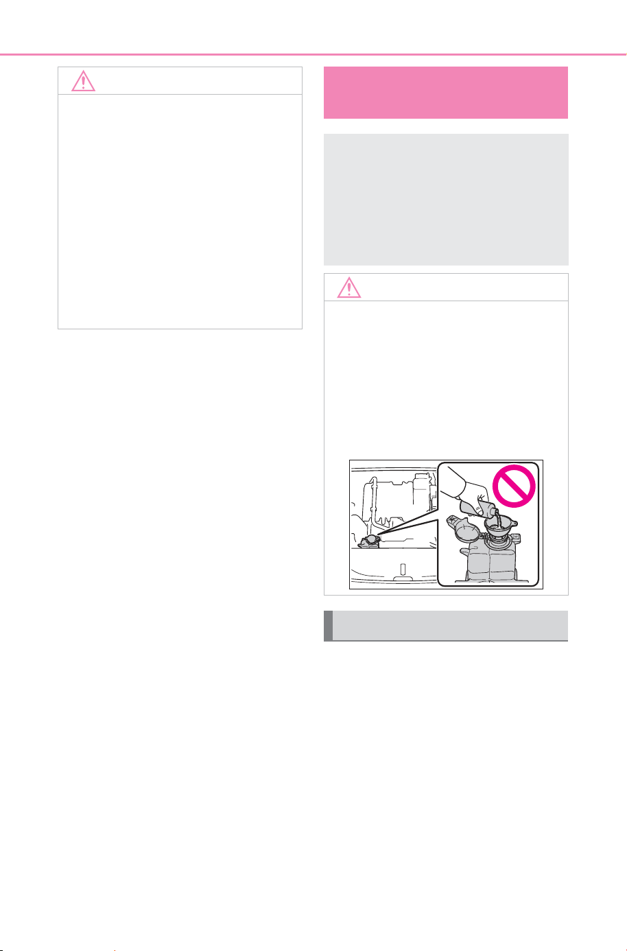
648
8-2. Steps to take in an emergency
Owner’s Manual_USA_M6740B_en
1 Stop the vehicle in a safe
place and turn off the air con-
ditioning system.
2 Leave the EV system operat-
ing and carefully lift the hood.
3 Check if the cooling fan is
operating.
If the fan is operating:
Wait until the “EV System
overheated Output power
reduced” message disap-
NOTICE
■ When handling jumper cables
When connecting the jumper
cables, ensure that they do not
become entangled in the cooling
fan.
■ When connecting jumper
cables
Make sure to connect jumper
cables to the specified terminals
and connecting point. Failure to
do so may adversely affect the
electronic devices or damage to
them.
If your vehicle over-
heats
When “EV System over-
heated Output power
reduced” is shown on the
multi-information display,
your vehicle may be over-
heating.
NOTICE
■ Cooling system coolant
The radiator coolant is exclusive
for radiator usage. Damage may
occur when water or any other
type of coolant is used, so never
use any other fluid. When there is
no “Genuine Traction Battery
Coolant”, immediately contact
your SUBARU dealer.
Correction procedures
SOLTERRA_OM_USA_A6740BE.book 648 ページ 2025年5月23日 金曜日 午後1時18分
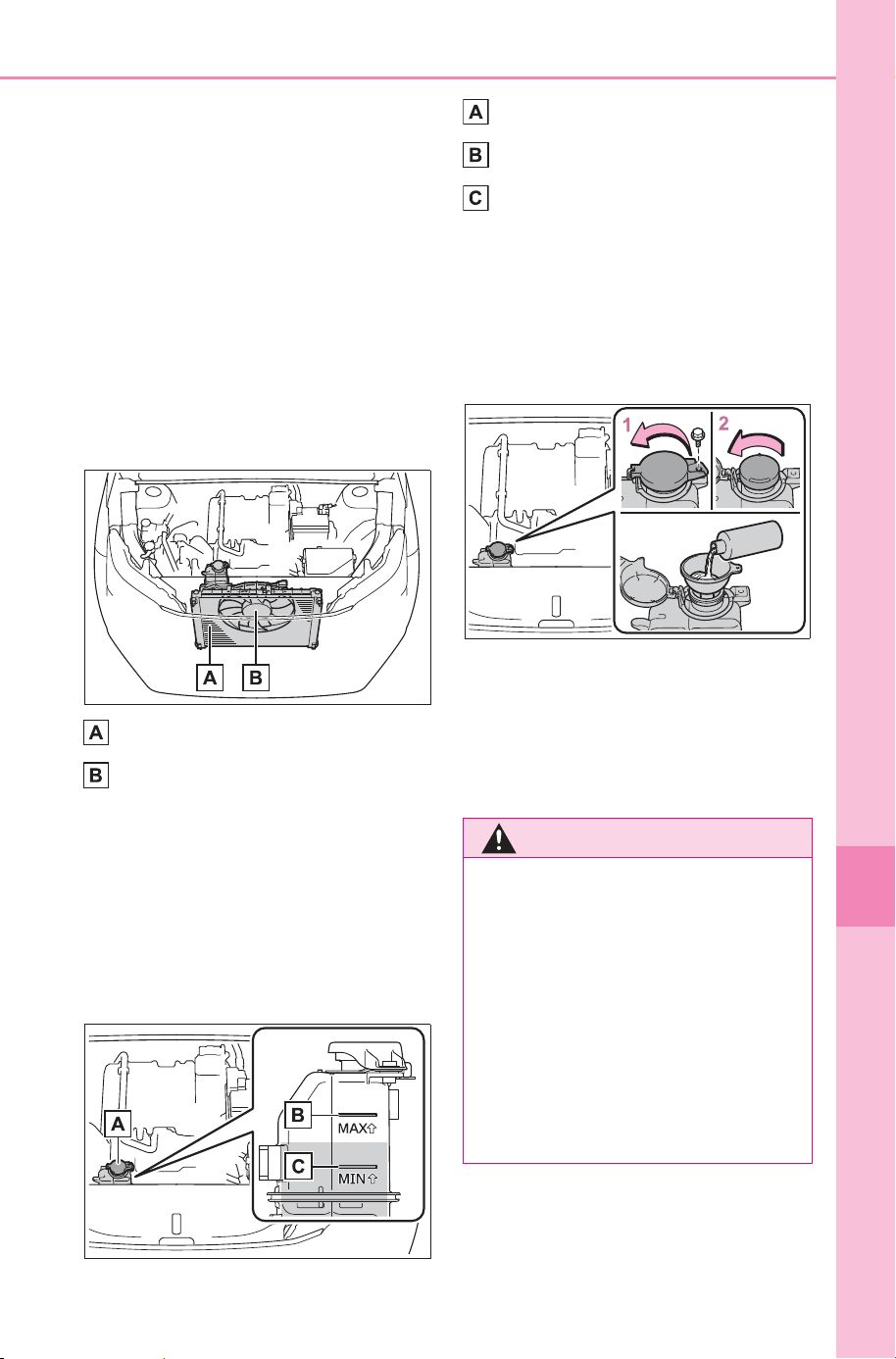
649
8-2. Steps to take in an emergency
Owner’s Manual_USA_M6740B_en
8
When trouble arises
pears and then stop the EV
system. If the message does
not disappear, call your SUB-
ARU dealer.
If the fan is not operating:
Stop the EV system immedi-
ately and call your SUBARU
dealer.
4 After the EV system has
cooled down, inspect the
hoses and radiator core (radi-
ator) for any leaks.
Radiator
Cooling fan
If a large amount of coolant leaks,
immediately contact your SUBARU
dealer.
5 The coolant level is satisfac-
tory if it is between the “MAX”
and “MIN” lines on the reser-
voir.
Reservoir
“MAX” line
“MIN” line
6 If the coolant is insufficient,
replenish with “Genuine Trac-
tion Battery Coolant”.
If you don’t have “Genuine Traction
Battery Coolant”, contact your
SUBARU dealer.
1 Remove the bolt.
2 Open the reservoir cap
Have the vehicle inspected at
the nearest your SUBARU
dealer.
WARNING
■ To prevent an accident or
injury when inspecting under
the hood of your vehicle
Observe the following precau-
tions.
Failure to do so may result in seri-
ous injury such as burns.
● If steam is seen coming from
under the hood, do not open the
hood until the steam has sub-
sided. The motor compartment
may be very hot.
SOLTERRA_OM_USA_A6740BE.book 649 ページ 2025年5月23日 金曜日 午後1時18分
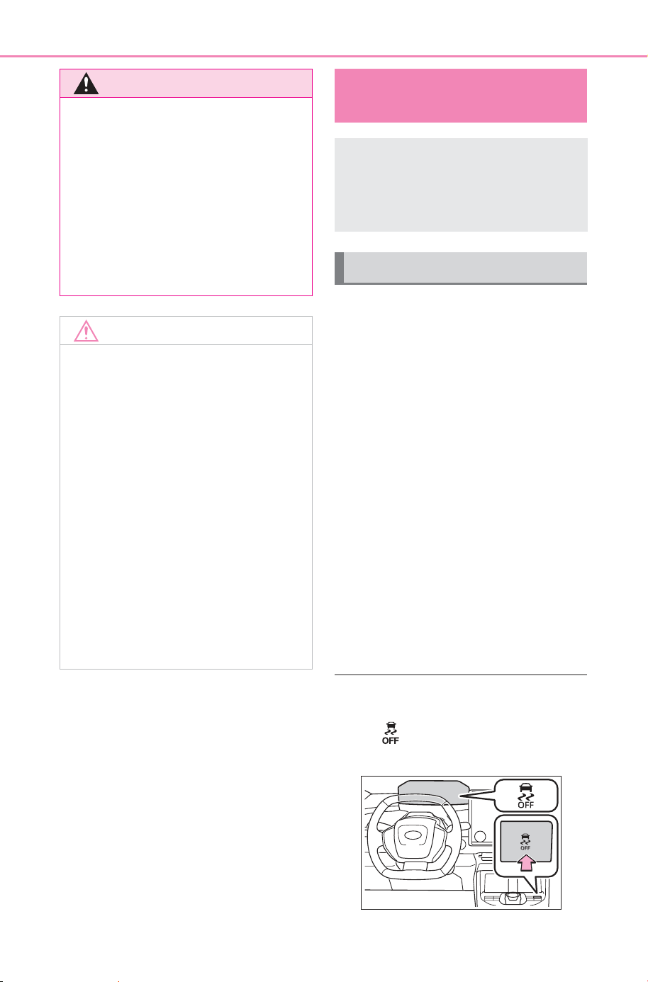
650
8-2. Steps to take in an emergency
Owner’s Manual_USA_M6740B_en
1 Stop the EV system. Set the
parking brake and shift the
shift position to P.
2 Remove the mud, snow or
sand from around the stuck
tire.
3 Place wood, stones or some
other material under the front
wheels to help provide trac-
tion.
4 Restart the EV system
5 Shift the shift position to D or
R and release the parking
brake. Then, while exercising
caution, depress the acceler-
ator pedal.
■ When it is difficult to free the
vehicle
Press to turn off TRAC.
(P.478)
WARNING
● Keep hands and clothing (espe-
cially a tie, a scarf or a muffler)
away from the fan. Failure to do
so may cause the hands or
clothing to be caught, resulting
in serious injury.
● Do not loosen the coolant reser-
voir cap while the EV system
and radiator are hot. High tem-
perature steam or coolant could
spray out.
NOTICE
■ When adding coolant
Add coolant slowly after the EV
system has cooled down suffi-
ciently. Adding cool coolant to a
hot EV system too quickly can
cause damage to the EV system.
■ To prevent damage to the
cooling system
Observe the following precau-
tions:
● Avoid contaminating the coolant
with foreign matter (such as
sand or dust, etc.).
● Do not use water or any other
coolant when refilling coolant.
Also, do not use any additive
agents for the coolant.
If the vehicle becomes
stuck
Carry out the following pro-
cedures if the tires spin or
the vehicle becomes stuck
in mud, dirt or snow:
Recovering procedure
SOLTERRA_OM_USA_A6740BE.book 650 ページ 2025年5月23日 金曜日 午後1時18分
651
8-2. Steps to take in an emergency
Owner’s Manual_USA_M6740B_en
8
When trouble arises
WARNING
■ When attempting to free a
stuck vehicle
If you choose to push the vehicle
back and forth to free it, make
sure the surrounding area is clear
to avoid striking other vehicles,
objects or people. The vehicle
may also lunge forward or lunge
back suddenly as it becomes free.
Use extreme caution.
■ When shifting the shift posi-
tion
Be careful not to shift the shift
position with the accelerator pedal
depressed.
This may lead to unexpected
rapid acceleration of the vehicle
that may cause an accident
resulting in death or serious injury.
NOTICE
■ To avoid damaging the trans-
mission and other compo-
nents
● Avoid spinning the tires and
depressing the accelerator
pedal more than necessary.
● If the vehicle remains stuck
even after these procedures are
performed, the vehicle may
require towing to be freed.
SOLTERRA_OM_USA_A6740BE.book 651 ページ 2025年5月23日 金曜日 午後1時18分

652
8-2. Steps to take in an emergency
Owner’s Manual_USA_M6740B_en
SOLTERRA_OM_USA_A6740BE.book 652 ページ 2025年5月23日 金曜日 午後1時18分

653
Owner’s Manual_USA_M6740B_en
9
9
Vehicle specifications
Vehicle specifications
9-1. Specifications
Maintenance data .......
654
Tire information ........... 662
9-2. Customization
Customizable features
671
9-3. Initialization
Items to initialize .........
686
9-4. Free/open source soft-
ware
Free/open source software
information ................ 687
SOLTERRA_OM_USA_A6740BE.book 653 ページ 2025年5月23日 金曜日 午後1時18分
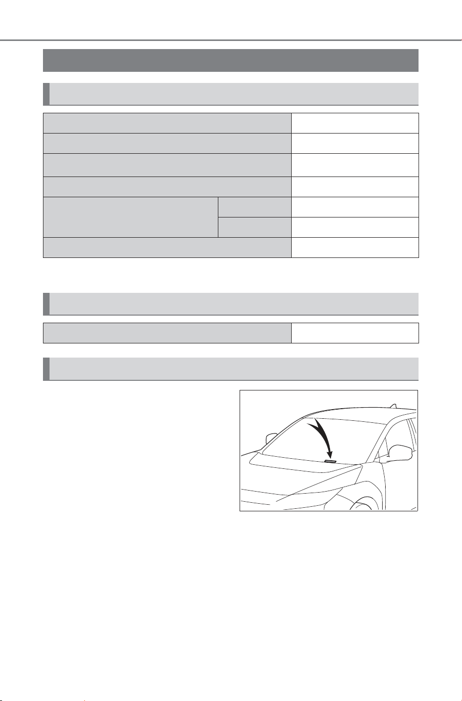
654
9-1. Specifications
Owner’s Manual_USA_M6740B_en
9-1.Sp ecifications
*
: Unladen vehicle
■ Vehicle identification num-
ber
The vehicle identification num-
ber (VIN) is the legal identifier
for your vehicle. This is the pri-
mary identification number for
your SUBARU. It is used in reg-
istering the ownership of your
vehicle.
This number is on the top left of
the instrument panel.
This number is also stamped
under the right-hand front seat.
Maintenance data
Dimensions and weights
Overall length 184.6 in. (4690 mm)
Overall width 73.2 in. (1860 mm)
Overall height
*
65.0 in. (1650 mm)
Wheelbase 112.2 in. (2850 mm)
Tread
Front 63.0 in. (1600 mm)
Rear 63.4 in. (1610 mm)
Vehicle capacity weight (Occupants + luggage) 1045 lb. (475 kg)
Seating capacity
Seating capacity 5 (Front 2, Rear 3)
Vehicle identification
SOLTERRA_OM_USA_A6740BE.book 654 ページ 2025年5月23日 金曜日 午後1時18分
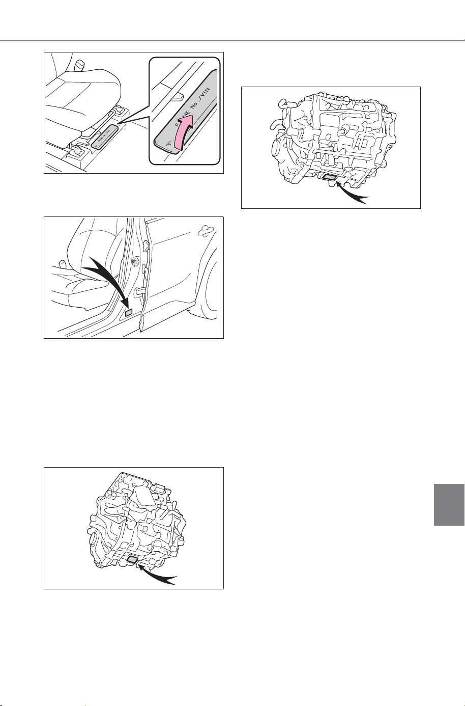
655
9-1. Specifications
Owner’s Manual_USA_M6740B_en
9
Vehicle specifications
This number is also on the Certi-
fication Regulation Label.
■ Motor model type and
motor number
The motor model type and the
motor number are stamped on
the motor as shown.
Front electric motor (traction
motor)
Rear electric motor (traction
motor) (AWD models)
SOLTERRA_OM_USA_A6740BE.book 655 ページ 2025年5月23日 金曜日 午後1時18分
656
9-1. Specifications
Owner’s Manual_USA_M6740B_en
*1
:For XEAM11L-SWDLNA, XEAM11L-SWDLLA, XEAM15L-SWDMNA,
XEAM15L-SWDMLA, XEAM15L-SWDHNA, XEAM15L-SWDHLA,
XEAM15L-SWDLLK, XEAM15L-SWDMLK, XEAM15L-SWDHLK mod-
els
*4
*2
:For XEAM11L-SWDLRK model
*4
*3
:For XEAM18L-SWDLNA, XEAM18L-SWDLLA, XEAM18L-SWDMNA,
XEAM18L-SWDMLA models
*4
*4
:The model code is indicated on the Certification Regulation Label.
(P.654)
Type A
*1
Front electric motor (traction motor)
Model 2XM
Type Permanent magnet synchronous motor
Maximum output
167.0 kW
*1
124.4 kW
*2
87.0 kW
*3
Maximum torque
198.1 ft•lbf (268.6 N•m, 27.3 kgf•m)
*1, 2
125.6 ft•lbf (170.3 N•m, 17.3 kgf•m)
*3
Rear electric motor (traction motor) (AWD models)
Model 3XM
Type Permanent magnet synchronous motor
Maximum output 88.3 kW
Maximum torque 125.2 ft•lbf (169.8 N•m, 17.3 kgf•m)
Traction battery
Type Lithium-ion battery
Voltage 3.70 V/cell
Cell rated capacity 200 Ah
SOLTERRA_OM_USA_A6740BE.book 656 ページ 2025年6月26日 木曜日 午前10時42分
657
9-1. Specifications
Owner’s Manual_USA_M6740B_en
9
Vehicle specifications
*1
:For XEAM11L-SWDLRK model
*2
*2
:The model code is indicated on the Certification Regulation Label.
(P.654)
Type B
*1
*1
:For XEAM11L-SWDLLA, XEAM18L-SWDLLA, XEAM18L-SWDMLA,
XEAM15L-SWDMLA, XEAM15L-SWDHLA, XEAM15L-SWDLLK,
XEAM15L-SWDMLK, XEAM15L-SWDHLK models
*2
*2
:The model code is indicated on the Certification Regulation Label.
(P.654)
Type C
*1
*1
:For XEAM11L-SWDLNA, XEAM18L-SWDLNA, XEAM18L-SWDMNA,
XEAM15L-SWDMNA, XEAM15L-SWDHNA models
*2
*2
:The model code is indicated on the Certification Regulation Label.
(P.654)
Quantity 78 cells
Nominal voltage 288.6 V
Type Lithium-ion battery
Voltage 3.70 V/cell
Cell rated capacity 200 Ah
Quantity 104 cells
Nominal voltage 384.8 V
Type Lithium-ion battery
Voltage 3.76 V/cell
Cell rated capacity 191 Ah
Quantity 104 cells
Nominal voltage 391.0 V
SOLTERRA_OM_USA_A6740BE.book 657 ページ 2025年5月23日 金曜日 午後1時18分
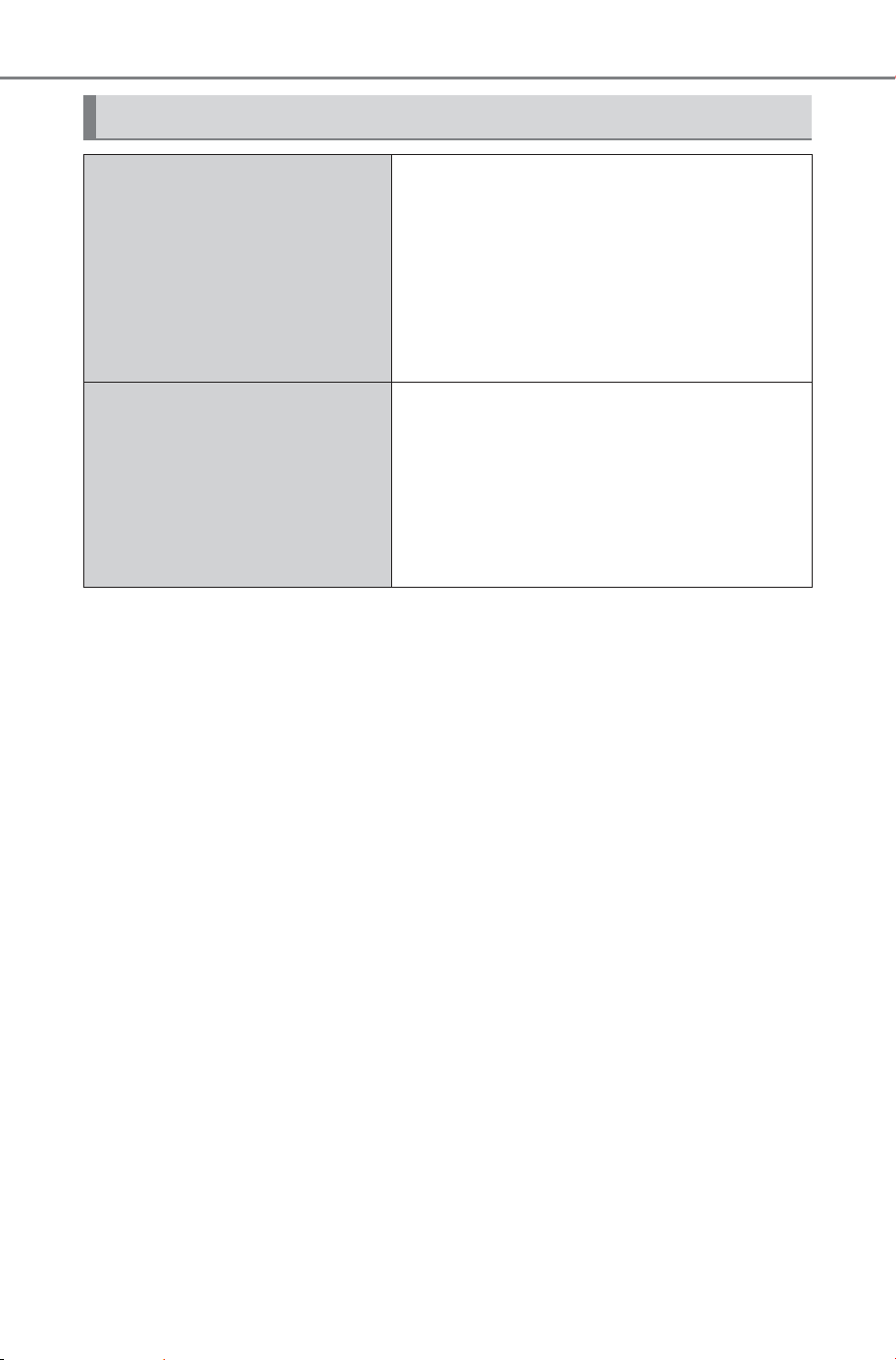
658
9-1. Specifications
Owner’s Manual_USA_M6740B_en
*1
:The coolant capacity is the quantity of reference.
If replacement is necessary, contact your SUBARU dealer.
*2
:For XEAM11L-SWDLLA, XEAM11L-SWDLRK models
*6
*3
:For XEAM11L-SWDLNA model
*6
*4
:For XEAM18L-SWDLLA, XEAM18L-SWDMLA, XEAM15L-SWDMLA,
XEAM15L-SWDHLA, XEAM15L-SWDLLK, XEAM15L-SWDMLK,
XEAM15L-SWDHLK
*6
*5
:For XEAM18L-SWDLNA, XEAM18L-SWDMNA, XEAM15L-SWDMNA,
XEAM15L-SWDHNA models
*6
*6
:The model code is indicated on the Certification Regulation Label.
(P.654)
Cooling system
Capacity
*1
FWD models
7.6 qt. (7.2 L, 6.3 Imp. qt.)
*2
7.4 qt. (7.0 L, 6.2 Imp. qt.)
*3
AWD models
8.1 qt. (7.7 L, 6.8 Imp. qt.)
*4
9.0 qt. (8.5 L, 7.5 Imp. qt.)
*5
Coolant type
Use either of the following:
• “Genuine Traction Battery Coolant”
• Similar high-quality ethylene glycol-
based, low electric conductivity coolant,
non-amine and non-borate coolant with
azole additives.
Do not use plain water alone.
SOLTERRA_OM_USA_A6740BE.book 658 ページ 2025年5月23日 金曜日 午後1時18分
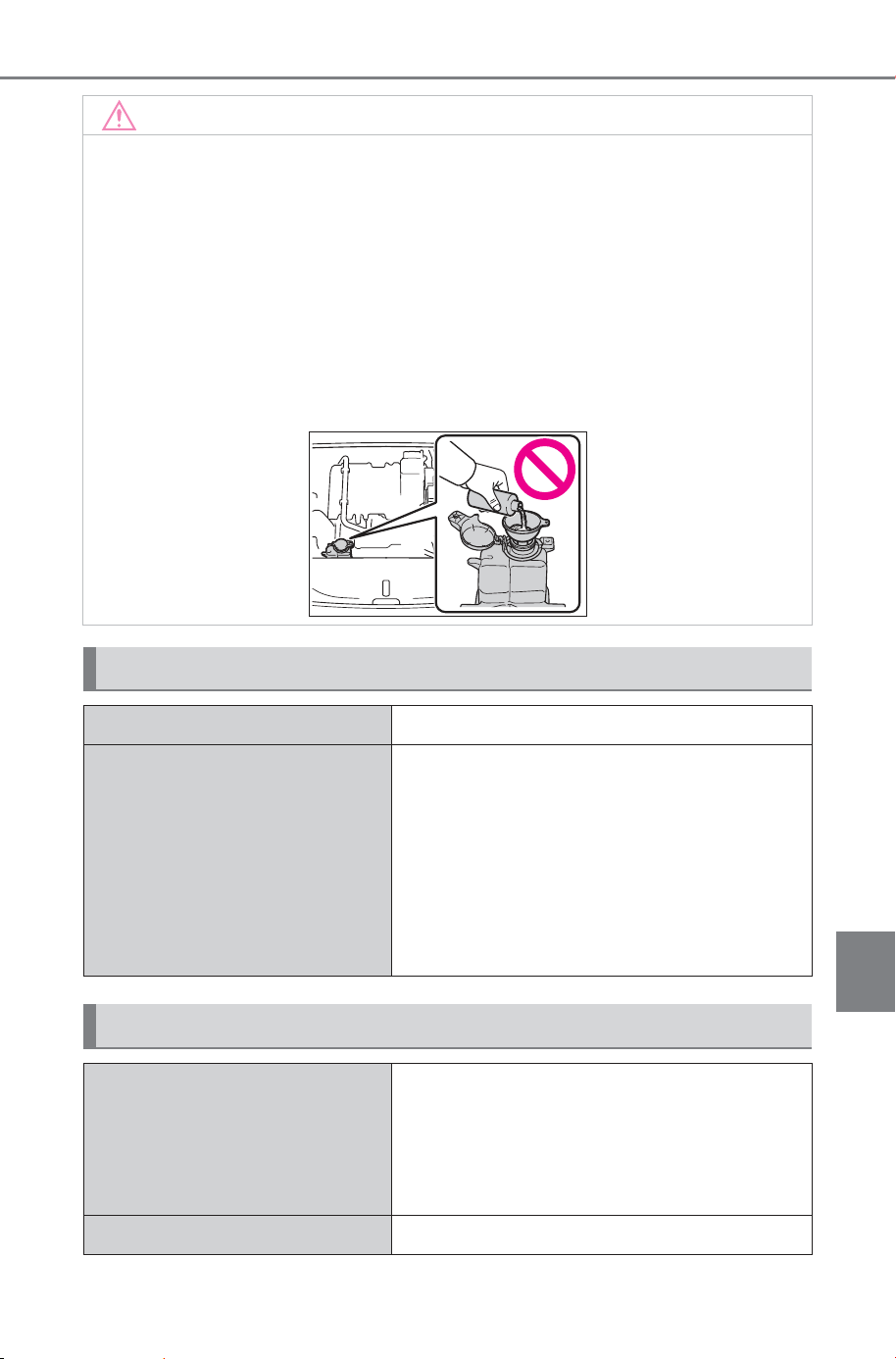
659
9-1. Specifications
Owner’s Manual_USA_M6740B_en
9
Vehicle specifications
NOTICE
■ Cooling system coolant
In order to ensure maximum performance of the traction battery cooling
system and limit risks of battery short circuit and other damage to your
vehicle, SUBARU recommends using “Genuine Traction Battery Coolant”
or similar high-quality ethylene glycol-based, low electric conductivity
coolant, non-amine and non-borate coolant with azole additives.
SUBARU cannot guarantee that the use of a product other than “Genuine
Traction Battery Coolant” will prevent risks of battery short circuit or other
damage.
Never use water as it will cause damage.
Do not reuse coolant that has been removed from the radiator.
Heater system
Capacity 4.2 qt. (4.0 L, 3.5 Imp. qt.)
Coolant type
Use either of the following:
• “GENUINE SUPER LONG LIFE COOL-
ANT (PINK)”
• Similar high-quality ethylene glycol-
based non-silicate, non-amine, non-
nitrite, and non-borate coolant with long-
life hybrid organic acid technology
Do not use plain water alone.
Electrical system (12-volt battery)
Specific voltage reading at
68°F (20°C):
12.0 V or More
In the case the voltage is less than stan-
dard, charge battery.
(Voltage is checked 20 minutes after the
motor and all lights turned off.)
Charging rates 5 A max.
SOLTERRA_OM_USA_A6740BE.book 659 ページ 2025年5月23日 金曜日 午後1時18分
660
9-1. Specifications
Owner’s Manual_USA_M6740B_en
*
: The fluid capacity is a reference quantity.
If replacement is necessary, contact your SUBARU dealer.
*
: The fluid capacity is a reference quantity.
If replacement is necessary, contact your SUBARU dealer.
*1
:Minimum pedal clearance when depressed with a force of 66 lbf (300 N,
31 kgf) while the EV system is operating.
Front eAxle
Fluid capacity
*
3.2 qt. (3.0 L, 2.6 Imp. qt.)
Fluid type e-Transaxle Fluid TE
NOTICE
■ Front eAxle fluid type
Using transaxle fluid other than the above type may cause abnormal
noise or vibration, or ultimately damage the front eAxle of your vehicle.
Rear eAxle (AWD models)
Fluid capacity
*
2.9 qt. (2.7 L, 2.4 Imp. qt.)
Fluid type e-Transaxle Fluid TE
NOTICE
■ Rear eAxle fluid type
Using transaxle fluid other than the above type may cause abnormal
noise or vibration, or ultimately damage the rear eAxle of your vehicle.
Brakes
Pedal clearance
*1
2.28 in. (58 mm) Min.
Pedal free play 0.04 - 0.24 in. (1.0 - 6.0 mm)
Parking brake indicator
*2
When pushing the parking brake switch for
1 to 4 seconds: turns off
When pulling the parking brake switch for
1 to 4 seconds: comes on
Fluid type
FMVSS No.116 DOT 3 or SAE J1703
FMVSS No.116 DOT 4 or SAE J1704
SOLTERRA_OM_USA_A6740BE.book 660 ページ 2025年5月23日 金曜日 午後1時18分
661
9-1. Specifications
Owner’s Manual_USA_M6740B_en
9
Vehicle specifications
*2
:Make sure to confirm that the brake system warning light (yellow) does
not illuminate. (If the brake system warning light illuminates, refer to
P.611)
18-inch tires
20-inch tires
Steering
Free play Less than 1.2 in. (30 mm)
Tires and wheels
Tire size 235/60R18 103V
Tire inflation pressure
(Recommended cold tire infla-
tion pressure)
Front:
39 psi (270 kPa, 2.7 kgf/cm
2
or bar)
Rear:
39 psi (270 kPa, 2.7 kgf/cm
2
or bar)
Wheel size 18 x 7 1/2J
Wheel nut torque 76 ft•lbf (103 N•m, 10.5 kgf•m)
Tire size 235/50R20 100V
Tire inflation pressure
(Recommended cold tire infla-
tion pressure)
Front:
38 psi (260 kPa, 2.6 kgf/cm
2
or bar)
Rear:
38 psi (260 kPa, 2.6 kgf/cm
2
or bar)
Wheel size 20 x 7 1/2J
Wheel nut torque 76 ft•lbf (103 N•m, 10.5 kgf•m)
SOLTERRA_OM_USA_A6740BE.book 661 ページ 2025年5月23日 金曜日 午後1時18分
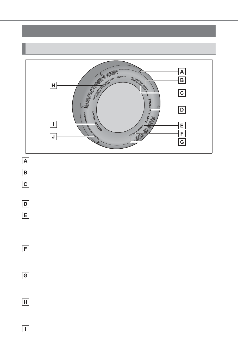
662
9-1. Specifications
Owner’s Manual_USA_M6740B_en
Location of treadwear indicators (P.571)
Load limit at maximum cold tire inflation pressure (P.665)
Maximum cold tire inflation pressure (P.665)
This means the pressure to which a tire may be inflated.
Tire size (P.663)
TUBELESS or TUBE TYPE
A tubeless tire does not have a tube and air is directly put into the tire. A
tube type tire has a tube inside the tire and the tube maintains the air pres-
sure.
Radial tires or bias-ply tires
A radial tire has “RADIAL” on the sidewall. A tire not marked “RADIAL” is a
bias-ply tire.
Summer tires or all season tires (P.572)
An all season tire has “M+S” on the sidewall. A tire not marked “M+S” is a
summer tire.
Tire ply composition and materials
Plies are layers of rubber-coated parallel cords. Cords are the strands
which form the plies in a tire.
DOT and Tire Identification Number (TIN) (P.663)
Tire information
Typical tire symbols
SOLTERRA_OM_USA_A6740BE.book 662 ページ 2025年5月23日 金曜日 午後1時18分
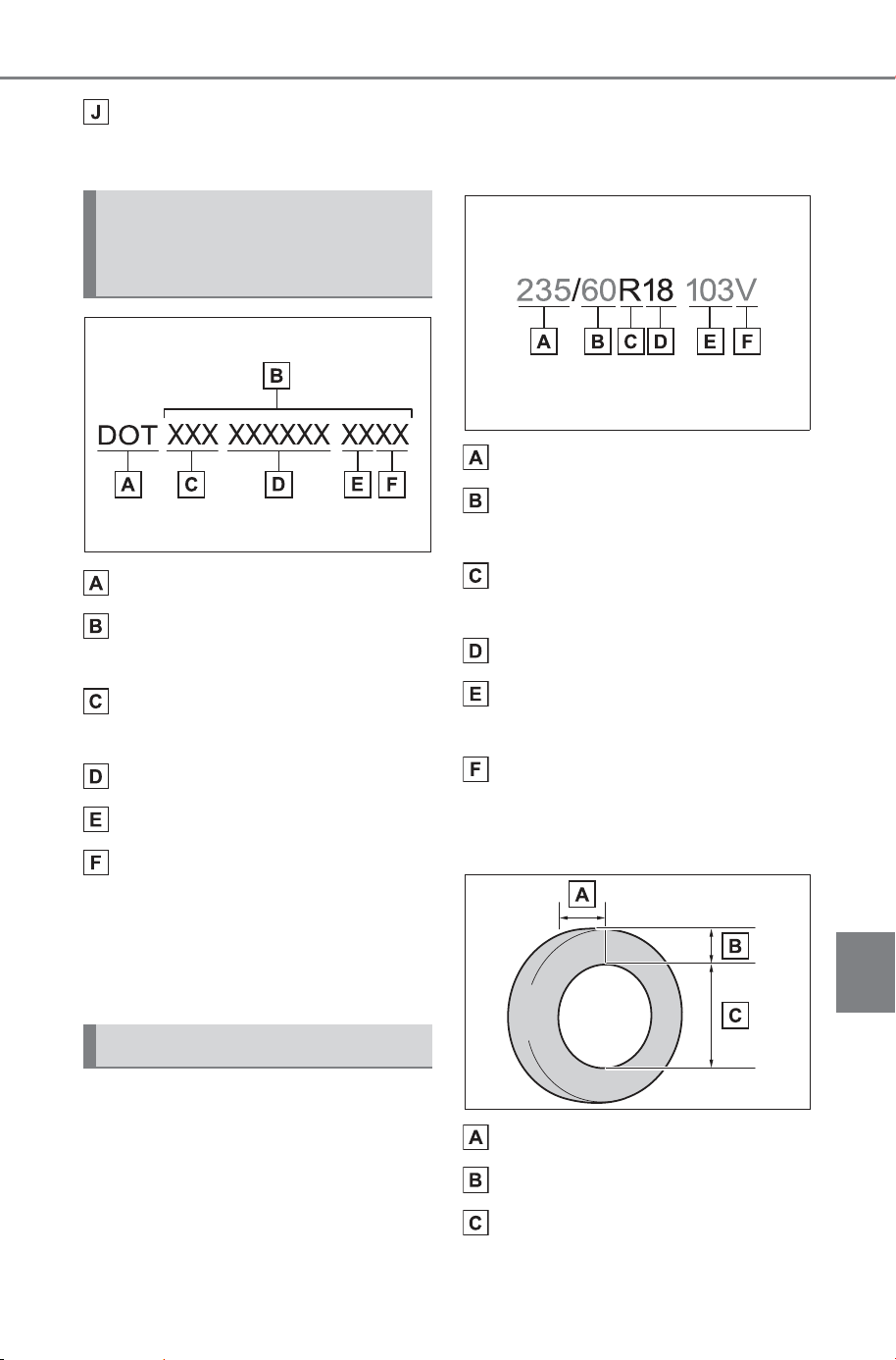
663
9-1. Specifications
Owner’s Manual_USA_M6740B_en
9
Vehicle specifications
Uniform tire quality grading
For details, see “Uniform Tire Quality Grading” that follows.
DOT symbol
*
Tire Identification Number
(TIN)
Tire manufacturer’s identifi-
cation mark
Manufacturer’s code
Manufacturing week
Manufacturing year
*
: The DOT symbol certifies that the
tire conforms to applicable Fed-
eral Motor Vehicle Safety Stan-
dards.
■ Typical tire size information
The illustration indicates typical
tire size.
Section width (millimeters)
Aspect ratio
(tire height to section width)
Tire construction code
(R = Radial, D = Diagonal)
Wheel diameter (inches)
Load index (2 digits or 3 dig-
its)
Speed symbol (alphabet with
one letter)
■ Tire dimensions
Section width
Tire height
Wheel diameter
Typical DOT and Tire
Identification Number
(TIN)
Tire size
SOLTERRA_OM_USA_A6740BE.book 663 ページ 2025年5月23日 金曜日 午後1時18分
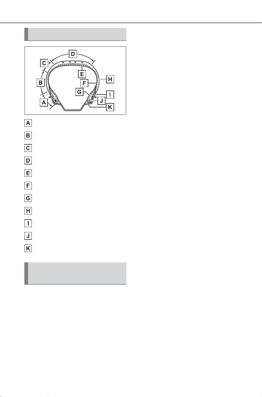
664
9-1. Specifications
Owner’s Manual_USA_M6740B_en
Bead
Sidewall
Shoulder
Tread
Belt
Inner liner
Reinforcing rubber
Carcass
Rim lines
Bead wires
Chafer
This information has been pre-
pared in accordance with regu-
lations issued by the National
Highway Traffic Safety Adminis-
tration of the U.S. Department of
Transportation.
It provides the purchasers
and/or prospective purchasers
of SUBARU vehicles with infor-
mation on uniform tire quality
grading.
Your SUBARU dealer will help
answer any questions you may
have as you read this information.
■ DOT quality grades
All passenger vehicle tires must
conform to Federal Safety
Requirements in addition to
these grades. Quality grades
can be found where applicable
on the tire sidewall between
tread shoulder and maximum
section width.
For example: Treadwear 200 Trac-
tion AA Temperature A
■ Treadwear
The treadwear grade is a com-
parative rating based on the
wear rate of the tire when tested
under controlled conditions on a
specified government test
course.
For example, a tire graded 150
would wear one and a half (1 - 1/2)
times as well on the government
course as a tire graded 100.
The relative performance of tires
depends upon the actual conditions
of their use. Performance may differ
significantly from the norm due to
variations in driving habits, service
practices and differences in road
characteristics and climate.
■ Traction AA, A, B, C
The traction grades, from high-
est to lowest, are AA, A, B and
C, and they represent the tire’s
ability to stop on wet pavement
Tire section names
Uniform Tire Quality
Grading
SOLTERRA_OM_USA_A6740BE.book 664 ページ 2025年5月23日 金曜日 午後1時18分
665
9-1. Specifications
Owner’s Manual_USA_M6740B_en
9
Vehicle specifications
as measured under controlled
conditions on specified govern-
ment test surfaces of asphalt
and concrete.
A tire marked C may have poor
traction performance.
Warning: The traction grade
assigned to this tire is based on
braking (straight ahead) traction
tests and does not include corner-
ing (turning) traction.
■ Temperature A, B, C
The temperature grades are A
(the highest), B, and C, repre-
senting the tire’s resistance to
the generation of heat and its
ability to dissipate heat when
tested under controlled condi-
tions on a specified indoor labo-
ratory test wheel.
Sustained high temperature can
cause the material of the tire to
degenerate and reduce tire life, and
excessive temperature can lead to
sudden tire failure.
Grade C corresponds to a level of
performance which all passenger
car tires must meet under the Fed-
eral Motor Vehicle Safety Standard
No. 109.
Grades B and A represent higher
levels of performance on the labo-
ratory test wheel than the minimum
required by law.
Warning: The temperature grades
of a tire assume that it is properly
inflated and not overloaded.
Excessive speed, underinflation, or
excessive loading, either sepa-
rately or in combination, can cause
heat buildup and possible tire fail-
ure.
Glossary of tire terminology
Tire related term Meaning
Cold tire inflation pres-
sure
Tire pressure when the vehicle has been parked
for three hours or more, or has not been driven
more than 1 mile or 1.5 km under that condition
Maximum inflation pres-
sure
The maximum cold inflated pressure to which a
tire may be inflated, shown on the sidewall of
the tire
Recommended inflation
pressure
Cold tire inflation pressure recommended by a
manufacturer
Accessory weight
The combined weight (in excess of those stan-
dard items which may be replaced) of transmis-
sion, power steering, power brakes, power
windows, power seats, radio and heater, to the
extent that these items are available as factory-
installed equipment (whether installed or not)
SOLTERRA_OM_USA_A6740BE.book 665 ページ 2025年5月23日 金曜日 午後1時18分

666
9-1. Specifications
Owner’s Manual_USA_M6740B_en
Curb weight
The weight of a motor vehicle with standard
equipment, including the maximum capacity of
traction battery and coolant, and if so equipped,
air conditioning and additional weight optional
traction motor
Maximum loaded vehicle
weight
The sum of:
(a) Curb weight
(b) Accessory weight
(c) Vehicle capacity weight
(d) Production options weight
Normal occupant weight
150 lb. (68 kg) times the number of occupants
specified in the second column of Table 1
*
that
follows
Occupant distribution
Distribution of occupants in a vehicle as speci-
fied in the third column of Table 1
*
below
Production options weight
The combined weight of installed regular pro-
duction options weighing over 5 lb. (2.3 kg) in
excess of the standard items which they
replace, not previously considered in curb
weight or accessory weight, including heavy
duty brakes, ride levelers, roof rack, heavy duty
battery, and special trim
Rim
A metal support for a tire or a tire and tube
assembly upon which the tire beads are seated
Rim diameter
(Wheel diameter)
Nominal diameter of the bead seat
Rim size designation Rim diameter and width
Rim type designation
The industry manufacturer’s designation for a
rim by style or code
Rim width Nominal distance between rim flanges
Vehicle capacity weight
(Total load capacity)
The rated cargo and luggage load plus 150 lb.
(68 kg) times the vehicle’s designated seating
capacity
Vehicle maximum load on
the tire
The load on an individual tire that is determined
by distributing to each axle its share of the max-
imum loaded vehicle weight, and dividing by two
Tire related term Meaning
SOLTERRA_OM_USA_A6740BE.book 666 ページ 2025年5月23日 金曜日 午後1時18分
667
9-1. Specifications
Owner’s Manual_USA_M6740B_en
9
Vehicle specifications
Vehicle normal load on
the tire
The load on an individual tire that is determined
by distributing to each axle its share of curb
weight, accessory weight, and normal occupant
weight (distributed in accordance with Table 1
*
below), and dividing by two
Weather side
The surface area of the rim not covered by the
inflated tire
Bead
The part of the tire that is made of steel wires,
wrapped or reinforced by ply cords and that is
shaped to fit the rim
Bead separation
A breakdown of the bond between components
in the bead
Bias ply tire
A pneumatic tire in which the ply cords that
extend to the beads are laid at alternate angles
substantially less than 90 degrees to the center-
line of the tread
Carcass
The tire structure, except tread and sidewall
rubber which, when inflated, bears the load
Chunking
The breaking away of pieces of the tread or
sidewall
Cord The strands forming the plies in the tire
Cord separation
The parting of cords from adjacent rubber com-
pounds
Cracking
Any parting within the tread, sidewall, or inner-
liner of the tire extending to cord material
CT
A pneumatic tire with an inverted flange tire and
rim system in which the rim is designed with rim
flanges pointed radially inward and the tire is
designed to fit on the underside of the rim in a
manner that encloses the rim flanges inside the
air cavity of the tire
Extra load tire
A tire designed to operate at higher loads and at
higher inflation pressures than the correspond-
ing standard tire
Groove The space between two adjacent tread ribs
Tire related term Meaning
SOLTERRA_OM_USA_A6740BE.book 667 ページ 2025年5月23日 金曜日 午後1時18分
668
9-1. Specifications
Owner’s Manual_USA_M6740B_en
Innerliner
The layer(s) forming the inside surface of a
tubeless tire that contains the inflating medium
within the tire
Innerliner separation
The parting of the innerliner from cord material
in the carcass
Intended outboard side-
wall
(a)The sidewall that contains a whitewall, bears
white lettering, or bears manufacturer, brand,
and/or model name molding that is higher or
deeper than the same molding on the other
sidewall of the tire, or
(b)The outward facing sidewall of an asymmetri-
cal tire that has a particular side that must
always face outward when mounted on a vehi-
cle
Light truck (LT) tire
A tire designated by its manufacturer as primar-
ily intended for use on lightweight trucks or mul-
tipurpose passenger vehicles
Load rating
The maximum load that a tire is rated to carry
for a given inflation pressure
Maximum load rating
The load rating for a tire at the maximum per-
missible inflation pressure for that tire
Maximum permissible
inflation pressure
The maximum cold inflation pressure to which a
tire may be inflated
Measuring rim
The rim on which a tire is fitted for physical
dimension requirements
Open splice
Any parting at any junction of tread, sidewall, or
innerliner that extends to cord material
Outer diameter The overall diameter of an inflated new tire
Overall width
The linear distance between the exteriors of the
sidewalls of an inflated tire, including elevations
due to labeling, decorations, or protective bands
or ribs
Passenger car tire
A tire intended for use on passenger cars, multi-
purpose passenger vehicles, and trucks, that
have a gross vehicle weight rating (GVWR) of
10,000 lb. or less.
Ply A layer of rubber-coated parallel cords
Tire related term Meaning
SOLTERRA_OM_USA_A6740BE.book 668 ページ 2025年5月23日 金曜日 午後1時18分
669
9-1. Specifications
Owner’s Manual_USA_M6740B_en
9
Vehicle specifications
Ply separation
A parting of rubber compound between adjacent
plies
Pneumatic tire
A mechanical device made of rubber, chemi-
cals, fabric and steel or other materials, that,
when mounted on an automotive wheel, pro-
vides the traction and contains the gas or fluid
that sustains the load
Radial ply tire
A pneumatic tire in which the ply cords that
extend to the beads are laid at substantially 90
degrees to the centerline of the tread
Reinforced tire
A tire designed to operate at higher loads and at
higher inflation pressures than the correspond-
ing standard tire
Section width
The linear distance between the exteriors of the
sidewalls of an inflated tire, excluding elevations
due to labeling, decoration, or protective bands
Sidewall
That portion of a tire between the tread and
bead
Sidewall separation
The parting of the rubber compound from the
cord material in the sidewall
Snow tire
A tire that attains a traction index equal to or
greater than 112, compared to the ASTM F2493
standard reference test tire when using the
snow traction test on the medium pack snow
surface as described in ASTM F1805-20, Stan-
dard Test Method for Single Wheel Driving Trac-
tion in a Straight Line on Snow-and Ice-Covered
Surfaces, and which is marked with an Alpine
Symbol ( ) on at least one sidewall
Test rim
The rim on which a tire is fitted for testing, and
may be any rim listed as appropriate for use
with that tire
Tread
That portion of a tire that comes into contact
with the road
Tread rib
A tread section running circumferentially around
a tire
Tire related term Meaning
SOLTERRA_OM_USA_A6740BE.book 669 ページ 2025年5月23日 金曜日 午後1時18分
670
9-1. Specifications
Owner’s Manual_USA_M6740B_en
*
:Table 1 Occupant loading and distribution for vehicle normal load for
various designated seating capacities
Tread separation Pulling away of the tread from the tire carcass
Treadwear indicators
(TWI)
The projections within the principal grooves
designed to give a visual indication of the
degrees of wear of the tread
Wheel-holding fixture
The fixture used to hold the wheel and tire
assembly securely during testing
Designated seating
capacity, Number of
occupants
Vehicle normal load,
Number of occupants
Occupant distribution in
a normally loaded vehi-
cle
2 through 4 2 2 in front
5 through 10 3
2 in front, 1 in second
seat
11 through 15 5
2 in front, 1 in second
seat, 1 in third seat, 1 in
fourth seat
16 through 22 7
2 in front, 2 in second
seat, 2 in third seat, 1 in
fourth seat
Tire related term Meaning
SOLTERRA_OM_USA_A6740BE.book 670 ページ 2025年5月23日 金曜日 午後1時18分
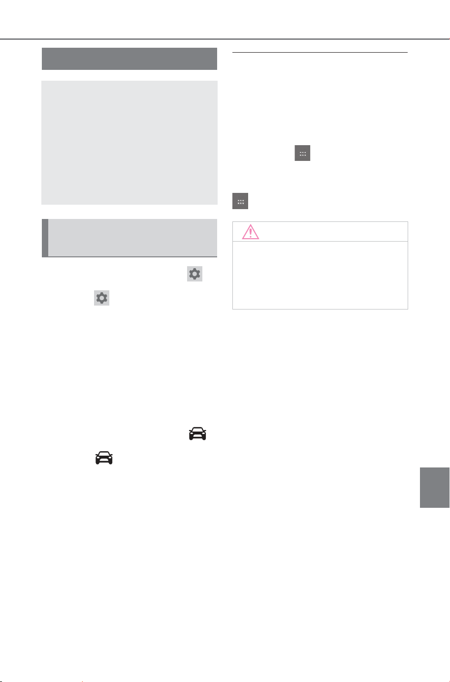
671
9-2. Customization
Owner’s Manual_USA_M6740B_en
9
Vehicle specifications
9-2.Customization
■ To change setting with
1 Select on the main menu.
2 Select “Vehicle customize” or
“Driving assist”.
3 According to the display,
select the desired setting.
Various setting can be changed.
Refer to the list of settings that can
be changed for details.
■ To change setting with
1 Select on the Multimedia
display.
2 Select “Driving assist”.
3 Select the item to change the
settings of from the list.
Each time the switch is selected,
the setting will be enabled/disabled.
When enabling is selected, the item
display will be emphasized.
■ During customization
Stop the vehicle in a safe place,
apply the parking brake, and shift
the shift position to P. Also, to pre-
vent 12-volt battery discharge, leave
the EV system operating while cus-
tomizing the features.
■ Using the icon
Some vehicle customize settings
can also be changed through the
icon.
Customizable features
Your vehicle includes a vari-
ety of electronic features
that can be personalized to
suit your preferences. The
settings of these features
can be changed using the
multimedia system or at
your SUBARU dealer.
Customizing vehicle fea-
tures
NOTICE
■ During customization
To prevent 12-volt battery dis-
charge, ensure that the EV sys-
tem is operating while
customizing features.
SOLTERRA_OM_USA_A6740BE.book 671 ページ 2025年5月23日 金曜日 午後1時18分
672
9-2. Customization
Owner’s Manual_USA_M6740B_en
Some function settings are changed simultaneously with other func-
tions being customized. Contact your SUBARU dealer for further
details.
Settings that can be changed using the multimedia system
Settings that can be changed by your SUBARU dealer
Definition of symbols: O = Available, – =Not available
■ Charging system (P.95, 100)
Customizable Features
Function Customized setting
Charging current
Max
32A
24A
16A
8A
O –
Charging limit
Full
90%
80%
70%
60%
50%
O –
DC charging power
Max
125 kW
100 kW
75 kW
50 kW
O –
Battery cooler
On
Off
O –
SOLTERRA_OM_USA_A6740BE.book 672 ページ 2025年5月23日 金曜日 午後1時18分
673
9-2. Customization
Owner’s Manual_USA_M6740B_en
9
Vehicle specifications
■ Gauges, meters and multi-information display (P.142, 147)
The language, units of measure, etc. of some items displayed on the
meter or multi-information display will be changed according to set-
tings on the multimedia display. Refer to “MULTIMEDIA OWNER’S
MANUAL”.
■ Rear seat reminder (P. 161 )
■ Door lock (P.159, 642)
Function Customized setting
Suggestion function
On
On (when the vehicle is
stopped)
Off
O O
Stop light indicator
On
Off
O
Function Customized setting
Indication to prevent mis-
placement in the rear seat
On
Off
O
Function Customized setting
Unlocking using a mechani-
cal key
All doors unlocked in first
step
Driver’s door unlocked in
first step, all doors unlocked
in second step
O
Automatic door locking func-
tion
Shift position linked door
locking operation
Off
Speed linked door locking
operation
O O
Automatic door unlocking
function
Shift position linked door
unlocking operation
Off
Driver’s door linked door
unlocking operation
O O
SOLTERRA_OM_USA_A6740BE.book 673 ページ 2025年5月23日 金曜日 午後1時18分
674
9-2. Customization
Owner’s Manual_USA_M6740B_en
■ Smart key system and wireless remote control (P.156, 177)
■ Smart key system (P.177)
*
: This setting can be changed when the smart door unlocking setting is set
to Driver’s door.
Function Customized setting
Operation signal (emer-
gency flashers)
On
Off
O O
Operation buzzer volume
1 to 7
Off
O O
Time elapsed before the
automatic door lock function
is activated if a door is not
opened after being unlocked
30 seconds
60 seconds
120 seconds
Off
O O
Open door reminder buzzer
On
Off
O
Function Customized setting
Smart key system
On
Off
O
Smart door unlocking
All the doors
Driver’s door
O O
Number of consecutive door
lock operations
2 times
As many as desired
O
Time elapsed before unlock-
ing all the door when gripping
and holding the driver’s door
handle
*
1.5 seconds
2 seconds
2.5 seconds
Off
O
SOLTERRA_OM_USA_A6740BE.book 674 ページ 2025年5月23日 金曜日 午後1時18分
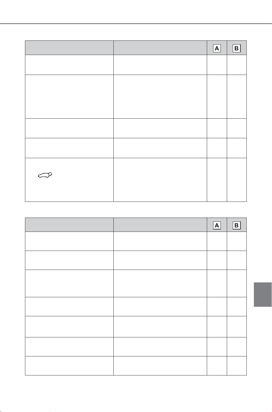
675
9-2. Customization
Owner’s Manual_USA_M6740B_en
9
Vehicle specifications
■ Wireless remote control (P.156)
■ Power back door (P.166)
*
: If equipped
Function Customized setting
Wireless remote control
On
Off
O
Unlocking operation
All doors unlocked in first
step
Driver’s door unlocked in
first step, all doors unlocked
in second step
O O
Theft deterrent panic mode
On
Off
O
Locking operation when door
opened
On
Off
O O
The function that activates
the switch of the wire-
less remote control when
locking the door (P.166)
On (Unlocking all the door)
On (Unlocking back door
only)
Off
O
Function Customized setting
Power back door opening
position
1 to 5
User optional setting
O
Power back door operation
On
Off
O
Buzzer volume
Level 1
Level 2
Level 3
O
Operation buzzer
On
Off
O
Hands Free Power Back
Door (kick sensor)
*
On
Off
O O
Kick in buzzer (kick sensor)
*
On
Off
O
Close & lock (walk away)
function
On
Off
O
SOLTERRA_OM_USA_A6740BE.book 675 ページ 2025年5月23日 金曜日 午後1時18分
676
9-2. Customization
Owner’s Manual_USA_M6740B_en
■ Driving position memory
*
(P.207)
*
: If equipped
■ Enabling easier driver entry and exit (power easy access sys-
tem)
*
(P.207)
*
: If equipped
■ Outside rear view mirrors (P.200)
■ Power windows (P.204)
Function Customized setting
Selection the door linking
driving position memory with
door unlock operation
Driver’s door
All doors
O
Function Customized setting
Driver’s seat slide movement
when exiting the vehicle
Full
Off
Partial
O O
Function Customized setting
Automatic mirror folding and
extending operation
Linked to the lock-
ing/unlocking of the doors
Off
Linked to operation of the
power switch
O
Function Customized setting
Key linked operation (open)
Off
On
– O
Key linked operation (close)
Off
On
– O
Wireless remote control
linked operation (open)
Off
On
– O
Wireless remote control
linked operation signal
(buzzer)
On
Off
– O
SOLTERRA_OM_USA_A6740BE.book 676 ページ 2025年5月23日 金曜日 午後1時18分
677
9-2. Customization
Owner’s Manual_USA_M6740B_en
9
Vehicle specifications
■ Power switch (P.232)
■ Lights (P.247)
*
: Except for Canada
■ Reverse warning buzzer (P.233)
■ Automatic light control system (P.247)
Function Customized setting
ACC customization
Enabling/Disabling ACC
mode
ON
OFF
O O
Function Customized setting
Daytime Running Lights
*
On
Off
O O
Function Customized setting
Signal (buzzer) when the
shift position is in R
Continual
Mute
– O
Function Customized setting
Light sensor sensitivity
Normal
Brighter
Bright
Dark
Darker
O O
Time elapsed before head-
lights automatically turn off
after doors are closed
30 seconds
Off
60 seconds
90 seconds
O O
Windshield wiper linked
headlight illumination
On
Off
– O
SOLTERRA_OM_USA_A6740BE.book 677 ページ 2025年5月23日 金曜日 午後1時18分
678
9-2. Customization
Owner’s Manual_USA_M6740B_en
■ Pre-Collision System (P.270)
*
: This setting changes in accordance with My Settings.
■ Lane Departure Alert system (LDA) (P.290)
*
: This setting changes in accordance with My Settings.
■ Proactive Driving Assist (P.295)
*
: This setting changes in accordance with My Settings.
Function Customized setting
Pre-Collision System
ON
OFF
O –
Warning timing
*
Later
Default
Earlier
O –
Function Customized setting
Lane Departure Alert system
(LDA)
*
ON
OFF
O –
Alert timing
*
Default
Earlier
O –
Alert options
*
Vibration
Audible
O –
Function Customized setting
Proactive Driving Assist
(PDA)
*
ON
OFF
O –
Support sensitivity
*
Low
Mid
High
O –
Deceleration Assist (DA)
*
ON
OFF
O –
Obstacle Anticipation Assist
(OAA)
*
ON
OFF
O –
SOLTERRA_OM_USA_A6740BE.book 678 ページ 2025年5月23日 金曜日 午後1時18分
679
9-2. Customization
Owner’s Manual_USA_M6740B_en
9
Vehicle specifications
■ Dynamic Radar Cruise Control (DRCC) (P.306)
*
: This setting changes in accordance with My Settings.
■ Road Sign Assist (P.303)
*
: This setting changes in accordance with My Settings.
■ Driver break suggestion (P.290)
Function Customized setting
Extended Resume Time
*
ON
OFF
O –
Acceleration setting
*
Low
Mid
High
O –
Guide message
*
ON
OFF
O –
Curve speed reduction
*
OFF
Low
Mid
High
O –
Function Customized setting
Road Sign Assist
*
ON
OFF
O –
Excess speed notification
method
*
None
Visual
Visual & Audible
O –
Other notifications method
*
None
Visual
Visual & Audible
O –
Excess speed notification
level
*
1 mph (2 km/h)
3 mph (5 km/h)
5 mph (10 km/h)
O –
Function Customized setting
Driver break suggestion
ON
OFF
O –
SOLTERRA_OM_USA_A6740BE.book 679 ページ 2025年5月23日 金曜日 午後1時18分
680
9-2. Customization
Owner’s Manual_USA_M6740B_en
■ Driver monitor (P.267)
*
: This setting changes in accordance with My Settings.
■ Lane Change Assist (P.287)
*
: This setting changes in accordance with My Settings.
■ Front Cross Traffic Alert (P.301)
*
: This setting changes in accordance with My Settings.
■ Traffic Jam Assist (P.324)
*
: This setting changes in accordance with My Settings.
Function Customized setting
Warning function
*
ON
OFF
O –
Function Customized setting
Lane Change Assist
*
ON
OFF
O –
Function Customized setting
Front Cross Traffic Alert
ON
OFF
O –
Alert timing
*
Later
Default
Earlier
O –
Function Customized setting
Traffic Jam Assist
*
ON
OFF
O –
Driver Monitor Camera
Recording
*
ON
OFF
O –
SOLTERRA_OM_USA_A6740BE.book 680 ページ 2025年5月23日 金曜日 午後1時18分
681
9-2. Customization
Owner’s Manual_USA_M6740B_en
9
Vehicle specifications
■ BSM (Blind Spot Monitor) (P.330)
*
: This setting changes in accordance with My Settings
■ Safe Exit Assist (P.335)
*
: This setting changes in accordance with My Settings
■ RCTA (Rear Cross Traffic Alert) function (P.351)
*1
:This setting changes in accordance with My Settings
*2
:The sound volume is linked among the SUBARU Parking Assist, RCTA,
and RCD.
Function Customized setting
BSM (Blind Spot Monitor)
On
Off
O –
Outside rear view mirror indi-
cator brightness
*
Bright
Dim
O –
Alert timing for presence of
approaching vehicle (sensi-
tivity)
*
Later
Default
Earlier
O –
Buzzer warning
*
On
Off
O –
Function Customized setting
Safe Exit Assist
On
Off
O –
Outside rear view mirrors dis-
play
*
On
Off
O –
Detection sensitivity
*
Low
Mid
High
O –
Function Customized setting
RCTA (Rear Cross Traffic
Alert)
On
Off
O –
Buzzer volume of RCTA
when operating
*1, 2
Level 1 ~ Level 3 O –
SOLTERRA_OM_USA_A6740BE.book 681 ページ 2025年5月23日 金曜日 午後1時18分
682
9-2. Customization
Owner’s Manual_USA_M6740B_en
■ SUBARU Parking Assist (P.340)
*1
:This setting changes in accordance with My Settings
*2
:The sound volume is linked among the SUBARU Parking Assist, RCTA,
and RCD.
*3
:For vehicles with panoramic view monitor, the setting can be changed on
the panoramic view monitor settings screen. For details, refer to “MULTI-
MEDIA OWNER’S MANUAL”.
■ RCD (Rear Camera Detection) (P.356)
■ PKSB (Parking Support Brake) (P.360)
*
: This setting changes in accordance with My Settings
Function Customized setting
SUBARU Parking Assist
*1
On
Off
O –
Buzzer volume of SUBARU
Parking Assist when operat-
ing
*1, 2
Level 1 ~ Level 3 O –
Distance from which the front
center sensor starts detec-
tion
*3
Standard
Near
O –
Distance from which the rear
center sensor starts detec-
tion
*3
Standard
Near
O –
Function Customized setting
RCD (Rear Camera Detec-
tion) function
On
Off
O –
Function Customized setting
PKSB (Parking Support
Brake) function
*
On
Off
O –
SOLTERRA_OM_USA_A6740BE.book 682 ページ 2025年5月23日 金曜日 午後1時18分
683
9-2. Customization
Owner’s Manual_USA_M6740B_en
9
Vehicle specifications
■ Advanced Park
*
(P.373)
*
: If equipped
Function Customized setting
Vehicle speed during opera-
tion
Slow
Standard
Fast
O –
Distance to objects
Standard
Far
O –
Preferred parking method
Parallel
Perpendicular
O –
Preferred parking direction
Forward
Reverse
O –
Preferred exit direction (per-
pendicular)
Right
Left
O –
Preferred exit direction (par-
allel)
Right
Left
O –
Camera view when parking
Standard
Wide
O –
Camera view when exiting
Standard
Wide
O –
Parking path adjustment -3 (Inward) ~ +3 (Outward) O –
Road width adjustment
Standard
Slightly narrow
Narrow
O –
Park position adjustment
(forward)
-3 (Rearward) ~ +3 (Front-
ward)
O –
Park position adjustment
(reverse)
-3 (Rearward) ~ +3 (Front-
ward)
O –
Rear accessory setting
Off
3.9 in. (10 cm)
7.9 in. (20 cm)
11.8 in. (30 cm)
15.7 in. (40 cm)
O –
Clear registered parking
space
- O –
SOLTERRA_OM_USA_A6740BE.book 683 ページ 2025年5月23日 金曜日 午後1時18分
684
9-2. Customization
Owner’s Manual_USA_M6740B_en
■ Automatic air conditioning system (P.492)
■ Illumination (P.507)
*
: If equipped
Function Customized setting
A/C Auto switch operation
On
Off
O O
Function Customized setting
Time elapsed before the inte-
rior lights turn off
15 seconds
Off
7.5 seconds
30 seconds
O O
Operation after the power
switch is turned off
On
Off
– O
Operation when the doors
are unlocked
On
Off
– O
Operation when you
approach the vehicle with the
electronic key on your per-
son
On
Off
– O
Interior lights, footwell lights,
shift lights, inside door han-
dle lights, door trim ornament
lights, center console light,
Instrument panel ornament
lights
On
Off
– O
Time elapsed before the
outer foot lights
*
turn off
15 seconds
Off
– O
Operation of the outer foot
lights
*
when you approach
the vehicle with the elec-
tronic key on your person
On
Off
– O
Operation of the outer foot
lights
*
when the doors are
unlocked
On
Off
– O
Door illumination when Safe
Exit Assist (SEA) is operat-
ing.
On
Off
– O
SOLTERRA_OM_USA_A6740BE.book 684 ページ 2026年1月6日 火曜日 午後2時32分

685
9-2. Customization
Owner’s Manual_USA_M6740B_en
9
Vehicle specifications
■ Vehicle customization
● When the speed linked door locking function and shift position linked door
locking function are both on, the door lock operates as follows.
• If the vehicle is started with all the doors locked, the speed linked door
locking function would not operate.
• If the vehicle is started with any door unlocked, the speed linked door lock-
ing function will operate.
• When shifting the shift position to any position other than P, all the doors
will be locked.
● When the smart key system is off, the selecting door to unlock cannot be
customized.
● When the doors remain closed after unlocking the doors and the auto-
matic door lock function is activated, the signals will be generated in
accordance with the Operation signal (buzzer) and the Operation signal
(emergency flashers) settings.
SOLTERRA_OM_USA_A6740BE.book 685 ページ 2025年5月23日 金曜日 午後1時18分
686
9-3. Initialization
Owner’s Manual_USA_M6740B_en
9-3.Initialization
*
: If equipped
Items to initialize
The following items must be initialized for normal system
operation after such cases as the battery being reconnected,
or maintenance being performed on the vehicle:
List of the items to initialize
Item When to initialize Reference
Power back door
• After reconnecting or chang-
ing the 12-volt battery
• After changing a fuse
P.172
Power window
• When functioning abnor-
mally
P.204
SUBARU Parking Assist
• If the 12-volt battery was dis-
charged or has been
removed and installed
P.340
Parking Support Brake func-
tion (static objects around the
vehicle)
• If the 12-volt battery was dis-
charged or has been
removed and installed
P.365
Tire pressure warning system
*
• When the specified tire infla-
tion pressure has changed,
such as due to carried load,
etc.
• When the tire inflation pres-
sure is changed such as
when the tire size is
changed.
P.573
SOLTERRA_OM_USA_A6740BE.book 686 ページ 2025年5月23日 金曜日 午後1時18分
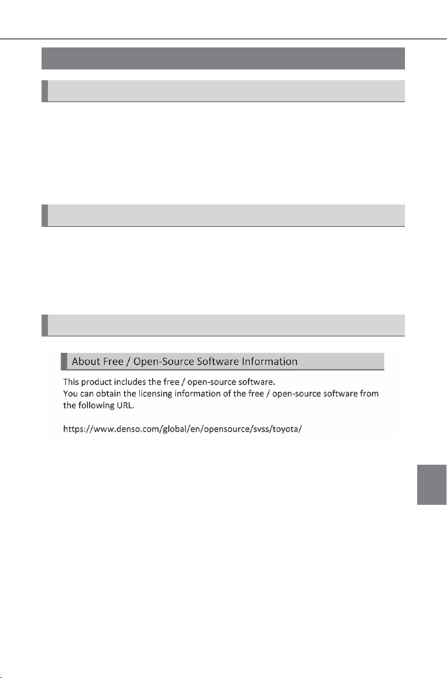
687
9-4. Free/open source software
Owner’s Manual_USA_M6740B_en
9
Vehicle specifications
9-4.Free/open source software
This product (inverter water pump for AWD vehicles) includes soft-
ware that is licensed under open-source software.
You can find license information for this free and open-source soft-
ware at the following URL.
https://www.aisin.com/info/ewp/license001.html
This product contains Free/open source software (FOSS).
License information and/or the source code of this FOSS can be
obtained at the following URL:
https://www.denso.com/global/en/opensource/dkey/toyota/
Free/open source software information
Water pump
Digital key
Multi-terrain Monitor
SOLTERRA_OM_USA_A6740BE.book 687 ページ 2025年5月23日 金曜日 午後1時18分

688
9-4. Free/open source software
Owner’s Manual_USA_M6740B_en
SOLTERRA_OM_USA_A6740BE.book 688 ページ 2025年5月23日 金曜日 午後1時18分

689
Owner’s Manual_USA_M6740B_en
10
10
For owners
For owners
10-1.For owners
Reporting safety defects for
U.S. owners...............
690
Reporting safety defects for
Canadian owners ......
690
Seat belt instructions for
Canadian owners (in
French)......................
691
SRS airbag instructions for
Canadian owners (in
French)......................
692
Headlight aim instructions
for Canadian owners (in
French)...................... 698
SOLTERRA_OM_USA_A6740BE.book 689 ページ 2025年5月23日 金曜日 午後1時18分

690
10-1. For owners
Owner’s Manual_USA_M6740B_en
10-1.For owners
Reporting safety
defects for U.S. own-
ers
If you believe that your vehi-
cle has a defect which could
cause a crash or could
cause injury or death, you
should immediately inform
the National Highway Traffic
Safety Administration
(NHTSA) in addition to noti-
fying SUBARU of America,
Inc.
If NHTSA receives similar
complaints, it may open an
investigation, and if it finds
that a safety defect exists in
a group of vehicles, it may
order a recall and remedy
campaign. However, NHTSA
cannot become involved in
individual problems
between you, your dealer,
or SUBARU of America, Inc.
To contact NHTSA, you may
call the Vehicle Safety
Hotline toll-free at 1-888-
327-4236 (TTY: 1-800-424-
9153); go to
http://www.safercar.gov; or
write to: Administrator,
NHTSA, 1200 New Jersey
Ave. S.E., Washington, DC
20590. You can also obtain
other information about
motor vehicle safety from
http://www.safercar.gov.
Reporting safety
defects for Canadian
owners
Canadian customers who
wish to report a safety-
related defect to Transport
Canada, Defects Investiga-
tions and Recalls, may tele-
phone the toll-free hotline 1-
800-333-0510, mail Trans-
port Canada - ASFAD, 330
Sparks Street, Ottawa, ON,
K1A 0N5, or complete the
online form at
https://www.tc.gc.ca/recalls.
SOLTERRA_OM_USA_A6740BE.book 690 ページ 2025年5月23日 金曜日 午後1時18分
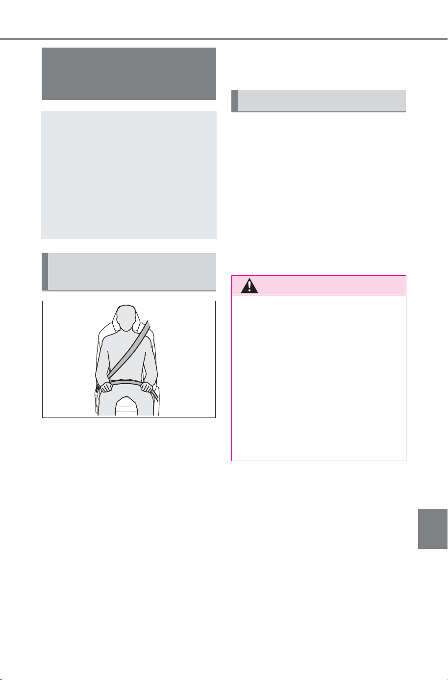
691
10-1. For owners
Owner’s Manual_USA_M6740B_en
10
For owners
Déroulez la sangle diagonale
de telle sorte qu’elle passe
bien sur l’épaule, sans pour
autant être en contact avec le
cou ou glisser de l’épaule.
Placez la sangle abdominale
le plus bas possible sur les
hanches.
Réglez la position du dossier
de siège.
Asseyez-vous le dos le plus
droit possible et calez-vous
bien dans le siège.
Ne pas vriller la ceinture de
sécurité.
■ Soins à porter aux cein-
tures de sécurité
Nettoyez avec un chiffon ou une
éponge humectée d’eau savon-
neuse tiède. Par ailleurs, véri-
fiez régulièrement que les
ceintures ne sont pas
effilochées, entaillées, ou ne
paraissent pas exagérément
usées.
Seat belt instructions
for Canadian owners
(in French)
The following is a French
explanation of seat belt
instructions extracted from
the seat belt section in this
manual.
See the seat belt section for
more detailed seat belt
instructions in English.
Utilisation correcte des
ceintures de sécurité
Entretien et soin
AVERTISSEMENT
■ État et usure des ceintures de
sécurité
Inspectez les ceintures de sécu-
rité périodiquement. Contrôlez
qu’elles ne sont pas entaillées,
effilochées, et que leurs ancrages
ne sont pas desserrés. Ne pas uti-
liser une ceinture de sécurité
défectueuse avant qu’elle ne soit
remplacée. Une ceinture de sécu-
rité défectueuse n’apporte aucune
garantie de protection de l’occu-
pant contre des blessures graves,
voire mortelles.
SOLTERRA_OM_USA_A6740BE.book 691 ページ 2025年5月23日 金曜日 午後1時18分
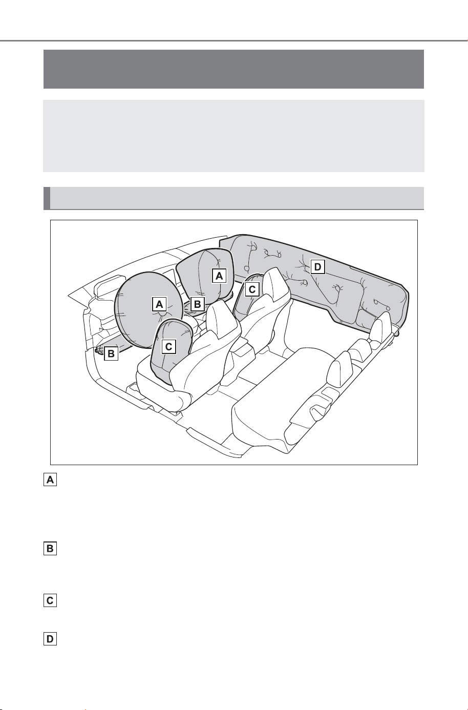
692
10-1. For owners
Owner’s Manual_USA_M6740B_en
Coussins gonflables SRS frontaux (coussin gonflable SRS con-
ducteur/coussin gonflable SRS passager)
Contribuent à réduire l’impact de la tête et du thorax du conducteur ou de la
conductrice et du passager avant
Coussins gonflables SRS de genoux
Contribuent à réduire l’impact sur le conducteur ou la conductrice et le pas-
sager avant
Coussins gonflables SRS latéraux
Contribuent à réduire l’impact du thorax des occupants des sièges avant
Coussins gonflables SRS rideau
• Contribuent à réduire l’impact de la tête des occupants des sièges avant
SRS airbag instructions for Canadian owners (in
French)
The following is a French explanation of SRS airbag instruc-
tions extracted from the SRS airbag section in this manual.
See the SRS airbag section for more detailed SRS airbag instruc-
tions in English.
Système de coussins gonflables SRS
SOLTERRA_OM_USA_A6740BE.book 692 ページ 2025年5月23日 金曜日 午後1時18分
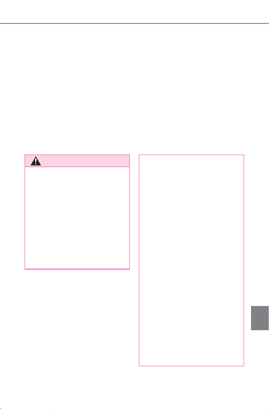
693
10-1. For owners
Owner’s Manual_USA_M6740B_en
10
For owners
et des sièges arrière latéraux
• Participent à empêcher les occupants d’être éjectés du véhicule en cas
de retournement de celui-ci
Votre véhicule est équipé de COUSSINS GONFLABLES INTELLI-
GENTS (ADVANCED AIRBAGS) conçus selon les normes de sécu-
rité américaines applicables aux véhicules à moteur (FMVSS208).
Le boîtier électronique de coussins gonflables (ECU) utilise les infor-
mations reçues des capteurs, etc., détaillés dans le schéma ci-des-
sus de composition du système pour commander le déploiement
des coussins gonflables. Ces informations comprennent des infor-
mations sur la gravité de la collision et les occupants. Le déploie-
ment rapide des coussins gonflables est obtenu au moyen d’une
réaction chimique dans les dispositifs pyrotechniques, qui produit un
gaz inoffensif permettant d’amortir le mouvement des occupants.
AVERTISSEMENT
■ Précautions avec les couss-
ins gonflables SRS
Respectez les précautions suiva-
ntes. À défaut, des blessures
graves, voire mortelles, pourraient
s’ensuivre.
● La personne au volant et tous
les passagers à bord du
véhicule doivent porter correcte-
ment leur ceinture de sécurité.
Les coussins gonflables SRS
sont des dispositifs de protec-
tion complémentaires aux cein-
tures de sécurité.
● Le coussin gonflable SRS con-
ducteur se déploie avec une
puissance considérable et peut
occasionner des blessures
graves, voire mortelles, notam-
ment lorsque le conducteur se
trouve très près du coussin gon-
flable. L’autorité fédérale
chargée de la sécurité routière
aux États-Unis, la NHTSA
(National Highway Traffic Safety
Administration) conseille:
Sachant que la zone de danger
pour le coussin gonflable conduc-
teur se trouve dans les premiers 2
à 3 in. (50 à 75 mm) du déploie-
ment, placez-vous à 10 in.
(250 mm) du coussin gonflable
conducteur pour garantir une
marge de sécurité suffisante.
Cette distance est à mesurer
entre le moyeu du volant de direc-
tion et le sternum. Si votre posi-
tion de conduite vous place à
moins de 10 in. (250 mm) du
coussin gonflable conducteur,
vous pouvez en changer de dif-
férentes façons:
SOLTERRA_OM_USA_A6740BE.book 693 ページ 2025年5月23日 金曜日 午後1時18分
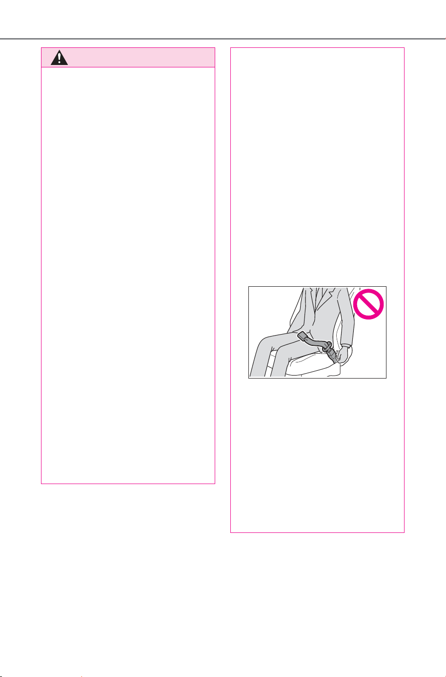
694
10-1. For owners
Owner’s Manual_USA_M6740B_en
AVERTISSEMENT
• Reculez votre siège au plus loin
possible tout en continuant à
pouvoir atteindre confortable-
ment les pédales.
• Inclinez légèrement le dossier
de siège. Bien que les véhicules
soient différents les uns des
autres, la plupart des conduc-
teurs et conductrices peuvent
s’asseoir à une distance de
10 in. (250 mm), même avec le
siège conducteur complètement
avancé, en inclinant simplement
un peu le dossier du siège. Si
vous avez des difficultés à voir
la route après avoir incliné le
dossier de siège, utilisez un
coussin ferme et antidérapant
pour vous rehausser ou, si votre
véhicule est équipé du réglage
en hauteur du siège, remontez-
le.
• Si votre volant de direction est
réglable, inclinez-le vers le bas.
Cela vous permet d’orienter le
coussin gonflable vers votre
buste plutôt que vers la tête et
le cou. Vous devez régler le
siège selon les recommanda-
tions de la NHTSA, tout en con-
tinuant à pouvoir agir sur le
volant de direction et les
pédales pour maîtriser le
véhicule et en conservant votre
vue des commandes au tableau
de bord.
● Si vous attachez une rallonge
de ceinture de sécurité à la bou-
cle de ceinture du siège pas-
sager avant, mais pas au pêne
de la ceinture de sécurité pro-
prement dite, le système de
coussins gonflables SRS déter-
mine que l’occupant porte sa
ceinture de sécurité, alors
même qu’elle n’est pas
attachée. Dans ce cas, les
coussins gonflables SRS fron-
taux côté passager avant ris-
quent de ne pas se déployer
correctement en cas de colli-
sion, causant des blessures
graves, voire mortelles. Veillez
à porter correctement la cein-
ture de sécurité lorsque vous
utilisez une rallonge de ceinture
de sécurité.
● Le coussin gonflable SRS pas-
sager avant se déploie avec
une violence considérable, qui
peut être très dangereuse voire
mortelle si le passager ou la
passagère avant se trouve très
près de lui. Le siège passager
avant doit être reculé le plus loin
possible du coussin gonflable,
avec le dossier réglé de
manière à ce que le passager
ou la passagère soit assis(e)
bien droit(e).
SOLTERRA_OM_USA_A6740BE.book 694 ページ 2025年5月23日 金曜日 午後1時18分
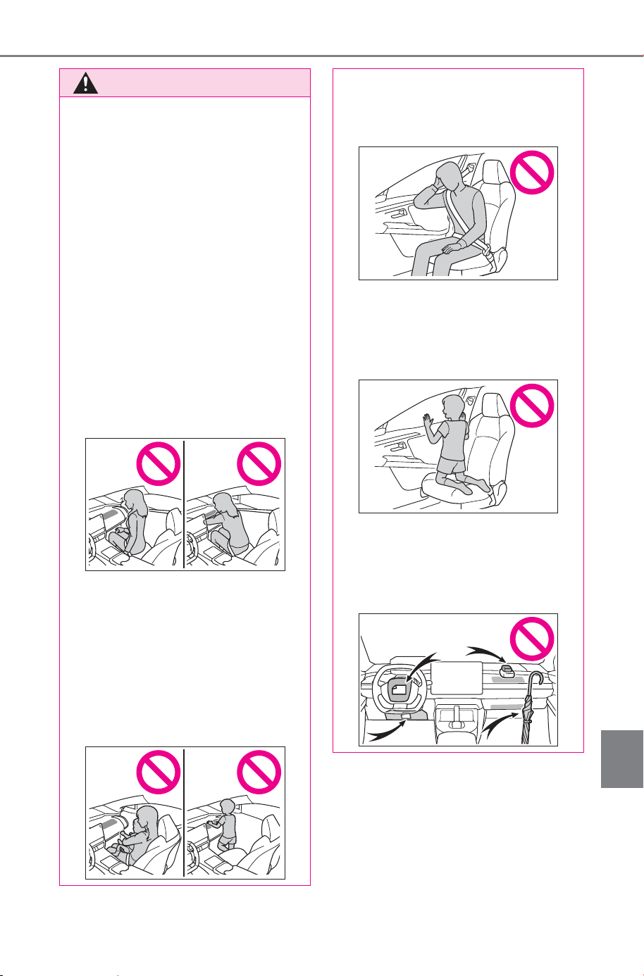
695
10-1. For owners
Owner’s Manual_USA_M6740B_en
10
For owners
AVERTISSEMENT
● Le déploiement d’un coussin
gonflable peut infliger des bles-
sures graves, voire mortelles,
aux nourrissons et aux enfants
mal assis et/ou mal attachés.
Installez dans un siège de sécu-
rité enfant les enfants trop
jeunes pour pouvoir utiliser la
ceinture de sécurité. SUBARU
recommande vivement que tous
les nourrissons et enfants
soient installés dans les sièges
arrière du véhicule et conven-
ablement attachés. Les sièges
arrière sont plus sûrs pour les
nourrissons et les enfants que
le siège passager avant.
● Ne pas s’asseoir sur le bord du
siège et ne pas s’appuyer con-
tre la planche de bord.
● La personne occupant le siège
avant ne doit jamais voyager
avec quoi que ce soit sur ses
genoux.
● Ne pas laisser un enfant se tenir
debout devant le coussin gon-
flable SRS passager avant ni
assis sur les genoux du pas-
sager ou de la passagère avant.
● Ne pas s’appuyer contre la
porte, contre le rail latéral de toit
ou contre le montant avant,
latéral ou arrière.
● Interdisez à quiconque de
s’agenouiller sur un siège en
appui contre la porte ou de sor-
tir la tête ou les mains à
l’extérieur du véhicule.
● Ne rien fixer ou disposer sur la
planche de bord, la garniture
centrale du moyeu de volant de
direction et la partie inférieure
du tableau de bord.
SOLTERRA_OM_USA_A6740BE.book 695 ページ 2025年5月23日 金曜日 午後1時18分
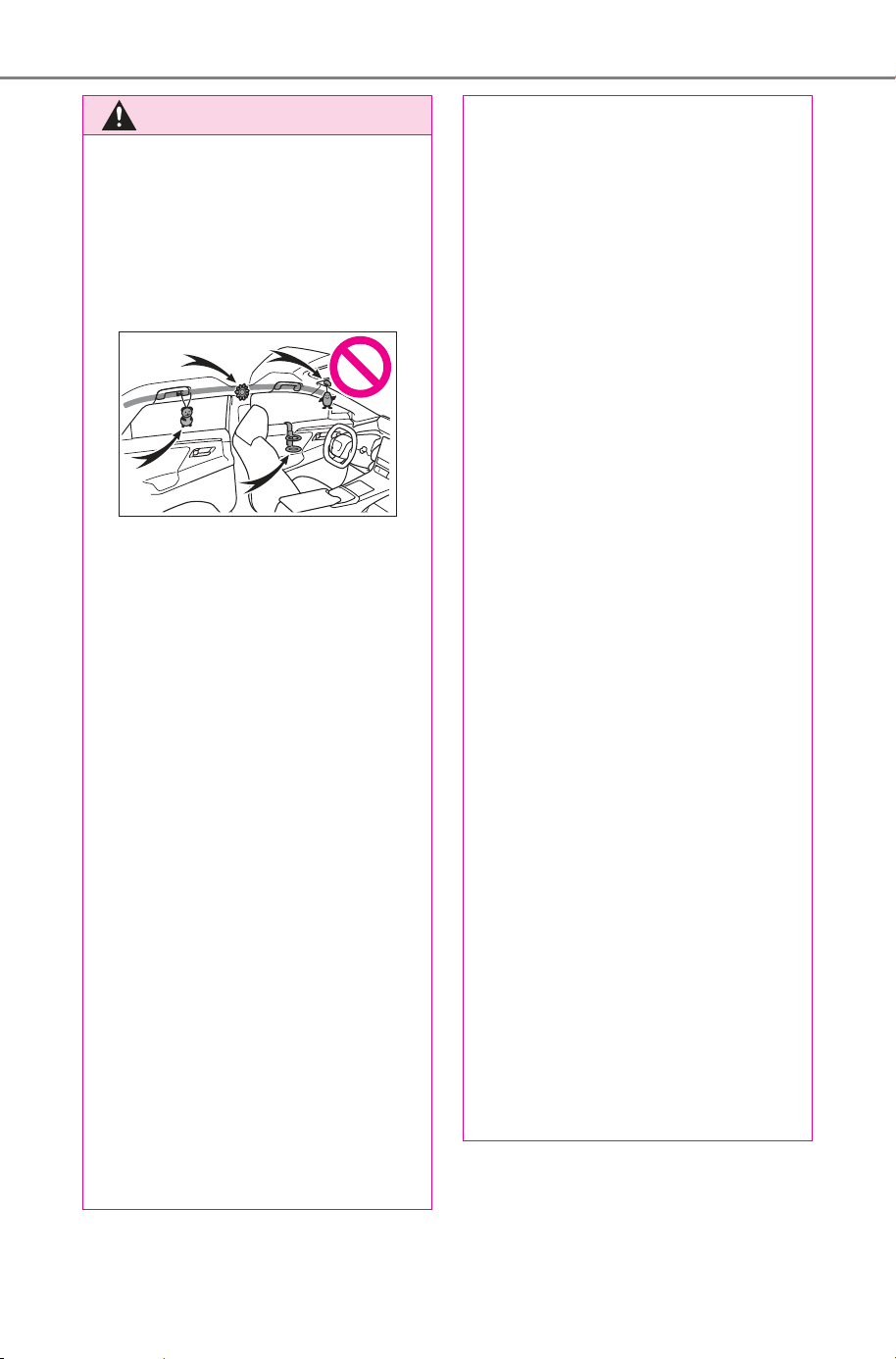
696
10-1. For owners
Owner’s Manual_USA_M6740B_en
AVERTISSEMENT
● Ne rien fixer sur les parties
telles que les portes, la vitre de
pare-brise, les vitres latérales,
les montants avant ou arrière,
les rails latéraux de toit et les
poignées de maintien. (À
l’exception de l’étiquette de lim-
itation de vitesse)
● Ne pas suspendre aux crochets
à vêtements un cintre nu ni
aucun objet dur ou tranchant.
Ces objets peuvent se trans-
former en projectiles capables
de tuer ou de blesser griève-
ment en cas de déploiement
des coussins gonflables SRS
rideau.
● Si une housse en vinyle recou-
vre la partie où le coussin gon-
flable SRS de genoux se
déploie, veillez à l’enlever.
● N’utilisez pour les sièges aucun
accessoire venant recouvrir les
parties par lesquelles se
déploient les coussins gonfla-
bles SRS latéraux, car il risquer-
ait d’en gêner le
déclenchement. De tels acces-
soires risquent d’empêcher les
coussins gonflables SRS
latéraux de se déployer cor-
rectement, de neutraliser le sys-
tème ou de provoquer le
déploiement intempestif des
coussins gonflables SRS, avec
un risque possible de blessures
graves, voire mortelles.
● Ne pas faire subir de chocs vio-
lents ni des pressions exces-
sives aux éléments constitutifs
du système de coussins gonfla-
bles SRS, ni aux parties qui les
entourent.
En effet, vous risqueriez d’occa-
sionner un mauvais fonctionne-
ment des coussins gonflables
SRS.
● Ne touchez aucun élément con-
stitutif des coussins gonflables
SRS immédiatement après leur
déclenchement (déploiement),
car ils sont alors encore très
chauds.
● Si vous avez des difficultés à
respirer après le déploiement
des coussins gonflables SRS,
ouvrez une porte ou une vitre
pour faire entrer de l’air frais, ou
bien descendez du véhicule si
cela ne présente pas de danger.
Retirez tout résidu dès que pos-
sible afin d’éviter d’éventuelles
irritations de la peau.
● Si une partie renfermant un
coussin gonflable SRS est
abîmée ou fendue, faites-la
remplacer par votre concession-
naire SUBARU.
● Ne rien poser sur le siège du
passager avant, comme un
coussin par exemple. Cela a
pour conséquence de répartir le
poids du passager sur toute la
surface du siège, ce qui
empêche le capteur de détecter
normalement le poids du pas-
sager. Il s’ensuit le risque que
les coussins gonflables SRS
frontaux du siège passager
avant ne se déploient pas en
cas de collision.
SOLTERRA_OM_USA_A6740BE.book 696 ページ 2025年5月23日 金曜日 午後1時18分
697
10-1. For owners
Owner’s Manual_USA_M6740B_en
10
For owners
AVERTISSEMENT
■ Modification et élimination en
fin de vie des éléments du
système de coussins gonfla-
bles SRS
Ne mettez pas à la casse votre
véhicule et ne lui apportez aucune
des modifications suivantes sans
consulter votre concessionnaire
SUBARU. Il pourrait arriver que
les coussins gonflables SRS
fonctionnent anormalement ou se
déploient intempestivement, avec
un risque possible de blessures
graves, voire mortelles.
● Dépose, repose, démontage ou
réparation des coussins gonfla-
bles SRS
● Réparation, dépose ou modifi-
cation des pièces suivantes ou
des parties qui les entourent
• Volant de direction
• Tableau de bord
• Planche de bord
•Sièges
• Sellerie de sièges
• Montants avant
• Montants latéraux
• Montants arrière
• Rails latéraux de toit
• Panneaux de portes avant
• Habillage de portes avant
• Haut-parleurs de portes avant
● Modifications des panneaux de
portes avant (percer un trou
dedans, par exemple)
● Réparation ou modification des
pièces suivantes ou des parties
qui les entourent
• Aile avant
• Pare-chocs avant
• Côtés de l’intérieur du véhicule
● Montage des pièces ou acces-
soires suivants
• Pare-buffles ou pare-kangou-
rous
• Chasse-neiges
•Treuils
• Galeries de pavillon
● Modifications de la suspen-
sions du véhicule
● Installation d’appareils électro-
niques, tels qu’un système radio
émetteur/récepteur mobile
(émetteur RF) ou un lecteur de
CD
● Aménagements du véhicule
visant à permettre sa conduite
par une personne atteinte d’un
handicap physique
SOLTERRA_OM_USA_A6740BE.book 697 ページ 2025年5月23日 金曜日 午後1時18分
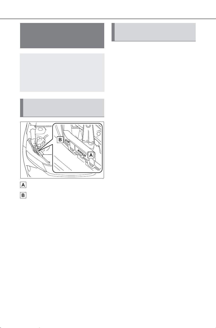
698
10-1. For owners
Owner’s Manual_USA_M6740B_en
Boulon de réglage A
Boulon de réglage B
Assurez-vous que le réservoir
de carburant du véhicule est
plein et que la partie de car-
rosserie située autour des
phares n’est pas déformée.
Garez le véhicule sur un sol
parfaitement horizontal.
Assurez-vous que la pression
de gonflage des pneus est au
niveau prescrit.
Demandez à quelqu’un de
s’asseoir sur le siège du con-
ducteur.
Faites rebondir le véhicule à
plusieurs reprises.
Headlight aim instruc-
tions for Canadian
owners (in French)
The following is a French
explanation of headlight
aim instructions from the
headlight aim section in this
manual.
Boulons de réglage verti-
cal
Avant de vérifier la portée
des phares
SOLTERRA_OM_USA_A6740BE.book 698 ページ 2025年5月23日 金曜日 午後1時18分
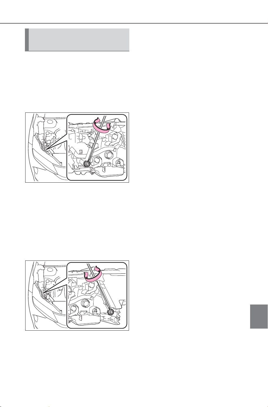
699
10-1. For owners
Owner’s Manual_USA_M6740B_en
10
For owners
1 Tournez le boulon A vers la
droite ou vers la gauche à
l’aide d’un tournevis cruci-
forme.
Retenez le sens de rotation
et le nombre de tours.
2 Tournez le boulon B du
même nombre de tours et
dans le même sens qu’à
l’étape
1.
Si vous n’arrivez pas à régler vos
phares en suivant cette procédure,
apportez le véhicule chez votre
concessionnaire SUBARU afin qu’il
règle la portée des phares.
Réglage de la portée des
phares
SOLTERRA_OM_USA_A6740BE.book 699 ページ 2025年5月23日 金曜日 午後1時18分

700
10-1. For owners
Owner’s Manual_USA_M6740B_en
SOLTERRA_OM_USA_A6740BE.book 700 ページ 2025年5月23日 金曜日 午後1時18分

701
Owner’s Manual_USA_M6740B_en
Index
What to do if... (Trouble-
shooting) ...................
702
Alphabetical Index....... 708
SOLTERRA_OM_USA_A6740BE.book 701 ページ 2025年5月23日 金曜日 午後1時18分
702
What to do if... (Troubleshooting)
Owner’s Manual_USA_M6740B_en
1-1.What to do i f... (Troubleshooting)
What to do if... (Troubleshooting)
If you lose your keys or
mechanical keys, new genu-
ine keys or mechanical keys
can be made by your SUB-
ARU dealer. (P.641)
If you lose your electronic
keys, the risk of vehicle theft
increases significantly. Con-
tact your SUBARU dealer
immediately. (P.641)
Is the key battery weak or
depleted? (P.594)
Is the power switch in ON?
When locking the doors, turn
the power switch off.
(P.232)
Is the electronic key left inside
the vehicle?
When locking the doors,
make sure that you have the
electronic key on your person.
The function may not operate
properly due to the condition
of the radio wave. (P.179)
Is the child-protector lock set?
The rear door cannot be
opened from inside the vehi-
cle when the lock is set. Open
the rear door from outside
and then unlock the child-pro-
tector lock. (P.163)
Is the charging cable con-
nected to the vehicle?
(P.9 2 )
Did you press the power
switch while firmly depress-
ing the brake pedal?
(P.229)
Is the shift position in P?
(P.229)
Is the electronic key any-
where detectable inside the
vehicle? (P.178)
If you have a problem,
check the following before
contacting your SUBARU
dealer.
The doors cannot be
locked, unlocked, opened
or closed
You lose your keys
The doors cannot be
locked or unlocked
The rear door cannot be
opened
If you think something is
wrong
The EV system does not
start
SOLTERRA_OM_USA_A6740BE.book 702 ページ 2025年5月23日 金曜日 午後1時18分
Owner’s Manual_USA_M6740B_en
703
What to do if... (Troubleshooting)
Is the electronic key battery
weak or depleted?
In this case, the EV system
can be started in a temporary
way. (P.643)
Is the 12-volt battery dis-
charged? (P.644)
Is the window lock switch
pressed?
The power window except for
the one at the driver’s seat
cannot be operated if the win-
dow lock switch is pressed.
(P.206)
The auto power off function
will be operated if the vehicle
is left in ACC or ON (the EV
system is not operating) for a
period of time. (P.233)
The seat belt reminder light is
flashing
Are the driver and the passengers
wearing the seat belts? (
P.614)
The parking brake indicator is
on
Is the parking brake released?
(
P.243)
Depending on the situation,
other types of warning buzzer
may also sound. (P.611, 621)
Did anyone inside the vehicle
open a door during setting the
alarm?
The sensor detects it and the
alarm sounds. (P. 66 )
Turn the power switch to ACC or
ON, or start the EV system.
(The alarm will be deactivated or
stopped after a few seconds.)
Is the message displayed on
the multi-information display?
Check the message on the
multi-information display.
(P.621)
When a warning light turns on
or a warning message is dis-
played, refer to P.611, 621.
The windows do not open
or close by operating the
power window switches
The power switch is
turned off automatically
A warning buzzer sounds
during driving
An alarm is activated and
the horn sounds
A warning buzzer sounds
when leaving the vehicle
A warning light turns on
or a warning message is
displayed
SOLTERRA_OM_USA_A6740BE.book 703 ページ 2025年5月23日 金曜日 午後1時18分
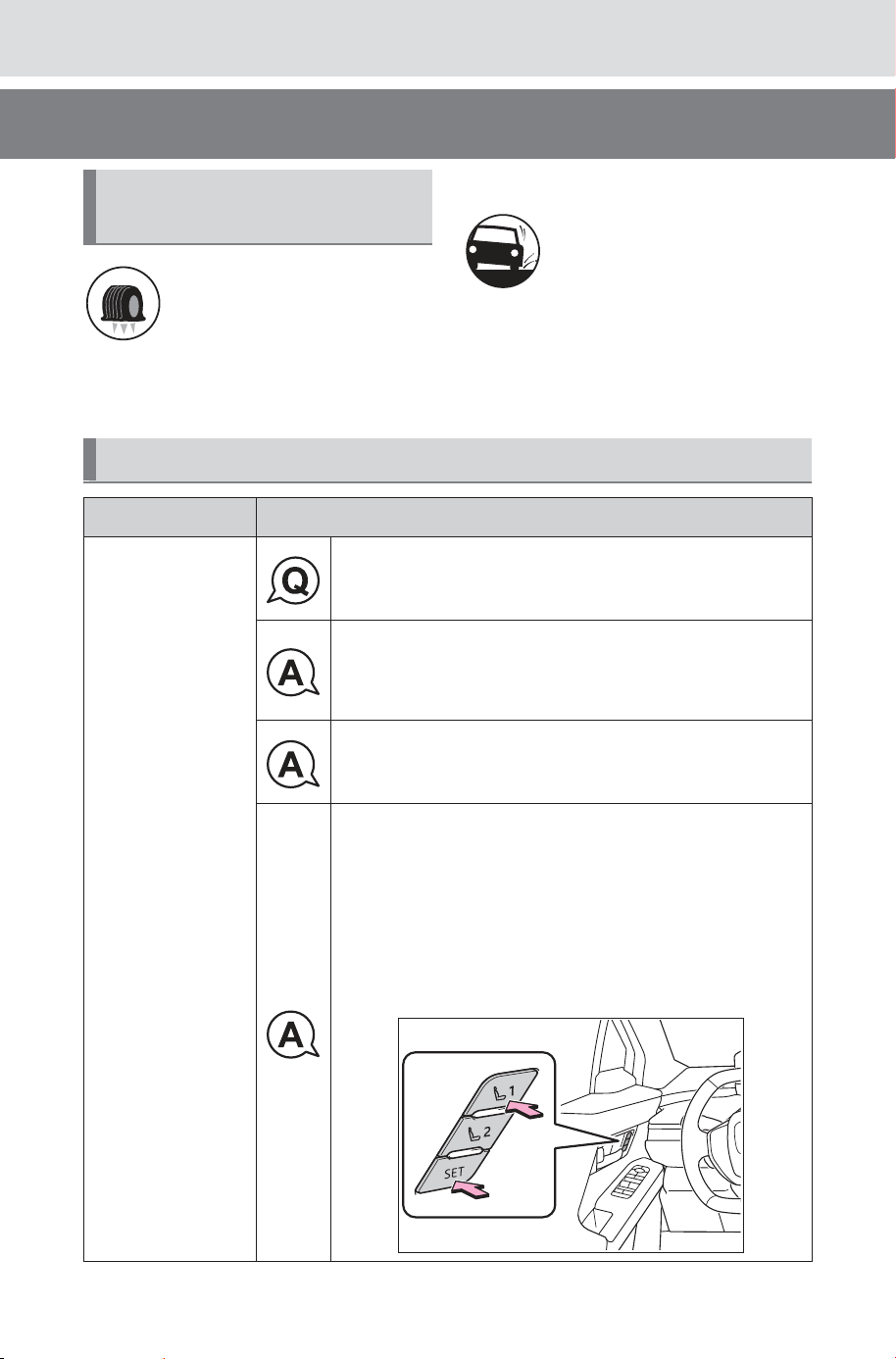
704
What to do if... (Troubleshooting)
Owner’s Manual_USA_M6740B_en
Stop the vehicle in a safe
place and replace the flat tire
with the spare tire. (P.628)
Try the procedure for when
the vehicle becomes stuck in
mud, dirt, or snow. (P.650)
When a problem has
occurred
If you have a flat tire
The vehicle becomes
stuck
Troubleshooting
System Q & A
Driving position
memory
Unable to register driving position.
It is possible that the shift position is in a position
other than P.
Make sure the shift is P.
The power switch may be turned off.
Make sure the power switch is ON.
It is possible that button “1” or “2” was pressed
more than 3 seconds after pressing the SET but-
ton on the door panel.
When registering, keep pressing the SET button,
or press the “1” or “2” button within 3 seconds
after releasing the SET button. Please check
P.208 for details.
SOLTERRA_OM_USA_A6740BE.book 704 ページ 2025年5月23日 金曜日 午後1時18分
Owner’s Manual_USA_M6740B_en
705
What to do if... (Troubleshooting)
RCTA
It is desired to adjust various functions.
• Various functions may be operated on the
multi-information display or adjusted at a SUB-
ARU dealer. Please check P.671 for adjust-
ment methods and adjustable items.
It is desired to turn on/off the warning sound
when reversing (shift position is R) and the vol-
ume is too loud/It is desired to be adjusted
Clearance sonar or RCTA (rear cross traffic
alert) may be activated.
It is possible to turn off the function and adjust
the volume.
Check P.671 for details.
Brake Hold
It is desired to use the brake hold function.
Operating conditions must be met for operation.
Check P.245 for details.
System Q & A
SOLTERRA_OM_USA_A6740BE.book 705 ページ 2025年5月23日 金曜日 午後1時18分
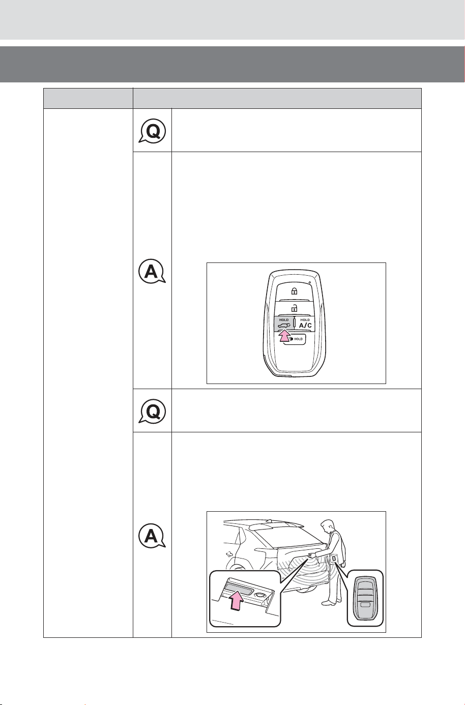
706
What to do if... (Troubleshooting)
Owner’s Manual_USA_M6740B_en
Back door
(vehicles with
power back
door)
It is desired to open and close the back door
using an electronic key.
• When using the wireless function of the elec-
tronic key to open/close the back door, unlock
the back door first.
• After unlocking the back door, press and hold
the back door button on the electronic key for
about 1 second.
For details, please refer to P.166.
It is desired to open and close the back door
using the back door switch.
• When opening and closing the back door from
outside the car, please carry the electronic key.
• The back door can be opened and closed by
pressing switch on the back door. For details,
please refer to P.166.
System Q & A
SOLTERRA_OM_USA_A6740BE.book 706 ページ 2025年5月23日 金曜日 午後1時18分
Owner’s Manual_USA_M6740B_en
707
What to do if... (Troubleshooting)
Remote Air Con-
ditioning System
It is desired to activate the air conditioning before
getting in the vehicle.
The air conditioning can be activated in advance
using the SubaruConnect App.
For details, check SubaruConnect App or the
SubaruConnect website.
The “SubaruConnect” website is below.
SUBARU of America
subaru.com
SUBARU Canada
subaru.ca
System Q & A
SOLTERRA_OM_USA_A6740BE.book 707 ページ 2025年5月23日 金曜日 午後1時18分

708
Alphabetical Index
Owner’s Manual_USA_M6740B_en
Alphabetical Index
A
A/C ...........................................492
Air conditioning filter.............592
Automatic air conditioning sys-
tem .....................................492
Front seat concentrated airflow
mode (S-FLOW).................499
My Room Mode.................... 117
Remote Air Conditioning System
...........................................501
ABS (Anti-lock Brake System)
...............................................476
Function ...............................476
Warning light ........................612
AC charging..............................95
AC charging cable
If the AC charging connector
cannot be unlocked..............86
ACA (Active Cornering Assist)
...............................................477
Acoustic Vehicle Alerting Sys-
tem...........................................73
Active Cornering Assist (ACA)
...............................................477
Advanced Park .......................373
Memory function...................392
Parallel exiting function ........390
Parallel parking function.......387
Perpendicular exiting (forward/
reverse) function ................385
Perpendicular parking (forward/
reverse) function ................382
Air conditioning filter.............592
Air conditioning system
Air conditioning filter.............592
Automatic air conditioning sys-
tem .....................................492
Front seat concentrated airflow
mode (S-FLOW).................499
Remote Air Conditioning System
...........................................501
Airbags ......................................33
Airbag operating conditions....34
Airbag precautions for your child
.............................................36
Correct driving posture ...........27
Curtain shield airbag operating
conditions .............................35
Curtain shield airbag precautions
.............................................36
Front passenger occupant clas-
sification system ...................41
General airbag precautions ....36
Locations of airbags ...............33
Modification and disposal of air-
bags......................................39
Side airbag operating conditions
.............................................35
Side airbag precautions..........36
Side and curtain shield airbags
operating conditions .............35
Side and curtain shield airbags
precautions...........................36
SRS airbag instructions for
Canadian owners ...............692
SRS airbags ...........................33
SRS warning light.................612
Alarm .........................................66
Alarm ......................................66
Warning buzzer ....................611
ALL AUTO (ECO) control .......490
Anchor brackets .................49, 59
Antenna (Smart key system) .177
Anti-lock Brake System (ABS)
Warning light.........................612
Anti-lock brake system (ABS)476
Function................................476
Approach warning..................313
Armrest....................................529
Assist grips.............................530
Audio system-linked display .149
Automatic air conditioning sys-
tem .........................................492
SOLTERRA_OM_USA_A6740BE.book 708 ページ 2025年5月23日 金曜日 午後1時18分

Owner’s Manual_USA_M6740B_en
Alphabetical Index
709
Air conditioning filter.............592
Front seat concentrated airflow
mode (S-FLOW).................499
Remote Air Conditioning System
...........................................501
Automatic door locking and
unlocking systems...............163
Automatic headlight leveling
system...................................248
Automatic High Beam (AHB).249
Automatic light control system
...............................................248
Auxiliary box lights ................507
Average electricity consumption
...............................................147
AWD operation status............150
B
Back door................................164
Hands Free Power Back Door
...........................................168
Power back door ..................166
Power back door switch .......166
Wireless remote control156, 166
Back-up lights
Replacing light bulbs ............599
Battery (12-volt battery).........568
Battery checking...................568
If the 12-volt battery is dis-
charged ..............................644
Preparing and checking before
winter..................................482
Replacing .............................646
Warning light ........................ 611
Battery (traction battery) .........70
Charging.........................95, 100
Location..................................70
Specification.........................656
Traction battery cooler............89
Traction battery heater ...........88
Warning messages...............127
Battery Electric Vehicle driving
tips ...........................................79
Battery Preconditioning.........113
Battery status display ............149
Blind Spot Monitor (BSM) ......330
Enabling/disabling the system
...........................................332
Bottle holders .........................512
Brake
Brake Hold............................245
Fluid..............................567, 660
Parking brake .......................241
Regenerative braking .............71
Warning light.........................611
Brake assist ............................476
Brake Hold............................245
Brake Override System..........216
Break-in tips............................216
Brightness control
Instrument panel light control145
BSM (Blind Spot Monitor) ......330
Enabling/disabling the system
...........................................332
C
Camera
Advanced Park .....................377
Digital inner mirror ................196
Driver monitor...............261, 267
Front camera ........................261
Care
Aluminum wheels .................549
Exterior .................................548
Interior ..................................551
Seat belts .............................551
Cargo and luggage.................222
Cargo capacity................222, 227
Cargo hooks............................513
Ceintures de sécurité
Nettoyage et entretien des cein-
tures de sécurité.................691
Center console light...............507
Chains......................................484
SOLTERRA_OM_USA_A6740BE.book 709 ページ 2025年5月23日 金曜日 午後1時18分

710
Alphabetical Index
Owner’s Manual_USA_M6740B_en
Charging ...........................95, 100
AC charging ...........................95
Battery Preconditioning ........ 113
Charging components ............83
Charging methods..................88
Charging procedure .......95, 100
Charging schedule function..106
Charging time may increase ..94
Charging tips ..........................90
DC charging .........................100
Display ... 91, 108, 117, 118, 127
How to use Plug & Charge sys-
tem .....................................132
Information related to charging
display.. 91, 108, 117, 118, 127
Locking and unlocking the AC
charging connector...............85
My Room Mode.................... 117
Opening and closing the
charging port lids..................84
Plug & Charge system .........132
Safety functions......................92
Things to know before charging
.............................................92
Warning messages...............127
When charging cannot be car-
ried out ...............................120
When charging schedule func-
tion does not operate normally
...........................................125
When DC charging cannot be
performed normally ....121, 134
When Plug & Charge cannot be
set normally........................134
Charging equipment ................83
Charging methods....................88
AC charging ...........................95
DC charging .........................100
Charging ports
Charging port lid.....................83
Locking and unlocking the AC
charging connector...............85
Opening and closing...............84
Charging schedule function..106
Setting ..................................108
Charging tips ............................90
Charging-linked functions
My Room Mode ......................88
Traction battery cooler............89
Traction battery heater ...........88
Traction battery warming control
.............................................89
Child restraint system..............47
Fixed with a LATCH system ...56
Fixed with a seat belt..............52
Front passenger occupant clas-
sification system ...................41
Points to remember ................47
Riding with children ................46
Types of child restraint system
installation method ...............49
Using an anchor bracket ........59
Child safety ...............................46
12-volt battery precautions ...647
Airbag precautions .................36
Back door precautions..........164
Child restraint system.............49
Electronic sunshade .............518
How your child should wear the
seat belt................................30
Power window lock switch....206
Power window precautions...205
Rear door child-protectors....163
Removed key battery precau-
tions....................................595
Seat belt precautions..............29
Child-protector........................163
Cleaning ..........................548, 551
Aluminum wheels .................549
Digital inner mirror ................196
Exterior .................................548
Interior ..................................551
Radar sensor........................261
Seat belts .............................551
SOLTERRA_OM_USA_A6740BE.book 710 ページ 2025年5月23日 金曜日 午後1時18分

Owner’s Manual_USA_M6740B_en
Alphabetical Index
711
Clock .......................................142
Coat hooks..............................529
Console box............................ 511
Coolant
Capacity ...............................658
Checking ..............................565
Preparing and checking before
winter..................................482
Cooling system
EV system overheating ........648
Coussins gonflables
Précautions avec les coussins
gonflables pour votre enfant
...........................................693
Cruise control
Dynamic radar cruise control
...................................306, 317
Warning lights.......................617
Cup holders ............................ 511
Current electricity consumption
...............................................147
Curtain shield airbags .............33
Customizable features ...........671
D
Daytime running light system247
Daytime running lights
Replacing light bulbs ............599
DC charging............................100
Deck board..............................513
Deck under tray ......................514
Defogger
Outside rear view mirrors .....496
Rear window ........................496
Windshield............................495
Digital inner mirror.................192
Digital key ...............................157
Dimension...............................654
Dinghy towing ........................228
Display
Charging. 91, 108, 117, 118, 127
Cruise control .......................317
Dynamic radar cruise control309
Multi-information display.......145
Pedestrians Rear of the Vehicle
...........................................372
Plug & Charge system..........135
RCD (Rear Camera Detection)
...........................................357
Rear Camera Detection (RCD)
...........................................357
SUBARU Parking Assist.......341
Warning message.................621
Do-it-yourself maintenance .556,
559
Door lock
Back door .............................164
Side doors ............................159
Smart key system.................177
Wireless remote control........156
Door trim ornament lights .....507
Doors
Automatic door locking and
unlocking system................163
Back door .............................164
Door glasses ........................204
Door lock ......................159, 164
Door lock buttons .................162
Open door warning buzzer ...162
Outside rear view mirrors .....200
Rear door child-protectors....163
Side doors ............................159
Drive-start control ..................221
Driver monitor.........................267
Driver’s seat position memory
...............................................207
Driving position memory.......207
Memory recall function .........209
Power easy access system ..207
Driving .....................................215
Battery Electric Vehicle driving
tips........................................79
Break-in tips .........................216
Correct posture.......................27
SOLTERRA_OM_USA_A6740BE.book 711 ページ 2025年5月23日 金曜日 午後1時18分

712
Alphabetical Index
Owner’s Manual_USA_M6740B_en
Drive mode select switch .....470
Procedures...........................215
Winter drive tips ...................482
Driving assist information
Warning light ........................616
Driving information display...147
Driving position memory .......207
Memory recall function .........209
Power easy access system..207
Driving range ..........................142
Driving support system informa-
tion display ...........................148
Dynamic radar cruise control
.......................................306, 317
Approach warning ................313
Curve speed reduction function
...........................................313
Warning lights.......................617
E
ECB (Electronically Controlled
Brake System) ......................476
Warning light ........................ 611
Eco Drive mode ......................470
Eco mode ................................238
EDR (Event data recorder)....... 11
Electric motor (traction motor)
Identification number............655
Location..................................70
Electric Power Steering (EPS)
Function ...............................477
Warning light ........................613
Electric Vehicle system features
.................................................70
Electric Vehicle system precau-
tions.........................................74
Electricity consumption.147, 151
Average electricity consumption
...........................................147
Current electricity consumption
...........................................147
Electronic key.........................154
Battery-saving function.........178
If the electronic key does not
operate properly .................642
Replacing the battery ...........594
Electronic sunshade ..............517
Operation..............................517
Electronically Controlled Brake
System (ECB)........................476
Warning light.........................611
Emergency Driving Stop System
...............................................321
Emergency flashers ...............602
Emergency tire puncture repair
kit ...........................................628
Storage location ...................630
Emergency, in case of
If a warning buzzer sounds ..611
If a warning light turns on .....611
If a warning message is dis-
played.................................621
If the 12-volt battery is dis-
charged ..............................644
If the electronic key does not
operate properly .................642
If the EV system will not start640
If the vehicle is submerged or
water on the road is rising ..603
If you have a flat tire .............628
If you lose your keys.............641
If you think something is wrong
...........................................609
If your vehicle becomes stuck
...........................................650
If your vehicle has to be stopped
in an emergency.................602
If your vehicle needs to be towed
...........................................605
If your vehicle overheats ......648
Entretien
Ceintures de sécurité ...........691
SOLTERRA_OM_USA_A6740BE.book 712 ページ 2025年5月23日 金曜日 午後1時18分

Owner’s Manual_USA_M6740B_en
Alphabetical Index
713
EPS (Electric Power Steering)
Function ...............................477
Warning light ........................613
EV system .................................70
ACC......................................232
Acoustic Vehicle Alerting System
.............................................73
Battery Electric Vehicle driving
tips........................................79
Brake Override System ........216
Drive-start control.................221
Driving range..........................81
Electric Vehicle system precau-
tions......................................74
Emergency shut off system....78
Features .................................70
How to start the EV system..229
How to use AC charging.........95
How to use DC charging ......100
If the EV system will not start640
If your vehicle has to be stopped
in an emergency.................602
Ignition switch (power switch)
...........................................229
Overheating..........................648
Power meter.........................142
Power switch ........................229
Regenerative braking .............71
Starting the EV system.........229
EV system malfunction indicator
lamp
Warning buzzers ..................612
Warning light ........................612
Event data recorder (EDR)....... 11
F
FCTA (Front Cross Traffic Alert)
...............................................301
Flat tire ....................................628
Tire pressure warning system
...........................................573
Floor mats .................................26
Fluid
Brake ....................................660
Front eAxle ...........................660
Rear eAxle............................660
Washer .................................570
Fog lights
Replacing light bulbs ............599
Footwell lights ........................507
Front Cross Traffic Alert (FCTA)
...............................................301
Front eAxle
Fluid......................................660
Front electric motor (traction
motor)
Specification .........................656
Front fog lights
Replacing light bulbs ............599
Front interior lights ................508
Front passenger occupant clas-
sification system ....................41
Front seat concentrated airflow
mode (S-FLOW) ....................499
Front seats ..............................183
Adjustment ...........................183
Cleaning ...............................551
Correct driving posture ...........27
Driving position memory.......207
Head restraints .....................186
Memory recall function .........209
Power easy access system ..207
Seat heaters .........................503
Seat position memory...........207
Seat ventilators.....................503
Front side marker lights.........247
Light switch...........................247
Front turn signal lights
Replacing light bulbs ............599
Turn signal lever ...................240
Fuses .......................................596
SOLTERRA_OM_USA_A6740BE.book 713 ページ 2025年5月23日 金曜日 午後1時18分

714
Alphabetical Index
Owner’s Manual_USA_M6740B_en
G
Garage door opener ...............538
Gauges ....................................142
Grip control.............................474
H
Head restraints .......................186
Headlights...............................247
Automatic High Beam (AHB)249
Light switch ..........................247
Replacing light bulbs ............599
Headlights aim........................598
Heated steering wheel ...........503
ALL AUTO (ECO) control .....490
Heater coolant
Checking ..............................565
Heater system
Capacity ...............................659
Heaters
Automatic air conditioning sys-
tem .....................................492
Heated steering wheel .........504
Outside rear view mirrors .....496
Seat heaters.........................503
Traction battery heater ...........88
Hill-start assist control ..........477
Hood ........................................561
Hooks
Cargo hooks.........................513
Coat hooks ...........................529
Retaining hooks (floor mat) ....26
Horn.........................................190
How to use Plug & Charge sys-
tem.........................................132
I
Identification
Electric motor (traction motor)
...........................................655
Vehicle..................................654
If your vehicle overheats .......648
Ignition switch (power switch)
...............................................229
Auto power off function.........233
Changing the power switch
modes.................................232
If your vehicle has to be stopped
in an emergency.................602
Starting the EV system.........229
Illuminated entry system .......508
Immobilizer system ..................65
Indicators ................................140
Charging indicator ..................85
Initialization
Electronic sunshade .............517
Items to initialize...................686
Power back door ..................172
Power windows ....................204
Inside door handle lights .......507
Inside rear view mirror...........191
Interior lights...........................507
J
Jack..........................................584
Positioning a floor jack .........563
Jack handle .............................584
Jam protection function
Power back door ..................170
Power windows ....................204
K
Keyless entry ..........................177
Smart key system.................177
Wireless remote control........156
Keys.........................................154
Battery-saving function.........178
Digital key.............................157
Electronic key .......................154
If the electronic key does not
operate properly .................642
If you lose your keys.............641
SOLTERRA_OM_USA_A6740BE.book 714 ページ 2025年5月23日 金曜日 午後1時18分

Owner’s Manual_USA_M6740B_en
Alphabetical Index
715
Key number plate .................154
Keyless entry................156, 177
Mechanical key ............154, 157
Power switch ........................229
Replacing the battery ...........594
Warning buzzer ....................178
Wireless remote control key.156
Knee airbags.............................33
L
Lane Change Assist (LCA) ....287
Operation .............................287
Lane Departure Alert (LDA) ...290
Operation .............................290
Warning lights.......................615
Lane Tracing Assist (LTA)......282
Operation .............................282
Warning lights.......................615
LATCH anchors ........................56
LCA (Lane Change Assist) ....287
Operation .............................287
LDA (Lane Departure Alert) ...290
Operation .............................290
Warning lights.......................615
Lever
Auxiliary catch lever .............561
Hood lock release lever........561
Turn signal lever...................240
Wiper lever ...........................253
License plate lights
Light switch ..........................247
Replacing light bulbs ............599
Light bulbs
Replacing .............................599
Lights
Automatic High Beam (AHB)249
Emergency flasher switch ....602
Headlight switch ...................247
Interior light list .....................507
Interior lights.........................508
Luggage compartment light..169
Personal lights......................509
Replacing light bulbs ............599
Turn signal lever ...................240
Vanity lights ..........................518
Load capacity..........................227
Locking and unlocking the AC
charging connector................85
LTA (Lane Tracing Assist)......282
Operation..............................282
Warning lights.......................615
Luggage compartment features
...............................................513
Luggage compartment light ..169
Luggage cover ........................515
M
Maintenance
Do-it-yourself maintenance ..559
General maintenance ...........556
Maintenance data.................654
Maintenance requirements...555
Menu icons..............................146
Meter
Clock ....................................142
Indicators..............................140
Instrument panel light control145
Meter control switches..........147
Meters ..................................142
Multi-information display.......145
Warning lights.......................611
Warning message.................621
Mirrors
Digital inner mirror ................192
Inside rear view mirror..........191
Outside rear view mirror defog-
gers ....................................496
Outside rear view mirrors .....200
Vanity mirrors........................518
Motor
Compartment........................564
Multi-information display.......145
Audio system-linked display .149
Charging. 91, 108, 117, 118, 127
SOLTERRA_OM_USA_A6740BE.book 715 ページ 2025年5月23日 金曜日 午後1時18分

716
Alphabetical Index
Owner’s Manual_USA_M6740B_en
Cruise control .......................317
Driving information display ...147
Driving support system informa-
tion display .........................148
Dynamic radar cruise control309
Electricity consumption ........147
LCA (Lane Change Assist)...289
LDA (Lane Departure Alert)..294
LTA (Lane Tracing Assist).....286
Menu icons...........................146
Meter control switches .........147
Navigation system-linked display
...........................................148
Plug & Charge system .........135
Suggestion function..............150
Tire pressure ........................573
Warning message ................621
Multi-terrain Monitor ..............401
How to switch the display.....407
If you notice any symptoms..468
Screen display......................403
My Room Mode....................... 117
Starting My Room Mode ...... 117
Warning messages............... 118
My Settings .............................210
N
Navigation system-linked display
...............................................148
Nettoyage
Ceintures de sécurité ...........691
O
Odometer ................................144
Odometer and trip meter display
Display items........................144
Open tray ................................512
Opener
Back door .............................166
Garage door.........................538
Hood.....................................561
Outer foot lights......................507
Outside rear view mirrors......200
Adjusting and folding ............200
BSM (Blind Spot Monitor).....330
Folding and extending ..........201
Linked mirror function when
reversing.............................203
Mirror position memory.........207
Outside rear view mirror defog-
gers ....................................496
RCTA (Rear Cross Traffic Alert)
...........................................351
SEA (Safe Exit Assist) ..........335
Outside temperature ..............142
P
Paddle switch..........................239
Panic mode .............................156
Parking brake..........................241
Operation..............................241
Parking brake engaged warning
buzzer.................................243
Warning light.........................618
Warning message.................243
Parking lights
Light switch...........................247
Parking Support Brake (PKSB)
...............................................360
Enabling/disabling the system
...........................................362
PCS (Pre-Collision System)...270
Enabling/disabling the system
...........................................281
Function................................270
Warning light.........................617
PDA (Proactive driving assist)
...............................................295
PDA indicator
Warning light.........................615
Personal lights................507, 509
Switch...................................509
SOLTERRA_OM_USA_A6740BE.book 716 ページ 2025年5月23日 金曜日 午後1時18分

Owner’s Manual_USA_M6740B_en
Alphabetical Index
717
PKSB (Parking Support Brake)
...............................................360
Enabling/disabling the system
...........................................362
Moving Vehicle Rear of the Vehi-
cle.......................................370
Pedestrians Rear of the Vehicle
...........................................371
Static Objects Front and Rear of
the Vehicle..........................365
Plug & Charge system ...........132
Information related to charging
display ................................135
Warning messages...............135
Power back door ....................166
Power back door switch .......166
Power back door switch 166, 167
Power control unit coolant
Checking ..............................566
Preparing and checking before
winter..................................482
Power easy access system ...207
Power meter............................142
Power mode............................470
Power outlet (1500 W)............530
Power outlets..........................519
Power steering (Electric Power
Steering system) ..................477
Power steering (Electric power
steering system)
Warning light ........................613
Power switch ..........................229
Auto power off function ........233
Changing the power switch
modes ................................232
If your vehicle has to be stopped
in an emergency.................602
Starting the EV system.........229
Power windows
Catch protection function .....204
Door lock linked window opera-
tion .....................................205
Jam protection function ........204
Operation..............................204
Window lock switch ..............206
Pre-Collision System (PCS)...270
Enabling/disabling the system
...........................................281
Function................................270
Warning light.........................617
Proactive driving assist (PDA)
...............................................295
R
Radar cruise control...............317
Radar cruise control (dynamic
radar cruise control).............306
Radiator...................................565
RCD (Rear Camera Detection)
...............................................356
Enabling/disabling the system
...........................................357
RCTA (Rear Cross Traffic Alert)
...............................................351
Enabling/disabling the system
...........................................352
Rear Camera Detection (RCD)
...............................................356
Enabling/disabling the system
...........................................357
Rear Cross Traffic Alert (RCTA)
...............................................351
Enabling/disabling the system
...........................................352
Rear eAxle
Fluid......................................660
Rear electric motor (traction
motor)
Specification .........................656
Rear fog light
Replacing light bulbs ............599
Rear interior lights..................508
SOLTERRA_OM_USA_A6740BE.book 717 ページ 2025年5月23日 金曜日 午後1時18分

718
Alphabetical Index
Owner’s Manual_USA_M6740B_en
Rear seat
Folding down the rear seatbacks
...........................................185
Rear seats ...............................184
Adjustment ...........................184
Head restraints.....................186
Rear side marker lights
Light switch ..........................247
Rear turn signal lights
Replacing light bulbs ............599
Turn signal lever...................240
Rear view mirror
Digital inner mirror................192
Inside rear view mirror..........191
Outside rear view mirrors .....200
Rear window defogger...........496
Regenerative braking...............71
Warning lights....................... 611
Remote Air Conditioning System
...............................................501
Replacing
Electronic key battery...........594
Fuses ...................................596
Light bulbs............................599
Tires .....................................583
Replacing the tire ...................583
Reporting safety defects for
Canadian owners .................690
Reporting safety defects for U.S.
owners...................................690
Road Sign Assist (RSA).........303
Roof luggage carrier ..............222
Roof tent .................................225
RSA (Road Sign Assist).........303
S
Safe Exit Assist (SEA)
Enabling/disabling the system
...........................................337
SEA (Safe Exit Assist)............335
Enabling/disabling the system
...........................................337
Seat belt reminder light..........614
Seat belts...................................29
Adjusting the seat belt shoulder
anchor height........................31
Automatic Locking Retractor
(ALR) ....................................31
Child restraint system installation
.............................................52
Cleaning and maintaining the
seat belt..............................551
Emergency Locking Retractor
(ELR) ....................................31
How to wear your seat belt.....30
How your child should wear the
seat belt................................30
Pregnant women, proper seat
belt use.................................29
Reminder light and buzzer ...614
Seat belt instructions for Cana-
dian owners ........................691
Seat belt pretensioners ..........32
SRS warning light.................612
Seat heaters ............................503
ALL AUTO (ECO) control .....490
Seat position memory............207
Seat ventilators.......................503
ALL AUTO (ECO) control .....490
Seating capacity .............227, 654
Seats................................183, 184
Adjustment ...................183, 184
Adjustment precautions........184
Child seats/child restraint system
installation ............................47
Cleaning ...............................551
Driving position memory.......207
Folding down the rear seatbacks
...........................................185
Head restraints .....................186
Power easy access system ..207
Properly sitting in the seat ......27
Seat heaters .........................503
Seat position memory...........207
SOLTERRA_OM_USA_A6740BE.book 718 ページ 2025年5月23日 金曜日 午後1時18分

Owner’s Manual_USA_M6740B_en
Alphabetical Index
719
Seat ventilators ....................503
Secondary Collision Brake (Sec-
ondary collision reduction at
the time of a frontal collision)
...............................................477
Sécurité de l’enfant
Précautions avec les coussins
gonflables...........................693
Sensor
Automatic headlight system .248
Automatic High Beam (AHB)249
BSM (Blind Spot Monitor).....331
Digital inner mirror................196
Dynamic radar cruise control261
Inside rear view mirror..........191
LCA (Lane Change Assist)...287
LDA (Lane Departure Alert)..290
LTA (Lane Tracing Assist).....282
Moving Vehicle Rear of the Vehi-
cle.......................................331
PCS (Pre-Collision System) .261
Power back door ..................170
Radar sensor........................261
Rain-sensing windshield wipers
...........................................254
RCTA (Rear Cross Traffic Alert)
...................................331, 351
SEA (Safe Exit Assist) ..........331
Static Objects Front and Rear of
the Vehicle..........................340
SUBARU Parking Assist sensor
...........................................340
Service plug ..............................74
Settings ...................................671
Shift lights...............................507
Shift position ..........................233
Drive mode select switch .....470
Paddle switch .......................239
Side airbags ..............................33
Side doors...............................159
Open door warning buzzer...161
Side marker lights
Light switch...........................247
Side mirrors ............................200
Adjustment ...........................200
BSM (Blind Spot Monitor).....330
Folding and extending ..........201
Heaters.................................496
Linked mirror function when
reversing.............................203
Mirror position memory.........207
Outside rear view mirror defog-
gers ....................................496
RCTA (Rear Cross Traffic Alert)
...........................................351
SEA (Safe Exit Assist) ..........335
Side turn signal lights
Replacing light bulbs ............599
Turn signal lever ...................240
Side windows..........................204
Smart key system...................177
Antenna location...................177
Entry functions..............159, 165
Starting the EV system.........229
Snow mode .............................471
Snow tires ...............................482
SOC (State of Charge) gauge 142
Software update......................257
“SOS” button ............................61
Specifications .........................654
Speedometer...........................142
SRS airbags ..............................33
Steering wheel ........................190
Adjustment ...........................190
Heated steering wheel..........503
Meter control switches..........147
Stop lights
Replacing light bulbs ............599
Storage feature .......................510
Storage precautions...............510
Stuck
If the vehicle becomes stuck 650
SOLTERRA_OM_USA_A6740BE.book 719 ページ 2025年5月23日 金曜日 午後1時18分

720
Alphabetical Index
Owner’s Manual_USA_M6740B_en
SUBARU Parking Assist ........340
Enabling/disabling the system
...........................................341
Function ...............................340
Warning lights.......................616
SUBARU Parking Assist sensor
...............................................340
SUBARU Safety Sense...........259
AHB (Automatic High Beam) 249
Driver monitor.......................267
Dynamic radar cruise control306
Emergency Driving Stop System
...........................................321
FCTA (Front Cross Traffic Alert)
...........................................301
LCA (Lane Change Assist)...287
LDA (Lane Departure Alert)..290
LTA (Lane Tracing Assist).....282
PCS (Pre-Collision System) .270
PDA (Proactive Driving Assist)
...........................................295
RSA (Road Sign Assist) .......303
Software update ...................257
Traffic Jam Assist .................324
SubaruConnect ........................61
Suggestion function...............150
Sun visors...............................518
Sunshade ................................517
Switches
Automatic High Beam switch249
Brake hold switch .................245
Camera switch .....................406
Cruise control .......................317
Door lock switch ...................162
Drive mode select switch .....470
Driving position memory
switches .............................207
Dynamic radar cruise control309
Eco mode .............................238
Electronic sunshade switch..517
Emergency flashers switch ..602
Garage door opener switches
...........................................538
Grip control...................471, 474
Heated steering wheel..........504
Ignition switch (power switch)
...........................................229
Light switch...........................247
LTA (Lane Tracing Assist) switch
...........................................285
Meter control switches..........147
Outside rear view mirror
switches..............................200
Paddle switch .......................239
Parking brake switch ............241
Power back door switch166, 167
Power switch ........................229
Power window switch ...........204
Rear window and outside rear
view mirror defoggers switch
...........................................496
Seat heater switches ............504
Snow mode switch ...............471
“SOS” button ..........................61
Vehicle-to-vehicle distance
switch .................................309
Ventilators (seat ventilators) .505
VIEW switch .........................406
VSC OFF switch...................478
Window lock switch ..............206
Windshield defogger switch..495
Windshield wipers and washer
switch .................................253
X-MODE switch ....................471
Switching the meter display..144
T
Tail lights
Light switch...........................247
Replacing light bulbs ............599
Theft deterrent system
Alarm ......................................66
Immobilizer system.................65
SOLTERRA_OM_USA_A6740BE.book 720 ページ 2025年5月23日 金曜日 午後1時18分

Owner’s Manual_USA_M6740B_en
Alphabetical Index
721
Things you should know
If you notice any symptoms..468
Ticket holders.........................512
Tire inflation pressure............150
Maintenance data.................661
Tire inflation pressure display
function...............................573
Warning buzzers ..................615
Warning light ........................615
Tire information......................662
Glossary ...............................665
Size ......................................663
Tire identification number .....663
Tire section names ...............664
Tire pressure warning system
...............................................573
Function ...............................573
Installing tire pressure warning
valves and transmitters ......575
Registering ID codes............579
Registering the position of each
wheel..................................576
Selecting wheel set ..............581
Setting the tire pressure .......577
Warning buzzers ..................615
Warning light ........................615
Tires.........................................571
Chains ..................................484
Checking ..............................571
Emergency tire puncture repair
kit........................................628
Glossary ...............................665
If you have a flat tire.............628
Inflation pressure..................588
Information ...........................662
Replacing .............................583
Rotating tires ........................573
Size ......................................661
Snow tires ............................482
Tire identification number .....663
Tire inflation pressure display
function...............................573
Tire pressure warning system
...........................................573
Uniform Tire Quality Grading664
Warning buzzers...................615
Warning light.........................615
Tools ................................584, 630
Top tether strap ........................59
Total load capacity .........222, 227
Towing
Dinghy towing.......................228
Emergency towing........605, 607
Towing eyelet........................608
Trailer sway control ..............477
Trailer towing ........................228
TRAC (Traction Control) ........477
Traction battery.........................70
Charging.........................95, 100
Location..................................70
Specification .........................656
Traction battery cooler............89
Traction battery heater ...........88
Warning messages...............127
Traction battery charge
Warning light.........................613
Traction Control (TRAC) ........477
Traffic Jam Assist...................324
Trailer sway control................477
Trailer towing ..........................228
Trip meters ..............................144
Turn signal lights
Replacing light bulbs ............599
Turn signal lever ...................240
U
USB Type-C charging ports...520
Using Battery Preconditioning
...............................................113
Utility vehicle precautions.....485
SOLTERRA_OM_USA_A6740BE.book 721 ページ 2025年5月23日 金曜日 午後1時18分

722
Alphabetical Index
Owner’s Manual_USA_M6740B_en
V
Vanity lights
Vanity lights ..........................518
Vanity mirrors .........................518
Vanity lights ..........................518
Vehicle data recordings.............9
Vehicle identification number654
Vehicle Stability Control (VSC)
...............................................477
Ventilators (seat ventilators) .503
VSC (Vehicle Stability Control)
...............................................477
W
Warning buzzers
Acceleration Suppression at Low
Speed.................................273
Approach warning ................313
Brake hold ............................618
Brake Override System ........613
Brake system ....................... 611
Break suggestion function....293
Cruise control .......................617
Drive-Start Control ...............613
Dynamic radar cruise control617
Electric power steering.........613
EV system malfunction indicator
lamp ...................................612
Hands off steering wheel warn-
ing (LDA) ............................293
Hands off steering wheel warn-
ing (LTA).............................284
LCA (Lane Change Assist)...287
LDA (Lane Departure Alert) 290,
615
LTA (Lane Tracing Assist)...282,
615
Open door ....................161, 162
Open hood ...........................162
Open window .......................205
PCS (Pre-Collision System) .617
Pre-collision warning ............271
RCTA (Rear Cross Traffic Alert)
...........................................352
Rear seat reminder...............161
Seat belt ...............................614
SRS airbag ...........................612
SUBARU Parking Assist.....346,
616
Tire pressure ........................615
Warning lights.........................611
ABS ......................................612
Brake hold operated indicator
...........................................618
Brake Override System ........613
Brake system........................611
Charging system ..................611
Cruise control indicator.........617
Drive-Start Control................613
Driving assist information indica-
tor .......................................616
Dynamic radar cruise control
indicator..............................617
Electric power steering .........613
EV system malfunction indicator
lamp....................................612
LDA indicator ........................615
LTA indicator.........................615
Parking brake indicator.........618
PDA indicator........................615
Pre-collision system .............617
Seat belt reminder light ........614
Slip indicator.........................617
SRS airbag ...........................612
SUBARU Parking Assist OFF
indicator..............................616
Tire pressure ........................615
Traction battery charge.........613
Warning messages.................621
Washer
Low washer fluid warning mes-
sage....................................570
Preparing and checking before
SOLTERRA_OM_USA_A6740BE.book 722 ページ 2025年5月23日 金曜日 午後1時18分

Owner’s Manual_USA_M6740B_en
Alphabetical Index
723
winter..................................482
Switch...................................253
Washing and waxing......548, 551
Weight
Cargo capacity .............222, 227
Load limits ............................227
Weight ..................................654
Wheel bolt wrench .................584
Wheels.....................................590
Replacing wheels .................590
Size ......................................661
Window glasses
Power windows ....................204
Window lock switch ...............206
Windows
Power windows ....................204
Rear window defogger .........496
Washer.................................253
Windshield defogger..............495
Windshield wipers
Position ................................253
Rain-sensing windshield wipers
...........................................253
Winter driving tips..................482
Wireless charger ....................521
Wireless charger tray lights ..507
Wireless remote control ........156
Battery-saving function.........178
Locking/Unlocking ................156
Panic mode ..........................156
Remote Air Conditioning System
...........................................501
Replacing the battery ...........594
X
X-MODE...................................471
Grip control...........................471
For information regarding
the equipment listed
below, refer to the “MUL-
TIMEDIA OWNER’S MAN-
UAL”.
· Navigation system
· Audio system
· Rear view monitor system
· SUBARU Parking Assist
monitor
· Panoramic view monitor
SOLTERRA_OM_USA_A6740BE.book 723 ページ 2025年5月23日 金曜日 午後1時18分
724
Owner’s Manual_USA_M6740B_en
Certifications
SubaruConnect
SOLTERRA_OM_USA_A6740BE.book 724 ページ 2025年5月23日 金曜日 午後1時18分
725
Owner’s Manual_USA_M6740B_en
For vehicles sold in the U.S.A. and Hawaii
Smart key system and Immobilizer system
SOLTERRA_OM_USA_A6740BE.book 725 ページ 2025年5月23日 金曜日 午後1時18分
726
Owner’s Manual_USA_M6740B_en
For vehicles sold in Canada
SOLTERRA_OM_USA_A6740BE.book 726 ページ 2025年5月23日 金曜日 午後1時18分
727
Owner’s Manual_USA_M6740B_en
For vehicles sold in the U.S.A. and Hawaii
Digital key
SOLTERRA_OM_USA_A6740BE.book 727 ページ 2025年5月23日 金曜日 午後1時18分
728
Owner’s Manual_USA_M6740B_en
For vehicles sold in Canada
SOLTERRA_OM_USA_A6740BE.book 728 ページ 2025年5月23日 金曜日 午後1時18分
729
Owner’s Manual_USA_M6740B_en
SOLTERRA_OM_USA_A6740BE.book 729 ページ 2025年5月23日 金曜日 午後1時18分
730
Owner’s Manual_USA_M6740B_en
For vehicles sold in the U.S.A. and Hawaii
Smart key system
SOLTERRA_OM_USA_A6740BE.book 730 ページ 2025年5月23日 金曜日 午後1時18分
731
Owner’s Manual_USA_M6740B_en
For vehicles sold in Canada
SOLTERRA_OM_USA_A6740BE.book 731 ページ 2025年5月23日 金曜日 午後1時18分
732
Owner’s Manual_USA_M6740B_en
For vehicles sold in the U.S.A. and Hawaii
For vehicles sold in Canada
SUBARU Safety Sense
SOLTERRA_OM_USA_A6740BE.book 732 ページ 2025年6月27日 金曜日 午前10時48分
733
Owner’s Manual_USA_M6740B_en
For vehicles sold in the U.S.A. and Hawaii
BSM (Blind Spot Monitor)
SOLTERRA_OM_USA_A6740BE.book 733 ページ 2025年6月27日 金曜日 午前10時48分
734
Owner’s Manual_USA_M6740B_en
For vehicles sold in Canada
SOLTERRA_OM_USA_A6740BE.book 734 ページ 2025年6月26日 木曜日 午前10時43分
735
Owner’s Manual_USA_M6740B_en
For vehicles sold in the U.S.A. and Hawaii
Wireless charger
SOLTERRA_OM_USA_A6740BE.book 735 ページ 2025年5月23日 金曜日 午後1時18分
736
Owner’s Manual_USA_M6740B_en
SOLTERRA_OM_USA_A6740BE.book 736 ページ 2025年7月3日 木曜日 午前11時50分
737
Owner’s Manual_USA_M6740B_en
For vehicles sold in Canada
For vehicles sold in the U.S. mainland and Hawaii
Garage door opener
SOLTERRA_OM_USA_A6740BE.book 737 ページ 2025年7月3日 木曜日 午前11時50分
738
Owner’s Manual_USA_M6740B_en
For vehicles sold in Canada
For vehicles sold in the U.S.A. and Hawaii
Tire pressure warning system
SOLTERRA_OM_USA_A6740BE.book 738 ページ 2025年7月3日 木曜日 午前11時50分
739
Owner’s Manual_USA_M6740B_en
For vehicles sold in the U.S.A. and Hawaii
For vehicles sold in Canada
SUBARU Parking Assist
SOLTERRA_OM_USA_A6740BE.book 739 ページ 2025年7月3日 木曜日 午前11時50分
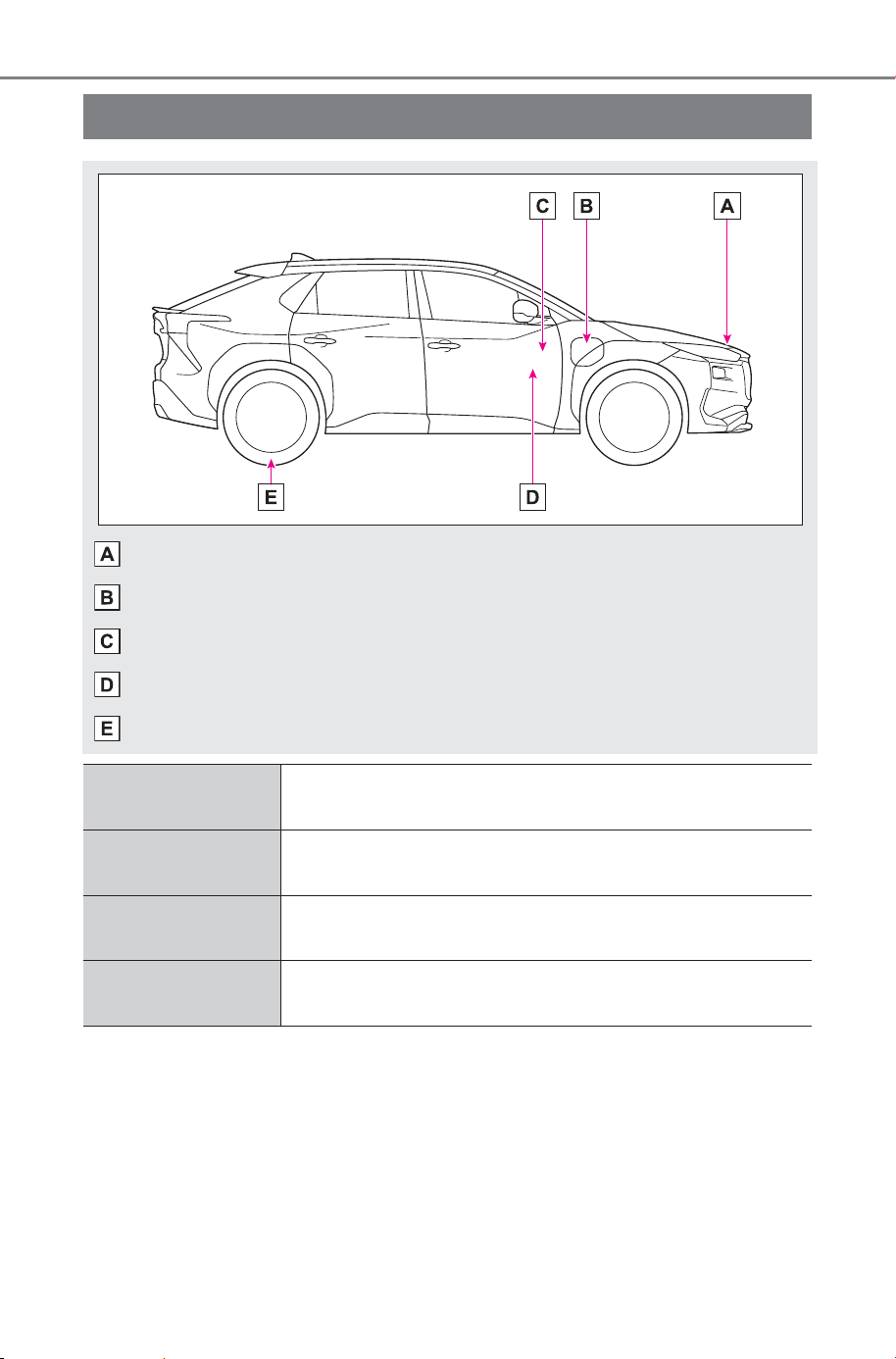
740
Owner’s Manual_USA_M6740B_en
CHARGING STATION INFORMATION
Auxiliary catch lever (P.5 61 )
Charging port lid (P.83)
Power back door switch (P.166)
Hood lock release lever (P.561)
Tire inflation pressure (P.661)
External power
source
P.88
Time needed for
charging
P.91
Traction battery
type
P.656
Cold tire inflation
pressure
P.661
SOLTERRA_OM_USA_A6740BE.book 740 ページ 2025年5月23日 金曜日 午後1時18分