Black plate (1,1)
北米Model "A1160BE-C" EDITED: 2014/ 1/ 17
Foreword
Congratulations on choosing a SUBARU vehicle. This Owner’s
Manual has all the information necessary to keep your SUBARU in
excellent condition and to properly maintain the emission control
system for minimizing emission pollutants. We urge you to read
this manual carefully so that you may understand your vehicle and
its operation. For information not found in this Owner’s Manual,
such as details concerning repairs or adjustments, please contact
the SUBARU dealer from whom you purchased your SUBARU or
the nearest SUBARU dealer.
The information, specifications and il lustrations found in this
manual are those in effect at the time of printing. FUJI HEAVY
INDUSTRIES LTD. reserves the right to change specifications and
designs at any time without prior notice and without incurring any
obligation to make the same or similar changes on vehicles
previously sold. This Owner’s Manual applies to all models and
covers all equipment, including factory installed options. Some
explanations, therefore may be for equipment not installed in your
vehicle.
Please leave this manual in the vehicle at the time of resale. The
next owner will need the information found herein.
FUJI HEAVY INDUSTRIES LTD., TOKYO, JAPAN
is a registered trademark of FUJI HEAVY INDUSTRIES LTD.
*
C
Copyright 2014 FUJI HEAVY INDUSTRIES LTD.
Black plate (2,1)
北米Model "A1160BE-C" EDITED: 2014/ 1/ 17
Vehicle types
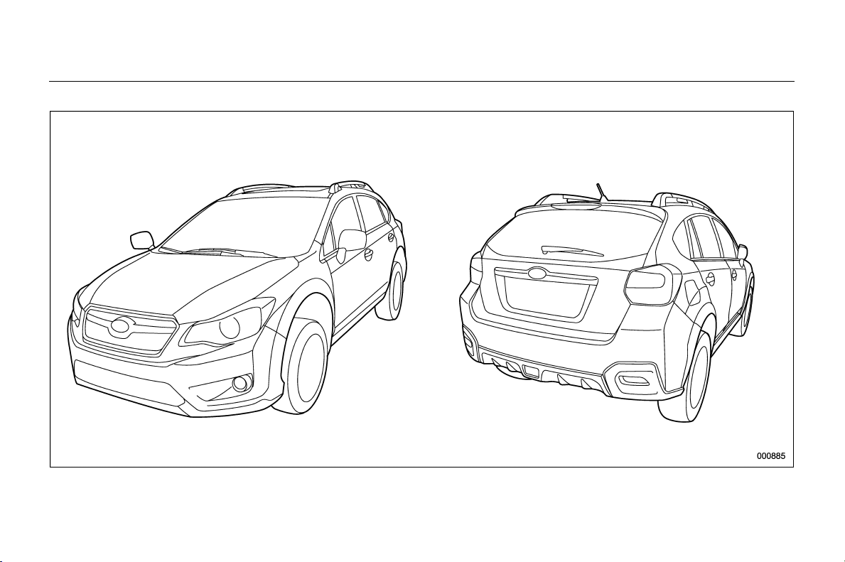
This manual describes the following vehicle types.

Black plate (3,1)
Model "ALL_MODEL_MEMO" EDITED: 2007/ 6/ 22
Black plate (3,1)
北米Model "A1160BE-C" EDITED: 2014/ 3/ 17
Warranties
& Warranties for U.S.A.
All SUBARU vehicles distributed by
Subaru of America, Inc. and sold at retail
by an authorized SUBARU dealer in the
United States come with the following
warranties:
. SUBARU Limited Warranty
. Emission Control Systems Warranty
. Emissions Performance Warranty
All warranty information, including details
of coverage and exclu sions, is in the
“Warranty and Maintenan ce Bookl et”.
Please read these warranties carefully.
& Warranties for Canada
All SUBARU vehicles distributed by
Subaru Canada, Inc. and sold at retail by
an authorized SUBARU dealer in Canada
come with the following warranties:
. SUBARU Limited Warranty
. Anti-Corrosion Warranty
. Emission Control Warranty
All warranty information, including details
of coverage and exclu sions, is in the
“Warranty and Service Booklet”. Please
read these warranties carefully.
& Models with HID headlights
CAUTION
High Intensity Discharge (HID) head-
lights contain mercury. For that
reason, it is necessary to remove
HID headlights before vehicle dis-
posal. Once removed, please reuse,
recycle or dispose of the HID head-
lights as hazardous waste.
& Models without HID head-
lights
NOTE
This vehicle does not contain mercury
devices or parts.
How to use this Owner’s
Manual
& Using your Owner’s Manual
Before you operate your vehicle, carefully
read this manual. To protect yourself and
extend the service life of your vehicle,
follow the instructions in this manual.
Failure to observe these instructions may
result in serious injury and damage to your
vehicle.
This manual is composed o f fourteen
chapters. Each chapter begins with a brief
table of contents, so you can usually tell at
a glance if that chapter contains the
information you want.
Chapter 1: Seat, seatbelt and SRS
airbags
This chapter informs you how to use the
seat and seatbelt and contains precau-
tions for the SRS airbags.
Chapter 2: Keys and doors
This chapter informs you how to operate
the keys, locks and windows.
Chapter 3: Instruments and controls
This chapter informs you about the opera-
tion of instrument panel indicators and
how to use the instruments and other
switches.
1
– CONTINUED –
0
Black plate (4,1)
北米Model "A1160BE-C" EDITED: 2014/ 3/ 17
2
Chapter 4: Climate control
This chapter informs you how to operate
the climate control.
Chapter 5: Audio
This chapter informs you how to operate
your audio system.
Chapter 6: Interior equipment
This chapter informs you how to operate
interior equipment.
Chapter 7: Starting and operating
This chapter informs you how to start and
operate your SUBARU.
Chapter 8: Driving tips
This chapter informs you how to drive your
SUBARU in various conditions and ex-
plains some safety tips on driving.
Chapter 9: In case of emergency
This chapter informs you what to do if you
have a problem, such as a flat tire or
engine overheating.
Chapter 10: Appearance care
This chapter informs you how to keep your
SUBARU looking good.
Chapter 11: Maintenance and service
This chapter informs you when you need
to take your SUBARU to the dealer for
scheduled maintenance and informs you
how to keep your SUBARU running
properly.
Chapter 12: Specifications
This chapter informs you about dimen-
sions and capacities of your SUBARU.
Chapter 13: Consumer information and
Reporting safety defects
This chapter informs you about Uniform
tire quality grading standards and Report-
ing safety defects.
Chapter 14: Index
This is an alphabetical listing of all that’sin
this manual. You can use it to quickly find
something you want to read.
& Safety warnings
You will find a number of WARNINGs,
CAUTIONs and NOTEs in this manual.
These safety warnings alert you to poten-
tial hazards that could result in injury to
you or others.
Please read these safety warnings as well
as all other portions of this manual care-
fully in order to gain a better understand-
ing of how to use your SUBARU vehicle
safely.
WARNING
A WARNING indicates a situation in
which serious injury or death could
result if the warning is ignored.
CAUTION
A CAUTION indicates a situation in
which injury or damage to your
vehicle, or both, could result if the
caution is ignored.
NOTE
A NOTE gives information or sugges-
tions how to make better use of your
vehicle.
& Safety symbol
You will find a circle with a slash through it
in this manual. This symbol means “ Do
not”, “Do not do this”,or“Do not let this
happen”, depending upon the context.
Black plate (5,1)
北米Model "A1160BE-C" EDITED: 2014/ 3/ 17
& Abbreviation list
You may find several abbreviations in this
manual. The meanings of the abbrevia-
tions are shown in the following list.
Abbreviation Meaning
A/C Air conditioner
A/ELR
Automatic/Emergency locking
retractor
ABS Anti-lock brake system
AKI Anti knock index
ALR Automatic locking retractor
AWD All-wheel drive
CVT
Continuously variable trans-
mission
DRL Daytime running light
EBD
Electronic brake force distri-
bution
ELR Emergency locking retractor
EV Electric vehicle
GAW Gross axle weight
GAWR Gross axle weight rating
GPS Global positioning system
GVW Gross vehicle weight
GVWR Gross vehicle weight rating
HEV Hybrid electric vehicle
HID High intensity discharge
Abbreviation Meaning
INT Intermittent
LATCH
Lower anchors and tethers for
children
LED Light emitting diode
LSD Limited slip differential
MIL Malfunction indicator light
MMT
Methylcyclopentadienyl man-
ganese tricarbonyl
OBD On-board diagnostics
RON Research octane number
SRS
Supplemental restraint sys-
tem
TIN Tire identification number
TPMS
Tire pressure monitoring sys-
tem
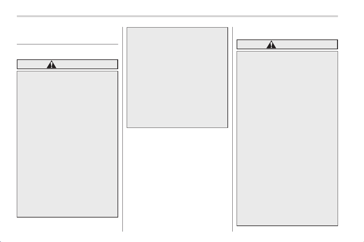
Vehicle symbols
There are some of the symbols you may
see on your vehicle.
For warning and indicator lights, refer to
“Warning and indicator lights” F29.
Mark Name
WARNING
CAUTION
Read these instructions care-
fully
Wear eye protection
Battery fluid contains sulfuric
acid
Keep children away
Keep flames away
Prevent explosions
3
0
Black plate (6,1)
北米Model "A1160BE-C" EDITED: 2014/ 3/ 17
4
Safety precautions when
driving
& Seatbelt and SRS airbag
WARNING
. All persons in the vehicle should
fasten their seatbelts BEFO RE
the vehicle starts to move. Other-
wise, the possibility of serious
injury becomes greater in the
event of a sudden stop or acci-
dent.
. To obtain maximum protection in
the event of an accide nt, the
driver and all passengers in the
vehicle should always wear seat-
belts when the vehicle is moving.
The SRS (Supplemental Restraint
System) airbag does not do away
with the need to fasten seatbelts.
In combination with the seat-
belts, it offers the best combined
protection in case of a serious
accident.
Not wearing a seatbelt increases
the chance of severe injury or
death in a crash even when the
vehicle has the SRS airbag.
. The SRS airbags dep loy with
considerable speed and force.
Occupants who are out of proper
position when the SRS airbag
deploys could suffer very serious
injuries. Because the SRS airbag
needs enough space for deploy-
ment, the driver should always
sit upright and well back in the
seat as far f rom the steering
wheel as practical while still
maintaining full vehicle control
and the front passenger should
move the seat as far back as
possible and sit upright and well
back in the seat.
For instructions and precautions, carefully
read the following sections.
. For the seatbelt system, refer to “Seat-
belts” F1-11.
. For the SRS airbag system, refer to
“*SRS airbag (Suppl emental Restraint
System airbag)” F1-37.
& Child safety
WARNING
. Never hold a child on your lap or
in your arms while the vehicle is
moving. The passenger cannot
protect the child from injury in a
collision, because the child will
be caught between the passen-
ger and objects inside the vehi-
cle.
. While riding in the vehicle, in-
fants and small children should
always be placed in the REAR
seat in an infant or child restraint
system which is appropriate for
the child’s age, height and
weight. If a child is too big for a
child restraint system, the child
should sit in the REAR seat and
be restrained using the seatbelts.
According to accident statistics,
children are safer when properly
restrained in the rear seating
positions than in the front seat-
ing positions. Never allow a child
to stand up or kneel on the seat.
. Put children aged 12 and under in
the REAR seat properly re-
strained at all times in a child
restraint device or in a seatbelt.
Black plate (7,1)
北米Model "A1160BE-C" EDITED: 2014/ 3/ 17
The SRS ai rbag deploys with
considerable speed and force
and can injure or even kill chil-
dren, especially if they are 12
years of age and under and are
not restrained or improperly re-
strained . B ecause children are
lighter and weaker than adults,
their risk of being injured from
deployment is greater.
. NEVER INSTALL A REARWARD
FACING CHILD SEAT IN THE
FRONT SEAT. DOING SO RISKS
SERIOUS INJURY OR DEATH TO
THE CHILD BY PLACING THE
CHILD’S HEAD TOO CLOSE TO
THE SRS AIRBAG.
. Always turn the child safety locks
to the “LOCK” position when
children sit in the rear seat.
Serious injury could result if a
child accidentally opens the door
and falls out. Refer to “Ch ild
safety locks” F2-29.
. Always lock the passenger’s win-
dows using the lock switch when
children are riding in the vehicle.
Failure to follow this procedure
could result in injury to a child
operating the power window. Re-
fer to “Windows” F2-29.
. Never leave unattended children,
adults or animals in the vehicle.
They could accidentally injure
themselves or others through
inadvertent operation of the ve-
hicle. Also, on hot or sunny days,
temperature in a closed vehicle
could quickly become high en-
ough to cause severe or possibly
fatal injuries to them.
. When leaving the vehicle, close
all windows and lock all doors.
For instructions and precautions, carefully
read the following sections.
. For the seatbelt system, refer to “Seat-
belts” F1-11.
. For the child restraint system, refer to
“Child restraint systems” F1-24.
. For the SRS airbag system, refer to
“*SRS airbag (Suppl emental Restraint
System airbag)” F1-37.
& Engine exhaust gas (carbon
monoxide)
WARNING
. Never inhale engine exhaust gas.
Engine exhaust gas contains
carbon monoxide, a colorless
and odorless gas which is dan-
gerous, or even lethal, if inhaled.
. Always properly maintain the en-
gine exhaust system to prevent
engine exhaust gas from enter-
ing the vehicle.
. Never run the hybrid system in a
closed space, such as a garage,
except for the brief time needed
to drive the vehicle in or out of it.
. Avoi d remaining in a parked
vehicle for a lengthy time while
the hybrid system is running. If
that is unavoidable, then use the
ventilation fan to force fresh air
into the vehicle.
. Always keep the front ventilator
inlet grille free from snow, leaves
or other obstructions to ensure
that the ventilation system al-
ways works properly.
. If at any time you suspect that
exhaust fumes are entering the
vehicle, have the problem
checked and corrected as soon
as possible. If you must drive
under these conditions, drive
only with all windows fully open.
. Keep the rear gate closed while
driving to prevent exhaust gas
from entering the vehicle.
5
– CONTINUED –
0
Black plate (8,1)
北米Model "A1160BE-C" EDITED: 2014/ 3/ 17
6
& Drinking and driving
WARNING
Drinking and then driving is very
dangerous. Alcohol in the blood-
stream de lays your reaction time
and impairs your perception, judg-
ment and attentiveness. If you drive
after drinking – even if you drink just
a little – it will increase the risk of
being involved in a serious or fatal
accident, injuring or killing yourself,
your passengers and others. In
addition, if you are injured in the
accident, alcohol may increase the
severity of that injury.
Please don’t drink and drive.
Drunken dr iving is one o f the most
frequent causes of accidents. Since alco-
hol affects all people differently, you may
have consumed too much alcohol to drive
safely even if the level of alcohol in your
blood is below the legal limit. The safest
thing you can do is never drink and drive.
However if you have no choice but to
drive, stop drinking and sober up comple-
tely before getting behind the wheel.
& Drugs and driving
WARNING
There are some drugs (over the
counter and prescription) that can
delay your reaction time and impair
your perception, judgment and at-
tentiveness. If you drive after taking
them, it may increase your, your
passengers’ and other persons’ risk
of being involved in a serious or
fatal accident.
If you are taking any drugs, check with
your doctor or pharmacist or read the
literature that accompanies the medication
to determine if the drug you are taking can
impair your driving ability. Do not drive
after taking any medications that can
make you drowsy or otherwise affect your
ability to safely operate a motor vehicle. If
you have a medical condition that requires
you to take drugs, please consult with
your doctor.
Never drive if you are under the influence
of any illicit mind-altering drugs. For your
own health and well-being, we urge you
not to take illegal drugs in the first place
and to seek treatment if you are addicted
to those drugs.
& Driving when tired or sleepy
WARNING
When you are tired or sleepy, your
reaction time will be delayed and
your perception, judgment and at-
tentiveness will be impaired. If you
drive when tired or sleepy, your,
your passengers’ and other per-
sons’ chances of being involved in
a serious accident may increase.
Please do not continue to drive but
instead find a safe place to rest if you
are tired or sleepy. On long trips, you
should make periodic rest stops to refresh
yourself before continuing on your journey.
When possible, you should share the
driving with others.
& Modification of your vehicle
CAUTION
Your vehicle should not be modified
other than with genuine SUBARU
parts and accessories. Other types
of modifications could affect its
performance, safety or durability,
and may even violate governmental
regulations. In addition, damage or
Black plate (9,1)
北米Model "A1160BE-C" EDITED: 2014/ 3/ 17
performance problems resulting
from modification may not be cov-
ered under warranties.
& Car phone/cell phone and
driving
CAUTION
Do not use a car phone/cell phone
while driving; it may distract your
attention from driving and can lead
to an accident. If you use a car
phone/cell phone, pull off the road
and p ark in a safe place before
using your phone. In some States/
Provinces, only hands-free phones
may legally be used while driving.
& Driving vehicles equipped
with navigation system
WARNING
Do not allow the monitor to distract
your attention from driving. Also, do
not operate the controls of the
navigation system while driving.
The loss of attention to driving
could lead to an accident. If you
wish to operate the controls of the
navigation system, first take the
vehicle off the road and stop it in a
safe place.
& Driving with pets
Unrestrained pets can interfere with your
driving and distract your attention from
driving. In a collisi on or sudden stop,
unrestrained pets or cages can be thrown
around inside the vehicle and hurt you or
your passengers. Besides, the pets can
be hurt under these situations. It is also for
their own safety that pets should be
properly restrained in your vehicle. Re-
strain a pet with a special traveling
harness which can be secured to the rear
seat with a seatbelt or use a pet carrier
which can be secured to the rear seat by
routing a seatbelt through the carrier’s
handle. Never restrain pets or pet carriers
in the front passenger’s seat. For further
information, consult your veterinarian,
local animal protection society or pet
shop.
& Tire pressures
Check and, if necessary, adjust t he
pressure of each tire at least once a
month and before any long journey.
Check the tire pressure when the tires are
cold. Use a pressure gauge to adjust the
tire pressures to the values shown on the
tire placard. For detailed information, refer
to “Tires and wheels” F11-22.
WARNING
Driving at high speeds with exces-
sively low tire pressures can cause
the tires to deform severely and to
rapidly become ho t. A sharp in-
crease in temperature could cause
tread separation, and destruction of
the tires. The resulting loss of
vehicle control could lead to an
accident.
7
0
Black plate (10,1)
北米Model "A1160BE-C" EDITED: 2014/ 3/ 17
8
General information
& California proposition 65
warning
WARNING
Engine exhaust, some of its consti-
tuents, and certain vehicle compo-
nents contain o r emit chemicals
known to the State of California to
cause cancer and birth defects or
other reproductive harm. In addi-
tion, certain fluids in vehicles and
certain components of product wear
contain or emit chemicals known to
the State of California to cause
cancer and birth defects or other
reproductive harm.
& California Perchlorate Advi-
sory
Certain vehicle components such as air-
bag modules, seatbelt pretensioners and
keyless entry transmitter batteries may
contain perchlorate material. Special
handling may apply for service or vehicle
end of life disposal. See www.dtsc.ca.gov/
hazardouswaste/perchlorate.
& Noise from under the vehicle
NOTE
You may hear a noise from under the
vehicle approximately 5 to 10 hours
after the ignition switch is turned to the
“LOCK” (off) position. However, this
does not indicate a malfunction. This
noise is caused by the operation of the
fuel evaporation leakage checking sys-
tem and is normal. The noise will stop
after approximately 15 minutes.
& Event data recorder
This vehicle is equipped with an event
data recorder (EDR). The main purpose of
an EDR is to record, in certain crash or
near crash-like situations, such as an
airbag deployment or hitting a road ob-
stacle, data that will assist in understand-
ing how a vehicle’s systems performed.
The EDR is designed to record data
related to vehicle dynamics and safety
systems for a short period of time, typically
30 seconds or less. The EDR in this
vehicle is designed to record such data
as:
. How various systems in your vehicle
were operating;
. Whether or not the driver and passen-
ger safety belts were buckled/fastened;
. How far (if at all) the driver was
depressing the accelerator and/or brake
pedal; and,
. How fast the vehicle was traveling.
These data can help provide a better
understanding of the circumstances in
which crashes and injuries occur. NOTE:
EDR data are recorded by your vehicle
only if a non-trivial crash situation occurs;
no data are recorded by the EDR under
normal driving conditions and no personal
data (e.g., name, gender, age, and crash
location) are recorded. However, other
parties, such as law enforcement, could
combine the EDR data with the type of
personally identifying data routinely ac-
quired during a crash investigation.
To read data recorded by an EDR, special
equipment is required, and access to the
vehicle or the EDR is needed. In addition
to the vehicle manufacturer, other parties,
such as law enforcement, that have the
special equipment, can read the informa-
tion if they have access to the vehicle or
the EDR.
Black plate (11,1)
北米Model "A1160BE-C" EDITED: 2014/ 3/ 17
Hybrid system features
WARNING
Some of the co mponen ts of the
hybrid system (e.g., high voltage
battery, electric motor, etc.) are high
voltage parts. To avoid serious in-
jury or death, carefully read the
following descriptions.
Your vehicle is equipped with a hybrid
system. The main power source for this
hybrid system is the engine though
depending on t he cir cumstances, the
electric motor may assist the power of
the engine. By controlling the interaction
of the engine and the electric motor, a high
level of performance, improved fuel econ-
omy, and a reduction in exhaust emissions
are achieved.
& General information for stop-
ping/restarting of the engine
and electric motor
NOTE
For details about the procedure for
starting the hybrid system, refer to
“Starting and stopping the hybrid sys-
tem” F7-8.
The engine will be automatically stopped
or restarted depending on the conditions
of the vehicle.
When starting:
The engine is used to start the vehicle
moving. However, when the accelerator
pedal is depressed lightly, the engine may
remain stopped and the electric motor
may be used to start the vehicle moving.
When accelerating gradually or driving
at a constant speed:
. When the vehicle speed is less than 25
mph (40 km/h), it is possible to drive using
only the power of the el ectric moto r.
However, when driving in reverse, the
engine will restart at a speed slower than
that experienced when the vehicle is
moving forward.
. When the vehicle speed is 25 mph (40
km/h) or more, the electric motor power
assists the engine power. However, when
driving uphill, if it is more efficient to drive
using engine power alone, the electric
motor may not operate.
When accelerating sharply:
The power of the electric motor is added to
that of the engine.
When driving using electric m otor
power alone and then accelerating:
The engine is restarted and the power of
the electric motor is added to that of the
engine.
When braking:
The engine is stopped. The electric motor
is used as a generator by using the
rotation of the wheels and this charges
the high voltage battery.
When the vehicle has been stopped:
The engine is stopped temporarily. De-
pending upon conditions, this may also
occur before a complete stop has been
achieved.
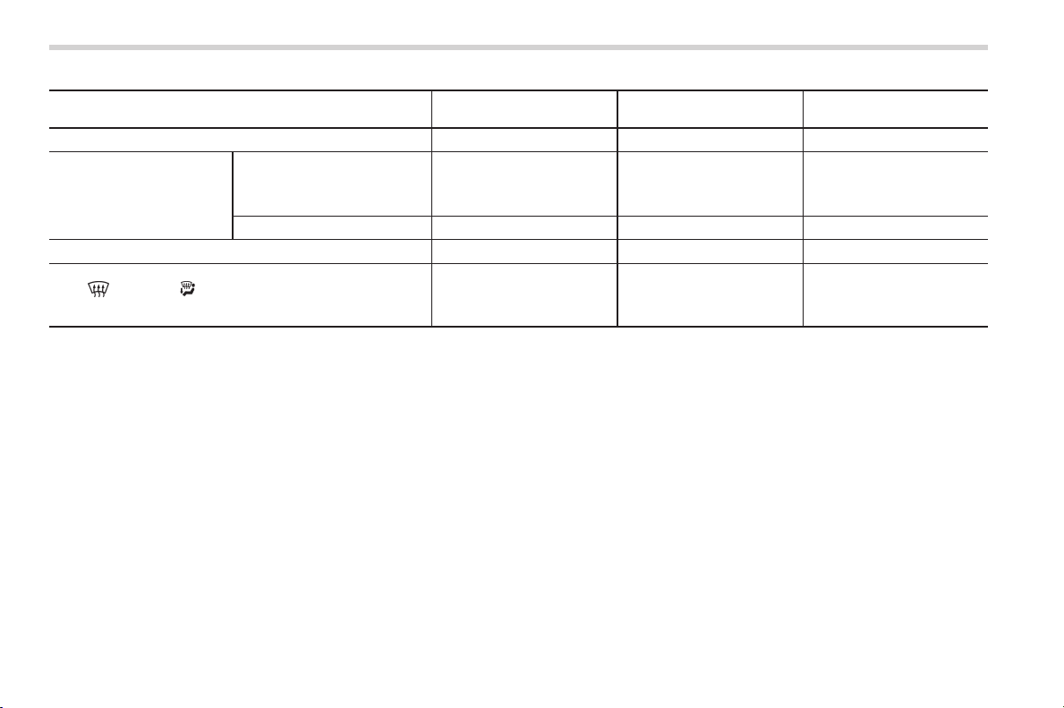
Depending on the position of the transmis-
sion select lever and the mode of the
climate control, the engine and the electric
motor are controlled as follows.
9
– CONTINUED –
0
Black plate (12,1)
北米Model "A1160BE-C" EDITED: 2014/ 3/ 17
10
Operation
Driving only using the elec-
tric motor power
Driving with the electric
motor assisting the engine
Engine automatically stops
Select lever is in the “D” position Operational Operational Operational
Select lever is in the “R”
position
Select lever has been shifted
into the “R” position while the
engine is automatically
stopped
Operational Operational Operational
In other cases Non-operational Operational Non-operational
Manual mode is selected
*1
Non-operational Operational Operational
The “ ” mode or “ ” mode of the climate system is
selected
*2
Non-operational Operational
Non-operational
*1
: For details, refer to “Selection of manual mode” F7-18.
*2
: For details, refer to “Airflow mode selection” F4-6.
Black plate (13,1)
北米Model "A1160BE-C" EDITED: 2014/ 3/ 17
Operation of the automatic engine stop
feature will depend upon a combination of
these various conditions. For example,
when you select the “
” mode of the
climate control, even if the select lever is
in the “D” position, the engine will not stop
automatically.
The engine may be automatically stopped
by the system when all of the following
conditions are met.
. the engine is sufficiently warmed up
. the high voltage battery and 12 V
engine restart battery are in good condi-
tion (plenty of electric power remains and
the temperature is within the specified
temperature range)
. the “
” mode or “ ” mode of the
climate control system is not selected
. the climate control function is not used
orusedwithanegligibletemperature
difference between the setting tempera-
ture and the temp erature i nside the
vehicle.
. the outside temperature is higher than
approximately 148F(−108C)
. the CHECK ENGINE warning light/
malfunction indicator light is off
. the vehicle is not stopped on a road
that has a steep slope
. negative pressure in the brake booster
is sufficient
. the brake pedal is firmly depressed
after it has been depressed to decelerate
or stop the vehicle (The system may not
operate in some cases if the brake pedal
is not fully depressed or if the brake is
applied suddenly.)
. the CVT fluid is sufficiently warmed up
. the temperature of the CVT fluid is not
abnormally high
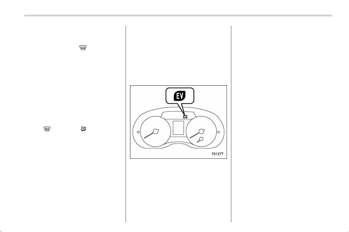
EV (Electric Vehicle) mode lamp
If the engine is temporarily stopped by the
system, the EV (Electric Vehicle) mode
lamp on the combination meter will illumi-
nate. This indicator light will turn off when
the system restarts the engine.
NOTE
. The 12 V engine restart battery is a
special high-performance battery.
When replacing the battery, be sure to
replace it with a genui ne SUBARU
battery (or equivalent) designed speci-
fically for use in a vehicle equipped
with a hybrid system. For details,
consult your SUBARU dealer.
. In the following cases, it may take
some time for stopping/restarting the
engine feature to operate.
– when the 12 V auxiliary battery
and/or 12 V engine restart battery is
discharged because the vehicle has
not been used for a long period of
time or for other reasons.
– when the outside temperature is
very high, or when it is very low
– when the terminals of the 12 V
auxiliary battery and/or 12 V engine
restart battery are disconnected
after replacing the battery
Also, in the following cases, the length of
time that the engine is temporarily stopped
by the system may be shorter.
. when the outside temperature is high,
or when it is low (because the air condi-
tioner or heater can no longer maintain the
set temperature)
. when consumption o f electricity by
electrical components is high
11
– CONTINUED –
0
Black plate (14,1)
北米Model "A1160BE-C" EDITED: 2014/ 3/ 17
12
WARNING
When driving on the electric motor
alone, there is no sound coming
from the engine. Therefore, there is
a possibility that the surrounding
people do not notice the vehicle
starting and approaching. Pay atten-
tion to your surroundings while
driving.
CAUTION
Depending on the state of the vehi-
cle (for example, if there is little
power remaining on the high voltage
battery), the engine may automati-
cally restart. Be sure to depress the
brake pedal while the vehicle is
stationary.
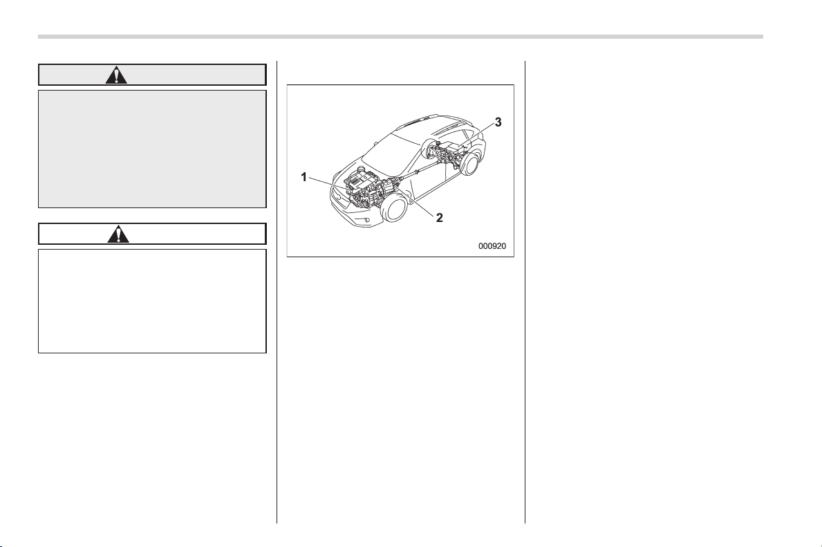
& Components
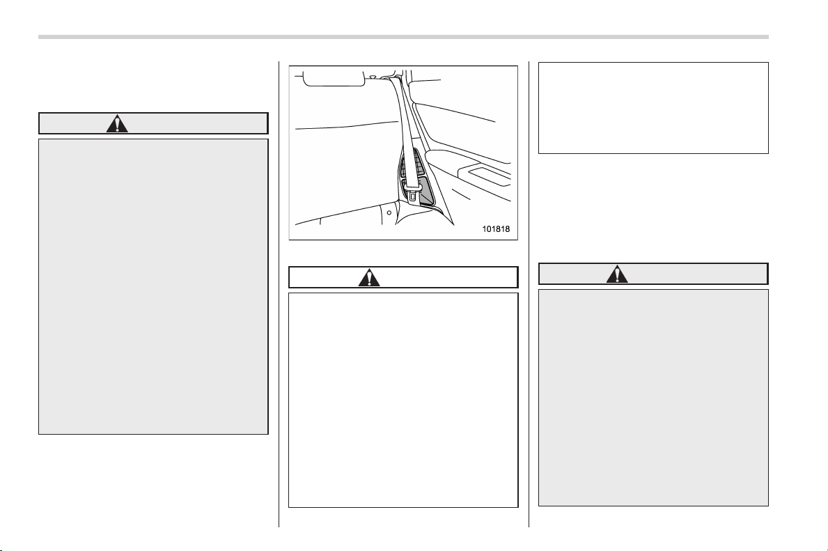
1) Engine
2) Drive electric motor assembly
3) High voltage battery
Black plate (15,1)
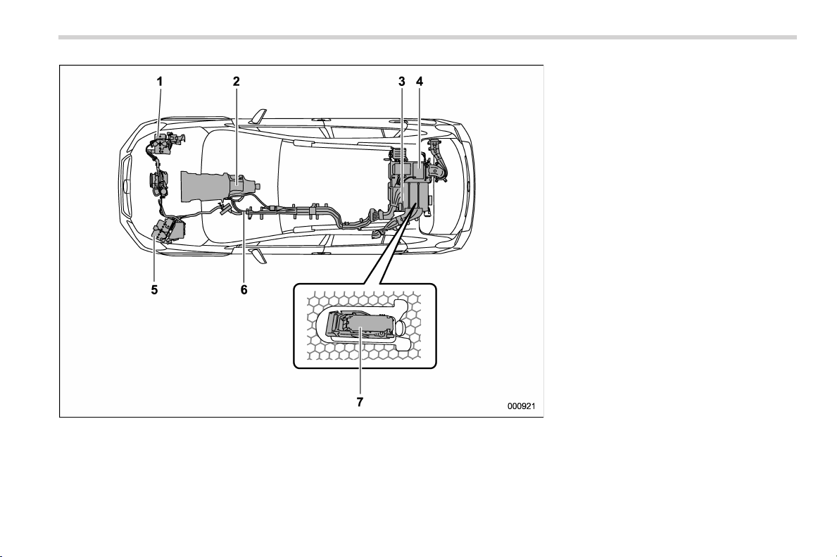
北米Model "A1160BE-C" EDITED: 2014/ 3/ 17
1) 12 V engine restart battery
2) Electric motor (located in the transmis-
sion)
3) High voltage battery
4) DC/DC converter
5) 12 V auxiliary battery
6) High voltage cable (orange)
7) Service disconnect plug
13
– CONTINUED –
0
Black plate (16,1)
北米Model "A1160BE-C" EDITED: 2014/ 3/ 17
14
& Safety precautions
! Precautions for daily use
WARNING
The hybrid system uses a high
vol tage (100 V or more). Always
observe the following precautions.
Otherwise, burns or electric shock
could occur, resulting in serious
injury or death.
. When inspection or repair is
needed, always have it per-
formed by your SUBARU dealer.
. Never touch, remove or disas-
semble the high voltage parts,
high voltage cable (orange) or
their connectors.
. Never touch the service discon-
nect plug. The service discon-
nect plug is used to cut off the
voltage of the high voltage bat-
tery when the vehicle is in-
spected or serviced by a
SUBARU dealer.
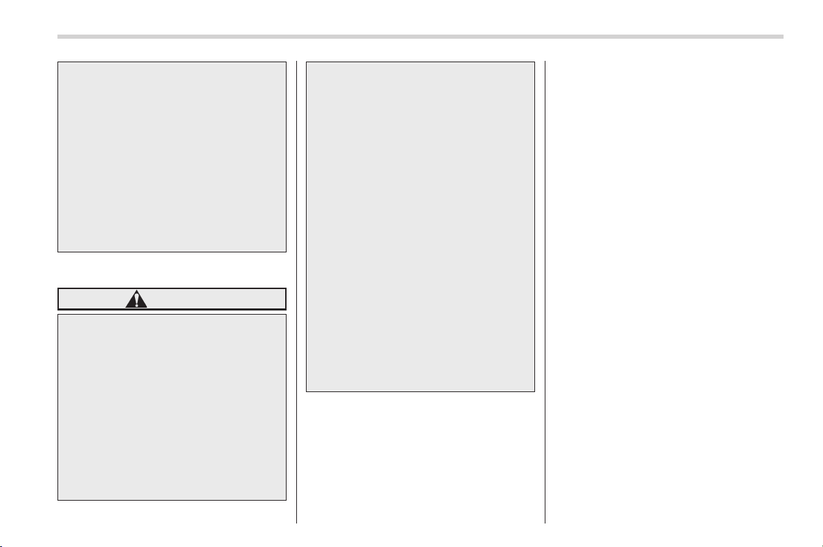
High voltage battery air intake
CAUTION
. Do not cover the high voltage
battery air intake (located on the
left next to the rear seat) with
luggage or clothes. It is impor-
tant that no liquids or any other
substances or objects be allowed
to enter the air intake. Please
advise passengers in this area to
use care around the air intake to
prevent any debris from entering.
Doing so may result in overheat-
ing or malfunctioning of the high
voltage battery.
. In order to ensure waterproofing,
be sure to install the cargo area
flooring. Ensure that large
amounts of water do not enter
the cargo area. Doing so may
result in malfunction of the hy-
brid system including the high
voltage battery.
NOTE
Because the gasoline engine is the
main power source of this vehicle, it
cannot run without gasoline.
! When an accident occurs
WARNING
Observe the following precautions.
Otherwise, serious injury (e.g.,
burns or electric shock) or death
may be caused.
. Never touch the following parts.
– High voltage parts
– High voltage cable (orange)
– Electric wires exposed inside
or outside the vehicle
. If there is liquid leaking from or
coating anything, do not touch it
under any circumstances. The
high voltage battery electrolyte
is a strong alkali. If the electrolyte
Black plate (17,1)
北米Model "A1160BE-C" EDITED: 2014/ 3/ 17
gets in your eyes or on your skin,
it could lead to serious injury. In
the event that it does get on you,
immediately wash it off with a
large amount of water and see a
doctor immediately for examina-
tion.
. If a fire occurs in the vehicle, put
it out with a electrical fire extin-
guisher. If a electrical fire extin-
guisher is not available, use a
large amount of water from a fire
hydrant or similar source.
! When disposing of your vehicle
WARNING
The nickel-metal hydride battery is
used as a high voltage battery. For
safety, observe the following pre-
cautions.
. I f you are disposing of your
vehicle, have a SUBARU dealer
remove and collect the high
voltage battery. If it is not prop-
erly collected, in addition to con-
tributing to environmental pollu-
tion, it is possible that the follow-
ing may occur, resulting in ser-
ious injury or death.
– An accident involving electric
shock that occurs when
someone touches the high
voltage portions of an illegally
dumped or otherwise impro-
perly disposed high voltage
battery.
– An accident involving electric
shock, heat generation,
smoke emission, fire, explo-
sion, leaking o f the battery
fluid, etc., caused by utilizing
the high volt age battery in
another vehicle.
. Do not offer the high voltage
battery for resale, transfer, mod-
ification, etc. under any circum-
stances. Particularly in the cases
of resale and transfer, the other
party of the resale/transfer may
not recognize the dangers of the
high voltage battery which could
result in serious injury.
& General information
! Tips for high voltage battery
. The engine and the regenerative brake
charge the high voltage battery. You do
not have to charge the hi gh voltage
battery from an outside source. However,
if the select lever is in the “P” or “N”
position, the battery will not be charged.
Even when driving in heavy traffic, place
the select lever in the “D” position.
. In order to maintain the battery in good
condition, drive the vehicle at least once
every a month for at least 30 minutes. If
you leave the vehicle for a long time, the
battery may discharge or the life of the
battery may be shortened.
! Regarding sounds and vibrations
particular to the hybrid system
The following sounds or vibration may
occur when the hybrid system is operat-
ing. However, these are characteristic to
the hybrid system and do not indicate a
malfunction.
. Electric motor sounds heard from the
engine compartment (near the transmis-
sion)
. Sounds from the engine compartment
and from the cargo area when starting or
stopping the hybrid system
. Operating sound of the high voltage
battery air intake (located on the left side
of the rear seats) or the cooling fan
(located in the cargo area)
. High frequency sounds from around
the cargo area
. Operation sou nds from the engine
compartment when driving using only
15
– CONTINUED –
0
Black plate (18,1)
北米Model "A1160BE-C" EDITED: 2014/ 3/ 17
16
electric motor power
. Sounds or vibrations from the engine
compart ment due to a rise in engine
acceleration while charging the high vol-
tage battery
. Relay operation sounds from the en-
gine compartment and rear of the vehicle
. Operation sounds and electric motor
sounds when depressing the brake pedal
. Vibrations when changing from electric
motor driving to engine driving or else
when the engine is restarted while
stopped
! Pedestrian alert system
When driving only using electric motor
power (forward and reverse traveling), a
sound will be made to alert people in the
vicinity that the vehicle is in close proxi-
mity. This alert system will operate when
the vehicle speed is approximately 15
mph (24 km/h) or less.
The pedestrian alert sound may be difficult
for people in the surrounding area to hear
in the following cases.
. The vehicle is in a noisy area.
. The vehicle is in the rain or strong
wind.
It may be more difficult to hear the sound
from the rear of the vehicle than from the
front.
! Regarding electromagnetic waves
High voltage parts and cables (orange)
incorporate electromagnetic shielding.
They emit almost the same amount of
electromagnetic waves as conventional
vehicles or home electronic appliances.
However, some noise may be emitted
when using radio parts. When installing
radio parts, consult your SUBARU dealer.
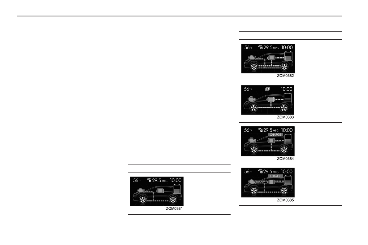
! Screen display
You can display the following information
on the multi function display.
. Status of the high voltage battery
. Energy flow between the engine, elec-
tric motor, high voltage battery and wheels
Power from the engine will be displayed in
orange, power from the electric motor will
be displayed in green and the energy flow
charging the high voltage battery will be
displayed in aqua.
Display Status
When driving only
by the engine
power
Display Status
When the electric
motor is assisting
the engine
When driving only
by the electric mo-
tor power
When charging the
high voltage bat-
tery with the re-
generative brakes
When charging the
high voltage bat-
tery while driving
using the engine
power
Black plate (19,1)
北米Model "A1160BE-C" EDITED: 2014/ 3/ 17
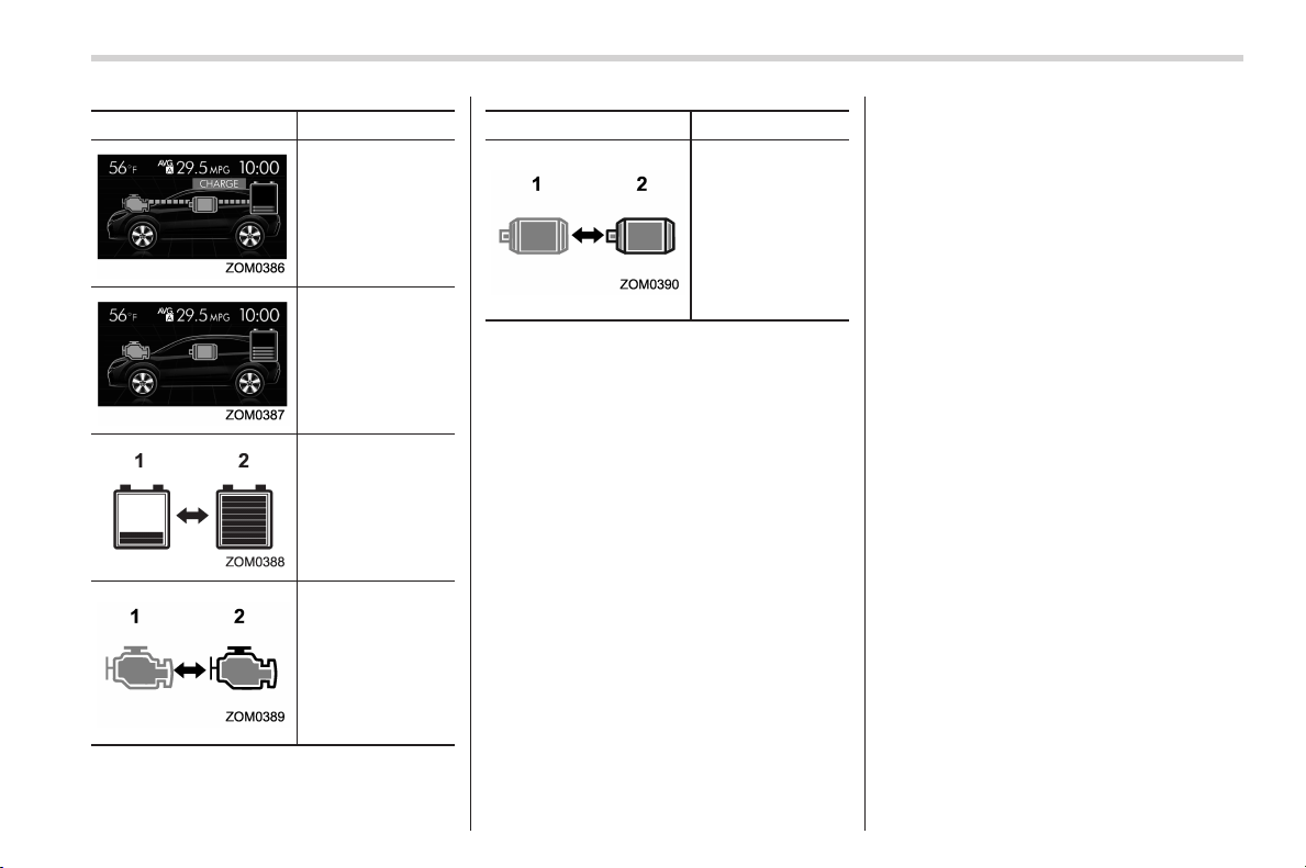
Display Status
When charging the
high voltage bat-
tery by using the
engine power
while the vehicle is
stopped
When there is no
energy current
Remaining high
voltage battery
power is
(1) low
(2) high
Operating/stop-
ping of the engine
(1) While stopped
(illuminated in
gray)
(2) While operat-
ing (illumi-
nated in or-
ange)
Display Status
Operating/stop-
ping of the electric
motor
(1) While stopped
(illuminated in
gray)
(2) While operat-
ing (illumi-
nated in green
or aqua)
In addition, if a warning or malfunction is
detected in the hybrid system, an inter-
ruption screen will be displayed on the
multi function display. For details, refer to
“Interruption screen” F3-35.
NOTE
. High voltage battery power is con-
sumed more than usual when driving
only using the electric motor power for
a long time.
. High voltage battery power is con-
sumed more than usual when repeat-
edly driving only using the electric
motor power continuously. There is
not a problem especially, however
avoid stop-and-go driving as much as
possible by methods such as checking
traffic reports before you start driving.
. The indicator of the remaining high
voltage battery power may show empty
when the remaining power is extremely
low. However, this does not indicate a
malfunction.
17
0

Black plate (2,1)
Model "ALL_MODEL_MEMO" EDITED: 2007/ 6/ 22
Left Page
————————————————————————————————————————
————————————————————————————————————————
————————————————————————————————————————
————————————————————————————————————————
————————————————————————————————————————
————————————————————————————————————————
————————————————————————————————————————
————————————————————————————————————————
————————————————————————————————————————
————————————————————————————————————————
————————————————————————————————————————
————————————————————————————————————————
————————————————————————————————————————

Black plate (1,1)
Table of contents
Seat, seatbelt and SRS airbags
1
Keys and doors
2
Instruments and controls
Climate control
4
Audio
5
Interior equipment
6
Starting and operating
7
Driving tips
8
In case of emergency
9
Appearance care
10
Maintenance and service
11
Specifications
12
Consumer information and Reporting safety defects
13
Index
14
3
北米Model "A1160BE-C" Edited: 2014/ 1/ 16
Black plate (22,1)
北米Model "A1160BE-C" EDITED: 2014/ 3/ 17
20
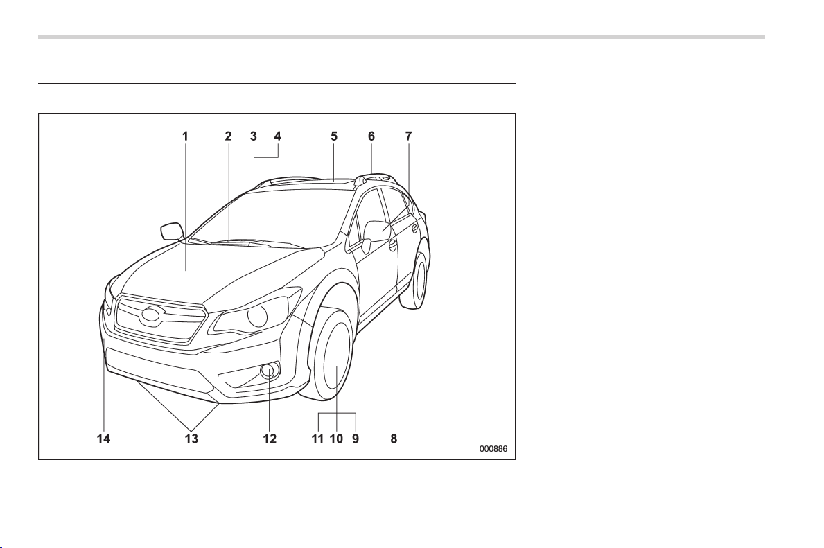
Illustrated index
& Exterior
1) Engine hood (page 11-7)
2) Wiper switch (page 3-83)
3) Headlight switch (page 3-78)
4) Replacing bulbs (page 11-40)
5) Moonroof (page 2-34)
6) Roof rails (page 8-13)
7) Outside mirror (page 3-93)
8) Door locks (page 2-5)
9) Tire pressure (page 11-24)
10) Flat tires (page 9-4)
11) Snow tires (page 8-10)
12) Fog light switch (page 3-81)
13) Tie-down hooks (page 9-18)
14) Towing hook (page 9-18)
Black plate (25,1)
北米Model "A1160BE-C" EDITED: 2014/ 3/ 17
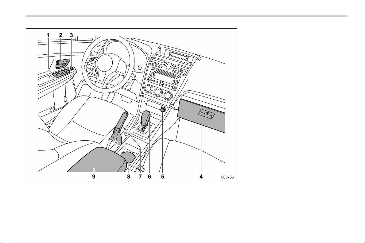
1) Power windows (page 2-29)
2) Door locks (page 2-5)
3) Outside mirror switch (page 3-93)
4) Glove box (page 6-5)
5) Front power supply socket (page 6-7)
6) Select lever (page 7-15)
7) Parking brake lever (page 7-29)
8) Cup holder (page 6-6)
9) Center console (page 6-5)
23
– CONTINUED –
0
Black plate (26,1)
北米Model "A1160BE-C" EDITED: 2014/ 3/ 17
24
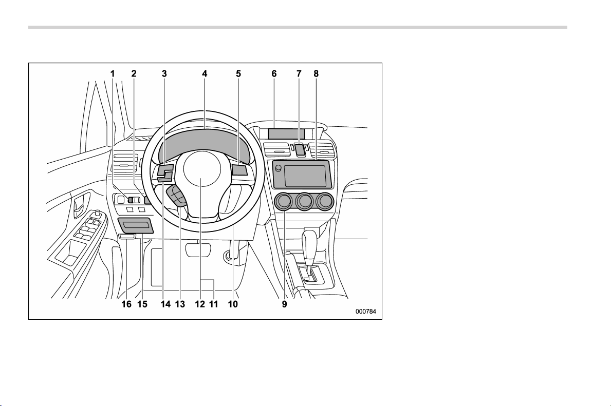
& Instrument panel
1) Illumination brightness control
(page 3-80)
2) Vehicle Dynamics Control OFF switch
(page 7-27)
3) Audio control buttons (page 5-30)
4) Combination meter (page 3-8)
5) Cruise control (page 7-33)
6) Multi function display (page 3-32)
7) Hazard warning flasher switch (page 3-7)
8) Audio (page 5-1)
9) Climate control (page 4-1)
10) Tilt/telescopic steering (page 3-96)
11) Horn (page 3-96)
12) SRS airbag (page 1-37)
13) Multi function display control switches
(page 3-32)
14) Hands-free switches (page 5-34)
15) Fuse box (page 11-38)
16) Hood lock release knob (page 11-7)

Black plate (27,1)
北米Model "A1160BE-C" EDITED: 2014/ 3/ 17
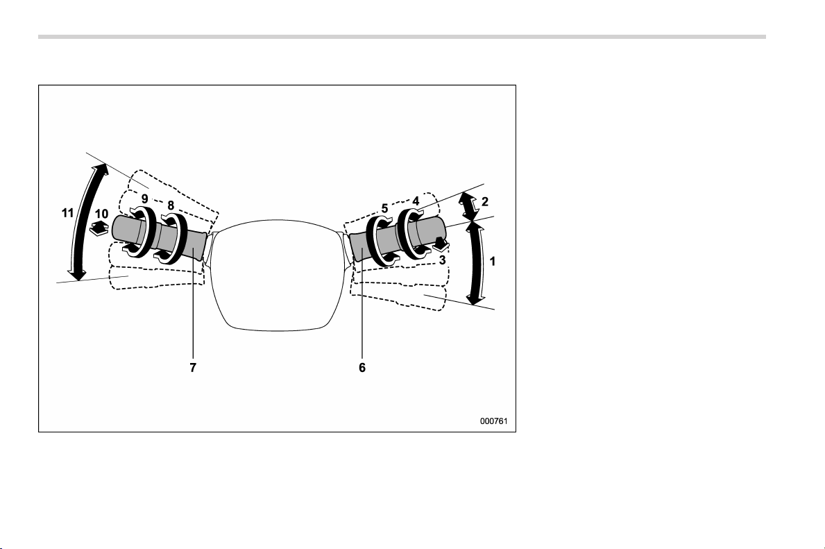
& Steering wheel
1) Audio control buttons (page 5-30)
2) Cruise control (page 7-33)
3) Shift paddle (page 7-18)
4) Hands-free switches (page 5-34)
5) Multi function display control switches
(page 3-32)
6) SRS airbag (page 1-37)
7) Horn (page 3-96)
25
– CONTINUED –
0
Black plate (28,1)
北米Model "A1160BE-C" EDITED: 2014/ 3/ 17
26
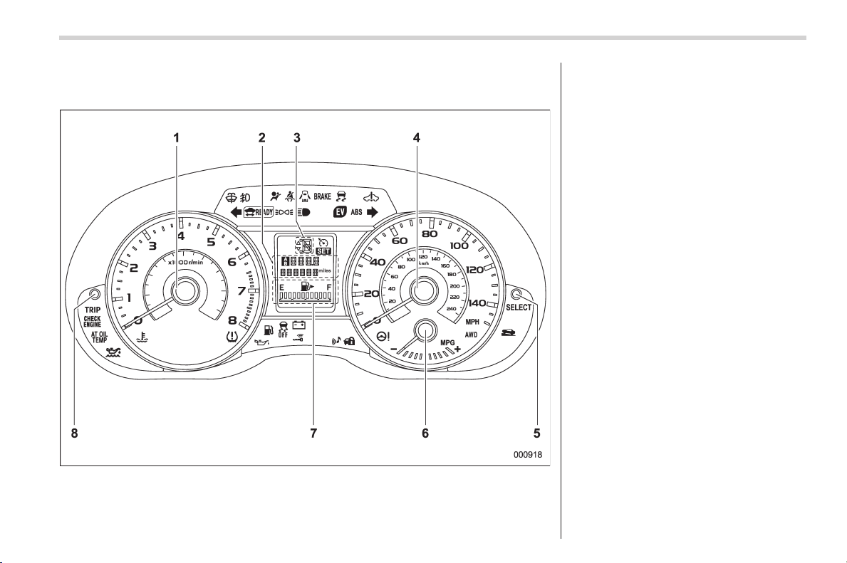
& Light control and wiper control levers/switches
1) Windshield wiper (page 3-82)
2) Mist (page 3-83)
3) Windshield washer (page 3-84)
4) Rear window wiper and washer switch
(page 3-85)
5) Wiper intermittent time control switch
(page 3-84)
6) Wiper control lever (page 3-83)
7) Light control switch (page 3-77)
8) Fog light switch (page 3-81)
9) Headlight ON/OFF/AUTO (page 3-78)
10) Headlight flasher High/Low beam
change (page 3-79)
11) Turn signal lever (page 3-80)
Black plate (29,1)
北米Model "A1160BE-C" EDITED: 2014/ 3/ 17
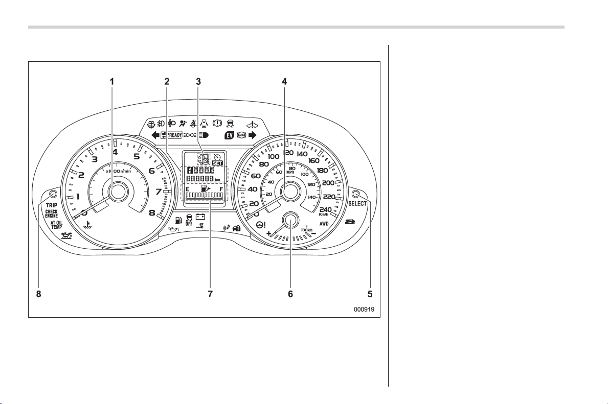
& Combination meter
! U.S.-spec. models
The illustration above is a typical example. For some models, the combination meter
may be slightly different than that shown in the illustration.
1) Tachometer (page 3-11)
2) Trip meter and odometer (page 3-10)
3) Select lever/gear position indicator
(page 3-29)
4) Speedometer (page 3-10)
5) Select knob (page 3-8)
6) ECO gauge (page 3-12)
7) Fuel gauge (page 3-11)
8) Trip meter A/B selection and trip meter
reset knob (page 3-10)
27
– CONTINUED –
0
Black plate (30,1)
北米Model "A1160BE-C" EDITED: 2014/ 3/ 17
28
! Except U.S.-spec. models
The illustration above is a typical example. For some models, the combination meter
may be slightly different than that shown in the illustration.
1) Tachometer (page 3-11)
2) Trip meter and odometer (page 3-10)
3) Select lever/gear position indicator
(page 3-29)
4) Speedometer (page 3-10)
5) Select knob (page 3-8)
6) ECO gauge (page 3-12)
7) Fuel gauge (page 3-11)
8) Trip meter A/B selection and trip meter
reset knob (page 3-10)
Black plate (31,1)
北米Model "A1160BE-C" EDITED: 2014/ 3/ 17
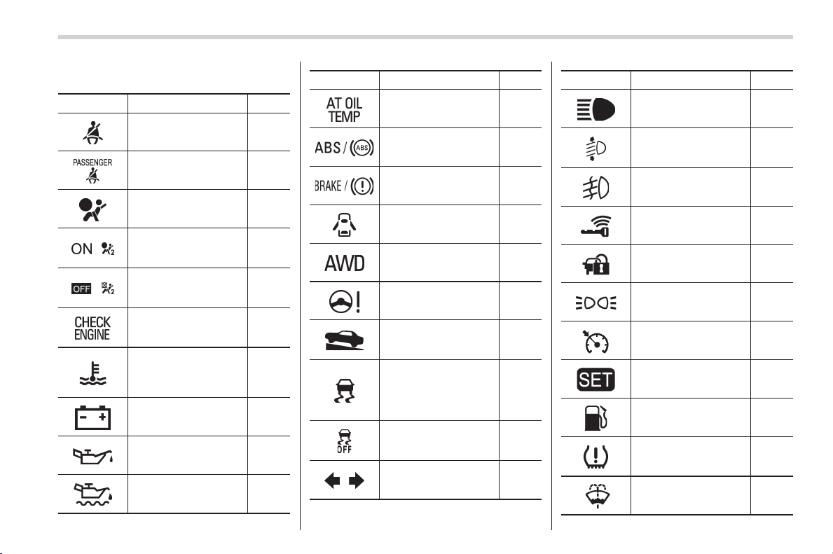
& Warning and indicator lights
Mark Name Page
Seatbelt warning light 3-13
Front passenger’s
seatbelt warning light
3-13
SRS airbag system
warning light
3-15
/
Front passenger’s
frontal airbag ON indi-
cator
3-15
/
Front passenger’s
frontal airbag OFF in-
dicator
3-15
CHECK ENGINE
warning light/Malfunc-
tion indicator light
3-15
Coolant temperature
low indicator light/
Coolant temperature
high warning light
3-16
Charge warning light 3-17
Oil pressure warning
light
3-17
Engine oil level warn-
ing light
3-18
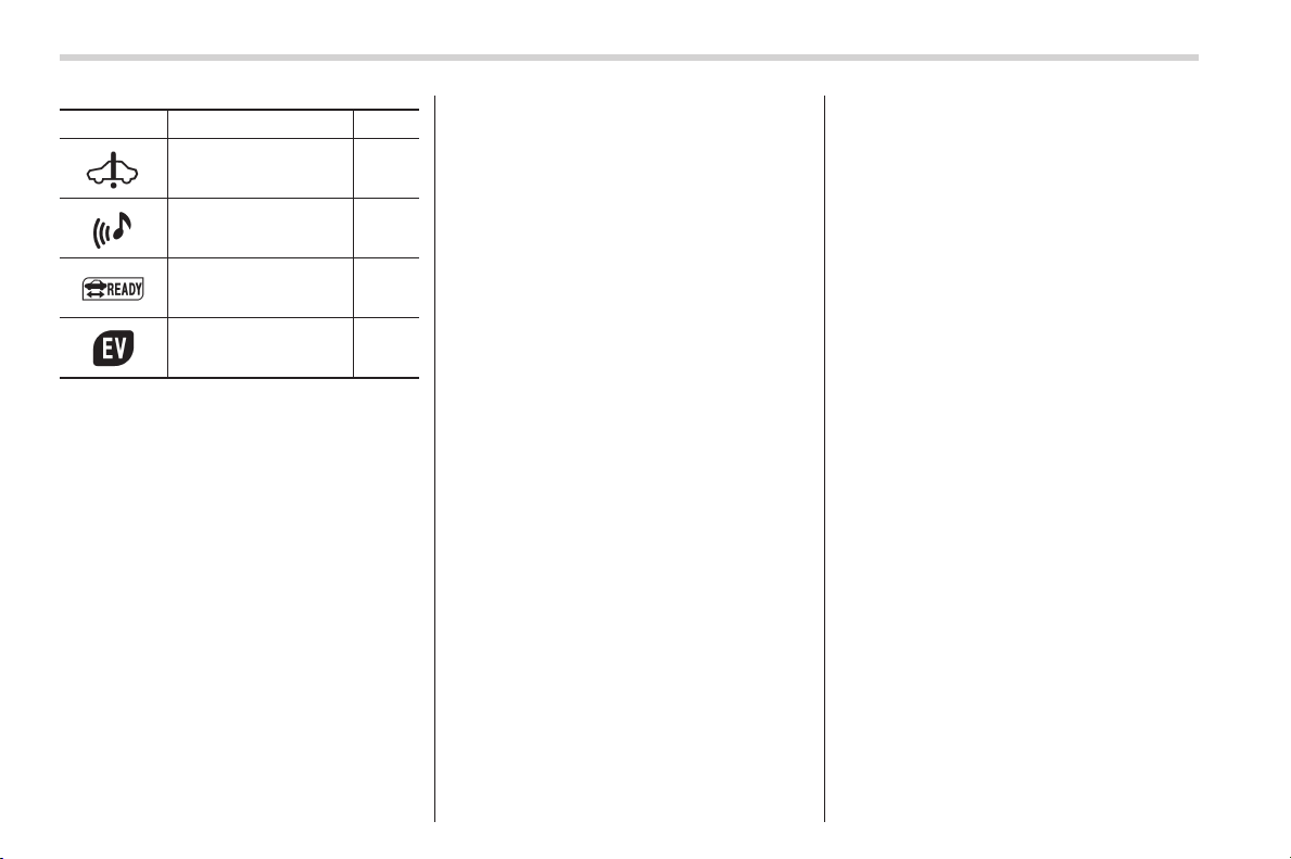
Mark Name Page
AT OIL TEMP warning
light
3-18
ABS warning light 3-20
Brake system warning
light (red)
3-21
Door open warning
light
3-22
AWD warning light 3-22
Power steering warn-
ing light
3-22
Hill start assist warn-
ing light/Hill start assist
OFF indicator light
3-22
Vehicle Dynamics
Control warning light/
Vehicle Dynamics
Control operation indi-
cator light
3-23
Vehicle Dynamics
Control OFF indicator
light
3-24
Turn signal indicator
lights
3-30
Mark Name Page
High beam indicator
light
3-30
Automatic headlight
beam leveler warning
light (if equipped)
3-30
Front fog light indicator
light (if equipped)
3-30
Access key warning
light (if equipped)
3-25
Security indicator light 3-29
Headlight indicator
light
3-30
Cruise control indica-
tor light
3-30
Cruise control set in-
dicator light
3-30
Low fuel warning light 3-22
Low tire pressure
warning light
(U.S.-spec. models)
3-18
Windshield washer
fluid warning light
3-18
29
– CONTINUED –
0

Black plate (33,1)
北米Model "A1160BE-C" EDITED: 2014/ 3/ 17
Function settings
A SUBARU dealer can change the settings of the functions shown in the following table to meet your personal requirements. Contact
the nearest SUBARU dealer for details. The settings for some of these functions can be changed using the multi function display. For
details, refer to “Multi function display” F3-32.
Item Function Possible settings Default setting
Alarm system Alarm system Operation/Non-operation Operation
Monitoring start delay time (after closure of doors) 0 seconds/30 seconds 30 seconds
Impact sensor operation (only models with shock
sensors (dealer option))
Operation/Non-operation Non-operation
Passive arming (models without “keyless access with
push-button start system”)
Operation/Non-operation Non-operation
Dome light and map lights illumination (models with
moonroof)
ON/OFF OFF
Dome light illumination (models without moonroof)
Keyless access (if equipped) Hazard warning flasher Operation/Non-operation Operation
Audible signal Operation/Non-operation Operation
Door unlock selection function (driver’s door unlock) Driver’s door only/All doors Driver’s door only
Door unlock selection function (rear gate unlock) Rear gate only/All doors Rear gate only
Remote keyless entry system Hazard warning flasher Operation/Non-operation Operation
Audible signal Operation/Non-operation Operation
Key lock-in prevention Key lock-in prevention Operation/Non-operation Operation
Defogger and deicer system for models
with the automatic climate control system
Rear window defogger, outside mirror defogger and
windshield wiper deicer
Operation for 15 minutes/
Continuous operation
Operation for 15
minutes
Dome light Operation of dome light/map light OFF delay timer OFF/10S/20S/30S 30S
Map light for models with a moonroof
31
– CONTINUED –
0

Black plate (34,1)
北米Model "A1160BE-C" EDITED: 2014/ 3/ 17
32
Item Function Possible settings Default setting
Battery drainage prevention function Battery drainage prevention function Operation/Non-operation Operation
Seatbelt warning Sounds a chime while driving Operation/Non-operation Operation
Auto on/off headlights (if equipped) Sensitivity of the operation of the auto on/off headlights Low/Normal/High/Very high Normal

Black plate (1,1)
北米Model "A1160BE-C" EDITED: 2014/ 3/ 17
Front seats........................................................... 1-2
Forward and backward adjustment ...................... 1-3
Reclining the seatback ........................................ 1-4
Seat cushion height adjustment (driver’s seat) ..... 1-4
Head restraint adjustment.................................... 1-5
Seat heater (if equipped) .................................... 1-6
Safety precautions .............................................. 1-6
Operation............................................................ 1-6
Rear seats............................................................ 1-7
Important precautions about the hybrid
system.............................................................. 1-8
Armrest (if equipped)........................................... 1-8
Head restraint adjustment.................................... 1-8
Folding down the rear seatback .......................... 1-10
Seatbelts ............................................................. 1-11
Seatbelt safety tips............................................. 1-11
Emergency Locking Retractor (ELR) ................... 1-12
Automatic/Emergency Locking Retractor
(A/ELR) ............................................................ 1-12
Seatbelt warning light and chime ........................ 1-13
Fastening the seatbelt ........................................ 1-13
Seatbelt maintenance ......................................... 1-20
Front seatbelt pretensioners ............................. 1-20
Seatbelt with shoulder belt pretensioner ............. 1-20
Seatbelt with shoulder belt and lap belt
pretensioners .................................................. 1-22
System monitors ............................................... 1-23
System servicing ............................................... 1-23
Precautions against vehicle modification ............ 1-24
Child restraint systems ..................................... 1-24
Where to place a child restraint system.............. 1-25
Choosing a child restraint system ...................... 1-27
Installing child restraint systems with A/ELR
seatbelt ........................................................... 1-27
Installing a booster seat..................................... 1-31
Installation of child restraint systems by use of
lower and tether anchorages (LATCH) .............. 1-32
Top tether anchorages ....................................... 1-35
*SRS airbag (Supplemental Restraint
System airbag)................................................ 1-37
General precautions regarding SRS airbag
system ............................................................ 1-37
Components...................................................... 1-44
SUBARU advanced frontal airbag system ........... 1-46
SRS side airbag and SRS curtain airbag............. 1-55
SRS airbag system monitors.............................. 1-62
SRS airbag system servicing ............................. 1-63
Precautions against vehicle modification ............ 1-64
Seat, seatbelt and SRS airbags
1
Black plate (38,1)
北米Model "A1160BE-C" EDITED: 2014/ 3/ 17
1-2
Seat, seatbelt and SRS airbags/Front seats
Front seats
WARNING
. Never adjust the seat while driv-
ing to avoid losing control of the
vehicle which can result in per-
sonal injury.
. Before adjusting the seat, make
sure the hands and feet of rear
seat passengers and cargo are
clear of the adjusting mechan-
ism.
. After adjusting the seat, push it
slightly to make sure it is se-
curely locked. If the seat is not
securely locked, it may move or
the seatbelt may not operate
properly.
. Do not put objects under the front
seats. They may interfere with
front seat locking and cause an
accident. You should, however,
store the flat tire repair kit under
the driver’s seat. When storing
the f lat tire repair kit, always
secure it with Velcro. Otherwise,
it will not remain stationary and it
may interfere with driver’s seat
locking and cause an accident.
. Seatbelts provide maximum re-
straint when the occupant sits
well back and upright in the seat.
To reduce the risk of sliding
under the seatbelt in a collision,
the front seatbacks should be
always used in the upright posi-
tion while the vehicle is running.
If the fr ont seatbacks are not
used in the upright position in a
collision, the risk of sliding under
the lap belt and of the lap belt
sliding up over the abdomen will
increase, and both can result in
serious internal injury or death.
. The SRS airbags dep loy with
considerable speed and force.
Occupants who are out of proper
position when the SRS airbag
deploys could suffer very serious
injuries. Because the SRS airbag
needs enough space for deploy-
ment, the driver should always
sit upright and well back in the
seat as far f rom the steering
wheel as practical while still
maintaining full vehicle control
and the front passenger should
move the seat as far back as
possible and sit upright and well
back in the seat.
WARNING
Put children aged 12 and under in
the rear seat properly restrained at
all times. The SRS airbag deploys
with considerable speed and force
and can injure or even kill children,
especially if they are 12 years of age
and under and are not restrained or
improperly restrained. Because chil-
dren are lighter and weaker than
adults, their risk of being injured
from deployment is greater. For that
reason, we strongly recommend
that ALL children (including those
in child seats and those that have
outgrown child restraint devices) sit
in the REAR seat properly re-
strained at all times in a child

Black plate (39,1)
北米Model "A1160BE-C" EDITED: 2014/ 3/ 17
restraint device or in a seatbelt,
whichever is appropriate for the
child’s age, height and weight. Se-
cure ALL types of child restraint
devices (including forward facing
child seat) in the REAR seats at all
times.
NEVER INSTALL A REARWARD FA-
CING CHILD SEAT IN THE FRONT
SEAT. DOING SO RISKS SERIOUS
INJURY OR DEATH TO THE CHILD
BY PLACING THE CHILD’S HEAD
TOO CLOSE TO THE SRS AIRBAG.
According to accident statistics,
children are safer when properly
restrained in the rear seating posi-
tions than in the front seating posi-
tions. For instructions and precau-
tions concerning child restraint sys-
tems, refer to “Child restraint sys-
tems” F1-24.
WARNING
Do not let rear passengers rest their
feet between the front seatback and
seat cushion. Doing so may lead to
defective operation of the following
systems and could result in serious
injury.
. Occupant detection system
. SRS side airbag
. Seat heater (if equipped)
& Forward and backward ad-
justment
Pull the lever upward and slide the seat to
the desired position. Then release the
lever and try to move the seat back and
forth to make sure that it is securely locked
into place.
Seat, seatbelt and SRS airbags/Front seats
1-3
– CONTINUED –
1
Black plate (40,1)
北米Model "A1160BE-C" EDITED: 2014/ 3/ 17
1-4
Seat, seatbelt and SRS airbags/Front seats
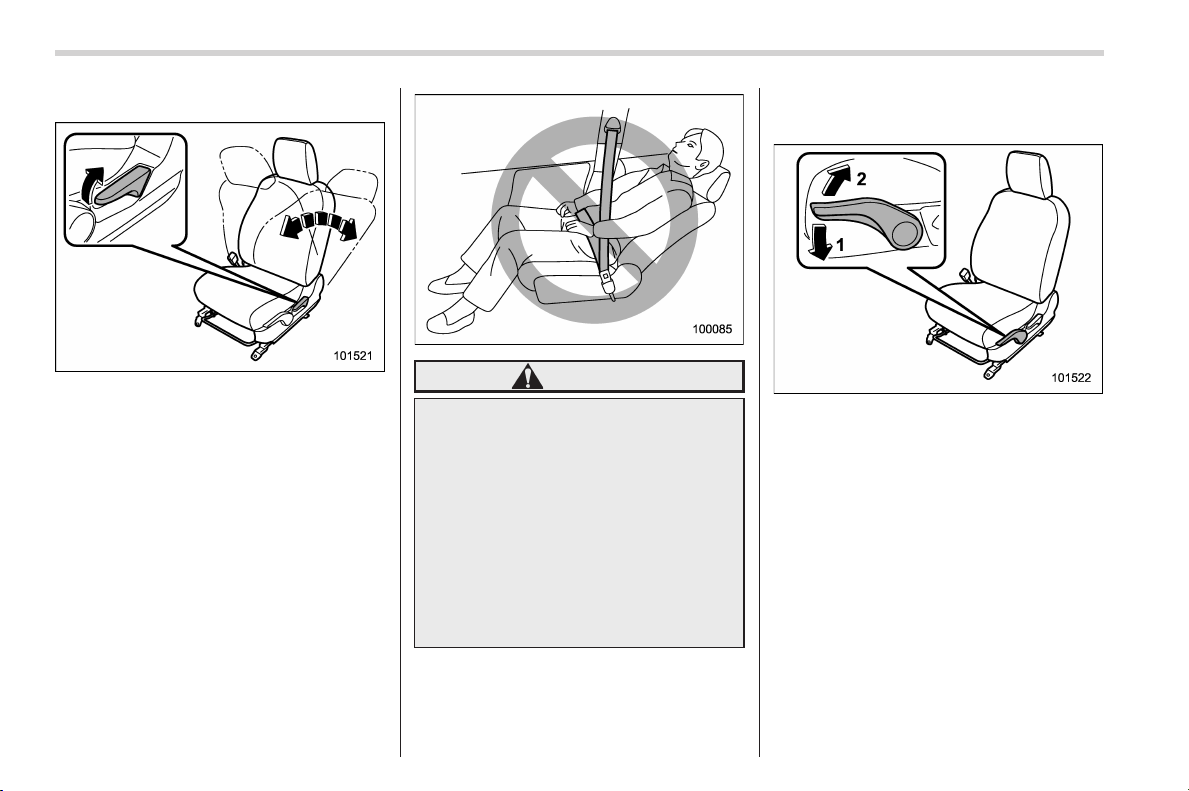
& Reclining the seatback
Pull the reclining lever up and adjust the
seatback to the desired position. Then
release the lever and make sure the
seatback is securely locked into place.
The seatback placed in a reclined position
can spring back upward with force when
the lever is pulled. While operating the
lever to return the seatback, hold the
seatback lightly so that it may be raised
back gradually.
WARNING
To prevent the passenger from slid-
ing under the seatbelt in the event of
a collision, always put the seatback
in the upright position while the
vehicle is in motion. Also, do not
place objects such as cushions
between the passenger and the
seatback. If you do so, the risk of
sliding under the lap belt and of the
lap belt sliding up over the abdomen
will increase, and both can result in
serious internal injury or death.
& Seat cushion height adjust-
ment (driver’s seat)
1) When the lever is pushed down, the seat
is lowered.
2) When the lever is pulled up, the seat
rises.
The height of the seat can be adjusted by
moving the seat cushion adjustment lever
up and down.
Black plate (41,1)
北米Model "A1160BE-C" EDITED: 2014/ 3/ 17
& Head restraint adjustment
WARNING
. Never drive the vehicle with the
head restraints removed because
they are designed to reduce the
risk of serious neck injury in the
event that the vehicle is struck
from the rear. Also, never install
the head restraints the opposite
way round. Doing so will prevent
the head restraints from func -
tioning as intended. Therefore,
when you remove the head re-
straints, you must reinstall all
head restraints correctly to pro-
tect vehicle occupants.
. All occupants, including the dri-
ver, should not operate a vehicle
or sit in a vehicle’s seat until the
head restraints are placed in their
proper positions in order to mini-
mize the risk of neck injury in the
event of a crash.
The head restraints for the driver’s seat
and front passenger’s seat are adjustable
in the following ways.
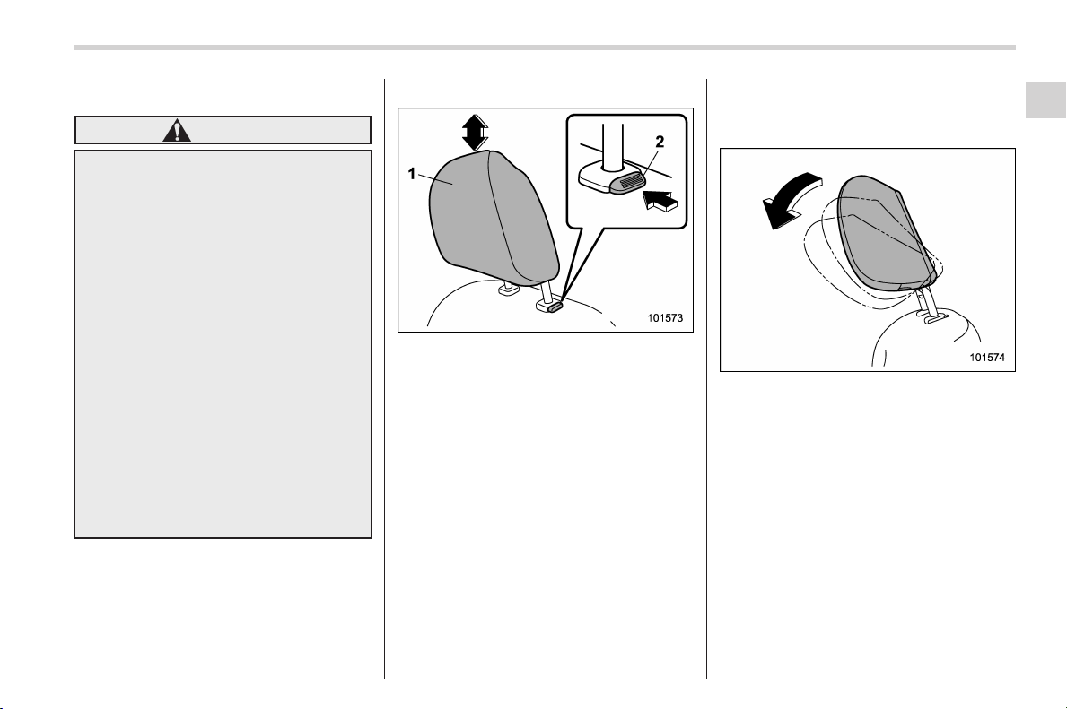
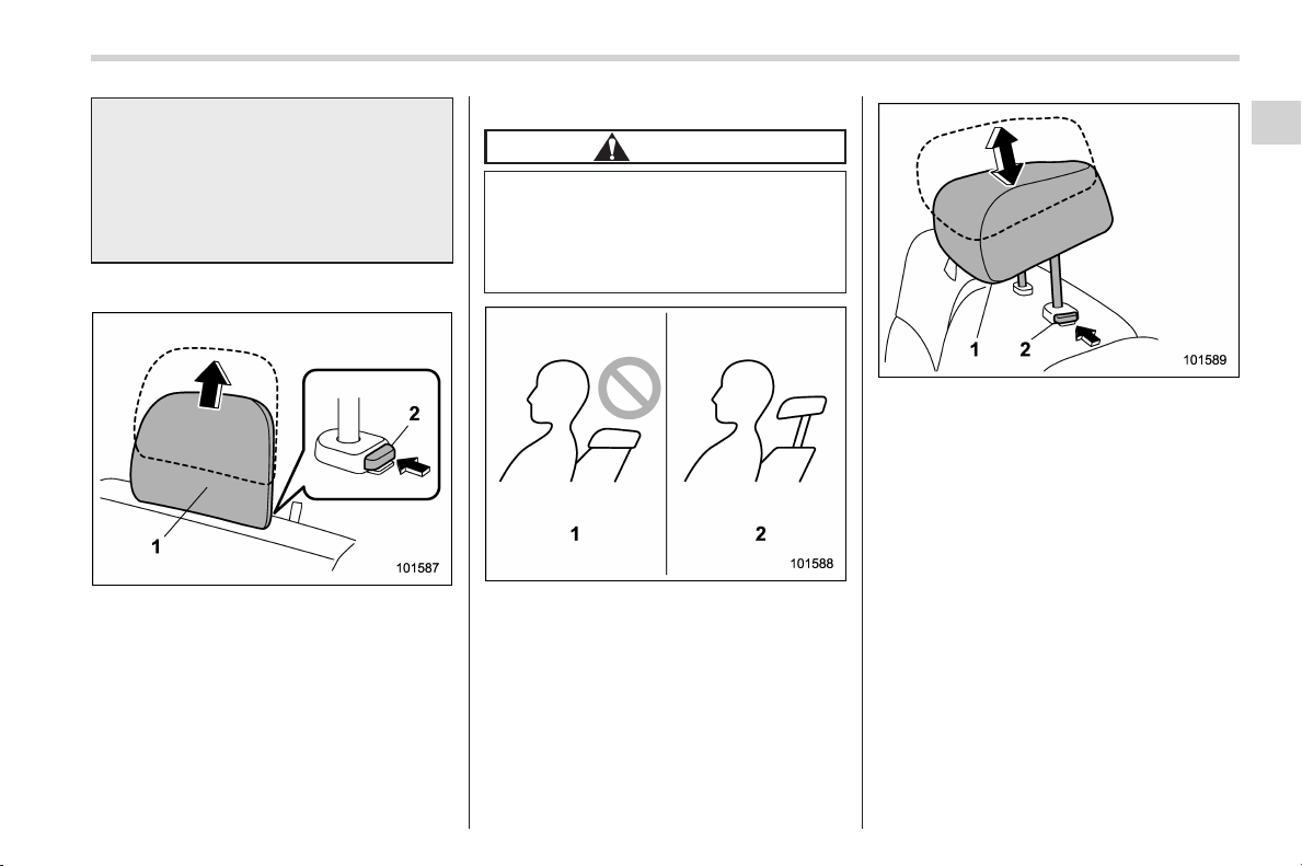
! Head restraint height adjustment
1) Head restraint
2) Release button
Each head restraint should be adjusted so
that the center of the head restraint is
closest to the top of the occupant’s ears.
To raise:
Pull the head restraint up.
To lower:
Push the head restraint down while
pressing the release button on the top of
the seatback.
To remove:
While pressing the release button, pull out
the head restraint.
To install:
Install the head restraint into the holes that
are located on the top of the seatback until
the head restraint locks.
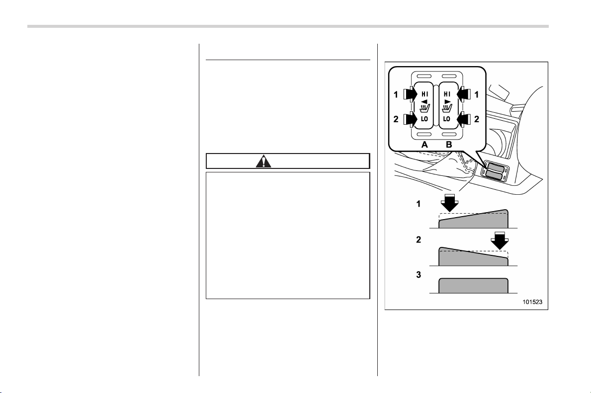
! Head restraint angle adjustment
The angle of the head restraint can be
adjusted in several steps. While maintain-
ing a suitable driving posture, adjust the
head restraint to a position where the back
of your head is as close to the head
restraint as possible.
To tilt:
Tilt the head restraint by hand to the
preferred position. A click will be audible
when the head restraint is locked.
To return:
Tilt the head restraint once as far forward
as i t can go. The head restraint will
automatically return to the fully upright
position. Then, adjust the head restraint
Seat, seatbelt and SRS airbags/Front seats
1-5
– CONTINUED –
1
Black plate (42,1)
北米Model "A1160BE-C" EDITED: 2014/ 3/ 17
1-6
Seat, seatbelt and SRS airbags/Seat heater
again to the preferred angle.
Seat heater (if equipped)
The seat heater is equipped in the front
seats.
The seat heater operates when the igni-
tion switch is either in the “ACC” or “ON”
position.
& Safety precautions
CAUTION
. There is a possibility that people
with delicate skin may suffer
slight burns even at low tempera-
tures if they use the seat heater
for a long period of time. When
using the heater, always be sure
to warn the persons concerned.
. Do not put anything on the seat
which insulates against heat,
such as a blanket, cushion, or
similar items. This may cause the
seat heater to overheat.
NOTE
Use of the seat heater for a long period
of time while the hybrid system is not
running can cause battery discharge.
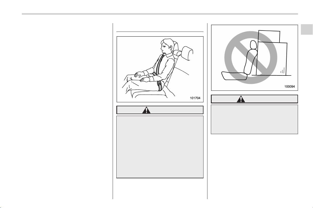
& Operation
1) HI – Rapid heating
2) LO – Normal heating
3) Off
A) Left-hand side
B) Right-hand side
Black plate (43,1)
北米Model "A1160BE-C" EDITED: 2014/ 3/ 17
To turn on the seat heater, push the “LO”
or “HI” position on the switch, as desired,
depending on the temperature.
Selecting the “HI” position will cause the
seat to heat up quicker.
To turn off the seat heater, lightly press the
opposite side of the current position.
The indicator located on the switch illumi-
nates when the seat heater is in operation.
When the vehicle’s interior is warmed
enough or before you leave the vehicle,
be sure to turn the switch off.
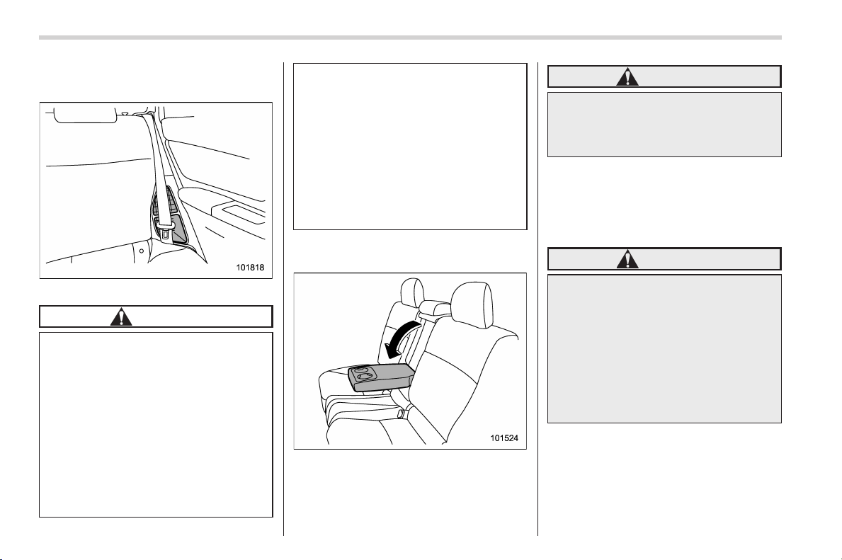
Rear seats
WARNING
Seatbelts p rovide maximum re-
straint when the occupant sits well
back and upright in the seat. Do not
put cushions or any other materials
between occupants and seatbacks
or seat cushions. If you do so, the
risk of sliding under the lap belt and
of the lap belt sliding up over the
abdomen will increase, and both can
result in serious internal injury or
death.
WARNING
Never stack luggage or other cargo
higher than the top of the seatback
because it could tumble forward and
injure passengers in the event of a
sudden stop or accident.
Seat, seatbelt and SRS airbags/Rear seats
1-7
– CONTINUED –
1
Black plate (44,1)
北米Model "A1160BE-C" EDITED: 2014/ 3/ 17
1-8
Seat, seatbelt and SRS airbags/Rear seats
& Important precautions about
the hybrid system
High voltage battery air intake
CAUTION
The high voltage battery air intake is
located next to the rear seat on the
left. Conform to the following in-
structions to prevent overheating of
the high voltage battery or malfunc-
tion of the hybrid system.
. Do not put any objects near the
high voltage battery air intake.
. Clean the high voltage battery air
intake periodically to prevent it
from clogging.
. It is important that no liquids or
any other substances or objects
be allowed to enter the air intake.
Please advise passengers in this
area to use care around the air
intake to prevent any debris from
entering.
. If water or any objects enter it, it
may malfunction. When a large
amount of water or any objects
enter it, contact your SUBARU
dealer for inspection.
& Armrest (if equipped)
To lower the armrest, pull on the top edge
of the armrest.
WARNING
To avoid serious injury, passengers
must never be allowed to sit on the
center armrest while the vehicle is in
motion.
& Head restraint adjustment
Both the rear window side seats and the
rear center seat are equipped with head
restraints.
WARNING
. Never drive the vehicle with the
head restraints removed because
they are designed to reduce the
risk of serious neck injury in the
event that the vehicle is struck
from the rear. Therefore, when
you have removed the head re-
straints, you must reinstall all
head restraints to protect vehicle
occupants.
Black plate (45,1)
北米Model "A1160BE-C" EDITED: 2014/ 3/ 17
. All occupants, including the dri-
ver, should not operate a vehicle
or sit in a vehicle’s seat until the
head restraints are placed in their
proper positions in order to mini-
mize the risk of neck injury in the
event of a crash.
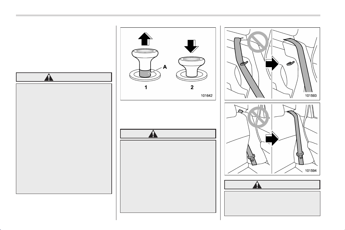
! Rear windows side seating position
1) Head restraint
2) Release button
To remove:
While pressing the release button, pull out
the head restraint.
To install:
Install the head restraint into the holes that
are located on the top of the seatback until
the head restraint locks.
! Rear center seating position
CAUTION
The head restraint is not intended to
be used in the retracted position.
Before sitting on the seat, raise the
head restraint to the extended posi-
tion.
1) Incorrect (retracted position)
2) Correct (extended position)
1) Head restraint
2) Release button
To raise:
Pull the head restraint up.
To lower:
Push the head restraint down while
pressing the release button on the top of
the seatback.
To remove:
While pressing the release button, pull out
the head restraint.
To install:
Install the head restraint into the holes that
are located on the top of the seatback until
the head restraint locks.
When the rear-center seating position is
occupied, raise the head restraint to the
Seat, seatbelt and SRS airbags/Rear seats
1-9
– CONTINUED –
1
Black plate (46,1)
北米Model "A1160BE-C" EDITED: 2014/ 3/ 17
1-10
Seat, seatbelt and SRS airbags/Rear seats
extended position. When the rear center
seating position is not occupied, lower the
head restraint to improve rearward visibi-
lity.
& Folding down the rear seat-
back
WARNING
. When you fold down the seat-
back, check that there are no
passengers or objects on the
rear seat. Not doing so creates
a risk of injury or property da-
mage if the seatback suddenly
folds down.
. Never allow passengers to ride
on the folded rear seatback or in
the cargo area. Doing so may
result in serious injury or death.
. Secure all objects and especially
long items properly to prevent
them from being thrown around
inside the vehicle and causing
serious injury during a sudden
stop, a sudden steering maneu-
ver or a rapid acceleration.
Lock release knob
1) Unlocked
2) Locked
A) Unlocking marker in red
WARNING
When you return the seatback to its
original position, check that the
unlocking marker on the lock re-
lease knob is not visible. Also,
shake the seatback slightly to con-
firm that it is securely fixed in place.
If the seatback is not securely fixed
in place, the seatback may suddenly
fold down in the event of sudden
braking, or objects may move out
from the cargo area, which could
cause serious injury or death.
WARNING
When the seatback is returned to its
original position, observe the follow-
ing precautions. Failure to do so
may lead to serious injury or an
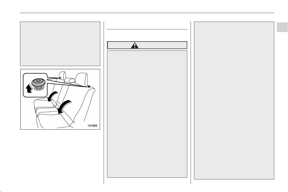
Black plate (47,1)
北米Model "A1160BE-C" EDITED: 2014/ 3/ 17
accident because the operation effi-
ciency of the seatbelt is inhibited.
. The sea tbelt should not pass
behind the securing hook for
the seatback.
. The seatbelt should not be
caught in the seatback and it
should be fully visible.
Unlock the seatback by pulling the lock
release knob and then fold the seatback
down.
To return the seatback to its origin al
position, raise the seatback until it locks
into place and make sure that the unlock-
ing marker on the lock release knob is no
longer visible.
Seatbelts
& Seatbelt safety tips
WARNING
. All persons in the vehicle should
fasten their seatb elts B EFORE
the vehicle starts to move. Other-
wise, the possibility of serious
injury becomes greater in the
event of a sudden stop or acci-
dent.
. All belts should fit snugly in order
to provide full restraint. Loose
fitting belts are not as effective in
preventing or reducing injury.
. E ach seatbelt is designed to
support only one person. Never
use a single belt for two or more
persons – even children. Other-
wise, in an accident, serious
injury or death could result.
. Replace all seatbelt assemblies
including retractors and attach-
ing hardware worn by occupants
of a vehicle that has been in a
serious accident. The entire as-
sembly should be replaced even
if damage is not obvious.
. Put children aged 12 and under in
the rear seat properly restrained
at all times. The SRS airbag
deploys with considerable speed
and force and can injure or even
kill children, especially if they are
12 years of age and under and
are not restrained or improperly
restrained. Because children are
lighter and weaker than adults,
their risk of being injured from
deployment is greater. For that
reason, we strongly recommend
that ALL children (including
those in child seats and those
that have outgrown child re-
straint devices) sit in the REAR
seat properly restrained at all
times in a child restraint device
or in a seatbelt, whichever is
appropriate for the child’s height
and weight.
Secure ALL types of child re-
straint devices (including for-
ward facing child seats) in the
REAR seats at all times.
NEVER INSTALL A REARWARD
FACING CHILD SEAT IN THE
FRONT SEAT. DOING SO RISKS
SERIOUS INJURY OR DEATH TO
THE CHILD BY PLACING THE
CHILD’S HEAD TOO CLOSE TO
THE SRS AIRBAG.
Seat, seatbelt and SRS airbags/Seatbelts
1-11
– CONTINUED –
1
Black plate (48,1)
北米Model "A1160BE-C" EDITED: 2014/ 3/ 17
1-12
Seat, seatbelt and SRS airbags/Seatbelts
According to accident statistics,
children are safer when properly
restrained in the rear seating
positions than in the front seat-
ing positions. For instructions
and precautions concerning the
child restraint system, refer to
“Child restraint systems” F1-24.
Your vehicle is equipped with a crash
sensing and diagnostic module, which will
record the use of the seatbelt by the front
passenger when any of the SRS frontal,
side and curtain airbags deploy.
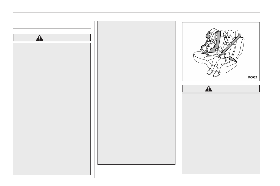
! Infants or small children
Use a child restraint system that is
suitable for your vehicle. Refer to “Child
restraint systems” F1-24.
! Children
If a child is too big for a child restraint
system, the child should sit in the rear seat
and be restrained using the seatbelts.
According to accident statistics, children
are safer when properly restrained in the
rear seating positions than in the front
seating positions. Never allow a child to
stand up or kneel on the seat.
If the shoulder portion of the belt crosses
the face or neck, move the child closer to
the belt buckle to help provide a good
shoulder belt fit. Care must be taken to
securely place the lap belt as low as
possible on the hips and not on the child’s
waist. If the shoulder portion of the belt
cannot be properly positioned, a child
restraint system should be used. Never
place the shoulder belt under the child’s
arm or behind the child’s back.
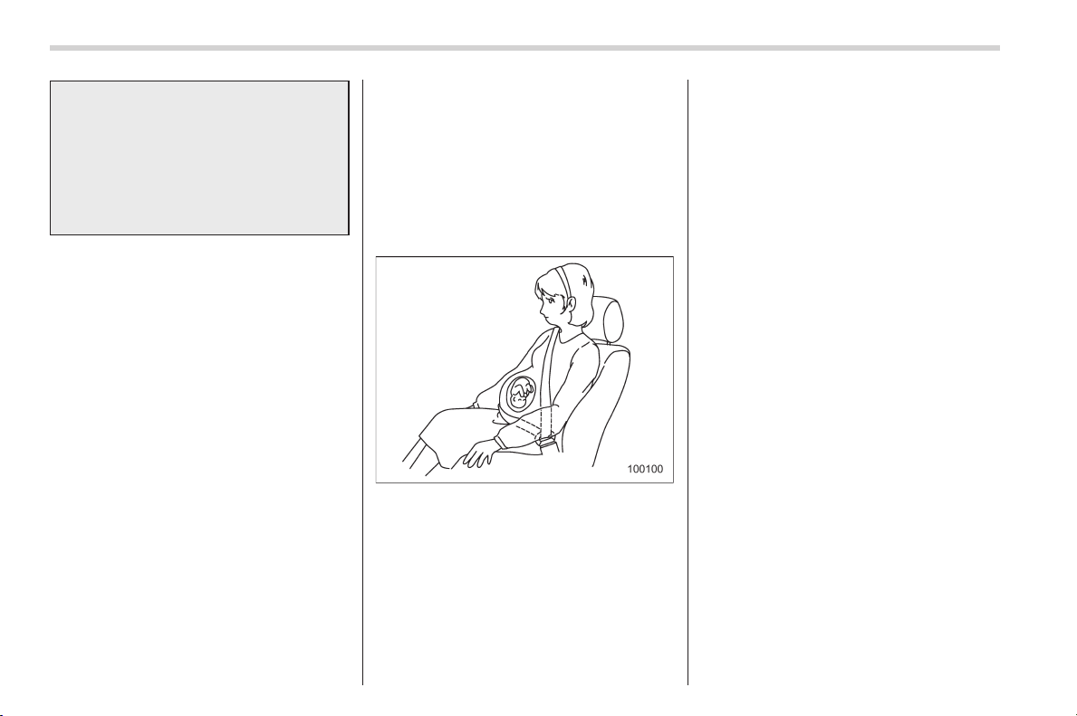
! Expectant mothers
Expectant mothers also need to use the
seatbelts. They should consult their doctor
for specific recommendations. The lap belt
should be worn securely and as low as
possible over the hips, not over the waist.
& Emergency Locking Retrac-
tor (ELR)
The driver’s seatbelt has an Emergency
Locking Retractor (ELR).
The emergency locking retractor allows
normal body movement but the retractor
locks automatically during a sudden stop,
impact or if you pull the belt very quickly
out of the retractor.
& Automatic/Emergency Lock-
ing Retractor (A/ELR)
Each passenger’s seatbelt has an Auto-
matic/Emergency Locking Retractor (A/
ELR). The Automatic/Emergency Locking
Retractor normally functions as an Emer-
gency Locking Retractor (ELR). The A/
ELR has an additional locking mode
“Automatic Locking Retractor (ALR)
mode” intended to secure a child restraint
system. When the seatbelt is once drawn
out completely and is then retracted even
slightly, the retractor locks the seatbelt in
that position and the seatbelt cannot be
extended. As the belt is rewinding, clicks
will be heard which indicate the retractor
functions as an ALR. When the seatbelt is
retracted fully, the ALR mode is released.
When securing a child restraint system on
the rear seats by the use of the seatbelt,
the seatbelt must be changed over to the
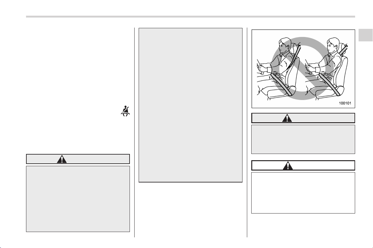
Black plate (49,1)
北米Model "A1160BE-C" EDITED: 2014/ 3/ 17
Automatic Locking Retractor (ALR) mode.
When the child restraint system is re-
moved, make sure that the seatbelt
retracts fully and the retractor returned to
the Emergency Locking Retractor (ELR)
mode.
For instructions on how to convert the
retractor to the ALR mode and restore it to
the ELR mode, refer to “Installing child
restraint systems with A/EL R seatbelt”
F1-27.
& Seatbelt warning light
and chime
Refer to “Seatbelt warning light and
chime” F3-13.
& Fastening the seatbelt
WARNING
. Never use a belt that is twisted or
reversed. In an accident, this can
increase the risk or severity of
injury.
. Keep the lap belt as low as
possible on your hips. In a colli-
sion, this spreads the force of the
lap belt over stronger hip bones
instead of across the weaker
abdomen.
. Seatbelts provide maximum re-
straint when the occupant sits
well back and upright in the seat.
To reduce the risk of sliding
under the seatbelt in a collision,
the front seatbacks should be
always used in the upright posi-
tion while the vehicle is running.
If the fr ont seatbacks are not
used in the upright position in a
collision, the risk of sliding under
the lap belt and of the lap belt
sliding up over the abdomen will
increase, and both can result in
serious internal injury or death.
. Do not put cushions or any other
materials between occupants
and seatbacks or seat cushions.
If you do so, the risk of sliding
under the lap belt and of the lap
belt sliding up over the abdomen
will increase, and both can result
in serious internal injury or
death.
WARNING
Never place the shoulder belt under
the arm or behind the back. If an
accident occurs, this can increase
the risk or severity of injury.
CAUTION
Metallic parts of the seatbelt can
become very hot in a vehicle that
has been closed up in sunny weath-
er; they could burn an occupant. Do
not touch such hot parts until they
cool.
Seat, seatbelt and SRS airbags/Seatbelts
1-13
– CONTINUED –
1
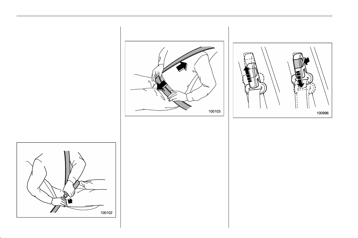
Black plate (50,1)
北米Model "A1160BE-C" EDITED: 2014/ 3/ 17
1-14
Seat, seatbelt and SRS airbags/Seatbelts
! Front seatbelts
1. Adjust the seat position according to
the following procedure.
Driver’s seat: Adjust the seatback to the
upright position. Move the seat as far from
the steering wheel as practical while still
maintaining full vehicle control.
Front passenger’s seat: Adjust the seat-
back to the upright position. Move the seat
as far back as possible.
2. Sit well back in the seat.
3. Pick up the tongue plate and pull the
belt out slowly. Do not let it get twisted. If
the belt stops before reaching the buckle,
return the belt slightly and pull it out more
slowly. If the belt still cannot be unlocked,
let the belt retract slightly after giving it a
strong pull, then pull it out slowly again.
4. Insert the tongue plate into the buckle
until you hear a click.
5. To make the lap part tight, pull up on
the shoulder belt.
6. Place the lap belt as low as possible
on your hips, not on your waist.
! Adjusting the front seat shoulder
belt anchor height
The shoulder belt anchor height should be
adjusted to the position best suited for the
driver/front passenger. Always adjust the
anchor height so that the shoulder belt
passes over the middle of the shoulder
without touching the neck.
To raise:
Slide the anchor up.
To lower:
Pull the release knob and slide the anchor
down.
Pull down on the anchor to make sure that
it is locked in place.
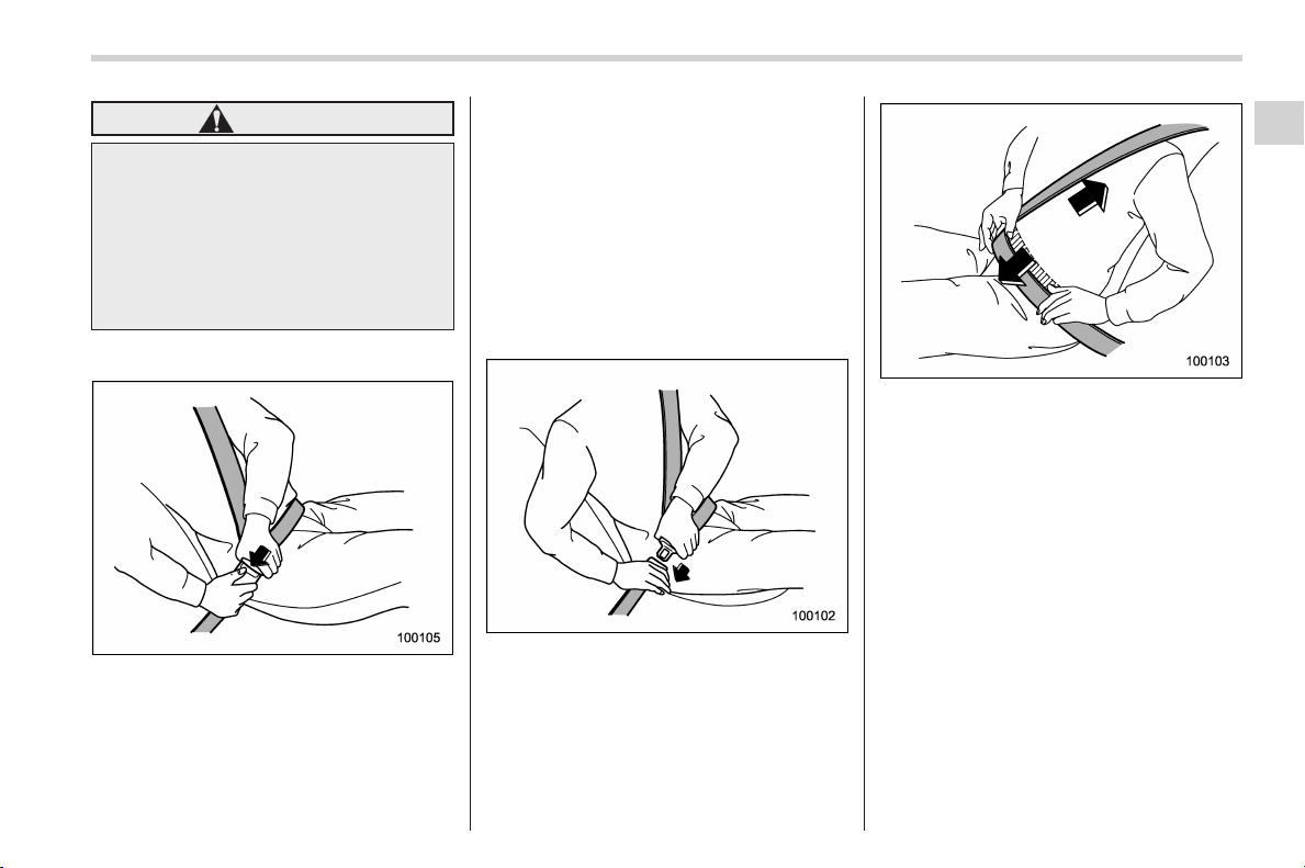
Black plate (51,1)
北米Model "A1160BE-C" EDITED: 2014/ 3/ 17
WARNING
When wearing the seatbelts, make
sure the shoulder portion of th e
webbing does not pass over your
neck. If it does, adjust the seatbelt
anchor to a lower position. Placing
the shoulder belt over the neck may
result in neck injury during sudden
braking or in a collision.
! Unfastening the seatbelt
Push the button on the buckle.
Before closing the door, make sure that
the belts are retracted properly to avoid
catching the belt webbing in the door.
! Rear seatbelts (except rear center
seatbelt)
1. Sit well back in the seat.
2. Pick up the tongue plate and pull the
belt out slowly. Do not let it get twisted. If
the belt stops before reaching the buckle,
return the belt slightly and pull it out more
slowly. If the belt still cannot be unlocked,
let the belt retract slightly after giving a
strong pull on it, then pull it out slowly
again.
3. Insert the tongue plate into the buckle
until you hear a click.
4. To make the lap part tight, pull up on
the shoulder belt.
5. Place the lap belt as low as possible
on your hips, not on your waist.
Seat, seatbelt and SRS airbags/Seatbelts
1-15
– CONTINUED –
1
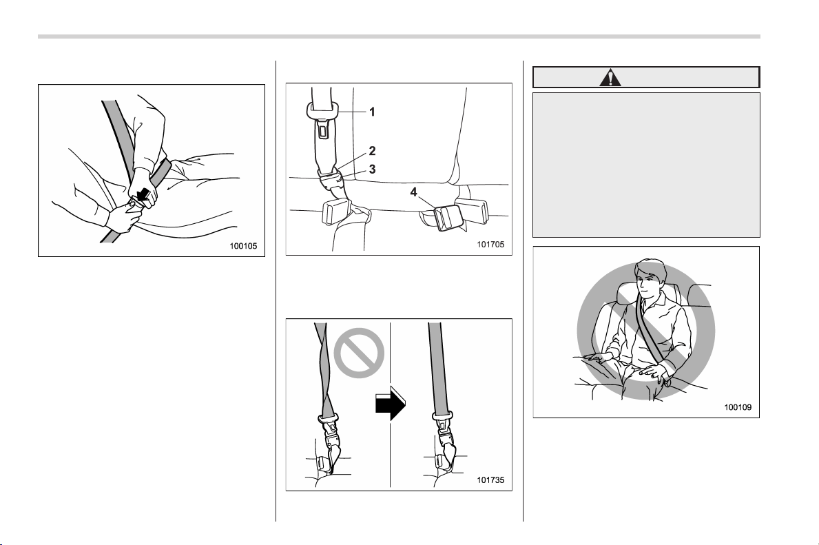
Black plate (52,1)
北米Model "A1160BE-C" EDITED: 2014/ 3/ 17
1-16
Seat, seatbelt and SRS airbags/Seatbelts
! Unfastening the seatbelt
Push the button on the buckle.
Before closing the door, make sure that
the belts are retracted properly to avoid
catching the belt webbing in the door.
! Rear center seatbelt
1) Center seatbelt tongue plate
2) Connector (tongue)
3) Connector (buckle)
4) Center seatbelt buckle
WARNING
Fastening the seatbelt with the web-
bing twisted can increase the risk or
severity of injury in an accident.
When fastening the belt after it is
pulled out from the retractor, espe-
cially when inserting the connec-
tor’s tongue plate into the mating
buckle (on right-hand side), always
check that the webbing is not
twisted.
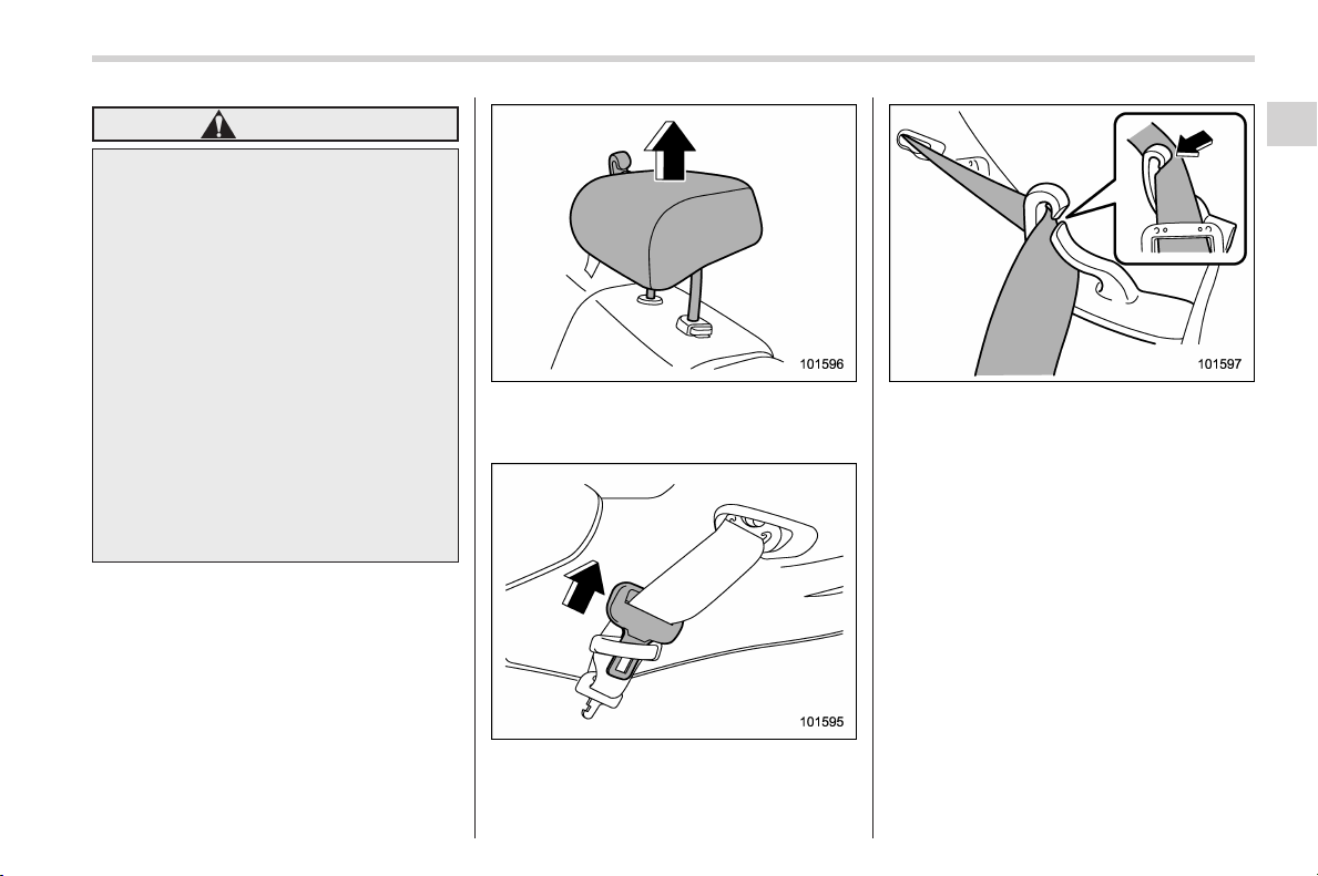
Black plate (53,1)
北米Model "A1160BE-C" EDITED: 2014/ 3/ 17
WARNING
. Be sure to fasten both tongue
plates to the respective buckles.
If the seatbelt is used only as a
shoulder belt (with the connec-
tor’s tongue plate not fastened to
the connector’s buckle on the
right-hand side), it cannot prop-
erly restrain the wearer in posi-
tion in an accident, possibly
resulting in serious injury or
death.
. The head restraint is not intended
to be used at the lowest position.
Before sitting on the seat, raise
the head restraint to the ex-
tended position. Otherwise, in
an accident, serious injury or
death could result.
1. Raise the head restraint to the ex-
tended position. Do not remove the head
restraint.
2. Remove the tongue plate from the belt
holder on the right side of the cargo area
and pull out the seatbelt slowly.
3. After drawing out the seatbelt, pass it
through the belt guide as follows: First
insert one edge of the belt into the open
gap in the belt guide; then slide the rest of
the belt in, so that the whole belt fits
inside.
Seat, seatbelt and SRS airbags/Seatbelts
1-17
– CONTINUED –
1
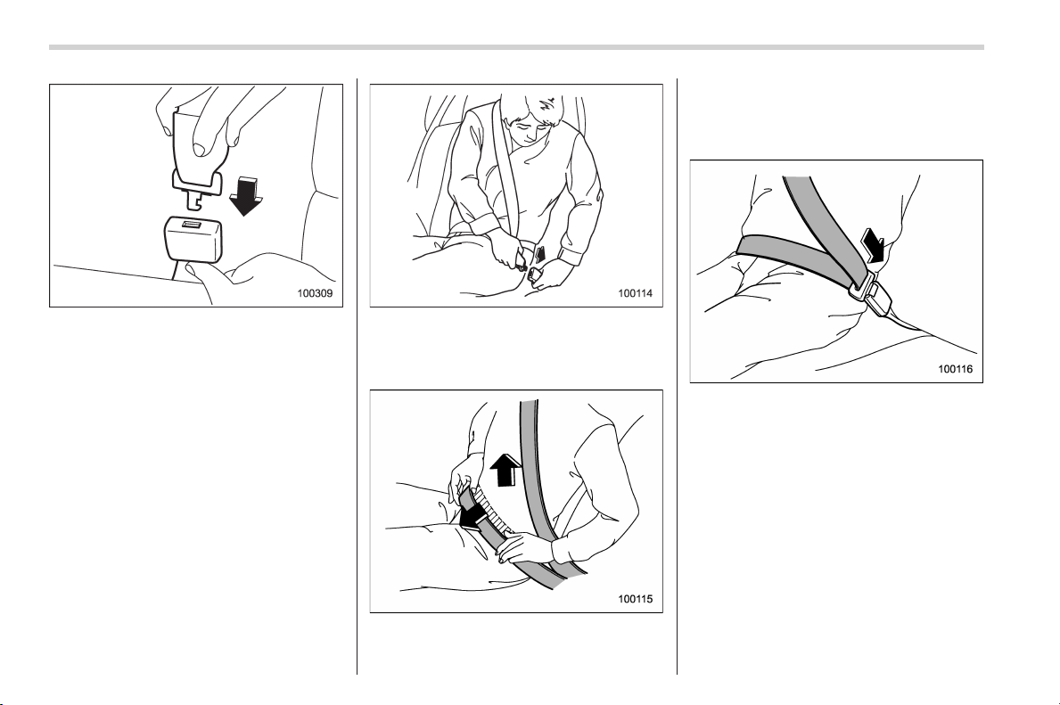
Black plate (54,1)
北米Model "A1160BE-C" EDITED: 2014/ 3/ 17
1-18
Seat, seatbelt and SRS airbags/Seatbelts
4. After confirming that the webbing is not
twisted, insert the connector (tongue)
attached at the webbing end into the
buckle on the right-hand side until a click
is heard.
If the belt stops before reaching the
buckle, return the belt slightly and pull it
out more slowly. If the belt still cannot be
unlocked, let the belt retract slightly after
giving it a strong pull, then pull it out slowly
again.
5. Insert the center seatbelt tongue plate
into the center seatbelt buckle marked
“CENTER” on the left-hand side until it
clicks.
6. To make the lap part tight, pull up on
the shoulder belt.
7. Place the lap belt as low as possible
on your hips, not on your waist.
! Unfastening the seatbelt
Push the release button of the center
seatbelt buckle (on the left-hand side) to
unfasten the seatbelt.
NOTE
When the seatback is folded down for
greater cargo area, it is necessary to
disconnect the connector.
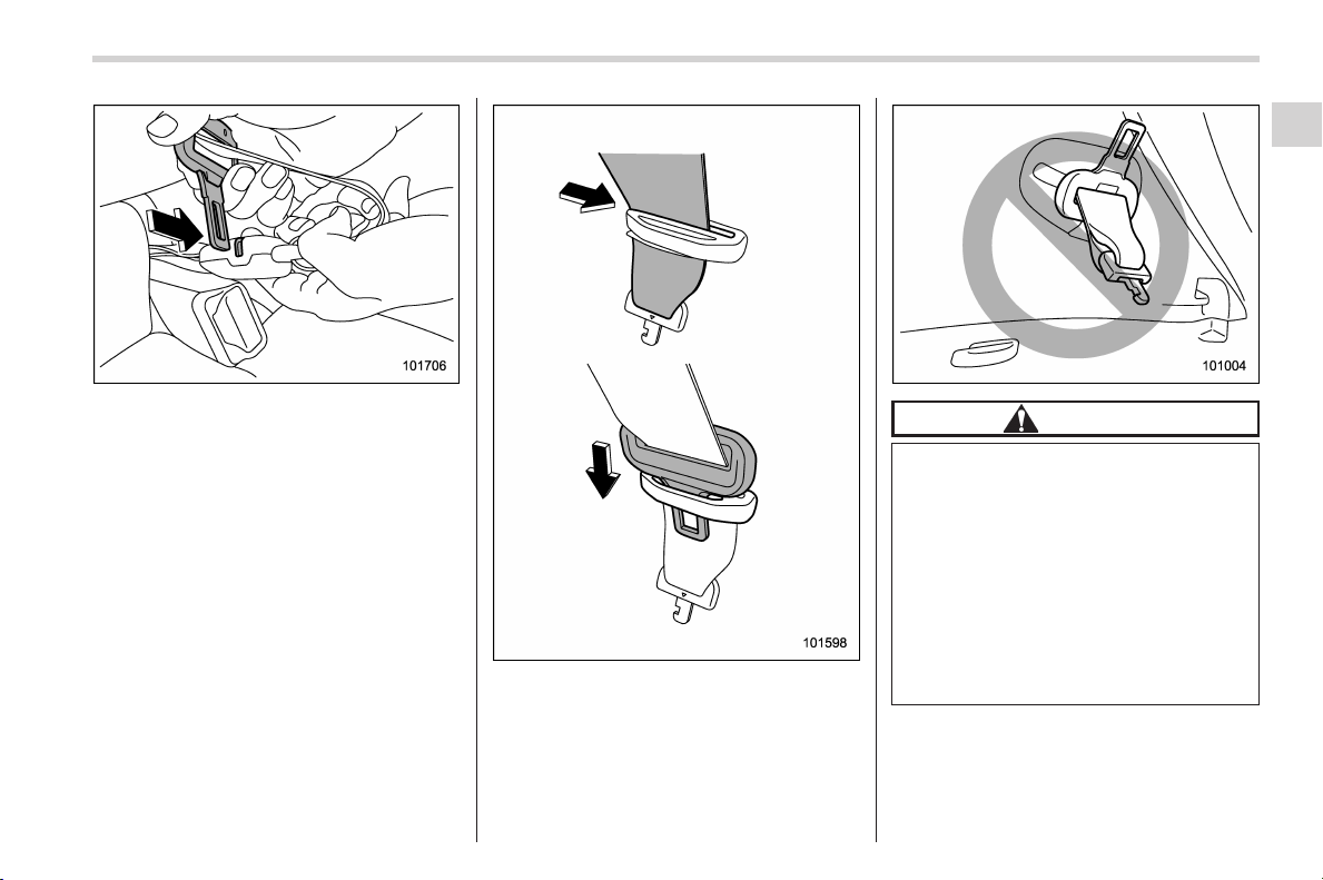
Black plate (55,1)
北米Model "A1160BE-C" EDITED: 2014/ 3/ 17
1. Insert a tongue plate or other hard
pointed object into the slot in the con-
nector (buckle) on the right-hand side and
push it in. The connector (tongue) plate
will then disconnect from the buckle.
2. Allow the retractor to roll up the belt.
You should hold the webbing end and
guide it back into the retractor while it is
rolling up. Insert the connector (tongue)
into the belt holder.
CAUTION
. Do not allow the retractor to roll
up the seatbelt too quickly.
Otherwise, the metal tongue
plates may hit against the trim,
resulting in damaged trim.
. Have the seatbelt fully rolled up
so that the tongue plates are
neatly stored. A hanging tongue
plate can swing and hit against
the trim during driving, causing
damage to the trim.
Seat, seatbelt and SRS airbags/Seatbelts
1-19
– CONTINUED –
1
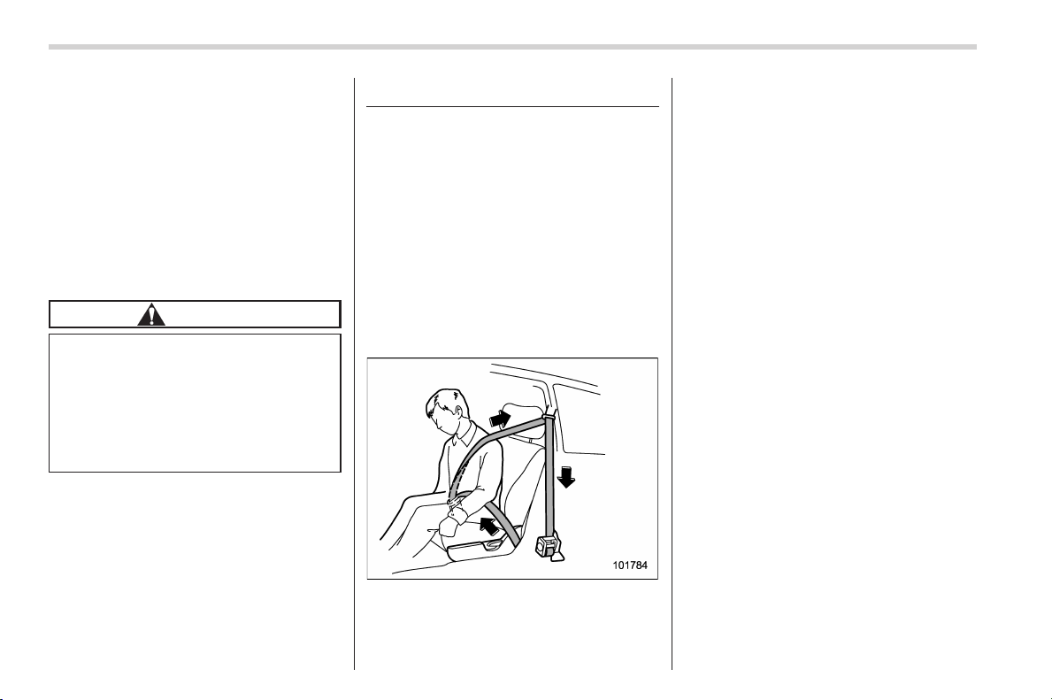
Black plate (56,1)
北米Model "A1160BE-C" EDITED: 2014/ 3/ 17
1-20
Seat, seatbelt and SRS airbags/Front seatbelt pretensioners
& Seatbelt maintenance
To clean the seatbelts, use a mild soap
and lukewarm water. Never bleach or dye
the belts because this could seriously
affect their strength.
Inspect the seatbelts and attachments
including the webbing and all hardware
periodically for cracks, cuts, gashes,
tears, damage, loose bolts or worn areas.
Replace the seatbelts even if only minor
damage is found.
CAUTION
. Keep the belts free of polishes,
oils, chemicals and particularly
battery acid.
. Never attempt to make modifica-
tions or changes that will prevent
the seatbelt from operating prop-
erly.
Front seatbelt pretensioners
The driver’s and front passenger’s seat-
belts have a seatbelt pretensioner. The
seatbelt pretensioners are designed to be
activated in the event of an accident
involving a moderate to severe frontal
and side collision and rollover accident.
& Seatbelt with shoulder belt
pretensioner
NOTE
This section is applicable to the dri-
ver ’s seatbelt.
The pretensioner sensor also serves as
follows.
. SRS frontal airbag sensor
. Side impact sensor
If the sensor detects a certain predeter-
mined amount of force during frontal or
side collisions or rollover accidents, the
front seatbelt is quickly drawn back in by
the retractor to take up the slack so that
the belt more effectively restrains the
driver.
When a seatbelt pretensioner is activated,
an operating noise will be heard and a
small amount of smoke will be released.
These occurrences are normal and not
harmful. This smoke does not indicate a
fire in the vehicle.
Once the seatbelt pretensioner has been
activated, the seatbelt retractor remains
locked. Consequently, the seatbelt cannot
be pulled out and retracted and therefore
must be replaced.
NOTE
. Seatbelt pretensioners are not de-
signed to activate in minor impacts or
in rear impacts.
. In cases of rollover accidents, as the
curtain airbags deploy, the driver’s side
seatbelt pretensioner and front passen-
ger’s side shoulder belt pretensioner
are activated simultaneously.
. In cases of frontal collisions, the
following components will operate si-
Black plate (57,1)
北米Model "A1160BE-C" EDITED: 2014/ 3/ 17
multaneously.
– Seatbelt pretensioner for driver
– Seatbelt pretensioner for front
passenger
– SRS frontal airbag for driver
– SRS frontal airbag for front pas-
senger*
– SRS curtain airbags (both sides)
(if an offset frontal collision occurs)
*: This does not operate if the occupant
detection system deactivates airbag op-
eration. For details, refer to “Front
passenger’s SRS frontal airbag” F1-46
.
. In cases of side collisions, the
following components will operate si-
multaneously.
– SRS curtain airbag (impacted
side)
– SRS side airbag (impacted side)
(when any of the center pillar im-
pact sensors/front door impact sen-
sors sense an impact force)
– Seatbelt pretensioner for driver
(when the driver’s side front door
impact sensor sense an impact
force)
– Seatbelt pretensioner for front
passenger (shoulder belt preten-
sioner only) (when the front pas-
senger’s side f ront door impact
sensor sense an impact force)
. Pretensioners are designed to func-
tion on a one-time-only basis. In the
event that a pretensioner is activated,
both the driver’s and front passenger’s
seatbelt retractor assemblies should
be replaced only by an authorized
SUBARU dealer. When replacing seat-
belt retractor assemblie s, use only
genuine SUBARU parts.
. If either front seatbelt does not
retract or cannot be pulled out due to
a malfunction or activation of the
pretensioner, contact your SUBARU
dealer as soon as possible.
. If the front seatbelt retractor assem-
bly or surrounding area has been
damaged, contact your SUBARU dealer
as soon as possible.
. When you sell your vehicle, we urge
you to explain to the buyer that it has
seatbelt pretensioners by alerting the
buyer to the contents of this section.
WARNING
. To obtain maximum protection,
the occupants should sit in an
upright position with their seat-
belts properly fastened. Refer to
“Seatbelts” F1-11.
. Do not modify, remove or strike
the front seatbelt retractor as-
semblies or surrounding area.
This could result in accidental
activation of the seatbelt preten-
sioners or could make the sys-
tem inoperative, possibly result-
ing in serious injury. Seatbelt
pretensioners have no user-ser-
viceable parts. For required ser-
vicing of front seatbelt retractors
equipped with seatbelt preten-
sioners, consult your SUBARU
dealer.
. When discarding front seatbelt
retractor assemblies or scrap-
ping the entire vehicle due to
collision damage or for other
reasons, consult your SUBARU
dealer.
Seat, seatbelt and SRS airbags/Front seatbelt pretensioners
1-21
– CONTINUED –
1
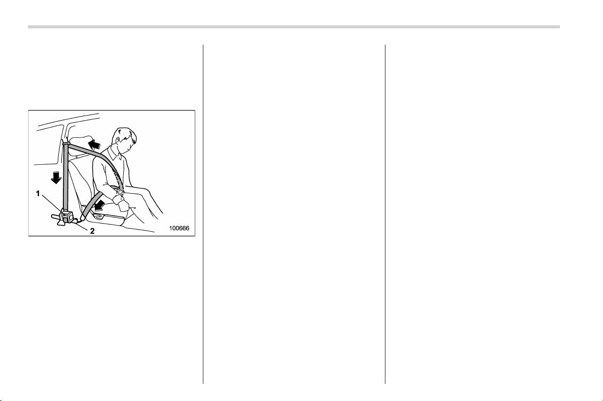
Black plate (58,1)
北米Model "A1160BE-C" EDITED: 2014/ 3/ 17
1-22
Seat, seatbelt and SRS airbags/Front seatbelt pretensioners
& Seatbelt with shoulder belt
and lap belt pretensioners
NOTE
This section is applicable to the front
passenger’s seatbelt.
1) Seatbelt retractor assembly (should er
belt pretensioner)
2) Lap belt pretensioner
On the f ront passenger ’s side, the
shoulder belt pretensioner is supplemen-
ted by a lap belt pretensioner, which is
located at the base of the center pillar.
Like the shoulder belt pretensioner, the lap
belt pretensioner instantaneously pulls in
the belt to eliminate slack if a certain level
of frontal collision force is detected. As a
result, the seatbelt restrains the front seat
occupant more effectively.
When a seatbelt pretensioner is activated,
an operating noise will be heard and a
small amount of smoke will be released.
These occurrences are normal and not
harmful. This smoke does not indicate a
fire in the vehicle.
Once the seatbelt pretensioner has been
activated, the seatbelt pretensioner re-
mains locked. Consequently, the seatbelt
cannot be pulled out and retracted and
therefore must be replaced.
NOTE
. Seatbelt pretensioners are not de-
signed to activate in minor impacts or
in rear impacts.
. When a rollover accident occurs, the
lap belt pretensioner does not activate;
however, as the curtain airbags deploy,
the shoulder belt pretensioner is acti-
vated. At this time, the driver’s side
seatbelt pretensioner and passenger’s
side shoulder belt pretensioner acti-
vate simultaneously.
. In cases of frontal collisions, the
following components will operate si-
multaneously.
– Seatbelt pretensioner for driver
– Seatbelt pretensioner for front
passenger
– SRS frontal airbag for driver
– SRS frontal airbag for front pas-
senger*
– SRS curtain airbags (both sides)
(if an offset frontal collision occurs)
*: This does not operate if the occupant
detection system deactivates airbag op-
eration. For details, refer to “Front
passenger’s SRS frontal airbag” F1-46
.
. In cases of side collisions, the
following components will operate si-
multaneously.
– SRS curtain airbag (impacted
side)
– SRS side airbag (impacted side)
(when any of the center pillar im-
pact sensors/front door impact sen-
sors sense an impact force)
– Seatbelt pretensioner for driver
(when the driver’s side front door
impact sensor sense a n impact
force)
– Seatbelt pretensioner for front
passenger (shoulder belt preten-
sioner only) (when the front pas-
senger ’s side front door i mpact
sensor sense an impact force)
. Pretensioners are designed to func-
tion on a one-time-only basis. In the
event that a pretensioner is activated,
both the driver’s and front passenger’s
seatbelt retractor assemblies should
be replaced only by an authorized
SUBARU dealer. When replacing seat-
Black plate (59,1)
北米Model "A1160BE-C" EDITED: 2014/ 3/ 17
belt retractor assemblies, use only
genuine SUBARU parts.
. If either front seatbelt does not
retract or cannot be pulled out due to
a malfunction or activation of the
pretensioner, contact your SUBARU
dealer as soon as possible.
. If the front seatbelt retractor assem-
bly or surrounding area has b een
damaged, contact your SUBARU dealer
as soon as possible.
. When you sell your vehicle, we urge
you to explain to the buyer that it has
seatbelt pretensioners by alerting the
buyer to the contents of this section.
WARNING
. To obtain maximum protection,
the occupants should sit in an
upright position with their seat-
belts properly fastened. Refer to
“Seatbelts” F1-11.
. Do not modify, remove or strike
the front seatbelt retractor as-
semblies or surrounding area.
This could result in accidental
activation of the seatbelt preten-
sioners or could make the sys-
tem inoperative, possibly result-
ing in serious injury. Seatbelt
pretensioners have no user-ser-
viceable parts. For required ser-
vicing of front seatbelt retractors
equipped with seatbelt preten-
sioners, consult your SUBARU
dealer.
. When discarding front seatbelt
retractor assemblies or scrap-
ping the entire vehicle due to
collision damage or for other
reasons, consult your SUBARU
dealer.
& System monitors
A diagnostic system continually monitors
the readiness of the seatbelt pretensioner
while the vehicle is being driven. The
seatbelt pretensioners share the control
module with the SRS airbag system.
Therefore, if any malfunction occurs in a
seatbelt pretensioner, the SRS airbag
system warning light will illuminate. For
details, refer to “SRS airbag system
monitors” F1-62.
& System servicing
WARNING
. When discarding a seatbelt re-
tractor assembly or scrapping
the entire vehicle damaged by a
collision, consult your SUBARU
dealer.
. Tampering with or disconnecting
the system’s wiring could result
in accidental activation of the
seatbelt pretensioner and/or
SRS airbag or could make the
system inoperative, which may
result in serious injury. Do not
use electrical test equipment on
any circuit related to the seatbelt
pretensioner and SRS airbag
systems. For required servicing
of the seatbelt pretensioner, con-
sult your nearest SUBARU deal-
er.
CAUTION
The sensors and SRS airbag control
modules are located in the following
locations.
. Front impact sensors: on both
sides of the radiator panel
. Front door impact sensors: on
both front doors
. Satellite safing sensor: under the
rear center seat
. SRS airbag control module (in-
cluding the impact sensors): un-
Seat, seatbelt and SRS airbags/Front seatbelt pretensioners
1-23
– CONTINUED –
1
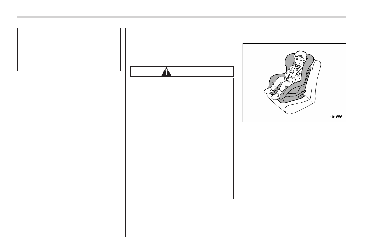
Black plate (60,1)
北米Model "A1160BE-C" EDITED: 2014/ 3/ 17
1-24
Seat, seatbelt and SRS airbags/Child restraint systems
der the center of the instrument
panel
If you need service or repair in those
areas or near the front seatbelt
retractors, have the work performed
by your authorized SUBARU dealer.
NOTE
If the front part of the vehi cle is
damaged in an accident to the extent
that the seatbelt pretensioner does not
operate, contact your SUBARU dealer
as soon as possible.
& Precautions against vehicle
modification
Always consult your SUBARU dealer if
you want to install any accessory parts to
your vehicle.
CAUTION
Do not perform any of the following
modifications. Such modifications
can interfere with proper operation
of the seatbelt pretensioners.
. Attachment of any equipment
(bush bar, winches, snow plow,
skid plate, etc.) other than genu-
ine SUBARU accessory parts to
the front end.
. Modification of the suspension
system or front end structure.
. Installation of a tire of different
size and construction from the
tires specified on the vehicle
placard attached to the driver’s
door pillar or specified for indivi-
dual vehicle models in this Own-
er’s Manual.
Child restraint systems
Infants and small children should always
be placed in an infant or child restraint
system in the rear seat while riding in the
vehicle. You should use an infant or child
restraint system that meets Federal Motor
Vehicle Safety Standards or Canada
Motor Vehicle Safety Standards, is com-
patible with your vehicle and is appro-
priate for the child ’s age and size. All child
restraint systems are designed to be
secured in vehicle seats by lap belts or
the lap belt portion of a lap/shoulder belt
(except those described in “Installation of
child restraint systems by use of lower and
tether anchorages (LATCH)” F1-32).
Children could be endangered in an
accident if their child restraints are not
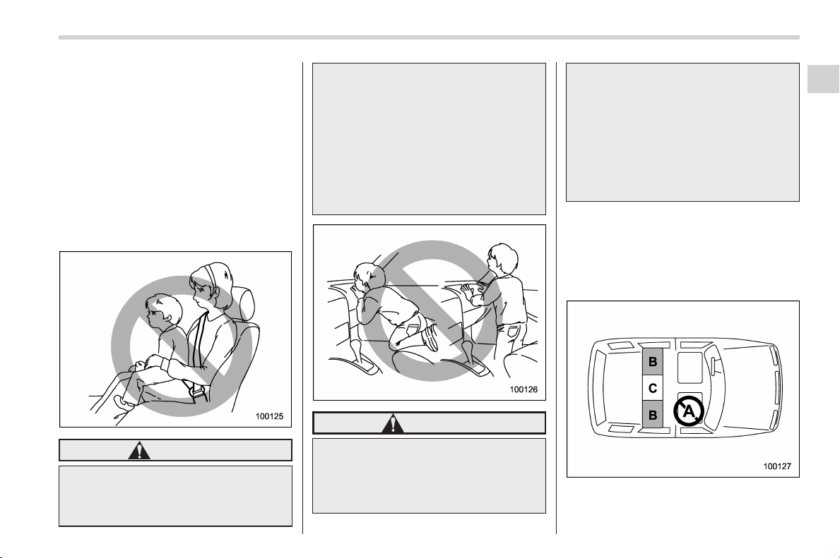
Black plate (61,1)
北米Model "A1160BE-C" EDITED: 2014/ 3/ 17
properly secured in the vehicle. When
installing the child restraint system, care-
fully follow the manufacturer’s instructions.
According to accident statistics, children
are safer when properly restrained in the
rear seating positions than in the front
seating positions.
All U.S. states and Canadian provinces
require that infants and small children be
restrained in an approved child restraint
system at all times while the vehicle is
moving.
WARNING
Never let a passenger hold a child
on his or her lap or in his or her
arms while the vehicle is moving.
The passenger cannot protect the
child from injury in a collision,
because the child will be caught
between the passenger and objects
inside the vehicle.
Additionally, holding a child in your
lap or arms in the front seat exposes
that child to another serious danger.
Since the SRS airbag deploys with
considerable speed and force, the
child could be injured or even killed.
WARNING
Children s hould b e properl y re-
strained at all times. Never allow a
child to stand up, or to kneel on any
seat. Unrestrained children will be
thrown forward during sudden stop
or in an accident and can be injured
seriously.
Additionally, children standing up or
kneeling on or in front of the front
seat are exposed another serious
danger. Since the SRS airbag de-
ploys with considerable speed and
force, the child could be injured or
even killed.
& Where to place a child re-
straint system
The following are SUBARU’s recommen-
dations on where to place a child restraint
system in your vehicle.
Seat, seatbelt and SRS airbags/Child restraint systems
1-25
– CONTINUED –
1
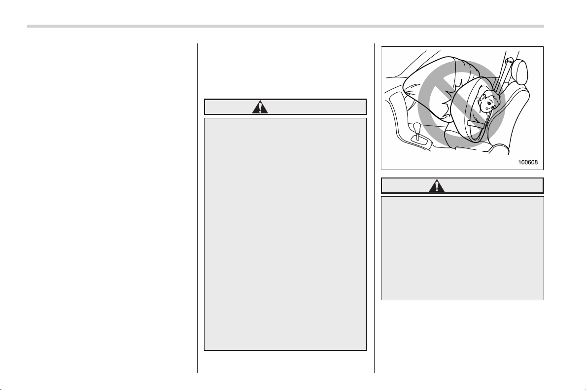
Black plate (62,1)
北米Model "A1160BE-C" EDITED: 2014/ 3/ 17
1-26
Seat, seatbelt and SRS airbags/Child restraint systems
A: Front passenger’s seat
You should not install a child restraint
system (including a booster seat) due to
the hazard to children posed by the
passenger’s airbag.
B: Rear seat, window-side seating
positions
Recommended positions for all types of
child restraint systems.
In these positions, Automatic/Emergency
Locking Retractor (A/ELR) seatbelts and
lower anchorages (bars) are provided for
installing a child restraint system.
Some types of child restraints might not be
able to be secured firmly due to projection
of the seat cushion.
In this seating position, you should use
only a child restraint system that has a
bottom base that fits snugly against the
contours of the seat cushion and can be
securely retained using the seatbelt.
C: Rear seat, center seating position
Installing a child restraint system is not
recommended, although the A/ELR seat-
belt and an upper anchorage (tether
anchorage, if equipped) are provided in
this position.
Some types of child restraints might not be
able to be secured firmly due to projection
of the seat cushion.
In this seating position, you should use
only a child restraint system that has a
bottom base that fits snugly against the
contours of the seat cushion and can be
securely retained using the seatbelt.
WARNING
Put children aged 12 and under in
the rear seat properly restrained at
all times. The SRS airbag deploys
with considerable speed and force
and can injure or even kill children,
especially if they are 12 years of age
and under and are not restrained or
improperly restrained. Because chil-
dren are lighter and weaker than
adults, their risk of being injured
from deployment is greater.
For that reason, be sure to secure
ALL types of child restraint devices
(including forward facing child
seats) in the REAR seats at all times.
You should choose a restraint de-
vice which is appropriate for the
child’s age, height and weight. Ac-
cording to accident statistics, chil-
dren are safer when properly re-
strained in the rear seating posi-
tions than in the front seating posi-
tions.
WARNING
SINCE YOUR VEHICLE IS
EQUIPPED WITH A PASSENGER’S
SRS AIRBAG, NEVER INSTALL A
REARWARD FACING CHILD
SAFETY SEAT IN THE FRONT PAS-
SENGER’S SEAT. DOING SO RISKS
SERIOUS INJURY OR DEATH TO
THE CHILD BY PLACING THE
CHILD’S H EAD TOO CLOSE TO
THE SRS AIRBAG.
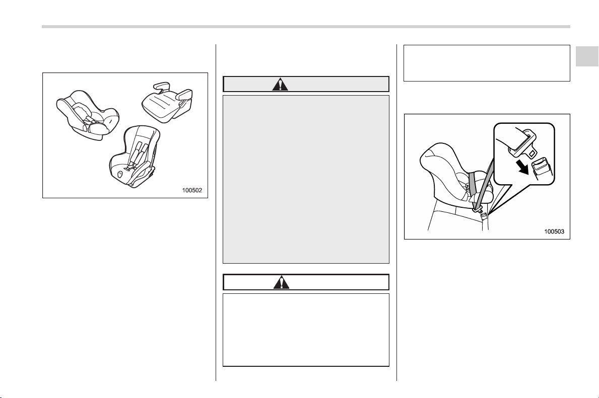
Black plate (63,1)
北米Model "A1160BE-C" EDITED: 2014/ 3/ 17
& Choosing a child restraint
system
Choose a child restraint system that is
appropriate for the child’s age and size
(weight and height) in order to provide the
child with proper protecti on. The child
restraint system should meet all applic-
able requirements of Federal Motor Vehi-
cle Safety Standards for the United States
or of Canada Motor Vehicle Safety Stan-
dards for Canada. It can be identified by
looking for the label on the child restraint
system or the manufacturer’s statement of
compliance in the document attached to
the system.
Also it is important for you to make sure
that the child restraint system is compa-
tible with the vehicle in which it will be
used.
& Installing child restraint sys-
tems with A/ELR seatbelt
WARNING
. Child restraint systems and seat-
belts can become hot in a vehicle
that has been closed up in sunny
weather; they could burn a small
child. Check the child restraint
system before you place a child
in it.
. Do not leave an unsecured child
restraint system in your vehicle.
Unsecured child restraint sys-
tems can be thrown around in-
side of the vehicle in a sudden
stop, turn or accident; they can
strike and injure vehicle occu-
pants as well as result in serious
injuries or death to the child.
CAUTION
When you install a child restraint
system, follow the manufacturer’s
instructions supplied with it. After
installing the child restraint system,
check to ensure that it is held
securely in position. If it is not held
tight and secure, the danger of your
child suffering personal injury in the
event of an accident may be in-
creased.
! Installing a rearward facing child
restraint
1. Place the child restraint system in the
rear seating position.
2. Run the lap and shoulder belt through
or around the child restraint system
following the instructions provided by its
manufacturer.
3. Insert the tongue plate into the buckle
until you hear a click.
Seat, seatbelt and SRS airbags/Child restraint systems
1-27
– CONTINUED –
1
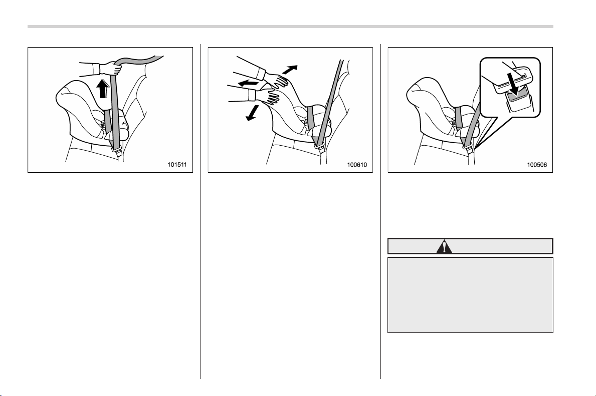
Black plate (64,1)
北米Model "A1160BE-C" EDITED: 2014/ 3/ 17
1-28
Seat, seatbelt and SRS airbags/Child restraint systems
4. Take up the slack in the lap belt.
5. Pull out the seatbelt fully from the
retractor to change the retractor over from
the Emergency Locking Retractor (ELR)
to the Automatic Locking Retractor (ALR)
function. Then, allow the belt to rewind
into the retractor. As the belt is rewinding,
clicks will be heard which indicate the
retractor functions as ALR.
6. Push and pull the child restraint
system forward and from side to side to
check if it is firmly secured. Sometimes a
child restraint can be more firmly secured
by pushing it down into the seat cushion
and then tightening the seatbelt.
7. Pull at the shoulder portion of the belt
to confirm that it cannot be pulled out (ALR
properly functioning).
8. To remove the child restraint system,
press the release button on the seatbelt
buckle and allow the belt to retract
completely. The belt will return to the
ELR mode.
WARNING
NEVER INSTALL A REARWARD FA-
CING CHILD SEAT IN THE FRONT
PASSENGER’SSEAT.DOINGSO
RISKS SERIOUS INJURY OR DEATH
TO THE CHILD BY PLACING THE
CHILD’S HEAD TOO CLOSE TO THE
SRS AIRBAG.
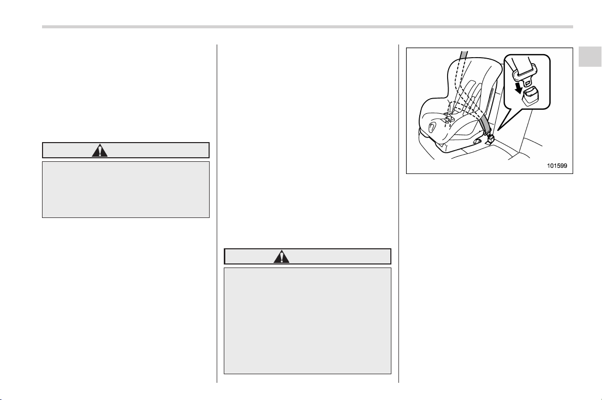
Black plate (65,1)
北米Model "A1160BE-C" EDITED: 2014/ 3/ 17
NOTE
When the child restraint system is no
longer in use, remove it and restore the
ELR function of the retractor. That
function is restored by allowing the
seatbelt to retract fully.
! Installing forward facing child re-
straint
WARNING
Before installing a child restraint
system, be sure to confirm that the
seatback is securely locked into
place. Otherwise, in an accident,
serious injury or death could result.
1. Shake the seatback slightly to confirm
that it is securely locked into place.
– It is possible to check whether the
seatback is locked visually. If the
seatback is locked into place, the red
colored unlockin g marker which is
attached to the bottom of the lock
release knob is invisible. For details,
refer to “Folding down the rear seat-
back” F1-10.
2. Prepare the rear seat head restraint
where a child restraint system is intended
to be installed in the following way.
– When a child restraint system is
installed on the window-side seating
position, remove the rear seat head
restraint. For details, refer to “Head
restraint adjustment” F1-8.
Store the head restraint in the cargo
area. Avoid placing the head restraint
in the passenger compartment to
prevent it from being thrown around
in the passenger compartment in a
sudden stop or a sharp turn.
– When a child restraint system is
installed on the rear center seating
position, raise the rear seat head
restraint to the extended position. Do
not remove the head restraint. For
details, refer to “Rear center seating
position” F1-9.
3. Place the child restraint system in the
rear seating position.
WARNING
When you intend to install a child
restraint system on the rear center
seating position, if the child restraint
system does not fit snugly against
the contours of the rear center seat
cushion, install the child restraint
system on the window-side seating
position to be safe. For details, refer
to “Where to place a child restraint
system” F1-25.
4. Run the lap and shoulder belt through
or around the child restraint system
following the instructions provided by its
manufacturer.
– When a child restraint system is
installed on the rear center seating
position, pass the rear center seatbelt
through the belt guide properly. For
details, refer to “Rear center seatbelt”
F1-16.
5. Insert the tongue plate into the buckle
until you hear a click.
Seat, seatbelt and SRS airbags/Child restraint systems
1-29
– CONTINUED –
1
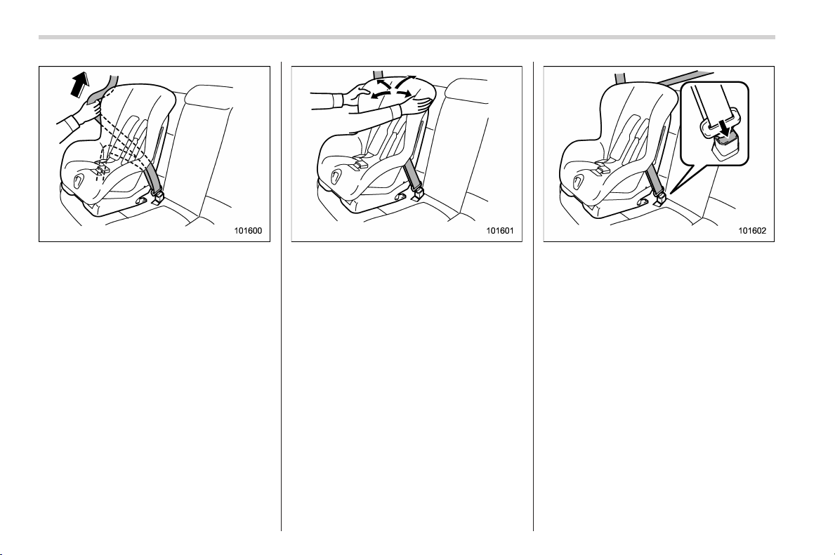
Black plate (66,1)
北米Model "A1160BE-C" EDITED: 2014/ 3/ 17
1-30
Seat, seatbelt and SRS airbags/Child restraint systems
6. Take up the slack in the lap belt.
7. Pull out the seatbelt fully from the
retractor to change the retractor over from
the Emergency Locking Retractor (ELR)
to the Automatic Locking Retractor (ALR)
function. Then, allow the belt to rewind
into the retractor. As the belt is rewinding,
clicks will be heard which indicate the
retractor functions as ALR.
8. Before having a child sit in the child
restraint system, try to move it back and
forth and right and left to check if it is firmly
secured. Sometimes a chi ld restraint
system can be more firmly secured by
pushing it down into the seat cushion and
then tightening the seatbelt.
9. Pull at the shoulder portion of the belt
to confirm that it cannot be pulled out (ALR
properly functioning).
10. Latch the top tether hook onto the
tether anchorage that is located behind
the rear seat and tighten the top tether
firmly. For additional instructions, refer to
“Top tether anchorages” F1-35.
11. To remove the child restraint system,
press the release button on the seatbelt
buckle and allow the belt to retract
completely. The belt will return to the
ELR mode.
If you have installed a child restraint
system for the rear center seating posi-
tion, when you remove the child restraint
system, the seatbelt may not be restored
to the ELR mode even if the seatbelt is
retracted. In this case, lower the head
restraint to the retracted position to allow
the seatbelt to retract moreover. The
seatbelt will return to the ELR mode.
Remember that the head restraint is not
intended to be used at the lowest position
(retracted position). Therefore, when the
rear center seat is occupied (including
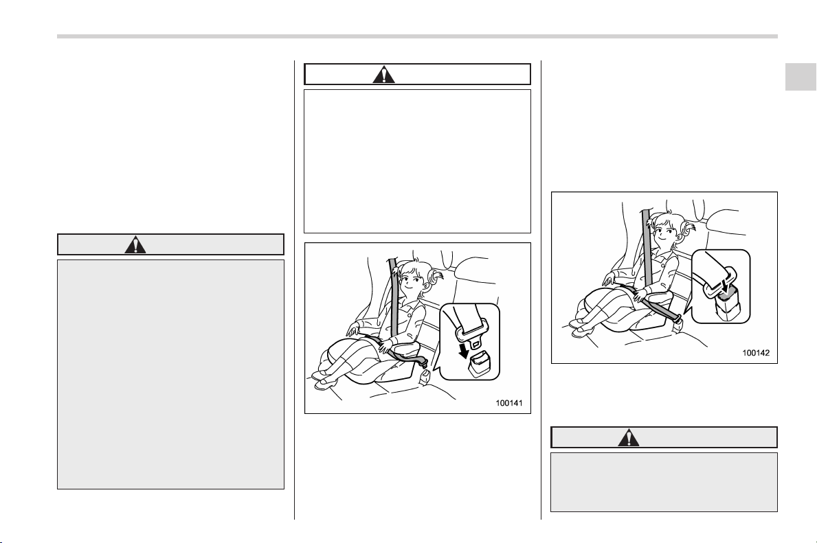
Black plate (67,1)
北米Model "A1160BE-C" EDITED: 2014/ 3/ 17
when a child restraint system is installed)
next time, be sure to raise the head
restraint to the extended position.
NOTE
When the child restraint system is no
longer in use, remove it and restore the
ELR function of the retractor. That
function is restored by allowing the
seatbelt to retract fully.
& Installing a booster seat
WARNING
. Child restraint systems and seat-
belts can become hot in a vehicle
that has been closed up in sunny
weather; they could burn a small
child. Check the child restraint
system before you place a child
in it.
. Do not leave an unsecured child
restraint system in your vehicle.
Unsecured child restraint sys-
tems can be thrown around in-
side of the vehicle in a sudden
stop, turn or accident; they can
strike and injure vehicle occu-
pants as well as result in serious
injuries or death to the child.
CAUTION
When you install a child restraint
system, follow the manufacturer’s
instructions supplied with it. After
installing the child restraint system,
check to ensure that it is held
securely in position. If it is not held
tight and secure, the danger of your
child suffering personal injury in the
event of an accident may be in-
creased.
1. Place the booster seat in the rear
seating position and sit the child on it. The
child should sit well back on the booster
seat.
2. Run the lap and shoulder belt through
or around the booster seat and the child
following the instructions provided by its
manufacturer.
3. Insert the tongue plate into the buckle
until you hear a click. Take care not to
twist the seatbelt.
Make sure the shoulder belt is positioned
across the center of child’s shoulder and
that the lap belt is positioned as low as
possible on the child’s hips.
4. To remove the booster seat, press the
release button on the seatbelt buckle and
allow the belt to retract.
WARNING
. Never use a belt that is twisted or
reversed. In an accident, this can
increase the risk or severity of
injury to the child.
Seat, seatbelt and SRS airbags/Child restraint systems
1-31
– CONTINUED –
1
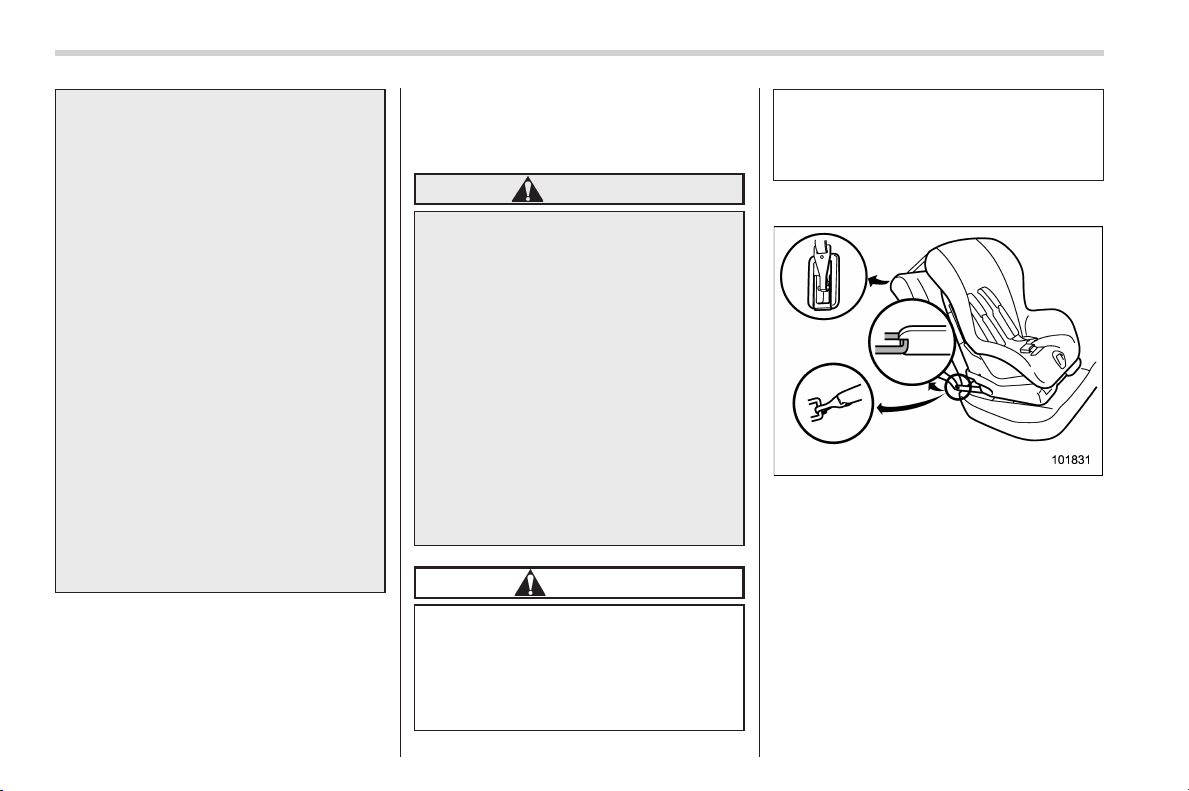
Black plate (68,1)
北米Model "A1160BE-C" EDITED: 2014/ 3/ 17
1-32
Seat, seatbelt and SRS airbags/Child restraint systems
. Never place the shoulder belt
under the child’s arm or behind
the child’s back. If an accident
occurs, this can increase the risk
or severity of injury to the child.
. The seatbelt should fit snugly in
order to provide full restraint.
Loose fitting belts are not as
effective in preventing or redu-
cing injury.
. Placethelapbeltaslowas
possible on the child’s hips. A
high-positioned lap belt will in-
crease the risk of sliding under
the lap belt and of the lap belt
sliding up over the abdomen, and
both can result in serious inter-
nal injury or death.
. Make sure the shoulder belt is
positioned across the center of
child’s shoulder. Placing the
shoulder belt over the neck may
result in neck injury during sud-
den braking or in a collision.
& Installation of child restraint
systems by use of lower and
tether anchorages (LATCH)
WARNING
. Child restraint systems and seat-
belts can become hot in a vehicle
that has been closed up in sunny
weather; they could burn a small
child. Check the child restraint
system before you place a child
in it.
. Do not leave an unsecured child
restraint system in your vehicle.
Unsecured child restraint sys-
tems can be thrown around in-
side of the vehicle in a sudden
stop, turn or accident; they can
strike and injure vehicle occu-
pants as well as result in serious
injuries or death to the child.
CAUTION
When you install a child restraint
system, follow the manufacturer’s
instructions supplied with it. After
installing the child restraint system,
check to ensure that it is held
securely in position. If it is not held
tight and secure, the danger of your
child suffering personal injury in the
event of an accident may be in-
creased.
! Lower and tether anchorages
Some types of child restraint systems can
be installed on the rear seat of your
vehicle without use of the seatbelts. Such
child restraint systems are secured to the
designated anchorages provided on the
vehicle body. The lower and tether an-
chorages are sometimes referred to as the
LATCH system (Lower Anchors and
Tethers for CHildren).
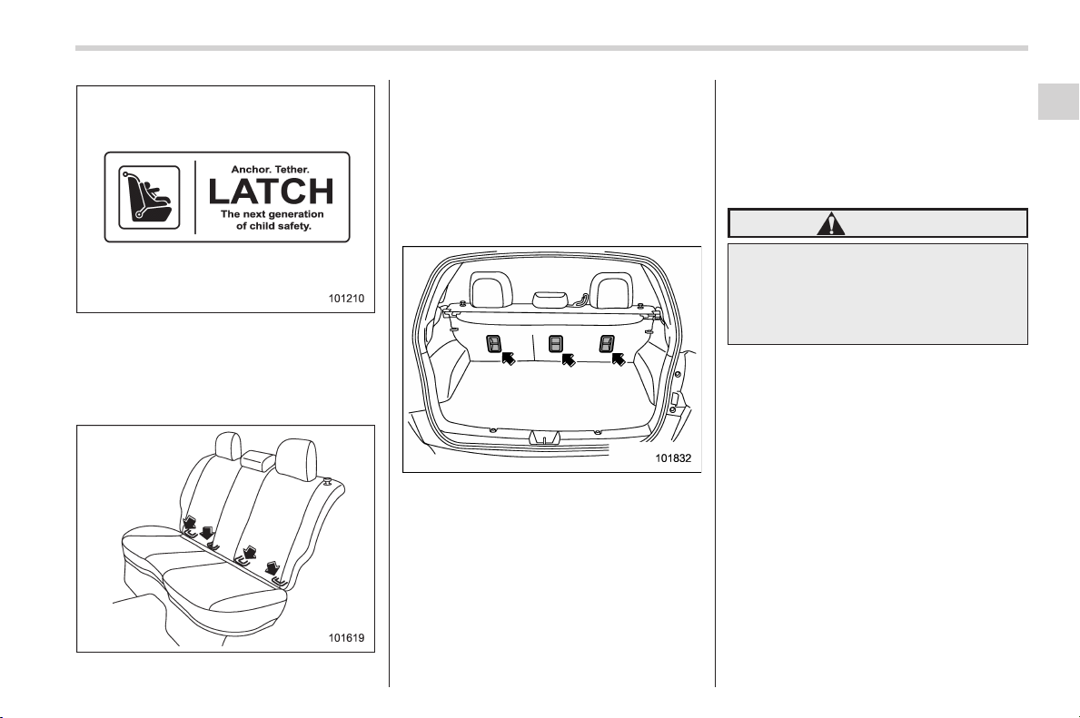
Black plate (69,1)
北米Model "A1160BE-C" EDITED: 2014/ 3/ 17
Your vehicle is equipped with four lower
anchorages (bars) and three upper an-
chorages (tether anchorages) for accom-
modating such child restraint systems.
! Lower anchorages
The lower anchorages (bars) are used for
installing a child restraint system only on
the rear seat window-side seating posi-
tions. For each window-side seating posi-
tion, two lower anchorages are provided.
Each lower anchorage is located where
the seat cushion meets the seatback.
! Tether anchorages
The tether anchorages (upper an-
chorages) are provided at the locations
shown in the above illustration. For de-
tails, refer to “ Top tether anchorages” F1-
35.
! To install a child restraint system
using lower and tether an-
chorages
To install a child restraint system using
lower and tether anchorages, perform the
following procedure.
WARNING
Before installing a child restraint
system, be sure to confirm that the
seatback is securely locked into
place. Otherwise, in an accident,
serious injury or death could result.
1. Shake the seatback slightly to confirm
that it is securely locked into place.
– It is possible to check whether the
seatback is locked visually. If the
seatback is locked into place, the red
colored unlocking marker which is
attached to the bottom of the lock
release knob is invisible. For details,
refer to “Folding down the rear seat-
back” F1-10.
Seat, seatbelt and SRS airbags/Child restraint systems
1-33
– CONTINUED –
1
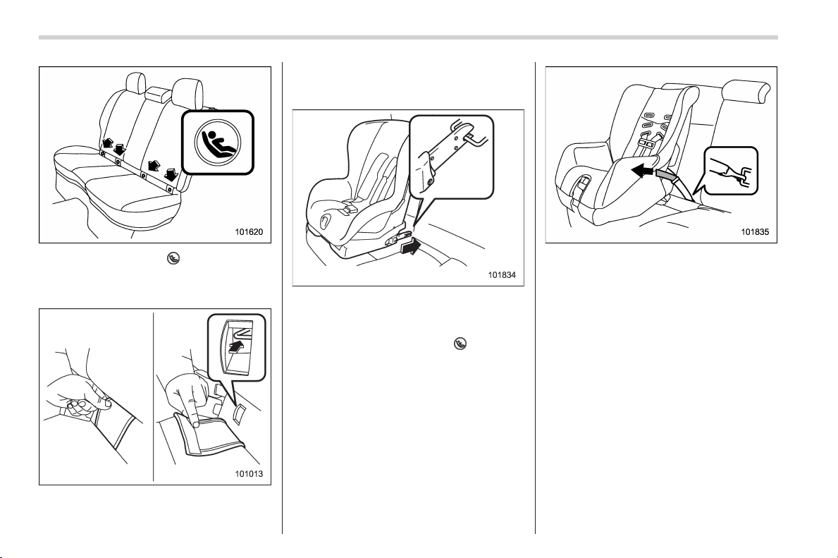
Black plate (70,1)
北米Model "A1160BE-C" EDITED: 2014/ 3/ 17
1-34
Seat, seatbelt and SRS airbags/Child restraint systems
2. You will find marks “ ” at the bottom of
the rear seat seatbacks. These marks
indicate the positions of the lower an-
chorages (bars).
Remove the covers and locate the lower
anchorages (bars).
3. Remove the rear seat head restraint.
For details, refer to “Rear windows side
seating position” F1-9.
4. While following the instructions sup-
plied by the child restraint system manu-
facturer, connect the lower hooks onto the
lower anchorages located at “
” marks on
the bottom of the rear seatback. When the
hooks are connec ted, make sure the
adjacent seatbelts are not caught.
5. [If your child restraint system is of a
flexible attachment type (which uses
tether belts to connect the child restraint
system properly to the lower anchorages)]
While pushing the child restraint into the
seat cushion, pull both left and right lower
tether belts up to secure the child restraint
system firmly by taking up the slack in the
belt.
6. Latch the top tether hook onto the
tether anchorage that is located behind
the rear seat and tighten the top tether
firmly. For additional instructions, refer to
“Top tether anchorages” F1-35.
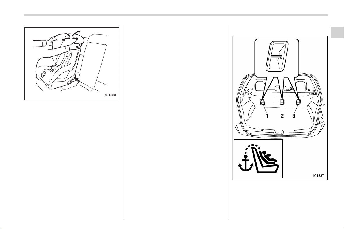
Black plate (71,1)
北米Model "A1160BE-C" EDITED: 2014/ 3/ 17
7. Before seating a child in the child
restraint system, try to move it back and
forth and right and left to verify that it is
held securely in position.
8. To remove the child restraint system,
follow the reverse procedures of installa-
tion.
If you have any question concerning this
type of child restraint system, ask your
SUBARU dealer.
& Top tether anchorages
Your vehicle is equipped with two or three
top tether anchorages so that a child
restraint system having a top tether can
be install ed in the rear seat. When
installing a child restraint system using
top tether, proceed as follows, while
observing the instructions by the child
restraint system manufacturer.
Since a top tether can provide additional
stability by offering another connection
between a child restraint system and the
vehicle, we recommend that you use a top
tether whenever one is required or avail-
able.
! Anchorage location
1) For left seat
2) For center seat
3) For right seat
Three upper anchorages are installed on
the back side of the rear seatback.
Seat, seatbelt and SRS airbags/Child restraint systems
1-35
– CONTINUED –
1
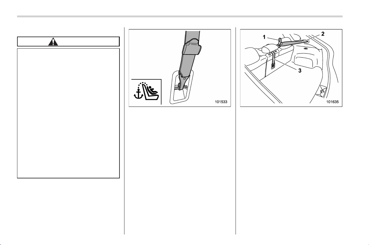
Black plate (72,1)
北米Model "A1160BE-C" EDITED: 2014/ 3/ 17
1-36
Seat, seatbelt and SRS airbags/Child restraint systems
! To hook the top tether
CAUTION
. Except for the center seating
position, remove the head re-
straint when mounting a child
restraint sys tem. Otherwise, it
might be possible that the top
tether cannot be fastened tightly.
. For the center seating position,
raise the center head restraint to
the extended position when
mounting a child restraint sys-
tem. Otherwise, it will be impos-
sible to use the seatbelt guide
that is attached to the head
restraint correctly.
The seatbelt guide is essential
for routing the belt webbing at
the center seating position. For
information about using the seat-
belt guide, refer to “Rear center
seatbelt” F1-16.
1. Attach the top tether hook to the
appropriate upper anchorage.
For the center seating position, route
the top tether under the head restraint as
illustrated below.
1) Seatbelt guide
2) Seatbelt of the center seating position
3) Top tether
2. Tighten the top tether securely.
Please contact your SUBARU dealer if
you have any questi on regarding the
installation of a child restraint system.

Black plate (73,1)
北米Model "A1160BE-C" EDITED: 2014/ 3/ 17
*SRS airbag (Supplemental
Restraint System airbag)
*SRS: This stands for supplemental re-
straint system. This name is used be-
cause the airbag system supplements the
vehicle’s seatbelts.
Your vehicle is equipped with a supple-
mental restraint system in addition to a
lap/shoulder belt at each front seating
position and each rear window-side seat-
ing positions. The supplemental restraint
system (SRS) consists of seven airbags.
The configurations are as follows.
. Driver’s and front passenger’s frontal
airbags
. Driver’s and front passen ger’s side
airbags
. Curtain airbags (for driver, front pas-
senger, and window-side rear passen-
gers)
. Knee airbag for driver
These SRS airbags are designed only
as a supplement to the primary protec-
tion provided by the seatbelt.
The system also controls front seatbelt
pretensioners. For operation instructions
and precautions concerning the seatbelt
pretensioner, refer to “Front seatbelt pre-
tensioners” F1-20.
& General precautions regard-
ing SRS airbag system
WARNING
. To obtain maximum protection in
the event of an accident, the
driver and all passengers in the
vehicle should always wear seat-
belts when the vehicle is moving.
The SRS airbag is designed only
to be a supplement to the primary
protection provided by the seat-
belt. It does not eliminate the
need to fasten seatbelts. In com-
bination with the seatbelts, it
offers the best combined protec-
tion in case of a serious accident.
Not wearing a seatbelt increases
the chance of severe injury or
death in a crash even when the
vehicle has the SRS airbag.
For instructions and precautions
concerning the seatbelt system,
refer to “Seatbelts” F1-11.
. The SRS side airbag and SRS
curtain airbag are designed only
to be a supplement to the primary
protection provided by the seat-
belt. They do not eliminate the
need to fasten seatbelts. It is also
important to wear your seatbelt
to help avoid injuries that can
result when an occupant is not
seated in a proper upright posi-
tion.
WARNING
. The SRS airbags deploy with
considerable speed and force.
Occupants who are out of proper
position when the SRS airbag
deploys could suffer very serious
injuries. Because the SRS airbag
needs enough space for deploy-
ment, the driver should always
sit upright and well back in the
seat as far from the steering
wheel as practical while still
maintaining full vehicle control
Seat, seatbelt and SRS airbags/*SRS airbag (Supplemental Restraint System airbag)
1-37
– CONTINUED –
1
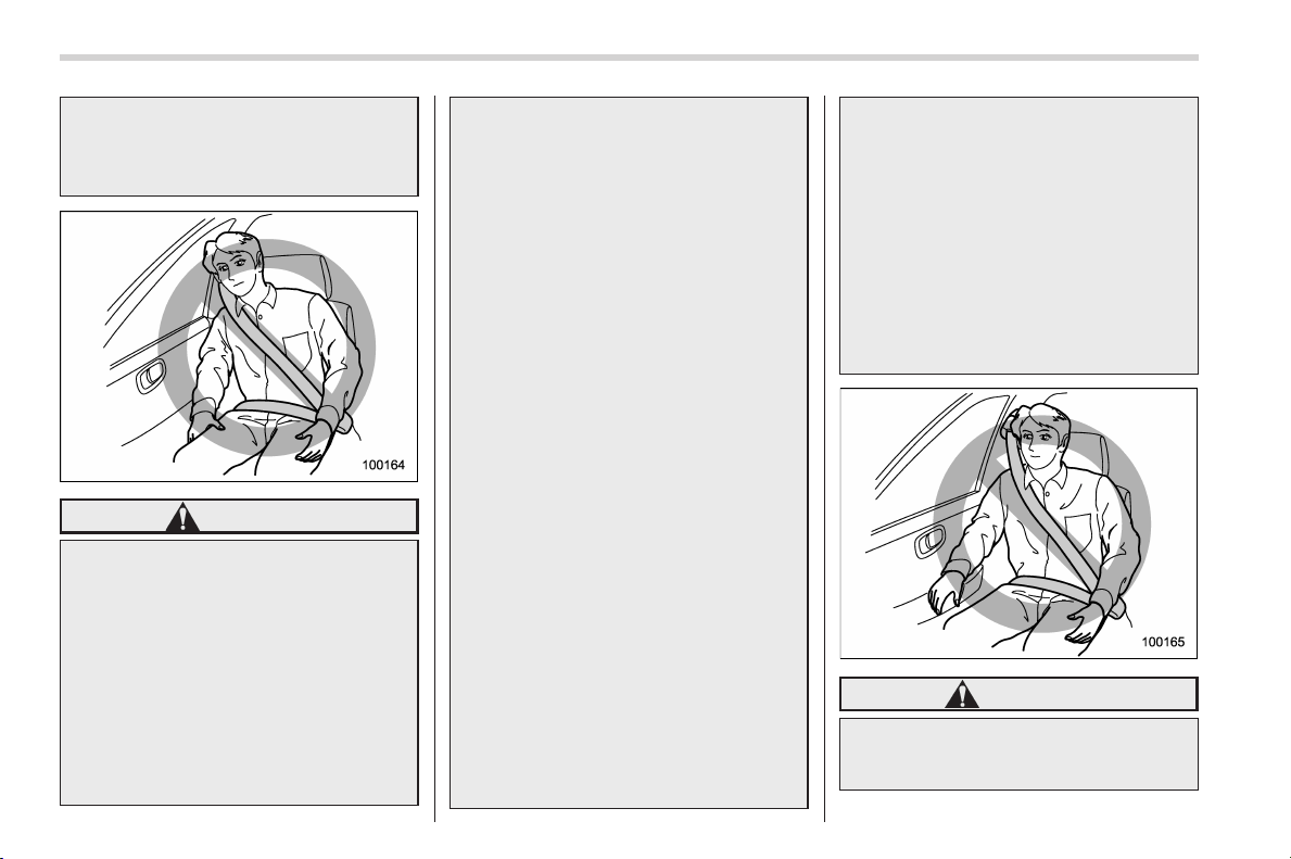
Black plate (74,1)
北米Model "A1160BE-C" EDITED: 2014/ 3/ 17
1-38
Seat, seatbelt and SRS airbags/*SRS airbag (Supplemental Restraint System airbag)
and the front passenger should
move the seat as far back as
possible and sit upright and well
back in the seat.
WARNING
. Do not sit or lean unnecessarily
close to either front door. The
SRS side airbags are stored in
both front seat seatbacks next to
the door, and they provide pro-
tection by deploying rapidly (fas-
ter than the blink of an eye) in the
event of a side impact or frontal
collision. However, the force of
SRS side airbag deployment may
cause injuries if your head or
other parts of the body are too
close to the SRS side airbag.
. Since your vehicle is equipped
with SRS curtain airbags, do not
sit or lean unnecessarily close to
the front or rear door on either
side. Also, do not put your head,
arms or hands out of the window.
The SRS curtain airbags on both
sides of the cabin are stored in
the roof side (between the front
pillar and a point behind the rear
quarter glass), and they provide
protection by deploying rapidly
(faster than the blink of an eye) in
the event of a side impact or
frontal collision. The SRS curtain
airbags also deploy in the event
of a rollover. However, the force
of its deployment may cause
injuries if your head is too close
to it.
. Do not sit or lean unnecessarily
close to the SRS airbag. Because
the SRS airbag deploys with
considerable speed – faster than
the blink of an eye – and force to
protect in high speed collisions,
the force of an airbag can injure
an occupant whose body is too
close to SRS airbag.
It is also important to wear your
seatbelt to help avoid injuries
that can result when the SRS
airbag contacts an occupant not
in proper position such as one
thrown forward during pre-acci-
dent braking.
Even when properly positioned,
there remains a possibility that
an occupant may suffer minor
injury such as abrasions and
bruises to the face or arms
because of the SRS airbag de-
ployment force.
WARNING
. Do not rest your arm on either
front door or its internal trim. You
could be injured in the event of
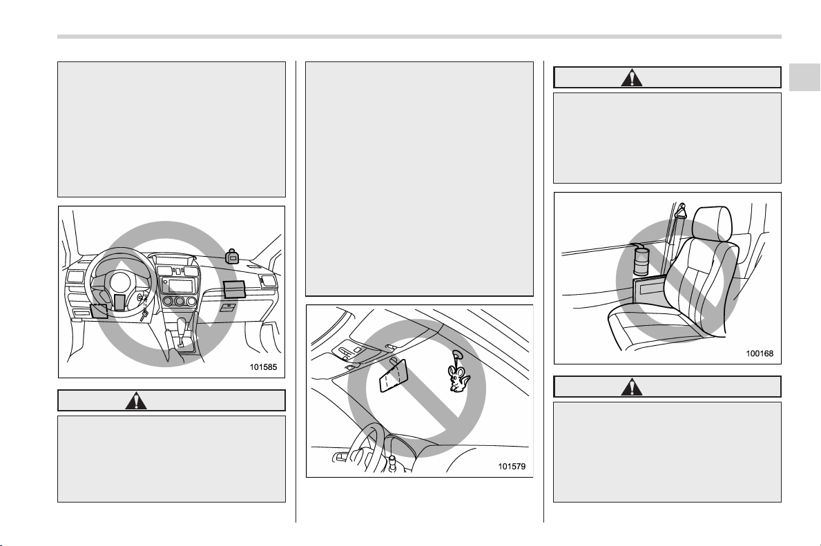
Black plate (75,1)
北米Model "A1160BE-C" EDITED: 2014/ 3/ 17
SRS side airbag deployment.
. Do not place any objects over or
near the SRS airbag cover or
between you and the SRS airbag.
If the SRS airbag deploys, these
objects could interfere with its
proper operation and could be
propelled inside the vehicle,
causing injury.
WARNING
. Do not put any objects over the
steering wheel pad and dash-
board. If the SRS frontal airbag
deploys, these objects could in-
terfere with its proper operation
and could be propelled inside the
vehicle, causing injury.
. Do not put any objects under the
driver’s side of the instrument
panel. If the SRS knee airbag
deploys, those objects could in-
terfere with its proper operation
and could be propelled inside the
vehicle, causing injury.
. The key must not be attached to
heavy, sharp or hard acces-
sories, or another key. If the
SRS knee airbag deploys, those
objects could interfere with its
proper operation and could be
propelled inside the vehicle and
cause injury.
WARNING
Do not attach accessories to the
windshield, or fit an extra-wide mir-
ror over the rear view mirror. If the
SRS airbag deploys, those objects
could become projectiles that could
seriously injure vehicle occupants.
WARNING
. Do not attach accessories to the
door trim or near either SRS side
airbags and do not place objects
near the SRS side airbags. In the
event of SRS side airbag deploy-
ment, they could be propelled
dangerously toward the vehicle’s
Seat, seatbelt and SRS airbags/*SRS airbag (Supplemental Restraint System airbag)
1-39
– CONTINUED –
1
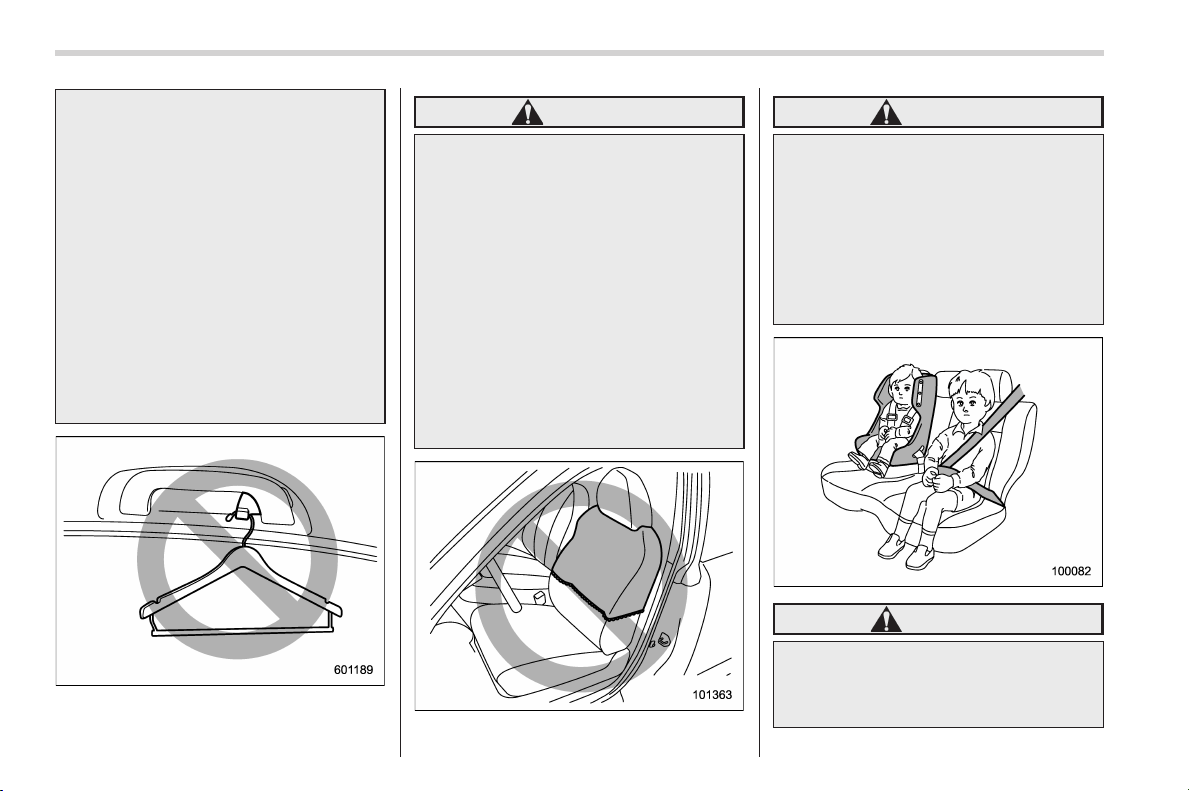
Black plate (76,1)
北米Model "A1160BE-C" EDITED: 2014/ 3/ 17
1-40
Seat, seatbelt and SRS airbags/*SRS airbag (Supplemental Restraint System airbag)
occupants and cause injuries.
. Do not attach a hands-free micro-
phone or any other accessory to
a front pillar, a center pillar, a rear
pillar, the windshield, a side win-
dow, an assist grip, or any other
cabin surface that would be near
a deploying SRS curtain airbag.
A hands-free microphone o r
other accessory in such a loca-
tion could be propelled through
the cabin with great force by the
curtain airbag, or it could prevent
correct deployment of the curtain
airbag. In either case, the result
could be serious injuries.
WARNING
Do not hang coat hangers or other
hard or pointed objects on the coat
hooks. If such items were hanging
on the coat hooks during deploy-
ment of the SRS curtain airbags,
they could cause serious injuries by
coming off the coat hooks and being
thrown through the cabin or by
preventing deployment of the cur-
tain airbags.
Before hanging clothing on the coat
hooks, make sure there are no sharp
objects in the pockets. Hang cloth-
ing directly on the coat hooks with-
out using hangers.
WARNING
Do not put any kind of cover or
clothes or other objects over either
front seatback and do not attach
labels or stickers to the front seat
surface on or near the SRS side
airbag. They could prevent proper
deployment of the SRS side airbag,
reducing protection available to the
front seat’s occupant.
WARNING
Put children aged 12 and under in
the rear seat properly restrained at
all times. The SRS airbag deploys
with considerable speed and force
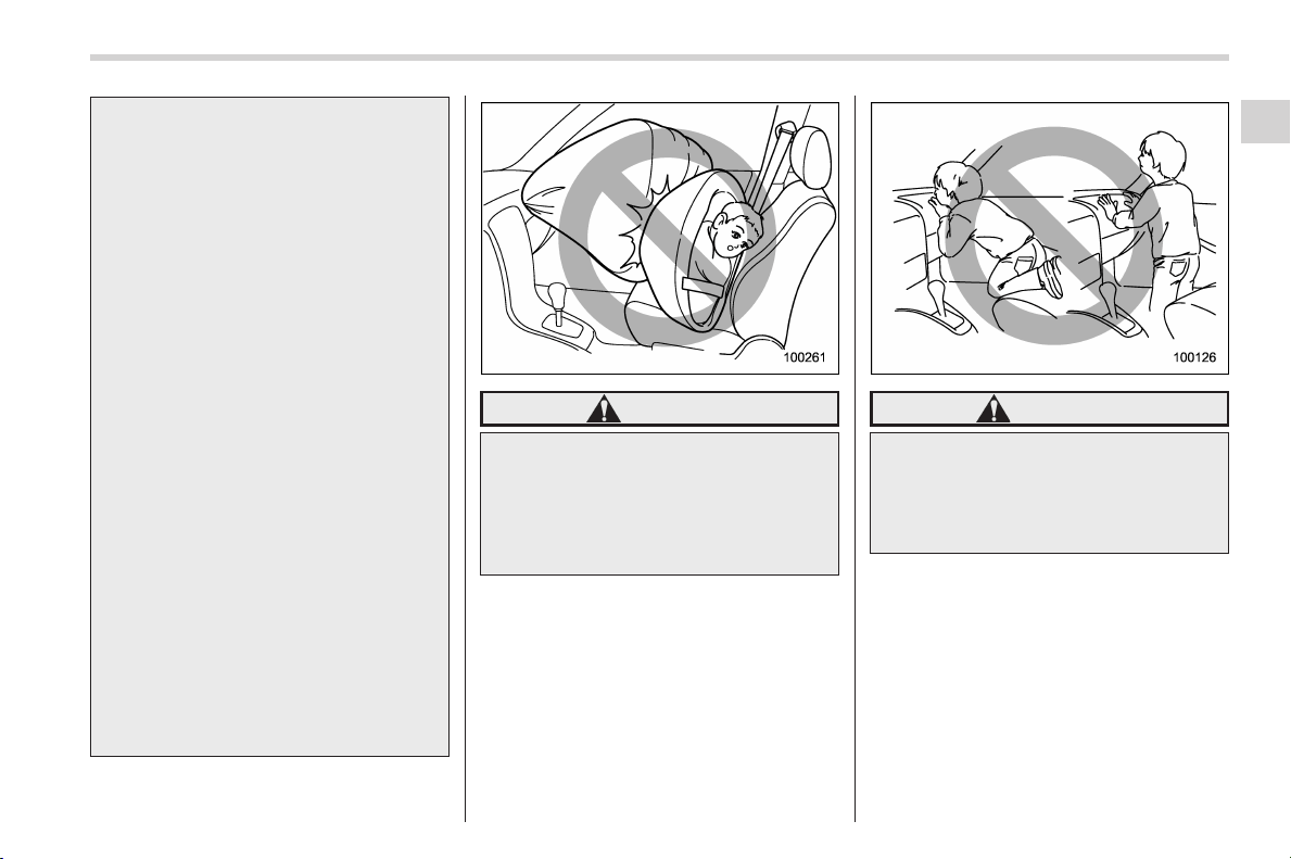
Black plate (77,1)
北米Model "A1160BE-C" EDITED: 2014/ 3/ 17
and can injure or even kill children,
especially if they are 12 years of age
and under and are not restrained or
improperly restrained. Because chil-
dren are lighter and weaker than
adults, their risk of being injured
from deployment is greater.
For that reason, we strongly recom-
mend that ALL children (including
those in child seats and those that
have outgrown child restraint de-
vices) sit in the REAR seat properly
restrained at all times in a child
restraint device or in a seatbelt,
whichever is appropriate for the
child’s age, height and weight.
Secure ALL types of child restraint
devices (including forward facing
child seats) in the REAR seats at
all times.
According to accident statistics,
children are safer when properly
restrained in the rear seating posi-
tions than in the front seating posi-
tions.
For instructions and precautions
concerning the child restraint sys-
tem, refer to “Child restraint sys-
tems” F1-24.
WARNING
NEVER INSTALL A REARWARD FA-
CING CHILD SEAT IN THE FRONT
SEAT. DOING SO RISKS SERIOUS
INJURY OR DEATH TO THE CHILD
BY PLACING THE CHILD’S HEAD
TOO CLOSE TO THE SRS AIRBAG.
WARNING
Never allow a child to stand up or
kneel on the front passenger’s seat.
The SRS airbag deploys with con-
siderable force and can injure or
even kill the child.
Seat, seatbelt and SRS airbags/*SRS airbag (Supplemental Restraint System airbag)
1-41
– CONTINUED –
1
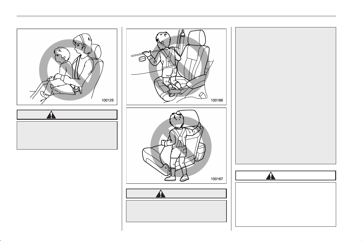
Black plate (78,1)
北米Model "A1160BE-C" EDITED: 2014/ 3/ 17
1-42
Seat, seatbelt and SRS airbags/*SRS airbag (Supplemental Restraint System airbag)
WARNING
Never hold a child on your lap or in
your arms. The SRS airbag deploys
with considerable force and can
injure or even kill the child.
WARNING
. Never allow a child to do the
following.
– Kneel on any passenger ’s
seat facing the side window
– Wrap his/her arms around the
front seat seatback
– Put his/he r head, arms or
other parts of the body out of
the window
In the event of an accident, the
force of SRS side airbag and/or
SRS curtain airbag deployment
could injure the child seriously
because his/her head, arms or
other parts of the body are too
close to the SRS side airbag and/
or SRS curtain airbag.
. Since your vehicle is also
equipped with a front passen-
ger’s SRS frontal airbag, children
aged 12 and under should be
placed in the rear seat anyway
and should be properly re-
strained at all times.
CAUTION
. When the SRS airbag deploys,
some smoke will be released.
This smoke could cause breath-
ing problems for people with a
history of asthma or other
breathing trouble. If you or your
passengers have breathing pro-

Black plate (79,1)
北米Model "A1160BE-C" EDITED: 2014/ 3/ 17
blems after SRS airbag deploys,
get fresh air promptly.
. A deploying SRS airbag releases
hot gas. Occupants could get
burned if they come into direct
contact with the hot gas.
NOTE
. When you sell your vehicle, we urge
you to explain to the buyer that it is
equipped with SRS airbags by alerting
the buyer to the applicable section in
this Owner’s Manual.
. If the SRS airbag deploys, fuel
supply will be cut off to reduce the risk
of fire caused by leaking fuel. For
details about restarting of the hybrid
system, refer to “If your vehicle is
involved in an accident” F9-24.
Seat, seatbelt and SRS airbags/*SRS airbag (Supplemental Restraint System airbag)
1-43
– CONTINUED –
1
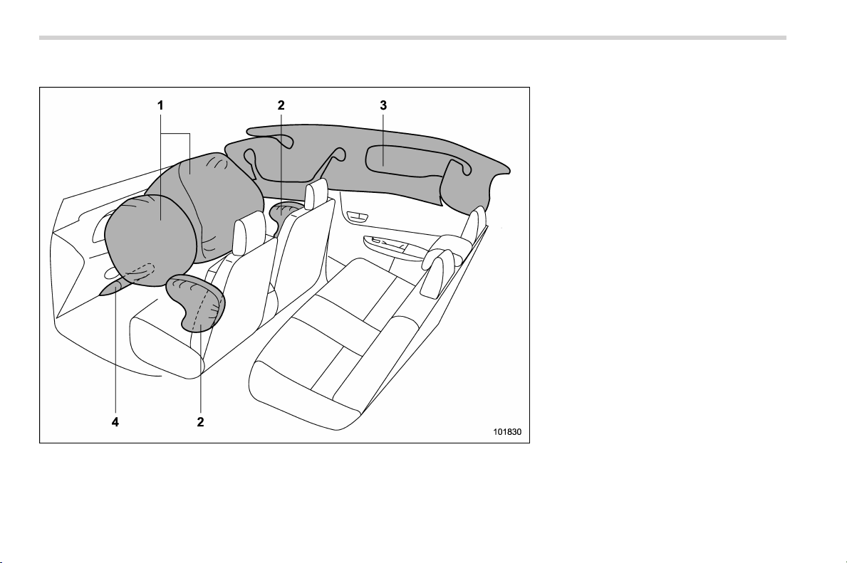
Black plate (80,1)
北米Model "A1160BE-C" EDITED: 2014/ 3/ 17
1-44
Seat, seatbelt and SRS airbags/*SRS airbag (Supplemental Restraint System airbag)
& Components
1) SRS frontal airbag
2) SRS side airbag
3) SRS curtain airbag
4) SRS knee airbag
The SRS airbags are stowed in the
following locations.
Driver’s SRS frontal airbag: in the center
portion of the steering wheel
Front passenger’s SRS frontal airbag:
near the top of the dashboard under an
“SRS AIRBAG” mark
SRS side airbag: in the door side of each
front seat seatback which bears an “SRS
AIRBAG” label
SRS cur tain airbag: in the roof side
(between the f ront pillar and a point
behind the rear quarter glass)
An “SRS AIRBAG” mark is located at the
top of each center pillar.
SRS knee airbag: under the st eering
column
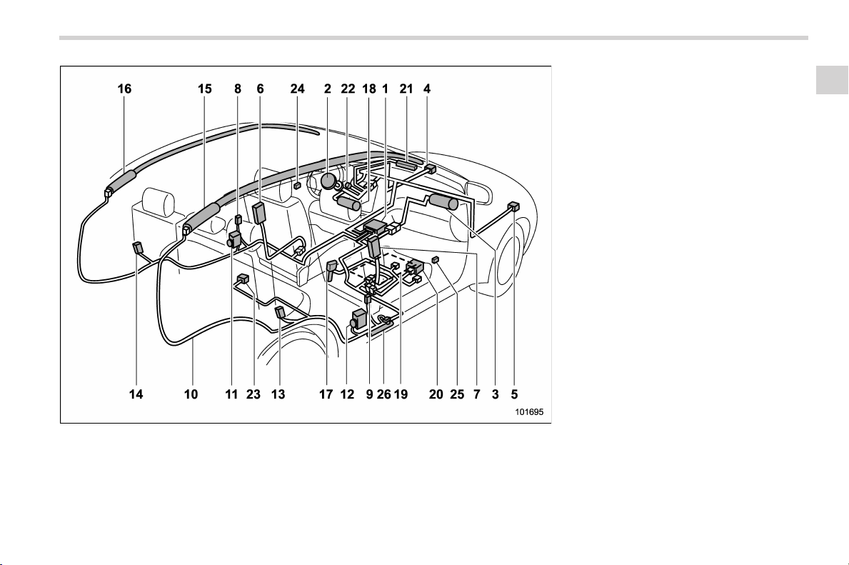
Black plate (81,1)
北米Model "A1160BE-C" EDITED: 2014/ 3/ 17
1) Airbag control module (including impact
sensor and rollover sensor)
2) Frontal airbag module (driver’s side)
3) Frontal airbag module (front passenger’s
side)
4) Front sub sensor (left-hand side)
5) Front sub sensor (right-hand side)
6) Side airbag module (driver’s side)
7) Side airbag module (front passenger’s
side)
8) Side airbag sensor (center pillar left-hand
side)
9) Side airbag sensor (center pillar right-
hand side)
10) Airbag wiring
11) Seatbelt pretensioner (driver’s side)
12) Seatbelt pretensioner (front passenger’s
side)
13) Curtain airbag sensor (rear wheel house
right-hand side)
14) Curtain airbag sensor (rear wheel house
left-hand side)
15) Curtain airbag module (right-hand side)
16) Curtain airbag module (left-hand side)
17) Seatbelt buckle switch (front passenger’s
side)
18) Knee airbag module (driver’s side)
19) Front passe nger’s occupant detection
system sensor
20) Front passe nger’s occupant detection
control module
21) Front passenger’s frontal airbag ON and
OFF indicator
22) SRS airbag system warning light
23) Satellite safing sensor (under the rear
center seat)
24) Front door impact sensor (left-hand side)
25) Front door impact sensor (right-hand
side)
26) Lap belt pretensioner (front passenger’s
side)
Seat, seatbelt and SRS airbags/*SRS airbag (Supplemental Restraint System airbag)
1-45
– CONTINUED –
1
Black plate (82,1)
北米Model "A1160BE-C" EDITED: 2014/ 3/ 17
1-46
Seat, seatbelt and SRS airbags/*SRS airbag (Supplemental Restraint System airbag)
& SUBARU advanced frontal
airbag system
Your vehicle is equipped with a SUBARU
advanced frontal airbag system that com-
plies with the new advanced frontal airbag
requirements i n the amended Federal
Motor Vehicle Safety Standard (FMVSS)
No. 208.
The SUBARU advanced frontal airbag
system automatically determines the de-
ployment force of the driver’s SRS frontal
airbag at the time of deployment as well as
whether or not to activate the front
passenger’s SRS frontal airbag and, if
activated, the deployment force of the
SRS frontal airbag at the time of deploy-
ment.
Your vehicle has warning labels on the
driver’s and front passenger’s sun visors
beginning with the phrase “EVEN WITH
ADVANCED AIR BAGS” and a tag
attached to the glove box lid beginning
with the phrase “Even with Advanced Air
Bags”. Make sure that you carefully read
the instructions on the warning labels and
tag.
Always wear your seatbelt. The SUBARU
advanced frontal airbag system is a
supplemental restraint system and must
be used in combination with a seatbelt. All
occupants should wear a seatbelt or be
seated in an appropriate child restraint
system.
For the locations of the SRS airbags, refer
to “Components” F1-44.
In a moderate to severe frontal collision,
the following components deploy.
. SRS frontal airbag for driver
. SRS frontal airbag for front passenger
. SRS knee airbag for driver
. SRS curtain airbag*
1
*1: When an offset frontal collision that is severe
enough to deploy the front airbag occurs.
These components supplement the seat-
belts by reducing the impact to the
occupant’s head, chest and knees.
! Driver’s SRS frontal airbag
The driver’s SRS frontal airbag uses a
dual stage inflator. The inflator operates in
different ways depending on the severity
of impact.
Have the system ins pected by your
SUBARU dealer immediately if the SRS
airbag system warning light illuminates.
NOTE
The driver’s SRS side airbag and SRS
curtain airbag are not controlled by the
SUBARU advanced frontal airbag sys-
tem.
! Front passenger’s SRS frontal air-
bag
The front passenger’s SRS frontal airbag
uses a dual stage inflator. The inflator
operates in different ways depending on
the severity of impact.
The occupant detection system sensor is
installed under the seat upholstery and
monitors the physique and posture of the
front passenger. Using this information,
the occupant detection system determines
whether the front passenger’s SRS frontal
airbag should be deployed or not.
The occupant detection system may not
inflate the front passenger’s SRS frontal
airbag even when the driver’s SRS frontal
airbag deploys. This is normal. In this
case, although the front passenger’s SRS
frontal airbag does not operate, the front
passenger’s seatbelt pretensioner oper-
ates with the driver’s seatbelt preten-
sioner. For detai ls ab out the sea tb elt
pretensioner, refer to “Front seatbelt pre-
tensioners” F1-20.
CAUTION
Observe the following precautions.
Failure to do so may prevent the
SUBARU advanced fro ntal airbag
system from functioning correctly
or cause the system to fail.

Black plate (83,1)
北米Model "A1160BE-C" EDITED: 2014/ 3/ 17
. Do not apply any strong impact
to the front passenger’s seat.
. Do not spill liquid on the front
passenger ’s seat. If liquid is
spilled, wipe it off immediately.
. Do not remove or disassemble
the front passenger’s seat.
. Do not install any accessory
(such as an audio amplifier) other
than a genuine SUBARU acces-
sory under the front passenger’s
seat.
. Do not place anyth ing (shoes,
umbrella, etc.) under the front
passenger’s seat.
. Do not put sharp object(s) on the
seat or pierce the seat uphols-
tery.
. Do not place a magnet near the
seatbelt buckle.
If the seatbelt buckle switch and/or front
passenger’s occupant detection system
have failed, the SRS airbag system
warning light will illuminate. Have the
system inspected by your SUBARU deal-
er immediately if the SRS airbag system
warning light illuminates.
If your vehicle has sustained impact, this
may affect the proper function of the
SUBARU advanced frontal airbag system.
Have your vehicle i nspected at your
SUBARU dealer. Do not use the front
passenger’s seat while driving the vehicle
to your SUBARU dealer.
NOTE
The front passenger’s SRS side airbag
and SRS curtain airbag are not con-
trolled by the SUBARU advanced fron-
tal airbag system.
! Passenger’s frontal airbag ON and
OFF indicators
Refer to “Front passenger’s frontal airbag
ON and OFF indicators” F3-15.
! Occupant detection system
The occupant detection system sensor is
installed under the seat upholstery and
monitors the physique and posture of the
front passenger. Using this information,
the occupant detection system determines
whether the front passenger’s SRS frontal
airbag should be deployed or not.
If the front passenger’s seat cushion is
wet, this may adversely affect the ability of
the system to determine deployment. If
the seat cushion is wet, the front passen-
ger should stop sitting on the front
passenger’s seat. Wipe off liquid from
the seat immediately, let the seat dry
naturally and then check the SRS airbag
system warning light as follows.
. If the SRS airbag system warning light
illuminates, keep the seat dry until the
warning light turns off. If the SRS airbag
system warning light stays on even when
the seat has dried, do not allow anyone to
sit on the front passenger’s seat and have
the system checked by your SUBARU
dealer.
. If the SRS airbag system warning light
does not illuminate, check that the front
passenger’s frontal airbag ON and OFF
indicators work properly. If the indicators
do not work properly, do not allow anyone
to sit on the front passenger’s seat and
have the system checked by your
SUBARU dealer.
Also, if luggage or electronic devices are
placed on the front passenger’s seat, this
may adversely affect the ability of the
system to determine deployment. This
may prevent the front passenger’s frontal
airbag ON and OFF indicators from work-
ing properly. Check that the indicators
work properly.
When the OFF indicator turns off and the
ON indicator illuminates, the front passen-
ger’s frontal airbag may deploy during a
collision. Remove luggage and electronic
devices from the front passenger’s seat.
Seat, seatbelt and SRS airbags/*SRS airbag (Supplemental Restraint System airbag)
1-47
– CONTINUED –
1
Black plate (84,1)
北米Model "A1160BE-C" EDITED: 2014/ 3/ 17
1-48
Seat, seatbelt and SRS airbags/*SRS airbag (Supplemental Restraint System airbag)
NOTE
This device complies with Part 18 of
the FCC Rules. This device may cause
interference. If this device causes inter-
ference, consult the nearest SUBARU
dealer. Also, for maintenance of the
system, consult the nearest SUBARU
dealer. A copy of the original declara-
tion of conformity can be found in
chapter 13.
! Conditions in which front passen-
ger’s SRS frontal airbag is not
activated
The front passenger’s SRS frontal airbag
will not be activated when any of the
following conditions are met regarding the
front passenger’s seat:
. The seat is empty.
. The seat is equipped with an appro-
priate child restraint system and an infant
is restrained in it. (See WARNING that
follows.)
. The front passenger’s occupant detec-
tion system is malfunctioning.
WARNING
NEVER INSTALL A REARWARD FA-
CING CHILD SEAT IN THE FRONT
PASSENGER’S SEAT EVEN IF THE
FRONT PASSENGER’S SRS FRON-
TAL AIRBAG IS DEACTIVATED. Be
sure to install it in the REAR seat in
a correct manner. Also, it is strongly
recommended that any forward fa-
cing child seat or booster seat be
installed in the REAR seat, and that
even children who have outgrown a
child restraint system be also
seated in the REAR seat. This is
because children sitting in the front
passenger’s seat may be killed or
severely inj ured should the front
passenger’s SRS frontal airbag de-
ploy. REAR seats are the safest
place for children.
CAUTION
When the front passenger’s seat is
occupied by an infant in an appro-
priate child restraint system, ob-
serve the following precautions.
Failure to do so may interfere with
the proper operation of the occu-
pant detection system, activating
the front passenger’s SRS frontal
airbag even though that seat is
occupied by the infant in the child
restraint system.
. Do not place any article (includ-
ing electronic devices) on the
seat other than the infant in the
child restraint system.
. Do not place more than one
infant in the child restraint sys-
tem.
! If the front passenger’s frontal
airbag ON indicator illuminates
and the OFF indicator turns off
even when an infant or a small
child is in a child restraint sys-
tem (including booster seat)
1. Turn the ignition switch to the “LOCK”
(off) position.
2. Remove the child restraint system
from the seat.
3. By referring to the child restraint
manufacturer’s recommendations as well
as the child restraint system installation
procedures in “Child restraint systems”
F1-24, correctly install the child restraint
system.
4. Turn the ignition switch to the “ON”
position and make sure that the front
passenger’s frontal airbag ON indicator
turns off and the OFF indicator illuminates.
If still the ON indicator remains illuminated
while the OFF indicator turns off, take the
following actions.
. Ensure that no article is placed on the
seat other than the child restraint system

Black plate (85,1)
北米Model "A1160BE-C" EDITED: 2014/ 3/ 17
and the child occupant.
. Ensure that the backward-forward po-
sition and seatback of front passenger’s
seat are locked into place securely by
moving the seat back and forth.
If the ON indicator still remains illuminated
while the OFF indicator turns off after
taking relevant corrective actions de-
scribed above, relocate the child restraint
system to the rear seat and immediately
contact you r SUBAR U dealer for an
inspection.
NOTE
When a child who has outgrown a child
restraint system or a small adult is
seated in the front passenger’s seat,
the SUBARU advanced frontal airbag
system may or may not activate the
front passenger’s SRS frontal airbag
depending on the occupant’s seating
posture. Children should always wear a
seatbelt when sitting in the seat irre-
spective of whether the airbag is
deactivated or activated. If the front
passenger’s SRS frontal airbag is acti-
vated (the ON indicator remains illumi-
nated while the OFF indicator turns off),
take the following actions.
. Ensure that no article is placed on
the seat other than the occupant.
If the ON indicator still remains illumi-
nated while the OFF indicator turns off
despite the fact that the actions noted
above have been taken, seat the child/
small adult in the rear seat and im-
mediately contact your SUBARU dealer
for an inspection. Even if the system
has passed the dealer inspection, it is
recommended that on subsequent trips
the child/small adult always take the
rear seat.
Children who have outgrown a child
restraint system should always wear the
seatbelt irrespective of whether the airbag
is deactivated or activated.
! Conditions in which front passen-
ger’s SRS frontal airbag is activated
The front passenger’s SRS frontal airbag
will be activated for deployment upon
impact when any of the following condi-
tions are met regarding the front passen-
ger ’s seat.
. When the seat is occupied by an adult.
. When certain items (e.g. jug of water)
are placed on the seat.
! If the passenger’s frontal airbag
OFF indicator illuminates and
the ON indicator turns off even
when the front passenger’s seat
is occupied by an adult
This can be caused by the adult incor-
rectly sitting in the front passenger’s seat.
1. Turn the ignition switch to the “LOCK”
(off) position.
2. Ask the front passenger to set the
seatback to the upright position, sit up
straight in the center of the seat cushion,
correctly fasten the seatbelt, position his/
her legs out forward, and adjust the seat to
the rearmost position.
3. Turn the ignition switch to the “ON”
position.
If the OFF indicator remains illuminated
while the ON indicator remains off, take
the following actions.
1. Turn the ignition switch to the “LOCK”
(off) position.
2. Make sure that the front passenger
does not use a blanket, seat cushion, seat
cover, seat heater or massager, etc.
3. If wearing excessive layers of clothing,
the front passenger should remove any
unnecessary items before sitting in the
front passenger’s seat, or should sit in a
rear seat.
4. Turn the ignition switch to the “ON”
Seat, seatbelt and SRS airbags/*SRS airbag (Supplemental Restraint System airbag)
1-49
– CONTINUED –
1

Black plate (86,1)
北米Model "A1160BE-C" EDITED: 2014/ 3/ 17
1-50
Seat, seatbelt and SRS airbags/*SRS airbag (Supplemental Restraint System airbag)
position and wait 6 seconds to allow the
system to complete self-checking. Follow-
ing the system check, both indicators turn
off for 2 seconds. Now, the ON indicator
should illuminate while the OFF indicator
remains off.
If the OFF indicator still remains illumi-
nated while the ON indicator remains off,
ask the occupant to move to the rear seat
and immediately contact your SUBARU
dealer for an inspection.
! How to contact the vehicle manu-
facturer concerning modifications
for persons with disabilities that
may affect the advanced airbag
system
Changing or moving any parts of the front
seats, rear seat, seatbelts, front bumper,
front side frame, radiator panel, instrument
panel, combination meter, steering wheel,
steering column, tire, suspension or floor
panel can affect the operation of the
SUBARU advanced airbag system. If
you have any questions, you may contact
the following SUBARU distributors.
<Continental U.S., Alaska and the District
of Columbia>
Subaru of America, Inc.
Customer Dealer Services Department
P.O. Box 6000
Cherry Hill, NJ 08034-6000
1-800-SUBARU3 (1-800-782-2783)
<Hawaii>
Subaru Hawaii
2850 Pukoloa Street, Suite 202,
Honolulu, HI 96819-4467
808-839-2273
<Guam>
Shen’s Corporation dba Prestige Automo-
bile
491, East Marine Corps Drive, Route 1
Dededo, Guam 96921-6255
671-633-2698
<Puerto Rico>
Trebol Motors
P.O. Box 11204, San Juan, Puerto Rico
00910
787-793-2828
<Canada>
Subaru Canada, Inc.
Consumer Support Department
560 Suffolk Court, Mississauga, Ontario
L5R 4J7
1-800-894-4212
There are currently no SUBARU distribu-
tors in any other U.S. territories. If you are
in such an area, please contact the
SUBARU distributor or dealer from which
you bought your vehicle.
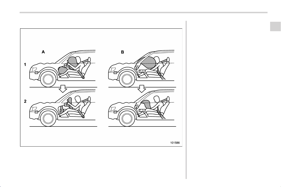
Black plate (87,1)
北米Model "A1160BE-C" EDITED: 2014/ 3/ 17
! Operation
A) Driver’s side
B) Passenger’s side
1) SRS AIRBAGs deploy as soon as a collision occurs.
2) After deployment, SRS AIRBAGs start to deflate immediately so that the driver’s vision is not
obstructed.
The SRS airbags can function only when
the ignition switch is in the “ON” position.
The SUBARU advanced frontal airbag
system is designed to determine the
activation or deactivation condition of the
front passenger’s SRS frontal airbag
depending on the characteristic of item
(s) or person on the front passenger’s seat
monitored by the front passenger’s occu-
pant detection system sensor. For this
reason, only the driver ’s SRS frontal
airbag may deploy in the event of a
collision, but this does not mean failure
of the system.
If the front sub sensors and the impact
sensors in the airbag control module
detect a predetermined amount of force
during a frontal collision, the control
module sends signals to the airbag
module(s) (only driver’s module or both
driver’s and front passenger’s modules)
instructing the module(s) to inflate the
SRS frontal airbag(s). On driver’s side, the
SRS knee airbag also inflates with the
SRS frontal airbag.
Seat, seatbelt and SRS airbags/*SRS airbag (Supplemental Restraint System airbag)
1-51
– CONTINUED –
1
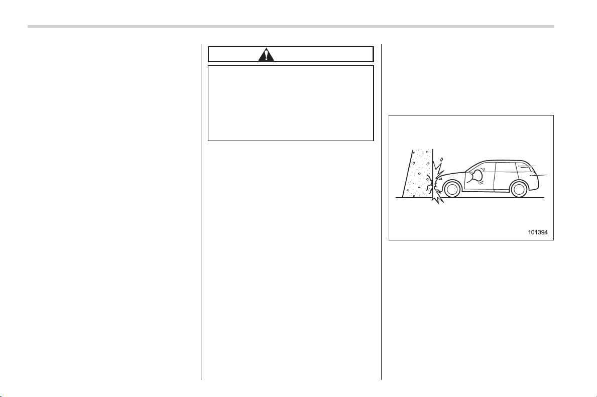
Black plate (88,1)
北米Model "A1160BE-C" EDITED: 2014/ 3/ 17
1-52
Seat, seatbelt and SRS airbags/*SRS airbag (Supplemental Restraint System airbag)
The driver’s and front passenger’s SRS
frontal airbags use dual stage inflators.
The two inflators of each airbag are
triggered either sequentially or simulta-
neously, depending on the severity of
impact, in the case of the driver’s SRS
frontal airbag and depending o n the
severity of impact and the characteristic
of item(s) or person on the seat in the case
of the front passenger ’s S RS frontal
airbag.
After deployment, the SRS airbag imme-
diately starts to deflate so that the driver’s
vision is not obstructed and the driver’s
ability to maintain control of the vehicle is
not impaired. The time required from
detecting impact to the deflation of the
SRS airbag after deployment is shorter
than the blink of an eye.
Both when only the driver’s SRS frontal
airbag deploys and the driver’s and front
passenger’s SRS frontal airbags deploy,
the driver’s and front passenger’s seatbelt
pretensioners operate at the same time.
When the SRS airbag deploys, a sudden,
fairly loud inflation noise will be heard and
some smoke will be released. These
occurrences are a normal result of the
deployment. This smoke does not indicate
a fire in the vehicle.
CAUTION
Do not touch the SRS airbag system
components around the steerin g
wheel and dashboard w ith bare
hands right after deployment. Doing
so can cause burns because the
components can be very hot as a
result of deployment.
The driver’s SRS frontal airbag and front
passenger’s SRS frontal airbag are de-
signed to deploy in the event of an
accident involving a moderate to severe
frontal collision. They are not designed to
deploy in most lesser frontal im pacts
because the necessary protection can be
achieved by the seatbelt alone. Also, they
are not designed to deploy in most side or
rear impacts or in most roll-over accidents
because deployment of only the driver’s
SRS frontal airbag or both driver’s and
front passenger ’s SRS frontal airbags
would not help the occupant in those
situations. The driver’s and front passen-
ger ’s SRS frontal airbags are designed to
function on a one-time-only basis.
SRS airbag deployment depends on the
level of force experienced in the passen-
ger compartment during a collision. That
level differs from one type of collision to
another, and it may have no bearing on
the visible damage done to the vehicle
itself.
! Example of accident in which the
driver’s/driver’s and front pas-
senger’s SRS frontal airbag(s)
will most likely deploy
A head-on collision against a thick con-
crete wall at a vehicle speed of 12 to 19
mph (20 to 30 km/h) or higher activates
only the driver’s SRS frontal airbag or both
driver’s and front passenger’s SRS frontal
airbags. The airbag(s) will also be acti-
vated when the vehicle is exposed to a
frontal impact similar in fashion and
magnitude to the collision described
above.
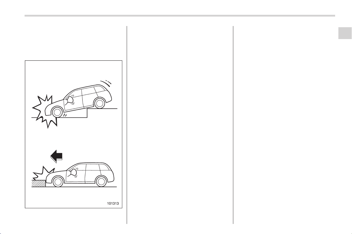
Black plate (89,1)
北米Model "A1160BE-C" EDITED: 2014/ 3/ 17
! Examples of the types of acci-
dents in which it is possible that
the driver’s/driver’s and front
passenger’s SRS frontal
airbag(s) will deploy
Only the driver’s SRS frontal airbag or
both driver’s and front passenger’s SRS
frontal airbags may be activated when the
vehicle sustains a hard im pact in the
undercarriage area from the road surface
(such as when the vehicle plunges into a
deep ditch, is severel y impacted or
knocked hard against an obstacle on the
road such as a curb).
Seat, seatbelt and SRS airbags/*SRS airbag (Supplemental Restraint System airbag)
1-53
– CONTINUED –
1
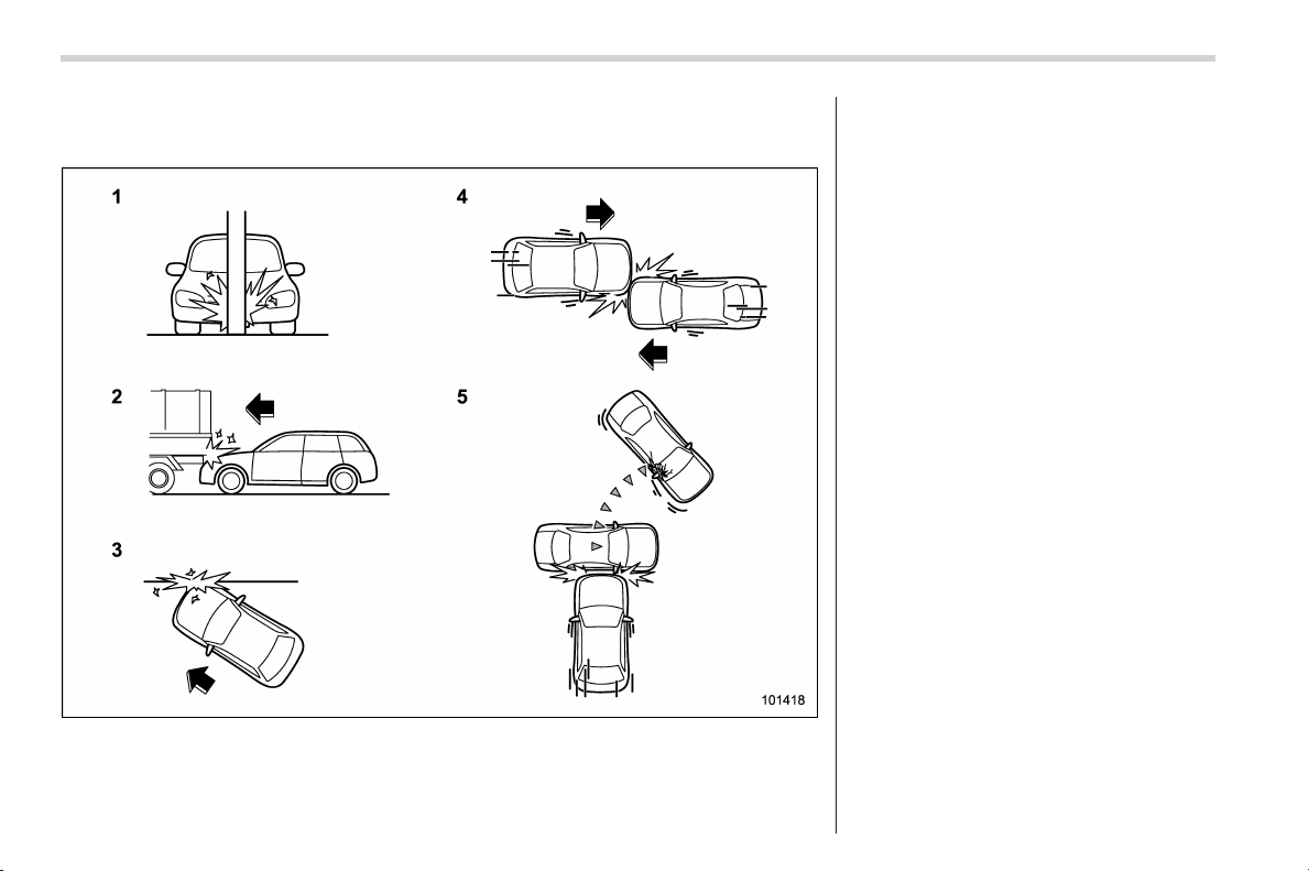
Black plate (90,1)
北米Model "A1160BE-C" EDITED: 2014/ 3/ 17
1-54
Seat, seatbelt and SRS airbags/*SRS airbag (Supplemental Restraint System airbag)
! Examples of the types of accidents in which deployment of the driver’s/
driver’s and front passenger’s SRS frontal airbag(s) is unlikely to occur
1) The vehicle strikes an object, such as a
telephone pole or sign pole.
2) The vehicle slides under the load bed of
a truck.
3) The vehicle sustains an oblique offset
frontal impact.
4) The vehicle sustains an offset frontal
collision.
5) The vehicle strikes an object that can
move or deform, such as a parked
vehicle.
There are many types of collisions which
might not necessarily require deployment
of driver’s/driver’s and front passenger’s
SRS frontal airbag(s). In the event of
accidents like those illustrated, the dri-
ver’s/driver’s and front passenger’s SRS
frontal airbag(s) may not deploy depend-
ing on the level of accident forces in-
volved.
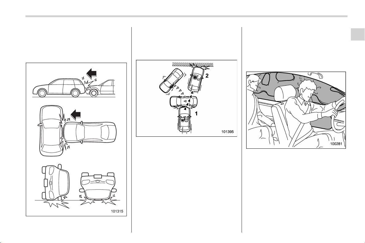
Black plate (91,1)
北米Model "A1160BE-C" EDITED: 2014/ 3/ 17
! Examples of the types of acci-
dents in which the driver’s/dri-
ver ’s and front passenger’s SRS
frontal airbag(s) are not de-
signed to deploy in most cases
The driver’s and front passenger’s SRS
frontal airbags are designed not to deploy
in most cases if the vehicle is struck from
the side or from behind, or if it rolls onto its
side or roof, or if it is involved in a low-
speed frontal collision.
1) First impact
2) Second impact
In an accident where the vehicle is
impacted more than once, the driver’s
and/or front passenger’s SRS frontal
airbag(s) will deploy only once on the first
impact.
Example: In the case of a double collision,
first with another vehicle, then against a
concrete wall in immediate succession,
once either or both of the driver’s and front
passenger’s SRS frontal airbags is/are
activated on the first impact, it/they will not
be activated on the second impact.
& SRS side airbag and SRS
curtain airbag
The SRS side airbag is stored in the door
side of each front seat seatback, which
bears an “SRS AIRBAG” label.
Inamoderatetoseveresideimpact
collision, the SRS side airbag on the
impacted side of the vehicle deploys
between the occupant and the door panel
and supplements the seatbelt by reducing
the impact on the occupant’s chest and
waist. The SRS side airbag operates only
for front seat occupants.
The SRS curtain airbag on each side of
the cabin i s stored in the roof side
(between the front pillar and a point over
the rear seat). An “SRS AIRBAG” mark is
Seat, seatbelt and SRS airbags/*SRS airbag (Supplemental Restraint System airbag)
1-55
– CONTINUED –
1

Black plate (92,1)
北米Model "A1160BE-C" EDITED: 2014/ 3/ 17
1-56
Seat, seatbelt and SRS airbags/*SRS airbag (Supplemental Restraint System airbag)
located at the top of each center pillar.
In a moderate to severe side impact
collision, the SRS curtain airbag on the
impacted side of the vehicle deploys
between the occupant and the side
window and supplements the seatbelt by
reducing the impact on the occupant’s
head.
In a rollover, SRS curtain airbags on both
sides of the vehicle deploy between the
occupant and the side window and sup-
plement the seatbelt by reducing the
impact to the occupant’s head.
In a frontal collision, SRS curtain airbags
on both sides of th e vehicl e deplo y
between the occupant and the side
window and supplement the seatbelt by
reducing the impact to the occupant’s
head.
! Operation
The SRS side airbag and SRS curtain
airbag can function only when the ignition
switch is in the “ON” position.
The driver’s and front passenger’s SRS
side airbags and SRS curtain airbags
deploy independently of each other since
each has its own impact sensor. There-
fore, they may not both deploy in the same
accident. Also, the SRS side airbag and
SRS curtain airbag deploys independently
of the driver’s and front passenger’s SRS
frontal airbags in the steering wheel and
instrument panel.
An impact sensor, which senses impact
force, is located in each of the following
locations.
. In the left and right front doors
. In the left and right center pillars
. In the left and right rear wheel houses
. Under the rear center seat
A rollover sensor is also located inside the
airbag control module.
If the impact sensor that is located under
the rear center seat and one of the center
pillar impact sensors or front door impact
sensors together sense an impact force
above a predetermined level in a side
collision, the control module causes both
the SRS side airbag and curtain airbag on
the impacted side to inflate regardless of
whether the rear wheel house imp act
sensor on the sa me si de s enses an
impact.
If the impact sensor that is located under
the rear center seat and one of the rear
wheel house impact sensors together
sense an impact force above a predeter-
mined level in a side collision, the control
module causes only the SRS curtain
airbag on the impacted side to inflate.
If the rollover sensor detects rollover of the
vehicle, the control module inflates the
SRS curtain airbags on both sides. At this
time, the driver’s and front passenger’s
seatbelt pretensioners also operate at the
same time.
After the deployment, the SRS side airbag
immediately starts to deflate. The time
required from detection of an impact to
deflation of an SRS side airbag after
deployment is shorter than the blink of
an eye.
The SRS curtain airbag remains inflated
for a while following deployment then
slowly deflates.
The SRS side airbag and SRS curtain
airbag deploy even when no one occupies
the seat on the side on which an impact is
applied.
When the SR S side airbag and SRS
curtain airbag deploy, a sudden, fairly loud
inflation noise will be heard and some
smoke will be released. These occur-
rences are a normal result of the deploy-
ment. This smoke does not indicate a fire
in the vehicle.
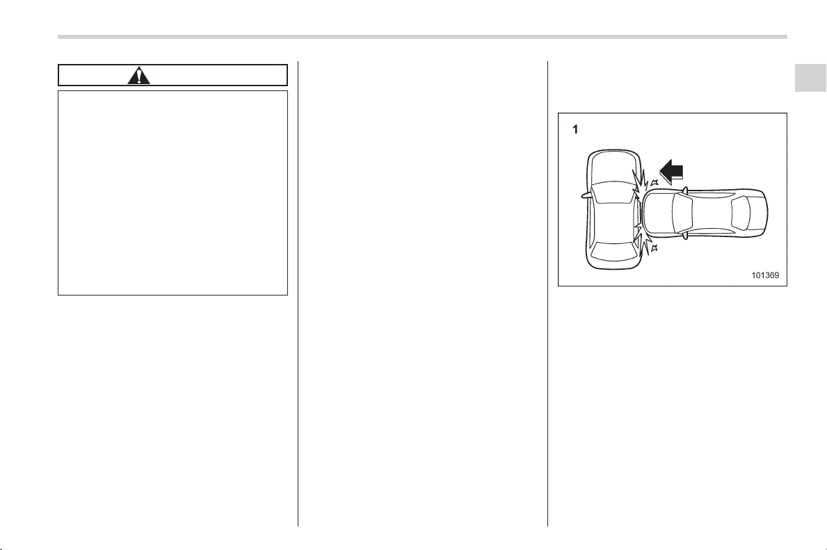
Black plate (93,1)
北米Model "A1160BE-C" EDITED: 2014/ 3/ 17
CAUTION
Do not touch the SRS side airbag
system components around the
front seat seatback with bare hands
right after deployment. Doing so can
cause burns because the compo-
nents can be very hot as a result of
deployment.
After deployment, do not touch any
part of the SRS curtain airbag
system (from the front pillar to the
part of the roof side over the rear
seat). Doing so can cause burns
beca use the components can be
very hot as a result of deployment.
The SRS side airbag and SRS curtain
airbag are designed to deploy in the event
of an accident involving a moderate to
severe side impact collision. They are not
designed to deploy in most lesser side
impact. Also, they are not designed to
deploy in most frontal or most rear impacts
because SRS si de air bag and SRS
curtain airbag deployment would not help
the occupant in those situations.
The SRS curtain airbags are also de-
signed to deploy when the vehicle is in an
extremely inclined state such as during a
rollover. They are not designed to deploy
in most lesser inclined state.
Each SRS side airbag and SRS curtain
airbag are designed to function on a one-
time-only basis.
SRS side airbag and SRS curtain airbag
deployment depend on the level of force
experienced in the passenger compart-
ment during a side impact collision. That
level differs from one type of collision to
another, and it may have no bearing on
the visible damage done to the vehicle
itself.
! Example of the type of accident
in which the SRS side airbag will
most likely deploy.
1) A severe side impact near the front seat.
Seat, seatbelt and SRS airbags/*SRS airbag (Supplemental Restraint System airbag)
1-57
– CONTINUED –
1
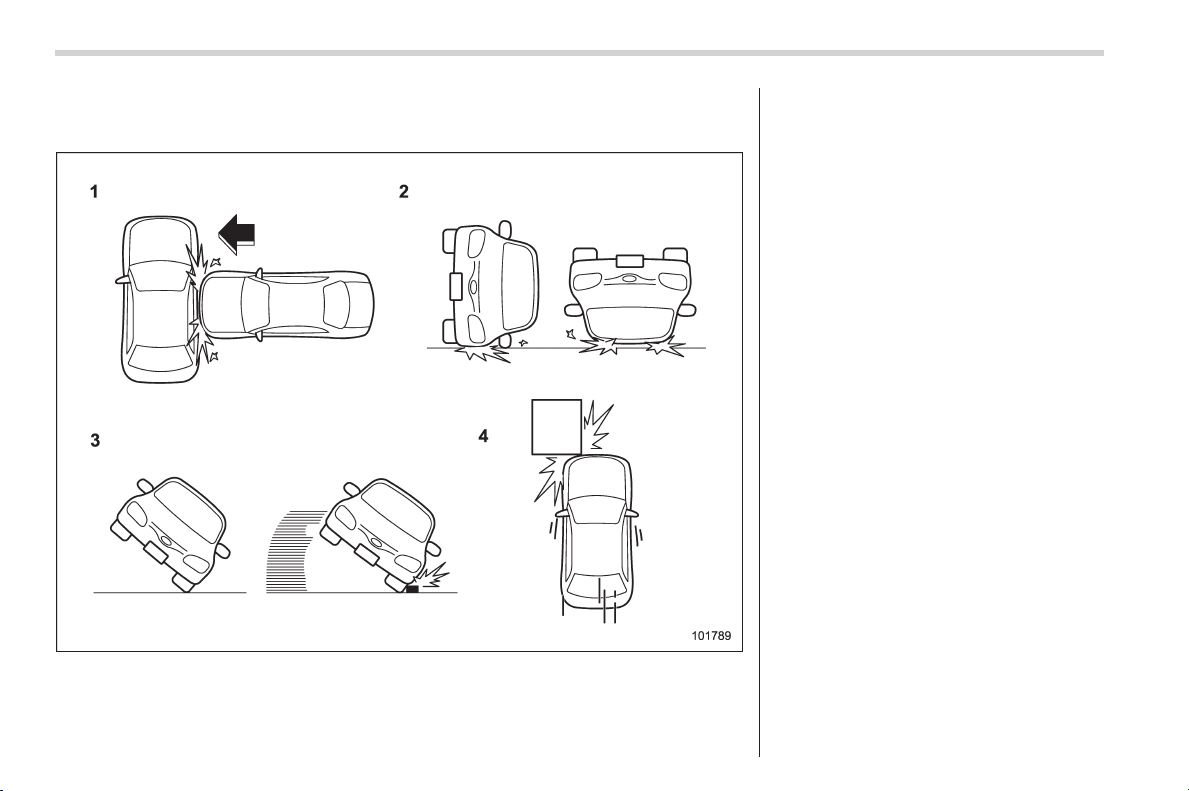
Black plate (94,1)
北米Model "A1160BE-C" EDITED: 2014/ 3/ 17
1-58
Seat, seatbelt and SRS airbags/*SRS airbag (Supplemental Restraint System airbag)
! Examples of the types of accidents in which the SRS curtain airbag will most
likely deploy.
1) The vehicle is involved in a severe side
impact near the front seat or the rear
seat.
2) The vehicle rolls onto its side or the roof.
3) The angle of vehicle tip-up is marginal or
the skidding vehicle’s tires hit a curb-
stone laterally.
4) An offset frontal collision that is severe
enough to deploy the front airbag.
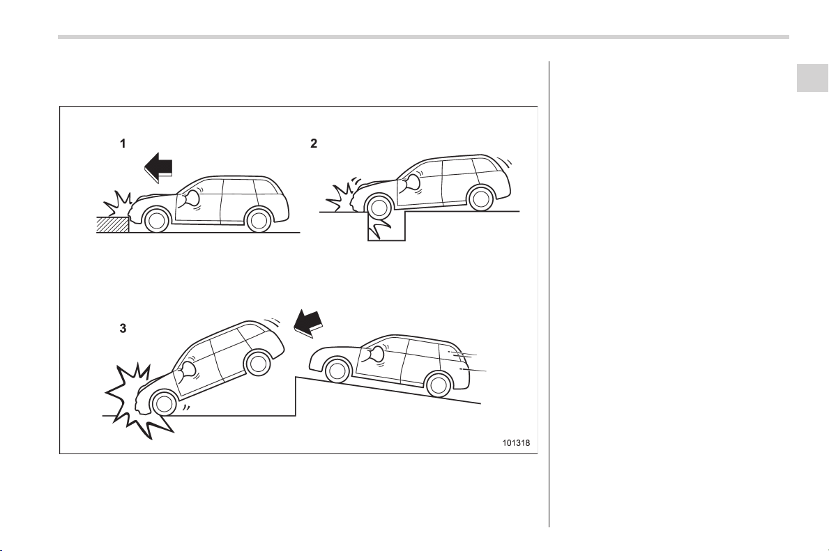
Black plate (95,1)
北米Model "A1160BE-C" EDITED: 2014/ 3/ 17
! Examples of the types of accidents in which it is possible that the SRS side
airbag and the SRS curtain airbag will deploy.
1) Hitting a curb, edge of pavement or hard
surface
2) Falling into or jumping over a deep hole
3) Landing hard or vehicle falling
It is possible that the SRS side and curtain
airbags will deploy if a serious impact
occurs to the underside of your vehicle.
Some examples are shown in the illustra-
tion.
Seat, seatbelt and SRS airbags/*SRS airbag (Supplemental Restraint System airbag)
1-59
– CONTINUED –
1
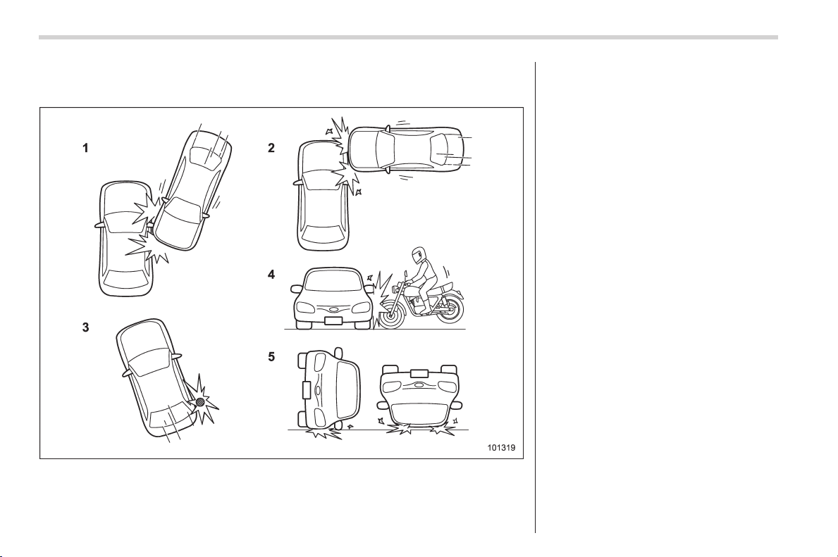
Black plate (96,1)
北米Model "A1160BE-C" EDITED: 2014/ 3/ 17
1-60
Seat, seatbelt and SRS airbags/*SRS airbag (Supplemental Restraint System airbag)
! Examples of the types of accidents in which the SRS side airbag is unlikely
to deploy.
1) The vehicle is involved in an oblique
side-on impact.
2) The vehicle is involved in a side-on
impact in an area outside the vicinity of
the passenger compartment.
3) The vehicle strikes a telephone pole or
similar object.
4) The vehicle is involved in a side-on
impact from a motorcycle.
5) The vehicle rolls onto its side or the roof.
There are many types of collisions which
might not necessarily require SRS side
airbag deployment. In the event of acci-
dents like those illustrated, the SRS side
airbag may not deploy depending on the
level of accident forces involved.
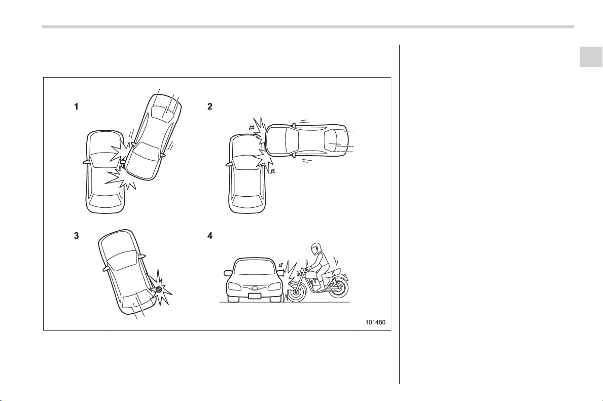
Black plate (97,1)
北米Model "A1160BE-C" EDITED: 2014/ 3/ 17
! Examples of the types of accidents in which the SRS curtain airbag is
unlikely to deploy.
1) The vehicle is involved in an oblique
side-on impact.
2) The vehicle is involved in a side-on
impact in an area outside the vicinity of
the passenger compartment.
3) The vehicle strikes a telephone pole or
similar object.
4) The vehicle is involved in a side-on
impact from a motorcycle.
There are many types of collisions which
might not necessarily require SRS curtain
airbag deployment. In the event of acci-
dents like those illustrated, the SRS
curtain airbag may not deploy depending
on the level of accident forces involved.
Seat, seatbelt and SRS airbags/*SRS airbag (Supplemental Restraint System airbag)
1-61
– CONTINUED –
1
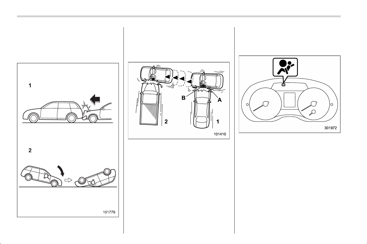
Black plate (98,1)
北米Model "A1160BE-C" EDITED: 2014/ 3/ 17
1-62
Seat, seatbelt and SRS airbags/*SRS airbag (Supplemental Restraint System airbag)
! Examples of the types of acci-
dents in which the SRS side
airbag and SRS curtain airbag
are not designed to deploy in
most cases
1) The vehicle is struck from behind.
2) The vehicle pitches end over end.
In the event of accidents like those
illustrated, the SRS side airbag and SRS
curtain airbag are not designed to deploy
in most cases.
1) First impact
2) Second impact
A) SRS curtain airbag
B) SRS side airbag
In an accident where the vehicle is struck
from the side more than once, the SRS
side airbag and SRS curtain airbag deploy
only once on the first impact.
Example: In the case of a double side
impact collision, first with one vehicle and
immediately followed by another from the
same direction, once the SRS side airbag
and SRS curtain airbag are activated on
the first impact, they will not be activated
on the second.
& SRS airbag system monitors
SRS airbag system warning light
A diagnostic system continually monitors
the readiness of the SRS airbag system
(including front s eatbelt pretensi oners)
while the vehicle is being driven. The
SRS airbag system warning light will show
normal system operation by illuminating
for approximately 6 seconds when the
ignition switch is turned to the “ON”
position.
The following components are monitored
by the indicator:
. Front sub sensor
– Right-hand side
Black plate (99,1)
北米Model "A1160BE-C" EDITED: 2014/ 3/ 17
– Left-hand side
. Airbag control module (including im-
pact sensor and rollover sensor)
. Frontal airbag module
– Driver’s side
– Front passenger’s side
. Knee airbag module (driver’s side)
. Side airbag sensor
– Center pillar right-hand side
– Center pillar left-hand side
. Front door impact sensor
– Right-hand side
– Left-hand side
. Side airbag module
– Driver’s side
– Front passenger’s side
. Curtain airbag sensor
– Rear wheel house right-hand side
– Rear wheel house left-hand side
. Curtain airbag module
– Right-hand side
– Left-hand side
. Satellite safing sensor (under the rear
center seat)
. Seatbelt pretensioner
– Driver’s side
– Front passenger’s side
. Lap belt pretensioner (front passen-
ger’s side)
. Seatbelt buckle switch (front passen-
ger ’s side)
. Front passenger’s occupant detection
system sensor
. Front passenger’s occupant detection
control module
. Front passenger’s frontal airbag ON
and OFF indicator
. All related wiring
WARNING
If the warning light exhibits any of
the following conditions, there may
be a malfunction in the seatbe lt
pretensioners and/or SRS airbag
system. Immediately take your vehi-
cle to your nearest SUBARU dealer
to have the system checked. Unless
checked and properly repaired, the
seatbelt pretensioners and/or SRS
airbag will not operate properly in
the event of a collision, which may
increase the risk of injury.
. Flashing or flickering of the warn-
ing light
. No illumination of the warning
light when the ignition switch is
first turned to the “ON” position
. Continuous illumination of the
warning light
. Illumination of the warning light
while driving
& SRS airbag system servicing
WARNING
. When discarding an airbag mod-
ule or scrapping the entire vehi-
cle damaged by a collision, con-
sult your SUBARU dealer.
. The SRS airbag has no u ser-
serviceable parts. Do not use
electrical test equipment on any
circuit related to the SRS airbag
system. For required servicing of
the SRS airbag, consult y our
nearest SUBARU dealer. Tamper-
ing with or disconnecting the
system’s wiring could result in
accidental inflation of the SRS
airbag or could make the system
inoperative, which may result in
serious injury.
CAUTION
If you need service or repair in areas
indicated in the following list, have
the work performed by an author-
Seat, seatbelt and SRS airbags/*SRS airbag (Supplemental Restraint System airbag)
1-63
– CONTINUED –
1
Black plate (100,1)
北米Model "A1160BE-C" EDITED: 2014/ 3/ 17
1-64
Seat, seatbelt and SRS airbags/*SRS airbag (Supplemental Restraint System airbag)
ized SUBARU dealer. The SRS air-
bag control module, impact sensors
and airbag modules are stored in
these areas.
. Under the center console
. On both the right and left sides at
the front of the vehicle
. Steering wheel and column and
nearby areas
. Bottom of the steering column
and nearby areas
. Top of the dashboard on front
passenger’ssideandnearby
areas
. Each front seat and nearby area
. Inside each center pillar
. Inside each front door
. In each roof side (from the front
pillar to a point over the rear seat)
. Between the rear seat cushion
and rear wheel house on each
side
. Under the rear center seat
In the event that the SRS airbag is
deployed, replacement of the system
should be performed only by an author-
ized SUBARU dealer. When the compo-
nents of the SRS airbag system are
replaced, use only genuine SUBARU
parts.
NOTE
In the following cases, contact your
SUBARU dealer as soon as possible.
. The front part of the vehicle was
involved in an accident in which only
the driver’s SRS frontal airbag or both
driver ’s and front passenger’sSRS
frontal airbags did not deploy.
. The pad of the steering wheel, the
cover over the front passenger’s SRS
frontal airbag, or either roof side (from
the front pillar to a point over the rear
seat) is scratched, cracked, or other-
wise damaged.
. The center pillar, front door, rear
wheel house or rear sub frame, or an
area near these parts, was involved in
an accident in which the SRS side
airbag and SRS curtain airbag did not
deploy.
. The fabric or leather of either front
seatback is cut, frayed, or otherwise
damaged.
. The rear part of the vehicle was
involved in an accident in which no
SRS airbag was deployed.
& Precautions against vehicle
modification
WARNING
To avoid accidental activation of the
system or rendering the s ystem
inoperative, which may r esult in
serious injury, no modifications
should be made to any components
or wiring of the SRS airbag system.
This i ncludes following modifica-
tions.
. Installation of custom steering
wheels
. Attachment of additional trim
materials to the dashboard
. Installation of custom seats
. Replacement of seat fabric or
leather
. Installation of additional fabric or
leather on the front seat
. Attachment of a hands-free mi-
crophone or any other accessory
to a front pillar, a center pillar, a
rear pillar, the windshield, a side
window, an assist grip, or any
other cabin surface that would be
near a deploying SRS curtain
airbag.
Black plate (101,1)
北米Model "A1160BE-C" EDITED: 2014/ 3/ 17
. Installation of additional electri-
cal/electronic equipment such as
a mobile two-way radio on or
near the SRS airbag s ystem
components and/or wiring is not
advisable. This could interfere
with prop er operati on of the
SRS airbag system.
CAUTION
Do not perform any of the following
modifications. Such modifications
can interfere with proper operation
of the SRS airbag system.
. Attachment of any equi pment
(bush bar, winches, snow plow,
skid plate, etc.) other than genu-
ine SUBARU accessory parts to
the front end.
. Modification of the suspension
system or front end structure.
. Installation of a tire of different
size and construction from the
tires specified on the vehicle
placard attached to the driver’s
door pillar or specified for indivi-
dual vehicle models in this Own-
er’s Manual.
. Attachment of any equi pment
(side steps or side sill protectors,
etc.) other than genuine SUBARU
accessory parts to the side body.
Always consult your SUBARU dealer if
you want to install any accessory parts on
your vehicle.
Seat, seatbelt and SRS airbags/*SRS airbag (Supplemental Restraint System airbag)
1-65
1

Black plate (2,1)
Model "ALL_MODEL_MEMO" EDITED: 2007/ 6/ 22
Left Page
————————————————————————————————————————
————————————————————————————————————————
————————————————————————————————————————
————————————————————————————————————————
————————————————————————————————————————
————————————————————————————————————————
————————————————————————————————————————
————————————————————————————————————————
————————————————————————————————————————
————————————————————————————————————————
————————————————————————————————————————
————————————————————————————————————————
————————————————————————————————————————

Black plate (3,1)
北米Model "A1160BE-C" EDITED: 2014/ 3/ 17
Keys ..................................................................... 2-3
Key types............................................................ 2-3
Key number plate................................................ 2-3
Immobilizer .......................................................... 2-3
Security indicator light ........................................ 2-4
Key replacement ................................................. 2-4
Certification for immobilizer system..................... 2-4
Door locks ........................................................... 2-5
Locking and unlocking from the outside .............. 2-5
Locking and unlocking from the inside ................ 2-7
Battery drainage prevention function ................... 2-7
Power door locking switches............................. 2-8
Key lock-in prevention function ........................... 2-8
Keyless access with push-button start
system (if equipped) ........................................ 2-9
Safety precautions ............................................. 2-10
Locking and unlocking with “keyless access”
entry function................................................... 2-13
Selecting audible signal operation ...................... 2-16
Warning chimes and warning light ...................... 2-16
Disabling keyless access function ...................... 2-17
When access key does not operate properly ....... 2-17
Replacing battery of access key ......................... 2-17
Replacing access key......................................... 2-18
Certification for keyless access with push-button
start system..................................................... 2-18
Remote keyless entry system ........................... 2-18
Safety precautions ............................................. 2-18
Transmitter ........................................................ 2-19
Locking the doors.............................................. 2-20
Unlocking the doors .......................................... 2-20
Unlocking the rear gate...................................... 2-20
Vehicle finder function ....................................... 2-20
Sounding a panic alarm ..................................... 2-21
Selecting audible signal operation (models
without “keyless access with push-button start
system”).......................................................... 2-21
Replacing the battery......................................... 2-21
Replacing lost transmitters ................................ 2-21
Certification for remote keyless entry system ..... 2-21
Alarm system..................................................... 2-22
General information ........................................... 2-22
System operation............................................... 2-22
Activating and deactivating the alarm system ..... 2-23
If you have accidentally triggered the alarm
system ............................................................ 2-23
Arming the system ............................................ 2-23
Disarming the system ........................................ 2-26
Valet mode ........................................................ 2-27
Passive arming.................................................. 2-27
Tripped sensor identification .............................. 2-28
Shock sensors (dealer option)............................ 2-28
Child safety locks .............................................. 2-29
Windows............................................................. 2-29
Power window operation by driver ..................... 2-30
Power window operation by passengers............. 2-32
Initialization of power window ............................ 2-32
Rear gate............................................................ 2-33
Lock/unlock....................................................... 2-33
Open/close ........................................................ 2-33
Keys and doors
2

Black plate (4,1)
北米Model "A1160BE-C" EDITED: 2014/ 3/ 17
Keys and doors
Moonroof (if equipped) ...................................... 2-34
Moonroof switches............................................. 2-35
Sun shade ......................................................... 2-36
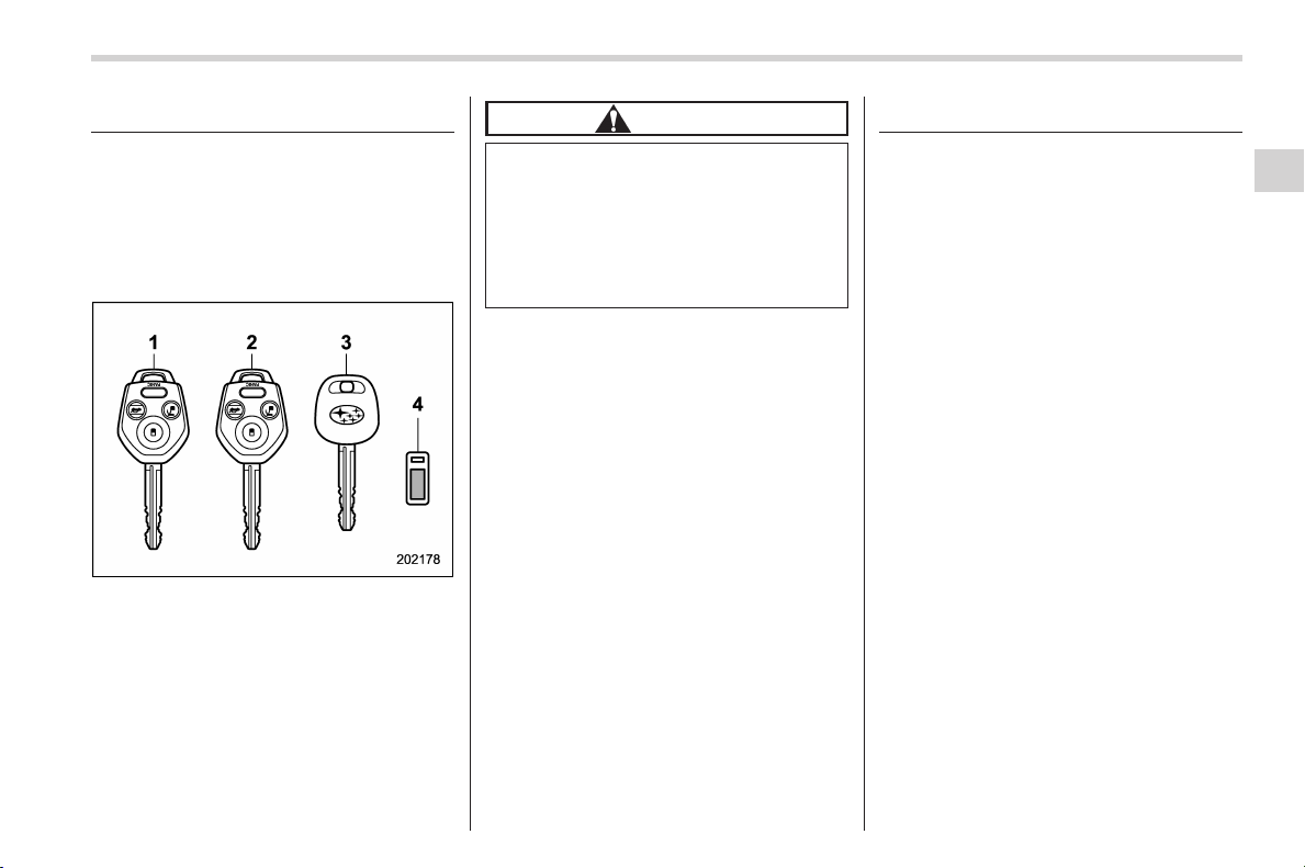
Black plate (105,1)
北米Model "A1160BE-C" EDITED: 2014/ 3/ 17
Keys
& Key types
NOTE
For models with “keyless access with
push-button start system”, refer to
“Keyless access with push-button start
system” F2-9.
1) Master key
2) Submaster key
3) Sub key
4) Key number plate
Three types of keys are provided for your
vehicle.
CAUTION
Do not attach a large key holder or
key case to either key. If it bangs
against your knees while you are
driving, it could turn the ignition
switch from the “ON” position to the
“ACC” or “LOCK” (off) position,
thereby stopping the hybrid system.
& Key number plate
The key number is stamped on the key
number plate attached to the key set.
Write down the key number and keep it in
another safe place, not in the vehicle. This
number is needed to make a replacement
key if you lose your key or lock it inside the
vehicle. Refer to “Key replacement” F2-4.
Immobilizer
The immobilizer system is designed to
prevent an una uthorized pe rson from
starting the hybri d system. Only keys
registered with your vehicle’s immobilizer
system can be used to operate your
vehicle.
For models with “keyless access with
push-button start system”:
If you press the push-button ignition
switch when carrying an unregistered
access key, the switch will not turn to the
“ON” position and the hybrid system will
not start.
For models without “keyless access
with push-button start system”:
Even if an unregistered key fits into the
ignition switch and can be turned to the
“START” position, the hybrid system will
automatically stop after several seconds.
Each immobilizer key contains a trans-
ponder in which the key’s ID code is
stored. The transponder transmits the
key’s ID code to the immobilizer system’s
receiver under any of the following condi-
tions.
. When an access key is detected within
the operating range of the antennas inside
the vehicle (models with “keyless access
Keys and doors/Keys
2-3
– CONTINUED –
2
Black plate (106,1)
北米Model "A1160BE-C" EDITED: 2014/ 3/ 17
2-4
Keys and doors/Immobilizer
with push-button start system”)
. When a key is inserted into the ignition
switch and turned to the “ON” position
(models without “keyless access with
push-button start system”)
If the transmitted ID code matches the ID
code registered in the immobilizer system,
the system allows the hybrid system to be
started. Since the ID code is transmitted
and acted up on almost instantly, the
immobilizer system does not impede
normal starting of the hybrid system.
If the hybrid system does not start, per-
form either of the following procedures.
. Perform the procedure described in
“Starting hybrid system” F9-24 (models
with “ keyless access with push-button
start system”).
. Pull out the key once before trying
again (models without “keyless access
with push-button start system”). Refer to
“Ignition switch” F3-3.
CAUTION
. Do not place the key under direct
sunlight or anywhere it may
become hot.
. Do not get the key wet. If the key
gets wet, wipe it dry with a cloth
immediately.
NOTE
To protect your vehi cle from th eft,
please pay close attention to the fol-
lowing security precautions:
. Never leave your vehicle unattended
with its keys inside.
. Before leaving your vehicle, close all
windows and the moonroof, and lock
the doors and rear gate.
. Do not leave spare keys or any
record of your key number in the
vehicle.
. The vehicle has a maintenance-free
type immobilizer system.
& Security indicator light
Refer to “Security indicator light” F3-29.
& Key replacement
Your key number plate will be required if
you ever need a replacement key made.
Any new key must be registered for use
with your vehicle’s immobilizer system
before it can be used. The maximum
number of keys that can be registered
for use with one vehicle is as follows.
. Four (models without “keyless access
with push-button start system”)
. Seven (models with “keyless access
with push-button start system”)
One key that has already been registered
is required in order to register a new key.
If you lose a key, the lost key’s ID code still
remains in the memory of the vehicle’s
immobilizer system. For security reasons,
the lost key’s ID code should be erased
from the memory. To erase the lost key’s
ID code, all keys that will be used are
required.
For details about new key registration and
erasing the lost key’s ID code, contact
your SUBARU dealer.
& Certification for immobilizer
system
! Models with “keyless access with
push-button start system”
Refer to “Certification for keyless access
with push-button start system” F2-18.
Black plate (107,1)
北米Model "A1160BE-C" EDITED: 2014/ 3/ 17
! Models without “keyless access
with push-button start system”
! U.S.-spec. models
FCC ID: MOZRI-38BFH
CAUTION
FCC WARNING
Changes or modifications not ex-
pressly approved by the party re-
sponsible for compliance could void
the user’s authority to operate the
equipment.
This device complies with part 15 of the
FCC Rules. Operation is subject to the
following two conditions: (1) This de-
vice may not cause harmful interfer-
ence, and (2) this device must accept
any interference received, including
interference that may cause undesired
operation.
! Canada-spec. models
NOTE
Operation is subject to the following
two conditions: (1) this device may not
cause interference, and (2) this device
must accept any interference, includ-
ing interference that may cause unde-
sired operation of the device.
NOTE
L’utilisation de ce dispositif est auto-
risée seulement aux deux conditions
suivantes: (1) il ne doit pas produire de
brouillage, et (2) l’utilisateur du dispo-
sitif doit être prêt à accepter tout
brouillage radioélectrique reçu, même
si ce brouillage est susceptible de
compromettre le fonctionnemen t du
dispositif.
Door locks
& Locking and unlocking from
the outside
NOTE
If you unlock the driver’s door with a
key and open the door while the alarm
system is armed, the alarm system is
triggered and the vehicle’shorn
sounds. In this case, perform any of
the following operations.
. Press any button on the remote
transmitter.
. Insert the key into the ignition
switch and turn the ignition switch to
the “ON” position.
For details about the alarm system,
refer to “Alarm system” F2-22.
Keys and doors/Door locks
2-5
– CONTINUED –
2
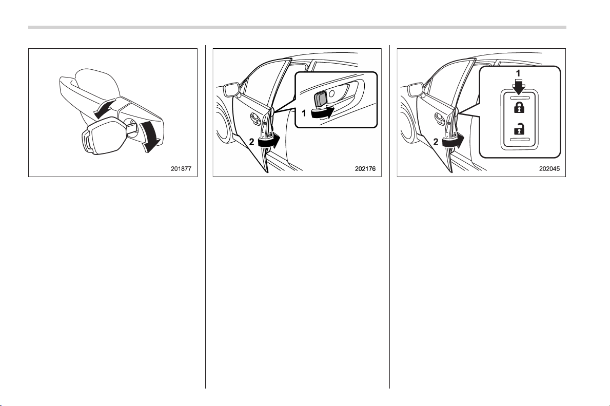
Black plate (108,1)
北米Model "A1160BE-C" EDITED: 2014/ 3/ 17
2-6
Keys and doors/Door locks
To lock the driver’s door from the outside
with the key, turn the key toward the front.
To unlock the door, turn the key toward the
rear. Pull the outside door handle to open
an unlocked door.
To lock the door from outside without the
key, the following methods are available.
Locking using lock lever
1) Rotate the lock lever forward.
2) Close the door.
Locking using power door locking switch
1) Press the front side (lock side) of the
power door locking switch.
2) Close the door.
In this case, all closed doors and the rear
gate are locked at the same time.
Always make sure that all doors and the
rear gate are locked before leaving your
vehicle.
NOTE
Make sure that you do not leave the key
inside the vehicle when locking the
doors from the outside without the key.
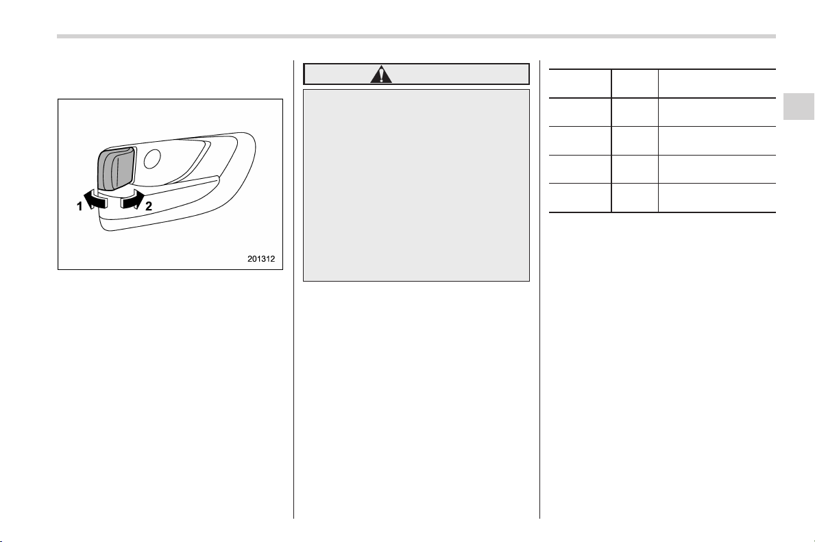
Black plate (109,1)
北米Model "A1160BE-C" EDITED: 2014/ 3/ 17
& Locking and unlocking from
the inside
1) Unlock
2) Lock
To lock the door from the inside, rotate the
lock lever forward. To unlock the door from
the inside, rotate the lock lever rearward.
The red mark on the lock lever appears
when the door is unlocked.
Pull the inside door handle to open an
unlocked door.
Always make sure that all doors and the
rear gate are closed before starting to
drive.
WARNING
Keep all doors locked when you
drive, especially when small chil-
dren are in your vehicle.
Along with the proper use of seat-
belts and child restraints, locking
the doors reduces the chance of
being thrown out of the vehicle in an
accident.
It also helps prevent passengers
from falling out if a door is acciden-
tally opened, and intruders from
unexpectedl y open ing d oors an d
entering your vehicle.
& Battery drainage prevention
function
If a door or the rear gate is not completely
closed, the interior lights w ill remain
illuminated as a result. However, several
lights are automatically turned off by the
battery drainage prevention function to
prevent the 12 V auxiliary battery from
discharging. The following interior lights
are affected by this function.
Item
Switch
position
Automatically turning
off
Map
lights
*1
OFF
*1
Approximately 20
minutes later
Dome light DOOR
Approximately 20
minutes later
Ignition
switch light
—
Approximately 20
minutes later
Cargo area
light
DOOR
Approximately 20
minutes later
*1: The battery drainage prevention function
affects only the map lights on models with the
moonroof, and only when the map light
switches are in the OFF position. The map
lights on models without the moonroof do not
turn off automatically, so push the light switches
manually to turn them off.
The operational/non-operational setting of
this function can be changed by a
SUBARU dealer. Contact your SUBARU
dealer to change the setting.
NOTE
. The factory setting (default setting)
for this function is set as “operational”.
. When lea ving the vehicle, please
make sure that all doors and the rear
gate are completely closed.
. For models with the push-button
ignition switch, the battery drainage
Keys and doors/Door locks
2-7
– CONTINUED –
2
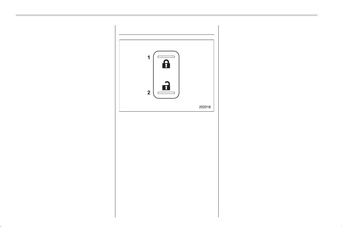
Black plate (110,1)
北米Model "A1160BE-C" EDITED: 2014/ 3/ 17
2-8
Keys and doors/Power door locking switches
prevention function does not operate
while the ignition switch is in “ACC” or
“ON” position.
. For models without the push-button
ignition switch, the battery drainage
prevention function does not operate
while the key is in the ignition switch.
Power door locking switches
1) Lock
2) Unlock
All doors and the rear gate can be locked
and unlocked by the power door locking
switches located at the driver’s side and
the front passenger’s side doors.
To lock the doors, push the front side of
the switch.
To unlock the doors, push the rear side of
the switch.
When you close the doors after you set
the door locks, the doors remain locked.
NOTE
Make sure that you do not leave the key
inside the vehicle before locking the
doors from the outside using the power
door locking switches.
& Key lock-in prevention func-
tion
This function prevents the doors from
being locked under the following condi-
tions.
. The key is still in the ignition switch
(models without “keyless access with
push-button start system”)
. The ignition switch is in the “ON ”
position (models with “keyless access with
push-button start system”)
This function’s operational/non-opera-
tional s etting can be chan ged by a
SUBARU dealer. Contact a SUBARU
dealer for details.
NOTE
. The factory setting (default setting)
for this function is set as “operational”.
. When leaving the vehicle, make sure
you are holding the key before locking
the doors.
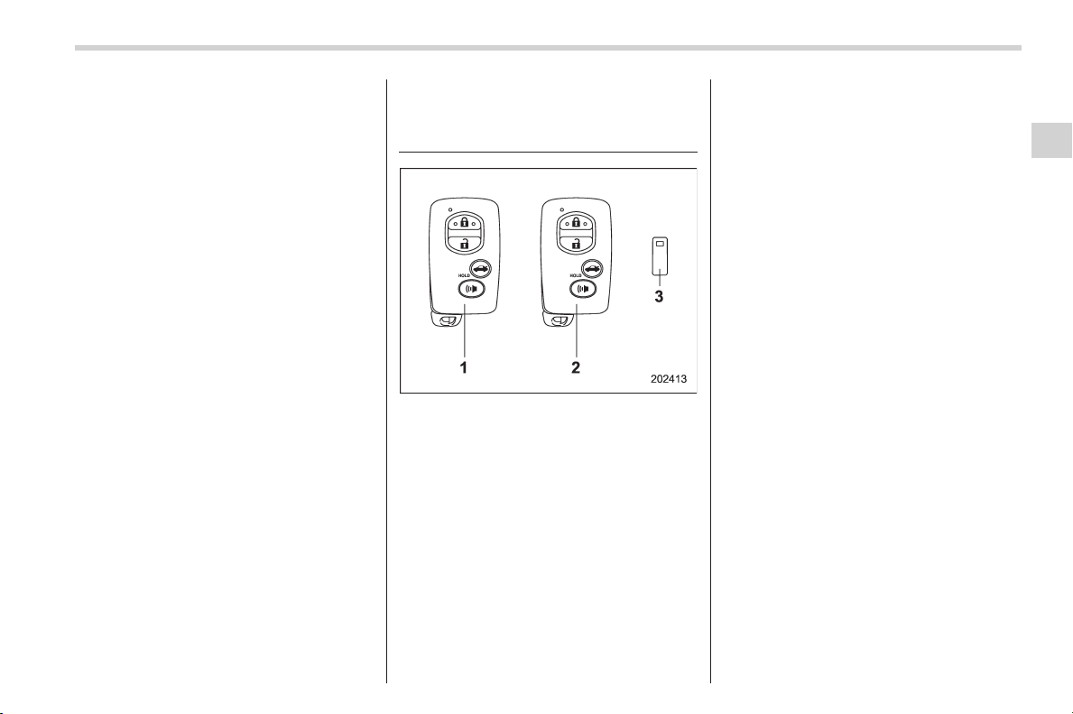
Black plate (111,1)
北米Model "A1160BE-C" EDITED: 2014/ 3/ 17
! Behavior with key lock-in preven-
tion function operational
With the driver’s door open, the doors are
automatically kept unlocked even if the
front side of the power door locking switch
is pressed.
! Behavior with key lock-in preven-
tion function non-operational
. If the lock lever is turned to the front
(“LOCK”) position with the driver’s door
open and the driver’s door is then closed
with the lock lever in that position, the
driver’s door is locked.
. If the spare key is used to lock the
driver’s door f rom th e outsi de o f the
vehicle, the door is locked.
Keyless access with push-
button start system (if
equipped)
1) Access key (main)
2) Access key (sub)
3) Key number plate
The vehicle has two access keys and a
key number plate. For details about the
key number plate, refer to “Key number
plate” F2-3.
The keyless access with push-button start
system allows you to perform the following
functions wh en you are carrying the
access key.
. Locking and unlocking of the doors and
rear gate
. Starting and stopping the hybrid sys-
tem. For detailed information, refer to
“Starting and stopping the hybrid system”
F7-8.
. Arming and disarming the alarm sys-
tem. For detailed information, refer to
“Alarm system” F2-22.
Locking and unlocking by the remote
keyless entry system can also be con-
trolled with the buttons on the access key.
For detailed information, refer to “Remote
keyless entry system” F2-18.
A mechanical key is attached to each
access key. The mechanical key is used
for the following operations.
. Locking and unlocking the driver’s door
. Locking and unlocking the glove box
You cannot unlock the glove box without
using the mechanical key. You can keep
the glove box locked when you leave your
vehicle and the access key (with the
mechanical key removed) at a parking
facility.
Keys and doors/Keyless access with push–button start system
2-9
– CONTINUED –
2
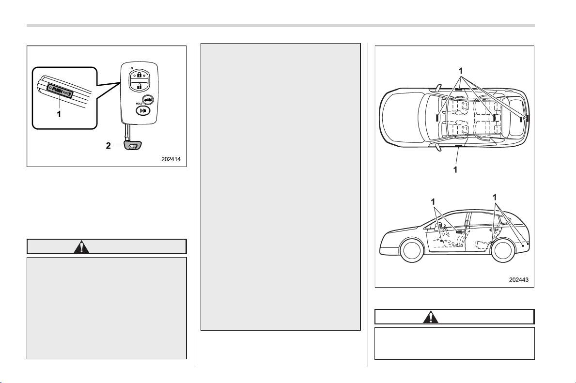
Black plate (112,1)
北米Model "A1160BE-C" EDITED: 2014/ 3/ 17
2-10
Keys and doors/Keyless access with push–button start system
1) Release button
2) Mechanical key
While pressing the release button of the
access key, take out the mechanical key.
& Safety precautions
WARNING
If you wear an implanted pacemaker
or an implanted defibrillator, stay at
least 8.7 in (22 cm) away from the
transmitting antennas installed on
the vehicle.
The radio waves from the transmit-
ting antennas on the vehicle could
adversely affect the operation of
implanted pacemakers and im-
planted defibrillators.
If you wear electric medical equip-
ment other than an implanted pace-
maker or an implanted defibrillator,
before using the key less access
with push-button start system, refer
to “Radio waves used for the key-
less access with push-button start
system” mentioned later, and con-
tact the electric medical equipment
manufacturer for more information.
The radio waves from the transmit-
ting antennas on the vehicle could
adversely affect the operation of the
electric medical equipment.
“Radio waves used for the keyless
access with push-button start sys-
tem”
. The keyless access with push-
button start system uses radio
waves of the following fre-
quency* in addition to the radio
waves used for the remote key-
less entry system. The radio
waves are periodically output
from the antennas installed on
the vehicle as shown in the
following illustration.
* Radio frequency: 134 kHz
1) Antenna
CAUTION
. Never leave or store the access
key inside the vehicle (e.g., on
the instrumental panel, inside the

Black plate (113,1)
北米Model "A1160BE-C" EDITED: 2014/ 3/ 17
glove box, on the seat, in the
door pocket or at the corner of
the cargo area) or within 6.6 ft (2
m) around the vehicle (e.g., in the
garage). The access key may be
locked inside the vehicle, or the
battery may discharge rapidly.
Note that the push-button igni-
tion switch may not turn on in
some cases depending on the
location of the access key.
. The access key contains electro-
nic components. Observe the
following precautions to prevent
malfunctions.
– Although you can replace the
battery of the access key
yourself, it is recommended
that the battery be replaced by
a SUBARU dealer to avoid the
risk of damage at the time of
replacement.
– Do not get the access key wet.
If the access key gets wet,
wipe it off immediately and let
it dry completely.
– Do not allow strong impacts to
the access key.
– Keep the access key away
from magnetic sources.
– Never leave the access key in
direct sunlight or anywhere
that may become hot, such
as on the dashboard. It may
damage the battery or cause
circuit malfunctions.
– Do not wash the access key in
an ultrasonic washer.
– Do not leave the access key in
humid or dusty locations.
Doing so may cause malfunc-
tions.
– Do not leave the access key
near personal computers or
home electric appliances.
Doing so may cause the ac-
cess key to malfunction, re-
sulting in battery discharge.
. If the access key is dropped, the
integrated mechanical key inside
may become loose. Be careful
not to lose the mechanical key.
. When you carry the access key
on an airplane, do not press the
button of the access key while in
the airplane. When any button of
the access key is pressed, radio
waves are sent and may affect
the operation of the airplane.
When you carry the access key
in a bag on an airplane, take
measures to prevent the buttons
of the access key from being
pressed.
NOTE
. The operational/non-operational
setting for the keyless access function
can be changed. For the setting proce-
dure, refer to “Disabling keyless ac-
cess function” F2-17. The setting can
also be changed by a SUBARU dealer.
For more details, contact a SUBARU
dealer.
. For detailed information about the
operation method for the push-button
ignition switch while the keyless ac-
cess function is switched to the non-
operational mode, refer to “Access key
– if access key does not operate
properly” F9-23.
. The keyless access with push-but-
ton start system uses weak radio
waves. The status of the access key
and environmental conditions may in-
terfere with the communication be -
tween the access key and the vehicle
under the following conditions, and it
may not be possible to lock or unlock
the doors or start the hybrid system.
– When operating near a facility
where strong radio waves are trans-
mitted, such as a broadcast station
Keys and doors/Keyless access with push–button start system
2-11
– CONTINUED –
2

Black plate (114,1)
北米Model "A1160BE-C" EDITED: 2014/ 3/ 17
2-12
Keys and doors/Keyless access with push–button start system
and power transmission lines
– When products that transmit
radio waves are used, such as an
access key or a remote transmitter
key of another vehicle
– When the access key is placed
near wireless communication
equipment such as a cell phone
– When the access key is placed
near a metallic object
– When metallic accessories are
attached to the access key
– When carrying the access key
with electronic appliances such as
a laptop computer
– When the battery of the access
key is discharged
. The access key is always commu-
nicating with the vehicle and is con-
tinuously using the battery. Although
the life of the battery varies depending
on the operating conditions, it is ap-
proximately 1 to 2 years. If the battery
becomes fully discharged, replace it
with a new one.
. If an access key is lost, it is
recommended that the access key be
reregistered. For reregistration of an
access key, contact a SUBARU dealer.
. For a spare access key, contact a
SUBARU dealer.
. Up to 7 access keys can be regis-
tered for one vehicle.
. Carefully store the key number plate
supplied w ith the access key. It is
necessary for vehicle repair.
. Do not leave the access key in the
storage spaces inside the vehicle, such
as the door pocket, dashboard and the
corner of the cargo area. Vibrations
may damage the key or turn on the
switch, possibly resulting in a lockout.
. After the 12 V auxiliary battery is
discharged or replaced, initialization of
the steering lock system may be re-
quired to start the hybrid system. In
this case, perform the following proce-
dure to initialize the steering lock.
(1) Turn the push-button ignition
switch to the “OFF” position. For
details, refer to “Switching power
status” F3-6.
(2) Open and close the driver’s
door.
(3) Wait for approximately 10 sec-
onds.
When the steering is locked, the initi-
alization is completed.
. Do not leave the access key in the
following places.
– On the instrument panel
– On the floor
– Inside the glove box
– Inside the door trim pocket
– On the rear seat
– At the cargo area
If you do, the following situations
may occur.
– The access key is mistakenly
locked inside the vehicle.
– A false warning issues although
no malfunction actually occurs.
– No warning issues even when
any malfunction occurs.

Black plate (115,1)
北米Model "A1160BE-C" EDITED: 2014/ 3/ 17
& Locking and unlocking with
“keyless access” entry func-
tion
! Operating ranges
1) Antenna
2) Operating range
The operating ranges of the door and rear
gate locking/unlocking functions are ap-
proximately 16 to 32 in (40 to 80 cm) from
the respective door handles and the rear
gate ornament.
1) LED indicator
When the access key is within either of the
operating ranges of the front doors, the
LED indicator on the access key flashes.
When the keyless access functions are
disabled, the LED indicator does not flash
unless a button on the access key is
pressed.
! Operating range tips
. Locking by using the keyless access
function can be operated only by the door
lock sensor in the operating range in
which the access key is detected.
. Unlocking by using the keyless access
function can be operated only by the door
handle in the operating range in which the
access key is detected.
. If the access key is placed too close to
the vehicle body, the keyless access
function may not operate properly. If they
do not operate properly, repeat the opera-
tion from further away.
. If the access key is placed near the
ground or in an elevated location from the
ground, even if it i s in the in dicate d
operating range, the keyless access func-
tion may not operate properly.
. When the access key is within the
operating range, it is possible for anyone,
even someone who is not carrying the
access key, to operate the keyless access
function. Note that locking and unlocking
can be operated only by the door handle,
door lock sensor, rear gate opener button
or rear lock button in the operating range
in which the access key is detected.
. It is not possible to lock the doors and
rear gate using the keyless access func-
tion when the access key is inside the
vehicle. However, depending on the status
of the access key and the environmental
conditions, the access key may be locked
inside the vehicle. Before locking, make
sure that you have the access key.
. When the battery of the access key is
dischar ged, or when operating it in a
location with strong radio waves or noise
(e.g., near a radio tower, power plant,
broadcast station, large display, airport,
electrical sign board or an area where
Keys and doors/Keyless access with push–button start system
2-13
– CONTINUED –
2
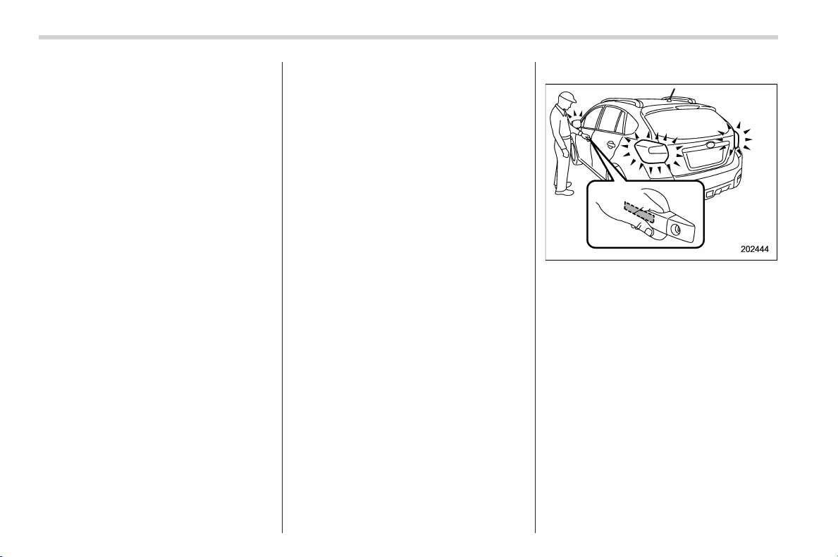
Black plate (116,1)
北米Model "A1160BE-C" EDITED: 2014/ 3/ 17
2-14
Keys and doors/Keyless access with push–button start system
wireless equipmen t is used), or while
talking on a cell phone, the operating
ranges may be reduced, or the keyless
access function may not operate.
In such a case, perform the procedure
described in “Locking and unlocking” F9-
23.
. When an access key is in the operating
range, if the door handle becomes wet
due to exposure to a significant amount of
water when the vehicle is washed or
dur ing heavy rain, the doors may be
locked or unlocked.
. The keyless access function may not
operate properly depending on the status
of the access key and the radio wave
conditions around the vehicle. In such a
case, perform the procedure described in
“Locking and unlocking” F9-23.
! How to use keyless access func-
tions
! Keyless access function tips
. When you lock the doors and rear gate
using the keyless access function, turn the
push-button ignition switch off. It is not
possible to lock the doors and rear gate
using the keyless access function when
the push-button ignition switch is on the
“ACC” or “ON” position. Refer to “Switch-
ing power status” F 3-6.
. If the door handle is gripped with a
gloved hand, the door lock may not be
released.
. If the door lock sensor is touched three
times or more repeatedly, the system will
ignore the sensor operation.
. When performing the locking proce-
dure too quickly, locking may not have
been completed. After locking the doors, it
is recommended to pull the REAR door
handles to confirm that the doors have
been locked.
. It is possible to lock the doors even
when one of the doors is open. After
performing the locking procedure, close
the opened door or rear gate to lock it.
. Within 3 seconds after locking the
doors and the rear gate by using the
keyless access function, it is not possible
to unlock doors and/or the rear gate by
using the keyless access function.
. When locking, be sure to carry the
access key to prevent locking the access
key in the vehicle.
. The setting of the hazard warning
flasher operation can be changed by your
SUBARU dealer. Contact your SUBARU
dealer for details.
. The setting of the hazard warning
flasher operatio n can be changed by
operating the multi function display. For
details, refer to “Hazard warning flasher
setting” F3-68.
! Unlocking
Carry the access key, and grip the door
handle.
. When the driver ’s door handle is
gripped, only the driver’s door will be
unlocked.
. When the front passenger’s door han-
dle is gripped, all doors including the rear
gate will be unlocked.
Also, an electronic chirp will sound twice
and the hazard warning flashers will flash
twice.
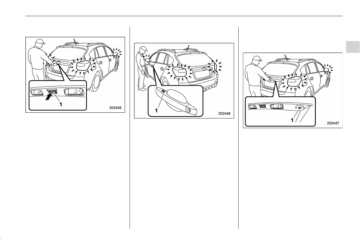
Black plate (117,1)
北米Model "A1160BE-C" EDITED: 2014/ 3/ 17
! Opening rear gate
1) Rear gate opener button
Carry the access key, and press the rear
gate opener button. Only the rear gate will
be unlocked and opened. Also, an elec-
tronic chirp will sound twice and the
hazard warning flashers will flash twice.
! Locking with the door lock
sensor
1) Door lock sensor
Carry the access key, close all doors
including the rear gate and touch the door
lock sensor on the door handle. All doors
including the rear gate will be locked. Also,
an electronic chirp will sound once and the
hazard warning flashers will flash once.
NOTE
After touching the door lock sensor to
lock all of the doors (including the rear
gate), if you touch the door lock sensor
once more to attempt the lock opera-
tion without first unlocking the doors,
nothing will happen, even if the door
lock sensor is touched. In this case,
perform the unlocking operation once
first. You can then touch the door lock
sensor to lock the doors.
! Locking with the rear lock button
1) Rear lock button
Carry the access key, close all doors
including the rear gate and press the rear
lock button. The rear gate and all doors
will be locked. Also, an electronic chirp will
sound once and the hazard warning
flashers will flash once.
! Power saving function
The keyless access function will be
disabled in the following cases to protect
the access key battery and the 12 V
auxiliary battery.
Case 1: When the keyless access func-
tion and the remote keyless entry system
Keys and doors/Keyless access with push–button start system
2-15
– CONTINUED –
2

Black plate (118,1)
北米Model "A1160BE-C" EDITED: 2014/ 3/ 17
2-16
Keys and doors/Keyless access with push–button start system
have not been used for 2 weeks or longer
while all doors are locked
Case 2: When the access key has been
left in the operating range for 10 minutes
or longer while all doors are locked
! Recovery from p ower saving
mode
When one of the following is operated, the
keyless access function will be recovered.
Case 1:
. Unlock the doors by operating any
procedure other than gripping the front
passenger’s door handle
. Lock the doors
. Open a door and then close it
Case 2:
. Unlock the doors by gripping the door
handle
. Unlock the doors by pressing the rear
gate opener button
. Lock the doors by touching the door
lock sensor
. Lock or unlock the doors by using the
remote keyless entry system
. Lock or unlock the doors by using the
power door locking switch
. Open either of the front doors
! Door unlock selection function
The door unlock selection function makes
it possible to unlock the driver’s door or
the rear gate without unlocking any other
doors. You can change the setting for the
driver’s door and for the rear gate inde-
pendently.
Operational: Only the driver’s door or the
rear gate will be unlocked.
Non-operational: All doors and the rear
gate will be unlocked.
For the factory setting (default setting),
refer to “Function settings” F31.
NOTE
The setting can be changed by your
SUBARU dealer. Contact your SUBARU
dealer for details. Also, the setting can
be changed by operating the multi
function display. For details, refer to
“Keyless access setting (models with
“keyless access with push-button start
system”)” F3-72.
& Selecting audible signal op-
eration
Using an electronic chirp, the system will
give you an audible signal when the doors
lock and unlock. If desired, you may turn
the audible signal off. For more details,
contact a SUBARU dealer.
NOTE
The setting can be changed by operat-
ing the multi function display. For de-
tails, refer to “Audible signal setting”
F3-66.
& Warning chimes and warning
light
The keyless access with push-button start
system sounds a w arni ng chim e and
flashes the access key warning light on
the combination meter in order to minimize
improper operations and help protect your
vehicle from theft.
For details, refer to “Warning chimes and
warning light of the keyless access with
push-button start system” F3-25.
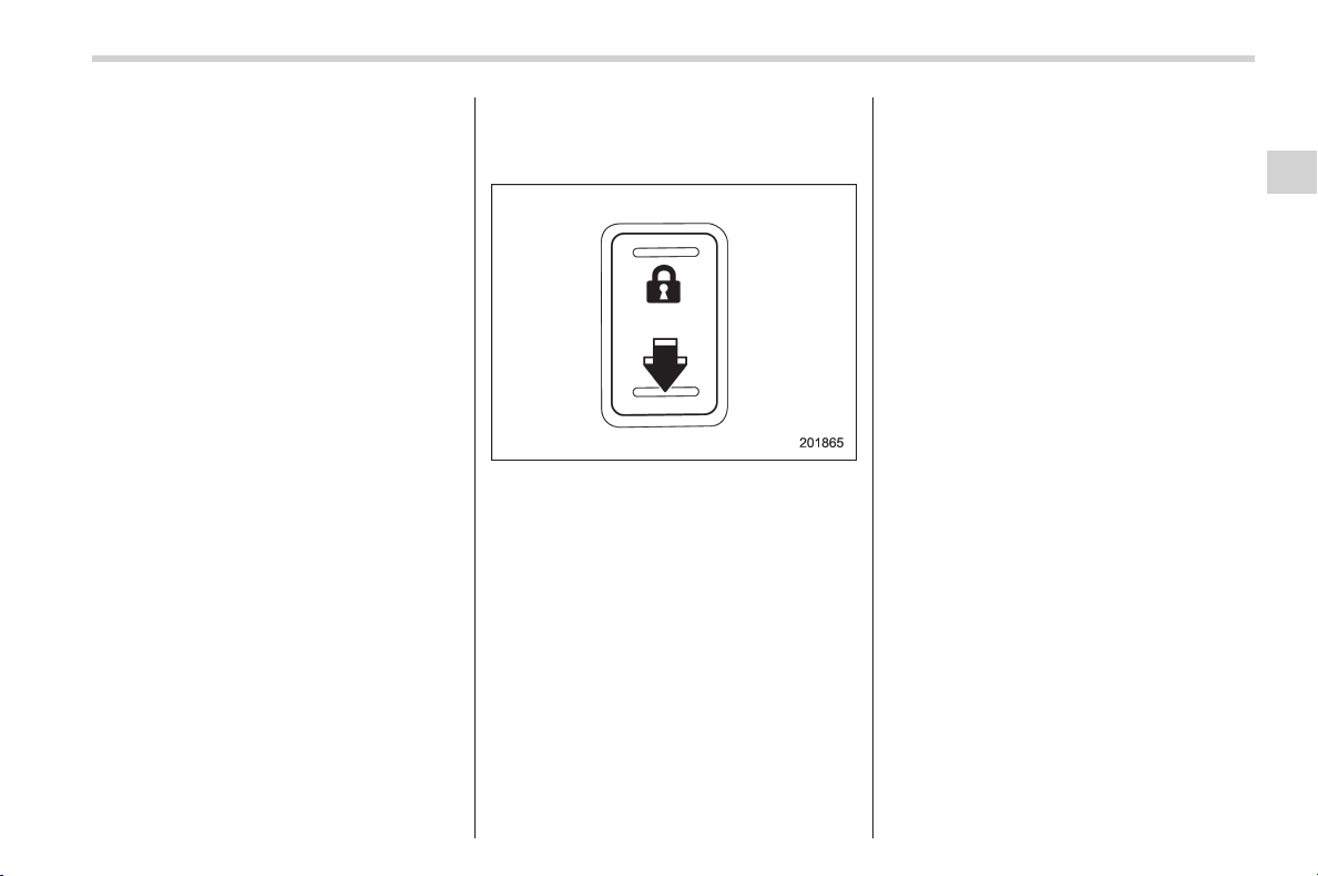
Black plate (119,1)
北米Model "A1160BE-C" EDITED: 2014/ 3/ 17
& Disabling keyless access
function
When the vehicle is not going to be used
for a long time, or when you choose not to
use the keyless access function, the
keyless access function can be disabled.
NOTE
. The locking and unlocking function
by the remote keyless entry system is
not disabled.
. The setting can also be changed at
SUBARU dealers. For more details,
contact a SUBARU dealer.
. To start the hybrid system while the
functions are disabled, perform the
procedure described in “ Starting hy-
brid system” F9-24.
. We recommend that you disable the
keyless access functions under the
following conditions.
– When the vehicle is not going to
be used for an extended period of
time
– When the keyless access func-
tions are not going to be used
– When the access key needs to be
stored inside or near the vehicle
! Disabling functions
1. Sit in the driver’s seat, and close the
door.
2. Push the rear side (unlock side) of the
power door locking switch.
3. Within 5 seconds after step 2 is
performed, open the driver’s door.
4. Within 5 seconds after step 3 is
performed, push the rear side (unlock
side) of the power door locking switch
twice while the door is open.
5. Within 30 seconds after step 4 is
performed, close and open the driver’s
door twice.
6. Within 30 seconds after step 5 is
performed, push the rear side (unlock
side) of the power door locking switch
twice while the door is open.
7. Within 30 seconds after step 6 is
performed, close and open the driver’s
door once.
8. Within 5 seconds after step 7 is
performed, close the door. A chirp sound
will be heard, and the functions will be
disabled.
NOTE
In steps 4 and 6, press the power door
locking switch slowly. If the switch is
pressed quickly, the functions may not
be disabled.
! Enabling functions
When the procedure to disable the func-
tions is performed again, the functions are
enabled.
& When access key does not
operate properly
Refer to “Access key – if access key does
not operate properly” F9-23.
& Replacing battery of access
key
Refer to “Replacing access key battery”
F11-46.
Keys and doors/Keyless access with push–button start system
2-17
– CONTINUED –
2
Black plate (120,1)
北米Model "A1160BE-C" EDITED: 2014/ 3/ 17
2-18
Keys and doors/Remote keyless entry system
& Replacing access key
Access keys can be replaced at SUBARU
dealers. For more details, contact a
SUBARU dealer.
& Certification for keyless ac-
cess with push-button start
system
! U.S.-spec. models
FCC ID: HYQ14ACX
FCC ID: Y8PSSPIMB02
FCC ID: Y8PSSPLF02
CAUTION
FCC WARNING
Changes or modifications not ex-
pressly approved by the party re-
sponsible for compliance could void
the user’s authority to operate the
equipment.
NOTE
This device complies with part 15 of the
FCC Rules. Operation is subject to the
following two conditions: (1) This de-
vice may not cause harmful interfer-
ence, and (2) this device must accept
any interference received, including
interference that may cause undesired
operation.
! Canada-spec. models
NOTE
Operation is subject to the following
two conditions: (1) this device may not
cause interference, and (2) this device
must accept any interference, includ-
ing interference that may cause unde-
sired operation of the device.
NOTE
L’utilisation de ce dispositif est auto-
risée seulement aux deux conditions
suivantes: (1) il ne doit pas produire de
brouillage, et (2) l’utilisateur du dispo-
sitif doit être prêt à accepter tout
brouillage radioélectrique reçu, même
si ce brouillage est susceptible de
compromettre le fonctionnemen t du
dispositif.
Remote keyless entry system
& Safety precautions
CAUTION
. Do not expose the remote trans-
mitter to severe shocks, such as
those experienced as a result of
dropping or throwing.
. Do not take the remote transmit-
ter apart except when replacing
the battery.
. Do not get the remote transmitter
wet. If it gets wet, wipe it dry with
a cloth immediately.
. When you carry the remote trans-
mitteronanairplane,donot
press the button of the remote
transmitter while in the airplane.
When any button of the remote
transmitter is pressed, radio
waves are sent and may affect
the operati on of the airplane.
When you carry the remote trans-
mitter in a bag on an airplane,
take measures to prevent the
buttons of the remote transmitter
from being pressed.
. FCC WARNING
Changes or modifications not
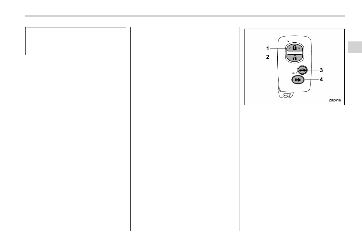
Black plate (121,1)
北米Model "A1160BE-C" EDITED: 2014/ 3/ 17
expressly approved by the party
responsible for compliance
could void the user’s authority
to operate the equipment.
& Transmitter
For models with “keyless access with
push-button start system”, the access
key is used as the transmitter for the
remote keyless entry system. For models
without “keyless access with push-button
start system”, the transmitter for the
remote keyless entry system is located
inside the key head.
The remote keyless entry system has the
following functions.
. Locking and unlocking the doors (and
rear gate) without a key
. Unlocking the rear gate without a key
. Sounding a panic alarm
. Arming and disarming the alarm sys-
tem. For detailed information, refer to
“Alarm system” F2-22.
The operable distance of the remote
keyless entry system is approximately 30
feet (10 meters). However, this distance
will vary depending on environmental
conditions. The system’s operable dis-
tance will be shorter in areas near a
facility or electronic equipment emitting
strong radio waves such as a power plant,
broadcast station, TV tower, or remote
controller of home electronic appliances.
NOTE
. For models with “keyless access
with push-button start system”,the
remote keyless entry system will not
be activated when the push-button
ignition switch is in any position other
than the “OFF” position.
. For models without “keyless access
with push-button start system”,the
remote keyless entry system will not
be activated when the key is inserted in
the ignition switch.
Access key
1) Lock/arm button
2) Unlock/disarm button
3) Rear gate unlock button
4) PANIC button
Keys and doors/Remote keyless entry system
2-19
– CONTINUED –
2
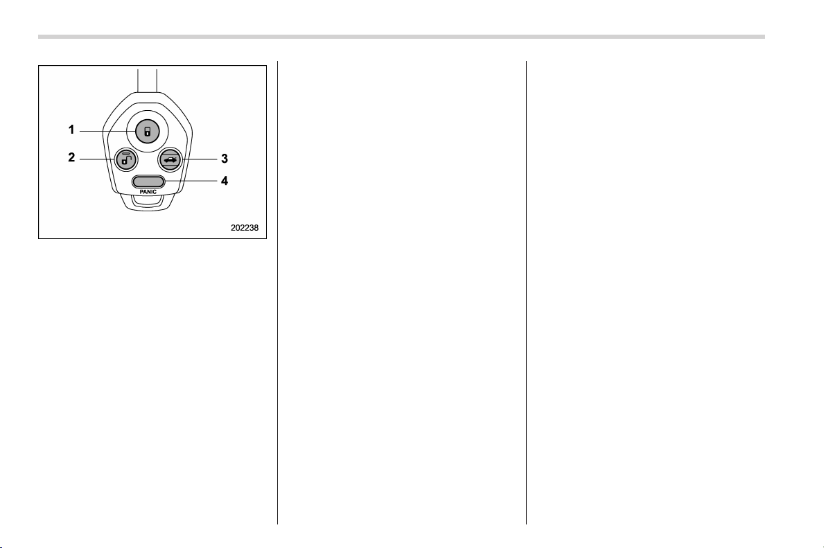
Black plate (122,1)
北米Model "A1160BE-C" EDITED: 2014/ 3/ 17
2-20
Keys and doors/Remote keyless entry system
Transmitter
1) Lock/arm button
2) Unlock/disarm button
3) Rear gate unlock button
4) PANIC button
NOTE
The hazard warning flashers will flash
once or twice when the transmitter
button is pressed i n the fol lowing
cases.
– When locking the doors
– When unlocking the doors
– When unlocking the rear gate
Operation of the hazard warning
flashers in the above cases can be set
to “On” or “Off” by a SUBARU dealer.
Consult your SUBARU dealer for de-
tails. Also, the setting can be changed
using the multi function display. For
details, refer to “ Hazard warning
flasher setting” F3-68.
& Locking the doors
Press the lock/arm button to lock all doors
and rear gate. An electronic chirp will
sound once and the hazard warning
flashers will flash once.
If any of the doors (or the rear gate) is not
fully closed, an electronic chirp will sound
five times and the hazard warning flashers
will flash five times to alert you that the
doors (or the rear gate) are not properly
closed. When you close the door, it will
automatically lock and then an electronic
chirp will sound once and the hazard
warning flashers will flash once.
& Unlocking the doors
Press the unlock/disarm button to unlock
the driver’s door. An electronic chirp will
sound twice and the hazard w arning
flashers will flash twice. To unlock all
doors and the rear gate, briefly press the
unlock/disarm button a second time within
5 seconds.
NOTE
If the interval between the first and
second presses of the unlock/disarm
button (for unlocking of all of the doors
and the rear gate) is extremely short,
the system may not respond.
& Unlocking the rear gate
Pressing the rear gate unlock button
unlocks the rear gate.
An electronic chirp will sound twice and
the hazard warning flashers w ill flash
twice.
& Vehicle finder function
Use this function to find your vehicle
parked among many vehicles in a large
parking lot. Provided you are within 30 feet
(10 meters) of the vehicle, pressing the
lock/arm button three times in a 5-second
period will cause your vehicle’s horn to
sound once and its hazard warning
flashers to flash three times.
NOTE
If the interval between presses is too
short when you press the loc k/arm
button three times, the system may
not respond to the signals from the
remote transmitter.
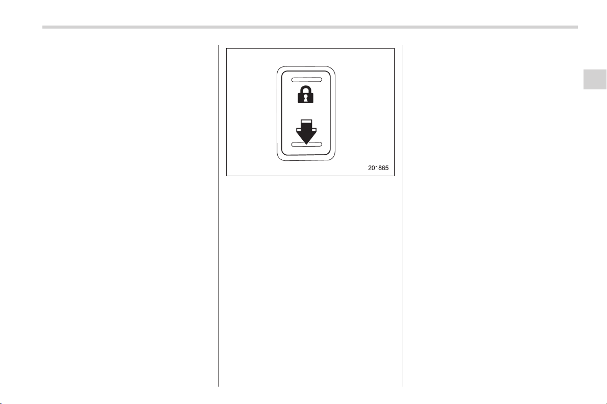
Black plate (123,1)
北米Model "A1160BE-C" EDITED: 2014/ 3/ 17
& Sounding a panic alarm
To activate the alarm, press the “PANIC”
button once.
The horn will sound and the hazard
warning flashers will flash.
To deactivate the panic alarm, press any
button on the remote transmitter. Unless a
button on the remote transmitter is
pressed, the alarm will be deactivated
after approximately 30 seconds.
& Selecting audible signal op-
eration (models without
“keyless access with push-
button start system”)
Using an electronic chirp, the system will
give you an audible signal when the doors
lock and unlock. If desired, you may turn
the audible signal off.
Perform the following steps to deactivate
the audible signal. You can also use the
same steps to restore the function.
1. Sit in the driver’s seat and shut all
doors and the rear gate.
2. Hold down the REAR (UNLOCK) side
of the power door locking switch.
3. While holding down the REAR (UN-
LOCK) side of the power door locking
switch, pull the key out and re-insert it into
the ignition switch at least 6 times within
10 seconds after Step 2.
4. Open and close the driver’s door once
within 10 seconds after Step 3.
5. The hazard warning flashers flash 3
times to indicate completion of the setting.
You may have the above settings done by
your SUBARU dealer. Also, the setting
can be changed using the multi function
display. For details, refer to “Audible signal
setting” F3-66.
& Replacing the battery
Refer to “Battery replacement” F11-45.
& Replacing lost transmitters
If you lose a t ransmitter or want to
purchase additional transmitters (up to
four can be programmed), your transmit-
ters should be reprogrammed for security
reasons. For details, contact your
SUBARU dealer and have the transmitters
programmed into the remote keyless entry
system.
& Certification for remote key-
less entry system
! U.S.-spec. models
FCC ID: CWTWB1U811
FCC ID: CWTWBU766
FCC ID: HYQ14ACX
This device complies with part 15 of the
FCC Rules. Operation is subject to the
following two conditions: (1) This de-
vice may not cause harmful interfer-
ence, and (2) this device must accept
any interference received, includi ng
interference that may cause undesired
operation.
Keys and doors/Remote keyless entry system
2-21
– CONTINUED –
2

Black plate (124,1)
北米Model "A1160BE-C" EDITED: 2014/ 3/ 17
2-22
Keys and doors/Alarm system
! Canada-spec. models
NOTE
Operation is subject to the following
two conditions: (1) this device may not
cause interference, and (2) this device
must accept any interference, includ-
ing interference that may cause unde-
sired operation of the device.
NOTE
L’utilisation de ce dispositif est auto-
risée seulement aux deux conditions
suivantes: (1) il ne doit pas produire de
brouillage, et (2) l’utilisateur du dispo-
sitif doit être prêt à accepter tout
brouillage radioélectrique reçu, même
si ce brouillage est susceptible de
compromettre le fonctionnement du
dispositif.
Alarm system
& General information
The alarm system helps to protect your
vehicle and valuables from theft. The horn
sounds and the hazard warning flashers
flash if someone attempts to break into
your vehicle.
For models with “keyless access with
push-button start system”:
The system can be armed and disarmed
with the keyless access function or access
key.
The system will not be activated when the
push-button ignition switch is in the “ACC”
or “ON” position.
For models without “keyless access
with push-button start system”:
The system can be armed and disarmed
with the remote transmitter.
The system will not be activated when the
key is inserted into the ignition switch.
Your vehicle’s alarm system has been set
for activation at the time of shipment from
the factory. You can set the system for
deactivation yourself or have it done by
your SUBARU dealer.
& System operation
The alarm system will sound the following
alarms when triggered.
. The vehicle’s horn will sound for 30
seconds.
. The hazard warning flashers will flash
for 30 seconds.
If any of the doors or the rear gate remains
open after the 30-second period, the horn
will continue to sound for a maximum of 3
minutes. If the door or the rear gate is
closed while the horn is sounding, the
horn will stop sounding with a delay of up
to 30 seconds.
The alarm is triggered by:
. Opening any of the doors or the rear
gate
. Physical impact to the vehicle, such as
forced entry (only models with sho ck
sensors (dealer option))
NOTE
The alarm system can be set to trigger
the illumination of the following interior
lights.
. Map lights (models with moonroof)
. Dome light (illuminates only when
the dome light switch is in the “DOOR”
position)
. Cargo area light (illuminates only

Black plate (125,1)
北米Model "A1160BE-C" EDITED: 2014/ 3/ 17
when the cargo area light switch is in
the “DOOR” position)
The notifications regarding the map
lights, dome light and cargo area light
are deactivated as the factory setting. A
SUBARU dealer can activate the sys-
tem. Contact your SUBARU dealer for
details.
& Activating and deactivating
the alarm system
To change the setting of your vehicle’s
alarm system for activation or deactiva-
tion, do the following.
1. Disarm the alarm system. Refer to
“Disarming the system” F2-26.
2. Sit in the driver’s seat and shut all
doors and the rear gate.
3. Turn the ignition switch to the “ON”
position.
4. Hold down the REAR (UNLOCK) side
of the driver’s power door locking switch,
open the driver’s door within the following
1 second, and wait 10 seconds without
releasing the switch. The setting will then
be changed as follows.
If the system was previously activated:
The odometer/trip meter screen displays
“AL oF” and the h orn so unds twi ce,
indicating that the system is now deacti-
vated.
If the system was previously deacti-
vated:
The odometer/trip meter screen displays
“AL on” and the horn sounds once,
indicating that the system is now acti-
vated.
NOTE
You may have the above setting
change done by your SUBARU dealer.
& If you have accidentally trig-
gered the alarm system
! To stop the alarm
Perform any of the following operations.
. Press any button on the access key/
remote transmitter.
. Turn the ignition switch to the “ON”
position (models without “keyless access
with push-button start system”).
. Turn the push-button ignition to the
“ACC” position (models with “keyless
access with push-button start system”).
NOTE
Only registered keys will stop the
alarm. If the immobilizer transponder
is not registered, the alarm will not
stop.
& Arming the system
! Tips
. The system can be armed even if the
engine hood, the windows and/or moon-
roof are open. Always make sure that they
are fully closed before arming the system.
. The 30-second standby time can be
eliminated if you prefer. Have it performed
by your SUBARU dealer.
. The system is in the standby mode for
a 30-second period before arming the
system. The security indicator light will
flash at short intervals during this period.
. If any of the following actions is done
during the standby period, the system will
not switch to the surveillance state.
– Doors (including the rear gate) are
unlocked using the access key/remote
transmitter.
– Doors (including the rear gate) are
unlocked using the keyless access
function (models with “keyless access
with push-button start system”).
– Any door (including the rear gate) is
opened.
– The ignition switch is turned to the
“ON” position (models without “keyless
access with push-button start sys-
tem”).
– Push-button ignition switch is
turned to the “ACC” position (models
Keys and doors/Alarm system
2-23
– CONTINUED –
2
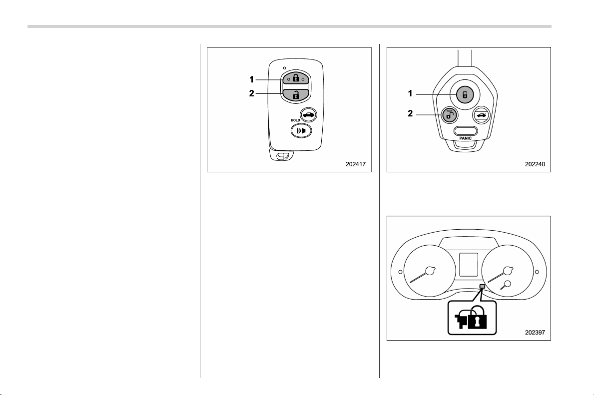
Black plate (126,1)
北米Model "A1160BE-C" EDITED: 2014/ 3/ 17
2-24
Keys and doors/Alarm system
with “keyless access with push-button
start system”).
! To arm the system using the access
key/remote transmitter
1. Close all windows and the moonroof (if
equipped).
2. Remove the key from the ignition
switch (models without “keyless access
with push-button start system”)/turn the
push-button ignition switch to the “OFF”
position (models with “keyless access with
push-button start system”).
3. Open the doors and get out of the
vehicle.
4. Make sure that the engine hood is
locked.
5. Close all doors and the rear gate.
Access key
1) Arm button: Press to arm the system
2) Disarm button: Press to disarm the
system
Transmitter
1) Arm button: Press to arm the system
2) Disarm bu tton: Press to disarm the
system
Security indicator light
6. Briefly press the arm button (for less
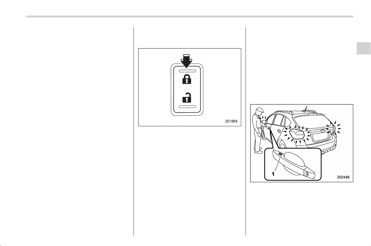
Black plate (127,1)
北米Model "A1160BE-C" EDITED: 2014/ 3/ 17
than 2 seconds). All doors (and the rear
gate) will lock, an electronic chirp will
sound once, the hazard warning flashers
will flash once, and the security indicator
light will start flashing rapidly. After rapid
flashing for 30 seconds (standby time), the
indicator lights will then flash slowly (twice
approximately every 2 seconds), indicat-
ing that the system has been armed for
surveillance.
If any of the doors or the rear gate is not
fully closed, an electronic chirp sounds
five times, the hazard warning flashers
flash five times to alert you that the doors
(or the rear gate) are not properly closed.
When you close the door, the system will
automatically arm and doors will automa-
tically lock.
! To arm the system using power
door locking switches
1. Close all windows.
2. Remove the key from the ignition
switch (models without “keyless access
with push-button start system”)/turn the
push-button ignition switch to the “OFF”
position (models with “keyless access with
push-button start system”).
3. Open the doors and get out of the
vehicle.
4. Make sure that the engine hood is
locked.
5. Close the doors (and the rear gate) but
leave only the driver’s door or the front
passenger’s door open.
6. Press the front side (“LOCK” side) of
the power door locking switch to set the
door locks.
7. Close the door. An electronic chirp will
sound once, the hazard warning flashers
will flash once and the security indicator
light will start flashing rapidly. After rapid
flashing for 30 seconds (standby time), the
indicator lights will then flash slowly (twice
approximately every 2 seconds), indicat-
ing that the system has been armed for
surveillance.
! To arm the system using the key-
less access function (if equipped)
1. Close all windows and the moonroof (if
equipped)
2. Turn the push-button ignition switch to
the “OFF” position.
3. Open the doors and get out of the
vehicle.
4. Make sure that the engine hood is
locked.
5. Close all doors and the rear gate.
1) Door lock sensor
Keys and doors/Alarm system
2-25
– CONTINUED –
2
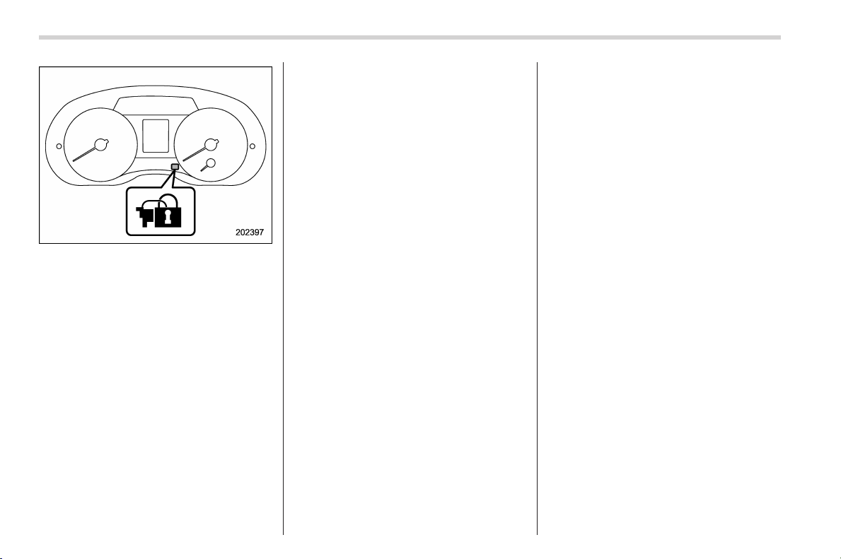
Black plate (128,1)
北米Model "A1160BE-C" EDITED: 2014/ 3/ 17
2-26
Keys and doors/Alarm system
Security indicator light
6. Carry the access key and touch the
door lock sensor. All doors (and the rear
gate) will lock, an electronic chirp will
sound once, the hazard warning flashers
will flash once, and the security indicator
light will start flashing rapidly. After rapid
flashing for 30 seconds (standby time), the
security indicator l ight will then flash
slowly (twice approximately every 2 sec-
onds), indicating that the system has been
armed for surveillance.
If any of the doors or the rear gate is not
fully closed, an electronic chirp sounds
five times, the hazard warning flashers
flash five times to alert you that the doors
(or the rear gate) are not properly closed.
When you close the door, the system will
automatically arm and doors will automa-
tically lock.
& Disarming the system
Perform either of the following procedures.
. Briefly press the disarm button (for less
than 2 seconds) on the access key/remote
transmitter.
. Carry the access key and perform
either of the following procedures (models
with “keyless access with push-button
start system”).
– Grip the front door handle.
– Press the rear gate opener button.
The following door(s) will unlock, an
electronic chirp will sound twice and the
hazard warning flashers will flash twice.
. Driver’s door: when either of the
following procedures is performed
– Press the disarm button on the
access key/remote transmitter briefly
(for less than 2 seconds).
– Grip the driver ’s door handle (mod-
els with “keyless access with push-
button start system”).
. Rear gate: when pressing the rear gate
opener button (models with “keyless ac-
cess with push-button start system”)
. All doors: when gr ipping the front
passenger’s door handle (models with
“keyless access with push-button start
system”)
The flashing of the security indicator light
will then change slowly (once approxi-
mately every 3 seconds from twice ap-
proximately every 2 seconds), indicating
that the alarm system has been disarmed.
To unlock all other doors and the rear
gate, briefly press the disarm button a
second time within 5 seconds.
! Emergency disarming
If you cannot disarm the system using the
access key/transmitter (i.e. the transmitter
is lost, broken or the transmitter battery is
too weak), you can disarm the system
without using the access key/remote
transmitter.
The system can be disarmed if you turn
the ignition switch from the “ LOCK” (off) to
the “ON” position with a registered key/
access key.
NOTE
For models with “keyless access with
push-button start system”, if the ac-
cess key battery is discharged, perform
the procedure described in “Switching
power status” F9-23. In such a case,
replace the battery immediately. Refer
to “Replacing access key battery” F11-
46.
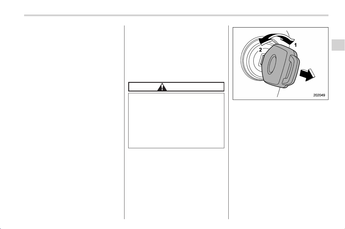
Black plate (129,1)
北米Model "A1160BE-C" EDITED: 2014/ 3/ 17
& Valet mode
When you choose the valet mode, the
alarm system does not operate. In valet
mode, the access key/remote transmitter
is used only for locking and unlocking the
doors and rear gate and for panic activa-
tion.
To enter the valet mode, change the
setting of your vehicle’s alarm system for
deactivation mode. Refer to “Activating
and deactivating the alarm system” F2-
23. The security indicator light will con-
tinue to flash once every 3 seconds
indicating that the system is in the valet
mode.
To exit valet mode, change the setting of
your vehicle’s alarm system for activation
mode. Refer to “Activating and deactivat-
ing the alarm system” F2-23.
& Passive arming
! Models with “keyless access with
push-button start system”
You cannot select the passive arming
mode.
! Passive arming mode
When passive arming mode has been
programmed by the dealer, arming of the
system is automatically accomplished
without using the remote transmitter. Note
that in this mode, DOORS MUST BE
MANUALLY LOCKED.
! To enter the passive mode
If you wish to program the passive arming
mode, have it done by your SUBARU
dealer.
! Arming the system
CAUTION
In passive mode, the system will
automatically activate the alarm but
WILL NOT automatically lock the
doors. In order to lock the doors
you must either lock them as in-
dicated in step 4 below or with the
key once they have been closed.
Failure to lock the doors manually
will result in a higher security risk.
1. Turn the ignition switch to the “ON”
position.
1) ON
2) LOCK (off)
2. Turn the ignition switch from “ON” to
“LOCK” (off) position and remove the key
from the ignition switch.
3. Open the doors and get out of the
vehicle.
Keys and doors/Alarm system
2-27
– CONTINUED –
2
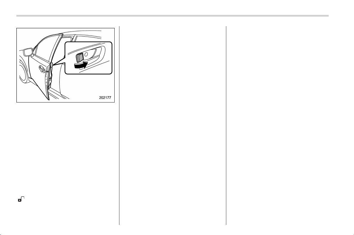
Black plate (130,1)
北米Model "A1160BE-C" EDITED: 2014/ 3/ 17
2-28
Keys and doors/Alarm system
4. Before closing the doors, lock all doors
with the inside door lock levers.
5. Close the doors. The system wi ll
automatically arm after 1 minute.
In the passive mode, the system can also
be armed with the remote transmitter or
with the power door locking switches. If
the remote transmitter or power door
locking switch is used to lock the vehicle,
arming will take place immediately regard-
less of whether or not the passive mode
has been selected.
! Disarming the system
To disarm the system, briefly press the
“
” button on the transmitter.
& Tripped sensor identification
The security indicator light flashes when
the alarm system has been triggered.
Also, the number of flashes indicates the
location of unauthorized intrusion or the
severity of impact on the vehicle.
When the ignition switch is turned to the
“ON” position, the indicator light will light
for 1 second and then flash as follows.
. When a door or the rear gate was
opened: 5 times
. When the ignition switch was turned to
the “ON” position: 3 times
. When a strong impact or multiple
impacts were sensed: twice (only models
with shock sensors (dealer option))
. When a light impact was sensed: once
(only models with shock sensors (dealer
option))
NOTE
Any of the above indicator light flash-
ings will recur each time the ignition
switch is turned to the “ON” position.
Rearming the alarm system cancels the
flashing.
& Shock sensors (dealer op-
tion)
The shock se nsors tri gger the alarm
system when they sense impacts applied
to the vehicle and when any of their
electric wires are cut. The alarm system
causes the horn to sound and the hazard
warning flashers to flash for a short time
when the sensed impact is weak, but it
warns of a strong impact or multiple
impacts by sounding the horn and flashing
the hazard warning flashers, both lasting
approximately 30 seconds.
If you desire, your SUBARU dealer can
connect them and set them for activation
or deactivation.
NOTE
. The shock sensors are not always
able to sense impacts caused by break-
ing in, and cannot sense an impact that
does not cause vibration (such as
breaking the glass using a rescue
hammer).
. The shock sensors may sense vi-
bration as indicated in the following
examples and trigger the alarm system.
Select the settings of the alarm system
and shock sensors appropriately de-
pending on where you usually park
your vehicle.
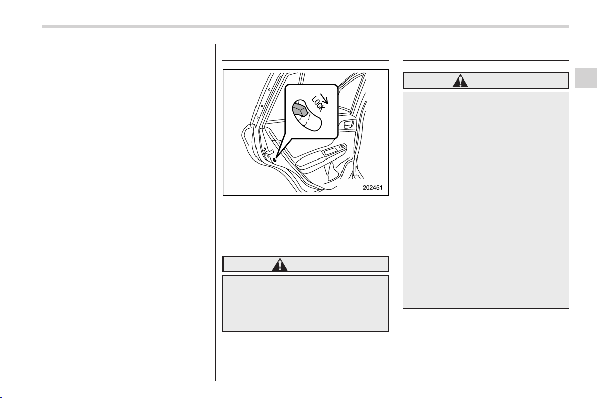
Black plate (131,1)
北米Model "A1160BE-C" EDITED: 2014/ 3/ 17
Examples:
– Vibration from a construction site
– Vibration in a multistory car park
– Vibration from trains
. You can have the sensitivity of the
shock sensors adjusted to your pre-
ference by your SUBARU dealer.
Child safety locks
Each rear door has a child safety lock.
When the child safety lock lever is in the
lock position, the door cannot be opened
from inside. The door can only be opened
from the outside.
WARNING
Always turn the child safety locks to
the “LOCK” position when children
sit in the rear seat. Serious injury
could result if a child accidentally
opens the door and falls out.
Windows
WARNING
To avoid serious personal injury
caused by entrapment, always con-
form to the following instructions
without exception.
. When operating the power win-
dows, be extremely careful to
prevent anyone’s fingers, arms,
neck, head or other objects from
being caught in the window.
. Always lock the passengers’ win-
dows using the lock switch when
children are riding in the vehicle.
. Before leaving the vehicle, al-
ways remove the key from the
ignition switch for safety and
never allow an unattended child
to remain in the vehicle. Failure
to follow this procedure could
result in injury to a child operat-
ing the power window.
The power windows operate only when
the ignition switch is in the “ON” position.
Keys and doors/Child safety locks
2-29
– CONTINUED –
2
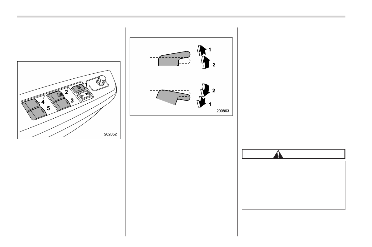
Black plate (132,1)
北米Model "A1160BE-C" EDITED: 2014/ 3/ 17
2-30
Keys and doors/Windows
& Power window operation by
driver
! Driver’s side power window
switches
1) Lock switch
2) For driver’s window (with one-touch auto
up and down feature)
3) For front passenger’s window
4) For rear left window
5) For rear right window
All door windows can be controlled by the
power window switch cluster at the driver
side door.
! Operating the driver ’s window
1) Automatically open/close
2) Open/close
To open:
Push the switch down lightly and hold it.
The window will open as long as the
switch is held.
This switch also has a one-touch auto
down feature that allows the window to be
opened fully without holding the switch.
Push the switch down until it clicks and
release it, and the window will fully open.
To stop the wi ndow halfway, pull the
switch up lightly.
To close:
Pull the switch up lightly and hold it. The
window will close as long as the switch is
held.
This switch also has a one-touch auto up
feature that allows the window to be
closed fully without holding the switch.
Pull the switch up until it clicks and release
it, and the window will fully close. To stop
the window halfway, push the switch down
lightly.
NOTE
If the vehicle’s battery is disconnected
due to situations such as battery or
fuse replacement, the one-touch auto
up/down function is deactivated. Initi-
alize the power window to reactivate
the one-touch auto up/down function.
Refer to “Initialization of power win-
dow” F2-32.
! Anti-entrapment function
CAUTION
. Never attempt to test this func-
tion using fingers, hands or other
parts of your body.
. The anti-entrapment function
may not operate properly if some
object gets trapped just before
the window fully closes.
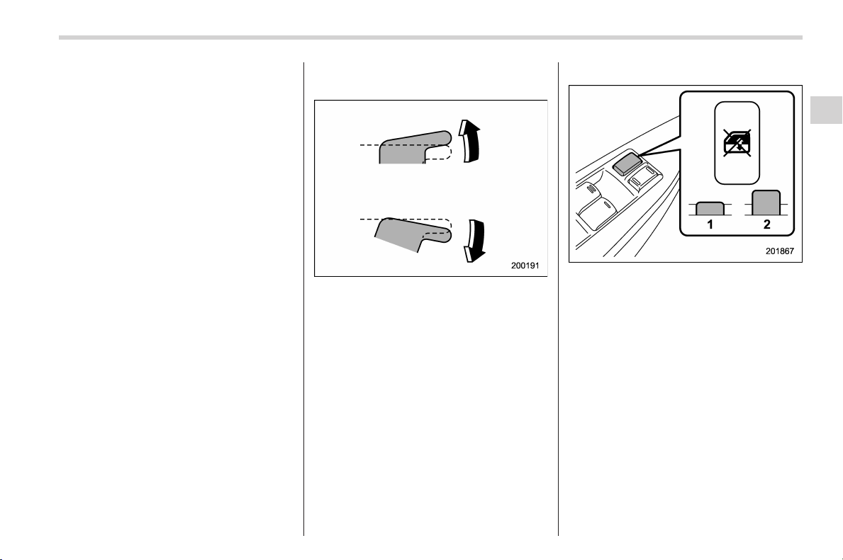
Black plate (133,1)
北米Model "A1160BE-C" EDITED: 2014/ 3/ 17
NOTE
. If a window detects an impact simi-
lar to that caused by trapping an object
(for example, when the vehicle encoun-
ters a deep pothole), the anti-entrap-
ment function may operate.
. The window cannot be operated for
a few seconds after the anti-entrap-
ment function operates.
. If the vehicle’s battery is discon-
nected due to situations such as
battery or fuse replacement, the anti-
entrapment function is deactivated.
Initialize the power window to reacti-
vate the anti-entrapment function. Re-
fer to “Initialization of power window”
F2-32.
While closing the driver’s window auto-
matically, if the window senses a sub-
stantial enough object trapped between
the window and the window frame, it
automatically moves down slightly and
stops.
! Operating the passengers’ win-
dows
To open:
Push the appropriate switch down and
hold it until the window reac hes the
desired position.
To close:
Pull the switch up and hold it until the
window reaches the desired position.
! Locking the passengers’ windows
1) Lock
2) Unlock
To lock:
Press the lock switch. When the lock
switch is in the lock position, the passen-
gers’ windows cannot be opened or
closed.
To unlock:
Press the lock switch again.
Keys and doors/Windows
2-31
– CONTINUED –
2
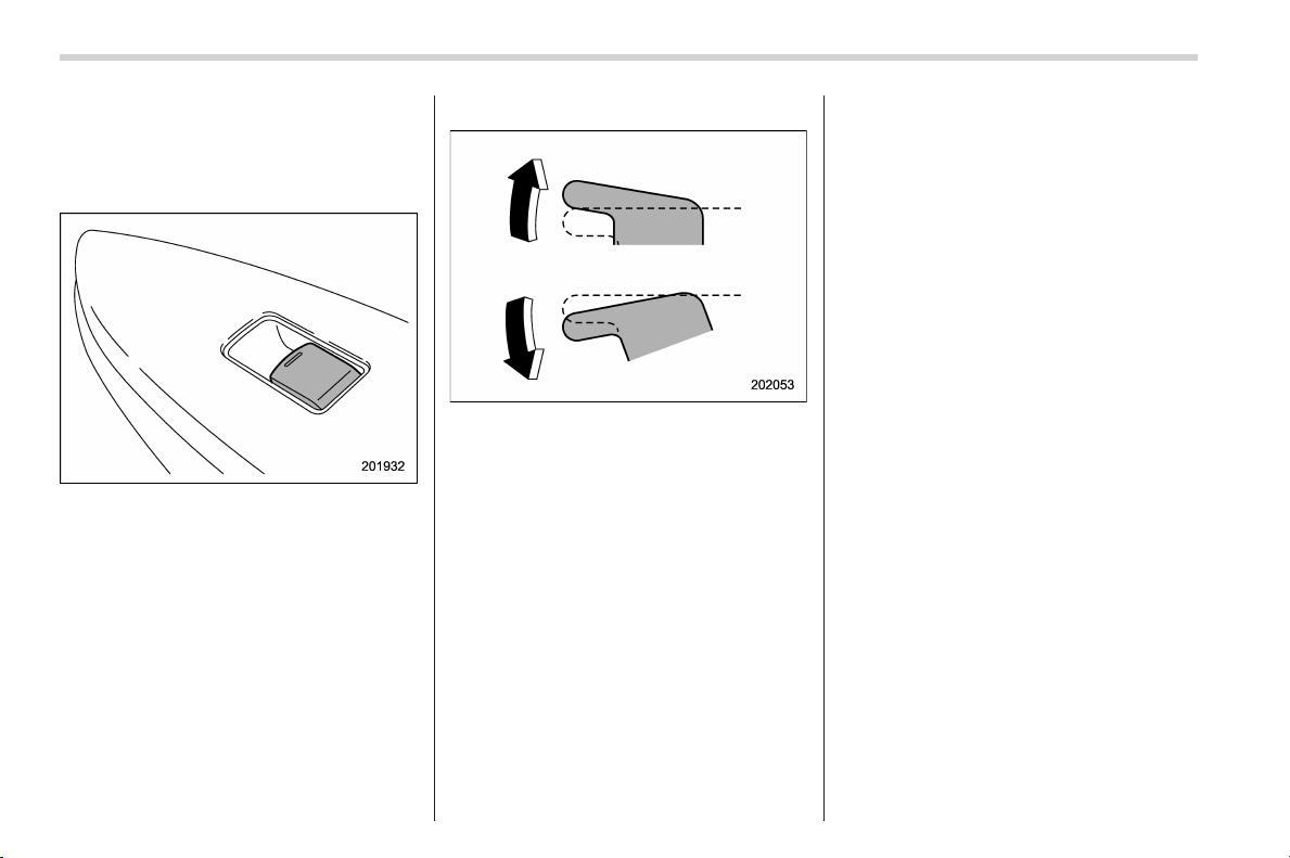
Black plate (134,1)
北米Model "A1160BE-C" EDITED: 2014/ 3/ 17
2-32
Keys and doors/Windows
& Power window operation by
passengers
! Passenger’s side power window
switches
Each passenger window can be controlled
by the power window switch located on
the door.
! Operating the windows
To open:
Press the switch down and hold it until the
window reaches the desired position.
To close:
Pull the switch up and hold it until the
window reaches the desired position.
When the lock switch on the power
window switch cl uster, located on the
driver’s side door, is in the lock position,
the passengers’ windows cannot be oper-
ated with the passengers’ switches.
& Initialization of power win-
dow
If the vehicle’s battery is disconnected due
to situations such as battery or fuse
replacement, the following functions are
deactivated.
. One-touch auto up/down function
. Anti-entrapment function
Initialize the power window using the
following procedure to reactivate these
functions.
1. Close the driver’s door.
2. Turn the ignition switch to the “ON”
position.
3. Open the driver’s side window halfway
by pushing down the power window
switch.
4. Pull up the power window switch and
close the window completely. Continue
pulling up the switch for approximately 1
second after the window is closed com-
pletely.
5. Open the driver ’s side window com-
pletely by fully pushing down the power
windows switch.
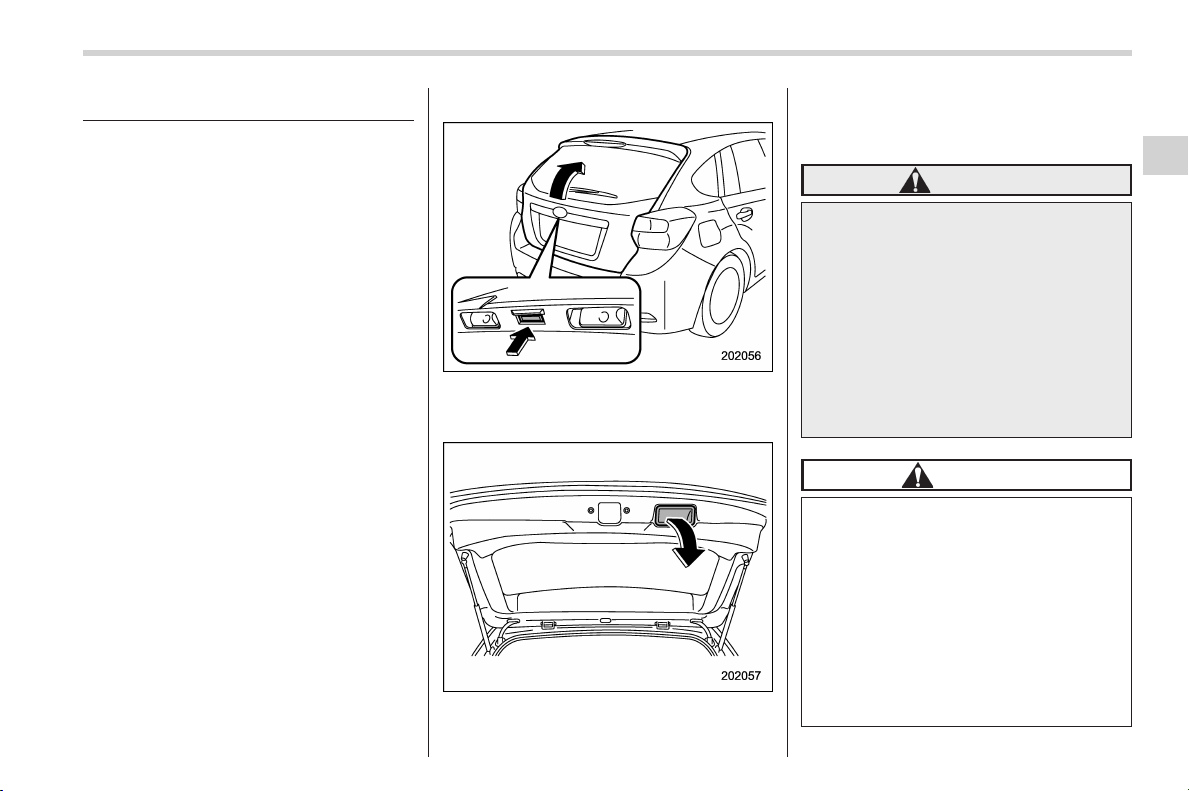
Black plate (135,1)
北米Model "A1160BE-C" EDITED: 2014/ 3/ 17
Rear gate
& Lock/unlock
The rear gate can be locked and unlocked
using any of the following systems.
. Power door locking switch: Refer to
“Power door locking switches ” F2-8.
. Keyless access with the push-button
start system (if equipped): Refer to “Key-
less access with push-button start system”
F2-9.
. Remote keyless entry system: Refer to
“Remote keyless entry system” F2-18.
NOTE
If the rear gate cannot be unlocked due
to a discharged 12 V auxiliary battery, a
malfunction in the door locking/unlock-
ing system or other causes, you can
unlock it by manually operating the
rear gate lock release lever.
For the procedure, refer to “Rear gate –
if the rear gate cannot be opened” F9-
22.
& Open/close
To open:
First unlock the rear gate lock then push
the rear gate opener button.
To close:
Lower the rear gate slowly and push down
firmly until the latch engages.
The rear gate can be lowered easily if you
pull it down holding the recessed grip.
WARNING
. To prevent dangerous ex haust
gas from entering the vehicle,
always keep the rear gate closed
while driving.
. Do not attempt to shut the rear
gate while holding the recessed
grip. Also avoid closing the rear
gate by pulling on the recessed
grip from inside the cargo space.
There is a danger of your hand
being caught and injured.
CAUTION
. Do not jam a plastic bag in or
place cellophane tape on the rear
gate stays or scratch the stays
while loading or unloading cargo.
That could cause leakage of gas
from the stays, which may result
in their inability to hold the rear
gate open.
. Be careful not to hit your head or
face on the rear gate when open-
ing or closing the rear gate and
Keys and doors/Rear gate
2-33
– CONTINUED –
2
Black plate (136,1)
北米Model "A1160BE-C" EDITED: 2014/ 3/ 17
2-34
Keys and doors/Moonroof
when loading or unloading car-
go.
NOTE
If the rear gate cannot be unlocked due
to a discharged 12 V auxiliary battery, a
malfunction in the door locking/unlock-
ing system or other causes, you can
unlock it by manually operating the
rear gate lock release lever. For the
procedure, refer to “Rear gate – if the
rear gate cannot be opened” F9-22.
Moonroof (if equipped)
WARNING
Never let anyone’s hands, arms,
head or any objects protrude from
the moonroof. A person could be
seriously injured if any of the follow-
ing conditions occur.
. The vehicle stops suddenly.
. The vehicle turns sharply.
. The vehicle is involved in an
accident.
. Body parts protruding from the
vehicle are struck by outside
objects.
To avoid serious personal injury
caused by entrapment, always con-
form to the following instructions
without exception.
. Before closing the moonroof,
make sure that no one’s hands,
arms, head or other objects will
be accidentally caught in the
moonroof.
. Before leaving t he vehicle, al-
ways remove the key from the
ignition switch for safety and
never allow an unattended child
to remain in the vehicle. Failure
to follow this procedure could
result in injury to a child operat-
ing the moonroof.
. Never try to check the anti-en-
trapment function by deliberately
placing part of your body in the
moonroof.
CAUTION
. Do not sit on the edge of the open
moonroof.
. Do not operate the moonroof if
falling snow or extremely cold
conditions have caused it to
freeze shut.
. The anti-entrapment function
does not operate when the moon-
roof is being tilted down. Be sure
to confirm that it is safe to do so
before tilting the moonroof down.
. If the moonroof does not close,
we recommend that you have the
system checked by a SUBARU
dealer.
The moonroof has both tilting and sliding
functions.
The moonroof operates only when the
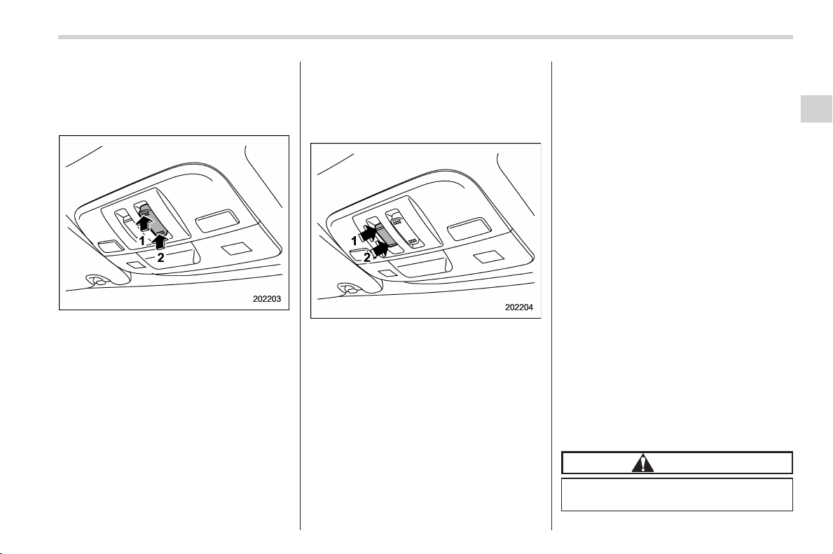
Black plate (137,1)
北米Model "A1160BE-C" EDITED: 2014/ 3/ 17
ignition switch is in the “ON” position.
& Moonroof switches
! Tilting moonroof
1) Raise
2) Lower
The tilting function is activated only when
the moonroof is fully closed.
To raise:
Press the rear side of the “UP/DOWN”
switch momentarily. The moonroof raises
completely.
To lower:
Press and hold the front side of the “UP/
DOWN” switch until the preferred position
has reached.
Release the switch after the moonroof has
been raised or has been lowered com-
pletely. Pressing the switch continuously
may cause damage to the moonroof.
! Sliding moonroof
1) Open
2) Close
To open:
Slide the “OPEN/CLOSE” switch rear-
ward. The sun shade will also be opened
together with the moonroof. The moonroof
will stop at a position approximately 16 in
(40 cm) away fro m the fu lly opened
position. Slide the switch rearward again
to open the moonroof completely.
To close:
Slide the “OPEN/CLOSE” switch forward.
To stop the moonroof at a selected mid-
way position while opening or closing it,
momentarily push the switch to the
“OPEN” side or “CLOSE” side.
After washing the vehicle or after it rains,
wipe away water on the roof prior to
opening the moonroof to prevent drops
of water from falling into the passenger
compartment.
NOTE
Driving with the moonroof fully open
can cause an annoying sound to be
generated at high speeds. If this oc-
curs, use the moonroof at the initial
stop position of 16 in (40 cm) away
from the fully closed position.
! Anti-entrapment function
When the moonroof senses a substantial
enough object trapped between its glass
and the vehicle’s roof during closure, it
automatically moves back to the fully open
position and stops there. The anti-entrap-
ment function may also be activated by a
strong shock on the moonroof even when
there is nothing trapped.
CAUTION
Never attempt to test this function
using fingers, hands or other parts
Keys and doors/Moonroof
2-35
– CONTINUED –
2
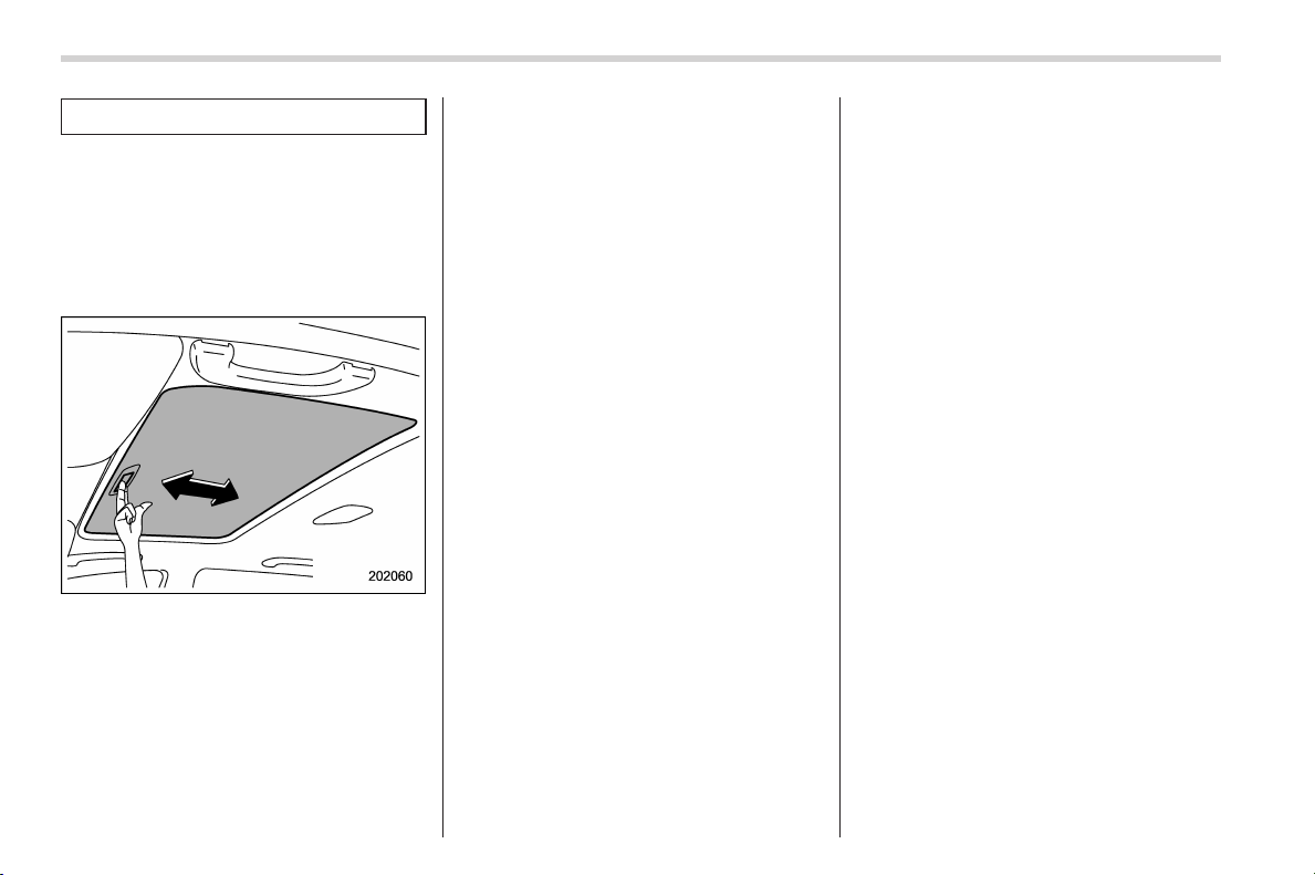
Black plate (138,1)
北米Model "A1160BE-C" EDITED: 2014/ 3/ 17
2-36
Keys and doors/Moonroof
of your body.
NOTE
For the sake of safety, it is recom-
mended that you avoid driving with the
moonroof fully opened.
& Sun shade
The sun shade can be slid forward or
backward by hand while the moonroof is
closed.
If the moonroof is opened, the sun shade
also moves back.

Black plate (5,1)
北米Model "A1160BE-C" EDITED: 2014/ 3/ 17
Ignition switch ..................................................... 3-3
Models with push-button start system.................. 3-3
Safety precautions .............................................. 3-3
Ignition switch positions...................................... 3-3
LOCK (off)........................................................... 3-4
ACC.................................................................... 3-4
ON ...................................................................... 3-4
START ................................................................ 3-4
Key reminder chime ............................................ 3-5
Ignition switch light (if equipped) ......................... 3-5
Push-button ignition switch (models with
push-button start system) ............................... 3-5
Safety precautions .............................................. 3-5
Operating range for push-button start system ...... 3-5
Switching power status ....................................... 3-6
When access key does not operate properly ........ 3-7
Hazard warning flasher....................................... 3-7
Meters and gauges.............................................. 3-8
Combination meter illumination ........................... 3-8
Canceling the function for meter/gauge needle
movement upon turning on the ignition
switch............................................................... 3-8
Meter/Gauge needle illumination setting............... 3-9
Speedometer...................................................... 3-10
Odometer........................................................... 3-10
Double trip meter ............................................... 3-10
Tachometer ........................................................ 3-11
Fuel gauge......................................................... 3-11
ECO gauge (if equipped) .................................... 3-12
Warning and indicator lights ............................. 3-12
Initial illumination for system check .................... 3-12
Seatbelt warning light and chime ....................... 3-13
SRS airbag system warning light........................ 3-15
Front passenger’s frontal airbag ON and OFF
indicators ........................................................ 3-15
CHECK ENGINE warning light/Malfunction
indicator light .................................................. 3-15
Coolant temperature low indicator light/Coolant
temperature high warning light......................... 3-16
Charge warning light.......................................... 3-17
Oil pressure warning light .................................. 3-17
Engine low oil level warning light ....................... 3-18
Windshield washer fluid warning light ................ 3-18
AT OIL TEMP warning light................................. 3-18
Low tire pressure warning light (U.S.-spec.
models) ........................................................... 3-18
ABS warning light.............................................. 3-20
Brake system warning light (red)........................ 3-21
Low fuel warning light ....................................... 3-22
Hill start assist warning light/Hill start assist OFF
indicator light .................................................. 3-22
Door open warning light .................................... 3-22
All-Wheel Drive warning light ............................. 3-22
Power steering warning light.............................. 3-22
Vehicle Dynamics Control warning light/Vehicle
Dynamics Control operation indicator light ....... 3-23
Vehicle Dynamics Control OFF indicator light ..... 3-24
Warning chimes and warning light of the keyless
access with push-button start system (if
equipped) ........................................................ 3-25
Security indicator light....................................... 3-29
Select lever/gear position indicator..................... 3-29
Turn signal indicator lights................................. 3-30
Instruments and controls
3

Black plate (6,1)
北米Model "A1160BE-C" EDITED: 2014/ 3/ 17
Instruments and controls
High beam indicator light ................................... 3-30
Cruise control indicator light .............................. 3-30
Cruise control set indicator light......................... 3-30
Automatic headlight beam leveler warning light
(models with HID headlights) ............................ 3-30
Front fog light indicator light (if equipped) .......... 3-30
Headlight indicator light (if equipped) ................. 3-30
Hybrid fail lamp.................................................. 3-30
Pedestrian alert warning light ............................. 3-30
Hybrid READY indicator light.............................. 3-31
EV (Electric Vehicle) mode lamp ......................... 3-31
Multi function display ........................................ 3-32
Safety precautions ............................................. 3-32
Features ............................................................ 3-32
Locations........................................................... 3-32
Basic operation.................................................. 3-33
Welcome screen................................................. 3-33
Ending screen.................................................... 3-33
Self-check screen............................................... 3-34
Interruption screen............................................. 3-35
Basic screens .................................................... 3-35
Selection screen ................................................ 3-42
Date and time settings........................................ 3-44
Image quality and volume settings...................... 3-51
Screen settings .................................................. 3-54
Maintenance settings.......................................... 3-61
Driving history registration ................................. 3-65
Car settings....................................................... 3-66
Initialize............................................................. 3-75
Light control switch........................................... 3-77
Precautions and tips.......................................... 3-77
Headlights ......................................................... 3-78
High/low beam change (dimmer) ........................ 3-79
Headlight flasher ............................................... 3-79
Daytime running light system ............................. 3-79
Turn signal lever ................................................ 3-80
Illumination brightness control ......................... 3-80
Headlight beam leveler (if equipped) ............... 3-81
Automatic headlight beam leveler (models with
HID headlights) ................................................ 3-81
Fog light switch (if equipped) ........................... 3-81
Wiper and washer.............................................. 3-82
Windshield wiper and washer switches .............. 3-83
Rear window wiper and washer switch ............... 3-85
Mirrors ................................................................ 3-85
Inside mirror...................................................... 3-85
Auto-dimming mirror/compass (if equipped) ....... 3-86
Auto-dimming mirror/compass with HomeLink
®
(if equipped) .................................................... 3-87
Outside mirrors ................................................. 3-93
Defogger and deicer .......................................... 3-94
Tilt/telescopic steering wheel ........................... 3-96
Horn.................................................................... 3-96
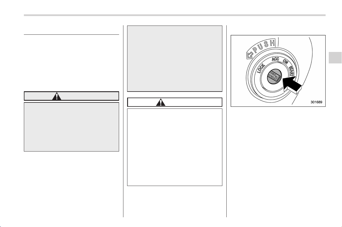
Black plate (143,1)
北米Model "A1160BE-C" EDITED: 2014/ 3/ 17
Ignition switch
& Models with push-button
start system
Your vehicle is equipped with the push-
button ignition switch. For details, refer to
“Push-button ignition switch (models with
push-button start system)” F3-5.
& Safety precautions
WARNING
. Never turn the ignition switch to
“LOCK” (off) while the vehicle is
being driven or towed because
that will lock the steering wheel,
preventing steering control. And
when the hybrid system is turned
off, it takes a much greater effort
than usual to steer.
. Before leaving t he vehicle, al-
ways remove the key from the
ignition switch for safety and
never allow an unattended child
to remain in the vehicle. Failure
to follow this procedure could
result in injury to a child or
others. Children co uld operate
the power windows, the moon-
roof or other controls or even
make the vehicle move.
CAUTION
Do not attach a large key holder or
key case to either key. If it banged
against your knees or hands while
you are driving, it could turn the
ignition switch from the “ON” posi-
tion to the “ACC” or “LOCK” (off)
position, thereby stopping the hy-
brid system. Also, if the key is
attached to a keyholder or to a large
bunch of other keys, centrifugal
force may act on it as the vehicle
moves, resulting in unwanted turn-
ing of the ignition switch.
& Ignition switch positions
The ignition switch has four positions:
LOCK (off), ACC, ON and START.
NOTE
. Keep the i gnition switch in the
“LOCK” (off) position when the hybrid
system is not running.
. Using electrical accessories for a
long time with the ignition switch in the
“ON” or “ACC” position can cause the
battery to go dead.
. If the ignition switch will not move
from the “LOCK” (off) position to the
“ACC” position, turn the steering wheel
slightly to the left and right as you turn
the ignition switch.
Instruments and controls/Ignition switch
3-3
– CONTINUED –
3
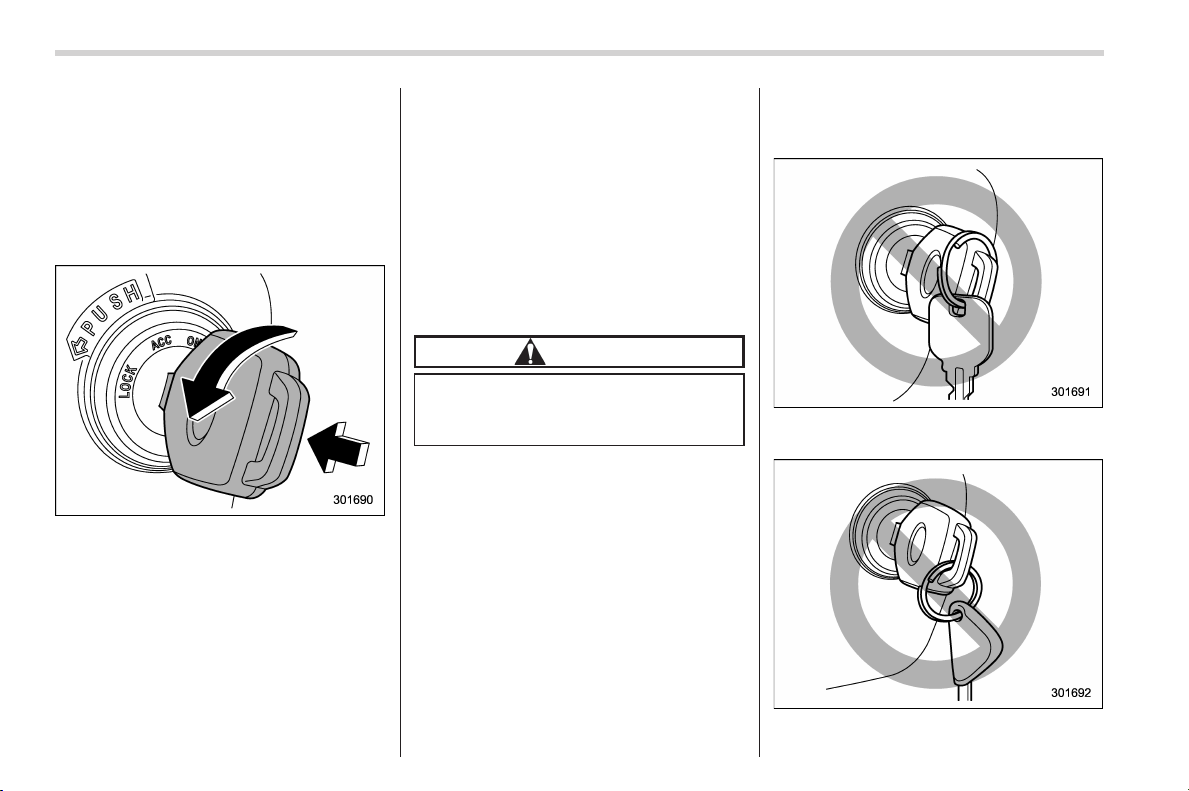
Black plate (144,1)
北米Model "A1160BE-C" EDITED: 2014/ 3/ 17
3-4
Instruments and controls/Ignition switch
& LOCK (off)
The key can only be inserted or removed
in this position. The ignition switch will lock
the steering wheel when you remove the
key.
If turning the key is difficult, turn the
steering wheel slightly to the right and left
as you turn the key.
The key can be turned from the “ACC” to
“LOCK” (off) position only when the select
lever is in the “P” position and the key is
pushed in while turning it.
& ACC
In this position the electrical accessories
(audio, accessory power outlet, etc.) can
be used.
& ON
This is the normal operating position after
the hybrid system is started.
& START
The hybrid system is started i n this
position. The starter cranks the engine to
start it. Then the hybrid system starts.
When the key is released (after the hybrid
system has started), the key automatically
returns to the “ON” position.
CAUTION
Do not turn the ignition switch to the
“START” position while the hybrid
system is running.
If your registered key fails to start the
hybrid system, pull out the key once (the
security indicator light will blink), and then
insert the key into the ignition switch and
turn it to the “START” position and again
try to start the hybrid system.
NOTE
The hybrid system may not start in the
following cases:
. The key grip is touching another key
or a metallic key holder.
. The key is near another key that
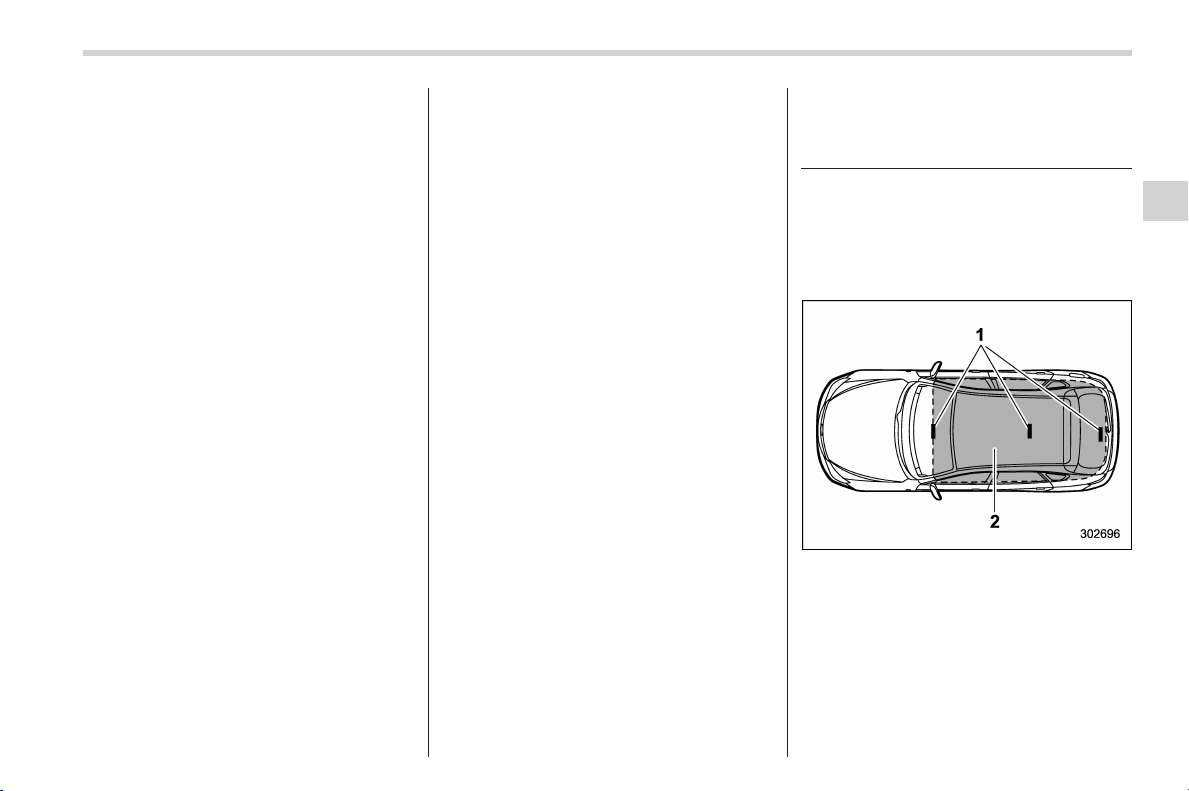
Black plate (145,1)
北米Model "A1160BE-C" EDITED: 2014/ 3/ 17
contains an immobilizer transponder.
. The key is near or touching another
transmitter.
& Key reminder chime
The reminder chime sounds when the
driver’s door is opened and the ignition
switch is in the “LOCK” (off) or “ACC”
position.
The chime stops under the following
conditions.
. when the ignition switch is turned to the
“ON” position
. when the key is removed from the
ignition switch
. when the driver’s door is closed
& Ignition switch light (if
equipped)
For easy access to the ignition switch in
the dark, the ignition switch light illumi-
nates when the driver’s door is opened or
when the driver’s door is unlocked using
the remote keyless entry transmitter.
The light remains illuminated for several
tens of seconds and then gradually turns
off under the following conditions.
. when the driver’s door is closed
. when the doors are unlocked using the
remote keyless entry transmitter
The light turns off immediately under the
following conditions.
. when the ignition switch is turned to the
“ON” position
. when all doors and the rear gate are
locked using the remote keyless entry
transmitter
Push-button ignition switch
(models with push-button
start system)
& Safety precautions
Refer to “Safety precautions” F2-10.
& Operating range for push-
button start system
1) Antenna
2) Operating range
NOTE
. If the access key is not detected
within the operating range of the an-
tennas inside the vehicle, the push-
button ignition switch and the hybrid
system start cannot be operated.
Instruments and controls/Push–button ignition switch (models with push–button start system)
3-5
– CONTINUED –
3
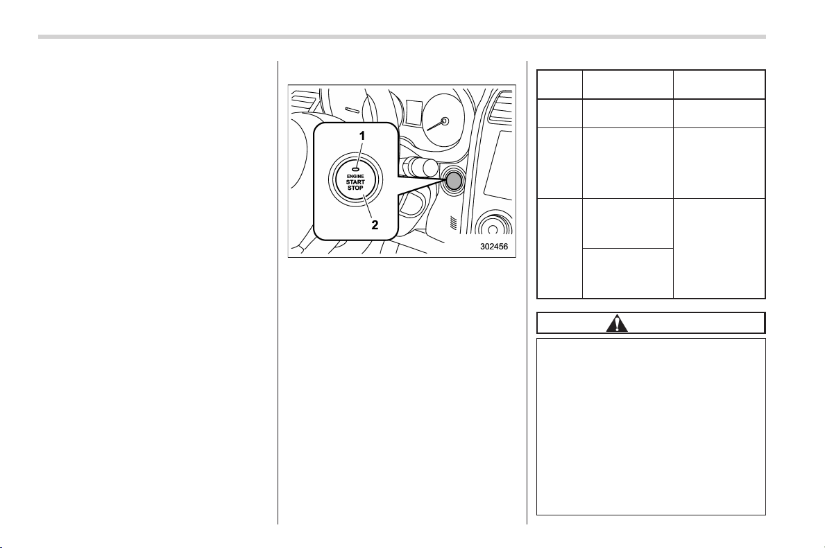
Black plate (146,1)
北米Model "A1160BE-C" EDITED: 2014/ 3/ 17
3-6
Instruments and controls/Push–button ignition switch (models with push–button start system)
. Even when the access key is outside
the vehicle, if it is placed too close to
the glass, it may be possible to switch
the power or to start the hybrid system.
. Do not leave the access key in the
following places. It may become im-
possible to operate the push-button
ignition switch and the hybrid system
start. It may also cause a false warning
to issue although no malfunction actu-
ally occurs, or not to issue a warning
when any malfunction occurs.
– On the instrument panel
– On the floor
– Inside the glove box
– Inside the door trim pocket
– On the rear seat
– At the cargo area
. When operating the push-button
ignition switch or starting the hybrid
system, if the access key battery is
discharged, perform the procedure
described in “Access key – if access
key does not operate properly” F9-23.
In such a case, replace the battery
immediately. Refer to “Replacing ac-
cess key battery” F11-46.
& Switching power status
1) Operation indicator
2) Push-button ignition switch
The power status is switched every time
the push-button ignition switch is pressed.
1. Carry the access key, and sit in the
driver’s seat.
2. Shift the select lever into the “P”
position.
3. Press the push-button ignition switch
without depressing the brake pedal. Every
time the button is pressed, the power is
switched i n the sequence of “OFF”,
“ACC”, “ON” and “OFF”. When the hybrid
system is stopped and the push-button
ignition switch is in “ACC” or “ON”, the
operation i ndicator on the push-button
ignition switch illuminates in orange.
Power
status
Indicator color Operation
OFF Turned off
Power is turned
off.
ACC Orange
The following
systems can be
used:
audio and ac-
cessory power
outlet.
ON
Orange
(while hybrid
system is
stopped)
All electrical
systems can be
used.
Turned off
(while hybrid
system is run-
ning)
CAUTION
. When the push-button ignition
switch is left in “ON” or “ACC”
for a long time, it may result in 12
V auxiliary battery discharge.
. Do not spill drinks or other
liquids on the push-button igni-
tion switch. It may cause a mal-
function.
. Do not touch the push-button
ignition switch with a hand soiled
with oil or other contaminants. It
may cause a malfunction.
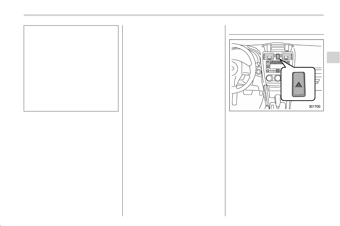
Black plate (147,1)
北米Model "A1160BE-C" EDITED: 2014/ 3/ 17
. If the push-button ignition switch
does not operate smoothly, stop
the operation. Contact a
SUBARU dealer immediately.
. If the push-button ignition switch
does not illuminate even when
the instrument panel illumination
is turned on, have the vehicle
inspected at a SUBARU dealer.
. If the vehicle was left in the hot
sun for a long time, the surface of
the push-button ignition switch
may get hot. Be careful not to
burn yourself.
NOTE
. The push-button ignition switch can-
not be switched to “OFF” when the
select lever is in a position other than
“P”.
. When operating the push-button
ignition switch, firmly press it all the
way.
. If the push-button ignition switch is
pressed quickly, the power may not
turn on or off.
. If the indicator light on the push-
button ignition switch flashes in green
when the push-button ignition switch is
pressed, steering is locked. When this
occurs, press the push-button ignition
switch while turning the steering wheel
left and right.
! Battery drainage prevention func-
tion
When the push-button ignition switch is
left in the “ACC” or “ON” position for
approximately 1 ho ur, the push-button
ignition switch will be automatically
switched to “OFF” to prevent the battery
from going dead. This function is activated
when the select lever is in the “P” position.
& When access key does not
operate properly
Refer to “Access key – if access key does
not operate properly” F9-23.
Hazard warning flasher
The hazard warning flasher is used to
warn other drivers when you have to park
your vehicle under emergency conditions.
The hazard warning flasher works regard-
less of the position of the ignition switch.
To turn on the hazard warning flasher,
push the hazard warning button on the
instrument panel. To turn off the flasher,
push the button again.
NOTE
When the hazard warning flasher is on,
the turn signals do not work.
Instruments and controls/Hazard warning flasher
3-7
3
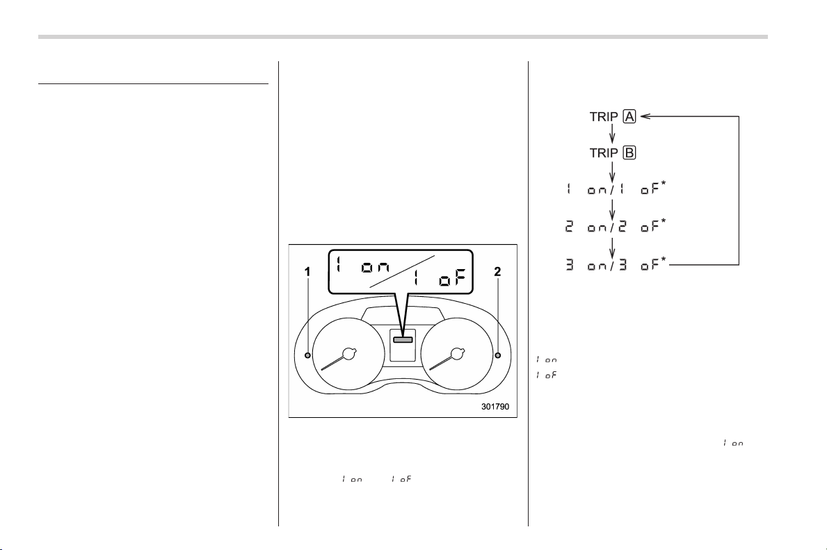
Black plate (148,1)
北米Model "A1160BE-C" EDITED: 2014/ 3/ 17
3-8
Instruments and controls/Meters and gauges
Meters and gauges
NOTE
Liquid-crystal displays are used in
some of the meters and gauges on
the combination meter. You will find
their indications hard to see if you wear
polarized glasses.
& Combination meter illumina-
tion
When the ignition switch is turned to the
“ON” position, the various parts of the
combination meter are illuminated in the
following sequence.
1. Warning lights, indicator lights, meter
needles, gauge needles and liquid crystal
display illuminate.
2. Meter and gau ge indic ations e ach
show MAX position.
3. Meter and gau ge indic ations e ach
show MIN position.
4. Regular illumination (for driving) be-
gins.
& Canceling the function for
meter/gauge needle move-
ment upon turning on the
ignition switch
It is possible to activate or deactivate the
movement of th e mete r needl es and
gauge needles that takes place when the
ignition switch is turned to the “ON”
position. To change the setting, perform
the following procedure.
1. Turn the ignition switch to the “LOCK”
(off) or “ACC” position.
1) Trip knob
2) Select knob
2. Press the trip knob or the select knob
to show “
” or “ ” on the trip meter
display.
The display can be switched as shown in
the following sequence by pressing the
trip knob.
*: They cannot be displayed when the
ignition switch is in the “ON” position.
To change the current setting, press and
hold the knob for at least 2 seconds.
: Activated
: Deactivated
NOTE
. Your vehicle’ s initial movement
setting of the meter/gauge needles
has been set for activation “
” at
the time of shipment from the factory.
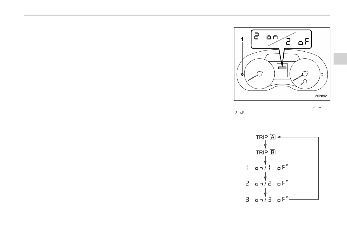
Black plate (149,1)
北米Model "A1160BE-C" EDITED: 2014/ 3/ 17
. It is not possible to change the initial
movement setting of the meter/gauge
needles when the ignition switch is in
the “ON” position. Change the setting
whentheignitionswitchisinthe
“LOCK” (off) or “ACC” position.
& Meter/Gauge needle illumi-
nation setting
When the setting is activated or deacti-
vated, the meter needles and gauge
needles illuminate and turn off as follows.
Activated:
When the driver’s door is opened while
the ignition switch is in the “LOCK” (off)
position, the needles illuminate and turn
off after approximately 20 seconds. The
illumination of the needles gradually turns
off after the ignition switch is turned from
the “ON” position to the “LOCK” (off)
position.
Deactivated:
The needles do not illuminate when the
driver’s door is opened while the ignition
switch is in the “LOCK” (off) position. The
illumination of the needles turns off im-
mediately after the ignition switch is turned
from the “ON” position to the “LOCK” (off)
position.
NOTE
. Even during the illumination after
the driver ’s door is opened, if the
ignition switch is turned to the “ON”
position, the combination meter will
illuminate as usual.
. If the doors are locked by the remote
keyless entry system or keyless ac-
cess function (if equipped) during the
illumination after the driver’s door is
opened, the illumination will be turned
off.
. Even while the illumination gradu-
ally turns off after the ignition switch is
turned to the “LOCK” (off) position, if
the ignition switc h is turned to the
“ON” position, the combination meter
illuminate as usual.
To change the setting:
1. Turn the ignition switch to the “LOCK”
(off) or “ACC” position.
2. Press the trip knob to show “ ” or
“
” on the odometer and trip meter
display. The display can be switched as
shown in the following illus tration b y
pressing the trip knob.
*: They cannot be displayed when the
ignition switch is in the “ON” position.
Instruments and controls/Meters and gauges
3-9
– CONTINUED –
3
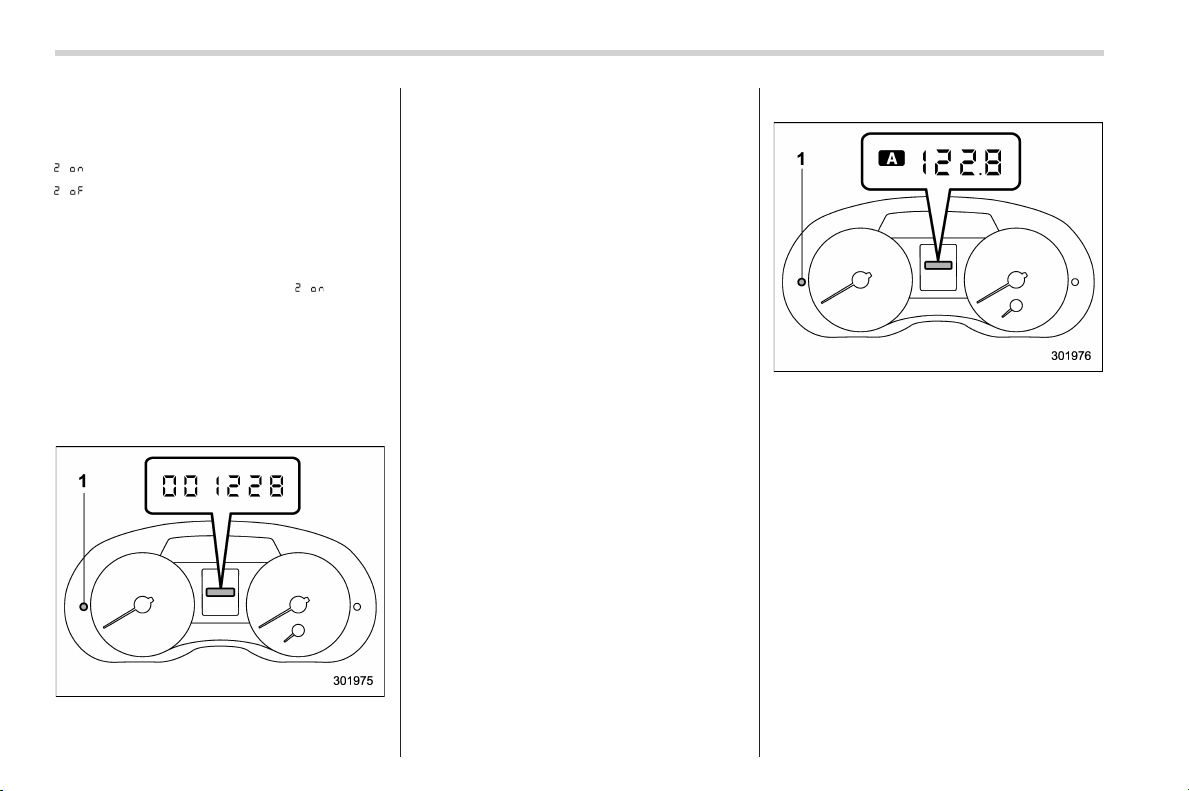
Black plate (150,1)
北米Model "A1160BE-C" EDITED: 2014/ 3/ 17
3-10
Instruments and controls/Meters and gauges
3. To change the current setting, press
the trip knob for at least 2 seconds.
: Activated
: Deactivated
NOTE
The initial illumination setting of the
meter/gauge needles of your vehicle
has been set for activation “
” at the
time of shipment from the factory.
& Speedometer
The speedome ter shows the vehicle
speed.
& Odometer
1) Trip knob
This meter displays the odometer when
the ignition switch is in the “ON” position.
The odometer shows the total distance
that the vehicle has been driven.
If you press the trip knob when the ignition
switch is in the “LOCK” (off) or “ACC”
position, the odometer/trip meter will light
up. If you do not press the trip knob within
10 seconds of illumination of th e od-
ometer/trip meter, the odometer/trip meter
will turn off.
Also, if you open and close the driver’s
door within 10 seconds of illumination of
the odometer/trip meter, the odometer/trip
meter will turn off.
& Double trip meter
1) Trip knob
This meter displays the two trip meters
when the ignition switch is in the “ON”
position.
The trip meter shows the distance that the
vehicle has been driven since you last set
it to zero.
If you press the trip knob when the ignition
switch is in the “LOCK” (off) or “ACC”
position, the odometer/trip meter will light
up. It is possible to switch between the A
trip meter and B trip meter indications
while the odometer/trip meter is lit up. If
you do not press the trip knob within 10
seconds of illumination of the odometer/
trip meter, the odometer/trip meter will turn
off.
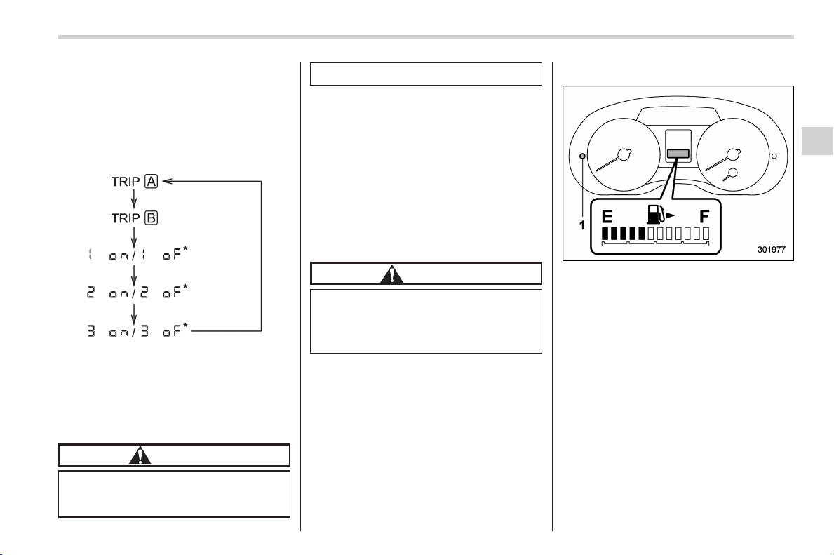
Black plate (151,1)
北米Model "A1160BE-C" EDITED: 2014/ 3/ 17
Also, if you open and close the driver’s
door within 10 seconds of illumination of
the odometer/trip meter, the odometer/trip
meter will turn off.
The display can be switched as shown in
the following sequence by pressing the
trip knob.
*: They cannot be displayed when the
ignition switch is in the “ON” position.
To set the trip meter to zero, select the A
trip or B trip meter by pressing the knob
and keep the knob pressed for more than
2 seconds.
CAUTION
To ensure safety, do not attempt to
change the function of the indicator
during driving, as an accident could
result.
NOTE
If the connection between the combina-
tion meter and battery is broken for any
reason such as vehicle maintenance or
fuse replacement, the data recorded on
the trip meter will be lost.
& Tachometer
The tachometer shows the engine speed
in thousands of revolutions per minute.
CAUTION
Do not operate the hybrid system
with the pointer of the tachometer in
the red zone. This may cause severe
damage to the engine.
& Fuel gauge
Fuel gauge
1) Trip knob
The fuel gauge is displayed when the
ignition is in the “ON” position, and it
shows the approximate amount of fuel
remaining in the tank.
The gauge indication may change slightly
during braking, turning or acceleration due
to fuel level movement in the tank.
If you press the trip knob while the ignition
switch is in the “LOCK” (off) or “ACC”
position, the fuel gauge will light up and
indicate the amount of fuel remaining in
the tank. If, while the fuel gauge is
indicating the amount of fuel remaining in
the tank, you (a) do not press the trip knob
for 10 seconds or (b) open and close the
Instruments and controls/Meters and gauges
3-11
– CONTINUED –
3
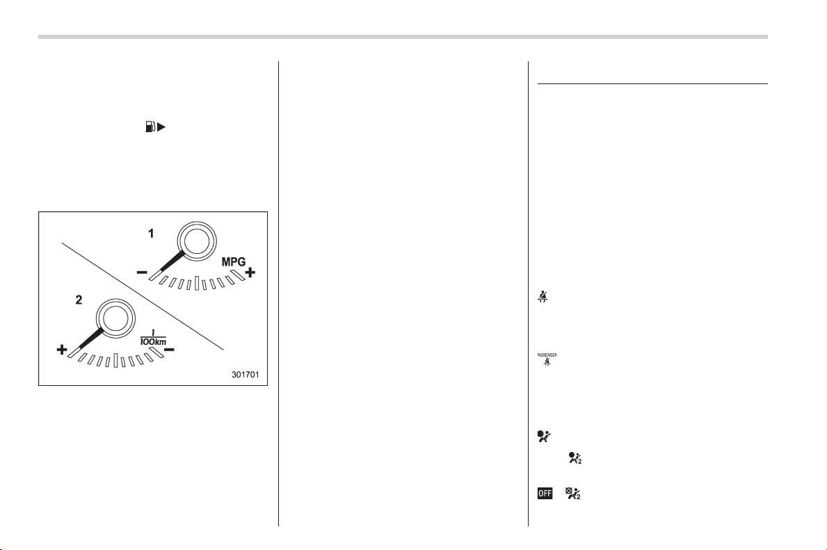
Black plate (152,1)
北米Model "A1160BE-C" EDITED: 2014/ 3/ 17
3-12
Instruments and controls/Warning and indicator lights
driver’s door, the fuel gauge indication will
turn off.
NOTE
You will see the “ ” sign in the fuel
gauge. This indicates that the fuel filler
door (lid) is located on the right side of
the vehicle.
& ECO gauge (if equipped)
1) U.S.-spec. models
2) Except U.S.-spec. models
The ECO gauge shows the difference
between the current rate of fuel consump-
tion and the average rate of fuel consump-
tion since the trip meter was last reset.
If the needle of the gauge moves towards
the right side, this indicates better fuel
efficiency.
NOTE
. The ECO gauge s hows only an
approximate indication of fuel effi-
ciency.
. After resetting the trip meter, the
average rate of fuel consumption is not
shown until driving 0.6 mile (1 km).
Before that time, the ECO gauge does
not operate.
Warning and indicator lights
& Initial illumination for system
check
Several of the warning and indicator lights
illuminate when the ignition switch is
initially turned to the “ON” position. This
permits checking the operation of the
bulbs.
Apply the parking brake and turn the
ignition switch to the “ON” position. For
the system check, the following l ights
illuminate and then turn off after several
seconds or after the hybrid system has
started.
: Seatbelt warning light
(The seatbelt warning light turns off
only when the driver fastens the
seatbelt.)
: Front passenger’s seatbelt warning
light
(The seatbelt warning light turns off
only when the front seat passenger
fastens the seatbelt.)
: SRS airbag system warning light
ON /
: Front passenger’s frontal airbag
ON indicator light
/ : Front passenger’s frontal airbag
OFF indicator light
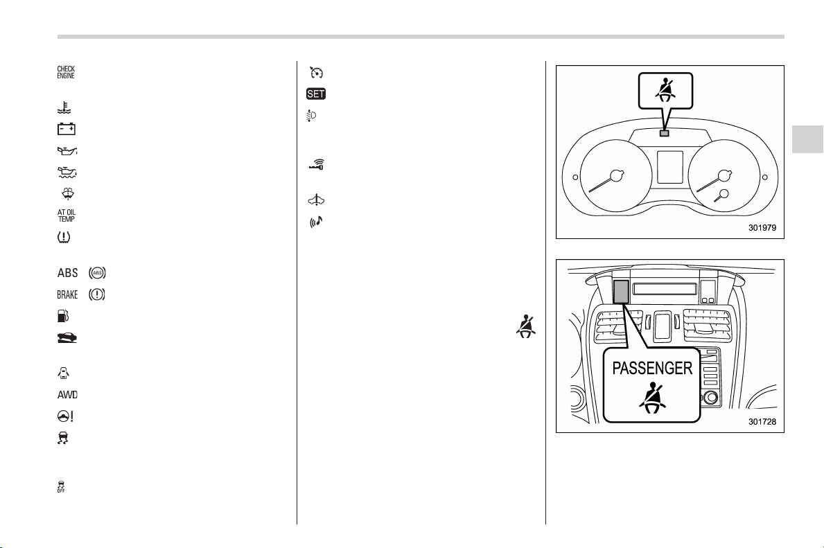
Black plate (153,1)
北米Model "A1160BE-C" EDITED: 2014/ 3/ 17
: CHECK ENGINE warning light/Mal-
function indicator light
: Coolant temperature high warning light
: Charge warning light
: Oil pressure warning light
: Engine low oil level warning light
: Windshield washer fluid warning light
: AT OIL TEMP warning light
: Low tire pressure warning light
(U.S.- spec. models)
/ : ABS warning light
/ : Brake system warning light
: Low fuel warning light
: Hill start assist warning light/Hill start
assist OFF indicator light
: Door open warning light
: AWD warning light
: Power steering warning light
: Vehicle Dynamics Control warning
light/Vehicle Dynamics Control opera-
tion indicator light
: Vehicle Dynamics Control OFF indica-
tor light
: Cruise control indicator light
: Cruise control set indicator light
: Automatic headlight beam leveler
warning light (models with HID head-
lights)
: Access key warning light
(if equipped)
: Hybrid fail lamp
: Pedestrian alert warning light
If any lights fail to illuminate, it indicates a
burned-out bulb or a malfunction of the
corresponding system.
Consult your authorized SUBARU dealer
for repair.
& Seatbelt warning light
and chime
Your vehicle is equipped with a seatbelt
warning device at the driver’s and front
passenger’s seat, as required by current
safety standards.
With the ignition switch turned to the “ON”
position, this device reminds the driver
and front passenger to fasten their seat-
belts by illuminating the warning lights in
the locations indicated in the following
illustration and sounding a chime.
Driver’s warning light
Front passenger’s warning light
! Operation
If the driver and/or front passenger have/
has not yet fastened the seatbelt(s) when
Instruments and controls/Warning and indicator lights
3-13
– CONTINUED –
3

Black plate (154,1)
北米Model "A1160BE-C" EDITED: 2014/ 3/ 17
3-14
Instruments and controls/Warning and indicator lights
the ignition switch is turned to the “ON”
position, the seatbelt warning light(s) will
flash for 6 seconds, to warn that the
seatbelt(s) is/are unfastened. If the dri-
ver’s seatbelt is not fastened, a chime will
also sound simultaneously.
NOTE
. If the driver’s and/or front passen-
ger’s seatbelt(s) are/is still not fastened
6 seconds later, the seatbelt warning
device operates as follows according
to the vehicle speed.
– At speeds lower than approxi-
mately 9 mph (15 km/h)
The warning light(s) for unfastened
seatbelt(s) will alternate between
steady illumination and flashing at
15-second intervals. The chime will
not sound.
– At speeds higher than approxi-
mately 9 mph (15 km/h)
The warning light(s) for unfastened
seatbelt(s) will alternate between
flashing and steady illumination at
15-second intervals and the chime
will sound while the warning light(s)
is/are flashing.
. It is possible to cancel the warning
operation th at follows the 6-second
warning after turning ON the ignition
switch . When the ignition switch is
turned ON next time, however, the
complete sequence of the warning
operation resumes. For further details
about canceling the warning operation,
please contact your SUBARU dealer.
If there is no passenger on the front
passenger’s seat, the seatbelt warning
device for the front passenger’s seat will
be deactivated. The front passenger’s
occupant detection system monitors
whether or not there is a passenger on
the front passenger’s seat.
Observe the following precautions. Failure
to do so may prevent the device from
functioning correctly or cause the device
to fail.
. Do not install any accessory such as a
table or TV onto the seatback.
. Do not store a heavy load in the
seatback pocket.
. Do not allow the rear seat occupant to
place his/her hands or legs on the front
passenger’s seatback, or allow him/her to
pull the seatback.
. Do not use front seats with their back-
ward-forward position and seatback not
being locked into place securely. If any of
them are not locked securely, adjust them
again. For adjusting procedure, refer to
“Front seats” F1-2.
If the seatbelt warning device for the front
passenger’s seat does not function cor-
rectly (e.g., it is activated even when the
front passenger’s seat is empty or it is
deactivated even when the front passen-
ger has not fastened his/her seatbelt),
take the following actions.
. Ensure that no article is placed on the
seat other than a child restraint system
and i ts chil d occupant, although w e
strongly recommend that all children sit
in the rear seat properly restrained.
. Ensure that there is no article left in the
seatback pocket.
. Ensure that the backward-forward po-
sition and seatback of front passenger’s
seat are locked into place securely by
moving the seat back and forth.
If still the seatbelt warning device for front
passenger’s seat does not function cor-
rectly after taking relevant corrective ac-
tions described above, immediately con-
tact your SUBARU dealer for an inspec-
tion.
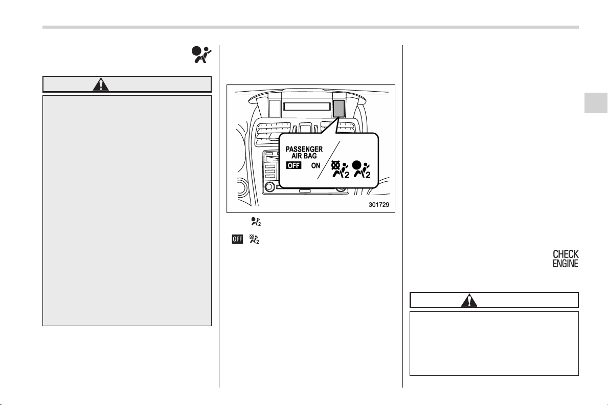
Black plate (155,1)
北米Model "A1160BE-C" EDITED: 2014/ 3/ 17
& SRS airbag system
warning light
WARNING
If the warning light exhibits any of
the following conditions, there may
be a malfunction in the seatbelt
pretensioners and/or SRS airbag
system. Immediately take your vehi-
cle to your nearest SUBARU dealer
to have the system checked. Unless
checked and properly repaired, the
seatbelt pretensioners and/or SRS
airbag will not operate properly in
the event of a collision, which may
increase the risk of injury.
. Flashing or flickering of the warn-
ing light
. No illumination of the warning
light when the ignition switch is
first turned to the “ON” position
. Continuous illumination of the
warning light
. Illumination of the warning light
while driving
For details about the components mon-
itored by the warning light, refer to “SRS
airbag system monitors” F1-62.
& Front passenger’s frontal
airbag ON and OFF indica-
tors
ON / : Front passenger’s frontal airbag ON
indicator
/ : Front passenger’s frontal airbag OFF
indicator
The front passenger’s frontal airbag ON
and OFF indicators show you the status of
the front passenger’s SRS frontal airbag.
The indicators are located next to the
clock in the center portion of the dash-
board.
When the ignition switch is turned to the
“ON” position, both the ON and OFF
indicators illuminate for 6 seconds during
which time the system is checked. Follow-
ing the system check, both indicators turn
off for 2 seconds. After that, one of the
indicators illuminates depending on the
status of the front passenger’s SRS frontal
airbag determined by the SUBARU ad-
vanced frontal airbag system monitoring.
If the front passenger’s SRS frontal airbag
is activated, the passenger’s frontal airbag
ON indicator will illuminate while the OFF
indicator will remain off.
If the front passenger’s SRS frontal airbag
is deactivated, the passenger’s frontal
airbag ON indicator will remain off while
the OFF indicator will illuminate.
With the ignition switch turned to the “ON”
position, if both the ON and OFF indica-
tors remain illuminated or off simulta-
neously even after the system check
period, the system is malfunctioning.
Contact your SUBARU dealer immedi-
ately for an inspection.
& CHECK ENGINE warn-
ing light/Malfunction in-
dicator light
CAUTION
If the CHECK ENGINE light illumi-
nates while you are driving, have
your vehicle checked/repaired by
your SUBARU dealer as soon as
possible. Continued vehicle opera-
tion without having the emission
Instruments and controls/Warning and indicator lights
3-15
– CONTINUED –
3
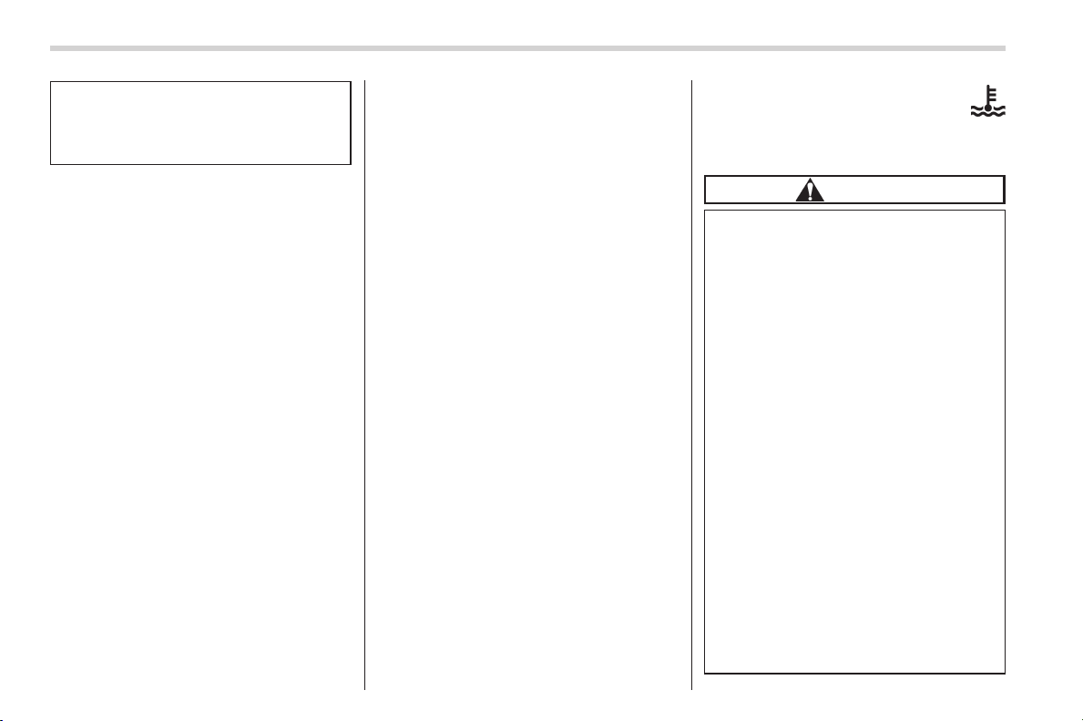
Black plate (156,1)
北米Model "A1160BE-C" EDITED: 2014/ 3/ 17
3-16
Instruments and controls/Warning and indicator lights
control system checked and re-
paired as necessary could cause
serious damage, which may not be
covered by your vehicle’s warranty.
If this light illuminates steadily or blinks
while the hybrid system is running, it may
indicate that there is a problem or potential
problem somewhere in the emission con-
trol system.
! If the light illuminates steadily
If the light illuminates steadily while driving
or does not turn off after the hybrid system
starts, an emission control system mal-
function has been detected.
You should have your vehicle checked by
an authorized SUBARU dealer immedi-
ately.
NOTE
This light also illuminates when the fuel
filler cap is not tightened until it clicks.
If you have recently refueled your vehicle,
the cause of the CHECK ENGINE warning
light/malfunction indicator light illuminating
could be a loose or missing fuel filler cap.
Remove the cap and retighten it until it
clicks. Make sure nothing is interfering
with the sealing of the cap. Tightening the
cap will not make the CHECK ENGINE
warning light turn off immediately. It may
take several driving trips. If the light does
not turn off, take your vehicle to your
authorized SUBARU dealer immediately.
! If the light is blinking
If the light is blinking while driving, an
engine misfire condition has been de-
tected which may damage the emission
control system.
To prevent serious damage to the emis-
sion control system, you should do the
following.
. Reduce vehicle speed.
. Avoid hard acceleration.
. Avoid steep uphill grades.
. Reduce the amount of cargo, if possi-
ble.
The CHECK ENGINE warning light may
stop blinking and illuminate steadily after
several driving trips. You should have your
vehicle checked by an authorized
SUBARU dealer immediately.
& Coolant temperature
low indicator light/Cool-
ant temperature high
warning light
CAUTION
. After turning the ignition switch
to the “ON” position, if this
indicator light/warning light be-
haves in any of the following
ways, the electrical system may
be malfunctioning. Contact your
SUBARU dealer immediately for
an inspection.
– It remains blinking in RED.
– It remains illuminated in RED
for more than 2 seconds.
– It remains blinking in RED and
BLUE alternately.
. While driving, if this indicator
light/warning light behaves in
any of the following ways, take
the speci fied appropriate mea-
sure listed below.
– Blinking or illuminated in
RED:
Safely stop the vehicle as
soon as possible, and refer
to the emergency steps to
take in the case of engine
Black plate (157,1)
北米Model "A1160BE-C" EDITED: 2014/ 3/ 17
overheating. After that, have
the system checked by your
nearest SUBARU dealer. Refer
to “Engine overheating” F9-
17.
– Blinking in RED and BLUE
alternately:
The electrical system may be
malfunctioning. Contact your
SUBARU dealer for an inspec-
tion.
This coolant temperature low indicator
light/coolant temperature high warning
light has the following three functions.
. Illumination in BLUE indicates insuffi-
cient warming up of the engine
. Blinking in RED i ndica tes t hat t he
engine is close to overheating
. Illumination in RED indicates overheat-
ing condition of the engine
For a system check, this indicator light/
warning light il luminates in RE D for
approximately 2 seconds when the igni-
tion switch is turned to the “ON” position.
After that, this indicator light/warning light
changes to BLUE and maintains illumina-
tion in BLUE. This BLUE illuminated light
turns off when the engine is warmed up
sufficiently.
If the engine coolant temperature in-
creases ov er the specified range, the
indicator li ght/warning light blinks in
RED. At this time, the engine is close to
overheating.
If the engine coolant temperature in-
creases further, the indicator light/warning
light illuminates in RED continuously. At
this time, the engine may be overheating.
When the indicato r light/wa rning li ght
blinks in RED or illuminates in RED, safely
stop the vehicle as soon as possible, and
refer to the emergency steps to take in the
case of engine overheating. Refer to
“Engine overheating” F9-17. After that,
have the system checked by your nearest
SUBARU dealer.
Also, if the indicator light/warning light
often blinks in RED, the electrical system
may be malfunctioning. Contact your
SUBARU dealer for an inspection.
NOTE
If the engine is restarted after a certain
driving condition, this indicator light/
warning light may illuminate in RED.
However, this is not a malfunction if the
indicator light/warning light turns off
after a short time.
& Charge warning light
If this light illuminates when the hybrid
system is running, it may indicate that the
charging system of the 12 V auxiliary
battery and 12 V engine restart battery is
not working properly.
If the light illuminates while driving or does
not turn off after the hybrid system starts,
stop the hybrid system at the first safe
opportunity and check the alternator belt.
If the belt is loose, broken or if the belt is in
good condition but the light remains
illuminated, contact your nearest
SUBARU dealer immediately.
& Oil pressure warning
light
If this light illuminates when the hybrid
system is running, it may indicate that the
engine oil pressure is low and the lubricat-
ing system is not working properly.
If the light illuminates while driving or does
not turn off after the hybrid system starts,
stop the hybrid system at the first safe
opportunity and check the engine oil level.
If the oil level is low, add oil immediately. If
the engine oil is at the proper level but the
light remains illuminated, contact y our
nearest SUBARU dealer immediately.
For details about checking the engine oil
Instruments and controls/Warning and indicator lights
3-17
– CONTINUED –
3
Black plate (158,1)
北米Model "A1160BE-C" EDITED: 2014/ 3/ 17
3-18
Instruments and controls/Warning and indicator lights
level or adding the engine oil, refer to
“Engine oil” F11-10.
CAUTION
Do not operate the hybrid system
with the oil pressure warning light
illuminated. This may cause serious
engine damage.
& Engine low oil level
warning light
This light illuminates when the engine oil
level decreases to the lower limit.
If the engine low oil level warning light
illuminates while driving, park the vehicle
in a safe and level location, and then
check the engine oil level. Wh en the
engine oil level is not within the normal
range, refill with engine oil. Refer to
“Engine oil” F11-10.
If the warning light does not turn off after
refilling the engine oil, or the warning light
illuminates even though the engine oil
level is within the normal range, have the
vehicle checked by a SUBARU dealer.
NOTE
. After replacing or adding the engine
oil, if the engine oil level is within the
normal range when restarting the hy-
brid system on a level surface, the
warning light will turn off.
. The warning light may illuminate
temporarily in the following conditions
because a low oil level may be detected
as a result of significant oil movement
in the engine.
– when the vehicle is considerably
inclined on an uphill or steep slope
– when the vehicle has continu-
ously accelerated and decelerated
– when the vehicle is continuously
turned
– when the vehicle is driven on a
road that alternates continuously
between uphill and downhill
& Windshield washer
fluid warning light
This light illuminates when the fluid level in
the windshield washer fluid tank de-
creases to the lower limit (approximately
1.1 US qt, 1.0 liter, 0.9 Imp qt).
& AT OIL TEMP warning
light
If this light illuminates when the hybrid
system is running, it may indicate that the
transmission fluid temperature is too hot.
If the light illuminates while driving, im-
mediately stop the vehicle in a safe place
and let the hybrid system idle until the
warning light turns off.
! Transmission control system warn-
ing
If the “AT OIL TEMP” warning light flashes
after the hybrid system has started, it may
indicate that the transmission control
system is not working properly. Contact
your nearest SUBARU dealer for service
immediately.
& Low tire pressure
warning light (U.S.-spec.
models)
When the ignition switch is turned to the
“ON” position, the low tire pressure warn-
ing light will illuminate for approximately 2
seconds to check that the tire pressure
monitoring system (TPMS) is functioning
properly. If there is no problem and all tires
are properly inflated, the light will turn off.
Each tire, including the spare (if provided),
should be checked monthly when cold
and inflated to the inflation pressure
recommended by the vehicle manufac-
turer on the vehicle placard or tire inflation
pressure label. (If your vehicle has tires of
a different size than the size indicated on
the vehicle placard or tire inflation pres-
sure label , yo u sho uld d eterm ine the
Black plate (159,1)
北米Model "A1160BE-C" EDITED: 2014/ 3/ 17
proper tire inflation pressure for those
tires.)
As an added safety feature, your vehicle
has been equipped with a tire pressure
monitoring system (TPMS) that illuminates
a low tire pressure telltale when one or
more of your tires is significantly under-
inflated. Accordingly, when the low tire
pressure telltale illuminates, you should
stop and check your tires as soon as
possible, and inflate them to the proper
pressure. Driving on a significantly under-
inflated tire causes the tire to overheat and
can lead to tire failure. Under-inflation also
reduces fuel efficiency and tire tread life,
and may affect the vehicle’s handling and
stopping ability.
Please note t hat the TPMS is not a
subst itute for proper tire ma intenance,
and it is the drive r’s responsi bili ty to
maintain correct tire pressure, even if
under-inflation has not reached the level
to trigger illumination of the TPMS low tire
pressure telltale.
Your vehicle has also been equipped with
a TPMS malfunction indicator to indicate
when the system is not operating properly.
The TPMS malfunction indicator is com-
bined with the low tire pressure telltale.
When the system detects a malfunction,
the telltale will flash for approximately one
minute and then remain continuously
illuminated. This sequence will continue
upon subsequent vehicle start-ups as long
as the malfun ction exists. When the
malfunction indicator is illuminated, the
system may not be able to detect or signal
low tire pressure as intended. TPMS
malfunctions may occur for a variety of
reasons, including the installation of re-
placement or alternate tires or wheels on
the vehicle that prevent the TPMS from
functioning properly. Always check the
TPMS malfunction telltale after replacing
one or more tir es or wh eels on your
vehicle to ensure that the replacement or
alternate tires and wheels allow the TPMS
to continue to function properly.
Should the warning light illuminate stea-
dily after blinking for approximately one
minute, have the system inspected by
your nearest SUBARU dealer as soon as
possible.
WARNING
If this light does not illuminate
briefly after the ignition switch is
turned ON or the light illuminates
steadily after blinking for approxi-
mately one minute, you should have
your Tire Pressure Monitoring Sys-
tem checked at a SUBARU dealer as
soon as possible.
If this light illuminates while driving,
never brake suddenly and k eep
driving straight ahead while gradu-
ally reducing speed. Then slowly
pull off the road to a safe place.
Otherwise an accident involving
serious vehicle damage and serious
personal injury could occur.
If this light still illuminates while
driving after adjusting the tire pres-
sure, a tire may have significant
damage and a fast leak that causes
the tire to lose air rapidly. If you have
a flat tire, refer to “In case of a flat
tire” F9-4.
When a replacement tire is mounted
or a wheel rim is replaced without
the original pressure sensor/trans-
mitter being transferred, the Low tire
pressure warning light will illumi-
nate steadily after blinking for ap-
proximately one minute. This indi-
cates the TPMS is unable to monitor
all four road wheels. Contact your
SUBARU dealer as soon as possible
for tire and sensor replacement and/
or system resetting.
If the light illuminates steadily after
blinking for approximately one min-
ute, promptly contact a SUBARU
dealer to have the system inspected.
Instruments and controls/Warning and indicator lights
3-19
– CONTINUED –
3
Black plate (160,1)
北米Model "A1160BE-C" EDITED: 2014/ 3/ 17
3-20
Instruments and controls/Warning and indicator lights
CAUTION
The tire pressure monitoring system
is NOT a substitute for manually
checking tire pressure. The tire
pressure should be checked peri-
odically (at least monthly) using a
tire gauge. After any change to tire
pressure(s), the tire pressure mon-
itoring system will not re-check tire
inflation pressures until the vehicle
is first driven more than 20 mph (32
km/h). After adjusting the tire pres-
sures, increase the vehicle speed to
at least 20 mph (32 km/h) to start the
TPMS re-checking of the tire infla-
tion pressures. If the tire pressures
are now above the severe l ow
pressure threshold, the low tire
pressure warning light should turn
off a few minutes later. Therefore, be
sure to install the specified size for
the front and rear tires.
& ABS warning light
CAUTION
. If any of the following conditions
occur, we recommend that you
have the ABS system repaired at
the first available opportunity by
your SUBARU dealer.
– The warning light does not
illuminate when the ignition
switch is turned to the “ON”
position.
– The warning light illuminates
when the ignition switch is
turned to the “ON” position,
but it does not turn off even
when the vehicle speed ex-
ceeds approximately 25 mph
(40 km/h).
– The warning light illuminates
during driving.
. When the warning light is on (and
the brake system warning light is
off), the ABS function shuts
down. However, the conventional
brake system continues to oper-
ate normally.
The ABS warning light illuminates to-
gether with the brake system warning light
if the EBD sy stem malfuncti ons. For
further details of the EBD system mal-
function warning, refer to “Electronic
Brake Force Distribution (EBD) system
warning” F3-21.
NOTE
If the warning light behavior is as
described in the following conditions,
the ABS system may be considered
normal.
. The warning light illuminates when
the ign ition switch is turned to the
“ON” position and turns off approxi-
mately 2 sec onds after the h ybrid
system has started.
. The warning light illuminates right
after the hybrid system is started but
turns off immediately, remaining off.
. The warning light remains illumi-
nated after the hybrid system has been
started, but it turns off when the vehicle
speed reaches approximately 25 mph
(40 km/h).
. The warning light illuminates during
driving, but it turns off immediately and
remains off.
When driving with an insufficient battery
voltage such as when the hybrid system is
jump started, the ABS warning light may
illuminate. This is due to the low battery
voltage and does not indicate a malfunc-
tion. When the battery becomes f ully
charged, the light will turn off.
Black plate (161,1)
北米Model "A1160BE-C" EDITED: 2014/ 3/ 17
& Brake system
warning light (red)
WARNING
. Driving with the brake system
warning light on is dangerous.
This indicates your brake system
may not be working properly. If
the light remains i lluminated,
have the brakes inspected by a
SUBARU dealer immediately.
. If at all in doubt about whether
the brakes are operating prop-
erly, do not drive the vehicle.
Have your vehicle towed to the
nearest SUBARU dealer for re-
pair.
This light has the following functions.
! Parking brake warning
The light illuminates with the parking
brake applied while the ignition switch is
in the “ON” position. It turns off when the
parking brake is fully released.
! Brake fluid level warning
This light illuminates when the brake fluid
level has dropped to near the “MIN” level
of the brake fluid reservoir with the ignition
switch in the “ON” position and with the
parking brake fully released.
If the brake system warning light should
illuminate while driving (with the parking
brake fully released and with the ignition
switch positioned in “ON”), it could be an
indication of leaking of brake fluid or worn
brake pads. If this occurs, immediately
stop the vehicle at the nearest safe place
and check the brake fluid level. If the fluid
level is below the “MIN” mark in the
reservoir, do not drive the vehicle. Have
the vehicle towed to the nearest SUBARU
dealer for repair.
! Electronic Brake Force Distribution
(EBD) system warning
The brake system warning light also
illuminates if a malfunction occurs in the
EBD system. In that event, it illuminates
together with the ABS warning light.
The EBD system may be malfunctioning if
the brake system warning light and ABS
warning light illuminate simultaneously
during driving.
Even if the EBD system fails, the conven-
tional braking system will still function.
However, the rear wheels will be more
prone to locking when the brakes are
applied harder than usual and the vehi-
cle’s motion may therefore become some-
what harder to control.
If the brake system warning light and ABS
warning light illuminate simultaneously,
take the following steps.
1. Stop the vehicle in the nearest safe,
flat place.
2. Shut down the hybrid system, apply
the parking brake and then restart it.
3. Release the parking brake. If both
warning lights turn off, the EBD system
may be malfunctioning. Drive carefully to
the nearest SUBARU dealer and have the
system inspected.
4. If both warning lights illuminate again
and remain illuminated after the hybrid
system has been restarted, shut down the
hybrid system again, apply the parking
brake, and check the brake fluid level.
5. If the brake fluid level is not below the
“MIN” mark, the EBD system may be
malfunctioning. Dri ve carefully to the
nearest SUBARU dealer and have the
system inspected.
6. If the brake fluid level is below the
“MIN” mark, DO NOT drive the vehicle.
Instead, have the vehicle towed to the
nearest SUBARU dealer for repair.
! Vacuum pump fail lamp
This light illuminates when a malfunction
is detected in the brake vacuum pump
system.
Instruments and controls/Warning and indicator lights
3-21
– CONTINUED –
3
Black plate (162,1)
北米Model "A1160BE-C" EDITED: 2014/ 3/ 17
3-22
Instruments and controls/Warning and indicator lights
NOTE
The brake vacuum pump system as-
sists the boost pressure under the
following conditions.
. when driving only using the electric
motor power
. when driving at high altitudes while
the engine is cold
& Low fuel warning light
The low fuel warning light illuminates
when the tank is nearly empty, at approxi-
mately 1.8 US gal (7.0 liters, 1.5 Imp gal).
It only operates when the ignition switch is
in the “ON” position.
CAUTION
Promptly put fuel in the tank when-
ever the low fuel warning light
illuminates. Engine misfires as a
result of an empty tank could cause
damage to the engine.
NOTE
This light does not turn off unless the
tank is replenished up to an internal
fuel quantity of approximately 4.5 US
gal (17 liters, 3.7 Imp gal).
& Hill start assist warning
light/Hill start assist
OFF indicator light
! Hill start assist warning light
While the hybrid system is running, if there
are any malfunctions in the Hill start assist
system, the warning light will illuminate.
WARNING
When the Hill start assist warning
light illuminates, have the vehicle
inspected at an authorized SUBARU
dealer.
! Hill start assist OFF indicator light
While the Hill start assist system is
deactivated, the Hill start assist OFF
indicator light illuminates continuously to
inform the driver that the Hill start assist
system is not operational.
& Door open warning
light
The warning light illuminates if any door,
the rear gate is not fully closed. This
function is effective even if the ignition
switch is in the “LOCK” (off) or “ACC”
position, or the key is removed from the
ignition switch.
Always make sure this light is not illumi-
nated before you start to drive.
& All-Wheel Drive warn-
ing light
This light blinks if the vehicle is driven with
tires of differing diameters fitted on the
wheels or with an excessively low air
pressure in any of the tires.
CAUTION
Continuing to drive with the AWD
warning light blinking can damage
the powertrain. If the AWD warning
light starts to blink, promptly park in
a safe place and check whether the
tires have differing diameters and
whet her any of the tires has an
excessively low inflation pressure.
& Power steering warn-
ing light
This warning light illuminates when the
ignition switch is turned to the “ON”
position and turns off after the hybrid
system has started. This indicates that
the warning system is working properly.
Black plate (163,1)
北米Model "A1160BE-C" EDITED: 2014/ 3/ 17
While the hybrid system is running, this
warning light illuminates when a malfunc-
tion has been detected in the electric
power steering system.
CAUTION
When the power steering warning
light is illuminated, there may be
more resistance when the steering
wheel is operated. Drive carefully to
the n earest SUBAR U dealer and
have the vehicle inspected immedi-
ately.
NOTE
If the steering wheel is operated in the
following ways, the power steering
control system may temporarily limit
the power assist in order to prevent the
system components, such as the con-
trol computer and drive motor, from
overheating.
. The steering wheel is operated fre-
quently and turned sharply while the
vehicle is maneuvered at extremely low
speeds, such as while frequently turn-
ing the steering wheel during parallel
parking.
. The steering wheel remains in the
fully turned position for a long period
of time.
At this time, there will be more resis-
tance when steering. However this is
not a malfunction. Normal steering
force will be restored after the steering
wheel is not operated for a while and
the power steering control system has
an opportunity to cool down. However,
if the power steering is operated in a
non-standard way which causes power
assist limitation to occur t oo fre-
quently, that may result in a malfunc-
tion of the power steering control
system.
& Vehicle Dynamics
Control warning light/
Vehicle Dynamics Con-
trol operation indicator
light
! Vehicle Dynamics Control warning
light
CAUTION
The Vehicle Dynamics Control sys-
tem provides its ABS control
through the electrical circuit of the
ABS system. Accordingly, if the ABS
is inoperative, the Vehicle Dynamics
Control system becomes unable to
provide ABS control. As a result, the
Vehicle Dynamics Control system
also becomes inoperative, causing
the warning light to illuminate.
Though both the Vehicle Dynamics
Control and ABS systems are inop-
erative in this case, the ordinary
functions of the brake system are
still available. You will be safe while
driving with this condition, but drive
carefully and have your vehicle
checked at a SUBARU dealer as
soon as possible.
NOTE
. If the electrical circuit of the Vehicle
Dynamics Control system itself mal-
functions, the warning light only illumi-
nates. At this time, the ABS (Anti-lock
Brake System) remains fully opera-
tional.
. The warning light illuminates when
the electronic control system of the
ABS/Vehicle Dynamics Control system
malfunctions.
The Vehicle Dynamics Control system is
probably inoperative under any of the
following conditions. Have your vehicle
checked at a SUBARU dealer immedi-
ately.
. The warning light does not illuminate
Instruments and controls/Warning and indicator lights
3-23
– CONTINUED –
3

Black plate (164,1)
北米Model "A1160BE-C" EDITED: 2014/ 3/ 17
3-24
Instruments and controls/Warning and indicator lights
when the ignition switch is turned to the
“ON” position.
. The warning light illuminates while the
vehicle is running.
NOTE
If the warning light behavior is as
described in the following examples,
the Vehicle Dynamics Control system
may be considered normal.
. The warning light illuminates when
the ignition switch is turned to the
“ON” position and turns off approxi-
mately 2 seconds after the hybrid
system has started.
. The warning light illuminates right
after the hybrid system is started but
turns off immediately, remaining off.
. The warning light illuminates after
the hybrid system has started and
turns off while the vehicle is subse-
quently being driven.
. The warning light illuminates during
driving, but it turns off immediately and
remains off.
. The warning light illuminates when
the hybrid system has stalled and
continues to illuminate after the hybrid
system has been restarted. However, it
will turn off once the vehicle starts
moving.
! Vehicle Dynamics Control opera-
tion indicator light
The indicator light flashes during activa-
tion of the skid suppression function and
during activation of the traction control
function.
NOTE
. The light may remain illuminated for
a short period of time after the hybrid
system has been started, especially in
cold weather. This does not indicate
the existence of a problem. The light
should turn off as soon as the engine
has warmed up.
. The indicator light illuminates when
the engine has developed a problem
and the CHECK ENGINE warning light/
malfunction indicator light is on.
The Vehicle Dynamics Control system is
probably malfunctioning under the follow-
ing condition. Have your vehicle checked
at a SUBARU dealer as soon as possible.
. The light does not turn off even after
the lapse of several minutes (the hybrid
system has warmed up) after the hybrid
system has started.
& Vehicle Dynamics
Control OFF indicator
light
The light illuminates when the Vehicle
Dynamics Control OFF switch is pressed
to deactivate the Vehicle Dynamics Con-
trol system.
The Vehicle Dynamics Control system is
probably malfunctioning under any of the
following conditions. Have your vehicle
checked at a SUBARU dealer immedi-
ately.
. The light does not illuminate when the
ignition switch is turned to the “ON”
position.
. The light does not turn off even once
several seconds have elapsed after the
ignition switch has been turned to the
“ON” position.
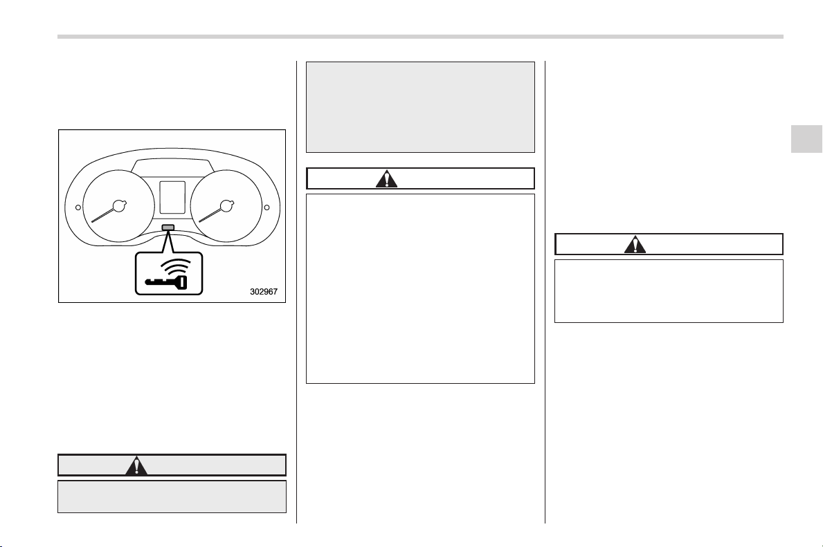
Black plate (165,1)
北米Model "A1160BE-C" EDITED: 2014/ 3/ 17
& Warning chimes and warning
light of the keyless access
with push-button start sys-
tem (if equipped)
Access key warning light
The keyless access with push-button start
system sounds a warning chime and
flashes the access key warning light on
the combination meter in order to minimize
improper operations and help protect your
vehicle from theft.
When the warning chime sounds and/or
the warning light flashes, take the appro-
priate action.
WARNING
Never drive the vehicle if the indi-
cator on the push-button ignition
switch is flashing in green when
starting the hybrid system. This
indicates the status that the steering
wheel is not released and could
result in an accident involving ser-
ious injury or death.
CAUTION
. When starting the hybrid system
again after the operation indica-
tor on the push-button ignition
switch flashes in green, if the
operation indicator is still flash-
ing in green, there could be a
steering lock malfunction. Con-
tact your SUBARU dealer as
soon as possible.
. When the operation indicator on
the push-button ignition switch
flashes in orange, contact a
SUBARU dealer immediately.
NOTE
. Even when the access key is within
the operating ranges inside the vehicle,
the access key warning for hybrid
system start may be provided depend-
ing on the status of the access key and
the environmental conditions.
. When the access key is taken out of
the vehicle through an open window,
the acce ss key takeout warning or
passenger access key takeout warning
will not be provided.
. If a warning or malfunction is de-
tected in the “keyless access with
push-button start system”, an interrup-
tion screen will be displayed on the
multi function display. For details, refer
to “Interruption screen” F3-35.
! List of warnings
CAUTION
When any of the following warnings
occurs even if the access key warn-
ing light does not illuminate, take
the appropriate action.
Instruments and controls/Warning and indicator lights
3-25
– CONTINUED –
3

Black plate (166,1)
北米Model "A1160BE-C" EDITED: 2014/ 3/ 17
3-26
Instruments and controls/Warning and indicator lights
Inside warning
chime
Outside warning
chime
Access key
warning light on
meter
Operation indica-
tor on push-button
ignition switch
Status Action
Ding,
ding ...
(intermittent)
—— —
The driver’s door was opened while
the push-button ignition switch is
“ACC” and the select lever is in the
“P” position.
Switch the push-button ignition
switch to “OFF”, or close the
driver’s door.
*When exiting the vehicle, be sure
to switch the push-button ignition
switch to “OFF”.
The push-button ignition switch
was switched to “OFF” while the
driver’s door is open.
Close the driver’s door.
Ding
Short beep
(2 seconds)
——
Lockout warning:
An attempt was made to lock all
doors while the access key is left
inside the vehicle.
Take out the access key from the
vehicle, and lock the doors.
*The doors cannot be locked while
the access key is inside the vehicle.
*A chirp sound will be heard, and all
doors will be unlocked.
—
Short beep
(2 seconds)
——
Access key lock-in warning:
The door lock sensor was touched
while the push-button ignition
switch is “OFF” and the access key
is inside the vehicle.
Take out the access key from the
vehicle, and lock the doors.
*If the access key is inside the
vehicle, the doors cannot be
locked.
—
Beep, beep ...
(5 beeps)
——
Door ajar warning:
The door lock sensor is touched
while the push-button ignition
switch is in the “OFF” position and
one of the doors including the rear
gate is opened.
Close the doors securely and lock
them.
*If one of the doors including the
rear gate is opened, the doors
cannot be locked.
Ding
Long beep (60
seconds max.)
——
Power warning:
The door lock sensor was touched
while carrying the access key and
the push-button ignition switch is in
a position other than “OFF” and the
select lever is in the “P” position.
Return the access key inside the
vehicle, or switch the push-button
ignition switch to “OFF”.
*If the push-button ignition switch is
not switched to “OFF”, the doors
cannot be locked.
Black plate (167,1)
北米Model "A1160BE-C" EDITED: 2014/ 3/ 17
Inside warning
chime
Outside warning
chime
Access key
warning light on
meter
Operation indica-
tor on push-button
ignition switch
Status Action
Ding, ding ...
(7 seconds)
—
(Flashes 1 sec.
intermittent)
—
Access key warning:
The vehicle was driven while the
access key is not inside the vehi-
cle.
Carry the access key, and drive the
vehicle.
Ding —
(Flashes 1 sec.
intermittent)
—
Access key warning for hybrid
system start:
The push-button ignition switch
was pressed while the access key
is not inside the vehicle.
Carry the access key, and press the
push-button ignition switch.
Ding
Beep, beep,
beep (3 beeps)
(Flashes 1 sec.
intermittent)
—
Access key takeout warning:
The driver exited the vehicle with
the access key and closed the
driver’s door while the push-button
ignition switch is in a position other
than “OFF” and the select lever is in
the “P” position.
Switch the push-button ignition
switch to “OFF”, and get out of the
vehicle.
Ding
Beep, beep,
beep (3 beeps)
(Flashes 1 sec.
intermittent)
—
Passenger access key takeout
warning:
A fellow passenger exited the
vehicle with the access key and
closed a door other than the
driver’s door while the push-button
ignition switch is in a position other
than “OFF”.
Return the access key to inside the
vehicle, or switch the push-button
ignition switch to “OFF”.
Long beep
(continuous)
Long beep
(continuous)
(Flashes 1 sec.
intermittent)
—
The driver exited the vehicle with
the access key and closed the
driver’s door while the push-button
ignition switch is in a position other
than “OFF” and the select lever is in
a position other than the “P” posi-
tion.
Shift the select lever to the “P”
position, switch the push-button
ignition switch to “OFF” and exit the
vehicle.
Instruments and controls/Warning and indicator lights
3-27
– CONTINUED –
3

Black plate (168,1)
北米Model "A1160BE-C" EDITED: 2014/ 3/ 17
3-28
Instruments and controls/Warning and indicator lights
Inside warning
chime
Outside warning
chime
Access key
warning light on
meter
Operation indica-
tor on push-button
ignition switch
Status Action
Long beep
(continuous)
—— —
Select lever position warning:
The driver’s door was opened while
the push-button ignition switch is in
a position other than “OFF” and the
select lever is in a position other
than the “P” position.
Shift the select lever to the “P”
position, switch the push-button
ignition switch to “OFF” and exit the
vehicle.
Ding —— —
The battery of the access key is
low.
Replace the battery of the access
key.
Ding ——
Flashes in green
(15 seconds max.)
Steering lock warning:
The hybrid system start procedure
was performed, but the steering is
still locked.
While turning the steering wheel
right and left lightly, depress the
brake pedal and press the push-
button ignition switch.
Ding ——Flashes in orange
System malfunction warning:
A malfunction was detected in the
power system or steering lock.
Contact a SUBARU dealer imme-
diately and have the vehicle in-
spected.
NOTE
An electronic chirp will sound while the select lever is in the “R” position. In this case, the select lever position warning chime
will not sound.
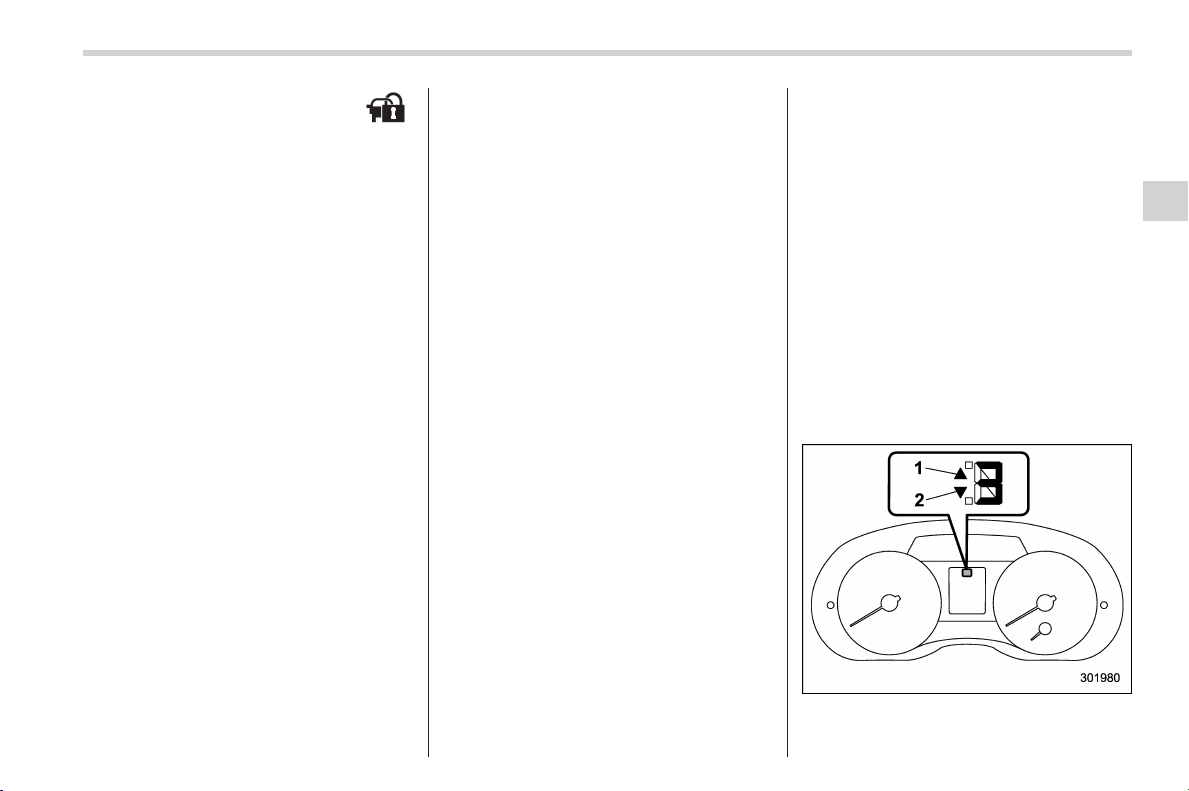
Black plate (169,1)
北米Model "A1160BE-C" EDITED: 2014/ 3/ 17
& Security indicator light
This indicator light shows the status of the
alarm system. It also indicates operation
of the immobilizer system.
! Alarm system
It blinks to show the driver the operational
status of the alarm system. For detailed
information, refer to “Alarm system ” F2-
22.
! Immobilizer system
The security indicator light starts blinking
in the following conditions.
For models with “keyless access with
push-button start system”:
. Immediately after the push-button igni-
tion switch is turned to the “OFF” position.
. Immediately after the driver’s door is
opened or closed when all of the following
conditions are met.
– The push-button ignition switch is in
the “ON” or “ACC” position.
– The access key is outside the
vehicle.
– The engine is not running.
For models without “keyless access
with push-button start system”:
. Approximately 60 seconds after the
ignition switch is turned from the “ON”
position to the “ACC ” or “LOCK” (off)
position.
. Immediately after the key is pulled out.
If the indicator light does not blink in the
above conditions, it may indicate that
immobilizer system may be malfunction-
ing. Contact your nearest SUBARU dealer
immediately.
In the event that an unauthorized key (for
example, an unauthorized duplicate) is
used, the security indicator light illumi-
nates. For details about the immobilizer
system, refer to “Immobilizer” F2-3.
NOTE
. The security indicator light remains
off in the following conditions. This is
normal and does not indicate a mal-
function.
Models with “keyless access with
push-button start system”:
– while the hybrid system is run-
ning
– the push-button ignition switch
has been turned to the “ON” or
“ACC” position and the driver’s
door has not been opened or closed
Models witho ut “keyless access
with push-button start system”:
– while the hybrid system is run-
ning
– for approximately 60 seconds
after the ignition switch is turned
from the “ON” position to the
“ACC” or “LOCK” (off) position
. Even if the security indicator light
blinks irregularly or its fuse blows (the
light does not blink if its fuse is blown),
the immobilizer system will function
normally.
& Select lever/gear position in-
dicator
1) Upshift indicator
2) Downshift indicator
Instruments and controls/Warning and indicator lights
3-29
– CONTINUED –
3
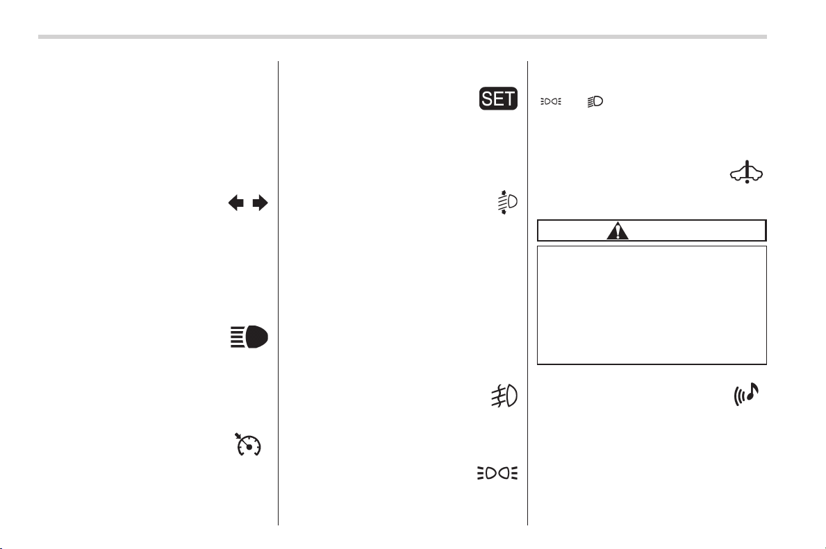
Black plate (170,1)
北米Model "A1160BE-C" EDITED: 2014/ 3/ 17
3-30
Instruments and controls/Warning and indicator lights
This indicator shows the position of the
select lever.
When the manual mode is selected, the
gear position indicator (which shows the
current gear selection) and the upshift/
downshift indicator light up. Refer to
“Continuously variable transmission ” F7-
15.
& Turn signal indicator
lights
These lights show the operation of the turn
signal or lane change signal.
If the indicator lights do not blink or blink
rapidly, the turn signal bulb may be burned
out. Replace the bulb as soon as possible.
Refer to “Replacing bulbs” F11-40.
& High beam indicator
light
This light shows that the headlights are in
the high beam mode.
This indicator light also illuminates when
the headlight flasher is operated.
& Cruise control indica-
tor light
This light illuminates when the cruise
control main button is pressed to activate
the cruise control function. For details,
refer to “To set cruise control” F7-34.
& Cruise control set in-
dicator light
This light illuminates when vehicle speed
has been set to use the cruise control
function. Refer to “To set cruise control”
F7-34.
& Automatic headlight
beam leveler warning
light (models with HID
headlights)
This light illuminates when the automatic
headlight beam leveler does not operate
normally.
If this light illuminates while driving or does
not turn off approximately 3 seconds after
turning the ignition switch to the “ON”
position, have your vehicle inspected at
your SUBARU dealer.
& Front fog light indicator
light (if equipped)
This indicator light illuminates while the
front fog lights are illuminated.
& Headlight indicator
light (if equipped)
This indicator light illuminates under the
following conditions.
. when the light switch is turned to the
“
” or “ ” position
. when the light control switch is in the
“AUTO” position and the headlights illumi-
nate automatically
& Hybrid fail lamp
The hybrid fail lamp illuminates when a
malfunction occurs in the hybrid system.
CAUTION
When the hybrid fail lamp is illumi-
nated, an interruption screen will be
displayed s imultaneously on the
multi function display. Perform the
procedure shown on the multi func-
tion display, then have your vehicle
inspected by a SUBARU dealer im-
mediately.
& Pedestrian alert warn-
ing light
This light illuminates when a malfunction
occurs in the pedestrian alert system.
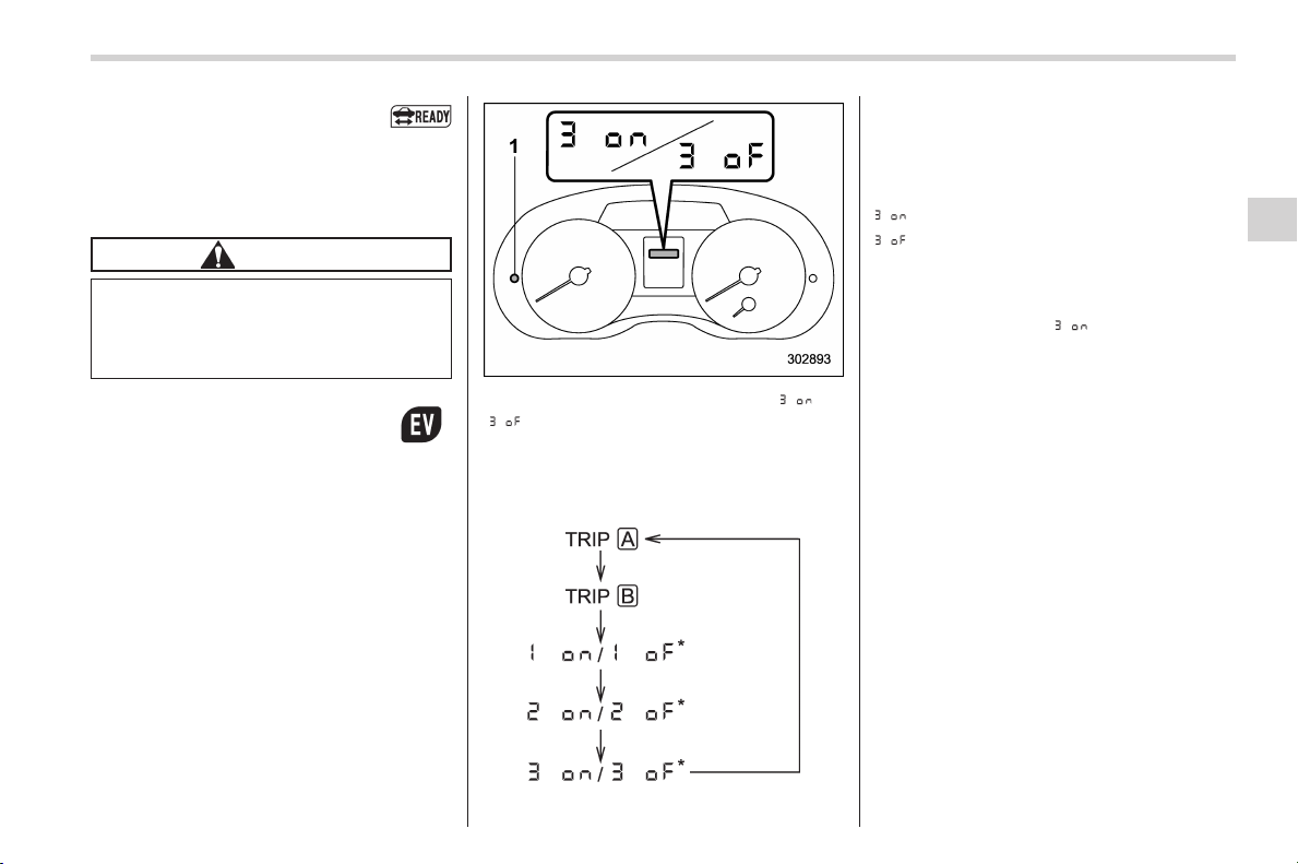
Black plate (171,1)
北米Model "A1160BE-C" EDITED: 2014/ 3/ 17
& Hybrid READY indica-
tor light
This light illuminates when the hybrid
system has started. It turns off when the
hybrid system has been turned off.
CAUTION
If the hybrid READY indicator light
does not illuminate when the engine
has been started, have your vehicle
checked at a SUBARU dealer.
& EV (Electric Vehicle)
mode lamp
This light illuminates in the following
cases.
. When driving only using the electric
motor power
. When the engine is automatically
stopped by the hybrid system
! Activation/deactivation settings
The EV (Electric Vehicle) mode lamp can
be activated or deactivated. To change the
setting, perform the following procedure.
1. Turn the ignition switch to the “LOCK”
or “ACC” position.
2. Press the trip knob to show “ ” or
“
” on the trip meter display.
The display can be switched as shown in
the following sequence by pressing the
trip knob.
*: Cannot be displayed when the ignition
switch is in the “ON” position.
To change the current setting, press the
trip knob for at least 2 seconds.
: Activated
: Deactivated
NOTE
Your vehicle’s initial setting has been
set for activation “
” at the time of
shipment from the factory.
Instruments and controls/Warning and indicator lights
3-31
3
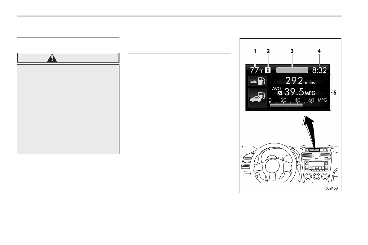
Black plate (172,1)
北米Model "A1160BE-C" EDITED: 2014/ 3/ 17
3-32
Instruments and controls/Multi function display
Multi function display
& Safety precautions
WARNING
Always pay adequate attention to
safe driving when operating the
multi function display while the
vehicle is in motion. When operation
of the multi function display is
disturbing your awareness and abil-
ity to concentrate on driving, stop
the vehicle in a safe place before
performing operations on the
screen. Also, do not concentrate
on the display while driving. Doing
so may cause you to look away from
the road and could result in an
accident.
& Features
The multi function display has the follow-
ing functions.
Description Page
Displays useful messages, such
as warning information, etc.
3-35
Displays basic screens (e.g. fuel
consumption screen, etc.)
3-35
Sets and adjusts maintenance
notification
3-61
Registers driving history 3-65
Sets and customizes car opera-
tion
3-66
Also, the multi function display can also be
used to set and initialize the multi function
display itself.
NOTE
When the vehicle is in motion, certain
functions and selections may not be
available.
& Locations
Multi function display
1) Outside temperature indicator
2) Information reminder
3) Top display (For the display setting, refer
to “Top display setting” F3-54.)
4) Clock
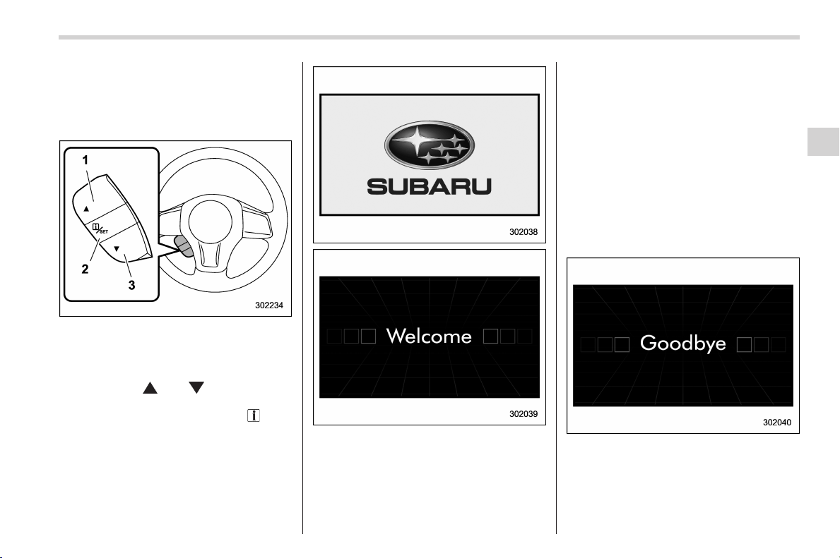
Black plate (173,1)
北米Model "A1160BE-C" EDITED: 2014/ 3/ 17
5) Driving information display (For the dis-
played contents, refer to “Basic screens”
F3-35.)
& Basic operation
Control switch
1) Up (select)
2) Set (enter)
3) Down (select)
By operating “ ” or “ ” of the control
switch, the screens and selection items
can be switched. When the “
/SET”
switch is pulled toward you, the item can
be selected and set.
& Welcome screen
When the door is unlocked and the
driver’s door is opened, the welcome
screen will appear for a short time.
NOTE
. The welcome screen will disappear
when the ignition switch is turned to
the “ON” position while the welcome
screen is displayed.
. If any of the doors (including the
rear gate) is opened while the welcome
screen is dis played, the d oor ajar
warning will appear.
. The welcome screen can be set to
on or off. For details, refer to “Bypass
screen setting” F3-59.
. For a certain period of time after the
welcome screen has once appeared, it
may not appear again even when the
driver’s door is opened again. This
does not indicate a malfunction.
& Ending screen
When the ignition switch is turned to the
“LOCK” (off) position, the “Goodbye”
screen will appear for several seconds.
Instruments and controls/Multi function display
3-33
– CONTINUED –
3
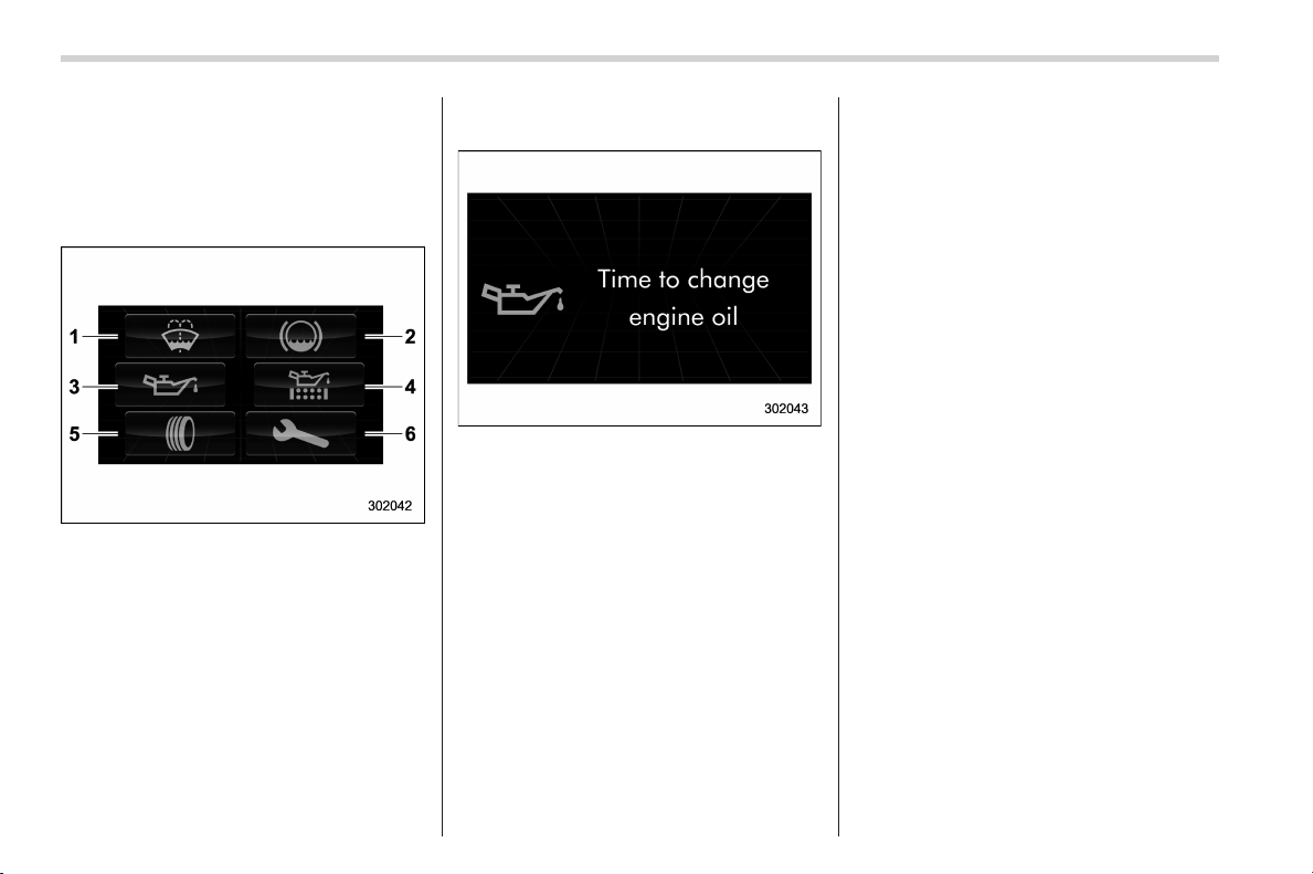
Black plate (174,1)
北米Model "A1160BE-C" EDITED: 2014/ 3/ 17
3-34
Instruments and controls/Multi function display
& Self-check screen
When the ignition switch is turned to the
“ON” position, the vehicle self-check is
performed. The screens corresponding to
the following items will appear one after
another for several seconds each.
1) Windshiel d washe r f luid: Checks the
level of windshield washer fluid.
2) Brake fluid: Checks the level of brake
fluid.
3) Engine oil: Checks the interval of engine
oil replacement.
4) Oil filter: Checks the interval of oil filter
replacement.
5) Tires: Checks the interval of tire rotation.
6) Inspection and maintenance: Checks the
interval of inspection and maintenance.
When the checks are performed, the color
of the icon corresponding to the checked
item will turn green.
If there is no warning message, the self-
check is complete without notification.
Example of notification
If there is a warning message or a
maintenance notification, the color of the
icon corresponding to the item will turn
yellow and the warning message or the
maintenance notification will be displayed.
Take the appropriate actions based on the
messages indicated.
NOTE
. The self-check screen can be set to
on or off. For details, refer to “On/Off
setting” F3-63.
. After performing the maintenance,
change the setting of the correspond-
ing maintenance item. For details, refer
to “Maintenance settings” F3-61.
. The maintenance notification screen
will be displayed under either of the
following conditions.
– The period of time remaining
until the registered notification date
is 15 days or less.
– The total driving distance remain-
ing until the registered notification
distance is approximately 311 miles
(500 km) or less.
. The maintenance notification screen
will be displayed until either of the
following conditions is satisfied.
– The period of time passed after
the registered notification date is 15
days or more.
– The total distance driven after the
registered notification distance is
approximately 311 miles (500 km) or
more.
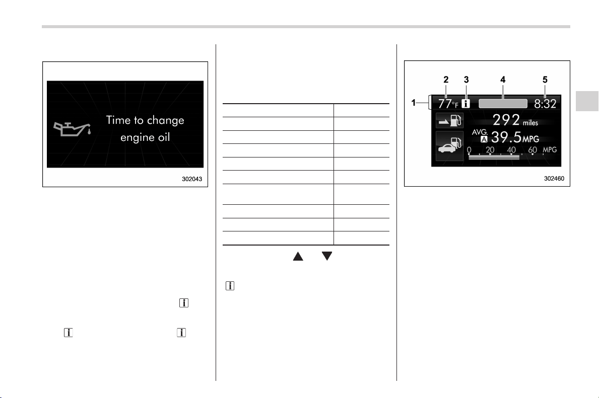
Black plate (175,1)
北米Model "A1160BE-C" EDITED: 2014/ 3/ 17
& Interruption screen
Warning information (display example)
Useful messages, such as reminder in-
formation, vehicle infor mation, warning
information, etc. may interrupt the current
screen and appear on the display accom-
panied by a beep. Take proper action
according to the message.
The warning screen will return to the
original screen after a few seconds. If
the warning screen can be displayed
again, an information reminder “
” will
appear on th e uppe r le ft part of the
display. To recall the message marked
with “
” on the display, pull the “ /SET”
switch on the steering wheel toward you.
& Basic screens
! Basic screen items
These are the basic screens of the multi
function display.
Item Page
Information bar 3-35
Fuel consumption screen 3-37
ECO history screen 3-37
Fuel save screen 3-38
Energy flow screen 3-38
Vehicle activation status
screen
3-39
Triple meter screen 3-40
Guidance screen 3-41
Clock/calendar screen
3-41
By operating the “ ” or “ ” switch on the
steering wheel, you can switch the screen
that is always displayed. Also, when the
“
/SET” switch is pulled and held, the
selection screen can be displayed. For
details about the selection screen, refer to
“Selection screen” F3-42.
! Information bar
1) Information bar
2) Outside temperature indicator
3) Information reminder
4) Top display
5) Clock
While the ignition switch is in the “ACC” or
“ON” position, the outside temperature
indicator, clock, etc. will be shown on the
information bar.
! Outside temperature indicator
This di splays the outside temperature
between − 408F(− 40 8C) and 1228F
(508C).
Instruments and controls/Multi function display
3-35
– CONTINUED –
3
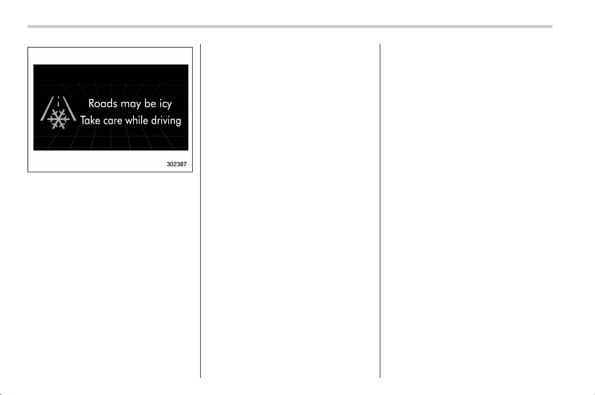
Black plate (176,1)
北米Model "A1160BE-E" EDITED: 2018/ 3/ 29
3-36
Instruments and controls/Multi function display
Icy road surface warning screen
When the outside temperature becomes
378F(38C) or less, the icy road surface
warning screen interrupts to inform the
driver that the road surface may be frozen.
NOTE
. The outside temperature indicator
shows the temperature around the
sensor. Therefore, the temperature in-
dication may differ from the actual
outside air temperature.
. The icy road surface warning screen
should be treated only as a guide. Be
sure to check the condition of the road
surface before driving.
. Once the icy road surface warning
screen is displayed, it will not be
displayed again unless the outside
temperature increases to 418F(58C) or
higher.
! Information reminder
The screen returns to the original screen
several seconds after the interruption
screen has been displayed. If the inter-
ruption screen can be displayed once
more even after the original screen has
appeared, an information reminder should
be displayed. For details about the inter-
ruption scre en, refer to “Interruption
screen” F3-35.
! Top display
One of the following items can be dis-
played on the top display.
. Average fuel consumption correspond-
ing to the driving distance of each trip
meter
. Current fuel consumption (This may
not be displayed when driving at a low
speed.)
. Driving range on remaining fuel
For details about the setting of the top
display, refer to “Top display setting” F3-
54.
NOTE
The driving range on the remaining fuel
is calculated using the average fuel
consumption of the last 19 miles (30
km) driven. This value may be different
from the values calculated using the
average fuel consumption correspond-
ing to the driving distance of each trip
meter or the current fuel consumption.
! Clock
The clock can be displayed in either 12-
hour display or 24-hour display. For details
about the setting, refer to “Current date
and time setting” F3-44.
NOTE
If the 12 V auxiliary battery is discon-
nected, the clock shown in the informa-
tion bar will be reset. Set the time again
after the 12 V auxiliary battery is
connected. For details about the
setting, refer to “Top display setting”
F3-54.
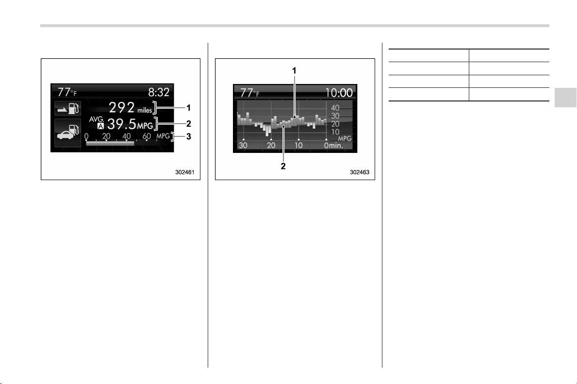
Black plate (177,1)
北米Model "A1160BE-C" EDITED: 2014/ 3/ 17
! Fuel consumption screen
1) Driving range on remaining fuel
2) Average fuel consumption corresponding
to the driving distance of each trip meter
3) Current fuel consumption
The di splayed location can be custo-
mized. For details, refer to “Fuel consump-
tion screen setting” F3-55.
! ECO history screen
1) Average fuel consumption per unit time
(bar graph)
2) Average fuel consumption corresponding
to the driving distance of each trip meter
(red line)
This screen displays the fuel economy
history for the vehicle using a bar graph.
The horizontal scale represents the past
time range and the vertical scale repre-
sents the fuel consumption. The green
bars show driving with good fuel economy
and the yellow bars show driving with poor
fuel economy.
The time range of the history can be set.
The width of the bar graph is adjusted as
follows depending on the set time range.
Time range Width of bar graph
30 minutes 1 minute
60 minutes 2 minutes
120 minutes
4 minutes
For details about the setting, refer to
“Economy history setting” F3-56.
Instruments and controls/Multi function display
3-37
– CONTINUED –
3
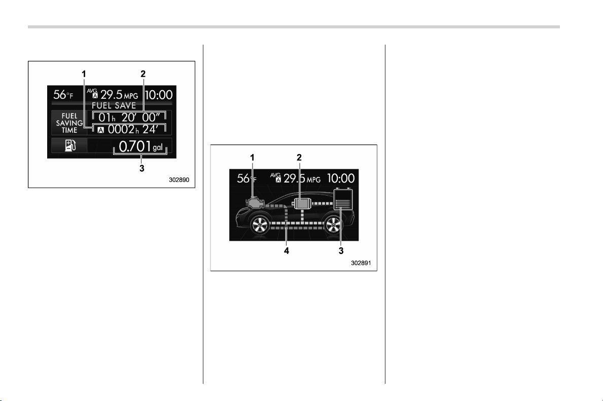
Black plate (178,1)
北米Model "A1160BE-C" EDITED: 2014/ 3/ 17
3-38
Instruments and controls/Multi function display
! Fuel save screen
This screen displays the following infor-
mation.
1) The total time the engine was stopped by
the hybrid system, from the most recent
reset of the currently displayed trip meter
to the current time.
2) The total time the engine was stopped by
the hybrid system, from the time that the
ignition switch was turned to the “ON”
position to the current time.
3) The total amount of fuel saved due to the
engine being stopped by the hybrid
system, from the most recent reset of the
currently displayed trip meter to the
current time.
NOTE
. When the trip meter is reset, the
corresponding accumulated time and
the amount of fuel sa ving are also
reset.
. The time spent with the engine
stopped by means of the hybrid system
is also added to the journey time.
! Energy flow screen
NOTE
For details, refer to “Screen display”
F16.
This screen displays the following infor-
mation.
1) Engine operation status display: When
the engine is in operation, the indicator
will illuminate in orange. When the
engine is stopped by the hybrid system,
the indicator will illuminate in gray. If the
ignition switch is turned to the “LOCK”
(off) position, the indicator will switch off.
2) Electric motor operation status display:
When generating, the indicator will illu-
minate in blue. When the electric motor is
in operation (except while generating) the
indicator will illuminate in green. When
the electric motor is not generating or the
electric motor is not in operation, the
indicator will illuminate in gray. If the
ignition switch is turned to the “LOCK”
(off) position, the indicator will switch off.
3) Remaining quantity of the high voltage
battery
4) Energy flow display: This displays the
energy flow and the remaining power of
the high voltage battery. Power from the
engine will be displayed in orange, power
from the electric motor will be displayed
in green and the current of energy
charging the high voltage battery will be
displayed in aqua.
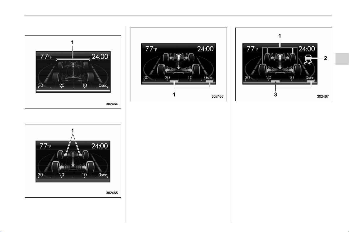
Black plate (179,1)
北米Model "A1160BE-C" EDITED: 2014/ 3/ 17
! Vehicle activation status screen
When the vehicle stops
1) Steering axle
When the vehicle is being driven regularly
1) Power train (illuminated in blue)
When the Vehicle Dynamics Control sys-
tem is being activated: the tires illuminate
in yellow.
1) History of Vehicle Dynamics Control
system activation
When the Vehicle Dynamics Control sys-
tem has been activated: the tires remain
illuminated in yellow whi le the Vehicle
Dynamics Control System is activated.
1) Activation status of the ABS (Anti-lock
Brake System)
2) Vehicle Dynamics Control system oper-
ating indicator (flashing in yellow)
3) History of Vehicle Dynamics Control
system activation
This screen displays the following vehicle
information.
. steering angle and driving wheel status
. activation status of the ABS (Anti-lock
Brake System)
. activation status of the Vehicle Dy-
namics Control system
While driving, t he vehicle wheels are
illuminated in blue and the driving direc-
Instruments and controls/Multi function display
3-39
– CONTINUED –
3
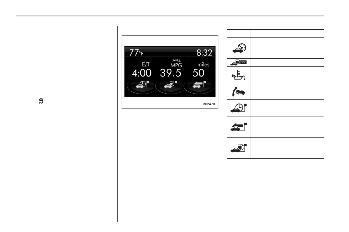
Black plate (180,1)
北米Model "A1160BE-C" EDITED: 2014/ 3/ 17
3-40
Instruments and controls/Multi function display
tion is represented using an animation of
the traffic lane.
If the ABS is activated, all of the vehicle’s
wheels will be illuminated in yellow and
the length of operation in seconds and the
number of activations will be displayed in
the bar indicator, located on the lowermost
part of the display.
If the Vehicle Dynamics Control system is
activated, the activated vehicle wheels will
be illuminated in yellow and the operating
indicator “
” will appear on the upper right
part of the display. Also, the length of
operation in seconds and the number of
activations will be displayed in the bar
indicator.
! Triple meter screen
Triple meter screen (display example)
This screen displays up to three optional
pieces of information that can be selected
from the following items.
The items shown in the triple meter screen
can be chan ged. For details, refer to
“Triple meter setting” F3-57.
Item Details
Average vehicle speed (Average
vehicle speed for the entire driving
time from when the trip meter was
reset)
Lifetime fuel consumption
Engine oil temperature
Accelerator opening ratio
Journey time (the time that has
elapsed since the ignition switch
was turned to the “ON” position)
Journey distance (the distance
that has been driven since the
ignition switch was turned to the
“ON” position)
Average fuel consumption for the
entire driving distance from when
the ignition switch was turned to
the “ON” position
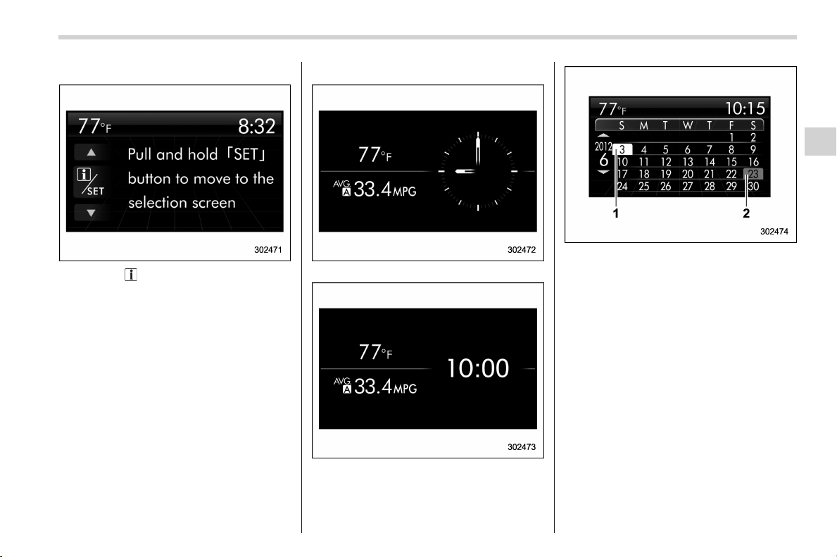
Black plate (181,1)
北米Model "A1160BE-C" EDITED: 2014/ 3/ 17
! Guidance screen
When the “ /SET” switch is pulled and
held, the selection screen can be dis-
played.
The displayed contents can be set or
customized from the selection screen. For
details, refer to “Selection screen” F3-42.
! Clock/calendar screen
Clock (analog format)
Clock (digital format)
Calendar
1) Today’s date
2) Birthday/Anniversary
In addition to the clock/calendar, the out-
side temperature and average fuel con-
sumption can also be displayed.
You can select clock (analog format),
clock (digital format) or calendar. The
clock/calendar can also be set so that it
is not displayed. For details, refer to
“Clock screen setting” F3-58.
Instruments and controls/Multi function display
3-41
– CONTINUED –
3
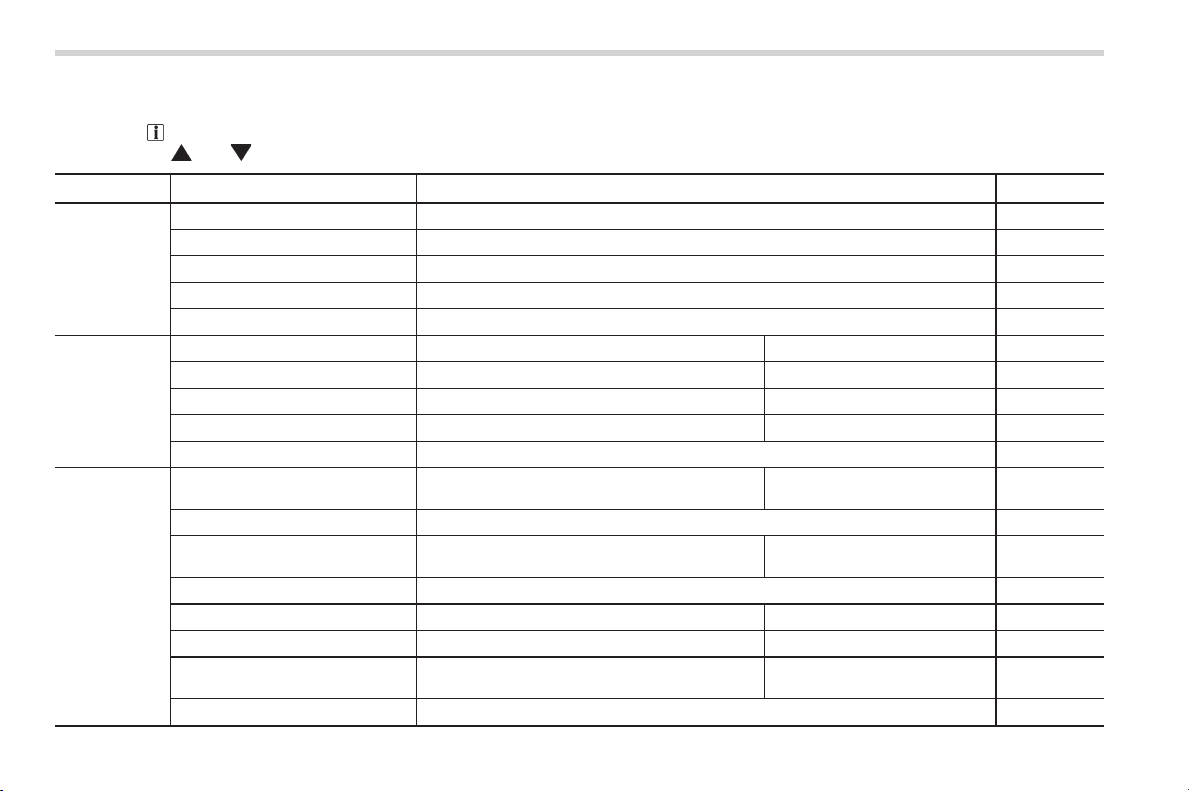
Black plate (182,1)
北米Model "A1160BE-C" EDITED: 2014/ 3/ 17
3-42
Instruments and controls/Multi function display
& Selection screen
When the “ /SET” switch is pulled and held, the setting screen for each menu can be displayed. Select the preferred menu by
operating the “
” or “ ” switch.
Top menu Menu option Description Page
Date
Date Set and adjust the time and date. 12h or 24h format can be selected. 3-44
Birthday Set a birthday. 3-45
Anniversary Set an anniversary day. 3-47
Daylight Saving Time Turn the daylight saving time on or off 3-50
Go Back Return to the top menu. —
Display
Brightness Adjust the brightness. +5 ↔ −53-51
Contrast Adjust the contrast. +5 ↔ −53-52
Screen Off Turn the screen on or off. On or Off 3-52
Beep Adjust the beep sound volume. High, Low or Off 3-53
Go Back Return to the top menu. —
Screen Setting
Top Display
Set and customize the top display information
contents.
Avg Cons, Inst Cons, Range or
Off
3-54
Cons Customize the fuel consumption information display. 3-55
Eco History
Set and customize the time of logging fuel
consumption history.
30 min, 60 min or 120 min 3-56
Triple Meter Set and customize the triple meter. 3-57
Clock Select the clock format. Analog, Digital, Calendar or Off 3-58
Bypass Screen Set the bypass screen for each item. On or Off 3-59
Languages Select the display language.
English or French or Spanish
(U.S.-spec. models only)
3-60
Go Back Return to the top menu. —

Black plate (183,1)
北米Model "A1160BE-C" EDITED: 2014/ 3/ 17
Top menu Menu option Description Page
Maintenance
Engine Oil Set and adjust the oil maintenance notification date. 3-62
Oil Filter Set and adjust the oil filter maintenance notification date. 3-63
Tires Set and adjust the tire maintenance notification date. 3-63
Maintenance Schedule Set and adjust the vehicle maintenance notification date. 3-63
On/Off
Turn on or off the self-check screen that is
activated when the ignition switch is turned to
the “ON” position.
On or Off 3-63
Clear All Settings Clear all settings for maintenance items. Yes or No 3-64
Go Back Return to the top menu. —
Driving History
Set Register and overwrite the driving record. 3-65
Go Back Return to the top menu. —
Car Setting
Audible Signal Set the audible signal. On or Off 3-66
Hazard Warning Flasher Set the hazard warning flasher. On or Off 3-68
Defogger Set and customize the operation of the defogger. 15 minutes or Continuous 3-69
Interior Light
Set and customize the interior light off delay
timer.
10, 20, 30 seconds or Off 3-70
Auto Light Sensor (if equipped)
Set and customize the sensitivity of the auto
light sensor.
Low, Mid, High or Max 3-71
Keyless Access Setting (if
equipped)
Set and customize the keyless access function.
Driver’s Door Unlock 3-72
Rear Gate Unlock 3-74
Go Back Return to top menu. —
Initialize
Reset to Defaults Reset all settings to the default settings. Yes or No 3-75
Lifetime Fuel Consumption Reset Clear logged lifetime fuel consumption data. Yes or No 3-76
Go Back Return to the top menu. —
Go Back
— Return to the top menu.
—
Instruments and controls/Multi function display
3-43
– CONTINUED –
3
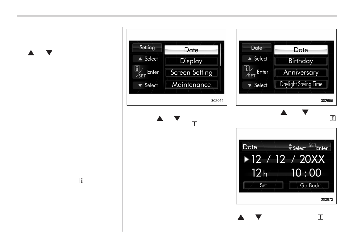
Black plate (184,1)
北米Model "A1160BE-C" EDITED: 2014/ 3/ 17
3-44
Instruments and controls/Multi function display
& Date and time settings
The items in the date and time settings
can be set. To change the items, operate
the “
” or “ ” switch.
NOTE
. The “Date” item must be set to
display the “Birthday”, “Anniversary”
and notifications for vehicle mainte-
nance.
. The “Birthday” and “Anniversary”
items can be entered after the “Date”
item has been set.
. Dates that do not exist in the
Gregorian calendar cannot be set (for
example, April 31).
. If your vehicle is equipped with the
genuine SUBARU navigation system,
the clock of navigation system must be
set separately.
! Preparation for date setting
1. Turn the ignition switch to the “ON”
position.
2. Pull and hold the “
/SET” switch
toward you to show the selection screen.
3. After the selection screen is displayed,
operate the “
” or “ ” switch to show the
“Date” item. Then, pull the “
/SET” switch
toward you.
! Current date and time setting
1. Perform the preparation steps accord-
ing to “Preparation for date setting” F3-
44.
2. Operate the “ ” or “ ” switch to
select the “Date” item. Then pull the “
/
SET” switch toward you.
3. Select the item to set by operating the
“
” or “ ” switch. Then pull the “ /SET”
switch toward you.
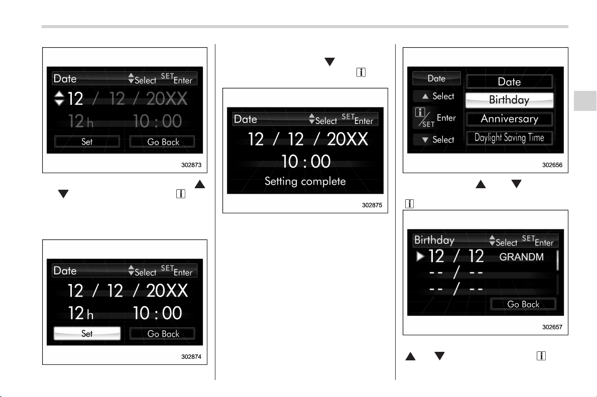
Black plate (185,1)
北米Model "A1160BE-C" EDITED: 2014/ 3/ 17
4. Select a number by operating the “ ”
or “
” switch. Then pull the “ /SET”
switch toward you. When “12 h” is
selected, the clock will be set to a 12-
hour display. When “24 h” is selected, the
clock will be set to a 24-hour display.
5. After entering the date and time, select
“Set” by operating the “
” switch and
confirm the setting by pulling the “
/SET”
switch toward you.
6. The system will notify you that the
setting is complete.
! Birthday setting
1. Perform the preparation steps accord-
ing to “Preparation for date setting” F3-
44.
2. Operate the “ ” or “ ” switch to
select the “Birthday” item. Then pull the
“
/SET” switch toward you.
3. Select the item to set by operating the
“
” or “ ” switch. Then pull the “ /SET”
switch toward you.
Instruments and controls/Multi function display
3-45
– CONTINUED –
3
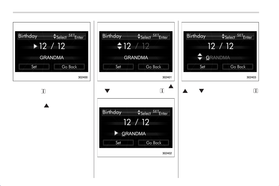
Black plate (186,1)
北米Model "A1160BE-C" EDITED: 2014/ 3/ 17
3-46
Instruments and controls/Multi function display
4. The selected item will be shown.
– Pull the “
/SET” switch toward you
to set the selected item.
– If you want to select the other item,
operate the “
” switch to go back to
step 3.
5. Select numbers by operating the “ ”
or “
” switch. Then pull the “ /SET”
switch toward you.
6. After entering the date by repeating
step 5, you can enter the name.
7. Select characters by operating the
“
” or “ ” switch. Then pull the “ /
SET” switch toward you.
– You can select characters of the
English alphabet (upper case charac-
ters and lower case characters are
available), eleven symbols or blank
spaces.
– The word being edited will be
displayed with an underline.
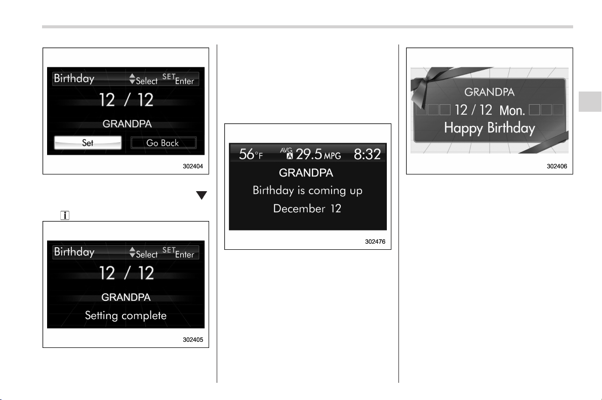
Black plate (187,1)
北米Model "A1160BE-C" EDITED: 2014/ 3/ 17
8. After entering the name by repeating
step 7, select “Set” by operating the “
”
switch and confirm the setting by pulling
the “
/SET” switch toward you.
9. The system will notify you that the
setting is complete.
! If a birthday is approaching
If a birthday is approaching, the following
screen will be displayed accompanied by
a beep when the ignition switch has been
turned to the “ON” position. This function
can be set to on or off. For details, refer to
“Bypass screen setting” F3-59.
From 1 to 7 days prior to the birthday
On a birthday (displayed in red)
NOTE
If “__” is selected for either the
“Month” or “Day” item instead of
numbers, the birthday notification will
be deactivated.
! Anniversary setting
1. Perform the preparation steps accord-
ing to “Preparation for date setting” F3-
44.
Instruments and controls/Multi function display
3-47
– CONTINUED –
3
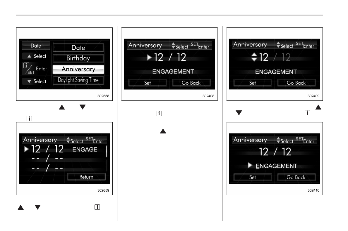
Black plate (188,1)
北米Model "A1160BE-C" EDITED: 2014/ 3/ 17
3-48
Instruments and controls/Multi function display
2. Operate the “ ” or “ ” switch to
select the “Anniversary” item. Then pull
the “
/SET” switch toward you.
3. Select the item to set by operating the
“
” or “ ” switch. Then pull the “ /SET”
switch toward you.
4. The selected item will be shown.
– Pull the “
/SET” switch toward you
to set the selected item.
– If you want to select another item,
operate the “
” switch to go back to
step 3.
5. Select numbers by operating the “ ”
or “
” switch. Then pull the “ /SET”
switch toward you.
6. After entering the date by repeating
step 5, you can enter the name.
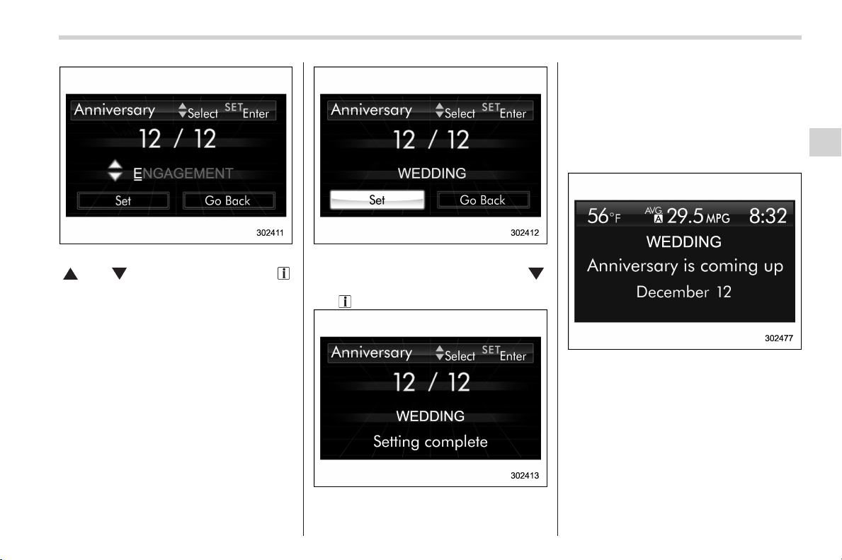
Black plate (189,1)
北米Model "A1160BE-C" EDITED: 2014/ 3/ 17
7. Select characters by operating the
“
” or “ ” switch. Then pull the “ /
SET” switch toward you.
– You can select characters of the
English alphabet (upper case charac-
ters and lower case characters are
available), eleven symbols or blank
spaces.
– The word being edited will be
displayed with an underline.
8. After entering the name by repeating
step 7, select “Set” by operating the “
”
switch and confirm the setting by pulling
the “
/SET” switch toward you.
9. The system will notify you that the
setting is complete.
! If an anniversary is approaching
If an anniversary is approaching, the
following screen will be displayed accom-
panied by a beep when the ignition switch
has been turned to the “ ON” position. This
function can be set to on or off. For details,
refer to “Bypass screen setting” F3-59.
From 1 to 7 days prior to the anniversary
Instruments and controls/Multi function display
3-49
– CONTINUED –
3
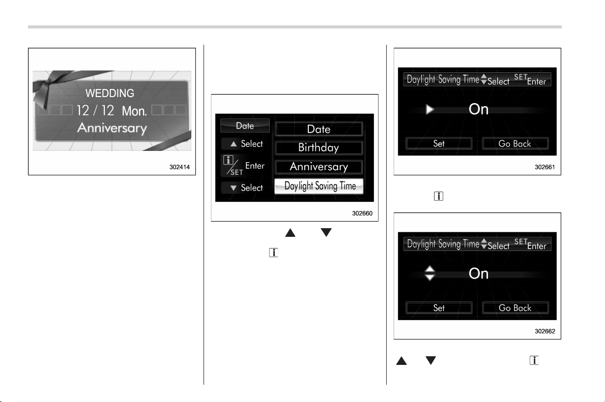
Black plate (190,1)
北米Model "A1160BE-C" EDITED: 2014/ 3/ 17
3-50
Instruments and controls/Multi function display
On an anniversary (displayed in orange)
NOTE
If “__” is selected for either the
“Month” or “Day” item instead of
numbers, the anniversary notification
will be deactivated.
! Clearing birthday or anniversary
1. Perform the preparation steps accord-
ing to “Preparation for date setting” F3-44
and display “Birthday” or “Anniversary” on
the screen.
2. When “__” is selected for either the
“Month” or “Day” item instead of numbers,
the setting of “Birthday” or “Anniversary”
will be cleared.
! Daylight saving time setting
1. Perform the preparation steps accord-
ing to “Preparation for date setting” F3-
44.
2. Operate the “ ” or “ ” switch to
select the “Daylight Saving Time” item.
Then pull the “
/SET” switch toward you.
3. The current setting will be displayed.
Pull the “
/SET” switch toward you to
enter the selection mode.
4. Select “On” or “Off” by operating the
“
” or “ ” switch. Then pull the “ /SET”
switch toward you.

Black plate (191,1)
北米Model "A1160BE-C" EDITED: 2014/ 3/ 17
5. Select “Set” by operating t he “ ”
switch, and confirm the setting by pulling
the “
/SET” switch toward you.
6. The system will notify you that the
setting is complete.
& Image quality and volume
settings
The items in the image quality and volume
settings can be set. To change the items,
operate the “
” or “ ” switch.
! Preparation for image quality and
volume settings
1. Turn the ignition switch to the “ON”
position.
2.Pullandholdthe“
/SET” switch
toward you to show the selection screen.
3. After the selection screen is displayed,
operate the “
” or “ ” switch to show the
“Display” item. Then, pull the “
/SET”
switch toward you.
! Brightness setting
1. Perform the preparation steps accord-
ing to “Preparation for image quality and
volume settings” F3-51.
2. Operate the “ ” or “ ” switch to
select the “Brightness” item. Then pull the
“
/SET” switch toward you.
Instruments and controls/Multi function display
3-51
– CONTINUED –
3
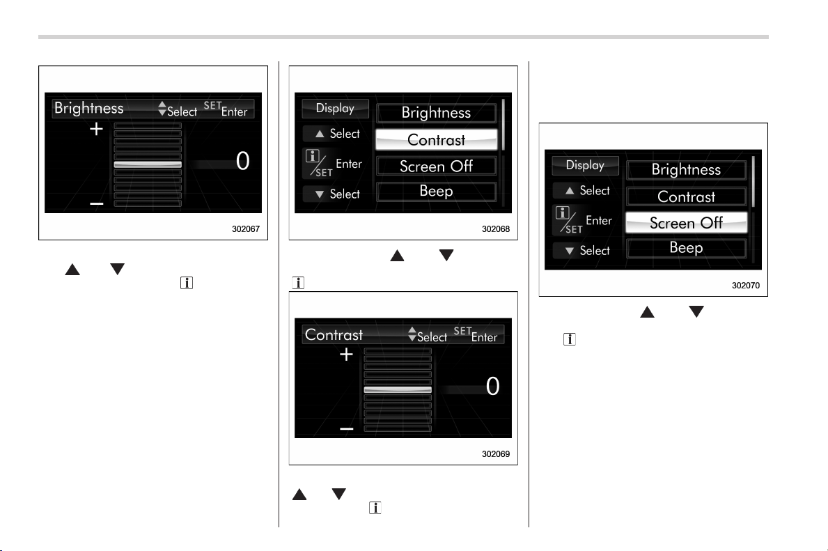
Black plate (192,1)
北米Model "A1160BE-C" EDITED: 2014/ 3/ 17
3-52
Instruments and controls/Multi function display
3. Select a brightness level by operating
the “
” or “ ” switch, and confirm the
setting by pulling the “
/SET” switch
toward you.
! Contrast setting
1. Perform the preparation steps accord-
ing to “Preparation for image quality and
volume settings” F3-51.
2. Operate the “ ” or “ ” switch to
select the “Contrast” item. Then pull the
“
/SET” switch toward you.
3. Select a contrast level by operating the
“
” or “ ” switch, and confirm the setting
by pulling the “
/SET” switch toward you.
! Screen OFF setting
1. Perform the preparation steps accord-
ing to “Preparation for image quality and
volume settings” F3-51.
2. Operate the “ ” or “ ” switch to
select the “Screen OFF” item. Then pull
the “
/SET” switch toward you.
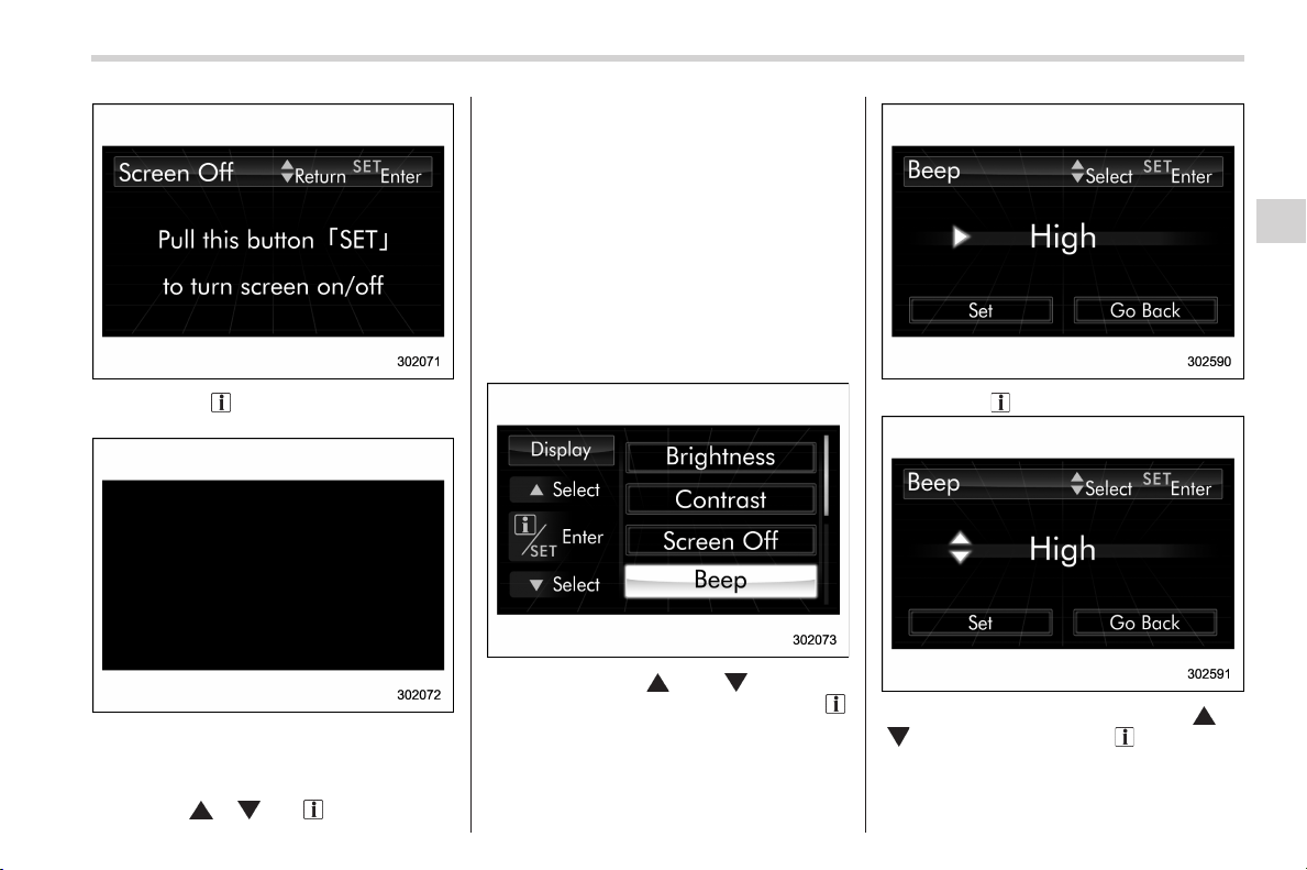
Black plate (193,1)
北米Model "A1160BE-C" EDITED: 2014/ 3/ 17
3. Pull the “ /SET” switch once more
toward you.
4. The screen is turned off.
Restoring the screen
When the “
”, “ ” or “ /SET” switch is
pulled toward you after the ignition switch
is turned to the “ON” position, the screen
will be restored. The screen will be
restored with the basic screen that was
displayed when the screen was turned off.
While the screen is off, a warning mes-
sage will be displayed if necessary, but
other screens will not be displayed.
! Beep volume setting
1. Perform the preparation steps accord-
ing to “Preparation for image quality and
volume settings” F3-51.
2. Operate the “ ” or “ ” switch to
select the “Beep” item. Then pull the “
/
SET” switch toward you.
3. Pull the “ /SET” switch toward you.
4. Select an item by operating the “ ” or
“
” switch. Then pull the “ /SET” switch
toward you.
Instruments and controls/Multi function display
3-53
– CONTINUED –
3
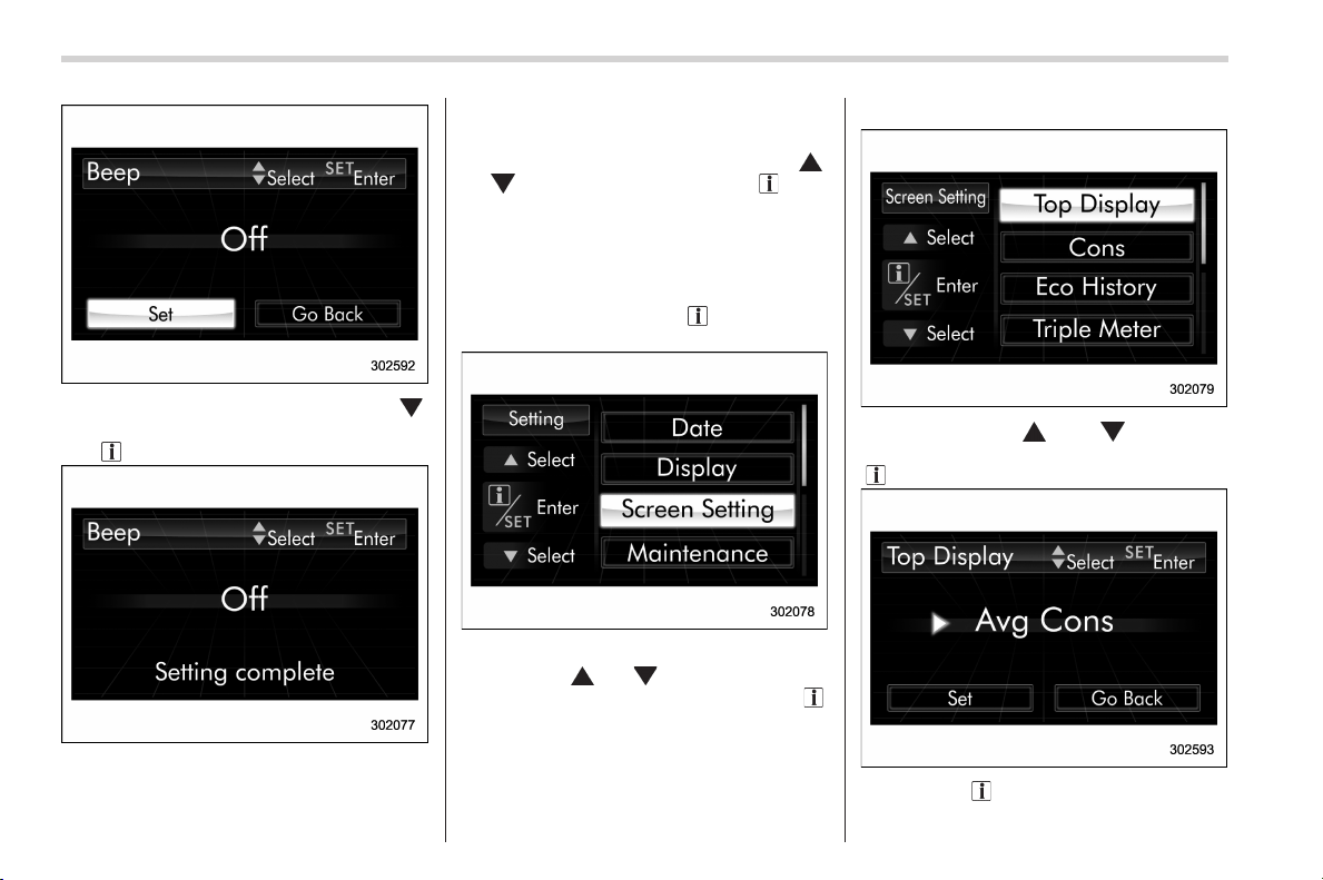
Black plate (194,1)
北米Model "A1160BE-C" EDITED: 2014/ 3/ 17
3-54
Instruments and controls/Multi function display
5. Select “Set” by operating t he “ ”
switch, and confirm the setting by pulling
the “
/SET” switch toward you.
6. The system will notify you that the
setting is complete.
& Screen settings
The items in the screen settings can be
set. To change the items, operate the “
”
or “
” switch, and then pull the “ /SET”
switch toward you.
! Preparation for screen settings
1. Turn the ignition switch to the “ON”
position.
2.Pullandholdthe“
/SET” switch
toward you to show the selection screen.
3. After the selection screen is displayed,
operate the “
” or “ ” switch to show the
“Screen Setting” item. Then, pull the “
/
SET” switch toward you.
! Top display setting
1. Perform the preparation steps accord-
ing to “Preparation for screen settings”
F3-54.
2. Operate the “ ” or “ ” switch to
select the “Top Display” item. Then pull the
“
/SET” switch toward you.
3. Pull the “ /SET” switch once more.
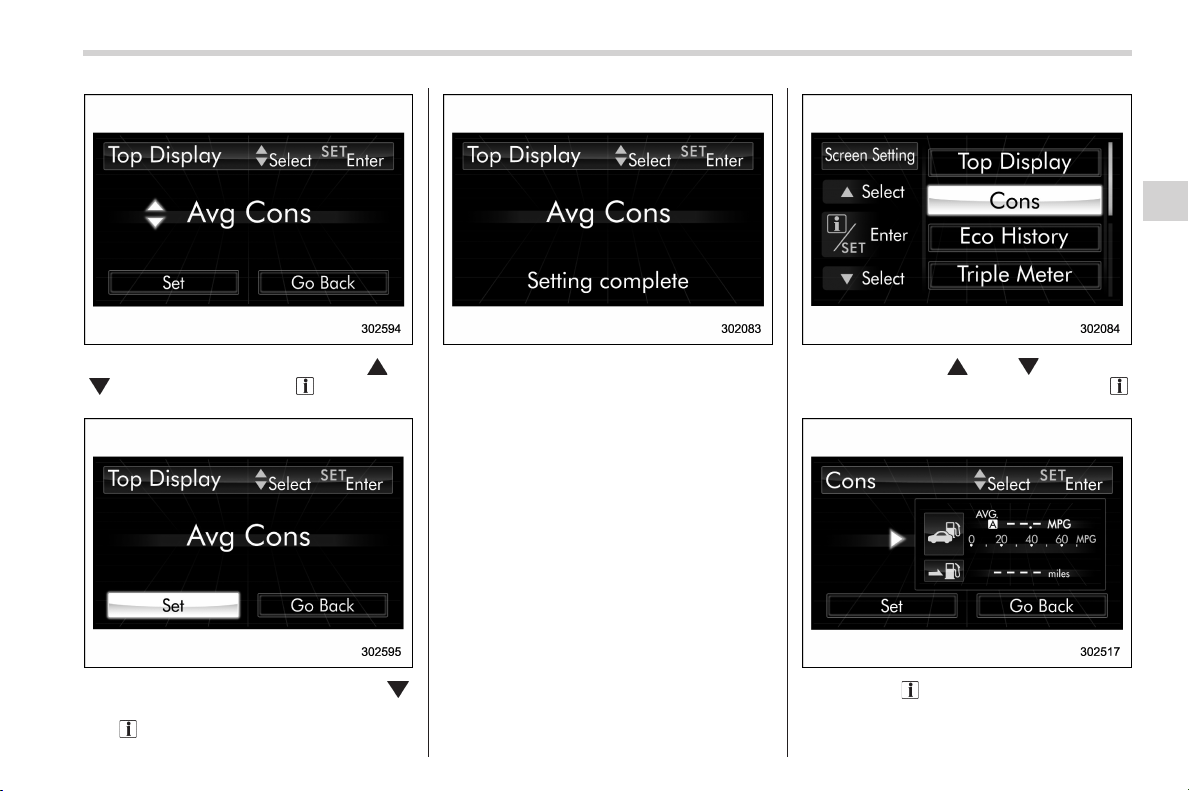
Black plate (195,1)
北米Model "A1160BE-C" EDITED: 2014/ 3/ 17
4. Select an item by operating the “ ” or
“
” switch. Then pull the “ /SET” switch
toward you.
5. Select “Set” by operating t he “ ”
switch, and confirm the setting by pulling
the “
/SET” switch toward you.
6. The system will notify you that the
setting is complete.
! Fuel consumption screen setting
1. Perform the preparation steps accord-
ing to “Preparation for screen settings”
F3-54.
2. Operate the “ ” or “ ” switch to
select the “Cons” item. Then pull the “
/
SET” switch toward you.
3. Pull the “ /SET” switch once more.
Instruments and controls/Multi function display
3-55
– CONTINUED –
3
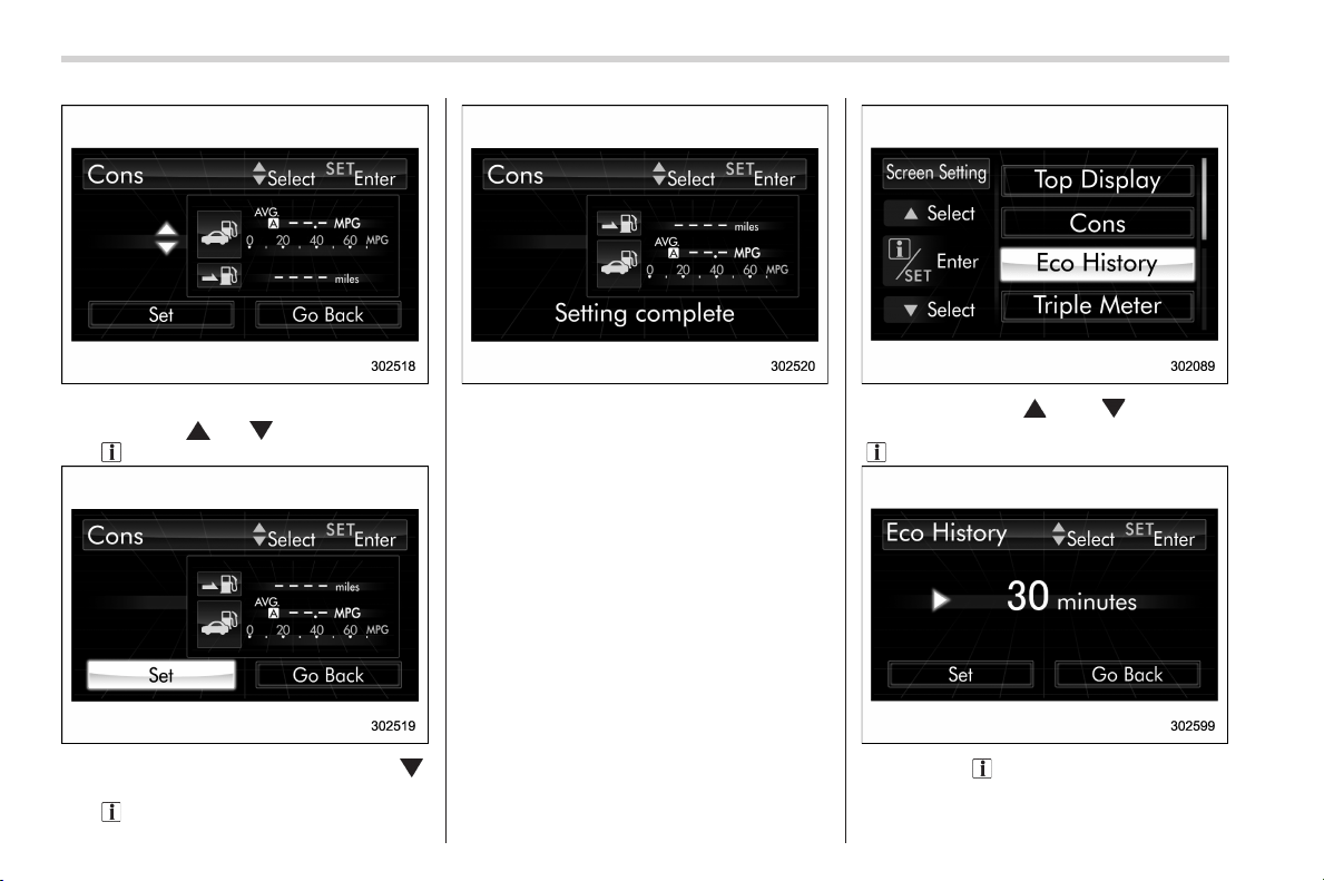
Black plate (196,1)
北米Model "A1160BE-C" EDITED: 2014/ 3/ 17
3-56
Instruments and controls/Multi function display
4. Select the displayed configuration by
operating the “
” or “ ” switch. Then pull
the “
/SET” switch toward you.
5. Select “Set” by operating t he “ ”
switch, and confirm the setting by pulling
the “
/SET” switch toward you.
6. The system will notify you that the
setting is complete.
! Economy history setting
1. Perform the preparation steps accord-
ing to “Preparation for screen settings”
F3-54.
2. Operate the “ ” or “ ” switch to
select the “Eco History” item. Then pull the
“
/SET” switch toward you.
3. Pull the “ /SET” switch once more.
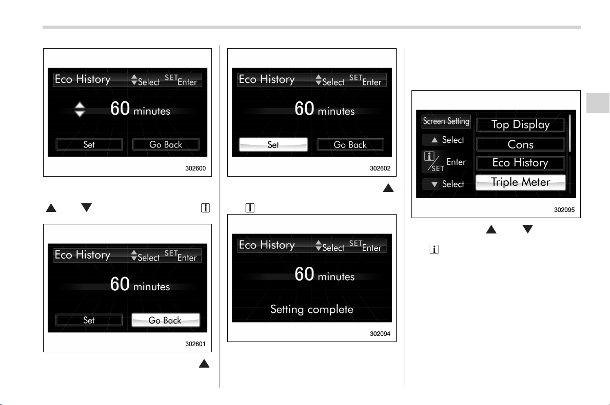
Black plate (197,1)
北米Model "A1160BE-C" EDITED: 2014/ 3/ 17
4. Select the time of the logged fuel
consumption history by ope rating the
“
” or “ ” switch. Then pull the “ /
SET” switch toward you.
5. Select “Go Back” by operating the “ ”
switch.
6. Select “Set” by operating the “ ”
switch and confirm the setting by pulling
the “
/SET” switch toward you.
7. The system will notify you that the
setting is complete.
! Triple meter setting
1. Perform the preparation steps accord-
ing to “Preparation for screen settings”
F3-54.
2. Operate the “ ” or “ ” switch to
select the “Triple Meter” item. Then pull
the “
/SET” switch toward you.
Instruments and controls/Multi function display
3-57
– CONTINUED –
3

Black plate (198,1)
北米Model "A1160BE-C" EDITED: 2014/ 3/ 17
3-58
Instruments and controls/Multi function display
3. Select the setting location (left, center
or right) by operating the “
” or “ ”
switch. Then pull the “
/SET” switch
toward you.
NOTE
The same item cannot be selected for
the left, center or right location.
4. Select the preferred item by operating
the “
” or “ ” switch. Then pull the “ /
SET” switch toward you.
If you also want to change the setting for
another location, repeat steps 3 and 4.
5. Select “Set” by operating the “ ”
switch, and confirm the setting by pulling
the “
/SET” switch toward you.
6. The system will notify you that the
setting is complete.
! Clock screen setting
1. Perform the preparation steps accord-
ing to “Preparation for screen settings”
F3-54.
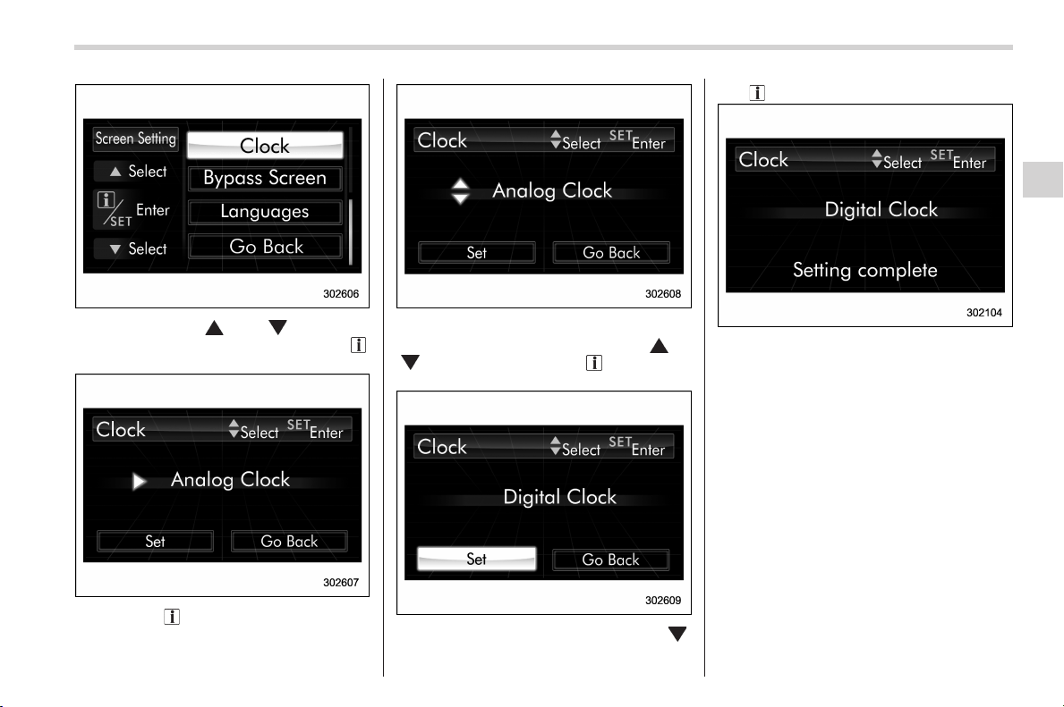
Black plate (199,1)
北米Model "A1160BE-C" EDITED: 2014/ 3/ 17
2. Operate the “ ” or “ ” switch to
select the “Clock” item. Then pull the “
/
SET” switch toward you.
3. Pull the “ /SET” switch once more.
4. Select “Analog Clock”, “Digital Clock”,
“Calendar” or “Off” by operating the “
” or
“
” switch. Then pull the “ /SET” switch
toward you.
5. Select “Set” by operating the “ ”
switch, and confirm the setting by pulling
the “
/SET” switch toward you.
6. The system will notify you that the
setting is complete.
! Bypass screen setting
1. Perform the preparation steps accord-
ing to “Preparation for screen settings”
F3-54.
Instruments and controls/Multi function display
3-59
– CONTINUED –
3
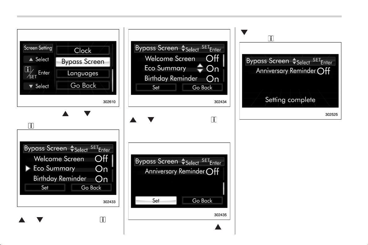
Black plate (200,1)
北米Model "A1160BE-C" EDITED: 2014/ 3/ 17
3-60
Instruments and controls/Multi function display
2. Operate the “ ” or “ ” switch to
select the “Bypass Screen” item. Then pull
the “
/SET” switch toward you.
3. Select the item to set by operating the
“
” or “ ” switch. Then pull the “ /SET”
switch toward you.
4. Select “On” or “Off” by operating the
“
” or “ ” switch. Then pull the “ /SET”
switch toward you.
If you want to change setting for another
item, repeat steps 3 and 4.
5. Select “Set” by operating the “ ” or
“
” switch, and confirm the setting by
pulling the “
/SET” switch toward you.
6. The system will notify you that the
setting is complete.
! Language setting
1. Perform the preparation steps accord-
ing to “Preparation for screen settings”
F3-54.
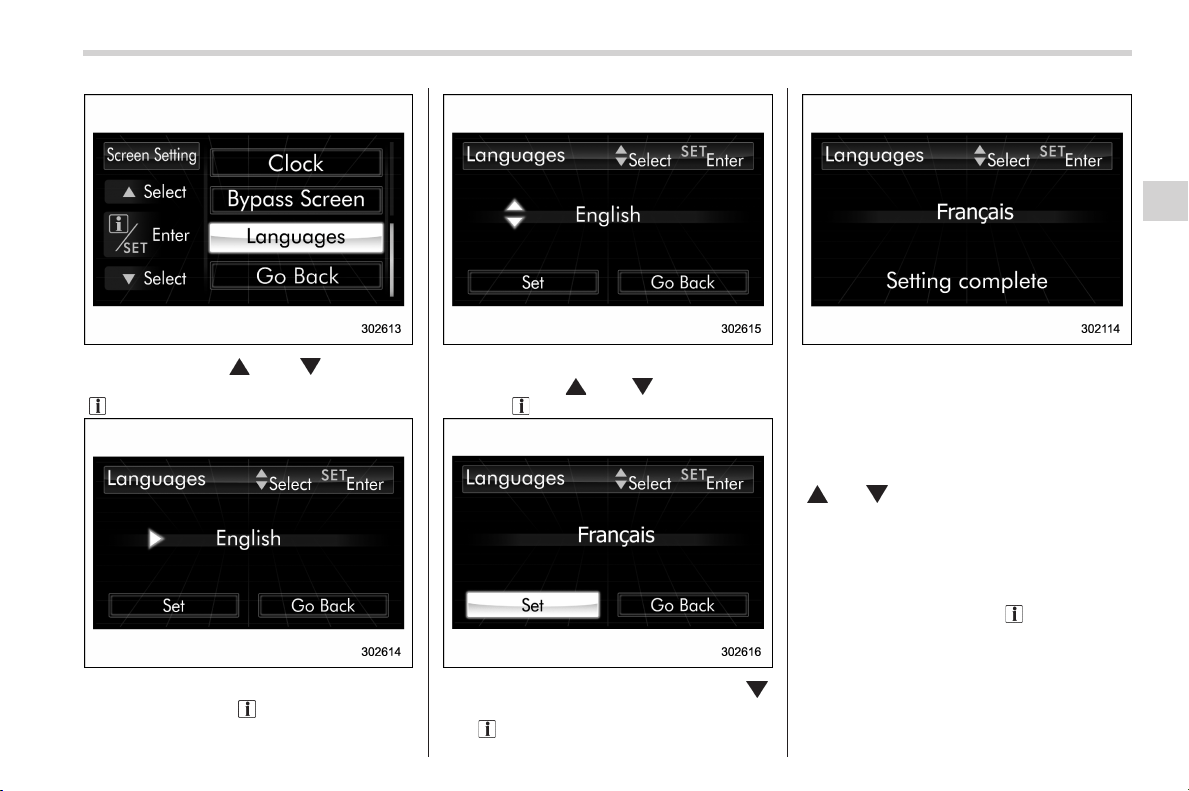
Black plate (201,1)
北米Model "A1160BE-C" EDITED: 2014/ 3/ 17
2. Operate the “ ” or “ ” switch to
select the “Languages” item. Then pull the
“
/SET” switch toward you.
3. The current language setting will be
displayed. Pull the “
/SET” switch toward
you to enter the language selection mode.
4. Select the preferred language by
operating the “
” or “ ” switch. Then
pull the “
/SET” switch toward you.
5. Select “Set” by operating the “ ”
switch, and confirm the setting by pulling
the “
/SET” switch toward you.
6. The system will notify you that the
setting is complete.
& Maintenance settings
The items in the maintenance settings can
be set. To change the items, operate the
“
” or “ ” switch toward you.
! Preparation for maintenance set-
tings
1. Turn the ignition switch to the “ON”
position.
2.Pullandholdthe“
/SET” switch
toward you to show the selection screen.
Instruments and controls/Multi function display
3-61
– CONTINUED –
3
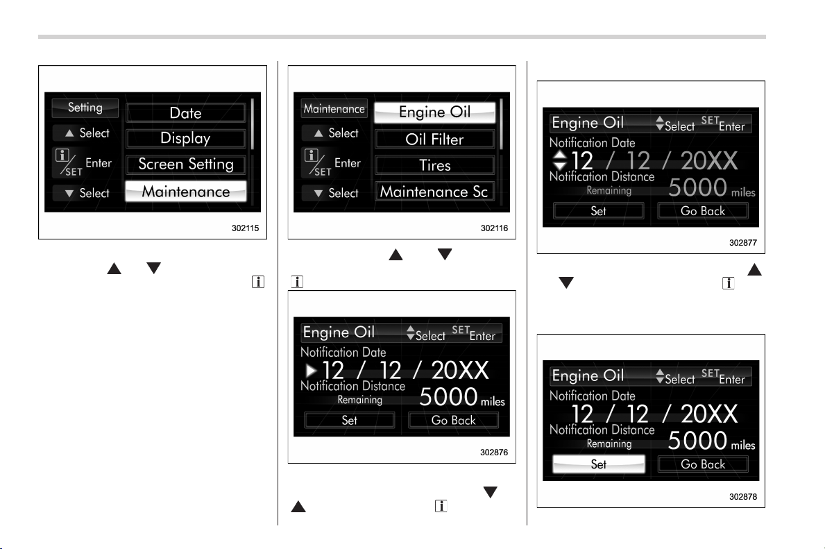
Black plate (202,1)
北米Model "A1160BE-C" EDITED: 2014/ 3/ 17
3-62
Instruments and controls/Multi function display
3. After the selection screen is displayed,
operate the “
” or “ ” switch to show the
“Maintenance” item. Then, pull the “
/
SET” switch toward you.
! Engine oil setting
1. Perform the preparation steps accord-
ing to “Preparation for maintenance set-
tings” F3-61.
2. Operate the “ ” or “ ” switch to
select the “Engine Oil” item. Then pull the
“
/SET” switch toward you.
3. Select the setting location (month, day,
year or distance) by operating the “
” or
“
” switch. Then pull the “ /SET” switch
toward you.
4. Select a number by operating the “ ”
or “
” switch. Then pull the “ /SET”
switch toward you.
If you also want to change the setting for
another location, repeat steps 3 and 4.
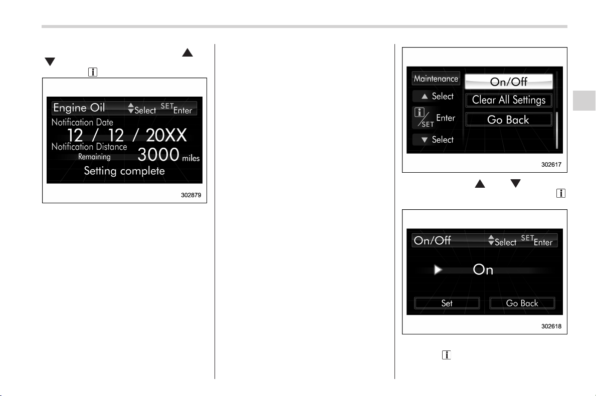
Black plate (203,1)
北米Model "A1160BE-C" EDITED: 2014/ 3/ 17
5. Select “Set” by operating the “ ” or
“
” switch and confirm the setting by
pulling the “
/SET” switch toward you.
6. The system will notify you that the
setting is complete.
NOTE
. The notification will be displayed
with information of both date and
distance or either date or distance in
accordance with the setting.
. When “__” is selected for either the
“Month”, “Day”, “Year” or “Distance”
item instead of numbers, the set noti-
fication will be deactivated.
. If the notification continues for 15
days or more, the system will display
“__” on the screen.
. When the distance announcement
reaches 0 mile (0 km), the display will
show “0000” for the next 311 miles (500
km). After exceeding 311 miles (500
km), “____” will be displayed.
! Oil filter setting
The setting procedure is the same as
“Engine oil setting” F3-62, but select the
“Oil Filter” item in step 2.
! Tires setting
The setting procedure is the same as
“Engine oil setting” F3-62, but select the
“Tires ” item in step 2.
! Maintenance schedule setting
The setting procedure is the same as
“Engine oil setting” F3-62, but select the
“Maintenance Schedule” item in step 2.
! On/Off setting
1. Perform the preparation steps accord-
ing to “Preparation for maintenance set-
tings” F3-61.
2. Operate the “ ” or “ ” switch to
select the “On/Off” item. Then pull the “
/
SET” switch toward you.
3. The current setting will be displayed.
Pull the “
/SET” switch toward you to
enter the selection mode.
Instruments and controls/Multi function display
3-63
– CONTINUED –
3
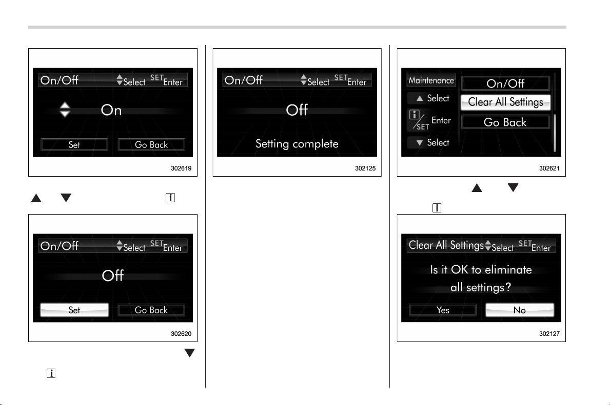
Black plate (204,1)
北米Model "A1160BE-C" EDITED: 2014/ 3/ 17
3-64
Instruments and controls/Multi function display
4. Select “On” or “Off” by operating the
“
” or “ ” switch. Then pull the “ /SET”
switch toward you.
5. Select “Set” by operating t he “ ”
switch, and confirm the setting by pulling
the “
/SET” switch toward you.
6. The system will notify you that the
setting is complete.
! Clear setting
1. Perform the preparation steps accord-
ing to “Preparation for maintenance set-
tings” F3-61.
2. Operate the “ ” or “ ” switch to
select the “Clear All Settings” item. Then
pull the “
/SET” switch toward you.
3. The system will prompt a Yes/No
dialogue (“No” is selected first). To clear
all maintenance settings, select “Yes” by
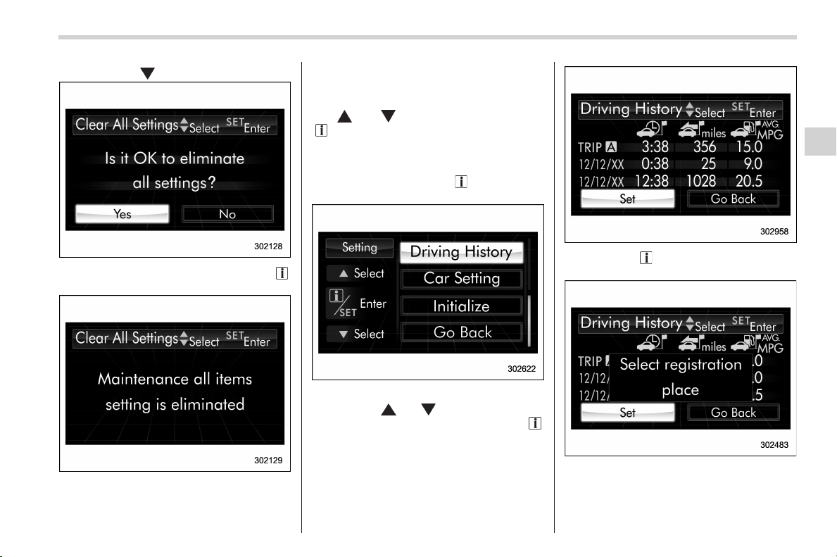
Black plate (205,1)
北米Model "A1160BE-C" EDITED: 2014/ 3/ 17
operating the “ ” switch.
4. Confirm the setting by pulling the “ /
SET” switch toward you.
5. The system will notify you that the
setting is complete.
& Driving history registration
The items in the driving history can be
registered. To change the items, operate
the “
” or “ ” switch, and then pull the
“
/SET” switch toward you.
1. Turn the ignition switch to the “ON”
position.
2.Pullandholdthe“
/SET” switch
toward you to show the selection screen.
3. After the selection screen is displayed,
operate the “
” or “ ” switch to show the
“Driving History” item. Then, pull the “
/
SET” switch toward you.
4. Pull the “ /SET” switch toward you
once more to enter the setting mode.
5. The system will notify you of the place
to be selected for approximately 2 sec-
onds.
Instruments and controls/Multi function display
3-65
– CONTINUED –
3
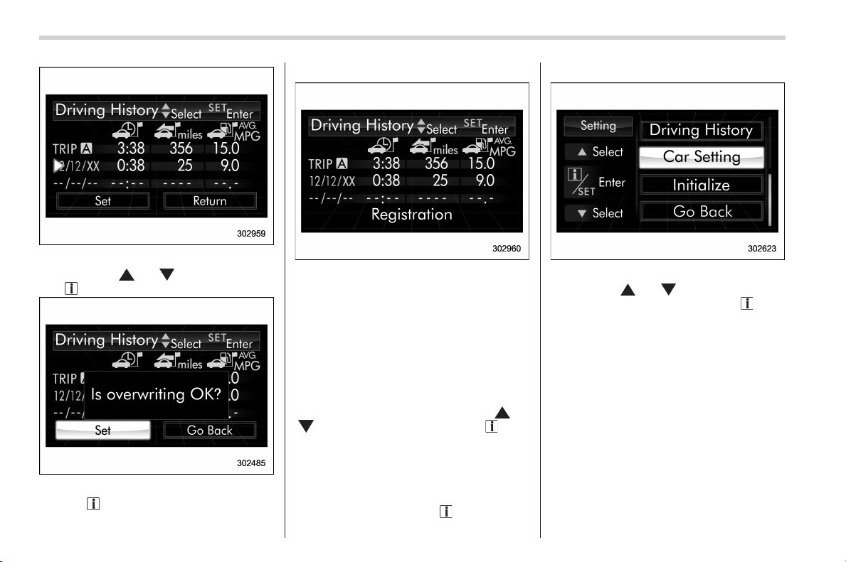
Black plate (206,1)
北米Model "A1160BE-C" EDITED: 2014/ 3/ 17
3-66
Instruments and controls/Multi function display
6. Select one of the registration lines by
operating the “
” or “ ” switch. Then pull
the “
/SET” switch toward you.
7. To overwrite the previous registration,
pull the “
/SET” switch toward you. When
registration is performed the first time, it is
registered directly without a notification.
8. The system will notify you that the
registration is complete.
NOTE
The driving history can be registered
for the trip meter A or B.
& Car settings
The items in the car settings can be set.
To change the items, operate the “
” or
“
” switch, and then pull the “ /SET”
switch toward you.
! Preparation for car settings
1. Turn the ignition switch to the “ON”
position.
2.Pullandholdthe“
/SET” switch
toward you to show the selection screen.
3. After the selection screen is displayed,
operate the “
” or “ ” switch to show the
“Car Setting” item. Then, pull the “
/SET”
switch toward you.
! Audible signal setting
1. Perform the preparation steps accord-
ing to “ Preparation for car settings” F3-66.
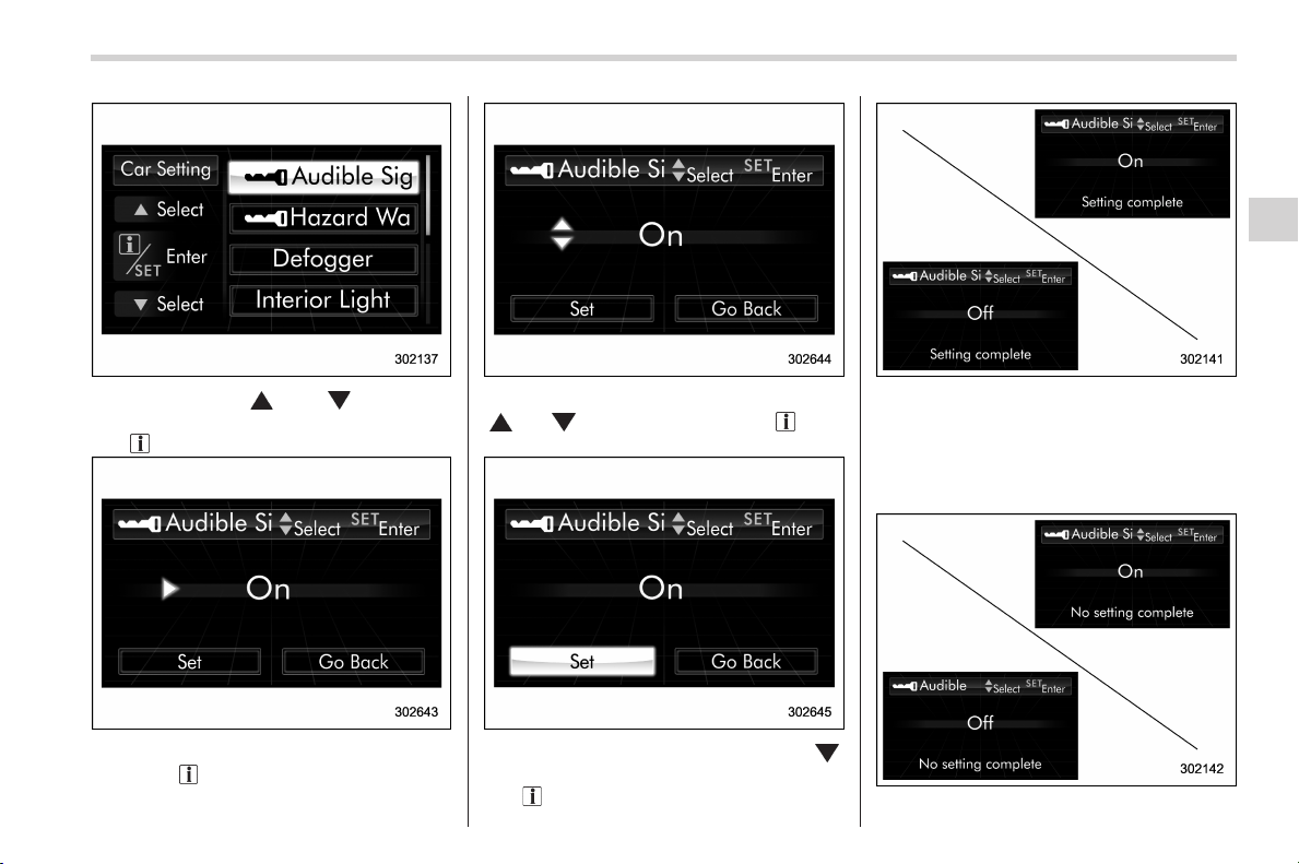
Black plate (207,1)
北米Model "A1160BE-C" EDITED: 2014/ 3/ 17
2. Operate the “ ” or “ ” switch to
select the “Audible Signal” item. Then pull
the “
/SET” switch toward you.
3. The current setting will be displayed.
Pull the “
/SET” switch toward you to
enter the selection mode.
4. Select “On” or “Off” by operating the
“
” or “ ” switch. Then pull the “ /SET”
switch toward you.
5. Select “Set” by operating the “ ”
switch, and confirm the setting by pulling
the “
/SET” switch toward you.
6. The system will notify you that the
setting is complete.
If the setting is not available, the following
notification will be displayed. In this case,
perform the setting procedure again.
Instruments and controls/Multi function display
3-67
– CONTINUED –
3
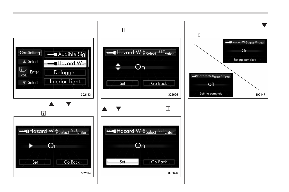
Black plate (208,1)
北米Model "A1160BE-C" EDITED: 2014/ 3/ 17
3-68
Instruments and controls/Multi function display
! Hazard warning flasher setting
1. Perform the preparation steps accord-
ing to “ Preparation for car settings” F3-66.
2. Operate the “ ” or “ ” switch to
select the “Hazard Warning Flasher” item.
Then pull the “
/SET” switch toward you.
3. The current setting will be displayed.
Pull the “
/SET” switch toward you to
enter the selection mode.
4. Select “On” or “Off” by operating the
“
” or “ ” switch. Then pull the “ /SET”
switch toward you.
5. Select “Set” by operating the “ ”
switch, and confirm the setting by pulling
the “
/SET” switch toward you.
6. The system will notify you that the
setting is complete.
If the setting is not available, the following
notification will be displayed. For more
details, contact a SUBARU dealer.
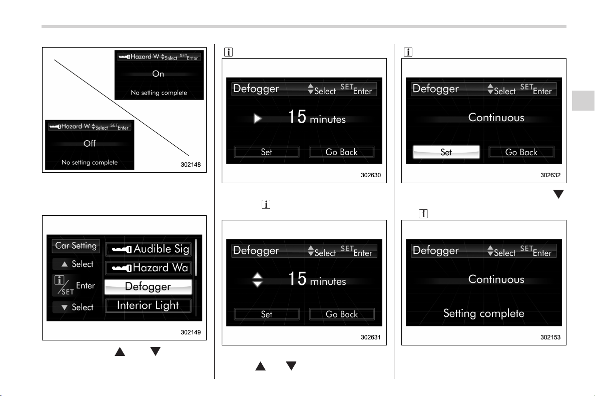
Black plate (209,1)
北米Model "A1160BE-C" EDITED: 2014/ 3/ 17
! Defogger setting
1. Perform the preparation steps accord-
ing to “ Preparation for car settings” F3-66.
2. Operate the “ ” or “ ” switch to
select the “ Defogger” item. Then pull the
“
/SET” switch toward you.
3. The current setting will be displayed.
Pull the “
/SET” switch toward you to
enter the selection mode.
4. Select the preferred setting by operat-
ing the “
” or “ ” switch. Then pull the
“
/SET” switch toward you.
5. Select “Set” by operating the “ ”
switch, and confirm the setting by pulling
the “
/SET” switch toward you.
6. The system will notify you that the
setting is complete.
Instruments and controls/Multi function display
3-69
– CONTINUED –
3
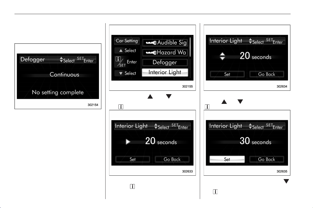
Black plate (210,1)
北米Model "A1160BE-C" EDITED: 2014/ 3/ 17
3-70
Instruments and controls/Multi function display
If the setting is not available, the following
notification will be displayed. For more
details, contact a SUBARU dealer.
! Interior light off delay timer setting
1. Perform the preparation steps accord-
ing to “ Preparation for car settings” F3-66.
2. Operate the “ ” or “ ” switch to
select the “Interior Light” item. Then pull
the “
/SET” switch toward you.
3. The current setting will be displayed.
Pull the “
/SET” switch toward you to
enter the selection mode.
4. Select the preferred setting by operat-
ing the “
” or “ ” switch. Then pull the
“
/SET” switch toward you.
5. Select “Set” by operating the “ ”
switch, and confirm the setting by pulling
the “
/SET” switch toward you.
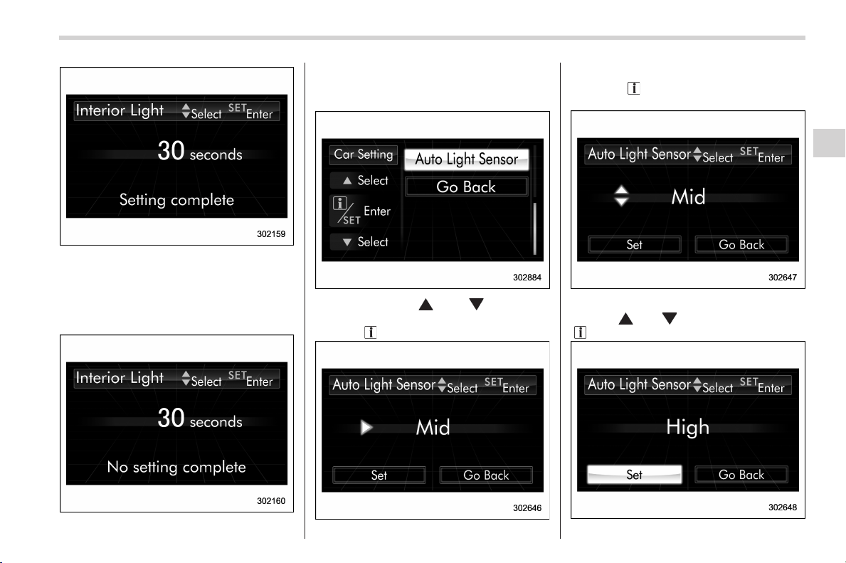
Black plate (211,1)
北米Model "A1160BE-C" EDITED: 2014/ 3/ 17
6. The system will notify you that the
setting is complete.
If the setting is not available, the following
notification will be displayed. For more
details, contact a SUBARU dealer.
! Auto light sensor sensitivity setting
1. Perform the preparation steps accord-
ing to “ Preparation for car settings” F3-66.
2. Operate the “ ” or “ ” switch to
select the “Auto Light Sensor” item. Then
pull the “
/SET” switch toward you.
3. The current setting will be displayed.
Pull the “
/SET” switch toward you to
enter the selection mode.
4. Select the preferred setting by operat-
ing the “
” or “ ” switch. Then pull the
“
/SET” switch toward you.
Instruments and controls/Multi function display
3-71
– CONTINUED –
3
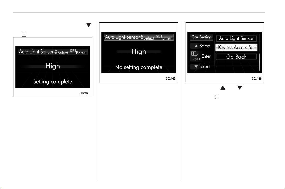
Black plate (212,1)
北米Model "A1160BE-C" EDITED: 2014/ 3/ 17
3-72
Instruments and controls/Multi function display
5. Select “Set” by operating t he “ ”
switch, and confirm the setting by pulling
the “
/SET” switch toward you.
6. The system will notify you that the
setting is complete.
If the setting is not available, the following
notification will be displayed. For more
details, contact a SUBARU dealer.
! Keyless access setting (models
with “keyless access with push-
button start system”)
! Preparation for keyless access
settings
1. Perform the preparation steps accord-
ing to “ Preparation for car settings” F3-66.
2. Operate the “ ” or “ ” switch to
select the “Keyless Access Setting” item.
Then pull the “
/SET” switch toward you.
! Driver’s door unlock setting
1. Perform the preparation steps accord-
ing to “Preparation for keyless access
settings” F3-72.
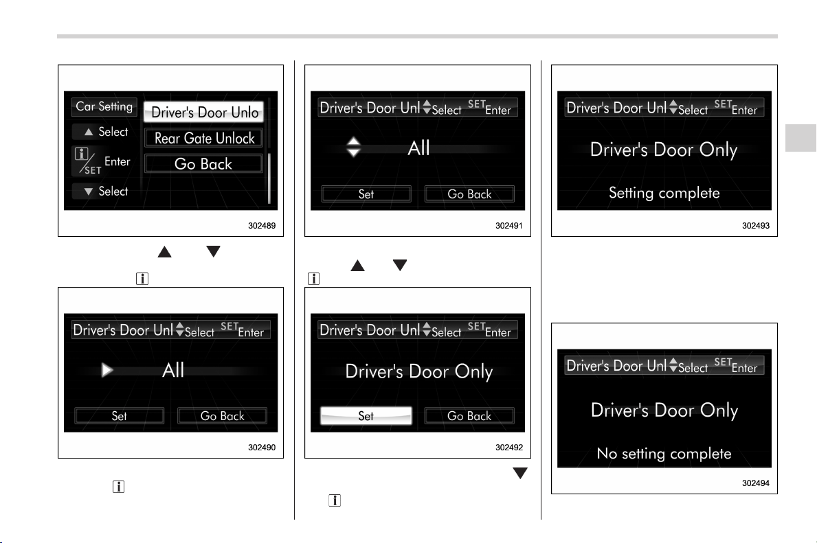
Black plate (213,1)
北米Model "A1160BE-C" EDITED: 2014/ 3/ 17
2. Operate the “ ” or “ ” switch to
select the “Driver’s Door Unlock” item.
Then pull the “
/SET” switch toward you.
3. The current setting will be displayed.
Pull the “
/SET” switch toward you to
enter the selection mode.
4. Select the preferred setting by operat-
ing the “
” or “ ” switch. Then pull the
“
/SET” switch toward you.
5. Select “Set” by operating the “ ”
switch, and confirm the setting by pulling
the “
/SET” switch toward you.
6. The system will notify you that the
setting is complete.
If the setting is not available, the following
notification will be displayed. In this case,
perform the setting procedure again.
Instruments and controls/Multi function display
3-73
– CONTINUED –
3
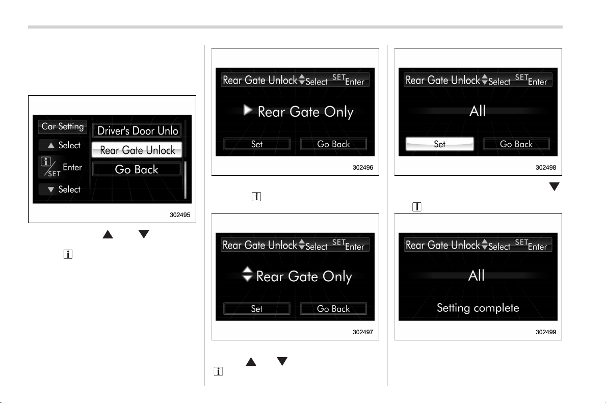
Black plate (214,1)
北米Model "A1160BE-C" EDITED: 2014/ 3/ 17
3-74
Instruments and controls/Multi function display
! Rear gate unlock setting
1. Perform the preparation steps accord-
ing to “Preparation for keyless access
settings” F3-72.
2. Operate the “ ” or “ ” switch to
select the “Rear Gate Unlock” item. Then
pull the “
/SET” switch toward you.
3. The current setting will be displayed.
Pull the “
/SET” switch toward you to
enter the selection mode.
4. Select the preferred setting by operat-
ing the “
” or “ ” switch. Then pull the
“
/SET” switch toward you.
5. Select “Set” by operating the “ ”
switch, and confirm the setting by pulling
the “
/SET” switch toward you.
6. The system will notify you that the
setting is complete.
If the setting is not available, the following
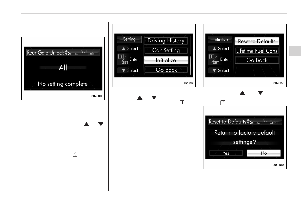
Black plate (215,1)
北米Model "A1160BE-C" EDITED: 2014/ 3/ 17
notification will be displayed. In this case,
perform the setting procedure again.
& Initialize
Items that have been set to your pre-
ference can be initialized. To select an
initialization menu, operate the “
” or “ ”
switch as follows.
! Preparation for initialization
1. Turn the ignition switch to the “ON”
position.
2. Pull and hold the “
/SET” switch
toward you to show the selection screen.
3. After the selection screen is displayed,
operate the “
” or “ ” switch to show the
“Initialize” item. Then, pull the “
/SET”
switch toward you.
! Reset to factory default settings
1. Perform the preparation steps accord-
ing to “Preparation for initialization” F3-
75.
2. Operate the “ ” or “ ” switch to
select the “Reset to Defaults” item. Then
pull the “
/SET” switch toward you.
3. The system will prompt a Yes/No
dialogue (“No” is selected first). To return
to the factory default settings, select “Yes”
Instruments and controls/Multi function display
3-75
– CONTINUED –
3
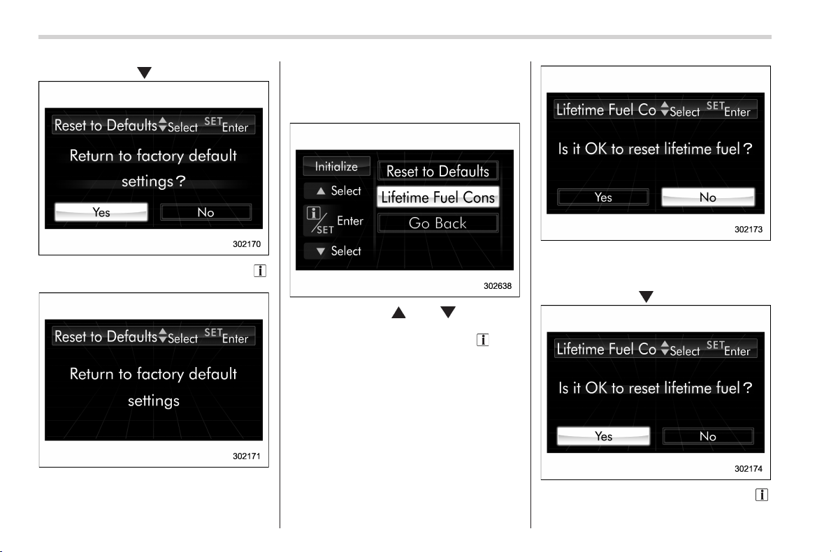
Black plate (216,1)
北米Model "A1160BE-C" EDITED: 2014/ 3/ 17
3-76
Instruments and controls/Multi function display
by operating the “ ” switch.
4. Confirm the setting by pulling the “ /
SET” switch toward you.
5. The system will notify you that the
setting is complete.
! Lifetime fuel consumption resetting
1. Perform the preparation steps accord-
ing to “Preparation for initialization” F3-
75.
2. Operate the “ ” or “ ” switch to
select the “Lifetime Fuel Consumption
Resetting” item. Then pull the “
/SET”
switch toward you.
3. The system will prompt a Yes/No
dialogue (“No” is selected first). To reset
the lifetime fuel consumption, select “Yes”
by operating the “
” switch.
4. Confirm the setting by pulling the “ /
SET” switch toward you.
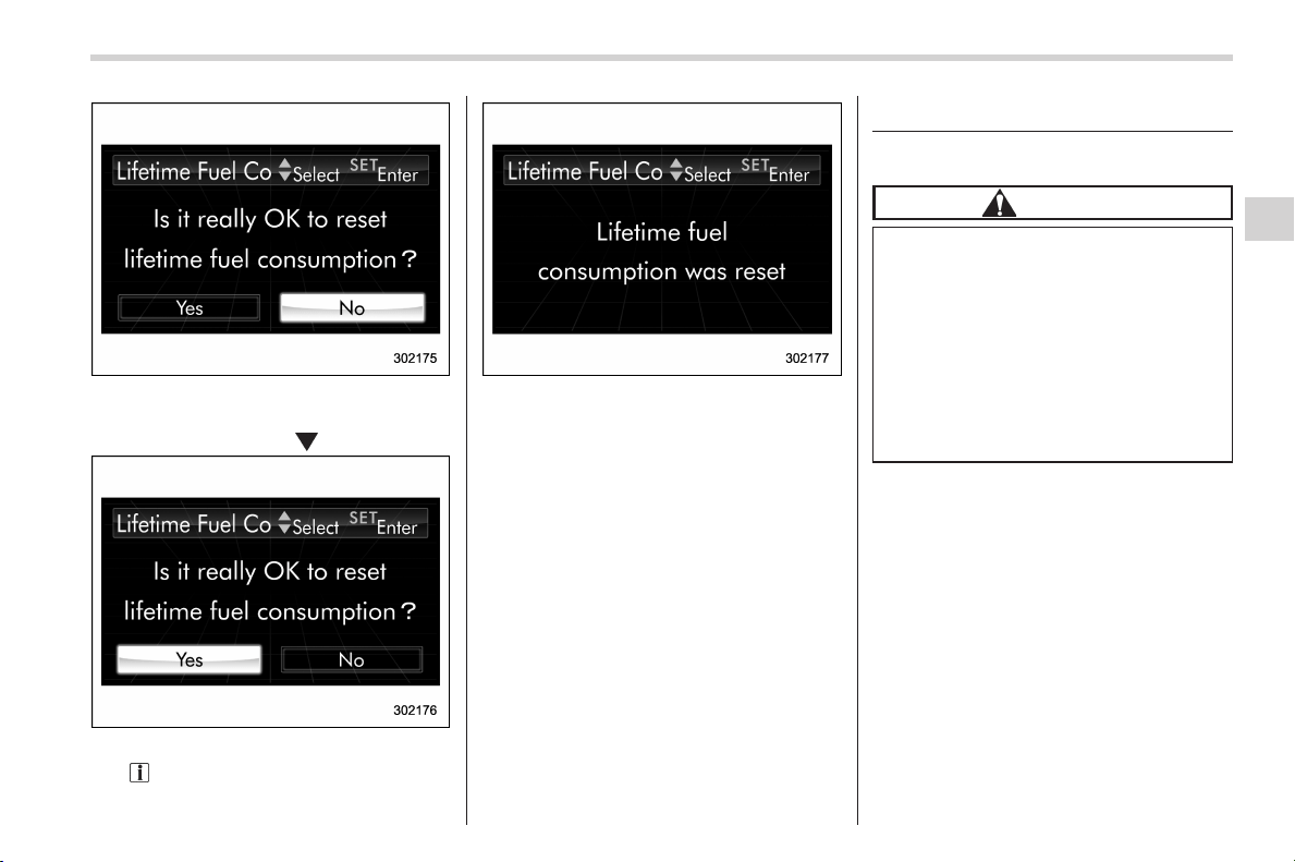
Black plate (217,1)
北米Model "A1160BE-C" EDITED: 2014/ 3/ 17
5. Reconfirmation will be displayed. If
you are sure you want to proceed, select
“Yes” by operating the “
” switch.
6. Confirm the setting again by pulling
the “
/SET” switch toward you.
7. The system will notify you that the
setting is complete.
Light control switch
& Precautions and tips
CAUTION
. Use of any lights for a long period
of time while the hybrid system is
not running can cause the 12 V
auxiliary battery to discharge.
. Before leaving the vehicle, make
sure that the lights are turned off.
If the vehicle is left unattended
for a long time with the lights
illuminated, the 12 V auxiliary
battery may be discharged.
NOTE
The light control switch can be oper-
ated (except auto on/off headlights),
even under the following conditions.
. when the key is not inserted into the
ignition switch (models without “key-
less access with push-button start
system”)
. when the push-button ignition
switch is turned off (models with “key-
less access with push-button start
system”)
If the driver’s door is opened while the
Instruments and controls/Light control switch
3-77
– CONTINUED –
3
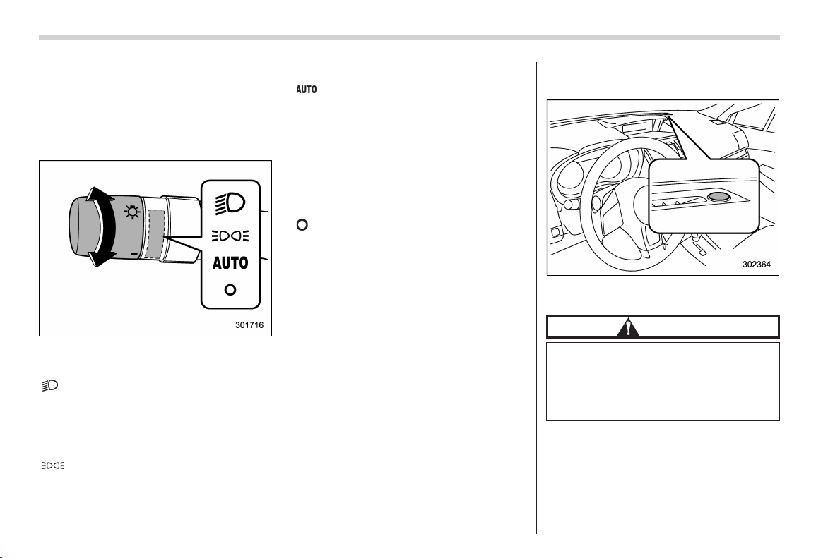
Black plate (218,1)
北米Model "A1160BE-C" EDITED: 2014/ 3/ 17
3-78
Instruments and controls/Light control switch
headlights are illuminated under such
conditions, the chirp sound will inform
the driver that the lights are illumi-
nated.
& Headlights
To turn on the headlights, turn the knob on
the end of the turn signal lever.
“
” position
Instrument panel illumination, headlights,
parking lights, front side marker lights, rear
side marker lights, tail lights and license
plate lights are on.
“
” position
Instrument panel ill umination, parking
lights, front side marker lights, rear side
marker lights, tail lights and license plate
lights are on.
“
” position: auto on/off headlights (if
equipped)
When the ignition switch is in the “ON”
position, the instrument panel illumination,
headlights, parking lights, front side mar-
ker lights, rear side marker lights, tail lights
and license plate lights are automatically
on or off depending on the level of the
ambient light.
“
” position
The headlights are all off.
NOTE
The sensitivity of the auto on/off head-
lights can be changed by a SUBARU
dealer. Consult your SUBARU dealer
for details. Also, for models with a multi
function display, the setting can be
changed using the display. For details,
refer to “Multi function display” F3-32.
! Sensor for the auto on/off head-
lights (if equipped)
The sensor is on the instrument panel as
shown in the illustration.
CAUTION
If any object is placed on or near the
sensor, the sensor may not detect
the level of the ambient light cor-
rectly and the auto on/off headlights
may not operate properly.
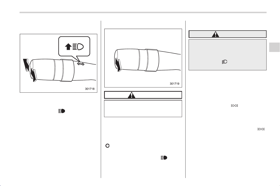
Black plate (219,1)
北米Model "A1160BE-C" EDITED: 2014/ 3/ 17
& High/low beam change
(dimmer)
To change from low beam to high beam,
push the turn signal lever forward. When
the headlights are on high beam, the high
beam indicator light “
” on the combina-
tion meter is also on.
To switch back to low beam, pull the lever
back to the center position.
& Headlight flasher
CAUTION
Do not hold the lever in the flashing
position for more than just a few
seconds.
To flash the headlights, pull the lever
toward you and then release it. The high
beam will stay on for as long as you hold
the lever. The headlight flasher works
even though the lighting switch is in the
“
” (off) position.
When the headlights are on high beam,
the high beam indicator light “
” on the
combination meter also illuminates.
& Daytime running light system
WARNING
The brightness of the illumination of
the high beam headlights is reduced
by the daytime running light system.
The light switch must always be
turned to the “
” position when it
is dark outside.
The high beam headlights will automati-
cally illuminate at reduced brightness
when the following conditions are fulfilled.
. The hybrid system is running.
. The parking brake is fully released.
. The light control switch is in the
“AUTO” (if equipped), “
” or off position.
. The select lever is in a position other
than the “P” position.
NOTE
. When the light switch is in the “ ”
position, the instrument panel illumina-
tion, front side marker lights, tail lights
and license plate lights are also illumi-
nated.
. For models with the auto on/off
headlights, while the light control
switch is in the “AUTO” position and
the system is activated to the auto-on
mode depending on the ambient light
Instruments and controls/Light control switch
3-79
– CONTINUED –
3
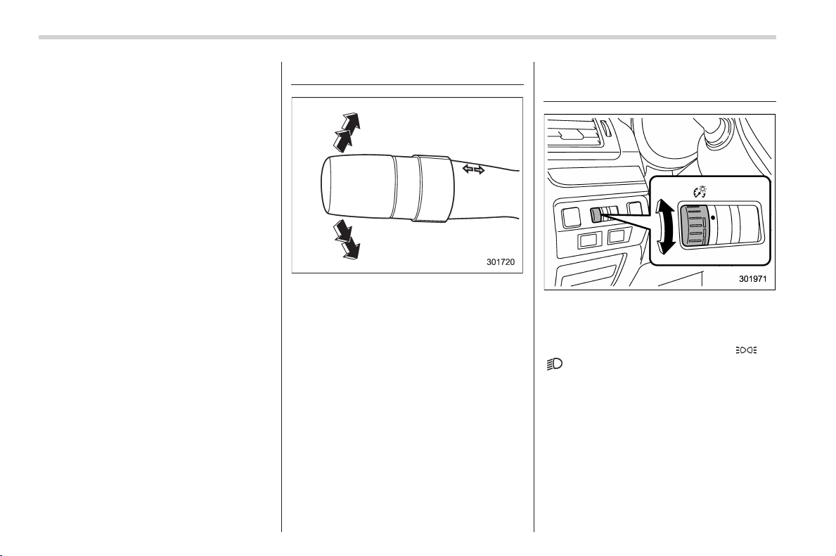
Black plate (220,1)
北米Model "A1160BE-C" EDITED: 2014/ 3/ 17
3-80
Instruments and controls/Turn signal lever
level, the high beam headlights that
have illuminated at reduced brightness
turn off, and the low beam headlights
turn on alternatively. At this time, the
instrument panel illumination, front
side marker lights, tail lights and
license plate lights are also illuminated.
Turn signal lever
To activate the right turn signal, push the
turn signal lever up. To activate the left
turn signal, push the turn signal lever
down. When the turn is finished, the lever
will return automatically. If the lever does
not return after cornering, return the lever
to the neutral position by hand.
To signal a lane change, push the turn
signal lever up or down slightly and hold it
during the lane change. The turn signal
indicator lights will flash in the direction of
the turn or lane change. The lever will
return automatically to the neutral position
when you release it.
Illumination brightness con-
trol
The illumination brightness of the instru-
ment panel di ms under the following
conditions.
. when the light switch is in the “
” or
“
” position
. when the light control switch is in the
“AUTO” position and the headlights illumi-
nate automatically (models with auto on/
off headlights: Refer to “Headlights” F3-
78.)
You can also adjust the illumination bright-
ness for better visibility in the following
ways.
To brighten, turn the control dial upward.
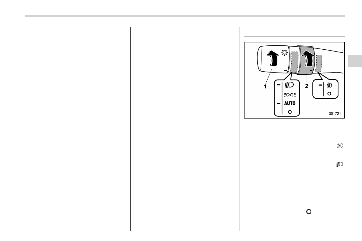
Black plate (221,1)
北米Model "A1160BE-C" EDITED: 2014/ 3/ 17
To darken, turn the control dial downward.
NOTE
. When the control dial is turned fully
upward, the illuminatio n brightness
becomes the maximum and the auto-
matic dimming function does not work
at all.
. The brightness setting is not can-
celed even when the ignition switch is
turned to the “LOCK” (off) position.
Headlight beam leveler (if
equipped)
& Automatic headlight beam
leveler (models with HID
headlights)
The HID headlights generate more light
than conventional halogen headlights.
Therefore a driver of an oncoming vehicle
may experience too much glare if your
headlight beam height adjustment is high
when the vehicle is carrying a heavy load.
The automatic headlight beam leveler
adjusts the headlight beam height auto-
matically and optimally according to the
load being carried by the vehicle.
Fog light switch (if equipped)
1) Headlight switch
2) Fog light switch
The front fog lights will turn on when the
fog light switch is placed in the “
”
position while the headlights are in the
following condition.
. while the headlight switch is in the “
”
position
. for models with the auto on/off head-
lights, while the headlight switch is in the
“AUTO” position and the headlights turn
on automatically
To turn off the front fog lights, turn the
switch back down to the “
” position.
Instruments and controls/Headlight beam leveler
3-81
– CONTINUED –
3
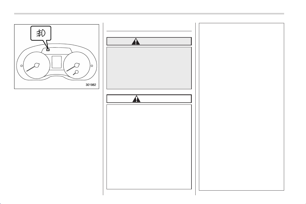
Black plate (222,1)
北米Model "A1160BE-C" EDITED: 2014/ 3/ 17
3-82
Instruments and controls/Wiper and washer
The indicator light on the combination
meter will illuminate when the front fog
lights are illuminated.
Wiper and washer
WARNING
In freezing weather, do not use the
windshield washer until the wind-
shield is sufficiently warmed by the
defroster.
Otherwise t he washer fluid can
freeze on the windshield, blocking
your view.
CAUTION
. Do not operate the washer con-
tinuously for more than 10 sec-
onds, or when the washer fluid
tank is empty. This may cause
overheating of the washer motor.
Check the washer fluid level
frequently, such as at fuel stops.
. Do not operate the wipers when
the windshield or rear window is
dry. This may scratch the glass,
damage the wiper blades and
might cause the wiper motor to
fail. Before operating the wiper
on a dry windshiel d or rear
window, always use the wind-
shield washer.
. In freezing weather, be sure that
the wiper blades are not frozen to
the windshield or rear window
before switching on the wipers.
Attempting to operate the wiper
with the blades frozen to the
window glass could cause not
only the wiper blades to be
damaged but also might cause
the wiper motor to fail. If the
wiper blades are frozen to the
window glass, be sure to operate
the defroster, windshield wiper
deicer (if equipped) or rear win-
dow defogger before turning on
the wiper.
. If the wipers stop during opera-
tion because of ice or some other
obstruction on the window, this
might cause the wiper motor to
fail even if the wiper switch is
turned off. If this occurs,
promptly stop the vehicle in a
safe place, turn the ignition
switch to the “LOCK” (off) posi-
tion and clean the window glass
to allow proper wiper operation.
. Use clean water if windshield
washer fluid is unavailable. In
areas where water freezes in
winter, use SUBARU Windshield
Washer Fluid or the equivalent.
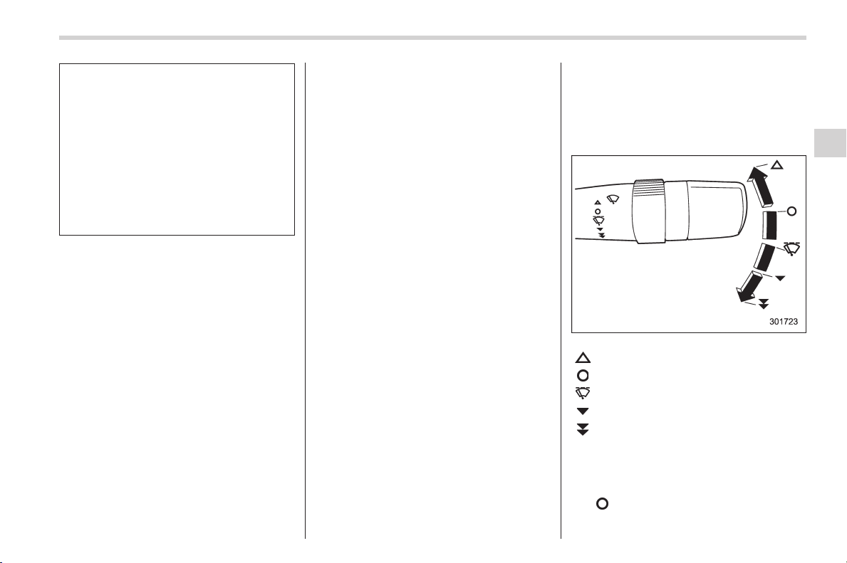
Black plate (223,1)
北米Model "A1160BE-C" EDITED: 2014/ 3/ 17
Refer to “Windshield washer
fluid” F11-31.
Also, when driving the vehicle
when there are freezing tempera-
tures, use non-freezing type wi-
per blades.
. Do not clean the wiper blades
with gasoline or a solvent, such
as paint thinner or benzine. This
will cause d eterioration of th e
wiper blades.
NOTE
. The windshield wiper motor is pro-
tected against overloads by a circuit
breaker. If the motor operates continu-
ously under an unusually heavy load,
the circuit breaker may trip to stop the
motor temporarily. If this happens, park
your vehicle in a safe place, turn off the
wiper switch, and wait f or approxi-
mately 10 minutes. The circuit breaker
will reset itself, and the wipers will
again operate normally.
. Clean your wiper blades and win-
dow glass periodically with a washer
solution to prevent streaking, and to
remove accumulations of road salt or
road film. Operate the wi ndshield
washer for at least 1 second so that
washer solution will be sprinkled all
over the windshield or rear window.
. Grease, wax, insects or other mate-
rial on the windshield or the wiper
blade results in jerky wiper operation
and streaking on the glass. If you
cannot remove those streaks after
operating the washer or if the wiper
operation is jerky, clean the outer sur-
face of the windshield or rear window
and the wiper blades using a sponge or
soft cloth with a neutral detergent or
mild-abrasive cleaner. After cleaning,
rinse the window glass and wiper
blades with clean water. The glass is
clean if no beads form on the glass
when you rinse with water.
. If you cannot eliminate the streaking
even after following this procedure,
replace the wiper blades with new
ones. For replacement instructions,
refer to “Replacement of wiper blades”
F11-32.
& Windshield wiper and washer
switches
The wiper operates only when the ignition
switch is in the “ON” or “ACC” position.
! Windshield wipers
: Mist (for a single wipe)
: Off
: Intermittent
: Low speed
:
High speed
To turn the wipers on, push the wiper
control lever down.
To turn the wipers off, return the lever to
the “
” position.
Instruments and controls/Wiper and washer
3-83
– CONTINUED –
3
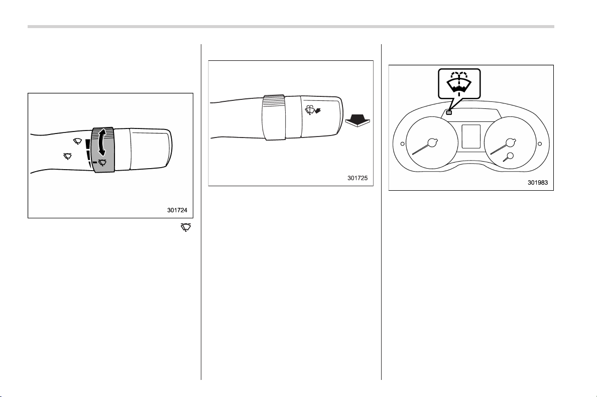
Black plate (224,1)
北米Model "A1160BE-C" EDITED: 2014/ 3/ 17
3-84
Instruments and controls/Wiper and washer
For a single wipe of the wipers, push the
lever up. The wipers operate until you
release the lever.
! Wiper intermittent time control
When the wiper switch is in the “ ”
position, turn the dial to adjust the operat-
ing interval of the wiper. The operating
interval can be adjusted in several steps
from the shortest interval to the longest.
! Windshield washer
To wash the windshield, pull the wiper
control lever toward you. The washer fluid
sprays until you release the lever. The
wipers operate while you pull the lever.
NOTE
The windshield washer fluid warning
light illuminates when the washer fluid
level in the tank has dropped to the
lower limit. If the warning light illumi-
nates, refill the tank with fluid. For the
refilling procedure, refer to “Wind-
shield washer fluid” F11-31.
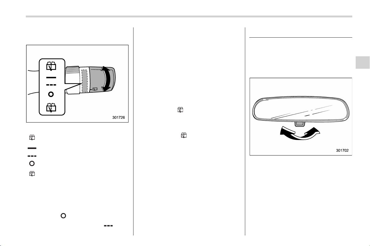
Black plate (225,1)
北米Model "A1160BE-C" EDITED: 2014/ 3/ 17
& Rear window wiper and
washer switch
:
Washer (accompanied by wiper op-
eration)
: Continuous
: Intermittent
:Off
:
Washer (accompanied by wiper op-
eration)
! Rear wiper
To turn the rear wiper on, turn the knob
switch upward.
To turn the wiper off, return the knob
switch to the “
” position.
With the switch turned to the “
” posi-
tion, the rear wiper will operate intermit-
tently at intervals corresponding to the
vehicle speed. In this position, when you
move the select lever to the “R” position,
the rear wiper will switch to continuous
operation. When you move the select
lever from the “R” position to another
position, the rear wipe r will return to
intermittent operation.
! Washer
To wash the rear window while the rear
wiper is operating, turn the knob switch
upward to the “
” position. The washer
fluid sprays until you release the knob.
To wash the rear window when the rear
wiper is not in use, turn the knob switch
downward to the “
” position. The washer
fluid sprays and the wiper operates until
you release the knob.
Mirrors
Always check that the inside and outside
mirrors are properly adjusted before you
start driving.
& Inside mirror
The inside mirror has a day and night
position. Pull the tab at the bottom of the
mirror toward you for the night position.
Push it away for the day position. The
night position reduces glare from head-
lights.
Instruments and controls/Mirrors
3-85
– CONTINUED –
3
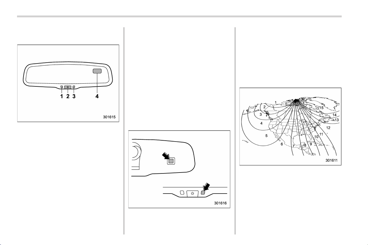
Black plate (226,1)
北米Model "A1160BE-C" EDITED: 2014/ 3/ 17
3-86
Instruments and controls/Mirrors
& Auto-dimming mirror/com-
pass (if equipped)
1) LED
2) Switch
3) Sensor
4) Compass display
The auto-dimming mirror has an anti-glare
feature which automatically reduces glare
coming from headlights of vehicles behind
you. It also contains a built-in compass.
. By pressing and holding the switch for
3 seconds, the automatic dimming func-
tion is toggled on or off. When the
automatic dimming function is on, the
LED indicator will illuminate.
Even with the mirror in anti-glare mode,
the mirror surface turns bright if the
transmission is shifted into reverse. This
is to ensure good rearward visibility during
reversing.
. By pressing and releasing the switch
for less than 3 seconds, the compass
display is toggled on or off. When the
compass is on, an illuminated compass
reading will appear in the upper right
corner of the mirror.
When cleaning the mirror, use a paper
towel or similar material dampened with
glass cleaner. Do not spray glass cleaner
directly on the mirror as that may cause
the liquid cleaner to enter t he mir ror
housing and damage the mirror.
! Photosensors
The mirror has a photosensor attached on
the front and back sides. During nighttime
driving, these sensors detect distracting
glare from vehicle headlights behind you
and automatically dim the mirror to elim-
inate glare and preserve your vision. For
this reason, use care not to cover the
sensors with stickers, or other similar
items. Periodically wipe the sensors clean
using a piece of dry soft cotton cloth or an
applicator.
! Compass zone adjustment
Compass calibration zones
1. Refer to the “Compass calibration
zones” map shown above to verify that
the compass zone setting is correct for
your geographical location.
2. Press and hold the switch for 6
seconds until the zone selection comes
up (a number will be displayed in the
mirror compass window).
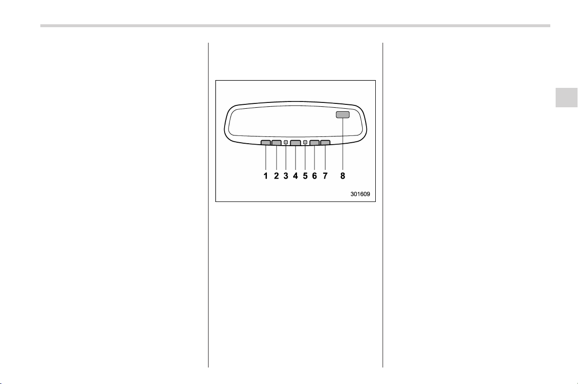
Black plate (227,1)
北米Model "A1160BE-C" EDITED: 2014/ 3/ 17
3. Press the switch repeatedly until the
correct zone setting for your location is
displayed.
4. Releasing the button for 10 seconds
will exit the zone setting mode.
! Compass calibration
1. If a “C” is displayed in the compass
window, the compass needs to be cali-
brated.
2. Drive the vehicle in a circle at 5 mph (8
km/h) or less until the display reads a
direction.
3. You can also calibrate the compass by
driving your vehicle on your everyday
routine. The compass will be calibrated
once it has tracked a complete circle.
4. To recalibrate your compass, push and
hold the switch for 9 seconds until a “C”
appears in the compass window.
5. Calibrate the compass according to
step 2 or step 3.
& Auto-dimming mirror/com-
pass with HomeLink
®
(if
equipped)
1) HomeLink
®
button 1
2) HomeLink
®
button 2
3) LED
4) HomeLink
®
button 3
5) Sensor
6) Automatic dimming on/off button
7) Compass display button
8) Compass display
The auto-dimming mirror has an anti-glare
feature which automatically reduces glare
coming from headlights of vehicles behind
you. It also contains a built-in compass
and HomeLink
®
wireless control system.
. By pressing the automatic dimming on/
off button, the automatic dimming function
is toggled on or off. When the automatic
dimming function is on, the LED indicator
will illuminate.
Even with the mirror in the automatic
dimming mode, the mirror surface turns
bright if the transmission is shifted into
reverse. This is to ensure good rearward
visibility during reversing.
. By pressing the compass display but-
ton, the compass display is toggled on or
off. When the compass is on, an illumi-
nated compass reading will appear in the
upper right corner of the mirror.
When cleaning the mirror, use a paper
towel or similar material dampened with
glass cleaner. Do not spray glass cleaner
directly on the mirror as that may cause
the liquid cleaner to enter t he mirror
housing and damage the mirror.
Instruments and controls/Mirrors
3-87
– CONTINUED –
3
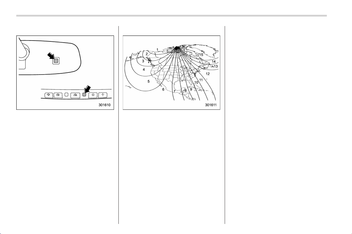
Black plate (228,1)
北米Model "A1160BE-C" EDITED: 2014/ 3/ 17
3-88
Instruments and controls/Mirrors
! Photosensors
The mirror has a photosensor attached on
both the front and back sides. During
nighttime driving, these sensors detect
distracting glare from vehicle headlights
behind you and automatically dim the
mirror to eliminate glare and preserve
your vision. For this reason, use care not
to cover the sensors with stickers, or other
similar items. Periodically wipe the sen-
sors clean using a piece of dry soft cotton
cloth or an applicator.
! Compass zone adjustment
Compass calibration zones
1. Re fer to the “Compass calibration
zones” map shown above to verify that
the compass zone setting is correct for
your geographical location.
2. Press and hold the compass display
button for 3 seconds until the zone
selection comes up (a number will be
displayed in the mirror compass window).
3. Press the compass display button
repeatedly until the correct zone setting
for your location is displayed.
4. Releasing the button for 5 seconds will
exit the zone setting mode.
! Compass calibration
1. If a “C” is displayed in the compass
window, the compass needs to be cali-
brated.
2. Drive the vehicle in a circle at 5 mph (8
km/h) or less until the display reads a
direction.
3. You can also calibrate the compass by
driving your vehicle on your everyday
routine. The compass will be calibrated
once it has tracked a complete circle.
4. To recalibrate your compass, push and
hold the compass display button for 9
seconds until a “C” appears in th e
compass window.
5. Calibrate the compass according to
step 2 or step 3.
! HomeLink
®
Wireless Control Sys-
tem
The HomeLink
®
Wireless Control System
can be used to activate remote control
devices such as gate operators, garage
door openers, door locks, home lighting
and security systems.
There are three HomeLink
®
buttons on the
mirror, each of which can be programmed
for operation of one desired device. For
details on the device types which can be
operated by this sys tem, co nsult th e
HomeLink
®
website at:
Black plate (229,1)
北米Model "A1160BE-C" EDITED: 2014/ 3/ 17
www.homelink.com or call 1-800-355-
3515.
Note the following information about this
system.
If your vehicle is equipped with the
HomeLink
®
Wireless Control System, it
complies with Part 15 of the Federal
Communica tions Commission Rules in
the U.S. and the RSS-210 of Industry
Canada in Canada. Its operation is subject
to the following two conditions:
(1) this device may not cause harmful
interference, and (2) thi s device must
accept any interference received, includ-
ing interference that may cause undesired
operation.
Changes and modifications to this system
by anyo ne oth er th an an authorized
service facility could void authorization to
use this equipment.
HomeLink
®
and the HomeLink
®
house are
registered trademarks of Johnson Con-
trols, Inc.
WARNING
. When programming the
HomeLink
®
Wireless Control Sys-
tem, you may be operatin g a
garage door opener or other
device. Make sure that people
and objects are out of the way of
the garage door or other device
to prevent potential harm or
damage.
. Do not use the HomeLink
®
Wire-
less Control System with a gar-
age door opener that lacks the
safety stop and reverse feature
as required by applicable safety
standards. A garage door opener
which cannot detect an object,
signaling the door to stop and
reverse, does not meet these
safety standards. Using a garage
door opener without these fea-
tures increases risk of serious
injury or death. For more infor-
mation, consult the HomeLink
®
website at www.homelink.com or
call 1-800-355-3515.
CAUTION
When programming the HomeLink
®
Wireless Control System to operate
a garage door opener or an entrance
gate, unplug the device’s motor
from the outlet during programming
to prevent motor burnout.
NOTE
. After programming your HomeLink
®
Wireless Control System for the de-
sired devices, retain the hand-held
transmitters for further programming
or device testing in the event of a
problem.
. It is recommended that you insert a
new battery in the hand-held transmit-
ter of a device to ensure correct
programming.
! Garage door opener program-
ming in the U.S.A.
NOTE
When programming the HomeLink
®
Wireless Control System for a garage
door opener, it is suggested that you
park the vehicle outside the garage.
1. Unplug the motor of the garage door
opener from the outlet.
NOTE
If any of the HomeLink
®
buttons are
already programmed for other devices,
skip step 2 because it clears the
memory of all three buttons.
Instruments and controls/Mirrors
3-89
– CONTINUED –
3
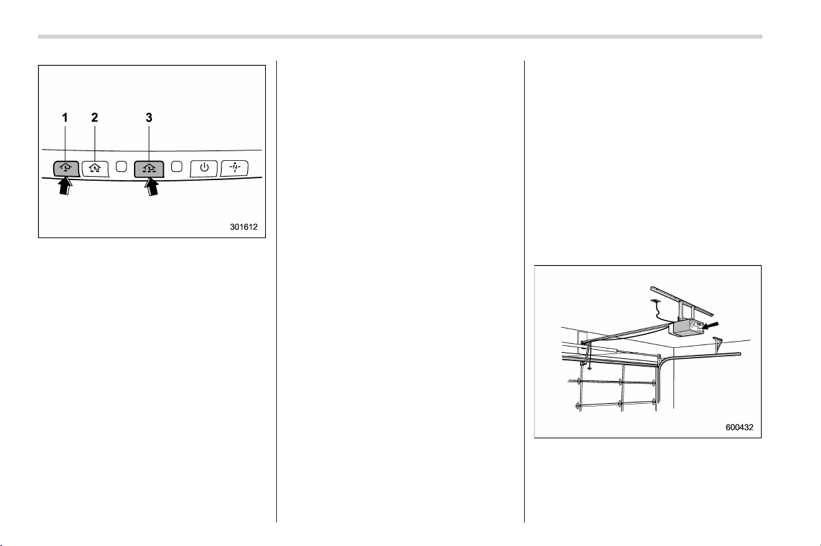
Black plate (230,1)
北米Model "A1160BE-C" EDITED: 2014/ 3/ 17
3-90
Instruments and controls/Mirrors
1) HomeLink
®
button 1
2) HomeLink
®
button 2
3) HomeLink
®
button 3
2. Press and hold the two outer
HomeLink
®
buttons (button 1 and button
3) until the indicator light begins to flash
(after approximately 20 seconds). Then
release both buttons.
3. Hold the end of the garage doo r
opener’s hand-held transmitter between
1 and 3 inches (25 and 76 mm) away from
the HomeLink
®
button you wish to pro-
gram.
4. Simultaneously press and hold both
the hand-held transmitter button and the
desired HomeLink
®
button. DO NOT re-
lease the buttons until step 5 has been
completed.
NOTE
Some gate operators and garage door
openers may require you to replace
this programming step 4 with proce-
dures in “Programming for entrance
gates and g arage do or op eners i n
Canada” F3-91.
5. Hold down both bu ttons until the
HomeLink
®
indicator light flashes, first
slowly then rapidly. When the indicator
light flashes rapidly, both buttons may be
released. (The rapidly flashing light indi-
cates successful programming of the new
frequency signal.)
6. Press and hold the programmed but-
ton and check the HomeLink
®
indicator
light. If the indicator light stays on con-
tinuously, your garage door should acti-
vate and the programming is completed.
If the indicator light flashes rapidly for 2
seconds and then stays on continuously,
your garage door opener may be pro-
tected by a rolling code feature. In this
case you need to perform the additional
steps that are described in “Programming
rolling-code-protected garage door open-
ers in the U.S.A.” F3-90.
! Programming rolling-code-pro-
tected garage door openers in
the U.S.A.
If your garage door opener has a rolling
code feature, program the HomeLink
®
Wireless Control System for it by following
steps 1 through 5 in “Garage door opener
programming in the U.S.A.” F3-89. Then
continue with the following steps.
NOTE
The assistance of a second person
may make the programming quicker
and easier.
1. Locate the training button on the
garage doo r opener motor head unit.
The exact location and color of the button
may vary by brand of garage door opener.
If it is difficult to locate the training button,
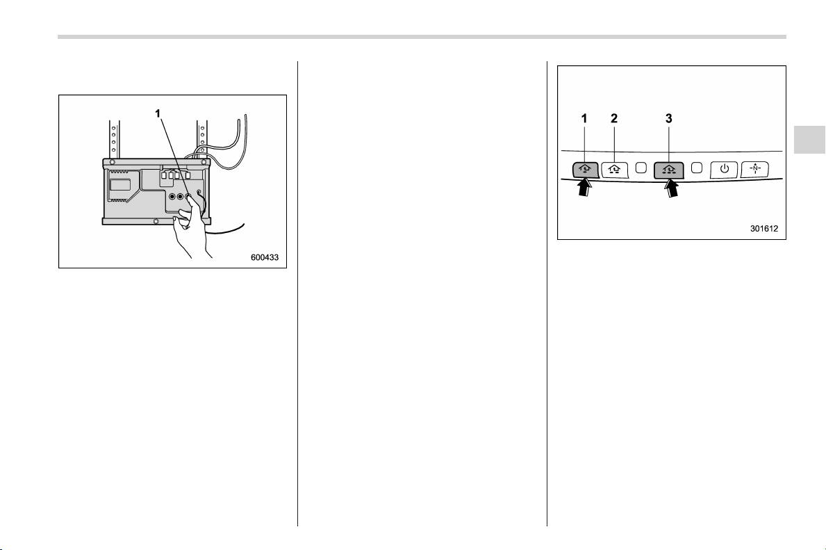
Black plate (231,1)
北米Model "A1160BE-C" EDITED: 2014/ 3/ 17
refer to your garage door opener’s instruc-
tion manual.
1) Training button
2. Press the training butto n on the
garage door opener motor hea d unit
(which activates the “training light” on the
unit). Proceed to step 3 within 30 seconds.
3. Inside the vehicle, firmly press, hold for
2 seconds and release the HomeLink
®
button that was programmed in the pre-
vious section. Press and release the
button a second time to complete the
programming procedure.
NOTE
Some garage door openers may re-
quire you to do the above press-hold-
release sequence a third time to com-
plete the programming.
4. The garage door opener should now
recognize the HomeLink
®
Wireless Control
System and your garage door opener
should activate when the Hom eLink
®
button is pressed.
! Programming for entrance gates
and garage door openers in
Canada
1. Unplug the motor of the entrance gate
or garage door opener from the outlet.
NOTE
If any of the HomeLink
®
buttons are
already programmed for other devices,
skip step 2 because it clears the
memory of all three buttons.
1) HomeLink
®
button 1
2) HomeLink
®
button 2
3) HomeLink
®
button 3
2. Press and hold the two outer
HomeLink
®
buttons (button 1 and button
3) until the Home Link
®
indicator light
begins to flash (after approximately 20
seconds). Then release both buttons.
3. Hold the end of the entrance gate’s/
garage door opener’s hand-held transmit-
ter between 1 and 3 inches (25 and 76
mm) away from the HomeLink
®
button you
wish to program.
4. Press and hold the desired HomeLink
®
button.
5. Press and release (“cycle”) the hand-
held transmitter button every 2 seconds
until step 6 is complete.
Instruments and controls/Mirrors
3-91
– CONTINUED –
3

Black plate (232,1)
北米Model "A1160BE-C" EDITED: 2014/ 3/ 17
3-92
Instruments and controls/Mirrors
6. When the indicator light flashes slowly
and then rapidly after several seconds,
release both buttons.
7. Plug the motor of the entrance gate/
garage door opener to the outlet.
8. Test your entrance gate/garage door
opener by pressing the programmed
HomeLink
®
button.
! Operating the HomeLink
®
Wire-
less Control System
Once programmed, the HomeLink
®
Wire-
less Control System can be used to
remote-control the devices to which its
buttons are programmed. To activate a
device, simply press the appropriate but-
ton. The indicator light illuminates, indicat-
ing that the signal is being transmitted.
! Programming other devices
To program other devices such as door
locks, home lighting and security systems,
contact HomeLink
®
at www.homelink.com
or call 1-800-355-3515.
! Reprogramming a single
HomeLink
®
button
1. Press and hold the HomeLink
®
button
you wish to reprogram. DO NOT release
the button until step 4 has been com-
pleted.
2. When the HomeLink
®
indicator light
begins to flash slowly (after approximately
20 seconds), position the hand-held trans-
mitter of the device between 1 to 3 inches
(25 to 76 mm) away from the HomeLink
®
button you wish to program.
3. Press and hold the hand-held trans-
mitter button. The HomeLink
®
indicator
light will flash, first slowly and then rapidly.
4. When the indicator light begins to flash
rapidly, release both buttons.
The programming for the previous device
is now erased and the new device can be
operated by pressing the HomeLink
®
button.
! Erasing HomeLink
®
button mem-
ory
NOTE
. Performi ng this procedure erases
the memory of all the preprogrammed
buttons simultaneously. The memory
of individual buttons cannot be erased.
. It is recommended that upon the
sale of the vehicle, the memory of all
programmed HomeLink
®
buttons be
erased for security purposes.
1) HomeLink
®
button 1
2) HomeLink
®
button 2
3) HomeLink
®
button 3
1. Press and hold the two outer buttons
(button 1 and button 3) until the indicator
light begins to flash (after approximately
20 seconds).
2. Release both buttons.
! In case a problem occurs
If you cannot activate a device using the
corresponding HomeLink
®
button after
programming, contact HomeLink
®
at
www.homelink.com or call 1-800-355-
3515 for assistance.
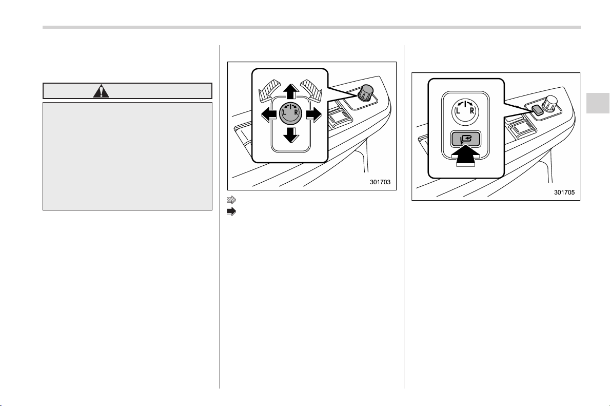
Black plate (233,1)
北米Model "A1160BE-C" EDITED: 2014/ 3/ 17
& Outside mirrors
! Convex mirror (passenger side)
WARNING
Objects look smaller in a convex
mirror and farther away than when
viewed in a flat mirror. Do not use
the convex mirror to judge the
distance of vehicles behind you
when changing lanes. Use the inside
mirror (or glance backwards) to
determine the actual size and dis-
tance of objects that you view in
convex mirror.
! Remote control mirror switch
: Select side to adjust
: Direction control
The remote control mirrors operate only
when the ignition switch is in the “ON” or
“ACC” position.
1. Turn the control switch to the side that
you want to adjust. “L” is for the left mirror,
“R” is for the right mirror.
2. Move the control switch in the direction
you want to move the mirror.
3. Return the control switch to the neutral
position to prevent unintentional opera-
tion.
The mirrors can also be adjusted manu-
ally.
! Power folding mirror switch (if
equipped)
The power folding mirror switch operates
only when the ignition switch is in the “ON”
or “ACC” position.
To fold the outside mirrors, press the
power folding mirror switch. To unfold the
mirrors, press the switch again.
NOTE
. If the outside mirrors h ave been
operated (folded or unfolded) manually,
when you turn the ignition switch from
the “LOCK” (off) position to the “ACC”
or “ON” position, the outside mirrors
may be adjusted automatically depend-
ing on the status of the power folding
mirror switch.
. If the outside mirrors h ave been
Instruments and controls/Mirrors
3-93
– CONTINUED –
3
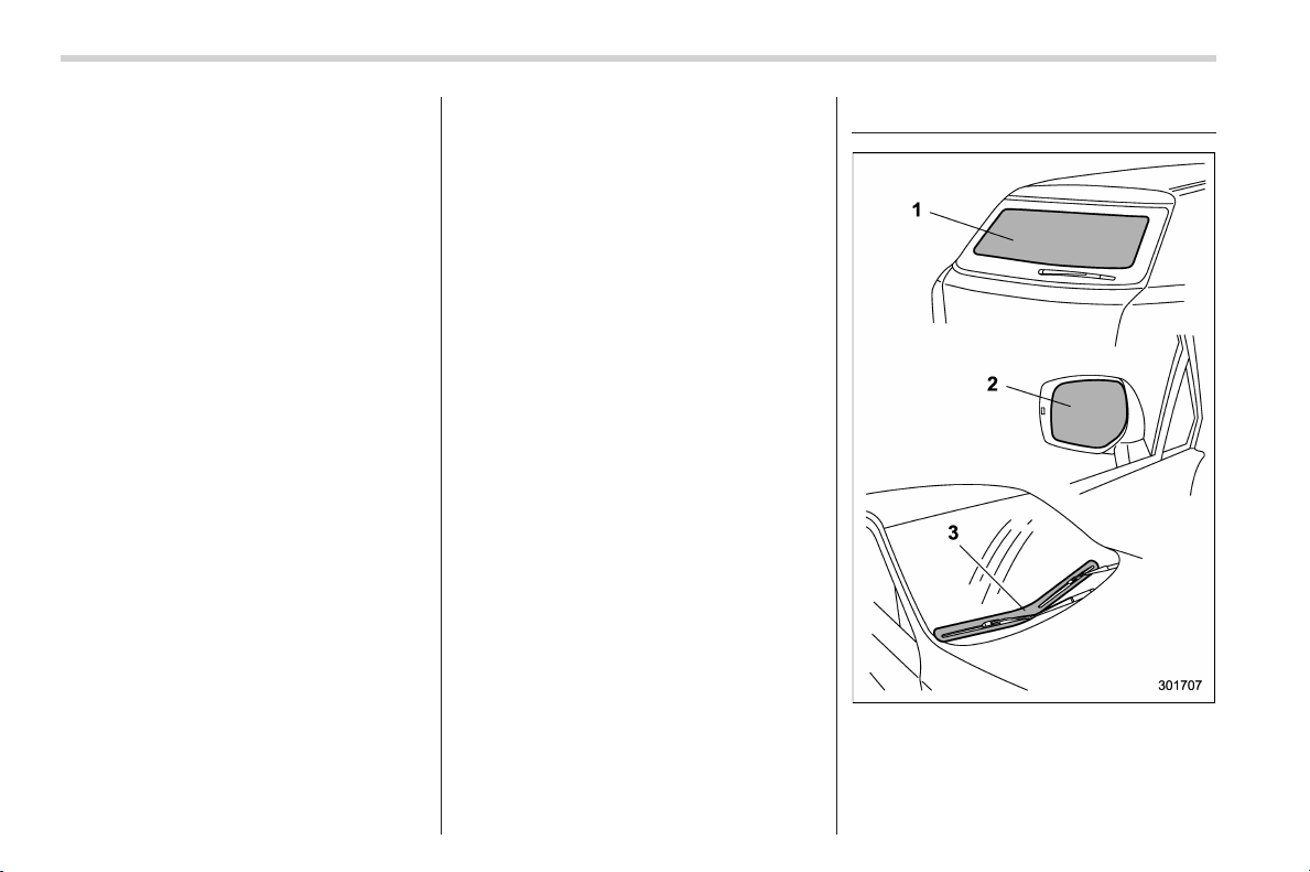
Black plate (234,1)
北米Model "A1160BE-C" EDITED: 2014/ 3/ 17
3-94
Instruments and controls/Defogger and deicer
manually folded slightly forward of the
regularly unfolded position, when you
turn the ignition switch from the
“LOCK” (off) position to the “ACC” or
“ON” position, the outside mirrors may
automatically fold further forward de-
pending on the status of the power
folding mirror switch. When this hap-
pens, press the power folding mirror
switch. By doing so, the outside mir-
rors which have been folded to the
furthest forward position will extend to
the r egularl y unfolded position and
then fold rearward in the usual way. In
order to unfold the outside mirrors,
press the switch again.
. When you unfold the outside mirrors
manually, the mirrors may b ecome
wobbly. Be sure to unfold the mirrors
by switch operation. If the outside
mirrors are still wobbly, fold the mirrors
again and then unfold them by switch
operation.
. When the temperature is low, the
outside mirrors may stop during switch
operation. If that occurs, push t he
switch again. When the outside mirrors
do not work by switch operation, move
them several times manually. This
makes it possible to operate them by
switch operation.
. When you operate the power folding
mirror switch continuously, it may not
work. This is not a malfunction. Oper-
ate the switch again after waiting for a
short period of time.
Defogger and deicer
1) Rear window defogger
2) Outside mirror defogger (if equipped)
3) Windshield wiper deicer (if equipped)
The vehicle is equipped with a rear
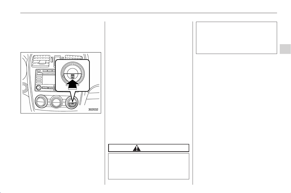
Black plate (235,1)
北米Model "A1160BE-C" EDITED: 2014/ 3/ 17
window defogger. Some models are also
equipped with an outside mirror defogger
and/or windshield wiper deicer. The de-
fogger and deicer system is activated only
when the ignition switch is in the “ON”
position.
Control switch
To activate the defogger and deicer
system, press the control switch that is
located on the climate control panel. The
rear window defogger, outside mirror
defogger and windshield wiper deicer are
activated simultaneo usly. The indicator
light on the control switch illuminates while
the defogger and deicer system is acti-
vated.
To turn them off, press the control switch
again. They also turn off when the ignition
switch is turned to the “ACC” or “LOCK”
(off) position.
The defogger and deicer system will
automatically shut off after approximately
15 minutes. If the rear window and the
outside mirrors have been cleared and the
windshield wiper blades have been deiced
completely before that time, press the
control switch to turn them off. If defrost-
ing, defogging or deicing is not complete,
you have to press the control switch to
turn them on again.
It is possible for the defogger and deicer
system to be set to continuous operation
mode by a SUBARU dealer. Consult your
SUBARU dealer for details. Also, the
setting can be changed using the multi
function display. For details, r efer to
“Defogger setting” F3-69.
If the 12 V auxiliary battery voltage drops
below the permissible level, continuous
operation of the defogger and deicer
system is canceled and the system stops
operating.
CAUTION
. To prevent the battery from being
discharged, do not operate the
defogger and deicer system con-
tinuously for any longer than
necessary.
. Do not use sharp instruments or
window cleaner containing abra-
sives to clean the inner surface
of the rear window. They may
damage the conductors printed
on the window.
NOTE
. Turn on the defogger and deicer
system if the wipers are frozen to the
windshield.
. If the windshield is covered with
snow, remove the snow so that the
windshield wiper deicer works effec-
tively.
. While the defogger and deicer sys-
tem is in the conti nuous operation
mode, if the vehicle speed remains at
9 mph (15 km/h) or less for 15 minutes,
the windshield wiper deicer automati-
cally stops operating, though the rear
window defogger and outside mirror
defogger maintain continuous opera-
tion in this condition.
Instruments and controls/Defogger and deicer
3-95
3
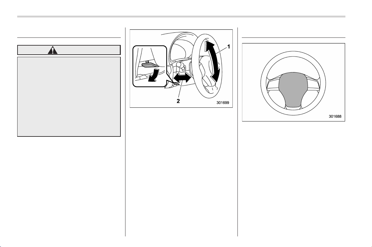
Black plate (236,1)
北米Model "A1160BE-C" EDITED: 2014/ 3/ 17
3-96
Instruments and controls/Tilt/telescopic steering wheel
Tilt/telescopic steering wheel
WARNING
. Do not adjust the steering wheel
tilt/telescopic position while driv-
ing. This may cause loss of
vehicle control and result in
personal injury.
. If the lever cannot be raised to
the fixed position, adjust the
steering wheel again. It is dan-
gerous to drive without locking
the steering wheel. This may
cause los s of vehicle con trol
and result in personal injury.
1) Tilt adjustment
2) Telescopic adjustment
1. Adjust the seat position. Refer to
“Front seats” F1-2.
2. Pull the tilt/telescopic lock lever down.
3. Move the steering wheel to the desired
level.
4. Pull the lever up to lock the steering
wheel in place.
5. Make sure that the steering wheel is
securely locked by moving it up and down,
and forward and backward.
Horn
To sound the horn, push the horn pad.

Black plate (7,1)
北米Model "A1160BE-C" EDITED: 2014/ 3/ 17
Ventilator control................................................. 4-2
Center and side ventilators .................................. 4-2
Climate control panel.......................................... 4-3
Type A ................................................................ 4-3
Type B ................................................................ 4-4
Automatic climate control operation ................. 4-5
Operation tips ..................................................... 4-5
Temperature sensors........................................... 4-5
Manual climate control operation ...................... 4-6
Airflow mode selection........................................ 4-6
Temperature control ............................................ 4-7
Fan speed control ............................................... 4-8
Air conditioner control ........................................ 4-8
Air inlet selection ................................................ 4-8
Defrosting ............................................................ 4-9
Type A ................................................................ 4-9
Type B................................................................. 4-9
Operating tips for heater and air
conditioner ........................................................ 4-9
Cleaning ventilation grille..................................... 4-9
Efficient cooling after parking in direct
sunlight ............................................................. 4-9
Lubrication oil circulation in the refrigerant
circuit.............................................................. 4-10
Checking air conditioning system before summer
season ............................................................ 4-10
Cooling and dehumidifying in high humidity and
low temperature weather conditions ................. 4-10
Air conditioner compressor shut-off when hybrid
system is heavily loaded.................................. 4-10
Refrigerant for your climate control system ........ 4-10
Air filtration system ........................................... 4-10
Replacing an air filter......................................... 4-11
Climate control
4
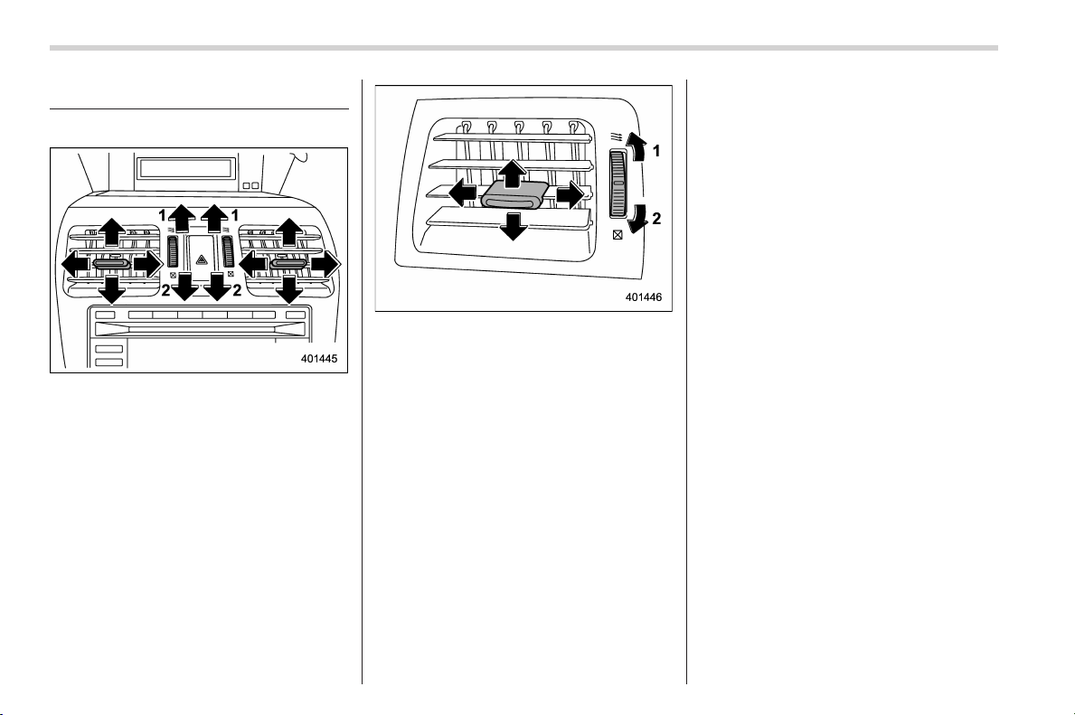
Black plate (240,1)
北米Model "A1160BE-C" EDITED: 2014/ 3/ 17
4-2
Climate control/Ventilator control
Ventilator control
& Center and side ventilators
Center ventilators
1) Open
2) Close
Side ventilators
1) Open
2) Close
To adjust the flow direction, move the tab.
To open or close the ventilator, turn the
thumb-wheel up or down.
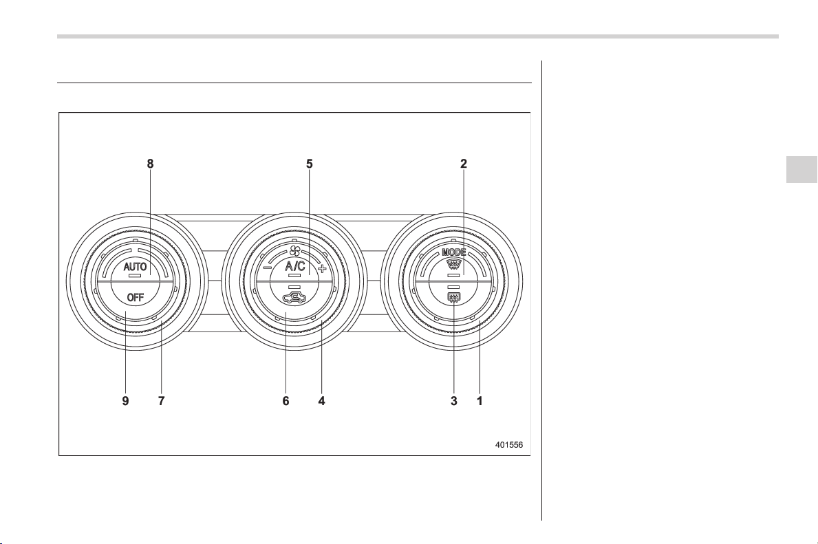
Black plate (241,1)
北米Model "A1160BE-C" EDITED: 2014/ 3/ 17
Climate control panel
& Type A
1) Airflow mode selection dial (Refer to
“Airflow mode selection” F4-6.)
2) Defroster button (Refer to “Airflow mode
selection” F4-6.)
3) Rear window defogger button (Refer to
“Defogger and deicer” F3-94.)
4) Fan speed control dial (Refer to “Fan
speed control” F4-8.)
5) Air conditioner button (Refer to “Air
conditioner control” F4-8.)
6) Air inlet selection button (Refer to “Air
inlet selection” F4-8.)
7) Temperature control dial (Refer to “Auto-
matic climate control operation” F4-5
and/or “Temperature control” F4-7.)
8) AUTO button (Refer to “Automatic cli-
mate control operation” F4-5.)
9) OFF button (Refer to “Automatic climate
control operation” F4-5.)
Climate control/Climate control panel
4-3
– CONTINUED –
4
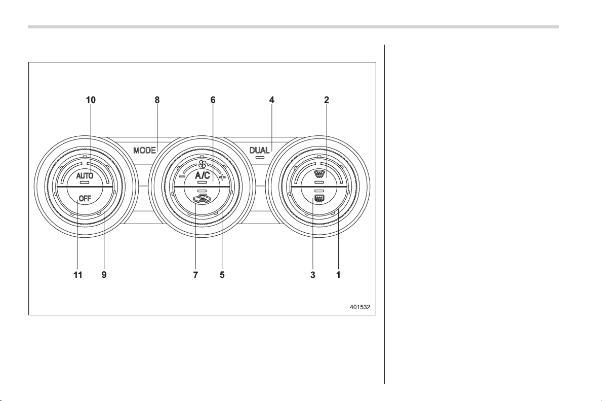
Black plate (242,1)
北米Model "A1160BE-C" EDITED: 2014/ 3/ 17
4-4
Climate control/Climate control panel
& Type B
1) Temperature control dial (Refer to “Auto-
matic climate control operation” F4-5
and/or “Temperature control” F4-7.)
2) Defroster button (Refer to “Airflow mode
selection” F4-6.)
3) Rear window defogger button (Refer to
“Defogger and deicer” F3-94.)
4) DUAL mode button (Refer to ““DUAL”
mode (type B)” F4-7.)
5) Fan speed control dial (Refer to “Fan
speed control” F4-8.)
6) Air conditioner button (Refer to “Air
conditioner control” F4-8.)
7) Air inlet selection button (Refer to “Air
inlet selection” F4-8.)
8) Airflow mode selection button (Refer to
“Airflow mode selection” F4-6.)
9) Temperature control dial (Refer to “Auto-
matic climate control operation” F4-5
and/or “Temperature control” F4-7.)
10) AUTO button (Refer to “Automatic cli-
mate control operation” F4-5.)
11) OFF button (Refer to “Automatic climate
control operation” F4-5.)
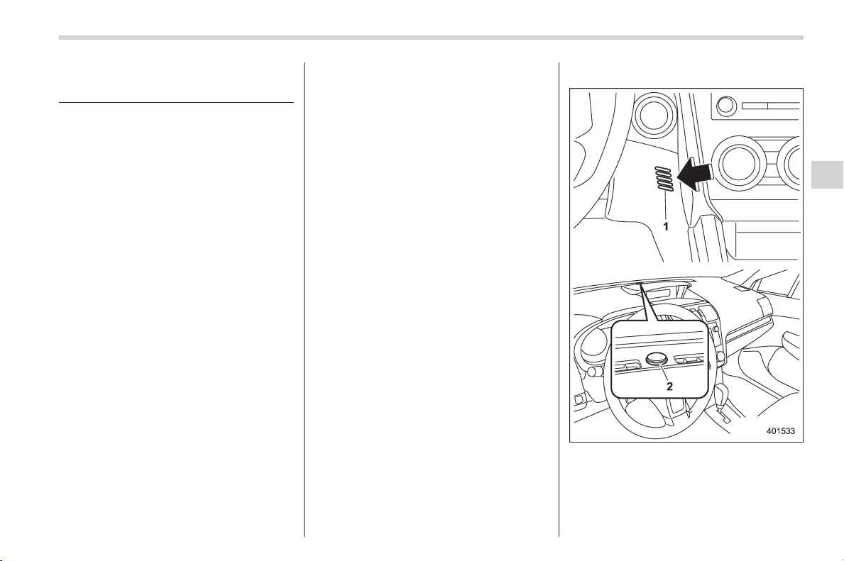
Black plate (243,1)
北米Model "A1160BE-C" EDITED: 2014/ 3/ 17
Automatic climate control
operation
When this mode is selected, the fan
speed, airflow distribution, air-inlet control,
and air conditioner compressor operation
are automatically controlled. To activate
this mode, perform the following.
1. Depress the “AUTO” button. The
indicator light “FULL AUTO” on the display
illuminates.
2. Set the preferred temperature using
the temperature control dial.
NOTE
. The controllable temperature range
may vary depending on the regional
specifications of the vehicle.
. If you operate any of the buttons on
the control panel other than the “OFF”
button, rear window defogger button
and temperature control dial(s) during
FULL AUTO mode operation, the
“FULL” indicator light on the control
panel will turn off and the “AUTO”
indicator light will remain illuminated.
You can then manually control the
system as desired using the button
you operated. To change the system
back to the FULL AUTO mode, press
the “AUTO” button.
3. To turn off the climate control system,
press the “OFF” button. Then the air inlet
selection will be set to OFF (outside air).
& Operation tips
. Operate the automatic climate control
system when the hybrid system is running.
. Even when cooling is not necessary,
setting the temperature much lower than
the current outlet air temperature turns on
the air conditioner compressor automati-
cally and the “A/C” indicator light on the
control panel illuminates.
& Temperature sensors
1) Interior air temperature sensor
2) Solar sensor
The automatic climate control system
employs several sensors. These sensors
are delicate. If they are not treated
Climate control/Automatic climate control operation
4-5
– CONTINUED –
4
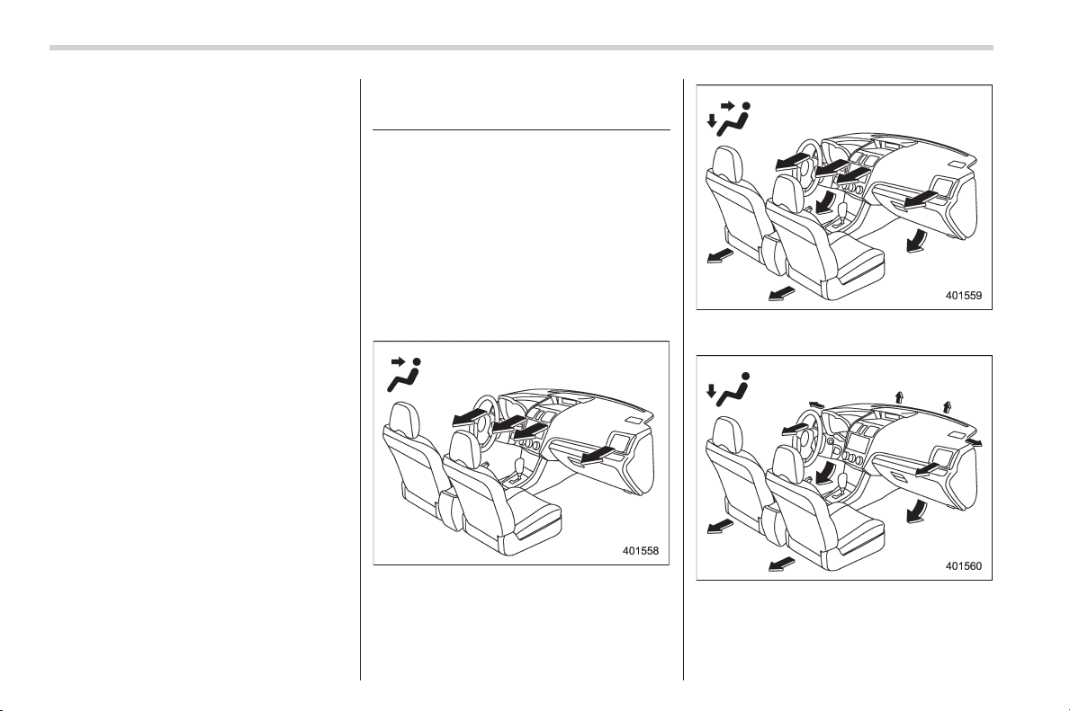
Black plate (244,1)
北米Model "A1160BE-C" EDITED: 2014/ 3/ 17
4-6
Climate control/Manual climate control operation
properly and become damaged, the sys-
tem may not be able to control the interior
temperature correctly. To avoid damaging
the sensors, observe the following pre-
cautions.
– Do not subject the sensors to impact.
– Keep water away from the sensors.
– Do not cover the sensors.
The sensors are located as follows.
– Solar sensor: beside the windshield
defroster grille
– Interior air temperature sensor: next to
the steering column
– Outside temperature sensor: near the
front bumper opening
Manual climate control op-
eration
& Airflow mode selection
To select the airflow mode:
Type A: Turn the airflow mode selection
dial.
Type B: Press the airflow mode selection
button.
To select the defrost mode:
Press the defroster button.
Airflow modes are as follows.
(Ventilation): Instrument panel outlets
(Bi-level): Instrument panel outlets and
foot outlets
(Heat): Foot outlets, both side outlets of
the instrument panel and some through
windshield defroster outlets (A small
amount of air flows to the windshield and
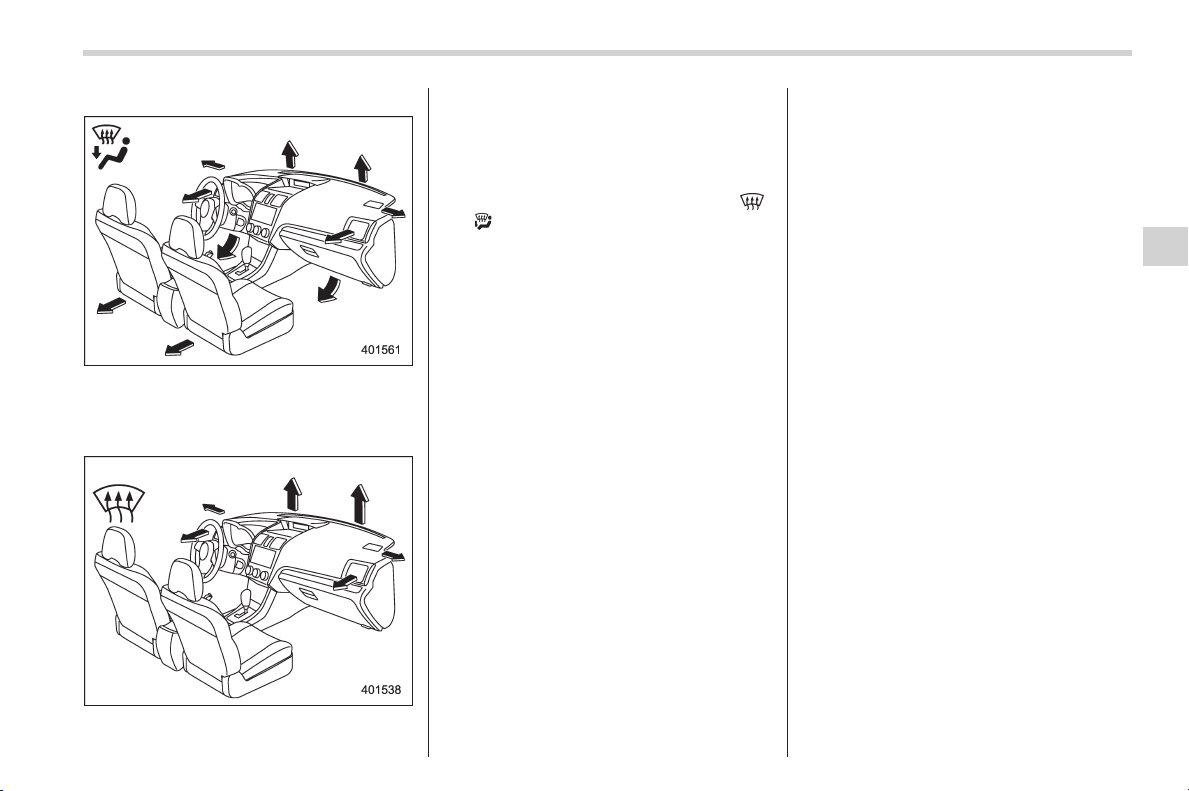
Black plate (245,1)
北米Model "A1160BE-C" EDITED: 2014/ 3/ 17
both side windows to prevent fogging.)
(Heat-def): Windshield defroster outlets,
foot outlets and both side outlets of the
instrument panel (Refer to “Defrosting”
F4-9.)
(Defrost ): Windshield defroster outlets
and both side outlets of the instrument
panel (Refer to “Defrosting” F4-9.)
NOTE
You cannot drive using only the electric
motor power while selecting the “
”
or “
” mode. Even while selecting the
other mode, you may not drive using
only the electric motor power depend-
ing on the vehicle condition. For de-
tails, refer to “General information for
stopping/restarting of the engine and
electric motor” F9.
& Temperature control
Turn the temperature control dial to set the
preferred interior temperature. With the
dial set to your preferred temperature, the
system automatically adjusts the tempera-
ture of air supplied from the outlets so that
the preferred temperature is achieved and
maintained.
If the dial is turned fully counterclockwise,
the system provides maximum cooling
performance. If the dial is turned fully
clockwise, the system provides maximum
heating performance.
NOTE
The controllable temperature range
may vary depending on the regional
specifications of the vehicle.
! “DUAL” mode (type B)
You can change the setting of the driver’s
side and front passenger’s side tempera-
ture independently by selecting the
“DUAL” mode.
You can select t he “DUAL” mode by
performing either of the following proce-
dures.
. Press the “DUAL” button
. Turn the passenger’s side temperature
control dial
The “DUAL” mode can be canceled by
pressing the “DUAL” button.
When the “DUAL” mode is selected:
Turn the driver’ssidedialtosetthe
driver’s side temperature. Turn the front
passenger’ssidedialtosetthefront
passenger’s side temperature.
When the “DUAL” mode is canceled:
Set the desired temperature by turning the
driver’s side dial.
Climate control/Manual climate control operation
4-7
– CONTINUED –
4
Black plate (246,1)
北米Model "A1160BE-C" EDITED: 2014/ 3/ 17
4-8
Climate control/Manual climate control operation
& Fan speed control
The fan operates only when the ignition
switch is in the “ON” position. Select the
preferred fan speed by turning the fan
speed control dial.
& Air conditioner control
The air conditioner operates only when
the hybrid system is running.
Press the air conditioner button while the
fan is in operation to turn on the air
conditioner. When the air conditioner is
on, the “A/C” indicator light illuminates.
To turn off the air conditioner, press the
button again.
NOTE
For efficient defogging or dehumidify-
ing in cold weather, turn on the air
conditioner. However, if the ambient
temperature decreases to approxi-
mately 328F(08C), the air conditioner
compressor will stop operating.
& Air inlet selection
Select the air inlet by pressing the air inlet
selection button.
ON position (recirculation): Interior air is
recirculated inside the vehicle. Press the
air inlet selection button to the ON position
for fast cooling with the air conditioner or
when driving on a dusty road.
OFF position (outside air): Outside air is
drawn into the passenger compartment.
Press the air inlet selection button to the
OFF position when the interior has cooled
to a comfortable temperature and the road
is no longer dusty.
WARNING
Continued operation in the ON posi-
tion may fog up the windows. Switch
to the OFF position as soon as the
outside conditions are no longer
dusty.
NOTE
. When the indicator light on the air
inlet selection button is flashing at
hybrid system starting, a malfunction
might be occurring in the electrical
system. Contact your SUBARU dealer
for inspection.
. The indicator light on the air inlet
selection button may flash in the
following cases. However, this does
not indicate a malfunction.
– After the 12 V auxiliary battery
has been disconnected and recon-
nected.
– When the 12 V auxiliary battery
voltage is low.
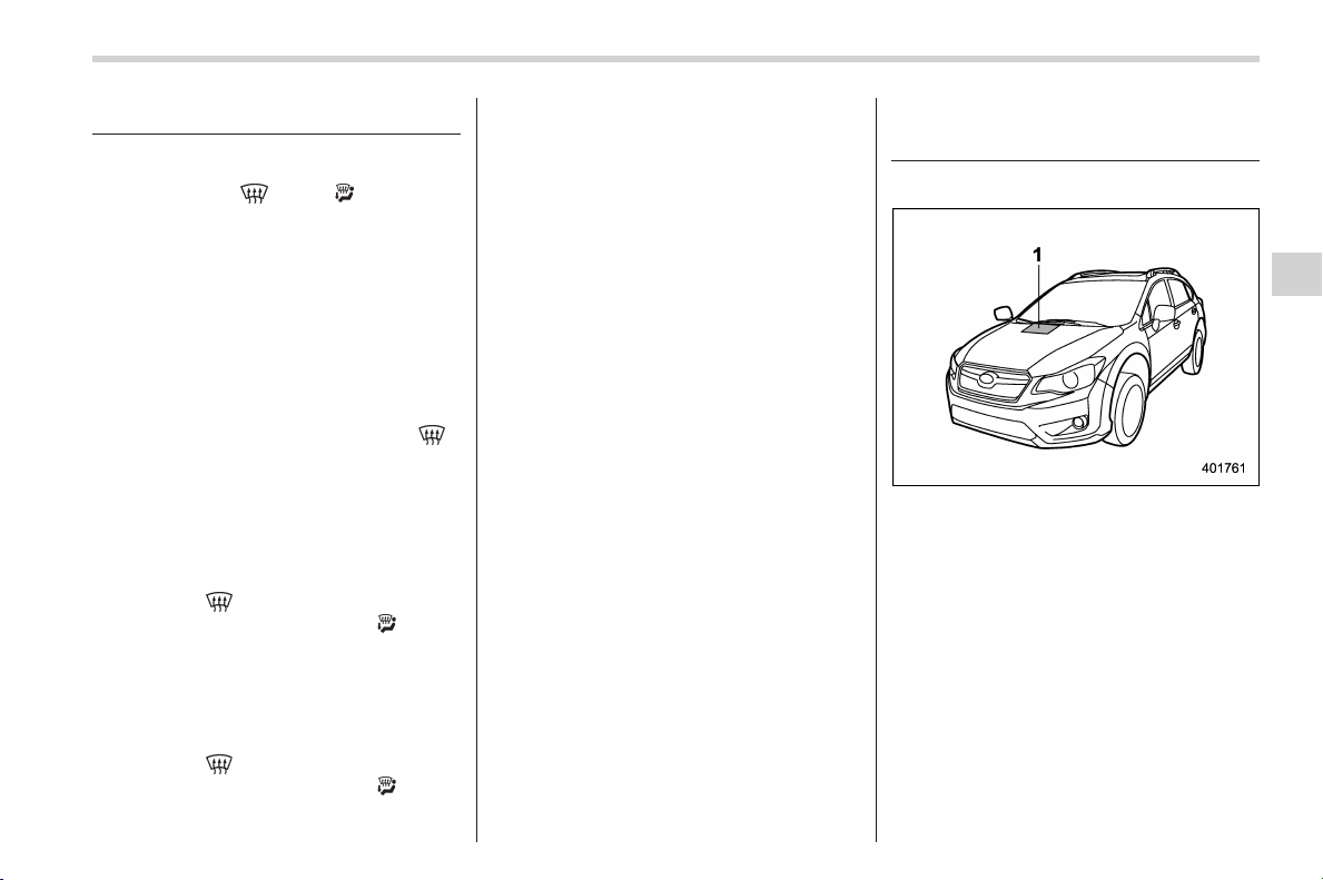
Black plate (247,1)
北米Model "A1160BE-C" EDITED: 2014/ 3/ 17
Defrosting
NOTE
. When the “ ” or “ ” mode is
selected, the air conditioner compres-
sor operates automatically regardless
of the position of the air conditioner
button to defrost the windshield more
quickly. However the indicator on the
air conditioner button will not illumi-
nate. At the same time, the air inlet
selection is automatically set to the
outside air mode.
. After defrosting the windshield by
pressing the defroster button “
”,
pressing the button again returns the
system to the setting that had been
selected before the defroster was acti-
vated.
& Type A
Select the “ ” mode by pressing the
defroster button, or select the “
” mode
by turning the airflow mode selection dial
to defrost or dehumidify the windshield
and front door windows.
& Type B
Select the “ ” mode by pressing the
defroster button, or select the “
” mode
by pressing the airflow mode selection
button to defrost or dehumidify the wind-
shield and front door windows.
Operating tips for heater and
air conditioner
& Cleaning ventilation grille
1) Front ventilation inlet grille
Always keep the front ventilation inlet grille
free of snow, leaves, or other obstructions
to ensure efficient heating and defrosting.
Since the condenser is located in front of
the radiator, this area should be kept clean
because cooling performance is impaired
by any accumulation of insects and leaves
on the condenser.
& Efficient cooling after parking
in direct sunlight
After parking in direct sunlight, drive with
the windows open for a few minutes to
Climate control/Defrosting
4-9
– CONTINUED –
4

Black plate (248,1)
北米Model "A1160BE-C" EDITED: 2014/ 3/ 17
4-10
Climate control/Air filtration system
allow outside air to circulate into the
heated interior. This results in quicker
cooling by the air conditioner. Keep the
windows closed during the operation of
the air conditioner for maximum cooling
efficiency.
& Lubrication oil circulation in
the refrigerant circuit
Operate the air conditioner compressor at
a low hybrid system speed (at idle or low
driving speeds) a few minutes each month
during the off-season to circulate its oil.
& Checking air conditioning
system before summer sea-
son
Check the air conditioner unit for refriger-
ant leaks, hose conditions, and proper
operation each spring. Have the air con-
ditioning system checked by your
SUBARU dealer.
& Cooling and dehumidifying in
high humidity and low tem-
perature weather conditions
Under certain weather conditions (high
relative humidity, low temperatures, etc.) a
small amount of water vapor emission
from the air outlets may be noticed. This
condition is normal and does not indicate
any probl em with the air conditioni ng
system.
& Air conditioner compressor
shut-off when hybrid system
is heavily loaded
To improve acceleration and gas mileage,
the air conditioner compressor is designed
to temporarily shut off during air condi-
tioner operation whenever the accelerator
is fully depressed such as during rapid
acceleration or when driving on a steep
upgrade.
& Refrigerant for your climate
control system
Your air conditioner uses ozone friendly
refrigerant HFC134a. Therefore, the meth-
od of adding, changing or checking the
refrigerant is different from the method for
CFC12 (freon). Consult your SUBARU
dealer for service. Repairs needed as a
result of using the wrong refrigerant are
not covered under warranty.
Air filtration system
Replace the filter element according to the
replacement schedu le as follows. This
schedule should be followed to maintain
the filter’s dust collection ability. Under
extremely dusty conditions, the filter
should be replaced more frequently. It is
recommended that you have your filter
checked or replaced by your SUBARU
dealer. For replacement, use only a
genuine SUBARU air filter kit.
Replacement schedule:
Every 12 months or 7,500 miles (12,000
km) whichever comes first
CAUTION
Contact your SUBARU dealer if the
following occurs, even if it is not yet
time to change the filter:
. Reduction of the airflow through
the vents.
. Windshield gets easily fogged or
misted.
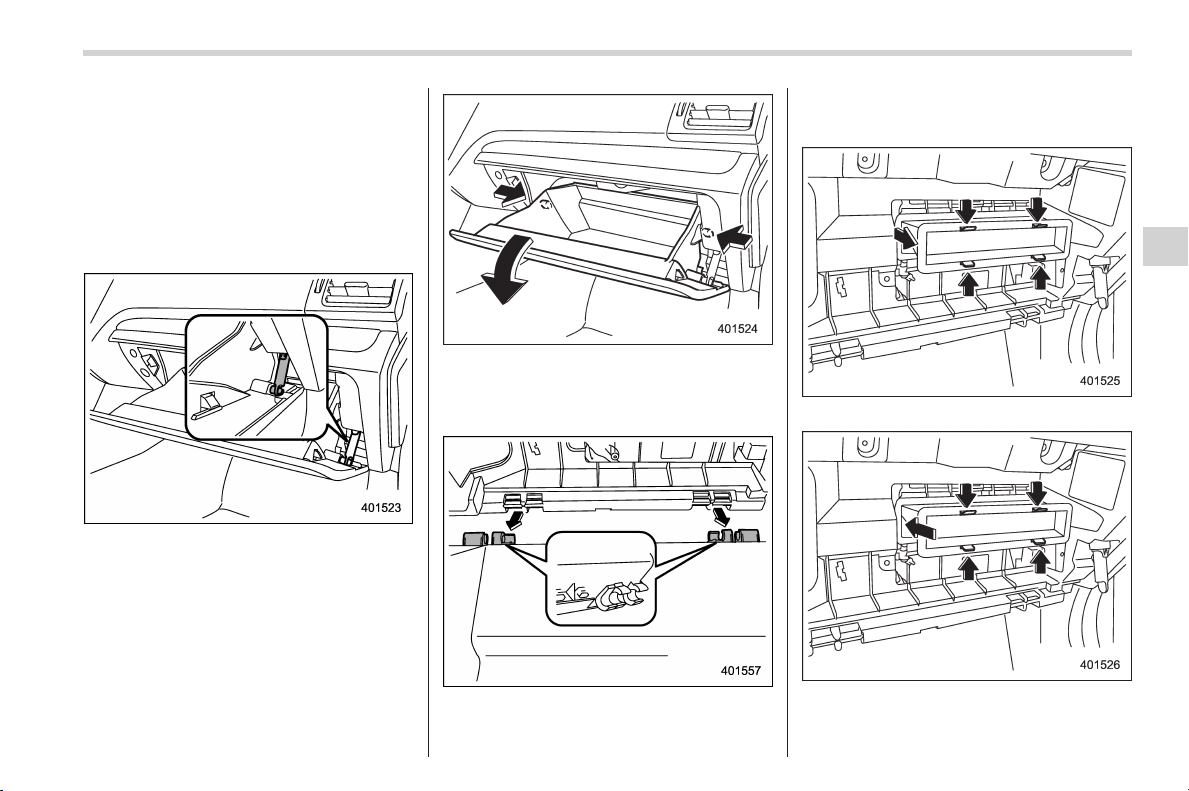
Black plate (249,1)
北米Model "A1160BE-C" EDITED: 2014/ 3/ 17
NOTE
The filter can influence the air condi-
tioning, heating and defroster perfor-
mance if not properly maintained.
& Replacing an air filter
1. Remove the glove box.
(1) Open the glove box.
(2) Remove the damper shaft from the
glove box.
(3) Push in the stoppers located on
both sides of the glove box and then
pull down the glove box as far as it will
go.
(4) Pull out the glove box horizontally
and remove the hinge portion. When
doing this, be careful not to damage
the hinge.
2. Remove the air filter.
3. Replace the air filter element with a
new one.
Climate control/Air filtration system
4-11
– CONTINUED –
4
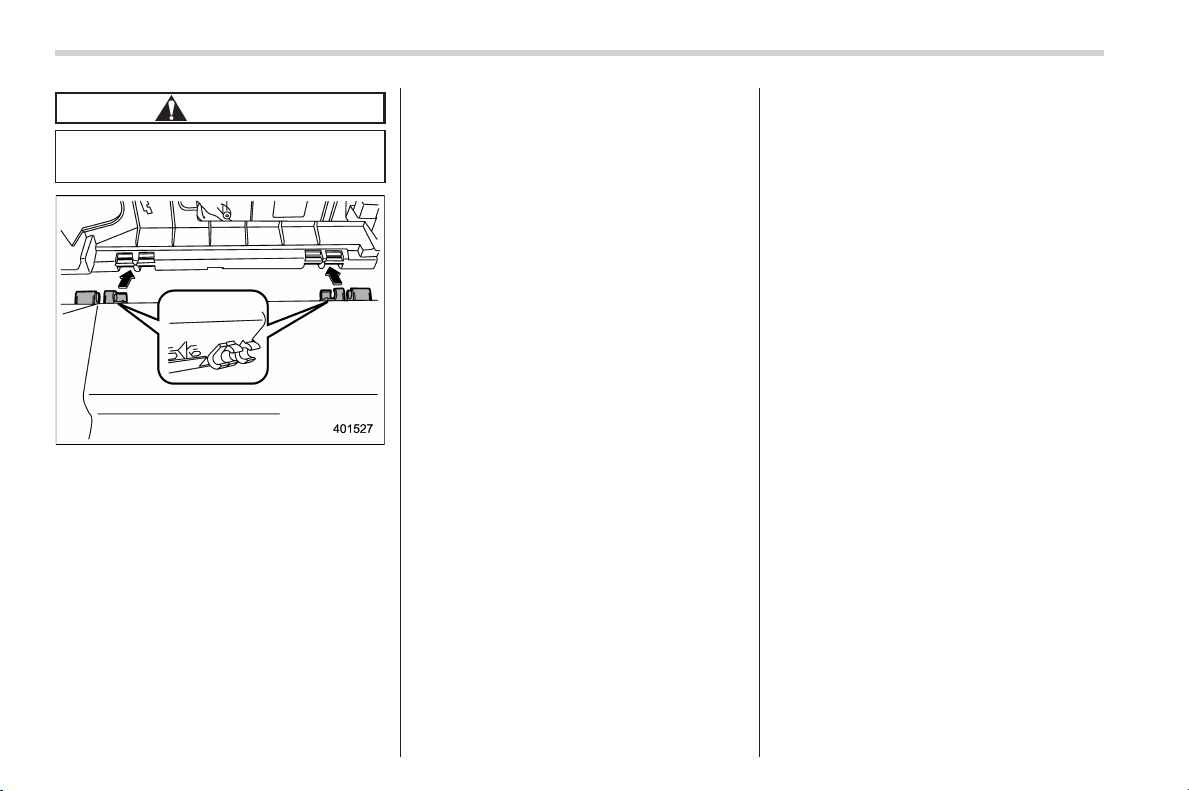
Black plate (250,1)
北米Model "A1160BE-C" EDITED: 2014/ 3/ 17
4-12
Climate control/Air filtration system
CAUTION
The arrow mark on the filter must
point UP.
4. Reinstall the glove box, and connect
the damper shaft.
5. Close the glove box.
6. Attach the service label to the driver’s
side door pillar.
Black plate (9,1)
北米Model "A1160BE-C" EDITED: 2014/ 3/ 17
Antenna system .................................................. 5-3
Roof antenna ...................................................... 5-3
FM reception....................................................... 5-3
Installation of accessories.................................. 5-4
Audio set ............................................................. 5-4
Type A audio set (if equipped) ............................. 5-5
Type B audio set (if equipped) ............................. 5-6
Power and audio controls .................................. 5-7
Power switch and volume control ........................ 5-7
Sound controls and audio settings ...................... 5-7
FM/AM radio operation ...................................... 5-11
FM selection ...................................................... 5-11
AM selection ...................................................... 5-11
Tuning ............................................................... 5-11
HD Radio
TM
Technology (Digital AM and FM
Radio) (type B audio)........................................ 5-13
Displaying radio PS (Program Service Name) and
RT (Radio Text) ................................................ 5-14
Station preset .................................................... 5-15
CD player operation ........................................... 5-16
Play file.............................................................. 5-16
How to insert a CD ............................................. 5-16
How to play back a CD ....................................... 5-17
To select a track from the beginning ................... 5-17
Fast-forwarding and rewinding ........................... 5-17
Repeating .......................................................... 5-18
Random playback .............................................. 5-18
Scan (type A audio)............................................ 5-19
Display selection (type A audio).......................... 5-19
Folder selection ................................................. 5-20
How to eject a CD from the player ...................... 5-20
When the following messages are displayed....... 5-20
Auxiliary input jack............................................ 5-21
Precautions to observe when handling a
compact disc................................................... 5-22
USB storage device / iPod
®
operations ........... 5-24
Play file ............................................................. 5-24
Connectable USB storage device ....................... 5-24
Connectable iPod
®
models................................. 5-24
Connecting USB storage device / iPod
®
............. 5-25
How to play back ............................................... 5-26
To select a track from the beginning .................. 5-26
To select a chapter from the beginning when
connecting iPod
®
............................................. 5-26
Fast-forwarding and rewinding ........................... 5-26
Repeating .......................................................... 5-26
Random playback .............................................. 5-27
SCAN (only when connecting USB storage
device) (type A audio) ...................................... 5-28
Selecting category (only when connecting
iPod
®
) ............................................................. 5-28
Display selection ............................................... 5-28
Folder selection (only when connecting USB
storage device)................................................ 5-29
Setting the playing speed (only when the
audiobook is playing) (type B audio) ................ 5-29
When the following messages are displayed....... 5-29
Audio control buttons ....................................... 5-30
MODE button..................................................... 5-30
“
” and “ ” switch .......................................... 5-30
Volume control switch ....................................... 5-31
Audio
5

Black plate (10,1)
北米Model "A1160BE-C" EDITED: 2014/ 3/ 17
Audio
Bluetooth
®
audio ................................................ 5-31
Media format...................................................... 5-32
Setting Bluetooth
®
audio .................................... 5-32
Bluetooth
®
audio operation................................. 5-33
Hands-free system (if equipped) ....................... 5-34
Safety precautions ............................................. 5-35
Using the Hands-free system .............................. 5-36
Bluetooth
®
setting ............................................. 5-51
Tips for the Hands-free system .......................... 5-53
Certification for the Hands-free system............... 5-54
Screensaver (type B audio) .............................. 5-55
Downloading pictures ........................................ 5-56
Selecting pictures .............................................. 5-56
Erasing pictures ................................................ 5-56
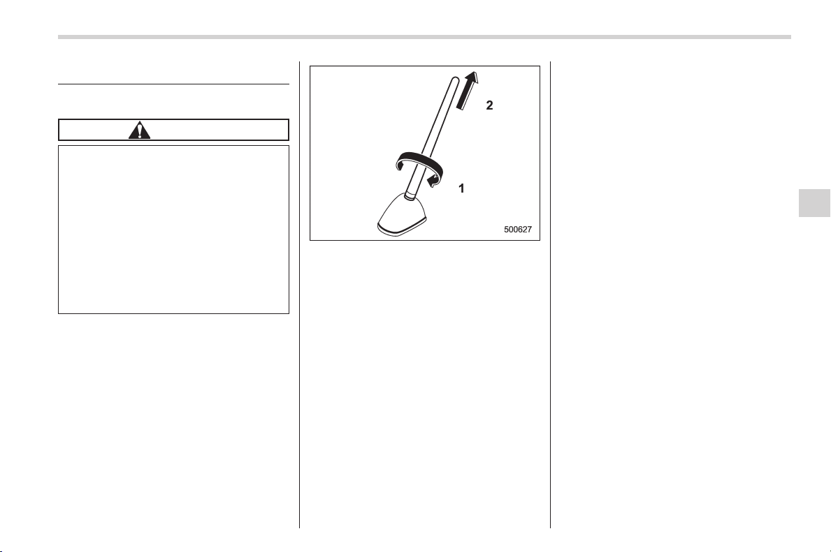
Black plate (255,1)
北米Model "A1160BE-C" EDITED: 2014/ 3/ 17
Antenna system
& Roof antenna
CAUTION
. Be sure to remove the antenna
rod before entering garages,
parking towers and other loca-
tions with low ceilings.
. Remove the antenna rod before
washing your car at a car wash. If
the antenna rod is left attached, it
may scratch the roof.
. When reinstalling th e removed
antenna rod, be sure to fully
tighten it.
1) Unscrew
2) Remove
The roof antenna is installed in the center
at the rear part of the roof.
The antenna rod can be removed by
unscrewing it from its base.
& FM reception
Although FM is normally static free,
reception can be affected by the surround-
ing area, atmospheric conditions, station
strength and transmitter distance. Build-
ings or other obstructions may cause
momentary static, flutter or station inter-
ference. If reception continues to be
unsatisfactory, switch to a stronger station.
Audio/Antenna system
5-3
5

Black plate (256,1)
北米Model "A1160BE-C" EDITED: 2014/ 3/ 17
5-4
Audio/Installation of accessories
Installation of accessories
Always consult your SUBARU dealer
before installing a citizen band radio or
other transmitting device in your vehicle.
Such devices may cause the electronic
control system to malfunction if they are
incorrectly installed or if they are not
suited for the vehicle.
Audio set
Your SUBARU may be equipped with one
of the following audio sets. Refer to the
pages indicated in this section for operat-
ing details.
NOTE
If a cell phone is placed near the audio
set, it may cause the audio set to emit
noise when the phone receives calls.
This noise does not indicate an audio
set malfunction. Note that a cell phone
should be placed as far as possible
from the audio set.
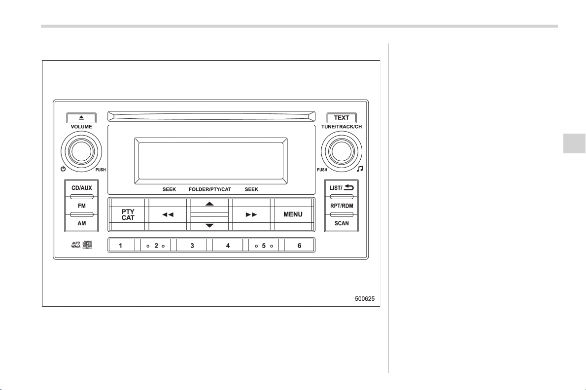
Black plate (257,1)
北米Model "A1160BE-C" EDITED: 2014/ 3/ 17
& Type A audio set (if equipped)
The audio set will operate only when the
ignition switch is in the “ACC” or “ON”
position.
. Power and audio controls: refer to page
5-7
. Radio operation: refer to page 5-11
. CD (compact disc) player operation:
refer to page 5-16
. Auxiliary input jack: refer to page 5-21
. USB storage device/iPod
®
operation:
refer to page 5-24
. Bluetooth
®
audio: refer to page 5-31
. Hands-free system: refer to page 5-34
Audio/Audio set
5-5
– CONTINUED –
5
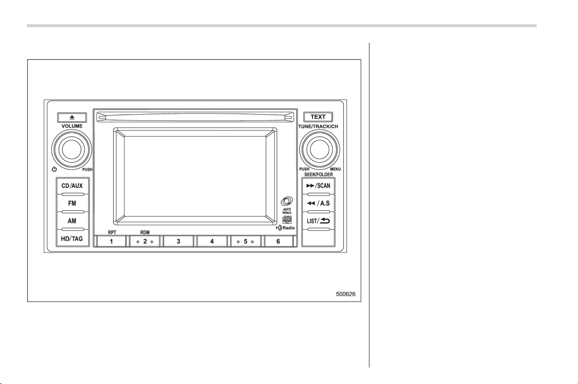
Black plate (258,1)
北米Model "A1160BE-C" EDITED: 2014/ 3/ 17
5-6
Audio/Audio set
& Type B audio set (if equipped)
The audio set will operate only when the
ignition switch is in the “ACC” or “ON”
position.
. Power and audio controls: refer to page
5-7
. Radio operation: refer to page 5-11
. CD (compact disc) player operation:
refer to page 5-16
. Auxiliary input jack: refer to page 5-21
. USB storage device/iPod
®
operation:
refer to page 5-24
. Bluetooth
®
audio: refer to page 5-31
. Hands-free system: refer to page 5-34

Black plate (259,1)
北米Model "A1160BE-C" EDITED: 2014/ 3/ 17
Power and audio controls
& Power switch and volume
control
Type A and B audio
The dial is used for both power (ON/OFF)
and volume control. The radio is turned
ON and OFF by pressing the dial, and the
volume is controlled by turning the dial.
& Sound controls and audio
settings
NOTE
. SPEED VOLUME CONTROL (SVC) is
a function that automatically adjusts
the volume according to the vehicle
speed. As the vehicle speed increases,
the audio volume automatically in-
creases to match the vehicle speed, in
order to create a pleasant listening
environment even as the driving noise
increases.
. For type B audio, SRS TruBass and
FOCUS are equipped.
. SRS Sound features:
(1) Sound originating from door
mount speakers can be heard at
ear level (built in SRS FOCUS effect)
(type B audio).
(2) Ultra rich bass sound can be
obtained from standard door mount
speakers (built in SRS TruBass
effect) (type B audio).
. TruBass, FOCUS, SRS and “
”
symbol are trademarks of SRS Labs,
Inc.
. TruBass and FOCUS technologies
are incorporated under license from
SRS Labs, Inc.
! Tone and balance control (type A
audio)
“TUNE/TRACK/CH”
dial
Each brief press of the “TUNE/TRACK/
CH” dial will change the control modes in
the following sequence.
Choose the preferred level for each mode
by turning the “TUNE/TRACK/CH” dial.
The control function returns to the tune/
track/channel control mode after approxi-
mately 5 seconds.
Audio/Power and audio controls
5-7
– CONTINUED –
5
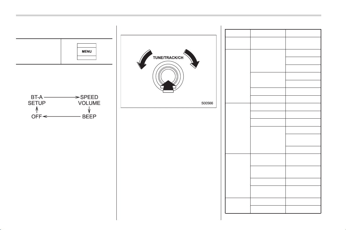
Black plate (260,1)
北米Model "A1160BE-C" EDITED: 2014/ 3/ 17
5-8
Audio/Power and audio controls
! Other settings (type A audio)
“MENU” button
Each brief press of the “MENU” button will
change the control modes in the following
sequence.
Choose the preferred settings for each
mode by turning the “TUNE/TRACK/CH”
dial.
The control function returns to the tune/
track/channel control mode after approxi-
mately 5 seconds.
! Audio settings (type B audio)
1. Press the “TUNE/TRACK/CH” dial to
display “SETTING Menu”.
2. Operate the “TUNE/TRACK/CH” dial
to select the preferred menu. You can
select the menu as shown in the following
chart.
First menu Second menu Third menu
Screen
OFF
——
Sound Tone
Bass
Mid
Treble
Balance
Balance
Fader
SVC —
SRS Sound —
Screen
Brightness —
Contrast —
Screen Size —
Screen Saver
Picture Select
Picture Down-
load
Picture Erase
BT Audio
Setup
Pair Audio
Player
—
Select Audio
Player
—
Set Passkey —
Delete Audio
Player
—
Others
HD ON/OFF —
Initialize
—

Black plate (261,1)
北米Model "A1160BE-C" EDITED: 2014/ 3/ 17
3. Operate the “TUNE/TRACK/CH” dial
to select the preferred setting for each
mode.
NOTE
Only “Screen OFF” can be displayed
while driving.
Audio/Power and audio controls
5-9
– CONTINUED –
5

Black plate (262,1)
北米Model "A1160BE-C" EDITED: 2014/ 3/ 17
5-10
Audio/Power and audio controls
! Adjustable level of each mode
Mode Range of levels
(displayed)
Default
setting
Turn counterclockwise Turn clockwise
Volume Volume control 0 to 40 15 For less volume For more volume
AUX volume control 0 to 40 15 For less volume For more volume
Tone and balance Bass control −8 to +8 0 For less bass sound For more bass sound
Midrange control −8 to +8 0 For less midrange sound For more midrange sound
Treble control −8 to +8 0 For less treble sound For more treble sound
Balance L9 to R9 0 Right channel attenuated Left channel attenuated
Fader R9 to F9 0 Front attenuated Rear attenuated
Other settings SPEED VOLUME OFF to 2 OFF For less auto volume change For more auto volume change
BEEP (Type A audio) OFF to ON ON OFF ON
SRS Sound (Type B audio) OFF to ON ON OFF ON
Brightness (Type B audio) 0 to 15 13 For less brightness For more brightness
Contrast (Type B audio) 0 to 15 8 For less contrast For more contrast
Screen size (Type B audio) Normal to Wide Wide Normal Wide
HD ON/OFF (Type B audio) OFF to ON ON ON OFF
Initialize (Type B audio) Cancel to Initialize Cancel Initialize
Cancel
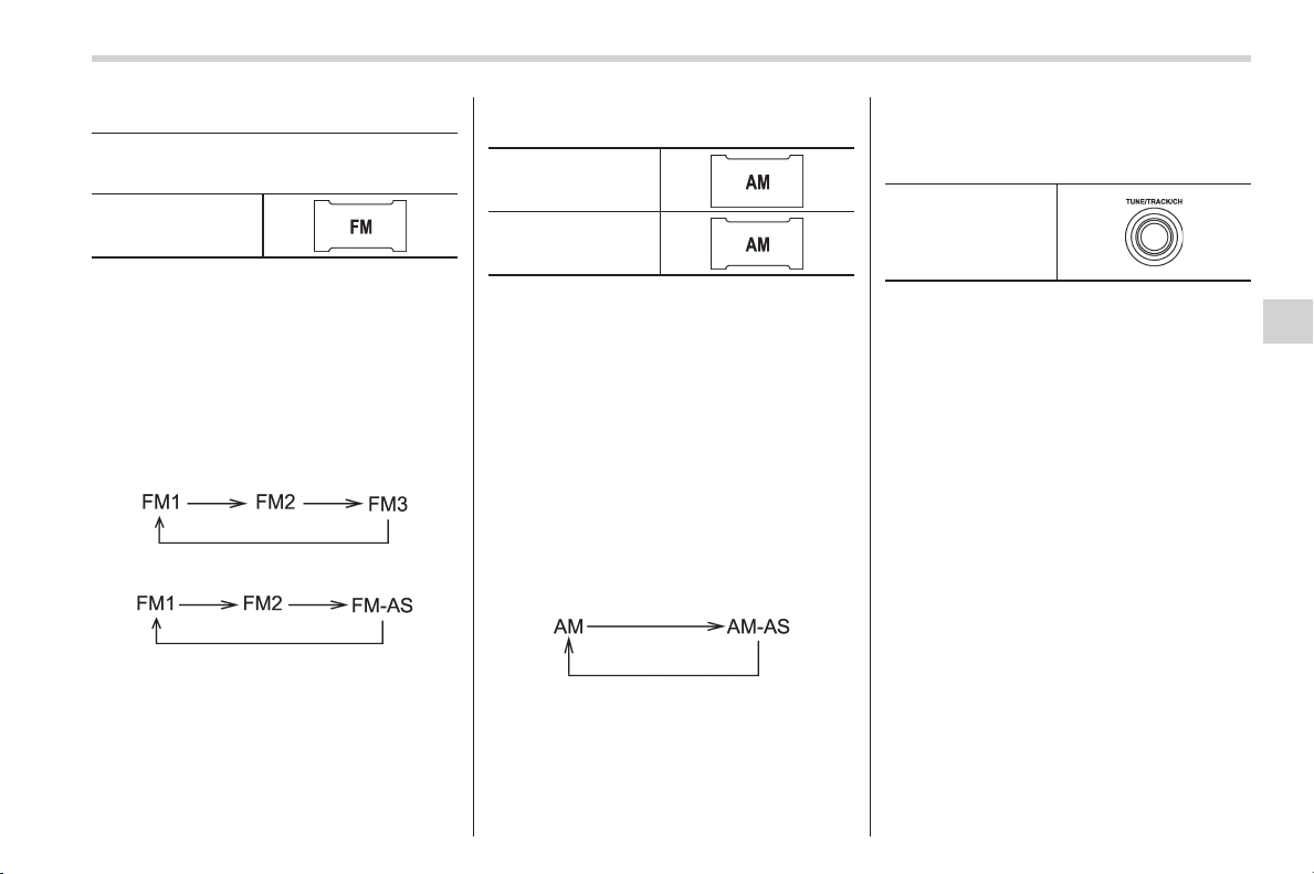
Black plate (263,1)
北米Model "A1160BE-C" EDITED: 2014/ 3/ 17
FM/AM radio operation
& FM selection
“FM” button
Press the “FM” button when the radio is off
to turn on the radio.
Press the “FM” button when the radio is on
to select the preferred reception mode.
Each time the “FM” button is briefly
pressed, the radio will change in t he
following sequence starting from the last
radio band that you selected.
Type A audio:
Type B audio:
& AM selection
Type A audio
Type B audio
Press the “ AM” button when the radio is off
to turn on the radio.
! Type A audio
Press the “AM” button when the radio is on
to select AM reception starting from the
last radio band and the last frequency
interval that you selected.
! Type B audio
Each time the “AM” button is briefly
pressed, the radio will change in the
following sequence starting from the last
radio band that you selected.
& Tuning
! Manual tuning
“TUNE/TRACK/CH”
dial
Turn the “TUNE/TRACK/CH” dial clock-
wise to increase the tuning frequency and
turn the “TUNE/TRACK/CH” dial counter-
clockwise to decrease it.
Each time the dial is turned, the frequency
interval can be changed between 10 kHz
in the AM mode and 0.2 MHz in the FM
mode.
! Stereo indicator
The stereo indicator “ST” (type A audio)/
“STEREO” (type B audio) will illuminate
when an FM stereo broadcast is received.
Audio/FM/AM radio operation
5-11
– CONTINUED –
5
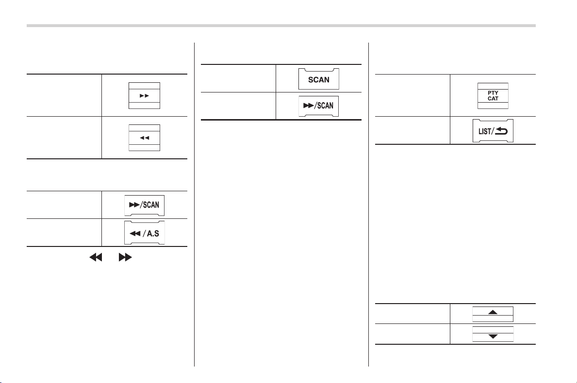
Black plate (264,1)
北米Model "A1160BE-C" EDITED: 2014/ 3/ 17
5-12
Audio/FM/AM radio operation
! Seek tuning (SEEK)
Type A audio:
Seek up
Seek down
Type B audio:
Seek up
Seek down
If you press the “ ” or “ ” button briefly,
the radio will automatically search for a
receivable station and stop at the first one
it finds. This function may not be available
when radio signals are weak. When this
happens, perform manual tuning to select
the preferred station.
! Scan tuning (SCAN)
Type A audio*
1
Type B audio*
2
*1: Press the button briefly.
*2: Press and hold the button.
If you press the “SCAN” button, the radio
will switch to the scan mode. In this mode,
the radio scans through the radio band
until a receivable station is found. The
radio will briefly stop at the station while
displaying the frequency, after which
scanning will continue until the entire band
has been scanned.
Press the “SCAN” button again to cancel
the SCAN mode and to stop at any
displayed channel.
Automatic tuning may not function prop-
erly if the station reception is weakened by
distance from the station or proximity to
tall buildings and hills.
! PTY (Program type) group tuning
(only FM reception)
Type A audio
Type B audio
Press the indicated button to change to
the PTY selection mode. At this time, the
PTY group that you are currently listening
to (type A audio)/that you selected the last
time (type B audio) will be displayed for 10
seconds. In the PTY selection mode,
“PTY” is displayed on the screen.
! PTY (Program type) group selec-
tion
In the PTY selection mode, perform the
following procedures to change the PTY
group by one step at a time.
Type A audio: Press the following but-
tons.
PTY group up by
one step
PTY group down by
one step
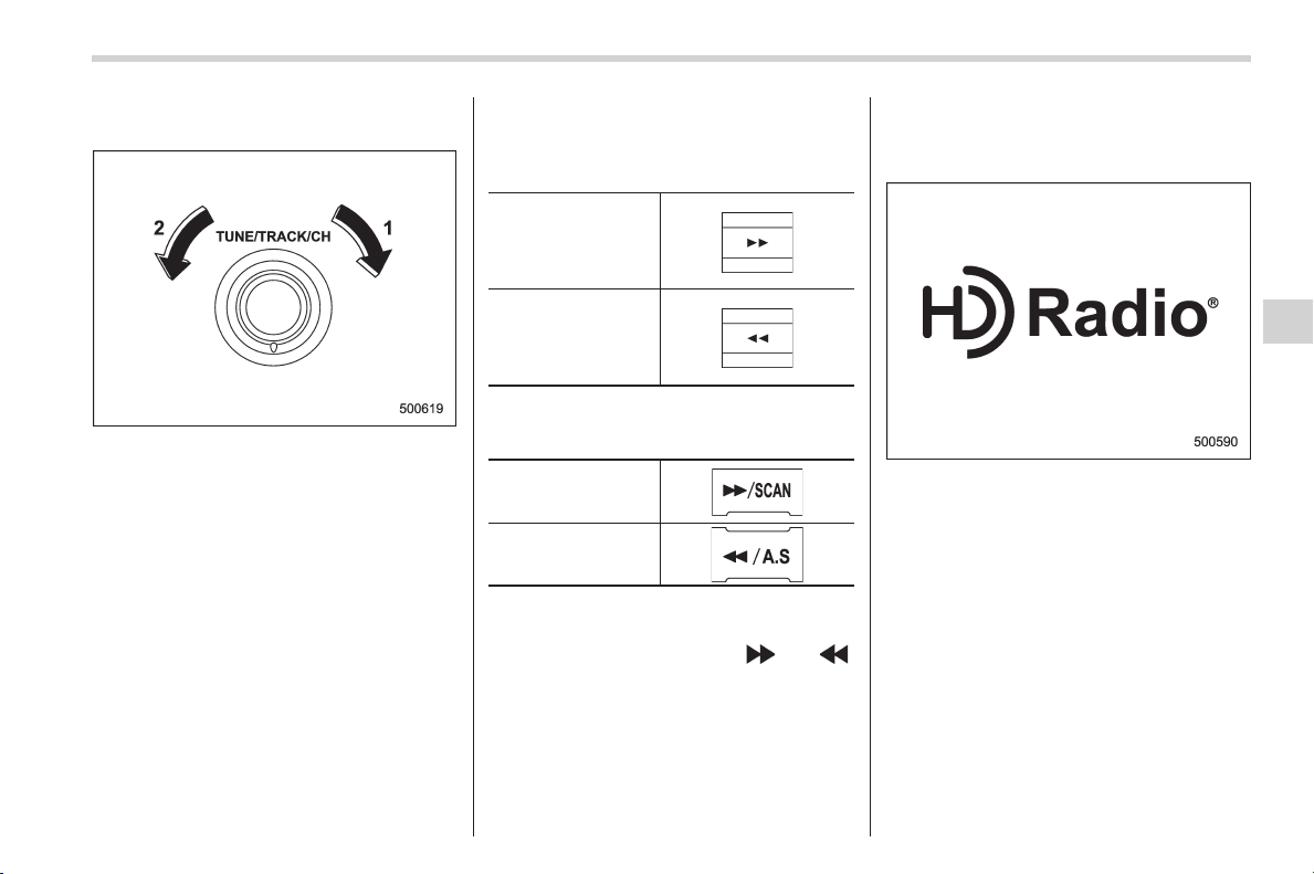
Black plate (265,1)
北米Model "A1160BE-C" EDITED: 2014/ 3/ 17
Type B audio: Turn the “TUNE/TRACK/
CH” dial.
1) PTY group up by one step
2) PTY group down by one step
This operation only changes the display. It
does not c hange the station that i s
currently being received.
! Seek in PTY (Program type)
group
Type A audio:
Seek up
Seek down
Type B audio:
Seek up
Seek down
In the PTY selection mode, when the
preferred PTY group has been selected,
pressing the “SEEK” button “
” or “ ”
seeks within that PTY group.
The control function returns to the normal
mode after approximately 10 seconds.
& HD Radio
TM
Technology (Di-
gital AM and FM Radio) (type
B audio)
HD Radio Technology is fueling the digital
radio revolution in the United States and
around the world.
The digital technology enables broadcas-
ters to offer new and unique FM content
via HD2 / HD3 channels, crystal-clear
sound and data services on both AM
and FM bands - all free, with no subscrip-
tion fee.
HD Radio Technology manufactured un-
der license from iBiquity Digital Corpora-
tion. U.S. and Foreign Patents. HD
Radio
TM
and the HD, HD Radio, and
“Arc” logos are proprietary trademarks of
iBiquity Digital Corp.
Audio/FM/AM radio operation
5-13
– CONTINUED –
5
Black plate (266,1)
北米Model "A1160BE-C" EDITED: 2014/ 3/ 17
5-14
Audio/FM/AM radio operation
For more information, visit www.hdradio.
com.
Press the
button while receiving FM
radio (except an analog broadcast). The
next channel of the station that is being
received will play.
! Mode selection
Turn the “TUNE/TRACK/CH” dial and
select the HD Radio ON mode (hybrid
mode) or OFF mode (analog mode).
! iTunes
®
tagging
To tag the received song, press and hold
the
button. Connect an iPod
®
to
store the tagged song to the iPod
®
. When
the iPod
®
is connected to iTunes
®
, you
can purchase the tagged songs from the
Apple
®
iTunes Music Store.
For the models of iPod
®
that support
iTunes
®
tagging, refer to the following
website: www.hdradio.com/tagging.php?
id=itunes.
! HD Radio indicators
Each indicator illuminates under the fol-
lowing conditions.
. The
indicator illuminates while a
digital broadcast is received during the HD
Radio ON mode.
. The “TAG” indicator illuminates when
you can operate the iTunes
®
tagging.
. The “LIVE” indicator illuminates when
the “Ballgame” is received.
. The “STEREO” indicator illuminates
when an FM stereo broadcast is received.
. The “PTY” indicator illuminates during
the PTY selection mode.
! About HD Radio
NOTE
. HD Radio Technology is a hybrid
broadcasting system that employs di-
gital and analog signals.
. When the vehicle moves outside the
digital broadcasting area (that is nar-
rower than the analog broadc asting
area due to the FCC output require-
ments), the radio reception automati-
cally changes from the digital signal to
the analog signal. When the vehicle
reenters the digital broadcasting area,
the radio reception automatically
changes from the analog signal to the
digital signal. When in a digital mode
the
Logo will be in orange on the
radio display.
. Depending on the broadcasting sta-
tion, a condition such as a sound delay,
echo effect or ski pping sound ma y
occur. However, this does not indicate
a malfunction.
. Depending on the broadcasting
area, the digital signal may not be
received in an area where the analog
signal can be properly received, or the
system frequently switches the chan-
nels between the digital and analog
signals. However, this does not indi-
cate a malfunction. If this frequent
switching between digital and analog
causes annoyance, set the radio to the
analog mode (HD Radio off mode) that
provides the same radio broadcasting
quality as a conventional radio.
& Displaying radio PS (Pro-
gram Service Name) and RT
(Radio Text)
“TEXT” button
! Type A audio
If the PS (Program Service Name) and/or
RT (Radio Text) are available, pressing
the “TEXT” button will change the display
among PS, RT and frequency. The default
setting is “PS”.
NOTE
. The maximum number of characters
that can be displayed for PS is 8.
. The maximum number of characters
that can be displayed for RT is 64.
Black plate (267,1)
北米Model "A1160BE-C" EDITED: 2014/ 3/ 17
. If RT is 13 characters or longer,
press and hold the “TEXT” button in
order to change the page.
! Type B audio
Press the “TEXT” button to show the next
page when the text is not fully displayed
while the PSD (Program Service Data) or
RT (Radio Text) service is received.
NOTE
. When the HD Radio function is
turned on, PSD provides addi tional
information about the broadcast. Text
data such as “Title” and “Artist” is
displayed on the screen.
. When the HD Radio function is
turned off (HD Radio off mode), the
radio text is displayed on the screen
while receiving the broadcasting sta-
tion with RBDS (Radio Broadcast Data
System).
& Station preset
! How to preset stations
1. Select the preferred reception mode.
2. Select the preferred station.
3. Press and hold one of the preset
buttons (from
to ) to store the
frequency. If the button is pressed briefly,
the preceding selection will remain in the
memory.
NOTE
. Up to six stations for each reception
mode may be preset.
. If the connection between the radio
and battery is broken for any reason
such as vehicle maintenance or radio
removal, all stations stored in the
preset buttons are cleared. If this
occurs, it is necessary to reset the
preset buttons.
! Selecting preset stations
1. Select the preferred reception mode.
2. Press the preferred preset button
(from
to ) briefly.
! Auto-store (type B audio)
Using the Auto-store function, you can
automatically store 6 stations on the
current waveband (FM-AS or AM-AS) by
pressing and holding the
button.
Use Auto-store to quickly find the stron-
gest stations, for example when traveling
through different reception areas.
NOTE
. When the HD Radio function is
turned on, Auto-store cannot be used
while receiving a broadcasting station
with SPS (Supplemental Program Ser-
vice).
. When you use Auto-store, the new
stations replace any stations pre-
viously stored.
. Interrupting Auto-store: If you acci-
dentally press the
button, you can
cancel the Auto-store function before it
has been completed as follows.
– switching to t he other source
mode
– pressing the
button
– switching to the other band
– turning the “TUNE/TRACK/CH”
dial
– pressing the “SCAN” button
! Displaying and selecting preset
stations (type B audio)
1. Press and hold the
button during
AM/FM reception to display the radio
screen.
2. Operate the “TUNE/TRACK/CH” dial
to select the stations.
Audio/FM/AM radio operation
5-15
5

Black plate (268,1)
北米Model "A1160BE-C" EDITED: 2014/ 3/ 17
5-16
Audio/CD player operation
CD player operation
NOTE
. Make sure to always insert a disc
with the label side up. If a disc is
inserted with the label side down, the
player displays “CHECK DISC”. Refer
to “When the following messages are
displayed” F5-20.
. If a disc is inserted during a radio
broadcast, the disc will interrupt the
broadcast.
. After the last song finishes, the disc
will automatically return to track 1 (the
first track on the disc) and will auto-
matically play back.
. The player is designed to be able to
play music CD-Rs and music CD-RWs,
but it may not be able to play certain
ones.
. Mini CDs (i.e., 8 cm/3 inch CDs) are
not supported, and if inserted, they will
be immediately ejected.
. CDs that can be played back are
accompanied by the following restric-
tions.
– Maximum number of folders: 255
– Maximum number of files in a
folder: 255
– Maximum number of files on a
CD: 510 (type A audio)/999 (type B
audio)
& Play file
NOTE
. Copyright protected MP3/WMA/AAC
files will not be played by the system.
The player will automatically skip to the
next file (track).
. WMA9 Lossless, WMA9 Profes-
sional and WMA9 voice cannot be
played.
MP3:
. Based on MPEG1, 2 and 2.5 Layer3
. Sampling rate (kHz): 48, 44.1, 32, 24,
22.05, 16, 12, 11.025, 8
. Bit rate (kbps): 8 to 320
. Supports variable bit rates
WMA (type A audio):
. Based on Windows Media Audio 9
. Sampling rate (kHz): 48, 44.1, 32
. Bit rate (kbps): 32 to 192
WMA (type B audio):
. Based on Windows Media Audio 7, 8
and 9
. Sampling rate (kHz): 48, 44.1, 32
. Bit rate (kbps): 32 to 192
AAC (type A audio):
. Based on MPEG4 AAC
. Sampling rate (kHz): 48, 44.1, 32, 24,
22.05, 16, 12, 11.025, 8
. Bit rate (kbps): 8 to 320
. Number of channels: 1 to 2ch
AAC (type B audio):
. Based on MPEG2 AAC and MPEG4
AAC
. Sampling rate (kHz): 48, 44.1, 32, 24,
22.05, 16, 12, 11.025, 8
. Bit rate (kbps): 8 to 320
. Number of channels: 1 to 2ch
& How to insert a CD
Hold a disc with a finger in the center hole
while gripping the edge of the disc, then
insert it in to the slot (with the label side
up) and the player will automatically pull
the disc into position.
NOTE
DO NOT INSERT TWO DISCS INTO THE
DISC INSERTION SLOT AT THE SAME
TIME.
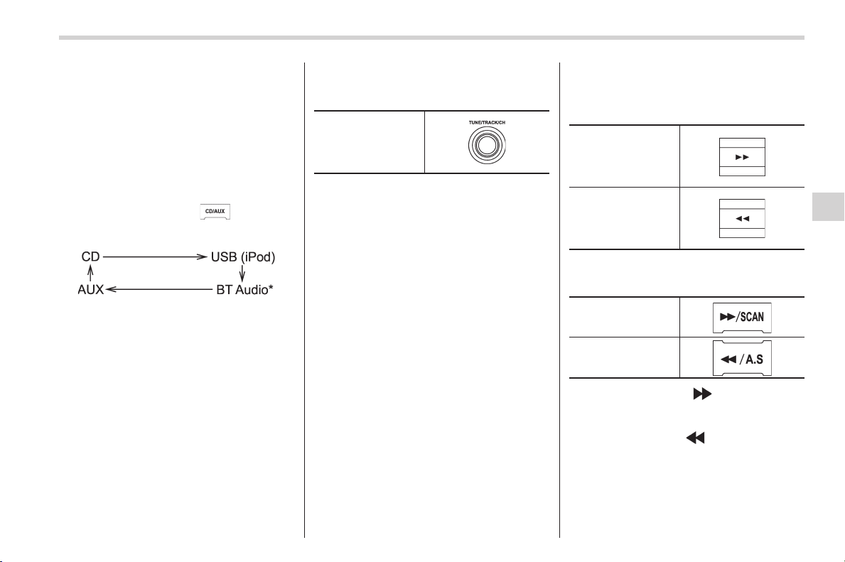
Black plate (269,1)
北米Model "A1160BE-C" EDITED: 2014/ 3/ 17
& How to play back a CD
! When there is no CD inserted
Properly insert a CD. Refer to “How to
insert a CD” F5-16.
When a CD is loaded, the player will start
playback of the CD, beginning with the
first track.
! When CD is in the player
Each brief press of the
button will
change the modes in the following se-
quence.
*: For type A audio, “BT-A” is displayed.
When the CD mode is selected, the player
will start playback.
& To select a track from the
beginning
“TUNE/TRACK/CH”
dial
Turn the “TUNE/TRACK/CH” dial clock-
wise to skip to the beginning of the next
track. Each time the dial is turned, the
indicated track number will increase.
Turn the “ TUNE/TRACK/CH” dial counter-
clockwise to skip to the beginning of the
current track. Each time the dial is turned,
the indicated track number will decrease.
NOTE
With an MP3, WMA or AAC:
. Skipping past the last track will take
you back to the first track in the folder.
. Skipping past the first track will take
you to the last track in the folder.
& Fast-forwarding and rewind-
ing
Type A audio:
Fast-forward
Rewind
Type B audio:
Fast-forward
Rewind
Press and hold the “ ” button to fast-
forward the track. Release the button to
stop fast-forwarding.
Press and hold the “
” button to rewind
the track. Release the button to stop
rewinding.
NOTE
. If you fast-forward to the end of the
last track, fast-forwarding will stop and
Audio/CD player operation
5-17
– CONTINUED –
5
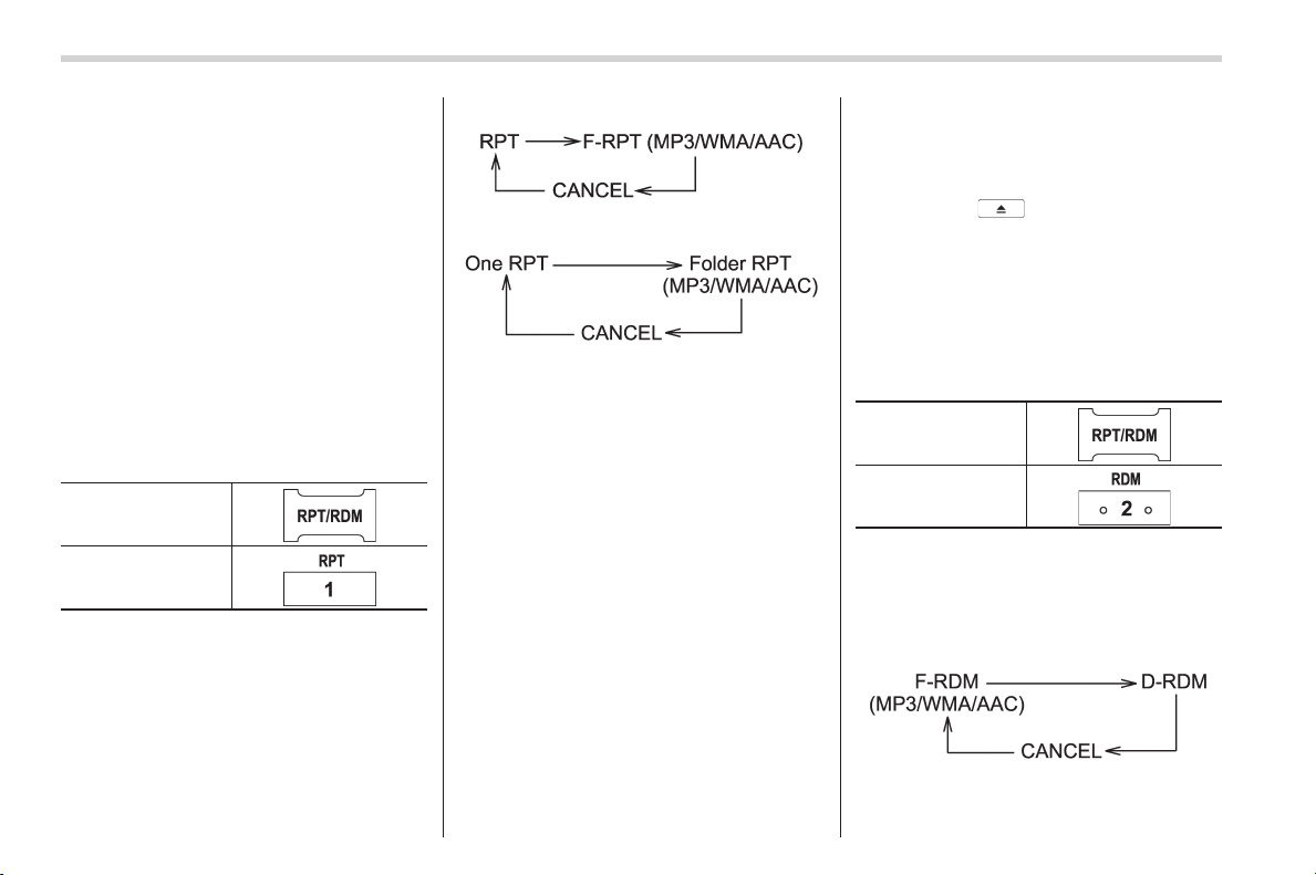
Black plate (270,1)
北米Model "A1160BE-C" EDITED: 2014/ 3/ 17
5-18
Audio/CD player operation
the player will start playback beginning
with the first track. For an MP3, WMA or
AAC folder, the player will start play-
back beginning with the first track of
the next folder.
. If you rewind to the beginning of the
first track, rewinding will stop and the
player will start playback. For an MP3,
WMA or AAC folder, the player will start
playback beginning with the first track
of the current folder.
& Repeating
To repeat a track, briefly press the follow-
ing button (“RPT” button) while the track is
playing.
Type A audio
Type B audio
Each time you briefly press the button, the
mode will change in the following se-
quences.
Type A audio:
Type B audio:
NOTE
. The “RPT” (type A audio)/“One
RPT” (type B audio) indication refers
to the repeat playback of a single track.
It repeats the track that is playing.
. The “F-RPT” (type A audio)/“Folder
RPT” (type B audio) indication refers to
the repeat playback of a folder. It
repeats the all of the tracks in the
folder. It i s possib le to select the
function when the MP3/WMA/AAC for-
mat track is playing.
To cancel the track repeat-play mode,
briefly press the “RPT” button and select
CANCEL. The “RPT” indication will turn
off, and the normal playback mode will be
resumed.
NOTE
The repeat-play mode will be cancelled
if you perform any of the following
steps.
. Press the
button.
. Press the “SCAN” button (type A
audio).
& Random playback
To playback tracks at random, press the
following button (“RDM” button) while a
track is playing.
Type A audio*
1
Type B audio*
2
*1: Press and hold the button.
*2: Press the button briefly.
Each time you press the button, the mode
will change in the following sequences.
Type A audio:
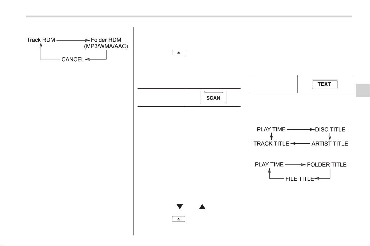
Black plate (271,1)
北米Model "A1160BE-C" EDITED: 2014/ 3/ 17
Type B audio:
NOTE
. The “RDM” (type A audio)/“Track
RDM” (type B audio) indication refers
to the random playback of the tracks. It
randomly repeats the tracks on the CD.
It is possible to select the function
when formats other than the MP3/WMA/
AAC format CD is playing.
. The “F-RDM” (type A audio)/“Folder
RDM” (type B audio) indication refers
to the random playback in the folder. It
randomly repeats the tracks in the
folder. It is possible to select the
function when an MP3/WMA/AAC for-
mat track is playing.
. The “D-RDM” indication refers to the
random playback of a disc. It randomly
repeats the tracks on the CD. It is
possible to select the function when
an MP3/WMA format track is playing.
To cancel the random playback mode,
press the “RDM” button again and select
CANCEL.
The “RDM” indication will turn off, and the
normal playback mode will be resumed.
NOTE
Random playback will be cancelled if
you perform any of the following steps.
. Press the
button.
. Press the “SCAN” button (type A
audio).
& Scan (type A audio)
“SCAN” button
The scan mode lets you listen to the first
10 seconds of each track in succession.
Press the “SCAN” button to start scanning
upward beginning with the track following
the currently selected one.
After all tracks on the disk/folder have
been scanned, normal playback will be
resumed. To cancel the scan mode, press
the “SCAN” button again.
NOTE
The scan mode will be cancelled if you
perform any of the following steps.
. Press the “RPT” button.
. Turn the “TUNE/TRACK/CH” dial.
. Press the “
” or “ ” side of the
“FOLDER/PTY/CAT” button.
. Press the
button.
. Turn off the power of the audio
equipment.
. Turntheignitionswitchtothe
“LOCK” (off) position.
& Display selection (type A
audio)
“TEXT” button
If you press the “TEXT” button during
playback, the display will change as
shown in the following sequence.
For CD-DA:
For MP3/WMA/AAC:
! Page (track/folder title) scroll
If you press the “TEXT” button again and
hold it, the title will be scrolled so you can
see all of it.
Audio/CD player operation
5-19
– CONTINUED –
5
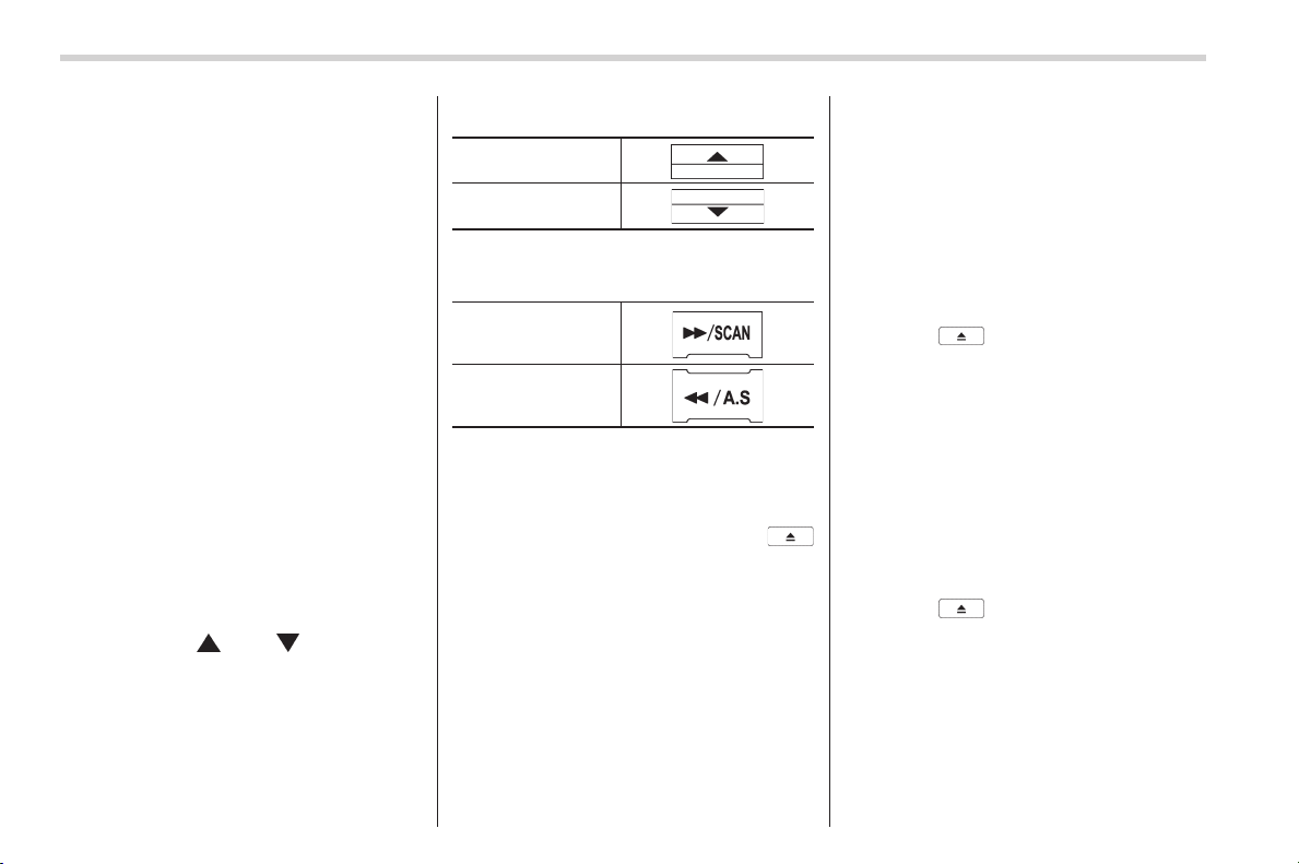
Black plate (272,1)
北米Model "A1160BE-C" EDITED: 2014/ 3/ 17
5-20
Audio/CD player operation
NOTE
. For type A audio, the display is
designed to show titles as shown in
the following items.
– When playing a CD-DA: 256 char-
acters
– When playing an MP3/WMA/AAC:
64 characters
– WhenplayinganiPod
®
: 255
characters
. If no operations are performed for 10
seconds, the screen that was displayed
before pressing and holding the
“TEXT” button will be shown.
& Folder selection
NOTE
. Sel ecting folders in this way is
possible only within a single disc.
. Only MP3/WMA/AAC folders are re-
cognized when an attempt to select the
next or previous folder is made. If no
appropriate folder exists on the disc,
pressing the “
” or “ ” side of the
“FOLDER/PTY/CAT” button starts play-
back beginning with the first track.
Press the following buttons briefly.
Type A audio:
To select the next
folder
To go back to the
previous folder
Type B audio:
To select the next
folder
To go back to the
previous folder
& How to eject a CD from the
player
When a disc is being played back or when
a disc is in the player, press the
button. The disc will be ejected.
NOTE
. Avoid driving the vehicle with a CD
sticking out. The CD may fall out due to
vibration.
. If you do not remove the ejected
disc within approximately 15 seconds,
a disc protection function will operate,
automatically reloading the disc. In this
case, the disc is not played.
& When the following mes-
sages are displayed
If one of the following messages is
displayed while operating the CD player,
determine the cause based on the follow-
ing information. If you cannot clear those
messages, please contact your SUBARU
dealer.
! When “PUSH EJECT” is displayed
Press the
button to eject the disc.
Check the disc for damage or deforma-
tion, and also check that the correct disc is
inserted. Do not try to eject the disc
forcibly. Mini CDs (i.e., 8 cm/3 inch CDs)
are not supported, and if inserted, they will
be immediately ejected and this message
will be displayed. If the disc cannot be
ejected or this message remains dis-
played, please contact your SUBARU
dealer.
! When “CHECK DISC” is displayed
Press the
button to eject the disc.
Check that the disc is not damaged or
scratched, and also check that the disc is
inserted correctly. This message may
appear when using some CD-RW discs.
Check that the disc type (i.e., 8 cm/3 inch
CDs are not supported) and data format
are correct. This player can only play
MP3, WMA and AAC data formats. If the
disc cannot be ejected or this message
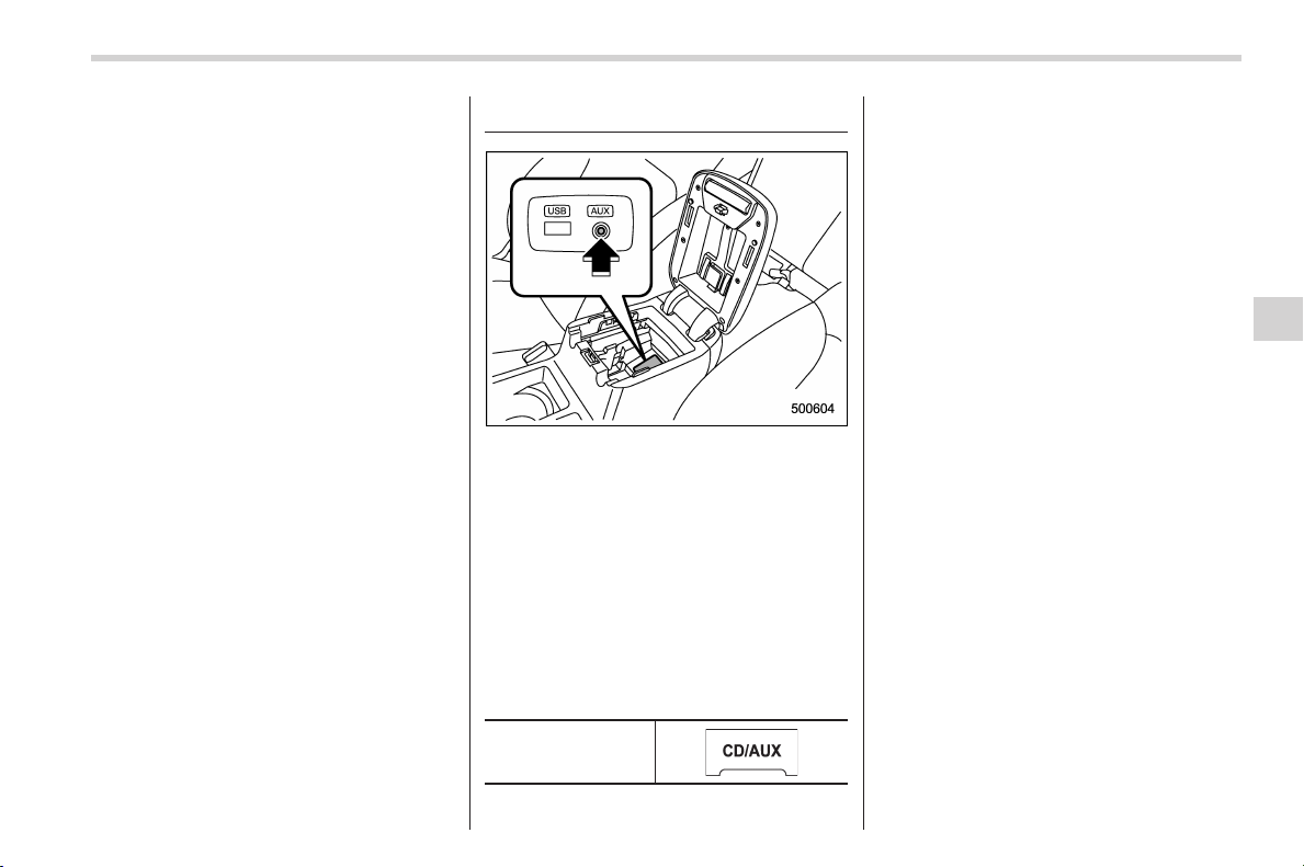
Black plate (273,1)
北米Model "A1160BE-C" EDITED: 2014/ 3/ 17
remains displayed, please contact your
SUBARU dealer.
Auxiliary input jack
You can connect an external audio device
to the vehicle’s audio system and play
back audio via the vehicle’s speakers.
An auxiliary (AUX) input jack is present in
the center console. A stereo mini pin plug
(3.5ø) can be inserted in this jack. The
connection cable is available at electrical
appliance or similar stores.
To use the AUX input jack:
1. Connect a portable audio player to the
AUX input jack.
“CD/AUX” button
2. Press the “CD/AUX ” button on the
audio control panel to select the AUX
mode. Refer to “When CD is in the player”
F5-17.
3. Play back the portable audio player.
Refer to the instruction manual for the
portable audio player.
NOTE
. The output sound of the portable
audio player is not loud, and the sound
via the vehicle’s speakers that are
connected to the vehicle audio set
may be very low. If you turn up the
volume of the audio set, the volume
becomes louder. However, when you
change from one portable audio player
to another one, the volume levels via
the vehicle’s speakers may be signifi-
cantly louder compared to the prior
device. To avoid a large volume differ-
ence, turn down the volume when you
change between portable audio
players.
. In some cases, when the sound
volume of the portable audio player is
low, the sound quality may become
impaired when you turn up the volume
of the vehicle audio system. In this
case, adjust the sound volume of the
portable audio player.
. In some cases, noise occurs be-
Audio/Auxiliary input jack
5-21
– CONTINUED –
5
Black plate (274,1)
北米Model "A1160BE-C" EDITED: 2014/ 3/ 17
5-22
Audio/Precautions to observe when handling a compact disc
cause of a bad connection between the
portable player and the vehicle audio
system. Try cleaning the stereo jack
and audio plug.
. If the noise is not reduced, check for
disconnection of the cord or a malfunc-
tion of the portable player.
Precautions to observe when
handling a compact disc
Use only compact discs (CDs, CD-Rs and
CD-RWs) that have the mark shown in the
following. Also, some compact discs
cannot be played.
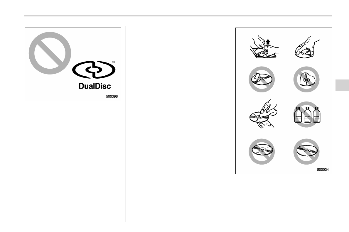
Black plate (275,1)
北米Model "A1160BE-C" EDITED: 2014/ 3/ 17
. You cannot use a DualDisc in the CD
player. If you insert a DualDisc into the
player, the disc may not come out again,
possibly causing the player to malfunction.
. In cold and/or rainy weather, dew can
form inside the CD player, preventing
normal operation. If this happens, eject
the CD and wait for the player to dry out.
. Skipping may occur when the CD
player is subjected to severe vibration
(for example, when the vehicle is driven
on a rough surface).
. To remove a disc from the case, press
the center of the case and hold both
edges of the disc. If the disc surface is
touched directly, contamination could
cause poor tone quality. Do not touch the
disc surface.
. Use a clean disc whenever possible. If
there are deposits, wipe the disc surface
from the center outward with a dry, soft
cloth. Be sure not to use a hard cloth,
thinner, benzine, alcohol, etc.
. Do not use any disc that is scratched,
deformed, or cracked. Also, do not use
any disc that has a non-standard shape
(for example, a heart shape). Malfunctions
or problems might result.
. A disc is vulnerable to heat. Never
keep it either in places exposed to direct
sunlight, near heaters or i n vehicles
parked in the sun or on hot days.
Audio/Precautions to observe when handling a compact disc
5-23
5
Black plate (276,1)
北米Model "A1160BE-C" EDITED: 2014/ 3/ 17
5-24
Audio/USB storage device / iPod
®
operations
USB storage device / iPod
®
operations
& Play file
Refer to “Play file” F5-16.
& Connectable USB storage
device
Mass storage class USB memory can be
connected. USB storage devices that can
be played back are accompanied by the
following restrictions.
. Maximum directory layers: 8 layers
(including the ROOT)
. Maximum number of files in a folder:
255
. Maximum number of folders: 512 (type
A audio)/255 (type B audio) (including the
ROOT)
. Maximum number of files on the
device: 130 ,560 (ty pe A au dio)/2,5 00
(type B audio)
NOTE
. HUB class USB memory cannot be
played.
. ATAPI subclass USB cannot be
played.
. For type A audio, High Speed USB
2.0 cannot be played.
. A USB memory that is powered by a
source other t han the USB power
supply (for example, an AC power
adapter, etc.) cannot be operated.
. A USB memory that is connected to
the memory card reader or multi card
reader cannot be operated.
. If the USB memory consists of two
drives or more, the system will recog-
nize only one of the drives after con-
necting the USB memory.
. The contents stored on the USB
memory may not be played in the same
order as they appear on a personal
computer.
. A personal computer ca nnot be
used even if it is connected to the
system using a USB cable.
. If the USB memory has a security
function, the contents stored on the
USB memory cannot be played by the
system.
. A USB memory and an iPod
®
cannot
be connected to th e system at the
same time.
& Connectable iPod
®
models
Model
Firmware
version
iPod
®
with video 1.3
classic 2.0.4
nano (1st generation) 1.3.1
nano (2nd generation) 1.1.3
nano (3rd generation) 1.1.3
nano (4th generation) 1.0.4
nano (5th generation) 1.0.2
nano (6th generation) 1.0
touch (1st generation) 3.1.3
touch (2nd generation) 3.1.3
touch (3rd generation) 4.1
touch (4th generation) 4.1
iPhone
®
1G 3.1.3
3G 3.1.3
3G S 3.1.3
4G
4.1
CAUTION
Do not connect an iPod
®
other than
the previously stated models. Doing
so may result in a malfunction or
cause the device to experience a
Black plate (277,1)
北米Model "A1160BE-C" EDITED: 2014/ 3/ 17
thermal hazard.
NOTE
. iPod
®
is a registered trademark of
Apple Inc.
. You are only permitted to personally
copy and play copyright-free material
or material that is legally permitted to
be copied and played by using an
iPod
®
and iTunes. Copyright infringe-
ment is prohibited by law.
. To check the firmware version of an
iPod
®
, connect it to a computer and
check the device manager. For further
information, see the User’s Guide for
the iPod
®
.
. To update the firmware version of an
iPod
®
, visit the Apple Inc. website.
. Depending on the model and firm-
ware version of an iPod
®
, it may not
work properly or not operate at all.
& Connecting USB storage de-
vice / iPod
®
WARNING
Do not operate an iPod
®
while
driving. Doing so may distract your
attention from driving and could
lead to an accident.
CAUTION
. If the data stored in an iPod
®
is
deleted while it is connected to
the in-vehicle system, the data
cannot be recovered.
. Do not store an iPod
®
in the
vehicle. If an iPod
®
is left in the
vehicle for a long period of time,
it may be deformed, discolored
or damaged by high temperature.
NOTE
. Even if a USB storage device or
iPod
®
is connected, it cannot be played
unless the USB/iPod
®
mode is se-
lected.
. Movies stored on a USB storage
device or an iPod
®
cannot be played
while the storage device or iPod
®
is
connected to the system.
. While an iPod
®
is connected, the
iPod
®
cannot be operated using the
click wheel on the iPod
®
(except some
models).
. When using an iPod
®
by connecting
it to in-vehicle equipment, the order of
the list items displayed on the in-
vehicle equipment may be di fferent
from that on the iPod
®
. However, this
does not indicate a malfunction.
. An iPod
®
battery that is connected
to in-vehicle equipment will be charged
when the ignition switch is in the “ON”
or “ACC” position. However, activation
of the iPod
®
may be delayed if the
battery charge of the iPod
®
is low.
. If an iPod
®
does not activate after
operation, disconnect the connection
cable from the iPod
®
and reset it. For
the resetting procedure, see the User’s
Guide of the iPod
®
.
. If an iPod
®
and the connection cable
are connected improperly, the iPod
®
cannot be powered on or will not be
recognized by in-vehicle equipment. In
this case, disconnect the connection
cable from the iPod
®
, and then connect
it again.
Audio/USB storage device / iPod
®
operations
5-25
– CONTINUED –
5
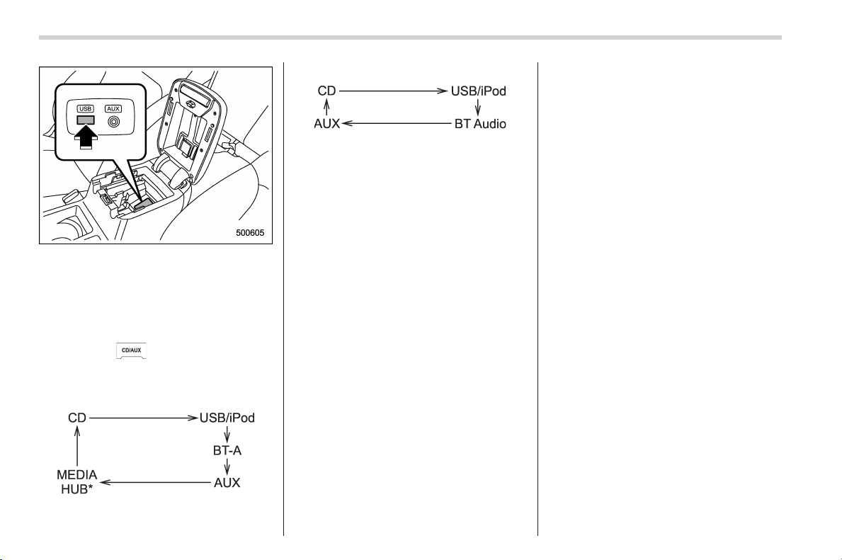
Black plate (278,1)
北米Model "A1160BE-C" EDITED: 2014/ 3/ 17
5-26
Audio/USB storage device / iPod
®
operations
The USB connector is located in the
center console. Use the connector to
connect a USB storage device/iPod
®
.
& How to play back
1. Connect a USB storage device/iPod
®
.
2. Press the
button. Each time you
briefly press the button, the mode will
change in the following sequence.
Type A audio:
*: Only when a Media Hub is connected.
Type B audio:
When the USB/iPod
®
mode is selected,
the player will start playback of the USB
storage device/iPod
®
.
NOTE
. Depending on the number of files
stored on the iPod
®
and the firmware
version, the iPod
®
may not activate
smoothly after operation or not work
properly.
. Do not disco nnect the connector
from the iPod
®
during iPod
®
operation.
& To select a track from the
beginning
Select a track in the same way as for a
CD. For details, refer to “To select a track
from the beginning” F5-17.
& To select a chapter from the
beginning when connecting
iPod
®
When playing podcasts or audiobooks,
select a chapter in the same way as for a
CD. For details, refer to “To select a track
from the beginning” F5-17.
& Fast-forwarding and rewind-
ing
Fast-forwarding and rewinding are oper-
ated in the same way as for a CD. For
details, refer to “Fast-forwarding and
rewinding” F5-17.
NOTE
When connecting iPod
®
:
. When the end of a track is reached
while fast-forwarding, fast-forwarding
ends and play begins from the begin-
ning of the next track.
. When the beginning of a track is
reached while rewinding, rewinding
ends and play begins from the begin-
ning of the track.
& Repeating
! When connecting USB storage de-
vice
Repeating is operated in the same way as
for a CD. For details, refer to “Repeating ”
F5-18.
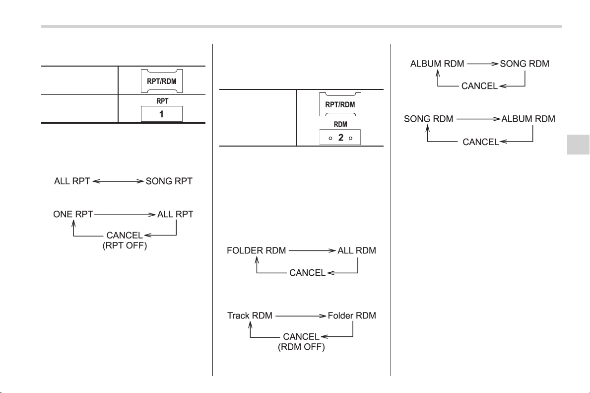
Black plate (279,1)
北米Model "A1160BE-C" EDITED: 2014/ 3/ 17
! When connecting iPod
®
Type A audio
Type B audio
Each time you briefly press the “RPT”
button, the mode wil l change in the
following sequence.
Type A audio:
Type B audio:
NOTE
. The “ALL RPT” indication refers to
the repeat playback of all tracks on the
entire iPod
®
.
. The “SONG RPT” (type A audio)/
“ONE RPT” (type B audio) indication
refers to the repeat playback of a single
track. It repeats the track that is play-
ing.
. When an audiobook is playing, the
mode does not change even if you
press the “RPT” button.
& Random playback
Type A audio*
1
Type B audio*
2
*1: Press and hold the button.
*2: Press the button briefly.
To playback tracks at random, press the
“RDM” button while a track is playing.
Each time you press the button, the mode
will change in the following sequence.
When connecting USB storage device
(type A audio):
When connecting USB storage device
(type B audio):
When connecting iPod
®
(type A audio):
When connecting iPod
®
(type B audio):
NOTE
. The “FOLDER RDM” indication re-
fers to the random playback in the
folders. It randomly repeats all of the
tracks in the folder.
. The “ALL RDM” indication refers to
the random playback on the entire USB
storage device. It randomly repeats all
of the tra cks on the USB storage
device.
. The “ALBUM RDM” indication refers
to the shuffle playback of the album. It
sequentially plays back all of the tracks
on the album.
. The “SONG RDM” indication refers
to the shuffle playback on the entire
iPod
®
. It randomly repeats all of the
tracks on the iPod
®
.
. When an iPod
®
is connected, the
files are played back at random by the
shuffle function of the iPod
®
. There-
Audio/USB storage device / iPod
®
operations
5-27
– CONTINUED –
5
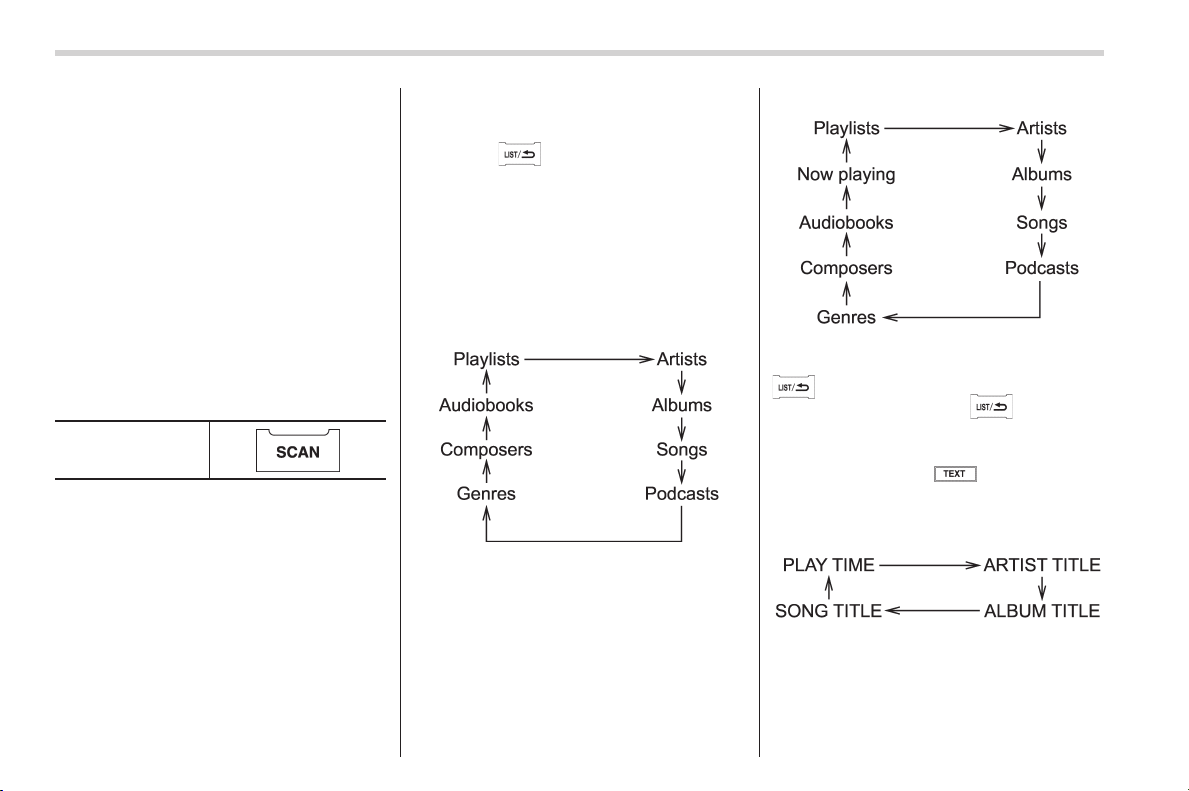
Black plate (280,1)
北米Model "A1160BE-C" EDITED: 2014/ 3/ 17
5-28
Audio/USB storage device / iPod
®
operations
fore, iPod
®
operation may be different
depending on the model of the con-
nected iPod
®
.
. When an audiobook or a podcast is
playing, the mode does not change
even if you press the “RDM” button.
To cancel the random playback mode,
press the “RDM” button and select CAN-
CEL. The “RDM” indication will turn off,
and the normal playback mode will re-
sume.
& SCAN (only when connecting
USB storage device) (type A
audio)
“SCAN” button
Scan is operated in the same way as for a
CD. For details, refer to “Scan (type A
audio)” F5-19.
NOTE
When an iP od
®
is connected, you
cannot select the SCAN mode.
& Selecting category (only
when connecting iPod
®
)
When the button is pressed briefly,
the iPod
®
menu will be displayed.
Each time you turn the “TUNE/TRACK/
CH” dial clockwise, the displayed category
will change in the following sequence.
Each time you turn the dial counterclock-
wise, the displayed category will change in
the opposite sequence.
Type A audio:
Type B audio:
To select the category, press the dial. To
close the iPod
®
menu, press and hold the
button. To return to the previous
screen, briefly press the
button.
& Display selection
If you press the button during
playback, the display will change as
shown in the following sequence.
! Page scroll
Refer to “Page (track/folder title) scroll”
F5-19.
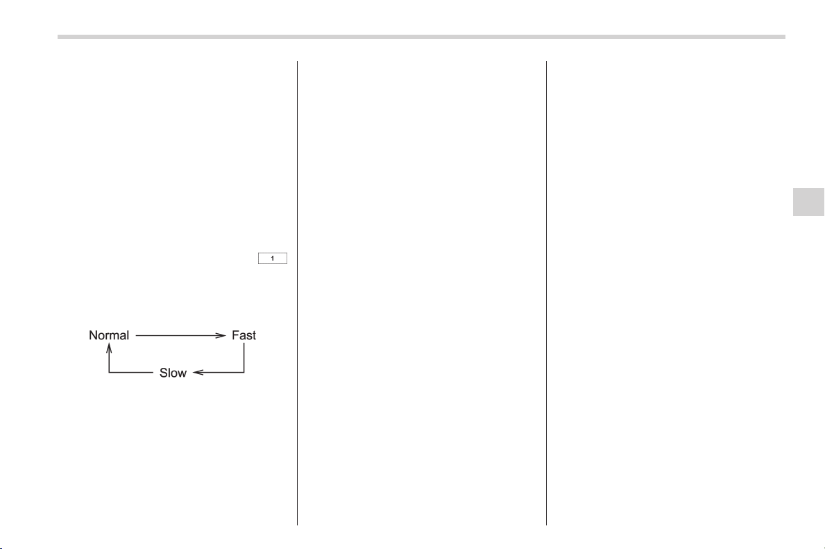
Black plate (281,1)
北米Model "A1160BE-C" EDITED: 2014/ 3/ 17
& Folder selection (only when
connecting USB storage de-
vice)
Refer to “Folder selection” F5-20.
NOTE
When an iP od
®
is connected, you
cannot select a folder.
& Setting the playing speed
(only when the audiobook is
playing) (type B audio)
Each time you briefly press the
button (the “RPT” button) while the audio-
book is playing, the playing speed will
change in the following sequence.
& When the following mes-
sages are displayed
If one of the following messages is
displayed while connecting the USB sto-
rage device/iPod
®
, determine the cause
based on the following information. If you
cannot clear those messages, please
contact your SUBARU dealer.
! When “CHECK DEVICE” is dis-
played
This message is displayed under the
following conditions.
. When there is a short in the USB bus
. When an unsupported device (for ex-
ample a USB mouse) is connected
. When an unsupported iPod
®
is con-
nected
. When a connected iPod
®
is frozen
. When a transmission malfunction oc-
curs
. When an iPod
®
confirmation malfunc-
tion occurs
. When a HUB class USB storage
device is connected
Disconnect the USB storage device/iPod
®
and check it.
! When “NO USB” is displayed (type
B audio)
This message is displayed under the
following conditions.
. No USB storage devices/iPod
®
are
connected.
. An incompatible USB storage device/
iPod
®
is connected.
Connect a supported USB storage device/
iPod
®
.
! When “No song” is displayed (type
B audio)
This message is displayed whe n no
playable audio files are in the connected
USB storage device/iPod
®
. Connect a
USB storage device/iPod
®
that has play-
able audio files stored in it.
Audio/USB storage device / iPod
®
operations
5-29
5
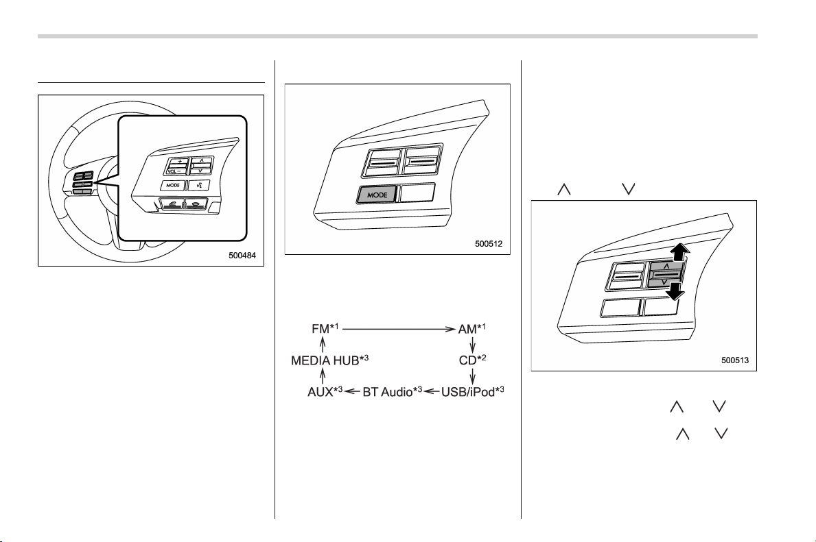
Black plate (282,1)
北米Model "A1160BE-C" EDITED: 2014/ 3/ 17
5-30
Audio/Audio control buttons
Audio control buttons
These buttons are located on the spokes
of the steering wheel. They allow the
driver to control audio functions without
taking his/her hands off the steering
wheel.
& MODE button
The “MODE” button is used to select the
preferred audio mode. Each time it is
pressed, the mode will change to the next
one in the following sequence:
*1: The frequency last received in the selected
waveband will be displayed.
*2: Only when a CD is in the player.
*3: Only when the device is connected.
! Models with Hands-free system
Press and hold this button if you wish to
immediately cut the volume to zero.
The audio display will show “MUTE”.
If you press and hold the button again, the
original sound volume will return an d
“MUTE” turns off.
& “ ” and “ ” switch
! With radio mode selected
Press the switch to the “
” or “ ” side
briefly to skip to a preset channel. Press
and hold the switch to the “
” or “ ” side
to seek the next receivable station and
stop at it.
That station’s frequency will be indicated
on the audio display.
Black plate (283,1)
北米Model "A1160BE-C" EDITED: 2014/ 3/ 17
! With CD mode selected
Press the switch to the “
” side briefly to
skip forward in the track order. Press the
switch to the “
” side briefly to skip
backward in the track order.
The track number will be shown on the
audio display.
When the MP3/WMA/AAC format track is
playing, press and hold the switch to the
“
” side to select the next folder. Press
and hold the switch to the “
” side to go
back to the previous folder.
! With USB/iPod
®
mode selected
Press the switch to the “
” side to skip
forward in the track order. Press the switch
to the “
” side to skip backward in the
track order. The track number will be
shown on the audio display.
& Volume control switch
Press the switch to the “+” side to increase
the volume. Press the switch to the “−”
side to reduce the volume.
A number indicating the volume will be
shown on the audio display.
Bluetooth
®
audio
NOTE
For models with the genuine SUBARU
navigation system, refer to the Owner’s
Manual supplement for the navigation
system.
NOTE
The Bluetooth word mark and logo are
registered trademarks of Bluetooth
SIG, Inc.
This function enables you to play back
audio sources from Bluetooth
®
audio
devices. You need to register the Blue-
tooth
®
audio device in the system before
using it.
Audio/Bluetooth
®
audio
5-31
– CONTINUED –
5
Black plate (284,1)
北米Model "A1160BE-C" EDITED: 2014/ 3/ 17
5-32
Audio/Bluetooth
®
audio
NOTE
. The Bluetooth
®
audio function may
not operate properly under the follow-
ing conditions.
– The device is turned off.
– The battery of the device has run
down.
– The device is not connected to
the system.
– The device is behind the seat or
in the glove box.
– A metal material is covering or
touching the device.
. Depending on the type of device that
is used, operation and sound volume
may be different from normal use of
those devices.
. The sound quality may degrade due
to the influence of the device that is
connected to the system or the circum-
stances of the Bluetooth network.
. When another Bluetooth
®
device is
simultaneously connected, noise may
be heard.
& Media format
Bluetooth
®
audio devices cannot be
connected if they are not compatible with
the following Bluetooth
®
profiles.
. A2DP (Advance d Audio Distribution
Profile)
. AVRCP (Audio/Video Remote Control
Profile)
& Setting Bluetooth
®
audio
“MENU” button
(type A audio)
“TUNE/TRACK/CH”
dial
Type A audio:
1. Select the “BT-A SETUP” menu by
pressing the “MENU” button. For details,
refer to “Other settings (type A audio)” F5-
8.
2. Perform the following procedure by
operating the “TUNE/TRACK/CH” dial
while “BT-A” is displayed.
Type B audio:
1. Select the “BT Audio Setup” menu by
operating the “TUNE/TRACK/CH” dial. For
details, refer to “Audio settings (type B
audio)” F5-8.
2. Perform the following procedure by
operating the “TUNE/TRACK/CH” dial
while “BT Audio” is displayed.
NOTE
You cannot set Bluetooth
®
audio while
driving.
! Registering (pairing) device
NOTE
Only one device can be registered.
1. Select the following menu.
–“PAIR AUDIO” (type A audio)
–“Pair Audio Player” (type B audio)
If a device is already registered, “MEM-
ORY FULL” will be displayed and the
mode will change to the Bluetooth
®
audio
setting mode.
2. After the passkey is shown on the
display, input the passkey into the device.
– If you input the correct passkey,
“PAIRED” will be displayed and the
registration procedure will be finished.
– If you input an incorrect passkey,
“FAILED” will be displayed, the regis-
tration procedure will not be success-
ful and the mode will change to the
Bluetooth
®
audio setting mode.
NOTE
After the ignition switch is turned to the
“LOCK” (off) position, the registered
device will not be automatically con-
nected to the system even if the
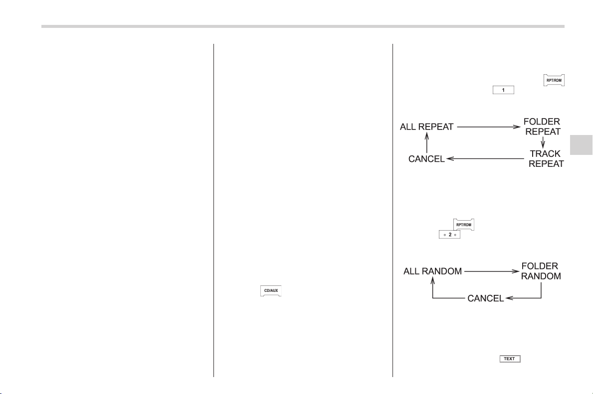
Black plate (285,1)
北米Model "A1160BE-C" EDITED: 2014/ 3/ 17
ignition switch is turned to the “ACC”
or “ON” position.
! Selecting device
1. Select the following menu.
–“SELECT AUDIO” (type A audio)
–“Select Audio Player” (type B audio)
If no devices are registered, “EMPTY” will
be displayed and the mode will change to
the Bluetooth
®
audio setting mode.
2. Select the “ CONFIRM” menu.
– If the device is connected, “SE-
LECTED” will be displayed and the
selecting procedure will be finished.
– If the device cannot be connected,
“FAILED” will be displayed and the
selecting procedure will not be suc-
cessful.
! Setting passkey
1. Select the “ SET PASSKEY” menu.
– After the currently set passkey is
displayed, a new passkey can be
entered.
2. Input the new passkey by operating
the “TUNE/TRACK/CH” dial.
3. Select the “ CONFIRM” menu.
– The new passkey will be displayed,
the passkey will be changed and the
mode will change to the Bluetooth
®
audio setting mode.
! Deleting device
1. Select the following menu.
–“DELETE AUDIO” (type A audio)
–“Delete Audio Player” (type B
audio)
If no devices are registered, “EMPTY” will
be displayed and the mode will change to
the Bluetooth
®
audio setting mode.
2. Select the “ CONFIRM” menu.
–“DELETED” will be displayed and
the mode will change to the Blue-
tooth
®
audio setting mode.
& Bluetooth
®
audio operation
NOTE
Depending on the connected device, it
may not activate as per the following
items or not work smoothly.
! How to play back
Press the
button and select the “ BT-
A” (type A audio)/“BT Audio” (type B
audio) mode.
! To select a track from its beginning
Select a track in the same way as for a
CD. Refer to “To select a track from the
beginning” F5-17.
! Repeating
Repeating is operated in the same way as
for a CD. Refer to “Repeating” F5-18.
Each time you briefly press the
button (type A audio)/ button (the
“RPT” button) (type B audio), the mode
will change in the following sequence.
! Random playback
Random playback is operated in the same
way as for a CD. Refer to “Random
playback” F5-18. Each time you press
and hold the
button (type A audio)/
press the
button (the “RDM” button)
briefly (type B audio), the mode will
change in the following sequence.
! Display selection (type A audio)
Select an item to be displayed using the
same way as for a CD. Refer to “Display
selection (type A audio)” F5-19. Each
time you briefly press the
button, the
Audio/Bluetooth
®
audio
5-33
– CONTINUED –
5
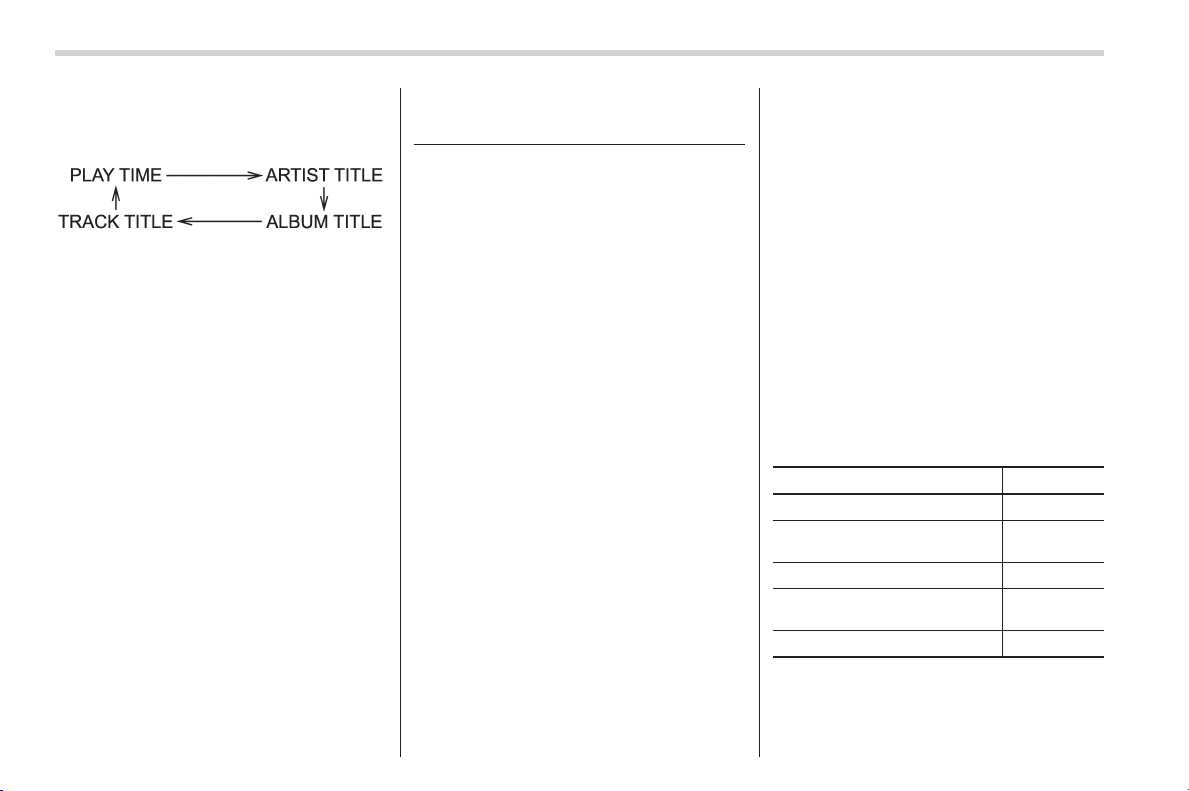
Black plate (286,1)
北米Model "A1160BE-C" EDITED: 2014/ 3/ 17
5-34
Audio/Hands–free system
indication will change in the following
sequence.
! Folder selection
Select a folder in the same way as for a
CD. Refer to “Folder selection” F5-20.
Hands-free system (if
equipped)
NOTE
. For models with the genuine
SUBARU navigation system, refer to
the Owner’s Manual supplement for the
navigation system.
. When selling your vehicle, make
sure that you initialize the Hands-free
system to prevent personal data from
being improperly accessed.
The Hands-free system operates while the
ignition switch is in the “ACC” or “ON”
position.
You can use your cell phone without
touching it by using the Hands-free sys-
tem. To use the Hands-free system,
connect a cell phone as follows.
When no cell phones are registered:
Register a cell phone to the in-vehicle
equipment. For details, refer to “When no
cell phones are registered” F5-46. After
registering a phone, the phone will be
automatically connected to the in-vehicle
equipment.
When a cell phone is already regis-
tered:
The registered cell phone will be auto-
matically connected to the in-vehicle
equipment when the ignition switch is
turned to the “ACC” or “ON” position while
carrying the cell phone.
When two cell phones or more are
already registered:
If the system detects a cell phone in the
passenger compartment which was pre-
viously connected to the in-vehicle equip-
ment when the ignition switch was last
turned to the “ACC” or “ON” position, the
system connects the cell phone automa-
tically to the in-vehicle equipment. You
can select the phone to be connected to
the in-vehicle equipment. For details, refer
to “Selecting a cell phone” F5-46.
After connecting a cell phone, you can use
the following functions.
Function Page
Making a phone call 5-47
Taking/declining an incoming
call
5-48
Registering phonebook data 5-48
Using and setting phonebook
data
5-50
Deleting data
5-50
Even when no cell phones are connected,
you may be able to set the following items.
Black plate (287,1)
北米Model "A1160BE-C" EDITED: 2014/ 3/ 17
Item Page
Security setting 5-51
Phone setting 5-52
System setting
5-53
& Safety precautions
WARNING
. For safety reasons, avoid operat-
ing a cell phone while driving.
. Do not make a phone call while
driving. When you have an in-
coming call, stop the vehicle in a
safe location before taking the
incoming phone call. When you
have to absolutely take a phone
call, tell the caller “I’ll call you
back”. And then call the caller
back after stopping the vehicle in
a safe location.
CAUTION
. Do not leave a cell phone in the
vehicle. The temperature in the
vehicle may become extremely
high and cause a malfunction of
the cell phone.
. When using a cell phone, be
careful not to get it close to the
in-vehicle equipment. Getting it
too close to the in-vehicle equip-
ment may result in deterioration
in tone quality or a poor connect-
ing condition.
. In the frequency band used by
this equipment, along with indus-
trial, scientific and medical
equipment such as a microwave
oven, radio stations (a license is
required) to be used by the
production line in the factory to
identify movable bodies, specific
small power radio stations (a
license is not required) and ama-
teur radio stations (a license is
required) are being operated.
(These three types of radio sta-
tions are hereinafter referred to
as “other radio stations.”) Before
using this equipment, be sure to
check to see if “other radio
stations” are being operated in
the vicinity. If there is detrimental
radio interference from this
equipment to “other radio sta-
tions,” move the equipment to
another location as soon as
possible to avoid radio interfer-
ence. The frequency band used
by this equipment is in the 2.4
GHz zone. The FH-SS modulation
is employed as a modulation
method. The expected inflicting
interference distance is less than
33 ft (10 m). This equipment uses
a full band and can avoid a band
used by a movable body identifi-
cation device.
Audio/Hands–free system
5-35
– CONTINUED –
5
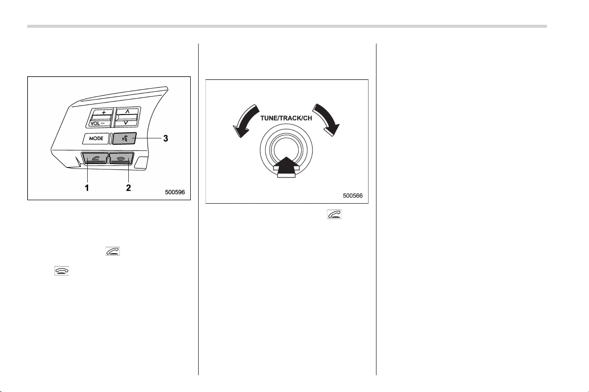
Black plate (288,1)
北米Model "A1160BE-C" EDITED: 2014/ 3/ 17
5-36
Audio/Hands–free system
& Using the Hands-free system
! Turning on/off the Hands-free mode
1) OFF hook switch
2) ON hook switch
3) Talk switch
To turn on the Hands-free mode, press the
OFF hook switch
. To turn off the
Hands-free mode, press the ON hook
switch
.
! Menu list of the Hands-free system
(when not using the voice com-
mand system)
1. Press the OFF hook switch to turn
on the Hands-free mode.
2. Turn the “TUNE/TRACK/CH” dial to
select a menu, and then press the dial to
enter the selected menu.

Black plate (289,1)
北米Model "A1160BE-C" EDITED: 2014/ 3/ 17
First menu Second menu Third menu Details Page
PHONE BOOK*
ADD ENTRY
BY VOICE Adding a new number by voice 5-48
BY PHONE Adding a new number by cell phone 5-48
MANUAL INPUT Adding a new number by inputting manually 5-49
CALL HISTORY Adding a new number from the call history 5-49
GO BACK
LIST NAMES — Showing the list of the names registered in the phonebook 5-50
CHANGE NAME — Changing a name registered in the phonebook 5-50
SET SPD DIAL/SET
SPEED DIAL
— Registering a speed dial 5-50
DELETE ENTRY — Deleting phonebook data 5-50
DEL SPD DIAL/DE-
LETE SPEED DIAL
— Deleting a registered speed dial 5-51
GO BACK —
REDIAL
DIAL — Redialing 5-47
STORE —
Adding a new number stored in the outgoing call history
memory
5-49
DELETE — Deleting a number stored in the outgoing call history memory 5-51
GO BACK —
CALLBACK
DIAL — Dialing a number stored in the incoming call history memory 5-47
STORE —
Adding a new number stored in the incoming call history
memory
5-49
DELETE — Deleting a number stored in the incoming call history memory 5-51
GO BACK —
*: If a cell phone is not registered, the menu described in the chart is not indicated.
Audio/Hands–free system
5-37
– CONTINUED –
5

Black plate (290,1)
北米Model "A1160BE-C" EDITED: 2014/ 3/ 17
5-38
Audio/Hands–free system
First menu Second menu Third menu Details Page
SETUP SECURITY
SET PIN Setting a PIN code 5-51
PHBK LOCK*
1
/
PHONE BOOK
LOCK*
1
Locking the phonebook 5-51
PHBK UNLOCK*
1
/
PHONE BOOK UN-
LOCK*
1
Unlocking the phonebook 5-52
GO BACK
PHONE SETUP
PAIR PHONE Registering a new cell phone*
2
5-46
SELECT PHONE Selecting a cell phone to be used 5-46
CHANGE NAME Changing the registered name of the cell phone 5-52
LIST PHONES Showing the list of the registered cell phones 5-52
SET PASSKEY Changing the pass key 5-53
DELETE Deleting the registered cell phone 5-53
GO BACK
SYSTEM SETUP
GUIDANCE VOL/
GUIDANCE VOLUME
Setting the volume of the voice guidance 5-53
INITIALIZE Initialization 5-53
SEL LANGUAGE/SE-
LECT LANGUAGE
Selecting the language (using the Hands-free system) 5-53
GO BACK
GO BACK —
*1: If a PIN code is not registered, the menu described in the chart is not available.
*2: Up to 5 cell phones can be registered.
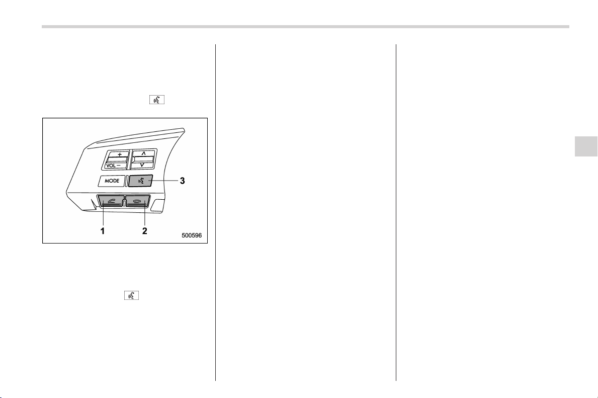
Black plate (291,1)
北米Model "A1160BE-C" EDITED: 2014/ 3/ 17
! Menu list of the Hands-free system
(when using voice command sys-
tem)
NOTE
Pressthetalkswitch and say
“Help” to listen to the help guidance.
1) OFF hook switch
2) ON hook switch
3) Talk switch
To turn on the voice command system,
press the talk switch
briefly. To turn off
the voice command system, wait for 5
seconds without using the voice command
system.
Audio/Hands–free system
5-39
– CONTINUED –
5

Black plate (292,1)
北米Model "A1160BE-C" EDITED: 2014/ 3/ 17
5-40
Audio/Hands–free system
The commands available for the voice command system are listed in the following chart.
English:
First menu Second menu Third menu Details Page
Phone book* Add entry
By voice Adding a new number by voice 5-48
By phone Adding a new number by cell phone 5-48
Call history Adding a new number from call history 5-49
Go back
List names Showing the list of the names registered in the phonebook 5-50
Change name Changing a name registered in the phonebook 5-50
Set speed dial Registering a speed dial 5-50
Delete entry Deleting phonebook data 5-50
Delete speed dial Deleting a registered speed dial 5-51
Go back
Redial
Dial Redialing 5-47
Store Adding a new number stored in the outgoing call history memory 5-49
Delete Deleting a number stored in the outgoing call history memory 5-51
Go back
Callback
Dial Dialing a number stored in the incoming call history memory 5-47
Store Adding a new number stored in the incoming call history memory 5-49
Delete Deleting a number stored in the incoming call history memory 5-51
Go back
*: If a cell phone is not registered, you cannot use this command.

Black plate (293,1)
北米Model "A1160BE-C" EDITED: 2014/ 3/ 17
First menu Second menu Third menu Details Page
Setup Security
Set PIN Setting a PIN code 5-51
Phone book lock*
1
Locking the phonebook 5-51
Phone book unlock*
1
Unlocking the phonebook 5-52
Go back
Phone setup
Pair phone Registering a new cell phone*
2
5-46
Select phone Selecting a cell phone to be used 5-46
Change name Changing the registered name of the cell phone 5-52
List phones Showing the list of the registered cell phones 5-52
Set passkey Changing the pass key 5-53
Delete Deleting the registered cell phone 5-53
Go back
Dial by name Making a phone call by saying a name 5-47
Dial by number Making a phone call by saying a number 5-47
Outgoing*
3
Selecting an outgoing call history when adding a new number
from the call history
5-49
Incoming*
3
Selecting an incoming call history when adding a new number
from the call history
5-49
*1: If a PIN code is not registered, you cannot use these commands.
*2: Up to 5 cell phones can be registered.
*3: Select the “Phone book” menu then select the “Add entry” menu. Only after then selecting the “Call history” menu will these menus become available
for use.
Audio/Hands–free system
5-41
– CONTINUED –
5

Black plate (294,1)
北米Model "A1160BE-C" EDITED: 2014/ 3/ 17
5-42
Audio/Hands–free system
Français:
Premier menu Deuxième menu Troisième menu Détails Page
Registre* Ajouter l’entrée
Vocalement Ajout d’un nouveau numéro par la voix 5-48
Par téléphone Ajout d’un nouveau numéro par le téléphone cellulaire 5-48
Historique d’appels Ajout d’un nouveau numéro à partir de l’historique des appels 5-49
Retourner
Lister les noms Affichage de la liste des noms enregistrés dans le répertoire 5-50
Modifier le nom Changement du nom enregistré dans le répertoire 5-50
Configurer composition abrégée Enregistrement d’un appel rapide 5-50
Supprimer l’entrée Effacement de données du répertoire 5-50
Supprimer composition abrégée Effacement d’une composition rapide enregistrée 5-51
Retourner
Recomposer
Composer Rappel du dernier numéro 5-47
Enregistrer
Ajout d’un nouveau numéro enregistré dans la mémoire des
historiques des appels sortants
5-49
Supprimer
Suppression d’un numéro enregistré dans la mémoire des
historiques des appels sortants
5-51
Retourner
Rappel
Composer
Appel du numéro enregistré dans la mémoire des historiques
des appels entrants
5-47
Enregistrer
Ajout d’un nouveau numéro enregistré dans la mémoire des
historiques des appels entrants
5-49
Supprimer
Suppression d’un numéro enregistré dans la mémoire des
historiques des appels entrants
5-51
Retourner
*: Si un téléphone cellulaire n’est pas enregistré, vous ne pouvez pas utiliser cette commande.
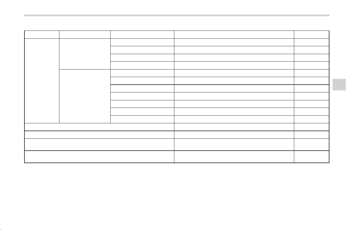
Black plate (295,1)
北米Model "A1160BE-C" EDITED: 2014/ 3/ 17
Premier menu Deuxième menu Troisième menu Détails Page
Réglages Sécurité
Configurer NIP Réglage du code PIN 5-51
Verrouiller le registre*
1
Verrouillage du répertoire 5-51
Déverrouiller le registre*
1
Déverrouillage du répertoire 5-52
Retourner
Réglages du téléphone
Jumeler le téléphone Enregistrement d’un nouveau téléphone cellulaire*
2
5-46
Sélectionner le téléphone Sélection du téléphone cellulaire à utiliser 5-46
Modifier le nom Changement du nom enregistré du téléphone cellulaire 5-52
Lister les téléphones Affichage de la liste des téléphones cellulaires enregistrés 5-52
Configurer le passe-partout Changement du mot de passe 5-53
Supprimer Effacement d’un téléphone cellulaire enregistré 5-53
Retourner
Composer par nom Passer un appel en dictant le nom 5-47
Composer par numéro Passer un appel en dictant le numéro 5-47
Sortant*
3
Sélectionner un historique d’appels sortants lors de l’ajout
d’un nouveau numéro à partir de l’historique des appels
5-49
Entrant*
3
Sélectionner un historique d’appels entrants lors de l’ajout
d’un nouveau numéro à partir de l’historique des appels
5-49
*1: Si un code PIN n’est pas enregistré, vous ne pouvez pas utiliser ces commandes.
*2: Vous pouvez enregistrer jusqu’à 5 téléphones.
*3: Vous ne pouvez sélectionner ces menus qu’après avoir sélectionné, dans l’ordre, les menus “Registre”, “Ajouter l’entrée” puis “Historique d’appels”.
Audio/Hands–free system
5-43
– CONTINUED –
5

Black plate (296,1)
北米Model "A1160BE-C" EDITED: 2014/ 3/ 17
5-44
Audio/Hands–free system
The other commands available for the voice command system are listed in the following chart.
Command
Details
English Français
1
0 (zero, oh) 0 (zéro) —
2 1 (one) 1 (un) —
3 2 (two) 2 (deux) —
4 3 (three) 3 (trois) —
5 4 (four) 4 (quatre) —
6 5 (five) 5 (cinq) —
7 6 (six) 6 (six) —
8 7 (seven) 7 (sept) —
9 8 (eight) 8 (huit) —
10 9 (nine) 9 (neuf) —
11
* (star) * (étoile) —
12 # (pound) # (carré, dièse) —
13 + (plus) + (plus) —
14 cancel annuler Turning off the Hands-free system
15
help aide Listening to the help guidance
16 repeat répéter
Repeat the help guidance that you listened to before speaking the “repeat”
command.
17 mute sourdine Cutting the volume to zero
18 previous précédent
19 confirm confirmer
20 PHONE BOOK add entry
ajouter l’entrée dans le re-
gistre
Adding a new number
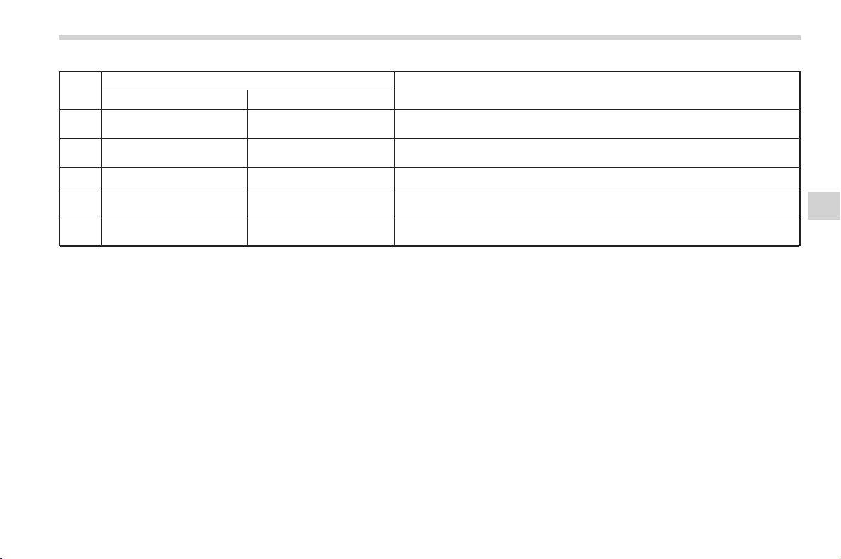
Black plate (297,1)
北米Model "A1160BE-C" EDITED: 2014/ 3/ 17
Command
Details
English Français
21
PHONE BOOK change
name
modifier le nom dans le
registre
Changing a name registered in the phonebook
22 PHONE BOOK delete entry
supprimer l’entrée du regis-
tre
Deleting phonebook data
23 PHONE BOOK list names lister les noms du registre Showing the list of the names registered in the phonebook
24
PHONE BOOK set speed
dial
configurer composition
abrégée pour le registre
Registering a speed dial
25
PHONE BOOK delete
speed dial
supprimer composition
abrégée pour le registre
Deleting a registered speed dial
Audio/Hands–free system
5-45
– CONTINUED –
5
Black plate (298,1)
北米Model "A1160BE-C" EDITED: 2014/ 3/ 17
5-46
Audio/Hands–free system
! Preparation for using the Hands-
free system
! When no cell phones are regis-
tered
Before using the Hands-free system, it is
necessary to register a cell phone in the
system. Perform the following procedure
to register a cell phone.
1. Press the OFF hook switch
.
2. Select “ENGLISH”/“FRA NÇAIS” by
operating the “TUNE/TRACK/CH” dial.
–“WELCOME!” will be displayed.
3. Press the “TUNE/TRACK/CH” dial or
the talk switch
.
4. Perform either of the following proce-
dures.
– Select the “ RECORD NAME”
menu.
– Press the talk switch
.
5. Say the name (voice tag) to be
registered.
6. Select the “ CONFIRM” menu.
– After “CAR M_MEDIA” (type A
audio)/“CAR MULTIMEDIA” (type B
audio) is displayed, a pass key will
be displayed.
7. Input the displayed pass key into the
cell phone while the following message is
displayed.
–“PKY: ****” (type A audio)
–“PASS KEY: ****” (type B audio)
NOTE
. If you input the correct pass key,
“PAIRED” will be displayed and the
registration procedure will be finished.
. If you input an incorrect pass key,
“FAILED” will be displayed and the
registration procedure will not be suc-
cessful.
. Up to 5 cell phones can be regis-
tered.
! Registering a cell phone
To register a cell phone to the in-vehicle
equipment, perform the following proce-
dure.
1. Select the “ SETUP” menu.
2. Select the “ PHONE SETUP” menu.
3. Select the “ PAIR PHONE” menu.
4. Perform either of the following proce-
dures.
– Select the “ RECORD NAME”
menu.
– Press the talk switch
.
5. Say the name (voice tag) to be
registered.
6. Select the “ CONFIRM” menu.
– After “CAR M_MEDIA” (type A
audio)/“CAR MULTIMEDIA” (type B
audio) is displayed, a pass key will
be displayed.
7. Input the displayed pass key into the
cell phone while the following message is
displayed.
–“PKY: ****” (type A audio)
–“PASS KEY: ****” (type B audio)
NOTE
. If you input the correct pass key,
“PAIRED” will be displayed and the
registration procedure will be finished.
. If you input an incorrect pass key,
“FAILED” will be displayed and the
registration procedure will not be suc-
cessful.
. Up to 5 cell phones can be regis-
tered.
! Selecting a cell phone
To select the registered cell phone for
connecting to the in-vehicle equipment,
perform the following procedure.
1. Select the “SETUP” menu.
2. Select the “PHONE SETUP” menu.
3. Select the “SELECT PHONE” menu.
– If no cell phones are registered,
“EMPTY” will be displayed and the
mode will change to the “PHONE
SETUP” mode.
Black plate (299,1)
北米Model "A1160BE-C" EDITED: 2014/ 3/ 17
4. Select the cell phone by performing
either of the following procedures.
– Operate the “TUNE/TRACK/CH”
dial.
– Press the talk switch
and say
the voice tag.
5. Select the “ CONFIRM” menu.
–“SELECTED” will be displayed, the
selected cell phone will be connected
to the in-vehicle equipment and the
mode will change to the “PHONE
SETUP” mode.
– If the selected cell phone cannot be
connected, “FAILED” will be displayed
and the mode will change to the
“PHONE SETUP” mode.
! Making a phone call
! Making a phone call by saying
name
1. Select the top menu (phone menu).
2. Press the talk switch
.
3. Say “DIAL BY NAME”.
4. Press the talk switch
again.
5. Say the preferred name (voice tag) to
be called.
6. Select the “ DIAL” menu.
! Making a phone call by saying
number
1. Select the top menu (phone menu).
2. Press the talk switch
.
3. Say “DIAL BY NUMBER”.
4. Press the talk switch
again.
5. Say the preferred phone number to be
called.
6. Select the “ DIAL ” menu.
! Making a phone call from speed
dial
It is possible to select a phone number
from speed dial registered with the in-
vehicle equipment to make a phone call.
1. Select the top menu (phone menu).
2. Press the preset button (from
to
) to which the preferred number is
registered.
3. Press the OFF hook switch
.
NOTE
When a preset button for which num-
bers are not registered is pressed, an
error message will be shown on the
audio screen.
! Redial
1. Select the “ REDIAL ” menu.
2. Press the OFF hook switch
.
3. Select the preferred number by turning
the “TUNE/TRACK/CH” dial.
4. Perform either of the following proce-
dures.
– Press the OFF hook switch
.
– Press the “TUNE/TRACK/CH” dial,
then select the “ DIAL ” menu.
! Callback
1. Select the “CALL BACK” menu.
2. Press the OFF hook switch
.
3. Select the preferred number by turning
the “TUNE/TRACK/CH” dial.
4. Perform either of the following proce-
dures.
– Press the OFF hook switch
.
– Press the “TUNE/TRACK/CH” dial,
then select the “ DIAL ” menu.
! Making a phone call from list
name
It is possible to select a phone number
from the list name registered with the in-
vehicle equipment to make a phone call.
For details, refer to “List names function”
F5-50.
! Top redial
1. Select the top menu (phone menu).
2. Press the OFF hook switch
and
Audio/Hands–free system
5-47
– CONTINUED –
5
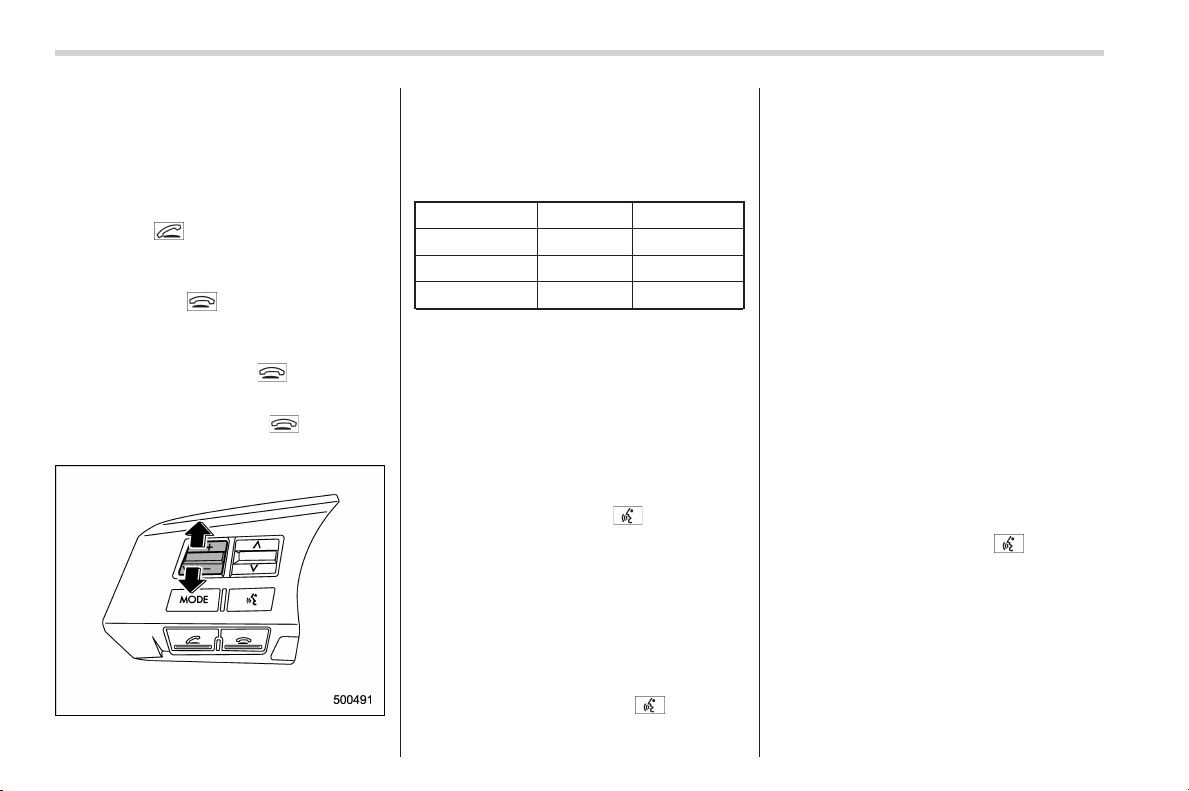
Black plate (300,1)
北米Model "A1160BE-C" EDITED: 2014/ 3/ 17
5-48
Audio/Hands–free system
load the outgoing call history.
3. Select the “ DIAL” menu.
! Taking a phone call and declining
an incoming call
To take a phone call: Press the OFF
hook switch
.
To put an incoming call on hold (only if
the cell phone has this function): Press the
ON hook switch
briefly.
To decline an incoming call (only if the
cell phone has this function): Press and
hold the ON hook switch
.
! Ending a call
Press the ON hook switch
.
! Volume control
You can adjust the phone call volume, the
voice volume and the voice guidance
volume. Refer to “Volume control switch”
F5-31.
! Adjustable level of each volume
Volume Range Initial setting
Phone call 0 to 14 7
Voice 0 to 14 7
Voice guidance 0 to 6
3
! Registering phonebook data
NOTE
The maximum number of phonebook
entries that can be registered in the
phonebook is 50.
! Registering by voice
1. Select the “ BY VOICE” menu.
2. Press the talk switch
.
3. Say the phone number to be regis-
tered.
4. Select the “ CONFIRM” menu.
5. Perform either of the following proce-
dures.
– Select the “RECORD NAME ” menu
by operating the “TUNE/TRACK/CH”
dial.
– Press the talk switch
.
6. Say the name (voice tag) to be
registered.
7. Select the “CONFIRM” menu.
– Then “STORED” will be displayed
and the mode will change to the
registering speed dial mode. Refer to
“Registering speed dial” F5-49.
! Registering by phone
1. Select the “BY PHONE” menu.
2. Select the “CONFIRM” menu.
– Then “TRANSFER” will be dis-
played.
3. Transfer the data from the cell phone.
For details about transferring the data,
refer to the instruction manual of the cell
phone.
4. Perform either of the following proce-
dures.
– Select the “RECORD NAME” menu
by operating the “TUNE/TRACK/CH”
dial.
– Press the talk switch
.
5. Say the name (voice tag) to be
registered.
6. Select the “CONFIRM” menu.
– Then “STORED” will be displayed
and the mode will change to the
registering speed dial mode. Refer to
“Registering speed dial” F5-49.

Black plate (301,1)
北米Model "A1160BE-C" EDITED: 2014/ 3/ 17
! Registering by inputting manu-
ally
1. Select the “MANUAL INPUT” menu by
operating the “TUNE/TRACK/CH” dial.
2. Input the phone number to be regis-
tered.
3. Perform either of the following proce-
dures.
– Select the “RECORD NAME” menu
by operating the “TUNE/TRACK/CH”
dial.
– Press the talk switch
.
4. Say the name (voice tag) to be
registered.
5. Select the “ CONFIRM” menu.
– Then “STORED” will be displayed
and the mode will change to the
registering speed dial mode. Refer to
“Registering speed dial” F5-49.
NOTE
While inputting the phone numbers, if
“GO BACK” (type A audio)/“BS” (type
B audio) is chosen using the “TUNE/
TRACK/CH” dial, the character that was
input last will be deleted.
! Registering from call history
1. Select the “ CALL HISTORY” menu.
2. Select “OUTGOING” or “INCOMING”
by operating the “TUNE/TRACK/CH” dial.
3. Select the phone number by operating
the “TUNE/TRACK/CH” dial.
4. Perform either of the following proce-
dures.
– Select the “RECORD NAME ” menu
by operating the “TUNE/TRACK/CH”
dial.
– Press the talk switch
.
5. Say the name (voice tag) to be
registered.
6. Select the “ CONFIRM” menu.
– Then “STORED” will be displayed
and the mode will change to the
registering speed dial mode. Refer to
“Registering speed dial” F5-49.
! Registering from redial
1. Select the “ REDIAL ” menu.
2. Select the phone number by operating
the “TUNE/TRACK/CH” dial.
3. Select the “ STORE” menu.
4. Select the “ CONFIRM” menu.
5. Perform either of the following proce-
dures.
– Select the “RECORD NAME ” menu
by operating the “TUNE/TRACK/CH”
dial.
– Press the talk switch
.
6. Say the name (voice tag) to be
registered.
7. Select the “CONFIRM” menu.
– Then “STORED” will be displayed
and the mode will change to the
registering speed dial mode. Refer to
“Registering speed dial” F5-49.
! Registering from call back
1. Select the “CALL BACK” menu.
2. Select the phone number by operating
the “TUNE/TRACK/CH” dial.
3. Select the “STORE” menu.
4. Select the “CONFIRM” menu.
5. Perform either of the following proce-
dures.
– Select the “RECORD NAME” menu
by operating the “TUNE/TRACK/CH”
dial.
– Press the talk switch
.
6. Say the name (voice tag) to be
registered.
7. Select the “CONFIRM” menu.
– Then “STORED” will be displayed
and the mode will change to the
registering speed dial mode. Refer to
“Registering speed dial” F5-49.
! Registering speed dial
1. After registering phonebook data, se-
lect the “SPEED DIAL” menu.
Audio/Hands–free system
5-49
– CONTINUED –
5
Black plate (302,1)
北米Model "A1160BE-C" EDITED: 2014/ 3/ 17
5-50
Audio/Hands–free system
2. Press the preset button (from to
) to which you want to register the
phone number.
NOTE
If the number to be used is already
registered in speed dial, “ OVER-
WRITE?” will be displayed.
! Using and setting phonebook data
! List names function
The voice tags registered in the phone-
book are spoken by using the list names
function. To use the list names function,
perform the following procedure.
1. Select the “ LIST NAMES” menu.
2. Select the registered data by perform-
ing either of the following procedures.
– Press the talk switch
.
– Operate the “TUNE/TRACK/CH”
dial.
3. After “SELECTED” is displayed, you
can select the following menus.
. “DIAL” to make a phone call
. “CHANGE NAME” to change the name
(voice tag)
. “SET SPD DIAL”/“SET SPEED DIAL”
to set the speed dial
. “DELETE ENTRY” to delete the name
(voice tag) from the phonebook
. “GO BACK” to go back to the menu
mode
NOTE
. After “LIST NAMES” is selected, if
the OFF hook switch
is pushed, the
selected number will be called.
. After “LIST NAMES” is selected, if
no operation is performed, the mem-
ories will be displayed and voice tags
will be spoken. After all memories/
voice tags are displayed/spoken,
“END OF LIST” will be displayed and
the mode will change to the “PHONE
BOOK” menu mode.
! Changing voice tag
1. Select the “ CHANGE NAME” menu.
2. Select the phone number by perform-
ing either of the following procedures.
– Operate the “TUNE/TRACK/CH”
dial.
– Press the talk switch
and say
the voice tag.
3. Select the “CONFIRM” menu (only
after saying the voice tag).
– Then the selected phone number/
name will be displayed.
4. Press the talk switch
.
5. Say the new voice tag.
6. Select the “CONFIRM” menu.
– Then “CHANGED” will be dis-
played.
! Set speed dial
1. Select the “SET SPD DIAL”/“SET
SPEED DIAL” menu.
2. Select the phone number by perform-
ing either of the following procedures.
– Operate the “TUNE/T RACK/CH ”
dial.
– Press the talk switch
and say
the voice tag.
3. Select the “CONFIRM” menu (only
after saying the voice tag).
4. Press the preset button (from
to
) to which you want to register the
phone number.
! Deleting data
! Deleting the phonebook data
1. Select the “DELETE ENTRY” menu.
2. Select the phone number by perform-
ing either of the following procedures.
– Operate the “TUNE/T RACK/CH ”
dial.
– Press the talk switch
and say
the voice tag.
3. Select the “CONFIRM” menu.
– Then “DELETED” will be displayed
Black plate (303,1)
北米Model "A1160BE-C" EDITED: 2014/ 3/ 17
and the selected phonebook data will
be deleted.
! Deleting the speed dial
1. Select the “DEL SPD DIAL”/“DELETE
SPEED DIAL” menu.
2. Press the preset button (from
to
) to which you want to delete the
speed dial.
3. Select the “ CONFIRM” menu.
– Then “DELETED” will be displayed
and the selected speed dial will be
deleted.
! Deleting the redial data
1. Select the “ REDIAL” menu.
2. Select the phone number by operating
the “TUNE/TRACK/CH” dial.
3. Select the “ DELETE” menu.
4. Select the “ CONFIRM” menu.
– Then “DELETED” will be displayed
and the selected redial data will be
deleted.
! Deleting the callback data
1. Select the “ CALLBACK” menu.
2. Select the phone number by operating
the “TUNE/TRACK/CH” dial.
3. Select the “ DELETE” menu.
4. Select the “ CONFIRM” menu.
– Then “DELETED” will be displayed
and the selected callback data will be
deleted.
& Bluetooth
®
setting
! Security setting
After selecting the “SECURITY” menu,
perform the following procedures.
! Setting PIN code
The PIN code is a 4-digit number and is
used when locking the phonebook.
1. Select the “ SET PIN” menu.
– Then “CURRENT PIN?” will be
displayed.
2. Input the current PIN code by perform-
ing either of the following procedures.
– Operate the “TUNE/TRACK/CH”
dial.
– Press the talk switch
and say
the number.
3. Select the “ CONFIRM” menu.
4. Input the new PIN code by performing
either of the following procedures.
– Operate the “TUNE/TRACK/CH”
dial.
– Press the talk switch
and say
the number.
5. Select the “ CONFIRM” menu.
! Locking the phonebook
CAUTION
After locking the phonebook, you
cannot unlock the phonebook with-
out inputting the PIN code. Do not
forget the PIN code after locking the
phonebook.
1. Select the “PHBK LOCK”/“PHONE-
BOOK LOCK” menu.
– Then “CURRENT PIN?” will be
displayed.
2. Input the PIN code by performing
either of the following procedures.
– Operate the “TUNE/T RACK/CH ”
dial.
– Press the talk switch
and say
the number.
3. Select the “CONFIRM” menu.
– If the inputted PIN code is correct,
“LOCKED” will be displayed and the
phonebook will be locked.
NOTE
While the phonebook is locked, if the
operation restricted menu is selected,
“PHBK LOCK” will be displayed.
Audio/Hands–free system
5-51
– CONTINUED –
5

Black plate (304,1)
北米Model "A1160BE-C" EDITED: 2014/ 3/ 17
5-52
Audio/Hands–free system
! Unlocking the phonebook
NOTE
If you have forgotten your PIN code
and/or are somehow unable to unlock
the phonebook, the phonebook lock
can be released by initializing the
registered data and re-setting the PIN
code. However, initializing the data will
cause all data registered in the hands-
free system, such as the registration
devices and phonebook data, to be
erased. For initialization, refer to “In-
itializing the registered data” F5-53.
1. Select the “PHBK UNLOCK”/“PHONE-
BOOK UNLOCK” menu.
– Then “CURRENT PIN?” will be
displayed.
NOTE
If the phonebook is not locked, “UN-
LOCK” will be displayed and the mode
will change to the security mode.
2. Input the PIN code by performing
either of the following procedures.
– Operate the “TUNE/TRACK/CH”
dial.
– Press the talk switch
and say
the number.
3. Select the “ CONFIRM” menu.
– If the inputted PIN code is correct,
“UNLOCKED” will be displayed and
the phonebook will be unlocked.
! Phone setup
After selecting the “PHONE SETUP”
menu, perform the following procedures.
! Setting pair phone
Refer to “Registering a cell phone” F5-46.
! Selecting phone
Refer to “Selecting a cell phone” F5-46.
! Changing the voice tag of the cell
phone
1. Select the “ CHANGE NAME” menu.
– If no cell phones are registered,
“EMPTY” will be displayed and the
mode will change to the “PHONE
SETUP” mode.
2. Select the cell phone by performing
either of the following procedures.
– Operate the “TUNE/TRACK/CH”
dial.
– Press the talk switch
and say
the voice tag.
3. Register the voice tag. For details,
refer to “Preparation for using the Hands-
free system” F5-46.
! List phones function
The cell phone voice tags saved in the cell
phone list are spoken by using the list
phones function.
1. Select the “LIST PHONES ” menu.
– If no cell phones are registered,
“EMPTY” will be displayed and the
mode will change to the “PHONE
SETUP” mode.
2. Registered cell phones are displayed
in the saved order. While displayed, if the
“TUNE/TRAC K/CH” dial is turned, the
next registered cell phone will be dis-
played. Press the ON hook button
to
close the Hands-free menu.
3. Select a cell phone by performing
either of the following procedures.
– Operate the “TUNE/T RACK/CH ”
dial.
– Press the talk switch
.
4. After “SELECTED” is displayed, you
can select the following menus.
. “SELECT PHONE” to connect the
selected cell phone
. “CHANGE NAME ” to change the voice
tag
. “DELETE” to delete the selected cell
phone from the list
. “GO BACK” to go back to the “PHONE
SETUP” mode

Black plate (305,1)
北米Model "A1160BE-C" EDITED: 2014/ 3/ 17
! Setting passkey
1. Select the “ SET PASSKEY” menu.
– After the currently set passkey is
displayed, a new passkey can be
entered.
2. Input the new passkey by performing
either of the following procedures.
– Operate the “TUNE/TRACK/CH”
dial.
– Press the talk switch
and say
the passkey.
3. Select the “ CONFIRM” menu.
– The new passkey will be displayed,
the passkey will be changed and the
mode will change to the “PHONE
SETUP” mode.
! Deleting registered cell phone
from the list
1. Select the “ DELETE” menu.
2. Select a cell phone to be deleted by
performing either of the following proce-
dures.
– Operate the “TUNE/TRACK/CH”
dial.
– Press the talk switch
and say
the voice tag.
3. Select the “ CONFIRM” menu.
–“DELETED” will be displayed, the
data will be deleted and the mode will
change to the “ PHONE SETUP”
mode.
! System setup
After selecting the “SYS TEM SETUP”
menu, perform the following procedures.
Select the following menus by operating
the “TUNE/TRACK/CH” dial.
! Setting guidance volume
To set the guidance volume, perform the
following procedure.
1. Select the “GUIDANCE VOL”/“GUI-
DANCE VOLUME” menu.
2. Set the guidance volume by operating
the “TUNE/TRACK/CH” dial.
! Initializing the registered data
To initialize the registered data, perform
the following procedure.
1. Select the “ INITIALIZE” menu.
2. Select the “ CONFIRM” menu.
– First “PLEASE WAIT”, then “INITI-
ALIZED” will be displayed. The regis-
tered data will be initialized and the
mode will change to the last mode.
! Selecting language
To select the language, perform the
following procedure.
1. Select the “SEL LA NGUAGE”/“SE-
LECT LANGUAGE” menu.
2. Select the preferred language by
operating the “TUNE/TRACK/CH” dial.
& Tips for the Hands-free sys-
tem
! Bluetooth
®
It is possible to connect a cell phone to the
in-vehicle equipment through the Blue-
tooth
®
format (wireless) to make a phone
call from the in-vehicle equipment or take
an incoming phone call.
Since the Bluetooth
®
format is wireless, a
connection between the in-vehicle equip-
ment and the cell phone can be made
without placing them in close proximity of
each other. The cell phone can be used
with it left in the breast pocket or bag.
NOTE
. The Hands-free system may not
operate properly under the following
conditions.
– The cell phone is turned off.
– The cell phone is not in the
phone call area.
– The battery of the cell phone has
run down.
– The cell phone is not connected
to the Hands-free system.
– The cell phone is behind the seat
Audio/Hands–free system
5-53
– CONTINUED –
5
Black plate (306,1)
北米Model "A1160BE-C" EDITED: 2014/ 3/ 17
5-54
Audio/Hands–free system
or in the glove box.
– A metal material covers or
touches the cell phone.
. Depending on the type of cell phone
that is used, the screen on the cell
phone may remain illuminated while
the ignition switch is in the “ON”
position. If this occurs, turn the illumi-
nation off by adjusting the cell phone
settings.
. Depending on the setting of the cell
phone, the dial lock function may be
activated after making a call. Deacti-
vate the automatic dial lock function of
the cell phone before using the Hands-
free system.
. Depending on the type of cell phone
that is used, operation and the sound
volume may be different from those of
cell phones currently used.
. When the ignition switch is turned to
the “LOCK” (off) position during a call,
the call may be disconnected or con-
tinued on the cell phone depending on
the type of cell phone that is used. Note
that operation of the cell phone may be
necessary if the call is continued on the
cell phone.
. Do not speak at the same time as the
other party during a call. If you and the
party speak at the same time, it may be
difficult for the other party to hear your
voice and vice versa. This is normal.
. The receiver sound volume should
be set as low as possible. Otherwise,
the party you are calling may notice an
undesirable echo sound.
. Speak clearly and loudly.
. Your voice may be difficult to be
heard by the party under the following
conditions.
– Driving on a rough road
– Driving at a high speed
– Driving with a window open
– When air from the ventilator
blows directly towards the micro-
phone
– When the sound coming from the
ventilator is loud
– When the cell phone is too close
to the microphone
. The sound quality may degrade due
to the influence of the cell phone that is
connected to the system or the circum-
stances of the Bluetooth network.
. When another Bluetooth
®
device is
simultaneously connected, noise may
be heard in the voice coming from the
hands-free phone.
! Corresponding profiles for the cell
phone
. HFP (Hands Free Profile): Ver. 1.0
. OPP (Object Push Profile): Ver. 1.1
& Certification for the Hands-
free system
CAUTION
FCC WARNING
Changes or modifications not ex-
pressly approved by the party re-
sponsible for compliance could void
the user’s authority to operate the
equipment.
NOTE
This device complies with Part 15 of
the FCC Rules and RSS-Gen of IC
Rules. Operation is subject to the
following two conditions: (1) this de-
vice may not cause harmful interfer-
ence, and (2) this device must accept
any interference received, includi ng
interference that may cause undesired
operation.
NOTE
This equipment has been tested and
found to comply with the limits for a
Class B digital device, pursuant to Part
15 of the FCC Rules. These limits are
designed to provide reasonable protec-
tion against harmful interference in a
residential installation. This equipment

Black plate (307,1)
北米Model "A1160BE-C" EDITED: 2014/ 3/ 17
may cause harmful interference to
radio commu nications, if it is not
installed and used in accordance with
the instructions. However, there is no
guarantee that interference will not
occur in a particular installation. If this
equipment does cause harmful inter-
ference to radio or television reception,
which can be determined by turning the
equipment off and on, the u ser is
encouraged to try to correct the inter-
ference by one or more of the following
measures.
. Reorient or relocate the receiving
antenna.
. Increase the separation between the
equipment and receiver.
. Connect the equipment into an out-
let on a circuit different from that to
which the receiver is connected.
. Consult the dealer or an experi-
enced radio/TV technician for help.
. Changes or modifications not ex-
pressly approved by the party respon-
sible for compliance could void the
user’s authority to operate the equip-
ment.
. This equipment complies with FCC/
IC radiation exposure limits set forth
for an uncontrolled environment and
meets the FCC radio frequency (RF)
Exposure Guidelines in Supplement C
to OET65 and RSS-102 of the IC radio
frequency (RF) Exposure rules. This
equipment has very low levels of RF
energy that it deemed to comply with-
out maximum permissive exposure
evaluation (MPE). But it is desirable
that it should be installed and operated
keeping the radiator at least 20 cm or
more away from person’s body (ex-
cluding extremities: hands, wrists, feet
and ankles).
. This transmitter must not be co-
located or operated in conjunction with
any other antenna or transmitter.
Screensaver (type B audio)
If the following operations are not per-
formed for more than 30 seconds while
the audio is ON, the screensaver will be
displayed.
. Operate any button or dial
. Shift the select lever to the “R” position
. A cell phone registered in the Hands-
free system is called
If one of the following operation s is
performed, the screensaver turns off and
the operation screen will be displayed.
. A cell phone registered in the Hands-
free system is called
If one of the following operation s is
performed, the screensaver turns off.
However, the operation screen will not
be displayed.
. Operate any button or any dial in a
condition other than the following condi-
tions
– Pressing the
button while a
mode other than the CD mode is
selected
– Pressing the volume control buttons
of the audio control buttons
– Pressing the power switch
. Insert a CD (except reloading a CD)
Audio/Screensaver (type B audio)
5-55
– CONTINUED –
5

Black plate (308,1)
北米Model "A1160BE-C" EDITED: 2014/ 3/ 17
5-56
Audio/Screensaver (type B audio)
. Connect a USB storage device or an
iPod
®
NOTE
The screensaver is not displayed under
the following conditions.
. While the ignition switch is in the
“LOCK” (off) position
. While the audio is OFF
. While the screen is OFF
. While talking on a cell phone regis-
tered in the Hands-free system
. While setting the audio
. While seek tuning, PTY group tun-
ing, scan tuning or auto-storing while
the FM/AM radio is on.
. While the rear view camera is being
used
& Downloading pictures
Perform the following procedure to down-
load a picture to be used as screensaver.
1. Connect a USB storage device. Refer
to “Connecting USB stor age device /
iPod
®
” F5-25.
2. Select the “Picture Download” menu
by operating the “TUNE/TRACK/CH” dial.
For details, refer to “Audio settings (type B
audio)” F5-8.
3. Select the preferred JPEG file by
operating the “TUNE/TRACK/CH” dial.
4. Select “Wide” or “Normal” by operating
the “TUNE/TRACK/CH” dial.
NOTE
. JPEG files that are 10 MB or less can
be saved.
. If the file name is too long, the file
may not be saved.
. Up to two JPEG files can be saved in
the in-vehicle equipment.
. If the aspect ratio of the displayed
picture is 16:9, “Wide” cannot be
selected.
. If the aspect ratio of the displayed
picture is 4:3, “Normal” cannot be
selected.
& Selecting pictures
1. Select the “Picture Select” menu by
operating the “TUNE/TRACK/CH” dial. For
details, refer to “Audio settings (type B
audio)” F5-8.
– If no pictures are saved, “No Data”
will be displayed. Press the
button to return to the “Screen Saver”
mode.
2. Select the preferred picture by operat-
ing the “TUNE/TRACK/CH” dial.
& Erasing pictures
1. Select the “Picture Erase” menu by
operating the “TUNE/TRACK/CH” dial. For
details, refer to “Audio settings (type B
audio)” F5-8.
– If no pictures are saved, “No Data”
will be displayed. Press the
button to return to the “Screen Saver”
mode.
2. Select the preferred picture by operat-
ing the “TUNE/TRACK/CH” dial.
3. Operate the “TUNE/TRACK/CH” dial
to select “OK” to erase the picture or
“Cancel” to cancel the operation.

Black plate (11,1)
北米Model "A1160BE-C" EDITED: 2014/ 3/ 17
Interior lights ....................................................... 6-2
Dome light .......................................................... 6-2
Cargo area light .................................................. 6-2
Map lights........................................................... 6-3
OFF delay timer .................................................. 6-3
Sun visors ........................................................... 6-4
Vanity mirror ....................................................... 6-4
Storage compartment ......................................... 6-5
Glove box ........................................................... 6-5
Center console.................................................... 6-5
Cup holders ......................................................... 6-6
Bottle holders...................................................... 6-7
Accessory power outlets .................................... 6-7
Use with a cigarette lighter (if equipped) .............. 6-8
Ashtray (if equipped)........................................... 6-9
Floor mat (if equipped)...................................... 6-10
Coat hook........................................................... 6-10
Shopping bag hook ........................................... 6-11
Cargo area cover ............................................... 6-11
Using the cover ................................................. 6-11
To remove the cover housing............................. 6-12
Stowage of the cargo area cover ........................ 6-12
To install the cover housing ............................... 6-13
Cargo tie-down hooks (if equipped)................. 6-13
Rear view camera (if equipped)........................ 6-14
How to use the rear view camera ....................... 6-15
Viewing range on the screen.............................. 6-15
Help line............................................................ 6-16
Interior equipment
6
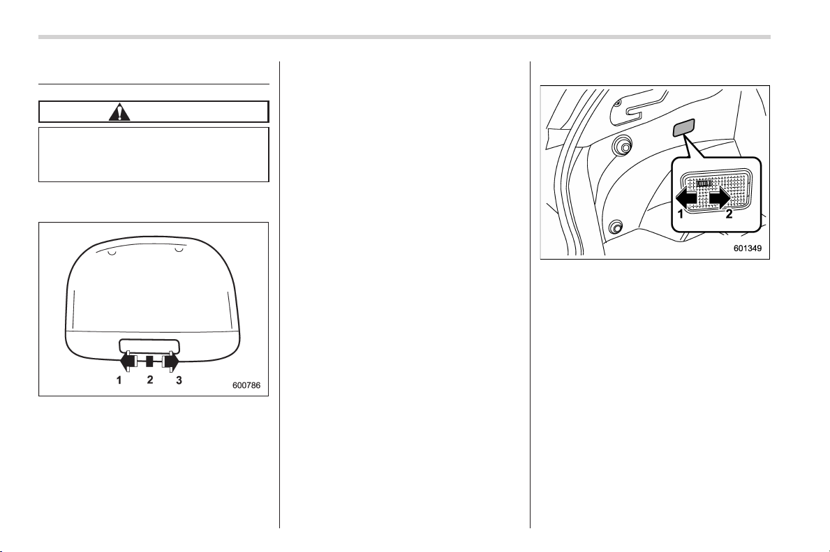
Black plate (312,1)
北米Model "A1160BE-C" EDITED: 2014/ 3/ 17
6-2
Interior equipment/Interior lights
Interior lights
CAUTION
When leaving your vehicle, make
sure the light s are turned off to
avoid battery discharge.
& Dome light
1) ON
2) DOOR
3) OFF
The dome light switch has the following
positions.
ON: The light remains on continuously.
OFF: The light remains off.
DOOR: The dome light illuminates auto-
matically in the following cases.
. Any of the doors or the rear gate is
opened.
. The doors or the rear gate are un-
locked using the keyless access function
(if equipped). Refer to “Locking and
unlocking with “keyless access” entry
function” F2-13.
. The doors or the rear gate are un-
locked using the remote keyless entry
system. Refer to “Remote keyless entry
system” F2-18.
. The ignition switch is turned from the
“ACC” position to the “LOCK” (off) posi-
tion.
& Cargo area light
1) DOOR
2) OFF
DOOR: The light illuminates when the rear
gate is opened. The light remains illumi-
nated for several seconds and gradually
turns off after the rear gate is closed.
OFF: The light remains off.
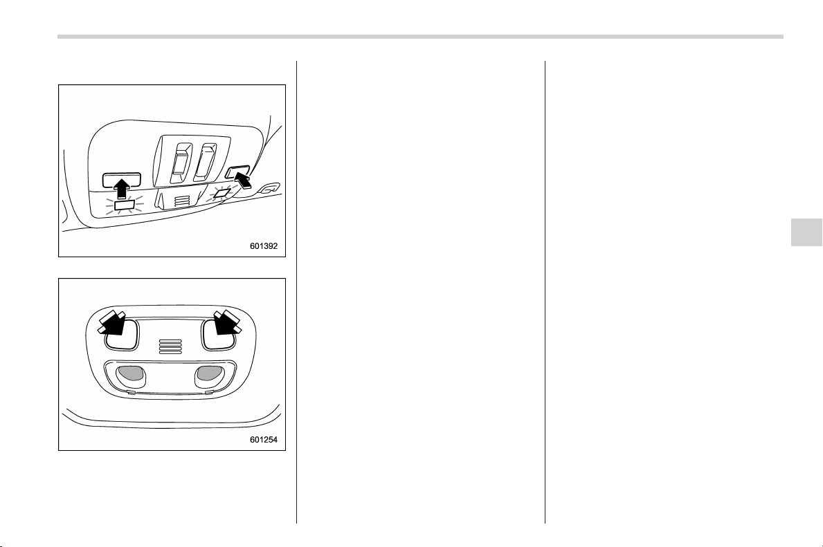
Black plate (313,1)
北米Model "A1160BE-C" EDITED: 2014/ 3/ 17
& Map lights
Type A
Type B
To turn on the map light, push the switch.
To turn it off, push the switch again.
NOTE
For the type A map lights, although the
light switches are in the ON position,
the lights are automatically turned off
after approximately 30 seconds of
illumination to prevent the 12 V aux-
iliary batter y from discharging. For
details, refer to “Battery drainage pre-
vention function” F2-7.
! Automatic illumination (models
with moonroof)
The map lights illuminate automatically in
the following cases.
. Any of the doors other than the rear
gate is opened. (The map lights do not
illuminate when only the rear gate i s
opened.)
. The doors are unlocked using the
keyless access function (if equipped).
Refer to “Locking and unlocking with
“keyless access” entry function” F2-13.
. The doors are unlocked using the
remote keyless entry system. Refer to
“Remote keyless entry system” F2-18.
. The ignition switch is turned from the
“ACC” position to the “LOCK” (off) posi-
tion.
& OFF delay timer
The following lights have an automatic
illumination function.
. dome light
. map light (type A)
After being illuminated automatically,
these lights remain on for several seconds
and then gradually turn off under the
following conditions.
. after all doors and the rear gate are
closed (dome light)
. after all doors are closed (type A map
light)
While the lights are illuminated, if any of
the following operations are performed,
the lights turn off immediately.
. The ignition switch is turned from the
“LOCK” (off) position to the “ACC” or “ON”
position.
. All doors and the rear gate are locked
using the keyless access function (if
equipped).
. All doors and the rear gate are locked
using the remote keyless entry system.
The setting for the period of time in which
the lights remain on (OFF delay timer) can
be changed by a SUBARU dealer. Con-
tact your SUBARU dealer for details. The
setting can be changed by operating the
Interior equipment/Interior lights
6-3
– CONTINUED –
6
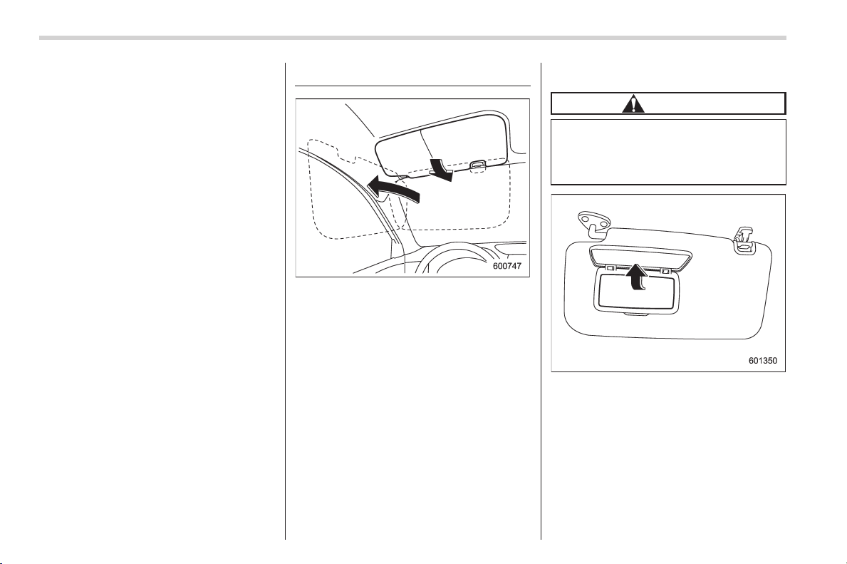
Black plate (314,1)
北米Model "A1160BE-C" EDITED: 2014/ 3/ 17
6-4
Interior equipment/Sun visors
multi function display. For details, refer to
“Interior light off delay timer setting” F3-
70.
Sun visors
To block out glare, swing down the visors.
To use the sun visor at a side window,
swing it down and move it sideways.
& Vanity mirror
CAUTION
Keep the vanity mirror cover closed
while the car is being driven to avoid
being temporarily blinded by the
glare of bright light.
To use the vanity mirror, swing down the
sun visor and open the vanity mirror cover.
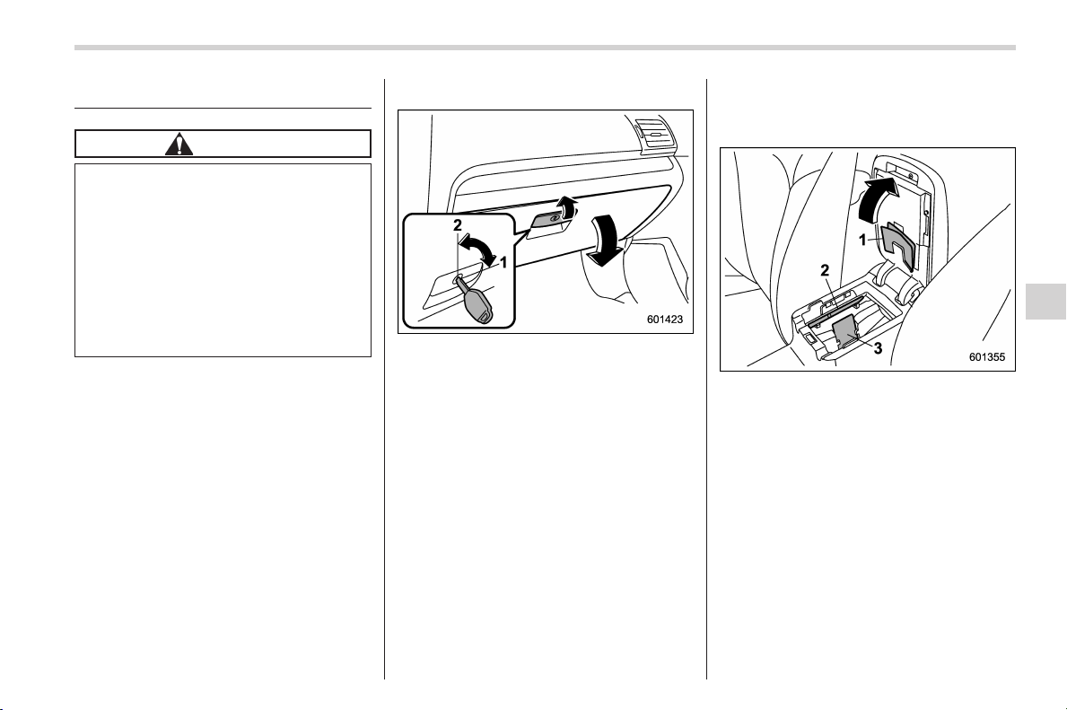
Black plate (315,1)
北米Model "A1160BE-C" EDITED: 2014/ 3/ 17
Storage compartment
CAUTION
. Always keep the storage com-
partment closed while driving to
reduce the risk of injury in the
event of a sudden stop or an
accident.
. Do not store spray cans, contain-
ers with flammable or corrosive
liquids or any other dangerous
items in the storage compart-
ment.
& Glove box
1) Lock
2) Unlock
To open the glove box, pull the handle. To
close it, push the lid firmly upward.
To lock the glove box, insert the key and
turn it clockwise. To unlock the glove box,
insert the key and turn it counterclockwise.
& Center console
The center console box provides a sto-
rage space.
1) Paper holder
2) Pen holder
3) Card holder
The top of the console can be used as an
armrest.
Interior equipment/Storage compartment
6-5
– CONTINUED –
6
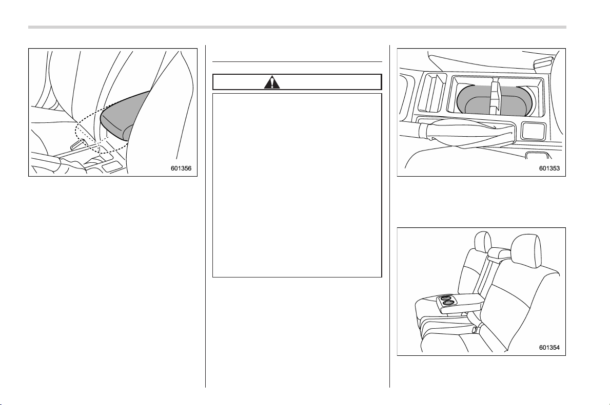
Black plate (316,1)
北米Model "A1160BE-C" EDITED: 2014/ 3/ 17
6-6
Interior equipment/Cup holders
For some models, the armrest is adjus-
table. Slide the armrest to the desired
position.
Cup holders
CAUTION
. Do not pick up a cup from the cup
holder or put a cup in the holder
while you are driving, as this may
distract you a nd lead to an
accident.
. Take care to avoid spills. Bev-
erages, if hot, might scald you
and/or your passengers. Spilled
beverages may also damage up-
holstery or carpets.
. When a cup in the rear passen-
ger’s cup holder contains a bev-
erage, do not fold down the rear
seatback. Otherwise, the bever-
age could spill and, if the bev-
erage is hot, it could scald you
and/or your passengers.
Front passenger’s cup holder
A dual cup holder is built into the center
console.
Rear passenger’s cup holder (if equipped)
A dual cup holder is built into the armrest.
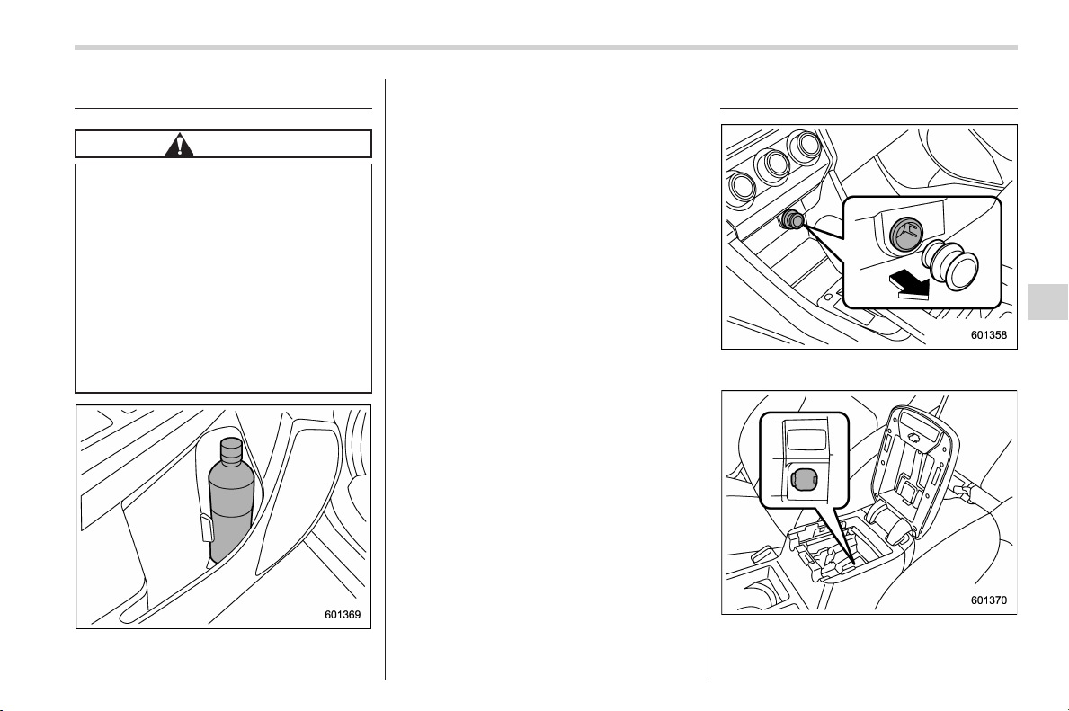
Black plate (317,1)
北米Model "A1160BE-C" EDITED: 2014/ 3/ 17
Bottle holders
CAUTION
. Do not pick up a bottle from the
bottle holder or put a bottle in the
holder while you are driving, as
this may distract you and lead to
an accident.
. When placing a beverage in a
bottle holder, make sure it is
capped. Otherwise, the beverage
could spill when opening/closing
the door or while driving and, if
the beverage is hot, it could scald
you and/or your passengers.
The bottle holder equipped on each door
trim can be used to hold beverage bottles
and other items.
Accessory power outlets
Power outlet below the climate control
dials
Power outlet in the center console
Accessory power outlets are provided
Interior equipment/Bottle holders
6-7
– CONTINUED –
6
Black plate (318,1)
北米Model "A1160BE-C" EDITED: 2014/ 3/ 17
6-8
Interior equipment/Accessory power outlets
below the climate control dials and in the
center console. Electrical power (12V DC)
from the battery is available at any of the
outlets when the ignition switch is in either
the “ACC” or “ON” position.
Youcanuseanin-vehicleelectrical
appliance by connecting it to an outlet.
The maximum power rating of an appli-
ance that can be connected is 120W.Do
not use an appliance which exceeds the
indicated wattage for each outlet.
When using appliances connected to two
outlets simultaneously, the total power
consumed by them mu st not exceed
120W.
CAUTION
. Do not attempt to use a cigarette
lighter in the accessory power
outlets.
. Do not place any foreign objects,
especially metal ones such as
coins or aluminum foil, into the
accessory power outlet. That
could cause a short circuit. Al-
ways put the cap on the acces-
sory power outlet when it is not
in use.
. Use only electri cal appliances
which are designed for 12V DC.
The maximum power rating of an
appliance that can be connected
is 120W. Do not use an appliance
which exceeds the indicated wat-
tage for each outlet.
When using appliances con-
nected to two outlets simulta-
neously, t he total power con-
sumed by them must not exceed
120W. Overloading the accessory
power outlet can cause a short
circuit. Do not use double adap-
ters or more than one electrical
appliance.
. If the plug on your electric appli-
ance is either too loose or too
tight for the accessory power
outlet, this can result in a poor
contact or cause the plug to get
stuck. Only use plugs that fit
properly.
. Use of an electric appliance in the
accessory power outlet for a long
period of time while the engine is
not running can cause battery
discharge.
. Before driving your vehicle, make
sure that the plug and the cord
on your electrical appliance will
not interfere with your shifting
gears and operating the accel-
erator and brake pedals. If they
do, do not use the electrical
appliance while driving.
& Use with a cigarette lighter (if
equipped)
To use the accessory power outlet as a
cigarette ligh ter soc ket, purchase the
cigarette lighter plug, which is an optional
accessory. A cigarette lighter plug is
available from your SUBARU dealer.
The cigarette lighter operates only when
the ignition switch is in the “ON” or “ACC”
position.
To use the cigarette lighter, push in the
knob and wait a few moments. It will
automatically spring up when ready for
use.
WARNING
To avoid being burned, never grasp
the lighter by the end with the
heating element. Doing so could
result in injury and could also
damage the heating element.
CAUTION
. Do not hold the lighter pushed in,
because it will overheat.
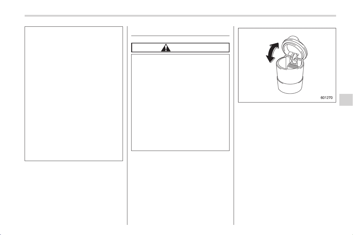
Black plate (319,1)
北米Model "A1160BE-C" EDITED: 2014/ 3/ 17
. The elec trical power socket is
originally designed to use a gen-
uine SUBARU cigarette lighter
plug. Do not use a non-genuine
cigarette lighter plug in the sock-
et. Doing so may cause a short-
circuit and overheating, resulting
in a fire.
. If the socket is ever used for a
plug-in accessory such as a cell
phone, that may damage the
portion of the socket ’s internal
mechanism that causes a cigar-
ette lighter plug to “pop out”
after its lighter element is heated.
Therefore, do not place a cigar-
ette lighter plug in a socket that
has been used, even once, to
power a plug-in accessory. Doing
so may cause the plug to stick
and overheat, creating a potential
fire hazard.
Ashtray (if equipped)
CAUTION
. Do not use ashtrays as waste
receptacles or leave a lighted
cigarette in an ashtray. This
could cause a fire.
. Always extinguish matches and
cigarettes before putting them
into the ashtray, and then close
the ashtray securely. If you keep
the ashtray open, the fire of the
cigarette may spread to another
cigarette butt and start a fire.
. Do not put flammable material in
the ashtray.
. Do not leave a lot of cigarette
butts in the ashtray.
NOTE
Particles of ash and tobacco will accu-
mulate around the hinges of the ash-
tray’s inner lid. Clean them off using a
toothbrush or a similar narrow-ended
implement.
The portable ashtray can be installed in
each cup holder or bottle holder. For the
locations of the cup holders, refer to “Cup
holders” F 6-6. For the locations of the
bottle holders, refer to “Bottle holders” F6-
7.
When using the ashtray, open the lid of the
ashtray. Fully close the lid after using the
ashtray to help reduce residual smoke.
Interior equipment/Ashtray
6-9
6
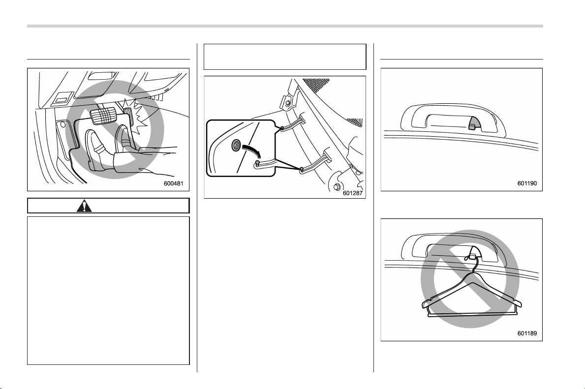
Black plate (320,1)
北米Model "A1160BE-C" EDITED: 2014/ 3/ 17
6-10
Interior equipment/Floor mat
Floor mat (if equipped)
CAUTION
If the floor mat slips forward and
interferes with the movement of the
pedals during driving, it could cause
an accident. Observe the following
precautions to prevent the floor mat
from slipping forward.
. Be sure to use a genuine
SUBARU floor mat or an equiva-
lent designed with grommets in
the correct locations.
. Make sure that the driver’s floor
mat is placed in its proper loca-
tion and is correctly secured on
its retaining pins.
. Do not use more than one floor
mat.
Retaining pins are located on the driver’s
side floor.
The floor mat should be properly secured
using the built-in grommets, by placing the
grommets over the pins and pushing them
downward.
Coat hook
A coat hook is attached to the rear
passenger’s hand grip.
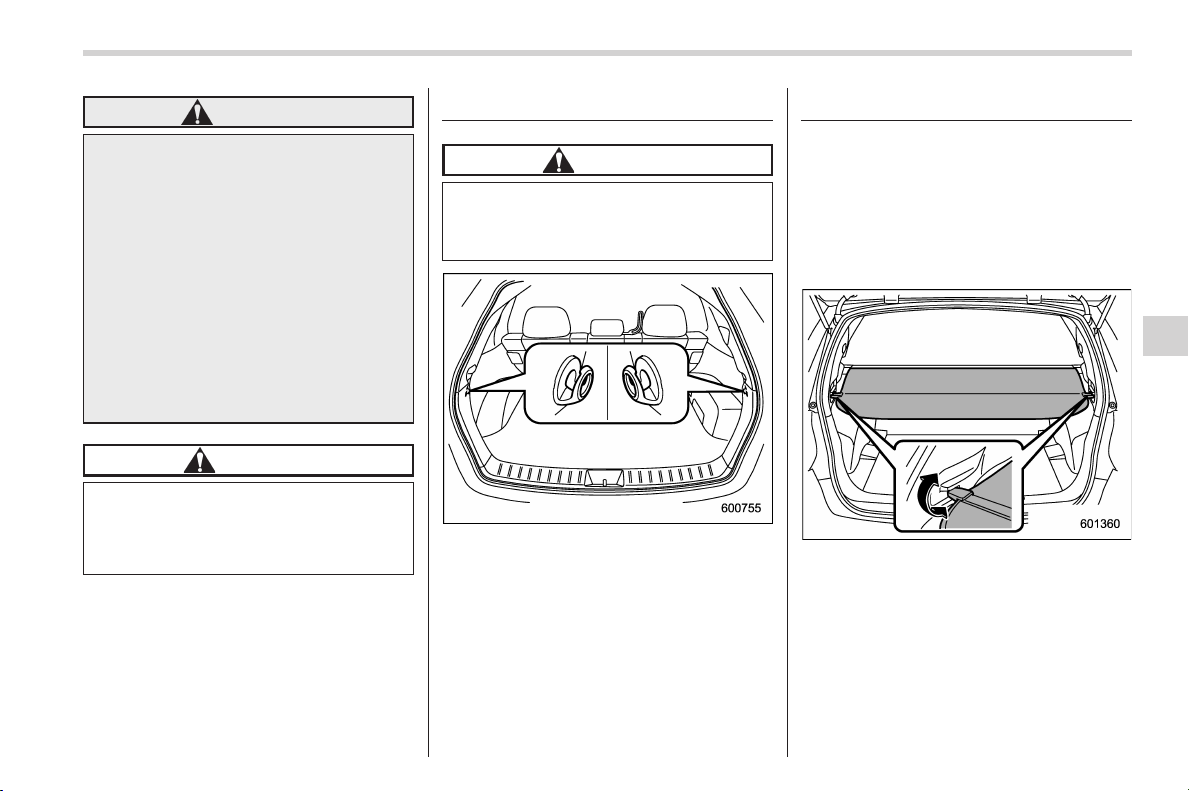
Black plate (321,1)
北米Model "A1160BE-C" EDITED: 2014/ 3/ 17
WARNING
Hang clothing directly on the coat
hooks without using hangers. Do
not hang coat hangers or other hard
or pointed objects on the coat
hooks. If such items are hanging
on the coat hooks, when the SRS
curtain airbags deploy, they could
cause serious injuries by coming off
the coat hooks and being thrown
through the cabin or by preventing
correct airbag deployment. Before
hanging clothing on the coat hooks,
make sure there are no pointed
objects in the pockets.
CAUTION
Never hang anything on the coat
hook that might obstruct the driver’s
view or that could cause injury in
sudden stops or in a collision.
Shopping bag hook
CAUTION
Do not hang items on the shopping
bag hook that weigh 6 lbs (3 kg) or
more.
A shopping bag hook is attached to each
side of the cargo area.
Cargo area cover
The cargo area cover is pr ovided for
covering the cargo area and to protect its
contents from direct sunlight. This cover is
detachable to make room for additional
cargo.
& Using the cover
To extend the cover, pull the end of the
cover out of the housing, then insert its
hooks into the catches as sh own. To
rewind it, unhook it from the catches and
it will rewind automatically. You should
hold on to the cover and guide it back into
the cover housing while it is rewinding.
Interior equipment/Shopping bag hook
6-11
– CONTINUED –
6
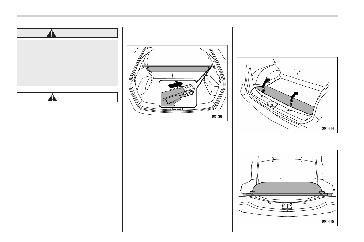
Black plate (322,1)
北米Model "A1160BE-C" EDITED: 2014/ 3/ 17
6-12
Interior equipment/Cargo area cover
WARNING
Do not place anything on the ex-
tended cover. Putting excessive
weight on the extended cover can
break it and an object on the cover
could tumble forward in the event of
a sudden stop or collision. This
could cause serious injury.
CAUTION
Be careful not to scratch the rear
gate stays while extending and
rewinding the cover.
Scratches on the stays could cause
leakage of gas from the stays, which
may result in their inability to hold
the rear gate open.
& To remove the cover housing
1. Rewind the cover.
2. Push the cover housing to the right
side and shorten it.
3. Take it off the retainer.
& Stowage of the cargo area
cover
The cargo area cover can be stowed in
under the cargo floor.
1. Raise and fold the rear end of the
cargo floor board.
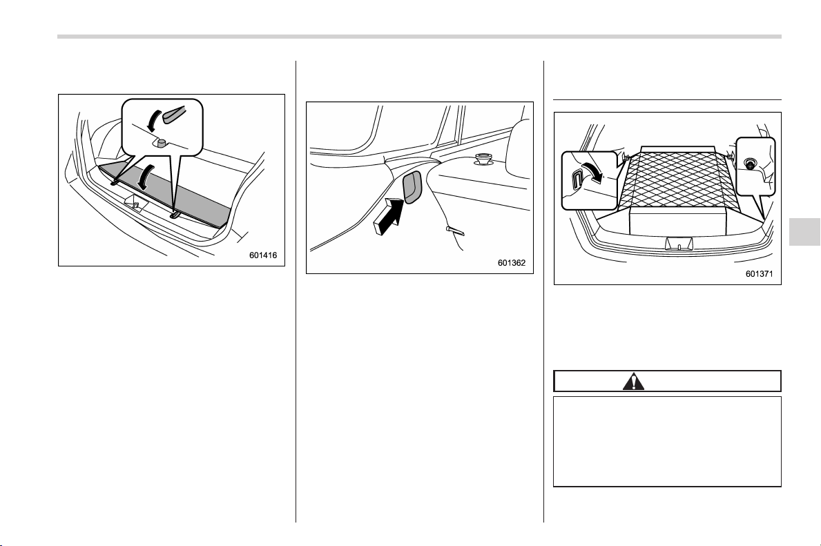
Black plate (323,1)
北米Model "A1160BE-C" EDITED: 2014/ 3/ 17
2. Stow the cover housing in the cargo
area end.
3. Put the cargo floor board back while
hanging two retaining straps on the hooks
that are located on the rear wall of cargo
area.
& To install the cover housing
1. Shorten the cover housing.
2. Insert both ends of the cover housing
into the recesses of the retainers.
Cargo tie-down hooks (if
equipped)
The cargo area is equipped with four tie-
down hooks so that cargo can be secured
with a cargo net or ropes.
When using the front tie-down hooks, turn
them down out of the storing recesses.
CAUTION
The cargo tie-down hooks are de-
signed only for securing light cargo.
Never try to sec ure cargo that
exceeds the capacity of the hooks.
The maximum load capacity is 22
lbs (10 kg) per hook.
Interior equipment/Cargo tie–down hooks
6-13
6
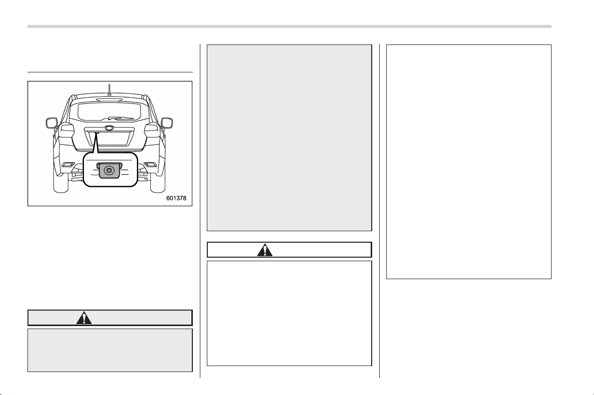
Black plate (324,1)
北米Model "A1160BE-C" EDITED: 2014/ 3/ 17
6-14
Interior equipment/Rear view cam era
Rear view camera (if
equipped)
A rear view camera is attached to the rear
gate. When the ignition switch is “ON” and
the select lever is set to “R”, the rear view
camera automatically displays the rear
view image behind the vehicle on one of
the following displays.
. Navigation display (if equipped)
. Multi function display (if equipped)
. Type B audio display (if equipped)
WARNING
. Since the rear view camera uses
a wide-angle lens, the image on
the monitor is different from the
actual view in terms of distance.
. Since the range of the image on
the monitor is limited, you should
always check the rear view and
the surrounding area with your
eyes and mirrors, and move
backward at a slow speed. Mov-
ing backward only by checking
the rear view image from the
camera could cause an accident.
. Do not disassemble or modify the
camera, switch or wiring. If
smoke comes out or you smell
a strange odor, stop using the
rear view camera immediately.
Contact y our S UBARU dealer
for an inspection. Continued use
may result in accident, fire or
electric shock.
CAUTION
. If your vehicle is washed with a
high-pressure washer, d o not
allow water to contact the camera
directly. Entry o f water in th e
camera lens may result in con-
densation, malfunction, fire or
electric shock.
. Since the camera is a precision
device, do not subject it to strong
impacts. Otherwise, malfunction,
fire or electric shock may occur.
. If mud or snow sticks to or is
frozen on the camera, you must
be very careful when removing it.
Otherwise, damage to the camera
may cause a fire or electric
shock. Pour water or lukewarm
water over the camera to remove
mud and ice, and wipe it with a
soft, dry cloth.
. Do not put a flame close to the
camera or wiring. Otherwise, da-
mage or fire may occur.
. When replacing the fuse, be sure
to use a fuse with the specified
rating. Use of a fuse with a
different rating may result in a
malfunction.
. If the rear view camera is used for
a long time while the engine is
not operated, the battery may
become completely discharged.
NOTE
. Do not wipe the camera with alcohol,
benzine or paint thinner. Otherwise,
discoloration may occur. To remove
contamination, wipe the camera with a
cloth moistened with a diluted neutral
detergent and then wipe it with a soft,
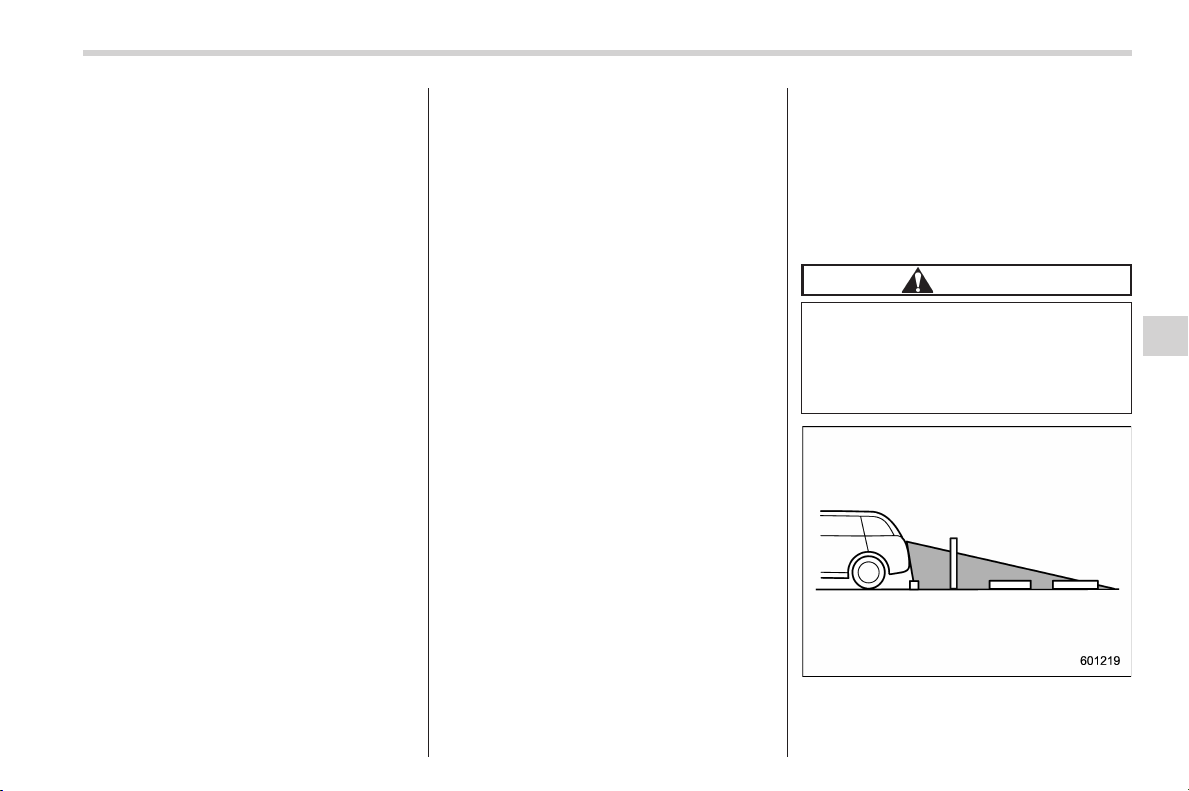
Black plate (325,1)
北米Model "A1160BE-C" EDITED: 2014/ 3/ 17
dry cloth.
. When waxing the vehicle, be careful
not to apply the wax to the camera. If it
comes in contact with the camera,
moisten a clean cloth with a diluted
neutral detergent to remove the wax.
. The camera lens has a hard coating
to help prevent scratches. However,
when washing the vehicle or cleaning
the camera l ens, be careful not to
scratch the camera lens. Do not use a
washing brush directly on the camera
lens. The image quality of the rear view
camera may deteriorate.
. Strong light shined on the camera
lens may develop vertical lines around
the light source. This is not a malfunc-
tion.
. Under fluorescent light, the display
may f licker. However, this is not a
malfunction.
. The image of the rear view camera
may be slightly different from the
actual color of the objects.
. For models with both the multi
function display and type B audio, the
rear view image is displayed on the
type B audio display.
& How to use the rear view
camera
When the select lever is set to “R”, the rear
view camera automatically displays the
rear view image from the vehicle. When
the lever is set to other positions, the
image before setting to “R” is displayed.
1. Set the ignition switch to “ON”.
2. Set the select lever to “R”.
NOTE
. For models with the genuine
SUBARU navigation system, the image
of the rear view camera has priority
over other screen displays. However,
while the navigation system is acti-
vated, the image of the rear view
camera is not displayed.
. The image of the rear view camera is
horizontally reversed as is the case
with the vehicle rear view mirror or the
side view mirror.
. It may be difficult to see the image of
the rear view camera in the following
cases. This is not a malfunction of the
camera.
– The vehicle is in a dark place (at
night, in a tunnel, etc.).
– The vehicle is in an extremely hot
or cold place.
– An object (such as raindrops,
snow, dirt, etc.) that disturbs the
view of the rear view camera sticks
to the lens of the camera.
– Strong light shined directly on
the camera lens (occasionally, there
are vertical lines on the screen).
& Viewing range on the screen
CAUTION
The range that can be viewed with
the r ear view camera is limited.
Always be sure to check with your
eyes when moving backward and
proceed slowly.
Range of view
Interior equipment/Rear view camera
6-15
– CONTINUED –
6
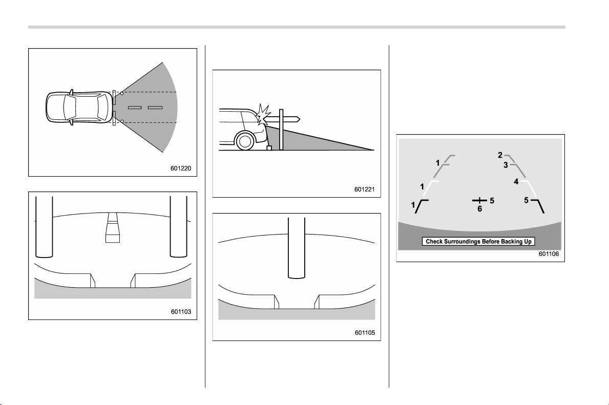
Black plate (326,1)
北米Model "A1160BE-C" EDITED: 2014/ 3/ 17
6-16
Interior equipment/Rear view cam era
Range of view
Image from camera
The area from the rear end of the bumper
can be viewed. Areas at both ends of the
bumper and areas just under the bumper
cannot be viewed.
Also, the image from the rear view camera
looks shorter than the actual distance.
Range of view
Image from camera
The area above the camera cannot be
viewed. If there is an object that has a
wide projection on its upper part such as a
sign pole behind the vehicle, the projec-
tion cannot be seen on the screen.
& Help line
The help line (distance marker and vehicle
width line) is a guide to help you realize
the actual distance from the screen image.
1) Vehicle width line (oblique vertical line)
2) Approx. 10 feet (3 m) from the bumper
(green horizontal line)
3) Approx. 6.5 feet (2 m) from the bumper
(green horizontal line)
4) Approx. 3 feet (1 m) from the bumper
(yellow horizontal line)
5) Approx. 1.5 feet (0.5 m) from the bumper
(red horizontal line)
6) Vehicle centerline
When the select lever is set to position
“R”, the monitor screen displays the help
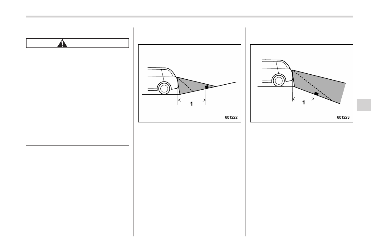
Black plate (327,1)
北米Model "A1160BE-C" EDITED: 2014/ 3/ 17
lines together with the rear view image.
CAUTION
. When moving backward, always
check the back with your eyes
without relying on the help lines.
. The actual position may be dif-
ferent from the indication of the
help lines.
. Differences may occur due to
number of passengers or loaded
cargo.
. When the vehicle is on a slope or
when the vehicle is inclined
against the road, the indication
is different from the actual posi-
tion.
! Difference between screen image
and actual road
The distance markers show the distance
for a level road when the vehicle is not
loaded. It may be different from the actual
distance depending on the loading condi-
tions or road conditions.
! When there is an upward slope at
the back
1) 3 feet (1 m)
The distance on the screen looks farther
than the actual distance.
! When there is a downward slope
at the back
1) 3 feet (1 m)
The distance on the screen looks nearer
than the actual distance.
NOTE
When cargo is loaded, the rear view
distance on the screen looks farther
thantheactualdistanceasinan
upward slope.
Interior equipment/Rear view camera
6-17
– CONTINUED –
6
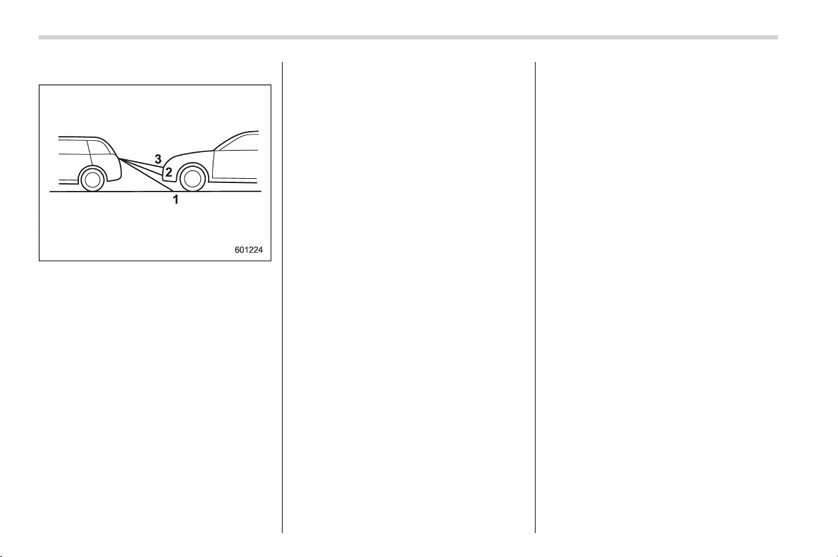
Black plate (328,1)
北米Model "A1160BE-C" EDITED: 2014/ 3/ 17
6-18
Interior equipment/Rear view cam era
! Feature of distance marker
1) 3 feet (1 m) line
2) 6.5 feet (2 m) line
3) 10 feet (3 m) line
The distance marker shows the distance
on the road. If there is a car or other object
close behind, distance cannot be correctly
displayed.

Black plate (13,1)
北米Model "A1160BE-C" EDITED: 2014/ 3/ 17
Fuel ...................................................................... 7-3
Fuel requirements ............................................... 7-3
Fuel filler lid and cap........................................... 7-4
State emission tes ting (U.S. only)...................... 7-7
Preparing to drive ............................................... 7-8
Starting and stopping the hybrid system.......... 7-8
General precautions when starting the hybrid
system.............................................................. 7-8
Models without “keyless access with push-button
start system” .................................................... 7-9
Models with “keyless access with push-button
start system” ................................................... 7-10
Remote engine start system (if equipped) ....... 7-13
System operations ............................................. 7-13
Entering the vehicle while it is running via remote
start................................................................. 7-14
Entering the vehicle following remote engine start
shutdown......................................................... 7-14
Pre-heating or pre-cooling the interior of the
vehicle ............................................................. 7-15
System maintenance .......................................... 7-15
Continuously variable transmission ................. 7-15
Continuously variable transmission features....... 7-15
Select lever ........................................................ 7-16
Selection of manual mode .................................. 7-18
Shift lock function .............................................. 7-19
Driving tips ........................................................ 7-20
Power steering ................................................... 7-20
Power steering warning light .............................. 7-20
Power steering system features .......................... 7-21
Braking ............................................................... 7-21
Braking tips....................................................... 7-21
Brake system .................................................... 7-22
Disc brake pad wear warning indicators ............. 7-22
ABS (Anti-lock Brake System).......................... 7-23
ABS system self-check ...................................... 7-23
ABS warning light.............................................. 7-23
Electronic Brake Force Distribution (EBD)
system ............................................................. 7-24
Steps to take if EBD system malfunctions ... ....... 7-24
Vehicle Dynamics Control system.................... 7-25
Safety precautions............................................. 7-25
System features................................................. 7-26
Vehicle Dynamics Control system monitor.......... 7-26
Vehicle Dynamics Control OFF switch ................ 7-27
Tire pressure monitoring system (TPMS)
(U.S.-spec. models)......................................... 7-28
Parking your vehicle ......................................... 7-29
Parking brake .................................................... 7-29
Parking tips ....................................................... 7-29
Hill start assist system...................................... 7-30
System features................................................. 7-30
To activate/deactivate the Hill start assist
system ............................................................ 7-32
Hill start assist warning light/Hill start assist OFF
indicator light .................................................. 7-33
Cruise control (if equipped) .............................. 7-33
To set cruise control .......................................... 7-34
To temporarily cancel the cruise control ............. 7-35
Starting and operating
7

Black plate (14,1)
北米Model "A1160BE-C" EDITED: 2014/ 3/ 17
Starting and operating
To turn off the cruise control .............................. 7-35
To change the cruising speed............................. 7-35
Cruise control indicator light .............................. 7-37
Cruise control set indicator light ........................ 7-37
Black plate (333,1)
北米Model "A1160BE-C" EDITED: 2014/ 3/ 17
Fuel
CAUTION
Use of a fuel which is low in quality
or use of an inappropri ate fuel
additive may cause engine damage.
& Fuel requirements
The engine is designed to operate using
unleaded gasoline with an octane rating
of 87 AKI (90 RON) or higher.
! Fuel octane rating
This octane rating is the average of the
Research Octane a nd Motor Octane
numbers and is commonly referred to as
the Anti Knock Index (AKI).
Using a gasoline with a lower octane
rating can cause persistent and heavy
knocking, which can damage the engine.
Do not be concerned if your vehicle
sometimes knocks lightly when you drive
up a hill or when you accelerate. Contact
your SUBARU dealer if you use a fuel with
the specified octane rating and y our
vehicle knocks heavily or persistently.
! Unleaded gasoline
The neck of the fuel filler pipe is designed
to accept only an unleaded gasoline filler
nozzle. Under no circumstances should
leaded gasoline be used because it will
damage the emission control system and
may impair driveability and fuel economy.
! Gasoline for California-certified
LEV
If your vehicle was certified to California’s
low emission vehicle (LEV) standards as
indicated on the underhood tune-up label,
it is designed to optimize engine and
emission performance with gasoline that
meets the clean burning low-sulfur Cali-
fornia gasoline specifications. If you live in
any other state than California, your
vehicle will operate on gasoline meeting
Federal specifications. Gasoline sold out-
side California is permitted to have higher
sulfur levels, which may affect the perfor-
mance of your vehicle’s catalytic converter
and may produce a sulfur exhaust odor or
smell. SUBARU recommends that you try
a different brand of unleaded gasoline
having lower sulfur to determine if the
problem is fuel related before returning
your vehicle to an authorized dealer for
service.
! MMT
Some gasoline contains an octane-en-
hancing additive called MMT (Methylcy-
clopentadienyl Manganese Tricarbonyl). If
you use such fuels, your emission control
system performance may deteriorate and
the CHECK ENGINE warning light/Mal-
function indicator light may turn on. If this
happens, return to your authorized
SUBARU Dealer for servi ce. If it is
determined that the condition is caused
by the type of fuel used, repairs may not
be covered by your warranty.
! Gasoline for cleaner air
Your use of gasoline with detergent
additives will help prevent deposits from
forming in your engine and fuel system.
This helps keep your engine in tune and
your emission control system working
properly, and is a way of doing your part
for cleaner air. If you continuously use a
high quality fuel with the proper detergent
and other additives, you should never
need to add any fuel system cleaning
agents to your fuel tank.
Many gasolines are now blended with
materials called oxygenates. Use of these
fuels can also help keep the air cleaner.
Oxygenated blend fuels, such as MTBE
(Methyl Tertiary Butyl ether) or ethanol
(ethyl or grain alcohol) may be used in
your vehicle, but should contain no more
than 15% MTBE or 10% ethanol for the
proper operation of your SUBARU.
Do not use any gasoline that contains
more than 10% ethanol, including from
Starting and operating/Fuel
7-3
– CONTINUED –
7
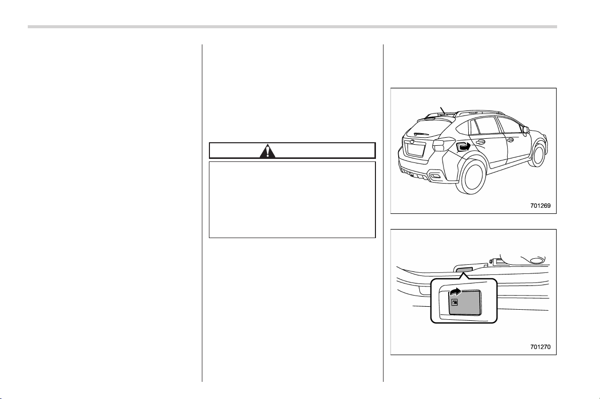
Black plate (334,1)
北米Model "A1160BE-C" EDITED: 2014/ 3/ 17
7-4
Starting and operating/Fuel
any pump labeled E15, E30, E50 or E85
(which are only some examples of fuel
containing more than 10% ethanol).
In addition, some gasoline suppliers are
now producing reformulated gaso lines,
which ar e designed to reduce vehicle
emissions. SUBARU approves the use of
reformulated gasoline.
If you are not sure what the fuel contains,
you should ask your service station
operators if their gasolines contain deter-
gents and oxygenates and if they have
been reformulated to reduce vehicle emis-
sions.
As additional guidance, only use fuels
suited for your vehicle as explained in the
following description.
. Fuel should be unleaded and have an
octane rating no lower than that specified
in this manual.
. Methanol (methyl or wood alcohol) is
sometimes mixed with unleaded gasoline.
Methanol can be used in your vehicle
ONLY if it does not exceed 5% of the fuel
mixture AND if it is accompanied by
sufficient quantities of the proper cosol-
vents and corrosion inhibitors required to
prevent damage to the fuel system. Do not
use fuel containing methanol EXCEPT
under these conditions.
. If undesirable driveability problems are
experienced and you suspect they may be
fuel related, try a different brand of gaso-
line b efore seeking service at your
SUBARU dealer.
. Fuel system damage or driveability
problems which result from the use of
improper fuel are not covered under the
SUBARU Limited Warranty.
CAUTION
Do not let fuel spill on the exterior
surfaces o f the vehicle. Because
fuel may damage the paint, be sure
to wipe off any spilled fuel quickly.
Paint damage caused by spilled fuel
is not covered under the SUBARU
Limited Warranty.
& Fuel filler lid and cap
! Locations of the fuel filler lid and
the lid release lever
Fuel filler lid
Fuel filler lid release lever
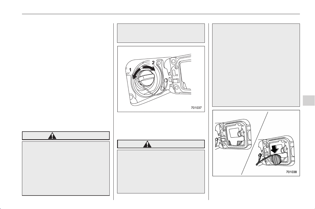
Black plate (335,1)
北米Model "A1160BE-C" EDITED: 2014/ 3/ 17
! Refueling
Only one person should be involved in
refueling. Do not allow others to approach
the area of the vehicle near the fuel filler
pipe while refueling is in progress.
Be sure to observe any other precautions
that are posted at the service station.
1. Stop the vehicle and turn the ignition
switch to the “LOCK” (off) position and
turn off all the other electrical components.
NOTE
When the ignition switch is turned to
the “LOCK” (off) position, the hybrid
system stops and the hybrid READY
indicator light turns off.
2. To open the fuel filler lid, pull the lid
release lever up. The lever is on the floor
at the left of the driver’s seat.
WARNING
Before opening the fuel filler cap,
first touch the vehicle body or a
metal portion of the fuel pump or
similar o bject to discharge any
static electricity that may be present
on your body. If your body is carry-
ing an electrostatic charge, there is
a possibility that an electric spark
could ignite the fuel, which could
burn you. To avoid acquiring a new
static electric charge, do not get
back into the vehicle while refueling
is in progress.
1) Open
2) Close
3. Remove the fuel filler cap by turning it
slowly counterclockwise.
WARNING
. Gasoline vapor is highly flam-
mable. Before refueling, always
turn the ignition switch to the
“LOCK” (off) position first and
then close all vehicle doors and
windows. Make sure that there
are no lighted cigarettes, open
flames or electrical sparks in the
adjacent area. Only handle fuel
outdoors. Quickly wipe up any
spilled fuel.
. When opening the cap, grasp it
firmly and turn it slowly to the
left. Do not remove the cap
quickly. Fuel may be under pres-
sure and spray out of the fuel
filler neck, especially in hot
weather. If you hear a hissing
sound while you are removing
the cap, wait for the sound to
stop and then slowly open the
cap to prevent fuel from spraying
out and creating a fire hazard.
4. Set the fuel filler cap on the cap holder
inside the fuel filler lid.
Starting and operating/Fuel
7-5
– CONTINUED –
7
Black plate (336,1)
北米Model "A1160BE-C" EDITED: 2014/ 3/ 17
7-6
Starting and operating/Fuel
WARNING
. When refueling, insert the fuel
nozzle securely into the fuel filler
pipe. If the nozzle is lifted or not
fully inserted, its automatic stop-
ping mechanism may not func-
tion, causing fuel to overflow the
tank and creating a fire hazard.
. Stop refueling when the auto-
matic stop me chanism on the
fuel nozzle activates. If you con-
tinue to add fuel, temperature
changes or other conditions
may cause fuel to overflow from
the tank and create a fire hazard.
5. Stop filling the tank after the fuel filler
pump automatically stops. Do not add any
more fuel.
6. Put the cap back on, turn it clockwise
until you hear a clicking noise. Be certain
not to catch the tether under the cap while
tightening.
7. Close the fuel filler lid completely.
If you spill any fuel on the painted surface,
rinse it off immediately. Otherwise, the
painted surface could be damaged.
NOTE
. You will see the “ ” sign in the fuel
gauge. This indicates that the fuel filler
door (lid) is located on the right side of
the vehicle.
. If the fuel filler cap is not tightened
until it clicks or if the tether is caught
under the cap, the CHECK ENGINE
warning li ght/malfunction indicator
light may illuminate. Refer to “CHECK
ENGINE warning light/Malfunction in-
dicator light” F3-15.
CAUTION
. Never add any cleaning agents to
the fuel tank. The addition of a
cleaning agent may cause da-
mage to the fuel system.
. After refueling, turn the cap to the
right until it clicks to ensure that
it is fully tightened. If the cap is
not securely tightened, fuel may
leak out while the vehicle is being
driven or fuel spillage could
occur in the event of an accident,
creating a fire hazard.
. Do not let fuel spill on the exterior
surfaces of the vehicle. Because
fuel may damage the paint, be
sure to wipe off any spilled fuel
quickly. Paint damage caused by
spilled fuel is not covered under
the SUBARU Limited Warranty.
. Always use a genuine SUBARU
fuel filler cap. If you use the
wrong cap, it may not fit or have
proper venting and your fuel tank
and emission control system
may be damaged. It could also
lead to fuel spillage and a fire.
. Immediately put fuel in the tank
whenever the low fuel warning
light illuminates. Engine misfires
as a result of an empty tank
could cause damage to the en-
gine.
Black plate (337,1)
北米Model "A1160BE-C" EDITED: 2014/ 3/ 17
State emission testing (U.S.
only)
WARNING
Testing of an All-Wheel Drive model
must NEVER be performed on a
single two-wheel dynamometer. At-
tempting to do so will result in
uncontrolled vehicle movement and
may cause an accident or injuries to
persons nearby.
CAUTION
. At state inspection time, remem-
ber to tell your in spect ion or
service station in advance not to
place your SUBARU AWD vehicle
on a two-wheel dynamometer.
Otherwise, serious transmission
damage will result.
. Resultant vehicle damage due to
improper testing is not covered
under the SUBARU Limited War-
ranty and is the responsibility of
the state inspection program or
its contractors or licensees.
California and a number of federal states
have Inspection/Maintenance programs to
inspect your vehicle’s emission control
system. If your vehicle does not pass this
test, some states may deny renewal of
your vehicle’s registration.
Your vehicle is equipped with a computer
that monitors the performance of the
engine’s emission control system. Certi-
fied emission inspectors will inspect the
On-Board Diagnostic (OBDII) system as
part of the state emission inspection
process. The OBDII system is designed
to detect engine and transmission pro-
blems that might cause the vehicle emis-
sions to exceed allowable limits. OBDII
inspections apply to all 1996 model year
and newer passenger cars and trucks.
Over 30 states plus the District of Colum-
bia have implemented emission inspec-
tion of the OBDII system.
. The inspection of the OBDII system
consists of a visual operational check of
the “CHECK ENGINE” warning light/mal-
function indicator light (MIL) and an
examination of the OBDII system with an
electronic scan tool.
. A vehicle
passes the OBDII system
inspection if proper operation of the
“CHECK ENGINE” warning light is ob-
served, there are no stored diagnostic
trouble codes, and the OBDII readiness
monitors are all complete.
. A vehicle
fails the OBDII inspection if
the “CHECK ENGINE” warning light is not
properly operating (light is illuminated or is
not working due to a burned out bulb) or
there is one or more diagnostic trouble
codes stored in the vehicle’s computer.
. A state emission inspection may reject
(not pass or fail) a vehicle if the number of
OBDII system readiness monitors “NOT
READY” is greater than one. If the
vehicle’s battery has been recently re-
placed or disconnected, the OBDII system
inspection may indicate that the vehicle is
not ready for the emission test. Under this
condition, the vehicle driver should be
instructed to drive his/her vehicle for a few
days to reset the readiness monitors and
return for an emission re-inspection.
. Owners of rejected or failing vehicles
should contact their SUBARU Dealer for
service.
Some states still use dynamometers in
their emission inspection program. A
dynamometer is a treadmill or roller-like
testing device that allows your vehicle’s
wheels to turn while the vehicle remains in
one place. Prior to your vehicle being put
on a dynamometer, tell you r emission
inspector
not to place your SUBARU
AWD vehicle on a two-wheel dynam-
ometer. Otherwise, serious transmis-
sion damage will result.
Starting and operating/State emission testing (U.S. only)
7-7
– CONTINUED –
7
Black plate (338,1)
北米Model "A1160BE-C" EDITED: 2014/ 3/ 17
7-8
Starting and operating/Preparing to drive
The U.S. Environmental Protection
Agency (EPA) and states using two-wheel
dynamometers in their emission testing
program have EXEMPTED SUBARU
AWD vehicles from the portion of the
testing program that involves a two-wheel
dynamometer. There are some states that
use four-wheel dynamometers in their
testing program. When properly used, this
equipment should not damage a SUBARU
AWD vehicle.
Under no circumstances should the rear
wheels be jacked off the ground, nor
should the driveshaft be disconnected for
state emission testing.
Preparing to drive
You should perform the following checks
and adjustments every day before you
start driving.
1. Check that all windows, mirrors, and
lights are clean and unobstructed.
2. Check the appearance and condition
of the tires. Also check tires for proper
inflation.
3. Look under the vehicle for any sign of
leaks.
4. Check that the hood and rear gate are
fully closed.
5. Check the adjustment of the seat.
6. Check the adjustment of the inside
and outside mirrors.
7. Fasten your seatbelt. Check that your
passengers have fastened their seatbelts.
8. Check the operation of the warning
and indicato r lig hts when th e ign itio n
switch is turned to the “ON” position.
9. Check the gauges, indicator and warn-
ing lights after starting the hybrid system.
NOTE
Engine oil, engine coolant, brake fluid,
washer fluid and other fluid levels
should be checked daily, weekly or at
fuel stops.
Starting and stopping the
hybrid system
The main power source of this vehicle is
the engine. The electric motor supports
the engine. When the engine starts, the
hybrid system will start.
& General precautions when
starting the hybrid system
WARNING
. Never start the hybrid system
from outside the vehicle (except
when using the remote engine
start system). It may result in an
accident.
. Do not leave the hybrid system
running in an enclosed environ-
ment with poor ventilation (e.g.,
in a closed garage). Prolonged
operation of a electric m otor
vehicle in an enclosed environ-
ment can cause a harmful build-
up of exhaust gas, which con-
tains carbon monoxide. Carbon
monoxide is harmful to your
health. Exposure to carbon mon-
oxide can cause headaches, diz-
ziness or in extreme cases, un-
Black plate (339,1)
北米Model "A1160BE-C" EDITED: 2014/ 3/ 17
consciousness and/or death.
. Do not start the hybrid system
near dry foliage, paper, or other
flammable substances. When the
engine is running, the exhaust
pipe and exhaust emissions can
create a fire hazard at high
temperatures.
CAUTION
. If the hybrid system is stopped
during driving, the catalyst may
overheat and burn.
. When starting the hybrid system,
be sure to sit in the driver’s seat
(except when using the remote
engine start system).
. If the hybrid READY indicator
light does not illuminate even
after the engine has started, have
the vehicle inspected by a
SUBARU dealer.
NOTE
. Avoid rapid racing and rapid accel-
eration im mediately after the hybrid
system has started.
. For a short time after the hybrid
system has started, the engine speed is
kept high. When the warm-up is com-
pleted, the engine speed lowers auto-
matically.
. On rare occasions, it may be difficult
to start the hybrid system depending
on the fuel and the usage condition
(repeated driving of a distance in which
the engine has not warmed up suffi-
ciently). In such a case, it is recom-
mended that you change to a different
brand of fuel.
. On rare occasions, transient knock-
ing may be heard from the engine when
the accelerator is operated rapidly
such as a rapid start-up and a rapid
acceleration. This is not a malfunction.
. The hybrid system may not start
immediately after the terminal of the 12
V auxiliary battery has bee n recon-
nected when replacing the 12 V aux-
iliary battery, etc. In this case, set the
ignition switch to the “ON” position
and start the hybrid system after over
10 seconds have passed. Idling may be
unstable immediately after the hybrid
system has started but this is not a
malfunction.
. The remaining power of the high
voltage battery may decrease when the
hybrid system has been stopped over-
night in a state where it is sufficiently
charged. However, this is a result of the
high voltage battery self-discharge and
is not a malfunction.
. If the accelerator pedal is depressed
while the vehicle is stopped, the engine
speed will not increase to a high rate of
revolution.
. You may not restart t he hybrid
system immediately after turning the
ignition switch to the “LOCK” (off)
position while the engine has been
automatically stopped. In such a case,
wait a few seconds and then perform
the starting procedure.
& Models without “keyless ac-
cess with push-button start
system”
! Starting the hybrid system
1. Apply the parking brake.
2. Turn off unnecessary lights and ac-
cessories.
3. Shift the select lever to the “P” or “N”
position (preferably the “P” position). The
starter motor will only operate when the
select lever is at the “P” or “N” position.
4. Turn the ignition switch to the “ON”
position and check the operation of the
warning and i ndicator lights. Refer to
“Warning and indicator lights” F3-12.
5. Turn the ignition switch to the “START”
position without depressing the accelera-
tor pedal. Release the key immediately
Starting and operating/Starting and stopping the hybrid system
7-9
– CONTINUED –
7
Black plate (340,1)
北米Model "A1160BE-C" EDITED: 2014/ 3/ 17
7-10
Starting and operating/Starting and stopping the hybrid system
after the engine has started. If the hybrid
system is started up after the engine has
been started, the hybrid READY indicator
light on the combination meter will illumi-
nate.
If the hybrid system does not start, try the
following.
(1) Turn the ignition switch to the
“LOCK” (off) position and wait for at
least 30 seconds. After checking that
the parking brake is firmly set, turn the
ignition switch to the “START” position
while depressing the accelerator pedal
slightly (approximately a quarter of the
full stroke). Release the accelerator
pedal as soon as the engine starts.
(2) If this fails to start the engine, turn
the ignition switch back to the “LOCK”
(off) position and wait for at least 30
seconds. Then fully depress the accel-
erator peda l and turn the ignition
switch to the “START” position. If the
engine s tarts, qu ickly r elease the
accelerator pedal.
(3) If this fails to start the engine, turn
the ignition switch again to the “LOCK”
(off) position. After waiting for 30
seconds or longer, turn the ignition
switch to the “START” position without
depressing the accelerator pedal.
(4) If the engine still refuses to start,
contact your nearest SUBARU dealer
for assistance.
6. Confirm that all warning and indicator
lights ( except hybrid READY indicator
light) have turned off after the engine has
started. The fuel injection system auto-
matically lowers the idle speed as the
engine warms up.
While the engine is warming up, make
sure that the select lever is at the “P” or
“N” position and that the parking brake is
applied.
CAUTION
Do not operate the starter motor
continuously for more than 10 sec-
onds. If the engine fails to start after
operating the st arter for 5 to 10
seconds, wait for 10 seconds or
more before trying again.
NOTE
If you have to start the engine while
depressing the accelerator pedal when
the engine is having difficulties start-
ing, switch to the brake pedal immedi-
ately after starting.
! Stopping the hybrid system
The ignition switch should be turned to the
“LOCK” (off) position only w hen the
vehicle is stopped, the select lever is in
the “P” position and the engine is idling or
stopped automatically.
WARNING
Do not stop the hybrid system when
the vehicle is moving. This will
cause loss of power to the power
steering and the brake booster,
making steering and braking more
difficult. I t could also result in
accidental activation of the “LOCK”
(off) position on the ignition switch,
causing the steering wheel to lock.
& Models with “keyless access
with push-button start sys-
tem”
! Safety precautions for “keyless
access with push-button start sys-
tem”
Refer to “Safety precautions” F2-10.
! Operating range for push-button
start system
Refer to “Operating range for push-button
start system” F3-5.
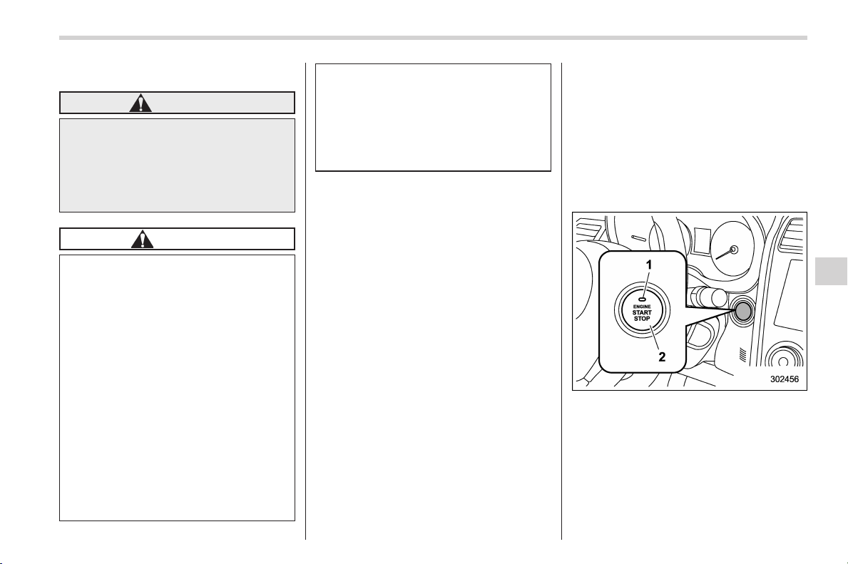
Black plate (341,1)
北米Model "A1160BE-C" EDITED: 2014/ 3/ 17
! Starting the hybrid system
WARNING
Never drive the vehicle if the indi-
cator on the push-button ignition
switch flashes in green after the
hybrid system has started. The
steering is still locked, and it may
result in an accident.
CAUTION
. When the operation indicator on
the push-button ignition switch
flashes in orange, there may be a
malfunction in the vehicle. Con-
tact a SUBARU dealer immedi-
ately.
. If the indicator on the push-
button ignition switch flashes in
green after the hybrid system has
started, it means that the steering
is still locked. Depress the brake
pedal while moving the steering
wheel to the right and left, and
press the push-button ignition
switch.
. Do not continue pushing the
push-button ignition switch for
more than 10 seconds. Doing so
could cause a malfunction. If the
hybrid system does not start,
stop pushing the push-button
ignition switch. Wait 10 seconds,
and then push the push-button
ignition switch to start the hybrid
system.
NOTE
. When the push-button ignition
switch is pressed while depressing
thebrakepedal,theenginestarter
operates for a maximum of 10 seconds
and after starting the engine, the starter
stops automatically.
. When the push-button ignition
switch is pressed while depressing
the brake pedal, the hybrid system
can be started regardless of the status
of the push-button ignition switch.
. If the security indicator light illumi-
nates when you attempt to start the
hybrid system but the system does not
start, press the push-button ignition
switch to switch the power to off and
then try to start the hybrid system
again.
. If the hybrid system does not start,
press the push-button ignition switch
without depressing the brake pedal to
switch the power to off. Then, while
depressing the brake pedal more for-
cefully, press the push-button ignition
switch.
. The hybrid system start procedures
may not function depending on the
radio wave conditions around the ve-
hicle. In such a case, refer to “Starting
hybrid system” F9-24.
. If the 12 V auxiliary battery is run
down, the steering cannot be unlocked.
Charge the battery.
When the push-button ignition switch is
pressed while depressing the brake pedal,
the engine will start. If the hybrid system
starts after the engine has started, the
hybrid READY indicator light on the
combination m eter will illuminate. The
starting procedure is as follows.
1. Carry the access key, and sit in the
driver’s seat.
Starting and operating/Starting and stopping the hybrid system
7-11
– CONTINUED –
7
Black plate (342,1)
北米Model "A1160BE-C" EDITED: 2014/ 3/ 17
7-12
Starting and operating/Starting and stopping the hybrid system
2. Apply the parking brake.
3. Shift the select lever into the “P”
position.
CAUTION
The hybrid system can also start
when the select lever is in the “N”
position, however, for safety rea-
sons, start in the “P” position.
4. Depress the brake pedal until the
operation i ndicator on the push-button
ignition switch turns green. When starting
with the select lever in the “N” position, the
indicator does not turn green.
5. While depressing the brake pedal,
press the push-button ignition switch.
NOTE
. While pressing the select lever but-
ton in, the indicator on the push-button
ignition switch will not turn green even
when the select lever is in the “P”
position.
. In case the hybrid system does not
start by the normal start procedure,
move the select lever to the “P” posi-
tion, and switch the power to “ACC”.
Depress the brake pedal, and press the
push-button ignition switch for at least
15 seconds. The hybrid system may
start. Only use this start procedure in
case of emergency.
. W hen the hybrid sys tem i s not
started, the brake pedal may feel stiff.
In such a case, depress the brake pedal
more forcefully than usual. Check that
the operation indicator on the push-
button ignition switch turns green, and
press the push-button ignition switch
to start the hybrid system.
! Stopping the hybrid system
1. Stop the vehicle completely.
2. Move the select lever to the “P”
position.
3. Press the push-button ignition switch.
The hybrid system will stop, and the power
will be switched off.
WARNING
. Do not touch t he push-button
ignition switch during driving.
When the push-button ignition
switch is operated as follows,
the hybrid system will stop.
— The switch is pressed and
held for 3 seconds or longer.
— The switch is pressed briefly 3
times or more in succession.
When the hybrid system stops,
the brake booster will not func-
tion. Greater foot pressure will be
required on the brake pedal.
The power steering system will
not operate either. Greater force
will be required to steer, and it
may result in an accident.
. If the hybrid system stops during
driving, do not operate the push-
button ignition switch or open
any of the doors until the vehicle
is stopped in a safe location. It is
dangerous because the steering
lock may be activated. Stop the
vehicle in a safe place, and
contact a SUBARU dealer imme-
diately.
CAUTION
Do not stop the hybrid system while
the select lever is in a position other
than the “P” position. If the hybrid
system is stopped while the select
lever is in a position other than the
“P” position, the power will be in
“ACC”. If the vehicle is left in this
condition, the 12 V auxiliary battery
may be discharged.
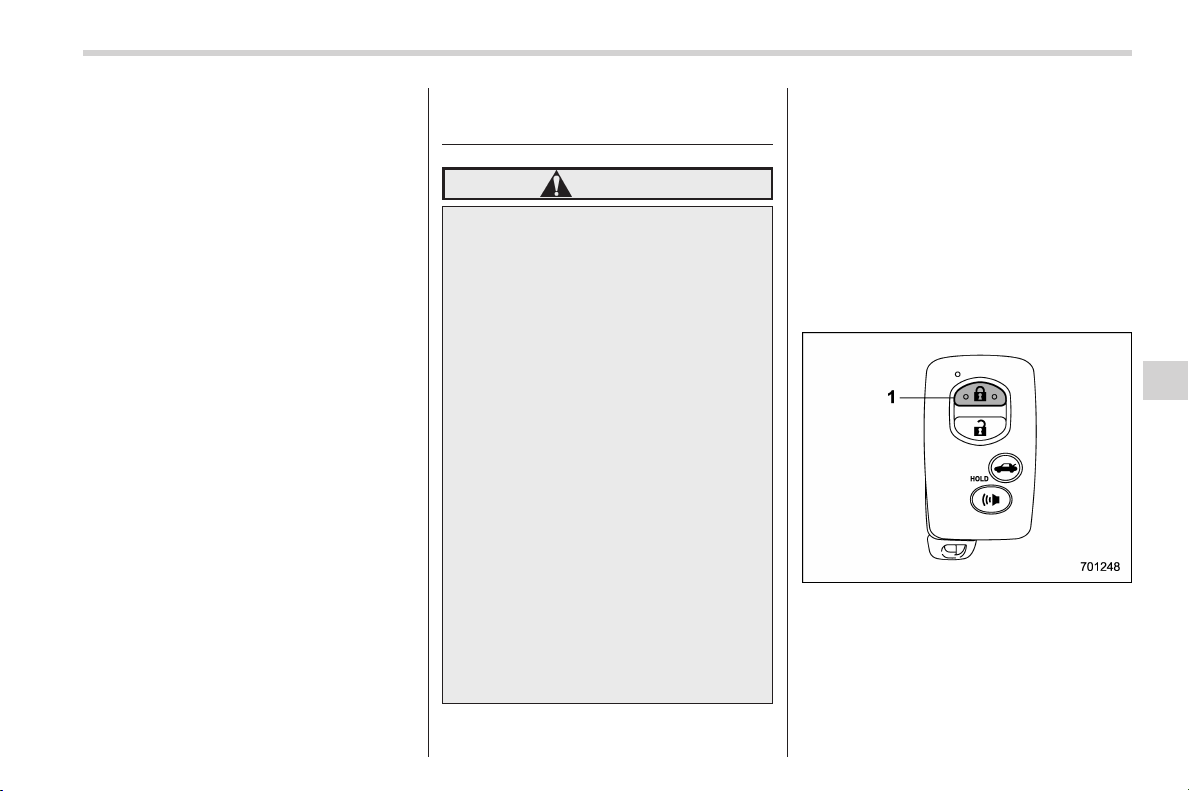
Black plate (343,1)
北米Model "A1160BE-C" EDITED: 2014/ 3/ 17
NOTE
Although you can stop the hybrid
system by operating the push-button
ignition switch, do not stop the hybrid
system during driving except in an
emergency.
! When access key does not operate
properly
Refer to “Starting hybrid system” F9-24.
Remote engine start system
(if equipped)
WARNING
. There are some general precau-
tions when starting the engine
(hybrid system). Carefully read
the pre cautions desc ribed in
“General precautions when start-
ing the hybrid system” F7-8.
. Do not remote start a vehicle in
an enclosed environment (e.g.
closed garage). Prolonged opera-
tion of a electric motor vehicle in
an enclosed environment can
cause a harmful build-up of Car-
bon Monoxide. Carbon Monoxide
is harmful to your health. Expo-
sure to high levels of Carbon
Monoxide can cause headaches,
dizziness or in extreme cases
unconsciousness and/or death.
. Before performing any servicing
of the vehicle, temporarily place
the remote engine start system in
service mode to preven t the
system from unexpectedly start-
ing the engine.
The remote engine start system allows
you to start the engine (hybrid system)
from outside the vehicle. In addition, the
remote engine start system can activate
the heater or air conditioner, providing you
with a comfortable cabin upon entry.
& System operations
NOTE
For more details, refer to the Owner ’s
Manual supplement for the remote
engine start system.
Access key
1) Lock button
An access key can be used as the remote
engine start transmitter. Operate the lock
button to start or stop the hybrid system as
follows.
Starting and operating/Remote engine start system
7-13
– CONTINUED –
7

Black plate (344,1)
北米Model "A1160BE-C" EDITED: 2014/ 3/ 17
7-14
Starting and operating/Remote engine start system
! Before starting the hybrid system
Before using the remote engine start
system to start the hybrid system, confirm
the following conditions.
. The select lever is in the “P” position.
. All doors including the rear gate are
closed.
. The engine hood is closed.
. The push-button ignition switch is in the
“OFF” position.
! Starting the hybrid system
To start the hybrid system with remote
engine start system, briefly press the lock
button twice within 2 seconds, then press
and hold the lock button for 3 seconds.
1. Press the lock button briefly. The
hazard warning flashers then flash once.
2. Within 2 seconds, press the lock
button briefly again. The hazard warning
flashers then flash once again.
3. After step 2, immediately press and
hold the lock button. The hazard warning
flashers then flash once.
4. Approximately 3 seconds after step 3,
release the lock button. The hybrid system
will then start successfully.
! Stopping the hybrid system
Press and hold the lock button to stop the
hybrid system with remote engine start
system.
! Automatic engine shutdown
Theremoteenginestartsystemwill
automatically shut down or will not start
the hybrid system under the fol lowing
conditions.
. The total run-time has exceeded 20
minutes.
. Any door or the rear gate is opened.
. The select lever is moved to any
position other than “P”.
. The engine hood is opened.
. Thepush-buttonignitionswitchis
pressed.
. The brake pedal is depressed.
. The engine speed is 3,000 rpm or
more.
The time setting until the hybrid system
automatically stops can be changed. To
change it, please contact your SUBARU
dealer. Note that some settings may
violate state, provincial, or local laws and
regulations. Check the laws in your area to
determine which setting is permitted.
& Entering the vehicle while it
is running via remote start
1. Unlock the vehicle doors using the
keyless access function or remote keyless
entry system. If the vehicle’s doors are
unlocked manually using the key, the
vehicle’s alarm system will trigger (if the
alarm system is armed prior to activating
the remote engine start system) and the
hybrid system will turn off. Perform either
of the following procedures to disarm the
alarm system. Refer to “Alarm system”
F2-22.
. Turn the push-button ignition switch
to the “ACC” or “ON” position.
. Press any button on the access key.
2. Enter the vehicle.
3. The hybrid system will shut down
when any door or rear gate is opened.
4. Press the push-button ignition switch
while depressing the brake pedal to restart
the hybrid system.
& Entering the vehicle follow-
ing remote engine start shut-
down
An alarm trigger may occur if the vehicle is
opened by the remote keyless entry
transmitter within a few seconds immedi-
ately following remote engine start shut-
down.
Black plate (345,1)
北米Model "A1160BE-C" EDITED: 2014/ 3/ 17
& Pre-heating or pre-cooling
the interior of the vehicle
Before exiting the vehicle, set the tem-
perature controls to the desired setting
and operation. After the system starts the
engine, the heater or air conditioning will
activate and heat or cool the interior to
your setting.
& System maintenance
! Changing the battery
Perform the procedure described in “Re-
placing access key battery” F11-46.
Continuously variable trans-
mission
WARNING
Do not shift from the “P” or “N”
position into the “D” or “R” position
while depressing the accelerator
pedal. This may cause the vehicle
to jump forward or backward.
CAUTION
. Shift into the “P” or “R” position
only after the vehicle is comple-
tely stopped. Shifting while the
vehicle is moving may cause
damage to the transmission.
. Do not race the engine for more
than 5 seconds in any position
except the “N” or “P” position
when the brake is applied or
when chocks are used in the
wheels. This may cause the
transmission fluid to overheat.
. Avoid shifting from one of the
forward driving positions into the
“R” position or vice versa until
the vehicle has completely
stopped. Such shifting may
cause damage to the transmis-
sion.
. When parking the vehicle, first
securely apply the parking brake
and then place the select lever in
the “P” position. Avoid parking
for a long time with the select
lever in any other position as
doing so could result in a dead
battery.
& Continuously variable trans-
mission features
The continuously variable transmission is
electronically controlled and provides an
infinite number of forward speeds and 1
reverse speed. It also has a manual mode.
NOTE
. When the engine coolant tempera-
ture is still low, the transmission will
upshift to higher engine speeds than
when the coolant temperature is suffi-
ciently high in order to shorten the
warm-up time and improve driveability.
The gearshift timing will automatically
shift to the normal timing after the
engine has warmed up.
. Immediately after transmission fluid
is replaced, you may feel that the
transmission ope ration is somewhat
Starting and operating/Continuously variable transmission
7-15
– CONTINUED –
7
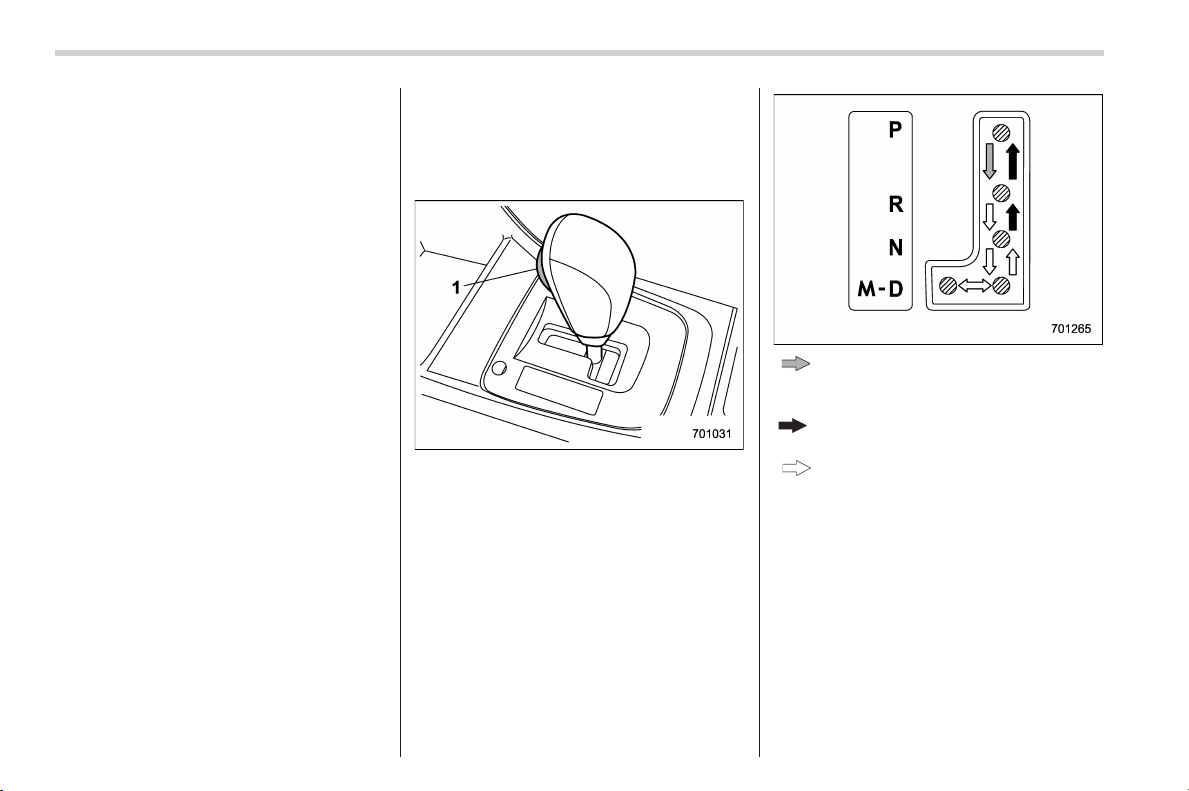
Black plate (346,1)
北米Model "A1160BE-C" EDITED: 2014/ 3/ 17
7-16
Starting and operating/Continuously variable transmission
unusual. This results from invalidation
of data which the on-board computer
has collected and stored in memory to
allow the transmission to shift at the
most appropriate times for the current
condition of your vehicle. Optimized
shifting will be restored as the vehicle
continues to be driven for a while.
. When driving a CVT model under
continuous heavy load conditions such
as when towing a camper or climbing a
long, steep hill, the hybrid system
speed or the vehicle speed may auto-
matically be reduced. This is not a
malfunction. This phenomenon results
from the engine control function main-
taining the cooling performance of the
vehicle. The hybrid system and vehicle
speed will return to a normal speed
when the hybrid system is able to
maintain the optimum cooling perfor-
mance after the heavy load decreases.
Driving under a heavy load must be
performed with extreme care. Do not
try to pass a vehicle in front when
driving on an uphill slope while towing.
. The continuously variable transmis-
sion is a chain type system that
provides s uperior transmission effi-
ciency for maximum fuel economy. At
times, depending on varying driving
conditions, a chain operating sound
may be heard that is characteristic of
this type of system.
& Select lever
! Select lever positions
1) Select lever button
: With the brake pedal depressed,
shift while pressing the select lever
button in.
: Shift while pressing the select lever
button in.
: Shift without pressing the select
lever button.
The select lever has four positions, “P”,
“R”, “N”, “D” and it also has an “M” gate.
! P (Park)
This position is for parking the vehicle and
starting the hybrid system. In this position,
the transmission is mechanically locked to
prevent the vehicle from rolling freely.
When you park the vehicle, first apply the
parking brake firmly, then shift into the “P”
position. Do not hold the vehicle with only
the mechanical friction of the transmis-
Black plate (347,1)
北米Model "A1160BE-C" EDITED: 2014/ 3/ 17
sion.
To shift the select lever from the “P” to any
other position, you should depress the
brake pedal fully then move the select
lever. This prevents the vehicle from
lurching when it is started.
! R (Reverse)
This position is for backing the vehicle. To
shift from the “N” to “R” position, stop the
vehicle completely then move the lever to
the “R” position while pressing the select
lever button in.
When the ignition switch has been turned
to the “LOCK” (off) position, movement of
the select lever from the “N” to “R” position
is possible for a limited time period by
depressing the brake pedal, and then it
becomes impossible. For details, refer to
“Shift lock function” F7-19.
! N (Neutral)
This position is for restarting a stalled
hybrid system. In this position, the trans-
mission is neutral, me aning that the
wheels and transmission are not locked.
Therefore, the vehicle will roll freely, even
on the slightest incline unless the parking
brake or foot brake is applied.
Avoid coasting with the transmission in
neutral. Engine braking has no effect in
this condition.
WARNING
Do not drive the vehicle with the
select lever in the “N” (neutral)
position. Engine braking has no
effect in this condition and the risk
of an accident is consequently in-
creased.
NOTE
If the select lever is in the “N” position
when you stop the hybrid system for
parking, you may not subsequently be
able to move it to the “R ” and “P”
positions. If this happens, turn the
ignition switch to the “ON” position.
You will then be able to move the select
lever to the “P” position.
! D (Drive)
This position is for normal driving. The
transmission shifts automatically and con-
tinuously into a suitable gear according to
the vehicle speed and the acceleration
you require. Also, while driving up and
down a hill, the transmission assists and
controls the driving performance and
engine braking while corresponding to
the road grade.
When more acceleration is required in the
“D” position, depress the accelerator
pedal fully to the floor and hold that
position. The transmission will automati-
cally downshift. When you release the
pedal, the transmission will return to the
original gear position.
For models with manual mode, if one of
the shift paddles behind the steering
wheel is operated while driving in the “D”
position, the transmission will temporarily
switch to the manual mode. In this mode,
you can shift into any gear position using
the shift paddles. For details about the
manual mode, refer to “Selection of
manual mode” F7-18. Once the vehicle
speed stabi lizes, the transmission will
switch from the manual mode back to
the “D” position for normal driving.
Starting and operating/Continuously variable transmission
7-17
– CONTINUED –
7
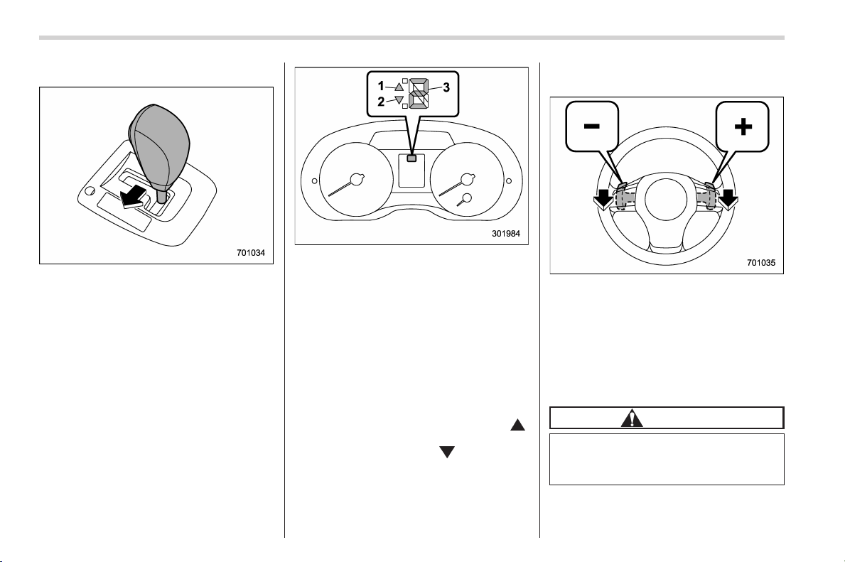
Black plate (348,1)
北米Model "A1160BE-C" EDITED: 2014/ 3/ 17
7-18
Starting and operating/Continuously variable transmission
& Selection of manual mode
With the vehicle either moving or station-
ary, move the select lever from the “D”
position to the “M” position to select the
manual mode.
1) Upshift indicator
2) Downshift indicator
3) Gear position indicator
When the manual mode is selected, the
gear position indicator and upshift indica-
tor and/or downshift indicator on the
combination meter illuminate.
The gear position indicator shows the
currently selected gear in the 1st-to-6th-
gear range. The upshift and downshift
indicators show when a gear shift is
possible. When the upshift indicator “
”
illuminates, upshifting is possible. When
the downshift indicator “
” illuminates,
downshifting is possible. When both in-
dicators illuminate, upshifting and down-
shifting are both pos sible. When the
vehicle stops (for example, at traffic
signals), the downshift indicator turns off.
Gearshifts can be performed using the
shift paddle behind the steering wheel.
To upshift to the next higher gear position,
pull the shift paddle that has “+” indicated
on it. To downshift to the next lower gear
position, pull the shift paddle that has “–”
indicated on it.
To deselect the manual mode, return the
select lever to the “D” position from the “M”
position.
CAUTION
Do not place or hang anything on
the shift paddles. Doing so may
result in accidental gear shifting.

Black plate (349,1)
北米Model "A1160BE-C" EDITED: 2014/ 3/ 17
! Manual mode tips
Please read the following points carefully
and bear them in mind when using the
manual mode.
. If you attempt to shift down when the
engine speed is too high, i.e., when a
downshift would push the t achom eter
needle beyond the red zone, beeps will
be emitted to warn you that the downshift
is not possible.
. If you attempt to shift up when the
vehicle speed is too low, the transmission
will not respond.
. You can perform a skip-shift (for
example, from 4th to 2nd) by operating
the shift paddle twice in rapid succession.
. The transmission automatically selects
1st gear when the vehicle stops moving.
. If the temperature of the transmission
fluid becomes too high, the “AT OIL
TEMP” warning light on the combination
meter will illuminate. Immediately stop the
vehicle in a safe location and let the hybrid
system idle until the warning light turns off.
& Shift lock function
The shift lock function helps prevent the
improper operation of the select lever.
. The select lever cannot be operated
unless the ignition switch is turned to the
“ON” position and the brake pedal is
depressed.
. The select lever cannot be moved from
the “P” position to an y other position
before t he brake pedal is depressed.
Depress the brake pedal first, and then
operate the select lever.
. Only the “P” position allows you to turn
the ignition switch from the “ACC” position
to the “LOCK” (off) position and remove
the key from the ignition switch.
. If the ignition switch is turned to the
“LOCK” (off) position while the select lever
is in the “N” position, the select lever may
not be moved to the “P” position after a
period of time. Therefore, move the select
lever to the “P” position with the brake
pedal depressed soon after the ignition
switch is turned to the “LOCK” (off)
position.
! Shift lock release
If the select lever cannot be operated, turn
theignitionswitchbacktothe“ON”
position then move the select lever to the
“P” position with the select lever button
pressed and brake pedal depressed.
If the select lever does not move after
performing the above procedure, perform
the following steps.
. When the select lever cannot be
shifted from “P” to “N”:
Refer to “Shift lock release using the shift
lock release button” F7-19.
. When the select lever cannot be
shifted from “N” to “R”, “P”:
Within 60 seconds after placing the igni-
tion switch in the “ACC” position, move the
select lever to the “P” position with the
select lever button pressed and brake
pedal depressed.
If you must perform the above procedure,
the shift lock system (or the vehicle control
system) may be malfunctioning. Contact a
SUBARU dealer for an inspection as soon
as possible.
If the select lever does not move after
performing the above procedure, refer to
“Shift lock release using the shift lock
release button” F7-19.
! Shift lock release using the shift
lock release button
Perform the following procedure to release
the shift lock.
1. Apply the parking brake and turn the
ignition switch to the “LOCK” (off) position.
Starting and operating/Continuously variable transmission
7-19
– CONTINUED –
7
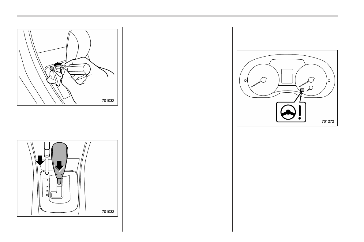
Black plate (350,1)
北米Model "A1160BE-C" EDITED: 2014/ 3/ 17
7-20
Starting and operating/Power steering
2. Wrap the tip of a flat-head screwdriver
with vinyl tape or a cloth and use it to
remove the shift lock cover. The shift lock
release button is located under the shift
lock cover.
3. While depressing the brake pedal,
insert a screwdriver into the hole, press
the s hift lock release button using a
screwdriver, and then move the select
lever.
If the select lever does not move after
performing the above procedure, the shift
lock system may be malfunctioning. Con-
tact a SUBARU dealer for an inspection
as soon as possible.
& Driving tips
. Always apply the foot or parking brake
when the vehicle is stopped in the “D” or
“R” position.
. Always apply the parking brake when
parking your vehicle. Do not hold the
vehicle with only the mechanical friction
of the transmission.
. Do not keep the vehicle in a stationary
position on an uphill grade by using the
“D” position. Use the brake instead.
. The engine may, on rare occasions,
knock when the vehicle rapidly acceler-
ates or rapidly pulls away from a standstill.
This phenomenon does not indicate a
malfunction.
Power steering
& Power steering warning light
Black plate (351,1)
北米Model "A1160BE-C" EDITED: 2014/ 3/ 17
& Power steering system fea-
tures
The vehicle is equipped with an electric
power steering system. When the ignition
switch is turned to the “ON” position, the
power steering warning light on the
combination meter illuminates to inform
the driver that the warning system is
functioning properly. Then, if the engine
started, the warning light turns off to inform
the driver that the steering power assist is
operational.
CAUTION
When the power steering warning
light is illuminated, there may be
more resistance when the steering
wheel is operated. Drive carefully to
the n earest SUBAR U dealer and
have the vehicle inspected immedi-
ately.
NOTE
If the steering wheel is operated in the
following ways, the power steering
control system may temporarily limit
the power assist in order to prevent the
system components, such as the con-
trol computer and drive motor, from
overheating.
. The steering wheel is operated fre-
quently and turned sharply while the
vehicle is maneuvered at extremely low
speeds, such as while frequently turn-
ing the steering wheel during parallel
parking.
. The steering wheel remains in the
fully turned position for a long period
of time.
At this time, there will be more resis-
tance when steering. However this is
not a malfunction. Normal steering
force will be restored after the steering
wheel is not operated for a while and
the power steering control system has
an opportunity to cool down. However,
if the power steering is operated in a
non-standard way which causes power
assist limitation to occur t oo fre-
quently, this may result in a malfunc-
tion of the power steering control
system.
Braking
& Braking tips
WARNING
Never rest your foot on the brake
pedal while driving. This can cause
dangerous overheating of the
brakes and needless wear on the
brake pads and linings.
! When the brakes get wet
When driving in rain or after washing the
vehicle, the brakes may get wet. As a
result, brake stopping distance will be
longer. To dry the brakes, drive the vehicle
at a safe speed while lightly depressing
the brake pedal to heat up the brakes.
! Use of engine braking
Remember to make use of engine braking
in addition to foot braking. When descend-
ing a grade, if only the foot brake is used,
the brakes may start working improperly
because of brake fluid overheating,
caused by overheated brake pads. To
help prevent this, shift into a lower gear to
get stronger engine braking.
! Braking when a tire is punctured
Do not depress the brake pedal suddenly
when a tire is punctured. This could cause
Starting and operating/Braking
7-21
– CONTINUED –
7
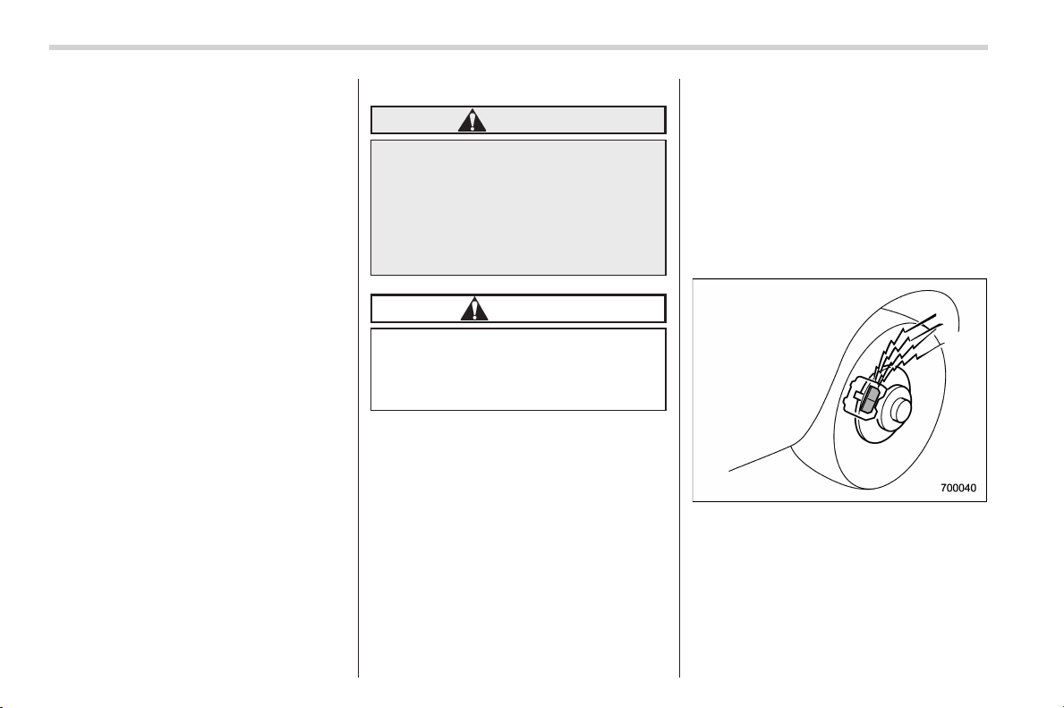
Black plate (352,1)
北米Model "A1160BE-C" EDITED: 2014/ 3/ 17
7-22
Starting and operating/Braking
a loss of control of the vehicle. Keep
driving s traight ahead while gradually
reducing speed. Then slowly pull off the
road to a safe place.
& Brake system
! Two separate circuits
Your vehicle has two separate circuit
brake systems. Each circuit works diag-
onally across the vehicle. If one circuit of
the brake system should fail, the other half
of the system still works. If one circuit fails,
the brake pedal will go down much closer
to the floor than usual and you will need to
press it down much harder. And a much
longer distance will be needed to stop the
vehicle.
! Brake booster
The brake booster uses engine manifold
vacuum to assist braking force. Do not
turn the ignition switch to the “LOCK” (off)
position while driving because that will
turn off the brake booster, resulting in poor
braking power.
The brakes will continue to work even
when the brake booster completely stops
functioning. If this happens, however, you
will have to depress the pedal much
harder than normal and the braking dis-
tance will increase.
! Brake assist system
WARNING
Do not be overconfident about the
brake assist. It is not a system that
brings more braking ability to the
vehicle beyond its braking capabil-
ity. Always use the utmost care
when driving regarding vehicle
speed and safe distance.
CAUTION
When you need to brake suddenly,
continue depressing the brake pedal
strongly to bring the effect of the
brake assist.
Brake assist is a driver assistance system.
It assists the brake power when the driver
cannot depress the brake pedal strongly
and the brake power is insufficient.
Brake assist generates the brake power
according to the speed at which the driver
depresses the brake pedal.
NOTE
When you dep ress the br ake pedal
strongly or suddenly, the following
phenomena occur. However, even
though these occur, they do not indi-
cate any malfunctions, and the brake
assist system is operating properly.
. You might feel that the brake pedal
is applied by lighter force and gener-
ates a greater braking force.
. You might hear an ABS operating
noise from the engine compartment.
& Disc brake pad wear warning
indicators
The disc brake pad wear warning indica-
tors on the disc brakes give a warning
noise when the brake pads are worn.
If a squeaking or scraping noise is heard
from the disc brakes while braking, im-
mediately have your vehicle checked by
your SUBARU dealer.
Black plate (353,1)
北米Model "A1160BE-C" EDITED: 2014/ 3/ 17
ABS (Anti-lock Brake Sys-
tem)
The ABS system prevents the lock-up of
wheels which may occur during sudden
braking or braking on slippery road sur-
faces. This helps prevent the loss of
steering control and directional stability
caused by wheel lock-up.
When the ABS system is operating, you
may hear a chattering noise or feel a slight
vibration in the brake pedal. This is normal
when the ABS operates.
The ABS system will not operate when the
vehicle speed is below approximately 6
mph (10 km/h).
WARNING
Always use the utmost care in
driving – overconfidence because
you are driving a vehicle with the
ABS system could easily lead to a
serious accident.
CAUTION
. The ABS system does not always
decrease stopping distance. You
should always maintain a safe
following distance from other
vehicles.
. When driving on badly surfaced
roads, gravel roads, icy roads, or
over deep newly fallen snow,
stopping distances may be long-
er for a vehicle with the ABS
system than one without. When
driving under these conditions,
therefore, reduce your speed and
leave ample distance from other
vehicles.
. When tire chains are installed,
stopping distances may be long-
er for a vehicle with the ABS
system than one without. Be sure
to reduce your speed and main-
tain a safe distance from the
vehicle in front.
. When you feel the ABS system
operating, you should maintain
constant brake pedal pressure.
Do not pump the brake pedal
since doing so may defeat the
operation of the ABS system.
& ABS system self-check
Just after the vehicle is started, you may
feel on the brake pedal a vibration similar
to when the ABS operates, and you may
also hear the sound of the ABS working
from the engine compartment. This is
caused by an automatic functional test of
the ABS system being carried out and
does not indicate any abnormal condition.
& ABS warning light
Refer to “ABS warning light” F3-20.
Starting and operating/ABS (Anti–lock Brake System)
7-23
7
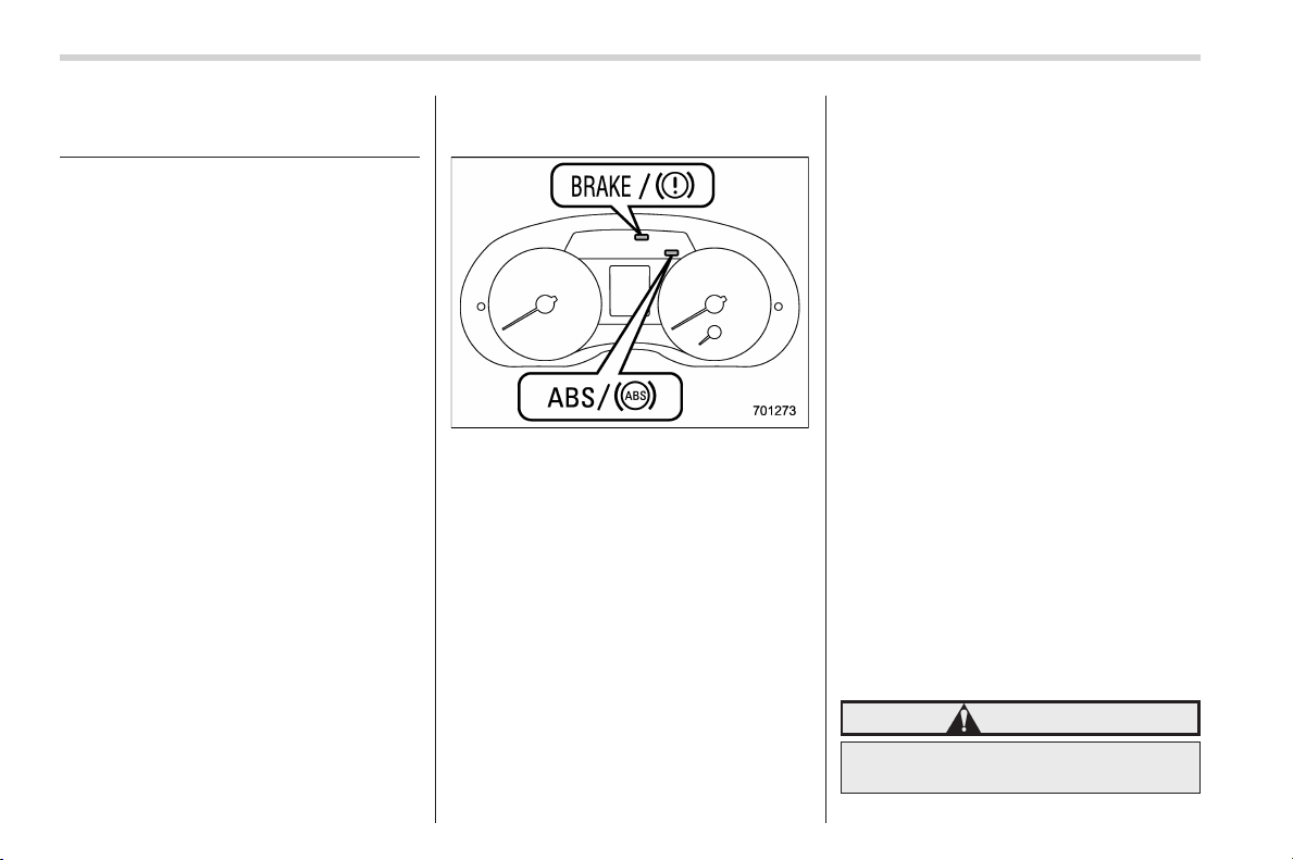
Black plate (354,1)
北米Model "A1160BE-C" EDITED: 2014/ 3/ 17
7-24
Starting and operating/Electronic Brake Force Distribution (EBD) system
Electronic Brake Force Dis-
tribution (EBD) system
The EBD system maximizes the effective-
ness of the brakes by allowing the rear
brakes to supply a greater proportion of
the braking force. It functions by adjusting
the distribution of braking force to the rear
wheels in accordance with the vehicle’s
loading condition and speed.
The EBD system is an integral part of the
ABS system and uses some of the ABS
system’s components to perform its func-
tion of optimizing the distribution of brak-
ing force. If any of the ABS components
used by the EBD system malfunction, the
EBD system also stops working.
When the EBD system is operating, you
may hear a chattering noise or feel a slight
vibration in the brake pedal. This is normal
and does not indicate a malfunction.
& Steps to take if EBD system
malfunctions
If a malfunction occurs in the EBD system,
the system stops working and the brake
system warning light and ABS warning
light illuminate simultaneously.
The EBD system may be malfunctioning if
the brake system warning light and ABS
warning light illuminate simultaneously
during driving.
Even if the EBD system malfunctions, the
conventional braking system will still func-
tion. However, the rear wheels will be
more prone to locking when the brakes
are applied harder than usual and the
vehicle’s motion may therefore become
somewhat harder to control.
If the brake system warning light and ABS
warning light illuminate simultaneously,
take the following steps.
1. Stop the vehicle in the nearest safe,
flat location.
2. Shut down the hybrid system, apply
the parking brake, and then restart it.
3. Release the parking brake. If both
warning lights turn off, the EBD system
may be malfunctioning. Drive carefully to
the nearest SUBARU dealer and have the
system inspected.
4. If both warning lights illuminate again
and remain illuminated after the hybrid
system has been restarted, shut down the
hybrid system, apply the parking brake,
and check the brake fluid level. Refer to
“Brake fluid” F11-18.
5. If the brake fluid level is not below the
“MIN” mark, the EBD system may be
malfunctioning. Dri ve carefully to the
nearest SUBARU dealer and have the
system inspected.
6. If the brake fluid level is below the
“MIN” mark, DO NOT drive the vehicle.
Instead, have the vehicle towed to the
nearest SUBARU dealer for repair.
WARNING
. Driving with the brake system
warning light illuminated is dan-
Black plate (355,1)
北米Model "A1160BE-C" EDITED: 2014/ 3/ 17
gerous. This indicates your brake
system may not be working
properly. If the li ght remains
illuminated, have the brakes in-
spected by a SUBARU dealer
immediately.
. If at all in doubt about whether
the brakes are operating prop-
erly, do not drive the vehicle.
Have your vehicle towed to the
nearest SUBARU dealer for re-
pair.
Vehicle Dynamics Control
system
& Safety precautions
WARNING
Always use the utmost care in
driving – overconfidence because
you are driving a vehicle with the
Vehicle Dynamics Control system
could easily lead to a serious acci-
dent.
CAUTION
. Even if your vehicle is equipped
with Vehicle Dynamics Control
system, winter tires should be
used when driving on snow-cov-
ered or icy roads; in addition,
vehicle speed should be reduced
considerably. Simply having a
Vehicle Dynamics Control sys-
tem does not guarantee that the
vehicle will be able to avoid
accidents in any situation.
. Activation of the Vehicle Dy-
namics Control s ystem is an
indication that the road being
travelled on has a slippery sur-
face; since having Vehicle Dy-
namics Control is no guarantee
that full vehicle control will be
maintained at all times and under
all conditions, its activation
should be seen as a sign that
the speed of the vehicle should
be reduced considerably.
. Whenever suspension compo-
nents, steering components, or
an axle are removed from a
vehicle, have an inspection of
that system performed by an
authorized SUBARU dealer.
. The following precautions should
be observed in order to ensure
that the Vehicle Dynamics Con-
trol system is operating properly:
– All four wheels should be
fitted with tires of the same
size, type, and brand. Further-
more, the amount of wear
should be the sam e for all
four tires.
– Keep the tire pressure at the
proper level as shown on the
vehicle placard attached to
the driver’s side door pillar.
. If non-matching tires are used,
the Vehicle Dynamics Control
system may not operate cor-
Starting and operating/Vehicle Dynamics Control system
7-25
– CONTINUED –
7

Black plate (356,1)
北米Model "A1160BE-D" EDITED: 2015/ 12/ 9
7-26
Starting and operating/Vehicle Dynamics Control system
rectly.
. The Vehicle Dynamics Contro l
system helps prevent unstable
vehicle motion such as skidding
using control of the brakes, en-
gine power and electric motor
power. Do not turn off the Vehicle
Dynamics Control system unless
it is absolutely necessary. If you
must turn off the Vehicle Dy-
namics Control system, drive
very carefully according to the
road surface conditions.
& System features
In the event of wheelspin and/or skidding
on a slippery road surface and/or during
cornering and/or an evasive maneuver,
the Vehicle Dynamics Control system
adjusts the hybrid system’s output and
the wheels’ respective braking forces to
help maintain traction and directional
control.
. Traction Control Function
The traction control function is designed to
prevent spinning of the driving wheels on
slippery road surfaces, thereby helping to
maintain traction and directional control.
Activation of this function is shown by
flashing the Vehicle Dynamics Control
operation indicator light.
. Skid Suppression Function
The skid suppression function is designed
to help maintain directional stability by
suppressing the wheels’ tendency to slide
sideways during steering operations. Acti-
vation of this function is shown by flashing
the Vehicle Dynamics Control operation
indicator light.
NOTE
. The Vehicle Dynamics Control sys-
tem may be considered normal when
the following conditions occur.
– Slight twitching of the brake
pedal is felt.
– The vehicle or steering wheel
shakes to a small degree.
– An operating sound from the
engine compartment is heard
briefly when starting the hybrid
system and when driving off after
starting the hybrid system.
– The brake pedal seems to jolt
when driving off after starting the
hybrid system.
. In the circumstances shown in the
following list, the vehicle may be less
stable than it feels to the driver. The
Vehicle Dynamics Control System may
therefore operate. Such operation does
not indicate a system malfunction.
– on gravel-covered or rutted
roads
– on unfinished roads
– when the vehicle is fitted with
snow tires or winter tires
. Activation of the Vehicle Dynamics
Control system will cause operation of
the steering wheel to feel slightly
different compared to that for normal
conditions.
. It is always important to reduce
speed when approaching a corner,
even if your vehicle is equipped with
the Vehicle Dynamics Control system.
. Always turn off the hybrid system
before replacing a tire. Failure to do so
may render the Vehicle Dynamics Con-
trol system unable to operate correctly.
& Vehicle Dynamics Control
system monitor
Refer to “Vehicle Dynamics Control warn-
ing light/Vehicle Dynamics Control opera-
tion indicator light” F3-23 and “Vehicle
Dynamics Control OFF indicator light” F3-
24.
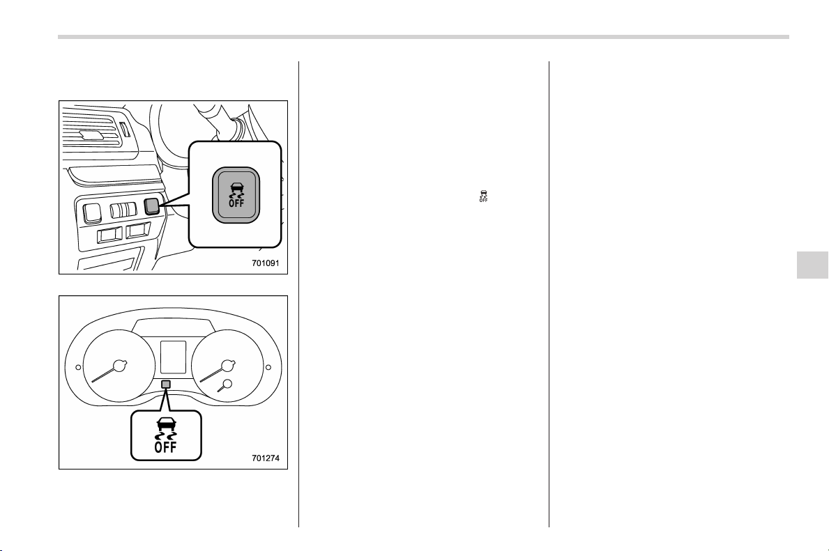
Black plate (357,1)
北米Model "A1160BE-C" EDITED: 2014/ 3/ 17
& Vehicle Dynamics Control
OFF switch
Vehicle Dynamics Control OFF switch
Indicator light
Pressingtheswitchtodeactivatethe
Vehicle Dynamics Control system can
facilitate the following operations.
. a standing start on a steeply sloping
road with a snowy, gravel-covered, or
otherwise slippery surface
. extrication of the vehicle when i ts
wheels are stuck in mud or deep snow
When the switch is pressed during hybrid
system operation, the Vehicle Dynamics
Control OFF indicator light “
” on the
combination meter illuminates. The Vehi-
cle Dynamics Control system will be
deactivated and the vehicle will behave
like a model not equipped with the Vehicle
Dynamics Control system . Whe n the
switch is pressed again to reactivate the
Vehicle Dynamics Control system, the
Vehicle Dynamics Control OFF indicator
light turns off.
With the Vehicle Dynamics Control system
deactivated, traction and stability en-
hancement offered by Vehicle Dynamics
Control system is unavailable. Therefore
you should not deactivate the Vehicle
Dynamics Control system except under
above-mentioned situations.
NOTE
. The Vehicle Dynamics Control sys-
tem will be activated automatically
when the hybrid system is started.
. If the switch is held down for 30
seconds or longer, the indicator light
turns off, the Vehicle Dynamics Control
system is activated, and the system
ignores any further pressing of the
switch. To ma ke the switch usable
again, turn the ignition switch to the
“LOCK” (off) position and restart the
hybrid system.
. Whentheswitchispressedto
deactivate the Vehicle Dynamics Con-
trol system, the vehicle’s running per-
formance is comparable with that of a
vehicle that does not have a Vehicle
Dynamics Control system. Do not de-
activate the Vehicle Dynamics Control
system except when absolutely neces-
sary.
. Even when the Vehicle Dynamics
Control system is deactivated, compo-
nents of the brake control system may
still activate. When the brake control
system is activated, the Vehicle Dy-
namics Control operation indicator
light flashes.
Starting and operating/Vehicle Dynamics Control system
7-27
7
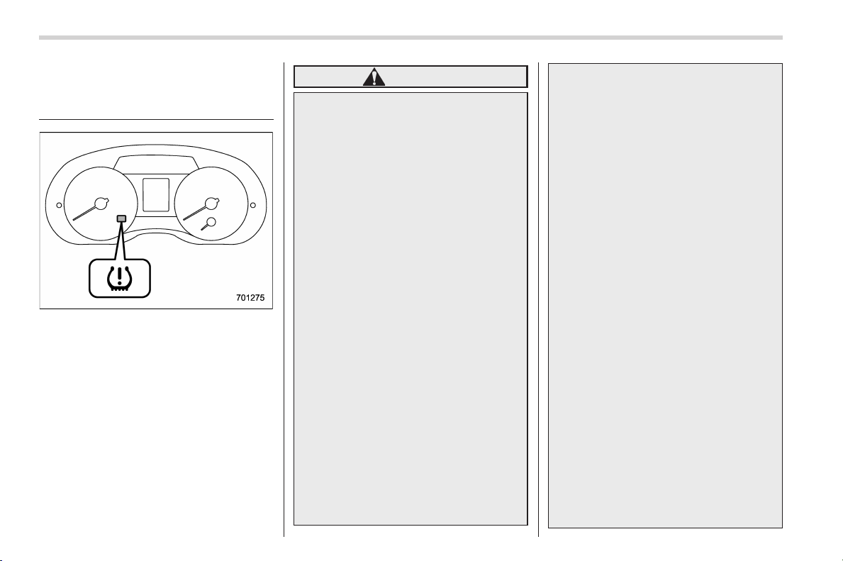
Black plate (358,1)
北米Model "A1160BE-C" EDITED: 2014/ 3/ 17
7-28
Starting and operating/Tire pressure monitoring system (TPMS) (U.S.–spec. models)
Tire pressure monitoring
system (TPMS) (U.S.-spec.
models)
Low tire pressure warning light
The tire pressure monitoring system pro-
vides the driver with a warning message
by sending a signal from a sensor that is
installed in each wheel when tire pressure
is severely low.
The tire pressure monitoring system will
activate only when the vehicle is driven at
speeds above 20 mph (32 km/h). Also,
this system may not react immediately to a
sudden drop in tire pressure (for example,
a blow-out caused by running over a
sharp object).
WARNING
If the low tire pressure warning light
illuminates while driving, never
brake suddenly and keep driving
straight ahead while gradually redu-
cing speed. Then slowly pull off the
road to a safe place. Otherwise an
accident involving serious vehicle
damage and serious personal injury
could occur.
Check the pressure for all four tires
and adjust the pressure to the COLD
tire pressure shown on the tire
placard on the door pillar on the
driver’s side.
Even when the vehicle is driven a
very short distance, the tires get
warm and their pressures increase
accordingly. Be sure to let the tires
cool thoroughly before a djusting
their pressures to t he standard
values shown on the tire placard.
Refer to “Tires and wheels” F11-22.
The tire pressure monitoring system
does not function when the vehicle
is stationary. After adjusting the tire
pressures, increase the vehicle
speed to at least 20 mph (32 km/h)
to start the TPMS re-checking of the
tire inflation pressures. If the tire
pressures are now above the severe
low pressure threshold, the low tire
pressure warning light should turn
off a few minutes later.
If this light still illuminates while
driving after adjusting the tire pres-
sure, a tire may have significant
damage and a fast leak that causes
the tire to lose air rapidly. If you have
a flat tire, refer to “In case of a flat
tire” F9-4.
When a replacement tire is mounted
or a wheel rim is replaced without
the original pressure sensor/trans-
mitter being transferred, the low tire
pressure warning light will illumi-
nate steadily after blinking for ap-
proximately one minute. This indi-
cates the TPMS is unable to monitor
all four road wheels. Contact your
SUBARU dealer as soon as possible
for tire and sensor replacement and/
or system resetting.
When a tire is repaired with liquid
sealant, the tire pressure warning
valve and transmitter may not oper-
ate properly. If a liquid sealant is
used, contact your nearest SUBARU
dealer or other qualified service
shop as soon as possible. Make
sure to replace the tire pressure
warning valve and transmitter when
replacing the tire. You may reuse the
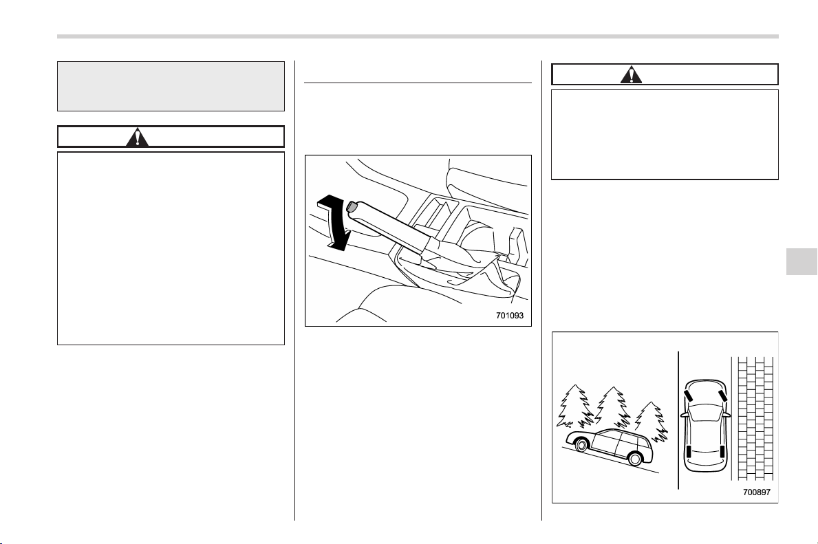
Black plate (359,1)
北米Model "A1160BE-C" EDITED: 2014/ 3/ 17
wheel if there is no damage to it and
if the sealant residue is properly
cleaned off.
CAUTION
. Do not place metal film or any
metal parts in the cargo area.
This may cause poor reception of
the signals from the tire pressure
sensors, and the tire pressure
monitoring system will not func-
tion properly.
. FCC WARNING
Changes or modifications no t
expressly approved by the party
responsible for compliance
could void the user’s authority
to operate the equipment.
NOTE
This device complies with Part 15 of
the FCC Rules and RSS-Gen of IC
Rules. Operation is subject to the
following two conditions: (1) this de-
vice may not cause harmful interfer-
ence, and (2) this device must accept
any interference received, including
interference that may cause undesired
operation.
Parking your vehicle
& Parking brake
To set the parking brake, depress the
brake pedal firmly and hold it down until
the parking brake lever is fully pulled up.
To release the parking brake, pull the lever
up slightly, press the release button, then
lower the lever while keeping the button
pressed.
When the parking brake is set while the
hybrid system is running, the parking
brake warning light illuminates. After
starting the vehicle, be sure that the
warning light has turned off before the
vehicle is driven. Refer to “Parking brake
warning” F3-21.
CAUTION
Never drive while the parking brake
is set because this will cause un-
necessary wear on the brake lin-
ings. Before starting to drive, always
make sure that the parking brake
has been fully released.
& Parking tips
When parking your vehicle, always per-
form the following items.
. Apply the parking brake firmly.
. Put the select lever in the “P” (Park)
position.
Never rely on the mechanical friction of
the transmission alone to hold the vehicle.
Starting and operating/Parking your vehicle
7-29
– CONTINUED –
7
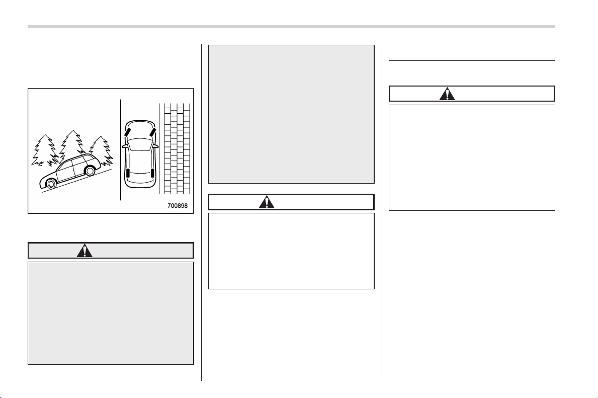
Black plate (360,1)
北米Model "A1160BE-C" EDITED: 2014/ 3/ 17
7-30
Starting and operating/Hill start assist system
When parking on a hill, always turn the
steering wheel. When t he ve hicle is
headed up the hill, the front wheels should
be turned away from the curb.
When facing downhill, the front wheels
should be turned into the curb.
WARNING
. Never leave unattended children
or pets in the vehicle. They could
accidentally injure themselves or
others through inadvertent op-
eration of the vehicle. Also, on
hot or sunny days, the tempera-
ture in a closed vehicle could
quickly become high enough to
cause severe or possibly fatal
injuries to people.
. Do not park t he vehicle over
flammable materials such as dry
grass, waste paper or rags, as
they may burn easily if they come
near hot engine or exhaust sys-
tem parts.
. Be sure to stop the hybrid system
if you take a nap in the vehicle. If
engine exhaust gas enters the
passenger compartment, occu-
pants in the vehicle could die
from carbon monoxide (CO) con-
tained in the exhaust gas.
CAUTION
If your vehicle has a front under-
spoiler and rear underspoiler (both
optional), pay attention to blocks
and other obstructions on the
ground when parking. The under-
spoilers could be damaged by con-
tact with them.
Hill start assist system
& System features
CAUTION
The Hill start assist system is a
device only for helping the driver
to START the vehicle on an uphill
grade. To prevent accidents when
the vehicle is parked on a slope, be
sure to firmly set the parking brake.
When setting the parking brake,
make sure that the vehicle remains
stationary when the brake pedal is
released.
The Hill start assist system is a device to
make the foll owing vehicle operations
easier.
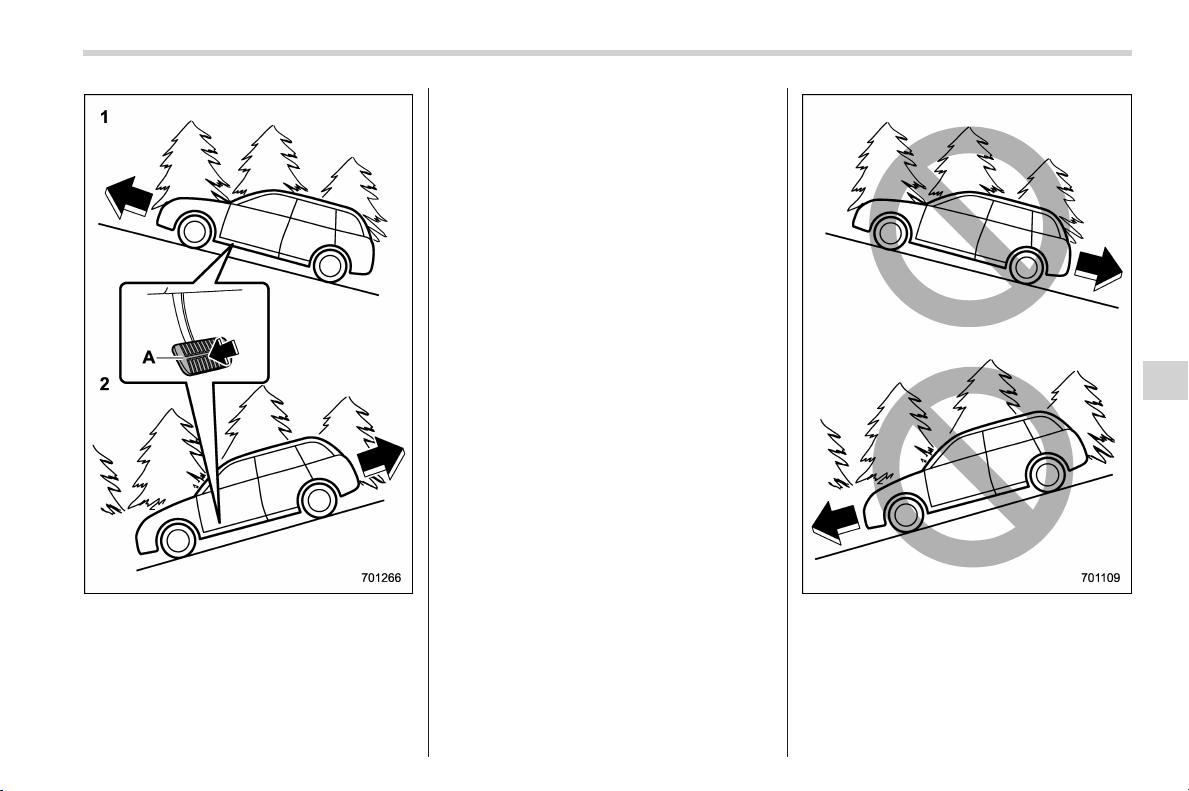
Black plate (361,1)
北米Model "A1160BE-C" EDITED: 2014/ 3/ 17
1) Starting forward facing uphill
2) Starting backward facing downhill
A) Brake pedal
In both these cases, the Hill start assist
system operates when the vehicle has
stopped with the brake pedal depressed.
Braking power is maintained temporarily
(for approximately 2 seconds) by the Hill
start assist system after the brake pedal is
released. The driver is therefore able to
start the vehicle in the same way as on a
level grade, just by using the accelerator
pedal.
If the braking power of the Hill start assist
system is insufficient after the brake pedal
is released, apply more braking power by
depressing the brake pedal again.
The Hill start assist system may not
operate on slight grades. Also, the Hill
start assist system does not operate in the
following cases.
. when starting backward facing uphill
. when starting forward facing downhill
. while the parking brake is applied
. while the ignition switch is in the “ACC”
or “LOCK” (off) position
. while the Hill start assist warning light/
Starting and operating/Hill start assist system
7-31
– CONTINUED –
7
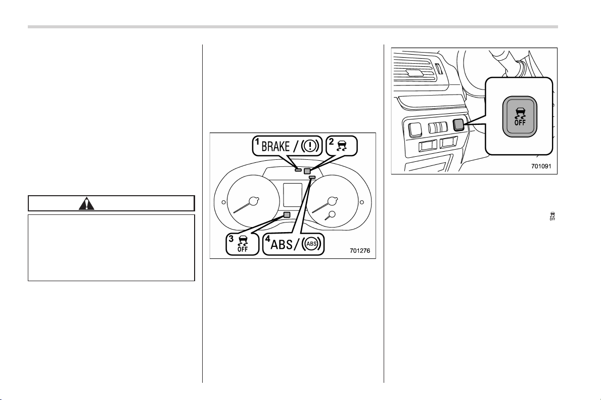
Black plate (362,1)
北米Model "A1160BE-C" EDITED: 2014/ 3/ 17
7-32
Starting and operating/Hill start assist system
Hill start assist OFF indicator light is
illuminated
When using the Hill start assist system, a
braking effect may be felt even after the
brake pedal has been released.
NOTE
A sl ight jolt may be felt when the
vehicle begins to move forward after
being reversed.
& To activate/deactivate the Hill
start assist system
CAUTION
While the Hill start assist system is
deactivated, when starting on an
uphill grade, braking power is not
maintained if the brake pedal is
released. Start on an uphill grade
by using the parking brake.
You can activate/deactivate the Hill start
assist system according to the following
procedure.
NOTE
If you make an error when performing
any steps in the following procedure,
place the ignition switch in the “LOCK”
(off) position once and then start over
again.
! To deactivate
1. Park your vehicle in a flat and safe
location and apply the parking brake.
2. Turn the ignition switch to the “LOCK”
(off) position.
3. Restart the hybrid system.
4. Confirm the following items.
(1) The Brake system warning light
illuminates.
(2) The Vehicle Dynami cs Control
warning light turns off.
(3) The Vehicle Dynami cs Control
OFF indicator light turns off.
(4) The ABS warning light turns off.
Vehicle Dynamics Control OFF switch
5. Press the Vehicle Dynamics Control
OFF switch and hold it until the Vehicle
Dynamics Control OFF indicator light “
”
on the combination meter illuminates for
several seconds and then turns off.
6. Within 5 seconds after the Vehicle
Dynamics Control OFF indicator light
turns off, release the Vehicle Dynamics
Control OFF switch.
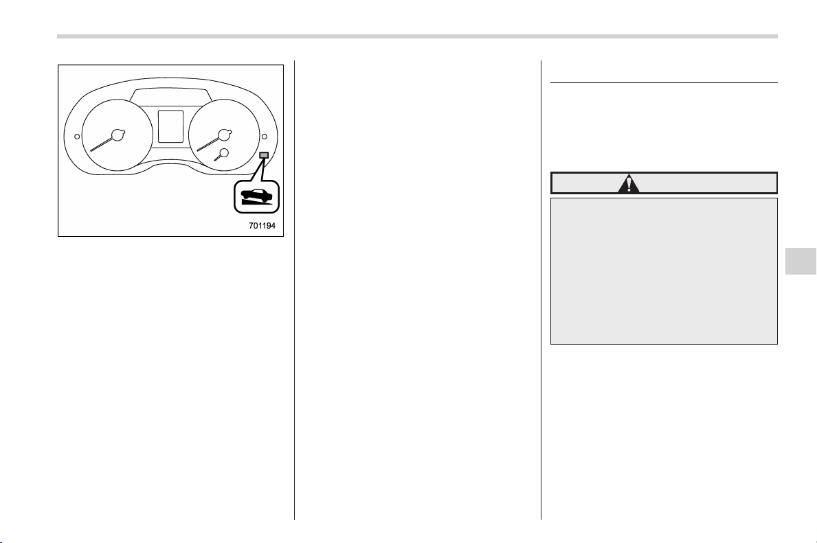
Black plate (363,1)
北米Model "A1160BE-C" EDITED: 2014/ 3/ 17
Hill start assist OFF indicator light
7. Within 2 seconds after releasing the
Vehicle Dynamics Control OFF switch,
press the Vehicle Dynamics Control OFF
switch once again. Then the Hill start
assist OFF indicator light blinks.
8. Turn the ignition switch to the “LOCK”
(off) position. The hill start assist system
has now been deactivated.
NOTE
While the Hill start assist system is
deactivated, the Hill start assist OFF
indicator light blinks.
! To activate
When the procedure to deactivate the Hill
start assist system is performed again, the
system is activated. When the Hill start
assist system is activated, the Hill start
assist OFF indicator light turns off.
& Hill start assist warning light/
Hill start assist OFF indicator
light
Refer to “Hill start assist warning light/Hill
start assist OFF indicator light” F3-22.
Cruise control (if equipped)
Cruise control enables you to maintain a
constant vehicle speed without holding
your foot on the accelerator pedal and it is
operative when the vehicle speed is 25
mph (40 km/h) or more.
WARNING
Do not use the cruise control under
any of the following conditions.
These may cause loss of vehicle
control.
. driving up or down a steep grade
. driving on sli ppery or winding
roads
. driving in heavy traffic
. towing a trailer
NOTE
Make sure the cruise control system is
turned off when the cruise control is
not in use to avoid unintentionally
setting of the cruise control.
Starting and operating/Cruise control
7-33
– CONTINUED –
7
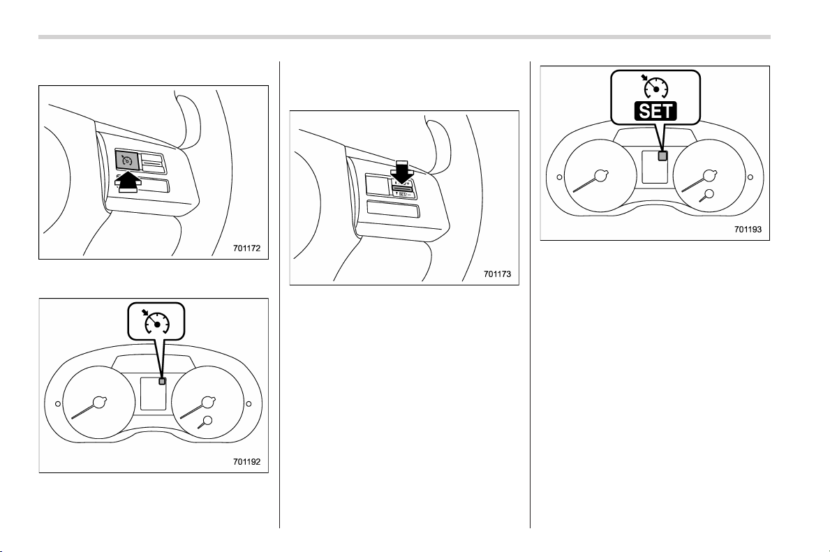
Black plate (364,1)
北米Model "A1160BE-C" EDITED: 2014/ 3/ 17
7-34
Starting and operating/Cruise control
& To set cruise control
Cruise control main button
1. Press the cruise control main button.
Cruise control indicator light
The cruise control indicator light on the
combination meter will illuminate.
2. Depress the accelerator pedal until the
vehicle reaches the desired speed.
3. Press the “RES/SET” switch to the
“SET” side and release it. Then release
the accelerator pedal.
Cruise control set indicator light
At this time, the cruise control set indicator
light is illuminated in the combination
meter.
The vehicle will maintain the desired
speed.
Vehicle speed can be temporarily in-
creased while driving with the cruise
control activated. Simply depress the
accelerator pedal to accelerate the vehi-
cle. When the accelerator pedal is re-
leased, the vehicle will return to and
maintain the previous cruising speed.
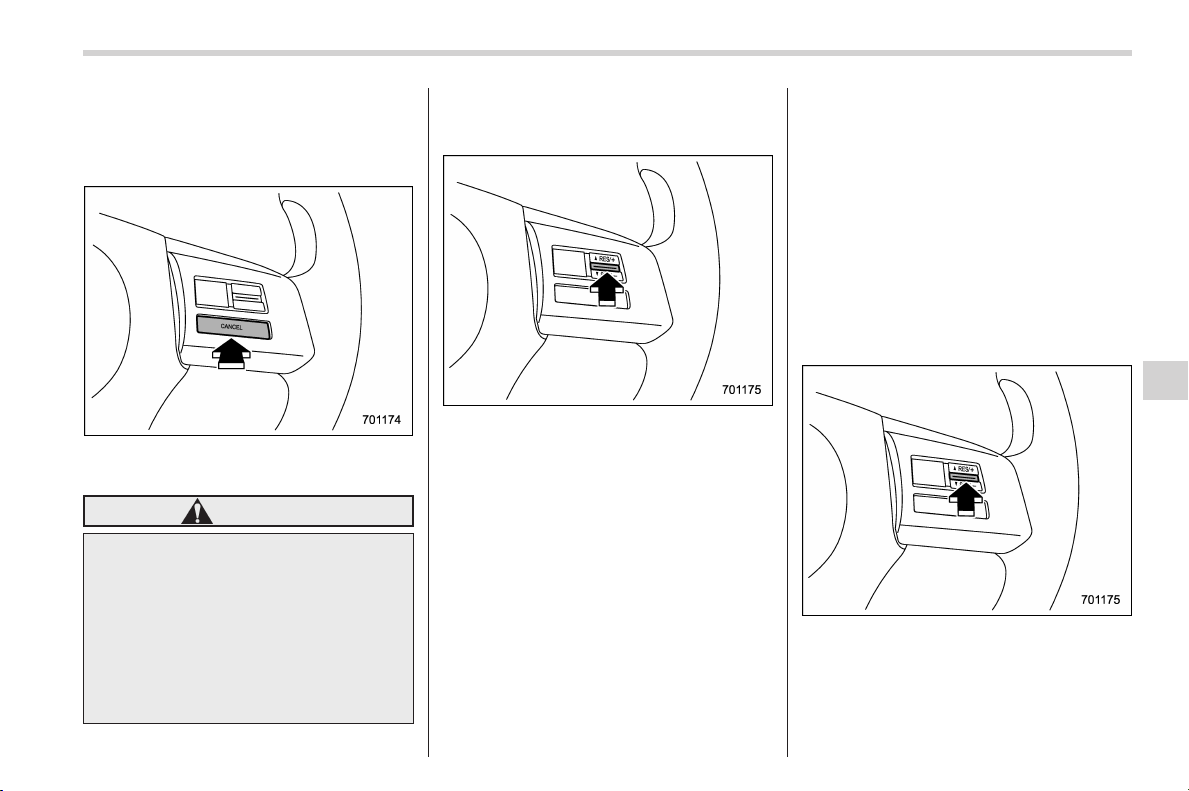
Black plate (365,1)
北米Model "A1160BE-C" EDITED: 2014/ 3/ 17
& To temporarily cancel the
cruise control
The crui se control can be temporarily
canceled in the following ways.
. Press the “CANCEL” button.
. Depress the brake pedal.
WARNING
You can cancel the cruise control by
shifting the select lever into the “N”
position. However, do not shift the
lever into the “N” position while
driving except in case of emergency.
If the select lever is shifted into the
“N” position, the engine brake will
no longer work. This could result in
an accident.
The cruise control set indicator light in the
combination meter turns off when the
cruise control is canceled.
To resume the cruise control after it has
been temporarily canceled and with vehi-
cle speed of approximately 20 mph (32
km/h) or more, press the “RES/SET”
switch to the “RES” side to return to the
original cruising speed automatically.
The cruise control set indicator light in the
combination meter will automatically illu-
minate at this time.
& To turn off the cruise control
There are two ways to turn off the cruise
control:
. Press the cruise control main button
again.
. Turn the ignition switch to the “ACC” or
“LOCK” (off) position (but only when the
vehicle is completely stopped).
& To change the cruising speed
! To increase the speed (by the “RES/
SET” switch)
Press the “RES/SET ” switch to the “RES”
side and hold it until the vehicle reaches
the desired speed. Then, release the
switch. The vehicle speed at that moment
will be memorized and treated as the new
set speed.
Starting and operating/Cruise control
7-35
– CONTINUED –
7
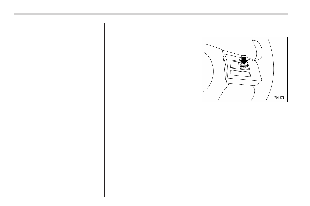
Black plate (366,1)
北米Model "A1160BE-C" EDITED: 2014/ 3/ 17
7-36
Starting and operating/Cruise control
U.S.-spec. models
When the difference between the actual
vehicle speed and the set speed is less
than 4 mph (6.8 km/h), the set speed can
be increased 1 mph (1.6 km/h) each time
by pressing the “RES/SET” switch to the
“RES” side quickly.
Except U.S.-spec. models
When the difference between the actual
vehicle speed and the set speed is less
than 4.4 km/h, the set speed can be
increased 1 km/h each time by pressing
the “RES/SET” switch to the “RES” side
quickly.
! To increase the speed (by accel-
erator pedal)
1. Depress the accelerator pedal to
accelerate the vehicle to the desired
speed.
2. Press the “RES/SET” switch to the
“SET” side once. Now the desired speed
is set and the vehicle will keep running at
that speed without depressing the accel-
erator pedal.
NOTE
. U.S.-spec. models
If the difference between the actual
vehicle spee d when the switch is
pressed and the speed last time you
set is less than 4 mph (6.8 km/h), the
vehicle speed will be lowered by 1 mph
(1.6 km/h). This occurs because the
cruise control system regards this
operation as that intended to decrease
the vehicle speed.
. Except U.S.-spec. models
If the difference between the actual
vehicle speed when the switch is
pressed and the speed last time you
set is less than 4.4 km/h, the vehicle
speed will be lowered by 1 km/h. This
occurs bec ause t he cr uise c ontrol
system regards this operation as that
intended to decrease the vehicle
speed.
! To decrease the speed (by the
“RES/SET” switch)
Press the “RES/SET” switch to the “SET”
side and hold it until the vehicle reaches
the desired speed. Then, release the
switch. The vehicle speed at that moment
will be memorized and treated as the new
set speed.
U.S.-spec. models
When the difference between the actual
vehicle speed and the set speed is less
than 4 mph (6.8 km/h), the set speed can
be lowered 1 mph (1.6 km/h) each time by
pressin g the “RES/SET” switch to the
“SET” side quickly.
Except U.S.-spec. models
When the difference between the actual
vehicle speed and the set speed is less

Black plate (367,1)
北米Model "A1160BE-C" EDITED: 2014/ 3/ 17
than 4.4 km/h, the set speed can be
lowered 1 km/h each time by pressing the
“RES /SET” switch to the “SET” side
quickly.
! To decrease the speed (by brake
pedal)
1. Depress the brake pedal to release
cruise control temporarily.
2. When the speed decreases to the
desired spee d, press the “RES/SET”
switch to the “SET” side once. Now the
desired speed is set and the vehicle will
keep running at that speed without de-
pressing the accelerator pedal.
& Cruise control indicator light
Refer to “Cruise control indicator light”
F3-30.
& Cruise control set indicator
light
Refer to “Cruise control set indicator light”
F3-30.
Starting and operating/Cruise control
7-37
7

Black plate (2,1)
Model "ALL_MODEL_MEMO" EDITED: 2007/ 6/ 22
Left Page
————————————————————————————————————————
————————————————————————————————————————
————————————————————————————————————————
————————————————————————————————————————
————————————————————————————————————————
————————————————————————————————————————
————————————————————————————————————————
————————————————————————————————————————
————————————————————————————————————————
————————————————————————————————————————
————————————————————————————————————————
————————————————————————————————————————
————————————————————————————————————————

Black plate (15,1)
北米Model "A1160BE-C" EDITED: 2014/ 3/ 17
New vehicle break-in driving – the first
1,000 miles (1,600 km) ..................................... 8-2
Fuel economy hints ............................................ 8-2
Engine exhaust gas (carbon monoxide)............ 8-2
Catalytic converter .............................................. 8-3
Periodic inspections ........................................... 8-4
Driving in foreign countries ............................... 8-4
Driving tips for AWD models.............................. 8-4
Off road driving ................................................... 8-6
Winter driving...................................................... 8-7
Operation during cold weather............................. 8-7
Driving on snowy and icy roads .......................... 8-9
Corrosion protection.......................................... 8-10
Snow tires ......................................................... 8-10
Tire chains ........................................................ 8-11
Rocking the vehicle ........................................... 8-11
Loading your vehicle......................................... 8-11
Vehicle capacity weight...................................... 8-12
GVWR and GAWR (Gross Vehicle Weight Rating
and Gross Axle Weight Rating) ........................ 8-13
Roof rail (if equipped) ........................................ 8-13
Roof molding and crossbar (if equipped)............ 8-14
Trailer towing ..................................................... 8-15
Driving tips
8
Black plate (370,1)
北米Model "A1160BE-C" EDITED: 2014/ 3/ 17
8-2
Driving tips/New vehic le break–in driving – the first 1,000 miles (1,600 km)
New vehicle break-in driving
– the first 1,000 miles (1,600
km)
The performance and long life of your
vehicle are dependent on how you handle
and care for your vehicle while it is new.
Follow these instructions during the first
1,000 miles (1,600 km):
. Do not race the engine. And do not
allow engine speed to exceed 4,000 rpm
except in an emergency.
. Do not drive at one constant engine or
vehicle speed for a long time, either fast or
slow.
. Avoi d star ting suddenly an d rapi d
acceleration, except in an emergency.
. Avoid hard braki ng, except in an
emergency.
The same break-in procedures should be
applied to an overhauled engine, newly
mounted engine or when brake pads or
brake linings are replaced with new ones.
Fuel economy hints
The following suggestions will help to save
fuel.
. Select the proper gear position for the
speed and road conditions.
. Avoid sudden acceleration or decelera-
tion. Always accelerate gently until you
reach the desired speed. Then try to
maintain that speed for as long as
possible.
. Do not pump the accelerator and avoid
racing the engine.
. Avoid unnecessary engine idling.
. Keep the hybrid system properly tuned.
. Keep the tires inflated to the correct
pressure shown on the tire placard, which
is located under the door latch on the
driver’s side. Low pressure will increase
tire wear and fuel consumption.
. Use the air conditioner only when
necessary.
. Keep the f ront and rear wheels in
proper alignment.
. Avoid carrying unnecessary luggage or
cargo.
Engine exhaust gas (carbon
monoxide)
WARNING
. Never inhale engine exhaust gas.
Engine exhaust gas contains
carbon monoxi de, a c olorless
and odorless gas which is dan-
gerous, or even lethal, if inhaled.
. Always properly maintain the en-
gine exhaust system to prevent
engine exhaust gas from enter-
ing the vehicle.
. Never run the engine in a closed
space, such as a garage, except
for the brief time needed to drive
the vehicle in or out of it.
. Avoi d remaining in a parked
vehicle for a lengthy time while
the engine is running. If that is
unavoidable, then use the venti-
lation fan to force fresh air into
the vehicle.
. Always keep the front ventilator
inlet grille free from snow, leaves
or other obstructions to ensure
that the ventilation system al-
ways works properly.
. If at any time you suspect that
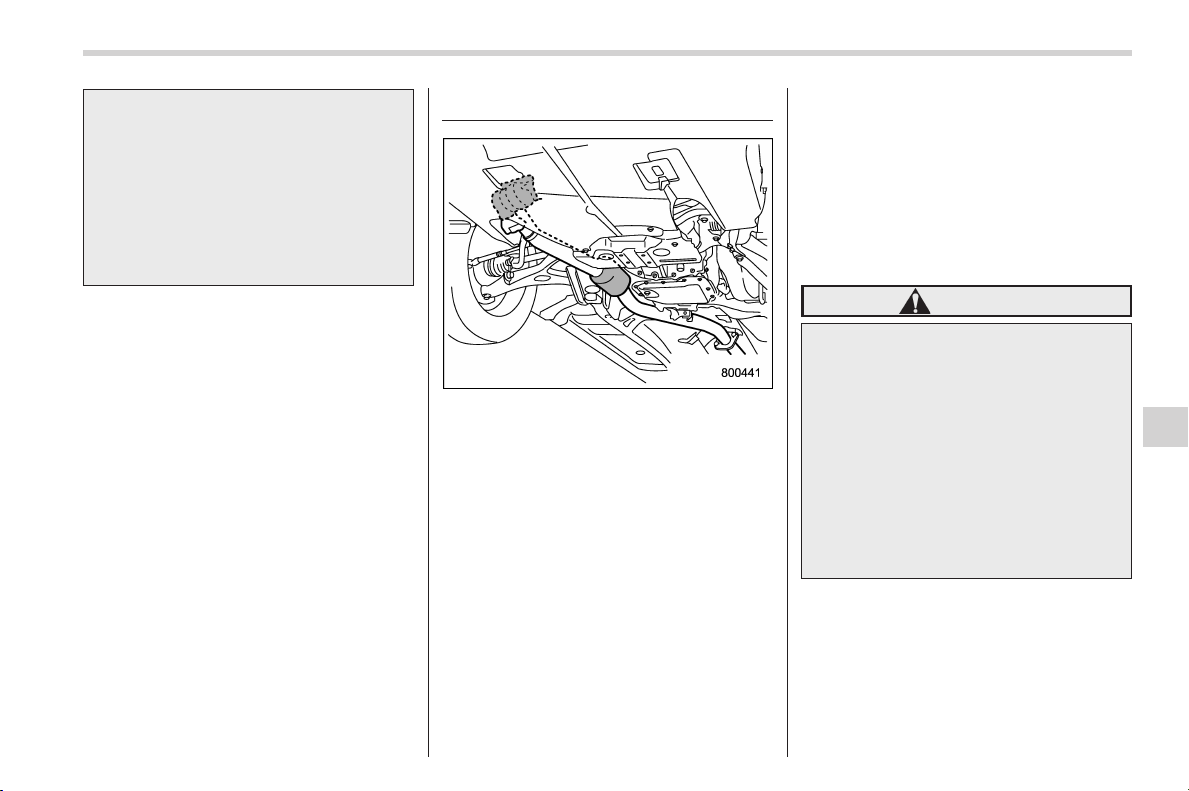
Black plate (371,1)
北米Model "A1160BE-C" EDITED: 2014/ 3/ 17
exhaust fumes are entering the
vehicle, have the problem
checked and corrected as soon
as possible. If you must drive
under these conditions, drive
only with all windows fully open.
. Keep the rear gate closed while
driving to prevent exhaust gas
from entering the vehicle.
NOTE
Due to the expansion and contraction
of the metals used in the manufacture
of the exhaust system, you may hear a
crackling sound coming from the ex-
haust system for a short time after the
hybrid system has been shut off. This
sound is normal.
Catalytic converter
The catalytic converter is installed in the
exhaust system. It serves as a catalyst to
reduce HC, CO and NOx in exhaust
gases, thus providing cleaner exhaust.
To avoid damage to the catalytic conver-
ter:
. Use only unleaded fuel. Even a small
amount of leaded fuel will damage the
catalytic converter.
. Never start the hybrid system by
pushing or pulling the vehicle.
. Avoid racing the engine.
. Never turn off the ignition switch while
the vehicle is moving.
. Keep your engine tuned-up. If you feel
the engine running rough (misfiring, back-
firing or in complete combustion), have
your vehicle checked and repaired by an
authorized SUBARU dealer.
. Do not apply undercoating or rust
prevention treatment to the heat shield of
catalytic converter and the exhaust sys-
tem.
. Do not drive with an extremely low fuel
level.
WARNING
. Avoid fire hazards. Do not drive
or park the vehicle anywhere
near flammable materials (e.g.,
grass, paper, rags or leaves),
because the catalytic converter
operates at very high tempera-
tures.
. Keep everyone and flammable
materials away from the exhaust
pipe while the hybrid system is
running. The exhaust gas is very
hot.
Driving tips/Catalytic converter
8-3
8
Black plate (372,1)
北米Model "A1160BE-C" EDITED: 2014/ 3/ 17
8-4
Driving tips/Periodic inspections
Periodic inspections
To keep your vehicle in the best condition
at all times, always have the recom-
mended maintenance services listed in
the maintenance schedule in the “War-
ranty and Maintenance Bookle t” per-
formed at the specified time or mileage
intervals.
Driving in foreign countries
When planning to use your vehicle in
another country:
. Confirm the availability of the correct
fuel. Refer to “Fuel requirements” F7-3.
. Comply with all regulations and re-
quirements of each country.
Driving tips for AWD models
WARNING
. Always maintain a safe driving
speed according to the road and
weather conditions in order to
avoid having an accident on a
sharp turn, during sudden brak-
ing or under other similar condi-
tions.
. Always use the utmost care in
driving – overconfidence be-
cause you are driving an All-
Wheel Drive vehicle could easily
lead to a serious accident.
. When replacing or installing tire
(s), all four tires must be the
same for following items.
(a) Size
(b) Circumference
(c) Speed symbol
(d) Load index
(e) Construction
(f) Manufacturer
(g) Brand (tread pattern)
(h) Degrees of wear
For the items (a) to (d), you must
obey the specification that is
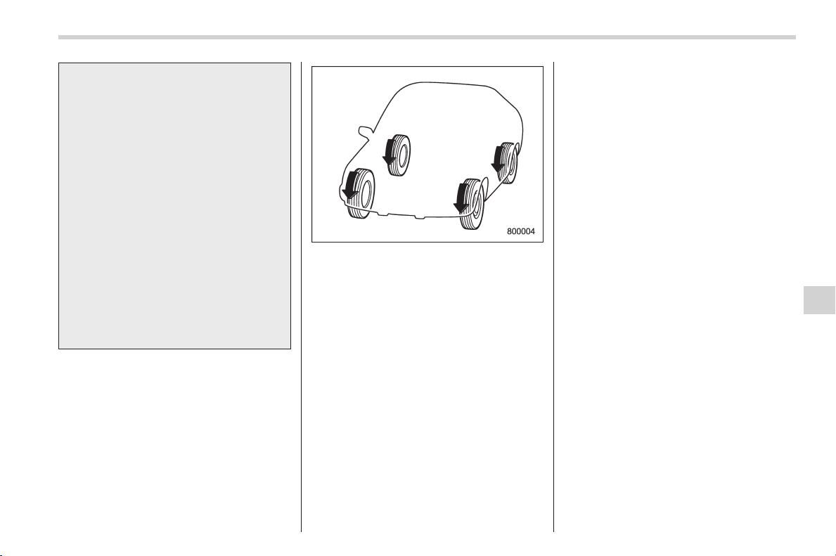
Black plate (373,1)
北米Model "A1160BE-C" EDITED: 2014/ 3/ 17
printed on the tire placard. The
tire placard is located on the
driver’s door pillar.
If all of four tires are not the same
for items (a) to (h), serious me-
chanical damage could occur to
the drive train of your car, and
affect the following.
— Ride
— Handling
— Braking
— Speedometer/Odometer
calibration
— Clearance between the body
and tires
It also may be dangerous and
lead to loss of vehicle control,
and it can lead to an accident.
All-Wheel Drive distributes the hybrid
system power to all four wheels. AWD
models provide better traction when driv-
ingonslippery,wetorsnow-covered
roads and when moving out of mud, dirt
and sand. By shifting power between the
front and rear wheels, SUBARU AWD can
also provide added traction during accel-
eration and added engine braking force
during deceleration.
Therefore, your SUBARU AWD vehicle
may handle differently than an ordinary
two wheel drive vehicle and it contains
some features unique to AWD. For safety
purposes as well as to avoid damaging
the AWD system, you should keep the
following tips in mind.
. An AWD model is better able to climb
steeper roads under snowy or slippery
conditions than a two wheel drive vehicle.
There is little difference in handling,
however, during extremely sharp turns or
sudden braking. Therefore, when driving
down a slope or turning corners, be sure
to reduce your speed and maintain an
ample distance from other vehicles.
. Always check the cold tire pressure
before starting to drive. The recom-
mended tire pressure is provided on the
tire placard, which is located under the
door latch on the driver’s side.
. There are some precautions that you
must observe when towing your vehicle.
For detailed information, refer to “Towing”
F9-18.
Driving tips/Driving tips for AWD models
8-5
8
Black plate (374,1)
北米Model "A1160BE-C" EDITED: 2014/ 3/ 17
8-6
Driving tips/Off road driving
Off road driving
WARNING
. Always maintain a safe driving
speed according to the road and
weather conditions in order to
avoid having an accident on a
sharp turn, during sudden brak-
ing or under other similar condi-
tions.
. Always use the utmost care in
driving – ove rconfidence be-
cause you are driving an All-
Wheel Drive model could easily
lead to a serious accident.
Because of the AWD feature and higher
ground clearance, your SUBARU can be
driven on ordinary roads or off-road. But
please keep in mind that an AWD
SUBARU is a passenger car and is
neither a conventional off-road veh icle
nor an all-terrain vehicle. If you do take
your SUBARU off-road, certain common
sense precautions such as those in the
following list should be taken:
. Make certain that you and all of your
passengers are wearing seatbelts.
. Carry some emergency equipment,
such as a towing rope or chain, a shovel,
wheel blocks, first aid kit and cell phone or
citizens band radio.
. Drive carefully. Do not take unneces-
sary risks by driving in dangerous areas or
over rough terrain.
. Slow down and employ extra caution at
all times. When driving off-road, you will
not have the benefit of marked traffic
lanes, banked curves, traffic signs and
the like.
. Do not drive across steep slopes.
Instead, drive either straight up or straight
down the slopes. A vehicle can much
more easily tip over sideways than it can
end over end. Avoid driving straight up or
down slopes that are too steep.
. Avoid sharp turning maneuvers, espe-
cially at higher speeds.
. Do not grip the inside or spokes of the
steering wheel. A bad bump could jerk the
wheel and injure your hands. Instead drive
with your fingers and thumbs on the
outside of the rim.
. If driving through water, such as when
crossing shallow streams, first check the
depth of the water and the bottom of the
stream bed for firmness and ensure that
the bed of the stream is flat. Drive slowly
and cross the stream without stopping.
The water should be shallow enough that
it does not reach the vehicle’s under-
carriage. Water entering the engine air
intake or the exhau st pip e or water
splashing onto electrical parts may da-
mage your vehicle and may cause it to
stall. Never attempt to drive through
rushing water; regardless of its depth, it
can wash away the ground from under
your tires, resulting in possible loss of
traction and even vehicle rollover.
. Always check your brakes for effec-
tiveness immediately after driving in sand,
mud or water. Do this by driving slowly
and stepping on the brake pedal. Repeat
that process several times to dry out the
brake discs and brake pads.
. Do not dri ve or park over or near
flammable materials such as dry grass or
fallen leaves, as they may burn easily. The
exhaust system is very hot while the
engine is running and right after engine
stops. This could create a fire hazard.
. After driving through tall grass, mud,
rocks, sand, rivers, etc., check that there
is no grass, bush, paper, rags, stones,
sand, etc. adhering to or trapped on the
underbody. Clear off any such matter from
the underbody. If the vehicle is used with
these materials trapped or adhering to the
underbody, a mechanical breakdown or
fire could occur.
. Secure all cargo carried inside the
vehicle and make certain that it is not
piled higher than the seatbacks. During

Black plate (375,1)
北米Model "A1160BE-C" EDITED: 2014/ 3/ 17
sudden stops or jolts, unsecured cargo
could be thrown around in the vehicle and
cause injury. Do not pile heavy loads on
the roof. Those loads raise the vehicle’s
center of gravity and make it more prone
to tip over.
. If you must rock the vehicle to free it
from sand or mud, depress the accelerator
pedal slightly and move the select lever
back and forth between “D” and “R”
repeatedly. Do not race the hybrid system.
For the best possible traction, avoid
spinning the wheels when trying to free
the vehicle.
. Never equip your vehicle with tires
larger than those specified in this manual.
. Wash the vehicle’s underbody after off-
road driving. Suspension components are
particularly prone to dirt buildup, so they
need to be washed thoroughly.
. Frequent driving of an AWD model
under hard-drivi ng conditions such as
rough roads or off roads will necessitate
more frequent replacement of the follow-
ing i tems than that specified in the
maintenance schedule described in the
“Warranty and Maintenance Booklet ” .
– Engine oil
– Brake fluid
– Rear differential gear oil
– Continuously variable transmission
fluid
– Front differential gear oil
Remember that damage done to your
SUBARU while operating it off-road and
not using comm on sens e pre cautio ns
such as those listed above is not eligible
for warranty coverage.
Winter driving
& Operation during cold
weather
! Maintenance
Carry some emergency equipment, such
as a window scraper, a bag of sand,
flares, a small shovel and jumper cables.
Check the battery and cables. Cold
temperatures reduce battery capacity.
The battery must be in good condition to
provide enough power for cold winter
starts.
It normally takes longer to start the hybrid
system in very cold weather conditions.
Use an engine oil of a proper grade and
viscosity for cold weather. Using heavy
summer oil will make it harder to start the
hybrid system.
Keep the door locks from freezing by
squirting them with deicer or glycerin.
Forcing a frozen door open may damage
or separate the rubber weather strips
around the door. If the door is frozen,
use hot water to melt the ice, and after-
wards thoroughly wipe the water away.
Use a windshield washer fluid that con-
tains an antifreeze solution. Do not use
engine antifreeze or other substitutes
Driving tips/Winter driving
8-7
– CONTINUED –
8
Black plate (376,1)
北米Model "A1160BE-C" EDITED: 2014/ 3/ 17
8-8
Driving tips/Winter driving
because they may damage the paint of
the vehicle.
SUBARU Windshield Washer Fluid con-
tains 58.5% methyl alcohol and 41.5%
surfactant, by volume. Its freezing tem-
perature varies according to how much it
is diluted, as indicated in the following
table.
Washer Fluid Con-
centration
Freezing Temperature
30% 10.48F(−128C)
50% −48F(−208C)
100%
−498F(−458C)
In order to prevent freezing of washer
fluid, check the freezing temperatures in
the table above when adjusting the fluid
concentration to the outside temperature.
If you fill the reservoir tank with a fluid with
a different concentration from the one
used previously, purge the old fluid from
the piping between the reservoir tank and
washer nozzles by operating the washer
for a certain period of time. Otherwise, if
the concentration of the fluid remaining in
thepipingistoolowfortheoutside
temperature, it may freeze and block the
nozzles.
CAUTION
. Adjust the washer fluid concen-
tration appropriately for the out-
side temperature. If the concen-
tration is inappropriate, sprayed
washer fluid may freeze on the
windshield and obstruct your
view, and the fluid may freeze in
the reservoir tank.
. State or local regulations on
volatile organic compounds may
restrict the use of methanol, a
common windshield washer anti-
freeze additive. Washer fluids
containing non-methanol anti-
freeze agents should b e used
only if they provide cold weather
protection without damaging
your vehicle’s paint, wiper blades
or washer system.
! Before driving your vehicle
Before entering the vehicle, remove any
snow or ice from your shoes because that
could make the pedals slippery and
driving dangerous.
While warming up the vehicle before
driving, check that the accelerator pedal,
brake pedal, and all other controls operate
smoothly.
Clear away ice and snow that has
accumulated under the fenders to avoid
making steering difficult. During severe
winter driving, stop when and where it is
safe to do so and check under the fenders
periodically.
! Parking in cold weather
Do not use the parking brake when
parking for long periods in cold weather
since it could freeze in that position.
Instead, you should observe the following
tips.
1. Place the select lever in “P”.
2. Use tire stops under the tires to
prevent the vehicle from moving.
When the vehicle is parked in snow or
when it snows, raise the wiper blades off
the glass to prevent damage to them.
When the vehicle has been left parked
after use on roads heavily covered with
snow, or has been left parked during a
snowstorm, icing may develop on the
brake system, which could cause poor
braking action. Check for snow or ice
buildup on the suspension, disc brakes
and brake hoses underneath the vehicle.
If there is caked snow or ice, remove it,
being careful not to damage the disc
brakes and brake hoses and ABS har-
ness.
Black plate (377,1)
北米Model "A1160BE-C" EDITED: 2014/ 3/ 17
WARNING
Snow can trap dangerous exhaust
gases under your vehicle. Keep
snow clear of the exhaust pipe and
from around your vehicle if you park
the vehicle in snow with the hybrid
system running.
! Refueling in cold weather
To help prevent moisture from forming in
the fuel system and the risk of its freezing,
use of an antifreeze additive in the fuel
tank is recommended during cold weather.
Use only additives that are specifically
designed for this purpo se. When an
antifreeze additive is used, its effect lasts
longer if the tank is refilled whenever the
fuel level reaches half empty.
If your SUBARU is not going to be used
for an extended period, it is best to have
the fuel tank filled to capacity.
& Driving on snowy and icy
roads
To prevent skidding and slipping, avoid
sudden braking, abrupt acceleration, high-
speed driving, and sharp turning when
driving on snowy or icy roads.
Always maintain ample distance between
your vehicle and the vehicle ahead of you
to avoid the need for sudden braking.
To supplement the foot brake, use the
engine brake effectively to control the
vehicle speed. (Shift into a lower gear
when necessary.)
Avoid shifting down abruptly. Such beha-
vior can cause the wheels to lock, possibly
leading to loss of vehicle control.
An anti-lock brake system (ABS) en-
hances your vehicle’s braki ng perfor-
mance on snowy and icy roads. For
information on braking on slippery sur-
faces, refer to “ABS (Anti-lock Brake
System)” F7-23 and “Vehicle Dynamics
Control system” F7-25.
WARNING
Do not use the cruise control on
slippery roads such as snowy or icy
roads. This may cause loss of
vehicle control.
CAUTION
Avoid prolonged continuous driving
in snowstorms. Snow will enter the
engine’s intake system and may
hinder the airflow, which could re-
sult in engine shutdown or even
breakdown.
! Wiper operation when snowing
Before driving in cold weather, make sure
the wiper blades are not frozen to the
windshield or rear window.
If the wiper blades are f rozen to the
windshield or rear window, perform the
following procedure.
. To thaw the windshield wiper blades,
use the defroster with the airflow selection
in “
” and the temperature set for
maximum warmth until the wiper blades
are completely thawed. Refer to “Climate
control” F4-1.
. If your vehicle is equipped with a wiper
deicer, use it. It is helpful to thaw the
windshield wiper blades. Refer to “Defog-
ger and deicer” F3-94.
. To thaw the rear wiper blade, use the
rear window defogger. Refer to “Defogger
and deicer” F3-94.
When driving in snow, if frozen snow starts
Driving tips/Winter driving
8-9
– CONTINUED –
8
Black plate (378,1)
北米Model "A1160BE-C" EDITED: 2014/ 3/ 17
8-10
Driving tips/Winter driving
to stick on the surface of the windshield
despite wiper operation, use the defroster
with the airflow selection in “
” and the
temperature set for maximum warmth.
After the windshield gets warmed enough
to melt the frozen snow on it, wash it away
using the windshield washer. Refer to
“Windshield washer” F3-84.
Snow stuck on the wiper arm prevents the
wiper from working effectively. If snow is
stuck on the wiper arm, pull off the road to
a safe place, then remove it. If you stop
the vehicle at road side, use the hazard
warning flasher to alert other drivers.
Refer to “Hazard warning flasher” F3-7.
We recommend use of non-freezing type
wiper blades (winter blades) during the
seasons you could have snow and freez-
ing temperatures. Blades of this type give
superior wiping performance in snowy
conditions. Be sure to use blades that
are suitable for your vehicle.
CAUTION
During high-speed driving, non-
freezing type wiper blades may not
perform as well as standard wiper
blades. If this happens, reduce the
vehicle speed.
NOTE
When the season requiring non-freez-
ing type wiper blades is over, replace
them with standard wiper blades.
& Corrosion protection
Refer to “Corrosion protection” F10-4.
& Snow tires
WARNING
. When replacing or installing win-
ter tire(s), all four tires must be
the same for following items.
(a) Size
(b) Circumference
(c) Speed symbol
(d) Load index
(e) Construction
(f) Manufacturer
(g) Brand (tread pattern)
(h) Degrees of wear
For the items (a) to (d), you must
obey the specificati on that i s
printed on the tire placard. The
tire placard is located on the
driver’s door pillar.
If all of four winter tires are not
the same for items (a) to (h),
serious mechanical damage
could occur to the drive train of
your car, and affect the following.
— Ride
— Handling
— Braking
— Speedometer/Odometer
calibration
— Clearance between the body
and tires
It also may be dangerous and
lead to loss of vehicle control,
and it can lead to an accident.
. Do not use a combination of
radial, belted bias or bias tires
since it may cause dangerous
handling characteristics and lead
to an accident.
Your vehicle is equipped with “all season
tires” as original equipment, which are
designed to provide an adequate measure
of traction, handling and braking perfor-
mance in year-round driving. In winter, it
may be possible to enhance performance
through use of tires designed specifically
for winter driving conditions.
When you choose to install winter tires on
your vehicle, be sure to use the correct tire
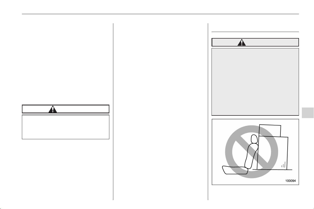
Black plate (379,1)
北米Model "A1160BE-C" EDITED: 2014/ 3/ 17
size and type. You must install four winter
tires that are of the same size, construc-
tion, brand and load range and you should
never mix radial, belted bias or bias tires
since this may result in dangerous hand-
ling characteristics. When you choose a
tire, make sure that there is enough
clearance between the tire and vehicle
body.
Remember to drive with care at all times
regardless of the type of tires on your
vehicle.
& Tire chains
CAUTION
Tire chains cannot be used on your
vehicle because of the lack of
clearance between the tires and
vehicle body.
NOTE
When tire chains cannot be used, use
of another type of traction device (such
as spring chains) may be acceptable if
use on your vehicle is recommended
by the device manufacturer, taking into
account tire size and road conditions.
Follow the device manufacturer’s in-
structions, especially regarding max-
imum vehicle speed.
To help avoid damage to your vehicle,
drive slowly, readjust or remove the
device if it is contacting your vehicle,
and do not spin your wheels. Damage
caused to your vehicle by use of a
traction device is not covered under
warranty.
Make certain that any traction device
you use is an SAE class S device, and
use it on the front wheels only. Always
use the utmost care when driving with
a traction device. Overconfidence be-
cause you are using a traction device
could easily lead to a serious accident.
& Rocking the vehicle
If you must rock the vehicle to free it from
snow, sand, or mud, depress the accel-
erator pedal slightly and move the select
lever back and forth between “D” and “R”
repeatedly. Do not race the hybrid system.
For the best possibl e traction, avoid
spinning the wheels when trying to free
the vehicle.
Loading your vehicle
WARNING
. Never allow passengers to ride
on a folded rear seatback, in the
cargo area. Doing so may result
in serious injury.
. Never s tack luggage or other
cargo higher than the top of the
seatback because it could tumble
forward and injure passengers in
the event of a sudden stop or
accident. Keep luggage or cargo
low, as close to the floor as
possible.
Driving tips/Loading your vehicle
8-11
– CONTINUED –
8
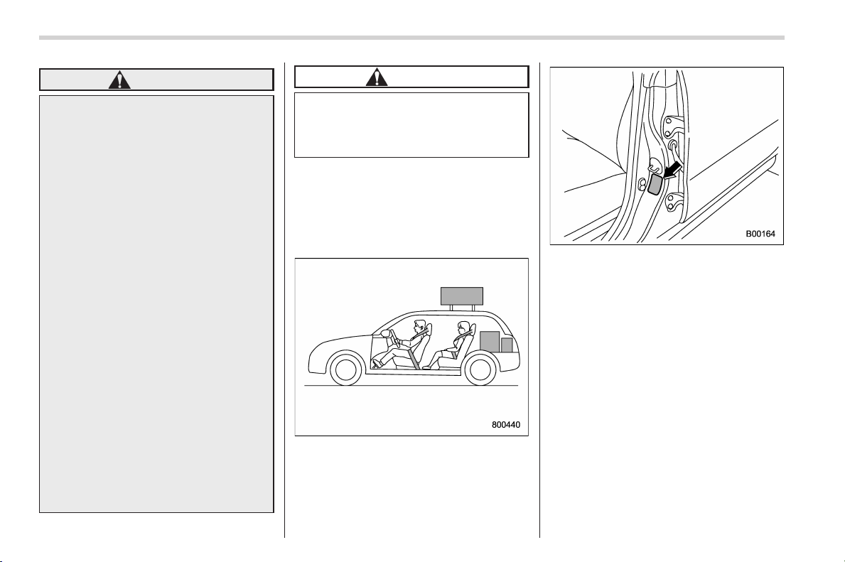
Black plate (380,1)
北米Model "A1160BE-C" EDITED: 2014/ 3/ 17
8-12
Driving tips/Loading your vehicle
WARNING
. When you carry something inside
the vehicle, secure it whenever
you can to prevent it from being
thrown around inside the vehicle
during sudden stops, sharp turns
or in an accident.
. Do not pile heavy loads on the
roof. These loads raise the vehi-
cle’s center of gravity and make it
more prone to tip over.
. Secure lengthy items properly to
prevent them from shooting for-
ward and causing serious injury
during a sudden stop.
. Never exceed the maximum load
limit. If you do, some parts on
your vehicle can break, or it can
change the way your vehic le
handles. This could result in loss
of control and cause personal
injury. Also, overloading can
shorten the life of your vehicle.
. Do not place anything on the
extended cargo area cover. Such
items could tumble forward in the
event of a sudden stop or a
collision. This could cause ser-
ious injury.
CAUTION
Do not carry spray cans, containers
with flammable or corrosive liquids
or any other dangerous items inside
the vehicle.
NOTE
For better fuel economy, do not carry
unneeded cargo.
& Vehicle capacity weight
Vehicle placard
The load capacity of you r vehicle is
determined by weight, not by available
cargo space. The maximum load you can
carry in your vehicle is shown on the
vehicle placard attached to the driver’s
side door pillar. It includes the total weight
of the driver and all passengers and their
belongings, any optional equipment such
as a trailer hitch, roof rack or bike carrier,
etc., and the tongue load of a trailer.
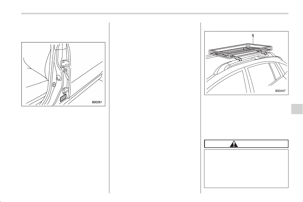
Black plate (381,1)
北米Model "A1160BE-C" EDITED: 2014/ 3/ 17
& GVWR and GAWR (Gross
Vehicle Weight Rating and
Gross Axle Weight Rating)
Certification label
The certification label attached to the
driver’s side doorjamb shows GVWR
(Gross Vehicle Weight Rating) and GAWR
(Gross Axle Weight Rating).
The GVW (Gross Vehicle Weight) must
never exceed the GVWR. GVW is the
combined total of weight of the vehicle,
fuel, driver, all passengers, luggage, any
optional equipment and t railer tongue
load. Therefore, the GVW changes de-
pending on the situation. The GVWR
equals Curb Weight (actual weight of your
vehicle – including standard equipment,
fluids and emergency tools) plu s the
vehicle capacity weight.
In addition, the total weight applied to
each axle (GAW) must never exceed the
GAWR. The front and rear GAWs can be
adjusted by relocating luggage inside the
vehicle.
Even if the total weight of your luggage is
lower than the vehicle capacity weight,
either front or rear GAW may exceed the
GAWR, depending on the distribution of
the luggage.
When possible, the load should be evenly
distributed throughout the vehicle.
If you carry heavy loads in the vehicle, you
should confirm that GVW and front and
rear GAWs are within the GVWR and
GAWR by putting your vehicle on a
vehicle scale, found at a commercial
weighing station.
Do not use replacement tires with a lower
load range than the originals because they
may lower the GVWR and GAWR limita-
tions. Replacement tires with a higher load
range than the originals do not increase
the GVWR and GAWR limitations.
& Roof rail (if equipped)
1) Roof rack
Luggage can be carried on the roof after
securing the roof rack to the roof rails.
When installing the roof rack on the roof
rails, follow the manufacturer’s instruc-
tions. The roof rails are designed to carry
loads (luggage and roof rack) of not more
than 150 lbs (68 kg).
CAUTION
. When using the roof rack, make
sure that the total carrying load
of the roof rack and luggage does
not exceed 150 lbs (68 kg). Over-
loading may cause damage to
the vehicle.
. For cargo carrying purposes, the
Driving tips/Loading your vehicle
8-13
– CONTINUED –
8
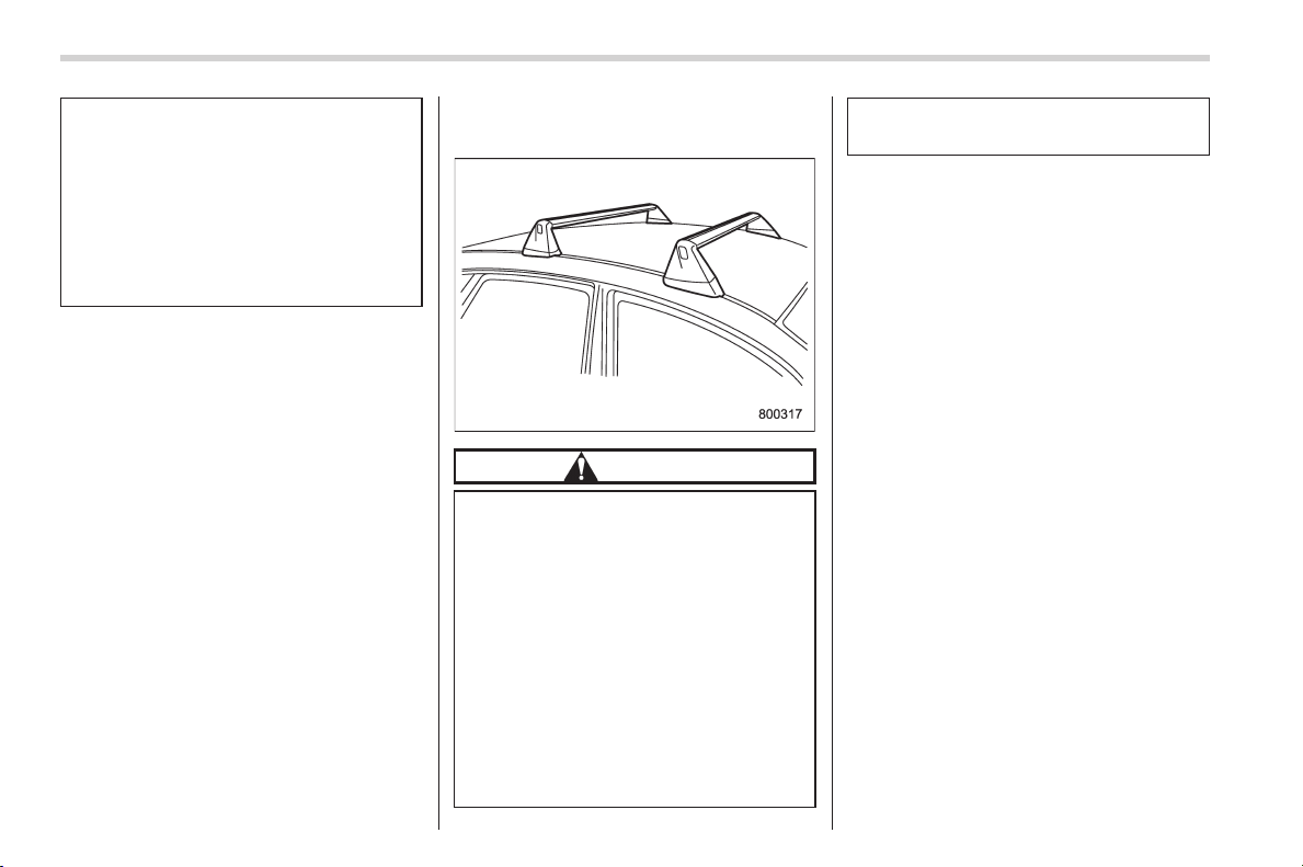
Black plate (382,1)
北米Model "A1160BE-C" EDITED: 2014/ 3/ 17
8-14
Driving tips/Loading your vehicle
roof rails must be used together
with the roof rack and any appro-
priate carrying attachment that
may be needed. The roof rails
must never be used alone to
carry cargo. Otherwise, damage
to the roof or paint, or a danger-
ous road hazard due to loss of
cargo could result.
NOTE
Remember that the vehicle’s center of
gravity is altered with the weight of the
load on the roof, thus affecting driving
characteristics.
Drive carefully. Avoid rapid starts, hard
cornering and abrupt stops. Crosswind
effects will be increased.
& Roof molding and crossbar
(if equipped)
CAUTION
. For cargo carrying purposes, the
roof molding must be used to-
gether with a roof crossbar kit
and the appropriate carrying at-
tachment. Otherwise, damage to
the roof or paint or a dangerous
road hazard due to loss of cargo
could result.
. When using the roof crossbar kit,
make sure that the total weight of
the crossbars, carrying attach-
ment and cargo does not exceed
the maximum load limit. Over-
loading may cause damage to
the vehicle and create a safety
hazard.
Cargo can be carried after securing the
roof crossbar kit to the roof molding and
installing the appropriate carrying attach-
ment. When installing the roof crossbar
kit, follow the manufacturer’s instructions.
When you carry cargo on the roof using
the roof c rossbar kit and a carrying
attachment, never exceed the maximum
load limit as explained below. You should
also be careful that your vehicle does not
exceed the Gross Vehicle Weight Rating
(GVWR) and front and rear Gross Axle
Weight Rating (GAWR). For information
about loading cargo into or onto your
vehicle, refer to “Loading your vehicle”
F8-11. The maximum load limit of the
cargo, crossbars and carrying attachment
must not exceed 176 lbs (80 kg). Place
the heaviest load at the bottom, nearest
the roof, and evenly distribute the cargo.
Always properly secure all cargo.
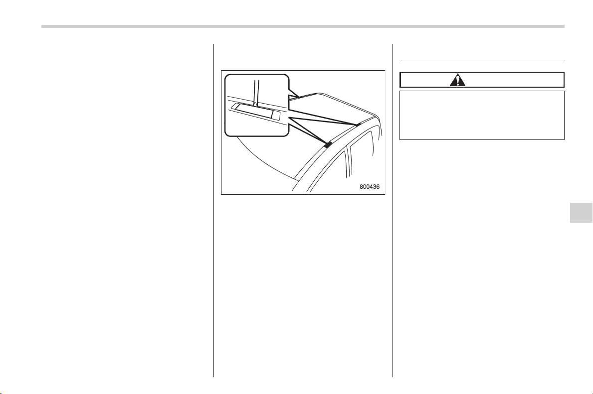
Black plate (383,1)
北米Model "A1160BE-C" EDITED: 2014/ 3/ 17
! Installing carrying attachments on
the crossbars
When installing any carrying attachment
such as a bike carrier, ski carrier, kayak
carrier, cargo basket, etc. on the cross-
bars, follow the manufacturer’s instruc-
tions and make sure that the attachment is
securely fixed to the crossbars. Use only
attachments designed specifically for the
crossbars. A set of the cro ssbars is
designed to carry loads (cargo and attach-
ment) of not more than 165 lbs (75 kg).
Before operating the vehicle, make sure
that the cargo is properly secured on the
attachment.
NOTE
Remember that the vehicle’s center of
gravity is altered with the weight of the
load on the roof, thus affecting the
driving characteristics.
Drive carefully. Avoid rapid starts, hard
cornering and abrupt stops. Crosswind
effects will be increased.
! Removal and installation of the
crossbars
Each of the two roof moldings has two
mounting points for crossbars. Each
mounting point is fitted with a cover. Use
a screwdriver to remove the covers. When
installing the crossbars on the roof mold-
ing, follow the manufacturer’s instructions.
Trailer towing
CAUTION
Your vehicle is neither designed nor
intended to be used for trailer tow-
ing. Therefore, never tow a trailer
with your vehicle.
Driving tips/Trailer towing
8-15
8

Black plate (2,1)
Model "ALL_MODEL_MEMO" EDITED: 2007/ 6/ 22
Left Page
————————————————————————————————————————
————————————————————————————————————————
————————————————————————————————————————
————————————————————————————————————————
————————————————————————————————————————
————————————————————————————————————————
————————————————————————————————————————
————————————————————————————————————————
————————————————————————————————————————
————————————————————————————————————————
————————————————————————————————————————
————————————————————————————————————————
————————————————————————————————————————

Black plate (17,1)
北米Model "A1160BE-C" EDITED: 2014/ 3/ 17
If you park your vehicle in case of an
emergency ........................................................ 9-2
Maintenance tools ............................................... 9-2
Tool locations ..................................................... 9-2
In case of a flat tire ............................................. 9-4
Emergency flat tire repair .................................... 9-4
Tire pressure monitoring system (TPMS)
(U.S.-spec. models) .......................................... 9-13
Jump starting ..................................................... 9-14
How to jump start............................................... 9-14
Engine overheating ............................................ 9-17
If steam is coming from the engine
compartment.................................................... 9-17
If no steam is coming from the engine
compartment ................................................... 9-17
Towing ................................................................ 9-18
Towing and tie-down hooks................................ 9-18
Using a flat-bed truck......................................... 9-20
Towing with all wheels on the ground................. 9-21
Rear gate – if the rear gate cannot be
opened............................................................. 9-22
Access key – if access key does not
operate properly ............................................. 9-23
Locking and unlocking....................................... 9-23
Switching power status...................................... 9-23
Starting hybrid system....................................... 9-24
If your vehicle is involved in an accident ........ 9-24
In case of emergency
9
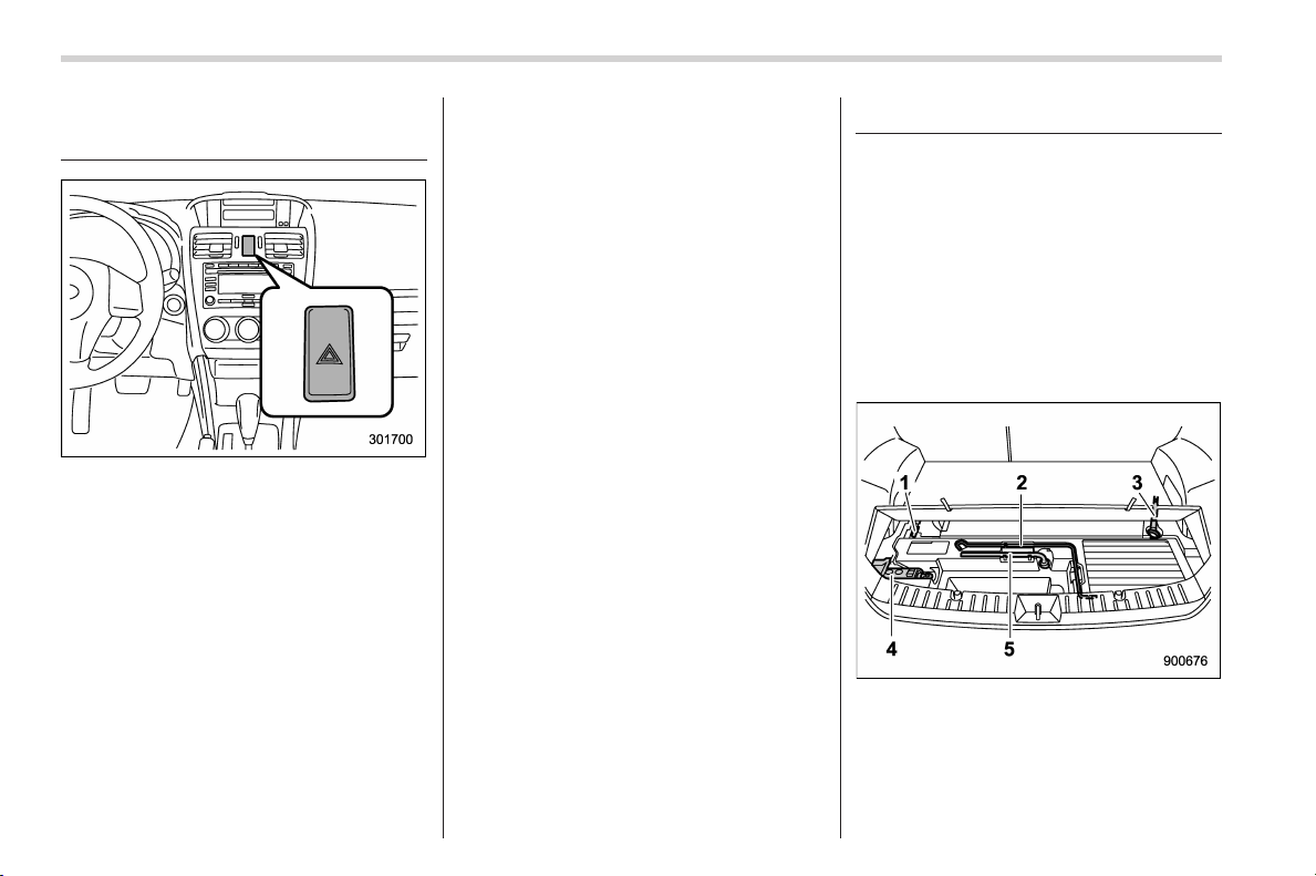
Black plate (388,1)
北米Model "A1160BE-C" EDITED: 2014/ 3/ 17
9-2
In case of emergency/If you park your vehicle in case of an emergency
If you park your vehicle in
case of an emergency
The hazard warning flasher should be
used in day or night to warn other drivers
when you have to park your vehicle under
emergency conditions.
Avoid stopping on the road. It is best to
safely pull off the road if a problem occurs.
The hazard warning flasher can be acti-
vated regardless of the ignition switch
position.
Turn on the hazard warning by pushing
the hazard warning flasher switch. Turn it
off by pushing the switch again.
NOTE
When the hazard warning flasher is on,
the turn signals do not work.
Maintenance tools
Your vehicle is equipped with the following
maintenance tools.
. Jack
. Jack handle
. Screwdriver
. Towing hook (eye bolt)
. Wheel nut wrench
& Tool locations
1) Screwdriver
2) Jack handle
3) Towing hook (eye bolt)
4) Jack
5) Wheel nut wrench
A jack, jack handle, wheel nut wrench and
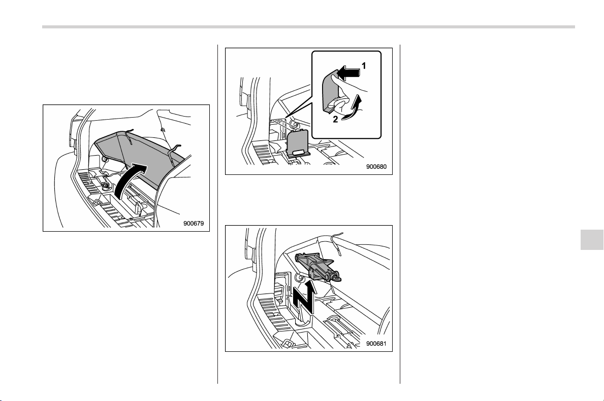
Black plate (389,1)
北米Model "A1160BE-C" EDITED: 2014/ 3/ 17
towing hook are stored under the floor of
the cargo area. A screwdriver is stored in
the glove box. The screwdriver can be
stored as shown in the illustration.
To take out the jack:
1. Raise and fold the cargo floor board.
1) Press the cover lightly
2) Pull out the cover.
2. Remove the jack cover as shown in
the illustration.
3. Take out the jack.
NOTE
For how to use the jack, refer to
“Replacement procedure” F11-28.
In case of emergency/Maintenance tools
9-3
9
Black plate (390,1)
北米Model "A1160BE-C" EDITED: 2014/ 3/ 17
9-4
In case of emergency/In case of a flat tire
In case of a flat tire
If you have a flat tire while driving, never
brake suddenly, and keep driving straight
ahead while gradually reducing speed.
Then slowly pull off the road to a safe
place.
& Emergency flat tire repair
Your vehicle is not equipped with a spare
tire. If you have a flat tire, you can use the
flat tire repair kit to temporarily repair
punctures, such as those made by nails
or similar objects. To ensure that repair
work goes smoothly, read the following
instructions before sealing a flat tire.
This flat tire repair kit is for temporary
repairs. After making a repair, immediately
have the tire repaired or replaced at a
SUBARU dealer or other qualified service
facility.
WARNING
. Read these instructions and
warnings carefully before sealing
a flat tire. Compliance with these
instructions is vital to ensuring
vehicle safety. Not complying
with these instructions means
risking tire damage, which can
affect vehicle handling and lead
to loss of vehicle control. This
may result in serious injury or
death.
. Do not use tire chains on a tire
that has been repaired with the
flat tire repair kit.
. Do not tow trailer.
. Before using the flat tire repair
kit, park your vehicle in a safe
location where it will not interfere
with traffic.
. When using the flat tire repair kit,
apply the parking brake to make
sure that the vehicle will not
move.
. When using the flat tire repair kit,
turn on the hazard warning
flashers.
. When using the flat tire repair kit,
do not leave the vehicle unat-
tended.
CAUTION
. If you accidentally swallow the
sealant, drink plenty of water and
seek medical attention immedi-
ately.
. If the sealant splashes into your
eyes or onto your skin, wash it
away immediately with plenty of
water. If you feel any discomfort,
seek medical attention.
. Keep the sealant out of the reach
of children.
. Contact with the sealant can
cause allergic reactions for peo-
ple who are allergic to natural
rubber (or latex).
. If used on a vehicle with a tire
pressure monitoring system
(TPMS), the system might not
function correctly.
! When is sealing possible?
Sealing is possible when minor punctures
with a diameter of no more than 3/16 in (4
mm) caused by nails or similar objects
piercing the visible tread of the tire.
CAUTION
Perform temporary repair without
removing the nail or similar objects
from the tire. Removing the nail or
similar objects could result in da-
mage that cannot be repaired with
the sealant in the flat tire repair kit.
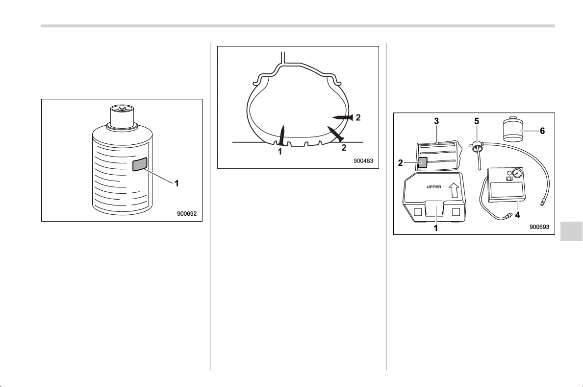
Black plate (391,1)
北米Model "A1160BE-C" EDITED: 2014/ 3/ 17
! When is sealing not possible?
Do not use the flat tire repair kit in the
following cases. Contact a SUBARU deal-
er or Commercial Road Service for assis-
tance.
1) Expiration date
. The expiration date of the sealant has
passed.
NOTE
The sealant has an expiration date.
Replace the sealant before the expira-
tion date has passed. Contact a
SUBARU dealer if you need to replace
the sealant.
1) Sealing is possible
2) Sealing is not possible
. The tire damage is not located within
the visible tread of the tire.
. The sidewall of the tire has cracks,
bumps, or similar damage.
. Two or more tires have been punctu-
red. (One bottle of sealant is sufficient to
seal only one tire.)
. The tire has already been damaged as
a result of being driven in an under inflated
condition.
. When the tire bead has unseated from
the wheel.
. The wheel or the tire valve of the flat
tire is damaged.
. The diameter of the puncture in the
visible tread of the tire is more than 3/16 in
(4 mm).
. The temperature is lower than −228F
(−308C).
! Flat tire repair kit
The flat tire repair kit is stored under the
driver’s seat.
1) Case
2) Speed limit label
3) Quick reference
4) Compressor
5) Sealant application cap
6) Bottle of sealant
NOTE
. Break the foil seal on the bottle of
the sealant only immediately before
using the sealant. Otherwise, the odor
could become irritating and the sealant
In case of emergency/In case of a flat tire
9-5
– CONTINUED –
9
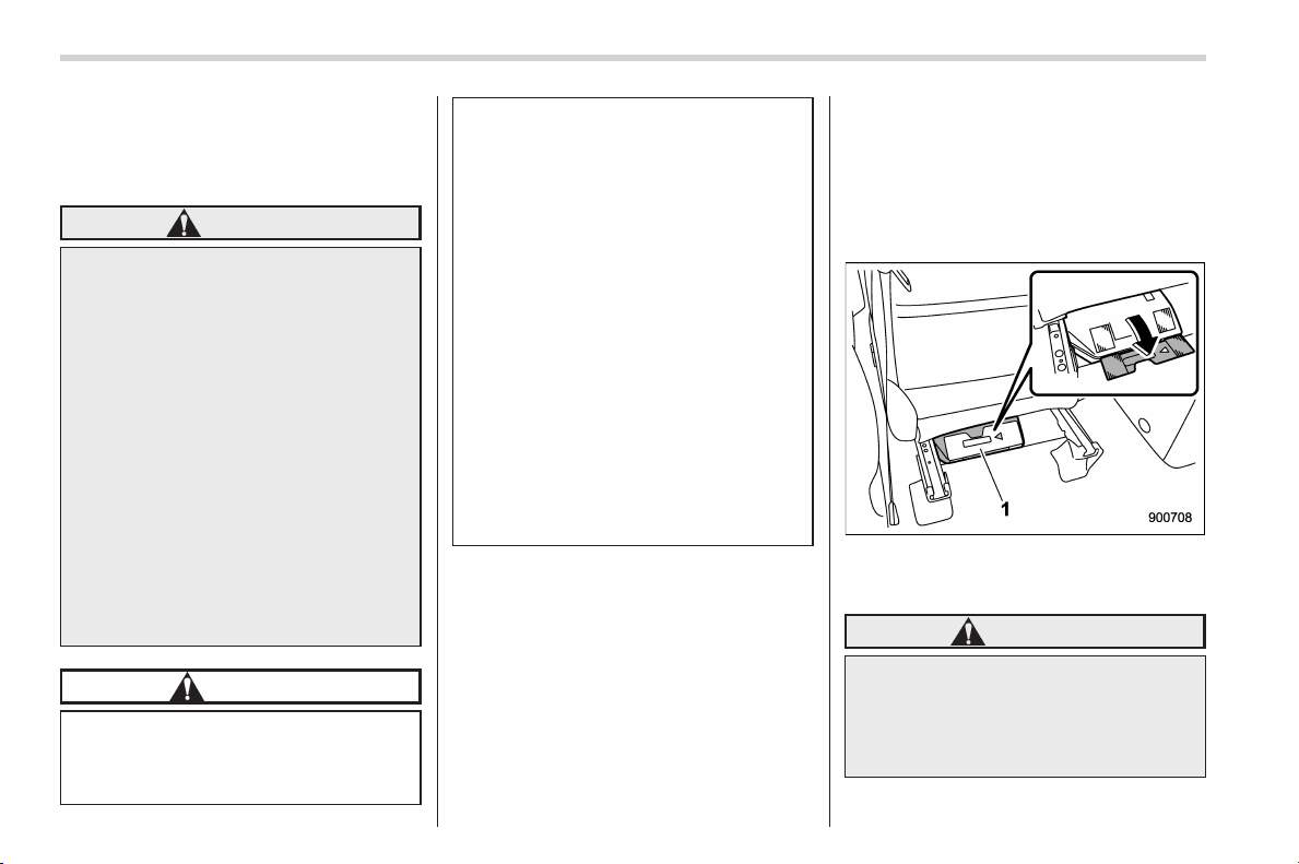
Black plate (392,1)
北米Model "A1160BE-C" EDITED: 2014/ 3/ 17
9-6
In case of emergency/In case of a flat tire
could be spilled.
. If sealant gets on your clothing, it
might be di fficult or impossible t o
remove.
WARNING
Observe the following when using
the compressor. Failure to do so
could r esult in a fire or electric
shock.
. Before using the compressor,
check the power cord for da-
mage. A damaged power cord
could result in an electric shock.
. Do not operate the compressor
with wet hands.
. If fire, smoke, odd odors, or any
other abnormal situation occurs
while using the compressor, dis-
continue use immediately, dis-
connect the power cord, and
contact a SUBARU dealer for
assistance.
CAUTION
Observe the following when using
the compressor. Failure to do so
could result in damage to the com-
pressor.
. Do not operate the compressor
continuously for 10 minutes or
longer.
. Keep water away from the com-
pressor. When working in rainy
conditions, keep the compressor
in a dry location.
. Do not use the compressor in
dusty or sandy locations.
. Stop using the compressor if it
becomes hot to the touch or its
operation becomes sluggish.
Confirm that the compressor
has cooled down before using it
again.
. Do not disassemble or modify the
compressor. Avoid subjecting
the compressor to physical im-
pacts.
! Before use
1. Park your vehicle in a safe location on
a flat, hard surface. Ensure that it does not
interfere with traffic.
2. Turn off the ignition switch.
3. Turn on the hazard warning flashers,
and have the passengers get out of the
vehicle and stand in safe place.
4. If necessary, move your vehicle so that
the valve on the punctured tire is at the
bottom.
5. Make sure the parking brake is ap-
plied.
6. Raise the driver’s seat to the highest
position, and then slide it as far forward as
possible. For details, refer to “Front seats”
F1-2.
7. Detach the locking plate, and take out
the flat tire repair kit.
WARNING
Do not place anything under the
driver’s seat other than the flat tire
repair kit. That may interfere with
front seat locking and cause an
accident.
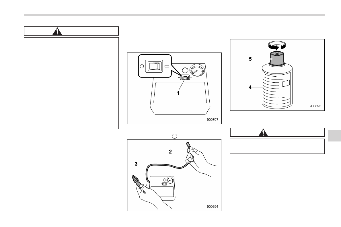
Black plate (393,1)
北米Model "A1160BE-C" EDITED: 2014/ 3/ 17
CAUTION
. Park your vehicle in a safe loca-
tion on a flat, hard surface.
. The flat tire repair kit is designed
only for tires of the specified tires
of a non-specified size or other
purposes. For the specified tire
size, refer to the tire placard
located on the driver’s door pil-
lar.
. Store the flat tire repair kit only in
its original location, locked into
place by the locking plate. Other-
wise, it could fly out if the brakes
are applied suddenly, resulting in
unexpected injury.
! How to seal a tire
Remove the compressor from the case
before use and place it on a flat surface
near the tire.
1. Make sure the compressor power
switch (1) is in the “
” (off) position.
2. Remove the hose (2) and power cable
(3) from the back of the compressor.
3. Shake the sealant bottle (4) well, and
then remove the cap (5).
CAUTION
One bottle of sealant is sufficient for
only one tire. Do not re-use sealant.
NOTE
When working in temperatures below
the freezing point, it is recommended
that you keep the bottle warm inside
the vehicle before using the sealant.
In case of emergency/In case of a flat tire
9-7
– CONTINUED –
9
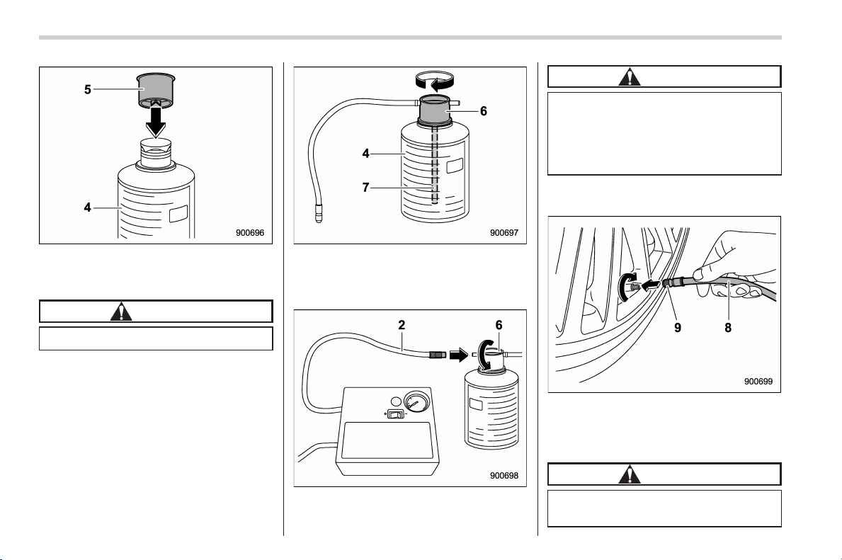
Black plate (394,1)
北米Model "A1160BE-C" EDITED: 2014/ 3/ 17
9-8
In case of emergency/In case of a flat tire
4. Use the protrusion on the top of the
cap (5) to make a hole in the aluminum
seal on the sealant (4).
CAUTION
Be careful not to spill the sealant.
5. Insert the tube (7) with the application
cap (6) into the sealant bottle (4), and then
tighten the sealant application cap (6) until
it clicks.
6. Connect the compressor hose (2) to
the sealant application cap (6).
CAUTION
. Be careful to not allow the hose
to become twisted.
. When connecting the hose, be
careful to not strip the threads on
the application cap.
7. Remove the valve cap from the punc-
tured tire.
8. Connect the valve fitting (9) on the tip
of the application cap’s rubber hose (8) to
the valve on the damaged tire, and tighten
completely.
CAUTION
The sealant might leak if the fitting is
not tight enough.
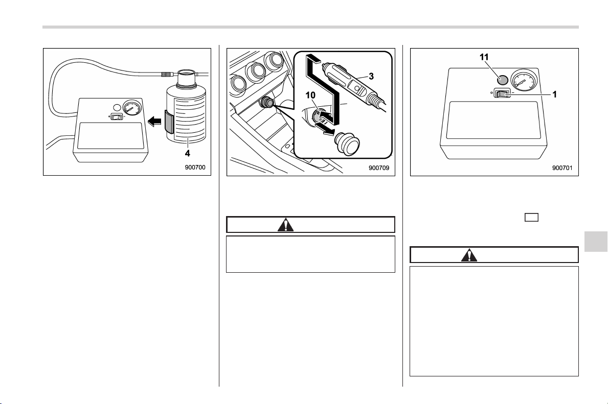
Black plate (395,1)
北米Model "A1160BE-C" EDITED: 2014/ 3/ 17
9. Secure the sealant bottle (4) to the
compressor with Velcro to keep the bottle
upright.
NOTE
It might not be possible to use the
sealant if the bottle falls over. Make
sure the bottle remains upright.
10. Insert the power cord of the compres-
sor (3) into the accessory power outlet
(10).
CAUTION
Be sure to power the compressor
only from the accessory power out-
let.
11. Set the ignition switch to the “ACC”
position.
12. Once again check the sidewall of the
tire for cracks, bumps, or similar damage
before starting the compressor. If there is
no such damage, press the “
” (on) side
of the compressor’s power switch (1) and
inject the sealant and air.
CAUTION
. When injecting sealant, the pres-
sure will exceed 45 psi (300 kPa)
temporarily and then decrease
when all the sealant enters the
tire.
. Do not stand directly next to the
tire while the sealant is being
injected.
. After some sealant and air have
inflated the tire partially, check
In case of emergency/In case of a flat tire
9-9
– CONTINUED –
9
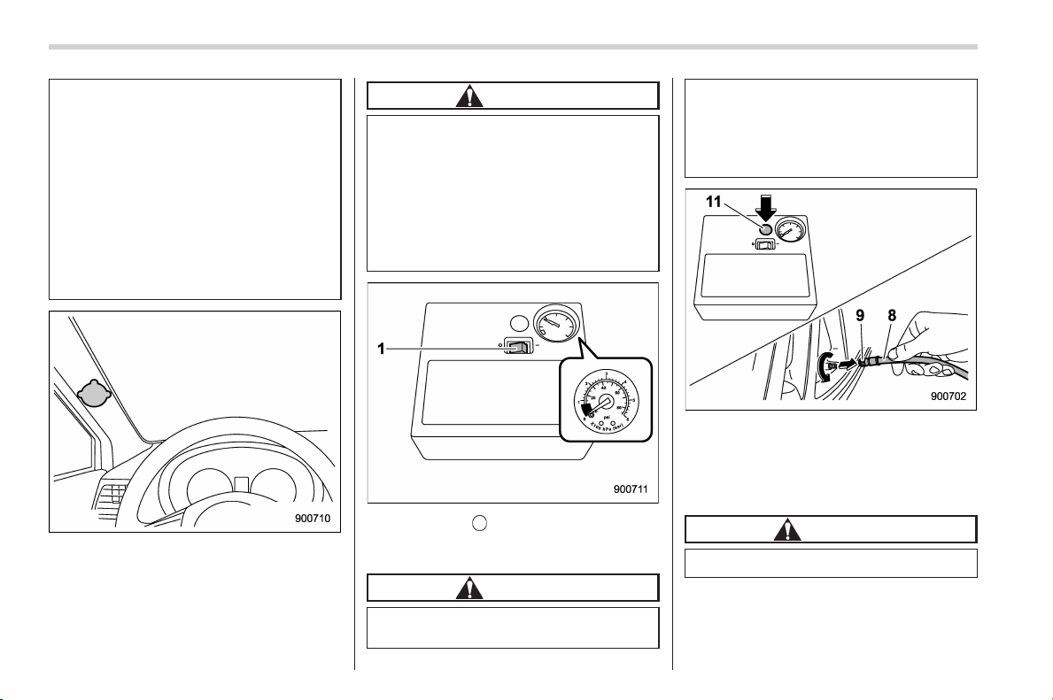
Black plate (396,1)
北米Model "A1160BE-C" EDITED: 2014/ 3/ 17
9-10
In case of emergency/In case of a flat tire
the sidewall of the tire for cracks
and bumps. If any cracks,
bumps, or similar damage ap-
pears in the sidewall while using
the compressor, stop the com-
pressor immediately and press
the air vent button to release the
pressure. In this case, you can-
not repair the tire with the flat tire
repair kit. Contact a SUBARU
dealer or Commercial Road Ser-
vice for assistance.
13. Attach the speed limit (50 mph (80
km/h)) label in a location where it can be
seen easily by the driver.
CAUTION
. Do not attach the speed limit
label to the steering wheel pad
or the dashboard. The label could
interfere with proper operation of
the SRS airbag.
. Do not attach the label in loca-
tions where it will block warning
indicators or the speedometer.
14. Press the “ ” (off) side of the power
switch (1) when the tire pressure reaches
26 psi (180 kPa).
CAUTION
If the tire pressure does not reach 26
psi (180 kPa) after 10 minutes, the
tire might be damaged severely. In
this case, you cannot repair the tire
with the flat tire repair kit. Contact a
SUBARU dealer or Commercial
Road Service for assistance.
15. Simultaneously, remove the valve fit-
ting (9) on the tip of the application cap’s
rub ber hose (8) fro m the valve while
pushing the air vent button (11) on the
compressor.
CAUTION
Remove the fitting quickly.
16. Reattach the tire valve cap.
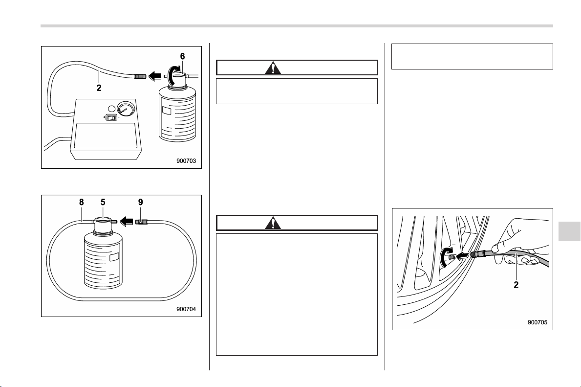
Black plate (397,1)
北米Model "A1160BE-C" EDITED: 2014/ 3/ 17
17. Remove the compressor hose (2) from
the application cap (6).
18. Connect the valve fitting (9) on the tip
of the application cap’s rubber hose (8) to
the other side of the application cap (5) to
prevent the remaining sealant from leak-
ing out.
CAUTION
Be careful that sealant does not leak
onto skin or fabric.
19. Put away the flat tire repair kit.
20. Immediately begin driving your vehicle
for approximately 10 minutes or 3 miles (5
km) to distribute the sealant through the
tire. Drive carefully, obeying legal speed
limits, never driving faster than 50 mph (80
km/h),andavoidingsuddensteering
movements.
21. After a short drive, stop in a safe place
and re-check the tire pressure.
CAUTION
. If you notice anything unusual
while driving, pull off the road to
asafeplaceandcontacta
SUBARU dealer or Commercial
Road Service for assistance. If
the sealant has not been set
completely, the tire might lose
pressure and became unstable.
. Secure the flat tire repair kit and
bottle so that they do not move.
Otherwise, they could strike a
passenger in the event of a
sudden stop or collision and
cause injury.
NOTE
The low tire press ure warning light
might illuminate while you are driving.
22. Park your vehicle in a safe location,
and check the tire pressure using the
gauge included with the compressor to
inspect tire pressure. The proper tire
pressure can be found on the tire placard
attached to the door pillar on the driver’s
side.
23. Remove the valve cap from the sea-
lant-filled tire.
24. Connect the compressor hose (2) to
the valve on the sealant-filled tire.
In case of emergency/In case of a flat tire
9-11
– CONTINUED –
9
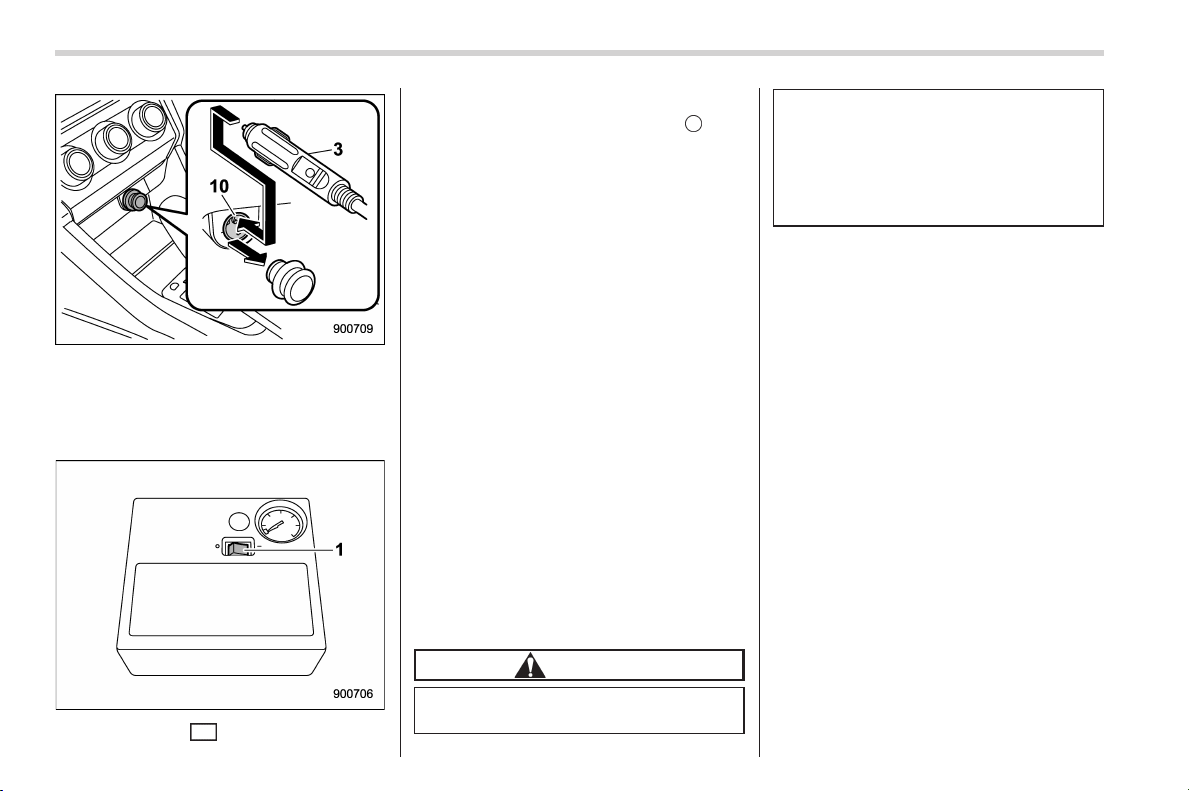
Black plate (398,1)
北米Model "A1160BE-C" EDITED: 2014/ 3/ 17
9-12
In case of emergency/In case of a flat tire
25. Insert the power cord of the compres-
sor (3) into the accessory power outlet
(10).
26. Set the ignition switch to the “ACC”
position.
27. Pres s the “ ” (on) side of the
compressor’s power switch (1), wait a
few seconds, and then press the “
” (off)
side of the switch.
28. If the tire pressure is 18 psi (130 kPa)
or more, adjust the tire to the specified
pressure on the tire placard.
If the tire pressure is less than 18 psi (130
kPa), the tire cannot be repaired with
sealant. Do not continue to drive your
vehicle. Contact a SUBARU dealer or
Commercial Road Service for assistance.
NOTE
In cold weather, more time might be
required to complete a repair, and you
might need to drive a longer distance.
In this case, repeat the Steps from (19)
to (26). If the pressure continues to
drop even after repeating this proce-
dure, the tire cannot be repaired with
the repair kit. Do not continue to drive
the car. Contact a SUBARU dealer or
Commercial Road Service for assis-
tance.
29. After sealing the flat tire, immediately
have your vehicle inspected at a SUBARU
dealer or other qualified service facility.
CAUTION
. Drive carefully, obeying legal
speed limits, never driving faster
than 50 mph ( 80 km/h), and
avoiding sudden steering move-
ments.
. Do not exceed a maximum driv-
ing distance of 125 miles (200
km) on a sealant-filled tire.
NOTE
. After sealing the flat tire temporarily,
have the tire repaired or replaced with a
new tire and tire valve as soon as
possible.
. When a tire is repaired with liquid
sealant, the tire pressure warning valve
and transmitter may not operate prop-
erly. If a liquid sealant is used, contact
your nearest SUBARU dealer or other
qualified service shop as soon as
possible. Make sure to replace the tire
pressure warning valve and transmitter
when replacing the tire. You may reuse
the wheel if there is no damage to it and
if the sealant residue is properly
cleaned off.
. The sealant, hose, speed limit label,
and sealant application cap need to be
replaced after using the flat tire repair
kit. Contact a SUBARU dealer for de-
tails.
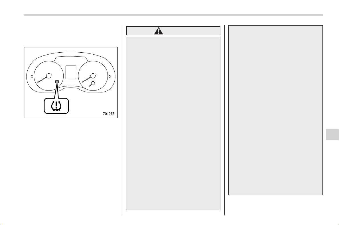
Black plate (399,1)
北米Model "A1160BE-C" EDITED: 2014/ 3/ 17
& Tire pressure monitoring
system (TPMS) (U.S.-spec.
models)
Low tire pressure warning light
The tire pressure monitoring system pro-
vides the driver with the warning message
indicated by sending a signal from a
sensor that is installed in each wheel
when tire pressure is severely low.
The tire pressure monitoring system will
activate only when the vehicle is driven.
Also, this system may not react immedi-
ately to a sudden drop in tire pressure (for
example, a blow-out caused by running
over a sharp object).
WARNING
. If the low tire pressure warning
light illuminates while driving,
never brake suddenly. Instead,
perform the following procedure.
(1) Keep driving straight ahea d
while gradually reducing
speed.
(2) Slowly pull off the road to a
safe place. Otherwise an acci-
dent involving serious vehicle
damage and serious personal
injury could occur.
(3) Check the pressure for all four
tires and adjust the pressure
to the COLD tire pressure
shown on the vehicle placard
on the door pillar on the
driver’s side.
If this light still illuminates while
driving after adjusting the tire
pressure, a tire may have signifi-
cant damage and a fast leak that
causes the tire to lose air rapidly.
If you have a flat tire, refer to “In
case of a flat tire” F9-4.
. When a replacement tire is
mounted or a wheel rim is re-
placed without the original pres-
sure sensor/transmitter being
transferred, the low tire pressure
warning light will illuminate stea-
dily after blinking for appr oxi-
mately one minute. This indi-
cates the TPMS is unable to
monitor all four road wheels.
Contact your SUBARU dealer as
soon as p ossible for tire and
sensor replacement and/or sys-
tem resetting.
. When a tire is repaired with liquid
sealant, the tire pressure warning
valve and transmitter may not
operate properly. If a liquid sea-
lant is used, contact your nearest
SUBARU dealer or other qualified
service shop as soon as possi-
ble. Make sure to replace the tire
pressure warning valve and
transmitt er when replacing the
tire. You may reuse the wheel if
there is no damage to it and if the
sealant residue is properly
cleaned off.
If the light illuminates steadily
after blinking for approximately
one minute, promptly contact a
SUBARU dealer to have the sys-
tem inspected.
In case of emergency/In case of a flat tire
9-13
9
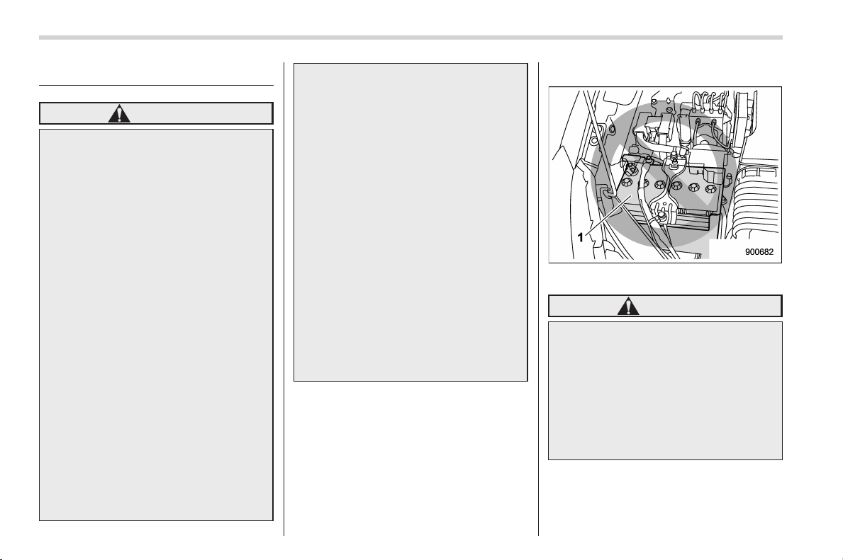
Black plate (400,1)
北米Model "A1160BE-C" EDITED: 2014/ 3/ 17
9-14
In case of emergency/Jump starting
Jump starting
WARNING
. Battery fluid is SULFURIC ACID.
Do not let it come in contact with
the eyes, skin, clothing or the
vehicle.
If battery fluid g ets on you,
thoroughly flush the exposed
area with water immediately. Get
medical help if the fluid h as
entered your eyes.
If battery fluid is accidentally
swallowed, immediately drink a
large amount of milk or water,
and obta in immediate medical
help.
Keep everyone including chil-
dren away from the battery.
. The gas generated by a battery
explodes if a flame or spark is
brought near it. Do not smoke or
light a match while jump starting.
. Never attempt jump starting if the
discharged battery is frozen. It
could cause the battery to burst
or explode.
. Whenever working on or around
a battery, always wear suitable
eye protectors, and remove metal
objects such as rings, bands or
other metal jewelry.
. Be sure the jumper cables and
clamps on them do not have
loose or missing insulation.
Do not jump start unless cables
in suitable condition are avail-
able.
. A running engine can be danger-
ous. Keep your fingers, hands,
clothing, hair a nd tools away
from the cooling fan, belts and
any other moving engine parts.
Removing ring s, watches and
ties is advisable.
. Jump starting is dangerous if it
done incorrectly. If you are un-
sure about the proper procedure
for jump starting, consult a com-
petent mechanic.
When your vehicle does not start due to a
run down (discharged) battery, the vehicle
may be jump started by connecting your
battery to another battery (called the
booster battery) with jumper cables.
& How to jump start
1) 12 V engine restart battery
WARNING
Observe the following precautions.
Otherwise, any flames or sparks in
the vicinity could cause an explo-
sion since batteries emit highly
flammable, explosive hydrogen
gas. Also, electric components or
the hybrid system may be damaged.
. Do not connect the jumper cable
to the 12 V engine restart battery.
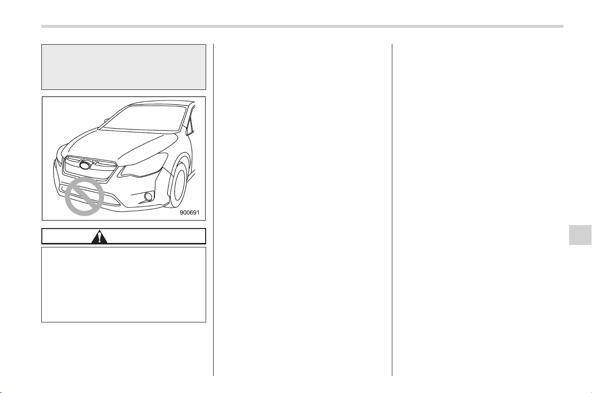
Black plate (401,1)
北米Model "A1160BE-C" EDITED: 2014/ 3/ 17
. Do not cross connect the 12 V
auxiliary battery and 12 V engine
restart battery in an attempt to
jump start the vehicle.
CAUTION
When replacing the battery or jump-
starting, do not touch the area
around the front bumper. Also, do
not put tools or cloths in this area. If
any function of the cooling system
operates, it may lead to an injury or
a failure of the cooling system.
1. Make sure the booster battery is 12
volts and the negative terminal is
grounded.
2. If the booster battery is in another
vehicle, do not let the two vehicles touch.
3. Turn off all unnecessary lights and
accessories.
4. Connect the jumper cables exactly in
the sequence illustrated.
In case of emergency/Jump starting
9-15
– CONTINUED –
9
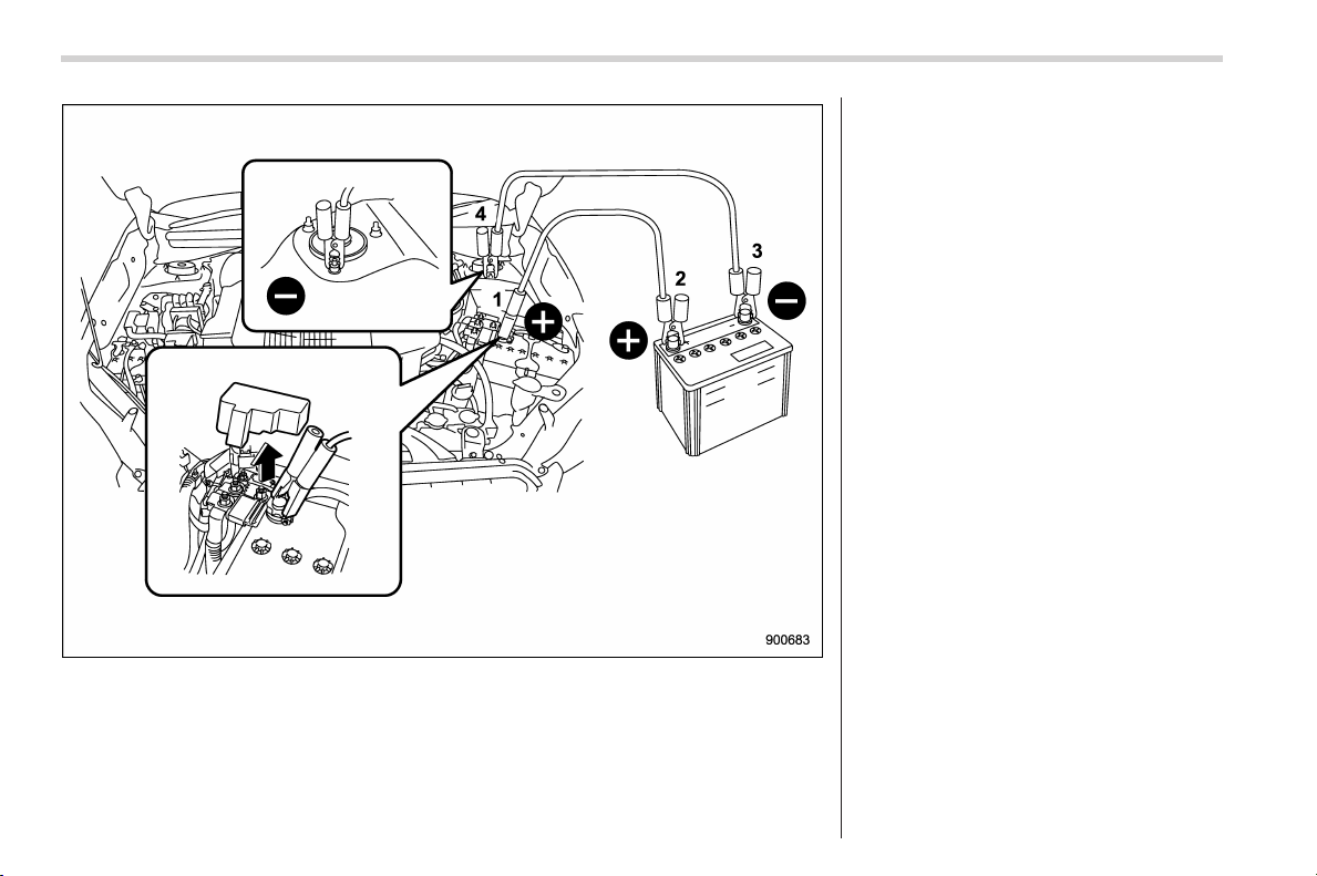
Black plate (402,1)
北米Model "A1160BE-C" EDITED: 2014/ 3/ 17
9-16
In case of emergency/Jump starting
(1) Connect one jumper cable to the
positive (+) terminal on the discharged
12 V auxiliary battery.
(2) Connect the other end of the
jumper cable to the positive (+) term-
inal of the booster battery.
(3) Connect one end of th e other
cable to the negative (−) terminal of
the booster battery.
(4) Connect the other end of the cable
to the strut mounting nut of the vehicle
withthedischarged12Vauxiliary
battery.
Make sure that the cables are not near
any moving parts and that the cable
clamps are not in contact with any other
metal.
5. Start the engine of the vehicle with the
booster battery and run it at moderate
speed. Then start the hybrid system of the
vehicle that has the discharged battery.
6. When finished, car efully disconnect
the cables in exactly the reverse order.
Black plate (403,1)
北米Model "A1160BE-C" EDITED: 2014/ 3/ 17
Engine overheating
WARNING
Never attempt to remove the radia-
tor cap until the engine has been
shut off and has fully cooled down.
When the engine is hot, the coolant
is under pressure. Removing the
cap while the engine is still hot
could release a spray of boiling hot
coolant, which could burn you very
seriously.
If the engine overheats, safely pull off the
road and stop the vehicle in a safe
location.
& If steam is coming from the
engine compartment
. Turn the ignition switch to the “LOCK”
(off) position and get everyone away from
the vehicle until it cools down.
. Contact an authorized SUBARU deal-
er.
& If no steam is coming from
the engine compartment
1. Keep the hybrid system running at
idling speed.
2. Open the engine hood to ventilate the
engine compartment. Refer to “Engine
hood” F11-7.
Confirm that the cooling fan is turning. If
the fan is not turning, immediately turn the
ignition switch to the “LOCK” (off) position
and contact an authorized SUBARU deal-
er for repair.
3. After the coolant temperature high
warning light that has blinked or illumi-
nated in RED turns off, turn the ignition
switch to the “LOCK” (off) position. For
details about the warning light, refer to
“Coolant temperature low indicator light/
Coolant temperature high warning light”
F3-16.
4. After the engine has fully cooled down,
check the coolant level in the reserve
tank. If the coolant level is below the
“LOW” mark, add coolant up to the “FULL”
mark.
NOTE
For details about how to check the
coolant level or how to add coolant,
refer to “Engine coolant” F11-14.
5. If there is no coolant in the reserve
tank, add coolant to the reserve tank.
Then remove the radiator cap and fill the
radiator with coolant.
If you remove the radiator cap from a hot
radiator, first wrap a thick cloth around the
radiator cap, then turn the cap counter-
clockwise slowly without pressing down
until it stops. Release the pressure from
the radiator. After the pressure has been
fully released, remove the cap by pressing
down and turning it.
In case of emergency/Engine overheating
9-17
9
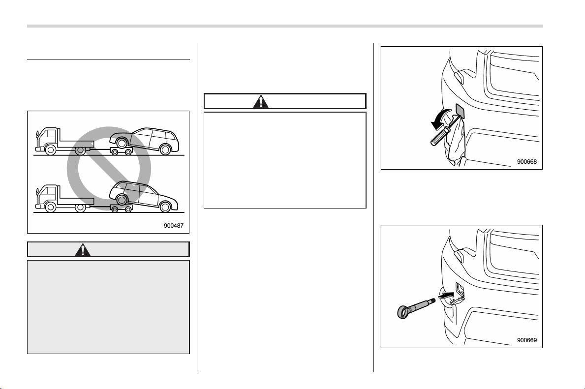
Black plate (404,1)
北米Model "A1160BE-C" EDITED: 2014/ 3/ 17
9-18
In case of emergency/Towing
Towing
If towing is necessary, it is best done by
your SUBARU dealer or a commercial
towing service. Observe the following
procedures for safety.
WARNING
Never tow AWD models with the
front wheels raised off the ground
while the rear wheels are on the
ground, or with the rear wheels
raised off the ground while the front
wheels are on the ground. This will
cause the vehicle to spin away due
to the operation or deterioration of
the center differential.
& Towing and tie-down hooks
The towing hooks should be used only in
an emergency (e.g., to free a stuck vehicle
from mud, sand or snow).
CAUTION
. Use only the specified towing
hook and tie-down hook. Never
use suspension parts or other
parts of the body for towing or
tie-down purposes.
. To prevent deformation to the
front bumper and the towing
hook, do not apply excessive
lateral load to the towing hook.
! Front towing hook
1. Take out the towing hook, screwdriver
and jack handle. For the locations of these
tools, refer to “Maintenance tools” F9-2.
2. Cover the tip of a flat-head screwdriver
with vinyl tape or cloth so that it will not
scratch the bumper. Insert the flat-head
screwdriver into the cutout of the cover
and pry open the cover.
3. Screw the towing hook into the thread
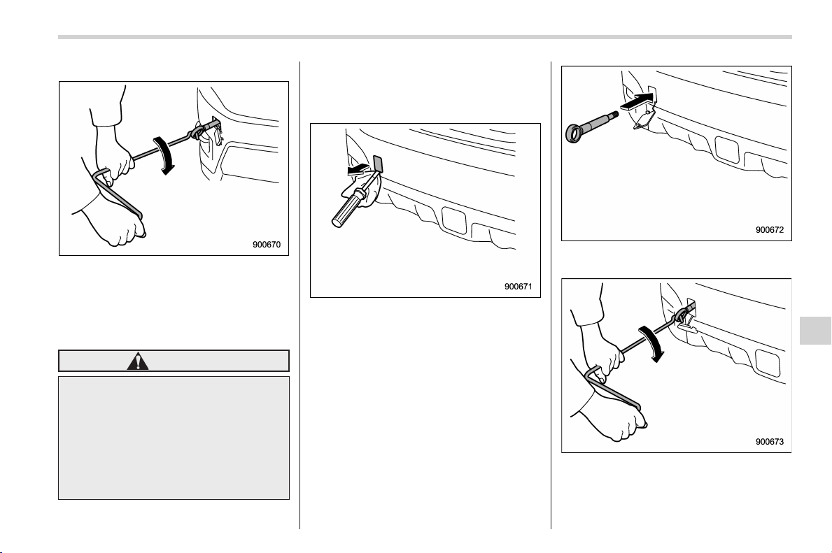
Black plate (405,1)
北米Model "A1160BE-C" EDITED: 2014/ 3/ 17
hole until its thread can no longer be seen.
4. Tighten the towing hook se curely
using the jack handle.
After towing, remove the towing hook from
the vehicle and stow it in the cargo area.
Fit the towing hook cover on the bumper.
WARNING
. Do not use the towing hook
except when towing your vehicle.
. Be sure to remove the towing
hook after towing. Leaving the
towing hook mounted on the
vehicle could interfere with prop-
er operation of the SRS airbag
system in a frontal collision.
! Rear towing hook
1. Take out the towing hook, screwdriver
and jack handle. For the locations of these
tools, refer to “Maintenance tools” F9-2.
2. Pry off the cover on the rear bumper
using a screwdriver, and you will find a
threaded hole for attaching the towing
hook.
3. Screw the towing hook into the thread
hole until its thread can no longer be seen.
4. Tighten the towing hook securely
using the jack handle.
After towing, remove the towing hook from
In case of emergency/Towing
9-19
– CONTINUED –
9
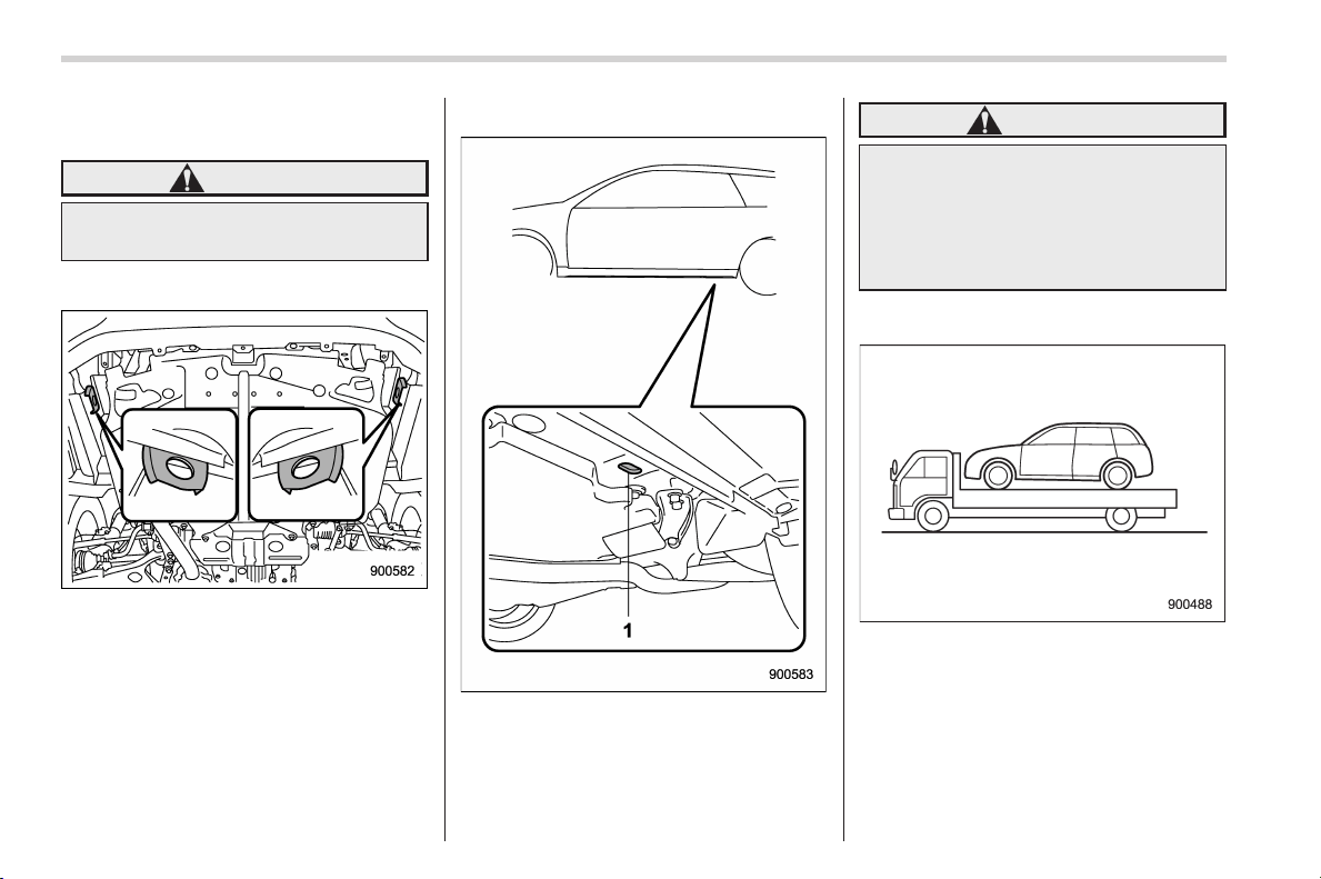
Black plate (406,1)
北米Model "A1160BE-C" EDITED: 2014/ 3/ 17
9-20
In case of emergency/Towing
the vehicle and stow it in the cargo area.
Fit the towing hook cover on the bumper.
WARNING
Do not use the towing hook except
when towing your vehicle.
! Front tie-down hooks
The front tie-down hooks are located
between each of the front tires and the
front bumper.
! Rear tie-down holes
1) Rear tie-down hole
The rear tie-down holes are located near
each of the jack-up reinforcements.
WARNING
Use the rear tie-down holes only for
downward anchoring. If they are
used to anchor the vehicle in any
other direction, cables may slip out
of the holes, possibly causing a
dangerous situation.
& Using a flat-bed truck
This is the best way to transport your
vehicle. Use the following procedures to
ensure safe transportation.
1. Shift the select lever into the “P”
position.
2. Pull up the parking brake lever firmly.
3. Secure the vehicle onto the carrier
properly with safety chains. Each safety
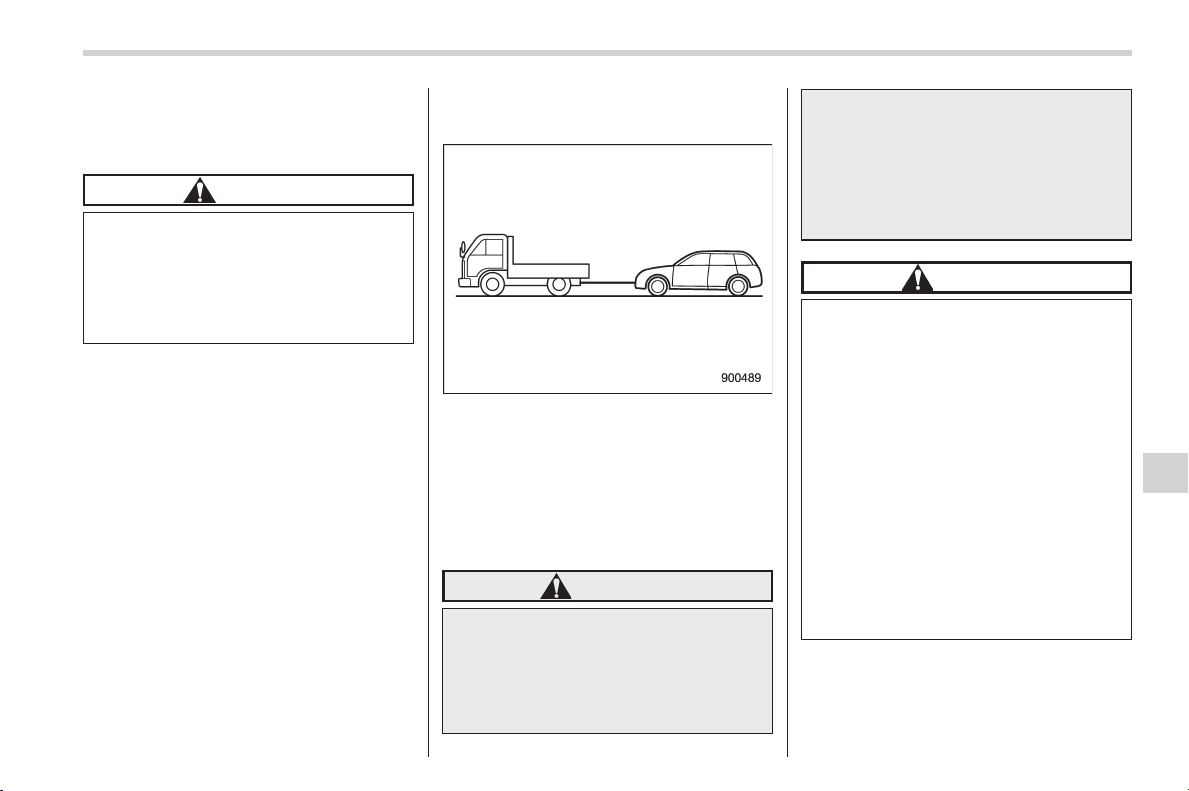
Black plate (407,1)
北米Model "A1160BE-C" EDITED: 2014/ 3/ 17
chain should be equally tightened and
care must be taken not to pull the chains
so tightly that the suspension bottoms out.
CAUTION
If your vehicle has a front under-
spoiler and rear underspoiler (both
optional), be careful not to scrape
them when placing the vehicle on
the carrier and when removing the
vehicle from the carrier.
& Towing with all wheels on the
ground
1. Release the parking brake and put the
transmission in the “N” position.
2. The ignition switch should be in the
“ACC” position while the vehicle is being
towed.
3. Take up slack in the towline slowly to
prevent damage to the vehicle.
WARNING
. Never turn the ignition switch to
the “LOCK” (off) position while
the vehicle is being towed be-
cause the steering wheel and the
direction of the wheels will be
locked.
. Remember that the brake booster
and power steering do not func-
tion when the hybrid system is
not running. Because the hybrid
system is turned off, it will take
greater effort to operate the
brake pedal and steering wheel.
CAUTION
. If transmission failure occurs,
transport your vehicle on a flat-
bed truck.
. Do not run the hybrid system
while being towed using this
method. Transmission damage
couldresultifthevehicleis
towed with the hybrid system
running.
. The traveling speed must be
limited to less than 20 mph (30
km/h) and the traveling distance
to less than 31 miles (50 km). For
greater speeds and distances,
transport your vehicle on a flat-
bed truck.
NOTE
For models with “keyless access with
push-button start system”, if you can-
In case of emergency/Towing
9-21
– CONTINUED –
9
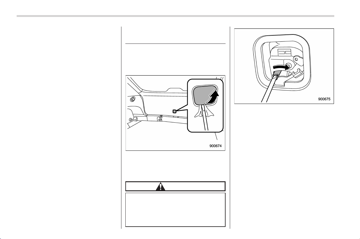
Black plate (408,1)
北米Model "A1160BE-C" EDITED: 2014/ 3/ 17
9-22
In case of emergency/Rear gate – if the rear gate cannot be opened
not turn the push-button ignition
switch to the “ACC” status, perform
the procedure described in “Switching
power status” F9-23.
Rear gate – if the rear gate
cannot be opened
In the event that you cannot open the rear
gate by operating the rear gate opener
button, you can open it from inside the
cargo area.
1. Remove the access cover at the
bottom-center of the rear gate trim.
2. Locate the rear gate open lever behind
the rear gate trim panel.
CAUTION
Never operate the rear gate open
lever with fingers because doing so
may cause an injury. Always use a
flat-head screwdriver or a similar
tool.
3. To open the rear gate, turn the lever to
the right position using a flat-head screw-
driver or a similar tool.

Black plate (409,1)
北米Model "A1160BE-C" EDITED: 2014/ 3/ 17
Access key – if access key
does not operate properly
CAUTION
Keep metallic objects, magnetic
sources and signal transmitters
away from the area between the
access key and the push-button
ignition switch. They may interfere
with the c ommunication between
the access key and the push-button
ignition switch.
If the locking/unlocking procedures, power
switch procedures or hybrid system start
procedures cannot be operated because
of strong radio signals in the surrounding
area or a low battery condition of the
access key, perform the following proce-
dure. When the battery of the access key
is discharged, replace it with a new one.
Refer to “Replacing access key battery”
F11-46.
& Locking and unlocking
1) Release button
2) Mechanical key
While pressing the release button of the
access key, take out the mechanical key.
Lock or unlock the driver’s door with the
mechanical key.
NOTE
After locking or unlocking, be sure to
reinsert the mechanical key into the
access key.
& Switching power status
1. Apply the parking brake.
2. Shift the select lever into the “P”
position.
3. Depress the brake pedal.
4. Hold the access key with the buttons
facing you, and touch the push-button
ignition switch with it.
When the communication between the
access key and the vehicle is completed,
a chime (ding) will sound. At the same
time, the status of the push-button ignition
switch changes to either of the following.
. When the keyless access with push-
button start system is deactivated:
“ACC”
. Under other conditions: “ON”
5. When the keyless access with push-
button start system is deactivated, press
the push-button ignition switch with the
brake pedal released. The status of the
push-button ignition switch then changes
to “ON”.
In case of emergency/Access key – if access key does not operate properly
9-23
– CONTINUED –
9
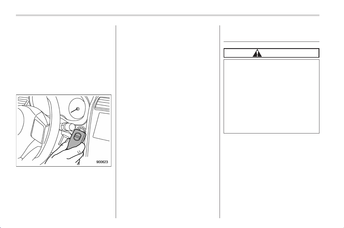
Black plate (410,1)
北米Model "A1160BE-C" EDITED: 2014/ 3/ 17
9-24
In case of emergency/If your vehicle is involved in an accident
NOTE
If the power does not switch even
though the above procedure was fol-
lowed precisely, contact your SUBARU
dealer.
& Starting hybrid system
1. Apply the parking brake.
2. Shift the select lever into the “P”
position.
3. Depress the brake pedal.
4. Hold the access key with the buttons
facing you, and touch the push-button
ignition switch with it.
When the communication between the
access key and the vehicle is completed,
a chime (ding) will sound. At the same
time, the push-button ignition switch turns
to the “ACC” or “ON” position.
5. Within 5 seconds after the push-button
ignition switch turns to the “ACC” or “ON”
position, while depressing the brake ped-
al, press the push-button ignition switch.
NOTE
If the hybrid system does not start even
though the above procedure was fol-
lowed precisely, contact your SUBARU
dealer.
If your vehicle is involved in
an accident
CAUTION
If your vehicle is involved in an
accident, be sure to inspect the
ground under the vehicle before
restarting the hybrid system. If you
find that fuel has leaked on th e
ground, do not try to restart the
hybrid system. The fuel system has
been damaged and is in need of
repair. Immediately contact the near-
est automotive service facility. We
recommend that you consult your
SUBARU dealer.
Your vehicle has a fuel pump shut off
system. To minimize the risk of fire due to
fuel leakage when the hybrid system stalls
or an airbag inflates upon collision or a
rear collision happens, the system stops
supplying fuel to the engine. Also, the
hybrid system is stopped to shut off the
high voltage.
Perform the following procedures to re-
start the hybrid system after the system is
activated.

Black plate (411,1)
北米Model "A1160BE-C" EDITED: 2014/ 3/ 17
Models without “keyless access with
push-button start system”:
1. Turn the ignition switch to the “LOCK”
(off) or “ACC” position.
2. Restart the hybrid system.
Models with “ke yless access with
push-button start system”:
1. Turn the push-button ignition switch to
the “ACC” or “OFF” position.
2. Restart the hybrid system.
NOTE
After restarting the hybrid system, you
can drive your vehicle only at a vehicle
speed of approximately 16 mph (25
km/h) or less. Have your vehicle in-
spected at a SUBARU dealer.
In case of emergency/If your vehicle is involved in an accident
9-25
9

Black plate (2,1)
Model "ALL_MODEL_MEMO" EDITED: 2007/ 6/ 22
Left Page
————————————————————————————————————————
————————————————————————————————————————
————————————————————————————————————————
————————————————————————————————————————
————————————————————————————————————————
————————————————————————————————————————
————————————————————————————————————————
————————————————————————————————————————
————————————————————————————————————————
————————————————————————————————————————
————————————————————————————————————————
————————————————————————————————————————
————————————————————————————————————————

Black plate (19,1)
北米Model "A1160BE-C" EDITED: 2014/ 3/ 17
Exterior care ....................................................... 10-2
Washing............................................................. 10-2
Waxing and polishing......................................... 10-3
Cleaning aluminum wheels ................................. 10-3
Corrosion protection.......................................... 10-4
Most common causes of corrosion ..................... 10-4
To help prevent corrosion................................... 10-4
Cleaning the interi or.......................................... 10-5
Seat fabric......................................................... 10-5
Leather seat materials........................................ 10-5
Synthetic leather upholstery............................... 10-5
Climate control panel, audio panel, instrument
panel, console panel, and switches .................. 10-5
Monitor (if equipped).......................................... 10-6
Appearance care
10
Black plate (414,1)
北米Model "A1160BE-C" EDITED: 2014/ 3/ 17
10-2
Appearance care/Exterior care
Exterior care
& Washing
CAUTION
. When washing the vehicle, the
brakes may get wet. As a result,
the brake stopping distance will
be longer. To dry the brakes,
drive the vehicle at a safe speed
while lightly depressing the
brake pedal to heat up the
brakes.
. Do not wash the engine compart-
ment and area adjacent to it. If
water enters the engine air intake
or electrical parts, it will cause
engine trouble or a malfunction
of electrical equipment.
. Do not use any organic solvents
when washing the surface of the
bulb assembly cover. However, if
a detergent with organic solvents
is used to wash the cover sur-
face, completely rinse off the
detergent with water. Otherwise,
the cover surface may be da-
maged.
. Since your vehicle is equipped
with a rear wiper, automatic car-
wash b rushes could bec ome
tangled around it, damaging the
wiper arm and other compo-
nents. Ask the automatic car-
wash operator not to let the
brushes touch the wiper arm or
to fix the wiper arm on the rear
window glass with adhesive tape
before operating the machine.
NOTE
When having your vehicle washed in
an automatic car wash, make sure
beforehand that the car was h is of
suitable type.
The best way to preserve your vehicle’s
beauty is frequent washing. Wash the
vehicle at least once a month to avoid
contamination by road grime.
Wash dirt off with a wet sponge and plenty
of lukewarm or cold water. Do not wash
the vehicle with hot water and in direct
sunlight.
Salt, chemicals, insects, tar, soot, tree
sap, and bird droppings should be washed
off by using a light detergent, as required.
If you use a light detergent, make certain
that it is a neutral detergent. Do not use
strong soap or chemical detergents. All
cleaning agents should be promptly
flushed from the surface and not allowed
to dry there. Rinse the vehicle thoroughly
with plenty of lukewarm water. Wipe the
remaining water off with a chamois or soft
cloth.
! Washing the underbody
Chemicals, salts and gravel used for
deicing road surfaces are extremely cor-
rosive, accelerating the corrosion of un-
derbody components, such as the exhaust
system, fuel and brake lines, brake
cables, floor pan and fenders, and sus-
pension.
Thoroughly flush the underbody and in-
side of the fenders with lukewarm or cold
water at frequent intervals to reduce the
harmful effects of such agents.
Mud and sand adhering to the underbody
components may accelerate their corro-
sion.
After driving off-road or on muddy or
sandy roads, wash the mud and sand off
the underbody. Carefully flush the suspen-
sion and axle parts, as they are particu-
larly prone to mud and sand buildup. Do
not use a sharp-edged tool to remove
caked mud.
Black plate (415,1)
北米Model "A1160BE-C" EDITED: 2014/ 3/ 17
CAUTION
. Be careful not to damage brake
hoses, sensor harness es, and
other parts when washing sus-
pension components.
. Be careful not to flush the engine
bottom for a long time. It may
cause damage of some electrical
parts.
! Using a warm water washer
. Keep a good distance of 12 in (30 cm)
or more between the washer nozzle and
the vehicle.
. Do not wash the same area continu-
ously.
. If a stain will not come out easily, wash
by hand. Some warm water washers are
of the high temperature, high pressure
type, and they can damage or deform the
resin parts such as moldings, or cause
water to leak into the vehicle.
& Waxing and polishing
Always wash and dry the vehicle before
waxing and polishing.
Use a good quality polish and wax and
apply them according to the manufac-
turer’s instructions. Wax or polish when
the painted surface is cool.
Be sure to polish and wax the chrome trim,
as well as the painted surfaces. Loss of
wax on a painted surface leads to loss of
the original luster and also quickens the
deterioration of the surface. It is recom-
mended that a coat of wax be applied at
least once a mo nth, or whenever the
surface no longer repels water.
If the appearance of the paint has dimin-
ished to the point where the luster or tone
cannot be restored, lightly polish the
surface with a fine-grained compound.
Never polish just the affected area, but
include the surrounding area as well.
Always polish in only one direction. A
No. 2000 grain compound is recom-
mended. Never use a coarse-grained
compound. Coa rse-grained compounds
have a smaller grain-size number and
could damage the paint. After polishing
with a compound, coat with wax to restore
the original luster. Frequent polishing with
acompoundoranincorrectpolishing
technique will result in removing the paint
layer and exposing the undercoat. When
in doubt, it is always best to contact your
SUBARU dealer or an auto paint specia-
list.
CAUTION
Do not use any agents with organic
solvents on the surface of the bulb
assembly cover. However, if a polish
or wax with organic solvents is
applied to the cover surface, com-
pletely wipe off the polish or wax.
Otherwise, the cover surface may be
damaged.
NOTE
Be careful not to block the windshield
washer nozzles with wax when waxing
the vehicle.
& Cleaning aluminum wheels
. Promptly wipe the aluminum wheels
clean of any kind of grime or agent. If dirt
is left on too long, it may be difficult to
clean off.
. Do not use soap containing grit to
clean the wheels. Be sure to use a neutral
cleaning agent, and later rinse thoroughly
with water. Do not clean the wheels with a
stiff brush or expose them to a high-speed
washing device.
. Clean the vehicle (including the alumi-
num whe els) with water as soon as
possible when it has been splashed with
sea water, exposed to sea breezes, or
driven on roads treated with salt or other
agents.
Appearance care/Exterior care
10-3
10

Black plate (416,1)
北米Model "A1160BE-C" EDITED: 2014/ 3/ 17
10-4
Appearance care/Corrosion protection
Corrosion protection
Your SUBARU has been designed and
built to resist corrosion. Special materials
and protective finishes have been used on
most parts of the vehicle to help maintain
fine appearance, strength, and reliable
operation.
& Most common causes of
corrosion
The most common causes of corrosion
are:
1. The accumulation of moisture retain-
ing dirt and debris in body panel sections,
cavities, and other areas.
2. Damage to paint and other protective
coatings caused by gravel and stone
chips or minor accidents.
Corrosion is accelerated on the vehicle
when:
1. It is exposed to road salt or dust
control chemicals, or used in coastal
areas where there is more salt in the air,
or in areas where there is considerable
industrial pollution.
2. It is driven in areas of high humidity,
especially when temperatures range just
above freezing.
3. Dampness in certain parts of the
vehicle remains for a long time, even
though other parts of the vehicle may be
dry.
4. High temperatures will cause corro-
sion to parts of the vehicle which cannot
dry quickly due to lack of proper ventila-
tion.
& To help prevent corrosion
Wash the vehicle regu larly to prevent
corrosion of the body and suspension
components. Also, wash the vehicle
promptly after driving on any of t he
following surfaces.
. roads that have been salted to prevent
them from freezing in winter
. mud, sand, or gravel
. coastal roads
After the winter has ended, it is recom-
mended that the underbody be given a
very thorough washing.
Before the beginning of winter, check the
condition of underbody components, such
as the exhaust system, fuel and brake
lines, brake cables, suspension, steering
system, floor pan, and fenders. If any of
them are found to be rusted, they should
be given an appropriate rust prevention
treatment or should be replaced. Contact
your SUBARU dealer to perform this kind
of maintenance and treatment if you need
assistance.
Repair chips and scratches in the paint as
soon as you find them.
Check the interior of the vehicle for water
and dirt accumulation under the floor mats
because that could cause corrosion.
Occasionally check under the mats to
make sure the area is dry.
Keep your garage dry. Do not park your
vehicle in a damp, poorly ventil ated
garage. In such a garage, corrosion can
be caused by dampness. If you wash the
vehicle in the garage or put the vehicle
into the garage when wet or covered with
snow, that can cause dampness.
If your vehicle is operated in cold weather
and/or in areas where road salts and other
corrosive materials are used, the door
hinges and locks, and hood latch should
be inspected and lubricated periodically.
Black plate (417,1)
北米Model "A1160BE-C" EDITED: 2014/ 3/ 17
Cleaning the interior
Use a soft, damp cloth to clean the climate
control panel, audio equipment, instru-
ment panel, center console, combination
meter panel, and switches. (Do not use
organic solvents.)
& Seat fabric
Remove loose dirt, dust or debris with a
vacuum cleaner. If the dirt is caked on the
fabric or hard to remove with a vacuum
cleaner, use a soft brush then vacuum it.
Wipe the fabri c surface with a tightly
wrung cloth and dry the seat fabric
thoroughly. If the fabric is still dirty, wipe
using a solution of mild soap and luke-
warm water then dry thoroughly.
If the stain does not come out, try a
commercially-available fabric cleaner. Use
the cleaner on a hidden place and make
sure it does not affect the fabric adversely.
Use the cleaner according to its instruc-
tions.
CAUTION
When cleaning the seat, do not use
benzine, paint thinner, or any similar
materials.
& Leather seat materials
The leather used by SUBARU is a high
quality natural product which will retain its
distinctive appearance and feel for many
years with proper care.
Allowing dust or road dirt to build up on the
surface can cause the material to become
brittle and to wear prematurely. Regular
cleaning with a soft, moist, natural fiber
cloth should be performed monthly, taking
care not to soak the leather or allow water
to penetrate the stitched seams.
A mild detergent suitable for cleaning
woolen fabrics may be used to remove
difficult dirt spots, rubbing with a soft, dry
cloth afterwards to restore the luster. If
your SUBARU is to be parked for a long
time in bright sunlight, it is recommended
that the seats and head restraints be
covered, or the w indows shaded, to
prevent fading or shrinkage.
Minor surface blemishes or bald patches
may be treated with a commercial leather
spray lacquer. You will discover that each
leather seat section will develop soft folds
or wrin kles, which is characteristi c of
genuine leather.
& Synthetic leather upholstery
The synthetic leather material used on the
SUBARU may be cleaned using mild soap
or detergent and water, after first vacuum-
ing or brushing away loose dirt. Allow the
soap to soak in for a few minutes and wipe
off with a clean, damp cloth. Commercial
foam-type cleaners suitable for synthetic
leather materials may be used when
necessary.
CAUTION
Strong cleaning agents such as
solvents, paint thinners, window
cleaner or fuel must never be used
on leather or synthetic interior ma-
terials. Doing so could damage the
surface and cause the color to
deteriorate.
& Climate control panel, audio
panel, instrument panel,
console panel, and switches
Use a soft, damp cloth to clean the climate
control panel, audio equipment, instru-
ment panel, center console, combination
meter panel, and switches.
Appearance care/Cleaning the interior
10-5
– CONTINUED –
10
Black plate (418,1)
北米Model "A1160BE-C" EDITED: 2014/ 3/ 17
10-6
Appearance care/Cleaning the interior
CAUTION
. Do not use organic solvents such
as paint thinners or fuel, or
strong cleaning agents that con-
tain those solvents.
. Do not use c hemical solvents
that contain silicone on the vehi-
cle audio system, electrical com-
ponents of the air-conditioner or
any switches. If silicone adheres
to these p arts, it may cause
damage to electrical compo-
nents.
& Monitor (if equipped)
To clean the audio/navigation/multi func-
tion display monitor, wipe it with a silicone
cloth or with a soft cloth. If the monitor is
extremely dirty, clean it with a soft cloth
moistened with neutral detergent then
carefully wipe off any remaining detergent.
CAUTION
. Do not spray neutral detergent
directly onto the monitor. Doing
so could damage the monitor’s
components.
. Do not wipe the monitor with a
hard cloth. Doing so could
scratch the monitor.
. Do not use cleaning fluid that
contains thinner, fuel, o r any
other volatile substance. Su ch
cleaning fluid could erase the
lettering on the switches at the
bottom of the monitor.

Black plate (21,1)
北米Model "A1160BE-C" EDITED: 2014/ 3/ 17
Maintenance schedule ....................................... 11-3
Maintenance precautions................................... 11-3
Before checking or servicing in the engine
compartment.................................................... 11-4
When checking or servicing in the engine
compartment.................................................... 11-5
When checking or servicing in the engine
compartment while the engine is running.......... 11-5
Maintenance tips ................................................ 11-5
Removing and reinstalling clips.......................... 11-5
Engine hood ....................................................... 11-7
Engine compartment overview.......................... 11-9
Engine oil.......................................................... 11-10
Engine oil consumption.................................... 11-10
Locations of the oil level gauge, oil filler cap
and oil filter ................................................... 11-10
Checking the oil level ....................................... 11-10
Changing the oil and oil filter............................ 11-11
Recommended grade and viscosity .................. 11-12
Synthetic oil..................................................... 11-12
Cooling system ................................................ 11-13
Safety precautions ........................................... 11-13
Cooling fan, hose and connections ................... 11-13
Engine coolant ................................................. 11-14
Air cleaner elemen t .......................................... 11-15
Replacing the air cleaner element ..................... 11-15
Spark plugs ...................................................... 11-17
Recommended spark plugs .............................. 11-17
Drive belts ........................................................ 11-17
Continuously variable transmission fluid....... 11-17
Front differential gear oil ................................ 11-18
Recommended grade and viscosity .................. 11-18
Rear differential gear oil.................................. 11-18
Recommended grade and viscosity .................. 11-18
Brake fluid........................................................ 11-18
Checking the fluid level.................................... 11-18
Recommended brake fluid ............................... 11-19
Brake booster .................................................. 11-19
Brake pedal ...................................................... 11-20
Checking the brake pedal free play .................. 11-20
Checking the brake pedal reserve distance....... 11-20
Hill start assist system.................................... 11-20
Replacement of bra ke pad and lining ............ 11-21
Breaking-in of new brake pads and linings ....... 11-21
Parking brake stroke ....................................... 11-22
Tires and wheels.............................................. 11-22
Types of tires................................................... 11-22
Tire pressure monitoring system (TPMS) (if
equipped) ...................................................... 11-22
Tire inspection................................................. 11-24
Tire pressures and wear .................................. 11-24
Wheel balance ................................................. 11-26
Wear indicators ............................................... 11-26
Tire rotation direction mark .............................. 11-27
Tire rotation..................................................... 11-27
Tire replacement.............................................. 11-27
Wheel replacement .......................................... 11-30
Aluminum wheels ............................................ 11-31
Windshield washer fluid.................................. 11-31
Adding the windshield washer fluid .................. 11-31
Maintenance and service
11

Black plate (22,1)
北米Model "A1160BE-C" EDITED: 2014/ 3/ 17
Maintenance and service
Windshield washer fluid ................................... 11-31
Replacement of wiper blades.......................... 11-32
Windshield wiper blade assembly ..................... 11-33
Windshield wiper blade rubber ......................... 11-33
Rear window wiper blade assembly .................. 11-34
Rear window wiper blade rubber....................... 11-35
Battery. .............................................................. 11-36
12 V auxiliary battery and 12 V engine restart
battery ........................................................... 11-36
High voltage battery ......................................... 11-37
Fuses ................................................................ 11-38
Installation of accessories............................... 11-39
Replacing bulbs ............................................... 11-40
Headlights (models with HID headlights) ........... 11-40
Headlights (models without HID headlights)...... 11-40
Front turn signal light ...................................... 11-41
Parking light .................................................... 11-41
Front fog light (if equipped).............................. 11-41
Rear combination lights ................................... 11-42
License plate light ........................................... 11-43
Map light ......................................................... 11-44
Dome light and cargo area light ....................... 11-45
Other bulbs ..................................................... 11-45
Battery replacement ........................................ 11-45
Battery replacement timing .............................. 11-45
Safety precautions........................................... 11-45
Replacing access key battery........................... 11-46
Replacing transmitter battery ........................... 11-47
Black plate (423,1)
北米Model "A1160BE-C" EDITED: 2014/ 3/ 17
Maintenance schedule
The scheduled maintenance items re-
quired to be serviced at regular intervals
are shown in the “Warranty and Main-
tenance Booklet”.
For details of your maintenance schedule,
read the separate “Warranty and Main-
tenance Booklet”.
NOTE
For models with a multi function dis-
play, you can set a reminder to be
displayed when a scheduled mainte-
nance item is almost due. For details,
refer to “Maintenance settings” F3-61.
Maintenance precautions
When maintenance and service are re-
quired, it is recommended that all work be
done by an authorized SUBARU dealer.
If you perform maintenance and service
by yourself, you should familiarize yourself
with the information provided in this
section on general maintenance and
service for your SUBARU.
Incorrect or incomplete service could
cause improper or unsafe vehicle opera-
tion. Any problems caused by improper
maintenance and service performed by
you are not eligible for warranty coverage.
WARNING
. Always select a safe area when
performing maintenance on your
vehicle.
. Always be very careful to avoid
injury when working on the vehi-
cle. Remember that some of the
materials in the vehicle may be
hazardous if improperly used or
handled, for example, battery
acid.
. Your vehicle should only be ser-
viced by persons fully competent
to do so. Serious personal injury
may result to persons not experi-
enced in servicing vehicles.
. Always use the proper tools and
make certain that they are well
maintained.
. Never get under the vehicle sup-
ported only by a jack. Always use
safety stands to support the
vehicle.
. Never ke ep the hybrid system
running in a poorly ventilated
area, such as a garage or other
closed areas.
. Do not smoke or all ow open
flames around the fuel or battery.
This will cause a fire.
. Because the fuel system is under
pressure, replacement of the fuel
filter should be performed only
by your SUBARU dealer.
. Wear adequate eye protection to
guard against getting oil or fluids
in your eyes. If something does
get in your eyes, thoroughly
wash them out with clean water.
. Do not tamper with the wiring of
the SRS airbag system or seat-
belt pretensioner system, or at-
tempt to take its connectors
apart, as that may activate the
Maintenance and service/Maintenance schedule
11-3
– CONTINUED –
11
Black plate (424,1)
北米Model "A1160BE-C" EDITED: 2014/ 3/ 17
11-4
Maintenance and service/Maintenance precautions
system or it can render it inop-
erative. NEVER use a circuit
tester for this wiring. If your
SRS airbag or seatbelt preten-
sioner needs service, consult
your nearest SUBARU dealer.
NOTE
SUBARU does not endorse the use of
non-SUBARU approved flushing sys-
tems and strongly advises agai nst
performing these services on a
SUBARU vehicle. Non-SUBARU ap-
proved flushing systems use chemi-
cals and/or solvents which have not
been tested or approved by SUBARU.
SUBARU warranties do not cover any
part of the vehicle which is damaged by
adding or applying chemicals and/or
solvents other than those approved or
recommended by SUBARU.
& Before checking or servicing
in the engine compartment
WARNING
. Always turn the ignition switch to
the “LOCK” (off) position and
apply the parking brake to pre-
vent the vehicle from moving.
. Always let the engine cool down.
Engine parts become very hot
when the engine is running and
remain hot for some time after
the engine is stopped.
. Do not spill engine oil, engine
coolant, brake fluid or any other
fluid on hot engine components.
This may cause a fire.
. When the ignition switch is in the
“ON” position, the cooling fan
may operate suddenly even
when the hybrid system is
stopped. If your body or clothes
come into contact with a rotating
fan, that could result in serious
injury. To avoid risk of inju ry,
perform the foll owing precau-
tions.
– Models with push-button start
system:
Always turn the push-button
ignition switch to the “OFF”
position and confirm that the
operation indicator on the
switch is turned off. Then take
the access key out from the
vehicle.
– Models without push-button
start system:
Always remove the key from
the ignition switch.
. Before performing any servicing
on a vehicle equipped with a
remote engine start system (if
equipped) temporarily place that
system in the service mode to
prevent it from un expectedly
starting the hybrid system.
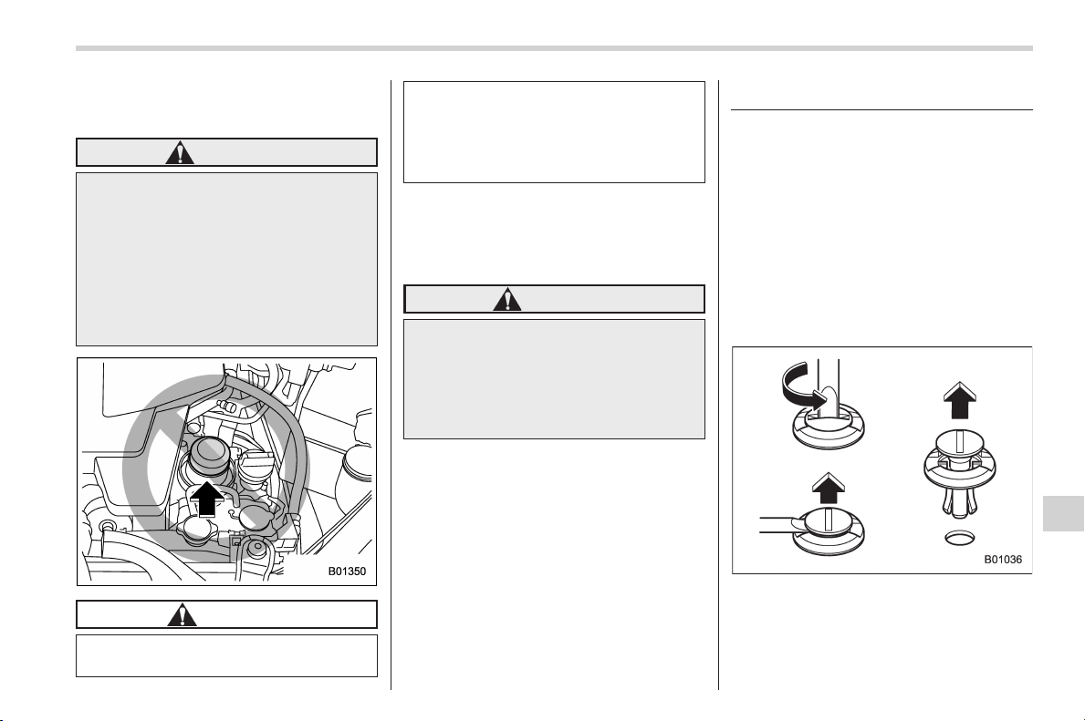
Black plate (425,1)
北米Model "A1160BE-C" EDITED: 2014/ 3/ 17
& When checking or servicing
in the engine compartment
WARNING
When performing inspection or
maintenance, if there is no need to
operate the engine, ensure that the
ignition switch is in the “LOCK” (off)
position. If you are performing in-
spection or maintenance while the
electric motor is in operation, the
engine could start during the work
and possibly lead to serious injury.
CAUTION
Do not touch the oil filter until the
engine has cooled down completely.
Doing so may result in a burn or
other injury. Note that the oil filter
becomes very hot when the engine
is running and remains hot for some
time after the engine has stopped.
& When checking or servicing
in the engine compartment
while the engine is running
WARNING
A running engine can be dangerous.
Keep your fingers, hands, clothing,
hair and tools away from the cooling
fan, drive belt and any other moving
engine parts. Removing rings,
watches and ties is advisable.
Maintenance tips
Some clips and fender linings must be
removed before replacing the air cleaner
elements or specific bulbs.
& Removing and reinstalling
clips
! Removing clips
There are several types of clips used for
your vehicle.
! Type A clips
1. Turn the clips counterclockwise using
a flat-head screwdriver until the center
portion of the clip is raised.
2. Remove the clips with a flat-head
screwdriver using leverage.
Maintenance and service/Maintenance tips
11-5
– CONTINUED –
11
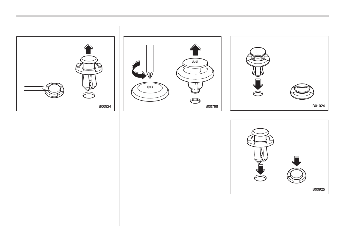
Black plate (426,1)
北米Model "A1160BE-C" EDITED: 2014/ 3/ 17
11-6
Maintenance and service/Maintenance tips
! Type B clips
1. Pull out the center portion of the clip
using a flat-head screwdriver as shown in
the illustration.
2. Pull the protruded center portion to
remove the entire body of the clip.
! Type C clips
1. Turn the clip counterclockwise using a
Phillips screwdriver until the center portion
of the clip is raised.
2. Remove the entire clip by pulling it up.
! Reinstalling clips
Type A clips
Type B clips
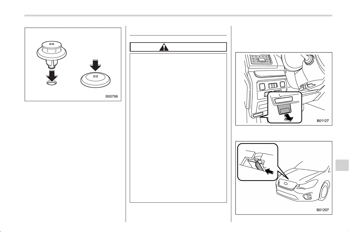
Black plate (427,1)
北米Model "A1160BE-C" EDITED: 2014/ 3/ 17
Type C clips
Insert the clip without the center portion
first and then push the center portion of
the clip into the hole.
Engine hood
CAUTION
. When you open the engine hood,
do not stand the wiper blades up.
Furthermore, while the hood is
open, do not operate the wind-
shield wipers. Doing so could
result in damage to the engine
hood and wiper blades.
. Be extremely careful not to catch
fingers or other objects when
closing the engine hood.
. Do not push the hood forcibly to
close it. It could deform the
metal.
. Be extremely careful opening the
engine hood when the wind is
strong. The engine hood could
close suddenly, possibly causing
injuries from slamming.
. Do not install accessories other
than genuine SUBARU parts to
the engine hood. If the engine
hood becomes too heavy, the
stay may not be able to support
holding it open.
To open the hood:
1. If the wiper blades are lifted off the
windshield, return them to their original
position.
2. Pull the hood release knob under the
instrument panel.
Maintenance and service/Engine hood
11-7
– CONTINUED –
11
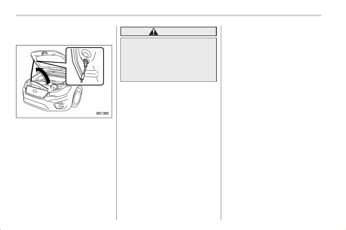
Black plate (428,1)
北米Model "A1160BE-C" EDITED: 2014/ 3/ 17
11-8
Maintenance and service/Engine hood
3. Release the secondary hood release
by moving the lever between the front
grille and the hood toward the left.
4. Lift up the hood, release the hood prop
from its retainer and put the end of the
hood prop into the slot in the hood.
To close the hood:
1. Lift the hood slightly and remove the
hood prop from the slot in the hood and
return the prop to its retainer.
2. Lower the hood to a height of approxi-
mately 5.9 in (15 cm) above its closed
position and then let it drop.
3. After closing the hood, be sure the
hood is securely locked.
If this does not close the hood, release it
from a slightly higher position.
WARNING
Always ch eck that the hood is
properly locked before you start
driving. If it is not, it might fly open
while t he vehicle is moving and
block your view, which may cause
an accident and serious bodily in-
jury.
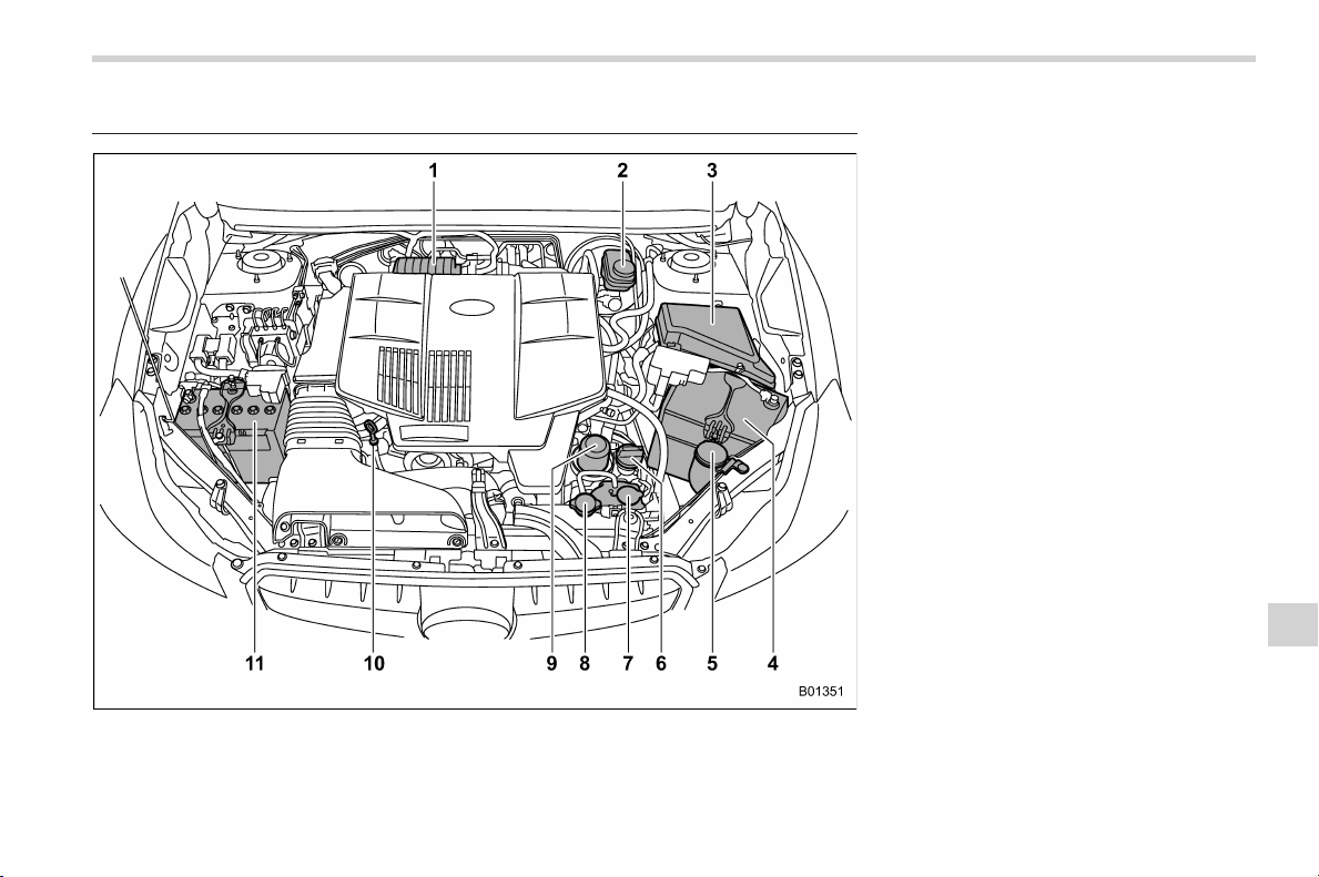
Black plate (429,1)
北米Model "A1160BE-C" EDITED: 2014/ 3/ 17
Engine compartment overview 1) Air cleaner case (page 11-15)
2) Brake fluid reservoir (page 11-18)
3) Fuse box (page 11-38)
4) 12 V auxiliary battery (page 11-36)
5) Windshield washer tank (page 11-31)
6) Engine oil filler cap (page 11-10)
7) Engine coolant reservoir (page 11-14)
8) Radiator cap (page 11-14)
9) Engine oil filter (page 11-11)
10) Engine oil level gauge (page 11-10)
11) 12 V engine restart battery (page 11-36)
Maintenance and service/Engine compartment overview
11-9
11
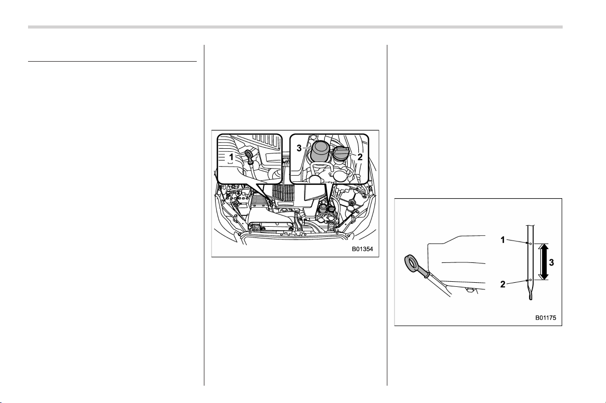
Black plate (430,1)
北米Model "A1160BE-C" EDITED: 2014/ 3/ 17
11-10
Maintenance and service/Engine oil
Engine oil
& Engine oil consumption
Some engine oil will be consumed while
driving. Under the following conditions, oil
consumption can be increased and thus
require refilling between maintenance
intervals:
. When the engine is new and within the
break-in period
. When the engine oil is of lower quality
. When the incorrect oil viscosity is used
. When engine braking is employed
. When the engine is operated at high
engine speeds
. When the engine is operated under
heavy loads
. When towing a trailer
. When the engine idles for long periods
of time
. When the vehicle is operated in stop
and go and/or heavy traffic situations
. When the vehicle is used under severe
thermal conditions
. Whe n the v ehicl e acce lerates and
decelerates frequently
Under these or similar conditions, you
should check your oil at least every 2nd
fuel fill-up and change your engine oil
more frequently. If your oil consumption
rate is greater than 1 quart every 1,200
miles or 1 liter every 2,000 kilometers,
contact your SUBARU dealer who may
perform a test under controlled conditions.
& Locations of the oil level
gauge, oil filler cap and oil
filter
1) Oil level gauge
2) Oil filler cap
3) Oil filter
& Checking the oil level
Check the engine oil level at each fuel
stop.
1. Park the vehicle on a level surface and
turn the ignition switch to the “LOCK” (off)
position. If you check the oil level just after
turning the ignition switch to the “LOCK”
(off) position, wait a few minutes for the oil
to drain back into the oil pan before
checking the level.
2. Pull out the level gauge, wipe it clean,
and insert it again.
3. Be sure the level gauge is correctly
inserted until it stops.
1) Full level
2) Low level
3) Approximately 1.1 US qt (1.0 liter, 0.9
Imp qt) from low level to full level
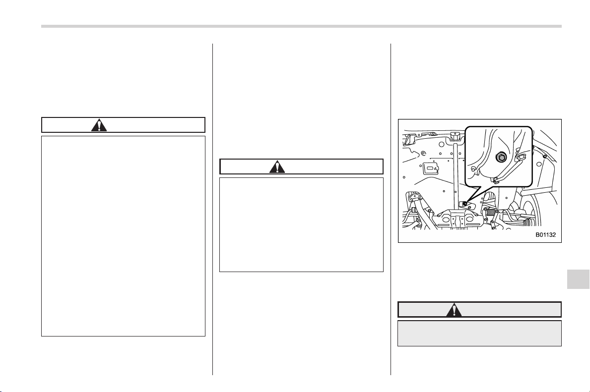
Black plate (431,1)
北米Model "A1160BE-C" EDITED: 2014/ 3/ 17
4. Pull out the oil level gauge again.
5. Check the oil levels on both sides of
the level gauge. The engine oil level must
be judged by the lowest of the two levels.
If the oil level is below the low level mark,
add oil so that the full level is reached.
CAUTION
. Be careful not to touch the en-
gine oil filter when removing the
oil filler cap. Doing so may result
in a burn, a pinched finger, or
may cause some other injury.
. Use only engine oil with t he
recommended grade and vis-
cosity.
. Be careful not to spill engine oil
when adding it. If oil touches the
exhaust pipe, it may cause a bad
smell, smoke, and/or a fire. I f
engine oil gets on the exhaust
pipe, be sure to wipe it off.
. If the level gauge is not pulled out
easily, twist the level gauge right
and left, then pull it out. Other-
wise, you may be injured acci-
dentally straining yourself.
To add engine oil, remove the engine oil
filler cap and slowly po ur en gine oi l
through the filler neck. After pouring oil
into the engine, you must use the level
gauge to confirm t hat the oil level is
correct.
NOTE
To prevent overfilling the engine oil, do
not add any additional oil above the
upper level when the engine is cold.
& Changing the oil and oil filter
CAUTION
If you change your own oil, be sure
to drain all the oil from the filter
before disposal. Do not dispose of
used engine oil by placing it in the
trash, or by p ouring it onto the
ground, into sewers, or into any
body of water. Check with your local
gover nment office for the proper
disposal options available to you.
Change the oil and oil filter according to
the maintenance schedule in the “War-
ranty and Maintenance Booklet”.
The engine oil and oil f ilter must be
changed more frequently than listed in
the maintenance schedule when driving
on dusty roads, when short trips are
frequently ma de, or when driv ing in
extremely cold weather.
1. Warm up the engine by letting the
engine idle for approximately 10 minutes
to ease draining the engine oil.
2. Park the vehicle on a level surface and
turn the ignition switch to the “LOCK” (off)
position.
3. Remove the oil filler cap.
4. Drain out the engine oil by removing
the drain plug while the engine is still
warm. The used oil should be drained into
an appropriate container and disposed of
properly.
WARNING
Be careful not to burn yourself with
hot engine oil.
5. Wipe the seating surface of the drain
Maintenance and service/Engine oil
11-11
– CONTINUED –
11
Black plate (432,1)
北米Model "A1160BE-C" EDITED: 2014/ 3/ 17
11-12
Maintenance and service/Engine oil
plug with a clean cloth and tighten it
securely with a new sealing washer after
the oil has completely drained out.
6. Remove the oil filter with an oil filter
wrench.
7. Before installing a new oil filter, apply a
thin coat of engine oil to the seal.
8. Clean the rubber seal seating area of
the engine and install the oil filter by hand
turning. Be careful not to twist or damage
the seal.
9. Tighten the oil filter by the amount
indicated in the following table after the
seal makes contact with the seating sur-
face.
Oil filter color Part number
Amount of
rotation
Black
15208AA160
1 rotation
CAUTION
. Never over tighten the oil filter
because that can result in an oil
leak.
. Thoroughly wipe off any engine
oil that has spilled over the
exhaust pipe and/or under-cover.
If spilled oil is not promptly
wiped up, the oil could cause a
fire.
10. Pour engine oil through the filler neck.
For the oil capacity (guideline), refer to
“Engine oil” F12-5.
The oil quantity indicated above is only
guideline.
The necessary quantity of oil depends on
the quantity of oil that has been drained.
The quantity of drained oil differs slightly
depending on the temperature of the oil
and the time the oil is left flowing out. After
refilling the engine with oil, therefore, you
must use the level gauge to confirm that
the level is correct.
11. Start the engine and make sure that no
oil leaks appear around the filter’s rubber
seal and drain plug.
12. Run the engine until it reaches the
normal operating temperature. Then turn
the ignition switch to the “LOCK” (off)
position and wait a few minutes to allow
the oil drain back. Check the oil level
again and if necessary, add more engine
oil.
CAUTION
Be careful not to spill engine oil
when adding it. If oil touches the
exhaust pipe, it may cause a bad
smell, smoke, and/or a fire.
& Recommended grade and
viscosity
CAUTION
Use only engine oil with the recom-
mended grade and viscosity.
Refer to “Engine oil” F12-5.
NOTE
Engine oil viscosity (thickness) affects
fuel economy. Oils of lower viscosity
provide better fuel economy. However,
in hot weather, oil of higher viscosity is
required to properly lubricate the en-
gine.
& Synthetic oil
You should use synthetic engine oil that
meets the same requirements given for
conventional engine oil. When using
synthetic oil, you must use oil of the same
classification, viscosity and grade shown
Black plate (433,1)
北米Model "A1160BE-C" EDITED: 2014/ 3/ 17
in this Owner’s Manual. Refer to “Engine
oil” F12-5. Also, you must follow the oil
and filter changing intervals shown in the
Warranty and Maintenance booklet.
NOTE
Synthetic oil of the grade and viscosity
noted in chapter 12 is the recom-
mended engine oil for optimum engine
performance. Conventional oil may be
used if synthetic oil is unavailable.
Cooling system
& Safety precautions
WARNING
Never attempt to remove the radia-
tor cap until the hybrid system has
been shut off and the engine has
cooled down completely. Since the
coolant is under pressure, you may
suffer serious burns from a spray of
boiling hot coolant when the cap is
removed.
CAUTION
. Vehicles are filled at the factory
with SUBARU Super Coolant that
does not require the first change
for 11 years/137,500 miles (11
years/220,000 km). This coolant
should not be mixed with any
other brand or type of coolant
during this period. Mixing with a
different coolant will reduce the
life of the coolant. Should it be
necessary to top up the coolant
for any reason, use only
SUBARU Super Coolant.
If the SUBARU Super Coolant is
diluted w ith another brand or
type, the maintenance interval is
shortened to that of the mixing
coolant.
. Do not splash the engine coolant
over painted parts. The alcohol
contained in the engine coolant
may damage the paint surface.
& Cooling fan, hose and con-
nections
Your vehicle employs an electric cooling
fan which is thermostatically controlled to
operate when the engine coolant reaches
a specific temperature.
If the radiator cooling fan does not operate
even when the coolant temperature high
warning light blinks or illuminates in RED,
the cooling fan circuit may be defective.
Refer to “Coolant temperature low indica-
tor light/Coolant temperature high warning
light” F3-16.
Check the fuse and replace it if necessary.
Refer to “Fuses” F11-38 and “Fuse panel
located in the engine compartment” F12-
12.
If the fuse is not blown, have the cooling
system checked by your SUBARU dealer.
If frequent addition of coolant is neces-
Maintenance and service/Cooling system
11-13
– CONTINUED –
11
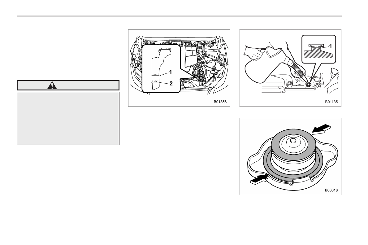
Black plate (434,1)
北米Model "A1160BE-C" EDITED: 2014/ 3/ 17
11-14
Maintenance and service/Cooling system
sary, there may be a leak in the engine
cooling system. It is recommended that
the cooling system and connections be
checked for leaks, damage, or looseness.
& Engine coolant
! Checking the coolant level
WARNING
Never attempt to remove the radia-
tor cap until the hybrid system has
been shut off and the engine has
cooled down completely. Since the
coolant is under pressure, you may
suffer serious burns from a spray of
boiling hot coolant when the cap is
removed.
1) “FULL” level mark
2) “LOW” level mark
Check the coolant level at each fuel stop.
1. Check the coolant level on the outside
of the reservoir while the engine is cool.
2. If the level is close to or lower than the
“LOW” level mark, add coolant up to the
“FULL” level mark. If the reserve tank is
empty, remove the radiator cap and refill
coolant up to just below the filler neck as
shown in the following illustration.
1) Fill up to this level
3. After refilling the reserve tank and the
radiator, reinstall the cap and check that
the rubber gaskets inside the radiator cap
are in the proper position.
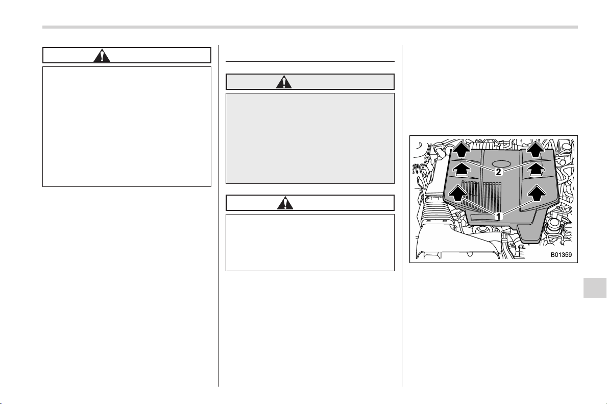
Black plate (435,1)
北米Model "A1160BE-C" EDITED: 2014/ 3/ 17
CAUTION
. Be careful not to spill engine
coolant when adding it. If coolant
touches the exhaust pipe, it may
cause a bad smell, smoke, and/or
a fire. If engine coolant gets on
the exhaust pipe, be sure to wipe
it off.
. Do not splash the engine coolant
over painted parts. The alcohol
contained in the engine coolant
may damage the paint surface.
! Changing the coolant
It may be difficult to change the coolant.
Have the coolant changed by your
SUBARU dealer if necessary.
The coolant should be changed according
to the maintenance schedule in the
“Warranty and Maintenance Booklet ” .
Air cleaner element
WARNING
Do not operate the engine with the
air cleaner element removed. The air
cleaner el ement not only filters
intake air but also stops flames if
the engine backfires. If the air
cleaner element is not installed
when the engine backfires, you
could be burned.
CAUTION
When replacing the air cleaner ele-
ment, use a genuine SUBARU air
cleaner element. If it is not used,
there is the possibility of causing a
negative effect to the engine.
The air cleaner element functions as a
filter screen. When the element is perfo-
rated or removed, engine wear will be
excessive and engine life shortened.
It is not necessary to clean or wash the air
cleaner element.
& Replacing the air cleaner
element
Replace the air cleaner element according
to the maintenance schedule in the
“Warranty and Maintenance Booklet”. Un-
der extremely dusty conditions, replace it
more frequently. It is recommended that
you always use genuine SUBARU parts.
1) Raise the front end of the engine cover
2) Raise the rear end of the engine cover
while pushing it to the back.
1. Remove the engi ne cover as d e-
scribed above.
Maintenance and service/Air cleaner element
11-15
– CONTINUED –
11
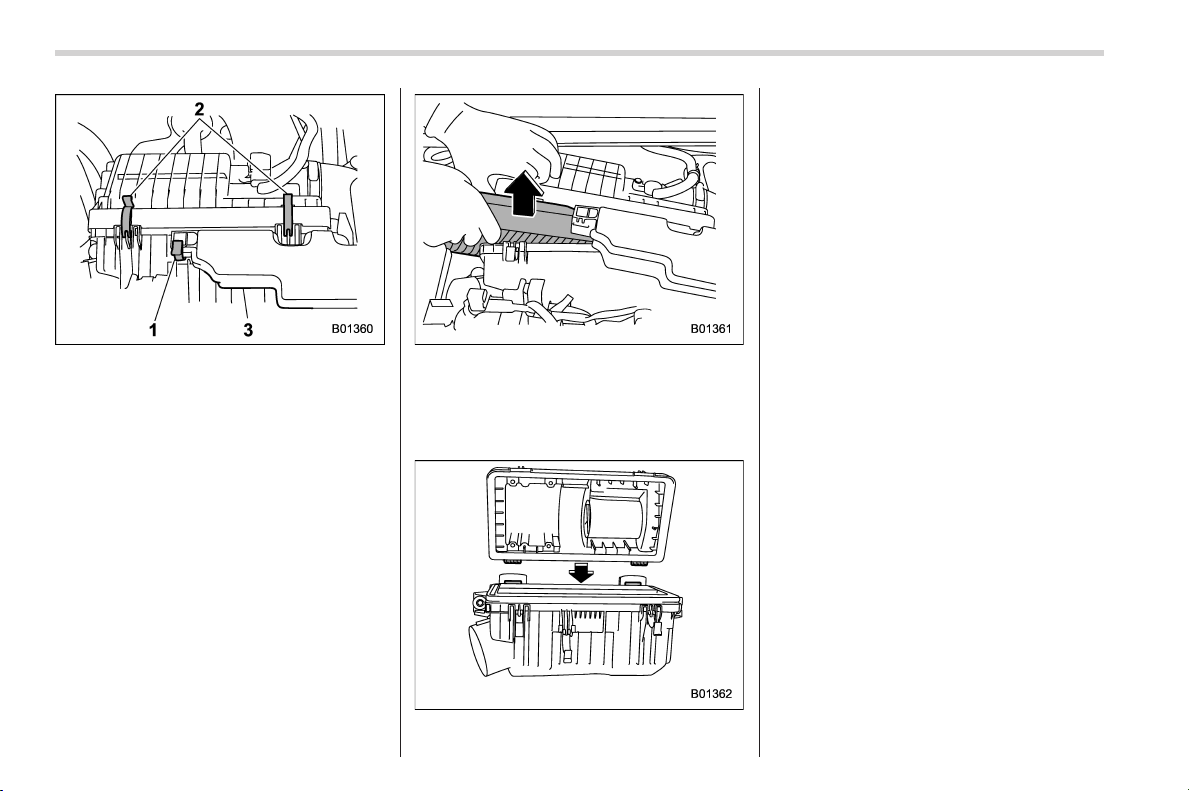
Black plate (436,1)
北米Model "A1160BE-C" EDITED: 2014/ 3/ 17
11-16
Maintenance and service/Air cleaner element
1) Clip
2) Clips
3) Resonator chamber
2. Release the clip holding the resonator
chamber.
3. Hold up the resonator chamber and
release the two clips holding the air
cleaner case (rear).
4. Open the air cleaner case (rear) and
remove the air cleaner element.
5. Clean the inside of the air cleaner case
(both front and rear) with a damp cloth and
install a new air cleaner element.
6. To install the air cleaner case (rear),
insert the two projections on the air
cleaner case (rear) into the slits on the
air cleaner case (front).
7. Install in the reverse order of removal.
Black plate (437,1)
北米Model "A1160BE-C" EDITED: 2014/ 3/ 17
Spark plugs
It may be difficult to replace the spark
plugs. It is recommended that you have
the spark plugs replaced by your
SUBARU dealer.
The spark plugs should be replaced
according to the maintenance schedule
in the “Warranty and Maintenance Book-
let”.
CAUTION
Make sure the cables are replaced in
the correct order.
& Recommended spark plugs
For the recommended spark plugs, refer
to “Electrical system” F12-8.
Drive belts
It is unnecessary to check the deflection of
the drive belt periodically because your
engine is equipped with an automatic belt
tension adjuster. However, replacement of
the belt should be done according to the
maintenance schedule in the “Warranty
and Maintenance Booklet”. Consult your
SUBARU dealer for replacement.
If the drive belt is loose, cracked or worn,
contact your SUBARU dealer.
Continuously variable trans-
mission fluid
It is not necessary to check the transmis-
sion fluid level. Check that there are no
cracks, damage or leakage. However, the
fluid inspection should be performed
according to the maintenance schedule
in the “Warranty and Maintenance Book-
let”. Consult your SUBARU dealer f or
details.
Maintenance and service/Spark plugs
11-17
11
Black plate (438,1)
北米Model "A1160BE-C" EDITED: 2014/ 3/ 17
11-18
Maintenance and service/Front differential gear oil
Front differential gear oil
It is not necessary to check the gear oil
level. Check that there are no cracks,
damage or leakage. However, the o il
inspection should be performed according
to the maintenance schedule in the
“Warranty and Maintenan ce Bookl et”.
Consult your SUBARU dealer for details.
& Recommended grade and
viscosity
Each oil manufacturer has its own base
oils and additives. Never use different
brands together. For details, refer to “Front
differential and rear differential gear oil”
F12-7.
CAUTION
Using a differential gear oil other
than the specified oil may cause
occurrences of rattling noises while
idling and poor fuel consumption.
Rear differential gear oil
It is not necessary to check the gear oil
level. Check that there are no cracks,
damage or leakage. However, the oil
inspection should be performed according
to the maintenance s chedule in the
“Warranty and Maintenance Booklet”.
Consult your SUBARU dealer for details.
& Recommended grade and
viscosity
Each oil manufacturer has its own base
oils and additives. Never use different
brands together. For details, refer to “Front
differential and rear differential gear oil”
F12-7.
CAUTION
Using a differential gear oil other
than the specified oil may cause
occurrences of rattling noises while
idling and poor fuel consumption.
Brake fluid
& Checking the fluid level
WARNING
. Never let brake fluid contact your
eyes because brake fluid can be
harmful to your eyes. If brake
fluid gets in your eyes, immedi-
ately flush them thoroughly with
clean w ater. For safety, when
performing this work, wearing
eye protection is advisable.
. Brake fluid absorbs moisture
from the air. Any absorbed moist-
ure can cause a dangerous loss
of braking performance.
. If the vehicle requires frequent
refilling, there may be a leak. If
you suspect a problem, have the
vehicle checked at your SUBARU
dealer.
CAUTION
. When adding brake fluid, be care-
ful not to allow any dirt into the
reservoir.
. Never splash the brake fluid over
painted surfaces or rubber parts.
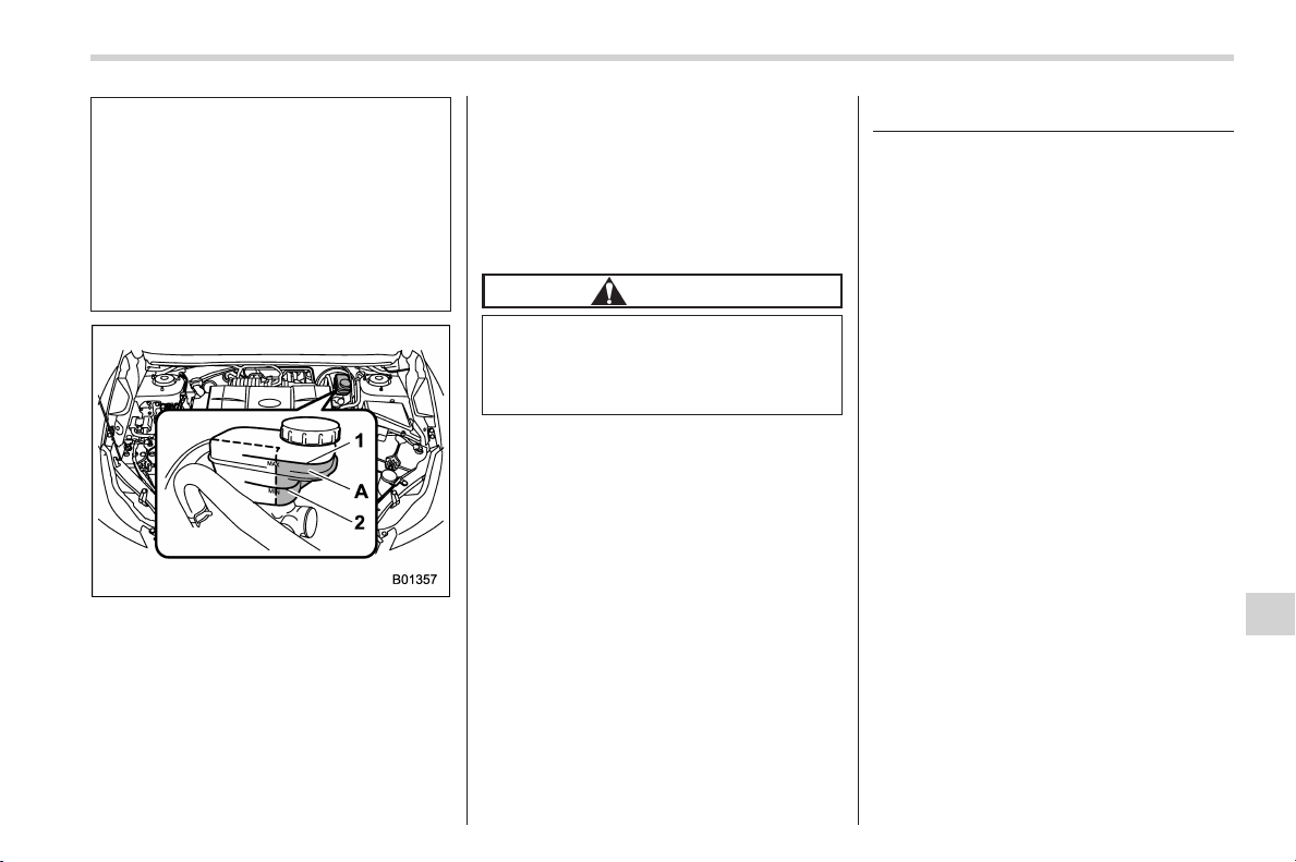
Black plate (439,1)
北米Model "A1160BE-C" EDITED: 2014/ 3/ 17
Alcohol contained in the brake
fluid may damage them.
. Be careful not to spill brake fluid
when adding it. If brake fluid
touches the exhaust pipe, it may
cause a bad smell, smoke, and/or
a fire. If brake fluid gets on the
exhaust pipe, be sure to wipe it
off.
1) “MAX” level line
2) “MIN” level line
A) The brake fluid level must be checked in
this area.
Check the fluid level monthly.
Check the fluid level on the outside of the
reservoir. Be sure to check the fluid level
for the brake system at the front part of
the reservoir (shaded area in the illustra-
tion). If the fluid level is below “MIN”, add
the recommended brake fluid to “MAX”.
Use only brake fluid from a sealed
container.
& Recommended brake fluid
Refer to “Fluids” F12-8.
CAUTION
Never use different brands of brake
fluid together. Also, avoid mixing
DOT 3 and DOT 4 brake fluids even if
they are the same brand.
Brake booster
If the brake booster does not operate as
described in the following, have it checked
by your SUBARU dealer.
1. With the ignition switch in the “LOCK”
(off) position, depress the brake pedal
several times, applying the same pedal
force each time. The distance the pedal
travels should not vary.
2. With the brake pedal depressed, start
the hybrid system. The pedal should move
slightly down to the floor.
3. With the brake pedal depressed, stop
the hybrid system and keep the pedal
depresse d for 30 seconds. The pedal
height should not change.
4. Start the hybrid system again and run
for approximately one minute then turn it
off. Depress the brake pedal several times
to check the brake booster. The brake
booster operates properly if the pedal
stroke decreases with each depression.
Maintenance and service/Brake booster
11-19
11
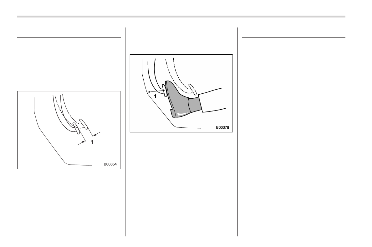
Black plate (440,1)
北米Model "A1160BE-C" EDITED: 2014/ 3/ 17
11-20
Maintenance and service/Brake pedal
Brake pedal
Check the brake pedal free pl ay and
reserve distance according to the main-
tenance schedule in the “Warranty and
Maintenance Booklet”.
& Checking the brake pedal
free play
1) 0.02 – 0.08 in (0.5 – 2.0 mm)
Turn the ignition switch to the “LOCK” (off)
position and firmly depress the brake
pedal several times. Lightly pull the brake
pedal up with one finger to check the free
play with a force of less than 2 lbf (10 N, 1
kgf).
If the free play is not within proper
specification, contact your SUBARU deal-
er.
& Checking the brake pedal
reserve distance
1) More than 2.56 in (65 mm)
Depress the pedal with a force of approxi-
mately 66 lbf (294 N, 30 kgf) and measure
the distance between the upper surface of
the pedal pad and the floor.
When the measurement is smaller than
the specification, or when the pedal does
not operate smoothly, contact with your
SUBARU dealer.
Hill start assist system
Ensure that the Hill start assist system
operates properly under the following
circumstances.
1. Stop the vehicle on an uphill grade by
depressing the brake pedal, with the
hybrid system running.
2. Make sure that the vehicle does not
move backward for several seconds after
the brake pedal is released.
3. Then make sure the vehicle starts
climbing the grade by following the normal
starting procedures.
If the Hill start assist system does not
operate as described above, contact your
SUBARU dealer.
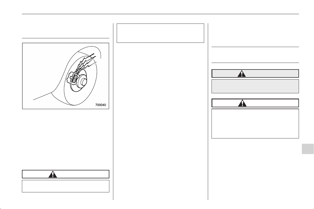
Black plate (441,1)
北米Model "A1160BE-C" EDITED: 2014/ 3/ 17
Replacement of brake pad
and lining
The disc brakes have audible wear
indicators on the brake pads. If the brake
pads wear close to their service limit, the
wear indicator makes a very a udible
scraping noise when the brake pedal is
applied.
If you hear this scraping noise each time
you apply the brake pedal, have the brake
pads serviced by your SUBARU dealer as
soon as possible.
CAUTION
If you continue to drive despite the
scraping noise from the audible
brake pad wear indicator, it will
result in the need for costly brake
rotor repair or replacement.
& Breaking-in of new brake
pads and linings
When replacing the brake pad or lining,
use only genuine SUBARU parts. After
replacement, the new parts must be
broken in as follows.
! Brake pad and lining
While maintaining a speed of 30 to 40
mph (50 to 65 km/h), step on the brake
pedal lightly. Repeat this five or more
times.
! Parking brake lining
1. Drive the vehicle at a speed of
approximately 22 mph (35 km/h).
2. With the parking brake release button
pushed in, pull the parking brake lever
SLOWLY and GENTLY (pulling with a
force of approximately 33.7 lbf [150 N,
15.3 kgf]).
3. Drive the vehicle for approximately
220 yards (200 meters) in this condition.
4. Wait 5 to 10 minutes for the parking
brake to cool down. Repeat this proce-
dure.
5. Check the parking brake stroke. If the
parking brake stroke is out of the specified
range, adjust it by turning the adjusting nut
located on the parking brake lever.
Parking brake stroke:
7 – 8 notches / 45 lbf (200 N, 20.4 kgf)
WARNING
A safe location and situation should
be selected for break-in driving.
CAUTION
Pulling the parking brake lever too
forcefully may cause the rear
wheels to lock. To avoid this, be
certain to pull the lever up slowly
and gently.
Maintenance and service/Replacement of brake pad and lining
11-21
11
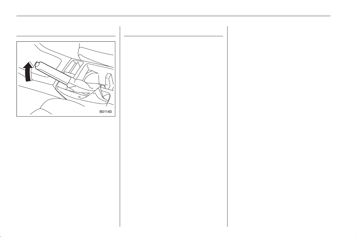
Black plate (442,1)
北米Model "A1160BE-C" EDITED: 2014/ 3/ 17
11-22
Maintenance and service/Parking brake stroke
Parking brake stroke
Check the parking brake stroke according
to the maintenance schedule in the
“Warranty and Maintenan ce Bookl et”.
When the parking brake is properly
adjusted, braking power is fully applied
by pulling the lever up 7 to 8 notches
gently but firmly (approximately 45 lbf [200
N, 20.4 kgf]). If the parking brake lever
stroke is not within the specified range,
have the brake system checked and
adjusted at your SUBARU dealer.
Tires and wheels
& Types of tires
You should be familiar with type of tires
present on your vehicle.
! All season tires
All season tires are designed to provide
an adequate measure of traction, handling
and braking performance in year-round
driving including snowy and icy r oad
conditions. However all season tires do
not offer as much traction performance as
winter (snow) tires in heavy or loose snow
or on icy roads.
All season tires are identified by “ALL
SEASON” and/or “M+S” (Mud & Snow) on
the tire sidewall.
! Summer tires
Summer tires are high-speed capability
tires best suited for highway driving under
dry conditions.
Summer tires are inadequate for driving
on slippery roads such as on snow-
covered or icy roads.
If you drive your vehicle on snow-covered
or icy roads, we strongly recommend the
use of winter (snow) tires.
When installing winter tires, be sure to
replace all four tires.
! Winter (snow) tires
Winter tires are best suited for driving on
snow-covered and icy roads. However
winter tires do not perform as well as
summer tires and all season tires on roads
other than snow-covered and icy roads.
& Tire pressure monitoring
system (TPMS) (if equipped)
The tire pressure monitoring system pro-
vides the driver with a warning message
by sending a signal from a sensor that is
installed in each wheel when tire pressure
is severely low. The tire pressure monitor-
ing system will activate only when the
vehicle is driven. Also, this system may
not react immediately to a sudden drop in
tire pressure (f or example, a blow-out
caused by running over a sharp object).
If you adjust the tire pressures in a warm
garage and will then drive the vehicle in
cold outside air, the resulting drop in tire
pressures may cause the low tire pressure
warning light to illuminate. To avoid this
problem when adjusting the tire pressures
in a warm garage, inflate the tires to
pressures higher than those shown on the
tire placard. Specifically, inflate them by an
extra 1 psi (6.9 kPa, 0.07 kgf/cm
2
) for
every difference of 108F (5.68C) between
the temperature in the garage and the
Black plate (443,1)
北米Model "A1160BE-C" EDITED: 2014/ 3/ 17
temperature outside. By way of example,
the following table shows the required tire
pressures that correspond to various out-
side temperatures when the temperature
in the garage is 608F (15.68C).
Example:
Tire size: P205/55R16 89V and
P205/50R17 88V
Standard tire pressures:
Front: 33 psi (230 kPa, 2.3 kgf/cm
2
)
Rear: 32 psi (220 kPa, 2.2 kgf/cm
2
)
Garage temperature: 608F (15.68C)
Outside
temperature
Adjusted pressure
[psi (kPa, kgf/cm
2
)]
Front Rear
308F(−18C) 36 (250, 2.5) 35 (240, 2.4)
108F(−128C)
38
(265, 2.65)
37
(255, 2.55)
−108F(−238C) 40 (280, 2.8)
39 (270, 2.7)
If the low tire pressure warning light
illuminates when you drive the vehicle in
cold outside air after adjusting the tire
pressures in a warm garage, re-adjust the
tire pressures using the method described
above. Then, increase the vehicle speed
to at least 20 mph (32 km/h) and check to
see that the low tire pressure warning light
turns off a few minutes later. If the low tire
pressure warning light does not turn off,
the tire pressure monitoring system may
not be functioning normally. In this event,
go to a SUBARU dealer to have the
system inspected as soon as possible.
While the vehicle is driven, friction be-
tween tires and the road surface causes
the tires to warm up. After illumination of
the low tire pressure warning light, any
increase in the tire pressures caused by
an increase in the outside air temperature
or by an increase in the temperature in the
tires can cause the low tire pressure
warning light to turn off.
System resetting is necessary when the
wheels are changed (for example, a
switch to snow tires) and new TPMS
valves are installed on the newly fitted
wheels. Have this work performed by a
SUBARU dealer following wheel replace-
ment.
It may not be possible to install TPMS
valves on certain wheels that are on the
market. Therefore, if you change the
wheels (for example, a switch to snow
tires), use wheels that have the same part
number as the standard-equipment
wheels. Without four operational TPMS
valve/sensors on the wheels, the TPMS
will not fully function and the warning light
on the combination meter will illuminate
steadily after blinking for approximately
one minute.
When a tire is replaced, adjustments are
necessary to ensure continued normal
operation of the tire pressure monitoring
system. As with wheel replacement, there-
fore, you should have the work performed
by a SUBARU dealer.
WARNING
If the low tire pressure warning light
does not illuminate briefly after the
ignition switch is turned ON or the
light illuminates steadily after blink-
ing for approximately one minute,
you should have your Tire Pressure
Monitoring System checked at a
SUBARU dealer as soon as possi-
ble.
If this light illuminates while driving,
never brake suddenly and k eep
driving straight ahead while gradu-
ally reducing speed. Then slowly
pull off the road to a safe place.
Otherwise an accident involving
serious vehicle damage and serious
personal injury could occur.
If this light still illuminates while
driving after adjusting the tire pres-
sure, a tire may have significant
damage and a fast leak that causes
the tire to lose air rapidly. If you have
Maintenance and service/Tires and wheels
11-23
– CONTINUED –
11
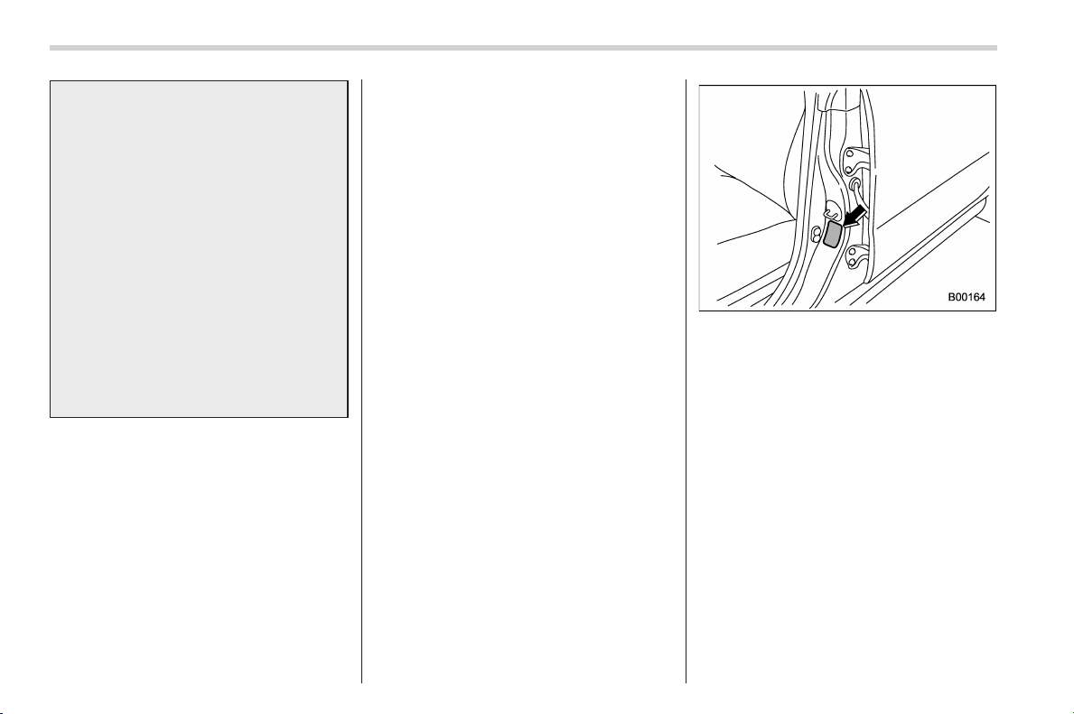
Black plate (444,1)
北米Model "A1160BE-C" EDITED: 2014/ 3/ 17
11-24
Maintenance and service/Tires and wheels
a flat tire, refer to “In case of a flat
tire” F9-4.
When a replacement tire is mounted
or a wheel rim is replaced without
the original pressure sensor/trans-
mitter being transferred, the low tire
pressure warning light will illumi-
nate steadily after blinking for ap-
proximately one minute. This indi-
cates the TPMS is unable to monitor
all four road wheels. Contact your
SUBARU dealer as soon as possible
for tire and sensor replacement and/
or system resetting. If the light
illuminates steadily after blinking
for approximately one minute,
promptly contact a SUBARU dealer
to have the system inspected.
& Tire inspection
Check on a daily basis that the tires are
free from serious damage, nail s, and
stones. At the same time, check the tires
for abnormal wear.
Contact your SUBARU dealer immedi-
ately if you find any problem.
NOTE
. When the wheels and tires strike
curbs or are subjected to harsh treat-
ment as when the vehicle is driven on a
rough surface, they can suffer damage
that cannot be seen with the naked eye.
This type of damage does not become
evident until time has passed. Try not
to drive over curbs, potholes or on
other rough surfaces. If doing so is
unavoidable, keep the vehicle’s speed
down to a walking pace or less, and
approach th e curbs as squarely as
possible. Also, make sure the tires are
not pressed against the curb when you
park the vehicle.
. If you feel unusual vibration while
driving or find it difficult to steer the
vehicle in a straight line, one of the
tires and/or wheels may be damaged.
Drive slowly to the nearest authorized
SUBARU dealer and have the vehicle
inspected.
& Tire pressures and wear
Maintaining the correct tire pressures
helps to maximize the tires’ service lives
and is essential for good running perfor-
mance. Check and, if necessary, adjust
the pressure of each tire (including the
spare - if equipped) at least once a month
(for example, during a fue l stop) and
before any long journey.
Tire placard
Check the tire pressures when the tires
are cold. Use a pressure gauge to adjust
the tire pressures to the values shown on
the tire placard. The tire placard is located
on the door pillar on the driver’s side.
Driving even a short distance warms up
the tires and increases the tire pressures.
Also, the tire pressures are affected by the
outside temperature. It is best to check tire
pressure outdoors before driving the
vehicle.
When a tire becomes warm, the air inside
it expands, causing the tire pressure to
increase. Be careful not to mistakenly
release air from a warm tire to reduce its
pressure.
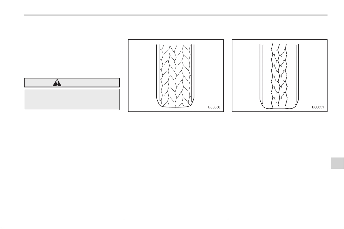
Black plate (445,1)
北米Model "A1160BE-C" EDITED: 2014/ 3/ 17
NOTE
. The air pressure in a tire increases
by approximately 4.3 psi (30 kPa, 0.3
kgf/cm
2
) when the tire becomes warm.
. The tires are considered cold when
the vehicle has been parked for at least
three hours or has been driven less
than one mile (1.6 km).
WARNING
Do not let air out of warm tires to
adjust pressure. Doing so will result
in low tire pressure.
Incorrect tire pressures detract from con-
trollability and ride comfort, and they
cause the tires to wear abnormally.
. Correct tire pressure (tread worn
evenly)
Roadholding is good , and ste ering is
responsive. Rolling resistance is low, so
fuel consumption is also lower.
. Abnormally low tire pressure (tread
worn at shoulders)
Rolling resistance is high, so fuel con-
sumption is also higher.
Maintenance and service/Tires and wheels
11-25
– CONTINUED –
11
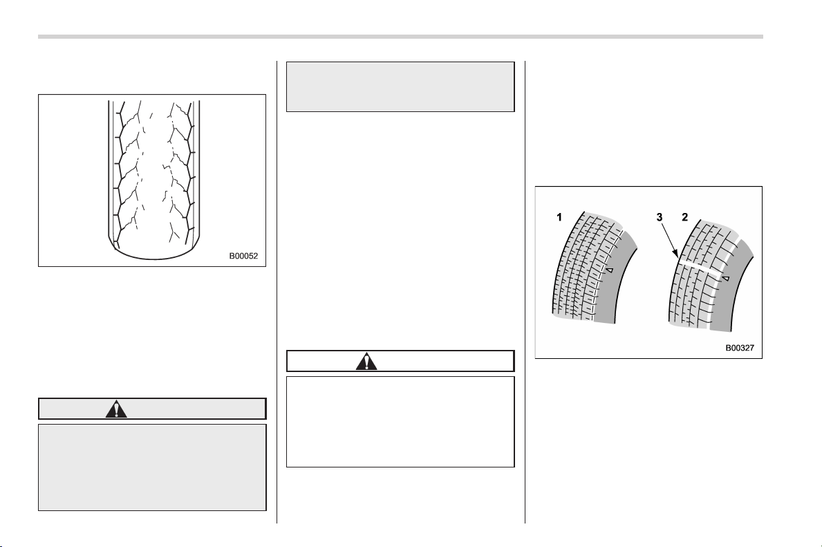
Black plate (446,1)
北米Model "A1160BE-C" EDITED: 2014/ 3/ 17
11-26
Maintenance and service/Tires and wheels
. Abnormally high tire pressure (tread
worn in center)
Ride comfort is poor. Also, the tire
magnifies the effects of road-surface
bumps and dips, possibly re sulting in
vehicle damage.
If the tire placard shows tire pressures for
the vehicle when fully loaded, adjust the
tire pressures to the values that match
current loading conditions.
WARNING
Driving at high speeds with exces-
sively low tire pressures can cause
the tires to deform severely and to
rapidly become hot. A sharp in-
crease in temperature could cause
tread separation, and destruction of
the tires. The resulting loss of
vehicle control could lead to an
accident.
& Wheel balance
Each wheel was correctly balanced when
your vehicle was new, but the wheels will
become unbalanced as the tires become
worn during use. Wheel imbalance causes
the steering wheel to vibrate slightly at
certain vehicle speeds and detracts from
the vehicle’s straight-line stability. It can
also cause steering and suspension sys-
tem problems and abnormal tire wear. If
you suspect that the wheels are not
correctly balanced, have them checked
and adjusted by your SUBARU dealer.
Also have them adjusted after tire repairs
and after tire rotation.
CAUTION
Loss of correct wheel alignment
causes the tires to wear on one side
and reduces the vehicle’s running
stability. Contact your SUBARU
dealer if you notice abnormal tire
wear.
NOTE
The suspension system is designed to
hold each wheel at a certain alignment
(relative to the other wheels and to the
road) for optimum straight-line stability
and cornering performance.
& Wear indicators
1) New tread
2) Worn tread
3) Tread wear indicator
Each tir e incorpora tes a tread we ar
indicator, which becomes vi sible when
the depth of the tread grooves decreases
to 0.063 in (1.6 mm). A tire must be
replaced when the tread wear indicator
appears as a solid band across the tread.
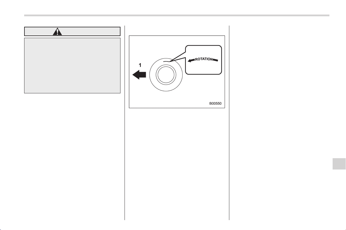
Black plate (447,1)
北米Model "A1160BE-C" EDITED: 2014/ 3/ 17
WARNING
When a tire’s tread wear indicator
becomes visible, the tire is worn
beyond the acceptable limit and
must be replaced immediately. With
a tire in this condition, driving at
high speeds in wet weather can
cause the vehicle to hydroplane.
The resulting loss of vehicle control
can lead to an accident.
NOTE
For safety, inspect tire tread regularly
and replace the tires before their tread
wear indicators become visible.
& Tire rotation direction mark
Example of tire rotation direction mark
1) Front
If the tire has the r otation direction
specification, the tire rotation direction
mark is placed on its sidewall.
When you install a tire that has the tire
rotation direction mark, install the tire with
the direction mark facing forward.
& Tire rotation
It may be difficult to rotate the tires. Have
the tires rotated by your SUBARU dealer.
& Tire replacement
The wheels and tires are important and
integral parts of your vehicle’s design;
they cannot be changed arbitrarily. The
tires fitted as standard equipment are
optimally matched to the characteristics
of the vehicle and were selected to give
the best possible combination of running
performance, ride comfort, and service
life. It is essential for every tire to have a
size and construction matching those
shown on the tire placard and to have a
speed symbol and load index matching
those shown on the tire placard.
Using tires of a non-specified size detracts
from controllability, ride comfort, braking
performance, speedometer accuracy and
odometer accuracy. It also creates incor-
rect body-to-tire clearances and inappro-
priately changes the vehicle’s ground
clearance.
All four tires must be the same in terms of
manufacturer, brand (tread pattern), con-
struction, and size. You are advised to
replace the tires with new ones that are
identical to those fitted as standard equip-
ment.
For safe vehicle operation, SUBARU
recommends replacing all four tires at
the same time.
Maintenance and service/Tires and wheels
11-27
– CONTINUED –
11
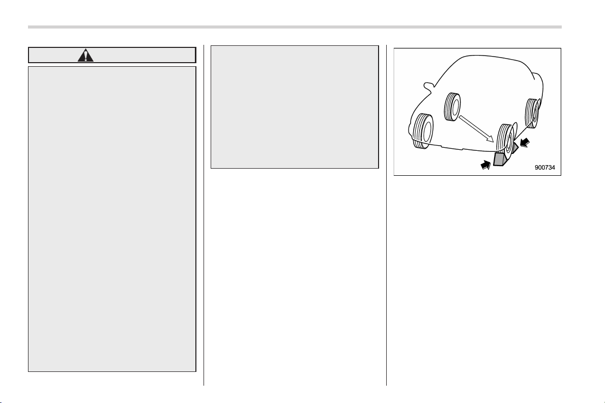
Black plate (448,1)
北米Model "A1160BE-C" EDITED: 2014/ 3/ 17
11-28
Maintenance and service/Tires and wheels
WARNING
. When replacing or installing tire
(s), all four tires must be the
same for following items.
(a) Size
(b) Circumference
(c) Speed symbol
(d) Load index
(e) Construction
(f) Manufacturer
(g) Brand (tread pattern)
(h) Degrees of wear
For the items (a) to (d), you must
obey the specification that is
printed on the tire placard. The
tire placard is located on the
driver’s door pillar.
If all of four tires are not the same
for items (a) to (h), serious me-
chanical damage could occur to
the drive train of your car, and
affect the following.
— Ride
— Handling
— Braking
— Speedometer/Odometer
calibration
— Clearance between the body
and tires
It also may be dangerous and
lead to loss of vehicle control,
and it can lead to an accident.
. Use only radial tires. Do not use
radial tires together with belted
bias tires and/or bias-ply tires.
Doing so can dangerously re-
duce controllability, resulting in
an accident.
! Replacement procedure
1. Park on a hard, level surface, when-
ever possible, then stop the engine.
2. Set the parking brake securely and
shift the select lever in the “P” (Park)
position.
3. Turn on the hazard warning flasher
and have everyone get out of the vehicle.
4. Put wheel blocks at the front and rear
of the tire diagonally opposite the tire to be
replaced.
5. Take out the jack, jack handle and
wheel nut wrench.
Refer to “Maintenance tools” F9-2.
NOTE
Make sure that the jack is well lubri-
cated before using it.
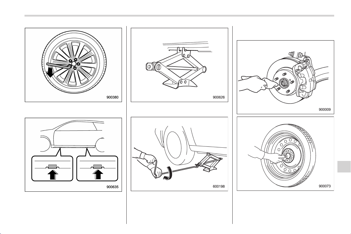
Black plate (449,1)
北米Model "A1160BE-C" EDITED: 2014/ 3/ 17
6. Loosen the wheel nuts using the wheel
nut wrench but do not remove the nuts.
Jack-up points
7. Place the jack under the side sill at the
front or rear jack-up point closest to the flat
tire.
Turn the jackscrew by hand until the jack
head engages firmly into the jack-up point.
8. Insert the jack handle into the jack-
screw, and turn the handle until the tire
clears the ground. Do not raise the vehicle
higher than necessary.
9. Remove the wheel nuts and the tire to
be replaced.
10. Before putting the new tire on, clean
the mounting surface of the wheel and hub
with a cloth.
11. Put on the new tire. Replace the wheel
Maintenance and service/Tires and wheels
11-29
– CONTINUED –
11
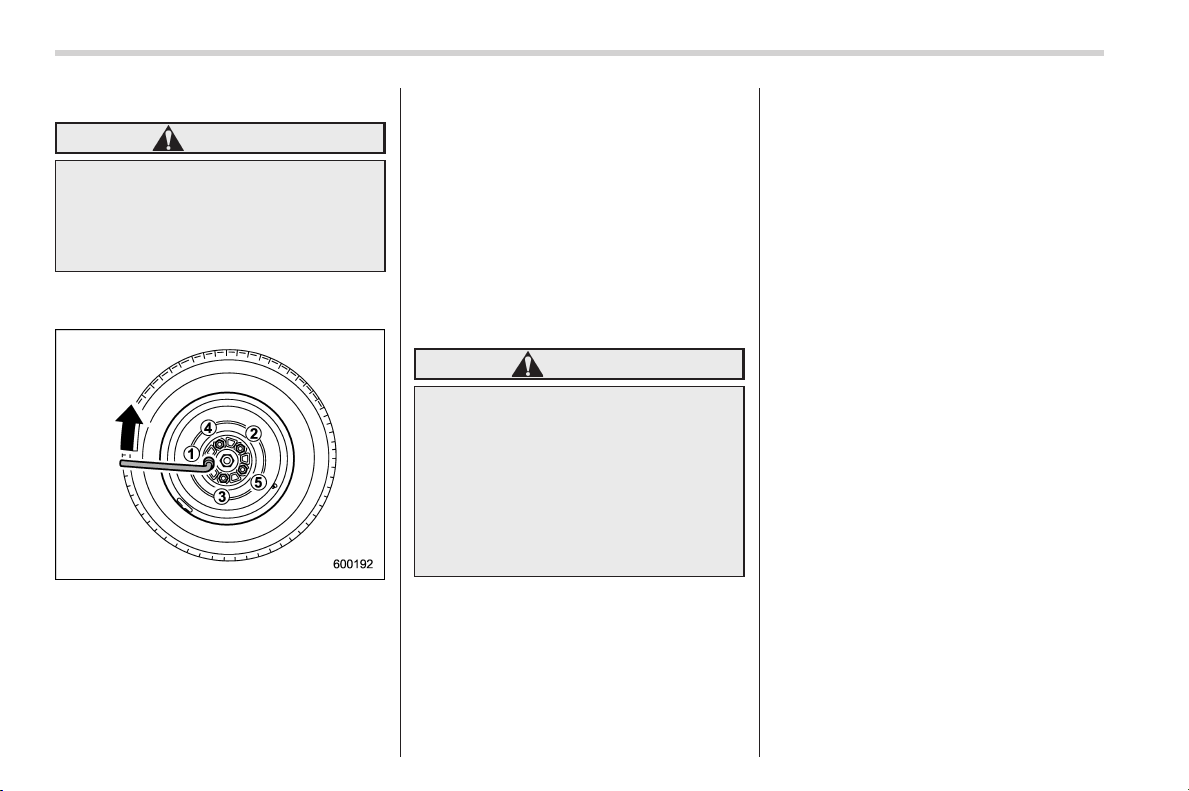
Black plate (450,1)
北米Model "A1160BE-C" EDITED: 2014/ 3/ 17
11-30
Maintenance and service/Tires and wheels
nuts. Tighten them by hand.
WARNING
Do not use oil or grease on the
wheel studs or nuts when the repla-
cement tire is installed. This could
cause the nuts to become loose and
lead to an accident.
12. Turn the jack handle counterclockwise
to lower the vehicle.
13. Use the wheel nut wrench to securely
tighten the wheel nuts to the specified
torque, following the tightening order in the
illustration.
For the wheel nut tightening torque, refer
to “Tires” F12-9. Never use your foot on
the wheel nut wrench or a pipe extension
on the wrench because you may exceed
the specified torque. Have the wheel nut
torque checked at the nearest automotive
service facility.
& Wheel replacement
When replacing wheels due, for example,
to damage, make sure the replacement
wheels match the specifications of the
wheels that are fitted as standard equip-
ment. Replacement wheels are available
from SUBARU dealers.
WARNING
Use only those wheels that are
specified for your vehicle. Wheels
not meeting specifications could
interfere with brake caliper opera-
tion and may cause the tires to rub
against the wheel well housing dur-
ing turns. The resulting loss of
vehicle control could lead to an
accident.
NOTE
When any of the wheels are removed
and replaced for tire rotation or for any
other reason, always check the tight-
ness of the wheel nuts after driving
approximately 600 miles (1,000 km). If
any nut is loose, tighten it to the
specified torque.
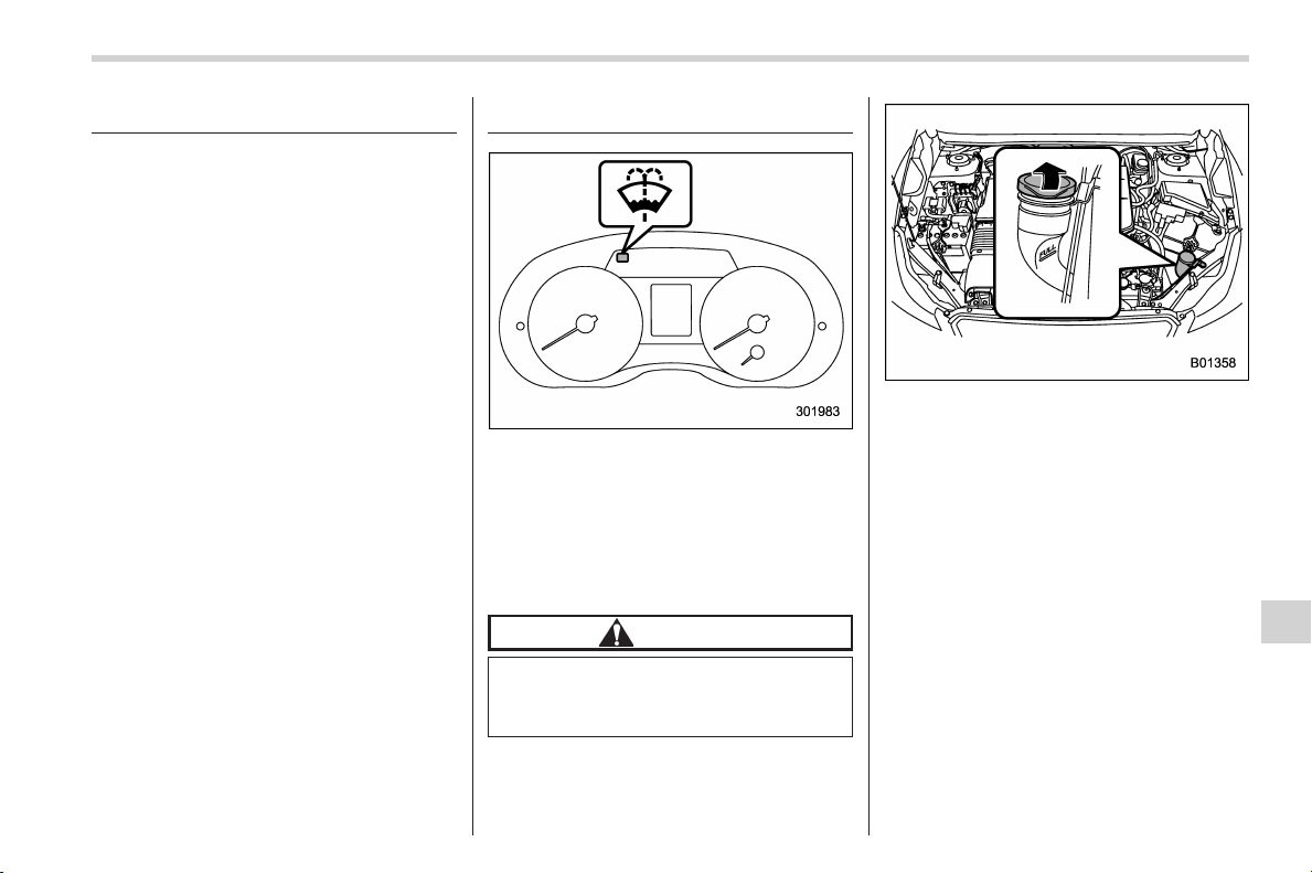
Black plate (451,1)
北米Model "A1160BE-C" EDITED: 2014/ 3/ 17
Aluminum wheels
Aluminum wheels can be scratched and
damaged easily. Handle them carefully to
maintain their appearance, performance,
and safety.
. When any of the wheels are removed
and replaced for tire rotation or to change
a flat tire, always check the tightness of
the wheel nuts after driving approximately
600 miles (1,000 km). If any nut is loose,
tighten it to the specified torque.
. Never apply oil to the threaded parts,
wheel nuts, or tapered surface of the
wheel.
. Never let the wheel rub against sharp
protrusions or curbs.
. When wheel nuts, balance weights, or
the center cap is replaced, be sure to
replace them with genuine SUBARU parts
designed for aluminum wheels.
Windshield washer fluid
When there is only a small amount of
washer fluid remaining, the windshield
washer fluid warning light will illuminate.
When this occurs, refill the washer fluid.
& Adding the windshield
washer fluid
CAUTION
Never use engine coolant as washer
fluid because it could cause paint
damage.
Remove the washer tank filler cap, then
add windshield w asher fluid until it
reaches the “FULL” mark on the tank.
& Windshield washer fluid
Use windshield washer fluid. If windshield
washer fluid is unavailable use clean
water.
In areas where water freezes in winter,
use an anti-freeze type windshield washer
fluid. SUBARU Windshield Washer Fluid
contains 58.5% methyl alcohol and 41.5%
surfactant, by volume. Its freezing tem-
perature varies according to how much it
is diluted, as indicated in the following
table.
Maintenance and service/Aluminum wheels
11-31
– CONTINUED –
11
Black plate (452,1)
北米Model "A1160BE-C" EDITED: 2014/ 3/ 17
11-32
Maintenance and service/Replacement of wiper blades
Washer Fluid
Concentration
Freezing
Temperature
30%
10.48F(−128C)
50% −48F(−208C)
100% −498F(−458C)
In order to prevent freezing of washer
fluid, check the freezing temperatures in
the table above when adjusting the fluid
concentration to the outside temperature.
If you fill the reservoir tank with a fluid with
a different concentration from the one
used previously, purge the old fluid from
the piping between the reservoir tank and
washer nozzles by operating the washer
for a certain period of time. Otherwise, if
the concentration of the fluid remaining in
thepipingistoolowfortheoutside
temperature, it may freeze and block the
nozzles.
CAUTION
. Adjust the washer fluid concen-
tration appropriately for the out-
side temperature. If the concen-
tration is inappropriate, sprayed
washer fluid may freeze on the
windshield and obstruct your
view, and the fluid may freeze in
the reservoir tank.
. State or local regulations on
volatile organic compounds may
restrict the use of methanol, a
common windshield washer anti-
freeze additive. Washer fluids
containing non-methanol anti-
freeze agents should b e used
only if they provide cold weather
protection without damaging
your vehicle’s paint, wiper blades
or washer system.
Replacement of wiper blades
Grease, wax, insects, or other material on
the windshield or the wiper blade results in
jerky wiper operation and streaking on the
glass. If you cannot remove the streaks
after operating the windshield washer or if
the wiper operation is jerky, clean the
outer surface of the windshield (or rear
window) and the wiper blades using a
sponge or soft cloth with a neutral
detergent or mild-abrasive cleaner. After
cleaning, rinse the windshield and wiper
blades with clean water. The windshield is
clean if beads do not form when you rinse
the windshield with water.
CAUTION
. Do not clean the wiper blades
with gasoline or a solvent, such
as paint thinner or benzine. This
will cause deterioration of the
wiper blades.
. While removing the wiper blades
from the wiper arms, do not
return the wiper arms to the
original positions. Otherwise,
the windshield surface may be
scratched.
. When returning the raised wiper
arms to the original positions,
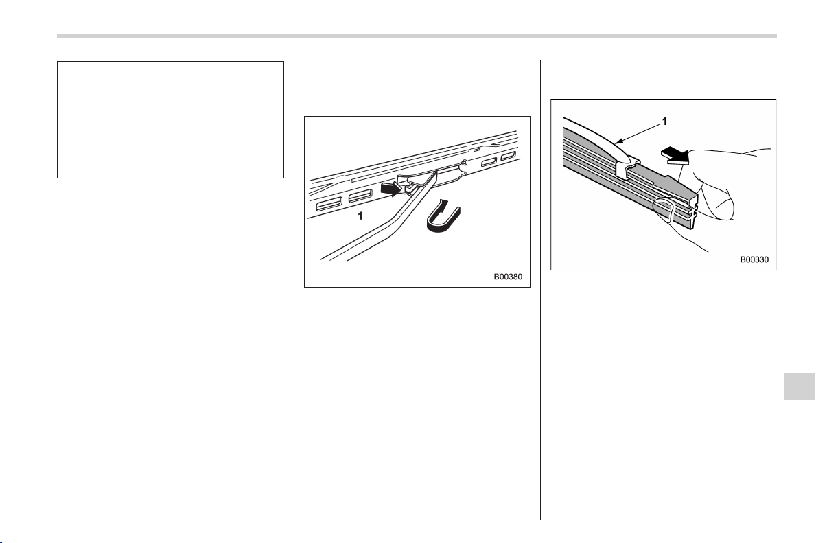
Black plate (453,1)
北米Model "A1160BE-C" EDITED: 2014/ 3/ 17
carefully return the wiper arms
on the windshield by hand. You
should not return the wiper arms
to the windshield only by the
return spring. Otherwise, the wi-
per arms may be deformed and/
or the windshield surface may be
scratched.
If you cannot eliminate the streaking even
after following this method, replace the
wiper blades using the following proce-
dures.
& Windshield wiper blade as-
sembly
1. Raise the wiper arm off the windshield.
1) Stopper
2. Remove the wiper blade assembly by
holding its pivot area and pushing it in the
direction shown by the arrow while de-
pressing the wiper blade stopper.
3. Install the wiper blade assembly to the
wiper arm. Make sure that it locks in place.
4. Hold the wiper arm by hand and slowly
lower it in position.
& Windshield wiper blade rub-
ber
1) Metal support
1. Grasp the locked end of the blade
rubber assembly and pull it firmly until the
stoppers on the rubber are free of the
metal support.
Maintenance and service/Replacement of wiper blades
11-33
– CONTINUED –
11
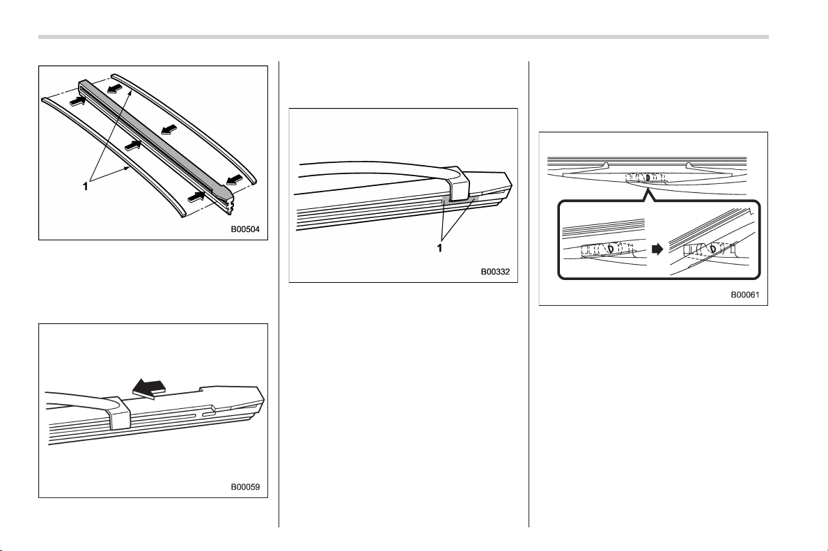
Black plate (454,1)
北米Model "A1160BE-C" EDITED: 2014/ 3/ 17
11-34
Maintenance and service/Replacement of wiper blades
1) Metal spines
2. If the new blade rubber is not provided
with two metal spines, remove the metal
spines from the old blade rubber and
install them in the new blade rubber.
3. Align the claws of the metal support
with the grooves in the rubber and slide
the blade rubber assembly into the metal
support until it locks.
1) Stopper
4. Be sure to position the claws at the
end of the metal support between the
stoppers on the rubber as shown. If the
rubber is not retained properly, the wiper
blade may scratch the windshield.
& Rear window wiper blade
assembly
1. Raise the wiper arm off the rear
window.
2. Turn the wiper blade assembly coun-
terclockwise.
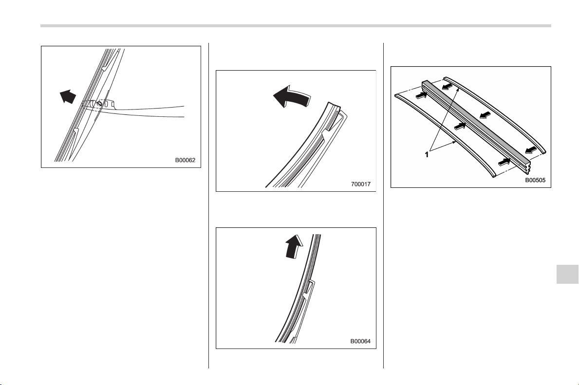
Black plate (455,1)
北米Model "A1160BE-C" EDITED: 2014/ 3/ 17
3. Pull the wiper blade assembly toward
you to remove it from the wiper arm.
4. Install the wiper blade assembly to the
wiper arm. Make sure that it locks in place.
5. Hold the wiper arm by hand and slowly
lower it in position.
& Rear window wiper blade
rubber
1. Pull out the end of the blade rubber
assembly to unlock it from the plastic
support.
2. Pull the blade rubber assembly out of
the plastic support.
1) Metal spines
3. If the new blade rubber is not provided
with two metal spines, remove the metal
spines from the old blade rubber and
install them in the new blade rubber.
Maintenance and service/Replacement of wiper blades
11-35
– CONTINUED –
11
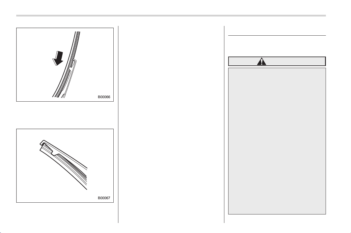
Black plate (456,1)
北米Model "A1160BE-C" EDITED: 2014/ 3/ 17
11-36
Maintenance and service/Battery
4. Align the claws of the plastic support
with the grooves in the blade rubber
assembly, then slide the blade rubber
assembly into place.
Securely retain both ends of the rubber
with the stoppers on the plastic support
ends. If the rubber is not retained properly,
the wiper may scratch the rear window
glass.
5. Install the wiper blade assembly to the
wiper arm. Make sure that it locks in place.
6. Hold the wiper arm by hand and slowly
lower it in position.
Battery
& 12 V auxiliary battery and 12
V engine restart battery
WARNING
. Before beginning work on or near
any battery, be sure to extinguish
all cigarettes, matches, and light-
ers. Never expose a battery to an
open flame or electric sparks.
Batteries give off a gas which is
highly flammable and explosive.
. For safety, in case an explosion
does occur, wear eye protection
or shield your eyes when work-
ing near any battery. Never lean
over a battery.
. Do not let battery fluid contact
eyes, skin, fabrics, or paint be-
cause battery fluid is a corrosive
acid. If battery fluid gets on your
skin or in your eyes, immediately
flush the area with water thor-
oughly. Seek medical help imme-
diately if acid has entered the
eyes.
If battery fluid is accidentally
swallowed, immediately drink a
large amount of milk or water,
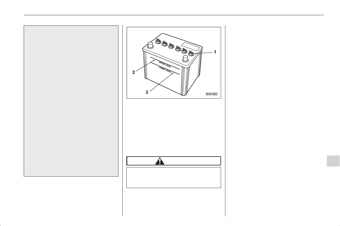
Black plate (457,1)
北米Model "A1160BE-C" EDITED: 2014/ 3/ 17
and seek medical attention im-
mediately.
. To lessen the risk of spark s,
remove rings, metal watchbands,
and other metal jewelry. Never
allow metal tools to contact the
positive battery terminal and any-
thing connected to it WHILE you
are at the same time in contact
with any other metallic portion of
the vehicle because a short cir-
cuit will result.
. Keep everyone including children
away from the battery.
. Charge the battery in a well-
ventilated area.
. Battery posts, terminals and re-
lated accessories contain lead
and lead compounds, chemicals
known to the State of California
to cause cancer and reproductive
harm. Batteries als o contain
other chemicals known to the
State of California to cause can-
cer.
Wash hands after handling
.
1) Cap
2) Upper level
3) Lower level
It is unnecessary to periodically check the
battery fluid level or periodically refill with
distilled water.
However, if the battery fluid level is below
the lower level, remove the cap. Fill to the
upper level with distilled water.
CAUTION
Never use more than 10 amperes
when charging the battery because
it will shorten battery life.
& High voltage battery
The high voltage battery is charged from
the operation of the engine and regenera-
tive brakes. Because of this, you do not
have to charge the high voltage battery
from an outside source. However, in order
to maintain the battery in good condition,
drive the vehicle at least once every
month for at least 30 minutes. If you leave
the vehicle for a long time, the battery may
discharge or the life of the battery may be
shortened.
Maintenance and service/Battery
11-37
11
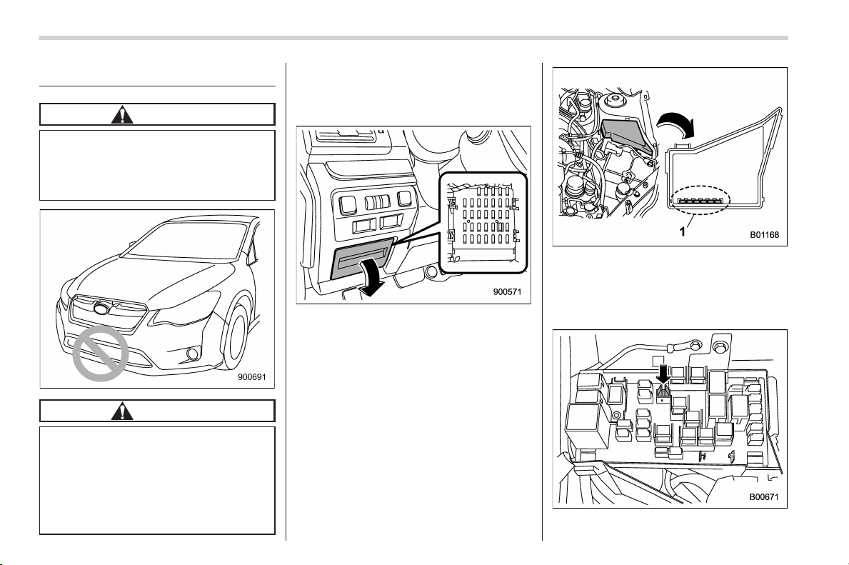
Black plate (458,1)
北米Model "A1160BE-C" EDITED: 2014/ 3/ 17
11-38
Maintenance and service/Fuses
Fuses
CAUTION
Never replace a fuse with one hav-
ing a higher rating or with material
other than a fuse because serious
damage or a fire could result.
CAUTION
When replacing a fuse, do not touch
the area around the front bumper.
Also, do not put tools or cloths in
this area. I f any function of the
cooling system operates, it may lead
to an injury or a failure of the
cooling system.
The fuses are designed to melt during an
overload to prevent damage to the wiring
harness and electrical equipment. The
fuses are located in two fuse boxes.
One is located under the instrument panel
behind the fuse box cover on the driver’s
seat side. To remove the cover, pull it out.
1) Spare fuses
The other one (main fuse box) is housed
in the engine compartment. Also, the
spare fuses are stored in the fuse box
cover.
The fuse puller is stored in the main fuse
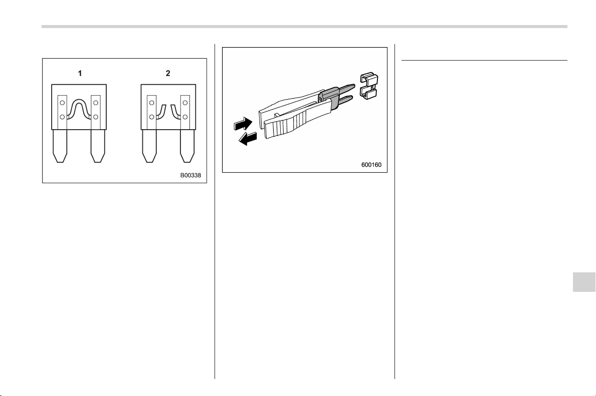
Black plate (459,1)
北米Model "A1160BE-C" EDITED: 2014/ 3/ 17
box in the engine compartment.
1) Good
2) Blown
If any lights, accessories or other electrical
controls do not operate, inspect the
corresponding fuse. If a fuse has blown,
replace it.
1. Turn the ignition switch to the “LOCK”
(off) position and turn off all electrical
accessories.
2. Remove the cover.
3. Determine which fuse may be blown.
Look at the back side of each fuse box
cover and refer to “Fuses and circuits”
F12-10.
4. Pull out the fuse with the fuse puller.
5. Inspect the fuse . If it has blown,
replace it with a spare fuse of the same
rating.
6. If the same fuse blows again, this
indicates that its system has a problem.
Contact your SUBARU dealer for repairs.
Installation of accessories
Always consu lt you r SUBAR U dea ler
before installing fog lights or any other
electrical equipment in your vehicle. Such
accessories may cause the electronic
system to malfunction if they are incor-
rectly installed or if they are not suited for
the vehicle.
Maintenance and service/Installation of accessories
11-39
11
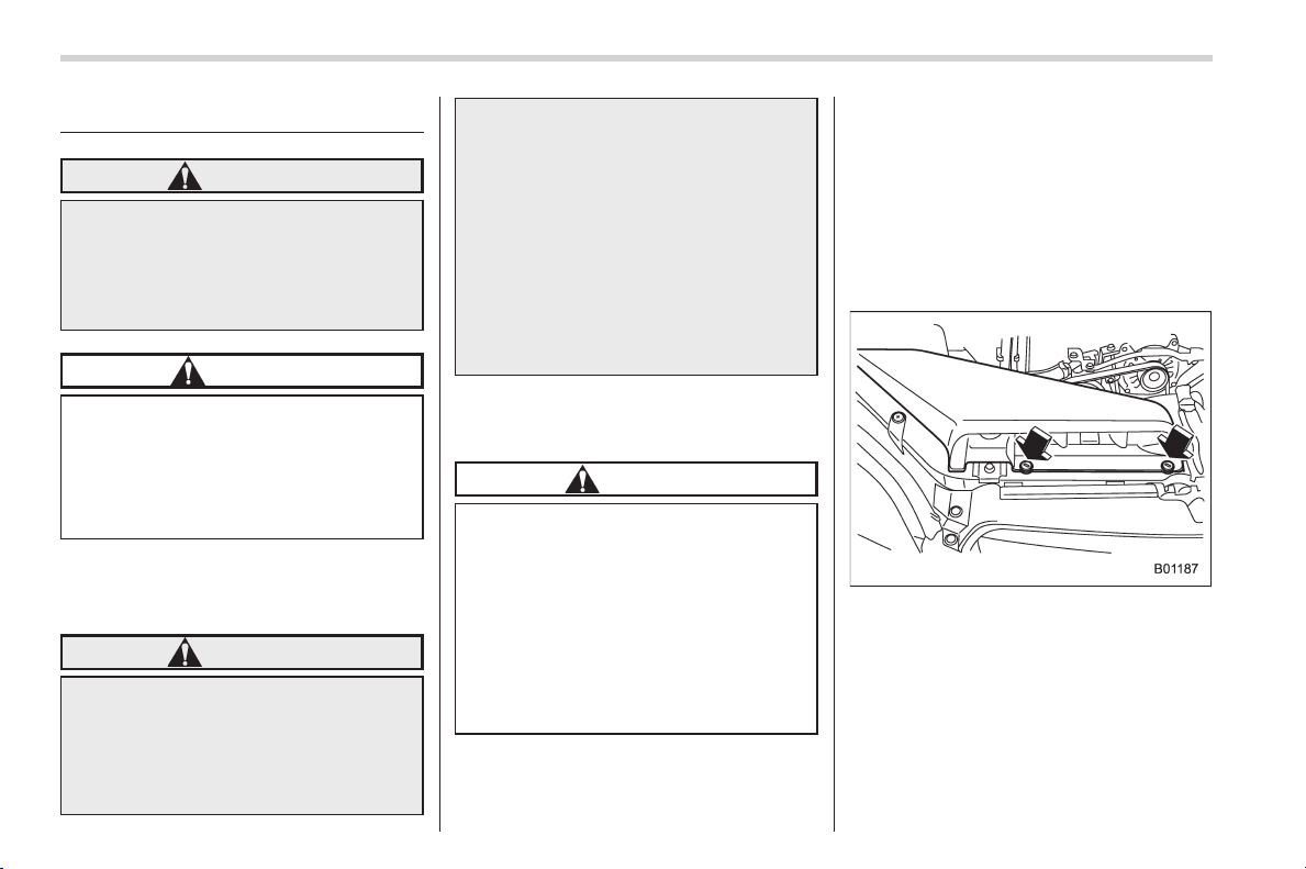
Black plate (460,1)
北米Model "A1160BE-C" EDITED: 2014/ 3/ 17
11-40
Maintenance and service/Replacing bulbs
Replacing bulbs
WARNING
Bulbs may become very hot while
illuminated. Before replacing bulbs,
turn off the lights and wait until the
bulbs cool down. Otherwise, there is
a risk of sustaining a burn injury.
CAUTION
Replace any bulb only with a new
bulb of the specified wattage. Using
a bulb of different wattage could
result in a fire. For the specified
wattage of each bulb, refer to “Bulb
chart” F12-14.
& Headlights (models with HID
headlights)
WARNING
High-intensity-discharge (HID) bulbs
are used for the low beams of the
headlights. These HID bulbs use an
extremely high voltage. To avoid the
risk of an electric shock that could
result in serious injury, observe the
following precautions.
. Do not replace any headlight
bulbs (both low beam and high
beam) by yourself.
. Do not remove/restore the head-
light assemblies by yourself.
. Do not remove any headlight-
assembly components by your-
self.
For replacement, contact your
SUBARU dealer.
& Headlights (models without
HID headlights)
CAUTION
Halogen headlight bulbs become
very hot while in use. If you touch
the bulb surface with bare hands or
greasy gloves, fingerprints or
grease on the bulb surface will
develop into hot spots, causing the
bulb to break. If there are finger
prints or grease on the bulb surface,
wipe them away with a soft cloth
moistened with alcohol.
NOTE
. If headlight aiming is required, con-
sult your SUBARU dealer for proper
adjustment of the headlight aim.
. It may be difficult to replace the
bulbs. Have the bulbs replaced by your
SUBARU dealer if necessary.
Perform the following steps to replace the
bulbs.
Right-hand side
1. Use a screwdriver to undo the clips on
the air intake duct, then remove the air
intake duct (right-hand side).
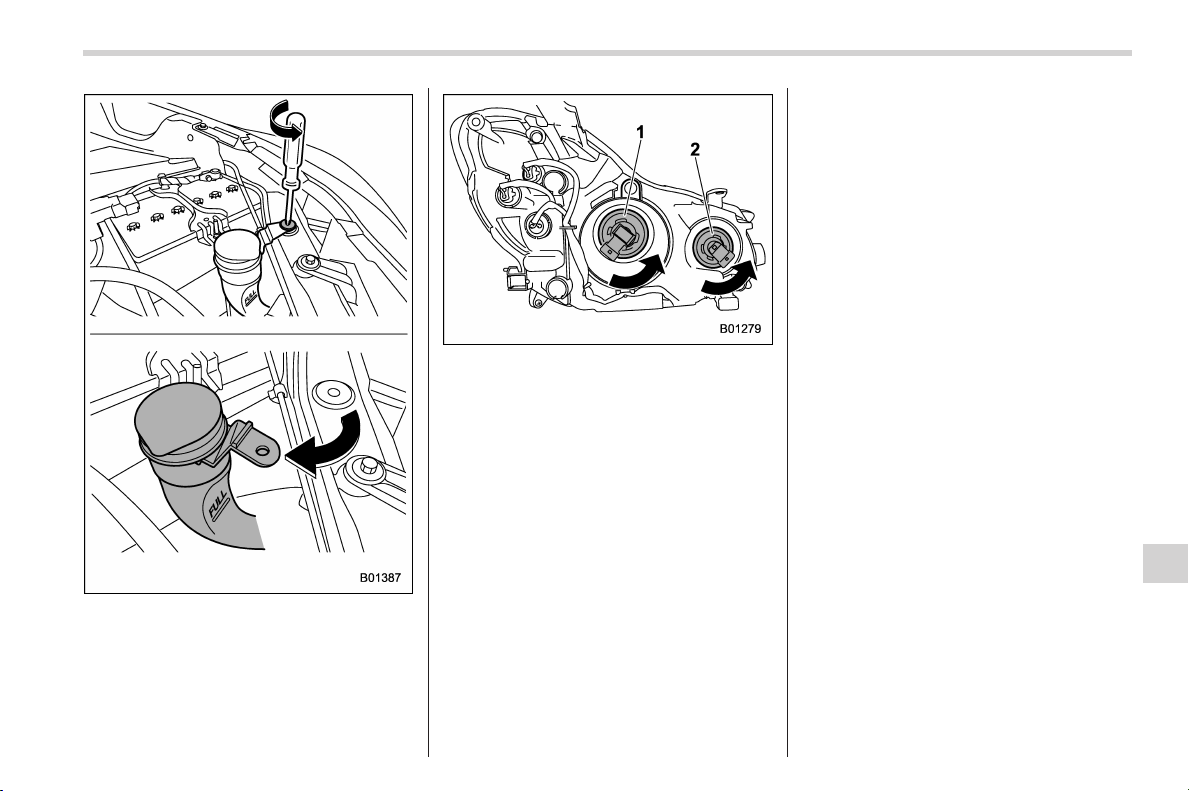
Black plate (461,1)
北米Model "A1160BE-C" EDITED: 2014/ 3/ 17
Left-hand side
2. Use a screwdriver to remove the
secured clip of the washer tank. To make
it easy to access the bulb, turn the neck of
the washer fluid filler pipe as illustrated
(left-hand side).
1) Low beam bulb
2) High beam bulb
3. Disconnect the electrical connector
from the bulb and remove the bulb from
the headlight assembly by turning it
counterclockwise.
4. Replace the bulb with new one. At this
time , use care not to touch the bulb
surface.
5. To install the bulb to the headlight
assembly, turn it clockwise until it clicks.
6. Reconnect the electrical connector.
7. Install the air intake duct with clips
(right-hand side).
8. Set the washer fluid filler pipe to the
original place and secure it by clip (left-
hand side).
& Front turn signal light
It may be difficult to replace the bulbs.
Have the bulbs replaced by your SUBARU
dealer if necessary.
& Parking light
It may be difficult to replace the bulbs.
Have the bulbs replaced by your SUBARU
dealer if necessary.
& Front fog light (if equipped)
It may be difficult to replace the bulbs.
Have the bulbs replaced by your SUBARU
dealer if necessary.
Maintenance and service/Replacing bulbs
11-41
– CONTINUED –
11
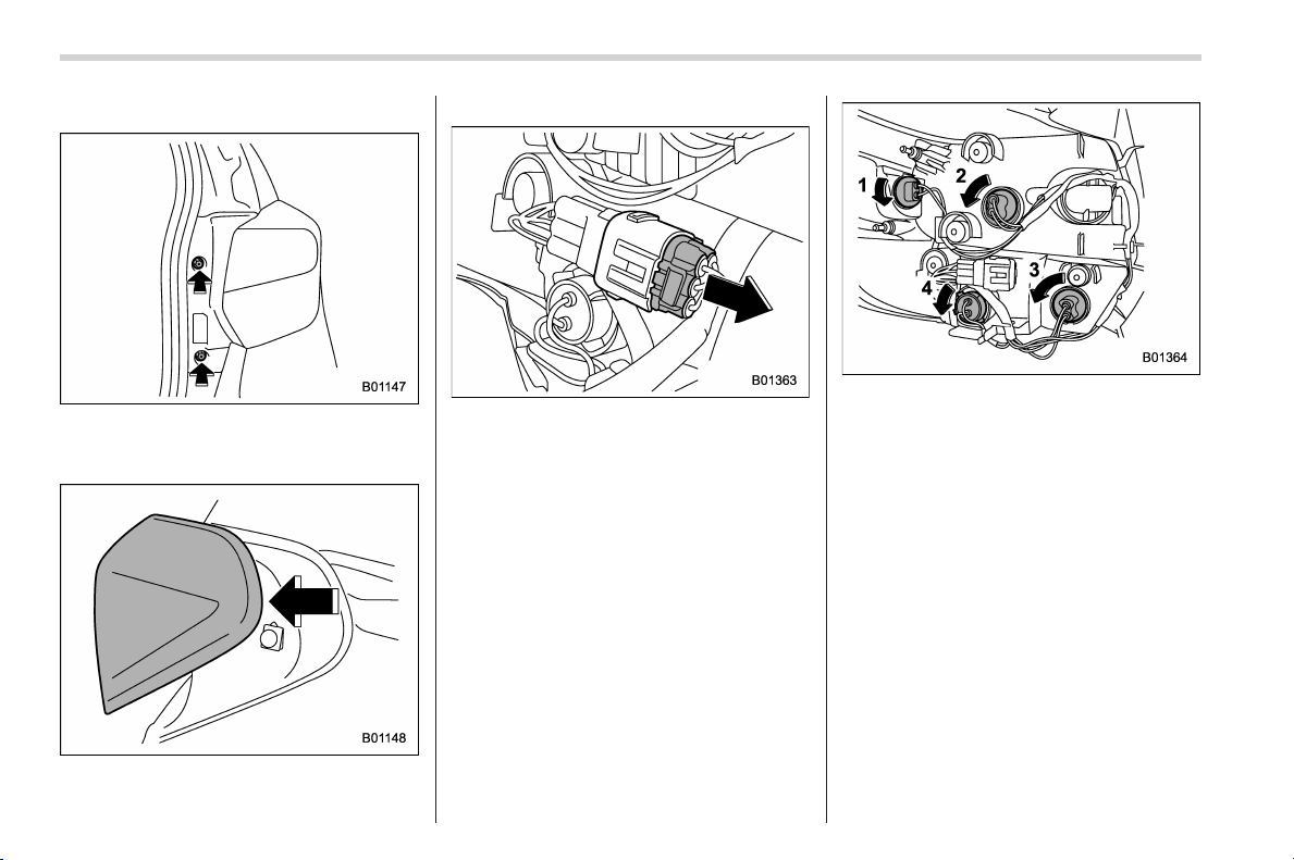
Black plate (462,1)
北米Model "A1160BE-C" EDITED: 2014/ 3/ 17
11-42
Maintenance and service/Replacing bulbs
& Rear combination lights
1. Using a Phillips screwdriver, remove
the upper and lower screws that secure
the rear combination light assembly.
2. Slide the rear combination light as-
sembly rearward.
3. Remove the rear combination light
assembly from the vehicle by disconnect-
ing the electrical connector.
1) Rear side marker light
2) Tail light
3) Backup light
4) Rear turn signal light
4. Remove the bulb socket from the rear
combination light assembly by turning it
counterclockwise.
5. Pull the bulb out of the bulb socket and
replace it with a new one.
6. Set the bulb socket into the rear
combination light assembly and turn it
clockwise until it locks.
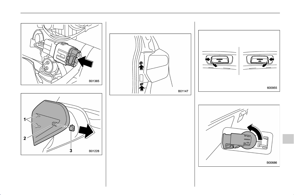
Black plate (463,1)
北米Model "A1160BE-D" EDITED: 2015/ 12/ 9
7. Reconnect the electrical connector.
1) Guide pins
2) Catch
3) Clip
8. Put the rear combination light assem-
bly into place while aligning the 2 guide
pins and a catch with the guide holes and
a clip on the vehicle.
9. Tighten the upper and lower screws.
& License plate light
1. License plate light must be pushed
inwards, then pulled out to be removed.
2. Turn the bulb socket counterclockwise
and pull out the socket.
Maintenance and service/Replacing bulbs
11-43
– CONTINUED –
11
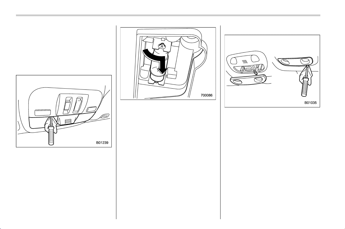
Black plate (464,1)
北米Model "A1160BE-D" EDITED: 2015/ 12/ 9
11-44
Maintenance and servi ce/Replacing bulbs
3. Pull the bulb out of the socket.
4. Install a new bulb.
5. Reinstall the bulb socket and the
license plate light cover.
& Map light
! Type A
1. Remove the lens by prying the edge of
the lens with a flat-head screwdriver.
2. Turn the bulb until the flat surfaces at
its ends are aligned vertically. Pull the bulb
straight downward to remove it.
3. Install a new bulb.
4. Reinstall the lens.
! Type B
1. Remove the lens by prying the edge of
the lens with a flat-head screwdriver.
2. Pull the bulb out of the socket.
3. Install a new bulb.
4. Reinstall the lens.
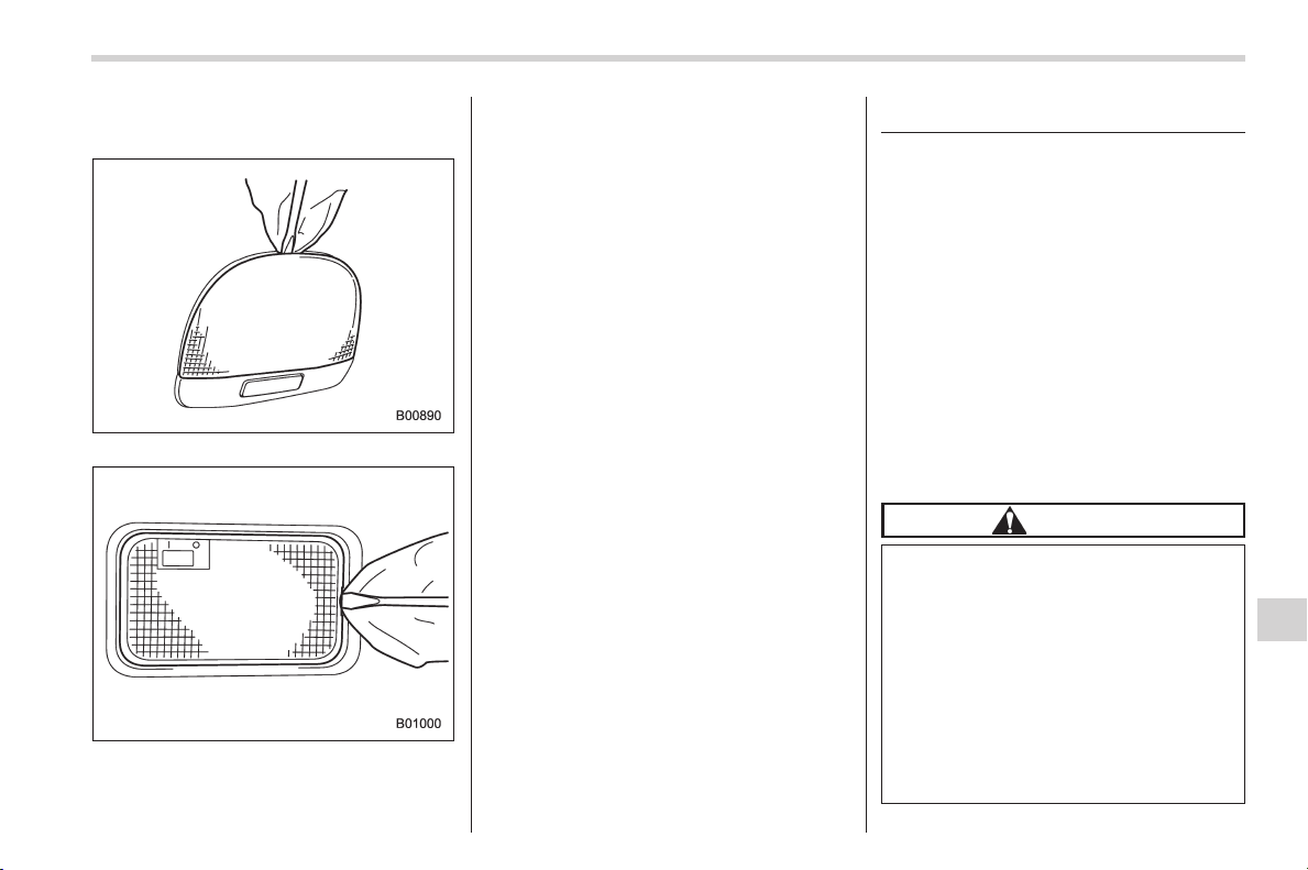
Black plate (465,1)
北米Model "A1160BE-C" EDITED: 2014/ 3/ 17
& Dome light and cargo area
light
Dome light
Cargo area light
1. Remove the lens by prying the edge of
the lens with a flat-head screwdriver.
2. Pull the bulb out of the socket.
3. Install a new bulb.
4. Reinstall the lens.
& Other bulbs
It may be difficult to replace the bulbs.
Have the bulbs replaced by your
SUBARU dealer if necessary.
Battery replacement
& Battery replacement timing
The access key/transmitter battery may
be discharged under the following condi-
tions.
. The operation of the keyless access
function is unstable
. The operating distance of the remote
keyless entry system is unstable
. The access key/transmitter does not
operate properly when used within the
standard distance
Replace the battery with a new one.
& Safety precautions
CAUTION
. Do not let dust, oil or water get on
or in the access key/transmitter
when replacing battery.
. Be careful not to damage the
printed circuit board in the ac-
cess key/transmitter when repla-
cing the battery.
. Be careful not to allow children to
touch the battery and any re-
moved parts; children could
swallow them.
Maintenance and service/Battery replacement
11-45
– CONTINUED –
11
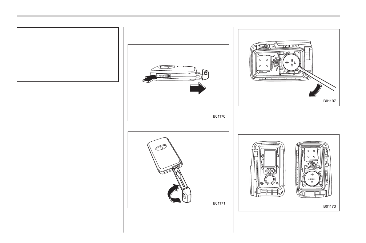
Black plate (466,1)
北米Model "A1160BE-C" EDITED: 2014/ 3/ 17
11-46
Maintenance and service/Battery replacement
. There is a danger of an explosion
if the battery is incorrectly re-
placed. Replace only with the
same or equivalent type of the
battery.
. Batteries should not be exposed
to excessive heat such as bright
sunlight, fire or the like.
NOTE
. Replace only with the same or
equivalent type of battery recom-
mended by the manufacturer.
. Dispose of used batteries according
to local laws.
. Mount the battery in the correct
orientation to prevent fluid leakage.
Be careful not to bend the terminals. It
may result in a malfunction.
. It is recommended that the battery
should be replaced by a SUBARU
dealer.
. Use a new battery.
. After replacing the battery, confirm
that the access key/transmitter func-
tions properly.
& Replacing access key battery
Battery: Button battery CR1632
1. Pull out the mechanical key.
2. Insert the key into the gap and turn it
clockwise to remove the cover.
3. Wrap a flat-head screwdriver with
insulating tape, and insert it between the
battery and the board. Then pry it out from
the board.
4. Insert a new battery with its positive (+)
side facing upward as shown in the
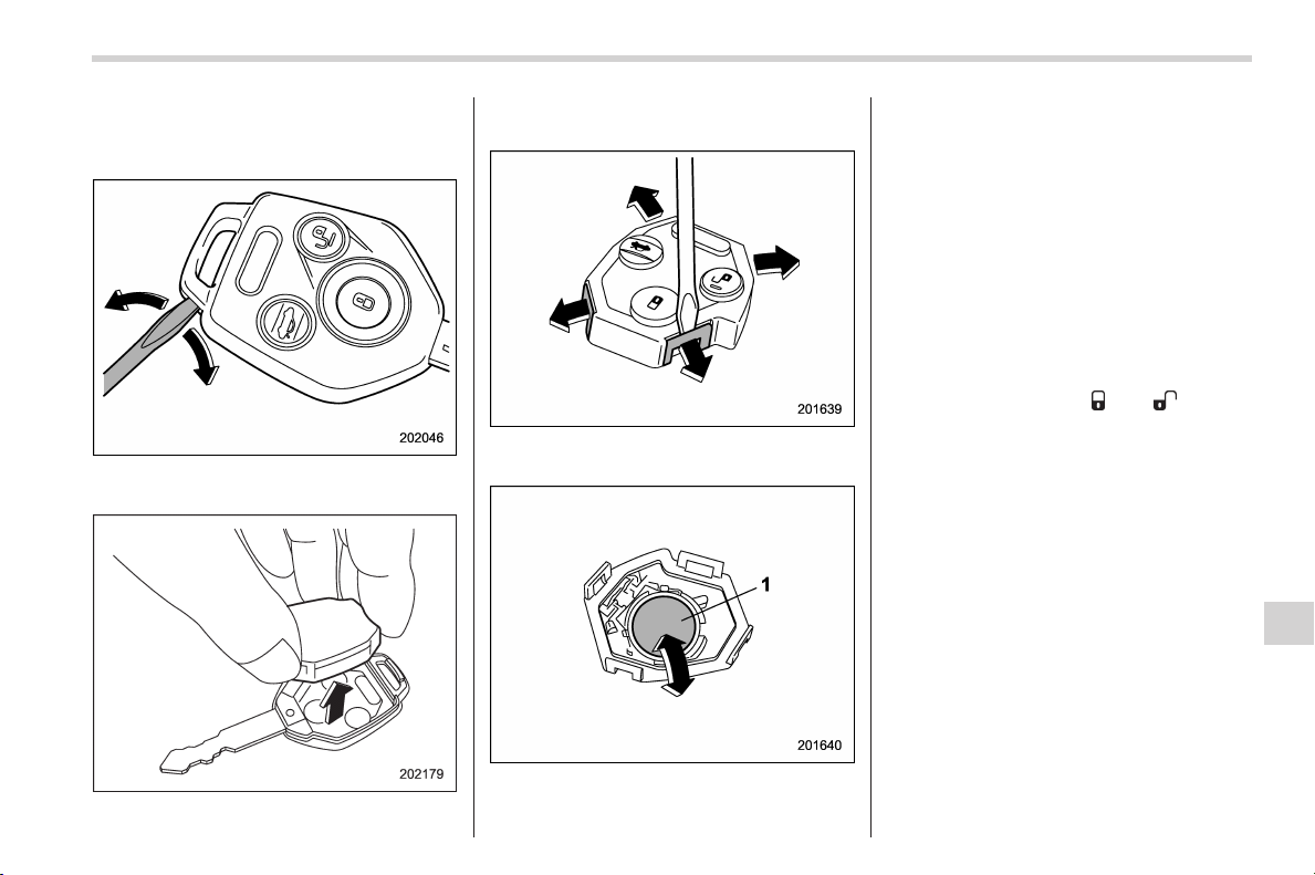
Black plate (467,1)
北米Model "A1160BE-C" EDITED: 2014/ 3/ 17
illustration. Attach the cover firmly.
& Replacing transmitter battery
1. Open the key head using a flat-head
screwdriver.
2. Remove the transmitter case from the
key head.
3. Open the transmitter case by releasing
the hooks.
1) Negative (−) side facing up
4. Replace the old battery with a new
battery (type CR1620 or equivalent) mak-
ing sure to install the new battery with the
negative (−) side facing up.
5. Put together the transmitter case by
fitting the hooks on the case.
6. Reinstall the transmitter case in the
key head.
7. Refit the removed half of the key head.
After the battery is replaced, the trans-
mitter must be synchronized with the
remote keyless entry system’s control
unit. Press either the “
” or “ ” button
six times to synchronize the unit.
Maintenance and service/Battery replacement
11-47
11

Black plate (2,1)
Model "ALL_MODEL_MEMO" EDITED: 2007/ 6/ 22
Left Page
————————————————————————————————————————
————————————————————————————————————————
————————————————————————————————————————
————————————————————————————————————————
————————————————————————————————————————
————————————————————————————————————————
————————————————————————————————————————
————————————————————————————————————————
————————————————————————————————————————
————————————————————————————————————————
————————————————————————————————————————
————————————————————————————————————————
————————————————————————————————————————

Black plate (23,1)
北米Model "A1160BE-C" EDITED: 2014/ 3/ 17
Specifications ..................................................... 12-2
Dimensions........................................................ 12-2
Engine ............................................................... 12-3
Electric motor .................................................... 12-3
High voltage battery ........................................... 12-3
Fuel ................................................................... 12-4
Engine oil .......................................................... 12-5
Front differential and rear differential gear oil...... 12-7
Fluids ................................................................ 12-8
Engine coolant ................................................... 12-8
Electrical system................................................ 12-8
Tires.................................................................. 12-9
Brake disc ......................................................... 12-9
Fuses and circuits ........................................... 12-10
Fuse panel located in the passenger
compartment ................................................. 12-10
Fuse panel located in the engine
compartment ................................................. 12-12
Bulb chart......................................................... 12-14
Safety precautions........................................... 12-14
Bulb chart ....................................................... 12-15
Vehicle identification ....................................... 12-17
Specifications
12
Black plate (472,1)
北米Model "A1160BE-C" EDITED: 2014/ 3/ 17
12-2
Specifications/Specifications
Specifications
These specifications are subject to change without notice.
& Dimensions
in (mm)
Overall length 175.2 (4,450)
Overall width 70.1 (1,780)
Overall height 63.6 (1,615)
Wheel base 103.7 (2,635)
Tread
Front 60.0 (1,525)
Rear 60.0 (1,525)
Ground clearance*
8.7 (220)
*: Measured with vehicle empty
Black plate (473,1)
北米Model "A1160BE-C" EDITED: 2014/ 3/ 17
& Engine
Engine model
FB20
(2.0 L, DOHC, non-turbo)
Engine type Horizontally opposed, liquid cooled 4 cylinder, 4-stroke gasoline engine
Displacement cu-in (cc) 121.7 (1,995)
Bore 6 Stroke in (mm) 3.31 6 3.54 (84.0 6 90.0)
Compression ratio 10.8 : 1
Firing order
1 – 3 – 2 – 4
& Electric motor
Type
Permanent magnet 3-phase synchronous motor
Maximum output 10 kW
Maximum torque
48 lbf·ft (65 N·m, 6.6 kgf·m)
& High voltage battery
Type
Nickel-Metal hydride battery
High voltage battery voltage 100.8 V
Rated capacity 5.5 Ah
Maximum output
13.5 kW
Specifications/Specifications
12-3
– CONTINUED –
12


Black plate (475,1)
北米Model "A1160BE-C" EDITED: 2014/ 3/ 17
& Engine oil
For the checking, adding and replacing procedure or other details, refer to “Engine oil” F11-10.
NOTE
The procedure for changing the engine oil and oil filter should be performed by a properly-trained expert. It is recommended
that you have this service performed by your SUBARU dealer.
! Approved engine oil
Always use the SUBARU approved engine oil. For further details, please contact your SUBARU dealer.
If the approved engine oil is unavailable, use the alternative engine oil described on the next page.
Specifications/Specifications
12-5
– CONTINUED –
12
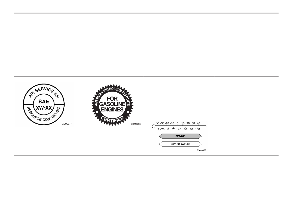
Black plate (476,1)
北米Model "A1160BE-C" EDITED: 2014/ 3/ 17
12-6
Specifications/Specifications
! Alternative engine oil
If the SUBARU approved oil is unavailable, the following alternative oil can be used.
NOTE
Each quantity indicated here is only a guideline. The necessary quantity for replacement may differ slightly depending on the
temperature and other factors.
Oil grade
SAE viscosity No. and
applicable temperature
Engine oil capacity
API (American Petroleum Insti-
tute) classification SM with the
words “ENERGY CONSER-
VING” or SN with the words
“RESOURCE CONSERVING”
or
ILSAC (International Lubricant
Specification Advisory Commit-
tee) GF-4 or GF-5, which can be
identified with the ILSAC certifi-
cation mark (Starburst mark)
0W-20 synthetic oil is the required oil
for optimum engine performance and
protection. Conventional oil may be
used if synthetic oil is unavailable.
*: If 0W-20 synthetic oil is not available,
5W-30 or 5W-40 conventional oil may
be used if replenishment is needed but
should be changed to 0W-20 synthetic
oil at the next oil change.
– Adding the oil from low level to
full level:
1.1 US qt (1.0 liter, 0.9 Imp qt)
– Changing the oil and oil filter:
5.1 US qt (4.8 liters, 4.2 Imp qt)
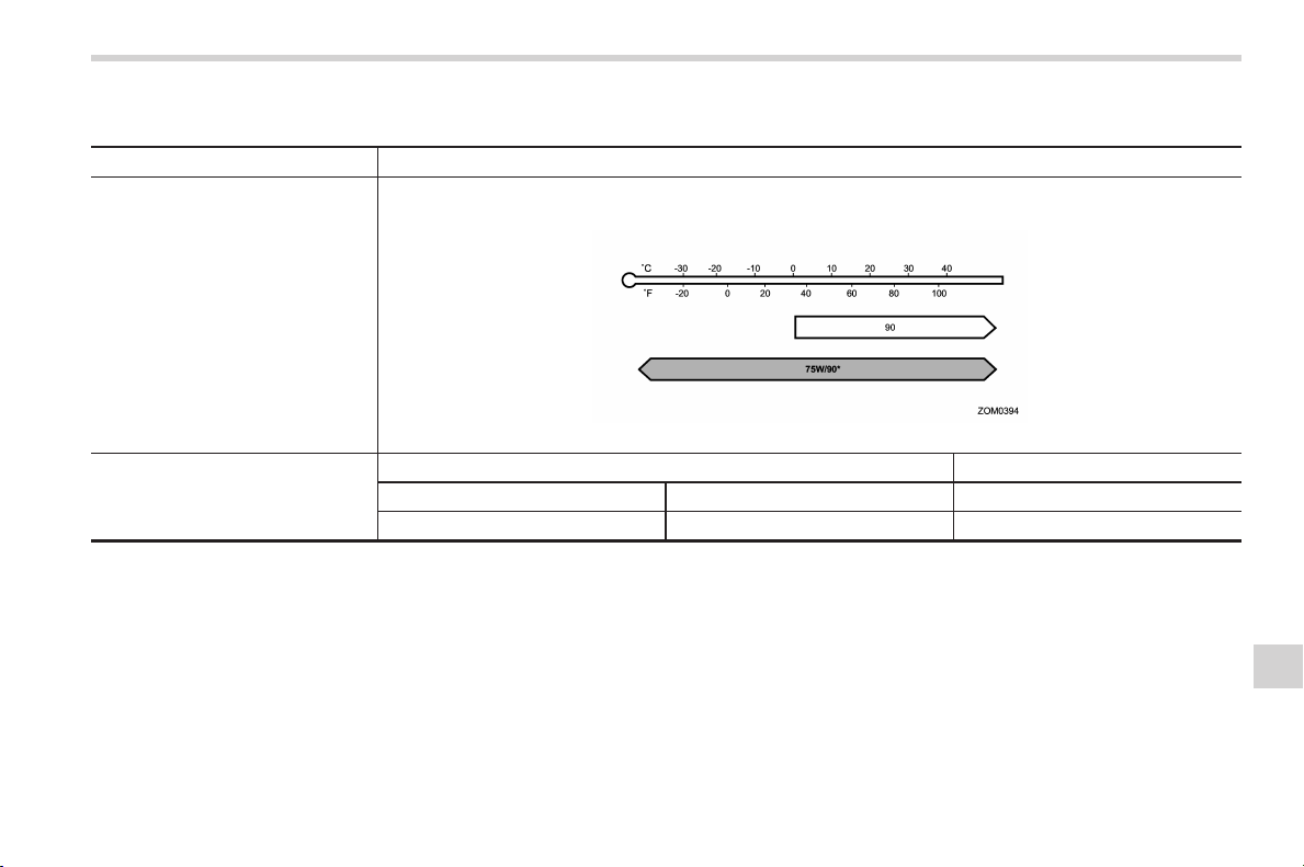
Black plate (477,1)
北米Model "A1160BE-C" EDITED: 2014/ 3/ 17
& Front differential and rear differential gear oil
Oil grade API classification GL-5
SAE viscosity No. and applicable
temperature
. 75W/90*
. 90
*: recommended
Oil capacity*
1
– Remarks*
2
Front differential gear oil 1.4 US qt (1.35 liters, 1.2 Imp qt) “Front differential gear oil” F11-18
Rear differential gear oil 0.8 US qt (0.8 liters, 0.7 Imp qt)
“Rear differential gear oil” F11-18
*1: The indicated oil quantity is only a guideline. The necessary quantity for replacement may differ slightly depending on the temperature and other
factors. After refilling the gearbox with oil, the oil level should be checked.
*2: For more details about maintenance and service, refer to the indicated section.
Specifications/Specifications
12-7
– CONTINUED –
12

Black plate (478,1)
北米Model "A1160BE-C" EDITED: 2014/ 3/ 17
12-8
Specifications/Specifications
& Fluids
Fluid
Fluid type*
1
Fluid capacity*
2
Remarks*
3
Continuously variable transmission
fluid
Consult your SUBARU dealer. 14.5 US qt (13.7 liters, 12.1 Imp qt)
“Continuously variable trans-
mission fluid” F11-17
Brake fluid
FMVSS No. 116, fresh DOT 3 or DOT 4
brake fluid
–
“Brake fluid” F11-18
*1: Use one of the indicated types of fluid.
*2: The indicated fluid quantity is only a guideline. The necessary quantity for replacement may differ slightly depending on the temperature and other
factors.
*3: For more details about maintenance and service, refer to the indicated section.
& Engine coolant
Coolant capacity Coolant type
8.7 US qt (8.2 liters, 7.2 Imp qt)
SUBARU Super Coolant
The indicated coolant quantity is only a guideline. The necessary quantity for replacement may differ slightly depending on the temperature and other
factors. For more details about maintenance and service, refer to “Cooling system” F11-13.
& Electrical system
Battery type and capacity (5HR)
12 V auxiliary battery 55D23L (12V-48AH)
12 V engine restart battery N-55R (12V-41AH)
Integrated starter generator 12V-200A
DC/DC converter 12V-130A
Spark plugs
DILZKAR7B11 (NGK)
Black plate (479,1)
北米Model "A1160BE-C" EDITED: 2014/ 3/ 17
& Tires
Tire size P225/55R17 95H
Wheel size
17 6 7J
Pressure Front
32 psi (220 kPa, 2.2 kgf/cm
2
)
Rear
30 psi (210 kPa, 2.1 kgf/cm
2
)
Wheel nut tightening torque
89 lbf·ft (120 N·m, 12 kgf·m)*
*: This torque is equivalent to applying approximately 88 to 110 lbf (40 to 50 kgf) at the end of the wheel nut wrench. If you have tightened the wheel nuts
by yourself, have the tightening torque checked at the nearest automotive service facility as soon as possible.
& Brake disc
If you need information on the usage limit value of brake discs and the method for measuring them, we recommend that you consult
your SUBARU dealer.
Specifications/Specifications
12-9
12
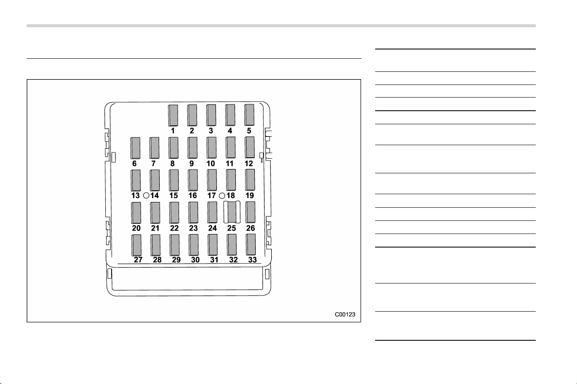
Black plate (480,1)
北米Model "A1160BE-C" EDITED: 2014/ 3/ 17
12-10
Specifications/Fuses and circuits
Fuses and circuits
& Fuse panel located in the passenger compartment
Fuse
panel
Fuse
rating
Circuit
1 20A
—
2 Empty
3 15A
. Door locking
4 10A
. Front wiper deicer relay
5 10A
. Combination meter
. Clock
6 7.5A
. Remote control rear
view mirrors
. Seat heater relay
7 15A
. Combination meter
. Integrated unit
8 15A
. Stop light
9 15A
. Front wiper deicer
10 7.5A
. Power supply (battery)
11 7.5A
. Turn signal unit
12 15A
. Transmission control
unit
. Engine control unit
. Integrated unit
13 20A
. Accessory power outlet
(center console)
. AC110V (If installed)
14 15A
. Parking light
. Tail light
. Rear combination light

Black plate (481,1)
北米Model "A1160BE-C" EDITED: 2014/ 3/ 17
Fuse
panel
Fuse
rating
Circuit
15 10A
. Luggage light
. Clock
16 7.5A
. Illumination
17 15A
. Seat heaters
18 10A
. Backup light
19 7.5A
(Spare)
20 10A
. Accessory power outlet
(instrument panel)
21 7.5A
. Starter relay
22 10A
. Air conditioner
. Rear window defogger
relay coil
23 Empty
24 10A
. Audio unit
. Clock
25 15A
. SRS airbag system
26 7.5A
. Power window relay
. Radiator main fan relay
27 15A
. Blower fan
28 15A
. Blower fan
29 15A
. Fog light
30 Empty
31 7.5A
. Auto air conditioner unit
. Integrated unit
Fuse
panel
Fuse
rating
Circuit
32 7.5A
. Steering lock control
unit
33 7.5A
. Vehicle Dynamics Con-
trol unit
Specifications/Fuses and circuits
12-11
– CONTINUED –
12
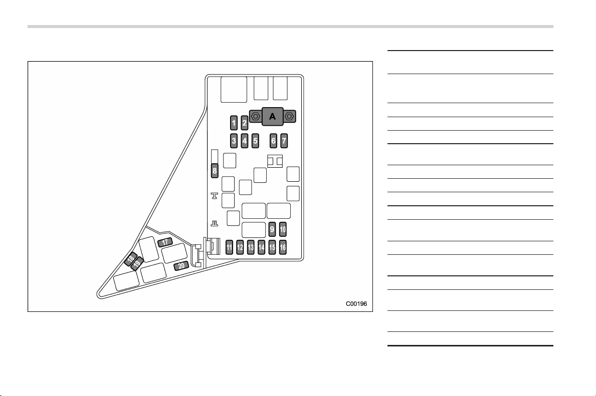
Black plate (482,1)
北米Model "A1160BE-C" EDITED: 2014/ 3/ 17
12-12
Specifications/Fuses and circuits
& Fuse panel located in the engine compartment
A) Main fuse
Fuse
panel
Fuse
rating
Circuit
1 30A
. ABS unit
. Vehicle Dynamics Con-
trol unit
2 25A
. Main fan (cooling fan)
3 25A
. Sub fan (cooling fan)
4
Empty
5
15A
. Brake vacuum pump
system
6
30A
. Headlight (low beam)
7
15A
. Headlight (high beam)
8 20A
. Back-up
9 15A
. Horn
10 25A
. Rear window defogger
. Mirror heater
11 15A
. Fuel pump
12 20A
. Continuously variable
transmission control unit
13 7.5A
. Engine control unit
14 15A
. Turn and hazard warn-
ing flasher
15 15A
. Tail and illumination re-
lay
16 7.5A
. 12 V auxiliary battery

Black plate (483,1)
北米Model "A1160BE-C" EDITED: 2014/ 3/ 17
Fuse
panel
Fuse
rating
Circuit
17 Empty
18
Empty
19 15A
. Headlight (low beam –
right hand)
20 15A
. Headlight (low beam –
left hand)
Specifications/Fuses and circuits
12-13
12
Black plate (484,1)
北米Model "A1160BE-C" EDITED: 2014/ 3/ 17
12-14
Specifications/Bulb chart
Bulb chart
& Safety precautions
WARNING
. Bulbs may become very hot while
illuminated. Before replacing
bulbs, turn off the lights and wait
until the bulbs cool down. Other-
wise, there is a risk of sustaining
a burn injury.
. For models with HID low beam
headlights, observe the following
precautions. Not doing so carries
the risk of an electric shock that
could result in serious injury
because the HID bulbs use an
extremely high voltage.
– Do not replace any headlight
bulbs (both low beam and
high beam) by yourself.
– Do not remove/restore the
headlight assemblies by your-
self.
– Do not remove any headlight-
assembly components by
yourself.
For replacement, contact your
SUBARU dealer.
CAUTION
Replace any bulb only with a new
bulb of the specified wattage. Using
a bulb of different wattage could
result in a fire.
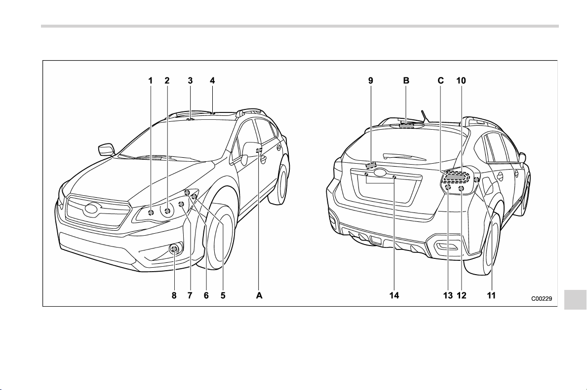
Black plate (485,1)
北米Model "A1160BE-C" EDITED: 2014/ 3/ 17
& Bulb chart
NOTE
Lights A, B and C are the LED (Light Emitting Diode) type. Consult your SUBARU dealer for replacement.
Specifications/Bulb chart
12-15
– CONTINUED –
12

Black plate (486,1)
北米Model "A1160BE-C" EDITED: 2014/ 3/ 17
12-16
Specifications/Bulb chart
Wattage Bulb No.*
1) High beam headlight 12V-60W HB3 (9005)
2) Low beam headlight
Models with HID light 12V-35W D2R
Models with halogen light 12V-55W H11
3)
Map light 12V-8W –
4)
Dome light 12V-8W –
5)
Front side marker light 12V-5W W5W (168)
6)
Parking light 12V-5W W5W (168)
7)
Front turn signal light 12V-21W WY21W
8)
Front fog light 12V-24W PSX24W
9)
Cargo area light 12V-5W –
10)
Tail light 12V-5W W5W
11)
Rear side marker light 12V-5W W5W (168)
12)
Rear turn signal light 12V-21W WY21W
13)
Back-up light 12V-16W W16W
14)
Licence plate light 12V-5W W5W
A)
Side turn signal light ––
B)
High mount stop light ––
C)
Brake light –
–
*: ECE specification
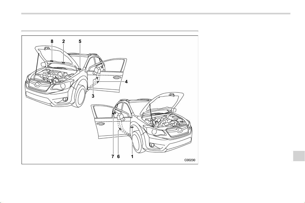
Black plate (487,1)
北米Model "A1160BE-C" EDITED: 2014/ 3/ 17
Vehicle identification 1) Vehicle identification number (under the
floor carpet of the right-hand front seat)
2) Emission control label
3) Tire inflation pressure label
4) Certification label
5) Vehicle identification number plate
6) Model number label
7) Fuel label
8) Air conditioner label
Specifications/Vehicle identification
12-17
12

Black plate (2,1)
Model "ALL_MODEL_MEMO" EDITED: 2007/ 6/ 22
Left Page
————————————————————————————————————————
————————————————————————————————————————
————————————————————————————————————————
————————————————————————————————————————
————————————————————————————————————————
————————————————————————————————————————
————————————————————————————————————————
————————————————————————————————————————
————————————————————————————————————————
————————————————————————————————————————
————————————————————————————————————————
————————————————————————————————————————
————————————————————————————————————————

Black plate (25,1)
北米Model "A1160BE-C" EDITED: 2014/ 3/ 17
For U.S.A. ........................................................... 13-2
Tire information.................................................. 13-2
Tire labeling ....................................................... 13-2
Recommended tire inflation pressure.................. 13-4
Glossary of tire terminology ............................... 13-5
Tire care – maintenance and safety
practices........................................................ 13-10
Vehicle load limit – how to determine................ 13-10
Determining compatibility of tire and vehicle
load capacities ............................................... 13-13
Adverse safety consequences of overloading
on handling and stopping and on tires ........... 13-14
Steps for Determining Correct Load Limit......... 13-14
Uniform tire quality grading standards .......... 13-15
Treadwear ....................................................... 13-15
Traction AA, A, B, C......................................... 13-15
Temperature A, B, C......................................... 13-15
Reporting safety defects (U.S.A.) ................... 13-16
Supplement ...................................................... 13-17
Declaration of conformity with FCC rules ......... 13-17
Consumer information and Reporting safety defects
13
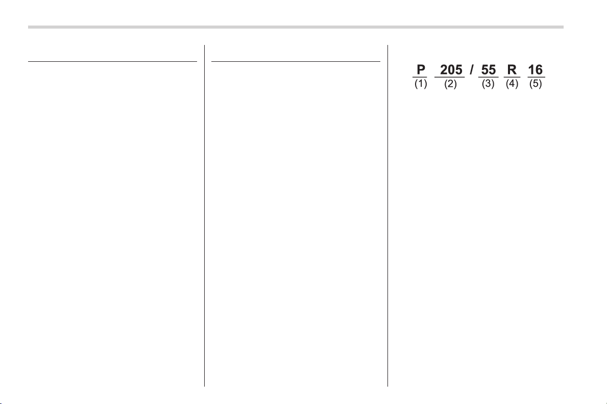
Black plate (492,1)
北米Model "A1160BE-C" EDITED: 2014/ 3/ 17
13-2
Consumer information and Reporting safety defects/For U.S.A.
For U.S.A.
The following information has been
compiled according to Code of
Federal Regulations “Title 49, Part
575”.
Tire information
& Tire labeling
Many markings (e.g. Tire size, Tire
Identification Number or TIN) are
placed on the sidewall of a tire by
tire manufacturers. These markings
can provide you with useful infor-
mation on the tire.
! Tire size
Your vehicle comes equipped with
P-Metric tire size. It is important to
understand the sizing system in
selecting the proper tire for your
vehicles. Here is a brief review of
the tire sizing system with a break-
down of its individual elements.
! P Metric
With the P-Metric system, Section
Width is measured in millimeters.
To convert millimeters into inches,
divide by 25.4. The Aspect Ratio
(Section Height divided by Section
Width) helps provide more dimen-
sional information about the tire
size.
Example:
(1) P = Certain tire type used on
light duty vehicles such as passen-
ger cars
(2) Section Width in millimeters
(3) Aspect Ratio (= section height
7 section width).
(4) R = Radial Construction
(5) Rim diameter in inches
! Load and Speed Rating De-
scriptions
The load and speed rating descrip-
tions will appear following the size
designation.
They provide two important facts
about the tire. First, the number
designation is its load index. Sec-
ond, the letter designation indicates
the tire’s speed rating.
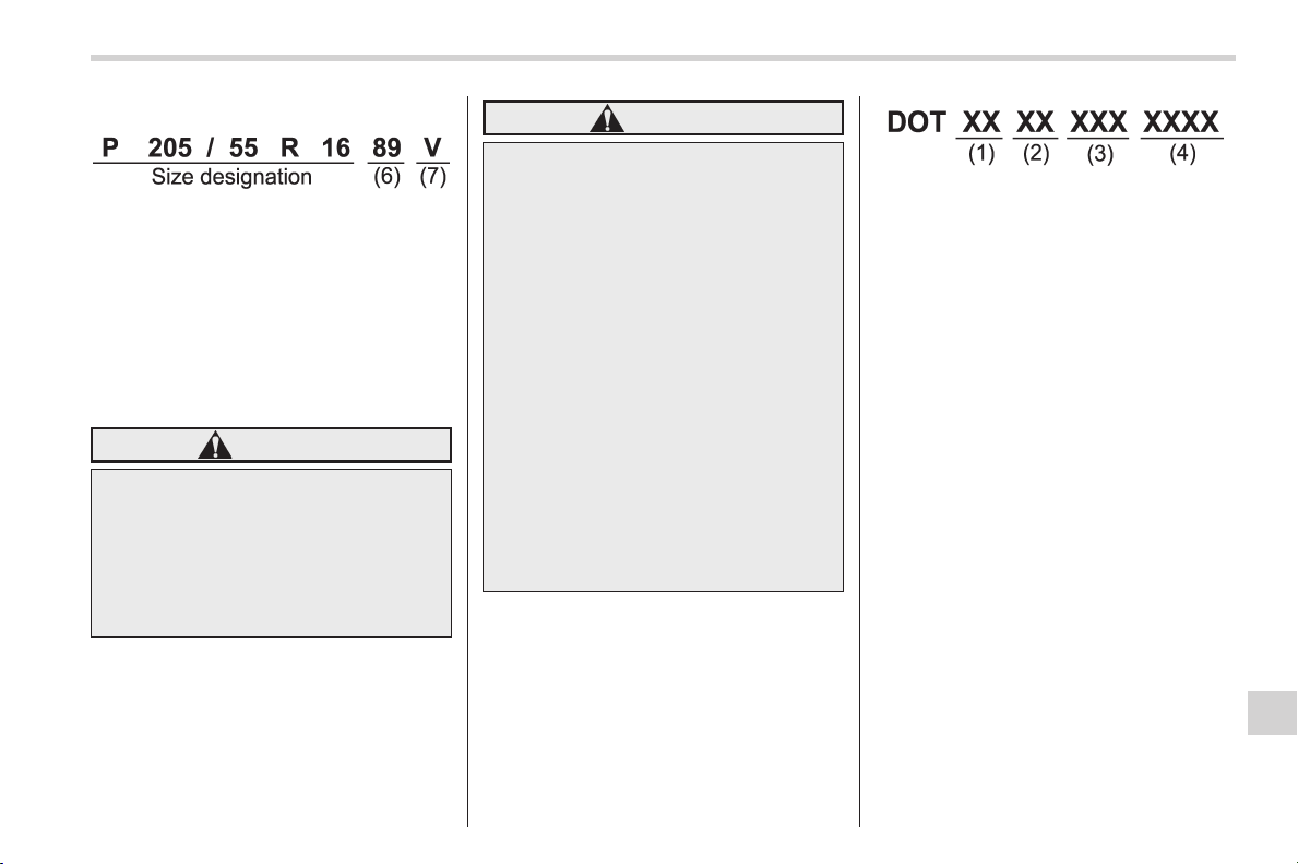
Black plate (493,1)
北米Model "A1160BE-C" EDITED: 2014/ 3/ 17
Example:
(6) Load Index: A numerical code
which specifies the maximum load
a tire can carry at the speed
indicated by its speed symbol, at
maximum inflation pressure.
For example, “90” means 1,323 lbs
(600 kg), “89” means 1,278 lbs (580
kg).
WARNING
Load indices apply only to the
tire, not to the vehicle. Putting
a load rated tire on any vehicle
does not mean the vehicle can
be loaded up to the tire’s rated
load.
(7) Speed Rating: An alphabetical
system describing a tire’s capability
to travel at established and prede-
termined speeds.
For example, “V” means 149 mph
(240 km/h)
WARNING
. Speed ratings apply only to
the tire, not to the vehicle.
Putting a speed rated tire on
any vehicle does not mean
the vehicle can be operated
at the tire’s rated speed.
. The speed rating is void if
the tires are worn out, da-
maged, repaired, retreaded,
or ot herwise al tered from
their original condition. If
tires are repaired, re-
treaded, or otherwise al-
tered, they may not be sui-
table for original equipment
tire designed loads and
speeds.
! Tire Identification Number (TIN)
Tire Identification Number (TIN) is
marked on the intended outboard
sidewall. The TIN is composed of
four groups. Here is a brief review
of the TIN with a breakdown of its
individual elements.
(1) Manufacturer’s Identification
Mark
(2) Tire Size
(3) Tire Type Code
(4) Date of Manufacture
The first two figures identify the
week, starting with “01” to represent
the first full week of the calendar
year; the second two figures repre-
sent the year. For example, 0101
means the 1st week of 2001.
! Other markings
The following makings are also
placed on the sidewall.
! Maximum permissible infla-
tion pressure
The maximum cold inflation pres-
sure to which this tire may be
inf lated. For example, “300 kPa
(44 PSI) MAX. PRESS”
Consumer information and Reporting safety defects/Tire information
13-3
– CONTINUED –
13
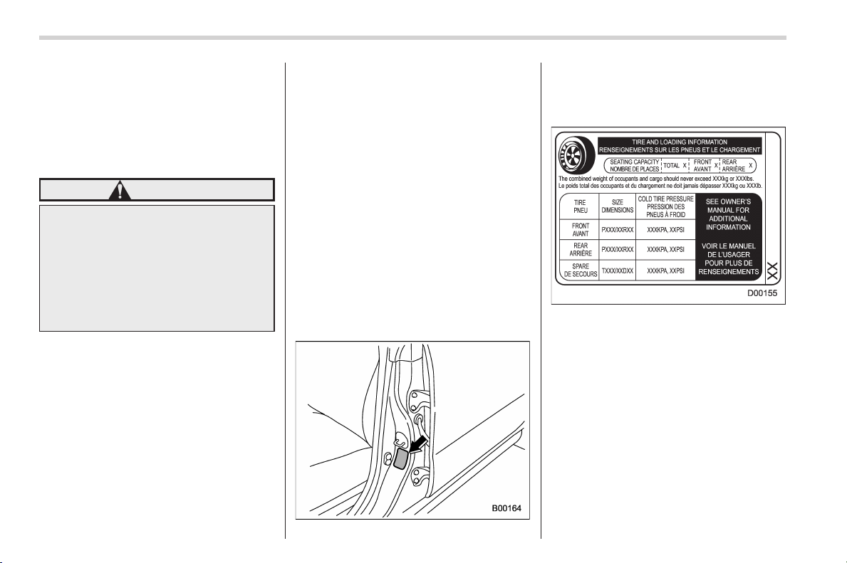
Black plate (494,1)
北米Model "A1160BE-C" EDITED: 2014/ 3/ 17
13-4
Consumer information and Reporting safety defects/Tire information
! Maximum load rating
The load rating at the maximum
permissible weight load for this tire.
For example, “MAX. LOAD 580 kg
(1279 LBS) @ 300 kPa (44 PSI)
MAX. PRESS.”
WARNING
Maximum load rating applies
only to the tire, not to the
vehicle. Putting a load rated
tire on any vehicle does not
mean the vehicle can be
loaded up to the tire’s rated
load.
! Construction typ e
Applicable construction of this tire.
For example, “TUBELESS STEEL
BELTED RADIAL”
! Construction
The generic name of each cord
material used in the plies (both
sidewall and tread area) of this tire.
For example, “PLIES: TREAD 2
STEEL + 2 POLYESTER SIDE-
WALL 2 POLYESTER”
! Uniform Tire Quality Grading
(UTQG)
For details, refer to “Uniform tire
quality grading standards” F13-15
.
& Recommended tire inflation
pressure
! Recommended cold tire infla-
tion pressure
For recommended cold tire inflation
pressure for your vehicle’s tires,
refer to “Tires” F12-9
.
! Vehicle placard
The vehicle placard is affixed to the
driver’s side B-pillar.
Example:
The vehicle placard shows original
tire size, recommended cold tire
inflation pressure on each tire at
maximum loaded vehicle weight,
seating capacity and loading infor-
mation.
! Adverse safety consequences
of under-inflation
Driving at high speeds with exces-
sively low tire pressures can cause
the tires to flex severely and to
rapidly become hot. A sharp in-

Black plate (495,1)
北米Model "A1160BE-C" EDITED: 2014/ 3/ 17
crease in temperature could cause
tread separation, and failure of the
tire(s). Possible resulting loss of
vehicle control could lead to an
accident.
! Measuring and adjusting air
pressure to achieve proper in-
flation
Check and, if necessary, adjust the
pressure of each tire (including the
spare) at least once a month and
before any long journey. Check the
tire pressures when the tires are
cold. Use a pressure gauge to
adjust the tire pressures to the
specific values. Driving even a
short distance warms up the tires
and increases the tire pressures.
Also, the tire pressures are affected
by the outside temperature. It is
best to check tire pressure out-
doors before driving the vehicle.
When a tire becomes warm, the air
inside it expands, causing the tire
pressure to increase. Be careful not
to mistakenly release air from a
warm tire to reduce its pressure.
& Glossary of tire terminology
. Accessory weight
The combined weight (in excess of
those standard items which may be
replaced) of automatic transmis-
sion, power steering, power brakes,
power windows, power seats, radio,
and heater, to the extent that these
items are available as factory-in-
stalled equipment (whether in-
stalled or not).
. Bead
The part of the tire that is made of
steel wires, wrapped or reinforced
by ply cords and that is shaped to fit
the rim.
. Bead separation
A breakdown of the bond between
components in the bead.
. Bias ply tire
A pneumatic tire in which the ply
cords that extend to the beads are
laid at alternate angles substantially
less than 90 degrees to the center-
line of the tread.
. Carcass
The tire structure, except tread and
sidewall rubber which, when in-
flated, bears the load.
. Chunking
The breaking away of pieces of the
tread or sidewall.
. Cold tire pressure
The pressure in a tire that has been
driven less than 1 mile or has been
standing for three hours or more.
. Cord
The strands forming the plies in the
tire.
. Cord separation
The parting of cords from adjacent
rubber compounds.
. Cracking
Any parting within the tread, side-
wall, or inner liner of the tire
extending to cord material.
. Curb weight
The weight of a motor vehicle with
standard equipment including the
maximum capacity of fuel, oil and
coolant, and if so equipped, air
conditioning and additional weight
optional engine.
Consumer information and Reporting safety defects/Tire information
13-5
– CONTINUED –
13

Black plate (496,1)
北米Model "A1160BE-C" EDITED: 2014/ 3/ 17
13-6
Consumer information and Reporting safety defects/Tire information
. Extra load tire
A tire designed to operate at higher
loads and higher inflation pressure
than the corresponding standard
tire.
. Groove
The space between two adjacent
tread ribs.
. Innerliner
The layer(s) forming the inside sur-
face of a tubeless tire that contains
the inflating medium within the tire.
. Innerliner separation
The parting of the innerliner from
cord material in the carcass.
. Intended outboard sidewall
(1) The sidewall that contains a
whitewall, bears white lettering
or bears manufacturer, brand,
and/or model name molding that
is higher or deeper than the
same molding on the other side-
wall of the tire, or
(2) The outward facing sidewall
of an asymmetrical tire that has
a particular side that must al-
ways face outward when mount-
ing on a vehicle.
. Light truck (LT) tire
A tire designated by its manufac-
turer as primarily intended for use
on lightweight trucks or multipur-
pose passenger vehicles.
. Load rating
The maximum load that a tire is
rated to carry for a given inflation
pressure.
. Maximum inflation pressure
The maximum cold inflation pres-
sure to which a tire may be inflated.
. Maximum load rating
The load rating for a tire at the
maximum permissible inflation
pressure for that tire.
. Maximum loaded vehic le weight
The sum of:
(a) Curb weight
(b) Accessory weight
(c) Vehicle capacity weight
(d) Production options weight
. Maximum permissible inflation
pressure
The maximum cold inflation pres-
sure to which a tire may be inflated.
. Measuring rim
The rim on which a tire is fitted for
physical dimension requirements.
. Normal occupant weight
150 lbs (68 kg) times the number of
occupants specified in the second
column of Table 1 that is appended
to the end of this section.
. Occupant distribution
Distribution of occupants in a vehi-
cle as specified in the third column
of Table 1 that is appended to the
end of this section.
. Open splice
Any parting at any junction of tread,
sidewall, or innerliner that extends
to cord material.
. Outer diameter
The overall diameter of an inflated
new tire.
. Overall width
The linear distance between the
exteriors of th e si dewalls of an
inflated tire, including elevations
due to labeling, de corations, or
protective bands or ribs.

Black plate (497,1)
北米Model "A1160BE-C" EDITED: 2014/ 3/ 17
. Passenger car tire
A tire intended for use on passen-
ger cars, multipurpose passenger
vehicles, and trucks, that have a
gross vehicle weight rating (GVWR)
of 10,000 lbs (4,535 kg) or less.
. Ply
A layer of rubber-coated parallel
cords.
. Ply separation
A parting of rubber compound
between adjacent plies.
. Pneumatic tire
A mechanical device made of rub-
ber, chemicals, fabric and steel or
other materials, that, when
mounted on an automotive wheel,
provides the traction and contains
the gas or fluid that sustains the
load.
. Production options weight
The combined weight of those
installed regular production options
weighing over 5.1 lbs (2.3 kg) in
excess of those standard items
which they replace, not previously
considered in curb weight or acces-
sory weight, including heavy duty
brakes, ride levelers, roof rack,
heavy duty battery, and special
trim.
. Radial ply tire
A pneumatic tire in which the ply
cords that extend to the beads are
laid at substantially 90 degrees to
the centerline of the tread.
. Recommended inflation pres-
sure
The cold inflation pressure recom-
mended by a vehicle manufacturer.
. Reinforced tire
A tire designed to operate at higher
loads and at higher inflation pres-
sures than the corresponding stan-
dard tire.
. Rim
A metal support for a tire or a tire
and tube assembly upon which the
tire beads are seated.
. Rim diameter
Nominal diameter of the bead seat.
. Rim size designation
Rim diameter and width.
. Rim type designation
The industry of manufacturer’s des-
ignation for a rim by style or code.
. Rim width
Nominal distance betwee n rim
flanges.
. Section width
The linear distance between the
exteriors of th e si dewalls of an
inflated tire, excluding elevations
due to labeling, decoration, or
protective bands.
. Sidewall
That portion of a tire between the
tread and bead.
. Sidewall separation
The parting of the rubber com-
pound from the cord material in
the sidewall.
. Test rim
The rim on which a tire is fitted for
testing, and it may be any rim listed
as appropriate for use with that tire.
. Tread
That portion of a tire that comes
into contact with the road.
Consumer information and Reporting safety defects/Tire information
13-7
– CONTINUED –
13

Black plate (498,1)
北米Model "A1160BE-C" EDITED: 2014/ 3/ 17
13-8
Consumer information and Reporting safety defects/Tire information
. Tread rib
A tread section running circumfer-
entially around a tire.
. Tread separation
Pulling away of the tread from the
tire carcass.
. Treadwear indicators (TWI)
The projections within the principal
grooves designed to give a visual
indication of the degrees of wear of
the tread.
. Vehicle capacity weight
The rated cargo and luggage load
plus 150 lbs (68 kg) times t he
vehicle’s designated seating capa-
city.
. Vehicle maximum load on the
tire
Load on an individual tire that is
determined by distributing to each
axle its share of the maximum
loaded vehicle weight and dividing
by two.
. Vehicle normal load on the tire
Load on an individual tire that is
determined by distributing to each
axle its share of the curb weight,
accessory weight, and normal oc-
cupant weight (distributed in accor-
dance with Table 1 that is ap-
pended to the end of this section)
and dividing by 2.
. Wheel-holding fixture
The fixture used to hold the wheel
and tire assembly securely during
testing.

Black plate (499,1)
北米Model "A1160BE-C" EDITED: 2014/ 3/ 17
Table 1 — Occupant loading and distribution for vehicle normal load for
various designated seating capacities
Designated seating
capacity, number of
occupants
Vehicle normal load,
number of occupants
Occupant distribution in a
normally loaded vehicle
2 through 4 2 2 in front.
5 through 10 3
2 in front, 1 in second
seat.
11 through 15 5
2 in front, 1 in second
seat, 1 in third seat, 1 in
fourth seat.
16 through 22 7
2 in front, 2 in second
seat, 2 in third seat, 1 in
fourth seat.
Consumer information and Reporting safety defects/Tire information
13-9
– CONTINUED –
13

Black plate (500,1)
北米Model "A1160BE-C" EDITED: 2014/ 3/ 17
13-10
Consumer information and Reporting safety defects/Tire information
& Tire care – maintenance and
safety practices
. Check on a daily basis that the
tires are free from serious damage,
nails, and stones. At the same time,
check the tires for abnormal wear.
. Inspect the tire tread regularly
and replace the tires before their
tread wear indicators become visi-
ble. When a tire’streadwear
indicator becomes visible, the tire
is worn beyond the acceptable limit
and must be replaced immediately.
With a tire in this condition, driving
at even low speeds in wet weather
can cause the vehicle to hydro-
plane. Possible resulting loss of
vehiclecontrolcanleadtoan
accident.
. To maximize the life of each tire
and ensure that the tires wear
uniformly, it is best to rotate the
tires every 7,500 miles (12,000 km).
For information about the tire rota-
tion order, refer to “Tire rotation”
F11-27
. Replace any damaged or
unevenly worn tires at the time of
rotation. After tire rotation, adjust
the tire pressures and make sure
the wheel nuts are correctly tigh-
tened. For information about the
tightening torque and tightening
sequence for the wheel nuts, refer
to “In case of a flat tire” F9-4
.
& Vehicle load limit – how to
determine
The load capacity of your vehicle is
determined by weight, not by avail-
able cargo space. The load limit of
your vehicle is shown on the
vehicle placard attached to the
driver’s side B-pillar. Locate the
statement “The combined weight
of occupants and cargo should
never exceed XXX kg or XXX lbs”
on your vehicle’s placard.
Thevehicleplacardalsoshows
seating capacity of your vehicle.
The total load capacity includes the
total weight of driver and all pas-
sengers and their belongings, any
cargo, any optional equipment such
as a trailer hitch, roof rack or bike
carrier, etc., and the tongue load of
a trailer. Therefore cargo capacity
can be calculated by the following
method.
Cargo capacity = Load limit − (total
weight of occupants + total weight
of optional equipment + tongue
load of a trailer (if applicable))
For information about vehicle load-
ing, refer to “Loading your vehicle”
F8-11
.
For information about towing capa-
city and weight limits, refer to
“Trailer towing” F8-15
.
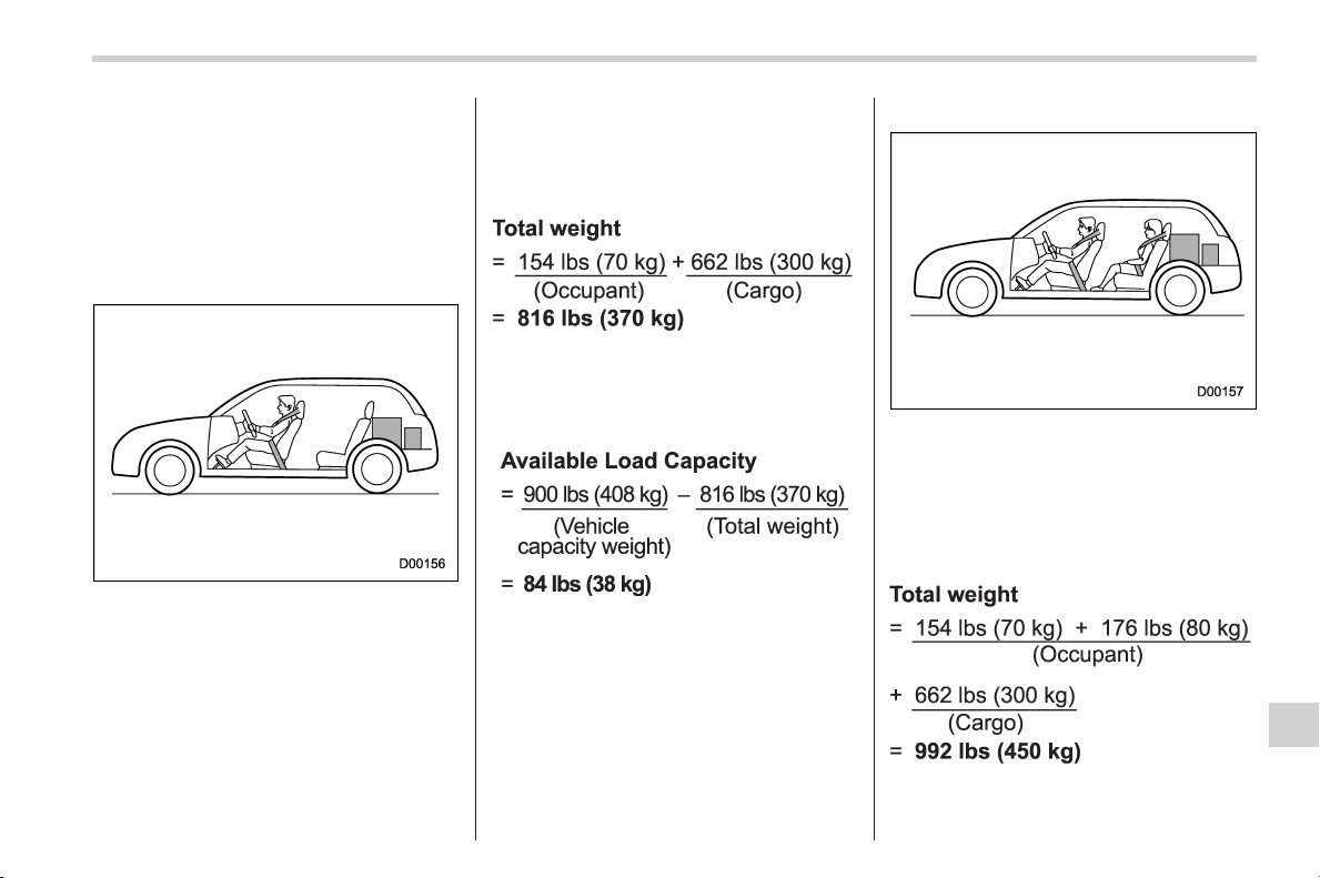
Black plate (501,1)
北米Model "A1160BE-C" EDITED: 2014/ 3/ 17
! Calculating total and load ca-
pacities varying seating con-
figurations
Calculate the available load capa-
city as shown in the following
examples:
Example 1A
Vehicle capacity weight of the
vehicle is 900 lbs (408 kg), which
is indicated on the vehicle placard
with the statement “The combined
weight of occupants and cargo
should never exceed 900 lbs or
408 kg”.
For example, if the vehicle has one
occupant weighing 154 lbs (70 kg)
plus cargo weighing 662 lbs (300
kg).
1. Calculate the total weight.
2. Calculate the available load ca-
pacity by su btracting the total
weight from the vehicle capacity
weight of 900 lbs (408 kg).
3. The result of step 2 shows that a
further 84 lbs (38 kg) of cargo can
be carried.
Example 1B
For example, if a person weighing
176 lbs (80 kg) now enters the
same vehicle (bringing the number
of occupants to two), the calcula-
tions are as follows.
1. Calculate the total weight.
Consumer information and Reporting safety defects/Tire information
13-11
– CONTINUED –
13
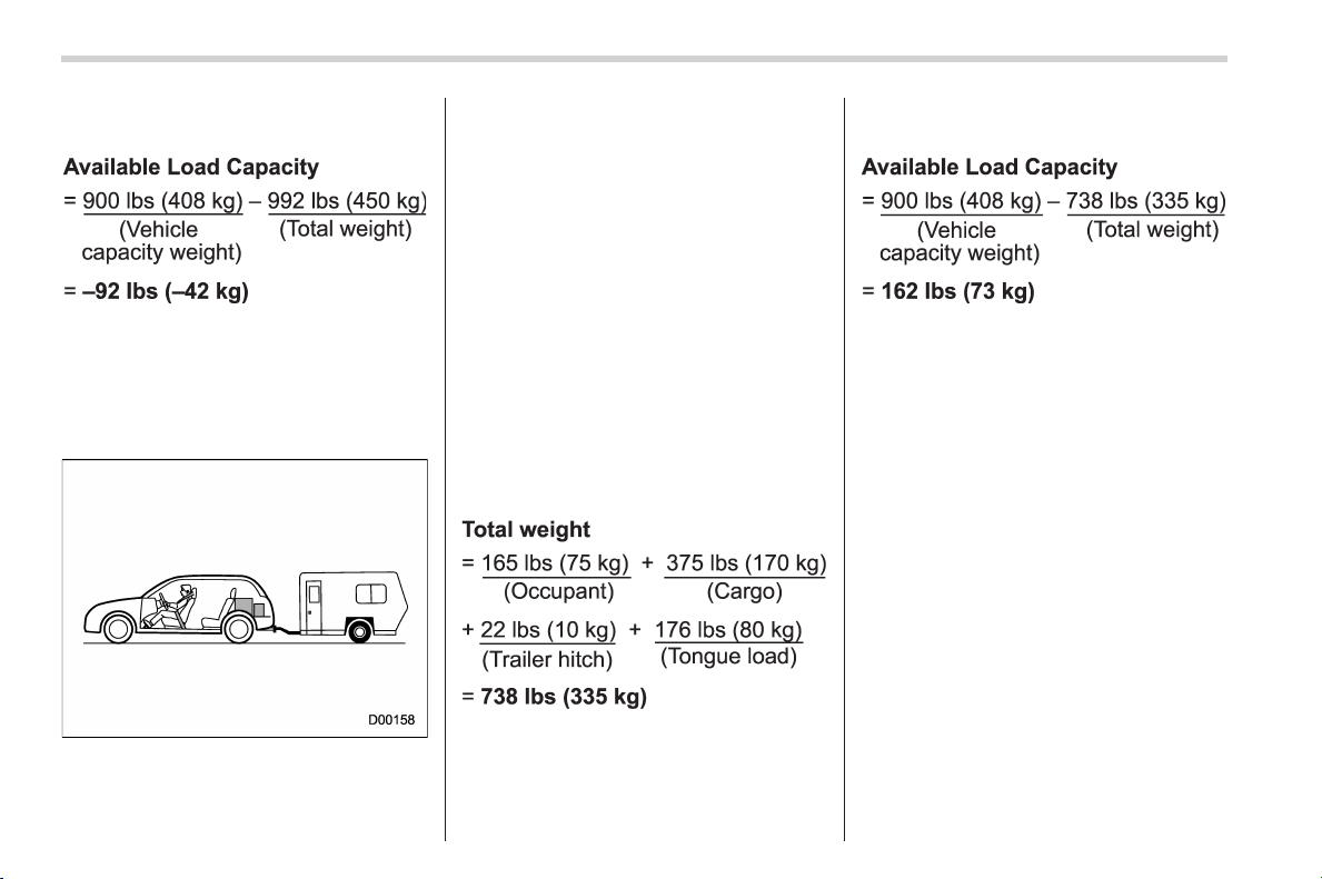
Black plate (502,1)
北米Model "A1160BE-C" EDITED: 2014/ 3/ 17
13-12
Consumer information and Reporting safety defects/Tire information
2. Calculate the available load ca-
pacity.
3. The total weight now exceeds
the capacity weight by 92 lbs (42
kg), so the cargo weight must be
reduced by 92 lbs (42 kg) or more.
Example 2A
Vehicle capacity weight of the
vehicle is 900 lbs (408 kg), which
is indicated on the vehicle placard
with the statement “The combined
weight of occupants and cargo
should never exceed 408 kg or
900 lbs”.
For example, the vehicle has one
occupant weighing 165 lbs (75 kg)
plus cargo weighing 375 lbs (170
kg). In addition, the vehicle is fitted
with a trailer hitch weighing 22 lbs
(10 kg), to which is attached a
trailer weighing 1,764 lbs (800 kg).
10% of the trailer weight is applied
to the trailer tongue (i.e. Tongue
load = 176 lbs (80 kg)).
1. Calculate the total weight.
2. Calculate the available load ca-
pacity.
3. The result of step 2 shows that a
further 162 lbs (73 kg) of cargo can
be carried.
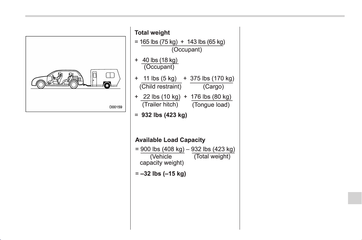
Black plate (503,1)
北米Model "A1160BE-C" EDITED: 2014/ 3/ 17
Example 2B
For example, if a person weighing
143 lbs (65 kg) and a child weighing
40 lbs (18 kg) now enter the same
vehicle (bringing the number of
occupants to three), and a child
restraint system weighing 11 lbs (5
kg) is installed in the vehicle for the
child to use, the calculations are as
follows.
1. Calculate the total weight.
2. Calculate the available load ca-
pacity.
3. The total weight now exceeds
the capacity weight by 32 lbs (15
kg), so the cargo weight must be
reduced by 32 lbs (15 kg) or more.
& Determining compatibility of
tire and vehicle load capaci-
ties
The sum of four tires’ maximum
load ratings must exceed the max-
imum loaded vehicle weight
(“GVWR”). In addition, sum of the
maximum load ratings of two front
tires and of two rear tires must
exceed each axle’smaximum
loaded capacity (“GAWR”). Original
equipment tires are designed to
fulfill those conditions.
The maximum loaded vehicle
weight is referred to Gross Vehicle
Weight Rating (GVWR). And each
axle’s maximum loaded capacity is
referred to Gross Axle Weight Rat-
ing (GAWR). The GVWR and each
axle’s GAWR are shown on the
vehicle certification label affixed to
the driver’s door.
The GVWR and front and rear
GAWRs are determined by not only
the maximum load rating of tires but
also loaded capacities of the vehi-
cle’s suspension, axles and other
Consumer information and Reporting safety defects/Tire information
13-13
– CONTINUED –
13

Black plate (504,1)
北米Model "A1160BE-C" EDITED: 2014/ 3/ 17
13-14
Consumer information and Reporting safety defects/Tire information
parts of the body.
Therefore, this means that the
vehicle cannot necessarily be
loaded up to the tire’s maximum
load rating on the tire sidewall.
& Adverse safety conse-
quences of overloading on
handling and stopping and
on tires
Overloading could affect vehicle
handling, stopping distance, and
vehicle and tire performance in the
following ways. This could lead to
an accident and possibly result in
severe personal injury.
. Vehicle stability will deteriorate.
. Heavy and/or high-mounted
loads could increase the risk of
rollover.
. Stopping distance will increase.
. Brakes could overheat and fail.
. Suspension, bearings, axles and
other body parts could break or
experience accelerated wear that
will shorten vehicle life.
. Tires could fail.
. Tread separation could occur.
. Tire could separate from its rim.
& Steps for Determining Cor-
rect Load Limit
1. Locate the statement “The com-
bined w eight of occupant s and
cargo should never exceed XXX
kg or XXX lbs.” on your vehicle’s
placard.
2. Determine the combined weight
of the driver and passengers that
will be riding in your vehicle.
3. Subtract the combined weight of
the driver and passengers from
XXX kg or XXX lbs.
4. The resulting figure equals the
available amount of cargo an d
luggage load capacity. For exam-
ple, if the “XXX” amount equals
1400 lbs. and there will be five 150
lb passengers in your vehicle, the
amount of available car go and
luggage load capacity is 650 lbs.
(1400 − 750 (5 6 150) = 650 lbs.)
5. Determine the combined weight
of luggage and cargo being loaded
on the vehicle. That weight may not
safely exceed the available cargo
and luggage load capacity calcu-
lated in Step 4.
6. If your vehicle will be towing a
trailer, load from your trailer will be
transferred to your vehicle. Consult
this manual to determine how this
reduces the available cargo and
luggage load capacity of your ve-
hicle.
Black plate (505,1)
北米Model "A1160BE-C" EDITED: 2014/ 3/ 17
Uniform tire quality grading
standards
This information indicates the rela-
tive performance of passenger car
tires in the area of treadwear,
traction, and temperature resis-
tance. This is to aid the consumer
in making an informed choice in the
purchase of tires.
Quality grades can be found where
applicable on the tire sidewall be-
tween tread shoulder and maxi-
mum section width. For example:
Treadwear 200 Traction AA Tem-
perature A
The quality grades apply to new
pneumatic tires for use on passen-
ger cars. Howeve r, they do not
apply to deep tread, winter type
snow tires, space-saver or tempor-
ary use spare tires, tires with
nominal rim diameters of 12 inches
or less, or to some limited produc-
tion tires.
All passenger car tires must con-
form to Federal Safety Require-
ments in addition to these grades.
& Treadwear
The treadwear grade is a compara-
tive rating based on the wear rate of
the tire when tested under con-
trolled conditions on a specified
government test course.
For example, a tire graded 150
would wear one and one-half (1-
1/2) times as well on the govern-
ment course as a tire graded 100.
The relative performance of tires
depends upon the actual conditions
of their use, however, and may
depart significantly from the norm
due to variations in driving habits,
service practices and differences in
road characteristics and climate.
& Traction AA, A, B, C
The traction grades, from highest to
lowest, are AA, A, B and C. Those
grades represent the tire’s ability to
stop on wet pavement as measured
under controlled conditions on spe-
cified government test surfaces of
asphalt and concrete. A tire marked
C may have poor traction perfor-
mance.
WARNING
The traction grade assigned to
this tire is based on straight-
ahead braking traction tests,
and does not include accel-
eration, cornering, hydroplan-
ing, or peak traction charac-
teristics.
& Temperature A, B, C
The temperature grades are A (the
highest), B, and C, representing the
tire’s resistance to the generation of
heat and its ability to dissipate heat
when tested under controlled con-
ditions on a specified indoor labora-
tory test wheel. Sustained high
temperature can cause the material
of the tire to degenerate and reduce
tire life, and excessive temperature
can lead to sudden tire failure. The
Consumer information and Reporting safety defects/Uniform tire quality grading standards
13-15
– CONTINUED –
13
Black plate (506,1)
北米Model "A1160BE-C" EDITED: 2014/ 3/ 17
13-16
Consumer information and Reporting safety defects/Reporting safety defects (U.S.A.)
grade C corresponds to a level of
performance which all passenger
car tires m ust meet un der the
Federal Motor Vehicle Safety Stan-
dards No. 109. Grades B and A
represent higher levels of perfor-
mance on the laboratory test wheel
than the minimum required by law.
WARNING
The temperature grade for this
tire is established for a tire
that is properly inflated and
not overloaded. Excessive
speed, underinflation, or ex-
cessive loading, either sepa-
rately or in combination, can
cause heat buildup and possi-
ble tire failure.
Reporting safety defects
(U.S.A.)
If you believe that your vehicle has
a defect which could caus e a
crash or could cause injury or
death, you should immediately in-
form the National Highway Traffic
Safety Administration (NHTSA) in
addition to notifying Subaru of
America, Inc.
If NHTSA receives similar com-
plaints, it may open an investiga-
tion, and if it finds that a safety
defect exists in a group of vehi-
cles, it may order a recall and
remedy campaign. However,
NHTSA cannot become involved
in individual problems between
you, your dealer, or Subaru of
America, Inc. To contact NHTSA,
you may call the Vehicle Safety
Hotline toll-free at 1-888-327-4236
(TTY: 1-800-424-9153); go to
http://www.safercar.gov; or write
to: Administrator, NHTSA, 1200
New Jersey Avenue, SE, West
Building, Washington, DC 20590.
You can also obtain other informa-
tion about motor vehicle safety
from http://www.safercar.gov.
Black plate (507,1)
北米Model "A1160BE-C" EDITED: 2014/ 3/ 17
Supplement
& Declaration of conformity with FCC rules
! Electrostatic sensor for occupant detection system
Consumer information and Reporting safety defects/Supplement
13-17
13

Black plate (2,1)
Model "ALL_MODEL_MEMO" EDITED: 2007/ 6/ 22
Left Page
————————————————————————————————————————
————————————————————————————————————————
————————————————————————————————————————
————————————————————————————————————————
————————————————————————————————————————
————————————————————————————————————————
————————————————————————————————————————
————————————————————————————————————————
————————————————————————————————————————
————————————————————————————————————————
————————————————————————————————————————
————————————————————————————————————————
————————————————————————————————————————

Black plate (27,1)
北米Model "A1160BE-C" EDITED: 2014/ 3/ 17
Index
14

Black plate (2,1)
北米Model "A1160BE-C" EDITED: 2014/ 3/ 17
14-2 Index
A
Abbreviation ................................................................... 3
ABS (Anti-lock Brake System) ..................................... 7-23
Warning light ......................................................... 3-20
Access key ................................................................. 2-9
Warning light ......................................................... 3-25
Accessories....................................................... 5-4, 11-39
Accessory power outlet................................................. 6-7
Air cleaner element ................................................... 11-15
Air conditioner
Automatic climate control .......................................... 4-5
Manual climate control.............................................. 4-6
Air filtration system..................................................... 4-10
Air flow mode .............................................................. 4-6
Alarm system ............................................................ 2-22
All-Wheel Drive warning light....................................... 3-22
Aluminum wheel ....................................................... 11-31
Cleaning ............................................................... 10-3
Antenna system........................................................... 5-3
Anti-lock Brake System (ABS) ..................................... 7-23
Arming the system ..................................................... 2-23
Armrest....................................................................... 1-8
Ashtray....................................................................... 6-9
AT OIL TEMP warning light ......................................... 3-18
Audio
Antenna system....................................................... 5-3
Auxiliary input jack ................................................. 5-21
Bluetooth
®
audio.................................................... 5-31
CD player operation ............................................... 5-16
Control button........................................................ 5-30
FM/AM radio operation ........................................... 5-11
iPod
®
operations .................................................... 5-24
Power and audio controls ......................................... 5-7
Set ........................................................................ 5-4
USB storage device operations ................................ 5-24
Auto on/off headlights ................................................. 3-78
Auto-dimming mirror/compass .............................. 3-86, 3-87
Automatic headlight beam leveler ................................. 3-81
Warning light.......................................................... 3-30
Automatic/Emergency Locking Retractor (A/ELR) ........... 1-12
Auxiliary input jack...................................................... 5-21
B
Battery
Drainage prevention function..................................... 2-7
Jump starting ......................................................... 9-14
Replacement (access key)..................................... 11-46
Replacement (remote engine start transmitter) ........... 7-15
Replacement (transmitter)...................................... 11-47
Vehicle battery ..................................................... 11-36
Bluetooth
®
audio ........................................................ 5-31
Booster seat .............................................................. 1-31
Bottle holder ............................................................... 6-7
Brake
Assist.................................................................... 7-22
Booster ....................................................... 7-22, 11-19
Disc ...................................................................... 12-9
Fluid ........................................................... 11-18, 12-8
Pad and lining...................................................... 11-21
Parking ....................................................... 7-29, 11-22
Pedal .................................................................. 11-20
System.................................................................. 7-22

Black plate (3,1)
北米Model "A1160BE-C" EDITED: 2014/ 3/ 17
Brake system ............................................................ 7-22
Warning light ......................................................... 3-21
Braking..................................................................... 7-21
Tips...................................................................... 7-21
Breaking-in of new brake pads and linings ................... 11-21
Bulb
Chart.................................................................. 12-14
Replacing............................................................. 11-40
C
Cargo area
Cover ................................................................... 6-11
Light............................................................. 6-2, 11-45
Tie-down hooks ..................................................... 6-13
Catalytic converter ....................................................... 8-3
Center
Console .................................................................. 6-5
Changing
Coolant................................................................ 11-15
Oil and oil filter ..................................................... 11-11
Charge warning light .................................................. 3-17
CHECK ENGINE warning light/Malfunction indicator
light....................................................................... 3-15
Checking
Brake pedal free play ............................................ 11-20
Brake pedal reserve distance ................................. 11-20
Coolant level ........................................................ 11-14
Fluid level (brake fluid) .......................................... 11-18
Fluid level (washer fluid) ........................................ 11-31
Oil level (engine oil) .............................................. 11-10
Child restraint systems ................................................ 1-24
Installation of a booster seat .................................... 1-31
Installation with A/ELR seatbelt ................................ 1-27
Lower and tether anchorages................................... 1-32
Top tether anchorages ............................................ 1-35
Child safety ................................................................... 4
Locks.................................................................... 2-29
Chime
Key........................................................................ 3-5
Light ..................................................................... 3-77
Seatbelt................................................................. 3-13
Cigarette lighter........................................................... 6-8
Cleaning
Aluminum wheels ................................................... 10-3
Interior .................................................................. 10-5
Ventilation grille ....................................................... 4-9
Climate control system ................................................. 4-3
Automatic ............................................................... 4-5
Manual................................................................... 4-6
Clock ................................................................ 3-44, 3-58
Coat hook.................................................................. 6-10
Compass........................................................... 3-86, 3-87
Console ..................................................................... 6-5
Continuously variable transmission
Oil temperature warning light (AT OIL TEMP) ............. 3-18
Continuously variable transmission (CVT)...................... 7-15
Fluid ........................................................... 11-17, 12-8
Coolant ........................................................... 11-14, 12-8
Temperature high warning light................................. 3-16
Temperature low indicator light ................................. 3-16
Cooling system ........................................................ 11-13
Index 14-3

Black plate (4,1)
北米Model "A1160BE-C" EDITED: 2014/ 3/ 17
14-4 Index
Corrosion protection ................................................... 10-4
Cruise control ............................................................ 7-33
Indicator light......................................................... 3-30
Set indicator light ................................................... 3-30
Cup holder .................................................................. 6-6
D
Daytime running light system....................................... 3-79
Defogger................................................................... 3-94
Defrosting ................................................................... 4-9
Deicer ...................................................................... 3-94
Differential gear oil
Front ........................................................... 11-18, 12-7
Rear............................................................ 11-18, 12-7
Dimensions ............................................................... 12-2
Disarming the alarm system ........................................ 2-26
Disc brake pad wear warning indicators ........................ 7-22
Dome light ........................................................ 6-2, 11-45
Door
Locks ..................................................................... 2-5
Open warning light ................................................. 3-22
Drive belts................................................................ 11-17
Driving
AWD vehicles .......................................................... 8-4
Car phone/cell phone .................................................. 7
Drinking ..................................................................... 6
Drugs ........................................................................ 6
Foreign countries ..................................................... 8-4
Off road .................................................................. 8-6
Pets .......................................................................... 7
Snowy and icy roads ................................................ 8-9
Tips ......................................................... 7-20, 8-2, 8-4
Tired or sleepy ........................................................... 6
Winter .................................................................... 8-7
E
ECO gauge ............................................................... 3-12
Electrical system ........................................................ 12-8
Electronic Brake Force Distribution (EBD) system........... 7-24
Warning ................................................................ 3-21
Emergency Locking Retractor (ELR) ............................. 1-12
Engine
Compartment overview............................................ 11-9
Coolant ....................................................... 11-14, 12-8
Exhaust gas (carbon monoxide) ............................. 5, 8-2
Hood .................................................................... 11-7
Low oil level warning light........................................ 3-18
Oil .............................................................. 11-10, 12-5
Overheating ........................................................... 9-17
EV (Electric Vehicle) mode lamp .................................. 3-31
Event data recorder ........................................................ 8
Exterior care .............................................................. 10-2
F
Floor mat................................................................... 6-10
Fluid level
Brake.................................................................. 11-18
Continuously variable transmission ......................... 11-17
Fog light
Bulb.......................................................... 11-41, 12-14
Indicator light ......................................................... 3-30
Switch................................................................... 3-81

Black plate (5,1)
北米Model "A1160BE-C" EDITED: 2014/ 3/ 17
Folding mirror switch .................................................. 3-93
Front
Differential gear oil ........................................ 11-18, 12-7
Seatbelt pretensioners ............................................ 1-20
Turn signal light .................................................... 11-41
Front seats.................................................................. 1-2
Forward and backward adjustment ............................. 1-3
Head restraint adjustment ......................................... 1-5
Reclining................................................................. 1-4
Seat cushion height adjustment ................................. 1-4
Fuel ........................................................................... 7-3
Consumption indicator ............................................ 3-37
Economy hints......................................................... 8-2
Filler lid and cap ...................................................... 7-4
Gauge .................................................................. 3-11
Requirements .................................................. 7-3, 12-4
Fuses ...................................................................... 11-38
Fuses and circuits.................................................... 12-10
G
GAWR (Gross Axle Weight Rating) .............................. 8-13
Glove box ................................................................... 6-5
GVWR (Gross Vehicle Weight Rating) .......................... 8-13
H
Hands-free system ..................................................... 5-34
Hazard warning flasher ........................................... 3-7, 9-2
Head restraint adjustment
Front seat ............................................................... 1-5
Rear seat................................................................ 1-8
Headlight
Beam leveler.......................................................... 3-81
Bulb replacing ...................................................... 11-40
Bulb wattage........................................................ 12-14
Control switch ........................................................ 3-77
Flasher.................................................................. 3-79
Indicator light ......................................................... 3-30
HID headlights ...................................................... 1, 11-40
High beam indicator light ............................................. 3-30
High/low beam change (dimmer) .................................. 3-79
Hill start assist ................................................. 7-30, 11-20
OFF indicator light .................................................. 3-22
Warning light.......................................................... 3-22
HomeLink
®
................................................................. 3-87
Hook
Cargo tie-down....................................................... 6-13
Coat ..................................................................... 6-10
Shopping bag ........................................................ 6-11
Towing and tie-down ............................................... 9-18
Horn ......................................................................... 3-96
Hose and connections............................................... 11-13
Hybrid system
Fail lamp ............................................................... 3-30
Features.................................................................... 9
Starting and stopping ............................................... 7-8
I
Ignition switch ............................................................. 3-3
Light ...................................................................... 3-5
Illumination brightness control ...................................... 3-80
Immobilizer ................................................................. 2-3
Index 14-5

Black plate (6,1)
北米Model "A1160BE-C" EDITED: 2014/ 3/ 17
14-6 Index
Indicator light (security indicator light) ....................... 3-29
Indicator light
Coolant temperature low ......................................... 3-16
Cruise control ........................................................ 3-30
Cruise control set................................................... 3-30
EV (Electric Vehicle) mode...................................... 3-31
Front fog light ........................................................ 3-30
Headlight .............................................................. 3-30
High beam ............................................................ 3-30
Hill start assist OFF................................................ 3-22
Hybrid READY....................................................... 3-31
Immobilizer............................................................ 3-29
Security ................................................................ 3-29
Select lever/Gear position ....................................... 3-29
Turn signal ............................................................ 3-30
Vehicle Dynamics Control OFF ................................ 3-24
Vehicle Dynamics Control operation ......................... 3-23
Inside mirror ...................................................... 3-85, 3-87
Interior lights ............................................................... 6-2
iPod
®
operations........................................................ 5-24
J
Jump starting............................................................. 9-14
K
Key ............................................................................ 2-3
Number .................................................................. 2-3
Reminder chime....................................................... 3-5
Replacement ........................................................... 2-4
Keyless access entry function...................................... 2-13
Keyless access with push-button start system ................. 2-9
Disabling keyless access functions ........................... 2-17
Locking and unlocking doors.................................... 2-13
Opening rear gate .................................................. 2-15
Warning chimes and warning light ............................ 3-25
When access key does not operate properly.............. 9-23
Keyless entry system .................................................. 2-18
L
Lap belt pretensioner .................................................. 1-22
Leather seat materials................................................. 10-5
License plate light..................................................... 11-43
Light
Backup ............................................................... 11-42
Cargo area .................................................... 6-2, 11-45
Control switch ........................................................ 3-77
Daytime running ..................................................... 3-79
Dome............................................................ 6-2, 11-45
Front fog ..................................................... 3-81, 11-41
Front side marker ......................................... 3-78, 12-14
Ignition switch ......................................................... 3-5
License plate ....................................................... 11-43
Map.............................................................. 6-3, 11-44
Parking ............................................................... 11-41
Rear combination ................................................. 11-42
Rear side marker light........................................... 11-42
Stop.................................................................... 11-42
Tail ..................................................................... 11-42
Turn signal ........................................ 3-80, 11-41, 11-42
Loading your vehicle................................................... 8-11
Low fuel warning light ................................................. 3-22
Low tire pressure warning light ..................................... 3-18

Black plate (7,1)
北米Model "A1160BE-C" EDITED: 2014/ 3/ 17
Lower and tether anchorage........................................ 1-32
M
Maintenance
Precautions ........................................................... 11-3
Schedule .............................................................. 11-3
Seatbelt ................................................................ 1-20
Tips...................................................................... 11-5
Tools ...................................................................... 9-2
Malfunction indicator light (check engine warning light) ... 3-15
Manual
Mode (continuously variable transmission) ................ 7-18
Map light........................................................... 6-3, 11-44
Meters and gauges ...................................................... 3-8
Mirror defogger .......................................................... 3-94
Mirrors...................................................................... 3-85
Moonroof .................................................................. 2-34
Multi function display .................................................. 3-32
N
New vehicle break-in driving.......................................... 8-2
O
Odometer.................................................................. 3-10
Off road driving ............................................................ 8-6
Oil filter.................................................................... 11-11
Oil level
Engine................................................................. 11-10
Warning light ......................................................... 3-18
Oil pressure warning light............................................ 3-17
Outside
Mirror defogger ...................................................... 3-94
Mirrors .................................................................. 3-93
Temperature indicator.............................................. 3-35
Overheating engine .................................................... 9-17
P
Parking
Brake.................................................................... 7-29
Brake stroke ........................................................ 11-22
Light ................................................................... 11-41
Tips ...................................................................... 7-29
Periodic inspections ..................................................... 8-4
Petrol fuel................................................................... 7-3
Power
Door locking switch.................................................. 2-8
Outlets ................................................................... 6-7
Outside mirrors ...................................................... 3-93
Steering ................................................................ 7-20
Steering warning light.............................................. 3-22
Windows ............................................................... 2-29
Precautions against vehicle modification................ 1-24, 1-64
Preparing to drive ........................................................ 7-8
Push-button
Ignition switch ......................................................... 3-5
R
Rear
Combination lights ................................................ 11-42
Differential gear oil........................................ 11-18, 12-7
Gate ............................................................. 2-33, 9-22
Index 14-7

Black plate (8,1)
北米Model "A1160BE-C" EDITED: 2014/ 3/ 17
14-8 Index
Turn signal light .................................................... 11-42
Rear seat.................................................................... 1-7
Armrest................................................................... 1-8
Folding down......................................................... 1-10
Head restraint adjustment ......................................... 1-8
Rear view camera...................................................... 6-14
Rear window
Defogger............................................................... 3-94
Wiper and washer switch ........................................ 3-85
Wiper blades ........................................................ 11-34
Recommended
Brake fluid............................................................. 12-8
Continuously variable transmission fluid.................... 12-8
Engine oil.............................................................. 12-5
Front differential gear oil ......................................... 12-7
Rear differential gear oil.......................................... 12-7
Spark plugs........................................................... 12-8
Refueling .................................................................... 7-5
Remote engine start system ........................................ 7-13
Remote keyless entry system ...................................... 2-18
Replacement
Brake pad and lining ............................................. 11-21
Wiper blades ........................................................ 11-32
Replacing
Access key battery................................................ 11-46
Air cleaner element ............................................... 11-15
Lost transmitters (remote keyless entry system)......... 2-21
Remote engine start transmitter battery..................... 7-15
Remote keyless entry transmitter battery.................. 11-47
Replacing bulbs .............................................. 11-40, 12-14
Backup light ......................................................... 11-42
Cargo area light ................................................... 11-45
Dome light........................................................... 11-45
Front fog light....................................................... 11-41
Front turn signal light ............................................ 11-41
Headlight............................................................. 11-40
License plate light................................................. 11-43
Map light ............................................................. 11-44
Parking light......................................................... 11-41
Rear combination light .......................................... 11-42
Rear side marker light........................................... 11-42
Rear turn signal light............................................. 11-42
Stop light............................................................. 11-42
Tail light............................................................... 11-42
Rocking the vehicle .................................................... 8-11
Roof molding and crossbar .......................................... 8-14
Roof rails................................................................... 8-13
S
Safety
Precautions when driving............................................. 4
Symbol...................................................................... 2
Warnings................................................................... 2
Screensaver .............................................................. 5-55
Seat
Fabric ................................................................... 10-5
Front...................................................................... 1-2
Heater.................................................................... 1-6
Rear ...................................................................... 1-7
Seatbelt................................................................. 4, 1-11
Fastening .............................................................. 1-13
Maintenance .......................................................... 1-20

Black plate (9,1)
北米Model "A1160BE-C" EDITED: 2014/ 3/ 17
Pretensioners ........................................................ 1-20
Safety tips............................................................. 1-11
Warning light and chime ......................................... 3-13
Security
Alarm system ........................................................ 2-22
Immobilizer.............................................................. 2-3
Indicator light......................................................... 3-29
Shock sensors....................................................... 2-28
Select lever
Position indicator ................................................... 3-29
Shift lock function................................................... 7-19
Shock sensors........................................................... 2-28
Shopping bag hook .................................................... 6-11
Shoulder pretensioners ............................................... 1-20
Snow tires........................................................ 8-10, 11-22
Snowy and icy roads .................................................... 8-9
Sounding a panic alarm .............................................. 2-21
Spark plugs...................................................... 11-17, 12-8
Specifications ............................................................ 12-2
Speedometer............................................................. 3-10
SRS
Curtain airbag........................................................ 1-55
Frontal airbag ........................................................ 1-46
Side airbag ........................................................... 1-55
SRS airbag (Supplemental Restraint System airbag) ... 4, 1-37
SRS airbag system
Monitors................................................................ 1-62
Servicing............................................................... 1-63
Warning light ......................................................... 3-15
State emission testing (U.S. only) .................................. 7-7
Steering wheel
Power ................................................................... 7-20
Tilt/telescopic ......................................................... 3-96
Stop light................................................................. 11-42
Storage compartment................................................... 6-5
Sun shade................................................................. 2-36
Sun visors .................................................................. 6-4
Supplemental Restraint System airbag (SRS) ................ 1-37
Synthetic leather upholstery ......................................... 10-5
T
Tachometer................................................................ 3-11
Temperature warning light
AT OIL TEMP......................................................... 3-18
Coolant ................................................................. 3-16
Tether (child restraint system) .............................. 1-32, 1-35
Tie-down hooks.......................................................... 9-18
Tire ................................................................. 11-22, 12-9
Chains .................................................................. 8-11
Inspection............................................................ 11-24
Pressures and wear.............................................. 11-24
Replacement........................................................ 11-27
Rotation .............................................................. 11-27
Size and pressure .................................................. 12-9
Types.................................................................. 11-22
Tire pressure monitoring system (TPMS) ............. 7-28, 11-22
Warning light.......................................................... 3-18
Tires and wheels ...................................................... 11-22
Tools.......................................................................... 9-2
Top tether anchorages ........................................ 1-32, 1-35
Towing ...................................................................... 9-18
Index 14-9

Black plate (10,1)
北米Model "A1160BE-C" EDITED: 2014/ 3/ 17
14-10 Index
All wheels on the ground ........................................ 9-21
Flat-bed truck ........................................................ 9-20
Hooks................................................................... 9-18
Trailer
Towing.................................................................. 8-15
Trip meter ................................................................. 3-10
Turn signal
Indicator lights ....................................................... 3-30
Lever.................................................................... 3-80
U
USB storage device operations.................................... 5-24
V
Valet mode................................................................ 2-27
Vanity mirror ................................................................ 6-4
Vehicle
Capacity weight ..................................................... 8-12
Identification ........................................................ 12-17
Pedestrian alert warning light................................... 3-30
Symbols .................................................................... 3
Vehicle Dynamics Control
OFF indicator light.................................................. 3-24
OFF switch ........................................................... 7-27
Operation indicator light .......................................... 3-23
System ................................................................. 7-25
Warning light ......................................................... 3-23
Ventilator .................................................................... 4-2
W
Warning and indicator lights ........................................ 3-12
Warning chimes
Keyless access with push-button start system............ 3-25
Seatbelt................................................................. 3-13
Warning light
ABS...................................................................... 3-20
Access key............................................................ 3-25
All-Wheel Drive ...................................................... 3-22
AT OIL TEMP......................................................... 3-18
Automatic headlight beam leveler ............................. 3-30
Brake system......................................................... 3-21
Charge.................................................................. 3-17
CHECK ENGINE.................................................... 3-15
Coolant temperature high ........................................ 3-16
Door open ............................................................. 3-22
Engine low oil level................................................. 3-18
Hill start assist ....................................................... 3-22
Hybrid fail lamp ...................................................... 3-30
Keyless access with push-button start system............ 3-25
Low fuel ................................................................ 3-22
Low tire pressure.................................................... 3-18
Oil pressure ........................................................... 3-17
Pedestrian alert ...................................................... 3-30
Power steering ....................................................... 3-22
Seatbelt................................................................. 3-13
SRS airbag system................................................. 3-15
Vehicle Dynamics Control........................................ 3-23
Windshield washer fluid........................................... 3-18
Warranties ..................................................................... 1
Washing .................................................................... 10-2
Waxing and polishing.................................................. 10-3
Wear indicators ........................................................ 11-26

Black plate (11,1)
北米Model "A1160BE-C" EDITED: 2014/ 3/ 17
Wheel
Aluminum............................................................. 11-31
Balance ............................................................... 11-26
Nut tightening torque .............................................. 12-9
Replacement ........................................................ 11-30
Windows................................................................... 2-29
Windshield
Washer fluid ......................................................... 11-31
Wiper and washer switches..................................... 3-83
Wiper blades ........................................................ 11-33
Wiper deicer.......................................................... 3-94
Winter
Driving.................................................................... 8-7
Tires............................................................ 8-10, 11-22
Wiper and washer...................................................... 3-82
Wiper deicer.............................................................. 3-94
Index 14-11

Black plate (2,1)
Model "ALL_MODEL_MEMO" EDITED: 2007/ 6/ 22
Left Page
————————————————————————————————————————
————————————————————————————————————————
————————————————————————————————————————
————————————————————————————————————————
————————————————————————————————————————
————————————————————————————————————————
————————————————————————————————————————
————————————————————————————————————————
————————————————————————————————————————
————————————————————————————————————————
————————————————————————————————————————
————————————————————————————————————————
————————————————————————————————————————

Black plate (2,1)
北米Model "A1160BE-C" EDITED: 2014/ 3/ 17
GAS STATION REFERENCE
&
Fuel:
Use only unleaded gasoline with an octane rating of 87 AKI
(90 RON) or higher.
& Fuel octane rating:
This octane rating is the average of the Research Octane and
Motor Octane numbers and is commonly referred to as the Anti
Knock Index (AKI). Refer to “Fuel octane rating” F7-3.
& Fuel capacity:
13.7 US gal (52 liters, 11.4 Imp gal)
& Engine oil:
Use only the following oils.
. API classification SM with the words “ENERGY CONSER-
VING” or SN with the words “RESOURCE CONSERVING”
. or ILSAC GF-4 or GF-5, which can be identified with the
ILSAC certification mark (Starburst mark)
For the complete viscosity requirements, refer to “Engine oil”
F12-5.
& Engine oil capacity:
5.1 US qt (4.8 liters, 4.2 Imp qt)
The indicated oil quantity is only a guideline and is estimated
based on a case when the engine oil is changed with an oil
filter. After refilling the engine with oil, the oil level should be
checked using the oil level gauge. For more details about
maintenance and service, refer to “Engine oil” F11-10.
& Cold tire pressure:
Refer to “Tires” F12-9.