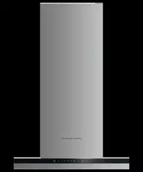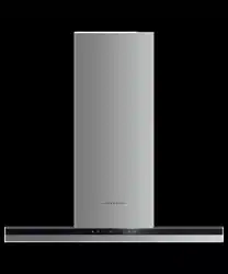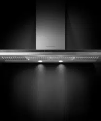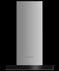

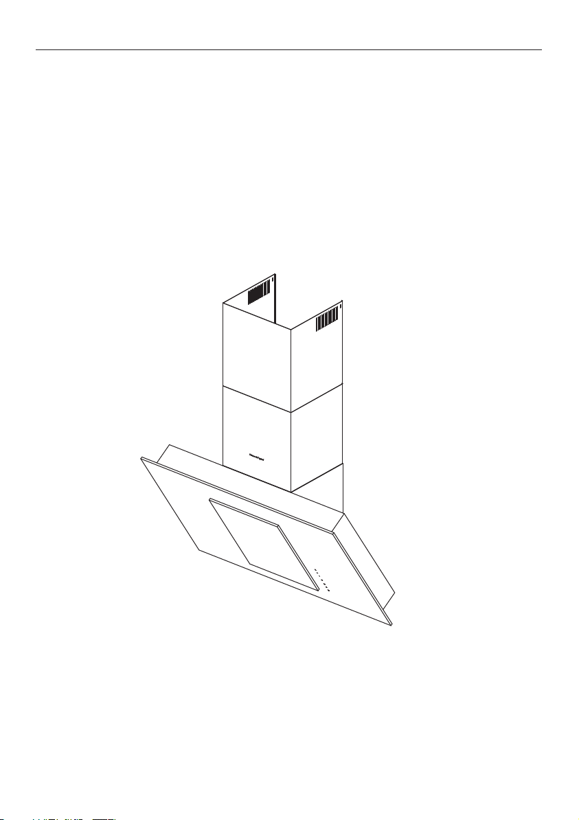
Tilted wall cooker hood
HT90GHB2 model
GB IE
INSTALLATION INSTRUCTIONS
USER GUIDE


1
CONTENTS
Introduction 3
Safety and warnings 4
Installation instructions 8
About your cooker hood – Energy efficiency 18
Operating instructions 19
Cleaning and maintenance 20
Parts and accessories 22
Manufacturer’s Warranty 23
Customer Care 24
ImpORTANT!
SAVE THESE INSTRUCTIONS
The models shown in this user guide may
not be available in all markets and are
subject to change at any time. For current
details about model and specification
availability in your country, please go to
our website www.fisherpaykel.com or
contact your local Fisher & Paykel dealer.
Registration
Register your product with us so we can
provide you with the best service possible.
To register your product visit our website:
www.fisherpaykel.com

3
INTRODUCTION
Thank you for purchasing a Fisher & Paykel product.
Thousands of hours go into the design, engineering, testing and perfecting of each
Fisher & Paykel appliance. The care and attention given to creating these beautiful
products doesn’t stop once it has found its home with you.
This use and care manual will answer most of your questions about the set-up, use and
on-going maintenance of your Fisher & Paykel product; however if you require further
information about your product and its use please consult our website for solutions
and further contact information to discuss with a service representative.
To ensure you receive all relevant product updates and the best service possible,
please register your Fisher & Paykel products through our website.
4
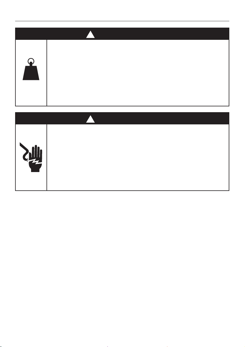
SAFETY AND WARNINGS
!
WARNING!
34.5 kg
Weight Hazard
The cooker hood is heavy. Please ensure
adequate care is taken when installing the
cooker hood to prevent personal injury. The
cooker hood must be installed onto a solid
wall, stud, beam or truss. Weight of the
product is 34.5 kg.
!
WARNING!
Electric Shock Hazard
Always disconnect the appliance from the
mains power supply before carrying out any
maintenance or repairs. Alterations to the
domestic wiring system must only be made
by a qualified electrician. Failure to follow this
advice may result in electrical shock or death.
IMPORTANT SAFETY INSTRUCTIONS
WARNING!
When using this appliance always exercise basic
safety precautions including the following:
• To avoid hazard, please read the entire set of
instructions before installing or using this appliance.
• Please make this information available to the person
installing the appliance – doing so could reduce your
installation costs.
• This appliance must be installed and connected to
the mains power supply only by a suitably qualified
person according to these installation instructions

5
SAFETY AND WARNINGS
and in compliance with any applicable local building
and electricity regulations. Failure to install the
appliance correctly could invalidate any warranty
orliability claims.
• If the power supply cable is damaged, it must be
replaced by the manufacturer, its service agent or
similarly qualified person in order to avoid a hazard.
• To comply with electrical safety regulations, this
cooker hood must be connected to a socket near
theappliance. The socket must be accessible, or
have an accessible isolating switch, to enable the
end user to isolate the cooker hood from the power
for the purpose of internal cleaning or maintenance.
• A power outlet should be within 750 mm of the
motor assembly and can be either on the wall,
behind the chimney or in the ceiling.
• Always switch the power off prior to installation,
servicing or cleaning the cooker hood.
• Ducting accessories are not supplied. All ducting must
comply with local requirements and building codes.
• Before connecting any pipes, consult municipal
ordinances to ensure that any applicable regulations
concerning the discharge of exhaust air are adhered
to and request permission from the person in charge
of the building.
• Exhaust air must not be discharged into an
existing flue that is used for exhausting fumes from
appliances burning gas or other fuels. There shall be
adequate ventilation of the room when the cooker
hood is used at the same time as appliances burning
gas or other fuels.

6
SAFETY AND WARNINGS
• When the cooker hood is turned on at the same time
as other appliances powered by energy other than
electricity, the air outlet must not be greater than
4Pa (4x10⁻⁵ bar).
• The minimum distance between the hob surface
andthe base of the cooker hood shall be 400mm
or650mm if installed over a gas hob.
• Stainless steel is very easily damaged during
installation if abraded or knocked by tools. It is
recommended to protect the top of the cooker hood
with cardboard or polystyrene during the installation
to minimise the risk of damage occurring.
• This appliance can be used by children aged from
8years or above and persons with reduced physical,
sensory or metal capabilities or lack of experience
or knowledge if they have been given supervision
orinstruction concerning use of the appliance in
a safe way and understand the hazards involved.
Children shall not play with the appliance. Cleaning
and user maintenance shall not be made by children
without supervision.
• You must read the details concerning the method
and frequency of cleaning.
• There is a fire risk if cleaning is not carried out in
accordance with the instructions.
• Never leave frying food unattended since grease
can overheat and catch fire. The risk of fire is even
greater in the case of used oil.
• Do not flambé under the cooker hood.
• Never use the cooker hood without the filters inplace.

7
SAFETY AND WARNINGS
• During climatic conditions causing electrical
interference, it is possible that the device may stop
working. By switching the device off and on the
device will resume normal operation safety.
• During an electrostatic discharge (ESD) it is possible
that the device will stop working. By switching the
device off and on the device will again work as
intended. There is no risk and no risk will appear.
• CAUTION: accessible parts may become hot when
used with cooking appliances.
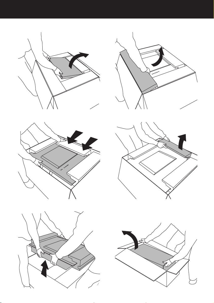
8
INSTALLATION INSTRUCTIONS
1 2
3 4
5 6
Unpacking your cooker hood
9
INSTALLATION INSTRUCTIONS
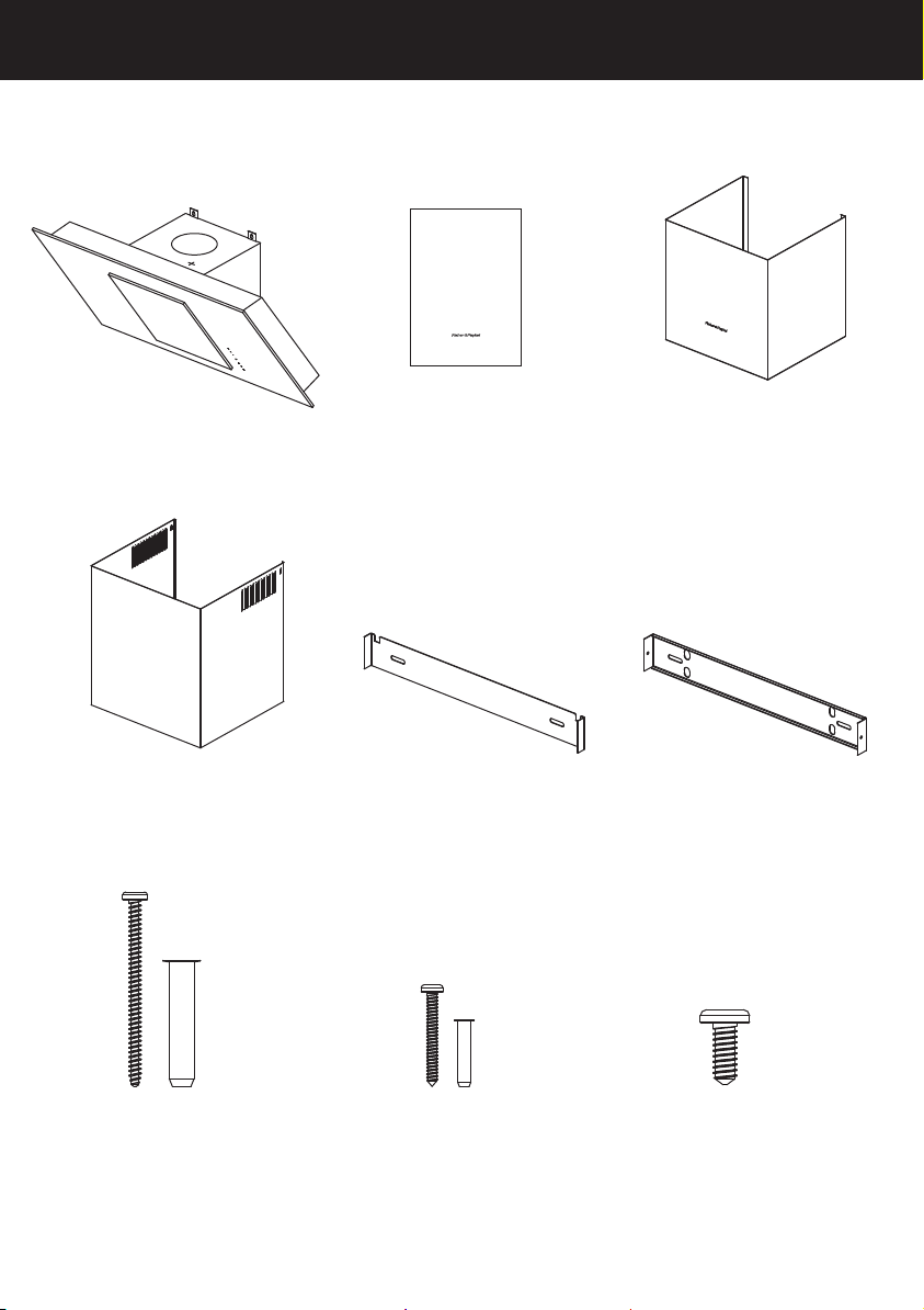
Contents of packaging
Installation instructions
User guide manual
(1)
Tilted wall cooker hood
HT90GHB2 model
GB IE
INSTALLATION INSTRUCTIONS
USER GUIDE
Chimney
(1)
Chimney bracket
(1)
Upper chimney bracket
(1)
60mm screws
and wall plugs
(6)
30mm screws
and wall plugs
(4)
10mm screws
(4)
Upper chimney
(1)
Cooker hood
(1)
10
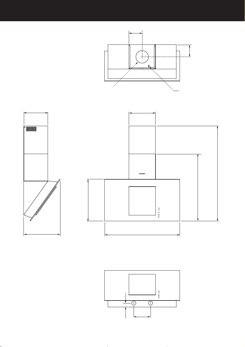
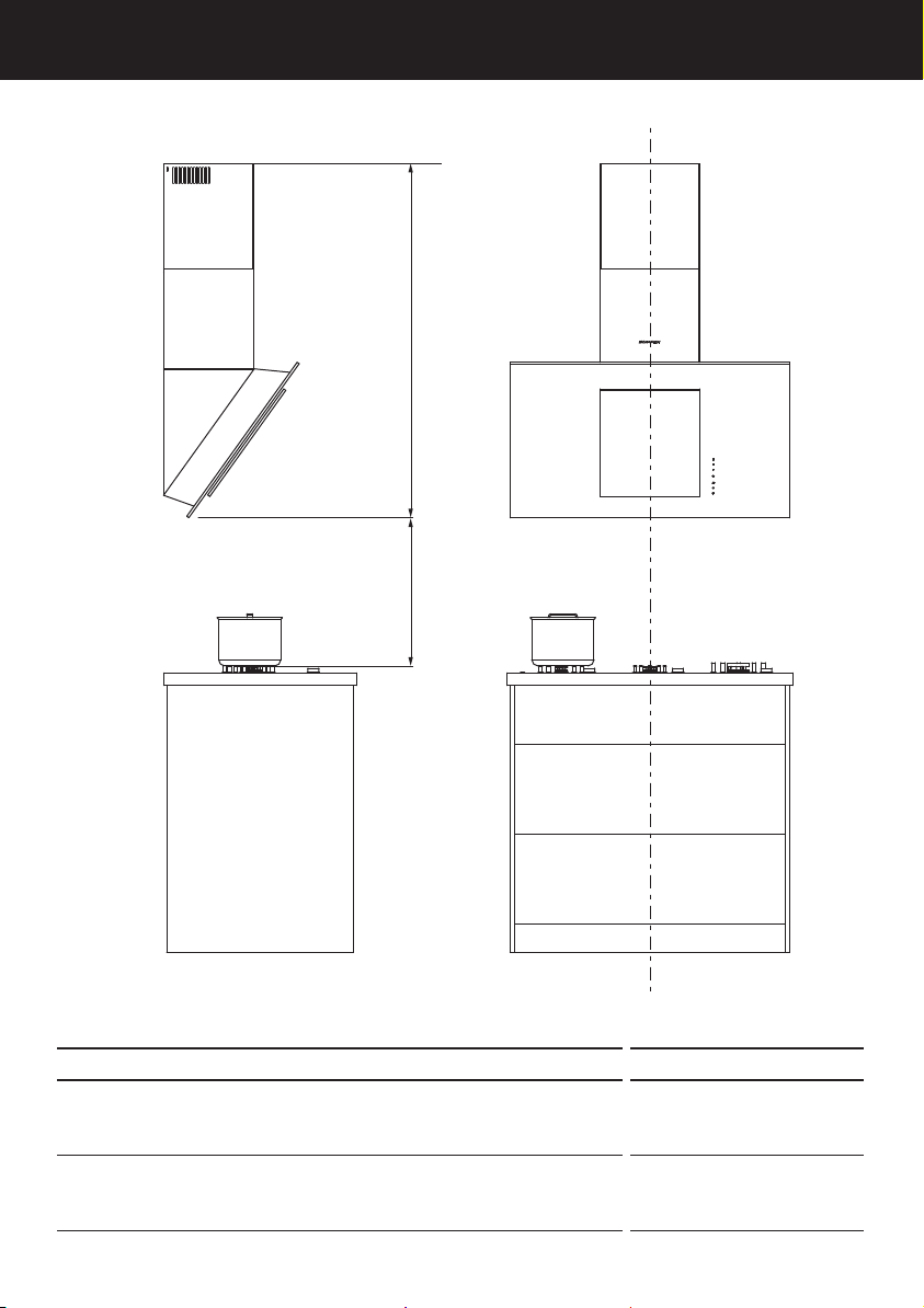
INSTALLATION INSTRUCTIONS
H
Power cord location
g
E
A
min
A
max
B
D
F
C
J
K
Ø
I
Product dimensions
11
INSTALLATION INSTRUCTIONS
HT90GHB2
PRODUCT DIMENSIONS mm
A
Overall height of product 800 – 1140
B
Overall width of product 900
C
Overall depth of product 380
D
Height of hood 520
E
Width of flue 320
F
Depth of flue 290
G
Distance from centre of ducting outlet to back of product 140
H
Distance from centre of ducting outlet to side of flue 160
I
Diameter of ducting outlet 150
J
Distance between centre of lights 200
K
Distance from centre of lights to back of product 45
Length of power cord 1800
ImpORTANT!
Actual product dimensions may vary by ± 2mm.
12
INSTALLATION INSTRUCTIONS
Height of cooker hood
M
L
MINIMUM CLEARANCES mm
L
Installation height
Ducted
Recirculation
min. 840 – max. 1140
min. 880 – max. 1140
M
Height top of hob to base of product
Electric hob
Gas hob
min. 400
min. 650

13
INSTALLATION INSTRUCTIONS
M
L
Venting options
Attention should be given to ensure that any applicable regulations concerning the
discharge of exhaust air are fulfilled.
The cooker hood can be installed to operate with the exhaust air ducted externally from
the kitchen, or installed to operate with the exhaust air recirculating within the kitchen.
Ducted
For ducted installation it is recommended that 150mm diameter, rigid or semi-rigid
ducting is used. This will require a 160mm (min) round hole in the ceiling or wall. Care
should be taken to position the hole correctly.
For optimal efficiency, use rigid or semi-rigid ducting for reduced noise and increased
airflow. Flexible ducting should only be used as a last resort (ie in difficult installations)
and if used, ensure that it is pulled tight.
Recirculating
To enable the product to operate with the air recirculating, please purchase a
recirculation diverter and carbon filters (refer to the ‘Parts and accessories’ section).
Therecirculation diverter is required to channel the air out the side vents at the top
ofthe flue and the carbon filters are required to remove odours.
Note: a ducting hole is not required in the wall or ceiling if the cooker hood is
installed to operate with exhaust air recirculating.
14
INSTALLATION INSTRUCTIONS
Installation
WARNING!
This product is heavy and requires two persons for installation.
WARNING!
Failure to install the screws or fixing device in accordance with these instructions may
result in electrical hazards.
The manufacturer is not liable for any damage caused by not following these instructions.
1
Preparing for installation:
Before installing your cooker hood:
Please read the instructions carefully.
Unpack the hood and check all functions are working.
Ensure the voltage (V) and the frequency (Hz) indicated on the serial plate match
thevoltage and frequency of the installation site.
Check that the area behind the installation surface to be drilled is clear of any
electrical cables or pipes etc.
The stainless steel and glass surfaces of the hood are very easily damaged during
installation if grazed or knocked by tools. Please take care to protect the surfaces
during installation.
Protect the hob surface below with cardboard, or the like, to prevent damage
occurring whilst the cooker hood is being installed above.
Temporarily mark the height of the bottom of the cooker hood and the centre of the
hob on the wall according to the information given in the ‘Installation Instructions –
Height of cooker hood’ section.
The wall used for mounting the cooker hood should have sufficient strength and a
flat surface.
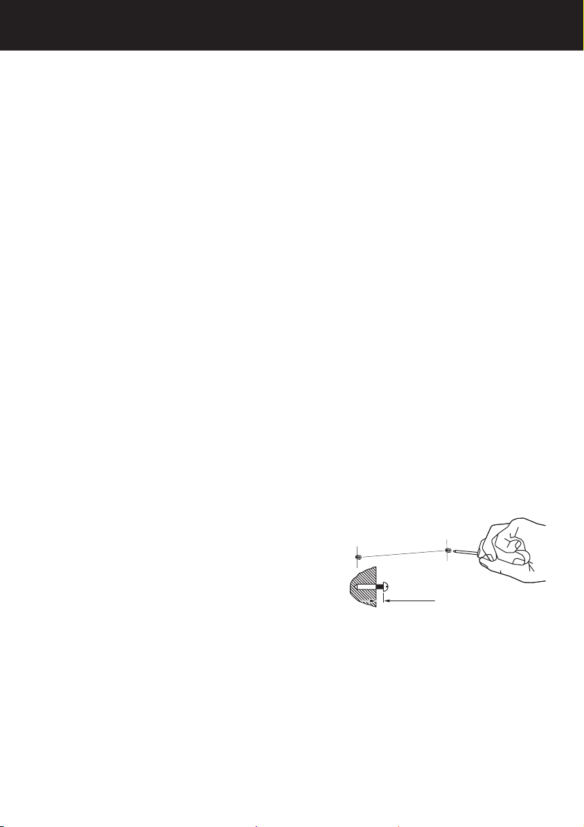
2
Attach chimney bracket and hood mounting screws
Attach the chimney bracket and upper
chimney bracket (if using the upper chimney)
in the locations shown in Fig.2 and 3. Use
the 30mm screws and expansion plugs if
attaching to masonry.
Attach the upper hood mounting screws
in the locations shown in Fig.2 and 3. Use
the 60mm screws and expansion plugs if
attaching to masonry. Ensure that there is a
2mm gap between the screw head and the
wall – see Fig.1
2 mm
Fig.1
15
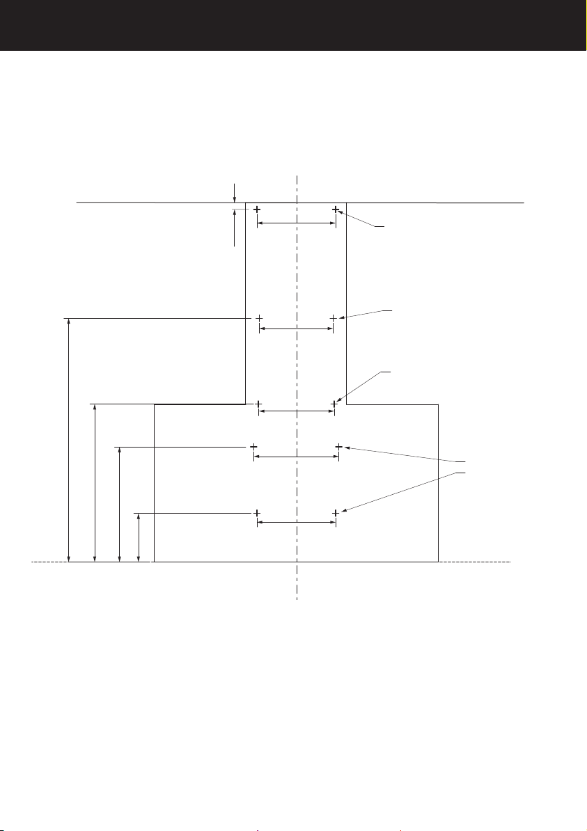
INSTALLATION INSTRUCTIONS
20 mm
155 mm
365 mm
501 mm
773 mm
250 mm
235 mm
240 mm
270 mm
250 mm
Upper chimney bracket
attachment points
Chimney bracket
attachment points
Upper hood
attachment points
Internal hood
attachment points
Fig.2
16
INSTALLATION INSTRUCTIONS
Fig.3
17
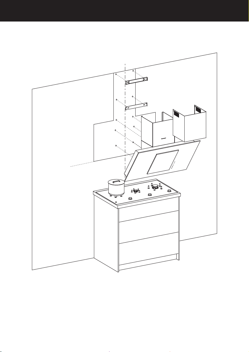
INSTALLATION INSTRUCTIONS
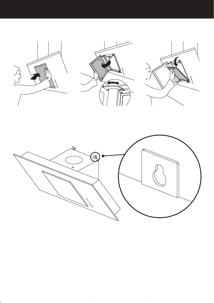
3
Attach hood to wall
Open the front panel on the hood and remove the filter as shown in figures 4 – 6.
Fig.4 Fig.5 Fig.6
Hang hood off upper hood mounting screw with 2mm gap. Hang off the keyhole
attachment points on the back of the hood (see Fig.7). Tighten screws.
Fig.7
Attach internal hood mounting screws to fix hood to wall. Use the 60mm screws.
Reattach filter and close front panel.
4
Attach ducting
Attach ducting and vent outside
5
Attach chimney
Place chimney around the chassis, align the tabs with the slots and attach to the
chimney bracket.
Extend the upper chimney and attach to the upper chimney bracket with 10mm
screws (if using upper chimney).

18
ABOUT YOUR COOKER HOOD – ENERGY EFFICIENCY
Product Fiche
EN61591
MODEL HT90GHB2
Annual Energy Consumption (kWh/annum) 32.2
Time Increase Factor 1
Energy Efficiency Index 52.8
Energy Efficiency Class A
Fluid Dynamic Efficiency 28.5
Fluid Dynamic Efficiency Class A
Lighting Efficiency 28.7
Lighting Efficiency Class A
Grease Filtering Efficiency 91.2
Grease Filtering Efficiency Class B
Airflow at Min. Speed (m³/hr) 200
Airflow at Max. Speed (m³/hr) 525
Airflow at Boost Speed (m³/hr) 710
Airborne noise at minimum (dB) 40
Airborne noise at maximum (dB) 64
Airborne noise at Boost (dB) 67
Airflow At Best Efficiency Point (m³/hr) 348.4
Electrical Power Input At Best Efficiency Point (W) 76.1
Lighting Nominal Power (W) 7
Lighting Average Illumination (lux) 201
Power consumption in Off mode (W) 0.41
Power consumption in Standby mode (W) 0.41
19
OPERATING INSTRUCTIONS
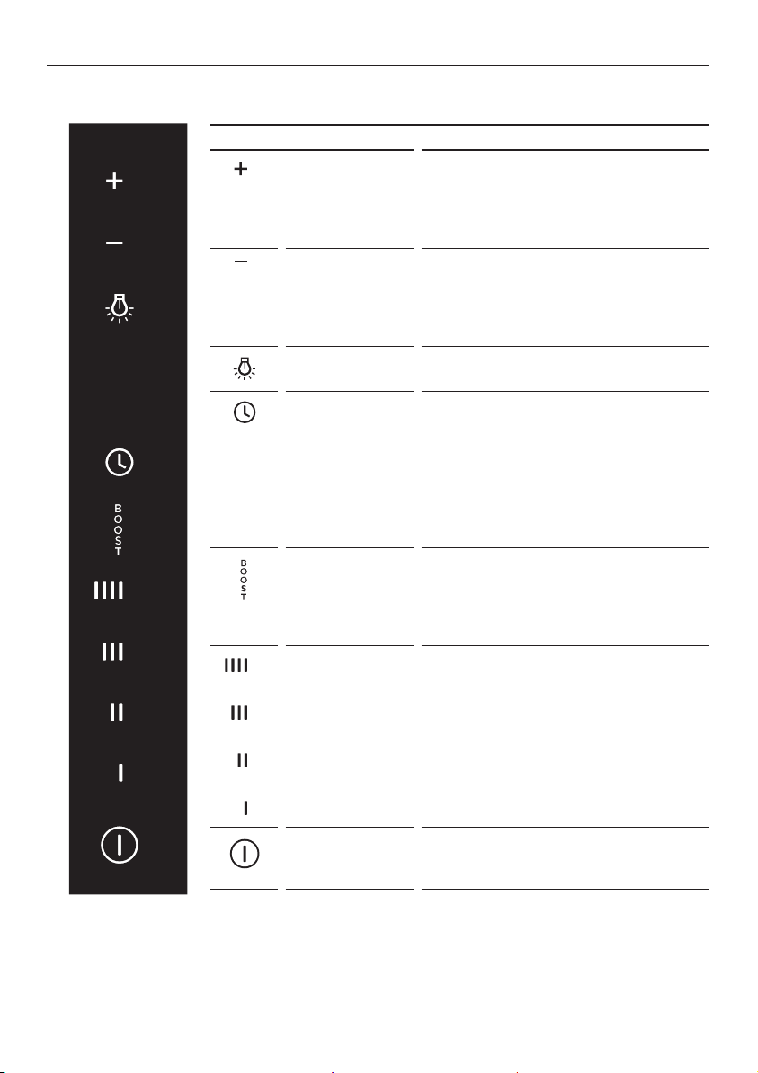
Touch control panel
CONTROL PANEL FEATURES
Increase
lighting level
Press once to adjust the light to the
highest level. The icon illuminates red
when on the highest level. Press and
hold to progressively increase the
light level.
Reduce
lighting level
Press once to adjust the light to
the lowest level. The icon illuminates
red when on the lowest level. Press
and hold to progressively dim the
light level.
Lights on/off Turn the lights on or off. The lights
turn on to the last level selected.
Timer Turn the timer on. The fan operates
for 5minutes at the current speed
and each descending speed before
turning off.
The timer icon flashes red when the
filters need cleaning. To reset the
timer press the button and it will stop
flashing and begin counting again.
Boost Turn the fan onto boost speed. The
icon flashes red when it is on. The
cooker hood will operate on boost
speed for 5minutes and will then
revert to speed 4.
Fan speed 1 – 4 Adjust the fan speed levels from 1–4
with 1 being the lowest level and 4
being the highest.
The fan speed level icon illuminates
red when selected.
Power on/off Turn the cooker hood on or off. The
fan automatically turns on to operate
at level 1.
20
ImpORTANT!
Never use abrasive or oil based cleaners
Maintenance
Before performing any cleaning or maintenance on your cooker hood, ensure that the
power supply is switched off to the hood.
The cooker hood should be cleaned regularly using a mild, liquid detergent to avoid
a build-up of grease occurring. Grease deposits are corrosive which can damage your
cooker hood.
Note: in areas of high humidity or coastal environments, cleaning should be carried
outfrequently.
Aluminium filter
Depending on use, and at least once a month, the aluminium grease filter should be
removed and cleaned with hot soapy water or in the dishwasher.
If washed in the dishwasher, the filter should be placed in an upright position to prevent
food from falling on it.
After rinsing and drying, replace the filter.
Note: some discolouration of
the frames may occur.
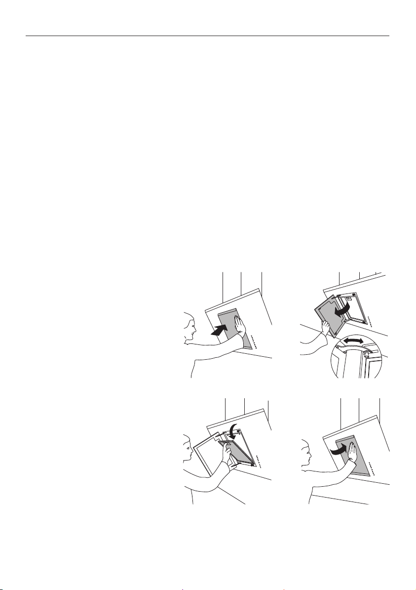
Removing the aluminium filter:
1
Open the front panel of the
cooker hood.
2
Pull the filter catch, tilt the
filter outward and disengage
itfrom the supports.
3
Reverse these instructions
when refitting the filter.
CLEANING AND MAINTENANCE
1 2
3 4

21
CLEANING AND MAINTENANCE
Carbon filter – for use in recirculation mode
Active carbon filters are disposable items designed to remove grease and odours from
cooking vapours before the air is channelled back into the kitchen. The active carbon
filter must be replaced periodically to work properly, at least once every three months,
depending on the frequency of use of the cooker hood.
Note: fully saturated carbon filters can become a barrier to air movement therefore
limiting cooker hood performance. In the event of fire, grease laden filters could be
flammable and therefore regular replacement is recommended.
Replacing the light bulb:
Please note replacement light bulbs are not covered by warranty.
1
Before changing the light bulb, ensure the cooker hood is disconnected from the
power supply.
2
Remove the aluminium grease filter.
3
Replace light bulbs.
4
Refit the aluminium filter.

22
PARTS AND ACCESSORIES
ITEM REFERENCE NUMBER
LED bulb x2 792556
Aluminium filter 791761
Recirculation carbon filter 50031
Recirculation diverter 50032
Ducting 150mm kit (eaves) 50033
Ducting 150mm kit (wall) 50034

23
MANUFACTURER’S WARRANTY
You automatically receive a 2 year Manufacturer’s Warranty with the purchase
ofthis Tilted wall cooker hood covering parts and labour for servicing within the
UnitedKingdom and Ireland.
Fisher & Paykel undertakes to:
Repair or, at its option, replace without cost to the owner either for material or labour
any part of the product, the serial number of which appears on the product, which is
found to be defective within TWO YEARS of the date of purchase.
Note: this Manufacturer’s Warranty is an extra benefit and does not affect your
legalrights.
This Manufacturer’s Warranty DOES NOT cover
A
Service calls which are not related to any defect in the product. The cost of a service
call will be charged if the problem is not found to be a product fault. For example:
1
Correcting the installation of the product.
2
Instructing you how to use the product.
3
Replacing house fuses or correcting house wiring or plumbing.
4
Correcting fault(s) caused by the user.
5
Noise or vibration that is considered normal, eg drain/fan sounds, refrigeration
noises oruserwarning beeps.
6
Correcting damage caused by pests, eg rats, cockroaches, etc.
7
Replacement light bulbs.
B
Defects caused by factors other than:
1
Normal domestic use; or
2
Use in accordance with the product’s user guide.
C
Defects to the product caused by accident, neglect, misuse or ‘act of God’.
D
The cost of repairs carried out by non-authorised repairers or the cost of correcting
such unauthorised repairs.
E
Normal recommended maintenance as set out in the product’s user guide.
F
Repairs when the appliance has been dismantled, repaired or serviced by other than
aFisher&Paykel Authorised Repairer or the selling dealer.
G
Pick-up and delivery.
H
Transportation or travelling costs involved in the repair when the product is installed
outside the Fisher&Paykel Authorised Repairer’s normal service area.
This product has been designed for use in a normal domestic (residential) environment.
This product is not designed for commercial use (whatsoever). Any commercial use by a
customer will affect this product’s Manufacturer’s Warranty.
Service under this Manufacturer’s Warranty must be provided by a Fisher&Paykel
Authorised Repairer (refer to the ‘Customer Care’ section at the back of this book).
Suchservice shall be provided during normal business hours. This Manufacturer’s
Warranty certificate should be shown when making any claim.
Please keep this user guide in a safe place.

24
CUSTOMER CARE
Before you call for service or assistance...
Check the things you can do yourself. Refer to your user guide and check that:
1
Your product is correctly installed.
2
You are familiar with its normal operation.
If after checking these points you still need assistance or parts, please refer to your
nearest Authorised Service Centre, Customer Care, or contact us through our local
website listed on the back cover.
In United Kingdom if you need assistance…*
Call the Fisher & Paykel Customer Care Centre and talk to one of our Customer
CareConsultants.
Phone: 08000 886 605
Fax: 08000 886 606
Website: www.fisherpaykel.com
Postal address: Fisher & Paykel Appliances Ltd, Maidstone Road, Kingston,
MiltonKeynes, Buckinghamshire, MK10 0BD
In Ireland if you need assistance…*
Phone: 1800 625 174 or 01-8077960
Fax: 1800 635 012
Website: www.fisherpaykel.com
Postal address: Fisher & Paykel Appliances, Unit D2, North Dublin Corporate Park,
Swords, Co. Dublin
*If you call, write or contact our website please provide: your name and address, model
number, serial number, date of purchase and a complete description of the problem.
This information is needed in order to better respond to your request for assistance.
Product details can be found on the chassis underneath the filter.
Registration
Register your product with us so we can provide you with the best service possible.
To register your product visit our website: www.fisherpaykel.com

25
CUSTOMER CARE
Complete and keep for safe reference:
Model
Serial No.
Purchase Date
Purchaser
Dealer
Suburb
Town
Country

104041 A 04.15
www.fisherpaykel.com
Copyright © Fisher & Paykel 2015. All rights reserved.
The product specifications in this booklet apply to the specific products
and models described at the date of issue. Under our policy of continuous
product improvement, these specifications may change at any time. You
should therefore check with your dealer to ensure this booklet correctly
describes the product currently available.
GB IE