
Installation Instructions
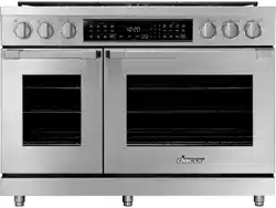
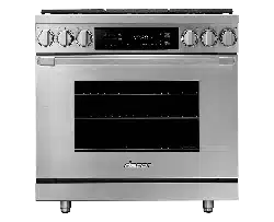
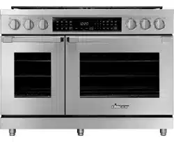
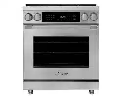
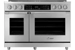
Heritage Pro Range
HDPR30S, HDPR36S, HDPR48S, HDER30S, HDER36S, HDER48S
Part No. 113428 Rev A

2 English
Table of Contents
Before You Begin 3
Important Notes 3
Customer-Assurance Information 3
Important Safety Instructions 4
Safety Symbols and Cautionary Information 4
Installation-Related Safety Instructions 5
Consignes de sécurité importante 7
Instructions de sécurité relatives à l'installation 7
Product Specications 9
HDPR30S, -36S, -48S Ranges 9
HDER30S, -36S, -48S Ranges 10
Included Accessories: HDPR30S/HDER30S 11
Included Accessories: HDPR36S, -48S/HDER36S, -48S 12
Needed Parts and Tools 13
Installation Requirements 14
Pre-installation Checklist 14
General Requirements 15
Location Requirements 17
Gas Requirements 18
Electrical Requirements 19
Installation Instructions 20
Preparing for Installation 20
Making the Electrical Connection 24
Making the Gas Connection 29
Final Installation 30
Verifying Proper Operation 33
Moving the Range for Service 34
Installation Checklist 34
3English
Before You Begin
Important Notes
Installer
• Read this manual thoroughly before installing the cooktop.
• Remove all packaging before connecting the electric and gas supplies.
• Observe all governing codes and ordinances.
• Leave this manual with the owner, and write the unit’s model/serial numbers inside for reference.
• Installation of the range requires basic mechanical skills.
Owner
• As with any heat-generating appliance, certain precautions must be followed.
• Ensure the range is installed properly by a qualied installer. (Product failure due to improper installation is
not warrantied.)
• Ensure the wall coverings near the range can withstand the heat it generates.
• Keep this manual handy for personal and professional reference.
Service Technician
The wiring diagram is in an envelope attached to the inside of the rangetop.
Dacor Customer Assurance
Phone: 833-35-ELITE (833-353-5483) USA, Canada
Hours of Operation: Mon – Fri, 5:00 a.m. to 5:00 p.m. Pacic Time
Website: www.dacor.com/customer-care/contact-us
Model Identication
HDPR48S/NG/H; HDER48S/NG/H
HDPR48S/NG; HDER48S/NG
HDPR48S/LP/H; HDER48S/LP/H
HDPR48S/LP; HDER48S/LP
• HDPR: Heritage Dual-Fuel Pro Range
• HDER: Heritage Dual-Fuel Epicure Range
• 48 (also 30, 36): Range width in inches
• S: Stainless Steel
• NG: Natural Gas; LP: Liquid Propane
• H: High Altitude (≥4000 ft/1219 m elev.); no letter: Low Alt.
(<4000 ft/1219 m elev.)
Customer-Assurance Information
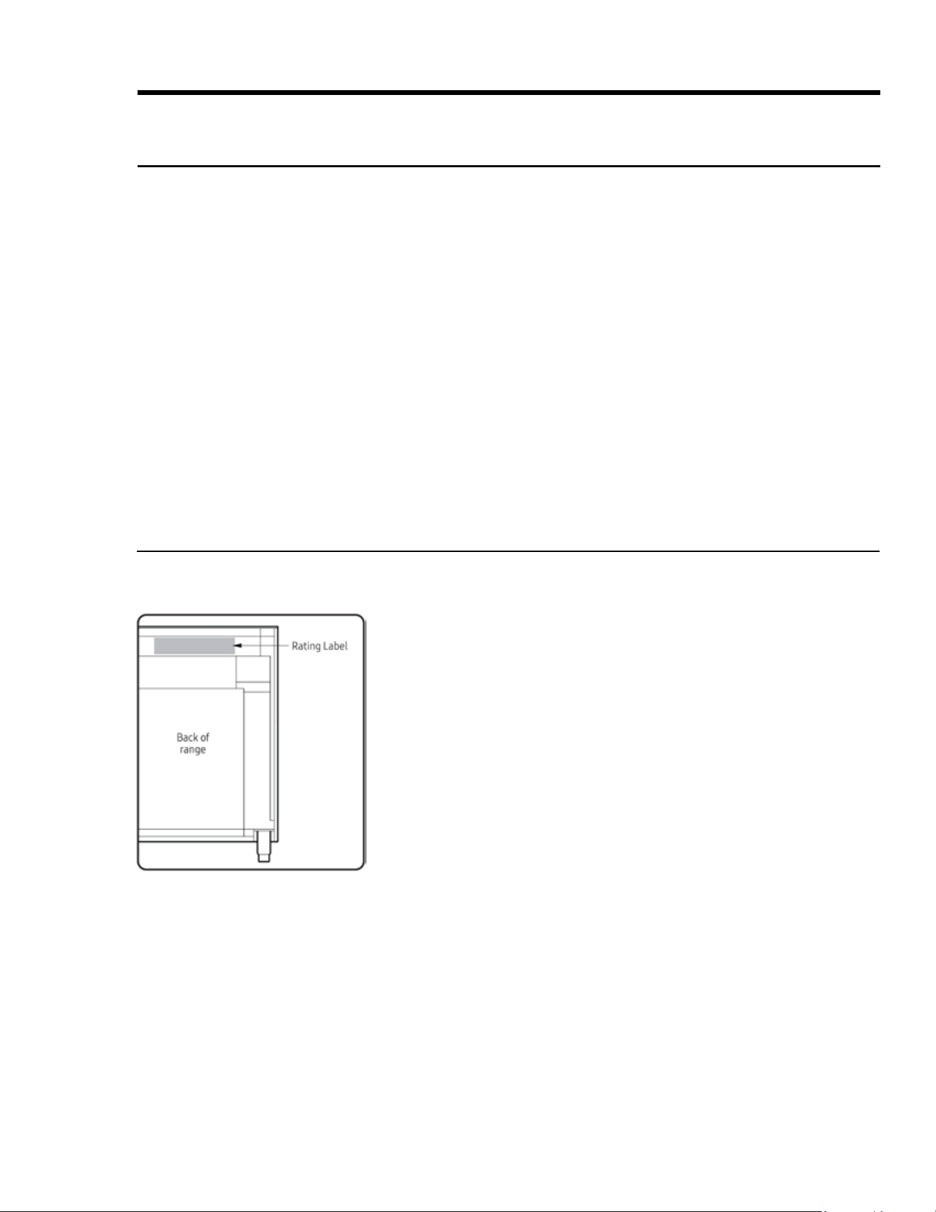
To resolve questions and installation issues, contact your Dacor dealer or Dacor Customer Assurance. Before
calling, have ready the range’s model/serial numbers, which are on the rating label on the back of the range..
4 English
Safety Symbols and Cautionary Information
Electrical and gas equipment can be dangerous if not handled properly. The Important Safety Instructions in
this manual are intended to minimize the risk of property damage, personal injury, and death. Carefully follow
the instructions in this manual.
Important Safety Instructions
About the Symbols In This Manual
These icons alert you to potentially unsafe conditions or helpful information.
Hazards or unsafe practices that may result in severe personal injury or death.
Hazards or unsafe practices that may result in electric shock, personal injury, or property damage.
Useful tips and instructions.
About the Anti-tip Bracket
All ranges can tip and cause personal injury and death. Install and check the anti-tip bracket as instructed.
• After installing the anti-tip bracket (see Installing the Anti-Tip Bracket, Pg. 17), verify proper installation by
carefully tipping the range forward. The bracket should keep the range safely in place.
• When the range is put back in place after maintenance, be sure it engages the anti-tip bracket.
• To avoid personal/property damage, do not step/sit/lean on the range.
State of California Proposition 65 Warning (USA only)
• The range contains chemicals known to the State of California to cause cancer and birth defects or other
reproductive harm.
• Gas appliances can cause low-level exposure to Proposition 65-listed substances (carbon monixide, formal-
dehyde, soot, etc) caused by the incomplete combustion of LP (liquid propane) or natural gas.
Commonwealth of Massachusetts
• The range must be installed by a plumber or gas tter qualied or licensed by the State of Massachusetts.
• If using ball-type gas shut-off valves, you must use the T-handle type.
• Flexible gas lines must not be connected in series.

5English
Important Safety Instructions
Installation-Related Safety Instructions
• Read these instructions thoroughly to reduce the risk of property damage, re, personal injury, and death,
and to ensure proper installation.
• These safety instructions cover installation-related safety issues. For use-and-care-related safety instruc-
tions, including general use, electrical, cooktop, and oven safety, see the User Manual.
Installation-Specic Safety
• Remove all tape and packing material.
• Use only new, exible connectors to make the gas connection.
• Ensure the anti-tip bracket is properly installed (Pg. 17).
• The range should be moved by two or more people.
• After unpacking the range, remove all accessories, taking care with heavy pieces.
• Verify that no parts came loose or were damaged during shipping.
• Ensure the range is correctly installed/adjusted by a qualied installer for the type of gas (natural or LP) you
will use. For the range to use LP gas, the installer must replace all surface burner orices with the provided
LP orice set, and reverse the GPR adapter. These adjustments must be made per manufacturer instruc-
tions and local regulations. The installer shall ensure proper conversion.
• Installation of the range must follow local codes or, in their absence, the National Fuel Gas Code, ANSI
Z223.1/NFPA.54, latest edition. In Canada, installation must follow the current Natural Gas and Propane In
-
stallation Code, CAN/CGA-B149.1, or the current Propane Installation Code, CAN/CGA-B149.2, and local codes
where applicable. The range is UL-certied according to ANSI Z21.1/CSA 1.1, latest edition.
Appliance-Location Safety
• Install the range indoors away from weather/water/strong drafts.
• If the range is near a window, do not hang paper blinds or curtains that could be blown over/onto the range.
• The range must be within easy reach of a grounded, 3- or 4-prong outlet.
• Wall coverings around the range must withstand heat up to 194°F (90°C).
• The oor under the range must be level and able to support the range (48”: 635 lbs.); synthetic ooring
(e.g., linoleum) must withstand 180°F (82°C) without shrinking, warping, or discoloring; the range must be
separated from carpeting by a sheet of ¼” plywood or similar insulator.
• The range needs sufcient space all around for its vents to properly exhaust heat and fumes.
• If cabinet storage above the range is unavoidable, allow at least 30 in. (76.2 cm) from cooking surface to
cabinet bottom, or install a range hood that projects outward 5 in. (12.7 cm) or more beyond the cabinetry.

6 English
Important Safety Instructions
Installation-Related Safety Instructions, cont.
Read these instructions thoroughly to reduce the risk of property damage, re, personal injury, and death, and
to ensure proper installation.
Gas Safety
If you smell gas:
• close the range's gas-supply valve and evacuate the building
• do not use a ame or sparking device (e.g., match, butane lighter or clicker, arc lighter)
• do not turn on any gas or electric appliances
• do not plug in a power cord or touch an electrical switch
• do not use any phone in your building
• instantly call the gas supplier from another building, and follow the supplier’s directions (if unable to reach
the gas supplier, call the re department).
Checking For Gas Leaks
Do not use a ame to check for leaks. With a brush, spread a soap-and-water solution around the area in ques-
tion. If there is a gas leak, small bubbles will appear in the solution. If unsure, call for professional help.
Fire Safety
• Do not store/place/use combustible items (e.g., paper, plastic, fabrics, gasoline) near the range.
• Do not wear loose-tting or hanging garments or accessories while using the range.
• Keep ammable items away from the cooktop burners.
• Regularly clean the oven vents.
• Do not use a towel or other bulky cloth as a pot holder.
• (Grease res) Turn off the burner, and if needed, use a multi-purpose, dry-chemical, or foam extinguisher.
• (Oven res) Keep the door closed, and turn off the oven. Do not open the door until the re is out. If needed,
use a multipurpose, dry-chemical, or foam extinguisher.
• Do not heat sealed containers.
Electrical and Grounding Safety
• Do not use a damaged plug, cord, or loose power outlet, and do not alter the plug, cord, or outlet.
• Do not put a fuse in a neutral or ground circuit.
• Use a dedicated 240 Vac, 60 Hz, 50 Amp breaker for the 48” range, a 30 Amp breaker for the 36” range, and
a 30 Amp breaker for the 30" range. A time-delay fuse or circuit breaker should be used. Plug only the range
into this circuit.
• If unsure that the intended outlet is properly grounded, have a licensed electrician check it.
• If a power cord is attached to the range, it must be inserted in a grounded, 3- or 4-prong outlet that meets
local ordinances. If codes allow a separate ground wire, a qualied electrician should determine its path. Do
not connect the ground wire to plastic plumbing/gas lines, or hot-water pipes.
• Electrical service to the range must follow local codes, or in their absence, the US National Electrical code/
NFPA No. 70 – Latest Revision or, in Canada, the Canadian Electrical Code CSA C22.1 or Latest Revisions.
• The owner shall ensure the range receives the proper electrical service.

7English
Consignes de sécurité importantes
Instructions de sécurité relatives à l'installation
• Lisez attentivement ces instructions pour réduire les risques de dommages matériels, d'incendie, de bless-
ures corporelles et de mort, et pour assurer une installation correcte.
• Ces consignes de sécurité couvrent les problèmes de sécurité liés à l'installation. Pour les consignes de
sécurité relatives à l'utilisation et aux soins, y compris l'utilisation générale, la sécurité électrique, la table
de cuisson et le four, se reporter au manuel de l'utilisateur.
Sécurité spécique à l'installation
• Enlever tout le ruban et le matériel d'emballage.
• N'utilisez que de nouveaux connecteurs exibles pour faire le raccordement au gaz.
• Assurez-vous que le support anti-basculement est correctement installé (Page 17).
• La cuisinière doit être déplacée par deux personnes ou plus.
• Après avoir déballé la cuisinière, enlevez tous les accessoires, en prenant soin d'utiliser des pièces lourdes.
• Vériez qu'aucune pièce ne s'est détachée ou n'a été endommagée pendant l'expédition.
• Assurez-vous que la cuisinière est correctement installée/ajustée par un installateur qualié pour le type
de gaz (naturel ou LP) que vous utiliserez. Pour que la cuisinière utilise du gaz de pétrole liquéé, l'instal-
lateur doit remplacer tous les orices du brûleur de surface par le jeu d'orices de gaz propane fourni et
inverser l'adaptateur GPR. Ces réglages doivent être effectués conformément aux instructions du fabricant
et aux réglementations locales. L'installateur doit assurer une conversion correcte.
• L'installation de la cuisinière doit respecter les codes locaux ou, en leur absence, le Code national du gaz
combustible, ANSI Z223.1 / NFPA.54, dernière édition. Au Canada, l'installation doit respecter le Code d'in
-
stallation du gaz naturel et du propane, CAN / CGA-B149.1, ou le Code d'installation du propane actuel, CAN
/ CGA-B149.2, et les codes locaux, s'il y a lieu. La gamme est certiée UL selon ANSI Z21.1 / CSA 1.1, dernière
édition.
Sécurité de l'emplacement de l'appareil
• Installez la cuisinière à l'intérieur à l'abri des intempéries, de l'eau et des forts courants d'air.
• Si la cuisinière est près d'une fenêtre, ne suspendez pas les stores ou rideaux en papier qui pourraient être
soufés sur / dans la cuisinière.
• La cuisinière doit être facilement accessible à partir d'une prise à 3 ou 4 broches mise à la terre.
• Les revêtements muraux autour de la cuisinière doivent résister à une chaleur allant jusqu'à 90°C (194°F).
• Le plancher sous la cuisinière doit être de niveau et pouvoir soutenir la cuisinière (48 po: 635 lb); un revête-
ment de sol synthétique (par exemple, linoléum) doit résister à 180°F (82°C) sans se rétracter, se déformer
ou se décolorer; la cuisinière doit être séparée de la moquette par une feuille de contreplaqué de ¼ "ou un
isolant similaire.
• La cuisinière a besoin d'un espace sufsant autour de ses évents pour évacuer correctement la chaleur et
les vapeurs.
• Si l'espace de rangement au-dessus de la cuisinière est inévitable, laissez au moins 30 po (76,2 cm) de la
surface de cuisson au fond de l'armoire ou installez une hotte qui dépasse de 12,7 cm (5 po) au-delà des
armoires.

8 English
Consignes de sécurité importantes
Instructions de sécurité relatives à l'installation, suite
Lisez attentivement ces instructions pour réduire les risques de dommages matériels, d'incendie, de blessures
corporelles et de mort, et pour assurer une installation correcte.
Sécurité du gaz
Si vous sentez une odeur de gaz:
• fermer la vanne d'alimentation en gaz de la cuisinière et évacuer le bâtiment
• n'utilisez pas de amme ou de dispositif d'allumage (par exemple, allumette, briquet au butane ou clicker,
arc plus léger)
• N'allumez aucun appareil à gaz ou électrique
• ne branchez pas un cordon d'alimentation ou ne touchez pas un interrupteur électrique
• n'utilisez aucun téléphone dans votre immeuble
• appeler immédiatement le fournisseur de gaz d'un autre bâtiment, et suivre les instructions du fournisseur
(s'il est impossible d'atteindre le fournisseur de gaz, appelez le service d'incendie).
Vérication des fuites de gaz
Ne pas utiliser une amme pour vérier les fuites. Avec une brosse, étendre une solution de savon et d'eau
autour de la zone en question. S'il y a une fuite de gaz, de petites bulles apparaîtront dans la solution. En cas
de doute, appelez une aide professionnelle.
La sécurité incendie
• Ne stockez / placez / n'utilisez pas d'objets combustibles (par exemple, papier, plastique, tissus, essence) à
proximité de la cuisinière.
• Ne portez pas de vêtements ou d'accessoires amples ou suspendus lorsque vous utilisez la cuisinière.
• Éloignez les objets inammables des brûleurs de la table de cuisson.
• Nettoyer régulièrement les évents du four.
• Ne pas utiliser une serviette ou un autre chiffon volumineux comme porte-pot.
• (Feux de graisse) Éteignez le brûleur et, si nécessaire, utilisez un extincteur à poudre, à usage chimique ou à
usage multiple.
• (Four allumé) Gardez la porte fermée et éteignez le four. N'ouvrez pas la porte tant que le feu n'est pas
éteint. Au besoin, utilisez un extincteur à usages multiples, à poudre chimique ou à mousse.
• Ne pas chauffer les contenants scellés.
Sécurité électrique et de mise à la terre
• N'utilisez pas une che, un cordon ou une prise électrique débranchés et ne modiez pas la che, le cordon
ou la prise.
• Ne mettez pas un fusible dans un circuit neutre ou de masse.
• Utilisez un disjoncteur 240 Vac, 60 Hz, 50 Amp dédié pour la gamme 48 ", un disjoncteur 40 Amp pour la
gamme 36", et un? Disjoncteur d'ampères pour la plage de 30 "Un fusible temporisé ou un disjoncteur doit
être utilisé Brancher uniquement la plage dans ce circuit.
• Si vous n'êtes pas sûr que la prise prévue est correctement mise à la terre, demandez à un électricien agréé
de la vérier.
• Si un cordon d'alimentation est attaché à la cuisinière, il doit être inséré dans une prise à trois ou quatre
broches mise à la terre et conforme aux réglementations locales. Si les codes permettent un l de terre
séparé, un électricien qualié devrait déterminer son chemin. Ne connectez pas le l de mise à la terre aux
conduites de plomberie / gaz en plastique ou aux conduites d'eau chaude.
• Le service électrique de la cuisinière doit respecter les codes locaux ou, en leur absence, le Code national de
l'électricité des États-Unis / NFPA nº 70 - Dernière révision ou, au Canada, le Code canadien de l'électricité
CSA C22.1 ou les dernières révisions.
• Le propriétaire doit s'assurer que la cuisinière reçoit le bon service électrique.
9English
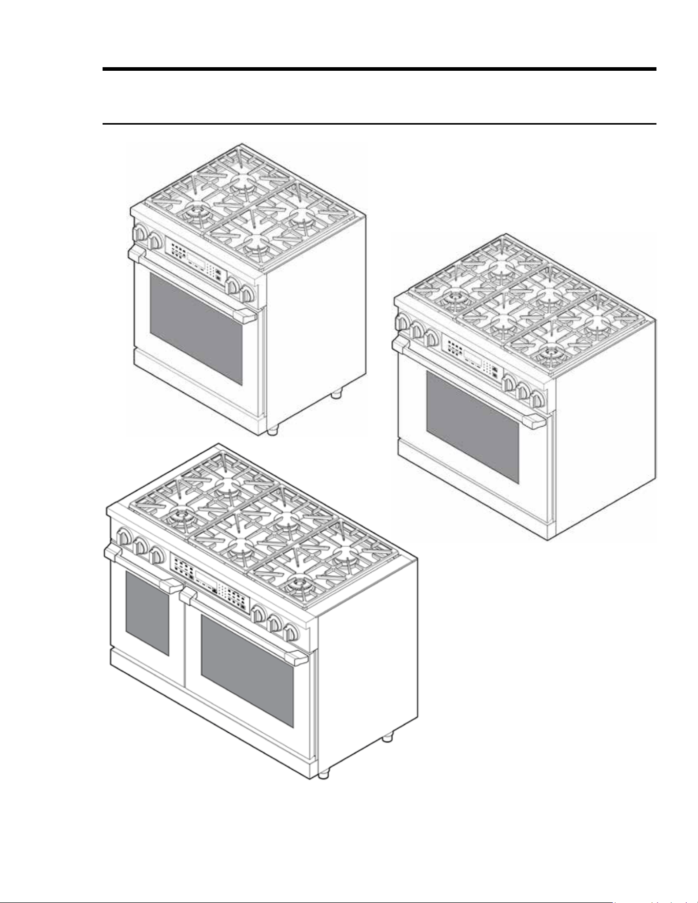
Product Specications
HDPR30S, -36S, -48S Ranges
HDPR48S
HDPR36S
HDPR30S
10 English
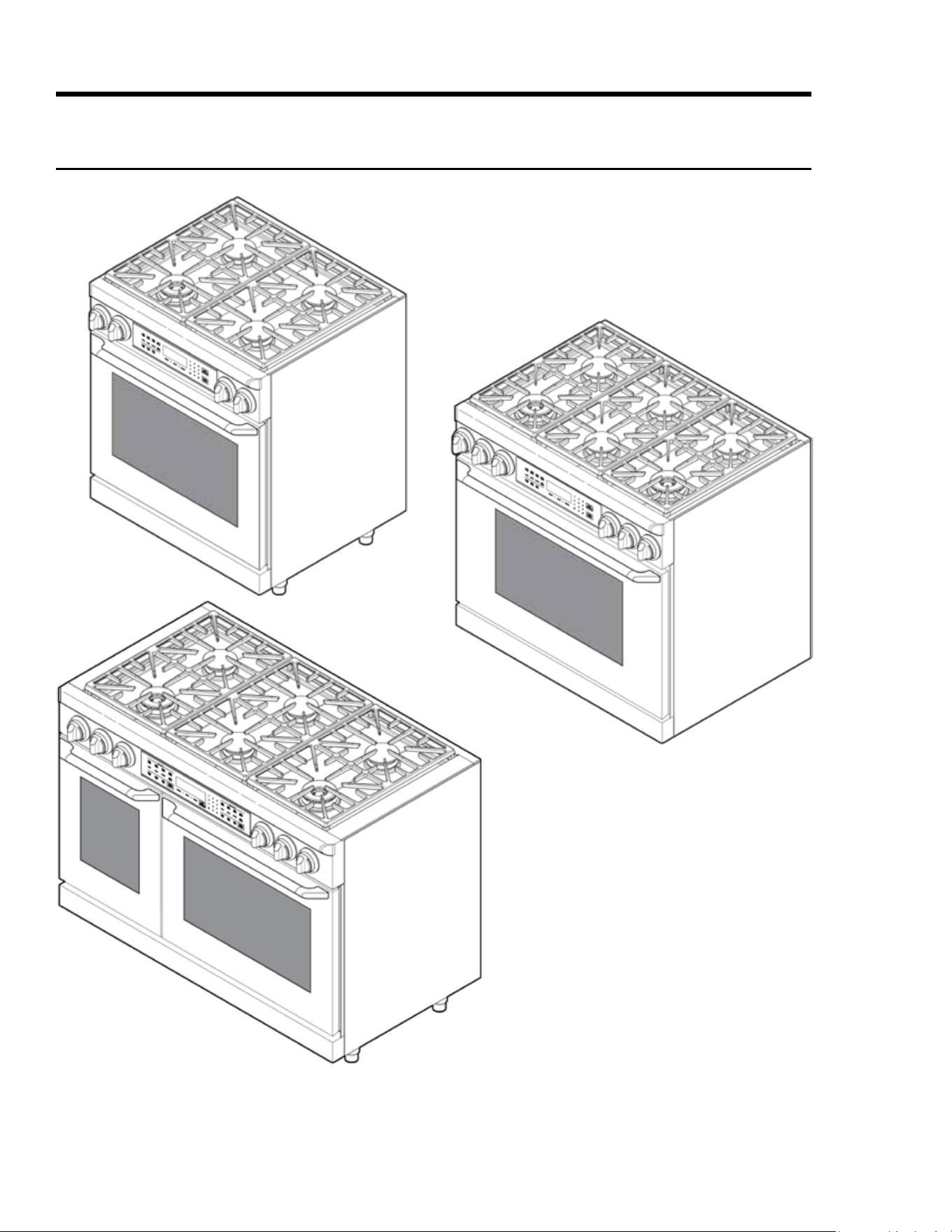
Product Specications
HDER30S, -36S, -48S Ranges
HDER48S
HDER36S
HDER30S
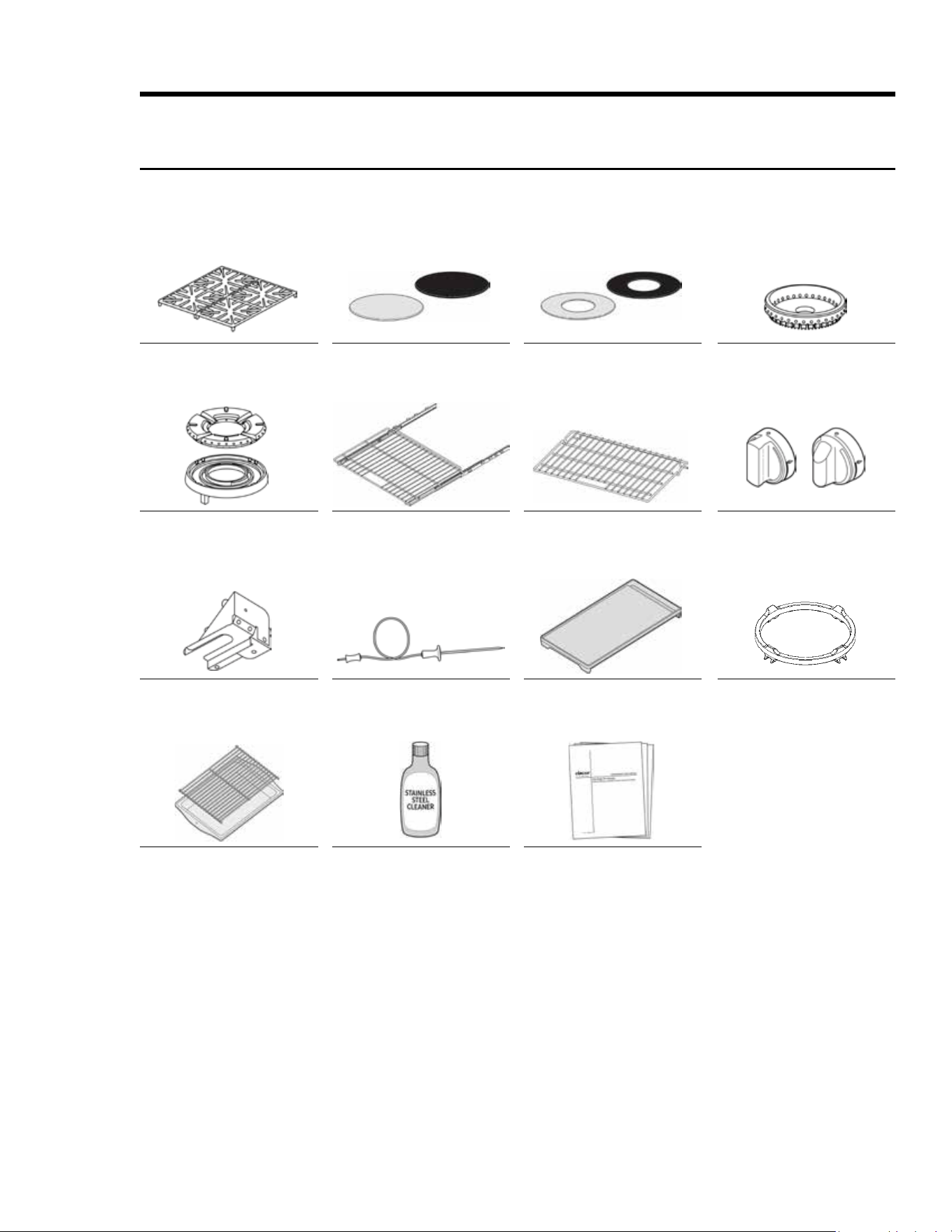
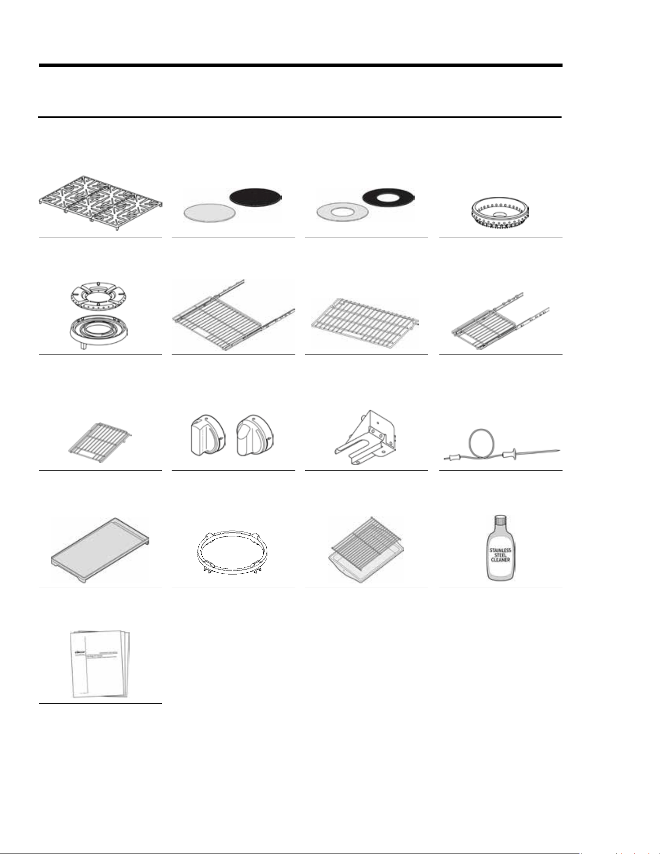
11English
Grates (2)
SimmerSear Burner Ring (1),
Burner Head (1)
Anti-Tip Bracket w/Screws
and Anchors
Broiler Pan and Grill
Standard Burner Caps*:
Porcelain (3), Brass (3)
GlideRack
TM
Oven Rack (2)
Temperature Probe (1)
Stainless-Steel Cleaner
SimmerSear Burner Caps*:
Porcelain (1), Brass (1)
Standard Oven Rack (1)
Griddle (1)
Literature Kit
Standard Burner Rings (3)
Burner-Control Knobs (4—
2 standard, 2 MAX GRIDDLE)
Wok Ring (1)
Product Specications
Included Accessories: HDPR30S/HDER30S
*The range comes with brass and porcelain burner caps to suit customer preference.
Porcelain Porcelain
Brass Brass
HDERSHDPRS
12 English
Grates (3)
SimmerSear Burner Rings (2),
Burner Heads (2)
18” Standard Oven Rack (1)
HDRP/HDER 48” only
Griddle (1)
Literature Kit
Standard Burner Caps*:
Porcelain (4), Brass (4)
GlideRack
TM
Oven Rack (2)
Burner-Control Knobs (6—
4 standard, 2 MAX GRIDDLE)
Wok Ring (1)
SimmerSear Burner Caps*:
Porcelain (2), Brass (2)
Standard Oven Rack (1)
Anti-Tip Bracket w/Screws
and Anchors
Broiler Pan and Grill
Standard Burner Rings (4)
18” GlideRack
TM
Oven Rack (2)
HDRP/HDER 48” only
Temperature Probe (1)
Stainless-Steel Cleaner
Product Specications
Included Accessories: HDPR36S, -48S/HDER36S, -48S
*The range comes with brass and porcelain burner caps to suit customer preference.
Porcelain Porcelain
Brass Brass
HDERSHDPRS
13English
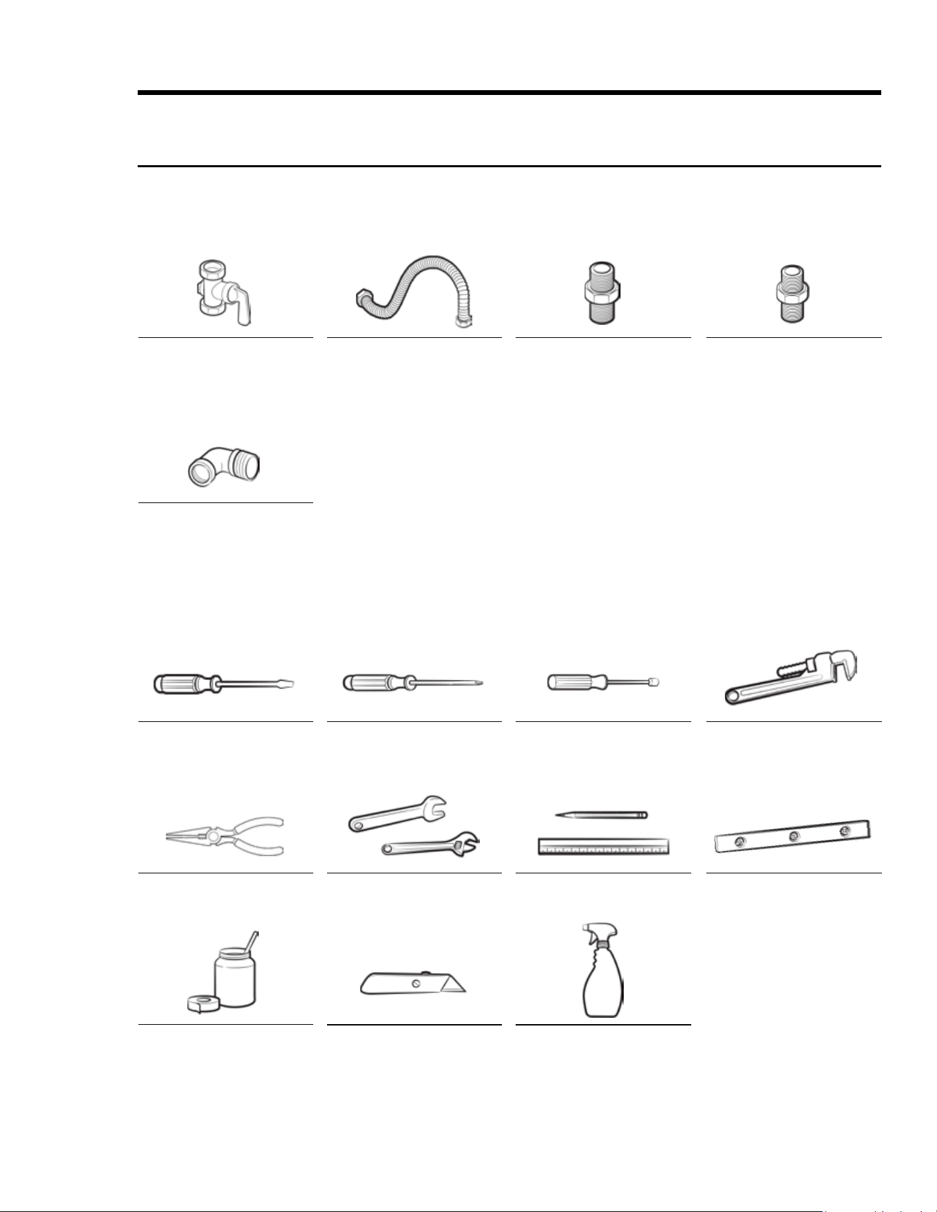
Product Specications
Needed Parts and Tools
Needed Parts
Gas Line Shut-Off Valve
135° Elbow (as needed)
Slotted Screwdriver
Needle-Nose Pliers
Pipe-Joing Compound
Flexible Metal Appliance
Conduit -in. (ID) x 5 ft.
Phillips Screwdriver
Open-End or Adjustable
Wrench
Flare Union Adapter ” in.
(NPT) x in. (ID)
Nutdriver
Pencil, Ruler
Flare Union Adapter ” in.
(NPT) x in. (ID)
Pipe Wrench (2)
Level
Needed Tools
Utility Knife Soap-and-Water Solution
14 English
Installation Requirements
Pre-Installation Checklist
F Before installing the range, read this manual thoroughly.
F Plan for a location where the range will not be subject to strong drafts.
F Remove packaging, grate boxes, regulator with literature, and literature package from the range, verify
that all items are present before beginning the installation.
General Requirements
Clearances and Dimensions
• For OTR installations above a gas cooktop, follow the local gas code.
• For safe operation, provide adequate space between the range and combustible surfaces. Location of the
electrical outlet and gas piping may be adjusted to meet the dimensions and clearances in this manual.
• Either a backguard or non-combustible material must be installed on the wall between the range and
hood. Non-combustible material is not needed from the oor to the top of the range. Openings in the wall
behind the range or in the oor below must be sealed.
• Canada only: A free-standing range shall be installed at least 4.7 in. (12 cm) from all adjacent surfaces.
The range complies with the maximum allowable wood-cabinet temperature of 194°F (90°C). Adjacent wall
coverings, countertops, and cabinets must tolerate such heat to avoid discoloration/delamination/melting.
Minimum Dimensions
Regarding overhead cabinets:
• A hood should be installed that projects at least 5” (12.7 cm) beyond the cabinet face to dissipate heat in
those cabinets.
• The hood must consist of sheet metal at least .0122” thick.
• There should be at least ¼” between the hood and the bottom of the combustible material or metal cabinet.
• The hood must be at least as wide as the range and centered over it.
• Clearance between the cook surface and hood bottom must be at least 24”. (For above-range cooking appli-
ances, follow that appliance’s installation criteria.)
• Maintain at least 30” (76.2 cm) clearance between the cook surface and bottom of an unprotected wood/
metal cabinet
or
Maintain at least 24” (61 cm) clearance if the bottom of the wood/metal cabinet is protected by at least ¼”
(.64 cm) ame-retardant millboard covered with at least No. 28 MSG sheet steel, .015” (.038 cm) stainless
steel, .024” (.061 cm) aluminum, or .02” (.051 cm) copper.
• Maintain at least 18 in. (45.7 cm) between the countertop and adjacent cabinet bottom.
15English
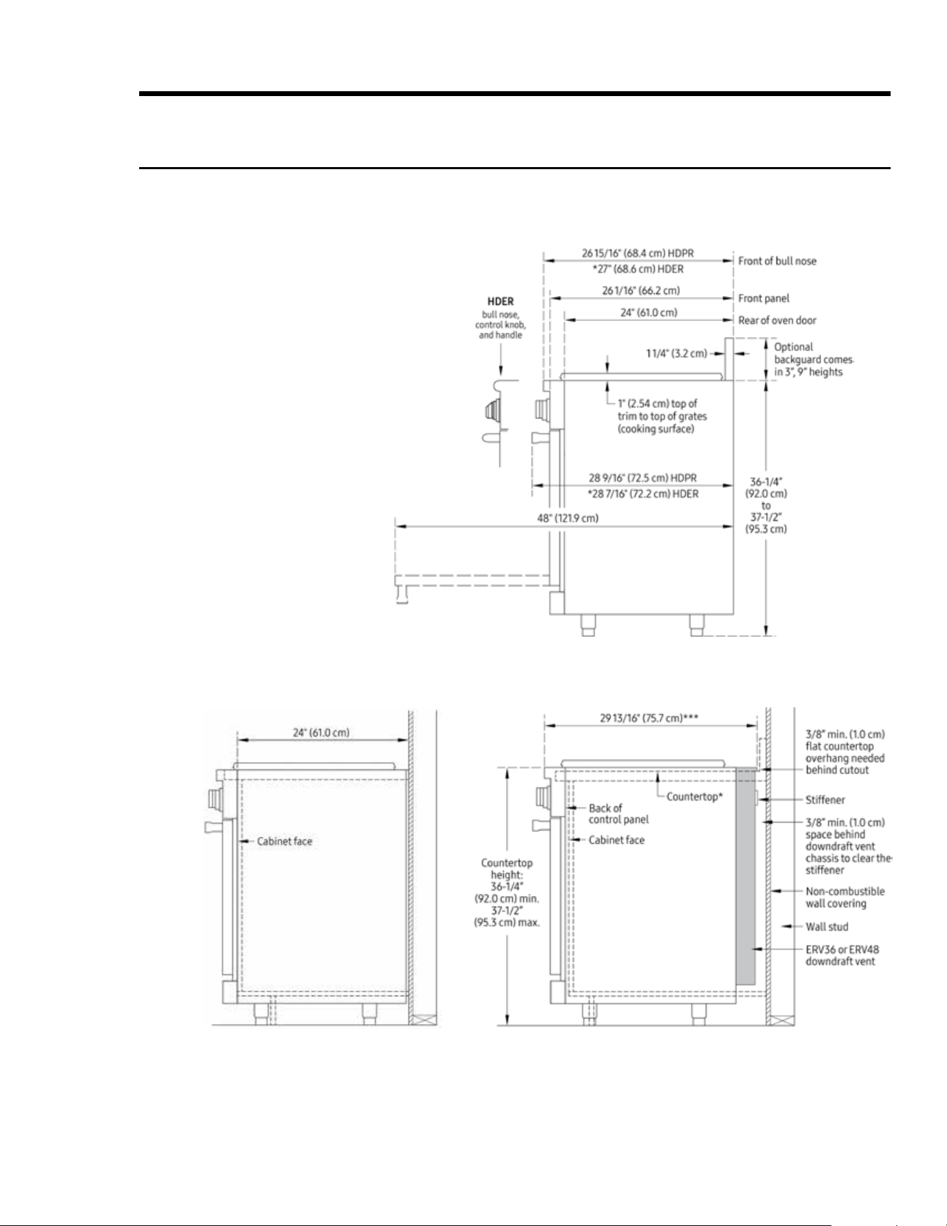
Installation Requirements
General Requirements, cont.
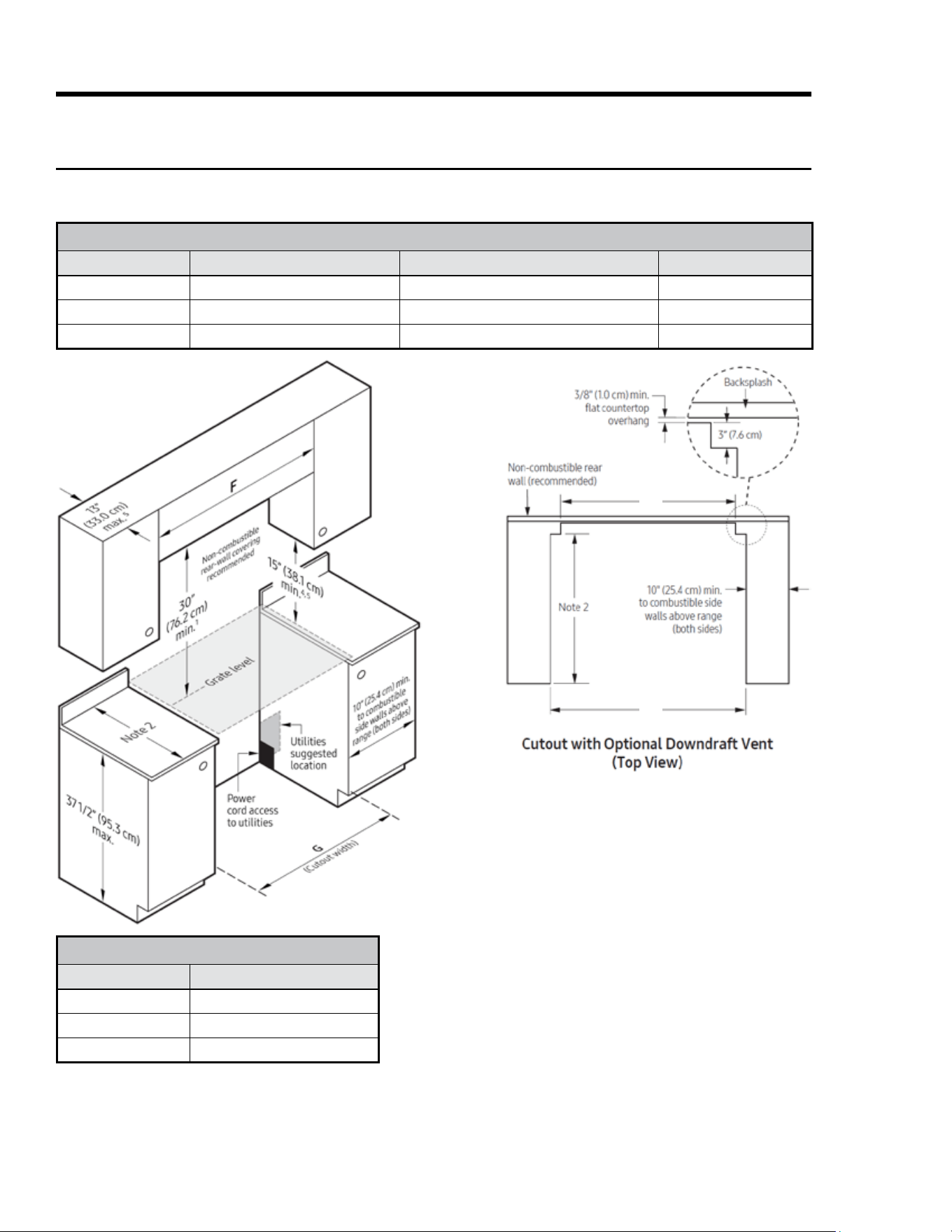
Product Dimensions (tolerances: ±1/16” ±1.6 mm)
HDPRS/HDERS30: 29 ” (75.9 cm); HDPRS/HDERS36: 35 ” (91.1 cm); HDPRS/HDERS48: 47 ” (121.6 cm)
Range-Only Installation Range-With-Downdraft Installation
Critical Depth/Height Dimensions
HDPRS shown;unique HDERS dimensions indicated*
16 English
Installation Requirements
CUTOUT DIMENSIONS
Model F—recommended/min G—min/max H
HDPRS/HDERS 30 36” (91.4 cm)/30” (76.2 cm) 30” (76.2 cm)/30 ” (76.5 cm) 27 " (69.5 cm)
HDPRS/HDERS 36 42” (106.7 cm)/36” (91.4 cm) 36” (91.4 cm)/36 ” (91.8 cm) 33 ” (84.8 cm)
HDPRS/HDERS 48 54” (137.2 cm)/48” (122.0 cm) 48” (121.9 cm)/48 ” (122.2 cm) 43 ” (110.5 cm)
General Requirements, cont.
Cabinet Dimensions
Maintain all max/min dimensions and clearances in the diagrams below for safe use.
Standard Cutout with
Range Hood
1. Vertical from range grate level to combustible overhead
surface; if installing an overhead hood, see hood speci-
cations for minimum required clearances.
2. Cabinet/countertop depth is at the customer’s discretion,
but cabinet face must not protrude beyond the rear of
the front panel. (See Product Dimensions, Pg. 13.)
3. Consult local codes for exact location requirements.
4. Vertical from grate level to combustible surface.
5. Does not apply to cabinets that horizontally are over 10”
(25.4 cm) from the range edge.
APPROVED DOWNDRAFT VENT MODELS
Range Downdraft Vent
HDPRS/HDERS 30
N/A
HDPRS/HDERS 36 MRV36-ER
HDPRS/HDERS 48 MRV48-ER
IMPORTANT: See the downdraft installation instruc-
tions for duct and electrical installation requirements.
Use only the specied Dacor downdraft models.
Cutout tolerances: +1/16”
(+1.6 mm), -0 unless
otherwise specied
G
H
17English
Installation Requirements
Location Requirements
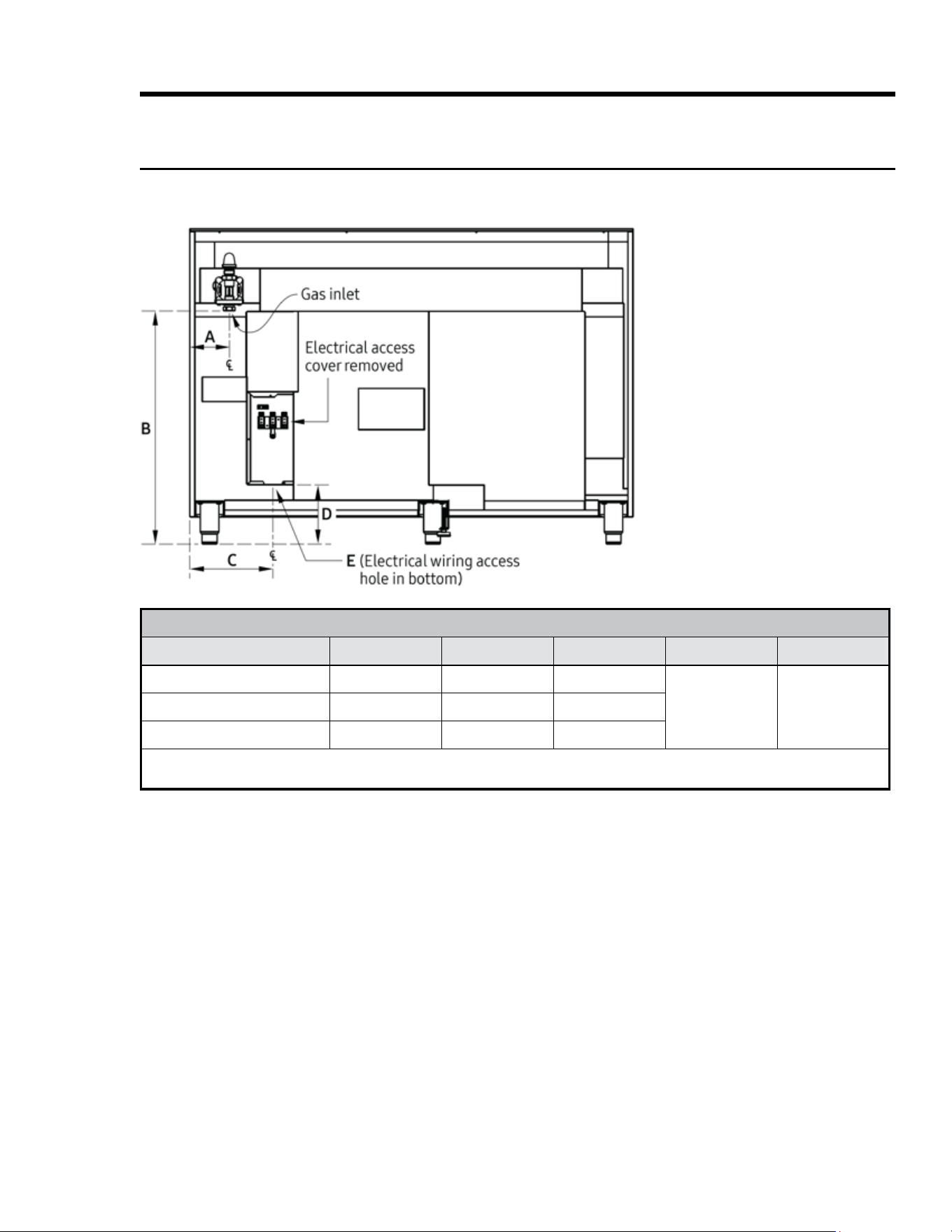
Gas/Electrical Range Hookups (HDPRS/HDERS 30”, 36”, 48”)
Gas/Electrical Service Inlets
• Existing utilities may be used if compatible with the requirements in this manual. (See building codes for
allowed gas-valve locations.)
• An external shut-off valve must be installed between the gas inlet and range so its gas supply can be turned
on/off.
• The valve and the circuit-breaker panel/fuse box must be accessible without moving the range.
• The gas-supply piping, shut-off valve, and the electrical junction box/receptacle must not interfere with the
placement requirements for the range.
• The junction box and gas-shut off valve must be located so the range can be pulled out for service without
being disconnected.
GAS-/ELECTRICAL-ACCESS DIMENSIONS
Model A B* C D* E**
HDPR30S/HDER30S 3 ¼" (8.3 cm) 27” (68.6 cm) 6 " (17.1 cm)
6 (17.1 cm) ” (2.2 cm) dia.HDPR36S/HDER36S 6 " (17.1 cm) 27” (68.6 cm) 12” (30.5 cm)
HDPR48S/HDER48S 4 ¼” (10.8 cm) 27” (68.6 cm) 9” (22.9 cm)
*Measurement with range legs adjusted to their lowest height; **the hole size for the electrical wiring may be increased to 1 ” (2.9
cm) by removing the conduit bracket in the bottom of the electrical box.
48” model shown
18 English
Gas Requirements
Provide Adequate Gas Supply
• Installation must follow local codes or, in their absence, the National Fuel Gas Code, ANSI Z223.1/NFPA 54.
• The cooktop operates at a manifold pressure of 5 in. (13 cm) of water column for natural gas/natural gas at
high altitude (NG-H) or 10 in. (25.4 cm) of water column for LP (propane)/LP at high altitude (LP-H).
• Verify that the oven is right for the provided gas service. When verifying regulator function, inlet pressure
must be at least 1 in. (2.5 cm) greater than the operating (manifold) pressure as given.
• The regulator inlet receives a ” gas line. (The range ships with a ”-to-” adapter on the regulator.)
• The gures in the table at
right are for reference only.
(See the rating label—rear
top-right corner of range—
for exact measurements.)
Installation Requirements
Special Gas Requirements (gas models sold in Massachusetts)
• Gas suppliers recommend installing a UL-approved gas detector per manufacturer specications.
• The range must be installed by a plumber or gas tter certied by the State of Massachusetts.
• A T-handle, manual gas valve must be installed in the gas-supply line to the range.
• If using a exible gas connector, multiple lines must not be connected in series.
• The pressure regulator at
the inlet of the cooktop
manifold must stay in the supply line no matter the type of gas used.
• Use only the range's regulator, which must be installed in the line between the cooktop gas inlet and the
shut-off valve.
• An external, manual shut-off valve must be installed between the gas inlet and the range.
• Ensure the connectors are installed by a qualied installer.
• For safety’s sake, use only new exible connectors.
MINIMUM GAS-SUPPLY PRESSURE REQUIREMENTS*
Gas Type Min. Manifold Pressure Min. Gas-Supply Pressure**
Natural gas 5” water column 6” water column
LP (propane) gas 10” water column 11” water column
*Gas-supply pressure for testing the regulator setting shall be at least 1” water column (249
Pa) above the specied manifold pressure; **Max gas-supply pressure, all models: psi.
19English
Installation Requirements
Electrical Requirements
Follow these directions to reduce risk of property damage, personal injury, or death.
The owner shall ensure that the electrical service meets requirements and that the electrical outlet is properly
grounded and installed by a licensed electrician.
The correct voltage, frequency, and amperage must be supplied to the range from a separate, grounded,
circuit protected by a proper-size circuit breaker or time-delay fuse. (Fuses: fuse both sides of the line (L1, L2).
• The wiring must be long that the range can be pulled out for service without being disconnected.
• Wiring to the range must:
– meet NEMA standards and have a minimum rating of ? Volts @ ? Amps for models HDPR30S/
HDER30S; 250 Volts @ 30 Amps for models HDPR36S/HDER36S; and 250 Volts @ 50 amps for models
HDPR48S/HDER48S
– include a strain relief
– be terminated by tinned leads, closed-loop terminals, or open-ended spade lugs with upturned ends
– connect to a junction box or receptacle installed by a licensed electrician
Connect the range via electical conduit or power cord.
• Conduit
– A 4-wire conduit connected to a 4-wire junction box
or, where local code permits (excludes new branch-circuit installations):
– A 3-wire conduit connected to a 3-wire junction box.
Suggested wiring color code: Black, white, red and green.
• Using an appliance cord:
– A 4-wire appliance cord equipped with a NEMA 14-50P plug connected to a NEMA 14-50R receptacle, or
– A 3-wire appliance cord (where local code permits) equipped with a NEMA 10-50P plug connected to a
NEMA 10-50R receptacle
– Appliance cord plug must be UL listed type SRD or SRDT.
Model Required Circuit Total Connected Load
HDPR30S, HDER30S ? Vac*, ? Hz, ? Amp. ? kW (? Amp.)
HDPR36S, HDER36S 240 Vac*, 60 Hz, 30 Amp. 5.75 kW (24.0 Amp.)
HDPR48S, HDER48S 240 Vac*, 60 Hz, 50 Amp. 10.1 kW (41.9 Amp.)
*4-wire, two 120 Vac hot (L1 and L2), one neutral, one ground; these ratings are for reference only;
see the range's data label (back of range) for exact specications.
20 English
Installation Instructions
Preparing for Installation
• If the gas or electric service provided does not meet the product specications, discontinue installation,
and call the dealer, gas supplier, or a licensed electrician.
• Before moving the range into place, install the anti-tip bracket (see below for instructions).
Unpacking the Range
Unpack the parts box, and verify that all specied components are present (see Pg. 9 or 10). If any item is miss-
ing or damaged, contact your dealer immediately. Do not install a damaged or incomplete range.
Installing a Backguard (optional)
Install the backguard before making the range gas and electrical connections. Install according to the back-
guard kit instructions.
Approved Backguard Models Backguard Description For Range Model
AHB30D6 6” tall for model HDPRS30, HDERS30
AHB30D9 9” tall for model HDPRS30, HDERS30
Installing the Anti-tip Bracket and Foot
There are two ways to mount the anti-tip bracket: Floor mounting (preferred), and wall mounting (Pg. 19).
Wall-mount the bracket if oor mounting is unsuitable; however, if the range’s front panel is over 26 ” (67.3
cm) from the back wall or if the oor is too thick, oor mounting must be used.
Floor-Mounting the Anti-tip Bracket
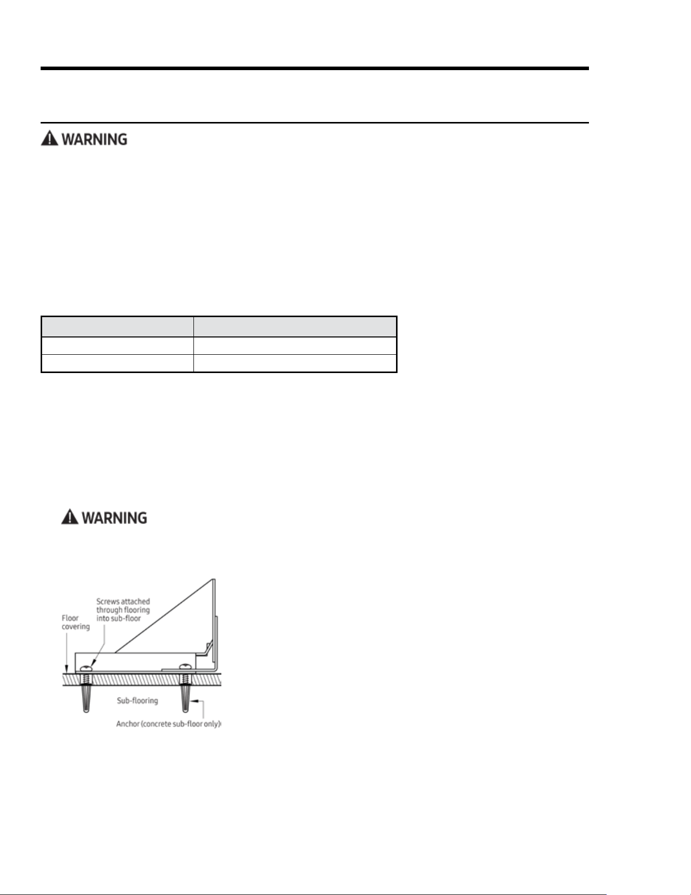
To perform as designed, the anti-tip bracket must attach to the concrete slab or wood sub-oor below any
upper ooring (including cement board). Do not attach the anti-tip bracket directly to oor coverings such
as ceramic/asphalt tile or linoleum.
• Four plastic anchors are provided with three sizes (4 each)
of #8 and #12 Phillips head screws for attaching the anti-tip
bracket to the oor. Use both anchors and four of the screws
to attach the bracket to a concrete sub-oor. Do not use
anchors on a wood sub-oor.
• Determine the location of the range center line and front
panel for the range’s nal position (see Product Dimen-
sions, Pg. 13) and the actual cabinet/cutout dimensions
used for the installation.
21English
Preparing for Installation, cont.
Installing the Anti-tip Bracket and Foot, cont.
Floor-Mounting the Anti-tip Bracket, cont.
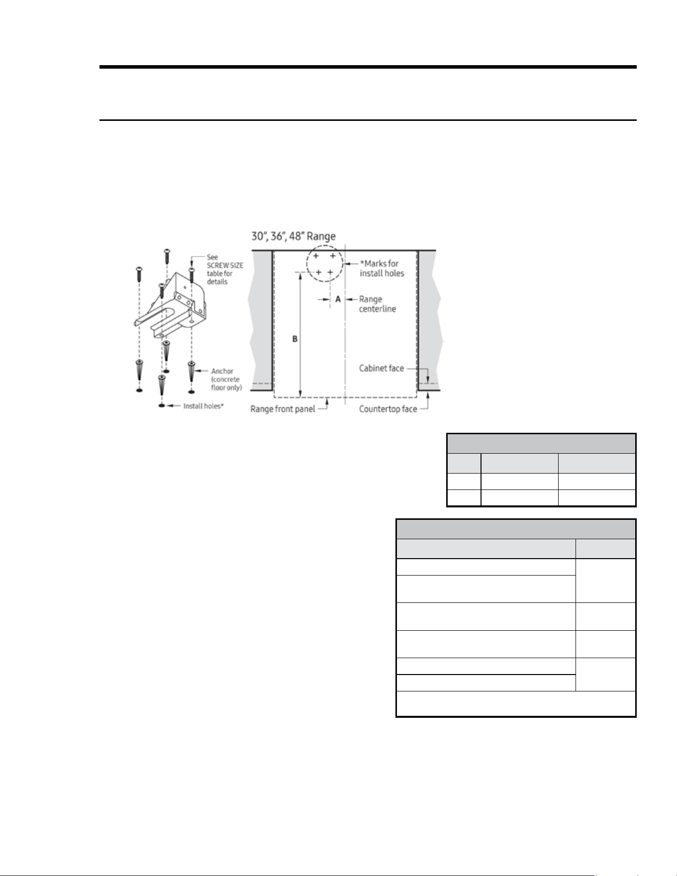
• Determine the anti-tip bracket location (see the diagram below). Mark the 4 hole locations on the oor.
• Determine screw size. Minimum full thread depth (portion of screw threaded into the sub-oor) is ” (1
cm) for wood and ” (1.6 cm) for concrete. (See the SCREW SIZE table, below, for correct screw sizes.)
Attaching the Bracket to a Concrete Floor
1. Drill four ” dia. countersink holes through the
ooring but not into the concrete.
2. Through these holes, drill 4 anchor holes 1¼”
(3.2 cm) into the concrete with a ³/₁₆” masonry
bit. This hole length is longer than the anchor.
3. Clean out the holes, and tap in each anchor so
its top is ush with the concrete surface.
4. Align the bracket and anchor holes, then insert
and tighten the screws.
Attaching the Bracket to a Wood Sub-Floor
1. (Ceramic, stone, other hard ooring over wood)
Drill 4 countersink holes to access the wood for
drilling pilot holes.
2. Drill 4 pilot holes (₁₆” dia. bit for #8 screws, ”
dia. for #12 screws). Align the bracket and pilot
holes, then insert and tighten the screws.
Installation Instructions
SCREW SIZE
Sub-oor Type/Floor Cover Thickness Screw Size
Concrete/wood sub-oor; no oor cover
#8 x 1*
Concrete/wood sub-oor; ooring up to
¼” thick
Concrete/wood sub-oor; ooring ¼” – ”
thick
#8 x 1 ¼*
Wood sub-oor; ooring over ” up to 1
³/₁₆” thick
#12 x 1 *
Concrete under ooring over ” thick
Purchase
separately**
Wood under ooring over 1 ³/₁₆” thick
*Included with range; **determine required depth based on info
in Step 3, and purchase from hardware store.
ANTI-TIP BRACKET PLACEMENT
Dim.
30, 36 48
A
13” (33.0 cm) 3 ” (8.9 cm)
B
22 ” (57.2 cm) 22 ” (57.2 cm)
22 English
Installation Instructions
Preparing for Installation, cont.
Installing the Anti-tip Bracket and Foot, cont.
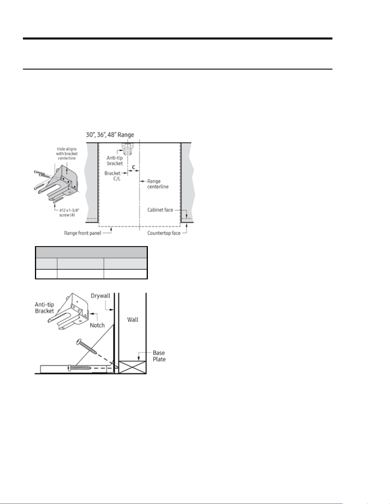
Wall-Mounting the Anti-tip Bracket
For this option to be suitable, the forward edge of the range's front panel must be 26 ” (67.3 cm) or less
from the wall, and the bracket screws must be able to engage the base plate inside the wall. Notches on
the sides of the bracket indicate the minimum height of the base plate and that any oor-covering thick-
ness will not impede secure threading.
5. Having determined the wall-mounting is suitable, place the bracket against the wall in the mounting
location.
6. Using a drill with ” diameter bit, drill four 1 ” deep pilot holes perpendicular to the screw-seating
surfaces shown.
7. Attach the bracket to the wall as shown with the four included #12 x 1 screws.
ANTI-TIP BRACKET PLACEMENT
Dim.
30, 36 48
C 14 ” (35.9 cm) 3 ” (8.9 cm)
1. Using product dimensions on Pg. 13 and actual cabinet/
cutout dimensions, determine the position of the range's
centerline and front panel when the range is in its nal
position.
2. Based on the diagram on Pg. 18, determine and mark the
position of the anti-tip bracket. Set the bracket in place
against the wall.
3. With a pencil, make a dot next to the notches on both
sides of the bracket.
4. (Determine if the base plate is as high as the notches)
With a ₁₆” drill bit, drill test holes in the wall at both dots.
Drill just deep enough to see if the bit contacts the base
plate. If there is contact, you can wall-mount the bracket.
If there is no contact, wall mounting is unsuitable, and
you must either oor-mount the bracket, or alter the wall,
adding base material above the notches.
23English
Installation Instructions
Preparing for Installation, cont.
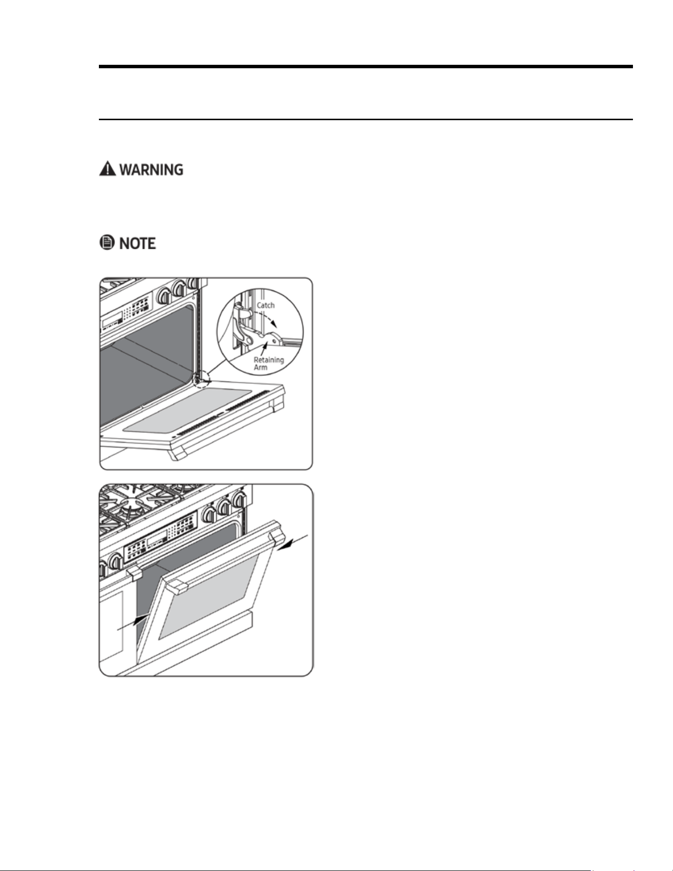
Removing the Oven Door
So the range is easier to move, remove the door(s) to reduce the weight.
• Do not try to disengage the hinge catches with the door(s) removed. The hinge springs could release, caus-
ing personal injury.
• Do not lift or carry the oven door(s) by the handle.
If using a backguard, install it (Pg. 17) before sliding the range into place.
1. On a stable, at surface, lay out some sort of padding on
which to put the oven door after you remove it.
2. Open the door fully.
3. With needle-nose pliers or a slotted screwdriver, ip the
catch out over the retaining arm on each hinge.
4. Raise the oven door to about a 15° angle from vertical.
5. With both hands, grasp the door just below the handle,
and pull the door away from the oven.
6. Set the door (handle-side down) on the padding you
prepared.
24 English
Installation Instructions
Making the Electrical Connection
• Wire the range according to local ordinances.
• Improperly connected electrical wiring can lead to electric shock and appliance damage. Dacor is not re-
sponsible for damage due to improper electrical connection.
• Connect the ground terminal (or lead) on the range to a grounded, metallic, permanent wiring system or
grounding conductor.
• Do not use an extension cord, which may result in re and personal injury.
• Do not install a fuse in the neutral or ground circuit, which may cause electric shock.
IMPORTANT
• Do not disconnect wires inside the range’s electrical ac-
cess cover unless instructed to do so.
• Leave sufcient slack in the conduit or power cord so the
range can be pulled out for service without disconnecting it.
• Be sure to re-attach the electrical-access cover after mak-
ing the electrical connections.
• See the range’s rating label (Pg. 3) for power require-
ments. There are four ways to wire the range:
– 4-wire conduit
and where allowed:
– 3-wire conduit
– 4-wire power cord
– 3-wire power cord
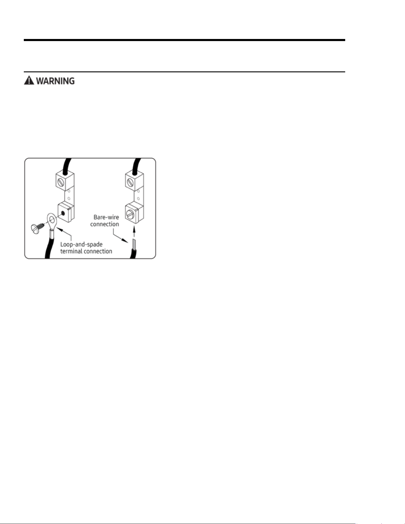
• Connect the green appliance wire to the neutral (white)
supply wire only if local building codes permit.
• See the graphic at left for loop-and-spade and bare-wire
connection methods.
25English
Installation Instructions
Making the Electrical Connection, cont.
Connecting the Conduit to the Range
For instructions on how to connect the power cord, see Pg. 24.
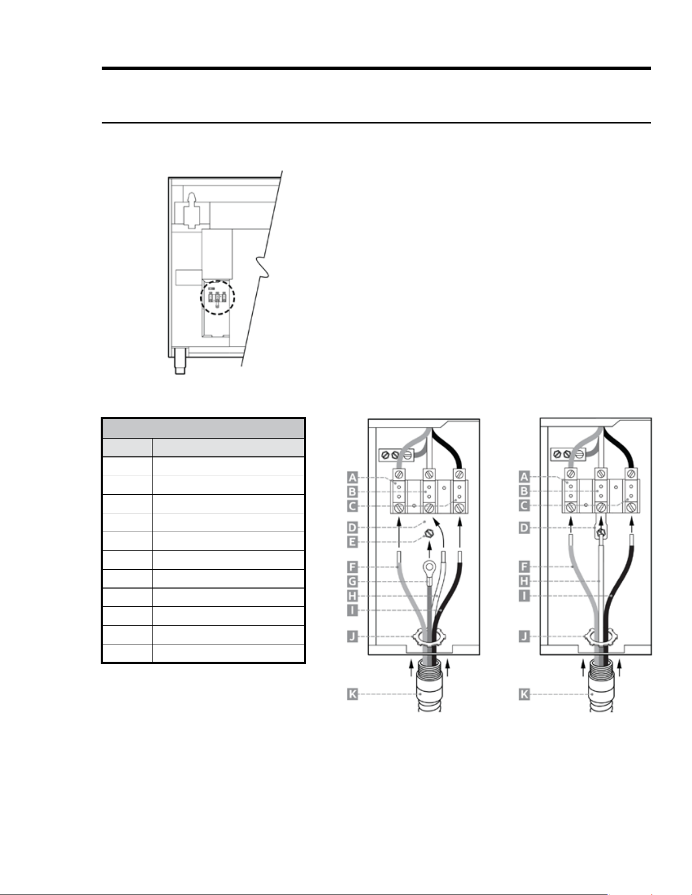
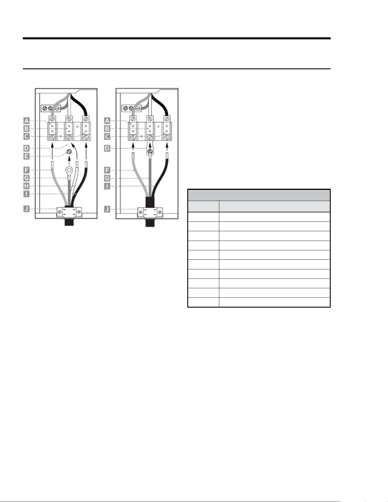
CONDUIT-TO-RANGE CONNECTIONS
Callout Description
A
L2 terminal
B
Neutral terminal
C
L1 terminal
D
Jumper link
E
Grounding screw
F
Red wire
G
Green wire
H
White wire
I
Black wire
J
Conduit strain-relief nut
K
Conduit
1. Remove the range's electrical-access cover (see left).
2. (4-wire only) Loosen the grounding screw (E), and re-
move the neutral-to-ground jumper link (D).
3. Remove the conduit’s strain-relief nut (J).
4. Slide the wires and the end of the strain relief into the
hole on the bottom of the range’s electrical box.
5. Before connecting the wires, slide the strain-relief nut
over the wires, then thread and tighten it onto the strain
relief in the box.
6. Connect the white wire (H) to the neutral terminal (B) in
the box.
7. Connect the black wire (I) to the L1 terminal (C).
8. Connect the red wire (F) to the L2 terminal (A).
9. (4-wire only) Connect the green wire (G) to the ground-
ing screw (E).
10. Re-attach the electrical-access cover.
3-Wire Connection
(if local code allows)
4-Wire Connection
26 English
Installation Instructions
Making the Electrical Connection, cont.
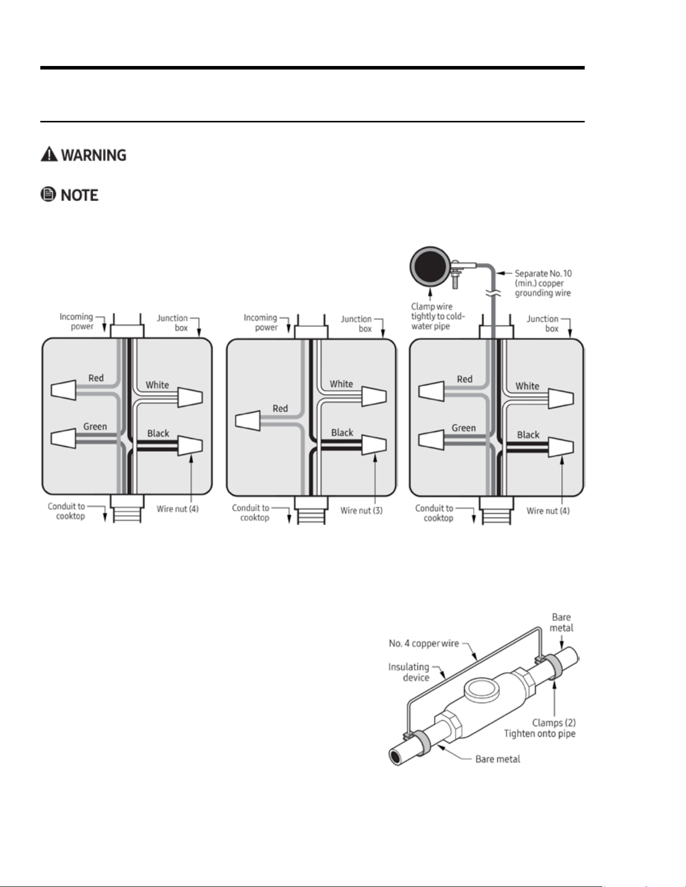
Connecting the Conduit to the House’s Junction Box
Do not connect the range’s green wire to the neutral (white) supply wire unless local code allows.
• The power supply must be properly polarized so the burner igniters do not keep sparking after ignition.
• If you are unsure the power supply is properly polarized/grounded, have it checked by a licensed electrician.
1. With the range in front of the cabinet cutout, feed the conduit wires
into the junction box. Per local code, connect the range to the junction
box via one of these 3 methods:
2. After connecting the conduit to the range (Pg. 22), connect the range’s white wire to the neutral (white)
supply wire in the junction box.
3. Connect the range’s black wire to the black (L1) power-supply wire.
4. Connect the range’s red wire to the red (L2) power-supply wire.
5. (4-wire only) Connect the green wire to a grounded supply wire
in the junction box or to a grounded, cold-water pipe. Concern-
ing this pipe:
– Use a separate, copper grounding wire (No. 10 minimum)
to connect to the pipe via a clamp and external grounding
connector screw.
– If materials isolate the cold-water pipe from ground, jumper
it with a No. 4 copper wire, clamped on both ends.
6. Replace the junction-box cover.
4-Wire Conduit Connection to
Junction Box
3-Wire Conduit Connection to
Junction Box
4-Wire Conduit Connection to
Junction Box w/External Ground
27English
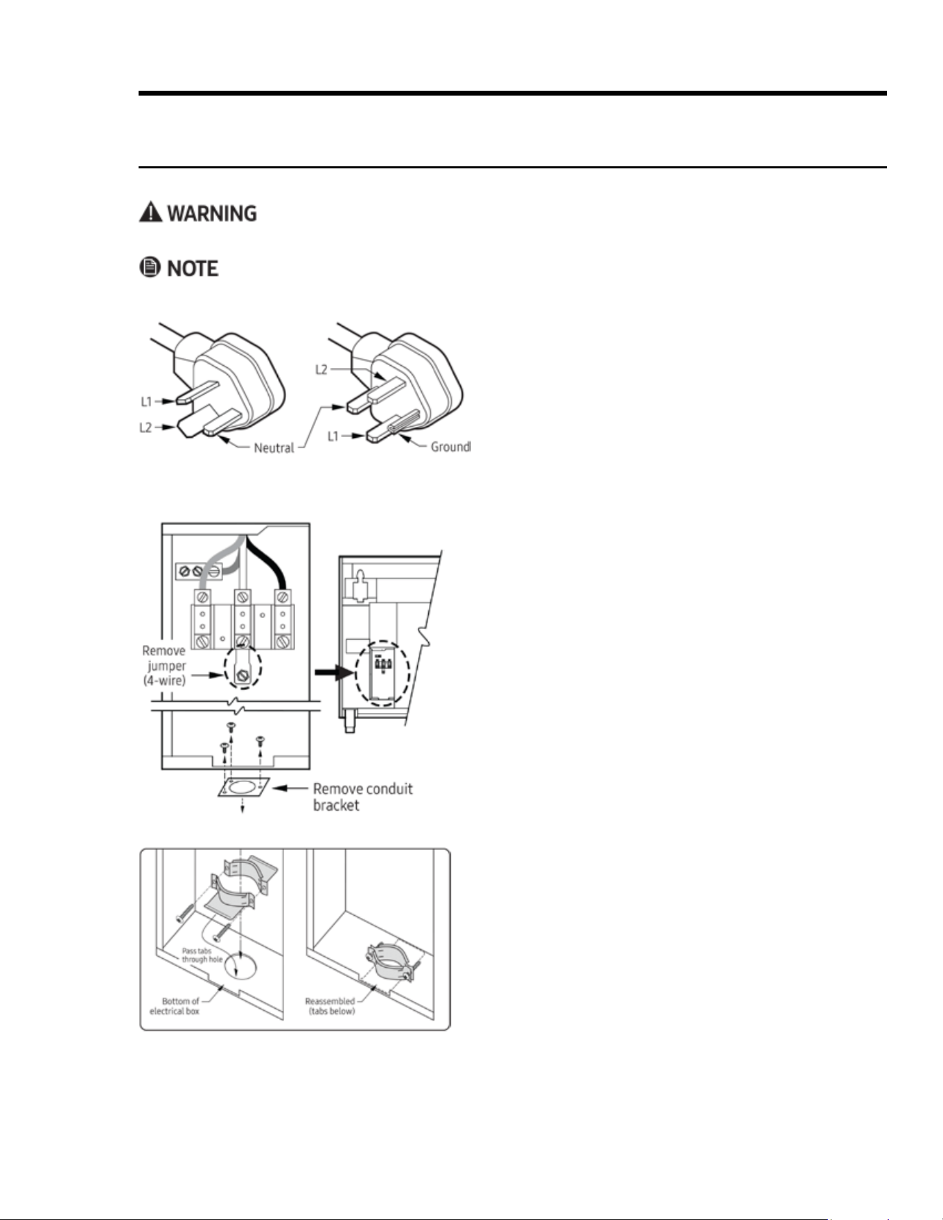
1. Remove the range’s electrical-access cover.
2. (4-wire only) Loosen the ground screw, and remove the
neutral-to-ground jumper link.
3. Remove the electrical box’s conduit bracket.
4. Remove the strain relief from the power cord.
a. Insert the tabs on each part of the strain relief down
through the hole in the box’s bottom.
b. Reassemble the strain relief so the tabs are under the
box and the strain relief itself is in the box.
Installation Instructions
Making the Electrical Connection, cont.
Connecting a Power Cord to the Range
Do not connect the range’s green wire to the neutral (white) supply wire unless local code allows.
The range does not come with a power cord; purchase the cord separately.
10-50P 3-Prong Plug (left); 14-50P 4-Prong Plug (right)
28 English
Installation Instructions
Making the Electrical Connection, cont.
Connecting a Power Cord to the Range, cont.
POWER-CORD CONNECTIONS
Callout Description
A
L2 terminal
B
Neutral terminal
C
L1 terminal
D
Jumper link (removed for 4-wire connection)
E
Ground screw
F
L2 wire
G
Green (ground) wire
H
White wire
I
L1 wire
J
Strain relief
4-Wire Cord Connection
5. Insert the end of the cord up through the hole/
strain relief.
6. Attach the power cord’s:
a. white (neutral) wire (H) to the neutral termi-
nal (B).
b. L1 wire (I) to the L1 terminal (C).
c. L2 wire (F) to the L2 terminal (A).
d. (4-wire only) ground wire (G) under the
box’s ground screw (E).
7. Snug the strain relief (J) around the cord.
8. Re-attach the electrical-access cover.
3-Wire Cord Connection
(if local code allows)
29English
Installation Instructions
Making the Gas Connection
• Before connecting the gas line, close the gas shut-off valve, and turn off power to the range at the circuit
breaker or fuse box.
• Do not apply excessive pressure when tightening gas connections and ttings.
• Do not use Teon tape or plumber’s putty on gas ex-line connections.
• (LP installation) The LP tank must have a high-pressure regulator (in addition to the range's regulator).
• The gas-supply pressure to the regulator must never exceed psi (pounds per square inch) or 3.5 kPa
(kilopascals).
• The range and shut-off valve must be disconnected from the gas-supply piping during pressure tests ex-
ceeding psi (3.5 kPa).
• The range must be isolated from the gas-supply piping by closing the shut-off valve during any pressure
testing at or below psi (3.5 kPa).
• For safety’s sake, check all gas lines for leaks as instructed. Do not use a ame to check for leaks.
The range’s gas-pressure regulator is factory-set for a specic type of gas. To verify that the range is compati-
ble with the home gas supply, check the rating label (see Pg. 3 for location). Ranges intended for LP gas have
“LP” in the model number. Consult your dealer if the range is incompatible with the home gas supply.
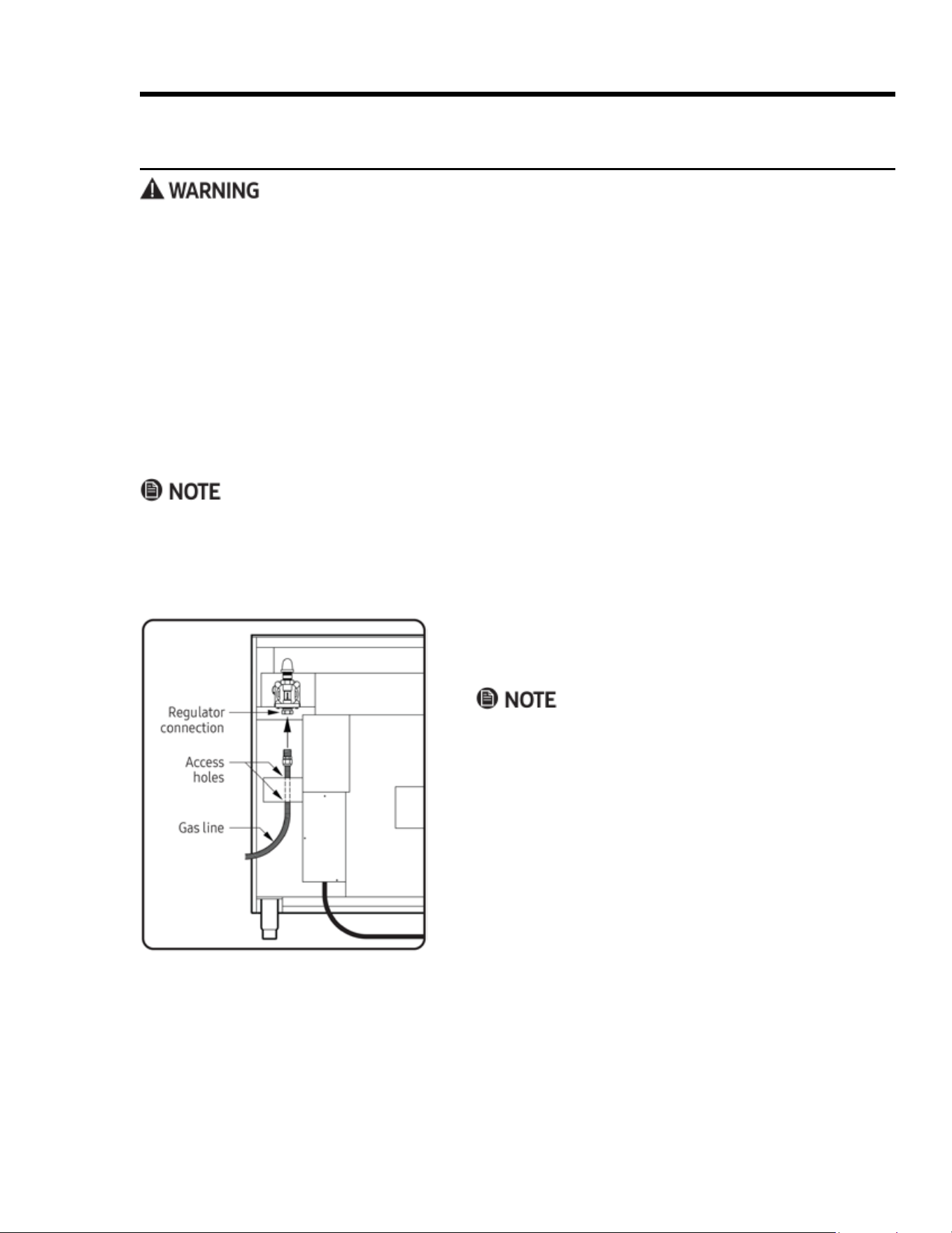
Before Sliding the Range Into the Cutout
1. Close the gas-supply valve; turn off power to the range.
2. Connect a exible gas-supply line to the gas shut-off
valve on the stub out.
The line must be long enough that the range can be pulled
out for service without disconnecting the line.)
3. Slide the gas line up through the access holes in the
chassis and into the regulator. (Move the wires inside the
access holes so the gas line can pass smoothly upward.)
4. Connect the gas line to the regulator.
5. With all cooktop controls off, open the gas-supply valve.
6. Use a soap-and-water solution to check all lines and
connections for leaks.
7. Having veried there are no gas leaks, close the gas-sup-
ply valve connected to the range.
30 English
Installation Instructions
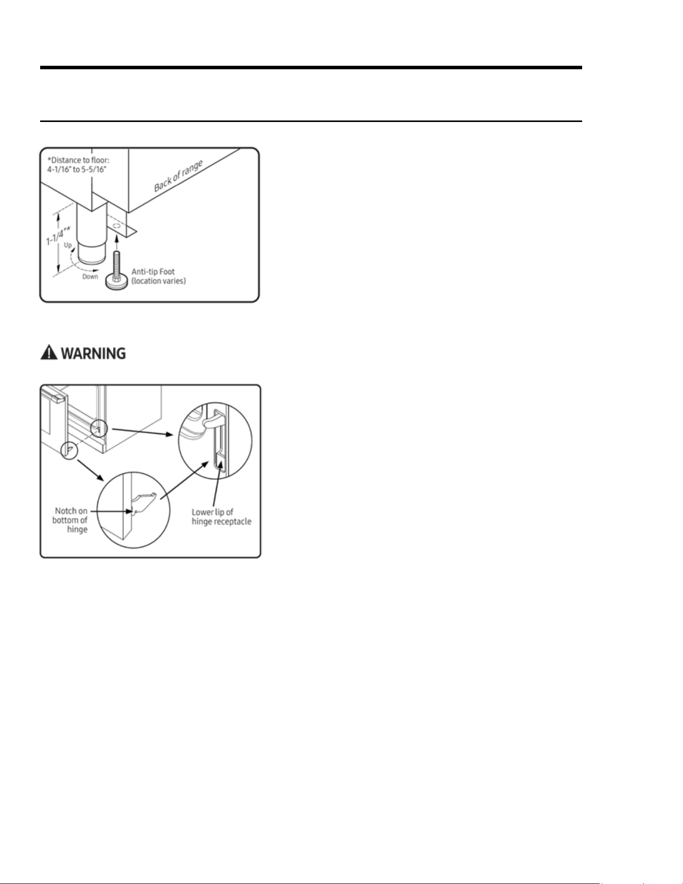
Attaching the Oven Door(s)
To avoid personal injury or property damage, precisely follow Steps 3 and 5.
1. Peel the protective coating from all range surfaces.
2. Measure from oor to countertop. Adjust the leveling legs
as needed so the cooktop trim is ush with or above the
countertop.
3. At the bottom-left rear of the range, lower (rotate) the
anti-tip foot until it is 1/16” (2 mm) off the oor.
4. Carefully slide the range into place in the cutout.
5. With a ashlight, verify that the the anti-tip foot is under
the anti-tip bracket.
6. With a level, check that the range does not tilt in any
direction; adjust the legs as needed to level the range.
1. Grasping the oven door on each side below the handle,
and, facing the oven, tilt the door 15° out from vertical.
2. Slide the hinges into their openings, resting the hinges on
their receptacles.
3. Keeping the door at a 15° angle, push in on the door’s bot-
tom corners until the notch on the bottom of each hinge
slips over the lower lip of each hinge receptacle.
4. Fully open the door.
5. Flip the two hinge locks toward the oven.
6. Carefully close-open-close the door completely to ensure
it is properly installed.
Final Installation
Installing the Anti-tip Foot
31English
Assembling Cooktop Components
Installation Instructions
⁕ Match the D-shaped opening on the back of each knob
with the D-shaped valve shaft of the appropriate burner,
push the knob fully onto the shaft.
a. Put the knobs with the words “MAX GRIDDLE” on the
center valve shafts (36", 48" models) and the right-side
valve shafts (30" model).
b. Put the remaining knobs on the other valve shafts.
Final Installation, cont.
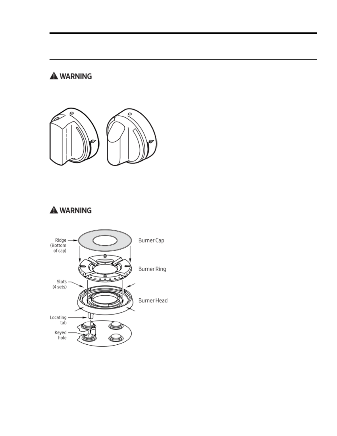
Installing the Burner-Control Knobs
Two types of knobs come with the range. The knobs for the center burners (36", 48") and right-side burners
(30") feature the words “MAX GRIDDLE,” which refers to the maximum heat setting for a burner over which the
griddle is placed. Exceeding the MAX GRIDDLE heat level may damage the griddle.
Pro Knob for
HDPRS Models
Epicure Knob for
HDERS Models
Do not operate the cooktop unless all burner components are properly assembled.
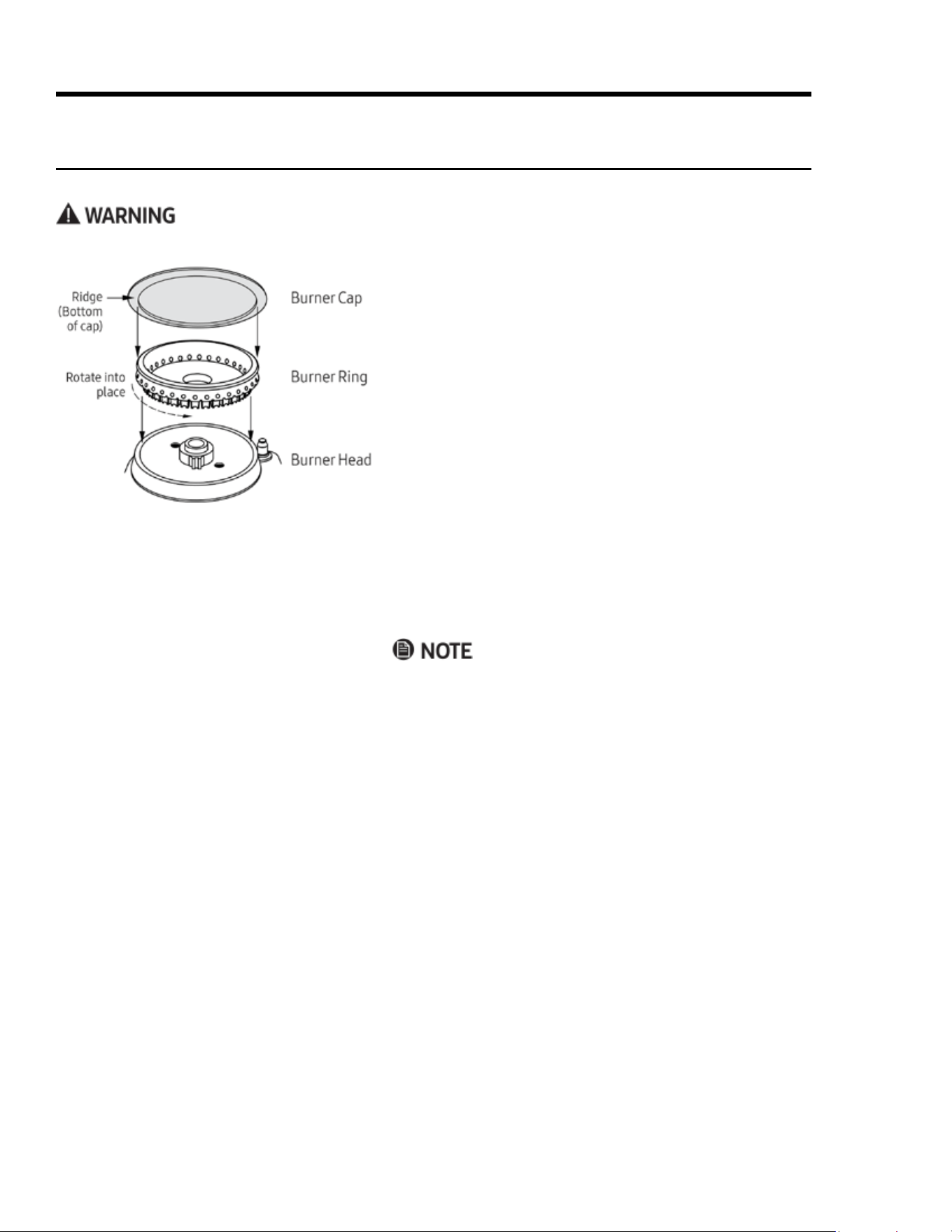
Installing SimmerSear Burner Components
1. Unpackage the burner components.
2. Install the burner head so the burner head’s locating
tab is in the burner base’s keyed hole.
3. Install the burner ring so the ring’s tabs t into the
slots in the head.
4. Install the burner cap so the ridge on the bottom of
the cap ts over the perimeter of the ring.
Either style of cap (brass or porcelain) may be used.
32 English
Installation Instructions
Final Installation, cont.
Assembling Cooktop Components, cont.
Do not operate the cooktop unless all burner components are properly assembled.
Installing Standard Burner Components
1. Unpackage the burner components.
2. Install the burner ring so its base ts within the ridge
around the burner head, and rotate the ring until it drops
into place.
3. Install the burner cap so the ridge on the bottom of the
cap ts over the perimeter of the ring.
Either style of cap (brass or porcelain) may be used.
Installing the Grates
1. Unpackage the grates.
2. Place the feet of each grate in the corresponding dimples
formed into the cooktop.
The grates are identical and may be placed over any pair of
burners front-to-back.
33English
Installation Instructions
Verifying Proper Operation
Before operating the range, read the User Manual completely to familiarize yourself with important safety,
service, and warranty information.
1. Turn off all burners, and verify that all burner compo-
nents are properly assembled.
2. Open the gas-supply valve, and verify that there are no
gas leaks.
3. Turn on power to the range at the power source.
4. Follow the prompts on the oven display to establish user
preferences and wireless-network settings.
5. On the display, touch MENU > BAKE.
The default bake temperature appears on the display.
6. Touch Start, and wait 3 minutes.
7. Open the door to verify that the oven is heating.
BAKE and the preheating temp appear on the display.
8. Touch CANCEL-SECURE or CANCEL RIGHT (48” models).
The oven's heating elements turns off.
9. Push-turn a burner-control knob to maximum ame.
Shortly, the burner ignites, and the ignitor stops sparking.
If the burner does not ignite in 4 seconds, turn it off, wait
5 minutes for gas to dissipate, then try again.
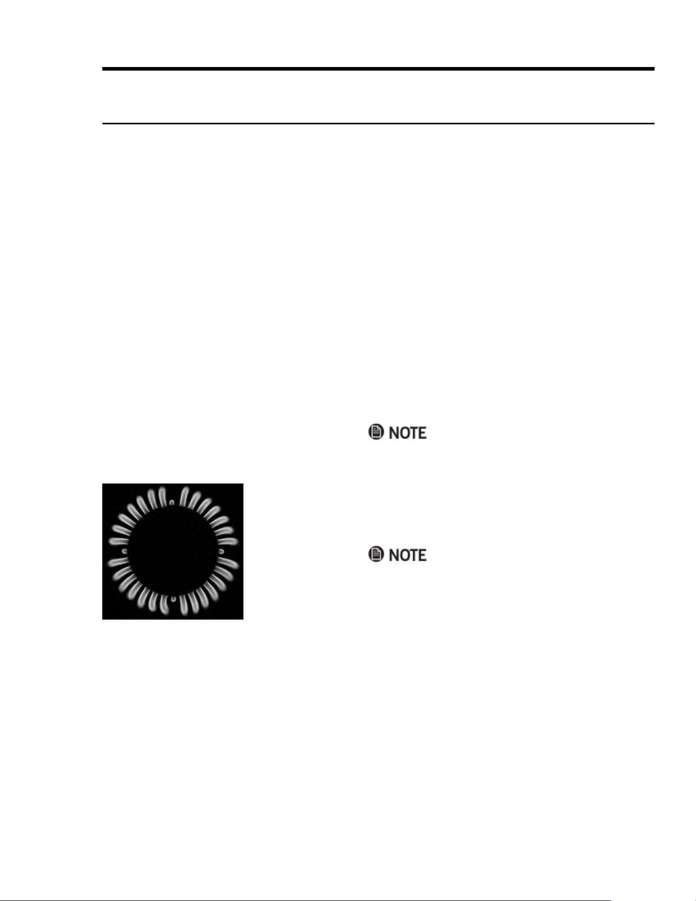
10. Turn the knob from max to minimum ame, observing
the ame as the knob turns.
A proper ame is steady and quiet, with a sharp, blue
inner cone that varies in length with the burner size.
Dacor’s Smart Flame™ feature reduces the ame under
the grate ngers to increase grate life. If the range is
equipped for LP gas, normal ame tips may be yellow.
11. Turn off the burner, and run the test for the other burners.
Proper
Flame

34 English
Installation Instructions
Moving the Range For Service
1. Close the gas-supply valve.
2. Turn off power to the range at the circuit breaker or fuse box.
3. Pull the range out of the cutout.
4. Push the range back into place, being sure to engage the anti-tip bracket (Pg. 29).
5. Turn on power to the range at the circuit breaker or fuse box.
6. Open the gas-supply valve.
Installation Checklist
Installer
Complete this checklist to ensure that no part of the installation was overlooked.
Owner
You are ultimately responsible for ensuring that the installation was performed properly by a qualied techni-
cian. Dacor is not responsible for property damage or product failure due to improper installation of the range.
F Was the plastic coating been peeled off the outside of the range?
F Were all packaging materials removed from the oven chamber?
F Were the leveling legs lowered to the oor and the unit leveled? (Pg. 27)
F Was the range secured with the provided anti-tip bracket and foot? (Pgs. 17–21, 27)
F Was the range wired/grounded and the electrical-access cover re-attached? (Pgs. 21–25)
F Was the gas-supply inlet pressure adjusted within the stated maximum? (Pg. 16)
F Was the range connected to the gas supply and gas-leak tests conducted? (Pg. 26)
F Was the oven door re-attached? (Pg. 27)
F Were the burner knobs installed? (Pg. 28)
F Were the burner components and grates installed? (Pg. 28)
F Was proper operation veried? (Pg. 30)
F Was the warranty activated on-line or the warranty card (see the User Manual) completed and mailed?

35English
Notes

Dacor – 14425 Clark Avenue, City of Industry, CA 91745 – Phone (800) 793-0093 – Fax (626) 403-3130 – www.dacor.com