ARCHITECTS AND ENGINEERS
DESIGN DATA MANUAL
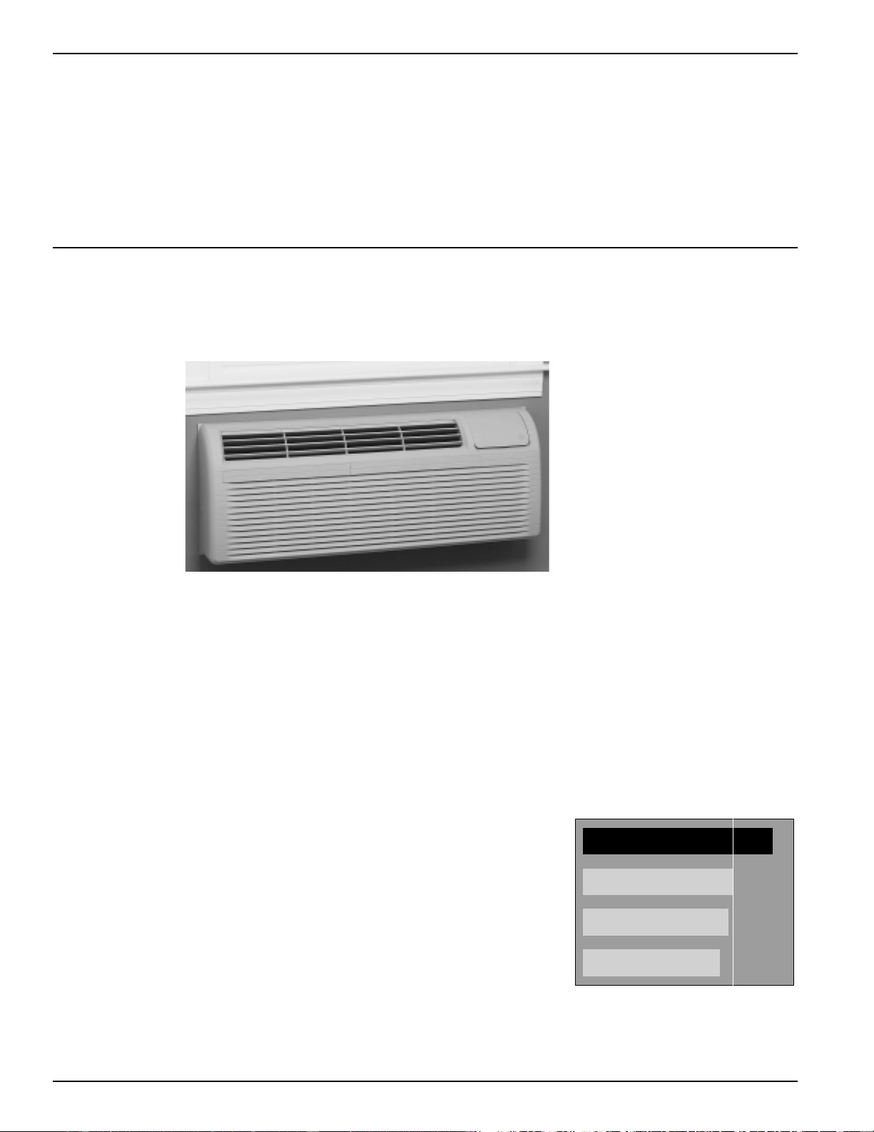
GE Zoneline
®
Packaged Terminal
Air Conditioners
We bring good things to life.
Contract Sales
g
2020 Data Manual 2002 11/7/02 3:19 PM Page 1
2
Quick Reference
2500 Series Cooling with Electric Heat
MODEL COOLING Cooling Electric Heat Electric Electric Min. Circuit
NUMBER (Btuh) Watts EER (Btuh) Heater Heat Protection
Watts Amps (Amps)
AZ25E07D2* 7100/6900 600/585 11.8/11.8 8600/7100 2550/2090 11.0/10.0 15
AZ25E07D3* 7100/6900 600/585 11.8/11.8 11700/9600 3450/2820 15.0/13.6 20
AZ25E09D2* 9000/8800 785/765 11.5/11.5 8600/7100 2550/2090 11.0/10.0 15
AZ25E09D3* 9000/8800 785/765 11.5/11.5 11700/9600 3450/2820 15.0/13.6 20
AZ25E09D5* 9000/8800 785/765 11.5/11.5 17000/13900 5000/4090 21.7/19.7 30
AZ25E12D2* 11700/11500 1075/1055 10.9/10.9 8600/7100 2550/2090 11.0/10.0 15
AZ25E12D3* 11700/11500 1075/1055 10.9/10.9 11700/9600 3450/2820 15.0/13.6 20
AZ25E12D5* 11700/11500 1075/1055 10.9/10.9 17000/13900 5000/4090 21.7/19.7 30
AZ25E15D2* 14600/14300 1520/1490 9.6/9.6 8600/7100 2550/2090 11.0/10.0 15
AZ25E15D3* 14600/14300 1520/1490 9.6/9.6 11700/9600 3450/2820 15.0/13.6 20
AZ25E15D5* 14600/14300 1520/1490 9.6/9.6 17000/13900 5000/4090 21.7/19.7 30
AZ25E07E3* 7100 600 11.8 8600 2550 9.6 15
AZ25E07E4* 7100 600 11.8 12600 3700 14.0 20
AZ25E09E3* 9000 785 11.5 8600 2550 9.6 15
AZ25E09E4* 9000 785 11.5 12600 3700 14.0 20
AZ25E09E5* 9000 785 11.5 17000 5000 18.9 30
AZ25E12E3* 11700 1075 10.9 8600 2550 9.6 15
AZ25E12E4* 11700 1075 10.9 12600 3700 14.0 20
AZ25E12E5* 11700 1075 10.9 17000 5000 18.9 30
AZ25E15E3* 14600 1520 9.6 8600 2550 9.6 15
AZ25E15E4* 14600 1520 9.6 12600 3700 14.0 20
AZ25E15E5* 14600 1520 9.6 17000 5000 18.9 30
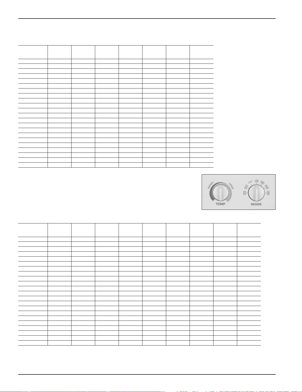
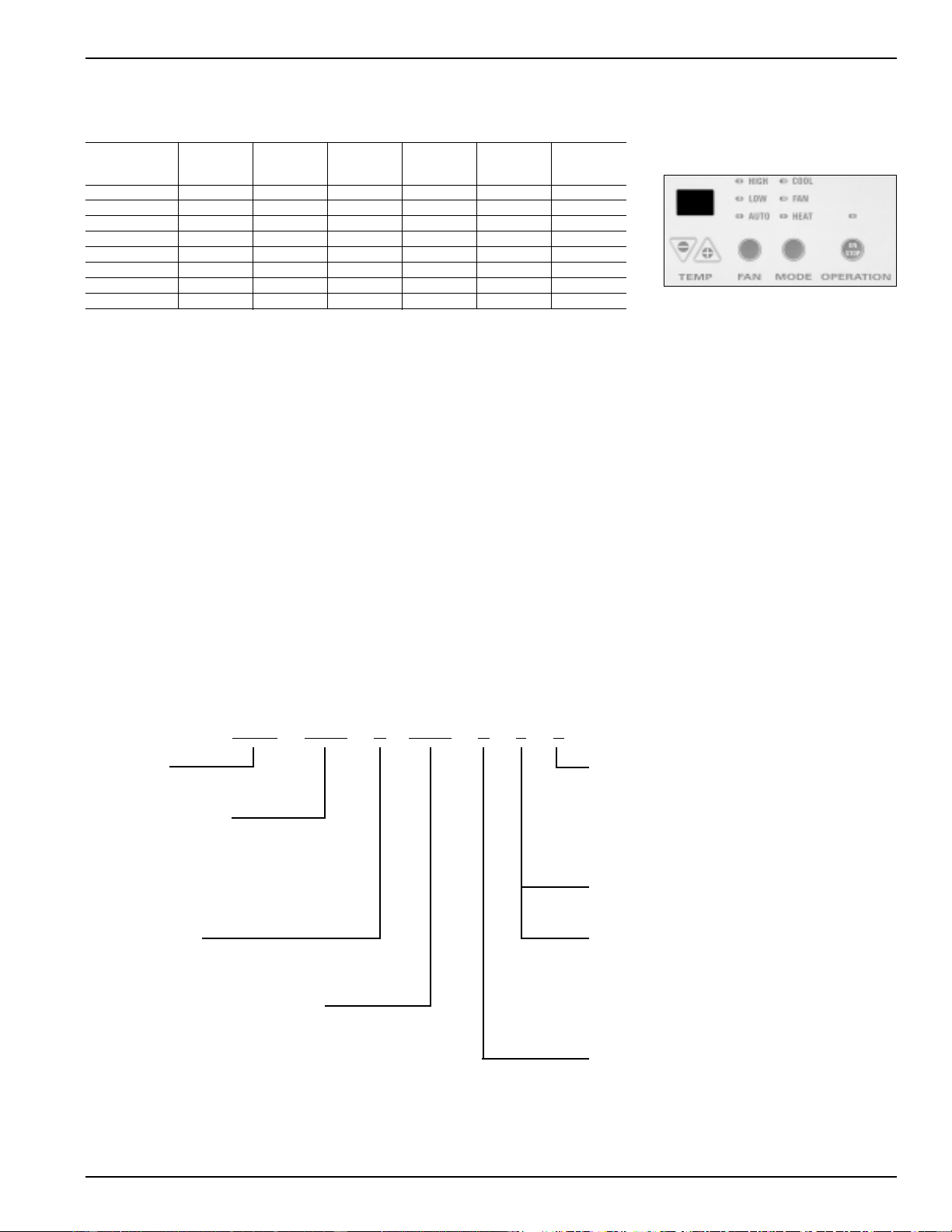
2500 and 3500 Series
Control Panel
3500 Series Heat Pump with Backup Resistance Heat
MODEL COOLING Cooling Reverse Electric Heat Electric Electric Min. Circuit
NUMBER (Btuh) Watts EER Cycle Heat COP (Btuh) Heater Heat Protection
(Btuh) Watts Amps (Amps)
AZ35H07D2* 7100/6900 600/585 11.8/11.8 6400/6200 3.5/3.5 8600/7100 2550/2090 11.0/10.0 15
AZ35H07D3* 7100/6900 600/585 11.8/11.8 6400/6200 3.5/3.5 11700/9600 3450/2820 15.0/13.6 20
AZ35H09D2* 9000/8800 785/765 11.5/11.5 8400/8200 3.5/3.5 8600/7100 2550/2090 11.0/10.0 15
AZ35H09D3* 9000/8800 785/765 11.5/11.5 8400/8200 3.5/3.5 11700/9600 3450/2820 15.0/13.6 20
AZ35H09D5* 9000/8800 785/765 11.5/11.5 8400/8200 3.5/3.5 17000/13900 5000/4090 21.7/19.7 30
AZ35H12D2* 11700/11500 1075/1055 10.9/10.9 10900/10700 3.3/3.3 8600/7100 2550/2090 11.0/10.0 15
AZ35H12D3* 11700/11500 1075/1055 10.9/10.9 10900/10700 3.3/3.3 11700/9600 3450/2820 15.0/13.6 20
AZ35H12D5* 11700/11500 1075/1055 10.9/10.9 10900/10700 3.3/3.3 17000/13900 5000/4090 21.7/19.7 30
AZ35H15D2* 14600/14300 1520/1490 9.6/9.6 13400/13200 3.1/3.1 8600/7100 2550/2090 11.0/10.0 15
AZ35H15D3* 14600/14300 1520/1490 9.6/9.6 13400/13200 3.1/3.1 11700/9600 3450/2820 15.0/13.6 20
AZ35H15D5* 14600/14300 1520/1490 9.6/9.6 13400/13200 3.1/3.1 17000/13900 5000/4090 21.7/14.7 30
AZ35H07E3* 7100 600 11.8 6400 3.5 8600 2550 9.6 15
AZ35H07E4* 7100 600 11.8 6400 3.5 12600 3700 14.0 20
AZ35H09E3* 9000 785 11.5 8400 3.5 8600 2550 9.6 15
AZ35H09E4* 9000 785 11.5 8400 3.5 12600 3700 14.0 20
AZ35H09E5* 9000 785 11.5 8400 3.5 17000 5000 18.9 30
AZ35H12E3* 11700 1075 10.9 10900 3.3 8600 2550 9.6 15
AZ35H12E4* 11700 1075 10.9 10900 3.3 12600 3700 14.0 20
AZ35H12E5* 11700 1075 10.9 10900 3.3 17000 5000 18.9 30
AZ35H15E3* 14600 1520 9.6 13400 3.1 8600 2550 9.6 15
AZ35H15E4* 14600 1520 9.6 13400 3.1 12600 3700 14.0 20
AZ35H15E5* 14600 1520 9.6 13400 3.1 17000 5000 18.9 30
LEGEND
COP – Coefficient of Performance
EER – Energy Efficient Ratio
* – Covers All Model Versions
All Units are 60 hertz single phase.
Dual rated 230/208 volt units are shown with ratings separated by “/”.
Units with one rating are 265 volt units.
2020 Data Manual 2002 11/7/02 3:19 PM Page 2
3
LEGEND
COP – Coefficient of Performance
EER – Energy Efficient Ratio
* – Covers All Model Versions
Quick Reference
5500 Series Control Panel
5500 Series Heat Pump with Backup Resistance Heat
MODEL COOLING Voltage Cooling Reverse
NUMBER (Btuh) 60 hz Watts EER COP Cycle Heat
1-phase (Btuh)
AZ55H07DA* 7100/6800 230/208 590/565 12.0/12.0 3.5/3.5 6400/6200
AZ55H09DA* 9000/8800 230/208 785/765 11.5/11.5 3.5/3.5 8400/8200
AZ55H12DA* 11800/11600 230/208 1085/1065 10.9/10.9 3.3/3.3 10900/10700
AZ55H15DA* 14700/14400 230/208 1470/1440 10.0/10.0 3.1/3.1 13400/13200
AZ55H07EA* 7100 265 590 12.0 3.5 6400
AZ55H09EA* 9000 265 785 11.5 3.5 8400
AZ55H12EA* 11800 265 1085 10.9 3.3 10900
AZ55H15EA* 14700 265 1470 10.0 3.1 13400
Zoneline
®
Chassis Nomenclature
The Zoneline chassis is identified by a model number defining the type of unit, cooling capacity, electrical information and optional features
included on the unit. When specifying or ordering the Zoneline chassis use of this nomenclature will assure receiving the correct unit.
Example
A Z 2 5 E 0 9 E 4 P
A Z
5 5 H 1 2 D A D
Zoneline
®
Packaged Terminal Chassis
Chassis Series
25 - Deluxe Line Cool/Electric Heat
35 - Deluxe Line Heat Pump
55 - Premium Line Heat Pump
Unit Type
E - Cooling with Electric Resistance Heat
H - Heat Pump with Electric Resistance Heat
Nominal Cooling Capacity
07 - 7,000 BTUH Cooling 12 - 12,000 BTUH Cooling
09 - 9,000 BTUH Cooling 15 - 15,000 BTUH Cooling
Special Features
B - Base Unit
C - Corrosion Treated
D - Internal Condensate Removal
(ICR) System (Heat Pump Models Only)
P - Dry Air 25
5500 Universal Power Connection
(see Premium Series Models - see page 53)
2500, Dry Air 25 & 3500 Numeric
Designator of Heater Size
230/208 Volt 265 Volt
2 - 2.55/2.09 kW 3 - 2.55 kW
3 - 3.45/2.82 kW 4 - 3.7 kW
5 - 5.0/4.09 kW 5 - 5.0 kW
Voltage/Phase/Frequency
D - 230/208 Volt Single Phase 60 Hz
E - 265 Volt Single Phase 60 Hz
2020 Data Manual 2002 11/7/02 3:19 PM Page 3
4
The Zoneline 2500, 3500 and 5500 Series have incorporated changes suggested by customers and
enhancements by GE’s Technology team:
- Auto Heat/Auto Cool settings to reduce operating sound level while increasing occupant comfort
- Ability to connect to wall thermostat or Central Desk Control without additional interface module
- 7-step temperature limiting with separately selectable heating and cooling limits
- Transfer Fan interface - enables a fan mounted in the wall to operate in conjunction with the unit fan
(fan, wiring and relay are field supplied)
- “Smart Fan” fan cycle/fan continuous operation to increase room occupant comfort
- Easier installation of chassis in existing wall cases
See the “Features and Benefits” section for in depth explanation of these changes and the industry leading features of the
GE Zoneline retained from the previous series.
The Newest Innovation from GE...
The Dry Air 25 Models center
around GE’s exclusive use of the
patented Dinh
®
Dehumidifier Heat
Pipe from Heat Pipe Technology, Inc.
This innovative NASA spin-off
technology enables Dry Air 25 to
remove 25% more moisture from
the air than other leading
manufacturers’ packaged terminal air
conditioners. This helps maintain
room comfort at a higher room
temperature, reducing operating costs.
The Dry Air 25 keeps a room cool
and dry, and this is the most
important benefit when it comes to
the occupant of the room - hotel
guests, apartment residents, students...
In a hot, humid climate, getting away
from the humidity is just as important
as the heat, and the Dry Air 25 is the
perfect solution. The dehumidifi-
cation of the Dry Air 25 has been
verified by the same ARI test
conditions that standard units are
rated under. A list of customers using
Dry Air 25 is available from GE.
COMPARISON OF DRY AIR 25
DEHUMIDIFICATION*
*Based on 12,000 BTU Units.
NOTE: The Dry Air 25 models
include all features of the 2500 series.
Removes
25
%
More
Moisture
GE Dry Air 25
GE 2500 Series Zoneline
®
Amana
Carrier
The Deluxe 2500 Series Zoneline Models Includes
The “Dry Air 25” Models Which Remove 25%
More Moisture Than Other Zoneline Models.
Deluxe
Dry Air 25
Models
Cooling With
Resistance Heat
• Removes 25%
More Moisture
than other
Zoneline Models,
up to 2.7
Additional Gallons
Per Day
• Cool and Dry Air
in Less Time than Standard Zoneline Models
• Heat Pipe is a Separate Sealed Refrigerant System
- No Mechanical Parts - No Special Maintenance Required
• Helps Maintain Lower Relative Humidity In Rooms
• Maintains Comfort at Slightly Higher Room Temperatures
- Reduces Operating Costs - Provides Comfort Without Overcooling
• Corrosion Treatment is Standard
• Excellent Choice for Humid Climates
• Available in 7000, 9000 and 12000 BTU Sizes
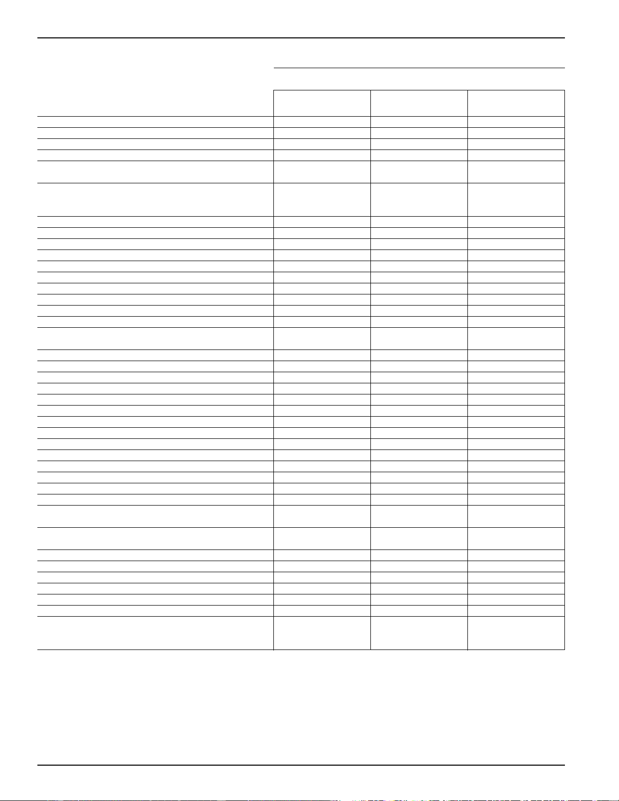
The Dry Air 25 system, a heat pipe, is a hermetically sealed heat transfer surface
installed in a “saddlebag” configuration around the indoor (evaporator) coil of the
Zoneline. This coil arrangement will transfer heat from the front coil of the
saddlebag to the rear coil without power consumption. This assembly uses R-22 as
the refrigerant and is not connected to the regular Zoneline refrigerant circuit.
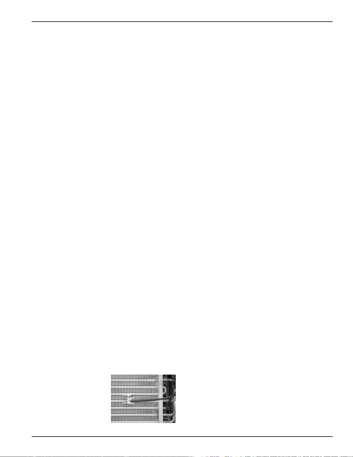
As warm humid air is pulled through the pre-cool (front) section of the heat pipe,
the heat removed from the air is absorbed by the refrigerant, causing the refrigerant
to change to a gas and flow to the re-heat (rear) section of the heat pipe. The air
leaving the pre-cool section of the heat pipe is cooler and at a higher relative
humidity level than the room air. The pre-cooled air is further cooled as it passes
through the evaporator; consequently, the relative humidity increases allowing the
evaporator coil to remove more moisture.
When the cold air from the evaporator comes in contact with the re-heat section of
the heat pipe, the heat that was removed by the pre-cool section is added back to the
air and the refrigerant in the heat pipe condenses and flows back to the indoor coil.
The air discharged into the room by this process is much drier, creating a more
comfortable room condition.
2020 Data Manual 2002 11/7/02 3:19 PM Page 4
5
Table of Contents
Front Cover . . . . . . . . . . . . . . . . . . . . . . . . . . . . . . . . . . . . . . . . . . . . . . . . . . . . . . . . . . . . . . . . . . . . . . . . . . . . . . . . . . . 1
Mini-Specs 2500 and 3500 series . . . . . . . . . . . . . . . . . . . . . . . . . . . . . . . . . . . . . . . . . . . . . . . . . . . . . . . . . . . . . . . . . . . 2
Mini-Specs 5500 and Nomenclature. . . . . . . . . . . . . . . . . . . . . . . . . . . . . . . . . . . . . . . . . . . . . . . . . . . . . . . . . . . . . . . . . 3
The 2500/3500/5500 and Dry 25 . . . . . . . . . . . . . . . . . . . . . . . . . . . . . . . . . . . . . . . . . . . . . . . . . . . . . . . . . . . . . . . . . . 4
Table of Contents . . . . . . . . . . . . . . . . . . . . . . . . . . . . . . . . . . . . . . . . . . . . . . . . . . . . . . . . . . . . . . . . . . . . . . . . . . . . . . . 5
Introduction . . . . . . . . . . . . . . . . . . . . . . . . . . . . . . . . . . . . . . . . . . . . . . . . . . . . . . . . . . . . . . . . . . . . . . . . . . . . . . . . . . . 6
The Zoneline System . . . . . . . . . . . . . . . . . . . . . . . . . . . . . . . . . . . . . . . . . . . . . . . . . . . . . . . . . . . . . . . . . . . . . . . . . 7
Features and Benefits
Features Table . . . . . . . . . . . . . . . . . . . . . . . . . . . . . . . . . . . . . . . . . . . . . . . . . . . . . . . . . . . . . . . . . . . . . . . . . . . . . . 8
Features and Benefits . . . . . . . . . . . . . . . . . . . . . . . . . . . . . . . . . . . . . . . . . . . . . . . . . . . . . . . . . . . . . . . . . . . . . 9 - 11
Auxiliary Control Switches . . . . . . . . . . . . . . . . . . . . . . . . . . . . . . . . . . . . . . . . . . . . . . . . . . . . . . . . . . . . . . . . 12 - 13
Central Desk Control . . . . . . . . . . . . . . . . . . . . . . . . . . . . . . . . . . . . . . . . . . . . . . . . . . . . . . . . . . . . . . . . . . . . . . . . 14
Remote Thermostat Control . . . . . . . . . . . . . . . . . . . . . . . . . . . . . . . . . . . . . . . . . . . . . . . . . . . . . . . . . . . . . . . 15 - 17
Multiple Unit Remote Control. . . . . . . . . . . . . . . . . . . . . . . . . . . . . . . . . . . . . . . . . . . . . . . . . . . . . . . . . . . . . . . . . 18
Heat Pumps and Energy Savings . . . . . . . . . . . . . . . . . . . . . . . . . . . . . . . . . . . . . . . . . . . . . . . . . . . . . . . . . . . . 19 - 20
Installation and Dimensions
Introduction to Installation . . . . . . . . . . . . . . . . . . . . . . . . . . . . . . . . . . . . . . . . . . . . . . . . . . . . . . . . . . . . . . . . . . . 21
Application Comments . . . . . . . . . . . . . . . . . . . . . . . . . . . . . . . . . . . . . . . . . . . . . . . . . . . . . . . . . . . . . . . . . . . . . . 21
Case Dimensions . . . . . . . . . . . . . . . . . . . . . . . . . . . . . . . . . . . . . . . . . . . . . . . . . . . . . . . . . . . . . . . . . . . . . . . . . . . 22
Wall Case/Sub-Base Installation . . . . . . . . . . . . . . . . . . . . . . . . . . . . . . . . . . . . . . . . . . . . . . . . . . . . . . . . . . . . 23 - 33
Condensate Disposal Systems . . . . . . . . . . . . . . . . . . . . . . . . . . . . . . . . . . . . . . . . . . . . . . . . . . . . . . . . . . . . . . 34 - 36
Ducted Installations. . . . . . . . . . . . . . . . . . . . . . . . . . . . . . . . . . . . . . . . . . . . . . . . . . . . . . . . . . . . . . . . . . . . . . 37 - 39
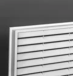
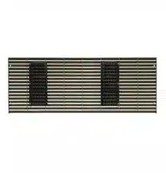
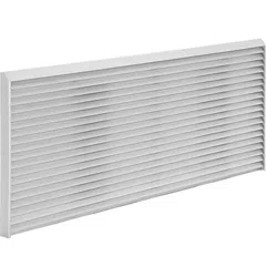
Exterior Grilles. . . . . . . . . . . . . . . . . . . . . . . . . . . . . . . . . . . . . . . . . . . . . . . . . . . . . . . . . . . . . . . . . . . . . . . . . . . . . 40
Product Data
Electrical Connection . . . . . . . . . . . . . . . . . . . . . . . . . . . . . . . . . . . . . . . . . . . . . . . . . . . . . . . . . . . . . . . . . . . . 41 - 43
Maximum Connected Load . . . . . . . . . . . . . . . . . . . . . . . . . . . . . . . . . . . . . . . . . . . . . . . . . . . . . . . . . . . . . . . . . . . 44
Cooling / Heat Pump Performance Data . . . . . . . . . . . . . . . . . . . . . . . . . . . . . . . . . . . . . . . . . . . . . . . . . . . . . . . . 45
Latent System Capacity. . . . . . . . . . . . . . . . . . . . . . . . . . . . . . . . . . . . . . . . . . . . . . . . . . . . . . . . . . . . . . . . . . . . . . . 46
Normal Yearly Operating Data. . . . . . . . . . . . . . . . . . . . . . . . . . . . . . . . . . . . . . . . . . . . . . . . . . . . . . . . . . . . . . . . . 47
Schematics . . . . . . . . . . . . . . . . . . . . . . . . . . . . . . . . . . . . . . . . . . . . . . . . . . . . . . . . . . . . . . . . . . . . . . . . . . . . . 48 - 50
Product Specifications
Suggested Bid Form Specifications . . . . . . . . . . . . . . . . . . . . . . . . . . . . . . . . . . . . . . . . . . . . . . . . . . . . . . . . . . 51 - 53
Specifications. . . . . . . . . . . . . . . . . . . . . . . . . . . . . . . . . . . . . . . . . . . . . . . . . . . . . . . . . . . . . . . . . . . . . . . . . . . 54 - 55
Complete Accessory List. . . . . . . . . . . . . . . . . . . . . . . . . . . . . . . . . . . . . . . . . . . . . . . . . . . . . . . . . . . . . . . . . . . . . . . . . 56
General Suggestions . . . . . . . . . . . . . . . . . . . . . . . . . . . . . . . . . . . . . . . . . . . . . . . . . . . . . . . . . . . . . . . . . . . . . . . . 57 - 58
Alphabetical Index . . . . . . . . . . . . . . . . . . . . . . . . . . . . . . . . . . . . . . . . . . . . . . . . . . . . . . . . . . . . . . . . . . . . . . . . . . . . . 59
Back Cover - Warranty . . . . . . . . . . . . . . . . . . . . . . . . . . . . . . . . . . . . . . . . . . . . . . . . . . . . . . . . . . . . . . . . . . . . . . . . . . 60
Important Notice
Equipment used as a primary source for heating or cooling is an integral part of the building in
which it is installed. Proper application is essential for satisfactory performance over a wide
range of operating conditions. It is strongly recommended that a professional engineer
determine proper application.
If this unit is a replacement unit, its specifications and performance may differ from those of
the unit it is replacing. For that reason, we again strongly recommend that a professional
engineer determine proper application.
2020 Data Manual 2002 11/7/02 3:19 PM Page 5

6
Introduction
This manual is designed to provide product, performance
and application information to our customers and their
architects and engineers for use in selection and design of a
zonal comfort control system utilizing GE Zoneline
®
Packaged Terminal Air Conditioners (PTAC) and Packaged
Terminal Heat Pumps (PTHP). GE Zoneline
®
PTACs and
PTHPs are self-contained units designed for through-the-wall
installations in hotels, motels, apartments, hospitals, nursing
homes and add-on rooms.
Zonelines provide individual room or zone control in both
cooling and heating operation. There is a model for
practically every application, ranging in cooling capacities
from 7,100 to 14,700 BTUH and heating capacities from
6,400 to 13,400 BTUH in heat pump operation. See page 54
for resistance heaters available.
The Zoneline offers a two tier lineup; the Deluxe Line - the
2500 Series with electric resistance heat, including the Dry
Air 25 Models with enhanced dehumidification for hot and
humid climates, and the 3500 Series heat pump; the
Premium Line - the 5500 Series heat pump.
Deluxe Line Standard Features:
• Freeze Sentinel
TM
• Indoor Coil Frost Control
• Central Desk Control Interface
• Standard Remote Thermostat Control Capability
• Random Restart
• Electronic Temperature Limiting
• “Smart Fan” Fan Cycle/Continuous Control
• Transfer Fan Interface
• Separate Indoor and Outdoor Fan Motors
• Room Occupancy Sensor Interface
NOTE: The Dry Air 25 models include all features of the
2500 series.
Premium Line Standard Features:
• All the Standard Features of the Deluxe Line
• Exclusive Simultaneous Heat Pump and Resistance
Heat Operation (when needed)
• Exclusive Reverse Cycle Defrost to Increase Heat Pump
savings
• Touch Pad Controls with Digital Temperature Readout
Advantages of the GE Zoneline
®
System:
• Flexible Application
• May be installed flush to finished floor to 3" from the
ceiling
• 7,100 to 14,700 BTUH units in same physical size
• Deluxe 2500 and 3500 Series may be ducted to
condition more than one room
• Compatible with Class 2 Remote Thermostat Control
• Compatible with 2 wire CDC and many Energy
Management systems
• Economical Installation
• No ductwork necessary
• No mechanical equipment rooms or pipes required for
heating/cooling units
• Replacement units fit existing 42" wide by 16" high wall
cases
• Quiet Operation
• Auto Fan operates unit at lowest, quietest fan speed
when possible to reduce the sound from the unit
• Indoor double cut-off scroll: two fan motor 2500 and
3500 Series units
• Indoor cross-flow blower: 2 fan motor 5500 Series units
• Energy-Saving Operation
• Units in unoccupied areas may be turned off
• Designed for efficient cooling operation - EERs from
9.6 to 12.0
• Efficient heat pump units - COPs from 3.1 to 3.5
• Extended heat pump operation without sacrificing
room comfort
• Ease of Maintenance
• Permanently lubricated fan motors
• Upfront lift out filters
• Air Discharge area is easily accessed for cleaning -
Deluxe Series
• Slide out chassis for easy access if service is required
• Heat Pump Operation (Defrost Termination)
After the heat pump models have switched to resistance heat
they will change back to heat pump operation as the
outdoor temperature rises - the 3500 series returns to heat
pump operation at 37°F outdoor coil temperature, and the
5500 series returns to heat pump operation at 32°F outdoor
air temperature.
2020 Data Manual 2002 11/7/02 3:19 PM Page 6
7
The Zoneline
®
System
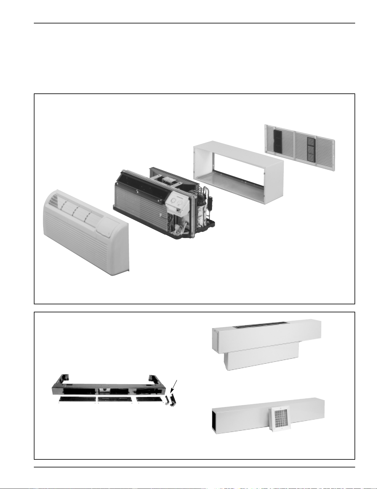
The typical Zoneline installation consists of the wall case (or sleeve), chassis, and exterior grille. Some installations may use a
sub-base for support of the unit or for ease of electrical connections. Each of the components should be the standard products
offered by GE or, in the case of the exterior grille, approved by GE Applications Engineering. Use of components not
specifically designed or approved for use with the Zoneline can result in unsatisfactory operation and can be the cause of
failure not covered by the warranty.
Components of the Zoneline
®
System
Room Cabinet
Chassis
Wall Case
RAB71 (Steel-Insulated)
RAB77 (SMC - Molded)
Wall Case Options
(See page 23)
RAG67 (shown)
Grill Options
(See page 40)
Deluxe Series shown
Power Connection Kit (not shown)
(required on Premium Series)
See pages 42 - 43
Typical Installation
Optional Accessories of the Zoneline
®
System
RAK204D20 Sub-Base (shown)
See pages 23 and 33 for information on
electrical sub-bases and chaseway.
RAK6052
Duct Adapter
(For Deluxe Series)
RAK601/602 (For Deluxe Series)
Duct Extension, Register and Trim Flange
Chaseway
2020 Data Manual 2002 11/7/02 3:19 PM Page 7
8
Zoneline
®
Features Model Series
AZ AZ AZ
2500 3500 5500
Enhanced Dehumidification - Dry Air 25 Optional N/A N/A
Cooling EER Range (230 Volts/265 Volts) 9.6 - 11.6 9.6 - 11.6 10.0 - 12.0
Heating COP Range (230 Volts/265 Volts) N/A 3.1 - 3.5 3.1 - 3.5
Heat Source - Electric Resistance Heat Page 54 ——
Heat Source - Heat Pump With — Std. Pages —
Backup Resistance Heat 19, 55
Heat Source - Heat Pump With Selectable
Full Time or On Demand Simultaneous/ ——Std. Pages
Supplemental Resistance Heat 20, 55
Staged Heating — 2 Stage 3 Stage
Universal Heater ——Standard
Automatic Emergency Heat — Standard Standard
Highly Featured Microprocessor Controls Standard Standard Standard-Plus
Electric Resistance Heat Lock-Out (above 46°F) ——Standard
Heat Pump Defrost System — Passive Reverse Cycle
Unit Diagnostics ——Standard
Quick Heat Recovery — Standard Standard
Service Indicator ——Temp Display Blinks
Touch Controls (Tactile Controls) ——Standard
Electronic Temperature Selection ——Standard
(Slews Up & Down) with Digital Display
Rotary Control Knobs Standard Standard —
Fan Motors - Permanently Lubricated 2 2 2
2 Speed Outdoor Fan Standard Standard Standard
Indoor Fan Speed Selections - AUTO/HIGH Standard Standard Standard
Fan Only Setting - HIGH/LOW Standard Standard Standard
Fan Cycle Switch “Smart Fan”“Smart Fan”“Smart Fan”
Rotary Compressor Standard Standard Standard
Automatic Compressor Restart Delay Standard Standard Standard
Power Connection Cord Included Included UPC*
Freeze Sentinel
TM
Standard Standard Standard
Indoor Coil Frost Control Standard Standard Standard
Transfer Fan Connections Standard Standard Standard
7 Step Electronic Temperature Limiting Standard Standard Standard
Energy Management System Interface Standard Standard Standard
Remote Control Capability Standard Standard Standard
With Wall Mounted Thermostat
Central Desk Control Capability Standard Standard Standard
With Load Shedding Option
Reversible Indoor Air Louvers 40°/50° Standard Standard Standard
Up-Front Filters Standard Standard Standard
Easy Clean Air Discharge Area Standard Standard —
Concealed Manual Vent Control Standard Standard Standard
Ducted Installation Capability RAK6052 RAK6052 —
Corrosion Treated Optional Optional —
Internal Condensate Removal (ICR) N/A Optional Optional
Factory Installed Option.
Cannot be used in Corrosion Areas.
*UPC - Universal Power Cord Connection (See pages 42, 43 and 55)
**265 volt units must be connected in a manner to meet National Electrical Code and all local codes.
2020 Data Manual 2002 11/7/02 3:19 PM Page 8
9
Features and Benefits
Standard Physical Dimensions
GE has maintained the same dimension since 1961- 42" wide
x 16” high x 13 3/4" deep.
Replacement of older units made easy.
Weather Protected Electrical Components
Vital electrical components are protected from the weather
by locating them on the indoor side of the weather barrier.
Weather-Resistant “Superseal”
Properly installed unit in undistorted case keeps air leakage
to a minimum.
7 CFM air infiltration with 25 MPH wind on non-ICR units -
10 CFM on units with ICR.
Industry specification is 19 CFM of air infiltration.
Heater Sizes to Meet Room Requirements
2500 and 3500 Series
230/208 Volt
• 15 Amp - 2.55/2.09 KW
• 20 Amp - 3.45/2.82 KW
• 30 Amp - 5.0/4.09 KW
265 Volt
• 15 Amp - 2.55 KW
• 20 Amp - 3.7 KW
• 30 Amp - 5.0 KW
5500 Series have universal heater – resistance heat output is
determined by power connection kit.
230/208 Volt
• 15 Amp - with RAK3152 - 2.55/2.09 KW
• 20 Amp - with RAK3202 - 3.45/2.82 KW
• 30 Amp - with RAK3202 - 5.0/4.09 KW
265 Volt
• 15 Amp - with RAK5152 - 1.7 KW
• 15 Amp - with RAK5172 - 3.0 KW
• 20 Amp - with RAK5302 - 3.7 KW
• 30 Amp - with RAK5302 - 5.0 KW
Unit Controls
2500 and 3500 series - rotary knobs for temperature and
operation selection
5500 series - touch pad controls with digital readout of
temperature set point
Highly Featured Microprocessor Controls
Microprocessor controls are programmed to interface with
the temperature sensors to maximize comfort conditions for
the room occupant and provide the outstanding features on
the units.
Thermistors are used to sense
small changes in temperature to
give excellent room control and
to allow the microprocessor to
monitor and react to changing
conditions.
Electric Resistance Heat Lock-Out
To maximize the savings of the heat pump operation, the
5500 series Zoneline does not utilize the resistance heater
when the outdoor temperature is above 45°F during normal
operation. The resistance heat is used in the Quick Heat
Recovery feature.
Automatic Emergency Heat
Heat Pump Defrost Systems
See pages 19 and 20 for discussion of heat pump operation
and defrost systems.
High Temperature Heat Pump Operation
Protection
Automatically protects the compressor if heat pump is
operated with high outdoor temperatures.
Shuts the outdoor fan off if the indoor coil gets too hot
during heat pump operation to prevent damage to the
compressor.
Quick Heat Recovery - Heat Pump Units
When the unit operation is changed from STOP or COOL
to HEAT, the electric resistance heaters are used to warm
the room to the thermostat set point. This provides faster
room temperature increase for greater guest comfort.
Unit Diagnostics
The 5500 series has a dip switch that activates each of the
various components of the unit to operate briefly. This
enables the service technician to determine if individual
components are functioning properly.
Service Indicator
On the 5500 series, the microprocessor detects a compressor
malfunction, the digital temperature display will blink. If the
malfunction occurs during cooling operation, the indoor
fan will operate to circulate room air. If in the heating
mode, the unit will automatically switch to resistance heat so
the room occupant will not be uncomfortable. The blinking
display is an alert that the unit is operating in the more
expensive resistance heat mode.
Fan Motors - Permanently Lubricated
All units have two fan motors for quiet operation and
maximum operating efficiency.
Motors are permanently lubricated to reduce maintenance
and totally enclosed to keep dirt and water out of the motor
windings.
2 Speed Outdoor Fan
The unit automatically selects the most efficient speed for
the outdoor fan. The operating sound level is lower when
the outdoor fan can operate in low speed yet there are
situations where it must operate in high speed - the unit
changes the fan speed automatically.
2020 Data Manual 2002 11/7/02 3:19 PM Page 9
10
Indoor Fan Speed Selections - AUTO/HIGH
Unit may be operated in HIGH HEAT, AUTO HEAT,
HIGH COOL or AUTO COOL.
In “AUTO”, the indoor fan will be in low speed for quieter
operation if the room temperature is within 1.8°F of the set
point, or in high speed if the room temperature is more
than 1.8°F away from the set point.
This feature allows the greatest control over the room
temperature while reducing the operating sound level.
Fan Only Setting - HIGH/LOW
The unit provides the option of selecting either HIGH or
LOW speed for Fan Only operation.
Fan Cycle Switch - “SmartFan”
Unique “SmartFan” allows unit to operate in fan continuous
in cooling operation and fan cycle in heating to provide
better guest comfort. This eliminates complaint of cold air
draft during heating operation.
This feature eliminates need of changing fan cycle switch
seasonally.
“SmartFan” settings are controlled by separate fan cycle/
continuous switches for heating and cooling modes.
Automatic Compressor Random Restart
In the event of a power failure all compressors attempting to
restart immediately when power is restored can result in a
power surge that can cause another power interruption.
The microprocessor in the Zoneline units have a random
restart logic system that prevents all units from starting at
the same time.
Rotary Compressor
Smoother operation for quiet, dependable service. GE has
used rotary compressors since 1961.
Compressor Restart Delay
Zonelines are designed to provide a minimum of three
minutes of compressor off time to allow refrigerant
pressures to equalize before restarting, to prevent damage to
compressor.
Zonelines are also designed to provide a minimum of three
minutes of compressor run time to prevent room occupant
disturbance due to short cycling air conditioner.
Freeze Sentinel
™
Detects low room temperature and turns on heater to help
protect against damage by freezing temperature in the room.
Heater automatically turns on at 41°F, warms indoor
thermistor temperature to 46°F, and shuts off.
Freeze Sentinel may be turned off by dip switch on auxiliary
control.
Indoor Coil Frost Control
Prevents indoor coil from
freezing and causing
complaints due to lack of
cooling. Frost can form on the
indoor coil when the unit is
operated in cooling when
outdoor temperatures are low.
The unit automatically shuts
the compressor off until the
indoor coil temperature warms
to the point where frosting will no longer occur.
Transfer Fan Interface
24 VAC terminals are provided to operate a relay to control
a fan mounted in a wall to move conditioned air into
another space. Transfer fans and their controlling relays are
field supplied.
Electronic Temperature Limiting
7 independent programmable heating temperature limits
and 7 independent programmable cooling temperature
limits. Wide selection of limits eliminates need to reset the
limits seasonally.
Limits are set by dip switches on auxiliary control panel.
Remote Control Capability with Wall Mounted
Thermostat
See pages 15 - 18
Central Desk Control Capability
See page 14
Energy Management System Interface With
Load Shedding Option
All units have a switch on the auxiliary control panel to allow
the indoor fan to continue operating if the unit is connected
to an Energy Management System that shuts off compressor
or heater operation. By allowing the indoor fan to run
when the heater or compressor is shut off by the Energy
Management System, the guest is less likely to realize the
operation of the unit has been altered. This helps to reduce
peak energy demand loads without disturbing the room
occupant.
Reversible Indoor Air Louvers
Allows air to be directed into room at 40 or 50 degree angles
to provide better air distribution.
Angle is changed by removing room front and screws
holding louver in place and rotating louver section 180°.
Heating Temperature Limits
Highest
Heat
65 70 72 74 76 78 80 85
Lowest
Cool
Cooling Temperature Limits
60 64 66 68 70 72 74 76
2020 Data Manual 2002 11/7/02 3:19 PM Page 10
11
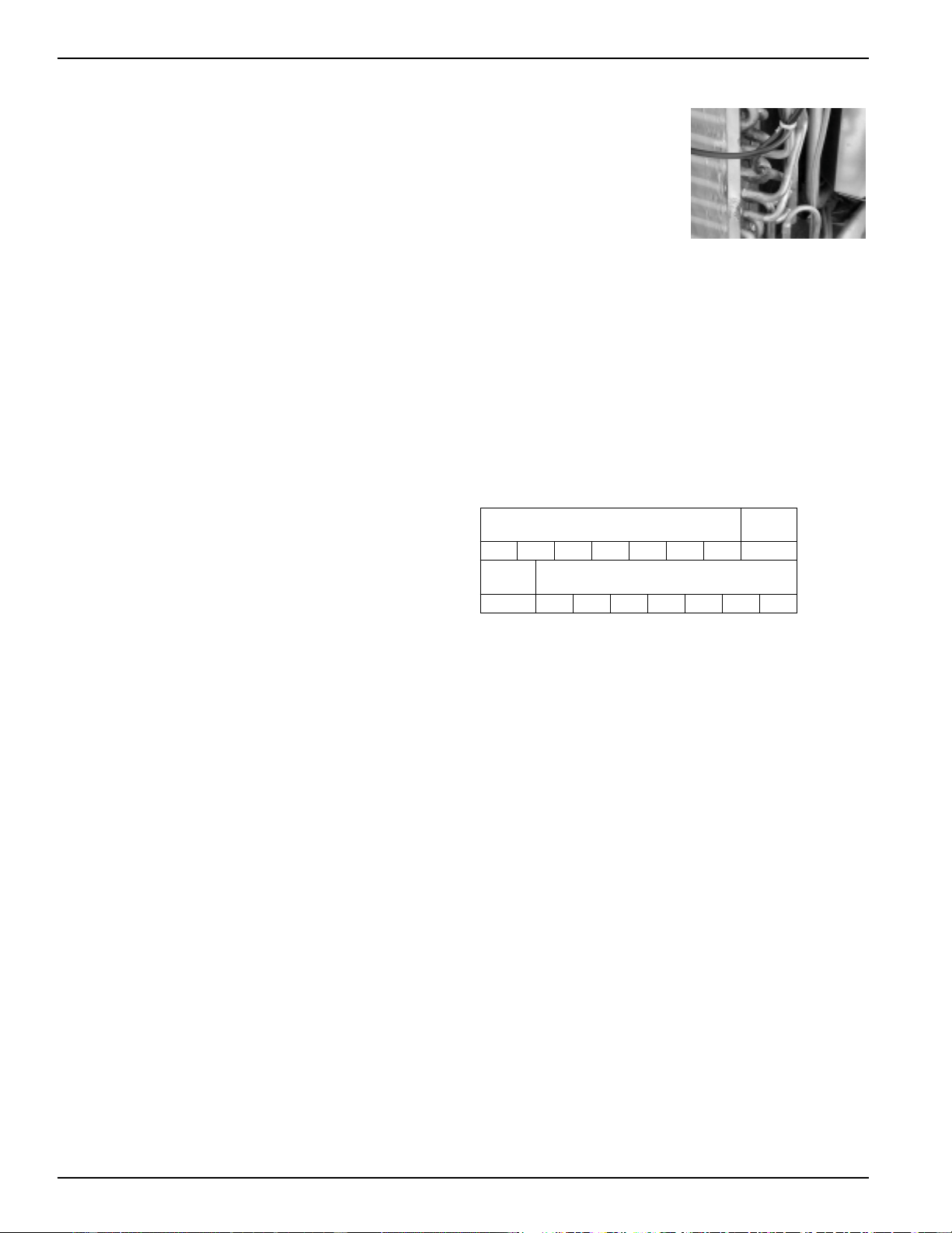
Up-Front Air Filters
Two up-front filters, easy
to remove and reinstall,
may be cleaned without
removing the room front.
Clean by brushing,
vacuuming, or back
flushing under faucet or
shower head.
Easy Clean Air Discharge Area
2500 and 3500 series units have an out-of-sight vertical
protective screen over the indoor fan. This allows easy
cleaning of air discharge area by simply removing room
front and wiping clean.
There is no screen directly below discharge louver to trap
unsightly dirt and debris where it may be seen by room
occupants.
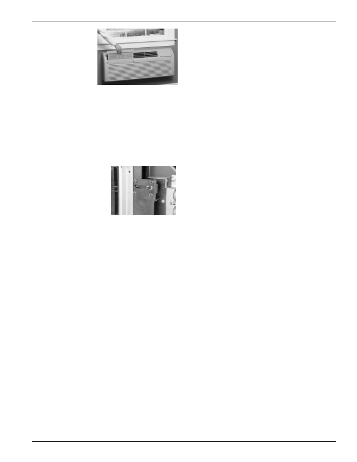
Concealed Manual Vent Control
Vent can allow up to 70 CFM
of outside air to enter the
room (40 CFM on 7100 BTUH
unit; 65 CFM on 9000 BTUH
unit; 70 CFM on 11700 BTUH
and 14600 BTUH units).
Greater amounts of air can be
introduced if the room has an
exhaust fan.
An open vent door brings unconditioned outdoor air into
the room, increasing heating and cooling costs.
Positive vent door closure prevents accidental opening and
unwanted air infiltration.
Shipping hardware may be left on the door for a permanent
closure.
Corrosion Protection (Optional)
2500 and 3500 series units may be ordered with special
protection to better withstand the damage by salt air and salt
water in seacoast areas.
Corrosion protected chassis is standard on Dry Air 25
models.
Heat Pump units with ICR are not available with corrosion
protection and should not be installed in seacoast or
corrosive environment.
Units installed in corrosive areas should be examined and
cleaned more frequently than normal installations.
Internal Condensate Removal (ICR)
See page 34 for a discussion of the Internal Condensate
Removal system available on the 3500 and 5500 series heat
pumps.
Enhanced Dehumidification
Moisture removal is an important function of an air
conditioner. People are more comfortable at higher
temperatures when the humidity level is relatively low.
Air conditioners operate with less energy consumption when
the room temperatures are set higher.
The GE Zoneline 2500 series with the Dry Air 25 heat pipe
application removes 25% more moisture than our base 2500
series unit - which is already an industry leader among the
major brands of Packaged Terminal Units.
The GE Zoneline Dry Air 25 chassis is the only unit available
with the application of the patented Dinh Dehumidifer Heat
Pipe under license from Heat Pipe Technology, Inc.
Customers who are using the Dry Air 25 report a fresher
smelling room as a result of the lower humidity levels - as
well as lower operating costs.
Locking Door Kit
RAK8022 - A door with a lock, that replaces the standard
control cover door to prevent unauthorized changing of
control setting, is offered as
an accessory.
2020 Data Manual 2002 11/7/02 3:19 PM Page 11
12
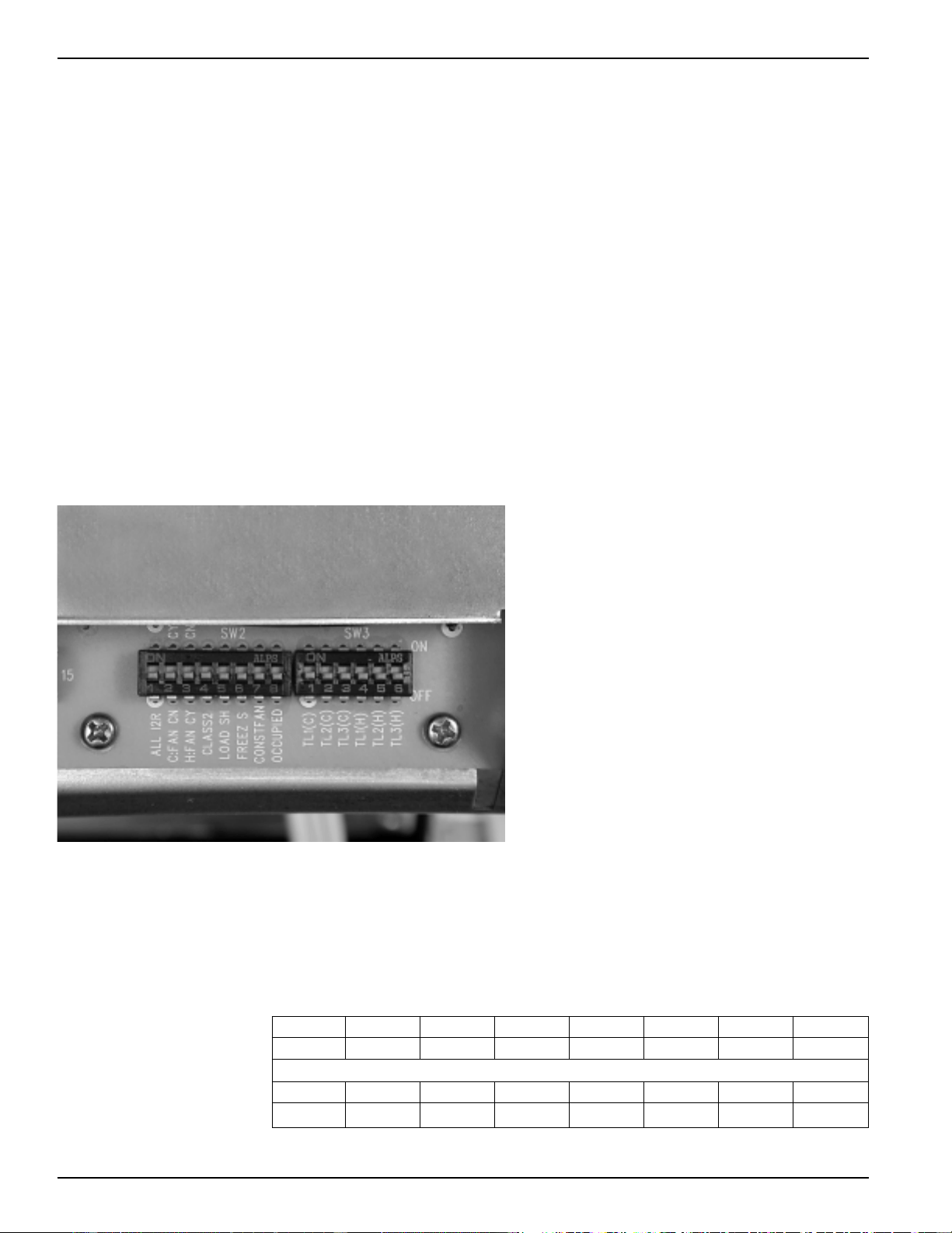
Auxiliary Control Switches
These switches are located behind the room cabinet under the control panel.
2500 and 3500 Series
Switches Description
(1) ALL I2R Heat pump override - Down - heat pump operation
Up - resistance heat only (not used on 2500 series)
(2) C:FAN Fan control for cooling operation - Down - Fan Continuous
Up - Fan Cycle
(3) H:FAN Fan control for heating operation - Down - Fan Cycle
Up - Fan Continuous
(4) CLASS 2 Remote Thermostat Mode Down - Unit Control
Up - Remote Thermostat
(5) LOAD SHED Load Shedding when connected to Central Desk Control System
Down - Fan shuts off with unit Up - Fan under “Smart Fan” settings
(6) FREEZ S Freeze Sentinel Override - Down - Freeze Sentinel ON
Up - Freeze Sentinel OFF
(7) CONST FAN Constant Fan - Fan runs when unit is in STOP mode
(8) OCCUPIED Occupancy Sensor Mode - Down - Unit Control
Up - Occupancy Sensor Connected
Temp L1 - Temp L3 Cooling temperature limiting (See table at bottom of page)
Temp L4 - Temp L6 Heating temperature limiting (See table at bottom of page)
Cooling Temperature Limits
Switches Up NONE 1 1,2 2 2,3 1,2,3 1,3 3
60 64 66 68 70 72 74 76
Heating Temperature Limits
Switches Up 6 4,6 4,5,6 5,6 5 4,5 4 NONE
65 70 72 74 76 78 80 85
Cooling and Heating temperature limits are set independently.
Temperature limiting switches in factory set down position except as noted.
LC Minimum Temperature
LC Minimum Temperature
2020 Data Manual 2002 11/7/02 3:19 PM Page 12
13
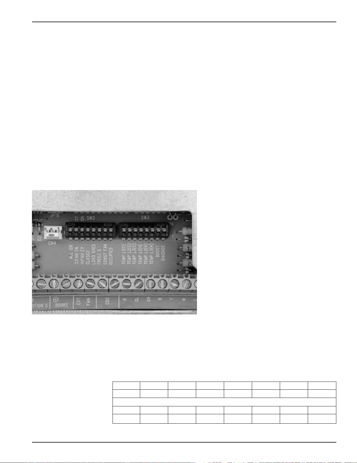
Auxiliary Control Switches
These switches are located behind the room cabinet under the control panel.
5500 Series
Switches Description
(1) ALL I2R Heat pump override - Down - Heat pump operation
Up - Resistance heat only
(2) C:FAN Fan control for cooling operation - Down - Fan Continuous
Up - Fan Cycle
(3) H:FAN Fan control for heating operation - Down - Fan Cycle
Up - Fan Continuous
(4) CLASS 2 Remote Thermostat Mode Down - Unit Control
Up - Remote Thermostat
(5) LOAD SHED Load Shedding when connected to Central Desk Control System
Down - Fan shuts off with unit Up - Fan under “Smart Fan” settings
(6) FREEZ S Freeze Sentinel Override - Down - Freeze Sentinel ON
Up - Freeze Sentinel OFF
(7) CONST FAN Constant Fan - Fan runs when unit is in STOP mode
(8) OCCUPIED Occupancy Sensor Mode - Down - Unit Control
Up - Occupancy Sensor Connected
Temp L1 - Temp L3 Cooling temperature limiting (See table at bottom of page)
Temp L4 - Temp L6 Heating temperature limiting (See table at bottom of page)
BOOST Turns on supplemental heater with heat pump when outdoor temperature is below 45°F
DIAGNOS Used by service technician to briefly operate unit components for diagnostics
Cooling Temperature Limits
Switches Up NONE 1 1,2 2 2,3 1,2,3 1,3 3
60 64 66 68 70 72 74 76
Heating Temperature Limits
Switches Up 6 4,6 4,5,6 5,6 5 4,5 4 NONE
65 70 72 74 76 78 80 85
Cooling and Heating temperature limits are set independently.
Temperature limiting switches in factory set down position except as noted.
LC Minimum Temperature
LC Minimum Temperature
2020 Data Manual 2002 11/7/02 3:19 PM Page 13
14
Central Desk Control
Some installations may want to govern the ability of the unit
to operate from a control device remote to the unit or even
remote to the room in which the unit is located. The
general term given to systems such as this is Central Desk
Control. The most common installation of this type of
system is a switch mounted at the registration desk and,
upon guest check-in, a button is pushed or a switch is moved
to allow the air conditioner to operate. Likewise, when the
guest checks out, the device is put into the “OFF” position so
the unit will not operate while the room is vacant.
It is not necessary that the controlling device be located at a
central desk to employ a device that will control the unit
operation. For instance, in some resort areas, devices are
connected to sliding glass doors and opening the door
causes a contact to close, turning the air conditioner off.
This prevents energy being wasted by operating the air
conditioner when warm humid air is entering the room.
Some systems operate by motion sensors or heat sensing
detectors mounted in the room. These types of systems
determine occupant presence in the room and allow the
unit to operate; if no one is in the room, the device signals
the air conditioner to turn off.
Zoneline models offer Load Shedding capabilities on units
connected to Central Desk Control Systems. For more
information on the Models’ Load Shedding Feature, see
page 10.
All Zoneline 2500, 3500, and 5500 Series units are
compatible with simple on/off 2 wire Central Desk Control
systems. Consult with the provider of other energy
management systems to be sure they are compatible with the
GE Zoneline units. Zoneline units have standard connectors
factory installed to provide a CDC interface that permits the
unit to be connected to most energy management systems.
The devices connected to the Zoneline units require no
power supply or transformers external to the unit.
Important CDC Comments (all series applicable)
1) When the switching device closes the circuit of the CDC
conductors, the unit operation stops.
2) Do not use a common buss (at the unit or at the switch
panel) in the wiring. Both wires comprising the circuit
must connect to the unit connectors and to the
controlling switch. Running one wire from one unit to
another unit is common bussing and may damage
internal components or cause erratic operation of the
system.
3) A 24 volt transformer is contained within the Zoneline
units. No external voltage may be applied to the unit through
the CDC terminals. (Voltage on the CDC conductors is
24 volts AC.)
4) Recommended wire size must be followed as a minimum
requirement.
Wire Size #AWG Maximum Allowable Length
#22 600 Ft.
#20 900 Ft.
#18 1500 Ft.
#16 2000 Ft.
Freeze Sentinel
TM
remains operational when the unit is
connected to a CDC system. Even if the unit is turned “OFF”
at the central location, if the sensor at the unit detects the
low temperature, the electric resistance heaters and fan will
automatically turn on.
Connecting the Zoneline unit to a CDC system does not
eliminate the ability to connect the unit to a remote
thermostat. Once the circuit is “opened”, and control of the
unit removed from the CDC system, the selected controls -
either the unit mounted control or the remote thermostat -
govern the operation of the unit.
Please see page 57 for installation recommendations for the
Central Desk Control wiring.
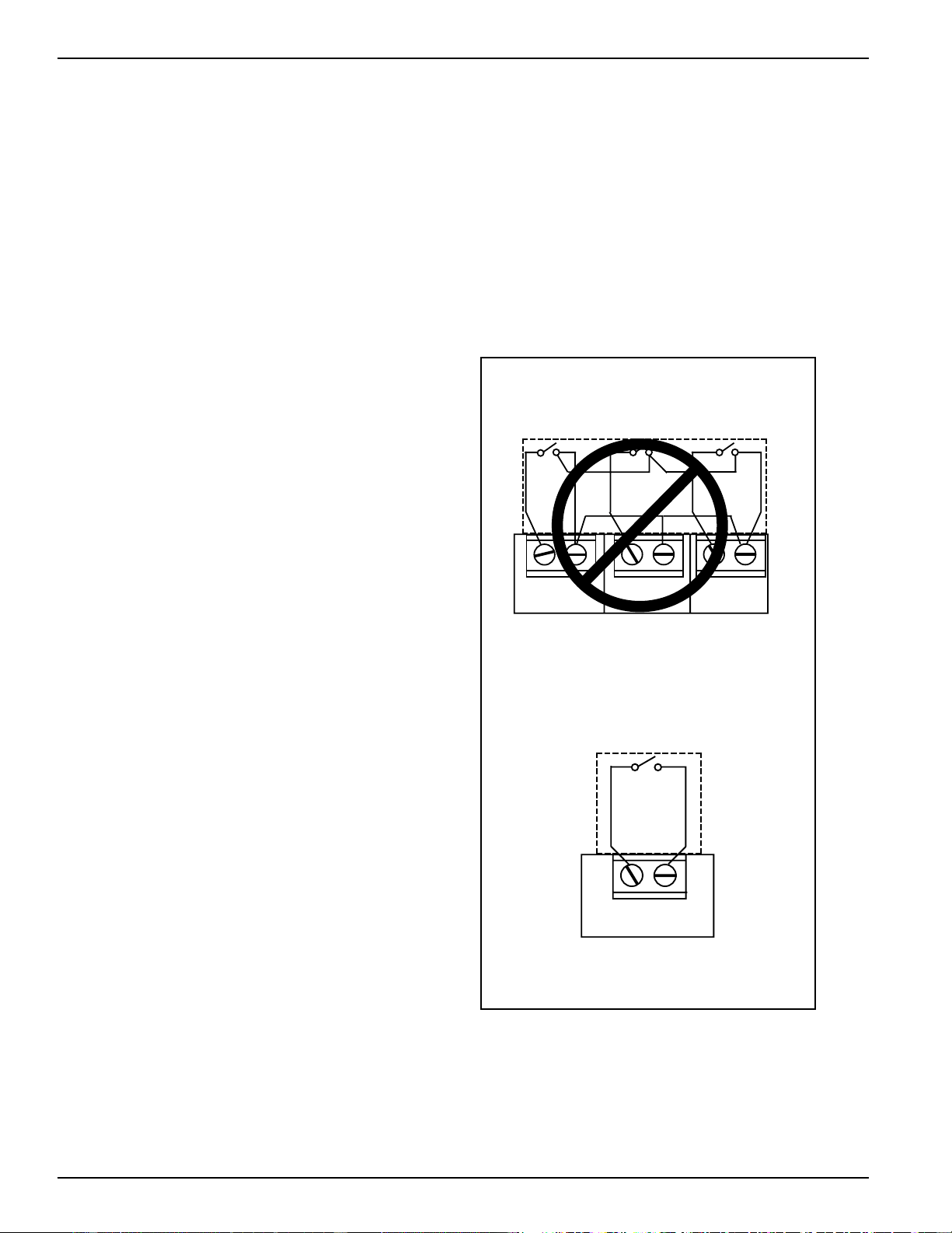
CDC Terminal Location and Typical Wiring
See page 12 and 13 for location of CDC terminals on unit
Unit #2
Unit #1
Unit #3
Example of Common Bussing
NOT PERMITTED
CDC Terminals
on Zoneline
INCORRECT Common Bussing
Normally Open
Switch -
Unit Operational
Typical Wiring
(All Wiring Shown Is Field Supplied)
2020 Data Manual 2002 11/7/02 3:19 PM Page 14
15
Remote Thermostat Control
In some installations, control of the
operation of the unit at a location
remote to the unit itself may be desired.
Unit mounting locations (high in the
wall or over a transom) resulting in
inaccessible unit mounted controls can
be connected to a remote thermostat.
Other installations may use remote
thermostat control for design or
performance enhancement. The unit is
connected to the thermostat by low voltage wiring, which
permits the operation of the unit to be selected and the
temperature to be sensed at the thermostat.
All Zoneline 2500, 3500 and 5500 Series units are adaptable
to Class 2 remote low voltage thermostat. The only
additional field supplied components are the remote
thermostat and wiring necessary to connect it.
The controls on the unit are not functional when the remote
control function is used.
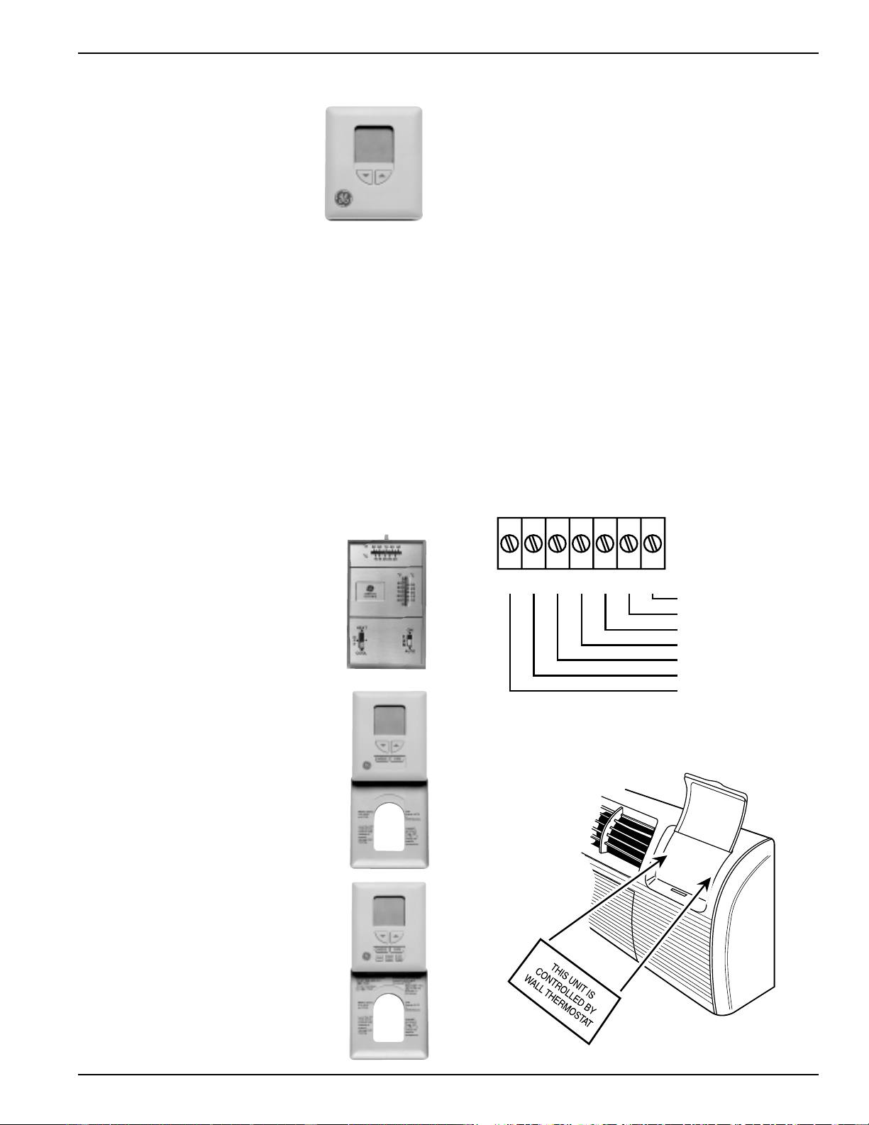
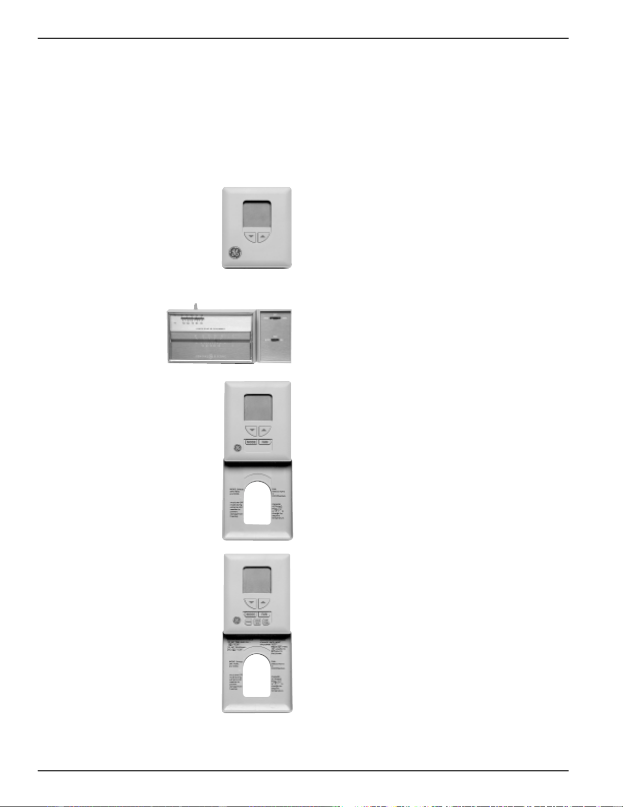
Resistance Heat Models
The Zoneline 2500 resistance heat units may be connected
to a single-stage thermostat designed for use with cooling
with electric heat systems. GE offers 3 thermostats
compatible with the 2500 series unit.
RAK163A1 - a mechanical manual
changeover thermostat requiring 4
connection wires.
RAK163D1 - a solid state digital manual
changeover thermostat requiring 5
connection wires.
RAK163P1 - a solid state digital
programmable auto changeover thermostat
requiring 5 connection wires.
The Class 2 Mode Switch (dip switch 12 on the auxiliary
control board) must be set to the ON/UP mode to enable
remote thermostat control. Refer to installation instructions
packaged with the chassis.
Please see page 57 for installation recommendations for the
remote thermostat wiring.
Compatibility of other thermostats considered for use with
the GE Zoneline unit is the responsibility of the customer.
The control voltage on the remote control conductors is
24 VAC. The units may not be compatible with some solid
state thermostats.
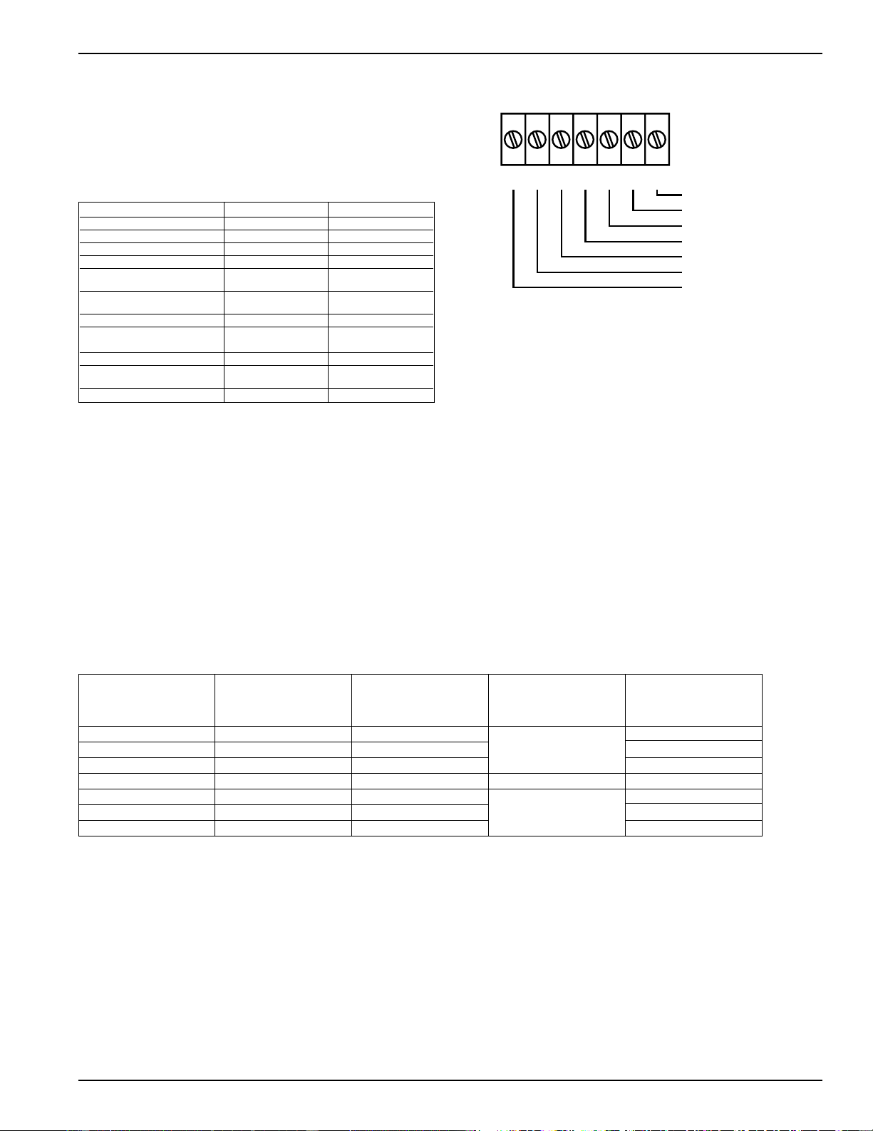
The fan speed for the 2500 series in remote thermostat
operation is selected by the connection of the fan wire from
the thermostat to either the HIGH or LOW terminal on the
unit. See the sketch of the unit terminals for the location of
the HIGH and LOW fan speed terminals. Operating in low
fan speed reduces the operating sound level of the unit.
Freeze Sentinel
TM
remains operational if the unit is
connected to a remote thermostat. The unit may be
connected to a Central Desk Control (CDC) system and
controlled with a remote thermostat when the CDC system
has the unit in an operational status. See page 14 for
additional information on the CDC system.
R
GL
GH
B
Y
W
C
Common - Ground
White - Heater
Yellow - Compressor
Black - Not Used On 2500
Green - High Speed Fan
Green - Low Speed Fan
Red - 24 VAC
(shown closed)
2020 Data Manual 2002 11/7/02 3:19 PM Page 15
16
Remote Thermostat Control
RAK806 Universal Control Cover Label
When a Zoneline unit is using a remote thermostat
control, the RAK806 Universal Control Cover Label is
recommended. The RAK806 is only available in a package
of 10 labels. The label is placed over the control panel
directing the user to the wall thermostat for operation of the
Zoneline unit.
Heat Pump Models
The Zoneline 3500 and 5500 Series heat
pump units may be connected to a single
stage cooling/two stage heating thermostat
designed for use with heat pump systems.
GE offers 3 thermostats compatible with
the 3500 and 5500 series units.
RAK147 - mechanical
manual changeover
thermostat requiring
6 connection wires
RAK147D1 - solid state digital manual
changeover thermostat requiring
6 connection wires.
RAK147P1 - solid state digital
programmable auto changeover
thermostat requiring 6 connection wires.
Please see page 57 for installation recommendations for the
remote thermostat wiring.
Compatibility of other thermostats considered for use with
the GE Zoneline unit is the responsibility of the customer.
The control voltage on the remote control conductors is
24 VAC. The units voltage may not be compatible with some
solid state thermostats.
The Class 2 Mode Switch, dip switch #4 on the 3500 & 5500
series must be set to the ON/UP mode to enable remote
thermostat control. Refer to installation instructions
packaged with the chassis.
(shown closed)
2020 Data Manual 2002 11/7/02 3:19 PM Page 16
Remote Thermostat Control
When connected to a remote thermostat, the indoor air
temperature sensing is shifted from the unit to the remote
thermostat. For this reason, the units will operate slightly
differently when connected to a remote thermostat. The
following chart shows the unit operation when connected to
a remote thermostat.
Temperature Boost option should not be used with remote
thermostat operation since this will cause the unit to switch to
resistance heat when outdoor temperatures are below 46°F.
See RAK806 Universal Control cover Label on page 15.
17
Remote Thermostat Control Selection Chart For Zoneline Packaged Terminal Units
LOW
ZONELINE THERMOSTAT VOLTAGE
SERIES MODEL TYPE FUNCTION CONDUCTORS
RAK163A1 Mechanical 4
2500 RAK163D1 Digital Cooling and Heating 5
RAK163P1 Digital Programmable 5
RAK147 Mechanical Single Stage 6
3500 and RAK147D1 Digital Cooling 6
5500 RAK147P1 Digital Programmable 2 - Stage Heating 6
Thermostat wire size - up to 60 feet AWG20 - up to 66 feet AWG18
Feature 3500 Series 5500 Series
Indoor Frost Control Yes Yes
Freeze Sentinel Yes Yes
Auto Fan Speed No No
Electronic Temperature Limiting No No
Switch to Resistance Heat Based Determined by Determined by
On Indoor Temperature Remote Thermostat Remote Thermostat
Switch to Resistance Heat Based
On Outdoor Temperature Yes Yes
Reverse Cycle Defrost – Yes
Simultaneous Resistance Heat
with Heat Pump – No
Resistance Heat Lockout – Yes
“Smart Fan” Fan Cycle Fan ON/AUTO Set On Fan ON/AUTO Set On
Remote Thermostat Remote Thermostat
Central Desk Control Yes Yes
R
GL
GH
B
Y
W
C
Common - Ground
White - Heater
Yellow - Compressor
Black - Not Used On 2500
Green - High Speed Fan
Green - Low Speed Fan
Red - 24 VAC
2020 Data Manual 2002 11/7/02 3:19 PM Page 17
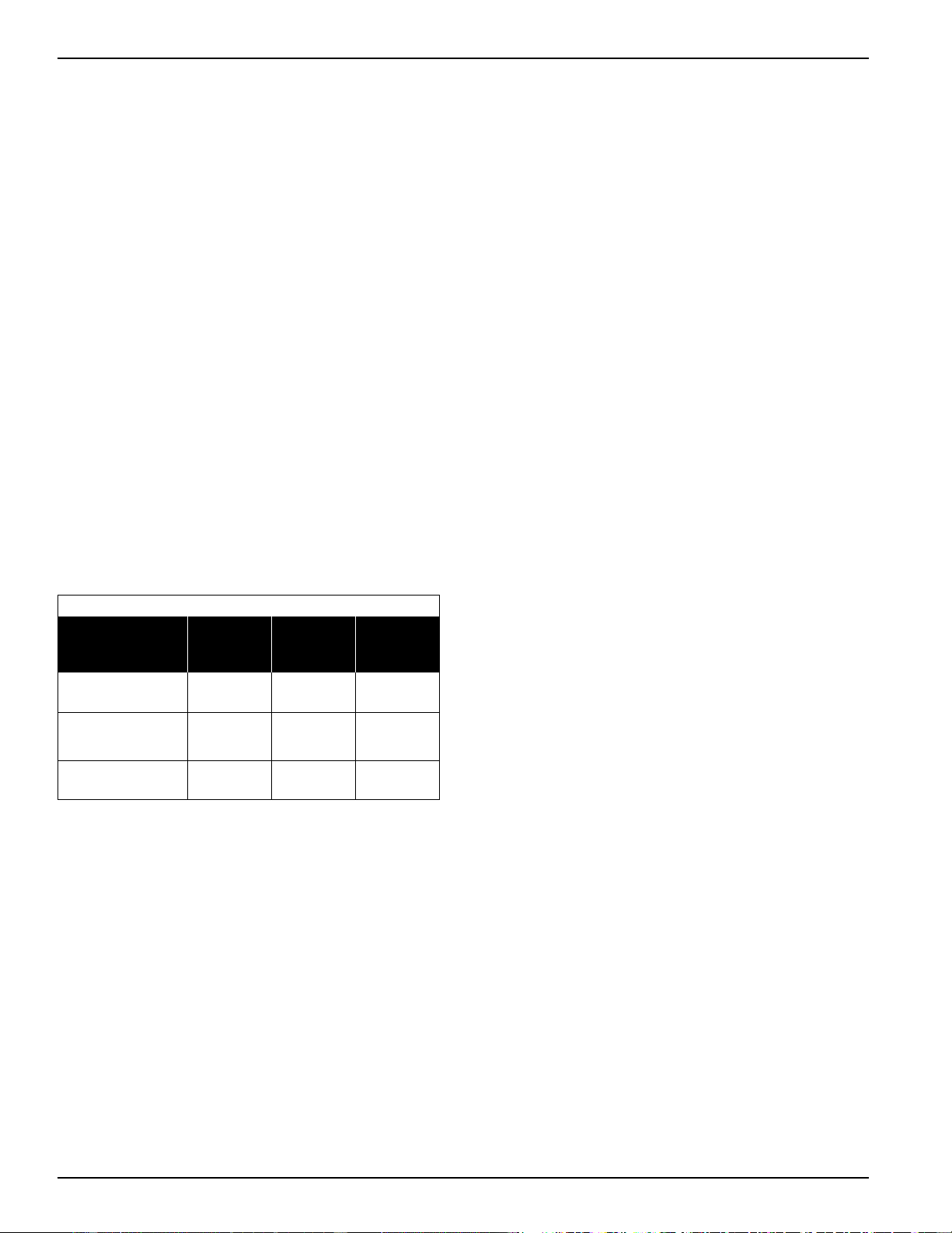
18
FIELD SUPPLIED RELAY SPECIFICATIONS
NUMBER OF RELAY DESIGNATION
UNITS CONTROLLED R1, R2, and R3
2 POTTER and BRUMFIELD TYPE KA11AY-24 OR EQUIVALENT
3 POTTER and BRUMFIELD TYPE KA14AY-24* OR EQUIVALENT
4 POTTER and BRUMFIELD TYPE KU17A11-24* OR EQUIVALENT
MORE THAN 4 USE COMBINATION OF RELAYS SPECIFIED ABOVE
NOTE: Current draw through thermostat contacts should not exceed 1.0 amps.
*Special order, 100 piece minimum order.
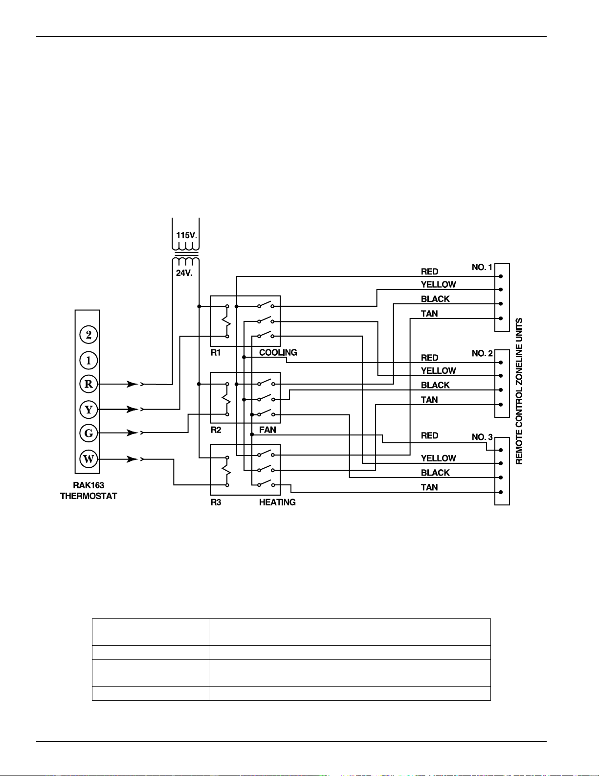
Remote Control (Low Voltage) Wiring
One stage Thermostat Controlling Three Zoneline Units
Resistance Heat Zoneline 2500 Series Units
(Not Applicable on Heat Pump Units)
Remote Thermostat Control
Multiple Units Connected to One Remote
Thermostat (2500 Series)
One remote control thermostat may be used to control
multiple resistance heat Zoneline units, however the units
may not be wired direct. Since each Zoneline unit has an
integral transformer, direct wiring can result in a “bucking”
or “boosting” voltage condition, and is in violation of the
National Electric Code. The diagram below shows the
correct wiring for such an installation through the use of
field supplied isolation relays.
For Use With Mechanical 4-Wire Systems Only
2020 Data Manual 2002 11/7/02 3:19 PM Page 18

19
Heat Pumps and Energy
Savings
• GE Zoneline Heat Pumps are designed to provide cost
efficient heat pump operation while monitoring room
conditions to maintain comfort.
The units employ a logic system monitoring both outdoor
and indoor temperatures to determine the heat source, thus
increasing energy savings by operating longer in the heat
pump mode.
Heat pumps save energy and cost less to operate than units
with electric resistance heaters as the only heat source. Just
as the EER of an air conditioner is an indication of the
efficiency of the unit, COP (Coefficient of Performance) is
the indication of the efficiency of the heat pump. This
relative efficiency of a heat pump compares the unit to
electric resistance heat. If a unit has a COP of 3.0, it means
the unit will produce three times as much heat at rating
conditions for the same electrical input wattage used for
electric resistance heat.
The compressor is used in heat pump operation just as in air
conditioning operation. In heat pump operation, the hot
refrigerant gas is directed to the indoor coil rather than to
the outdoor coil. Room air that circulates over the indoor
coil gains heat from the coil rather than losing heat to the
coil as during cooling operation.
As the outdoor temperature falls, the heat pump is able to
extract less heat from the outdoor air to raise the
temperature of the indoor air. For this reason, all packaged
terminal heat pumps also have electric resistance heaters as
backup to heat pump operation. At some point, the heat
pump is unable to provide sufficient heat to adequately
warm the room. Many Packaged Terminal Heat Pumps cease
heat pump operation and change to more expensive
resistance heat at some pre-determined outdoor
temperature to compensate for the inability of the heat
pump to maintain room temperature. This point, called the
“switchover point”, is usually at an outdoor temperature
where savings from heat pump operation may still be
realized, if the unit is designed to maintain room comfort at
the lower outdoor temperatures.
Balance Point
An important consideration of the selection of a heat pump
unit is the “balance point” of the installation. Virtually every
room is unique - with different insulation - different sizes
and types of windows - different types of construction -
different directional exposures. All of these variables, as well
as geographical location, must be considered in order to
determine the balance point, the point at which the heat
pump is unable to produce enough heat to compensate for
the heat loss of the room or area being heated. For these
reasons a consulting engineer should be engaged to
calculate the heat loss and specify the heat pump unit
required.
GE offers two series of Zoneline Heat Pump units - the 3500
Series with Standard Microprocessor controls and the 5500
Series with Highly Featured Microprocessor controls - and
both series react to the indoor temperature as well as the
outdoor temperature in determining the heat source to
provide comfortable room conditions and energy savings.
This determination of the heat source based on the indoor
temperature helps provide a more comfortable room.
• Heat Pump Operation - Zoneline 3500 Series
Switchover to resistance heat is determined by indoor
temperature differential and outdoor coil temperature
The Zoneline 3500 Series heat pumps are Standard
Microprocessor controlled units. A solid state thermostat
control is used to measure the room temperature and
compare it to the temperature selected with the “TEMP”
control knob. A temperature sensor is in contact with the
outdoor coil to monitor the outdoor coil temperature
during heat pump operation.
The switchover point of the 3500 Series heat pump is
determined by the outdoor coil temperature or the indoor
air temperature. When the outdoor coil temperature is
above 9°F. (which corresponds to approximately 25°F.
outdoor air temperature), the unit attempts to provide
sufficient heat through heat pump operation to satisfy the
selected temperature setting.
The microprocessor monitors the indoor room temperature
and determines if the heat pump output is adequate to
maintain comfort conditions. As long as the heat pump
output maintains the room temperature within 2.7°F of the
set point, the unit will operate in the heat pump mode. If
the room temperature continues to decline with the heat
pump operating, heat pump operation will terminate and
the unit will switch over to electric resistance heat to warm
the room. This heat source logic allows the heat pump to
operate to lower outdoor temperatures, increasing the
savings from heat pump operation, while providing the
ability to use resistance heat only when necessary. The heat
pump and the electric resistance heaters never operate
simultaneously on the Zoneline 3500 Series Units.
A heat pump override switch is provided in the auxiliary
controls to allow the unit to operate only in resistance heat.
The use of this option significantly increases the cost for
heating.
Heat pump defrost - Zoneline 3500 Series
If the outdoor coil drops below 9°F. (which corresponds to
approximately 25°F. outdoor air temperature), the unit
employs a passive defrost system. A “passive defrost system”
prevents heat pump operation until outdoor temperatures
rise sufficiently to enable economical heat pump operation
to resume. During the defrost mode, the indoor
temperature is maintained by the electric resistance heater.
The defrost cycle terminates when the outdoor coil
temperature rises above 36°F., at which point the
microprocessor will allow the unit to return to economical
heat pump operation.
Heat pump condensate
See page 34 for information on heat pump condensate. The
Zoneline 3500 Series heat pumps may be ordered with a
factory installed Internal Condensate Removal (ICR) system
to minimize the amount of condensate water draining from
the unit during heat pump operation. The ICR system has
proven to be an effective means of minimizing the amount
of heat pump condensate dripping from the unit. However,
if the requirements of a particular installation will allow no
dripping of condensate water from the wall case, the
installation of an internal or external drain system is
recommended.
Units with ICR may not be installed in seacoast or corrosive
environment applications.
2020 Data Manual 2002 11/7/02 3:19 PM Page 19
20
Heat Pumps and Energy
Savings
• Heat Pump Operation - Zoneline 5500 Series
Heat sources: Heat pump, heat pump and simultaneous
electric resistance heat, or electric resistance heat
The Zoneline 5500 Series heat pumps employ a highly
featured microprocessor control system interfaced with
thermistors to accurately measure indoor air temperature,
outdoor air temperature, indoor coil temperature, and
outdoor coil temperature. This system allows the
microprocessor to precisely and predictably react to
changing conditions in order to provide a very advanced
Packaged Terminal Heat Pump operating system.
The Zoneline 5500 series is designed to help insure a
comfortable room. When “HEAT” is selected, the unit will
determine if the room air is warm enough to satisfy the
thermostat setting. If the temperature at the unit sensor is
below the desired temperature, the electric resistance heater
will be utilized to warm the room to the point where the
thermostat is satisfied. This feature is designed to allow the
temperature of an unoccupied room to be maintained at an
energy saving level without inconveniencing the room
occupant. Once the thermostat has been satisfied, the
resistance heater will turn off and the heat pump will operate
as shown in Zoneline 5500 Series Heat Source Logic chart
when the thermostat calls for heat again. The unit will operate
in this manner even if connected to a Central Desk Control.
*If the “Temperature Boost” switch (dip switch #8) is in the
“ON” position, the supplemental simultaneous heater will be
used with heat pump operation. Simultaneous supplemental
heater: 1.0 KW @ 230 V; 0.8 KW @ 208 V; 1.7 KW @ 265 V
The “Temperature Boost” option utilizes the supplemental
simultaneous heater simultaneously with heat pump
operation when the outdoor temperature is below 46°F.
regardless of the indoor air temperature. The chart above
indicates the heat source of the Zoneline 5500 series heat
pump under various indoor and outdoor conditions. The
unit is designed to provide heat pump savings without
sacrificing room comfort. The Quick Heat Recovery feature
is not affected by the Zoneline 5500 Series Heat Source
Logic shown in the chart above. For more information
about the Quick Heat Recovery Feature, see page 9. The full
heat output of the resistance heater is dependent upon
circuit amperage and the power connection kit used. See
pages 42 - 43 for information on the power connection kits
and available heater capacities.
A heat pump override switch is provided in the auxiliary
controls to allow the unit to operate only in resistance heat.
The use of this option significantly increases the cost for
heating.
Heat pump defrost - Zoneline 5500 Series
The Zoneline 5500 Series has a reverse cycle demand
defrost system to extend heat pump operation and increase
savings from extended operation. The microprocessor
determines the need for defrosting by criteria based on
continuous compressor running time, outdoor air
temperature, outdoor coil temperature, and the rate of
temperature change of the outdoor coil. When defrosting is
required, the unit reverses the flow of refrigerant to direct
the hot gas into the outdoor coil to melt the frost build-up.
Before and after the reverse cycle defrosting, the unit shuts
off the compressor to allow the refrigerant pressures to
equalize throughout the system. This eliminates the
possibility of a loud reversing noise. During these periods of
pressure equalization, the full resistance heat capacity of the
unit is activated to help insure room comfort conditions
during the defrost cycle. The unit remains in the defrost
cycle for a minimum of 2 minutes up to a maximum of 9
minutes. The defrost cycle terminates when the outdoor coil
reaches a temperature of 68°F or the maximum time has
been reached.
Heat pump condensate See page 34 for information on
heat pump condensate. The Zoneline 5500 Series heat
pump may be ordered with a factory installed Internal
Condensate Removal (ICR) system to minimize the amount
of condensate water draining from the unit during heat
pump operation.
ROOM
TEMPERATURE
VS. THERMOSTAT
SET POINT
Less Than 1.8°F.
Below
1.8°F to 2.7°F.
Below
More than 2.7°F.
Below
Above 46°F.
Heat Pump
Heat Pump
Heat Pump
Between 46°F.
and 25°F.
Heat Pump*
Heat Pump +
Supplemental
Heater
Full Resistance
Heat
Below 25°F.
Full Resistance
Heat
Full Resistance
Heat
Full Resistance
Heat
Zoneline 5500 Series Heat Source Logic
2020 Data Manual 2002 11/7/02 3:19 PM Page 20
21
Application Comments
Use and Care Manual and installation instructions are
shipped with Zoneline units. It is important that any air
conditioning system be properly sized and applied in order
to achieve the desired temperature and humidity levels with
the space to be conditioned. Air conditioners are designed
primarily to provide heating and cooling with the additional
benefit that during operation in the cooling mode, the units
also remove some moisture from the conditioned space. The
following are some brief application comments on
undersizing, oversizing, heating, wall coverings, and air
infiltration: all are important in the proper matching of the
heating/air conditioning system to the building structure.
Undersizing: If an air conditioner is undersized (cooling
capacity is less than required for a specific application), the
unit will typically not be able to cool the space down to the
desired temperature (thermostat set point), nor be able to
remove enough moisture from the air. A result could be a
warm and humid or warm and dry conditioned space.
Oversizing: If an air conditioner is oversized (cooling
capacity is greater than required for the specific
application), the unit will typically cool the space down to
the desired temperature (thermostat set point) too quickly.
The compressor then begins to cycle on and off.
Dehumidification only takes place when the compressor is
operating. A typical result in a hot/humid climate could be
a cool but excessively humid space.
Heating: Undersizing can result in not being able to
maintain the desired temperature level within the
conditioned space.
Wall Covering: Use of a non-permeable wall covering (some
paints, some wallpapers, and other types of coverings) which
severely restricts passage of air or water vapor can cause a
severe moisture problem. Typical results could be staining of
room surfaces, wall damage, as well as mold and mildew
growth in hot/humid climates.
Air Infiltration: Excessive air infiltration can magnify
problems associated with undersizing or oversizing of an air
conditioner unit and can be the root cause of insufficient
cooling, dehumidification, or heating. Some sources of air
infiltration include vents, gaps around windows and doors,
and improperly sealed floor, ceiling and wall joints.
Recommendation
For the above reasons it is strongly recommended that a
professional engineer be retained to match the Zoneline
unit with the building structure.
Air Distribution
Zoneline packaged terminal air conditioners and heat
pumps discharge air from the top of the unit through
reversible 2-position discharge louvers. Unit discharge
louvers are reversed by removing the room cabinet from the
unit, removing seven screws that hold the louver section in
place, removing the louver section and rotating it end for
end, reinstalling the louver section in the room cabinet with
the seven screws, and reinstalling the room cabinet on the
unit. The unit is shipped from the factory with the discharge
louvers at an angle of 50° off vertical. In the alternate
position, the louvers will be at an angle of 40° off vertical.
All room cabinets return air through the front of the unit.
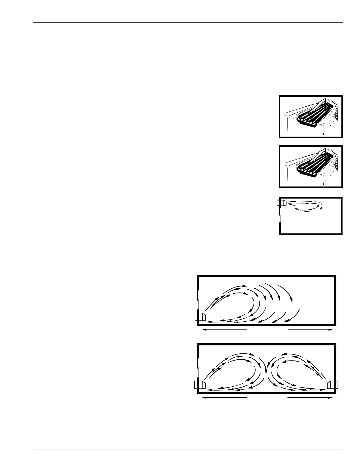
High Wall Mount - For units
mounted high in the wall, the
discharge louvers should be at a
setting that provides the most
horizontal air discharge.
Recommended installation is at
least 3" below the ceiling. In
installations where units are
close to the ceiling, the most
horizontal discharge angle can
be obtained by removing the
discharge grill from the room
cabinet.
Supply Air Throw - One
Zoneline unit should not be
required to do a job obviously
requiring two or more units.
Units should be located
around large rooms according
to calculated loads or in such
fashion as to achieve balanced
air distribution in all parts of
the room. The single unit in
the “Incorrect” illustration
below obviously cannot
condition the entire room.
Add a second unit as shown in the “Correct” illustration.
50°
40°
OVER 40 FT.
INCORRECT
OVER 40 FT.
CORRECT
2020 Data Manual 2002 11/7/02 3:19 PM Page 21
22
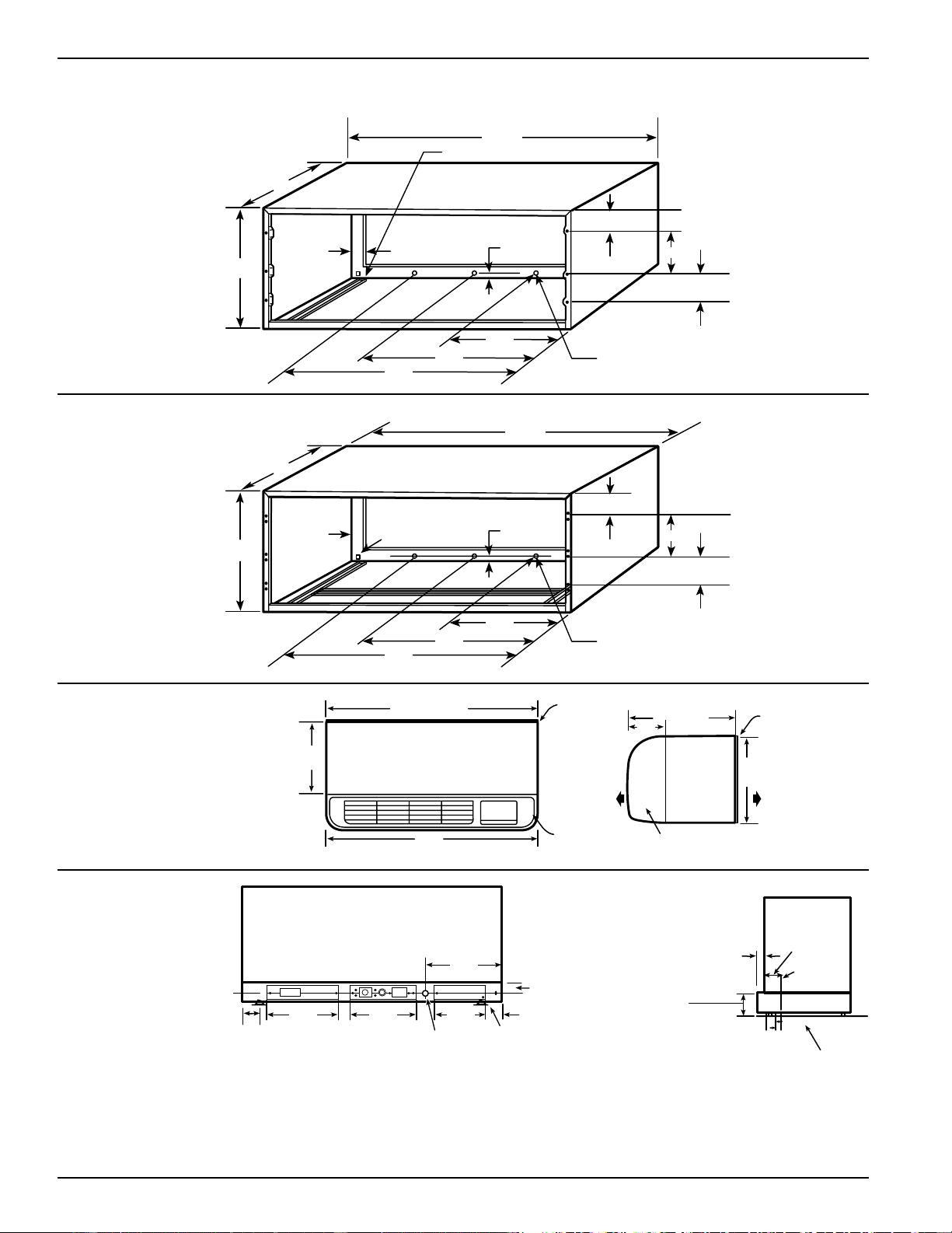
Dimensions
RAB71
WALL CASE
WALL OPENING
16-1/4" MIN. x 42-1/4" MIN.
RAB77
WALL CASE
WALL OPENING
16-1/2" MIN. x 42-3/8" MIN.
WALL CASE WITH
CHASSIS INSTALLED
WALL CASE WITH
SUB-BASE
*SHOWN WITH ACCESS COVERS REMOVED.
NOTE: CAUTION - REMOVE KNOCKOUTS FROM INSIDE OUT.
Installation Instructions Packed With Wall Case . . . See Page 25 For Additonal Information Concerning
Outdoor Weather Panel and Case Stiffener.
A-Additional
Wall Case Depths
RAB7116 - 16"
RAB7124 - 24"
RAB7128 - 28"
RAB7131 - 31"
42"
13-3/4"
16"
1-1/2" TYP
1/2"
6"
21"
36"
A
1/2" SQ. HOLE (2 REQ'D.)
1/2" DIA.
HOLE (3 REQ'D.)
2-3/4"
5-5/8"
4"
6"
19"
36"
16-1/4"
13-7/8"
1-1/2"
42-1/8"
1/2" SQ. HOLE
(2 REQ'D.)
9/16"
2-7/8"
5-5/8"
4"
1/2" DIA.
(3 REQ'D.)
RAB71 = 42"
RAB77 = 42-1/8"
RAB71 = 13-3/4"
RAB77 = 13-7/8"
42"
TOP VIEW
GRILLE
ROOM
CABINET
INSIDE
ROOM
CABINET
SIDE
VIEW
RAB71 = 20-7/8"
RAB77 = 21"
OUTSIDE
RAB71 = 16"
RAB77 = 16-1/4"
GRILLE
7-1/8"
FRONT VIEW*
3-1/2"
12-3/4" 12" 9-3/8"
2-1/2"
1-7/16"
LEVELING SCREW
KNOCKOUTS (ENCLOSURE)
4 REAR; 4 BOTTOM
SEE PAGE 32 FOR KNOCKOUT LOCATION DIMENSIONS.
1-5/16"
2-3/8" MIN.
INTERIOR
WALL
3" MIN.
ADJUSTABLE
TO 5" MAX.
FINISHED FLOOR
SIDE VIEW
13"
2020 Data Manual 2002 11/7/02 3:19 PM Page 22
23
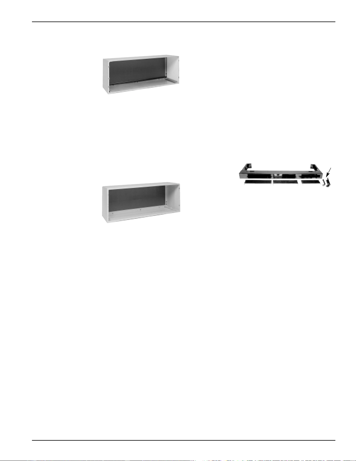
Wall Case
A choice of wall cases is available for the Zoneline unit.
RAB71 - This insulated
case is constructed of
heavy gauge galvanized
steel and finished with a
protective baked enamel
finish for protection and
appearance. Design of
the case provides for
support of the chassis and
free draining of any water entering the wall case.
A petroleum microcrystalline wax is applied at critical points
of fabrication to seal against moisture. The dimensions of
the RAB71 wall case are: 42" wide by 16" high by 13 3/4"
deep, the same dimensions as the original wall case for GE
Zoneline units built in 1961. The RAB71 wall case is also
available in depths other than the standard depth of 13 3/4".
Special order steel case are: RAB7116 - 16" deep; RAB7124 -
24" deep; RAB7128 - 28" deep; and RAB7131 - 31" deep. All
of these special order deep wall cases are insulated and have
sheet metal dividers, or splitters, to prevent the recirculation
of condenser discharge air.
RAB77 - This non-
insulated wall case is
molded from fiberglass-
reinforced polyester
compound. This SMC
(Sheet Molded
Compound) wall case
offers outstanding
strength, durability, color retention, water integrity and
corrosion resistance. The dimensions of the RAB77 wall case
are: 42 1/8" wide by 16 1/4" high by 13 7/8" deep.
• Both wall cases are of universal design, accepting all
Zoneline chassis of current design as well as all GE
Zoneline chassis produced since 1961.
• Drain holes are provided in the rear of the wall case to
permit excessive cooling condensate water, heat pump
condensate, or precipitation entering the wall case to drain
freely. A drain kit may be connected to the wall case to
control any water draining from the wall case. See pages
34 - 36 for information on RAD10 Drain Kit.
RAK901L - For installations when the wall case extends into
room, an RAK901L is an insulation kit that can be used with
the RAB77 or any existing non-insulated wall case to
minimize the possibility of condensation forming on the
indoor side of the case during the winter.
Sub-Base
The sub-base is an optional accessory for the Zoneline unit
and is presented with the wall case information since the
decision to use or not to use a sub-base in the installation is a
factor in the location of the wall opening for the unit.
National Electrical Code
®
requires that air conditioning units
connected to voltages in excess of 250 volts be “permanently
connected”. There are also some installations where units
connected to voltage sources under 250 volts may also need to
be “permanently connected”. If you are in doubt about the
requirements for a particular installation being designed,
consult Article 440 of the NEC or the local electrical inspector.
These requirements are designed to protect personal safety
and should be strictly followed. Although NEC is cited here as
a reference, all electrical wiring and installations must
conform to any and all local electrical codes and regulations.
“Permanent Connection” generally means wiring between
the building wiring and the unit must be contained in an
enclosed “chaseway”, where access to the wiring connections
is more restrictive than a normal line cord plugged into a
receptacle. NEC requirements may be met by using flexible
or rigid conduit to contain the wiring between the unit and
a junction box that contains the wiring connections. The
conduit is connected to the unit and to the junction box with
connectors to hold the conduit in place. The junction box
may be located in the floor or the wall of the structure but
only approved connectors may be used outside the unit or
the junction box. The sub-base is UL
®
listed as a junction
box for permanent connection of a Zoneline unit.
Using a sub-base in an installation requiring permanent
connection provides a convenient, consistent location for
unit wiring to be connected to building wiring. The use of a
sub-base is not required, but the convenience and the
improved aesthetics it offers makes the use of a sub-base a
viable means of permanent connection.
RAK204 - The
RAK204 Series of
sub-bases provides a
variety of designs
that fit the site needs
and are available for
use with Zoneline PTAC/PTHP units. The RAK204U will most
likely be used for support of the wall case and unit.
208/230 volt receptacles can also be mounted in the cover
plate for easy access when direct connect wiring is not
required. 265 volt units are to be “Direct Connected” and the
external receptacle (when wiring is not enclosed in a chaseway)
does not meet this requirement. A knockout for a fuseholder
or a disconnect is also provided in the cover plate.
RAK204U - No receptacle or wiring but will accept any field
supplied 15, 20 or 30 amp receptacle and wiring. Chaseway
not included. RAK205CW chaseway must be ordered
separately.
The RAK4002A (2500/3500 Series) or RAK4002B (5500
Series) junction box performs the same function as any of
the other sub-base kits by selecting the correct receptacle
and installing it in the interior mounting plate inside the
RAK204U.
RAK204D20 – 208/230 volt 15/20 amp receptacle.
Receptacle is NEMA6-20R (GE4181-2 or other of same
design) with 18" of #12AWG wires attached to the
receptacle. Chaseway included.
RAK204D30 – 208/230 volt 30 amp receptacle. Receptacle is
NEMA6-30R (large tandem) with 18” of #12AWG wires
attached to the receptacle. Chaseway included.
RAK204E15 – 265 volt 15 amp receptacle. Receptacle is
NEMA7-15R (GE0716-6 or other of same design) with 18" of
#12AWG wires attached to the receptacle. Chaseway included.
RAK204E20 – 265 volt 20 amp receptacle. Receptacle is
NEMA7-20R (GE0720-3 or other of same design) with 18" of
#12AWG wires attached to the receptacle. Chaseway included.
RAK204E30 – 265 volt 30 amp receptacle. Receptacle is
NEMA7-30R (GE0730 or other of same design) with 18" of
#12AWG wires attached to the receptacle. Chaseway included.
RAB71 Wall Case
RAB77 Wall Case
Typical RAK204D20 sub-base shown
Chaseway
2020 Data Manual 2002 11/7/02 3:19 PM Page 23
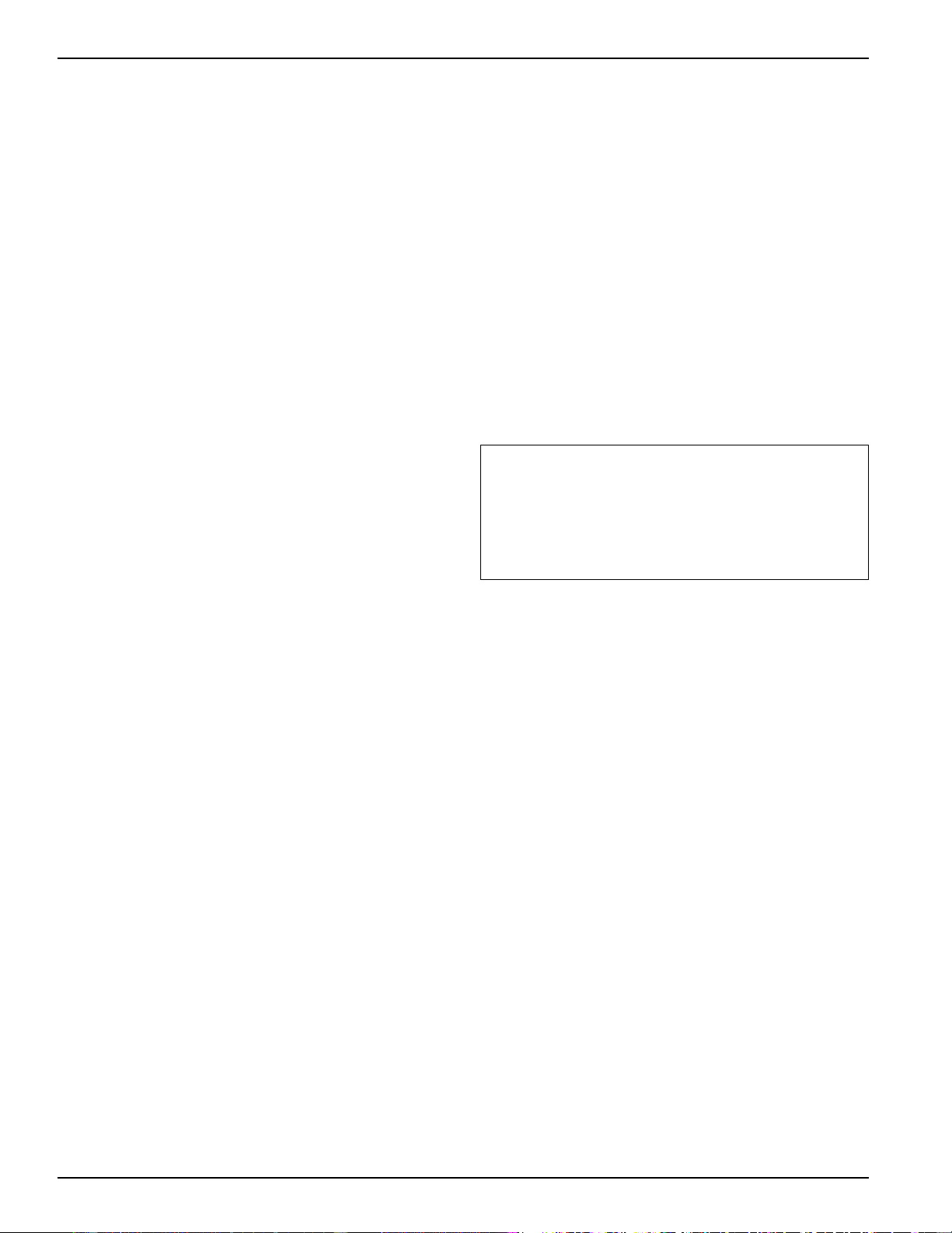
24
Sub-Base (Cont.)
There are separate internal compartments to permit
separation of low voltage (Class 2) connections from line
voltage connections as required by NEC. Conduit containing
building wiring enters the sub-base through knockouts
located in the rear or bottom of the sub-base and is not
accessible when the wall case is installed.
The sub-base attaches to the RAB71 wall case with two clips
(field assembled) that are screwed into pre-drilled holes in
the bottom front flange of the wall case. It attaches to the
RAB77 wall case with clips that fit over molded ribs without
requiring the use of screws into the wall case. See page 33
for illustration. Since the sub-base extends under the wall
case, clearance from the inner edge of the wall case to the
finished wall must be 2-3/8" or greater. The sub-base has 4
leveling legs and adjustable side channels to enable the area
under the wall case to be enclosed. Clearance from the
bottom edge of the wall case to the finished floor must be
between 3" and 5".
The sub-base may be used as support for the chassis and wall
case in installations where the wall is of insufficient thickness
to provide secure mounting of the wall case.
Wall Case Installation Data
General
Generally, Zoneline units are installed 3" to 5" above the
floor (flush to finished floor installation is possible) as near
to the center of the room as possible; underneath a window
or a glass panel is typical. Normal installation of the wall case
allows installation flexibility; from flush with the finished
interior wall to a minimum of 1/4" of the wall case
extending beyond the finished exterior of the building.
Special consideration must be given to installations where
the wall case does not extend a minimum of 1/4" beyond
the finished exterior wall. See pages 30 and 31 for
information on this type of installation. The unit may be
installed high in the wall and these installations usually
require a remote thermostat and are discussed on
pages 17 and 18.
Regardless of the installation, there are several things to
consider when selecting a location for installing the unit. For
instance, drapery location could interfere with air discharge,
and placement of furniture may have an impact on the
performance of the unit. The following information is
intended to minimize installation problems and assure you
of trouble-free installation.
Refer to page 22 for required wall opening dimensions.
Minimum recommended interior and exterior case
projection for standard wall thicknesses are shown in the
drawings in this manual. The case may be installed flush
with the finished indoor wall. Special attention must be paid
to room-side case projection when the unit is installed in a
ducted application as shown on page 39.
In walls thicker than 13 1/2" for line cord connected units
and 11 1/8" for sub-base installations, it may be necessary to
install a field fabricated case extension or use one of the
special order RAB71 deep wall cases. If you are unable to
locate a local source for case extensions please contact your
salesperson for a possible supplier. Such extension must be
carefully flashed and sealed both to the wall case and to the
wall to insure water integrity. This is necessary to insure that
any water entering the wall case, either from operation of
the unit or from other sources, such as rain storms or from
washing the exterior of the building, will drain from the case
without the possibility of capillary action drawing the water
into either the room or the wall cavity. In an installation
where the case is recessed less than 3" from the outside
surface, flashing and sealing may be all the modificaton
necessary. In such an installation, the sides and top of the
wall opening must be waterproof to prevent moisture from
seeping into and damaging the walls. See Pages 30 and 31
for suggested detail. Since the installation of a case
extension requires a considerable amount of attention, we
recommend using one of the deep wall cases if the standard
case is not of sufficient depth.
Mounting an outdoor grille or louver section to the building
face may cause a space between the outdoor coil and the
louver section. Air splitters, aligned with the ends of the
outdoor coil, must be installed between the outdoor coil
inlet and outlet air streams. Gaps between the outdoor coil
and the louver section may allow condenser air recirculation
and affect the operation of the unit. See page 40 for
requirements for custom louver sections.
The wall case should be level from side to side and from
level to 1/4 bubble tilt to the outdoors. The condensate
disposal system in the unit is designed to dissipate the
condensate water generated during cooling operation in
accordance with ARI standards and actually uses this
water for maximum unit efficiency. A level unit will also
insure proper performance of the Internal Condensate
Removal (ICR) system optional on heat pump units.
For new construction, early planning with the architect is
necessary. Unit location, electrical connection locations, and
wall openings of the proper dimensions are essential to
avoid the necessity of rework, fillers, framing, moving
electrical outlets, and other expensive modifications.
For existing construction it is important that carpentry,
masonry and electrical work be performed by competent,
qualified personnel. Since installations in existing
construction may involve removal of building material from
the structure, locating the wall case must be done correctly.
Window, Curtain and Panel Wall Construction
With this type of construction, provision for support of the
unit, other than by the wall itself, is often required. Such
support may be in the form of wood or metallic material of
the proper thickness to maintain a level case. This additional
support should be located both near the wall and at the
front of the wall case. Sub-base (RAK204 Series) with four
leveling legs provides an excellent support for the unit in
this type of installation. See page 28 for details of this type of
installation.
In existing construction, common practice is to remove a
pane of glass, metal, wood, or other construction material
and build a frame around the wall case. Similar filler panel
material may be installed around the case for appearance
and weather seal.
2020 Data Manual 2002 11/7/02 3:19 PM Page 24

25
Masonry Wall Construction (Cont.)
The wall case should be installed during construction and
lintels should be used to support the blocks above the wall
case. The wall case will not support the concrete block. The
installation instructions show how the wall case must be
secured to the masonry and caulked. Do not remove the
cardboard stiffener supplied with the wall case until ready to
install the chassis. See page 29 for details of installation in
masonry wall.
For existing masonry construction, wall openings must be
made by removing concrete blocks to achieve the proper
size opening. Consult the builder, architect, or owner to
determine the necessity for lintels to support the block
above the wall case.
Anchor bolts are normally required to secure the case to the
wall and shims may be required to prevent distortion of the
wall case when securing the wall case to the wall. Field
supplied case angles can be used to position and secure the
wall case to the wall and to cover oversized wall openings.
Brick, Frame, Stucco and Shingle Construction
For new construction, the opening for the wall case should
be framed and the wall case inserted into the opening
during construction. Lintels should be used when the
building material is heavy and is not self supporting (such as
brick). The wall case will fit an opening of six courses of
standard brick or five courses of jumbo brick. Wall framing
in this type construction is normally on 16" centers and the
wall case will fit a framed opening spanning three 16" O.C.
2" x 4" stud spaces.
For existing construction the indoor and outdoor wall will
need to be cut out, allowing for clearances of 1/8" on all
sides of the wall case. Work should begin on the inside wall.
Cut the correct dimensions and mark (using drill holes) the
outside wall from each corner of the inside cutout. Studding
that interferes with the opening must be removed and a
suitable frame constructed to secure the wall case and
provide adequate support for case and chassis.
Preparation of the Wall Case for All Types of
Construction
As shipped, the RAB71 or RAB77 is ready for installation.
Do not remove the stiffener from inside the wall case or the
weather closure panel from the outside face of the wall case
until the outdoor grille and chassis are ready to be installed.
Installation of Wall Case in Wall Opening
1. Position the wall case into the wall. The room side edge of
the RAB71 or RAB77 wall case should be at least flush with
the finished wall for line cord installations and permanent
connection installations when no sub-base is used, and
should project into the room at least 2-3/8" when a sub-
base is used. If the minimum exterior dimensions are not
met, refer to page 27 and 28. The outside edge of the wall
case should extend at least 1/4" beyond the outside wall.
This is necessary for proper caulking, to prevent sealing the
drain holes in the rear flange of the wall case, and to
facilitate the installation of an accessory drain, if used.
The wall case should be level from side to side and from
level to 1/4 bubble tilt to the outdoors. The condensate
disposal system in the unit is designed to dissipate the
condensate water generated during cooling operation in
accordance with ARI standards and actually uses this
water for maximum unit efficiency. A level unit will also
insure proper performance of the Internal Condensate
Removal (ICR) system optional on heat pump units.
2. The wall case should be secured to the wall at both sides.
Use a minimum of two screws or other fastening device
on each side. See Figure 2 page 26. Mark the wall case on
each side 2" from the bottom and 2" from the top at a
point where basic wall structure is located. Drill wall case
and use fasteners appropriate for wall construction. All
holes for fasteners in the side of the wall case must be at
least 2" up from the bottom of the wall case. Never locate
screws or put other holes in the bottom of the wall case.
The only exception is when an RAD10 drain kit is installed
to connect to an internal drain system. See page 36 for
RAD10 Drain Kit information.
If the wall opening is greater than the case dimensions,
spacers must be used on the sides between the wall case
and the wall support structure to prevent distorting the
wall case.
3. Caulk or gasket the entire opening on the outside
between the wall case and exterior wall surface (4 sides)
to provide total water and air seal.
4. Caulk or gasket room-side opening between wall case and
interior wall surface (4 sides). Opening beneath or
around the wall case can allow outdoor air to leak into the
room resulting in increased operating costs and improper
room temperature control.
Care should be taken in location of electrical supply entry in
relationship to wall sleeve to assure access to receptacle or
junction box once unit is installed.
• Refer to page 42 for maximum power cord length.
• Permanent connected units close to finished floor must
allow for conduit clearance.
Case Angles
In some installations such as curtain walls, window walls, or
where the structural material of the wall is insufficient to
support or fasten wall case to, the use of case angles may be
used. Case angles are pieces of steel or other material of
similar structural strength that are formed to a 90° angle,
with holes to fasten the case angle to the wall case and to
the structural component of the wall surrounding the
wall case.
The following describes the procedure when field fabricated
and installed case angles are applied.
1. Position case angles around top and sides of wall case at
the desired location. Position case angles vertically on
each side of wall case to provide a level installation.
2. Mark wall case through holes in case angles. The lowest
hole on the sides of the wall case must be a minimum of
2" above the bottom of the case.
3. For RAB71 wall case drill 5/32" diameter holes at
locations marked on wall case in Step 2, and assemble
angles to wall case using #10 x 1/2" self tapping screws.
For RAB77 wall case follow the same procedure except
use a #10 x 1/2" bolt, washer and nut to attach case angles
to case. Install screws or bolts from outside wall case.
4. Do not drill any holes in bottom of wall case. Do not
distort wall case.
5. Do not use case angles for a lintel.
2020 Data Manual 2002 11/7/02 3:19 PM Page 25
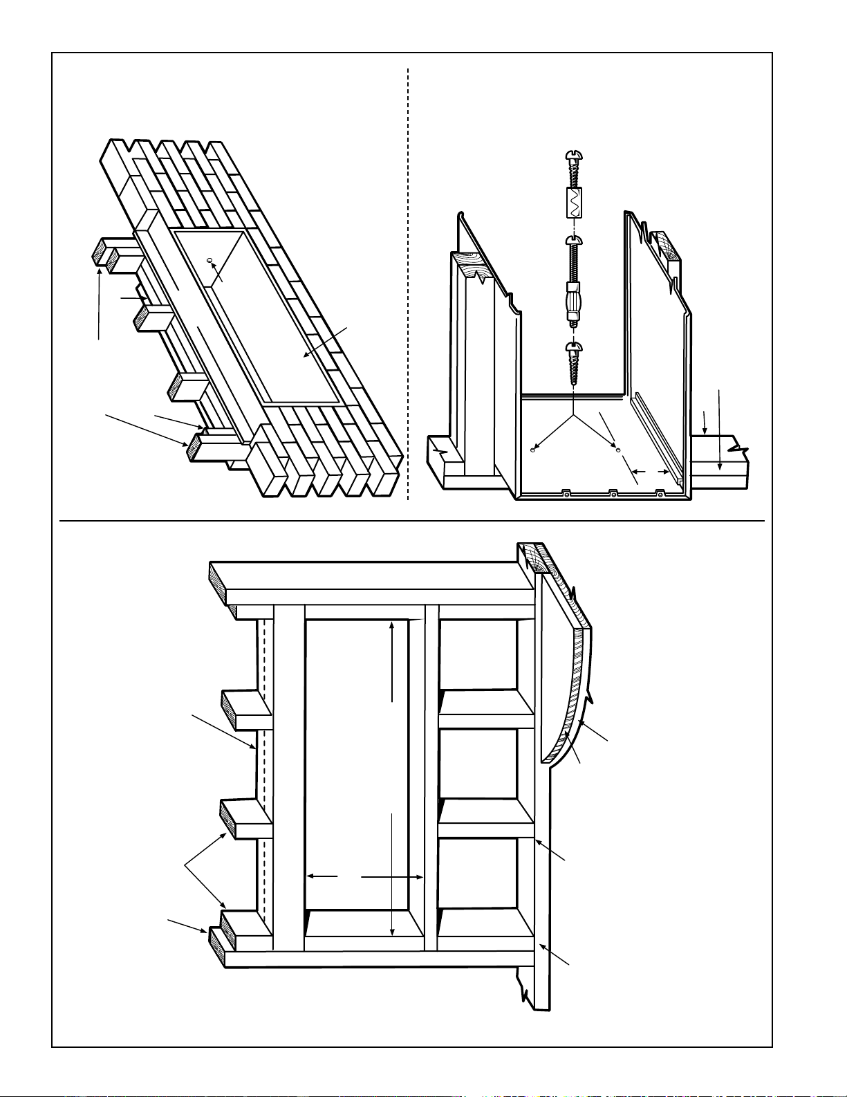
26
FRAMING FOR WALL CASE
BRICK VENEER AND FRAME CONSTRUCTION
FASTENING WALL CASE
Figure 1 Figure 2
MAIN STUD
JACK STUDS
HEADER – 4" x 4" OR
2 - 2" x 4" ON EDGE
16-1/4" MIN. RAB71
16-1/2" MIN. RAB77
ADJUSTABLE FRAMING TO SECURE
THIS DIMENSION
42-1/4" MIN. (RAB71)
42-3/8" MIN. (RAB77)
JACK STUD
CRIPPLE
FINISHED FLOOR
SUB-FLOOR
Note: Do not remove the stiffener
support from inside the wall case
until the chassis is to be installled.
MAIN STUDS
JACK STUD
HEADER
MOUNTING
SCREW HOLE
LINTEL
Framing detail for this construction is as
shown in Figure 1. Note use of lintel
under first course of brick above the
Zoneline case. Do not use the case as a
lintel. Mounting screw holes shown are to
be made by the installer.
NO HOLES PERMITTED
IN BOTTOM OF CASE
(EXCEPTION -RAD10
DRAIN KIT)
Choice of attachment devices
through both ends of case or the
top. Mounting screw holes and
attachment devices by installer.
MAIN STUD
JACK STUD
2" MIN.
WOOD
SCREW
MOLLY
OR TOGGLE
BOLT
EXPANSION
ANCHOR
BOLT
NO HOLES PERMITTED IN
BOTTOM OF CASE
(EXCEPTION - RAD10
DRAIN KIT)
2020 Data Manual 2002 11/7/02 3:19 PM Page 26
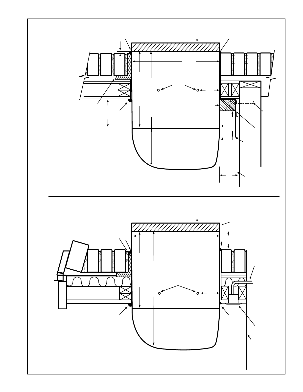
27
WALL SECTION – DETAILED SIDE VIEW
FRAME AND BRICK VENEER INSTALLATION
Cord Set Connected
CAULK*
Sub-Base Connected
CAULK*
STEEL LINTEL
RAB71 13-3/4"
RAB77 13-7/8"
20-7/8" (RAB71)
21" (RAB77)
ROOM
CABINET
2" MIN.
MOUNTING SCREWS
BY INSTALLER
RAB71 16"
RAB77 16-1/4"
WALL CASE
OUTDOOR
GRILLE
CAULK*
CAULK*
1/4"
MIN.
RAG60 1/4"
RAG61, 62, 63 1-3/8"
RAG64, 65, 66 1-3/8"
POWER SUPPLY
CONDUIT
WALL RECEPTACLE
(BY OTHERS)
FINISHED FLOOR
OR TOP OF
CARPET
*Caulk around perimeter of wall case all four sides
where it joins the building - Interior and Exterior.
CAULK*
1/4"
CAULK*
LINTEL
RAB71 13-3/4"
RAB77 13-7/8"
20-7/8" (RAB71)
21" (RAB77)
ROOM
CABINET
2" MIN.
MOUNTING SCREWS
BY INSTALLER
RAB71 16"
RAB77 16-1/4"
WALL CASE
OUTDOOR
GRILLE
SIDE CHANNEL
3" MIN.
5" MAX.
1-5/16"
FINISHED FLOOR
OR TOP OF
CARPET
SUB-BASE
(RAK204)
CAULK*
POWER SUPPLY CONDUIT
(ALTERNATE ENTRY)
3-11/16"
*Caulk around
perimeter of wall
case all four
sides where it
joins the building
- Interior and
Exterior.
2-3/8"
2020 Data Manual 2002 11/7/02 3:19 PM Page 27
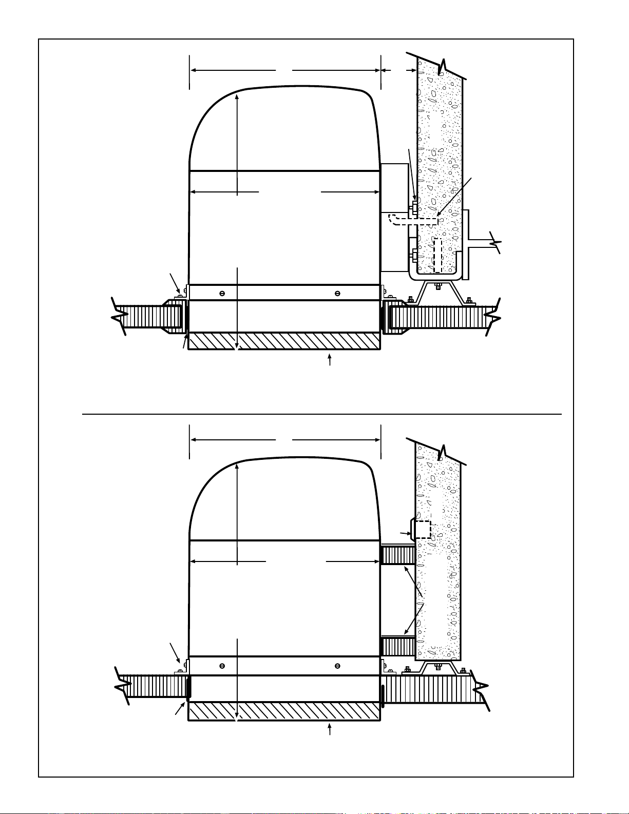
28
WALL SECTION – DETAILED SIDE VIEW
WINDOW, 2" CURTAIN OR PANEL WALL INSTALLATION WITH RAG REAR GRILLE EXTENDED BEYOND OUTER WALL SURFACE
Cord Set Connected Sub-Base Connected
ROOM
CABINET
Gasket and
caulk around
perimeter of
wall case all
four sides
where it joins
the building
WALL CASE
OUTDOOR
GRILLE
Gasket and
caulk around
perimeter of
wall case all
four sides
where it joins
the building
CASE ANGLE (FIELD SUPPLIED)
RAB71 22-1/4"
RAB77 22-3/8"
WITH RAG61-66
RAB71 21-1/8"
RAB77 21-1/4"
WITH RAG60
RAB71
16"
RAB77
16-1/4"
RECEPTACLE
(BY OTHERS)
MIN. 2 SUPPORTS
FIELD SUPPLIED
FLOOR
USE NO
SCREWS IN
BOTTOM OF
CASE
16"
ROOM
CABINET
WALL CASE
OUTDOOR
GRILLE
CASE ANGLE (FIELD SUPPLIED)
RAB71 22-1/4"
RAB77 22-3/8"
WITH RAG61-66
RAB71 21-1/8"
RAB77 21-1/4"
WITH RAG60
RAB71
16"
RAB77A
16-1/4"
16"
WALL OR
WINDOW
GASKET
(FIELD
SUPPLIED)
SIDE
CHANNEL
(RAK204)
SUB-BASE
POWER SUPPLY
CONDUIT
(ALTERNATE ENTRY)
LEVELING LEG
3" MIN.
5" MAX.
FLOOR
2020 Data Manual 2002 11/7/02 3:19 PM Page 28
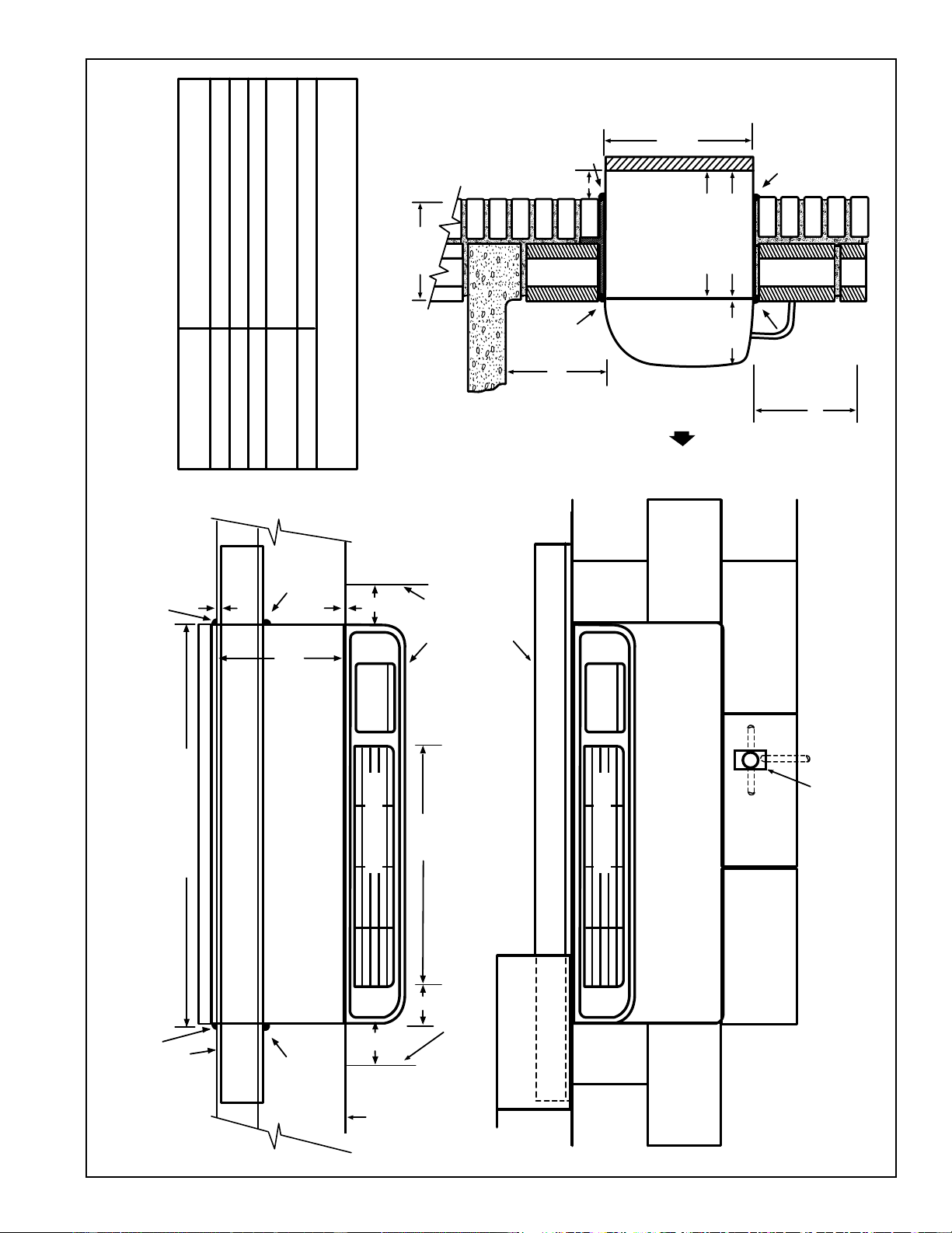
29
WALL CASE INSTALLATION – CORD SET CONNECTED
EXAMPLE: BLOCK AND VENEER – DIMENSIONAL DATA AND COMMENTS
ARE ALSO APPLICABLE TO OTHER TYPES OF CONSTRUCTION
Manufacturer Required
Minimum Installation Clearance
1/4" (See note 1)
Allow For Electrical Wiring 0" Min. (See page 27)
0" Minimum
0" Minimum 2" Recommended
See pages 38-39 for ducted application.
3" Minimum
FINISHED
EXTERIOR WALL
Dimension
A
B
C
D
E
NOTE:
1. FOR OUTSIDE FLUSH MOUNTING SEE PAGE 35 FOR DRAIN INSTALLATION.
CAULK*
CAULK*
CAULK*
CAULK*
CAULK*
CAULK*
CASE
RAB71 42"
RAB77 42-1/8"
FINISHED
EXTERIOR
WALL
ROOM CABINET
RAB71 13-3/4"
RAB77 13-7/8"
ADJACENT WALL
ADJACENT WALL
D
A
C
D
27-1/4"
TOP VIEW
2-1/2"
*Caulk around perimeter of wall case all four sides
where it joins the building - Interior and Exterior.
ROOM CABINET
LINTEL
FRONT VIEW
ELECTRICAL RECEPTACLE (BY OTHERS).
FLUSH MOUNTED.
WALL OPENING
16-1/4" x 42-1/4" MIN. FOR RAB71
16-1/2" x 42-3/8" MIN. FOR RAB77
See page 42 for line cord length.
INSIDE
MAX. WALL THICKNESS
13-1/8"
E
B
A
CAULK*
FINISH FLOOR
*Caulk around
perimeter of wall case
all four sides whiere it
joins the building -
Interior and Exterior.
ROOM
CABINET
7-1/8"
RAB71 13-3/4"
RAB77 13-7/8"
16" RAB71
16-1/8" RAB77
SIDE VIEW OF
ALTERNATE
HIGH MOUNT
With conduit
power supply.
CONDUIT
FIELD
SUPPLIED
2020 Data Manual 2002 11/7/02 3:19 PM Page 29
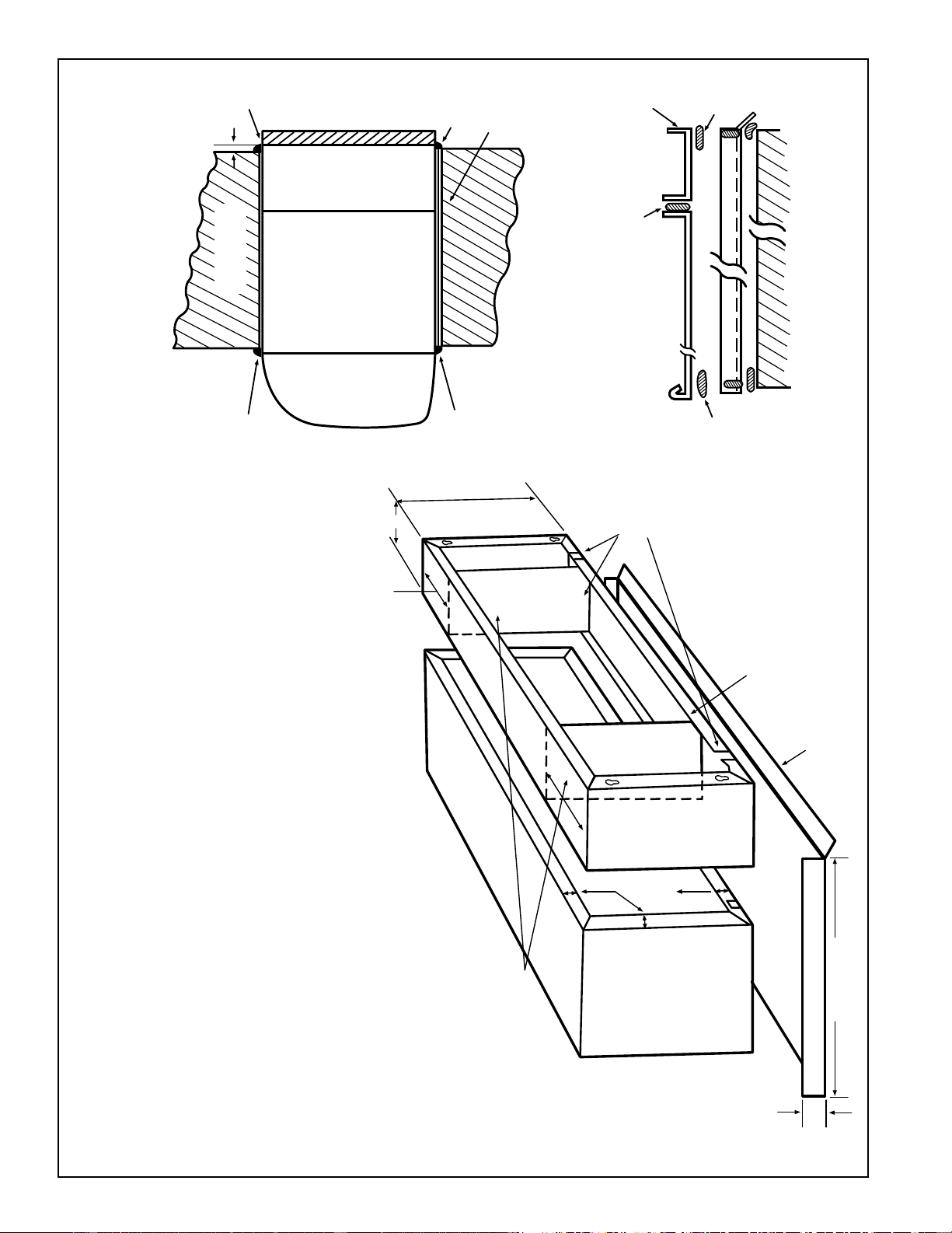
30
METAL CASE EXTENSION FOR WALLS DEEPER THAN 13-1/8" (11-1/8" WITH SUB-BASE)
FIELD FABRICATED – GE RECOMMENDS THE USE OF ONE OF THE DEEPER RAB71 WALL CASES OFFERED AS SPECIAL ORDER ITEMS. SEE PAGE 29.
CAULK*
SPLITTER BETWEEN
AIR INTAKE AND
DISCHARGE
Zoneline units can be installed in walls of greater
depth than the wall case. Where the case recession
is less than 3” and where it is possible to waterproof
the exposed sides and top of the opening, the
suggested procedure is to apply a flashing to the
bottom of the wall case as shown on page 29.
Where waterproofing is questionable or not
possible, or for installations in walls of greater
depth, the following is a suggested application
procedure. It involves the field fabrication of a case
extension. Since the wall case is a water bearing
container, the extension likewise must also be
water bearing and the connection between the two
must be watertight. The case extension must
contain splitters to prevent recirculation of the
outdoor air circuit.
1. The case extension is field fabricated. The
extension depth “D” should allow for a minimum
outdoor projection of 1/4”. This allows for room
cabinet clearance to the finished wall and ample
surfaces to apply sealant or caulking for a tight
weather seal between the completed wall
case/extension assembly and the wall opening. It
is recommended that the extension be painted
and corner and lap joints be additionally sealed
with a quality grade sealant.
2. The wall case and extension should be
connected prior to installation in the wall
opening. A quality grade sealant should be
applied to all four (4) butting flanges. Use bolts
and nuts or oversized self tapping screws
(driven from the wall case to the extension) to
attach the two assemblies. Clean all drain holes
of excess sealant. The assembly must be free
draining.
3. Install flashing, using a quality grade sealant
between the flashing and wall as shown in
section A-A below.
4. Install the wall case/extension assembly
following procedures described for a standard
installation. See diagrams below. The assembly
should be sealed or caulked to the wall around
all four sides both outdoors and indoors.
NOTE: The wall case/extension assembly should
be level.
5. Suggested materials for case extension and
flashing should be non-ferrous metals. Minimal
acceptable material: Galvanized G-90 painted.
SEALANT - ALL
FOUR (4) FLANGES
6-1/4" ± 1/4"
AS REQ'D.
CUT DRAIN SLOTS
IN BOTH FLANGES
(FOUR REQUIRED)
TO MATCH DRAIN
HOLES IN RAB71/77
FLANGES AND
DRAIN HOLE
LOCATIONS
SAME AS ON
WALL CASE
1" WIDE
45° DRIP LIP
FLASHING (FIELD SUPPLIED)
13-3/4" + D"
2" MIN.
D
10-5/8" ± 1/4"
CAULK*
CAULK*
CAULK*
WALL -
ANY
CONSTRUCTION
RAB71/77ROOM
CABINET
CASE
EXT.
SEE DETAIL
SECTION A-A
*Caulk around perimeter of wall case all four sides
where it joins the building - Interior and Exterior.
EXTENSION
ALL 4 FLANGES
WALL CASE
ALL 4
SIDES
WALL
FLASHING
ALL 4
SIDES
SECTION A-A
BASEPAN/FLANGE DESIGN
SHOWING SEALANT LOCATIONS.
1/4" MIN.
RAB71/77
WALL CASE
1-1/2"
(4 SIDES)
EXTENSION
(FIELD
SUPPLIED)
2020 Data Manual 2002 11/7/02 3:19 PM Page 30
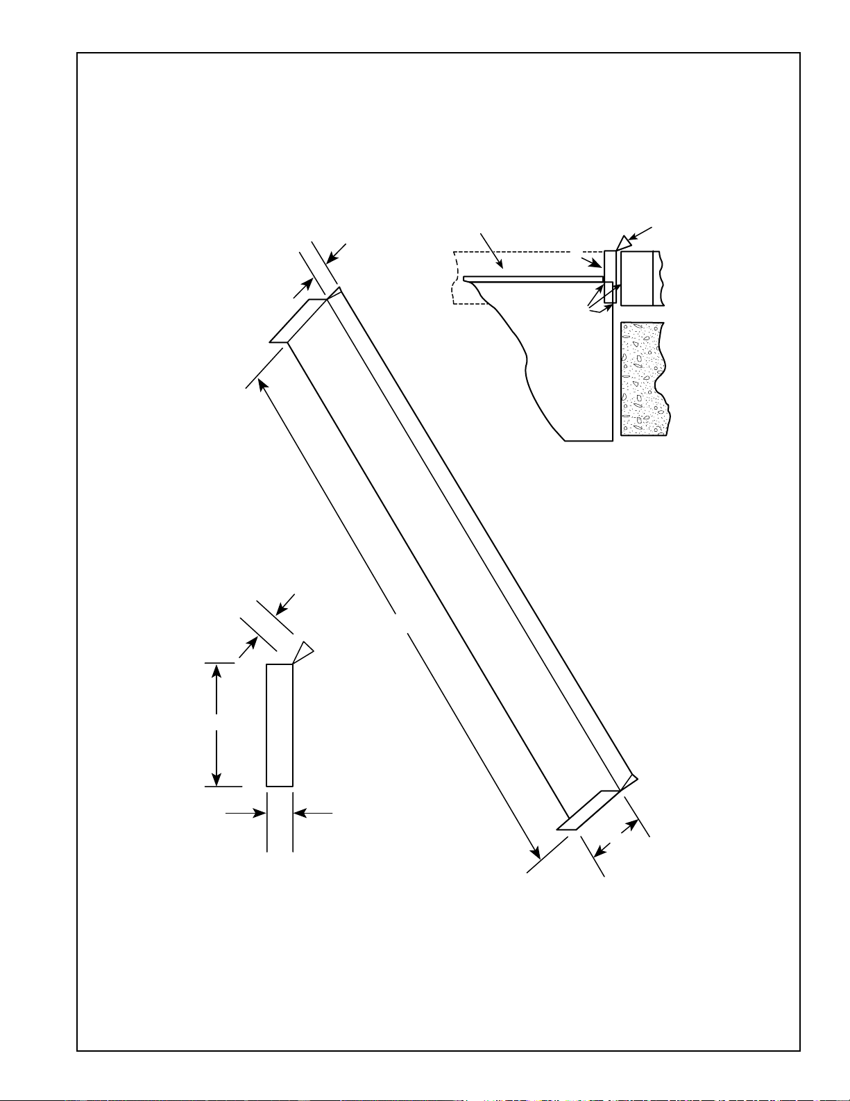
31
ALTERNATE – CASE RECESSION LESS THAN 3" WITH SIDES AND TOP
OF WALL OPENING WATERPROOF, FLASHING ON BOTTOM ONLY
CAULK*
A
DIMENSIONS:
A. DISTANCE FROM GRILLE OR CASE TO OUTSIDE SURFACE OF WALL PLUS 2” TO 4”
(TO INSERT UNDER CASE).
B. 1” DRIP LIP (MINIMUM)
C. 42” PLUS - SUFFICIENT TO FIT SNUGGLY UNDER AND UP AROUND THE CASE.
D. 2” MINIMUM
(CAUTION: WHEN CAULKING DO NOT BLOCK DRAIN HOLES IN CASE OR GRILLE.)
IF GRILLE IS TO BE MOUNTED TO WALL SURFACE A SPLITTERS MUST BE USED, SEE PAGE 30.
B
D
C
A
B
*Caulk around perimeter of wall case all four sides
where it joins the building - Interior and Exterior.
DRIP
FLASHING
OUTDOOR
GRILLE
CASE
For an installation
that will provide
better protection
against water
infiltration, GE
recommends the use
of one of the deeper
RAB71 wall cases
offered as special
order items. See
page 23.
2020 Data Manual 2002 11/7/02 3:19 PM Page 31
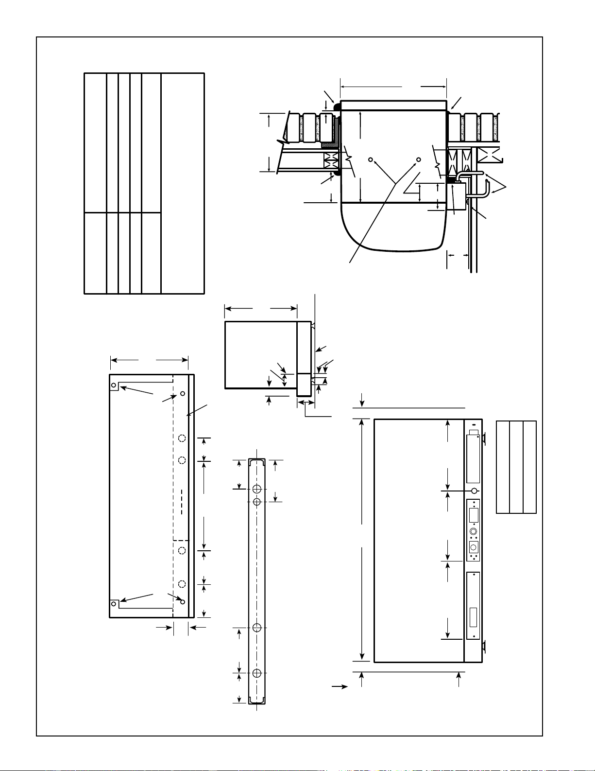
32
RAB71/77 WALL CASE INSTALLATION - RAK204 SERIES SUB-BASE CONNECTED
EXAMPLE: FRAME & BRICK VENEER - DIMENSIONAL DATA AND COMMENTS
ARE ALSO APPLICABLE TO OTHER TYPES OF CONSTRUCTION
TOP VIEW
Manufacturer Required
Minimum Installation Clearance
1/4" (See note 1)
3" Min. (5" MAX.)
2-3/8" Minimum
0" Minimum 2" Recommended
See pages 38-39 for ducted application.
Dimension
A
B
C
D
NOTE:
1. FOR OUTSIDE FLUSH MOUNTING SEE PAGE 31 FOR
DRAIN INSTALLATION.
2-3/8"
MIN.
FINISHED
INTERIOR
WALL
LEVELING SCREW
LEVELING SCREW
RAB71 13-3/4"
RAB77 13-7/8"
5.15" 7.70" 18.86" 1.5"
5.15" 7.70"
10.30"
8.80"
BACK VIEW
FRONT VIEW
42"
D
D
SEE NOTE
LEFT SIDE
INTERIOR
ADJACENT
WALL
12-3/4" 12-7/8" 13"
LEVELING SCREW
KNOCKOUT SIZE
LARGE 1-1/8" DIA.
SMALL 7/8" DIA.
KNOCKOUTS
(ENCLOSURE)
4 REAR; 4 BOTTOM
*SHOWN WITH ACCESS COVERS REMOVED.
NOTE: CAUTION - REMOVE KNOCKOUTS FROM INSIDE OUT.
SIDE VIEW
WITH WALL
CASE SHOWN
IN PLACE
FINISHED FLOOR
3" MIN.
ADJUSTABLE
TO 5"
1-5/16" 2-3/8"
INTERIOR
WALL
RAB71 16"
RAB77 16-1/4"
7/8"
1-1/2"
FINISHED FLOOR
RAB71 16"
RAB77 16-1/4"
SIDE VIEW
MAX. WALL THICKNESS
11-1/8"
MOUNTING SCREWS
AND HOLES BY
INSTALLER
LEVELING SCREWS
(2) SUB-BASE BODY
(2) SIDE EXTENSIONS
CONDUIT ENTRY
(ALTERNATES)
CAULK*
ROOM
CABINET
C
A
B
CAULK*
3-11/16"
2-3/8" MIN. CASE
EDGE TO FINISHED
WALL
13-3/4"
CAULK*
*Caulk around
perimeter of
wall case all
four sides
where it joins
the building -
Interior and
Exterior.
RECOMMEND 2" TO
INTERIOR ADJACENT
WALL BOTH SIDES.
2020 Data Manual 2002 11/7/02 3:19 PM Page 32
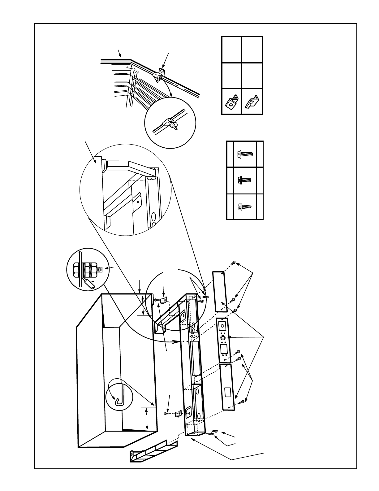
33
RAK204 SERIES SUB-BASE INSTALLATION AND ELECTRICAL DATA
RAB71/77 WALL CASE
RAK4002B
CHASEWAY OPTION
(Shown Without Chassis and Wall Case for Installation Location Only.)
NOTE: TYPE “E”
MOUNTING CLIP MUST
BE USED WITH MOLDED
CASE.
MOLDED
CASE
SUB-BASE
MOUNTING CLIP
TYPE “E”
TYPE
“D”
USE WITH
RAB71
TYPE
“E”
USE WITH
RAB77
TYPE “A” TYPE “B” TYPE “C”
6 REQ’D. 2 REQ’D. 8 REQ’D.
GREEN
GROUND
SCREW
(TYPE “C”)
METAL CASE
SCREW CLIP
TYPE “D”
TYPE “A”
SCREW
TO SECURE
SIDE CHANNELS
6"
5/32" DIA. HOLE (SEE NOTE)
FOR SECURING TYPE “D”
CLIPS TO SLEEVE USING
TYPE “A” SCREWS
6"
TYPE “A”
SCREW
TYPE “C”
SCREW
ACCESS PLATES
TYPE “C”
SCREW
TYPE “B” SCREW
SIDE CHANNELS ARE ADJUSTABLE
FROM 13-3/4" TO 2-3/8" IN LENGTH
BY BREAKING OFF SECTIONS OF SIDE
CHANNELS.
NOTE: IF METAL CASE DOES NOT HAVE SCREW HOLES, 5/32" DIA. HOLES MUST
BE DRILLED 6" FROM EACH SIDE IN FRONT FLANGE. (SEE INSERT).
Electrical wiring may enter the sub-base through any of the knockout holes provided in the sub-base.
Knockout holes in the sub-base access plate may accommodate a receptacle, which allows the use of
a power cord (if permitted by code for the particular installation). A knockout for a circuit breaker, fuseholder
or a disconnect is also provided. See page 23 for description of electrical contents of these sub-bases.
2020 Data Manual 2002 11/7/02 3:19 PM Page 33
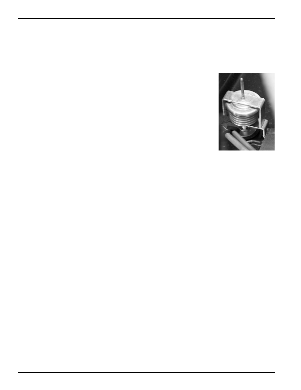
34
Condensate Disposal Systems
Cooling Condensate
Air conditioners produce condensate water as a result of
lowering the humidity of the area being conditioned. When
the indoor coil temperature is below the dew point,
moisture in the air condenses into water droplets on the
coil. This water drains to a pan located under the indoor
coil and is routed through the barrier, the partition
separating the indoor and outdoor sides of the unit, to the
base pan on the outdoor side. It is then picked up and
dispersed against the outdoor coil, which is hot when the
unit is in the air conditioning mode. The water is evaporated
into the atmosphere by contact with the hot outdoor coil.
This evaporation process also helps lower the temperature of
the outdoor coil and improves the operating efficiency of
the unit.
Slinger Ring Systems
Packaged Terminal units employ various means of dispersing
the condensate water against the outdoor coil. One of the
most popular, and most effective, means is by the use of a
“slinger ring”. A “slinger ring” is a ring around the
circumference of the outdoor fan. The design of the unit
positions the slinger ring very close to the bottom of the
base pan so water in the base pan is lifted by the rotating
ring. Water picked up by the slinger ring will be dispersed
into the air stream and deposited on the hot outdoor coil
where it evaporates.
All Zoneline Series Packaged Terminal Air Conditioners and
Packaged Terminal Heat Pumps utilize a slinger ring for
cooling condensate disposal.
Certification Test Requirements
ARI (Air Conditioning & Refrigerating Institute) requires
that all certified Packaged Terminal Air Conditioners and
Packaged Terminal Heat Pumps pass a cooling condensate
disposal test. One stipulation of the ARI test is that “the test
start with condensate collection pan brimful”. In order to
pass the ARI Condensate Disposal Test the unit must operate
continuously for four hours without condensed water
blowing, dripping, or running off the unit casing during the
test or after the unit has been turned off. Under extremely
high outdoor humidity conditions or extreme operating
conditions, such as exceptionally high air infiltration (a door
or window left open while the unit is running, for instance)
it is possible for any air conditioner to be unable to dissipate
all the cooling condensate generated.
All Zoneline Series Packaged Terminal Air Conditioners and
Packaged Terminal Heat Pumps meet the condensate disposal
requirements of ARI standards 310-93 and 380-93.
Heat Pump Condensate
During the operation of a unit in the heat pump, or “reverse
cycle”, mode the outdoor coil becomes the cold coil and the
indoor coil becomes the hot coil due to reversing the flow of
the refrigerant. When the temperature of the outdoor coil is
below the dew point, condensation will form on the outdoor
coil just as it does on the indoor coil during cooling
operation. Since the dew point is humidity as well as
temperature related, there may be more condensate on days
when the relative humidity is high.
Heat Pump Condensate Disposal
Since the outdoor coil is cold during heat pump operation,
the condensate water cannot be deposited on the outdoor
coil as the water would cause frost to form on the coil. This
frost would block the air flow through the coil and greatly
diminish the ability of the heat pump to extract heat from
the outdoor air. Rather than allow this problem to occur,
heat pump units must dispose of the condensate in another
manner.
Temperature Activated Drain Valve
The most widely used method
of disposing of heat pump
condensate is with a
“Temperature Activated Drain
Valve”. This is a device
mounted in the base pan of a
heat pump unit with a bellows
that expands on temperature
rise and contracts with
temperature drop. A shaft with
a rubber plug on the end is
connected to the bellows.
When the outdoor
temperature remains above a
certain temperature, the
bellows is expanded and the
plug fits tightly into a hole in
the bottom, or base pan, of the unit. When the plug is
blocking the hole, as it should be during cooling operation,
the condensate water is contained in the base pan. At
temperatures when heating is required, the bellows
contracts, the rubber plug is retracted from the hole and the
heat pump condensate water is allowed to drain into the wall
case. The valve is fully open at 49°F.
Drain Kits
Although the Zoneline units are designed to dissipate all of
the condensate generated during normal cooling operation,
there may be times when abnormal operating conditions
cause more condensate than the unit can dissipate. Heat
pumps also generate condensate that the unit may not be
designed to dissipate. For these reasons, if condensate
dripping from the wall case is objectionable, an internal or
external drain system should be installed. See pages 35 and
36 for information covering the drain systems and the
RAD10 kit available to connect to the wall case.
Internal Condensate Removal (ICR) System
GE has developed an Internal Condensate Removal (ICR)
System for Packaged Terminal Heat Pumps. This system has
been offered as an option on Zoneline Packaged Terminal
Heat Pumps since 1982, and thousands of them are in use.
During heat pump operation the ICR system utilizes a small
pump to lift the water from the base pan and pump it into a
collector tray positioned above the indoor coil. The water
drains from the collector tray and drips onto the warm
indoor coil where it is evaporated into the room atmosphere.
If an excess amount of water is pumped to the indoor side, it
is routed back to the outdoor portion of the base pan.
The ICR system has proven to be an effective means of
minimizing the amount of heat pump condensate dripping
from the unit. However, if the restrictions of a particular
installation will allow absolutely no drippage of condensate
water from the wall case, the installation of an internal or
external drain system is recommended.
Units with ICR may not be installed in seacoast or corrosive
environment applications.
2020 Data Manual 2002 11/7/02 3:19 PM Page 34
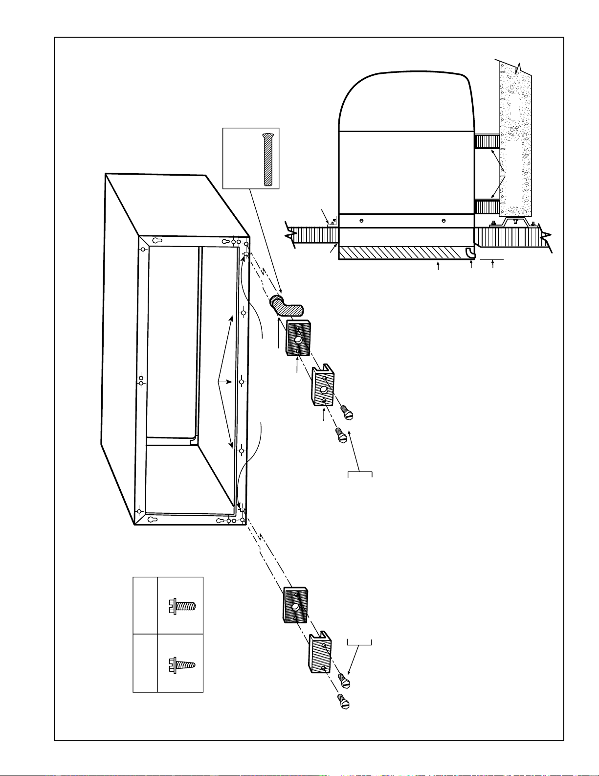
35
WALL CASE WITH RAD10 DRAIN KIT
EXTERNAL DRAIN
SEE PAGE 36 FOR INTERNAL DRAIN
SEE PAGE 36 NOTE #6
SCREWS
REAR
GRILLE
“A”
METAL
“B”
PLASTIC
SQUARE DRAIN HOLES
NEOPRENE SPONGE GASKET
1/2" O.D. 90° ELBOW DRAIN TUBE
STEEL MOUNTING PLATE
USE TYPE “A” SCREW FOR METAL CASE (RAB71)
AND TYPE “B” SCREW FOR MOLDED CASE (RAB77)
Alternate
6" long, 1/2"
O.D. straight
copper tube.
NOTE: SHADED PARTS AND
SCREWS ARE INCLUDED
WITH RAD10 DRAIN KIT.
USE EITHER THE 90°
ELBOW TUBE OR THE
STRAIGHT TUBE
DEPENDING UPON THE
REQUIREMENTS OF THE
PARTICULAR
INSTALLATION.
WALL CASE ROOM
CABINET
PROJECTION
BEYOND WALL
CASE
90° ELBOW
DRAIN TUBE
MIN. 2 SUPPORTS
FIELD SUPPLIED
FLOOR
CASE ANGLES (FIELD SUPPLIED)
TYPICAL INSTALLATION
Caulk around
perimeter of
wall case all
four sides
where it joins
the building.
3"
4"
WATER DRAINAGE - Precipitation entering the unit through the outdoor louver may not be removed entirely by the
condensate removal system. The base pan flange is designed to allow excess water, either condensate water or
precipitation, to flow into the wall case and drain through two drain holes in the rear of the wall case. If there is more
water in the wall case than can be drained through these holes it will drain through the three overflow drain holes.
These drain holes must not be blocked when mounting or caulking the wall case.
For those installations where water draining from the drain holes is objectionable or where positive drainage is
desired, the RAD10 drain kit is available with either a 90° elbow or a 6” straight tube to be used either to connect to a
field supplied drain line or to allow the water to drip free rather than drain down the surface of the building.
NOTE: Drain kit using either the 90° elbow tube or the straight tube may be installed without modification when using
RAG60 exterior grille. Drain kit using the 90° elbow tube may be installed without modification when using RAG61
through RAG66 exterior grilles. Modification must be made to the RAG61 through RAG66 exterior grilles when using
the straight tube. Modification must be made to the RAG67 grille if using either the 90° elbow tube or the straight tube
(see installation instructions with the RAG67 grille).
2020 Data Manual 2002 11/7/02 3:19 PM Page 35
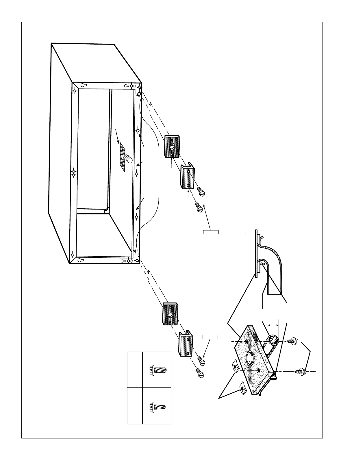
36
WALL CASE WITH RAD10 DRAIN KIT
INTERNAL DRAIN
SEE PAGE 35 FOR EXTERNAL DRAIN
SCREWS
“A”
METAL
“B”
PLASTIC
SQUARE DRAIN HOLES
NEOPRENE SPONGE GASKET
STEEL MOUNTING PLATE
USE TYPE “A” SCREW FOR METAL CASE (RAB71)
AND TYPE “B” SCREW FOR MOLDED CASE (RAB77)
NOTE: SHADED PARTS AND SCREWS
INCLUDED WITH RAD10 DRAIN KIT.
THE 90° ELBOW TUBE IS
RECOMMENDED FOR INTERNAL
DRAIN INSTALLATION.
OVERFLOW RELIEF DRAIN
SEE NOTE 6
SEE DETAIL
BELOW
USE TYPE “A” SCREWS FOR BOTH RAB71 AND RAB77
NUT
(MOLDED CASE (RAB77) ONLY)
DETAIL
GASKET
CABINET BOTTOM
TUBE
1/2" OD
COVER
PLATE
1. THE RAD10 DRAIN KIT IS INSTALLED IN THE BOTTOM OF THE WALL CASE WHEN IT IS DESIRED TO
DRAIN CONDENSATE TO AN INTERNAL DRAIN SYSTEM IN THE BUILDING.
2. THE DRAIN KIT IS MOUNTED ON THE BOTTOM OF THE WALL CASE PRIOR TO INSTALLATION OF
THE CASE IN THE WALL. IT MAY BE LOCATED ANYWHERE ON THE ROOM SIDE PORTION EXCEPT
FOR SUB-BASE INSTALLATIONS. FOR THESE THE DRAIN SHOULD BE AT LEAST 3" FROM THE
INDOOR EDGE OF THE CASE SO AS TO ADEQUATELY CLEAR THE SUB-BASE.
3. A TEMPLATE IS FURNISHED WITH THE KIT FOR LOCATING THE NECESSARY 3 HOLES IN THE CASE
BOTTOM - TWO TO PROVIDE A SECURING MEANS AND ONE TO PROVIDE A DRAIN HOLE FOR THE
1/2" OD TUBING. (SEE DETAILS AT LEFT)
4. A TUBE OR HOSE 1/2" I.D. (OBTAINED LOCALLY) MUST BE INSTALLED ON THE DRAIN TUBE AND
CONNECTED TO THE INTERNAL DRAIN SYSTEM IN THE BUILDING.
5. WITH THE RAD10 THE TWO SQUARE DRAIN HOLES IN THE BOTTOM OUTER FLANGE OF THE
WALL CASE ARE SEALED BY THE GASKETS AND MOUNTING PLATES SHOWN ABOVE.
6. THREE (3) 1/2" DIAMETER HOLES LOCATED 1/4" ABOVE THE CASE BOTTOM IN THE BOTTOM
OUTER FLANGE PROVIDE OVERFLOW DRAINAGE TO THE OUTDOORS WHEN WIND DRIVEN RAIN
ENTERS THE CHASSIS.
2020 Data Manual 2002 11/7/02 3:19 PM Page 36
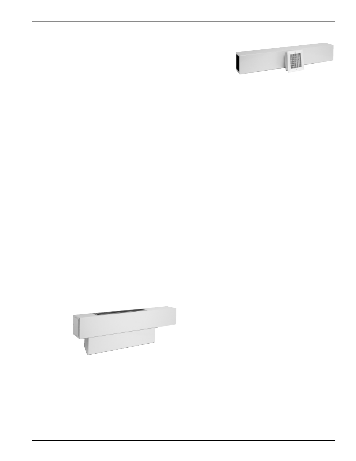
37
Ducted Installations
2500 and 3500 Series Zoneline units may be
used in ducted installations.
With a ducted installation it is possible to condition the air
in two areas that have a common wall separating them. A
special adapter mounts on the wall case and a transition
piece directs the air from the unit into the adapter.
Instructions for mounting the adapter to the wall case are
included with the duct adapter. The adapter contains a grille
that allows air from the unit to be discharged into the
primary room and the adapter connects to a duct extension
that allows the air to flow to the adjoining room. Ducting a
unit may allow a single unit to be used rather than a
separate unit in each room, providing a means of reducing
initial equipment cost. The duct may extend a total of 15
feet (with a field fabricated insulated duct extension) in one
direction, either to the right or to the left of the unit. A
baffle in the adapter allows up to 50% of the discharge air to
be delivered to the secondary room.
The installation of the wall case and sub-base, if used, is the
same for units being ducted as for free-standing units. The
duct adapter support bracket overlaps the wall case by 1"
and the bracket and mounting screws add approximately
3/8" (3/16" on each side) to the width of the wall case. If
less than 1" of the wall case projects into the room it will be
necessary to allow for the additional width in the opening
for the wall case. The duct adapter mounting brackets
should be mounted prior to installing the case in the wall.
Refer to pages 38 and 39 for drawings of ducted
installations.
Prior to the installation of the transition from the room
cabinet to the adapter, it will be necessary to remove the
discharge grille from the room cabinet. Instructions for this
modification are included with the duct adapter.
New Ducted Installations
Components
Duct Adapter RAK6052 - The duct adapter is secured to
each side of the wall case and requires the drilling of
mounting holes
in the wall case
during
installation.
A template for
the hole
location is in
the installation
instructions.
By securing
the duct
adapter to the
wall case, the chassis retains the slide-out feature for
servicing after the transition piece is removed.
Duct Extension RAK601 - This kit contains a 44" long
insulated duct, a register mounting collar, and an air supply
register. It can be secured to the duct adapter at either end
of the adapter. This duct may be cut at any dimension and
used in two applications providing the sum of the two duct
lengths necessary do not exceed the 44" length. Even in
single applications the mounting flange must be cut off one
end of the duct to accept the collar and supply register.
Mounting Collar and Supply Register RAK602 These
components are included in the Duct Extension Kit
RAK601. They
may be ordered
separately for
installations
where two duct
extensions are
made from one
RAK601.
Ducted Application
Considerations
When designing a ducted application some application
considerations to be made include:
1. Do not exceed the 15 foot length maximum for the duct
extension. Field supplied duct extension must be
completely insulated with minimum of 1/2" insulation
2. The duct must be a straight run. Turns or bends in the
duct extension create air pressure drops that the unit is
not designed to overcome.
3. Minimum recommended clearance between the unit and
the adjacent wall is 2".
4. Provisions for return air must be made to allow air
circulation from secondary room. Doors in both
secondary and primary rooms may be undercut or a
return grille may be installed through a common wall.
5. When calculating the heat gain / heat loss take both areas
into consideration.
Replacements of Existing
Ducted Units
Since the design of the Zoneline chassis has changed over
the years to provide better performance and appearance,
some of the components used in ducted applications have
changed. Select the proper components from the
information below. The best procedure in determining the
correct kit is to measure duct extension cross section.
Flat Top-Discharge Units
(Zoneline Units Built Prior to 1988)
Existing Duct Extension Cross Section Measurements:
8-3/8" height x 6-1/2" width
Duct Adapter RAK7012 - This duct adapter will allow the
replacement of a new chassis (2500 or 3500 Series unit) into
an existing ducted application. This adapter will align
properly with the duct extension and will eliminate the need
to modify the wall opening. In order to minimize
replacement costs, some of the components of the old duct
adapter must be removed and used in the new installation.
Consult the Installation Instructions of the RAK7012 before
removing and discarding the old duct adapter. See
additional notes page 58.
Slope-Front Discharge Units
(Models With AZC, AZR, AZW, or AZ21 or AZ31 Prefix)
Existing Duct Extension Cross Section Measurements:
7-3/32" height x 6-1/2" width
Duct Transition RAK7022 - This duct transition will allow the
replacement of a new slope-front discharge Zoneline chassis
(2500 or 3500 Series unit) into a previous design slope-front
ducted installation. See additional notes page 58.
Duct Adapter RAK6052
RAK601 Duct Extension,
Mounting Collar and Register
2020 Data Manual 2002 11/7/02 3:19 PM Page 37
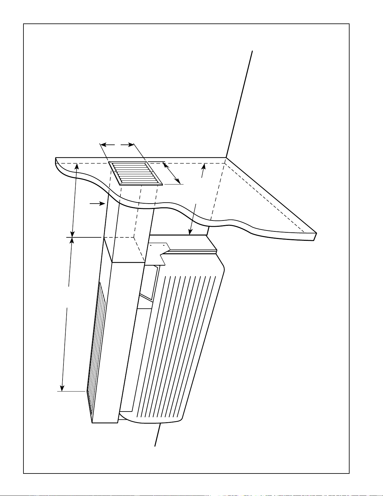
38
DUCTED APPLICATION (AZ2500/3500 SERIES)
44"
DUCT ADAPTER EXTENSION HAS 1/2" INSULATION
NOTES:
1. RAK6052 kit includes duct adapter, transition and mounting hardware.
2. RAK601 duct extension may be installed at either end of the RAK6052 duct adapter.
Maximum duct extension length is 15'. Duct extension must be field fabricated for
installations where length of duct exceeds length of RAK601 (44"). Field fabricated duct
extension must be insulated to prevent condensation from forming on exterior. Duct
extension may not contain bends or turns.
3. Ducted units may need to be permanently connected. Check local code for specific
electrical installation requirements.
4. Duct extension kit RAK601 contains 44" duct extension, discharge grille mounting collar,
and discharge grille. Duct extension must be cut to required length. Two ducted
installations may be made from one kit if the combined ducted length is less than 44".
RAK602 kit contains mounting collar, discharge grille and mounting hardware necessary
for second installation.
5. Filler strip (field supplied) actual width depends upon wall case projection into room.
A flush installation to finished wall (i.e., no filler strip) can be made.
6. Unit must be installed to provide at least a 2" clearance between side of unit and wall.
7. Provisions for return air must be made in order to allow air circulation from secondary
room. Doors in both secondary and primary rooms may be undercut or a return grille
may be installed through common wall.
8. For replacement of previous design units, see pages 37 and 58.
RAK601
44" LENGTH
RAK6052
ADAPTER
TRANSITION
8" high
RECOMMENDED
MINIMUM
CLEARANCE
2" TO SIDE WALL
7-3/8"
wide
2020 Data Manual 2002 11/7/02 3:19 PM Page 38
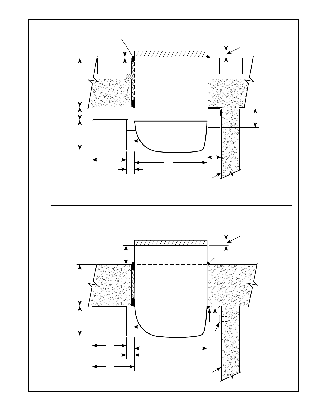
39
DUCTED DETAILED SIDE VIEWS (AZ2500/3500 SERIES)
SEE PAGE 38 FOR ALL NOTES
Line Cord Installation
CAULK*
Sub-Base Installation
ANY CONSTRUCTION
12-3/4"
MAX.
6-1/2"
10" 7-3/32"
RAK6052
ADAPTER
16-1/8"
TRANSITION
ROOM
CABINET
3/4" MIN.
WALL TO
CASE EDGE
WALL CASE
FINISHED
FLOOR
RECEPTACLE
(BY OTHERS
ALT. LOCATIONS)
CAULK*
RAG60 - 1/4"
RAG61-66 - 1-3/8"
*Caulk around perimeter of wall case all four sides
where it joins the building - Interior and Exterior.
1/4"
MIN.
2-29/32"
*2-3/8" min. when installed with RAK204.
RAG60 - 1/4"
RAG61-66 - 1-3/8"
3-11/16"
RAK
204
3" MIN.
5" MAX.
FINISHED
FLOOR
16-1/8"
TRANSITION
ROOM
CABINET
WALL CASE
Caulk around
perimeter of
wall case all
four sides
where it joins
the building -
Interior and
Exterior.
2-29/32"
7-3/32"
RAK6052
ADAPTER
FILLER STRIP (SEE NOTE 5 ON PAGE 36)
6-1/2" 11-1/8"
MAX.
2-3/8"*
MIN.
1/4"
2020 Data Manual 2002 11/7/02 3:19 PM Page 39
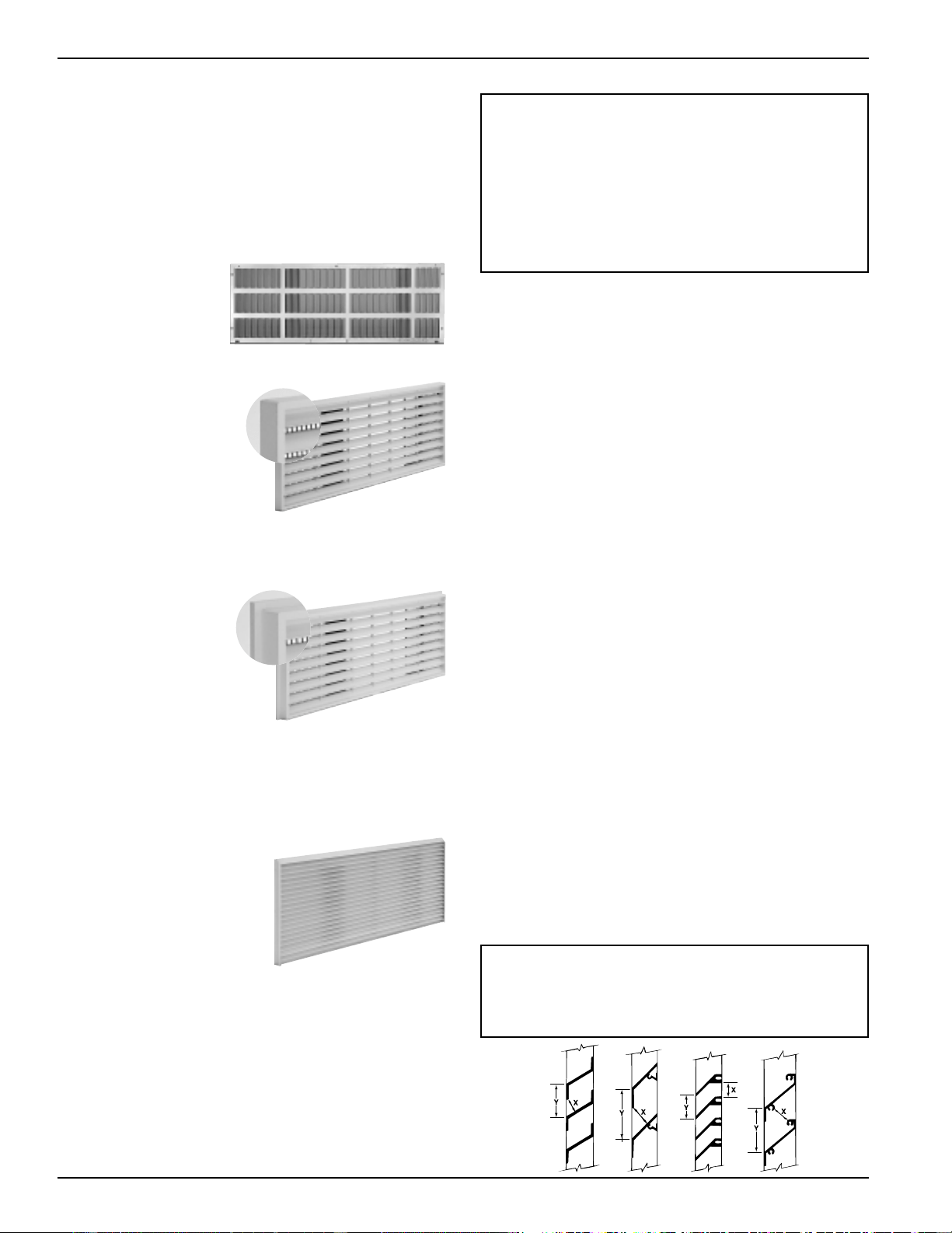
40
Exterior Grilles
Four styles of outdoor grilles are available for exterior
treatments. The standard stamped aluminum grille
(RAG60), the molded architectural louvered exterior grilles
(RAG61-63), the molded architectural louvered exterior
grilles with flange (RAG64-66), and the extruded aluminum
architectural louvered grille (RAG67). All grilles include air
deflectors and gaskets to prevent condenser air
recirculation.
RAG60 Outdoor Grille -
The standard exterior
grille is made of durable
aluminum to protect
chassis components and
prevent air recirculation.
RAG61, 62, 63 Architectural
Grille - One piece optional
molded grille and frame
assembly provides improved
appearance, protection and
weatherability. Molded of
durable polycarbonate, the
surfaces of the grille have a
colorfast, slightly textured
finish which blends well
with most types of wall
surfaces. The grilles can be painted in the field to match the
building for improved aesthetics.
RAG64, 65, 66
Architectural Grille with
Flange - Identical to
RAG61-63 grilles with the
addition of a 1/2" flange
around the top and sides to
help conceal the juncture
of the RAB71 wall case and
the wall opening. The best
appearance is achieved with
this grille when the wall case extends minimally (between
1/4" and 1/2") beyond the exterior face of the building.
Colors: RAG61 and 64 - Beige; RAG62 and 65 - Dark Maple
RAG63 and 66 - Bittersweet Chocolate.
RAG67 Extruded
Aluminum Grille - The
RAG67 is made from
extruded anodized
aluminum for use where
an aluminum architectural
grille is preferred. The
RAG67 is available in a
clear finish and may be
special ordered from GE in
other colors. Minimum order quantities may be required.
Contact your General Electric salesperson for details.
All grilles are installed and secured to the wall case from the
inside. Keyhole slots in the rear flange of the case allow the
grille to be placed in position before securing it firmly to the
wall case.
Replacement of existing units: If an existing grille is not
replaced, capacity and efficiency will be reduced and the
unit may fail to operate properly or fail prematurely. A
deflector kit, RAK40, may be used with grilles that were
not designed for current AZ Series GE Zoneline units.
The RAK40 contains air deflectors and gaskets that
mount to the chassis to direct the hot exhaust air away
from the air intake to allow the unit to function properly.
All grilles used with GE Zoneline units must comply with
requirements of Exterior Architectural Treatments and
Special Outdoor Grilles. as follows.
Exterior Architectural
Treatments and Special
Outdoor Grilles
The architectural design of a building may dictate the use of
special or oversized louvers for aesthetic reasons. Louvers
other than standard Zoneline exterior grilles may be used
on the Zoneline unit, however, these special louvers, or any
special exterior architectural treatments of the building
facade that may restrict the free circulation of condenser
airflow, should be referred to GE Application Engineering
for evaluation and approval. The following guidelines should
be followed in selecting a louver:
1. The louver must have a minimum of 65% free area.
ASHRAE defines free area as the minimum area of the
opening in an air inlet or outlet through which air can
pass. Percent (%) free area equals the X dimension
divided by the Y dimension.
2. The louver should be attached to the wall case in a
manner that will prevent recirculation of condenser
discharge air into the air inlet. If the louver is not
attached directly to the wall case, a field supplied splitter
or gasket is required between the chassis and the louver to
prevent recirculation.
It is important that the above criteria be followed since a
louver that is too restrictive or allows recirculation will
reduce the unit’s capacity and efficiency, increase the
electrical current draw, cause intermittent operation due to
the compressor overload protector shutting the compressor
off, and cause failure of the compressor overload and
shorten compressor life. Using the unit with a grille that is
too restrictive or allows recirculation may constitute
improper installation. A scale drawing of the louver section
should be sent to GE Application Engineering. To assure
the proper performance of the Zoneline unit and comply
with Underwriters Laboratories requirements, it may be
necessary to send a sample louver section (at least 16" x 42")
to GE to be tested with the Zoneline unit.
RAG60 Outdoor Grille
RAG61 Outdoor Grille
RAG64 Outdoor Grille
RAG67
Sample Calculations
Free Area (%) = x 100 x = 1" y = 1.5"
F.A. % = x 100 = 66.7%
x
y
1
1.5
2020 Data Manual 2002 11/7/02 3:19 PM Page 40
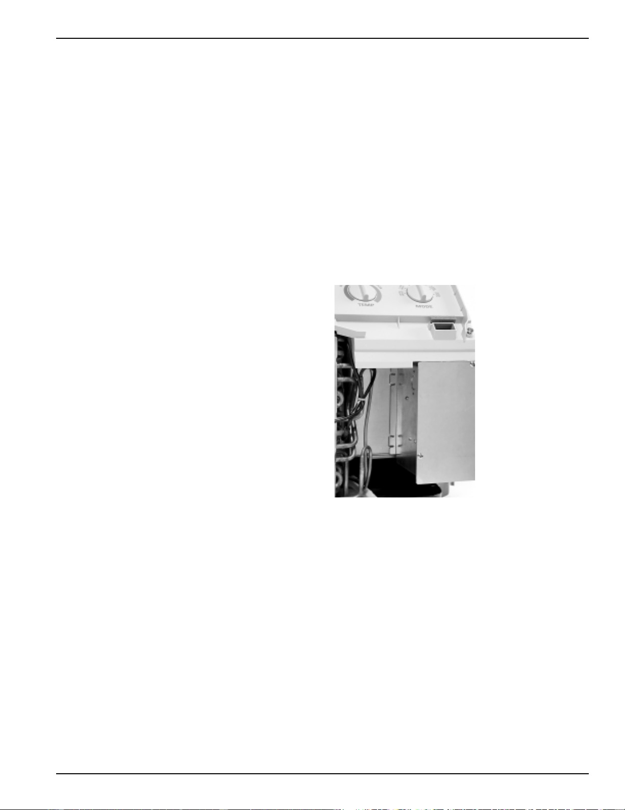
41
Power Connection For Deluxe
Series (2500 & 3500)
The Zoneline 2500 and 3500 Series units have discrete heater
wattages. Each unit has a factory installed heater and must be
installed on an electrical circuit with sufficient over-current
protection to carry the amperage load of the unit. See
specifications on page 54 for model number nomenclature,
heater amperage, and minimum circuit ampacity for the
particular Zoneline model. To determine maximum
connected load for individual model see page 44.
230/208 Volt Unit Installation - Line Cord Connected Units
Zoneline 2500 and 3500 series units for installation on 230 or
208 volt circuits have a factory installed line cord with a plug
conforming to NEC standards for the circuit amperage.
Graphic representation of the wall receptacles are shown on
page 42. The line cord length is also shown on page 42.
230/208 Volt Unit Installation - Permanent Connected Units
If a permanent, or direct wired, installation of a 230 or 208
volt units is desired, a junction box kit, RAK4002A, is
available to allow direct connection when the 208/230 volt
chassis is installed with the appropriate electrical sub-base.
When the cord set is enclosed by the RAK4002A and the
sub-base chase way RAK205CW, the wiring is totally enclosed
and the unit is considered to be permanently connected
(correct ampacity RAK204 series sub-base required).
If an installation using flexible conduit is desired, the
RAK4002A kit mounts to the chassis to form an enclosed
junction box with a removable front panel for access to the
unit wiring. A 7/8" diameter hole in the bottom of the
enclosure enables field supplied rigid or flexible conduit to
be connected to the kit. A wiring harness of three conductors
and an in-line connector is included with the RAK4002A.
The factory installed line cord must be cut off approximately
8" from where it comes through the barrier, or bulkhead, of
the unit. Strip insulation off 3/4" of each conductor to expose
wire for field connection. These wires are then connected to
the building wiring by field supplied connectors.
265 or 277 Volt Unit Installation - Permanent Connected
Units
National Electric Code (Article 440 Section G) requires
permanent connection for units connected to power sources
over 250 volts, therefore these units must be permanently
connected (direct wired).
Zoneline 2500 or 3500 Series units rated for installation on
265 volt circuits have discrete heater wattages and the
appropriate cord set to match the 265 volt sub-base
receptacle installed in this sub-base. When installed with the
correct sub-base and chaseway the wiring is totally enclosed
and the installation is considered to be permanently
connected. If there are any questions regarding electrical
connection at the unit GE recommends consulting with your
local electrical inspector.
A junction box is included with every 265/277 volt chassis to
facilitate the installation of conduit if desired. A 7/8"
diameter hole in the bottom of the RAK4002A junction box
enables field supplied rigid or flexible conduit to be
connected to the unit. A knockout is provided in the junction
box for the installation of a field supplied cartridge type fuse,
if required. A wiring harness of three conductors and an in-
line connector is included with the RAK4002A. This wiring
harness can be ordered separately as RAK4002CW to facilitate
chassis removal.
When direct connecting the unit, connections to the
building wiring should be made in the junction box with
field supplied connectors.
All wiring must conform to local electrical regulations and
codes.
RAK4002A
Wire harness can be ordered
separately with RAK4002CW
2020 Data Manual 2002 11/7/02 3:19 PM Page 41
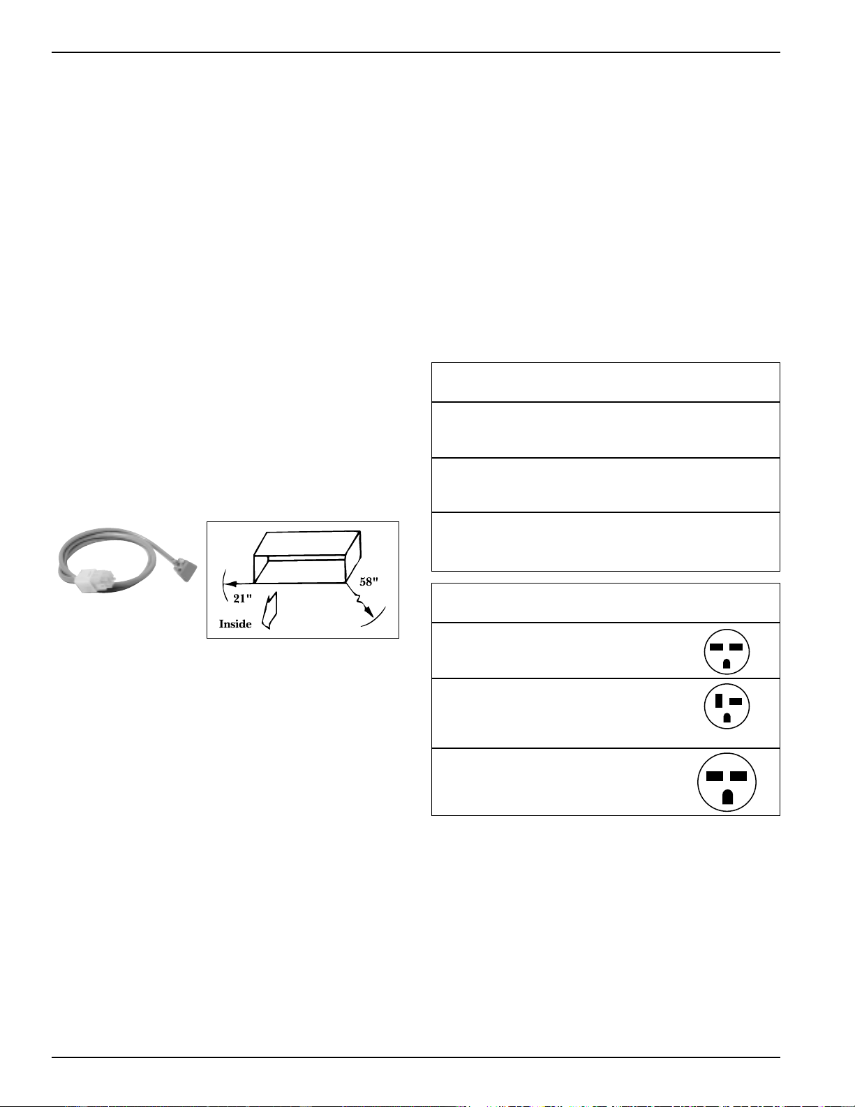
42
Power Connection Kits For
Premium Series (5500)
The Zoneline 5500 Series units are connected to the
building power supply by a unique power connection kit.
By utilizing a separate universal power connection (UPC)
kit, each unit is capable of providing various outputs of
electric resistance heat to more closely meet the heating
requirements of the particular room, thereby increasing the
installation flexibility of the particular chassis. This power
connection kit is the only means of supplying power to the
Zoneline chassis and the appropriate kit is determined by
the voltage and the desired resistance heat output that may
be supported by the branch circuit.
230/208 Volt Installations
Connections to 208 or 230 volt circuits may be made with a
line cord power connection kit.
Line Cord Kits consist of a self-aligning 9-pin molded
connector that plugs into a mating connector on the
Zoneline chassis and insulated line cord with an electrical
plug on the end. The configuration of the electrical plug
conforms to NEC standards for the circuit amperage and the
postion of the wires in the 9-pin connector determines the
heater wattage and current requirements when it is plugged
into the Zoneline chassis.
Permanent Connection is accomplished by ordering the
correct ampacity electrical sub-base to match the Power
Cord Kit being used. See page 23 Sub-Base for description.
There may be special requirements by some sites that rigid
or flexible conduit be used. (Such as the wall case must be
installed flush to finished floor and there is no room for a
sub-base.) In these installations the RAK4002B junction box
will be needed and the Power Cord/Cord Set will be cut and
connected to building wiring inside the RAK4002B junction
box. Conduit will be attached to the RAK4002B and to the
site supplied building/room junction box where the
building wiring enters the room. Wiring will be totally
enclosed by conduit and junction boxes.
Line Cord Heater Circuit Protective
Kit Voltage KW Ampacity Device
RAK3152 230/208 2.55/2.09 15 Amp 15 Amp
Time Delay
Fuse or Breaker
RAK3202 230/208 3.45/2.82 20 Amp 20 Amp
Time Delay
Fuse or Breaker
RAK3302 230/208 5.00/4.09 30 Amp 30 Amp
Time Delay
Fuse or Breaker
Receptacle
Type Mfg Part No Configuration
15 AMP GE GE4069
Tandem Hubbell 5661
NEMA6-15R P&S 5661
20 AMP GE GE4182
Perpen- Hubbell 5461
dicular P&S 5871
NEMA6-20R
30 AMP Hubbell 9330
Large P&S 5930
Tandem
NEMA6-30R
Premium
Typical Line Cord
Power Connection Kit
Maximum Cord Extension
2020 Data Manual 2002 11/7/02 3:19 PM Page 42
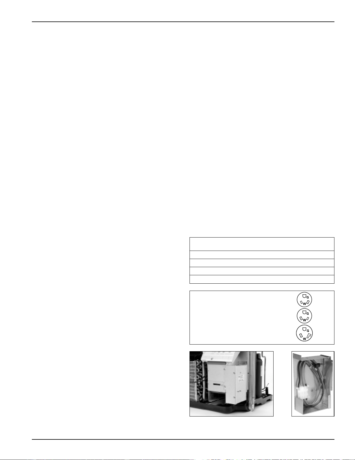
43
Power Connection Kits For
Premium Series (5500)
265 or 277 Volt Installations
National Electrical Code (Article 440 section G) requires
permanent connection for installation on circuit in excess of
250 volts.
Permanent Connection Kits are available for 265 volt
installations. The regular kit consists of a self-aligning 9-pin
connector that plugs into a mating connector on the chassis,
a length of power cord with the plug cap molded to the end.
There are four 265 volt cord sets so that the desired heater
KW will be achieved when the correct RAK5*** kit is
selected. See chart below for guide. These cord sets will
match the receptacle in the RAK204E Series sub-base. It is
important that care be used in this selection process. This
cord set, when used with the appropriate sub-base with
provided chase way from the junction box to the sub-base, is
considered to be permanently connected.
For those installations that require a method of direct
connection using flexible or rigid conduit, the RAK4002B
junction box (provided with chassis) can be used and the
field supplied conduit attached to it. The universal cord set
will be cut off and connections made inside the junction box.
See page 44 for total connected load for 5500 series units.
Electrical Wiring Information - 2500/3500/5500
Series
All Zoneline units are single phase 60 hertz units.
For all installations feeder, sub-feeder, branch circuit and
electrical protective devices and selection must conform to
the National Electrical Code and to local codes.
Maximum connected load in amperes, including demands
for the electric heater and the fan motor, are shown on
page 44. Branch circuit ampacity and electrical protective
device sizing are shown on page 42 for 230/208 volt units
and on this page for 265 volt units. (Although presented
with Premium 5500 Series this information also is valid for
Deluxe Series 2500 and 3500 Series units.)
More than one unit per branch circuit is not recommended;
however, when in doubt, consult the National Electrical
Code. All wiring, including installation of receptacle, must
conform to local electrical regulations and codes.
Replacement of Existing Chassis
230/208 Volt and 265 Volt Units
There have been changes to NEC and improvements and
modifications to the Zoneline chassis and sub-bases since the
unit was first introduced. Some of these changes require
alterations to be made when replacing an older unit with a
new chassis.
Line Cord Connected Units
The plug configuration of new line cord connected units
complies with the current NEC standards. Older installations
may have wall receptacles that conformed to NEC standards
at the time the building was constructed and may not match
the configuration of the plug on the new line cord.
Recommended solution is to change the wall receptacle to
conform to current standard plug configuration. See chart
on page 42 for current receptacle configuration.
Permanent Connected Units With Sub-base
If the existing unit is connected to a sub-base the installation
of the new unit may involve modifying the existing
installation slightly. It is recommended these modifications
be made by a qualified electrician.
If the existing sub-base is the full width of the wall case,
RAK201 sub-base access plate may be ordered and used to
replace the cover on the old sub-base. Field supplied wiring,
conduit and conduit connectors should be used to make
connection between new chassis and the center knockout of
the RAK201. The wiring connections should be made inside
the sub-base and the RAK201 attached to the sub-base with
the 2 screws provided.
If the existing sub-base is not the full width of the wall case
the electrician will have to modify the existing cover plate to
allow field supplied wiring, conduit, and conduit connectors
to be run from the permanent connection kit to the sub-base.
Permanent Heater Circuit Protective Device
Connection Kit Voltage KW Ampacity (Fuse Included)
RAK5152 265 1.7 15 Amp 15 Amp
RAK5172 265 3.0 15 Amp 15 Amp
RAK5202 265 3.7 20 Amp 20 Amp
RAK5302 265 5.0 30 Amp 30 Amp
NEMA7-15R; receptacle used on 265V sub-base 15 Amp
GE0715
NEMA7-20R; receptacle used on 265V sub-base 20 Amp
GE0720-3
NEMA7-30R; receptacle used on 265V sub-base 30 Amp
GE073
RAK4002B Installed RAK4002B
2020 Data Manual 2002 11/7/02 3:19 PM Page 43
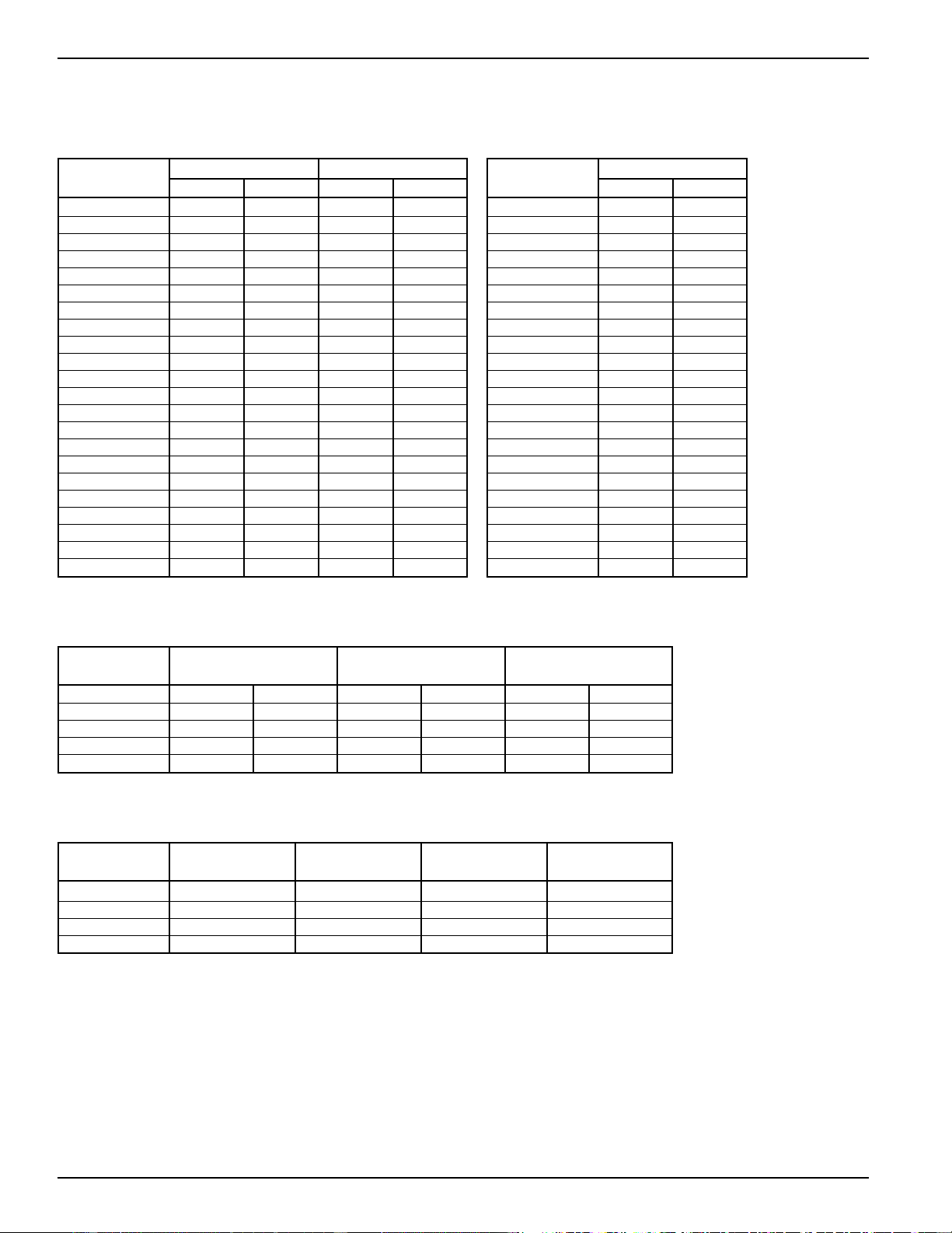
44
Maximum Connected Load For Deluxe Series (2500 and 3500)
The maximum connected load of a Zoneline unit occurs when the unit is in resistance heating operation. The maximum
amperage shown in the tables below is the combined total of the resistance heater and the indoor fan motor.
Model 230 V 208 V
Number Watts Amps Watts Amps
AZ25E07D2* 2600 11.4 2130 10.2
AZ25E07D3* 3500 15.3 2860 13.8
AZ25E09D2* 2610 11.4 2140 10.3
AZ25E09D3* 3510 15.3 2870 13.9
AZ25E09D5* 5060 22.0 4140 20.0
AZ25E12D2* 2620 11.5 2150 10.3
AZ25E12D3* 3520 15.4 2880 13.9
AZ25E12D5* 5070 22.1 4150 20.0
AZ25E15D2* 2630 11.5 2160 10.4
AZ25E15D3* 3520 15.4 2890 14.0
AZ25E15D5* 5080 22.1 4160 20.1
AZ35H07D2* 2600 11.4 2130 10.2
AZ35H07D3* 3500 15.3 2860 13.8
AZ35H09D2* 2610 11.4 2140 10.3
AZ35H09D3* 3510 15.3 2870 13.9
AZ35H09D5* 5060 22.0 4140 20.0
AZ35H12D2* 2620 11.5 2150 10.3
AZ35H12D3* 3510 15.4 2880 13.9
AZ35H12D5* 5070 22.1 4150 20.0
AZ35H15D2* 2630 11.5 2160 10.4
AZ35H15D3* 3530 15.4 2890 14.0
AZ35H15D5* 5080 22.1 4160 20.1
Model 265 V
Number Watts Amps
AZ25E07E3* 2600 9.8
AZ25E07E4* 3750 14.3
AZ25E09E3* 2610 9.9
AZ25E09E4* 3760 14.3
AZ25E09E5* 5060 19.2
AZ25E12E3* 2620 9.9
AZ25E12E4* 3770 14.3
AZ25E12E5* 5070 19.2
AZ25E15E3* 2630 9.9
AZ25E15E4* 3780 14.3
AZ25E15E5* 5080 19.2
AZ35H07E3* 2600 9.8
AZ35H07E4* 3750 14.3
AZ35H09E3* 2610 9.9
AZ35H09E4* 3760 14.3
AZ35H09E5* 5060 19.2
AZ35H12E3* 2620 9.9
AZ35H12E4* 3770 14.3
AZ35H12E5* 5070 19.2
AZ35H15E3* 2630 9.9
AZ35H15E4* 3780 14.3
AZ35H15E5* 5080 19.2
Maximum Connected Load For Premium Series (5500) 230/208 V
Model With RAK3152 With RAK3202 With RAK3302
Number Watts/Amps Watts/Amps Watts/Amps
230V 208V 230V 208V 230V 208V
AZ55H07DA* 2615/11.4 2145/10.3 3515/15.3 2880/13.9 3515/15.3** 2880/13.9**
AZ55H09DA* 2615/11.4 2145/10.3 3515/15.3 2880/13.9 5065/22.0 4150/20.0
AZ55H12DA* 2640/11.5 2165/10.4 3540/15.4 2900/14.0 5090/22.1 4170/20.1
AZ55H15DA* 2685/11.7 2210/10.6 3585/15.6 2945/14.2 5135/22.3 4215/20.3
Maximum Connected Load For Premium Series (5500) 265V
Model With RAK5152*** With RAK5172 With RAK5202 With RAK5302
Number Watts/Amps Watts/Amps Watts/Amps Watts/Amps
AZ55H07EA* 2235/8.6 3075/11.6 3775/14.3 3775/14.3**
AZ55H09EA* 2400/9.1 3075/11.6 3775/14.3 5075/19.2
AZ55H12EA* 2670/10.3 3100/11.7 3800/14.4 5100/19.3
AZ55H15EA* 2965/11.4 3135/11.8 3835/14.5 5135/19.4
* Covers all model versions.
** AZ55H07 does not have 5 kW heater.
*** Maximum connected load occurs when this unit with this power connection kit is in simultaneous
operation of heat pump with supplemental 1700 watt heater.
2020 Data Manual 2002 11/7/02 3:19 PM Page 44
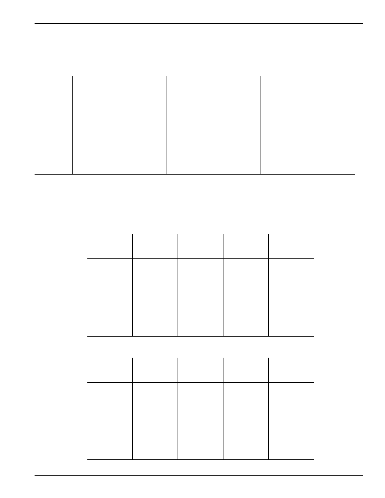
45
Cooling Performance Data
Heat Pump Performance Data
Total Capacity - BTU/Hr.
BTUH At 80°F D.B. - 67°F W.B.
Temperature
of Air Entering
Condenser
75
82
85
95
105
115
AZ AZ AZ AZ
25E07D 25E09D 25E12D 25E15D
25E07E 25E09E 25E12E 25E15E
7750 9900 12800 15900
7580 9690 12590 15620
7500 9600 12500 15500
7100 9000 11700 14600
6600 8250 10750 13600
6000 7500 9650 12300
AZ AZ AZ AZ
35H07D 35H09D 35H12D 35H15D
35H07E 35H09E 35H12E 35H15E
7750 9900 12800 15900
7580 9690 12590 15620
7500 9600 12500 15500
7100 9000 11700 14600
6600 8250 10750 13600
6000 7500 9650 12300
AZ AZ AZ AZ
55H07D 55H09D 55H12D 55H15D
55H07E 55H09E 55H12E 55H15E
7750 9900 12900 16000
7580 9690 12690 15720
7500 9600 12600 15600
7100 9000 11800 14700
6600 8250 10850 13700
6000 7500 9750 12400
Zoneline 2500 Series Zoneline 3500 Series Zoneline 5500 Series
Capacities and COP at Various Outdoor Temperatures
BTUH At 70°F Indoor Temperature
Zoneline 3500 Series
AZ35H07D AZ35H09D AZ35H12D AZ35H15D
Outdoor AZ35H07E AZ35H09E AZ35H12E AZ35H15E
Temperature F° BTUH COP BTUH COP BTUH COP BTUH COP
65 7200 3.75 10000 3.75 13050 3.55 15950 3.35
60 7000 3.70 9600 3.70 12550 3.50 15300 3.30
55 6800 3.65 9100 3.65 11950 3.45 14650 3.25
50 6600 3.55 8700 3.55 11350 3.35 13850 3.15
47 6400 3.50 8400 3.50 10900 3.30 13400 3.10
45 6250 3.45 8200 3.45 10600 3.25 13050 3.05
40 5950 3.35 7700 3.30 9800 3.10 12250 2.95
35 5550 3.20 7100 3.20 9000 3.00 11300 2.80
30 5150 3.05 6500 3.05 8200 2.85 10300 2.65
25 4700 2.90 5900 2.85 7300 2.65 9250 2.50
Zoneline 5500 Series
AZ55H07D AZ55H09D AZ55H12D AZ55H15D
Outdoor AZ55H07E AZ55H09E AZ55H12E AZ55H15E
Temperature F° BTUH COP BTUH COP BTUH COP BTUH COP
65 7200 3.75 10000 3.75 13050 3.55 15950 3.35
60 7000 3.70 9600 3.70 12550 3.50 15300 3.30
55 6800 3.65 9100 3.65 11950 3.45 14650 3.25
50 6600 3.55 8700 3.55 11350 3.35 13850 3.15
47 6400 3.50 8400 3.50 10900 3.30 13400 3.10
45 6250 3.45 8200 3.45 10600 3.25 13050 3.05
40 5950 3.35 7700 3.30 9800 3.10 12250 2.95
35 5550 3.20 7100 3.20 9000 3.00 11300 2.80
30 5150 3.05 6500 3.05 8200 2.85 10300 2.65
25 4700 2.90 5900 2.85 7300 2.65 9250 2.50
2020 Data Manual 2002 11/7/02 3:19 PM Page 45
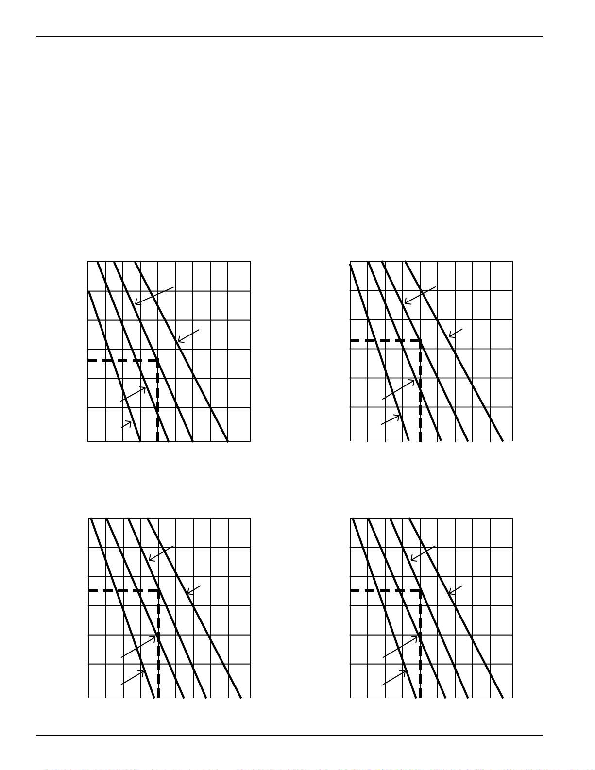
46
Latent System Capacity
The total capacity of an air conditioner is made up of the
Sensible capacity, the output of the unit used to remove heat
from the air in the area being conditioned, and the Latent
capacity, the output of the unit used to dehumidify the air in
the area being conditioned. For humid climates and
applications, the Sensible/Latent capacity split of the unit
should be considered. The Sensible capacity listed in the
specification charts on pages 52 and 53 are at standard
rating conditions of 95°F. dry bulb/75°F. wet bulb outdoors;
80°F. dry bulb/67°F. wet bulb indoors. The Latent system
capacity is 1.00 minus the Sensible capacity. (If the Sensible
capacity is listed at .74 the Latent capacity is .26. This means
that 74% of the capacity of the unit is used to remove heat
from the air and 26% is used to remove moisture from the
air at standard test conditions).
In some applications information about the Sensible/Latent
split, or ratio, at conditions other than the standard rating
conditions is needed. The charts below provide data at
various indoor conditions. To use the charts, first determine
which Zoneline model is being considered and refer to the
appropriate chart. Next, locate the indoor dry bulb
temperature under consideration across the horizontal axis
of the chart and draw a line straight up until it touches the
line representing the indoor wet bulb temperature of the
area; from this point draw a horizontal straight line to the
vertical axis. The point where the line touches the axis
represents the latent percent of the total capacity of the unit.
An example is shown for the standard indoor conditions of
80°F. dry bulb/67°F. wet bulb.
L
a
t
e
n
t
%
o
f
T
o
t
a
l
AZ25E07D/E AZ35H07D/E
AZ55H07D/E
SHR 74%
60
50
40
30
20
10
0
60 65 70 75 80 85 90 95 100 105
°
F
Degrees (Indoor Dry Bulb)
67
°
F W.B.
Indoor Wet Bulb Temp
71
°
F W.B.
63
°
F W.B.
59
°
F W.B.
AZ25E09D/E AZ35H09D/E
AZ55H09D/E
SHR 67%
67
°
F W.B.
Indoor Wet Bulb Temp
71
°
F W.B.
63
°
F W.B.
59
°
F W.B.
L
a
t
e
n
t
%
o
f
T
o
t
a
l
60
50
40
30
20
10
0
60 65 70 75 80 85 90 95 100 105
°
F
Degrees (Indoor Dry Bulb)
60 65 70 75 80 85 90 95 100 105
°
F
Degrees (Indoor Dry Bulb)
AZ25E12D/E AZ35H12D/E
AZ55H12D/E
SHR 65%
67
°
F W.B.
Indoor Wet Bulb Temp
71
°
F W.B.
63
°
F W.B.
59
°
F W.B.
L
a
t
e
n
t
%
o
f
T
o
t
a
l
60
50
40
30
20
10
0
60 65 70 75 80 85 90 95 100 105
°
F
Degrees (Indoor Dry Bulb)
AZ25E15D/E AZ35H15D/E
AZ55H15D/E
SHR 65%
67
°
F W.B.
Indoor Wet Bulb Temp
71
°
F W.B.
63
°
F W.B.
59
°
F W.B.
L
a
t
e
n
t
%
o
f
T
o
t
a
l
60
50
40
30
20
10
0
2020 Data Manual 2002 11/7/02 3:19 PM Page 46
47
Normal Yearly Operating Data
Formula for Calculating Operating Costs Using Above Data:
Heating* - = Operating Cost
*The above formula is for electric resistance heating only. Power consumption using the Zoneline Heat Pumps should be adjusted by Seasonal Performance Factor (SPF).
The local power supplier should be consulted for recommended value of “C.” This factor will vary between 17 and 24.
Cooling - x x Cooling Hours x Cost per KWH = Operating Cost
(Cooling Hours based on 75°F. indoor temperature with
air conditioner sized to meet the design conditions.)
ASHRAE
Location Heating Estimated
Degree Cooling
Days Hours
ALABAMA
Birmingham 2,551 1,390
Huntsville 3,070 1,340
Mobile 1,560 1,640
Montgomery 2,291 1,580
ARIZONA
Flagstaff 7,152 310
Phoenix 1,765 2,280
Tucson 1,800 1,920
Yuma 974 2,520
ARKANSAS
Fort Smith 3,292 1,410
Little Rock 3,219 1,330
CALIFORNIA
Bakersfield 2,122 1,530
Fresno 2,611 1,210
Los Angeles 2,061 310
Sacramento 2,502 1,030
San Diego 1,458 390
San Francisco 3,015 110
COLORADO
Colorado Springs 6,423 520
Denver 6,283 550
Grand Junction 5,641 910
CONNECTICUT
Hartford 6,235 480
D.C.
Washington 4,224 1,010
DELAWARE
Wilmington 4,930 770
FLORIDA
Jacksonville 1,239 1,690
Miami 214 2,850
Orlando 766 1,930
Tallahassee 1,485 1,500
Tampa 683 2,350
GEORGIA
Atlanta 2,961 1,130
Augusta 2,397 1,400
Macon 2,136 1,440
Savannah 1,819 1,510
IDAHO
Boise 5,809 670
Lewiston 5,542 600
Pocatello 7,033 570
ILLINOIS
Chicago 6,155 780
Moline 6,408 760
Springfield 5,429 890
INDIANA
Evansville 4,435 1,090
Fort Wayne 6,205 710
Indianapolis 5,699 820
South Bend 6,439 600
IOWA
Burlington 6,114 730
Des Moines 6,588 710
Sioux City 6,951 770
KANSAS
Dodge City 4,986 1,020
Goodland 6,141 800
Topeka 5,182 880
Wichita 4,620 1,070
ASHRAE
Location Heating Estimated
Degree Cooling
Days Hours
KENTUCKY
Lexington 4,683 830
Louisville 4,660 1,130
LOUISIANA
Alexandria 1,921 1,670
Baton Rouge 1,560 1,860
New Orleans 1,385 1,790
Shreveport 2,184 1,470
MAINE
Portland 7,511 290
MARYLAND
Baltimore 4,654 850
MASSACHUSETTS
Boston 5,634 500
MICHIGAN
Detroit 6,293 590
Flint 7,377 440
Grand Rapids 6,894 530
MINNESOTA
Duluth 10,000 200
Minneapolis 8,382 550
MISSISSIPPI
Jackson 2,239 1,560
MISSOURI
Columbia 5,046 960
Kansas City 4,711 1,210
Springfield 4,900 970
St. Louis 4,900 1,080
MONTANA
Billings 7,049 520
Glasgow 8,996 410
Great Falls 7,750 420
Missoula 8,125 350
NEBRASKA
Grand Island 6,530 770
Omaha 6,612 750
NEVADA
Ely 7,733 500
Las Vegas 2,709 1,980
Reno 6,332 520
NEW JERSEY
Newark 4,589 710
NEW MEXICO
Albuquerque 4,348 1,040
Clayton 5,158 720
Silver City 3,705 1,260
NEW YORK
Albany 6,875 480
Binghamton 7,286 310
Buffalo 7,062 450
New York 4,811 790
Rochester 6,748 470
Syracuse 6,756 500
NORTH CAROLINA
Asheville 4,042 690
Charlotte 3,191 1,230
Raleigh 3,393 1,070
Winston-Salem 3,595 960
NORTH DAKOTA
Bismarck 8,851 510
Fargo 9,226 490
Williston 9,243 580
ASHRAE
Location Heating Estimated
Degree Cooling
Days Hours
OHIO
Cincinnati 5,265 840
Cleveland 6,351 610
Columbus 5,660 810
Dayton 5,622 740
Toledo 6,494 590
OKLAHOMA
Oklahoma City 3,725 1,200
Tulsa 3,860 1,410
OREGON
Medford 5,008 620
Pendleton 5,127 590
Portland 4,635 270
PENNSYLVANIA
Harrisburg 5,251 730
Philadelphia 5,144 810
Pittsburgh 5,987 590
Scranton 6,254 440
Williamsport 5,934 600
RHODE ISLAND
Providence 5,954 470
SOUTH CAROLINA
Charleston 2,033 1,390
Columbia 2,484 1,440
Greenville 2,980 1,120
SOUTH DAKOTA
Rapid City 7,345 580
Sioux Falls 7,839 610
TENNESSEE
Chattanooga 3,254 1,180
Knoxville 3,494 1,070
Memphis 3,232 1,320
Nashville 3,578 1,220
TEXAS
Corpus Christi 914 2,380
Dallas 2,363 1,900
El Paso 2,700 1,580
Houston 1,396 1,850
Lubbock 3,578 1,310
San Antonio 1,546 1,920
UTAH
Milford 6,497 910
Salt Lake City 6,052 830
VERMONT
Burlington 8,269 130
VIRGINIA
Norfolk 3,421 1,010
Richmond 3,865 1,020
Roanoke 4,150 870
WASHINGTON
Seattle 5,145 180
Spokane 6,655 430
Yakima 5,941 530
WEST VIRGINIA
Charleston 4,476 860
Huntington 4,446 820
WISCONSIN
Madison 7,863 530
Milwaukee 7,635 450
WYOMING
Casper 7,410 600
Cheyenne 7,381 420
Sheridan 7,680 530
Calculated Heat Gain (BTUH) Unit Cooling Watts
Installed unit capacity (BTUH) 1000 Watts/KW
Heat Loss KW x Heating Degree Days x “C” x Cost per KWH
Outdoor Design Temperature Difference
2020 Data Manual 2002 11/7/02 3:19 PM Page 47
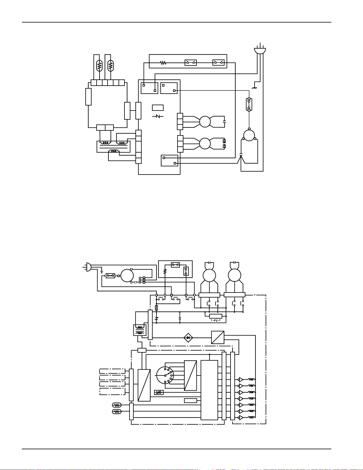
48
MAIN
BOARD
UNIT
CN1
OR
OR
YL
YL
ID. COIL
ROOM
123456
CN5
CN3
1
2
CN2
CN104
WH
WH
YL
YL
CN103
BK
BK
TRANSFORMER
RY103
BK
RD
BK
WH
RD
CN101
CN102
1
3
5
1
3
5
1
2
5
7
DRIVE
BOARD
UNIT
RY102 RY101
CN8
NR101
Varistor
BR
YL
FM
BK
WH
RD
GY
BL
FM
ID. FAN MOTOR
OD. FAN MOTOR
RUNNING
CAPACITOR
RUNNING
CAPACITOR
RUNNING
CAPACITOR
CM
O. L. P.
GY (RIB SIDE)
COMPRESSOR
BK
C
S
R
RD
WH
GR
BK
HEATER UNIT
GY
BL
BL
PROTECTOR
HEATER
FUSE
COLOR
BK : BLACK
BL : BLUE
BR : BROWN
GR : GREEN
GY : GRAY
OR : ORANGE
RD : RED
WH : WHITE
YL : YELLOW
WH
O. L. P.
COMP.
MOTOR
RUNNING
CAPACITOR
C
S
R
HEATER
PROTECTOR
(HEATER UNIT)
FUSE
RY102 RY101
RY103
OUTDOOR
FAN
MOTOR
INDOOR
FAN
MOTOR
FAN MOTOR
CAPACITOR
FAN MOTOR
CAPACITOR
CN102
CN101
RY106
RY107
RY104
RY105
CN8
CN103
Varistor
(NR101)
Capacitor
(C101. C102)
FUSE
(FU101)
DRIVE BOARD UNIT
REGULATOR
(TR1)
TRANSFORMER
CN3
MAIN BOARD UNIT
DECODER
SELECT SW
HEAT H
HEAT A
OFF
FAN L
FAN H
COOL A
COOL H
THERMO CONTROL
DIP SW(for setting)
INTERFACE
CONTROL
CIRCUIT
CN2
CN104
RY107
RY106
RY105
RY104
RY103
RY102
RY101
CN1
ROOM
ID. COIL
REMOTE T' STAT
CDC
TRANSFER FAN
MOTION SENSOR
DOOR SWITCH
CN5
Typical 2500 Series Wiring Diagram
Typical 2500 Series Schematic Diagram
2020 Data Manual 2002 11/7/02 3:19 PM Page 48
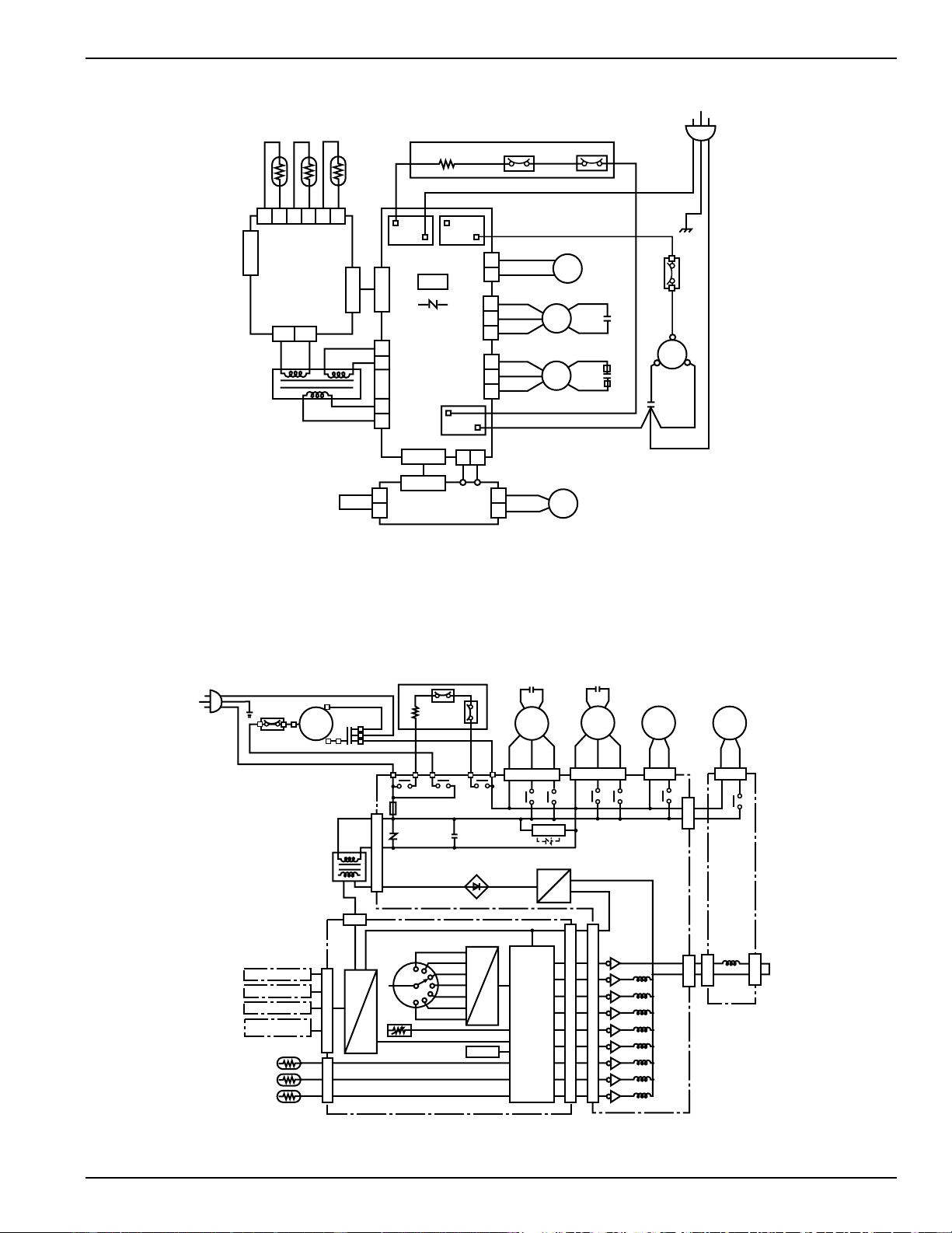
49
MAIN
BOARD
UNIT
CN1
OR
OR
YL
YL
ID. COIL
ROOM
123456
CN5
CN3
1
2
CN2
CN104
WH
WH
YL
YL
CN103
BK
BK
TRANSFORMER
RY103
BK
RD
BK
WH
RD
CN101
CN102
1
3
5
1
3
5
1
2
5
7
DRIVE
BOARD
UNIT
RY102 RY101
CN8
NR101
Varistor
BR
YL
FM
BK
WH
RD
GY
BL
FM
ID. FAN MOTOR
OD. FAN MOTOR
RUNNING
CAPACITOR
RUNNING
CAPACITOR
RUNNING
CAPACITOR
CM
O. L. P.
GY (RIB SIDE)
COMPRESSOR
BK
C
S
R
RD
WH
GR
BK
HEATER UNIT
GY
BL
BL
PROTECTOR
HEATER
FUSE
COLOR
BK : BLACK
BL : BLUE
BR : BROWN
GR : GREEN
GY : GRAY
OR : ORANGE
RD : RED
WH : WHITE
YL : YELLOW
WH
BK
BK
OD. COIL
1
3
RV
REV.
VALVE
SOLE.
CN107
1
3
CN203
1
2
1
3
CN202
CN201
ICR
BOARD UNIT
(OPTIONAL)
PM
YL
YL
CN105
RD*1
RD*1
CN106
RD
RD
(OPTIONAL)
ICR
BR
RD*1: RED(208/230V), BLUE(265V)
O. L. P.
COMP.
MOTOR
RUNNING
CAPACITOR
C
S
R
HEATER
PROTECTOR
(HEATER UNIT)
FUSE
RY102
RY101
RY103
OUTDOOR
FAN
MOTOR
INDOOR
FAN
MOTOR
FAN MOTOR
CAPACITOR
FAN MOTOR
CAPACITOR
CN102
CN101
RY106
RY107
RY104
RY105
CN8
CN103
Varistor
(NR101)
Capacitor
(C101. C102)
FUSE
(FU101)
DRIVE BOARD UNIT
REGULATOR
(TR1)
TRANSFORMER
CN3
MAIN BOARD UNIT
DECODER
SELECT SW
HEAT H
HEAT A
OFF
FAN L
FAN H
COOL A
COOL H
THERMO CONTROL
DIP SW(for setting)
INTERFACE
CONTROL
CIRCUIT
RY107
RY106
RY105
RY104
RY103
RY102
RY101
CN1
ROOM
ID. COIL
REMOTE T' STAT
CDC
TRANSFER FAN
MOTION SENSOR
DOOR SWITCH
CN5
REVERSE
VALVE
SOL.
CN105
CN106
ICR
PUMP
CN201
RY201
ICR BOARD UNIT
(OPTIONAL)
CN107
CN203
CN202
RY201
RY108
(OPTIONAL)
RY108
CN2
CN104
OD. COIL
Typical 3500 Series Wiring Diagram
Typical 3500 Series Schematic Diagram
2020 Data Manual 2002 11/7/02 3:19 PM Page 49
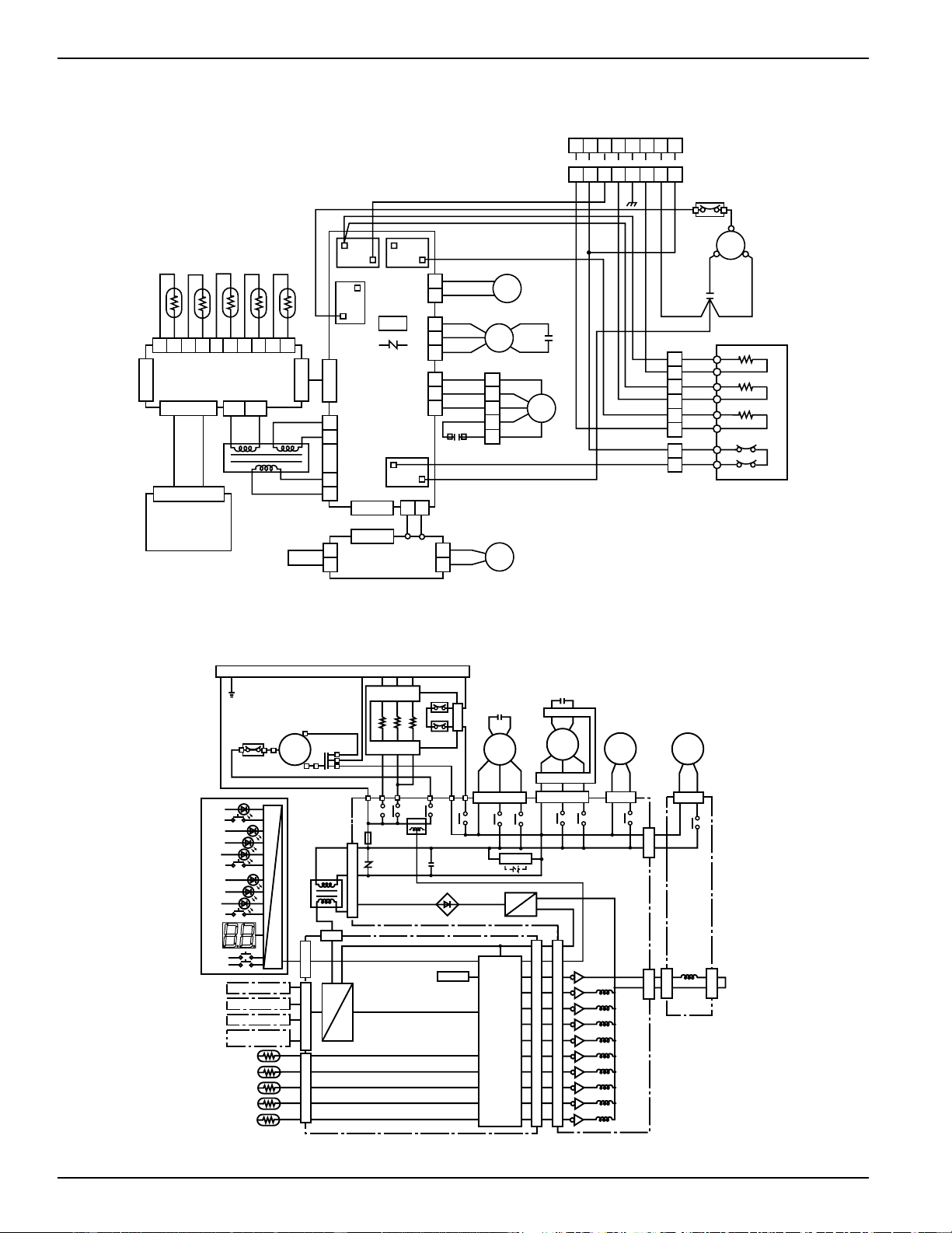
50
1
2
34
5
6
7
8
9
10
YL
YL
OR
OR
BK
BK
BL
BL
RD
RD
ROOM
ID. COIL
OD. COIL
OUTDOOR
HEATER
CN1
MAIN BOARD UNIT
CN5
CN2
CN104
CN6 & 7
12
CN3
WH
WH
YL
YL
BK
BK
1
2
5
7
CN103
OPERATION
BOARD UNIT
CN301 & 302
TRANSFORMER
1
2
BR
CN203
CN107
ICR
BOARD UNIT
(OPTIONAL)
CN202
CN201
1
3
1
3
RD
RD
CN106
PM
YL
YL
ICR
(OPTIONAL)
RY103
RD
BL
1
3
5
CN101
DRIVE
BOARD
UNIT
1
3
5
CN102
CN8
NR101
VARISTOR
RY101
BK
RY102
RY109
1
3
CN105
1
2
3
4
6
FM
RD
WH
BK
OR
OR
RD
WH
BK
BL
GY
RUNNING
CAPACITOR
ID. FAN MOTOR
RUNNING
CAPACITOR
FM
RD
WH
BK
BL
GY
OD. FAN MOTOR
RV
RD*1
RD*1
REV.
VALVE
SOLE.
CM
RUNNING
CAPACITOR
WH
RD
R
S
C
BK
COMPRESSOR
O.L.P.
6
3
5
2
4
1
2
1
BK
BK
RD
RD
BK
FUSE
PROTECTOR
HEATER UNIT
BL
WH
WH
RD
RD
BR
BK
BK
BK
RD
RD
WH
WH
HEATER
HEATER
HEATER
RD
WH
RD
GY
1
2
3
65489
1
2
3
45679
BK
BR
GY
RD
GR
WH
BL
OR
(265V)
(208/230V)
COLOR BK : BLACK
BL : BLUE
BR : BROWN
GR : GREEN
GY : GRAY
OR : ORANGE
RD : RED
WH : WHITE
YL : YELLOW
RD*1 : RED (208/230V),
: BLUE (265V)
WH
O. L. P.
COMP.
MOTOR
RUNNING
CAPACITOR
C
S
R
HEATER
PROTECTOR
RY102
RY109
RY103
OUTDOOR
FAN
MOTOR
INDOOR
FAN
MOTOR
FAN MOTOR
CAPACITOR
FAN MOTOR
CAPACITOR
CN102
CN101
RY106
RY107
RY104
RY105
CN8
CN103
Varistor
(NR101)
Capacitor
(C101, C102)
FUSE
(FU101)
DRIVE BOARD UNIT
REGULATOR
(TR1)
TRANSFORMER
CN3
MAIN BOARD UNIT
DIP SW(for setting)
INTERFACE
RY107
RY106
RY105
RY104
RY103
RY102
RY101
ROOM
ID. COIL
REMOTE T' STAT
CDC
TRANSFER FAN
MOTION SENSOR
DOOR SWITCH
CN5
REVERSE
VALVE
SOL.
CN105
CN106
ICR
PUMP
CN201
RY201
ICR BOARD UNIT
(OPTIONAL)
CN107
CN203
CN202
RY201
RY108
(OPTIONAL)
RY108
OD. COIL
CN6 & 7
HEATER
HEATER
UNIVERSAL CONNECTOR
HEATER UNIT
CURRENT
DETECTOR (CT1)
FUSE
HEATER
CN2
CN104
CONTROL
CIRCUIT
UP
DOWN
THERMO
FAN SPEED
AUTO
LOW
HIGH
MODE
HEAT
FAN
COOL
OPE
OPE
OPERATION BOARD
OUTDOOR
RY109
RY101
CN1
DECODER
Typical 5500 Series Wiring Diagram
Typical 5500 Series Schematic Diagram
2020 Data Manual 2002 11/7/02 3:19 PM Page 50

51
Suggested Bid Form
Specifications
The following are suggested specifications for the Zoneline 2500
Series Packaged Terminal Air Conditioner, the 3500 series
Packaged Terminal Heat Pump and the 5500 series Packaged
Terminal Heat Pump.
The contractor will furnish Packaged Terminal Air
Conditioners of the sizes and capacities shown on the
schedule and in the specifications. The units shall be located
as shown on the drawings and each shall consist of a chassis,
room cabinet, wall case, sub-base if specified, and outdoor
grille.
Units shall be listed by UL, and ARI and cUL certified as to
capacity and efficiency and shall be GE Zoneline
®
models or
equal. Unit dimensions shall not exceed 42 1/8" wide and
16 1/4" high with room cabinet in place.
Units shall be designed to operate on _______ volts, 60 Hz.,
single phase power.
Chassis. Air conditioner chassis shall be the standard
product of the manufacturer and shall be shipped in
protective cartons to prevent damage. Cartons shall be
appropriately marked at the factory with wording sufficient
to warn handlers against improper stacking, up-ending,
rolling or dropping.
Chassis shall be slide-in type, ready to operate after
installation.
Each shall consist of the following sections and components:
Each unit shall have a matching, easily removable, textured
finish, wrap-around room cabinet molded of high
temperature styrene to resist corrosion and damage. Room
cabinet shall have slide-out washable filters accessible
without requiring removal of room cabinet from chassis;
Hermetically-sealed refrigerant system with external
vibration isolated rotary-type compressor, condenser and
evaporator coils and capillary refrigerant control. Cooling
shall be possible to outdoor temperature of 35°F. without
damage to the compressor. Airflow system consisting of one
permanently lubricated two-speed fan motor for the outdoor
fan and a separate permanently lubricated two-speed fan
motor for the indoor fan. Outdoor fan shall be multi-blade
axial-flow design made of non-corrosive material. Indoor fan
shall be of a design to optimize air flow and operating
sound. All motors on the exterior side of the weather barrier
shall be of an enclosed design to reduce the effects of
moisture and corrosion.
Unit shall have a resistance heater to provide specified heat
output;
A fan cycle switch to permit continuous fan operation or fan
cycle operation, independently selectable for heating and
cooling operation;
A positive cooling condensate disposal system which meets
the test requirements of applicable A.R.I. Standard 310-93
(for Packaged Terminal Air Conditioners) and 380-93 (for
Packaged Terminal Heat Pump). (80°F. dry bulb, 75°F. wet
bulb, 80% relative humidity).
Condenser and evaporator coils to be constructed of copper
tubing and aluminum plate fins with enhancements
necessary to achieve EER and COP rating of the unit;
Indoor and outdoor airflows that match the capacity of the
coils for efficient heat transfer. Water blow-off shall not
occur on the indoor coil;
Adjustable indoor discharge air louvers that provide a 50°
off vertical air pattern with an alternate position to provide a
40° off vertical air pattern;
Easily accessible controls for selection of unit Operation and
Thermostat setting. Controls shall be covered by a hinged
door;
Air discharge area accessible for cleaning without tools when
room front is removed;
Positive-closing fresh air vent, with vent door secured for
shipping, and optional securing in the closed position, with
a concealed manual control;
Solid state thermostat control to sense room temperature;
Electronic temperature limiting with seven independent
heating and cooling settings to limit maximum and
minimum temperatures without restricting movement of
thermostat control knob;
Freeze Sentinel
TM
to automatically activate the electric
resistance heater and fan motor to warm and circulate
indoor air to help prevent damage due to freezing
temperatures. Freeze Sentinel
TM
shall operate as long as unit
is connected to powered electrical circuit and unit shall
provide ability for owner to defeat the Freeze Sentinel
operation;
Compatible with 2 wire Central Desk Control systems;
Remote Thermostat compatibility with Class 2 remote
thermostat;
Connections to interface with a transfer fan to move air into
another room;
Connections to interface with occupancy sensors;
Unit shall have means of electrical connection listed by
Underwriters Laboratories and compatible with the unit’s
required voltage and ampacity in conformance with
National Electrical Code
®
(NEC) and local codes.
Additional specifications for GE Zoneline 2500 Series Packaged
Terminal Air Conditioner with Dry Air 25
Unit shall be equipped with factory installed heat pipe
around evaporator coil to increase dehumidification by at
least 25% over other non-heat pipe Zoneline units. Unit
must be certified by ARI for capacity and dehumidification.
Heat pipe system must be separate from the sealed
refrigerating system of the unit.
2020 Data Manual 2002 11/7/02 3:19 PM Page 51

52
Additional specifications for GE Zoneline 3500 Series Packaged
Terminal Heat Pump (for 5500 series units use specifications
noted for 5500 series instead of these specifications).
Heat pump units shall automatically change from heat
pump operation to electric resistance heat when heat pump
operation is unable to produce sufficient heat to maintain
room temperature within 2.7°F. of thermostat set point, or
when the outdoor coil temperature falls below 9°F. -
approximately 25°F. outdoor temperature.
Heat pump unit shall automatically begin a passive defrost
cycle when the outdoor coil temperature drops below 9°F.
Defrosting shall be accomplished by natural defrost with unit
automatically reinitiating heat pump operation when
outdoor coil reaches 37°F.
Unit shall be equipped with a temperature activated drain
valve to allow water generated in heat pump operation and
defrost cycles to drain into wall case rather than being
deposited on outdoor coil.
Each time the heat mode is selected, or the unit is powered
up in the heat mode selection, the heat pump will use
electric resistance heat to bring room temperature to
selected thermostat set point. Heat pump operation will be
used on subsequent unit heating operation if the room
temperature is within 2.7°F of the set point and the unit is
not in the defrost cycle.
Unit shall have a switch concealed from room occupant to
allow heat pump operation to be overridden and heat
provided by electric resistance heat regardless of outdoor
temperature.
In the event of compressor failure during heat pump
operation, unit shall automatically switch to electric
resistance heat to maintain selected room temperature
regardless of outdoor temperatures.
Alternate specifications for GE Zoneline 5500 Series Packaged
Terminal Heat Pump (for 3500 series units use specifications
noted for 3500 series instead of these specifications).
Heat pump units shall provide operation that will either:
A) automatically phase in partial electric resistance heat, if
outdoor temperature is below 46°F., simultaneously with heat
pump if heat pump alone is unable to maintain room
temperature; or B) use partial electric resistance heat
simultaneous with heat pump operation any time the
outdoor temperature is below 45°F. Selection of A or B
operation is made by means of a selector switch concealed
from room occupant. In either A or B operation the unit will
switch to full resistance heat if room temperature continues
to decline or the outdoor temperature falls below 25°F. If the
outdoor temperature is above 46°F., unit will lock out electric
resistance heat and operate on heat pump only.
Heat pump unit shall include Reverse Cycle Defrost that
automatically begins a defrost cycle when microprocessor
determines criteria for defrosting has been met. Defrosting
shall be accomplished by systematically ceasing heat pump
operation, pausing to allow internal refrigerant pressures to
equalize, then operating the compressor with the flow of
refrigerant reversed, to allow the hot gas to flow through the
outdoor coil melting the accumulated frost. Unit shall
automatically resume heat pump operation, after pausing to
allow refrigerant pressures to equalize, at conclusion of
defrost cycle.
Unit shall be equipped with a temperature activated drain
valve to allow water generated in heat pump operation and
defrost cycles to drain into wall case rather than being
deposited on outdoor coil.
Each time the heat mode is selected, or the unit is powered
up in the heat mode selection, the heat pump will use
electric resistance heat to bring room temperature to
selected thermostat set point. Heat pump operation will be
used on subsequent unit heating operation if the room
temperature is within 2.7°F of the set point and the unit is
not in the defrost cycle.
Unit shall have a switch concealed from room occupant to
allow heat pump operation to be overridden and heat
provided by electric resistance heat regardless of outdoor
temperature.
In the event of compressor failure during heat pump
operation, unit shall automatically switch to electric
resistance heat to maintain selected room temperature
regardless of outdoor temperatures.
Specifications for Optional Internal Condensate Removal (ICR)
system for Zoneline 3500 or 5500 series heat pump units.
Unit shall have a factory installed Internal Condensate
Removal (ICR) system to permit unit to automatically
dispose of heat pump generated condensate water with no
overflow to outdoors to occur during heating under outdoor
ambient of 55°F. Dry Bulb, 90% Relative Humidity; indoor
ambient 70°F. Dry Bulb, 52% Relative Humidity, for four
hours of continuous run time.
2020 Data Manual 2002 11/7/02 3:19 PM Page 52

53
Wall Cases and Grilles are needed for new installations
Alternate specification for steel wall case.
Wall case shall be constructed of heavy gauge, zinc-coated,
phosphated steel, insulated and shall have a protective
baked-on enamel finish. Bottom critical points of the steel
wall case shall be treated with petroleum microcrystalline
wax for added corrosion protection and shall meet ASTM
B-117, 1800 hour hot air aerated salt spray test.
Alternate specification for molded wall case.
Wall case shall be constructed of a non-corroding fiberglass
reinforced polyester compound.
Cases shall be installed through exterior walls where shown
on the plans and shall be installed per manufacturer’s
installation instructions. In no instance shall fasteners be
used through the bottom in order to retain the water
integrity of the bottom of the wall case.
Outside weather panels shipped with the cases shall remain
in place until the outdoor air louvers and chassis are
installed, at which time they are to be removed and
discarded by the installer.
Outside Grille. Each unit shall be equipped with a standard
exterior grille that has been designed to allow unit operation
in high ambient conditions. Grilles shall be of material and
design specified.
Special grilles or customer louver sections to be supplied by
others will conform to minimum free area requirements for
unit performance and shall be submitted to the
PTAC/PTHP manufacturer, if requested, for feasibility and
airflow characteristics.
Specifications for Sub-base (if required).
Sub-Base. Each unit shall have a field installed UL listed
electrical sub-base. The sub-base shall be attached to the
lower inside flange of the wall case prior to installation in
the exterior wall and shall include adjustable screws at the
bottom corners to permit exact leveling of the wall case. The
sub-base shall have a factory installed receptacle to allow
unit line cord to plug into mating receptacle and shall have
a chaseway to contain and conceal the line cord. The sub-
base shall have side panels adjustable from a minimum of
2 3/8" to a maximum of 13 3/4" to enclose the area under
the wall case.
Weather Resistance. Complete unit including outside louver
shall be submitted to an independent agency for weather
resistance and water infiltration tests.
Air infiltration test to be conducted in accordance with
ASTM E283-91. With static air pressure differential of 1.57
lb./ft.
2
(.3" H
2
O) equivalent to 25 mph wind, allowable air
infiltration shall not exceed 7 ft.
3
/min.
Water infiltration test to be conducted in accordance with
ASTM E331-86 with static air pressure differential of 10.0
lb./ft
2
(1.93" water) equivalent to 63 mph wind, 5.0 gal./ft.
2
(8" rain/ft.
2
/hr.) for 15 minutes and there shall be no
leakage into the room.
Approvals. Units shall be certified under the ARI and cUL
certification program and listed by UL.
Service. Submit complete information with bid covering
service availability, to whom service on units will be assigned,
complete address and phone number, including phone
number of emergency service personnel.
Start-Up, Adjust, Demonstrate. Contractor shall be
responsible for the initial starting of units, adjustments
thereto, etc., to place the units in required operating
condition. Contractor shall demonstrate to the owner, or his
representative, the operation of units for both summer and
winter functions.
Warranty. The warranty shall be a full one year parts and
labor on entire unit plus an additional full four years parts
and labor for the sealed refrigerating system, including
service call for diagnosis, and transportation to and from
service shop, if necessary, at no charge to customer. The
warranty shall also include a limited 2nd thru 5th year parts
only warranty for fan motors, switches, thermostat, heater,
heater protectors, compressor overload, solenoids, circuit
boards, auxiliary controls, thermistors, frost controls, ICR
pump, capacitors, varistors, and indoor blower bearing.
Installation Responsibility. Units shall be installed according
to the manufacturer’s recommendations and the
manufacturer shall not be responsible for unit failure as a
result of improper installation, or unit performance when
installed with accessories not approved by the manufacturer.
2020 Data Manual 2002 11/7/02 3:19 PM Page 53
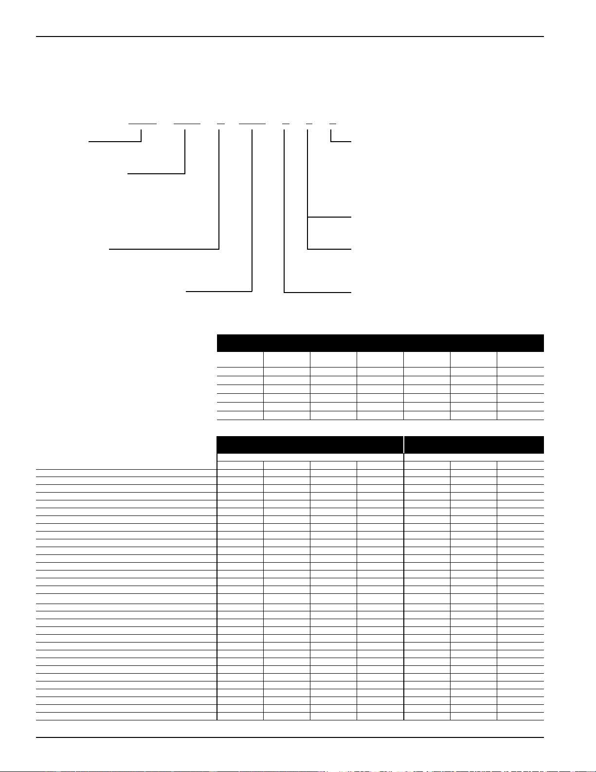
54
Deluxe Line: 2500,
Dry Air 25 & 3500 Series -
Models are manufactured with fixed heater
wattages with the appropriate power cord
attached (all 265 volt models are
permanently connected). 5.0 KW heaters
are not available on 7,000 BTUH models.
Zoneline
®
Chassis Nomenclature
The Zoneline chassis is identified by a model number defining the type of unit, cooling capacity, electrical information and optional features
included on the unit. When specifying or ordering the Zoneline chassis the use of this nomenclature will assure receiving the correct unit.
Example
A Z 2 5 E 0 9 E 4 P
A Z 5 5 H 1 2 D A D
Zoneline
®
Packaged Terminal Chassis
Chassis Series
25 - Deluxe Line Cool/Electric Heat
35 - Deluxe Line Heat Pump
55 - Premium Line Heat Pump
Unit Type
E - Cooling with Electric Resistance Heat
H - Heat Pump with Electric Resistance Heat
Nominal Cooling Capacity
07 - 7,000 BTUH Cooling 12 - 12,000 BTUH Cooling
09 - 9,000 BTUH Cooling 15 - 15,000 BTUH Cooling
Special Features
B - Base Unit
C - Corrosion Treated
D - Internal Condensate Removal
(ICR) System (Heat Pump Models Only)
P - Dry Air 25
5500 Universal Power Connection
(see Premium Series Models - see page 53)
2500, Dry Air 25 & 3500 Numeric
Designator of Heater Size
(see Heater Table Below)
Voltage/Phase/Frequency
D - 230/208 Volt Single Phase 60 Hz
E - 265 Volt Single Phase 60 Hz
Heater Heater Minimum
Voltage Amps Designator Watts KWH Ampacity BTUH
230/208 11.1/10.0 2 2550/2090 2.55/2.09 15 8,600/7,100
230/208 15.0/13.6 3 3450/2820 3.45/2.82 20 11,700/9,600
230/208 21.7/19.7 5 5000/4090 5.00/4.09 30 17,000/13,900
265 9.6 3 2550 2.55 15 8,600
265 14.0 4 3700 3.7 20 12,600
265 18.9 5 5000 5.0 30 17,000
Heater Table
2500 Series Units Dry Air 25
230/208V Models AZ25E07D AZ25E09D AZ25E12D AZ25E15D AZ25E07D*P AZ25E09D*P AZ25E12D*P
Capacity
Cooling BTUH 7,100/6,900 9,000/8,800 11,700/11,500 14,600/14,300 6,800/6,600 8,600/8,400 11,200/11,000
EER (BTU/Watt) 11.8/11.8 11.5/11.5 10.9/10.9 9.6/9.6 11.1/11.1 10.8/10.8 10.2/10.2
Dehumidification Pts/Hr 1.7 2.7 3.6 4.5 2.2 3.4 4.5
Sensible Heat Ratio @ 230 Volts 75% 68% 67% 67% 66% 58% 57%
CFM, Indoor Fan High 240 260 270 310 230 230 240
CFM, Indoor Fan Low 210 230 240 280 200 200 210
Vent CFM 40/35 65/60 70/65 70/65 40/35 65/60 70/65
Power/Ratings
Power Factor 95 96 97 94 95 96 97
Watts 600/585 785/765 1075/1055 1520/1490 600/585 785/765 1075/1055
Amperes, F.L. 2.8/3.0 3.6/3.9 4.9/5.3 7.0/7.5 2.8/3.0 3.6/3.9 4.9/5.3
Amperes, L.R. 19.0 21.0 33.0 38.0 19.0 21.0 33.0
Weight (Net/Ship)** 92/108 93/109 101/117 111/127 98/114 99/115 107/123
Sound Transmission Class (STC) 28 28 28 28 28 28 28
265V Models AZ25E07E AZ25E09E AZ25E12E AZ25E15E AZ25E07E*P AZ25E09E*P AZ25E12E*P
Capacity
Cooling BTUH 7,100 9,000 11,700 14,600 6,800 8,600 11,200
EER (BTU/Watt) 11.8 11.5 10.9 9.6 11.1 10.8 10.2
Dehumidification Pts/Hr 1.7 2.7 3.6 4.5 2.2 3.4 4.5
Sensible Heat Ratio @ 265 Volts 75% 68% 67% 67% 66% 58% 57%
CFM, Indoor Fan High 240 260 270 310 230 230 240
CFM, Indoor Fan Low 210 230 240 280 200 200 210
Vent CFM 40 65 70 70 40 65 70
Power/Ratings
Power Factor 96 94 94 96 96 94 94
Watts 600 785 1075 1520 600 785 1075
Amperes, F.L. 2.4 3.2 4.4 6.0 2.4 3.2 4.4
Amperes, L.R. 16.0 18.0 24.0 31.0 16.0 18.0 24.0
Weight (Net/Ship)** 92/108 93/109 101/117 111/127 98/114 99/115 107/123
Sound Transmission Class (STC) 28 28 28 28 28 28 28
*For Dry Air 25 model number, designate respective heater number using chart above, followed by the letter “P”.
** ICR adds 3 pounds to unit weight
Deluxe Series - Cooling & Electric Heat Dry Air 25
2020 Data Manual 2002 11/7/02 3:19 PM Page 54
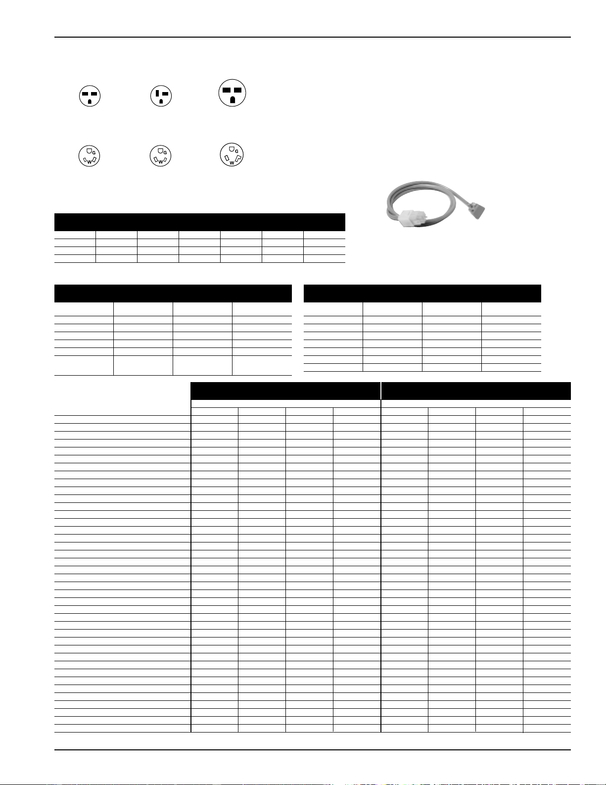
55
Receptacles/Sub-Bases
Tandem
230/208V 15 Amp
NEMA6-20R
Perpendicular
230/208V 20 Amp
NEMA6-20R
Large Tandem
230/208V 30 Amp
NEMA6-30R
265V 15 Amp
NEMA7-15R;
receptacle used on
265V sub-base
265V 20 Amp
NEMA7-20R;
receptacle used on
265V sub-base
265V 30 Amp
NEMA7-30R;
receptacle used on
265V sub-base
Premium Line: 5500 Series - Power Connection Kits are
REQUIRED on Premium Zoneline Chassis. (see chart below)
The correct kit for the installation is determined by the voltage
and amperage of the electrical circuit and the means of
connecting the unit to the building wiring. If the unit is to be
plugged into a receptacle, a line cord kit would be used; if the
unit is to be permanently connected, a permanent connection kit
would be used. 265 volt cord set units must be installed in
compliance with National Electrical Code.
®
Power Connection Kits - Required on premium models. See
specification sheet for heater KW and branch circuit ampacity.
RAK3152/3202/3302
230/208 volt Line Cord Connection Kit
RAK204U RAK204D20 RAK204D30 RAK204E15 RAK204E20 RAK204E30
Voltage N/A 230/208 230/208 265 265 265
Amps N/A 15/20 30 15 20 30
Receptacle N/A NEMA6-20R NEMA6-30R NEMA7-15R NEMA7-20R NEMA7-30R
265 Volt units are to be direct connected. Cordset through enclosed chaseway
into interior sub-base receptacle meets the NEC requirements.
Sub-bases
Power Connection RAK3152 RAK3202 RAK3302
Kit
Heater KW 2.55/2.09 3.45/2.82 5.00/4.09
Watts 2,550/2,090 3,450/2,820 5,000/4,090
BTUH 8,600/7,100 11,700/9,600 17,000/13,900
Amps 11.0/10.0 15.0/13.6 21.7/19.7
Min. Circuit Amps 15 20 30
Recommended 15 Amp 20 Amp 30 Amp
Protective Time Delay Time Delay Time Delay
Device Fuse or Breaker Fuse or Breaker Fuse or Breaker
230/208 Volt
Line Cord Connected Units
RAK5152 RAK5172 RAK5202 RAK5302
1.7 3.0 3.7 5.0
1,700 3,000 3,700 5,000
5,800 10,200 12,600 17,000
6.4 11.3 14.0 18.9
15 15 20 30
15 Amp 15 Amp 20 Amp 30 Amp
Time Delay Fuse Time Delay Fuse Time Delay Fuse Time Delay Fuse
265 Volt
Permanent Connected Units** (Cord Set)
3500 Series Units 5500 Series Units
230/208V Models AZ35H07D AZ35H09D AZ35H12D AZ35H15D AZ55H07D AZ55H09D AZ55H12D AZ55H15D
Capacity
Cooling BTUH 7,100/6,900 9,000/8,800 11,700/11,500 14,600/14,300 7,100/6,800 9,000/8,800 11,800/11,600 14,700/14,400
EER (BTU/Watt) 11.8/11.8 11.5/11.5 10.9/10.9 9.6/9.6 12.0/12.0 11.5/11.5 10.9/10.9 10.0/10.0
Dehumidification Pts/Hr 1.7 2.7 3.6 4.5 1.7 2.8 3.6 4.8
Sensible Heat Ratio @ 230 Volts 75% 68% 67% 67% 75% 67% 68% 65%
CFM, Indoor Fan High 250 260 280 310 240 290 330 350
CFM, Indoor Fan Low 220 230 250 280 220 270 310 330
Vent CFM 40/35 65/60 70/65 70/65 40/35 65/60 70/65 70/65
Power/Ratings
Power Factor 95 96 97 94 95 96 94 95
Watts 600/585 785/765 1075/1055 1520/1490 590/565 785/765 1085/1065 1470/1440
Amperes, F.L. 2.8/3.0 3.6/3.9 4.9/5.3 7.0/7.5 2.7/2.9 3.6/3.9 5.1/5.5 6.7/7.3
Amperes, L.R. 19.0 21.0 33.0 38.0 19.0 21.0 33.0 38.0
Reverse Cycle Heat BTUH 6400/6200 8400/8200 10900/10700 13400/13200 6,400/6,200 8,400/8,200 10,900/10,700 13,400/13,200
COP 3.5/3.5 3.5/3.5 3.3/3.3 3.1/3.1 3.5/3.5 3.5/3.5 3.3/3.3 3.1/3.1
Watts 535/520 705/685 970/950 1265/1250 535/520 705/685 970/950 1,265/1,250
Amps 2.4/2.6 3.1/3.4 4.3/4.7 5.8/6.3 2.4/2.6 3.1/3.3 4.3/4.7 5.8/6.3
Weight (Net/Ship)** 96/112 99/115 111/127 121/137 101/117 106/122 116/132 123/139
Sound Transmission Class (STC) 28 28 28 28 28 28 28 28
265V Models AZ35H07E AZ35H09E AZ35H12E AZ35H15E AZ55H07E AZ55H09E AZ55H12E AZ55H15E
Capacity
Cooling BTUH 7,100 9,000 11,700 14,600 7,100 9,000 11,800 14,700
EER (BTU/Watt) 11.8 11.5 10.9 9.6 12.0 11.5 10.9 10.0
Dehumidification Pts/Hr 1.7 2.7 3.6 4.5 1.7 2.8 3.6 4.8
Sensible Heat Ratio @ 265 Volts 75% 68% 67% 67% 75% 67% 68% 65%
CFM, Indoor Fan High 250 260 280 310 240 290 330 350
CFM, Indoor Fan Low 220 230 250 280 220 270 310 330
Vent CFM 40 65 70 70 40 65 70 70
Power/Ratings
Power Factor 96 94 94 96 96 94 94 96
Watts 600 785 1075 1520 590 785 1085 1470
Amperes, F.L. 2.4 3.2 4.4 6.0 2.3 3.2 4.5 5.8
Amperes, L.R. 16.0 18.0 24.0 31.0 16.0 18.0 24.0 31.0
Reverse Cycle Heat BTUH 6,400 8,400 10,900 13,400 6,400 8,400 10,900 13,400
COP 3.5 3.5 3.3 3.1 3.5 3.5 3.3 3.1
Watts 535 700 970 1265 535 705 970 1,265
Amps 2.2 2.8 3.9 5.0 2.2 2.8 3.9 5.0
Weight (Net/Ship)** 96/112 99/115 111/127 121/137 101/117 106/122 116/132 123/139
Sound Transmission Class (STC) 28 28 28 28 28 28 28 28
** ICR adds 3 pounds to unit weight
Deluxe Series - Heat Pump Units Premium Series - Heat Pump Units
2020 Data Manual 2002 11/7/02 3:19 PM Page 55
56
Kit Number Description For Additional Information Refer to Page
RAA62A Spare filters for AZ25, AZ35, and AZ55 Models (10 per box) 10
RAB71 Steel Wall Case - 13 3/4” deep 22
RAB7116 Steel Wall Case - 16” deep 22
RAB7124 Steel Wall Case - 24” deep 22
RAB7128 Steel Wall Case - 28” deep 22
RAB7131 Steel Wall Case - 31” deep 22
RAB77 Molded Wall Case 22
RAD10 Interior/Exterior Drain kit 35
RAF452A Room Front Grille for AZ25, AZ35, and AZ55 Models 7
RAG60 Stamped Aluminum Exterior Grille 39
RAG61 Architectural Exterior Grille, Beige Molded Durable Polycarbonate 39
RAG62 Architectural Exterior Grille, Maple Molded Durable Polycarbonate 39
RAG63 Architectural Exterior Grille, Bittersweet Chocolate Molded Durable Polycarbonate 39
RAG64 Architectural Exterior Grille w/Flange, Beige Molded Durable Polycarbonate 39
RAG65 Architectural Exterior Grille w/Flange, Maple Molded Durable Polycarbonate 39
RAG66 Architectural Exterior Grille w/Flange, Bittersweet Chocolate Molded Durable Polycarbonat 39
RAG67 Aluminum Architectural Grille (Custom Colors Available by Special Order) 39
RAK40 Condenser Air Deflector Kit 21
RAK147 Wall Thermostat For Heat Pump Models - Mechanical 16
RAK147D1 Wall Thermostat For Heat Pump Models - Electronic Digital 16
RAK147P1 Wall Thermostat For Heat Pump Models - Electronic Digital Programmable 16
RAK163A1 Wall Thermostat For Resistance Heat Models - Mechanical 15
RAK163D1 Wall Thermostat For Resistance Heat Models - Electronic Digital 15
RAK163P1 Wall Thermostat For Resistance Heat Models - Electronic Digital Programmable 15
RAK201 Sub-base Cover Plate with Knockouts 43
RAK240D20 Sub-base - 208/230 Volt with NEMA 6-20R 15/20 Amp Receptacle -Chaseway Included 23
RAK204D30 Sub-base - 208/230 Volt with NEMA 6-30R 30 Amp Receptacle -Chaseway Included 23
RAK204E15 Sub-base - 265 Volt with NEMA 7-15R 15 Amp Receptacle - Chaseway Included 23
RAK204E20 Sub-base - 265 Volt with NEMA 7-20R 20 Amp Receptacle - Chaseway Included 23
RAK204E30 Sub-base - 265 Volt with NEMA 7-30R 30 Amp Receptacle - Chaseway Included 23
RAK204U Sub-base - non-electrical Chaseway not Included 23
RAK205CW Chaseway for Sub-base 41
RAK3152 Universal Power Cord - 5500 series - 15 Amp 230/208 V - 2.55/2.09 kW heat 41
RAK3202 Universal Power Cord - 5500 series - 20 Amp 230/208 V - 3.45/2.82 kW heat 41
RAK3302 Universal Power Cord - 5500 series - 30 Amp 230/208 V - 5.0/4.09 kW heat 42
RAK4002A Direct Connect Junction Box - 230/208 Volts for use with AZ25 or AZ35 41
RAK4002B Direct Connect Junction Box - 230/208 Volts for use with AZ55 Models 42
RAK4002CW Wiring Harness w/In-Line Connector - Adapt Line Cord to Direct Connection 41
RAK5152 Universal Power Cord - 5500 series - 265 V / 15 Amp - Use w/RAK204E15 Sub-base - 1.7 kW heat 42
RAK5172 Universal Power Cord - 5500 series - 265 V - 15 Amp - Use w/RAK204E15 Sub-base - 3.0 kW heat 42
RAK5202 Universal Power Cord - 5500 series - 265 V - 20 Amp - Use w/RAK204E20 Sub-base - 3.7 kW heat 42
RAK5302 Universal Power Cord - 5500 series - 265 V - 30 Amp - Use w/RAK204E30 Sub-base - 5.0 kW heat 42
RAK601 Duct extension - Insulated - 44” long - includes Register and Mounting Flange 37
RAK602 Register and Trim Flange (Included with RAK601) 37
RAK6052 Duct Adapter for New Installation (or Older non-GE Duct Adapter Installation) 37
RAK7012 Duct Transition for 2500/3500 Replacing Existing Chassis (Original Installation Pre-1988) 37
RAK7022 Duct Transition for 2500/3500 Replacing Existing Chassis (1988 - 1998 Original Installation) 37
RAK8022 Locking Door Kit 11
RAK806 Control Panel Cover (for use with remote thermostat) 15
RAK901L Wall Case Insulation Kit 23
Complete Accessory List
2020 Data Manual 2002 11/7/02 3:19 PM Page 56

57
General Installation
Suggestions
Many times poor or non-existent caulking around the
exterior of the wall case results in air infiltration causing the
unit to run excessively. One way to check for air infiltration
is to look under and around the unit to the outdoors. If you
can see light, there is air infiltration. The first floor of a
building is where this problem most frequently occurs since
caulking the bottom of the wall case may require lying
outside in the dirt while working. This has been the cause of
many complaints about the “short cycling” of the Freeze
Sentinel
™
.
Curtains, furniture or other obstructions interfering with the
discharge air circulation will make the unit cycle turn off too
soon since the cooled (or heated) discharge air is pulled
back into the unit. This results in a room that is not
adequately heated or cooled.
Blocking the discharge air on the left side during heating
operation can result in the air getting hot enough to distort
the plastic room front. If you have a property where this may
occur we recommend a “tent card” advising room occupants
not to put anything on the unit.
Electrical Wiring Installation
Do not allow the installer to drill a hole in the wall case to
run the electrical wiring. If this is done, the wiring will have
to be run between the chassis and the edge of the wall case
so it can be connected to the unit wiring on the room side
of the wall case. When the chassis is removed for servicing or
cleaning, the insulation on the wires can be cut and can
create a safety hazard.
If the electrical connection on a 230 volt or 208 volt
installation is to be made by the line cord plugged into a
wall mounted receptacle, the receptacle should be located in
the wall under the case or close to the side of the wall case.
This installation makes a much neater appearance than a
line cord running a foot or more across the floor. The
electrician may want to place the receptacle as far from the
unit as possible to save a few feet of wiring without
considering how the installation may appear.
Central Desk Control and Remote
Thermostat Wiring
Do not allow the installer to drill a hole in the wall case to
run Central Desk Control wiring or remote thermostat wiring
to the unit terminals. CDC and remote thermostat wiring is
classified as low voltage wiring and does not have to be run in
conduit unless required by local code. CDC and remote
thermostat wiring should be run in the walls and exit the wall
under the wall case about 2" from the right hand side. The
base pan is designed with a clearance for the line cord and
the low voltage wiring can be run to the chassis in this area
also. Wire molding can be used to hold the wiring close to
the bottom of the wall case. If a sub-base is used, the wiring
can be run through the sub-base, entering the rear and
exiting through one of the front panels. When the room
cabinet is in place the CDC or remote thermostat wiring is
usually not visible to someone standing or sitting in the
room. Do not run the low voltage wiring in conduits with line
voltage wiring or near uninsulated line voltage wiring since
induced current can interrupt the low voltage controls.
Consult the electrical inspector early in the project,
especially if the power to the air conditioner is to be 265
volts, to understand what is required to comply with local
electrical codes.
Wall Case/Exterior Grille
When making an installation where the exterior grille is
flush with the exterior wall, or part of a custom
window/louver section, make sure the installer caulks the
wall case to the exterior wall, especially the bottom of the
case. Many times the air conditioners are run during
construction and the building is not closed. This can result
in excessive humidity from the warm humid air entering the
building, or the “drying out” of the building materials.
Many problems have been caused by condensate water or
rainwater running back into the building where proper
caulking has not been done.
Capacity Considerations
A unit that has a greater cooling capacity than required will
cool the room quickly but will usually not run long enough
under normal operation to adequately dehumidify the
room. Most musty odors in rooms are due to excess
humidity. Using a smaller capacity unit or using Dry Air 25
units will provide better dehumidification. The largest factor
in causing mold and mildew in the room is excess moisture,
and a smaller unit running longer or a Dry Air 25 model
can remove more moisture. Mold behind wall coverings that
do not allow water vapor to pass through - vinyl wallpaper or
oil base paints, for example - is not a problem of excessive
moisture in the room, but rather is caused by moisture
trapped in the walls.
Using a resistance heater larger than required - using a 5 kW
heater when a 3.45 kW heater would suffice for example -
may not cost any more in electrical consumption since the
larger heater will operate for less time. The “Demand
Charge” portion of the utility bill - which is based on the
highest electrical load for a period of time - may be a
significant portion of the utility bill. Some customers have
reported the “Demand Charge” actually being more than
the usage charge. In a 100 room property it would be
possible for the demand of the 5.0 kW heater versus a 3.45
kW heater to be 155 kW more than the demand charge if
the lower wattage heaters were used. Working with the utility
companies to understand their method of billing and taking
advantage of any rebates they may offer can reduce the
utility bill.
Exterior Grilles
When replacing an older unit the existing outdoor grille
may need to be changed or modified. Outdoor air flow
patterns have changed and this may dictate the need for
outdoor grille replacement or modification.
2020 Data Manual 2002 11/7/02 3:19 PM Page 57

58
Ducted Installation Comments
New Installations
The GE Zoneline 2500 and 3500 series are approved for
ducted installation using the GE Duct Adapter model
RAK6052 and the GE Duct Extension RAK601. A field
fabricated duct extension with the same interior
measurements as the RAK601 may be used with the
RAK6052 duct adapter. GE does not recommend ducting in
more than one direction.
The use of a duct adapter other than the RAK6052 is not
approved by GE and may cause problems such as inadequate
airflow to the secondary room or the unit shutting off on
one of the overload devices.
Failure to allow for adequate air return from the secondary
room is often the cause of less than satisfactory performance
of a ducted installation.
Replacement Installations
GE offers duct adapters to allow for easy replacements of
previous design chassis in ducted installations where a GE
duct adapter was used in the original installation. A duct
adapter is available that will align with the duct extension
when GE built components were used in the original
installation.
The duct extension used from the early 1960’s until late
1987 was 8-3/8" high by 6-1/2" wide. If the chassis to be
replaced is the flat-top discharge (design until late 1987) the
duct adapter model RAK7012 will align with the existing
duct extension. This means the duct extension will not have
to be changed. However, to keep the cost of the replacement
to a minimum there are components that will need to be
taken off the existing installation and used on the RAK7012
duct adapter. The wall case mounting brackets, screws,
discharge grille, damper, and end cap will need to be
retained.
If the chassis is a slope-front discharge and the duct
dimensions are 8-3/8" high by 6-1/2" wide then the chassis
has already been replaced and the purchase of a new duct
adapter is not required. The only piece that needs to be
replaced in this installation is the transition piece, model
RAK7022, which fits between the chassis and the duct
adapter.
If the chassis being replaced has a model number that
begins with AZ22E or AZ32H the new 2500 or 3500 series
unit can be installed using the same components that were
used for the 2200 or 3200 series unit.
If the chassis is a slope-front discharge and the duct
dimensions are 7-3/32" high by 6-1/2" wide only the
RAK7022 transition piece is required to install a 2500 or
3500 series unit in the ducted installation.
There were a number of Zoneline units installed in ducted
installations that did not use a GE duct adapter. The easiest
way to determine if the existing duct adapter is a GE duct
adapter is to compare the duct adapter dimensions to the
dimensions above. If the dimensions are different than the
dimensions above or it the duct adapter is not made of sheet
metal, it is not a GE duct adapter. In such installations GE
recommends the removal of the old duct adapter and duct
extension and the installation of a RAK6052 duct adapter
and a RAK601 duct extension. Zoneline units installed in
installations not using GE duct adapters and an extension
with the same cross-section dimensions as the duct adapter
may not be covered by the warranty.
2020 Data Manual 2002 11/7/02 3:19 PM Page 58

59
Alphabetical Index
Category Page No.
Accessory List . . . . . . . . . . . . . . . . . . . . . . . . . . . . . . . . . . . . . . . . . . . . . . . . . . . . . . . . . . . . . . . . . . . . . . . . . . . . . . . . . 56
Application Comments. . . . . . . . . . . . . . . . . . . . . . . . . . . . . . . . . . . . . . . . . . . . . . . . . . . . . . . . . . . . . . . . . . . . . . . . . . 21
Auxiliary Control Switches . . . . . . . . . . . . . . . . . . . . . . . . . . . . . . . . . . . . . . . . . . . . . . . . . . . . . . . . . . . . . . . . . . . 12 - 13
Case Dimensions. . . . . . . . . . . . . . . . . . . . . . . . . . . . . . . . . . . . . . . . . . . . . . . . . . . . . . . . . . . . . . . . . . . . . . . . . . . . . . . 22
Central Desk Control . . . . . . . . . . . . . . . . . . . . . . . . . . . . . . . . . . . . . . . . . . . . . . . . . . . . . . . . . . . . . . . . . . . . . . . . . . . 14
Condensate Disposal Systems . . . . . . . . . . . . . . . . . . . . . . . . . . . . . . . . . . . . . . . . . . . . . . . . . . . . . . . . . . . . . . . . . 34 - 36
Cooling/Heat Pump Performance Data . . . . . . . . . . . . . . . . . . . . . . . . . . . . . . . . . . . . . . . . . . . . . . . . . . . . . . . . . . . . 45
Ducted Installations . . . . . . . . . . . . . . . . . . . . . . . . . . . . . . . . . . . . . . . . . . . . . . . . . . . . . . . . . . . . . . . . . . . . . . . . . 37 - 39
Dry Air . . . . . . . . . . . . . . . . . . . . . . . . . . . . . . . . . . . . . . . . . . . . . . . . . . . . . . . . . . . . . . . . . . . . . . . . . . . . . . . . . . . . . . . 4
Electrical Connection . . . . . . . . . . . . . . . . . . . . . . . . . . . . . . . . . . . . . . . . . . . . . . . . . . . . . . . . . . . . . . . . . . . . . . . 41 - 43
Exterior Grilles . . . . . . . . . . . . . . . . . . . . . . . . . . . . . . . . . . . . . . . . . . . . . . . . . . . . . . . . . . . . . . . . . . . . . . . . . . . . . . . . 40
Features and Benefits . . . . . . . . . . . . . . . . . . . . . . . . . . . . . . . . . . . . . . . . . . . . . . . . . . . . . . . . . . . . . . . . . . . . . . . . 9 - 11
Features Table . . . . . . . . . . . . . . . . . . . . . . . . . . . . . . . . . . . . . . . . . . . . . . . . . . . . . . . . . . . . . . . . . . . . . . . . . . . . . . . . . 8
General Suggestions . . . . . . . . . . . . . . . . . . . . . . . . . . . . . . . . . . . . . . . . . . . . . . . . . . . . . . . . . . . . . . . . . . . . . . . . 57 - 58
Heat Pumps - Energy Savings . . . . . . . . . . . . . . . . . . . . . . . . . . . . . . . . . . . . . . . . . . . . . . . . . . . . . . . . . . . . . . . . . 19 - 20
Introduction to Installation . . . . . . . . . . . . . . . . . . . . . . . . . . . . . . . . . . . . . . . . . . . . . . . . . . . . . . . . . . . . . . . . . . . . . . 21
Introduction to Zoneline . . . . . . . . . . . . . . . . . . . . . . . . . . . . . . . . . . . . . . . . . . . . . . . . . . . . . . . . . . . . . . . . . . . . . . . . . 6
Latent System Capacity. . . . . . . . . . . . . . . . . . . . . . . . . . . . . . . . . . . . . . . . . . . . . . . . . . . . . . . . . . . . . . . . . . . . . . . . . . 46
Maximum Connected Load . . . . . . . . . . . . . . . . . . . . . . . . . . . . . . . . . . . . . . . . . . . . . . . . . . . . . . . . . . . . . . . . . . . . . . 44
Mini-Specs 2500 . . . . . . . . . . . . . . . . . . . . . . . . . . . . . . . . . . . . . . . . . . . . . . . . . . . . . . . . . . . . . . . . . . . . . . . . . . . . . . . . 2
Mini-Specs 3500 . . . . . . . . . . . . . . . . . . . . . . . . . . . . . . . . . . . . . . . . . . . . . . . . . . . . . . . . . . . . . . . . . . . . . . . . . . . . . . . . 2
Mini-Specs 5500 . . . . . . . . . . . . . . . . . . . . . . . . . . . . . . . . . . . . . . . . . . . . . . . . . . . . . . . . . . . . . . . . . . . . . . . . . . . . . . . . 3
Multiple Unit Remote Control . . . . . . . . . . . . . . . . . . . . . . . . . . . . . . . . . . . . . . . . . . . . . . . . . . . . . . . . . . . . . . . . . . . . 18
Nomenclature. . . . . . . . . . . . . . . . . . . . . . . . . . . . . . . . . . . . . . . . . . . . . . . . . . . . . . . . . . . . . . . . . . . . . . . . . . . . . . . . . . 3
Normal Yearly Operating Data . . . . . . . . . . . . . . . . . . . . . . . . . . . . . . . . . . . . . . . . . . . . . . . . . . . . . . . . . . . . . . . . . . . . 47
Remote Thermostat Control . . . . . . . . . . . . . . . . . . . . . . . . . . . . . . . . . . . . . . . . . . . . . . . . . . . . . . . . . . . . . . . . . . 15 - 17
Schematics . . . . . . . . . . . . . . . . . . . . . . . . . . . . . . . . . . . . . . . . . . . . . . . . . . . . . . . . . . . . . . . . . . . . . . . . . . . . . . . . 48 - 50
Specifications . . . . . . . . . . . . . . . . . . . . . . . . . . . . . . . . . . . . . . . . . . . . . . . . . . . . . . . . . . . . . . . . . . . . . . . . . . . . . . 54 - 55
Suggested Big Form Specifications . . . . . . . . . . . . . . . . . . . . . . . . . . . . . . . . . . . . . . . . . . . . . . . . . . . . . . . . . . . . . 51 - 53
Table of Contents . . . . . . . . . . . . . . . . . . . . . . . . . . . . . . . . . . . . . . . . . . . . . . . . . . . . . . . . . . . . . . . . . . . . . . . . . . . . . . . 5
Wall Case/Sub Base Installation . . . . . . . . . . . . . . . . . . . . . . . . . . . . . . . . . . . . . . . . . . . . . . . . . . . . . . . . . . . . . . . 23 - 33
Warranty . . . . . . . . . . . . . . . . . . . . . . . . . . . . . . . . . . . . . . . . . . . . . . . . . . . . . . . . . . . . . . . . . . . . . . . . . . . . . . . . . . . . . 60
Zoneline System . . . . . . . . . . . . . . . . . . . . . . . . . . . . . . . . . . . . . . . . . . . . . . . . . . . . . . . . . . . . . . . . . . . . . . . . . . . . . . . . 7
2020 Data Manual 2002 11/7/02 3:19 PM Page 59
ZONELINE
WARRANTY
Staple sales slip or cancelled check here. Proof of original
purchase date is needed to obtain service under warranty.
For service in the U.S., call 800-GE-CARES. In Canada,
contact: Gordon R. Williams Corporation, 888-209-0999.
WHAT IS COVERED
FULL ONE-YEAR WARRANTY
For one year from date of original purchase, we
will provide, free of charge, parts and service
labor on site to repair or replace any part of the
Zoneline unit that fails because of a
manufacturing defect.
FULL FIVE-YEAR SEALED REFRIGERATING
SYSTEM WARRANTY
For five years from the date of original
purchase, we will provide, free of charge, parts
and on-site service labor to repair or replace
any part of the sealed refrigerating system (the
compressor, condenser, evaporator and all
connecting tubing) that fails because of a
manufacturing defect.
LIMITED 2ND THROUGH
5TH YEAR PARTS WARRANTY
For the second through the fifth year from date
of original purchase, General Electric will
provide, free of charge, parts that fail as a result
of a manufacturing defect. Parts covered are fan
motors, switches, thermostat, heater, heater
protectors, compressor overload, solenoids,
circuit boards, auxiliary controls, thermistors,
frost controls, ICR pump, capacitors, varistors,
and indoor blower bearing. This is a limited
parts-only warranty, and does not include labor
or transportation to and from the service shop.
WHAT IS NOT COVERED
• Service trips to your site to teach you how to
use the product.
• Improper installation.
If you have an installation problem, or if the
air conditioner is of improper cooling capacity
for the intended use, contact your dealer or
installer. You are responsible for providing
adequate electrical connecting facilities.
• Replacement of fuses or resetting of circuit
breakers.
• In commercial locations, labor necessary to
move the unit to a location where it is
accessible for service by an individual
technician.
• Failure of the product resulting from
modifications to the product or due to
unreasonable use including failure to provide
reasonable and necessary maintenance.
• Failure or damage resulting from corrosion
due to installation in an environment
containing corrosive chemicals.
• Failure or damage resulting from corrosion
due to installation in a coastal environment,
except for models treated with special factory-
applied anti-corrosion protection as
designated in the model number.
• Damage to product caused by improper
power supply voltage, accident, fire, floods or
acts of God.
• Incidental or consequential damage to
personal property caused by possible defects
with this air conditioner.
Warrantor: General Electric Company. Louisville, KY 40225
This warranty is extended to the original purchaser and any succeeding owner for products purchased for use
within the USA and Canada. In Alaska, the warranty excludes the cost of shipping or service calls to your site.
Some states do not allow the exclusion or limitation of incidental or consequential damages. This warranty
gives you specific legal rights, and you may also have other rights which vary from state to state. To know
what your legal rights are in your state, consult your local or state consumer affairs office or your state’s
Attorney General.
Equipment used as a primary source for heating or cooling is an integral part of the building in which it is installed. Proper application is
essential for satisfactory performance over a wide range of operating conditions. It is strongly recommended that a professional engineer
determine proper application.
If this unit is a replacement unit, its specifications and performance may differ from those of the unit it is replacing. For that reason, we
again strongly recommend that a professional engineer determine proper application. See page 21.
GE has a policy of continuous improvement on its products and reserves the right to change materials and specifications without notice.
Listed by
Underwriters'
Laboratories.
R
R
R
©2002 GE Consumer Products
Pub. No. 20-S070
OTT2020 11/02
GE Appliances
GE Consumer Products
Louisville, Kentucky 40225
GEAppliances.com
g
2020 Data Manual 2002 11/7/02 3:19 PM Page 60