
Loading ...
Loading ...
Loading ...
13
TURN OFF WATER SUPPLY
1. Close the main water supply valve, located
near the well pump or water meter.
2. Open all faucets to drain all water from
house pipes.
NOTE: Be sure not to drain water from the
water heater, as damage to the water heater
elements could result.
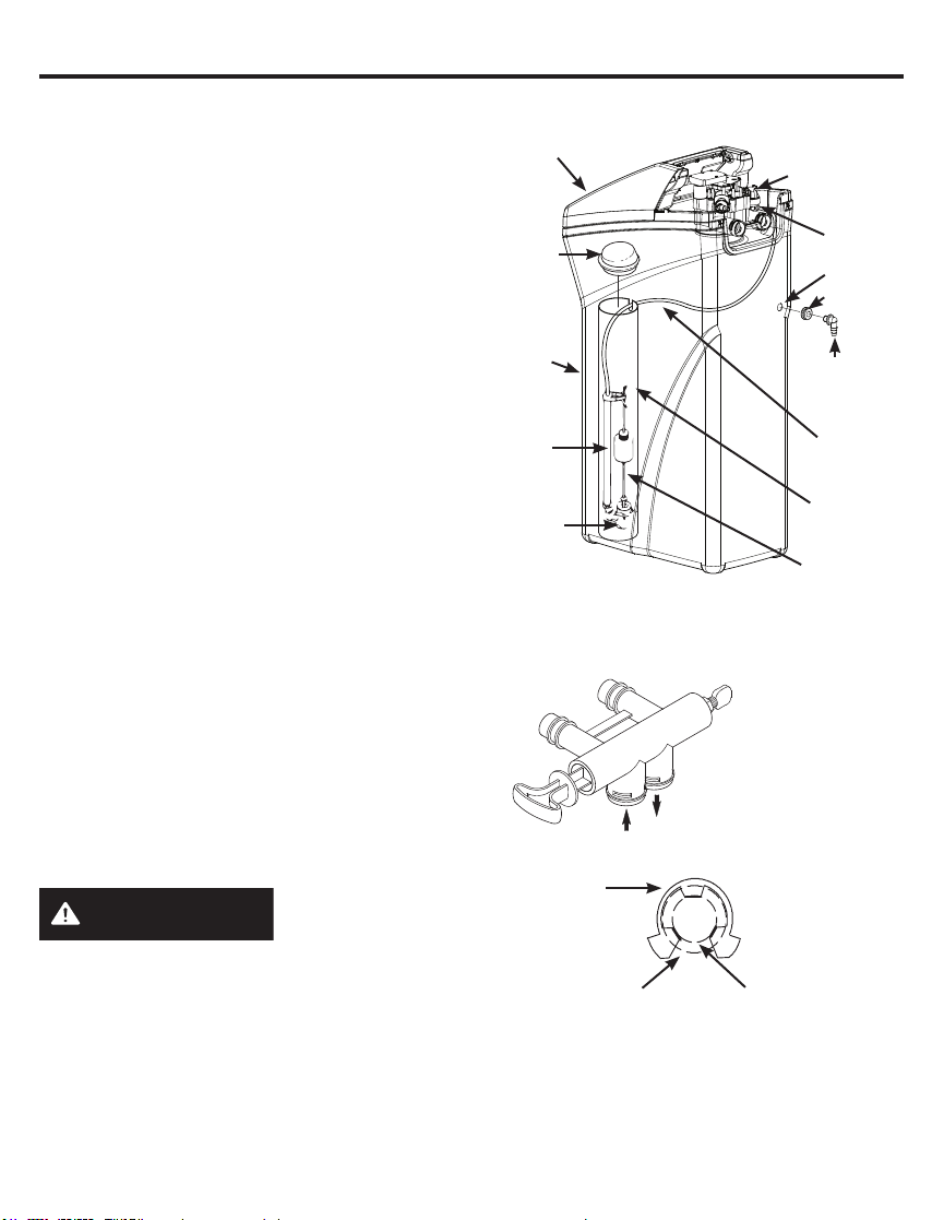
INSTALL BRINE TANK OVERFLOW ADAPTER
Install the brine tank overflow grommet and
adapter in the 13/16” diameter hole in the back
of the salt storage tank sidewall, (see Figure 9).
NOTE: The brine tank overflow adapter accepts
either 1/2” or 3/8” I.D. hose.
INSTALL THE BYPASS VALVE
NOTE: For easier installation, remove the top
cover. Release 2 clips at rear of cover. Rotate
cover forward and lift up.
1. Remove two clips from the water softener
valve inlet and outlet ports and visually check
and remove any debris, (see Figure 7).
2. Make sure the turbine assembly spins freely
in the”out” port of the valve, (see Figure 8).
3. If not already done, put a light coating of
silicone grease (provided) on the single
bypass valve o-rings, (see Figure 7).
4. Push the single bypass valve into the
softener valve as far as it will go. Snap the
two large holding clips into place, from the
top down, (see Figure 7 and 10).
IMPORTANT: Be sure the clips snap firmly into
place so the single bypass valve will not pull out.
MOVE WATER SOFTENER INTO PLACE
WARNING
Excessive Weight
Hazard
Use two or more people to move and install
water Softener Failure to do so can result in
back or other injury.
1. Move the water softener into the desired
location. Set it on a solid, level surface.
IMPORTANT: Do not place shims directly
under the salt storage tank to level the softener.
The weight of the tank, when full of water and
salt, may cause the tank to fracture at the shim.
CORRECT ASSEMBLY
Outside diameter
of clip channel on
single bypass valve
Clip
Outside diameter of
water softener valve
inlet & outlet
NOTE: Be sure all 3 tabs of the clip go through
the matching holes on the water softener valve
inlet or outlet, and fully into the channel on the
single bypass valve. Make sure that the tabs
are fully seated.
Figure 10
SINGLE BYPASS VALVE
If connecting to floor
level plumbing, install
the bypass valve turned
downward, as shown.
Salt
Cover
Brinewell
Cover
Brine
Tank
Stand
Tube
Float Stem
Brinewell
Brine
Tubing
Brine Tank
Overflow
Adapter
Grommet
Hole
Nut - Ferrule
Nozzle Venturi
Assembly
Figure 9
NOTE: Unit is shown with top cover removed.
Brine
Valve
Assembly
Installation Instructions
Loading ...
Loading ...
Loading ...