
1
INSTALLATION,USE&CAREMANUAL
48”FREESTANDINGDUALFUELRANGES
ModelsPRO486GDFSX [MTYKPZU7X5DUA]
ModelsPRO486GDFSAR [MTYKPZU7S5DUA]
ModelsPRO486GDFSBI [MTYKPZU7W5DUA]
ModelsPRO486GDFSNE [MTYKPZU7N5DUA]
ModelsPRO486GDFSRO [MTYKPZU7R5DUA]
ModelsPRO486GDFSVI [MTYKPZU7L5DUA]
ModelsPRO486GDFSGI [MTYKPZU7I5DUA]
ModèlesMAS486GDFSXT [
MTYKPZA7X5DUA]
310835

2
BERTAZZONISpA
ViaPalazzina8
42016GuastallaRE
ITALY
WWW.BERTAZZONI‐ITALIA.COM
FromthedeskofthePresident
DearnewownerofaBertazzoniproduct,
Iwanttothankyouforchoosingoneofour
beautifulPROranges.Weknowthatyouhavemany
brandsandproductstochoosefromandweare
thrilledthatyouhavedecidedtotakeoneofyour
productsintoyourhome.
Wetake
asmuchprideinmakingourrangesaswe
hopeyouwillinowningthem.Myfamilystarted
manufacturingcookingappliancesin1882.Eachof
ourproductsisablendofItaliandesignfinesseand
superiorappliancetechnolo gy.Whilewecannot
replaceyouruniquetalentatcookingdelicious
recipes
foryourself,yourfamilyandyourfriends,
wetryourbesttomakecookingeasier,more
effectiveandmorefun.
Ourappliancesaredesignedaccordingtothe
strictestsafetyandperformancestandardforthe
EuropeanandtheNorthAmericanmarket.We
followthemostadvancedmanufacturing
philosophy.Eachapplianceleavesthe
factoryafter
thoroughqualityinspectionandtesting.Our
distributorsandourservicepartnersarereadyto
answeranyquestionsyoumayhaveregardinghow
toinstall,useandcareforyourBertazzoniproduct.
Thismanualwillhelpyoulearntousetheproduct
inthesafestandmosteffectivemanner
andcare
foritsothatitmaygiveyouthehighestsatisfaction
foryearstocome.
Themanualalsoincludesdirectionsforthe
professionalinstallerthatwillinstalltheproductin
yourhome.Werecommendusingfactory‐trained
professionalsforthedelicatetaskofinstallingand
testingappliancesinyour
home.Pleasecall
CustomerServiceifyouneedhelplocatinga
factory‐trainedprofessionalinstallerinyourarea.
Pleasekeepthismanualforfutureuse.
Grazie!

3
TABLEOFCONTENTS
WARRANTYANDSERVICE........................................................................................................................................5
CUSTOMERSERVICE.......................................................................................................................................................5
REPLACEMENTPARTS....................................................................................................................................................5
IMPORTANTSAFETYINFORMATION........................................................................................................................6
BEFOREINSTALLATION............................................................................................................................................9
INSTALLINGTHELEGS............................................................................................................................................10
INSTALLINGTHEWORKTOPFRONTGUARD............................................................................................................10
INSTALLINGTHEBACKGUARD............................................................................................................................... . 11
INSTALLATIONREQUIREMENTS.............................................................................................................................12
ELECTRICAL..................................................................................................................................................................12
GAS...............................................................................................................................................................................12
INSTALLATIONADJACENTTOKITCHENCABINETS...................................................................................................13
EXHAUSTHOODINSTALLATION.............................................................................................................................13
ELECTRICALCONNECTION......................................................................................................................................14
WIRINGDIAGRAM.................................................................................................................................................17
GASCONNECTION.................................................................................................................................................19
PRESSUREREGULATOR................................................................................................................................................20
GASCONVERSION.................................................................................................................................................20
STEP1:PRESSUREREGULATOR....................................................................................................................................20
STEP2:SURFACEBURNERS..........................................................................................................................................21
STEP3:MINIMUMFLAMEADJUSTMENT.....................................................................................................................21
GASBURNERSDATATABLES..................................................................................................................................22
INSTALLATIONCHECKLIST............................................................................................................................... .......23
INSTALLATIONCHECKLIST............................................................................................................................... .......23
FINALPREPARATION.............................................................................................................................................23
USERMANUAL......................................................................................................................................................24
ROOMVENTILATION.............................................................................................................................................24
SURFACEBURNERLAYOUT....................................................................................................................................25
SURFACECOOKING................................................................................................................................................25
SYMBOLS......................................................................................................................................................................25
SURFACEBURNEROPERATION....................................................................................................................................26
TIPSFORUSINGBURNERSCORRECTLY........................................................................................................................26
TIPSFORUSINGPANSCORRECTLY...............................................................................................................................27
OVENCOOKING.....................................................................................................................................................28
SYMBOLS......................................................................................................................................................................29
OVENRACKS.................................................................................................................................................................29
OVENFUNCTIONSELECTOR.........................................................................................................................................29
USINGTHEOVEN...................................................................................................................................................30
OVENLIGHT..................................................................................................................................................................30
COOLINGFANS.............................................................................................................................................................30
FRONTINDICATORLIGHTS...........................................................................................................................................30
SOUNDBUZZER............................................................................................................................................................30
OVENCONVECTIONFAN..............................................................................................................................................30

4
BAKE.....................................................................................................................................................................31
PREHEATINGTHEOVEN.....................................................................................................................................31
GETTINGTHEBESTRESULTS..............................................................................................................................31
BAKEWARETYPE.................................................................................................................................................31
BAKERACKPOSITIONS............................................................................................................................... ........31
CONVECTION......................................................................................................................................................... 31
CONVECTION.......................................................................................................................................................31
CONVECTIONBAKE.............................................................................................................................................31
TURBO.................................................................................................................................................................31
RACKPOSITIONS.................................................................................................................................................32
BAKINGRECOMMENDATIONS...........................................................................................................................33
WARMING............................................................................................................................... .............................. 33
PROOFING.............................................................................................................................................................33
DEHYDRATE...........................................................................................................................................................34
BROIL/CONVECTIONBROIL..................................................................................................................................35
BROILINGANDROASTINGRECOMMENDATIONS...................................................................................................36
CAREANDMAINTENANCE.....................................................................................................................................37
SELF‐CLEANINGTHEOVEN.....................................................................................................................................37
MAINTAININGYOURRANGE..................................................................................................................................38
CLEANINGYOURRANGE........................................................................................................................................39
TROUBLESHOOTINGGUIDE....................................................................................................................................40
LOCATIONOFAPPLIANCETAGS............................................................................................................................. 41
IMPORTANTAPPLIANCEINFORMATION................................................................................................................42

5
WARRANTYANDSERVICE
AllBertazzoniproductscarrya2yearpartsandlabourwarranty.
ServiceonallBertazzoniproductsshallbecarriedoutbyfactory‐trainedprofessionalsonly.
ForwarrantyservicepleasecontactCustomerServiceatthenumbers indicatedbelow.
CUSTOMERSERVICE
English/Spanishhotline (866)905‐0010
French(800)561‐7625
Fax(714)
428‐0040
Email
Mailingaddress
SERVICEPOWER
1503SouthCoastdrive
Suite320
CostaMesaCA92626
REPLACEMENTPARTS
OnlyBertazzonireplacementpartsmaybeusedinperformingserviceontheappliance.
Replacementpartsareavailablefromfactoryauthorizedpartsdistributors.
APWagner PHONE
1 888 279 2463 FAX716 856 4779
ReliableParts PHONE 206 5758818 FAX206 5750910
Coast PHONE 800 821 0244 FAX604 321 6646
6
IMPORTANTSAFETYINFORMATION
PLEASEREADANDFOLLOWTHESEIMPORTANTINSTRUCTIONSFORTHESAFETYOFYOURHOMEANDOF
THEPEOPLELIVINGINIT.
SavethisManualforlocalelectricalinspector’suse.
Readandsavetheseinstructionsforfuturereference.
Observeallgoverningcodes,ordinancesandregulations.
WARNING!
Iftheinformationinthismanualis
notfollowedexactly,afireorexplosionmayresultcausingproperty
damage,personalinjuryordeath.
Donotstoreorusegasolineorotherflammablesubstancesinthevicinityofthisoranyotherappliance.
Installationandservicemustbeperformedbyaqualifiedinstaller,serviceagencyorthegas
supplier.
InMassachusetts:Allgasproductsmustbeinstalledbya"Massachusetts"licensedplumberorgasfitter.A
"T"handletypemanualgasvalvemustbeinstalledinthegaslineconnectedtothisappliance.
WHATTODOIFYOUSMELLGAS
Donotlightanyappliance.
Donottouchanyelectricalswitch.
Donotuse anyphoneinyourbuilding.
Immediatelycallyourgassupplierfromaneighbour’sphone.Followthegassupplier’sinstructions.
Ifyoucannotreachyourgassuppliers,callthefiredepartment.
Warning!
This range can tip. Injury to persons could result.
Install anti-tip device shipped with range. See
Installation Instructions.

7
WARNING!
Readthisinstructionbookletbeforeinstallingandusingtheappliance.
Themanufacturerwillnotberesponsibleforanydamagetopropertyortopersonscausedbyincorrect
installationorimproperuseoftheappliance.
The manufacturer reserves the right to make changes to its products when considered necessary and
useful,
withoutaffectingtheessentialsafetyandoperatingcharacteristics.
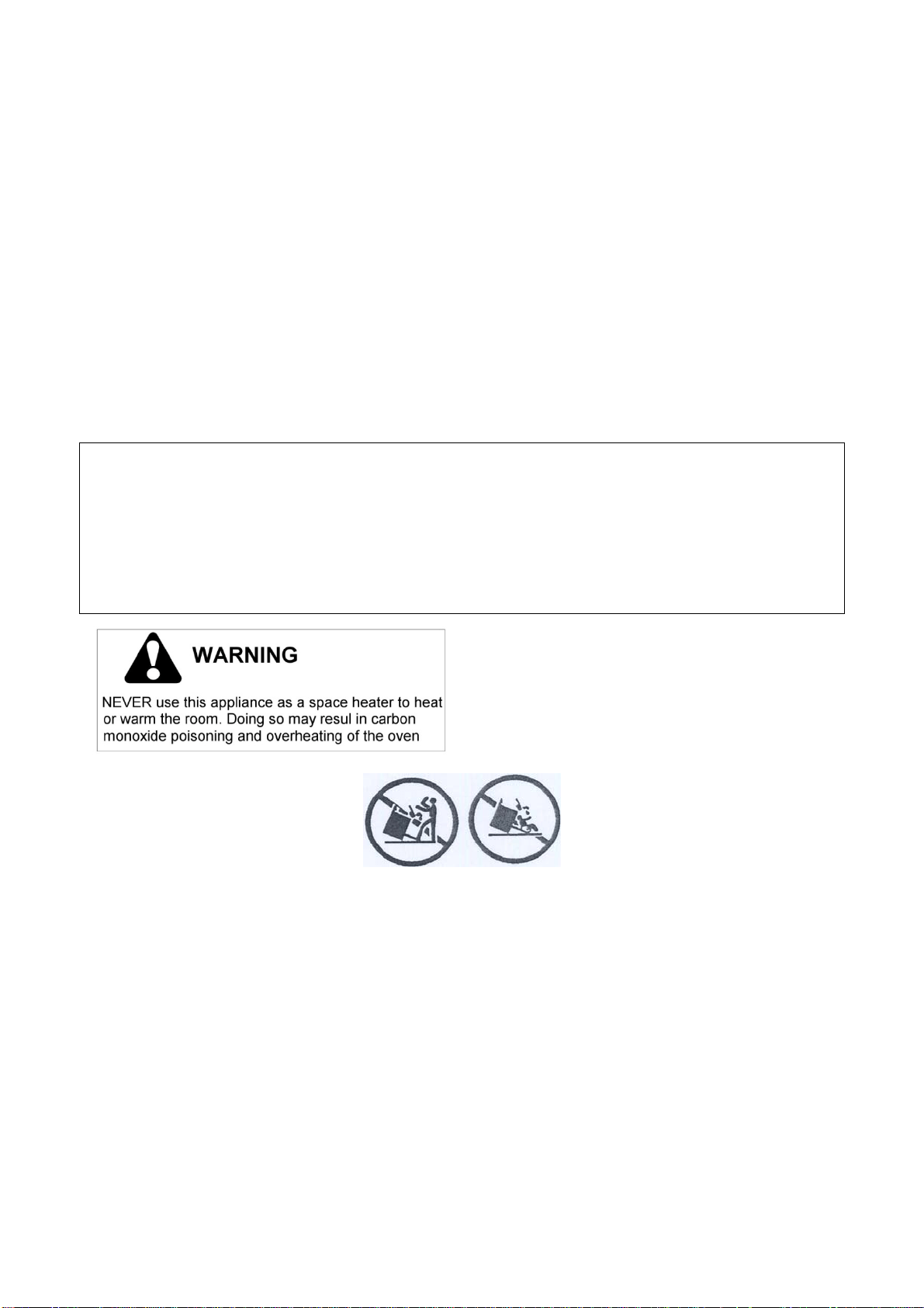
Thisappliancehasbeendesignedfornon‐professional,domesticuseonly.
Donotusethisappliancetoheataroom.
Donotplaceanypotorpanontheopenovendoor.Thedoorismadeofglassanditcanbreak
ifloaded
withaweight.
Beforebeginninginstallation,pleasereadtheseinstructionscompletelyandcarefully.
Do not remove permanently affixed labels, warnings, or plates from the product. This may void the
warranty.‐Pleaseobservealllocalandnationalcodesandordinances.
Pleaseensuretherangeisproperlygrounded.
Theinstallershould
leavetheseinstructionswiththeconsumerwhoshouldretainforlocalinspector'suse
andforfuturereference.
Theplugshouldalwaysbeaccessible.
Installation must confor m with local codes or in the absence of codes, the National Fuel Gas Code
NSIZ223.1‐latest edition. Electrical installation must be in accordance with
the National Electrical Code,
ANIS/NFPA70‐latesteditionand/or local codes.IN CANADA:Installation must bein accordance withthe
current CAN/CGA‐B149.1 National Gas Installation Code or CAN/CGA‐B 149.2, Propane Installation Code
and/or local codes. Electrical installation must be in accordan c e with the current CSA C22.1 Canadian
ElectricalCodesPart
1and/orlocalcodes.
Installationofanygas‐firedequipmentshouldbemadebyalicensedplumber.Amanualgas shut‐offvalve
mustbeinstalledinthegassupplylineaheadoftheoveninthegasflowforsafetyandeaseofservice.
8
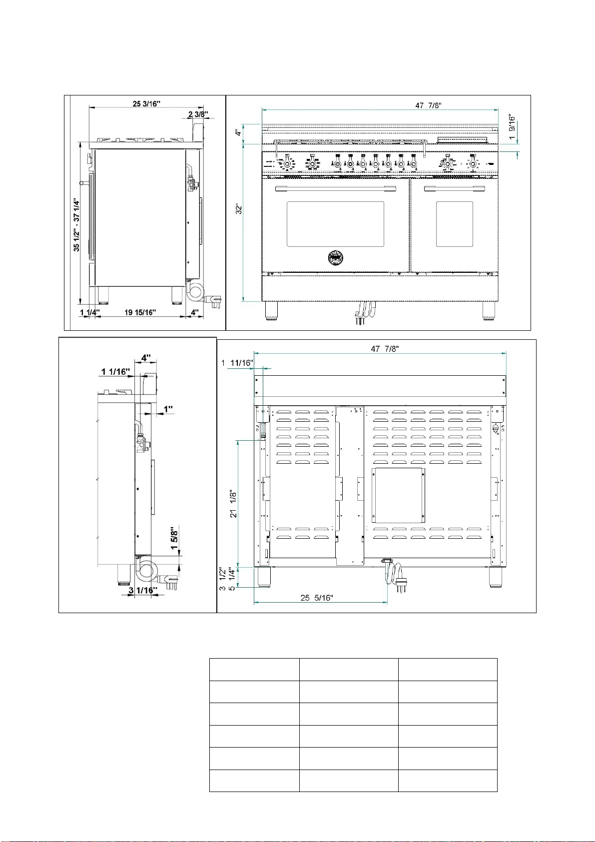
PRODUCTSPECIFICATIONS
Dimensions(insertdrawingsfront,sideandback)
Weight
Burnerpower
Naturalgas
LPgas
Auxiliary
3750BTU/h 3750BTU/h
Semi‐rapid
6000BTU/h 6300BTU/h
Rapid
10400BTU/h 11400BTU/h
Dualburner(inner)
2730BTU/h 2900BTU/h
Dualburner(outer)
15000BTU/h 16400BTU/h

9
BEFOREINSTALLATION
This appliance shall only be installed by an
authorizedprofessional.
This appliance shall be installed in accordance
withthemanufacturer’sinstallationinstructions.
This appliance must be installed in accordance
withthenorms&standardsofthecountrywhere
it will be installed. The installation of this
appliance must conform to local
codes and
ordinances. In the absence of local codes,
InstallationsmustconformstoAmericanNational
Standards,NationalFuel GasCodeANSIZ223.1–
latestedition**orB149.1.
The appliance, when installed, must be
electrically grounded in accordance with local
codes or,in the absenceof localcodes, with the
National
ElectricalCode,ANSI/NFPA70.
If local codes permit, a flexible metal appliance
connection with the new AGA or CGA certified
design, max. 5 feet (1,5 m) long, ½” I.D. is
recommended for connecting this appliance to
the gas supply line. Do not bend or damage the
flexibleconnectorwhenmovingthe
appliance.
This appliance must be used with the pressure
regulator provided. The regulator shall be
properlyinstalled inorder tobe accessiblewhen
theappliance isinstalled in itsfinallocation.The
pressureregulatormustbesetforthetypeofgas
tobeused.Thepressureregulatorhas½”
female
pipe thread. The appropriate fitting must be
determined basedon thesize ofyour gas supply
line,theflexiblemetalconnectorandtheshutoff
valve.
The appliance must be isolated from the gas
supply piping system by closing its individual
manualshutoffvalveduringanypressuretesting
ofthegas
supplypipingsystemattestpressures
equaltoorlessthan½psi(3.5kPa).
All openingandholes in the wall andfloor, back
and under the appliance shall be sealed before
installationoftheappliance.
Amanualvalveshallbeinstalledin anaccessible
location inthe gas
line external to the appliance
for thepurpose of turningon orshutting off gas
totheappliance
WARNING!
Donotuseaerosolspraysinthevicinityofthis
appliancewhileitisinoperation
ROOM VENTILATION: An exhaust fan may be
used with the appliance; in each case it
shall be
installed in conformity with the appropriate
national and local standards. Exhaust hood
operationmay affectotherventedappliances; in
each case it shall be installed in conformity with
theappropriatenationalandlocalstandards.
TYPEOFGAS
Thisapplianceisshippedfromthefactoryforuse
with natural
gas. For use with propane LP gas
please follow the conversion procedure
described on pg. 17. A step by step conversion
procedureisalsoincludedwitheachsetofLPgas
nozzles.
GASPRESSURE
Themaximuminletgassupplypressureincoming
to the gas appliance pressure regulator is 20’’
water
column(5kPa).
The minimu m gas supply pressure for checking
theregulatorsettingshallbeatleast1“w.c.(249
Pa)abovetheinletspecifiedmanifold pressureto
the appliance (this operating pressure is 4” w.c.
(1.00kPa)forNaturalGasand11” w.c.(2.75kPa
forLPGas).

10
INSTALLINGTHELEGS
Bertazzonirangesmustbeusedonlywiththe
legsproperlyinstalled.
Fourheight‐adjustablelegsareshippedwiththe
rangeinthepolystyrenecontainersituatedover
theappliance.
Before installing the legs, position the appliance
nearitsfinallocation as the legsarenotsuitable
formovingtheapplianceoverlong
distances.
After unpacking the range, raise it enough to
insert the legs in the appropriate receptacles
situated on the lower part of the appliance.
Lowertherangegently tokeepanyunduestrain
fromlegsandmountinghardware.Ifpossibleuse
apalletorliftjackinsteadoftiltingthe
unit.
Adjust leg height to the desiredlevel bytwisting
the inside portion of the leg assembly until the
properheightis reached.Check witha level that
thecooktopisperfectlylevel.
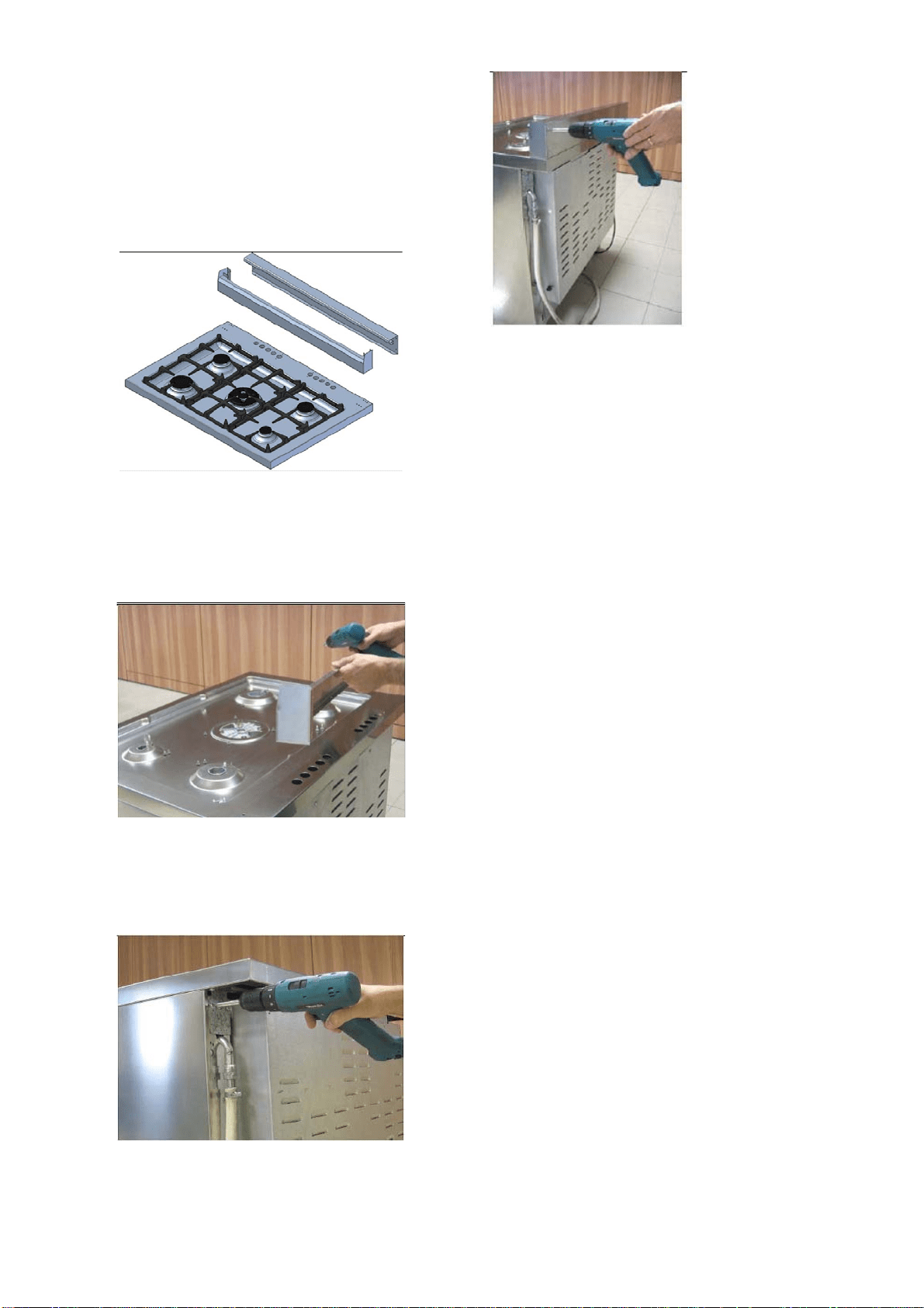
INSTALLINGTHEWORKTOP
FRONTGUARD
Toincreasetheclearancebetweenthefrontedge
of the worktop and the burners it is possible to
install the worktop front guard shipped with the
appliance.
Toinstallthefrontguard,holditwiththepointed
edges looking up. Align the edges of the front
guard with the appropriate receptacles
in the
bottomoftheworktopand press firmly untilthe
frontguardissecurelyattachedtotheworktop.
ATTENTION: once installed the front guard may
only be removed by disassembling the worktop.
Attempting to remove the front guard without
disassembling the worktop will result in
permanentdamagetothe
worktop.
11
INSTALLINGTHEBACKGUARD
The back guard must be installed prior to
operation of the appliance for appropriate
ventilationoftheovencompartment.
Thesuppliedbackguardisa2‐partassembly.The
box also contains a set of metal screws for
securingthebackguardtotheworktop.
Disassemble the back guard and position the
frontpart on the worktop. Alignthe screwholes
with the corresponding holes at the back of the
worktop.
If the holes are not aligned, partially loosen the
brackets at the back of the worktop as shown
below.
Installthefrontpartofthebackguardby
tighteningthe2centralscrewsfromthetopand
2lateralscrewsfromthebottom.
12
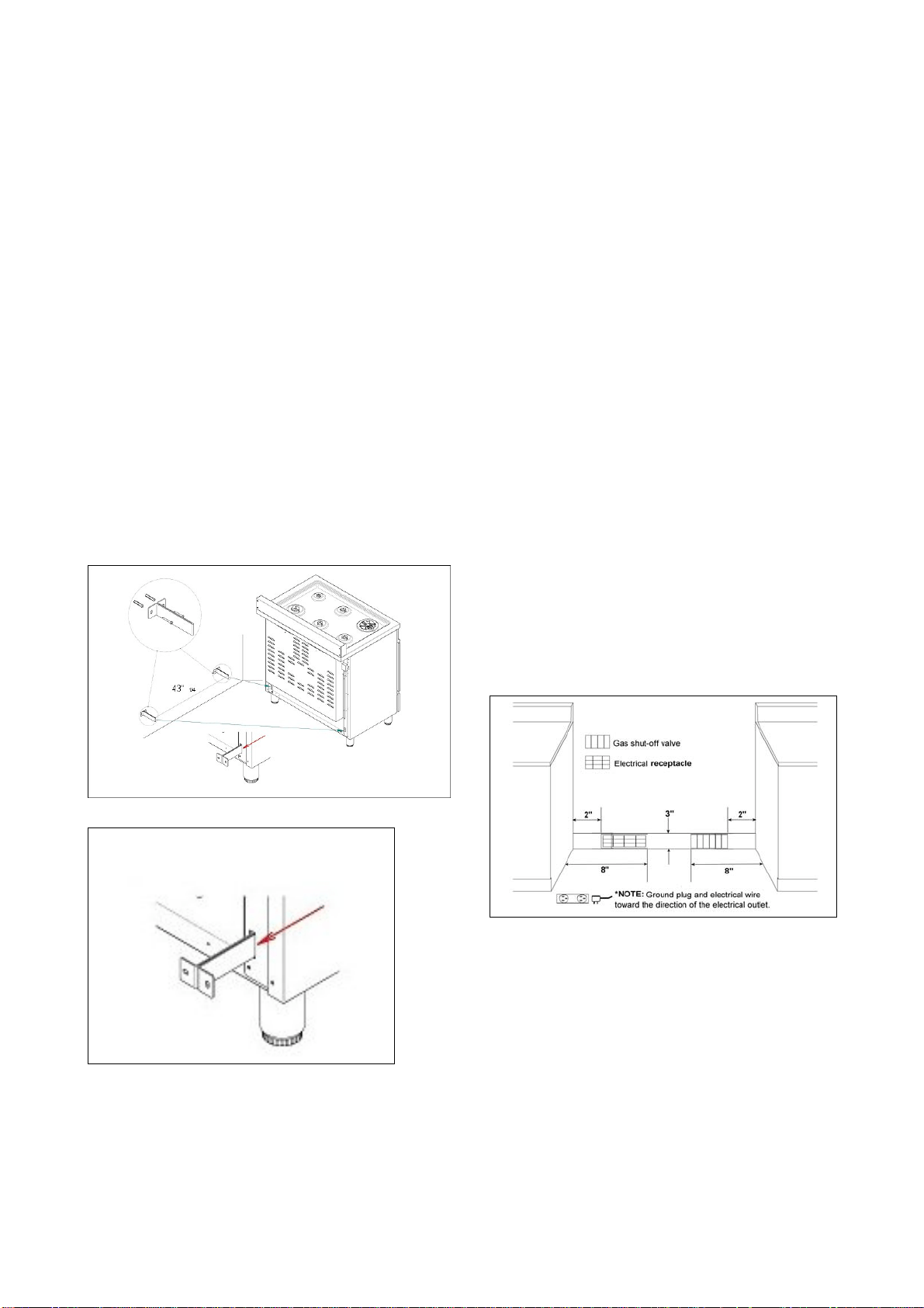
INSTALLINGTHEANTI‐TIPStabilityDEVICE
Theanti‐tipbracketshippedwiththerangemust
beproperly securedto the rearwallas shownin
thepicturebelow.
Theheightofthebracketfromthefloormustbe
determined after the range legs have been
adjusted to the desired height and
afterthe
rangehasbeenlevelled.
Measure the distance from the floor to the
bottom of the anti‐tip bracket receptacle on the
backoftheappliance.
Position the two anti‐tip brackets on the wall at
the desired height plus 1/8" (0.32 cm). The
bracketsmustbeplaced at
2”5/16(6,0cm)from
the side of the range. The distance between the
twobracketis43”1/4(109,8cm).
Secure thebrackets to thewall with appropriate
hardware.
Slidetherangeagainstthewalluntilthebrackets
are fully inserted into their receptacles on the
backoftherange.
INSTALLATIONREQUIREMENTS
ELECTRICAL
A properly grounded and horizontally‐mounted
electrical receptacle Type NEMA 14‐50R should
beinstallednohigherthan3"(7.6cm)abovethe
floor,nolessthan2”(5cm)andnomorethan8”
(20,3 cm) from the left side (facing product);
refer to ELE CTRICAL CONNECTION section pag.
13.
Checkalllocalcoderequirements.
GAS
Anagency‐approved,properly‐sizedmanualshut‐
off valve should be installed no higher than 3"
(7.6 cm) above the floor and no less than 2” (5
cm)andnomorethan8”(20.3cm)fromtheright
side(facingproduct).
To connect gas
between shut‐off valve and
regulator, use agency ‐approved, properly sized
flexible or rigid pipe. Check all local code
requirements.
13
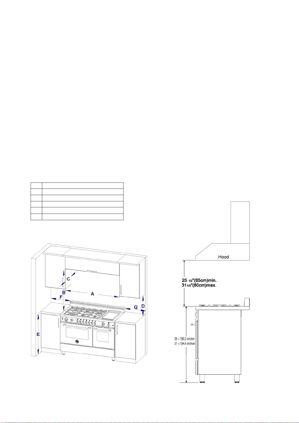
INSTALLATIONADJACENTTOKITCHEN
CABINETS
This range may be installed directly adjacent to
existingcountertophighcabinets(36"or91.5cm
fromthefloor).
For the best look, the worktop should be level
with the cabinet countertop. This can be
accomplished by raising the unit using the
adjustmentspindlesonthelegs.
ATTENTION: the range CANNOT
be installed
directly adjacent to kitchen walls, tall cabinets,
tall appliances, or other vertical surfaces above
36" (91.4 cm)high. The minimum side clearance
insuchcasesis6"(15.2cm).
Wallcabinetswithminimumsideclearancemust
be installed 18" (45.7 cm) above the countertop
withcountertopheightbetween
35½”(90.2cm)
and37¼”(94.6cm).Themaximumdepthofwall
cabinetsabovetherangeshallbe13"(33.0cm)
EXHAUSTHOODINSTALLATION
ThisrangewillbestperformwhenusedwithPRO
lineBertazzoniexhausthoods.Thesehoodshave
been designed to work in conjunction with the
Bertazzoni range and have the same finish for a
perfectlook.
For maximum performance, the height of the
bottomofthe hood fromtheworktop should be
between 25 1/2" (65 cm) and 31 1/2" (80 cm).
This would typically result in the bottom of the
hoodbeing 611/2"(156.2 cm)to67 1/2"(171.5
cm) above the floor. These measurements
provide for safe and efficient operation of the
hood.
Before installation of the exhaust hood,
consult
local or regional building and installation codes
foradditionalspecificclearancerequirements.
Refer to the range hood installation instructions
provided by the manufacturer for additional
information.
A 48” (122 cm)
B 36” (91,5 cm)
C 13” (33,0 cm)
D 18” (45,7 cm)
E 35”1/2(90,2 cm) / 37” ¼ (94,6 cm)
F 6” (15,2 cm)

14
ELECTRICALCONNECTION
The appliance shall be connected toa single
phase electric line rated at 120/208Vac or
120/240Vacand60Hzfrequency.
Electricpowerrating:
‐120/208Vac:6700Wattor32Amax.
‐120/240Vac:8500Wattor37Amax.
Heatingelements(240V)power rating:
LEFTOVEN:
‐Ovenbakeelement=2100Watt
‐Ovencircularelement=3300Watt
‐Ovenbroilelement=3400Watt
RIGHTOVEN:
‐Upper+broilelement=900+1100Watt
‐Bottomelement=900Watt
WORKTOPELE.GRIDDLEELEMENT=1100Watt
Installa suitableelectricpowersupplyreceptacle
connection type NEMA 14‐50Rable to support a
load ofat least40 A(per line)according to local
coderequirements.Forfourorthreewirespower
supplyconnectionsystemseediagrambelow.
FOUR-WIRE CONN.RECEPTACLE NEMA 14-50R
THREE-WIRE CONN.RECEPTACLE NEMA 14-50R
Check your local code for which of the options
belowshould be usedin grounding the
receptaclepowersupplyconnections.
OPTION 1 – FOUR Wires connection:
‐ Connect the L1 receptacle terminal to the
incoming BLACK electrical supply wire (L1‐hot
wire)
‐ Connect the L2 receptacle terminal to the
incoming RED electrical supply wire (L2‐hot
wire)
‐ Connect the NEUTRAL receptacle terminal to
the incoming NEUTRAL (WHITE) electrical
supplywire
‐ Connect the GROUND receptacle terminal to
the incoming GROUND (GREEN) electrical
supplywire
OPTION 2 - THREE-Wires connection:
‐ Connect the L1 receptacle terminal to the
incoming BLACK electrical supply wire (L1‐hot
wire)
‐ Connect the L2 receptacle terminal to the
incoming RED electrical supply wire (L2‐hot
wire)
‐ Connect the NEUTRAL with the GROUND
receptacle terminal to the incoming NEUTRAL
(WHITE)electricalsupplywire
DO NOT USE EXTENSION CORDS WITH THIS
APPLIANCE AS IT MAY RESULT IN FIRE,
ELECTRIC SHOCK OR OTHER type of
PERSONAL INJURY.
The appliance isequipped at the factory with an
electric supply cord set 4 wires type with ring
terminals (L1, L2, N, Ground) suitable for range
use UL/CSA listed type SRDT/DRT 2x6AWG (L1,
L2)+2x8AWG (N, G) rated 300V, 40 or 50A with
fused plug type NEMA 14‐50P; cable length 1,5
m.;incasethesupplycordsetmustbereplaced,
it shall be replaced with anidentical set having
the same technical specs and followingcarefully
theinstructionsanddiagramsbelow:
1) Disconnect appliance from electrical power
supplyreceptacle
2) Slideouttheappliancefrominstallationplace
toaccessto
backenclosurepanel
3) Remove back enclosure panel by removing
the6screwsasshownbelow

15
4) Loosestrainreliefbyunscrewingthetwo
strainrelief'sscrewsasindiagram.
16
5) Remove damaged supply cord set by taking
off the 4 electrical connection screws (block
L1,N,L2andGroundscrew,seediagram)
6) Insert the new supply cord set in the strain
relief and lock it with two strain relief's
screwsinsuitableposition.
7) Fixwell the ringterminals
G, L1, N,L2ofthe
new supply cord set asshown in diagram
withits4screws
8) Re‐install the back enclosure panel with 6
screws
9) Slide the appliance back into its proper
location
10) Re‐connect the appl iance to the electrical
power.
ELECTRICALGROUNDING
Thisapplianceisequippedwitha four‐prongplug
for your protection against shock hazard and
should be plugged dir ectly into a properly
grounded recepta cle. Do not cut or remove the
groundingprongfromthisplug.
WARNING!
ELECTRICALSHOCKHAZARD
Disconnectelectricalpowe ratthecircuit
breakerbox
orfuseboxbeforeinstallingthe
appliance.
Provideappropriategroundfortheappliance.
Usecopperconductorsonly.
Failuretofollowtheseinstructionscouldresult
inseriousinjuryordeath
CAUTION
Labelallwirespriortodisconnectingwhen
servicingcontrols.Wiringerrorscancause
improperanddangerousoperation.
Verifyproperoperation
afterservicing
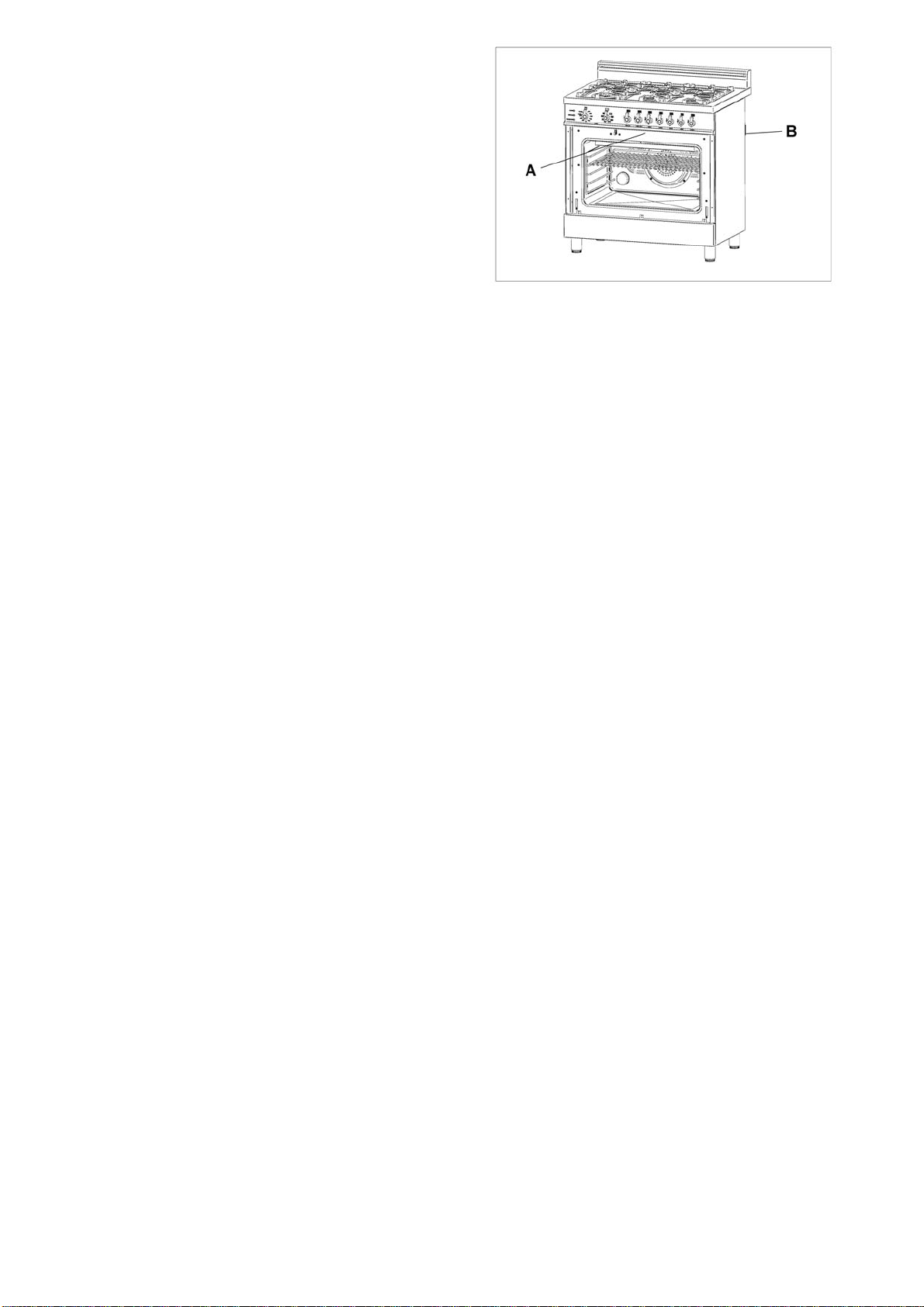
LOCATIONOFAPPLIANCEPLATES
Thedataratingplateshowsthemodelandserial
number of your range. It is located under the
front edge of the range cooktop, and is visible
whentheovendoorisopen(seeillustration)
A=Ratingplate(s)locatedunderfrontedgeof
cooktop
B=Wiring/schematicdiagramplacedon
backsidepanelandoninstallationbooklet
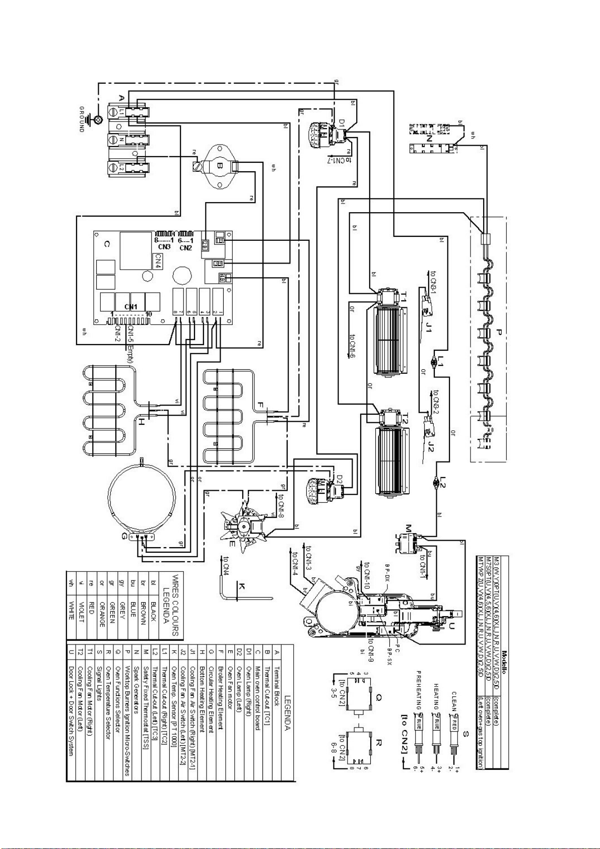
17
WIRINGDIAGRAM
LEFT OVEN + GAS TOP IGNITION
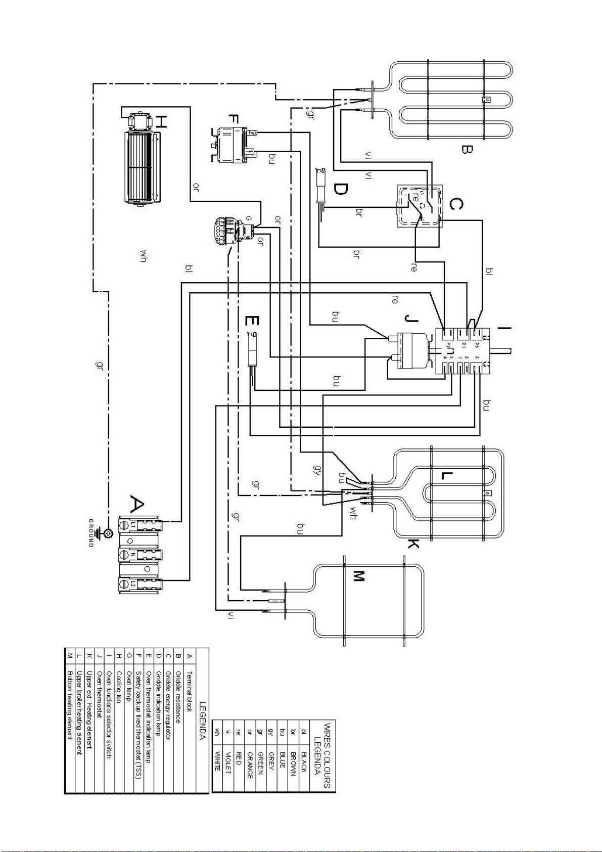
18
RIGHT OVEN + GRIDDLE

19
GASCONNECTION
All gas connections must comply with national
and local codes. The gas supply line (service)
must be the same size or greater than the inlet
lineof theappliance. This range usesa 1/2"NPT
inlet (see drawing below for details of gas
connection). On all pipe joints use appropriate
sealant
resistanttogas.
This range can be used with Natural or
LP/Propane gas. The range is shipped from the
factoryforusewithnaturalgas.
For LP/propane household installation, the
appliance mustbe converted bythe dealer, bya
factory‐trained professional or by a qualified
licensedplumberorgas
servicecompany.
Gasconversionisimportantforsafeandeffective
useoftheappliance.Itistheresponsibility ofthe
dealerandtheowneroftherangetope rformthe
appropriate gas conversion following the
directionsofthemanufacturer.
THEGASCONVERSIONPROCEDUREIS
DESCRIBEDINTHISMANUALANDINTHE
PACKAGECONTAININGTHECONVERSION
NOZZLESSHIPPEDWITHEVERYRANGE.
Pleaseprovidetheservicepersonwiththis
manualbeforeworkisstartedontherange.
WARNING!
DONOTUSEANOPENFLAMEWHENCHECKING
FORLEAKS!
Leak testing of the appliance shall be conducted
according to the manufacturer's instructions.
Before placing
the oven into operation, always
check for leaks with soapy water solution or
otheracceptablemethod.
MANUALSHUT‐OFFVALVE
THISVALVEISNOTSHIPPEDWITHTHE
APPLIANCEANDMUSTBESUPPLIEDBYTHE
INSTALLER.
The manual shut‐off valve must be installed in
the gasservice linebetween the
gashook‐up on
the wall and the appliance inlet, in a position
whereitcanbereachedquicklyintheeventofan
emergency.
In Massachusetts: A 'T' handle type manual gas
valve must be installed in the gas supply line to
thisappliance.
FLEXIBLECONNECTIONS
In case of
installation with flexible couplings
and/or quick‐disconnect fittings, the installer
must use a heavy‐duty, AGA design‐certified
commercial flexible connector of at least 1/2"
(1.3 cm) ID NPT (with suitable strain reliefs) in
compliance with ANSI Z21.41 and Z21.69
standards.
In Massachusetts: The unit must be installed
witha
36"(3‐foot)longflexiblegasconnector.
InCanada:useCAN1‐6.10‐88metalconnectors
forgasappliancesandCAN1‐6.9M79quick
disconnectdeviceforusewithgasfuel.
PRESSURETEST‐POINTSTOPPERVALVE
To avoid gas leaks, the pressure test‐point
stoppervalveandgaske tsupplied
withtherange
mustbeinstalledonthegasfittingatthebackof
therangeaccordingtothediagrambelow.

20
PRESSUREREGULATOR
Since service pressure may fluctuate with local
demand, every gas cooking appliance must be
equipped with a pressure regulator on the
incoming service line for safe and efficient
operation.
The pressure regulator shipped with the
appliance has two female threads ½” NPT. The
regulatorshallbeinstalledproperly in
ordertobe
accessible when the appliance is installed in its
finalposition.
Manifoldpressureshouldbecheckedwitha
manometerandcomplywiththevaluesindicated
below:
Naturalgas4.0"W.c.P.
LP/Propane11.0"W.C.P.
Incominglinepressureupstreamfromthe
regulatormustbe1"W.c.P.higherthanthe
manifoldpressureinordertocheckthe
regulator.
Theregulatorusedon
thisrangecanwithstanda
maximuminputpressureof1/2PSI(14.0"W.c.P.)
Ifthelinepressureexceedsthatamount,astep‐
downregulatorisrequired.
The appliance, its individual shut‐off valve, and
the pressure regulator must be disconnected
from the gas line during any pressure testing of
that system
at pressures in excess of 1/2 psig
(3.45kPa).
The individual manual shut‐off valve must be in
the OFF position during any pressure testing of
the gas supply piping system at test pressures
equaltoorlessthan½psig(3.45kPa).
GASCONVERSION
WARNING!
Beforecarryingoutthisoperation,disconnect
theappliancefromgasandelectricity.
Gasconversionshallbeconductedbyafactory‐
trainedprofessional.
Callthecustomerservicehotlinetoidentifya
factory‐trainedprofessionalnearyourhome.
The gas conversion procedure for this range
includes6steps:
1. Pressureregulator
2.
Surfaceburners
3. Adjustmentofminimumsetting
The conversion is not completed if all 6 steps
havenotbeenconcludedproperly.
Beforeperformingthegasconversion,locatethe
package containing the replacement nozzle
shipped with every range. IMPORTANT: Each
nozzle hasa number indicating its flowdiameter
printedonthe
body.Consultthetableonpage20
formatchingnozzlestoburners.
Savethenozzlesremovedfromtherangefor
futureuse.
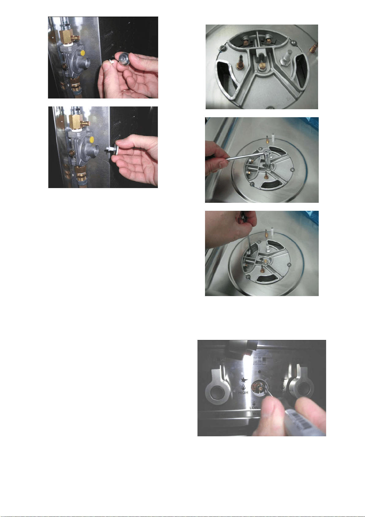
STEP1:PRESSUREREGULATOR
Thepressureregulatorsuppliedwiththe
applianceisaconvertibletypepressure regulator
forusewithNaturalGasatanominaloutlet
pressureof
4”w.c.orLPgasatanominaloutlet
pressureof11”w.c.anditispre‐arrangedfrom
thefactorytooperatewithoneofthese
gas/pressureasindicatedinthelabelsaffixedon
theappliance,packageandInstructionbooklet.
Toconverttheregulatorforusewithotherliquid
propaneLPgas:
1. Unscrewbyhandtheuppercapofthe
regulator,removethewhiteplastic
attachmentfromthecap,reverseits
directionandscrewitagainfirmlyagainstthe
cap.Thewhiteplasticattachmenthasarrows
indicatingthepositionfornaturalgas(NAT)
andLPgas(LP).
2. Screw
byhandthemetalcapintheoriginal
positionontheregulator.
21
STEP2:SURFACEBURNERS
Toreplacethenozzlesofthesurfaceburners,lift
up theburners andunscrew the nozzles shipped
withtherangeusinga7mm{socketwrench).
Replacenozzlesusingtheconversionsetsupplied
with the range or by a Bertazzoni authorized
parts warehouse. Each nozzle has
a number
indicating itsflowdiameter printed on the body.
Consultthetableonpage20formatchingnozzles
toburners.
STEP3:MINIMUMFLAMEADJUSTMENT
WARNING!
Theseadjustmentsshouldbemadeonlyforuse
oftheappliancewithnaturalgas.Forusewith
liquidpropanegas,thechokescrewmustbe
fullyturnedinaclockwisedirection.
SURFACEBURNERS
1. Light one burner at a time and set the
knob
totheMINIMUMposition(smallflame).
2. Removetheknob.
3. The range is equipped with a safety valve.
Using asmall‐sizeslotted screwdriver, locate
the choke valve on the valve body and turn
the choke screw to the right or left untilthe
burnerflameisadjustedto
desiredminimum.
4. Make sure that the flame does not go out
when switching quickly from the MAXIMUM
totheMINIMUMposition.

22
GASBURNERSDATATABLES
Burner Position Injector Gas Pressure MaxRate MinRate By‐pass
diam.[mm.] Type [i.w.c.] [BTU/h] [W] [BTU/h] [W] diam.[mm]
Auxiliary FrontR 0,92 NG 4” 3750 1098 900 264 Regulated
0,56 LP(Propane) 11” 3750 1098 900 264 0,29
Semi‐Rapid RearL&C 1,17 NG 4” 6000 1759 1500 439 Regulated
FrontC 0,73 LP(Propane) 11” 6300 1845 1500 439 0,36
Rapid RearR 1,55 NG 4” 10400 3046 2500 732 Regulated
0,98 LP(Propane) 11” 11400 3339 2500 732 0,47
FrontLInner 0,80 NG 4” 2730 799 900 264 Regulated
DualBurner 0,50 LP(Propane) 11” 2900 849 900 264 0,29
FrontLOuter N°2x1,30 NG 4” 15000 4394 4500 1318 Regulated
N°2x0,83 LP(Propane) 11” 16400 4804 4500 1318 0,65

23
INSTALLATIONChecklist
1. Istherangemountedonitslegs?
2. Isthebackguardsecurelyconnected?
3. Hastheanti‐tipdevicebeenproperly
installed?
4. Doestheclearancefromthesidecabinets
complywiththemanufacturersdirections?
5. Istheelectricityproperlygrounded?
6. Isthegasservicelineconnectedfollowing
thedirectionsofthemanufacturer?
7. Haveallthepropervalves,stoppersand
gasketbeeninstalledbetweentherangeand
theserviceline?
8. Hasthegasconnectionbeencheckedfor
leaks?
9. Hastherangebeensetforthetypeofgas
availableinthehousehold?
10. Doesthe
flameappearsharpblue,withno
yellowtipping,shootingorflamelifting?
11. Hastheminimumsettingforallburnersbeen
adjusted?
FINALPREPARATION
Allstainlesssteelbodypartsshouldbewiped
withhot,soapywaterandwithaliquidstainless
steelcleanser.
Ifbuild‐upoccurs,donotusesteelwool,abrasive
cloths,cleaners,orpowders!Ifitisnecessaryto
scrapestainlesssteeltoremoveencrusted
materials,soakwithhot,wetclothsto
loosenthe
material,thenuseawoodornylonscraper.Do
notuseametalknife,spatula,oranyothermetal
tooltoscrapestainlesssteel!Scratchesare
almostimpossibletoremove.
Beforeusingtheovenforfoodpreparation,wash
thecavitythoroughlywithawarmsoapand
watersolution
toremovefilmresiduesandany
dustordebrisfrominstallation,thenrinseand
wipeddry.

24
USERMANUAL
WARNING!
ProperInstallation.Besureyourapplianceis
properlyinstalledandgrounded byaqualified
technician.
Donotleavechildrenalone.Childrenshouldnot
beleftaloneorunattendedinareawhere
applianceisinuse.Theyshouldneverbe
allowedtositorstandonanypartofthe
appliance.
Wearproperapparel.Loose‐fittingorhanging
garmentsshouldneverbewornwhileusingthe
appliance.
Userservicing.Donotrepairorreplaceanypart
oftheapplianceunlessspecifically
recommendedinthemanual.Allotherservicing
shouldbereferredtoaqualifiedtechnician.
Useonlydrypotholders.Moistor
damp
potholdersonhotsurfacesmayresultinburns
fromsteam.Donotletpotholdertouchhot
heatingelements.Donotuseatowelorother
bulkycloth.
Donottocovertheholesinsidetheovenwith
aluminiumfoil.
Donottocovertheworktopwithaluminium
foil.
Donot
storeanyflammableobjectorobjects
underpressureinthestoragecompartment.
Keeptheareaofoperationoftherangefree
fromcombustiblematerials,gasolineandother
flammablevapoursandliquid.
Donotstoredangerousorflammablematerials
inthecabinetsabovetheappliance.
Donotusetheappliancefor
spaceheating.
Donotuseaerosolspraysinthevicinityofthe
appliancewhilecooking.
Donotsitorstepontheovendoor.
Donotuseovencompartmentforstorage.
UseCareWhenOpeningDoor.Lethotairor
steamescapebeforeremovingorreplacingfood
Donotheatunopened
foodcontainers.Build‐up
ofpressuremaycausecontainertoburstand
resultininjury.
Keepovenventductsunobstructed.
Alwaysplaceovenracksindesiredlocation
whenoveniscool.Ifrackmustbemovedwhile
ovenishot,donotletpotholdercontacthot
heatingelementinoven.
Donotcleanovendoorgasket.Thedoorgasket
isessentialforagoodseal.Careshouldbetaken
nottorub,damage,ormovethegasket.
Donotuseovencleaningproducts.No
commercialovencleanerorovenliner
protectivecoatingofanykindshouldbeusedin
oraround
anypartoftheoven.
Cleanonlypartslistedinmanual.
Beforestartingtheself‐cleaningcycleofthe
oven,removebroilerpanandotherutensils.
Donotusewaterongreasefires.
Smotherfireorflamesorusedrychemicalor
foam‐typeextinguis her.
ROOMVENTILATION
The use of a gas cooking appliance generates
heat and humidity in the room where it is
installed. Proper ventila tion in the room is
needed. Make sure the kitchen is equipped with
a range hood of appropriate power (400 CFM
minimum). Activate the exhaust fan/range hood
when possible. Intensive and continuous
use of
the appliancemay require additional ventilation,
forexamplebyopeningawindow.

25
SURFACEBURNERLAYOUT
1.SmallBurner
2.Mediumburner
3.Rapidburner
4.Dualburner(Powerburner)
Model
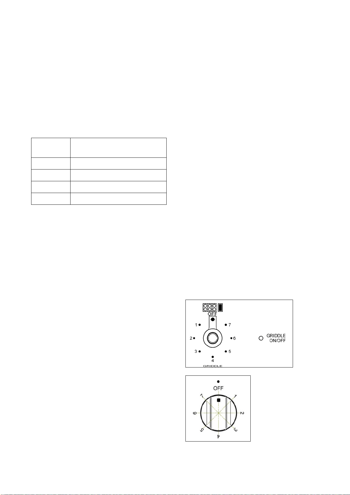
SURFACECOOKING
SYMBOLS
(*)
(**)
Burnerposition(inthiscasefront
rightburner).
Maximum temperature setting
/Recommended control knob
positionforburnerignition
Minimumtemperaturesetting
(*)Appliancewithworktopgasvalvesalternative
type
(**)Theoperatingsymbolsaresilk‐printedon
theknobs

26
SURFACEBURNEROPERATION
THERMOCOUPLESAFETYVALVE
Each surface burner of a Bertazzoni range is
equippedwithathermocouplesafetydevice.
The thermocouple opens the flow of gas to the
burner only when hot. Should the flame go off,
the thermocouple willimmediatelyclose the gas
flow to the burner eliminating any
risk to your
home.
Forfasteractivationofthether mocouple,always
light the burners on maximum power. This will
allow the thermocouple to reach the optimum
temperatureinthefastesttime.
ELECTRICIGNITION
To activate the ele ctric ignition, simply turn the
control knob counter‐clockwise to maximum
power (
position). Press the knob to start the
flow of gasand theignition spark. The spark will
releasedatthemetaltipofthewhiteceramicpin
locatedonthesideoftheburner.Oncetheflame
ison,releasethecontrolknobgently.
If the flame turns off, repeat the
above
procedure.
The dual power‐burner is composed by two
burners (inside and outside). Each burner is
activated by a separate control knob. The two
burners can be operated separately or together
for maximum power. To activate the power‐
burner,turnonthecentralburnerfirst,thenturn
onthe
externalring.
ATTENTION: do not ignite burners if the black
burner cap is not installed or not centred. The
flamewillbeirregular.
MANUALIGNITION
Manualignitionisalwayspossibleevenwhenthe
poweriscutofforintheeventofpowerfailure.
Turn the control knob counter‐clockwise
to the
MAXIMUM position. Light the flame with a
kitchenlighterorwithamatch.
TIPSFORUSINGBURNERSCORRECTLY
WARNING!
KEEPCHILDRENATASAFEDISTANCEFROMTHE
APPLIANCEDURINGOPERATION.
DONOTALLOWCHILDRENTOOPERATETHE
APPLIANCE.
1. Always check that the burner caps are
properly
installedbeforeoperation.
2. Verifythatthe flameoftheworktop burners
iscompletelyblueandwithregularaspectas
shownbelow.
3. Alwaysadjusttheburnerflamesoitdoesnot
extendbeyondtheedgeofthepan.
27
TIPSFORUSINGPANSCORRECTLY
ATTENTION!
Alwaysensurethatbottomandhandles ofpans
donotprotrudefromtheworktop.
Whencookingwithflammablefatsuchasoil,do
notleavetherangeunattended.
Use pots of the appropriate size on each burner
followingtheindicationofthediagrambelow.
Burner Recommendedpansize
inches(mm)
Small 3½”‐51/2”(90–140)
Medium 51/2”‐101/4”(140–260)
Large 71/8”‐101/4”(180–260)
Dualburner 82/3”‐101/4”(220–260)
When boiling liquids, turn the knob to the
MINIMUM position once boiling is reached to
avoidoverflow..
Alwaysusepotswithmatchinglid.
Drythebottomofpansbeforeoperation.
Usepotswithaflat,thickbottom(exceptforwok
cooking).
WOK COOKING: always use the wok adapter
supplied
with the range. Wok pan external
diameter shall not be smaller than 10” (25cm)
andlargerthan16”(40cm).
SIMMERING: use the simmer ring supplied with
therange.
USINGTHEELECTRICGRIDDLE
WARNING
Thegriddleelementishotafteruse.Allow
sufficienttimeforgriddlecomponentscool
beforecleaning.
Theelectricgriddleelementisrated240voltsAC
1100watts.
SEASONINGTHEGRIDDLE
Beforeusingthegriddleforthefirst time,itmust
beseasoned.
If the griddle has not been used for
a period of
time,itshouldbereseasoned.
Toseasonthegridlle:
1. clean the griddle thoroughly with hot, soapy
watertoremoveanyprotectivecoating.
2.rinsewithamixtureof1quartwater and1cup
whitevinegar.Drythoroughly.
3. Pour 1 teaspoon vegetable oil into the
center
ofthegriddle.Donotusecornoilasitgetssticky.
Rubthe oilover theentiresurface ofthe griddle
usingaheavycloth.
4. Turn the control knob to a maximum setting
(7). Turn the heat off when the oil begins to
smoke.Allowthegriddleto
cool.
5. Repeat step 3. Be sure to cover the
entiresurfacewiththeoil
6.Repeat step 4.Allowthegriddle tocool.Wipe
the entire surface of the griddle using a heavy
cloth.Applyaverythinlayerofvegetableoil.The
griddleisnowreadytouse.
Use
Pressandturntheknobanti‐clockwisetothe
selectedposition
(**)
(**)Theoperatingsymbolsaresilk‐printedon
theknobs

28
Pre‐heat at the maximum temperature, ( 7
position) for 15minutes, then place the foodon
thegriddleandcooktothedesiredtemperature.
The activation of the griddle is shown by the
indicator light which is also found on the front
paneloftheappliance.
Griddle cooking recommendations
FOOD KNOB
POSITION
SETTING
Eggs 5-6 300°F to 325°F
(150°C to 160°C)
Bacon; Breakfast
Sausage
6 350°F to 375°F
(177°C to 190°C)
Toasted
Sandwiches
5-6 325°F to 350°F
(160°C to 177°C)
Boneless Chicken
Breasts
6 350°F to 375°F
(177°C to 190°C)
Boneless Pork
Chops, ½” thick
6 350°F to 375°F
(177°C to 190°C)
Ham Slices, ½”
thick
6 350°F to 375°F
(177°C to 190°C)
Pancakes;
French Toast
6 350°F to 375°F
(177°C to 190°C)
Potatoes; Hash
Browns
7 375°F to 400°F
(190°C to 205°C)
OVENCOOKING(LEFTOVEN)
WARNING!
UseCareWhenOpeningDoor.Lethotairor
steamescapebeforeremovingorreplacing
food.
DoNotHeatUnopenedFoodContainers.Build‐
upofpressuremaycausecontainertoburstand
resultininjury.
KeepOvenVentDuctsunobstructed.
PlacementofOvenRacks.Alwaysplaceoven
racksindesired
locationwhileoveniscool.If
rackmustbemovedwhileovenishot,donotlet
potholdercontacthotheatingelementinoven.
DoNotCleanDoorGasket.Thedoorgasketis
essentialforagoodseal.Careshouldbetaken
nottorub,damage,ormovethegasket
DoNotUseOvenCleaners.Nocommercialoven
cleanerorovenlinerprotectivecoatingofany
kindshouldbeusedinoraroundanypartofthe
oven.
CleanOnlyPartsListedinmanual.
BeforeSelf‐CleaningtheOven.Removebroiler
panandotherutensils.
CAUTION
Donotstoreitemsofinteresttochildrenin
cabinetsabovearangeoronthebackguardofa
range–childrenclimbingontherangetoreach
itemscouldbeseriouslyinjured.
DO NOT TOUCH HEATING ELEMENTS OR
INTERIOR SURFACE OF OVEN
Heating elements may be hot even though are
dark in colour. Interior surfaces of an oven
become hot enough to cause burns. During and
after use, do not touch, or let clot hing or other
flammable materials come into contact with the
heating elements or interior surfaces of oven
untiltheyhave
hadsufficienttimetocool.Other
surfaces of the appliance may become hot
enough to cause burns, for example, oven vent
openingsandsurfacesneartheseopenings,oven
doors,ovenglasswindow.
WARNING
TO REDUCE THE RISK OF TIPPING OF THE
APPLIANCE, THE APPLIANCE MUST BE
SECURED WITH A PROPERLY INSTALLED
ANTI-TIP DEVICES. TO CHECK IF THE
DEVICES ARE INSTALLED PROPERLY,
REMOVE THE APPLIANCE FROM THE WALL
AND VERIFY THAT THE ANTI-TIP DEVICES
ARE ENGAGED.
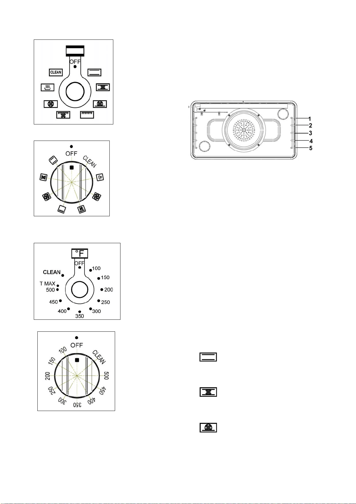
29
SYMBOLS
OVEN FUNCTIONS SELECTOR
(**)
TEMPERATURE/CLEAN SELECTOR
(**)
(**)Theoperatingsymbolsaresilk‐printedon
theknobs
OVENRACKS
Bertazzoni ranges areequipped withcommercial
gradeshelvesandanenamelcookingtray.
Shelves are mounted on the appropriate guides
situated on the sides of the oven compartment.
Inserttheshelfbetweentopandbottomguidein
anyofthe5positionsavailable.
Tokeeptheovenascleanaspossible,cookmeat
onthetray.
When available, always follow recipe book
directions. Personal experience will help to
determine any variations in the values reported
in the table. In any case, it is recommended to
followtheinstructionsofthespecificrecipe
being
used.
ATTENTION!
Whenusingtheovenforthefirsttimeitshould
beoperatedfor15‐30minutesatatemperature
ofabout500 °F/260°Cwithoutcookinganything
insideinordertoeliminateanymoistureand
odoursfromtheinternalinsulation.
OVENFUNCTIONSELECTOR
The oven has 8 functions defined for the
following
operations (from OFF position in
clockwisedirection):
-
BAKE(Broiler+Bottomheating
elements)tobeusedwithoventemperature
from0to500°F/260°C
-
CONVECTIONBAKE(Broiler+Bottom
heatingelements+fan)tobeusedwithoven
temperaturefrom0to500°F/260°C
-
TURBO(Circular+Bottomheating
elements+fan)tobeusedwithoven
temperaturefrom0to500°F/260°C

30
- BROILER(Broilerheatingelement) to
beusedwithtemperatureselectorat500°F
forbroiling
-
CONVECTIONBROILER(Broiler
heatingelement+fan)tobeusedwith
temperatureselectorat500°Fforconvection
broiling
-
CONVECTION(Circularheating
element+fan)tobeusedwithoven
temperaturefrom0to500°F/260°C
-
DEHYDRATE(Bottomheatingelement
+fan)tobeusedwithtemperatureselector
at100°F(correspondingtoaninternaloven
setupfixedtemperatureof100°F/38°C)
-
PROOFING(Bottomheatingelement)
tobeusedwithtemperatureselectorsetat
150°F(correspondingtoaninternaloven
setupfixedtemperatureof100°F/38°C)
-
WARMING‐Level1(Bottomheating
element)tobeusedwithtemperature
selectorsetat200°F(correspondingtoan
internalovensetupfixedtemperatureof
140°F/60°C)
-
WARMING‐Level2(Bottomheating
element)tobeusedwithtemperature
selectorsetat250°F(correspondingtoan
internalovensetupfixedtemperatureof
170°F/77°C)
-
WARMING‐Level3(Bottomheating
element)tobeusedwithtemperature
selectorsetat300°F(correspondingtoan
internalovensetupfixedtemperatureof
220°F/105°C)
-
CLEAN(Broiler+Bottomheating
elements)tobeusedwithtemperature
selectorsetatCLEANforautomaticself‐
cleaningcycleatatemperatureofabout
840°F/450°C(seeproperchapter“SELF
CLEANINGTHEOVEN”pag.35fordetails ).
USINGTHEOVEN
OVENLIGHT
The appliance is equipped with two oven lamps
that light up when the oven door is opened or
each time the oven is in operation. They are
turnedoffduringthecleaningcycle.
COOLINGFANS
The appliance is equipped with two cooling fan
motors that activate when the oven
is in
operation for cookingor cleaning,except incase
of DEHYDRATE and PROOFING functions. In
stand‐bycondition(bothselectorinOFFposition)
the cooling fan motors operate if oven
temperatureexceedsapproximately430°F/220°C
and stop automatically when oven temperature
drops below approximately 285‐360°F/140‐
180°C.
FRONTINDICATORLIGHTS
This appliance isequipped with3 indicatorlights
onthefrontpanel:
‐CLEAN/REDcolour: on withdoor locke d during
cleaningcycle
‐HEATING/BLUE colour: on when cooking or
cleaning temperature is reached, always on
during functions Dehydrate‐Proofing‐Warming
levels1‐2‐3
‐ PRE‐HEATING/BLUE colour: on during pre‐
heating
period; not active for functions
Dehydrate‐Proofing‐Warminglevels1‐2‐3.
The indicator lights flash intermittently (in some
case together with the s ound buzzer) when an
error is detected. For explanation of errors,
please refer to the chapter TROUBLESHOOTING
GUIDE.
SOUNDBUZZER
The appliance is equipped with a sound buzzer
that emits a triple “beep” each time the pre‐
heating time is finished (not used for functions
CLEAN and Dehydrate‐Proofing‐Warming levels
1‐2‐3”) anda single intermittent “beep”in some
casejointlywiththeindicatorlightwhenanerror
isdetected(refer tochapterTROUBLESHOOTING
GUIDE).
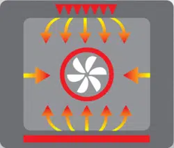
OVENCONVECTIONFAN
The appliance is equipped with an oven fan
mounted inside a circular heating element,
protectedbyafanshieldonthebackoftheoven
cavity; it operates each time that the oven
operates in the functions ROASTING, TURBO,
CONVECTION BROILER, CONVECTION BAKE and
DEHYDRATE.

31
BAKE
PREHEATINGTHEOVEN
Preheat the oven before baking. The oven does
not need to be preheated for large pieces of
meat or poultry. See your recipe for preheating
recommendation. Preheating time depends on
thetemperaturesettingandthenumberofracks
intheoven
.
GETTINGTHEBESTRESULTS
Minimizeopeningthedoor.
Choosetherightsizebakeware.
Usethebakewarerecommendedintherecipe.
Storethebroilerpansoutsidetheoven:extra
panswithoutfoodaffectthebrowningand
cooking.
Browningcandependfromthetypeofpanused:
- Fortender,
goldenbrowncrusts,uselight
non‐stickanodizedorshinymetalpans.
- Forbrowncrispcrusts,usedarknon‐
stick/anodizedordark,dullmetalutensilsor
glassbakeware.Thesemayrequirelowering
thebaketemperature25°F.
BAKEWARETYPE
Metal bake ware (with or without a non‐stick
finish),heat‐proofglass,glassceramic,pottery,or
other utensils are suitable for the oven. Suitable
cookie sheets have a small lip on one side only.
Heavysheetsorthosewithlipsonmorethanone
sidemayaffectthe
bakingtime.
BAKERACKPOSITIONS
Racklevelpositionsintheovenarenumberedas
inthediagramonpage25.
ONE RACK BAKING‐The Bake mode is best for
baking on one rack with rack level 3 and 4 used
for most baked items. When baking tall items,
rack
level4 may be used.Piesarebestbaked on
racklevel4or5toensurethebottomofthecrust
is done without over‐browning the top. When
large pieces of meat or poultry are roastedsuch
as aprime ribof beef ora turkey,rack level4
is
thepreferredrack.
TWO RACK BAKING‐Rack levels3 and 5may be
used when baking on two levels. Cookies and
biscuits can be cooked properly using these two
racks.Casserole dishesmayal so bebakedusing
thesetwolevels.
CONVECTION
COOKINGWITHCONVECTION
There are many advantages to cooking with
convection.Intheconvectionsystem,afaninthe
backoftheovenmovesheatedairevenlyaround
the oven. The moving air provides even heat so
foods can be placed on any rack level with
consistent results and without having to rotate
the
pans. Convection also enables cooking
simultaneouslyonmultipleracks.
Low, shallow bake ware should be used with
convectioncooking.This allows theheatedairto
properly move around the food. Pans with high
sidesorpansthatarecov eredarenotsuitablefor
convection cooking because high sides or lids
prohibitthewarmairfromcirculatingaroundthe
food.
Any food cooked uncovered will brown evenly
and form a nice crust. Foods in covered dishes
(casseroles, pot roast) or delicate custards are
notsuitableforconvectioncooking.
CONVECTION
CONVECTIONBAKE
TURBO
Time can be saved by baking an entire batch of
cookies at the same time. The cookies will bake
evenly and be done all at once. The baking time
may be shorter due to the warm circulating air.
For small items such as cookies, check to see if
they are done
one to two minutes before the
recipetime.Forlargerbakeditemssuchascakes,
check five to six minutes before the time
indicatedontherecipe
.
Convection cooking of meat and poultry will
result in foods that are brown and crispy on the
outside and moist and juicy on the inside. Large
meatorpoultryitemsmaycookupto30minutes
less than the suggested time so check them so
theywillnotbeoverbaked.
Ameatthermometer
or an instant read thermometer will provide
more accurate results than the "minute per
pound" method. Thelarger the piece of meat or
poultry,themoretimeyouwillsave.
Converting Conventional Baking to Convection
Cooking -
To convert most recipes for baked
items(cookies,cakes,pies,etc.),reducetheoven
temperatureby 25°F. For meatsandpoultry,use
the temperature recommended in recipes and
cookingcharts.
CONVECTION BAKE
Full power heat is radiated from the bake
element in the bottom of the oven cavity and
partialpower isradiatedfrom thebroil element.
Airiscirculatedbythefanintherearof theoven.
It provides more even heat distribution

32
throughout the oven cavity for all uses. Multiple
rack use is possible for baking large amounts of
food.Whenroasting,coolairisquicklyreplaced‐
searingmeatsontheoutsideand retai ning more
juices andnatural flavour onthe inside withless
shrinkage
CONVECTION
The rear element operates at full power. Air is
circulated by the fan for even heating. Use this
setting for food which requires gentle cooking
suchaspastries,soufflésorcakes.
TURBO
The rear and bottom elements operate at full
power. Air is circulated by the fan for even
heating. Use this setting to reduce pre‐heating
time of the oven or for recipes which require
uniform cooking with strong heat from bottom
suchaspizza,focaccia,bread
.
TIPSFORCONVECTIONand
BAKE/CONVECTION/TURBO
PreheatingtheOven
Preheat the oven before baking. The oven does
not need to be preheated for large pieces of
meat or poultry. See your recipe for preheating
recommendation. Preheating time depends on
thetemperaturesettingandthenumberofracks
intheoven.
Temperature
Setting
When using Convection Bake, reduce the
temperaturerecommendedintherecipeby25°F.
When roasting meats, check internal
temperature prior to time recommended by
recipe to prevent over cooking. When roasting
meats in convection mode, do not reduce
temperaturesetting.
Condensation
Itisnormalforacertainamountofmoistureto
evaporatefromthefoodduringanycooking
processTheamountdependsonthemoisture
contentofthefood.Themoisturewillcondense
onanysurfacecoolerthan.theinsideofthe
oven,suchasthecontrolpanel.
RACKPOSITIONS
LargeMainOvenOneRackBaking
When baking on one rack, best results are
obtainedinthebakemode(seeBake).
Whenroastinga turkey oralargepiece ofmeat,
convectionbakemaybeused.Rack4isthemost
appropriaterack.
TwoRackBaking
Racks 4 and 2
are most appropriate when using
the conve cti on bake mode. Round cake pans
should be staggered on racks 4 and 2.
Rectangular(9x13)cakepansandcookiesheets
shouldbeplacedonrack4directlyundertheone
onrack2.
Thismay be usedforcakes,cookies, biscuitsand
other foods for which two rack baking is
desirable.
Whenseveralcasseroles,frozenpiesorcakesare
tobebaked,useracks4and2.
Thesetworackscanalsobeusedforalargeoven
meal.
BakewareType
Aluminiumbakewaregivesthebestbrowning
results.
Cookiesheets
withonlytwosidesgivethebest
results.Aluminiumcommercialhalf‐sheetsor
professionalcookingutensilsmaybeusedbut
bakingtimesmaybeincreased.
Placement
Forbetterbrowning,utensilssuchascookie
sheets.Rectangularbakingpansshouldbeplaced
crosswiseontherackwiththeshortersidefacing
right
andlefttoallowbetterairflow.
Whenbakingonmorethanonerack,cookie
sheetsandrectangular(9x13)cakepans should
notbestaggered;roundcakepansshouldbe
staggered.
SettingsforBAKE/CONVECTIONand
BAKE/CONVECTION/TURBOcookingmodes
These cooking modes are for baking, roasting or
warming
usingoneortworacks.
1. Select BAKE/CONVECTION or BAKE/
CONVECTION/TURBO using the Selector
switch.
2. Set the oven temperature using the oven
temperature control knob (not over
Tmax=500°F setting position). If using
CONVECTION,settheovencontrolknob25°F
below temperature suggested in the recipe.
Do no change recipe
temperature if roasting
meatsorpoultry.

33
BAKINGRECOMMENDATIONS
FOOD PAN
SIZE
CONTROL
TEMPERATURE
SETTING
TOTAL
SUGGESTED
COOKING
TIME
Cookies 12”x15”
Cookie
Sheet
375° 8 to 12
minutes
Layer
Cakes
8”or
9”Round
350° 25 to 35
minutes
Sheet
Cakes
9”x13”
Pan
350° 30 to 40
minutes
Bunt
Cakes
12 Cup 325° 60 to 75
minutes
Brownies
or Bar
Cookies
9"x9"
Pan
325° 20 to 25
minutes
Biscuits 12"x15"
Cookie
Sheet
425° or Package
Directions
10 to 15
minutes
Quick
Bread
8"x4"
Loaf Pan
350° 55 to 70
minutes
Muffins 12 cup
Muffin
Pan
425° 14 to 19
minutes
Fruit Pies 9"
Diamete
r
425° 35 to 45
minutes
Fruit
Cobblers
9"x9"
Pan
400° 25 to 30
minutes
Yeast
Bread,
Loaves
8"x4"
Loaf Pan
375° 25 to 30
minutes
Dinner
Rolls
9"x13"
Pan
400° 12 to 18
minutes
Cinnamon
Rolls
9"x13"
Pan
375 25 to 30
minutes
Yeast
Cotter
and Cake
12"x15"
Cookie
Sheet
400° 20 to 30
minutes
WARMING
SLOW COOKING AND LOW TEMPERATUREUSES
OFTHEOVEN
Inthis ovenfunction the pre‐heatinglight/sound
indicators are deactivated; only the heating
indicatorlightisactive.
In addition to providing perfect temperature for
bakingandroasting,theovencanbeusedatlow
temperaturesto keepfoodattheproper
serving
temperatureandtowarmplates.
Set the oven to bake and use the temperature
suggestedonthechartbelow.
TherearethreepossiblesettingforWARMING
mode;selectinfunctionselector(symbol)and
then:
- Level1withtemperatureselectorsetat200°F
(internalovensetupfixedtemperatureof
140°F=60°C)
- Level2withtemperatureselectorsetat250°F
(internalovensetupfixedtemperatureof
170°F=77°C)
- Level3with
temperatureselectorsetat300°F
(internalovensetupfixedtemperatureof
220°F=105°C)
FOODSAFETY
The United States Department of Agriculture
recommends to NOT keep food at temperatures
between40°Fto140°Fforlongerthan2hours.
Cookingrawfoodsbelow275°Fisnot
recommended.
FOOD OVEN TEMPERATURE
Beef 150°F (70°C)
Bacon 200° -225°F (90 - 110°C)
Biscuits and Muffins
(Covered)
175°-200°F (80 – 90°C)
Casserole (covered) 175°-200°F (80 – 90°C)
Fish and Seafood 175°-200°F (80 – 90°C)
Deep Fried Foods 200° -225°F (90 - 110°C)
Gravy or Cream Sauces
(covered)
175°F (80°C)
Lamb and Veal Roasts 175°-200°F (80 – 90°C)
Pancakes and Waffles
(covered)
200° -225°F (90 - 110°C)
Potatoes Baked 200°F (110°C)
Mashed (covered) 175°F (80°C)
Pies and Pastries 175°F (80°C)
Pizza (covered) 225°F (110°C)
Pork 175°-200°F (80 – 90°C)
Poultry (covered) 175°-200°F (80 – 90°C)
Vegetables (covered) 175°F (80°C)
PROOFING
Inthis ovenfunction the pre‐heatinglight/sound
indicators are deactivated; only the heating
indicatorlightisactive.
In PROOFING mode only the lower heating
elementisactivetomaintainalowtemperature
to proof bread; proofing is the rising of a yeast
dough.
To activate PROOFING mode: set function
selectoronandsettemperatureselectorat150°F
(corresponding to an internal oven setup fixed
temperatureof100°F=38°C).
Looselycoverthebowlorpananduseanyrack.
Keepthe doorclosed and checkthe risingof the
doughuntilthedesiredresultisobtained.
Coolingfansdoesnotoperateduring
PROOFING.
34
DEHYDRATE
Inthis ovenfunction the pre‐heatinglight/sound
indicators are deactivated; only the heating
indicatorlightisactive.
DEHYDRATE mode dries food inside the oven by
usinglowerheatingelementjointlywiththeoven
fan.
DEHYDRATEisusedtodryand/orpreservefoods
such as fruits, vegetables and herbs through
circulation of heated air that slowly remove the
moisturefromitems.
To activate DEHYDRATE mode: set function
selectoronandsettemperatureselectorat100°F
(corresponding to an internal oven setup fixed
temperatureof100°F=38°C).
Cooling fans does not operate during
DEHYDRATE.
FOOD PREPARATION APPROXIMATE
DRYINGTIME(hrs)
TESTFORDONENESS
Fruit
Apples Dipped in 1/4 cup lemon juice
and 2 cups water;1/4" slices
11-15 Slightly pliable
Bananas Dipped in 1/4 cup lemon juice
and 2 cups water;1/4" slices
10-15 Soft, pliable
Cherries Wash and towel dry. For fresh
cherries, remove pits
10-15 Pliable, leathery, chewy
Orange peels and slices 1/4" slices of orange; orange
part of skin thinly peeled from
oranges
Peels:2-4
Slices: 12-16
Orange peel: dry and brittle.
Orange slices: skins are dry and
brittle, fruit is slightly
Pineapple rings Towel dried Canned: 9-13
Fresh: 8-12
Sott and pliable
Strawberries Wash and towel dry. Sliced
1/2" thick, skin (outside) down
on rack
12-17 Dry, brittle
Vegetable
Peppers Wash and towel dry. Remove
membrane of peppers,
coarsely chopped about 1"
pieces
16-20 Leathery with no moisture inside
Mushrooms Wash and towel dry. Cut off
stem end. Cut into 1/8" slices
7-12 Tough and leathery, dry
Tomatoes Wash and towel dry. Cut thin
slices, 1/8" thick, drain well.
16-23 Dry, brick red colour
Herbs
Oregano Sage parsley
And thyme And fennel
Rinse and dry with paper towel 3-5 Crisp and brittle
Basil Use basil leaves 3 to 4 inches
from top. Spray with water,
shake off moisture and pat dry
3-5
Crisp and brittle

35
BROIL/CONVECTIONBROIL
TipsforBroiling
Broiling requires constant exposure to high,
intense heat. Only the upper element heats in
theBROILERmode.
Itisrecommendedthatyoupreheatthebroil
elementbeforestartingtocook.Preheatuntilthe
"PRE‐HEATING"lightturnsoff(about5‐6
minutes).
GettingtheBestResults
Defrostfoodbeforebroiling.
Keepovendoorclosedduringbroiling.
Steaksshouldbemore than1"thick ifraremeat
isdesired.Useconvectionbroilifsteaksareover
1‐1/2inchesthick.Turnfoodoveronceafterhalf
cookingtime.Itisnotnecessarytoturnverythin
food
(ham slices, fillets of fish, etc.). Liver slices
mustbeturnedoverregardlessofthickness.
Use a timer. Set it for the minimum time and
checkthefood.
Center food directly under the broiling element
forbestbrowning.
RackPositions
Beforeturningontheoven,place therackinthe
desired position. After preheating the broiler,
centerthebroilpanunderthebroilelement.
2‐Use this rack position when broiling beef
steaks,groundmeatpatties,hamsteakandlamb
chops 1 inch or less thick. Also use when
browningfood.
3‐Use this rack position when broiling meat 1
1/8 inches or more thick, fish, poultry, pork
chops,hamsteaks1inchormorethick.
3 or 4‐Use this rack when broiling chicken
quartersorhalves.
Utensils
Aporcelainenamelbroilpanisincludedwiththe
range. Use metal or glass‐ceramic bake ware
whenbrowningcasseroles,maindishes,orbread.
DONOTuseheat‐proofglassorpottery.Thistype
of glassware cannot withstand the intense heat
ofthebroilelement.
BroilingUsingMeatThermometer
To more accurately define the preparation of
thicksteaksorchops(atle ast11/2inchesthick),
usea meatthermometer. Insertthe point ofthe
thermometer into the side of the meat reaching
thecenterofthesteakorchop.
For rare steaks, cook the first side to 90°F. For
mediumorwelldonesteaks,cookthefirstsideto
100°F. Turn andcook the second side to desired
internaltemperature.
SETTINGBROILERORCONVECTIONBROILER
Select BROILER to brown foodon the top side
only.Thismoderequiresturningfoodif browning
isrequiredonbothsides.
Select CONVECTION BROILER to brown food
slightly also on the bottom side. This mode is
preferred for browningfood on both sidethat is
too delicate for turning
such as fish. The degree
ofbrowningofeachsidemightbedifferent.
TOSETTHEOVENTOBROILEROR
CONVECTIONBROILER
1. Placeovenrackindesiredposition.
2. SetSelectorSwitchtoBROILERor
CONVECTIONBROILER.
3. Set oven temperature control knob to
BROILER or CONVECTION BROILER setting
correspondingto500°FfixedBROILERsetting
(notoverTmax=500°Forunder450°Fsetting
position).
4. Wait until PRE‐HEATING light turns off, after
approximately5‐6minutes
5. Placefoodinovenatdesiredrackpositionas
referencedonPage26.
6. Close oven door. The door should be closed
throughoutthebroilcycle.

36
BROILINGANDROASTINGRECOMMENDATIONS
FOOD ITEM RACK
NUMBER
OVEN MODE
FUNCTION
SELECTOR
CONTROL
TEMPERATURE
SETTING
SELECTOR
APPROXIMATE
COOKING TIME
SPECIAL
INSTRUCTIONS
AND TIPS
BEEF
Ground Beef
Patties, ½” thick
2 Broiler or
convection Broiler
500°F fixed
temperature
setting
15 to 20 minutes Broil until no pink in
center
T-Bone Steak 2 Broiler or
convection Broiler
500°F fixed
temperature
setting
12 to 20 minutes Time depends on
rareness of steak
Flank Steak 2 Broiler or
convection Broiler
500°F fixed
temperature
setting
12 to 20 minutes Rare to Medium Rare
Eye of Round
Roast
3
Bake or Convection
bake
325° 20 to 25 min/lb Small roasts take
more minutes per
pound; reduce time
by using Convection
Bake
PORK
Loin Roast
3 Bake or Convection
bake
325° 20 to 25 min/lb Cook until juices are
clear
POULTRY
Boneless Skinless
Chicken Breasts
2 Broiler or
convection Broiler
500°F fixed
temperature
setting
20 to 25 minutes Cook until juices are
clear
Chicken Thighs 3 Broiler or
convection Broiler
500°F fixed
temperature
setting
25 to 30 minutes Remove skin; Cook
until juices are clear
Half Chickens 3 Broiler or
convection Broiler
500°F fixed
temperature
setting
30 to 45 minutes Turn with tongs;
Cook until juices are
clear
Roast Chicken 4 Bake or Convection
bake
350° 75 to 90 minutes Do not stuff; reduce
time by using
Convection Bake
Turkey 4 Bake or Convection
bake
325° 20 to 25 min/lb Do not stuff; reduce
time by using
Convection Bake
37
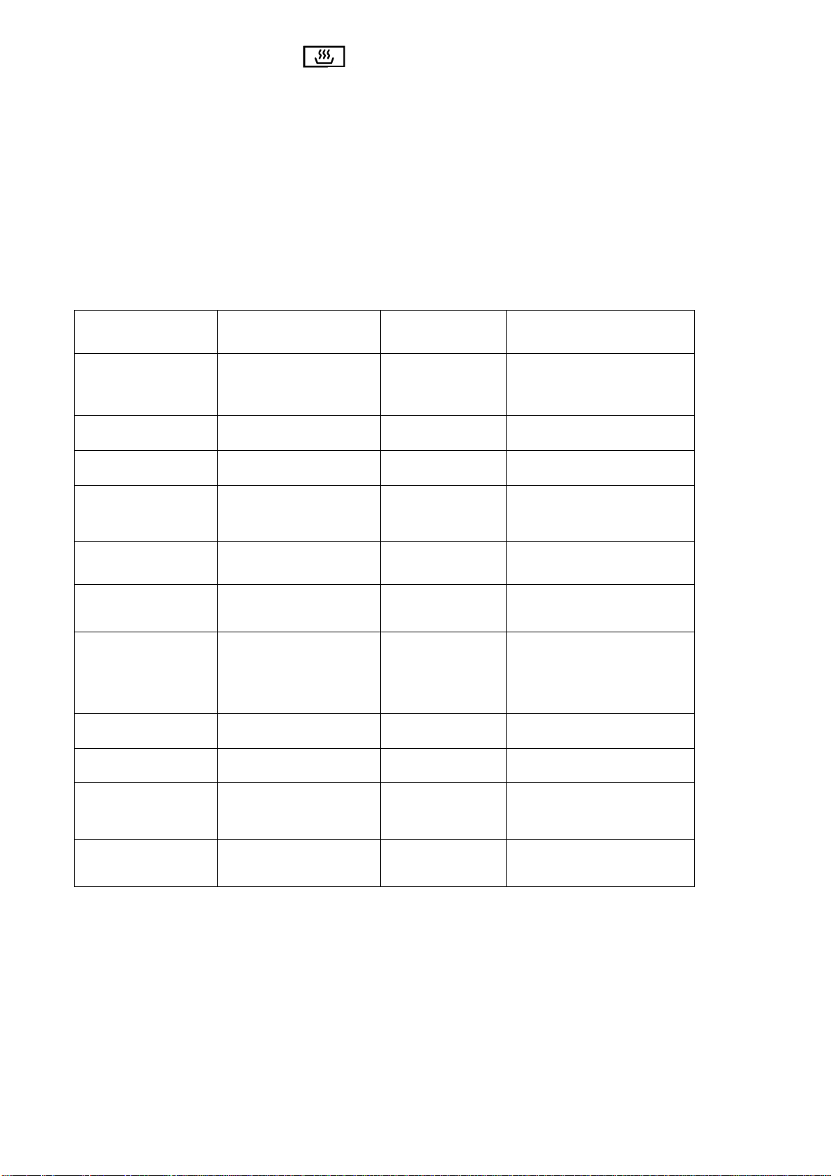
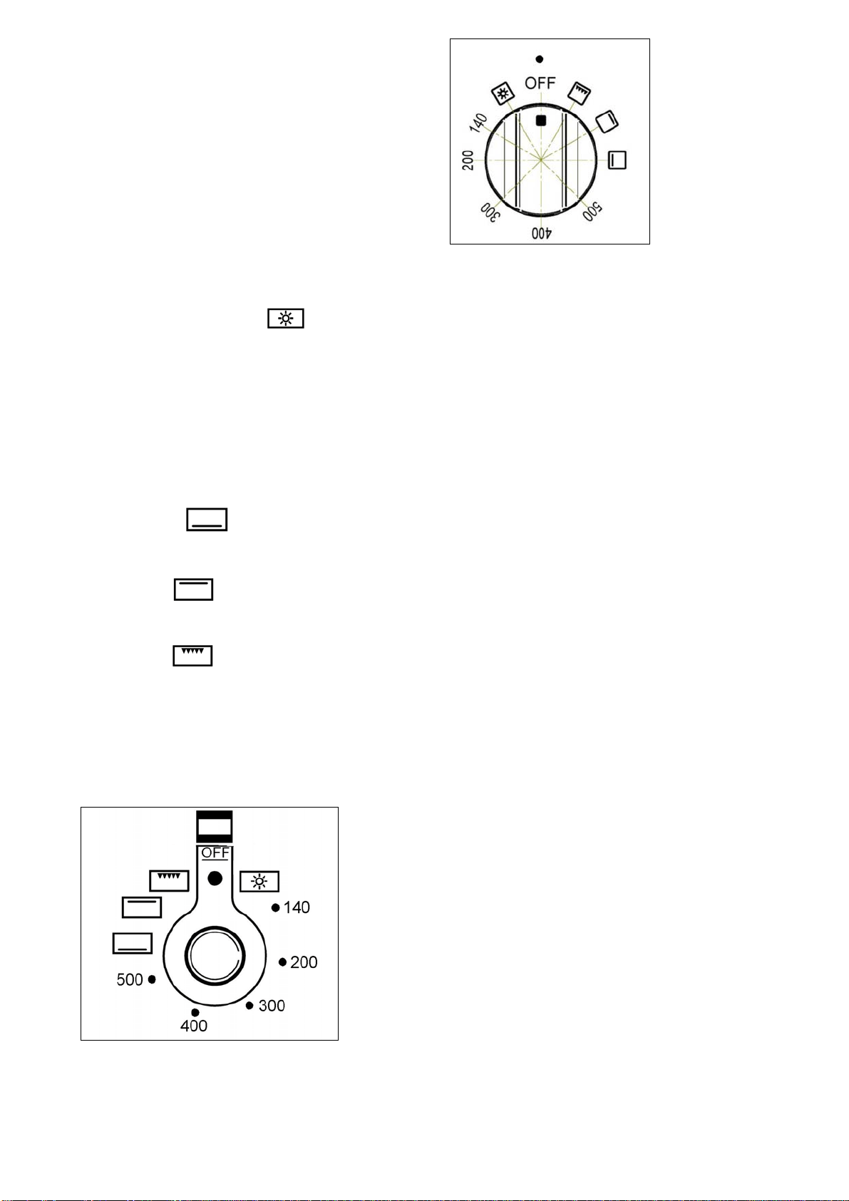
OVENCOOKING(RIGHTOVEN)
SINGLECONTROLELECTRIC
CONVENTIONAL
(NOTSELF‐CLEANTYPE)
The electric oven is controlled by an electric
thermostat combined with a functions selector
switchusedtoturnontheheatingelements.The
electric oven can be combined with an electric
grill. The oven is heated by 2 elements: one on
thetopandoneonthebottom.Turningtheknob
clockwiseinthefirstpositionwehavethesingle
operation of the oven light
. Turns on the
bottom element and the top external elements
while the thermostat is used to set the
temperature ranging from 140°F to 500°F.It can
beadjusted usingthescale indicatedon thering
around the knob. An orange light turns off
indicating thatthe temperature settin g has been
reached. Therefore, it is normal for this light to
turnon andoffwhile theoven isworking. There
are3fixedpositionbeyondthe500°Fsetting:
‐ the symbol
indicates the only the
bottom element (900W) has been turned on, at
fixedmax.temp.setting(500°F);
‐ the symbol
indicates that only the top
external element (900W) has beenturned on, at
fixedmax.temp.setting(500°F);
‐ the symbol
indicates that only the top
broil element (1100W) has been turned on, at
fixedmax.temp.setting(500°F);
For bake and broil suggestion/recommendation
use, see chapters “BAKE” at pag.and chapter
“BROIL”atpage.
(**)
(**)Theoperatingsymbolsaresilk‐printedon
theknobs
CAREANDMAINTENANCE
SELF‐CLEANINGTHEOVEN
(ONLYFORNLEFTOVEN)
ElectricOven
The self‐cleaning mode of your new range
featuresa pyrolyticself‐cleaning cycle. When set
to the CLEAN mode, the oven reaches a high
temperature of approximately 840°F/450°C that
burnsoffallfoodresidues from the insideofthe
oven.
When the oven is set for CLEAN, the cooktop
burnersmaybeused.
Itis commonto seesmokeand/orflames during
the clean cycle, depending on the content and
amount of greasy residues in the oven. If the
flame persists, turn off the oven and allow it to
cool before opening the door and wipe off the
excessiveresidues.
Atthe endofthe CLEANcycle,some greyash or
burnedresiduemayremain inside theoven.This
is a mineral deposit that does not burn or melt.
The amount of ash depends on how heavily
soiled the oven was before it was cleaned. It is
easily removed, when the
oven is cold, using a
damppapertowel,sponge,orcloth.
Wipe off any smoke residuethatremains on the
front frame with a cleaning product suitable for
oven cavitycleaning. If stains remain, use amild
liquid cleaner. The amount of smoke stain is
directlyrelatedtotheamountoffoodresiduesin
theovencavitybeforethestartofthe
self‐clean‐
ingcycle.
BeforeSelfCleaningtheOven
Wipe out large spillages, grease and any loose
soilthat canbeeasily removed.Remove anysoil
thatis outsidethe door sealarea.This appliance
is designed to clean the oven interior and the
portion of the door that faces the oven cavity.
Theouter edgesofthe door
andthe ovencavity

38
arenotinthecleaningzone.Wipethisareaclean
beforestartingtheself‐cleaningcycle.
Removeallutensilsandracks.
Makesurethelightbulbsandglasscovers are in
place.
Turnontheventilatorhoodabovetherangeand
leaveiton untiltheself‐clean cycleis completed
(redindicatorlightturningoff).
NOTE: FOR THE FIRST SELF‐CLEANING CYCLE,
REMOVE SMALL ANIMALS ANDBIRDSFROMTHE
KITCHEN AND SURROUNDING AREAS. OPEN A
NEARBY WINDOW FOR ADDITIONAL
VENTILATION.
DoorLock
WhentheCLEANcyclestarts,theautomaticdoor
lockcyclebegins.Checkthedoortoconfirmthat
it is locked. You can stop the self ‐cleaning cycle
by turning thefunction selector tothe OFF posi‐
tion. The CLEANING light will turn off only after
the oven has cooled below 500°260°C
and the
automatic door lock has completed its cycle to
theopenposition.
NOTE: MAKE SURE THAT THE OVEN DOOR IS
LOCKED AT THE BEGINNING OF THE SELF‐
CLEANINGCYCLE.
ToSet/StartSelf‐Cleancycle
1. Checkthattheovencavityiscompletelyempty
andtheovendoorcorrectlyclosed.
2. SelectCLEANfuonovenfunctionselector.
3. Settemperatureselectorto CLEAN.
Afterthese 3steps thecooling fanswill activate,
the oven do or will lock automatically after 60
secondsandboththepre‐heatingandcleanlight
indicatorswillturnon.
As soon as clean light turns on check to ensure
thattheovendooriscorrectlylocked.
AttheEndoftheSelf‐Cleancycle
The self‐cleaning cycle lasts approximately 2‐2 ¼
hours; 30‐40 minutes for pre‐heating the oven
(pre‐heatingandcleanlightbothon),60minutes
for actual cleaning (heating and clean light both
on), 30‐35 minutes for cool‐down (only clean
lighton).
WhentheCLEANlightis
turnedofftheovendoor
is unlocked. This will happen when the oven
temperature drops below 460‐500°F/240‐260°C
about.
Attheendofthecycleturn boththeovenmode
selectorsandthetemperaturetotheOFF
position.
CleaningHints
1 . The porcelain enamel finish is acid resistant,
butnotacid proof.Acidicfood,suchascitrus
juices,tomatoes,rhubarb,vinegar,alcoholor
milk,shouldbewipedoff andnotallowedto
bakeontotheporcelainduringthenextuse.
2.Removetheovenracks.
3 . The heating
elements in the oven do not
require cleaning; the elements burn
themselves clean when the oven is in use.
Elements are permanently connected. It is
not necessary to clean the broiler shield
abovethebroilelement.
CAUTION
The interior of the oven will still be at baking
temperatures when the automatic lock cycles to
its open po sition and the oven door can be
opened.
MAINTAININGYOURRANGE
REPLACINGTHEOVENLIGHTBULBS
WARNING!
Disconnectpowerbeforeservicingunit.
To replace the oven light bulb, unscrew the
protectioncapthatprojectsoutinsidetheoven.
NOTE: Touching the bulb withfingers may cause
thebulbtoburnout.Alwaysuseprotectiveglove
oruseaclothtoremovethebulb.

39
CLEANINGYOURRANGE
ATTENTION!
Neveruseabrasivecleaners!
Scratchesonthestainlesssteelsurfacesare
permanent.
Donotcleantherangewhenhot!
Cleaning after installation: use a stainless steel
cleaning pro duct or wipe to eliminate the glue
residues of the blue protection film after
removal.
Cleaning the worktop: periodically clean the
burnerheads,
thecastironpansupportsandthe
burner caps using warm water. Remove burned
food and fat residues with a rubber spatula . If
food residue preve nt the smooth operation of
the control knobs, call the customer service
hotline to schedule service by a factory ‐trained
professional.
Cleaning stainless steel:
for best results use a
stainlesssteelcleanerproductwithasoftsponge
or wipe. Alternatively use a soft sponge or cloth
witha warmsoapandwater solution.Neveruse
abrasivepowdersorliquids!
Cleaning the burner caps: lift the burner caps
fromtheburnerheadsandwashthemin
awarm
soap and water solution. Dry thoroughly before
usingthemagain.Beforereinstallingthemonthe
burner head, check that the gas flow holes are
not clogged with food residues or cleaning
productresidues.
Cleaning Enamel: enamelled parts should be
cleaned frequently with warm soap and water
solution applied
with a soft sponge or wipe.
Never use abrasive powders or liquids! Do not
leave acid or alkaline substances on the
enamelled parts (such as vinegar, lemon juice,
salt,tomatosauce,etc.). Usearubberspatulato
removefatresidues.
Cleaning glassdoor: cleanthe glassusing anon‐
abrasive sponge
or wipe with a warm soap and
warm water solution. Use a rubber spatula to
removefatresidues.
ATTENTION: while cleaning the door, avoid
spillageoffoodresiduesandcleaningproductsin
theventing holessituated onthetop sideofthe
door.Toclean the insideoftheoven
door,calla
factory‐trainedprofessional.
ATTENTION:forfurther details aboutcleaningof
the appliance, please contact your appliance
retailer.

40
TROUBLESHOOTINGGUIDE
OVENPROBLEM POSSIBLECAUSESAND/ORREMEDY
Rangedoesnotfunction Rangeis notconnectedto electricalpower.Aska professionaltocheck
powercircuitbreaker,wiringandfuses.
Self‐cleancycledoesnotactivate Doorisnotshuttightenoughforautomaticdoorlatchtolock
Broildoesnotwork Temperature controlknob is rotatedtoo farpastbroilposition (500°F);
PRE‐HEATINGindicatorwilllightintermittently
Doordoesnotopen Oven is still in self‐clean mode. Door latch will release when safe
temperatureisreached.
Ovenlightdoesnotwork Lightbulbisburnedout.Rangeisnotconnectedtopower/cleaniscycle
on
Ignitersdoesnotwork Circuitistrip ped.Fuseisblown.Rangeisnotconnectedtopower.
Igniters sparking but no flame
ignition
Gassupplyvalveisin“OFF”position.Gassupplyisinterrupted.
Igniters spark continuously after
flameignition
Ignition micro‐switches remain incorrectly engaged; call a qualified
technicianforrepair.
Burnerignites but flameislarge,
distorted,oryellow
Burnerportsareclogged.Unitisnotsettotheappropriategastype.Call
aqualifiedtechnicianforgasconversionprocedure.
Oven dooris locked and will not
release,evenaftercooling
Turntheovenoffatthecircuitbreakerandwait5minutes.Turnbreaker
backon.Theovenshouldresetitselfandwillbeoperable.
Ovenisnotheating
Checkthecircuitbreakerorfuseboxtoyourhouse.Makesurethereis
proper electrical power to the oven. Make sure the oven temperature
hasbeenselected.
Oven light is not working
properly
Replaceorreinsertthelightbulbiflooseordefective.
Ovenlightstayson Checkforobstructioninovendoor.Checktoseeifhingeisbent.
Cannot remove lens cover on
light
Theremaybesoilbuild‐uparoundthelenscover.Wipelenscoverarea
withacleandrytowelprior toattemptingtoremovethelenscover.
PRE‐HEATING indicator lights up
intermittently and sound alarm
on
This is a FAULT alarm indicating the failure of the cooling fan/s. Try
resettingbyturningbothselectorstotheOFFposition.Iftheerrorisnot
repaired, call a qualified technician for diagnosis and repair. If not
repaired, this error
indicator will appear again within 10 seconds once
theovenisactivatedinanyfunctionsforwhichcoolingfansarerequired
to operate, preventing the use of the oven. Set both selectors to OFF
positionandcallaqualifiedtechnicianforrepair.
HEATING indicator light turned
onintermittentlyandwithsound
alarmon
ThisisaFAULTindicatingfailureoftheovensensortemperatureprobe;
in this case cooling fans will start automatically. To reset, switch both
selector to the OFF position.To stop buzzer and light indicator,
disconnect the appliance from the
main electrical supply and call a
qualifiedtechnicianforrepair.
CLEAN indicator light on
intermittently and sound alarm
on
Electrical power failure happening during cleaning cycle operation;
cleaning cycle interrupted; cooling fans remains both activated; the
error will be reset by putting two selectors in OFF position; repeat
cleaningcycleifneededafter3‐4hours.
CLEAN indicator light turned on
intermittently,soundalarmoff
Interruption/Stopofanincompletecleaningcycleduetoaintentionalor
accidental displacement of one of the two oven selectors from CLEAN
position during cleaning cycle operation; put both selectors in OFF

41
position,waitthatdoorlatchunlocksthedoorwhenoventemperature
is dropped below 500°F(260°C) and then re‐select a desired oven
function.
PRE‐HEATING indicator light on
intermittently,soundalarmon
Wrong temperature knob selection in oven functions BROILER or
CONVECTION BROILER (temperature knob positioned not at 500°F
position, over Tmax or under 450°F position); select OFF position and
then500°Fontemperatureselector;
Or
Wrong temperature knob selection for oven functions BAKE,
CONVECTION BAKE; TURBO, CONVECTION (temperature knob
positionedoverTmax=500°Fposition);selectOFFpositionandthenthe
desiredtemperatureunderTmaxpositionontemperatureselector.
LOCATIONOFAPPLIANCETAGS
Theratingtagshowsthemodelandserialnumberofyourrange.Itislocatedunderthefrontedgeofthe
rangecooktop,andisvisiblewhentheovendoorisopen(seeillustration)
A=Ratingtag(s)locatedunder front edgeofcooktop
B=Wiring/schematicdiagramplacedbehindbacksidepanelandoninstallatio n booklet

42
IMPORTANTAPPLIANCEINFORMATION
MODEL ______________________________________________________________
DATEINSTALLED _______________________________________________________________
DEALER _________________________________ ______________________________
_______________________________________________________________
INSTALLER _______________________________________________________________
________________________________________________________________
SERVICER _______________________________________________________________
________________________________________________________________

43
BERTAZZONISpA
ViaPalazzina8
42016GuastallaRE
ITALY
WWW.BERTAZZONI‐ITALIA.COM
