Loading ...
Loading ...
Loading ...
Range Hood / User Manual
9 / 62 EN
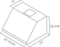
3 Techncal specfıcatons of your applance
3.1 List of Materials
3.1.1 Parts supplied
Removing the packaging
A
Remove carton carefully, Wear
gloves to protect against sharp
edges.
A
WARNING:
Remove the protec-
tive film covering the product before
putting into operation.
• Hood canopy.
• Blower.
• Duct transition.
• Lamp already installed.
• Grease filter.
• Hardware bag with:
– Use, care and installation guide
– 2 hollow wall anchors with screws to secure
hood to the wall at the bottom
– 4 Wood screws to secure the wood support
to the wall
– 4 Phillips head screws to secure the transition
to the hood outlet on the top
– 6 Phillips head screws to secure hood to the
wood support (2 secured to wood support)
– 1 Safety screw and lock washer to secure
the blower (screw is marked with red or blue
paint)
– 2 Flat washers for wall anchors
3.1.2 Parts not supplied
Optional Accessories
• Duct Cover
• Heat Lamps kit (2 IR 175W)
• Backsplash kit
Tools/Materials required
• Wire nuts
• Tape to mount template
• 8” rounded metal duct length to suit installation
• Measuring tape
• Pliers
• Gloves
• Knife
• Safety glasses
• Electric drill with 5/16” and 3/8” Bits
• Strain relief
• Spirit level
• Duct tape
• Screwdrivers:
– Phillips (Posidrive) # 2
– Torx # 2
• Wire cutter/stripper
• Masking tape
• Hammer
• Saw, jig saw or reciprocating saw
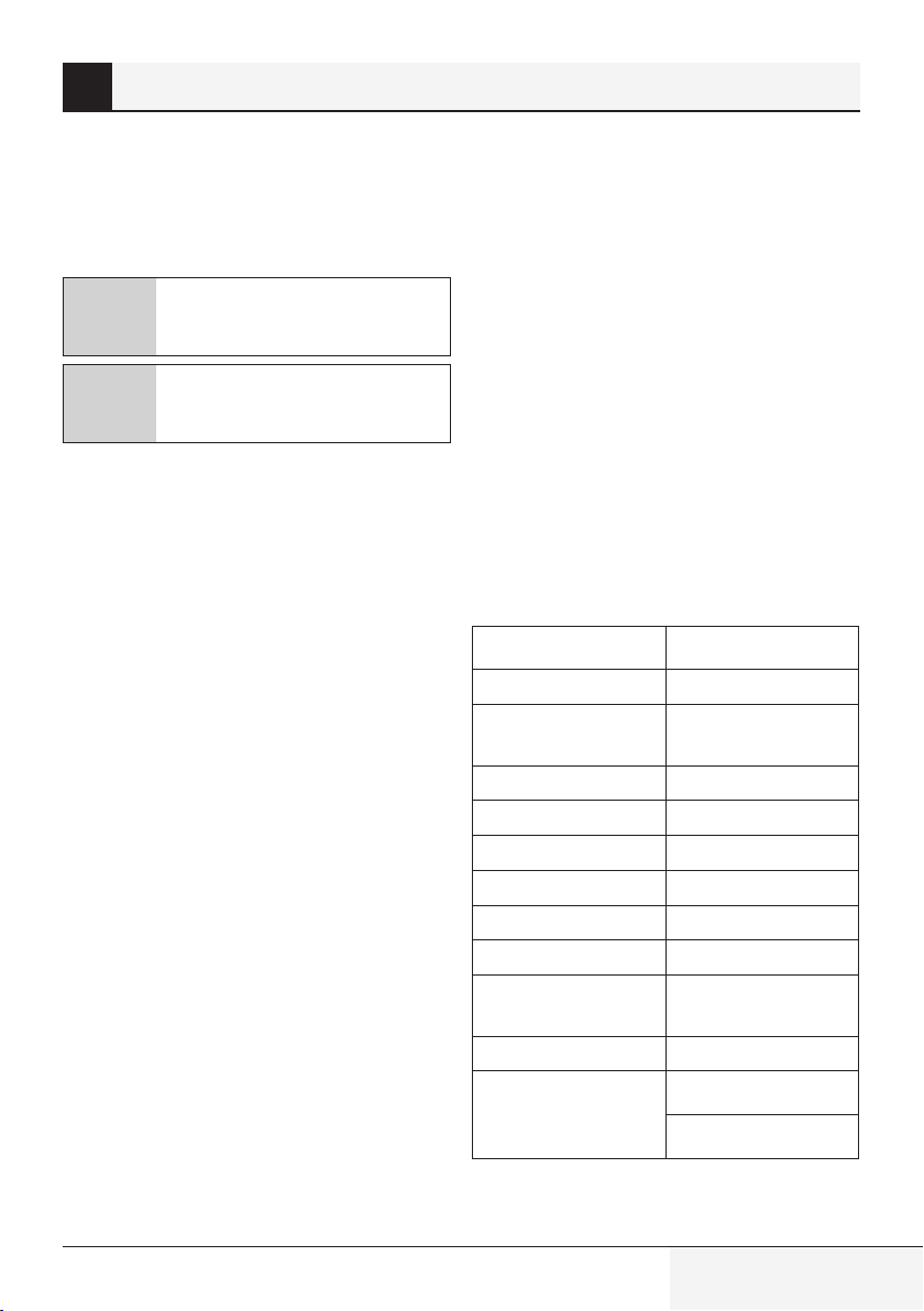
CHP30100SS
Operatng mode
ducted out only
Max. Ventlaton
Capacty
515 CFM
Nr.of Speeds
4
Controls
Mechancal Knobs
Lghts
2 x 50 W Halogene
Flterng
2 x Baffle Flters
Volts
120 V
Frequency
60 Hz
Total Power
(motor + lamps)
550 W
Plug type
Hard Wre
Requred ds-
tance above
cooktop
30” (gas cooktop)
30” (electrcal cooktop)
Loading ...
Loading ...
Loading ...