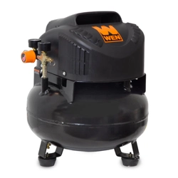
User manual Air Compressor
INSTALLATION
HOW TO SET UP YOUR UNIT
Location of the Air Compressor
- Locate the air compressor in a clean, dry and well ventilated area.
- The air compressor should be located at least 12" (30.5 cm) away from the wall or other obstructions that will interfere with the flow of air.
- The air compressor pump and shroud are designed to allow for proper cooling. The ventilation openings on the compressor are necessary to maintain proper operating temperature. Do not place rags or other containers on or near these openings.
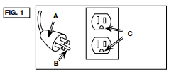
GROUNDING INSTRUCTIONS (FIG. 1)
The portable air compressor is equipped with a cord having a grounding wire with an appropriate grounding plug (A).
- The cord set and plug (A) with this unit contains a grounding pin (B). This plug MUST be used with a grounded outlet (C). IMPORTANT: The outlet being used must be installed and grounded in accordance with all local codes and ordinances.
- Make sure the outlet being used has the same configuration as the grounded plug. DO NOT USE AN ADAPTER. See figure 1.
- Inspect the plug and cord before each use. Do not use if there are signs of damage.
- If these grounding instructions are not completely understood, or if in doubt as to whether the compressor is properly grounded, have the installation checked by a qualified electrician
Do not modify the plug provided. If it does not fit the available outlet, a correct outlet should be installed by a qualified electrician.
EXTENSION CORDS
If an extension cord must be used, be sure it is:
- a 3-wire extension cord that has a 3-blade grounding plug, and a 3-slot receptacle that will accept the plug on the product
- in good condition
- no longer than 50' (15.2 m)
- 14 gauge (AWG) or larger. (Wire size increases as gauge number decreases. 12 AWG and 10 AWG may also be used. DO NOT USE 16 OR 18 AWG.)
NOTICE: Risk of Property Damage. The use of an undersized extension cord will cause voltage to drop resulting in power loss to the motor and overheating. Instead of using an extension cord, increase the working reach of the air hose by attaching another length of hose to its end. Attach additional lengths of hose as needed.
VOLTAGE AND CIRCUIT PROTECTION
Refer to the Specification Chart for the voltage and minimum branch circuit requirements.
Warning: Risk of Overheating. Certain air compressors can be operated on a 15 amp circuit if the following conditions are met.
- Voltage supply to circuit must comply with the National Electrical Code.
- Circuit is not used to supply any other electrical needs.
- Extension cords comply with specifications.
- Circuit is equipped with a 15 amp circuit breaker or 15 amp time delay fuse. NOTE: If compressor is connected to a circuit protected by fuses, use only time delay fuses. Time delay fuses should be marked "D" in Canada and "T" in the US.
If any of the above conditions cannot be met, or if operation of the compressor repeatedly causes interruption of the power, it may be necessary to operate it from a 20 amp circuit. It is not necessary to change the cord set.
OPERATION
KNOW YOUR AIR COMPRESSOR
READ THIS OWNER’S MANUAL AND SAFETY RULES BEFORE OPERATING YOUR UNIT. Compare the illustrations with your unit to familiarize yourself with the location of various controls and adjustments. Save this manual for future reference.
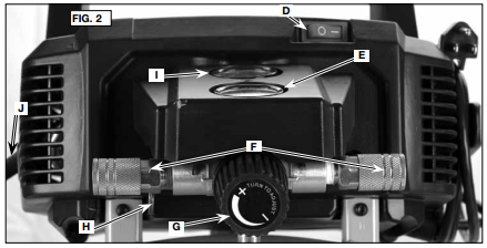
DESCRIPTION OF OPERATION (FIG. 2–4)
Become familiar with these controls before operating the unit.
On(I)/Off(O) Switch (D): Place this switch in the On (I) position to provide automatic power to the pressure switch and Off (O) to remove power at the end of each use.
Pressure Switch (not shown): The pressure switch automatically starts the motor when the air tank pressure drops below the factory set "cut-in" pressure. It stops the motor when the air tank pressure reaches the factory set "cut-out" pressure.
Safety Valve (H): If the pressure switch does not shut off the air compressor at its "cutout" pressure setting, the safety valve will protect against high pressure by "popping out" at its factory set pressure (slightly higher than the pressure switch "cut-out" setting).
Tank Pressure Gauge (I): The tank pressure gauge indicates the reserve air pressure in the tank.
Outlet Pressure Gauge (E): The outlet pressure gauge indicates the air pressure available at the outlet side of the regulator. This pressure is controlled by the regulator and is always less than or equal to the tank pressure.
Regulator (G): Controls the air pressure shown on the outlet pressure gauge. Turn regulator knob clockwise to increase pressure and counterclockwise to decrease pressure.
Cooling System (not shown): This compressor contains an advanced design cooling system. At the heart of this cooling system is an engineered fan. It is perfectly normal for this fan to blow air through the vent holes in large amounts. You know that the cooling system is working when air is being expelled.
Air Compressor Pump (not shown): Compresses air into the air tank. Working air is not available until the compressor has raised the air tank pressure above that required at the air outlet.
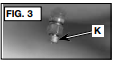
Drain Valve (K): The drain valve is located at the base of the air tank and is used to drain condensation at the end of each use.
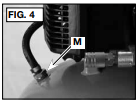
Check Valve (M): When the air compressor is operating, the check valve is "open", allowing compressed air to enter the air tank. When the air compressor reaches "cut-out" pressure, the check valve "closes", allowing air pressure to remain inside the air tank.
Motor Overload Protector (not shown): The motor has a thermal overload protector. If the motor overheats for any reason, the overload protector will shut off the motor. The motor must be allowed to cool down before restarting. To restart:
- Set the On/Off lever to "Off" and unplug unit.
- Allow the motor to cool.
- Plug the power cord into the correct branch circuit receptacle.
- Set the Auto/Off lever to "On" position.
Quick-Connect Body (F): The quick connect body accepts industrial quick connect plugs. The two quick connect bodies allow the use of two tools at the same time.
HOW TO USE YOUR UNIT (FIG. 2)
How to Stop
- Set the On/Off switch (D) to "Off".
- Unplug unit when not in use.
Before Starting
Do not operate this unit until you read this instruction manual for safety, operation and maintenance instructions.
Before Each Start-Up
- Set the On/Off switch (D) to "Off".
- Plug the power cord into the correct branch circuit receptacle. (Refer to Voltage and Circuit Protection paragraph in the Installation section of this manual.)
- Turn the regulator knob (G) counterclockwise to set the outlet pressure to zero.
- Turn regulator knob (G) counterclockwise until fully closed. Ensure regulated pressure gauge reads 0 PSI (0 kPa).
- Attach hose and accessories.
- Ensure all covers and labels are in place, legible (for labels) and securely mounted. Do not use compressor until all items have been verified.
NOTE: The hose or accessory will require a quick connect plug if the air outlet is equipped with a quick connect body (F).
Warning:
- Risk of unsafe operation. Firmly grasp air hose in hand when installing or disconnecting to prevent hose whip.
- Risk of unsafe operation. Do not use damaged or worn accessories. NOTE: The hose or accessory will require a quick connect plug if the air outlet is equipped with a quick connect body (F).
- Risk of Bursting. Too much air pressure causes a hazardous risk of bursting. Check the manufacturer’s maximum pressure rating for air tools and accessories. The regulator outlet pressure must never exceed the maximum pressure rating.
NOTICE: Risk of property damage. Compressed air from the unit may contain water condensation and oil mist. Do not spray unfiltered air at an item that could be damaged by moisture. Some air tools and accessories may require filtered air. Read the instructions for the air tools and accessories.
How to Start
1. Set the On/Off switch (D) to "On" and allow tank pressure to build. Motor will stop when tank pressure reaches "cut-out" pressure.
2. Turn regulator knob (G) clockwise to increase pressure and stop when desired pressure is reached.
Warning: Risk of unsafe operation. If any unusual noise or vibration is noticed, stop the compressor immediately and have it checked by a trained service technician.
The compressor is ready for use.
MAINTENANCE
CUSTOMER RESPONSIBILITIES
Warning:
- Risk of unsafe operation. Unit cycles automatically when power is on. When performing maintenance, you may be exposed to voltage sources, compressed air, or moving parts. Personal injuries can occur. Before performing any maintenance or repair, disconnect power source from the compressor and bleed off all air pressure.
- Risk from Flying Objects. Always wear certified safety equipment: ANSI Z87.1 eye protection (CAN/CSA Z94.3) with side shields
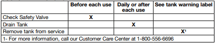
Before starting compressor, pull the ring on the safety valve (H) to make sure that the safety valve operates freely. If the valve is stuck or does not operate smoothly, it must be replaced with the same type of valve
TO DRAIN TANK (FIG. 2, 3)
Warning: Risk of Unsafe Operation. Air tanks contain high pressure air. Keep face and other body parts away from outlet of drain. Use ANSI Z87.1 eye protection (CAN/CSA Z94.3) when draining as debris can be kicked up into face.
Warning: Risk from noise. Always wear proper hearing protection during use. Under some conditions and duration of use, noise from this product may contribute to hearing loss.
NOTE: All compressed air systems generate condensate that accumulates in any drain point (e.g., tanks, filter, aftercoolers, dryers). This condensate contains lubricating oil and/or substances which may be regulated and must be disposed of in accordance with local, state, and federal laws and regulations.
Warning: Risk of Bursting. Water will condense in the air tank. If not drained, water will corrode and weaken the air tank causing a risk of air tank rupture.
NOTICE: Risk of Property Damage. Drain water from air tank may contain oil and rust which can cause stains.
- Set the On/Off switch (D) to "Off".
- Turn the regulator knob (G) counterclockwise to set the outlet pressure to zero.
- Remove the air tool or accessory.
- Place a suitable container under the drain valve to catch discharge.
- Pull ring on safety valve (H) allowing air to bleed from the tank until tank pressure is approximately 20 psi. Release safety valve ring.
- Drain water from air tank by opening drain valve (K) on bottom of tank.
- After the water has been drained, close the drain valve. The air compressor can now be stored.
NOTE: If drain valve is plugged, release all air pressure. The valve can then be removed, cleaned, the reinstalled.
SERVICE AND ADJUSTMENTS
ALL MAINTENANCE AND REPAIR OPERATIONS NOT LISTED MUST BE PERFORMED BY TRAINED SERVICE TECHNICIAN.
Warning: Risk of Unsafe Operation. Unit cycles automatically when power is on. When servicing, you may be exposed to voltage sources, compressed air, or moving parts. Before servicing unit unplug or disconnect electrical supply to the air compressor, bleed tank of pressure, and allow the air compressor to cool.
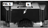
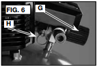
TO REPLACE REGULATOR (FIG. 5–9)
- Release all air pressure from air tank. See To Drain Tank in the Maintenance section.
- Unplug unit.
- Remove the console cover (N).
- Using an adjustable wrench remove the safety valve (H) from the regulator manifold (G).
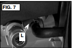
- Remove the hose by removing the hose clamp (L). NOTE: The hose clamp is not reusable. You must purchase a new hose clamp, see Replacement Parts in the Service section or purchase a standard hose clamp at a local hardware store.
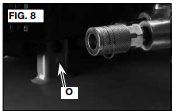
- Remove three pump mounting screws (O) securing pump..
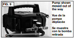
- Carefully lift pump up away from brackets and out of the way.
- Using an adjustable wrench remove the regulator manifold (G).
- Apply pipe sealant to new regulator manifold and assemble, tighten with wrench.
- Reapply pipe sealant to safety valve.
- Reassemble all components in reverse order of removal. Make sure to orient gauges to read correctly and use wrenches to tighten all components.
STORAGE
Before you store the air compressor, make sure you do the following:
- Review the Maintenance section on the preceding pages and perform scheduled maintenance as necessary.
- Drain water from air tank. See To Drain Tank under Maintenance.
- Protect the electrical cord and air hose from damage (such as being stepped on or run over). Wind air hose loosely around the compressor handle. Wrap electrical cord onto the cord wrap.
- Store the air compressor in a clean and dry location.
ACCESSORIES
Warning: Since accessories, other than those offered by BOSTITCH, have not been tested with this product, use of such accessories with this tool could be hazardous. To reduce the risk of injury, only BOSTITCH recommended accessories should be used with this product.
A complete line of accessories is available from your BOSTITCH Factory Service Center or a BOSTITCH Authorized Warranty Service Center. Please visit our Web Site visitar www. BOSTITCH.com for a catalog or for the name of your nearest supplier.
TROUBLESHOOTING
Warning: Risk of Unsafe Operation. Unit cycles automatically when power is on. When servicing, you may be exposed to voltage sources, compressed air, or moving parts. Before servicing unit unplug or disconnect electrical supply to the air compressor, bleed tank of pressure, and allow the air compressor to cool.
Excessive tank pressure - safety valve pops off.
- Pressure switch does not shut off motor when compressor reaches "cut-out" pressure. Pressure switch "cut-out" too high.
Move On/Off lever to the "Off" position, if the outfit does not shut off contact a Trained Service Technician. Contact a Trained Service Technician.
Air leaks at fittings.
- Tube fittings are not tight enough.
Tighten fittings where air can be heard escaping. Check fittings with soapy water solution. Do Not Overtighten.
Air leaks in air tank or at air tank welds.
Air tank must be replaced. Do not repair the leak. Warning: Risk bursting. Do not drill into, weld or otherwise modify air tank or it will weaken. The tank can rupture or explode.
Air leaks between head and valve plate
Contact a Trained Service Technician.
Air leak from safety valve
- Possible defect in safety valve.
Operate safety valve manually by pulling on ring. If valve still leaks, it should be replaced.
Knocking Noise.
- Possible defect in safety valve.
Operate safety valve manually by pulling on ring. If valve still leaks, it should be replaced.
Pressure reading on the regulated pressure gauge drops when an accessory is used.
- It is normal for "some" pressure drop to occur.
If there is an excessive amount of pressure drop when the accessory is used, adjust the regulator following the instructions in the Description of Operation paragraph in the Operation Section.
NOTE: Adjust the regulated pressure under flow conditions (while accessory is being used).
Compressor is not supplying enough air to operate accessories.
- Prolonged excessive use of air.
Decrease amount of air usage.
- Compressor is not large enough for air requirement.
Check the accessory air requirement. If it is higher than the SCFM or pressure supplied by your air compressor, you need a larger compressor.
Check and replace if required.
Have checked by a Trained Service Technician.
Tighten fittings.
Regulator knob has continuous air leak.
Replace.
Regulator will not shut off air outlet.
Replace.
Motor will not run.
- Fuse blown, circuit breaker tripped.
Check fuse box for blown fuse and replace as necessary. Reset circuit breaker. Do not use a fuse or circuit breaker with higher rating than that specified for your particular branch circuit. Check for proper fuse. You should use a time delay fuse. Check for low voltage problem. Check the extension cord. Disconnect the other electrical appliances from circuit or operate the compressor on its own branch circuit.
- Extension cord is wrong length or gauge.
Check the extension cord.
- Loose electrical connections.
Check wiring connection inside terminal box.
Have checked by a Trained Service Technician.
- Motor overload protection switch has tripped
Refer to Motor Overload Protection under Operation. If motor overload protection trips frequently, contact a Trained Service Technician.