Loading ...
To prevent the risk of personal injury and/or
death, make sure power is not applied to the
product until it is fully installed and ready for
final testing. All work must be done with power
turned off to the circuit being worked on.
To reduce the risk of electric shock, do not connect to a
circuit operating at more than 150 V to ground.
Power Supply
Pull power supply wiring to the control location.
• Leave about 6 to 8" (15 to 20 cm) of wire for connections.
•
This wiring should be size 12 or 14 AWG, in compliance with
local code requirements.
•
A qualified person should run a dedicated circuit from the main
circuit breaker panel to the control location. If a dedicated
circuit is not possible, it is acceptable to tap into an existing
circuit. However, there must be enough capacity to handle
the load (amps) of the floor heating system being installed,
and any appliance likely to be used on the circuit such as a
hair dryer or vacuum cleaner.
• Avoid circuits that have ballasted lighting, motors, exhaust
fans, or hot tub pumps to reduce the likelihood of interference.
•
The circuit breaker should be rated 20 amps for total circuit
loads up to 15 amps. A 15-amp circuit breaker may be used
for total circuit loads up to 12 amps.
•
A GFCI (ground-fault circuit interrupter) or AFCI (arc-fault
circuit interrupter) type circuit breaker may be used, but is
not necessary.
Thermostat Wiring
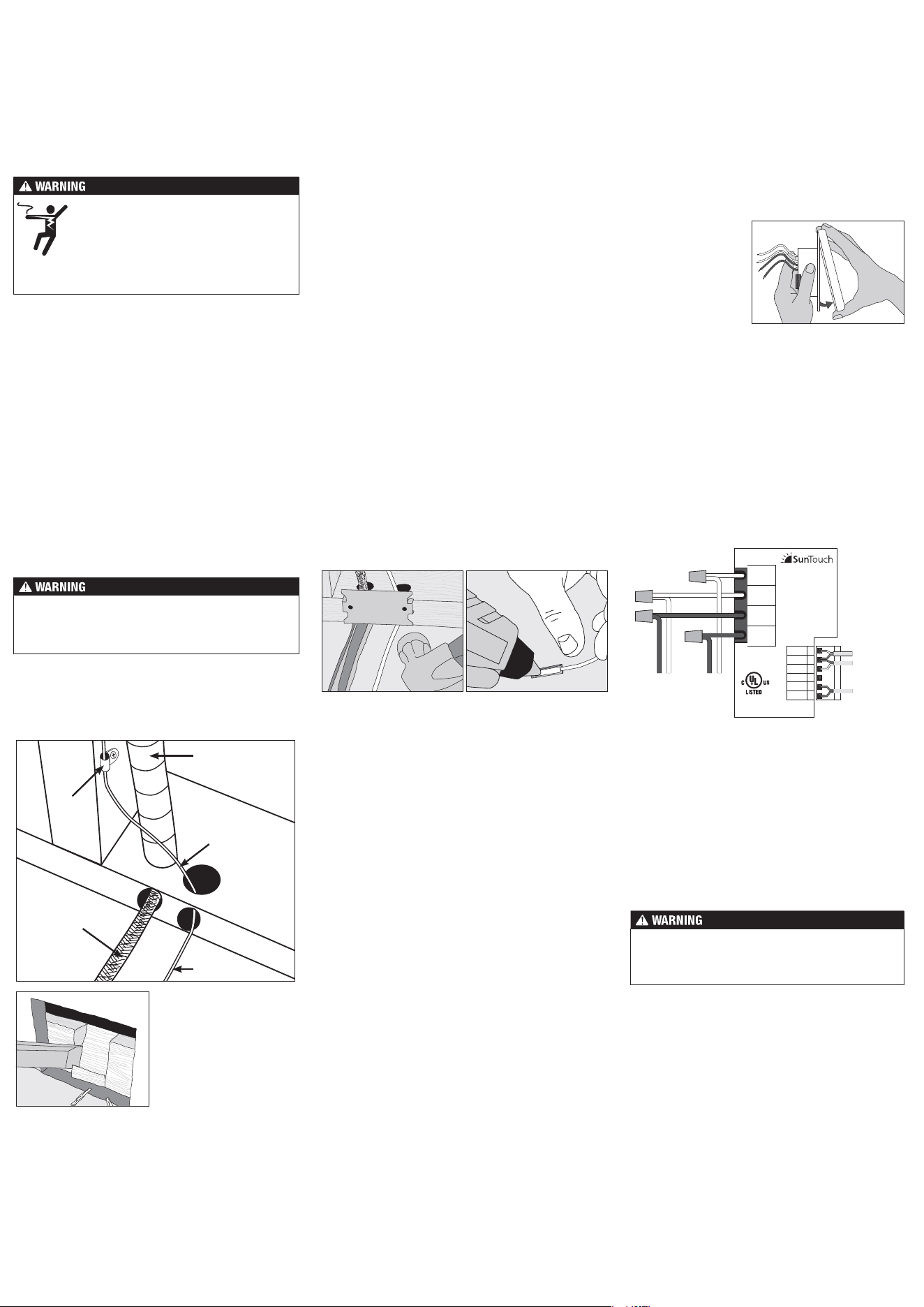
Before connecting the wires to the back of the thermostat,
detach the display front from the base.
Bottom Plate Work
•
Drill or chisel holes at the bottom plate as indicated. One
hole is for routing the power lead conduit and the other is
for the thermostat sensor. These holes should be directly
below the electrical box(es).
Make sure 120 VAC is supplied to 120 VAC cables and 240
VAC is supplied to 240 VAC cables. Otherwise, dangerous
overheating and a fire hazard could result. Do not exceed
15-amps on this control.
SunStat Sensor Installation
•
The SunStat sensor can be installed with or without electrical
conduit depending on code requirements. Conduit is
recommended for added protection against nails and screws.
• Do not place the sensor in the same conduit as the power
leads to avoid possible interference. Open a separate knock-
out in the bottom of the thermostat box. Feed the sensor
(and conduit, if used) through the knock-out, down through
the cut-out in the bottom plate, and out into the floor where
the heating cable will be installed.
•
If the sensor wire needs to be secured to the wall stud,
wait until after the wire or mat and sensor are completely
installed on the floor.
•
At the sensor location, measure at least 1' into the heated
area. Mark the spot where the sensor will be attached to
the floor. Be sure to place the sensor exactly between two
of the heating wires. Ensure the sensor wire does not cross
over any heating wires.
•
Do not locate the sensor outside the heating area or in a gap
between heating wires that is wider than the rest of the floor.
Do not locate the sensor where direct sun, hot-water piping,
heat duct, or lighting below will cause inaccurate temperature
reading. Do not locate the sensor where an insulating item
such as a rug is likely to be placed.
• To make sure the sensor tip does not create a high spot in
the floor, it may be necessary to chisel a channel into the
floor and lay the sensor tip into the channel. Hot glue the
tip into place.
•
Do not cut the sensor wire or remove the black cable protector.
Strip the wire ends to 1/8" long.
Floor Heating Mat or Cable Power Lead Installation
•
The shielded power lead can be installed with or without
electrical conduit (recommended for added protection
against nails or screws), depending on code requirements.
•
Remove one of the knock-outs in the electrical box to
route the power lead. If electrical conduit is not required by
code, install a wire collar to secure the power leads where
they enter the box. If conduit is required by code, install
1/2" (minimum) conduit from the bottom plate up to the
electrical box. For multiple power leads (multiple cables),
install 3/4" conduit.
• Secure a steel nail plate over the cutout in the bottom plate
to protect the wires against baseboard nails later.
SunStat Relay Rough-in Wiring
A SunStat Relay C3 is used when more than 15 amps must be
controlled by one SunStat thermostat. The SunStat Command
is only compatible with the SunStat Relay C3. Do not use
other models.
• Pull 18 AWG to 24 AWG 2-conductor shielded wire from the
relay location to this control location. The wire may be up
to 100' (30 m) long.
• Strip the wire ends to 1/8" long.
Refer to the instructions provided with the SunStat Relay C3
for additional details.
Home Automation System Rough-in Wiring
A short or 24 VAC applied between the Away and Com terminal
will switch the thermostat between the 'Away' temperature
and regular operation.
• Pull 18 AWG to 24 AWG 2-conductor shielded wire from the
home automation control to this control location.
• Strip the wire ends to 1/8" long.
Power lead
conduit
Wire
clip
Power
lead
Sensor wire
Sensor wire
For retrofit installations,
cut out drywall and chisel
out the bottom plate to
route wires to control.
Sensor, relay and home automation connections are made
to the terminal block by inserting the wires into the square
openings and tightening the screws on the side.
•
Connect the sensor wires to the SENSOR terminals on the
thermostat. These connections are not polarity sensitive.
•
For a SunStat Relay C3, connect 2 wires from the relay to
the Com and Relay terminals on the thermostat. Ensure the
Com wire at the relay is the same conductor connected
to the Com terminal on the thermostat.
• Connect the Away and Com terminals to the appropriate
conductors from a home automation system. Refer to
the instructions for the home automation control before
making these connections.
Designed and
assembled in Canada
E365015
Temp. Ind. &
Reg. Equip.
L1
L
LOAD 1
1
2
3
4
5
6
SENSOR
SENSOR
RELAY(B)
COM (A)
AWAY
MAY 2015
1080-01
GFCI CLASS A
L2
N
LOAD 2
Floor Heating
Floor Heating
Power:
120/240 ±10% V (ac)
60 Hz, 3 W
Load:
120/240 V (ac), 15 A
1800/3600 W
SunStat Command
(240 V)
(120 V)
(240 V)
(120 V)
Home Auto.
Relay C3
Floor sensor
Mat or
Cable
power
lead
Power
supply
from
breaker
See over for operation details
Finish Thermostat Installation
• Ensure all connections are secure.
• Carefully press the wires back into the electrical box. Do
not use the control to push them.
•
Use the included screws to attach the thermostat base to
the electrical box. Do not overtighten.
• When re-attaching the display front, line up the top edge
with the base, then rotate the bottom towards the base.
Ensure the pins are not bent when connecting.
Make sure the wire connections are secure by gently tugging
on them. Otherwise, arcing could occur, causing dangerous
overheating and a possible fire hazard. For added security,
overwrap each wire nut connection with electrical tape.
While holding the base
section in one hand,
pull the lower half of the
display front towards
you to pivot it away from
the base.
Using the wire nuts included with the thermostat:
•
Connect the ground wire from the power supply to the
ground wire from the floor heating power lead. If the
electrical box is metal, use a short length of wire to connect
ground wires to the bonding screw.
•
Connect the white wire labeled LOAD 2 on the thermostat
to the white (or blue for 240 VAC) wire from the heating
mat or cable power lead.
•
Connect the black wire labeled LOAD 1 on the thermostat
to the black wire from the heating mat or cable power lead.
•
For 120 VAC connections, the L wire connects to the
black (L) hot conductor from the breaker panel. The N wire
connects to the white (N) neutral conductor.
•
For 240 VAC connections, the L1 connects to one side
of the 240 VAC supply from the breaker panel and the
L2 to the other.
Loading ...
Loading ...