OPERATOR’S MANUAL
■
pH-3020
For technical assistance or the dealer nearest you consult our web page at
www.wmaze.com or call (800-562-4993) or (360) 833-2874
pH PERMISSIVE
CONTROL SYSTEM
8.914-301.0-D10/31/19
89143010-3

CONTENTS
2
8.914-301.0-D • PH-3020 Permissive Control System
Model Number
Serial Number
Date of Purchase
The model and serial numbers will be found on a decal attached to the
pH Permissive Control System. You should record both serial number
and date of purchase and keep in a safe place for future reference.
Introduction .................................................................................................................................... 3
Unpacking ...................................................................................................................................... 3
Important Safety Information ......................................................................................................... 4
Component Identification ............................................................................................................... 5
How Automation Works.................................................................................................................. 6
Installation...................................................................................................................................... 6
Electrical Instructions .................................................................................................................. 6,7
Operating Instructions................................................................................................................. 7,8
Digital pH Controller ..................................................................................................................8-10
Feed Rate Adjustment ................................................................................................................. 10
Sensor Maintenance .................................................................................................................... 10
Winterizing and Shipping ............................................................................................................. 10
Metering Pump Installation, Operation and Maintenance........................................................11-12
pH-3020, Exploded View ............................................................................................................. 13
pH-3020, Exploded View Parts List ............................................................................................. 14
Auto-Fill/Holding Tank Options ..................................................................................................... 15
Auto-Fill/Holding Tank Parts Lists and Tables .............................................................................. 16
Metering Pump, Exploded View and Parts List.............................................................................17
Filter Pump, Exploded View, Parts List and Tables ...................................................................... 18
Electrical, Exploded View and Parts List ...................................................................................... 19
Troubleshooting ........................................................................................................................... 20
Error Messages ........................................................................................................................... 21
Preventative Maintenance ........................................................................................................... 21
Warranty ...................................................................................................................................... 22

pH PERMISSIVE CONTROL SYSTEM
OPERATOR’S MANUAL
3
8.914-301.0-D • PH-3020 Permissive Control System
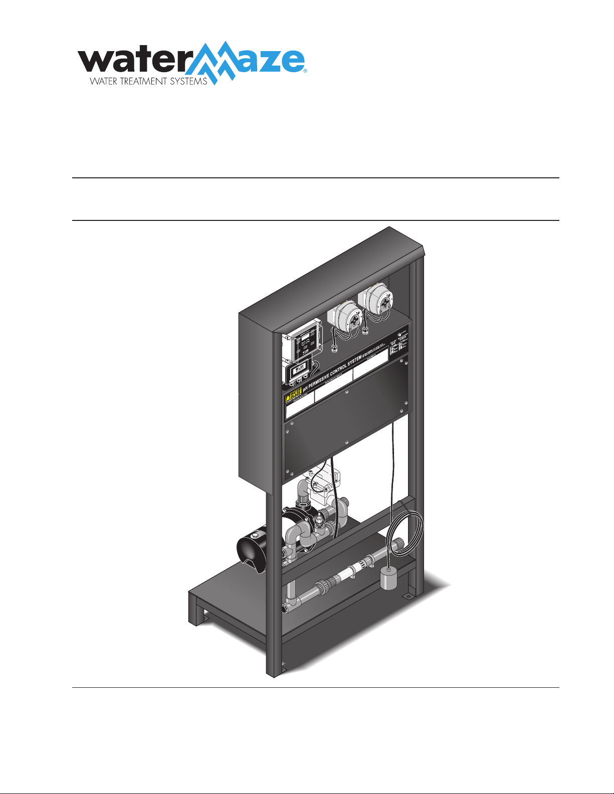
INTRODUCTION
Thank you for purchasing a WATER MAZE.
This manual covers the operation and maintenance of
the WATER MAZE pH Permissive Control System. All
information in this manual is based on the latest product
information available at the time of printing.
WATER MAZE reserves the right to make changes at
any time without incurring any obligation.
Owner/User Responsibility:
The owner and/or user must have an understanding of
the manufacturer’s operating instructions and warnings
before using this WATER MAZE machine. Warning
information should be emphasized and understood. If
the operator is not fluent in English, the manufacturer’s
instructions and warnings shall be read to and discussed
with the operator in the operator’s native language by
the purchaser/owner, making sure that the operator
comprehends its contents.
Owner and/or user must study and maintain for future
reference the manufacturers’ instructions.
This manual should be considered a permanent
part of the machine and should remain with it if
machine is resold.
When ordering parts, please specify model and
serial number.
UNPACKING
pH Permissive Control System
Model 3020
Congratulations and thank you for ordering the
WATER MAZE pH Permissive Control System. Carefully
unpack your new equipment and check contents against
packing slip. The pH Permissive Control System includes
the following:
pH Permissive Control System on Stand
Box containing:
— pH Probe
— Peristaltic Pump Injectors
— Tubing
— Filters
If any part is missing. Please report it immediately to
your WATER MAZE Dealer.
4
pH PERMISSIVE CONTROL SYSTEM
OPERATOR’S MANUAL
8.914-301.0-D • PH-3020 Permissive Control System
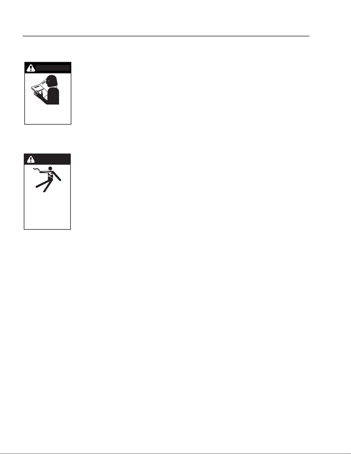
IMPORTANT
SAFETY INFORMATION
CAUTION: To reduce the risk of
injury, read operating instruc-
tions carefully before using.
ATTENTION: Pour réduire
le risque de blessures, lire at-
tentivement les instructions de
f n c t i o n n e m e n t a v a n t
l'utilisation.
1. Read the owner's manual
thoroughly. Failure to follow instructions could cause a
malfunction of the machine and result in death, seri-
ous bodily injury and/or property damage.
DANGER: Meet the National
Electrical code and local codes
for all wiring.
DANGER: Respecter le Code na-
tional de l'électricité et les codes
locaux pour tous les câblages.
2. The installation of the machine
must comply with local and/or
national codes.
WARNING: All wiring must be
performed by a qualified electri-
cian.
AVERTISSEMENT: Tout le câblage doit être effectué
par un électricien qualifié.
WARNING: Ground system before connecting to the
power supply.
AVERTISSEMENT: Mettre le système à la masse
avant de le raccorder à la source d'alimentation.
3.Do not spray water near electrical components.
4. Never make adjustments on the machine while it is
in operation except those prescribed in this manual.
5. Before servicing the machine, refer to the MSDS on
all of the material identified in the waste stream. You
must comply with all warnings and wear all protective
clothing stated on the MSDS.
6. Be certain coupled hoses have been locked before
operating.
7. Inlet water temperature must not exceed 104°F
(40°C).
8. When making repairs disconnect machine from
electrical source.
9. The best insurance against an accident is precaution
and knowledge of the equipment.
WARNING
CAUTION
READ OPERATOR’S
MANUAL
THOROUGHLY
PRIOR TO USE.
HAZARDOUS
VOLTAGE CAN
SHOCK, BURN
OR CAUSE DEATH.
GROUND SYSTEM
BEFORE CONNECTING
TO POWER SUPPLY
PRIOR TO US
E.
DANGER
10. WATER MAZE is not liable for any modifications
or the use of components not purchased from
WATER MAZE.
11. Components will freeze and must be located in a
heated enclosure in cold climates.
pH PERMISSIVE CONTROL SYSTEM
OPERATOR’S MANUAL
5
8.914-301.0-D • PH-3020 Permissive Control System
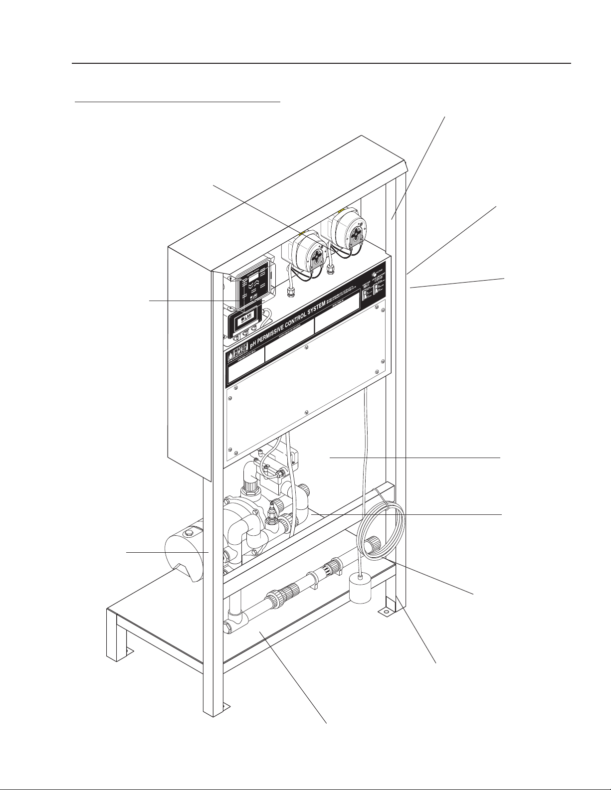
COMPONENT IDENTIFICATION
pH-3020
89143010-4
Clean Out Port
Mixer
Flow Switch
Low Water
Protect Float
ON/OFF
Switch
Voltage Light
Base Pump
Acid Pump
pH Controller
Pump
Sensor
6
pH PERMISSIVE CONTROL SYSTEM
OPERATOR’S MANUAL
8.914-301.0-D • PH-3020 Permissive Control System
HOW AUTOMATION WORKS
The pH Sensor is mounted on the recirculation line of
the pH Permissive Control System. The sensor analyzes
the water as it goes through the line and—operating
like a miniature battery—it generates a small electronic
signal which is amplified and analyzed by the controller
for display on the readout meter and for activation of the
chemical feeders.
The Sensor reads the pH of the water. The ideal pH range
is 6.5 to 7.5. Below 6.5, the water is increasingly acidic.
This causes eye irritation and corrosion of the equip-
ment (HBG tank, pump, plumbing, etc.). Above 7.5, the
water is too alkaline. This also causes eye irritation plus
cloudiness and scaling. When the pH requirements are
met the pH permissive system allows the waste stream
to move forward to the HBG or other external device.
INSTALLATION
Location
1. The pH Permissive System must be installed on a
level surface, preferably a concrete pad near the
feed tank. In cold climates the pH Permissive Sys-
tem will freeze and should be located in a heated
enclosure.
2. Fasten pH Permissive System's legs to the floor.
3. Connect at least a 1" inlet and outlet line to inlet and
outlet of pump. We provide female slip fittings at the
inlet and outlet. You will need to provide plumbing
from the feed tank to the pH Permissive System.
4. A normally open (black) float is provided to protect
the pump from sucking air. Position the float above
the bulkhead in the feed tank that feeds the inlet side
of the pump. When the float is in the down position
there should be a couple inches of water above the
top portion of the bulkhead.
5. Install chemical injectors into recycle line per draw-
ings on page 12.
6. Install tubing from injectors to the acid and base
pumps per instructions on page 10 and 11.
7. Install tubing and filters from the acid and base
pumps to your chemical drums, per instructions on
page 10.
8. Install sensor per instructions on page 6.
Auto-Fill Option 8.903-682.0 (see page 14-15)
1. Position the sump pump in the bottom of sump pit.
Elevate on a stand or cinder blocks, 6" off the pit
floor, to keep pump from sucking in rocks or other
heavy material that may plug pump or plumbing.
2. Position the pump away from incoming water to help
prevent cavitation.
3. Tie a rope or chain to the pump handle and bring out
of the top of the pit for ease of pump removal. Do not
lift pump by power cords or plumbing. Have a union
installed on plumbing at the top of the pit. Position
union so it can easily be reached and opened for
pump removal.
4. Install plumbing to outlet of sump pump and run to
the top of the feed tank. Plumbing not provided,
except for 1-1/2" bulkhead going into tank. Leave
room in the feed tank for shut-off float to arch and
shut-off sump pump before feed tank overflows.
Position inlet bulkhead from the sump pump on the
opposite side of the feed tank from bulkhead feeding
the pH Permissive system.
5. Install 1/2" bulkhead for shut-off float on feed tank.
Position away from water coming from the sump
pump to prevent interference of the float. Install float
(See Electrical Instructions for proper float).
6. Install low water protect float (See Electrical Instruc-
tions for proper float) in sump pit, approximately
6 inches above the sump pump inlet when float is
in the down position.
Holding Tank Option 8.903-681.0
(see pages
14-15)
1. Install drain per diagram on page 14-15.
2. Install bulkhead that will be accommodating inlet
plumbing to mix pump about 1/2 way up the side of
feed tank—just above the black portion of the tank.
3. Install the bulkhead for the N/O float (black) 8 inches
above the bulkhead installed in step 2.
4. Install bulkhead from the outlet of the mix pump 12
" from the top and opposite the bulkhead in step 2.
ELECTRICAL INSTRUCTIONS
DANGER: Keep water spray away
from electrical wiring or fatal elec-
tric shock may occur.
DANGER: Garder le jet d'eau à
l'écart de tout câblage électrique
ou des chocs électriques mortels
pourraient survenir.
Check for proper voltage. It is recom-
mended that a Ground Fault Circuit
Interrupter be installed. Before making electrical connec-
tions, make sure breaker is OFF and all codes, safety,
lockout/tag out procedures are followed.
Review wiring diagram provided and refer to it during
the following:
1. Remove the backside of control panel to access
electrical.
KEEP WATER
SPRAY AWAY FROM
ELECTRICAL WIRING.
DANGER

pH PERMISSIVE CONTROL SYSTEM
OPERATOR’S MANUAL
7
8.914-301.0-D • PH-3020 Permissive Control System
2. Run 120 volt single phase to the pH Permissive
Control System. Access hole provided underneath
controls. Locate terminal strip inside electrical con-
trol panel and connect 120 volt power to terminals
“1” and “N” (“1020” and “1030” on Auto-Fill Option
#30-731). Connect ground wire to ground post.
3. Connect normally open float (black) switch from feed
tank to terminal “4” and “5” on terminal strip (“1070
” and “1071” on Auto-Fill Option #30-731).
4. Connect pH Permissive System to HBG as fol-
lows:
a. Connect two black 16 gauge wires to pH Per-
missive Control System. One wire connects to
“2” and one wire connects to “3” on terminal
strip. (“1550” and “1552” on 30-731 Auto-Fill
Option).
b. Refer to HBG wiring diagram.
c. Remove wires from “9” on relay 2 (second relay
from the left) of HBG and wire nut with wire
from “2” (“1550” on Auto-Fill Option #30-731) of
terminal strip off of the pH Permissive System.
d. Connect wire on “3” (“1552” on Auto-Fill Option
#30-731) of pH Permissive Control System to
“9” on relay 2 of HBG.
5. Connect pH Permissive System to a customer pro-
vided external devise.
a. Connect two black 16 gauge wires to pH Per-
missive Control System. One wire connects to
“2” and one wire connects to “3” on terminal
strip. (“1550” and “1552” on 30-731 Auto-Fill
Option).
b. “2” and “3” (“1550” and “1552” on Auto-Fill Option
#30-761) on the pH Permissive System are “dry
contacts” and need a separate 120 volt power
supply with your external device.
6. Leave breaker OFF, follow Operating Instructions.
Auto-Fill Option Electrical Instructions:
1. In addition to the above electrical instructions, wire
the sump pump to the control panel on the pH Per-
missive Control System. One wire will go to “1030”
on terminal strip and one wire will go to “1141”. The
ground wire will go to terminal post.
2. The low water protect float (116-FS) for the sump
pump is a normally open (Black) float and is wired
into “1140” and “1160” on terminal strip.
3. The high level float (116A-FS) in the feed tank is a
normally closed (Grey) float and is wired into the
terminal strip “1141” and “1160”.
Sensor
To avoid electrical interference with the sensor signal,
keep the sensor cables away from high voltage lines,
electric motors, power transformers and other electrical
equipment.
Make sure to connect the sensor to the female BNC
connector on the controller cabinet. To connect the BC
connectors, just push it in lightly and twist clockwise.
Do the same in reverse for disconnecting. Connect the
sensor cable and sensor in the same manner as above.
Mount the sensor on the recirculation line as shown on
page 12. The sensor should be located on the top side
of the tee.
Save the protection caps of the sensor for winterizing or
storage of the sensor.
As shown on page 12, insert the sensor successively
through:
• the compression fitting
• the o-ring
• the PVC tee
Slide the sensor assembly into the tee so that the tip of
the sensor will be located approximately in the middle
of the recirculation pipe. Tighten nut over sensor to
secure.
Start the mix pump. (See Operating Instructions below.)
Check for leaks around the sensors. If there is a leak, try
tightening the compression fitting or add some silicone
sealant.
OPERATING INSTRUCTIONS
Start Up
1. Make sure mix pump switch and the acid and base
pumps are in the OFF position.
2. Turn breaker ON.
3. Voltage light will illuminate.
4. Push mix pump switch to auto position. (Hand mode
bypasses float and should only be used for servic-
ing.) Turn the acid and base pumps to the ON posi-
tion.
5. If your holding tank has enough fluid to raise the
normally open black float switch, the mix pump will
turn on. If you don't have enough fluid to raise the
float, the mix pump will not run. This protects the
pump from sucking air.
6. The mix pump takes the fluid from the holding tank,
runs fluid by the sensor and returns fluid back to the
tank. The sensor reads the pH level of the fluid and
sends a signal to the pH controller. The controller
displays a digital display of the pH level of fluid.
7. If the pH of the fluid in the tank is within the set
points of 6.5 and 7.5, no pH adjustment will need to
take place. Neither the acid or base pump will run
because no pH adjustment fluid is needed. The HBG
or other external devices will be allowed to draw fluid
8
pH PERMISSIVE CONTROL SYSTEM
OPERATOR’S MANUAL
8.914-301.0-D • PH-3020 Permissive Control System
from the tank. The mix pump will continue to run and
continue to sense the pH levels as long as enough
fluid is present in the holding tank. (See step 5.)
8. If the pH of the fluid in the holding tank is not within
the set points of 6.5 and 7.5, pH adjustment will
take place. Which chemical feed pump is turned on
depends on whether the pH in the tank needs to be
raised or lowered. The needed chemical feed pump
will draw up the pH adjust chemical and inject it into
the outlet plumbing of the mix pump. The pH adjust-
ment in the tank should happen quickly. If adjustment
takes longer than one (1) hour, the controller will lock
out the system and give you an error code of E5 or
E6. If this happens, shut off power to the machine.
Check to see if you have chemical, if the chemical
filter screen is plugged or the injector is plugged.
Also check tubing for a blockage, kinks, leaks, etc.
You may have to increase the speed on the effected
pump (See page 9 and 10 for pump instructions.)
and start at the beginning or step 1 of Operating
Instructions. While this is happening, the HGB or
other external devices will not be allowed to turn on
until the pH set points are met.
DIGITAL pH CONTROLLER
The pH controller is a microprocessor-based device that
accepts the signal sent by the sensor. The pH controller
then displays that signal digitally, and sends a signal to
the feed pump telling it to turn on or off. The pH controller
also sends a signal to the HBG, or other external device,
telling it to turn on or off its method of drawing fluid. The
controller is pre-programmed to maintain a pH level of
6.5 to 7.5. No additional programming is necessary.
When the pH Permissive Control System is started up
it is ready to go. Please call the factory before attempting
any customizing of the pH controller.
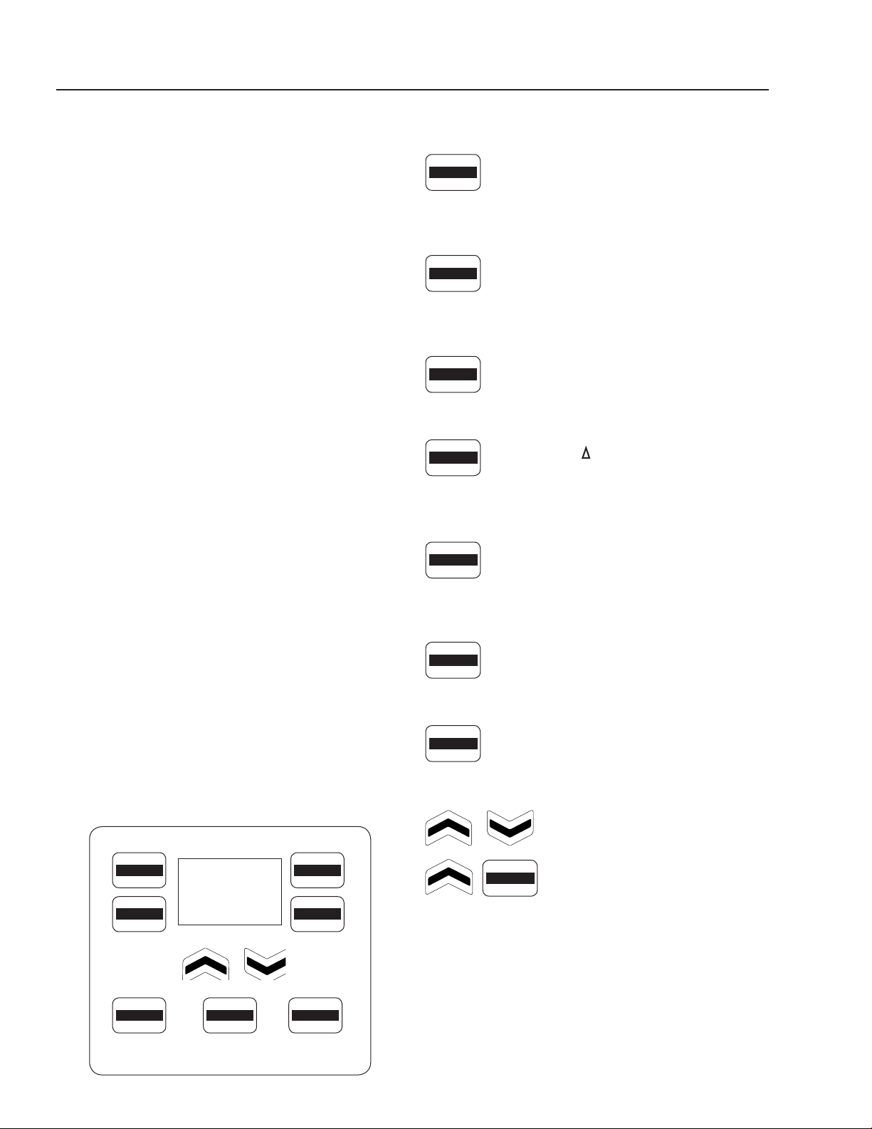
pH Permissive Control System Keypad
KEY FUNCTIONS:
This key is used to setup the control profile
for the acid dosing pump. Holding this key for
five (5) seconds will allow priming of Pump
A. Factory Set — Unless customizing or
priming pump, don't touch this key.
This key is used to setup the control profile for
the base (alkali) dosing pump. Holding this key
for five (5) seconds will allow priming of Pump
B. Factory Set — Unless customizing or
priming pump, don't touch this key.
This key is used to program the high and low
alarm points and hysteresis (ON/OFF mode).
Factory Set — Unless customizing, don't
touch this key.
This key is used to program 'run times' for
Pumps A and B. This key also allows setting
of the 'manual temperature' and the controller
response rate pH. Factory Set — Unless
customizing, don't touch this key.
This key, when pressed, will display details
of the last successful electrode calibration.
(Holding this key for five (5) seconds will allow
entry into a new calibration procedure. (See
page 8 for calibration procedure.)
Pressing this key will cause the display to
alternate showing various settings. (Holding
the key for five (5) seconds will allow entry to
the 'advanced features' menu. Factory Set.
This key is used for starting and stopping (run
or edit) the pumps and changing set points
in the controller. It changes the mode of the
controller from 'RUN' to 'OFF'.
These keys are used to change values on
the display.
Simultaneously pressing these two
(2) keys will lock the keypad to pre-
vent casual tampering. Pressing
them a second time will unlock the
keypad. (Wait five (5) seconds be-
tween locking and unlocking).
ACID
PUMP A
BASE
PUMP B
RUN
EDIT
DISPLAY
MENU
ALARMS
mA
-TIMERS- CALIBRATE
HOLD 5 SEC
ACID
PUMP A
BASE
PUMP B
ALARMS
mA
-TIMERS-
CALIBRATE
HOLD 5 SEC
DISPLAY
MENU
RUN
EDIT
ALARMS
mA
pH PERMISSIVE CONTROL SYSTEM
OPERATOR’S MANUAL
9
8.914-301.0-D • PH-3020 Permissive Control System
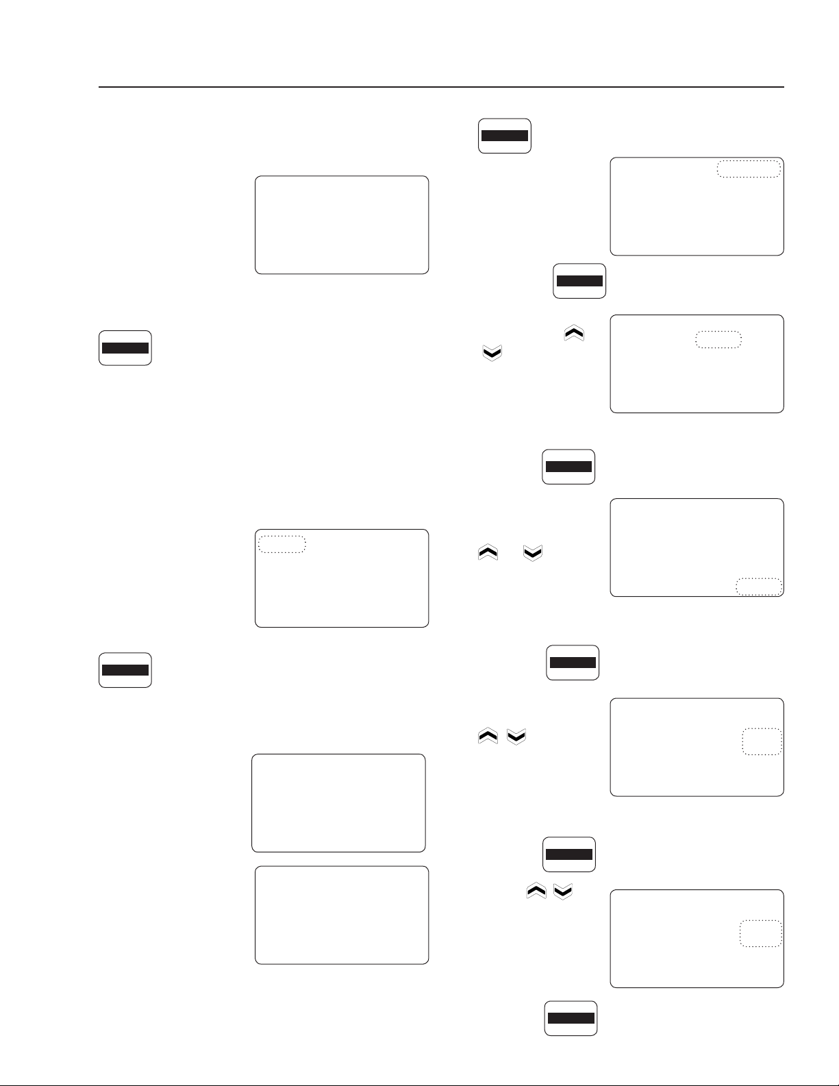
DIGITAL DISPLAY SCREEN
The controller display screen will show a large digital
reading of the attached tank's pH level. Every few
seconds the display al-
ternates, showing the
pH reading and 'OFF'.
(A small digital reading
of 'RUN' or 'OFF' will ap-
pear in the lower left of
the display screen.)
Tap the 'RUN/EDIT' key until 'RUN' is displayed in lower
left corner of the display screen.
If the pH level drops below or rises above
the set points either 'PUMP A', for acid pump, or
'PUMP B', for base pump, will begin to flash in the
upper left corner of the display screen and the af-
fected pump will turn on. Above the 'RUN' display, in
the lower left corner, a timer will come on and start
to time-out until the pH level is reached. (Refer to
Operating Instructions on page 7, step 8.) Once the pH
level is reached timer will stop and reset to zero.
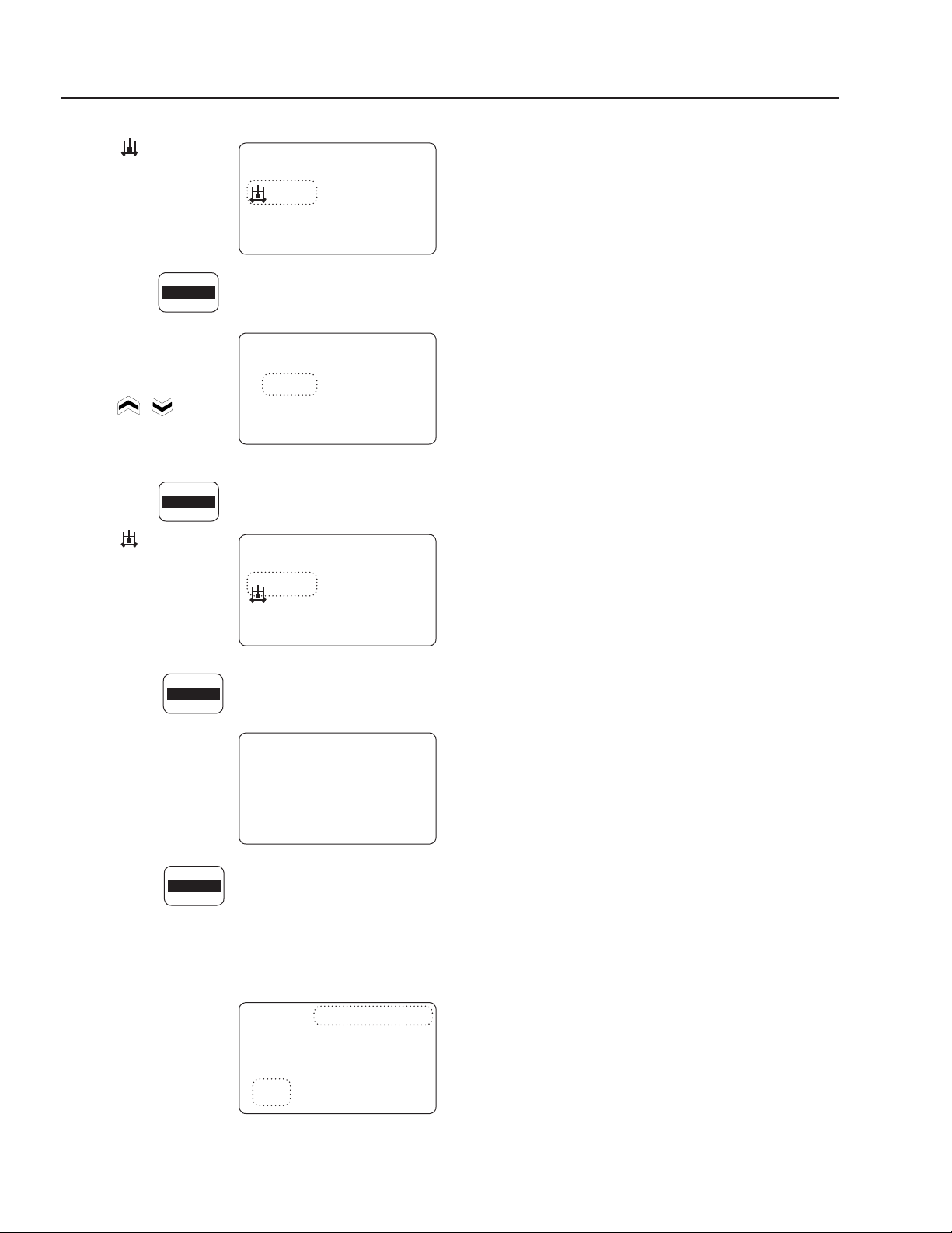
CALIBRATION
Viewing Last Calibra-
tion Data
Press the Calibrate/Hold
5 Sec key once.
'CALIBRATE' will be visible in the upper
right corner of the display screen. Also
displayed will be the 'pH' and '%' (slope) of the previ-
ous calibration. The display will alternate between 'pH'
and '°C'.
'2 Point' indicates that
the previous calibration
was a two-point calibra-
tion.
'1 Point' indicates the
previous calibration was
a one-point calibration.
Re-Calibrating
Calibration must take
place weekly. For two-point calibration, the default set-
tings are Buffer 1 = 7.00 pH and Buffer 2 = 4.00 pH.
1. Hold the 'CALIBRATE/HOLD 5 SEC key
down for five (5) seconds. 'CALIBRATE',
on the display screen,
will start flashing.
2. Press the key again.
'2 point' will start
flashing. The
or
key can be used
to toggle between '1
point' and '2 point'.
Display should be set
to '2 point'.
3. Press the key again.
'MANUAL', in the
lower right corner will
begin to flash. The
or key can
be used to toggle
between 'MANUAL'
and 'ACT'. Display
should be set to 'MANUAL'.
4. Press the key again.
Temperature will be-
gin to flash. Use the
keys to pro-
gram desired buffer
solution temperature.
5. Press the key again.
The 'Buf- fer 1' value will start flashing.
Use the
keys
to program 'Buffer 1'
pH (or leave at 7.0).
6. Press the key again.
RUN
EDIT
of f
Slope
MANUAL
00.0
pH
CALIBRATE
HOLD 5 SEC
10 0
Slope
MANUAL
2 Point
CALIBRATE
-59.1
pH
10 0
Slope
MANUAL
1 Point
CALIBRATE
-59.1
pH
CALIBRATE
HOLD 5 SEC
CALIBRATE
HOLD 5 SEC
2 Point
CALIBRATE
CALIBRATE
HOLD 5 SEC
MANUAL
2 Point
CALIBRATE
CALIBRATE
HOLD 5 SEC
MANUAL
2 Point
CALIBRATE
20
°C
CALIBRATE
HOLD 5 SEC
CALIBRATE
HOLD 5 SEC
7.0
Buffer 1
MANUAL
2 Point
CALIBRATE
7.0
pH
pH
P u mp A
Slope
MANUAL
00.0
pH
r un
1:00
CALIBRATE
10
pH PERMISSIVE CONTROL SYSTEM
OPERATOR’S MANUAL
8.914-301.0-D • PH-3020 Permissive Control System
The symbol will
prompt you to
put the probe in 'Buf-
fer 1'. Wait for the mV
value to settle.
7. Press the key again.
This will accept the
first calibration value
and will display the
'Buffer 2' pH. Use
the
keys to
program 'Buffer 2' to
4.0 pH.
8. Press the key again.
The symbol will
prompt you to put the
probe in 'Buffer 2'.
Wait for the mV value
to settle.
9. Press the key again.
This will accept the
second calibration
value and will display
the mV/pH (and the
'%' Slope) result of
the calibration.
10. Press the key again to accept this
calibration and exit calibration mode. Press any other
key to abort calibration
If the calibration is unsuccessful (slope<70% or offset
< ± 30 mV) an 'ERROR CALIBRATE' and 'E7' are dis-
played; the calibration
should be repeated or
else the controller reverts
to using the 'last success-
ful' calibration performed.
A slope of less than 70%
indicates a dirty/faulty probe or contaminated buffer.
(Refer to page 20 for other error messages.)
FEED RATE ADJUSTMENT
Even though the controller is designed to automatically
maintain the proper chemical levels, there may be some
underfeeding or overfeeding if the feed rates are set
too low or high. This is due to the lag time between the
beginning of chemical feeding and the sensing of those
chemicals by the sensors after recirculation through the
unit and the tank.
If the chemical levels tends to be systematically on the
high side, you should reduce the feed rate of the chemical
feed pump. This is done by removing the enclosure cap
on the front of the pump and turning the screw counter-
clockwise to slow the pump down. If the chemical level is
too low or takes longer than one (1) hour to adjust, raise
pump speed up by turning screw clockwise.
SENSOR MAINTENANCE
To test the sensor, carefully add a very small amount of
white vinegar or a dilute acid solution to the water and
test the probes. The pH reading should go down. If not,
clean or replace the sensor.
Cleaning The pH Sensor
The cleaning of the pH sensor must be done on a weekly
maintenance schedule if used in a moderate to heavy
oil and dirt load; on a monthly maintenance schedule if
used in a low oil and dirt level.
To clean the sensor, do the following:
• Loosen the sensor from the compression tee. With a
Q-Tip and any household degreaser (i.e. 409) spray
and wipe the sensor probe clean. Rinse with clean
water. Dip the probes into a 5% hydrochloric acid
solution (muriatic acid). This solution is effective for
solubilizing hard water deposits that may occur on
the probe.
WINTERIZING AND SHIPPING
NOTICE: For winterizing and shipping, always keep the
sensor above freezing temperature. Make sure to place
the plastic cap on the tip of the sensor and to add a few
drops of water inside the cap to prevent the sensor from
drying out. Shipping and storing a sensor without plastic
cap will void its warranty.
7.0
Buffer 1
MANUAL
2 Point
CALIBRATE
00.0
mV
pH
4.0
Buffer 2
MANUAL
2 Point
CALIBRATE
10.0
pH
pH
CALIBRATE
HOLD 5 SEC
CALIBRATE
HOLD 5 SEC
CALIBRATE
HOLD 5 SEC
CALIBRATE
HOLD 5 SEC
4.0
Buffer 2
MANUAL
2 Point
CALIBRATE
-177.0
mV
pH
10 0
Slope
MANUAL
2 Point
CALIBRATE
-59.1
mV
%
e7
2 Point
ERROR CALIBRATE
30.0
mV / Ph
pH PERMISSIVE CONTROL SYSTEM
OPERATOR’S MANUAL
11
8.914-301.0-D • PH-3020 Permissive Control System
2. CONNECT SUCTION TUBING TO PUMP: Remove
compression fitting. Feed tube through fitting.
NOTE: To soften the end of the tubing, immerse it
in hot water.
3. CONNECT SUCTION TUBING TO STRAINER:
Install strainer so it’s off the bottom of the chemi-
cal container. Cut the suction tubing to the length
needed. Put weight on tubing. Push strainer end into
tubing.
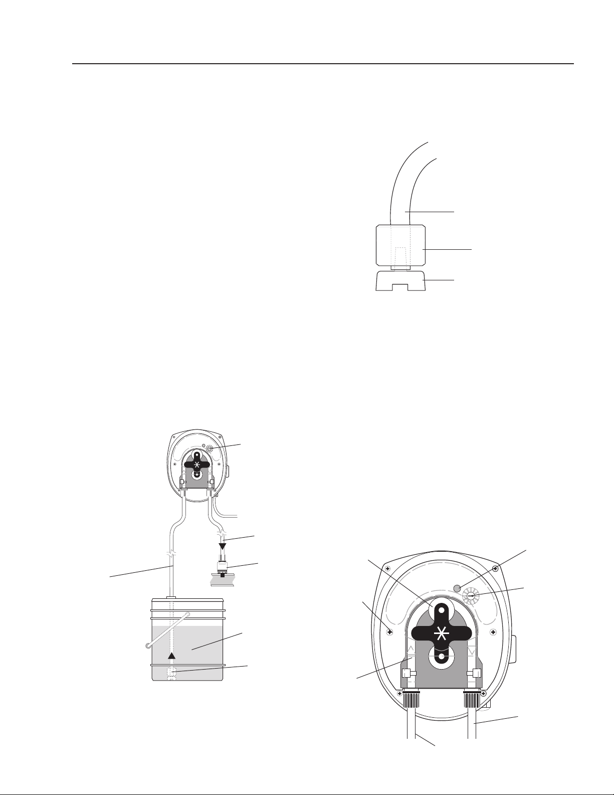
METERING PUMP OPERATION
If not already done, put the end of the suction tubing into
the chemical container, near the bottom.
Move the “ON-OFF” switch to ON. PRIME: To prime
the pump and lines push the 3-way switch to full speed.
FEED ADJUSTMENT: (ONLY A QUALIFIED WATER
MAZE SERVICE TECHNICIAN SHOULD MAKE THIS
ADJUSTMENT.) The feed adjustment is under the cover
plate. Remove the plate and turn the adjusting screws
clockwise to increase feed or counterclockwise to
decrease feed.
Suction Tube
Strainer
Weight
METERING PUMPS
(Variable Speed Peristaltic)
TECHNICAL INFORMATION
Materials:
Squeeze Tubing Special synthetic rubber
Strainer and
Injection Point Fitting PVC
Feed Rate: 1-7 or 8-45 GPD
Tubing Size: 1-7 or 8-45 GPD
Dimensions: Height = 5"
Width = 4"
Depth = 4-1/4"
Standard Accessories Provided with Pump:
• Squeeze Tubing Assembly
• Check Valve
• Strainer w/weight
• Bulkhead fitting w/elbow
Electrical Rating:
• 20-265 VAC
• 7W
• 50/60 Hz
Maximum System Pressure: 45 PSI
INSTALLATION
1. SUCTION TUBING: Take the 5 ft. length of 1/4"
O.D. tubing included, measure and cut the lengths
needed to run from pump head to the chemical tank.
Cut the tubing ends square.
Chemical
Container
Strainer
w/weight
Suction
Tube
Power
Cord
Discharge
Tube
Flow
Adjustment
Check
Valve
Indicator
Light
Speed
Adjusting
Screw w/
Indexing
mark
On-Off-
Full speed
switch (right
or left side)
Dishcharge
Inlet
Pump
Rollers
Cover
Screws
Squeeze
Tube

12
pH PERMISSIVE CONTROL SYSTEM
OPERATOR’S MANUAL
8.914-301.0-D • PH-3020 Permissive Control System
METERING PUMP
MAINTENANCE
DANGER: DO NOT ATTEMPT TO FEED CHEMICALS
WITHOUT CONSULTING YOUR CHEMICAL FEEDER
DEALER OR CHEMICAL SUPPLIER.
DANGER: Ne pas tenter d'alimenter des produits
chimiques sans d'abord consulter le concession-
naire d'alimentation en produits chimiques ou le
fournisseur de produits chimiques.
CAUTION: Wear protective gloves,
goggles, and other adequate pro-
tection for the chemical hazard.
ATTENTION: Porter des gants de
protection, des lunettes étanches
et d'autres protections adéquates
pour les risques chimiques.
Before replacing the pump head,
remove chemical from tubing as
follows:
1. Remove strainer from chemical tank.
2. Run pump until all chemical is removed from the
tubing.
FILLING THE CHEMICAL TANK: To avoid running out,
of chemical, follow a regular schedule of monitoring
chemical supply. Also inspect and clean the strainer by
flushing with a compatible liquid, as needed.
SQUEEZE TUBING INSPECTION: Inspect tubing
regularly and replace it if it is deteriorating.
REPLACING SQUEEZE TUBING:
1. Remove compression fittings from the tubing at the
pump head.
2. Pull the suction and discharge tubing from the pump
head.
3. Remove the front cover from the pump
4. Rotate the pump rollers to a vertical position.
5. Lift the inlet fitting out of the housing.
6. Pull the tube out while rotating the pump rollers clock-
wise.
7 Remove the outlet fitting.
8. Install the inlet fitting for the new tube assembly.
9. Press the tube into place in front of a roller while
rotating the roller assembly clockwise.
10. Install the outlet fitting.
11. Reconnect the suction and discharge lines.
12. Install the front cover.
WARNING
PROTECTIVE
EYEWEAR AND
CLOTHING MUST
BE WORN.
CAUTION: DO NOT LOSE THE BEARING FROM
THE CENTER HOLE IN THE BACK COVER.
ATTENTION: NE PAS DESSERRER LE PALIER DE
TROU CENTRAL DANS LA PLAQUE DU COUVER-
CLE.
CAUTION: Clear or transparent plastic tubing should
be replaced at least every three months if exposed to
the sun. Replace tubing yearly if feeder is installed
indoors.
ATTENTION: Un tube en plastique clair ou transpar-
ent devrait être remplacé au moins tous les trois
mois s'il est exposé au soleil. Remplacer le tube
une fois par année si le dispositif d'alimentation est
installé à l'intérieur.
INSPECT FOR LEAKAGE:
Inspect the chemical system daily for any signs of leak-
age. If leaking occurs at tubing connections, tighten fit-
ting compression nut finger tight. If leakage continues,
remove pressure from the system. Disconnect the tubing,
trim ends square and reconnect.
INSPECT FOR BLOCKED FLOW:
Precipitates or other chemical reactions cause injection
points to clog. If the type of chemical being fed eliminates
the use of flushing solution, the injection point must be
inspected at regular intervals. Strainers must be kept
clean with periodic back-flushing.

pH PERMISSIVE CONTROL SYSTEM
OPERATOR’S MANUAL
13
8.914-301.0-D • PH-3020 Permissive Control System
89143010-1
pH-3020
EXPLODED VIEW
Chemical
Injectors
For
Detail See
Control Panel
Illustration.
pH
Sensor
3
31
23
6
27
26
25
19
26
26
26
5
9
1
2
10
12
Inlet
18
21
28
17
4
22
16
13
37
35
36
14
20
11
8
7
30
38
29
33
32
32
24
34
29
28
15
Outlet

14
pH PERMISSIVE CONTROL SYSTEM
OPERATOR’S MANUAL
8.914-301.0-D • PH-3020 Permissive Control System
pH-3020
PARTS LIST
ITEM PART NO. DESCRIPTION QTY.
1 8.706-397.0 Plug, 3/4" MT, SCH 80 PVC 1
2 8.706-404.0 Bushing, 1-1/2" x 1"
MT x FT, PVC 80 1
3 8.749-858.0 Adapter, PVC 1" S x 1/2" FT 2
4 8.706-421.0 Hanger, Pipe, 1-1/2"
Click #47 2
5 8.706-430.0 Tee, 1" S x S, PVC 80 4
6 8.706-447.0 Adapter, 1", 3/4" S x FIPT,
PVC 80 2
7 9.802-064.0 Grommet, Rubber,
Nozzle Holder 2
8 9.802-065.0 Grommet, 1-5/16 Rubber,
Drum Cleaner, MB2802 1
9 8.706-597.0 Union, 1", S x S, PVC 80 2
10 8.917-759.0 Pump, 3/4HP, 115V, 1Ph 1
11 8.749-855.0 Pump, Peristaltic, 8-45 gpd 2
12 9.802-436.0 Cord, SERV, SEO, 10/3 Ft.
Coleman 16 ft
13 8.716-052.0 Switch, Curvette
ON-OFF-ON/RC911RB-B-0-N 2
14 9.802-455.0 Light, Indicator, Green 125V 1
15 8.716-142.0 Switch, Float, N/O,
.20PMDWOP, 1003825
(Black) 1
16 8.716-999.0 Controller, PH LMI,
DP5000-1A-0 1
17 8.717-003.0 Mixer, TAHStatic, 05-021 1
18 8.921-708.0 Cover, Panel 1
19 8.716-137.0 Switch, Flow, 1" PVC,
Model 225 1
ITEM PART NO. DESCRIPTION QTY.
20 9.802-514.0 Strain Relief, STRT, LQ TITE
3231 Small 14
21 8.913-227.0 Stand, Welded Assembly,
pH System 1
22 8.913-230.0 Bracket, Controller Mount,
pH Stand 1
23 8.717-001.0 ▲ Probe Cable, 10" 1
8.717-000.0 Probe, Sensor EX, pH 1
24 8.749-860.0 Check Valve, PVC, 1/8" MT 2
25 8.706-409.0 Adapter, 1" MT x S 1
26 8.706-373.0 Elbow, 1" S x S 6
27 8.717-002.0 Probe, Mounting Gland 1
28 8.706-409.0 Adapter, 1" MT x S 2
8.706-405.0 ▲ Bushing, 1-1/4" x 1" 2
29 8.706-366.0 Pipe, 1", PVC 80 1 ft
30 8.706-361.0 Pipe, 1", PVC Clear 3 ft
31 8.749-861.0 Bulkhead, PVC, 3/8",
w/Elbow
(remove nut and washers) 2
32 8.749-857.0 Tubing, 1/4", PE, Black 12 ft
33 8-718-941.0 Screw, # 10 x 5/8", Tek 4
34 8.750-270.0 Fitting, Compression, 1-1/2" 1
35 9.802-765.0 Screw, 1/4-20 X 1/2",
BH Black 4
36 9.802-759.0 Screw, 10/32" x 1/2"
BHSOC BLK 4
37 9.802-791.0 Nut, Cage,
10/32"" X 16 GA 4
38 8.718-817.0 Nut, 1/4-20,
Whiz Loc Flange, SS 4
▲ Not Shown
pH PERMISSIVE CONTROL SYSTEM
OPERATOR’S MANUAL
15
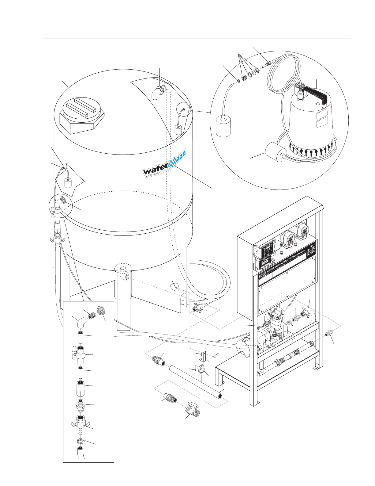
8.914-301.0-D • PH-3020 Permissive Control System
89143010-2
AUTO-FILL/HOLDING TANK
OPTIONS
310 Gallon
Holding Tank
Float Switch
N/O
HOLDING TANK
Option #8.903-681.0
AUTO-FILL OPTION
#8.903-682.0
Hi-Limit Float
N/C Switch
Assembly
Sump Float Switch
N/O
Sump Pump
1
3
2
5
5
4
2
1
6
4
6
5
7
13
15
3
8
10
10
11
9
12
11
20
19
17
19
18
17
14
14
15
16
19
17
16
21
23
22

16
pH PERMISSIVE CONTROL SYSTEM
OPERATOR’S MANUAL
8.914-301.0-D • PH-3020 Permissive Control System
HOLDING TANK OPTION #89036810
PARTS LIST
AUTO-FILL OPTION #89036820
PARTS LIST
ITEM PART NO. DESCRIPTION QTY.
1 8.715-364.0 Pump, Grundfos 1/2 HP Sump SS, AP-12, 120V 1
2 8.716-142.0 Switch, Float, N/O, .20 PMDWOP, #1003825 (Black) 1
3 8.716-143.0 Switch, Float, N/C, #1003826 (Gray) 1
4 8.750-743.0 Bulkhead, 1/2" Polypro 1
5 9.802-514.0 Strain Relief, STRT, LQ TITE 3231 Small 1
DIMENSIONS, WEIGHTS & ELECTRICAL
MODEL
HP
VOLTS
PHASE
AMPS
SHIPPING
WEIGHT
SHIPPING CARTON
L x W x H
PACKING
VOL.
Cu. Ft.
MAX.
WATER
TEMP.
AP12 .5
(.37 kw)
115 1 8 24 lbs.
(10.9 kg)
7-3/4" x 7-3/4" x 12-3/4"
(19.69 x 19.69 x 32.39 cm)
0.5
(.014 cu. m)
131°F
(55°)
Performance Table
Model 5 Ft.
1.52 m
10 Ft.
3.05 m
15 Ft.
4.57 m
20 Ft.
6.10 m
25 Ft.
7.62 m
AP-12 72 gpm
(272 lpm)
64 gpm
(242 lpm)
56 gpm
(212 lpm)
44 gpm
(166 lpm)
30 gpm
(113 lpm)
ITEM PART NO. DESCRIPTION QTY.
1 8.719-173.0 Tank, 310 Gallon
CONE BTM. w/Stand 1
2 8.706-490.0 Bulkhead, 1-1/2" POLYPRO 1
3 8.711-811.0 Hose, 1", Gray Spiralite, /Ft. 30ft
4 8.707-349.0 Valve, 2" Single Union Ball 1
5 8.706-583.0 Pipe, 2" Gray, PVC 80 19"
6 8.706-451.0 Adapter, 2" Slip x MT
PVC 801 2
7 9.802-514.0 Strain Relief, STRT, LQ TITE
3231 Small 1
8 8.900-803.0 Label, Water Maze, Logo
Small 1
9 8.706-487.0 Hanger, 2", Click #59 Pipe 1
10 8.718-812.0 Screw, 10/32 x 3/4"
BH SOC SS 2
11 9.802-695.0 Nut, 10/32" Keps 2
12 8.919-049.0 Bracket, Pipe Hanger 1
13 8.750-743.0 Bulkhead, 1/2" Polypro 1
ITEM PART NO. DESCRIPTION QTY.
14 8.706-366.0 Pipe, 1", PVC SCH 80
2.5" Long 2
15 8.706-484.0 Bulkhead, 1", Polypro 2
16 8.706-404.0 Bushing, 1.5" x 1" MT x FT
PVC 80 2
17 8.706-707.0 Adapter, 1" MT x 1" MT
CAML 3
18 8.706-444.0 Adapter, Female, 1" Slip x FT
PVC 80 1
19 8.706-709.0 Coupler, 1" FT x 1" Hose Barb
CAMLO 3
20 9.803-629.0 Clamp, Screw 9/16" W
1-1/2" OD, SS 2
21 8.706-439.0 Nipple, 1" PVC 80, Close 1
22 8.706-359.0 Valve, 1'S PVC 80 S x S
Mold In Place BA 1
23 8.706-378.0 Elbow, I" Slip x FPT
PVC 80 90° 1
pH PERMISSIVE CONTROL SYSTEM
OPERATOR’S MANUAL
17
8.914-301.0-D • PH-3020 Permissive Control System
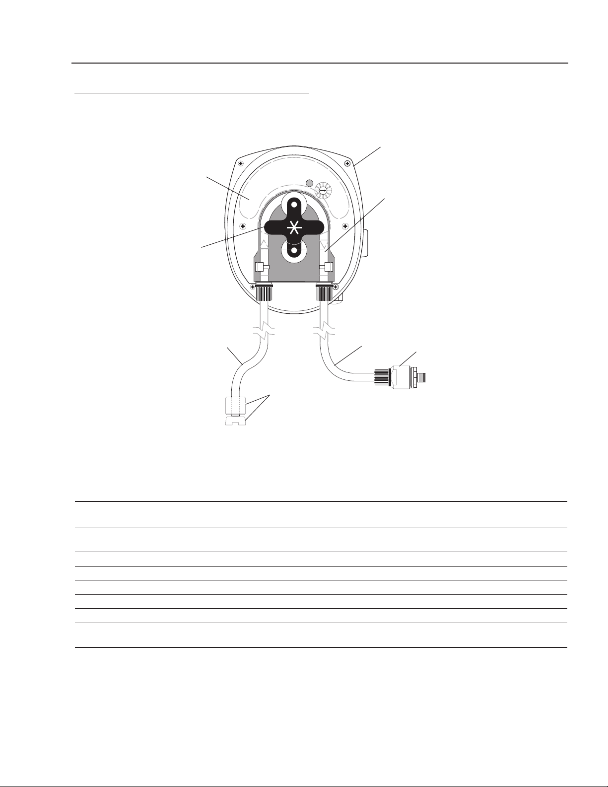
METERING PUMP AND PARTS LIST
ITEM PART NO. DESCRIPTION QTY
1 8.749-855.0 Pump, Peristaltic, PR-7, 8-45 gpd 1
8.749-856.0 Pump, Peristaltic, PRS-1,1-7 gpd 1
2 8.749-862.0 Tube, Squeeze, Santoprene, PR-7, * 8-45 gpd 1
8.749-864.0 Tube, Squeeze, Santoprene, PRS-1, * 1-7 gpd 1
3 8.749-860.0 Check Valve, PVC 1
4 8.749-857.0 Tubing, 1/4", PE, Black AR
5 8.749-863.0 Strainer, w/welght 1
6 8.711-737.0 Tubing, 1/8", ID Norprene AR
7 8.751-801.0 Faceplate, PRS-1/PR-7 1
8 8.751-375.0 Roller Assembly, PR-7 1
8.751-376.0 Roller Assembly, PRS-1 1
* Alternative tubing materials are available
1
2
6
3
4
7
8
5
18
pH PERMISSIVE CONTROL SYSTEM
OPERATOR’S MANUAL
8.914-301.0-D • PH-3020 Permissive Control System
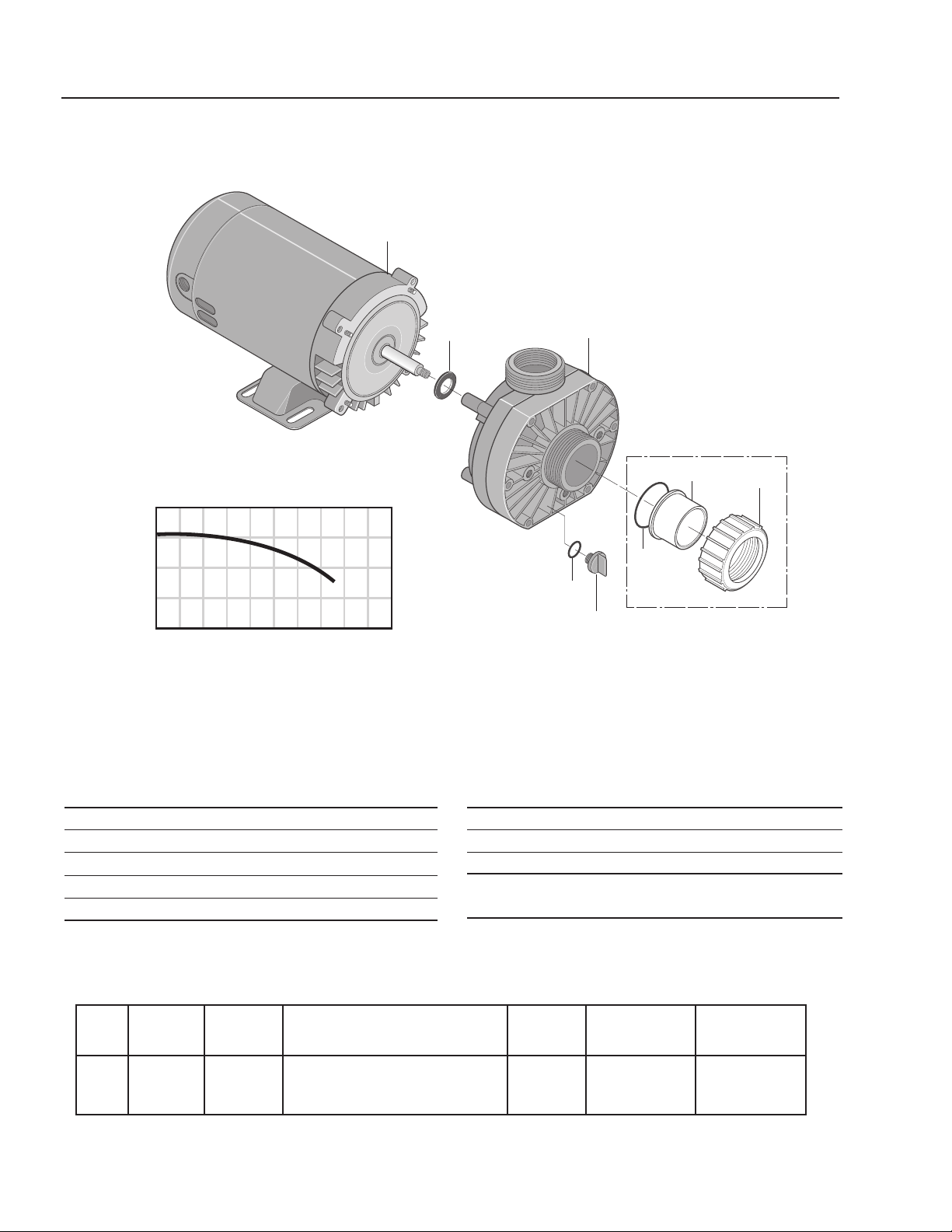
ITEM PART NO. DESCRIPTION QTY
1 8.726-025.0 Motor, 3/4 HP,115V 1
2 NA Slinger 1
3 8.726-024.0 Pump, 3/4 HP, Wet End 1
4 NA Drain Plug 1
5 NA O-Ring, Drain Plug 1
HP Volts Phase
Size
Inlet Outlet
Running
Amps
Max.
Pressure
Max.
Water Temp.
3/4 115V 1 1-1/2" FPT/ 1-1/2"FPT/
1-1/2" MBT 1-1/2" MBT
10.0 40 PSI 104°F/40°
ITEM PART NO. DESCRIPTION QTY
6 NA O-Ring 1
7 NA Adapter, Union 1
8 NA Collar, Union 1
Kit:
6-8 8.750-270.0 Fitting, Compression, 1-1/2" Slip
Pump
Part # 8.917-759.0
40
20
0
20 40 60 80
U.S. GALLONS PER MINUTE
TOTAL HEAD IN FEET
1
2
3
4
5
6
7
8
pH PERMISSIVE CONTROL SYSTEM
OPERATOR’S MANUAL
19
8.914-301.0-D • PH-3020 Permissive Control System
17
8
9
10
10
11
16
12
15
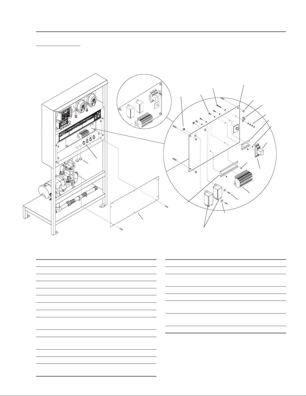
89143010-5
ELECTRICAL
CAUTION: DISCONNECT ALL LIVE POWER AT THE SOURCE BEFORE
WORKING ON THE ELECTRICAL SYSTEM.
ITEM PART # DESCRIPTION QTY
1 8.716-396.0 Block, Terminal 9
8.716-398.0 ▲ Block Terminal, Blue 2
8.716-399.0 ▲ End Cover 1
8.716-401.0 ▲ Partition Plates 2
8.716-402.0 ▲ Bridge, Fixed 1
9.804-609.0 ▲ Marker, Blank 1
2 9.802-468.0 Relay, 120V, RH2B-UL-AC120 1
3 9.802-467.0 Base, Relay, SH2B-05, IDEC 1
4 8.716-264.0 Relay, SKY MFG, 120V
# SKHT-1X 2
5 9.802-105.0 Plug, 7/8", Hole 2
6 9.802-514.0 Strain Relief, STRT, LQ TITE
3231, Small 14
7 8.921-708.0 Cover, Panel 1
8 8.718-871.0 Nut, .50 ID, Push Flat 4
9 8.716-460.0 Terminal, Grounding
Lug, LAMA6-14-Q 1
ITEM PART # DESCRIPTION QTY
10 9.802-695.0 Nut, 10/32" KEPS 8
11 9.802-457.0 Din Rail,35MM 2"
12 9.802-759.0 Screw, 10/32" x 1/2"
BHSOC BLK 8
13 8.718-968.0 Washer, 10 X SAE ZN 4
14 9.802-457.0 Din Rail,35MM 4"
15 9.802-791.0 Nut, Cage,
10/32"" X 16 GA 4
16 9.802-762.0 Screw, 10/32" x 1-1/4" RH,
SL, BLK 1
17 8.913-229.0 Stand Off, PH Stand 1
▲ Not Shown
Power In
Auto Fill
Option
6
5
4
1
12
13
14
2
3
7
10

20
pH PERMISSIVE CONTROL SYSTEM
OPERATOR’S MANUAL
TROUBLESHOOTING
8.914-301.0-D • PH-3020 PERMISSIVE CONTROL SYSTEM
ACID OR BASE PUMP NOT TURNING ON
PROBLEM POSSIBLE CAUSE SOLUTION
NO VOLTAGE LIGHT
Breaker not on Turn breaker on.
GFCI tripped Reset.
Bad lamp Replace.
MIX PUMP WON'T
TURN ON
Switch not in auto position
Put switch in auto position.
Float in feed tank is in down position Fill tank.
No voltage to pump Check continuity through mix
pump switch.
Thermal protect on motor tripped Let motor cool.
SUMP PUMP WON'T
TURN ON
Switch not in auto position Put switch in auto position.
Low water float in pit is in the down
position
Fill pit.
Is upper shut-off float in feed tank in
the upper position
Drain tank.
ACID OR BASE PUMP
NOT TURNING ON
Pump switch off Turn on.
pH within 6.5 - 7.5 Desired range. Pumps not required to
be on.
Mix Pump not on See above Mix Pump troubleshooting.
Bad Idec relay Replace relay.
Fuse in pump blower Replace fuse.
Flow switch not activated with pump
on
Jumper #1 and #2 on controller
terminal TB4.
pH PERMISSIVE CONTROL SYSTEM
OPERATOR’S MANUAL
21
8.914-301.0-D • PH-3020 Permissive Control System
PREVENTATIVE MAINTENANCE
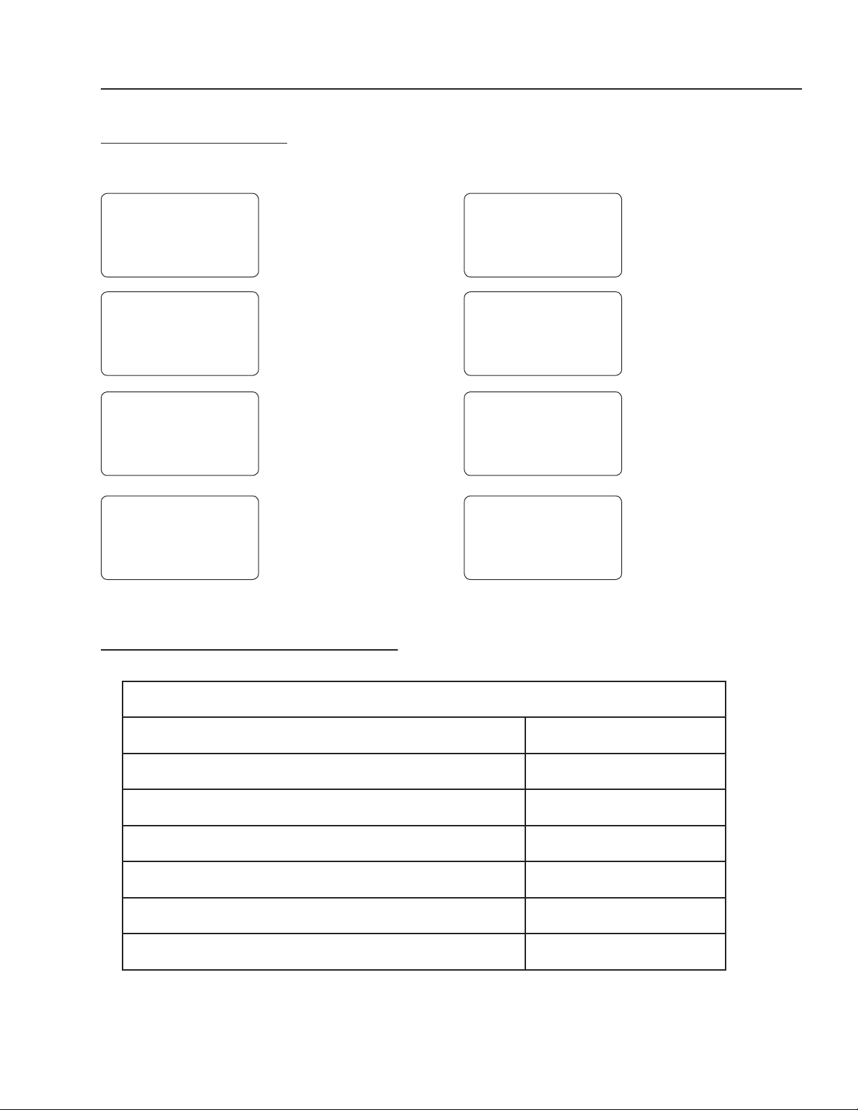
ERROR MESSAGES
Turn System off to clear error message.
E1
E2
E3
E4
E5
E6
e7
E9
E1 = LOW LEVEL
SWITCH
E2 = FLOW SWITCH
E3 = ALARM 1:
LOW pH (PUMP B)
E4 = ALARM 2:
LOW pH (PUMP A)
E5 = PUMP B
'LOCKOUT'
E6 = PUMP A
'LOCKOUT'
E7 = CALIBRATION
ERROR - Probe
is out of Manufac-
turer's
Limits
E9 = FAULTY or
DISCONNECTED
PROBE
MAINTENANCE SCHEDULE
Check plumbing for leaks. Check Daily
Check chemical tubing for leaks and deterioration. Check Daily
Drain cone bottom on tank. Drain Daily
Clean and calibrate probe.* Maintain Weekly
Suction out pit.* Maintain Monthly
Clean sump pump and float.* Clean Monthly
Check and clean chemical strainers.* Maintain Monthly
*NOTE: This is a guide. Depending on your wash load, these items may have to be done more or less often.

pH PERMISSIVE CONTROL SYSTEM OPERATOR’S MANUAL
22
WATER MAZE LIMITED NEW PRODUCT WARRANTY
WASH-WATER SYSTEMS
WHAT THIS WARRANTY COVERS
All WATER MAZE wash-water systems are warranted by WATER MAZE to the original purchaser to be free from defects in materi-
als and workmanship under normal use, for the periods specified below. This Limited Warranty, subject to the exclusions shown
below, is calculated from the date of the original purchase, and applies to the original components only. Any parts replaced under
this warranty will assume the remainder of the part’s warranty period. A 60 day grace period will be given for installation.
ONE YEAR PARTS AND 30 DAY LABOR WARRANTY:
All components excluding normal wear items as described below.
WARRANTY PROVIDED BY OTHER MANUFACTURERS:
Motors, which are warranted by their respective manufacturers, are serviced through these manufacturers’ local authorized
service centers. WATER MAZE cannot provide warranty on these items.
NON-WARRANTY REPLACEMENT PARTS:
These parts, excluding normal wear items as described below, will be warranted for the duration specified by the original com-
ponent manufacturer. O-rings and leaks at glued fittings are covered the first time on original start-up only.
WHAT THIS WARRANTY DOES NOT COVER
This warranty does not cover the following items:
1. Normal wear items, such as mechanical seals, filters, gaskets, O-rings, check valves, filtering media, ozone bulbs.
O-rings and leaks at glued fittings are covered the first time on original start-up only.
2. Damage or malfunctions resulting from accidents, abuse, modifications, alterations, incorrect installation, improper
servicing, failure to follow manufacturer’s maintenance instructions, or use of the equipment beyond its stated usage
specifications as contained in the operator’s manual.
3. Damage due to freezing, chemical deterioration (oxidation, chloride or fluoride corrosion).
4. Damage to components from fluctuations in electrical or water supply.
5. Normal maintenance service, including adjustments.
6. Transportation to service center, field labor charges, or freight damage.
7. Death of microbes (Biostax 900 & 100) from lack of refrigeration after received and stored.
WHAT YOU MUST DO TO OBTAIN WARRANTY SERVICE
While not required for warranty service, we request that you register your WATER MAZE Product by returning the completed
registration card. In order to obtain warranty service on items warranted by WATER MAZE, you must return the product to your
Authorized WATER MAZE Dealer, freight prepaid, with proof of purchase, within the applicable warranty period. If the product is
permanently installed, you must notify your Authorized WATER MAZE Dealer of the defect. Your Authorized WATER MAZE Dealer
will file a claim with WATER MAZE, who must subsequently verify the defect. In most cases, the part must be returned toWATER
MAZE freight prepaid with the claim. For warranty service on components warranted by other manufacturer’s, your Authorized
WATER MAZE Dealer can help you obtain warranty service through these manufacturers’ local authorized service centers.
LIMITATION OF LIABILITY
WATER MAZE’S liability for special, incidental, or consequential damages is expressly disclaimed. In no event shall
WATER MAZE’S liability exceed the purchase price of the product in question. WATER MAZE makes every effort to ensure that
all illustrations and specifications are correct, however, these do not imply a warranty that the product is merchantable or fit for a
particular purpose, or that the product will actually conform to the illustrations and specifications. THE WARRANTY CONTAINED
HEREIN IS IN LIEU OF ALL OTHER WARRANTIES, EXPRESS OR IMPLIED, INCLUDING ANY IMPLIED WARRANTY OF
FITNESS FOR THE PARTICULAR PURPOSE, INCLUDING QUALITY OF WATER TREATMENT. WATER MAZE does not au-
thorize any other party, including authorized WATER MAZE Dealers, to make any representation or promise on behalf of WATER
MAZE, or to modify the terms, conditions, or limitations in any way. It is the buyer’s responsibility to ensure that the installation
and use of WATER MAZE products conforms to local codes. While WATER MAZE attempts to assure that its products meet
national codes, it cannot be responsible for how the customer chooses to use or install the product.
WATER MAZE
www.wmaze.com • 1-360-833-2333 • 1-800-535-0941
8.914-301.0-D • PH-3020 Permissive Control System


8.914-301.0 • Printed in U.S.A.