Loading ...
Loading ...
Loading ...
15
ENG
ENGLISH
LVDSPINMAPGUIDE
Note:1.AllGND(ground)pinsshouldbeconnectedtogethertotheLCDmodule’smetalframe.
2.AllVLCD(powerinput)pinsshouldbeconnectedtogether.
3.AllInputlevelsofLVDSsignalsarebasedontheEIA644Standard.
4.#1~#6~#10NC(NoConnection)ThesepinsareusedonlyforLGD(Donotconnect)
5.SpecificpinNo.#44isusedforNosignaldetectionofsystemsignalinterface.
ItshouldbeGNDforNSB(NoSignalBlack)duringthesysteminterfacesignalisnot.
IfthispinisH,LCDModuledisplaysAGP(AutoGenerationPattern).
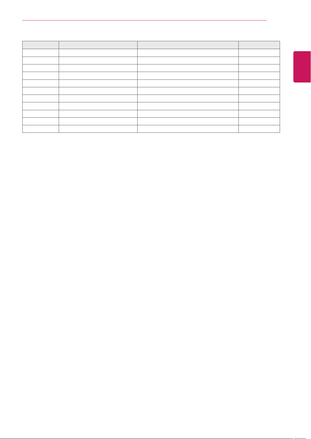
PinNo. Symbol Description Note
41 NC NoConnection 4
42 NCorGND NoConnectionorGround
43 NCorGND NoConnectionorGround
44 GND Ground 5
45 GND Ground
46 GND Ground
47 NC NoConnection
48 VLCD PowerSupply+12.0V 2
49 VLCD PowerSupply+12.0V 2
50 VLCD PowerSupply+12.0V 2
51 VLCD PowerSupply+12.0V 2
Loading ...