Owner's Manual
NOTE TO EQUIPMENT OWNER:
Please read this Owner’s Information Manual carefully before installing and using this appliance
and keep this manual for future reference.
For your convenience, please record the model and serial numbers of your new equipment in the
spaces provided. This information, along with the installation data and dealer contact information,
will be helpful should your system require maintenance or service.
UNIT INFORMATION
Model # ___________________________________
Serial # ___________________________________
INSTALLATION INFORMATION
Date Installed _____________________________
DEALERSHIP CONTACT INFORMATION
Company Name: _________________________________
Address:_________________________________________
________________________________________________
Phone Number:__________________________________
Technician Name:_________________________________
________________________________________________
40MB*D
Ducted Heat Pump Split System
Sizes 09 to 48
TABLE OF CONTENTS
PAGE
A NOTE ABOUT SAFETY. . . . . . . . . . . . . . . . . . . . . . . . . . . . . . . . . . . . . . . . . . . . . . . . . . . . . . . . . . . . . . . . . . . . . . . . . . . . . . . . . . . 2
MODEL NUMBER NOMENCLATURE . . . . . . . . . . . . . . . . . . . . . . . . . . . . . . . . . . . . . . . . . . . . . . . . . . . . . . . . . . . . . . . . . . . . . . . 2
GENERAL . . . . . . . . . . . . . . . . . . . . . . . . . . . . . . . . . . . . . . . . . . . . . . . . . . . . . . . . . . . . . . . . . . . . . . . . . . . . . . . . . . . . . . . . . . . . . . . . 3
IMPORTANT SAFETY INFORMATION . . . . . . . . . . . . . . . . . . . . . . . . . . . . . . . . . . . . . . . . . . . . . . . . . . . . . . . . . . . . . . . . . . . . . . 4
PARTS NAMES . . . . . . . . . . . . . . . . . . . . . . . . . . . . . . . . . . . . . . . . . . . . . . . . . . . . . . . . . . . . . . . . . . . . . . . . . . . . . . . . . . . . . . . . . . . 5
REMOTE CONTROL OPERATION . . . . . . . . . . . . . . . . . . . . . . . . . . . . . . . . . . . . . . . . . . . . . . . . . . . . . . . . . . . . . . . . . . . . . . . . . . 6
REMOTE CONTROL FUNCTIONS . . . . . . . . . . . . . . . . . . . . . . . . . . . . . . . . . . . . . . . . . . . . . . . . . . . . . . . . . . . . . . . . . . . . . . . . . . 7
USING THE REMOTE CONTROL . . . . . . . . . . . . . . . . . . . . . . . . . . . . . . . . . . . . . . . . . . . . . . . . . . . . . . . . . . . . . . . . . . . . . . . . . . . 10
AIR CONDITIONER OPERATIONS AND PERFORMANCE . . . . . . . . . . . . . . . . . . . . . . . . . . . . . . . . . . . . . . . . . . . . . . . . . . . . . 19
MAINTENANCE . . . . . . . . . . . . . . . . . . . . . . . . . . . . . . . . . . . . . . . . . . . . . . . . . . . . . . . . . . . . . . . . . . . . . . . . . . . . . . . . . . . . . . . . . . 19
HINTS FOR ECONOMICAL OPERATION . . . . . . . . . . . . . . . . . . . . . . . . . . . . . . . . . . . . . . . . . . . . . . . . . . . . . . . . . . . . . . . . . . . . 19
FOLLOWING SYMPTOMS ARE NOT AIR CONDITIONER TROUBLES . . . . . . . . . . . . . . . . . . . . . . . . . . . . . . . . . . . . . . . . . . 21
TROUBLESHOOTING . . . . . . . . . . . . . . . . . . . . . . . . . . . . . . . . . . . . . . . . . . . . . . . . . . . . . . . . . . . . . . . . . . . . . . . . . . . . . . . . . . . . . 22
SUMMARIZE. . . . . . . . . . . . . . . . . . . . . . . . . . . . . . . . . . . . . . . . . . . . . . . . . . . . . . . . . . . . . . . . . . . . . .. . . . . . . . . .. . . . . . . . . . . . . . 28
SAFETY PRECAUTION. . . . . . . . . . . . . . . . . . . . . . . . . . . . . . . . . . . . . . . . . . . . . . . . . . . . . . . . . . . . . . . . . . . . . . . . . . . . . . . . . . . . . 27
FUNCTION SUMMARY. . . . . . . . . . . . . . . . . . . . . . . . . . . . . . . . . . . . . . . . . . . . . . . . . . . . . . .. . . . . . . . . . . . . . . . . . . . . . . . . . . . . 28
NAME AND FUNCTION OF INDICATORS ON THE WIRE CONTROLLER.. . . . . . . . . . . . . . . . . . . . . . . . . . . . .. . . . . . . . . . . 29
INSTALLATION METHOD. . . . . . . . . . . . . . . . . . . . . . . . . . . . . . . . . . . . . . . . . . . . . . . . . . . . . . . . . . . . . .. . . . . . . . . . . . . . . . . . . . 30
NAME AND OPERATION OF THE BUTTON ON THE WIRE CONTROL- LER. . . . . . . . . . . . . . .. . . . . . . . . . . . . . . . . . . . . 31
USING METHOD. . . . . . . . . . . . . . . . . . . . . . . . . . . . . . . . . . . . . . . . . . . . . . . . . . . . . . . . . . . . . . . . . . . . . . . . . .. . . . . . . . . . . . . . . . 33
TECHNICAL INDICATION AND REQUIREMENT . . . . . . . . . . . . . . . . . . . . . . . . . . . . . . . . . . . . . . . . . . . . . . . . . . . . . . . . . . . . . 35
A NOTE ABOUT SAFETY
Any time you see this symbol in manuals, instructions and on
the unit, be aware of the potential for personal injury. There are
three levels of precaution:
DANGER identifies the most serious hazards which will result in
severe personal injury or death.
WARNING signifies hazards that could result in personal injury or
death.
CAUTION is used to identify unsafe practices which could result
in minor personal injury or product and property damage.
NOTE is used to highlight suggestions which will result in
enhanced installation, reliability, or operation.
PERSONAL INJURY, DEATH AND / OR PROPERTY
DAMAGE HAZARD
Failure to follow this warning could result in personal injury,
death or property damage.
Improper installation, adjustment, alteration, service,
maintenance, or use can cause explosion, fire, electrical shock,
or other conditions which may cause personal injury or
property damage. Consult a qualified installer, service agency,
or your distributor or branch for information or assistance. The
qualified installer or service agency must use
factory--authorized kits or accessories when modifying this
product.
Read and follow all instructions and warnings, including labels
shipped with or attached to unit before operating your new air
conditioner.
!
WARNING
GENERAL
The high wall fan coil unit provides quiet, maximum comfort. In
addition to cooling and/.
IMPORTANT: The high wall fan coil unit should be installed by
authorized personnel only; using approved tubing and accessories.
If technical assistance, service or repair is needed, contact the
installer.
The high wall fan coil unit can be set up and operated from the
remote control (provided). If the remote is misplaced, the system
can be operated from the “Auto” setting on the unit.
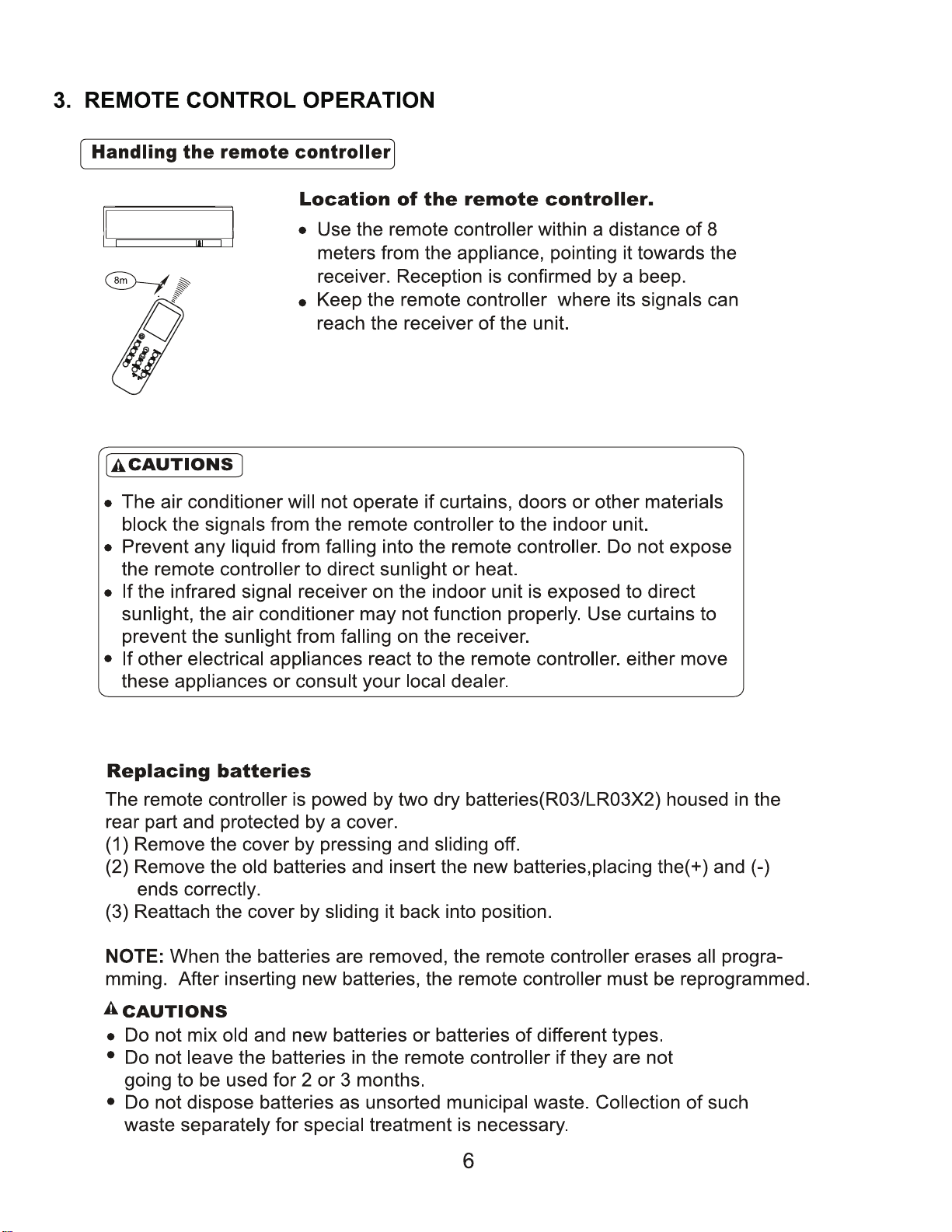
Operating Mo
five operating modes.
S Fan only
S Auto
S Heating (heat pump models only)
S Cooling
S Dehumidification (DRY)
Fan Only
In Fan Only mode, the system filters and circulates room air
without changing room air temperature.
Auto
In Auto mode, the system will automatically cool or heat the room
according to the user--selected set point.
Heating
In Heating mode, the system heats and filters room air.
Cooling
In Cooling mode, the system cools, dries and filters room air.
Dehumidification (DRY)
In Dehumidification mode, the system dries, filters and slightly
cools room air temperature. This mode prioritizes air
dehumidification but it does not take the place of a dehumidifier.
Remote Control
The remote control transmits commands to set up and operate the
system. The control has a window display panel that shows the
current system status. The control can be secured to a surface
when used with the mounting bracket provided.
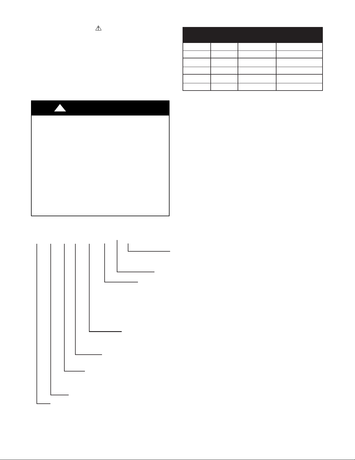
Model number Nomenclature
Model Numbers
The first two digits indicate the equipment type.
40 = Indoor unit;
38 = Outdoor uni
Digit 5 indicates the system's type:
C = Cooling only;
Q = Heat pump
Maximum Number of fan coil units connected to the outdoor unit
B = 1:1
Digits 7, 8 indicate the system's capacity in 1000
BTU/Hr
Example: 09 = 9000 BTU/Hr
Digit 9 - Indoor Fan Coil Unit Type
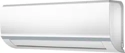
B = High-Wall
C = Cassette
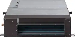
D = Ducted
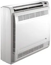
F = Console
G = Underceiling
H = High Wall Color Variation
- = Outdoor
Digit 12 indicates voltage
1 = 115/l/60
3 = 208-230-1-60Hz
40 MA Q B 09 B -- 3
Digits 10, 11 - blank
Digits 3 and 4 represent the model
Unit Tons Unit Btuh
0.75 9,000
12,000
18,000
208/230-1 40MBQB09D--3
40MBQB12D--3
40MBQB18D--3
208/230-1
208/230-1
1
1.5
24,000 40MBQB24D--3208/230-12
36,000 40MBQB36D--3208/230-13
48,000 40MBQB48D--3208/230-14
Indoor Model
Number
Volt- Ph @
60Hz
2
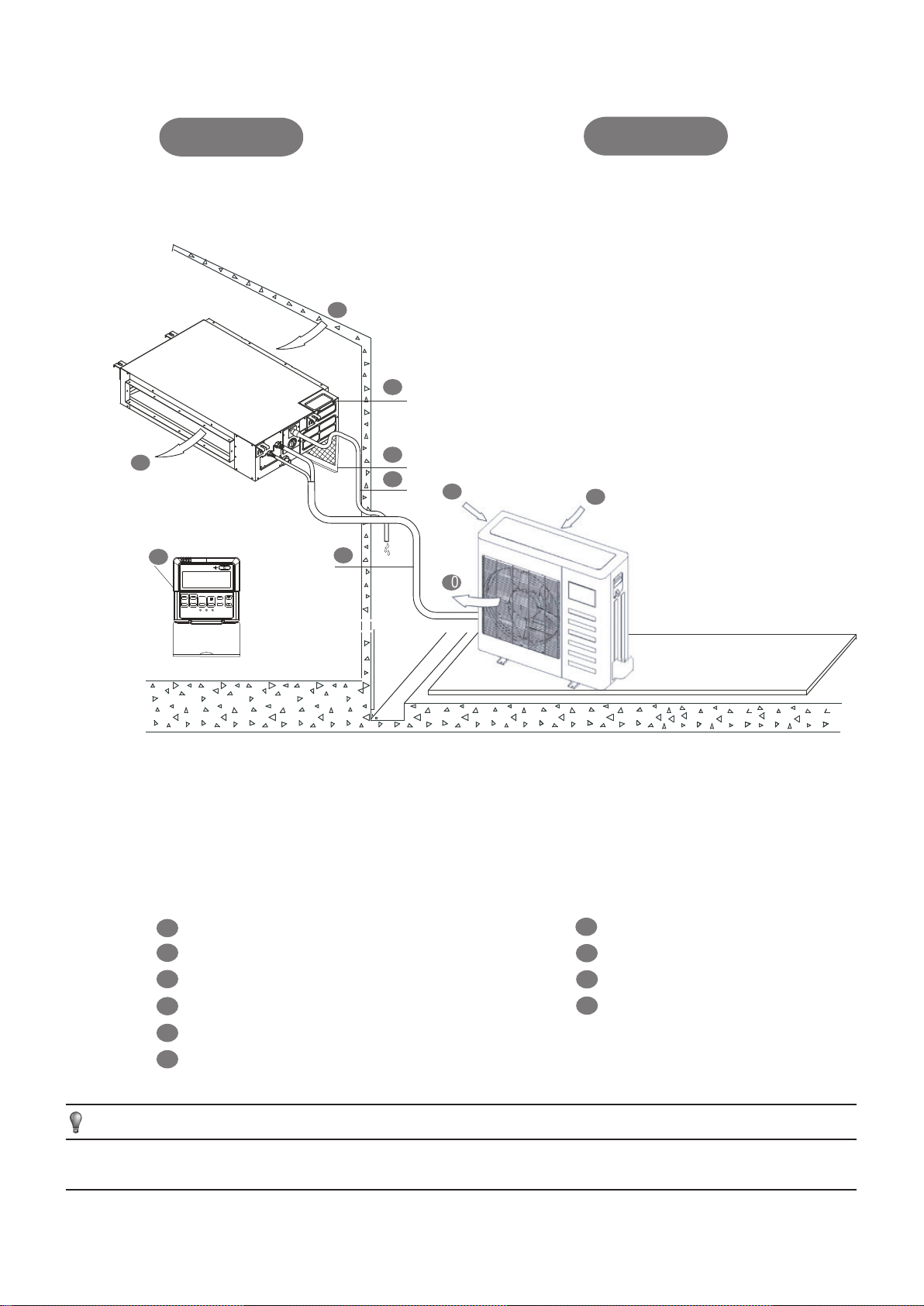
INDOOR UNIT
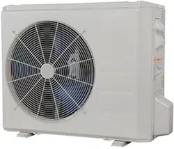
OUTDOOR UNIT
Wire controller(on some models)
Air filter(on some models)
Air inlet(side and rear)
Air outlet
Fig.1
1
2
3
4
5
6
7
8
9
10
Electric control cabinet
1
2
3
4
5
6
7
8
9
10
Connecting pipe
Air inlet
Drain pipe
Air outlet
Air inlet
INDOOR UNIT
OUTDOOR UNIT(A,B,C)
M
NOTE
All the pictures in this manual are for explanation purpose only. They may be slightly different from the air conditioner
you purchased(depend on model).The actual shape shall prevail.
(A)
3
1. IMPORTANT SAFETY INFORMATION
To prevent injury to the user or other people and property
damage, the following instructions must be followed. Incorrect
operation due to ignoring of instructions may cause harm or
damage.
Ask your dealer for installation of the air conditioner.
Incomplete upgrades may result in a water leakage, electric
shock, and fire.
Ask your dealer for upgrades, repair, and maintenance.
Incomplete improvement, repair, and maintenance may result
in a water leakage, electric shock, and fire.
In order to avoid electric shock, fire or injury, or if you
detect any abnormality such as a burning smell, turn off
the power supply and call your dealer for instructions.
Never let the indoor unit or the remote controller get wet.
It may cause an electric shock or a fire.
Never press the button of the remote controller with a
hard, pointed object.
The remote controller may be damaged.
Never replace a fuse with that of another rate or other
wires when a fuse blows out.
Use of wire or copper wire may cause the unit to break down
or cause a fire.
Do not use the air conditioner for other purposes.
In order to avoid any quality deterioration, do not use the unit
for cooling precision instruments, food, plants, animals or
works of art.
Before cleaning, be sure to stop the operation, turn the
breaker off or pull out the supply cord.
Otherwise, an electric shock and injury may result.
In order to avoid electric shock or fire, make sure that an
earth leak detector is installed.
Be sure the air conditioner is grounded.
In order to avoid electric shock, make sure that the unit is
grounded and that the earth wire is not connected to gas or
water pipe, lightning conductor or telephone earth wire.
Do not expose your body to the air flow for a long time.
Do not insert fingers, rods or other objects into the air
inlet or outlet.
When the fan is rotating at high speed, it will cause injury.
Never use a flammable spray such as hair spray,lacquer
or paint near the unit.
It may cause a fire.
Never touch the air outlet or the horizontal blades while
the swing flap is in operation.
Fingers may get caught or the unit may break down.
Never put any objects into the air inlet or outlet.
Objects touching the fan at high speed can be dangerous.
Never inspect or service the unit.
Ask a qualified service person to perform this work.
Do not dispose this product as unsorted municipal
waste.Collection of such waste separately for special
treatment is necessary.
Do not dispose of electrical appliances as unsorted municipal
waste, use separate collection facilities.
Contact you local government for information regarding the
collection systems available.
If electrical appliances are disposed of in landfills or
dumps, hazardous substances can leak into the
groundwater and get into the food chain, damaging your
health and well-being.
To prevent refrigerant leak, contact your dealer.
When the system is installed and operates in a small room, it
is required to maintain the concentration of the refrigerant,
below the limit. Otherwise, oxygen in the room may be
affected, resulting in a serious accident.
The refrigerant in the air conditioner is safe and normally
does not leak.
If the refrigerant leaks in the room, and comes in contact with
a fire of a burner, a heater or a cooker the refrigerant leak
may transform in to a harmful gas.
Turn off any combustible heating devices, ventilate the
room, and contact the dealer where you purchased the
unit.
Do not use the air conditioner until a service person confirms
that the portion where the refrigerant leaks is repaired.
The safety precautions listed here are divided into two categories. In
either case, important safty information is listed which must be read
carefully.
Failure to observe a caution may result in injury or damage
to the equipment.
in death.
The appliance shall be installed in accordance with national
wiring regulations.Failure to observe a warning may result
CAUTION
CAUTION
WARNING
WARNING
4
NOTE
2. PARTS NAMES
The air conditioner consists of the indoor unit, the outdoor unit,
the connecting pipe and the remote controller.
(Refer to Fig.2-1)
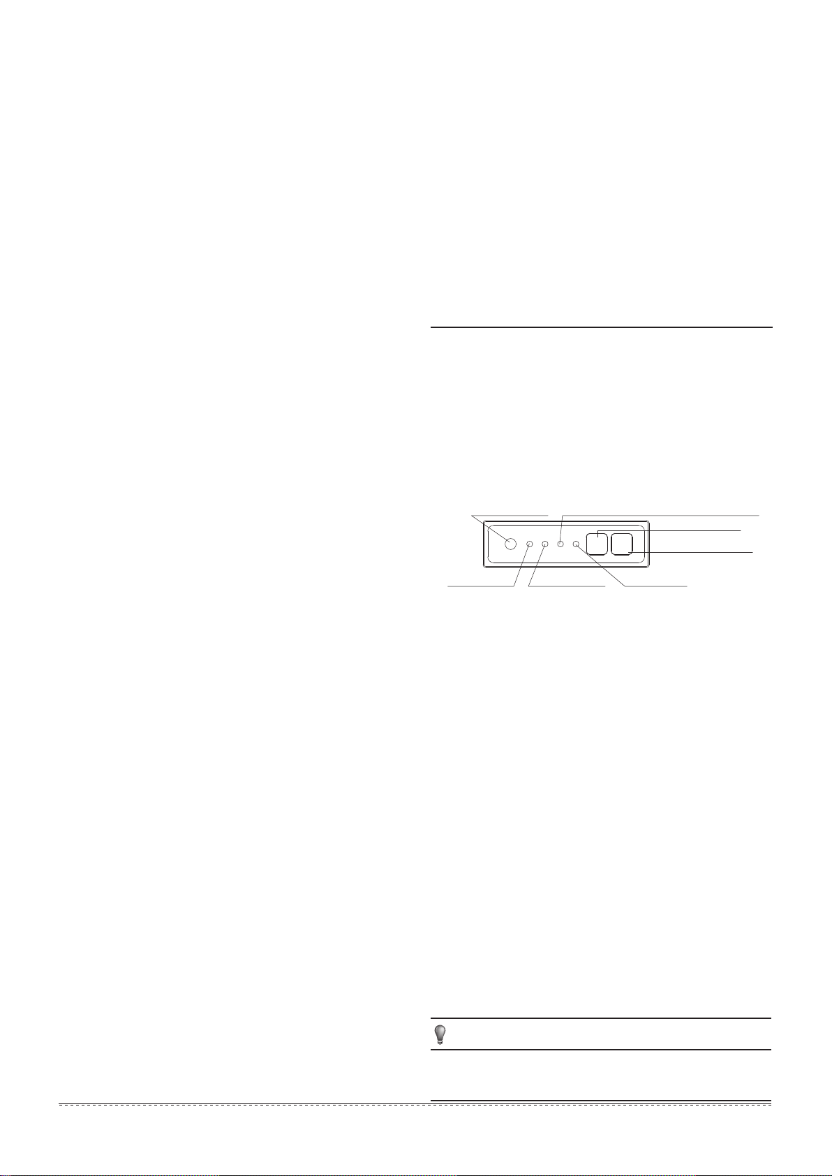
Function indicators on indoor unit display panel
Display panel
This manual does not include Remote Controller
Operations, see the<<Remote Controller Owner's
manual>> packed with the unit for details.
PRE-DEF indicator(cooling and heating type)
or fan only indicator(cooling only type)
Infrared signal receiver
Display Digital tube
Operation lamp
Timer indicator
Alarm indicator
Temporary button
In order to avoid injury, do not remove the fan guard of
the outdoor unit.
Do not operate the air conditioner with a wet hand.
An electric shock may happen.
Do not touch the heat exchanger fins.
These fins are sharp and could result in cutting injuries.
Do not place items which might be damaged by moisture
under the indoor unit.
Condensation may form if the humidity is above 80%, the
drain outlet is blocked or the filter is polluted.
After a long use, check the unit stand and fitting for
damage.
If damaged, the unit may fall and result in injury.
To avoid oxygen deficiency, ventilate the room
sufficiently if equipment with burner is used together
with the air conditioner.
Arrange the drain hose to ensure smooth drainage.
Poor drainage may cause wetting of the building, furniture
etc.
Never touch the internal parts of the controller.
Do not remove the front panel. Some parts inside are
dangerous to touch, and the unit may be damaged.
Never expose little children, plants or animals directly to
the air flow.
Adverse influence to little children, animals and plants may
result.
Do not allow a child to mount on the outdoor unit or
avoid placing any object on it.
Falling or tumbling may result in injury.
Do not operate the air conditioner when using a room
fumigation - type insecticide.
Failure to observe could cause the chemicals to deposit in
the unit, which could endanger the health of those who are
hypersensitive to chemicals.
Do not place appliances which produce open fire in
places exposed to the air flow from the unit or under the
indoor unit.
It may cause incomplete combuston or deformation of the
unit due to the heat.
Do not install the air conditioner at any place where
flammable gas may leak out.
If the gas leaks out and remains around the air conditioner, a
fire may break out.
The appliance is not intended for use by young children
or infirm persons without supervision.
Do not operate your air conditioner in a wet room such
as a bathroom or laundry room.
This appliance can be used by children aged from 8
years and above and persons with reduced physical,
sensory or mental capabilities or lack of experience
and knowledge if they have been given supervision
or instruction concerning use of the appliance in a safe
way and understand the hazards involved. Children shall
not play with the appliance. Cleaning and user
maintenance shall not be made by children without
supervision.
Fig.2-1
This appliance is not intended for use by persons
(including children) with reduced physical, sensory or
mental capabilities, or lack of experience and
knowledge, unless they have been given supervision or
instruction concerning use of the appliance by a person
responsible for their safety.
Children should be supervised to ensure that they do not play
with the appliance.
If the supply cord is damaged, it must be replaced by the
manufacturer, its service agent or similarly qualified persons
in order to avoid a hazard.
FORCED AUTO
The OPERATION lamp is lit, and the air conditioner will run
under FORCED AUTO mode. The remote controller operation is
enabled to operate according to the received signal.
1
FORCED COOL
The OPERATION lamp flashes, the air conditioner will turn to
FORCED AUTO after it is enforced to cool with a wind speed of
HIGH for 30 minutes. The remote controller operation is
disabled.
OFF
The OPERATION lamp goes off. The air conditioner is OFF
while the remote controller operation is enabled.
2
3
For the inverter type,this switch is used for after-sales service
purposes only,the user should not select it.
For fixed-frequency type,
this function is used to operate the unit
temporarily in case you misplace the remote controller or its
batteries are exhausted. Two modes including
FORCED
AUTO and FORCED COOL can be selected through the
TEMPORARY BUTTON on the air-in grill control box of the
indoor unit. Once you push this button, the air conditioner will
run in such order:
FORCED
AUTO, FORCED COOL, OFF,
and back to
FORCED
AUTO.
5
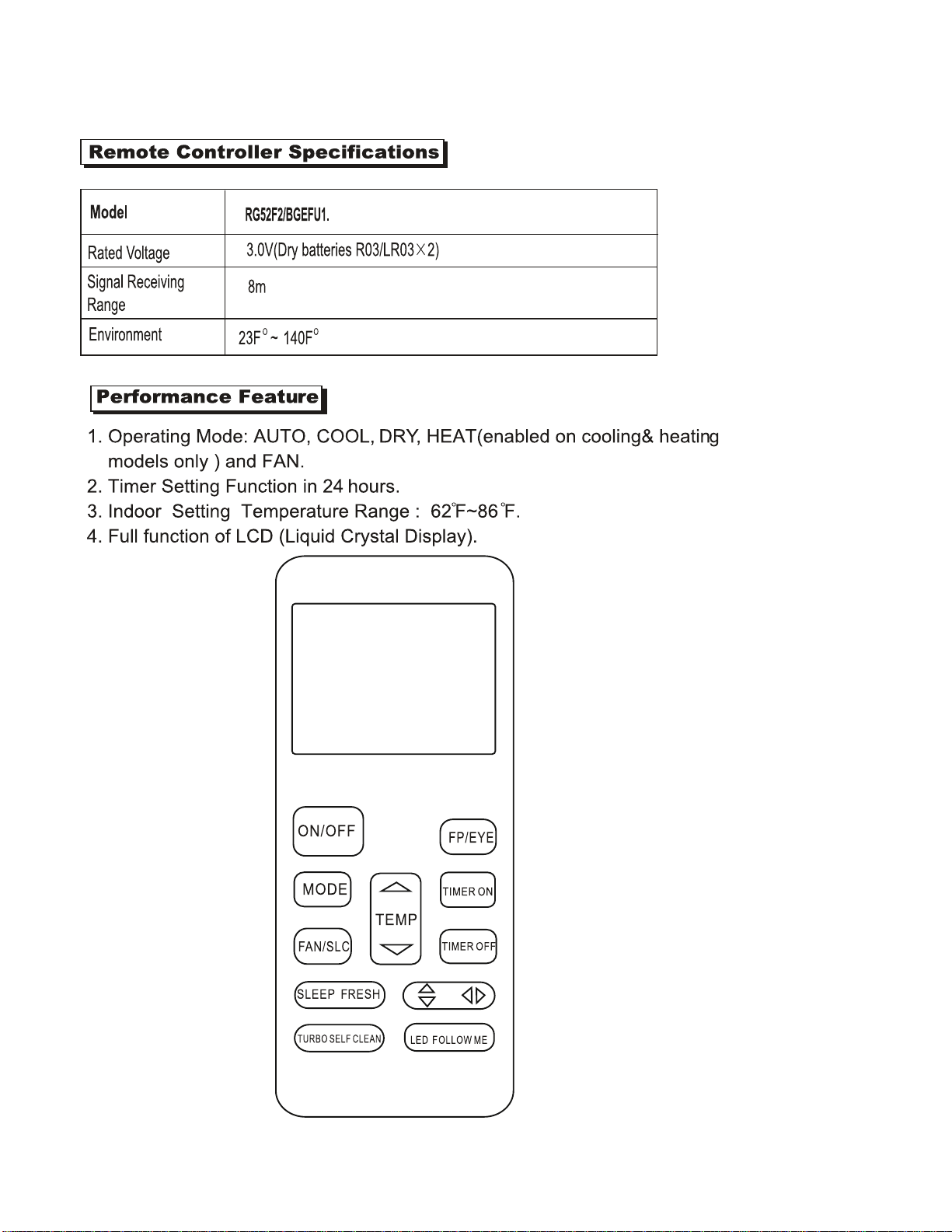
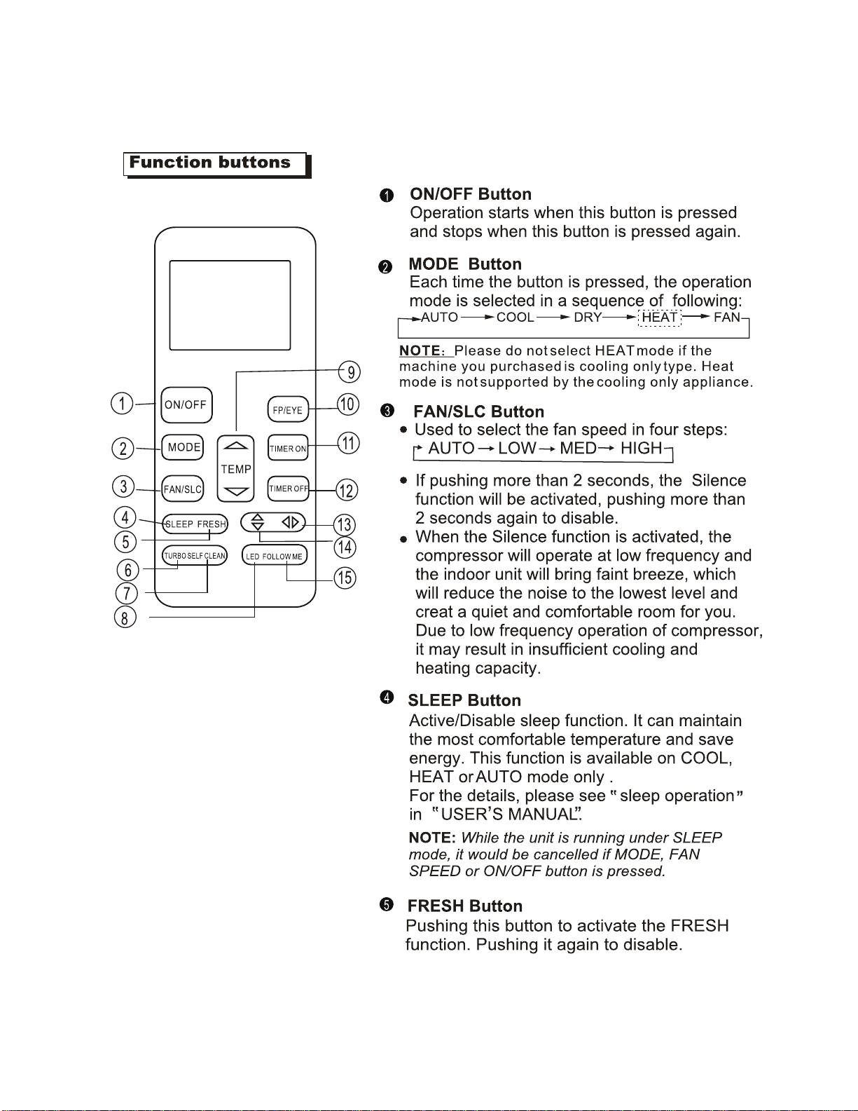
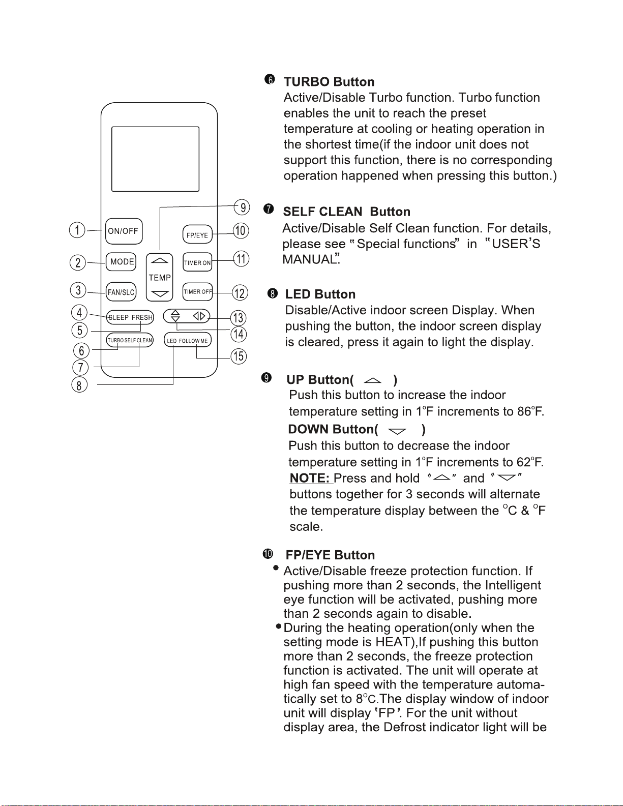
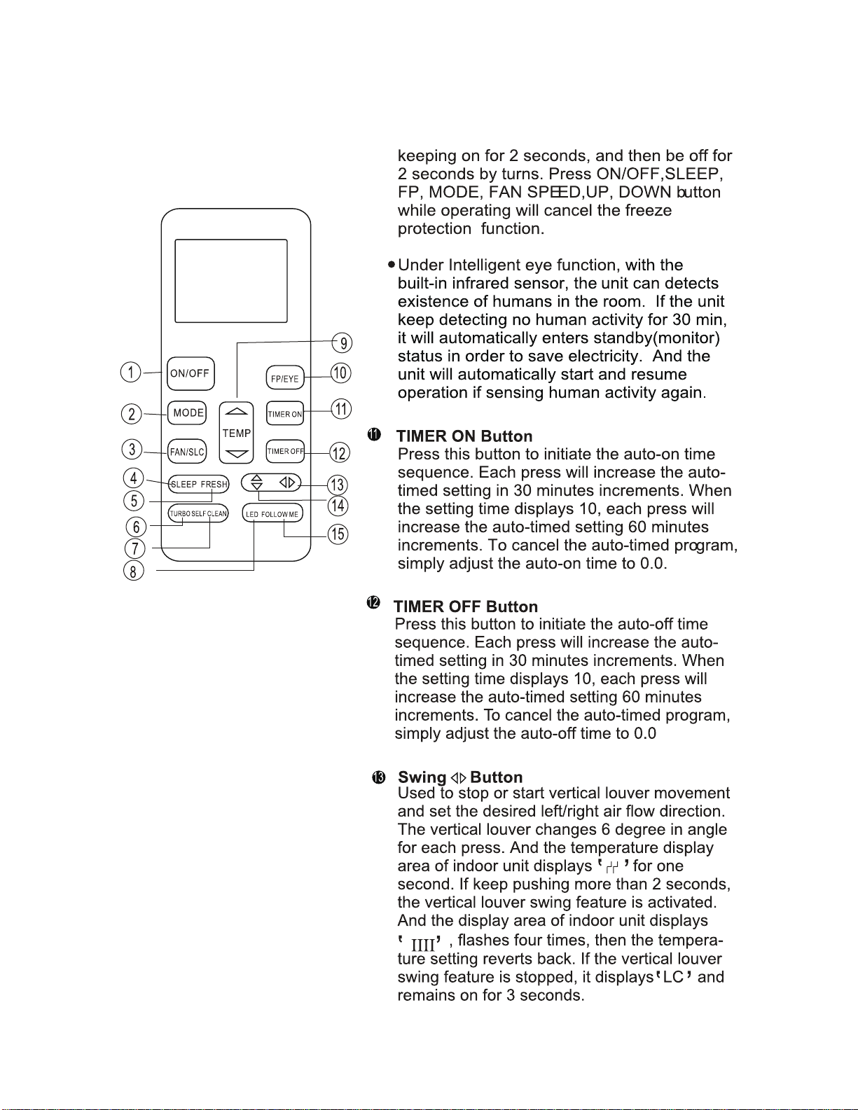
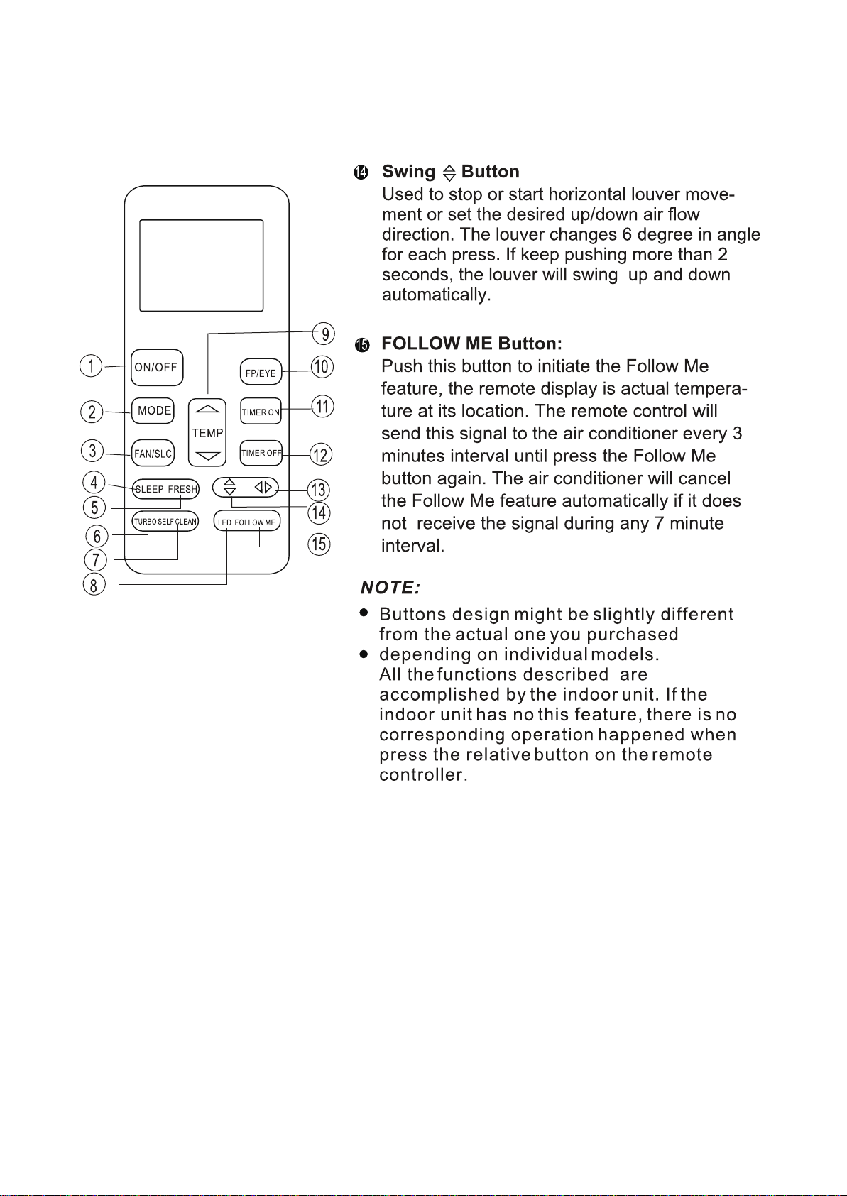
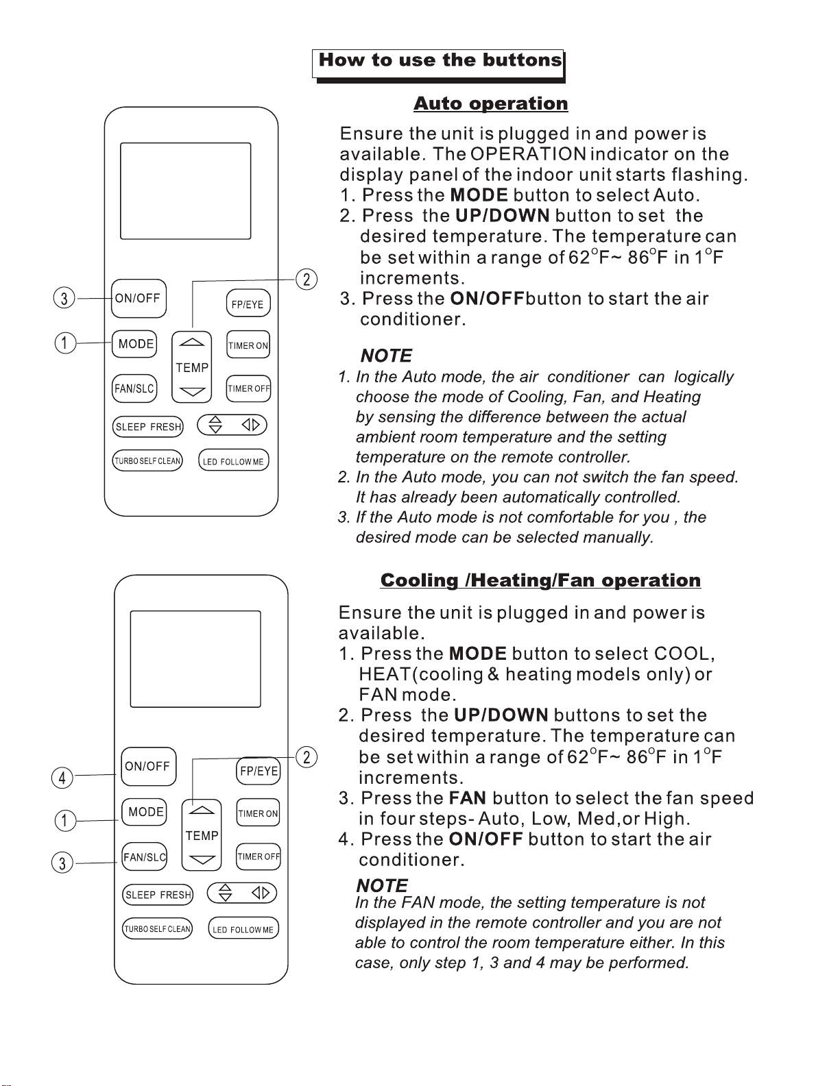
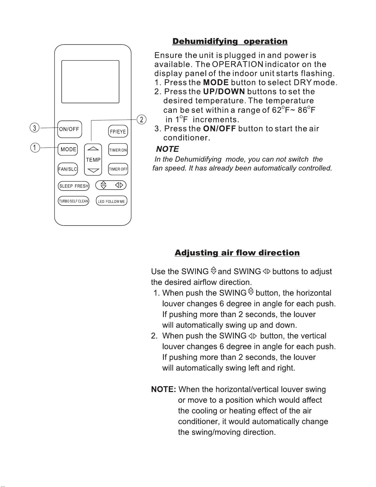
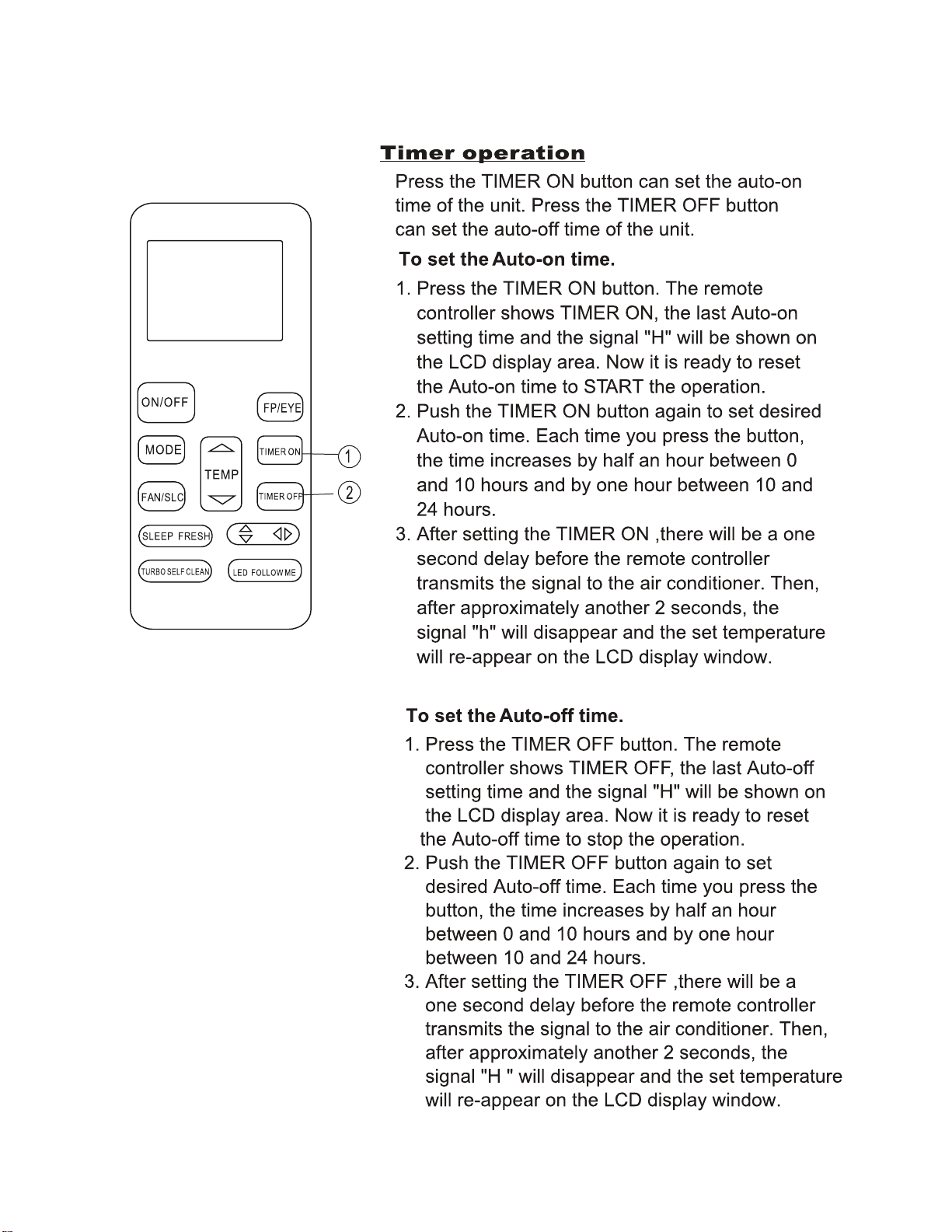
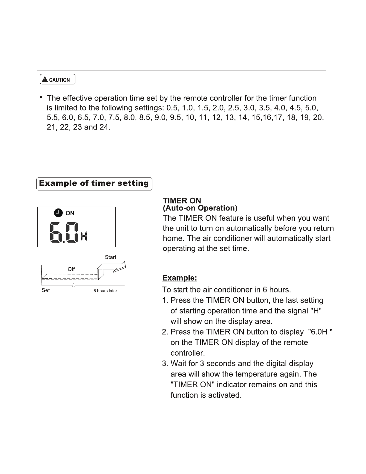
4. REMOTE CONTROL FUNCTIONS
7
8
9
5. USING THE REMOTE CONTROL
10
11
12
13
14
15
16
17
18
NOTE
Use the system in the following temperature for safe and
effective operation.The max operation temperature for
the air conditioner.(Cooling/Heating)
CAUTION
The following should be noticed to ensure an economical operation.
(Refer to corresponding chapterfor details)
Before you clean the air conditioner, be sure the power
supply is off.
Check to see if wiring is broken or disconnected.
Use a dry cloth to wipe the indoor unit and remote
controller.
A wet cloth may be used to clean the indoor unit if it is
very dirty.
Never use a damp cloth on the remote controller.
Do not use a chemically-treated duster for wiping or leave
such material on the unit for long because.
it may damage or fade the surface of the unit.
Do not use benzine, thinner, polishing powder, or similar
solvents for cleaning.
These may cause the plastic surface to crack or deform.
1
If air conditioner is used outside the above conditions, it
may cause the unit to function abnormally.
Is it normal for condensation to form on the unit when
the relative humidity in a room is high. Close the door
and windows to help reduce the condensation.
Optimum performance will be achieved within these
operating temperature range.
2
3
Three-minute protection feature
A protection feature prevents the air conditioner from
being activated for approximately 3 minutes
when it restarts immediately after operation.
Power failure
Power failure during operation will stop the unit completely.
The OPERATION lamp on the indoor unit will start flashing
when power is restored.
To restart operation, push the ON/OFF button on the
remote controller.
Lightning or a mobile telephone operating nearby
may cause the unit to malfunction.
Adjust the air flow direction properly to avoid winding toward
your body.
Adjust the room temperature properly to get a comfortable
situation and to avoid supercooling and superheat.
In cooling, close the curtains to avoid direct sunlight.
To keep cool or warm air in the room, never open doors or
windows more often than necessary.
Set the timer for the desired operating time.
Never put obstructions near the air outlet or the air inlet. Or it
will cause lower efficiency, even a sudden stop.
Adjust the air flow direction properly to avoid winding toward
your body.
Adjust the room temperature properly to avoid supercooling
and superheat.
In cooling, close the curtains to avoid direct sunlight.
To keep cool or warm air in the room, never open doors or
windows more than necessary.
If you don't plan to use the unit for a long time, please
disconnect power and remove the batteries from the remote
controller. When the power switch is connected, some energy
will be consumed, even if the air conditioner isn't in operation.
So please disconnect the power to save energy. And please
switch the power on 12 hours before you restart the unit to
ensure a smooth operation.
A clogged air filter will reduce cooling or heating efficiency,
please clean it once two weeks.
Table 2-1
Cooling operation
Dry operation
Heating operation
(cooling only type without)
Mode
Temperature
Outdoor
temperature
(for the models with low
temperature cooling system)
temperature
Room
32 °F~122°F / 0°C ~ 50°C
32 °F~122°F / 0°C ~ 50°C
5 °F~122°F / -15°C ~ 50°C
5 °F~76°F / -15°C ~ 24°C
32°F~86°F
(0°C~30°C)
62°F ~90°F
(17°C~32°C)
62°F ~90°F
(17°C~32°C)
Disconnect the unit with the power and then connect the unit
with the power again. Push the ON/OFF button on the remote
controller to restart operation.
With this new technology, the display area will display EC (if
applicable) and the LED indication lamps continue flashing
when the outdoor unit detects refrigerant leakage.
Refrigerant Leakage Detection(optional):
,
,
6. AIR CONDITIONER OPERATIONS AND
PERFORMANCE
7. HINTS FOR ECONOMICAL OPERATION
. MAINTENANCE
8
19
Maintenance after a long stop period
Check and remove everything that might be blocking inlet and
outlet vents of indoor units and outdoor units.
Clean air filters and casings of indoor units.
Refer to "Cleaning the air filter" for details on how to proceed
and make sure to install cleaned air filters back in the same
position.
Maintenance before a long stop period
Let the indoor units run in fan only operation for about half a day
in order to dry the interior of the units.
Clean air filters and casings of indoor units. Refer to " Cleaning
the air filter" for details on how to proceed and make sure to
install cleaned air filters back in the same position.
Check and remove everything that might be blocking inlet and
outlet vents of indoor units and outdoor units.
Clean air filters and casings of indoor units.
Refer to "Cleaning the air filter" for details on how to proceed
and make sure to install cleaned air filters back in the same
position.
Turn on the power at least 12 hours before operating the unit in
order to ensure smoother operation. As soon as he power is
turned on, the remote controller displays appear.
Cleaning the air filter(on some models)
The air filter can prevent dust or other particulate from entering
the unit. In case of blockage of the filter, the working efficiency of
the air conditioner may greatly decrease.
Therefore, the filter must be cleaned once every two weeks
during long time usage.
If the air conditioner is installed in a dusty place , clean the the air
filter frequently.
If the accumulated dust is too heavy to be cleaned , please
replace the filter with a new one(replaceable air filter is an
optional fitting).
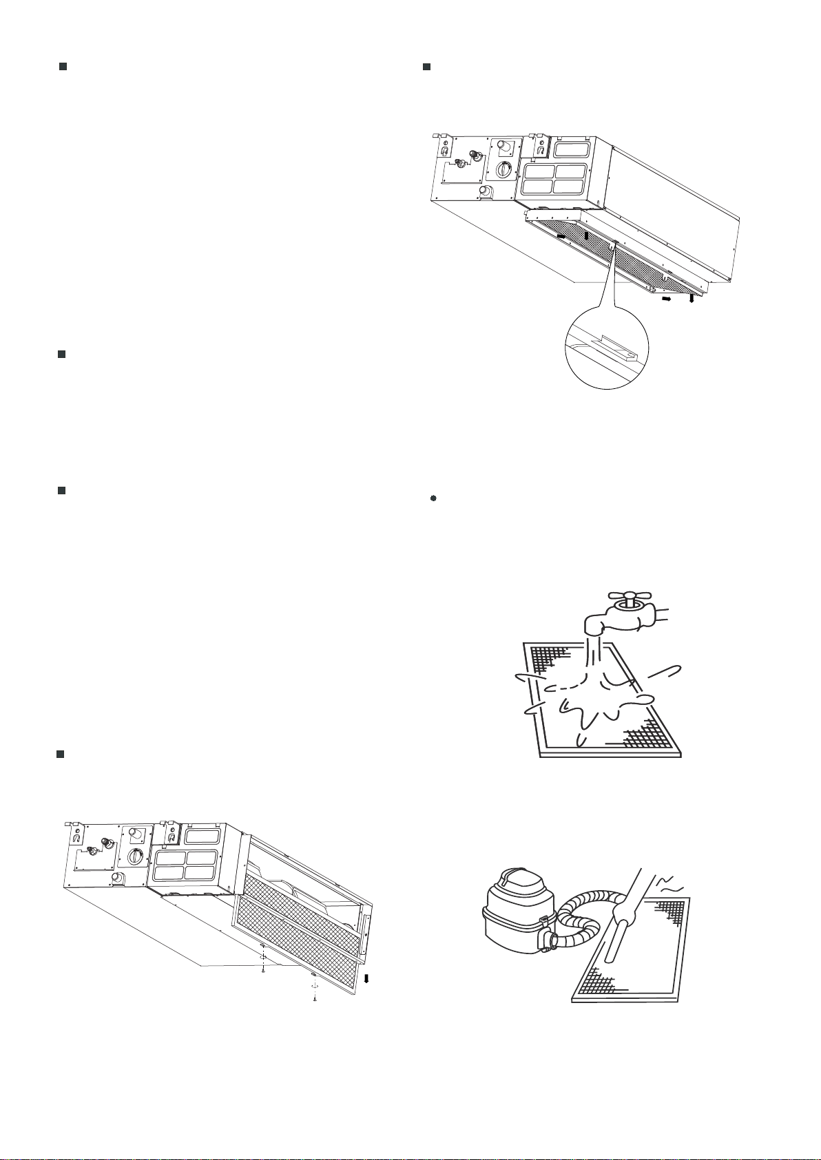
If your unit is a rear ventilated model, please remove the filter
fixed screws(2 screws)and pull the filter away from the unit.
If your unit is a descensional ventilated model, please push the
filter up slightly to let the position retainer move away from the
flange fixed holes, and take off the filter according to the arrow
direction shows in the following fig.
Fig.5-4
Fig.5-3
Clean the air filter (vacuum cleaner or pure water may be used
to clean the air filter. If the dust accumulation is too heavy ,
please use asoft brush and mild detergent to clean it and dry
out in cool place) .
Fig.5-2
Fig.5-1
20
CAUTION
The air-in side should face up when using vacuum cleaner.
(Refer to Fig.5-4)
The air-in side should face down when using water. (Refer to
Fig.5-3)
5. Re-install the air filter
6. Install and close the air-in grill in the reverse order of step 1
and 2 and connect the control box cables to the corresponding
terminators of the main body .
Do not dry out the air filter under direct sunshine or with fire.
Symptom 1: The system does not operate
Symptom 2: Change into the fan mode during
cooling mode
The air conditioner does not start immediately after the ON/OFF
button on the romote controller is pressed.
If the operation lamp lights, the system is in normal condition.To
prevent overloading of the compressor motor, the air
conditioner starts 3 minutes after it is turned ON.
If the operation lamp and the "
PRE-DEF indicator(cooling and
heating type) or fan only indicator(cooling only type)"
light, it
means you choose the heating model, When just starting, if the
compressor has not started, the indoor unit appears "anti cold
wind" protection because of its overlow outlet temperature.
In order to prevent the indoor evaporator frosting, the system
will change into fan mode automatically, restore to the cooling
mode after soon.
When the room temperature drops to the set temperature, the
compressor goes off and the indoor unit changes to fan mode;
when the temperature rises up, the compressor starts again. It
is same in the heating mode.
Symptom 3: White mist comes out of a unit
Symptom 3.1: Indoor unit
When humidity is high during cooling operation If the interior of
an indoor unit is extremely contaminated, the temperature
distribution inside a room becomes uneven. It is necessary to
clean the interior of the indoor unit. Ask your dealer for details
on cleaning the unit. This operation requires a qualified service
erson
Symptom 4.2: Indoor unit, outdoor unit
A continuous low hissing sound is heard when the system is in
operation.
This is the sound of refrigerant gas flowing through both indoor
and outdoor units.
A hissing sound which is heard at the start or immediately after
stopping operation or defrost operation.
This is the noise of refrigerant caused by flow stop or flow
change.
Symptom 4.3: Outdoor unit
When the tone of operating noise changes.
This noise is caused by the change of frequency.
Symptom 5: Dust comes out of the unit
Symptom 6: The unit can emit odors
When the unit is used for the first time in a long time.
This is because dust has gotten into the unit.
The unit can absorb the smell of rooms, furniture, cigarettes,
etc., and then emit it again.
Symptom 7: The outdoor unit fan does not
spin.
During operation. The speed of the fan is controlled in order to
optimize product operation.
Sptom 4: Noise of air conditionerscooling
Symptom 3.2: Indoor unit, outdoor unit
Symptom 4.1: Indoor unit
When the system is changed over to heating operation after
defrost operation moisture generated from defrosting becomes
steam and is exhausted.
A continuous low "shah" sound is heard when the system is in
cooling operation or at a stop.
When the drain pump (optional accessories) is in operation,this
noise is heard.
A "pishi-pishi" squeaking sound is heard when the system stops
after heating operation.
Expansion and contraction of plastic parts caused by
temperature change make this noise.
FOLLOWING SYMPTOMS ARE NOT AIR
CONDITIONER TROUBLES
9.
21
CAUTION
The operation lamp is flashing rapidly (5Hz). This lamp is still
flashing rapidly after you turn off the power and turn it on again.
(Refer to Table 7-1 and Table 7-2)
Remote controller receives malfunction or the button does not
work well.
A safety device such as a fuse, a breaker frequently actuates.
Obstacles and water enter the unit.
Water leaks from indoor unit.
Other malfunctions.
If one of the following malfunctions occur, stop operation, shut
off the power, and contact with your dealer.
If the system does not properly operate except the above
mentioned cases or the above mentioned malfunctions is
evident, investigate the system according to the following
procedures. (Refer to Table 7-3)
7.1. Troubles and causes of air conditioner
Please cut off the power supply when appearing the
above malfunction, check if the voltage provided is out of
range, check if the installation of air-conditioner is
correct, then electrify again after 3 minutes power off. If
the problem is still existent, please contact the local
service station or the equipment provider.
TROUBLESHOOTING
10.
22
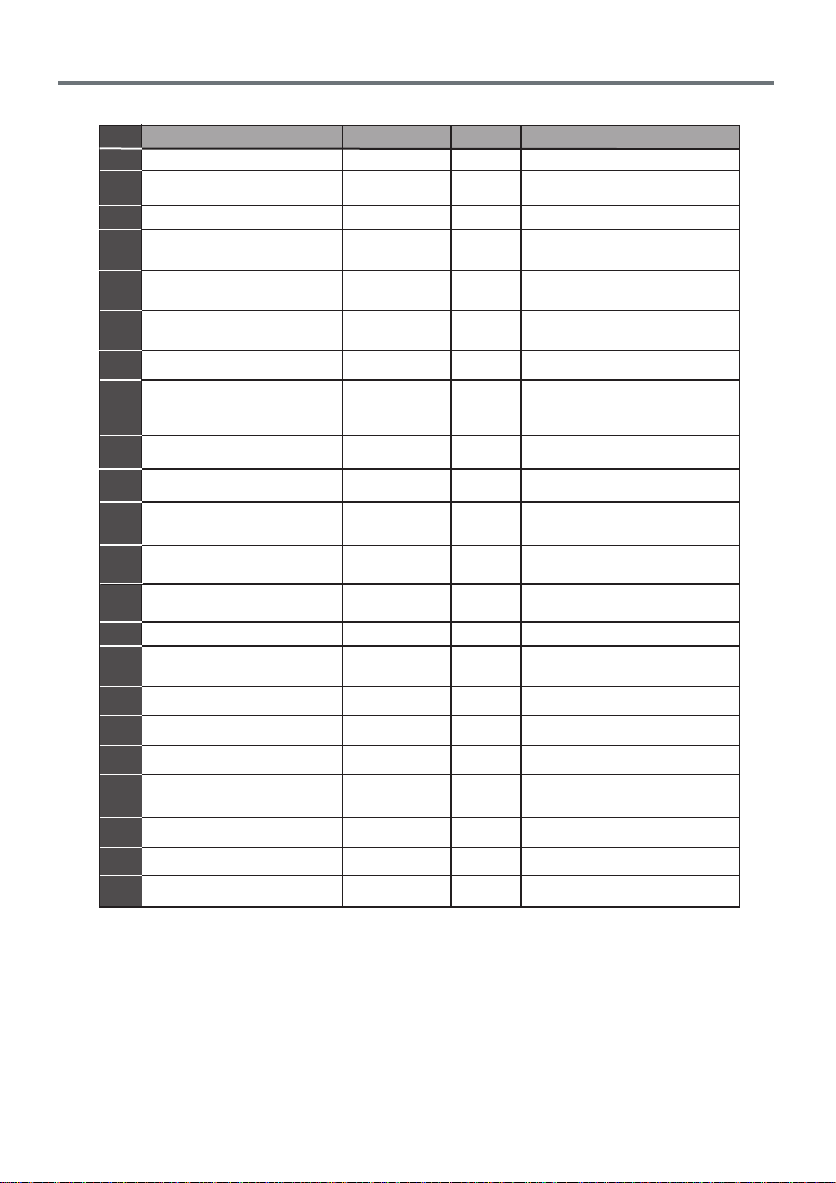
Table 7-1
NO.
Malfunction Timer lamp
Running lamp (flashes per second)
1
2
3
4
5
6
7
8
Display (nixie tube)
Refrigerant leakage detection
malfunction
OFF
EC
Water-level alarm malfunction
8
EE
OFF
Outdoor room temperature sensor
open circuit or short circuit
F1
2
Outdoor condenser pipe
temperature sensor error
3
4
5
ON
F2
E3
Indoor fan speed malfunction
OFF
E4
Indoor room temperature sensor
open circuit or short circuit
OFF
E5
Evaporator coil temperature
sensor open circuit or short circuit
OFF
E9
Other malfunction of twins model
OFF
9
Communication malfunction
between indoor and outdoor units
OFF
E1
10
11
12
13
Discharging air temperature
sensor error
F3
Outdoor EEPROM error
F4
Communication malfunction
between two indoor units (for
twins model)
E8
OFF
F0
1
10
9
7
6
5
4
2
1
Current overload protection
Indoor EEPROM error
E0
OFF
14
15
16
17
18
19
20
21
22
Outdoor fan speed malfunction
(Only for DC fan motor)
T2b sensor error
F5
F6
6
7
1
2
ON
ON
ON
ON
ON
ON
Inverter module IPM protection
P0
Flash
High/Low voltage protection
P1
Flash
High temperature protection of
compressor top
P2
3
Outdoor low temp. protection
P3
4
Compressor drive error
P4
5
Mode conflict
P5
6
Flash
Flash
Flash
Flash
23
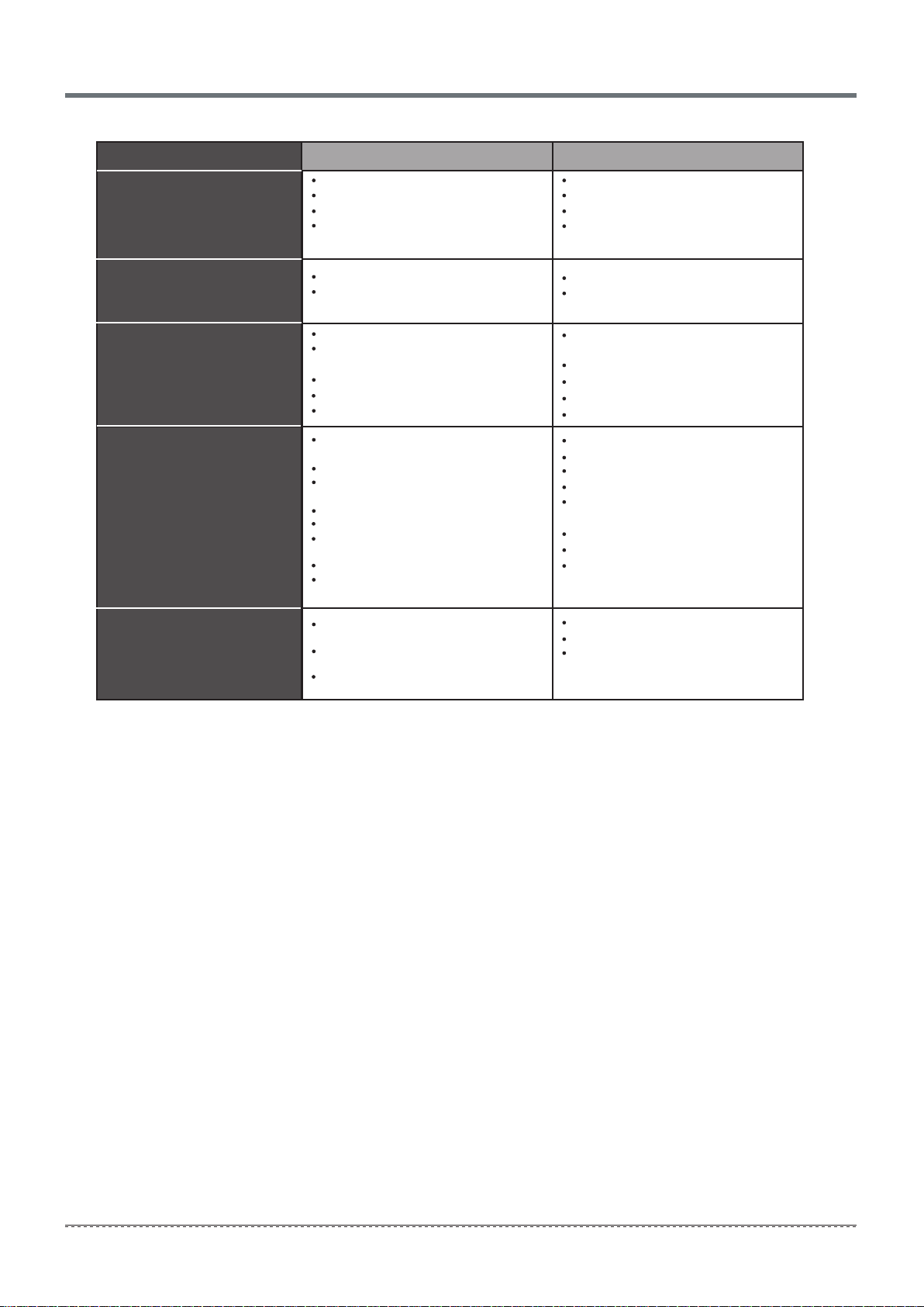
Table 7-2
Solution
Clean the heat exchanger.
Clean the air filter.
Eliminate all dirt.
Close doors and windows.
Adjust curtains to shelter unit from
sunshine.
Reduce heat source.
AC cooling capacity reduces (normal).
Check leakage and rightly recharge
refrigerant.
Symptoms Causes
Unit does not start
Air flowing normally however
unit is not cooling cooling
Units starts or stops
frequently
Low cooling effect
Low heating effect
Outdoor unit and indoor unit heat
exchanger is dirty.
The air filter is dirty.
Inlet/outlet of indoor/outdoor units is
blocked.
Doors and windows are open
Direct sunlight on unit.
A strong heat source nearby. heat
resource.
Outdoor temp. is too high.
Leakage of refrigerant or lack of
refrigerant.
Use heating device.
Close doors and windows.
Check leakage and rightly recharge
refrigerant.
Outdoor temperature is lower than
44.6˚F/7˚C
Doors and windows not completely
closed.
Leakage of refrigerant or lack of
refrigerant.
Power failure.
Power switch is off.
Fuse of power switch may have burned.
Batteries of remote controller exhausted
or other problem of controller.
Temperature is not set correctly.
Unit is in 3 minutes protection mode for
the compressor.
Refrigerant is too low or too high.
Air or no concentrating gas in the
refrigerating circuit.
Compressor is malfunction.
Voltage is too high or too low.
System circuit is blocked.
Wait for the return of power.
Switch on the power.
Replace the fuse.
Replace the batteries or check the
controller.
Set the temperature properly.
Wait.
Check leakage, and rightly recharge
refrigerant.
Vacuum and recharge refrigerant.
Maintenance or change compressor.
Install manostat.
Find reasons and solution.
24
Symptoms
Causes
The fan speed can not be
changed.
Check whether the MODE
indicated on the display is
"AUTO"
Check whether the MODE
indicated on the display is
"DRY"
When the automatic mode is
selected, the air conditioner will
automatically change the fan
speed.
When dry operation is selected,
the air conditioner automatically
change the fan speed. The fan
speed can be selected during
"COOL" , "FAN ONLY",
and
"HEAT"
The wire controller signal is
not transmitted even when
the ON/OFF button is pushed.
The power supply is off.
Not receiving tone sounds
from the indoor unit even
when the ON/OFF button is
pressed.
Check whether the signal
transmitter of the wire
controller is properly directed
to the infrared signal receiver
of the indoor unit when the
ON/OFF button is pressed.
Directly transmit the signal transmitter of
the wire controller to the
infrared signal receiver of the
indoor unit, and then repeatly
push the ON/OFF button twice.
The indication on the display
disappears after a period of
time.
Check whether the timer
operation has come to an
end when the TIMER OFF
is indicated on the display.
The air conditioner operation will
stop at the set time
The TIMER ON indicator
goes off after a period of
certain time.
Check whether the timer
operation is started when
the TIMER ON is indicated
on the display.
Up to the set time, the
air conditioner will automatically
start and the appropriate
indicator will go off.
The TEMP. indicator does
not come on.
Check whether the MODE
indicated on the display is
FAN ONLY
The temperature cannot be set during
FAN mode.
Table 7-3
Solution
7.2. Troubles and causes of wire controller
Before asking for serving or repairing , check the following points. (Refer to Table 7-3)
Check whether the signal
transmitter of the wire
controller is properly directed
to the infrared signal receiver
of the indoor unit.
25

● This manual gives detailed description of the precautions
that should be brought to your attention during operation.
● In order to ensure correct service of the wired controller
please read this manual carefully before using the unit.
● For convenience of future reference, keep this manual
after reading it.
● The wired controller will reset to factory setting with auto
mode, auto fan and 76°F(24°C) setting temperature when
the air conditioner restarts after power failure.
And this may cause inconsistent displays on the wired
controller and on the air conditioner. You need to readjust
the running status through the wired controller.
26
11. SAFETY PRECAUTIONS
The following contents are stated on the product and the operation manual,
including usage, precautions against personal harm and property loss, and the
methods of using the product correctly and safely. After fully understanding the
following contents (identifiers and icons), read the text body and observe the
following rules.
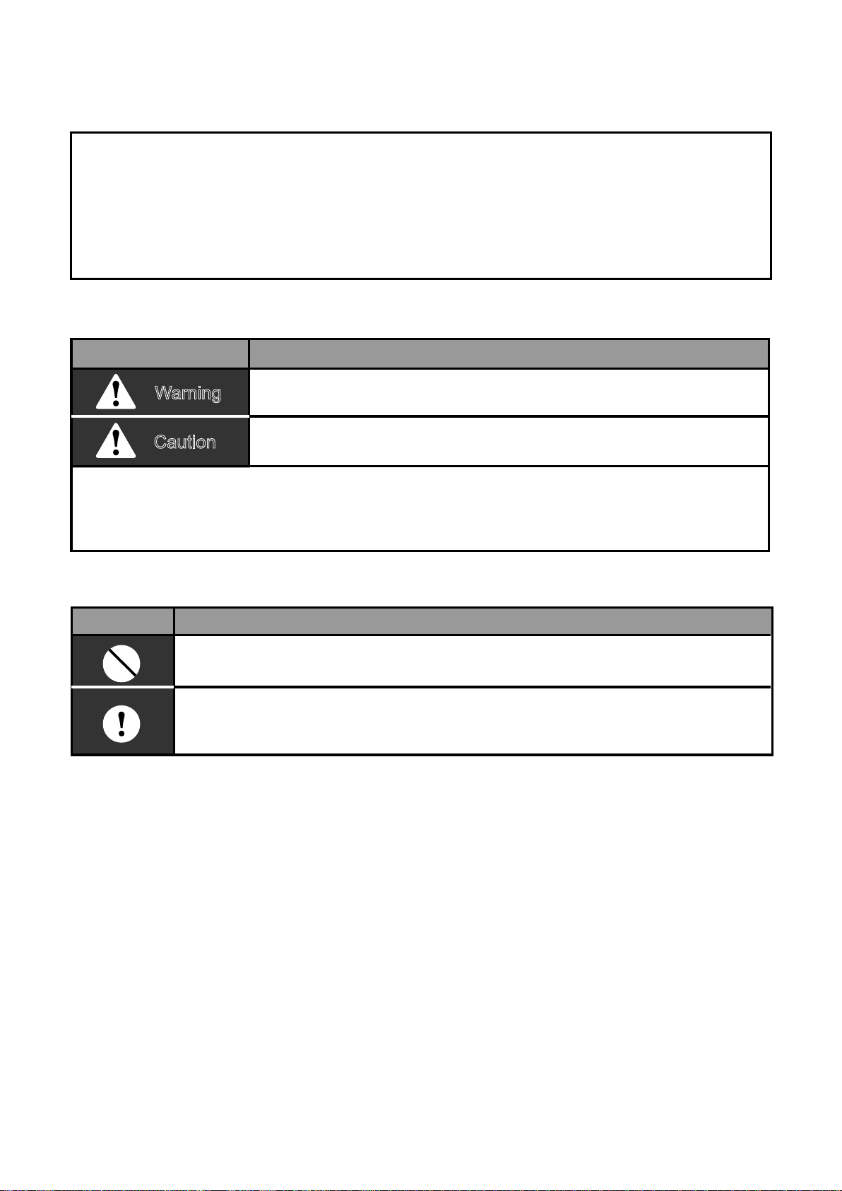
Identifier description
Identifier Meaning
Means improper handling may lead to personal death or
severe injury.
Means improper handling may lead to personal injury or
property loss.
[Note]: 1. “Harm” means injury, burn and electric shock which need
long-term treatment but need no hospitalization
2. “Property loss” means loss of properties and materials.
Warning
Caution
Icon description
Meaninglcon
It indicates forbidding. The forbidden subject-matter is indicated in the
icon or by images or characters aside.
It indicates compulsory implementation. The compulsory subject-matter
is indicated in the icon or by images or characters aside.
27
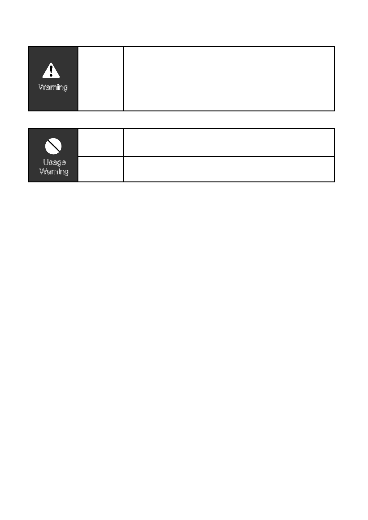
Warning
W
arning
Please entrust the distributor or professionals to install
the unit. The installers must have the relevant know-how.
Improper installation performed by the user without perm
ission may cause fire, electric,shock, personal injury or
water leakage.
Delegate
installation
Forbid
Forbid
Usage
W
arning
Do not spray flammable aerosol to the wire
controller directly. Otherwise, fire may occur.
Do not operate with wet hands or let water enter the wire
controller. Otherwise, electric shock may occur.
12. SUMMARIZE
13. FUNCTION SUMMARY
Usage condition:
Main function:
1. Power supply: 5V DC.
2. Operation temperature:
-5°F(-15°C)~ +109°F(+43°C).
3. Operation humidity: 40%-90%, RH.
1. Connecting to indoor unit by A, B, C,
D, E termina.;
2. Button setting action mode.
3. LCD display.
4. Timer for rest time.
28
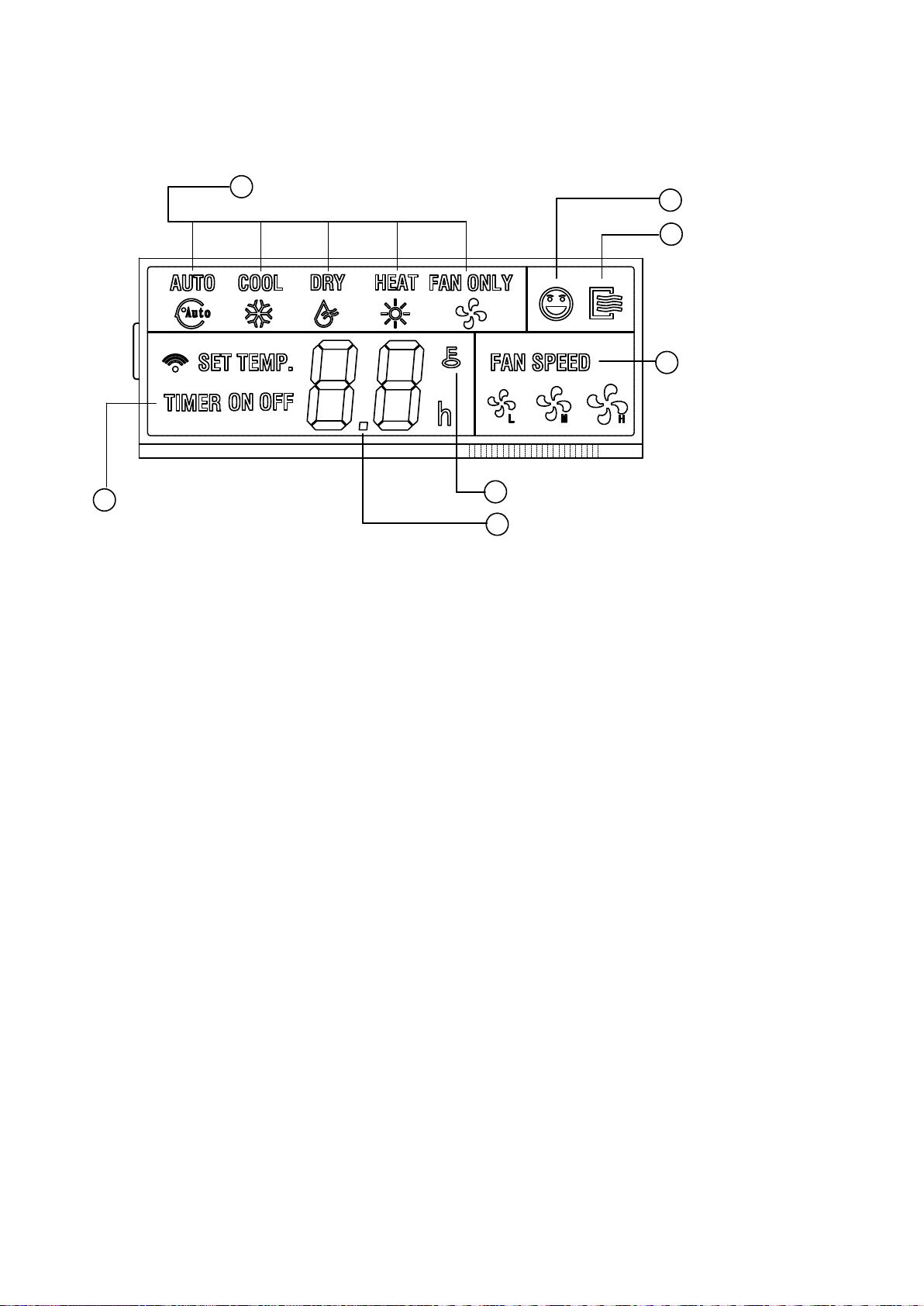
14. NAME AND FUCTION OF INDICATORS ON THE
CONTROLLER
When adjust setting off time or only off
time is set , the "OFF" is lighted. If on
and off timer are both set, the"ON" and
"OFF"are both lighted.
③ Follow me function:
There is a temperature sensor inside the
wire controller, after setting temperature,
it will compare the two temperatures,
and the space of wire controller will be
① Operation mode indication:
When press " MODE " button, the follow-
ing mode can be selected in circle. Auto
→Cool →Dry→Heat→Fan only→Auto.
For cooling only model,heat mode is
skipped.
② Timer :
When adjust setting on time or only on
time is set, the "ON" is lighted.
1
2
1 121 12
1
Operation mode indication
3
Follow me function
4
ON/OFF indication
2
Timer ON/OFF
7
Temperature display zone
6
Lock
5
Fan speed indication
29
the same as setting temperature. It is
available under cooling, heating, auto
mode.
④ ON/OFF indication :
When it is on, the icon display, other-
wise it is extinguished.
⑤ Fan speed indication :
There are four fan modes : low, middle,
high, auto. For some models, no middle
fan then the middle fan is seen as high
speed.
⑥ Lock:
When the " LOCK " button is pressed,
the icon appear and other buttons is
unable, press again, the icon disappear.
⑦ Temperature display zone:
Generally it displays setting tempera-
ture, it can be adjusted by press tem-
perature button ▲ and ▼. But in fan
mode, no display here.
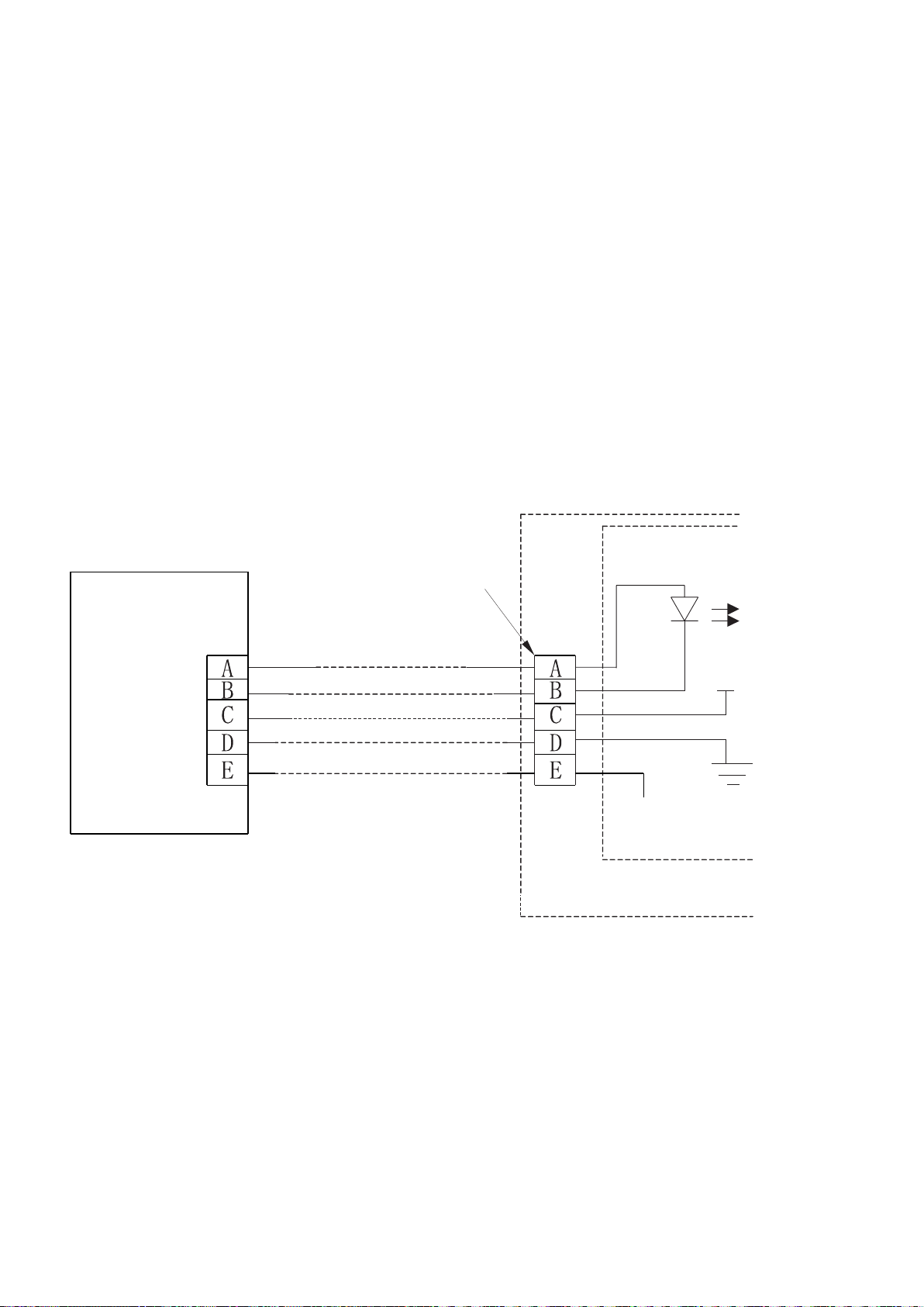
15. INSTALLATION METHOD
5-Core Shield Cable
5-way terminal
Emitter tube
Indoor Unit
RUN
GND
+5V
Indoor switch board
Wire Controller
30
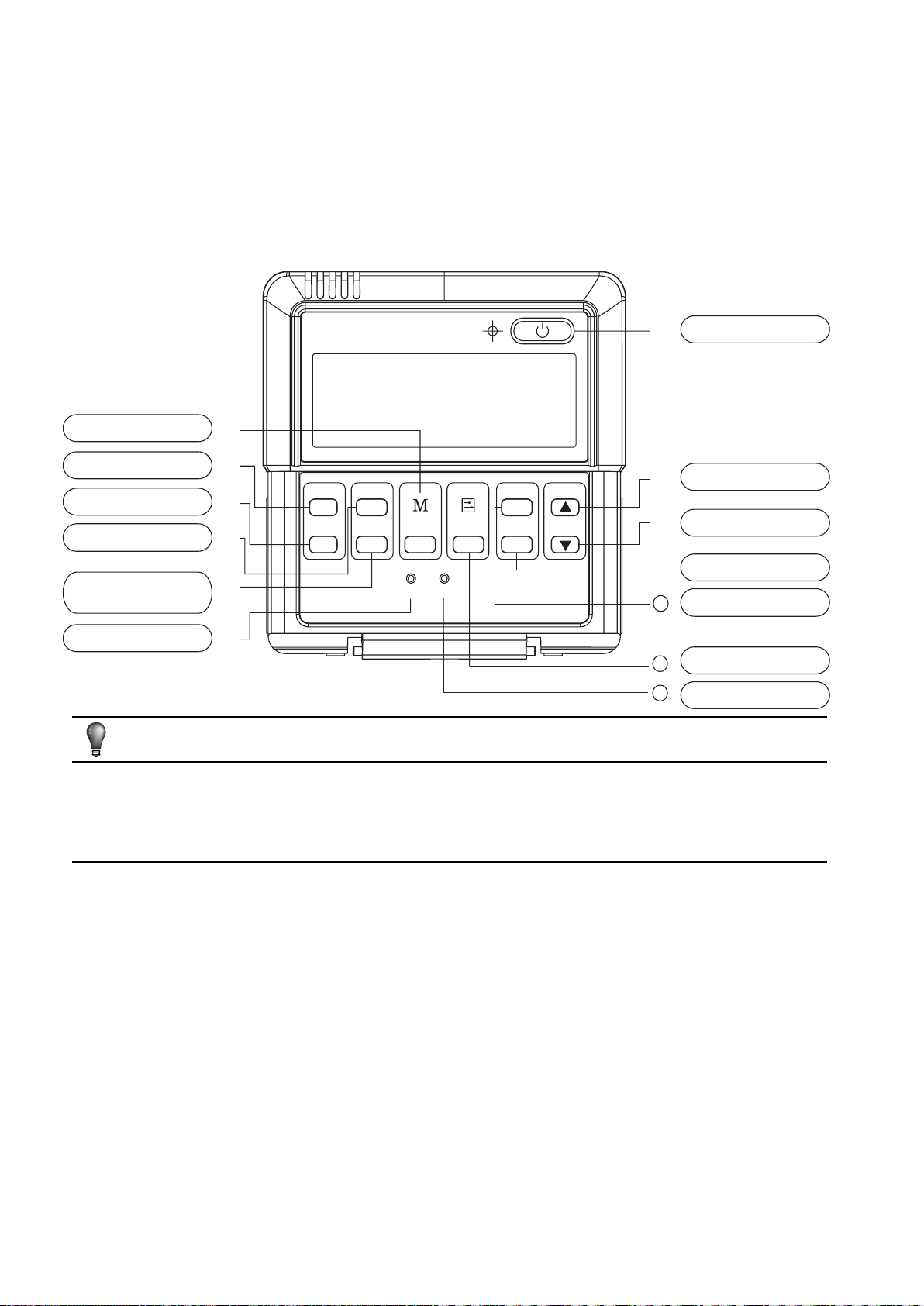
16. NAME AND OPERATION OF THE BUTTON ON
THE WIRE CONTROLLER
When a wire controller is needed, a small 5-way terminal should be added,fix an infra-
red emitter with gumwater near the receiver on the switch board. Connect its anode
and cathode to A and B,and +5V, GND, RUN to C, D, E on the switch board.
MODE BUTTON
TIMER ON BUTTON
FOLLOW ME BUTTON
TIMER OFF BUTTON
ELECTRICAL
HEATER BUTTON
RESET BUTTON
ON / OFF BUTTON
ADJUST BUTTON ▲
ADJUST BUTTON ▼
SWING BUTTON
ECONOMY BUTTON
FAN SPEED BUTTON
LOCK BUTTON
TIMER
ON
TIMER
OFF
FOLLOW
ME
AUXIL
HEATER
MODE
RESET
LOCK
FAN SPEED
ECO
SWING
TEMP
①
②
③
④
⑤
⑥
⑦
⑧
⑨
⑩
12
13
11
All the pictures in this manual are for explanation purpose only. There may be
slightly different from the wire controller you purchased(depend on model). The
actual shape shall prevail.
NOTE
31

① Mode botton:
When press this botton,the operation
mode change as the following
sequence:
Remark: For the cooling only model, the
heating mode is skipped.
② Timer on button :
Press this button, timer on function is
active. Then every press, the time
increase 0.5h, after 10h, 1h increase-
ment after each press. If cancel this
Function, just set it to "0.0" .
③ Timer off button:
Press this button, timer off function is
active.Then every press, the time
increase 0.5h, after 10h, 1h increase-
ment after each press. If cancel this
function, just set it to "0.0" .
④ Follow me button :
When under cool, heat and auto mode,
press this button, follow me function is
active. Pressing the ON/OFF button or
MODE button will not cancel the Follow
me feature. This function is disable
when the unit is off or under DRY or FAN
mode. Pressing the FOLLOW ME button
again will cancel the follow me feature.
⑤Electrical heater button :
If press this button in heat mode, electri-
cal heater function become ineffective.
⑥ Reset button(hidden):
Use a 1mm stick to press in the little hole,
then the current setting is canceled. The
wire controller enter into original state.
⑦ON/OFF button:
When in off state, press this button, the
indicator is on, the wire controller enter
into on state, and send setting information
to in door Pcb. When in on state,press this
button, the indicator is off, and send
instruction. If timer on or timer off has
been set, it concel this setting then send
instruction to stop the machine.
⑧ Adjust button ▲:
Set indoor temperature up. If press and
hold on, it will increase at 1°F(1°C) per
0.5 second.
⑨ Adjust button ▼ :
Set indoor temperature down. if press and
hold on, it will decrease at 1°F(1°C) per
0.5 second.
→AUTO → COOL→DRY→HEAT→FAN
32
AUTOMATIC OPERATION
Connect to power,indoor operation lamp
flash.
1. Press "MODE" button, select " AUTO " ;
2. Press the button "▲" and "▼", set tem-
perature you want, generally it is among
62°F(17°C)~86°F(30°C);
3. Press " ON/OFF" button, operation
lamp is on, the air-conditioner work in auto
mode, indoor fan is auto, and can not be
changed. Auto is displayed on LCD. Press
ON/OFF button again to stop.
4. Economy operation is valid in auto
mode.
5. In event of power interruption such as a
blackout, the air conditioner stops once.
But it restarts automatically and performs
previous operation when the power supply
is resumed.
17. USING METHOD
⑩ Swing button:
First press, start swing function;second
press, stop swing. (Match to some
model with swing function).
11 Economy operation button :
press this button, the indoor unit oper-
ates in economy mode, press again, exit
this mode (it may be ineffective for some
models)
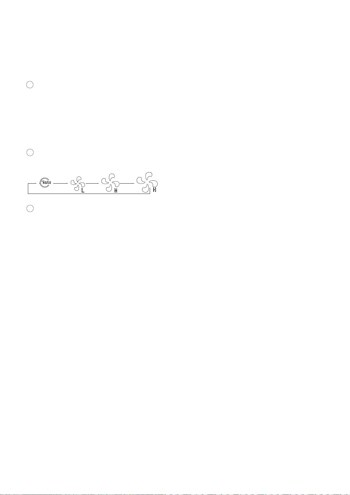
12 Fan speed button:
press this button consecutively, the fan
speed will circle as follow:
13 Lock button(hidden):
When you push the LOCK button, all
current settings are locked in and the
wire controller does not accept any oper-
ation except that of the LOCK button.
Use the lock mode when you want to
prevent setting from being changed
accidentally or play fully. Push the
LOCK button again when you want to
cancel the LOCK mode.
33

DRY OPERATION
1. Press " MODE " button, select " DRY "
mode.
2. Press temperature adjust button to
select setting temp.
3. Press " ON/OFF " button, indoor unit
operation lamp on, it works in dry mode.
Press ON/OFF button again, it stops to
work.
4. In dry mode, economy operation and
fan speed are ineffective.
TIMER SETTING
Timer on only:
1. Press " TIME ON " button, it display
"SET" on LCD, and display " H " and "ON"
, it is waiting for timer on setting.
2. Press " timer " on button repeatedly to
adjust time setting.
3. If press this button and hold on, the
time will increase at 0.5h, after 10h, it
increase at 1h.
4. After setting 0.5 second, the wire con-
troller send timer on information, it is
finished.
Timer off only:
1. Press "TIME OFF " button, it display
"SET" on LCD, and display " H " and ON,
it is waiting for timer on setting.
2. Press "TIME OFF" button repeatedly to
adjust time setting.
3. If press this button and hold on , the
time will increase at 0.5h, after 10h, it
increase at 1h.
4. After setting 0.5 second, the wire con-
troller send timer off information, it is
finished.
COOL/HEAT/FAN MODE OPERA-
TION
1. Press "MODE" button, select "COOL"
, "HEAT" or "FAN ONLY" mode.
2. Press temperature adjust button to
select setting temp.
3. Press "FAN SPEED" button to select
high/mid/low/auto.
4. Press "ON/OFF" button, indoor unit
operation lamp on, it works in selected
mode. Press "ON/OFF" button again, it
stops to work.
Remark: When in fan mode, no tempera-
ture can be set.
34
TIMER ON AND TIMER OFF BOTH
CHANGE TIMER
1. Set timer on time as the correspond-
ing step1 and 2.
2. Set timer off time as the correspond-
ing step1 and 2.
3. Timer off time must be longer than
timer on time.
4. 0.5 second after setting, the wire con-
troller send information.the setting is
finished.
If there is a need of changing timer
time, press corresponding button to
revise it. If concel timer, change timer
time to 0.0.
The timer time is relative time,that is
delay after setting time( i, e: setting
time is 8:05 A,M). So when imer is set,
the standard time can not be adjusted.
18. TECHNICAL INDICA-
TION AND REQUIRE-
MENT
EMC and EMI comply with the CE
certification requirements.
NOTE
3
5
Copyright 2014 Carrier Corporation S 7310 W. Morris St. S Indianapolis, IN 46231
Manufacturer reserves the right to change, at any time, s pecifications and designs without notice and without obligations.
Replaces: New
Edition Date: /1411