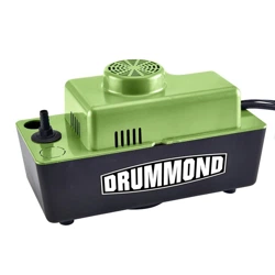
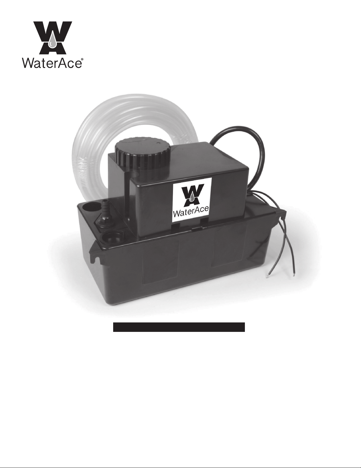
Owner’s Manual
Condensate
Utility Pump
General Safety . . . . . . . . . . . . . . . . . . . . 2
Specications. . . . . . . . . . . . . . . . . . . . . 3
Installation. . . . . . . . . . . . . . . . . . . . .3 & 4
Warranty . . . . . . . . . . . . . . . . . . . . . . . . .5
TABLE OF CONTENTS
2
A condensate pump is an electrical device designed
to operate in inherently wet environments.
ALWAYS USE EXTREME CAUTION
when installing or maintaining this product!
Need Help: Call 1-877-326-3561 for assistance;
Do Not Return to Store
Important Safety Instructions
Carefully read and follow all safety
instructions in this manual and on pump.
SAVE THESE INSTRUCTIONS – This manual
contains important instructions that should be
followed during installation, operation, and
maintenance of the product.
Save this manual for future reference.
Safety Labels
This is the safety alert symbol. When you
see this symbol on your pump or in this manual,
look for one of the following signal words and be
alert to the potential for personal injury!
Indicates a hazard which, if
not avoided, will result in death or serious injury.
Indicates a hazard which,
if not avoided, could result in death or serious
injury.
Indicates a hazard which, if
not avoided, could result in minor or moderate
injury.
NOTICE indicates practices not related to
personal injury.
Keep safety labels in good condition. Replace
missing or damaged safety labels.
General Safety
Risk of burns. Do not
touch an operating motor. Motors are de-
signed to operate at high temperatures. To
avoid burns when servicing pump, allow it to
cool for 20 minutes after shut-down before
handling.
Do not allow pump or any system compo-
nent to freeze. To do so will void warranty.
Pump water only with this pump.
Periodically inspect pump and system com-
ponents.
Wear safety glasses at all times when work-
ing on pumps.
Risk of explosion. Pump
body may explode if used as a booster
pump.
GENERAL SAFETY
STOP
Before you start
3
PRE-INSTALLATION
BEFORE USE
Examine the pump and all parts to ensure no parts are dam-
aged. If any part of the pump appears to be damaged, do not
use this pump and contact 1 877 326-3561 for assistance.
INTENDED USE
Your condensate pump is designed as an automatic conden-
sate removal pump for water dripping o an air conditioner
evaporative coil. The pump is controlled by a oat/switch mecha-
nism which turns the pump on when automatically 2-1/4” of water
collects in the tank and automatically switches o when the tank
drains to approximately 1-1/4”.
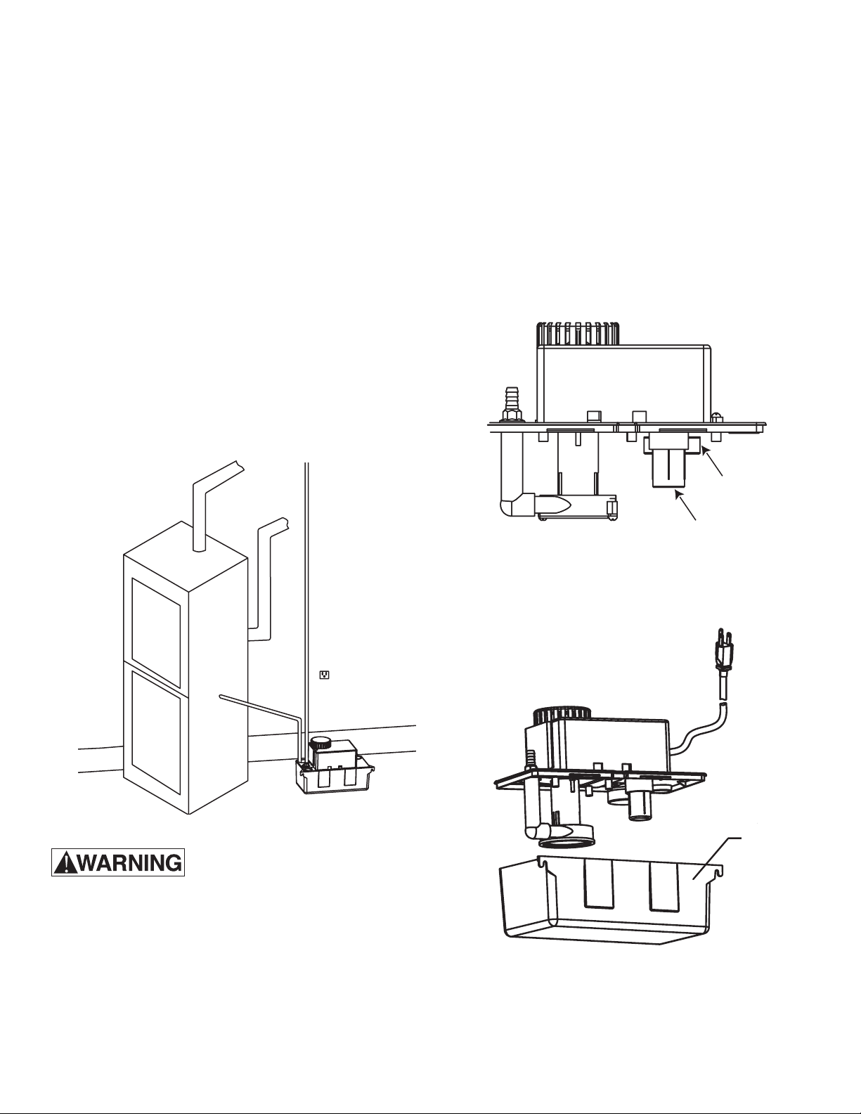
INSTALLATION
MOUNTING THE PUMP
Do not install this pump in a
manner that will subject it to
splashing or spraying.
The tank has two slots provided to mount the unit. The slots
are located on the ends of the tank. The unit should be mount-
ed either on the side of the air conditioner unit or a nearby
wall. The pump must be level and the inlet must be below the
coil drain. Conduit ttings are not compatible with the
plastic pump housing.
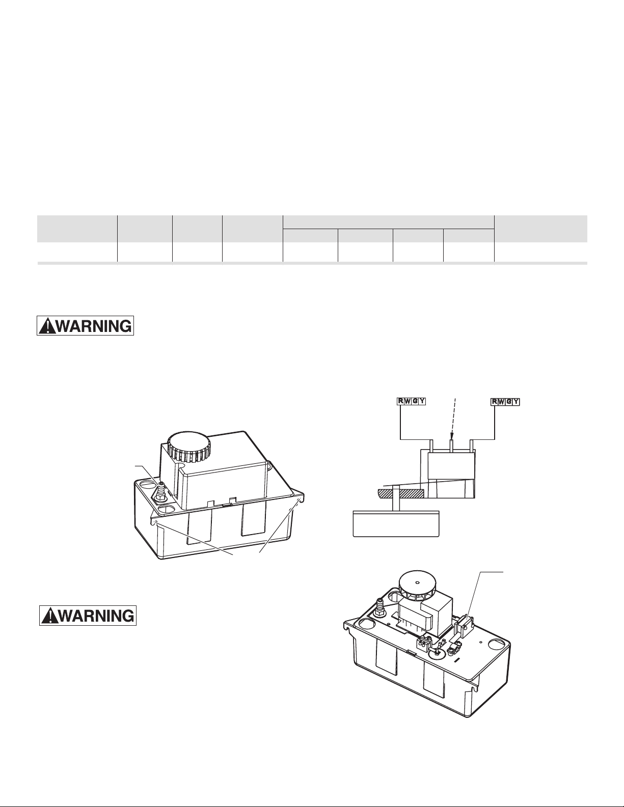
MAKING THE ELECTRICAL CONNECTIONS
Shut off electrical power at the
fuse box before making any
connections. All wiring must comply with local codes.
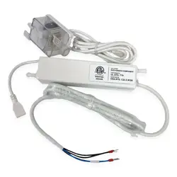
LINE VOLTAGE: Connect the power cord to the line voltage
specied on the motor and nameplate. The power cord must
be connected to a constant source of power (not a fan or other
device that runs intermittently).
If the power cord does not havea plug, wiring is as
follows: green (or yellow/green) - ground. Black (or brown) -
line. And White (or blue) - neutral.
BEFORE INSTALLING THE PUMP
Before installing the pump, allow the air conditioner to cycle
several times, collecting condensate in a separate container
to help ush any residual oils that may have remained in the
system.
MATERIALS REQUIRED (NOT INCLUDED)
Before using this pump, ensure you have the following items:
Safety Glasses, Philips Screwdriver, Level, At least two screws
(for wall or air handler mount only), Wall Anchors (for wall only),
1/2” Hose Clamp.
SPECIFICATIONS & PERFORMANCE
GPH of Water @ Total Feet of Lift
Model HP Volt Amps 0 ft. 5 ft. 10 ft. 15 ft. Max. Lift
CDSP-20 1/12 115 1.5 100 83 67 42 18 ft.
The Safety Switch NC and COM leads can be connected
in series with a low voltage thermostat circuit. This will
protect against overow by shutting down heating/air-
conditioning system if water level in pump tank rises
above normal level. An optional alarm can be connected
to the NO termenal.
Check Valve
Mounting Slots
Safety Switch
(Low Voltage, Class ll)
Thermostat
Terminal
Connection
in Furnace
Typical
Thermostat
Optional Alarm
Hook Up
NC NO COM
4
TESTING THE PUMP INSTALLATION
• Turn on power.
• Remove the motor/tank cover assembly and hold
level.
• Test the motor switch by raising the motor switch
oat with a nger. The motor should turn on just
before the oat contacts the cover.
• Test the safety switch by raising the safety switch
oat with a nger. The safety switch should
activate before the oat contacts the cover.
• Replace the motor/tank cover assembly on the
tank.
CARE AND CLEANING
Ensure the pump is disconnect
ed from the power source before
attemting to service or remove any component.
• Ensure the oats move freely and clean when
necessary.
• Clean the tank (1) with warm water and mild soap.
• Check the inlet and outlet piping. Clean as neces
sary. Ensure there are no kinks in the line that
would inhibit ow.
INSTALLATION continued
CONNECTING THE PIPING
• Run exible tubing or pipe from the evaporator
drain into one of the three pump inlets. Be sure
the inlet piping is sloped downward to allow grav
ity ow. Extend the inlet piping into the tank from
1 to 3 inches to ensure that it will not interfere with
proper oat operation. Be sure that the inlet piping
is cut at an angle where it enters the tank.
• The outlet piping should be exible tubing
secured with a hose clamp (not provided) or pipe
(3/8 in, I.D. maximum to prevent excessive ow
back to the unit). From the condensate unit, ex
tend discharge piping straight up as high as
necessary. Do not extend this line above the
head/GPH of the particular model being installed.
From this high point, slope the discharge line down
slightly to a point above the drain area; then turn
down and extend to a point below or approxi-
mately level with the bottom of the condensate
unit. This will give a siphoning eect which will
improve eciency of the condensate unit and will,
in most cases, eliminate the need for a check
valve. If it is not possible to slope the discharge line
down, make an inverted “U” trap directly above
the pump at the
highest point.
Safety Switch Float
Motor Switch Float
(1) Tank

5
Retain Original Purchase Receipt for Warranty Eligibility
Limited Warranty
Manufacturer warrants to the original consumer purchaser (“Purchaser” or “You”) that its products are free from defects in
material and workmanship for a period of twelve (12) months from the date of the original consumer purchase. If, within
twelve (12) months from the original consumer purchase, any such product shall prove to be defective, it shall be repaired
or replaced at manufacturer’s option, subject to the terms and conditions set forth herein. Note that this limited warranty
applies to manufacturing defects only and not to ordinary wear and tear. All mechanical devices need periodic parts and
service to perform well. This limited warranty does not cover repair when normal use has exhausted the life of a part or
the equipment.
The original purchase receipt and product warranty information label are required to determine warranty eligibility. Eligibil-
ity is based on purchase date or original product – not the date of replacement under warranty. The warranty is limited to
repair or replacement of original purchased product only, not replacement product (i.e. one warranty replacement allowed
per purchase).
Purchaser pays all removal, installation, labor, shipping, and incidental charges.
Claims made under this warranty shall be made by returning the product to the retail outlet where it was purchased or to
the factory immediately after the discovery or any alleged defect. Manufacturer will subsequently take corrective action as
promptly as reasonably possible. No requests for service will be accepted if received more than 30 days after the warranty
expires. Warranty is not transferable and does not apply to products used in commercial/rental applications.
General Terms and Conditions; Limitations of Remedies
You must pay all labor and shipping charges necessary to replace product covered by this warranty. This warranty does
not apply to the following: (1) acts of God; (2) products which, in manufacturer’s sole judgment, have been subject to
negligence, abuse, accident, misapplication, tampering, or alteration; (3) failures due to improper installation, operation,
maintenance or storage; (4) atypical or unapproved application, use or service; (5) failures caused by corrosion, rust or
other foreign materials in the system, or operation at pressures in excess of recommended maximums.
This warranty sets forth manufacturer’s sole obligation and purchaser’s exclusive remedy for defective products.
MANUFACTURER SHALL NOT BE LIABLE FOR ANY CONSEQUENTIAL, INCIDENTAL, OR CONTINGENT DAMAGES
WHATSOEVER. THE FOREGOING LIMITED WARRANTIES ARE EXCLUSIVE AND IN LIEU OF ALL OTHER EXPRESS
AND IMPLIED WARRANTIES, INCLUDING BUT NOT LIMITED TO IMPLIED WARRANTIES OF MERCHANTABILITY
AND FITNESS FOR A PARTICULAR PURPOSE. THE FOREGOING LIMITED WARRANTIES SHALL NOT EXTEND
BEYOND THE DURATION PROVIDED HEREIN.
Some states do not allow the exclusion or limitation of incidental or consequential damages or limitations on how long an
implied warranty lasts, so the above limitations or exclusions may not apply to You. This warranty gives You specic legal
rights and You may also have other rights which vary from state to state.
WARRANTY
1899 Cottage Street
Ashland, Ohio 44805
Telephone: 1-844-394-2604