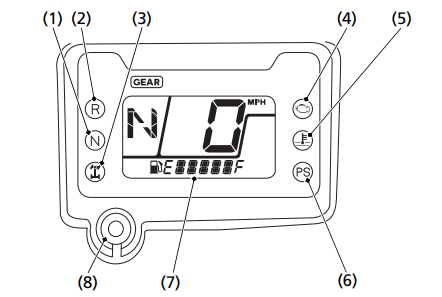
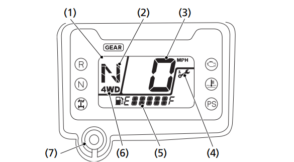
The indicators and displays on your ATV keep you informed, alert you to possible problems, and make your riding safer and more enjoyable. Refer to the indicators frequently. Their functions are described on the following pages.
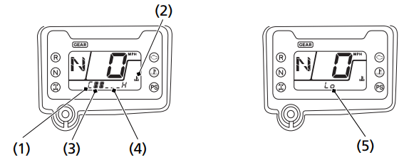
(1) neutral indicator
(2) reverse indicator
(3) differential lock indicator
(4) PGM-FI indicator
(5) high coolant temperature indicator
(6) PS (Electric Power Steering) indicator (TRX520FM2)
(7) multi-function display
(8) mode select button
Lamp Check
Initial lamp check:
The indicators come on for a few seconds and then go off when you turn the ignition switch to ON (I).
TRX520FM2:
The PS (Electric Power Steering) indicator comes back on and remains on until the engine is started after initial lamp check.
The high coolant temperature indicator and PGM-FI indicator come back on for a few seconds and then go off after initial lamp check.
These indicators are identified in the table on page 17 with the words: Lamp Check.
When applicable, the reverse or neutral indicators come back on and remain on until you shift out of reverse or neutral after initial lamp check.
When applicable, the differential lock indicator comes back on and remains on until you shift out of the front differential lock mode after initial lamp check.
If one of these indicators does not come on when it should, have your dealer check for problems.
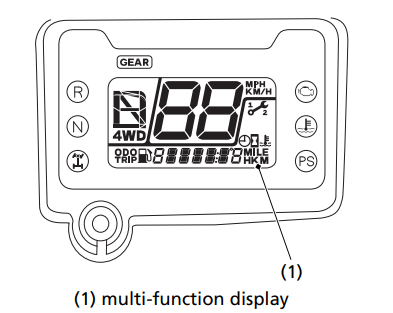
Display Check
When the ignition switch is turned on, the multi-function display (1) will temporarily show all the modes and digital segments and initial message. This is so you can make sure the liquid crystal display is functioning properly
The displays are identified in the table on page 18 with the words: Display Check.
If any part of these displays does not come on when it should, have your dealer check for problems.
Meter Input Signal Failure
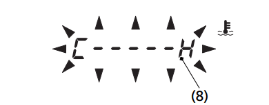
If the neutral indicator, reverse indicator, differential lock indicator, PGM-FI indicator, or high coolant temperature indicator stays on and the gear position indicator “–” and coolant temperature gauge “C – – – – – H” blinks, have your dealer check for problems.
Multi-function Display
The multi-function display (1) includes the following functions:
4WD indicator
Odometer
Gear position indicator
Tripmeter
Speedometer
Coolant temperature gauge
Maintenance minder indicator
Hour meter
Fuel gauge
Maintenance tripmeter
Digital clock
Maintenance hour meter
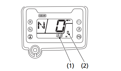
(1) multi-function display
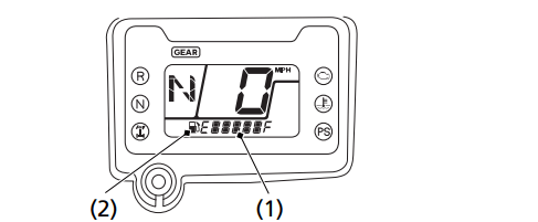
(2) gear position indicator
(3) speedometer
(4) maintenance minder indicator
(5) lower part of the multi-function display
(6) 4WD indicator
(7) mode select button
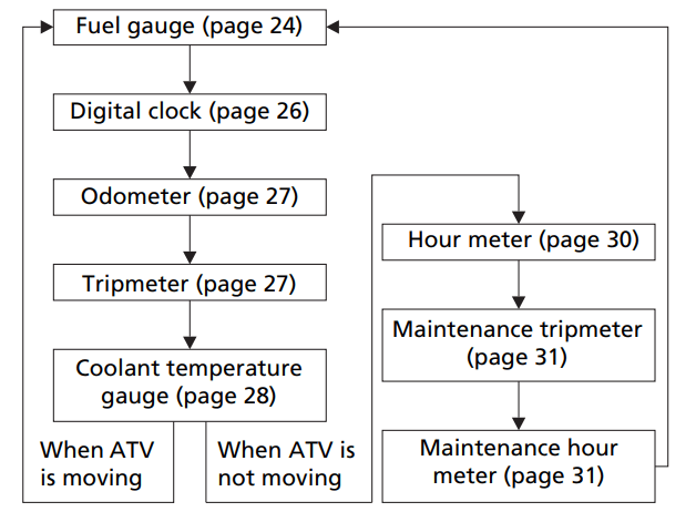
The lower part of the multi-function display (5) shows the fuel gauge, digital clock, odometer, tripmeter, coolant temperature gauge, hour meter, maintenance tripmeter or maintenance hour meter. To change the lower part of the multi-function display, push the mode select button (7).
Each time you press the mode select button, the mode will change as shown in the illustration.
If there is a fuel warning with your ATV, the display will automatically change to the fuel gauge. If you try to change the display back to ordinary display, it will automatically return to the fuel gauge.
If there is a coolant temperature warning with your ATV, the display will automatically change to the coolant temperature gauge. If you try to change the display back to ordinary display, it will automatically return to the coolant temperature gauge.
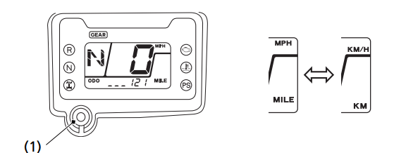
Speed and Mileage Unit Changing
The speedometer, odometer, tripmeter, and maintenance tripmeter show in either “MPH” and “MILE” or “KM/H” and “KM”. To change the speed and mileage units, press and hold the mode select button (1) for more than 5 seconds in the odometer mode (page 21) with the ATV stopped.
(1) mode select button
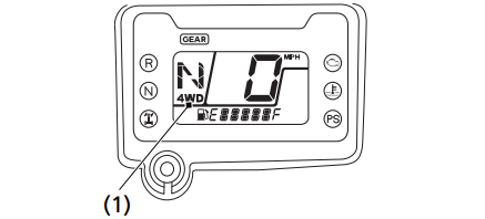
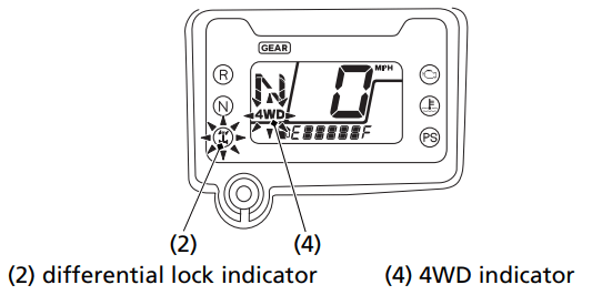
4WD Indicator
The 4WD indicator (1) shows when the 4WD mode engages (page 35).
(1) 4WD indicator
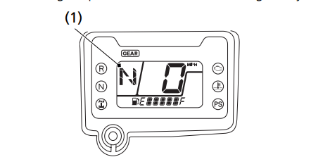
Gear Position Indicator
The gear position indicator (1) shows the gear position when the ignition switch is in the ON (I) position.
The indicator displays: N for neutral, R for reverse, and 1 – 5 for the five forward gears.
“–” will be displayed on the gear position indicator when the transmission is not shifted into gear properly. Before riding, check that the gear position is properly displayed on the gear position indicator.
If the gear position indicator shows “–” or blinks, turn the ignition switch to the OFF (w) position, and then turn it back to the ON (q) position again.
If the gear position indicator shows “–”, rock the vehicle back and forth and make sure the gear position indicator is displayed properly and then if the gear position indicator still shows “–” or blinks, see your dealer.
If the “–” on the gear position indicator is blinking, see your dealer.
(1) gear position indicator
Fuel Gauge
The fuel gauge (1) shows the approximate fuel supply available with the fuel mark (2). The fuel tank capacity is:
3.88 US gal (14.7 ℓ)
(1) fuel gauge
(2) fuel mark
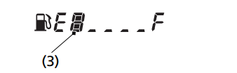
Regardless of what mode the display is in, when the fuel level reaches 1st segment (3), the display will automatically switch to the fuel gauge display. You should refuel as soon as possible. The amount of fuel remaining when the fuel gauge reaches the 1st segment is approximately: 1.82 US gal (6.9 ℓ)
(3) 1st segment
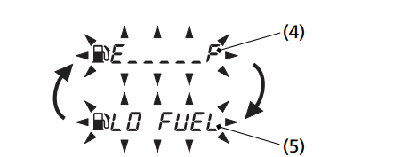
(4) “E _ _ _ _ _ F”
(5) “LO FUEL”
When the fuel gauge shows “E _ _ _ _ _ F” (4) and “LO FUEL” (5) blinks 3 times alternately and the fuel mark blinks, you should refuel as soon as possible.
The amount of fuel reserve is approximately: 1.29 US gal (4.9 ℓ)
Fuel gauge failure:
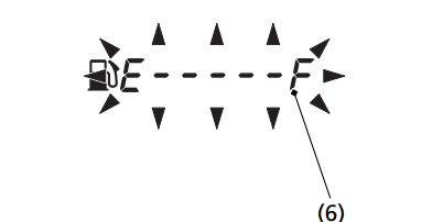
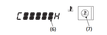
If the fuel gauge “E – – – – – F”(6) is blinking, the fuel gauge function has failed. See your dealer.
(6) “E – – – – – F”
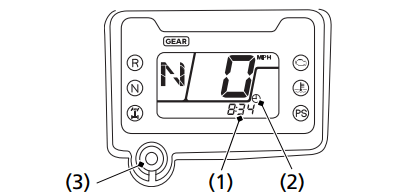
Digital Clock
The digital clock (1) shows time with the clock mark (2) when the ignition switch is ON (I).
(1) digital clock
(2) clock mark
(3) mode select button
To adjust the time, proceed as follows:
Turn the ignition switch ON (I) and select the digital clock mode.
Press and hold the mode select button (3) until the display starts blinking.
To advance the display 1 minute at a time, press and release the mode select button for 0.5 seconds. To advance the display more quickly, press and hold the mode select button.
.Release the mode select button when the display reaches the desired time.
To end the adjustment, press and release the mode select button for less than 0.5 seconds or turn the ignition switch to OFF (O).
After the battery is reconnected (page 193), check the clock. Readjust the clock if necessary.
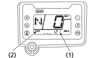
Odometer
The odometer (1) registers total distance traveled in mileage while the ignition switch is ON (q) with the “ODO” mark (2). The odometer locks at 999,999 when the readout exceeds 999,999.
(1) odometer
(2) “ODO” mark
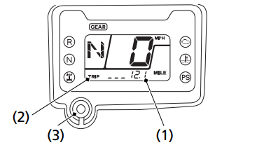
Tripmeter
The tripmeter (1) shows mileage per trip since you last reset the tripmeter while the ignition switch is ON (I) with the “TRIP” mark (2). The tripmeter returns to 0.0 when the readout exceeds 999.9. To reset the tripmeter to zero, press the mode select button (3) and hold it in for at least 2 seconds in the tripmeter mode.
(1) tripmeter
(2) “TRIP” mark
(3) mode select button
Coolant Temperature Gauge
The coolant temperature gauge (1) shows coolant temperature with the coolant temperature mark (2) while the ignition switch is ON (I).
The normal operating temperature range is within the section between the 1st segment (3) and 4th segment (4).
When coolant temperature is low, the coolant temperature gauge will display “Lo” (5).
(1) coolant temperature gauge
(2) coolant temperature mark
(3) 1st segment
(4) 4th segment
(5) “Lo”
When the coolant exceeds the specified temperature, the 5th segment (6) appears and the high coolant temperature indicator (7) lights.
If this occurs, stop the engine and check the reserve tank coolant level. Read pages 221 – 222 and do not ride the ATV until the problem has been corrected.
NOTICE: Continuing to ride with an overheated engine can cause serious engine damage.
(6) 5th segment
(7) high coolant temperature indicator
If the “C – – – – – H” (8) blinks, the meter input signal has failed. See your dealer.
Hour meter
The hour meter (1) shows accumulated hours while the ignition switch is ON (I) with the hour meter mark (2). The hour meter provides accurate service period information for initial and regular maintenance. The hour meter locks at 99,999.9 when the readout exceeds 99,999.9.
(1) hour meter
(2) hour meter mark
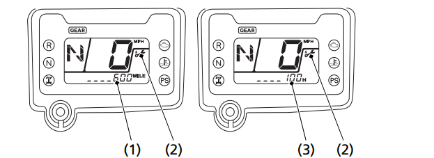
Maintenance Tripmeter/Maintenance Hour meter
The maintenance tripmeter (1) shows mileage to maintenance while the ignition switch is ON (I) with the maintenance minder indicator (2).
The maintenance hour meter (3) shows remaining time to maintenance while the ignition switch is ON (q) with the maintenance minder indicator.
(1) maintenance tripmeter
(2) maintenance minder indicator
(3) maintenance hour meter
The maintenance tripmeter decreases from 600 miles (1,000 km) after reset. The maintenance hour meter decreases from 100 hour after reset.
The initial setting of the maintenance tripmeter is 100 miles (150 km). The initial setting of the maintenance hour meter is 20 hours.
Maintenance Minder Indicators:
Initial Maintenance
Appears at 100 miles (150 km) or 20 operating hours, whichever comes first.
Regular Maintenance Interval 1
Appears 600 miles (1,000 km) or 100 operating hours after the Initial Maintenance or Regular Maintenance Interval 2 is performed and maintenance minder is reset, whichever comes first in the maintenance schedule.
Regular Maintenance Interval 2
Appears 600 miles (1,000 km) or 100 operating hours after Regular Maintenance Interval 1 is performed and maintenance minder is reset, whichever comes first in the maintenance schedule.
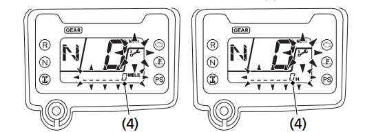
When the maintenance tripmeter or maintenance hour meter amounts to 0, the display of the maintenance minder indicator changes. When the maintenance tripmeter or maintenance hour meter are selected, the maintenance minder indicator and lower part of the multi-function display (4) start blinking. When another mode is selected, the maintenance minder indicator appears in the display.
(4) lower part of the multi-function display
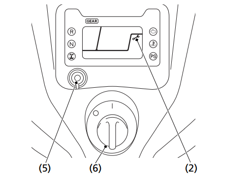
Reset the maintenance tripmeter/maintenance hour meter after maintenance is performed.
To reset the maintenance tripmeter/maintenance hour meter, proceed as follows:
Press and hold the mode select button (5) and turn the ignition switch (6) to ON (I). The maintenance minder indicator will appear, then it will blink twice and the multi-function display will temporarily show all the modes and digital segments. The indicator message will disappear.
Reset operation will be cancelled if the mode select button is released before the indicator blinks twice.
If the maintenance is done before the setting interval, be sure to reset the meters after the maintenance.
(2) maintenance minder indicator
(5) mode select button
6) ignition switch
Controls & Features
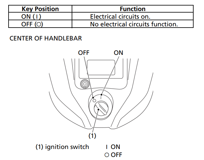
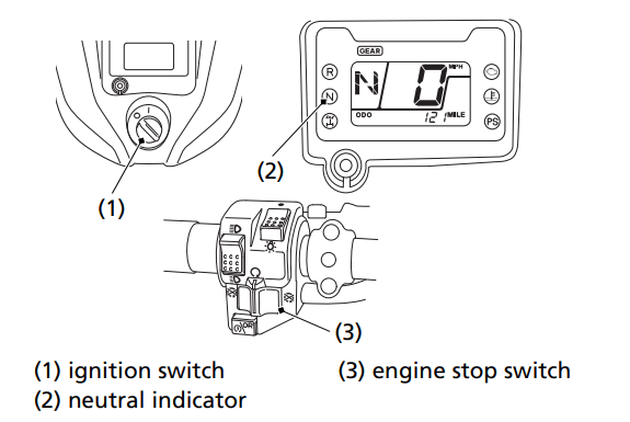
Ignition Switch
The ignition switch (1) is used for starting and stopping the engine (page 80). Insert the key and turn it to the right for the ON (I) position.
The ignition switch is also used to reset the maintenance tripmeter/ maintenance hour meter (page 33).
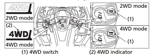
4WD Switch
Your ATV is equipped with a 4WD switch (1), which permits a choice between the “2WD” and “4WD” drive modes. Select a drive mode that’s suitable for your riding.
Keep both hands on the handlebar while the machine is in motion and come to a complete stop before using the 4WD switch.
The 4WD switch is located above the throttle lever. To select the drive mode, with your ATV stopped, push the 4WD switch.
To check your present drive mode, look at the 4WD indicator (2).
2WD mode: the 4WD indicator disappears when the 2WD mode engages. 4WD mode: the 4WD indicator appears when the 4WD mode engages.
If the 4WD indicator does not appear when selecting the 4WD mode, accelerate your ATV slowly until the 4WD indicator appears.
The 4WD indicator and differential lock indicator both flash together when there is any abnormality in the front final gear system. See Front Differential Lock and Speed Limiter Override (Differential Lock Switch and Start/Override Button) page 38.
Front Differential Lock and Speed Limiter Override (Differential Lock Switch and Start/Override Button)
Your ATV is equipped with a front differential lock feature that includes a speed limiter and speed limiter override. This system is designed to provide maximum traction to help you escape from situations where the vehicle might otherwise become stuck, in the mud for example. When the front differential lock mode is activated, the front differential gear is locked causing all four wheels to rotate at the same speed. Because locking all four wheels together changes the way the vehicle handles and increases the amount of room necessary to turn, a speed limiter restricts the speed to 20 mph (32 km/h). Pushing and holding the start/override button in this mode allows you to momentarily override the 20 mph (32 km/h) speed limiter, up to 40 mph (64 km/h), to help you free the vehicle in more severe conditions. You should only use this feature where maximum traction is required and only in low speeds. For normal riding, use 2WD and 4WD modes.
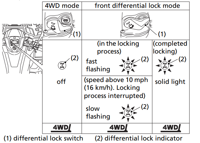
To select the front differential lock mode:
When the 4WD mode is engaged, reduce the speed of your ATV to below 10 mph (16 km/h) and slide the differential lock switch (1) over the 4WD switch. The differential lock indicator (2) will flash fast and the front differential locking process begins. When the locking is complete, the differential lock indicator stays on.
If the speed of your ATV is above 10 mph (16 km/h), the locking process will be interrupted and the differential lock indicator will slowly flash.
If the differential lock indicator does not stay on when the front differential lock mode is selected, steer the handlebar either to the left or right all the way while your ATV is stopped. If the differential lock indicator is still flashing, move your ATV slowly while steering the handlebar all the way to right or left.
To activate the speed limiter override mode:
Push the start/override button (3) when the front differential lock mode is activated.
Front final gear system failure:
The differential lock indicator and 4WD indicator (4) will both flash when there is any abnormality in the front final gear system. If this occurs, the front final gear actuator will stop moving, and the front final gear system will be fixed in the current position, either 2WD mode, 4WD mode or front differential lock mode.
If both the differential lock indicator and 4WD indicator flash, reduce speed and take your ATV to your dealer as soon as possible.
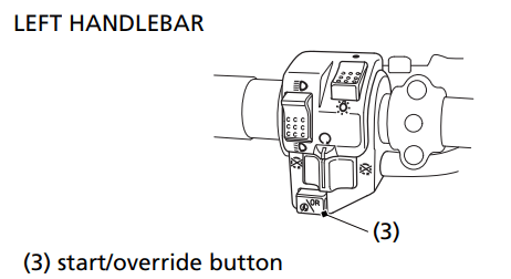
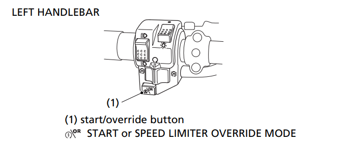
Start/Override Button
The start/override button (1) is used for starting the engine and activating the speed limiter override mode. Pushing the button in starts the engine. See Starting Procedure, page 82.
When the engine is not running and the start/override button is pushed, the starter motor will crank the engine. The starter motor will not operate if the engine stop switch is in the OFF (r) position when the start/override button is pushed.
To activate the speed limiter override mode, see Front Differential Lock and Speed Limiter Override (Differential Lock Switch and Start/ Override Button), page 36.
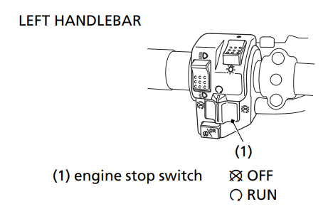
Engine Stop Switch
The engine stop switch (1) is used to stop the engine in an emergency. To operate, slide the switch to the OFF () position. The switch must be in the RUN () position to start the engine, and it should normally remain in the RUN () position even when the engine is OFF
If your ATV is stopped with the ignition switch ON (I) and the engine stop switch OFF (), the battery will discharge. Turn the ignition switch to OFF (O) to prevent battery discharge
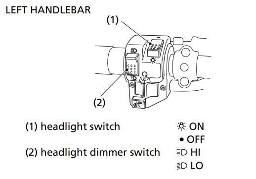
Headlight Switch
The headlight switch (1) is used to turn the headlights and assist headlight ON () or OFF (). To operate, turn the switch to ON () or OFF ().
Headlight Dimmer Switch
The headlight dimmer switch (2) is used to change between the high and low beams of the headlight and to activate the assist headlight. To operate, turn the switch to HI () for high beam headlights and to activate the assist headlight. Turn the switch to LO () for low beam headlights and to deactivate the assist headlight.
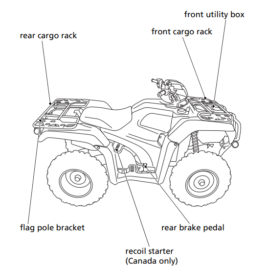
Recoil Starter (Canada only)
The recoil starter (1) is used to start the engine when the battery is low. See Using the Recoil Starter (Canada only), page 86.
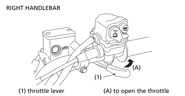
Throttle Lever
The throttle controls engine rpm (speed). To increase engine rpm, press the throttle lever (1) with your thumb. To reduce engine rpm, release pressure on the throttle lever. The throttle will automatically return to the closed position (engine idle) when you remove your thumb.
Front Brake Lever
The front brake lever is used to slow or stop your ATV. To operate, pull the lever. For information on braking techniques, see page 91.
Rear Brake Lever/Parking Brake Lever
The rear brake lever/parking brake lever is used to slow or stop your ATV. To operate, pull the lever. For information on braking techniques, see page 91.
Rear Brake Pedal
The rear brake pedal is used to slow or stop your ATV. To operate, depress the pedal. For information on braking techniques, see page 91.
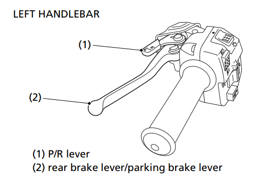
Parking Brake/Reverse Lever (P/R Lever)
The P/R lever (1) on the rear brake lever/parking brake lever (2) is used to apply the parking brake or to shift the transmission into reverse.
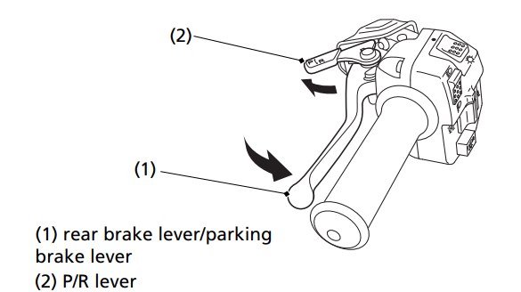
To apply the parking brake:
Bring the vehicle to a complete stop and make sure the transmission is in neutral.
Squeeze the rear brake lever/parking brake lever (1), then rotate the P/R lever (2) clockwise until it engages the slot on the rear brake lever/parking brake lever bracket.
For information on Parking, see page 106.
To release the parking brake:
Squeeze the rear brake lever/parking brake lever until the P/R lever is released from the slot on the rear brake lever/parking brake lever bracket.
The brake lights are activated by applying the parking brake. When using the parking brake, be sure to turn the ignition switch to OFF (O) to avoid discharging the battery.
To shift the transmission into reverse:
See Riding in Reverse, page 89.
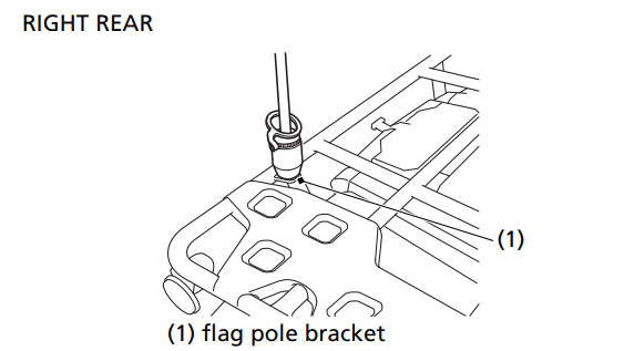
Flag Pole Bracket
Flag poles are optional equipment available from your dealer. To mount a pole in the bracket (1), follow the instructions that come with the flag pole kit.
Flag poles are required in some riding areas. Check local regulations before riding.
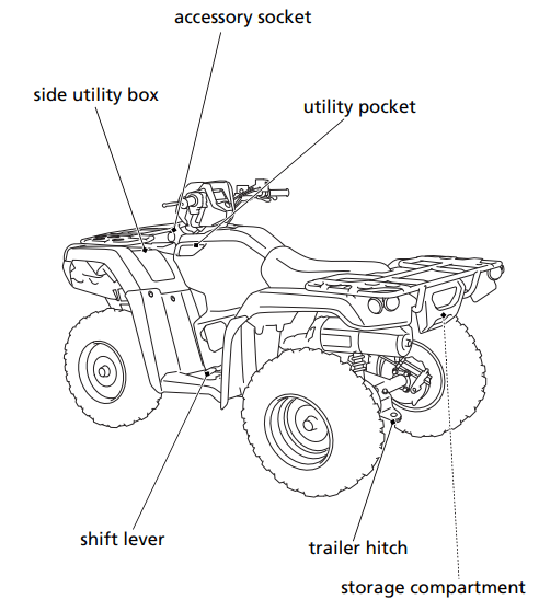
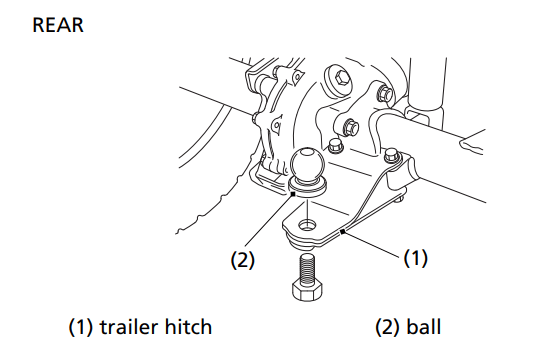
Trailer Hitch
The trailer hitch (1) is located on the rear axle housing. To use the hitch, you’ll need a proper size ball (2) as specified by the trailer manufacturer.
To attach the ball and properly hook up a trailer, follow the trailer manufacturer’s instructions. For load limits and operational guidelines, see page 67.
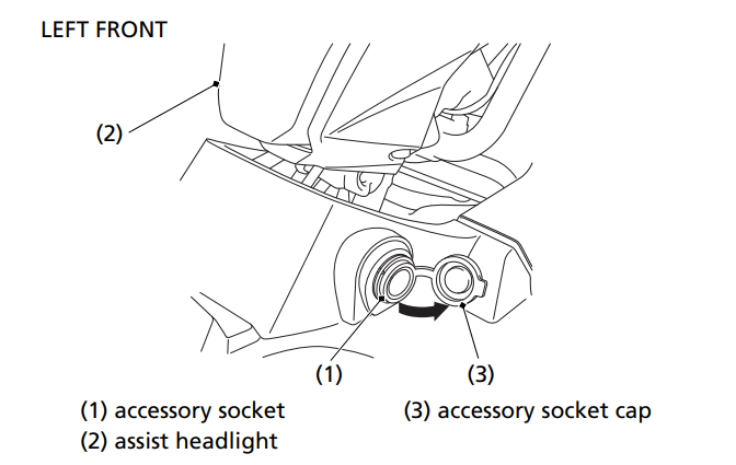
Accessory Socket
The accessory socket (1) is attached to the left side under the assist headlight (2). You can use the accessory socket to power a trouble light, spotlight, CB radio, or cell phone, etc.
To use the accessory socket, turn the ignition switch to ON (I), start the engine. Then, turn the headlights OFF (), and open the accessory socket cap (3).
Be sure the engine is on and the headlights are turned off before using the accessory socket, otherwise you may drain the battery.
The accessory socket’s rated capacity is DC 12 V, 120 Watts (10 A) or less. If you exceed this limit, you may blow a fuse. See If a Fuse Blows, page 223.
When you are done using an accessory, unplug it and cover the socket with the cap.
Be careful not to flood this accessory socket when washing your ATV.
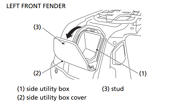
Side Utility Box
The side utility box (1) is located on the left side of the front fender. You may store small, lightweight items in the box.
To open:
Pull up the front of the side utility box cover (2).
To close:
Push down the front of the side utility box cover until it locks in place. Make sure that the stud (3) is locked securely in position by pulling up lightly on the front of the side utility box cover.
Be careful not to flood this area when washing your ATV.
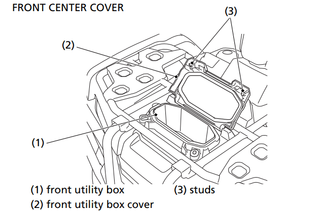
Front Utility Box
The front utility box (1) is located on the front center cover. You may store small, lightweight items in the box.
To open:
Pull up the front of the front utility box cover (2).
To close:
Push down the front of the front utility box cover until it locks in place. Make sure that the studs (3) are locked securely in position by pulling up lightly on the front of the front utility box cover.
Be careful not to flood this area when washing your ATV.
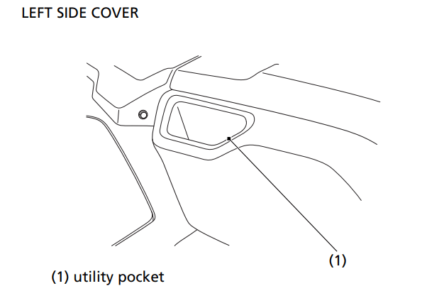
Utility Pocket
The utility pocket (1) is located on the left side cover. You may store small, lightweight items in the pocket.
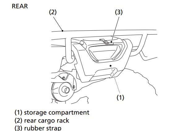
Storage Compartment
The storage compartment (1) is located below the rear cargo rack (2).
To open the compartment, unhook the rubber strap (3).
Be careful not to flood this area when washing your ATV.
EPS (Electric Power Steering) (TRX520FM2)
This ATV is equipped with an electronically controlled, electricpower-assisted steering system.
While the engine is running, the EPS (Electric Power Steering) system provides power from the electric motor, which helps you to turn the ATV’s handlebar more easily.
The EPS system on this ATV utilizes an overheat protection feature to prevent damage to system components. In certain extended, repetitive high-load situations the PS indicator will illuminate and, the system will reduce or even disable power steering assist. The steering will perform as a normal non-EPS system during this brief period. If this occurs, safely stop the vehicle and allow the EPS system to cool down until the PS indicator goes off. After cooling down, steering will return to normal EPS operation.
The PS indicator should light when the ignition switch is turned on and remain on until the engine is started.
The PS indicator also lights when there is any abnormality in the EPS system. If this occurs, the electric power assist for turning will not be available, but the manual steering system will perform as usual.
If the PS indicator lights at any time while riding, other than the temporary overheat condition described above, reduce speed and take your ATV to your dealer as soon as possible. Continuing to ride with a EPS system problem can damage system components.
Do not modify your Electric Power Steering system. In case of a malfunction, take your ATV to your dealer.
Starting & Stopping the Engine
Always follow the proper starting procedure described below.
For your safety, avoid starting or operating the engine in an enclosed area such as a garage. Your ATV’s exhaust contains poisonous carbon monoxide gas which can collect rapidly in an enclosed area and cause illness or death.
Preparation
Before starting, select a level surface and lock the parking brake (page 45).
Turn the ignition switch (1) to ON (I).
Confirm the following: ‘The transmission is in neutral, the neutral indicator (2) is ON and the gear position indicator shows “N”.
The engine stop switch (3) is set to RUN ().
Starting Procedure
This ATV is fuel-injected with an automatic choke. Follow the procedure indicated below.
Any Air Temperature
• Press the start/override button with the throttle completely closed.
The engine will not start if the throttle is fully open (because the electronic control module cuts off the fuel supply).
Snapping the throttle or fast idling for more than 5 minutes may cause exhaust pipe and muffler discolorations.
Flooded Engine
If the engine fails to start after repeated attempts, it may be flooded with excess fuel. To clear a flooded engine:
1. Leave the engine stop switch set to RUN ().
2.Open the throttle fully.
3.(USA)
Press the start/override button for 5 seconds.
(Canada)
Press the start/override button for 5 seconds (or operate the recoil starter several times).
4. Follow the normal starting procedure.
5.If the engine starts, then open the throttle slightly if idling is unstable.
If the engine does not start, wait 10 seconds, then follow steps 1 – 4 again.
Bank Angle Sensor Ignition Cut-off System
Your vehicle’s banking (lean angle) sensor system is designed to automatically stop the engine if the vehicle is overturned.
Before restarting the engine, you must turn the ignition switch to the OFF (O) position and then back to ON (I). The engine will not restart until you perform this procedure.
Stalled Engine
You can restart the engine while the vehicle is stopped by squeezing the front brake lever and pressing the start/override button.
Do not press the throttle lever while starting in gear. The engine will not start if the throttle is fully open (because the electronic control module cuts off the fuel supply).
Once you have started the engine, release the front brake lever, then apply throttle gradually
How to Stop the Engine
Normal Engine Stop
To stop the engine, make sure the transmission is in neutral by checking that the neutral indicator light is on, then turn the ignition switch to OFF (O).
The engine stop switch should normally remain in the RUN () position even when the engine is OFF.
If your ATV is stopped with the engine stop switch OFF () and the ignition switch ON (I), the battery will discharge.
Emergency Engine Stop
To stop the engine in an emergency, use the engine stop switch. To operate, slide the switch to either OFF () position.
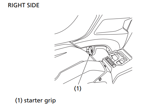
Using the Recoil Starter (Canada only)
The recoil starter is used to start the engine when the battery is low. To operate the recoil starter:
Turn the ignition switch to ON and engine stop switch to RUN.
Check that the transmission is in neutral.
Grasp the starter grip (1) firmly, then pull it out slowly approximately 4 in (100 mm).
Pull the grip up briskly and fully.
After the engine starts, allow the starter grip to return slowly.
Pull the recoil starter grip straight out so that the cord does not touch the side cover. Repeated contact with the side cover can damage the starter cord.
If the starter grip does not return smoothly (because of dirt in the assembly), see your dealer.
Taking Care of the Unexpected
General Guidelines
Keeping your ATV well-maintained is the best way to reduce the possibility of having a problem while riding. However, problems can arise even with well-maintained machines.
Remember to take along your owner’s manual, the tool kit that came with your ATV, and any other items (such as tire repair supplies and additional tools) that might help you solve a problem on your own.
If something goes wrong during a ride, the first thing to do is stop as soon as you safely can. Do not continue riding if you have a flat tire, or you hear an unusual noise, or your ATV just doesn’t feel right. If you continue riding, you could cause more damage and endanger your own safety
After stopping, take time to assess the situation. Carefully inspect your ATV to identify the problem, then consider your options before you decide what to do.
If a problem is relatively minor and you have the tools, supplies, and skills to make a permanent repair, you may be able to fix it on the trail and continue riding. Or, you may be able to make a temporary repair that allows you to slowly ride back to your base where you can make a permanent repair or get help.
When a problem is more serious — or you don’t have the tools, supplies, experience, or time to deal with it — you need to choose the safest way to get yourself and your ATV back to base. For example, if you are close enough, you (or you and another person) might be able to push it back.
Should you ever have a problem while riding, please follow these guidelines:
• Always put personal safety first.
• Take time to assess the situation and your options before deciding what to do.
• If the problem is relatively minor and you have the tools, supplies, and skills to make a temporary repair, be sure to have permanent repairs made as soon as possible.
• Do not continue riding if you are hurt or your ATV is not in safe riding condition.
Additional recommendations for specific problems follow.
If Your Engine Quits or Won’t Start
Proper operation and maintenance can prevent starting and engine performance problems. In many cases, the cause of the problem may be a simple operational oversight.
If you have a problem starting the engine — or experience poor engine performance — the following information may help you. If you can’t correct the problem, see your dealer.
If your ATV won’t start, listen as you press the start/override button. If you don’t hear the starter motor turning, refer to the Starter motor doesn’t operate symptom. If you can hear the starter motor working normally, refer to the Starter motor works, but the engine won’t start symptom.
SYMPTOM: Starter motor doesn’t operate.
POSSIBLE CAUSE
WHAT TO DO
ignition switch OFF
Turn the ignition switch ON.
engine stop switch OFF
Slide the engine stop switch to RUN
transmission not in neutral
Shift into neutral or squeeze the front brake lever.
blown fuse
Replace with a new fuse of the same rating (page 223).
battery lead loose
Tighten the battery lead.
low (or dead) battery
Charge the battery (page 195). If charging doesn’t help, see your dealer.
faulty starter motor
If all possible causes are negative, the starter motor may be faulty. See your dealer
SYMPTOM: Starter motor works, but the engine won’t start.
POSSIBLE CAUSE
WHAT TO DO
out of fuel
Fill the fuel tank.
flooded engine
See Flooded Engine (page 83).
loose or unconnected spark plug cap
Install the spark plug cap securely. If the engine still won’t start, see your dealer.
loose battery cables
Tighten the battery terminal bolts.
weak battery
Charge the battery (page 195). If charging doesn’t help, see your dealer.
SYMPTOM: Engine starts, but runs poorly.
POSSIBLE CAUSE
WHAT TO DO
high coolant temperature
Check the coolant temperature gauge and high coolant temperature indicator. Refer to If the High Coolant Temperature Indicator Lights, page 221.
runs erratically, misfires
See your dealer.
blubbers (rich fuel mixture)
See your dealer.
sooty exhaust (rich fuel mixture)
See your dealer.
detonates or pings under load
If applicable, switch to the recommended octane gasoline (page 126) or change your brand of gasoline. If the problem persists, see your dealer.
afterfires (backfires)
See your dealer.
pre-ignition (runs on after ignition switched OFF)
See your dealer.
SYMPTOM: Engine starts, but runs poorly or dies when hot.
POSSIBLE CAUSE
WHAT TO DO
poor or inadequate fuel flow due to clogged fuel filter
See your dealer. (ensure clean fuel supply)
If You Have a Flat Tire
How you handle a flat tire on the trail depends on how serious the tire damage is, and what tools and supplies you have with you.
If you have a slow leak or a minor puncture, use the plug method to make a temporary repair. (The plug method is applied from the outside of the tire and is the same as that for conventional tubeless tires.)
A plug-type repair kit, available at most auto parts stores or service stations, provides a plug, an installation tool, tire cement, and an instruction sheet. Follow the instructions provided with the repair kit to make a temporary repair.
As soon as possible, have the tire permanently repaired by your dealer. Any tire that cannot be repaired should be replaced.
Whenever the ATV is to be operated far from service facilities or available transportation, we recommend that you carry a tire pump and a repair kit with the vehicle.
If the leak is more serious, or a temporary repair doesn’t hold, the tire must be replaced. The tire will also need to be replaced if it is damaged (page 186). Replacing a tire involves removing and reinstalling the wheel (page 219).
If you are unable to repair a flat tire on the trail, you will need to send for help. We strongly recommend that you do not try to ride with a flat tire. The ATV will be hard to handle, and if the tire comes off the rim, it may lock up the wheel and cause you to crash.
Emergency Wheel Removal/Installation
Refer to Safety Precautions on page 111.
Removal
Park your ATV on a firm, level surface.
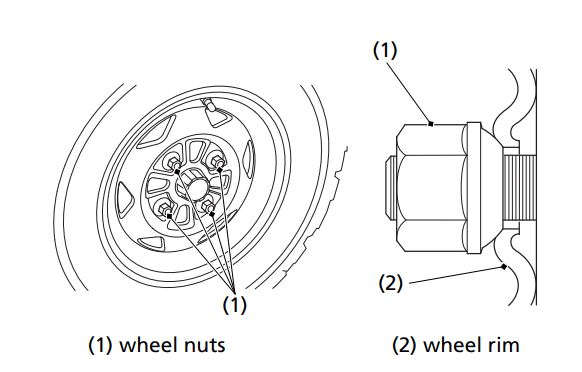
Loosen — but do not remove — the wheel nuts (1).
Raise the front (or rear) wheels off the ground and place a support block under the vehicle.
Remove the wheel nuts.
Remove the wheel.
• Avoid getting grease, oil, or dirt on the front brake disc or pad surfaces when removing and installing each wheel. Any contamination can cause poor brake performance or rapid pad wear after reassembly.
Installation
Position the wheel.
Position the wheel nuts so that the tapered sides face the wheel rim (2).
Hand-tighten the wheel nuts on the wheel, then lower the ATV to the ground before tightening the nuts in a crisscross (rather than circular) pattern to the specified torque: 47 lbf·ft (64 N·m, 6.5 kgf·m)
If a torque wrench was not used for installation, see your dealer as soon as possible to verify proper assembly. Improper assembly may lead to loss of braking capability.
If the High Coolant Temperature Indicator Lights
Normally, the high coolant temperature indicator will only light momentarily when you turn the ignition to ON (I).
High coolant temperature may be caused by restriction of air flow to the radiator (such as mud caked on the radiator), extended idling, an oil leak, a coolant leak, a low oil level, a low coolant level, or extended operation under adverse conditions.
If the all segment of the coolant temperature gauge and high coolant temperature indicator are on while you’re riding, don’t ignore it. Pull safely to a stop. Stop the engine as soon as it’s safe to do so, and let it cool.
NOTICE: Continuing to ride with high coolant temperature or an overheated engine can cause serious engine damage.
A steaming engine indicates a coolant leak. Shut the engine off and wait until the steaming stops. Look for a leak, but don’t touch the engine or radiator system. Let everything cool off first.
Check for any restriction of air flow to the radiator.
If there’s no obvious problem, leave the engine on so the fan and coolant circulating system can continue working. Monitor the coolant temperature gauge and high coolant temperature indicator. The indicator may turn off after a brief stop with no load on the engine.
Check the radiator fan. If the fan is not working, turn the engine off. Open the fuse box (page 224) and check the radiator fan fuse. If the fuse is blown, replace it with the proper (same rating) spare fuse. Start the engine. If the all segment of the coolant temperature gauge and high coolant temperature indicator stays on, turn the engine off. If the radiator fan is working, visually check the coolant level in the reserve tank, located under the left front fender. It isn’t necessary to touch the radiator system.
If the reserve tank is low or empty, don’t ride without adding coolant (page 144). After adding coolant, turn the engine on and check the coolant temperature gauge and high coolant temperature indicator. If the indicator doesn’t turn off, do not ride. The engine needs repair. Transport your ATV to your dealer (page 204). If the temperature drops to normal, check the coolant level. If it has gone down, add more coolant
Check for an oil leak.
Check the oil level. If necessary, add the recommended oil (page 132) to the upper level mark. If you must leave your ATV to get oil, secure it as much as possible.
Start the engine, and check that the coolant temperature gauge and high coolant temperature indicator goes off.
If you are able to resume riding, continue to monitor the coolant temperature gauge and high coolant temperature indicator frequently.
If there is an oil leak — do not ride the ATV until the leak is repaired by your dealer (page 204).
If there’s a mild coolant leak, you can ride for awhile, carefully watching the coolant temperature gauge and indicator. Be prepared to stop and add more coolant or water. If the leak is bad, transport your ATV to your dealer (page 204).
If a Fuse Blows
All of the electrical circuits on your ATV have fuses to protect them from damage caused by excess current flow (short circuit or overload).
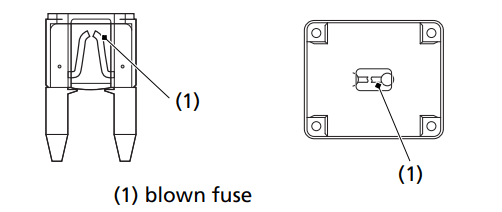
If something electrical on your ATV stops working, the first thing you should check for is a blown fuse (1).
Check all the fuses before looking elsewhere for another possible cause of the problem. Replace any blown fuses and check component operation.
The main fuse and the circuit fuses are located under the rear fender cover.
TRX520FM2:
The EPS (Electric Power Steering) block fuse is located under the rear fender cover.
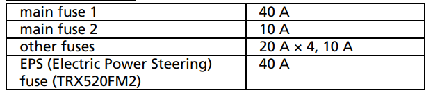
Recommended Fuses
Main Fuses Access
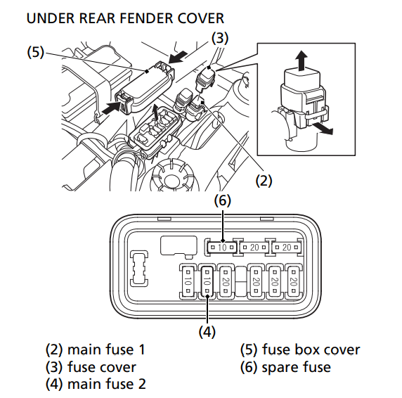
To prevent an accidental short circuit, turn the ignition switch to OFF (w) before checking or replacing the fuses.
Remove the seat (page 122).
Remove the rear fender cover (page 123).
To access the main fuse 1 (2), remove the fuse cover (3).
To access the main fuse 2 (4), remove the fuse box cover (5).
.Pull the main fuse 1 out. If the main fuse 1 is blown, install the spare fuse on the underside of the rear fender cover (page 121).
Pull the main fuse 2 out with the fuse puller on the underside of the rear fender cover (page 121). If the main fuse 2 is blown, install the spare fuse (6).
Install the fuse cover.
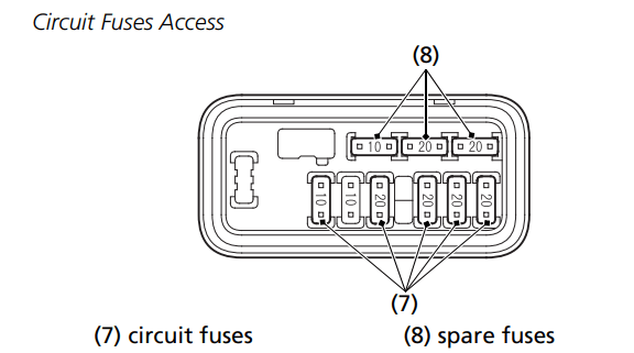
To check or replace a circuit fuse (7), pull the old fuse out of its retaining clips with fuse puller on the underside of the rear fender cover (page 121). If the fuse is blown, replace it with a spare fuse (8) of the same rating.
Install the fuse box cover.
Install the rear fender cover.
Install the seat.
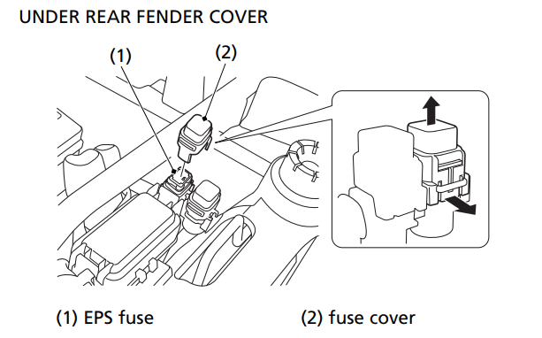
EPS (Electric Power Steering) Fuse Access (TRX520FM2)
Turn the ignition switch to OFF (w) before checking the fuse.
Remove the seat (page 122).
Remove the rear fender cover (page 123).
To access the EPS fuse (1), remove the fuse cover (2). If the EPS fuse is blown, see your dealer for this service.
Install the fuse cover.
Install the rear fender cover.
Install the seat.
If you do not have a spare fuse and you cannot ride the ATV without fixing the problem, take a fuse of the same rating or a lower rating from one of the other circuits that you can do without temporarily.
If you replace a blown fuse with a spare fuse that has a lower rating, replace the fuse with the correct rating as soon as you can. Also remember to replace any spare fuses that were installed.
If the replacement fuse of the same rating burns out in a short time, there is probably a serious electrical problem on your ATV. Leave the blown fuse in that circuit and have your ATV checked by your dealer.
If You Crash
Personal safety is your first priority after a crash. If you or anyone else has been injured, take time to assess the severity of the injuries and whether it is safe to continue riding. If you cannot ride safely, send someone for help. Do not ride if you will risk further injury.
If you decide you are capable of riding safely, carefully inspect your ATV for damage and determine if it is safe to ride. Check the tightness of critical nuts and bolts securing such parts as the handlebar, control levers, brakes, and wheels.
If there is minor damage, or you are unsure about possible damage but decide to try riding the ATV back to your base, ride slowly and cautiously.
Sometimes, crash damage is hidden or not immediately apparent. When you get home, thoroughly check your ATV and correct any problems you find. Also, be sure to have your dealer check the frame and suspension after any serious crash.
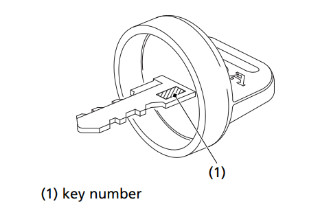
If You Lose Your Key
Be sure to record your key number (1). Store the spare key and recorded key number in a safe location. You’ll need this number to have a duplicate key made.
If you lose your key and aren’t carrying a duplicate, either get your spare or have one made. If you don’t know your key number, call the dealer where you purchased your Honda ATV. They may have it listed in their records. If they don’t, transport your ATV to them or the nearest dealer. The dealer will probably have to remove the ignition switch assembly to find the key number so they can make a key for you.
If the Battery Is Low (or Dead)
Jump starting is not recommended, especially if you use an automobile battery. The greater amperage of an automobile battery when the car engine is running can damage your ATV’s electrical system.
Bump starting is also not recommended.
If you can’t charge the battery or it appears unable to hold a charge, contact your dealer.
(Canada only)
Your ATV will operate even if the battery is low (or dead), as long as the engine is running. If the engine is not running, it may be started using the recoil starter.
Shift the shift lever in neutral position.
Apply the parking brake.
Turn the ignition switch to the ON (I) position.
Use the recoil starter (page 86) to start the engine.
If a Component Fails
The brake levers or pedal, control cables, and other components can be damaged as you ride in dense brush or over rocky terrain. Making a trailside repair depends on how serious the damage is and what tools and supplies you have with you.
If any component of the brake system is damaged, you may be able to ride carefully back to your base using the other brake components for slowing or stopping.
If you damage a throttle cable or other critical component, your ATV may be unsafe to ride. Carefully assess the damage and make any repairs that you can. But if there is any doubt, it’s best to be conservative and safe.


 ) position. The switch must be in the RUN (
 ) position to start the engine, and it should normally remain in the RUN (
 ) or OFF (
 ). To operate, turn the switch to ON (
 ) for high beam headlights and to activate the assist headlight. Turn the switch to LO (
 ) for low beam headlights and to deactivate the assist headlight.
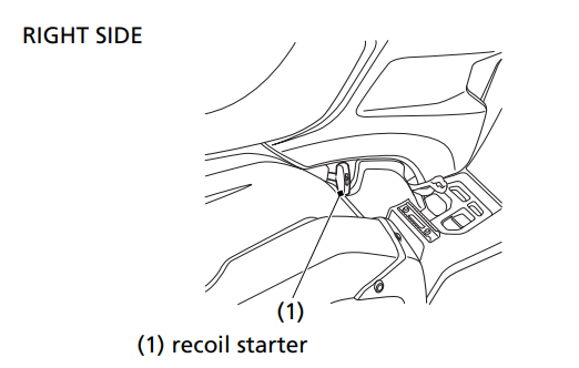
 ).
). ) and the ignition switch ON (I), the battery will discharge.