
Cybex MG 500 Multi-Gym
Strength Systems
Owner’s and Service Manual
Strength Systems
Part Number 58600 E
www.cybexinternational.com


Cybex MG 500 Multi-Gym
Strength Systems
Owner’s and Service Manual
Strength Systems
Part Number 58600 E
Cybex
®
and the Cybex logo are registered trademarks of Cybex International, Inc.
DISCLAIMER: Cybex International, Inc., makes no representations or warranties regarding the contents of this manual. We reserve the right t o
revise this document at any time or to make changes to the product described within it without notice or obligation to notify a ny person of such
revisions or changes.
© Copyright 2009, Cybex International, Inc. All rights reserved.
Printed in the United States of America.
10 Trotter Drive Medway, MA 02053 • 508-533-4300 • FAX 508-533-5183


i Table of Contents
1 Safety
Safety......................... 1-1
Warning/Caution Decals .......... 1-3
Regular Maintenance Activities ..... 1-9
Using Proper Form .............. 1-9
2 Technical Specifications
General Specifications............ 2-1
Machine Specifications ........... 2-4
3 General Exercise Guidelines
Training Suggestions ............. 3-1
Glossary ....................... 3-2
Exercise Charts
4 Exercises
Hip Abduction .................. 4-2
Hip Adduction .................. 4-2
Hip Flexion..................... 4-3
Hip Extension................... 4-3
Leg Extension .................. 4-4
Seated Leg Curl................. 4-5
Standing Calf Raise .............. 4-6
Seated Row .................... 4-6
Front Lat Pulldown............... 4-7
Seated Rear Deltoid Row ......... 4-8
Standing Shrugs ................ 4-8
Decline Bench Press ............. 4-9
Bench Press.................... 4-9
Incline Bench Press .............. 4-10
Military Press ................... 4-10
Chest Press .................... 4-11
Chest Fly ...................... 4-11
Tricep Pressdown ............... 4-12
Overhead Tricep Extension ........ 4-12
Standing Arm Curl ............... 4-13
Hammer Curl ................... 4-13
Wrist Curl ...................... 4-14
Abdominal Crunch ............... 4-14
Seated Leg Press................ 4-15
Uni-Lateral Seated Row........... 4-16
Seated Calf Raise ............... 4-16
Table of Contents
5 Customer Service
Ordering Parts .................. 5-1
Cybex Limited Warranty .......... 5-2
Delivery Inspection............... 5-5
Installation ..................... 5-5
Returning Goods ................ 5-6
6 Assembly
Tools Required .................. 6-2
Unpacking Main Frame Assembly. . . 6-2
Installing Weight Stacks........... 6-7
Fly Station Diagram .............. 6-11
Fly Station Assembly ............. 6-12
Leg Press Diagram .............. 6-35
Leg Press Assembly ............. 6-36
Pressing Station Diagram ......... 6-57
Pressing Station Assembly ........ 6-58
Leg Extension/Leg Curl Diagram . . . 6-79
Leg Extension/Leg Curl Assembly. . . 6-80
Cables Adjustments.............. 6-101
Fly Station ..................... 6-101
Leg Press Station................ 6-102
Leg Extension/Leg Curl Station. . . . . 6-103
Pressing Station................. 6-103
Weight Stack Cable Check ........ 6-105
Weight Stack Cable Adjustment .... 6-106
Final Assembly.................. 6-107
7 Maintenance
Daily Procedures ................ 7-1
Weekly Procedures .............. 7-3
Yearly Procedures ............... 7-5
“As Required” Procedures......... 7-5
Cable Adjustments............... 7-5
Fly Station ..................... 7-6
Leg Press Station................ 7-7
Leg Extension/Leg Curl Station. . . . . 7-8
Pressing Station................. 7-8
Weight Stack Cable Tension Check. . 7-10
Alternative Weight Stack Cable Tension
Check......................... 7-10
Weight Stack Cable Adjustment .... 7-11
8 Service
Parts Lists and Diagrams ......... 8-1


Cybex MG 500 Multi-Gym Owner’s Manual
Safety
Page 1-1
1 - Safety
Safety
Read the Owner’s Manual carefully before assembling, servicing or using the MG 500.
! WARNING: Serious injury could occur if these safety precautions are not
observed:
• DO NOT use the MG 500 if it is not located on a solid level surface.
• Read all cautions/warnings and obtain proper instruction on use of the machine prior to
using. Use appropriate positioning, speed and controlled movements.
• Obtain a medical exam prior to beginning an exercise program.
• If at any time during exercise you feel faint, dizzy or experience pain, stop and consult
your physician.
• Keep head, limbs, fingers and hair clear of all moving parts.
• DO NOT wear loose or dangling clothing while using the MG 500. Keep away from all
moving parts.
• Inspect the MG 500 prior to use. DO NOT use if damaged or inoperable.
• DO NOT attempt to fix a broken or jammed machine. Notify floor staff.
• Use the machine only for the intended use. Obtain instruction and DO NOT modify the
machine.
• Be certain that the weight pin is completely inserted. Use only the pin provided by the
manufacturer. If unsure, seek assistance.
• NEVER use dumbbells or other means to incrementally increase the weight resistance.
• NEVER pin the weights in an elevated position. DO NOT use the machine if found in this
condition. Seek assistance from floor staff.
• Children must not be allowed near this machine. Teenagers must be supervised.
• DO NOT use if guards are missing or damaged.
• DO NOT remove any labeling from the MG 500. Replace any damaged labels.

Safety
Page 1-2
Facility Safety Precautions
• Make sure that the MG 500 is set up and always operated on a level surface.
• Read the Owner’s Manual carefully before assembling, servicing or using the MG 500.
• Make sure that all users are properly trained on how to use the MG 500.
• Make sure there is enough room for safe access and operation of the MG 500. When the MG 500
is in use, there must be a minimum of at least three feet on all sides for safe access, operation
and passage.
• Perform regular maintenance checks on the MG 500. Pay close attention to cables and their
connections. Also pay close attention to all areas most susceptible to wear.
• Immediately replace worn or damaged components. If unable to immediately replace worn or
damaged components then remove from service until the repair is made.
• Use only Cybex supplied components to maintain/repair the MG 500.
• Keep a repair log of all maintenance activities.
NOTE: It is the sole responsibility of the user/owner or facility operator to ensure that regular
maintenance is performed.
Cybex MG 500 Multi-Gym Owner’s Manual
Cybex MG 500 Multi-Gym Owner’s Manual
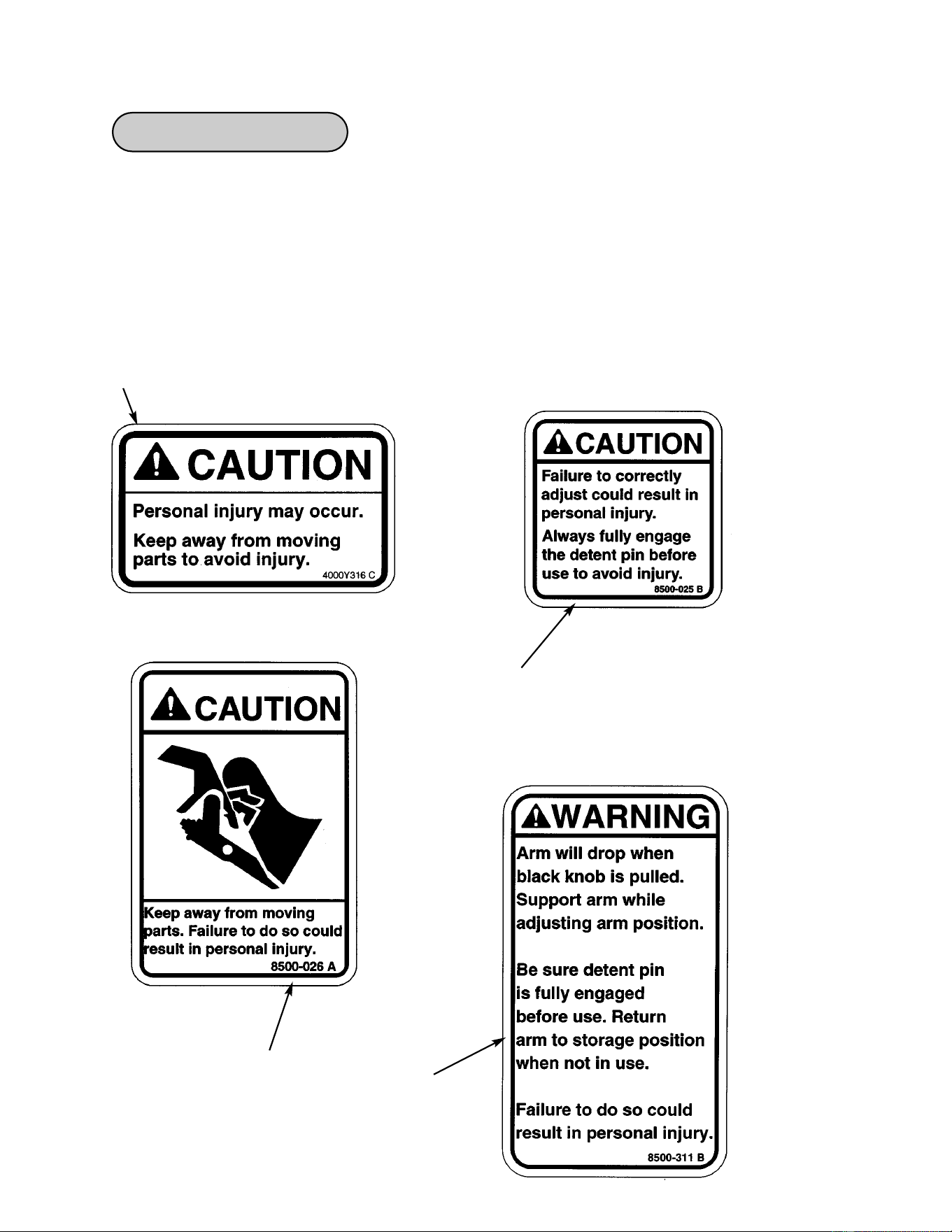
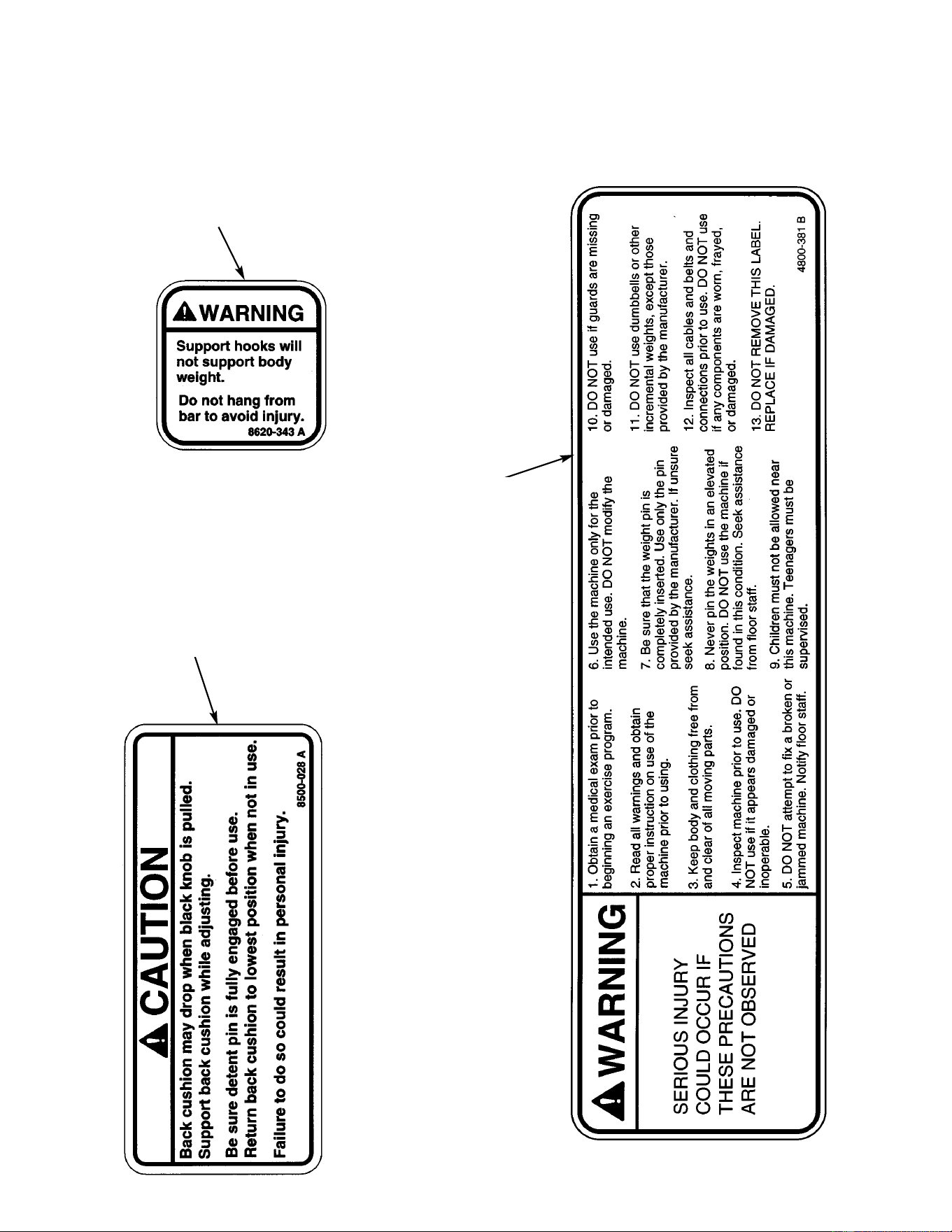
Warning/Caution Decals
Warning decals indicate a potentially hazardous situation, which, if not avoided, could result
in death or serious injury.
Caution decals indicate a potentially hazardous situation, which, if not avoided, could result
in minor or moderate injury.
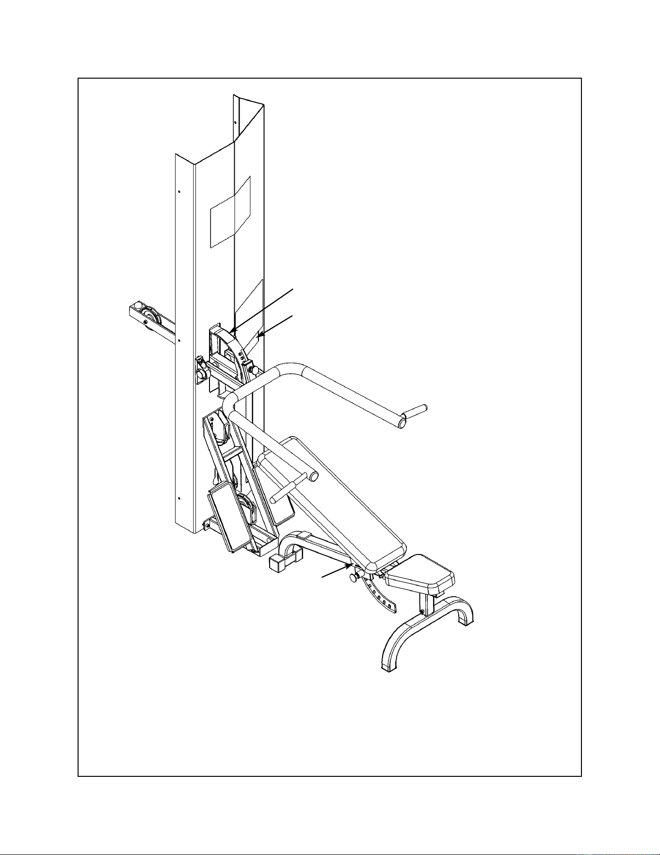
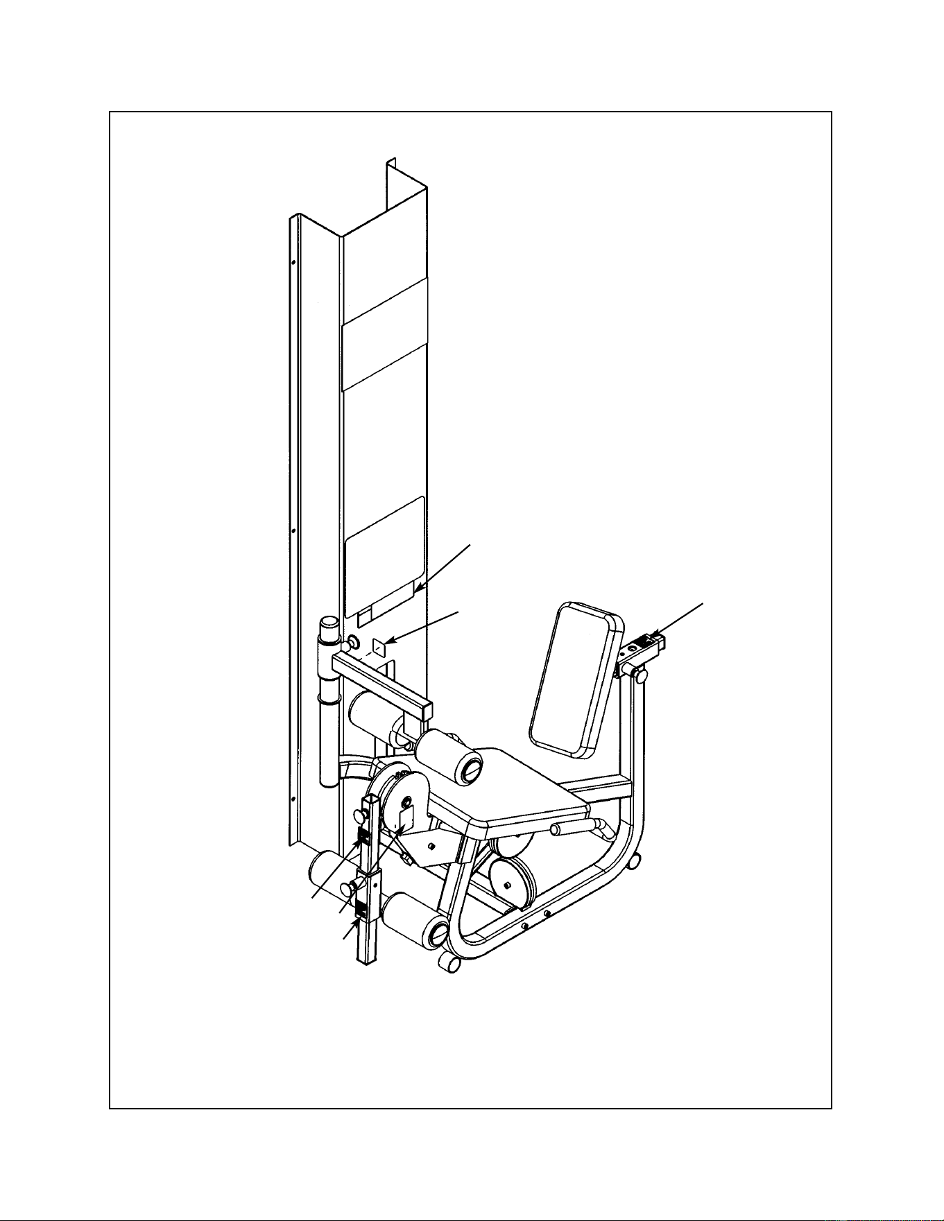
The warning and caution decals are shown below and on the following pages. The diagrams
following the decals show where each decal is located.
See Leg Press Station diagram, letter A.
See Fly Station
and Leg Press
Station diagrams,
letter C.
See Pressing
Station diagram,
letter D.
See Fly Station
diagram, letter B.
Safety
Page 1-3
Cybex MG 500 Multi-Gym Owner’s Manual
Safety
Page 1-4
See Pressing
Station diagram,
letter F.
See Pressing
Station diagram,
letter G.
See Fly Station
diagram, letter E.
Cybex MG 500 Multi-Gym Owner’s Manual
B. Caution Decal .................... 8500-026
C. Caution Decal .................... 8500-025
E. Warning Decal ................... 8620-343
F. Warning Decal ................... 4800-381
DESCRIPTION PART NO.
F
C
B
Fly Station
E
Safety
Page 1-5
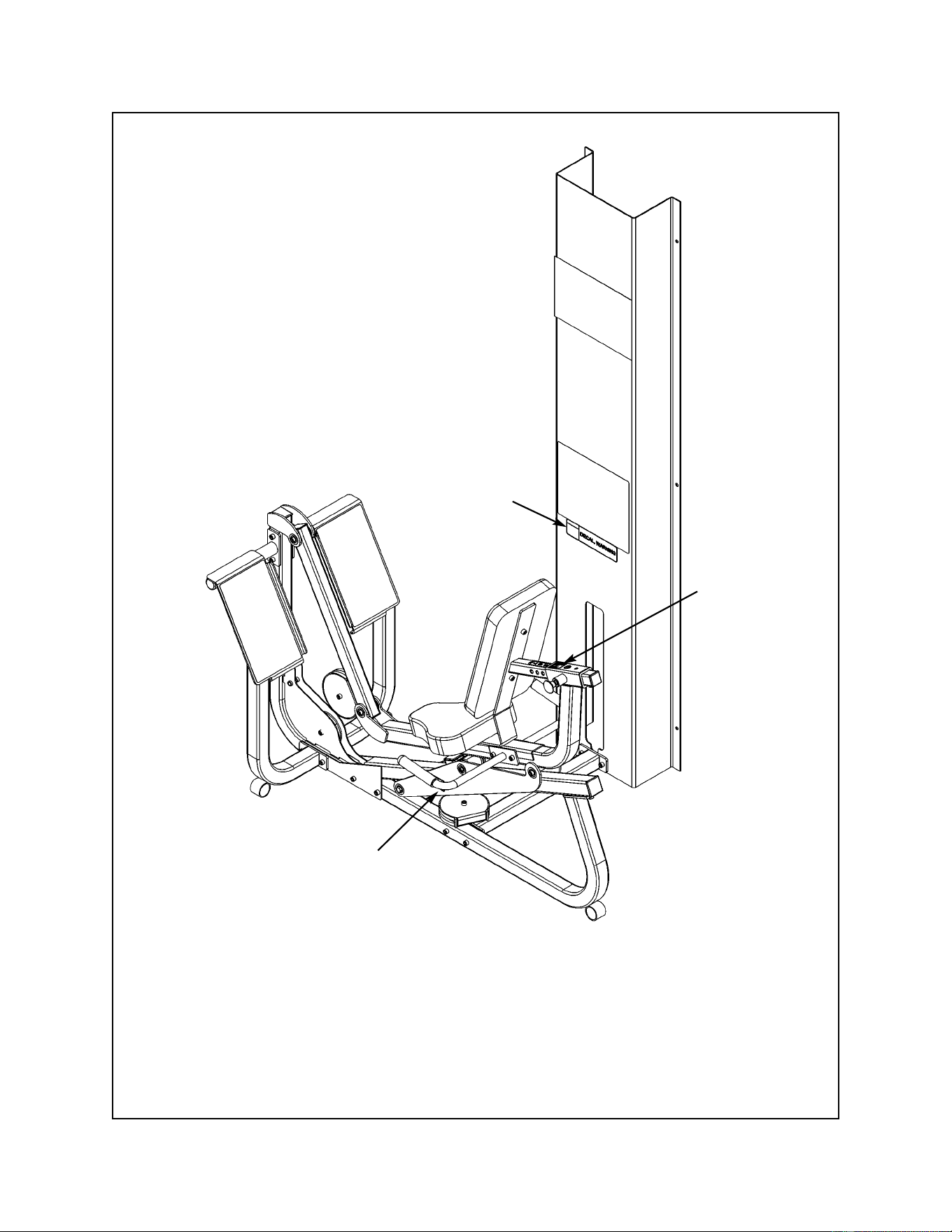
Cybex MG 500 Multi-Gym Owner’s Manual
A. Caution Decal .................... 4000Y316
C. Caution Decal ................... 8500-025
F. Warning Decal ................... 4800-381
DESCRIPTION PART NO.
A
C
F
Leg Press Station
Safety
Page 1-6
Cybex MG 500 Multi-Gym Owner’s Manual
D. Warning Decal ................... 8500-311
F. Warning Decal ................... 4800-381
G. Caution Decal .................... 8500-028
DESCRIPTION PART NO.
D
F
G
Pressing Station
Safety
Page 1-7
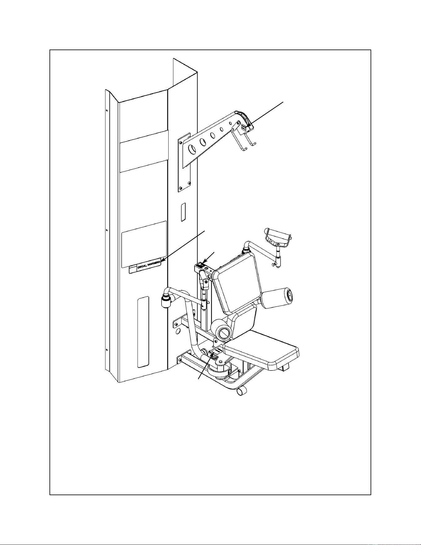
Cybex MG 500 Multi-Gym Owner’s Manual
F. Warning Decal ................... 4800-381
B. Caution Decal .................... 8500-026
C. Caution Decal .................... 8500-025
DESCRIPTION PART NO.
F
B
Leg Extension/Leg Curl Station
C
C
C
C
Safety
Page 1-8

Cybex MG 500 Multi-Gym Owner’s Manual
Regular Maintenance Activities
Preventative maintenance activities must be performed to maintain normal operation of your
MG 500. Keeping a log sheet of all maintenance actions will assist you in staying current with
all preventative maintenance activities. The preventative maintenance actions are described in
detail in Chapter 7. Briefly, they include:
Daily
1. Clean upholstery.
Weekly
1. Inspect all nuts and bolts for looseness. Tighten as required.
2. Inspect all cables for damage or wear (see Chapter 7). Immediately discontinue use if a
cable is worn or damaged.
3. Check for worn handles, worn snap links, and worn warning labeling. Replace all worn
parts immediately.
4. Inspect weight stacks for proper alignment and operation. Correct all improper alignment
and operation issues immediately.
5. Lubricate guide rods using automotive engine oil only.
Yearly
1. Replace all cables at least annually.
As Required
1. Inspect grips and replace as necessary.
Using Proper Form
Before working out, read and understand the training suggestions listed in Chapter 3. See
Chapter 4 for proper form during exercise.
Safety
Page 1-9

Cybex MG 500 Multi-Gym Owner’s Manual
Safety
Page 1-10
This page intentionally left blank

Cybex MG 500 Multi-Gym Owner’s Manual
Technical
Specifications
Page 2-1
2 - Technical Specifications
General Specifications
Frame Finish
• Shall be made of mechanical quality 11 gauge and 16 gauge steel purchased in mill run
quantities to assure the best consistency.
• Prior to applying finish, each part shall be put through a multi-stage wash to remove all
oils and to chemically prepare the surface for maximum adhesion. After the wash, the
frames shall be dried and coated with an Electrostatically applied powdercoat finish that
shall be applied in powder form and then baked until cured.
• The finish shall be textured and very hard, assuring a scratch and chip resistant finish.
Weight Selection
• Weights are to be selected by using a high quality selector pin that completely penetrates
the weight plate and locks in place to eliminate any chance of disengaging the pin during
use. The pin shall be attached to the weight stack with a plastic lanyard in order that the
pin stays with the appropriate machine. All weights shall be selected while the user is in
position on/in the machine to allow adjustment of the resistance from the exercise
position.
Weight Stacks Configuration
• All weight stacks shall have (4” x 12” x 1”), 12 1/2 pound weights.
Weight Plates
• Shall be made of solid cold-rolled steel with wrinkle black powder coat finish.
• Guide rod holes shall be machined to a tolerance of .006 inches.
Weight Plate Bushings
• Self-aligning low-friction bushings shall surround the guide rods for smooth gliding
motion.

Cybex MG 500 Multi-Gym Owner’s Manual
Technical
Specifications
Page 2-2
Pulleys
• Shall use Dupont Corp. fiberglass-reinforced nylon 70G33 material, tensile strength rated
at 22,500 PSI with 6203ZZ double sealed bearings dynamic load rated at 1600 lbs.
• Pulleys shall be 4.50 inches in diameter with a cable groove with a depth of .250 inches.
Weight Transport
• Shall be lubricated, 7 x 19, 1/8” galvanized steel, nylon coated aircraft cable with breaking
strength rated at 2000 pounds.
• All cable ends shall be finished off with a swaged fitting with a breaking strength
exceeding that of the cable itself.
Weight Stack Guide Rods
• Shall be solid ground and polished cold-drawn steel with minimum yield strength of
100,000 PSI with a hard chrome plated piston steel finish with an overall minimum
accuracy of .010.
Weight Stack Suspension
• Shall have heavy-duty neoprene bumpers with an 80-durometer rating under the weight
stacks to reduce shock and vibration stresses to the frame and facility.
Handgrips
• Shall be closed-end PVC closed cell foam vinyl sleeve.
Frame Construction
• Primarily 1 1/2 x 2” tubing with 11 gauge wall thickness, but different tubing sizes and
wall thickness shall be used as required through engineering stress analysis.
• Shielding shall be 16 gauge wall thickness sheet metal.
• Fully welded frames for maximum structural integrity and minimum maintenance.
• All machining and welding must be done utilizing jigs and fixtures to insure highest
quality and interchangability of parts.
Radial Bearings
• 87503 double shielded bearing with 17 mm stainless steel shafts, dynamic load rating
1660 lbs.

Cybex MG 500 Multi-Gym Owner’s Manual
Technical
Specifications
Page 2-3
Hardware
• All 3/8” socket head cap screws shall be of grade 8 (or equivalent). All bolts shall be either
chromed or zinc plated for additional corrosion resistance.
Weight Stack Guards
• All weight stacks shall be guarded on the backside to prevent bystanders from
inadvertent contact with the weight stack during use.
Cushion/Upholstery
• A superior grade of Boltaflex from Omnova shall be used on all pad covers and wear
covers.
• The color shall be sulfide stain resistant.
• All edges shall be stitched to eliminate any folds in the material that would limit durability.
• Cushions come with replaceable slipcovers on all high use areas, reducing maintenance
expense by not having to replace the entire cushion.
• Cushion foam consists of a combination of high and medium density closed-cell Omalon
polyurethane, for durability and comfort.
Adjustments
• Recessed high contrast Lexan decal for all seat and pad adjustments for maximum
readability.
Instructional Placard
• Shall provide step-by-step instructions and a picture to illustrate use, visible from the
exercise position.
• Placard shall indicate proper positioning, and clearly describe the correct use of
machines.
Cybex MG 500 Multi-Gym Owner’s Manual
Technical
Specifications
Page 2-4
MG 500 - Product No. 8600
8602
Machine Weight
(includes weight stacks)
1733 lbs.
788 kg
Three Weight Stacks
230 lbs. each
105 kg
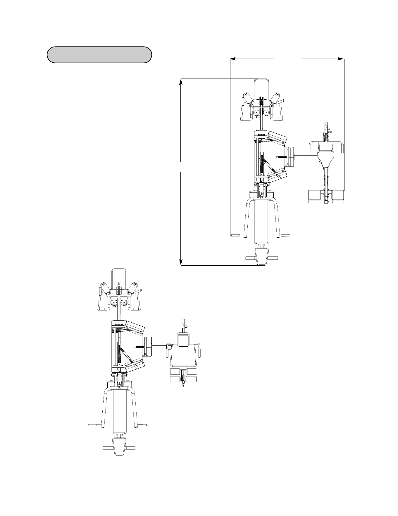
Size
inches - 128 L x 74 W x 83 H
cm - 325 L x 188 W x 211 H
128
74
Machine Specifications
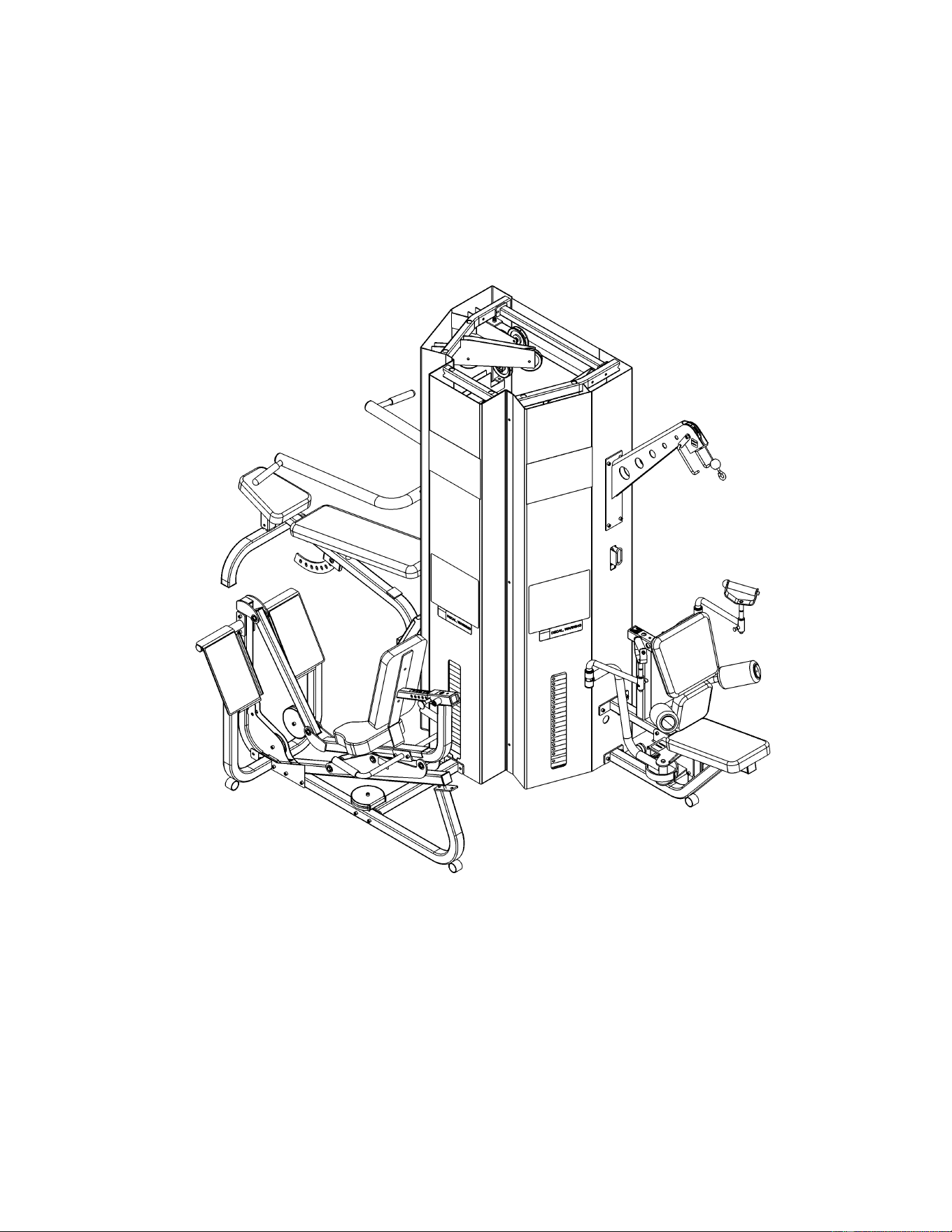
Leg Press Configuration (8602)
Leg Extension Configuration (8600)

Cybex MG 500 Multi-Gym Owner’s Manual
General
Exercise
Guidelines
Page 3-1
3 - General Exercise Guidelines
Training Suggestions
Before you workout
Prior to starting a training program, get a complete physical exam to make sure your physician
agrees that you are ready. Always warm-up your muscles before a workout. A 5 - 10 minute
cardio warm-up followed by slow stretching (no bouncing) is recommended. Continue with a
lighter set (50% of normal of intended exercises. Proper breathing is very important. Exhale
during muscle exertion, and inhale while returning to the start position. Start your program
conservatively. Choose weights you can easily lift in the first weeks. Always
perform the full range of motion unless you have an injury, then consult a
professional trainer. Your Cybex dealer can help you find one. Know the terms? A “repetition”
(rep) is defined as one complete movement through an exercise, returning to the start position.
A “set” is a continuous series of reps usually between 6 - 15.
During your workout
The number of reps. you perform in a set depends on your goal. To build muscle and strength,
do fewer reps (6 - 8) with heavier weight. To firm your muscles and build endurance, do more
reps. (12 - 15) with lighter weight. Never “cheat” by shortening the range of motion, bouncing
the weight, or shifting your posture. This may allow you to lift more weight, but it is dangerous
and less effective. Catch your breath between sets, then continue. When “circuit training”
move briskly to the next exercise; when doing multiple sets on one exercise, rest 45 - 90
seconds before the next set. Work up to three sets per exercise. When you can perform the
desired reps and sets for any exercise, increase the weight by a half or full plate.
Designing your workout
Circuit training is a good way to start. This involves doing one set per exercise, then moving to
the next exercise, pausing only briefly between them (to keep your heart and breath rate up)
until completing a balanced “circuit” of 8 - 10 exercises for your entire body. Then repeat the
circuit. After several weeks, you can move into multiple sets (3 in a row) per exercise if you
choose. For both of these, exercise the complete body every other day, up to three times a
week Note: A full day’s rest, plus proper nutrition and hydration are required for
optimum muscle-building or toning. Alternatively, work out half your body one day (e.g., the
upper body) and the other half the following day (e.g. the lower body). To reduce muscle
soreness, end each series of sets for a given muscle with a set of increased reps and lighter
weights. At the end of your workout, cool down in a similar way to your warm-up.

General
Exercise
Guidelines
Page 3-2
Cybex MG 500 Multi-Gym Owner’s Manual
Abduction - movement away from the mid-line of the body.
Acceleration - the rate at which an object’s velocity changes with time; that is the change of
velocity divided by the time interval.
Accuracy - freedom from error. Degree of conformity of a measure to a standard or a true
value.
Action Line - the direction of pull created by the fibers or tendons of the muscle at the point of
application.
Active Insufficiency - a two joint muscle loses the ability to cross-bridge (generate force) due
to full shortening over its greatest anatomical length and tension created in an opposing muscle
(antagonist).
Active Range of Motion - the degree of motion that occurs between two adjacent segments
through voluntary contraction of the agonist.
Active Stabilization - provided by an internal force. Static stabilization is provided through an
isometric contraction where dynamic stabilization is a series of motions. Dynamic stabilizers
maintain the relative positions of the segments, preventing undesirable or unnecessary motions
due to external forces as well as artifacts of internal forces. May also refer to the
concentric/eccentric contractions of a muscle acting in a force couple to produce motion while
maintaining a relatively fixed axis of rotation.
Adipose tissue - fat tissue.
Adduction - movement towards the mid-line of the body.
Agonist - (prime mover) the muscle most involved in producing a movement.
Aerobic - utilizing oxygen.
Aerobic Endurance - the ability to persist in physical activities that rely heavily upon oxygen
for energy production.
Anabolic - pertaining to the synthesis of complex substances from simpler substances, especially
to the synthesis of body proteins from amino acids.
Anaerobic - without oxygen.
Anaerobic Endurance - the ability to persist in physical activities of short duration that require
high rates of energy expenditure. These high rates of energy expenditure cannot be met solely
by aerobic metabolism.
Glossary

Cybex MG 500 Multi-Gym Owner’s Manual
General
Exercise
Guidelines
Page 3-3
Anthropometrics - measurements and relationships of length and girth of body parts.
Antagonist - the muscle in opposition to the agonist.
Anatomical Position - standing erect, with feet and palms facing forward.
Anatomical Pulley - a bone or skeletal prominence that alters the direction of the pull of a
muscle to increase the muscle’s mechanical advantage.
Anatomy - geography, naming by orientation and/or apparent capability (non-functional).
Anchor Points - the points at which a load enters and exits the body and/or limb.
Anterior - anatomical term meaning towards the front. Same as ventral.
Assistant Mover - a muscle that is less effective at performing a specified motion, but does
have a small degree of mechanical ability to help the prime mover. There are many borderline
cases.
Atrophy - reduction in size of cells and tissues.
Axis of Rotation - imaginary line or point which an object rotates.
Bilateral - refers to both sides.
Biolocomotion - a perspective/description of the human body and its mechanics based upon
locomotion. All animals with legs (regardless of numbers) move with the same mechanics.
Gravity is the common denominator.
Biomechanics - analysis of the load placed on a joint by both the muscle and resistance.
Anatomy, Kinesiology, and Physics = Engineering.
Body Composition - the component parts of the body - mainly fat and fat-free weight.
Calorie - a unit of work or energy equal to the amount of heat required to raise the temperature
of 1 g of water to 1 degree C.
Cam - a mechanical device used to vary leverage.
Carbohydrate - a chemical compound consisting of carbon, hydrogen and oxygen atoms in
specified arrangements. Carbohydrates are major components of food such as bread, potatoes
and rice.

General
Exercise
Guidelines
Page 3-4
Cybex MG 500 Multi-Gym Owner’s Manual
Cardiovascular - pertaining to the heart and blood vessels.
Cartilage - there are several types. Hyaline cartilage is a relatively thin covering on the ends of
many bones. It forms a smooth, resilient, low friction surface for the movement of one bone
on another. Wedges of cartilage (fibrocartilage) called menisci, disks and labrums are to
increase stability, provide shock absorption, and to facilitate motion in some joints.
Center of Gravity - the center of a body’s mass. In the human body, it is the point which all
parts are in balance with one another. The COG may be within the body, altered by the position
of the body even to the point of being outside the body (pike position), or altered by the
addiction of load to specific body areas.
Circumduction - a circular movement permitted at ball and socket, condylar and saddle joints.
Consists of flexion, abduction, extension and adduction in sequence.
Circuit Training - a conditioning program consisting of a number of exercises performed at
“stations”. Usually, a given exercise is performed at a station within a specified time; then the
athlete moves to the next station, with its own particular exercise and specified time, then to the
next station, and so on.
Closed Chain Kinetic Exercise - a series of rigid links interconnected by a series of
pincentered joints. These are constructed so that motion at one joint will produce motion at all
the joints in the system. Produces greater mechanical efficiency at the risk of increased joint
loading. Leg press, bench press.
Close-Packed Position - all synovial joints have a position where joint surfaces are maximally
congruent and the ligaments and capsule are maximally taut.
Collagen - a fibrous protein that serves as the major component of ligaments and tendons.
Compression - two forces acting along the same line towards each other that constitute a
compressive load or compressive stress.
Concentric action - contraction of a muscle resulting in shortening of the muscle.
Connective Tissue - comprised of mostly the proteins collagen and elastin with water;
includes tendons, ligaments, bursae, cartilage, disks, menisci, fascia and bone.
Cross-bridge - the connection and intertwining of the actin and myosin filaments in a myofibril
relative to a muscular contraction.
Curvilinear Motion - the frequently occurring combination of rotatory and translatory motions.
Distraction - two forces acting along the same line and in opposite directions, they constitute
a distractive, tensile load or tensile stress.
Diathrodial Joint - ball and socket joint.
Distal - furthest from the attached end of the limb; away from the body.

General
Exercise
Guidelines
Page 3-5
Cybex MG 500 Multi-Gym Owner’s Manual
Dorsal - pertaining to the back; opposite of ventral, palmar or plantar.
Dorsiflexioni - movement of the foot up in the sagitial plane; movement toward the leg.
Eccentric - muscle action in which tension is developed in the muscle while it is lengthening.
Negative work is performed.
Eccentric Action - a muscle contraction incapable of overcoming the resistance imposed;
the overall muscle length increases.
Endurance- the ability to persist in performing some physical activity.
Energy - the capacity to perform work.
Energy (kinetic) - energy associated with motion.
Energy (potential) - energy by virtue of position.
Energy System - one of three metabolic systems involving a series of chemical reactions
resulting in the formation of waste products and the manufacture of ATP.
Eversion - movement of the sole of the foot outward; opposite of inversion.
Extension - movement at a joint, bringing two parts into or towards a straight line, increasing
the angle of the joint. Returning to anatomical position from a position of flexion in the sagitial
plane.
External Force - a push or pull on the body that arises from a source outside the body.
External Rotation - movement of the anterior surface of a segment away from the mid-line;
also termed lateral rotation.
Fast-twitch Fibers - skeletal muscle fibers most active in short-duration, intensive exercise,
e.g., in sprints and jumps.
Fatigue - the inability to maintain a given level of physical performance.
Flexibility - the range of movement of a specific joint or group of joints, influenced by the
associated bones and bony structures, muscles, tendons and ligaments.
Flexion - movement about a joint in which bones on either side of the joint are brought closer
together, decreasing the angle of the joint. Joint movement away from anatomical position,
occurring within the sagitial plane.
Foot-pound - the work required to move one pound of resistance one foot in distance.

General
Exercise
Guidelines
Page 3-6
Cybex MG 500 Multi-Gym Owner’s Manual
Force - an interaction between two objects, in the form of a push or pull, that may or may not
produce motion, Force = mass x acceleration.
Force Angle - (FA) the angle between the action line and the lever, on the side of the joint axis.
Force Couple - concentric/eccentric contractions of opposing muscles acting to produce
motion while maintaining a relatively fixed axis of rotation.
Frontal Plane - (coronal) imaginary line that divides the body into anterior and posterior
halves; lies at a right angle to the sagittal plane.
Fulcrum - the support on which a lever rotates in moving or lifting.
Hyperextension - continuation of the movement of extension past the neutral position.
Hypertrophy - increased cell size leading to increased tissue size.
Impulse - the change in momentum.
Inertia - the tendency of a body to remain at rest or continue in motion unless disturbed by
an external force.
Inferior - a lower position upon or within the body.
Insertion - the more distal attachment site of a muscle. The movable part or attachment of a
muscle as opposed to origin.
Intermittent Work - work sessions interrupted by rest sessions.
Internal Forces - act on the body and arise from sources within the human body.
Inversion - moving the sole of the foot inward. Opposite of eversion.
Isokinetic - action in which the rate of movement is constantly maintained through a specific
range of motion even though maximal force is exerted.
Isokinetic Contraction - a muscular contraction through a range of motion at a constant
velocity.
Isometric - a contraction in which movement is produced but no movement occurs.
Isometric (static) Contraction - a muscular contraction in which there is no change in the
angle of the involved joint(s) and little or no change in the length of the contracting muscle.
Isotonic - a contraction in which movement is produced.
Medial Rotation - movement around an axis and toward the mid-line of the body. Also
termed internal rotation.
Medial - aspect nearest the mid-line of the body; pertaining to the center. Opposite of lateral.
Metabolism - the sum total of the chemical changes or reactions occurring in the body.

Cybex MG 500 Multi-Gym Owner’s Manual
General
Exercise
Guidelines
Page 3-7
Moment Arm - (MA) the shortest distance between the action line and the joint axis.
Momentum - determined by mass x velocity. Will remain constant unless the object is acted
upon by another force.
Muscle Contraction - shortening of a muscle and/or development of tension in a muscle.
Muscular Endurance - the ability of a muscle or muscle group to perform repeated
contractions against a light load for an extended period of time.
Neutral - a point between the two extremes of a joint’s range of motion.
Obesity - excess body fat.
Open Kinematic Chain - the ends of the limbs are free to move without causing motion at
another joint. Open chain motions are not predictable because the joints amy function either
independently or in unison. Less mechanically efficient, therefore more stress is placed upon
muscular tissue.
Origin - attachment of a muscle that remains relatively fixed during muscular contraction.
Overload - to exercise a muscle or muscle group against resistance greater than that which is
normally encountered. The resistance (load) can be maximal or near-maximal.
Passive Insufficiency - a two-joint muscle loses the ability to cross-bridge (generate force)
due to full lengthening over its greatest anatomical length due to force created in an opposing
muscle.
Passive Stabilization - due to noncontractile components. Internal stabilization is created by
connective tissue (muscular support is not provided anatomically or physiologically) and external
stabilization is provided by a bench or brace.
Plane of Motion - a two-dimensional flat surface running through an object. Motion occurs in
the plane or parallel to the plane.
Plantar - anatomical term referring to the sole or bottom.
Plantarflexion - movement of the foot down in the sagittal plane; movement away from the
leg.
Posterior - anatomical term meaning toward the back. Opposite of anterior.
Potential Energy - energy by virtue of position.
Power - the product of force and velocity. Work divided by time.

Cybex MG 500 Multi-Gym Owner’s Manual
General
Exercise
Guidelines
Page 3-8
Prime Mover - (agonist) a muscle that is mechanically optimal to produce a specific motion
at a joint. There can be more than one prime mover for a particular motion and a specific
muscle can be a prime mover for more than one motion at a joint.
Progressive Resistance - overloading a muscle or muscle group consistently throughout the
duration of a weight-resistance program.
Pronation - a triplanar motion at the subtalar joint consisting of abduction, depression and
eversion, resulting in lowering of the longitudinal arch of the foot. Position of the forearm with
the palm facing down.
Protein - a basic foodstuff containing amino acids.
Proximal - towards the attached end of the limb or origin.
Range of Motion - the amount of motion available to a joint within the anatomical limits of the
joint structure. Can be classified as Passive (movement produced via a force outside the limb),
Active (movement produced by muscles within the limb) or Resisted (movement challenged
under additional load). The amount of resistance will affect the range of motion with direct
proportion.
Reciprocal Inhibition - contraction of agonist causes relaxation of antagonist.
Reliability - the extent to which an experiment, test or measuring procedure yields the same
results on repeated trials. Also known as reproducibility or repeatability.
Repetition Maximum (RM) - the maximum load that a muscle or muscle group can lift in a
given number of repetitions before fatiguing. For example, an eight-RM load is the maximum
load that can be lifted eight times.
Repositioners - muscles that lift the extremity and move it to a new location allowing the
prime movers to again accept load or propel.
Response - a sudden temporary adjustment in physiological function brought on by a single
exposure to exercise, e.g., the rise in heart rate associated with an exercise bout.
Rotary Motion - (radial or angular) the movement of an object around a fixed axis in a curved
path.
S.A.I.D. Principle - Specific Adaptation to Imposed Demand. A muscle will gain strength in
the specific ranges of motion and speeds in which it is trained.
Sagittal Plane - Imaginary line that divides the body, or any of its parts, into right and left
sections.
Scoliosis - a lateral curvature of the vertebral column, usually in the thoracic area.
Secondary Joint - hinge joints that have a singular function (elbow/knee). Muscles are
situated on either side of these joints in virtual, if not real, pairings.
Set - in an interval training program, a group of work and relief intervals. In weight lifting, the
number of repetitions performed consecutively without resting.

Cybex MG 500 Multi-Gym Owner’s Manual
General
Exercise
Guidelines
Page 3-9
Shear - two parallel forces applied in opposite directions that are not in line with each other
constitute a shearing load or stress. The site of muscular attachment is the axis around which
the forces of shear develop. This becomes the “force axis” as opposed to the anatomical axis.
Shunt Muscle - directs the greater part of its contractile force along the bone it is moving
(creating greater force towards compression/stabilization). The brachioradialis is a shunt
during an arm curl.
Skeletal Muscle - muscle controlling skeletal movement that is normally under voluntary
control.
Skewing - the result of a vector shift through a limb or system.
Sliding Filament Theory - a muscle shortens or lengthens because the thick and thin
myofibrils slide past one another without the filaments changing length.
Slow-twitch Fibers - skeletal muscle fibers characterized by relatively slow contraction times
and great capacity for the aerobic production of adenosine triphosphate.
Sprain - the permanent deformation of the structure due to excessive or prolonged
stress/strain.
Spurt Muscle - directs the greater part of its force across the bone it is moving rather than
along it (creating greater effort towards motion). The biceps is a spurt during an arm curl.
Stabilizer - a muscle that steadies or supports a joint in order that another active muscle may
have a firm base upon which to pull.
Static contraction - a muscular contraction that does not involve changes in the angle of the
joint(s) involved.
Steady state - that state of physiological stability wherein the energy demands of the body
can be met relatively easily for a prolonged period of time.
Strain - the deformation of the structure as the result of stress.
Strength - the ability to exert muscular force briefly.
Stress - the force created within a structure when placed under load.
Submaximal exercise - usually exercise at less than maximal intensity, but may also refer to
exercise of less than maximal duration.
Superior - a higher position upon or within the body.

Cybex MG 500 Multi-Gym Owner’s Manual
General
Exercise
Guidelines
Page 3-10
Synergist - occurs during the action of two muscles, both of which have a common joint
action and each of which has a second action that is antagonistic or opposing to the other.
True synergy is simply the stabilization of one muscle to prevent any action in one of the joints
traversed by a multi-joint muscle.
Synovial Fluid - transparent, viscous lubricating fluid found in joint cavities, bursae and tendon
sheaths.
Tendons - cords of dense fibrous tissue that connect muscle to bone.
Tertiary Joint - a complex joint structure (wrist/ankle-subtalor), designed for finely controlled
movements.
Torque - the ability of a force to produce movement around an axis.
Training - a program of exercise designed to improve the skills and increase the energy
capacities of an athlete for a particular event.
Translatory Motion - (linear) the movement of an object in a straight line.
Unilateral - refers to only one side.
Validity - the extent to which a measurement or information is relevant or meaningful;
appropriate to the end in view and supported by objective truth.
Vector - an arrow which represents a force’s point of application, action line or direction
indicating pull or magnitude of force being exerted.
Vector Shift - the alteration of a load as it is transferred between the anchor points through a
segment’s kinematic chain.
Velocity - the rate at which an objects position changes with time; that is the total change in
position divided by the total change in time: V-d/t.
Weight - the weight of an object is the gravitational force exerted on it by the earth. W=mg,
where g = gravitational acceleration.
Work - W = Fd. The amount of work performed is equivalent to the force applied to an object
times the distance the object is moved.
Single-Set & Circuit Training Diary
MACHINE
Date
Plates
Reps
Plates
Reps
Plates
Reps
Plates
Reps
Plates
Reps
Plates
Reps
Plates
Reps
Plates
Reps
Plates
Reps
Plates
Reps
Plates
Reps
Plates
Reps
Seat
Pad
Single-Set & Circuit Training Diary
MACHINE
Date
Plates
Reps
Plates
Reps
Plates
Reps
Plates
Reps
Plates
Reps
Plates
Reps
Plates
Reps
Plates
Reps
Plates
Reps
Plates
Reps
Plates
Reps
Plates
Reps
Seat
Pad
NAME
INSTRUCTOR
Multiple-Set Training Diary
MACHINE
Date
Set
Plates
Reps
Plates
Reps
Plates
Reps
Plates
Reps
Plates
Reps
Plates
Reps
Plates
Reps
Plates
Reps
Plates
Reps
Plates
Reps
Plates
Reps
Plates
Reps
Seat
Pad
1 2 3 1 2 3 1 2 3 1 2 3 1 2 3 1 2 3 1 2 3 1 2 3 1 2 3 1 2 3 1 2 3 1 2 3 1 2 3
NAME
INSTRUCTOR
Multiple-Set Training Diary
MACHINE
Date
Set
Plates
Reps
Plates
Reps
Plates
Reps
Plates
Reps
Plates
Reps
Plates
Reps
Plates
Reps
Plates
Reps
Plates
Reps
Plates
Reps
Plates
Reps
Plates
Reps
Seat
Pad
1 2 3 1 2 3 1 2 3 1 2 3 1 2 3 1 2 3 1 2 3 1 2 3 1 2 3 1 2 3 1 2 3 1 2 3 1 2 3
Cybex MG 500 Multi-Gym Owner’s Manual
Exercises
Page 4-1
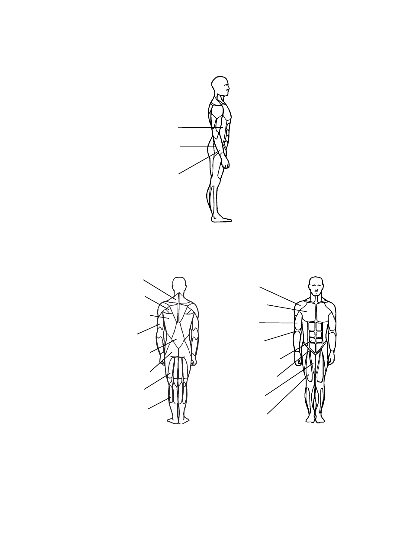
Obliques
Adductors
Wrist
&
Forearm
Flexors
Trapezius
Teres Major
Latissimis Dorsi
Triceps
Erector Spinae
Hamstrings
Gastrocnemius
Deltoid
Pectoralis
Biceps
Brachialis
Rectus Abdominus
Hip Flexor Group
Adductors
Quadriceps
Gluteus Maximus
4 - Exercises
Cybex MG 500 Multi-Gym Owner’s Manual
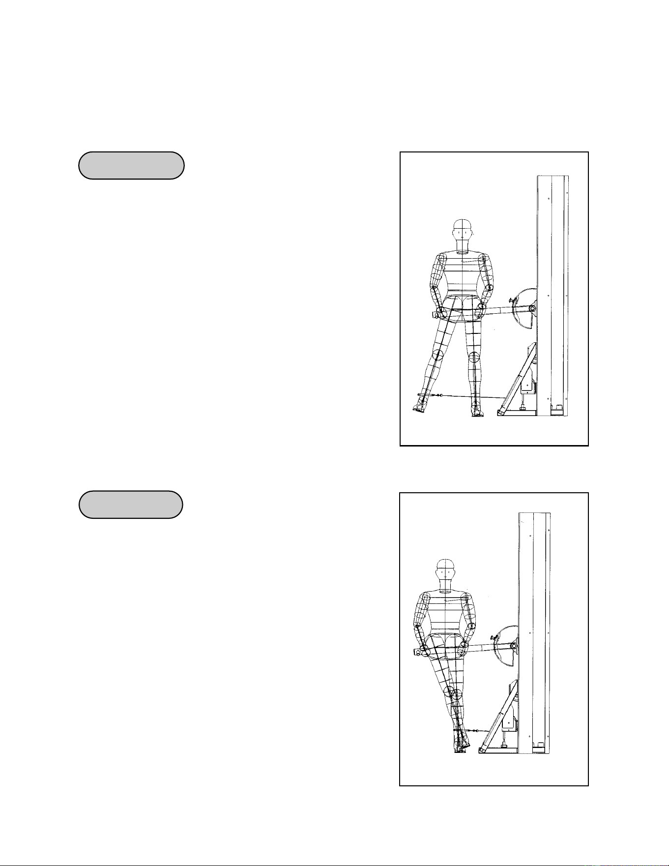
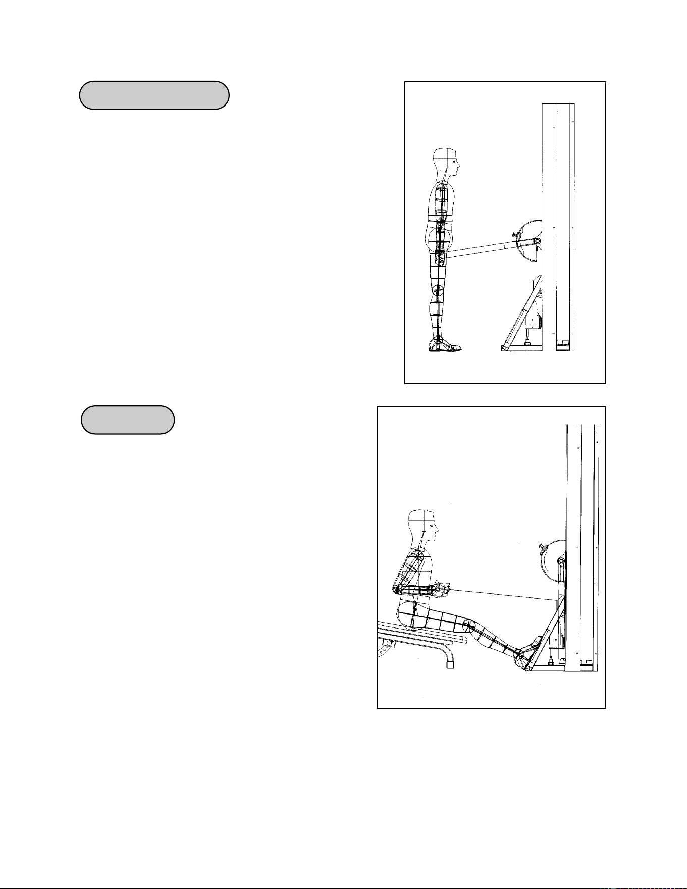
Hip Abduction
Hip Adduction
Emphasis: Gluteus Medius
1. Attach ankle strap to swivel low-pulley and adjust
pressing arm to waist height for stability.
2. Wrap strap just above ankle around leg to be
exercised.
3. Place the exercising leg in front of the stationary leg
while maintaining tension in the cable.
4. Stand erect with slight bend in knees and brace
your position with inside arm against the pressing arm.
5. Exhale while lifting the working leg slowly across
and away from the body to approximately 45
degrees. This is your maximum range of motion.
6. Inhale when returning to the staring position.
Emphasis: Hip Adductors
1. Attach ankle strap to swivel low-pulley and adjust
pressing arm to waist height for stability.
2. Wrap strap just above ankle around leg to be
exercised.
3. Place the exercising leg in front of the stationary
leg while maintaining tension in the cable.
4. Stand erect with slight bend in knees and brace
your position with inside arm against the pressing arm.
5. Exhale while lifting the working leg slowly across
and away from the body to approximately 20 degrees
past midline. This is your maximum range of motion.
6. Inhale when returning to the starting position.
Exercises
Page 4-2
Read and understand all instructions and warnings prior to using equipment.
Note: See the general training suggestions in Chapter 3 and all of the safety related
information located in Chapter 1.
Cybex MG 500 Multi-Gym Owner’s Manual
Exercises
Page 4-3
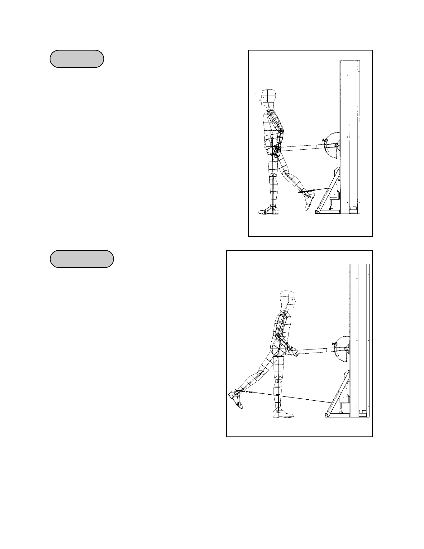
Hip Flexion
Hip Extension
Emphasis: Hip Flexors, Rectus Femons and Sartonus
1. Attach ankle strap to swivel low-pulley and adjust
pressing arm to waist height for stability.
2. Wrap strap just above ankle around leg to be
exercised, facing away from the machine.
3. Stand erect with slight bend in knees and brace your
position with hands on the pressing arm.
4. Exhale while lifting the working leg slowly up and
away from the body to approximately 90 degrees in
front of you. This is your maximum range of motion.
5. Inhale when returning to the starting position.
Emphasis: Gluteus Maximus, Hamstrings
1. Attach ankle strap to swivel low-pulley and
adjust pressing arm to waist height for stability.
2. Wrap strap just above ankle around leg to be
exercised, facing the machine.
3. Stand erect with slight bend in knees and
brace your position with hands on the
pressing arm.
4. Exhale while lifting the working leg slowly back
and away from the body to approximately
15-20 degrees behind you. This is your
maximum range of motion.
5. Inhale when returning to the starting position
and repeat with the opposite leg.
Cybex MG 500 Multi-Gym Owner’s Manual
Exercises
Page 4-4
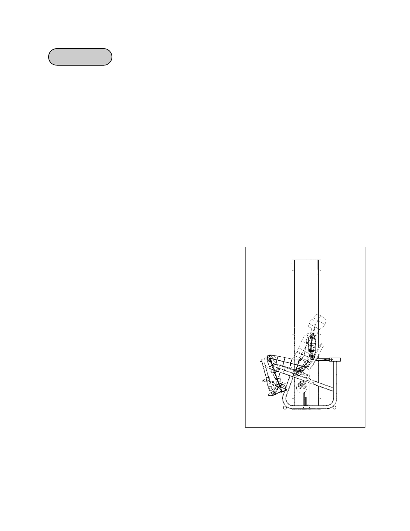
Leg Extension
Note: The Leg Extension/Seated Leg Curl Station performs two exercises: Leg Extension
and Seated Leg Curl.
To adjust machine from Seated Leg Curl to Leg Extension Follow steps 1-5.
1. Pull detent pin at machine’s axis of rotation, lowering lower arm into one of the two below
positioned slots.
2. Adjust thigh pad bar so that thigh pads out off to the side.
3. Be sure that all detent pins are securely in place and adjustments are at the desired
height.
4. Place feet under lower leg pads.
5. Grip hand grips lightly to help stabilize body during the exercise.
Emphasis: Quadriceps
1. Select appropriate resistance.
2. Adjust back pad so that knees are in line with
machine’s axis of rotation.
3. Sit upright and grasp handles to stabilize your body.
4. Tighten quadriceps and slowly extend lower legs
with a smooth motion. Pause while extended and
slowly return to starting position.
NOTE: On the first rep. further align knees by
rotating thighs so knee-cap is directly on top
of knees. Maintain this position through each
rep.
NOTE: Minimum resistance that may be selected for
this exercise is two plates - approximately
25 lbs.
Cybex MG 500 Multi-Gym Owner’s Manual
Exercises
Page 4-5
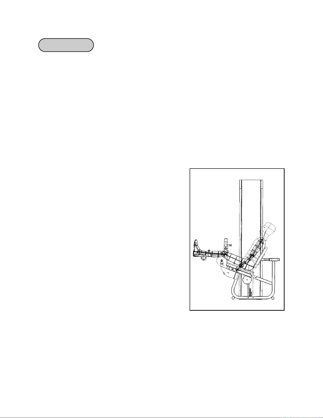
Seated Leg Curl
To adjust machine from Leg Extension to Seated Leg Curl follow steps 1-4.
1. Pull detent pin at machine’s axis of rotation, raising lower arm into one of the two above
positioned slots.
2. Adjust thigh pads to control unwanted movement of upper legs during exercise.
3. Be sure that all detent pins are securely in place and adjustments are at the desired
height.
4. Grip handles tightly to help stabilize body during exercise.
Emphasis: Hamstrings
1. Select appropriate resistance.
2. Adjust back pad so that center of knees aligns with
rotation point of machine.
3. Adjust height of lower leg pads to a height
comfortably above ankles.
4. Lift/lower resistance with smooth controlled
movements without resting.
NOTE: On the first rep. ensure that
knees are correctly positioned
by rotating your thighs, so that
knee caps point upward.
Maintain this position through
each rep.
NOTE: Minimum resistance that may be selected
for this exercise is two plates - approximately
25 lbs.
Cybex MG 500 Multi-Gym Owner’s Manual
Exercises
Page 4-6
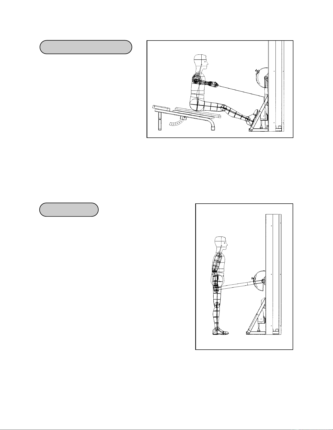
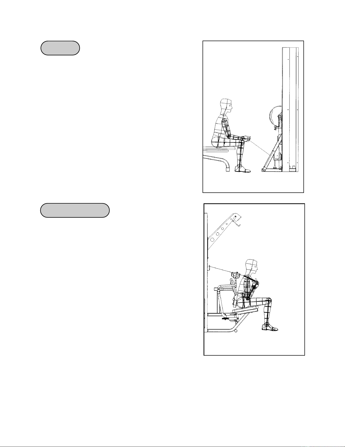
Standing Calf Raise
Seated Row
Emphasis: Gastrocnemius, Soleus
1. Adjust pressing-arm height so that weight stack is
suspended about 4” when in standing position.
2. Firmly grasp handles and position feet shoulder
width apart.
3. Keeping your arms and back straight, lift pressing
arm.
4. Keeping the back straight, hips tucked in and knees
over toes, raise heels as far as possible with a
smooth continuous motion.
5. Do not hyperextend (lock) knees during
movement.
Emphasis: Latissimus Dorsi, Teres Major, Trapezius,
Brachioradius
1. Lower the pressing station arm into the bottom
position and attach the seated row handle.
2. Slide the adjustable bench into the pressing
station and set on position 1, allowing easy
access to foot rests.
3. Place feet on rests and keep back straight.
Bend forward at the hips and grasp handle.
Maintaining an upright position, pull toward
abdomen.
4. Pinch shoulder blades back to maximize stability
and effectiveness.
Cybex MG 500 Multi-Gym Owner’s Manual
Exercises
Page 4-7
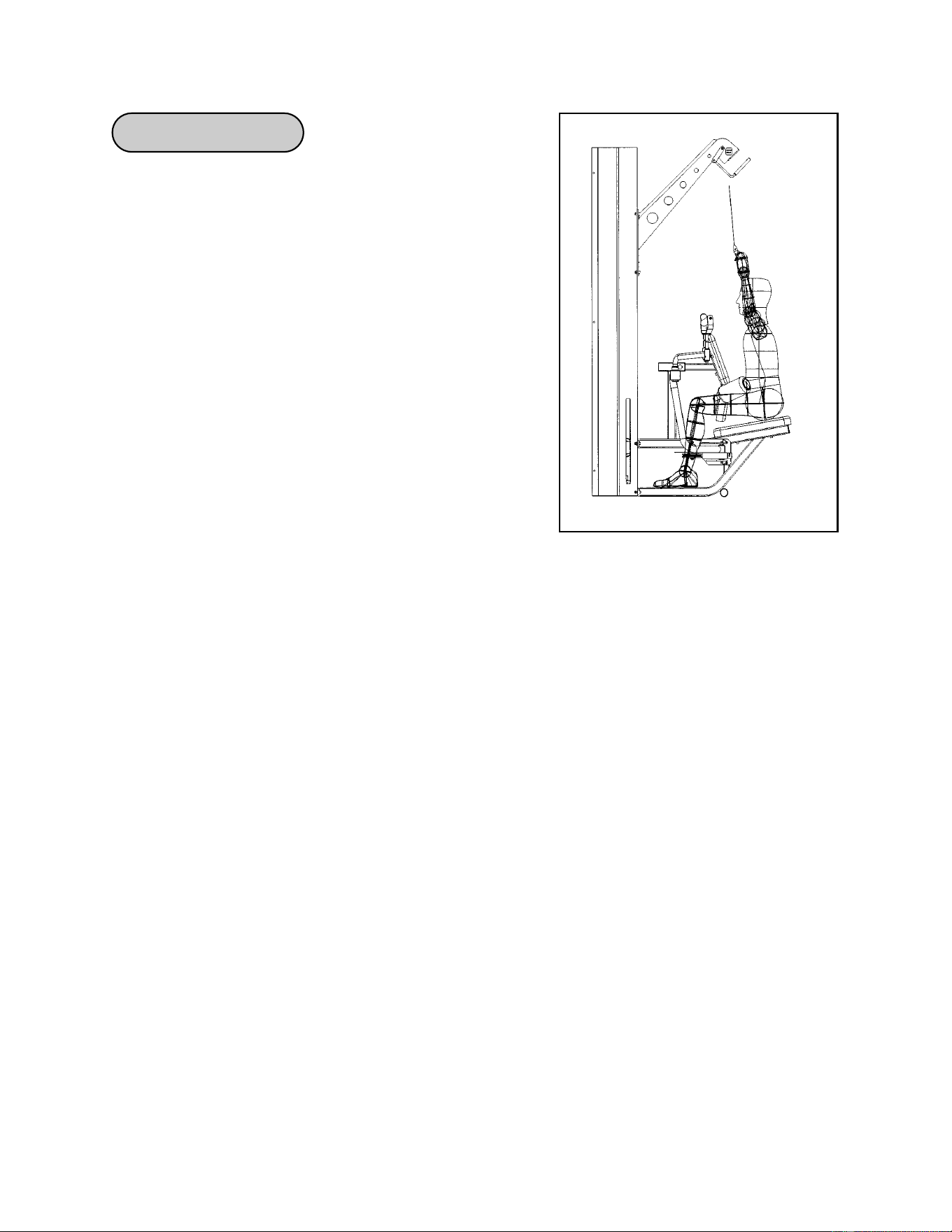
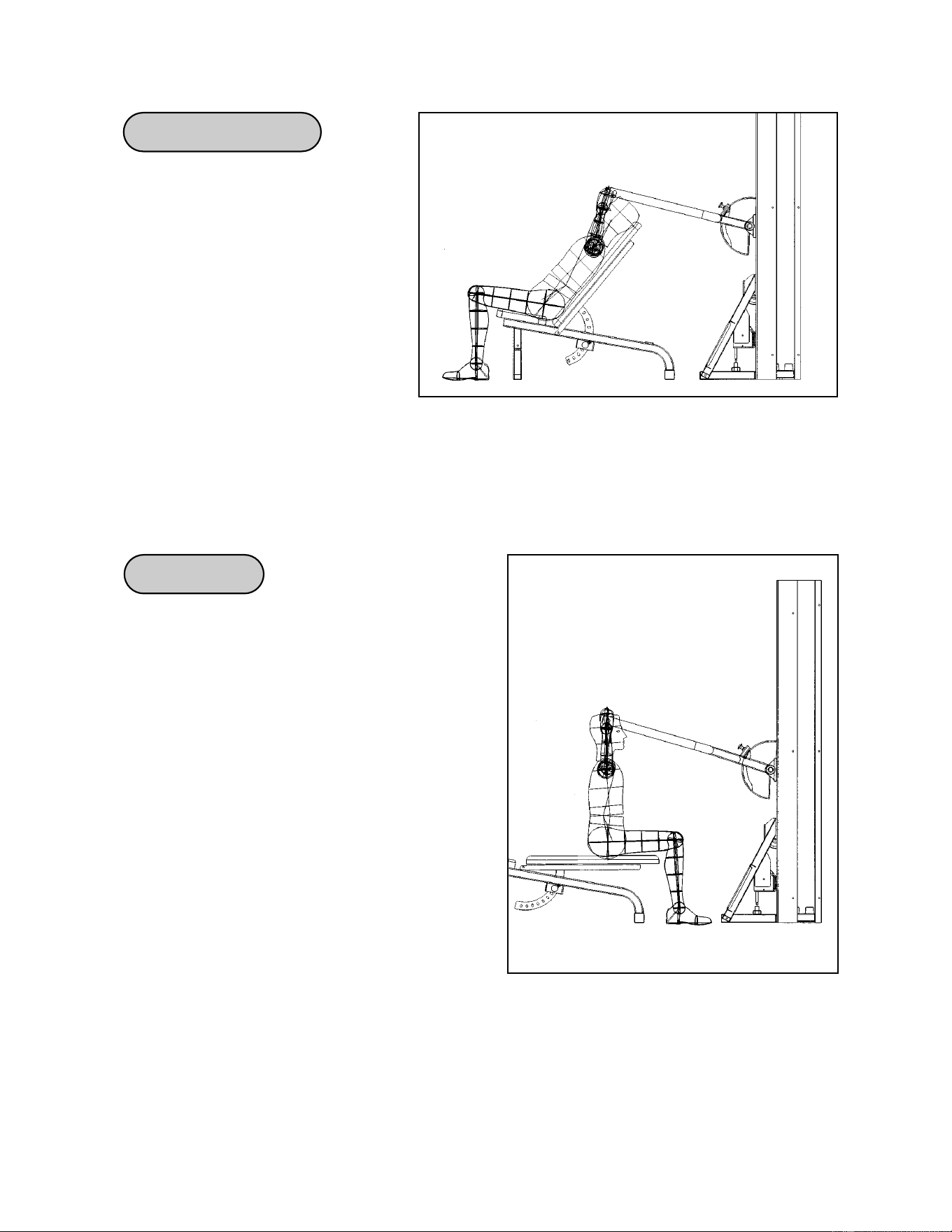
Front Lat Pulldown
Emphasis: Latissimus Dorsi and Teres Major
1. Adjust seat back so thigh support pads are
positioned comfortably.
2. Using an overhead grip, bend the elbows to 90
degrees and place a firm grip on the bar. This hand
width will be optimal for your motion.
3. Sit down placing legs under thigh pad and lean back
slightly.
4. Exhale while putting elbows toward your side. The
bar should travel to top of chest but not lower.
NOTE: Although frequently performed, the pulldown
“behind the neck” is far less effective and is
not recommended due to the stress it places
on shoulders. A good variation is to perform
the front pulldown with the low row handle,
using the same form.
Cybex MG 500 Multi-Gym Owner’s Manual
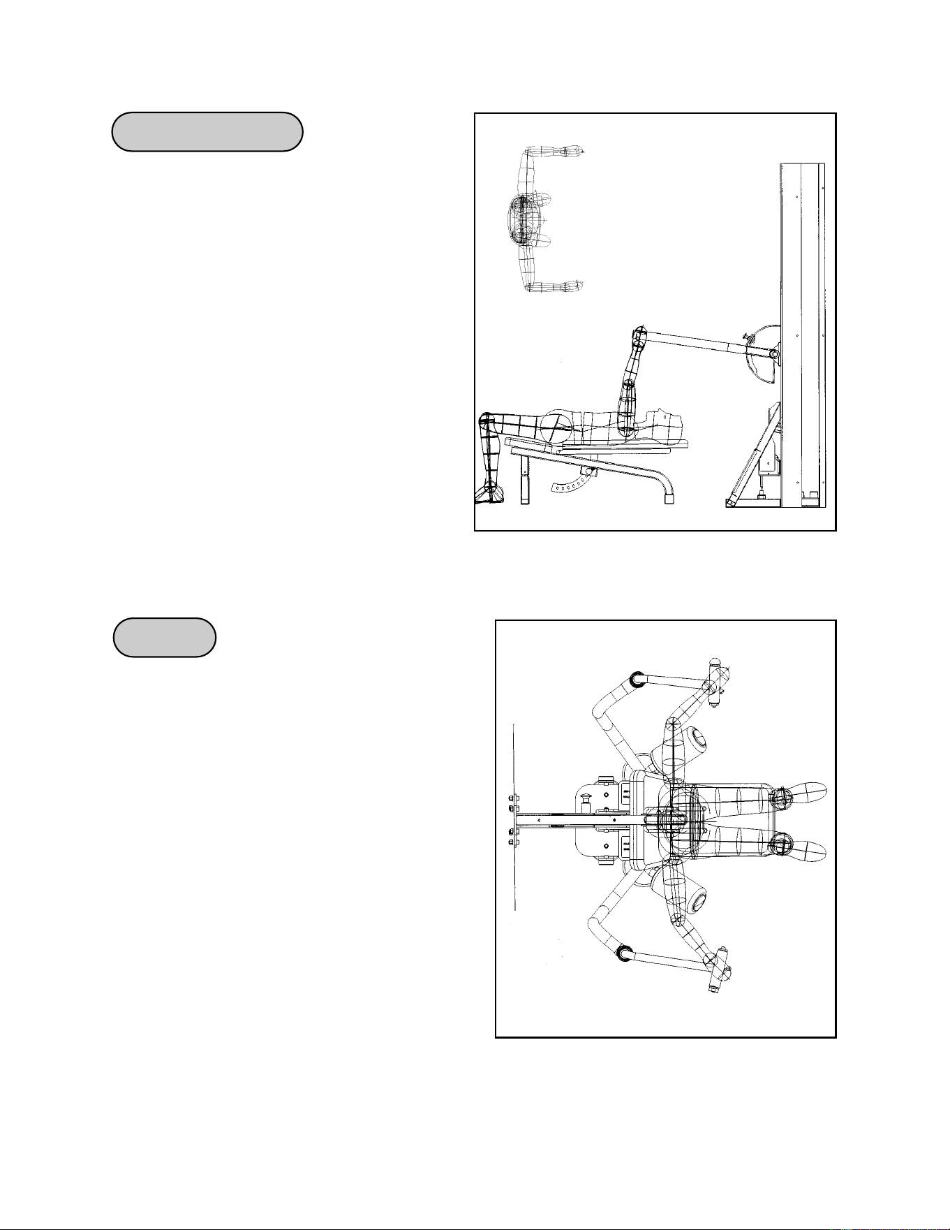
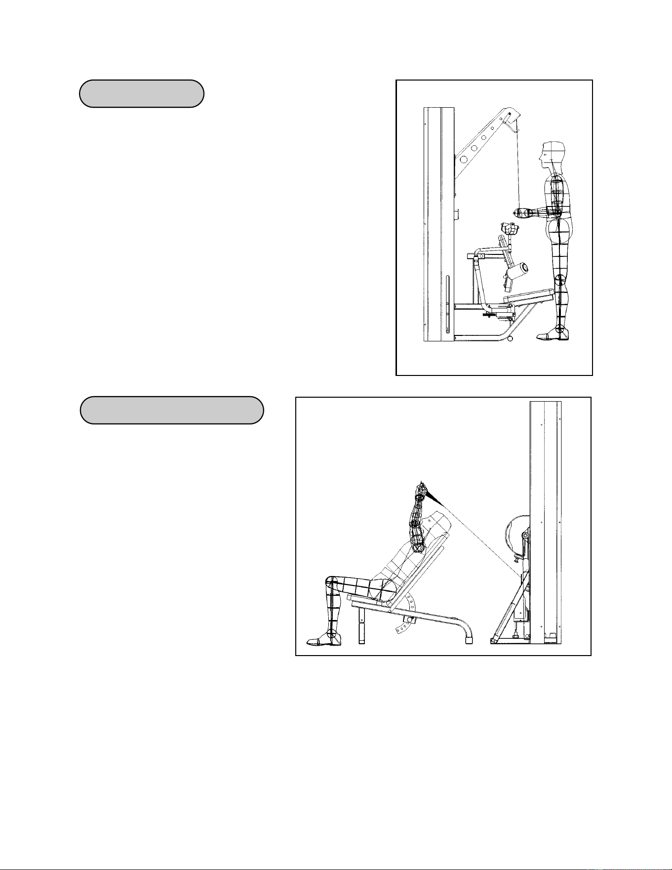
Standing Shrugs
Exercises
Page 4-8
Seated Rear Deltoid Row
Emphasis: Rear Deltoid,
Trapezius, Erector Spinae,
Brachioradius
1. Lower the pressing station arm
into the bottom position and
attach the lat pulldown handle.
2. Slide the adjustable bench into
the pressing station and set on
position 1, allowing easy access
to foot rests.
3. Place feet on rests, keep back straight, bend forward from the hips, and grasp handle.
Sitting upright, pull bar toward chest, keeping the elbows slightly below shoulder level.
4. Be sure to pinch the shoulder blades back to maximize stabilization and effectiveness,
pull upward.
Emphasis: Upper Trapezius
1. Adjust pressing arm to slightly below waist level,
bend at the knees, and grasp handles.
2. Stand erect, keep arms straight, elevate the
shoulders up, and back toward the base of the
head.
NOTE: Although commonly performed, do not
“roll” the shoulders during the shrugs.
That movement is less effective and could
potentially injure the shoulder.
Cybex MG 500 Multi-Gym Owner’s Manual
Exercises
Page 4-9
Decline
Bench Press
Bench Press
(BENCH POSITIONS 1 - 2)
Emphasis: Pectoralis Major, Anterior
Deltoid, Triceps
1. Slide the adjustable bench into the
pressing station and align the
handles at midchest.
2. Adjust the pressing arm to the
desired range of motion. The
upper arm should not be below parallel with the floor.
3. Pinch shoulder blades down and back to stabilize the spine and maximize effectiveness.
4. Position feet firmly on the floor for increased stability.
5. Inhale as you lower the weight and exhale as you press upward.
(BENCH POSITIONS 3 - 5)
Emphasis:Pectoralis Major,
Anterior Deltoid,
Triceps
1. Slide the adjustable bench into the
pressing station and align the
handles at midchest.
2. Adjust the pressing arm to the
desired range of motion. The upper
arm should not be below parallel with the floor.
3. Pinch shoulder blades down and back to stabilize the spine and maximize effectiveness.
4. Position feet firmly on the floor for increased stability.
5. Inhale as you lower the weight and exhale as you press upward.
Cybex MG 500 Multi-Gym Owner’s Manual
Exercises
Page 4-10
Military Press
Incline Bench Press
(BENCH POSITIONS 6 - 10)
Emphasis: Pectoralis Major,
Anterior Deltoid, Triceps
1. Slide the adjustable bench into
the pressing station and align
the handle set midchest.
2. Adjust the pressing arm to the
desired range of motion. The
upper arm should not be below
parallel with the floor.
3. Position feet firmly on the floor for increased stability.
4. Inhale as you lower the weight and exhale as you press upward.
(BENCH POSITION 2)
Emphasis: Anterior Deltoid, Triceps
1. Slide the adjustable bench into the pressing
station. Face machine and align handles at
shoulder height.
2. Adjust the pressing arm to the desired
range of motion. The upper arm should not
be below parallel with the floor.
3. Pinch shoulder blades down and back to
stabilize the spine and maximize
effectiveness.
4. Inhale as you lower the weight and exhale
as you pull upward.
Cybex MG 500 Multi-Gym Owner’s Manual
Exercises
Page 4-11
Chest Press
Chest Fly
Emphasis: Pectoralis Major
1. Adjust seat back to desired range of
motion and handle height to midchest.
2. Grip the handles and position elbows
out to the sides, level with handles.
3. Pinch shoulder blades back and together.
4. Leave a slight bend in your arms while
tightening your chest and slowly moving
the handles toward midline until they meet.
5. Return to starting position in a slow,
controlled manner without resting.
Emphasis: Pectoralis Major
1. Adjust seat back to desired range of motion
and handle height to midchest.
2. Grip the handles and position elbows out to
the sides, level with handles.
3. Pinch shoulder blades back and together.
4. Leave a slight bend in your arms while
tightening your chest and slowly moving the
handles toward midline until they meet.
5. Return to starting position in a slow,
controlled manner without resting.
Exercises
Page 4-12
Cybex MG 500 Multi-Gym Owner’s Manual
Overhead Tricep Extension
Tricep Pressdown
Emphasis: Triceps
1. Attach the rotating curl bar to the lat pulldown
boom.
2. Face machine with legs straddling the seat, grip the
bar with palms facing down.
3. Start exercise with bar close to your chest and
elbows at your side.
4. Tighten triceps and extend arms as far as possible
without moving either elbows or shoulders.
5. Inhale while returning to the start position without
resting or changing the shoulder/arm position.
Emphasis: Triceps
1. Slide adjustable bench into
pressing station and set to
position 5.
2. Attach soft crossover handles
to midpulley.
3. From a seated position, reach
back and grasp handles. Arms
should be vertical while the
palms remain facing upward.
4. Tighten triceps and extend arm as
far as possible without moving
either elbows or shoulders.
5. Inhale while returning to the start position without resting or changing the shoulder/arm
position.
Exercises
Page 4-13
Cybex MG 500 Multi-Gym Owner’s Manual
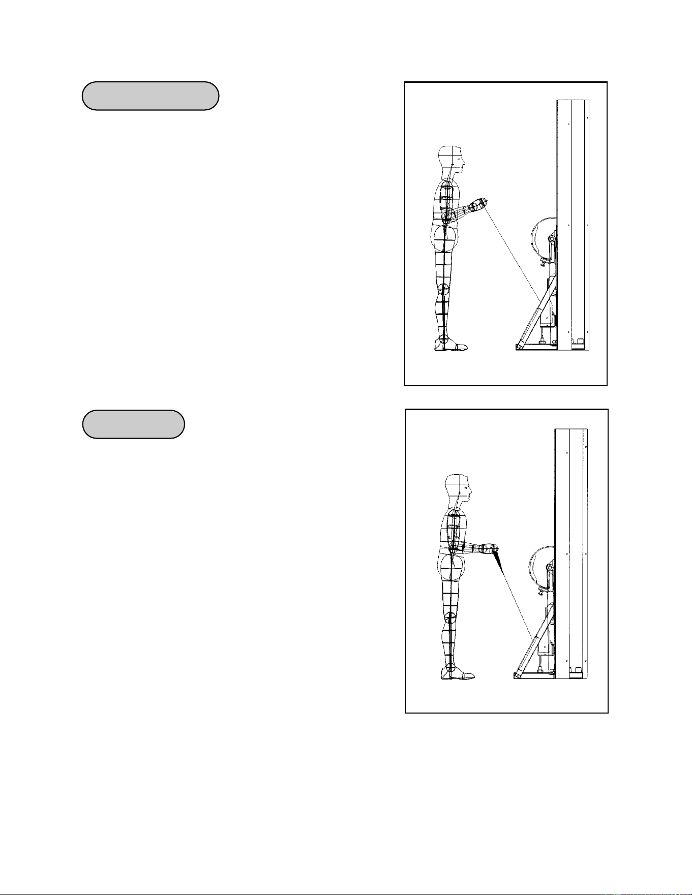
Standing Arm Curl
Hammer Curl
Emphasis: Biceps
1. Attach rotating curl bar to swivel low-pulley. Face
the machine, and grip the bar with palms up.
2. Stand erect, keep arms close to sides, exhale while
tightening biceps and flexing elbows as far as
possible without raising shoulders.
3. Inhale as you lower the weight.
Emphasis: Brachioradialis, Biceps
1. Attach soft crossover handles to swivel low-pulley.
Face the machine and grasp the handles with
palms facing upward.
2. Stand erect and while keeping the arms close to
the sides tighten the biceps/forearms and flex the
elbows as far as possible without raising the
shoulders.
3. Inhale as you lower the weight.
Exercises
Page 4-14
Cybex MG 500 Multi-Gym Owner’s Manual
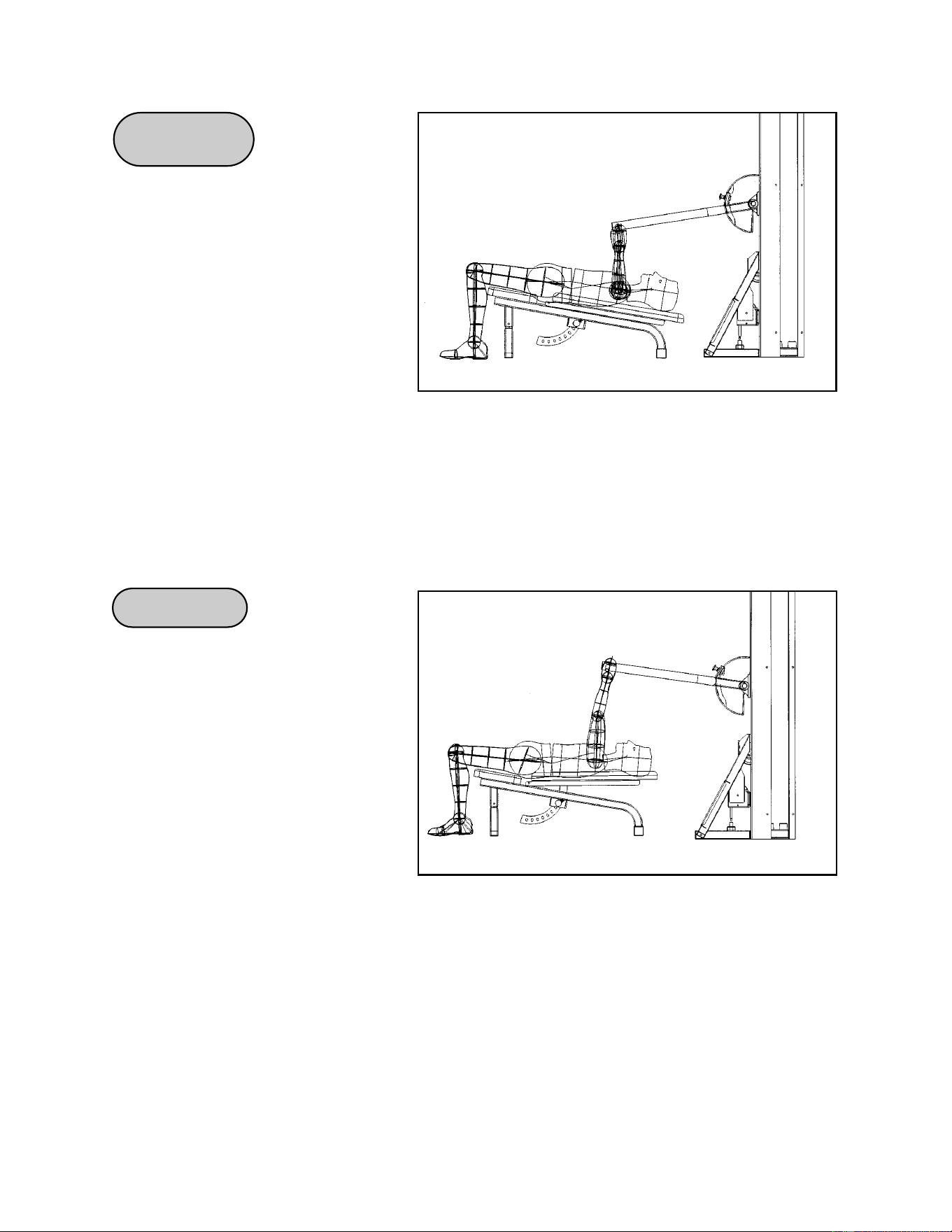
Wrist Curl
Abdominal Crunch
Emphasis: Forearm Flexors
1. Lower the pressing station arm into bottom position
and attach rotating curl handle to swivel low-pulley.
2. Slide the adjustable bench into pressing station and
set to position 2, allowing feet to rest on platform.
Sit facing the machine and grasp handle with palms
facing up and forearms resting on knees.
3. Tighten forearms and curl handle up and in, moving
as far as possible without additional arm or shoulder
motion.
4. Inhale as you lower the weight.
Emphasis: Rectus Abdominus
1. Adjust seat back to desired starting position.
2. Position back firmly against back pads.
3. Position handles over shoulders and securely
against chest.
4. Crunch forward directing ribs down toward pelvis
with smooth controlled movements.
5. Return to the starting position and repeat without
resting.
Exercises
Page 4-15
Cybex MG 500 Multi-Gym Owner’s Manual
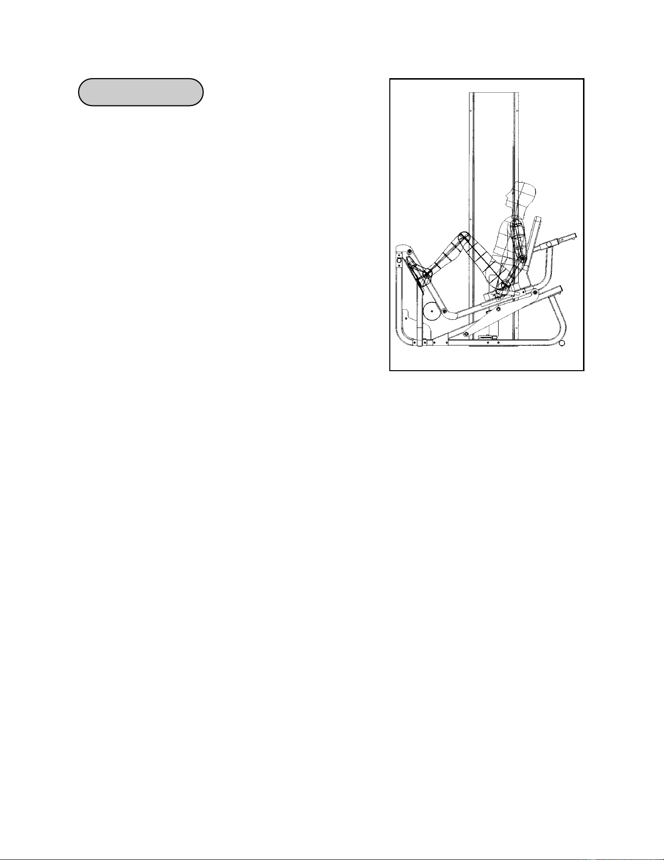
Seated Leg Press
NOTE: The appropriate starting position will allow
your feet to be securely located on foot
plates, legs to be placed at approximately
90 degrees and your back squarely
positioned against back pad.
NOTE: Maintain proper back positioning during
exercise to reduce chance of back injury.
Emphasis: Quadriceps, Glutes, Hamstrings.
1. Select appropriate resistance.
2. Adjust seat mechanism to desired starting position.
3. Locate feet securely on foot plates and position
yourself squarely in seat.
4. Lift/lower resistance with smooth controlled movements without resting.
5. Do not hyperextend (lock) knees during movement.
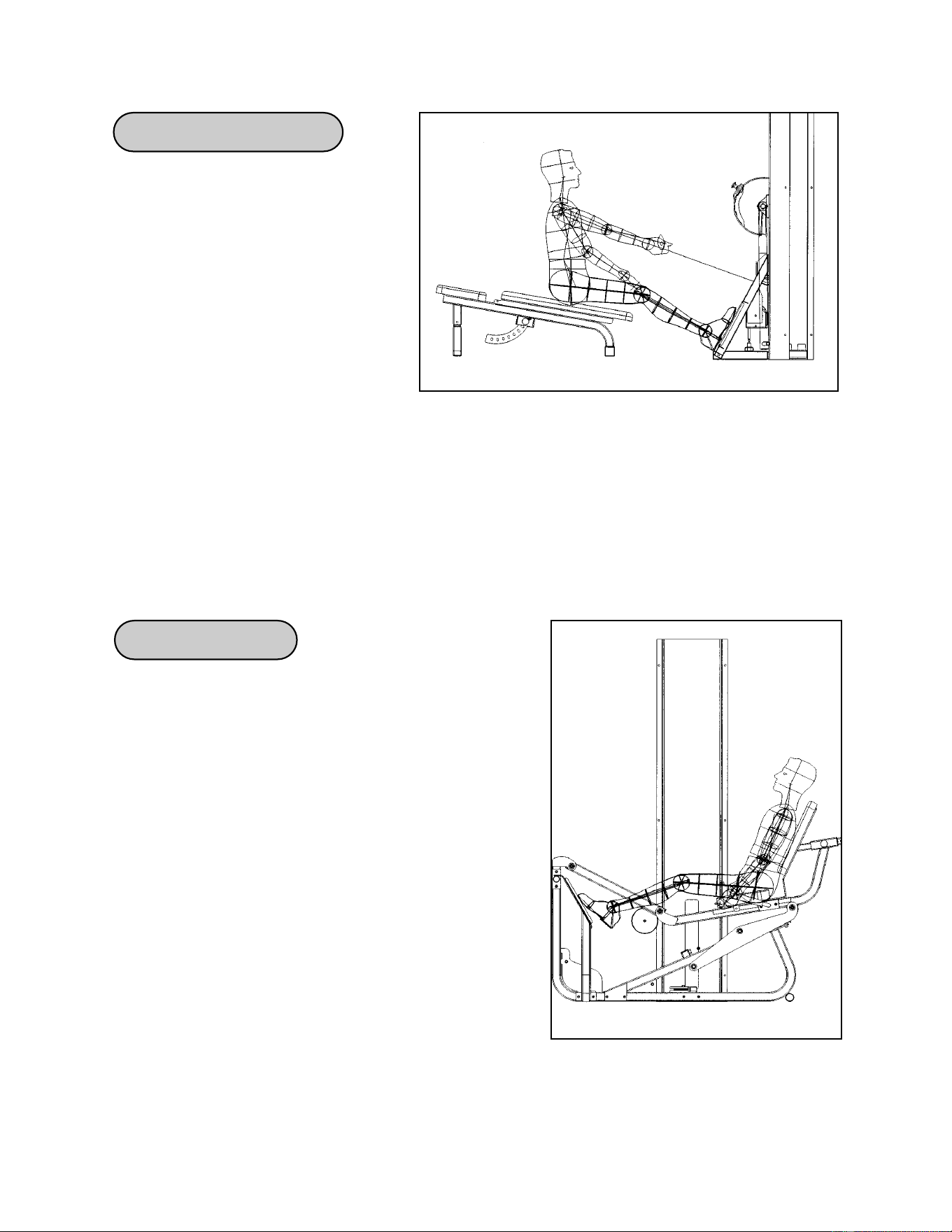
Seated Calf Raise
Cybex MG 500 Multi-Gym Owner’s Manual
Exercises
Page 4-16
Emphasis: Latissimus Dorsi,
Teres Major, Trapezius,
Brachioradialis
1. Lower the pressing station arm
into the bottom position and
attach a soft crossover handle
to midpulley.
2. Slide the adjustable bench into
the pressing station and set on
position 1, allowing easy access to foot rests.
3. Place feet on rests and keep back straight. Bend forward at the hips and grasp handle.
Maintaining an upright position, pull toward side of body.
4. Pinch shoulder blades back to maximize stability and effectiveness.
NOTE: This exercise offers a unique opportunity in requiring the exerciser to stabilize
against side-bending for improved muscular function.
Uni-Lateral Seated Row
Emphasis: Gastrocnemius, Soleus
The appropriate position will allow your feet to be
securely located on the lower third of the foot plates,
knees slightly bent and back squarely positioned
against back pad.
1. Adjust seat mechanism to a position which
requires you to press about 4” in order to
position yourself for the exercise.
2. Locate feet securely on the lower third of the
foot plates, and position yourself squarely in the rest.
3. Press the weight up about 4” while allowing a
slight bend in the knees for safety.
4. Maintaining a slight bend in knees, lower heels
slightly past the plane of the foot plates then press
heels back-up with a smooth controlled motion.

Cybex MG 500 Multi-Gym Owner’s Manual
Customer
Service
Page 5-1
Ordering Parts
5 - Customer Service
When contacting Customer Service, call 888-GO CYBEX (888-462-9239) or
508-533-4300 or fax 508-533-5183 during the hours of 8:00 a.m. - 6:00 p.m. (Eastern
Standard Time) Monday through Friday. Please specify if you need inside sales support or
technical support.
Information can also be found on the web at www.eCybex.com or by email at
Having the following information ready when calling will assist our Cybex representatives in
serving you:
• Unit Serial Number
• Product Name
The unit serial number and product name can be found on the serial number decal. See
Chapter 8 for exact location of serial number decal.
• Part Description
• Part Number
Part descriptions and part numbers are located in Chapter 8 of this manual.
• Upholstery Color
When ordering cushions or wear covers please be ready to provide the exact upholstery
color required.
• Shipping Address
• Contact Name
In addition to your shipping address and contact name, your account number is
helpful but not required.

Cybex MG 500 Multi-Gym Owner’s Manual
Customer
Service
Page 5-2
LIMITED WARRANTY FOR
ALL CYBEX COMMERCIAL STRENGTH PRODUCTS
NOTE: Save this document for your records. This warranty includes all Cybex commercial Strength
products, including: CYBEX "EAGLE", "FREE WEIGHT", "FUNCTIONAL TRAINER", "MODULAR",
"MULTI-GYM", "PLATE LOADED", "VR" and "VR2" Products.
WHO IS COVERED: The original buyer purchasing the product from Cybex or its designee. Buyer
includes any person receiving the product in an unused condition as a gift from the original buyer. The
terms "you" and "your" are used in this Limited Warranty to refer to the original buyer and any person
receiving the product as a gift from the original buyer. The terms "we," "us" and "our" are used in this
Limited Warranty to refer to Cybex International, Inc. This warranty covers all products sold under
the Cybex "Eagle", "Free Weight", "Functional Trainer", "Modular", "Multi-Gym", "Plate Loaded",
"VR" and "VR2" names and used in the continental United States. Products sold or moved out-
side the borders of the continental United States of America are subject to the terms provided by
the local distributor, and are not covered under this warranty.
WHAT IS COVERED: Except as otherwise stated in this Limited Warranty, we will repair or correct any
product or part defect which we determine is related to materials or workmanship and is not due to
normal wear and tear occurring during the stated WARRANTY PERIOD.
WHAT IS NOT COVERED: Product requires normal maintenance including, but not limited to, regular
inspection and wear component replacement. We do not warrant damage caused by the lack of normal
maintenance repairs such as those detailed within the Owner's Manual. We do not warrant any causes
beyond our control. Corrosion, oxidation or deterioration caused by product location, exposure or
environment, or conditions caused by unsuitable finishes, cleaners, or lubricants are not covered.
Damage or breakage caused by unauthorized service, installation, alteration, modification, assembly or
disassembly, negligence, or conditions of use which are unintended for the product are not warranted.
This warranty does not cover cosmetic or surface corrosion resulting from chips or scratches in the
paint. Extra expenses including, but not limited to, loss of machine use and inconvenience are not
covered. Due to varying conditions under which the product is used, we offer no warranties, express or
implied, as to the length of service. We do not warrant any products that have not been paid for, or in
the event that we have offered a payment plan, products owned by buyers who are in arrears on a
payment plan. If you are a non-consumer buyer, we only warrant products purchased directly from us
or from one of our authorized dealers in that dealer's authorized territory. THIS WARRANTY DOES NOT
COVER UNINTENDED USE. See "INTENDED USE" below.
INTENDED USE: This warranty covers only defects that arise in the ordinary, intended use of the
product. Products sold under the Cybex "Eagle", "Free Weight", "Functional Trainer", "Modular",
"Multi-Gym", "Plate Loaded", "VR" and "VR2" names are intended for commercial use, including
use in health clubs and similar facilities.
WARRANTY PERIOD: The warranty period begins on the date the product was delivered to you. The
warranty period for the structural frame expires after ten (10) years. The warranty period for rotary
bearings, guide rods, pulleys, weight stacks, bushings, linear bearings, bars, handles, and all other
parts not listed herein expires after two (2) years. The warranty period for cables and belts expires after
one (1) year. The warranty period for upholstery and handgrips expires after one hundred twenty (120)
days.
WHO WILL PAY LABOR AND TRANSPORTATION COSTS: If we determine, during the first
year of the warranty period, that the product or any covered part must be shipped to the
manufacturing facility for repair or service, all warranty repairs, including transportation costs
and labor, will be made at NO CHARGE to you; thereafter, you will be responsible for labor
and transportation costs for repair or service.
Refer to Next Page for Continuation of Limited Warranty

Cybex MG 500 Multi-Gym Owner’s Manual
Customer
Service
Page 5-3
WHAT YOU MUST DO TO OBTAIN WARRANTY COVERAGE: Retain proof of purchase. All warranty
repairs and corrections require proof of purchase. To obtain coverage, please contact Cybex Customer
Service within seven (7) days after discovery of the defect and follow the directions provided to you by
your Cybex Service Representative.
WHAT WE WILL DO TO CORRECT COVERED REPAIRS: Authorized repairs or corrections will be
performed using new or remanufactured parts shipped to you, or at our discretion, replacement of the
product. Any replacement parts provided to you are warranted for the remaining portion of the original
WARRANTY PERIOD.
MODIFICATIONS TO WARRANTY ARE NOT AUTHORIZED: No one is authorized to modify, change,
transfer or extend in any way the terms of this Limited Warranty.
THINGS TO KNOW ABOUT OBTAINING PRODUCT ACCESSORIES, PARTS AND REPAIR
SERVICE: To secure repair service under this warranty, please contact Cybex Customer Service at
(508) 533-4300, Monday - Friday from 8:00 - 6:00 p.m. Eastern time. To expedite service, please have
your product serial number available when calling. Your customer service technician will assist you with
any shipping or repair requirements deemed necessary to obtain repair or correction. A Return
Authorization Number (RA#) is required when returning a product or part if the item is to be covered
under warranty. We are not responsible for products or parts shipped to our facility without a RA#. All
returns shall be accompanied by a proof of purchase to ensure warranty coverage. We may require the
product or part be returned for inspection prior to making a warranty coverage decision.
You may also contact us by writing to: Cybex International, Inc., Attn: Customer Service Department,
10 Trotter Drive, Medway, MA, 02053.
DISCLAIMER OF WARRANTIES AND LIMITATION OF REMEDIES: It is impossible to eliminate all
risks inherently associated with use of this product. Personal injury or other unintended consequences
may result because of factors beyond our control. WE MAKE NO OTHER WARRANTIES OF ANY KIND,
EXPRESS OR IMPLIED, OTHER THAN THOSE EXPRESSLY SET FORTH WITHIN THIS DOCUMENT.
ALL WARRANTIES OTHER THAN THE WARRANTIES EXPRESSLY PROVIDED HEREIN ARE SPECIFI-
CALLY EXCLUDED. IN THE CASE OF NON-CONSUMER BUYERS, ALL IMPLIED WARRANTIES OF
MERCHANTABILITY AND FITNESS FOR A PARTICULAR PURPOSE ARE HEREBY DISCLAIMED.
IN THE CASE OF A CONSUMER BUYER, THE DURATION OF ALL IMPLIED WARRANTIES OF
MERCHANTABILITY OR FITNESS FOR A PARTICULAR PURPOSE IS LIMITED TO THE DURATION OF
THE EXPRESS WARRANTIES PROVIDED WITHIN THIS DOCUMENT.
WE WILL NOT BE LIABLE FOR ANY DIRECT OR INDIRECT, CONSEQUENTIAL OR INCIDENTAL
DAMAGES, LOSSES OR EXPENSES, INCLUDING BUT NOT LIMITED TO COMMERCIAL LOSSES,
BUSINESS INTERRUPTION, OR DAMAGE TO PROPERTY OTHER THAN THE PRODUCT OR
PRODUCTS TO WHICH THIS LIMITED WARRANTY APPLIES.
EFFECT OF STATE LAWS: Some States do not allow limitations on how long an implied warranty
lasts, so the above limitation may not apply to you. Some States do not allow the exclusion or
limitation of incidental or consequential damages, so the above limitation or exclusion may not apply to
you. This warranty gives you specific legal rights, and you may also have other rights which vary from
State to State.
ALTERNATIVE DISPUTE RESOLUTION FOR NON-CONSUMER BUYERS: WE RESERVE THE
RIGHT TO MANDATE ALTERNATIVE DISPUTE RESOLUTION TO SETTLE ANY OR ALL CLAIMS
RESULTING FROM THIS SALES TRANSACTION. ALTERNATIVE DISPUTE RESOLUTION
PROCEEDINGS WILL BE CONDUCTED IN THE STATE OF MASSACHUSETTS ACCORDING TO THE
COMMERCIAL RULES OF THE AMERICAN ARBITRATION ASSOCIATION.

Cybex MG 500 Multi-Gym Owner’s Manual
Customer
Service
Page 5-4
See Chapter 6 for proper installation. Allow the appropriate operating space between
machines. It is the responsibility of the purchaser to determine the appropriate operating
space for customer safety and convenience. Do not crowd the exercise area.
Safety
Use extra caution when assembling and installing equipment, particularly when lifting or
moving heavy objects (such as installing weight stacks) and when using power tools.
Installation
Upon arrival, it is important that you thoroughly inspect all of the equipment for damage.
If you discover damage, point it out to the truck driver and request that the driver make a
record of the damage on the receiving report. Be sure to obtain a copy of the receiving report
for your files.
Apparent Damage - Any damage seen with a visual check must be noted on the freight bill
and signed by the carrier’s agent. Failure to do so will result in the carrier’s refusal to honor
your damage claim. The carrier will provide you with the required forms for filing such claims.
Concealed Damage - Damage not seen with a visual check upon receipt of a shipment but
noticed later must be reported to the carrier as soon as possible. Upon discovery of the dam-
age, a written or phone request to the carrier
asking them to perform an inspection of the materials must be made within ten days of the
date of delivery. Keep all shipping containers and packing
materials - they will be needed as part of the inspection process. The carrier will provide you
with an inspection report and the necessary forms for filing a concealed damage claim.
Concealed damage is the carrier’s responsibility.
• Contact Cybex Technical Support if you received damaged equipment and
provide them with the information on the report regarding your damaged
equipment.
• Contact Cybex Inside Sales if you did not receive the appropriate
equipment and provide them with the information regarding your order.
You may call Cybex at 888-462-9239 (888-GO CYBEX) and specify if you are calling for a
Technical Support Representative or an Inside Sales Representative.
Delivery Inspection

Cybex MG 500 Multi-Gym Owner’s Manual
Customer
Service
Page 5-5
Returning Goods
When agreed to by Cybex, the buyer may return products with a Return Material Authorization
Number (RMA).
The RMA number can be obtained through the Cybex Customer Service department. Under
no circumstances will defective parts or equipment be accepted by Cybex without
proper the proper RMA number and prepayment of all postage or freight charges.
Please use the following steps when obtaining an RMA number.
1. Call the Customer Service Hotline at 888-GO-CYBEX (888-462-9239) for the return of any
item that is defective.
2. Provide the technician with a detailed description of the problem you are having or the
defect in the item you wish to return.
3. Provide the model and serial number of your Cybex product. The serial number location
can be found in Chapter 8.
4. If your situation cannot be resolved over the phone, the technician will request that you
return the defective part(s) to Cybex for repair or replacement. You will then be given an
RMA number. Write the RMA number on the outside of the package that contains the
item(s) to be returned. Along with the parts, please Include a description of the problem,
the serial number of the unit, your facility name address and phone number as well as a
contact name.
5. Forward the package to Cybex, prepaid for shipping charges.
NOTE: Merchandise returned without an RMA number on the outside of the package
or shipments sent C.O.D. will not be accepted by the Cybex receiving
department.

Cybex MG 500 Multi-Gym Owner’s Manual
Customer
Service
Page 5-6
This page intentionally left blank
6 - Assembly
Cybex MG 500 Multi-Gym Owner’s Manual
Assembly
Page 6-1

Cybex MG 500 Multi-Gym Owner’s Manual
Assembly
Page 6-2
• 7/32” Allen wrench
• 5/16” Allen wrench
• 9/16” Socket/wrench
• External snap ring pliers
Tools Required
Unpacking Main Frame Assembly
! WARNING: Use extreme caution when assembling the MG 500, especially when
working on the inside of the main frame assembly. Failure to do so
could result in injury.
• Rubber mallet
• Step ladder
• Automotive engine oil
• Utility knife
NOTE: Two or three people are required to assemble the MG 500.
1. Read and understand all instructions thoroughly before assembling the MG 500.
NOTE: Each step number in the assembly instructions tells you what you will be
doing. The lettered steps following each step number describes the procedure
required. Do not continue with step 2 until you have carefully read all of the
assembly instructions.
2. Verify you have received the appropriate configuration (see steps 2A and 2B).
A. If you ordered the Leg Extension/Leg Curl configuration (8600-001), verify you have
the following: Leg Extension/Leg Curl box, Pressing Station box, Fly Station box,
three weight stacks (17 plates each) and the main frame.
B. If you ordered the Leg Press configuration (8602-001), verify you have the
following: Leg Press box, Pressing Station Box, Fly Station box, three
weight stacks (17 plates each) and the Main Frame.
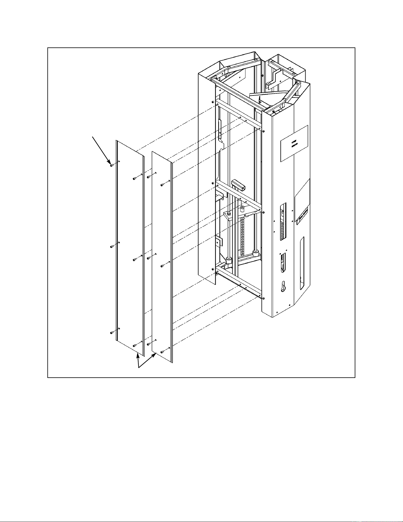
3. Unpacking main frame assembly (see steps 3A - 3D and Figure 1, located on the
next page).
A. Carefully place MG 500 near area of installation. A minimum amount of area
required is 164” L x 110” W.
B. Using a 5/16” Allen wrench, remove the 12 SHCS .375-16 x .625 screws (six for each
panel) securing the two back panels. See Figure 1.
C. Carefully remove the two panels and set them aside (along with the 12 screws).
D. Remove the main frame hardware box and three cushion boxes located on the inside
of the main frame assembly. Set the boxes aside.
Cybex MG 500 Multi-Gym Owner’s Manual
Assembly
Page 6-3
Figure 1
Back covers
SHCS .375-16 x .625
(quantity of 12)
Cybex MG 500 Multi-Gym Owner’s Manual
Assembly
Page 6-4
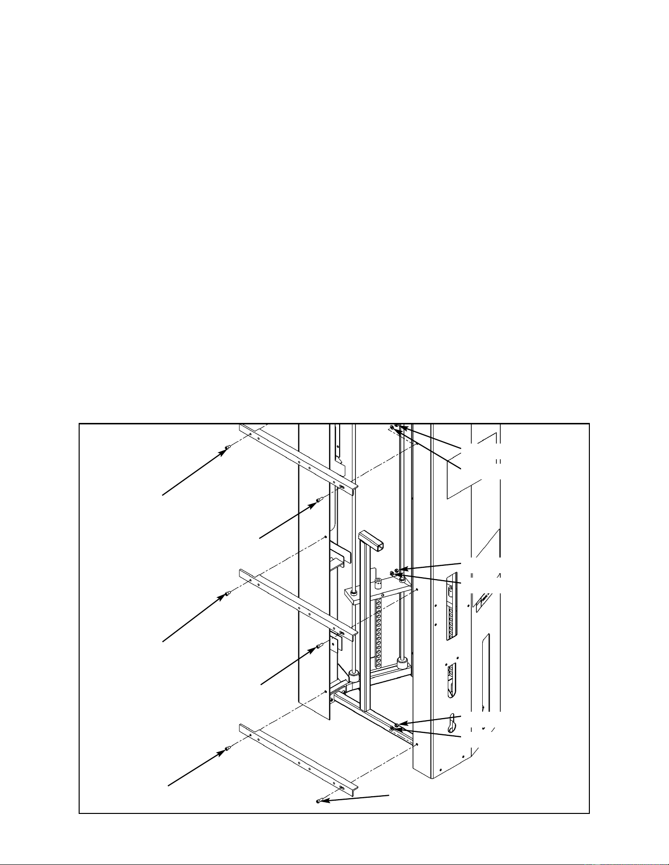
Figure 2
SHCS .375-16 x .625
SHCS .375-16 x .625
SHCS .375-16 x .625
SHCS .375-16 x 1.00
SHCS .375-16 x 1.00
SHCS .375-16 x 1.00
Nylon Locknut .375
Washer
Nylon Locknut .375
Washer
Nylon Locknut .375
Washer
4. Removing main frame assembly from pallet (see steps 4A - 4F).
A. Remove the shipping brackets securing main frame to the pallet. See Figure 1 located
on the previous page.
! WARNING: The main frame assembly weighs approximately 600 pounds and will be
difficult to remove from the pallet. A minimum of three people are
required to remove main frame assembly from the shipping pallet. Use
extreme caution Failure to do so could result in injury.
B. Determine the exact location for the MG 500 based upon overall size.
C. Carefully move and tip main frame assembly so that the Fly Station end is leaning off
the pallet.
D. Carefully raise main frame assembly high enough so that a third person can remove
the pallet.
E. Carefully lower and position main frame assembly so that it is in the exact area where
the MG 500 will be used.
F. Remove all three braces as shown in Figure 2. Set aside braces and hardware. The
braces will be re-installed at the end of the assembly procedure.
Cybex MG 500 Multi-Gym Owner’s Manual
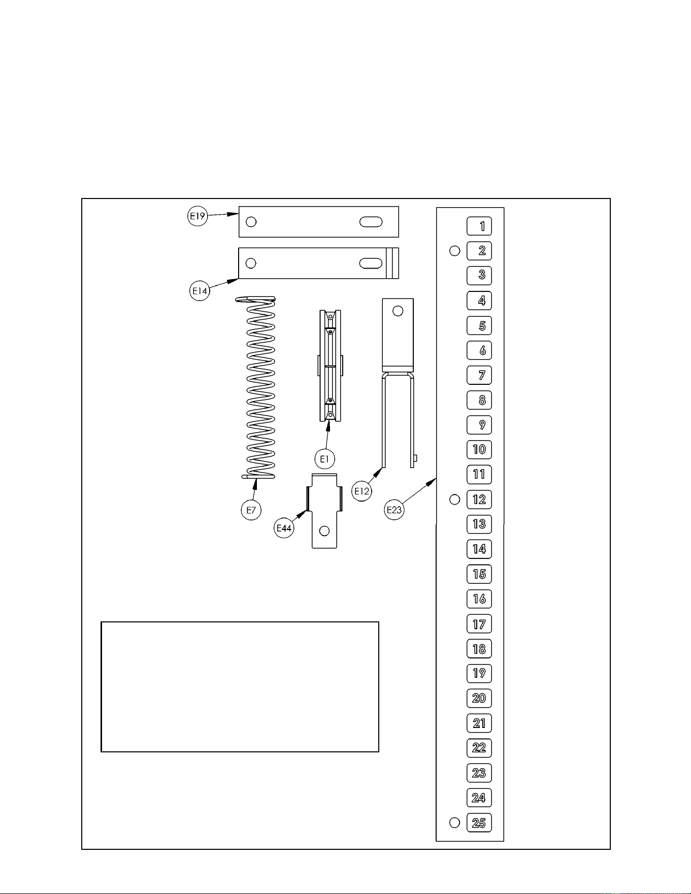
Figure 3
Assembly
Page 6-5
E1 20 08014 Pulley Assembly
E7 3 51119 Selector Pin Retainer
E12 1 8650-203 Pulley Clevis
E14 2 8650-205 Adjuster
E19 2 8650-339 Pulley Tab
E23 3 9100-313 Weight Plate Decal (1-25)
E44 6 8650-378 Cable Retainer
ITEM QTY PART NO. DESCRIPTION
5. Verify contents of the two main frame hardware packs (see steps 5A, 5B, Figures 3
and 4).
A. Remove the two hardware packs from the main frame hardware box.
B. Verify contents of both hardware packs. These parts are used on the inside of the MG
500 (such as for routing cables). See Figures 3 and 4.
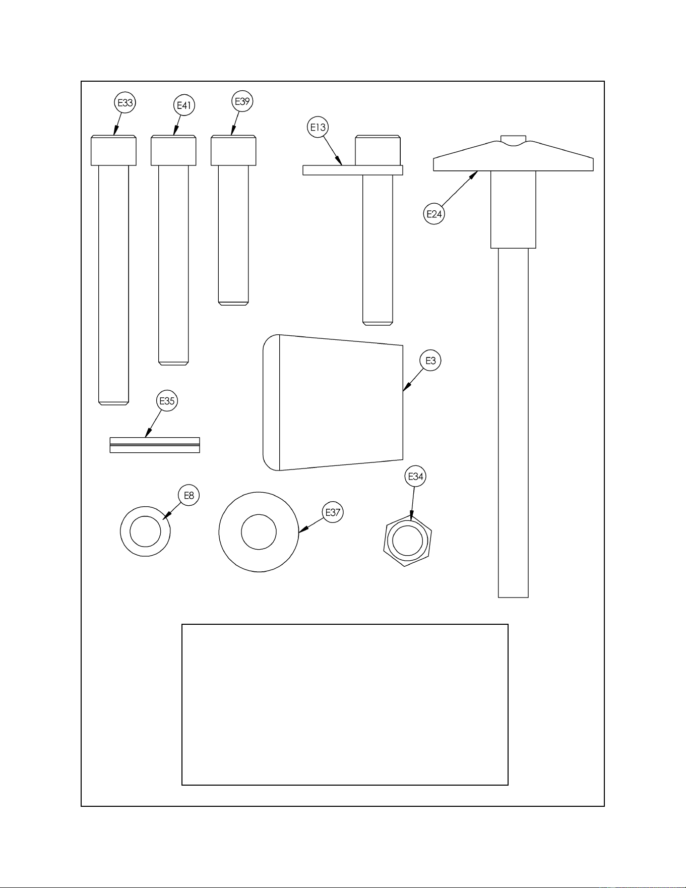
Cybex MG 500 Multi-Gym Owner’s Manual
Assembly
Page 6-6
E3 3 4700M005 Rubber Boot
E8 6 8550-358 Spacer
E13 3 8650-204 Cam Bolt
E24 3 BH030201 Quick Release Pin .375 Dia. x 4.00
E33 3 HC702834 SHCS .375-16 x 3.00
E34 20 HN704901 Nylon Locknut .375-16
E35 3 HP286819 Spiral Pin .188 x 1.12
E37 3 HS347700 Washer USS .375
E39 13 JC702824 SHCS .375-16 x 1.75
E41 1 HC702830 SHCS .375-16 x 2.50
ITEM QTY PART NO. DESCRIPTION
Figure 4
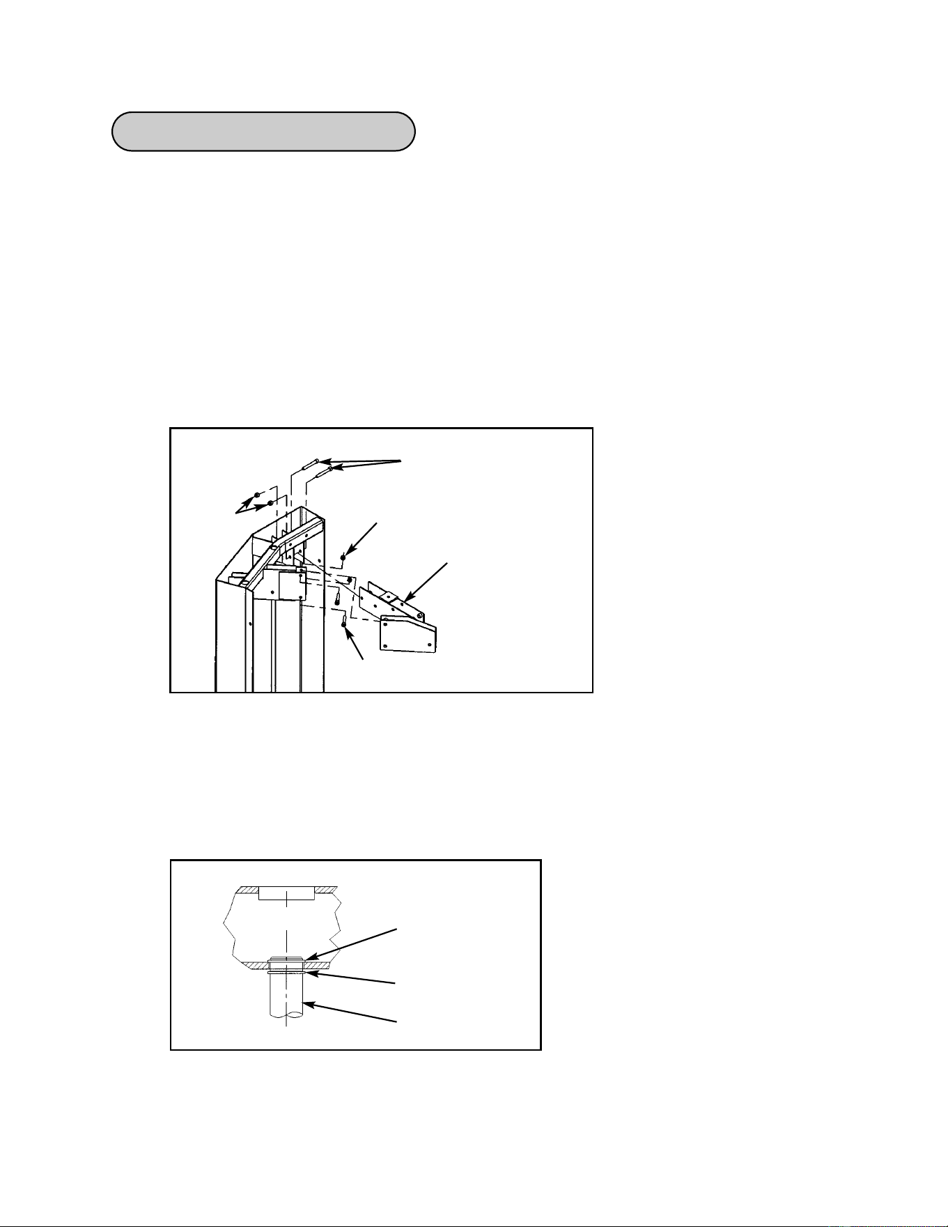
Cybex MG 500 Multi-Gym Owner’s Manual
Assembly
Page 6-7
Installing Weight Stacks
Figure 2
Upper snap ring
Lower snap ring
Frame
Guide rod
C. Using an external snap ring pliers, slide the lower snap ring down about two inches
from the top part of the guide rod (this will provide access to the upper ring). See
Figure 2.
NOTE: A step ladder may be helpful when removing snap rings.
D. Repeat step 1C for the other guide rod.
! WARNING: Use extreme caution when installing the weight stacks, especially when
working on the inside of the main frame assembly. Failure to do so
could result in injury.
NOTE: Two people will be required to perform this procedure.
1. Install Pressing Station weight stack (see steps 1A - 1S, Figures 1 and 2).
A. Remove the four SHCS and nylon locknuts securing the pulley bracket. See Figure 1.
B. Slide bracket downward and remove.
Figure 1
Bracket
SHCS .375-16 x 2.75
SHCS .375-16 x 2.00
Nylon
Locknut
Nylon
Locknut
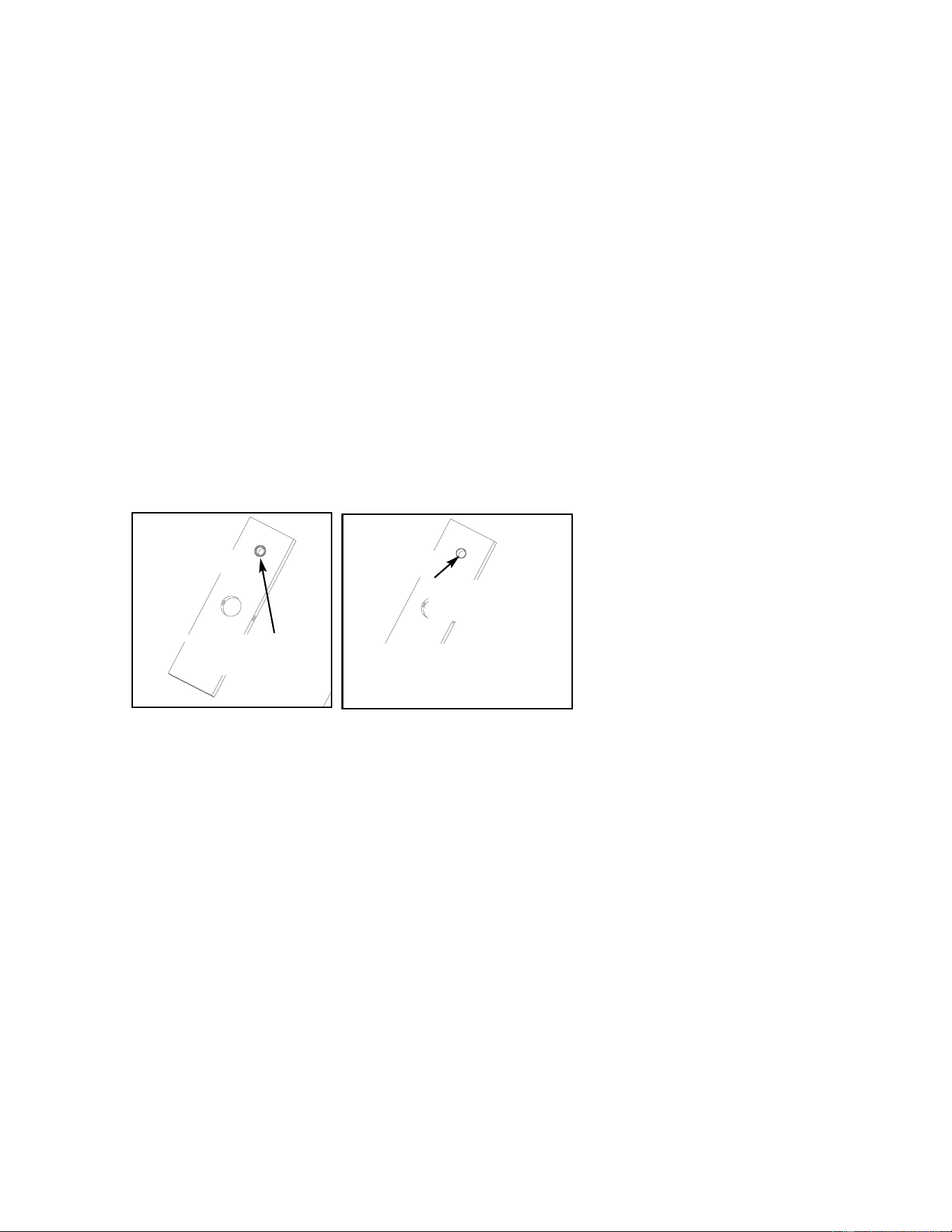
Cybex MG 500 Multi-Gym Owner’s Manual
Assembly
Page 6-8
E. Raise one of the guide rods high enough to expose the upper snap ring. Using an
external snap ring pliers, remove upper snap ring and then carefully lower guide rod.
F. Repeat step E for the other guide rod.
G. Remove lower snap ring on each guide rod.
H. Lean each guide rod outward.
I. Using a utility knife, cut the shipping tie strap securing the top weight and carefully
remove top weight.
J. Wipe both guide rods clean over entire length. Lubricate with light coating of medium
weight automotive engine oil.
K. With an assistant, carefully install each weight plate one at a time. NOTE: Install
weight plates in reverse order as removed in step 7M. NOTE: When installing weight
plates, position plates so wide edges of bushings face upward and narrow edges of
bushings face downward. See Figures 3A and 3B.
L. Slide top weight onto guide rods.
M. On each guide rod, place lower snap rings at least two inches below top end of guide
rod.
N. On one of the guide rods, install the upper snap ring. Lower guide rod and secure
lower snap ring.
O. Repeat step N for other guide rod.
P. Install pulley bracket (removed in steps 1A and 1B). See Figure 1.
Q. Carefully install weight detent pin onto spiral cord.
R. Place ring end of spiral cord over stem of top weight.
S. Place rubber cap over stem of top weight so that rubber cap is loose and easy to
remove. The rubber cap will be removed later and placed on the weight stack cable.
WIDE bushing
edge faces upward
NARROW bushing
edge
NOTE: The narrow
bushing edge must
face downward.
CORRECT
WRONG
Figure 3A
Figure 3B
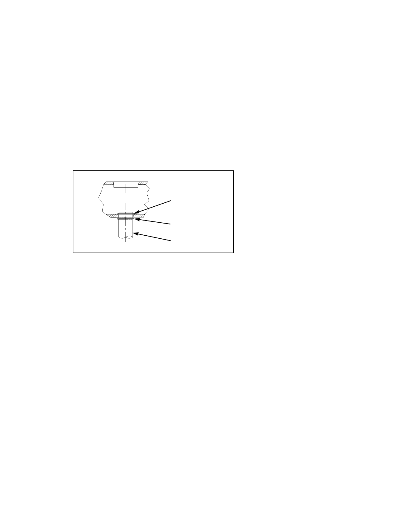
Cybex MG 500 Multi-Gym Owner’s Manual
Assembly
Page 6-9
Figure 4
Upper snap ring
Lower snap ring
Frame
Guide rod
2. Install optional station weight stack (see steps 2A - 2Q and Figure 4).
! WARNING: Use extreme caution when installing the weight stacks, especially when
working on the inside of the main frame assembly. Failure to do so
could result in injury.
NOTE: Two people will be required to perform this procedure.
A. Using an external snap ring pliers, slide the lower snap ring down about two inches
from the top part of the guide rod (this will provide access to the upper ring). See
Figure 4.
NOTE: A step ladder may be helpful when removing snap rings.
B. Repeat step A for other guide rod.
C. Raise one of the guide rods high enough to expose the upper snap ring. Using an
external snap ring pliers, remove upper snap ring and then carefully lower guide rod.
D. Repeat step C for the other guide rod.
E. Remove lower snap ring on each guide rod.
F. Lean each guide rod outward.
G. Using a utility knife, cut the shipping tie strap securing the top weight and carefully
remove top weight.
H. Wipe both guide rods clean over entire length. Lubricate with light coating of medium
weight automotive engine oil.
I. With an assistant, carefully install each weight plate one at a time. NOTE: See
Figure 3A for proper positioning of weight plates.
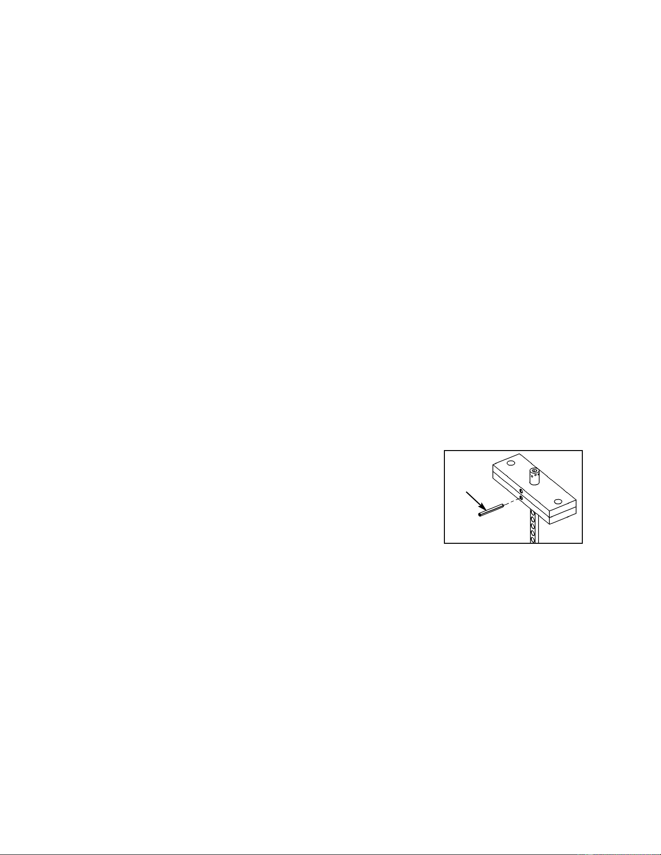
J. Slide top weight onto guide rods.
K. On each guide rod, place lower snap rings at least two inches below top
end of guide rod.
L. On one of the guide rods, install the upper snap ring. Lower guide rod and secure
lower snap ring.
M. Repeat step M for other guide rod.
O. Carefully install weight detent pin onto spiral cord.
P. Place ring end of spiral cord over stem of top weight.
Q. Place rubber cap over stem of top weight so that rubber cap is loose and easy to
remove. The rubber cap will be removed later and placed on the weight stack cable.
3. Install optional station weight stack - Leg Press Station only (see step 3A).
A. Repeat steps 2A - 2Q.
4. Install optional station weight stack - Leg Extension/Leg Curl Station only (see
steps 4A - 4C and Figure 5).
A. Repeat steps 2A - 2I. NOTE: Do not install top weight plate or second weight.
B. Locate spring pin 10 mm x 90 mm from the Leg
Extension/Leg Curl hardware pack (located in the Leg
Extension/Leg Curl (frame) carton). Slide top weight plate
onto second plate and carefully pound the spring pin into
the second weight plate hole, securing second plate to the
top weight plate. See Figure 5. NOTE: Insert pin so that it is
flush with the weight plate.
C. Repeat steps 2J - 2Q.
5. Install weight plate decals (see steps 5A - 5F).
A. Locate the weight stack number decals (quantity of three).
B. Carefully peel the backing off the decal. Align holes in decal with holes with
appropriate holes in weight stack. NOTE: Do not allow adhesive to touch weight stack
at this time.
C. Insert a guide rod through each hole of the template. NOTE: A guide rod can be
anything that fits through the weight stack hole, such as a weight stack selector pin.
D. Carefully align and rub decal onto weight plates.
E. Carefully remove front side, leaving numbers adhering to weight plates.
F. Repeat steps 5A - 5E to install all weight plate decals to all three weight stacks.
Cybex MG 500 Multi-Gym Owner’s Manual
Assembly
Page 6-10
Figure 5
Pin
second
weight
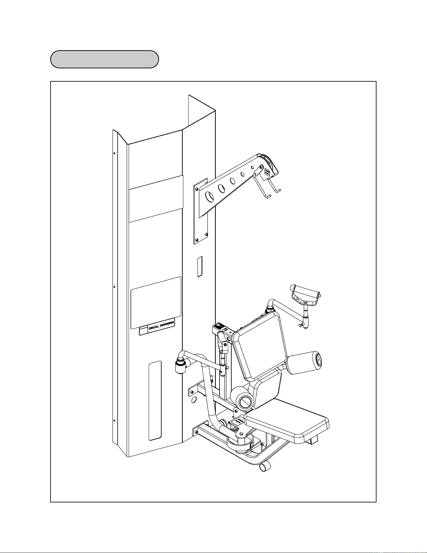
Assembly
Page 6-11
Fly Station Diagram
Cybex MG 500 Multi-Gym Owner’s Manual

Assembly
Page 6-12
Fly Station Assembly
B5 1 4035S121-0 Cushion w/Wear Cover
B6 1 4106S055-0 Seat Cushion
B8 1 5245-011 Back Cushion
B9 2 4800-135 Round Cushion w/Wear Cover
B12-A 1 8520-212 Handle (without bumper)
B12-B 1 8520-212 Handle (with bumper)
B16 1 8620-200 Frame
B17 1 8620-201 Hip Support
B18 1 8620-202 Cushion Mount
B19 1 8620-203 Right Pivot
B20 1 8620-204 Left Pivot
B21 1 8620-207 Right Pivot Handle
B22 1 8620-208 Left Pivot Handle
B23 1 8620-209 Right Arm
B24 1 8620-210 Left Arm
B25 1 8620-211 Boom
B26 1 8620-214 Hook
B42 2 PP080223 Plastic Insert
B51 1 8500-201 Pulldown Bar
B52 1 8620-002 Cable 151.25” Long
B53 1 8620-003 Cable 65.97” Long
B54 1 8620-004 Cable 106.25” Long
B57 1 8620-338 Ab Crunch Strap
B58 1 8620-341 Guard
1 Hardware Pack
B71 1 8620-215 Bracket
ITEM QTY PART NO. DESCRIPTION
Figure 1
1. Verify contents of the Fly Station boxes (see steps 1A - 1C and Figures 1-3).
A. Locate the Fly Station box (containing the frame).
B. Locate the Fly Station cushion box (removed from the main frame assembly).
C. Verify contents of both boxes. See Figures 1-3.
Cybex MG 500 Multi-Gym Owner’s Manual
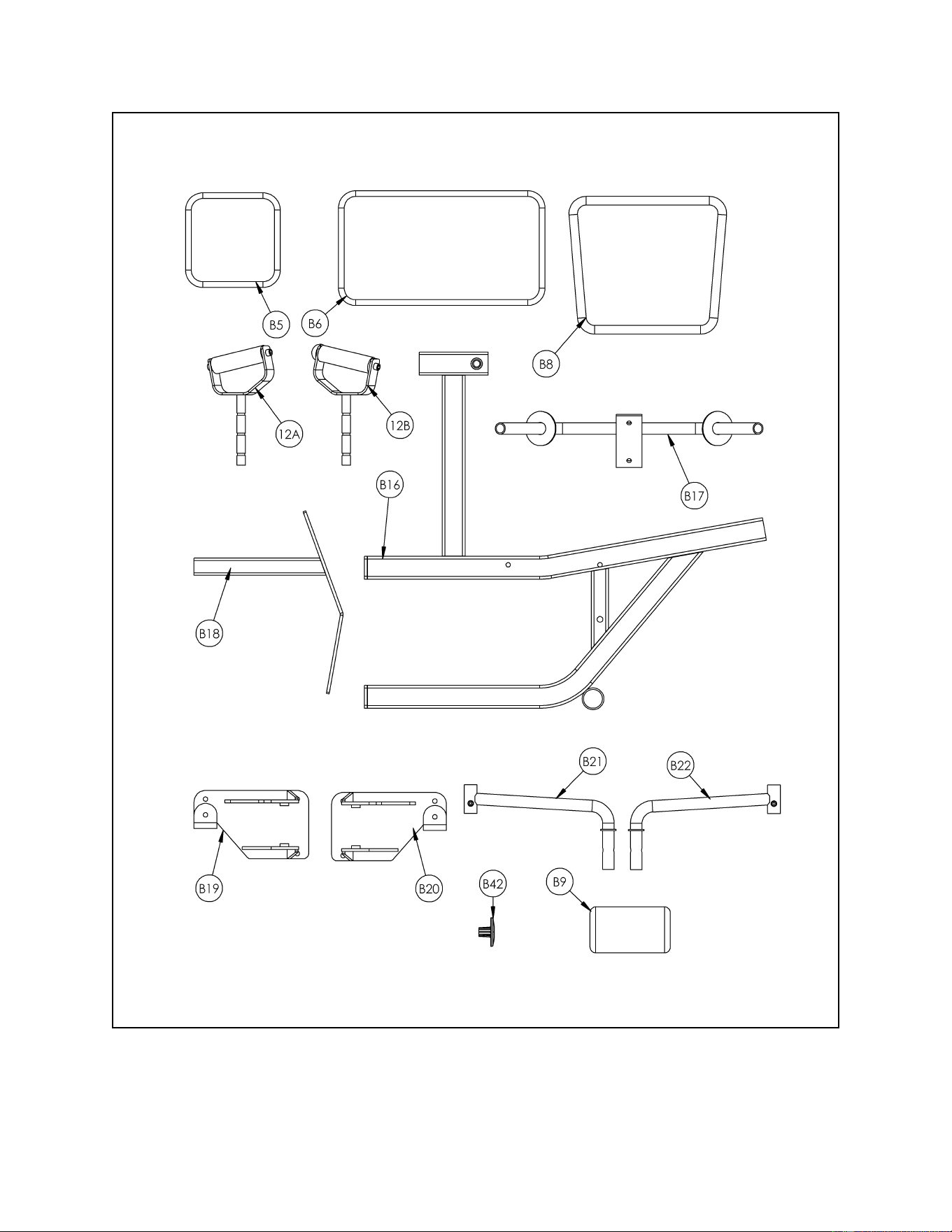
Assembly
Page 6-13
Figure 2
Cybex MG 500 Multi-Gym Owner’s Manual
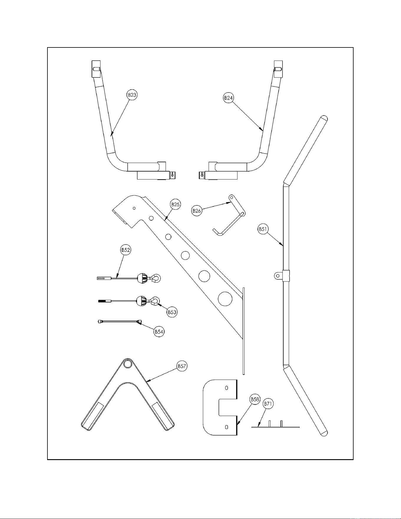
Assembly
Page 6-14
Figure 3
Cybex MG 500 Multi-Gym Owner’s Manual
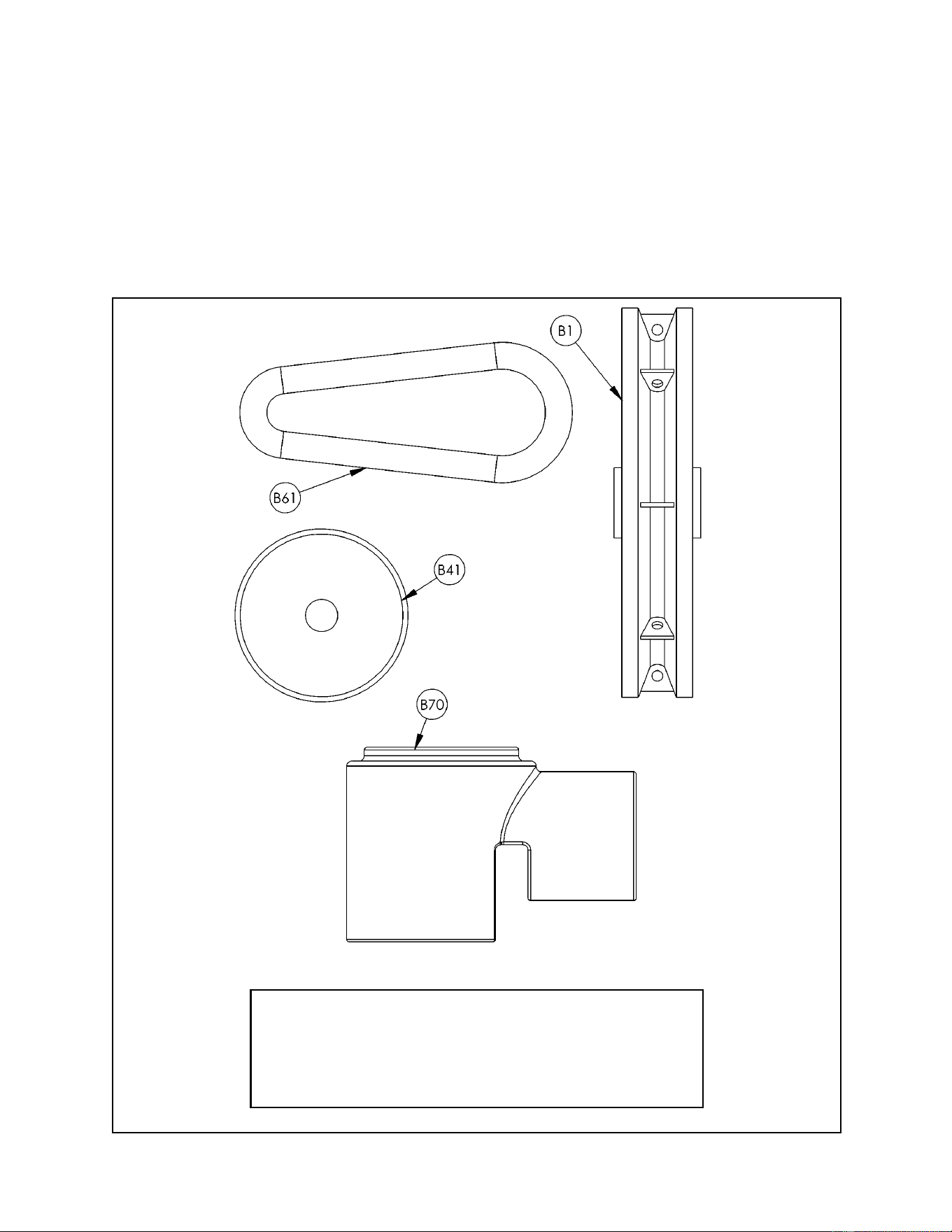
Assembly
Page 6-15
2. Verify contents of the Fly Station hardware pack (see steps 2A - 2B and Figures 4 and
5).
A. Locate hardware pack from step 1B.
B. Verify contents of hardware pack. If desired, sort out hardware into different
containers. Do not combine hardware with other hardware packs. See Figures 4 and 5
for contents of hardware pack.
B1 3 08014 Pulley
B41 2 PL-52062 Bumper 2.00 Dia. x .625
B61 2 GQ000206 Snap Link
B70 2 8620-344 Pivot Guard
ITEM QTY PART NO. DESCRIPTION
Fly Station Hardware Pack
Figure 4
Cybex MG 500 Multi-Gym Owner’s Manual
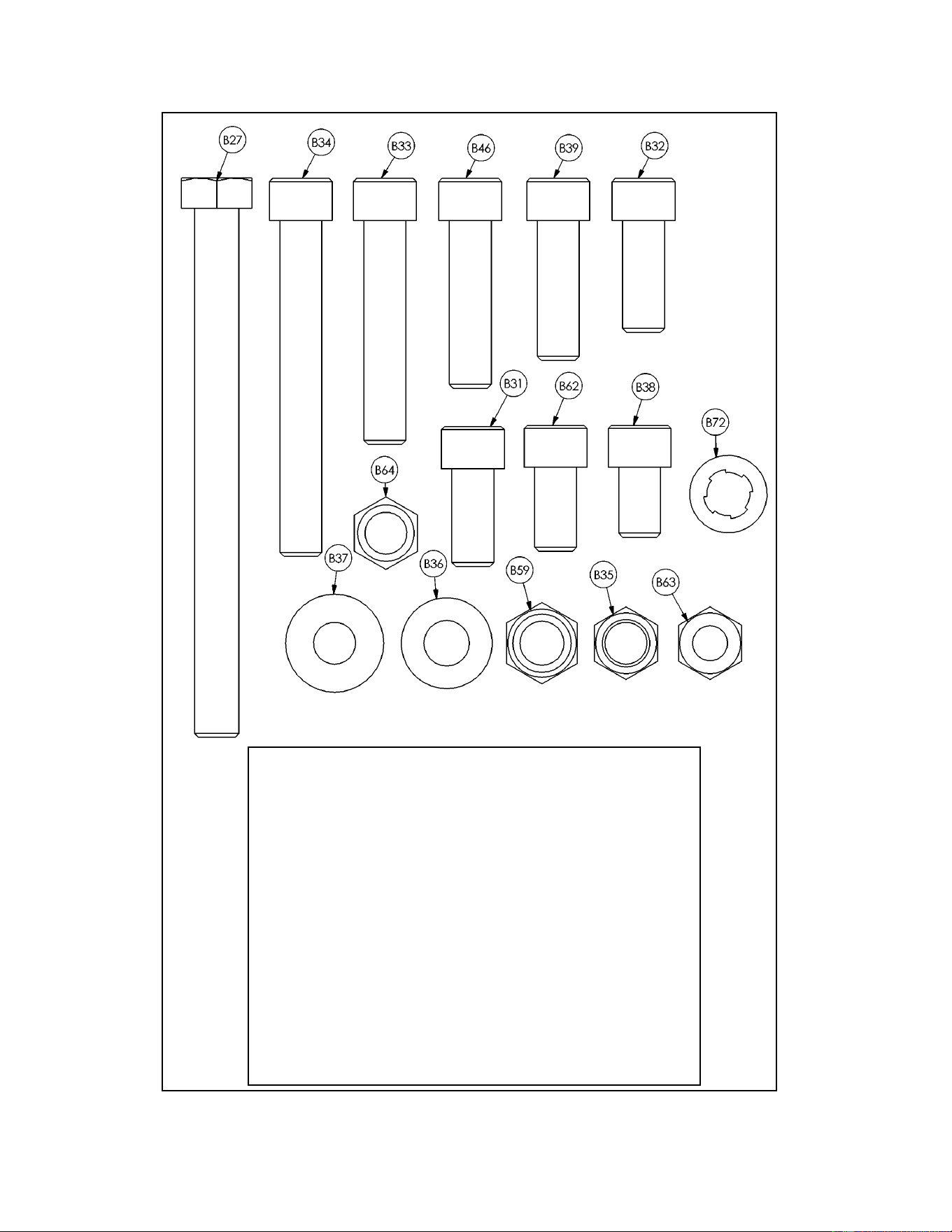
Assembly
Page 6-16
Figure 5
B27 2 8620-342 HHCS 10 mm x 120 mm
B31 4 HC702816 SHCS .375-16 x .875
B32 4 HC702817 SHCS .375-16 x 1.00
B33 3 HC702826 SHCS .375-16 x 2.00
B34 5 HC702834 SHCS .375-16 x 3.00
B35 14 HN704901 Nylon Locknut .375-16
B36 4 HS347600 Washer SAE .375
B37 2 HW-60085 Washer USS .312 (black)
B38 4 JC702814 SHCS .375-16 x .625
B39 2 JC702820 SHCS .375-16 x 1.25
B46 2 HC702822 SHCS .375-16 x 1.50
B59 2 8630-336 Nylon Locknut 10 mm
B62 2 HC702815 SHCS .375-16 x .750
B63 1 HN704400 Jam Nut .375-16
B64 1 HN704000 Hex Nut .375-16
B72 6 JS347400 Internal Tooth Lockwasher
ITEM QTY PART NO. DESCRIPTION
Fly Station Hardware Pack
Cybex MG 500 Multi-Gym Owner’s Manual
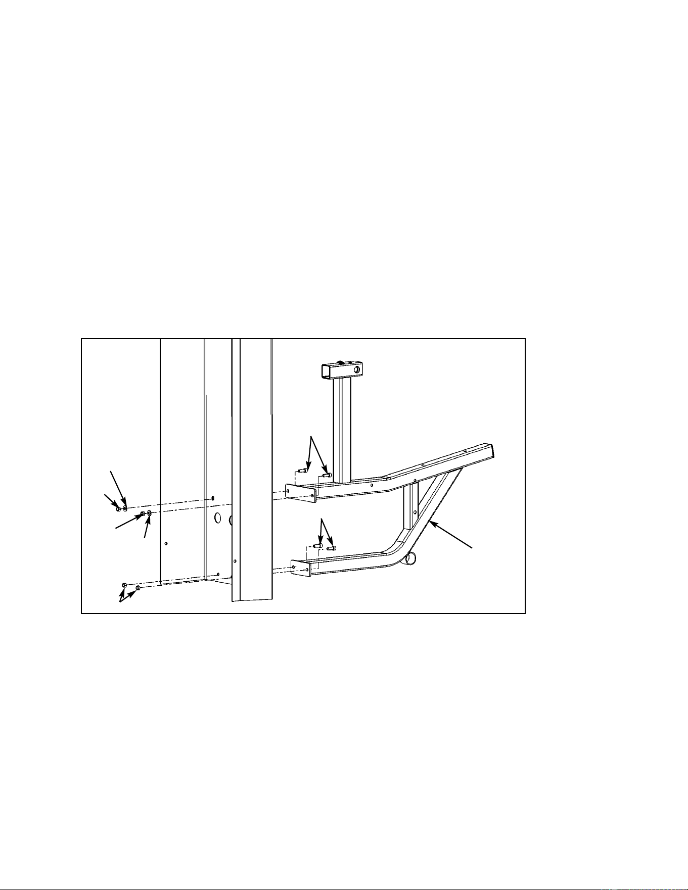
Assembly
Page 6-17
B16
B36
B35
B32
B35
B36
B32
B35
Figure 6
3. Attach fly frame to main frame assembly (see steps 3A - 3E and Figure 6).
A. Locate the following items: frame (#B16), four SHCS .375-16 x 1.00 (#B32), two flat
washers .375 (#B36) and four nylon locknuts .375-16 (#B35).
B. Locate the column containing the Fly Station placard. Carefully position Fly frame
(#B16) next to the column and align all four holes.
C. Insert two SHCS .375-16 x 1.00 (#B32) through the bottom two holes of the Fly frame
and attach two nylon locknuts (#B35) as shown in Figure 6. NOTE: Do not securely
tighten hardware at this time.
D. Insert two SHCS .375-16 x 1.00 (#B32) through the top two holes of the Fly frame
attach two washers (#B36) and two nylon locknuts (#B35) as shown in Figure 6.
E. Securely tighten all hardware installed from steps 3C and 3D.
Cybex MG 500 Multi-Gym Owner’s Manual
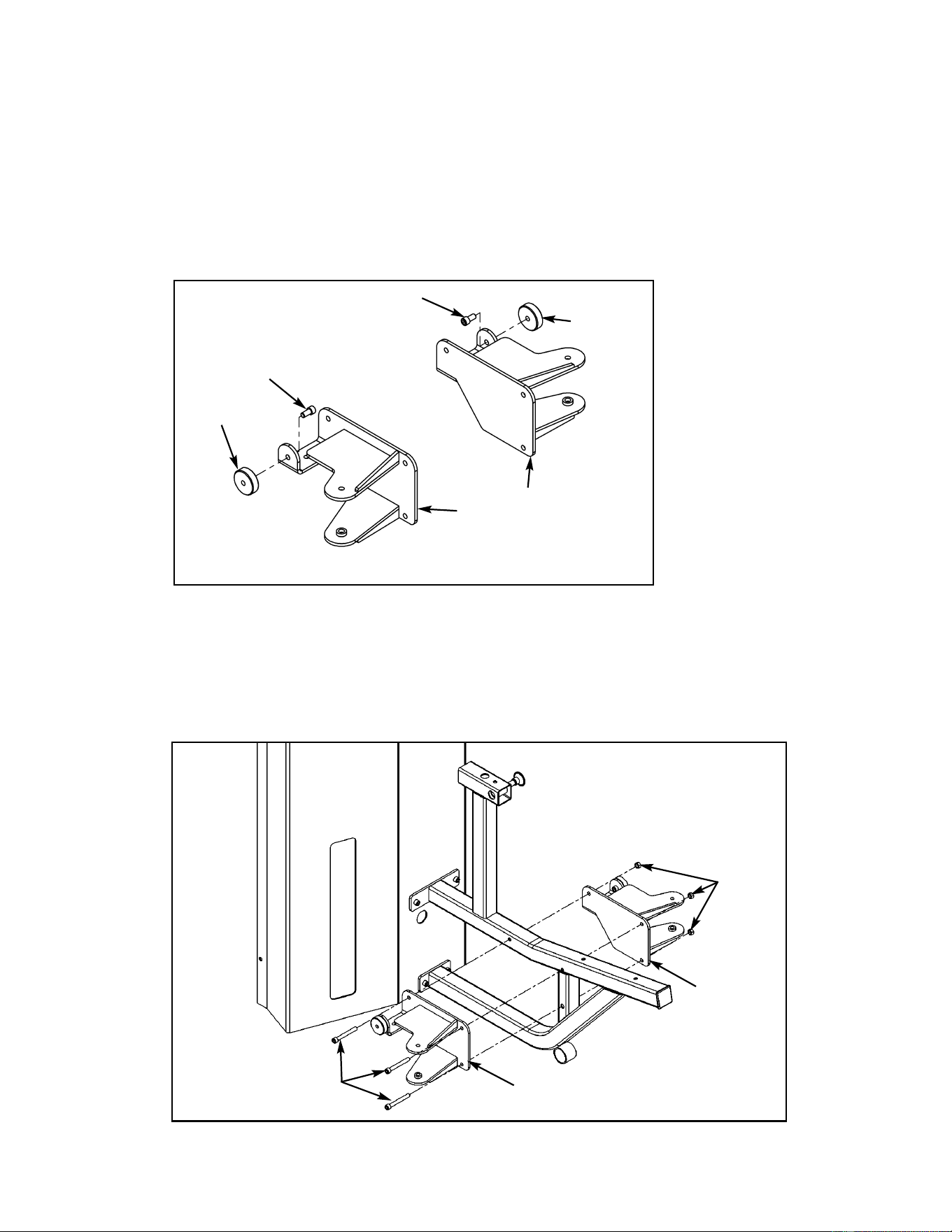
B34
B35
Figure 8
B19
B20
Assembly
Page 6-18
B62
B62
B41
B41
B19
B20
Figure 7
4. Install left and right pivots (see steps 4A - 4F and Figures 7 - 9).
A. Locate the following items: left pivot (#B19), right pivot (#B20), two round bumpers
(#B41), two SHCS .375-16 x .750 (#B62).
B. Attach bumpers (#B41) to pivots (#B19 and #B20) using two SHCS .375-16 x .750
(#B62) as shown in Figure 7. Securely tighten hardware.
C. Locate three SHCS .375-16 x 3.00 (#B34) and three nylon locknuts .375-16 (#B35).
D. Install pivots (#B19 and #B20) using three SHCS .375-16 x 3.00 (#B34) and three
nylon locknuts (#B35) as shown in Figure 8. Securely tighten hardware.
Cybex MG 500 Multi-Gym Owner’s Manual
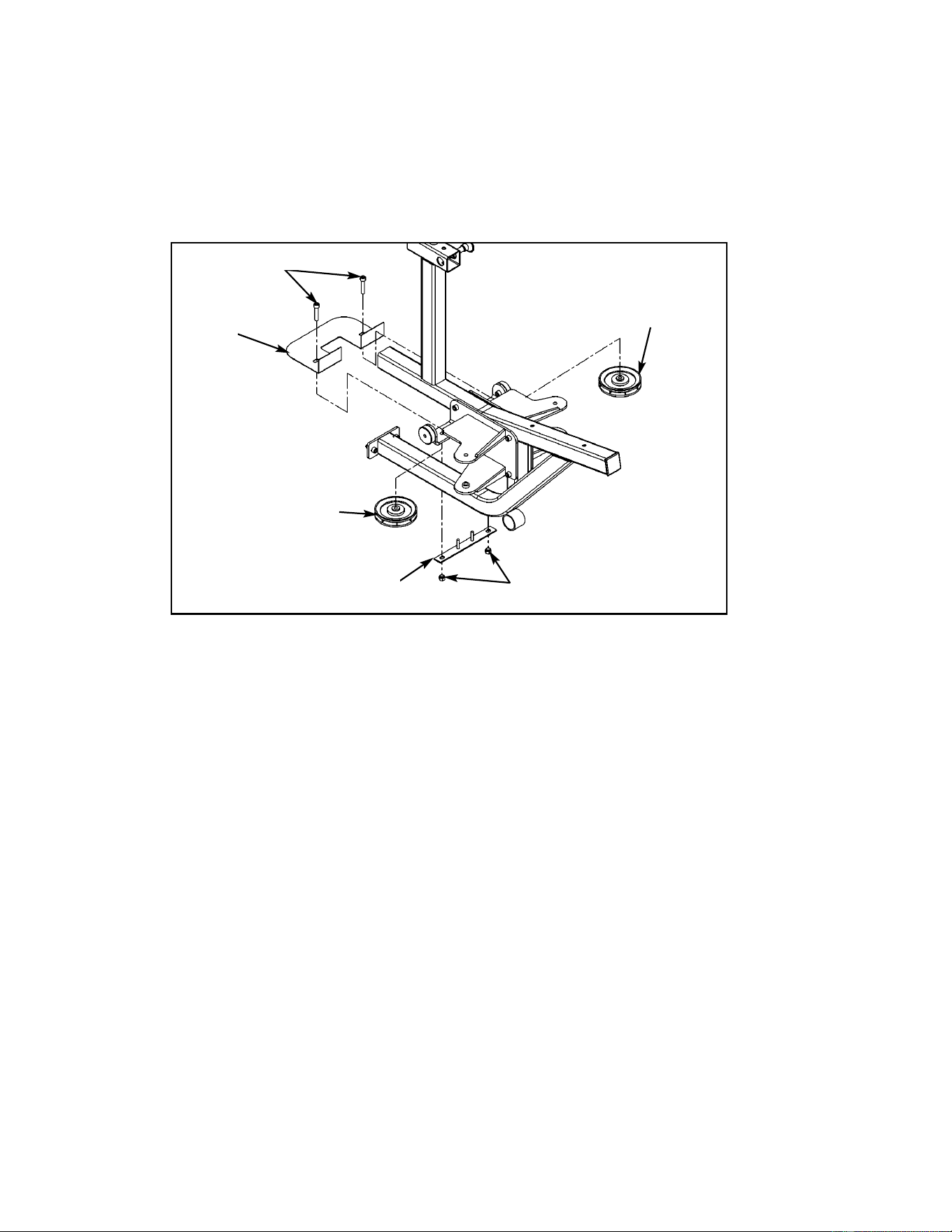
Assembly
Page 6-19
B71
B1
B33
B35
Figure 9
B58
E. Locate guard (#B58), two pulleys (#B1), two SHCS .375-16 x 2.00 (#B33), two nylon
locknuts .375-16 (#B35) and bracket (#B71).
F. Install guard (#B58), pulleys (#B1) and bracket (#B71) using two SHCS .375-16 x 2.00
(#B33) and two nylon locknuts (#B35) as shown in Figure 9.
Cybex MG 500 Multi-Gym Owner’s Manual
B1
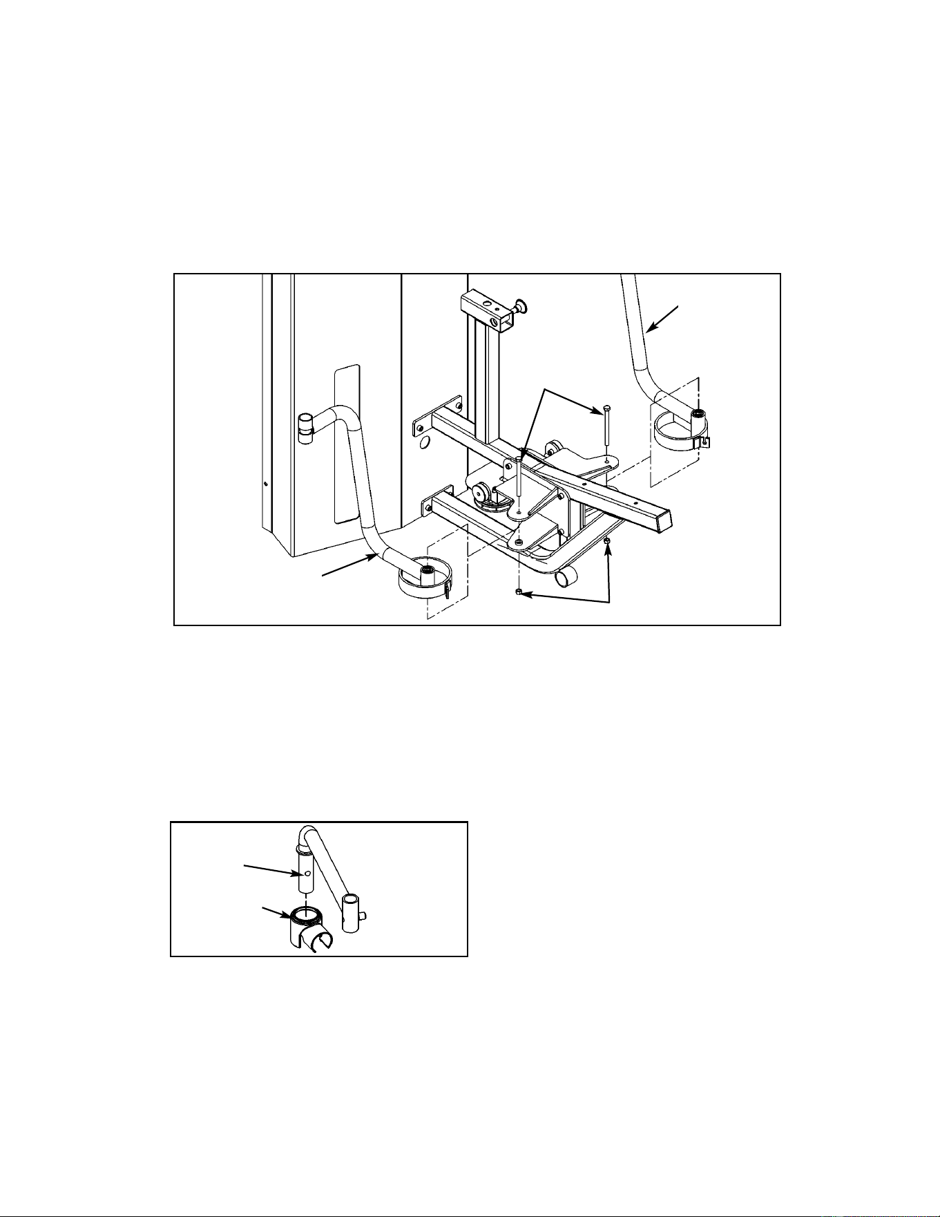
Figure 10
B27
B24
B59
B23
5. Install left and right arms (see steps 5A, 5B and Figure 10).
A. Locate (user position) right arm (#B23) and left arm (#B24), two HHCS 10 mm x 120 mm
(#B27) and two locknuts 10 mm (#B59).
B. Install (user position) right arm (#B23) using HHCS 10 mm x 120 mm (#B27) and
locknut 10 mm (#B59). See Figure 10. Repeat this step for installing the left arm (#B24).
6. Install left and right pivot handles (see steps 6A - 6F, Figures 11A - 13).
A. Locate pivot handles (#B21 and #B22), two SHCS .375-16 x .625 (#B38) and two pivot
guards (#B70).
B. Slide pivot guard (#B70) onto (user position) right pivot handle (#B21). See Figure 11A.
Figure 11A
B21
B70
Cybex MG 500 Multi-Gym Owner’s Manual
Assembly
Page 6-20
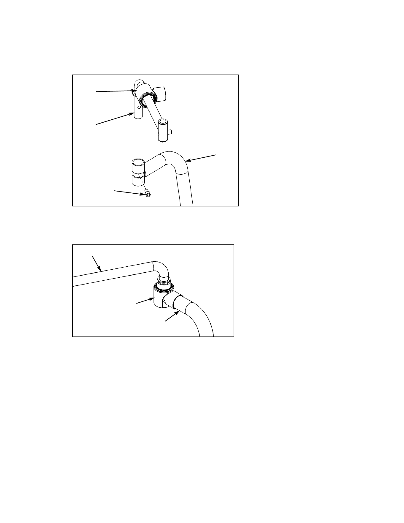
Assembly
Page 6-21
C. Secure right pivot handle (#B21) to right arm (#B23) using SHCS .375-16 x .625
(#B38). See Figure 11B.
Figure 11B
B70
B21
B38
D. Slide guard (#B70) downward and snap into place. See Figure 11C.
Figure 11C
B70
Cybex MG 500 Multi-Gym Owner’s Manual
B23
E. Repeat steps B - D to install the other pivot guard (#B70) and left pivot handle (#B22).
B21
B23
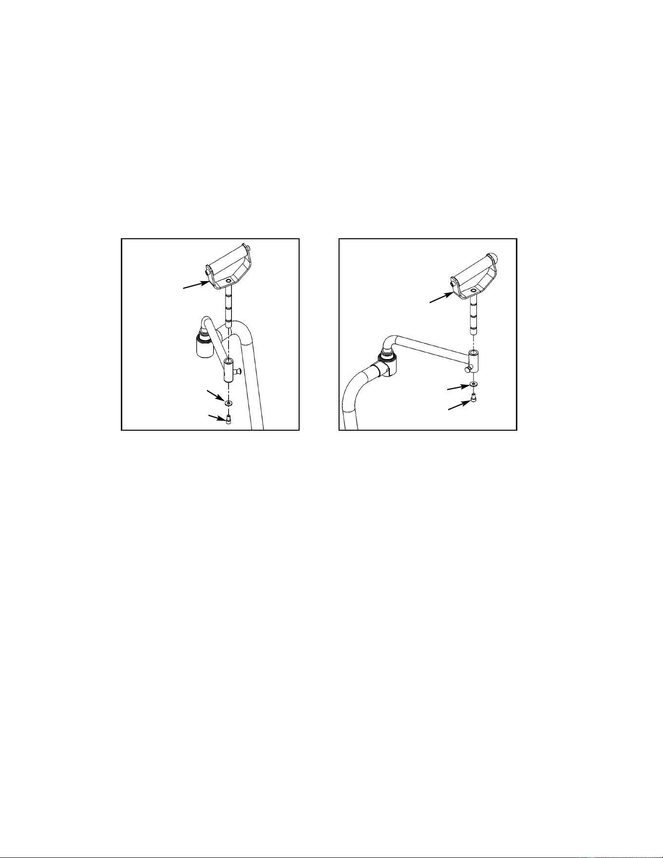
Assembly
Page 6-22
Figure 12A
Figure 12B
B38
B37 (black)
B38
B37 (black)
B12-A
B12-B
7. Install handles (see steps 7A - 7C, Figures 12A and 12B).
A. Locate both pivot handles (#B12), two black flat washers (#B37) and two SHCS
.375-16 x .625 (#B38).
B. Install handle (#B12-A - without bumper) on user position right side using one black
flat washer (#B37) and one SHCS .375-16 x .625 (#B38) as shown in Figure 12A.
C. Install handle (#B12-B - with bumper) on user position left side using one black flat
washer (#B37) and one SHCS .375-16 x .625 (#B38) as shown in Figure 12B.
Cybex MG 500 Multi-Gym Owner’s Manual
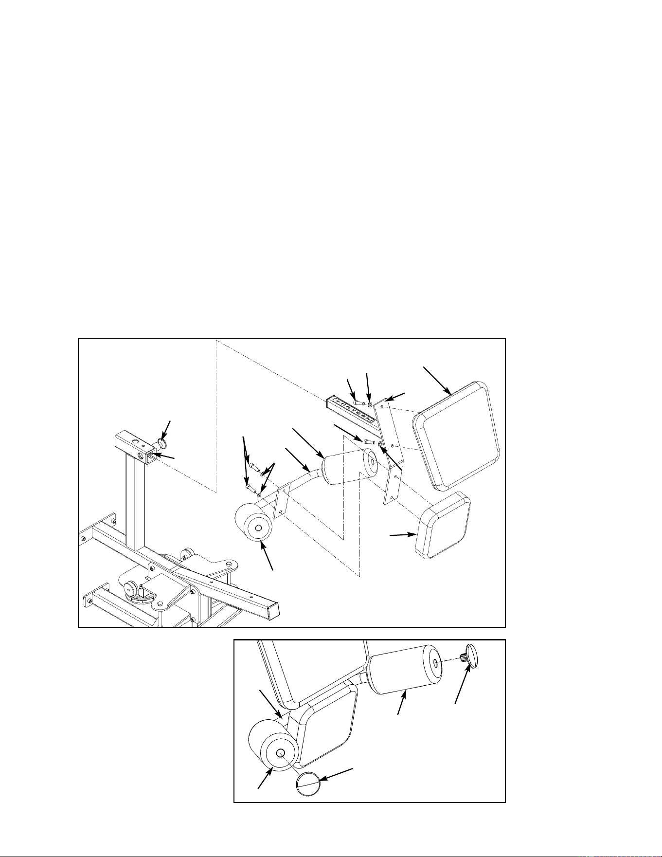
Figure 13
B46
B5
B39
B39
B18
B8
B17
Detent Pin
Frame
8. Install cushion supports and cushions (see steps 8A - 8I and Figures 13 - 15).
A. Locate cushion mount (#B18), hip support (#B17), back cushion (#B8), cushion (#B5),
two round cushions (#B9), two plastic inserts (#B42), two SHCS .375-16 x 1.50 (#B46),
two SHCS .375-16 x 1.25 (#B39) and six internal tooth lockwashers (#B72).
B. Slide round cushions (#B9) onto cushion mount (#B18).
C. Slide cushion mount (#B18) onto frame as shown in Figure 13.
D. Slide both round cushions (#B9) onto cushion mount (#B18).
E. Install back cushion (#B8) to cushion mount (#B18) using two SHCS .375-16 x 1.25
(#B39) and two internal tooth lockwashers (#B72).
F. Install cushion (#B5) and hip support (#B17) to cushion mount (#B18) using two SHCS
.375-16 x 1.50 (#B46) and two internal tooth lockwashers (#B72).
Cybex MG 500 Multi-Gym Owner’s Manual
Figure 14
B42
B42
G. Using a rubber
mallet, install
plastic inserts
(#B42) to secure
round cushions
(#B9) on hip
support (#B17)
as shown in
Figure 14.
Assembly
Page 6-23
B17
B9
B9
B9
B9
B72
B72
B72
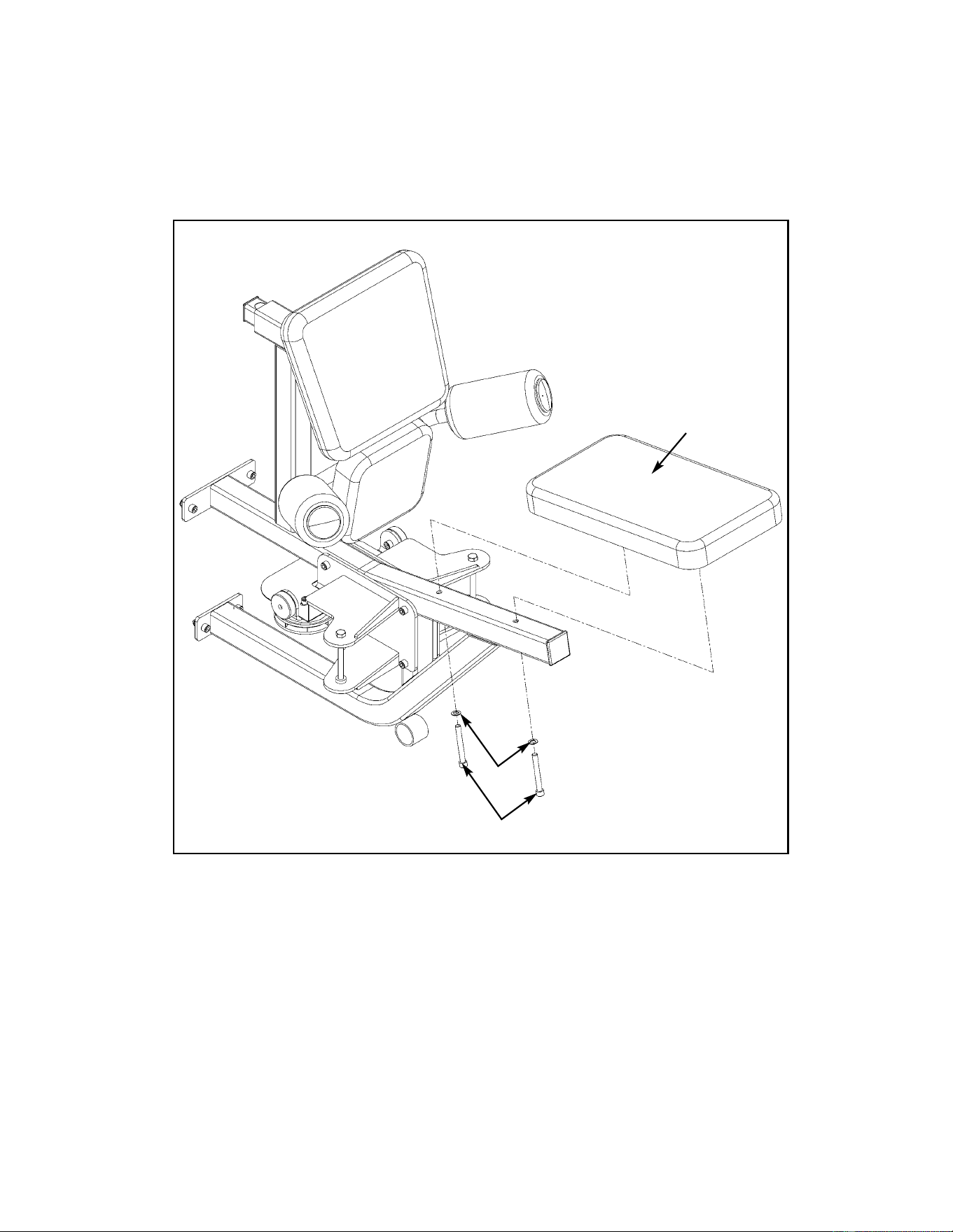
Assembly
Page 6-24
Figure 15
B34
B6
H. Locate seat cushion (#B6), two SHCS .375-16 x 3 (#B34) and two internal tooth
lockwashers (#B72). See Figure 15.
I. With seam in back, install seat cushion as shown in Figure 15.
Cybex MG 500 Multi-Gym Owner’s Manual
B72
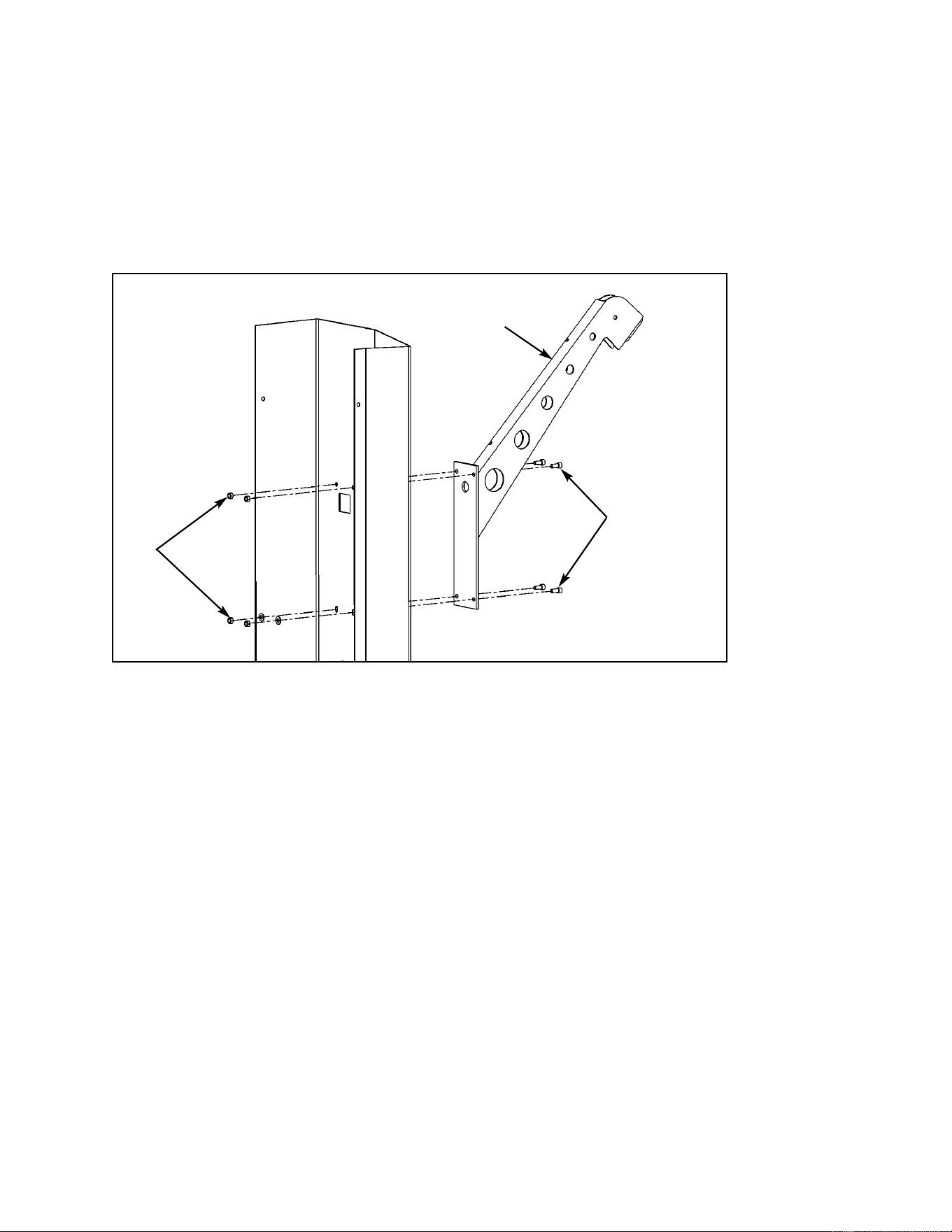
Figure 16
B31
B35
B25
9. Install upper boom (see steps 9A - 9D, Figures 16 and 17).
A. Locate upper boom (#B25), four SHCS .375-16 x .875 (#B31), four locknuts .375-16
(#B35) and two flat washers .375 (#B36).
B. With an assistant install upper boom (#B25) as shown in Figure 18 using the four
SHCS .375-16 x .875 (#B31) and four nylon locknuts (#B35).
Cybex MG 500 Multi-Gym Owner’s Manual
Assembly
Page 6-25
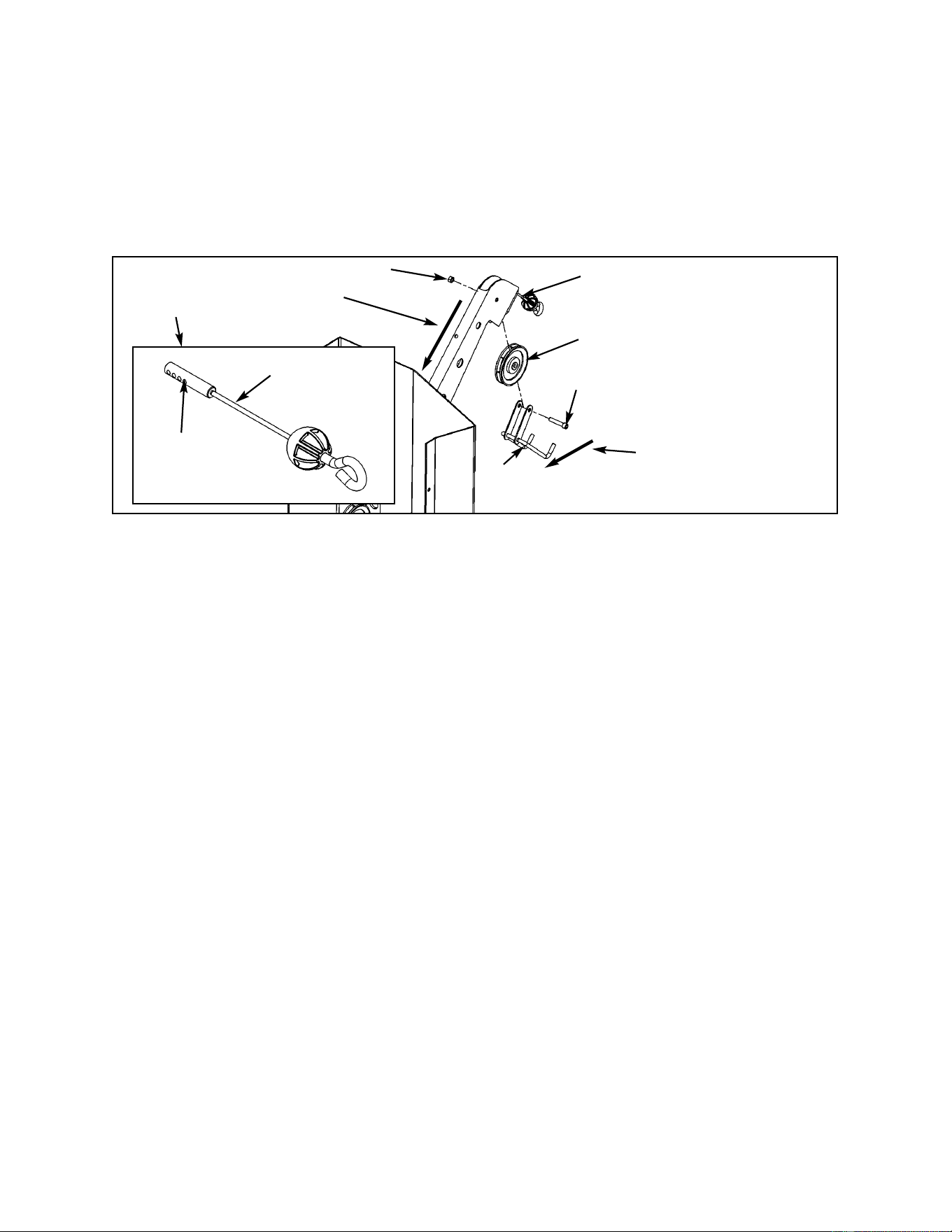
Assembly
Page 6-26
Cybex MG 500 Multi-Gym Owner’s Manual
Figure 17
B35
B1
B33
B26
B52
Route weight stack connector
end downward through inside
of boom.
Hook will swivel up or
down. Position hook
all the way back
(downward) when
installing/tightening
hardware.
C. Locate weight stack cable (#B52), one pulley (#B1), one SHCS .375-16 x 2.00 (#B33),
one nylon locknut .375-16 (#B35) and hook (#B26).
D. Assemble pulley (#B1), hook (#B26) into boom and route cable (#B52) around pulley.
Secure using SHCS .375-16 x 2.00 (#B33) and locknut (#B35). Route cable downward
through boom. See Figure 17.
Weight
Stack
Connector
B52
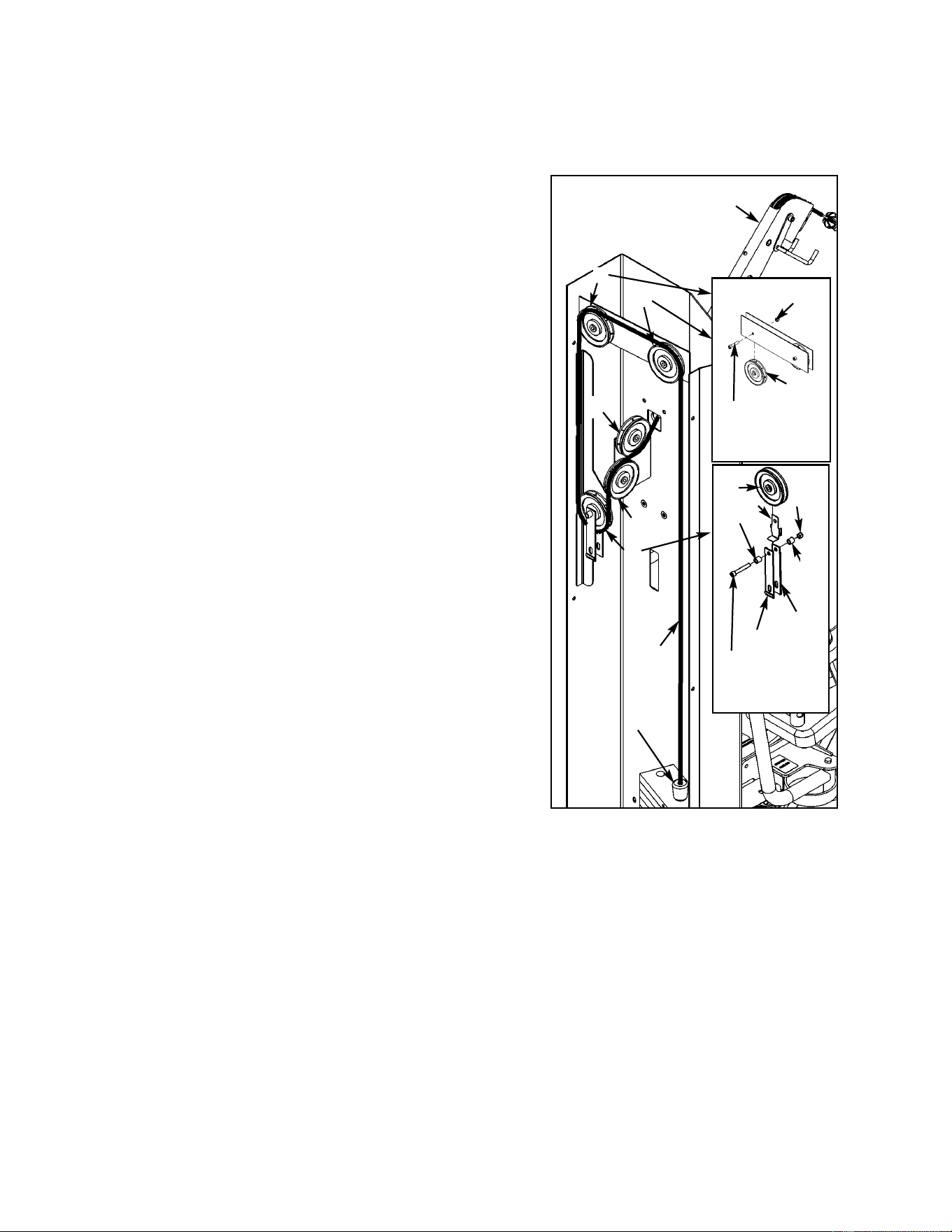
10. Route weight stack cable around pulleys to weight stack (see steps 10A - 10G and
Figure 18).
A
B
C
D
E
F
Figure 18
E1
.375-16 x 1.75)
E39 (SHCS
E34
E19
E14
E33 (SHCS
.375-16 x 3.00)
E8
E34
From the main frame hardware pack, locate five
pulleys (#E1), four SHCS .375-16 x 1.75 (#E39), one
SHCS .375-16 x 3.00 (#E33), five nylon lock-nuts
.375-16 (#E34), one spiral pin (#E35), two spacers
(#E8), one pulley tab (#E19), one adjuster (#E14)
and one cable retainer (#E44).
A. At the same time, route cable (#B52) and install
first pulley (#E1) on inside of column using one
SHCS .375-16 x 1.75 (#E39) and one nylon
locknut .375-16 (#E34). See Figure 18, letter A.
B. At the same time, route cable (#B52) and install
second pulley (#E1) using one SHCS .375-16 x
1.75 (#E39) and one nylon locknut .375-16
(#E34). See Figure 18, letter B.
C. At the same time, route cable (#B52) and install
third pulley (#E1), pulley tab (#E19), adjuster
(#E14), cable retainer (#E44) and route cable
(#B52). Use SHCS .375-16 x 3.00 (#E33), two
spacers (#E8) and nylon locknut (#E34). See
Figure 18, letter C. NOTE: Tab on bracket needs
to be located on the outside.
D. With an assistant holding the hanging pulley
installed in step C, route cable (#B52) upward
and install fourth pulley (#E1) one using adjuster
(#E14), one pulley tab (#E19), one SHCS .375-
16 x 3.00 (#E33) and one nylon locknut (#E34).
See Figure 18, letter D. Verify cable is resting
between the pulley (E1) and the retainer tab.
(Cable is already routed
through the boom from
step #9)
B52
E. With an assistant holding the hanging pulley, (at the same time) route cable (B#52) and
install fifth pulley (#E1) using one SHCS .375-16 x 1.75 (#E39) and one nylon locknut
(#E34). See Figure 18, letter E.
F. Route cable (#B52) down to weight stack. Slide rubber boot (#E3) on cable.
G. Drive a spiral pin (#E35) through top weight connector and cable. Top weight should
be snug (just resting) on the second plate.
NOTE: All cables (for all three stations) will be adjusted for tension at the very
end of the assembly procedure.
Cybex MG 500 Multi-Gym Owner’s Manual
Assembly
Page 6-27
E1
E8
E44
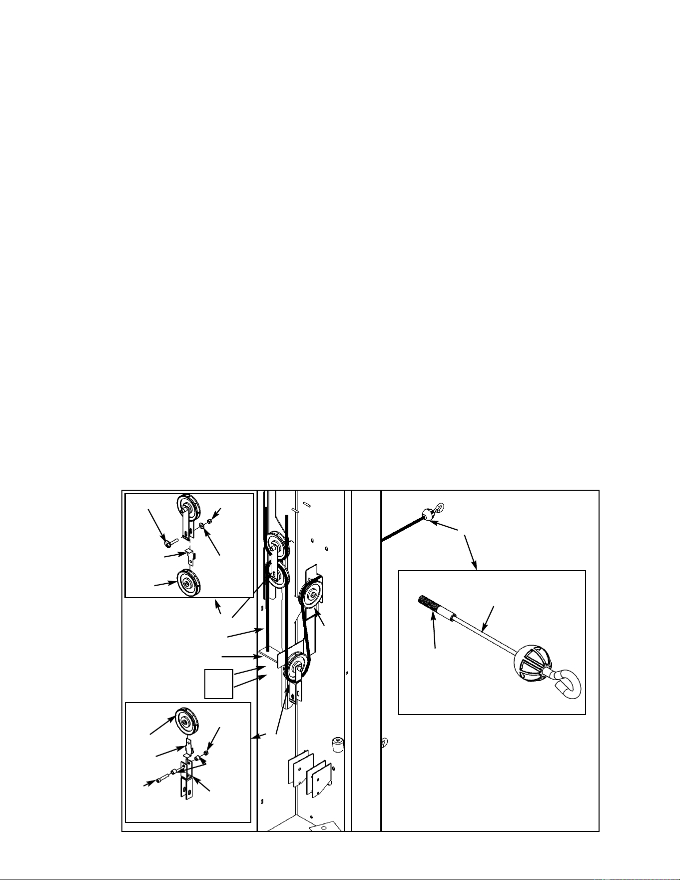
Assembly
Page 6-28
Figure 19
A
B
C
D
E
E34
E37
E13
B64
B63
E12
(SHCS .375-16 x 3.00)
E33
E34
E1
E8
E1
11. Routing second cable (see steps 11A - 11E and Figure 19).
From the main frame hardware pack, locate three pulleys (#E1), one SHCS .375-16 x 1.75
(#E39), one SHCS .375-16 x 3.00 (#E33), one cam bolt (#E13), two spacers (#E8), one
washer .375 (#E37), one pulley clevis (#E12), three nylon locknuts .375-16 (#E34) and two
cable retainers (#E44). From the Fly Station hardware pack, locate locate cable (#B53),
one hex nut (#B64) and one jam nut (#B63).
A. Route cable (#B53) through pulley slot in column. Be sure ball on cable is on the
outside of the column. See Figure 19, letter A.
B. At the same time route cable (#B53) and install the first pulley (#E1) using one SHCS
.375-16 x 1.75 (#E39) and one nylon locknut (#E34) as shown in Figure 19, letter B.
C. At the same time route cable (#B53) and install pulley clevis (#E12), pulley (#E1) and
cable retainer (#E44) using one SHCS .375-16 x 3.00 (#E33), one nylon locknut (#E34)
and two spacers (#E8). See Figure 19, letter C. Verify cable is resting between the
pulley (#E1) and the retainer tab.
D. At the same time route cable (#B53) and Install the third pulley (#E1) and cable retainer
(#E44) using one cam bolt (#E13), one washer (#E37) and one nylon locknut (#E34).
Verify that the tab on the bracket is facing outward and also verify that the cable is
resting between the pulley (#E1) and the retainer tab. See Figure 19, letter D.
E. Route cable (#B53) downward and install hex nut (#B64) and then jam nut (#B63). Jam
nut should be flush with end of cable and hex hut should be snug against jam nut,
do not over tighten. Be sure brackets are snug in the “V” slots. See Figure 19, letter E.
Threaded End
Connector
for Hex Nut/Jam
Nut.
B53
B53
Cybex MG 500 Multi-Gym Owner’s Manual
E44
E44
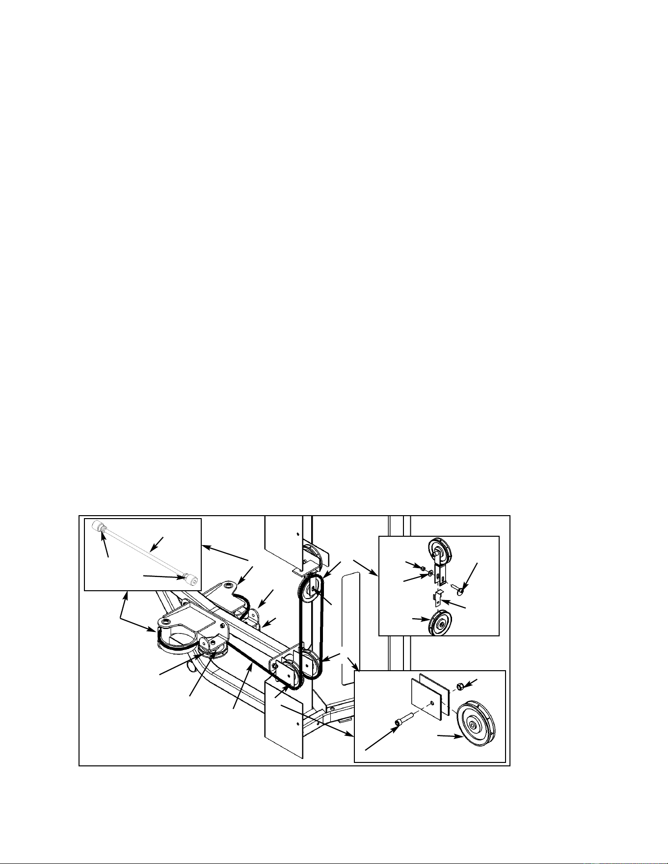
Figure 20
12. Routing cam cable (see steps 12A - 12H and Figure 20).
Locate cable (#B54) from the Fly Station hardware pack. From the main frame hardware
pack, locate three pulleys (#E1), one cable retainer (#E44), two SHCS .375-16 x 1.75
(#E39), one cam bolt (#E13), one washer .375 (#E37) and three nylon locknuts (#E34).
A. Place one end of cable (#B54) in the cable slot of (user position) right cam arm and
route cable to first pulley (#B1). See Figure 20, letter A.
B. The first pulley (#B1) is already installed. Route cable (#B54) around the first pulley
(#B1) as shown in Figure 20, letter B.
C. At the same time install second pulley (#E1) and route cable (#B54) using one SHCS
.375-16 x 1.75 (#E39) and one nylon locknut (#E34). See Figure 20, letter C.
D. At the same time install cable retainer (#E44), third pulley (#E1) and route cable (#B54)
using cam bolt (#E13), washer (#E37) and nylon locknut. See Figure 20, letter D.
E. At the same time install fourth pulley (#E1) and route cable (#B54) using one SHCS
.375-16 x 1.75 (#E39) and one nylon locknut (#E34). Verify cable is resting between the
pulley (#E1) and the retainer tab. See Figure 20, letter E.
F. The fifth pulley (#B1) is already installed. Route cable (#B54) as shown in Figure 20,
letter F.
G. Finish routing cable and place cable end in slot. See Figure 20, letter G.
H. Adjust cam bolt (#E13) until cable (#B54) is snug. Be sure bracket is snug in the “V”
slot.
A
C
D
E
F
H
B
G
E34
E39 (SHCS .375-16 x 1.75)
E1
E34
E37
E13
E1
Connector
for Cam
B54
B54
B1
B1
Cybex MG 500 Multi-Gym Owner’s Manual
Assembly
Page 6-29
E44
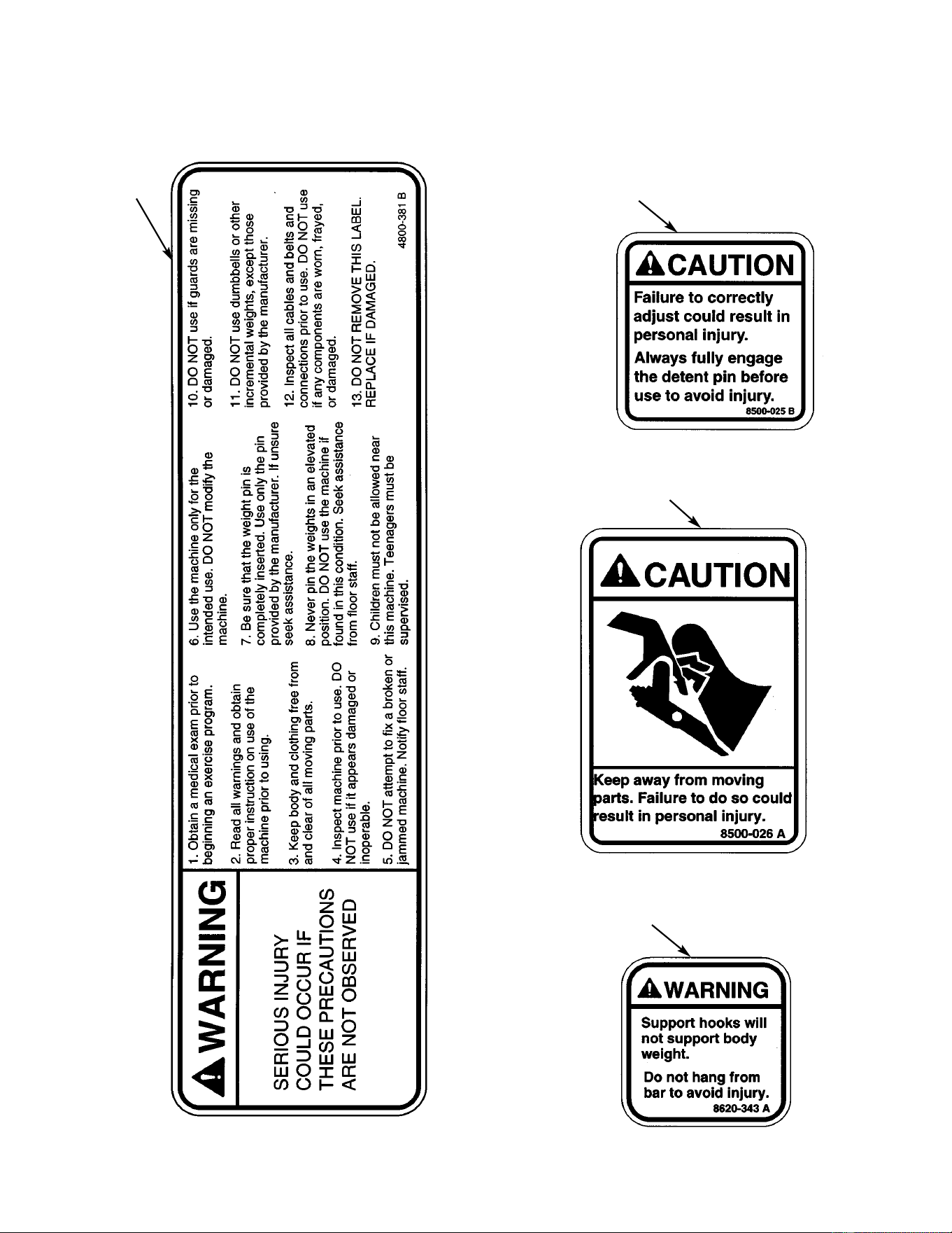
Assembly
Page 6-30
C
A B
13. Verify warning decals are present and not damaged (see decals below and Figure 21).
D
Cybex MG 500 Multi-Gym Owner’s Manual
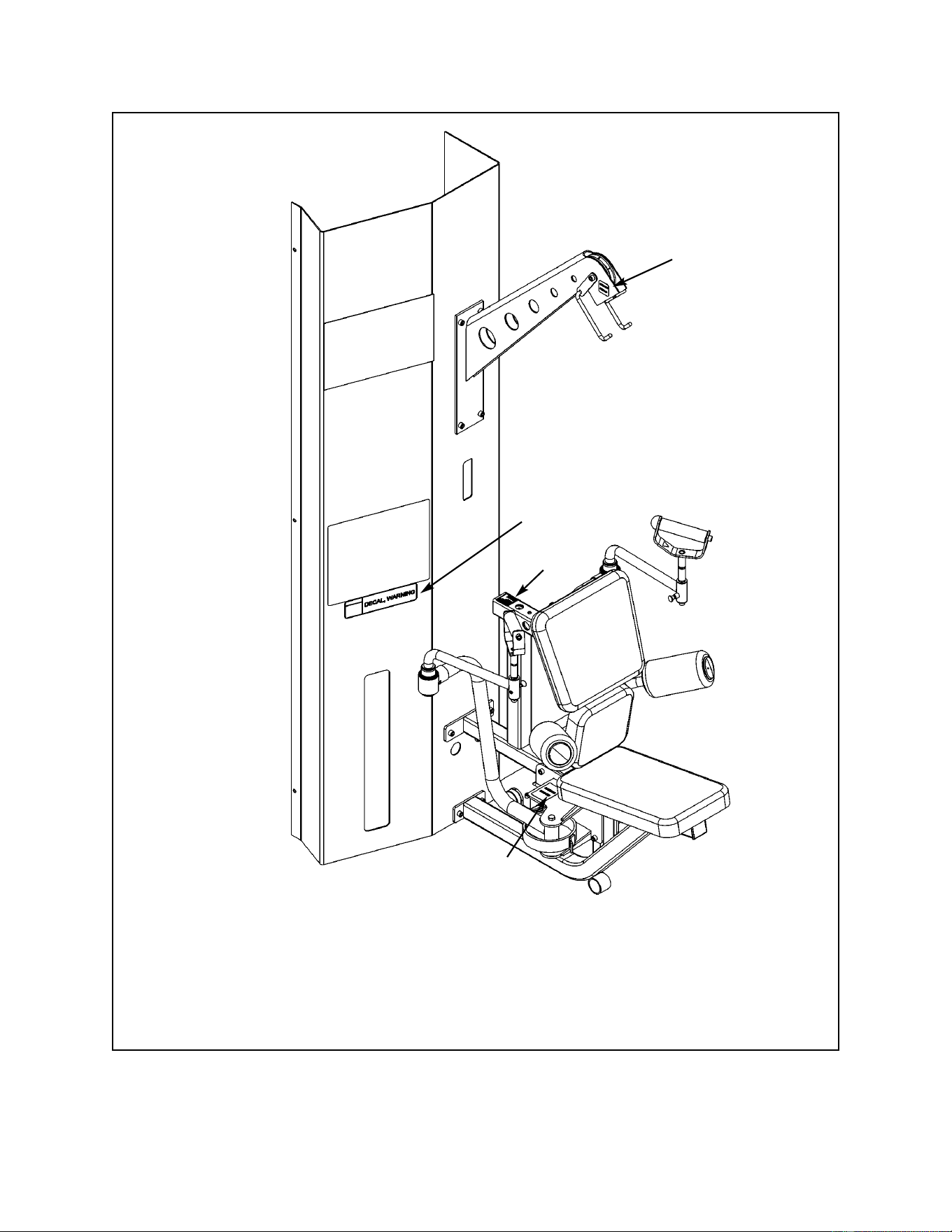
A. Warning Decal ................... 4800-381
B. Caution Decal .................... 8500-025
C. Caution Decal .................... 8500-026
D. Warning Decal.................... 8620-343
DESCRIPTION PART NO.
A
B
C
Figure 21
D
Cybex MG 500 Multi-Gym Owner’s Manual
Assembly
Page 6-31
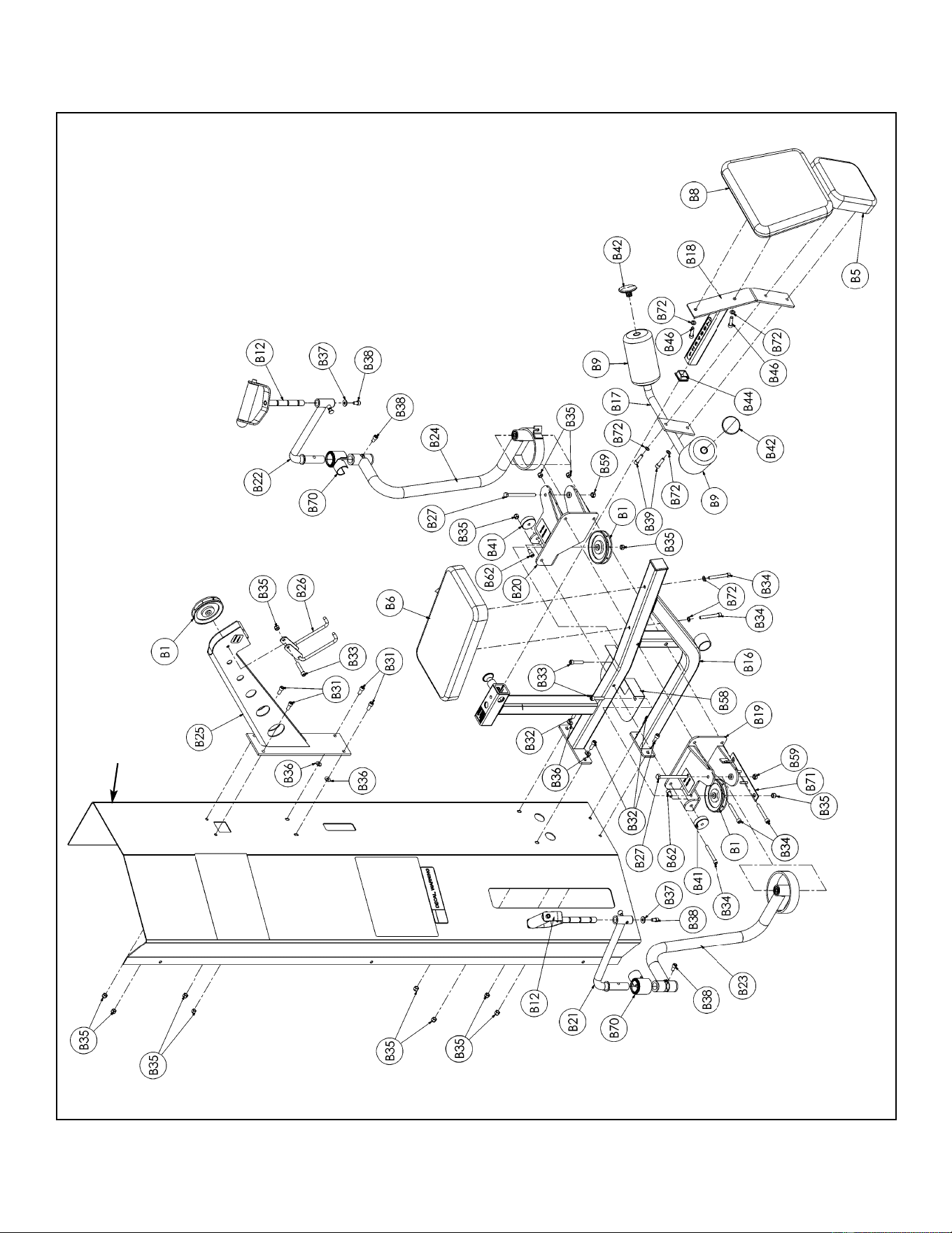
Assembly
Page 6-32
Fly Station Exploded-View Diagram (for assembly only)
Column
Cybex MG 500 Multi-Gym Owner’s Manual

B1 3 08014 Pulley
B5 1 4035S121-0 Cushion
B6 1 4106S055-0 Seat Cushion
B8 1 5245-011 Back Cushion
B12 2 8520-212 Handle (one with bumper)
B16 1 8620-200 Frame
B17 1 8620-201 Hip Support
B18 1 8620-202 Slide Cushion Mount
B19 1 8620-203 Right Pivot
B20 1 8620-204 Left Pivot
B21 1 8620-207 Right Hand Pivot Handle
B22 1 8620-208 Left Hand Pivot Handle
B23 1 8620-209 Right Arm
B24 1 8620-210 Left Arm
B25 1 8620-211 Boom
B26 1 8620-214 Hook
B27 2 8620-342 HHCS 10 mm x 120 mm
B31 4 HC702816 SHCS .375-16 x .875
B32 4 HC702817 SHCS .375-16 x 1.00
ITEM QTY PART NO. DESCRIPTION
B33 3 HC702826 SHCS .375-16 x 2.00
B34 5 HC702834 SHCS .375-16 x 3.00
B35 14 HN704901 Nylon Locknut
B36 4 HS347600 Flat Washer
B37 2 HW-60085 Washer .3125
B38 4 JC702814 SHCS .375-16 x .625
B39 2 JC702820 SHCS .375-16 x 1.25
B40 Removed 10/02
B41 2 PL-52062 Bumper 2.00 Dia. x .625
B42 2 PP080223 Plastic Insert
B44 1 PP090211 Plastic Insert 1.50 Sq x 10-14 G
B46 2 HC702822 SHCS .375-16 x 1.50
B58 1 8620-341 Guard
B59 2 8630-336 Nylon Locknut 10 mm
B62 5 HC702815 SHCS .375-16 x .750
B70 2 8620-344 Pivot Guard
B71 1 8620-215 Bracket
B72 6 JS347400 Internal Tooth Lockwasher
ITEM QTY PART NO. DESCRIPTION
Fly Station Parts List (not all parts are listed such as pulleys for inside of MG 500 and handles).
See Chapter 8 for a complete parts listing.
Cybex MG 500 Multi-Gym Owner’s Manual
Assembly
Page 6-33

This page intentionally left blank
Cybex MG 500 Multi-Gym Owner’s Manual
Assembly
Page 6-34
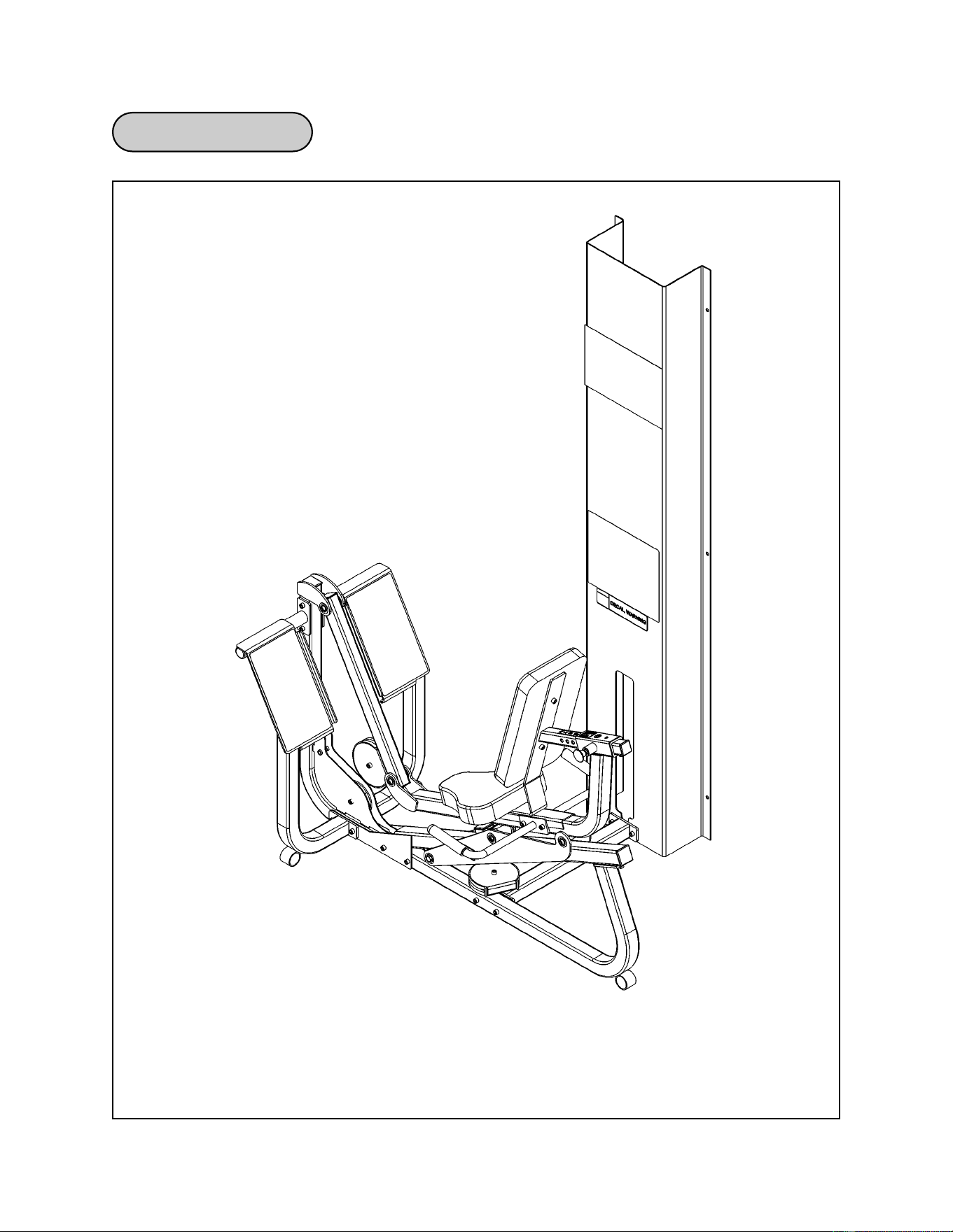
Cybex MG 500 Multi-Gym Owner’s Manual
Assembly
Page 6-35
Leg Press Diagram

Leg Press Assembly
Cybex MG 500 Multi-Gym Owner’s Manual
Assembly
Page 6-36
C6 1 4106S055-0 Back Cushion
C9 1 4800-026 Seat Cushion
C14 1 8630-200 Frame
C15 1 8630-201 Seat Frame
C16 1 8630-202 Seat Tube
C17 1 8630-203 Right Foot Plate
C18 1 8630-204 Left Foot Plate
C19 1 8630-205 Roller Tube
C20 1 8630-206 Roller Plate
C21 1 8630-207 Right Handle
C22 1 8630-208 Left Handle
C23 1 8630-209 Pivot Tube
C24 1 8630-210 Connector
C27 1 8630-326 Plastic Seat Sleeve
C46 1 8630-002 Cable 216.50” Long
1 Hardware Pack
ITEM QTY PART NO. DESCRIPTION
Figure 1
1. Verify contents of the Leg Press Station boxes (see steps 1A - 1C, Figures 1-3).
A. Locate the Leg Press Station box (containing the frame).
B. Locate the Leg Press cushion box (removed from the main frame assembly).
C. Verify contents of both boxes. See Figures 1-3.
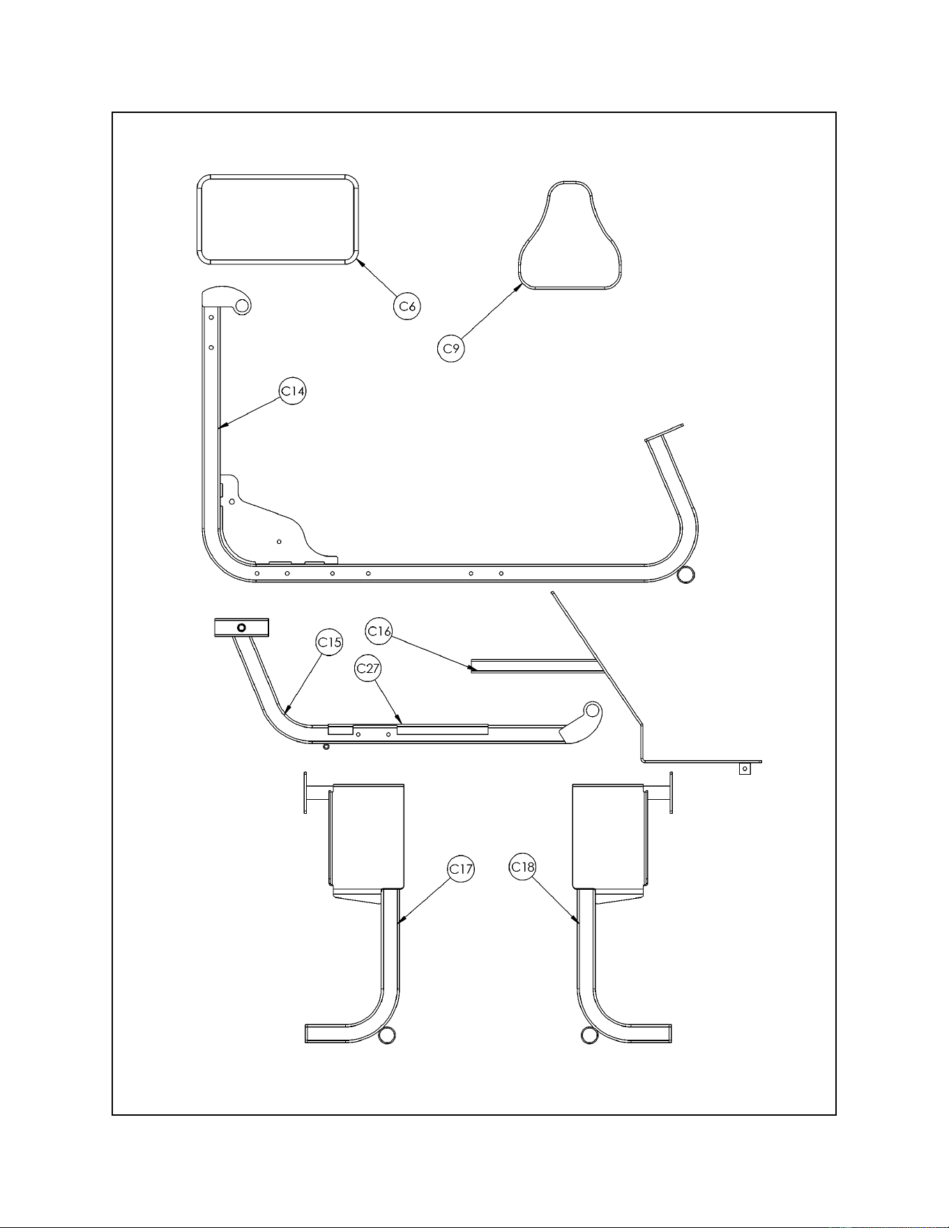
Cybex MG 500 Multi-Gym Owner’s Manual
Assembly
Page 6-37
Figure 2
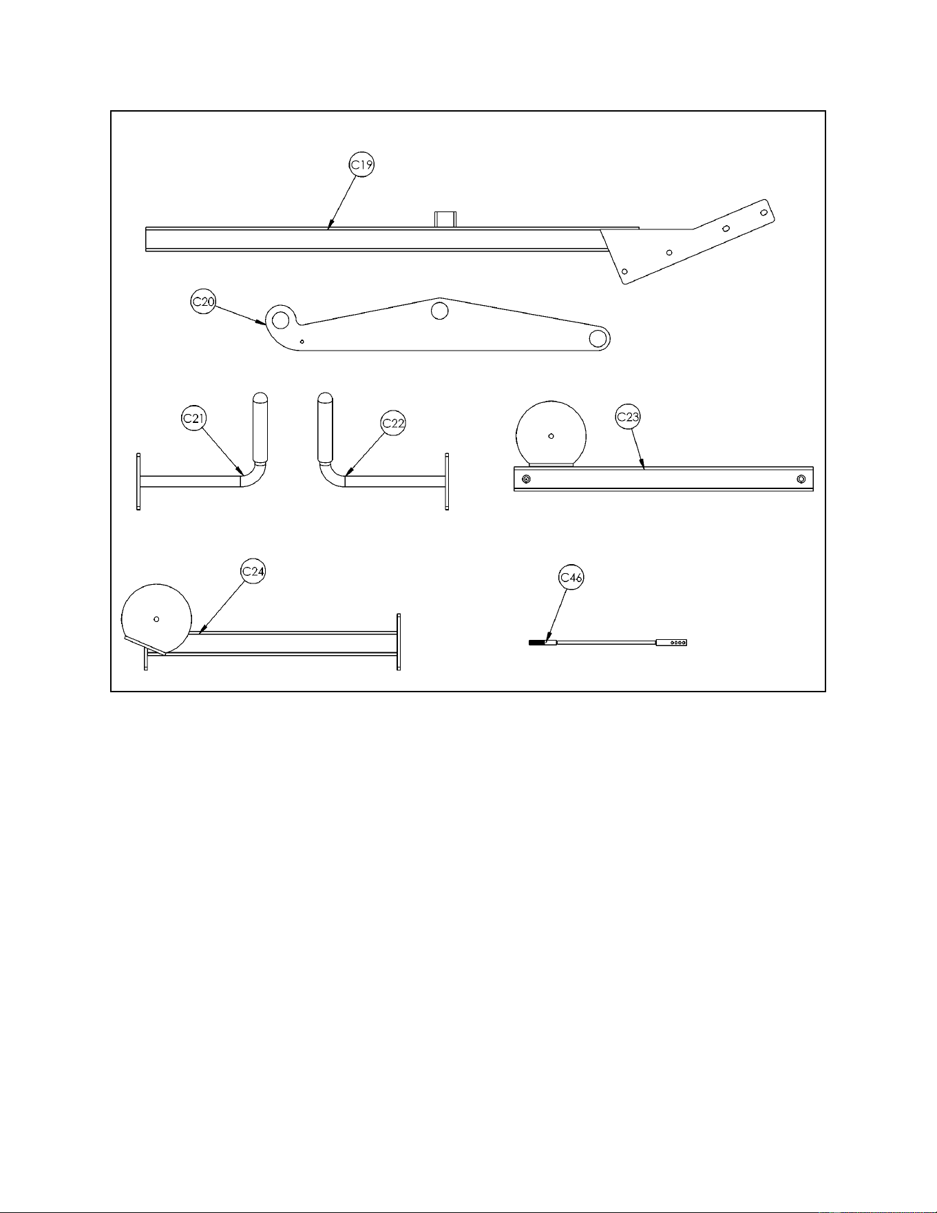
Cybex MG 500 Multi-Gym Owner’s Manual
Assembly
Page 6-38
Figure 3
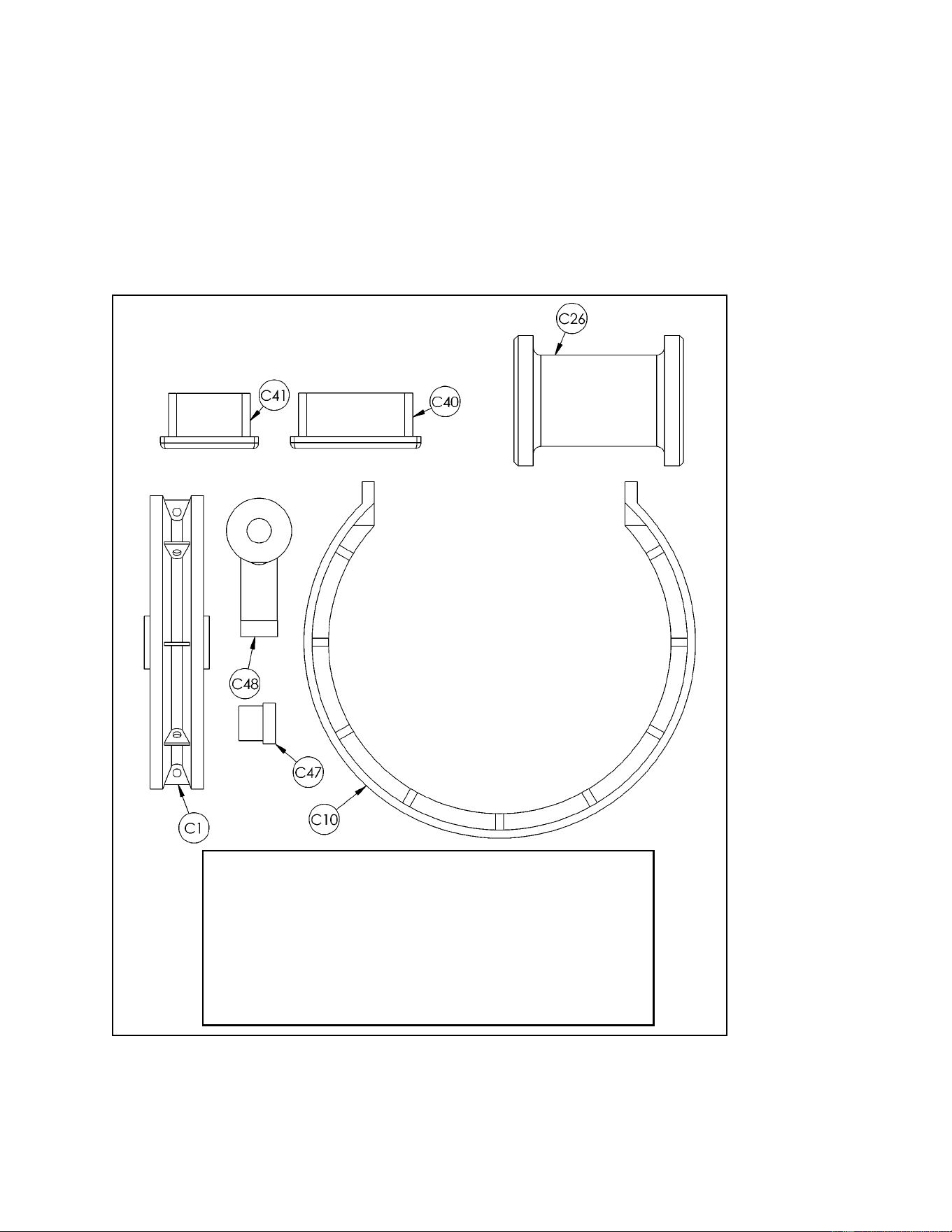
Cybex MG 500 Multi-Gym Owner’s Manual
Assembly
Page 6-39
Figure 4
C1 3 08014 Pulley Assembly
C10 2 4800-570 Cable Guard
C26 2 8630-322 Roller Assembly
C40 1 PP090210 Plastic Insert 2.00 Sq x 10-14 G
C41 1 PP090211 Plastic Insert 1.50 Sq x 10-14 G
C47 2 8630-340 Spacer
C48 1 FB030213 Rod End Bearing
ITEM QTY PART NO. DESCRIPTION
2. Verify contents of the Leg Press Station hardware pack (see steps 2A, 2B, Figures 4
and 5).
A. Locate hardware pack from step 1.
B. Verify contents of hardware pack. If desired, sort out hardware into different
containers. Do not combine hardware with other hardware packs. Refer to Figures 4
and 5 for contents of hardware pack.
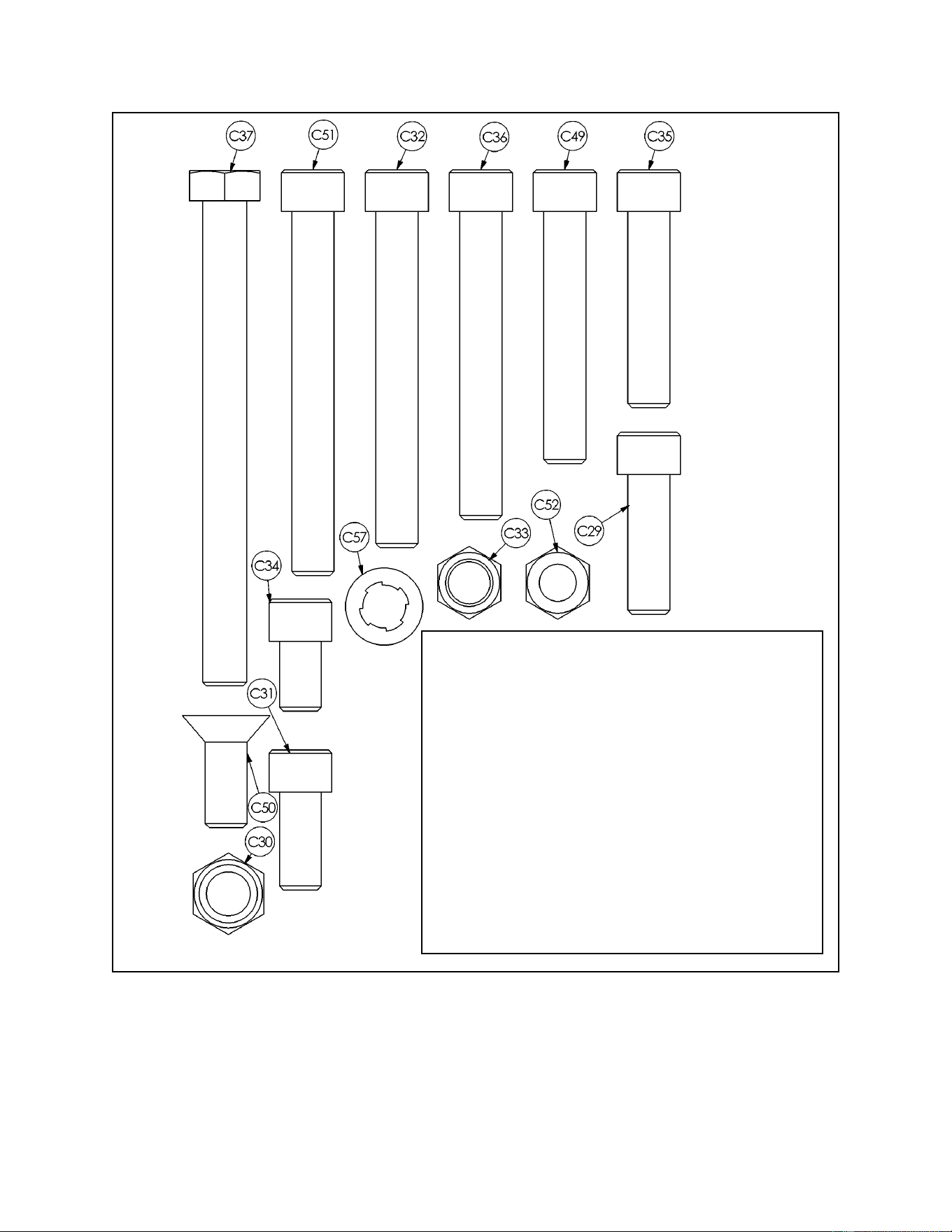
Cybex MG 500 Multi-Gym Owner’s Manual
Assembly
Page 6-40
Figure 5
C29 4 JC702820 SHCS .375-16 x 1.25
C30 3 8630-336 Nylon Locknut 10 mm
C31 1 HC702816 SHCS .375-16 x .875
C32 4 HC702834 SHCS .375-16 x 3.00
C33 20 HN704901 Nylon Locknut .375-16
C34 1 JC702814 SHCS .375-16 x .625
C35 3 JC702824 SHCS .375-16 x 1.75
C36 4 JC702832 SHCS .375-16 x 2.75
C37 Removed
C43 3 HC331271 HHCS 10 mm x 110 mm
C49 1 HC702828 SHCS .375-16 x 2.25
C50 2 JC700917 FHSC .375-16 x 1.00
C51 4 JC702836 SHCS .375-16 x 3.25
C52 1 JN714400 Jam Nut .375-24 UNF
C57 8 JS347400 Internal Tooth Lockwasher
ITEM QTY PART NO. DESCRIPTION
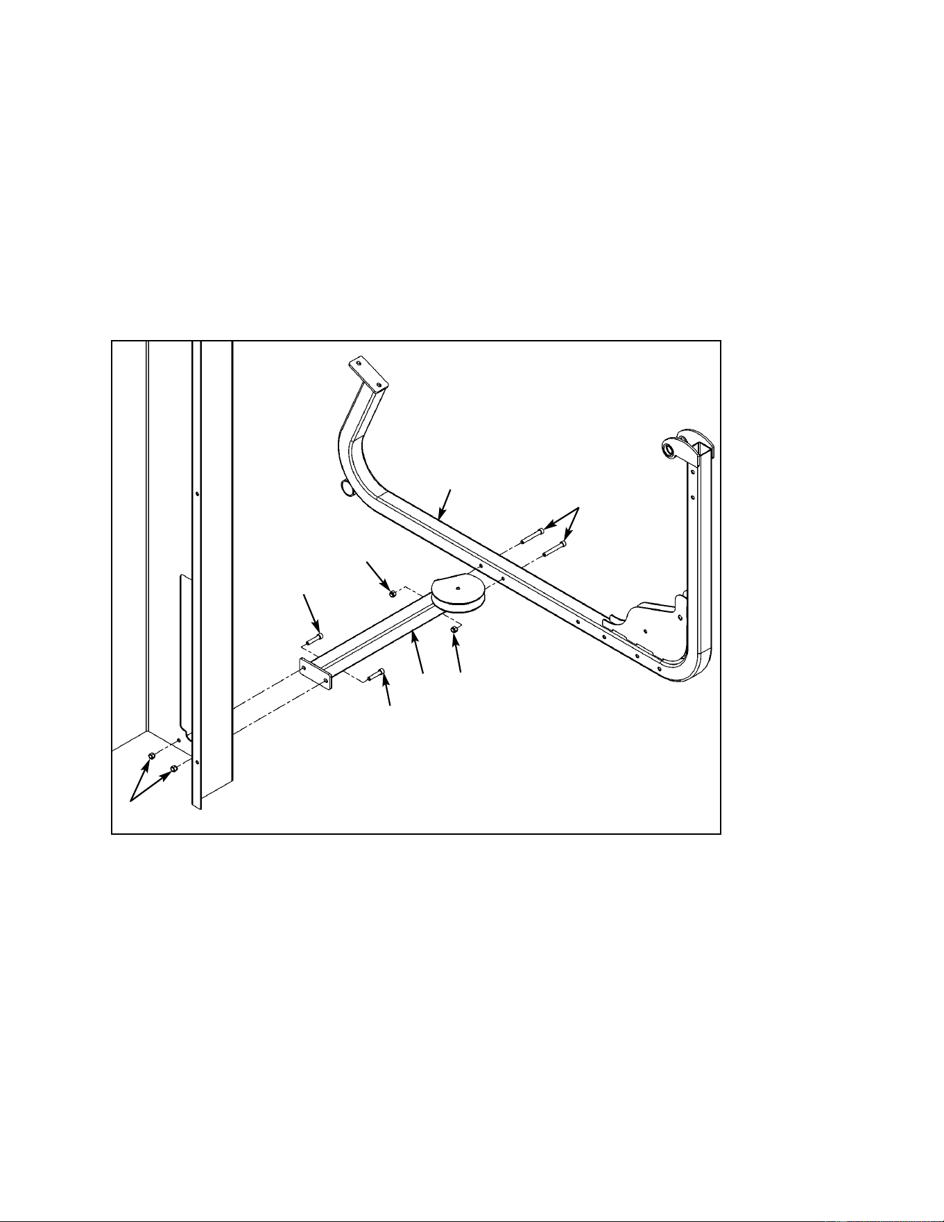
Cybex MG 500 Multi-Gym Owner’s Manual
Assembly
Page 6-41
Figure 6
C29
C33
C36
C33
C24
C33
C14
C29
3. Attach leg press frame to main frame assembly (see steps 3A - 3C and Figure 6).
A. Locate connector (#C24), frame (#C14), two SHCS .375-16 x 2.75 (#C36), two SHCS
.375-16 x 1.25 (#C29) and four nylon locknuts .375-16 (#C33).
B. Attach connector (#C24) to frame (#C14). Tighten securely using two SHCS .375-16 x
2.75 (#C36) and two nylon locknuts (#C33).
C. Attach frame to column as shown in Figure 6, using two SHCS .375-16 x 1.25 (#C29)
and two nylon locknuts (#C33).
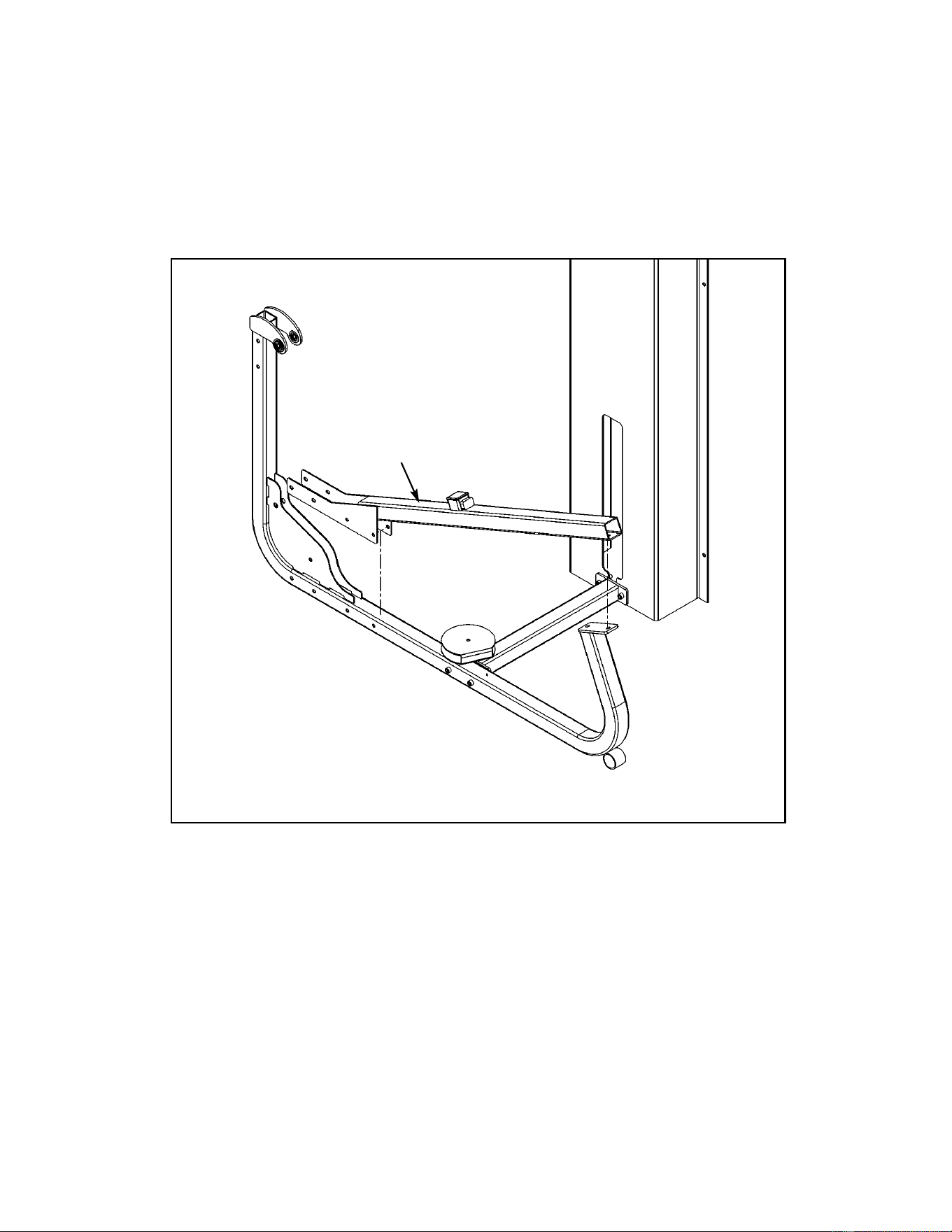
Cybex MG 500 Multi-Gym Owner’s Manual
Assembly
Page 6-42
C19
Figure 7
4. Install roller tube (see steps 4A - 4F, Figures 7 and 8).
A. Locate roller tube (#C19).
B. Set roller tube (#C19) on frame as shown in Figure 8. Do not install any hardware at
this time. See Figure 7.
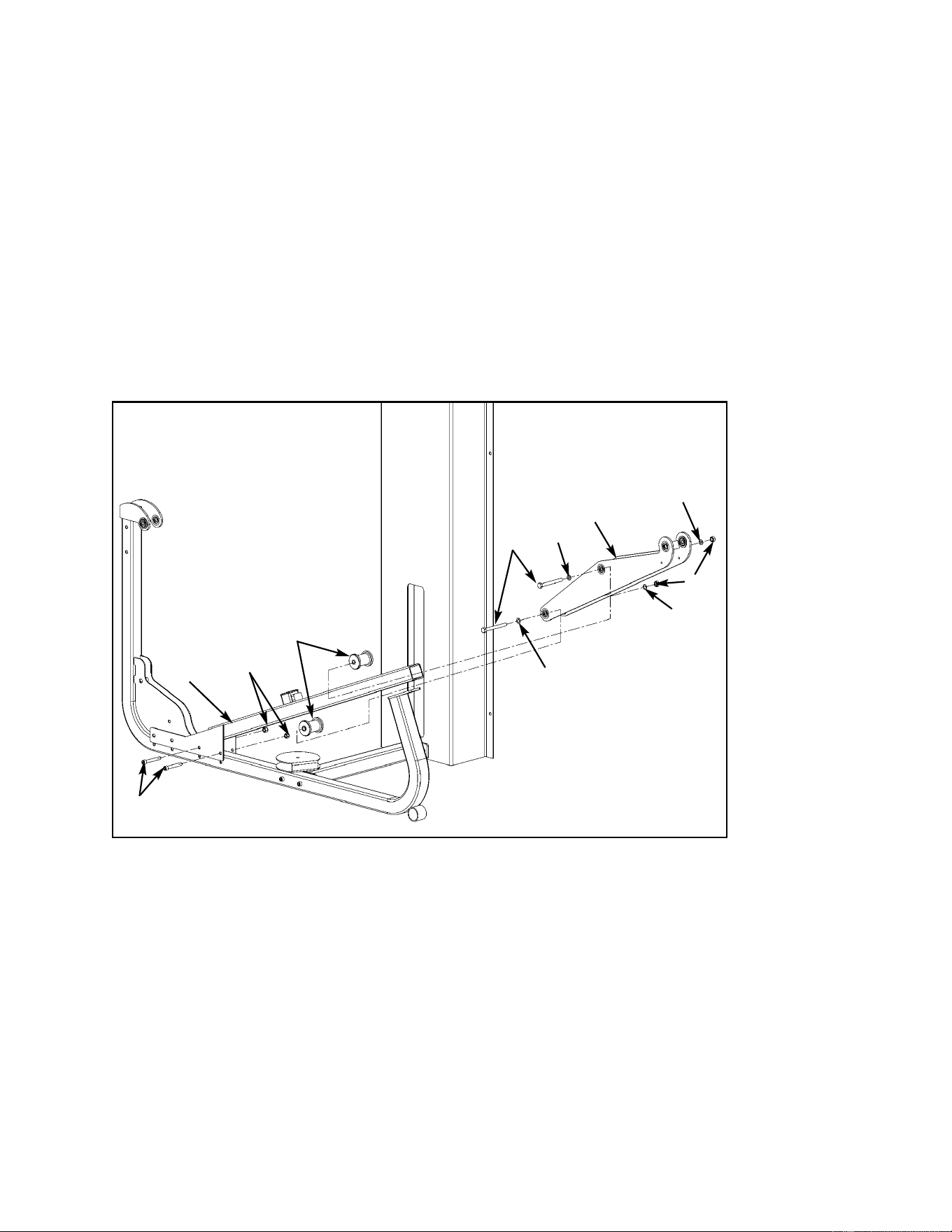
Cybex MG 500 Multi-Gym Owner’s Manual
Assembly
Page 6-43
Figure 8
C20
C43
C30
C26
C33
C36
C19
C. Locate roller plate (#C20), two rollers (#C26), two SHCS .375-16 x 2.75 (#C36), two
HHCS 10 mm x 100 mm (#C43), two nylon locknuts 10 mm (#C30), two nylon
locknuts .375-16 (#C33) and four internal tooth lockwashers (C57).
D. Slide roller plate (#C20) on roller tube (#C19) as shown in Figure 8. Be sure tabs are
facing to the back and upward.
E. Install rollers (#C26) and secure roller plate (#C20) using two HHCS 10 mm x 100 mm
(#C43), two nylon locknuts 10 mm (#C30) and four internal tooth lockwashers (C57).
See Figure 8.
F. Install two SHCS .375-16 x 2.75 (#C36) and two nylon locknuts .375-16 (#C33) to
secure roller tube. See Figure 8. Do not securely tighten hardware at this time.
C57
C57
C57
C57
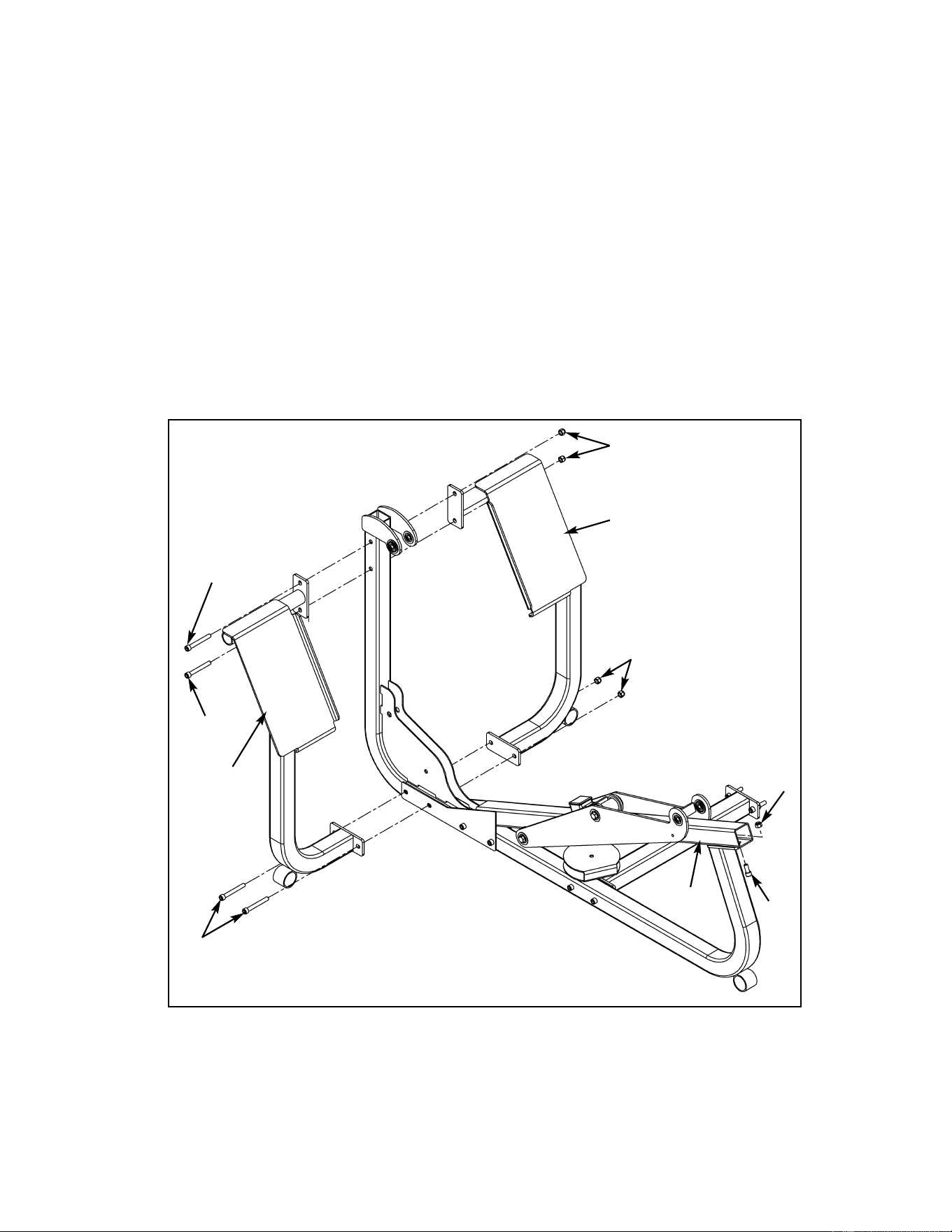
Cybex MG 500 Multi-Gym Owner’s Manual
Assembly
Page 6-44
C17
C33
C33
C18
C32
C51
Figure 9
C32
C33
C31
C19
5. Install footplates (see steps 5A - 5D and Figure 9).
A. Locate right footplate (#C17), left footplate (#C18), one SHCS .375-16 x .875 (#C31),
two SHCS .375-16 x 3.00 (#C32), two SHCS .375-16 x 3.25 (#C51) and five nylon
locknuts .375-16 (#C33).
B. Install left (#C18) and right (#C17) footplates. Use two SHCS .375-16 x 3.00 (#C32) for
the two upper holes and use two SHCS .375-16 x 3.25 (#C51) for the bottom two
holes as shown in Figure 9.
C. Install SHCS .375-16 x .875 (#C31) and nylon locknut .375 (#C33) securing roller tube
(#C19) as shown in Figure 9.
D. Securely tighten all hardware from steps 3 - 5.
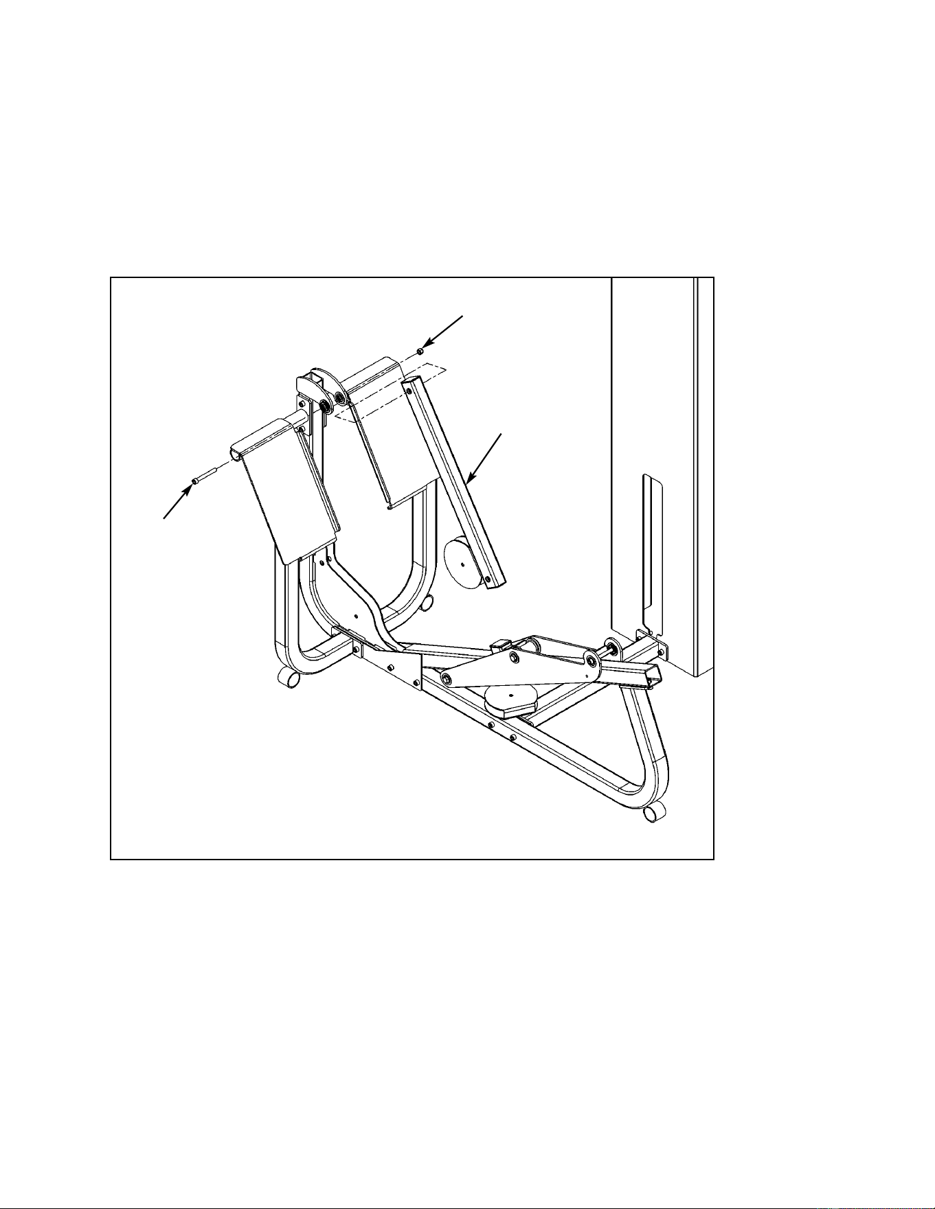
Cybex MG 500 Multi-Gym Owner’s Manual
Assembly
Page 6-45
C23
C51
C33
Figure 10
6. Install pivot tube (see steps 6A, 6B and Figure 10).
A. Locate pivot tube (#C23), one SHCS .375-16 x 3.25 (#C51) and one nylon locknut .375-
16 (#C33).
B. Place pivot tube (#C23) on frame as shown below. Secure end by footplate with SHCS
.375-16 x 3.25 (#C51) and nylon locknut (#C33). Do not tighten hardware at this time.
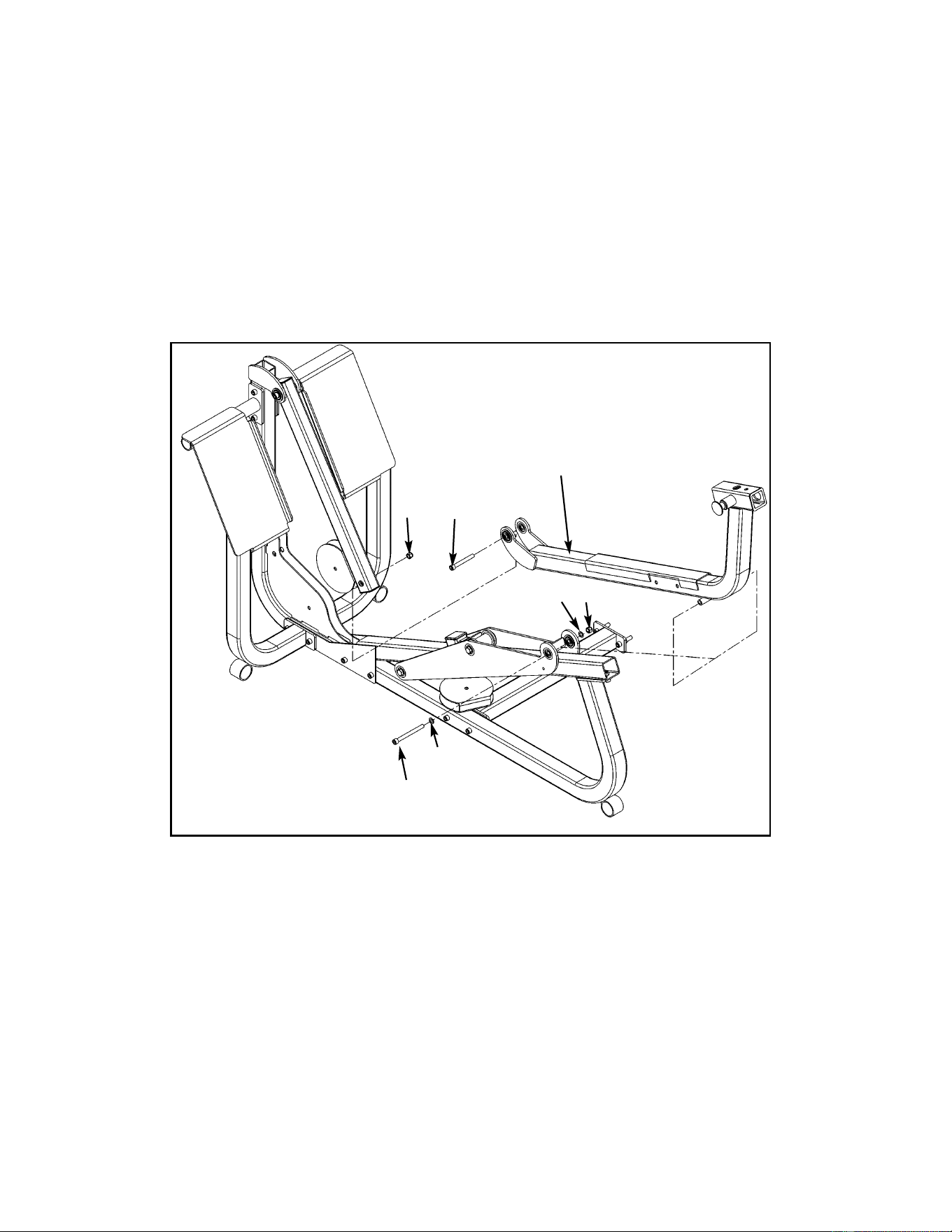
Cybex MG 500 Multi-Gym Owner’s Manual
Assembly
Page 6-46
C15
C51
C43
C33
Figure 11
C30
7. Install seat frame (see steps 7A - 7B and Figure 11).
A. Locate seat frame (#C15), one SHCS .375-16 x 3.25 (#C51), one HHCS 10 mm x 110
mm (#C43), one nylon locknut 10 mm (#C30), one nylon locknut .375-16 (#C33) and
two internal tooth lockwashers (#C57).
B. Install seat frame (#C15) as shown in Figure 11 using one SHCS .375-16 x 3.25 (#C51),
one nylon locknut .375-16 (#C33) and two internal tooth lockwashers (#C57) for the end
connecting to the pivot tube. Use one HHCS 10 mm x 110 mm (#C43) to secure the
other end of the seat frame.
C57
C57
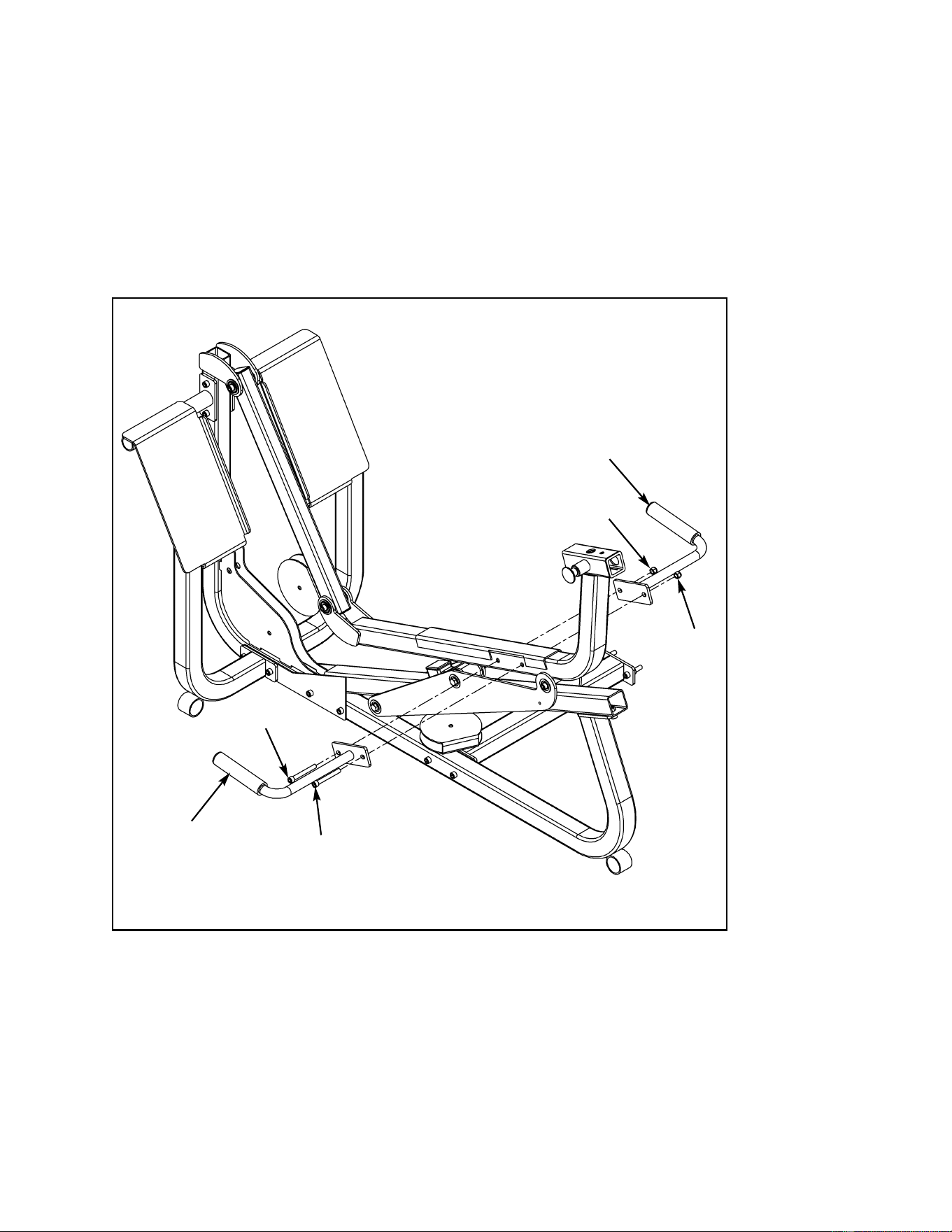
Cybex MG 500 Multi-Gym Owner’s Manual
Assembly
Page 6-47
C21
C22
C33
C33
C32
C32
Figure 12
8. Install handles (see steps 8A, 8B and Figure 12).
A. Locate right handle (#C21), left handle (#C22), two SHCS .375-16 x 3.00 (#C32) and
two nylon locknuts .375-16 (#C33).
B. Install right handle (#C21) and left handle (#C22) as shown in Figure 12, using two
SHCS .375-16 x 3.00 (#C32) and two nylon locknuts (#C33). Securely tighten hardware
from steps 6 - 8.
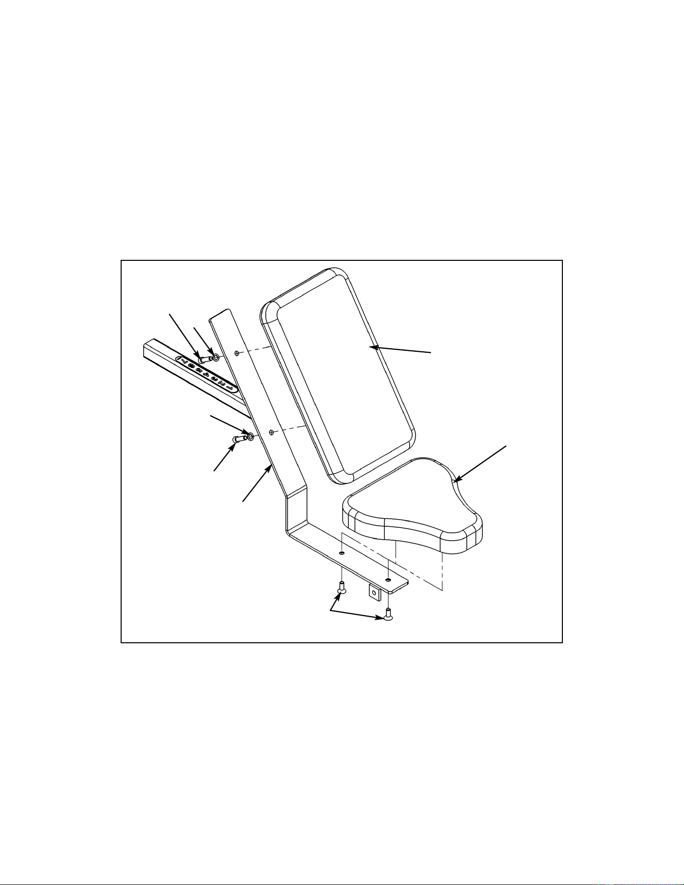
Cybex MG 500 Multi-Gym Owner’s Manual
Assembly
Page 6-48
C9
C16
C50
C6
C29
C29
Figure 13
9. Install cushions (see steps 9A - 9I and Figures 13 - 16).
A. Locate seat tube (#C16), seat cushion (#C9), back cushion (#C6), two FHSCS .375-16
x 1.00 (#C50), two SHCS .375-16 x 1.25 (#C29) and two internal tooth lockwashers
(#C57).
B. Install seat cushion (#C9) to seat tube (#C16) as shown in Figure 13 and secure using
two FHSCS .375-16 x 1.00 (#C50).
C. Install back cushion (#C6) to seat tube (#C16) as shown in Figure 13, using two SHCS
.375-16 x 1.25 (#C29) and two internal tooth lockwashers (#C57).
C57
C57
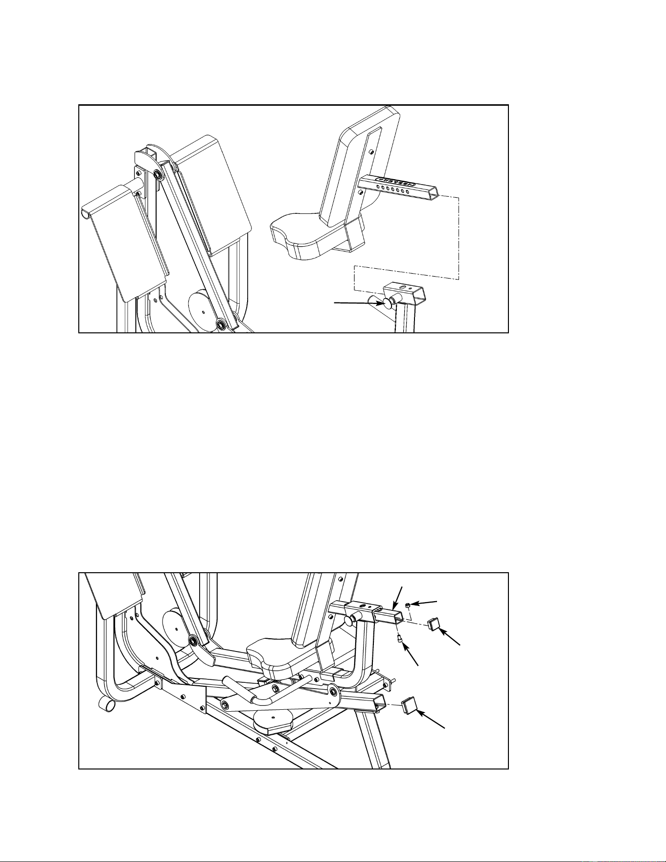
Cybex MG 500 Multi-Gym Owner’s Manual
Assembly
Page 6-49
C41
C40
C16
Figure 14
Figure 15
C33
C34
D. Slide seat tube through seat frame as shown in Figure 14.
Pull detent pin to
slide seat tube
onto seat frame.
E. Locate one SHCS .375-16 x .625 (#C34) and one nylon locknut .375-16 (#C33), one
plastic insert (#C40) and one plastic insert (#C41).
F. Secure with SHCS .375-16 x .625 (#C34) and nylon locknut (#C33) as shown in Figure
15. Securely tighten all hardware.
G. Locate plastic insert (#C40) and plastic insert (#C41).
H. Using a rubber mallet, install plastic insert (#C41) into seat tube (#C16) as shown in
Figure 15.
I. Using a rubber mallet, install plastic insert (#C40) into roller tube as shown in Figure
15.
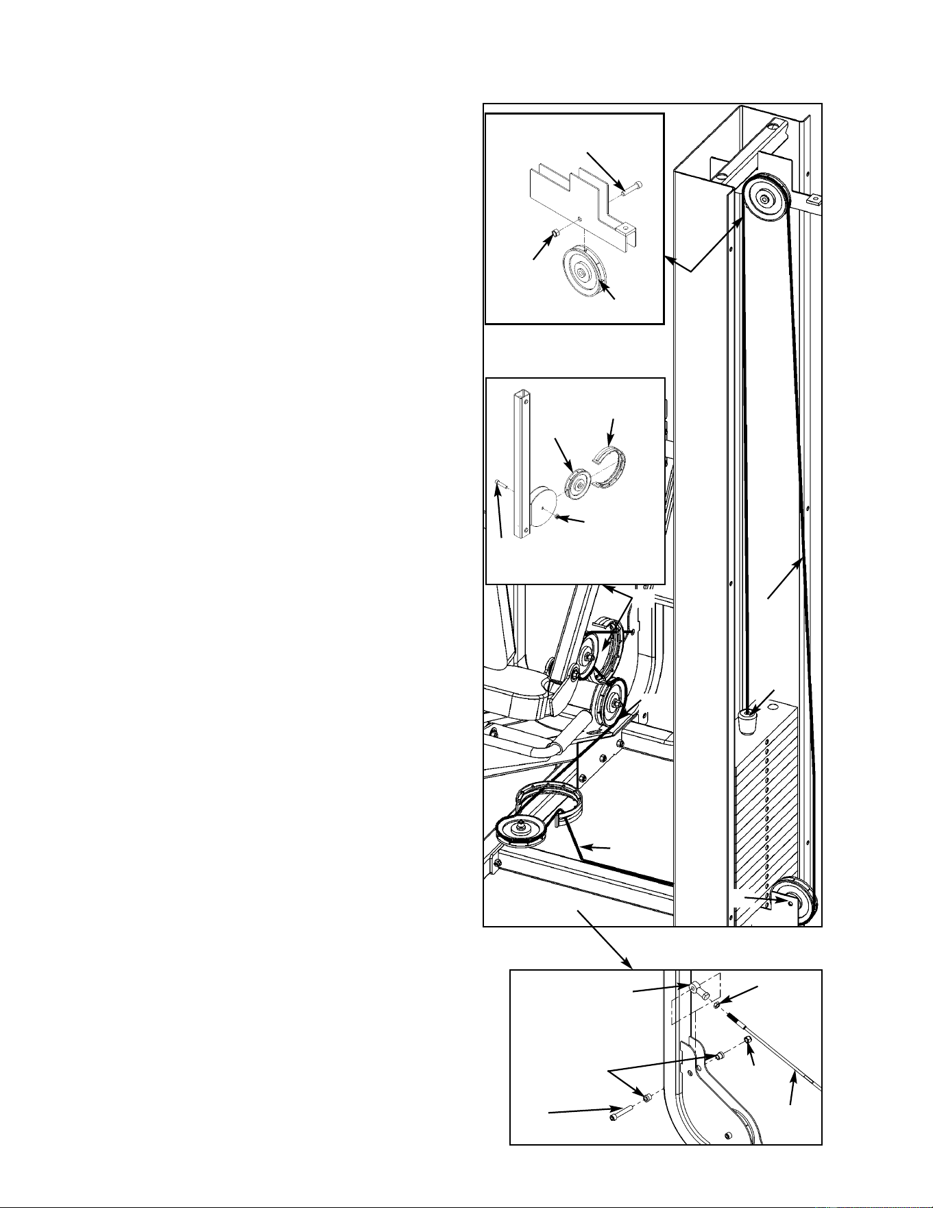
Cybex MG 500 Multi-Gym Owner’s Manual
Figure 16
10. Install weight stack cable (see steps 10A -
10J and Figure 16).
From the Leg Press Station hardware pack,
locate cable (#C46), three pulleys (#C1), three
SHCS .375-16 x 1.75 (#C35), one SHCS .375-
16 x 2.25 (#C49), four nylon locknuts .375
(#C33) two cable guards (#C10), one jam nut
.375-24 (#C52), one rod end bearing (#C48),
and two spacers (#C47). From the main frame
hardware pack, locate two pulleys (#E1), two
SHCS .375-16 x 1.75 (#E39) and two nylon
locknuts .375 (#E34).
A. Thread jam nut (#C52) half way on
threaded end of cable (#C46).
B. Thread rod end bearing (#C48) up to jam
nut (#C52) and install rod end bearing
(#C48) using one SHCS .375-16 x 2.25
(#C49) two spacers (#C47) and one nylon
locknut (#C33). See Figure 16, letter B.
C. Slide cable (#C48) through cable guard
(#C10) and install first pulley (#C1) and
route cable (#C48) using hardware shown
in Figure 16, letter C.
D. Install second pulley (#C1) and route cable
(#C48) using hardware shown in Figure 16,
letter D.
E. Slide cable (#C48) through cable guard
(#C10) and install third pulley (#C1) using
hardware shown in Figure 16, letter E.
F. Route cable (#C48) and install fourth pulley
(#E1) using hardware shown in Figure 16,
letter F.
G. Route cable (#C48) and install fifth pulley
(#E1) using hardware shown in Figure 16,
letter G.
H. Route cable (#C48) down to weight stack.
Slide rubber boot (#E3) on cable.
I. Drive spiral pin (#E35) through top weight
connector and cable. Top weight should be
just resting on second weight.
J. Slide rubber boot (#E3) over step of top
weight.
E39
(SHCS .375-16 x 1.75)
E34
C1
C33
C10
C35
(SHCS .375-16 x 1.75)
C
D
E
F
G
H - I
E1
C48
C52
Cable
C33
C47
C49
B
(SHCS .375-16 x 2.25)
C33
Assembly
Page 6-50

Cybex MG 500 Multi-Gym Owner’s Manual
Assembly
Page 6-51
This page intentionally left blank
(this allows step 11 and Figure 17 to be located on facing pages)
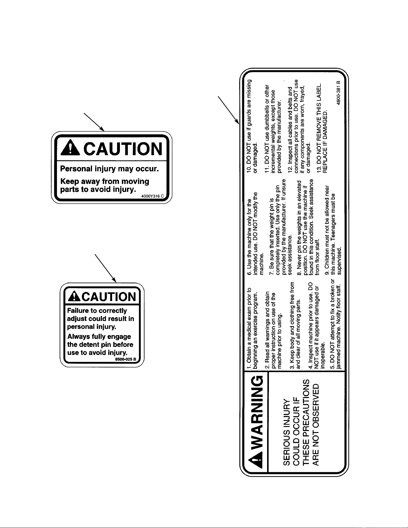
Cybex MG 500 Multi-Gym Owner’s Manual
Assembly
Page 6-52
A
B
C
11. Verify warning decals are present and not damaged (see decals below and Figure 17).
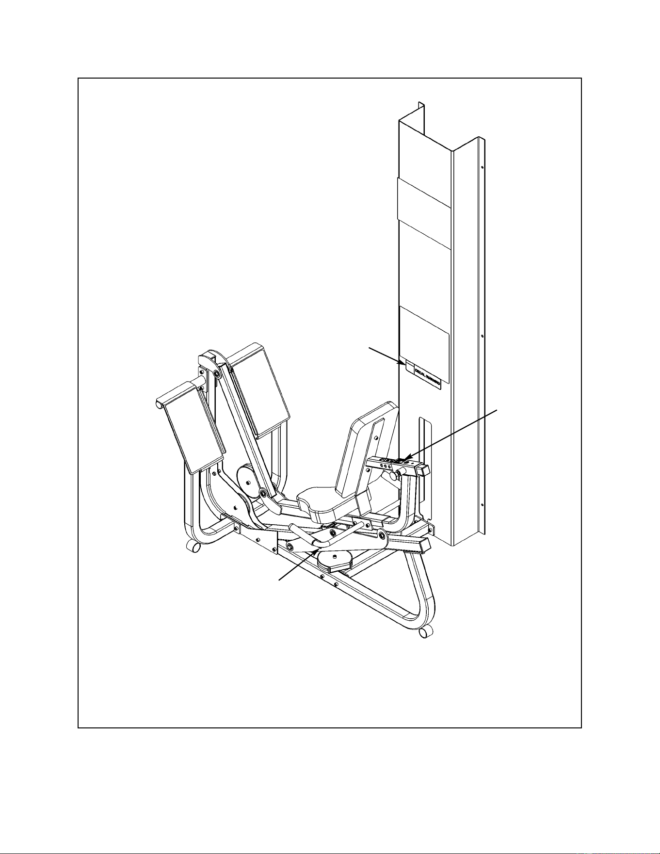
Cybex MG 500 Multi-Gym Owner’s Manual
Assembly
Page 6-53
A. Caution Decal .................... 4000Y316
B. Warning Decal ................... 4800-381
C. Caution Decal ................... 8500-025
DESCRIPTION PART NO.
A
C
B
Figure 17
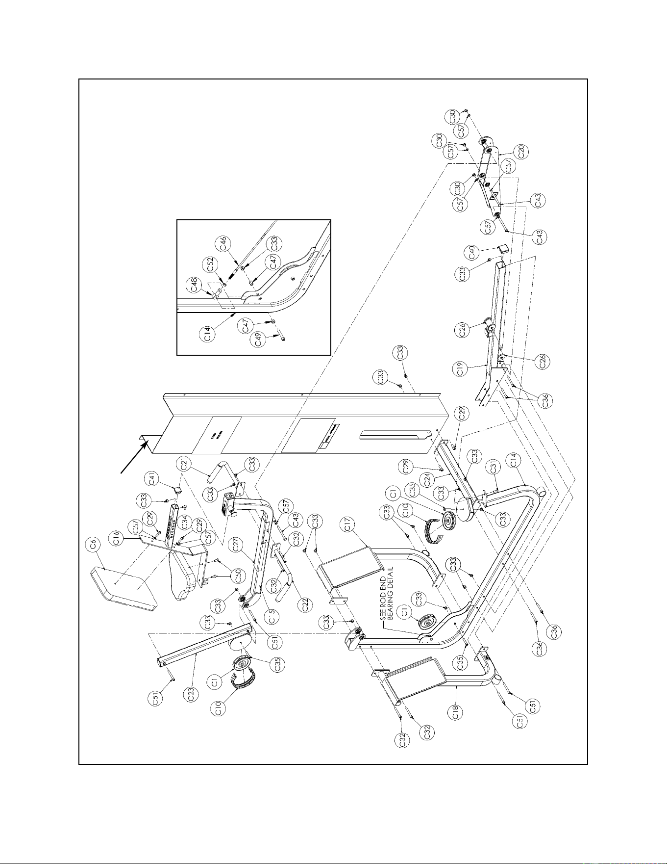
Cybex MG 500 Multi-Gym Owner’s Manual
Assembly
Page 6-54
Column
ROD END
BEARING DETAIL
Leg Press Exploded-View Diagram (for assembly only)

Cybex MG 500 Multi-Gym Owner’s Manual
Assembly
Page 6-55
C1 3 08014 Pulley
C6 1 4106S055-0 Back Cushion
C9 1 4800-026 Seat Cushion
C10 2 4800-570 Cable Guard
C14 1 8630-200 Frame
C15 1 8630-201 Seat Frame
C16 1 8630-202 Seat Tube
C17 1 8630-203 Right Foot Plate
C18 1 8630-204 Left Foot Plate
C19 1 8630-205 Roller Tube
C20 1 8630-206 Roller Plate
C21 1 8630-207 Right Handle
C22 1 8630-208 Left Handle
C23 1 8630-209 Pivot Tube
C24 1 8630-210 Connector
C26 2 8630-322 Roller
C27 1 8630-326 Seat Sleave
C28 2 8630-331 Spacer
C29 4 JC702820 SHCS .375-16 x 1.25
ITEM QTY PART NO. DESCRIPTION
C30 3 8630-336 Nylon Locknut 10 mm
C31 1 HC702816 SHCS .375-16 x .875
C32 4 HC702834 SHCS .375-16 x 3.00
C33 20 HN704901 Locknut .375-16
C34 1 JC702814 SHCS .375-16 x .625
C35 3 JC702824 SHCS .375-16 x 1.75
C36 4 JC702832 SHCS .375-16 x 2.75
C37 Removed
C40 1 PP090210 Plastic Insert 2.00 Sq x 10-14 G
C41 1 PP090211 Plastic Insert 2.00 Sq x 10-14 G
C43 3 HC331271 HHCS 10 mm x 110 mm
C47 2 8630-340 Spacer
C48 1 FB030213 Rod End Bearing
C49 1 HC702828 SHCS .375-16 x 2.25
C50 2 JC700917 FHSCS .375-16 x 1.00
C51 4 JC702836 SHCS .375-16 x 3.25
C52 1 JN714400 Jam Nut .375-24
C57 8 JS347400 Internal Tooth Lockwasher
ITEM QTY PART NO. DESCRIPTION
Leg Press Station Parts List (not all parts are listed such as pulleys for inside). See Chapter 8 for
a complete parts listing.

Cybex MG 500 Multi-Gym Owner’s Manual
Assembly
Page 6-56
This page intentionally left blank
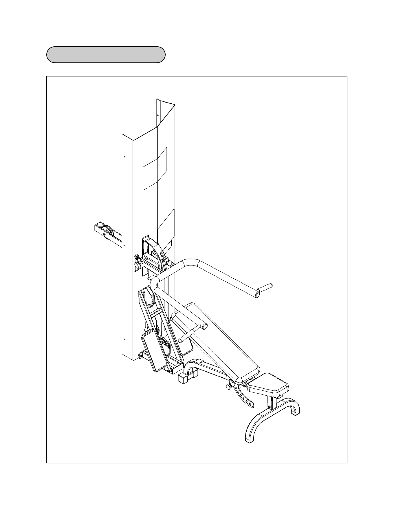
Cybex MG 500 Multi-Gym Owner’s Manual
Assembly
Page 6-57
Pressing Station Diagram

Cybex MG 500 Multi-Gym Owner’s Manual
Assembly
Page 6-58
1. Verify contents of the Pressing Station boxes (see steps 1A - 1C and Figures 1-3).
A. Locate the Pressing Station box (containing the frame).
B. Locate the Pressing Station cushion box (removed from the main frame assembly).
C. Verify contents of both boxes. See Figures 1-3.
Pressing Station Assembly
A8 1 4800-019 Seat Cushion
A9 1 4800-009 Back Cushion
A16 1 8610-308 Shaft
A17 1 8610-203 Brace
A18 1 8610-204 Platform
A19 1 8610-201 Pressing Arm
A20 1 8610-207 Leg
A21 1 8610-210 Bench Frame
A22 1 8610-205 Swivel Pulley Bracket
A23 1 8510-208 Cushion Plate
A24 1 8610-202 Pivot Arm
A25 1 8510-210 Detent Plate
A49 1 8610-002 Cable 179.25 Long
A50 1 8610-003 Cable 173.44 Long
A55 1 51122 Ankle Strap
A56 2 5310S040 Handle Sub-Assembly
A57 1 02204 EZ Curl Handle
1 Hardware Pack
ITEM QTY PART NO. DESCRIPTION
Figure 1
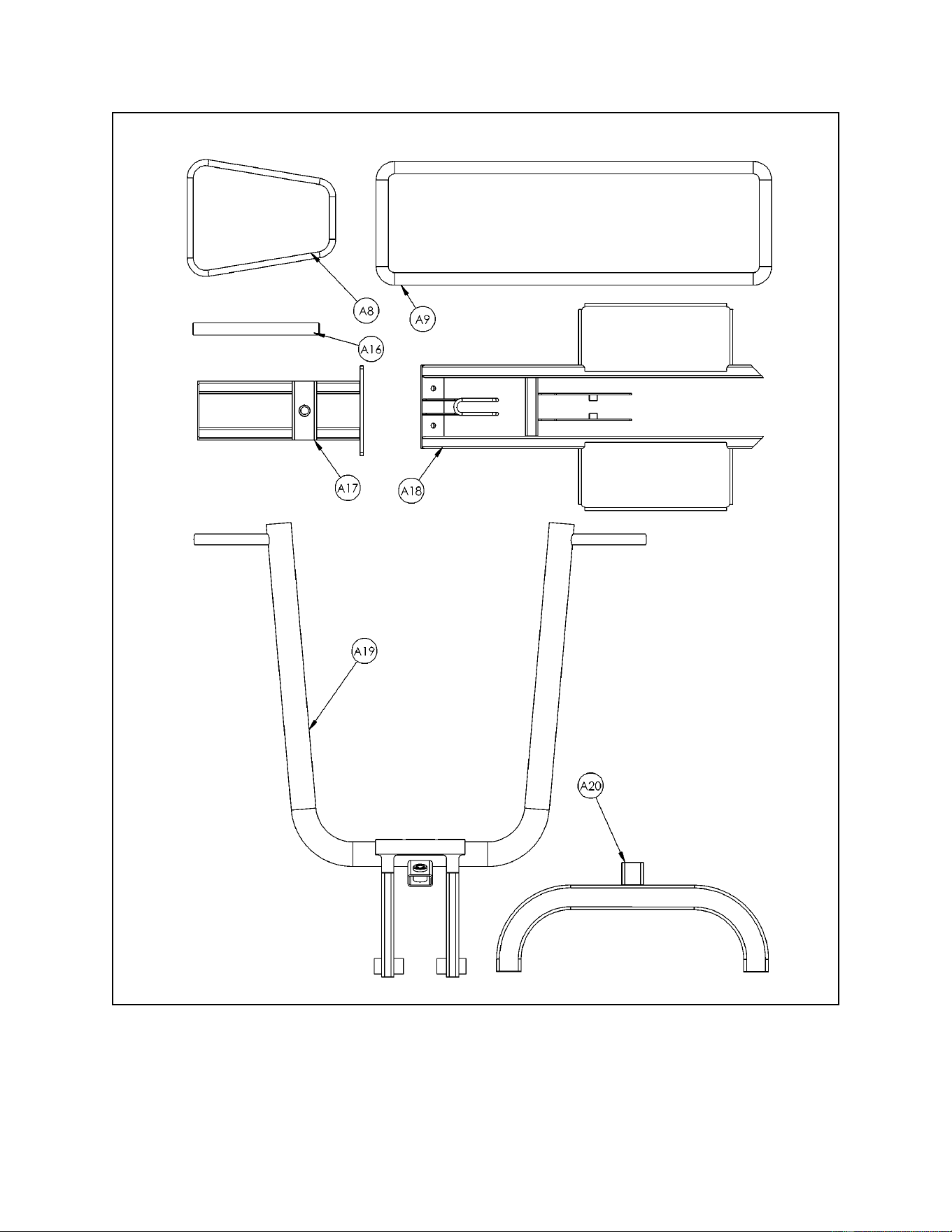
Cybex MG 500 Multi-Gym Owner’s Manual
Assembly
Page 6-59
Figure 2
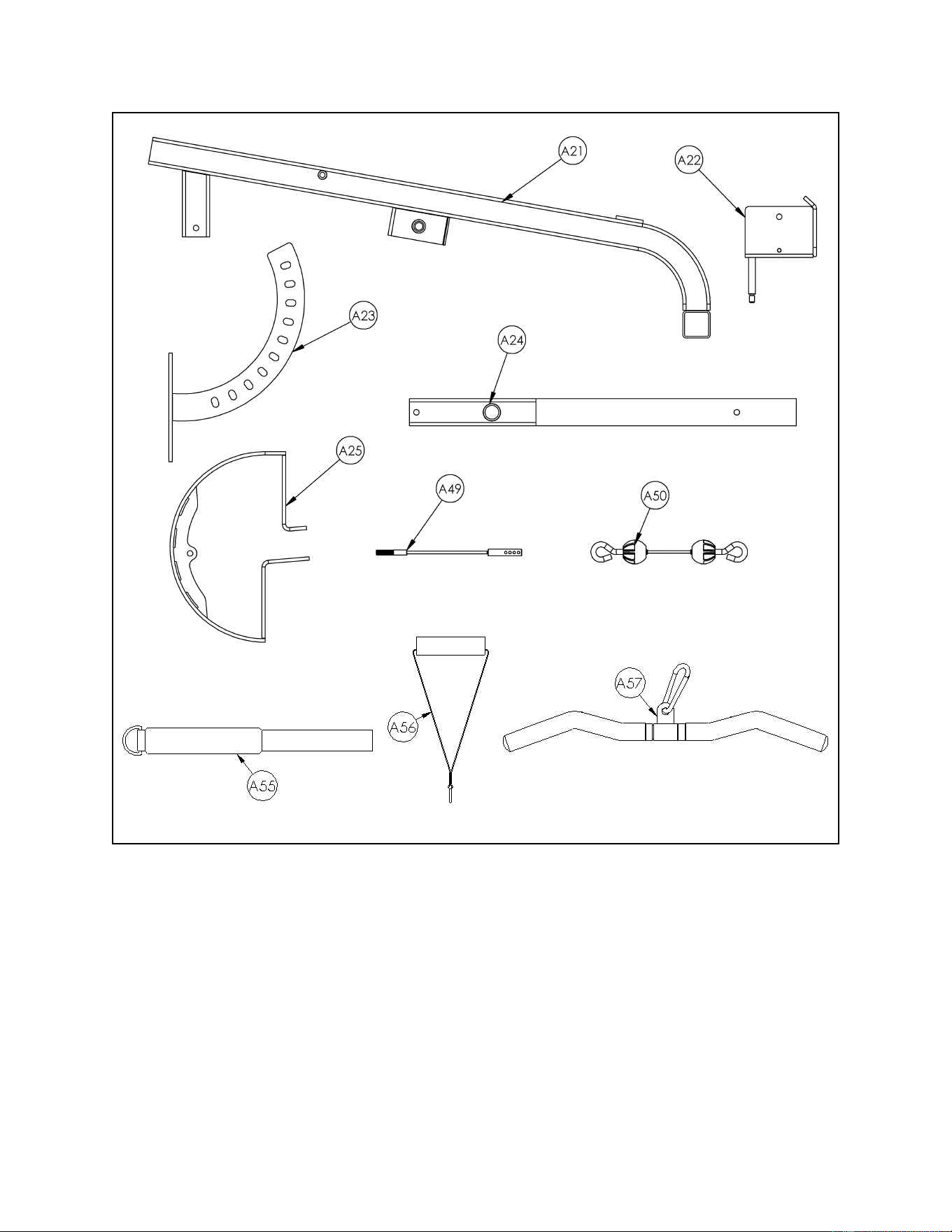
Cybex MG 500 Multi-Gym Owner’s Manual
Assembly
Page 6-60
Figure 3
2. Verify contents of the Pressing Station hardware pack (see steps 2A, 2B, Figures 4
and 5).
A. Locate hardware pack.
B. Verify contents of hardware pack. If desired, sort out hardware into different
containers. Do not combine hardware with other hardware packs. See Figures 4 and 5
for contents of hardware pack.
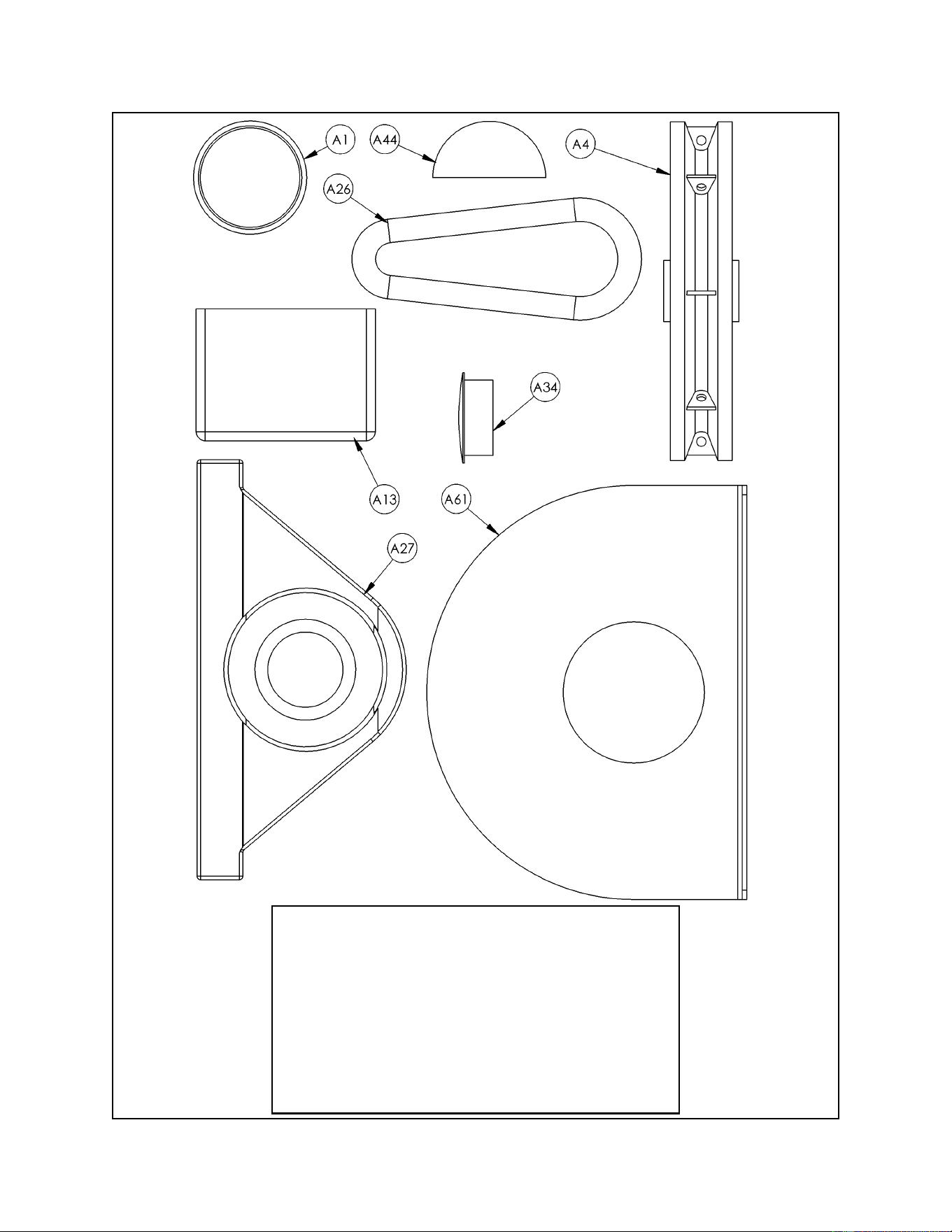
Cybex MG 500 Multi-Gym Owner’s Manual
Assembly
Page 6-61
Figure 4
A1 2 01190 Vinyl Black End Cap
A4 4 08014 Pulley
A13 2 8510-344 Rubber Boot
A26 2 GQ000206 Snap Link
A27 2 HB-60652 Pillow Block Bearing
A34 2 PN660200 Plastic Insert 1.00 Dia. x 11 G
A44 1 4505-331 Bumper 1.50 Dia.
A61 2 8610-330 Guard
1 Tube of Loctite
ITEM QTY PART NO. DESCRIPTION
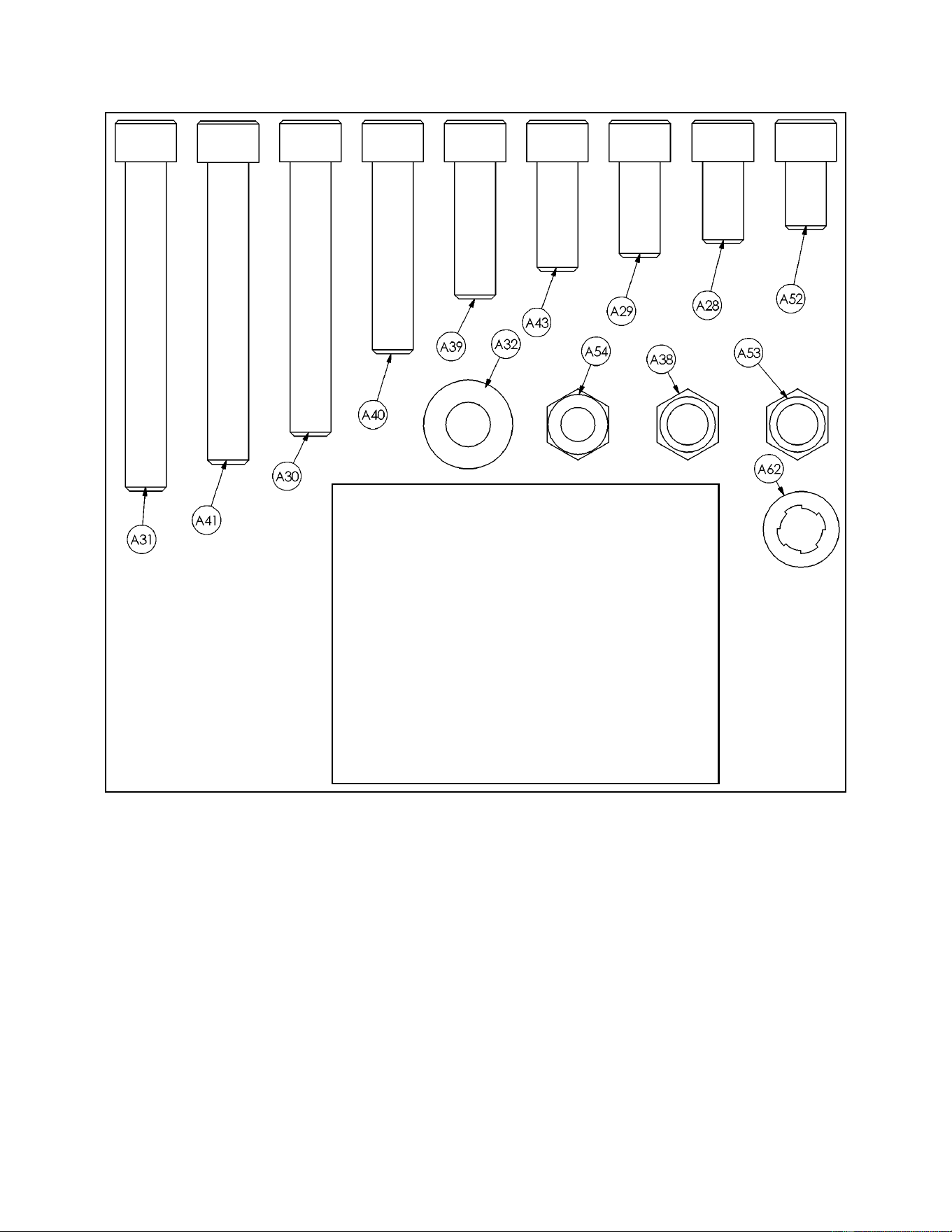
Cybex MG 500 Multi-Gym Owner’s Manual
Assembly
Page 6-62
Figure 5
A28 2 HC702815 SHCS .375-16 x .750
A29 4 HC702816 SHCS .375-16 x .875
A30 1 HC702830 SHCS .375-16 x 2.50
A31 4 HC702834 SHCS .375-16 x 3.00
A32 1 HS347600 Flat Washer .375
A38 18 HN704901 Nylon Locknut .375-16
A39 6 JC702820 SHCS .375-16 x 1.25
A40 2 JC702824 SHCS .375-16 x 1.75
A41 2 JC702832 SHCS .375-16 x 2.75
A43 1 HC702817 SHCS .375-16 x 1.00
A52 1 JC702814 SHCS .375-16 x .625
A53 1 HN704000 Hex Nut .375-16
A54 1 HN704400 Jam Nut .375-16
A62 5 JS347400 Internal Tooth Lockwasher
ITEM QTY PART NO. DESCRIPTION
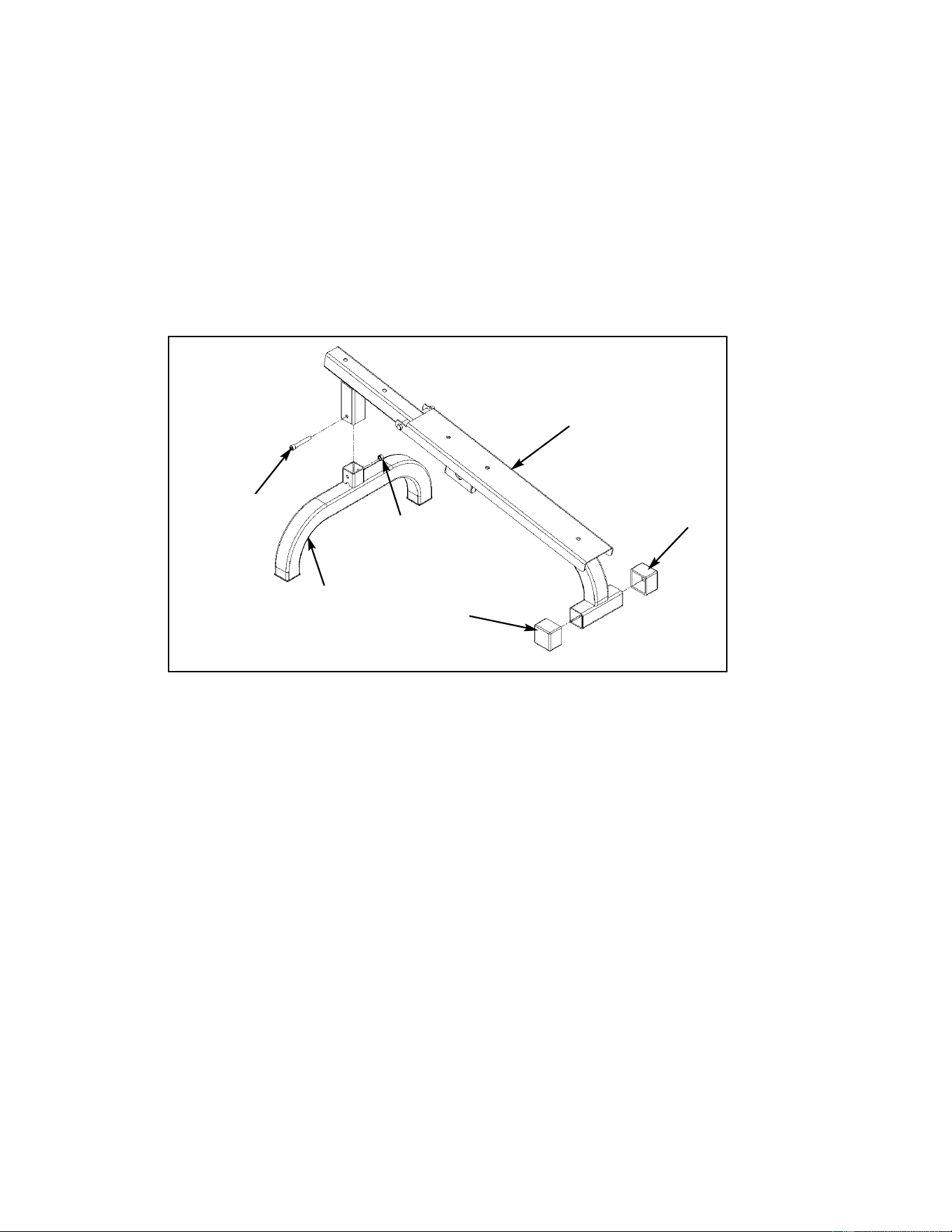
Cybex MG 500 Multi-Gym Owner’s Manual
Assembly
Page 6-63
Figure 6
A30
A13
A13
A21
A38
3. Assemble the Pressing Station Bench (see steps 3A - 3N, Figures 6 - 8).
A. Locate bench frame (#A21), leg (#A20), one SHCS .375-16 x 2.50 (#A30), one nylon
locknut .375-16 (#A38) and two rubber caps (#A13).
B. Attach leg (#A20) to bench (#A21) using one SHCS .375-16 x 2.50 (#A30) and one nylon
locknut (#A38). See Figure 6.
C. Attach two rubber caps (#A13) to bench frame (#A21) using a rubber mallet. See
Figure 6.
A20
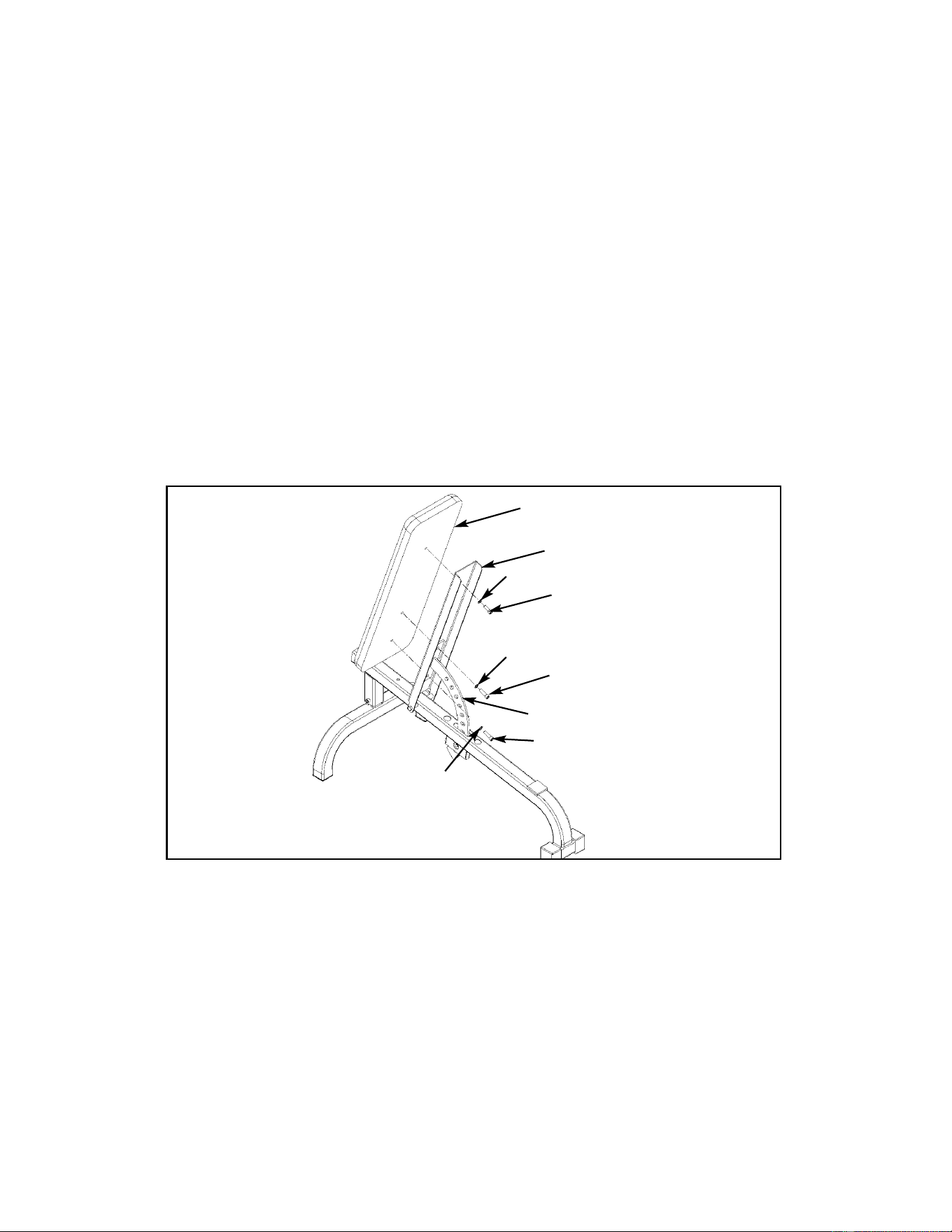
Cybex MG 500 Multi-Gym Owner’s Manual
Figure 7
A9
A43
Back Plate
A39
A39
A23
Assembly
Page 6-64
D. Locate the back cushion (#A9), cushion plate (#A23), one SHCS .375-16 x 1.00 (#A43),
two SHCS .375-16 x 1.25 (#A39) and three internal tooth lockwashers (#A62).
E. Carefully raise the back plate.
F. Insert cushion plate adjustment bar (#A23) into hole in bench as shown in Figure 7.
G. Place back cushion (#A9) onto back plate (#A23) and align holes.
H. Insert two SHCS .375-16 x 1.25 (#A39) and two internal tooth lockwashers (#A62) as
shown in Figure 5, securing the back cushion and cushion plate to the back plate. Do
not tighten screws at this time.
I. Insert one SHCS .375-16 x 1.00 (#A43) and one internal tooth lockwasher (#A62)
through cushion plate and back cushion (in the top hole) as shown in Figure 7.
J. Securely tighten all three screws from steps H and I.
A62
A62
A62
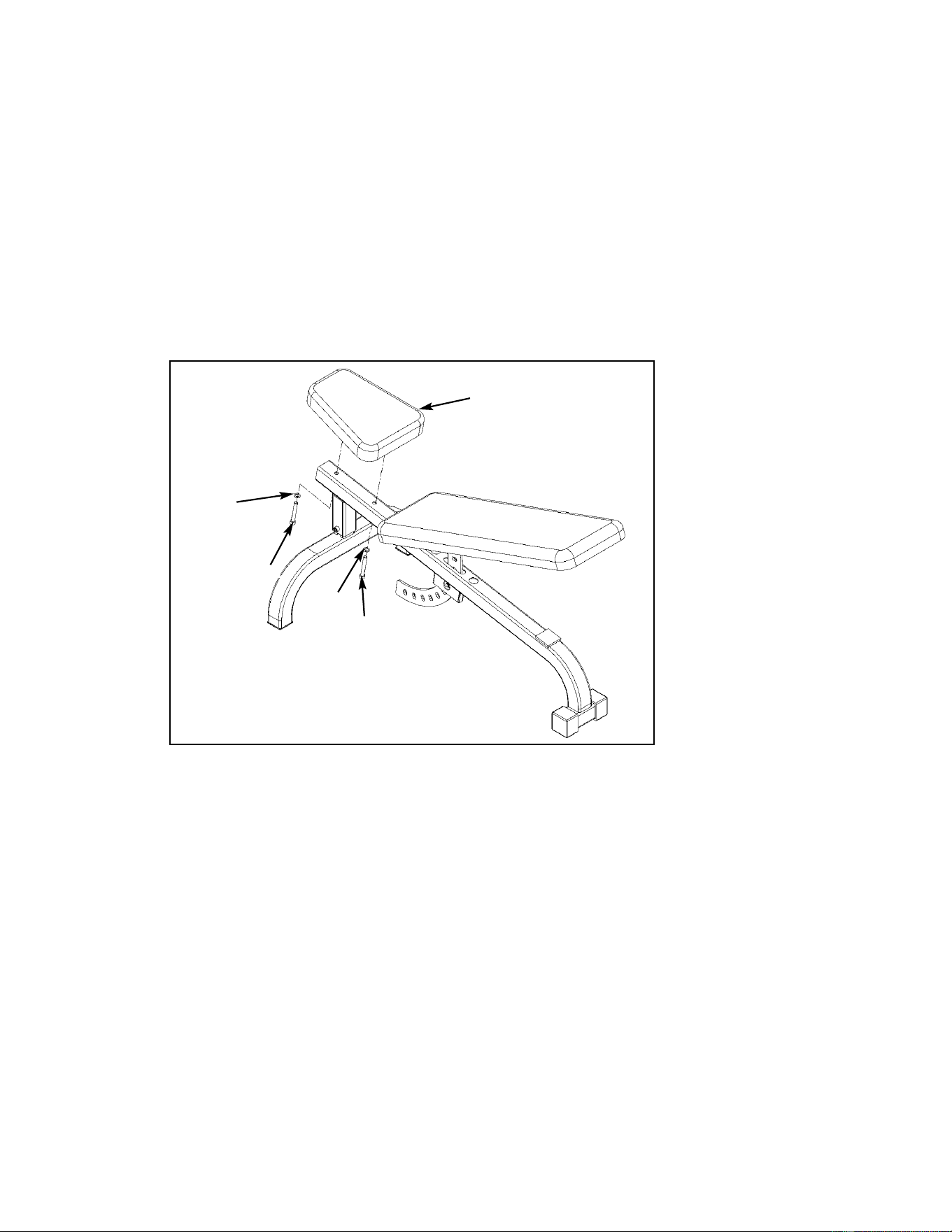
Cybex MG 500 Multi-Gym Owner’s Manual
Assembly
Page 6-65
Figure 8
A8
A31
A31
K. Locate seat cushion (#A8), two SHCS .375-16 x 3.00 (#A31) and two internal tooth
lockwashers (#A62).
L. Raise back cushion to the fifth position.
M. Install seat cushion to the bench using two SHCS .375-16 x 3.00 (#A31) and two
internal tooth lockwashers (#A62) as shown in Figure 8.
Note: Place seat cushion so that that the wider end faces toward the back cushion.
N. Lower back cushion and set bench aside.
A62
A31
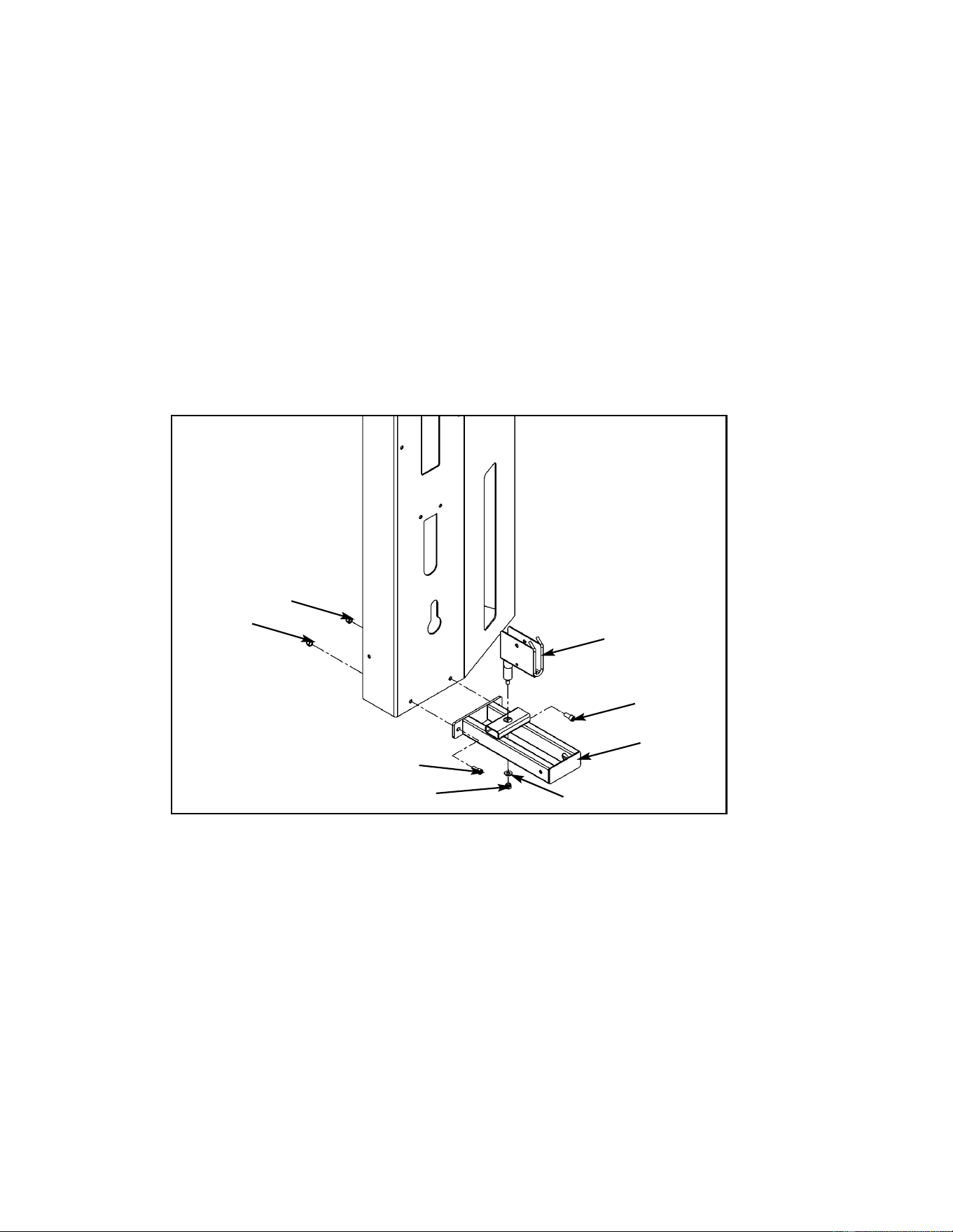
Cybex MG 500 Multi-Gym Owner’s Manual
Assembly
Page 6-66
Figure 9
A22
A29
A17
A38
A38
A29
A38
A32
4. Install brace to the pressing station column (see steps 4A - 4E and Figure 9).
A. Locate brace (#A17), swivel pulley bracket (#A22), one flat washer .375 (#A32), three
nylon locknuts (#A38) and two SHCS .375-16 x .875 (#A29).
B. Insert swivel pulley bracket (#A22) into brace (#A17) as shown in Figure 9.
C. Attach flat washer (#A32) and nylon locknut (#A38). Tighten securely.
D. Turn swivel pulley bracket (#A22) so that it is facing away from the column as shown in
Figure 9.
E. Attach brace (#A17) to column using two SHCS .375-16 x .875 (#A29) and two nylon
locknuts (#A38). NOTE: Do not securely tighten screws at this time. See Figure 9.
NOTE: Install pulley
bracket (#A22) to brace
(#A17) before installing
brace to column (as
stated in steps 4B - 4E).
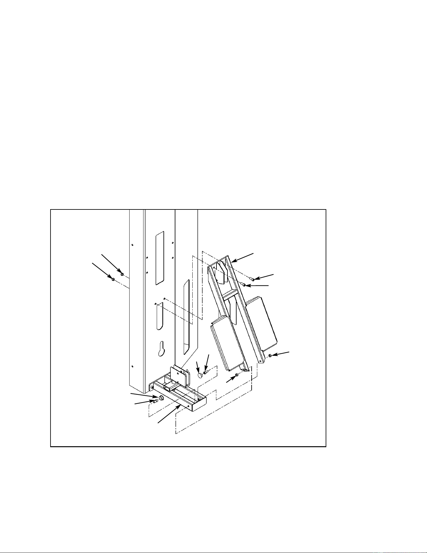
Cybex MG 500 Multi-Gym Owner’s Manual
Assembly
Page 6-67
Figure 10
A38
A38
A38
A38
A28
A34
A28
A34
A29
A29
A18
A17
5. Install platform to column (see steps 5A - 5E and Figure 10).
A. Locate platform (#A18), two SHCS .375-16 x .875 (#A29), two SHCS .375-16 x .750
(#A28), four nylon locknuts (#A38) and two plastic inserts 1.00 Dia. x 11 G (#A34).
B. Attach upper end of platform (#A18) to column using two SHCS .375-16 x .875 (#A29)
and two nylon locknuts (#A38). See Figure 10. NOTE: Do not securely tighten screws
at this time.
C. Attach lower end of platform (#A18) to brace (#A17) using two SHCS .375-16 x .750
(#A28) and two nylon locknuts (#A38). NOTE: Place SHCS (#A28) on Allen wrench
then place through hole in brace (#A17).
D. Securely tighten all hardware installed in steps 5B and 5C.
E. Install two plastic inserts 1.00 Dia. (#A34) as shown in Figure 10.
NOTE: Place SHCS (#A28)
on Allen wrench
then place through
hole in brace (#A17).
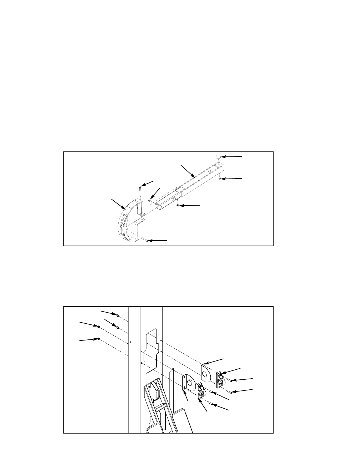
Cybex MG 500 Multi-Gym Owner’s Manual
Assembly
Page 6-68
Figure 11
Figure 12
A31
A24
A38
A38
A41
A25
A27
A39
A39
A39
A39
A27
A38
A38
A38
A38
A52
A44
6. Install pressing arm (see steps 6A - 6K, Figures 11 - 13).
A. Locate detent plate (#A25), pivot arm (#A24), two pillow block bearings (#A27),
pressing arm (#A19), shaft (#A16), two vinyl end caps (#A1), one SHCS .375-16 x 3.00
(#A31), one SHCS .375-16 x 2.75 (#A41), four SHCS .375-16 x 1.25 (#A39), six nylon
locknuts (#A38), one SHCS .375-16 x .625 (#A52), one bumper (#A44) and two guards
(#A61).
B. Attach detent plate (#A25) to pivot arm (#A24) as shown in Figure 11 (warning decal
faces upward), using SHCS .375-16 x 3.00 (#A31), SHCS .375-16 x 2.75 (#A41) and
two nylon locknuts (#A38).
C. Install bumper (#A44) with SHCS .375-16 x.625 (#A52).
D. Install pillow block bearings (#A27) and guards (#A61) as shown in Figure 12 using four
SHCS .375-16 x 1.25 (#A39) and four nylon locknuts (#A38). Be sure set screws (on
pillow blocks) are located on the outside. NOTE: Do not securely tighten screws
(#A39) at this time.
A61
A61
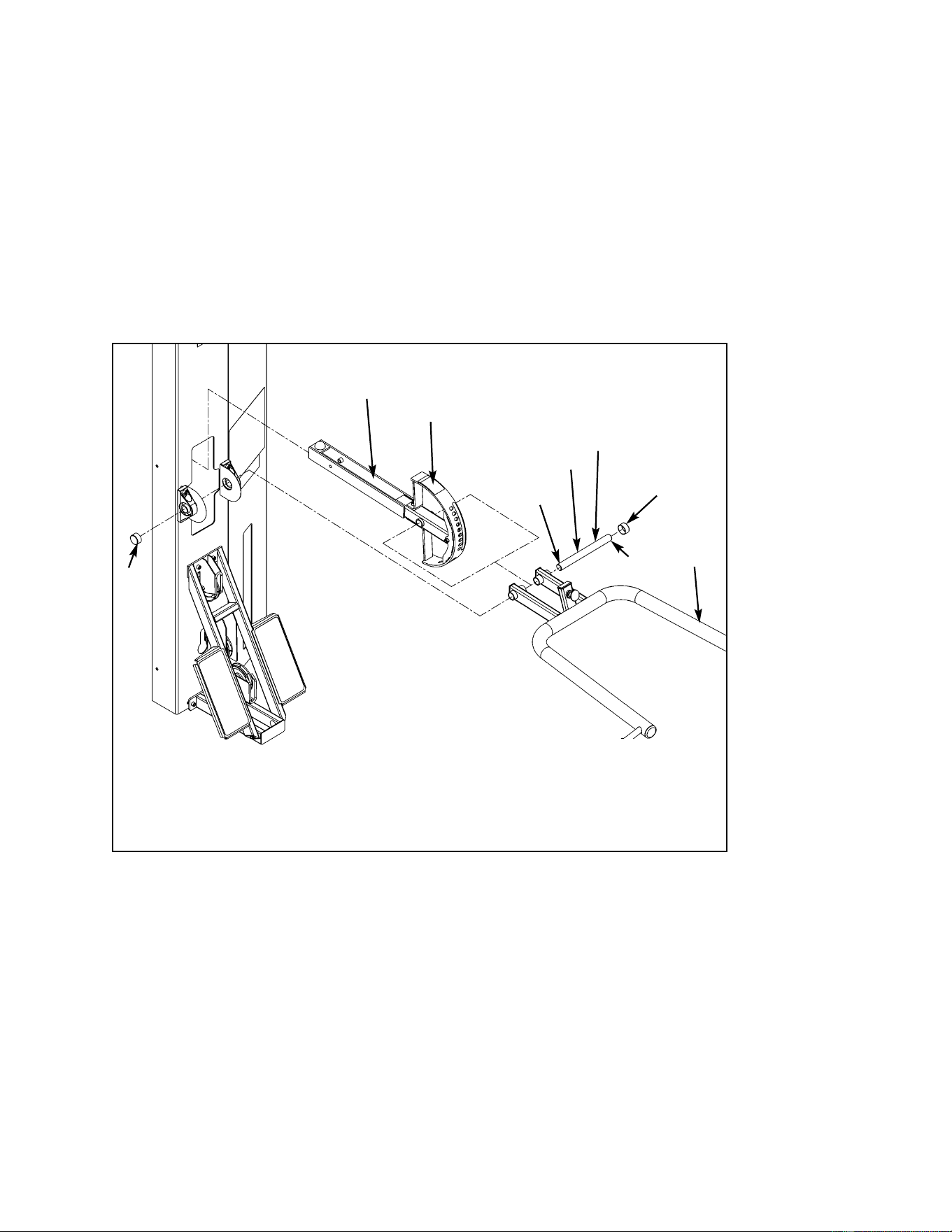
Cybex MG 500 Multi-Gym Owner’s Manual
Assembly
Page 6-69
Figure 13
A24
A25
A16
A1
A19
A1
Apply loctite
to outside
edge of shaft.
Loctite
Loctite
E. Verify set screws are loose in pillow block bearings.
F. With an assistant, carefully place pivot arm (#A24) detent plate (#A25) through slot in
column, then align pressing arm (#A19) into place and slide shaft (#A16) through pillow
block bearing, pressing arm, pivot arm and to the other side through pivot arm,
pressing arm and pillow block bearing. See Figure 13.
! WARNING: Arm will drop when detent pin is pulled out. Be sure detent pin is
fully engaged during assembly. Failure to do so could result in
personal injury.
G. Position shaft and arm so that the arm is centered on the shaft.
H. Securely tighten the four pillow block bearing bolts.
I. Tighten pillow block bearing set screws.
J. With an assistant holding the arm, pull out detent pin and lower arm to lowest position
and engage detent pin.
K. Apply loctite around outside edge of shaft (#A16). Slide a vinyl end cap (#A1) on each
end of shaft (#A16).
! WARNING: Arm will drop when detent pin is
pulled out. Be sure detent pin is
fully engaged during assembly.
Failure to do so could result in
personal injury.

Cybex MG 500 Multi-Gym Owner’s Manual
Assembly
Page 6-70
7. Install weight stack cable (see steps 7A - 7I and Figure 14). NOTE: The letters in Figure
14 refer to the steps below (order of when the pulleys are installed and how the cable is
routed).
From the Pressing Station hardware pack, locate weight stack cable (#A49), one pulley
(#A4), one SHCS .375-16 x 3.00 (#A31), one nylon locknut .375-16 (#A38), one hex nut
.375-16 (#A53) and one jam nut .375-16 (#A54). From the main frame hardware pack,
locate four pulleys (#E1), two SHCS .375-16 x 1.75 (#E39), one SHCS .375-16 x 2.50
(#E41), one SHCS .375-16 x 3.00 (#E33), four nylon locknuts .375-16 (#E34), one
adjuster (#E14), one pulley tab (#E19), two spacers (E#8) and one cable retainer (#E44).
A. Install threaded end of cable (#A49) into location shown in Figure 14, letter A. Place
hex nut (#A53) then jam nut (#A54) on cable. Install jam nut so that it is flush with
cable end and snug hex nut up to jam nut.
B. The first pulley is the hanging pulley. Do not install this pulley at this time. Loop cable
down for the first pulley. At the same time, install the second pulley (#E1) using one
SHCS .375-16 x 2.50 (#E41) and one nylon locknut (#E34) as shown in Figure 14,
letter B.
C. At the same time route cable (#A49) down and install third pulley (#A4) using one
SHCS .375-16 x 3.00 (#E33) and one nylon locknut (#E34) as shown in Figure 14,
letter C.
D. At the same time route cable (#A49) upward and install pulley (#A1) using one
SHCS .375-16 x 1.75 (#E39) and one nylon locknut (#E34) as shown in Figure 14,
letter D.
E. Install hanging pulley bracket using one SHCS .375-16 x 3.00 (#E33), one pulley (#E1)
two spacers (#E8), one pulley tab (#E19), one adjuster (#E14), one cable retainer (#E44)
and one nylon locknut (#E34). Be sure the slotted end of the adjuster is facing
outward. Verify cable is resting between the pulley (#E1) and the retainer tab. See
Figure 14, letter E.
F. At the same time, route cable (#A49) and install fifth pulley (#E1) using one
SHCS .375-16 x 1.75 (#E39) and one nylon locknut (#E34). See Figure 14, letter F.
G. Route cable (#A49) down to top weight. Place rubber boot (#E3) onto cable and slide
cable end into stem of top weight. Drive the spiral pin into top weight/cable end to
secure cable.
H. Place rubber boot (#E3) over stem of top weight.
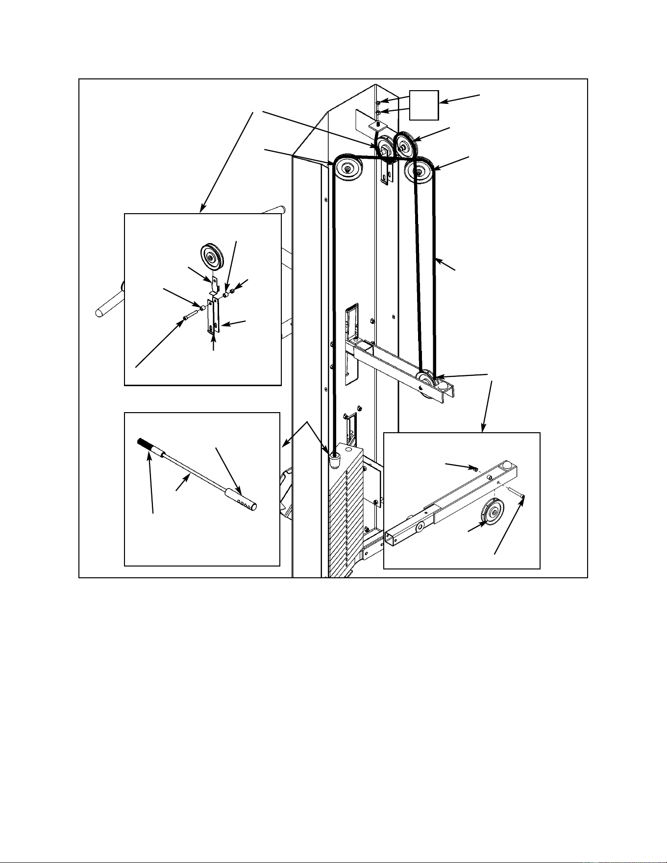
Cybex MG 500 Multi-Gym Owner’s Manual
Assembly
Page 6-71
Figure 14
F
A
E
B
D
C
A4
A38
A31 (SHCS .375-16 x 3.00)
E34
E8
E33 (SCHS .375-16 x 3.00)
E14
E19
G, H
Weight Stack
Connector
Threaded End
Connector
A49
A49
A54
A53
E8
E44

Cybex MG 500 Multi-Gym Owner’s Manual
Assembly
Page 6-72
8. Install the other cable for the Pressing Station (see steps 8A - 8H and Figure 15).
From the Pressing Station hardware pack, locate cable (#A50), three pulleys (#A1), two
SHCS .375-16 x 1.75 (#A40), one SHCS .375-16 x 2.75 (#A14) and three nylon locknuts
.375-16 (#A38). From the main frame hardware pack, locate three pulleys (#E1), one cable
retainer (#E44), two SHCS .375-16 x 1.75 (#E39) three nylon locknuts .375-16 (#E34), one
cam bolt (#E13) and one flat washer (#E37).
A. Start routing cable (#A50) as shown in Figure 15, letter A.
B. At the same time, install first pulley (#A4) onto the swivel bracket (#A22) and route
cable (#A50) using one SHCS .375-16 x 1.75 (#A40) and one nylon locknut (#A38).
See Figure 15, letter B.
C. At the same time, install second pulley (#A4) using one SHCS .375-16 x 2.75 (#A14)
and one nylon locknut (#A38) and route cable. See Figure 15, letter C.
D. At the same time, install third pulley (#E1) and route cable (#A50) using one
SHCS .375-16 x 1.75 (#A40) and one nylon locknut (#E34). See Figure 15, letter D.
E. Route cable (#E50) up to hanging pulley bracket and install pulley (#E1) and cable
retainer (#E44) using the cam bolt (#E13), washer (#E37) and nylon locknut (#E34) and
route cable. Verify cable is routed between the pulley (#E1) and the retainer tab. See
Figure 15, letter E.
F. At the same time, install fifth pulley (#E1) and route cable (#A50) using one SHCS
.375-16 x 1.75 (#E39). See Figure 15, letter F.
G. At the same time, install the last pulley (#A4) and route cable (#A50) using one
SHCS .375-16 x 1.75 (#A40) and one nylon lock nut (#A38). See Figure 15, letter G.
H. Adjust cable using the cam bolt (#E13) installed in step E to remove slack.
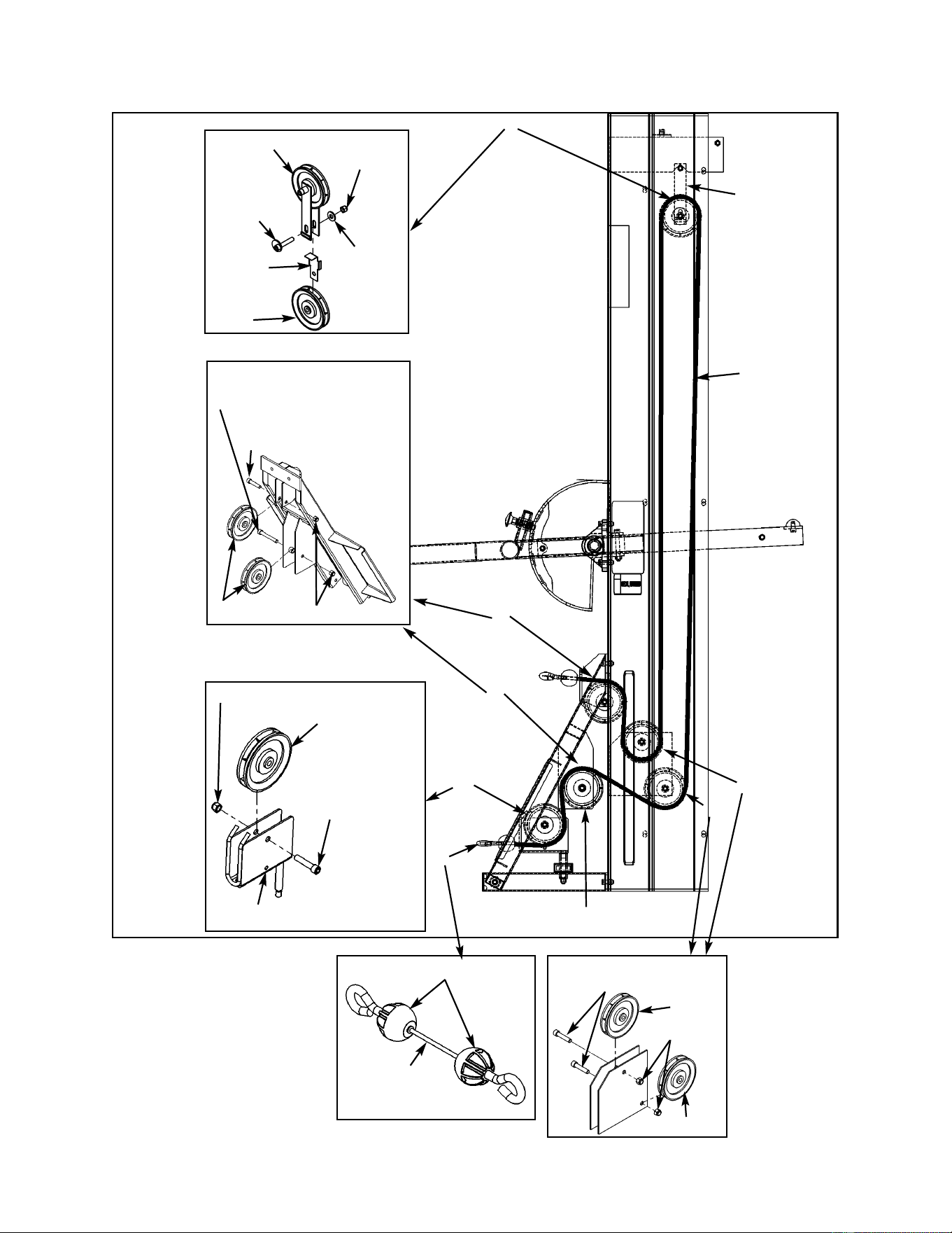
Cybex MG 500 Multi-Gym Owner’s Manual
Assembly
Page 6-73
Figure 15
E
F
G
C
D
B
A
A40
(SHCS .375-16 x 1.75)
A38
A4
A4
A38
A40
(SHCS .375-16 x .175)
E34
E1
E1
E39
(SHCS .375-16 x 1.75)
E1
E1
E13
E37
E34
A41
(SHCS .375-16 x 2.75)
Same Cable End
A50
A22
Hanging
Pulley
Bracket
A22
A50
E44
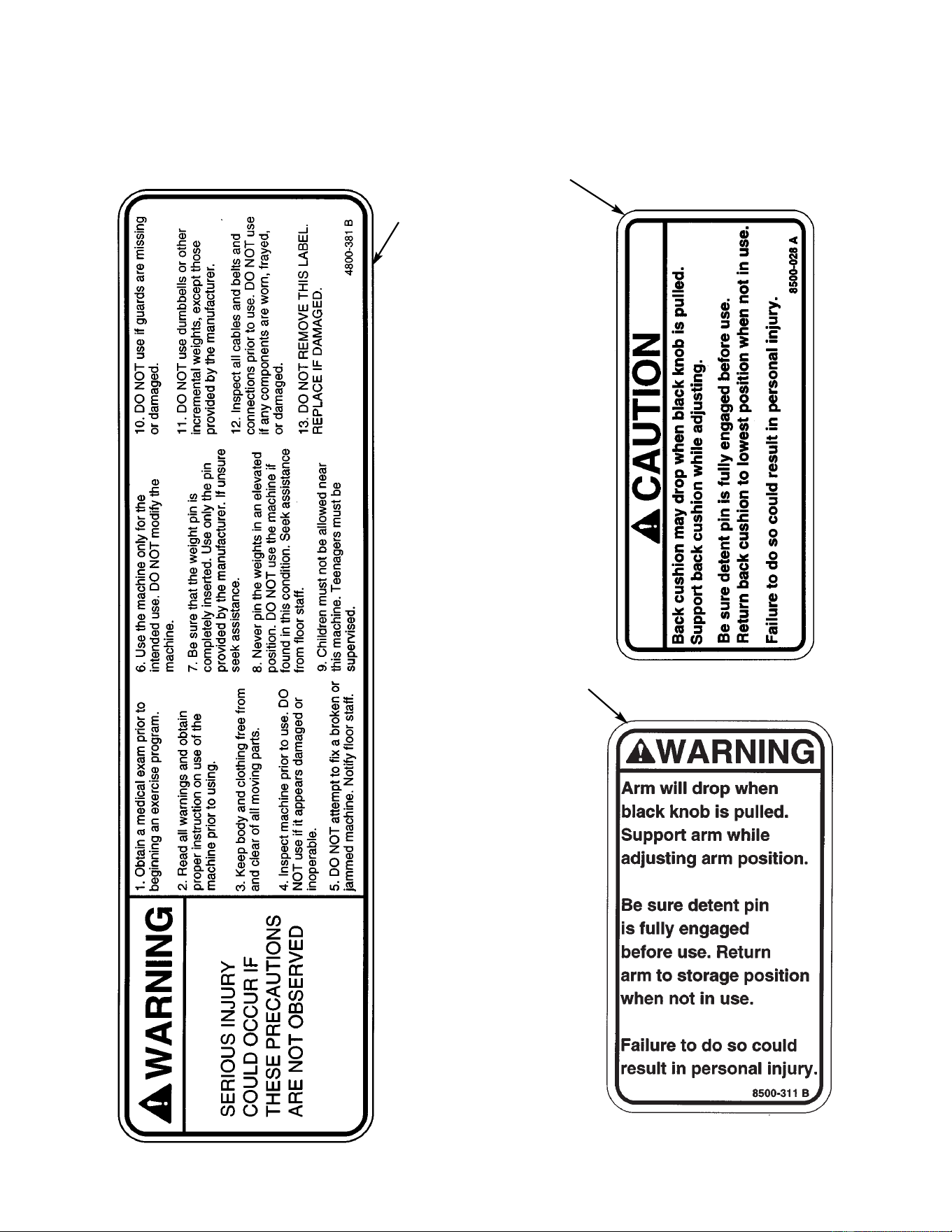
Cybex MG 500 Multi-Gym Owner’s Manual
Assembly
Page 6-74
A
C
B
9. Verify all warning and caution decals are present and not damaged (see decals below
and Figure 16).
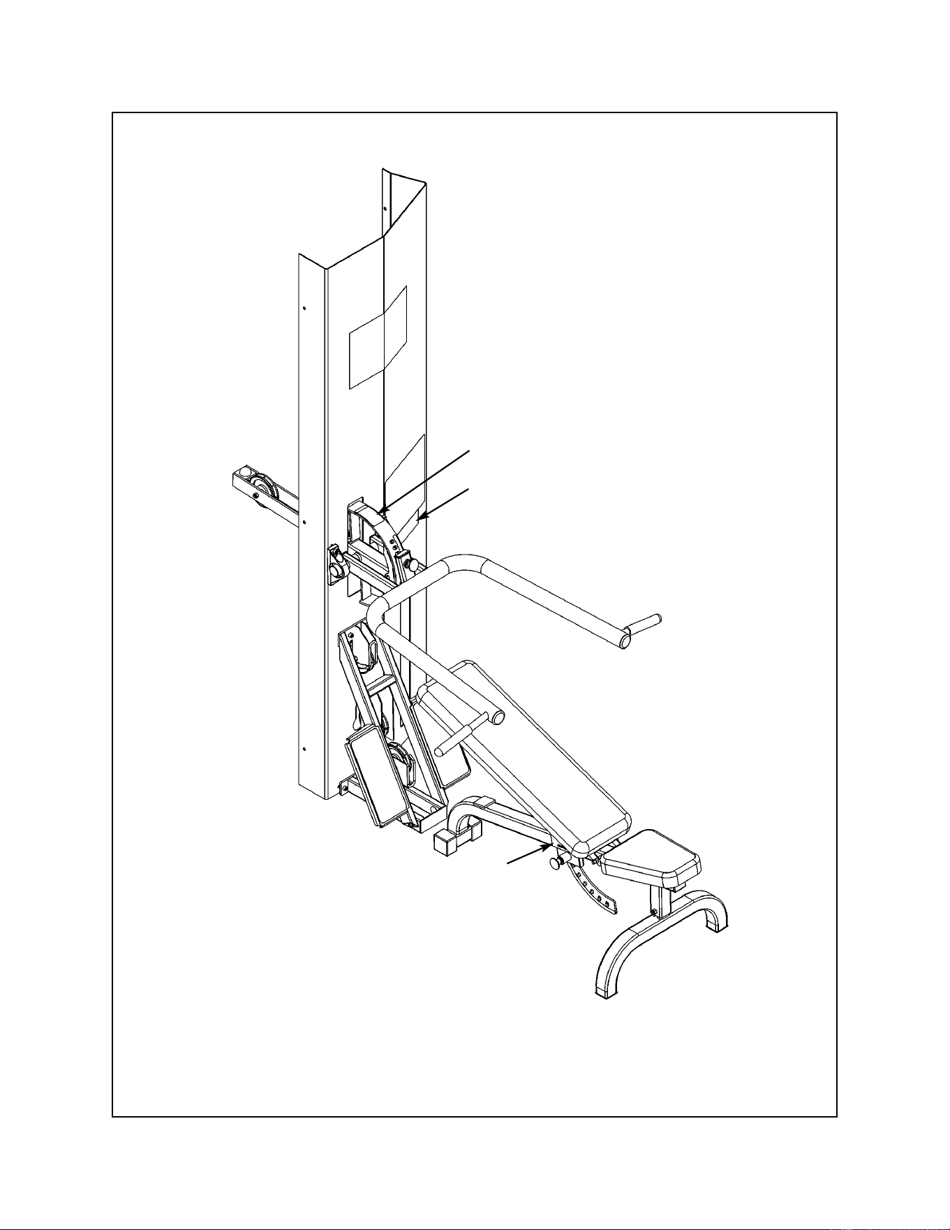
Cybex MG 500 Multi-Gym Owner’s Manual
Assembly
Page 6-75
A. Warning Decal ................... 4800-381
B. Caution Decal ................... 8500-028
C. Warning Decal.................... 8500-311
DESCRIPTION PART NO.
C
A
B
Figure 16
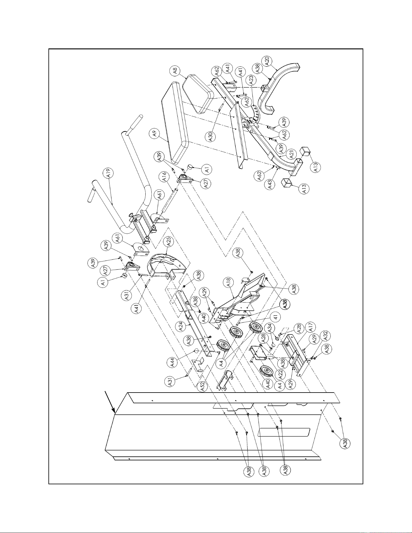
Cybex MG 500 Multi-Gym Owner’s Manual
Assembly
Page 6-76
Column
Pressing Station Exploded-View Diagram

Cybex MG 500 Multi-Gym Owner’s Manual
Assembly
Page 6-77
A1 2 01190 Vinyl Black End Cap
A4 4 02205 Pulley
A8 1 4800-019 Seat Cushion
A9 1 4800-009 Back Cushion
A13 2 8510-344 Rubber Cap
A16 1 8610-308 Shaft
A17 1 8610-203 Brace
A18 1 8610-204 Platform
A19 1 8610-201 Pressing Arm
A20 1 8610-207 Leg
A21 1 8610-210 Bench Frame
A22 1 8610-205 Swivel Pulley Bracket
A23 1 8510-208 Cushion Plate
A24 1 8610-202 Pivot Arm
A25 1 8510-210 Detent Plate
A26 2 GQ000206 Snap Link
A27 2 HB-60652 Pillow Block Bearing
ITEM QTY PART NO. DESCRIPTION
Pressing Station Parts List (not all parts are listed such as pulleys for inside of MG 500 and handles). See
Chapter 8 for a complete parts listing.
A28 2 HC702815 SHCS .375-16 x .750
A29 4 HC702816 SHCS .375-16 x .875
A30 1 HC702830 SHCS .375-16 x 2.50
A31 4 HC702834 SHCS .375-16 x 3.00
A32 1 HS347600 Flat Washer .375
A34 2 PN660200 Plastic Insert 1.00 Dia. x 11 G
A38 18 HN704901 Nylon Locknut .375-16
A39 6 JC702820 SHCS .375-16 x 1.25
A40 2 JC702824 SHCS .375-16 x 1.75
A41 2 JC702832 SHCS .375-16 x 2.75
A43 1 HC702817 SHCS .375-16 x 1.00
A44 1 4505-331 Bumper
A52 1 JC702814 SHCS .375-16 x .625
A53 1 HN704000 Hex Nut .375-16
A54 1 HN704400 Jam Nut .375-16
A61 2 8610-330 Guard
A62 5 JS347400 Internal Tooth Lockwasher
ITEM QTY PART NO. DESCRIPTION

Cybex MG 500 Multi-Gym Owner’s Manual
Assembly
Page 6-78
This page intentionally left blank
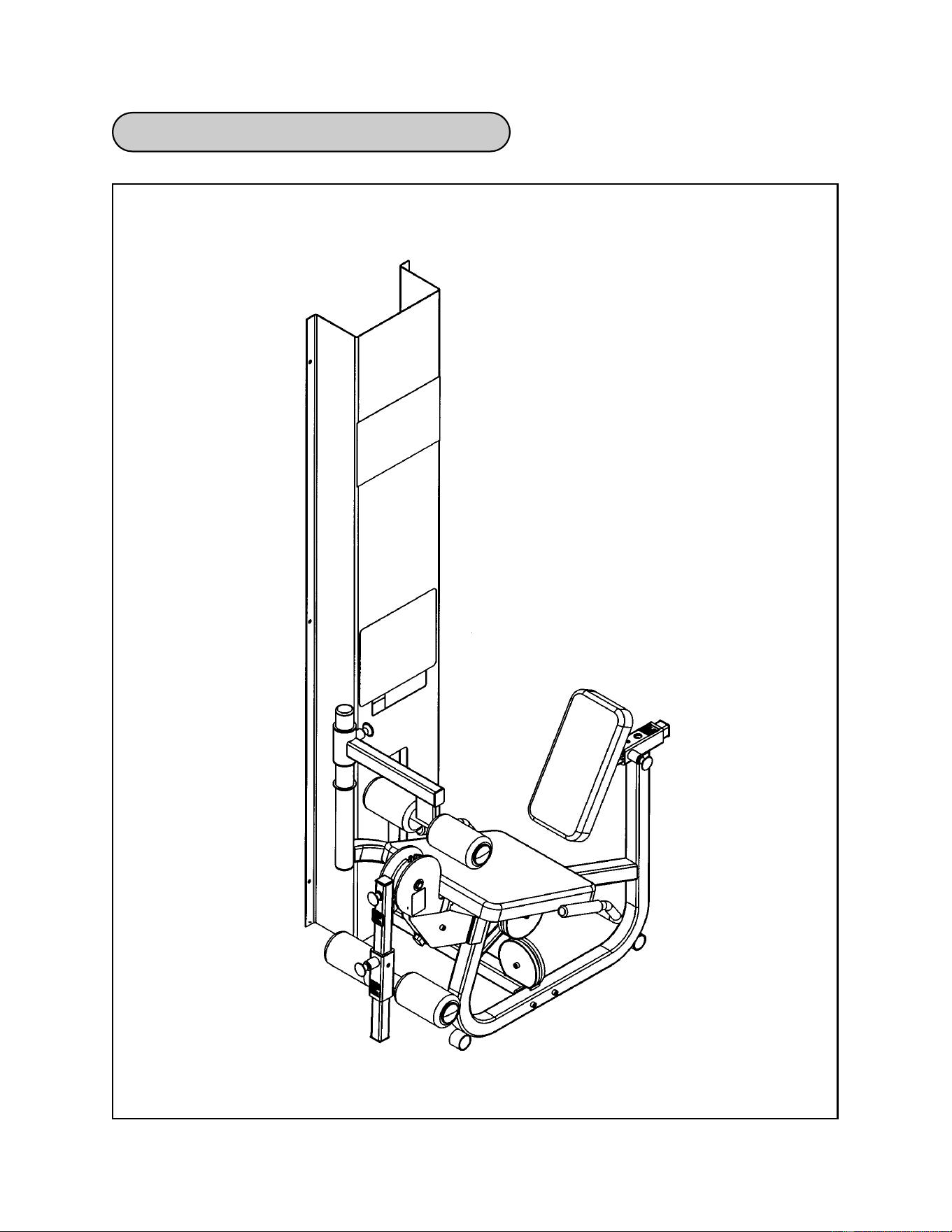
Cybex MG 500 Multi-Gym Owner’s Manual
Assembly
Page 6-79
Leg Extension/Leg Curl Station Diagram

Cybex MG 500 Multi-Gym Owner’s Manual
Assembly
Page 6-80
1. Verify contents of the Leg Extension/Leg Curl Station boxes (see steps 1A - 1C and
Figures 1-3).
A. Locate the Leg Extension/Leg Curl box (containing the frame).
B. Locate the Leg Extension/Leg Curl Station cushion box (removed from the main frame
assembly).
C. Verify contents of both boxes. See Figures 1-3.
Leg Extension/Leg Curl Station Assembly
D9 1 4850-202 Right Handle
D10 1 4850-203 Left Handle
D13 4 4800-135 Round Cushion w/Wear Cover
D14 1 8520-308 Leg Curl Tube
D19 1 8640-002 Cable 132.12 L
D20 1 8640-003 Cable 83.49 L
D21B 1 8640-213 Frame
D22 1 8640-201 Cushion Post (for Back Cushion)
D23 1 8640-202 Cam
D24 Removed 3/20/01
D25 1 8640-204 Adjuster
D26 Removed 3/20/01
D27 1 8640-206 Leg
D28 1 8640-207 Brace
D29 Removed 3/20/01
D46 4 PP080223 Plastic Insert
D49 1 4800-021 Back Cushion
D50B 1 4800-074 Seat Cushion
D58 1 02120 Pulley Mount
D60 1 8640-211 Cushion Bracket
D61 1 8640-212 Cushion Post
D62 1 8640-214 Leg Bar
D63 1 8640-334 Support Plate
1 Hardware Pack
ITEM QTY PART NO. DESCRIPTION
Figure 1
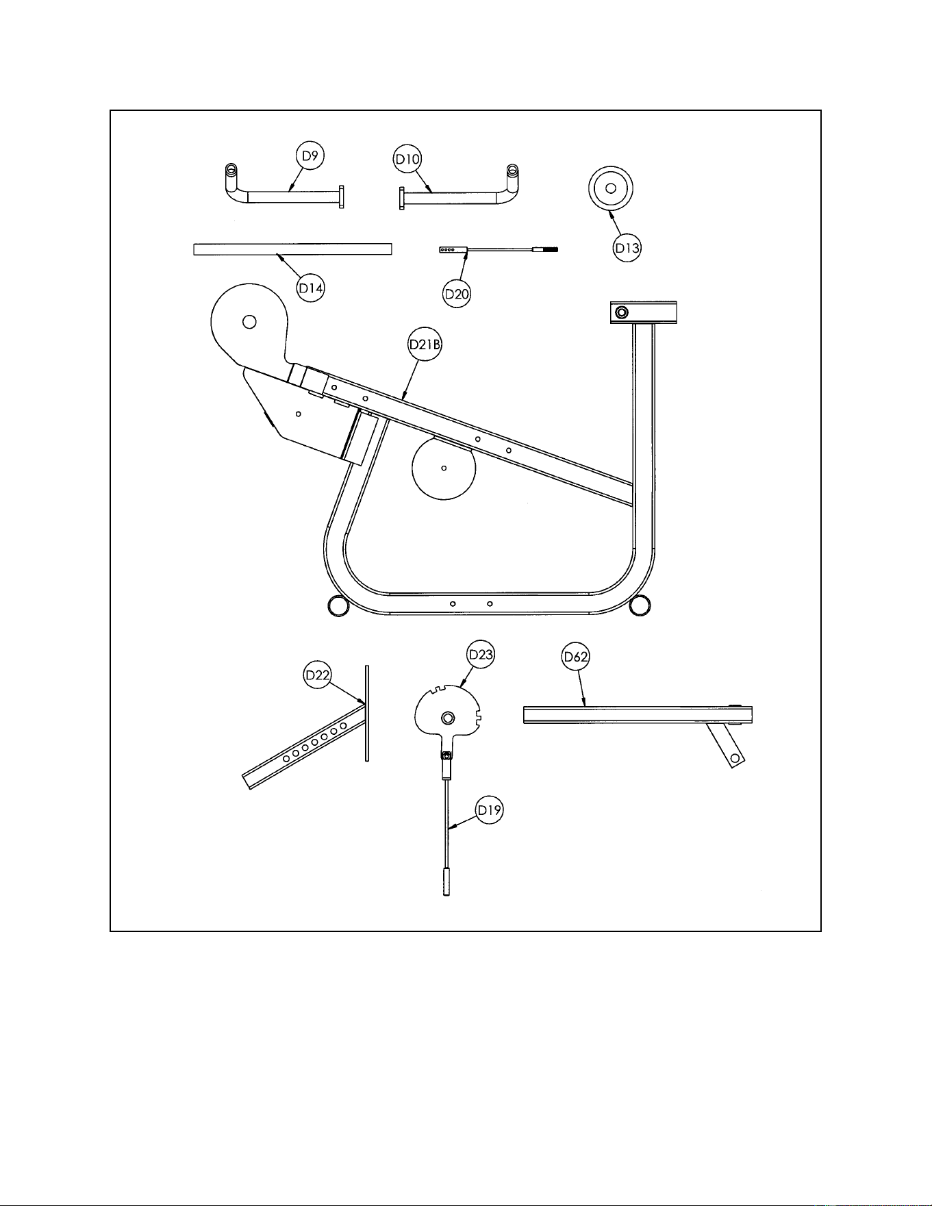
Cybex MG 500 Multi-Gym Owner’s Manual
Assembly
Page 6-81
Figure 2
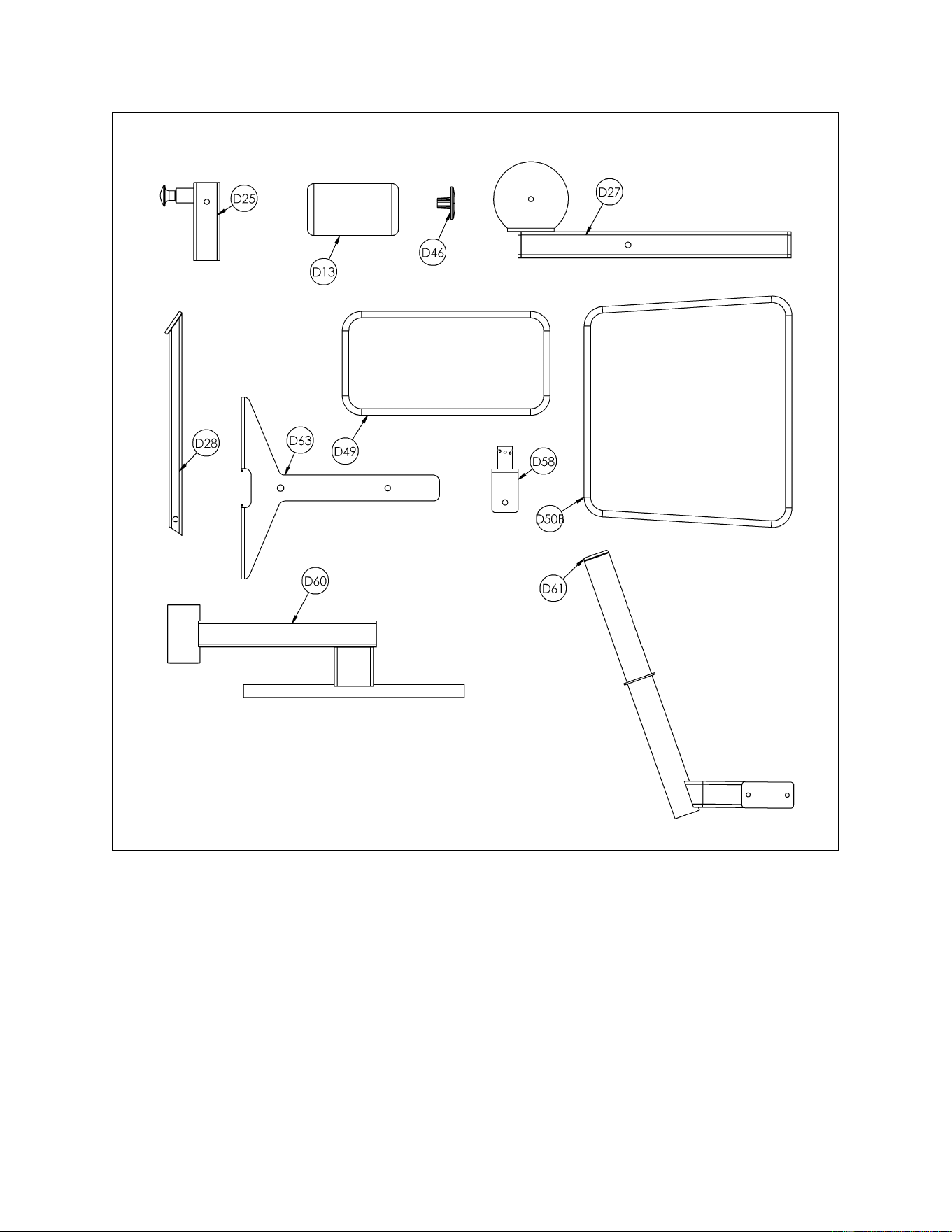
Cybex MG 500 Multi-Gym Owner’s Manual
Assembly
Page 6-82
2. Verify contents of the Leg Extension/Leg Curl hardware pack (see steps 2A, 2B,
Figures 3 and 4).
A. Locate hardware pack.
B. Verify contents of hardware pack. If desired, sort out hardware into different
containers. Do not combine hardware with other hardware packs. See Figures 3
and 4 for contents of hardware pack.
Figure 3
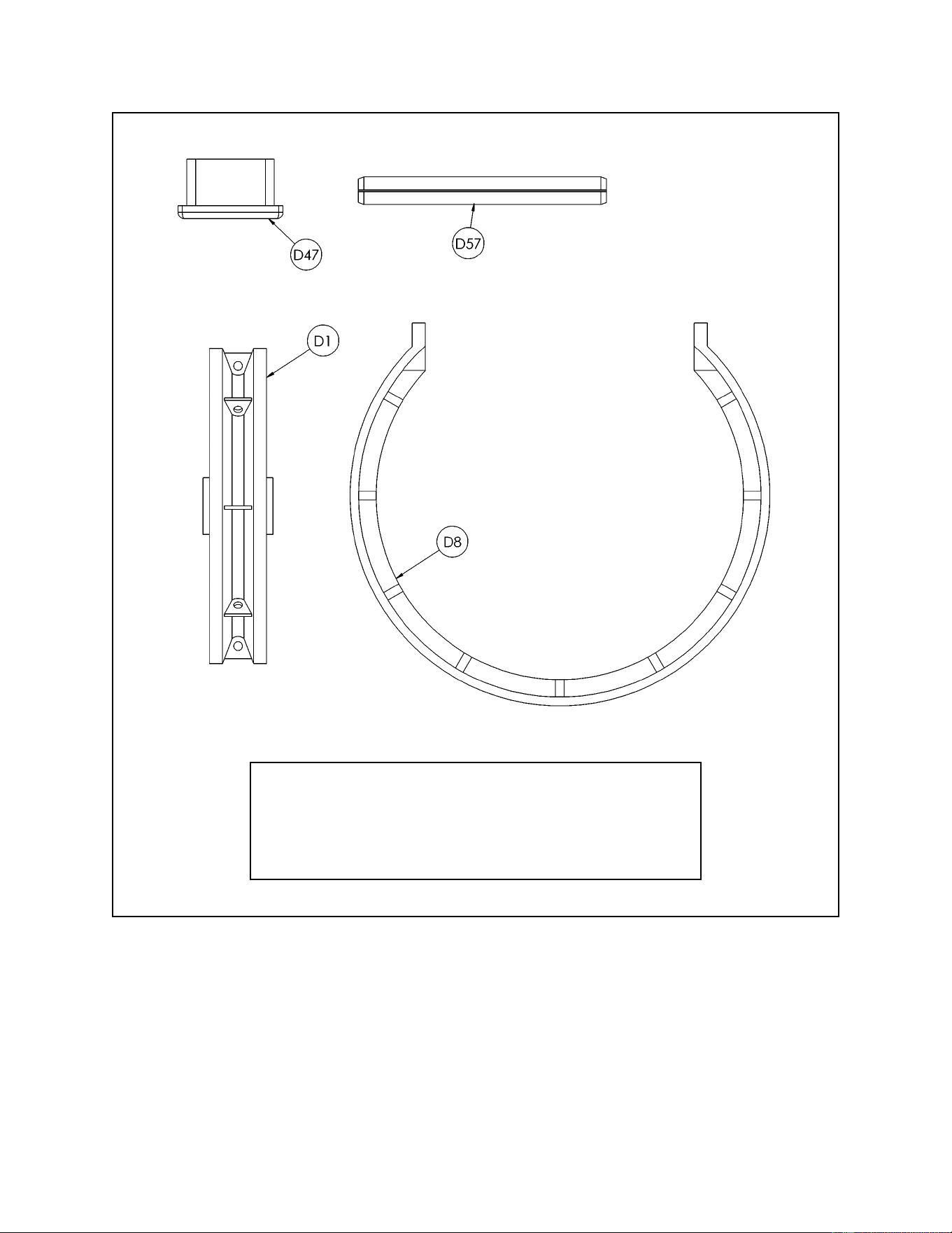
Cybex MG 500 Multi-Gym Owner’s Manual
Assembly
Page 6-83
Figure 4
D1 4 08014 Pulley
D8 2 4800-570 Cable Guard
D47 1 PP090211 Plastic Insert 1.50 Sq x 10-14 G
D57 1 8640-330 Spring Pin (used to pin 2nd weight)
ITEM QTY PART NO. DESCRIPTION
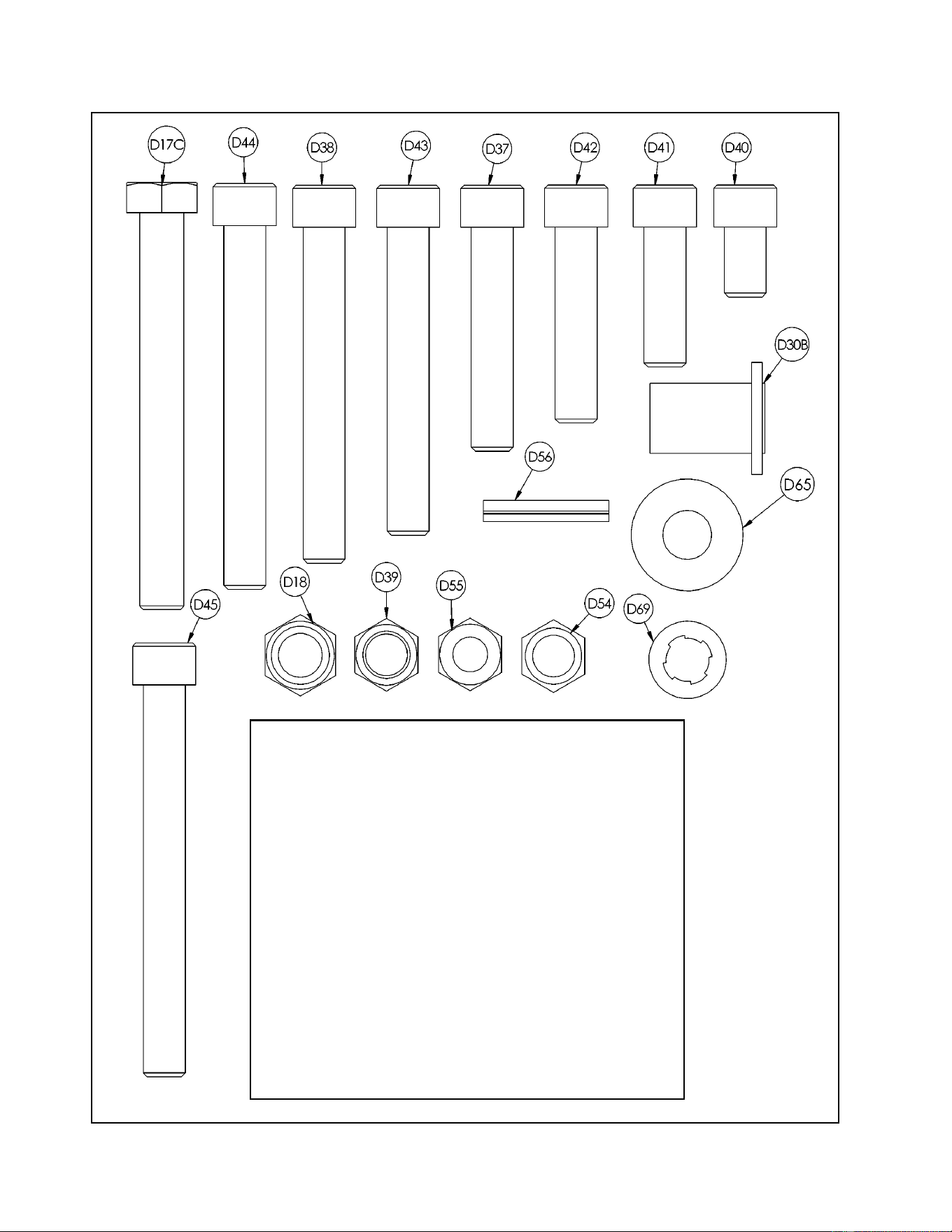
Cybex MG 500 Multi-Gym Owner’s Manual
Figure 5
D17C 1 HC331269 HHCS 10 mm x 90 mm
D18 1 8630-336 Nylon Locknut 10 mm
D30B 2 8640-347 Insert
D31 Removed 3/20/01
D37 2 HC702826 SHCS .375-16 x 2.00
D38 2 HC702834 SHCS .375-16 x 3.00
D39 12 HN704901 Nylon Locknut
D40 1 JC702814 SHCS .375-16 x .625
D41 4 JC702820 SHCS .375-16 x 1.25
D42 2 JC702824 SHCS .375-16 x 1.75
D43 4 JC702832 SHCS .375-16 x 2.75
D44 2 JC702836 SHCS .375-16 x 3.25
D45 1 JC702838 SHCS .375-16 x 3.50
D54 1 HN704000 Hex Nut .375-16
D55 1 HN704400 Jam Nut .375-16
D56 1 HP286819 Spiral Pin .188 x 1.12
D65 2 HS347700 Washer
D69 6 JS347400 Internal Tooth Lockwasher
ITEM QTY PART NO. DESCRIPTION
Assembly
Page 6-84
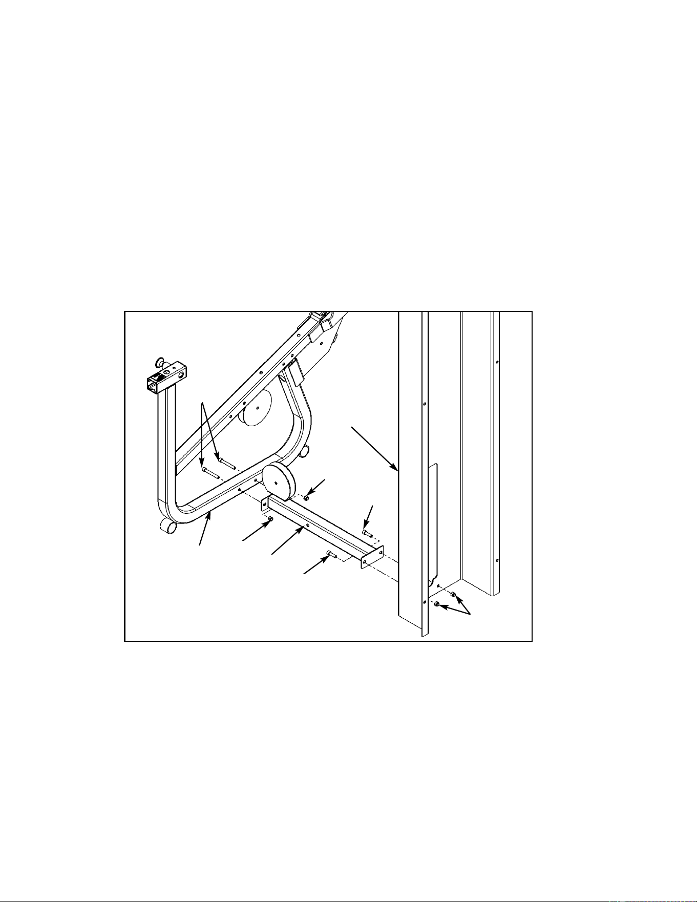
Cybex MG 500 Multi-Gym Owner’s Manual
Assembly
Page 6-85
Figure 6
D41
D39
Column
D43
3. Assemble leg and seat frame to column (see steps 3A - 3D and Figure 6).
A. Locate leg (#D27), two SHCS .375-16 x 1.25 (#D41) and two nylon lock nuts (#D39).
B. Attach leg (#D27) to column using two SHCS .375-16 x 1.25 (#D41) and two nylon
locknuts (#D39) as shown in Figure 4. NOTE: Do not securely tighten hardware at this
time.
C. Locate seat frame (#D21B), two SHCS .375-16 x 2.75 (#D43) and two nylon locknuts
(#D39).
D. Attach seat frame (#D21B) to leg (#D27) using two SHCS .375-16 x 2.75 (#D43) and
two nylon locknuts (#D39) as shown in Figure 4. NOTE: Do not securely tighten
hardware at this time.
D41
D39
D39
D27
D21B
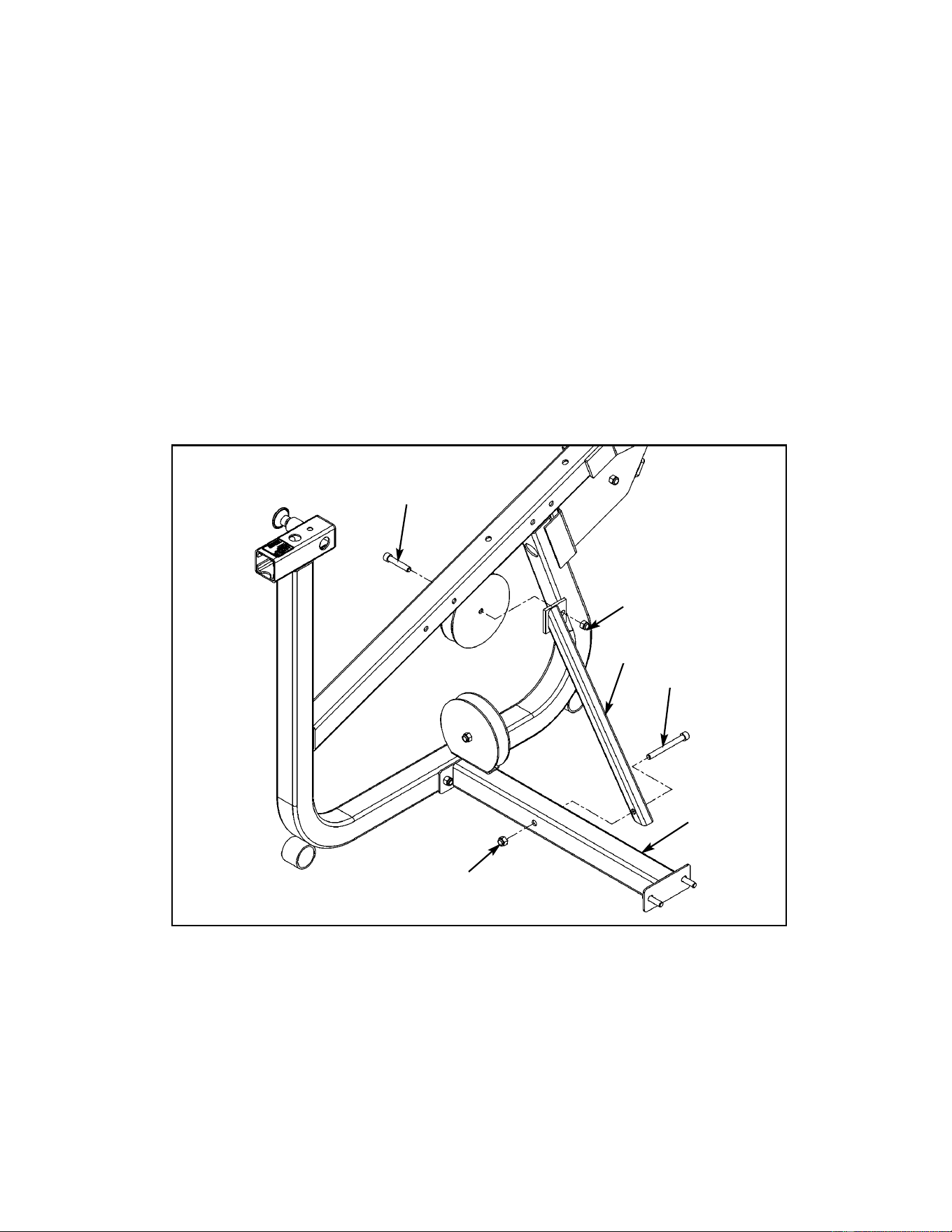
Cybex MG 500 Multi-Gym Owner’s Manual
Figure 7
D37
Assembly
Page 6-86
4. Install brace (see steps 4A - 4D and Figure 7).
A. Locate brace (#D28), one SHCS .375-16 x 3.50 (#D45), one SHCS .375-16 x 2.00
(#D37) and two nylon locknuts .375-16 (#D39).
B. Attach lower portion of brace (#D28) to leg (#D27) using SHCS .375-16 x 3.50 (#D45)
as shown in Figure 7.
C. Attach top end of brace (#D28) using one SHCS .375-16 x 2.00 (#D37) as shown in
Figure 7.
NOTE: Do not tighten SHCS (#D37 and #D45) at this time as the SHCS (#D37) will
need to be removed when installing the pulley.
D. Securely tighten hardware from step #3 on previous page.
D45
D39
D39
D28
D27
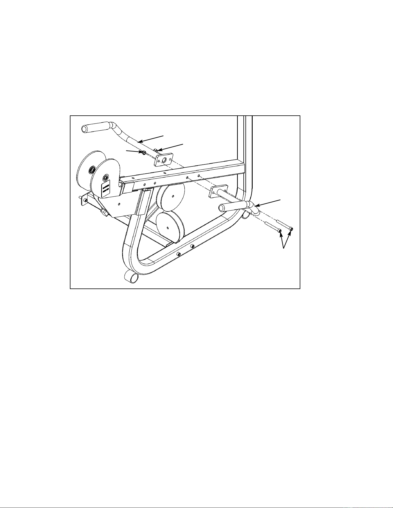
Cybex MG 500 Multi-Gym Owner’s Manual
Assembly
Page 6-87
Figure 8
D39
D39
D44
5. Install left and right handles (see steps 5A, 5B and Figure 8).
A. Locate (user position) right handle (#D9), left handle (#D10), two SHCS .375-16 x 3.25
(#D44) and two nylon locknuts .375-16 (#D39).
B. Install left and right handles (#D9 and #D10) using two SHCS .375-16 x 3.25 (#D44)
and two nylon locknuts (#D39) as shown in Figure 8.
D9
D10
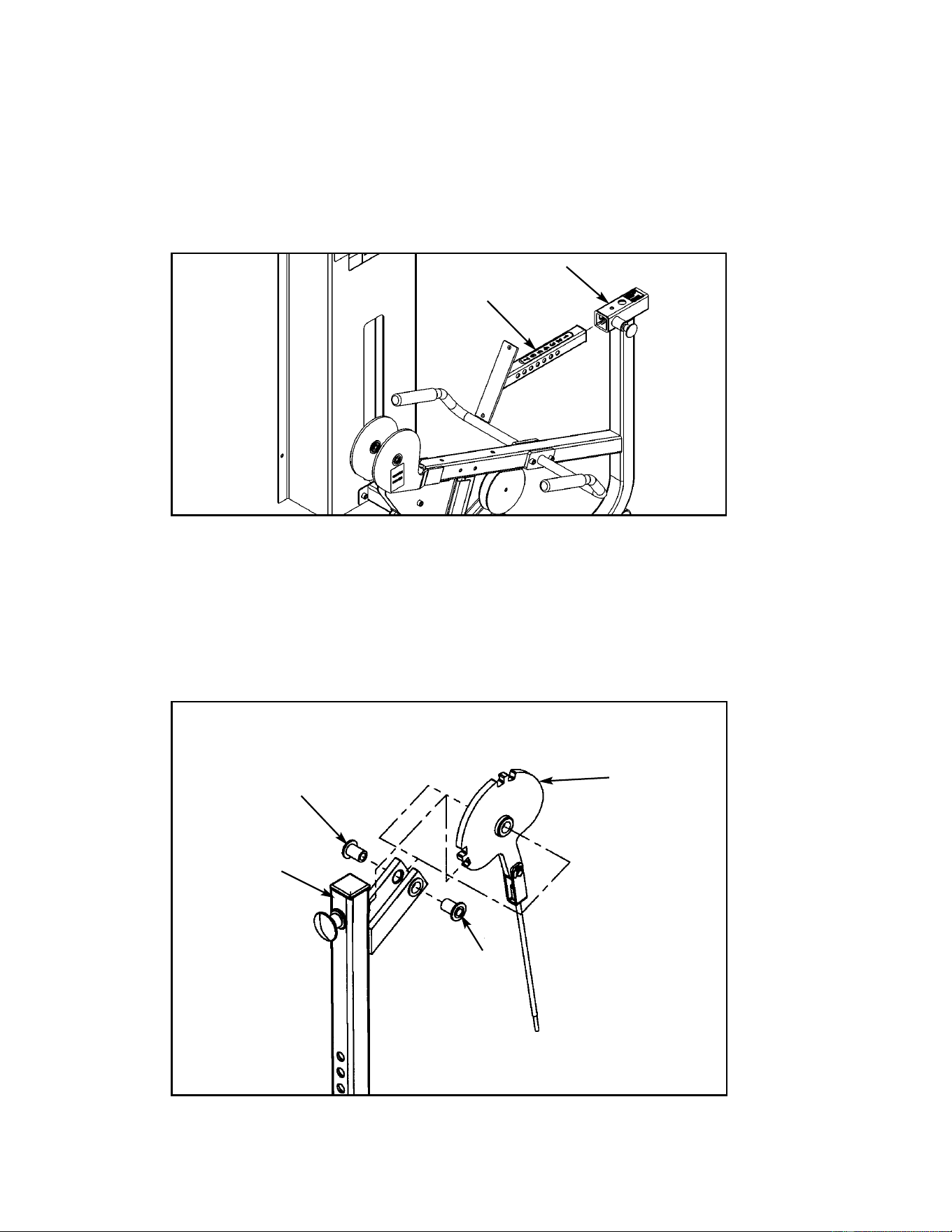
Cybex MG 500 Multi-Gym Owner’s Manual
Assembly
Page 6-88
Figure 10
D30B
D62
D30B
D23
7. Install cam assembly (see steps 7A - 7D, Figures 10 and 11).
A. Locate cam (#D23) and two inserts (#D30B).
B. Attach cam (#D23) to leg bar (#D62) using two inserts (#D30B) as shown in Figure 10.
Figure 9
D21B
D22
6. Install cushion post to seat frame (see steps 6A, 6B and Figure 9).
A. Locate cushion post (#D22).
B. Pull detent pin and slide cushion post (#D22) into seat frame (#D21B) as shown in
Figure 9.
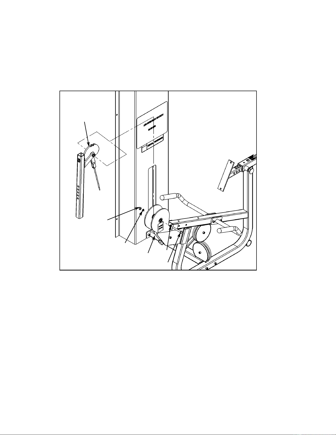
Cybex MG 500 Multi-Gym Owner’s Manual
Assembly
Page 6-89
C. Locate one HHCS 10 mm x 90 mm (#D17C) and one nylon locknut 10 mm (#D18) and
two internal tooth lockwashers (#D69).
D. Install cam assembly onto frame (#D21B) using one HHCS 10 mm x 90 mm (#D17C),
one nylon locknut 10 mm (#D18) and two internal tooth lockwashers (#D69) as shown
in Figure 11.
Figure 11
Cam Assembly
D18
D17C
D21B
D69
D69
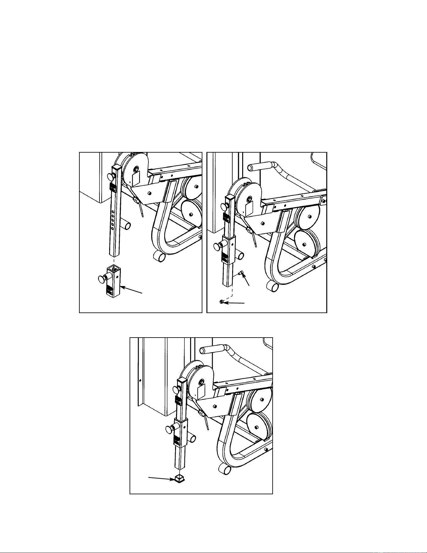
Cybex MG 500 Multi-Gym Owner’s Manual
8. Install adjuster (see steps 8A - 8D and Figures 12A - 12C).
A. Locate adjuster (#D25) and slide it onto the leg post as shown in Figure 12A.
B. Locate one SHCS .375-16 x .625 (#D40) and one nylon locknut (#D39).
C. Install SHCS .375-16 x .625 (#D40) and one nylon locknut (#D39) as shown in Figure
12B. Tighten hardware securely.
D. Locate and install the plastic insert (#D47) as shown in Figure 12C.
Figure 12A Figure 12B
Figure 12C
D25
D39
D40
D47
Assembly
Page 6-90
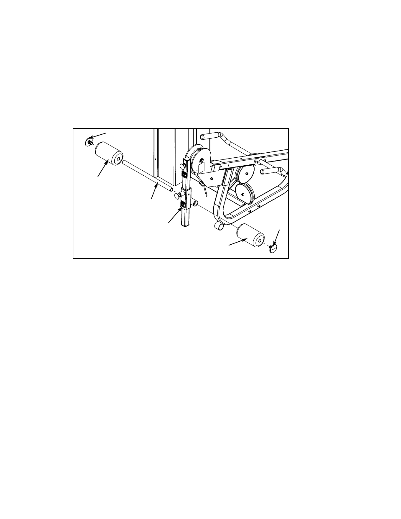
Cybex MG 500 Multi-Gym Owner’s Manual
Assembly
Page 6-91
9. Install cushions (see steps 9A - 9I, Figures 13 and 14).
A. Locate leg curl tube (#D14), two round cushions (#D13) and two plastic inserts (#D46).
B. Slide leg curl tube (#D14) onto adjuster and install both round cushions as shown in
Figure 13.
C. Install two plastic inserts (#D46) using a rubber mallet. See Figure 13.
D13
D46
D46
D13
Figure 13
D14
Adjuster
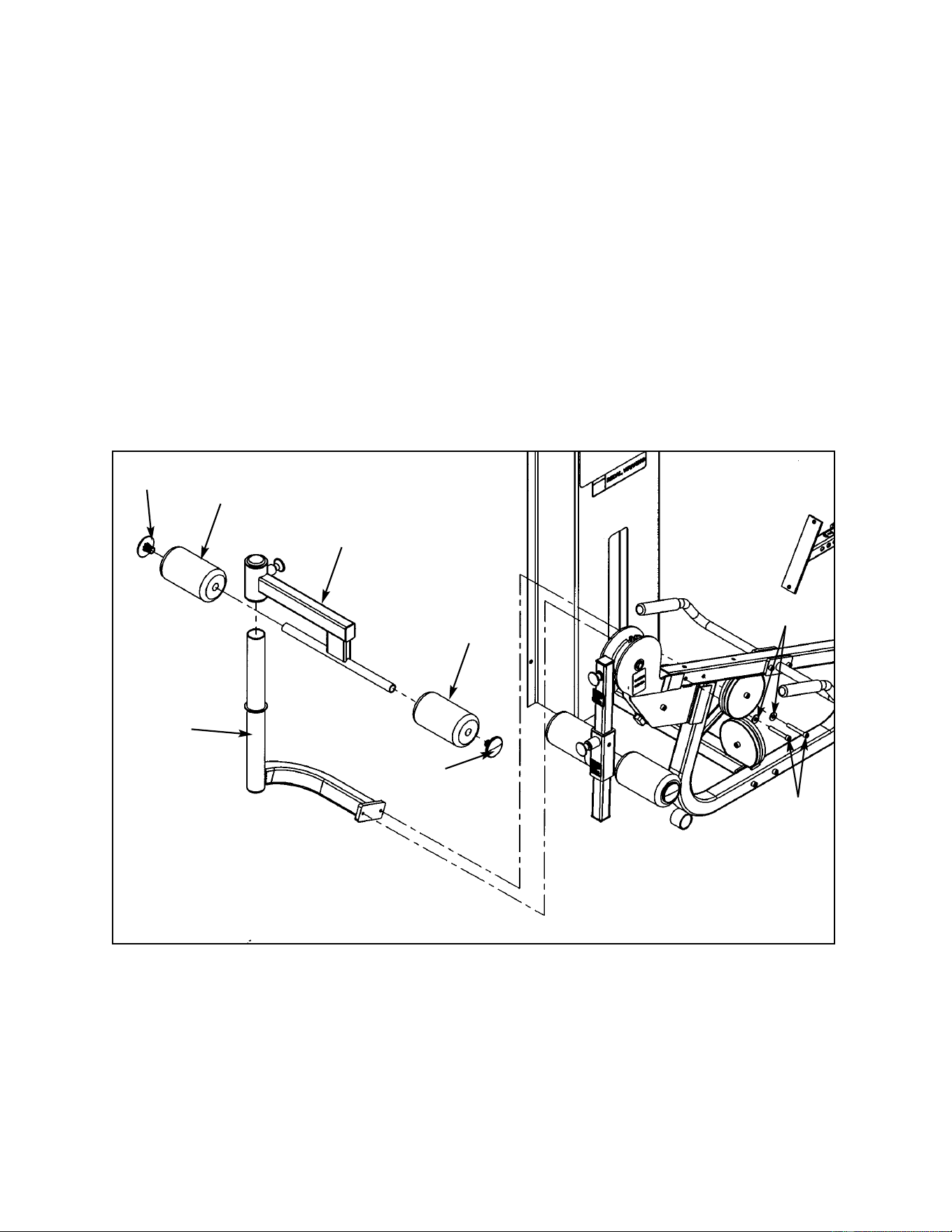
Cybex MG 500 Multi-Gym Owner’s Manual
Assembly
Page 6-92
D. Locate cushion post (#D61), two washers (#D65) and two SHCS .375-016 x 2.75
(#D43).
E. Install cushion post (#D61) using two washers (D65) and two SHCS .375-016 x 2.75
(#D43). See Figure 14.
F. Locate cushion bracket (#D60), two round cushions (#D13) and two plastic inserts
(#D46).
G. Slide both cushions (#D13) onto cushion bracket (#D60).
H. Install two plastic inserts (#D46) using a rubber mallet. See Figure 15.
I. Pull out detent pin and slide cushion bracket (#D60) onto cushion post (#D61) as
shown in Figure 14.
D61
D46
D13
D13
D46
D60
Figure 14
D65
D43
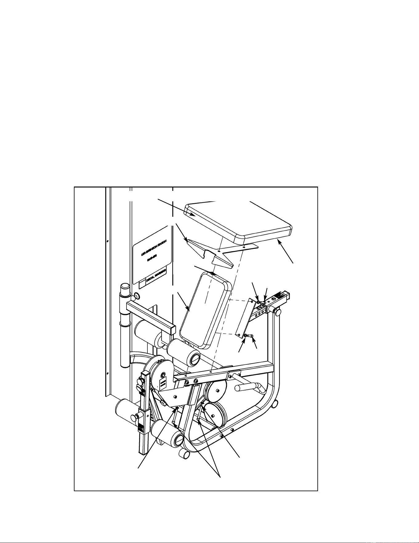
Cybex MG 500 Multi-Gym Owner’s Manual
Assembly
Page 6-93
8. Install seat and back cushions (see steps A - D and Figure 15).
A. Locate seat cushion (#D50), back cushion (#D49), two SHCS .375-16 x 3.00 (#D38),
two SHCS .375-16 x 1.25 (#D41), support plate (#63) and four internal tooth lockwash
ers (#D69).
B. Place support plate (D63) onto frame as shown in Figure 15).
C. Insert one SHCS .375-16 x 3.00 (#D38) and one internal tooth lockwasher (#D69)
through frame and cushion plate and seat cushion. Then install the other SHCS and
internal tooth lockwasher.
D. Install back cushion (#D49) using two SHCS .375-16 x 1.25 (#D41) and two internal
tooth lockwashers (#D69) as shown in Figure 15.
D49
Figure 15
D50B
D41
D41
D38
Place wide end of cushion facing front
Seam
D63
D69
D69
D69
D69

Cybex MG 500 Multi-Gym Owner’s Manual
Assembly
Page 6-94
9. Install and route cables (see steps 9A - 9M and Figure 16)
From the Leg Extension/Leg Curl hardware pack, locate weight stack cables (#D19) and
(#D20), four pulleys (#D1), two cable guards (#D8), two SHCS .375-16 x 1.75 (#D42), one
SHCS .375-16 x 2.00 (#D37), two nylon locknuts (#D39), one hex nut (#D54), one jam nut (#D55)
and pulley mount (#D55). From the main frame hardware pack, locate two pulleys (#E1), two
SHCS .375-16 x 1.75 (#E39), two nylon locknuts (#E34) and one spiral pin (#E35).
A. At the same time, install pulley (#D1) and route cable (#D19) using one SHCS
.375-16 x 1.75 (#D42) and one nylon locknut (#D39). See Figure 16, letter A.
B. Route cable (#D19) through frame. See Figure 16, letter B.
C. Remove the SHCS .375-16 x 2.00 (#D37). Loop cable (#D19) through cable guard
(#D8) and install next pulley (#D1) and cable guard (#D8) using the SHCS .375-16 x
2.00 (#D37) and nylon locknut (#D39) that was just removed. See Figure 16, letter C.
D. Loop cable (#D19) through the second cable guard (#D8) and install the next pulley
(#D1) using SHCS .375-16 x 1.75 (#D42) and one nylon locknut (#D39). See Figure 16,
letter D.
E. Route cable (#D19) to inside of column as shown in Figure 16, letter E.
F. At the same time, route cable (#D19) and install the next pulley (#E1) using one
SHCS .375-16 x 1.75 (#E39) and one nylon locknut (#E34). See Figure 16, letter F. Set
cable down.
G. Using the weight stack cable (#D20), attach one end as shown in Figure 16, letter G.
Install hex nut (#D54) first and then jam nut (#D55). Position jam nut (#D55) so it
is even with cable end.
H. The hanging pulley will be installed in the next step. At the same time, route cable
(#D20) and install the last pulley (#E1) before the weight stack, using one
SHCS .375-16 x 1.75 (#E39) and one nylon locknut (#E34). Set cable down.
I. Pick up the other cable (#D19) and install the pulley mount (#D55). Drive a spiral pin
(#D53) through cable end and pulley mount (#D55) as shown in Figure 16, letter I.
J. Wrap a portion of the weight stack cable (#D20) around the last pulley (#D1) to be
installed. At the same time, route cable (#D20) and install the last pulley (#D1) using
one SHCS .375-16 x 2.00 (#D37) and one nylon locknut (#D39). See Figure 16, letter J.
K. Slide rubber boot onto cable (#D20). Drive a spiral pin (#E35) through top weight
connector and cable (#D20). Top weight should be snug (just resting on the second
plate). See Figure 16, letter K.
L. If necessary, adjust hex nut (#D51) to remove any slack.
M. Securely tighten hardware.
NOTE: All cables will be adjusted after verification of the warning and caution decals
for the Leg Extension/Leg Curl.
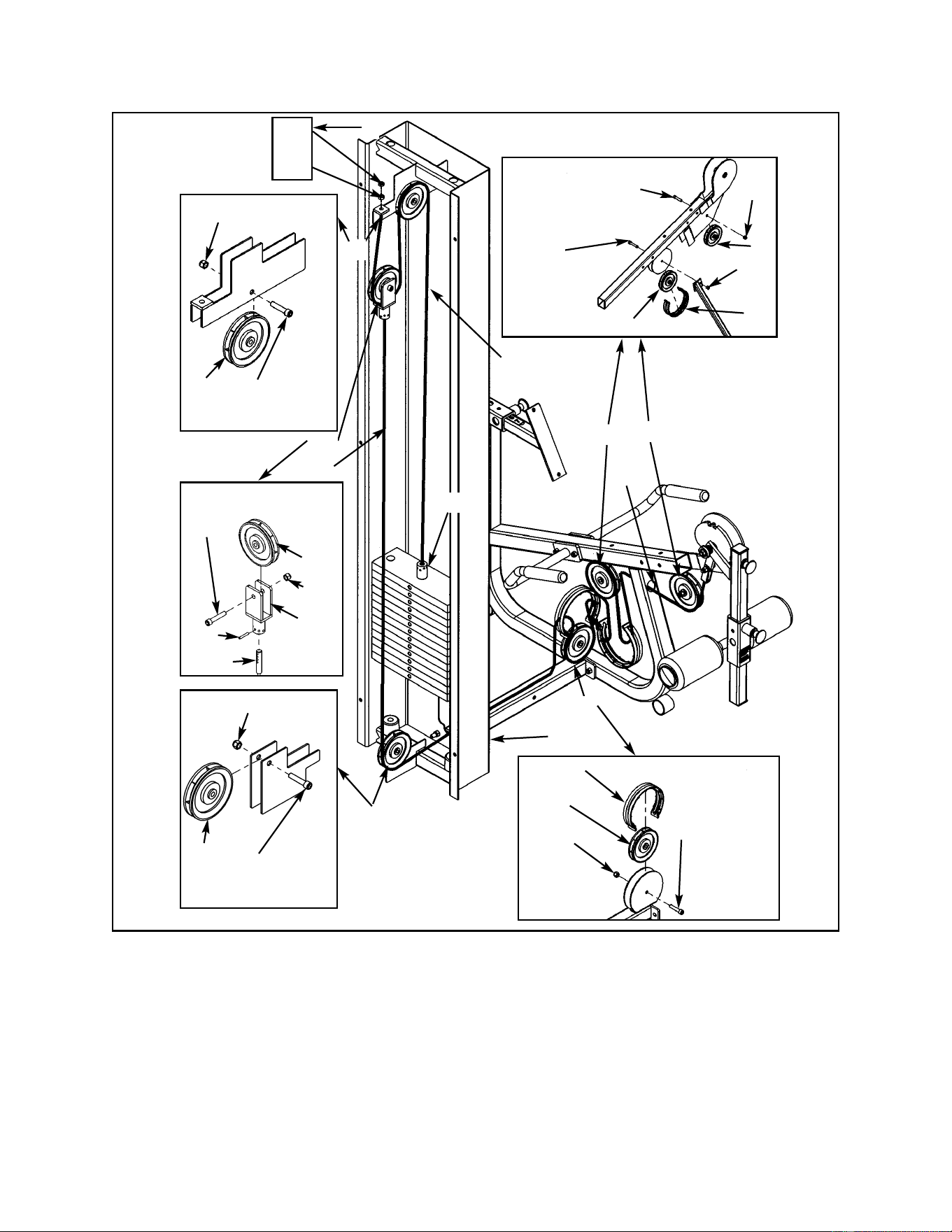
Cybex MG 500 Multi-Gym Owner’s Manual
Assembly
Page 6-95
E39
(SHCS
.375-16 x 1.75)
E34
E1
E1
E34
E39
(SHCS
.375-16 x 1.75)
D37
(SHCS .375-16
x 2.00)
D1
D39
D53
D19
D39
D1
D8
D42
(SHCS
.375-16 x 1.75)
D39
D1
D39
D1
D42
(SHCS .375-16
x 1.75)
D37
(SHCS
.375-16 x 2.00)
D8
Figure 16
A
C
D
B
E
F
I, J
D54
D55
H
G
K
D19
D20
D55
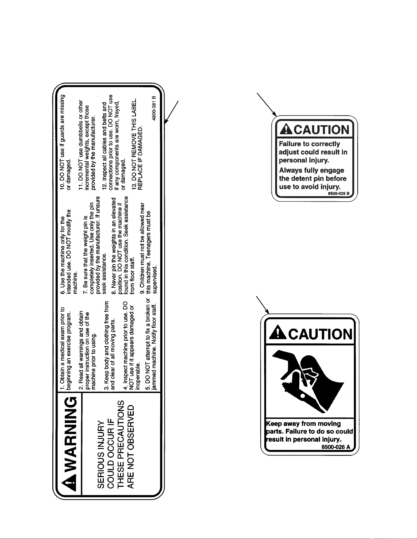
Cybex MG 500 Multi-Gym Owner’s Manual
A
B
C
9. Verify all warning and caution decals are present and not damaged (see decals below
and Figure 17).
Assembly
Page 6-96
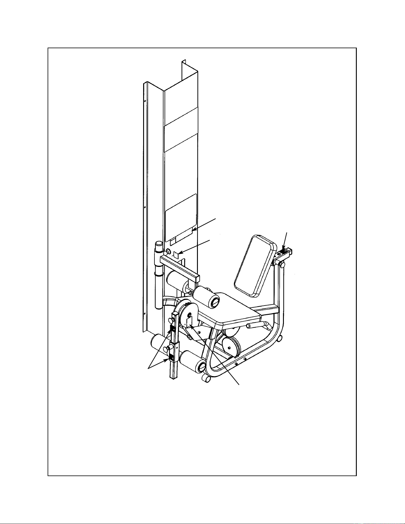
Cybex MG 500 Multi-Gym Owner’s Manual
Assembly
Page 6-97
A. Warning Decal ................... 4800-381
B. Caution Decal .................... 8500-025
C. Caution Decal .................... 8500-026
DESCRIPTION PART NO.
B
A
C
Figure 17
B
B
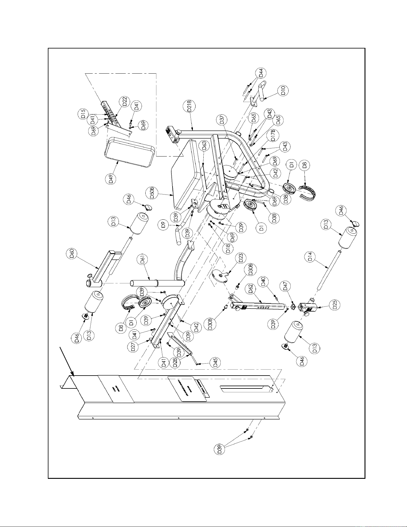
Cybex MG 500 Multi-Gym Owner’s Manual
Assembly
Page 6-98
Column
Leg Extension/Leg Curl Exploded-View Diagram

Cybex MG 500 Multi-Gym Owner’s Manual
Assembly
Page 6-99
D1 4 08014 Pulley
D8 2 4800-570 Cable Guard
D9 1 4850-202 Right Handle
D10 1 4850-203 Left Handle
D13 4 8500-052 Cushion 4.00 Dia. x 7.00 L x .875
D14 1 8520-308 Leg Curl Tube
D17C 1 HC331269 HHCS 10 mm x 90 mm
D18 1 8630-336 Nylon Locknut 10 mm
D21A 1 8640-213 Frame
D22 1 8640-201 Cushion Post
D23 1 8640-202 Cam
D24 Removed 3/20/01
D25 1 8640-204 Adjuster
D26 Removed 3/20/01
D27 1 8640-206 Leg
D28 1 8640-207 Brace
D29 Removed 3/20/01
D30B 2 8640-347 Insert
D31 1 8640-326 Spacer Block
ITEM QTY PART NO. DESCRIPTION
D37 1 HC702826 SHCS .375-16 x 2.00
D38 2 HC702834 SHCS .375-16 x 3.00
D39 12 HN704901 Nylon Locknut .375-16
D40 1 JC702814 SHCS .375-16 x .625
D41 4 JC702820 SHCS .375-16 x 1.25
D42 2 JC702824 SHCS .375-16 x 1.75
D43 4 JC702832 SHCS .375-16 x 2.75
D44 2 JC702836 SHCS .375-16 x 3.25
D45 1 JC702838 SHCS .375-16 x 2.75
D46 4 PP080223 Plastic Insert
D47 3 PP090211 Plastic Insert 1.50 Sq x 10-14 G
D49 1 4800-021 Back Cushion
D50B 1 4800-074 Seat Cushion
D60 1 8640-211 Cushion Bracket
D61 1 8640-212 Cushion Post
D62 1 8640-214 Leg Bar
D63 1 8640-334 Support Plate
D65 2 HS347700 Washer
D69 6 JS347400 Internal Tooth Lockwasher
ITEM QTY PART NO. DESCRIPTION
Leg Extension/Leg Curl Station Parts List (not all parts are listed such as pulleys and cables for inside of
MG 500). See Chapter 8 for a complete parts listing.

Cybex MG 500 Multi-Gym Owner’s Manual
Assembly
Page 6-100
This page intentionally left blank
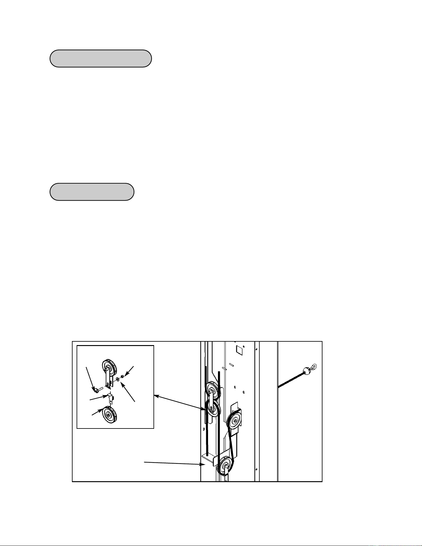
Cybex MG 500 Multi-Gym Owner’s Manual
Assembly
Page 6-101
Cables Adjustments
There are several cables utilized in the MG 500. The number of cables used in each station include:
• Fly Station - 3 cables
• Leg Press Station - 1 cable
• Leg Extension/Leg Curl Station - 2 cables
• Pressing Station - 2 cables
Adjust cables in order of station, starting with the Fly Station, then either the Leg Press Station or Leg
Extension/Leg Curl Station (depending upon which configuration you have) and then the Pressing
Station.
Fly Station
1. Check weight stack cable (see step 1A).
A. See the general weight stack cable adjustment section on page 6-104.
2. Check tension on next cable (see steps 2A - and Figure 1).
A. Adjust hex nut to to remove any excess slack. See Figure 1.
B. If further adjustment is necessary, adjust cam bolt to remove excess slack.
NOTE: Pulley must be in the “V” slot and top weight plate must be just sitting on
second wieght plate.
Nylon
Locknut
Washer
Cam
Bolt
Pulley
Figure 1
Hex nut
adjustment
Retainer
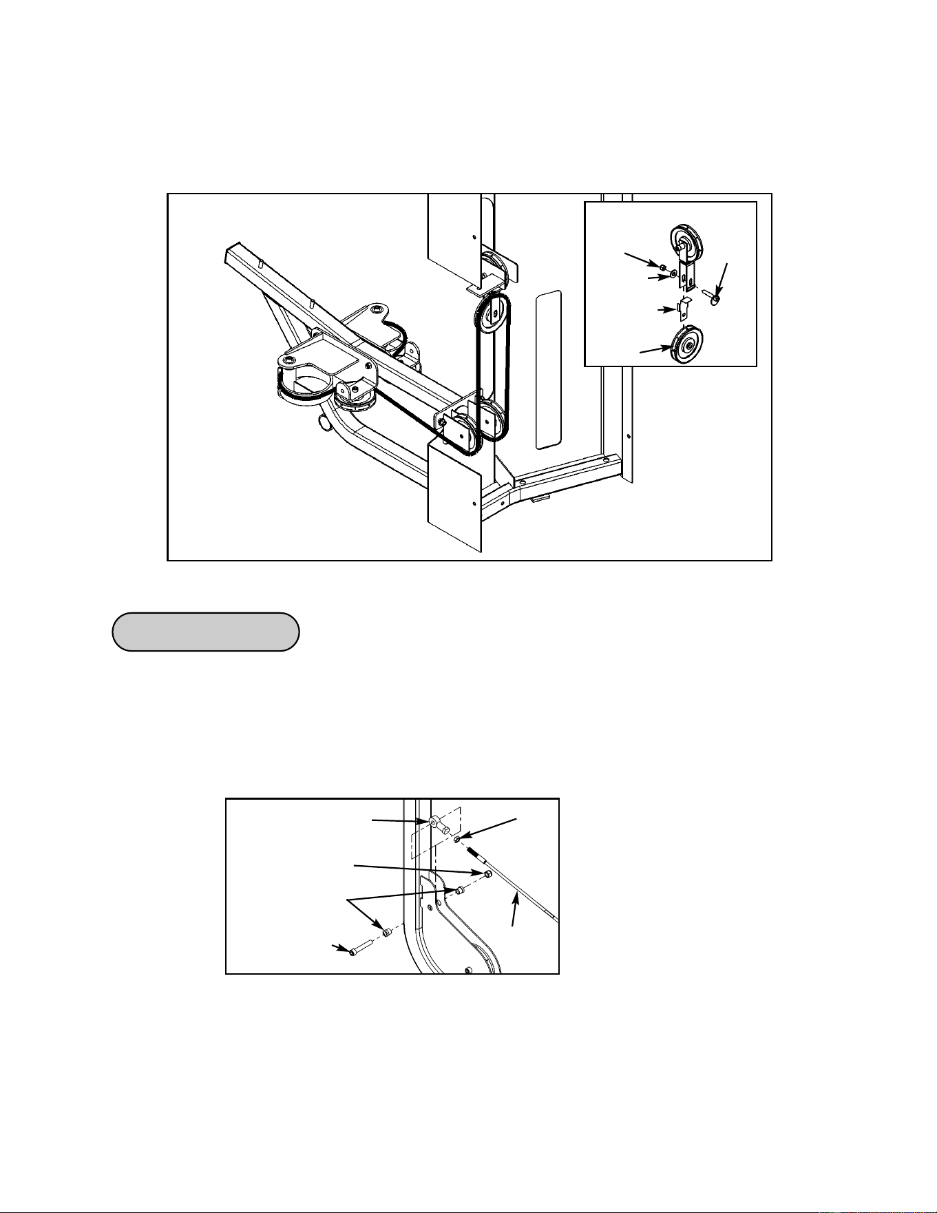
Cybex MG 500 Multi-Gym Owner’s Manual
Assembly
Page 6-102
3. Check cam cable (see step 3A and Figure 2).
A. Adjust cam bolt (if necessary) to remove excess slack. See Figure 2.
Nylon
Locknut
Washer
Cam
Bolt
Pulley
Figure 2
Leg Press Station
1. Check weight stack cable (see step 1A and Figure 3).
A. See the general weight stack cable adjustment section on page 6-96.
B. Adjust jam nut to remove slack. See Figure 1.
Figure 1
Rod End Bearing
Jam Nut
Cable
Nylon Locknut
Spacer
SHCS
.375-16 x 2.25
Retainer
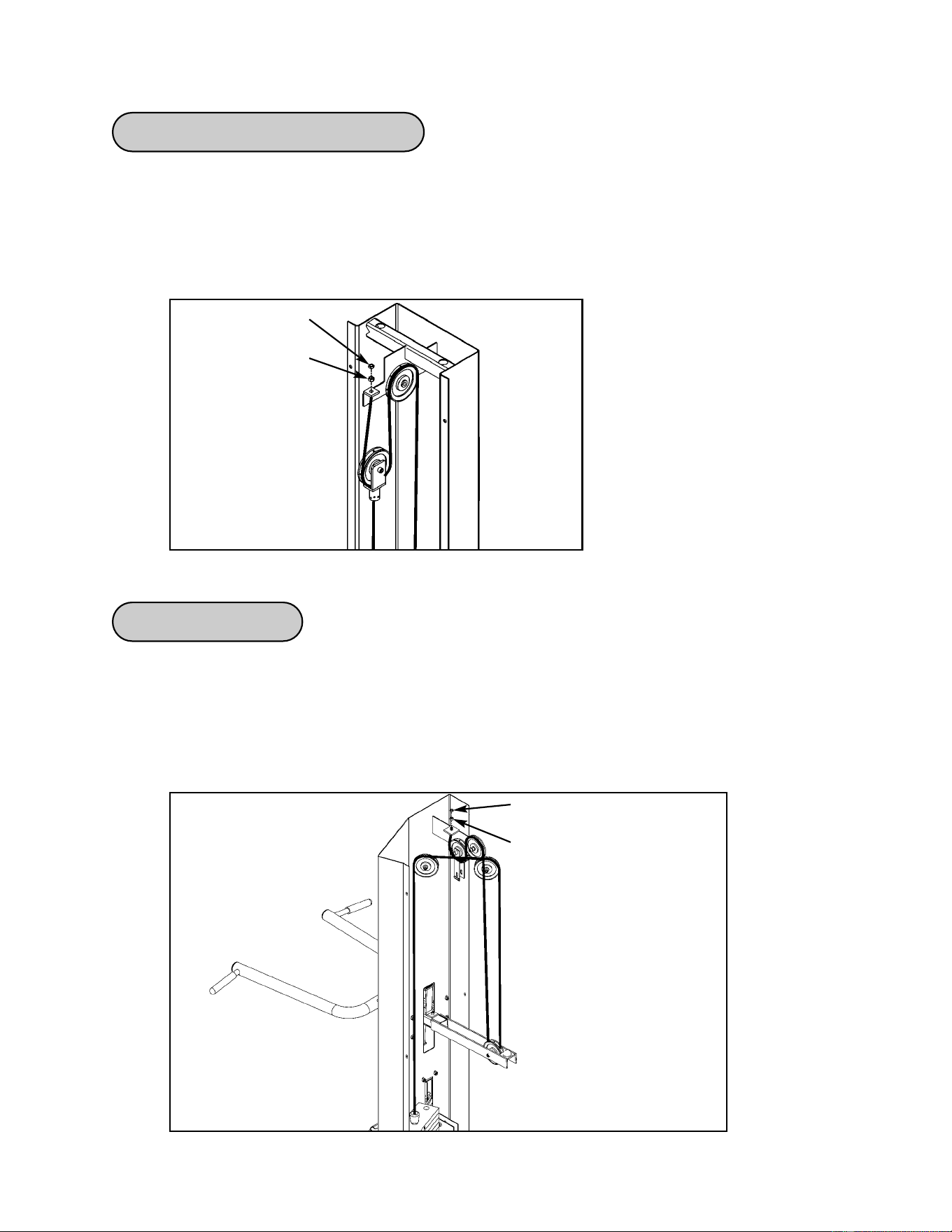
Cybex MG 500 Multi-Gym Owner’s Manual
Assembly
Page 6-103
Leg Extension/Leg Curl Station
1. Check weight stack cable (see step 1A and Figure 1).
A. See the general weight stack cable adjustment section on page 6-92.
B. Adjust hex nut to remove slack.
Pressing Station
1. Check weight stack cable (see step 1A and Figure 1).
A. See the weight stack check section on page 6-95.
B. Adjust hex nut to remove any slack.
Hex Nut
Jam Nut
Figure 1
Figure 1
Jam Nut
Hex Nut
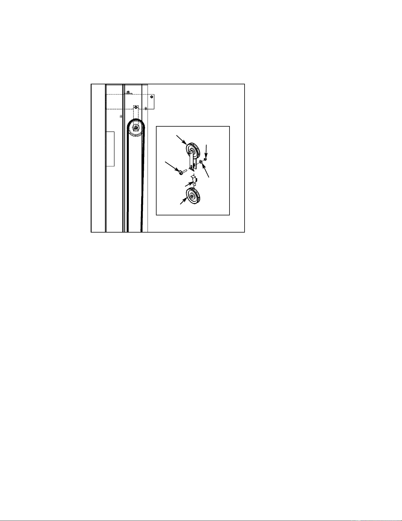
Cybex MG 500 Multi-Gym Owner’s Manual
Assembly
Page 6-104
Figure 2
Pulley
Pulley
Cam
Bolt
Washer
Nylon
Locknut
2. Check tension on next cable (see steps 2A and Figure 2).
A. Adjust cam bolt (if necessary) to remove excess slack. See Figure 2.
Retainer

Cybex MG 500 Multi-Gym Owner’s Manual
Assembly
Page 6-105
Weight Stack Cable Check
1. Check tension of weight stack cable.
NOTE: Assure top plate is flush with weight stack prior to and during cable tension check.
A. Select a point on the cable half way between weight stack and pulley.
NOTE: Assure weight stack top plate is flush with weight stack prior to, and during,
cable tension check.
B. Push cable right or left. Cable deflection greater than 3/4” indicates excessive slack.
Deflection of 1/4” to 3/4” is normal, as is a slight increase in slack between checks.
2. Alternative Method - Check tension of weight stack cable.
A. Select top weight plate (using weight selector pin).
B. Slowly raise and lower top weight plate (in normal fashion).
C. Verify top weight plate is just resting on second plate.
NOTE (1): If there is too much tension then the top weight plate will not properly rest on
second weight and the weight stack selector pin may be difficult to insert into
weight plates.
NOTE (2): Too much slack is indicated if top weight plate does not lift immediately after
raising top weight plate (in normal fashion). A slight slack in cable is ok.
D. Adjust cable if there is too much tension or too much slack. See Cable Tension
Adjustment to adjust tension.
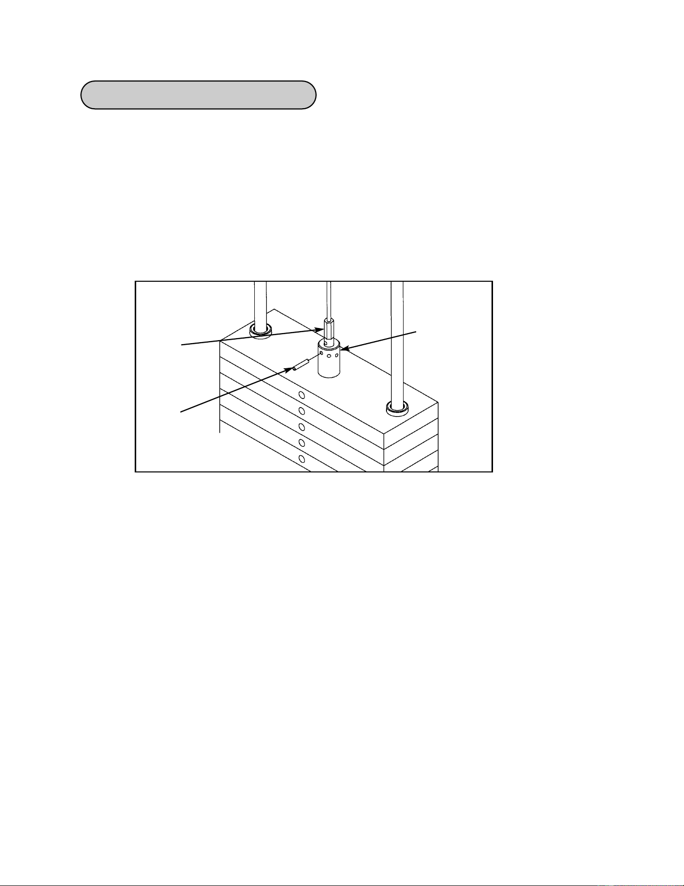
Cybex MG 500 Multi-Gym Owner’s Manual
Assembly
Page 6-106
Tools Required:
• 3/16” Punch
• Hammer
1. Adjust top weight connector (see steps 1A - 1G).
A. Slide protective rubber cover up cable to expose cable/plate junction. Note spiral pin
location in cable fitting. See Figure 1.
Cable
End
Spiral
Pin
Top Weight
Connector
Figure 1
B. Using a 3/16” punch and hammer, drive spiral pin out of top plate connector and
cable fitting.
C. Grip cable fitting firmly, pull down to tighten cable. Rotate fitting to align spiral pin hole
with an opening in top plate connector.
D. Insert pin punch through top plate connector and spiral pin hole to hold cable in place.
E. Drive spiral pin through top plate connector and fitting from opposite side, pushing out
pin punch. Assure spiral pin ends are flush.
F. Test cable tension (see Weight Stack Cable Tension Check). Deflection of 1/4” to 3/4”
indicates proper tension. If top weight plate does not rest securely against the second
plate and selector pin cannot be fully inserted, there is too much tension on the cable,
fitting pin hole with another connector opening as required to adjust tension. Check
that spiral pin is flush. If cable tension cannot be corrected, contact a Cybex
Customer Relations Technician.
G. Once proper tension is achieved, fully inset selector pin and replace protective cover
over cable fitting.
Weight Stack Cable Adjustment

Cybex MG 500 Multi-Gym Owner’s Manual
Assembly
Page 6-107
1. Visual Inspection (see steps 1A - 1C).
A. Visually inspect the entire MG 500. Be sure cables are properly tensioned, hardware is
secure and each station is correctly assembled.
B. Place ankle strap, EZ curl handle and handle sub-assembly on or near the Pressing
station.
C. Place pulldown bar and ab crunch strap on or near the Fly Station.
2. Replace braces and back covers (See Steps 2A - 2B).
A. Install all three braces. See Figure 2 on page 6-4.
B. Install back covers. See Figure 1 on page 6-3.
3. Functional Inspection (see step 3A).
A. Check for proper operation of each station.
Final Assembly

Cybex MG 500 Multi-Gym Owner’s Manual
Assembly
Page 6-108
This page intentionally left blank
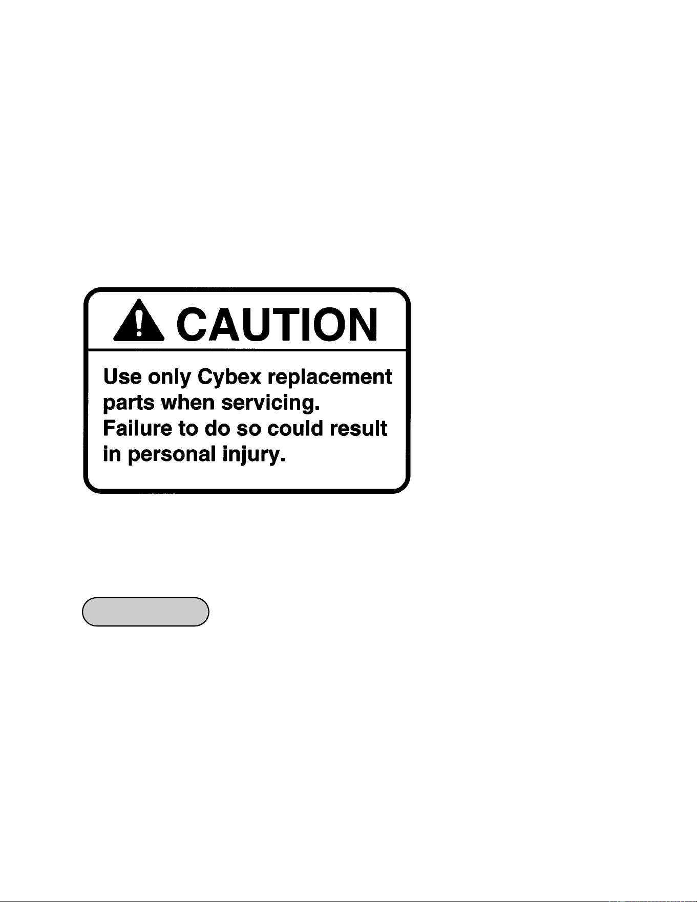
Cybex MG 500 Multi-Gym Owner’s Manual
Assembly
Page 7-1
All preventive maintenance activities must be performed on a regular basis. Performing
routine preventive maintenance actions can aid in providing safe, trouble-free operation of
your Cybex MG 500.
NOTE: Cybex is not responsible for performing regular inspection and maintenance
actions for your machines. Instruct all personnel in equipment inspection and
maintenance actions and also in accident reporting/recording. Cybex phone
representatives are available to answer any questions or concerns that you may
have.
Daily Procedures
7 - Maintenance
1. Upholstery - Wipe down all upholstery as per the recommendations listed below for light
soiling and more difficult stains.
Light Soiling
• A solution of 10% household liquid dish soap with warm water applied with a soft damp
cloth.
• If necessary, a solution of liquid cleanser and water applied with a soft bristle brush. Wipe
away the residue with a water dampened cloth.
NOTE: All
inspections and
repairs must be
performed by
trained service
personnel only.
Cybex will void warranty if
non-Cybex replacement parts
are used.

Cybex MG 500 Multi-Gym Owner’s Manual
Assembly
Page 7-2
More Difficult Stains
• Dampen a soft white cloth with a solution of household bleach (sodium hypochlorite),
10 % bleach, 90% water. Rub gently. Rinse with a water dampened cloth to remove
bleach concentration.
• The same procedure can be used with full strength household bleach, if necessary.
• Allow bleach to puddle on the affected area or apply with a soaked cloth for
approximately 30 minutes. Rinse with a water dampened cloth to remove any
remaining bleach concentration.
Alternative Method for Difficult Stains
• Dampen a soft white cloth with rubbing alcohol and rub gently. Rinse with a water
dampened cloth to remove any remaining rubbing alcohol concentration.
NOTE: To restore luster, a light coat of spray furniture wax can be used. Apply for 30
seconds and follow with a light buffing using a clean white cloth.
Please Review Carefully
When using strong cleaning agents such as rubbing alcohol or bleach, it is advisable to
first test in an inconspicuous area. Other cleaning agents may contain harsh or unknown
solvents and are subject to formula changes by the product manufacturer without notice.
Should you desire to use other cleaning agents, carefully try them in an inconspicuous
area to determine potential damage to the material. Never use harsh solvents or cleaners
which are intended for industrial applications. To clean stained or soiled areas, a soft white
cloth is recommended. Avoid use of paper towels.
Cleaning products may be harmful/irritating to your skin, eyes, etc. Use protective gloves
and eye protection. Do not inhale or swallow any cleaning product. Protect surrounding
area/clothing from exposure. Use in a well ventilated area. Follow all product
manufacturer’s warnings. Cybex and its vendors cannot be held responsible for damage
or injuries resulting from the use or misuse of cleaning products.
2. Frames - Wipe down all frames using a mild solution of warm water and car wash soap.
Be sure to dry thoroughly. AVOID acid or chlorine based cleaners and also cleaners
containing abrasives as these could scratch or damage the equipment.
3. Chrome - Clean chrome tubes, first using chrome polish and then using a car wax seal.
Neutral cleaners with a pH between 5.5 and 8.5 are recommended. Be sure to dry
thoroughly. AVOID acid or chlorine based cleaners and also cleaners containing abrasives
as these could scratch or damage the equipment.
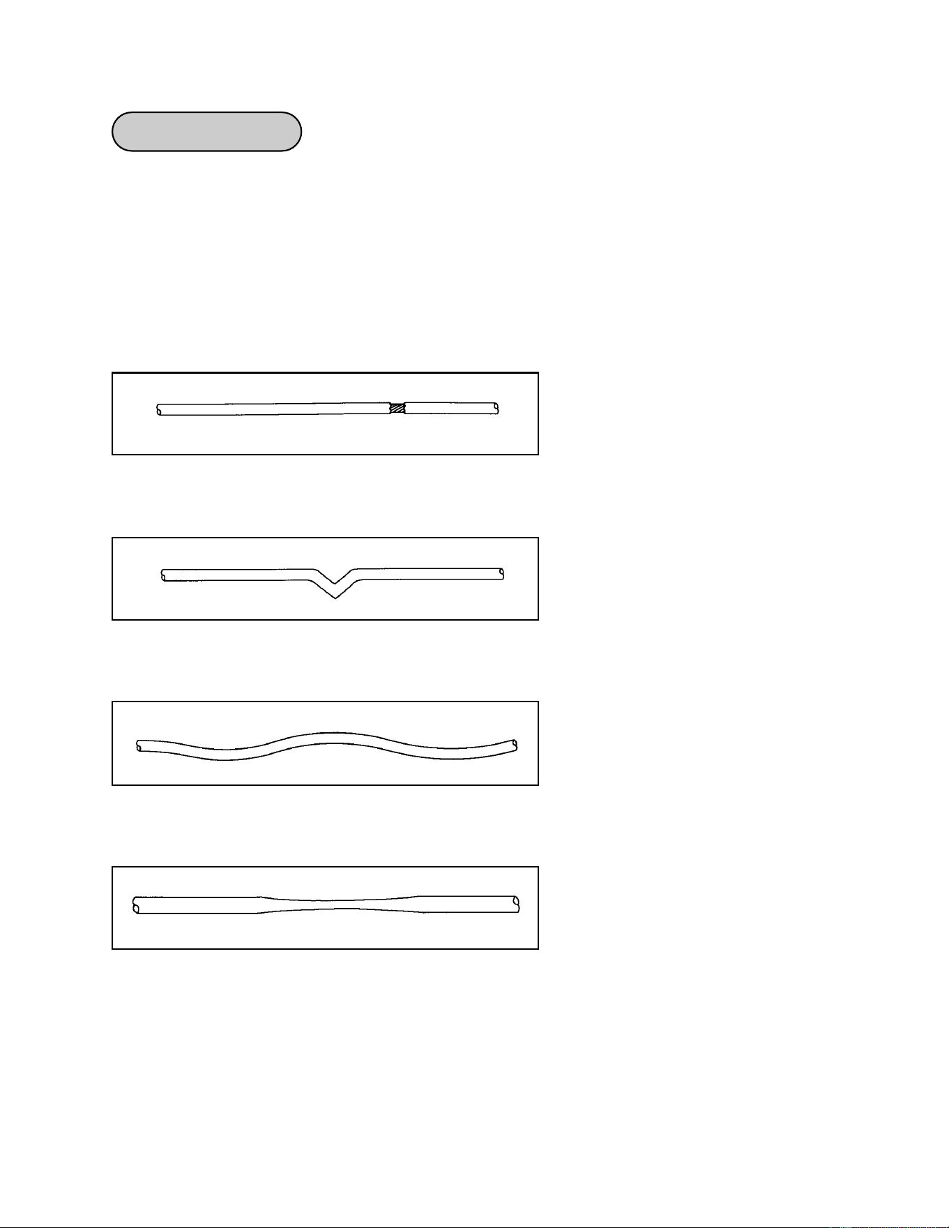
Cybex MG 500 Multi-Gym Owner’s Manual
Assembly
Page 7-3
1. Inspect all nuts and bolts for looseness. Tighten as required.
2. Inspect all cables for wear or damage and proper tension. When inspecting cables, run
your fingers on the cable, paying particular attention to bends in the cable and
attachment points.
! WARNING: Replace all worn cables immediately. The following conditions may
indicate a worn cable:
Figure 1
• A kink in the cable. See Figure 2.
• A curled sheath. See Figure 3.
Figure 2
Figure 3
Figure 4
• “Necking”, a stretched cable sheath. See Figure 4.
Weekly Procedures
• A tear or crack in the cable sheath that exposes the cable. See Figure 1.
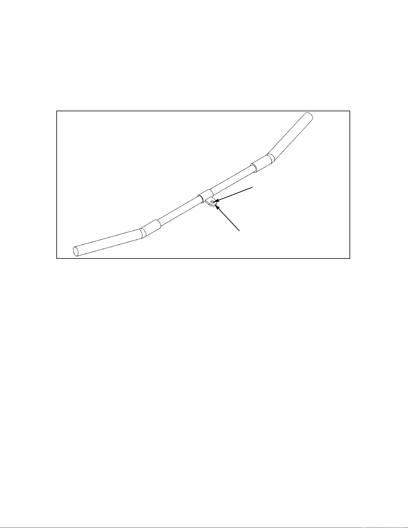
Cybex MG 500 Multi-Gym Owner’s Manual
Assembly
Page 7-4
Attachment Hole
NOTE: Replace bar if less
than 1/8” of material
remains to the edge.
Figure 5
3. Inspect bars and handles for wear, paying particular attention to tab area connecting points.
Replace all worn handles immediately.
! CAUTION: Replace all worn handles immediately. Do not use if less than 1/8” of
material remains to the edge. See Figure 5.
4. Inspect snap links for proper latching (indicates wear). Replace all worn
snap links immediately.
5. Inspect all labeling for readability. This includes instructional placards,
warning and caution decals. Replace all warning labeling immediately.
6. Inspect all weight stacks for proper alignment and operation.
NOTE: Correct all improper alignment and operation issues
immediately.
7. Wipe Weight Stack Guide Rods and Leg Press Linear bearings clean over
entire length. Lubricate with a light coat of medium weight automotive
engine oil.

Cybex MG 500 Multi-Gym Owner’s Manual
Assembly
Page 7-5
Yearly Procedures
Replace all cables at least annually.
“As Required” Procedures
Inspect grips and replace as necessary.
Cables Adjustments
There are several cables utilized in the MG 500. The number of cables used in each station include:
• Fly Station - 3 cables
• Leg Press Station - 1 cable
• Leg Extension/Leg Curl Station - 2 cables
• Pressing Station - 2 cables
Adjust cables in order of station, starting with the Fly Station, then either the Leg Press Station or Leg
Extension/Leg Curl Station (depending upon which configuration you have) and then the Pressing
Station.
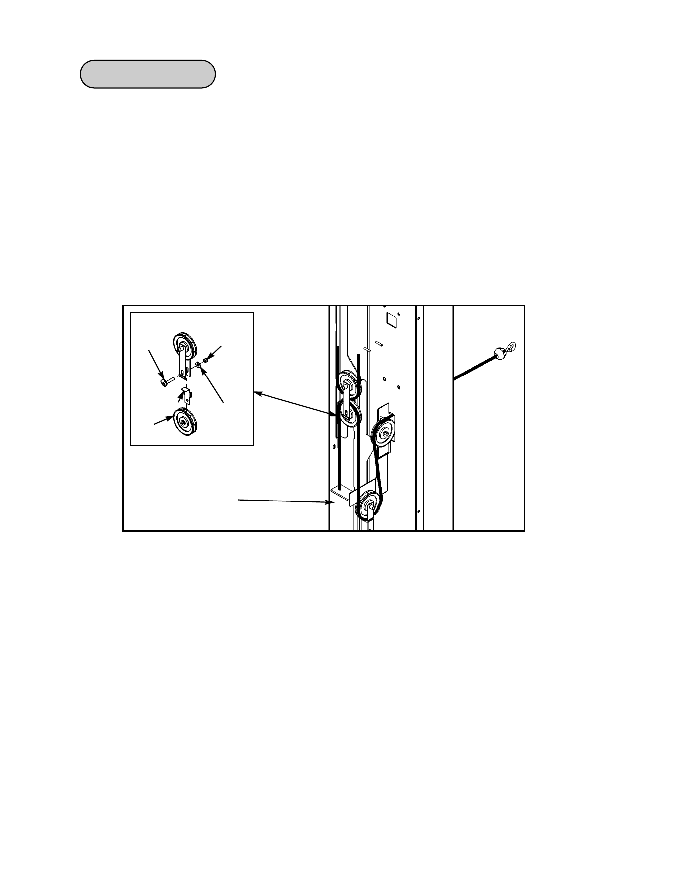
Cybex MG 500 Multi-Gym Owner’s Manual
Assembly
Page 7-6
Fly Station
1. Check weight stack cable (see step 1A).
A. See the general weight stack cable adjustment section on page 6-95.
2. Check tension on next cable (see steps 2A - and Figure 1).
A. Adjust hex nut to to remove any excess slack. See Figure 1.
B. If further adjustment is necessary, adjust cam bolt to remove excess
slack.
NOTE: Pulley must be in the “V” slot and top weight plate must be just
sitting on second weight plate.
Nylon
Locknut
Washer
Cam
Bolt
Pulley
Figure 1
Hex nut
adjustment
Retainer
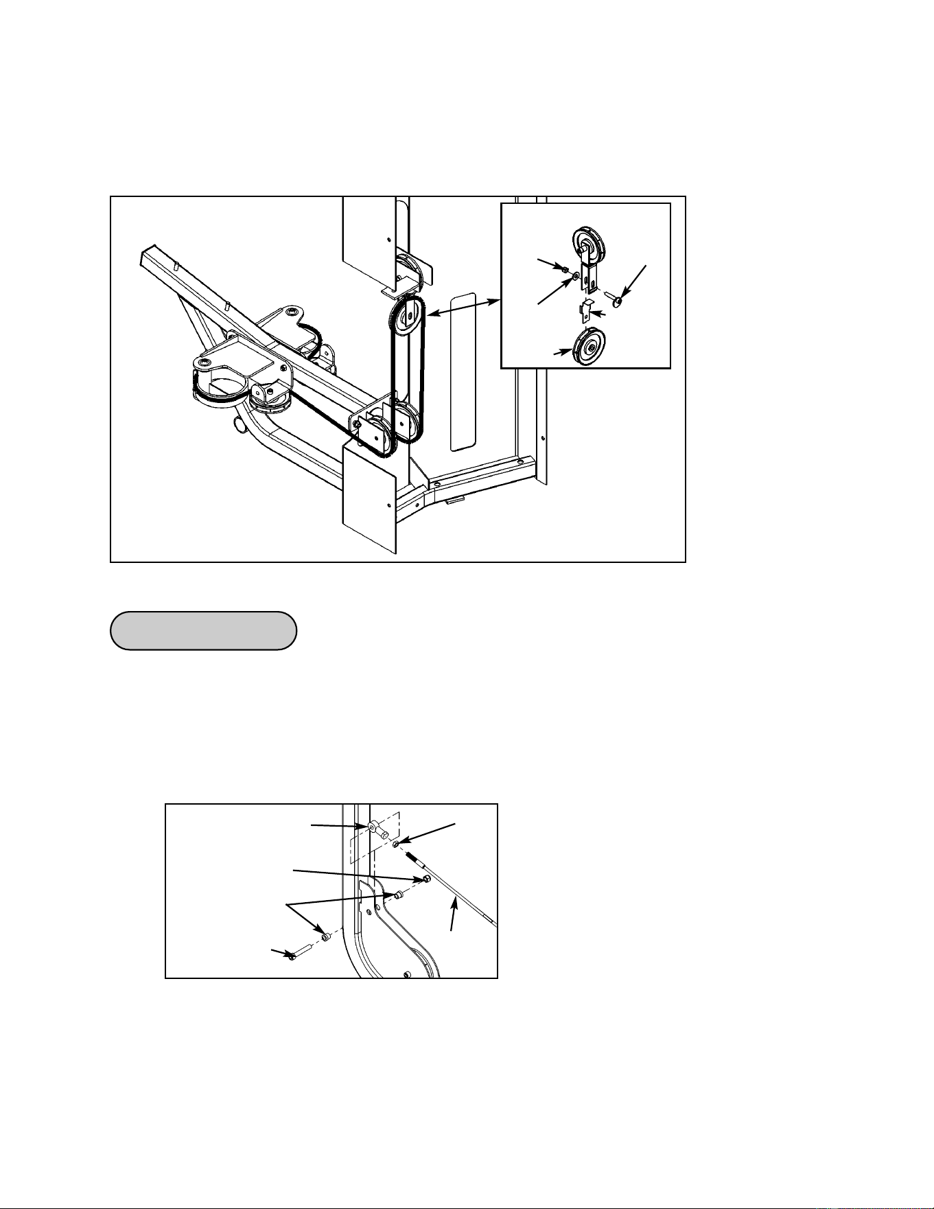
Cybex MG 500 Multi-Gym Owner’s Manual
Assembly
Page 7-7
3. Check cam cable (see step 3A and Figure 2).
A. Adjust cam bolt (if necessary) to remove excess slack. See Figure 2.
Nylon
Locknut
Washer
Cam
Bolt
Pulley
Figure 2
Leg Press Station
1. Check weight stack cable (see step 1A and Figure 1).
A. See the general weight stack cable adjustment section on page 6-96.
B. Adjust jam nut to remove slack. See Figure 1.
Figure 1
Rod End Bearing
Jam Nut
Cable
Nylon Locknut
Spacer
SHCS
.375-16 x 2.25
Retainer

Cybex MG 500 Multi-Gym Owner’s Manual
Assembly
Page 7-8
Leg Extension/Leg Curl Station
1. Check weight stack cable (see step 1A and Figure 1).
A. See the general weight stack cable adjustment section on page 6-92.
B. Adjust hex nut to remove slack.
Pressing Station
1. Check weight stack cable (see step 1A and Figure 1).
A. See the weight stack check section on page 6-95.
B. Adjust hex nut to remove any slack.
Hex Nut
Jam Nut
Figure 1
Figure 1
Jam Nut
Hex Nut
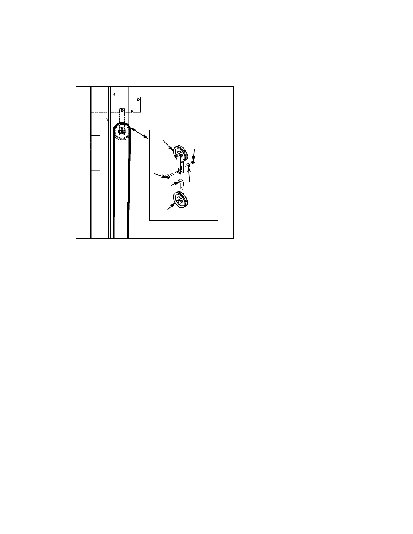
Cybex MG 500 Multi-Gym Owner’s Manual
Assembly
Page 7-9
Figure 2
Pulley
Pulley
Cam
Bolt
Washer
Nylon
Locknut
2. Check tension on next cable (see steps 2A and Figure 2).
A. Adjust cam bolt (if necessary) to remove excess slack. See Figure 2.
Retainer

Cybex MG 500 Multi-Gym Owner’s Manual
Assembly
Page 7-10
1. Select top weight plate (using weight selector pin).
2. Slowly raise and lower top weight plate (in normal fashion).
3. Verify top weight plate is just resting on second plate.
NOTE: If there is too much tension then the top weight plate will not properly rest on
second weight and the weight stack selector pin may be difficult to insert into
weight plates.
NOTE: Too much slack is indicated if top weight plate does not lift immediately after
raising top weight plate (in normal fashion). A slight slack in cable is ok.
4. Adjust cable if there is too much tension or too much slack. See Cable Tension
Adjustment to adjust tension.
Weight Stack Cable Tension Check
Alternative Weight Stack Cable Tension Check
NOTE: Assure weight stack top plate is flush with weight stack prior to, and during, cable
tension check.
1. Select a point on the cable half way between weight stack and pulley.
2. Push cable right or left. Cable deflection greater than 3/4” indicates excessive slack.
Deflection of 1/4” to 3/4” is normal, as is a slight increase in slack between checks.
See Cable Tension Adjustment to adjust tension.
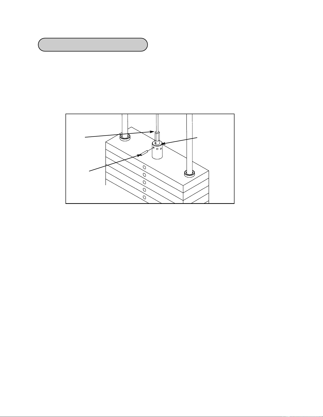
Cybex MG 500 Multi-Gym Owner’s Manual
Assembly
Page 7-11
Tools Required:
• 3/16” Punch
• Hammer
1. Slide protective rubber cover up cable to expose cable/plate junction. Note roll pin
location in cable fitting. See Figure 8.
Figure 8
2. Using a 3/16” pin punch and hammer, drive spiral pin out of top plate connector and
cable fitting.
3. Grip cable fitting firmly, pull down to tighten cable. Rotate fitting to align spiral pin hole
with an opening in top plate connector.
4. Insert pin punch through top plate connector and spiral pin hole to hold cable in place.
5. Drive spiral pin through top plate connector and fitting from opposite side, pushing out
pin punch. Assure spiral pin ends are flush.
6. Test cable tension (see Weight Stack Cable Tension Check). Deflection of 1/4” to 3/4”
indicates proper tension. If top weight plate does not rest securely against the second
plate and selector pin cannot be fully inserted, there is too much tension on the cable,
fitting pin hole with another connector opening as required to adjust tension. Check
that spiral pin is flush. If cable tension cannot be corrected, contact a Cybex Customer
Relations Technician.
7. Once proper tension is achieved, fully inset selector pin and replace protective cover
over cable fitting.
Weight Stack Cable Adjustment
Spiral
Pin
Cable
End
Top Weight
Connector

Cybex MG 500 Multi-Gym Owner’s Manual
Assembly
Page 7-12
This page intentionally left blank

Cybex MG 500 Multi-Gym Owner’s Manual
Service
Page 8-1
8 - Service
Please refer to the next several pages for parts lists, exploded-view diagrams and cable
routing diagrams.
NOTE: All
inspections and
repairs must be
performed by
trained service
personnel only.
Cybex will void warranty if
non-Cybex replacement parts
are used.

Cybex MG 500 Multi-Gym Owner’s Manual
Service
Page 8-2
A1 2 01190 Vinyl Black End Cap
A2 4 02205 Foam Grip 10.00
A3 2 08009 Flange Bearing .50 x .62 x .50 L
A4 4 08014 Pulley
A5 2 11040-440 Cybex Knob
A6 Removed
A7 2 4005M100 Foam Grip 6.00
A8 1 4800-019 Seat Cushion
A9 1 4800-009 Back Cushion
A10 1 8510-304 Cushion Plate
A11 2 8510-330 Lexan Washer
A12 2 8510-343 Non-Slip
A13 2 8510-344 Rubber Cap
A14 2 8510-364 Notched Plastic Insert
A15 2 8510-366 Detent Pin
A16 1 8610-308 Shaft
A17 1 8610-203 Brace
A18 1 8610-204 Platform
A19 1 8610-201 Pressing Arm
A20 1 8610-207 Leg
A21 1 8610-210 Frame
A22 1 8610-205 Swivel Pulley Bracket
A23 1 8510-208 Cushion Plate
A24 1 8610-202 Pivot Arm
A25 1 8510-210 Detent Plate
A26 2 GQ000206 Snap Link
A27 2 HB-60652 Pillow Block Bearing
A28 2 HC702815 SHCS .375-16 x .750
A29 4 HC702816 SHCS .375-16 x .875
A30 1 HC702830 SHCS .375-16 x 2.50
A31 4 HC702834 SHCS .375-16 x 3.00
A32 1 HS347600 Washer, SAE .375
A33 1 HS-60546 HHCS Bolt .375 x 5.00
A34 2 PN660200 Plastic Insert 1.00 Dia. x 11 G
A35 3 PP090210 Plastic Insert 2.00 Sq x 10-14 G
A36 2 PP080224 Plastic Inset 2.00 Dia.
A37 3 PP090205 Plastic Insert 1.00 x 2.00 x 11 G
A38 19 HN704901 Nylon Locknut, .375-16
A39 6 JC702820 SHCS .375-16 x 1.25
A40 2 JC702824 SHCS .375-16 x 1.75
A41 2 JC702832 SHCS .375-16 x 2.75
A42 1 51081 Handle
A43 1 HC702817 SHCS .375-16 x 1.00
A44 1 4505-331 Bumper
A45 1 8500-028 Caution Decal
A46 1 8500-311 Warning Decal
A47 1 8500-318 Adjustment Decal
A48 1 8500-319 Adjustment Decal
A49 1 8610-002 Cable 179.25 L
A50 1 8610-003 Cable 173.44 L
A51 2 BS070201 Com Spring
A52 1 JC702814 SHCS .375-16 x .625
A53 1 HN704000 Hex Nut .375-16
A54 1 HN704400 Jam Nut .375-16
A55 1 51122 Ankle Strap
A56 2 5310S040 Handle Sub-Assembly
A57 1 8500-202 EZ Curl Handle
A58 1 4800-381 Warning Decal
A59 1 8610-598 Placard Decal
A60 1 3900-391 Cybex Decal 11.37 Vert. Wht/Wht
A61 2 8610-330 Formed Guard
A62 5 JS347400 Internal Tooth Lockwasher
A63 1 51198 Strength Warranty Sheet (not shown)
ITEM QTY PART NO. DESCRIPTIONITEM QTY PART NO. DESCRIPTION
8610 - Pressing Station
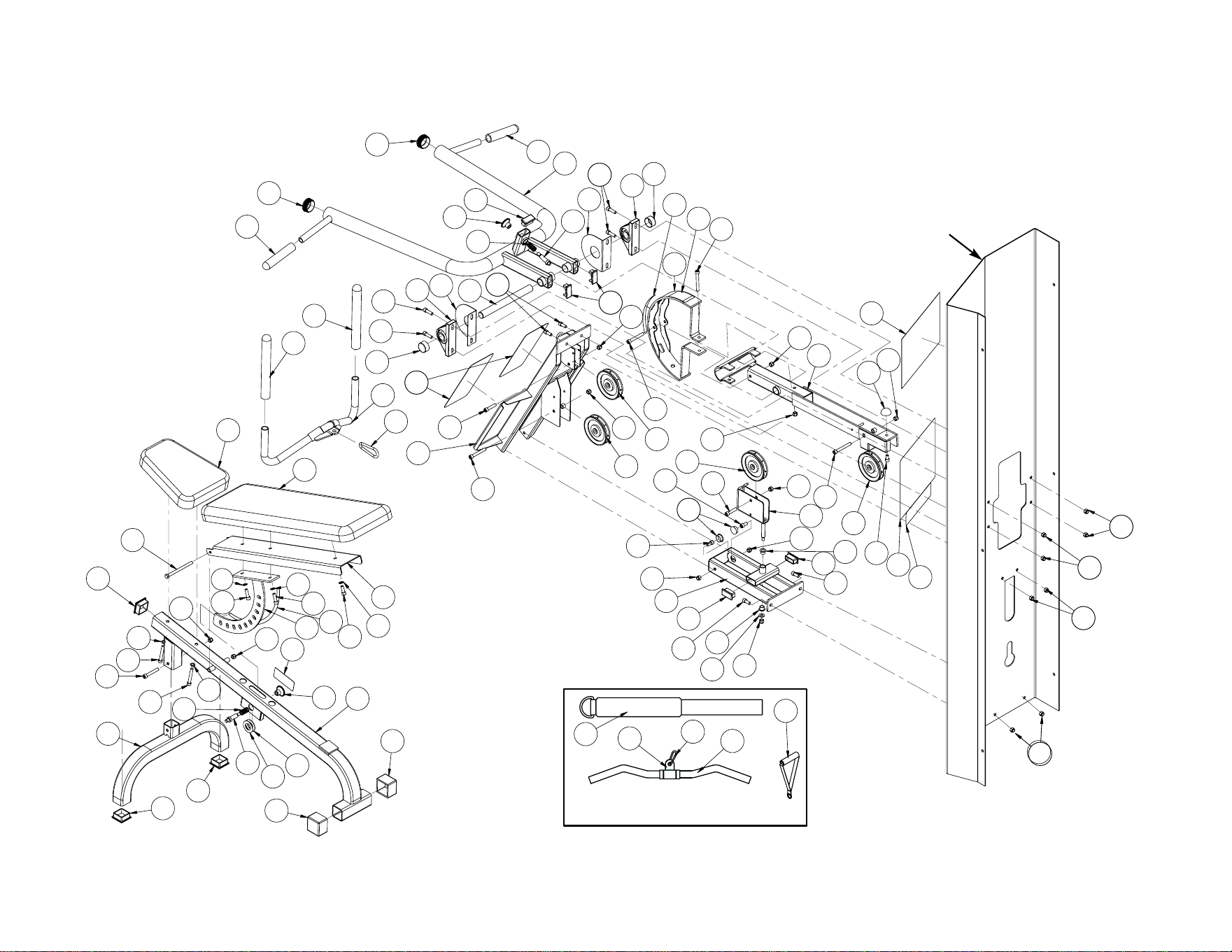
Service
Page 8-3
A38
A38
A38
A38
A38
A38
A29
A38
A38
A38
A34
A44
A39
A14
A29
A25
A38
A24
A38
A4
A40
A38
A22
A31
A4
A38
A3
A29
A34
A27
A12
A37
A43
A52
A51
A59
A58
A60
A7
A19
A36
A36
A7
A5
A37
A39
A1
A14
A15
A39
A39
A16
A1
A38
A4
A41
A31
A38
A4
A40
A17
A38
A2
A2
A42
A26
A41
A9
A8
A10
A33
A23
A5
A38
A38
A30
A13
A13
A21
A35
A35
A20
A15
A38
A29
A3
A32
A28
A28
A27
A18
A12
A11
A11
A37
A39
A35
A31
A31
A51
A39
A47
A48
A45
A61
A61
A46
A62
A62
A62
A62
A62
A26
A2
A56
A57
A55
HANDLE DETAIL
Cybex MG 500 Multi-Gym Owner’s Manual
8610 - Pressing Station
COLUMN

Cybex MG 500 Multi-Gym Owner’s Manual
Service
Page 8-4
B1 3 08014 Pulley
B2 4 08135 Ball Bearing
B3 1 11040-440 Cybex Knob
B4 1 08229 Detent Pin
B5 1 4035S121-0 Cushion
B6 1 4106S055-0 Seat Cushion
B7 1 4605-511 Plastic Insert 5.94
B8 1 5245-011 Cushion
B9 2 8500-052 Cushion
B10 1 8500-025 Caution Decal
B11 2 8500-026 Caution Decal
B12 2 8520-212 Handle
B13 2 8520-307 Hand Grip 5.125 L
B14 2 8520-320 Rod Handle Grip
B15 2 8520-346 Detent Pin
B16 1 8620-200 Frame
B17 1 8620-201 Hip Support
B18 1 8620-202 Cushion Tube
B19 1 8620-203 Right Pivot
B20 1 8620-204 Left Pivot
B21 1 8620-207 Right Hand Pivot Handle
B22 1 8620-208 Left Hand Pivot Handle
B23 1 8620-209 Right Arm
B24 1 8620-210 Left Arm
B25 1 8620-211 Boom
B26 1 8620-214 Hook
B27 2 8620-342 HHCS 10 mm x 120 mm
B28 4 FB050226 Flanged Bearing 1.00 x 1.25 1.00 L
B29 4 FB130212 Flange Bushing .75 ID
B30 1 HP707017 Stud .375-16 x 1.00
B31 4 HC702816 SHCS .375-16 x .875
B32 4 HC702817 SHCS .375-16 x 1.00
B33 3 HC702826 SHCS .375-16 x 2.00
B34 5 HC702834 SHCS .375-16 x 3.00
B35 14 HN704901 Nylon Locknut .375-16
B36 4 HS347600 Washer, SAE .375
B37 2 HW-60085 Washer .3125
B38 4 JC702814 SHCS .375-16 x .625
B39 2 JC702820 SHCS .375-16 x 1.25
B40 Removed (11/02)
B41 2 PL-52062 Bumper 2.00 Dia. x .625
B42 2 PP080223 Plastic Insert
B43 1 PP090210 Plastic Insert 2.00 Sq x 10-14 G
B44 1 PP090211 Plastic Insert 1.50 Sq x 10-14 G
B45 2 PP460202 Plastic Knob .164 8-32 x .59
B46 2 HC702822 SHCS .375-16 x 1.50
B47 1 8520-313 Seat Adjusting Decal
B48 2 BS070207 Com Spring .19 x .24 .38 L
B49 1 BS070201 Com Spring .56 x .66 1.50 L
B50 1 4505-331 Bumper 1.50 Dia.
B51 1 8500-201 Pulldown Bar
B52 1 8620-002 Cable 151.12 L
B53 1 8620-003 Cable 65.97 L
B54 1 8620-004 Cable 106.25 L
B55 2 8620-336 Hand Grip 5.00 L
B56 2 8620-337 Spacer
B57 1 8620-338 Ab Crunch Tricep Strap
B58 1 8620-341 Guard
B59 2 8630-336 Nylon Locknut 10 mm
B60 2 PR400201 Grip
B61 2 GQ000206 Snap Link
B62 5 HC702815 SHCS .375-16 x 7.50
B63 1 HN704400 Jam Nut .375-16
B64 1 HN704000 Hex Nut .375-16
B65 1 8620-598 Placard Decal
B66 1 3900-391 Cybex Decal 11.37 Vert. Wht/Wht
B67 1 4800-381 Warning Decal
B68 2 8620-343 Warning Decal
B69 2 5340Y045 Arrow Decal
B70 2 8620-344 Pivot Guard
B71 1 8620-215 Bracket
B72 6 JS347400 Internal Tooth Lockwasher
ITEM QTY PART NO. DESCRIPTION
ITEM QTY PART NO. DESCRIPTION
8620 - Fly Station
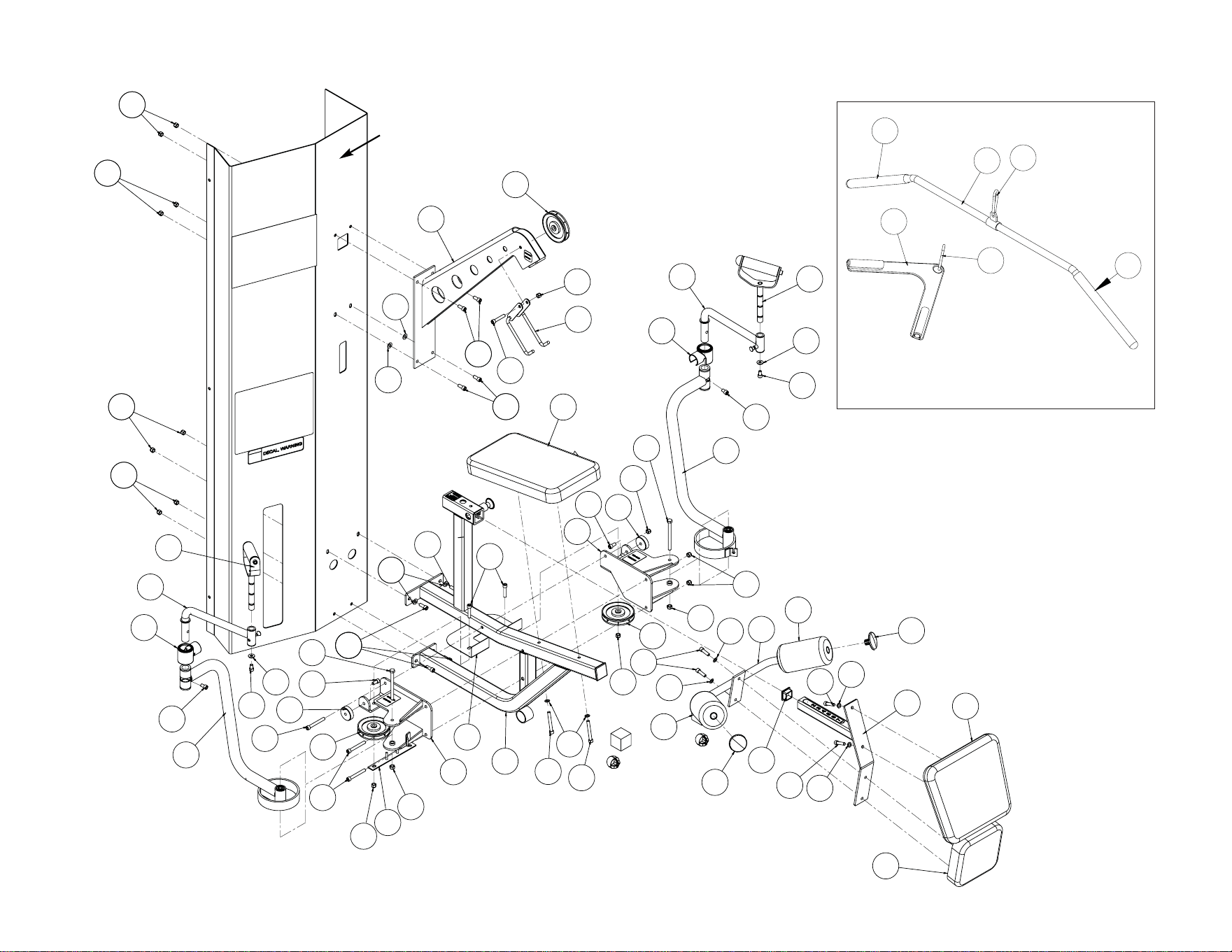
Cybex MG 500 Multi-Gym Owner’s Manual
8620 - Fly Station
Service
Page 8-5
B35
B35
B31
B31
B35
B35
B36
B1
B35
B26
B33
B31
B31
B25
B35
B36
B35
B21
B12
B37
B38
B23
B38
B34
B34
B19
B41
B35
B27
B62
B16
B34
B34
B32
B32
B58
B33
B1
B20
B27
B35
B41
B62
B35
B39
B35
B17
B44
B46
B18
B8
B46
B5
B12
B22
B37
B38
B38
B24
B6
B1
B59
B59
B42
B42
B70
B70
B71
B36
B9
B9
B72
B72
B72
B72
B72
B60
B51
B61
B60
B61
B57
HANDLE DETAIL
COLUMN

Service
Page 8-6
Cybex MG 500 Multi-Gym Owner’s Manual
C1 3 08014 Pulley
C2 10 FB030242 Bearing with snap ring, 30 mm x 10 mm
C3 1 08172 Cybex Knob
C4 1 4000Y316 Caution Decal
C5 2 4005M100 Grip
C6 1 4106S055-0 Back Cushion
C7 1 4505-329 Detent Pin
C8 1 4605-511 Plastic Insert 5.94
C9 1 4800-026 Bottom Cushion
C10 2 4800-570 Cable Guard
C11 1 8500-025 Caution Decal
C12 1 8520-313 Seat Adjusting Decal
C13 Removed
C14 1 8630-200 Frame
C15 1 8630-201 Seat Frame
C16 1 8630-202 Seat Tube
C17 1 8630-203 Right Foot Plate
C18 1 8630-204 Left Foot Plate
C19 1 8630-205 Roller Tube
C20 1 8630-206 Roller Plate
C21 1 8630-207 Right Handle
C22 1 8630-208 Left Handle
C23 1 8630-209 Pivot Tube
C24 1 8630-210 Connector
C25 2 8630-321 Non-Slip
C26 2 8630-322 Roller
C27 1 8630-326 Plastic Seat Sleeve
C28 2 8630-331 Spacer
C29 4 JC702820 SHCS .375-16 x 1.25
C30 3 8630-336 Nylon Locknut, 10 mm
C31 1 HC702816 SHCS .375-16 x .875
C32 4 HC702834 SHCS .375-16 x 3.00
C33 20 HN704901 Nylon Locknut, .375-16
C34 1 JC702814 SHCS .375-16 x .625
C35 3 JC702824 SHCS .375-16 x 1.75
C36 4 JC702832 SHCS .375-16 x 2.75
C37 Removed
C38 2 PP090000 Plastic Insert 1.50 x 2.00 x 11 G
C39 1 PP090200 Plastic Insert 1.75 Sq x 10-14 G
C40 2 PP090210 Plastic Insert 2.00 Sq x 11 G
C41 1 PP090211 Plastic Insert 1.50 Sq x 10-14 G
C42 1 PU060201 Bumper
C43 3 HC331271 HHCS 10 mm x 110 mm
C44 2 PP080225 Plastic Insert 1.50 x 2.00 11 G
C45 1 BS070201 Com Spring .56 x .66 1.50 L
C46 1 8630-002 Cable 216.50 L
C47 2 8630-340 Spacer
C48 1 FB030213 Rod End Bearing
C49 1 HC702828 SCHS .375-16 x 2.25
C50 2 JC700917 FHSCS .375-16 x 1.00
C51 4 JC702836 SHCS .375-16 x 3.25
C52 1 JN714400 Jam Nut .375-24 UNF
C53 1 8630-598 Placard Decal
C54 1 3900-391 Cybex Decal 11.37 Vert. Wht/Wht
C55 1 4800-381 Warning Decal
C56 CM00021 Patent Pending Removed 7/6/09
C57 8 JS347400 Internal Tooth Lockwasher
8630 - Leg Press Station
ITEM QTY PART NO. DESCRIPTIONITEM QTY PART NO. DESCRIPTION
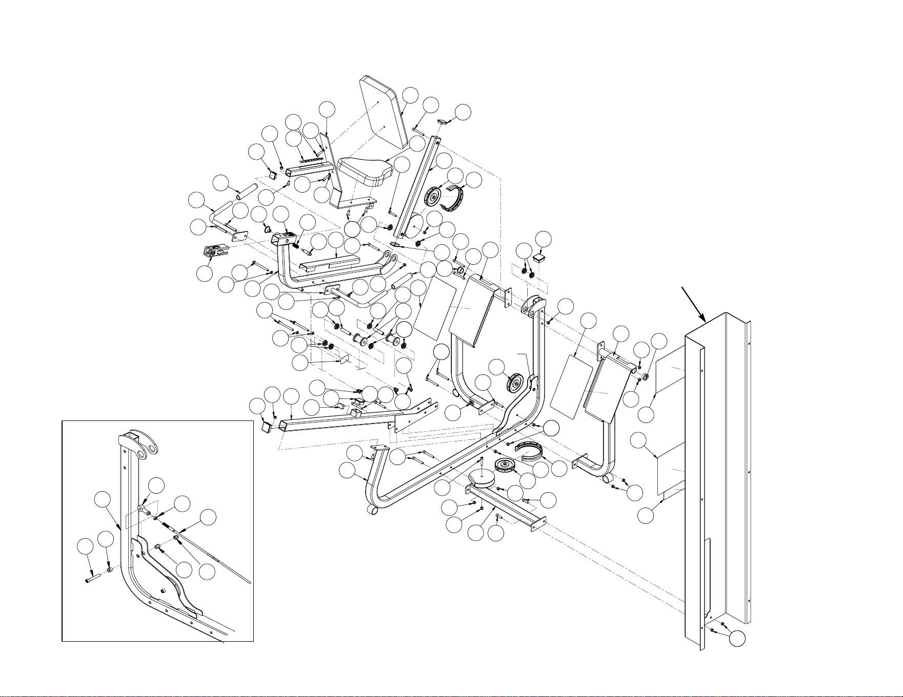
C33
C51
SEE
ROD END
BEARING
DETAIL
C50
C2
C51
C42
C33
C57
C43
C8
C32
C32
C5
C22
C41
C33
C12
C29
C29
C34
C3
C7
C45
C50
C16
C6
C51
C38
C23
C1
C10
C35
C33
C2
C2
C38
C11
C27
C51
C33
C5
C21
C33
C33
C15
C43
C2
C2
C28
C2
C28
C26
C2
C30
C30
C36
C39
C4
C33
C40
C19
C31
C14
C36
C35
C33
C33
C33
C1
C10
C33
C24
C29
C29
C32
C44
C32
C40
C2
C33
C33
C44
C33
C25
C18
C17
C25
C33
C33
C35
C1
C56
C54
C53
C55
C9
C57
C57
C57
C57
C57
C49
C47
C47
C33
C48
C52
C46
C14
ROD END BEARING DETAIL
8630 - Leg Press Station
COLUMN
Cybex MG 500 Multi-Gym Owner’s Manual
Service
Page 8-7

Cybex MG 500 Multi-Gym Owner’s Manual
Service
Page 8-8
D1 4 08014 Pulley
D2 2 FB030242 Bearing with snap ring 30 mm x 10 mm
D3 Removed 3/20/01
D4 4 11040-440 Cybex Knob
D5 2 4050M025 Grip
D6 3 4505-329 Detent Pin
D7 2 4605-511 Plastic Insert 5.94
D8 2 4800-570 Cable Guard
D9 1 4850-202 Right Handle
D10 1 4850-203 Left Handle
D11 4 8500-025 Caution Decal
D12 2 8500-026 Caution Decal
D13 4 8500-052 Cushion 4.00 Dia. x 7.00 L x .875
D14 1 8520-308 Leg Curl Tube
D15 1 8520-313 Seat Adjusting Decal
D16 Removed 7/13/01
D17A 1 8630-335 HHCS 10 mm x 100 mm (units with
serial number before 8650NVXXXX13)
D17B 1 8640-345 HHCS 10 mm x 80 mm (units with
serial number after 8650NVXXXX13)
D17C 1 HC331269 HHCS 10 mm x 90 mm (units with
serial number after 8650NV031928)
D18 1 8630-336 Nylon Locknut 10 mm
D19 1 8640-002 Cable 132.12 L
D20 1 8640-003 Cable 83.49 L
D21A 1 8640-200 Frame (units with serial number before
8650NVXXXX13)
D21B 1 8640-213 Frame (units with serial number after
8650NVXXXX13)
D22 1 8640-201 Cushion Post (for Back Cusion)
D23 1 8640-202 Cam
D24 Removed 3/20/01
D25 1 8640-204 Adjuster
D26 Removed 3/20/01
D27 1 8640-206 Leg
D28 1 8640-207 Brace
D29 Removed 3/20/01
D30A 2 8640-321 Insert (units with serial number before
8650NVXXXX13)
D30B 2 8640-347 Insert (units with serial number after
8650NVXXXX13)
D31 Removed 3/20/01
D32 4 BS070201 Com Spring .56 x .66 1.50 L
D33 2 FB050211 Bearing Flange .38 x .50 .25 L
D34 2 FB050226 Flange Bearing
1.00 ID x 1.25 OD x 1.00 L
D35 4 FB130205 Flange Bearing .62 x .75 x .38 L
D36 1 4507-301 Pin
D37 2 HC702826 SHCS .375-16 x 2.00
D38 2 HC702834 SHCS .375-16 x 3.00
D39 12 HN704901 Nylon Locknut .375-16
D40 1 JC702814 SHCS .375-16 x .625
D41 4 JC702820 SHCS .375-16 x 1.25
D42 2 JC702824 SHCS .375-16 x 1.75
D43 4 JC702832 SHCS .375-16 x 2.75
D44 2 JC702836 SHCS .375-16 x 3.25
D45 1 JC702838 SHCS .375-16 x 3.50
D46 4 PP080223 Plastic Insert
D47 3 PP090211 Plastic Insert 1.50 Sq x 10-14 G
D48 1 PU060201 Bumper
D49 1 4800-021 Back Cushion
D50A 1 4800-015 Seat Cushion (units with serial number
before 8650NVXXXX13)
D50B 1 4800-074 Seat Cushion (units with serial number
after 8650NVXXXX13)
D51 1 3900-391 Cybex Decal 11.37 Vert. Wht/Wht
D52 1 4800-381 Warning Decal
D53A 1 8640-598 Placard (units with serial number before
8650NVXXXX13)
D53B 1 8640-597 Placard (units with serial number after
8650NVXXXX13)
D54 1 HN704000 Hex Nut .375-16
D55 1 HN704400 Jam Nut .375-16
D56 1 HP286819 Spiral Pin
D57 1 8640-330 Spring Pin 10 mm x 90 mm Black
D58 1 02120 Pulley Mount
D59 1 08229 Detent Pin
D60 1 8640-211 Cushion Bracket
D61 1 8640-212 Cushion Post
D62 1 8640-214 Leg Bar
D63 1 8640-334 Support Plate
D64 2 FB130206 Flange Bearing 2.00 x 2.25 x 1.00
D65 2 HS347700 Washer
D66 2 PP080224 Plastic Insert 2.00 Dia.
D67 1 PP090000 Plastic Insert 1.50 x 2.00 Dia.
D68 2 08017 Retaining Ring .375
D69 6 JS347400 Interanl Tooth Lockwasher
8640 - Leg Extension/Leg Curl Station
ITEM QTY PART NO. DESCRIPTION
ITEM QTY PART NO. DESCRIPTION
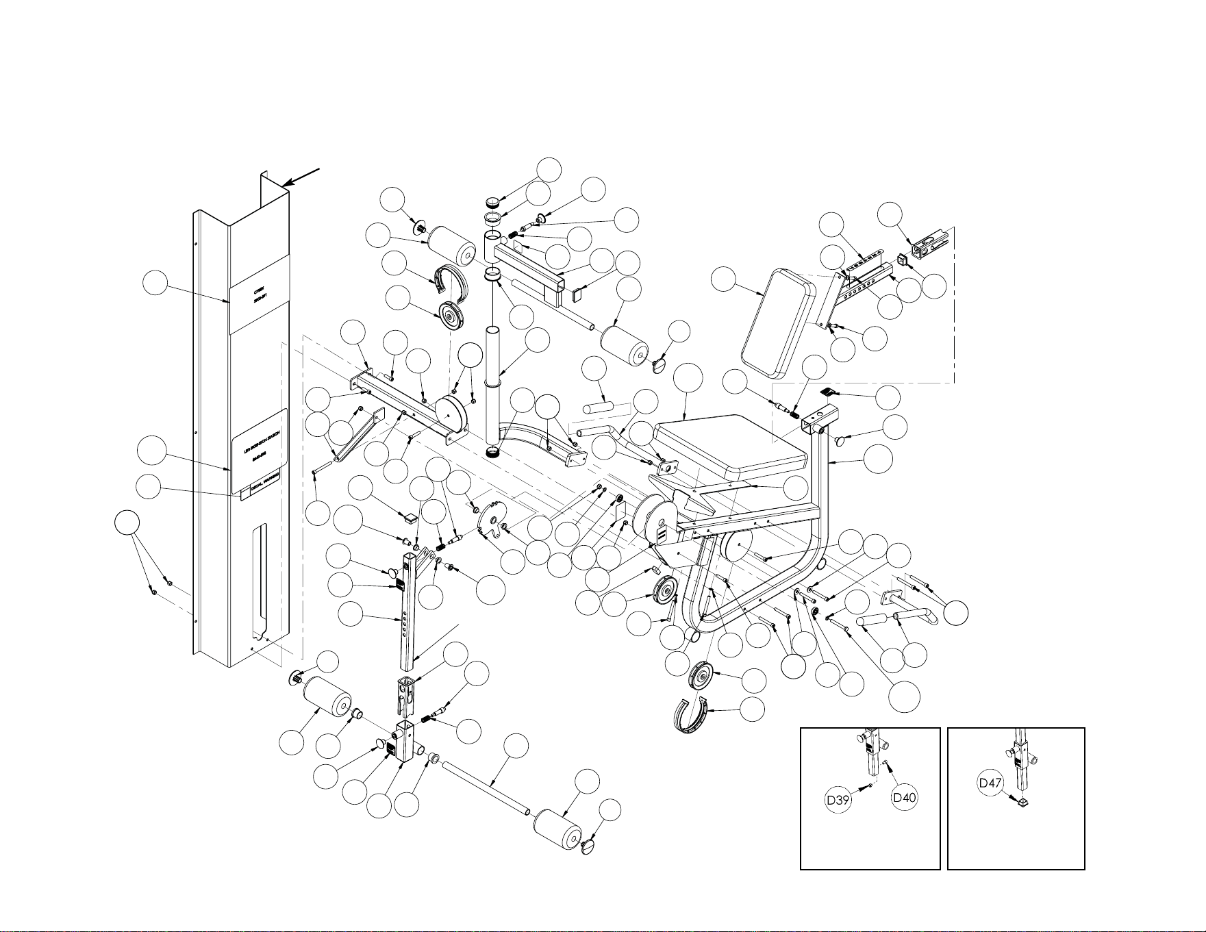
Cybex MG 500 Multi-Gym Owner’s Manual
Service
Page 8-9
8640 - Leg Extension/Leg Curl Station
D13
D46
D39
D13
D34
D4
D11
D39
D2
D43
D44
D14
D7
D6
D32
D34
D25
D43
D39
D46
D69
D51
D53B
D52
D39
D47
D30B
D4
D11
D35
D32
D6
D35
D35
D30B
D23
D35
D45
D39
D41
D41
D39
D42
D39
D39
D1
D8
D28
D27
D13
D32
D59
D4
D13
D49
D41
D15
D41
D22
D47
D7
D6
D32
D11
D4
D21B
D50B
D5
D9
D39
D39
D18
D12
D39
D12
D48
D1
D38
D42
D43
D2
D17C
D5
D10
D44
D37
D1
D8
D66
D64
D60
D61
D66
D63
D43
D65
D65
D62
D67
D64
D39
D11
D46
D46
D69
D69
D69
D38
D69
D69
SEE LEG
POST DET
AIL
LEG POST
DETAIL 1
LEG POST
DETAIL 2
COLUMN

Service
Page 8-10
Cybex MG 500 Multi-Gym Owner’s Manual
E1 20 08014 Pulley
E2 3 3900-391 Cybex Decal 11.37 Vert. Wht/Wht
E3 3 4700M005 Rubber Cap
E4 6 4700-019 Flange Bearing .62 ID x .95 OD x 1.50 L
E5 3 4800-256 Top Weight
E6 3 4800-381 Warning Decal
E7 3 51119 Selector Pin Retainer
E8 6 8550-358 Spacer
E9 1 8650-200 Leg Press Column
E10 1 8650-209 Pressing Column
E11 1 8650-202 Fly Column
E12 1 8650-203 Pulley Clevis
E13 3 8650-204 Cam Bolt
E14 2 8650-205 Pulley Adjuster
E15 1 8650-206 Brace
E16 1 8650-207 Brace
E17 6 8650-321 Weight Rod
E18 3 8650-333 Support Angle
E19 2 8650-339 C/Pulley Tab
E20 1 HC702830 SHCS .375-16 x 2.50
E21 1 8650-344 Panel
E22 1 8650-345 Panel
E23 3 9100-313 Weight Plate Decal 1-25
E24 3 BH030201 Pin, Q Release .375 Dia. x 4.00 L
E25 6 BR030206 Retaining Ring
E26 12 BR030214 Retaining Ring .625 Dia.
E27 1 8610-598 Placard
E28 1 8620-598 Placard
E29 1 8630-598 Placard
E30 6 HC702815 SHCS .375-16 x .750
E31 3 HC702817 SHCS .375-16 x 1.00
E32 6 HC702828 SHCS .375-16 x 2.25
E33 3 HC702834 SHCS .375-16 x 3.00
E34 39 HN704901 Nylon Locknut .375-16
E35 3 HP286819 Spiral Pin .188 x 1.12
E36 21 HS347600 Washer .375
E37 3 HS347700 Washer .375
E38 15 JC702814 SHCS .375-16 x .625
E39 13 JC702824 SHCS .375-16 x 1.75
E40 6 PR060005 Weight Bumper
E41 1 8650-208 Pulley Bracket
E42 2 HC702826 SHCS .375-16 x 2.00
E43 2 JC702832 SHCS .375-16 x 2.75
E44 6 8650-378 Cable Retainer
8650 - Main Frame
ITEM QTY PART NO. DESCRIPTION ITEM QTY PART NO. DESCRIPTION
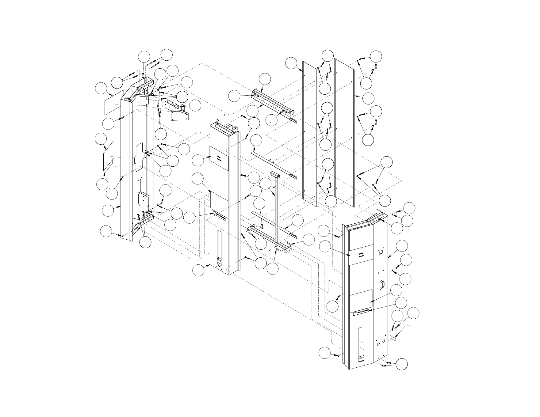
Cybex MG 500 Multi-Gym Owner’s Manual
Service
Page 8-11
E43
SERIAL NUMBER
DECAL
E38
E38
E36
E36
E21
E22
E38
E36
E38
E36
E38
E38
E36
E36
E38
E36
E34
E30
E30
E38
E36
E11
E2
E28
E6
E38
E36
E30
E34
E16
E32
E18
E32
E34
E34
E34
E15
E18
E32
E18
E32
E32
E32
E34
E9
E6
E29
E2
E34
E2
E31
E36
E42
E41
E36
E34
E30
E31
E36
E34
E27
E6
E30
E31
E36
E34
E34
E30
E10
E34
8650 - Main Frame
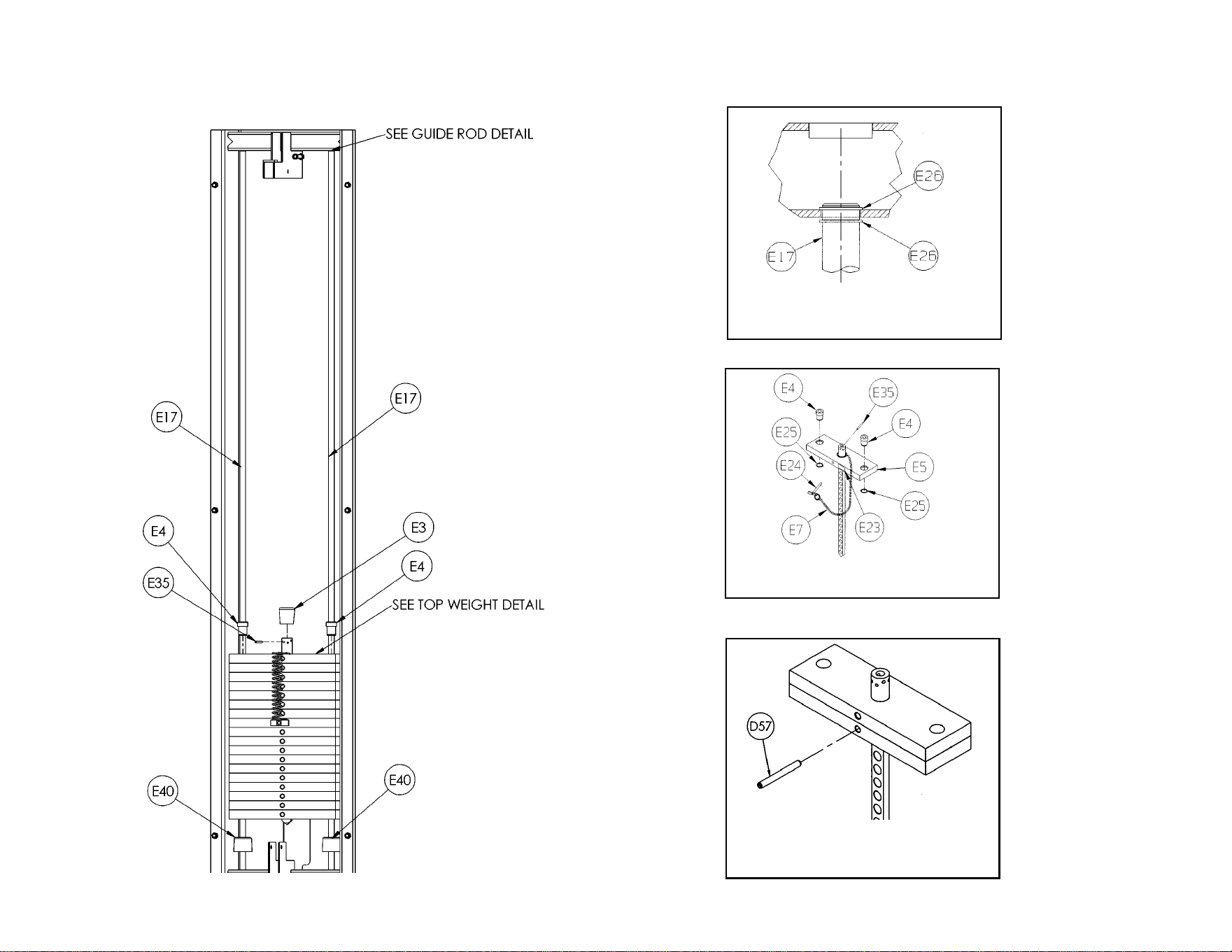
Service
Page 8-12
TOP WEIGHT DETAIL
Weight Stack
and Guide
Rod
Information
GUIDE ROD DETAIL
LEG EXTENSION/LEG CURL
PINNING SECOND WEIGHT
DETAIL
Cybex MG 500 Multi-Gym Owner’s Manual
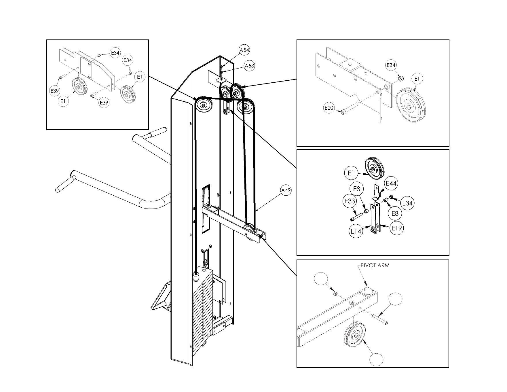
Service
Page 8-13
E34
E1
E33
MAIN FRAME PULLEY DETAIL
MAIN FRAME PULLEY DETAIL
MAIN FRAME PULLEY DETAIL
PRESSING STATION
PULLEY DETAIL
Pressing
Station Cable
Routing
Diagram
Cybex MG 500 Multi-Gym Owner’s Manual
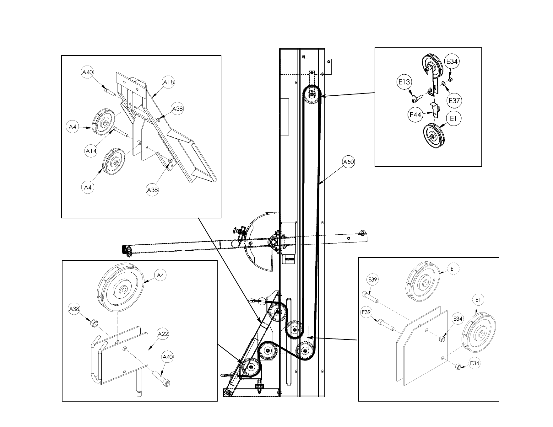
Cybex MG 500 Multi-Gym Owner’s Manual
Service
Page 8-14
PRESSING STATION PULLEY DETAIL
PRESSING STATION
PULLEY DETAIL
MAIN FRAME PULLEY DETAIL
MAIN FRAME PULLEY DETAIL
Pressing Station
Cable Routing
Diagram
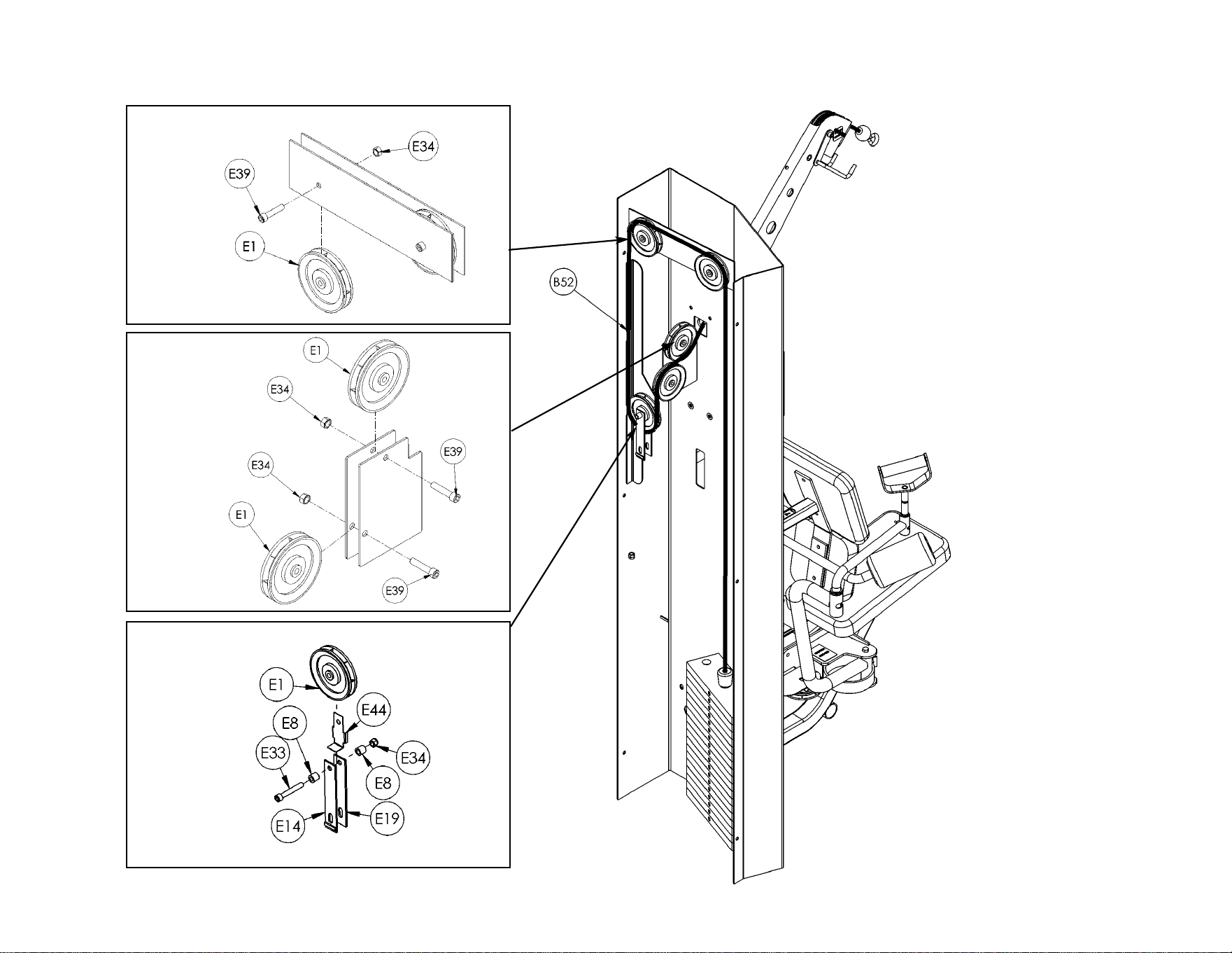
Cybex MG 500 Multi-Gym Owner’s Manual
Service
Page 8-15
MAIN FRAME
PULLEY DETAIL
MAIN FRAME
PULLEY DETAIL
MAIN FRAME
PULLEY DETAIL
Fly Station
Cable Routing
Diagram
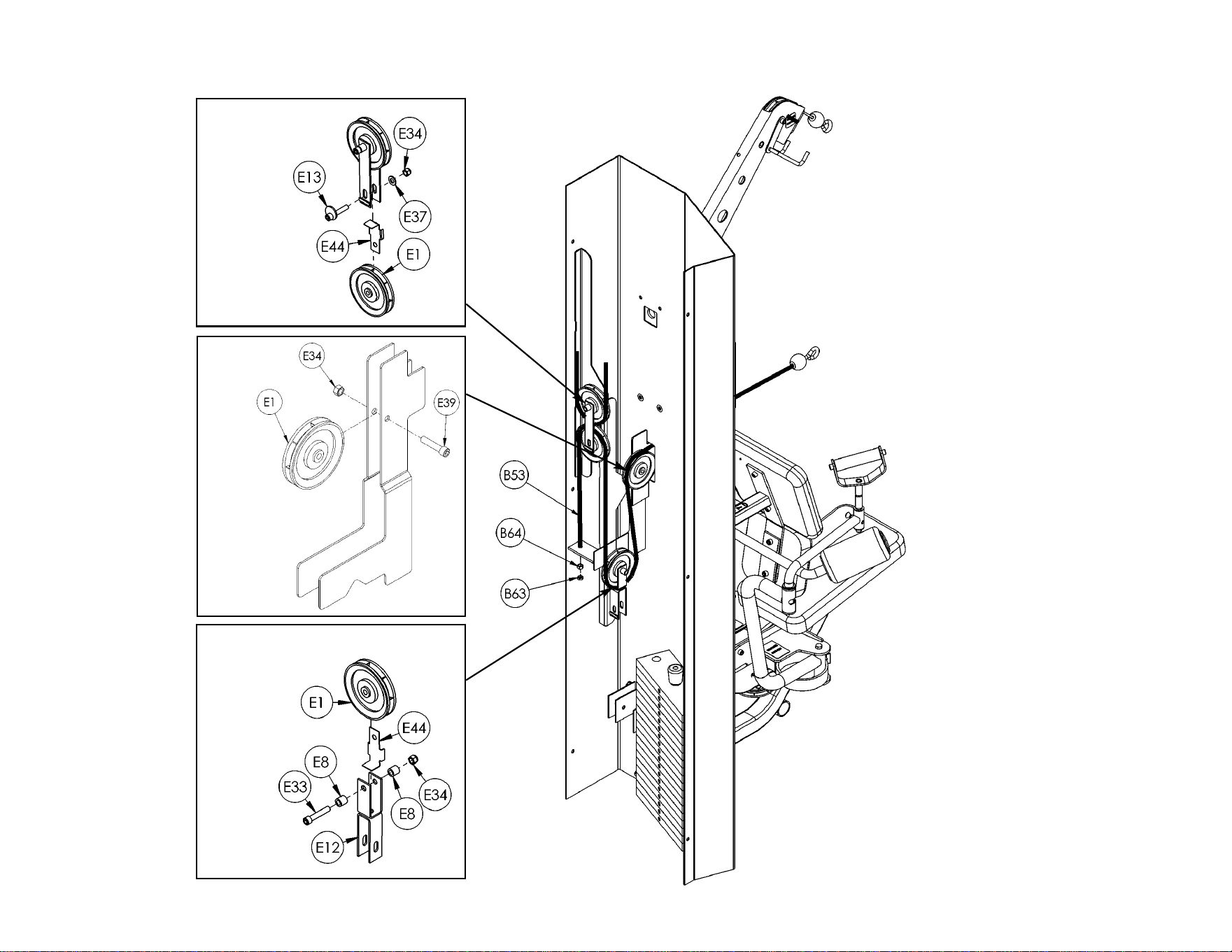
Cybex MG 500 Multi-Gym Owner’s Manual
Service
Page 8-16
MAIN FRAME
PULLEY DETAIL
MAIN FRAME
PULLEY DETAIL
MAIN FRAME
PULLEY DETAIL
Fly Station
Cable Routing
Diagram
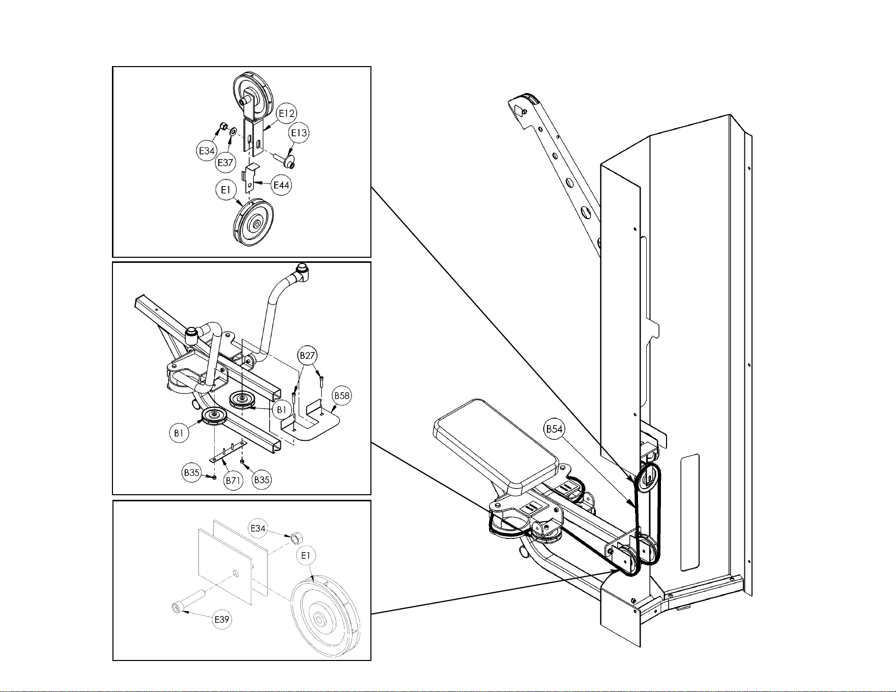
Cybex MG 500 Multi-Gym Owner’s Manual
Service
Page 8-17
MAIN FRAME
PULLEY DETAIL
FLY STATION
PULLEY DETAIL
MAIN FRAME
PULLEY DETAIL
Fly Station Cable Routing
Diagram
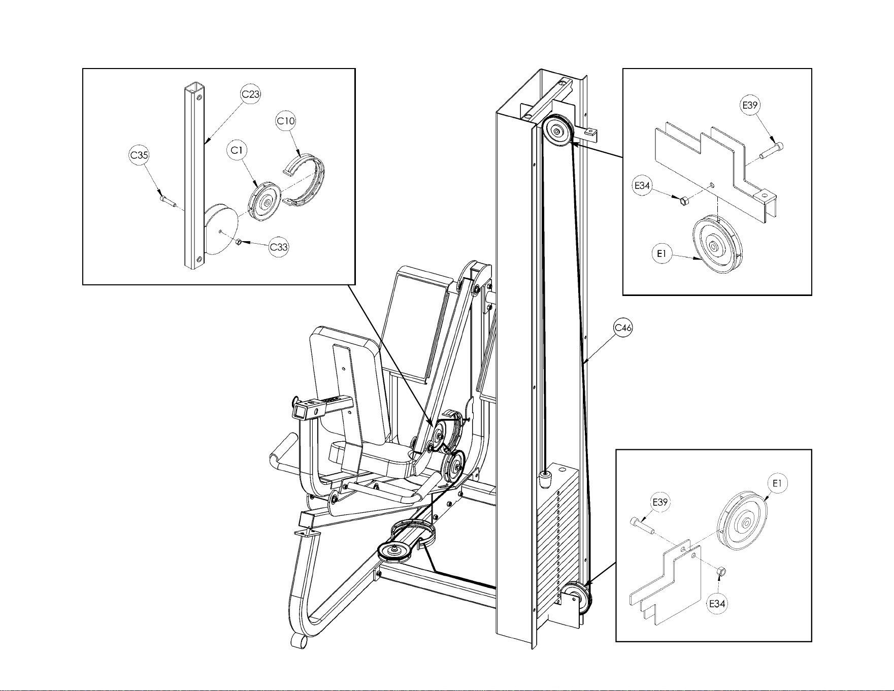
Cybex MG 500 Multi-Gym Owner’s Manual
Service
Page 8-18
LEG PRESS
PULLEY DETAIL
MAIN FRAME
PULLEY DETAIL
MAIN FRAME
PULLEY DETAIL
Leg Press Station
Cable Routing
Diagram
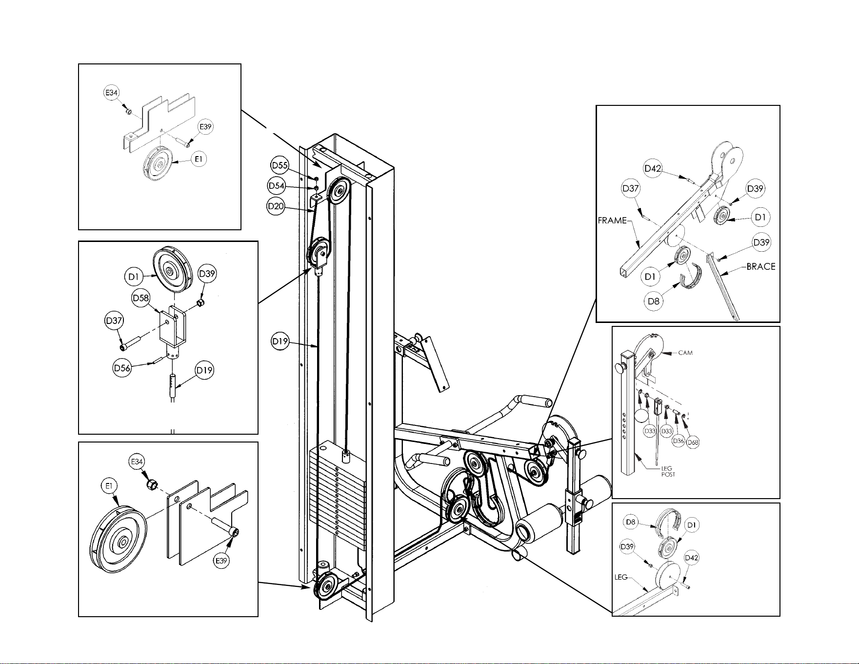
Service
Page 8-19
A68
MAIN FRAME
PULLEY DETAIL
LEG EXTENSION/LEG CURL
PULLEY DETAIL
MAIN FRAME PULLEY DETAIL
LEG
EXTENSION/LEG
CURL
PULLEY DETAIL
LEG
EXTENSION/
LEG CURL
PULLEY
DETAIL
Leg Extension/Leg Curl Station Cable
Routing Diagram
Cybex MG 500 Multi-Gym Owner’s Manual


10 Trotter Drive Medway, MA 02053 • 508-533-4300 • FAX 508-533-5183
www.cybexinternational.com • T[email protected]•[email protected]


