V1.0
2017.10
MATRICE 600
User Manual
Searching for Keywords
Search for keywords such as “battery” and “install” to nd a topic. If you are using Adobe Acrobat
Reader to read this document, press Ctrl+F on Windows or Command+F on Mac to begin a search.
Navigating to a Topic
View a complete list of topics in the table of contents. Click on a topic to navigate to that section.
Printing this Document
This document supports high resolution printing.
©
2017 DJI All Rights Reserved.
1
Using This Manual
Legends
Warning Important Hints and Tips Reference
Information
The MATRICE
TM
600 does not include a gimbal or camera. A corresponding gimbal or camera is
required for certain functions mentioned in this manual.
Before Flight
The following tutorials and manuals have been produced to help you get the most out of your
Matrice 600.
1. Matrice 600 In the Box
2. Matrice 600 Disclaimer and Safety Guidelines
3. Matrice 600 Quick Start Guide
4. Matrice 600 Intelligent Flight Battery Safety Guidelines
5. Matrice 600 User Manual
Check to see that you have all of the components listed in the Matrice 600 In the Box document.
Before assembly, read the Matrice 600 Disclaimer and Safety Guidelines. Get prepared by using the
Matrice 600 Quick Start Guide. Assemble the Matrice 600 by referencing the User Manual and the
video tutorial on the DJI website (http://www.dji.com).
Watch Video Tutorial
Please watch the tutorial video below to learn how to install the Matrice 600 correctly:
http://www.dji.com/product/matrice600/info#video
Download DJI Assistant 2
When using your Matrice 600 for the first time, you will need to activate it in the DJI Assistant 2
software.
http://www.dji.com/product/matrice600/info#downloads
DJI ASSISTANT
TM
2 supports Windows 7 or above.
Download DJI GO App
Be sure to use the DJI GO
TM
app or other apps compatible with DJI aircraft during ight. Scan the QR
code or visit http://m.dji.net/djigo to download the DJI GO app.
DJI GO supports iOS 8.0 (or later ) or Android 4.2 (or later).
2
©
2017 DJI All Rights Reserved.
Warning
The rotating propellers can cause serious damage and injury. Fly with caution at all times.
Assembly Warning
1. Ensure that all other parts are installed before inserting the Intelligent Flight Batteries.
2. Use the extension rod to separate the GPS module from the center frame to avoid interference with
the power system.
3. Ensure the frame arms are mounted correctly.
4. DO NOT remove any glued-in screws.
5. Unless specied, screws with blue or red glue on their threads can be used without threadlocker
for the rst time. After that, apply a suitable amount of threadlocker to the thread.
6. The Matrice 600 should be lifted off the ground when testing the landing gear or recalibrating servo
travel.
Flight Warning
1. The aircraft is not waterproof. DO NOT y in rainy or snowy weather.
2. Ensure that all parts are in good condition before each ight. DO NOT y with worn or damaged
parts.
3. Ensure that the propellers and motors are installed correctly and propellers and frame arms are
unfolded before each ight.
4. Ensure that all cables are connected correctly and rmly before each ight.
5. Maintain a safe distance from people, buildings, high voltage power lines, tall trees, water, and
other hazards when ying the aircraft.
6. Only use DJI TB47S/TB48S Intelligent Flight Batteries as the power supply.
7. DO NOT overload the system.
8. DO NOT go near or touch the motors or propellers when they are spinning, as this can cause
serious injury.
9. Disconnect the batteries and remove the camera during transportation to avoid damage or injury.
10. Only use compatible DJI parts.
If you encounter any problems or if you have any questions, please contact your
local DJI authorized dealer or DJI Support.
DJI Support Website:
www.dji.com/support

©
2017 DJI All Rights Reserved.
3
Contents
Using This Manual 1
Legends 1
Information 1
Before Flight 1
Watch Video Tutorial 1
Download DJI Assistant 2 1
Download DJI GO App 1
Warning 2
Assembly Warning 2
Flight Warning 2
Product Prole 5
Introduction 5
Highlighted Features 5
Installation 6
Mounting the Frame Arms 6
Mounting the Retractable Modules 8
Mounting the Landing Gear 11
Mounting GPS Module 12
Mounting the Upper and Lower Covers of the Center Frame 13
Mounting the Gimbal (Optional) 14
Intelligent Flight Battery 15
Prole 15
Intelligent Flight Battery Functions 15
Using the Batteries 16
Remote Controller 21
Prole 21
Preparing Remote Controller 21
Remote Controller Overview 21
Remote Controller Operations 23
Dual Remote Controllers Mode 28
Remote Controller LEDs 30
Linking the Remote Controller 31
Return-to-Home (RTH) 33
Prole 33
Smart RTH 33

4
©
2017 DJI All Rights Reserved.
Low Battery RTH 33
Failsafe RTH 34
RTH Safety Notices 35
Updating the Home Point 35
DJI GO App 36
Equipment 36
Editor 39
Explore 39
Me 39
DJI Assistant 2 40
Installation and Launching 40
Using the DJI Assistant 2 40
Flight 42
Flight Environment 42
Flight Limits and No Fly Zones 42
Pre-Flight Checklist 45
Flight Status Indicators 46
Calibrating the Compass 47
Auto Takeoff and Auto Landing 48
Starting and Stopping the Motors 48
Stopping the Motors Mid-ight 49
Flight Test 49
Appendix 50
Specications 50
Intelligent Flight Modes 53
Upgrading the Firmware 54
Charging Hub for Intelligent Flight Batteries 55
Retractable Landing Gear 57
Reserved Mounting Position Dimensions 59
A3 Flight Controller Overview 60
Lightbridge 2 Air System Overview 61
Mounting the Gimbal (Optional) 62
Mounting the Expansion Bays (Optional) 66
Modular Redundancy System (Optional) 67
DJI Zenmuse X3 Gimbal with Camera 67

©
2017 DJI All Rights Reserved.
5
Product Prole
Introduction
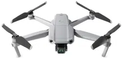
The Matrice 600 is a six-rotor flying platform designed for professional aerial photography and
industrial applications. The aircraft uses six Intelligent Flight Batteries to extend ight time. The built-
in API Control feature, expandable center frame and maximum takeoff weight of 15.1 kg make the
Matrice 600 ideal for connecting other devices to meet the specic needs of different applications.
Highlighted Features
The DJI next-generation A3 ight control system and Lightbridge 2 transmission system are built into
the Matrice 600 for accurate and stable ight performance and real-time HD transmission. The Matrice
600 is fully compatible with the DJI Onboard and Mobile SDKs, allowing developers to optimize the
ying platform for specic applications. The A3 can be upgraded to the A3 Pro by two upgrade kits.
The A3 Pro’s three GPS modules and IMUs add triple modular redundancy to greatly reduce the risk
of system failure.
The Matrice 600 is compatible with the DJI Zenmuse X3, X5 series, XT gimbal with camera, Zenmuse
Z15 series HD gimbal, and Ronin-MX gimbal for professional aerial photography and industrial
applications.
The expandable center frame makes it easy to mount additional components and devices to achieve
greater functionality and results.
The Matrice 600 uses six Intelligent Flight Batteries and a patented battery management system to
extend ight time and provide safe and reliable power supply.
The retractable landing gear included with the Matrice 600 allows for clear, 360-degree camera views.
6
©
2017 DJI All Rights Reserved.
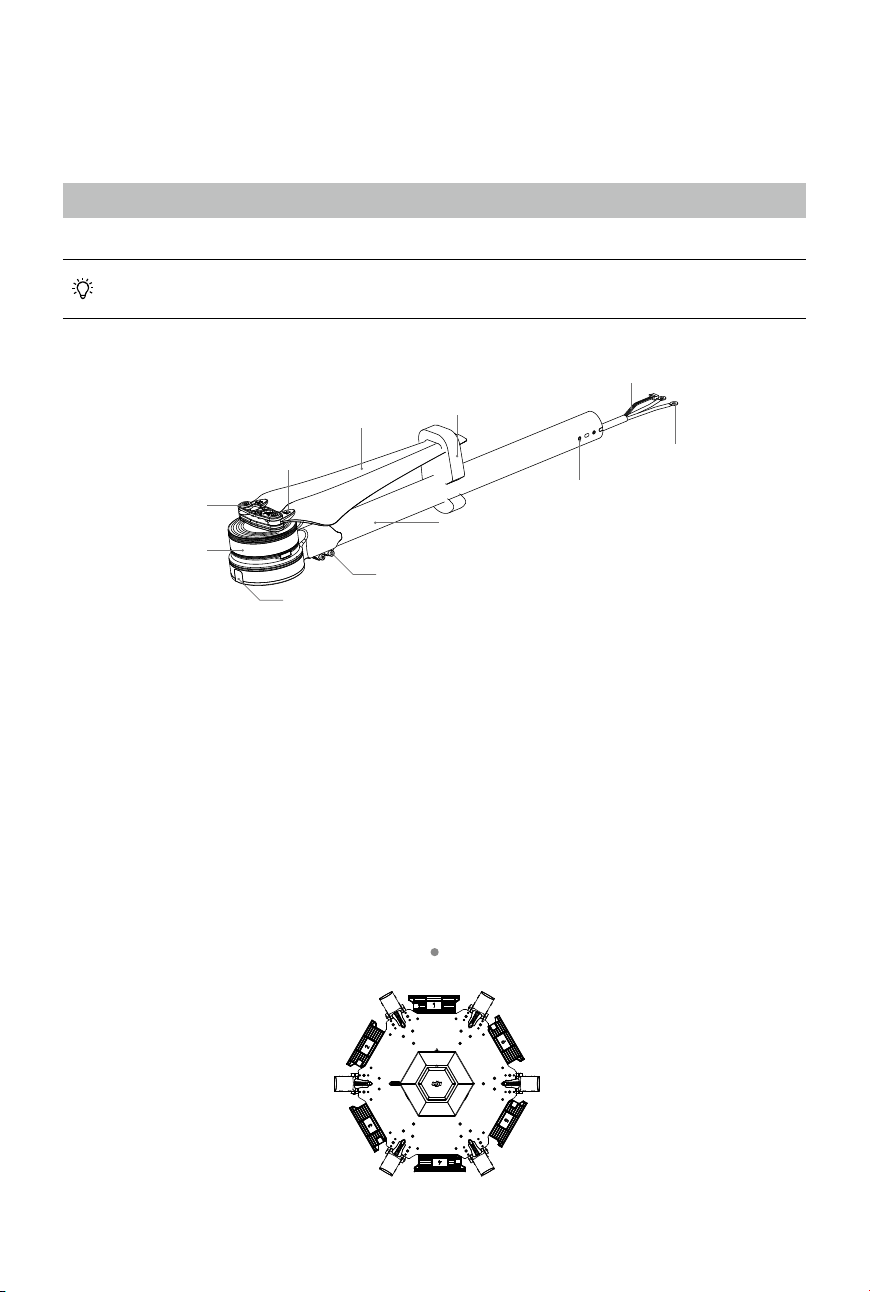
1. Preparing the frame arms.
a. Check for cracks on all propellers. Ensure all the screws are secured in position.
b. Ensure all motors are mounted correctly and rmly and are free from obstruction.
c. Mount the arms with red motor bases to the M1 and M2 positions (on both sides of battery
compartment No. 1) to indicate the nose direction of the Matrice 600. When viewed from above
with battery compartment No. 1 facing forward, the M1 position is on the right side of battery
compartment No. 1, and the M2 - M6 positions are arranged counter-clockwise from M1.
d. Identify the “CW” and “CCW” marks on the propellers. Mount the frame arms marked “CCW” to
the M1, M3 and M5 positions of the center frame. Mount the arms marked “CW” to the M2, M4
and M6 positions of the center frame.
M1M2
M3 M6
M4 M5
Aircraft’s Front
Motor
CW or CCW Mark
Propeller
Propeller Holder
Propeller Cover
Front / Rear Indicator
Arm Screws
Screw Holes
Arm Tube
Power Cables
ESC Signal Cable
Installation
Tools Required: 1.5 mm hex key, 2.0 mm hex key, 2.5 mm hex key, medium strength threadlocker.
Mounting the Frame Arms
The frame arm cables come with heat shrink tubing for easy wiring. Remove the tubing from
the cables just before connecting the cables.
©
2017 DJI All Rights Reserved.
7
MATRICE 600
User Manual
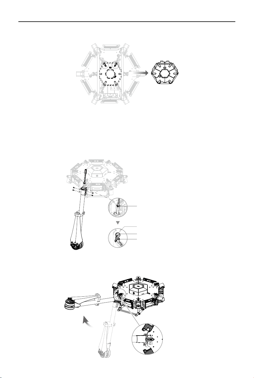
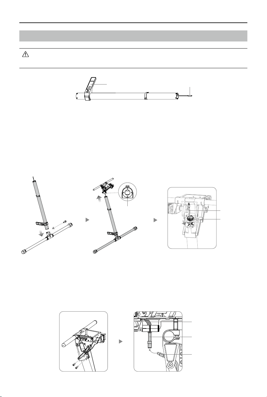
3. Insert the frame arm into the arm connector on the center frame with the propeller away from the
center frame. Rotate the frame arm to align the screw holes on the frame arm and connector. Then
insert and tighten four M3×6.5 screws.
4. Pull the cables of the frame arm through the arm stopper and insert the stopper into the arm
connector.
5. Pull the cables through the cable outlet and cable xing ring on the lower plate of the center frame.
Arm Stopper
Lower Plate of the Center Frame
Cable Outlet
Cable Fixing Ring
2. Remove the lower cover of the center frame for installation and connection.
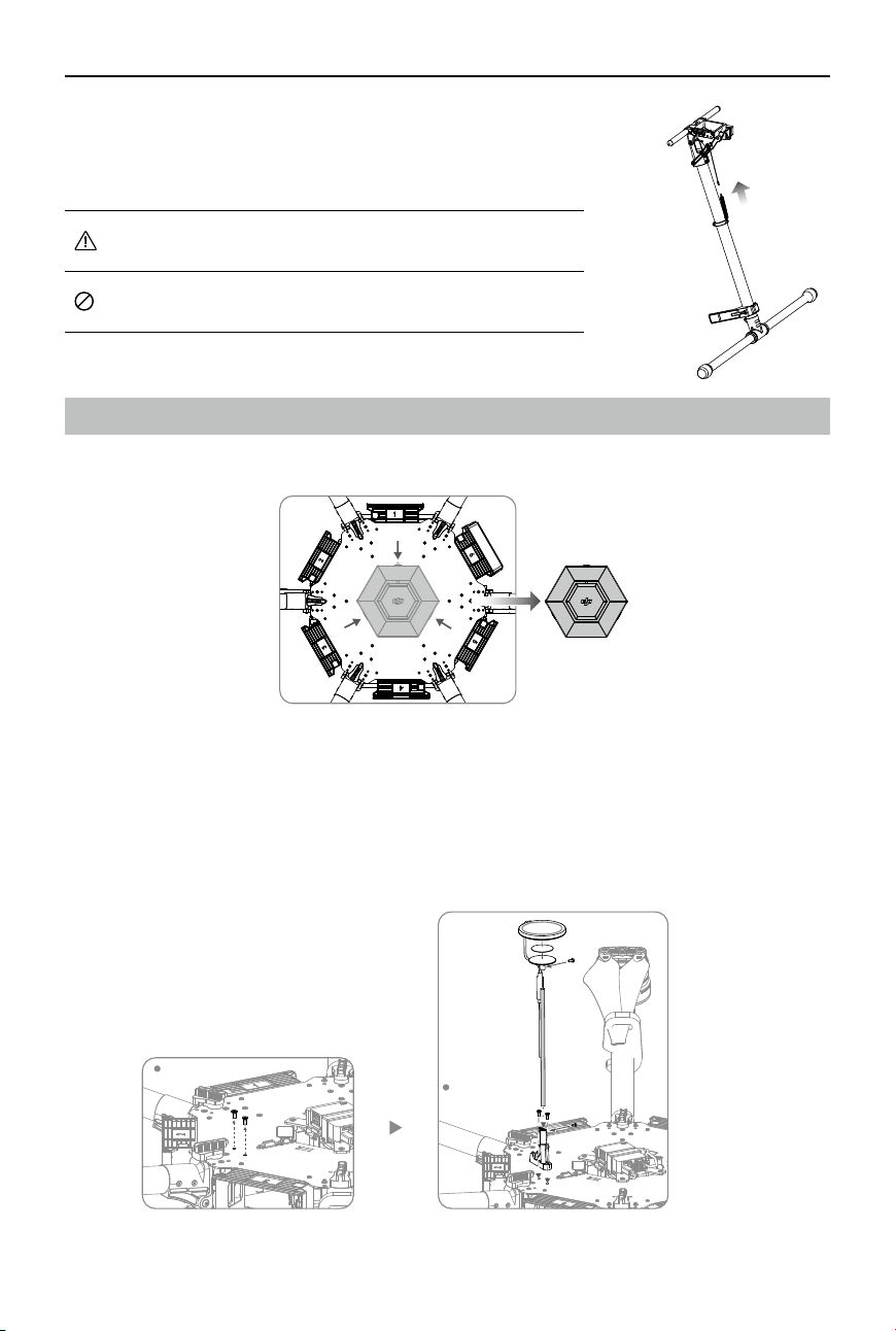
6. Gently lift the frame arm. Twist the red knob to lock each arm in place. Be sure you hear an audible
click, which indicates a proper lock. Check the arm for movement. To store, untwist the knob and
lower the frame arm.
8
©
2017 DJI All Rights Reserved.
MATRICE 600
User Manual
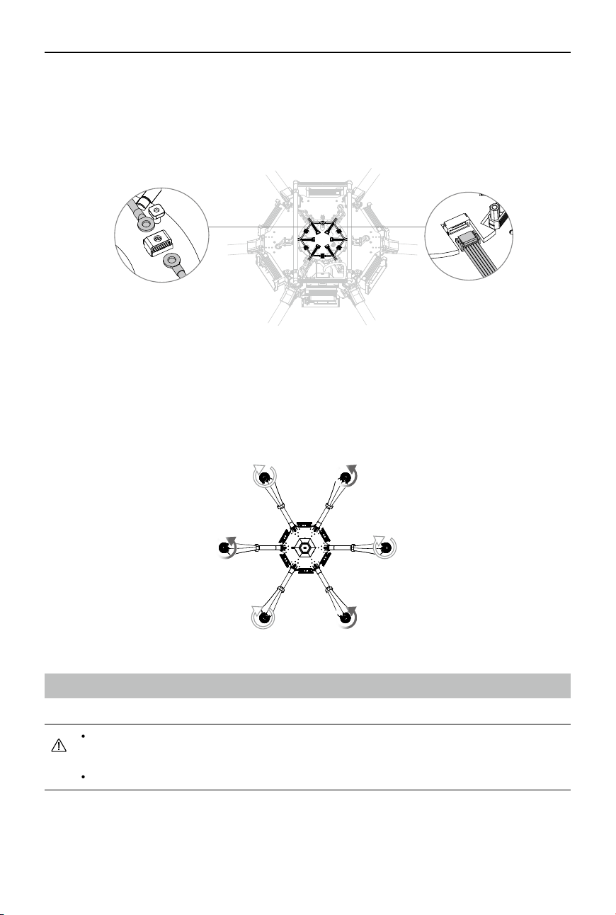
7. Connect the power cables to the center frame. Each cable must be screwed into a positive (+) or
negative (-) gold bracket. Red cables are positive and black cables are negative. Each bracket will
have two cables of the same color screwed into it. Then tighten each M3×5.5 screw (square head)
using the square socket wrench.
8. Plug each ESC signal cable into the slot near each arm on the center frame.
9. Ensure that all ESC cables and power cables are correctly installed on the center frame.
10. Identify the position and rotational direction of the motors. When viewed from above, motors M1 to
M6 are arranged counter-clockwise with motors M1 and M2 at the front of the aircraft and motors
M5 and M6 at the rear. Motors M1, M3 and M5 rotate counter-clockwise as indicated by the “CCW”
mark, while motors M2, M4 and M6 rotate clockwise as indicated by the “CW” mark.
Mounting the Retractable Modules
DO NOT mix up the mounting positions for the left and right retractable modules. Identify
the left module by locating the control board and power cable integrated on the left module.
Operate with care to avoid injury from the connecting arm.
Power Cables
ESC Signal Cable
M1M2
M3 M6
M4
M5
©
2017 DJI All Rights Reserved.
9
MATRICE 600
User Manual
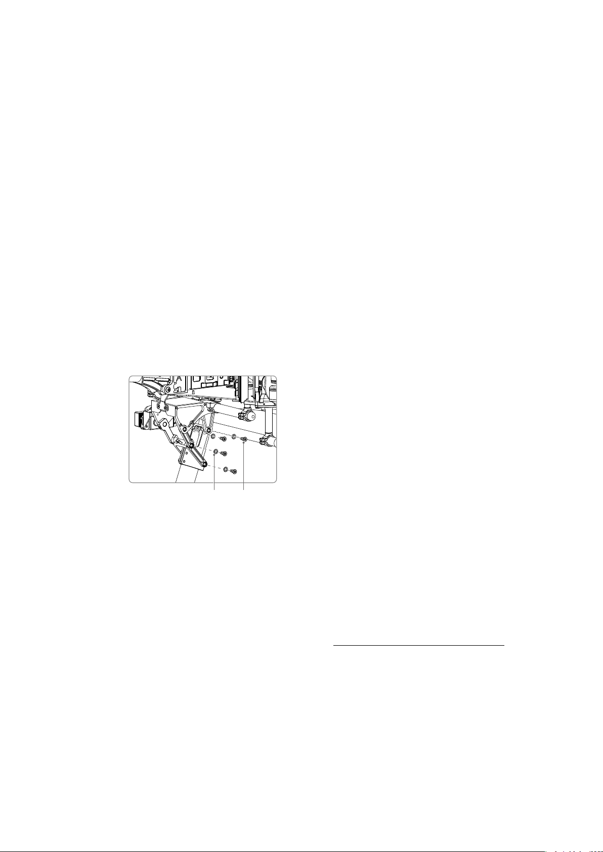
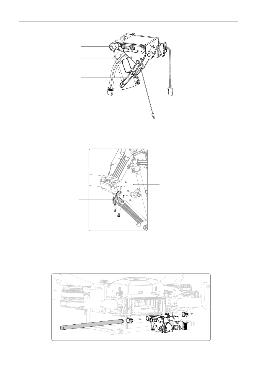
1. Mount the retractable module bracket to the mounting position on the lower plate of the
center frame as shown below. Apply medium strength threadlocker to two M3×8.5 screws.
Insert and tighten the screws.
2. With the servo of the retractable module at the rear of the aircraft, insert the retractable module
mounting rod into one mounting hole on the center frame, mounting holes on the retractable module
and the other mounting hole on the center frame respectively. Ensure that the left retractable module
is mounted on the left side of the aircraft (when viewed from the rear).
Mounting Holes
Servo
Servo Cable
Power Cable
(Left module only)
Connecting Arm
Control Board
(Left module only)
Lower Plate of the Center Frame
Retractable
Module Bracket
10
©
2017 DJI All Rights Reserved.
MATRICE 600
User Manual
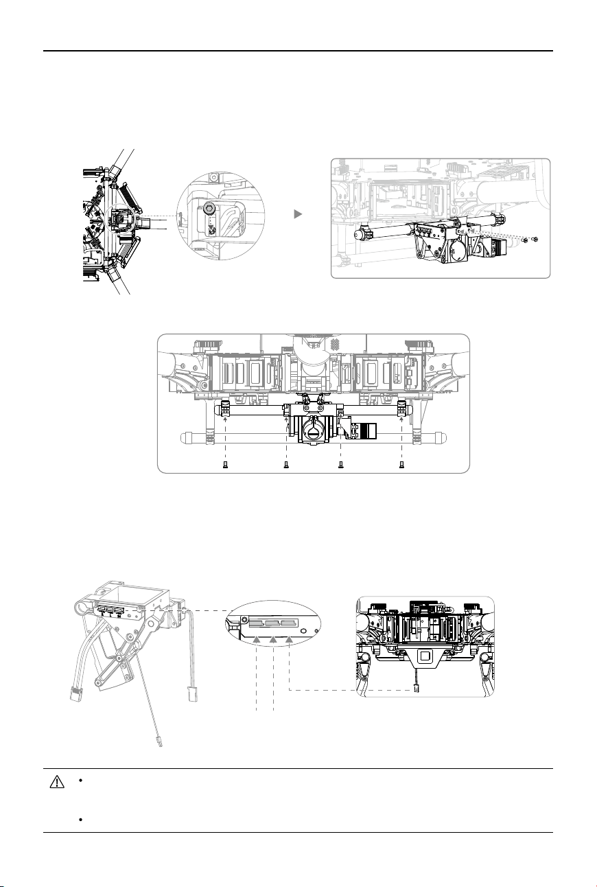
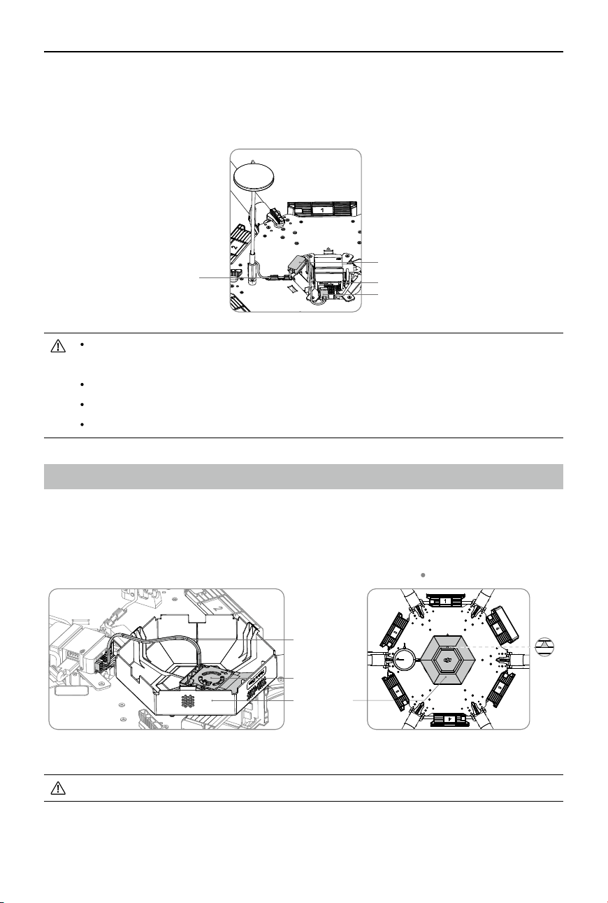
6. Connecting the servo cables.
a. Connect the left servo cable to the “L” port on the control board.
b. Connect the right servo cable to the “R” port on the control board.
c. Connect the servo cable at the bottom of the center frame to the “IN” port on the control board.
3. Align the cable xing ring and the screw hole on the bottom of the retractable module. Insert and
tighten the M3×5.5 screw.
4. Align the screw holes of the connector on the center frame and the screw holes on the middle of
the retractable module. Insert and tighten the two M3×6.5 screws.
5. Insert and tighten the four M3×6.5 screws to secure the retractable module on the mounting rod.
DO NOT mix the cabling between the left and right servos, otherwise the landing gear
cannot function properly.
Arrange the wiring neatly to prevent the frame edges from cutting the cables.
Servo Cable at the Bottom of the Center Frame
R
L
IN
Left Servo CableRight Servo Cable
©
2017 DJI All Rights Reserved.
11
MATRICE 600
User Manual
The antennas are attached to the landing gear legs upon delivery. DO NOT move the
antennas. Pull out the antenna cables from the landing gear legs before mounting.
Mounting the Landing Gear
1. Insert one landing gear leg into each landing skid tube and ensure that the antenna is pointing in
the same direction as the screw hole on the landing skid tube. Secure the landing gear leg in place
by inserting and tightening the M3×8 (cylinder) screw. Be sure to insert the screws from right to left
as shown below to avoid damaging the screw holes.
2. Insert the landing gear leg into the connector on the retractable module. DO NOT damage the
antenna cable. Rotate the landing gear leg until its slots are aligned with the ns in the connector.
3. Pull the antenna cable through the landing gear stopper and insert the stopper into the connector
on the retractable module.
4. Insert two M3×8 (cylinder) screws into the screw holes on the connector and tighten. Be sure to
insert the screws from left to right as shown below to avoid damaging the screw holes.
5. Pull the antenna cable through the retractable module and then connect to the antenna extension
cable at the bottom of the center frame. Then move the antenna protector on the antenna extension
cable to cover the point of connection with the antenna cable.
Antenna
Antenna Cable
Fins in the Connector
Antenna Cable
Landing Gear
Stopper
Antenna Protector
Antenna Extension Cable
Antenna Cable
12
©
2017 DJI All Rights Reserved.
MATRICE 600
User Manual
6. Connect both springs to the legs and the center frame.
Watch your ngers when mounting the springs to the landing
gear.
DO NOT move the spring mount on the landing gear leg to
avoid affecting ight performance.
Mounting GPS Module
1. Remove the upper cover of the center frame.
Aircraft’s Front
2. Remove the two M3×5.5 screws on the left of the upper plate. Attach the collapsible GPS mount
using two M3×8 screws.
3. Mount a GPS module to the GPS mount with an extension rod. Ensure the arrow points toward the
front of the aircraft (M1, M2). Insert two M2x4 screws into the two connectors above and under the
extension rod.
Aircraft’s Front
©
2017 DJI All Rights Reserved.
13
MATRICE 600
User Manual
DO NOT damage the fan cable when removing the upper cover of the center frame.
Ensure that the GPS module is securely mounted and the arrow is pointing towards the
nose of the aircraft.
Mount the GPS with an extension rod to avoid interference from power system.
Ensure the extension rod is rm and stable before each ight.
Avoid catching your ngers in the collapsible mount when folding for transportation.
Mounting the Upper and Lower Covers of the Center Frame
1. Connect the fan cable (with a JST 4-pin connector) to the fan port on the upper cover rst, and then
re-mount the upper cover. Make sure the arrow on it is pointing toward the front of the aircraft (M1,
M2) and DO NOT damage the cables. Insert the upper cover into the slots on the upper plate. Be
sure you hear audible clicks, which indicate a proper lock.
Fan
Upper Cover
Fan Cable
Slot
CAN HUB
CAN1 Port
GPS Cable
4. Plug the GPS cable into the CAN1 port on the ight controller.
5. Attach the CAN HUB of the GPS module onto the upper plate of the center frame. Then insert the
GPS cable into the slot on the upper plate of the center frame.
6. Fix the GPS cable onto the extension rod using tape.
Aircraft’s Front
14
©
2017 DJI All Rights Reserved.
MATRICE 600
User Manual
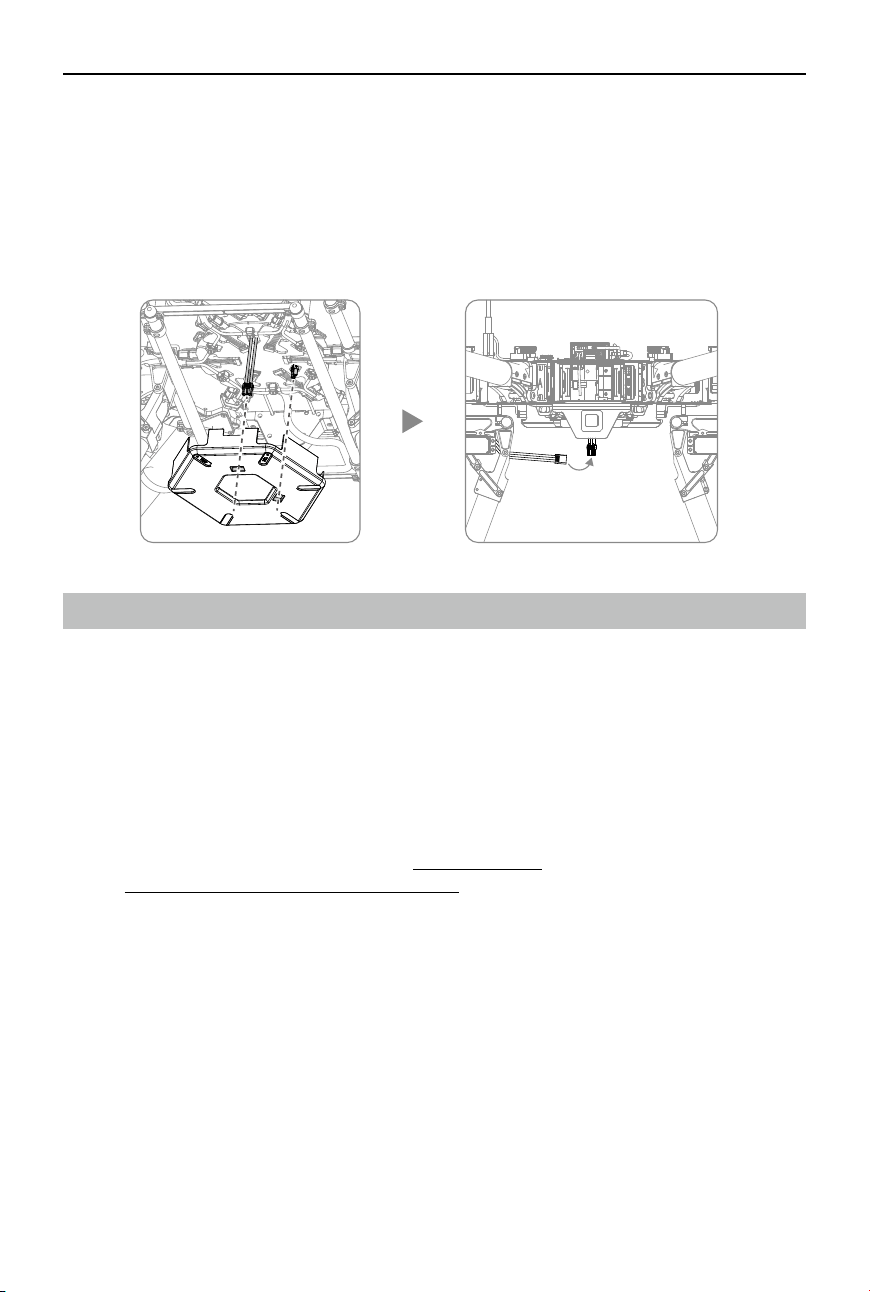
2. Arrange the cables connected to the lower plate of the center frame. Pull the XT30 power cable on
the lower plate through the LIPO-6S cable outlet on the lower cover, align the reserved XT30 port on
the lower plate to the DC-18V cable outlet on the lower cover of the center frame, and then re-mount
the lower cover of the center frame. DO NOT damage the cables. Insert the lower cover into the
slots on the lower plate, making sure you hear audible clicks indicating a proper lock.
3. Connect the power cable of the retractable module to the XT30 power cable at the bottom of the
center frame.
Mounting the Gimbal (Optional)
The built-in ight control system of the Matrice 600 is compatible with the following DJI gimbals and
cameras.
Ronin-MX
Zenmuse X3
Zenmuse X5 Series
Zenmuse XT
Zenmuse Z15 Series HD Gimbal: Z15-A7, Z15-BMPCC, Z15-5D III, Z15-GH4
Different accessories are used to mount different gimbals or cameras. Purchase corresponding
accessories according to your needs. Refer to Appendix (p. 62) for details on mounting the gimbal.
Refer to DJI Zenmuse X3 Gimbal with Camera (p. 67) for gimbal movement control for all the gimbals
above.
©
2017 DJI All Rights Reserved.
15
Intelligent Flight Battery
Prole
The Matrice 600 has six battery compartments and six Intelligent Flight Batteries to extend the ight
time. The standard Intelligent Flight Battery has a capacity of 4500mAh, voltage of 22.2V, and built-in
smart charge-discharge function. It can only be charged with an appropriate DJI approved charger or
charging hub.
The Intelligent Flight Battery must be fully charged before rst-time use. Refer to Charging the
Intelligent Flight Battery (p. 18) for more information.
Intelligent Flight Battery Functions
1. Battery Level Display: LEDs display the current battery level.
2. Battery Life Display: LEDs display the current battery life.
3. Auto-discharging Function: The battery automatically discharges to below 65% of total power
when it is left idle (pressing the power button will cause the battery to exit idle state) for more than
10 days to prevent swelling. It takes about two days to discharge the battery from 100% to 65%,
and it is normal to feel moderate heat emitting from the battery during the discharge process. The
discharge thresholds can be adjusted in the DJI GO app.
4. Balanced Charging: Automatically balances the voltage of each battery cell when charging.
5. Overcharge Protection: Automatically stops charging the battery when it is fully charged.
6. Temperature Detection: The battery will only charge when its temperature is between 5°C (41°F)
and 40°C (104°F).
7. Overcurrent Protection: The battery stops charging when the maximum current of 10A is exceeded.
8. Over-Discharge Protection: The battery stops discharging when the battery voltage reaches 18V to
prevent damage from over-discharge.
9. Short Circuit Protection: Automatically cuts the power supply when a short circuit is detected.
10. Battery Cell Damage Detection: The DJI GO app shows a warning message if a damaged battery
cell is detected.
11. Battery Log: Show the last 32 entries of battery information including the warning messages.
12. Sleep Mode: The battery enters sleep mode after 10 minutes of inactivity to save power.
13. Communication: The battery voltage, capacity, current, and other relevant information is sent to
the ight controller.
Read the
Disclaimer and Safety Guidelines
and
Intelligent Flight Battery Safety Guidelines
before use. Users take full responsibility for all operations and usage.
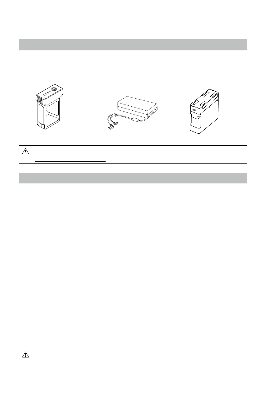
Intelligent Flight Battery
Charging Hub
Charger
16
©
2017 DJI All Rights Reserved.
MATRICE 600
User Manual
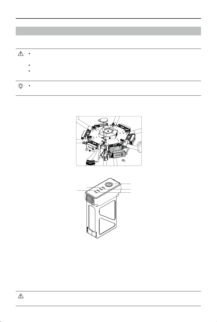
Using the Batteries
Installing the Batteries
Powering ON/OFF
Powering On: Press the Power Button once, then press again and hold for 2 seconds to power on.
The Power LED will turn red and the Battery Level Indicators will display the current
battery level.
The Matrice 600 has six Intelligent Flight Batteries and an advanced battery management system.
When you power on one of the batteries, the battery management system will automatically assess
the power level for all of the other batteries. If the power supply is OK, the other batteries will power on
automatically. Likewise, you only need to power off one battery and all the other batteries will power
off automatically.
There are six battery compartments on the Matrice 600. You must load all six battery
compartments with batteries of the same model before each ight.
Make sure all the batteries are fully charged before each ight.
Never insert the Intelligent Flight Battery into or remove it from the battery compartment of
the Matrice 600 when it is powered on.
If using more than six batteries, you can mark them separately (six batteries for one set) with
the battery stickers that come with the Matrice 600.
Insert the six Intelligent Flight Batteries into the battery compartments.
DO NOT manually power on more than one Intelligent Flight Battery to avoid damaging the
batteries.
Power Button (Built-in LED)
LED2
LED4
LED1
LED3
©
2017 DJI All Rights Reserved.
17
MATRICE 600
User Manual
If the power supply is not OK when powering on the batteries, the DJI GO app will either prompt you
to adjust the battery positions or tell you there is a large voltage difference.
To adjust the battery positions:
1. Power off all the batteries.
2. Adjust battery positions by following the tips in the DJI GO app.
3. Ensure all the battery positions are correct and then power on one of the batteries. The other
batteries will power on automatically if the positions are correct.
If the message prompt says there is a large voltage difference, the power supply issue cannot be
resolved by adjusting the battery positions. Fully charge all the batteries and try again.
Powering Off: Press the Power Button once, then press again and hold for 2 seconds to power off.
Ensure that all Intelligent Flight Batteries are operating normally before takeoff. If a battery
abnormal status appears in the DJI GO app, follow the on-screen instructions. The DJI GO
app will instruct you to land if a battery abnormality occurs during ight. In this event, you
should land and check the battery immediately.
Low Temperature Notice
1. Using the Intelligent Flight Battery at core temperatures below -10℃ is not advised. Between -10℃
and 5℃, the Intelligent Flight Battery should attain a voltage of 4.2 V, but it is recommended that
you apply the insulation sticker to the battery to prevent a rapid drop in temperature.
2. In cold environments (i.e. air temperature below 5℃), the performance of the Intelligent Flight
Battery is reduced. Ensure the Intelligent Flight Battery is fully charged and attains a voltage of 4.35
V before takeoff.
3. In very cold environments (e.g. air temperature of -20℃, battery core temperature of 5℃), the
Intelligent Flight Battery’s core temperature will drop rapidly even after pre-heating, and its
performance is signicantly reduced. It is not recommended to y under such conditions.
4. If the DJI GO app displays the Low Battery Level warning, stop flying and land the aircraft
immediately. You will still be able to control the aircraft’s movement when this warning is triggered.
5. For the optimal performance, maintain the Intelligent Flight Battery’s core temperature above 20℃
when in use.
Ensure the temperature of the Intelligent Flight Battery exceeds 5℃ before takeoff.
To warm up the battery, power on the Intelligent Flight Battery inside the battery compartment,
for approximately 1-2 minutes, before takeoff. Begin ying by hovering the aircraft at a low
altitude, for approximately 1 minute, to ensure the battery temperature is stable.
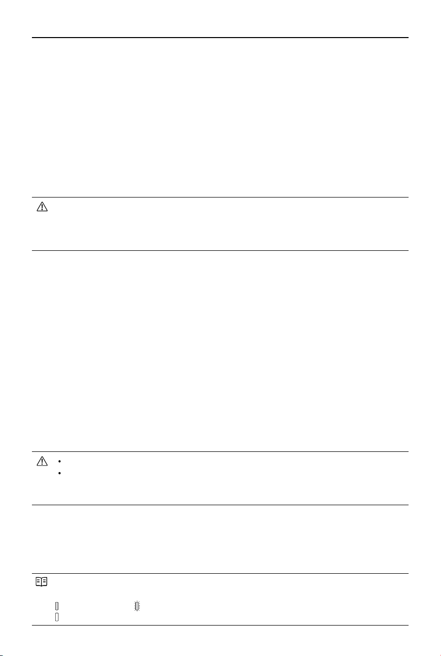
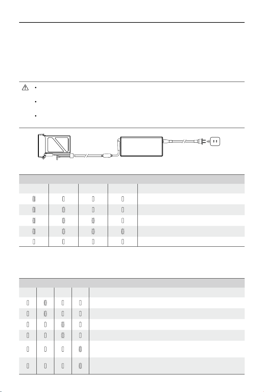
Checking the Battery Level
The Battery Level Indicator shows how much battery capacity is remaining. When the battery is
powered off, press the power button once. The Battery Level Indicator will light up to display the
current battery level. See the table below for details.
The Battery Level Indicator will show the current battery level during charging and discharging.
Its LEDs can exhibit the following behavior.
: LED is on. : LED is blinking.
: LED is off.
18
©
2017 DJI All Rights Reserved.
MATRICE 600
User Manual
Battery Level Indicator
LED1 LED2 LED3 LED4 Battery Level
87.5%~100%
75%~87.5%
62.5%~75%
50%~62.5%
37.5%~50%
25%~37.5%
12.5%~25%
0%~12.5%
=0%
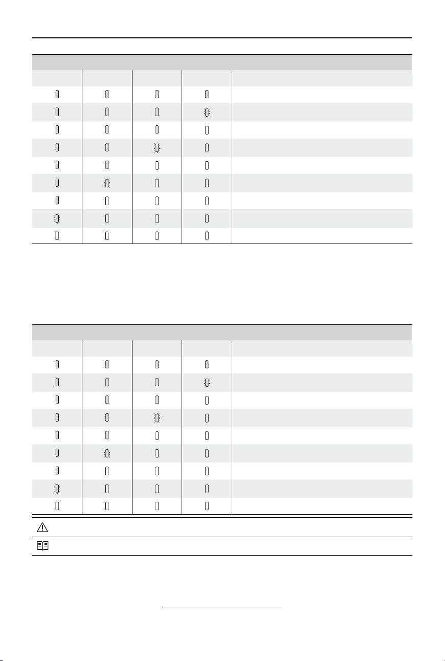
Checking the Battery Life
The battery life indicates the number of cycles the battery can be charged and discharged before it
must be replaced. When the battery is powered off, press and hold the power button for 5 seconds
to check the battery life. The Battery Level LEDs will light up and/or blink as described below for 2
seconds:
Battery Life
LED1 LED2 LED3 LED4 Battery Life
90%~100%
80%~90%
70%~80%
60%~70%
50%~60%
40%~50%
30%~40%
20%~30%
below 20%
When the battery life reaches 0%, it can no longer be used.
For more information about the battery, launch the DJI GO app and go to the Battery tab.
Charging the Intelligent Flight Battery
The Matrice 600 is shipped with two Charging Hubs. Each Charging Hub can charge up to four
Intelligent Flight Batteries. Refer to Using the Charging Hub (p. 56) for more details.
Use the standard battery charger to charge one Intelligent Flight Battery:
©
2017 DJI All Rights Reserved.
19
MATRICE 600
User Manual
1. Connect the battery charger to a suitable power supply (100-240V 50/60Hz).
2. Open the protection cap and connect the Intelligent Flight Battery to the battery charger. If the
battery level is above 95%, turn on the battery before charging.
3. The Battery Level Indicator will display the current battery level during charging.
4. The Intelligent Flight Battery is fully charged when Battery Level Indicators are all off. Disconnect
the Intelligent Flight Battery from the battery charger.
DO NOT charge the Intelligent Flight Battery and the remote controller at the same time to
avoid overloading the battery charger (model: A14-100P1A).
Air cool the Intelligent Flight Battery after each ight. Allow its temperature to drop to room
temperature before charging.
The charging temperature range is 5° to 40° C. The battery management system will stop
the battery from charging when the battery cell temperature is out of range.
Charger
Intelligent Flight Battery
Power Outlet
Battery Level Indicator While Charging
LED1 LED2 LED3 LED4 Battery Level
0%~25%
25%~50%
50%~75%
75%~100%
Fully charged
Charging Protection LED Display
The table below describes the battery protection mechanisms and their corresponding LED patterns.
Battery Level Indicator While Charging
LED1 LED2 LED3 LED4 Indicator Pattern Battery Protection Item
LED2 blinks twice per second Overcurrent detected
LED2 blinks three times per second Short circuit detected
LED3 blinks twice per second Overcharge detected
LED3 blinks three times per second Charger overvoltage detected
LED4 blinks twice per second
Charging temperature is too
low (<5°C)
LED4 blinks three times per second
Charging temperature is too
high (>40°C)
20
©
2017 DJI All Rights Reserved.
MATRICE 600
User Manual
After any of the above protection issues are resolved, press the power button to turn off the Battery
Level Indicator. Unplug the Intelligent Flight Battery from the battery charger and plug it back in to
resume charging. Note that you do not need to unplug and plug the battery charger in the event of a
charging temperature error; the battery charger will resume charging when the temperature falls within
the normal range.
DJI does NOT take any responsibility for damage caused by third-party battery chargers.
Calibrating the Battery Capacity:
To effectively calibrate the capacity of the Intelligent Flight Battery, it is recommended to
charge and discharge the battery thoroughly for every 10 charge-and-discharge cycles.
Choose one of the following methods to discharge battery. After discharging the battery, fully
charge the battery to nish the calibration.
Slow: Place the battery into the Matrice 600’s battery compartment and power it on. Leave it
on until there is less than 5% battery level, or until it can no longer be turned on. Check the
battery level in the DJI GO app.
Fast: Fly the Matrice 600 outdoors until there is less than 5% battery level, or until the battery
can no longer be turned on.
©
2017 DJI All Rights Reserved.
21
Remote Controller
Prole
The remote controller integrates video downlink and aircraft control into one system. The combined system
operates at 2.4 GHz with a maximum signal transmission range of 5 km. The device features a number of
standard and customizable buttons that allow users to quickly access certain aircraft functions, such as
taking and reviewing photos/videos, as well as controlling the gimbal and landing gear. It is powered by a
2S rechargeable battery.
Stick Mode: Control can be set to Mode 1, Mode 2 (by default), or a custom mode in the DJI
GO app.
Mode 1: The right stick serves as the throttle.
Mode 2: The left stick serves as the throttle.
DO NOT operate more than 3 aircrafts within in the same area (size equivalent to a soccer
eld) to prevent transmission interference.
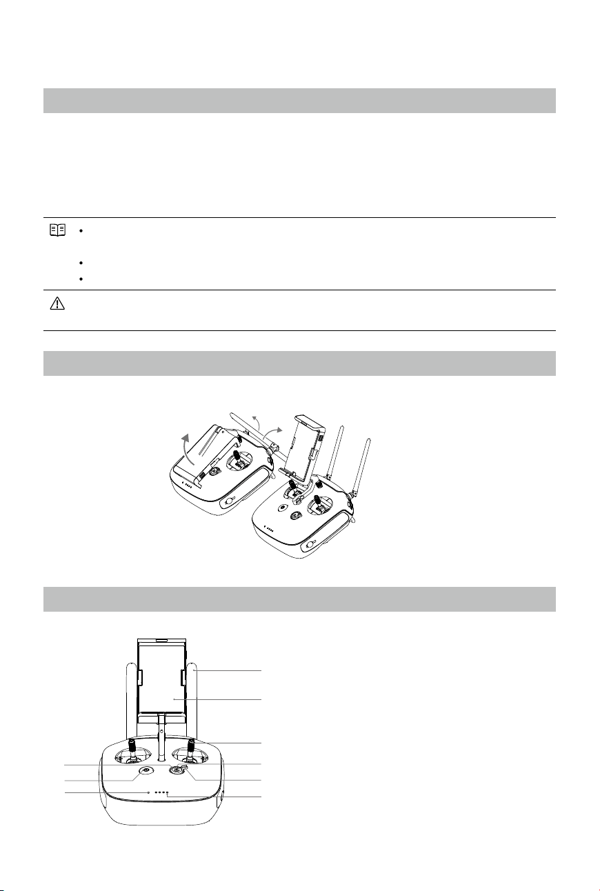
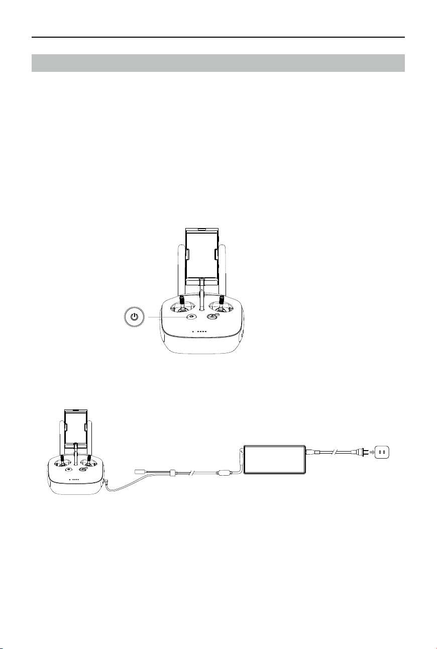
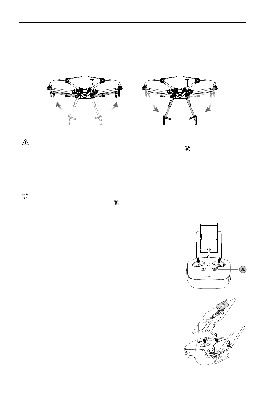
Preparing Remote Controller
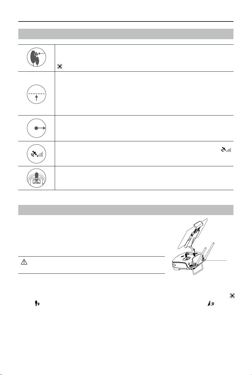
Tilt the Mobile Device Holder to the desired position then adjust the antenna as shown.
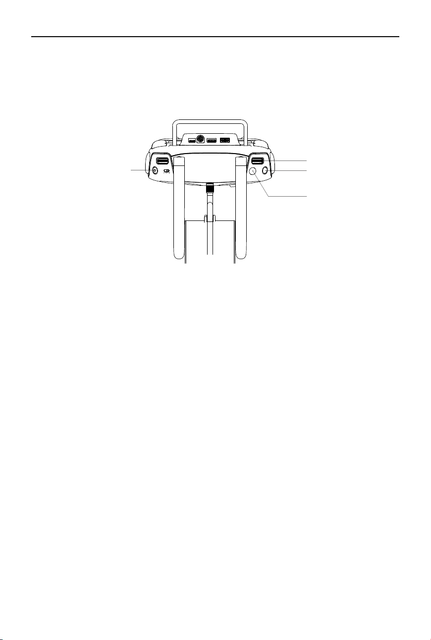
Remote Controller Overview
[1]
[2]
[4]
[5]
[6]
[7]
[8]
[9]
[3]
[1] Antennas
Relays aircraft control and video signal.
[2] Mobile Device Holder
Mounting place for your mobile device.
[3] Control Stick
Controls aircraft orientation.
[4] Return-to-Home (RTH) Button
Press and hold the button to initiate Return-
to-Home (RTH).
22
©
2017 DJI All Rights Reserved.
MATRICE 600
User Manual
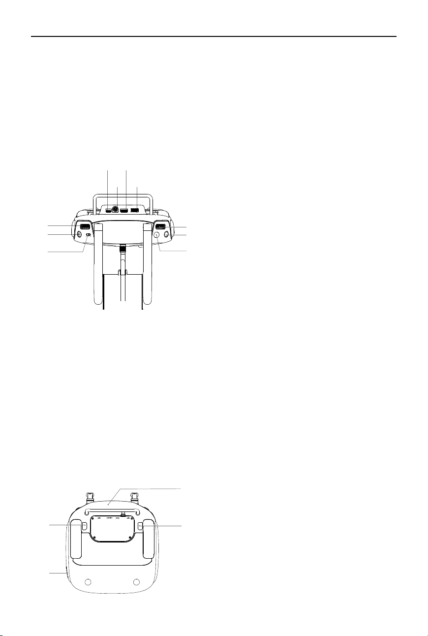
[10] Camera Settings Dial
Turn the dial to adjust camera settings.
Only functions when the remote controller is
connected to a mobile device running the
DJI GO app.
[11] Playback Button
Playback the captured images or videos.
[12] Shutter Button
Press to take a photo. If in burst mode, the
set number of photos will be taken with
one press.
[13] Flight Mode Switch
Used to switch between P, A and F mode.
[14] Video Recording Button
Press to start recording video. Press again
to stop recording.
[15] Gimbal Dial
Use this dial to control the tilt or pan of the
gimbal.
[16] Micro USB Port
Reserved.
[17] SDI Port
Connect an SDI display device.
[18] HDMI OUT Port
Connect an HD compatible monitor.
[19] USB Port
Connect to mobile device to access all of
the DJI GO app controls and features.
[20] GPS Module
Used to pinpoint the location of the remote
controller.
[21] Back Left Button
Customizable button in the DJI GO app.
[22] Back Right Button
Customizable button in the DJI GO app.
[23] Power Port
Connect to a power source to charge the
remote controller’s internal battery.
[13]
[15]
[10]
[11]
[12]
[14]
[16] [18]
[17] [19]
[20]
[21]
[23]
[22]
[5] Landing Gear Control Switch
Toggle the switch up or down to raise or
lower the landing gear.
[6] Battery Level LEDs
Displays the current battery level.
[7] Status LED
Displays the power status.
[8] Power Button
Used to power on or power off the remote
controller.
[9] RTH Status LED
Circular LED around the RTH button displays
RTH status.
©
2017 DJI All Rights Reserved.
23
MATRICE 600
User Manual
Remote Controller Operations
Powering On and Off the Remote Controller
The Matrice 600 remote controller is powered by a 2S rechargeable battery with a capacity of
6000mAh. The battery level is indicated by the Battery Level LEDs on the front panel. Follow the steps
below to power on your remote controller:
1. When powered off, press the Powe
r Button once and the Battery Level LEDs will display the current
battery level.
2. Then, press and hold the Power Button to power on the remote controller.
3. The remote controller will beep when it powers on. The Status LED will blink red (secondary
remote controller blinks solid purple) rapidly, indicating that the remote controller is linking to the
aircraft. The Status LED will show a solid green light (secondary remote controller shows a solid
cyan light) when linking is completed.
4. Repeat step 2 to power off the remote controller after finish using it.
Charging Remote Controller
Charge the remote controller via supplied charger.
Charger
Power Outlet
24
©
2017 DJI All Rights Reserved.
MATRICE 600
User Manual
Controlling the Camera
Shoot videos or images and adjust camera settings via the Shutter Button, Camera Settings Dial,
Playback Button and Video Recording Button on the remote controller when using a Zenmuse X3, X5
series or XT gimbal with camera.
[1] Camera Settings Dial
Turn the dial to quickly adjust camera settings such as ISO and shutter speed without letting go of
the remote controller. Move the dial button to left or right to view the pictures or videos in playback
mode.
[2] Playback Button
Press to view images or videos that have already been captured.
[3] Shutter Button
Press to take a photo. If burst mode is activated, multiple photos will be taken with a single press.
[4] Recoding Button
Press once to start recording video, then press again to stop recording.
Controlling the Aircraft
This section explains how to use the various features of the remote controller. Mode 2 (throttle stick on
the left) is set by default.
[1]
[2]
[3]
[4]
©
2017 DJI All Rights Reserved.
25
MATRICE 600
User Manual
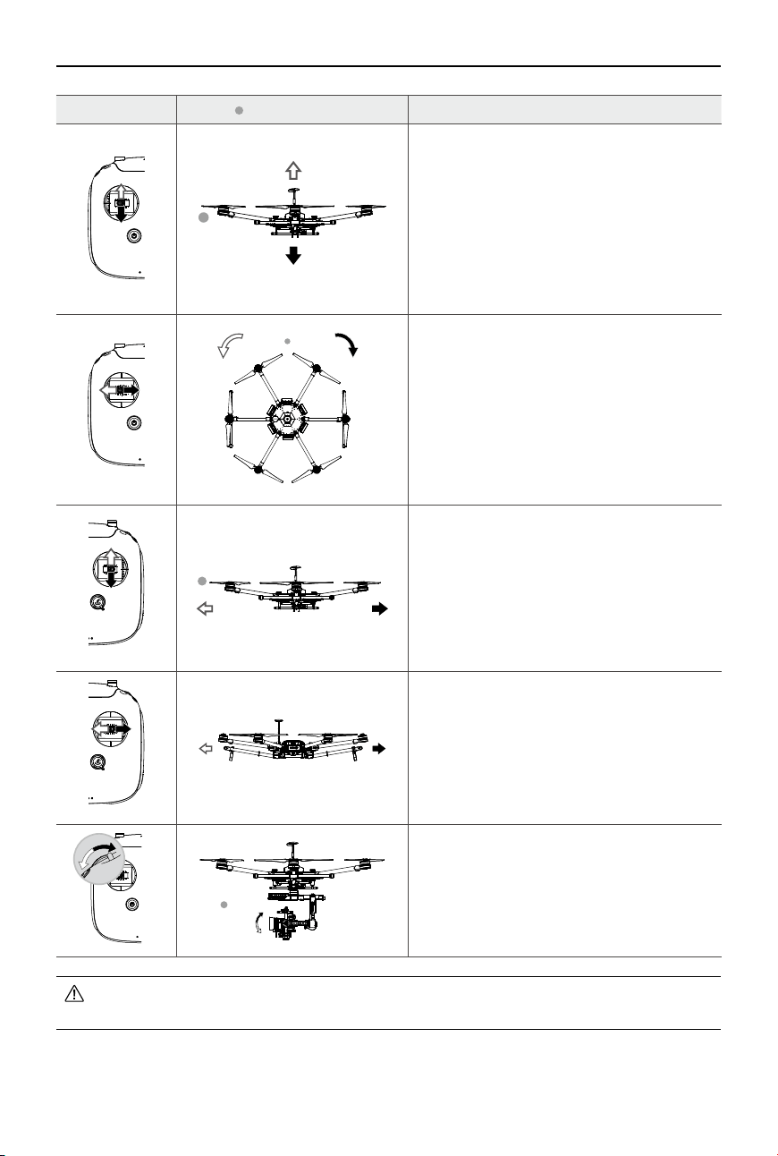
Remote Controller Aircraft ( indicates nose direction) Function
Moving the Left Stick up/down changes the
aircraft’s elevation. Push it up to ascend and
down to descend.
Use this stick to take off when the motors are
spinning at idle speed. The aircraft will hover
in place if the Left Stick is released.
Moving the Left Stick left/right changes the
heading of the aircraft. Push it left to rotate the
aircraft counter clock-wise, and right to rotate
the aircraft clockwise.
Moving the Right Stick up/down changes the
aircraft’s forward and backward pitch. Push it
up to y forwards and down to y backwards.
Push the Right Stick further for a larger pitch
angle and faster ight.
Moving the Right Stick left/right changes the
aircraft’s left and right pitch. Push it left to y
left and right to y right.
Push the Right Stick further for a larger pitch
angle and faster ight.
Turn the Gimbal Dial to control the pitch or
pan movement of the gimbal. The Gimbal
Dial controls the pitch by default. You can set
the back left or back right button to allow the
Gimbal Dial to control the pan movement by
using the DJI GO app.
Always push the control sticks gently to prevent sudden and unexpected movement of the
aircraft.
26
©
2017 DJI All Rights Reserved.
MATRICE 600
User Manual
P-mode (Positioning): P-mode works best when GPS signal is strong. There are several states in
P-mode which are automatically selected by the Matrice 600 depending on GPS signal strength:
P-GPS: GPS is available. The aircraft uses GPS for positioning.
P-ATTI: GPS is not available. The aircraft only uses its barometer for maintaining altitude.
A-mode (Attitude): GPS is not used for positioning. The aircraft only uses its barometer to maintain
altitude. If it is still receiving a GPS signal, the aircraft will automatically Return-to-Home if the remote
controller signal is lost, and if the Home Point was recorded successfully.
F-mode (Function): Intelligent Flight Mode and API Control are supported in this mode. Refer to the
Intelligent Flight Modes (p. 53) section in the Appendix and SDK in DJI Assistant 2 (p. 40) for more
information.
The ight mode is locked in P-mode by default. To enable other ight modes, go to the DJI GO app >
Camera View >
> Enable Multiple Flight Mode.
Atti Mode Warning
The aircraft will enter A-mode in the following two instances:
Passive: When there is weak GPS signal or when the compass experiences interference.
Active: Users toggle the ight mode switch to A-mode.
In A-mode, some advanced features are disabled. Therefore, the aircraft cannot position in this mode
and is easily affected by its surroundings, which may result in horizontal shifting. Use the remote
controller to position the aircraft.
Maneuvering the aircraft in A-mode can be difcult. Before switching the aircraft into A-mode, make
sure you are comfortable ying in this mode. DO NOT y the aircraft too far away as you might lose
control and cause a potential hazard.
Avoid ying in areas where GPS signal is weak, or in conned spaces. The aircraft will otherwise be
forced to enter A-mode, leading to potential ight hazards, please land it in a safe place as soon as
possible.
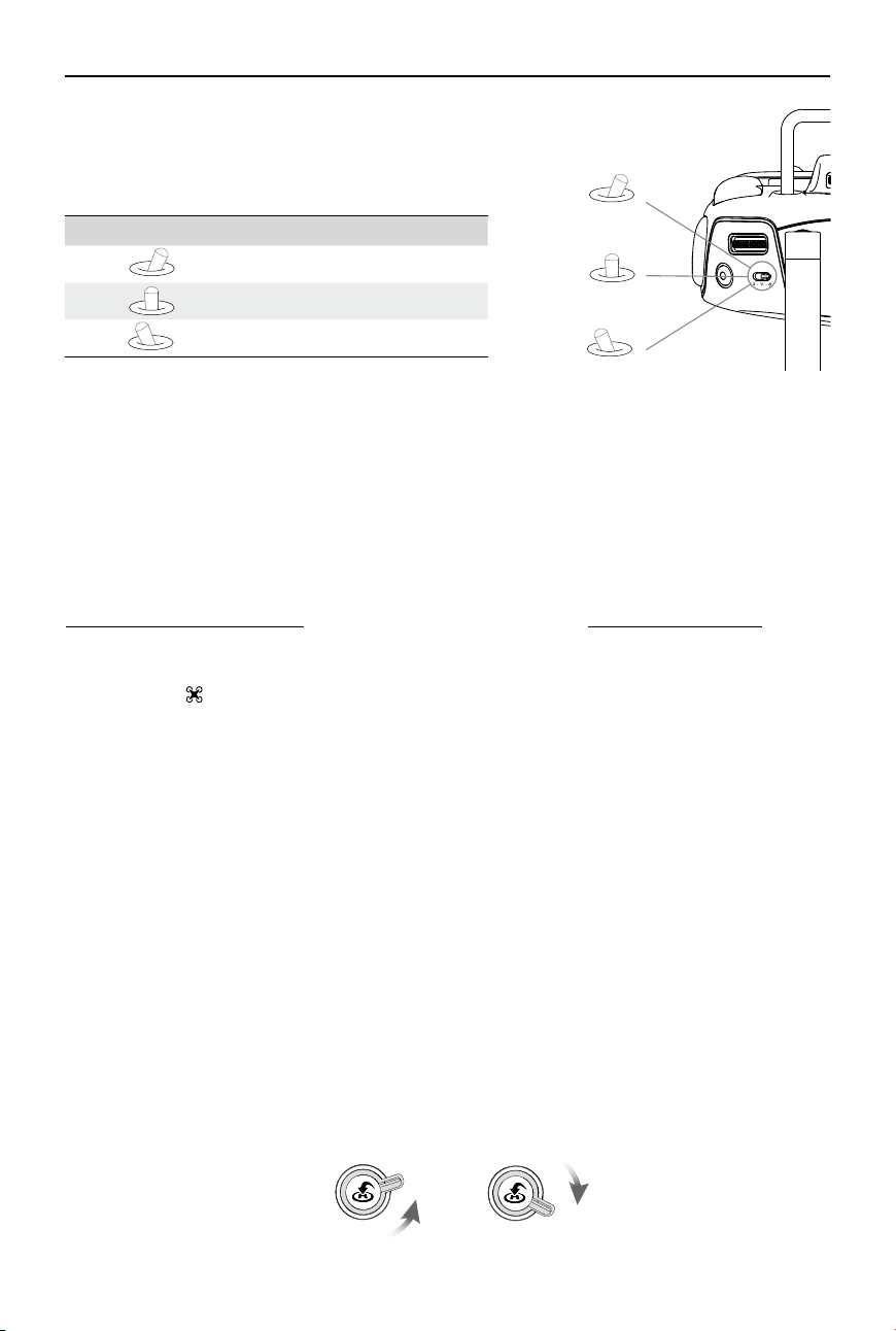
Landing Gear Control Switch
This switch has two positions. Toggle the switch up or down to raise or lower the landing gear.
Figure Flight Mode
P
P-mode
A
A-mode
F
F-mode
Flight Mode Switch
Toggle the switch to select the desired ight mode.
You may choose between P-mode, A-mode and F-mode.
A
P
F
LowerRaise
©
2017 DJI All Rights Reserved.
27
MATRICE 600
User Manual
By default, the landing gear will not raise or lower if you toggle the control switch when the
aircraft is on the ground. Go to the DJI GO app > Camera View > > Advanced Settings >
Disable Landing Gear Auto-Lock, and then the landing gear will raise or lower if you toggle
the control switch when the aircraft is on the ground. Ensure that the switch is in the lower
position when enabling this feature. The feature will be disabled after raising and lowering the
landing gear once. Enable it in the DJI GO app if you want to raise or lower the landing gear
again.
Auto-raise and auto-lower features of the landing gear can be set in the DJI GO app. Go to
the DJI GO app > Camera View > > Advanced Settings > Self-Adaptive Landing Gear.
RTH Button
Press and hold this button to start the Return-to-Home (RTH)
procedure. The LED around the RTH Button will blink white to
indicate the aircraft is entering RTH mode. The aircraft will then
return to the last recorded Home Point. Press this button again to
cancel the RTH procedure and regain control of the aircraft.
Connecting Mobile Device
1. Press the button on the side of the Mobile Device Holder to
release the clamp.
2. Place your mobile device inside the clamp and adjust it to secure
your mobile device.
3. Connect your mobile device to the remote controller via a USB
cable.
1. Raise: Raise the landing gear to its upper most position. The landing gear will automatically raise
when the aircraft reaches an altitude of 1.2 m for the rst time.
2. Lower: The landing gear will lower to its lowest position for landing. The landing gear will
automatically lower if Auto-Landing is enabled in the DJI GO app or when the aircraft is landing
automatically as part of the RTH procedure.
28
©
2017 DJI All Rights Reserved.
MATRICE 600
User Manual
Optimal Transmission Range
The signal transmission between the aircraft and the remote controller performs best when the aircraft
is within the optimal transmission range. Open up the antennas on the remote controller to optimize
transmission range. Ideally, the at surface of the antenna should be facing the aircraft. If the signal is
weak, y the aircraft closer to you.
Optimal Transmission Range
Strong Weak
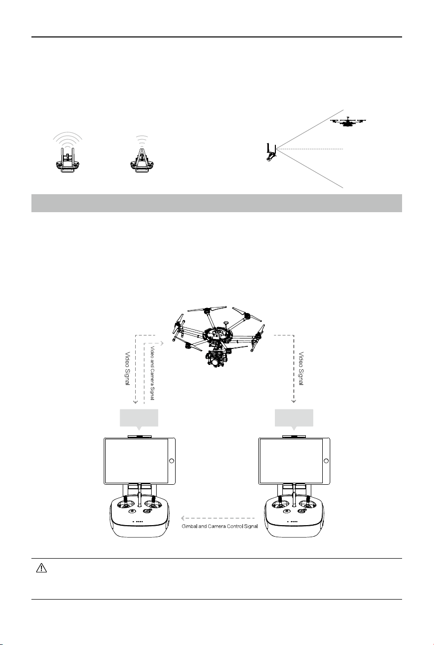
Dual Remote Controllers Mode
More than one remote controlle
r can be connected to the same aircraft in the Dual Remote Controllers
mode. When using a DJI gimbal in the Dual Remote Controllers mode, the primary remote controller
controls the movement of the aircraft, while the secondary remote controller controls the movement
of the gimbal. When multiple secondary remote controllers (max 3) are connected to the aircraft,
only the first connected secondary remote controller is able to control the gimbal. The remaining
secondary remote controllers can view the live feed video from the aircraft and set the camera
parameters, but cannot control the gimbal.
Primary Remote
Controller
Secondary
Remote
Controller
U
se the gimbal dial on the remote controller to tilt the camera in the Single Remote Controller
mode. In Dual Remote Controllers mode, use the secondary remote controller to tilt, pan or
roll the camera.
©
2017 DJI All Rights Reserved.
29
MATRICE 600
User Manual
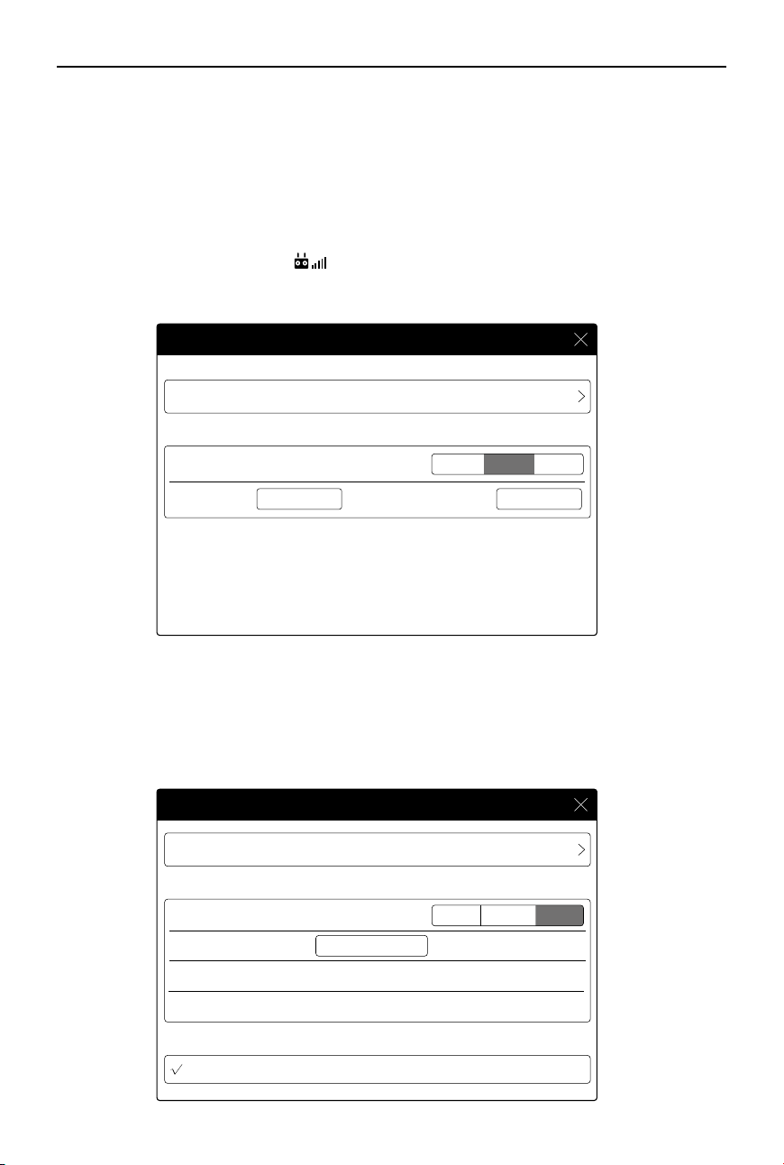
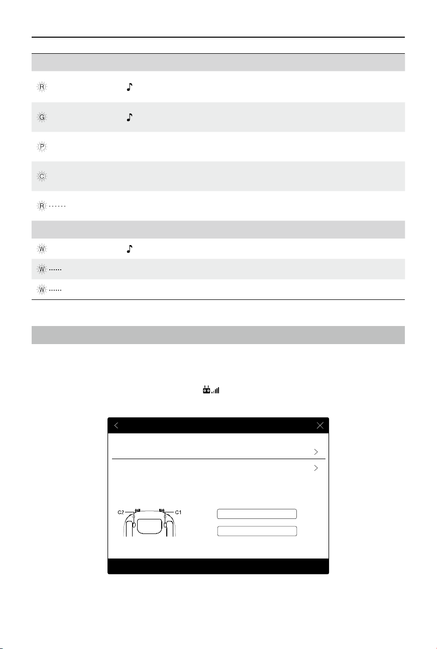
Setting Up Dual Remote Controllers Mode
The Dual Remote Controllers mode is
disabled by default. Users must enable this feature on the
Primary Remote Controller through the DJI GO app. Follow the steps below for setup:
Primary Remote Controller:
1. Connect the remote controller to your mobile device and launch the DJI GO app.
2. Go to the Camera View, and tap
to enter the remote controller settings window.
3. Select Primary in the Set Remote Controller Status section to set the remote controller as the Primary
remote controller.
Secondary RC List
Remote Controller Settings
Primary and Secondary
Set Remote Controller Status
Remote Controller Settings
Primary
OFF
RC Name Connection Password
T12254 1234
Secondary
Secondary
Primary
OFF
Set Remote Controller Status
Remote Controller Name
Search for Primary Controller
Request Control
S88642
Primary RC List
T12254
Remote Controller Settings
Remote Controller Settings
Primary and Secondary
4. Enter the connection password for the secondary remote controller.
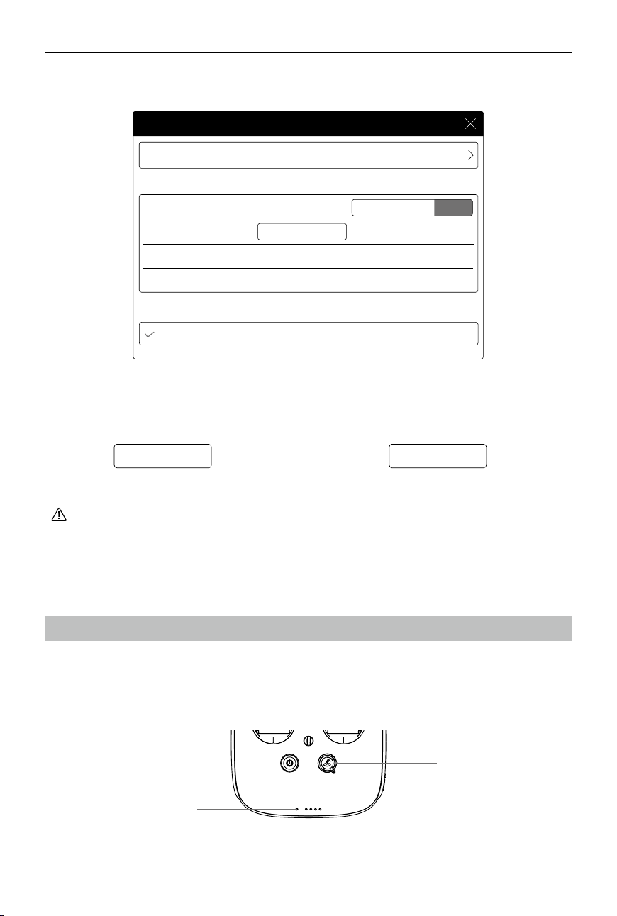
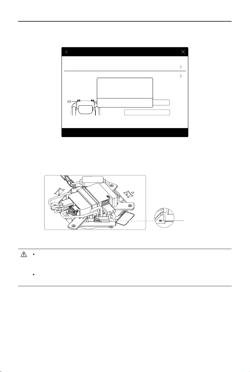
Secondary Remote Controller:
1. Select Secondary in the Set Remote Controller Status section to set the remote controller as the secondary
remote controller.
30
©
2017 DJI All Rights Reserved.
MATRICE 600
User Manual
2. Tap Search for Primary Controller to register the primary remote controller.
3. Select the name of the remote
controller from the Primary RC List and input the connection
password to connect to the desired primary remote controller.
RTH Status LED
Status LED
Remote Controller LEDs
The Status LED reects connection status between the remote controller and the aircraft. The RTH
Status LED indicates the Return-to-Home status of the aircraft. See the table below for details on these
indicators.
Primary
OFF
Secondary
Set Remote Controller Status
Remote Controller Name
Search for Primary Controller
Request Control
Primary RC List
S88642
T12254
Remote Controller Settings
Remote Controller Settings
Primary and Secondary
Remote Controller Settings
Set Remote Controller Status
Slave RC List
Master and Slave
Remote Controller Settings
MasterOFF
RC Name
Connection Password
T12254 1234
Slave
The remote controller cannot link to the aircraft or control aircraft movement if it is set to
Secondary. Set the remote controller as Primary in the DJI GO app if you want to link the
remote controller to the aircraft.
©
2017 DJI All Rights Reserved.
31
MATRICE 600
User Manual
Status LED Alarm Remote Controller Status
—
Solid Red chime
T
he remote controller is set as primary but is
not connected to the aircraft.
—
Solid Green chime
T
he remote controller is set as primary and
connected to the aircraft.
—
Solid Purple 2 beeps
The remote controller is set as
secondary but
is not connected to the aircraft.
—
Solid Cyan 2 beeps and chime
T
he remote controller is set as secondary and
connected to the aircraft.
Blinking Red 1 slow beep repeating
Remote controller error. Refer to the DJI GO app
for details.
RTH Status LED Sound Aircraft Status
—
Solid White chime RTH procedure begins.
Blinking White 1 beep repeating Sending RTH command to the aircraft.
Blinking White 2 beeps repeating Aircraft RTH in progress.
Linking the Remote Controller
The remote controller is linked to your aircraft by default. Linking is only required when a new remote
controller is used for the rst time. Follow these steps to link a new remote controller:
1. Power on the remote controller and connect it to your mobile device. Then power on the aircraft.
2. Go to the DJI GO app > Camera View >
> Remote Controller Settings > Linking Remote
Controller.
Remote Controller Settings
Remote Controller Calibration
Stick Mode
Button Customization
Gimbal Pitch/YawC1
C2 Not Defined
Default stick mode is Mode 2, changing stick modes alters the way the aircraft is controlled.
Do not change unless familiar with your new mode.
You can customize the C1 and C2 buttons on the back of the RC.
Linking Remote Controller
32
©
2017 DJI All Rights Reserved.
MATRICE 600
User Manual
Remote Controller Calibration
Stick Mode
Button Customization
Not DefinedC1
C2 Not Defined
Default stick mode is Mode 2, changing stick modes alters the way the aircraft is controlled.
Do not change unless familiar with your new mode.
You can customize the C1 and C2 buttons on the back of the RC.
Searching for aircraft frequency,
timeout in 54 seconds
Cancel
Press the linking button on the aircraft
to link this remote controller
Remote Controller Settings
Linking Remote Controller
3. The remote controller Status LED will blink blue and beep to indicate that the remote controller is
ready to be linked.
4. Press the LINK Button on the Lightbridge 2 Air System (shown in the gure below) to begin linking.
The remote controller Status LED will glow solid green if linking is successful.
T
he remote controller cannot link to the aircraft or control aircraft movement if it is set
to secondary. Set the remote controller as primary in the DJI GO app if you want to link
the remote controller to the aircraft.
The remote controller will disconnect from the linked aircraft if another remote controller
attempts to link to the same aircraft.
LINK Button
©
2017 DJI All Rights Reserved.
33
Return-to-Home (RTH)
Prole
The Return-to-Home (RTH) function brings the aircraft back to the last recorded Home Point. There
are three events that will trigger RTH procedure: Smart RTH, Low Battery RTH and Failsafe RTH.
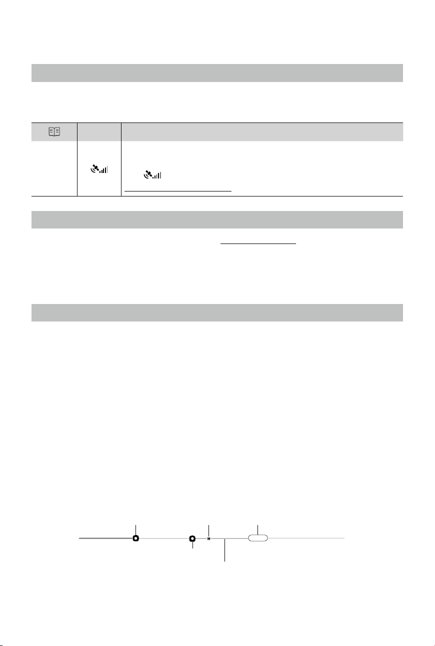
GPS
Description
Home
Point
The default Home Point is the first location where your aircraft received
strong GPS signals (i.e. the white GPS icon is followed by at least four white
bars
). You can update the Home Point via the DJI GO app. Refer to
Updating Home Point (p. 35) for details.
Smart RTH
Use the RTH button on the remote controller (see RTH Button on p. 27 for more details) or the RTH
button in the DJI GO app when GPS is available to enable Smart RTH. With Smart RTH, you may
control the aircraft’s orientation to avoid collision when it is returning to the Home Point. Press and
hold the Smart RTH button to start the RTH procedure, then press the Smart RTH button again to
exit Smart RTH and regain control of the aircraft.
Low Battery RTH
Low Battery RTH is triggered when the DJI Intelligent Flight Battery is depleted to a point which may
affect the safe return of the aircraft. Users are advised to y back or land the aircraft immediately
when these warnings are shown. The DJI GO app will advise users to return the aircraft to the Home
Point when the low battery warning is triggered. The aircraft will automatically return to the Home Point
if no action is taken after 10 seconds. User can cancel the RTH procedure by pressing on the RTH
button once. The thresholds for these warnings are automatically determined based on the current
aircraft altitude and its distance from the Home Point. If the RTH procedure is cancelled following a
low battery level warning the Intelligent Flight Battery may not have enough charge for the aircraft to
land safely, which may lead to the aircraft crashing or being lost.
The aircraft will land automatically (cannot be cancelled) if the current battery level can only support
the aircraft to land to the ground from its current position. Users can use the remote controller to
control the aircraft’s movement during the landing process.
The figure below describes the behavior of the Battery Level Indicator during different stages of
events.
Critical Battery Warning
(Red)
Low Battery Warning
Sufcient Battery Level (Green)
Remaining Flight Time
Power Required
to Return Home
09:29
34
©
2017 DJI All Rights Reserved.
MATRICE 600
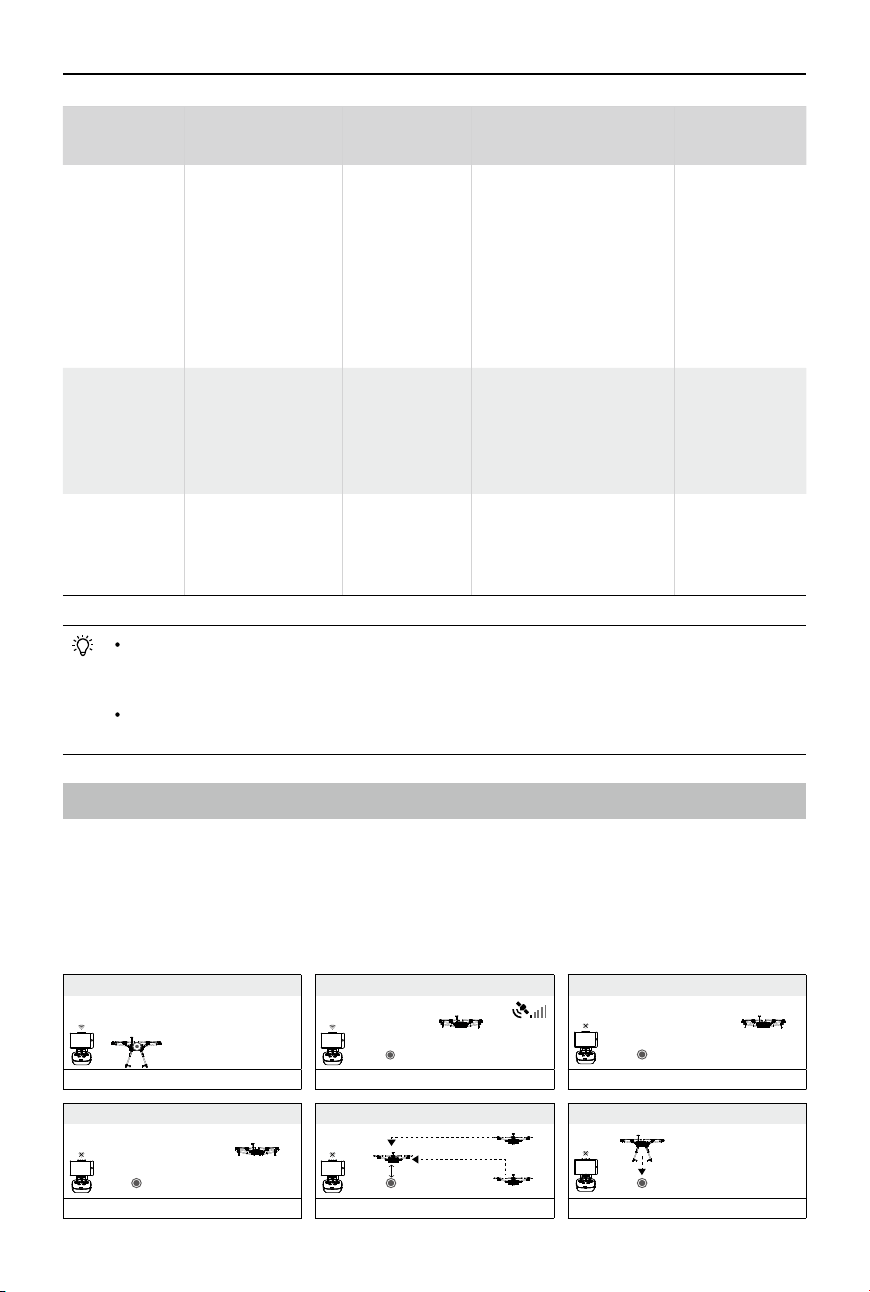
User Manual
1 Record Home Point (HP)
Flashing Green
5 Go Home(20m can be set)
Flashing Yellow Rapidly
3 Remote Controller Signal Lost
Flashing Yellow Rapidly
2 Conrm Home Point
Flashing Green
6 Landing after Hovering 15secs
Flashing Yellow Rapidly
4
Signal Lost Lasts 3secs.
Flashing Yellow Rapidly
Height over HP>20m
Elevate to 20m
Height over HP<=20m
20m
Battery Level Description
Aircraft Status
Indicator
DJI GO App
Flight
Instructions
Low Battery
Warning
The battery level is
low. Please land the
aircraft.
Aircraft Status
Indicator
blinking RED
slowly.
Tap Go-Home to make the
aircraft return to Home Point
and land automatically, or
Cancel to resume normal
ight. If no action is taken,
the aircraft will automatically
return to the Home Point
and land after 10 seconds.
Fly the aircraft
back and land
it as soon as
possible, then
stop the motors
and replace the
battery.
Critical Battery
Warning
The aircraft must
land immediately.
Aircraft Status
Indicator
blinking RED
rapidly.
The DJI GO app screen
will ash red and the
aircraft will begin to
descend.
The aircraft
will begin
to descend
and land
automatically.
Remaining
Flight Time
Estimated remaining
ight time based on
the current battery
level.
N/A N/A N/A
When the critically low battery level warning is triggered and the aircraft is descending
to land automatically, you may push the throttle stick upwards to hover the aircraft and
navigate it to a more appropriate location for landing.
Color zones and markers on the battery level indicator reect the estimated remaining ight
time and are adjusted automatically, according to the aircraft’s current status.
Failsafe RTH
Failsafe RTH is activated automatically if the remote controller signal (including video relay signal)
is lost for more than 3 seconds provided that the Home Point has been successfully recorded and
the compass is working normally. The operator can interrupt the Return-to-Home procedure and
regain control over the aircraft if the remote controller signal is recovered.
Failsafe Illustration
©
2017 DJI All Rights Reserved.
35
MATRICE 600
User Manual
The aircraft cannot avoid obstruction during RTH, therefore it is important to set a
reasonable RTH altitude before each ight. Go to the DJI GO app > Camera View >
> Set Return-to-Home Altitude.
20m
If the aircraft is flying under 20 meters (65 feet) and RTH (including Smart
RTH, Low Battery RTH and Failsafe RTH) is triggered, the aircraft will first
automatically ascend to 20 meters (65 feet) from the current altitude and you
cannot control the aircraft during ascending. In Smart RTH, you can exit RTH to
cancel the ascending by pressing the RTH button once.
20m
H
The aircraft automatically descends and lands if RTH is triggered when the
aircraft ies within a 65 feet (20 meter) radius of the Home Point.
Aircraft cannot return to the Home Point when GPS signal is weak (
displays red) or unavailable.
The aircraft will stop ascending and immediately return to the Home Point if you
move the throttle stick during Failsafe RTH.
Updating the Home Point
You can update the Home Point in the DJI GO app during flight.
There are two options for setting the Home Point:
1. Set the aircraft’s current coordinates as the Home Point.
2. Set the remote controller’s current coordinates as the Home Point.
RTH Safety Notices
GPS
Follow the instructions below to update the Home Point:
1. Connect your mobile device to the remote controller and go to the DJI GO app > Camera View > .
2. Tap
to set the remote controller’s current coordinates as the Home Point; tap to set the
aircraft’s current coordinates as the Home Point.
3. The Aircraft Status Indicator will blink green to indicate that the new Home Point has been set
successfully.
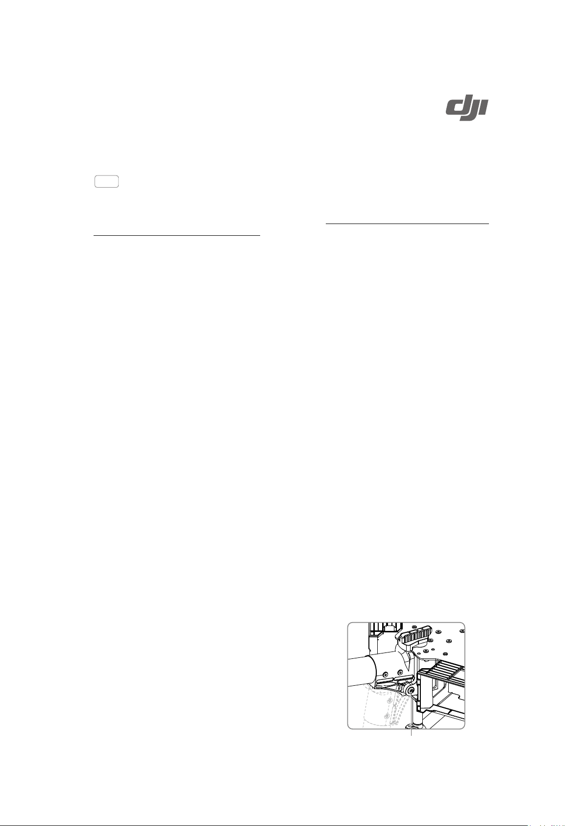
Ensure the space above the GPS module (shown in the
gure) is not obstructed when updating the Home Point.
36
©
2017 DJI All Rights Reserved.
AE
22:02
LOG
60
1080P
ISO
F
EV
1600
2.8
2.0
1/50
09:29
61
%
P-GPS
12
M/S
M/S
H: D:
V.S
H.S
4.22.3
39
M
210
M
232
M
MENU
SAFE TO FLY (GPS)
DJI GO App
Use the DJI GO app to congure your aircraft. If using a gimbal or camera, you can also control the
gimbal or camera in the app. The Library, Explore, and Me sections in the app allow you to share your
content with friends.
Equipment
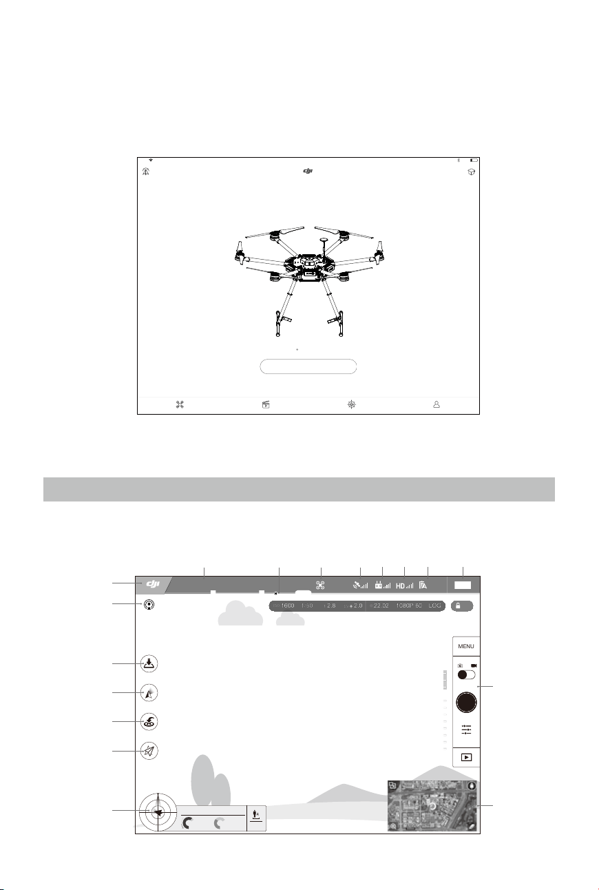
On the Equipment page, you can enter Camera View, visit the Academy or view your ight records.
Camera View
[17]
[16]
[15]
[14]
[13]
[12]
[11]
[10]
[9]
[8][7][6][5]
[4][3][2][1]
MATRICE 600
22%
4:21PM
iPad
Aircraft Connected
Camera
Equipment Editor Explore Me
Learn more
©
2017 DJI All Rights Reserved.
37
MATRICE 600
User Manual
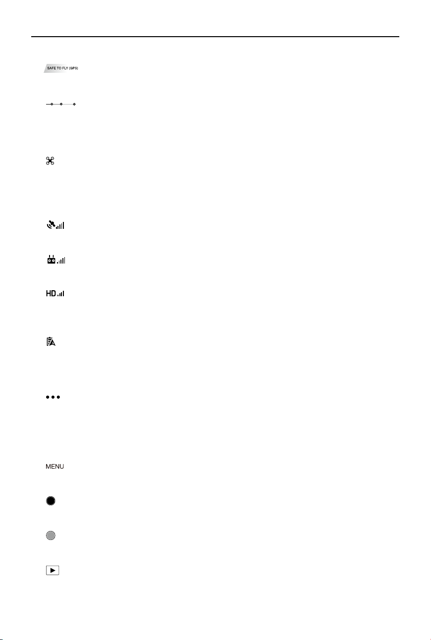
[1] System Status
: Indicates the current aircraft system status and GPS signal strength.
[2] Battery Level Indicator
: Describes the battery level of the aircraft according to its immediate status. The colored
zones represent the various stages of battery level. When the battery level drops to a certain
stage, the system will prompt the user to take the appropriate action.
[3] Flight Mode
: The text next to this icon indicates the current ight mode.
Tap this icon to congure the Main Controller Settings, to change the ight limits and set the gain
values.
[4] GPS Signal Strength
: Shows the current GPS signal strength. White bars indicate adequate GPS strength.
[5] Remote Controller Signal
: Shows the signal strength of the remote controller.
[6] HD Video Link Signal Strength
: Shows the signal strength of the HD video downlink between the aircraft and the remote
controller.
[7] Battery Level
61%
: Shows the current battery level.
Tap this icon to view the battery information menu where you can set the battery warning
thresholds and view the battery log.
[8] General Settings
: Tap this icon to view General Settings where you can set the ight parameters, and enable
the Flight Route display.
[9] Camera Operation Bar
This bar will be displayed when using a Zenmuse X3, X5 series or XT gimbal with camera.
Shutter and Recording Settings
: Tap this icon to enter various camera value settings including the Color Mode, Video Size,
and Image Size.
Shutter
: Tap this button to take a single photo. Press and hold this button to switch between Single
Shot, Triple Shot and Timed Shot modes.
Record
: Tap once to start recording video, then tap again to stop recording. You can also press the
Video Recording Button on the remote controller.
Playback
: Tap this icon to play back photos and videos after they are captured.
38
©
2017 DJI All Rights Reserved.
MATRICE 600
User Manual
Camera Settings
: Tap this icon to set the ISO, Shutter Speed and Exposure Value of the camera.
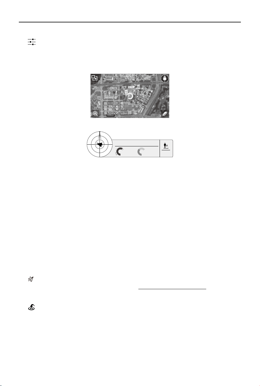
[10] Mini Map
Displays the ight path of the current ight. Tap the Mini Map to switch between Camera View
and Map View.
[11] Flight Telemetry
H: D:
V.S
M/S
M/S
H.S
4.22.3
39M 210M
232M
Flight Attitude and Radar Function:
The aircraft’s ight attitude is indicated by the target-like icon.
(1) The red arrow shows which direction the aircraft is facing.
(2) The ratio of the grey area to the blue area indicates the aircraft’s pitch.
(3) The horizontal level of the grey area indicates the aircraft’s roll angle.
Flight Parameters:
Altitude: Vertical distance from the Home Point.
Distance: Horizontal distance from the Home Point.
Vertical Speed: Movement speed across a vertical distance.
Horizontal Speed: Movement speed across a horizontal distance.
Aircraft Distance:
The horizontal distance between the aircraft and the operator.
[12] Intelligent Flight Mode
: This icon displays the Intelligent Flight Mode settings when the aircraft has entered F-mode. Tap
to select one of the Intelligent Flight Modes. Refer to Intelligent Flight Modes (p. 53) for details.
[13] Return-to-Home (RTH)
: Initiate RTH home procedure. Tap to have the aircraft return to the latest Home Point.
[14] Gimbal Operation Mode
This icon will be displayed when using a DJI gimbal (or camera). Tap to select a mode or re-align
the gimbal.
©
2017 DJI All Rights Reserved.
39
MATRICE 600
User Manual
[15] Auto Takeoff/Landing
/ : Tap to initiate auto takeoff or landing.
[16] Livestream
: This icon indicates the current video feed is being broadcast live on YouTube. Ensure that
mobile data service is available on your mobile device.
[17] Back
: Tap this icon to return to the main menu.
Editor
An intelligent video editor is built into the DJI GO app. After recording several video clips and
downloading them to your mobile device, go to Editor on the home screen. You can then select a
template and a specied number of clips which are automatically combined to create a short lm that
can be shared immediately.
Explore
Find out about our latest events, featured products and trending Skypixel uploads in the Explore
page.
Me
If you already have a DJI account, you will be able to participate in forum discussions, earn Credits in
the DJI Store, and share your artwork with the community.
Follow Mode
The gimbal’s orientation is aligned with the aircraft’s nose. One
user alone can control the pitch motion of the gimbal, but a second
operator is required to control the yaw motion using a second remote
controller.
FPV Mode
The gimbal will lock to the movement of the aircraft to provide a First-
Person-View ying experience.
Free Mode
The gimbal’s motion is independent of the aircraft’s orientation. One
user alone can control the pitch motion of the gimbal, but a second
user is required to control the yaw motion using a second remote
controller.
Re-alignment
Re-align the yaw angle of the gimbal with that of the aircraft. The pitch
angle remains unchanged during the re-alignment.
40
©
2017 DJI All Rights Reserved.
DJI Assistant 2
When using your Matrice 600 for the rst time, activate it in the DJI Assistant 2 software.
Installation and Launching
1. Download the DJI Assistant 2 installation le from the ofcial DJI website:
http://www.dji.com/product/matrice600/info#downloads
2. Complete the installation for the DJI Assistant 2 software.
3. Launch the DJI Assistant 2 software.
Using the DJI Assistant 2
1. Ensure that all the six Intelligent Flight Batteries are fully charged and then install them.
2. Power on the remote controller, and then turn on one of the Intelligent Flight Batteries in the
aircraft. If other batteries are not triggered automatically, connect your mobile device to the remote
controller and go to the DJI GO app for information.
3. Connect the Micro USB port (at the bottom of the Aircraft Status Indicator) of the Matrice 600 to the
computer with a Micro USB cable. Do not disconnect the cable until conguration is nished.
4. When a connection is established, the software will display the connected devices: “M600” and
“Lightbridge 2”. Click the corresponding device to congure settings.
If the software doesn’t display both of the connected devices, check the USB connection
between the aircraft and the computer, and the driver on your computer.
M600
Activating the Aircraft
When using your Matrice 600 for the rst time, click on the “M600” icon and you will be prompted to
activate the aircraft on your computer. Follow the steps on-screen to activate the aircraft.
Basic Settings
GPS Mounting Position
If using the GPS module that comes with the Matrice 600 only, enter its mounting position into the
appropriate elds. The default values are the mounting position on the left of the center frame. Fill in
the values related to the aircraft’s center of gravity if mounting the module to another position.
Modular Redundancy System
If using the modular redundancy system, identify the module according to the number of times the
module’s LED blinks (e.g. If a GPS blinks once, it is “GPS1”). Then enter each module’s corresponding
mounting position into the appropriate elds. Ensure that the values are correct, or else the aircraft’s
positioning will be off.
DJI Device
If using the D-RTK GNSS, enter the antenna mounting positions into the appropriate elds.
©
2017 DJI All Rights Reserved.
41
MATRICE 600
User Manual
SDK
Enable API Control
If you are using the DJI SDK, select Enable API Control to allow the flight control system to
communicate with external devices such as an on-board computer. The external device will be able
to control the aircraft only if the Flight Mode Switch on the remote controller is toggled to F-mode. For
information on setting the API parameters, read the related documents and manuals on the DJI SDK
page of the DJI Developer website (https://developer.dji.com).
API Control and the Intelligent Flight Modes cannot be used at the same time. If you are
using Intelligent Flight Mode, nish the current intelligent ight mission and toggle the Flight
Mode Switch to F-mode again to use API Control.
API Control is automatically disabled after firmware updates. Re-enable this option if
necessary.
Ground Station Status
If Ground Station Status is enabled, the data from the ight control system to external devices will
include information on the Ground Station mission.
Battery Manager
View the battery information on this page.
Firmware Update
Check the current rmware version of the aircraft and ensure the installed rmware is up-to-date. If
not, login with your DJI account and click the Upgrade button.
Ensure that your computer has internet access, or else you cannot get the latest rmware.
Ensure that the Intelligent Flight Batteries have enough power supply.
The aircraft settings may be reset after rmware upgrade. Check the settings.
Simulator
Use the simulator for ight training according to the tips in the software.
Lightbridge 2
Firmware Update
Check the current rmware version of the Lightbridge 2 Air System and ensure the installed rmware
is up-to-date. If not, login with your DJI account and click the Upgrade button.
Ensure that your computer has internet access, or else you cannot get the latest rmware.
Ensure that the Intelligent Flight Batteries have enough power supply.
Both the Lightbridge 2 Air System and the remote controller rmware must be up-to-date, or
else they will not link.
Update the remote controller firmware via the DJI GO app. Refer to Upgrading the
Firmware (p. 54) for details.
Restart the aircraft after upgrading the aircraft and Lightbridge 2 Air System rmware.
42
©
2017 DJI All Rights Reserved.
Flight
Once pre-ight preparation is complete, it is recommended to use the ight simulator to learn how to
y safely. Ensure that all ights are carried out in an open area.
Flight Environment
1. Do not use the aircraft in adverse weather conditions including rain, snow, fog, and wind speeds
exceeding 8 m/s.
2. Only y in open areas. Tall buildings and steel structures may affect the accuracy of the compass
and the GPS signal.
3. Avoid ying near obstacles, crowds, high voltage power lines, trees and bodies of water.
4. Avoid ying in areas with high levels of electromagnetism, including mobile phone base stations
and radio transmission towers.
5. Aircraft and battery performance is subject to environmental factors such as air density and
temperature. Be very careful when ying over 8,202 feet (2,500 meters) above sea level as the
battery and aircraft performance may be reduced.
6. The Matrice 600 cannot operate in P-mode within the Earth’s polar regions.
Flight Limits and No Fly Zones
Flight limits on height and distance can be set.
Unmanned aerial vehicle (UAV) operators should abide by the regulations from self-regulatory
organizations such as the ICAO (International Civil Aviation Organization), the FAA and their local
aviation authorities. For safety reasons, flight limits are enabled by default to help users use this
product safely and legally.
When operating in P-mode, the height limit, distance limit and No Fly Zones work together to monitor
ight. In A-mode, only the height limit prevents the aircraft from going above 50 meters*.
* The value is set to 120 if the aircraft has ever received a strong GPS signal (i.e. at least three bars are displayed after the
GPS icon) when powered on.
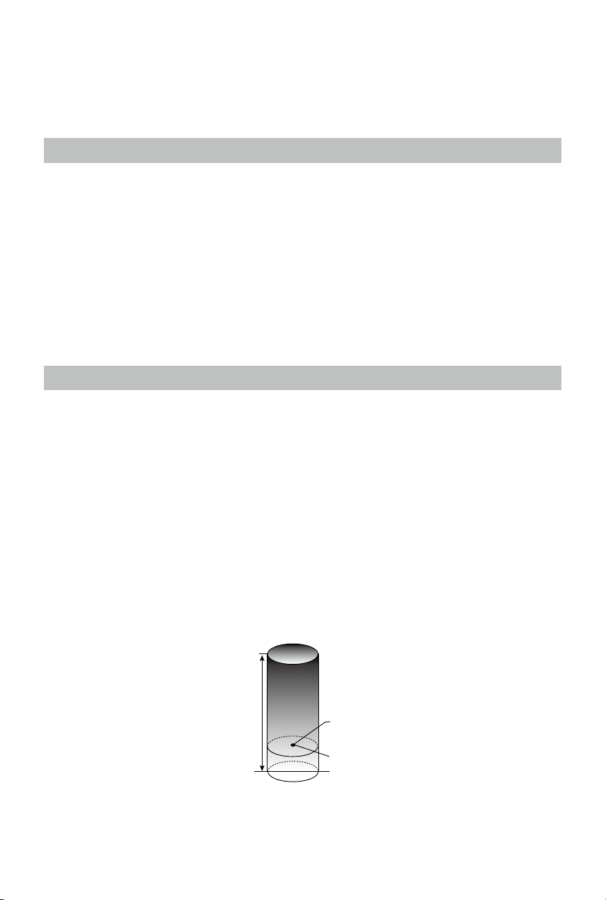
Maximum Height and Radius Limits
Users can change the maximum height and radius limits in the DJI GO app. Once complete, your
Matrice 600 will y in a restricted cylinder that is determined by these settings. The tables below show
the details of these limits.
Maximum Flight Altitude
Max Radius
Home Point
Height of aircraft
when turned on
©
2017 DJI All Rights Reserved.
43
MATRICE 600
User Manual
Safe to Fly (GPS) Blinking Green Slowly
Flight Limits DJI GO App
Max Height Flight altitude must be below the preset height. Warning: Height limit reached.
Max Radius Flight distance must be within the max radius. Warning: Distance limit reached.
Safe to Fly (No GPS) Blinking Yellow Slowly
Flight Limits DJI GO App
Max Height
If the Max Flight Altitude set in the DJI GO app
is ≤ 50m*, the ight altitude will not exceed the
preset value.
If the Flight Altitude set in the DJI GO app is >
50m*, the ight altitude will not exceed 50m*.
Warning: Height limit reached.
Max Radius No limit
.
* The value is set to 120 if the aircraft has ever received a strong GPS signal (i.e. at least three white bars are displayed after
the GPS icon) when powered on.
If you y out of bounds, you can still control the Matrice 600, but cannot y it further.
If the Matrice 600 loses GPS signal and ies out of the max radius but regains GPS signal
afterwards, it will y back within range automatically.
No Fly Zones
All No Fly Zones are listed on the DJI ofcial website at http://ysafe.dji.com/no-y. No Fly Zones are
divided into Airports and Restricted Areas. Airports include major airports and flying fields where
manned aircraft operates at low altitudes. Restricted Areas include borders between countries or
sensitive sites. The details of the No Fly Zones are explained below:
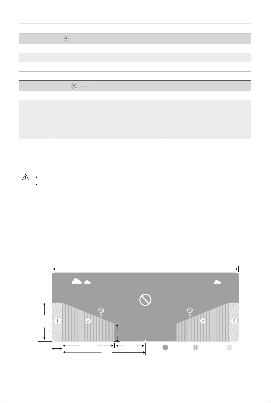
Airports (requires GPS):
Warning Zone Free ZoneNo Fly Zone
Altitude-Restricted Zone Warning ZoneNo Fly Zone
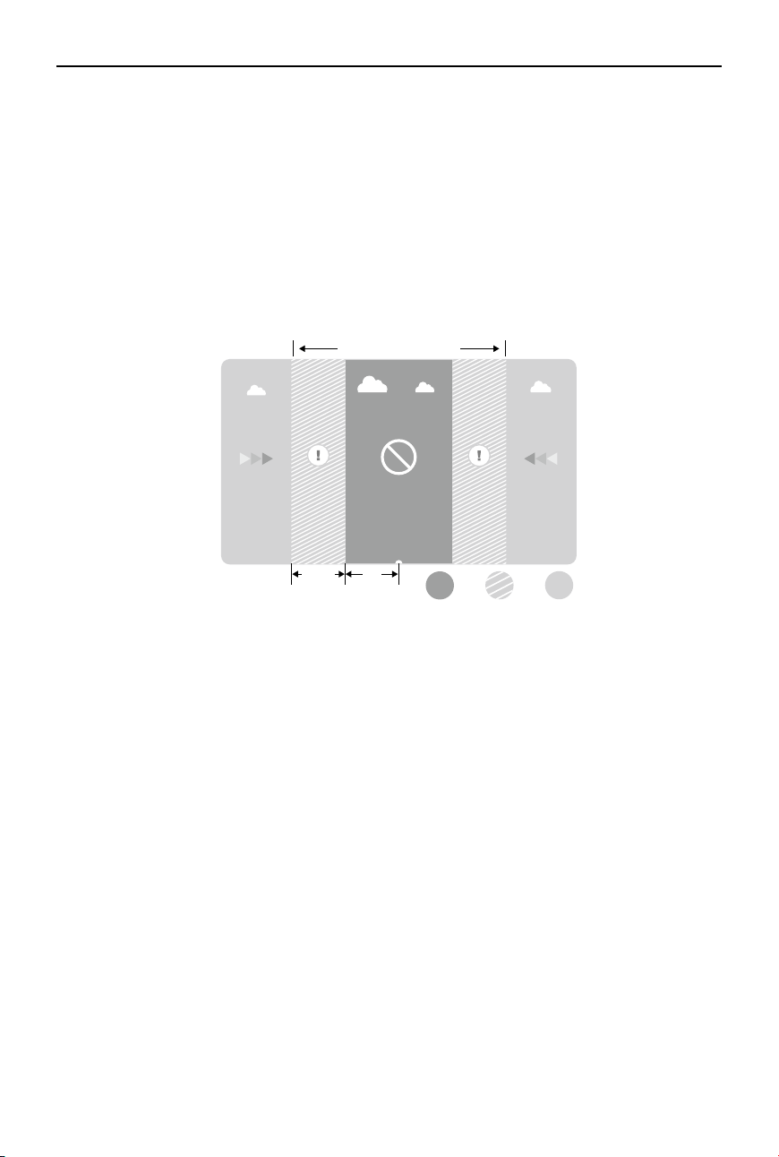
Restricted Areas
R1
66 feet
1 mile
320 feet
R2
100m
R
Airports
1640
feet
1. Airport No Fly Zones are comprised of a no y zone and an altitude-restricted zone. Each type of
zone encompasses a radius of a certain size.
44
©
2017 DJI All Rights Reserved.
MATRICE 600
User Manual
Warning Zone Free ZoneNo Fly Zone
Altitude-Restricted Zone Warning ZoneNo Fly Zone
Restricted Areas
R1
66 feet
1 mile
320 feet
R2
100m
R
Airports
1640
feet
2. R1 miles around the airport (depending on its shape and size) encompasses the no y zone, inside
of which takeoff and ight are prohibited.
3. From R1 to R1+1 miles around the airport, the flight altitude is limited at a 15 degree incline,
starting at 66 feet (20 meters) from the edge of airport and radiating outwards. The ight altitude is
limited to 1640 feet (500 meters) at R1+1 miles.
4. When the aircraft is within 320 feet (100 meters) of a no y zone, a warning message will appear in
the DJI GO app.
Restricted Areas (requires GPS):
1. Restricted Areas do not have an altitude-restricted zone.
2. R miles around the Restricted Area (depending on the regulation) is a no y zone, inside of which
takeoff and ight are prohibited.
3. A Warning Zone is set on the perimeter of the Restricted Area. When the aircraft is within 0.062
miles (100 m) of the no y zone (inside the Warning Zone), a warning message will appear in the
DJI GO app.
©
2017 DJI All Rights Reserved.
45
MATRICE 600
User Manual
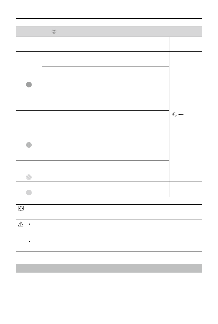
Safe to Fly (GPS) Blinking Green Slowly
Zone Restrictions DJI GO App Warning
Aircraft Status
Indicator
No Fly
Zone
Motors will not start.
Warning: You are in a no y zone.
Takeoff prohibited.
Blinking Red
If the aircraft loses GPS
signal and enters the
restricted area but regains
GPS signal afterwards,
the aircraft will enter Semi-
Automatic Descent and
land itself.
Warning: You are in a no y zone.
Automatic landing has begun. (If the
aircraft is within R1)
Altitude-
Restricted
Zone
If the aircraft loses GPS
signal and enters the
restricted area but regains
GPS signal afterwards, it will
descend to a safe altitude
and hover 15 feet below the
safe altitude.
Warning: You are in a restricted
zone. Descending to a safe altitude.
(If the aircraft is within R2 but
outside R1)
Warning: You are in a restricted
zone. Max ight height restricted
between 20 and 500 m. Fly
Cautiously.
Warning
Zone
No ight restrictions.
Warning: You are approaching a
Restricted Area. Fly cautiously.
Free Zone
No ight restrictions. None. None.
Semi-Automatic Descent: All stick commands are available except the throttle stick command
during the descent and landing process. Motors will stop automatically after landing.
When ying in No Fly Zones, the Aircraft Status Indicator will blink red slowly and continue
for 5 seconds, then switch to indicate the current ying status and continue for 7 seconds,
at which point it will switch back to blinking red slowly.
For safety reasons, please do NOT y close to airports, highways, railway stations, railway
lines, city centers or other busy areas. Try to ensure the aircraft is visible at all times.
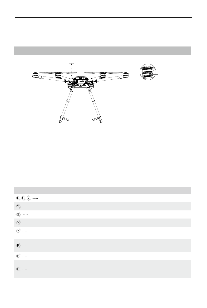
Pre-Flight Checklist
Before each ight, make sure:
1. All rmware is up-to-date.
2. The remote controller, Intelligent Flight Batteries and your mobile device are fully charged.
3. Frame arms, propellers and GPS mount are mounted correctly and unfolded.
4. All cables are connected correctly and rmly.
46
©
2017 DJI All Rights Reserved.
MATRICE 600
User Manual
Normal
Blinking Red, Green and Yellow Alternatively Power on and self-check
×4 Blinking Yellow Four Times Aircraft warming up
Blinking Green Slowly P-GPS
Blinking Yellow Slowly P-ATTI or ATTI mode
Blinking Yellow
(Alternates with other ight mode and D-RTK patterns)
Intelligent Flight Mode
Blinking Red (Alternates with ight mode patterns)
Searching for RTK signal. The aircraft
cannot take off.
Blinking Blue (Alternates with ight mode patterns) Using D-RTK GNSS
Blinking Blue Rapidly for 1.5 seconds
Switching devices (IMU or GPS
modules) for the modular redundancy
system
Aircraft Status Indicator
Front/Rear LEDs
Front/Rear LEDs
There is a Front/Rear LED on each frame arm of the Matrice 600 to show the orientation of the aircraft
after motors started. The Front LEDs are red and located on frame arms M1 and M2. The Rear LEDs
are green and located on frame arms M3 to M6.
Aircraft Status Indicator
The Aircraft Status Indicator shows the system status of the ight controller. Refer to the table below
for more information about the Aircraft Status Indicator:
5. The DJI GO app is connected to the aircraft.
6. Motors start properly and are functioning as normal.
Flight Status Indicators
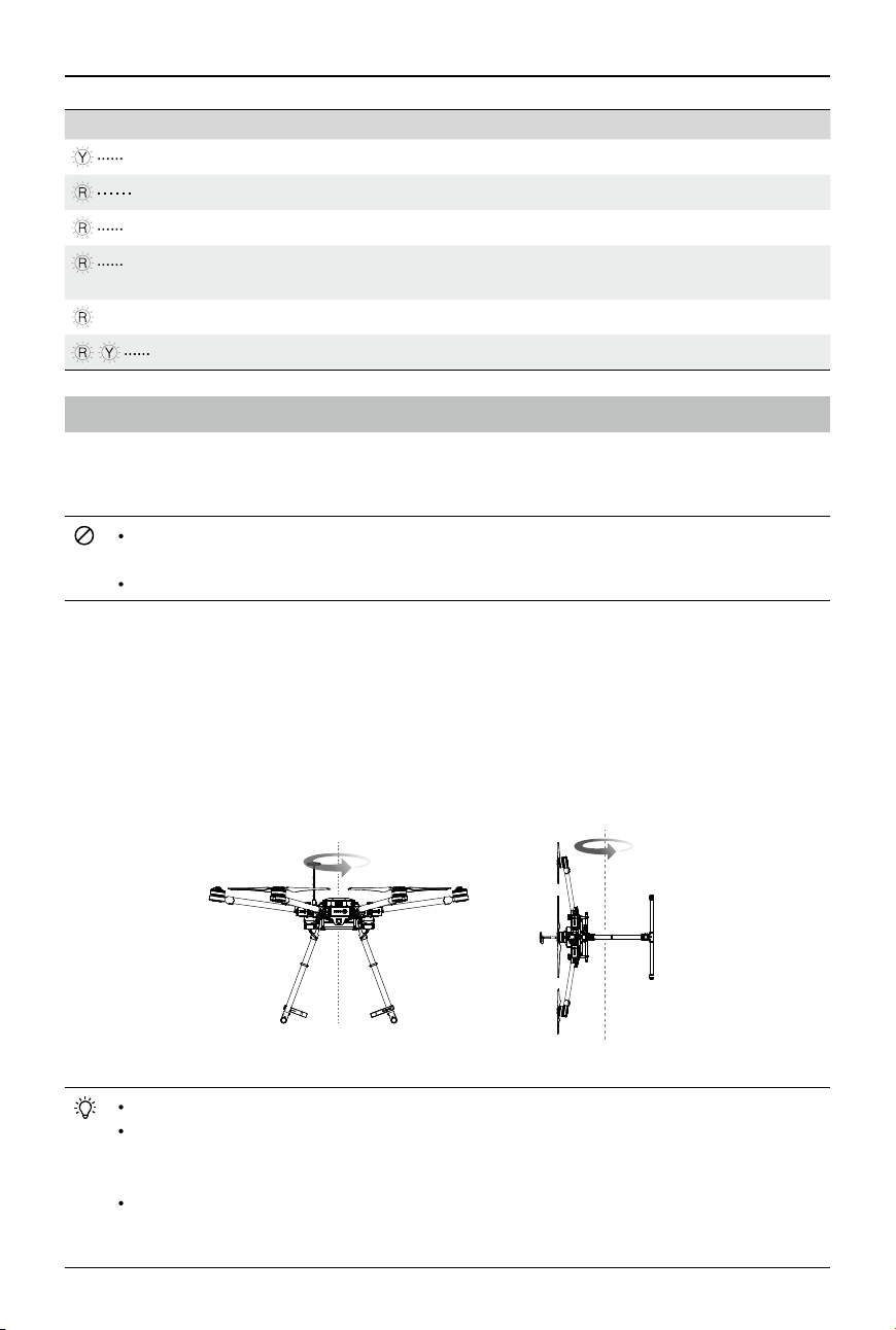
©
2017 DJI All Rights Reserved.
47
MATRICE 600
User Manual
Warning
Blinking Yellow Rapidly Remote controller signal lost
Blinking Red Slowly Low battery warning
Blinking Red Rapidly Critically low battery warning
Blinking Red Rapidly for 0.6 second when
performing CSC
Large IMU bias or IMU initialization
—— Solid Red Critical error, contact DJI Support
Blinking Red and Yellow Alternatively Compass calibration required
Calibrating the Compass
Be sure to calibrate the compass before your rst ight, or else the aircraft cannot work properly. After
that, calibrate the compass when the DJI GO app or the Aircraft Status Indicator prompts you to do so.
DO NOT calibrate your compass where there is a chance of strong magnetic interference,
such as magnetite quarries, parking structures, and underground steel reinforcements.
DO NOT carry ferromagnetic objects such as cellular phones with you during calibration.
Calibration Procedures
Choose an open space to carry out the following procedures.
1. Tap the System Status bar in the app and select Calibrate, then follow the on-screen instructions to
calibrate the aircraft step-by-step.
2. Hold the aircraft horizontally, and rotate it 360 degrees along the central axis. The Aircraft Status
Indicator will emit a solid green light.
3. Hold the aircraft vertically with its nose pointing downwards, and rotate it 360 degrees around its
central axis.
4. Recalibrate the compass if the Aircraft Status Indicator blinks red.
Calibrate the compass after you launch the DJI GO app if you are prompted to do so.
After successful calibration, the compass may become abnormal and the DJI GO app will
prompt you to recalibrate the compass when you place the aircraft on the ground. Move the
aircraft to another location.
The DJI GO app will prompt you to resolve the compass issue if the compass is affected by
strong interference after calibration is complete. Follow the prompted instructions to resolve
the compass issue.
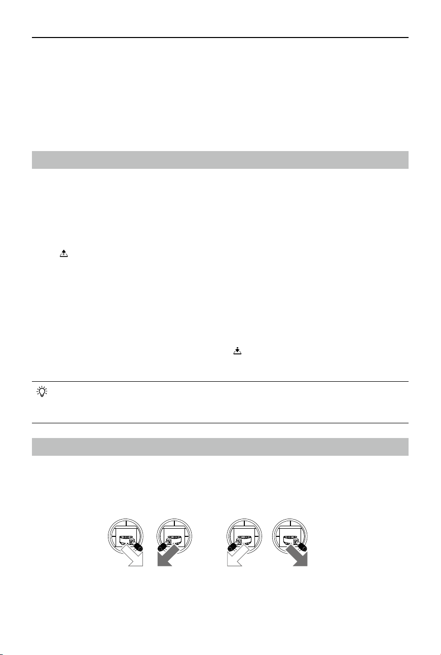
48
©
2017 DJI All Rights Reserved.
MATRICE 600
User Manual
When to Recalibrate
1. The compass data is abnormal, and the Aircraft Status Indicator is blinking red and yellow
alternatively.
2. Flying in a new location, or a location that is different from your last ight.
3. The mechanical structure of the Matrice 600 is changed, i.e. the mounting position of the GPS
module is changed.
4. Severe drifting occurs in ight, i.e. the Matrice 600 has difculty ying in a straight line.
Auto Takeoff and Auto Landing
Auto Takeoff
Use Auto Takeoff to take off your aircraft automatically if the Aircraft Status Indicator is blinking green.
Follow the steps below to use Auto Takeoff:
1. Launch the DJI GO app and enter the Camera View.
2. Ensure that the aircraft is in P-mode.
3. Go through the pre-ight checklist.
4. Tap and slide Conrm to take off.
5. The aircraft will take off and hover 1.2 meters above the ground, and then raise the landing gear
automatically.
Auto Landing
Use Auto Landing to land your aircraft automatically if the Aircraft Status Indicator is blinking green.
Follow the steps below to use Auto Landing:
1. Ensure that the aircraft is in P-mode.
2. Check that the landing area is clear before tapping to land the aircraft.
3. The aircraft will lower the landing gear and begin to land automatically.
The landing gear will automatically raise when the aircraft reaches an altitude of 1.2 m for the
rst time, and will automatically lower when the aircraft begins to land automatically. Users
can turn this feature ON/OFF in the DJI GO app.
Starting and Stopping the Motors
Starting the Motors
A Combination Stick Command (CSC) is used to start/stop the motors. Push both sticks to the bottom
inner or outer corners to start the motors. Once the motors have started spinning, release both sticks
simultaneously.
OR
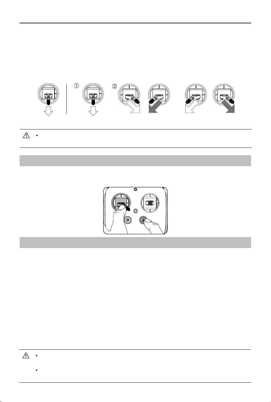
©
2017 DJI All Rights Reserved.
49
MATRICE 600
User Manual
Stopping the Motors
There are two methods to stop the motors.
Method 1: When the aircraft has landed, push the throttle down and hold. The motors will stop after 3
seconds.
Method 2: When the Matrice 600 has landed, push the throttle stick down, then perform the CSC
command to stop the motors. Release both sticks once the motors have stopped.
Stopping the Motors Mid-ight
Push the left stick to the bottom inside corner and press the RTH button at the same time. Only stop
the motors mid-ight in emergency situations when doing so can reduce the risk of damage or injury.
Flight Test
Takeoff / Landing Procedures
1. Place the aircraft on an open, at area on the ground with the rear of the aircraft facing you.
2. Power on the remote controller and your mobile device, and then one of the Intelligent Flight
Batteries.
3. Launch the DJI GO app and enter Camera View.
4. Wait until the Aircraft Status Indicator blinks green. This means the Home Point is recorded and it is
safe to y. If it blinks yellow, the Home Point has not been recorded and you should not take off.
5. Push the throttle stick up slowly to take off or use Auto Takeoff.
6. To land, hover over a level surface, toggle the landing gear control switch to lower the landing
gear, and then gently pull down on the throttle stick to descend slowly.
7. After landing, execute the CSC command or push the throttle stick down for 3 seconds until the
motors come to a stop.
8. Turn off one of the Intelligent Flight Batteries and then the remote controller.
When the Aircraft Status Indicator blinks yellow rapidly during ight, the aircraft has entered
the Failsafe mode.
The Aircraft Status Indicator will blink red slowly for a Low Battery Level warning, and blink
red rapidly for a Critically Low Battery Level warning during ight.
Method 1 Method 2
OR
When using method 2 to stop the motors, the aircraft may rollover if it doesn’t touch the ground
completely. Please use it with caution. Method 1 is recommended for stopping the motors.

50
©
2017 DJI All Rights Reserved.
Appendix
Specications
Aircraft
Structure
Diagonal Wheelbase 1133 mm
Dimensions
1668 mm×1518 mm×759 mm
(with propellers, frame arms and GPS mount unfolded)
640 mm×582 mm×623 mm
(with propellers, frame arms and GPS mount folded)
Package Dimensions 620 mm×320 mm×505 mm
Intelligent Flight Battery Quantity 6
Weight (with six TB47S batteries) 9.1 kg
Weight (with six TB48S batteries) 9.6 kg
Max Takeoff Weight 15.1 kg
Performance
Hovering Accuracy (P-mode with GPS) Vertical: ±0.5 m, Horizontal: ±1.5 m
Max Angular Velocity Pitch: 300°/s, Yaw: 150°/s
Max Pitch Angle 25°
Max Speed of Ascent 5 m/s
Max Speed of Descent 3 m/s
Max Wind Resistance 8 m/s
Max Service Ceiling Above Sea Level 2500 m
Max Speed 18 m/s (No wind)
Hovering Time* (with six TB47S batteries) No payload: 35 min, 6 kg payload: 16 min
Hovering Time* (with six TB48S batteries) No payload: 40 min, 5.5 kg payload: 18 min
Propulsion System
Motor Model DJI 6010
Propeller Model DJI 2170
Flight Control System
Model A3
Other
Supported DJI Gimbals
Zenmuse X3, Zenmuse X5, Zenmuse XT;
Zenmuse Z15 Series HD Gimbal:
Z15-A7, Z15-BMPCC, Z15-5D III, Z15-GH4;
Ronin-MX
Retractable Landing Gear Standard
Operating Temperature 14° to 104° F (-10° to 40° C)
* The hovering time is based on ying at 10m above sea level in a no-wind environment and landing with
10% battery level.
©
2017 DJI All Rights Reserved.
51
MATRICE 600
User Manual
Remote Controller
Operating Frequency
920.6 MHz to 928 MHz (Japan)
5.725 GHz to 5.825 GHz
2.400 GHz to 2.483 GHz
Max Transmitting Distance
(unobstructed, free of interference)
FCC: 5 km
CE: 3.5 km
EIRP
10 dBm @ 900 M
13 dBm @ 5.8 G
20 dBm @ 2.4 G
Video Output Port HDMI, SDI, USB
Dual Users Capability
Primary-and-Secondary control
Mobile Device Holder Supports smartphones and tablets
Output Power 9 W
Operating Temperature 14° to 104° F (-10° to 40° C)
Storage Temperature
Less than 3 months: -4° to 113° F (-20° to 45° C)
More than 3 months: 72° to 82° F (22° to 28° C)
Charging Temperature 41° to 104° F (5° to 40° C)
Battery 6000 mAh LiPo 2S
Max Tablet Width 170 mm
Charger
Model A14-100P1A
Voltage Output 26.3 V
Rated Power 100 W
Battery (Standard)
Model TB47S
Capacity 4500 mAh
Voltage 22.2 V
Type LiPo 6S
Energy 99.9 Wh
Net Weight 595 g
Operating Temperature 14° to 104° F (-10° to 40° C)
Storage Temperature
Less than 3 months: -4° to 113° F (-20° to 45° C)
More than 3 months: 72° to 82° F (22° to 28° C)
Charging Temperature 41° to 104° F (5° to 40° C)
Max Charging Power 180 W

52
©
2017 DJI All Rights Reserved.
MATRICE 600
User Manual
Battery (Optional)
Model TB48S
Capacity 5700 mAh
Voltage 22.8 V
Type LiPo 6S
Energy 129.96 Wh
Net Weight 680 g
Operating Temperature 14° to 104° F (-10° to 40° C)
Storage Temperature
Less than 3 months: -4° to 113° F (-20° to 45° C)
More than 3 months: 72° to 82° F (22° to 28° C)
Charging Temperature 41° to 104° F (5° to 40° C)
Max Charging Power 180 W
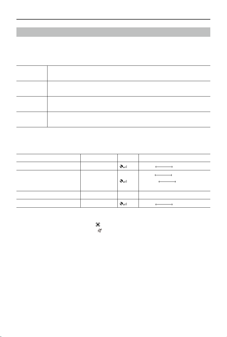
©
2017 DJI All Rights Reserved.
53
MATRICE 600
User Manual
Intelligent Flight Modes
Intelligent Flight Modes allow users to lock the orientation of the aircraft in different fashions or to pre-
plan ight paths. Intelligent Flight Modes only work in F-mode, and users must toggle the ight mode
switch to F-mode to activate Intelligent Flight Modes.
Point of
Interest (POI)
Record a point of interest (POI). The aircraft’s nose always points towards the POI.
Waypoints
Record a ight path, and the aircraft will y along the same path repeatedly while you
control the orientation. The ight path can be saved and re-used in the future.
Course Lock
(CL)
Lock the current nose direction as the aircraft’s forward direction. The aircraft will
move in the locked direction regardless of its orientation (yaw angle).
Home Lock
(HL)
Record a Home Point, and push the Pitch stick up/down to control the distance of the
aircraft from the Home Point.
Prerequisites of Intelligent Flight Modes
Use them under the following conditions:
Intelligent Flight Modes GPS Enabled GPS Flight Distance Limits
POI Yes
Aircraft
5m~500m
POI
Waypoints Yes
Aircraft
< 500m
Waypoint
Waypoint
>5m
Waypoint
Whole path length<5000m
CL No None None
HL Yes
Aircraft
≥5m
Home Point
Enabling Intelligent Flight Modes
Go to the DJI GO app > Camera View >
> Multiple Flight Modes. On the remote controller, toggle
the Flight Mode Switch to F-mode. Tap
in the DJI GO app to use Intelligent Flight Modes by
following the steps in the app.
54
©
2017 DJI All Rights Reserved.
MATRICE 600
User Manual
Upgrading the Firmware
Upgrading the Aircraft and Lightbridge 2 Air System Firmware
Connect the aircraft to the DJI Assistant 2 to upgrade the aircraft’s and Lightbridge 2 Air System’s
rmware. Refer to DJI Assistant 2 (p. 40) for details.
Upgrading the Remote Controller Firmware
The System Status bar in Camera View of the DJI GO app will flash several times if a firmware
upgrade is available. Follow these steps to upgrade the rmware via the DJI GO app.
1. Go to the DJI GO app > Camera View > System Status bar > Overall Status. Tap Download
Firmware to download and upgrade the rmware.
2. A progress bar in the DJI GO app will indicate the upgrade status. The Status LED on the remote
controller will be solid blue while the upgrade is in progress and it will turn solid green when the
upgrade is successful. The LED will turn solid red if the upgrade fails. Restart the remote controller
and try again.
DO NOT perform the rmware upgrade while the aircraft is ying in the air. Only carry out
the rmware upgrade when the aircraft is on the ground.
Both the Lightbridge 2 Air System and the remote controller rmware must be up-to-date, or
else they will not link.
Check in the DJI GO app that you have the latest rmware installed before each ight.
The rmware upgrade requires an internet connection. Connect your mobile device to a Wi-Fi
network whenever possible.
DO NOT power off the remote controller during the upgrade.
The remote controller may become unlinked from the aircraft after the rmware upgrade.
Relink the remote controller and aircraft if necessary.
Upgrading the Zenmuse X3, X5 Series and XT Firmware
If you are using a Zenmuse X3, X5 series or XT gimbal with camera, mount the gimbal with camera to
the aircraft and follow the steps below to upgrade its rmware via a Micro SD card.
Step 1- Check the Battery Level and Micro SD Card Storage
a. Ensure that the Intelligent Flight Batteries have at least 50% power level. Power on one of the
batteries and ensure that other batteries are triggered automatically. If not, nd solutions in the DJI
GO app.
b. Ensure that there is at least 100MB of free space on the Micro SD card.
Step 2- Prepare the Firmware Update Package
a. Download the rmware update package from the Matrice 600 page on the DJI website.
(http://www.dji.com/product/matrice600/info#downloads)
b. Insert the Micro SD card into your PC. Extract all the downloaded les into the root directory of the
Micro SD card. While the Matrice 600 is powered off, remove the Micro SD card from your PC and
insert it into the Micro SD card slot on the gimbal.
Step 3- Upgrade the Firmware
a. Ensure the remote controller is powered off and then power on one of the Intelligent Flight Batteries.
The rmware upgrade will begin automatically once all the Intelligent Flight Batteries are triggered.
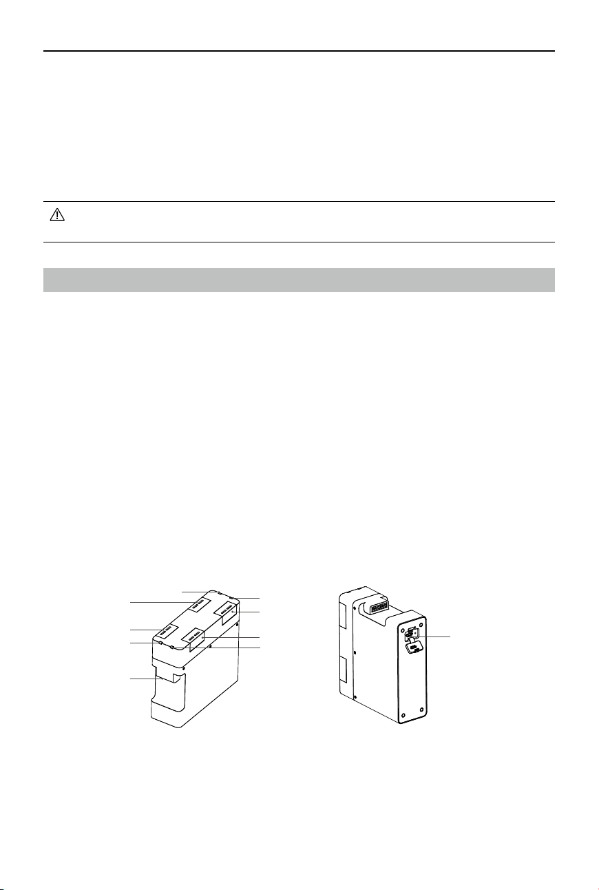
©
2017 DJI All Rights Reserved.
55
MATRICE 600
User Manual
b. It will take approximately 25 minutes to complete the rmware upgrade. The gimbal will repeat a
beeping pattern of four fast beeps to indicate that the upgrade is in progress, and emit one slow
beep followed by two fast beeps to indicate that the upgrade has been completed successfully.
c. Check the upgrade status by opening the .txt le that is automatically generated after the upgrade.
You should see the text “result: successful” in the .txt le if the upgrade is successful. Otherwise,
try upgrading the rmware again if you see the text “result: failed” in the text le or the gimbal
sounds a long beeping sound.
Ensure that there is only one version of update le in the Micro SD card, or else there will be
an update error.
Charging Hub for Intelligent Flight Batteries
The Matrice 600 is shipped with two Charging Hubs. When used with the Matrice 600 Battery Charger,
it can charge up to four Intelligent Flight Batteries. The Intelligent Flight Batteries will be charged
in sequence according to their power levels, from high to low. The Micro USB port allows users to
update the rmware.
Warning
1. The Charging Hub is only compatible with the Matrice 600 Battery Charger. Do not attempt to use
the Charging Hub with any other battery charger.
2. The Charging Hub is only compatible with TB47S and TB48S Intelligent Flight Batteries. Do not
attempt to use the Charging Hub with other battery models.
3. Place the Charging Hub on a at and stable surface when in use. Ensure the device is properly
insulated to prevent re hazards.
4. Do not attempt to touch or expose the metal terminals on the Charging Hub.
5. Clean the metal terminals with a clean, dry cloth if there is any noticeable buildup.
Overview
[1] Charging Port 1
[2] Status LED 1
[3] Charging Port 2
[4] Status LED 2
[5] Charging Port 3
[6] Status LED 3
[7] Charging Port 4
[8] Status LED 4
[9] Power Port
[10] Firmware Update Port
(Micro USB Slot)
[10]
[2]
[4]
[6]
[9]
[1]
[7]
[8]
[3]
[5]
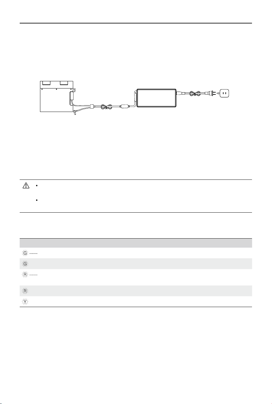
56
©
2017 DJI All Rights Reserved.
MATRICE 600
User Manual
Using the Charging Hub
Following the instructions below to use the Charging Hub:
1. Connecting to a Power Source
Connect the standard Matrice 600 Battery Charger to a power outlet (100-240V 50/60Hz), then
connect the Charging Hub to the Matrice 600 Battery Charger.
2. Connecting Batteries
Insert the Intelligent Flight Battery into the charging port to begin charging. The Intelligent Flight
Battery with the highest power level will be fully charged rst. Other batteries will be charged in
the same manner, according to their power levels. Refer to the “Status LED Indicator Description”
section for more information about the Status LEDs’ blinking patterns. Unplug the batteries when
they are fully charged.
When charging more than one Intelligent Flight Battery, distribute them as evenly as
possible among the charging slots.
DO NOT touch the metal terminals. DO NOT leave the metal terminals exposed to open air
when they are not in use.
Status LED Indicator Description
Status LED Indicator Description
Blinking Green
Charging
—— Solid Green
Fully charged
Blinking Red
Abnormal power supply, please check the connection to the Battery
Charger
—— Solid Red
No battery connected to this port
—— Solid Yellow
The battery is not charging
Upgrading the Firmware
The rmware update program has an “exe” extension. Visit the Matrice 600 page on the ofcial DJI
website to check if there is a rmware upgrade.
1. Download the latest rmware upgrade from the ofcial DJI website.
(http://www.dji.com/product/matrice600/info#downloads)
2. Turn on the Charging Hub, then connect it to a computer using a Micro USB cable.
Battery Charger
Charging Hub
Power Outlet
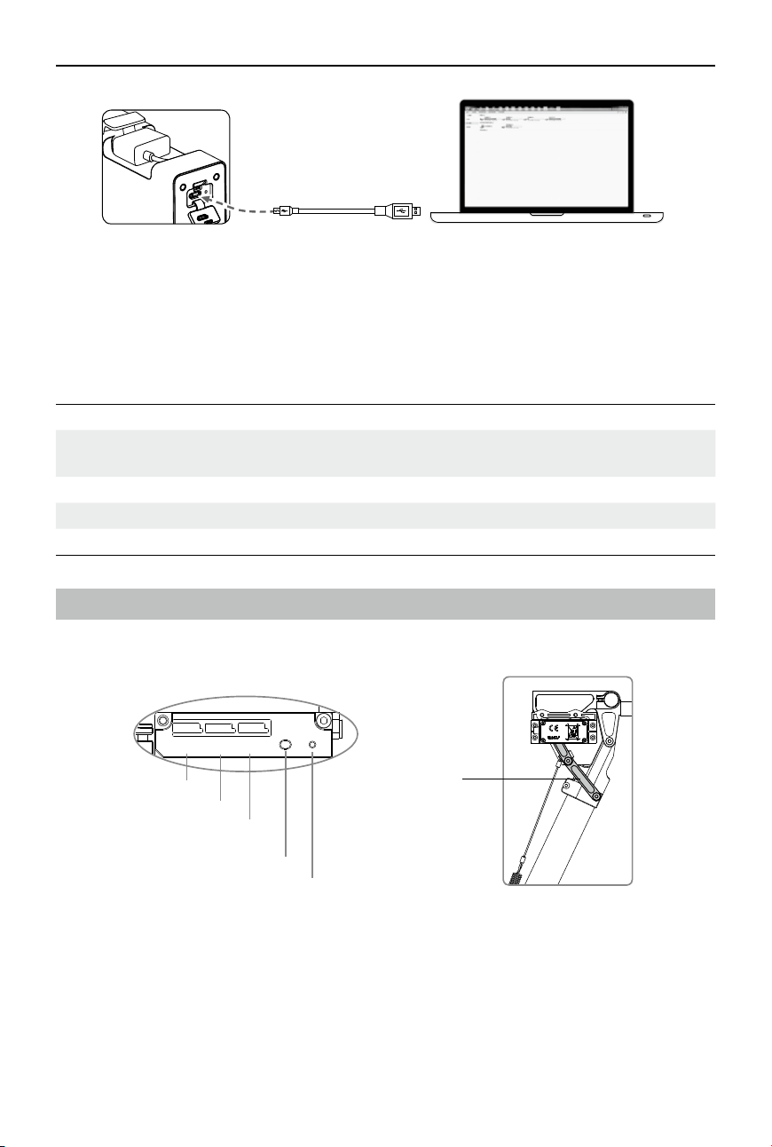
©
2017 DJI All Rights Reserved.
57
MATRICE 600
User Manual
Specications
Compatible Battery Charger Matrice 600 Standard Charger (A14-100P1A)
Compatible Battery Models
TB47S Intelligent Flight Battery
TB48S Intelligent Flight Battery
Operating Temperature 14 °F to 104 °F (5 °C to 40 °C)
Operating Voltage 26.3 V
Weight 440 g
Keep your hands away from all moving parts to avoid injuries.
Instructions:
1. Be sure to remove the two springs on the landing gear, or else calibration may fail.
2. Ensure that the “R”, “L” and “IN” connections are correct.
3. Keep the whole aircraft off of the ground during calibration, as landing gear will move.
R
L
IN
To left servo
To the servo cable at the bottom of
the center frame
SET Button
LED
To right servo
Connecting Arm
Retractable Landing Gear
Recalibrating Servo Travel
3. Run the rmware update program. Press the update button and wait for the process to nish.
4. The Charging Hub will automatically restart when the update has been successfully completed.
5. Repeat this process if the rmware upgrade fails for any reason.
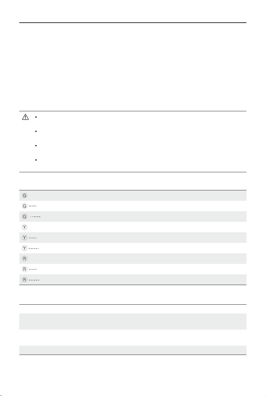
58
©
2017 DJI All Rights Reserved.
MATRICE 600
User Manual
4. Use a pin to press and hold the SET button while powering on one of the Intelligent Flight
Batteries, releasing the button when the battery powers on. The remaining batteries will power on
automatically (if the remaining batteries do not automatically power on, connect your mobile device
to the remote controller and follow the on-screen tips in the DJI GO app). The LED will blink yellow
quickly. Press the SET button again. Auto calibration will begin and the LED will blink yellow slowly.
DO NOT obstruct any moving parts during auto calibration.
5. During calibration, the left landing gear leg will raise and lower, followed by the right landing gear leg.
6. After calibration, both the left and right landing gear legs will be lowered and the LED will display a
solid green light. This indicates that the landing gear is working properly.
7. Connect both springs to the legs and the center frame.
If the LED is solid yellow after calibration, a problem has occurred. Ensure that the servos
are mounted correctly and then try again.
Avoid obstructions during calibration. If the landing gear was obstructed, recalibration will
be required, per the above steps.
If the “R” and “L” servo cables are reversed, travel will not be measured correctly. Fix the
connections and recalibrate the landing gear using the above steps.
Landing gear servo travel has been pre-calibrated. Mechanical adjustment of the servo
travel is not recommended.
LED Description
— Solid Green System normal
Blinking Green Rapidly Calibration required
Blinking Green Slowly Recalibration required
— Solid Yellow Calibration failed
Blinking Yellow Rapidly Enter calibration mode
Blinking Yellow Slowly System calibrating
— Solid Red Servo stalled
Blinking Red Rapidly Unsafe startup alert
Blinking Red Slowly Input signal abnormal
Specications
Operating Voltage 6S LiPo Input Signal PWM (High-Pulse Width 800 - 2200us)
Operating Current Max 1 A @ 6S LiPo Output Signal
PWM (Mid Position is 1520us) in 90
Hz
Operating
Temperature
-20° to 70° C Output Voltage 6 V
Total Weight 742 g Servo Travel 150° (Min 120°)
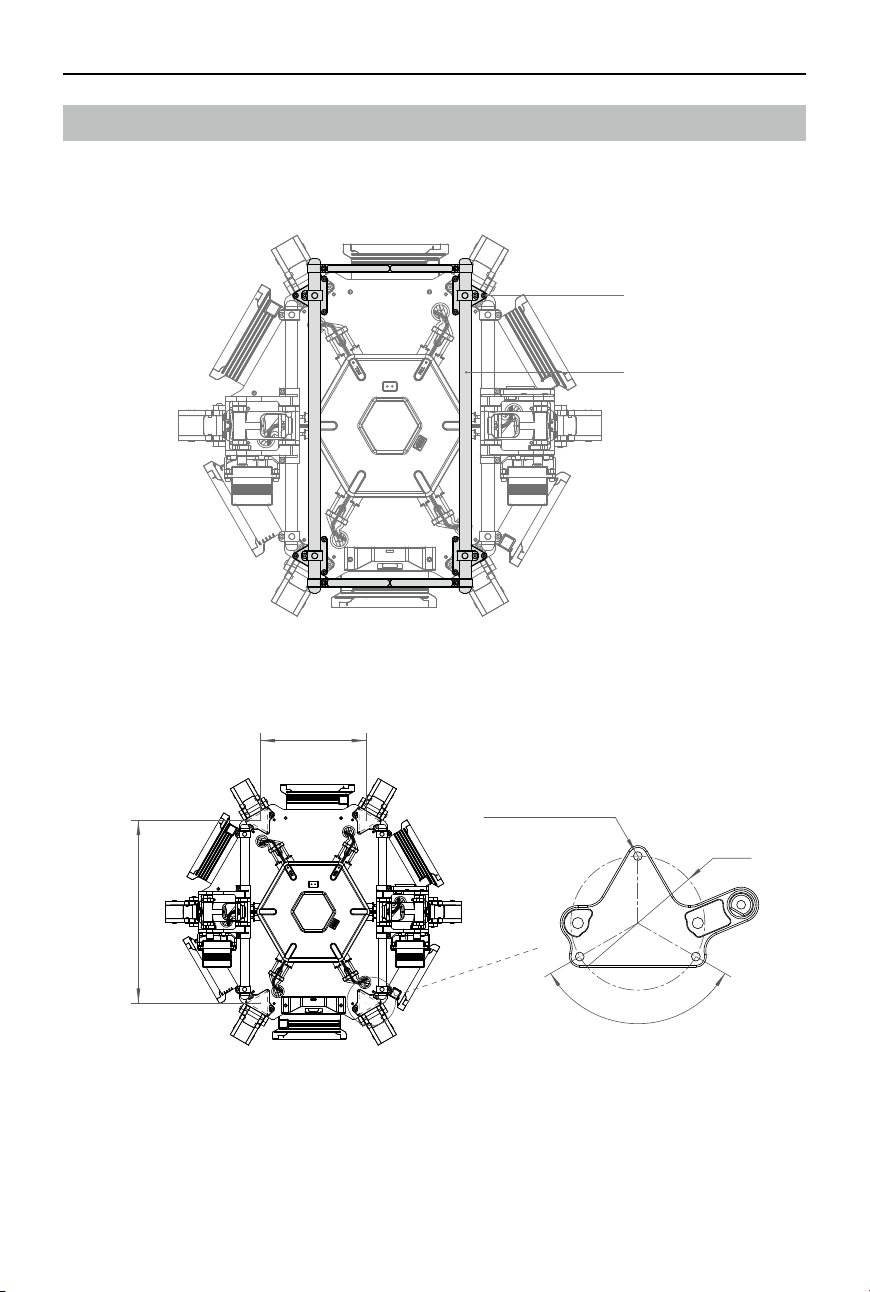
©
2017 DJI All Rights Reserved.
59
MATRICE 600
User Manual
Reserved Mounting Position Dimensions
A mounting position for your own devices is reserved at the bottom of the center frame.
1. Remove the twelve M3×6.5 screws at the bottom of the center frame rst, and then remove the
expansion mounting kit.
M3×6.5 Screws
Expansion Mounting Kit
2. The dimensions of the reserved mounting position is shown as follows (unit: mm).
149.1
258.3
3xM3
120°
Ф3
8
Thread depth 4 mm
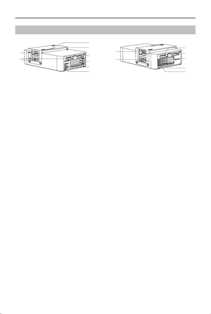
60
©
2017 DJI All Rights Reserved.
MATRICE 600
User Manual
[1] IMU1
Communicates with the IMU Pro module (modular redundancy system).
[2] CAN1
Dedicated DJI CAN-Bus port. Communicates with the GPS-Compass Pro module or other DJI
devices (e.g. Real Time Kinematic (RTK) GPS system, gimbals).
[3] Orientation Arrow
Points to the front of the aircraft.
[4] Status Indicator
Indicates the status of the ight controller and triple modular redundancy system.
[5] RF Port
Communicates with the DJI Lightbridge 2 Air System. Connected to the Lightbridge 2 Air System
upon delivery.
[6] iESC Port
Communicates with the DJI Smart ESC. Connected to the DJI Smart ESC upon delivery.
[7] M1-M8 Pins
Connects to the corresponding ESC PWM port for each motor. M1-M6 have been connected to
the ESCs and M7 has been connected to the ground upon delivery. M8 is reserved.
[8] LED Port
Communicates with the LED module. Connected to the Aircraft Status Indicator upon delivery.
[9] IMU2 Port
Communicates with the IMU Pro module (modular redundancy system).
[10] PMU Port
Derives power from the PMU. Connected to the PMU upon delivery.
[11] CAN2
Communicates with an SDK device.
[12] API Port
Communicates with an SDK device.
[13] F5-F8 Pins
Multifunction PWM output ports.
[14] F1-F4 Pins
Multifunction PWM output ports. The fan control cable (1-pin) has been connected to the F1 pin
and the landing gear servo cable has been connected to the F2 pin upon delivery.
[15] S-Bus Port
The fan power cable (2-pin) has been connected to the S-Bus port upon delivery.
[9]
[10]
[11]
[12]
[13]
[14]
[15]
[1]
[3]
[5]
[2]
[4]
[6]
[7]
[8]
A3 Flight Controller Overview
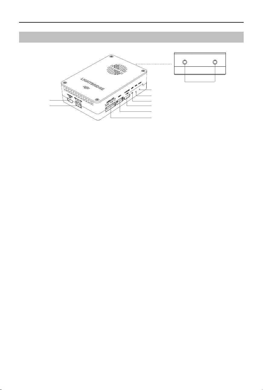
©
2017 DJI All Rights Reserved.
61
MATRICE 600
User Manual
Lightbridge 2 Air System Overview
[8]
[1]
[2]
[7]
[6]
[5]
[4]
[3]
[9]
[1] HDMI IN
Supports up to 1080p60 input resolution. This port has been connected to an HDMI cable and
the other end of the cable is an HDMI-D connector.
[2] AV IN
Receives AV input from the camera.
[3] Gimbal Port
Connects to a DJI gimbal or camera.
[4] DBUS Port
Sends the remote controller signal to the ight controller. Connected to the RF port on the ight
controller upon delivery.
[5] Upgrade Port
Connected to the USB Hub built into the center frame upon delivery.
[6] Link Button
Used to link the Air System with the remote controller.
[7] Control Indicator
Indicates the status of the Air System and remote controller.
[8] Video Indicator
Indicates the video transmission status.
[9] Antenna Port
This port has been connected to an antenna extension cable upon delivery.

62
©
2017 DJI All Rights Reserved.
MATRICE 600
User Manual
Mounting the Gimbal (Optional)
The built-in ight control system of the Matrice 600 is compatible with the following DJI gimbals and
cameras.
Ronin-MX
Zenmuse X3
Zenmuse X5 Series
Zenmuse XT
Zenmuse Z15 Series HD Gimbal: Z15-A7, Z15-BMPCC, Z15-5D III, Z15-GH4
Different accessories are used to mount different gimbals or cameras. Purchase corresponding
accessories according to your needs. The following section provides brief instructions for installation
and connection. Refer to the video tutorial on the Matrice 600 page of the official DJI website for
details.
Ronin-MX
Refer to the Ronin-MX User Manual and the Gimbal Connection Illustrator (p. 64) for installation and
connection.
Zenmuse X3, X5 Series and XT
Using the Mounting Kit
1. Remove the upper cover of the center frame gently to avoid damaging the fan cable. Unplug the
power cable of the retractable module at the bottom of the center frame, and then remove the
lower cover of the center frame.
2. Pull the gimbal video cable (7-pin) and gimbal attitude cable (CAN) for X series in the accessory
pack through the lower plate of the center frame. Then connect them to the Gimbal port on the
Lightbridge 2 Air System and the CAN1 port on the A3 flight controller. Refer to the Gimbal
Connection Illustrator (p. 65) for details.
3. Pull the XT30 power cable on the lower plate through the LIPO-6S cable outlet on the lower cover,
align the reserved XT30 port on the lower plate with the DC-18V cable outlet on the lower cover
of the center frame, arrange the gimbal cables, and then re-mount the lower cover of the center
frame. DO NOT damage the cables.
4. Mount the gimbal brackets and dampers to the gimbal mounting plate.
5. If using the Zenmuse X5 gimbal with camera, mount one key to the center of the gimbal mounting
plate with four M2x5 screws. If using the Zenmuse X5R gimbal with camera, mount two keys to one
end of the gimbal mounting plate with eight M2x5 screws.
6. Mount the mounting kit to the inner screw holes on the base plate of the lower expansion bay.
7. Mount the lower expansion bay:
a. Mount the four connectors to the base plate of the expansion bay by inserting and tightening
four M3×5.5 screws.
b. Remove the crossbar near the front of the aircraft on the expansion mounting rods.
c. Open the two connectors on one side of the expansion bay and then mount the expansion bay
to the expansion mounting rods under the center frame.
d. Close the two connectors.
e. Insert and tighten four M3×8 screws.
8. Connect the other ends of the gimbal video cable (7-pin) and gimbal attitude cable (CAN) to the
corresponding ports on the Gimbal Lock located on the gimbal mounting plate.
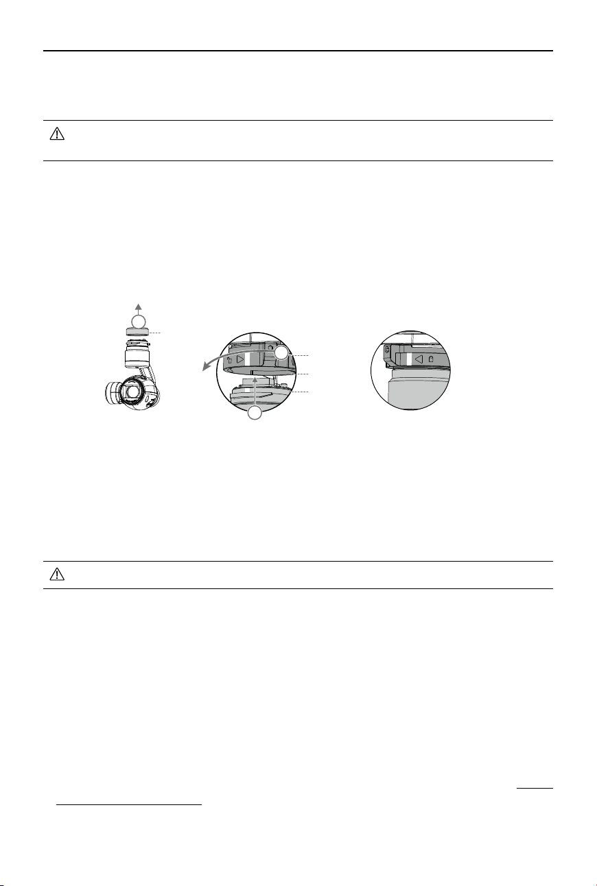
©
2017 DJI All Rights Reserved.
63
MATRICE 600
User Manual
9. Connect the gimbal power cable to the DC-18V port at the bottom of the center frame. Connect the
power cable of the retractable module to the XT30 power cable at the bottom of the center frame.
The X series gimbal cables are only for using an X series gimbal with the Matrice 600. DO
NOT mix up the X series gimbal cables with other cables.
Mounting the Gimbal with Camera
Be sure to power off the aircraft.
Zenmuse X3
1. Remove the Gimbal Cover.
2. Rotate the Gimbal Lock to the unlocked position. Insert the gimbal by aligning the white marks on
the gimbal and Gimbal Lock.
3. Rotate the Gimbal Lock back to the locked position. Ensure the gimbal is locked securely.
Zenmuse X5 Series
Refer to the Attach the Zenmuse X5 or Attach the Zenmuse X5R section in the Zenmuse X5 User
Manual or the Zenmuse X5R User Manual to mount the Zenmuse X5 series to the Matrice 600.
Zenmuse XT
Refer to the Mounting the Zenmuse XT on the Inspire 1 in the Zenmuse XT User Manual to mount the
Zenmuse XT to the Matrice 600.
Ensure the Micro SD card is inserted into the camera.
Removing the Gimbal with Camera
Ensure to power off the aircraft. While holding the upper part of the gimbal, rotate the Gimbal Lock to
the unlocked position to remove the gimbal.
Zenmuse Z15 Series HD Gimbal
1. Remove the upper cover of the center frame gently to avoid damaging the fan cable. Unplug the
power cable of the retractable module at the bottom of the center frame, and then remove the lower
cover of the center frame.
2. Pull the gimbal video cable (7-pin) and gimbal attitude cable (CAN) for the Z15 series in the
accessory pack through the lower plate of the center frame. Then connect them to the Gimbal port
on the Lightbridge 2 Air System and the CAN1 port on the A3 ight controller. Refer to the Gimbal
Connection Illustrator (p. 65) for details.
3. Pull the XT30 power cable on the lower plate through the LIPO-6S cable outlet on the lower cover,
align the reserved XT30 port on the lower plate with the DC-18V cable outlet on the lower cover
Locked
Gimbal Connector
Mounting Place
Gimbal Lock
Gimbal Cover
2
1
3
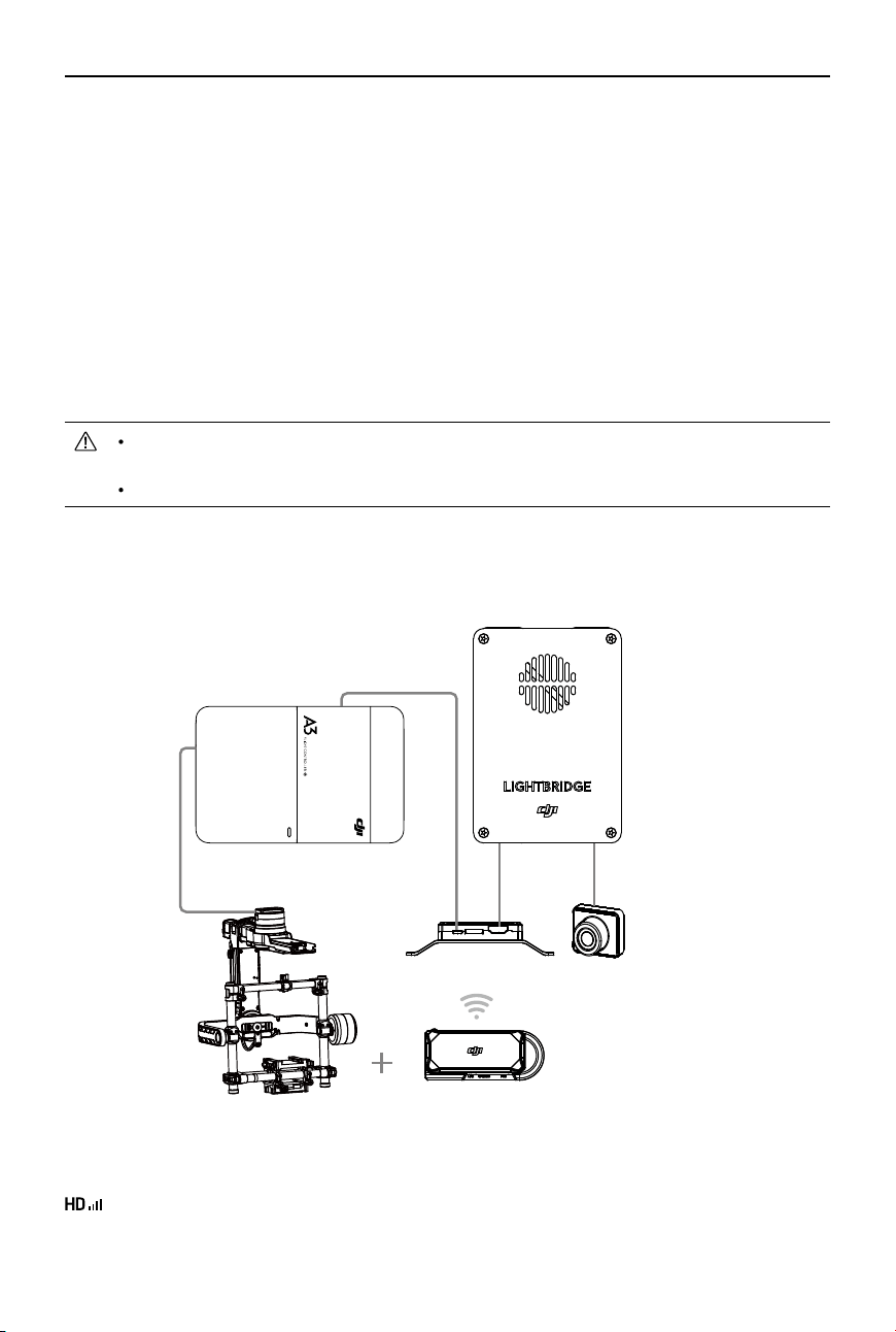
64
©
2017 DJI All Rights Reserved.
MATRICE 600
User Manual
of the center frame, arrange the gimbal cables, and then re-mount the lower cover of the center
frame. DO NOT damage the cables.
4. Replace the original dampers of the gimbal with the new dampers in the accessory pack. Then
replace the original gimbal brackets with the new ones. Insert and tighten the eight M3x8 screws.
5. Mount the four new brackets to the expansion mounting rod at the bottom of the center frame.
Adjust the gimbal to the center of the aircraft. Then insert and tighten the four M3x8 screws.
6. Connect the other ends of the gimbal video cable (7-pin) and gimbal attitude cable (CAN) to the
corresponding ports on the Z15 series GCU.
7. Connect the XT30 connector of the power distribution cable in the accessory pack to the XT30
cable at the bottom of the center frame. Connect the other XT30 connector of the power distribution
cable to the power cable of the retractable module. Connect the XT60 connector to the power
cable of the Z15 series GCU.
The Z15 series gimbal cables are only for using the Z15 series gimbal with the Matrice 600.
DO NOT mix up the Z15 series gimbal cables with other cables.
Be sure to mount the gimbal to the center of the aircraft to avoid affecting ight performance.
Gimbal Connection Illustrator
Ronin-MX
When using the Ronin-MX, set the App Output Mode in the DJI GO app to display the image on your
mobile device from the camera used with the Ronin-MX. Launch the DJI GO app > Camera View >
> Disable EXT Port, adjust the Bandwidth Allocation to ensure that the “HDMI” percentage is
more than 0%, and then set the App Output Mode to HDMI.
*You can connect the CAN cable to
the CAN Hub on the GPS cable.
A3 Flight Controller
Lightbridge 2 Air System
Ronin-MX
SRW-60G Transmitter
SRW-60G Receiver
FPV Camera
CAN1*
CAN1*
CAN
PWR HDMI
HDMI
AV
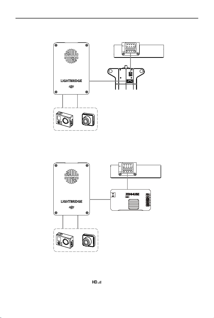
©
2017 DJI All Rights Reserved.
65
MATRICE 600
User Manual
Zenmuse X3, X5 Series and XT
GIMBAL
HDMI AV
OR
CAN1
Zenmuse Z15 Series HD Gimbal
A3 Flight Controller
A3 Flight Controller
Z15 Series GCU
Gimbal Mounting Plate
FPV Camera
FPV Camera
Lightbridge 2 Air System
Lightbridge 2 Air System
When using the Zenmuse X3, X5 Series, XT or Z15 series HD gimbal, set the App Output Mode in
the DJI GO app to display the image on your mobile device from the camera used with your gimbal.
Launch the DJI GO app > Camera View > > Enable EXT Port, adjust the Bandwidth Allocation to
ensure that the “EXT” percentage is more than 0%, and then set the App Output Mode to EXT.
GIMBAL
G7
HDMI AV
CAN1
OR
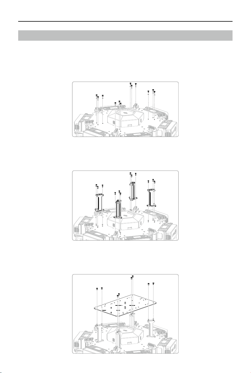
66
©
2017 DJI All Rights Reserved.
MATRICE 600
User Manual
Mounting the Expansion Bays (Optional)
Extend the center frame of the Matrice 600 with the expansion bays to mount your own devices.
Mounting the Upper Expansion Bay
1. Remove the four sets of triangularly arranged M3x5.5 screws (twelve screws in total).
2. Mount the four brackets of the expansion bay to the upper plate of the center frame by inserting
and tightening twelve M3×8 screws.
3. Mount the base plate of the expansion bay to the brackets by inserting and tightening eight
M3×5.5 screw.
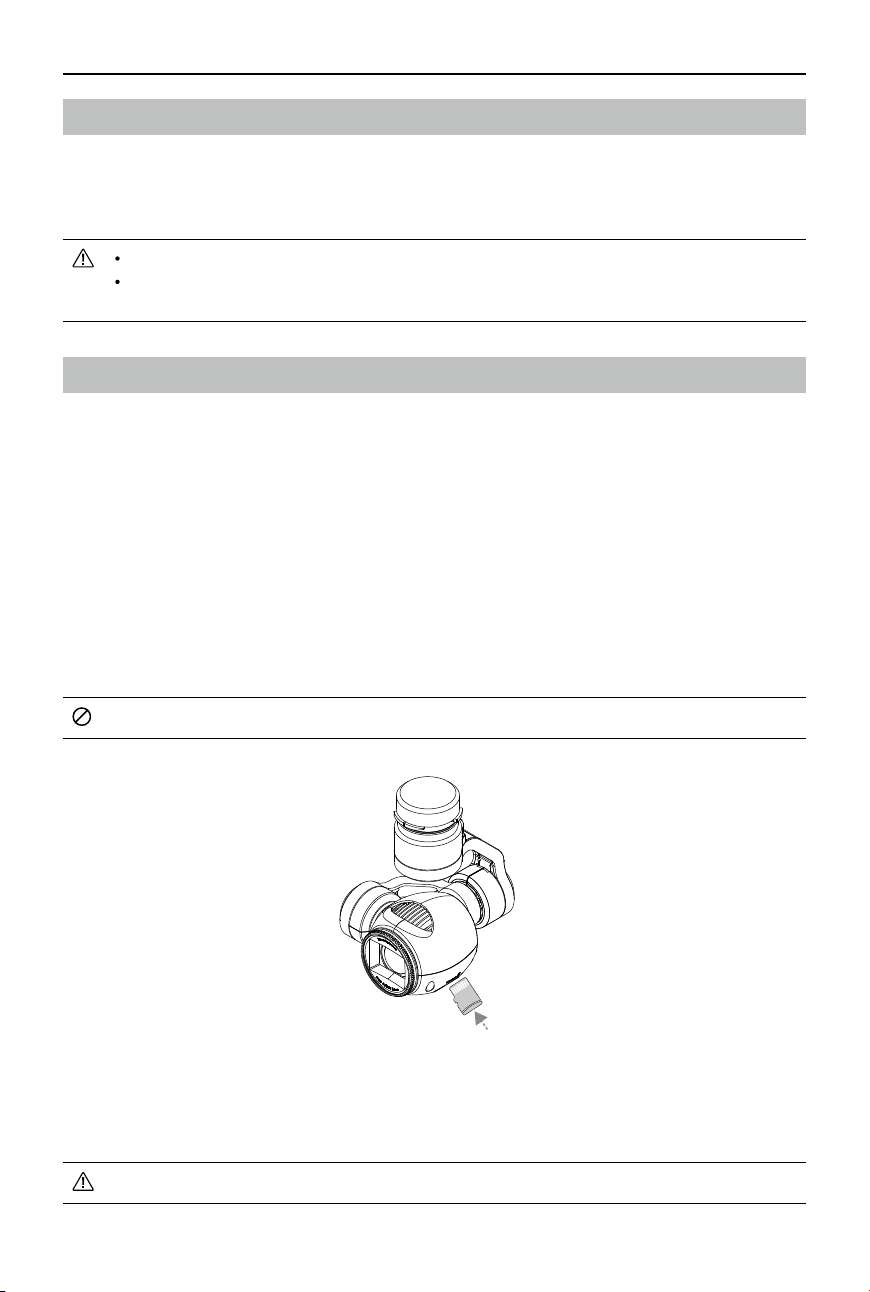
©
2017 DJI All Rights Reserved.
67
MATRICE 600
User Manual
Modular Redundancy System (Optional)
The A3 ight control system built into the Matrice 600 can be upgraded to the A3 Pro by installing two
upgrade kits. Refer to the A3/A3 Pro User Manual for installation and usage. After installation, be sure
to connect the Matrice 600 to the DJI Assistant 2 to congure the modular redundancy system.
The IMU Pro module's top side should be facing up. DO NOT mount it upside down.
Ensure that the module positions set in DJI Assistant 2 match the modules' actual positions,
otherwise ight safety will be affected.
DJI Zenmuse X3 Gimbal with Camera
Camera
Camera Prole
The X3 gimbal camera can record up to 4K 4096×2160p video at 24 fps, and capture 12-megapixel
images. It features a 1/2.3” Sony EXMOR CMOS image sensor. Preview of the camera’s POV in the
DJI GO app before shooting images and video. Have extra options to shoot stills in burst mode or
self-timer mode, and export video in either MOV or MP4 format.
Camera Micro SD Card Slot
To store your photos and videos, plug in the Micro SD card into the Micro SD card slot on the gimbal
before powering on the Matrice 600. The camera supports a single Micro SD card of up to 64GB. A
UHS-1 type Micro SD card is recommended because of its fast read and write capability, allowing you
to store high-resolution video les.
DO NOT remove the Micro SD card from the gimbal when it is powered on.
Camera Data Port
Power on the Matrice 600 and then connect a USB cable to the Camera Data Port to download photos
or videos from the camera to your PC.
Power on the aircraft before downloading the les.
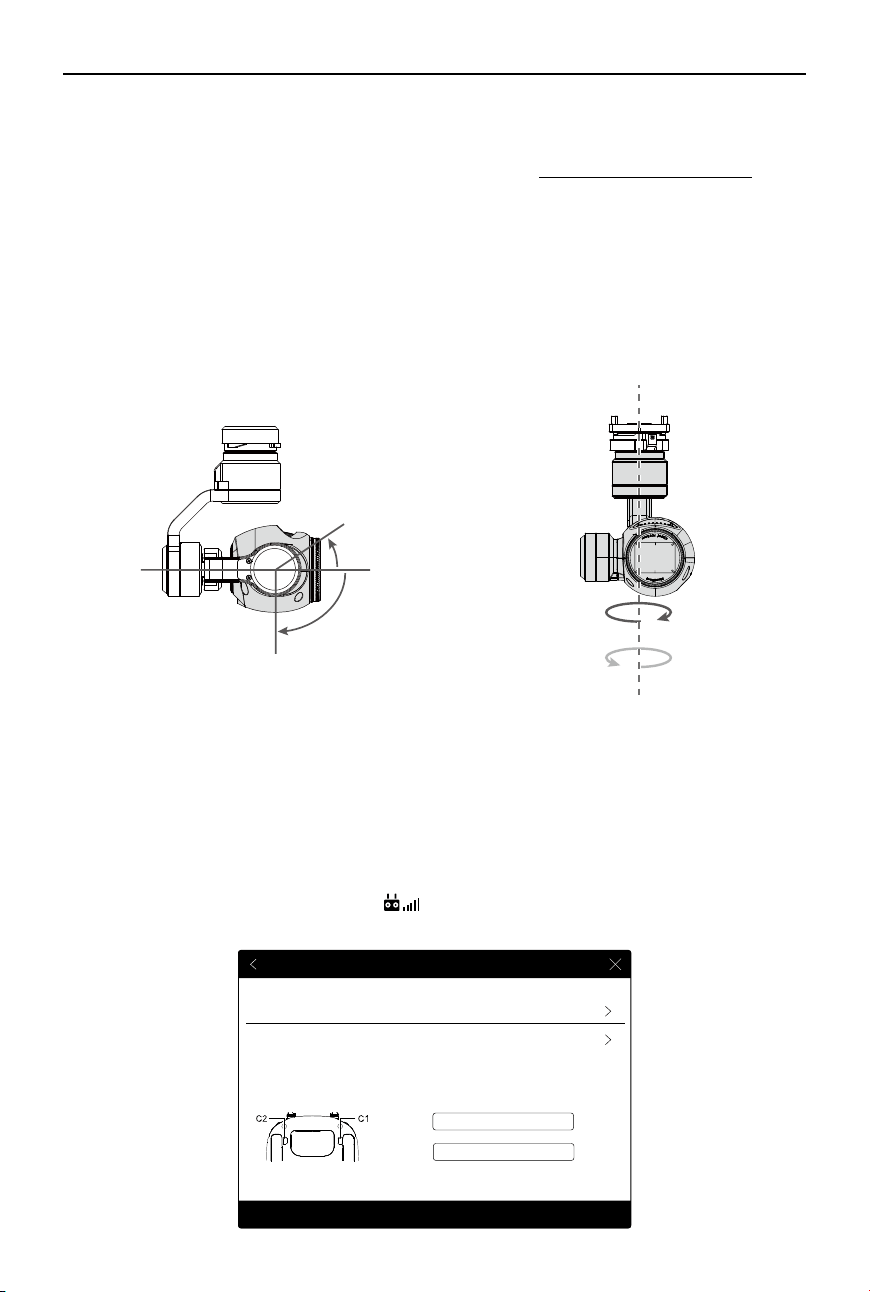
68
©
2017 DJI All Rights Reserved.
MATRICE 600
User Manual
Camera Operation
Use the Shutter and Record button on the remote controller to shoot images or the videos through the DJI
GO app. For more information on how to use these buttons, refer to Controlling the Camera (p. 24).
ND Filter
Attach an ND lter to the front of the camera to reduce over exposure and the ‘jello’ effect.
Gimbal
Gimbal Prole
The 3-axis gimbal provides a steady platform for the camera, allowing you to capture stable video and
images. The gimbal can tilt the camera up to 120 degrees and rotate 320 degrees.
-320°
+
30°
-90°
0°
+
3
20°
Under the default settings, turn the gimbal dial on the remote controller to tilt the camera. Note that
you cannot simultaneously tilt and pan the camera in the Single Remote Controller mode. Enable the
Primary-and-Secondary mode in the DJI GO app and set a second remote controller to secondary if
you wish to tilt and pan the camera together.
Gimbal Dial Settings
Follow the instructions below to use the gimbal dial to tilt/pan the camera:
1. Power on the aircraft and the remote controller.
2. Go to the DJI GO app > Camera View >
> Remote Controller Settings.
3. Set the customizable button C1 or C2 as the Gimbal Pitch/Yaw.
Remote Controller Settings
Remote Controller Calibration
Stick Mode
Button Customization
Gimbal Pitch/YawC1
C2 Not Defined
Default stick mode is Mode 2, changing stick modes alters the way the aircraft is controlled.
Do not change unless familiar with your new mode.
You can customize the C1 and C2 buttons on the back of the RC.
Linking Remote Controller
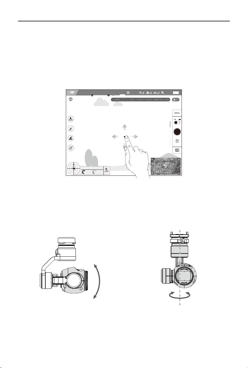
©
2017 DJI All Rights Reserved.
69
MATRICE 600
User Manual
Press the C1 or C2 button to switch between pitch mode and yaw mode. Use the gimbal dial to
control the tilt/pan motion of the camera.
Using the DJI GO App to Control the Gimbal
Follow the steps below to use the DJI GO app to control the gimbal’s pitch/yaw motion:
1. Go to the DJI GO app > Camera View.
2. Tap and hold on the screen until a blue circle appears.
3. Move your nger to control the gimbal’s pitch/yaw motion.
AE
22:02
LOG
60
1080P
ISO
F
EV
1600
2.8
2.0
1/50
09:29
61%
P-GPS
12
M/S
M/S
H: D:
V.S
H.S
4.22.3
39M 210M
232M
MENU
SAFE TO FLY (GPS)
Pitch Yaw
Gimbal Operation Modes
Switch between the three operation modes in Camera View in the DJI GO app. Note that your mobile
device must be connected to the remote controller for changes to take effect. Refer to the table below
for details:
70
©
2017 DJI All Rights Reserved.
MATRICE 600
User Manual
Follow Mode
The gimbal’s orientation is aligned with the aircraft’s nose. One
user alone can control the pitch motion of the gimbal, but a second
operator is required to control the yaw motion using a second remote
controller.
FPV Mode
The gimbal will lock to the movement of the aircraft to provide a First-
Person-View ying experience.
Free Mode
The gimbal’s motion is independent of the aircraft’s orientation. One
user alone can control the pitch motion of the gimbal, but a second
user is required to control the yaw motion using a second remote
controller.
Re-alignment
Re-align the yaw angle of the gimbal with that of the aircraft. The pitch
angle remains unchanged during the re-alignment.
A gimbal motor error may occur if the gimbal is placed on an uneven ground because
of impact with ground objects. Be sure to take off from a at, open ground to protect the
gimbal from impact.
Flying in heavy fog or inside clouds may make the gimbal wet, leading to a temporary
failure. The gimbal will recover when it dries out.
Specications
Gimbal
Model Zenmuse X3
Power Output (Camera Attached) Static: 9 W; In Motion: 11 W
Operating Current Static: 750 mA; In Motion: 900 mA
Angular Vibration ±0.03°
Mounting Detachable
Controllable Range Pitch: -90° to +30°; Yaw: ±320°
Mechanical Range Pitch: -125° to +45°; Yaw: ±330°
Controllable Speed Pitch: 120°/s; Yaw: 180°/s
Camera
Name X3
Model FC350
Total Pixels 12.76 M
Effective Pixels 12.4 M
Max Image Size 4000 x 3000
ISO 100-3200 (Video); 100-1600 (Photo)
Shutter 8 to 1/8000 s
FOV (Field Of View) 94°

©
2017 DJI All Rights Reserved.
71
MATRICE 600
User Manual
CMOS Sony EXMOR 1/2.3”
Lens
20 mm (35 mm format equivalent), f/2.8
,
focus at ∞
9 elements in 9 groups
Anti-distortion
Still Photography Modes
Single shot
Burst mode: 3/5/7 frames
Auto Exposure Bracketing (AEB): 3/5 frames at ±0.7EV
Timed shot
Video Recording Modes
UHD (4K): 4096x2160p 24/25, 3840x2160p 24/25/30
FHD: 1920x1080p 24/25/30/48/50/60
HD: 1280x720p 24/25/30/48/50/60
Video Storage Bitrate 60 Mbps
Supported File Formats
FAT32/exFAT
Image: JPEG, DNG
Video: MP4/MOV (MPEG-4 AVC/H.264)
Supported SD Cards
Micro SD
Max capacity: 64 GB; Class 10 or UHS-1 rating required
Operating Temperature -10° to 40 ℃

This content is subject to change.
Download the latest version from
http://www.dji.com/product/matrice600
If you have any questions about this document, please contact DJI by
sending a message to
.
MATRICE is a trademark of DJI. Copyright
©
2017 DJI All Rights Reserved.
The terms HDMI, HDMI High Denition Multimedi a Interface, and the
HDMI Logo are trademarks or registered trademarks of HDMI Licensing
Administrator, Inc.