Room Air Conditioner
Service and Parts
Manual
0
F
Power
Mode
Timer
0
n
/0ff
Fan
Speed
Temp
CoolMoney
Saver
®
Fan
Only
Dry
hr
Auto
Swing

—2—
1. PREFACE
1.1 SAFETY PRECAUTIONS ...............................2
1.2 INSULATION RESISTANCE TEST.................2
1.3 PRODUCT SPECIFICATIONS .......................3
1.4 OPERATING INSTRUCTIONS.......................4
2.
DISASSEMBLY INSTRUCTIONS
2.1 MECHANICAL PARTS....................................5
2.1.1 FRONT GRILLE .....................................5
2.1.2 CABINET................................................5
2.1.3 CONTROL BOX .....................................5
2.2 AIR HANDLING PARTS..................................6
2.2.2 FAN AND S H R O U D ..........................6
2.2.3 MOTOR ................................................7
2.3 ELECTRICAL PARTS .....................................7
2.3.1 OVER LOAD PROTECTOR...................7
2.3.2 COMPRESSOR .....................................7
2.3.3 CAPACITOR ..........................................8
2.3.4 POWER CORD ......................................8
2.4 REFRIGERATION CYCLE.................................9
2.4.1 CONDENSER ......................................9
2.4.2 EVAPORATOR ....................................9
2.4.3 CAPILLARY TUBE...............................9
4.
TROUBLESHOOTING GUIDE
4.1 PIPING SYSTEM ..........................................13
4.2 TROUBLESHOOTING GUIDE......................14
3. SCHEMATIC DIAGRAM
3.1 CIRCUIT DIAGRAM......................................12
5. EXPLODED VIEW
..................................19
6. REPLACEMENT PARTS LIST
.......20
1. PREFACE
This SERVICE MANUAL provides various service information, including the mechanical and electrical
parts etc. This room air conditioner was manufactured and assembled under a strict quality control system.
The refrigerant is charged at the factory. Be sure to read the safety precautions prior to servicing the unit.
1.1 SAFETY PRECAUTIONS
1. When servicing the unit, turn off the air conditioner
and unplug the power cord.
2. Observe the original lead dress.
If a short circuit is found, replace all parts which
have been overheated or damaged by the short
circuit.
3. After servicing the unit, make an insulation
resistance test to protect the customer from being
exposed to shock hazards.
1.2
INSULATION RESISTANCE TEST
1. Unplug the power cord and connect a jumper
between 2 pins (black and white).
2. The grounding conductor (green or green & yellow)
is to be open.
3. Measure the resistance value with an ohm meter
between the jumpered lead and each exposed
metallic part on the equipment.
4. The value should be over 1M .
CONTENTS
2.2.1 COVER (AT THE TOP)..........................6
2.2.2 AIR GUIDE AND BLOWER....................6
1.3 PRODUCT SPECIFICATIONS
—3—
Buyer Model EP12G33B
BTU performance (Cooling) 1
1,500/12,000
BTU performance (Heating) 9,200/11,200
EER 9.8/9.8
COP
Dehumid. ( Pts/Hr) 3.3
Dry Air Flow (CFM) 265
dBA Level (Indoor / Outdoor) 51/57
Est. Cooling Area (SQ.FT) 550
Voltage / 60 Hz 208/230
Watts (Cooling) 1,170/1,220
Watts (Heating) 2,900/3,500
Rated Amps (Cooling) 5.8/5.5
Rated Amps (Heating) 14.0/15.3
Thermostat Control Thermistor
Air Diflection
4-Way
Remote controller Ye
s
Auto swing Ye
s
Auto Restart Ye
s
Energy saver fuction Ye
s
Timer 24
Hr,On/Off
Sleep -
Fan Speed: Cooling(Heating) 2(
2)
Fan Only 2
Compressor ROTARY
In Door Fan Type BLOWER
Type Air Discharge Side by side
Outdoor Vent / Exhaust Yes
Rear grille Ye
s
Chassis Type Sl
ide In-Out
Carton Height(inch) 18 1/8
Width 27 1/16
Depth 23 5/8
Demension Height(inch) 14 31/32
Width 23 5/8
Depth 22 1/16
Net Weight(lbs.) 87
Shippling Weight(lbs.) 93
Stuffing Quantity (20/4040Hi ft) 135/297/297
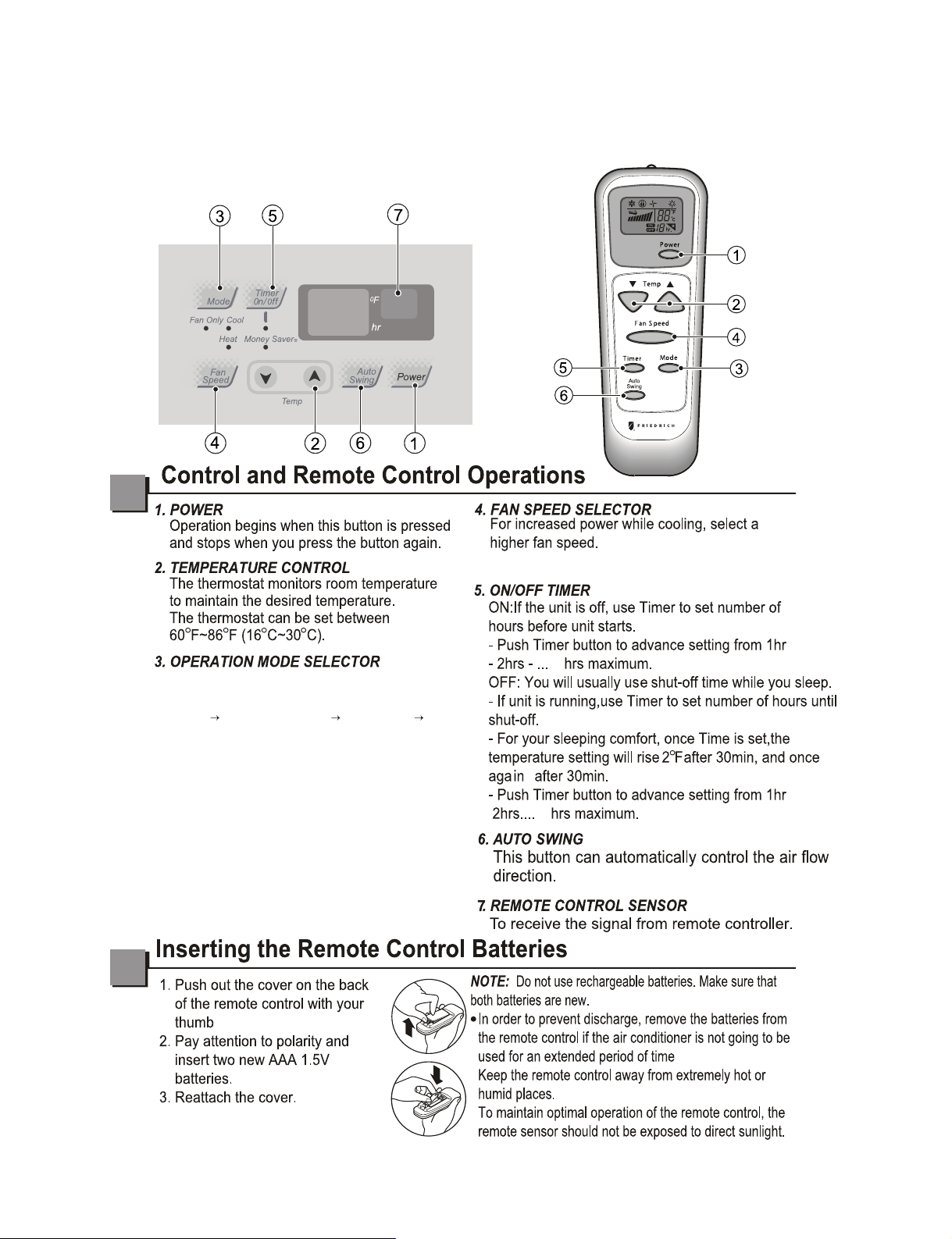
1.4 OPERATING INSTRUCTIONS
—4—
24
24
COOL MONEY SAVER FAN ONLY HEAT
COOL:Fan runs continually for normal cooling
operation.
MONEY SAVER:The fan stops when the
compressor stops cooling.Approximately every
3 minutes the fan will turn on and the unit will
check the room air temperature to determine if
cooling is needed.
FAN ONLY:Fan-only operation.
HEAT:Fan runs continually for normal heating
operation.
-Push this button to shift mode of operation
from:
2 speed:Low;High
— Before the following disassembly, POWER SWITCH is set to OFF and disconnected the power cord.
2. DISASSEMBLY INSTRUCTIONS
—5—
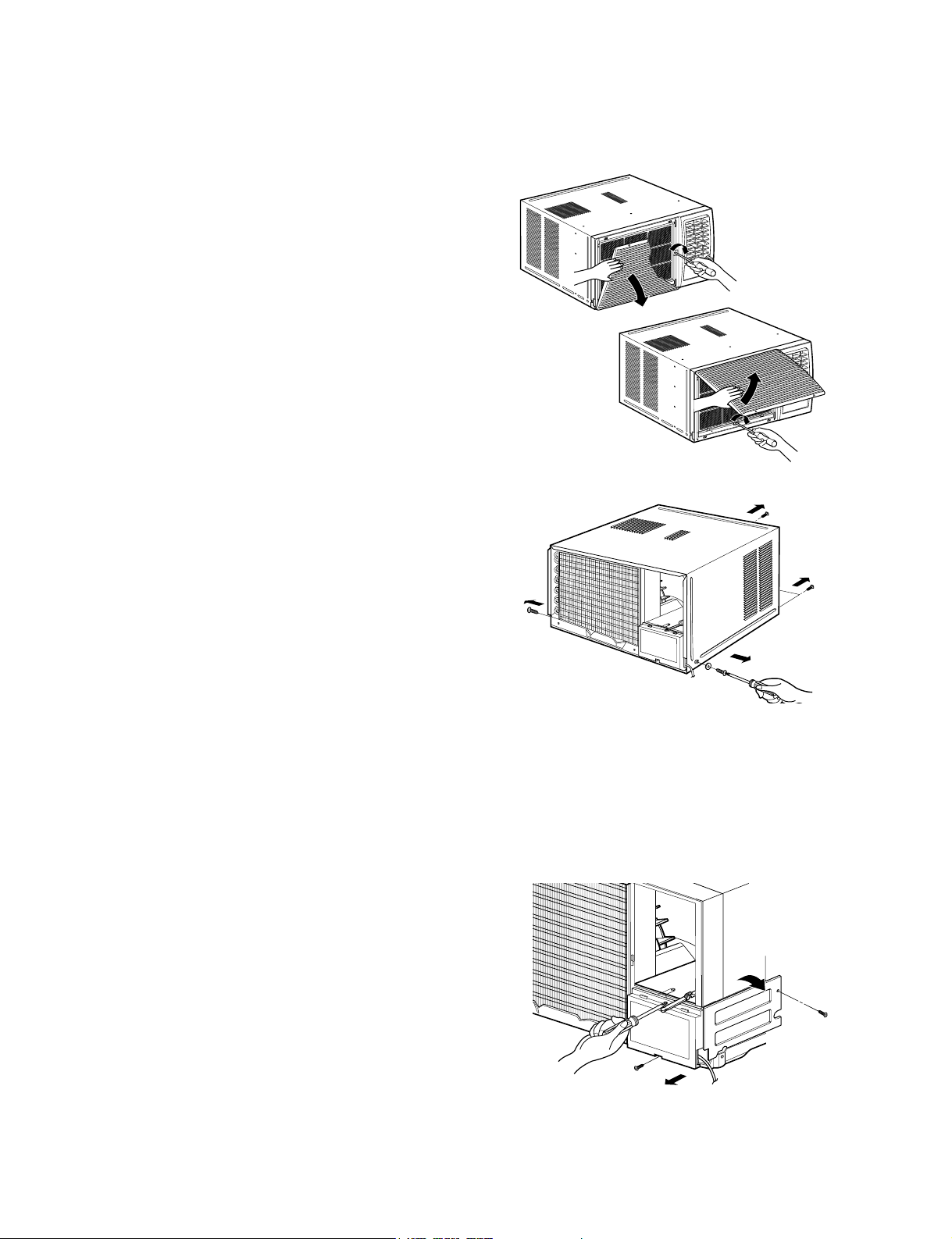
1. Open the lnlet grille upward or downward.
2. Remove the screw which fastens the front grille.
3. Pull the front grille from the right side.
4. Remove the front grille.
5. Re-install the component by referring to the
removal procedure, above.(See Figure 17)
1. After disassembling the FRONT GRILLE, remove
the 2 screws which fasten the cabinet at both
sides.
2. Remove the 2 screws which fasten the cabinet at
back.
3. Pull the base pan forward. (See Figure 18)
4. Remove the cabinet.
5. Re-install the component by referring to the
removal procedure, above.
1. Disconnect the unit from the power source.
2. Remove the front grille.
3. Remove the cabinet.
4. Remove the screw which fastens the control box
cover.
5. Remove the housing which connects motor wire
in the control box.
6. Remove the 3 leads from the compressor.
7.Discharge the capacitor by placing a 20,000
ohmresistor across the capacitor terminals.
8. Remove the 2 screws which fasten the control
box.(See Figure 19)
9. Pull the control box forward completely.
10. Re-install the components by referring to the
removal procedure, above. (See Figure 19)
Figure 17
Figure 19
Figure 18
2.1 MECHANICAL STRUCTURE
2.1.1 FRONT GRILLE
2.1.2 CABINET
2.1.3 CONTROL BOX
Air handling parts
2.2 AIR HANDLING PARTS
—6—
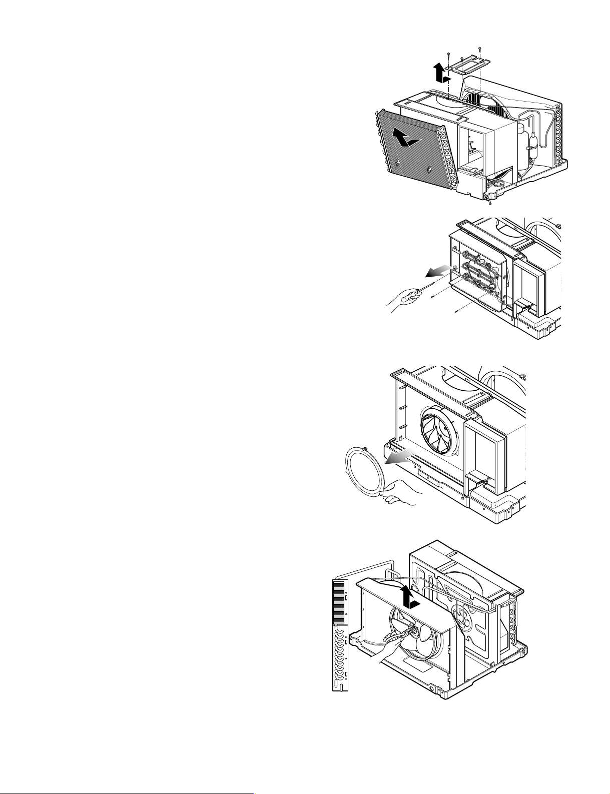
2.2.1.
AIR GUIDE AND BLOWER
1. Remove the front grille.
2. Remove the cabinet.
3. Remove the control box.
4. Remove the 3 screws which fasten the brace.
5. Remove the brace.
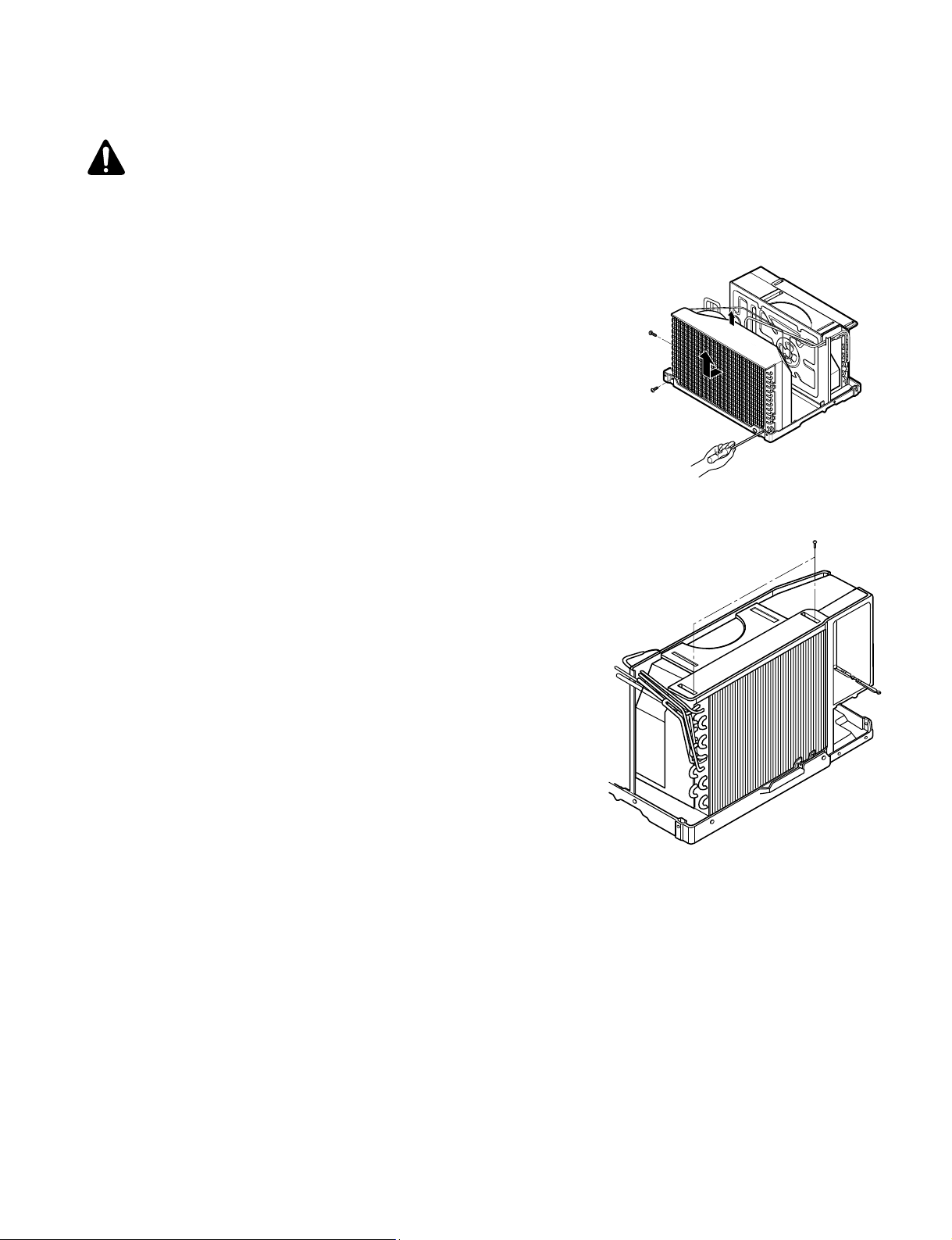
6. Remove the 2 screws which fasten the evaporator.
7. Move the evaporator forward and pulling it upward
slightly. (See Figure 20)
8. Move the evaporator to the left carefully.
12. Pull out the hook of orifice by pushing the tabs and
remove it. (See Figure 21)
13. Remove the clamp with a hand plier which
secures the blower.
14. Remove the blower.
15. Remove the 4 screws which fasten the air guide
from the barrier.
16. Move the air guide backward, pulling out from the
base pan.
17. Re-install the components by referring to the
removal procedure, above.
2.2.2
FAN AND SHROUD
1. Remove the cabinet.
2. Remove the brace.
3. Remove the 3 screws which fasten the condenser.
4. Move the condenser to the left carefully.
5. Remove the clamp which secures the fan.
6. Remove the fan and then pull out the shroud.
(See Figure 22)
7. Re-install by referring to the removal procedure.
Figure
22
Figure
21
Figure 20
Figure A
9. Remove the 2 terminals carefully. (See Figure A,
at Electric heater Model)
10. Remove the 3 screws that fasten the Heater
Cover. (See Figure A, at Electric Heater Model)
11. Remove the Heater cover. (See Figure A, at
Electric Heater Model)
2.3 ELECTRICAL PARTS
—7—
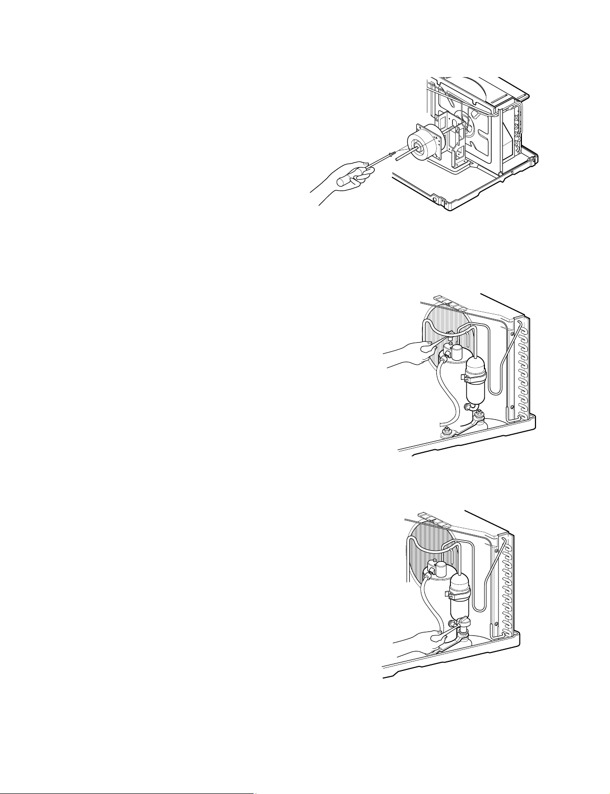
1. Remove the cabinet.
2. Remove the evaporator.
3. Remove the orifice.
4. Remove the blower.
5. Remove the fan.
6. Remove the control box cover and housing of the
motor in the control box.
7. Remove the 2 screws which fasten the motor from
the mount motor. (See Figure 23)
8. Remove the motor.
9. Re-install the components by referring to the
removal procedure, above.(See Figure 23)
Figure 23
2.2.3. MOTOR
2.3.1. OVERLOAD PROTECTOR
1. Remove the cabinet.
2. Remove the nut which fastens the terminal cover.
3. Remove the terminal cover. (See Figure 24)
4. Remove all the leads from the overload protector.
5. Remove the overload protector.
6. Re-install the component by referring to the
removal procedure, above.
Figure 24
2.3.2. COMPRESSOR
1. Remove the cabinet.
2. Discharge the refrigerant system using a Freon
TM
Recovery System.
If there is no valve to attach the recovery system,
install one (such as a WATCO A-1) before venting
the Freon
TM
. Leave the valve in place after
servicing the system.
3. Remove the overload protector.
4. After purging the unit completely, unbraze the
suction and discharge tubes at the compressor
connections.
5. Remove the 3 nuts and the 3 washers which
fasten the compressor.
6. Remove the compressor. (See Figure 25)
7. Re-install the components by referring to the
removal procedure, above.
Figure 25
—8—
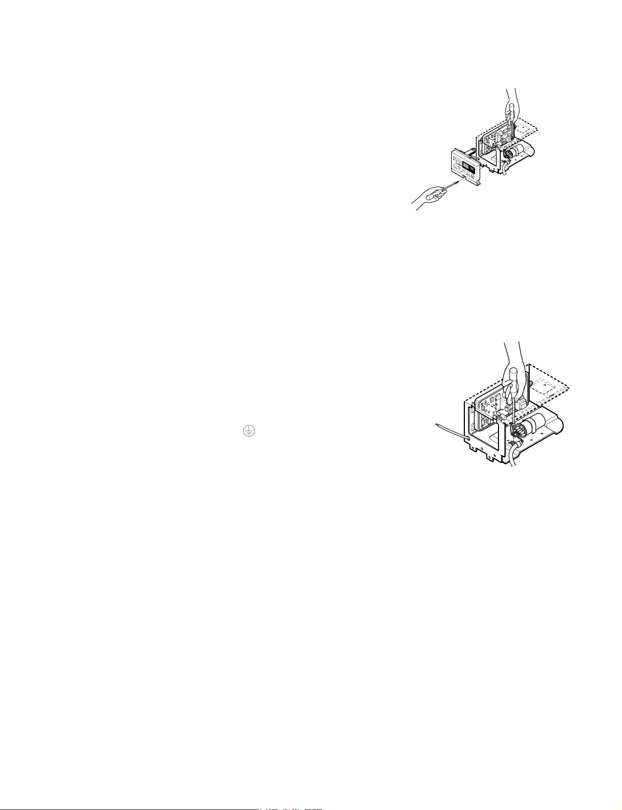
2.3.3. CAP
ACITOR
1. Remove the control box.
2. Remove the screw which fasten control panel from
control box.
3. Remove the screw which located in the front.
4. Open the bottom side of control box.
5. Remove the screw and the clamp which fastens
the capacitor.
6. Disconnect all the leads of capacitor terminals.
7. Re-install the components by referring to the
removal procedure, above. (See Figure 27)
Figure 27
2.3.4. POWER CORD
Figure 30
1. Remove the control box.
2. Open the control box.
3. Disconnect the grounding screw from the control
box.
4. Disconnect the 2 receptacles.
5. Remove a screw which fastens the clip cord.
(See Figure 30)
6. Remove the power cord.
7. Re-install the component by referring to the above
removal procedure, above.
(Use only one ground-marked hole for ground
connection.)
8. If the supply cord of this appliance is damaged, it
must be replaced by the special cord. (The
special cord means the cord which has the same
specification marked on the supply cord attached at
the unit.)
—9—
CAUTION: Discharge the refrigerant system using Freon
TM
Recovery System.If
there is no valve to attach the recovery system, install one (such as a WATCO A-1)
before venting the Freon
TM
. Leave the valve in place after servicing the system.
2.4 REFRIGERATION CYCLE
2.4.1
CONDENSER
Figure 31
1. Remove the cabinet.
2. Remove the 3 screws which fasten the
brace.
3. Remove the 3 screws which fasten the condenser
and shroud.
4. After discharging the refrigerant completely,
unbraze the interconnecting tube at the condenser
connections.
5. Remove the condenser carefully.
6. Re-install the component by referring to notes.
(See Figure 31)
2.4.3 CAPILLARY TUBE
Figure 32
1. Remove the cabinet.
2. Remove the 2 screws which fasten the evaporator.
3. Move the evaporator sideways carefully.
4. After discharging the refrigerant completely,
unbraze the interconnecting tube at the evaporator
connections.
5. Remove the evaporator carefully.
6. Re-install the component by referring to notes.
(See Figure 32)
1. Remove the cabinet.
2. After discharging the refrigerant completely,
unbraze the interconnecting tube at the capillary
tube.
3. Remove the capillary tube.
4. Re-install the component by referring to notes.
2.4.2 EVAPORATOR
—10—
— Replacement of the refrigeration cycle.
1. When replacing the refrigeration cycle, be sure to
Discharge the refrigerant system using a Freon
TM
recovery System.
If there is no valve to attach the recovery system,
install one (such as a WATCO A-1) before venting
the Freon
TM
. Leave the valve in place after
servicing the system.
2. After discharging the unit completely, remove the
desired component, and unbraze the pinch-off
tubes.
3. Solder service valves into the pinch-off tube ports,
leaving the valves open.
4. Solder the pinch-off tubes with Service valves.
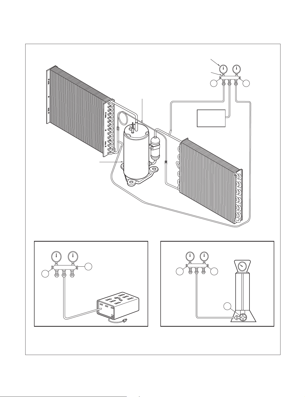
5. Evacuate as follows.
1) Connect the vacuum pump, as illustrated figure
33A.
2) Start the vacuum pump, slowly open manifold
valves A and B with two full turns counterclock-
wise and leave the valves open.
The vacuum pump is now pulling through valves
A and B up to valve C by means of the manifold
and entire system.
CAUTION: If high vacuum equip-
ment is used, just crack valves A
and B for a few minutes, then open
slowly with the two full turns counter-
clockwise. This will keep oil from foaming
and being drawn into the vacuum pump.
3) Operate the vacuum pump vaccum for 20 to 30
minutes, until 600 microns of vaccum is
obtained. Close valves A and B, and observe
vacuum gauge for a few minutes. A rise in pres-
sure would indicate a possible leak or moisture
remaining in the system. With valves A and B
closed, stop the vacuum pump.
4) Remove the hose from the vacuum pump and
place it on the charging cylinder. See figure
37B. Open valve C.
Discharge the line at the manifold connection.
5) The system is now ready for final charging.
6. Recharge as follows :
1) Refrigeration cycle systems are charged from
the High-side. If the total charge cannot be put
in the High-side, the balance will be put in the
suction line through the access valve which you
installed as the system was opened.
2) Connect the charging cylinder as shown in figure
33B.
With valve C open, discharge the hose at the
manifold connection.
3) Open valve A and allow the proper charge to
enter the system. Valve B is still closed.
4) If more charge is required, the high-side will not
take it. Close valve A.
5) With the unit running, open valve B and add the
balance of the charge.
a.
Do not add the liquid refrigerant to the Low-side.
b. Watch the Low-side gauge; allow pressure to
rise to 30 lbs.
c. Turn off valve B and allow pressure to drop.
d. Repeat steps b. and c. until the balance of the
charge is in the system.
6) When satisfied the unit is operating correctly,
use the pinch-off tool with the unit still running
and clamp on to the pinch-off tube. Using a tube
cutter, cut the pinch-off tube about 2 inches from
the pinch-off tool. Use sil-fos braze and braze
pinch-off tube closed. Turn off the unit, allow it to
set for a while, and then test the leakage of the
pinch-off connection.
NOTICE
—11—
Equipment needed: Vacuum pump, Charging cylinder, Manifold gauge, Brazing equipment. Pin-off tool capable
of making a vapor-proof seal, Leak detector, Tubing cutter, Hand Tools to remove components, Service valve.
A
COMPOUND GAUGE
EVAPORATOR
(LOW PRESSURE SIDE)
COMPRESSOR
CAPILLARY TUBE
CONDENSER
(HIGH PRESSURE SIDE)
SEE INSETS
BELOW
MANIFOLD
GAUGE
B
Figure 33A-Pulling Vacuum
Figure 33B-Charging
A
B
EXTERNAL
VACUUM PUMP
A
CHARGING
CYLINDER
LOW
HI
B
C
EP12
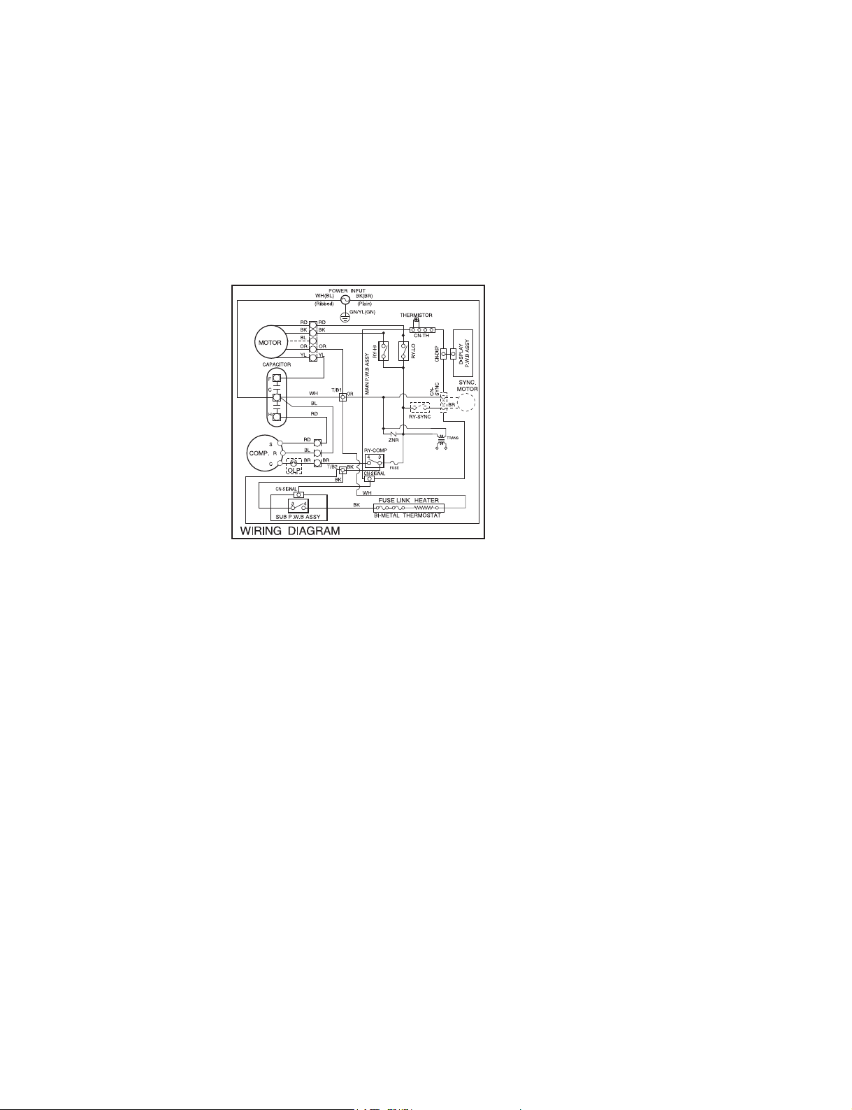
3. SCHEMATIC DIAGRAM
3.1 CIRCUIT DIAGRAM
—12—
(SMPS)
BR
(250V/T3.15A)
MEZ62420704
4. TROUBLESHOOTING GUIDE
4.1 PIPING SYSTEM
——
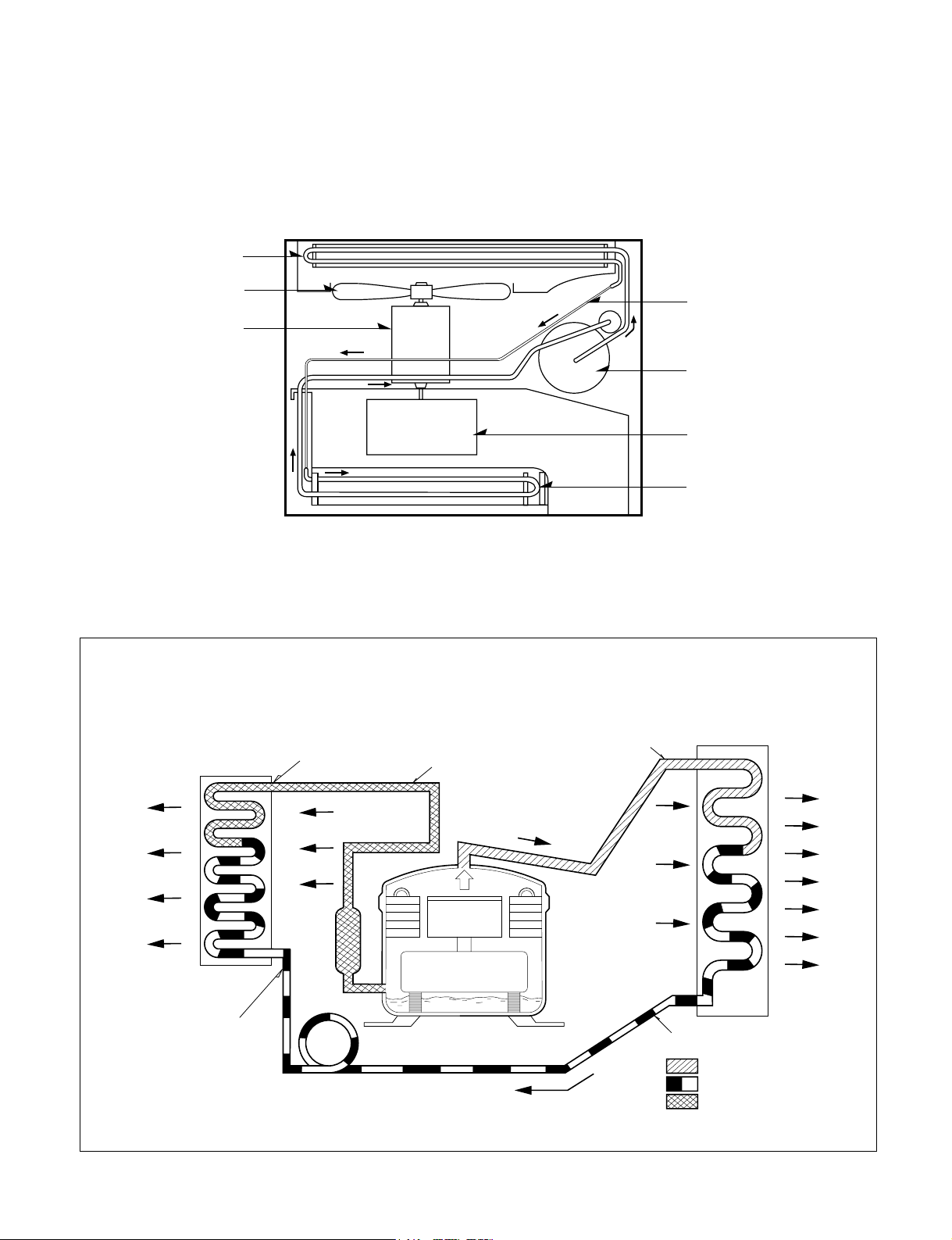
Figure 32 is a brief description of the important components and their function in what is called the refrigeration
system. This will help you to understand the refrigeration cycle and the flow of the refrigerant in the cooling cycle.
MOTOR
COMPRESSOR
OIL
(LIQUID REFRIGERANT)
CAPILLARY TUBE
OUTSIDE COOLING
AIR FOR REFRIGERANT
PASS THROUGH
SUCTION LINE
COOL LOW PRESSURE VAPOR
COOLED
AIR
COMPLETE LIQUID
BOIL OFF POINT
LIQUID
PRESSURE
DROP
ROOM AIR HEAT LOAD
VAPOR INLET
HOT
DISCHARGED
AIR
LIQUID OUTLET
HIGH PRESSURE VAPOR
LIQUID REFRIGERANT
LOW PRESSURE VAPOR
ROOM AIR CONITIONER
EVAPORATOR COILS CONDENSER COILS
CYCLE OF REFRIGERATION
CAPILLARY TUBE
COMPRESSOR
BLOWER
EVAPORATOR COIL
CONDENSER COIL
FAN
MOTOR
Figure 32
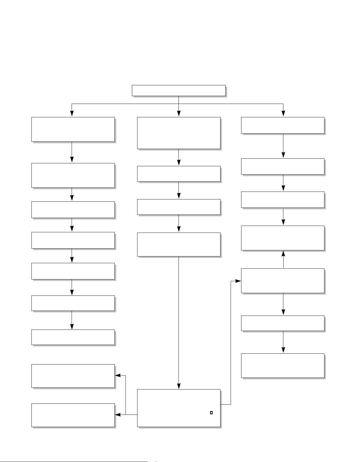
In general, possible trouble is classified in two causes.
The one is called Starting Failure which is caused from an electrical defect, and the other is Ineffective Air
Conditioning caused by a defect in the refrigeration circuit and improper application.
Unit is running but cooling is ineffective
Ineffective Cooling
Check of outdoor coil
(heat exchanger) & the fan
operation.
Check gas leakage.
Repair gas leak.
Replacement of unit if the
unit is beyond repair.
Satisfactory operation with
temperature difference of
inlet & outlet air ; 44.6~50
F
Check heat load increase.
Unexpected residue
Overloaded Circuit
Check of inside gas
pressure.
Adjusting of refrigerant
charge
Malfunction of compressor
Replacement of
compressor
Check of cold air circulation
for smooth flow.
Dirty indoor coil
(Heat exchanger)
Malfunction of fan
Clogged of air filter
Obstruction at air outlet
Correct above trouble
Stop of auto air-swing
Check clogging in
refrigeration circuit.
Repair clogging in
refrigeration circuit.
4.2 TROUBLESHOOTING GUIDE
—14—
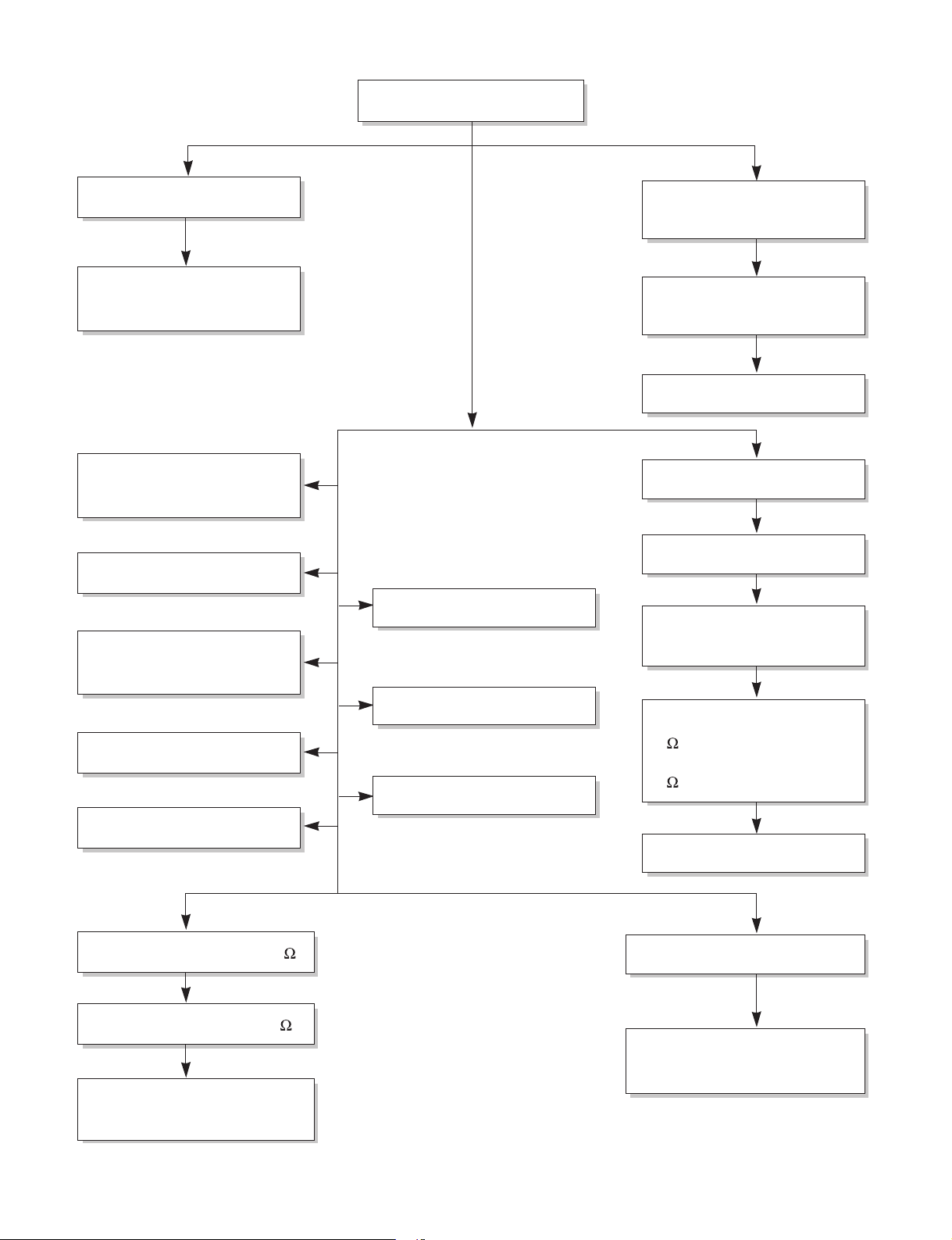
Fails to Start
Check of circuit breaker
and fuse.
Gas leakage of feeler bulb
of thermostat
Check of control switch.
Only fan fails to start.
Improper wiring.
Defect of fan motor
capacitor.
Irregular motor resistance
( ).
Irregular motor insulation
( ).
Replacement of fan motor
Regular but fails to start
Replacement of compressor
(locking of rotor, metal)
Improper thermostat setting
Loose terminal connection.
Improper wiring
Irregular motor resistance ( )
Irregular motor insulation ( )
Replacement of compressor
(Motor damaged)
Drop of power voltage.
Check capacitor.
Replacement.
Only compressor fails to
start.
Defect of compressor
capacitor.
Check of power source.
Check of control switch
setting.
—15—
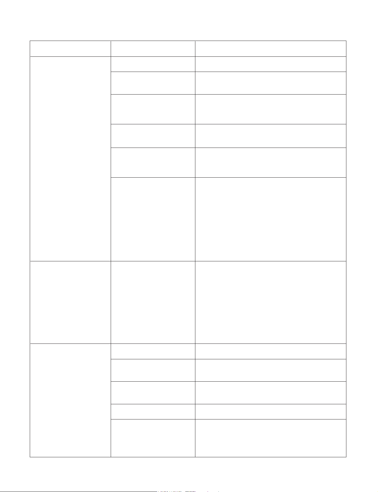
COMPLAINT CAUSE REMEDY
Check voltage at outlet. Correct if none.
Check voltage to rotary switch. If none, check
power supply cord. Replace cord if circuit is open.
Check switch continuity. Refer to wiring diagram
for terminal identification. Replace switch if
defective.
Connect wire. Refer to wiring diagram for terminal
identification. Repair or replace loose terminal.
Test capacitor.
Replace if not within ±10% of manufacturer's
rating. Replace if shorted, open, or damaged.
Fan blade hitting shroud or blower wheel hitting
scroll. Realign assembly.
Units using slinger ring condenser fans must
have
1
/
4
to
5
/
16
inch clearance to the base. If it is
hitting the base, shim up the bottom of the fan
motor with mounting screw(s).
Check fan motor bearings; if motor shaft will not
rotate, replace the motor.
Check voltage. See limits on this page. If not within
limits, call an electrician.
Test capacitor.
Check bearings. Does the fan blade rotate freely?
If not, replace fan motor.
Pay attention to any change from high speed to
low speed. If the speed does not change, replace
the motor.
Check grommets; if worn or missing, replace them.
If cracked, out of balance, or partially missing,
replace it.
If cracked, out of balance, or partially missing,
replace it.
Tighten it.
If knocking sounds continue when running or
loose, replace the motor. If the motor hums or
noise appears to be internal while running,
replace motor.
No power
Power supply cord
Rotary switch
Wire disconnected or
connection loose
Capacitor (Discharge
capacitor before testing.)
Will not rotate
Revolves on overload.
Grommets
Fan
Turbo fan
Loose set screw
Worn bearings
Fan motor will not run.
Fan motor runs
intermittently
Fan motor noise.
—16—
NAME PLATE RATING MINIMUM MAXIMUM
115V 103.5V 126.5V
208/230V 187V 253V
COMPLAINT CAUSE REMEDY
Check voltage. See the limits on the preceding.
page. If not within limits, call an electrician.
Check the wire connections, if loose, repair or
replace the terminal. If wires are off, refer to wiring
diagram for identification, and replace. Check wire
locations. If not per wiring diagram, correct.
Check for continuity, refer to the wiring diagram
for terminal identification. Replace the switch if
circuit is open.
Check the position of knob If not at the coldest
setting, advance the knob to this setting and
restart unit.
Check continuity of the thermostat. Replace
thermostat if circuit is open.
Check the capacitor.
Replace if not within ±10% of manufacturers
rating. Replace if shorted, open, or damaged.
Check the compressor for open circuit or
ground. If open or grounded, replace the compres-
sor.
Check the compressor overload, if externally
mounted. Replace if open. (If the compressor
temperature is high, remove the overload, cool it,
and retest.)
Voltage
Wiring
Rotary
Thermostat
Capacitor (Discharge
capacitor before
servicing.)
Compressor
Overload
Compressor will not run,
but fan motor runs.
ROOM AIR CONDITIONER VOLTAGE LIMITS
—17—
COMPLAINT CAUSE
REMEDY
Check the voltage. See the limits on the preced-
ing page. If not within limits, call an electrician.
Check overload, if externally mounted.
Replace if open. (If the compressor temperature
is high, remove the overload, cool, and retest.)
If not running, determine the cause. Replace if
required.
Remove the cabinet. inspect the interior surface
of the condenser; if restricted, clean carefully
with a vacuum cleaner (do not damage fins) or
brush. Clean the interior base before
reassembling.
If condenser fins are closed over a large area
on the coil surface, head pressures will increase,
causing the compressor to cycle. Straighten the
fins or replace the coil.
Test capacitor.
Check the terminals. If loose, repair or replace.
Check the system for a restriction.
If restricted, clean of replace.
Close if open.
Determine if the unit is properly sized for the area to
be cooled.
Check the set screw or clamp. If loose or missing,
correct. If the blower or fan is hitting air guide,
rearrange the air handling parts.
Remove the cabinet and carefully rearrange tubing
not to contact cabinet, compressor, shroud, and bar-
rier.
Voltage
Overload
Fan motor
Condenser air flow
restriction
Condenser fins
(damaged)
Capacitor
Wiring
Refrigerating system
Air filter
Exhaust damper door
Unit undersized
Blower or fan
Copper tubing
Compressor cycles
on overload.
Insufficient cooling or heat-
ing
Excessive noise.
—18—
352380
147582
W5210E-1
W5210E-2
359011
264110
249950
567480
238310
237200
268711-2
W0CZZ
135500
268711-1
753010
352111
753000
T
R
E M
I
EN
ERG
Y
SA
V
ER
E D
O
M
f f
O F a
n
O
n
/
f
n/ Of
O l
o o C
e
H
ta
148000
149980
554030
346811
W48602
349600
359012
W48602354210
349001
567502
554160
550140
130410
352113
35211A
731373
130910
749740
552102
738900
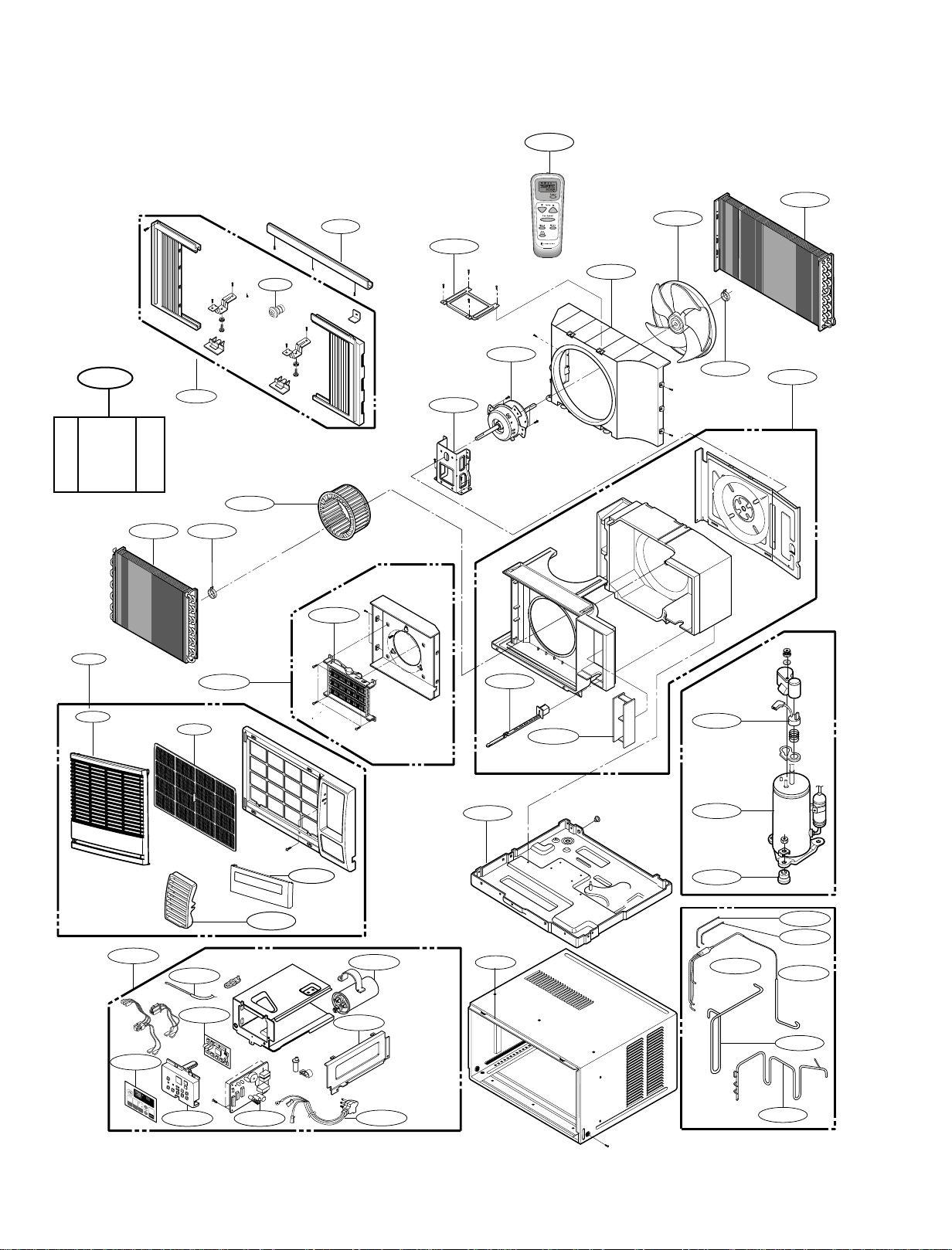
5.Exploded Vie w
-19-
135303
147581
152302
135312
235500
267110
422100