Loading ...
Loading ...
Loading ...
9
Tuning Hint: If you are using the M500/3
to drive a subwoofer system (“LP” mode),
and a component satellite speaker system
(“HP” mode), 80 Hz is a good baseline
“Filter Freq. (Hz)” setting. After properly
adjusting the “Input Sens.”, as outlined in
Appendix A (page 14), you can fine tune
the “Filter Freq. (Hz)” control to achieve
the desired system frequency response.
REMOTE LEVEL CONTROL OPTIONAL
INPUT SECTION
(
L
)
(
R
)
Remote
Level
Control
CH. 1&2 SUB CH. Preouts
+12 VDC Ground Remote
CH. 1
(
L
)
CH. 2
(
R
)
Bridged Mono Subwoofer Output
With the addition of the optional Remote
Level Control (HD-RLC), you can control the
volume of the subwoofer channel (Subwoofer
Level) or of the entire M500/3 from a location of
your choosing. This is useful for subwoofer level
control, cabin speaker level control, zone volume
control or even as a master volume control for
the entire system.
The HD-RLC connects to the jack labeled
“Remote Level Control” on the Connection
Panel of the amplifier using a standard telephone
cable (supplied with the HD-RLC). If desired,
multiple M-Series (model years 2010+) and
MHD amplifiers can be controlled from a single
HD-RLC controller using a simple phone line
“splitter” and multiple phone cables.
When connected to the amplifier, the
HD-RLC operates as follows. At full counter-
clockwise rotation, the audio of the selected
channels will mute completely. At full clockwise
rotation the level will be the same as if the
HD-RLC was not connected at all. In other
words, it operates strictly as a level attenuator.
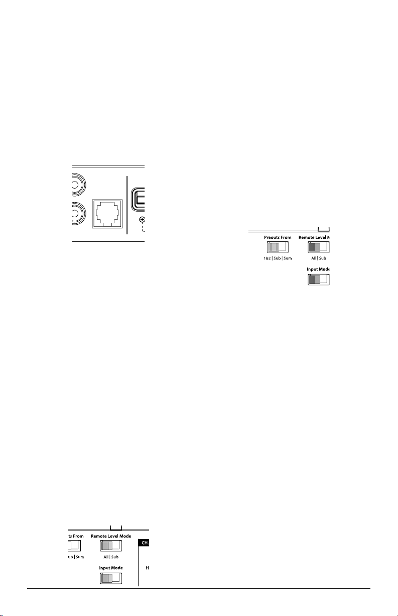
“Remote Level Mode” Switch: This switch
allows you to assign the operation of the
HD-RLC to the entire amplifier or only the
subwoofer channel. In the “Al l” position, the
HD-RLC knob will affect all channels equally.
In the “Sub Ch.” position, only the level of
the subwoofer channel will be affected by the
HD-RLC knob.
PREOUTS
The M500/3 incorporates a pass-through
preamp output section, so that additional
amplifiers can be easily added to the system. This
pass-through pre-amp output can be configured
three different ways using the switch labeled
“Preouts From”.
1) “1&2”: The preamp output delivers the same
signal that is connected to the CH 1&2 Inputs.
2) “Sub”: The preamp output delivers the same
signal that is connected to the Subwoofer
Channel Inputs.
3) “Sum”: The preamp output delivers a summed
signal, combining the “Ch 1 & 2” inputs and the
“Sub Ch.” inputs into a stereo signal pair.
Note: Any signal delay between the “Ch 1 & 2”
and “Sub Ch.” inputs can result in a cancellation
of signals within certain frequency ranges when
using the “Sum” position. If you experience a loss
of bass output in the “Sum” position, compared
to the “1&2” position, you are likely dealing
with a delayed signal in either the front or rear
outputs of the source unit. If the front to rear delay
is desirable for other reasons or if it cannot be
defeated at the source unit, we recommend that
you use the “1&2” position.
Note: In any of the three modes, the preamp
output signal is not affected by any crossover
filter selected (if the input signal is full-range, the
preamp output will be full-range).
Loading ...
Loading ...
Loading ...