Loading ...
Loading ...
Loading ...
8 | JL Audio - M500/3 Owner’s Manual
FILTER CONTROLS
Most speakers are not designed to reproduce
the full range of frequencies audible by the human
ear. For this reason, most speaker systems are
comprised of multiple speakers, each dedicated
to reproducing a specific frequency range. Filters
are used to select which frequency range is sent to
each section of a speaker system. The division of
frequency ranges to different speakers can be done
with passive filters (coils and/or capacitors between
the amplifier outputs and the speakers), which
are acceptable and commonly used for filtering
between mid-range speakers and tweeters. Filtering
between subwoofer systems and satellite speaker
systems is best done with active filters, which cut
off frequency content at the input to the amplifier.
Active filters are more stable than passive filters
and do not introduce extraneous resistance, which
can degrade subwoofer performance.
The active filter built into each channel
section of the M500/3 can be used to eliminate
potentially harmful and/or undesired frequencies
from making their way through the amplifier
sections to the speaker(s). This serves to improve
tonal balance and to avoid distortion and possible
speaker failure. Correct use of these filters can
substantially increase the longevity and fidelity of
your audio system.
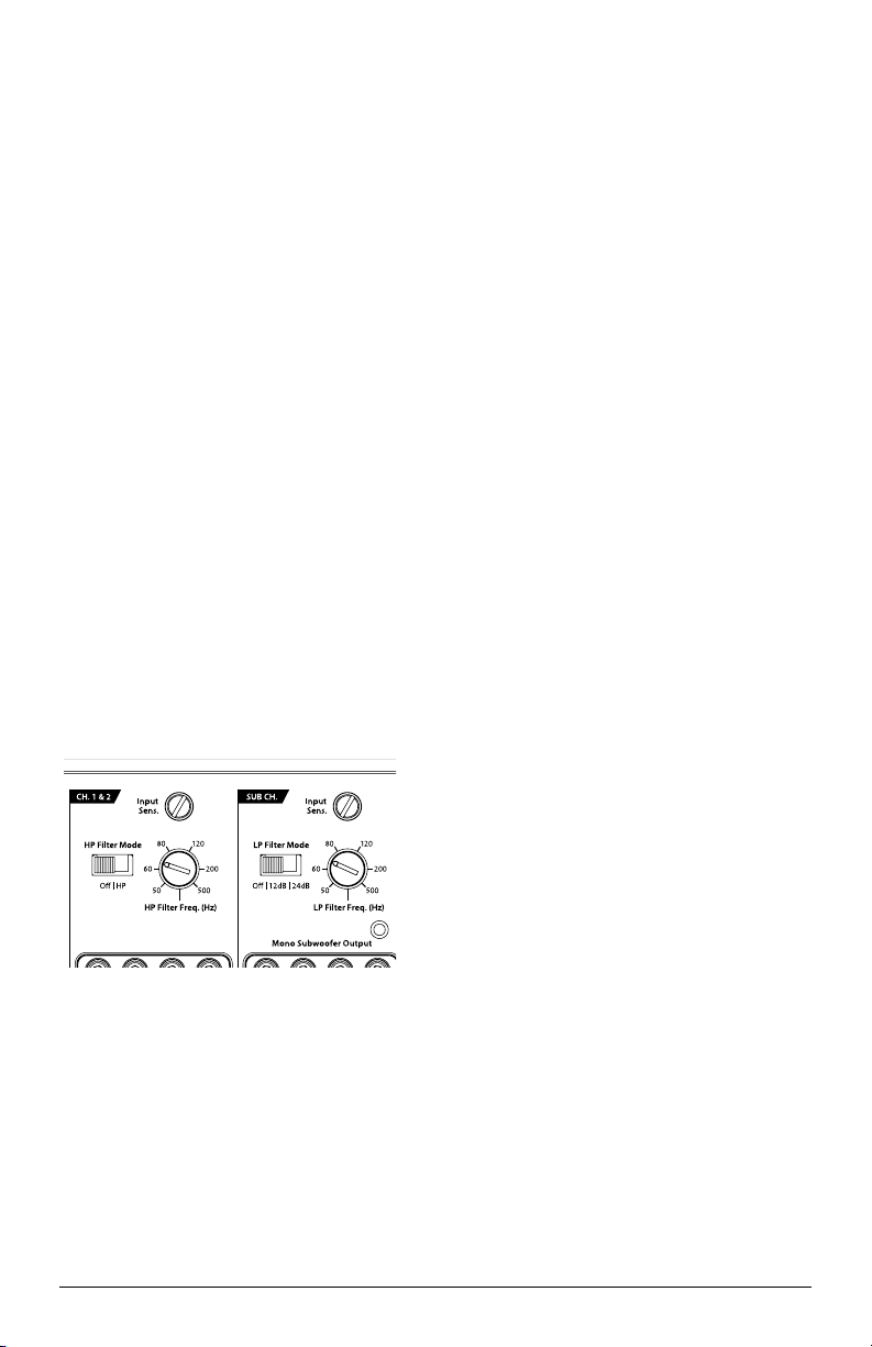
1) “Filter Mode” Controls: The M500/3 employs
a 12dB per octave high-pass filter for its main
channels. The Subwoofer Channel employs a
low-pass filter with the option of 12dB or 24dB
/ octave slopes. Each of these filters can be
controlled or defeated completely by way of the
“Filter Mode” switch in each Channel Section:
Channel 1 & 2 Filter: 2dB/octave High-Pass only
“Off”: Defeats the filter completely, allowing
the full range of frequencies present at the
inputs to feed these channels. This is useful for
systems utilizing outboard active crossovers
or requiring full-range reproduction for this
channel pair.
“HP” (High-Pass): Configures the filter
to attenuate frequencies below the indicated
filter frequency at a rate of 12dB per octave.
This is useful for connection of component
speakers or coaxials to this channel pair in a
bi-amplified system.
Subwoofer Channel Filter: 12dB/octave
or 24dB / octave, Low-Pass only
“Off”: Defeats the filter completely, allowing
the full range of frequencies present at the
inputs to feed this channel. This is useful for
systems utilizing outboard active crossovers.
“12dB” (Low-Pass): Configures the filter
to attenuate frequencies above the indicated
filter frequency at a rate of 12dB per octave.
This is useful for connection of subwoofers
in a bi-amplified system. This shallower slope
gently attenuates high-frequencies from your
subwoofer signal and is often well-suited for
sedans and coupes with trunks.
“24dB” (Low-Pass): Configures the filter
to attenuate frequencies above the indicated
filter frequency at a rate of 24dB per octave.
This is useful for connection of subwoofers
in a bi-amplified system. This sharper slope
more aggressively removes high-frequencies
from your subwoofer signal and is often well-
suited for SUV’s, wagons and hatchbacks.
2) “Filter Freq. (Hz)” The filter frequency
markings surrounding these rotary controls
(one in each Channel Section) are for
reference purposes and are generally accurate
to within 1/3 octave or better. If you would
like to select the filter cutoff frequency with a
higher level of precision, consult the chart in
Appendix B (page 15).
Loading ...
Loading ...
Loading ...