
Cybex Modular
Owner’s and Service Manual
Strength Systems
Part Number 55620 H
www.cybexinternational.com


Cybex Modular
Owner’s and Service Manual
Strength Systems
Part Number 55620 H
DISCLAIMER: Cybex International, Inc., makes no representations or warranties regarding the contents of this manual. We reserve the right to
revise this document at any time or to make changes to the product described within it without notice or obligation to notify any person of
such revisions or changes.
© Copyright 2009 Cybex International, Inc. All rights reserved.
Printed in the United States of America.
10 Trotter Drive Medway, MA 02053 • 508-533-4300 • FAX 508-533-5183


i Table of Contents
1 Safety
Safety......................... 1-1
Warning/Caution Decals .......... 1-2
Regular Maintenance Activities ..... 1-21
Using Proper Form .............. 1-21
2 Exercises
(Lower Body)
Seated Leg Press -5652/5322 ..... 2-1
Leg Extension/Leg Curl -
5653/5607 .................... 2-3
(Upper Body)
Low Row (5651/5302) ............ 2-5
Lat Pulldown - 5601.............. 2-7
Chest Press - 5640 .............. 2-9
Pressing Station - 5647/5306 ...... 2-11
Shoulder Press - 5639 ........... 2-13
Tricep Pressdown - 5603.......... 2-15
Tricep Extension - 5641........... 2-17
Arm Curl - 5644 ................. 2-19
(Multi Station)
Cable Crossover -
5648/5649/5650/5311 ........... 2-21
Cable Column -
5605/5633/5315/5316 ........... 2-23
Assisted Chin-Up/Dip - 5611 and
SS Assisted Chin-Up/Dip - 5345 . . 2-25
3 Customer Service
Contacting Service............... 3-1
Ordering Parts .................. 3-1
Returning Goods ................ 3-2
Damaged Parts ................. 3-3
4 Assembly
Weight Stack Installation .......... 4-1
Handle Rack ................... 5631
Modular Mover ................. 5632
Seated Leg Press ............... 5652/5322
Leg Extenstion/Leg Curl .......... 5653/5307
Table of Contents
Page i
5 Maintenance
Daily Procedures ................ 5-1
Weekly Procedures .............. 5-4
Yearly Procedures ............... 5-6
“As Required” Procedures......... 5-6
6 Assembly and Service
Modular Center Post ............. 5600
Tandem Center Post ............. 5629
Lat Pulldown ................... 5601
Tricep Pressdown ............... 5603
45 Degree Back Extension ........ 5608
Bent Leg Abdominal Board ........ 5610
Blank ......................... 5624
Leg Raise Chair ................. 5645
Cable Column .................. 5605
Cable Column .................. 5633
Cable Column .................. 5315/5316
Assist Dip/Chin ................. 5611
Single Station Dip/Chin ........... 5345
Shoulder Press ................. 5639
Chest Press .................... 5640
Tricep Extension ................ 5641
Arm Curl....................... 5644
Low Row ...................... 5651/5302
Pressing Station ................ 5647/5306
Cable Crossover ................ 5648/5649
5650/5311
Seated Leg Press ............... 5652/5322
Leg Extension/Leg Curl ........... 5653/5307


Page 1-1
1 - Safety
Safety
Read the Owner’s Manual carefully before assembling, servicing or using the equipment.
It is the responsibility of the facility owner and/or owner of the equipment to instruct users on
proper operation of the equipment and review all labels.
! WARNING: Serious injury could occur if these safety precautions are not observed:
USER SAFETY PRECAUTIONS
• Obtain a medical exam prior to beginning an exercise program.
• Read and understand warning labels and user manual prior to exercising. Obtain
instruction prior to use.
• Keep body and clothing free from and clear of all moving parts.
• Inspect machine prior to use. DO NOT use if it appears damaged or inoperable.
• DO NOT attempt to fix a broken or jammed machine. Notify floor staff.
• Use the machine only for the intended use. DO NOT modify the machine.
• Be sure that the weight pin is completely inserted. Use only the pin provided by the
manufacturer. If unsure seek assistance.
• Never pin the weights in an elevated position. DO NOT use the machine if found in this
condition. See assistance from floor staff.
• Children must not be allowed near these machines. Teenagers must be supervised.
• DO NOT use if guards are missing or damaged.
• DO NOT use dumbbells or other incremental weights, except those provided by the
manufacturer.
• Inspect all cables and belts and connections prior to use. DO NOT use if any components
are worn, frayed or damaged.
• DO NOT remove any labeling from equipment. Replace any damaged labels.
• Stop exercising if you feel faint, dizzy or experience pain at any time while exercising and
consult your physician.
Cybex Modular Owner’s Manual

Cybex Modular Owner’s Manual
Facility Safety Precautions
• Read the Owner’s Manual carefully before assembling, servicing or using the equipment.
• Securely anchor each machine to the floor using the anchor holes provided in each
machine.
• Make sure that each machine is set up and operated on a solid level surface. Do not
install equipment on an uneven surface.
• Make sure that all users are properly trained on how to use the equipment.
• Make sure there is enough room for safe access and operation of the equipment.
• Perform regular maintenance checks on the equipment. Also pay close attention to all
areas most susceptible to wear, including (but not limited to) cables, pulleys, belts and
grips.
• Immediately replace worn or damaged components. If unable to immediately replace worn
or damaged components then remove from service until the repair is made.
• Use only Cybex supplied components to maintain/repair the equipment.
• Keep a repair log of all maintenance activities.
• Inspect all cables and belts and connections prior to use. DO NOT use if any components
are worn, frayed, or damaged.
NOTE: It is the sole responsibility of the user/owner or facility operator to ensure that regular
maintenance is performed.
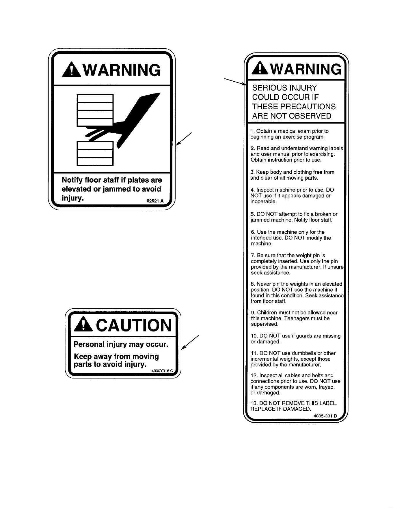
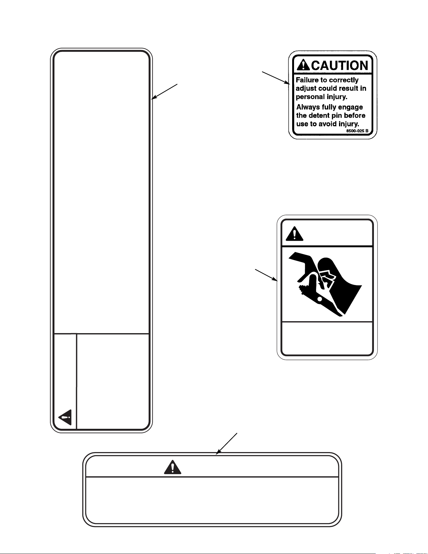
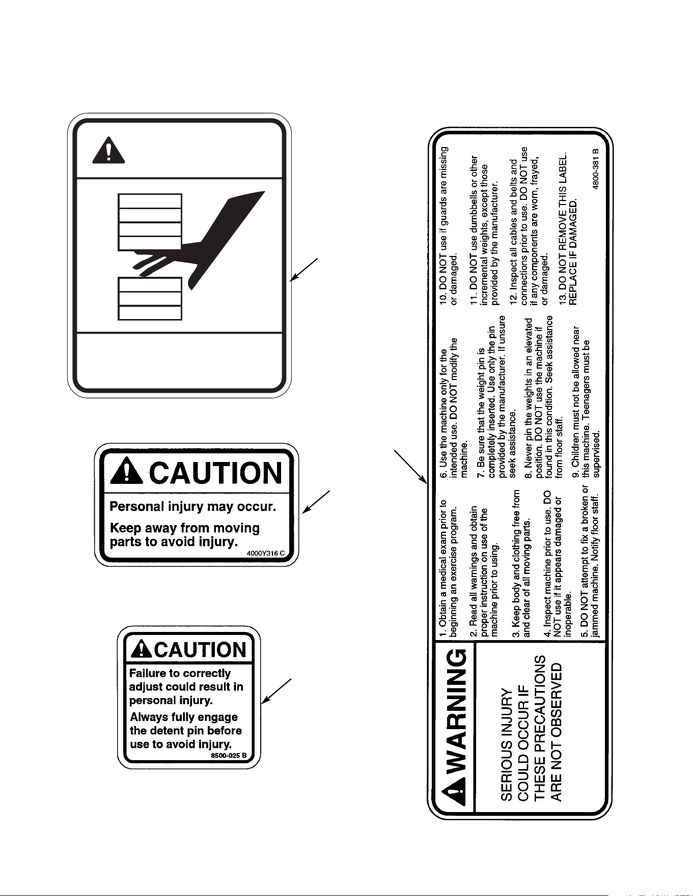
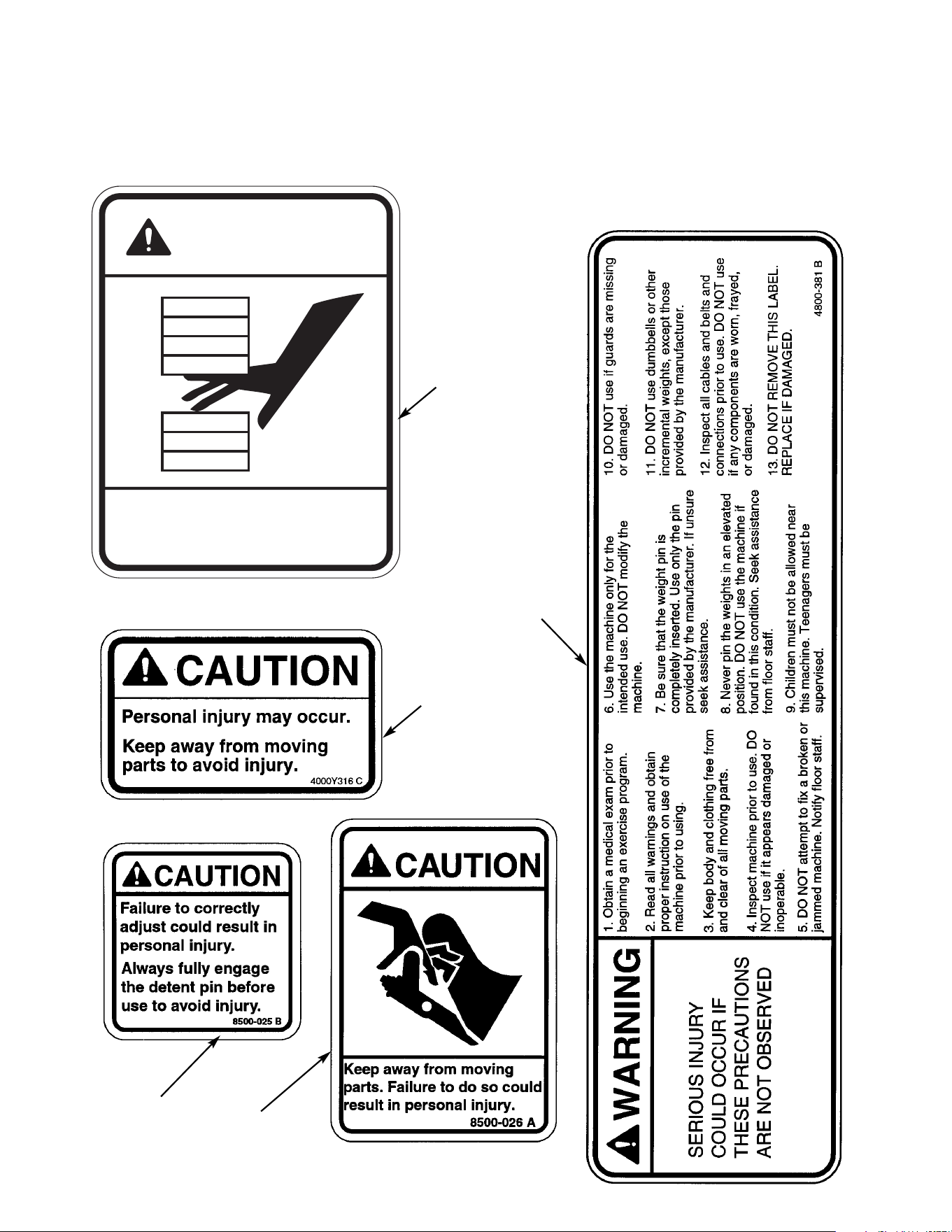
Warning/Caution Decals
Warning decals indicate a potentially hazardous situation, which, if not avoided, could result
in death or serious injury.
Caution decals indicate a potentially hazardous situation, which, if not avoided, could result in
minor or moderate injury.
The warning and caution decals are shown on the following page. The diagrams following the
decals show where each decal is located.
Page 1-2
NOTE: Cybex is not responsible for the actual anchoring of equipment. Consult
with a professional contractor.
NOTE: Use fasteners having a minimum of 500 lbs. tensile capacity (3/8” grade 2
bolts or better).
NOTE: If legs/frame does not contact surface, DO NOT pull down with anchors.
Shim any leg or frame not in contact with surface using flat washers.
Cybex Modular Owner’s Manual
Page 1-3
A
B
C
Cybex Modular Owner’s Manual
Page 1-4
CAUTION
350 LBS MAXIMUM LOAD
DO NOT EXCEED MAXIMUM CROSS TUBE LOAD.
PERSONAL INJURY MAY RESULT.
5649-329 A
CAUTION
Keep away from moving
parts. Failure to do so could
result in personal injury.
8500-026 A
G
E
4800-381 C
SERIOUS INJURY
COULD OCCUR IF
THESE PRECAUTIONS
ARE NOT OBSERVED
WARNING
2. Read and understand warning
labels and user manual prior to
exercising. Obtain instruction
prior to use.
1. Obtain a medical exam prior to
beginning an exercise program.
3. Keep body and clothing free from
and clear of all moving parts.
4. Inspect machine prior to use. DO
NOT use if it appears damaged or
inoperable.
5. DO NOT attempt to fix a broken or
jammed machine. Notify floor staff.
6. Use the machine only for the
intended use. DO NOT modify the
machine.
7. Be sure that the weight pin is
completely inserted. Use only the pin
provided by the manufacturer. If unsure
seek assistance.
8. Never pin the weights in an elevated
position. DO NOT use the machine if
found in this condition. Seek assistance
from floor staff.
9. Children must not be allowed near
this machine. Teenagers must be
supervised.
10. DO NOT use if guards are missing
or damaged.
11. DO NOT use dumbbells or other
incremental weights, except those
provided by the manufacturer.
12. Inspect all cables and belts and
connections prior to use. DO NOT use
if any components are worn, frayed,
or damaged
.
13. DO NOT REMOVE THIS LABEL.
REPLACE IF DAMAGED.
D
F
Cybex Modular Owner’s Manual
Page 1-5
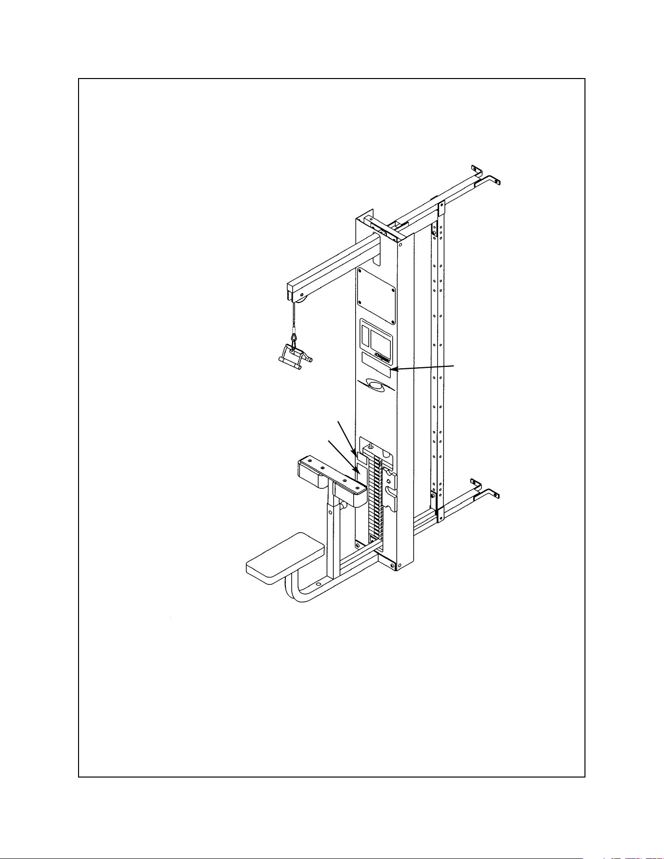
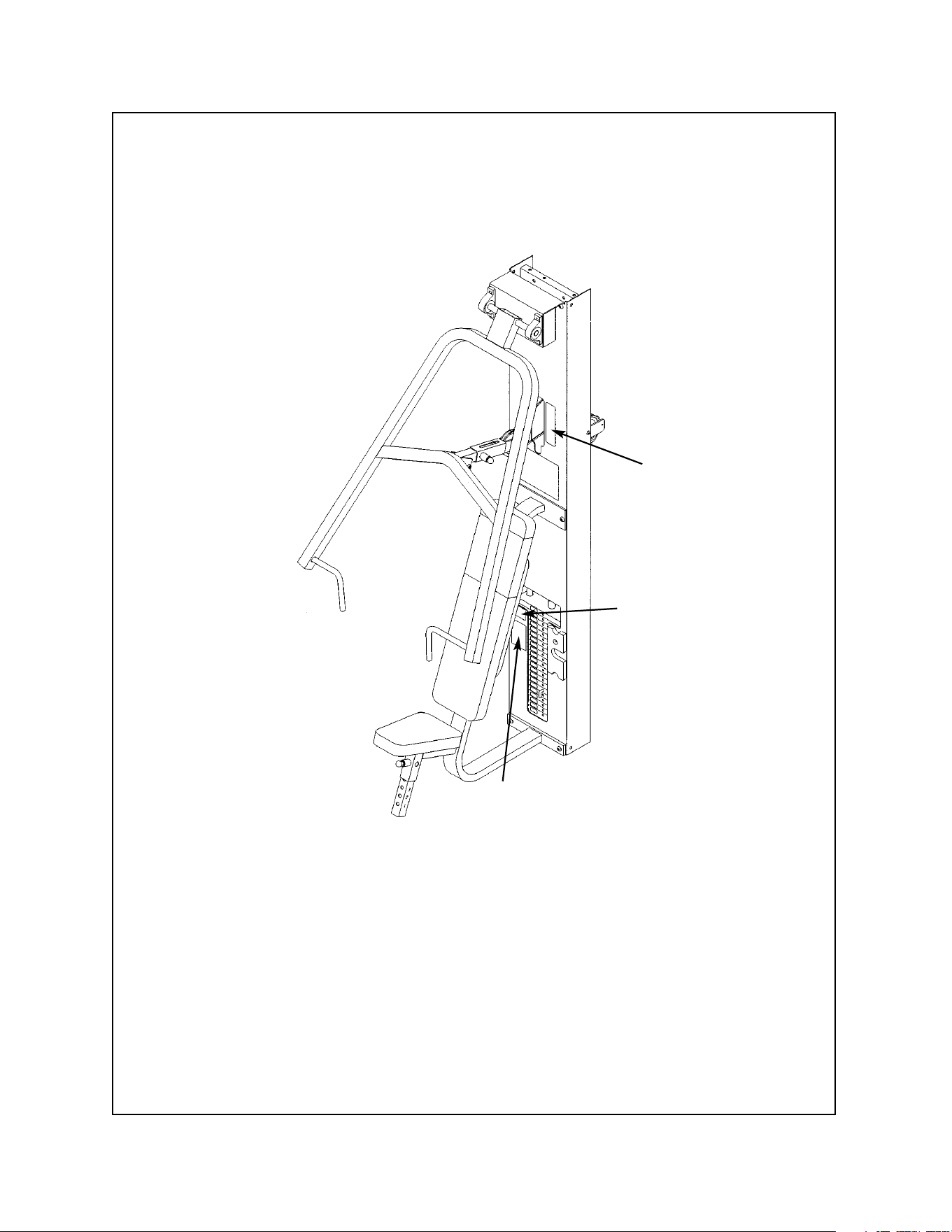
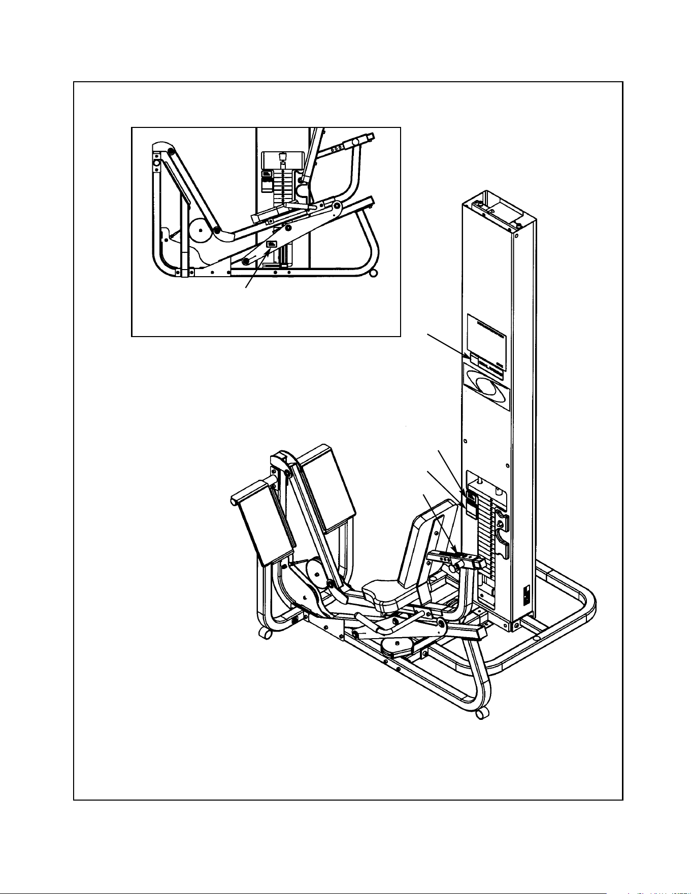
Lat Pulldown - 5601
B
D
A
A. Warning Decal ................... 02521
B. Caution Decal .................... 4000Y316
D. Warning Decal.................... 4800-381
DESCRIPTION PART NO.
Cybex Modular Owner’s Manual
Page 1-6
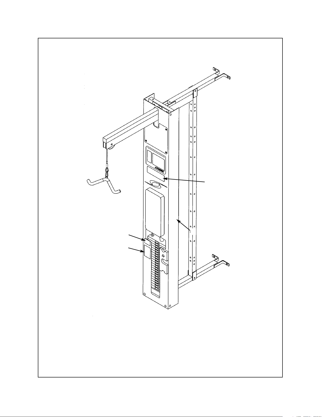
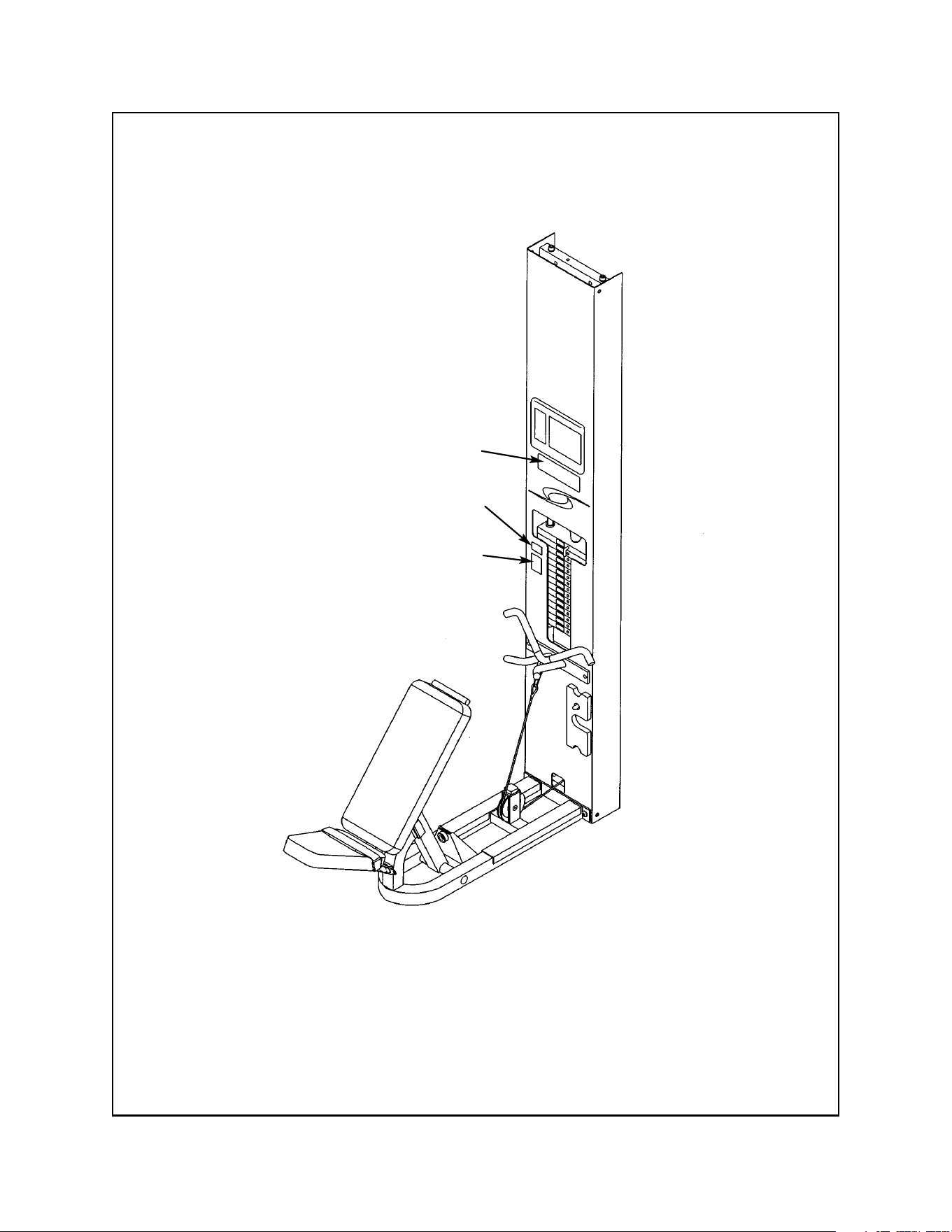
Tricep Pressdown - 5603
D
B
B
A
A. Warning Decal ................... 02521
B. Caution Decal .................... 4000Y316
D. Warning Decal.................... 4800-381
DESCRIPTION PART NO.
Cybex Modular Owner’s Manual
Page 1-7
Cable Column - 5605/5315/5316/5633
B
A
D
A. Warning Decal ................... 02521
B. Caution Decal .................... 4000Y316
D. Warning Decal.................... 4800-381
DESCRIPTION PART NO.
5605 - Modular without Booms
5633 - Modular with Booms
5315 - Free Standing without Booms
5316 - Free Standing with Booms
Cybex Modular Owner’s Manual
Page 1-8
Assist Chin Up/Dip - 5611
D
A
A. Warning Decal ................... 02521
B. Caution Decal .................... 4000Y316
D. Warning Decal.................... 4800-381
DESCRIPTION PART NO.
B
5345 - Single Station Chin-Up/Dip
Cybex Modular Owner’s Manual
Page 1-9
D
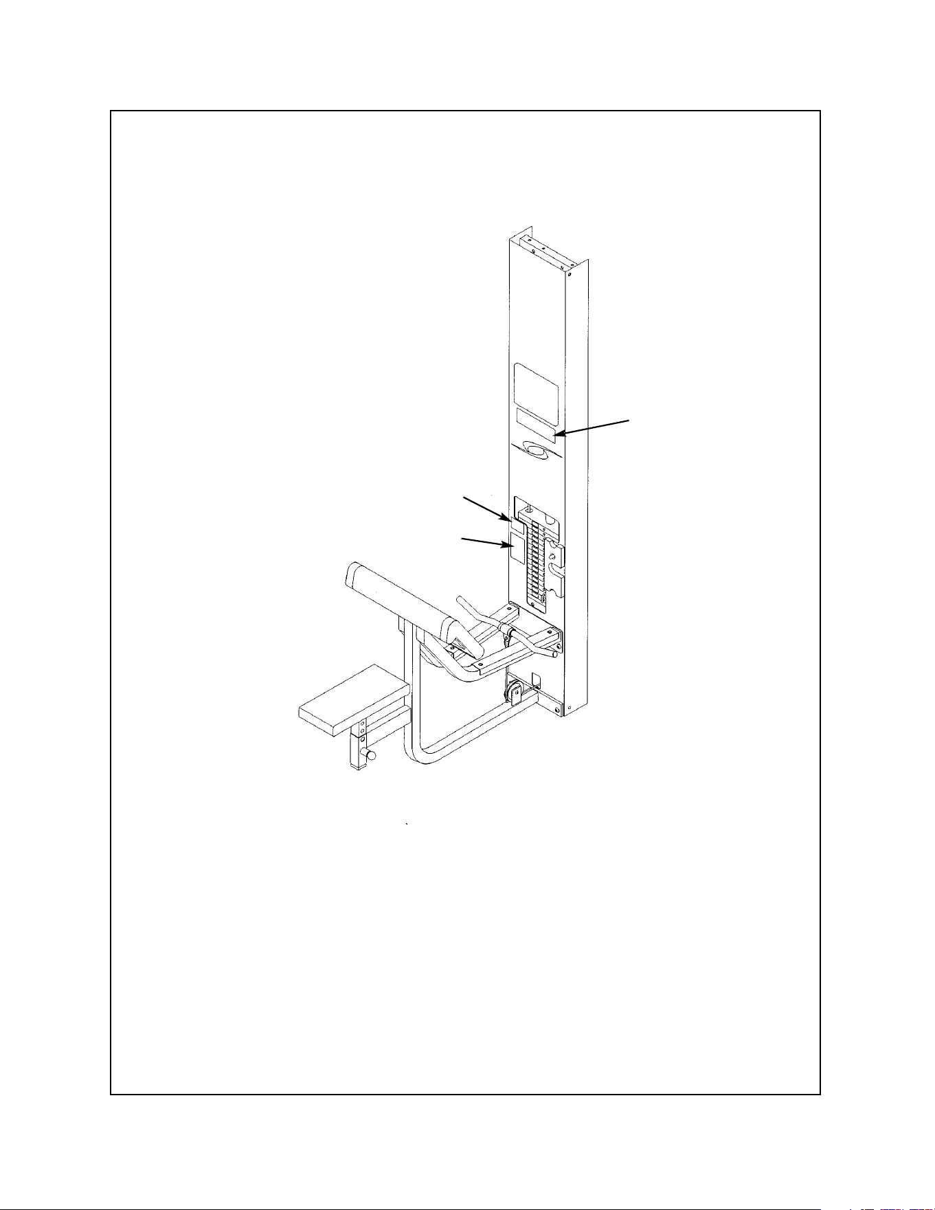
Low Row - 5651 and 5302
A
A. Warning Decal ................... 02521
B. Caution Decal .................... 4000Y316
D. Warning Decal.................... 4800-381
DESCRIPTION PART NO.
B
Cybex Modular Owner’s Manual
Page 1-10
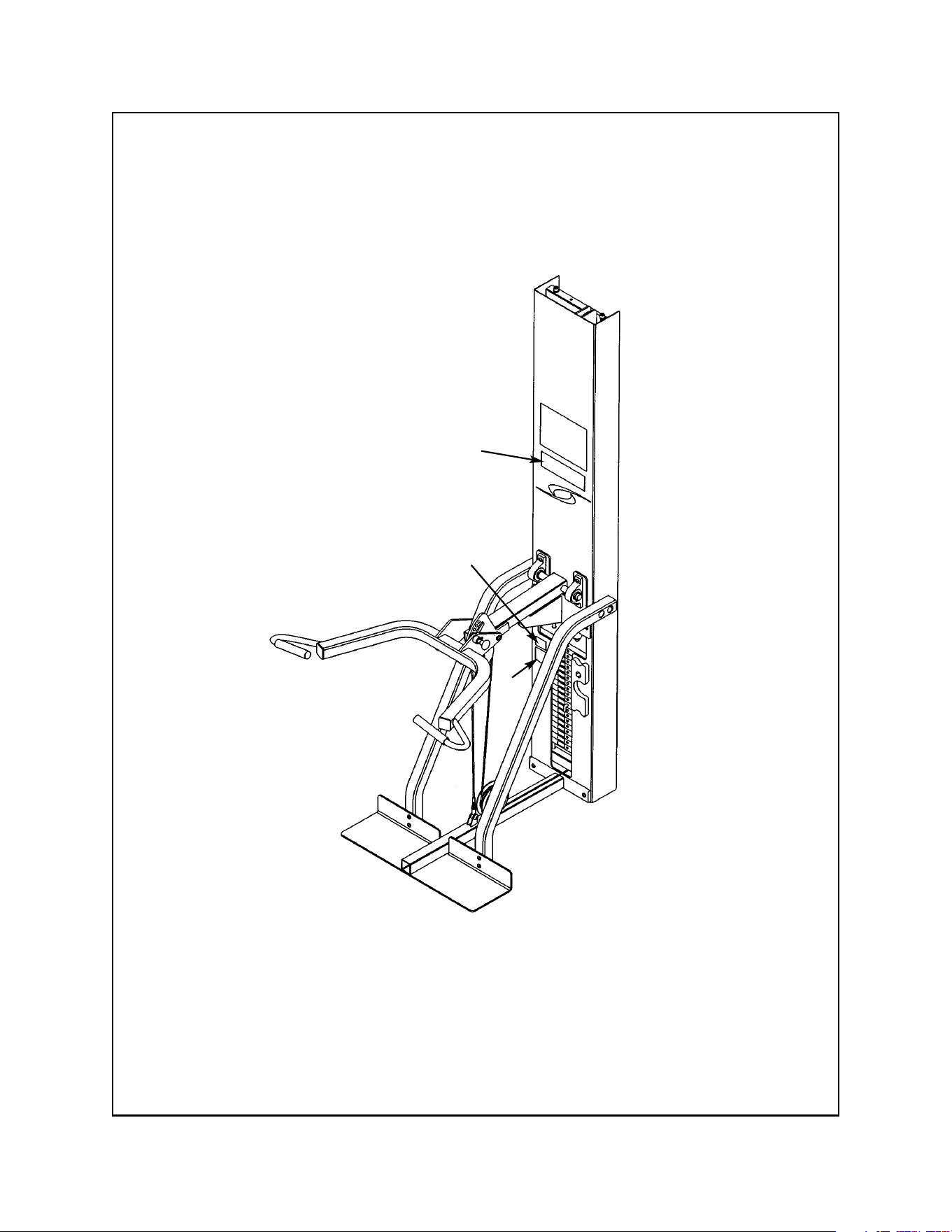
Shoulder Press - 5639
A
B
D
A. Warning Decal ................... 02521
B. Caution Decal .................... 4000Y316
D. Warning Decal.................... 4800-381
DESCRIPTION PART NO.
Cybex Modular Owner’s Manual
Page 1-11
C
Chest Press - 5640
B
A
A. Warning Decal ................... 02521
B. Caution Decal .................... 4000Y316
C. Warning Decal.................... 4605-381
DESCRIPTION PART NO.
Cybex Modular Owner’s Manual
Page 1-12
Tricep Extension - 5641
D
B
A
A. Warning Decal ................... 02521
B. Caution Decal .................... 4000Y316
D. Warning Decal.................... 4800-381
DESCRIPTION PART NO.
Arm Curl - 5644
B
A
D
Cybex Modular Owner’s Manual
Page 1-13
A. Warning Decal ................... 02521
B. Caution Decal .................... 4000Y316
D. Warning Decal.................... 4800-381
DESCRIPTION PART NO.
Cybex Modular Owner’s Manual
Page 1-14
Pressing Station - 5647 and 5306
D
A
B
A. Warning Decal ................... 02521
B. Caution Decal .................... 4000Y316
D. Warning Decal.................... 4800-381
DESCRIPTION PART NO.
Cybex Modular Owner’s Manual
Page 1-15
Cable Crossover - 5311, 5648, 5649 and 5650
A. Warning Decal ................... 02521
B. Caution Decal .................... 4000Y316
D. Warning Decal.................... 4800-381
E. Caution Decal .................... 5649-329
F. Caution Decal .................... 8500-025
DESCRIPTION PART NO.
E
D
A
F
B
Cybex Modular Owner’s Manual
Page 1-16
Seated Leg Press - 5652 and 5322
D
A
B
A. Warning Decal ................... 02521
B. Caution Decal .................... 4000Y316
D. Warning Decal.................... 4800-381
F. Caution Decal .................... 8500-025
DESCRIPTION PART NO.
F
Cybex Modular Owner’s Manual
Page 1-17
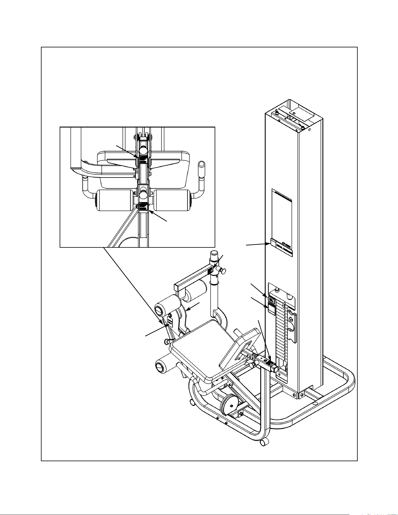
Leg Extension/Leg Curl - 5653 and 5307
A. Warning Decal ................... 02521
B. Caution Decal .................... 4000Y316
D. Warning Decal.................... 4800-381
F. Caution Decal .................... 8500-025
G. Caution Decal .................... 8500-026
DESCRIPTION PART NO.
G
D
F
Product No. 5307 - Freestanding
Product No. 5653 - Modular
G
B
A
F
F
F

Regular Maintenance Activities
Preventative maintenance activities must be performed to maintain normal operation of your
equipment. Keeping a log sheet of all maintenance actions will assist you in staying current
with all preventative maintenance activities. The preventative maintenance actions are
described in detail in Chapter 5. Briefly, they include:
Daily
1. Clean upholstery.
Weekly
1. Inspect all nuts and bolts for looseness. Tighten as required.
2. Inspect all cables for damage or wear (see Chapter 5). Immediately discontinue use if a
cable is worn or damaged.
3. Check for worn handles, worn snap links, and worn warning labeling. Replace all worn
parts immediately.
4. Inspect weight stacks for proper alignment and operation. Correct all improper alignment
and operation issues immediately.
5. Lubricate guide rods using automotive engine oil only.
Yearly
1. Replace all cables at least annually.
As Required
1. Inspect grips and replace as necessary.
Using Proper Form
Before working out, read and understand the exercises located on the placard and in
Chapter 2.
Cybex Modular Owner’s Manual
Page 1-18
1. Select appropriate resistance.
2. Adjust seat mechanism to desired starting
position.
3. Located feet securely on foot plates and
position yourself squarely in seat.
4. Lift/lower resistance with smooth, controlled
movements.
NOTE: Do not hyperextend (lock) knees
during movement.
NOTE: The appropriate starting position
will allow your feet to be securely
located on the foot plates, legs
to be placed at approximately 90
degrees and your back squarely
positioned against back pad.
NOTE: Maintain proper back positioning
during exercise to reduce chance of
back injury.
2 - Exercise
Page 2-1
Cybex Modular Owner’s Manual
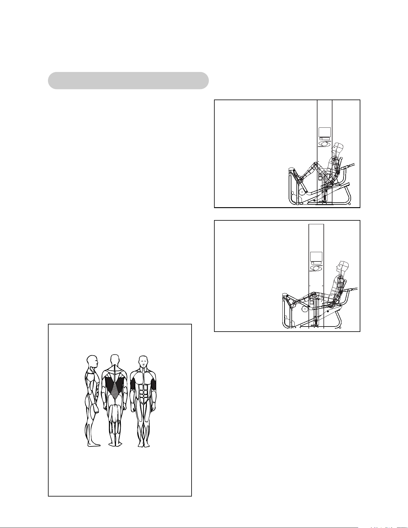
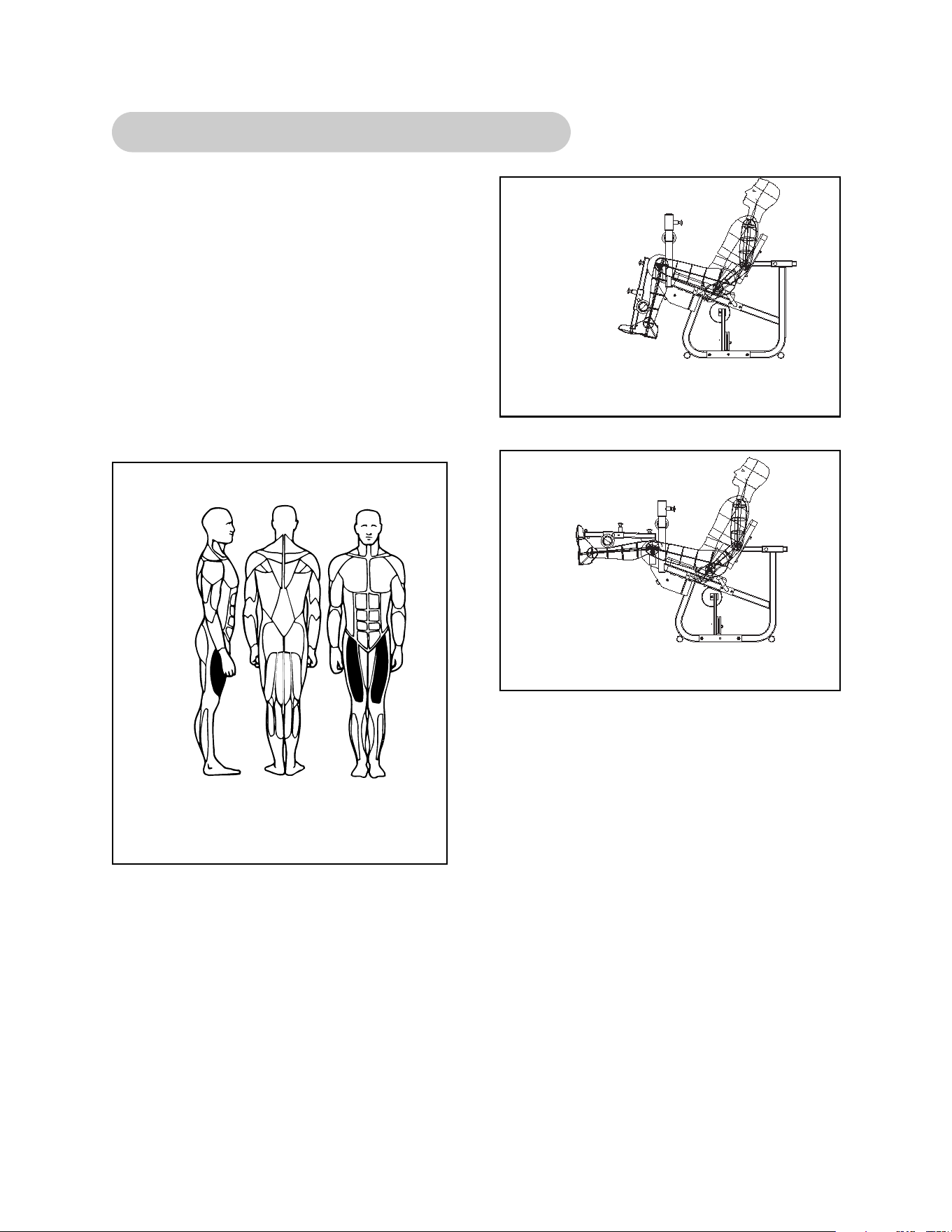
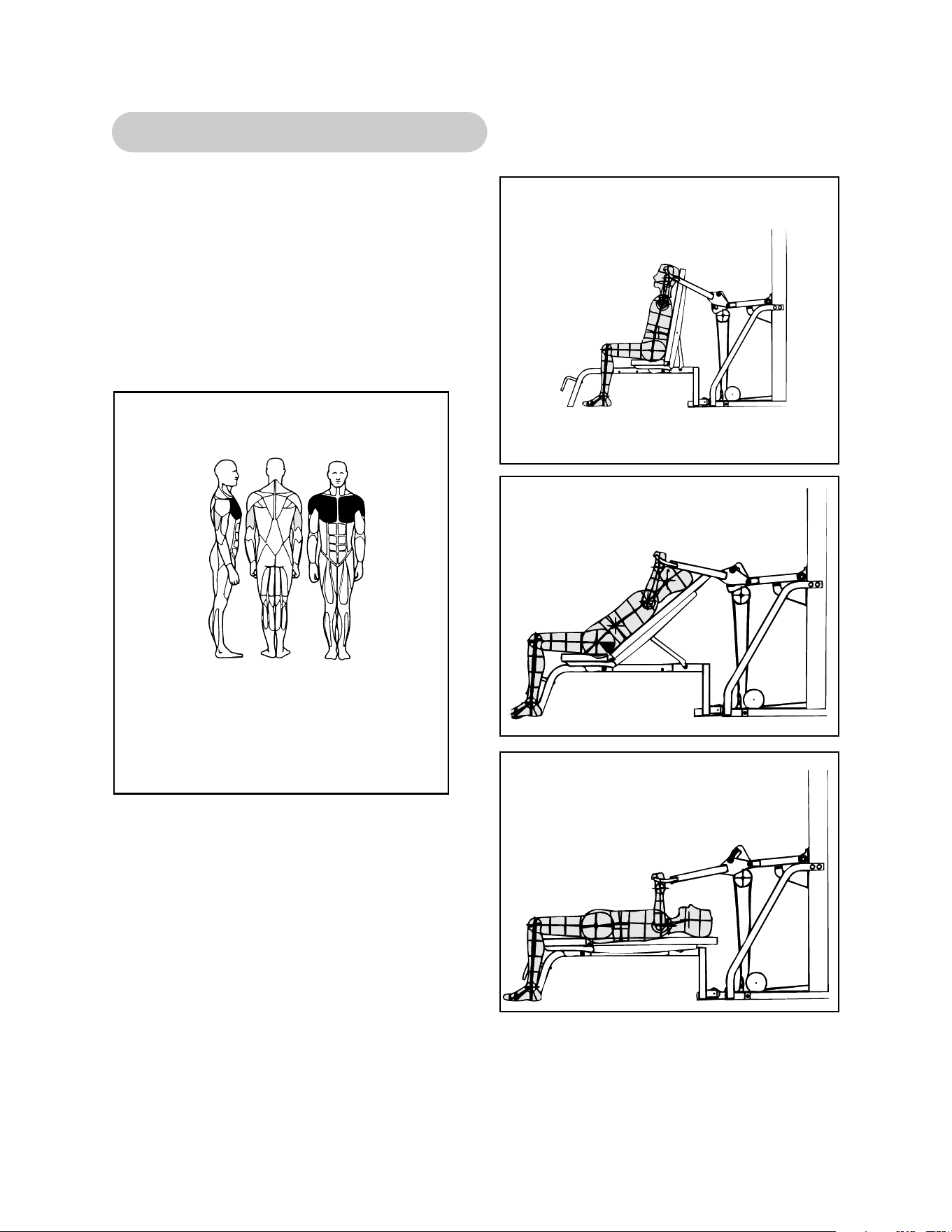
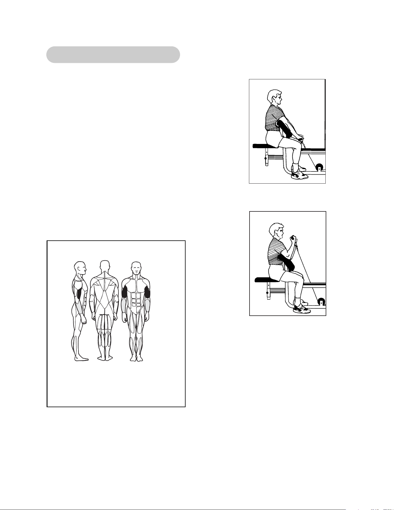
5652/5322 - Modular Seated Leg Press
MUSCLES TRAINED
Primary - Pectoralis Major
Secondary - Anterior Deltoid, Triceps
(Basic Press) and Biceps
(Advanced Press)
Start Position
Stop Position

Page 2-2
Cybex Modular Owner’s Manual
This page intentionally left blank
Page 2-3
Cybex Modular Owner’s Manual
5653/5307 - Modular Leg Extension/Leg Curl
1. Select appropriate resistance.
2. Adjust back pad so that center of knees align
with machine’s axis of rotation.
3. Pull detent pin on input arm, lowering arm
into one of the two start positions.
4. Pull detent pin and adjust height of lower leg
pads to a height comfortable above ankles.
5. Lift/lower resistance with smooth, controlled
movements without resting.
MUSCLES TRAINED
Primary - Pectoralis Major
Secondary - Anterior Deltoid, Triceps
(Basic Press) and Biceps
(Advanced Press)
Stop Position
Start Position
Start Position
Stop Position

Page 2-4
Cybex Modular Owner’s Manual
This page intentionally left blank
Page 2-5
Cybex Modular Owner’s Manual
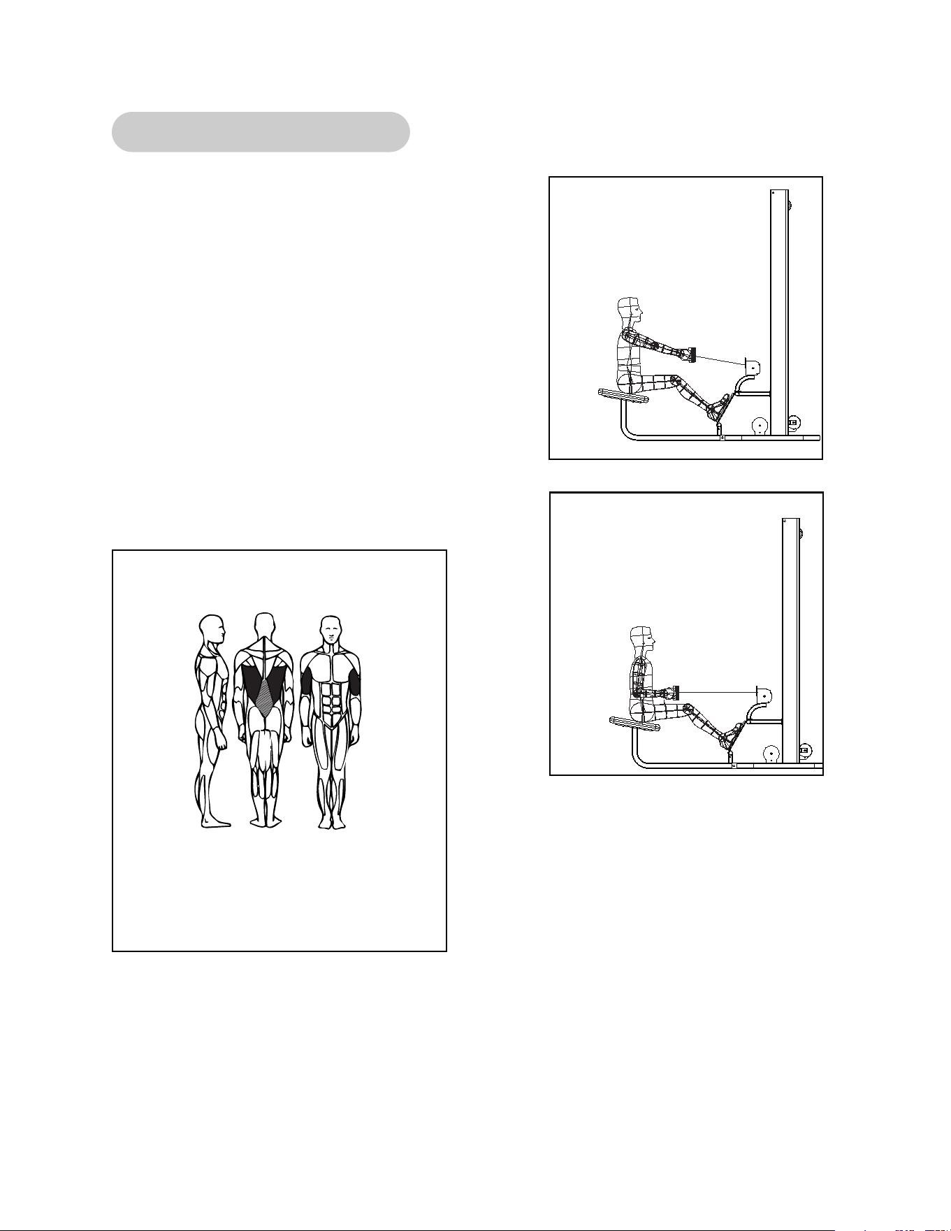
5651/5302 - Modular Low Row
1. Select appropriate resistance.
2. Grasp handle and position feet securely on
foot plate.
3. Position yourself comfortably on seat and
maintain a slight bend in the knees.
4. Throughout the exercise keep back straight
and upright.
5. Lift/lower resistance with smooth, controlled
movements.
NOTE: For optimum performance and safety,
avoid excessive bending of spine
during exercise.
MUSCLES TRAINED
Primary - Biceps and Latissimus Dorsi
Secondary - Erector Spinae
Start Position
Stop Position

Page 2-6
Cybex Modular Owner’s Manual
This page intentionally left blank
Page 2-7
Cybex Modular Owner’s Manual
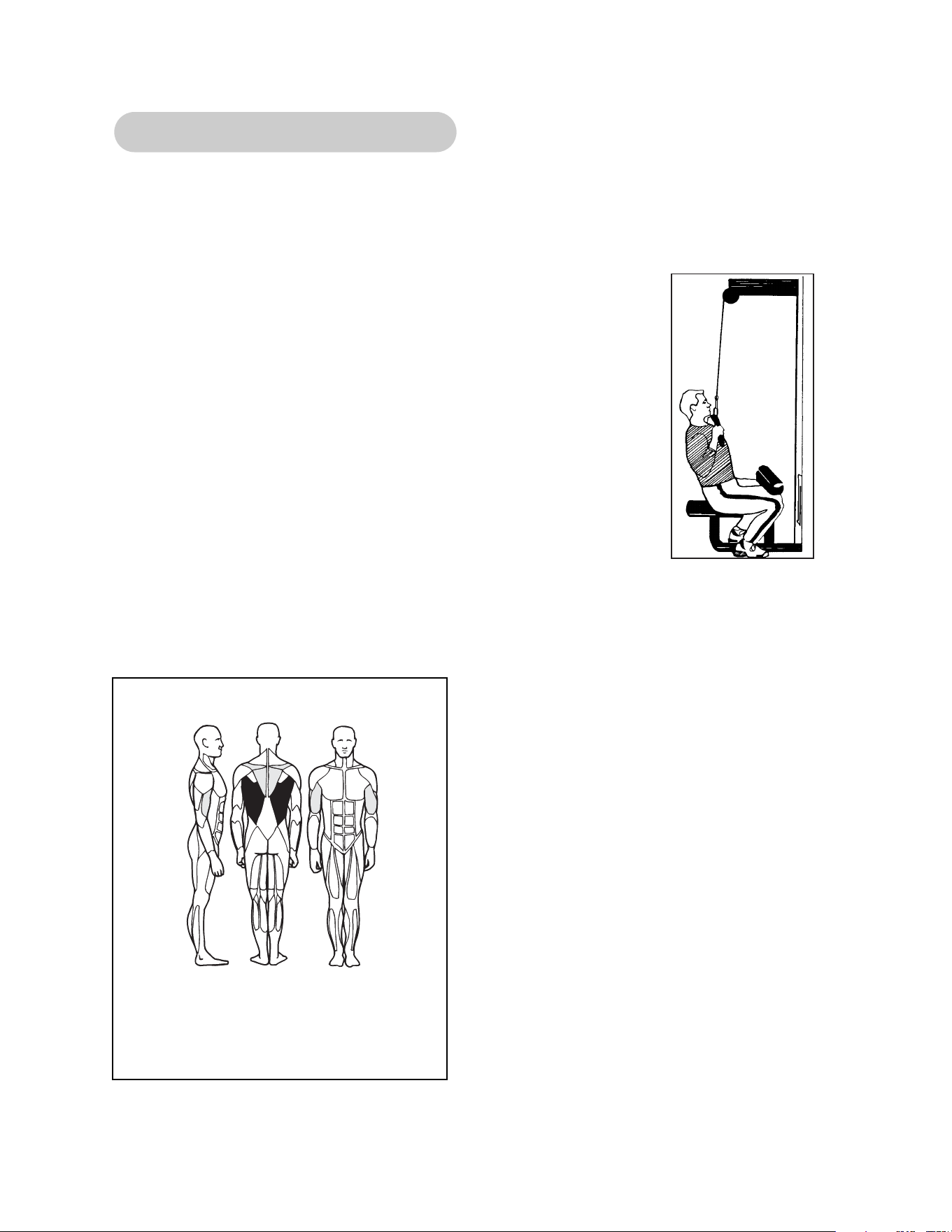
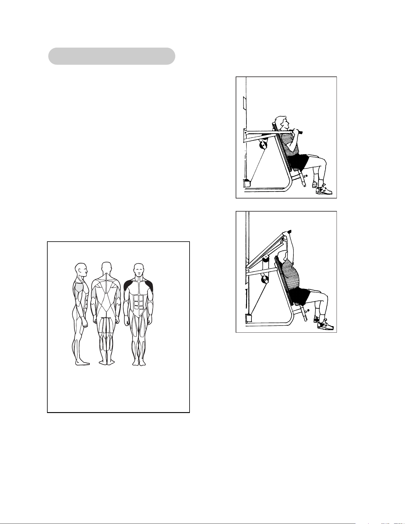
5601 - Modular Lat Pulldown
1. Adjust thigh pads to allow access and stabilization while
exercising.
2. Slect appropriate resistance.
3. Grasp bar and sit down, securing knees under thigh pads.
4. Lean back slightly at hips and maintain position throughout
movement.
5. With chest up and shoulders held back, pull bar down in front
to upper part of chest. Your elbows should move down to the
sides of your body.
6. Return to the start position and repeat.
7. Lift/lower resistance with smooth, controlled movements.
NOTE: Grasping the bar excessively wide or narrow, does not increase muscular
effectiveness. It only decreases your range of motion.
Read and understand all instructions and warnings prior to using this machine. See Chapter 1,
Safety in the Modular Owner’s Manual or consult with floor staff.
MUSCLES TRAINED
Primary - Latissimus Dorsi, Teres Major
Secondary - Biceps, Rhomboids and
Lower Trapezius

Page 2-8
Cybex Modular Owner’s Manual
This page intentionally left blank
Page 2-9
Cybex Modular Owner’s Manual
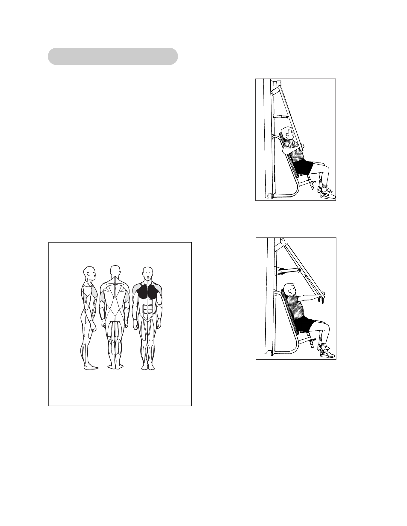
5640 - Modular Chest Press
1. Adjust seat height so that handles are at
mid-chest.
2. Adjust handle position so that when grasped,
upper arms are straight to side.
3. Select appropriate resistance.
4. Grasp handles.
5. Position elbows out to side, level with handles.
6. With chest up and shoulders held back, press
handles forward with a smooth, controlled
movement.
7. Lift/lower resistance with smooth, controlled
movements.
MUSCLES TRAINED
Primary - Pectoralis Major
Secondary - Anterior Deltoid and
Triceps
Start Position
Stop Position

Page 2-10
Cybex Modular Owner’s Manual
This page intentionally left blank
Page 2-11
Cybex Modular Owner’s Manual
5647/5306 - Modular Pressing Station
1. Select appropriate resistance.
2. Adjust the bench back pad angle (flat, 30, 40,
60, 80).
3. Adjust pressing arm to desired position.
4. Lift/lower resistance with smooth, controlled
movements.
MUSCLES TRAINED
Primary - Pectoralis Major, Anterior
Deltoids (depending upon bench
angle)
Secondary - Triceps
Start Position
Start Position
Stop Position

Page 2-12
Cybex Modular Owner’s Manual
This page intentionally left blank
Page 2-13
Cybex Modular Owner’s Manual
5639 - Modular Shoulder Press
1. Adjust seat height so that handles are level
with shoulders.
NOTE: Range of motion may be reduced by
selecting a lower seat position.
2. Select appropriate resistance.
3. Grasp either set of handles.
TIP: The parallel handles will help reduce
shoulder impingement and may be more
comfortable for some users.
4. Press straight up with a smooth, controlled
movement.
5. Return to the start position and repeat.
MUSCLES TRAINED
Primary - Anterior Deltoids
Secondary - Middle Deltoids and
Triceps
Start Position
Stop Position

Page 2-14
Cybex Modular Owner’s Manual
This page intentionally left blank
Page 2-15
Cybex Modular Owner’s Manual
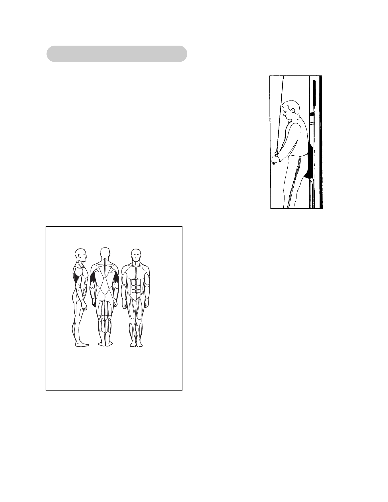
5603 - Modular Tricep Pressdown
1. Select appropriate resistance.
2. Attach the desired handle to the clip.
3. Position yourself with your hips and back firmly against
back pad.
4. While leaning forward slightly, extend your arms downward
maintaining your elbows in a stationary position.
5. Return to the start position and repeat.
6. Lift/lower with smooth, controlled movements.
NOTE: The appropriate grip position allows you to keep
your chest up and shoulders held back while
extending your arms.
MUSCLES TRAINED
Primary - Triceps

Page 2-16
Cybex Modular Owner’s Manual
This page intentionally left blank
Page 2-17
Cybex Modular Owner’s Manual
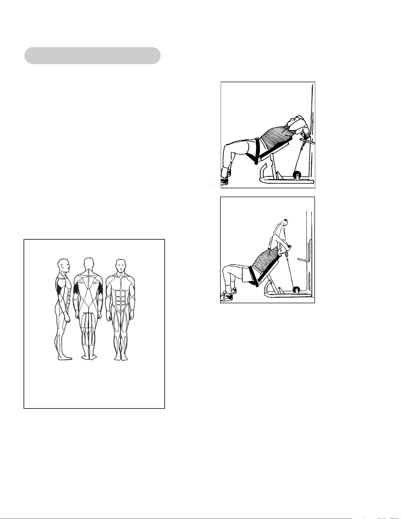
5641 - Modular Tricep Extension
1. Select appropriate resistance.
2. Position yourself in chair, attaching seat belt
to assist in stabilization.
3. Pivot chair backwards to grasp handle. Lower
seat back down to begin exercise.
4. Maintain elbows in a stationary position while
extending arms overhead.
5. Lift/lower resistance with smooth, controlled
movements.
6. When exercise is complete, lean chair
backwards to replace handle. Ensure
handle has been securely replaced before
letting go.
MUSCLES TRAINED
Primary - Triceps
Start Position
Stop Position

Page 2-18
Cybex Modular Owner’s Manual
This page intentionally left blank
1. Adjust seat height to allow your upper arms to
rest on pad.
2. Select appropriate resistance.
3. Grasp bar, position arms parallel on pad.
4. Lower your shoulders, pressing your arms
firmly into the pad, elevating your elbows
slightly.
5. Curl arms as far as possible, maintaining your
elbow position.
6. Return to the start position and repeat.
7. Lift/lower resistance with smooth, controlled
movements.
Page 2-19
Cybex Modular Owner’s Manual
5644 - Modular Arm Curl
MUSCLES TRAINED
Primary - Biceps
Secondary - Brachioradialis and
Bracialis
Start Position
Stop Position

Page 2-20
Cybex Modular Owner’s Manual
This page intentionally left blank
Page 2-21
Cybex Modular Owner’s Manual
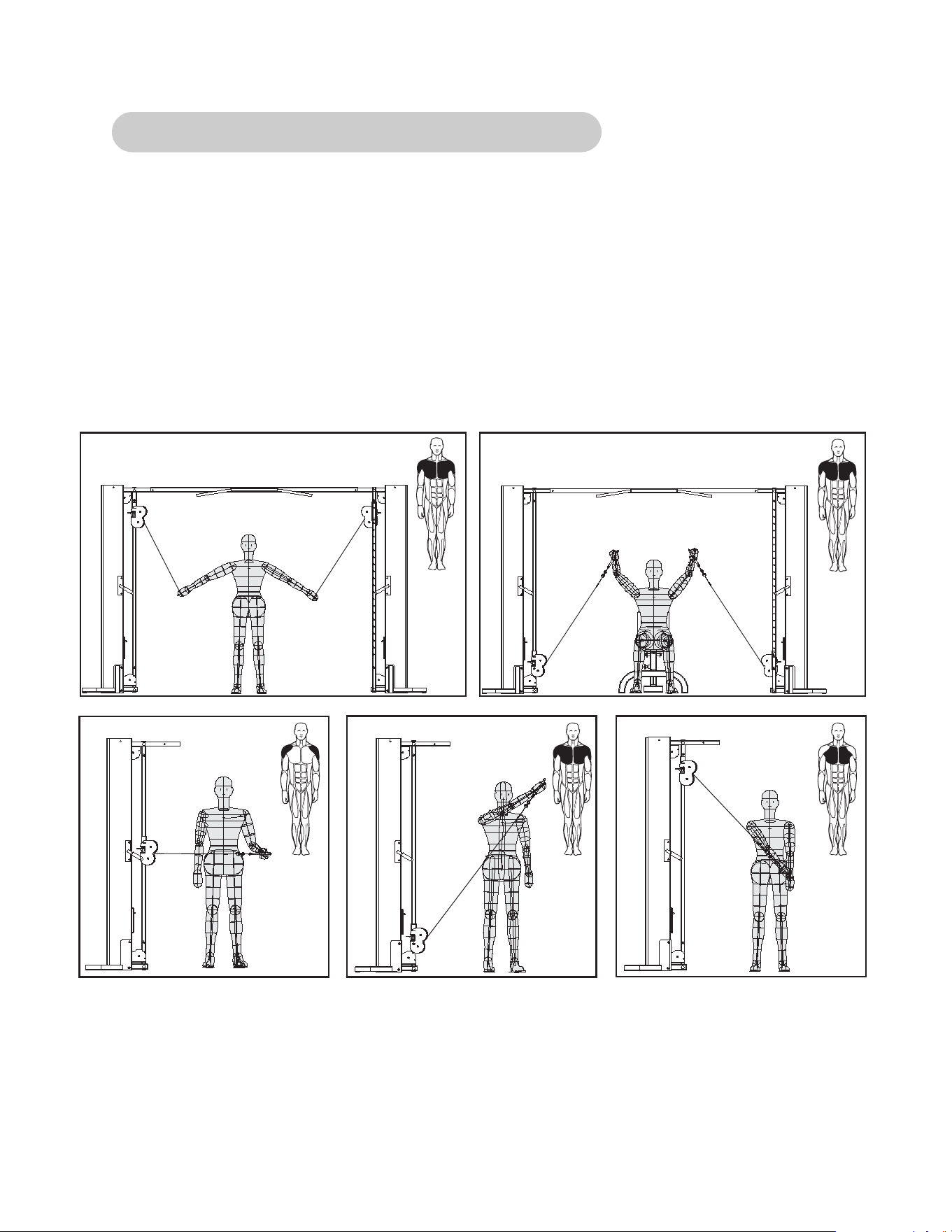
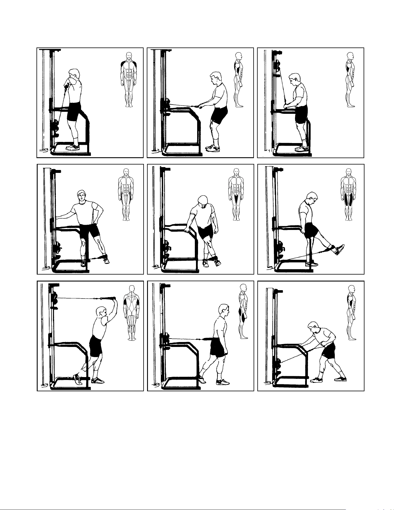
5648/5649/5650/5311 - Modular Cable Crossover
Pectoralis Major
Anterior Deltoid
Rotator Cuff Pectoralis Major
Anterior Deltoid
Pectoralis Major
Pectoralis Major
Anterior Deltoid
The Cable Crossover is a very versatile machine. With the use of various handles, virtually
every body part can be trained.
1. Select appropriate resistance.
2. Adjust pulley height by grasping handle, pulling detent pin, sliding mechanism to desired
height. Ensure that pin is locked into place before releasing handle.
3. Grasp handle securely and lift/lower resistance with smooth, controlled movements.
NOTE: Exercises may be performed in either linear or diagonal patterns.
Page 2-22
Cybex Modular Owner’s Manual
Latissimus Dorsi
Teres Major
Side Deltoid
Triceps
Latissimus Dorsi
Biceps
Triceps
Biceps
Hip AbductorsHip Adductors
Glutes
Hamstrings
Page 2-23
Cybex Modular Owner’s Manual
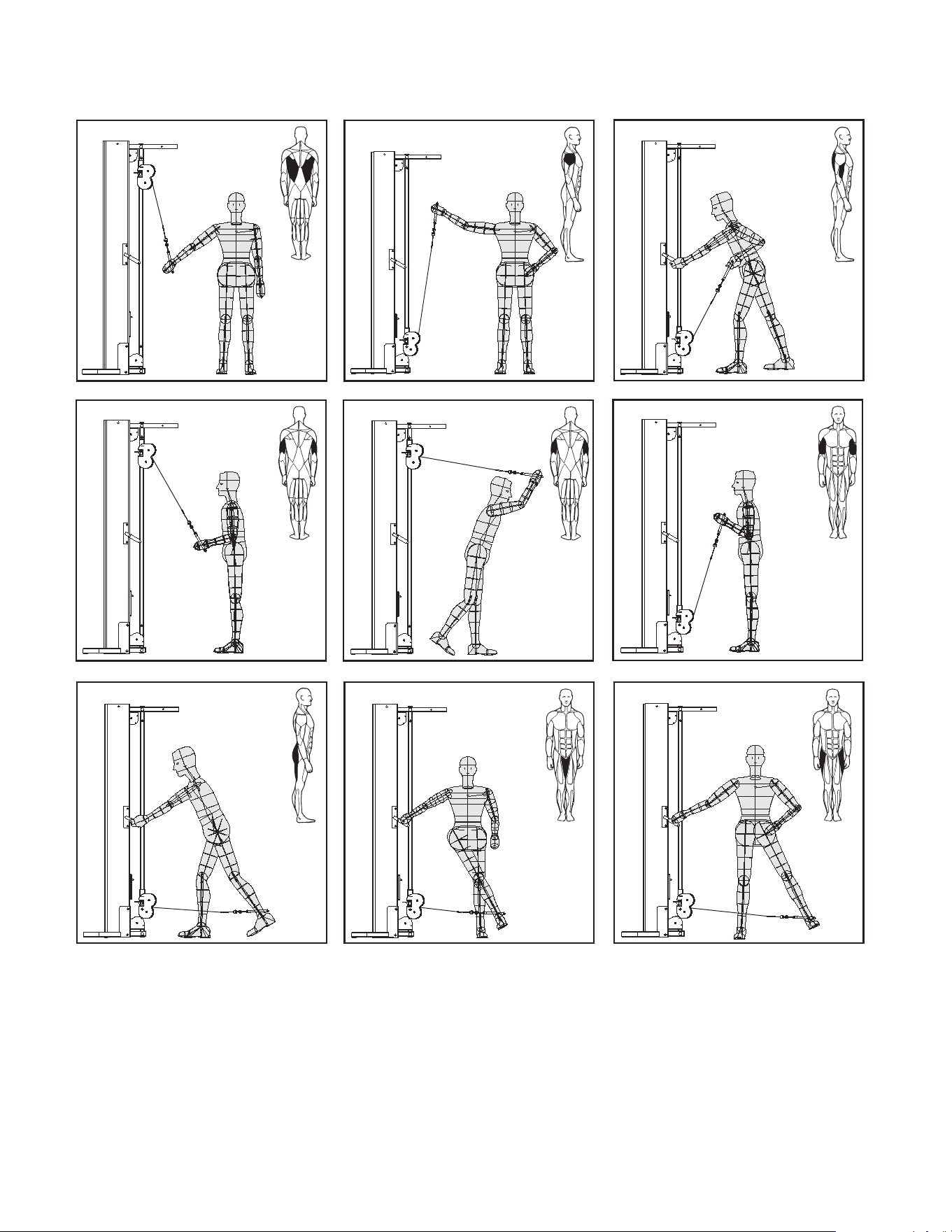
5605.5633/5315/5316 - Modular Cable Column
Pectoralis Major
Anterior Deltoid
Pectoralis Major Pectoralis Major
Side Deltoid
Rotator Cuff
Latissimus Dorsi
Teres Major
The Cable Column is a very versatile machine. With the use of various handles, virtually every
body part can be trained.
1. Select appropriate resistance.
2. Adjust pulley height by grasping handle, unlocking twist knowb, sliding mechanism to the
desired height. Ensure that the twist knob has been locked before releasing handle.
3. Grasp handle securely and lift/lower resistance with smooth, controlled movements.
NOTE: Exercises may be performed in either linear or diagonal patterns.
Page 2-24
Cybex Modular Owner’s Manual
Deltoids
Latissimus Dorsi
Biceps
Triceps
Hip Abductors
Hip Adductors
Hip Flexors
Quadriceps
Triceps
Quadriceps
Glutes
Latissimus Dorsi
Biceps
Page 2-25
Cybex Modular Owner’s Manual
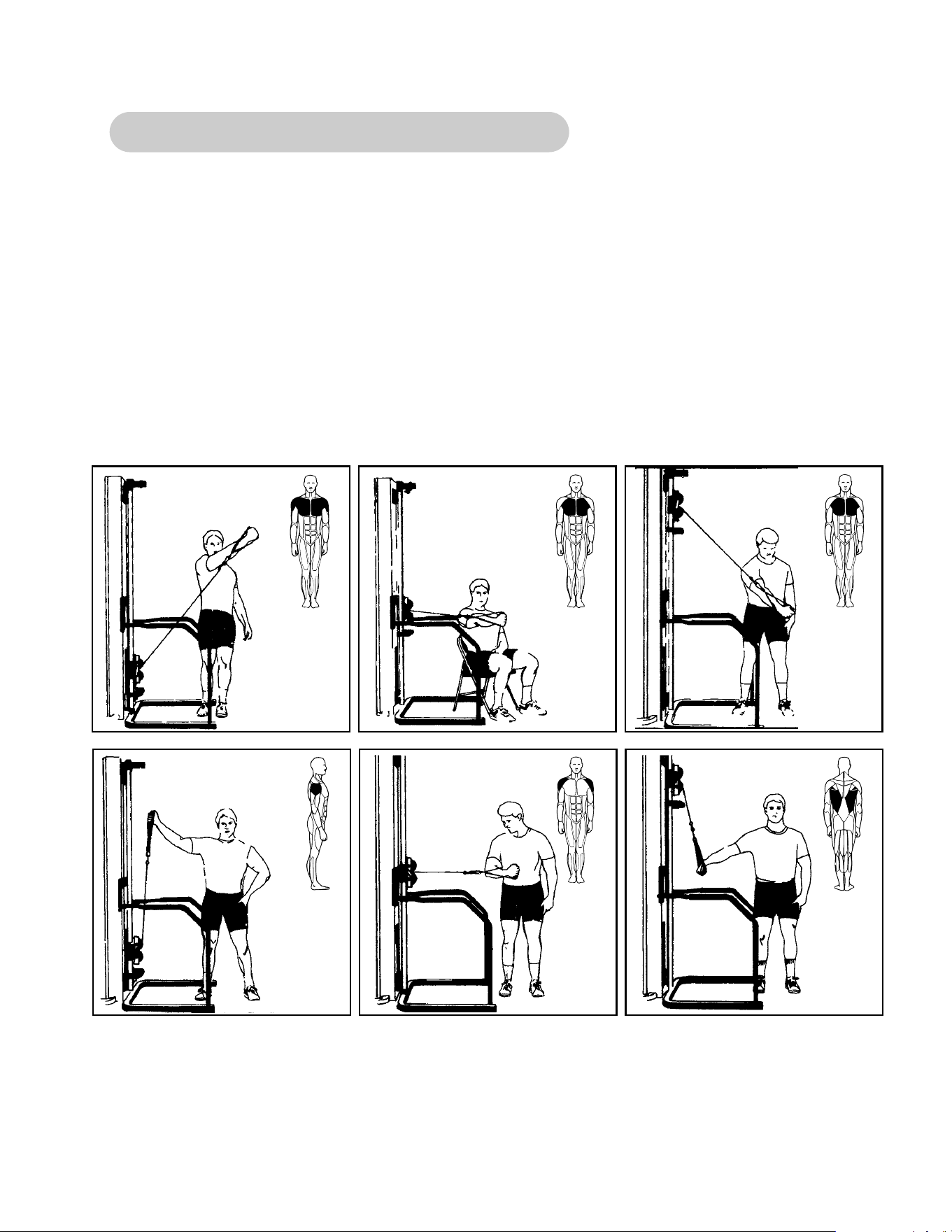
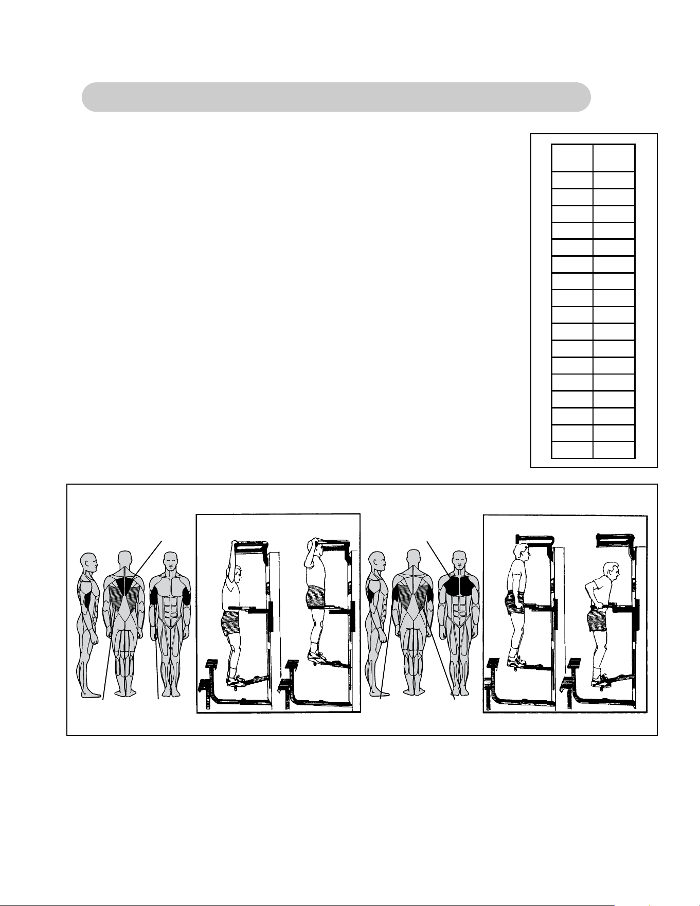
5611 Modular Assisted Chin-Up/Dip and 5345 - Single Station Dip/Chin
1. Select assisted (foot support down) or unassisted (foot support
pivots up against tower) dip or chin exercise.
2. Select appropriate resistance.
3. Select wide or narrow grip position.
4. Grasp exercise handles securely.
5. For assisted dip or chin exercise, place feet firmly on the foot support.
6. Lift/lower body with smooth, controlled movements.
NOTE: Exit machine from top step only! Do not exit machine from ground level.
Rhomboids
Start
Finish
Start
Finish
Latissimus Dorsi Biceps
Muscles Trained
Pectoralis Group
Latissimus Dorsi
Triceps
Muscles Trained
100
106
112
18
9417
8816
8215
7614
7013
6412
5811
5210
469
408
347
286
225
164
Plate
No.
Assist
(Pounds)
19
20

Page 2-26
Cybex Modular Owner’s Manual
This page intentionally left blank

Cybex Modular Owner’s Manual
Page 3-1
Contacting Service
3 - Customer Service
Hours of phone service are Monday through Friday from 8:00 a.m. to 6:00 p.m. Eastern
Standard Time.
For Cybex customers living in the USA, contact Cybex Customer Service at 800-766-3211.
Your options at this number include:
• Press 63 to place a parts order or to check parts order status.
• Press 64 to speak to a technical support representative regarding troubleshooting or to
schedule a field service call.
• Press 65 to check status of a repair order only and you have your RRM number.
• Press 66 to check status of a dispatched field service call and you have your inquiry
number.
• Press 67 for service of a medical or isokinetic product.
• Press 0 to go to the Cybex operator.
For Cybex customers living outside the USA, contact Cybex Customer Service at 508-533-
4300 or fax 508-533-5183.
Order parts and find information on the web at www.eCybex.com or by e-mail at
Ordering Parts
Visit eCybex.com to shop for parts online or fax your order to 508-533-5183.
To speak with a customer service representative, call 800-766-3211 (for customers living with-
in the USA) or 508-533-4300 (for customers outside the USA). You may also contact us
through email at [email protected]
Having the following information ready when calling will assist our Cybex representatives in
serving you:
• Unit Serial Number
• Product Name
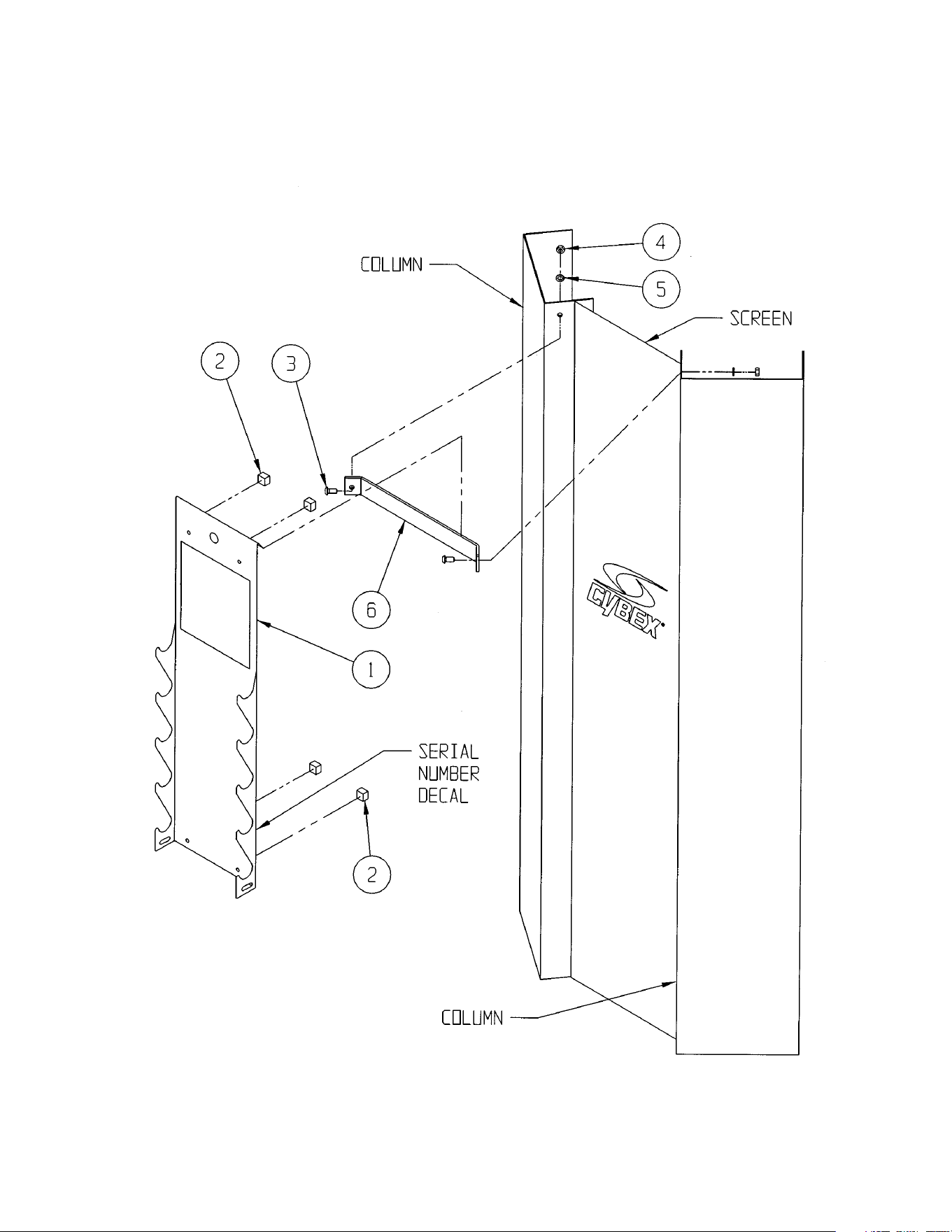
The unit serial number and product name can be found on the serial number decal. See
Chapter 6 for exact location of serial number decal.
• Part Description
• Part Number
Part descriptions and part numbers are located in Chapter 6 of this manual.

Cybex Modular Owner’s Manual
Page 3-2
The Return Material Authorization (RMA) system outlines the procedures to follow when
returning material for placement, repair, or credit. The system assures that returned materials
are properly handled and analyzed. Follow the following procedures carefully.
Contact your authorized Cybex dealer on all warranty-related matters. Your local Cybex
dealer will request a RMA from Cybex, if applicable. Under no circumstances will defective
parts or equipment be accepted by Cybex without proper RMA and an Automated Return
Service (ARS) label.
1. Call the Customer Service Hotline listed above for the return of any time that is
defective.
2. Provide the technician with a detailed description of the problem you are having or
the defect in the item you wish to return.
3. Provide the model and serial number of your Eagle equipment
4. At Cybex’s discretion, the technician may request that you return the problem
part(s) to Cybex for evaluation and repair or replacement. The technical will assign
you a RMA number and will send you an ARS label. The ARS label and the RMA
numbers must be clearly displayed on the outside of the package that contains the
item(s) to be returned. Include the description of the problem, the serial number of
the Eagle equipment and the name and address of the owner in the package along
with the part(s).
5. Forward the package through UPS to Cybex.
Attn: Customer Service Department
Cybex International, inc.,
10 Trotter Drive
Medway, MA 02053
NOTE: Merchandise returned without an RMA number on the outside of the package or
shipments sent C.O.D. will not be accepted by the Cybex receiving department.
Return Material Authorization (RMA)
• Shipping Address
• Contact Name
In addition to your shipping address and contact name, your account number
is helpful but not required.

Cybex Modular Owner’s Manual
Page 3-3
Materials damaged in shipment should not be returned for credit. Shipping damages are the
responsibility of the carrier (UPS, Federal Express, trucking companies, etc.)
Apparent Damage - Upon receipt of your shipment, check all items carefully. Any damage
seen with a visual check must be noted on the freight bill and signed by the carriers agent.
Failure to do so will result in the carriers refusal to honor your damage claim. The carrier will
provide you with the required forms for filing such claims.
Concealed Damage - Damage not seen with a visual check upon receipt of a shipment but
notices later must be reported to the carrier as soon as possible. Upon discovery of the dam-
age, a written or phone request to the carrier asking them to perform an inspection of the
materials must be made within ten days of the delivery date. Keep all shipping containers and
packing materials as they will be needed in the inspection process. The carrier will provide
you with and inspection report and the necessary forms for filing a concealed damage claim.
Concealed damage claim is the carriers responsibility.
Damaged Parts

Cybex Modular Owner’s Manual
Page 3-4
This page intentionally left blank
4 - Assembly
Page 4-1
Cybex Modular Owner’s Manual
TOOLS REQUIRED
• 5/16” Allen wrench
• Soft hammer
• Medium weight automotive engine oil
NOTE: Refer to the appropriate Assembly & Parts Instruction sheet (weight stack diagrams)
when performing the procedure listed below.
1. Remove the two socket head cap screws securing the guide rods.
2. Carefully lean guide rods away from column.
3. Remove guide rod collets and plastic caps.
4. Wipe guide rods clean over entire length. Lubricate with light coating of medium weight
automotive engine oil.
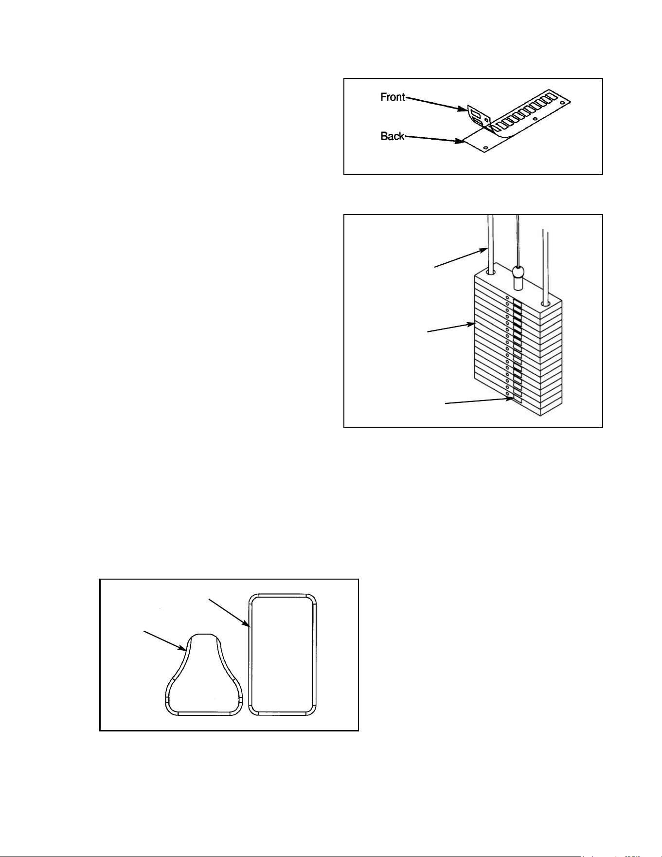
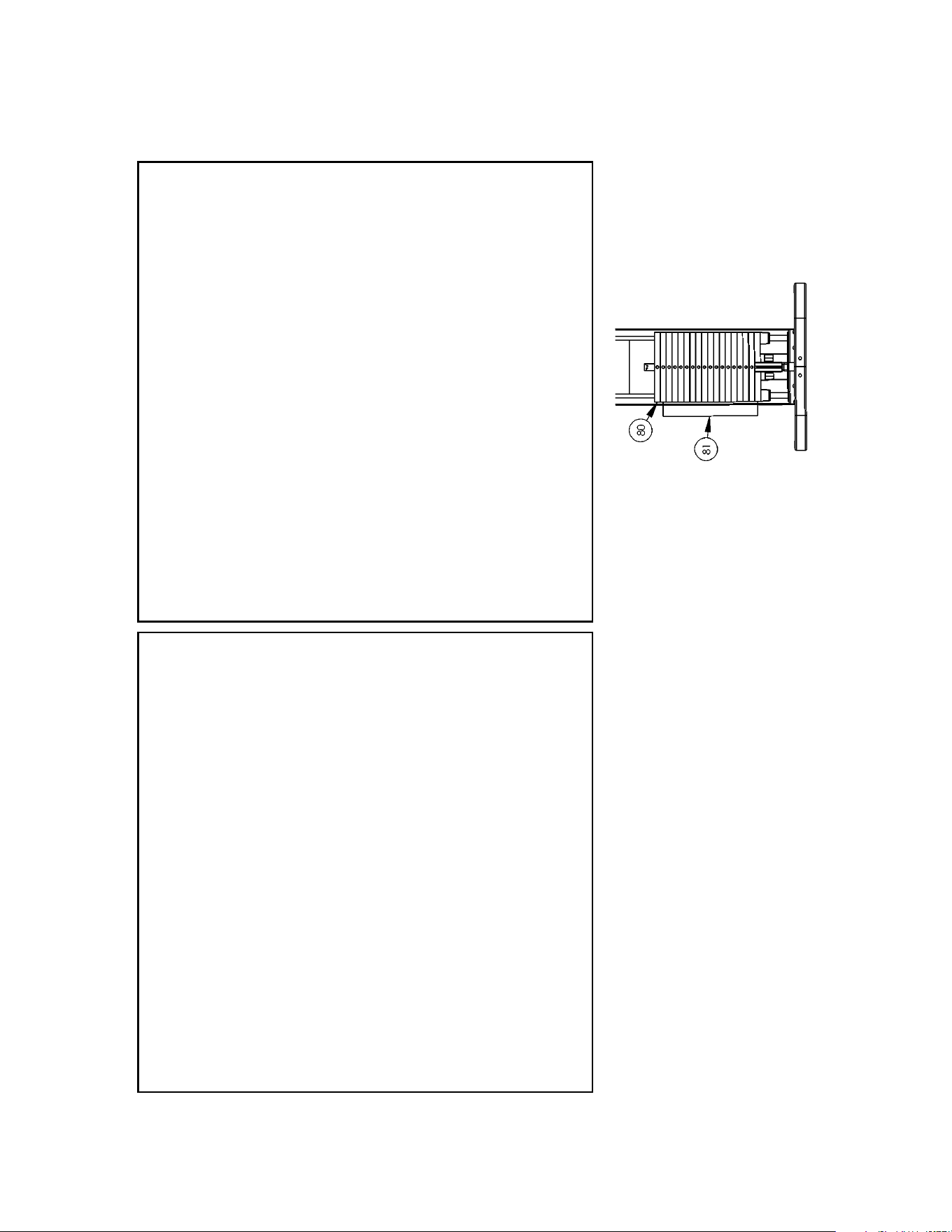
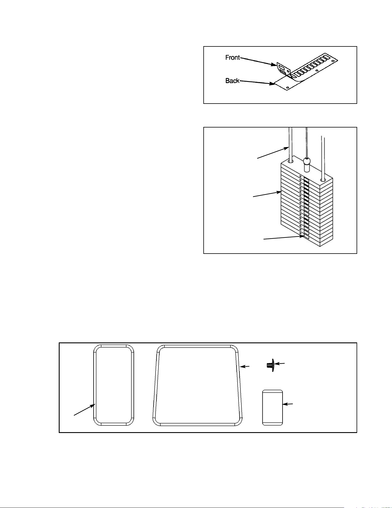
5. Install each weight plate one at a time, starting with the last plate (going from highest
numerical value to lowest). NOTE: For 15 and 25 weight plate stacks, the first plate installed
has no number. NOTE: When installing weight plates, position plates so wide edges of bushings
face upward and narrow edges of bushings face downward. See example below..
6. Install top weight.
7. Replace plastic caps and guide rod collets on guide rods.
8. Return guide rods to full upright position.
Weight Stack Installation
NOTE: Refer to Chapter 6 (Assembly and Service) for further assembly information.
CORRECT
NARROW bushing
edge
WIDE bushing
edge faces upward
NOTE: The narrow
bushing edge must
face downward.
WRONG

Cybex Modular Owner’s Manual
Page 4-2
9. Insert both socket head cap screws that were removed in step 1 and tighten securely.
10. Insert cable end into top weight and align cable fitting opening with opening in top
weight for proper cable tension. NOTE: See Cable Adjustment and Installation Section.
11. Using a hammer drive roll pin through top plate connector and cable fitting. Assure pin is
flush with top plate collar.
12. Insert selector pin into each plate to assure proper alignment. See Cable Adjustment and
Installation section if selector pin does not fit smoothly, or if cable appears to have
excessive slack.
13. Place half weight on weight peg (if applicable).
Cybex Modular Owner’s Manual
Page 4-3
MODULAR HANDLE RACK
5631 ASSEMBLY & PARTS
A. Handle Rack....................... 5631
DESCRIPTION PART NO.
A

Cybex Modular Owner’s Manual
ITEM QTY PART NO. DESCRIPTION
1 1 01930 Handle Rack
2 4 PU060205 Rubber Bumper .88" T
3 2 JC780417 BHSCS .50-13 x 1.00
4 2 HN784000 Hex Nut .50-13
5 2 JS388300 Lockwasher .50
6 1 01937 Mounting Plate
5631 - Handle Rack
TOOLS REQUIRED
• 5/16" Allen wrench
• 3/4" Wrench
MOUNTING HANDLE RACK ON MODULAR UNITS
1. Install mounting plate (item 6) between towers with BHSCS (item 3),
hex nut (item 4), and lockwasher (item 5).
2. Remove paper backing from one of the pieces of tape that is located on backside of Handle Rack
(item 1). Place a rubber bumper (item 2) on the tape. Repeat this step until all four bumpers have
been placed on the Handle Rack.
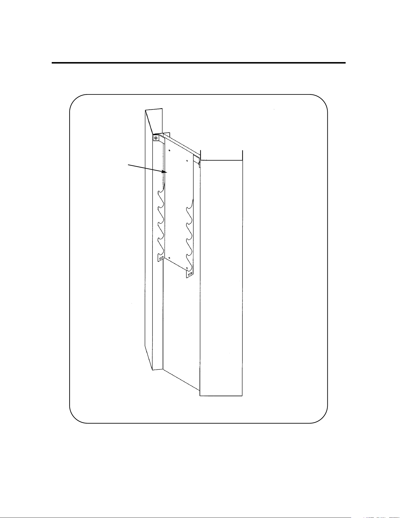
3. Hang handle rack (item 1) over top edge of mounting plate (item 6).
NOTE: Be sure that the rubber bumpers rest against the perforated panel.
MOUNTING HANDLE RACK ON ANY UNITS WITH A BACK COVER
1. Remove paper backing from the four pieces of tape located on backside of Handle Rack (item 1).
2. Secure Handle Rack to back cover of unit.
MOUNTING HANDLE RACK TO A WALL
1. Remove paper backing from one of the pieces of tape that is located on backside of Handle Rack
(item 1). Place a rubber bumper (item 2) on the tape. Repeat this step until all four bumpers have
been placed on the Handle Rack.
2. Position handle rack against the wall (or mounting surface). Mark holes on the
wall through the four mounting holes in the Handle Rack.
3. Secure Handle Rack to the wall using the proper tools and hardware.
NOTE: This machine shipped with an Owner’s Manual. Additional copies can be obtained by contacting
your dealer or a Cybex Representative at 1-888-462-9239.
Cybex Modular Owner’s Manual
Page 4-5

Cybex Modular Owner’s Manual
Page 4-6
This page intentionally left blank
Cybex Modular Owner’s Manual
Page 4-7
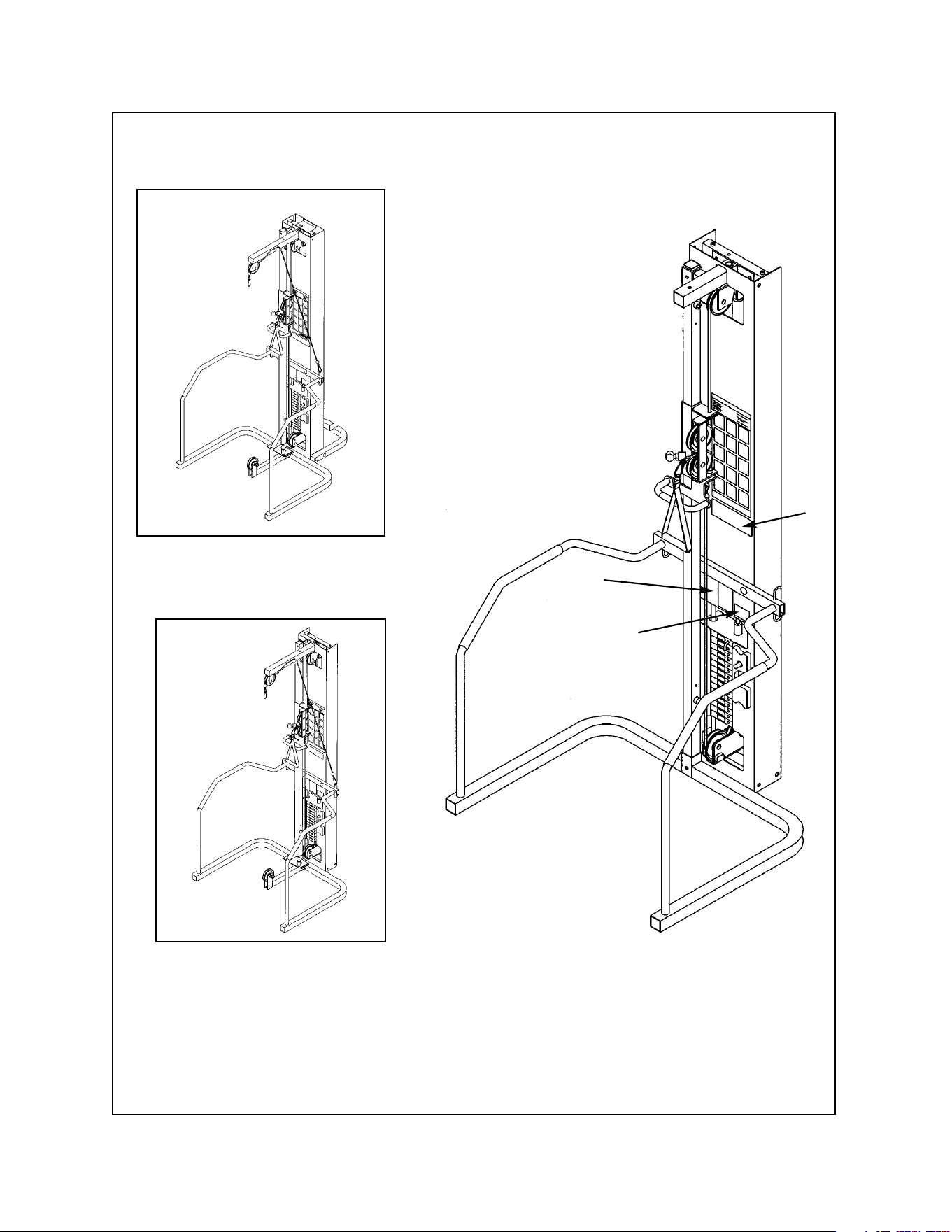
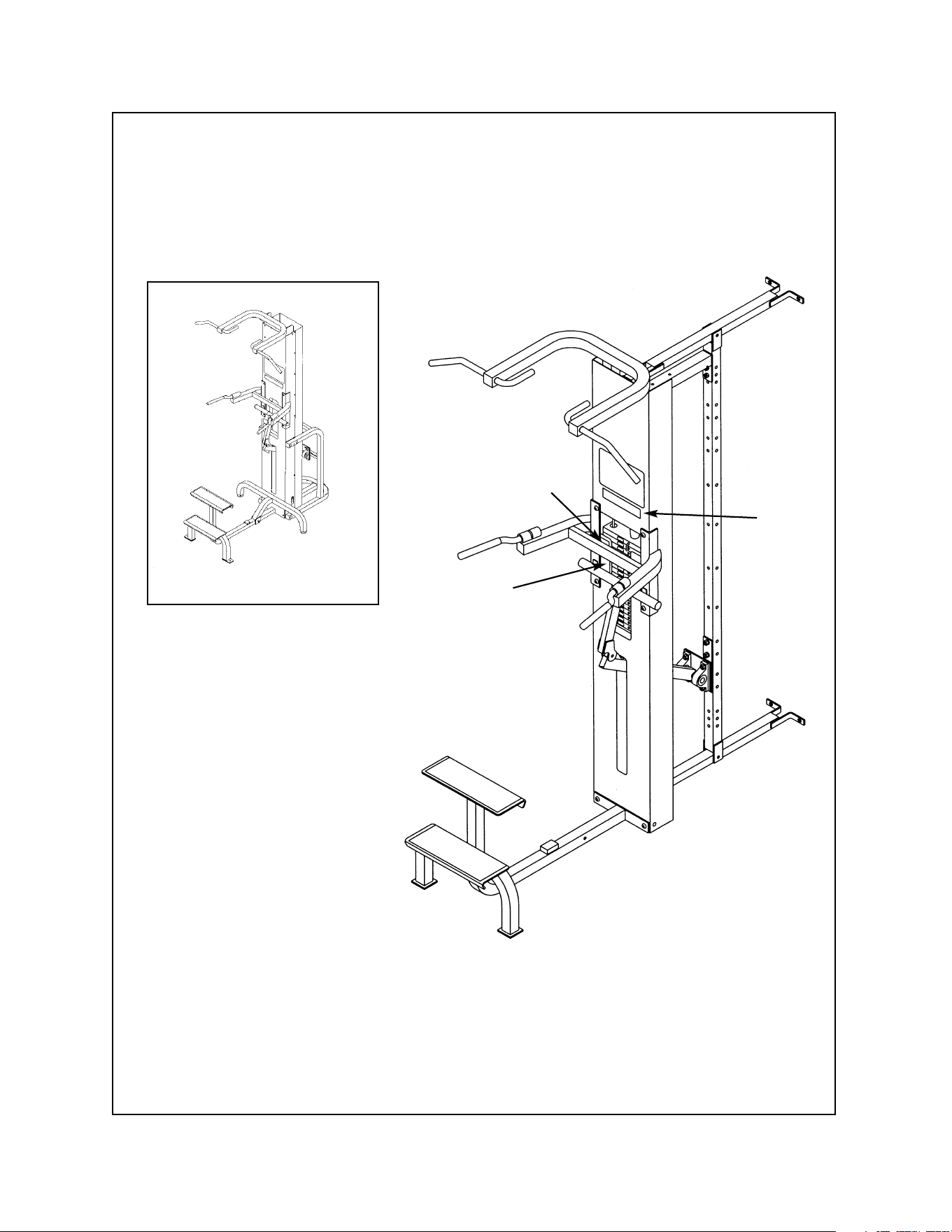
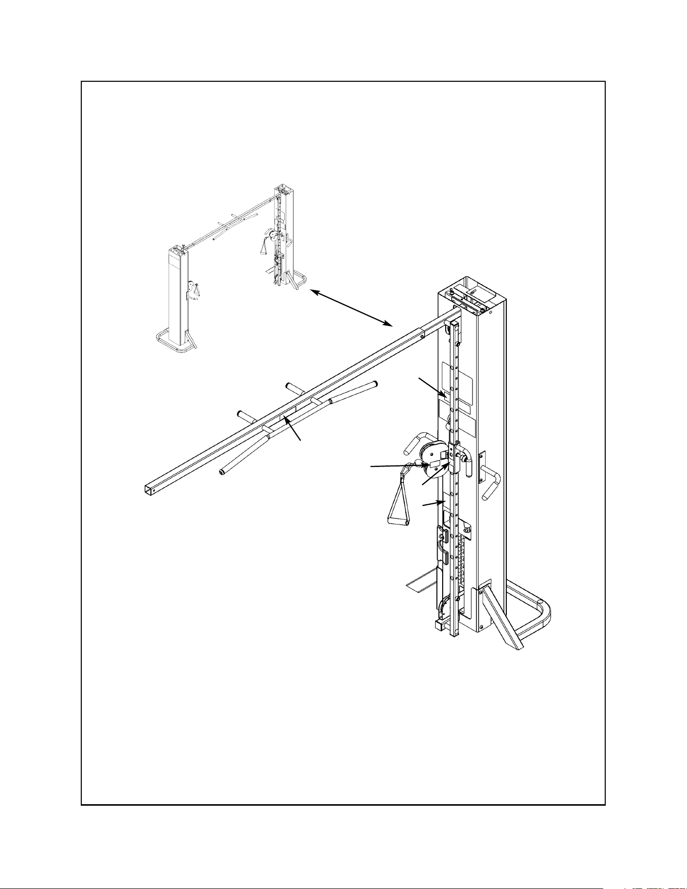
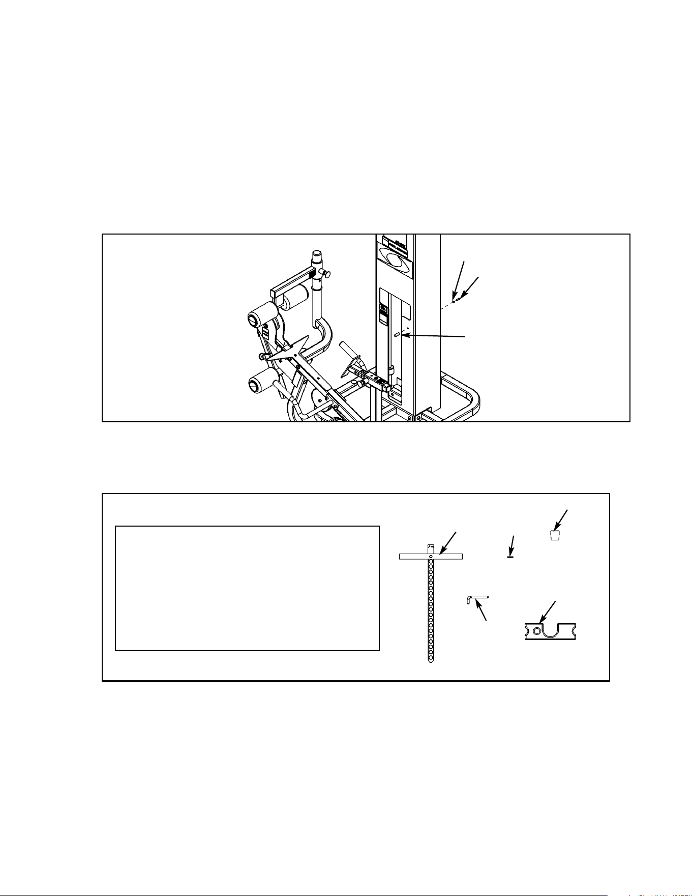
Modular Mover
5632
TOOLS REQUIRED
• 3/8” Allen wrench
• 3/8” Allen wrench
CAUTION!! When raising or lowering modular unit, keep hands and feet clear of columns, angle
supports and frame attachments.
1. Read and understand all instructions thoroughly before performing this procedure.
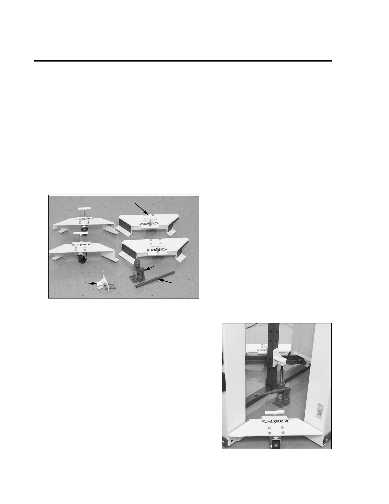
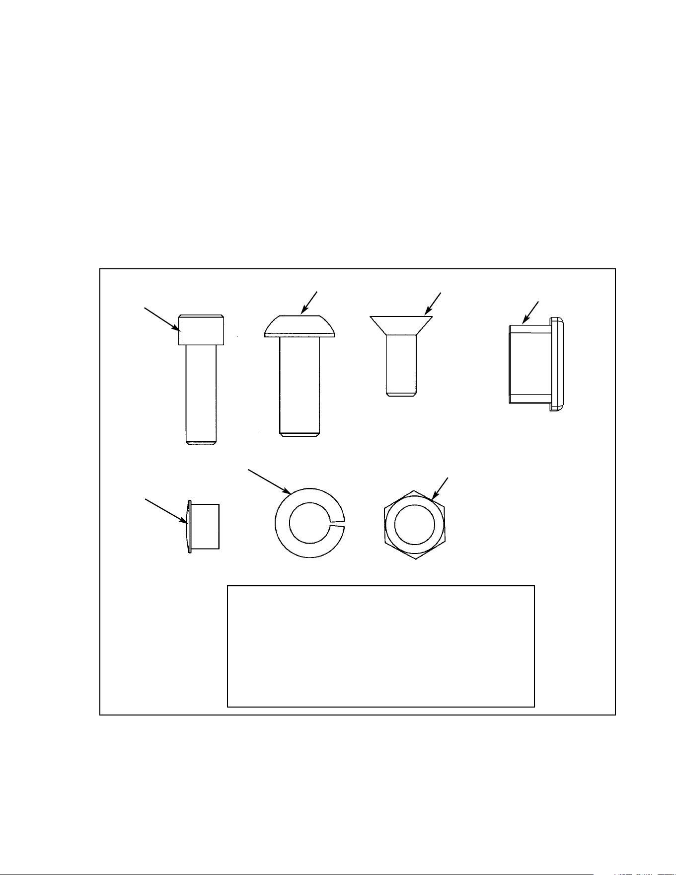
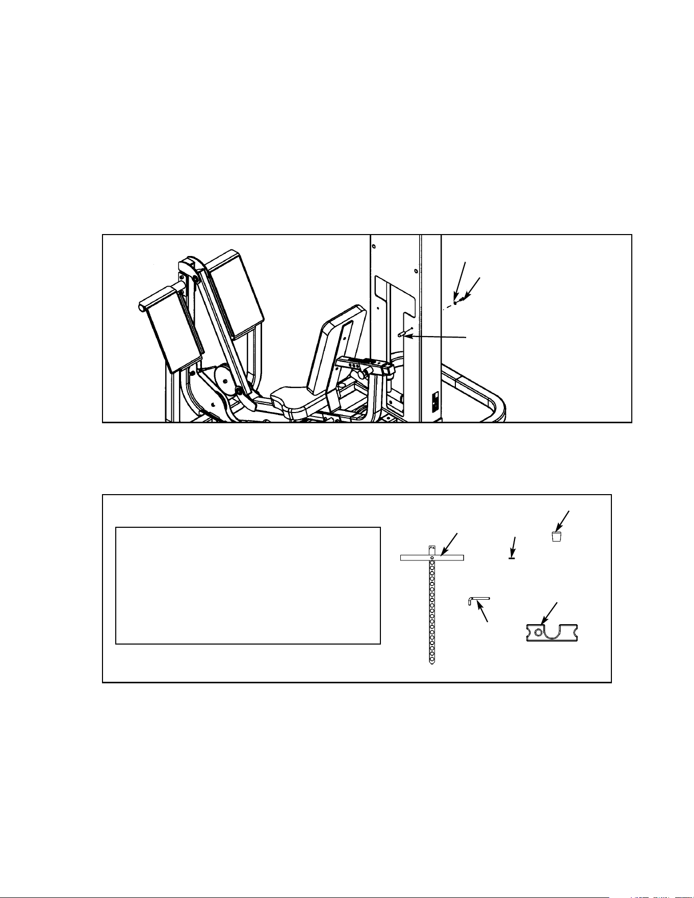
2. Verify you received the items shown in Figure 1.
Assembly Instructions
A. Handle Jack ...................... 01950
B. Jack Handle
C. Modular Mover .................. 01941
D. Lifting Bracket ................... 01951
E. Hex Nut.............................. HN784000
F. Split Lockwasher ............... JS388300
G. SHCS .500-13 x 2.75 ........ JC782832
DESCRIPTION PART NO.
3. Remove all perforated screens and set aside.
4. Remove all side stations (if applicable).
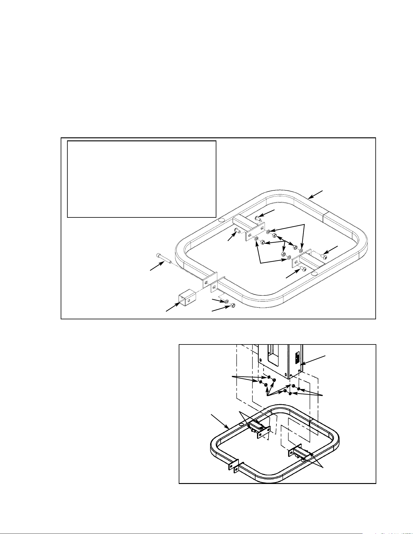
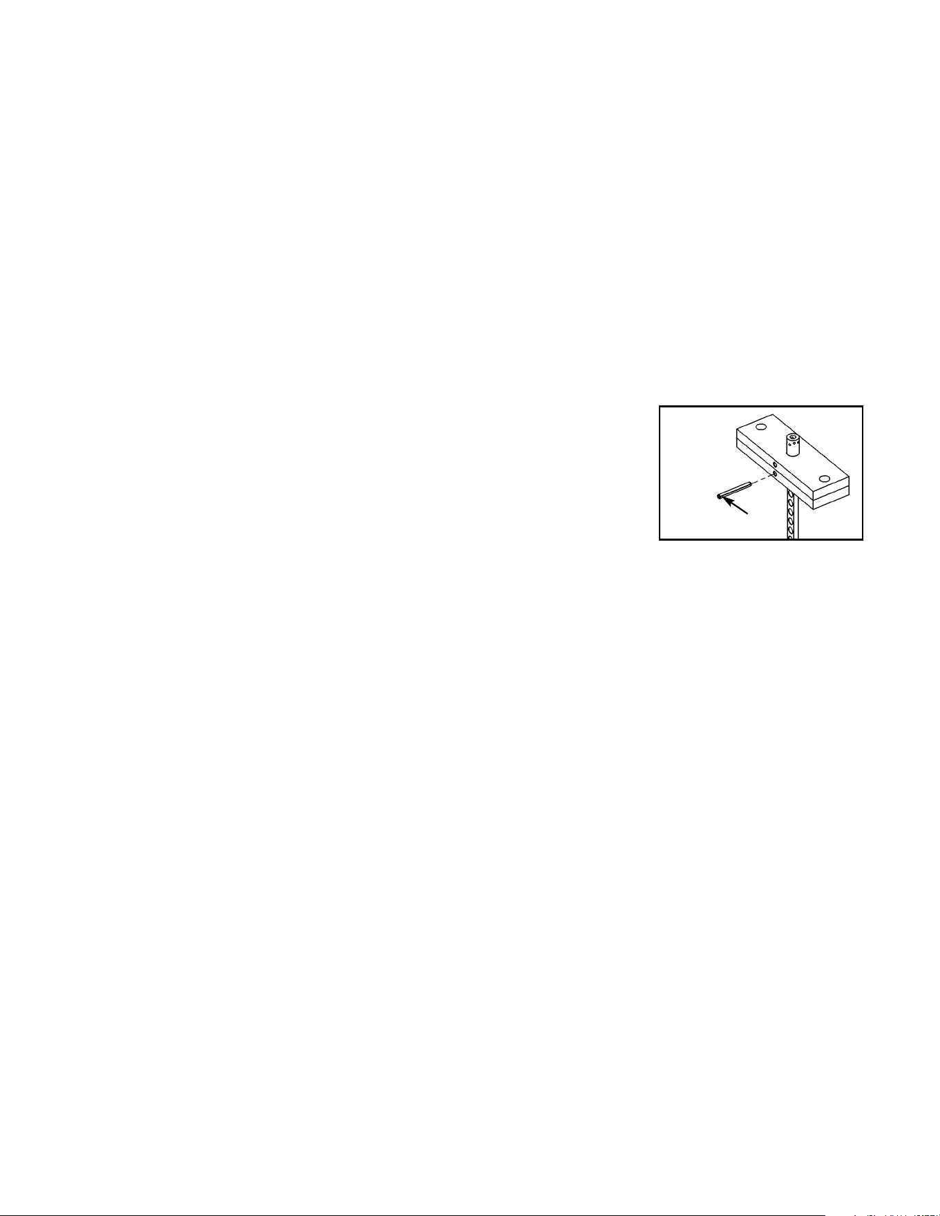
5. Install lifting bracket to the center of post using two
socket head cap screws. After tightening screws in
step 3, place hydraulic jack under lifting bracket
and raise modular unit approximately 1” off the
floor. See Figure 2.
Figure 1
Figure 2
A
B
C
D, E, F, G
Cybex Modular Owner’s Manual
Page 4-8
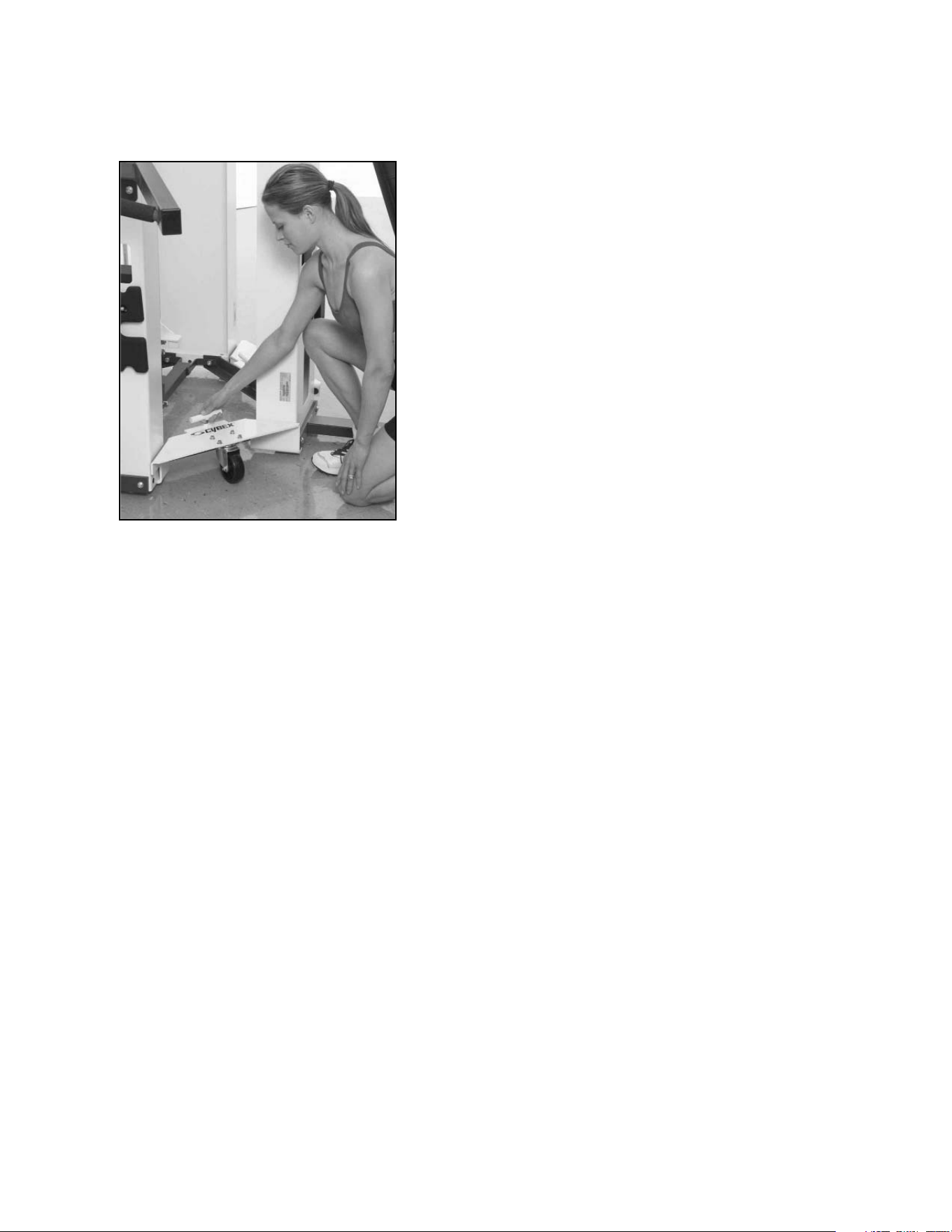
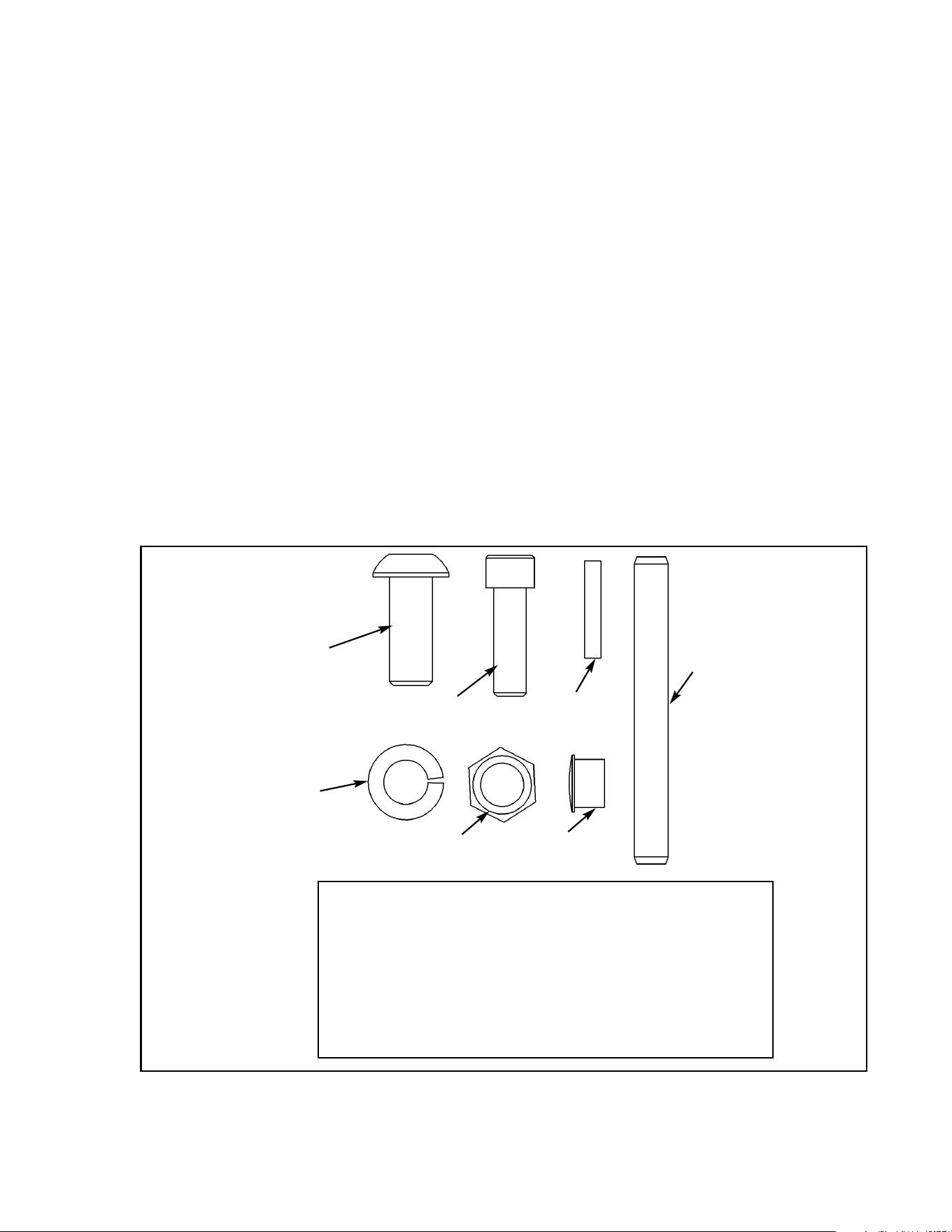
6. Install lift dolly and tighten in place using T-handle on dolly. See Figure 3.
7. Repeat step 4 for each remaining position around the modular unit. NOTE: If a leg Curl/Leg
Extension is next to an O.C. Cable Column, then do not install lift dolly in this position.
8. After lift dollies have been secured in place, the modular unit can be lowered and the hydraulic
jack can be removed.
9. Move modular unit to desired location. NOTE: When moving modular unit be sure to support any
pieces attached to the columns.
10. Position modular unit as desired. Install hydraulic jack and raise unit. Remove lift dollies and
lower modular unit.
11. Remove lifting bracket from center post.
12. Reattach any side stations.
13. Reattach perforated screens to the modular unit. Be sure screens are secured.
Figure 3

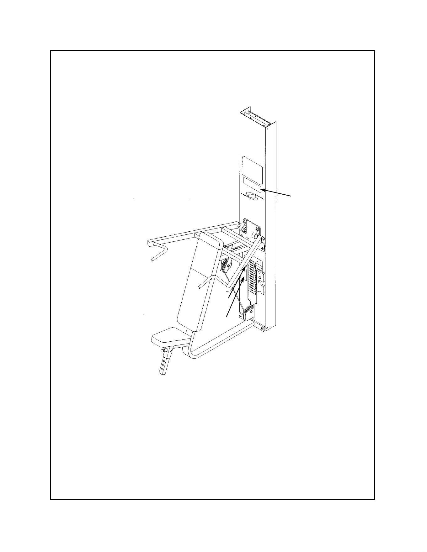
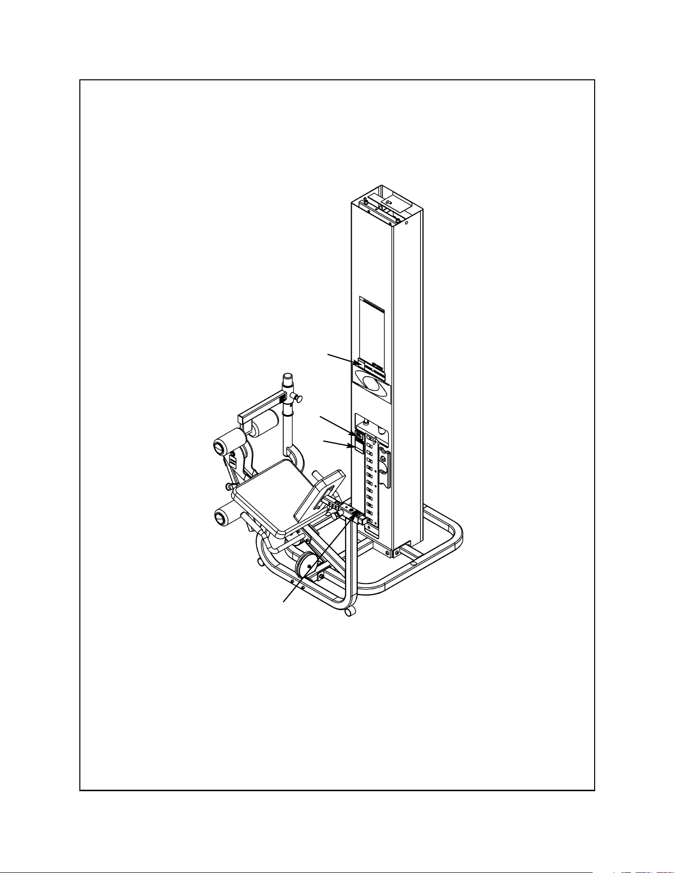
Modular Seated Leg Press
5652 - Modular/Tandem configuration
5322 - Free Standing configuration
TOOLS REQUIRED
• 5/32” Allen wrench
• 7/32” Allen wrench
• 5/16” Allen wrench
• 3/8” Allen wrench
• 9/16” Socket/wrench
• 3/4” Socket/wrench
• Rubber mallet
• Step ladder
NOTE: A minimum of two people will be required to assemble the Leg Press configuration.
1. Read and understand all instructions thoroughly before assembling the Leg Press (see steps
A - C).
A. Locate the Modular Assembly & Service manual that you received with your order. If you did
not receive a manual contact Cybex Customer Service and ask for part number 55620.
B. If you are assembling the Leg Press station into a Tandem configuration, locate and review the
Tandem Center Post instructions contained with the Tandem configuration (this sheet is also
located in the Modular Assembly & Service manual). Skip step 1 in the Tandem Center Post
instructions.
C. If you are assembling the Leg Press station into a Modular configuration, locate and review
the Modular Center Post instructions contained with the Modular configuration. Skip step 1 in
the Modular Center Post instructions.
2. Verify you have received the appropriate configuration (see steps 2A - 2C, Figures 1 and 2).
• Hammer
• Utility knife
• Automotive engine oil
Assembly Instructions
Unpacking
A. If you ordered the Modular/Tandem
configuration (5262):
Shipping Package Part Number
• Leg Press Column 5562-9x
• Leg Press Package 5652-50
• Weight Package 4700S040
• Weight Package 4700S129
• Top Weight Package 4700-027
• Cushion Set 8630-010
B. If you ordered the Free Standing
configuration (5322):
Shipping Package Part Number
• Leg Press Column 5322-9x
• Leg Press Package 5652-50
• Leg Press Stabilizer 5302-51
• Weight Package 4700S040
• Weight Package 4700S129
• Top Weight Package 4700-027
• Cushion Set 8630-010
Cybex Modular Owner’s Manual
Page 4-9
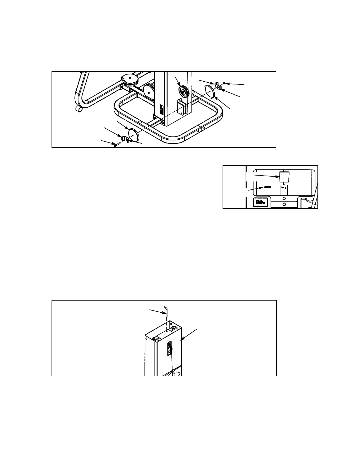
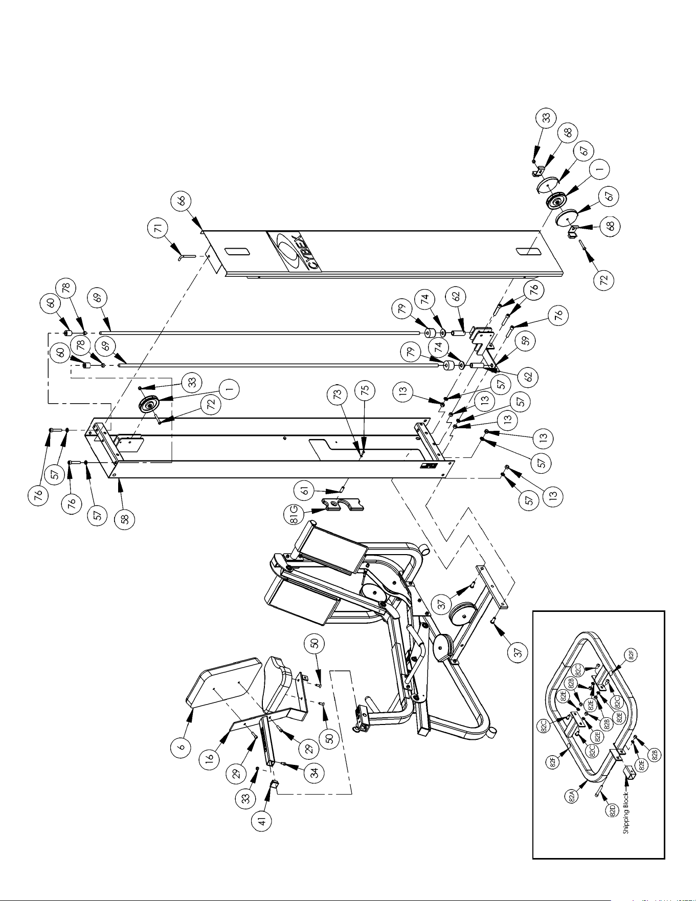
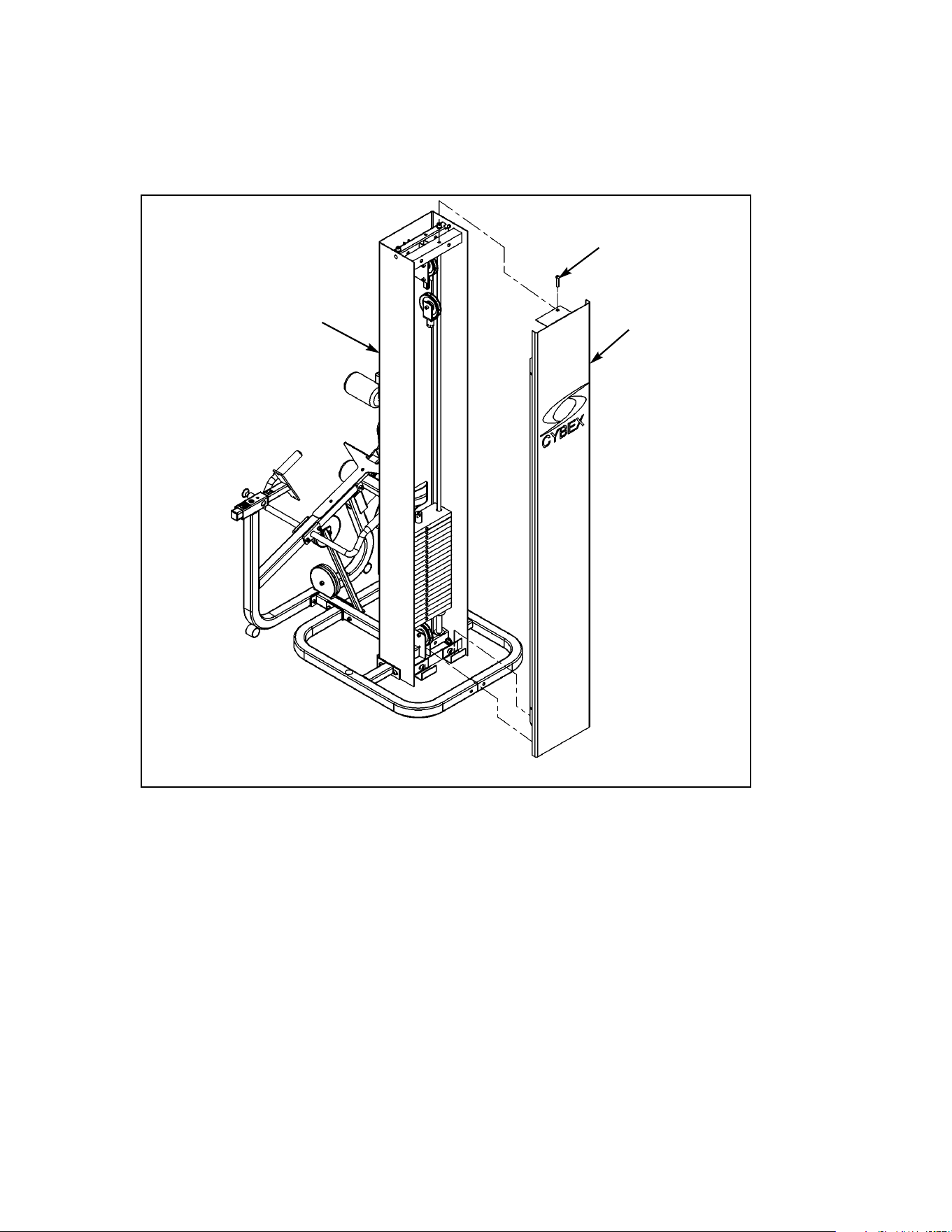
3. Unpack the carton containing the column (see steps 3A - 3I and Figures 3 - 8).
A. Locate and open the Leg Press Column carton.
B. The column should be laying so that the back side is facing upward.
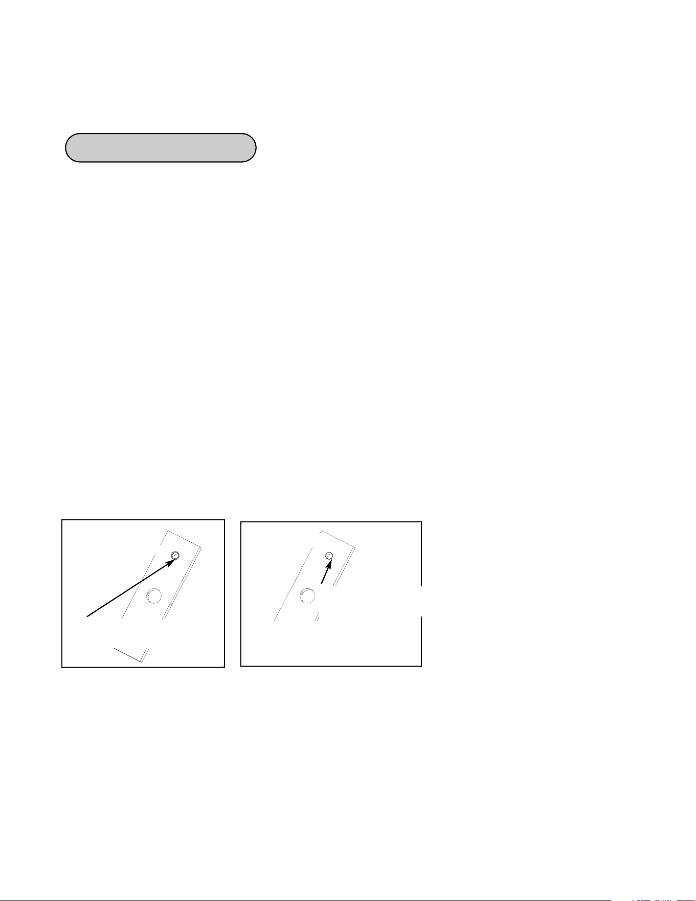
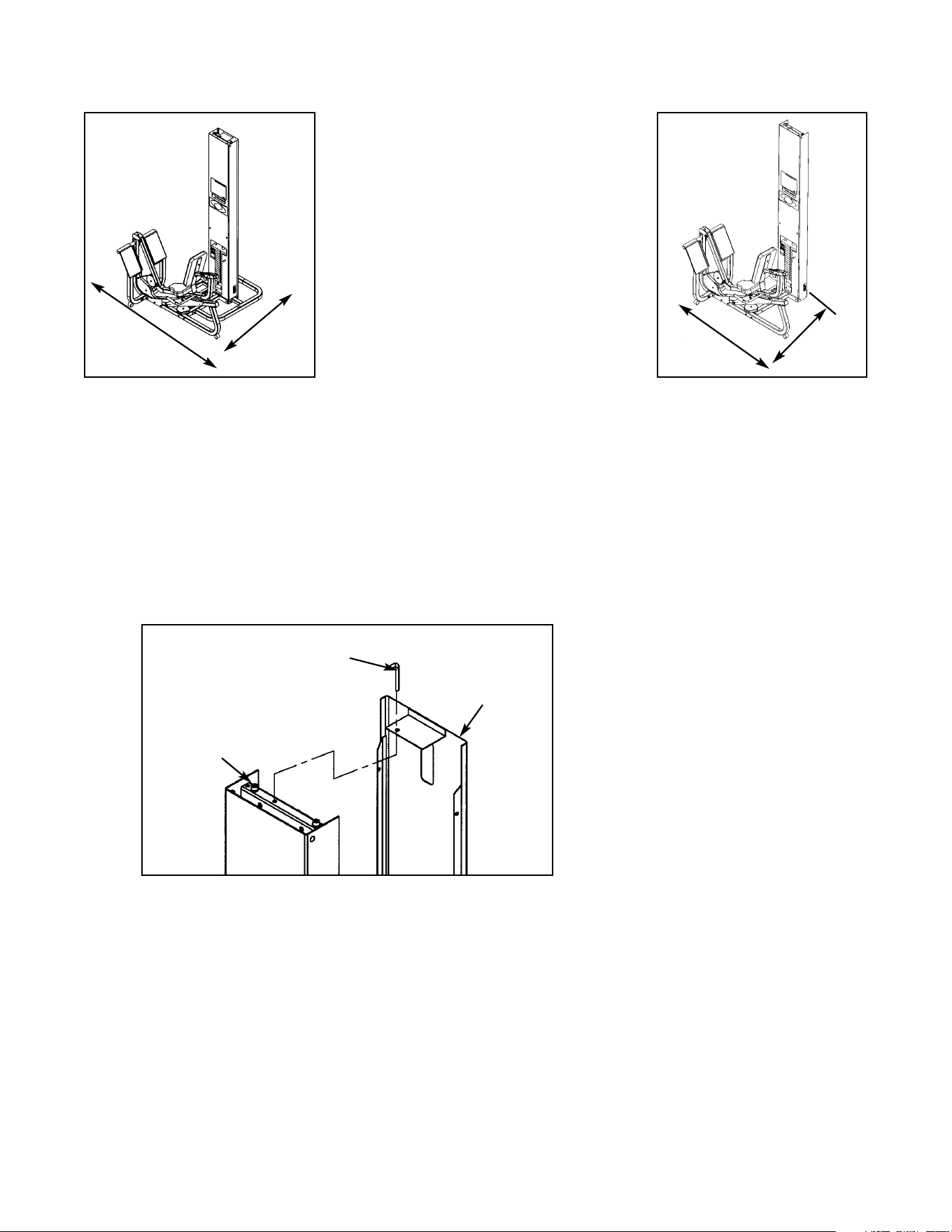
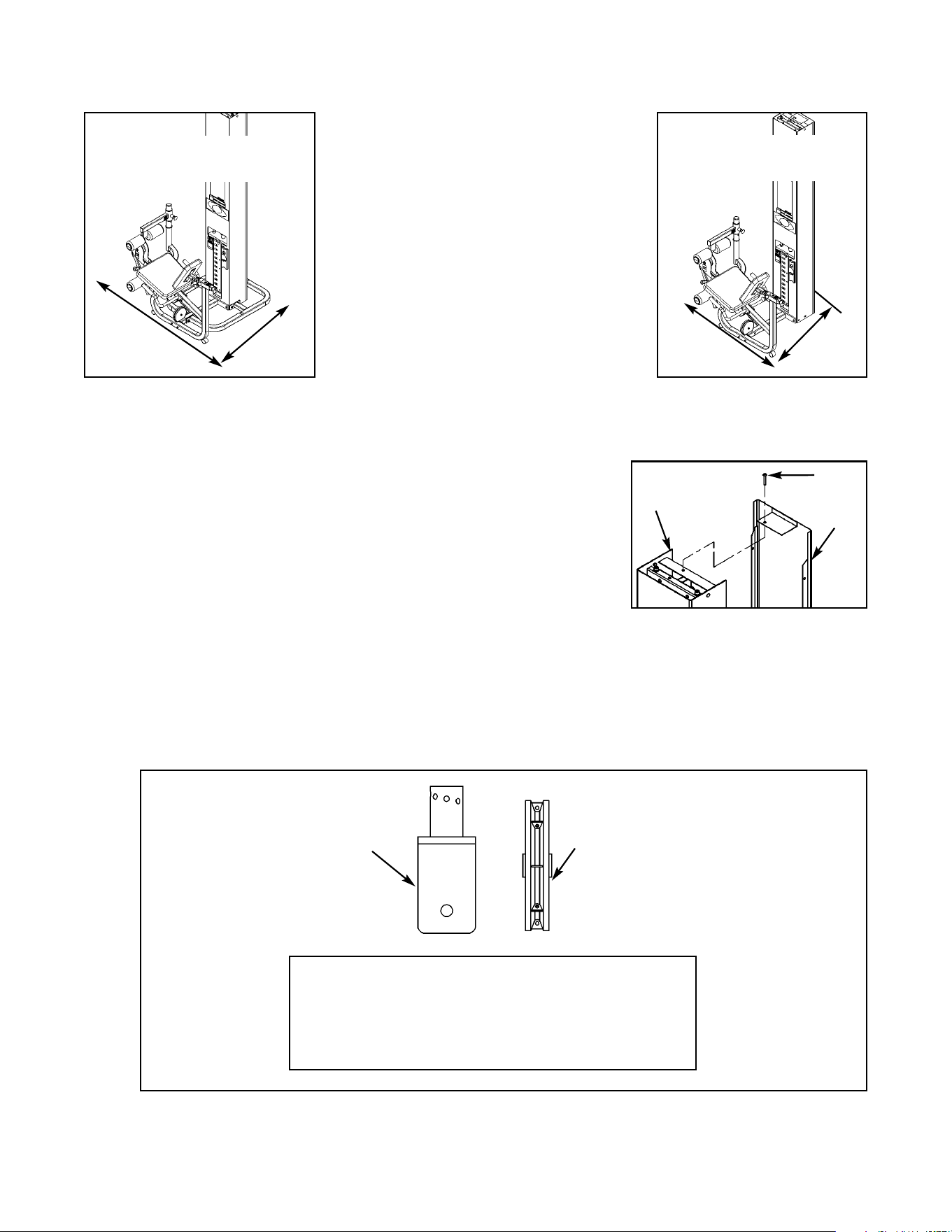
C. For Free Standing units containing a back cover, remove the pin (#83) securing the back
cover (#66). Remove back cover by sliding it then lifting it upward. See Figure 3.
Figure 3
D. Remove the shipping supports securing the pulley mount and two hardware packs located
inside the column.
E. Verify contents of both hardware packs. See Figures 4 - 6.
NOTE: Figures 4 and 5 are for the Free Standing configuration.
Figures 5 and 6 are for the Tandem/Modular configuration.
83
Column
66
Figure 1
Figure 2
C. Carefully place shipping
packages near area of
installation.
D. For Free Standing configurations,
allow a minimum amount 92” x
89” for operating space. See
Figure 1.
E. For Modular/Tandem
configurations, allow a minimum
of 92” x 76” for operating space.
See Figure 2.
92”
89”
92”
76”
Cybex Modular Owner’s Manual
Page 4-10
Figure 4
1 2 08014 Pulley Assembly
13 2 HN784000 Hex Nut .50-13
33 2 HN704901 Nylon Locknut .375-16
42 2 PU060201 Bumper
57 2 JS38800 Split Lockwasher .500
67 2 5301-310 Pulley Guard
68 2 5301-311 Stop
72 2 HC700430 BHSCS .375-16 x 2.50
76 3 JC782830 SHCS .50-13 x 2.50
ITEM QTY PART NO. DESCRIPTION
76
72
57
13
33
1
42
67
68
Cybex Modular Owner’s Manual
Page 4-11
Figure 5
61 1 02106 Half Weight Peg
65 1 4800-515 Weight Plate Decal
73 1 HS308300 Split Lockwasher .250
75 1 JC620415 BHSCS .250-20 x .75
ITEM QTY PART NO. DESCRIPTION
Figure 6
1 2 08014 Pulley Assembly
72 2 HC700430 BHSCS .375-16 x 2.50
33 2 HC704901 Nylon Locknut .375-16
13 3 JC620415 Hex Nut .500-13
76 3 JC782830 SHCS .500-13 x 2.50
57 2 JS388300 Split Lockwasher .500
ITEM QTY PART NO. DESCRIPTION
73
61
75
65
76
72
13
33
57
1
Cybex Modular Owner’s Manual
Page 4-12
G. Locate the pulley mount (#59), three SHCS .500-13 x 2.50 (#76), three split lockwashers
.500 (#57) and three hex nuts .500-13 (#13).
H. Attach pulley mount (#59) to column as shown in Figure 8. Securely tighten hardware.
Figure 8
76
57
13
13
57
F. Remove both SHCS .500-
13 x 2.50 #76), both split
lockwashers (#57) and both
guide rod collets (#60)
securing guide rods (#69).
Remove guide rods from
column.
Figure 7
I. Reinstall both guide rods. NOTE: Do not securely tighten guide rods at this time.
76
57
57
60
69
59
Column
Cybex Modular Owner’s Manual
Page 4-13
82C
82E
82B
82E
82C
82C
82C
82D
82E
82B
82A
Shipping Block
4. Attach column to the appropriate configuration (see steps 4A - 4E, Figures 9 and 10).
NOTE: For Free Standing configuration, see steps 4A - 4C then go to step 5.
For Tandem configuration see step 4D then go to step 5.
For Modular configurations see step 4E then to go step 5.
A. Place base (#82A) in area where the station will be used.
B. Remove the hardware from the base (#82A) as shown in Figure 9.
82A 1 5301-200 Base
82B 5 HN784000 Hex Nut .50-13
82C 4 JC780417 BHSCS .50-13 x 1.00
82D 1 JC782836 SHCS .50-13 x 3.25
82E 5 JS388300 Split Lockwasher .50
1 Shipping Block
ITEM QTY PART NO. DESCRIPTION
Figure 9
C. With an assistant, carefully place column into stabilizer (#82A) then attach hardware as shown
in Figure 10.
82C
82C
Figure 10
82B
82E
82E
82A
Column
Cybex Modular Owner’s Manual
Page 4-14
D. For the Tandem configuration, attach both columns to frame as shown in the Tandem Center
Post & Dome Installation instruction sheet.
E. For the Modular configuration, install angle braces onto each column. See the exploded-view
diagram shown in the Modular Center Post Installation Instruction sheet
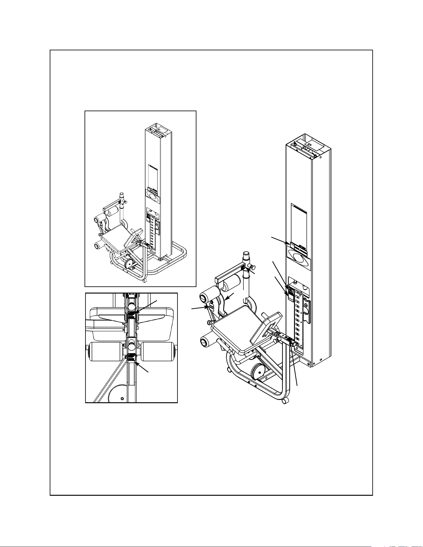
5. Install the Leg Press Assembly to the appropriate configuration (see steps 5A - 5F and
Figures 11 - 13B).
A. Locate the Leg Press assembly and hardware pack.
B. Verify contents of hardware pack. See Figure 11.
Figure 11
13 2 HN784000 Hex Nut .50-13
29 2 JC702820 SHCS .375-16 x 1.25
37 2 JC780420 BHSCS .50-13 x 1.25
41 1 PP090211 Plastic Insert 1.500 Sq x 10-14 G
50 2 JC700917 FHSCS .375-16 x 1.00
57 2 JS388300 Split Lockwasher .500
77 2 PN660201 Hole Plug
ITEM QTY PART NO. DESCRIPTION
37
50
29
77
57
13
41
Cybex Modular Owner’s Manual
Page 4-15
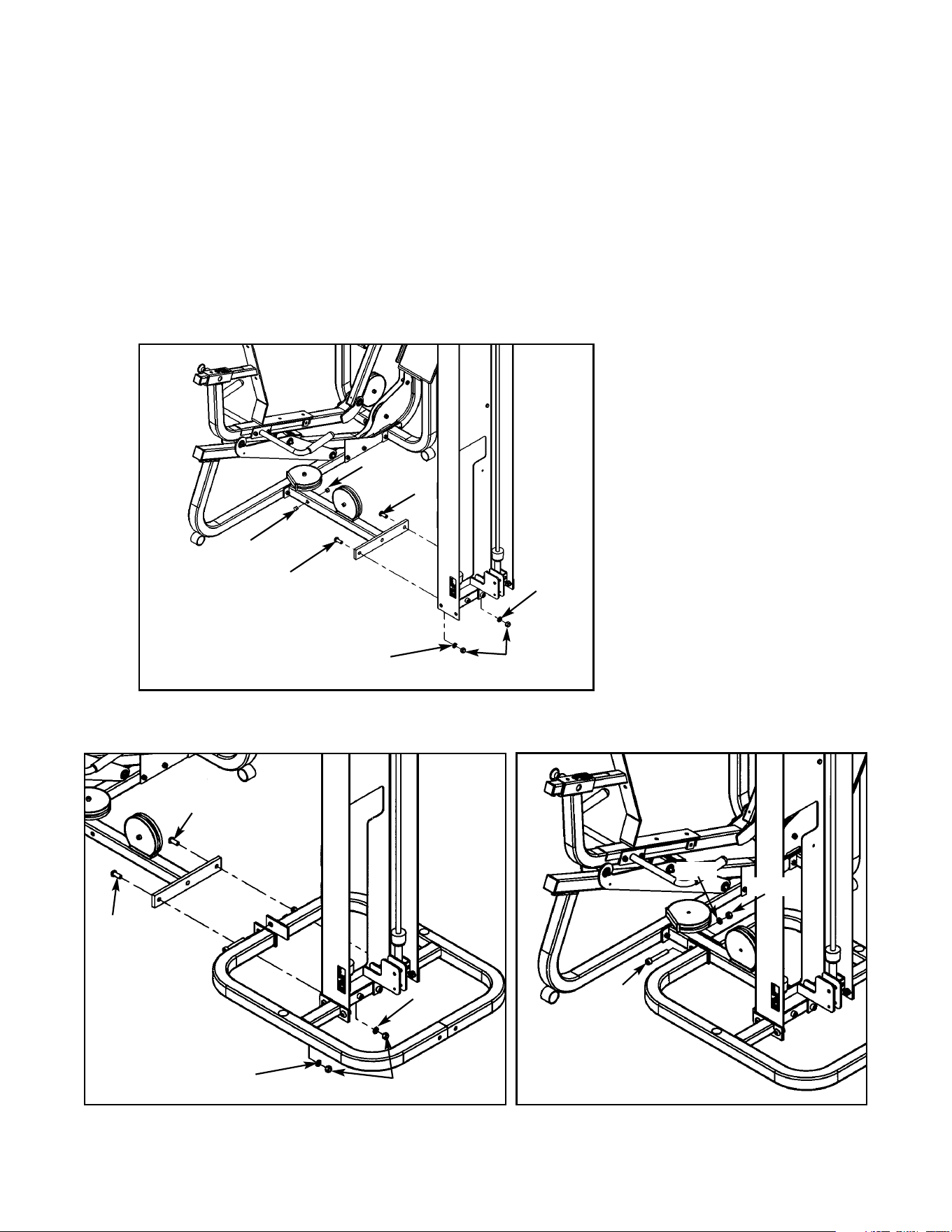
Figure 12
C. Locate two BHSCS .50-13 x 1.25 (#37), two split lockwashers (#57), two hex nuts .50-13
(#13) and two hole plugs (#77). For the Free Standing configuration, also locate (from step 4B)
one SHCS .50-13 x 3.25 (#82D), one split lockwasher .50 (#82E) and one hex nut .50-13
(#82B).
D. Install the Leg Press Assembly to the column. See Figure 12 for Modular/Tandem
configurations and Figures 13A and 13B for Free Standing configuration.
E. Install hole plugs (#77) to the Leg Press Assembly (Modular/Tandem configurations only). See
Figure 12.
Figure 13A
Figure 13B
82D
82E
82B
77
77
57
57
13
37
37
57
57
13
37
37
Cybex Modular Owner’s Manual
Page 4-16
F. For Modular configuration only, see step 4 of the Modular Center Post installation instructions,
part number 55600.
6. Install weight stack (see steps 6A - 6M, Figures 14 and 15).
A. Locate the half weight pin (#61), BHSCS .250-20 x .75 (#75) and split lockwasher (#73) from
the column hardware pack shown in Figure 5.
B. Install the half weight peg as shown in Figure 14.
Figure 14
C. Locate the top weight package and verify the contents. See Figure 15.
2 1 4800-250 Top Weight Assembly
8 1 HP286819 Spiral Pin
12 1 4700M005 Rubber Boot
14 1 5310P044 Weight Selector Pin
21 1 C-ZA00200 Half Weight
ITEM QTY PART NO. DESCRIPTION
Figure 15
75
73
61
2
12
8
14
21
Cybex Modular Owner’s Manual
Page 4-17

D. Verify that you received the appropriate number of weight plates.
E. Remove the two SHCS securing the guide rods.
F. Carefully lean guide rods away from column.
G. Remove guide rod collets and plastic caps.
H. Wipe guide rods clean over entire length. Lubricate with light coating of medium weight
automotive engine oil.
I. Install each weight plate one at a time.
J. Install top weight.
K. Replace plastic caps and guide rod collets on guide rods.
L. Return guide rods to full upright position.
M. Insert both SHCS that were removed in step 6A.
NOTE: Do not secure top weight at this time.
Cybex Modular Owner’s Manual
Page 4-18
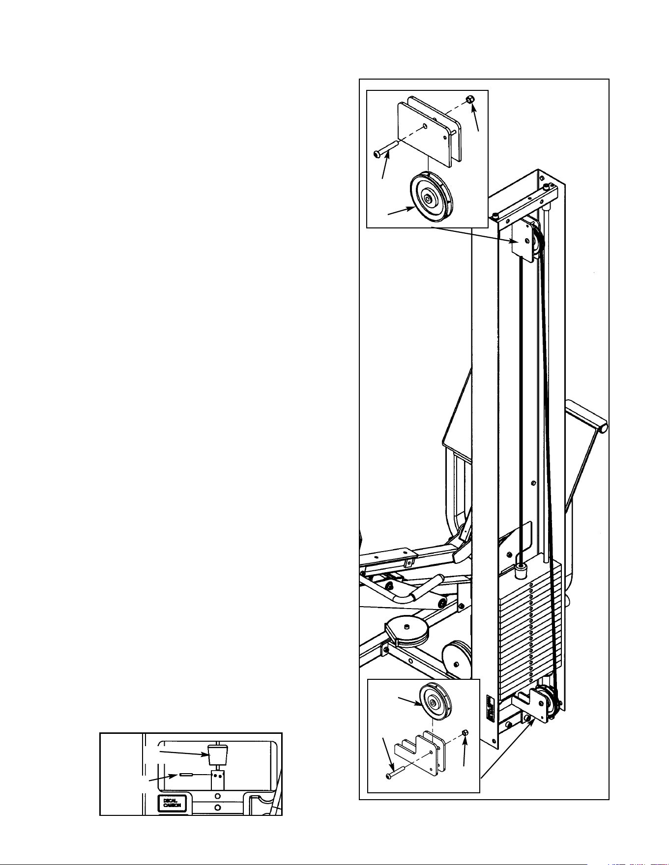
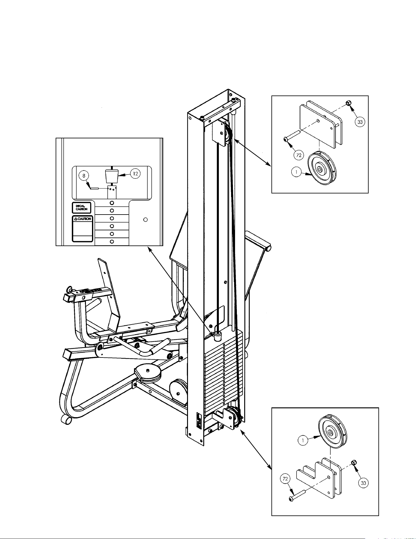
7. Routing Cable - Modular/Tandem configuration
only (see steps 7A - 7I, Figures 16 and 17).
NOTE: For Free Standing configuration see
step 8.
A. Install upper assemblies to any stations within
the Modular/Tandem configuration that
contain upper assemblies. See the Modular
and Tandem installation instructions.
B. Locate two pulleys (#1), two BHSCS .375-16 x
2.50 (#72) and two nylon locknuts .375-16
(#33).
C. At the same time, install pulley to lower pulley
bracket and route cable using one pulley (#1),
one BHSCS .375-16 x 2.50 (#72) and one
nylon locknut .375-16 (#33). See Figure 16.
D. Route cable to upper pulley bracket and
install pulley/route cable using one pulley (#1),
one BHSCS .375-16 x 2.50 (#72) and one
nylon locknut .375-16 (#33). See Figure 16.
E. Route cable downward to top plate.
F. Slide rubber boot (#12) onto cable end. See
Figures 16 and 17.
G. Insert cable end into top weight and align
cable fitting opening with opening in top
weight for proper cable tension as shown in
Figure 17. See the Owner’s Manual for proper
cable adjustment.
H. Using a hammer, drive roll pin (#8) through top
plate connector and cable fitting. Assure pin is
flush with top plate collar.
I. Insert selector pin into each weight plate to
assure proper alignment. See the Cable
Adjustment and Installation section of the
Owner’s Manual if the selector pin does not fit
smoothly or if cable appears to have
excessive slack.
1
72
33
33
72
1
Figure 17
12
8
Cybex Modular Owner’s Manual
Page 4-19

Figure 18
8. Routing Cable - Free Standing configuration only (see steps 8A - 8J and Figures 18 - 22).
A. Locate the back cover (#66), two pulleys (#1), two BHSCS .375-16 x 2.50 (#72), two nylon
locknuts .375-16 (#33), two stop brackets (#68)/bumpers (#42) and two pulley guards (#67).
B. Route cable through lower slot in back cover (#66) and place back cover onto back of
column. See Figure 18.
C. With top part of back cover (#66) leaned back, route cable/install pulley (#1) using one
BHSCS .375-16 x 2.50 (#72) and one nylon locknut .375-16 (#33). See Figure 19.
Figure 19
66
NOTE:Route cable through
back cover onto back
of column.
Cable
Cable
1
72
33
66
Cybex Modular Owner’s Manual
Page 4-20
D. Install lower pulley using one pulleys (#1), one BHSCS .375-16 x 2.50 (#72), one nylon
locknut .375-16 (#33), two stop brackets (#68)/bumpers (#42) and two pulley guards (#67).
See Figure 20.
Figure 20
Figure 22
E. Route cable downward to top plate.
F. Slide rubber boot (#12) onto cable end. See Figure 21.
G. Insert cable end into top weight and align cable fitting
opening with opening in top weight for proper cable
tension as shown in Figure 21. See the Owner’s
Manual for proper cable adjustment.
H. Using a hammer, drive roll pin (#8) through top plate connector and cable fitting. Assure pin is
flush with top plate collar.
I. Insert selector pin into each weight plate to assure proper alignment. See the Cable
Adjustment and Installation section of the Owner’s Manual if the selector pin does not fit
smoothly or if cable appears to have excessive slack.
J. Secure back cover (#66) using weight selector pin (#71). See Figure 22.
1
33
67
67
68
42
42
68
72
71
66
Figure 21
12
8
Cybex Modular Owner’s Manual
Page 4-21
9. Install Weight Plate Decal and Half Weight
(see steps 9A - 9H, Figures 23 and 24).
A. Locate the weight plate decals.
B. Place weight plate decals on weight plates
according to steps listed below and
Figures 23 and 24.
C. Slowly and carefully peel off back side of
decal. NOTE: When peeling off back cover,
make sure that the decals remain attached to
the front sticker.
D. Align holes in decal with appropriate holes in
weight stack. NOTE: Do not allow the
adhesive to touch weight stack at this time.
E. Insert a guide pin through each hole of the
template. NOTE: A guide pin can be any-
thing that fits through the weight stack hole,
such as a weight stack selector pin.
F. Carefully align decal and rub it onto weight
plates.
G. Carefully remove front side, leaving decals
adhering to weight plates. See Figure 24
H. Locate half weight and install it on the half weight peg.
10. Install the back and seat cushions (see steps 10A - 10I and Figures 25 - 28).
A. Locate the cushion box and verify the contents as shown in Figure 25.
Figure 23
Decal
Weight Stack
Guide Rod
Figure 24
Figure 25
6
9
Cybex Modular Owner’s Manual
Page 4-22
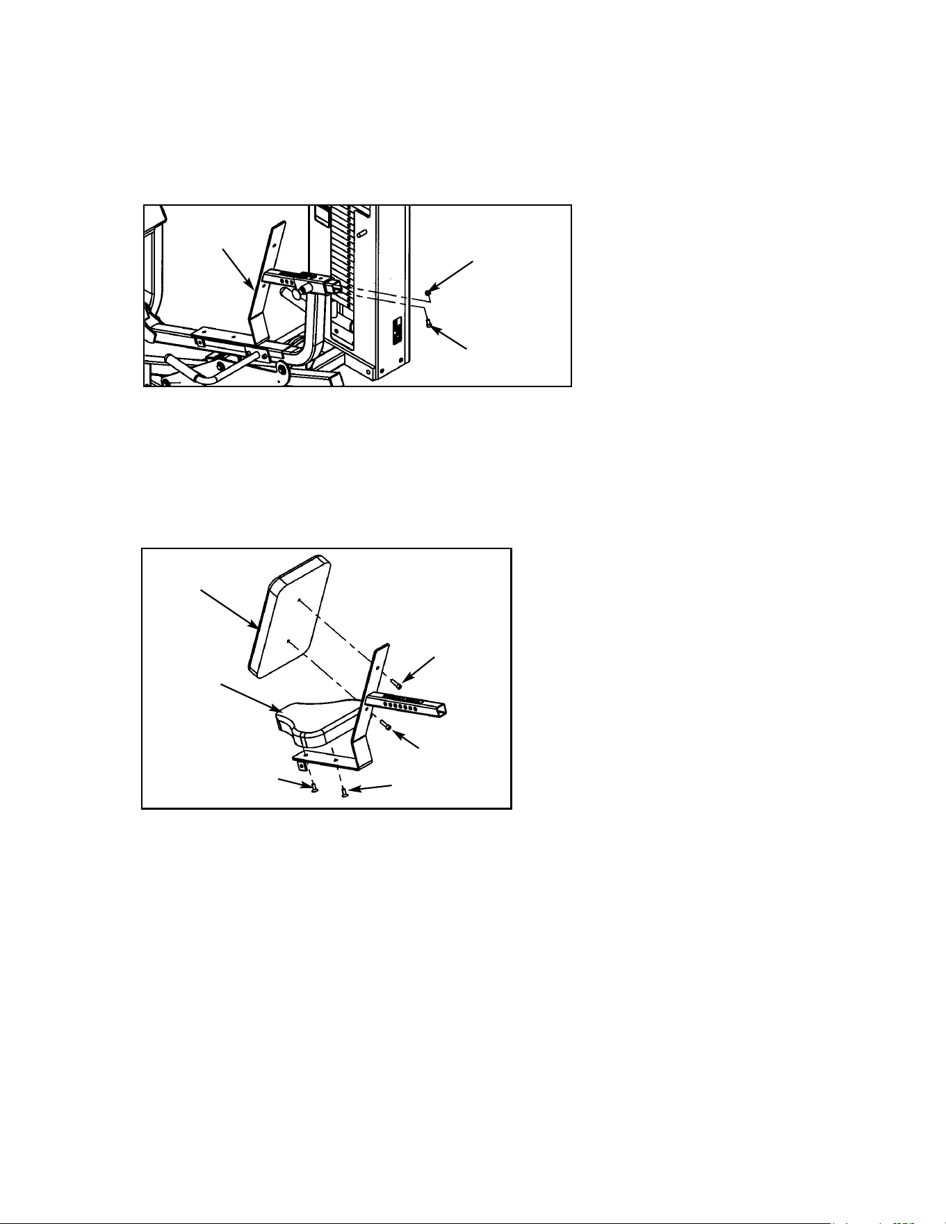
Figure 26
D. Locate seat cushion bracket, back cushion (#6), seat cushion (#9), two FHSCS .375-16 x 1.00
(#50) and two SHCS .375-16 x 1.25 (#29).
E. Install seat and back cushions as shown in Figure 27.
Figure 27
B. Locate the back cushion (#6), seat cushion (#9), two SHCS. .375-16 x 1.25 and two FHSCS
.375-16 x 1.00.
C. Remove the SHCS and nylon locknut securing the cushion post. See Figure 26.
Nylon
Locknut
SHCS
Cushion
Post
6
9
29
29
50
50
Cybex Modular Owner’s Manual
Page 4-23
F. Locate plastic insert (#41).
G. Install cushion assembly onto frame.
H. Secure cushion assembly using SHCS and hex nut (removed from step 10C). See Figure 27.
I. Install plastic insert as shown in Figure 28.
41
Nylon
Locknut
SHCS
Figure 28
11. Verify proper operation.
Cybex Modular Owner’s Manual
Page 4-24
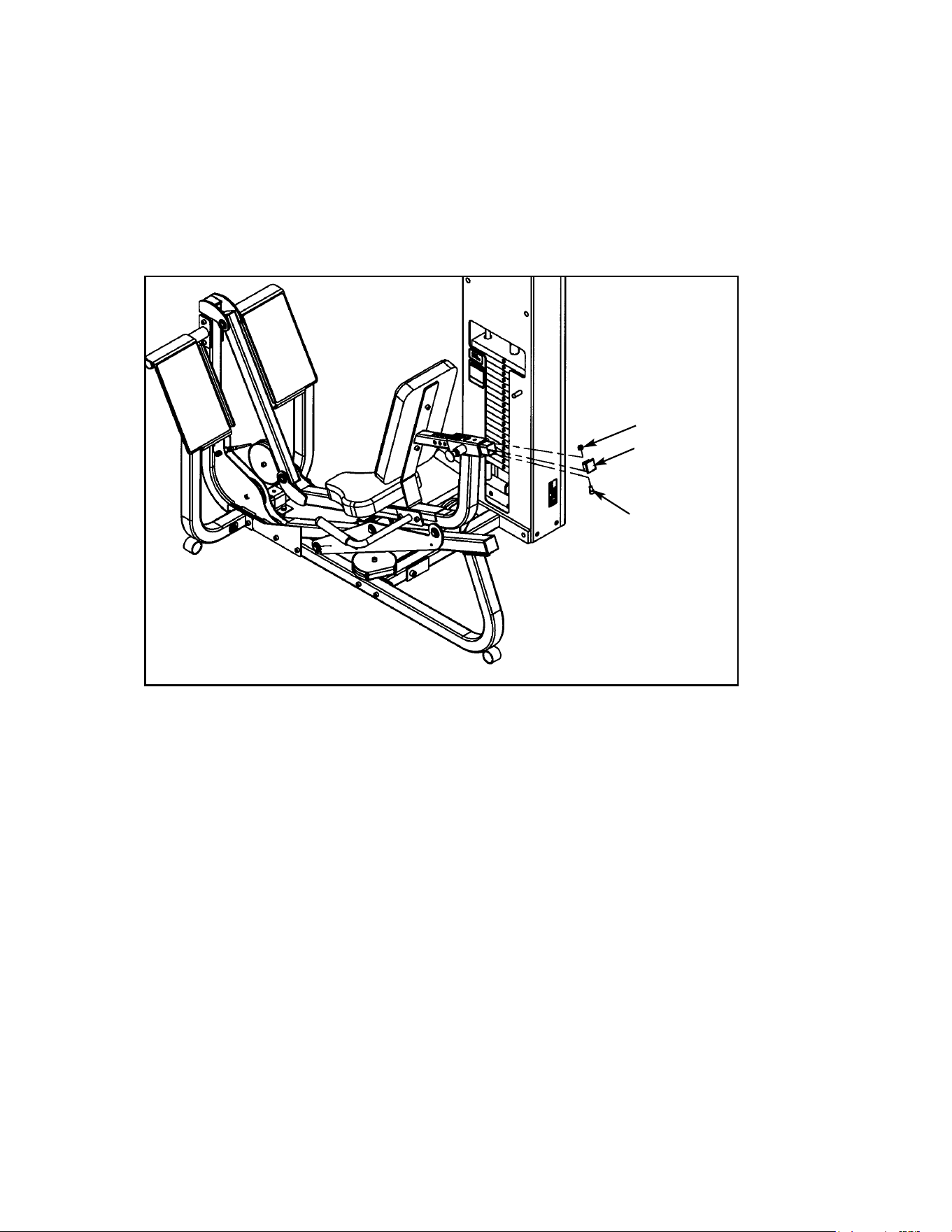
12. Verify warning decals are present and not damaged (see decals below and Figure 28).
WARNING
Notify floor staff if plates are
elevated or jammed to avoid
injury.
02521 A
A
D
B
C
Cybex Modular Owner’s Manual
Page 4-25
A. Warning Decal ................... 4000Y316
B. Caution Decal .................... 4000Y316
C. Warning Decal ................... 4800-381
D. Caution Decal .................... 8500-025
DESCRIPTION PART NO.
D
Figure 28
A
B
C
C
Cybex Modular Owner’s Manual
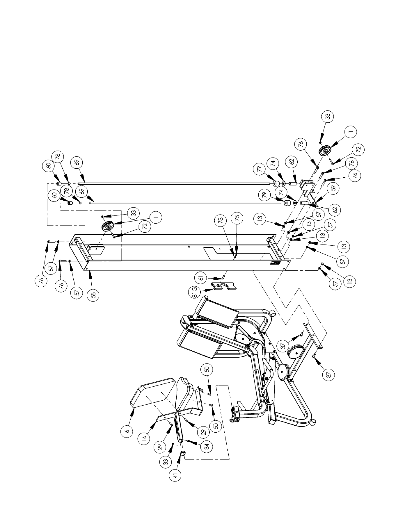
Page 4-26
1 2 08014 Pulley
6 1 4106S055-0 Back Cushion
13 5 HN784000 Hex Nut .50-13
16 1 8630-202 Seat Tube
29 2 JC702820 SHCS .375-16 x 1.25
33 3 HN704901 Nylon Locknut .375-16
34 1 JC702814 SHCS .375-16 x .625
37 2 JC780420 BHSCS .50-13 x 1.25
41 1 PP090211 Plastic Insert 1.50 Sq x 10-14 G
50 2 JC700917 FHSCS .375-16 x 1.00
57 4 JS388300 Split Lockwasher .50
58 1 01243 Column
59 1 01247 Pulley Mount
60 2 01755 Guide Rod Collet
61 1 02106 Half Weight Peg
62 2 02330 Spacer 3.00 Weight
66 1 5301-201 Cover
• 67 2 5301-310 Pulley Guard
• 68 2 5301-311 Stop
69 2 5310M035 Weight Rod .625 Dia. x 85.31
70 1 55652 Instruction Modular Leg Press (not shown)
71 1 5310P044 Weight Select Pin
72 2 HC700430 BHSCS .375-16 x 2.50
73 1 HS308300 Split Lockwasher .25
74 2 HS760106 Flat Washer 1.75 x .68 x .140
75 1 JC620415 BHSCS .25-20 x .75
76 5 JC782830 SHCS .50-13 x 2.50
77 2 PN660201 Plug
78 2 PP080204 Plastic Cap .625 ID x .68 OD
79 2 PR060005 Bumper
80 17 4005C062 Weight Stack 4 x 12
81 1 4700-027 Top Weight Assembly
81B 1 4700M005 Rubber Boot (not shown)
81C 1 4800-256 Top Weight 18-4 x 12
81E 1 5310P044 Weight Selector Pin (not shown)
81G 1 C-ZA000200 Half Weight
• 82 1 5301-51 Modular Base Assembly
• 82A 1 5301-200 Base
• 82B 5 HN78400 Hex Nut .50-13
• 82C 4 JC780417 BHSCS .50-13 x 1.00
• 82D 1 JC782836 SHCS .50-13 x 3.25
• 82E 5 JS388300 Split Lockwasher .50
• 82F 2 PP080202 Plastic Insert 1.19 Dia. x 11 G
5322/5562 - Modular Seated Leg Press
ITEM QTY PART NO. DESCRIPTIONITEM QTY PART NO. DESCRIPTION
• For freestanding units only.
Cybex Modular Owner’s Manual
Page 4-27
5362 - Modular/Tandem Configuration
Cybex Modular Owner’s Manual
Page 4-28
5322 - Free Standing Configuration
Cybex Modular Owner’s Manual
Page 4-29
Cable Routing
Cybex Modular Owner’s Manual
Page 4-30

Cybex Modular Owner’s Manual
Page 4-31
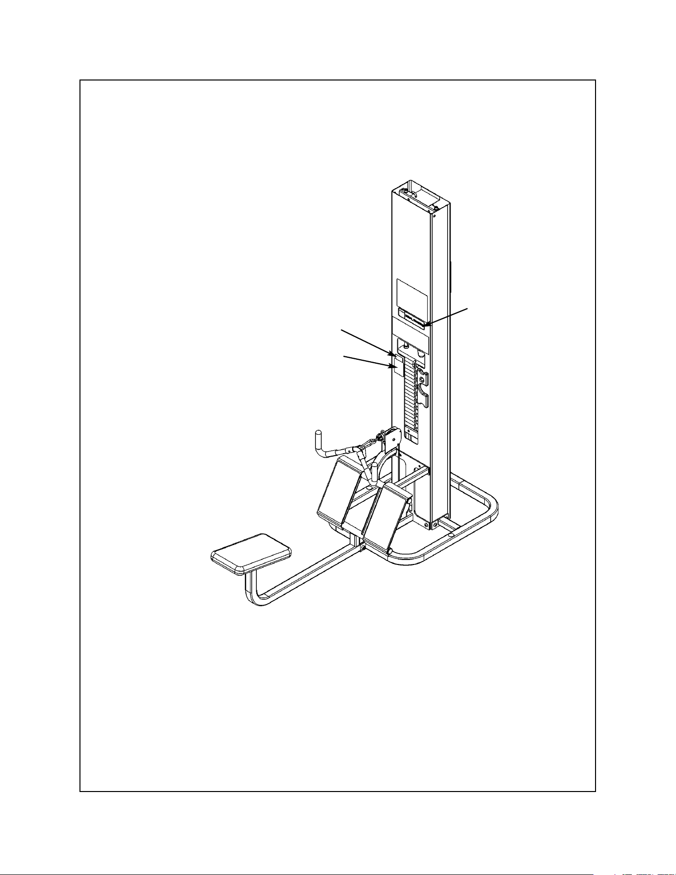
Modular Leg Extension/Leg Curl
5653 Modular/Tandem Configuration
5307 Free Standing Configuration
TOOLS REQUIRED
• 5/32” Allen wrench
• 7/32” Allen wrench
• 5/16” Allen wrench
• 3/8” Allen wrench
• 9/16” Socket/wrench
• 3/4” Socket/wrench
• Rubber mallet
• Step ladder
NOTE: A minimum of two people will be required to assemble the Leg Extension/Leg Curl.
1. Read and understand all instructions thoroughly before assembling the Leg Extension/Leg
Curl (LE/LC) (see steps A - C).
A. Locate the Modular Assembly & Service manual that you received with your order. If you did
not receive a manual contact Cybex Customer Service and ask for part number 55620.
B. If you are assembling the Leg Extension/Leg Curl station into a Tandem configuration, locate
and review the Tandem Center Post instructions contained with the Tandem configuration (this
sheet is also located in the Modular Assembly & Service manual). Skip step 1 in the Tandem
Center Post instructions.
C. If you are assembling the Leg Extension/Leg Curl station into a Modular configuration, locate
and review the Modular Center Post instructions contained with the Modular configuration.
Skip step 1 in the Modular Center Post instructions.
2. Verify you have received the appropriate configuration (see steps 2A - 2C, Figures 1 and 2).
• Hammer
• Utility knife
• Automotive engine oil
Assembly Instructions
Unpacking
A. If you ordered the Modular/Tandem
configuration (5653):
Shipping Package Part Number
• LE/LC Column 5653-9x
• LE/LC Package 5653-50
• Weight Package 4700S040
• Weight Package 4700S043
• Top Weight Package 4700-010
• Cushion Set 8640-011
B. If you ordered the Free Standing
configuration (5307):
Shipping Package Part Number
• LE/LC Column 5307-9x
• LE/LC Package 5653-50
• LE/LC Stabilizer 5302-51
• Weight Package 4700S040
• Weight Package 4700S043
• Top Weight Package 4700-010
• Cushion Set 8640-011
3. Unpack the carton containing the column (see steps 3A - 3F and Figures 3 - 7).
A. Locate and open the Leg Extension/Leg Curl Column carton.
B. The column (#78) should be laying so that the back side is
facing upward.
C. For Free Standing units containing a back cover, remove the
BHSCS .375-16 x 2.00 (#69) securing the back cover (#74).
Remove back cover by sliding it then lifting it upward. See
Figure 3.
D. Remove any shipping supports and the carton located inside the column.
E. Verify contents of the carton. See Figure 4.
Figure 3
69
78
74
Figure 1
Figure 2
C. Carefully place shipping
packages near area of
installation.
D. For Free Standing configurations,
allow a minimum amount 88” x
76”. See Figure 1.
E. For Modular/Tandem
configurations, allow a minimum
of 88” x 67”. See Figure 2.
1 3 08014 Pulley Assembly 4.50
40 1 02120 Pulley Mount
1 Hardware Pack
1 Hardware Pack
ITEM QTY PART NO. DESCRIPTION
40
1
Figure 4
88”
76”
88”
67”
Minimum space required
during operation.
Minimum space required
during operation.
Cybex Modular Owner’s Manual
Page 4-32
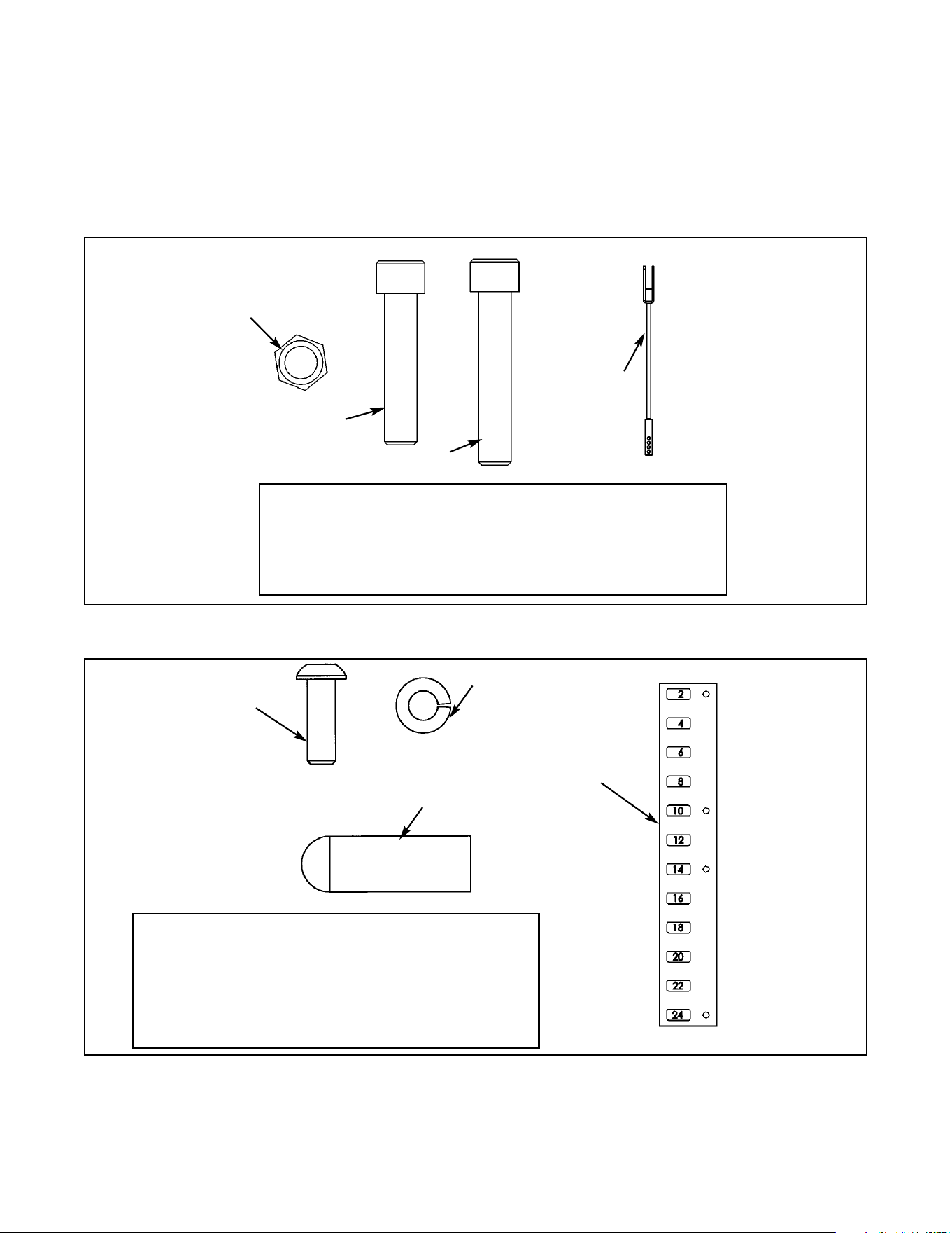
Figure 5
26 1 HC702826 SHCS .375-16 x 2.00
29 3 JC702824 SHCS .375-16 x 1.75
53 1 5653-003 Weight Stack Cable
57 4 HN704901 Nylon Locknut .375-16
ITEM QTY PART NO. DESCRIPTION
57
26
29
F. Remove both hardware packs from the carton and verify the contents of each. See
Figures 5 - 7.
NOTE: Figures 5 and 6 are for the Free Standing configuration.
Figures 6 and 7 are for the Tandem/Modular configuration.
Figure 6
67 1 02106 Half Weight Peg
73 1 4800-515 Weight Plate Decal
82 1 HS308300 Split Lockwasher .25
84 1 JC620415 BHSCS .25-20 x .75
1 55653 Assembly Instructions
ITEM QTY PART NO. DESCRIPTION
82
67
84
73
53
Cybex Modular Owner’s Manual
Page 4-33
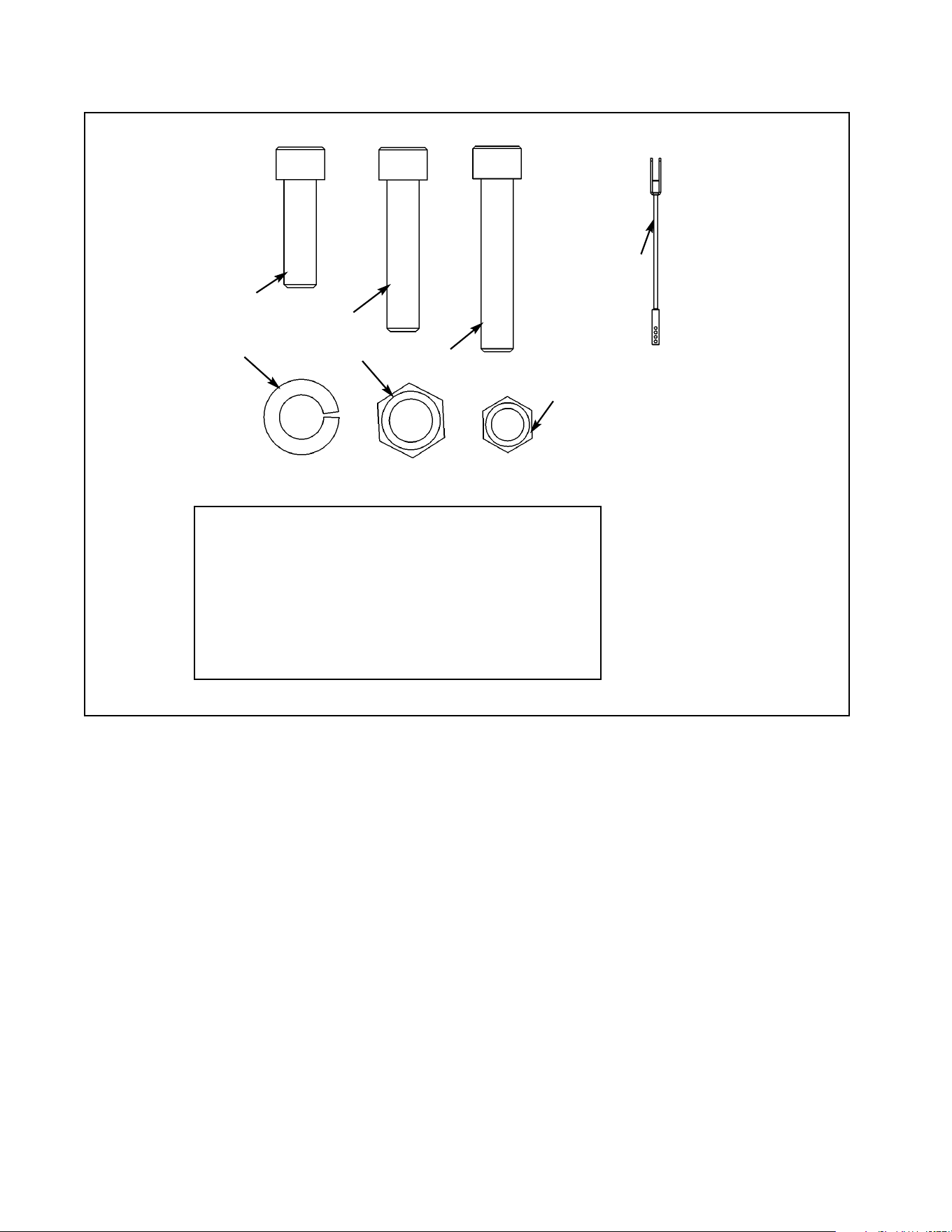
Figure 7
26 1 HC702826 SHCS .375-16 x 2.00
29 3 JC702824 SHCS .375-16 x 1.75
53 1 5653-003 Weight Stack Cable
57 4 HC704901 Nylon Locknut .375-16
59 4 JC702820 SHCS .50-13 x 1.25
64 4 HN784000 Hex Nut .50-13
87 4 JS388300 Split Lockwasher .50
ITEM QTY PART NO. DESCRIPTION
59
29
26
57
64
87
53
Cybex Modular Owner’s Manual
Page 4-34
4. Attach column to the appropriate configuration (see steps 4A - 4F, Figures 8 and 9).
NOTE: For Free Standing configuration, see steps 4A - 4C then go to step 5.
For Tandem configuration see step 4D and 4E then go to step 5.
For Modular configurations see step 4D and 4F then go to step 5.
A. Place the base assembly (#65) in area where the station will be used.
B. Remove the hardware from the base (#65A) as shown in Figure 8.
65 1 5302-51 Base Assembly
65A 1 5301-200 Base
65B 5 HN784000 Hex Nut .50-13
65C 4 JC780417 BHSCS .50-13 x 1.00
65D 1 JC782836 SHCS .50-13 x 3.25
65E 5 JS388300 Split Lockwasher .50
1 Shipping Block
ITEM QTY PART NO. DESCRIPTION
Figure 8
C. With an assistant, carefully place
column (#78) into stabilizer
(#65A) then attach hardware as
shown in Figure 9.
65C
65C
Figure 9
65B
65E
65C
65E
65B
65E
65C
65C
65C
65D
65E
65B
65A
Shipping Block
65E
65A
78
Cybex Modular Owner’s Manual
Page 4-35
D. For Tandem and Modular configurations, locate four SHCS .50-13 x 1.25 (#59), four split
lockwashers .50 (#87) and four hex nuts .50-13 (#64). See Figure 7 (hardware pack).
E. For the Tandem configuration, using the hardware located in step 4D, attach both columns to
frame as shown in the Tandem Center Post & Dome Installation instruction sheet.
NOTE: The generic column shown in the Tandem and Modular instruction sheets will slightly
differ in appearance than the Leg Extension/Leg Curl Column (an angle bracket is used
instead of a tube).
F. For the Modular configuration, using the hardware located in step 4D, install angle braces
onto each column. See the exploded-view diagram shown in the Modular Center Post
Installation Instruction sheet.
5. Install the Leg Extension/Leg Curl Assembly to the appropriate configuration (see steps 5A -
5F and Figures 10 - 12B).
A. Locate the Leg Extension/Leg Curl assembly and hardware pack.
B. Verify contents of hardware pack. See Figure 10.
Figure 10
38 1 HP286819 Spiral Pin
39 1 8640-330 Spring Pin 10 mm x 90 mm Black
60 2 JC780420 BHSCS .50-13 x 1.25
61 2 PN660201 Hole Plug
64 2 HN784000 Hex Nut .50-13
87 2 JS388300 Split Lockwasher .50
90 2 JC702820 SHCS .375-16 x 1.25
ITEM QTY PART NO. DESCRIPTION
87
39
60
64
38
64
61
Cybex Modular Owner’s Manual
Page 4-36
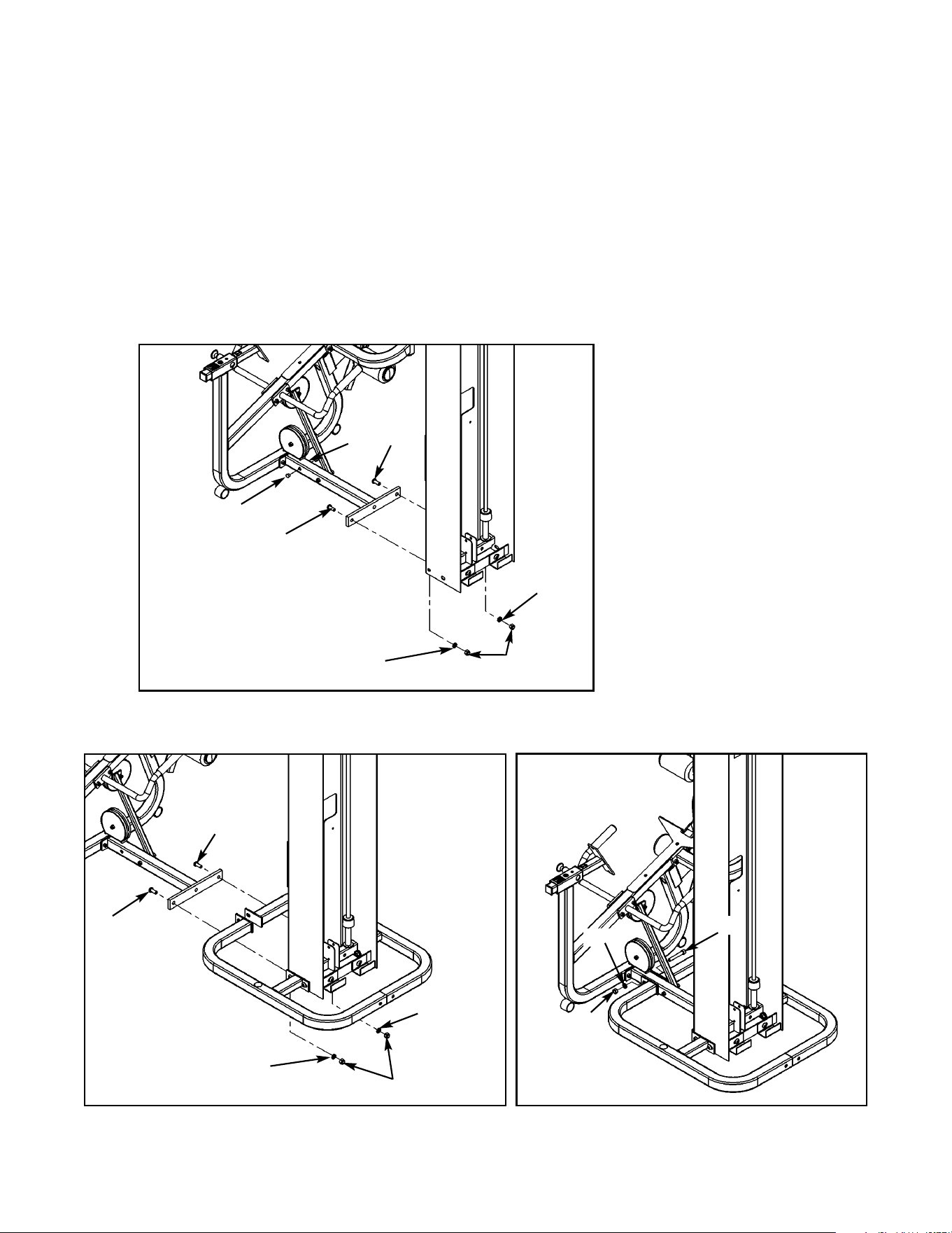
Figure 11
C. Locate two BHSCS .50-13 x 1.25 (#60), two split lockwashers .50 (#87), two hex nuts .50-13
(#64) and two hole plugs (#61). For the Free Standing configuration, also locate (from step 4B)
one SHCS .50-13 x 3.25 (#65D), one split lockwasher .50 (#65E) and one hex nut .50-13
(#65B).
D. Install the Leg Extension/Leg Curl Assembly to the column. See Figure 12 for
Modular/Tandem configurations and Figures 12A and 12B for Free Standing configuration.
E. Install hole plugs (#61) to the Leg Extension/Leg Curl Assembly (Modular/Tandem
configurations only). See Figure 11.
Figure 12A
Figure 12B
65B
65E
65D
60
60
87
87
64
60
60
87
87
64
61
61
Cybex Modular Owner’s Manual
Page 4-37
F. For Modular configuration only, see step 4 of the Modular Center Post installation instructions,
part number 55600.
6. Install weight stack (see steps 6A - 6O, Figures 13 - 15).
A. Locate the half weight peg (#67), BHSCS .25-20 x .75 (#84) and split lockwasher (#82) from
the column hardware pack shown in Figure 5.
B. Install the half weight peg (#67) as shown in Figure 13.
Figure 13
C. Locate the top weight package and verify the contents. See Figure 14.
63 1 4700-010 Top Weight Assembly
63B 1 4700M005 Rubber Boot
63C 1 4700-307 Top Weight 20-4 x 12
63E 1 5310P044 Weight Selector Pin
63G 1 C-ZA00200 Half Weight
63H 1 HP286819 Spiral Pin
ITEM QTY PART NO. DESCRIPTION
Figure 14
84
82
67
63C
63B
63H
63E
63G
Cybex Modular Owner’s Manual
Page 4-38
D. Verify that you received 20 weight plates.
E. Remove the two SHCS securing the guide rods.
F. Carefully lean guide rods away from column.
G. Remove guide rod collets and plastic caps.
H. Wipe guide rods clean over entire length. Lubricate with light coating of medium weight
automotive engine oil.
I. Install each weight plate one at a time. NOTE: Do not install the second weight and top
weight at this time.
J. Locate the spring pin 10 mm x 90 mm black (#39).
K. Slide the top weight plate onto second plate and carefully pound
the spring pin into the second weight plate hole, securing second
plate to the top plate. See Figure 15. NOTE: Insert pin so that it is
flush with the weight plate.
L. Install top weight.
M. Replace plastic caps and guide rod collets on guide rods.
N. Return guide rods to full upright position.
O. Insert both SHCS that were removed in step 6E (securing guide rods).
NOTE: Do not secure top weight at this time.
Figure 15
39
Pin
second
weight
Cybex Modular Owner’s Manual
Page 4-39
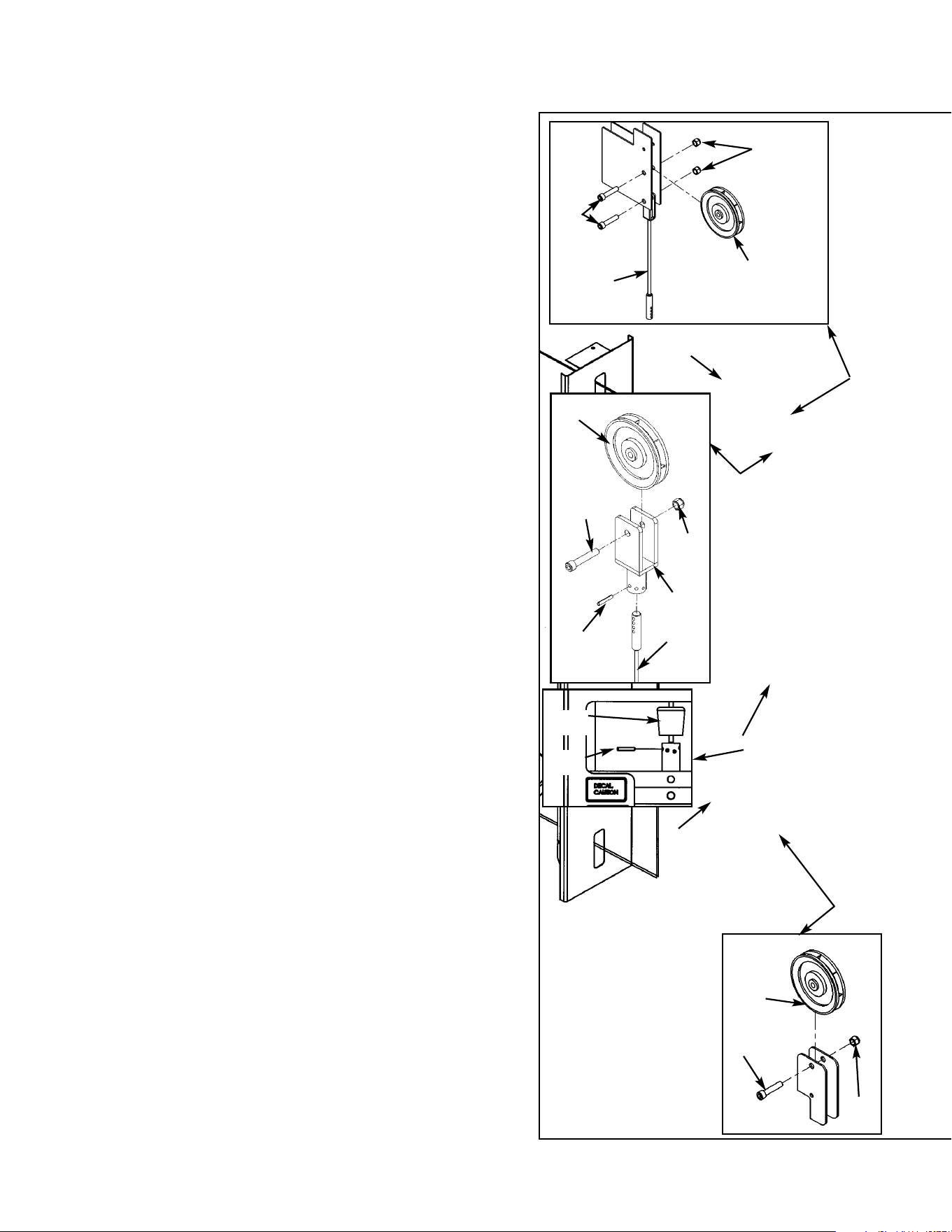
Figure 16
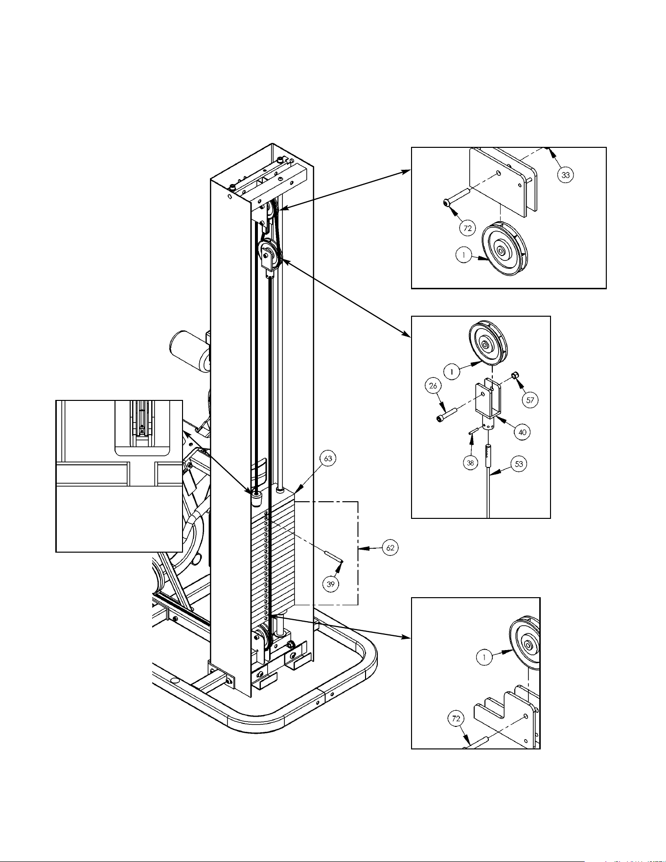
7. Routing Cable (see steps 7A - 7J and Figure 16).
A. Install upper assemblies to any stations within the
Modular/Tandem configuration that contain upper
assemblies. See the Modular and Tandem
installation instructions.
B. Locate weight stack cable (#53), four pulleys (#1),
pulley mount (#40), three SHCS .375-16 x 1.75
(#29), one SHCS .375-16 x 2.00 (#26) and four
nylon locknuts .375-16 (#57) and one spiral pin
(#38).
C. Route cable to inside of column (#78). See Figure
16, letter D.
D. At the same time, install pulley to lower pulley
bracket and route cable (#53) using one pulley
(#1), one SHCS .375-16 x 1.75 (#29) and one
nylon locknut .375-16 (#57). See Figure 16,
letter D. Set cable down.
E. Attach one end of the weight stack cable (#53) to
the frame as shown in Figure 16 (using one SHCS
.375-16 x 1.75 (#29) and one nylon locknut .375-
16 (#57). See Figure 16, letter E.
F. NOTE: Do not install hanging pulley in this step.
At the same time, route cable (#53) and install the
last pulley before the weight stack (using one
SHCS .375-16 x 1.75 (#29) and one nylon locknut
.375-16 (#57). See Figure 16, letter F.
G. Pick up the other cable and install the pulley
mount (#40). Drive a spiral pin (#63H) through
cable end and pulley mount as shown in Figure
16, letter G.
H. Wrap a portion of the weight stack cable (#53)
around the last pulley (#1) to be installed. At
the same time, route cable (#53) and install
pulley (#1) using one SHCS .375-16 x 2.00
(#26) and one nylon locknut (#57).
I. Route cable downward to top plate. Slide rubber
boot (#63B) onto cable. Drive a spiral pin through
top plate connector and cable end. The top
weight should be snug (just resting on the next
plate). See Figure 16, letter H.
J. Slide rubber boot over top weight connector.
1
53
57
57
29
1
29
1
26
57
53
38
C
D
I, J
E, F
G
63B
63H
78
40
NOTE:
See the Modular
Assembly & Service
Manual for proper roll
pin adjustment (if
necessary).
Cybex Modular Owner’s Manual
Page 4-40
K. For Free Standing units, place back cover (#74) to column (#78) into position (bottom first)
and secure using the BHSCS .375-16 x 2.00 (#69) that was removed from step 3C. See
Figure 17.
Figure 17
69
74
78
Cybex Modular Owner’s Manual
Page 4-41
8. Install Weight Plate Decal and Half Weight
(see steps 9A - 9H, Figures 19 and 20).
A. Locate the weight plate decals.
B. Place weight plate decals on weight plates
according to steps listed below and Figures
18 and 19.
C. Slowly and carefully peel off back side of
decal. NOTE: When peeling off back cover,
make sure that the decals remain attached to
the front sticker.
D. Align holes in decal with appropriate holes in
weight stack. NOTE: Do not allow the
adhesive to touch weight stack at this time.
E. Insert a guide pin through each hole of the
template. NOTE: A guide pin can be any-
thing that fits through the weight stack hole,
such as a weight stack selector pin.
F. Carefully align decal and rub it onto weight
plates.
G. Carefully remove front side, leaving decals
adhering to weight plates. See Figure 19.
H. Locate half weight and install it on the half weight peg.
10. Install the back and seat cushions (see steps 10A - 10I and Figures 20 - 21).
A. Locate the cushion box and verify the contents as shown in Figure 20.
Figure 18
Decal
Weight Stack
Guide Rod
Figure 19
Figure 20
36
37
11
33
Cybex Modular Owner’s Manual
Page 4-42
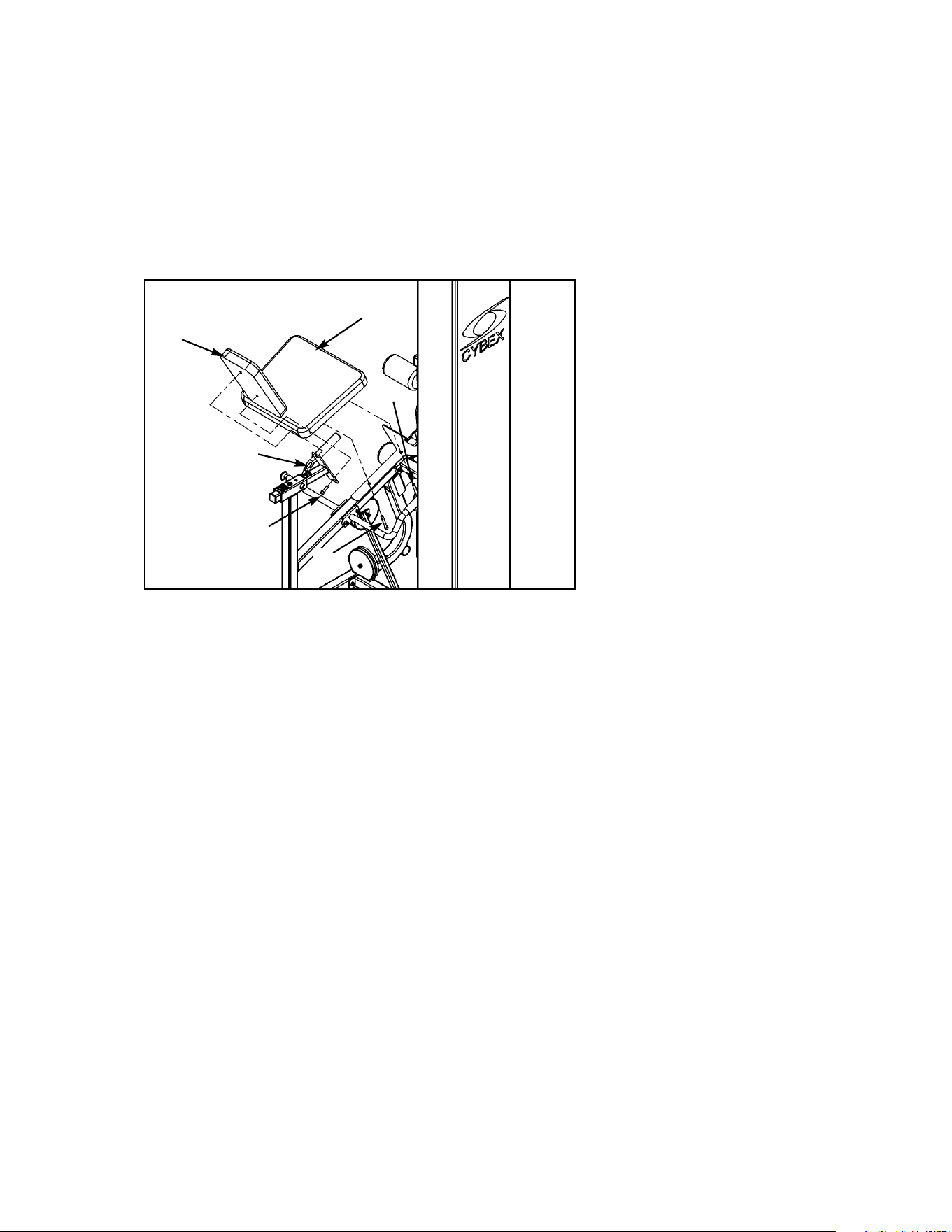
Figure 21
B. Locate the back cushion (#36), seat cushion (#37), four cushions 4.00 Dia. x 7.00 L x .875
(#11), four plastic inserts (#33) and two SHCS .375-16 x 1.25 (#59).
C. Install back cushion (#36) using two SHCS .375-16 x 1.25 (#59) as shown in Figure 21.
D. Install seat cushion (#37) using two SHCS .375-16 x 3.00 (#27) secured into the frame.
Remove the hex nut and washer then install each SHCS into the cushion. See Figure 21.
37
90
36
27
90
27
Cybex Modular Owner’s Manual
Page 4-43
11. Verify proper operation.
12. Verify warning decals are present and not damaged (see decals below and Figure 22).
WARNING
Notify floor staff if plates are
elevated or jammed to avoid
injury.
02521 A
A
D
B
C
E
Cybex Modular Owner’s Manual
Page 4-44
A. Warning Decal ................... 02521
B. Caution Decal .................... 4000Y316
C. Warning Decal ................... 4800-381
D. Caution Decal .................... 8500-025
E. Caution Decal .................... 8500-026
DESCRIPTION PART NO.
D
Figure 22
A
B
C
D
D
E
D
E
Cybex Modular Owner’s Manual
Page 4-45

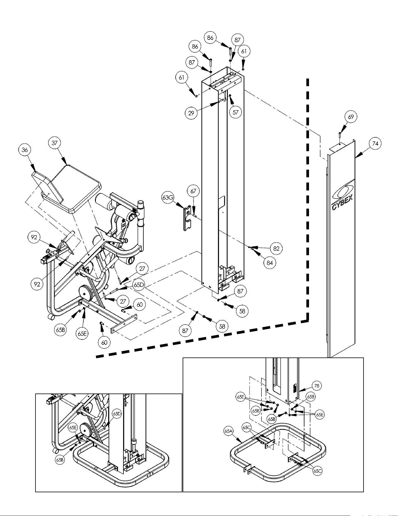
1 3 08014 Pulley
26 2 HC702826 SHCS .375-16 x 2.00
27 2 HC702834 SHCS .375-16 x 3.00
29 3 JC702824 SHCS .375-16 x 1.75
36 1 4800-021 Back Cushion
37 1 4800-015 Seat Cushion
38 1 HP286819 Spiral Pin
39 1 8640-330 Spring pin 10 mm x 90 mm Black
40 1 02120 Pulley Mount
53 1 5653-003 Weight Stack Cable
57 3 HN704901 Nylon Locknut .375-16
58 2 HN784900 Nylon Locknut .50-13
59 4 JC782820 SHCS .375-16 x 1.25
60 2 JC780420 BHSCS .50-13 x 1.25
61 2 PN660201 Hole Plug
62 20 4000C062 Weight Plate 4 x 12
63 1 4700-010 Top Weight Assembly
63A 2 4700-019 Bearing Flange .62 x .92 x 1.50 Lg
63B 1 4700M005 Rubber Cap
63C 1 4700-307 Top Weight 20-4 x 12
63D 1 4700M004 Cable Connector
63E 1 5310P044 Weight Selector Pin
63F 2 BR030206 Retaining Ring
63G 1 C-ZA000200 Half Weight
63H 1 HP286819 Spiral Pin
64 4 HN784000 Hex Nut .50-13
65 1 5302-51 Modular Base Assembly
65A 1 5301-200 Base
65B 5 HN784000 Hex Nut .50-13
65C 4 JC780417 BHSCS .50-13 x 1.00
65D 1 JC782836 SHCS .50-13 x 3.25
65E 5 JS388300 Split Loackwasher .50
66 2 01755 Guide Rod Collet - Long
67 1 02106 Half Weight Peg
69 1 HC700426 BHSCS .375-16 x 2.00
74 1 5310C029 Back Cover
75 2 5310M035 Weight Rod .625 Dia. x 85.31
78 1 5653-200 Column
79 2 5653-302 Weight Spacer 4.00
82 1 HS308300 Split Lockwasher
83 4 HS760106 Flat Washer 1.75 .688 .140 T
84 1 JC620415 BHSC .25-20 x .75
86 2 JC782830 SHCS .50-13 x 2.50
87 6 JS388300 Split Lockwasher .50
88 2 PP080204 Plastic Cap .625 ID x .68 OD
89 2 PR060005 Bumper Weight
90 2 JC7082820 SHCS .375-16 x 1.25
5307/5653 - Leg Extension/Leg Curl Station
ITEM QTY PART NO. DESCRIPTION ITEM QTY PART NO. DESCRIPTION
Cybex Modular Owner’s Manual
Page 4-46
Tandem/Modular Configuration
Free Standing Configuration
Cybex Modular Owner’s Manual
Page 4-47
Cable Routing
Cybex Modular Owner’s Manual
Page 4-48
All preventive maintenance activities must be performed on a regular basis. Performing
routine preventive maintenance actions can aid in providing safe, trouble-free operation of all
Cybex Strength Systems equipment.
NOTE: Cybex is not responsible for performing regular inspection and maintenance actions
for your machines. Instruct all personnel in equipment inspection and maintenance
actions and also in accident reporting/recording. Cybex phone representatives are
available to answer any questions or concerns that you may have.
Page 5-1
1. Upholstery - Wipe down all upholstery as per the recommendations listed below for light
soiling and more difficult stains.
Light Soiling
• A solution of 10% household liquid dish soap with warm water applied with a soft damp
cloth.
• If necessary, a solution of liquid cleanser and water applied with a soft bristle brush.
Wipe away the residue with a water dampened cloth.
Chapter 5 - Maintenance
Daily Procedures
NOTE: All inspections
and repairs must be
performed by trained
service personnel only.
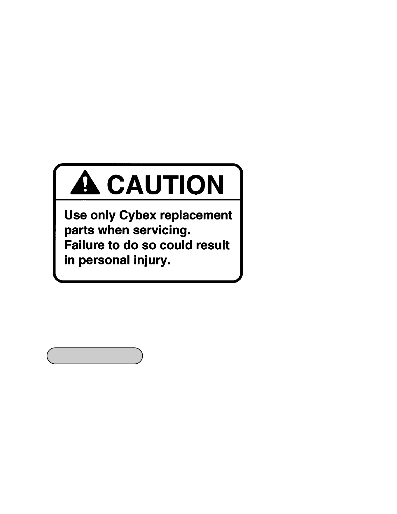
Cybex will void warranty if
non-Cybex replacement parts
are used.
Cybex Modular Owner’s Manual

Page 5-2
More Difficult Stains
• Dampen a soft white cloth with a solution of household bleach (sodium hypochlorite),
10% bleach, 90% water. Rub gently. Rinse with a water dampened cloth to remove
bleach concentration.
• The same procedure can be used with full strength household bleach, if necessary.
• Allow bleach to puddle on the affected area or apply with a soaked cloth for
approximately 30 minutes. Rinse with a water dampened cloth to remove any remaining
bleach concentration.
Alternative Method for Difficult Stains
• Dampen a soft white cloth with rubbing alcohol and rub gently. Rinse with a water
dampened cloth to remove any remaining rubbing alcohol concentration.
NOTE: To restore luster, a light coat of spray furniture wax can be used. Apply for 30
seconds and follow with a light buffing using a clean white cloth.
Please Review Carefully
When using strong cleaning agents such as rubbing alcohol or bleach, it is advisable to
first test in an inconspicuous area. Other cleaning agents may contain harsh or unknown
solvents and are subject to formula changes by the product manufacturer without notice.
Should you desire to use other cleaning agents, carefully try them in an inconspicuous
area to determine potential damage to the material. Never use harsh solvents or cleaners
which are intended for industrial applications. To clean stained or soiled areas, a soft white
cloth is recommended. Avoid use of paper towels.
Cleaning products may be harmful/irritating to your skin, eyes, etc. Use protective gloves
and eye protection. Do not inhale or swallow any cleaning product. Protect surrounding
area/clothing from exposure. Use in a well ventilated area. Follow all product
manufacturer’s warnings. Cybex and its vendors cannot be held responsible for damage
or injuries resulting from the use or misuse of cleaning products.
2. Frames - Wipe down all frames using a mild solution of warm water and car wash soap.
Be sure to dry thoroughly. AVOID acid or chlorine based cleaners and also cleaners
containing abrasives as these could scratch or damage the equipment.
3. Chrome - Clean chrome tubes, first using chrome polish and then using a car wax seal.
Neutral cleaners with a pH between 5.5 and 8.5 are recommended. Be sure to dry
thoroughly. AVOID acid or chlorine based cleaners and also cleaners containing abrasives
as these could scratch or damage the equipment.
Cybex Modular Owner’s Manual

Cybex Modular Owner’s Manual
4. Guidelines for cleaning front panel:
• Use clean soft cloths or sponges for application of cleaners and again for washing and
rinsing.
• Follow up the application with warm water rinse.
• Don’t use abrasives or high alkaline cleaners.
• Don’t leave cleaners on for long periods, wash immediately.
• Don’t apply cleaners in direct sunlight or at elevated temperatures.
• Don’t use scrapers, squeegees or razors.
• Don’t clean with gasoline.
Compatible Cleaners and Detergents:
• Formula 409
• Top Job
• Joy
• Palmolive
• Windex with Ammonia D
To Minimize Fine or Hairline Scratches:
Mild automotive polish applied and removed with a soft, clean cloth will help fill scratches.
Suggested Polishes:
• Johnson Paste Wax
• Mirror Glaze #10 Plastic Polish (by Mirror Bright Polish Co.)
• Novus Plastics Polish #1, #2 (by Novus Inc.)
Page 5-3
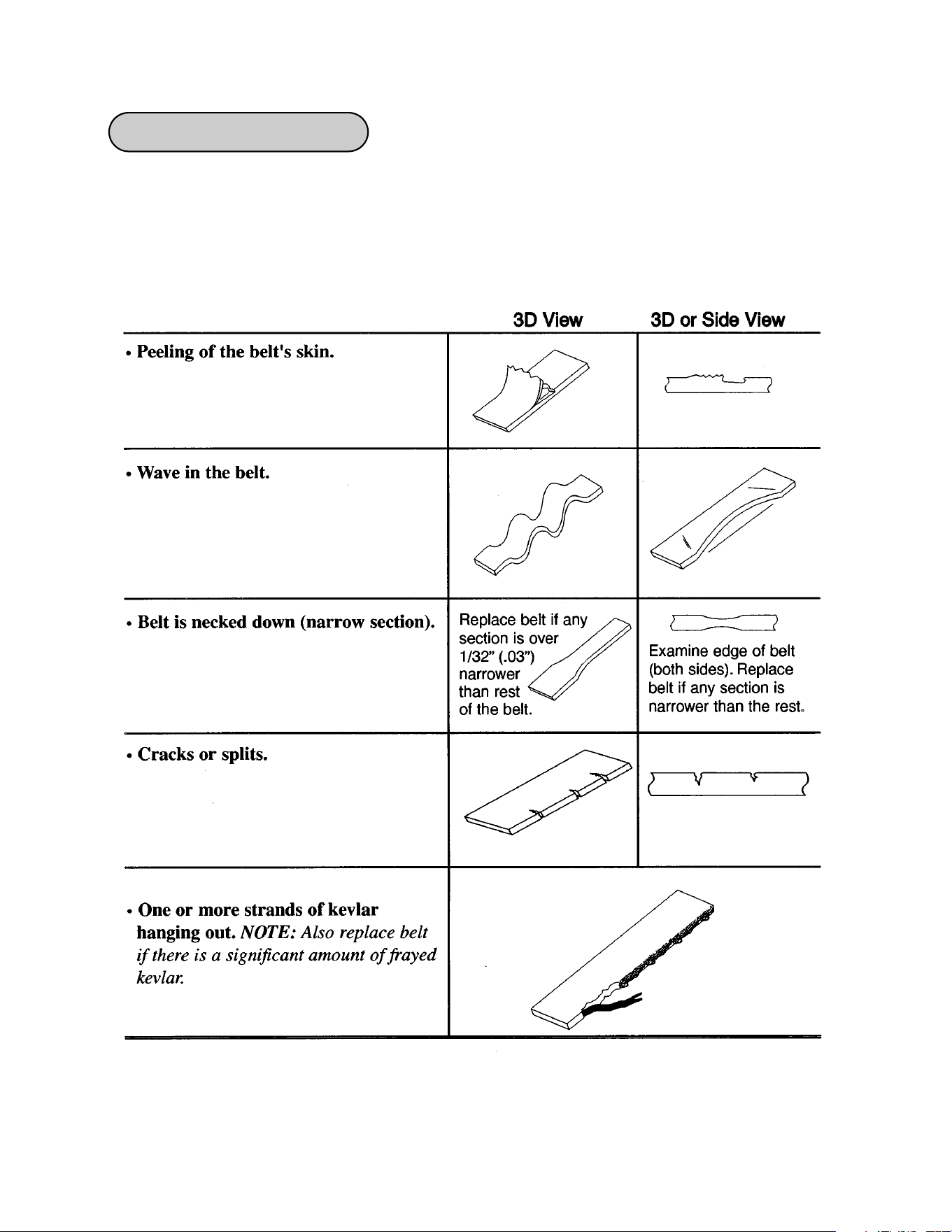
1. Check all nuts and bolts for looseness. Tighten as required.
2. Inspect all belts (entire length) for any non-uniformity and wear.
Immediately replace belt if any of the following conditions are present:
Weekly Procedures
Cybex Modular Owner’s Manual
Page 5-4
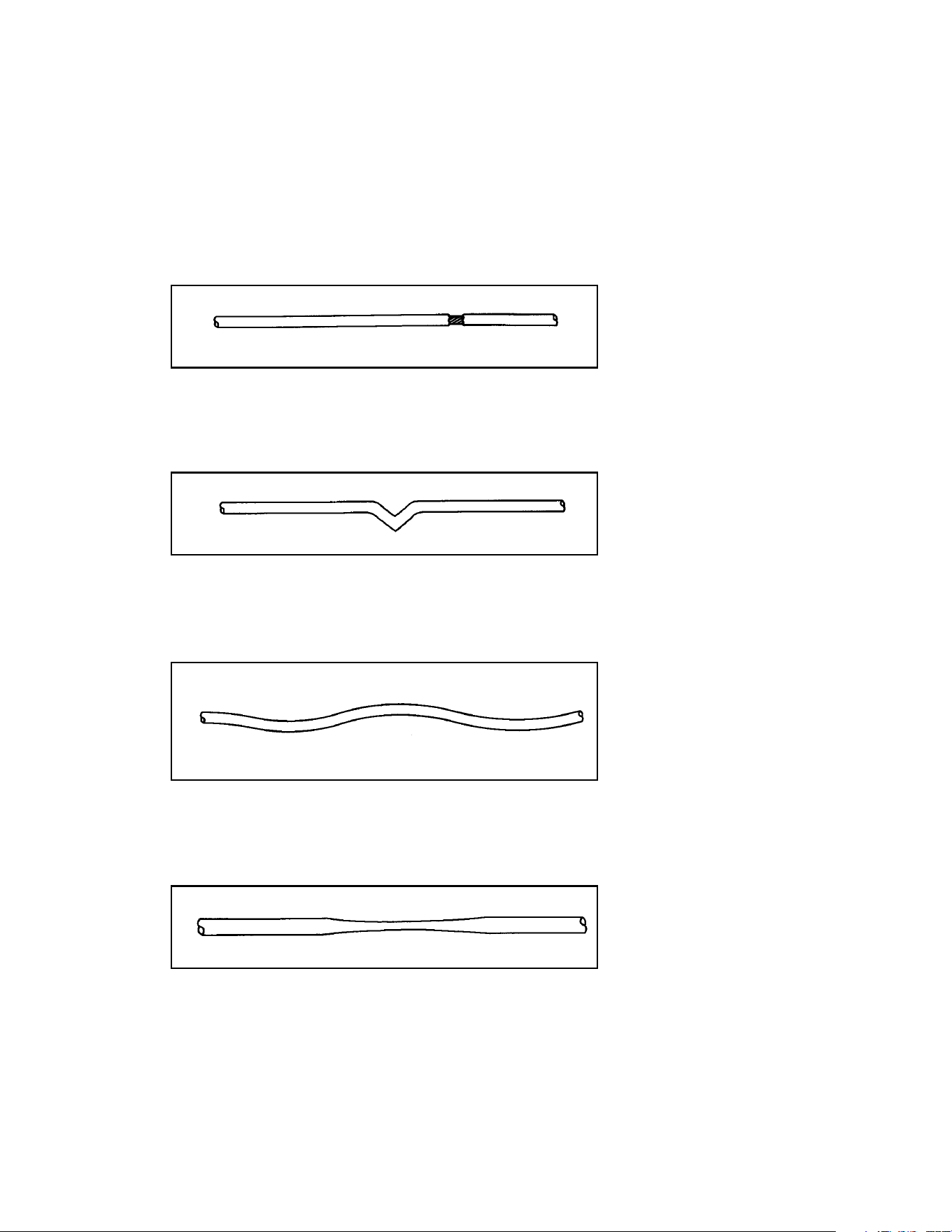
3. Some machines use cables in addition to belts. Inspect all cables for wear or damage and
proper tension. When inspecting cables, run your fingers on the cable, paying particular
attention to bends in the cable and attachment points.
Replace all worn cables immediately. The following conditions may indicate a worn
cable:
• A tear or crack in the cable sheath that exposes the cable. See Figure 1
• A kink in the cable. See Figure 2.
• A curled sheath. See Figure 3.
• “Necking”, a stretched cable sheath. See Figure 4.
Figure 1
Figure 2
Figure 3
Figure 4
Cybex Modular Owner’s Manual
Page 5-5

1. Replace all belts and cables at least annually.
Yearly Procedures
4. Inspect bars and handles for wear, paying particular attention to tab area connecting
points.
Replace all worn handles immediately.
5. Inspect snap links for proper latching (indicates wear).
Replace all worn snap links immediately.
6. Inspect all labeling for readability. This includes instructional placards, warning and
caution decals.
Replace all worn labeling immediately.
7. Inspect all weight stacks for proper alignment and operation.
Correct all improper alignment and operation issues immediately.
8. Wipe Weight Stack Guide Rods clean over entire length. Lubricate with a light coat of
medium weight automotive engine oil.
1. Inspect grips and replace as necessary.
“As Required” Procedures
Cybex Modular Owner’s Manual
Page 5-6
6 - Assembly and Service
Please refer to the next several pages for parts lists, exploded-view diagrams and cable
routing diagrams.
NOTE: All
inspections and
repairs must be
performed by
trained service
personnel only.
Cybex will void warranty if
non-Cybex replacement parts
are used.
Page 6-1
Cybex Modular Owner’s Manual

Page 6-2
Cybex Modular Owner’s Manual
This page intentionally left blank
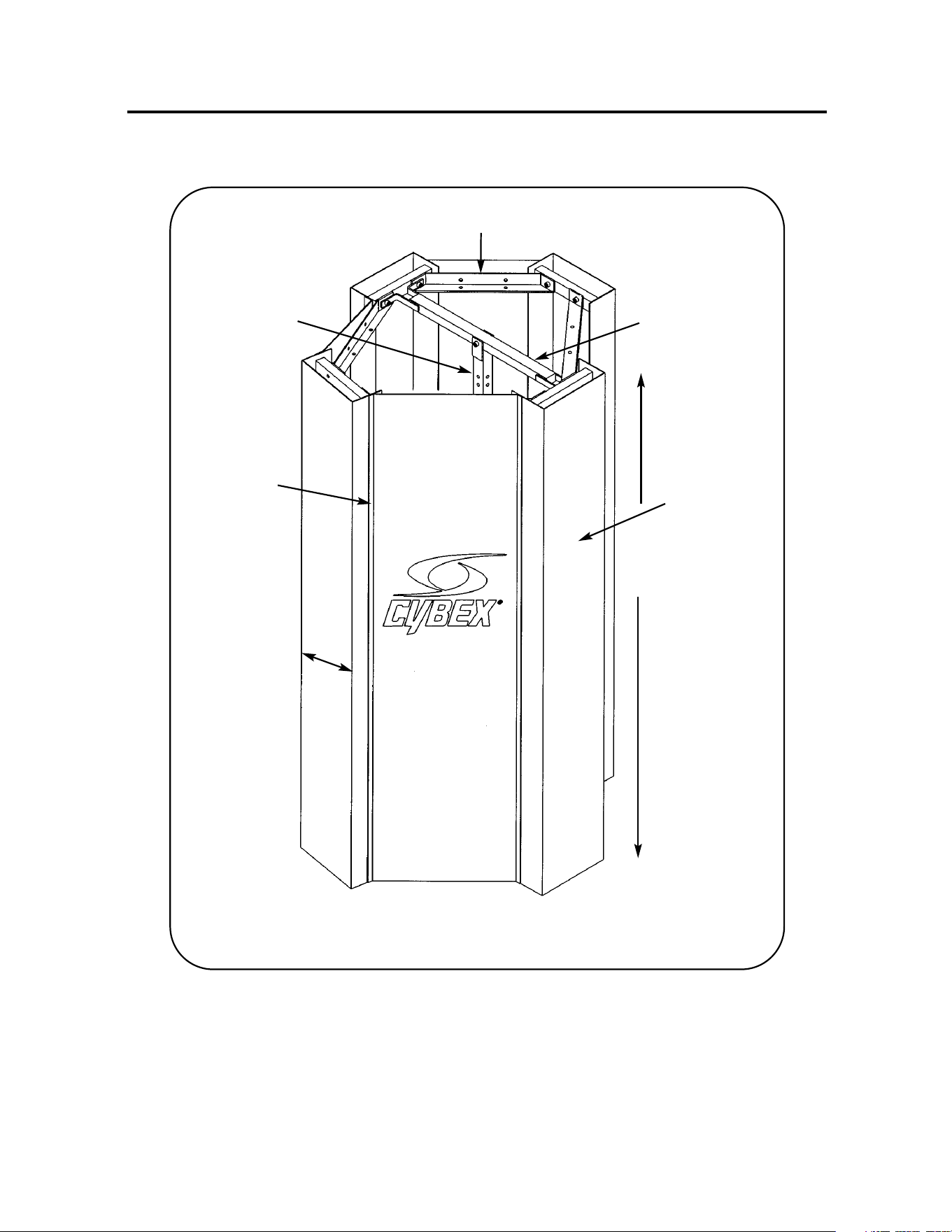
MODULAR CENTER POST
5600 ASSEMBLY & PARTS
Cross Brace
Center Post
Column
Perforated
Panel
Angle Brace
7’ 6”
1’ 1”

5600 - Modular Center Post
1 1 01543 Upright Tube (Center Post)
2 2 01544 Cross Brace
3 18 HN784000 Hex Nut .50-13
4 2 JC782838 SHCS .50-13 x 3.50
5 18 JS388300 Split Lockwasher .50
6 8 01062 Angle Brace
7 4 02215 Magnetic Edge Guard (RH)
8 16 JC782834 SHCS .50-13 x 3.00
9 4 02214 Magnetic Edge Guard (LH)
10 24 HT552510 Self Tapping Phillips Screw 6-20 x .375
11 1 01547 Modular Dome Cover
ITEM QTY PART NO. DESCRIPTION
Assembly Notes
NOTE: (1) Two people will be required to assemble center post.
(2) Unless otherwise specified, leave all nuts and bolts loose until end
of assembly.
1. If ceiling is less than 10 feet then install weight stacks and skip step 5.
Otherwise, if ceiling is greater than 10 feet then do not install weight stacks
until step 5.
2. Install angle braces (item 6) onto column as shown in the exploded-view
diagram.
3. Install lower assemblies for each Modular station to columns.
4. Install center post (item 1) and each upper cross brace (item 2).
5. Install weight stacks utilizing short guide rods. Attach cable to weight stack.
6. Install upper assemblies for each Modular station.
7. Route cable for each Modular station.
8. Install body weight stations (if used).
9. Attach the left hand magnetic edge guard and right hand magnetic edge guard
to perforated panel. Repeat this step for each panel.
See PANEL ASSEMBLY TOP VIEW.
10. Install all perforated panels. See INSTALLATION OF PANELS.
NOTE: The letters in the exploded-view diagram refer to the installation of
perforated panels.
11. Install all upholstery.
NOTE: This machine shipped with an Owner’s Manual. Additional copies can be obtained by
contacting your dealer or a Cybex Representative at 1-888-462-9239.
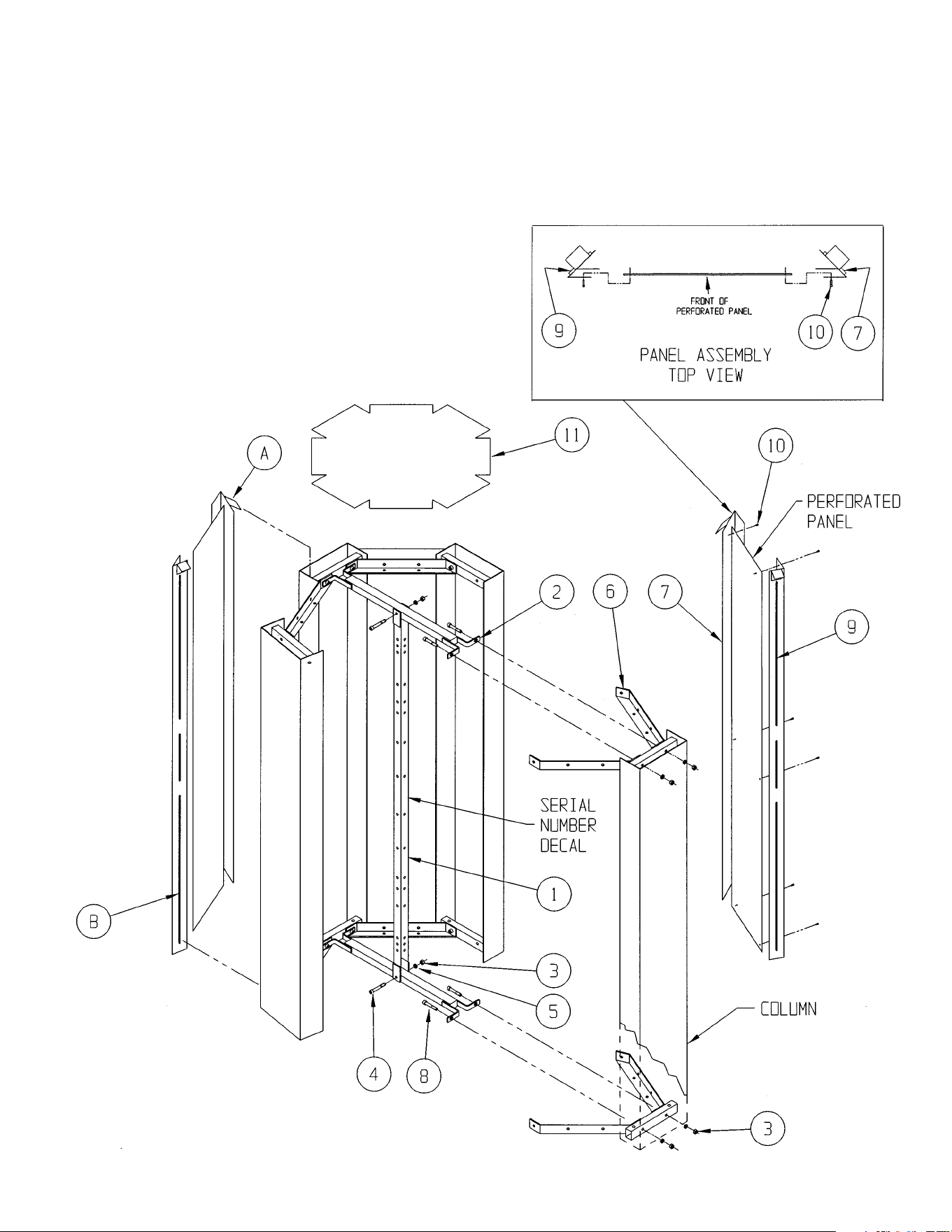
NOTE: The letters in the exploded-view
diagram refer to the installation of
perforated panels.
Installation of Panels
A. Place hook over edge of column.
B. Place magnetic edge strip against column.

10 Trotter Drive Medway, MA 02053 • 508-533-4300 • FAX 508-533-5183 • www.cybexinternational.com • T[email protected]
Copyright © 2002 CYBEX International, Inc. All rights reserved • 55600 • June 2004
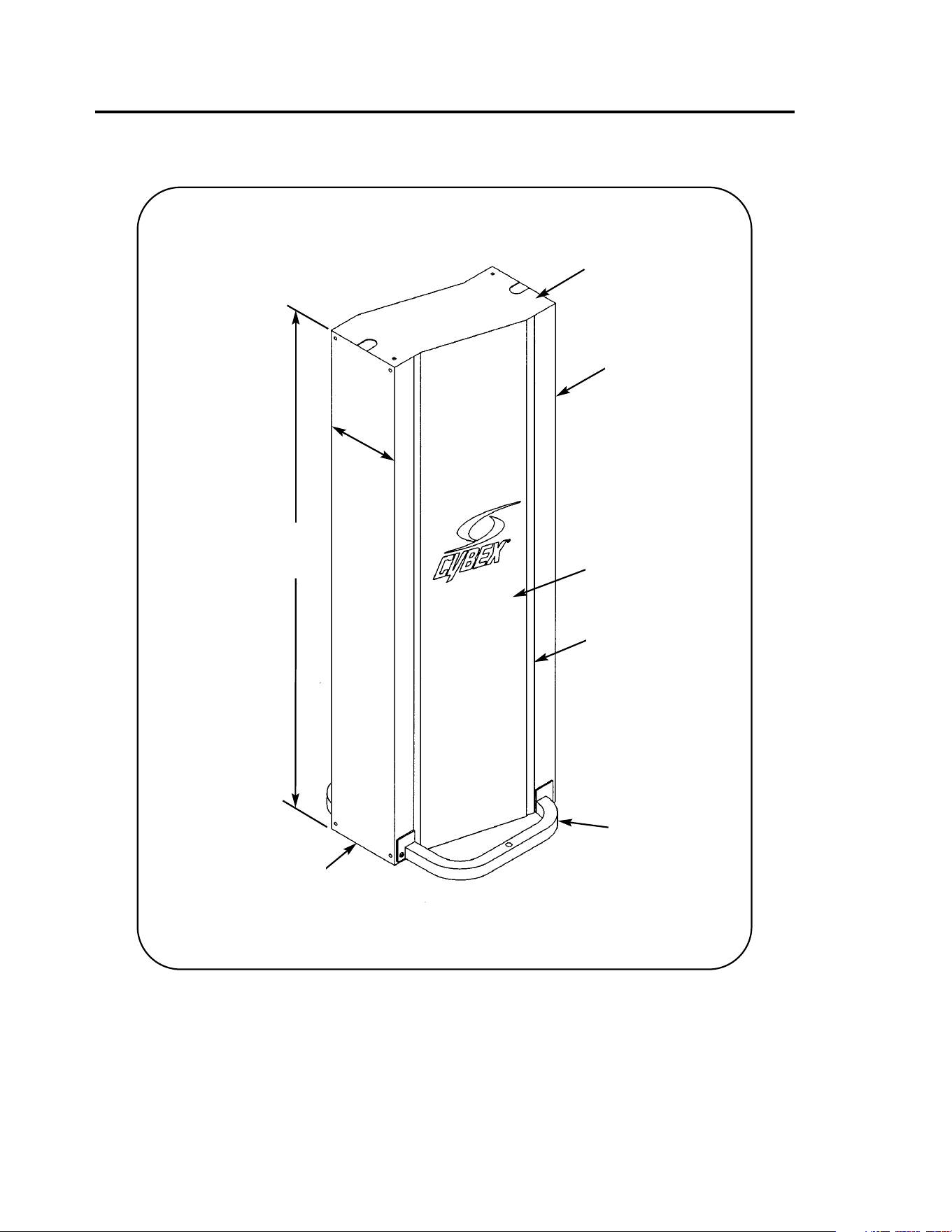
TANDEM CENTER POST & DOME
5629 ASSEMBLY & PARTS
Dome
Stabilizer
Column
Perforated Panel
Magnetic Edge Guard,
Right Hand
Column
1’ 1”
7’ 6”

5629 - Tandem Center Post & Dome
1 1 01779 Frame
2 2 01778 Stabilizing Base
3 8 JC782834 SHCS .50-13 x 3.00
4 4 JC780417 BHSCS .50-13 x 1.00
5 14 JS388300 Split Lockwasher .50
6 14 HN784000 Hex Nut .50-13
7 2 02216 Right Hand Magnetic Edge Guard
8 2 02217 Left Hand Magnetic Edge Guard
9 21 HT552510 Self-Tapping Phillips Screw 6-20 x .375
10 1 01776 Dome
11 2 PP080202 Plastic Insert
12 6 HS387700 Washer .50
ITEM QTY PART NO. DESCRIPTION
Assembly Notes
1. If ceiling is less than 10 feet then install weight stacks using the long guide
rods supplied with column. Otherwise, if ceiling is greater than 10 feet then
do not install weight stacks until step 5.
CAUTION: Columns will lean with weight stacks installed.
2. Attach both columns to frame.
3. Install lower assemblies and stabilizer (item 2) to each column.
4. Install upper assemblies to each column.
5. Install weight stacks utilizing short guide rods. Attach each cable to
appropriate weight stack.
6. Route cables.
7. Attach right hand magnetic edge guard (item 7) and left hand magnetic
guard (item 8) to perforated panels using five screws (item 9) for each
magnetic strip. See PANEL ASSEMBLY TOP VIEW.
8. Install perforated panels. See INSTALLATION OF PANELS.
NOTE: The letters in the exploded-view diagram refer to the installation
of perforated panels.
9. Install upholstery.
NOTE: Hardware pack includes additional hardware required for
machines with lower pulley mount.
NOTE: This machine shipped with an Owner’s Manual. Additional copies can
be obtained by contacting your dealer or a Cybex Representative at
1-888-462-9239.
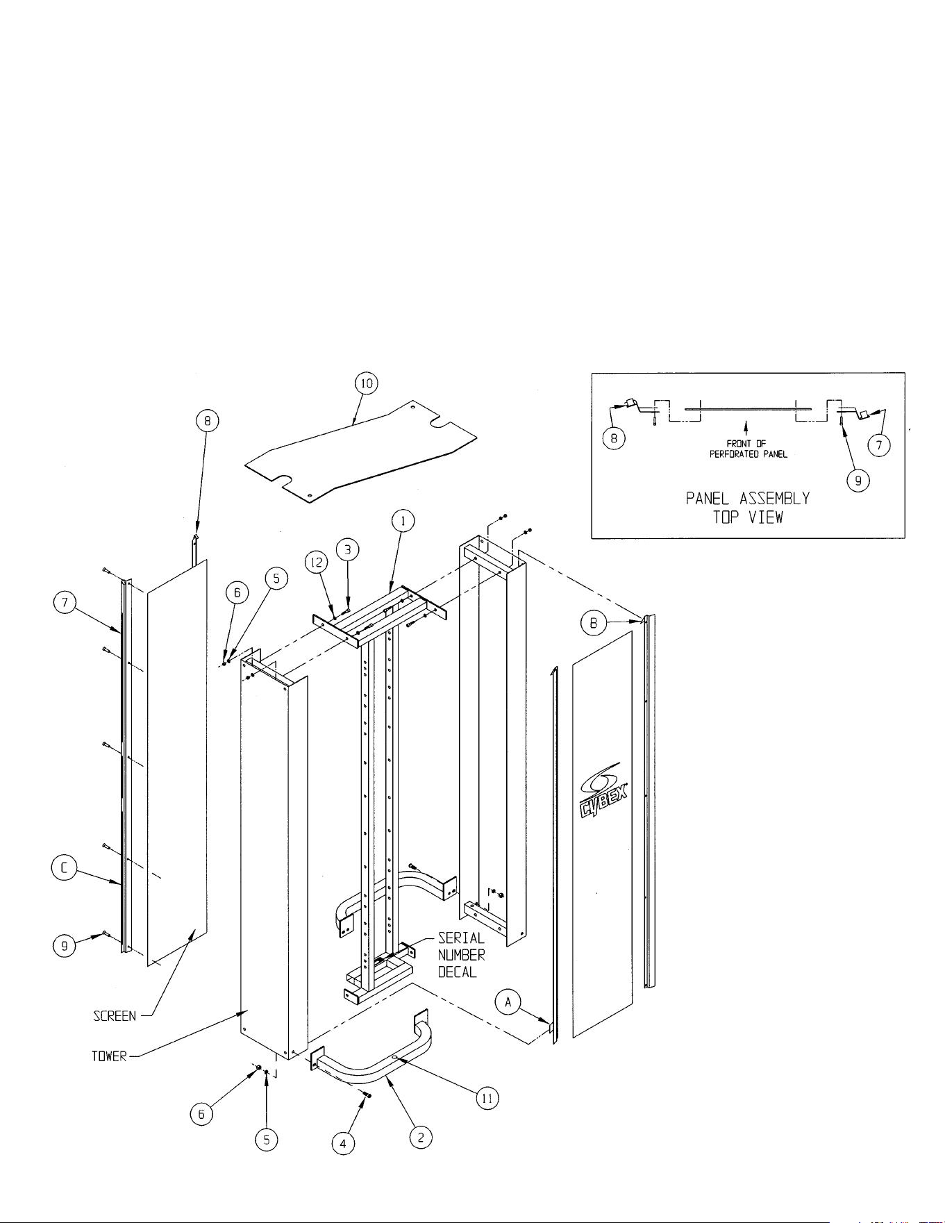
NOTE: The letters in the exploded-view
diagram refer to the installation
of perforated panels.
Installation of Panels
A. Slide hook located on lower left side
of perforated panel into inside edge
of column..
B. Place hook over edge of column.
C. Place magnetic edge strip against
column.

10 Trotter Drive Medway, MA 02053 • 508-533-4300 • FAX 508-533-5183 • www.cybexinternational.com • T[email protected]
Copyright © 2002 CYBEX International, Inc. All rights reserved • 55629 • June 2004
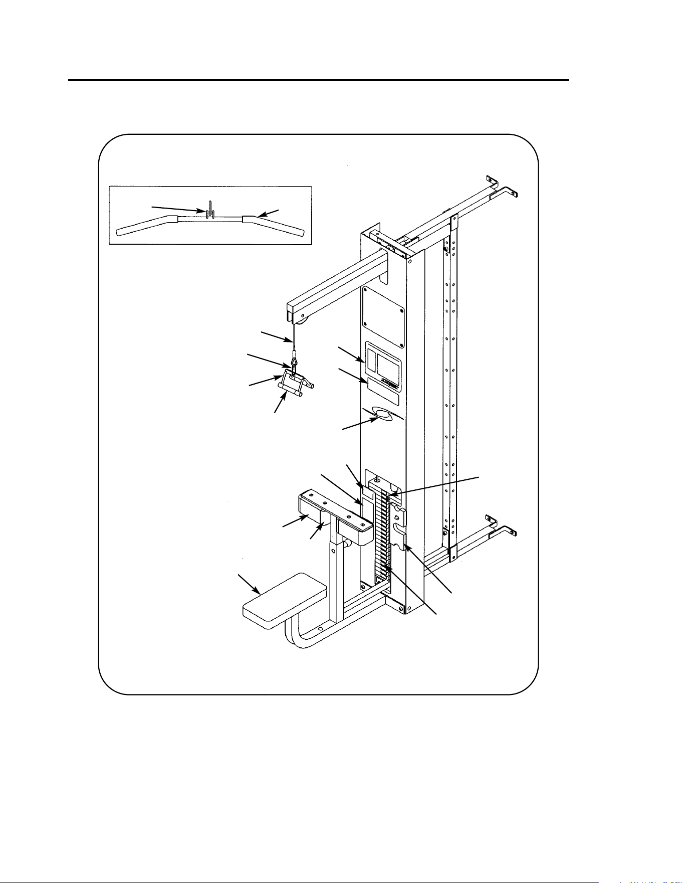
MODULAR LAT PULLDOWN
5601 ASSEMBLY & PARTS
A. Handle Subassembly......... 01255
B. Foam Grip.......................... 5310M042
C. Pulldown Bar...................... 4005-105
D. Foam Grip.......................... PR400201
E. Snap Link........................... GQ000206
F. Seat Cushion ..................... 4800-024
G. Thigh Cushion and Wear
Cover (item H).................... 4800-071
H. Wear Cover ........................ 4800-101
DESCRIPTION PART NO.
I. Cable Subassembly........... 01063
J. Placard Decal..................... 01065
K. Weight Selector Pin ........... 5310P044
L. Serial Number Decal
M. Caution Decal .................... 4000Y316
N. Half Weight ........................ C-ZA000200
O. Warning Decal.................... 02521
P. Vortex Decal....................... 3900-426
Q. General Warning Decal...... 4800-381
R. Weight Plate Decal ............ 4800-515
DESCRIPTION PART NO.
UPHOLSTERY HARDWARE PACK....4005S088
A
B
P
Q
J
E
M
N
H
G
O
F
I
D
C
NOTE: See exploded-view
diagram for item: L.
R
K

5601 - Lat Pulldown
1 1 01048 Seat Support
2 1 01069 Adjusting Post
3 2 JC780422 BHSCS .50-13 x 1.50
4 6 JS388300 Split Lockwasher .50
5 4 HN784000 Hex Nut .50-13
6 1 4000M218 Detent Pin
7 1 PP080202 Plastic Insert
8 1 01054 Pulley Mount
9 4 GP000004 Pulley Spacer
10 2 GP000203 Pulley Center
11 2 GP000000 Pulley Assembly
12 4 HC700414 BHCS .375-16 x .62
13 1 JC782838 SHCS .50-13 x 3.50
14 1 PP090200 Plastic Insert
15 1 01055 Scuff Plate
16 4 01066 Plastic Fastener
17 2 01755 Guide Rod Collet
18 2 5310M035 Weight Stack Guide Rod
19 2 PR060005 Weight Bumper
20 2 JC782830 SHCS .50-13 x 2.50
21 2 PP080204 Plastic Cap .625 ID x .68 OD
22 2 01239 Spacer
23 4 PN660201 Hole Plug
24 1 4700M005 Rubber Cap
25 1 4700-010 Top Weight Assembly
• 26 Removed
• 27 19 4005C062 Stack Weight 4 x 12
28 1 HP286819 Spiral Pin
29 2 JC700917 FHSCS .375-16 x 1.00
30 4 JC700922 FHSCS .375-16 x 1.50
• 31 2 4700-019 Flange Bearing
• 32 2 BR030206 Retaining Ring
33 1 JC782834 SHCS .50-13 x 3.00
34 Removed
35 1 02106 Half Weight Peg
36 1 HS308300 Split Lockwasher .25
37 1 JC620415 BHSCS .25-20 x .75
38 1 4800-024 Seat Cushion
39 2 4800-071 Thigh Cushion
40 1 01065 Placard Decal
41 1 4000Y316 Caution Decal
42 1 02521 Warning Decal
43 Removed
44 1 4800-381 General Warning Decal
45 1 01063 Cable Subassembly
46 1 5310P044 Weight Selector Pin
47 1 C-ZA000200 Half Weight
48 1 02224 Modular Screen (not shown)
ITEM QTY PART NO. DESCRIPTION
• FOR UNITS MANUFACTURED PRIOR TO JUNE 1993, CALL 1-888-462-9239.
Assembly Notes
1. Keep all shipping packages near area of installation. Standard items incude:
• Lat Column Assembly - 5601-98 • Top Weight Package - 4700-010 (black)
• Lat Pulldown Package - 5601-50 • Weight Pack 1 - 4700S040 (black)
• Lat Pulldown Cushion Box Assembly - 4005A070-0 • Weight Pack 2 - 4700S043 (black)
NOTE: x denotes specific color
2. When installing seat support, tip 90 degrees and insert through column slot. NOTE: Remove lower cross braces
(if installed) before installing seat support. Use hardware supplied with the Center Post to secure seat
support to lower cross braces.
3. Securely tighten seat support before installing weight stack.
4. Follow the assembly guidelines listed on either the 5600 Modular Center Post Assembly & Parts instruction sheet
or the 5629 Tandem Center Post Assembly & Parts instruction sheet.
49 1 01255 Handle Subassembly
50 2 GQ000206 Snap Link
51 1 4005-105 Pulldown Bar (not shown)
52 1 3900-426 Vortex Decal
53 1 4800-515 Weight Plate Decal
54 2 4800-101 Wear Cover
55 2 5310M042 Foam Grip
56 2 PR400201 Foam Grip (not shown)
57 2 HS760106 Flat Washer 1.75 .69 .14T
58 1 BS070201 Com Spring .56 x .66 x 1.50 LG
59 1 PP460200 Plastic Knob
ITEM QTY PART NO. DESCRIPTION
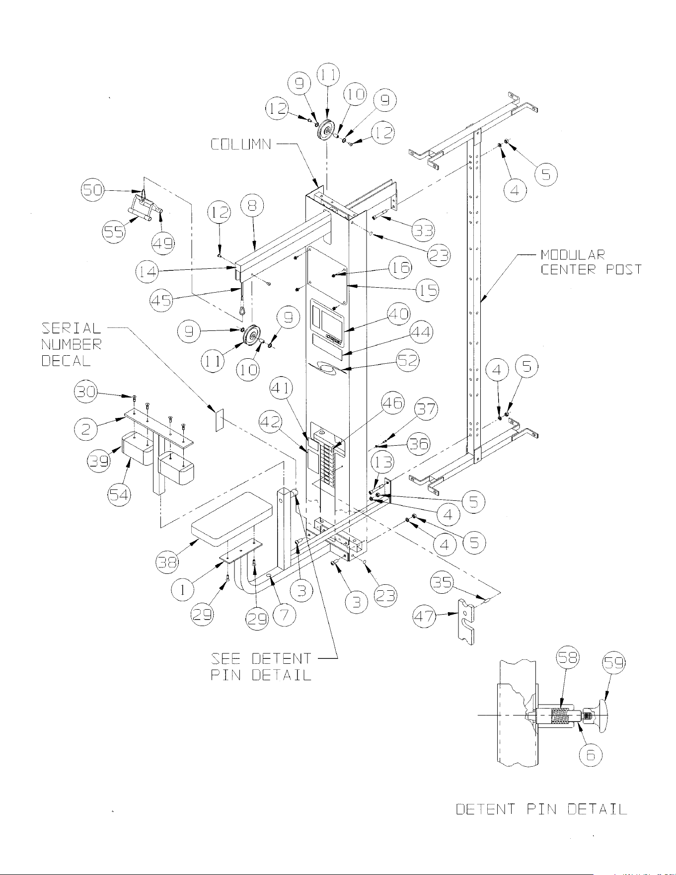
NOTE: This machine shipped with an Owner’s Manual.
Additional copies can be obtained by contacting your dealer
or a Cybex Representative at 1-888-462-9239.
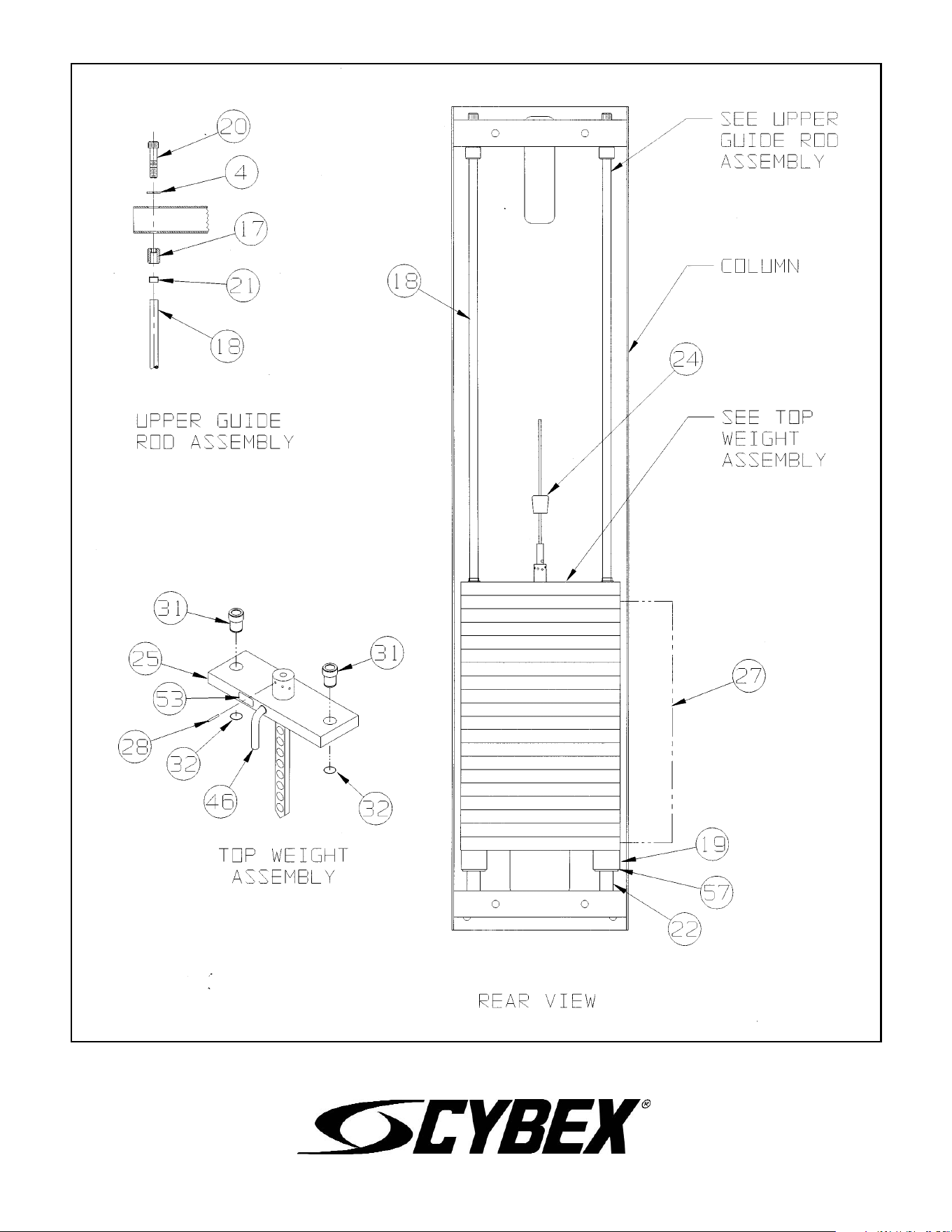
10 Trotter Drive Medway, MA 02053 • 508-533-4300 • FAX 508-533-5183 • www.cybexinternational.com • T[email protected]
Copyright © 2002 CYBEX International, Inc. All rights reserved • 55601 Rev H • November 2007
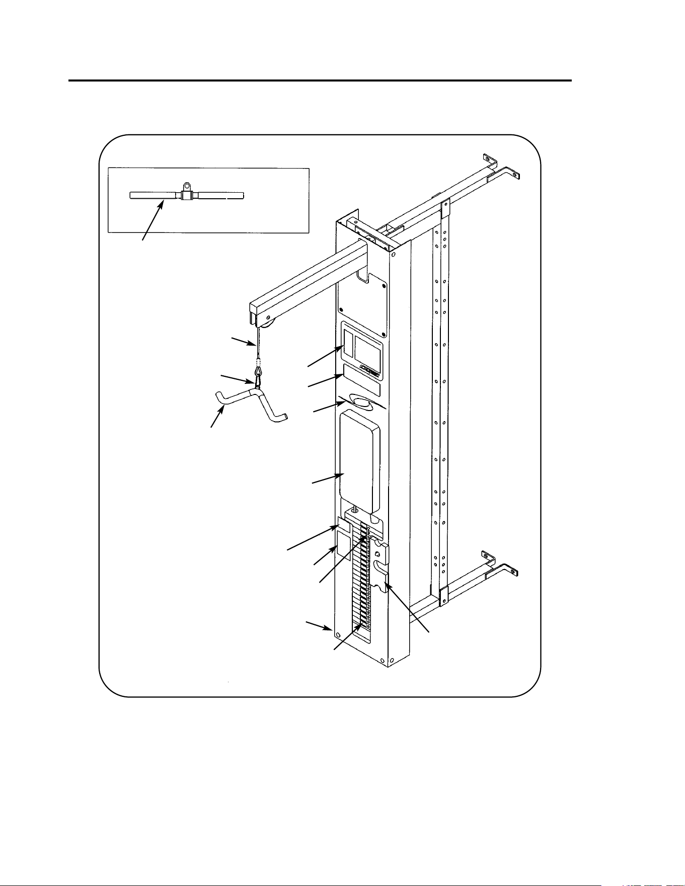
MODULAR TRICEP PRESSDOWN
5603 ASSEMBLY & PARTS
A. Back Cushion .................... 4106S055-0
B. Foam Grip.......................... 4055M028
C. Straight Handle.................. 02203
D. Cambered Handle ............. 51013
E. Snap Link........................... GQ000206
F. Weight Selector Pin ........... 5310P044
G. Placard Decal..................... 01114
H. Cable Subassembly........... 01113
DESCRIPTION PART NO.
I. Serial Number Decal
J. Caution Decal .................... 4000Y316
K. Half Weight ........................ 4301C096
L. Warning Decal.................... 02521
M. Vortex Decal....................... 3900-426
N. General Warning Decal...... 4800-381
O. Weight Plate Decal ............ 4800-515
DESCRIPTION PART NO.
Upholstery Hardware Pack....5460S014
A
B,
D
B,
C
E
F
G
H
I
J
K
L
M
N
O

5603 - Tricep Pressdown
1 1 01109 Pulley Mount
2 2 GP000000 Pulley Assembly
3 4 GP000004 Pulley Spacer
4 2 GP000203 Pulley Center
5 1 HN784000 Hex Nut .500-13
6 4 HC700414 BHSC .375-16 x .625
7 1 JC782838 SHCS .50-13 x 3.50
8 3 JS388300 Split Lockwasher .50
9 1 PP090200 Plastic Insert
10 1 01055 Scuff Plate
11 4 01066 Plastic Fastener
12 2 01755 Guide Rod Collet
13 2 5310M035 Weight Stack Guide Rod
14 2 BS110200 Spring .70 ID x 1.22
OD X 2.07 L
15 2 JC782830 SHCS .50-13 x 2.50
16 6 PN660201 Hole Plug
17 2 PP080204 Plastic Cap
.625 ID x .68 OD
••18 2 4700-019 Flange Bearing
19 1 4700-016 Top Weight Assembly
20 2 BR030206 Retaining Ring
21 1 HP286819 Spiral Pin
22 1 4700M005 Rubber Cap
23 14 4700C089 Stack Weight 3 x 12
24 2 HS347600 Washer .375
25 2 JC700420 BHSCS .375-16 x 1.25
• 26 1 02192 Stabilizer
• 27 2 HN784000 Hex Nut .50-13
• 28 2 JC780420 BHSCS .50-13 x 1.25
• 29 4 JS388300 Splilt Lockwasher .50
• 30 2 PP660006 Hole Plug
31 1 02106 Half Weight Peg
32 1 HS308300 Split Lockwasher .25
33 1 JC620415 BHSCS .25-20 x .75
34 Removed
35 2 JC782815 SHCS .50-13 X .75
• 36 1 02231 Bar Support
ITEM QTY PART NO. DESCRIPTION
• See Assembly Note #3.
•• FOR UNITS MANUFACTURED PRIOR TO JUNE 1993, CALL 1-888-462-9239.
Assembly Notes
1. Keep all shipping packages near area of installation. Standard items incude:
• Tricep Pressdown Assembly - 5603-98 • Top Weight Package - 4700-016 (black)
• Tricep Pressdown Package - 5603-50 • Weight Pack 1 - 4700S110 (black)
• Tricep Pressdown Cushion Box Assembly - 5603-00
NOTE: x denotes specific color
2. Follow the assembly guidelines listed on either the 5600 Modular Center Post Assembly & Parts
instruction sheet or the 5629 Tandem Center Post Assembly & Parts instruction sheet.
3. Items 26 - 30 are required when using the Tricep Pressdown station in a tandem configuration. Follow
assembly guidelines listed on the 5629 Tandem Center Post Assembly & Parts instruction sheet.
NOTE: This machine shipped with an Owner’s Manual. Additional copies can be obtained by contacting
your dealer or a Cybex Representative at 1-888-462-9239.
• 37 2 PP080202 Hole Plug
38 1 4106S055-0 Back Cushion
39 1 01114 Placard Decal
40 1 4000Y316 Caution Decal
41 1 02521 Warning Decal
42 1 3900-426 Vortex Decal
43 1 4800-381 General Warning Decal
44 1 01113 Cable Subassembly
45 1 5310P044 Weight Selector Pin
46 1 4301C096 Half Weight
47 1 02224 Modular Screen (not shown)
48 1 02203 Straight Handle (not shown)
49 1 51013 Cambered Handle
50 2 GQ000206 Snap Link
51 1 4800-515 Weight Plate Decal
52 4 4055M028 Foam Grip
ITEM QTY PART NO. DESCRIPTION
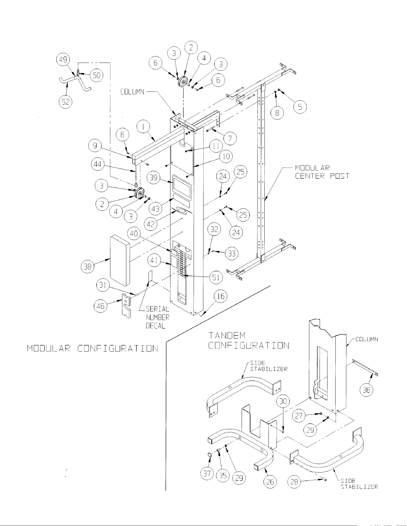
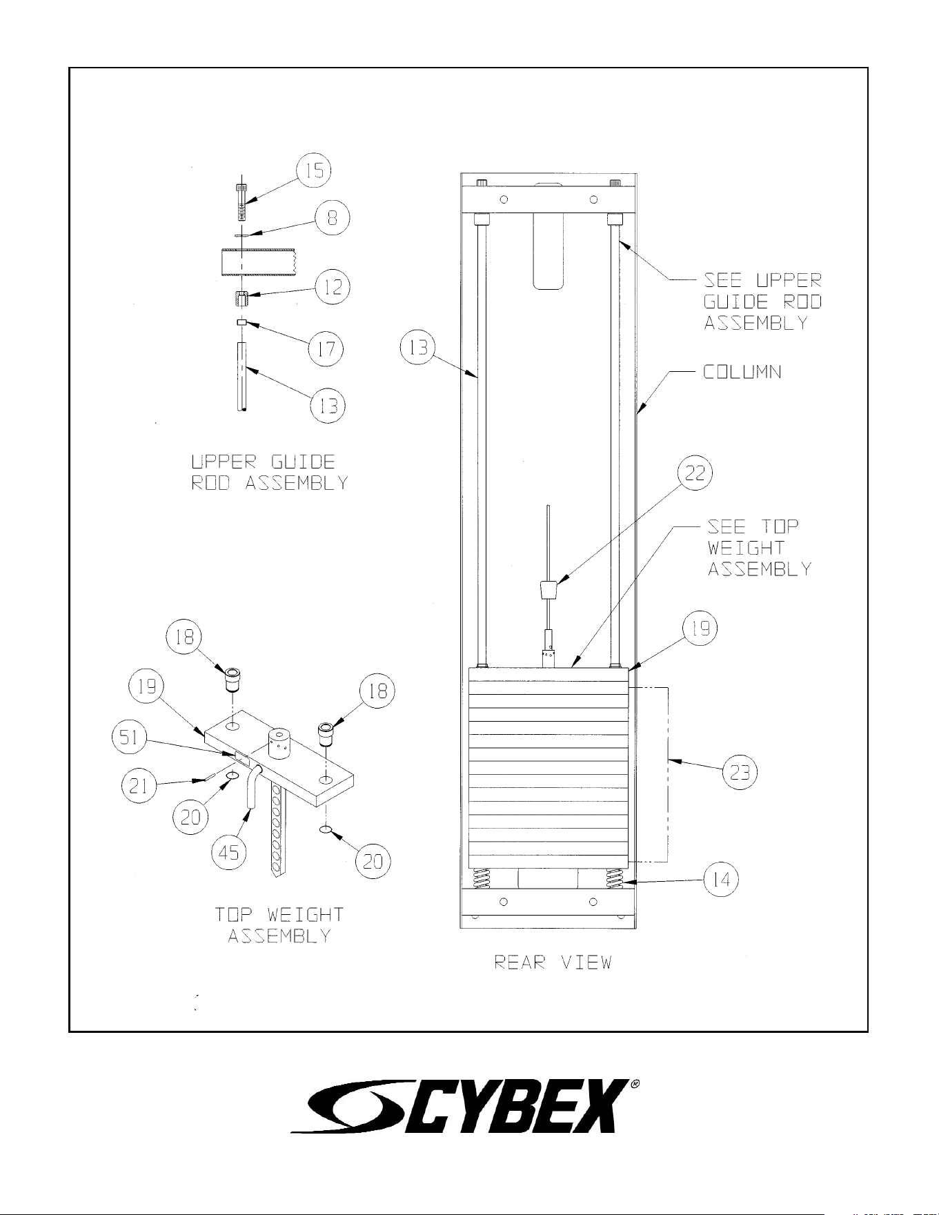
10 Trotter Drive Medway, MA 02053 • 508-533-4300 • FAX 508-533-5183 • www.cybexinternational.com • T[email protected]
Copyright © 2002 CYBEX International, Inc. All rights reserved • 55603 Rev C • November 2007
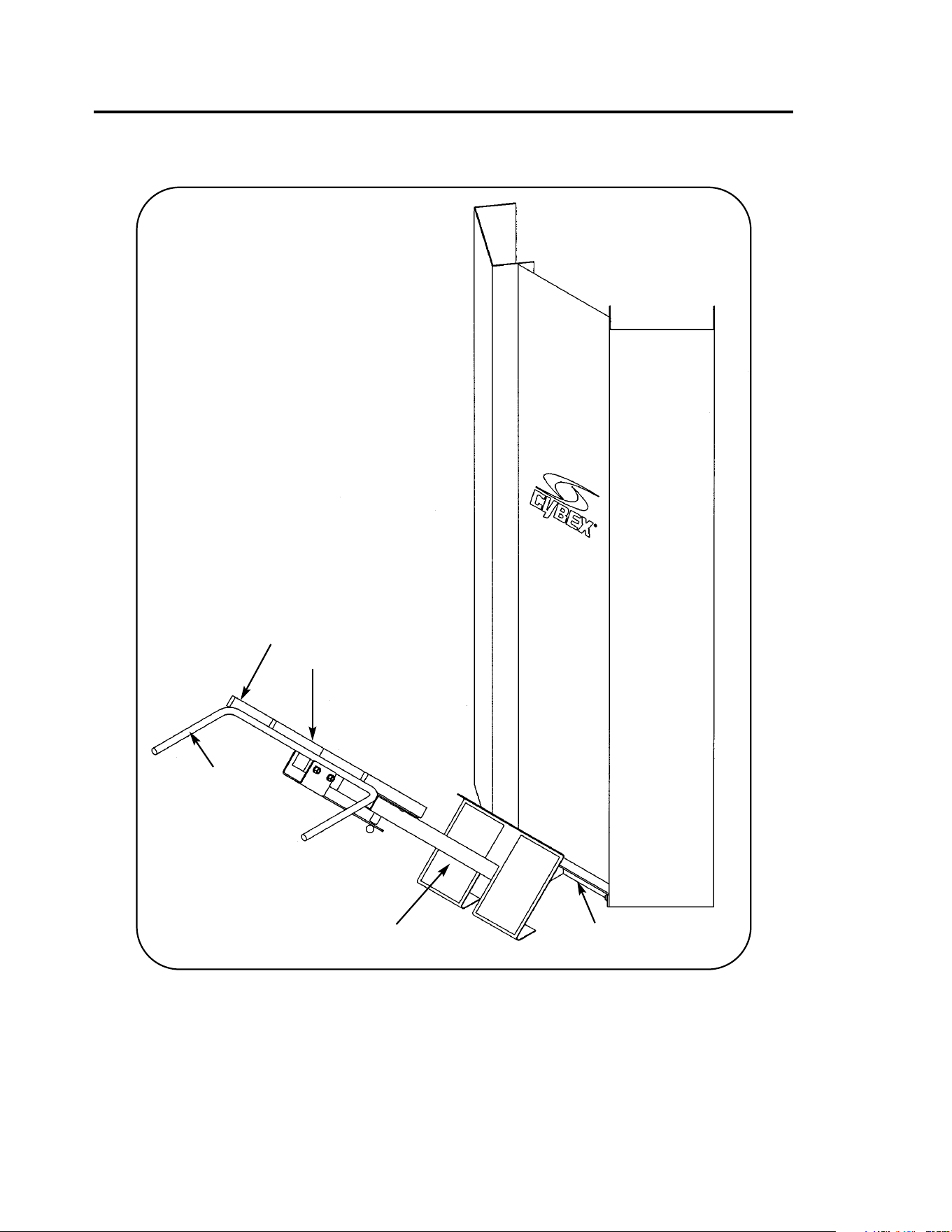
MODULAR 45
o
BACK EXTENSION
5608 ASSEMBLY & PARTS
A. Wear Cover ........................ 5410S024-0
B. Cushion With Wear
Cover (Item A).................... 01214
DESCRIPTION PART NO.
C. Foam Grip.......................... 4045M079
D. Non-Slip Fabric.................. 02185
E. Serial Number Decal
DESCRIPTION PART NO.
Upholstery Hardware Pack........ 5410S025
D
A
B
C
E

5608 - 45
o
Back Extension
1 1 01206 Frame
2 1 01209 Pad Plate
3 1 4000M218 Detent Pin
4 1 5410P007 Adjusting Tube
5 2 JC702832 SHCS .375-16 x 2.75
6 2 HN704000 Hex Nut .375-16
7 2 HN784000 Hex Nut .50-13
8 2 HS348300 Split Lockwasher .375
9 2 JC780417 BHSCS .50-13 x 1.00
10 2 JS388300 Split Lockwasher .50
11 1 PP090210 Plastic Insert 2.00 Sq
12 2 HS347600 Washer .375
13 2 JC700422 BHSCS .375-16 x 1.50
14 2 01214 Cushion
15 2 02185 Non-slip Fabric
16 2 4045M079 Foam Grip
17 1 5410-302 Stop Bracket
18 1 PP460200 Plastic Knob
19 1 BS070201 Com Spring .56 x .66 1.50 L
20 2 5410S024-0 Wear Cover
ITEM QTY PART NO. DESCRIPTION
Assembly Notes
1. Keep all shipping packages near area of installation.
Standard items include:
• 45
o
Back Extension Package - 5608-50
• Cushion Box Assembly - 5410A020-0
2. Follow assembly guidelines listed on the 5600 Modular
Center Post Assembly & Parts instruction sheet, part
number 55600.
NOTE: This machine shipped with an Owner’s Manual.
Additional copies can be obtained by contacting your
dealer or a Cybex Representative at 1-888-462-9239.
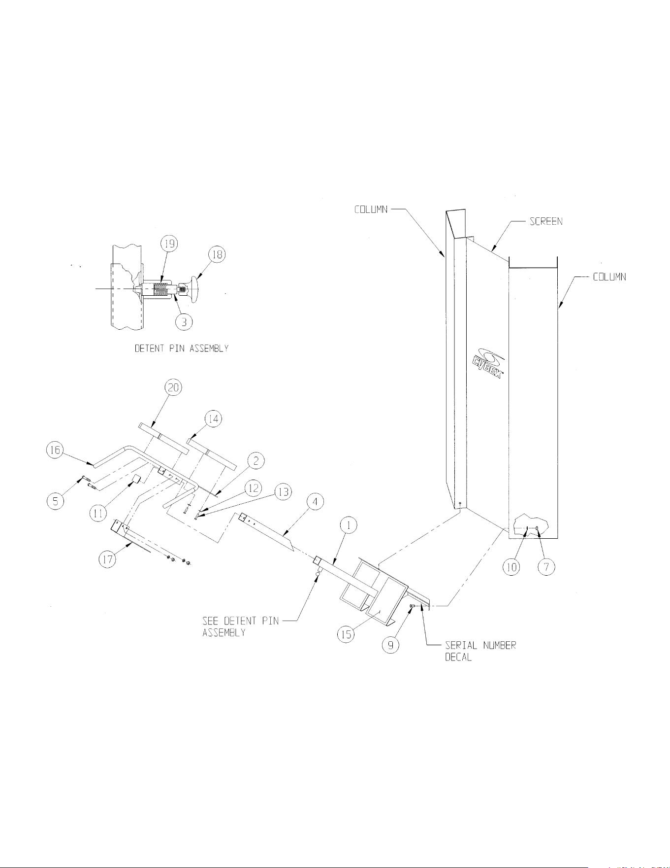

10 Trotter Drive Medway, MA 02053 • 508-533-4300 • FAX 508-533-5183 • www.cybexinternational.com • T[email protected]
Copyright © 2002 CYBEX International, Inc. All rights reserved • 55608 • June 2004
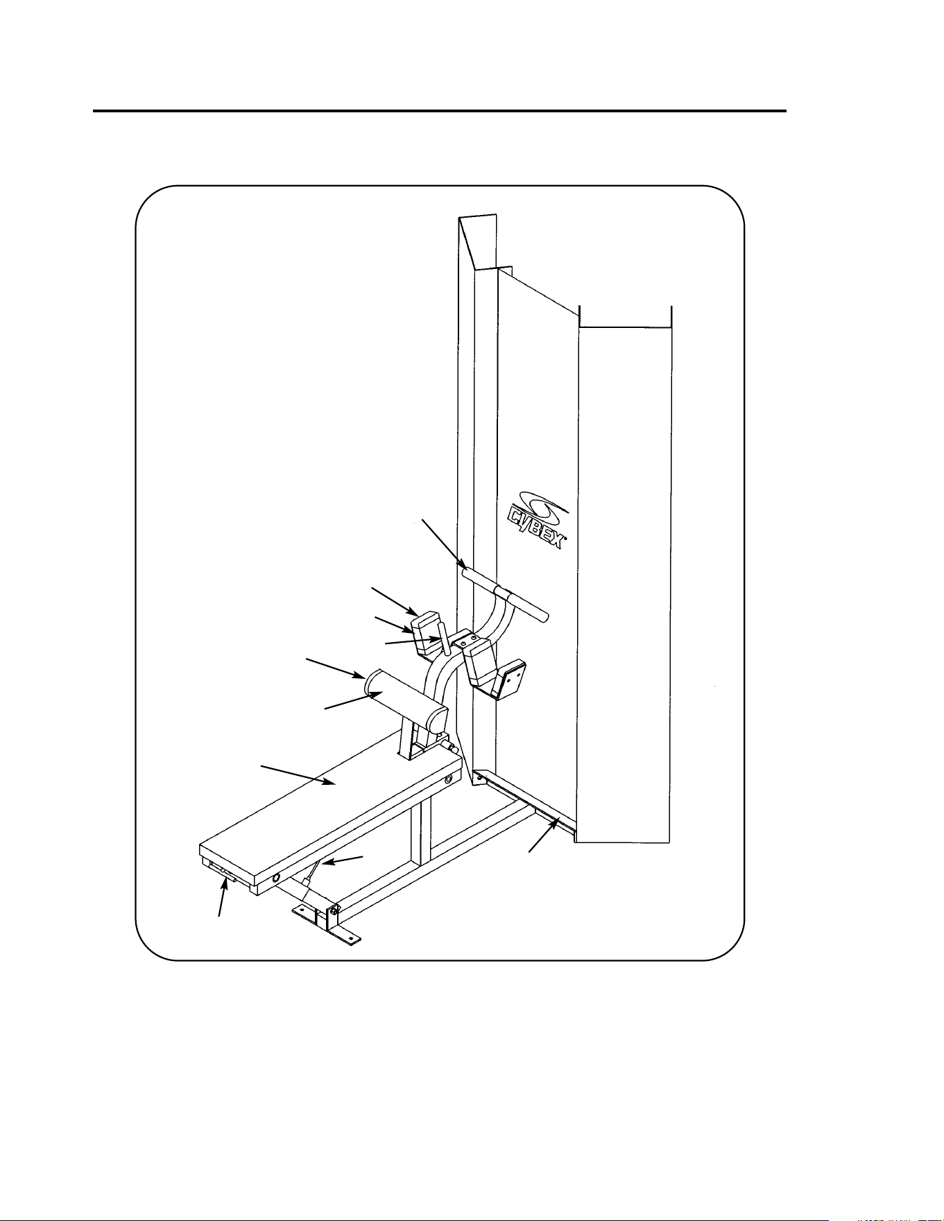
MODULAR BENT LEG ABDOMINAL BOARD
5610 ASSEMBLY & PARTS
A. Back Cushion..................... 01286
B Contour Cushion With
Wear Cover (Item C)........... 4800-014
C. Wear Cover ........................ 4800-094
D. Sling Cushion With
Wear Cover (Item E)........... 4000S114-0
Upholstery Hardware Pack For Item A....5450S040
Upholstery Hardware Pack For Item B....5500S026
Upholstery Hardware Pack For Item D....01285
DESCRIPTION PART NO.
E. Wear Cover ........................ 4000S115-0
F. Foam Grip.......................... 4005M100
G. Rubber Grip ....................... 02023
H. Cable Subassembly........... 01284
I. Serial Number Decal
J. T-Handle ............................ 01259
DESCRIPTION PART NO.
A
H
B
D
G
C
I
J
E
F

1 1 01256 Bench
2 1 01257 Base
3 1 01258 Adjusting Tube
4 1 01260 Adjusting Tube
5 1 01261 Adjusting Tube
6 1 01282 Ankle Pad Plate
7 1 01283 Bronze Bearing
8 1 4000M218 Detent Pin
9 2 5208M041 Upper Pivot Shaft
10 4 FB050209 Flange Bearing 1.00 ID x 1.25 OD x .75 L
11 2 FB050219 Flange Bearing .62 ID x .75 OD x .50 L
12 2 GP000004 Pulley Spacer
13 1 GP000203 Pulley Center
14 1 GP000204 Pulley Assembly 3.00
15 2 HC700414 BHSCS .375-16 x .625
16 2 HC700432 BHSCS .375-16 x 2.75
17 1 HD403330 Shoulder Bolt .625 x 2.50 .50-13
18 1 HF309001 Terminal Fastener
19 3 HN704000 Hex Nut .375-16
20 3 HN784000 Hex Nut .50-13
21 3 HS348300 Split Lockwasher .375
22 4 HY662912 Set Screw .312-18 x .50 Cup Point
23 1 JC702814 SHCS .375-16 x .625
24 2 JC780417 BHSCS .50-13 x 1.00
25 3 JS388300 Split Lockwasher .500
26 4 PP080202 Plastic Insert 1.19 x 11 G
27 4 PP090001 Plastic Insert 1.50 x 2.50 x 11 G
28 1 PP090200 Plastic Insert 1.75 Sq x 11 G
29 1 PP090201 Plastic Insert 2.00 Sq x 11 G
30 1 5320P040 Detent Pin
31 4 JC700436 BHSCS .375-16 x 3.25
32 Removed
33 10 JC700420 BHSCS .375-16 x 1.25
34 2 BS070201 Compression Spring
35 2 HY582910 Set Screw #10-32 x .19 Cup Point
36 Removed
37 4 4000S114-0 Sling Cushion
38 1 4800-014 Contour Cushion
39 1 01286 Back Cushion
40 1 4005M100 Foam Grip
41 2 02023 Rubber Grip
42 1 01284 Cable Subassembly
43 1 01259 T-Handle
44 1 PP460200 Plastic Knob
45 1 4800-094 Wear Cover
46 1 4000S115-0 Wear Cover
1. Keep all shipping packages near area of installation. Standard items include:
• Bent Leg Abdominal Board Package - 5610-50
• Cushion Box Assembly - 5610-0
2. Follow assembly guidelines listed on the 5600 Modular Center Post Assembly &
Parts instruction sheet, part number 55600.
NOTE: The following steps are required when installing cushions on ankle plate
(item #6):
1. Remove ankle plate from frame
2. Install cushions on ankle plate
3. While keeping ankle plate straight, secure ankle plate to frame
5610 - Bent Leg Abdominal Board
Assembly Notes
ITEM QTY PART NO. DESCRIPTION
NOTE: This machine shipped with an Owner’s Manual. Additional copies can be
obtained by contacting your dealer or a Cybex Representative at 1-888-462-
9239.
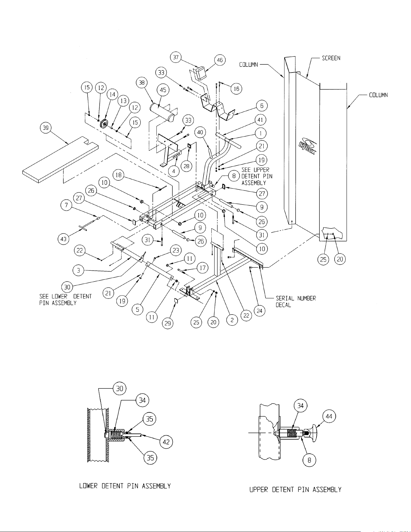

10 Trotter Drive Medway, MA 02053 • 508-533-4300 • FAX 508-533-5183 • www.cybexinternational.com • T[email protected]
Copyright © 2002 CYBEX International, Inc. All rights reserved • 55610 • June 2004
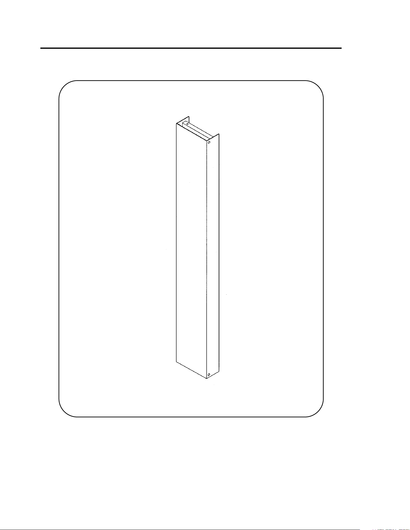
MODULAR BLANK
5624 ASSEMBLY & PARTS

ITEM QTY PART NO. DESCRIPTION
1 1 PN660201 Hole Plug
Assembly Notes
1. Keep all shipping packages near area of installation.
Standard items include:
• Blank Column Assembly - 5624-9x
2. Follow assembly guidelines listed on the 5600
Modular Center Post Assembly & Parts
instruction sheet, part number 55600.
5624 - Blank
NOTE: This machine shipped with an Owner’s Manual.
Additional copies can be obtained by contacting your
dealer or a Cybex Representative at 1-888-462-9239.
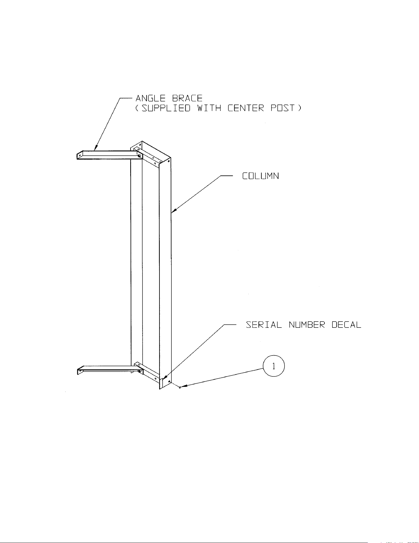

10 Trotter Drive Medway, MA 02053 • 508-533-4300 • FAX 508-533-5183 • www.cybexinternational.com • T[email protected]
Copyright © 2002 CYBEX International, Inc. All rights reserved • 55624 • June 2004
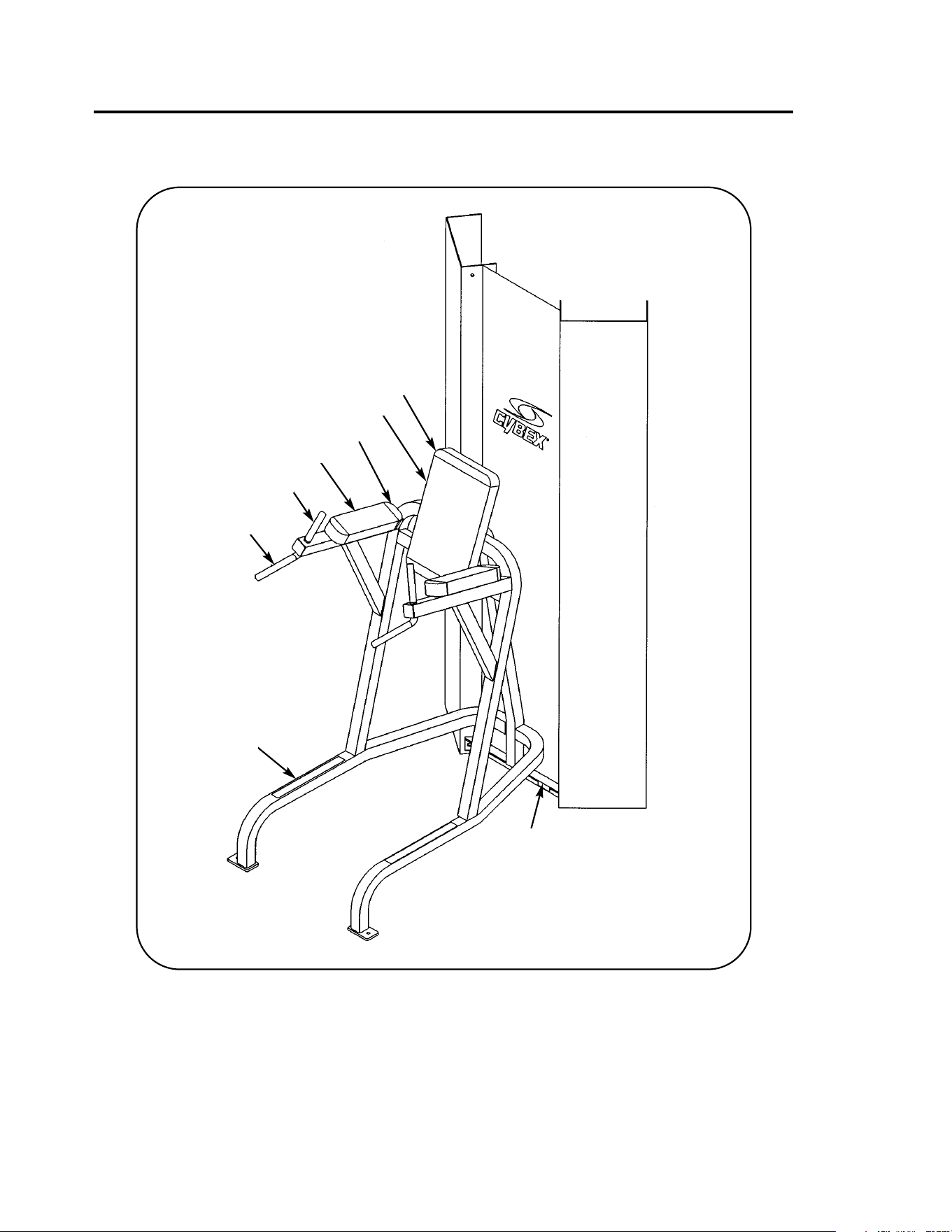
MODULAR LEG RAISE CHAIR
5645 ASSEMBLY & PARTS
A. Foam Grip.......................... 4050M025
B. Foam Grip.......................... 4055M028
C. Non-Slip Fabric.................. 4000M197
D. Serial Number Decal
E. Back Cushion With
Wear Cover (Item F)........... 4800-011
Upholstery Hardware Pack ...... 5525-003
DESCRIPTION PART NO.
F. Wear Cover ........................ 4111S060-0
G. Arm Cushion With
Wear Cover (Item H) .......... 5530-003-0
H. Wear Cover ........................ 5530-311-0
DESCRIPTION PART NO.
C
D
B
A
H
E
F
G

ITEM QTY PART NO. DESCRIPTION
1 1 02482 Leg Raise Chair Frame
2 2 HN784000 Hex Nut .50-13
3 2 JC780417 BHSCS .50-13 x 1.00
4 2 JS388300 Lockwasher .50
5 2 PP090210 Plastic Insert 2.00 Sq X 10-14G
6 2 HC700417 BHSCS .375-16 x 1.00
7 4 JC700434 BHSCS .375-16 x 3.00
8 1 4800-011 Back Cushion
9 2 5530-003-0 Arm Cushion
10 2 5530-311-0 Wear Cover
11 1 4111S060-0 Wear Cover
12 2 4050M025 Foam Grip 6.00
13 2 4055M028 Foam Grip 8.00
14 2 4000M197 Non-Slip Fabric
Assembly Notes
1. Keep all shipping packages near area of installation.
Standard shipping items include:
• Leg Raise Chair Package - 5645-50
• Cushion Box Assembly - 5530-004-0
2. Follow assembly guidelines listed on the 5600 Modular Center Post Assembly & Parts
instruction sheet, part number 55600.
5645 - Leg Raise Chair
NOTE: This machine shipped with an Owner’s Manual. Additional copies
can be obtained by contacting your dealer or a Cybex Representative
at 1-888-462-9239.
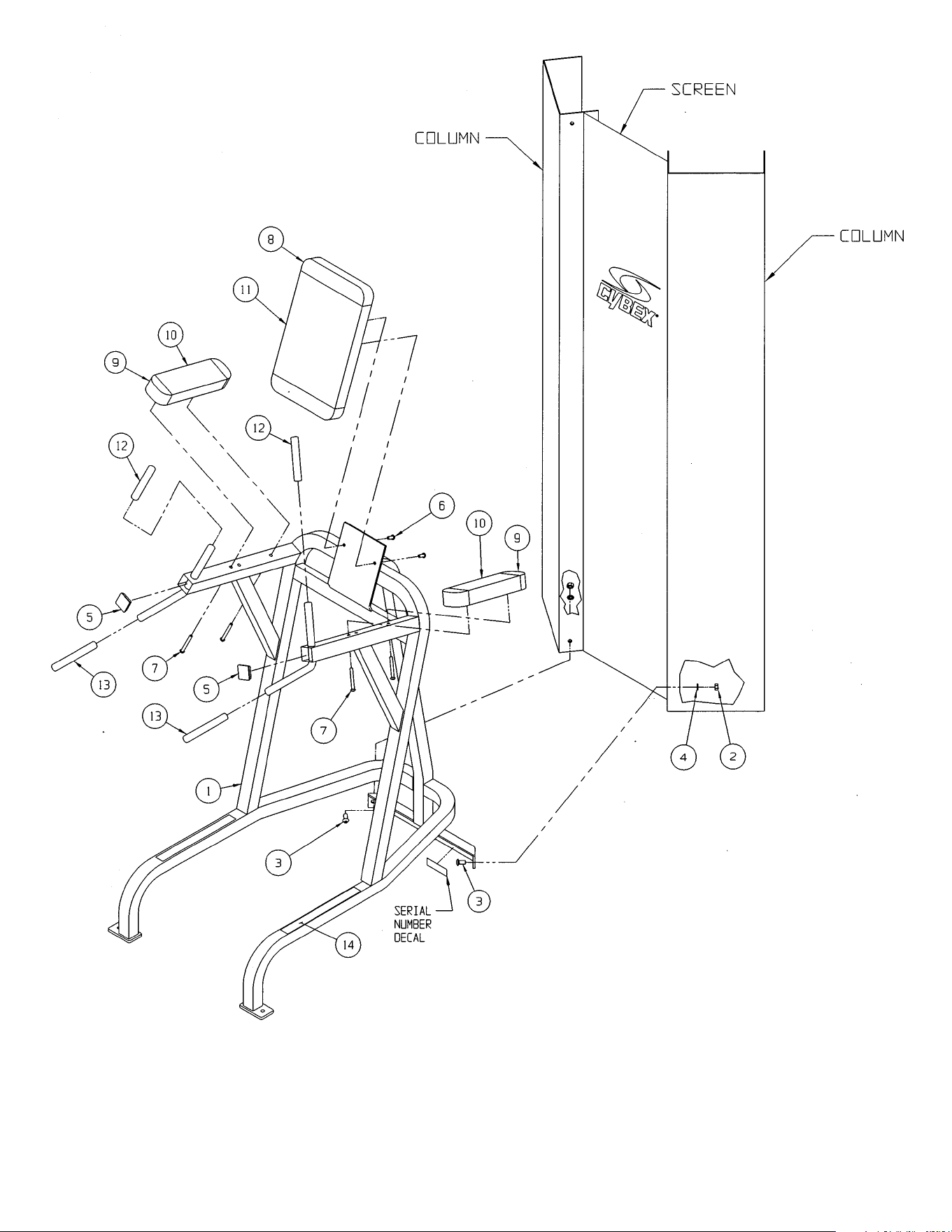

10 Trotter Drive Medway, MA 02053 • 508-533-4300 • FAX 508-533-5183 • www.cybexinternational.com • T[email protected]
Copyright © 2002 CYBEX International, Inc. All rights reserved • 55645 Rev A • August 2007

CABLE COLUMN
5605
ASSEMBLY & PARTS
See reverse side for bill of materials.

ITEM QTY PART NO. DESCRIPTION
1 1 01667 Hand Rail
2 1 5315-201 Cross Tube
3 4 JC780417 BHSCS .50-13 x 1.00
4 11 JS388300 Split Lockwasher .50
5 2 PP090210 Plastic Insert 2.00 Sq x 10-14G
6 2 PP090205 Plastic Insert
1.00 x 2.00 x 11 G
7 14 4700C089 Stack Weight 3 x 12
8 2 01141 Spacer
9 1 01142 Pulley Mount Cap
10 1 01143 Pulley Mount
11 1 01144 Upper Pulley Bracket
12 1 01455 Lower Pulley Bracket
13 1 5315-205 Short Top Tube
14 1 5315-203 Adjusting Tube
15 1 5315-202 Ballet Bar Bracket
16 1 01150 Pulley Bracket
17 1 01155 Pivot Tube
18 2 01755 Guide Rod Collet
19 2 01694 Corner Bracket
20 1 5315-307 Ballet Bar
21 2 5310M035 Weight Stack Guide Rod
22 1 5315P011 Adjusting Tube
23 2 PR060005 Weight Bumper
24 2 FB030220 Machinery Bushing
25 4 FB050219 Flange Bearing .62 ID x .75
OD x .50 L
26 2 FB050222 Flange Bearing .75 OD x .88
ID x .75 L
27 6 GP000000 Pulley Assembly 4.50
28 14 GP000004 Pulley Spacer
29 7 GP000203 Pulley Center
30 1 GP000204 Pulley Assembly 3.00
31 2 HC700417 BHSCS .375-16 x 1.00
32 2 HC782817 SHCS .50-13 x 1.00
33 2 HN704000 Hex Nut .375-16
34 2 HN705618 Eye Socket Nut
35 8 HN784000 Hex Nut .50-13
36 2 HS348300 Split Lockwasher .375
37 4 HT582210 Tap Screw #10-32 x .375
38 10 JC700914 FHSCS .375-16 x .62
39 4 HC700414 BHSCS .375-16 x .625
40 6 JC782830 SHCS .50-13 x 2.50
41 2 JC782834 SHCS .50-13 x 3.00
42 4 JS407100 Machinery Bushing .625
43 4 PN660201 Hole Plug
44 2 PP080202 Plastic Insert
45 2 PP080204 Plastic Cap .625 ID x .68 OD
46 1 PU060200 Bumper
47 2 PU060201 Bumper
48 1 01892 Bracket
49 2 HC620430 BHSCS .25-20 x 2.50
50 2 HN624100 Hex Nut .25-20
51 4 PR069400 Recess Bumper
52 1 01692 Threaded Insert
53 1 JC700422 SHCS .375-16 x 1.50
54 2 PP090210 Plastic Insert 2.00 SQ
55 2 HN784900 Nylon Locknut .500-13
56 1 01475 Top Weight Assembly
• 57 2 4700-019 Flange Bearing
58 2 BR030206 Retaining Ring
59 2 HP286819 Spiral Pin
60 1 02106 Half Weight Peg
61 1 JC620415 BHSCS .25-20 x .75
62 1 HS308300 Split Lockwasher .25
63 1 01702 Handle Subassembly
64 2 1670M115 Foam Grip
65 1 02224 Screen (not shown)
66 1 01159 Placard Decal
67 1 4000Y316 Caution Decal
ITEM QTY PART NO. DESCRIPTION
68 1 5208M046 Foam Grip
69 1 5315S028 Cable Subassembly
70 1 4301C096 Half Weight
71 1 02521 Warning Decal
72 1 4800-381 General Warning Decal
73 1 5310P044 Weight Stack Selector Pin
74 1 4800-515 Weight Plate Decal
75 2 HS760106 Flat Washer 1.75 OD .69 .14T
76 1 GQ000206 Snap Link
77 1 5310S040 Handle (not shown)
78 1 51121 Thigh Strap (not shown)
79 1 02203 Straight Handle (not shown)
80 1 51122 Ankle Strap (not shown)
81 1 51073 Hip Harness (not shown)
5605 - Cable Column
Assembly Notes
1. Keep all shipping packages near area of installation.
Standard items include:
• Cable Column Assembly - 5605-9x
• Handrail - 5315-50
• Top Weight Package - 01475
• Weight Pack 1 (3 x 12, black) - 4700S110
NOTE: x denotes specific color.
2. Follow assembly guidelines listed on the 5600
Modular Center Post Assembly & Parts instruction
sheet. Also refer to the steps listed below.
NOTE: Refer to the exploded-view assembly
diagram when performing steps listed below.
3. Lay column on side.
4. Install lower pulley bracket (item 12). Install
upper pivot tube (item 17) and upper pulley
mount (item 11).
5. Install short top tube (13).
6. Set chrome tube into hand rail assembly.
Fasten upper portion finger tight.
7. Attach lower portion of hand rail to column.
8. Route cable. NOTE: Be sure to insert cable
through brass bushing. See Cable Routing
Detail.
9. Install weight stack.
10. Mount column to Modular configuration.
NOTE: This machine shipped with an Owner’s
Manual. Additional copies can be obtained by
contacting your dealer or a Cybex Representative
at 1-888-462-9239.
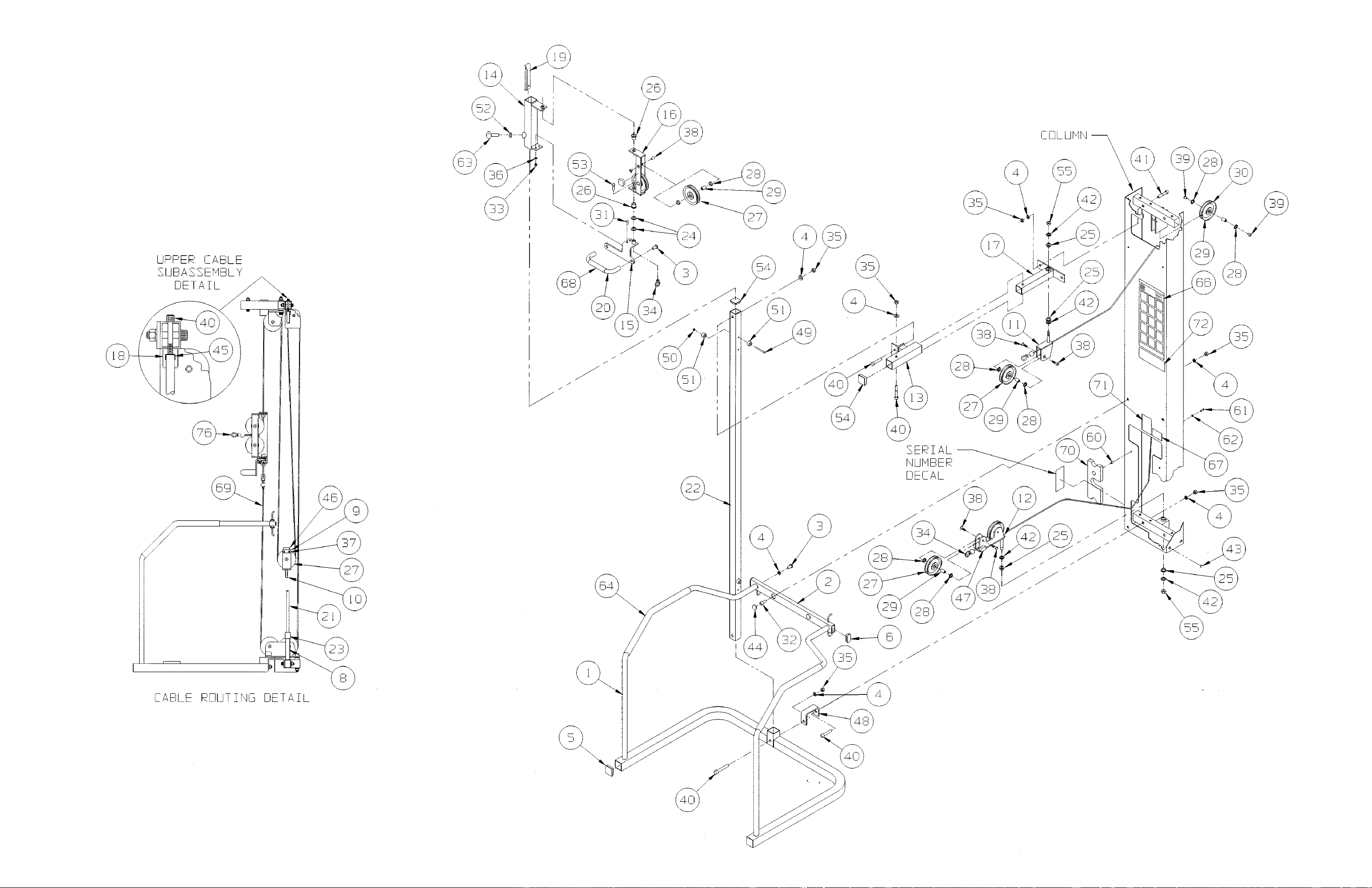
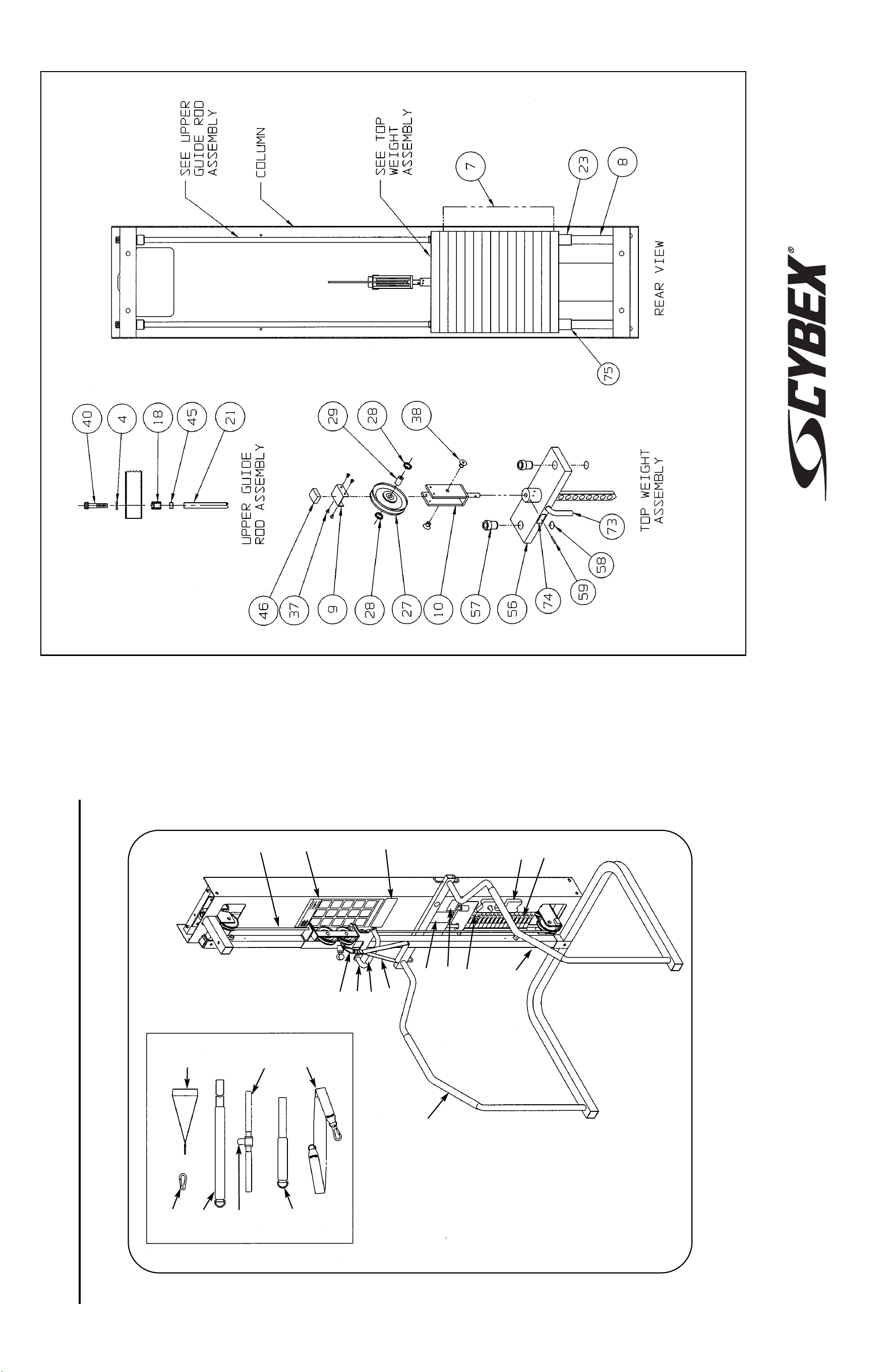
CABLE COLUMN
5605
ASSEMBLY & PARTS
A. Placard Decal .................... 01159
B. Snap Link........................... GQ000206
C. Handle Subassembly......... 01702
D. Ballet Bar ........................... 5315-307
E. Foam Grip.......................... 5208M046
F. Weight Selector Pin ........... 5310P044
G. Caution Decal .................... 4000Y316
H. Cable Subassembly........... 5315S028
I. Serial Number Decal
J. Handle Subassembly......... 5310S040
DESCRIPTION PART NO.
K. Thigh Strap ........................ 51121
L. Foam Grip.......................... 4055M028
M. Straight Handle.................. 02203
N. Ankle Strap ........................ 51122
O. Hip Harness ....................... 51073
P. Half Weight ........................ 4301C096
Q. Foam Grip.......................... 1670M115
R. Warning Decal.................... 02521
S. Warning Decal ................... 4800-381
T. Weight Plate Decal ............ 4800-515
DESCRIPTION PART NO.
A
J
H
K
L
E
D
C
M
O
Q
F
P
N
I
G
B
B
S
T
R
10 Trotter Drive Medway, MA 02053 • 508-533-4300 • FAX 508-533-5183 • www.cybexinternational.com • T[email protected]
Copyright © 2002 CYBEX International, Inc. All rights reserved • 55605 Rev A • August 2007

CABLE COLUMN
5633
ASSEMBLY & PARTS
Assembly Notes
1. Keep all shipping packages near area of
installation. Standard items include:
• Shipping box for Column - 5605-9x
• Handrail - 5315-50
• Top Weight Package - 01475
• Weight Pack 1 (3 x 12, black) - 4700S110
• Upper Boom - 5315K002
• Lower Boom - 5315K003
NOTE: x denotes specific color.
2. Follow assembly guidelines listed on the
5600 Modular Center Post Assembly & Parts
instruction sheet. Also refer to the steps
listed below.
NOTE: Refer to the exploded-view assembly
diagram when performing steps listed below.
3. Lay column on side.
4. Install lower pulley bracket (item 12). Install
upper pivot tube (item 17) and upper pulley
mount (item 11).
5. Lift column into upright position and secure
to center post.
6. Install Upper Boom. See Upper Boom
Installation Instructions supplied with the
Upper Boom kit.
7. Set chrome tube into hand rail assembly.
Fasten upper portion finger tight
8. Install Lower Boom if applicable. See Lower
Boom instructions supplied with Lower Boom
kit.
9. Attach lower portion of hand rail to column.
10. Route cable. NOTE: Be sure to insert cable
through brass bushing. See Cable Routing
Detail.
11. Install weight stack.
12. Mount column to Modular configuration.

ITEM QTY PART NO. DESCRIPTION
1 1 01667 Hand Rail
2 1 5315-201 Cross Tube
3 4 JC780417 BHSCS .50-13 x 1.00
4 11 JS388300 Split Lockwasher .50
5 2 PP090210 Plastic Insert 2.00 SqX
6 2 PP090205 Plastic Insert 1.00 x 2.00
7 1 4113M041 Detent Pin
8 2 01141 Spacer
9 1 01142 Pulley Mount Cap
10 1 01143 Pulley Mount
11 1 01144 Upper Pulley Bracket
12 1 01455 Lower Pulley Bracket
13 1 5315-204 Top Tube
14 1 5315-203 Adjusting Tube
15 1 5315-202 Ballet Bar Bracket
16 1 01150 Pulley Bracket
17 1 01155 Pivot Tube
18 2 01755 Guide Rod Collet
19 2 01694 Corner Bracket
20 1 5315-307 Ballet Bar
21 2 5310M035 Weight Stack Guide Rod
22 1 5315P011 Adjusting Tube
23 2 PR060005 Weight Bumper
24 2 FB030220 Machinery Bushing
25 8 FB050219 Flange Bearing
.62 ID x .75 OD x .50 L
26 2 FB050222 Flange Bearing
.75 OD X .88 ID x .75 L
27 8 GP000000 Pulley Assembly 4.50
28 16 GP000004 Pulley Spacer
29 8 GP000203 Pulley Center
30 1 GP000204 Pulley Assembly 3.00
31 4 HC700417 BHSCS .375-16 x 1.00
32 2 HC782817 SHCS .50-13 x 1.00
33 4 HN704000 Hex Nut .375-16
34 5 HN705618 Eye Socket Nut
35 8 HN784000 Hex Nut .50-13
36 2 HS348300 Split Lockwasher .375
37 4 HT582210 Tap Screw #10-32 x .375
38 12 JC700914 FHSCS .375-16 x .62
39 4 HC700414 BHSCS .375-16 x .625
40 4 JC782830 SHCS .50-13 x 2.50
41 3 JC782834 SHCS .50-13 x 3.00
42 5 JS407100 Machinery Bushing .625
43 4 PN660201 Hole Plug
44 2 PP080202 Plastic Insert
45 2 PP080204 Plastic Cap .625 ID x .68 OD
46 1 PU060200 Bumper
47 2 PU060201 Bumper
48 1 01892 Bracket
49 2 HC620430 BHSCS .25-20 x 2.50
50 4 HN624100 Hex Nut .25-20
51 4 PR069400 Recess Bumper
52 1 01692 Threaded Insert
53 1 JC700422 SHCS .375-16 x 1.50
54 2 PP090210 Plastic Insert 2.00 Sq
55 2 HN784900 Nylon Locknut .50-13
56 1 01475 Top Weight Assembly
57 2 4700-019 Flange Bearing
58 2 BR030206 Retaining Ring
59 1 HP286819 Spiral Pin
60 1 02106 Half Weight Peg
61 1 PP090000 Plastic Insert
62 3 HS308300 Split Lockwasher .25
63 1 JC620415 BHSCS .25-20 x .75
64 14 4700C089 Stack Weight 3 x 12
65 1 HS387500 Washer .50
66 1 5315-206 Mounting Bracket
ITEM QTY PART NO. DESCRIPTION
67 1 5315-210 Gusset Bracket
68 1 4301C096 Half Weight
69 2 JC620415 BHSCS .25-20 x .75
70 2 01053 Pulley Clevis Adapter
71 1 5315-207 Lower Arm
72 1 5315-208 Pulley Tab
73 1 5315-209 Mounting Bracket
74 1 BH030205 Quick Release Pin
75 1 HN704400 Jam Nut .375-16
76 1 4108Y057 Black RLD Number Decal
77 2 HN784900 Nylon Locknut .50-13
78 1 JC700422 BHSCS .375-16 x 1.50
79 1 JC780938 FHSCS .50-13 x 3.50
80 1 JD403332 Shoulder Bolt
81 1 BS070201 Compression Spring
82 Removed
83 1 PP460200 Plastic Knob
84 Removed
85 2 1670M115 Foam Grip
86 1 01702 Handle Subassembly
87 1 02224 Screen (not shown)
88 1 01159 Placard Decal
89 1 4000Y316 Caution Decal
90 1 5208M046 Foam Grip
91 1 5315S028 Cable Subassembly
92 Removed
93 1 02521 Warning Decal
94 1 4800-381 Warning Decal
95 1 5315-211 Cable Subassembly
96 1 4800-515 Weight Plate Decal
97 1 GQ000206 Snap Link
98 2 HS760106 Flat Washer 1.75 OD .69 .14 T
99 1 5310P044 Weight Selector Pin
100 1 5310S040 Handle Assembly (not shown)
101 1 02203 Straight Handle (not shown)
102 1 51122 Ankle Strap (not shown)
103 1 51073 Hip Harness (not shown)
104 1 5315-003 Pulldown Bar (not shown)
105 1 01255 Handle Assembly (not shown)
106 1 51121 Thigh Strap (not shown)
5633 - Cable Column
NOTE: This machine shipped with an Owner’s Manual.
Additional copies can be obtained by contacting your dealer
or a Cybex Representative at 1-888-462-9239.
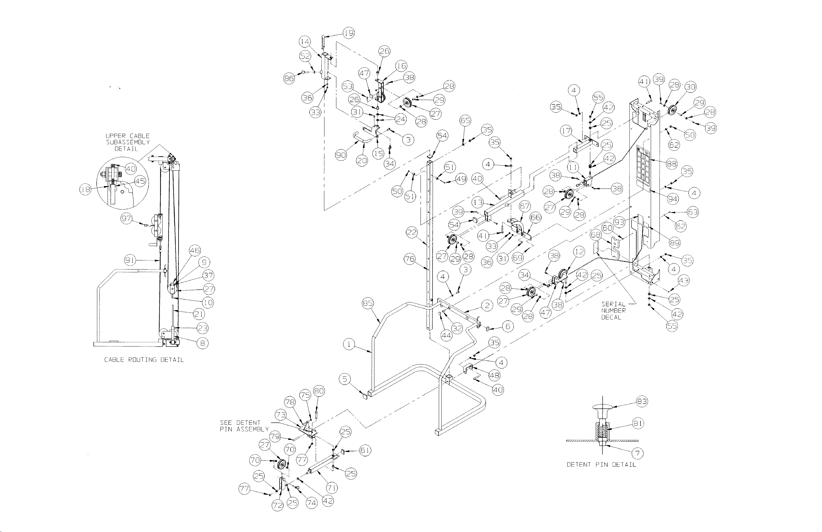
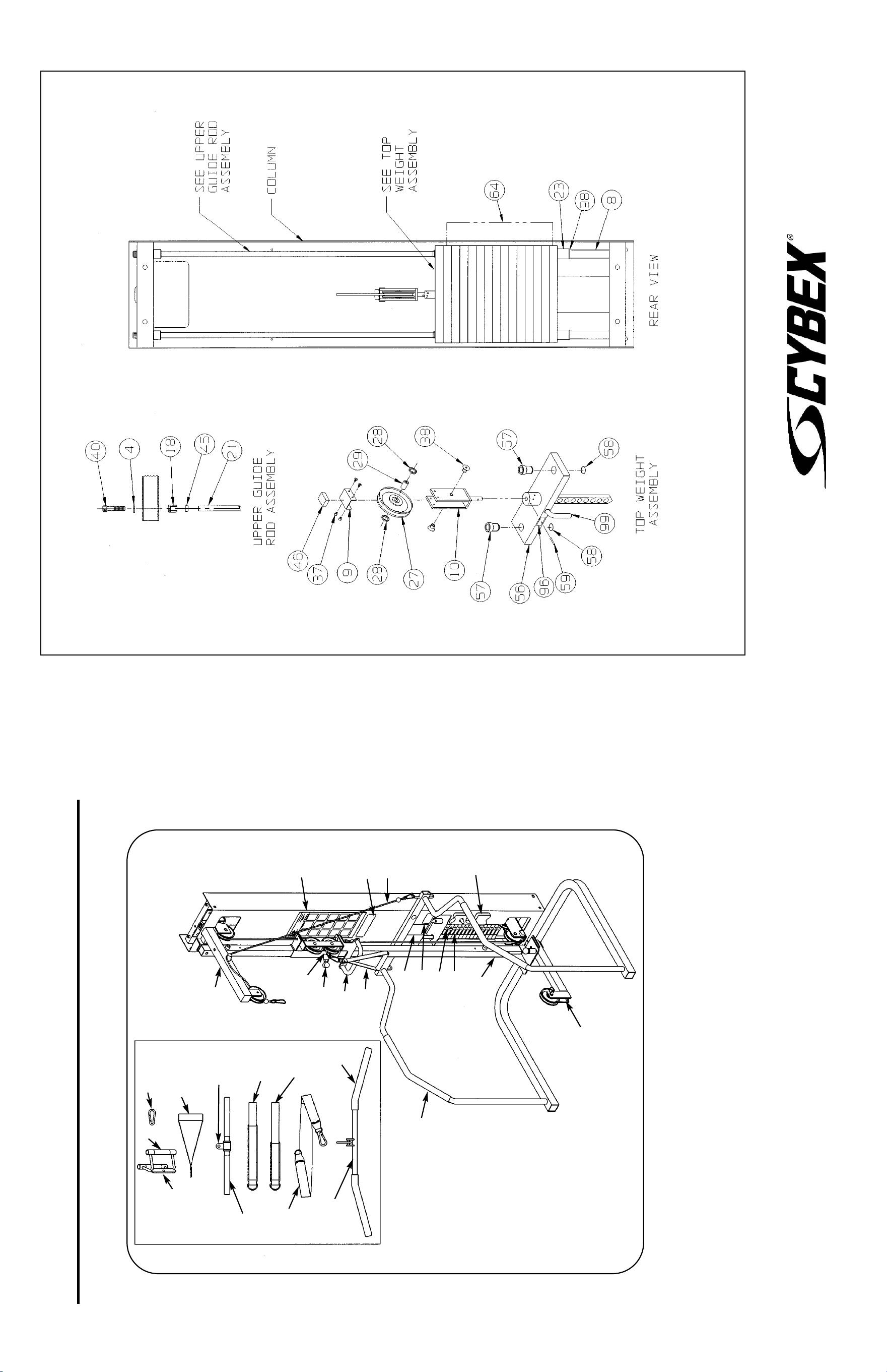
10 Trotter Drive Medway, MA 02053 • 508-533-4300 • FAX 508-533-5183 • www.cybexinternational.com • T[email protected]
Copyright © 2002 CYBEX International, Inc. All rights reserved • 55633 Rev A • August 2007
CABLE COLUMN
5633 ASSEMBLY & PARTS
A. Placard Decal..................... 01159
B. Snap Link........................... GQ000206
C. Handle Subassembly......... 01702
D. Ballet Bar ........................... 5315-307
E. Foam Grip.......................... 5208M046
F. Weight Selector Pin ........... 5310P044
G. Caution Decal .................... 4000Y316
H. Cable Subassembly........... 5315S028
I. Serial Number Decal
J. Handle Subassembly......... 5310S040
K. Warning Decal.................... 02521
L. Foam Grip.......................... 4055M028
M. Straight Handle.................. 02203
N. Ankle Strap ........................ 51122
DESCRIPTION PART NO.
O. Hip Harness ....................... 51073
P. Upper Boom Kit................. 5315K002
Q. Cable Subassembly........... 5315-211
R. Pulldown Bar ..................... 5315-003
S. Handgrip ............................ PR400201
T. Lower Boom Kit................. 5315K003
U. Handle Subassembly......... 01255
V. Half Weight ........................ 4301C096
W. Weight Plate Decal............. 4800-515
X. General Warning Decal...... 4800-381
Y. Foam Grip.......................... 1670M115
Z. Foam Grip.......................... 5310M042
AA. Thigh Strap ........................ 51121
DESCRIPTION PART NO.
B
J
U
O
N
R
S
Z
L
M
X
Q
V
I
W
Y
T
G
F
K
A
H
C
D,E
J
P
AA
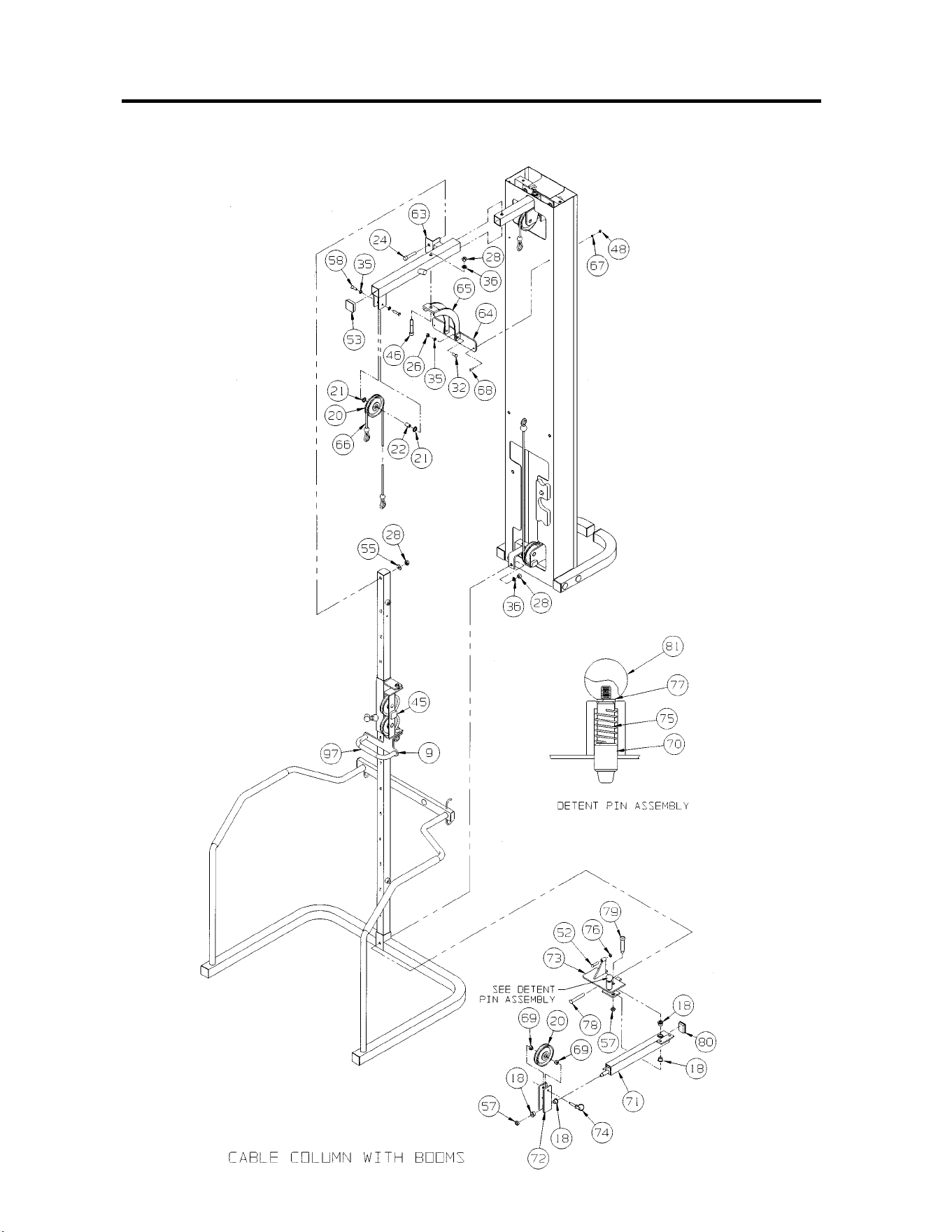
CABLE COLUMN
5315 (WITHOUT BOOMS) AND 5316 (WITH BOOMS)
ASSEMBLY & PARTS

ITEM QTY PART NO. DESCRIPTION
1 2 01755 Long Guide Rod Collet
2 2 01694 Corner Bracket
3 1 4108Y057 Black RLD Number Decal
4 2 01141 Weight Spacer 5.00
5 1 01142 Pulley Mount Cap
6 1 01143 Pulley Mount
7 1 01144 Upper Pulley Bracket
8 1 01155 Pivot Tube
9 1 5315-307 Ballet Bar
10 2 5310M035 Weight Stack Guide Rod
11 1 5310C029 Cover
12 1 5315-203 Adjusting Tube
13 1 5315-202 Ballet Bar Bracket
14 1 01150 Pulley Bracket
15 1 5315P011 Adjusting Tube
16 1 5315S028 Cable Subassembly
17 2 PR060005 Weight Bumper
18 8 FB050219 Flange Bearing .62 x .75 x .50 L
19 2 FB050222 Flange Bearing .75 x .88 x .75 L
20 8 GP000000 Pulley Assembly 4.50
21 16 GP000004 Pulley Spacer
22 8 GP000203 Pulley Center
23 1 GP000204 Pulley Assembly 3.00
24 8 JC782830 SHCS .50-13 x 2.50
25 6 HC782817 SHCS .50-13 x 1.00 (BL Oxide)
26 4 HN704000 Hex Nut .375-16
27 2 HN705618 Nut-Eye Socket
28 16 HN784000 Hex Nut .500-13
29 4 HT582210 Tap Screw #10-32 x .375 F
30 10 JC700914 FHSCS .375-16 x .62
31 Removed
32 4 HC700417 BHSCS .375-16 x 1.00
33 4 JC780417 BHSCS .50-13 x 1.00
34 5 JS407100 Machinery Bushing .625
35 4 HS348300 Split Lockwasher .375
36 14 JS388300 Split Lockwasher .50
37 6 PP080202 Plastic Insert 1.19 Dia. x 11 G
38 2 PP080204 Plastic Cap .625 ID. x .68 OD
39 6 PP090210 Plastic Insert 2.00 Sq x 10-14 G
40 1 PU060200 Bumper
41 2 FB030220 Machinery Bushing
42 Removed
43 4 PN660201 Hole Plug
44 1 01892 Bracket
45 2 PU060201 Bumper
46 2 JC782834 SHCS .50-13 x 3.00
47 2 HC620430 BHSCS .25-20 x 2.50
48 4 HN624100 Hex Nut .25-20
49 4 PR069400 Recess Bumper
50 1 01155 Pivot Tube
51 1 01692 Threaded Insert
52 2 JC700422 BHSCS .375-16 x 1.50
53 2 PP090210 Plastic Insert 2.00 SQ x 10-14 G
54 2 HC781230 HHCS .50-13 x 2.50
55 3 HS387500 Washer .50
56 2 5315-343 Attaching Tab
57 4 HN784900 Nylon Locknut .50-13
58 6 HC700414 BHSCS .375-16 x .62
59 Removed
60 1 01667 Handrail
61 1 5315-201 Cross Tube
62 2 PP090205 Plastic Insert 1.0 x 2.0 x 11 G
63 1 5315-204 Top Tube
64 1 5315-206 Mounting Bracket
ITEM QTY PART NO. DESCRIPTION
65 1 5315-210 Gusset Bracket
66 1 5315-211 Cable Aubassembly
67 3 HS308300 Split Lockwasher .25
68 3 JC620415 BHSCS .25-20 x .75
69 2 01053 Pulley Clevis Adapter
70 1 4113M041 Start Detent Pin
71 1 5315-207 Lower Arm
72 1 5315-208 Pulley Tab
73 1 5315-209 Mounting Bracket
74 1 BH030205 Quick Release Pin .375 x 2.00
75 1 BS070201 Spring .56 ID x .66 OD x 1.50 L
76 1 HN704400 Jam Nut .375-16
77 Removed
78 1 JC780938 FHSCS .50-13 x 3.50
79 1 JD403332 S/Bolt .625 x 2.75 .50-13
80 1 PP090000 Plastic Insert 1.5 x 2.0 x 11 G
81 1 PP460200 Plastic Knob .312-18
82 Removed
83 2 5315-214 Base
84 1 5315-205 Short Top Tube
85 2 1670M115 Handrail Grip
86 2 5310P044 Weight Selector Pin
87 1 4301C096 Half Weight 3 x 12
88 1 02106 Half Weight Peg
89 2 01066 Plastic Fastener
90 1 01691 Handle Lock
91 1 01159 Placard Decal
92 1 4800-381 General Warning Decal
93 1 02521 Warning Decal
94 1 4000Y316 Caution Decal
95 1 3900-378 Cybex Decal 11.37 Vert Wht/Plm
95 1 3900-391 Cybex Decal 11.37 Vert Blk/Plm
95 1 3900-419 Cybex Decal 11.37 Vert Wht/Wht
96 1 4800-515 Weight Plate Decal
97 1 5208M046 Foam Grip 12.75
98 1 GQ000206 Snap Link
99 1 02024 Column
100 1 55315 Cable Column Instruction Sheet
101 1 01475 Top Weight Assembly
102 2 4700-019 Flange Bearing
103 2 BR030206 Retaining Ring
104 1 HP286819 Spiral Pin
105 14 4700C089 Stack Weight 3 x 12 (not shown)
106 1 4700M005 Rubber Cap (not shown)
107 2 HS760106 Flat Washer 1.75 OD .69 ID .14T
108 1 5310S040 Handle Subassembly (not shown)
109 1 02203 Straight Handle (not shown)
110 1 51121 Thigh Strap (not shown)
111 1 51122 Ankle Strap (not shown)
112 1 51073 Hip Harness (not shown)
113 1 5315-003 Pulldown Bar (not shown)
114 1 01255 Handle Subassembly (not shown)
5315 - Cable Column without Booms & 5316 - Cable Column with Booms
NOTE: This machine shipped with an Owner’s Manual.
Additional copies can be obtained by contacting your
dealer or a Cybex Representative at 1-888-462-9239.
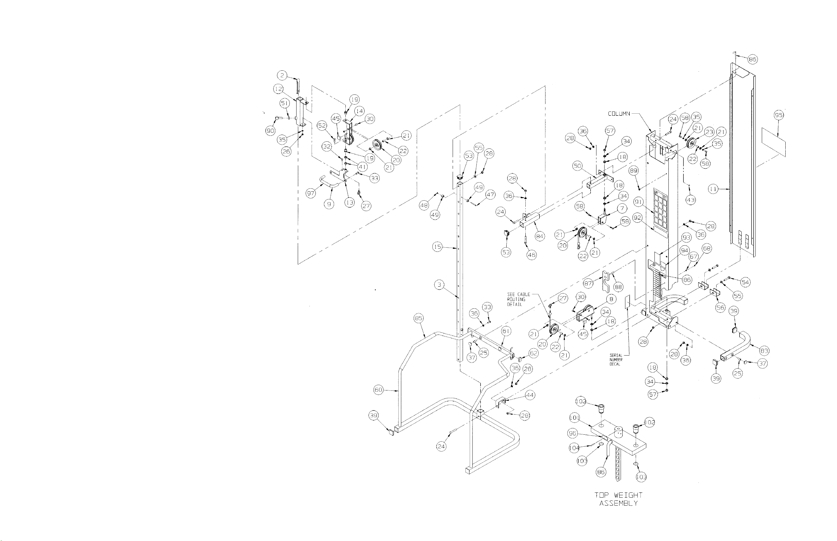
Assembly Notes
1. Keep all shipping packages near area of
installation. Standard items include:
• Cable Column Assembly - 5315A001-9x
• Cable Column Package - 5315-50
• Cable Column Upper Arm Kit - 5315K002
(if applicable)
• Cable Column Lower Arm Kit - 5315K003
(if applicable)
• Top Weight Package (15-3 x 12, black) -01475
• Weight Pack 1 (3 x 12, black) - 4700S110
NOTE: x denotes specific color.
NOTE: Refer to the exploded-view assembly diagram
when performing steps listed below.
2. Attach handrail to column.
3. Install lower pulley bracket (item 8). Install upper
pivot tube (item 50) and upper pulley mount (item 7).
4. Install Upper Boom. See Cable Column With Booms
diagram, located on this instruction sheet and
Upper Boom instructions, supplied with Upper
Boom kit.
NOTE: if not installing Upper Boom, then install
short top tube (item #84).
5. Set chrome tube into hand rail assembly.
Fasten upper portion finger tight.
6. Install Lower Boom if applicable. See Cable
Column With Booms diagram, located on
this instruction sheet and lower boom instructions
supplied with Lower Boom kit.
7. Attach lower portion of hand rail to column.
8. Route cable. NOTE: Be sure to insert cable
through brass bushing. See Cable Routing
Detail.
9. Install weight stack.
10. Install base stabilizers (item #83).
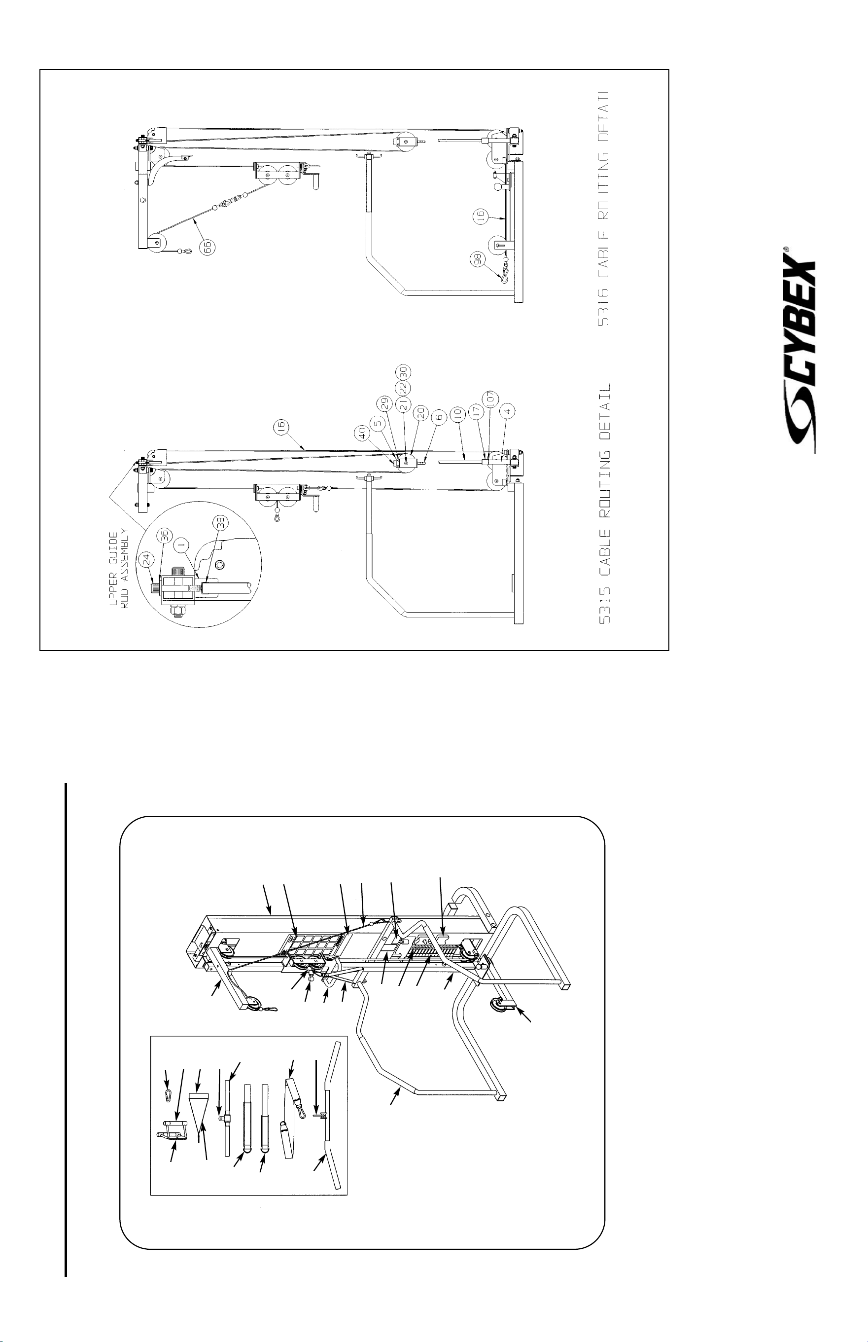
10 Trotter Drive Medway, MA 02053 • 508-533-4300 • FAX 508-533-5183 • www.cybexinternational.com • T[email protected]
Copyright © 2002, 2007 CYBEX International, Inc. All rights reserved • 55315 Rev A • August 2007
CABLE COLUMN
5315 (WITHOUT BOOMS) AND 5316 (WITH BOOMS) ASSEMBLY & PARTS
A. Placard Decal .................... 01159
B. Snap Link .......................... GQ000206
C. Handle Subassembly......... 01072
D. Ballet Bar ........................... 5315-307
E. Foam Grip.......................... 5208M046
F. Weight Selector Pin ........... 5310P044
G. Caution Decal .................... 4000Y316
H. Cable Subassembly........... 5315S028
I. Serial Number Decal
J. Handle Subassembly......... 5310S040
K. Foam Grip.......................... 5310M042
L. Foam Grip.......................... 4055M028
M. Straight Handle.................. 02203
N. Ankle Strap ........................ 51122
O. Hip Harness ...................... 51073
DESCRIPTION PART NO.
P. Upper Boom Kit ................ 5315K002
Q. Cable Subassembly........... 5315-211
R. Pulldown Bar ..................... 5315-003
S. Hand Grip .......................... PR400201
T. Lower Boom Kit................. 5315K003
U. Handle Subassembly......... 01255
V. Half Weight ........................ 4301C096
W. Foam Grip.......................... 1670M115
X. Weight Plate Decal ............ 4800-515
Y. General Warning Decal...... 4800-381
Z. Warning Decal.................... 02521
AA. Cybex Decal Wht/Plm....... 3900-378
AA. Cybex Decal Blk/Plm ........ 3900-391
AA. Cybex Decal Wht/Wht ...... 3900-419
BB. Thigh Strap ....................... 51121
DESCRIPTION PART NO.
U
B
K
S
M
L
O
R
S
N
J
W
I
X
F
Z
T
V
G
Q
P
H
C
D,E
J
AA
A
Y
BB
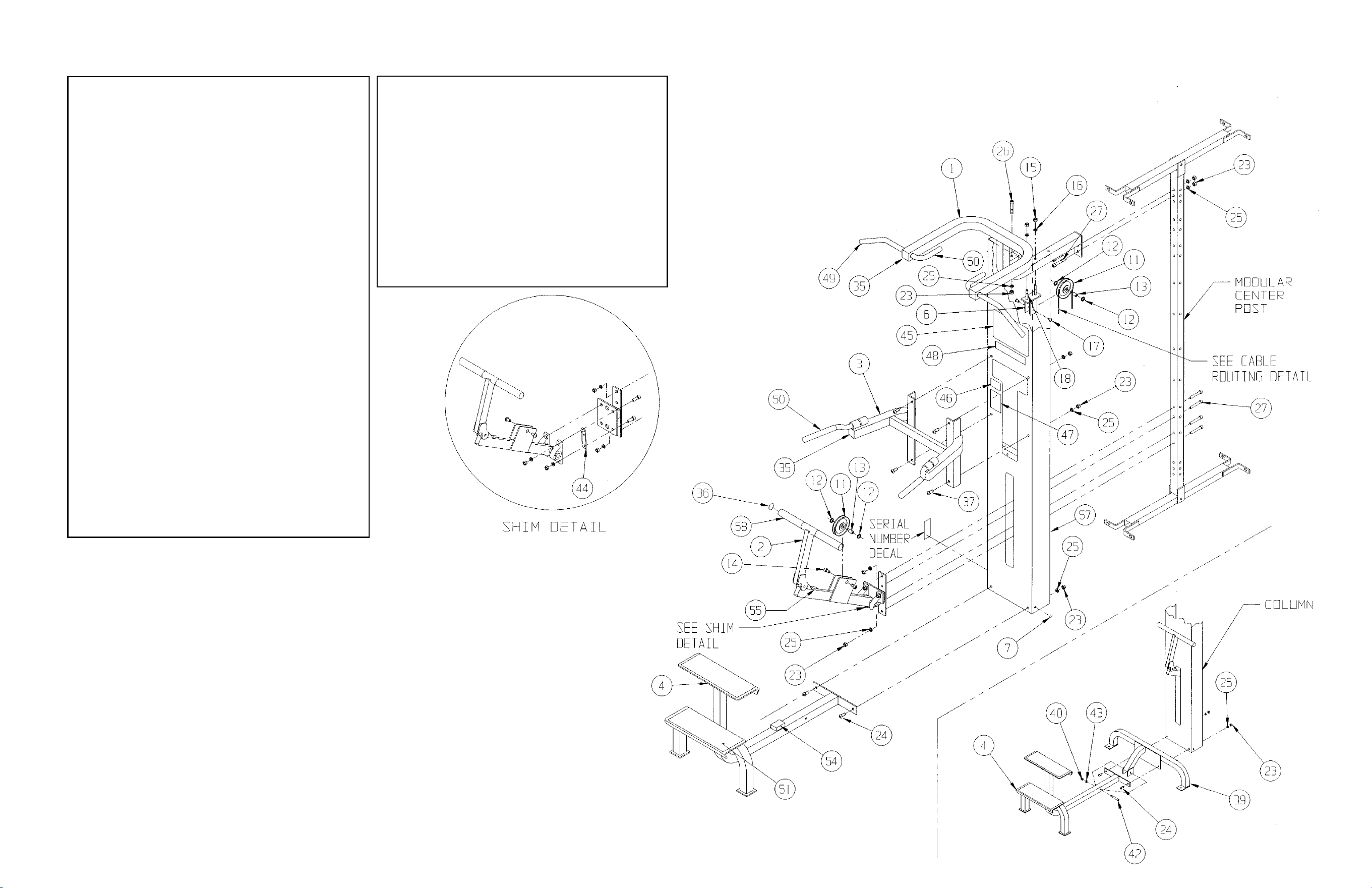
1 1 01291 Upper Arm Subassembly
2 1 5345-003 Lever Assembly
3 1 01297 Arm Subassembly
4 1 01293 Step Assembly
5 2 01755 Guide Rod Collet
6 1 01182 Pulley Mount
7 4 PN660201 Hole Plug
8 2 4107M066 Weight Stack Guide Rod
9 1 8640-330 Spiral Pin 10 MM x 90 MM
10 2 PR060005 Weight Bumper
11 2 GP000000 Pulley Assembly
12 4 GP000004 Pulley Spacer
13 2 GP000203 Pulley Center
14 2 HC700415 BHSCS .375-16 x .75
15 2 HN704000 Hex Nut .375-16
16 2 HS348300 Split Lockwasher .375
17 2 HC700414 BHSCS .375-16 x .625
18 2 JC702832 SHCS .375-16 x 2.75
19 2 JC782830 SHCS .50-13 x 2.50
20 1 JN734200 Hex Nut .438-14
21 1 JN734400 Jam Nut .438-14
22 2 PP080204 Plastic Cap .625 ID x .68 OD
23 13 HN784000 Hex Nut .50-13
24 2 JC780420 BHSCS .50-13 x 1.25
25 15 JS388300 Split Lockwasher .50
26 1 JC782832 SHCS .50-13 x 2.75
27 6 JC782836 SHCS .50-13 x 3.25
28 1 01068 Top Weight Assembly
••29 2 4700-019 Flange Bearing
••30 2 BR030206 Retaining Ring
31 1 4700M005 Rubber Cap
32 1 HP286819 Spiral Pin .188 x 1.12
33 1 02224 Modular Screen (not shown)
••34 19 4005C062 Stack Weight 4 x 12
35 4 PP090210 Plastic Insert 2.00 Sq X 10-14 G
36 2 BG030201 Steel Plug
37 4 JC780417 BHSCS .50-13 x 1.00
38 1 HS347700 Washer .375
• 39 1 01419 Stabilizer
• 40 1 HN784000 Hex Nut .50-13
41 Removed
• 42 1 JC782836 SHCS .50-13 x 3.25
• 43 1 JS388300 Split Lockwasher .50
44 2 5580-324 Shim
45 1 01302 Placard Decal
46 1 4000Y316 Caution Decal
47 1 02521 Warning Decal
48 1 4800-381 General Warning Decal
49 2 PR400201 Foam Grip
50 4 4055M028 Foam Grip
51 2 01186 Non-Slip Fabric
52 1 01187 Cable Subassembly
53 1 5310P044 Weight Selector Pin
54 1 PU060204 Bumper
55 1 PU060201 Bumper
56 1 4800-515 Weight Plate Decal
57 2 5345-319 Rubber Grip 7.75
• See Assembly Note #7.
•• FOR UNITS MANUFACTURED PRIOR TO JUNE 1993, CALL 1-888-462-9239.
Assembly Notes
1. Keep all shipping packages near area of installation. Standard shipping items include:
• Assisted Chin Up/Dip Assembly - 5611-9x • Power Assist Package - 5611-50
• Top Weight Package - 01068 (black) • Weight Pack 1 - 4700S040 (black)
• Weight pack 2 - 4700S043 (black) NOTE: x denotes specific color
2. Follow assembly guidelines listed on the 5600 Modular Center Post Assembly & Parts instruction sheet
or the 5629 Tandem Center Post Assembly & Parts instruction sheet. Also refer to all the assembly notes listed below.
3. After installing weight stack, drive spirally coiled pin (item #9) into third weight plate (hole normally used for selector pin).
Be sure pin is flush.
4. After pinning third weight, install foot lever assembly. Rotate lever arm 90 degrees and slide
through column slot from backside of column. Pillow block covers holes 4 - 7 above crossmember.
5. Adjust cable until foot lever arm touches top of slot in column.
6. Verify weight selector pin goes through each hole in the weight stack.
7. Items 39 - 43 are required when the Assisted Chin Up/Dip station is used in Tandem configuration.
See assembly guidelines listed on the 5629 Tandem Center Post Assembly & Parts instruction sheet,
part number 55629.
5611 - Assist Chin Up/Dip
ITEM QTY PART NO. DESCRIPTION
NOTE: This machine shipped with an Owner’s Manual. Additional
copies can be obtained by contacting your dealer or a Cybex
Representative at 1-888-462-9239.
ITEM QTY PART NO. DESCRIPTION
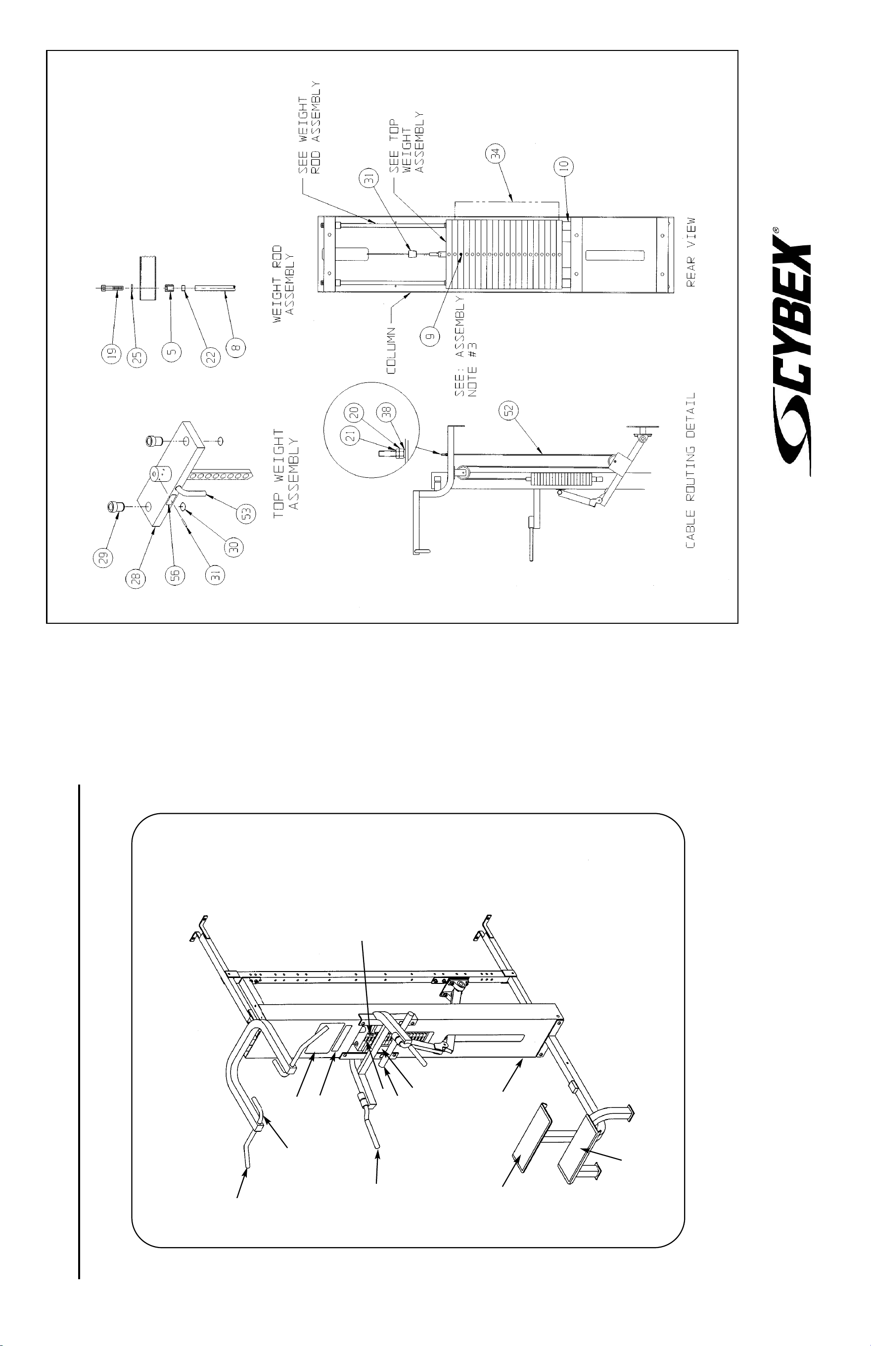
MODULAR ASSIST CHIN UP/DIP
5611 ASSEMBLY & PARTS
A. Foam Grip.......................... PR400201
B. Foam Grip.......................... 4055M028
C. Non-Slip Fabric.................. 01186
D. Cable Subassembly........... 01187
E. Placard Decal .................... 01302
F. Weight Selector Pin ........... 5310P044
DESCRIPTION PART NO.
G. Serial Number Decal
H. Caution Decal .................... 4000Y316
I. Warning Decal.................... 02521
J. General Warning Decal...... 4800-381
K. Weight Plate Decal ............ 4800-515
L. Rubber Grip ....................... 5345-319
DESCRIPTION PART NO.
E
A
B
J
I
G
F
B
NOTE: See exploded-view diagram for
items: D (#52) and H (#46).
K
C
C
L
10 Trotter Drive Medway, MA 02053 • 508-533-4300 • FAX 508-533-5183 • www.cybexinternational.com • T[email protected]
Copyright © 2002, 2004, 2007 CYBEX International, Inc. All rights reserved • 55611 Rev A • August 2007
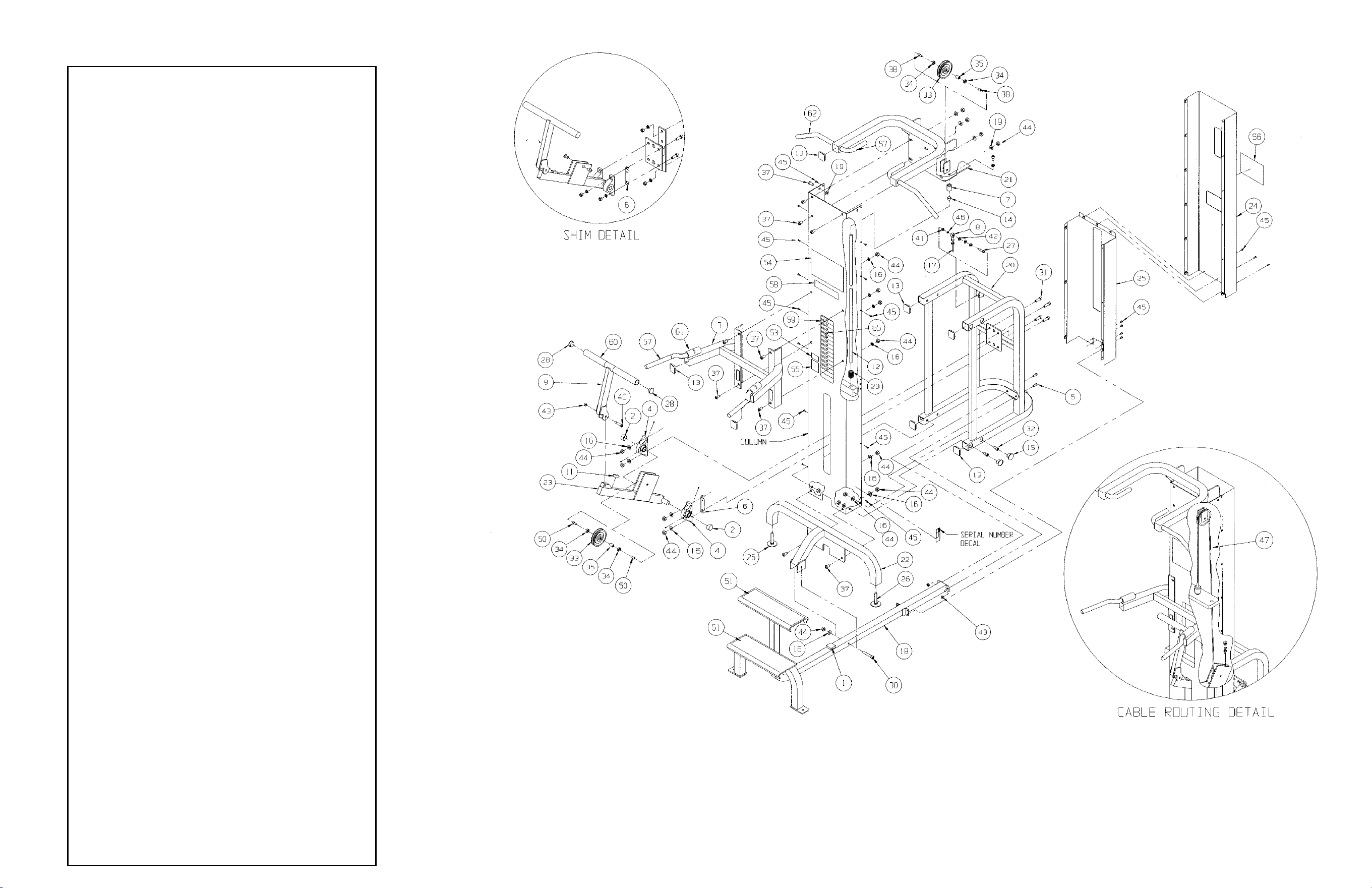
5345 - Single Station Dip/Chin
1 2 PU060204 Bumper
2 2 01190 Vinyl Black End Cap
3 1 01167 Arm Assembly
4 2 4000-100 Pillow Block Bearing
5 2 HC700417 BHSCS .375-16 x 1.00
6 2 5580-324 Shim
7 2 01755 Guide Rod Collet
8 1 FB030213 Rod End Bearing
9 1 5345-206 Lever
10 Removed
11 1 PU060201 Bumper
12 2 4025M073 Weight Stack Guide Rod
13 8 PP090210 Plastic Insert 2.00 x 2.00 x 10-14G
14 2 PP080204 Plastic Cap .625 ID x .68 OD
15 10 PP080202 Plastic Insert 1.19 Dia. x 11 G
16 19 JS387400 Internal Tooth Lackwasher .50
17 1 JN714400 Jam Nut .375-24
18 1 5345-200 Step
19 10 HS387700 Washer SAE .50
20 1 5345-202 Frame
21 1 5345-203 Upper Arm
22 1 5345-204 Support Leg
23 1 02321 Pulley Lever
24 1 5345-303 Top Cover (Backside)
25 1 5345-304 Lower Cover (Backside)
26 2 JG780034 Leveling Guide
27 1 JD343317 Shoulder Bolt .375 x 1.00 .312-18
28 2 BG030201 Steel Plug
29 2 PR060005 Weight Bumper
30 1 JC782834 SHCS .50-13 x 3.00
31 4 JC782822 SHCS .50-13 x 1.50
32 4 JC782815 SHCS .50-13 x .75
33 2 GP000000 Pulley Assembly
34 4 GP000004 Pulley Spacer
35 2 GP000203 Pulley Center
36 1 8640-330 Spiral Pin 10 mm x 90 mm
37 12 JC780417 BHSCS .50-13 x 1.00
38 2 HC700414 BHSCS .375-16 x .62
39 REMOVED
40 1 HD383322 Shoulder Bolt .50 x 1.50 .375-16
41 1 HN664000 Hex Nut .312-18
42 2 HS347600 Washer .375
43 3 HN704901 Nylon Locknut .375-16
44 25 HN784000 Hex Nut .50-13
45 25 JC620410 BHSCS .250-20 x .50
46 1 HS328300 Split Lockwasher .312
47 1 5345-002 Cable Subassembly
48 Removed
49 2 JS388300 Split Lockwasher .50
50 2 JC700914 FHSCS .375-16 x .62
51 2 01186 Non-Slip Fabric
52 Removed
53 2 4000Y316 Caution Decal
54 1 01302 Placard Decal
55 1 02521 Warning Decal
56 1 3900-378 Cybex Decal 11.37 Vert Wht/Plm
56 1 3900-391 Cybex Decal 11.37 Vert Blk/Plm
56 1 3900-419 Cybex Decal 11.37 Vert Wht/Wht
57 4 4055M028 Foam Grip 8.00
58 1 4800-381 Warning Decal
59 1 4800-515 Weight Plate Decal
60 2 5345-319 Rubber Grip 7.75
61 4 FB050206 Sleeve Bearing
62 2 PR400201 Grip 14.00
63 2 BR030206 Retaining Ring
64 1 4700M005 Rubber Cap
65 1 5310P044 Weight Selector Pin
66 19 4005C062 Stack Weight 4 x 12
67 1 01068 Top Weight Assembly
68 2 JC782830 SHCS .50-13 x 2.50
69 2 4700-019 Flange Bearing
70 1 HP286819 Spiral Pin
ITEM QTY PART NO. DESCRIPTION
NOTE: Attach lever arm first without shim.If arm
does not align properly then install shim
on the side that needs the most alignment.
Assembly Notes
1. Attach step (item 18) to column. NOTE: Using two
people, raise column slightly and slide step under column.
2. Attach support leg (item 22) to column. it will be necessary
to raise column slightly by placing two 1/2” washers under
each side of column in order to align holes. Secure step to
support leg. Remove washers after securing support leg.
3. Install weight stack then drive spiral pin (item 36) into third
weight plate (hole normally used for selector pin).
4. Install upper arm assembly (item 21) to column.
NOTE: Two people will be required to install upper arm
assembly.
5. Route cable.
NOTE: This machine shipped with an Owner’s Manual.
Additional copies can be obtained by contacting your dealer
or a Cybex Representative at 1-888-462-9239.
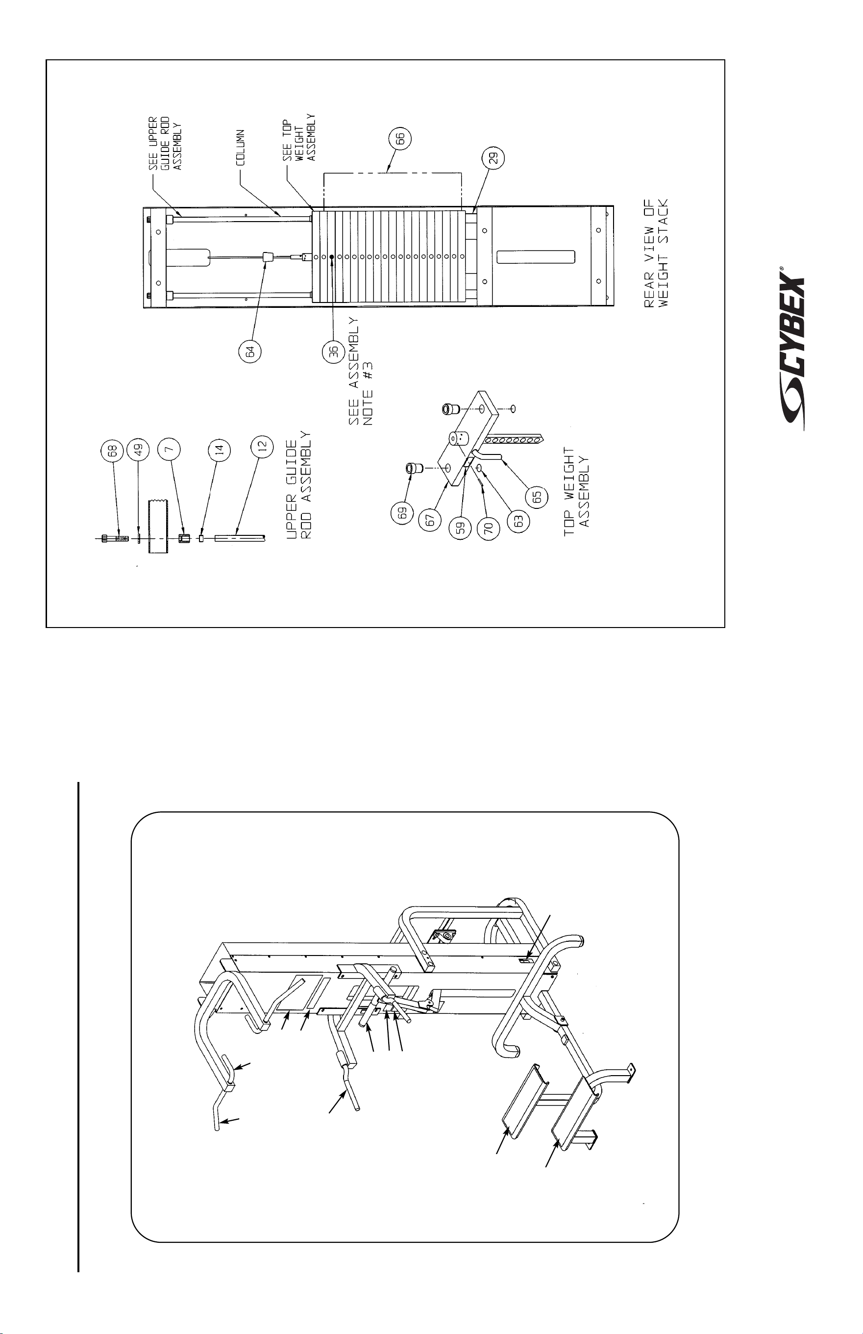
SINGLE STATION DIP/CHIN
5345 ASSEMBLY & PARTS
A. Non-slip Fabric .................. 01186
B. Placard Decal..................... 01302
C. Caution Decal .................... 4000Y316
D. Foam Grip.......................... 4055M028
E. Cybex Decal Wht/Plm ....... 3900-378
E. Cybex Decal Blk/Plm......... 3900-391
E. Cybex Decal Wht/Wht ....... 3900-419
F. Cable Subassembly........... 5345-002
DESCRIPTION PART NO.
G. Rubber Grip ....................... 5345-319
H. Warning Decal.................... 02521
I. Serial Number Decal
J. Grip .................................... PR400201
K. Warning Decal ................... 4800-381
L. Weight Plate Decal ............ 4800-515
M. Weight Selector Pin ........... 5310P044
DESCRIPTION PART NO.
D
C
G
A
A
K
B
H
J
D
I
NOTE: See exploded-view diagram for
items: E (#56), F (#47), L (#59)
and M (#65).
10 Trotter Drive Medway, MA 02053 • 508-533-4300 • FAX 508-533-5183 • www.cybexinternational.com • T[email protected]
Copyright © 2002,2004, 2007 CYBEX International, Inc. All rights reserved • 55345 Rev A • August 2007
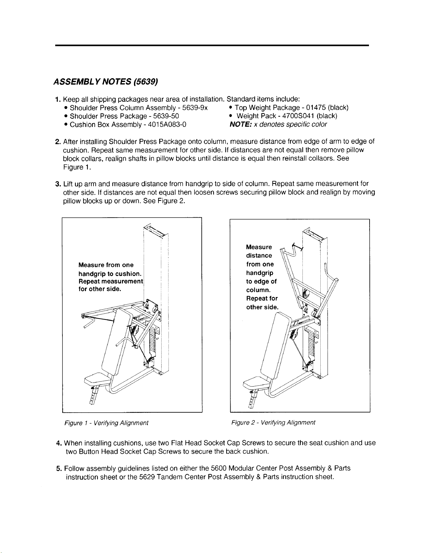
MODULAR SHOULDER PRESS
5639
ASSEMBLY & PARTS

ITEM QTY PART NO. DESCRIPTION
1 2 01084 Spacer 6.00
2 2 01193 Finned Fastener
3 2 01439 Weight Stack Guide Rod
4 2 01755 Guide Rod Collet
5 1 02245 Pulley Bracket
6 2 BS110200 Spring .65 ID x 1.23 OD x 2.07 L
7 5 GP000000 Pulley Assembly 4.50
8 10 GP000004 Pulley Spacer
9 5 GP000203 Pulley Center
10 10 HC700414 BHSCS .375-16 x .625
11 10 HN784000 Hex Nut .50-13
12 4 JC782830 SHCS .50-13 x 2.50
13 Removed
14 12 JS388300 Split Lockwasher .50
15 4 PN660201 Hole Plug
16 2 PP080204 Plastic Cap .625 ID x .68 OD
17 2 01190 Vinyl Back End Cap
18 1 02250 Arm
19 1 02253 Frame
20 1 4000M218 Detent Pin
21 2 4000-100 Pillow Block Bearing
22 1 4025P026 Cushion Mount Subassembly
23 2 BG030202 Steel Plug
24 1 BS070201 Spring .56 ID x .66 OD x 1.50 L
25 1 FB030213 Rod End Bearing (Female) .375-24
26 1 HN664000 Hex Nut .312-18
27 1 HS327600 Washer SAE .312
28 1 HS328300 Split Lockwasher .312
29 4 HS368000 Nylon Washer .443 ID x .75 OD x .125 T
30 2 JC780417 BHSCS .50-13 x 1.00
31 2 JC780420 BHSCS .50-13 x 1.25
32 4 JC780422 BHSCS .50-13 x 1.50
33 1 JD343322 Shoulder Bolt .375 x 1.50 .312-18
34 1 JN714400 Jam Nut .375-24
35 Removed
36 •1 PP090200 Plastic Insert 1.75 Sq x 11 G
37 1 PP090202 Plastic Insert 1.5 x 3.0 x 11 G
38 2 PP090000 Plastic Insert 1.5 x 2.0 x 10-14 G
39 2 PP090205 Plastic Insert 1.0 x 2.0 x 11 G
40 1 PP460200 Plastic Knob .312-18
41 2 PU060201 Bumper
42 1 02106 Half Weight Peg
43 2 4700-019 Flange Bearing
44 1 01475 Top Weight Assembly
45 1 4700M005 Rubber Cap
46 2 BR030206 Retaining Ring
47 1 HP286819 Spiral Pin .188 x 1.12
48 1 HS308300 Split Lockwasher .25
49 1 JC620415 BHSCS .25-20 x .75
50 4 4700C089 Stack Weight 3 x 12
51 10 4005C062 Stack Weight 4 x 12
52 2 JC700920 FHSCS .375-16 x 1.25
53 2 HC700430 BHSCS .375-16 x 2.50
54 Removed
55 1 4025S038-0 Back Cushion
56 1 5520S008-0 Seat Cushion
57 1 02255 Placard Decal
58 1 4000Y316 Caution Decal
59 1 02521 Warning Decal
60 1 3900-426 Vortex Decal
61 1 4800-381 General Warning Decal
62 2 PR400200 Grip
63 1 02254 Cable Subassembly
64 1 4301C096 Half Weight
65 1 5310P044 Weight Selector Pin
66 1 02224 Modular Screen (not shown)
67 1 4800-515 Weight Plate Decal
68 1 4000S118-0 Wear Cover
5639 - Shoulder Press
NOTE: This machine shipped with an Owner’s
Manual. Additional copies can be obtained by
contacting your dealer or a Cybex
Representative at 1-888-462-9239.
NOTE: x denotes specific color
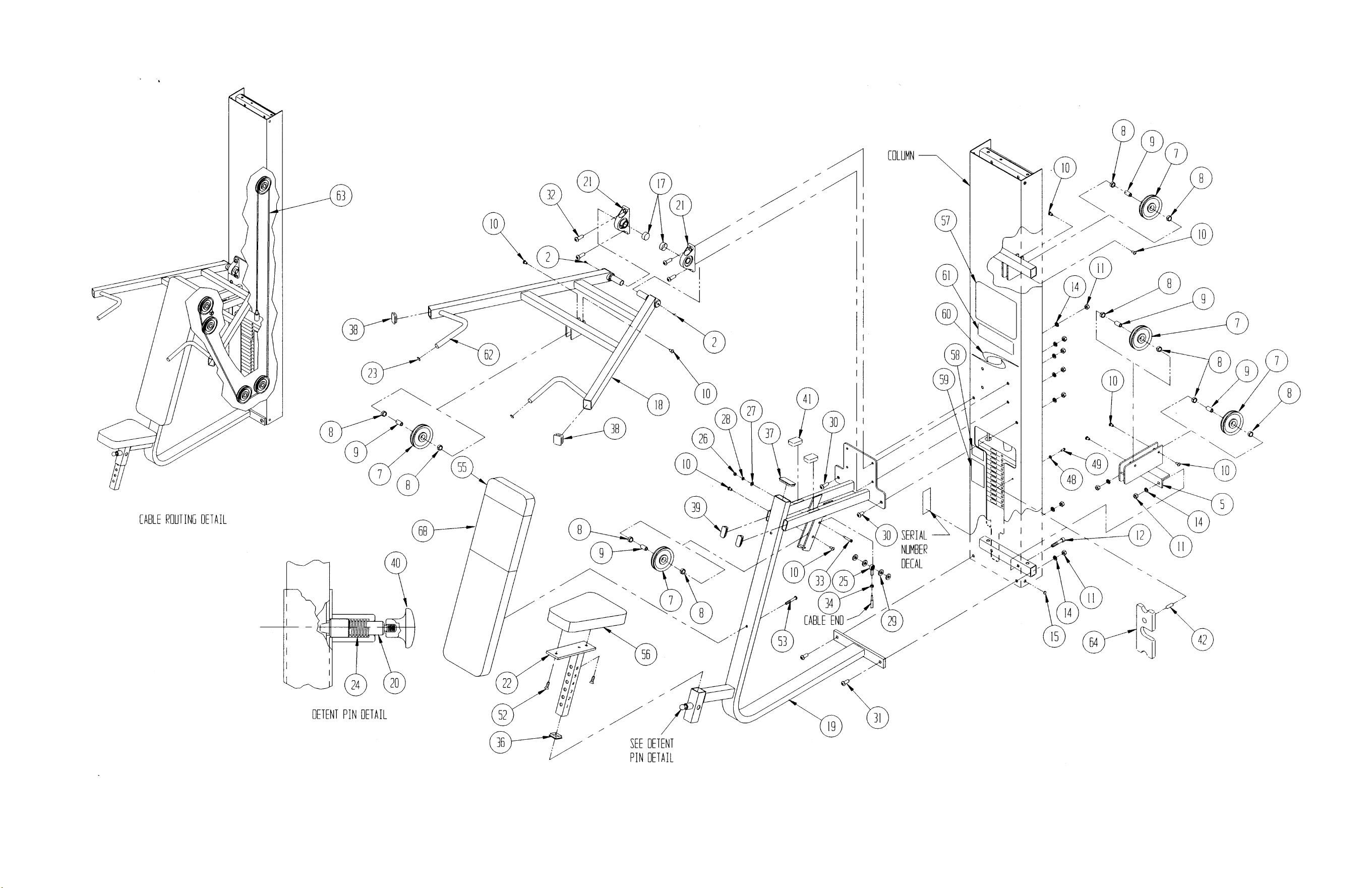
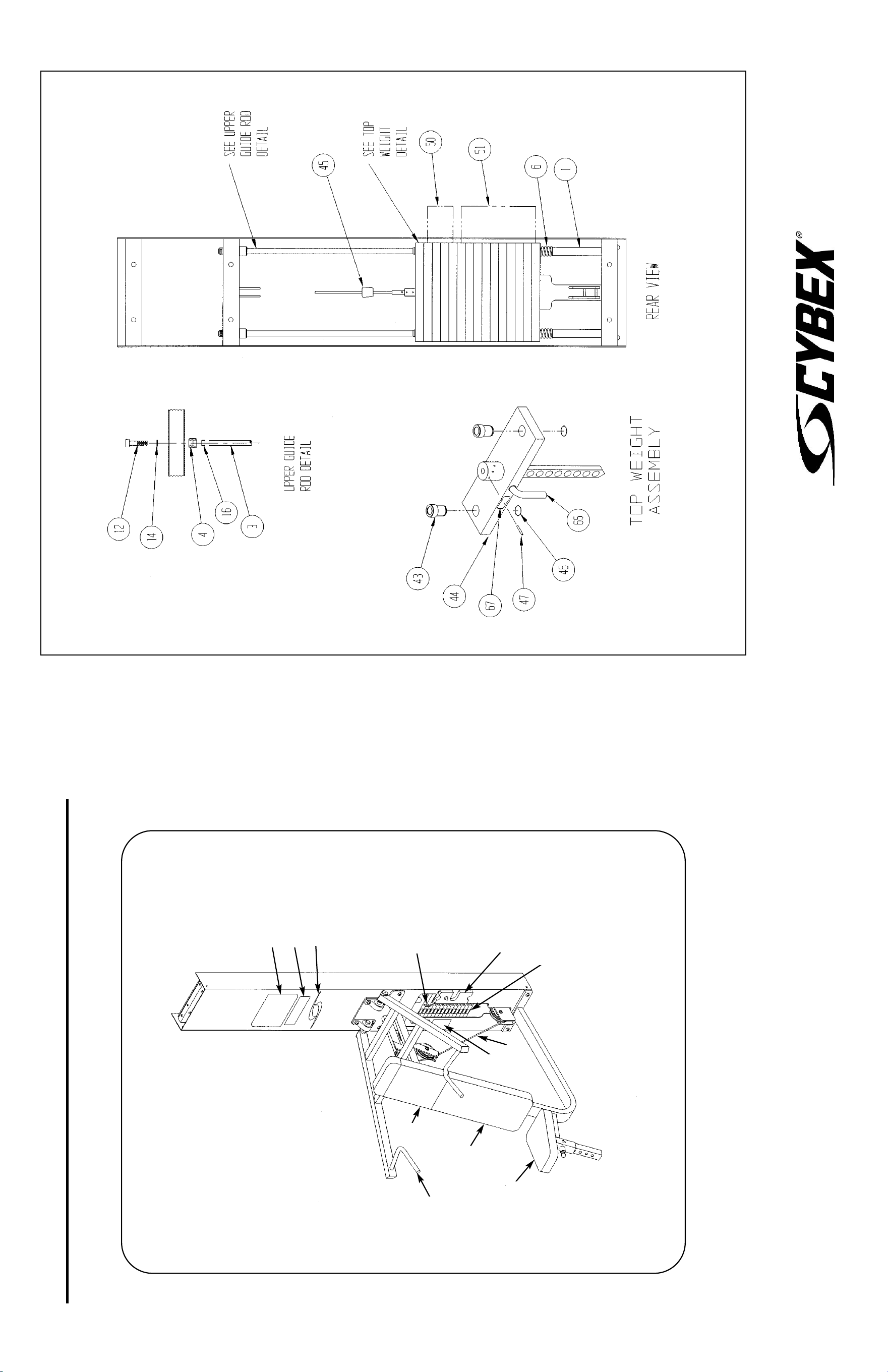
10 Trotter Drive Medway, MA 02053 • 508-533-4300 • FAX 508-533-5183 • www.cybexinternational.com • T[email protected]
Copyright © 2002 CYBEX International, Inc. All rights reserved • 55639 • June 2004
MODULAR SHOULDER PRESS
5639 ASSEMBLY & PARTS
A. Placard Decal..................... 02255
B. Grip .................................... PR400200
C. Back Cushion With
Wear Cover (Item D) .......... 4025S038-0
D. Wear Cover ........................ 4000S118-0
E. Seat Cushion ..................... 5520S008-0
F. Cable Subassembly........... 02254
G. Serial Number Decal
Upholstery Hardware Pack ...... 4015S098
DESCRIPTION PART NO.
H. Caution Decal .................... 4000Y316
I. Half Weight ........................ 4301C096
J. Weight Selector Pin ........... 5310P044
K. Warning Decal.................... 02521
L. Vortex Decal ...................... 3900-426
M. General Warning Decal...... 4800-381
N. Weight Plate Decal ............ 4800-515
DESCRIPTION PART NO.
A
M
L
B
D
C
E
K
F
I
N
NOTE: See exploded-view diagram for
items: G and H (# 58).
J
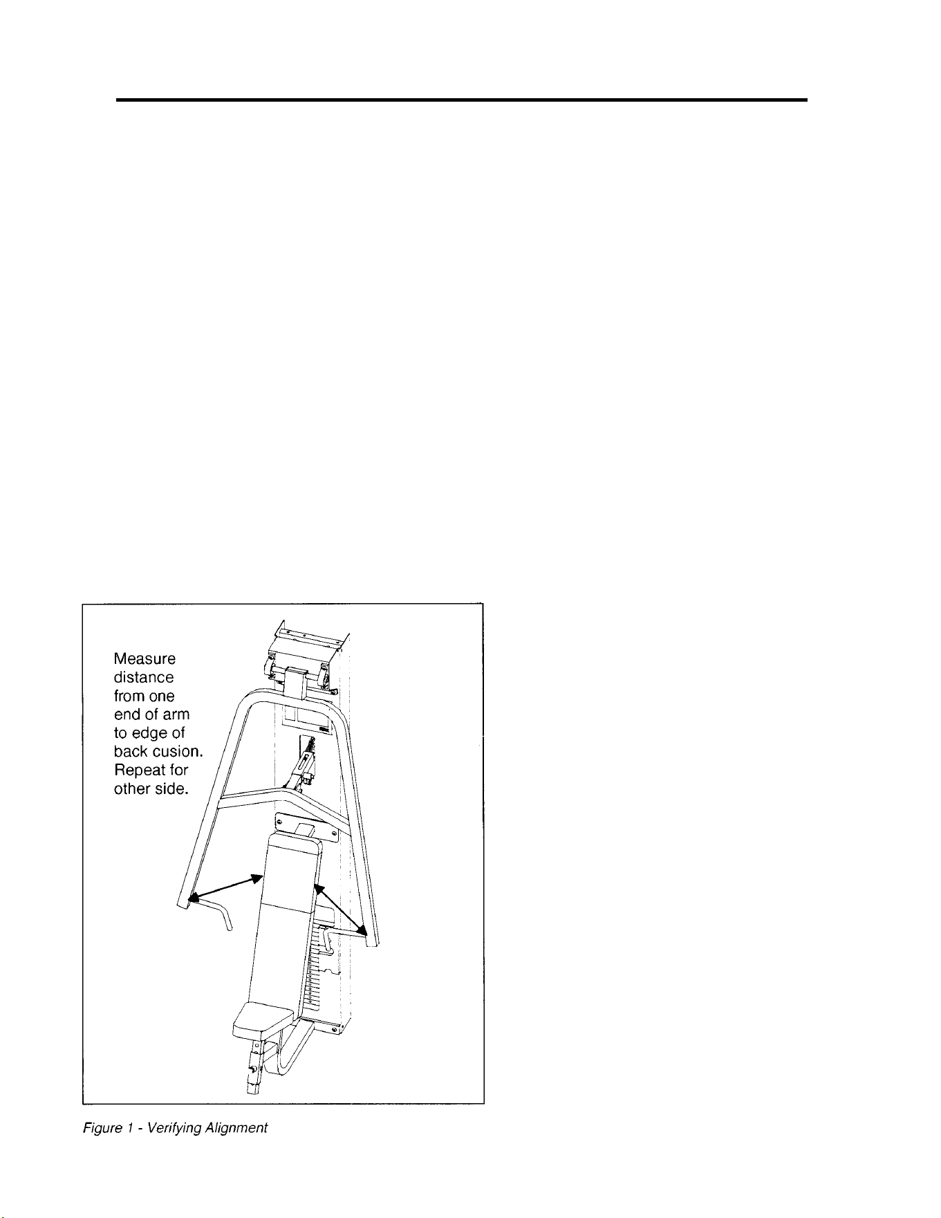
MODULAR CHEST PRESS
5640
ASSEMBLY & PARTS
Assembly Notes
1. Keep all shipping packages near area of installation.
Standard shipping items include:
• Chest Press Column Assembly - 5640-9x
• Chest Press Seat Package - 5640-50
• Chest Press Arm Package 5640-51
• Chest Press Cushion Box Assembly 4015A083-0
• Top Weight Package (20-4 x 12, black) - 4700-010
• Weight Pack 1 (4 x 12, black) - 4700S040
• Weight Pack 2 (4 x 12, black) - 4700S043
NOTE: x denotes specific color
2. Follow steps 1 - 6 of the assembly guidelines listed
on the 5600 Modular Center Post or steps 1 -4 listed
on the 5629 Tandem Center Post Assembly & Parts
instruction sheet.
3. Measure distance from edge of back cushion
to one end of arm. Repeat for other side. See
Figure 1.
4. Adjust position of input arm assembly until the
two measurements are as equal as possible.
5. Install cable end as shown in the Cable Routing
diagram using washer (item #19), hex nut
(item #23 and jam nut (item #24).
6. Install pulley mount (item #53) and adjusting
tube (items #3 and #4).
7. Complete cable routing and then refer to step 8
in the Modular Center Post Assembly & Parts
or step 6 in the Tandem Center Post Assembly
& Parts instruction sheets.
NOTE: This machine shipped with an
Owner’s Manual. Additional copies can be
obtained by contacting your dealer or a
Cybex Representative at 1-888-462-9239.

ITEM QTY PART NO. DESCRIPTION
1 Removed
2 2 01755 Guide Rod Collet
3 1 02293 Adjusting Tube
4 1 02297 Outer Adjusting Tube
5 2 08009 Flange Bearing .50 ID x .62 OD x .50 L
6 2 4000M218 Detent Pin
7 2 4107M066 Weight Stack Guide Rod
8 2 BS070201 Compression Spring
9 2 PR060005 Weight Bumper
10 2 GP000000 Pulley Assembly 4.50
11 6 GP000004 Pulley Spacer
12 3 GP000203 Pulley Center
13 1 GP000207 Pulley Assembly 6.0
14 1 HC662815 SHCS .312-18 x .75
15 6 HC700414 BHSCS .375-16 x .625
16 2 HN704000 Hex Nut .375-16
17 2 HN704901 Nylon Locknut .375-16
18 1 HS328300 Split Lockwasher .312
19 3 HS347700 Washer USS .375
20 2 JC782815 SHCS .50-13 x .75
21 2 JD383326 Shoulder Bolt .50 x 2.00 .375-16
22 2 JD383327 Shoulder Bolt .50 x 2.25 .375-16
23 1 JN714200 Hex Nut .375-24
24 1 JN714400 Jam Nut .375-24
25 Removed
26 14 JS388300 Split Lockwasher .50
27 4 PN660201 Hole Plug
28 2 PP080204 Plastic Cap .625 ID x .68 OD
29 2 PP460200 Plastic Knob .312-18
30 1 02283 Frame
31 12 HN784000 Hex Nut .50-13
32 2 JC780417 BHSCS .50-13 x 1.00
33 10 JC780420 BHSCS .50-13 x 1.25
34 1 HC661217 HHCS .312-18 x 1.00
35 1 PP090200 Plastic Insert 1.75 Sq x 11 G
36 2 HC700430 BHSCS .375-16 x 2.50
37 2 01190 Vinyl Black End Cap
38 1 02301 Arm
39 1 02319 Bearing Mount
40 2 4000-100 Pillow Block Bearing
41 4 HS387500 Washer USS .50
42 2 PP090201 Plastic Insert 2.00 Sq x 11 G
43 2 4700-019 Flange Bearing
44 1 4700-010 Top Weight Assembly
45 2 BR030206 Retaining Ring
46 4 HP286819 Spiral Pin 1.12 ID x .188 OD
47 1 02106 Half Weight Peg
48 1 4700M005 Rubber Cap
49 1 HS308300 Split Lockwasher .25
50 1 JC620415 BHSCS .25-20 x .75
51 19 4005C062 Stack Weight 4 x 12
52 2 JC700920 FHSCS .375-16 x 1.25
53 1 02303 Pulley Mount
54 1 4025P026 Cushion Mount
55 1 PR060003 Recess Bumper
56 1 HN664900 Nylon Locknut .312-18
57 Removed
58 1 4025S038-0 Back Cushion
59 1 5520S008-0 Seat Cushion
60 1 02320 Placard Decal
61 1 4000Y316 Caution Decal
62 1 02521 Warning Decal
63 1 4605-381 General Warning Decal
64 1 5310P044 Weight Selector Pin
65 2 PR400200 Grip
66 1 C-ZA000200 Half Weight
67 1 02225 Modular Screen (not shown)
68 1 4800-515 Weight Plate Decal
69 1 4116S072 Cable Subassembly 71.88
70 1 4000S118-0 Wear Cover
5640 - Chest Press
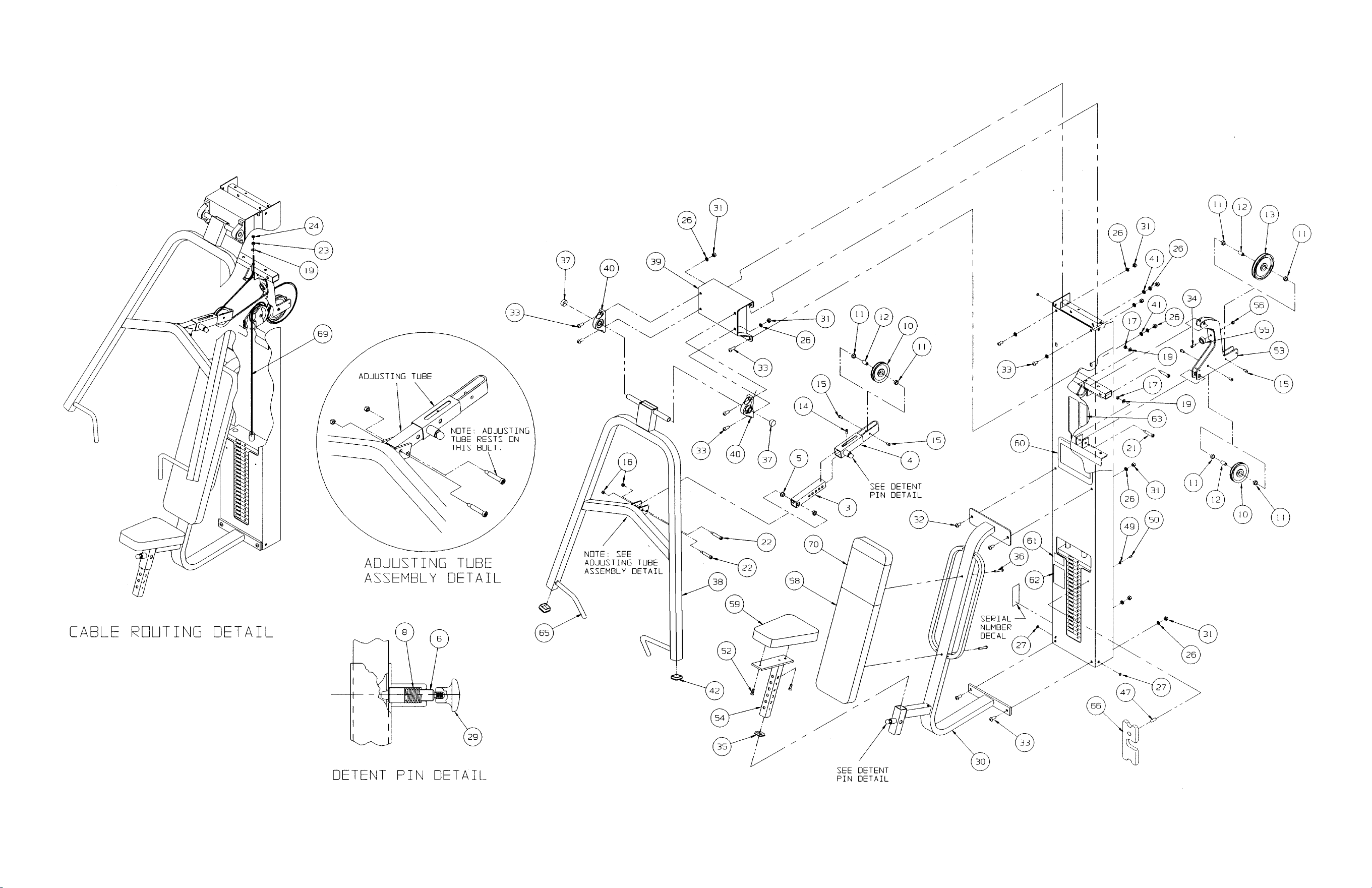
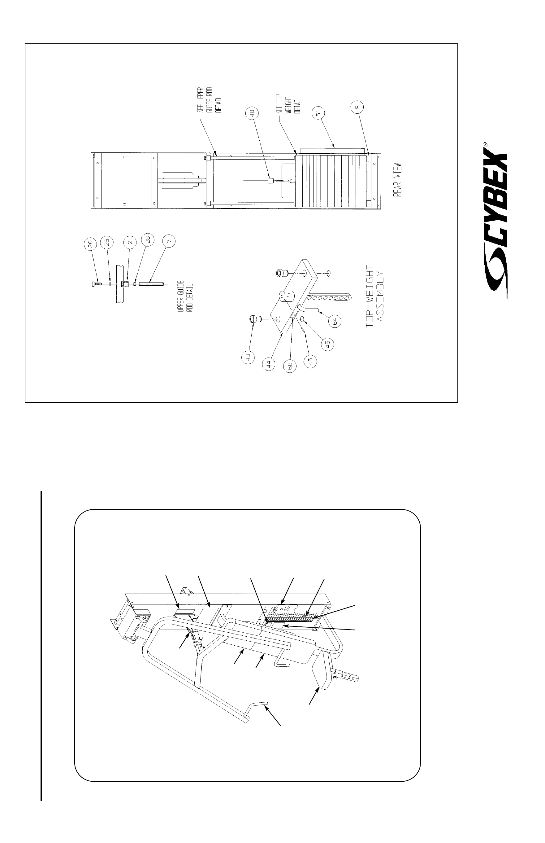
10 Trotter Drive Medway, MA 02053 • 508-533-4300 • FAX 508-533-5183 • www.cybexinternational.com • T[email protected]
Copyright © 2002 CYBEX International, Inc. All rights reserved • 55640 • June 2004
MODULAR CHEST PRESS
5640 ASSEMBLY & PARTS
A. Placard Decal..................... 02320
B. Weight Selector Pin ........... 5310P044
C. Back Cushion With
Wear Cover (Item D) .......... 4025S038-0
D. Wear Cover ........................ 4000S118-0
E. Seat Cushion ..................... 5520S008-0
F. Hand Grip .......................... PR400200
Upholstery Hardware Pack ...... 4015S098
DESCRIPTION PART NO.
G. Caution Decal .................... 4000Y316
H. Half Weight ........................ C-ZA000200
I. Cable Subassembly........... 4116S072
J. Serial Number Decal
K. Warning Decal.................... 02521
L. General Warning Decal...... 4605-381
M. Weight Plate Decal............. 4800-515
DESCRIPTION PART NO.
C
D
F
E
H
G
A
I
B
L
K
M
NOTE: See exploded-view diagram for item J.
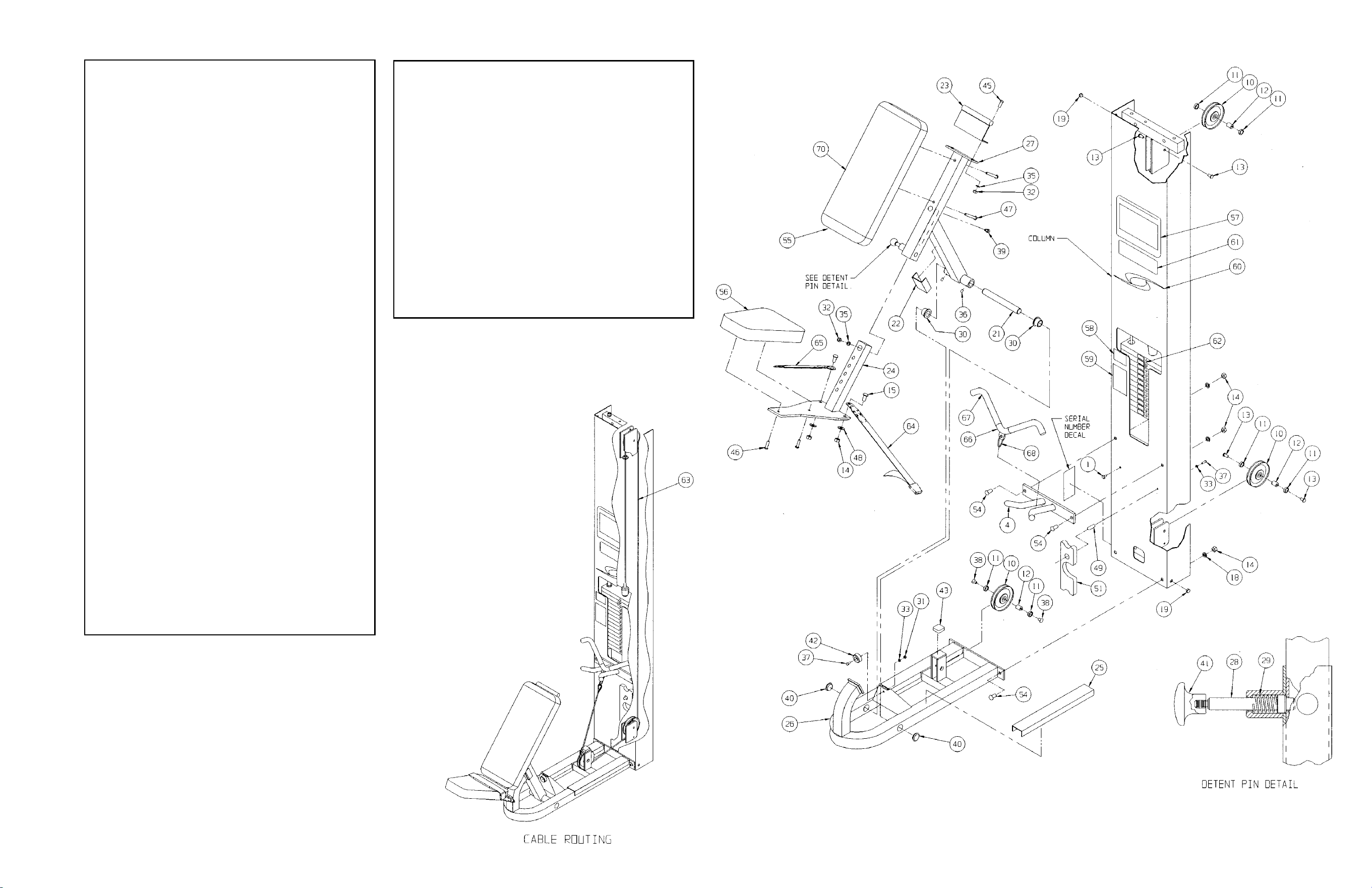
ITEM QTY PART NO. DESCRIPTION
1 Removed
2 2 01439 Weight Stack Guide Rod
3 2 01755 Guide Rod Collet
4 1 02311 Bar Holder
5 2 BR030206 Retaining Ring
6 2 HP286819 Spiral Pin .
7 2 02330 Spacer
8 14 4700C089 Stack Weight 3 x 12
9 2 PR060005 Weight Bumper
10 3 GP000000 Pulley Assembly 4.50
11 6 GP000004 Pulley Spacer
12 3 GP000203 Pulley Center
13 4 HC700414 BHSCS .375-16 x .625
14 8 HN784000 Hex Nut .50-13
15 2 JC780417 BHSCS .50-13 x 1.00
16 2 JC782830 SHCS .50-13 x 2.50
17 Removed
18 6 JS388300 Split Lockwasher .50
19 4 PN660201 Hole Plug
20 2 PP080204 Plastic Cap .625 ID x .68 OD
21 1 01438 Upper Pivot Shaft
22 1 01441 Machined Bumper
23 1 02306 Stabilizer
24 1 02308 Adjusting Post
25 2 02309 Bumper
26 1 02317 Base Frame
27 1 02325 Seat Weldment
28 1 2450M930 Detent Pin
29 1 BS070201 Compression Spring
30 2 FB050209 Flange Bearing
31 1 HN624100 Hex Nut .25-20
32 3 HN704000 Hex Nut .375-16
33 2 HS308300 Split Lockwasher .25
34 Removed
35 3 HS348300 Split Lockwasher .375
36 2 HY662912 Set Screw .312-18 x .50
37 2 JC620415 BHSCS .25-20 x .75
38 2 JC700914 FHSCS .375-16 x .62
39 1 JC702814 SHCS .375-16 x .625
40 2 PP080202 Plastic Insert
1.19 Dia. X 11 G
41 1 PP460200 Plastic Knob .312-18
42 1 PR060003 Recess Bumper
43 1 PU060200 Bumper
44 1 02224 Modular Screen (not shown)
45 2 HC700417 BHSCS .375-16 x 1.00
46 2 JC700420 BHSCS .375-16 x 1.25
47 2 JC700434 BHSCS .375-16 x 3.00
48 2 JS387400 Internal Tooth Lockwasher .50
49 1 02106 Half Weight Peg
50 2 4700-019 Flange Bearing
ITEM QTY PART NO. DESCRIPTION
51 1 4301C096 Half Weight 3 x 12
52 1 4700-016 Top Weight Assembly
53 1 4700M005 Rubber Cap
54 4 JC780420 BHSCS .50-13 x 1.25
55 1 02329-0 Back Cushion
56 1 5520S008-0 Seat Cushion
57 1 02323 Placard Decal
58 1 4000Y316 Caution Decal
59 1 02521 Warning Decal
60 1 3900-426 Vortex Decal
61 1 4800-381 General Warning Decal
62 1 5310P044 Weight Selector Pin
63 1 02315 Cable Subassembly
64 1 405UB050 Seat Belt (Buckle Half)
65 1 405UB051 Seat Belt (Connector Half)
66 1 51013 Cambered Handle
67 2 4055M028 Foam Grip
68 1 GQ000206 Snap Link
69 1 4800-515 Weight Plate Decal
70 1 01458 Wear Cover
71 2 HS760106 Flat Washer 1.75 OD .69 ID .14
5641 - Tricep Extension
Assembly Notes
1. Keep all shipping packages near area of installation.
Standard shipping items include:
• Tricep Extension Column Assembly - 5641-9x
• Tricep Extension Package - 5641-50
• Tricep Extension Cushion Box Assembly - 5641-0
• Top Weight Package (15-3 x 12, black) - 4700-016
• Weight Pack (3 x 12, black) - 4700S110
NOTE: x denotes specific color
2. Follow assembly guidelines listed on the 5600 Modular Center Post
or the 5629 Tandem Center Post Assembly & Parts instruction sheet.
NOTE: This machine shipped with an Owner’s
Manual. Additional copies can be obtained by
contacting your dealer or a Cybex Representative
at 1-888-462-9239.
NOTE: Install cushion so
that top of cushion is
located just below round
bar on stabilizer (Item
#23).
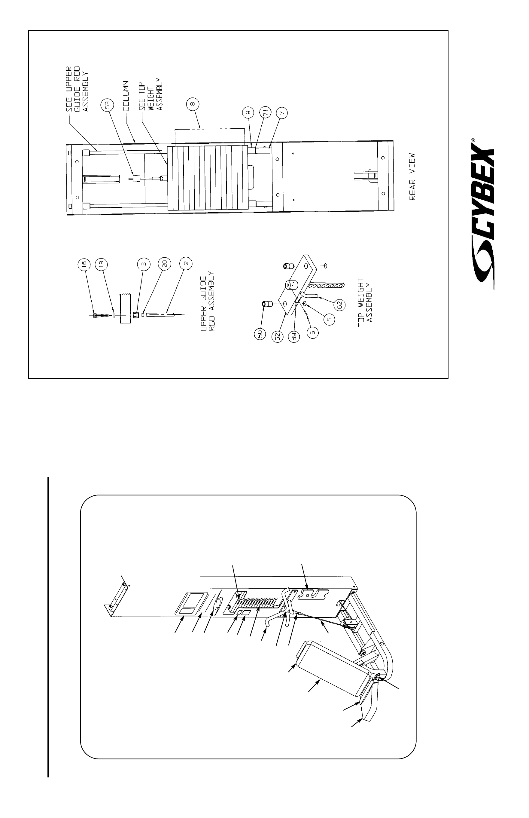
MODULAR TRICEP EXTENSION
5641 ASSEMBLY & PARTS
A. Placard Decal..................... 02323
B. Weight Selector Pin ........... 5310P044
C. Caution Decal .................... 4000Y316
D. Back Cushion With
Wear Cover (Item E)........... 02329-0
E. Wear Cover ........................ 01458
F. Seat Cushion ..................... 4015S073-0
G. Half Weight ........................ 4301C096
H. Lap Belt (Buckle Half) ........ 405UB050
Upholstery Hardware Pack ...... 02316
DESCRIPTION PART NO.
I. Lap Belt
(Connector Half)................. 405UB051
J. Cambered Handle.............. 02203
K. Foam Grip.......................... 4055M028
L. Snap Link........................... GQ000206
M. Cable Subassembly........... 02315
N. Serial Number Decal
O. Warning Decal.................... 02521
P. Vortex Decal ...................... 3900-426
Q. General Warning Decal...... 4800-381
R. Weight Plate Decal ............ 4800-515
DESCRIPTION PART NO.
F
H
I
M
D
G
L
J
K
R
O
C
P
Q
A
E
B
NOTE: See exploded-view diagram
for item N.
10 Trotter Drive Medway, MA 02053 • 508-533-4300 • FAX 508-533-5183 • www.cybexinternational.com • T[email protected]
Copyright © 2002 CYBEX International, Inc. All rights reserved • 55641 • June 2004
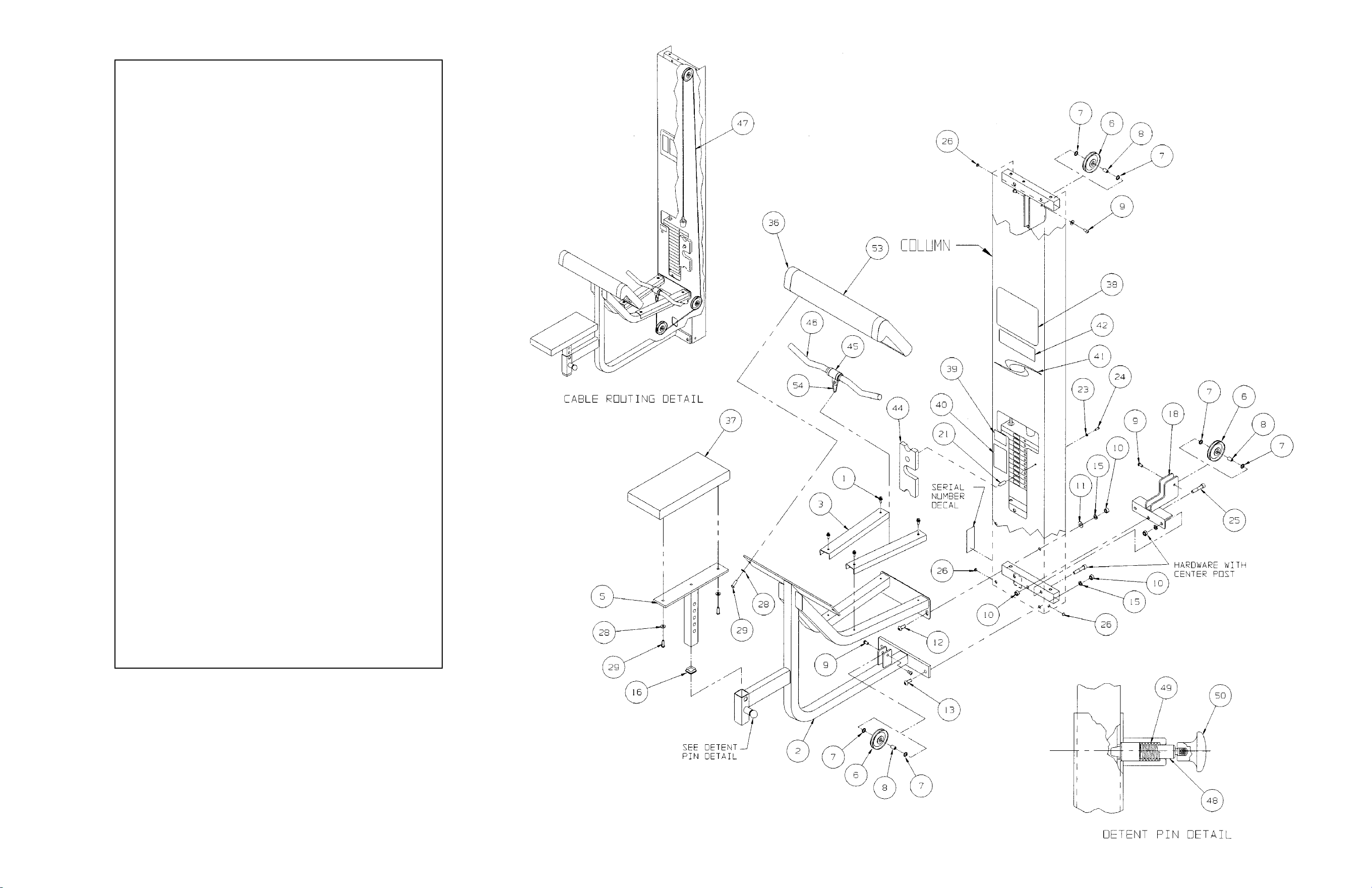
ITEM QTY PART NO. DESCRIPTION
1 4 01066 Plastic Fastener
2 1 02489 Frame
3 2 02490 Bumper
4 Removed
5 1 5460P022 Cushion Mount
6 3 GP000000 Pulley Assembly 4.50
7 6 GP000004 Pulley Spacer
8 3 GP000203 Pulley Center
9 6 HC700414 BHSCS .375-16 x .625
10 5 HN784000 Hex Nut .50-13
11 2 HS387700 Washer SAE .50
12 2 JC780417 BHSCS .50-13 x 1.00
13 2 JC780420 BHSCS .50-13 x 1.25
14 Removed
15 6 JS388300 Split Lockwasher .50
16 1 PP090200 Plastic Insert 1.75 Sq x 11 G
17 Removed
18 1 01247 Pulley Mount
19 2 01521 Weight Stack Guide Rod
20 2 01755 Guide Rod Collet
21 1 02106 Half Weight Peg
22 2 PR060005 Weight Bumper
23 1 HS308300 Split Lockwasher .25
24 1 JC620415 BHSCS .25-20 x .75
25 3 JC782830 SHCS .50-13 x 2.50
26 4 PN660201 Hole Plug
27 2 PP080204 Plastic Cap .625 ID x .68 OD
28 4 HS347600 Washer SAE .375
29 4 JC700420 BHSCS .375-16 x 1.25
30 2 4700-019 Flange Bearing
31 1 4700-016 Top Weight Assembly
32 1 4700M005 Rubber Cap
33 2 BR030206 Retaining Ring
34 1 HP286819 Spiral Pin
35 14 4700C089 Stack Weight 3 x 12
36 1 01216 Arm Cushion
37 1 4800-024 Seat Cushion
38 1 02493 Placard
39 1 4000Y316 Caution Decal
40 1 02521 Warning Decal
41 1 3900-426 Vortex Decal
42 1 4800-381 General Warning Decal
43 1 5310P044 Weight Selector Pin
44 1 4301C096 Half Weight
45 1 02199 Handle
46 1 02205 Grip
47 1 02492 Cable Subassembly
48 1 4000M218 Detent Pin
49 1 BS070201 Com Spring
50 1 PP460200 Plastic Knob
51 1 02224 Modular Screen (not shown)
52 1 4800-515 Weight Plate Decal
53 1 5460S013-0 Wear Cover
54 1 GQ000206 Snap Link
5644 - Arm Curl
Assembly Notes
1. Keep all shipping packages near area of installation.
• Standard shipping items include:
• Arm Curl Column Assembly - 5644-9x
• Arm Curl Package - 5644-50
• Cushion Box Assembly - 5460A020-0
• Top Weight Package (15 - 3 x 12, black) - 4700-016
• Weight Pack (3 x 12, black) - 4700S110
NOTE: x denotes specific color
2. Follow assembly guidelines listed on the 5600 Modular Center Post or the 5629
Tandem Center Post Assembly & Parts instruction sheet.
NOTE: This machine shipped with an Owner’s
Manual. Additional copies can be obtained by
contacting your dealer or a Cybex Representative
at 1-888-462-9239.
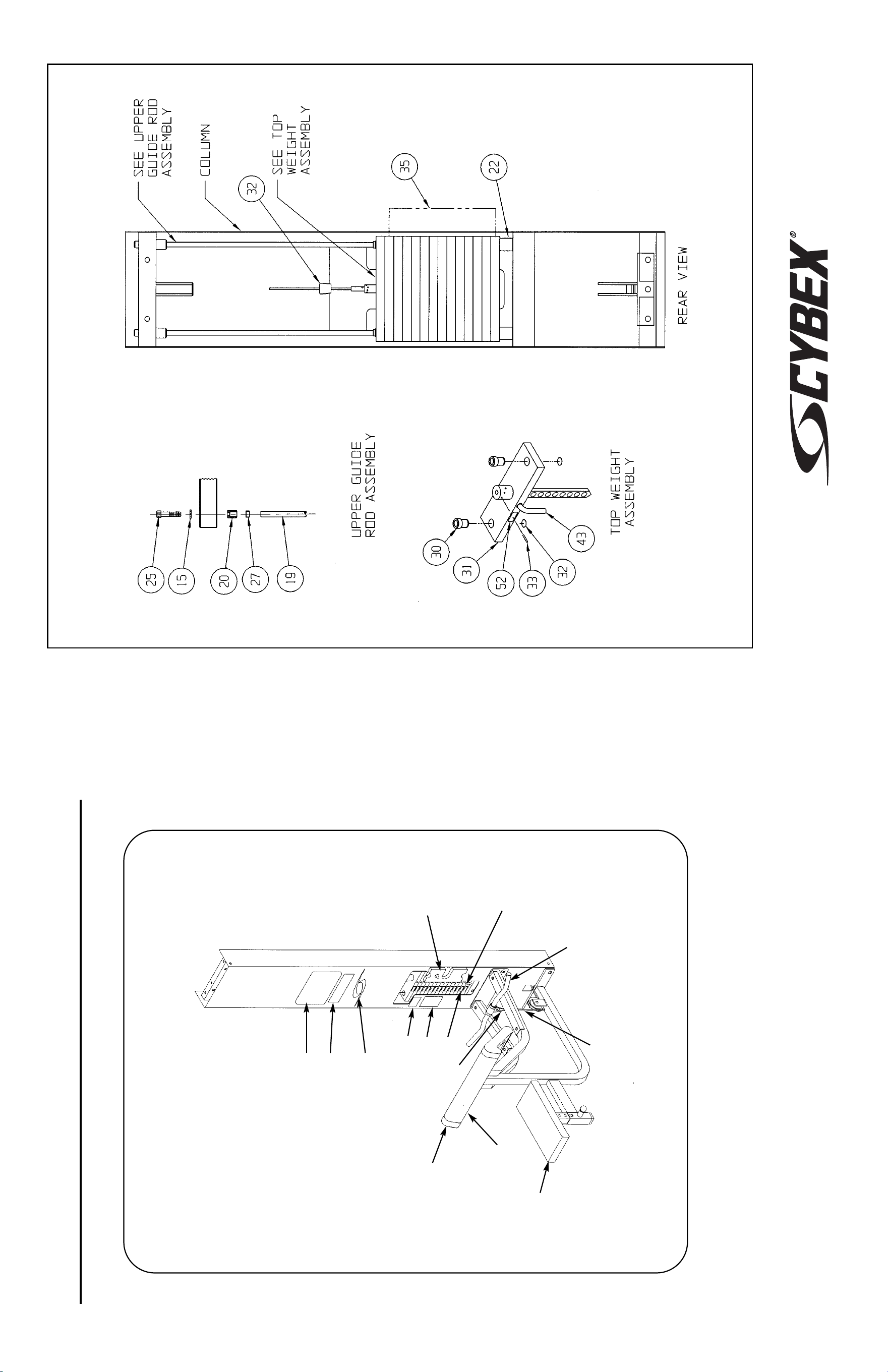
MODULAR ARM CURL
5644 ASSEMBLY & PARTS
A. Placard Decal..................... 02493
B. Weight Selector Pin ........... 5310P044
C. Caution Decal .................... 4000Y316
D. Arm Cushion With
Wear Cover (Item E)........... 01216
E. Wear Cover ........................ 5460S013-0
F. Seat Cushion ..................... 4800-024
G. Half Weight ........................ 4301C096
H. Handle Subassembly......... 02199
Upholstery Hardware Pack ...... 5460S014
DESCRIPTION PART NO.
I. Snap Link........................... GQ000206
J. Cable Subassembly........... 02492
K. Foam Grip.......................... 02205
L. Serial Number Decal
M. Warning Decal.................... 02521
N. Vortex Decal....................... 3900-426
O. General Warning Decal...... 4800-381
P. Weight Plate Decal ............ 4800-515
DESCRIPTION PART NO.
A
O
N
M
C
G
H,K
J
F
D
E
I
B
P
NOTE: See exploded-view diagram for
item: L.
10 Trotter Drive Medway, MA 02053 • 508-533-4300 • FAX 508-533-5183 • www.cybexinternational.com • T[email protected]
Copyright © 2002 CYBEX International, Inc. All rights reserved • 55644 • June 2004
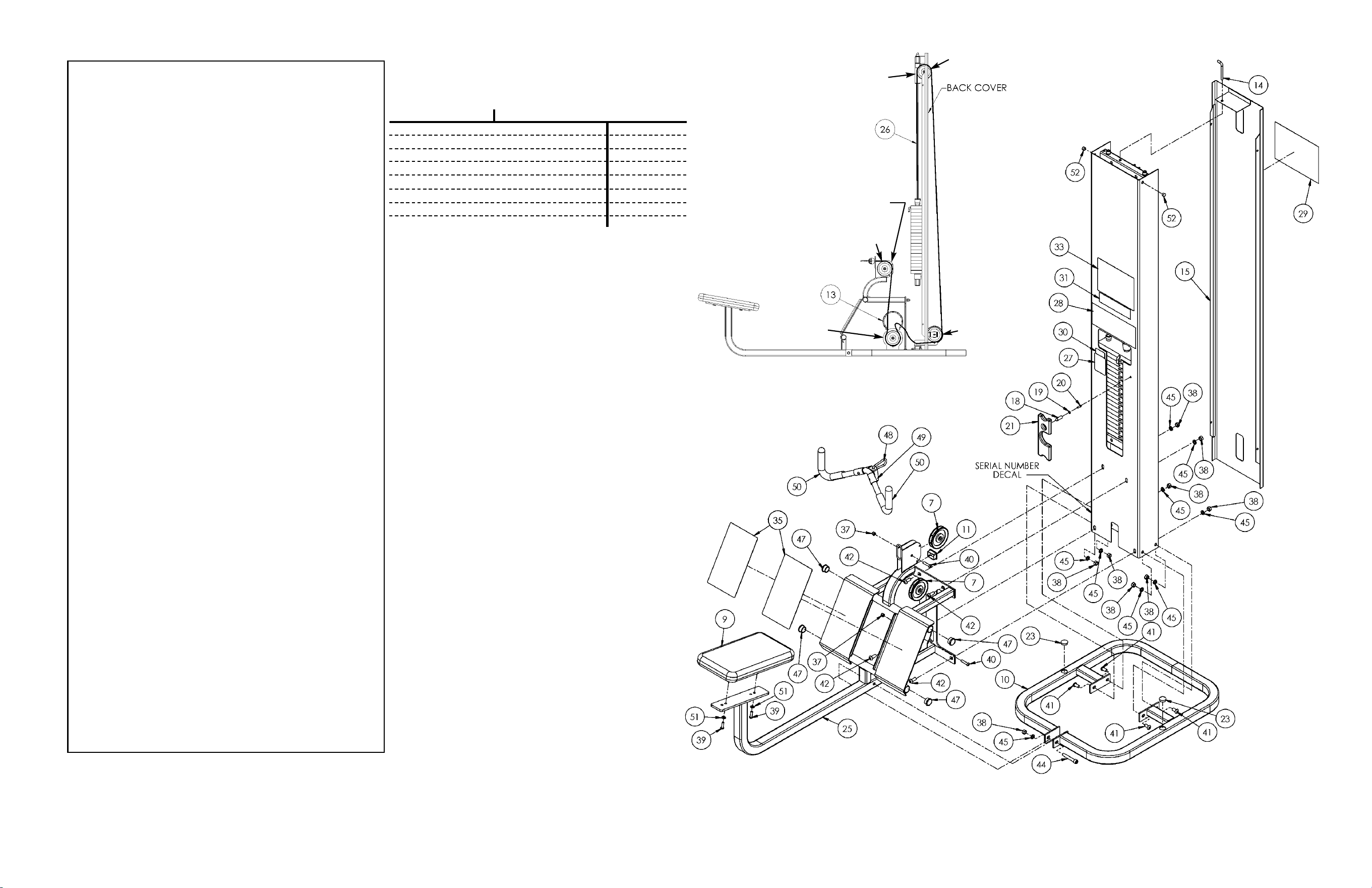
5302 CONFIGURATION
5302 and 5651 - Low Row
1 1 01247 Pulley Mount
2 1 4800-250 Top Weight Assembly
3 2 4700-019 Brg Flg .62 x .92 x 1.50 L
4 2 BR030206 Retaining Ring
5 2 01439 Weight Rod .625 Dia. x 65.31
6 2 01755 Guide Rod Collet-Long
7 4 08014 Pulley
8 1 HP286819 Spiral Pin
9 1 4106S055-0 Seat Cushion
•10 1 5302-51 Base Package
11 1 PP090000 Plastic Insert
12 1 4700M005 Rubber Boot
13 1 4800-570 Cable Guard
•14 2 5310P044 Weight Select Pin
•15 1 5301-201 Back Cover
•16 2 5301-310 Pulley Guard
•17 2 5301-311 Stop
18 1 02106 Half Weight Peg
19 1 HS308300 Split Lockwasher .25
20 1 JC620415 BHSCS .25-20 x .75
21 1 C-ZA00200 Half Weight
22 19 4005C062 Weight Plate 4.00 x 12.00
•23 2 PP080202 Plastic Insert, 1.19 Dia.-11 G
•24 2 PU060201 Bumper
25 1 5651-50 Low Row Frame
26 1 5651-002 Cable
27 1 02521 Caution Decal
28 1 3900-426 Vortex Decal 11.37 Grey
29 1 3900-378 Cybex Decal 11.37 Vert. Wht/Plm
29 1 3900-391 Cybex Decal 11.37 Vert. Blk/Plm
29 1 3900-419 Cybex Decal 11.37 Vert. Wht/Wht
30 1 4000Y316 Caution Decal
31 1 4800-381 Warning Decal
32 1 4800-515 Weight Plate Decal
33 1 5651-598 Placard Decal
34 2 PR060005 Weight Bumper
35 2 8630-321 Non-Slip
36 2 HC700430 BHSCS .375-16 x 2.50
37 4 HN704901 Nylon Locknut, .375-16
•38 12 HN784000 Hex Nut .50-13
39 2 JC700420 BHSCS .375-16 x 1.25
40 2 JC700424 BHSCS .375-16 x 1.75
•41 4 JC780417 BHSCS .50-13 x 1.00
42 4 JC780420 BHSCS .50-13 x 1.25
43 5 JC782830 SHCS .50-13 x 2.50
•44 1 JC782836 SHCS .50-13 x 3.25
•45 13 JS388300 Split Lockwasher .50
46 2 PP080204 Plastic Cap .625 ID x .68 OD
47 4 PP080225 Plastic Insert 1.50-8 12 G
48 1 GQ000206 Snap Link
49 1 51081 Handle Subassembly
50 Removed 10/28/08
51 2 HS347600 Washer .375
•52 4 PN660201 Hole Plug
ITEM QTY PART NO. DESCRIPTION
CABLE ROUTING DETAIL
• Not used in all configurations. Quantities will vary
depending upon type of configuration.
7. Install half weight peg (item #18).
8. Install seat cushion, for normal usage use front
holes as shown.
9. Install weight stack and top weight.
10. Tighten all hardware.
11. Install rear cover (item #15) if applicable.
12. Route cable as shown in the Cable Routing Detail
diagram. NOTE: Pulley “D” must be installed with
the rear cover open. Pulley “C” installed with guards
(item #16) and stop (item #17) to hold rear cover in
place.
13. Adjust cable for one inch of free play.
A
B
C
D
Assembly Notes (5302 and 5651)
1. Install unit in area where it will be used. Keep all shipping
packages near area of installation. Standard items include:
Shipping Package Model Configuration - 5302 5651
Base Package - 5302-51 1 x
Low Row Assembly - 5302-001 1 x
Low Row Assembly - 5651-001 x 1
Low Row Frame - 5651-50 1 1
Top Weight Package - 4700-010 1 1
Weight Package - 4700S040 1 1
Weight Package - 4700S043 1 1
Cushion Set - 5603-00 1 1
NOTE: This machine shipped with an Owner’s Manual.
Additional copies can be obtained by contacting your
dealer or a Cybex Representative at 1-888-462-9239.
NOTE: For tandem and quad (modular) configurations,
follow assembly guidelines listed on either the 5600 Modular
Center Post Assembly & Parts instruction sheet or the 5629
Tandem Center Post Assembly & Parts instruction sheet.
Also refer to all steps listed below.
2. Read and understand instructions thoroughly before
assembling the Low Row. Refer to the exploded-view
diagram and parts list when assembling the Low Row.
3. Remove back cover (item #15). Remove pin (item #14)
securing cover at the top end, and lift out.
4. Install Pulley mount (item #1).
5. Install column (item #22) to base (item #10). NOTE:
5651 configuration does not have a base (item #10) or
back cover (item #15).
6. Install frame (item #25) to column (item #22).
NOTE: Be sure
cable is routed
between pins
NOTE: Be sure
cable is routed
thru loop.
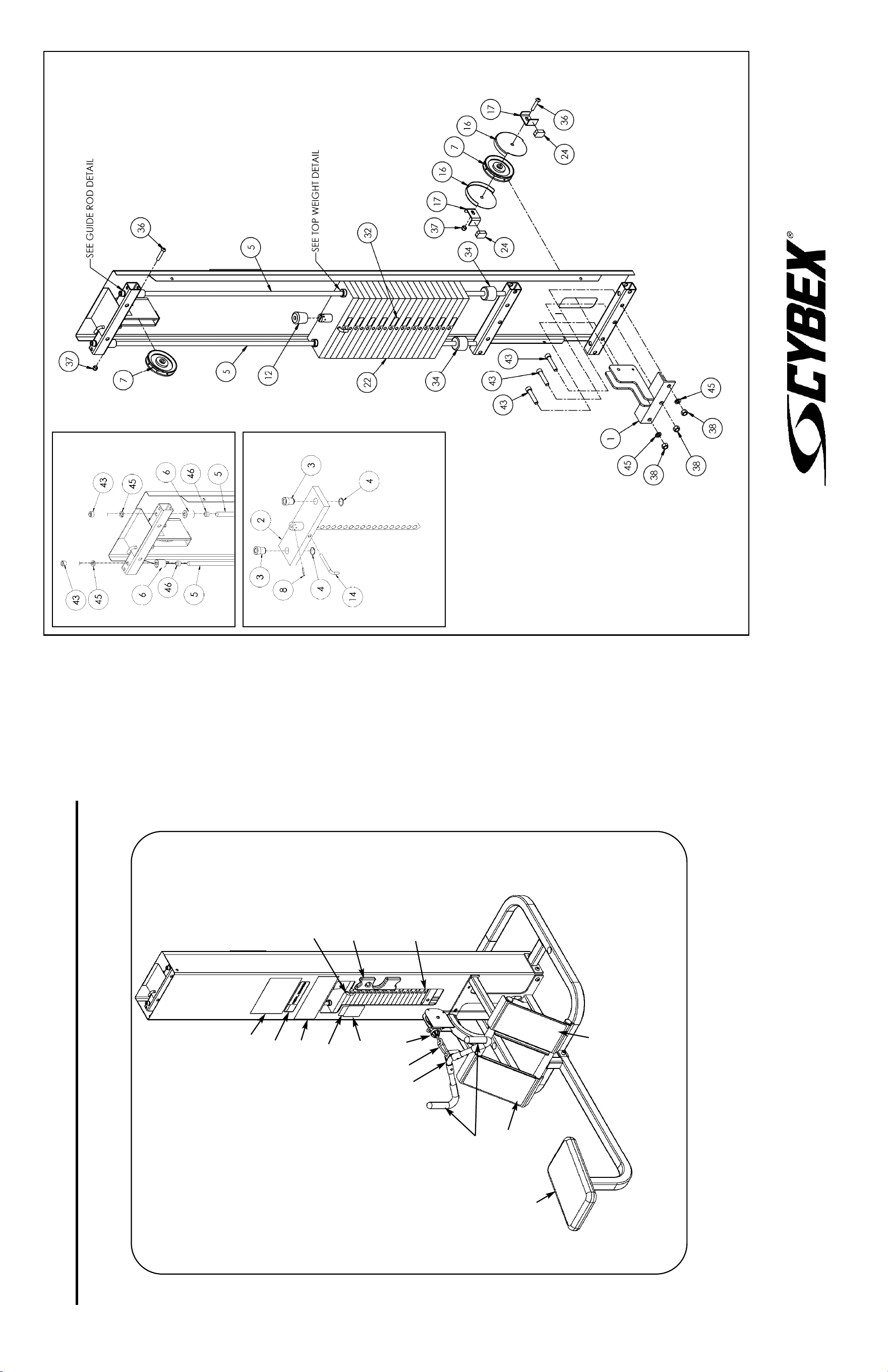
LOW ROW
5302, 5651 ASSEMBLY & PARTS
A. Seat Cushion ..................... 4106S055-0
B. Weight Selector Pin ........... 5310P044
C. Half Weight ........................ C-ZA00200
D. Cable Subassebly.............. 5651-002
E. Caution Decal .................... 02521
F. Vortex Decal....................... 3900-426
G. Cybex Decal Wht/Plm ....... 3900-378
G. Cybex Decal Blk/Plm......... 3900-391
G. Cybex Decal Wht/Wht ....... 3900-419
DESCRIPTION PART NO.
H. Caution Decal .................... 4000Y316
I. Warning Decal ................... 4800-381
J. Weight Plate Decal ............ 4800-515
K. Placard Decal..................... 5651-598
L. Non-Slip............................. 8630-321
M. Serial Number Decal
N. Snap Link........................... GQ000206
O. Handle Subassembly......... 8610-206
P. Grip.................................... 51081
DESCRIPTION PART NO.
C
NOTE: See exploded-view diagram for item:
G (#29) and M (Serial Number Decal).
A
L
L
GUIDE ROD
DETAIL
TOP WEIGHT DETAIL
K
I
F
H
E
B
J
D
P
O
N
10 Trotter Drive Medway, MA 02053 • 508-533-4300 • FAX 508-533-5183 • www.cybexinternational.com • T[email protected]
Copyright © 2002 CYBEX International, Inc. All rights reserved • 55651 • June 2004
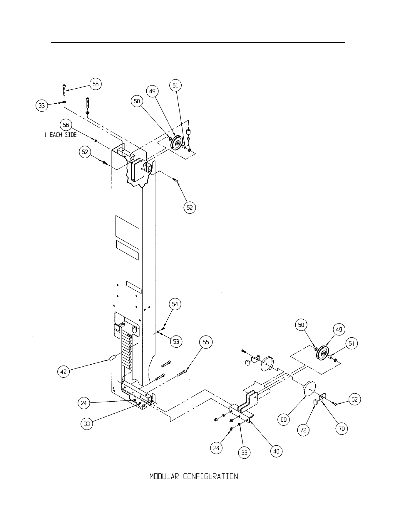
MODULAR PRESSING STATION
5647 AND 5306
ASSEMBLY & PARTS

5647 - Modular Pressing Station & 5306 - Free Standing Pressing Station
1 2 01190 Black Vinyl End Cap
2 2 01470 Pulley Guard
3 2 08014 Pulley Assembly 4.50
4 1 01872 Cybex Knob
5 1 4505-329 Detent Pin
6 2 08301 Hand Grip 6.00 L
7 2 4000-100 Pillow Block Bearing
8 4 4000Y316 Caution Decal
9 1 4800-570 Cable Guard
10 1 5305-002 Cable Subassembly
11 1 5305-201 Platform
12 1 5305-202 Bar Stop
13 1 5305-203 Link
14 1 5305-204 Arm
15 1 5305-305 Pivot Shaft
16 1 5305-310S Brace Tube Set
17 1 BS070201 Com Spring .56 x .66 x 1.50 L
18 1 FB030213 Female Rod End Bearing .375-24
19 2 FB030212 Flange Bearing .75 x .88 x .75 L
20 2 HC700415 BHSCS .375-16 x .75
21 4 HC700417 BHSCS .375-16 x 1.00
22 1 HC702828 SHCS .375-16 x 2.25
23 7 HN704901 Nylon Locknut .375-16
24 16 HN784000 Hex Nut .50-13
25 2 HN784900 Nylon Locknut .50-13
26 2 HS347700 USS Washer .375
27 1 JC700420 BHSCS .375-16 x 1.25
28 1 JC702824 SHCS .375-16 x 1.75
29 8 JC780417 BHSCS .50-13 x 1.00
30 2 JC780420 BHSCS .50-13 x 1.25
31 4 JC780422 BHSCS .50-13 x 1.50
32 1 JN714400 Jam Nut .375-24
33 10 JS388300 Split Lockwasher .50
34 6 PP080202 Plastic Insert 1.19 Dia. x 11 G
35 1 PP080222 Vinyl End Cap .50 x .50
36 2 PP090206 Plastic Insert
37 5 PP090210 Plastic Insert 2.00 Sq x 10-14 G
38 1 PU060203 Bumper
39 2 01239 Weight Stack Spacer
40 1 01247 Pulley Mount
41 2 01755 Guide Rod Collet
42 1 02106 Half Weight Peg
43 1 02521 Caution Decal
44 1 3900-426 Vortex Decal
45 1 4800-381 Warning Decal
46 1 5305-598 Placard Decal
47 2 5310M035 Weight Stack Guide Rod
48 2 PR060005 Weight Bumper
49 2 GP000000 Pulley Assembly 4.50
50 4 GP000004 Pulley Spacer
51 2 GP000203 Pulley Center
52 4 HC700414 BHSCS .375-16 x .62
53 1 HS308300 Split Lockwasher .25
54 1 JC620415 BHSCS .25-20 x .75
55 5 JC782830 SHCS .50-13 x 2.50
56 4 PN660201 Hole Plug
57 2 PP080204 Plastic Cap .625 ID x .68 OD
58 1 4700-010 Top Weight Assembly
59 2 4700-019 Flange Bearing
60 2 BR030206 Retaining Ring
61 1 HP286819 Spiral Pin
62 1 4700M005 Rubber Cap
63 19 4005C062 Stack Weight
64 1 5310P044 Weight Selector Pin
65 Removed
66 1 3900-378 Cybex Decal 11.37 Vert. Wht/Plm
66 1 3900-391 Cybex Decal 11.37 Vert. Blk/Plm
66 1 3900-419 Cybex Decal 11.37 Vert. Wht/Wht
67 1 5301-200 Base
68 1 5301-201 Cover
69 2 5301-310 Pulley Guard
70 2 5301-311 Stop
ITEM QTY PART NO. DESCRIPTION
71 1 JC782836 SHCS .50-13 x 3.25
72 2 PU060201 Bumper
73 1 4800-515 Weight Plate Decal
74 2 HS760106 Flat Washer 1.75 OD .69 ID .14 T
75 Removed
76 1 C-ZA000200 Half Weight
ITEM QTY PART NO. DESCRIPTION
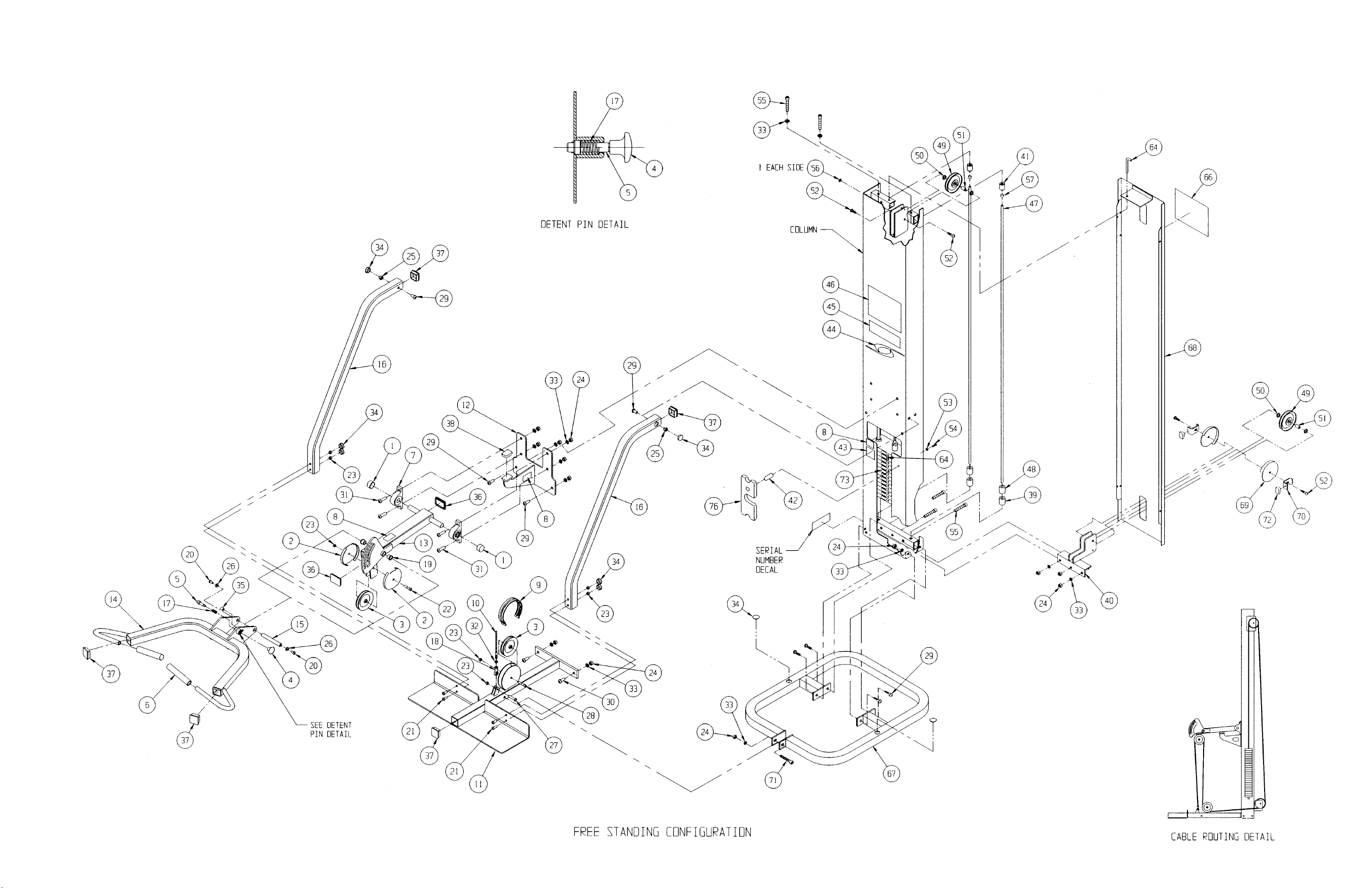
Assembly Notes
1. Keep all shipping packages near area of installation. Standard items incude:
• Pressing Station Column Assembly - 5647-9x (Modular) or 5305-001-9x (Free Standing)
• Pressing Station Package - 5305-50
• Bench Subassembly - 4000-003-96
• Cushion Box Assembly - 4000-005-00
• Top Weight Package - 4700-010 (20-4x12 black) OR 4700-015 (20-3x12 black)
• Weight Pack 1 - 4700S040 (black) 4700S067 (Weight Pack 1)
• Weight Pack 2 - 4700S043 (black) 4700S043 (Weight Pack 2)
2. Follow the assembly guidelines listed on either the 5600 Modular Center Post Assembly &
Parts instruction sheet or the 5629 Tandem Center Post Assembly & Parts instruction
sheet.
NOTE: This machine shipped with an Owner’s Manual. Additional
copies can be obtained by contacting your dealer or a Cybex
Representative at 1-888-462-9239.
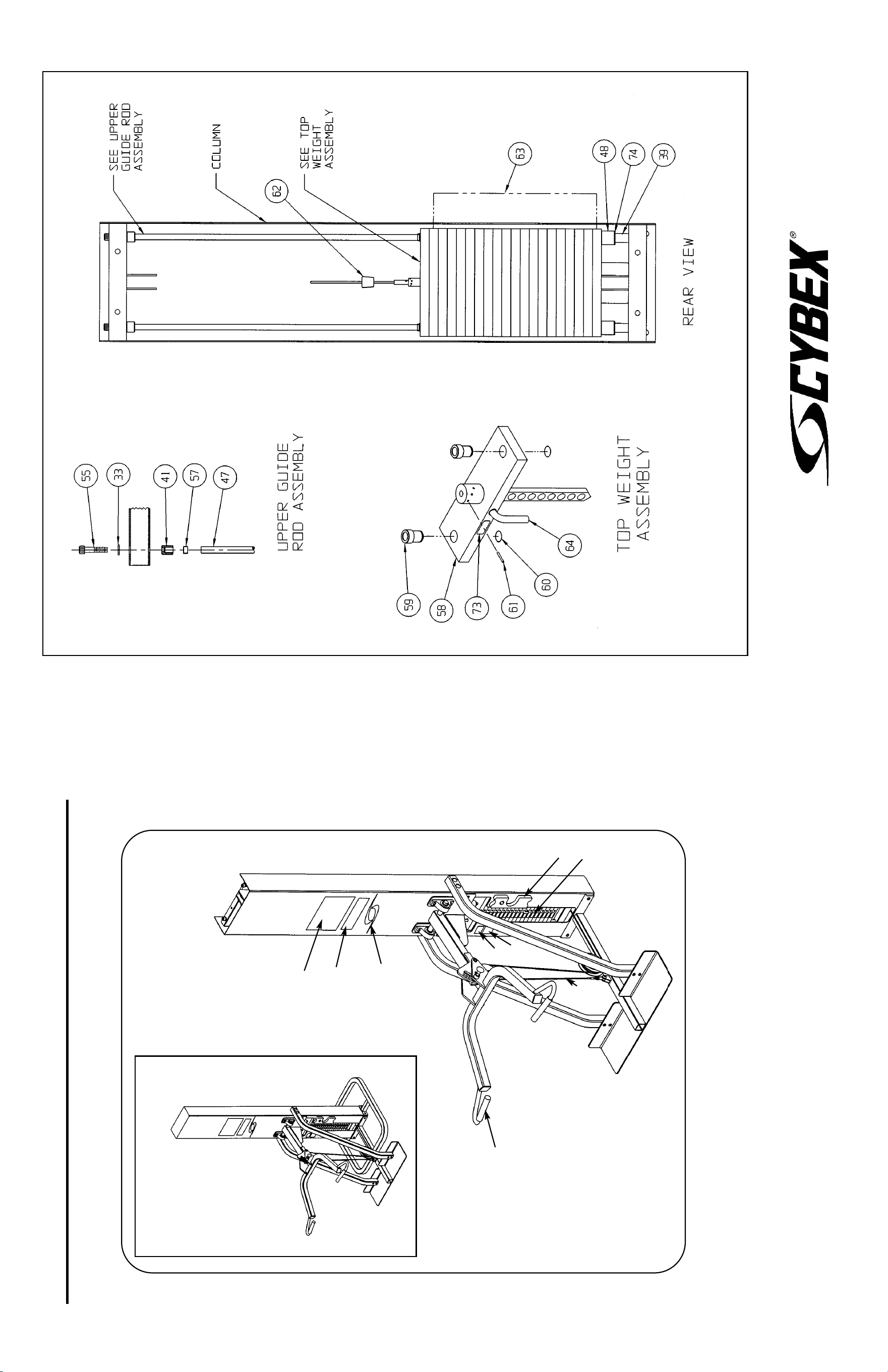
10 Trotter Drive Medway, MA 02053 • 508-533-4300 • FAX 508-533-5183 • www.cybexinternational.com • T[email protected]
Copyright © 2002 CYBEX International, Inc. All rights reserved • 55647 • June 2004
MODULAR PRESSING STATION
5647 AND 5306 ASSEMBLY & PARTS
A. Hand Grip .......................... 08301
B. Caution Decal .................... 4000Y316
C. Cable Subassembly........... 5305-002
D. Caution Decal .................... 02521
E. Vortex Decal ...................... 3900-426
F. Warning Decal ................... 4800-381
G. Placard Decal..................... 5305-598
DESCRIPTION PART NO.
H. Weight Selector Pin ........... 5310P044
I. Serial Number Decal
J. Cybex Decal WHT/PLM..... 3900-378
J. Cybex Decal BLK/PLM...... 3900-391
J. Cybex Decal WHT/WHT .... 3900-419
K. Weight Plate Decal ............ 4800-515
DESCRIPTION PART NO.
G
F
E
B
D
C
H
A
NOTE: See exploded-view diagram
for items: I, and J (#66).
Product No. 5306 - Free Standing Product No. 5647 - Modular
K

CABLE CROSSOVER
5311, 5648, 5649 AND 5650
ASSEMBLY & PARTS
NOTE: For tandem and quad (modular) configurations, follow
assembly guidelines listed on either the 5600 Modular Center Post
Assembly & Parts instruction sheet or the 5629 Tandem Center
Post Assembly & Parts instruction sheet. Also refer to all steps
listed below.
2. Read and understand instructions thoroughly before
assembling the Cable Crossover. Refer to the exploded-view
diagram and parts list when assembling the Cable Crossover.
3. Remove column from carton. For units with a back cover
(5311 and 5649), remove the cover before removing column
from carton. To remove cover, remove bolt securing cover at
the top end, then slide cover toward top end and lift out.
4. Install column to base (item #47). NOTE: 5648 and 5650
configurations do not have a base.
NOTE: For installing tandem and quad configurations, use
hardware items #58, #71 and #84.
5. For tandem configurations only (5648 and 5650),
install detent tube lower mount (item #78).
6. Install double pulley bracket (item #31).
7. Install weight stack.
8. Install crossbar mount (item #30) for 5311, 5649
and 5650. NOTE: Do not tighten screws at this
time. Crossbar must be loose when installing
crossover tube.
NOTE: For 5648 configuration, install detent tube
upper mount (item #79) in place of the crossbar
mount. Install plastic cap (item #80) into item #79.
9. Install right handle (item #34) and left handle (item
#33).
10. Install adjusting handle (item #37) to detent tube.
11. Install (chrome) detent tube (item #49).
12. Install adjusting bracket (item #45). NOTE: Do not
overtighten. Be sure pulley bracket swivels freely.
13. Install adjusting shield (item #50) and upper
pulley(#7) to handle assembly on the detent
(chrome) tube. See letter A in the Cable Routing
Detail diagram.
14. Route cable as shown in the Cable Routing Detail
diagram, starting with pulley B and continuing in
alphabetical order.
15. Adjust cable for one inch of free play.
16. Install crossover tube.
17. Tighten all hardware.
18. Install rear cover where applicable.
NOTE: This machine shipped with an Owner’s
Manual. Additional copies can be obtained by
contacting your dealer or a Cybex
Representative at 1-888-462-9239.
Assembly Notes (5311, 5648, 5649 and 5650)
1. Install unit in area where it will be used. Keep all shipping packages
near area of installation. Standard items include:
Shipping Package Model Configuration - 5311 5648 5649 5650
Cable Crossover Half Assembly - 5649 2 x 1 x
Tandem w/o Crossbar Assembly - 5648 x 1 x x
Tandem with Crossbar Assembly - 5650 x x x 1
Crossover Tube Package - 5649-003 1 x x x
Base Package - 5649-50 2 x 1 x
Top Weight Package - 4700-012 (black) 2 1 1 1
Weight Pack 1 - 4700S042 (black) 2 1 1 1

5311, 5648, 5649 and 5650 - Cable Crossover
1 4 4605-550 Small Plug .25-20
2 8 HF449063 C onnector Insert .75 x .25-20
3 2 01143 Pulley Mount
4 4 01141 Weight Spacer 5.00
5 4 01755 Guide Rod Collet-Long
6 2 02106 Half Weight Peg
7 14 08014 Pulley Assembly
8 2 08172 Knob
9 2 BS070201 Spring
10 2 08229 Detent Pin
11 28 4005C062 Weight Stack 4.00 x 12.00
12 2 HC700430 BHSCS .375-16 x 2.50
13 2 C-ZA00200 Half Weight
14 2 4605-512 Insert Plastic 7.94
15 2 5649-314 Detent Tube Decal
16 4 PP080202 Insert Plastic 1.19 Dia. x 11 G
17 2 4700-218 Top Weight Assembly
18 4 4700-019 Brg Flg .62 x .92 x 1.50 L
19 6 4800-700 Foam Grip
• 20 2 5310C029 Back Cover
21 4 5310M035 Weight Rod .625 . x 85.31
22 2 3900-378 Cybex Decal 11.37 Vert. Wht/Plm
22 2 3900-391 Cybex Decal 11.37 Vert. Blk/Plm
22 2 3900-419 Cybex Decal 11.37 Vert. Wht/Wht
23 2 5649-200 Column
24 2 5649-598 Placard Decal
25 2 4800-381 Warning Decal
26 2 3900-426 Vortex Decal
27 2 02521 Caution Decal
28 4 4000Y316 Caution Decal
29 2 5649-329 Caution Decal Maximum Load
• 30 2 5649-203 Crossbar Mount
31 2 5649-208 Double Pulley Bracket
32 4 4113M064 Bumper
33 2 5649-205 Left Handle
34 2 5649-206 Right Handle
35 2 4800-515 Weight Plate Decal
36 2 5649-002 Cable Subassembly
37 2 5649-207 Adjusting Handle
38 2 HN704000 Hex Nut .375-16
39 4 5315-343 Attaching Tab
40 2 8500-025 Caution Decal
• 41 1 5649-201 Cross Bar
42 A 2 4605-501 Grip
42 B 2 4605-518 Grip
43 2 PU060200 Bumper
44 2 5310P044 Weight Selector Pin
45 2 5649-330 Adjusting Bracket
46 8 PR069400 Recess Bumper
• 47 2 5649-209 Base Support
48 2 01142 Pulley Mount Cap
49 2 5649-303 Detent Tube
50 2 5649-331 Adjusting Shield
51 4 BR030206 Retaining Ring
52 4 HB-60011 Flange Bearing .375 ID x 1.00 OD
53 4 HC620428 BHSCS .25-20 x 2.25
54 8 HC700417 BHSCS .375-16 x 1.00
55 2 HN704400 Nut, Jam .375-16
56 4 HN624100 Hex Nut .25-20
57 30 HN704901 Nylon Locknut .375-16
58 16 HN784000 Hex Nut .50-13
59 4 HN784900 Nylon Locknut .50-13
60 2 HP286819 Spiral Pin .188 x 1.125
61 2 HS308300 Split Lockwasher .25
62 8 HS760106 Flat Washer 1.75 x .688 x .140 T
63 8 HT582210 Tap Screw 10-32 x .375 Phil
64 2 JC620415 BHSCS .25-20 x .75
65 14 JC700424 BHSCS .375-16 x 1.75
66 6 JC700434 BHSCS .375-16 x 3.00
67 4 PR060005 Weight Bumper
68 2 HC700426 BHSCS .375-16 x 2.00
69 8 JC780420 BHSCS .50-13 x 1.25
70 12 JC782830 SHCS .50-13 x 2.50
71 16 JS388300 Split Lockwasher .50
72 8 PN660200 Plastic Insert 1.00 Dia. x 11 G
73 4 PN660201 Hole Plug
74 4 PP080204 Plastic Cap .625 ID x .68 OD
75 2 PP090210 Plastic Cap 2.00 Sq
76 4 PP090211 Plastic Insert 1.50 Sq x 11 G
77 4 JC780417 BHSCS .50-13 x 1.00
• 78 1 5648-201 Detent Tube Lower Mount
• 79 1 5648-202 Detent Tube Upper Mount
• 80 1 PP090200 Plastic Insert 1.75 Sq
81 1 GQ000206 Snap Link
82 1 5310S040 Handle Subassembly
83 1 01193 Finned Fastener
• 84 4 JC782817 SHCS .50-13 x 1.00
ITEM QTY PART NO. DESCRIPTION
ITEM QTY PART NO. DESCRIPTION
• Not used in all configuration. Quantities will vary depending upon type
of configuration.
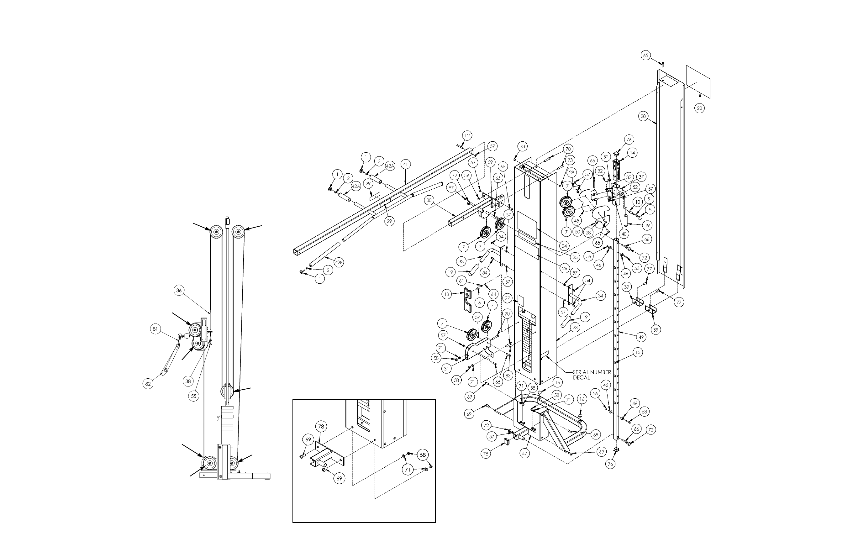
CABLE ROUTING DETAIL
5311 CONFIGURATION
G
E
A
B
F
D
C
TANDEM CONFIGURATION DETAIL
NOTE: Be sure cable
is routed between the
two pins.
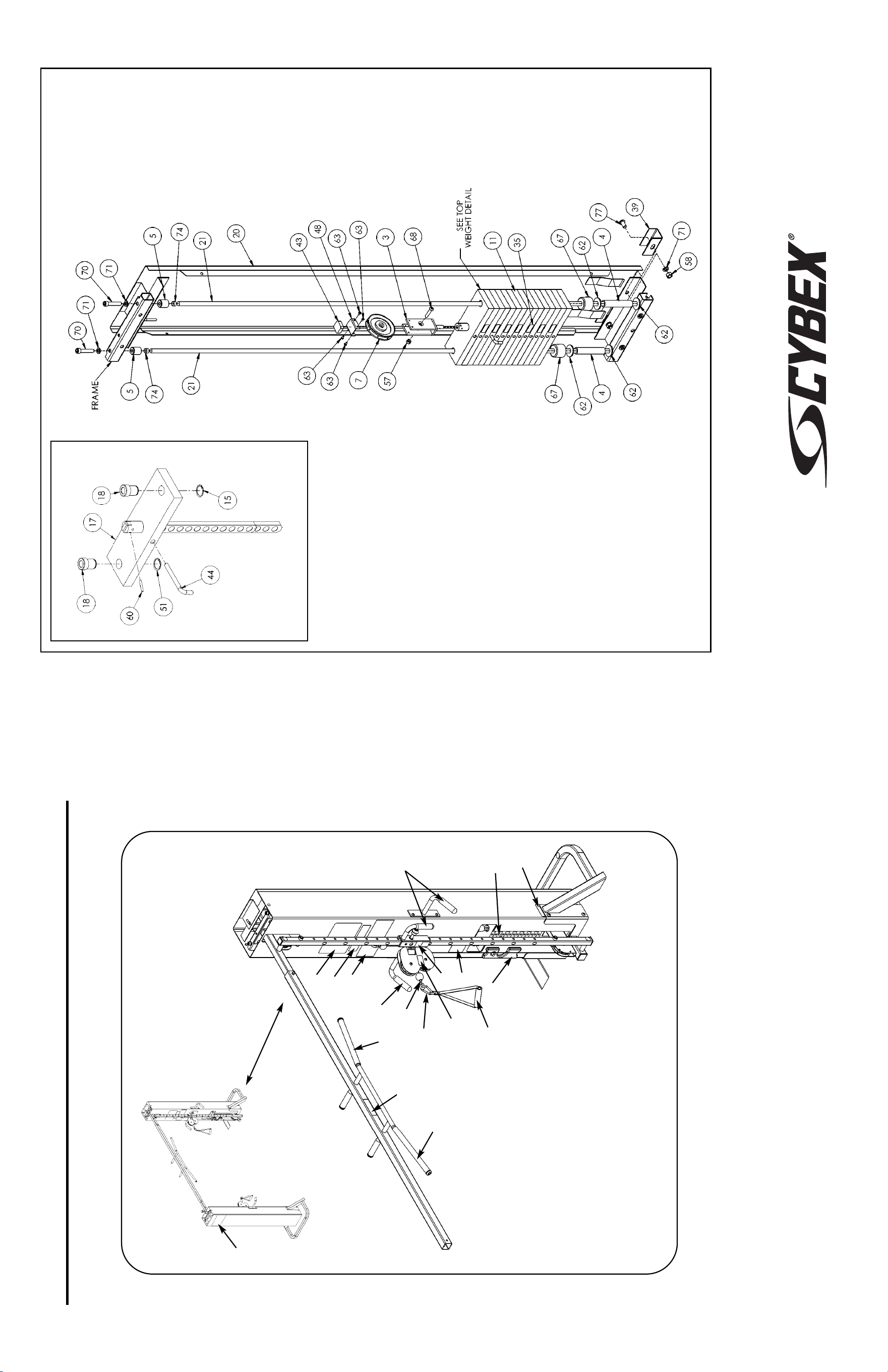
10 Trotter Drive Medway, MA 02053 • 508-533-4300 • FAX 508-533-5183 • www.cybexinternational.com • T[email protected]
Copyright © 2002 CYBEX International, Inc. All rights reserved • 55649 • June 2004
CABLE CROSSOVER
5311, 5648, 5649 AND 5650 ASSEMBLY & PARTS
A. Half Weight ........................ C-ZA00200
B. Foam Grip.......................... 4800-700
C. Cybex Decal Wht/Plm ....... 3900-378
C. Cybex Decal Blk/Plm......... 3900-391
C. Cybex Decal Wht/Wht ....... 3900-419
D. Placard Decal..................... 5649-598
E. Warning Decal ................... 4800-381
F. Serial Number Decal
G. Vortex Decal....................... 3900-426
H. Caution Decal .................... 02521
DESCRIPTION PART NO.
I. Caution Decal .................... 4000Y316
J. Caution Decal
Maximum Load.................. 5649-329
K. Weight Plate Decal ............ 4800-515
L. Cable Subassebly.............. 5649-002
M. Grip .................................... PR400202
N. Weight Selector Pin ........... 5310P044
O. Caution Decal .................... 8500-025
P. Snap Link........................... GQ000206
Q. Handle Subassembly......... 5310S040
DESCRIPTION PART NO.
L
J
F
M
E
G
N
H
I
D
B
A
B
C
M
NOTE: See exploded-view diagram for item: K (35).
O
P
Q
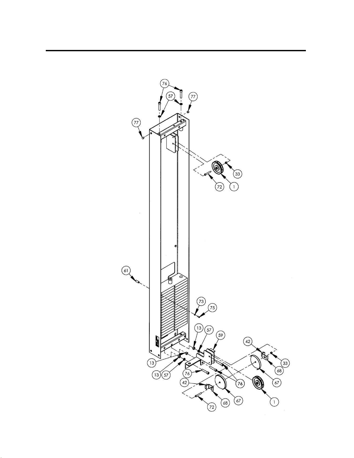
MODULAR SEATED LEG PRESS
5652 AND 5322
ASSEMBLY & PARTS
Modular Configuration

1 6 08014 Pulley
2 10 FB030242 Bearing w/Snap ring 30mm OD x
10 mm
3 1 08172 Cybex Knob
4 2 4000Y316 Caution Decal
5 2 4005M100 Grip
6 1 4106S055-0 Back Cushion
7 1 4505-329 Detent Pin
8 1 4605-511 Plastic Insert 5.94
9 1 4800-026 Bottom Cushion
10 3 4800-570 Cable Guard
11 1 8500-025 Caution Decal
12 1 8520-313 Seat Adjusting Decal
13 7 HN784000 Hex Nut .50-13
14 1 8630-200 Frame
15 1 8630-201 Seat Frame
16 1 8630-202 Seat Tube
17 1 8630-203 Right Foot Plate
18 1 8630-204 Left Foot Plate
19 1 8630-205 Roller Tube
20 1 8630-206 Roller Plate
21 1 8630-207 Right Handle
22 1 8630-208 Left Handle
23 1 8630-209 Pivot Tube
24 1 5652-201 Connector
25 2 8630-321 Non-Slip
26 2 8630-322 Roller
27 1 8630-326 Plastic Seat Sleeve
28 2 8630-331 Spacer
29 2 JC702820 SHCS .375-16 x 1.25
30 3 8630-336 Nylon Locknut 10 mm
31 1 HC702816 SHCS .375-16 x .875
32 2 HC702834 SHCS .375-16 x 3.00
33 21 HN704901 Nylon Locknut .375-16
34 1 JC702814 SHCS .375-16 x .625
35 4 JC702824 SHCS .375-16 x 1.75
36 4 JC702832 SHCS .375-16 x 2.75
37 2 JC780420 BHSCS .50-13 x 1.25
38 2 PP090000 Plastic Insert 1.50 x 2.00 x 11 G
39 1 PP090200 Plastic Insert 1.75 Sq x 10-14 G
40 2 PP090210 Plastic Insert 2.00 Sq x 11 G
41 1 PP090211 Plastic Insert 1.50 Sq x 10-14 G
42 3 PU060201 Bumper
43 3 HC331271 HHCS 10 mm x 110 mm
44 2 PP080225 Plastic Insert 1.50 x 2.00 11 G
45 1 BS070201 Com Spring .56 x .66 1.50 L
46 1 5652-002 Cable
47 2 8630-340 Spacer
48 1 FB030213 Rod End Bearing
49 1 HC702828 SHCS .375-16 x 2.25
50 2 JC700917 FHSCS .375-16 x 1.00
51 4 JC702836 SHCS .375-16 x 3.25
52 1 JN714400 Jam Nut .375-24 UNF
53 1 5652-598 Placard Decal
54 1 3900-432 Cybex Decal 8.75 x 13
55 1 4800-381 Warning Decal
56 1 CM000211 Decal Removed 7/6/09
57 6 JS388300 Split Lockwasher .50
58 1 01243 Column
59 1 01247 Pulley Mount
60 2 01755 Guide Rod Collet
61 1 02106 Half Weight Peg
62 2 02330 Spacer 3.00 Weight
63 1 02521 Caution Decal
64 1 3900-426 Cybex Decal 11.37
65 1 4800-515 Weight Plate Decal
66 1 5301-201 Cover
67 2 5301-310 Pulley Guard
68 2 5301-311 Stop
69 2 5310M035 Weight Rod .625 Dia. x 85.31
70 1 55652 Instruction Modular Leg Press
(not shown)
71 1 5310P044 Weight Select Pin
72 2 HC700430 BHSCS .375-16 x 2.50
73 1 HS308300 Split Lockwasher .25
74 2 HS760106 Flat Washer 1.75 x .68 x .140
75 1 JC620415 BHSCS .25-20 x .75
76 5 JC782830 SHCS .50-13 x 2.50
77 8 PN660201 Plug
78 2 PP080204 Plastic Cap .625 ID x .68 OD
79 2 PR060005 Bumper
80 17 4005C062 Weight Stack 4 x 12
81 1 4700-027 Top Weight Assembly
81A 2 4700-019 Bearing Flance .62 x .92 x 1.50 L
81B 1 4700M005 Rubber Cap
81C 1 4800-256 Top Weight 18-4 x 12
81D 1 4700M004 Cable Connector
81E 1 5310P044 Weight Selector Pin
81F 2 BR030206 Retaining Ring
81G 1 C-ZA000200 Half Weight
81H 2 HP286819 Spiral Pin
82 1 5302-51 Modular Base Assembly
82A 1 5301-200 Base
82B 5 HN78400 Hex Nut .50-13
82C 4 JC780417 BHSCS .50-13 x 1.00
82D 1 JC782836 SHCS .50-13 x 3.25
82E 5 JS388300 Split Lockwasher .50
82F 2 PP080202 Plastic Insert 1.19 Dia. x 11 G
83 2 JC702838 SHCS .375-16 x 3.50
84 8 HS348300 Split Lockwasher .375
5652 - Modular Seated Leg Press & 5322 - Free Standing Seated Leg Press
ITEM QTY PART NO. DESCRIPTIONITEM QTY PART NO. DESCRIPTION
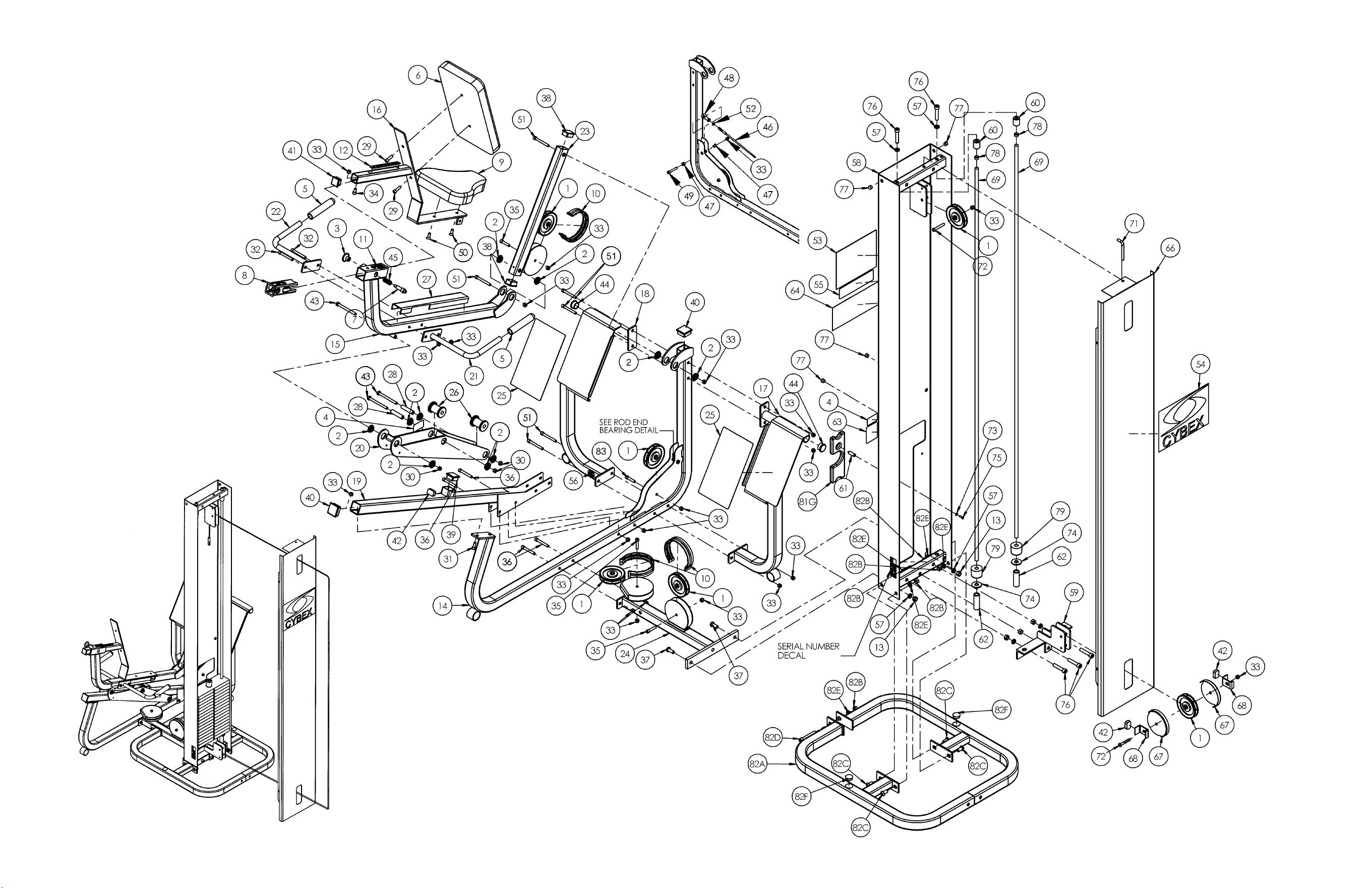
Cable Routing Detail
Free Standing C onfiguration
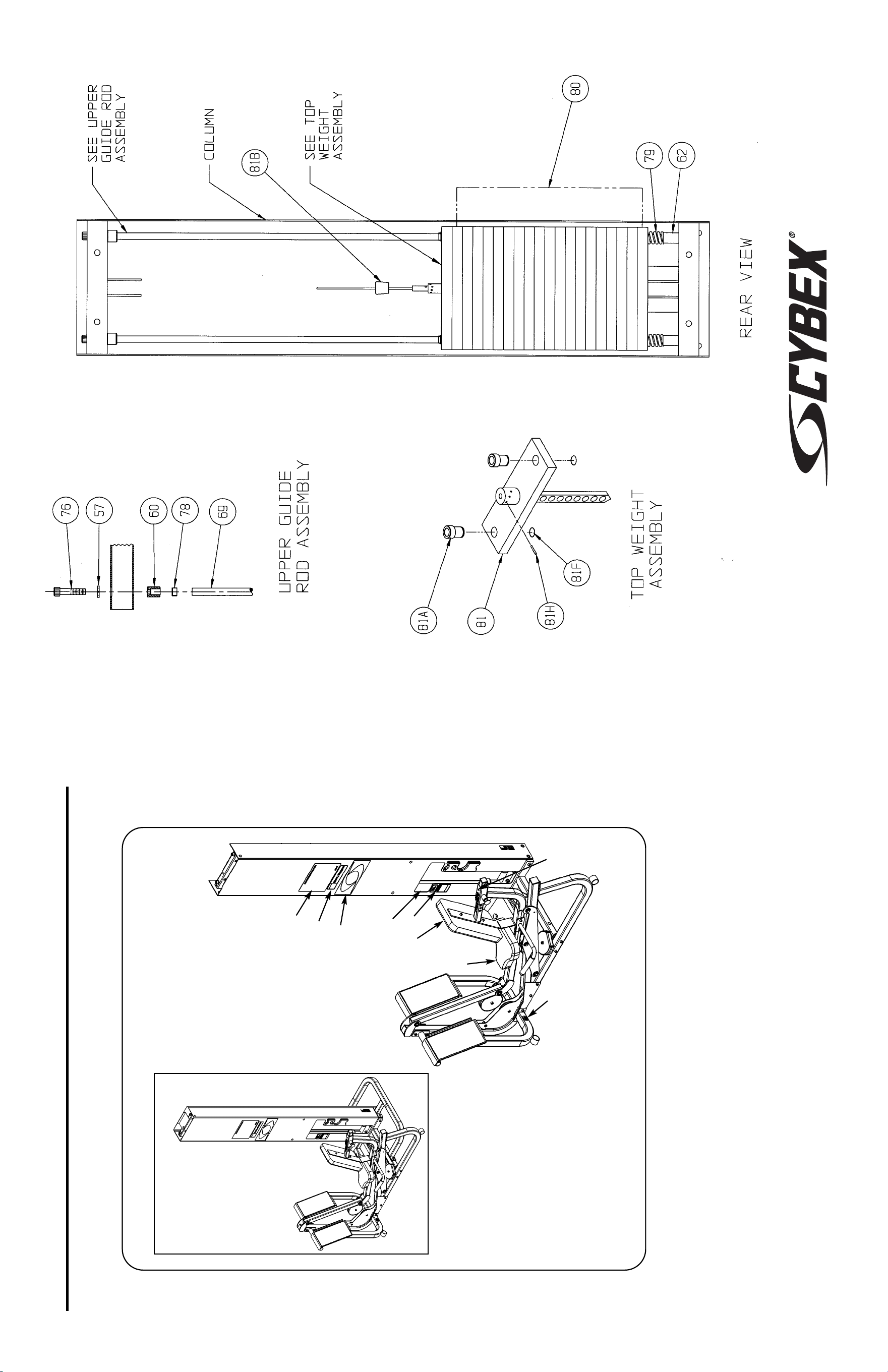
10 Trotter Drive Medway, MA 02053 • 508-533-4300 • FAX 508-533-5183 • www.cybexinternational.com • T[email protected]
Copyright © 2008 CYBEX International, Inc. All rights reserved • 55652 D • April 2008
A
A. Back Cushion................ 4106S055-0
B. Seat Cushion................. 4800-026
C. Cybex Decal Wht/Wht... 3900-378
C. Cybex Decal Blk/Plm .... 3900-391
C. Cybex Decal Wht/Plm... 3900-419
D. Caution Decal................ 02521
DESCRIPTION PART NO.
E. Caution Decal................ 4000Y316
F. Warning Decal............... 4800-381
G. Placard Decal ................ 5652-598
H. Adjustment Decal.......... 8520-313
I. Serial Number Decal ..... CM000202
J. Grip................................ 4005M100
DESCRIPTION PART NO.
MODULAR SEATED LEG PRESS
5652 AND 5322 ASSEMBLY & PARTS
D
C
F
E
G
Product No. 5322 - Freestanding
Product No. 5652 - Modular
B
H
I
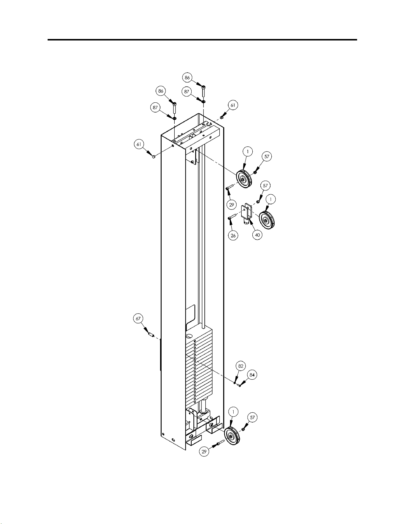
Modular Configuration
MODULAR LEG EXTENSION/LEG CURL
5653 AND 5307 ASSEMBLY & PARTS

1 6 08014 Pulley
2 4 08172 Cybex Knob
3 2 4050M025 Grip
4 3 4505-329 Detent Pin
5 2 4605-511 Plastic Insert 5.94
6 2 4800-570 Cable Guard
7 1 4850-202 Right Handle
8 1 4850-203 Left Handle
9 4 8500-025 Caution Decal
10 2 8500-026 Caution Decal
11 4 8500-052 Cushion 4.00 Dia. x 7.00 L x .875
12 1 8520-308 Leg Curl Tube
13 1 8520-313 Seat Adjusting Decal
14 1 HC702826 SHCS .375-16 x 2.00
15 1 8630-336 Nylon Locknut 10 mm
16 1 8640-213 Frame
17 1 8640-201 Cushion Post (for Back Cusion)
18 1 8640-202 Cam
19 1 8640-204 Adjuster
20 1 8640-207 Brace
21 2 8640-347 Insert
22 4 BS070201 Com Spring .56 x .66 1.50 L
23 2 FB050211 Bearing Flange .38 x .50 .25 L
24 2 FB050226 Bearing Flange
1.00 ID x 1.25 OD x 1.00 L
25 4 FB130205 Bearing Flange .62 x .75 x .38 L
26 1 HC702826 SHCS .375-16 x 2.00
27 2 HC702834 SHCS .375-16 x 3.00
28 1 JC702814 SHCS .375-16 x .625
29 5 JC702824 SHCS .375-16 x 1.75
30 4 JC702832 SHCS .375-16 x 2.75
31 2 JC702836 SHCS .375-16 x 3.25
32 1 JC702838 SHCS .375-16 x 3.50
33 4 PP080223 Plastic Insert
34 3 PP090211 Plastic Insert 1.50 Sq x 10-14 G
35 1 PU060201 Bumper
36 1 4800-021 Back Cushion
37 1 4800-074 Seat Cushion
38 1 HP286819 Spiral Pin
39 1 8640-330 Spring Pin 10 mm x 90 mm Black
40 1 02120 Pulley Mount
41 1 08229 Detent Pin
42 1 8640-211 Cushion Bracket
43 1 8640-212 Cushion Post
44 1 8640-214 Leg Bar
45 1 8640-334 Support Plate
46 2 FB130206 Flange Bearing 2.00 x 2.25 x 1.00
47 2 HS347700 Washer
48 2 PP080224 Plastic Insert 2.00 Dia.
49 1 PP090000 Plastic Insert 1.50 x 2.00 Dia.
50 2 08017 Retaining Ring
51 1 4507-301 Pin
52 1 5653-002 Cable Subassembly
53 1 5653-003 Cable Subassembly
54 1 5653-201 Leg
55 2 FB030242 Bearing with Snap Ring
56 1 HC331269 HHCS 10MM x 90MM
57 13 HN704901 Nylon Locknut .375-16
58 4 HN784900 Nylon Locknut .500-13
59 6 JC782820 SHCS .375-16 x 1.25
60 2 JC780420 BHSCS .500-13 x 1.25
61 4 PN660201 Hole Plug
62 20 4000C062 Weight Stack 4 x 12
63 1 4700-010 Top Weight Assembly
63A 2 4700-019 Bearing Flange .62 x .92 x 1.50 L
63B 1 4700M005 Rubber Cap
63C 1 4700-307 Top Weight 20-4 x 12
63D 1 4700M004 Cable Connector
63E 1 5310P044 Weight Selector Pin
63F 2 BR030206 Retaining Ring
63G 1 C-ZA000200 Half Weight
63H 2 HP286819 Spiral Pin
64 2 HN784000 Hex Nut .50-13
65 1 5302-51 Modular Base Assembly
65A 1 5301-200 Base
65B 5 HN784000 Hex Nut .50-13
65C 4 JC780417 BHSCS .50-13 x 1.00
65D 1 JC782836 SHCS .50-13 x 3.25
65E 5 JS388300 Split Loackwasher .50
65F 2 PP080202 Plastic Insert 1.19 Dia.-11 GA
66 2 01755 Guide Rod Collet - Long
67 1 02106 Half Weight Peg
68 1 02521 Warning Decal
69 1 HC700426 BHSCS .375-16 x 2.00
70 1 3900-378 Cybex Decal Wht/Wht
70 1 3900-391 Cybex Decal Blk/Plm
70 1 3900-419 Cybex Decal Wht/Plm
71 1 4000Y316 Caution Decal
72 1 4800-381 Warning Decal
73 1 4800-515 Weight Plate Decal 2-24
74 1 5310C029 Cover
75 2 5310M035 Weight Rod .625 Dia. x 85.31
76 2 5315-343 Attaching Tab
77 1 55653 Modular Adjustable Cable
Instruction (Not Shown)
78 1 5653-200 Tower
79 2 5653-302 Weight Spacer 4.00
80 1 5653-598 Placard
81 1 02224 Modular Screen
82 1 HS308300 Split Lockwasher
83 4 HS760106 Flat Washer 1.75 .688 .140 T
84 1 JC620415 BHSC .25-20 x .75
85 2 JC780417 BHSCS .50-13 x 1.00
86 2 JC782830 SHCS .50-13 x 2.50
87 4 JS388300 Split Lockwasher .50
88 2 PP080204 Plastic Cap .625 ID x .68 OD
89 2 PR060005 Bumper Weight
90 2 JC7082820 SHCS .375-16 x 1.25
5653 - Modular Leg Extension/Leg Curl & 5307 - Free Standing Leg Extension/Leg Curl
ITEM QTY PART NO. DESCRIPTIONITEM QTY PART NO. DESCRIPTION
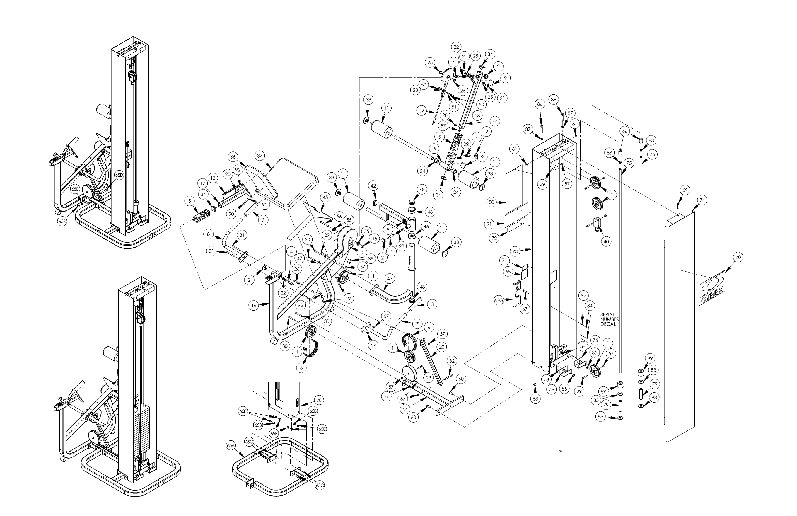
Cable Routing Detail
Free Standing Configuration
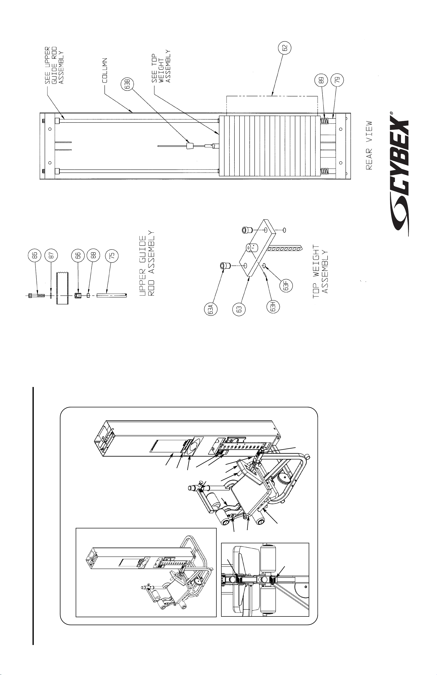
A. Back Cushion................ 4800-021
B. Seat Cushion................. 4800-074
C. Cybex Decal Wht/Wht... 3900-378
C. Cybex Decal Blk/Plm .... 3900-391
C. Cybex Decal Wht/Plm... 3900-419
D. Caution Decal................ 02521
E. Caution Decal................ 4000Y316
DESCRIPTION PART NO.
F. Warning Decal............... 4800-381
G. Caution Decal................ 8500-025
H. Caution Decal................ 8500-026
I. Placard Decal................ 5653-598
J. Adjustment Decal.......... 8520-313
K. Serial Number Decal ..... CM000202
L. Grip................................ 4050M025
DESCRIPTION PART NO.
MODULAR LEG EXTENSION/LEG CURL
5653 AND 5307 ASSEMBLY & PARTS
H
C
F
G
I
Product No. 5307 - Freestanding
Product No. 5653 - Modular
B
H
L
L
E
A
D
J
G
G
K
10 Trotter Drive Medway, MA 02053 • 508-533-4300 • FAX 508-533-5183 • www.cybexinternational.com • T[email protected]
Copyright © 2002 CYBEX International, Inc. All rights reserved • June 2004


10 Trotter Drive Medway, MA 02053 • 508-533-4300 • FAX 508-533-5183
www.cybexinternational.com • T[email protected]•[email protected]


