Loading ...
Loading ...
Loading ...

1 DESCRIPTION
1.1 PURPOSE
This machine is used to cut grass, light weeds, and other
similar vegetation at or around ground level. The cutting
plane must be approximately parallel to the ground surface.
You cannot use the machine to cut or chop hedges, shrubs,
bushes, flowers and compost.
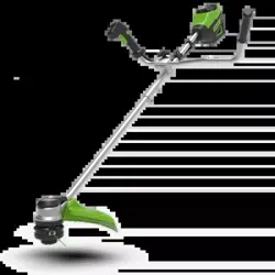
1.2 OVERVIEW
Figure 1 - 20.
1
Battery release button
2
On/off button
3
Speed button
4
Lock-out button
5
Trigger
6
Auxiliary handle
7
Upper shaft
8
Coupler
9
Lower shaft
10
Trimmer head
11
Cut-off blade
12
Guard
13
Screw
14
Release button
15
Positioning hole
16
Knob
17
Cap
18
Lower support
19
Tab
20
Spool cover
21
Spool housing
22
Spool
23
Line exist hole
24
Slot
25
Angle transmission hole
26
Metal rod
27
Nut
28
Outer cup
29
Blade
A
Direction of roatation
B
Best cutting area
C
Dangerous cutting area
2 SAFETY
WARNING
Make sure that you follow all safety instructions.
Refer to Safety Manual.
3 INSTALLATION
3.1 UNPACK THE MACHINE
WARNING
Make sure that you correctly assemble the machine before
use.
WARNING
• If parts of the machine are damaged, do not use the
machine.
• If you do not have all the parts, do not operate the
machine.
• If parts are damaged or missing, contact the service
center.
1. Open the package.
2. Read the documentation provided in the box.
3. Remove all the unassembled parts from the box.
4. Remove the machine from the box.
5. Discard the box and packing material in compliance with
local regulations.
3.2 ATTACH THE GUARD
Figure 2.
WARNING
Do not touch the cut-off blade.
1. Remove the screws from the trimmer head with a Phillips
head screwdriver (not included).
2. Put the guard onto the trimmer head.
3. Align the screw holes on the guard with the screw holes
on the trimmer head.
4. Tighten the screws.
3.3 ASSEMBLE THE SHAFT
Figure 3.
1. Loosen the screw on the coupler.
2. Push in the release button on the lower shaft.
3. Align the release button with the positioning hole and
slide the two shafts.
4. Turn the lower shaft until the button locks into the
positioning hole.
5. Tighten the screw with the hex wrench.
3.4 ATTACH THE AUXILIARY
HANDLE
Figure 4.
4
English
EN
Loading ...
Loading ...
Loading ...