Loading ...
Loading ...
Loading ...
QUICK INSTALLATION GUIDE (Replacing an Existing Pump)
This quick installation guide assumes you will be cutting the existing pump free from the plumbing.
More detailed instructions are provided in the Detailed Installation Instructions.
s WARNING
!
DO NOT RUN THE PUMP BEFORE PRIMING IT; THE SEAL AND IMPELLER COULD BE PERMANENTLY DAMAGED
1. Ensure power has been shut o at the breaker
before proceeding.
2. This pump is dual voltage (115/230 V)! Inspect the voltage
wiring on the pump and ensure it matches the voltage on
the breaker before continuing with the installation
(see Voltage Setting Instructions).
3. Completely relieve pressure from the water system before
working on the water system. Open the faucet nearest the
tank and allow the water to drain until the tank is empty.
4. Disconnect wiring from the pressure switch to the
electrical source.
5. Using a hacksaw or reciprocating saw, cut all PVC piping as close
to the old pump as possible at both the suction and discharge
openings. Ensure the pipe from the well and the pipe from the
tank are clean and free of any pipe shavings or pieces, as these
could get into the pump and damage the impeller.
6. Set the new pump in place.
7. Seal the threads at the suction opening on the pump with PTFE
tape or thread compound and insert the 1-1/4" male galvanized
adapter into the suction opening. Tighten securely, but do not
overtighten, as this could crack the fitting.
8. Attach the 1-1/4" PVC pipe from the well to the male adapter
(additional fittings may need to be added). Check to ensure
the joints are airtight. Even a pinhole can prevent proper
operation of the pump.
9. Seal the threads of the discharge opening on the pump with
PTFE tape or thread compound and insert the 1" male PVC
adapter into the discharge opening. Tighten securely, but
do not overtighten, as this could crack the fitting.
10. Attach the 1" PVC pipe from the tank to the 1" male PVC adapter
(additional fitting may need to be added). Check to ensure
the joints are airtight. Even a pinhole can prevent proper
operation of the pump.
11. A pressure gauge is not supplied with the pump. It should be
installed into the 1/8" NPT hole on the front of the casing on the
opposite side of the pressure switch (see Typical Installations,
Figures 3, 4, 5, or 6).
12. An electrician should be employed to do the wiring and connect
the electrical service to the pump (see Wiring Instructions).
13. Prime the pump (see Priming Instructions).
14. Verify everything has been completed using the Installation
Checklist provided in this manual.
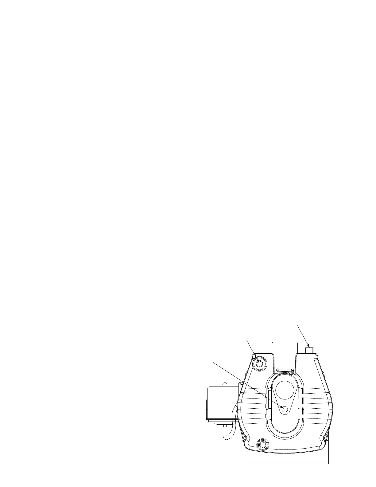
PLUG DESCRIPTIONS AND SOCKET SIZES
s NOTICE
!
Do not use open style wrenches to loosen plugs.
Plugs may become damaged and dicult to remove.
Priming Plug
9/16" - 8 pt
Pressure Gauge Plug
5/16"- 8 pt
Clean-out Plug
5/16"- 8 pt
Drain Plug
5/16" - 8 pt
6
Loading ...
Loading ...
Loading ...