Loading ...
Loading ...
Loading ...
MAINTENANCE
s WARNING
!
RISK OF ELECTRICAL SHOCK
Before servicing motor-operated equipment, shut o the power at the main electrical panel and disconnect the power supply from motor and accessories.
Use safe working practices during servicing of equipment.
PERFORM INSPECTIONS MONTHLY
1. Ensure the pump is still securely bolted to the foundation.
2. To avoid any fire hazards, ensure that there is adequate clearance
from any combustible materials, shelving or cabinets. Ensure
there are no leaves or debris near the pump.
3. Ensure that the motor is securely wired into a proper GFCI-
protected circuit. Test the GFCI periodically by pressing the test
switch when the pump is operating. This should shut o the
pump. If the GFCI does not shut the pump o, have an electrician
replace the GFCI as soon as possible. Remember to reset the GFCI
by pressing the reset switch.
4. Look for any signs of leaks in pipes. Replace or repair if necessary.
5. Clean the exterior of the pump with a solution of vinegar and
water, if needed.
DRAINING
Should the unit be subject to freezing, it will be necessary to drain the
pump and tank. To do this, shut o the power to the pump at the main
electrical panel. Open a tap in the water system to release the pressure.
Remove the drain and priming plugs from the pump casing. Remove the
pressure tank drain plug (if so equipped). Allow ample time for the system
to drain before reinstalling the plugs.
LUBRICATION
The pump requires none.
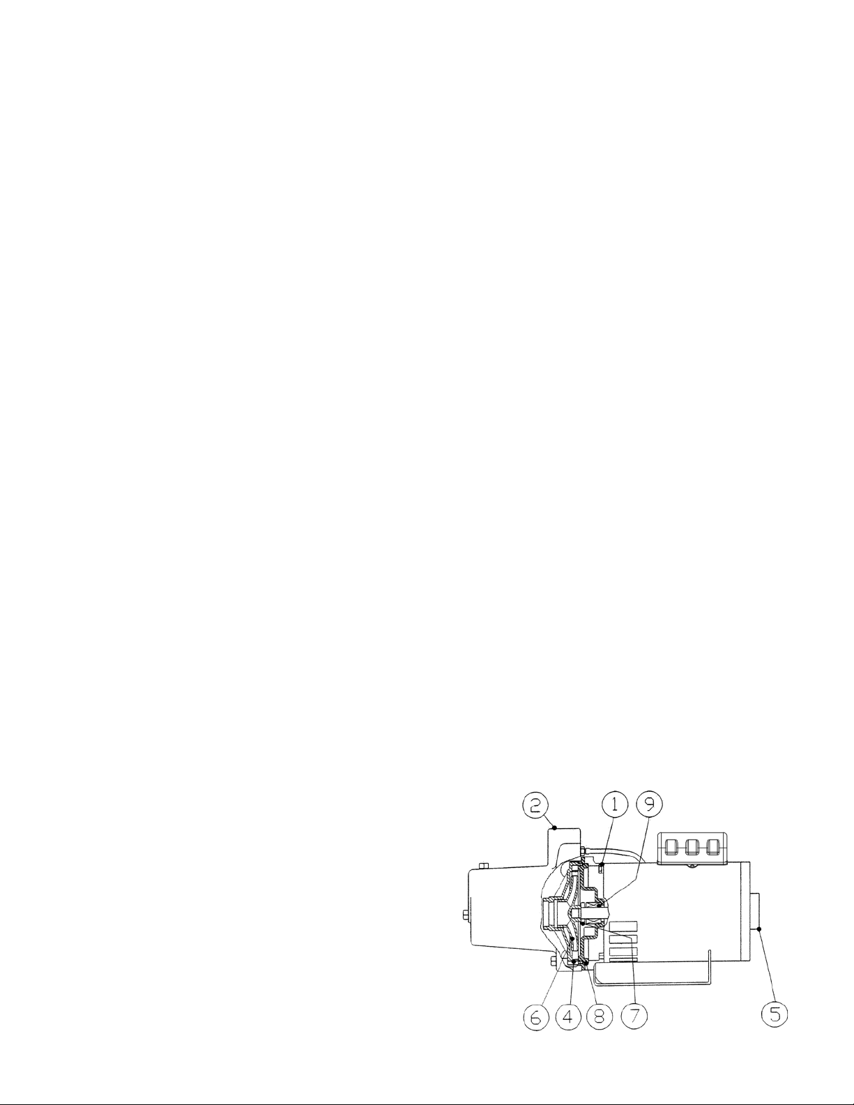
REPLACING MECHANICAL SEAL (See Figure 8)
s CAUTION
!
ONLY DULY QUALIFIED PERSONS SHOULD PERFORM
MAINTENANCE ON ELECTRICAL AND/OR MECHANICAL DEVICES.
Disassembly:
1. Shut o the power to the pump at the main service panel and
disconnect the power supply from motor.
2. Open a tap in the water system to release the pressure.
3. Remove the drain and fill plugs to allow the pump to drain.
4. Disconnect the tube leading to the pressure switch.
5. Remove the four bolts (1) and remove casing (2).
6. Pry the diuser (4) out of the casing using two slotted
screwdrivers for leverage.
7. Remove the cap (5) and insert a screwdriver to prevent the shaft
from turning while unscrewing the impeller (6). The impeller has
a right-hand thread. If the impeller cannot be turned by hand,
insert a flat object into the impeller vane.
8. Slip the rotating seal (7) o the shaft and remove the
seal plate (8).
9. Remove the ceramic seal seat (9) from the seal plate.
Reassembly:
1. Clean all parts thoroughly before assembling.
2. Lightly lubricate (with soapy water) the rubber cap on
the ceramic seal (9), and push it into the seal plate using
thumbs only. Make sure the smooth surface of the ceramic
seat faces outwards.
NOTE: If the pump will remain out of service for longer
than one week, the seal components must be installed dry
(no lubrication).
3. Put the seal plate back on the motor.
4. Lubricate the rotating seal (7) with soapy water and slip it onto
the shaft with the ‘carbon’ ring towards the ceramic seat.
5. Replace the impeller (6) and the diuser (4).
6. Replace the casing (2), making sure that the gasket is not
damaged and is in place.
7. Reconnect the tubes to the casing and to the pressure switch.
8. Reconnect the power.
9. Prime pump, start, and check for leaks.
Figure 8
13
Loading ...
Loading ...
Loading ...