Loading ...
Loading ...
Loading ...
35
ENGLISH
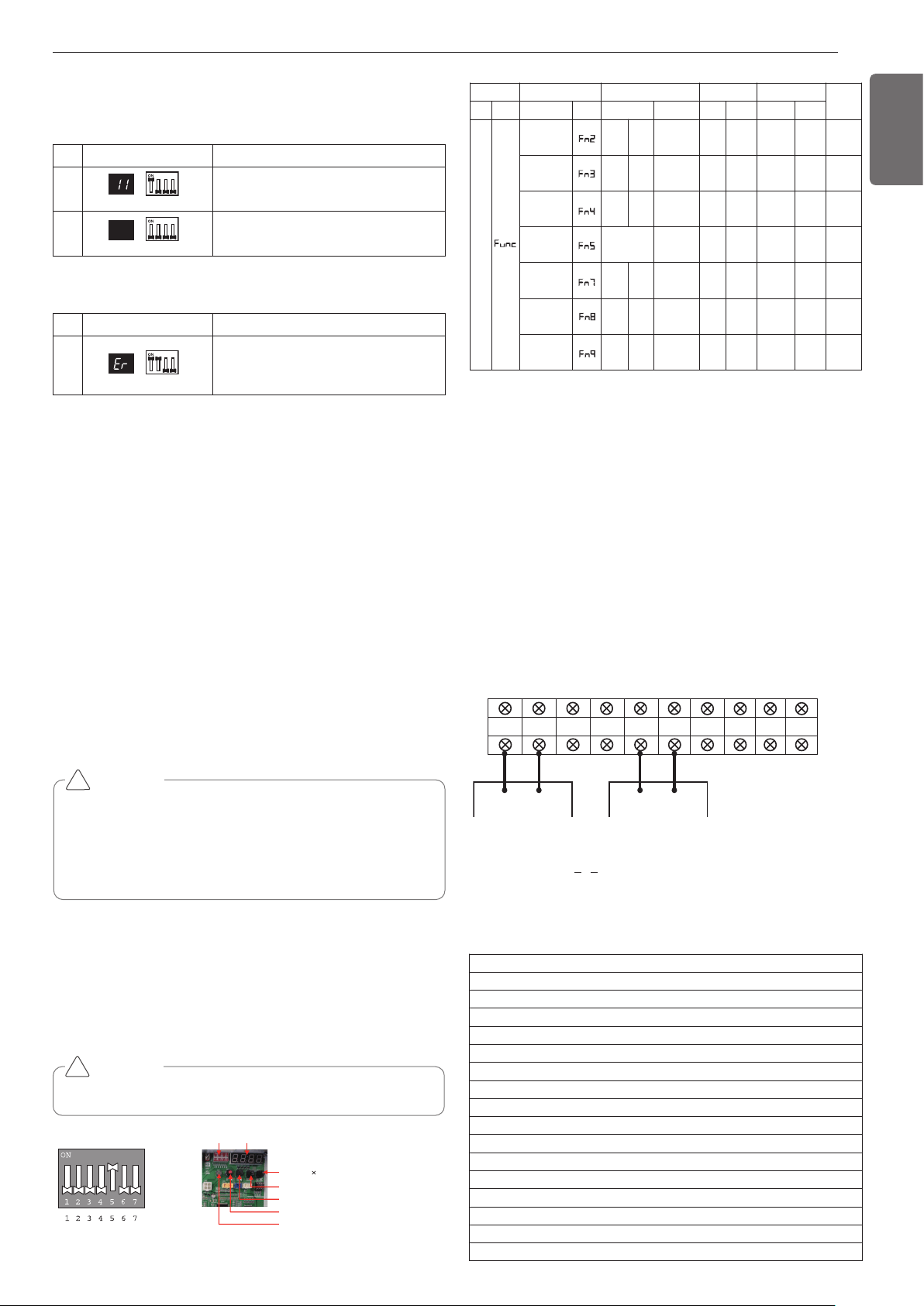
No. Display and setup Setup and Contents
1
- Operation: Turn dip S/W No.1 on.
- Display: "11" is displayed in 7-SEG
2
- Operation: Turn dip S/W No.1 on.
- 7-SEG disappeared
7-SEG SW01M
7-SEG SW01M
No. Display and setup Setup and Contents
1
- Operation: more than 2 dip switches
turned on.
- Display: "Er" is displayed in 7-SEG
7-SEG SW01M
CAUTION
• Waiting for 80seconds after power on.
• The zoning information and Master IDU information remove from
EEPROM after Auto-addressing.
• If there is installed the central control, it is impossible setting of
Master IDU in zoning.
!
Setting method of Master indoor unit in zon-
ing
1. Master unit PCB DIP switch on: No.5
2. Select the mode using ‘▶’, ‘◀’ Button: "idu" Push the ‘●’ button
3. Select the "id 7" function using ‘▶’, ‘◀’ Push the ‘●’ button
4. select HR unit number and Pipe number as you want to change
- 7-Segment Display "[ x ] [ y ] [ _ ] [ _ ]"
[_]: Blank, [x]: HR unit number, [y]: Pipe number
- Change the HR unit number and Pipe number using ‘▶’, ‘◀’ Push
the ‘●’ button as you want to set
5. Select IDU number as you want
- 7-Segment Display "[ _ ] [ _ ] [ x ] [ y ]"
[_]: Blank, [x]: Indoor unit 10-digit number, [y]: Indoor unit 1-digit
number
- Set the master IDU number using ‘▶’, ‘◀’ Push the ‘●’ button
as you want to set
Identification of Manual Valve ID (Address)
Example of checking valve address
(In case that an indoor unit of central control address "11" is connected
to a valve #1 of an HR unit)
DIP-SW01 7 - Segment
SW01C ( : confirm)
SW02C (ඔ : backward)
SW03C (ඖ : forward)
SW04C (
: cancel)
SW01D (reset)
Dip switch setting
Setting the function
Select the mode/function/option/value using ‘▶’, ‘◀’ Button and con-
firm that using the ‘●’ button after dip switch No.5 is turned on.
CAUTION
It is only executed when all indoor units are off.
!
Group Number setting
Group Number setting for Indoor Units
- Confirm the power of whole system(Indoor Unit, Outside Unit) is
OFF, otherwise turn off.
- The communication cables connected to CEN.A and CEN.B terminal
should be connected to central control of Outside Unit with care for
their polarity (A-A, B-B ).
- Turn the whole system on.
- Set the group and Indoor Unit number with a wired remote control.
- To control several sets of Indoor Units into a group, set the group ID
from 0 to F for this purpose.
Outside Units (External PCB)
Example) Group number setting
1
st
number indicate the group number
2nd number point out indoor unit number
SODU.B SODU.A IDU.B IDU.A CEN.B CEN.A DRY1 DRY2 GND 12V
B(D) A(C) BA
1 F
Group Indoor unit
* Functions save in EEPROM will be kept continuously, though the
system power was reset.
To cancel the function you need to set OFF.
Mode Function Option Value Action
Remarks
Content
Display1
Content
Display2
Content Display3
Content Display4
Implement Display5
Installation
Geothermal
mode set-
ting
on
oFF
Selected
the option
- -
Change
the set
value
Blank
Save in
EEPROM
Sol. Valve
200 V out-
put
on
oFF
Selected
the option
- -
Change
the set
value
Blank
Save in
EEPROM
Variable
water flow
control
on
oFF
Selected
the option
- -
Change
the set
value
Blank
Save in
EEPROM
Outside unit
address
-
-
0~254
set
the
value
Change
the set
value
Blank
Save in
EEPROM
Target
pressure
adjusting
oFF
op1~
op4
Selected
the option
- -
Change
the set
value
Blank
Save in
EEPROM
Use Sump
Heater
on
oFF
Selected
the option
- -
Change
the set
value
Blank
Save in
EEPROM
IDU capacity
adjusting
on
oFF
Selected
the option
- -
Change
the set
value
Blank
Save in
EEPROM
Group recognizing the central controller
No.0 group (00~0F)
No.1 group (10~1F)
No.2 group (20~2F)
No.3 group (30~3F)
No.4 group (40~4F)
No.5 group (50~5F)
No.6 group (60~6F)
No.7 group (70~7F)
No.8 group (80~8F)
No.9 group (90~9F)
No. A group (A0~AF)
No. B group (B0~BF)
No. C group (C0~CF)
No. D group (D0~DF)
No. E group (E0~EF)
No. F group (F0~FF)
Loading ...
Loading ...
Loading ...