Loading ...
Loading ...
Loading ...
36
See the lower drawing on page 35. Plug in the
power cord, press the power switch to the reset posi-
tion, and rock the Pulley (19) forward and backward
just enough that the Magnet (43) passes the Reed
Switch (38) repeatedly.
Repeat these actions until the console displays correct
feedback. When the reed switch is correctly adjusted,
press the power switch to the off position, unplug the
power cord, and reattach the left disc.
HOW TO ADJUST THE DRIVE BELT
If the pedals slip while you are pedaling, even while
the resistance is adjusted to the highest level, the drive
belt may need to be adjusted.
To adjust the drive belt, first press the power switch
to the off position and unplug the power cord.
See assembly step 16 on page 16. Use a standard
screwdriver to remove the Shield Cover (75) and the
Shield Cover Cap (118).
See assembly step 15 on page 16. Remove
the Right Upper Body Leg Outer and Inner Covers
(69, 83).
See assembly step 12 on page 14. Remove the
Right Pedal Arm (58) from the Right Upper Body
Leg (60).
Next, remove the M8 x 16mm Screw (95), the Axle
Cover (53), and the M8 Washer (not shown) from the
right Crank Arm (20). Then, carefully remove the Right
Pedal Arm (58) and the Right Roller Arm (59) from the
elliptical.
See EXPLODED DRAWING C on page 43. Identify
the Left and Right Shields (73, 74). Remove the
M4 x 19mm Tek Screws (5), the M4 x 19mm Screws
(127), and the M4 x 48mm Screw (107) from the Left
and Right Shields; make sure to note the location of
each size of Screw. Then, remove the Right Shield.
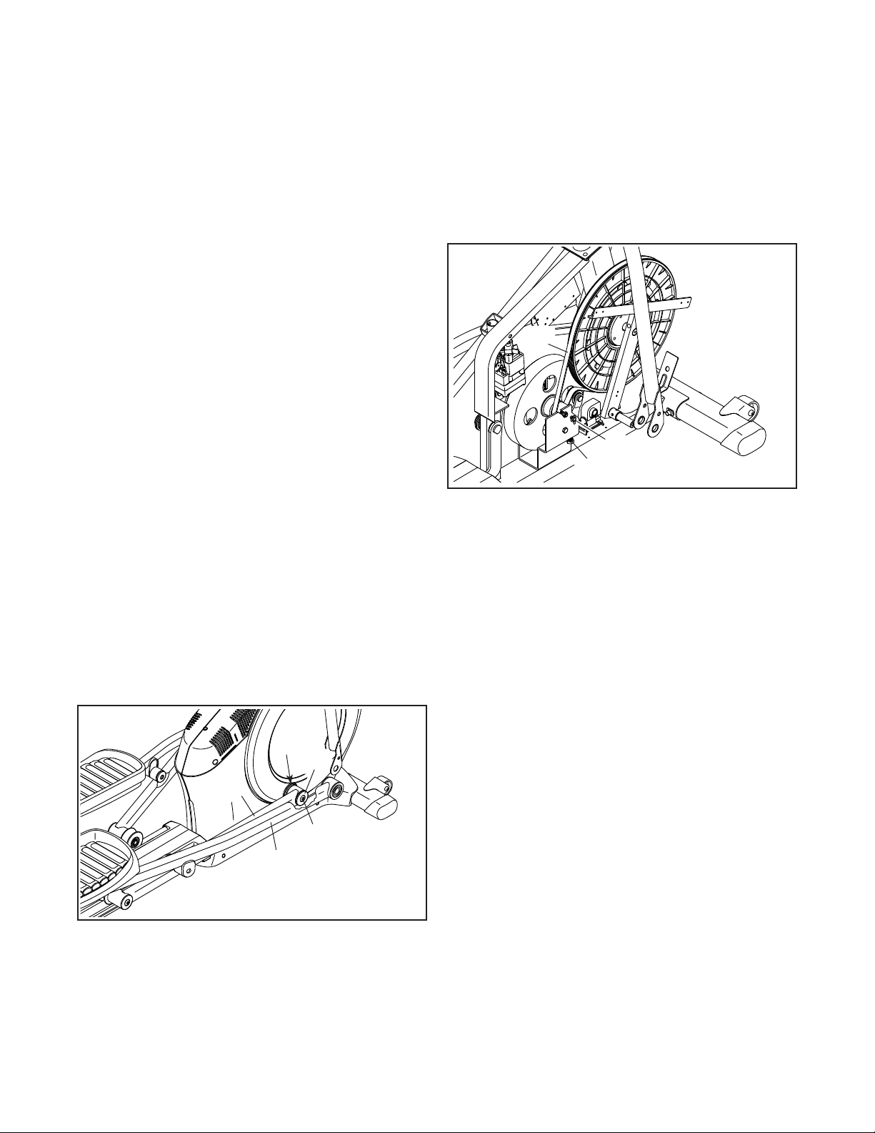
Then, locate and loosen the Idler Screw (89). Tighten
the Belt Adjustment Screw (91) until the Drive Belt
(113) is tight. Then, retighten the Idler Screw.
Reattach the right shield, the right roller arm, the right
pedal arm, the shield cover cap, and the shield cover.
Then, plug in the power cord.
95
58
59
20
53
113
91
89
Loading ...
Loading ...
Loading ...