Loading ...
Loading ...
Loading ...
5
ENGLISH
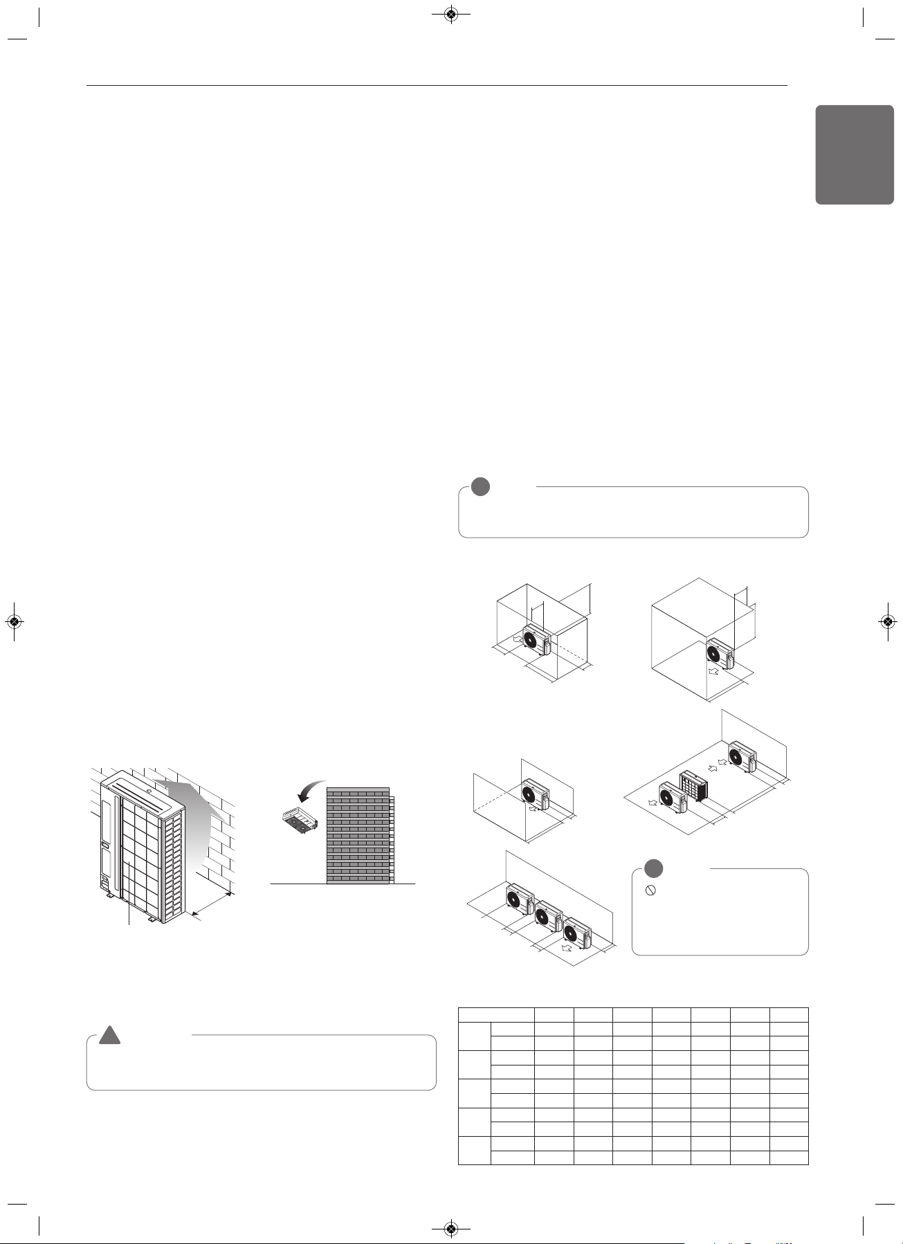
Air inlet grille
700
[Unit : mm]
Turn the air outlet side toward the
building's wall, fence or windbreak screen.
WARNING
Fix the outdoor unit firmly with anchor bolt or it may fall and hurt
people. (refer to ‘Foundation for installation’)
!
• The following values are the least space for installation. If any service
area is needed for service according to field circumstance, obtain
enough service space.
• The unit values is inch & mm
2 Ton
Proper clearance for the outdoor unit coil is critical for proper unit oper-
ation. When installing the outdoor unit, consider service, inlet and out-
let and minimum allowable space requirements as illustrated in the
diagrams below and on the next few pages.
Minimum Clearance Requirements for the Multi V S 24K Outdoor Unit
Specific clearance requirements in the diagram below are for Multi V S
24,000 Btu/h (ARUN024GSS4) systems. Figure 40 shows the overall
minimum clearances that must be observed for safe operation and ad-
equate airflow around the outdoor unit. When placing the outdoor unit
under an overhang, awning, sunroof or other “roof-like structure”, ob-
serve the clearance requirements as shown in Cases 1 and 2 in for
height in relation to the unit. This clearance ensures that heat radiation
from the condenser is not restricted around the unit.
Adhere to all clearance requirements if installing the unit on a roof. Be
sure to level the unit and ensure that the unit is adequately anchored.
Consult local codes for rooftop mounting requirements. To have suc-
cessful service access to the outdoor unit, see Figure 40 for minimum
spacing. When installing multiple outdoor units, see Cases 4 and 5 in
for correct spacing requirements.
Outdoor Unit Service Access and Allowable Clearances Diagram.
24K Outdoor Unit Service Access and Allowable Clearances Diagram
Legend.
INSTALLATION SPACESELECT THE BEST LOCATION
Select space for installing outdoor unit, which will meet the following
conditions:
• No direct thermal radiation from other heat sources
• No possibility of annoying neighbors by noise from unit
• No exposition to strong wind
• With strength which bears weight of unit
• Note that drain flows out of unit when heating
• With space for air passage and service work shown next
• Because of the possibility of fire, do not install unit to the space
where generation, inflow, stagnation, and leakage of combustible
gas is expected.
• Avoid unit installation in a place where acidic solution and spray (sul-
fur) are often used.
• Do not use unit under any special environment where oil, steam and
sulfuric gas exist.
• It is recommended to fence round the outdoor unit in order to pre-
vent any person or animal from accessing the outdoor unit.
• If installation site is area of heavy snowfall, then the following direc-
tions should be observed.
- Make the foundation as high as possible.
- Fit a snow protection hood.
Select installation location considering following conditions to avoid
bad condition when additionally performing defrost operation.
• Install the outdoor unit at a place well ventilated and having a lot of
sunshine in case of installing the product at a place with a high hu-
midity in winter (near beach, coast, lake, etc).
(Ex) Rooftop where sunshine always shines.
• Performance of heating will be reduced and preheat time of the in-
door unit may be lengthened in case of installing the outdoor unit in
winter at following location:
- Shade position with a narrow space
- Location with much moisture in neighboring floor.
- Location with much humidity around.
- Location where ventilation is good. It is recommended to install the
outdoor unit at a place with a lot of sunshine as possible as.
- Location where water gathers since the floor is not even.
When installing the outdoor unit in a place that is constantly exposed to a
strong wind like a coast or on a high story of a building, secure a normal
fan operation by using a duct or a wind shield.
• Install the unit so that its discharge port faces to the wall of the build-
ing.
Keep a distance 500mm or more between the unit and the wall sur-
face.
• Supposing the wind direction during the operation season of the air
conditioner, install the unit so that the discharge port is set at right
angle to the wind direction.
A
B
D
G
C
G
20 inches or less
Case 1 Case 2
20 inches or less
C
D
E
D
F
Case 4
Case 3
D
B
B
Case 5
NOTE
!
If the outdoor unit is installed between standard and minimum clearances, ca-
pacity decreases approximately 10%.
NOTE
!
Do not place the unit where ani-
mals and/or plants will be in the
path of the warm air, or where the
warm air and / or noise will disturb
neighbors.
Unit: Inch / mm A B C D E F G
Case 1
Standard 12 / 300 24 / 600 - 12 / 300 - - -
Minimum 4 / 100 10 / 250 - 4 / 100 - - 40 / 1000
Case 2
Standard - - 20 / 500 - - - -
Minimum - - 14 / 350 - - - 40 / 1000
Case 3
Standard - - 20 / 500 12 / 300 - - -
Minimum - - 14 / 350 4 / 100 - - -
Case 4
Standard - - - 12 / 300 24 / 600 - -
Minimum - - - 4 / 100 8 / 200 79 / 2000 -
Case 5
Standard - 24 / 600 - 12 / 300 - - -
Minimum - 10 / 250 - 4 / 100 - - -
1,MFL67798024,영영 18. 7. 19. 영영 2:13 Page 5
Loading ...
Loading ...
Loading ...