Loading ...
Loading ...
Loading ...
23
ENGLISH
Example) Group number setting
1
st
number indicate the group number
2nd number point out indoor unit number
SODU.B SODU.A IDU.B IDU.A CEN.B CEN.A DRY1 DRY2 GND 12V
B(D) A(C)
1 F
Group Indoor unit
Group recognizing the central controller
No.0 group (00~0F)
No.1 group (10~1F)
No.2 group (20~2F)
No.3 group (30~3F)
No.4 group (40~4F)
No.5 group (50~5F)
No.6 group (60~6F)
No.7 group (70~7F)
No.8 group (80~8F)
No.9 group (90~9F)
No. A group (A0~AF)
No. B group (B0~BF)
No. C group (C0~CF)
No. D group (D0~DF)
No. E group (E0~EF)
No. F group (F0~FF)
Master unit PCB DIP switch on : No.5
Select the mode using ‘▶’, ‘◀’ Button :
“Func” Push the ‘●’ button
Select the Function using ‘▶’, ‘◀’ Button :
“Fn1” Push the ‘●’ button
Select the Option using ‘▶’, ‘◀’ Button :
“oFF”,“op1”,“op2” Push the ‘●’ button
Cool & Heat Selection mode is set
Function setting
Switch control Function
Switch(Phase) Switch(Bottom)
oFF op1(mode) op2(mode)
Right Left Not operate Cooling Cooling
Right Right Not operate Heating Heating
Left - Not operate Fan mode Off
CAUTION
• Ask an authorized technician to setting a function.
• If do not use a function, set an off-mode.
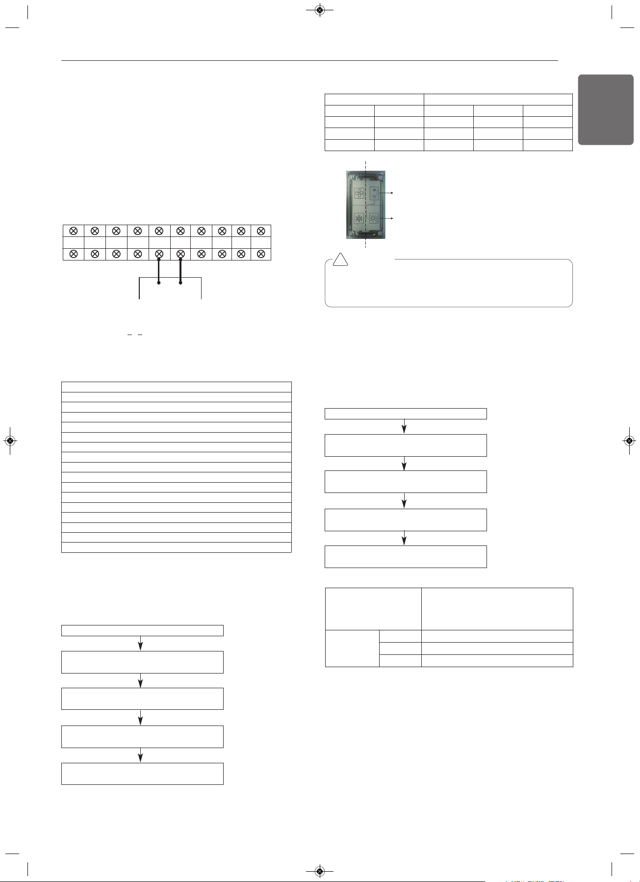
• If use a function, first install a Cool & Heat selector.
!
Switch (Phase)
Switch (Bottom)
Left side
Right side
Master unit PCB DIP switch on : No.5
Select the mode using ‘▶’, ‘◀’ Button :
“Func” Push the ‘●’ button
Select the Function using ‘▶’, ‘◀’ Button :
“Fn2” Push the ‘●’ button
Select the Option using ‘▶’, ‘◀’ Button :
“op1~op3” Push the ‘●’ button
Start the Static pressure compensation mode :
Save the selected option value in EEPROM
FAN Maximum RPM of each step
Static pressure compensation mode
This function secures the air flow rate of ODU, in case static pressure
has been applied like using duct at fan discharge of ODU.
Static pressure compensation mode setting method
Cool & Heat selector
Mode setting method
Model
ARUN060GSS4
ARUN053GSS4
ARUN048GSS4
ARUN038GSS4
Max.RPM
Standard 800
OP1 850
OP2 850
Group Number setting
Group Number setting for Indoor Units
- Confirm the power of whole system(Indoor Unit, Outdoor Unit) is
OFF, otherwise turn off.
- The communication cables connected to CEN.A and CEN.B terminal
should be connected to central control of Outdoor Unit with care for
their polarity (A-A, B-B ).
- Turn the whole system on.
- Set the group and Indoor Unit number with a wired remote control.
- To control several sets of Indoor Units into a group, set the group ID
from 0 to F for this purpose.
Outdoor Units (External PCB)
1,MFL67798024,영영 18. 7. 19. 영영 2:14 Page 23
Loading ...
Loading ...
Loading ...