2
Features of your new air conditioner
Cool Summer Oer
On those hot sweltering summer days and long restless nights, there is no better escape from the heat than the cool
comforts of home. Your new air conditioner brings an end to exhausting hot summer days and lets you rest.
This summer, beat the heat with your own air conditioner.
Cost Ecient System
Your new air conditioner not only provides maximum cooling power in the summer, but can also be an ecient heating
method in the winter with the advanced “Heat pump” system. This technology is up to 300% more ecient than
electrical heating, so you can further reduce its running cost. Now, meet year-round needs with one air conditioner.
Flexible installation
Duct type air conditioner is designed to be slimmer and oers dierent solutions for any shape room allowing for
specic air ow requirements. Also, the air intake can be set up on either the bottom or rear of the unit, so there is more
exibility in installation.
Correct Disposal of This Product
(Waste Electrical & Electronic Equipment)
(Applicable in countries with separate collection systems)
This marking on the product, accessories or literature indicates that the product and its electronic accessories (e.g. charger, headset, USB
cable) should not be disposed of with other household waste at the end of their working life. To prevent possible harm to the environment
or human health from uncontrolled waste disposal, please separate these items from other types of waste and recycle them responsibly to
promote the sustainable reuse of material resources.
Household users should contact either the retailer where they purchased this product, or their local government office, for details of where
and how they can take these items for environmentally safe recycling.
Business users should contact their supplier and check the terms and conditions of the purchase contract. This product and its electronic
accessories should not be mixed with other commercial wastes for disposal.

3
Contents
Safety precautions
.....................................................................................................................................................
4
Viewing your air conditioner ..................................................................................................................................................10
Using your air conditioner ..................................................................................................................................................... 10
Tips on using your air conditioner ....................................................................................................................................................................... 10
DEMAND RESPONSE MODE (DRM 1, 2, 3) ........................................................................................................................................................ 12
Cleaning and maintaining the air conditioner ................................................................................................................. 13
Maintaining your air conditioner .......................................................................................................................................................................... 13
Appendix .................................................................................................................................................................................... 15
Troubleshooting ........................................................................................................................................................................................................... 15
Operation ranges ......................................................................................................................................................................................................... 17
Safety precautions .....................................................................................................................................................................18
Preparation for installation .....................................................................................................................................................20
Deciding on where to install the indoor unit ......................................................................................................................21
Indoor unit installation ............................................................................................................................................................25
Easier Handling ..........................................................................................................................................................................26
Purging the unit .........................................................................................................................................................................27
Connecting the refrigerant pipe ............................................................................................................................................28
Cutting/aring the pipes ..........................................................................................................................................................29
Performing leak test & insulation ..........................................................................................................................................30
Drainpipe and drain hose installation ..................................................................................................................................32
Interface module Installation (Optional) .............................................................................................................................34
Connecting the connection cord ...........................................................................................................................................34
Adjusting air ow .......................................................................................................................................................................36
Easy Tuning ..................................................................................................................................................................................37
Setting the indoor unit option code .....................................................................................................................................38
Setting an indoor unit address and installation option ...................................................................................................39
Troubleshooting (NSHHXEG) .......................................................................................................................................42
Troubleshooting (ACJNHFKH) .....................................................................................................................................45
Extending the power cable .....................................................................................................................................................48
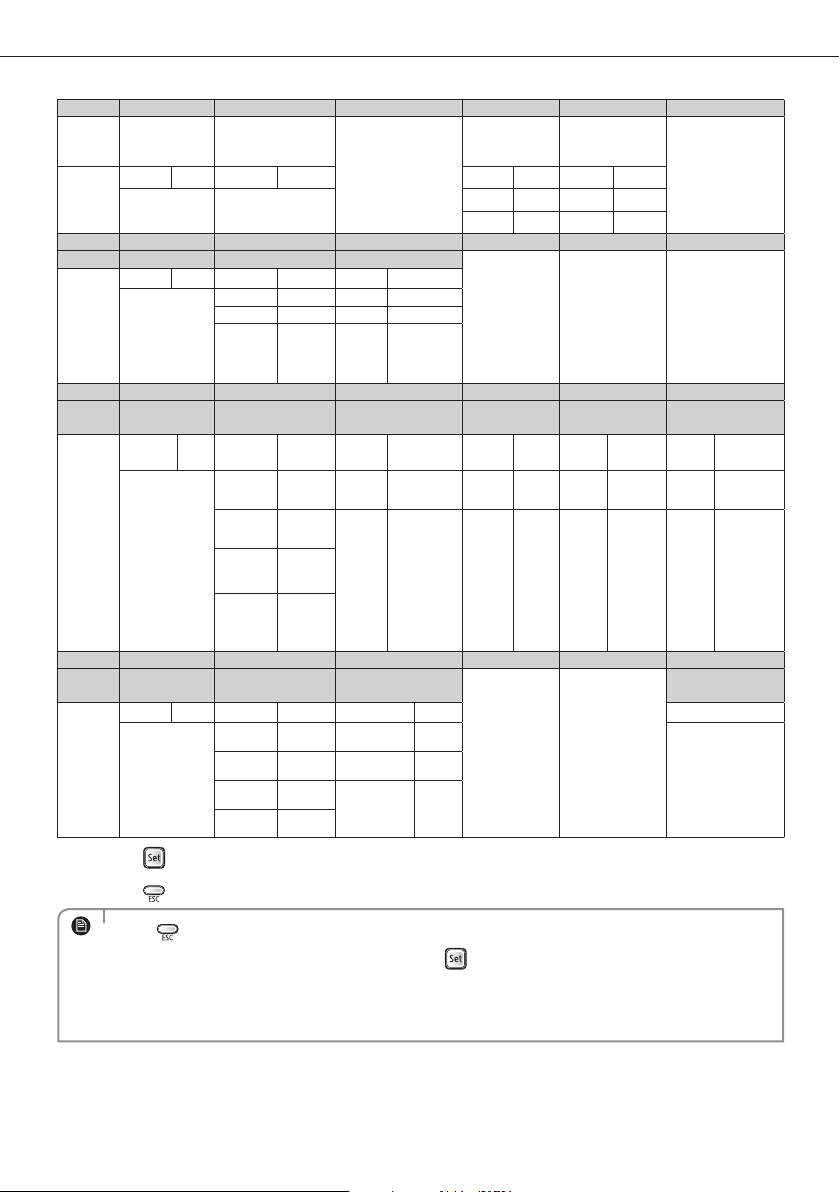
USING PARTS
INSTALLATION PARTS

4
A
Safety precautions
USING PARTS
Before using your new air conditioner, please read this manual thoroughly to ensure that
you know how to safely and eciently operate the extensive features and functions of your
new appliance.
Because the following operating instructions cover various models, the characteristics of
your air conditioner may dier slightly from those described in this manual. If you have any
questions, call your nearest contact center or nd help and information online at www.
samsung.com.
Important safety symbols and precautions:
WARNING
Hazards or unsafe practices that may result in severe personal injury
or death.
CAUTION
Hazards or unsafe practices that may result in minor personal injury
or property damage.
Follow directions.
Do NOT attempt.
Make sure the machine is grounded to prevent electric shock.
Unplug the power plug from the wall socket.
Do NOT disassemble.
FOR INSTALLATION
WARNING
Use the power line with the power specications of the product or higher and use
the power line for this appliance only. In addition, do not use an extension line.
Extending the power line may result in electric shock or fire.
Do not use an electric transformer. It may result in electric shock or fire.
If the voltage/frequency/rated current condition is different, it may cause fire.
The installation of this appliance must be performed by a qualied technician or
service company.
Failing to do so may result in electric shock, fire, explosion, problems with the
product, or injury.
Install a switch and circuit breaker dedicated to the air conditioner.
Failing to do so may result in electric shock or fire.
Fix the outdoor unit rmly so that the electric part of the outdoor unit is not exposed.
Failing to do so may result in electric shock or fire.
5
FOR INSTALLATION
WARNING
Do not install this appliance near a heater, inammable material. Do not install
this appliance in a humid, oily or dusty location, in a location exposed to direct
sunlight and water (rain drops). Do not install this appliance in a location where
gas may leak.
This may result in electric shock or fire.
Never install the outdoor unit in a location such as on a high external wall where it
could fall.
If the outdoor unit falls, it may result in injury, death or property damage.
This appliance must be properly grounded. Do not ground the appliance to a gas
pipe, plastic water pipe, or telephone line.
Failure to do so may result in electric shock, fire, an explosion, or other problems with
the product.
Never plug the power cord into a socket that is not grounded correctly and make
sure that it is in accordance with local and national codes.
FOR INSTALLATION
CAUTION
Install your appliance on a level and hard oor that can support its weight.
Failing to do so may result in abnormal vibrations, noise, or problems with the
product.
Install the draining hose properly so that water is drained correctly.
Failing to do so may result in water overflowing and property damage.
When installing the outdoor unit, make sure to connect the draining hose so that
draining is performed correctly.
The water generated during the heating operation by the outdoor unit may overflow
and result in property damage.
In particular, in winter, if a block of ice falls, it may result in injury, death or property
damage.
6
Safety precautions
FOR POWER SUPPLY
WARNING
When the circuit breaker is damaged, contact your nearest service center.
Do not pull or excessively bend the power line. Do not twist or tie the power line.
Do not hook the power line over a metal object, place a heavy object on the power
line, insert the power line between objects, or push the power line into the space
behind the appliance.
This may result in electric shock or fire.
FOR POWER SUPPLY
CAUTION
When not using the air conditioner for a long period of time or during a thunder/
lightning storm, cut the power at the circuit breaker.
Failing to do so may result in electric shock or fire.
FOR USING
WARNING
If the appliance is ooded, please contact your nearest service center.
Failing to do so may result in electric shock or fire.
If the appliance generates a strange noise, a burning smell or smoke, unplug the
power plug immediately and contact your nearest service center.
Failing to do so may result in electric shock or fire.
In the event of a gas leak (such as propane gas, LP gas, etc.), ventilate immediately
without touching the power line.
Do not touch the appliance or power line.
Do not use a ventilating fan.
A spark may result in an explosion or fire.
To reinstall the air conditioner, please contact your nearest service center.
Failing to do so may result in problems with the product, water leakage, electric
shock, or fire.
A delivery service for the product is not provided. If you reinstall the product in
another location, additional construction expenses and an installation fee will be
charged.
Especially, when you wish to install the product in an unusual location such as in
an industrial area or near the seaside where it is exposed to the salt in the air, please
contact your nearest service center.
7
FOR USING
WARNING
Do not touch the circuit breaker with wet hands.
This may result in electric shock.
Do not strike or pull the air conditioner with excessive force.
This may result in fire, injury, or problems with the product.
Do not place an object near the outdoor unit that allows children to climb onto
the machine.
This may result in children seriously injuring themselves.
Do not turn the air conditioner o with the circuit breaker while it is operating.
Turning the air conditioner off and then on again with the circuit breaker may cause a
spark and result in electric shock or fire.
After unpacking the air conditioner, keep all packaging materials well out of the
reach of children, as packaging materials can be dangerous to children.
If a child places a bag over its head, it may result in suffocation.
Do not insert your ngers or foreign substances into the outlet when the air
conditioner is operating or the front panel is closing.
Take special care that children do not injure themselves by inserting their fingers into
the product.
Do not touch the front panel with your hands or ngers during the heating
operation.
This may result in electric shock or burns.
Do not insert your ngers or foreign substances into the air inlet/outlet of the air
conditioner.
Take special care that children do not injure themselves by inserting their fingers into
the product.
Do not use this air conditioner for long periods of time in badly ventilated
locations or near inrm people.
Since this may be dangerous due to a lack of oxygen, open a window at least once an
hour.
8
A
FOR USING
WARNING
If any foreign substance such as water has entered the appliance, cut the power by
unplugging the power plug and turning the circuit breaker o and then contact
your nearest service center.
Failing to do so may result in electric shock or fire.
Do not attempt to repair, disassemble, or modify the appliance yourself.
Do not use any fuse (such as cooper, steel wire, etc.)other than the standard fuse.
Failing to do so may result in electric shock, fire, problems with the product, or injury.
FOR USING
CAUTION
Do not place objects or devices under the indoor unit.
Water dripping from the indoor unit may result in fire or property damage.
Check that the installation frame of the outdoor unit is not broken at least once a
year.
Failing to do so may result in injury, death or property damage.
Max current is measured according to IEC standard for safety and current is
measured according to ISO standard for energy eciency.
Do not stand on top of the appliance or place objects (such as laundry, lighted
candles, lighted cigarettes, dishes, chemicals, metal objects, etc.) on the appliance.
This may result in electric shock, fire, problems with the product, or injury.
Do not operate the appliance with wet hands.
This may result in electric shock.
Do not spray volatile material such as insecticide onto the surface of the appliance.
As well as being harmful to humans, it may also result in electric shock, fire or
problems with the product.
Do not drink the water from the air conditioner.
The water may be harmful to humans.
Do not apply a strong impact to the remote controller and do not disassemble the
remote controller.
Do not touch the pipes connected with the product.
This may result in burns or injury.
Safety precautions
9
FOR USING
CAUTION
Do not use this air conditioner to preserve precision equipment, food, animals,
plants or cosmetics, or for any other unusual purposes.
This may result in property damage.
Avoid directly exposing humans, animals or plants from the air ow from the air
conditioner for long periods of time.
This may result in harm to humans, animals or plants.
This appliance is not intended for use by persons (including children) with
reduced physical, sensory or mental capabilities, or lack of experience and
knowledge, unless they have been given supervision or instruction concerning
use of the appliance by a person responsible for their safety. Children should be
supervised to ensure that they do not play with the appliance.
FOR CLEANING
WARNING
Do not clean the appliance by spraying water directly onto it. Do not use benzene,
thinner or alcohol to clean the appliance.
This may result in discoloration, deformation, damage, electric shock or fire.
Before cleaning or performing maintenance, unplug the air conditioner from the
wall socket and wait until the fan stops.
Failing to do so may result in electric shock or fire.
FOR CLEANING
CAUTION
Take care when cleaning the surface of the heat exchanger of the outdoor unit
since it has sharp edges.
To avoid cutting your fingers, wear thick cotton gloves when cleaning it.
Do not clean the inside of the air conditioner by yourself.
For cleaning inside the appliance, contact your nearest service center.
When cleaning the internal filter, refer to the descriptions in the ‘Cleaning and
maintaining the air conditioner’ section.
Failure to do may result in damage, electric shock or fire.
10
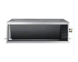
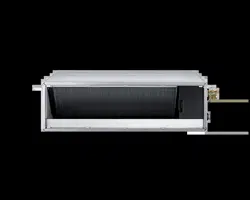
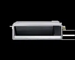
Viewing your air conditioner
Congratulations on the purchase of the air conditioner. We hope you enjoy the features of your air conditioner
and stay cool or warm with optimal e ciency.
Please read the user manual to get started and to make the best use of the air conditioner.
• Your air conditioner may slightly look di erent from illustration shown above depending on your
model.
NOTE
Using your air conditioner
Tips on using your air conditioner
Here are some tips that you would follow when using your air conditioner.
TOPIC RECOMMENDATION
Cooling
• If current outside temperatures are much higher than
the selected indoor temperature, it may take time to
bring the inner temperature to the desired coolness.
• Avoid drastically turning down the temperature.
Energy is wasted and the room does not cool faster.
Air intake
Air outlet
Ceiling
Air intake
Air outlet
Ceiling
• A Samsung-branded air conditioning unit installed in an area which is not easily accessible
(including without limitation roofs or positions above 2.4 metres for the outdoor unit) may require
additional costs for labour and access equipment as may be mandated by occupational health and
safety requirements. Such costs are to be borne by you should service or maintenance (including
service or maintenance covered by your warranty or by a consumer guarantee) be required.
NOTE
MA DUCT TYPE
BIG DUCT TYPE

11
Using your air conditioner
TOPIC RECOMMENDATION
Heating
•Since the air conditioner heats the room by taking heat
energy from outdoor air, the heating capacity may
decrease when outdoor temperatures are extremely low.
If you feel the air conditioner insuciently heats, using
an additional heating appliance in combination with the
air conditioner is recommended.
Frost & De-ice
•When the air conditioner runs in Heat mode, due to
temperature dierence between the unit and the outside
air, frost will form.
•If this happens:
- The air conditioner stops heating.
- The air conditioner will operate automatically in De-ice
mode for 10minutes.
- The steam produced on the outdoor unit in De-ice
mode is safe.
•No intervention is required; after about 10 minutes, the
air conditioner operates again normally.
•The unit will not operate when it starts to de-
ice.
NOTE
Fan
•Fan may not operate for about 3~5 minutes at the
beginning to prevent any cold blasts while the air
conditioner is warming up.
High indoor/
outdoor
temperatures
•If both indoor and outdoor temperatures are high and
the air conditioner is running in Heat mode, the outdoor
unit’s fan and compressor may stop at times. This is
normal; wait until the air conditioner turns on again.
Power failure
•If a power failure occurs during the operation of the air
conditioner, the operating immediately stops and unit
will be o. When power returns, the air conditioner will
run automatically.
Protection
mechanism
•If the air conditioner has just been turned on after
operation stops or being plugged in, cool/warm air does
not come out for 3minutes to protect the compressor of
the outdoor unit.
12
Using your air conditioner
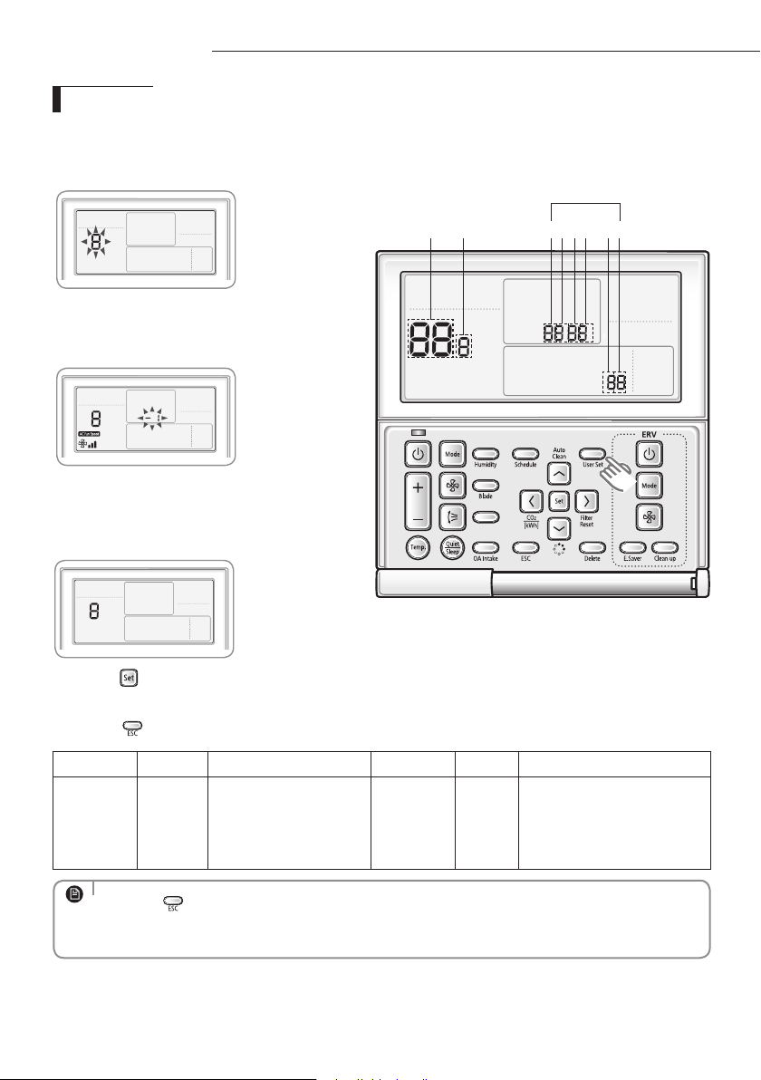
DEMAND RESPONSE MODE (DRM 1, 2, 3)
This air conditioner is equipped with a Demand Response unit which will respond to a signal sent by the power
supply utility during emergency conditions.
During a Demand Response Event, the indoor and outdoor unit will be operated according to DRM mode(DRM
1, 2, 3) and indoor unit will show "
, , " on the display.
Away/MDS
AIR CONDITIONER DEMAND RESPONSE MODES
Operational
instruction
(OI)
Demand
response mode
(DRM)*
Description of operation in this mode
Mandatory for compliance
with this Standard (AS/NZS
4755.3.1)
OI 1 DRM 1 Compressor o Yes
OI 2 DRM 2
The air conditioner continues to cool or heat
during the demand response event, but the
electrical energy consumed by the air conditioner
in a half hour period is not more than 50% of the
total electrical energy that would be consumed
if operating at the rated capacity in a half hour
period.
No
OI 3 DRM 3
The air conditioner continues to cool or heat
during the demand response event, but the
electrical energy consumed by the air conditioner
in a half hour period is not more than 75% of the
total electrical energy that would be consumed
if operating at the rated capacity in a half hour
period.
No

13
A
Cleaning and maintaining the air conditioner
For the best performance from your air conditioner, clean it periodically. When cleaning, make sure to unplug from
the unit for user’s safety.
Maintaining your air conditioner
If the air conditioner will not be used for an extended period of time, dry the air conditioner to maintain it in best
condition.
1. Dry the air conditioner thoroughly by operating in Fan mode for 3 to 4 hours and
disconnect the power plug. There may be internal damage if moisture is left in
components.
2. Before using the air conditioner again, dry the inner components of the air
conditioner again by running in Fan mode for 3 to 4 hours. This helps remove
odors which may have generated from dampness.
Periodical checks
Refer to the following chart to maintain the air conditioner properly.
Type Description Monthly
Every 4
months
Once a
year
Indoor unit
Clean the air lter (1)
Clean the condensate drain pan (2)
Thoroughly clean the heat exchanger (2)
Clean the condensate drain pipe (2)
Replace the remote control batteries (1)
Outdoor unit
Clean the heat exchanger on the outside of the unit (2)
Clean the heat exchanger on the inside of the unit (2)
Clean the electric components with jets of air (2)
Verify that all the electric components are rmly tightened (2)
Clean the fan (2)
Verify that all the fan assembly is rmly tightened (2)
Clean the condensate drain pan (2)
• The checks and maintenance operations described are essential to guarantee the eciency of the air
conditioner. The frequency of these operations varies according to the characteristics of the area, the
amount of dust, etc.
1) The described operations should be performed more frequently if the area of installation is very
dusty.
2) These operations must always be performed by qualied personnel. For more detailed information,
see the Installation Manual.
NOTE
14
A
Internal protections via the unit control system
This internal protection operates if an internal fault occurs in the air conditioner.
Type Description
Against cold air
The internal fan will be o to against cold air when the heat pump is heating.
De-ice cycle
The internal fan will be o to against cold air when the heat pump is heating.
Anti-protection of internal
battery
The compressor will be o to protect internal battery when the air conditioner
operates in Cool mode.
Protect compressor
The air conditioner does not start operating immediately to protect the
compressor of the outdoor unit after it has been started.
• If the heat pump is operating in Heat mode, De-ice cycle is actuated to remove frost from an outdoor
unit that may have deposited at low temperatures.
• The internal fan is switched o automatically and restarted only after the de-ice cycle is completed.
NOTE
Cleaning and maintaining the air conditioner
15
A
Troubleshooting
Refer to the following chart if the air conditioner operates abnormally. This may save
time and unnecessary expenses.
PROBLEM SOLUTION
The air conditioner
does not operate
immediately after it
has been restarted.
•Because of the protective mechanism, the appliance
does not start operating immediately to keep the unit
from overloading. The air conditioner will start in 3
minutes.
The air conditioner
does not work at all.
•Check that the power plug is properly connected. Insert
the power plug into the wall socket correctly.
•Check if the circuit breaker is switched o.
•Check if there is a power failure.
•Check your fuse. Make sure it is not blown out.
The temperature
does not change.
•Check if you selected Fan mode.
Press the
Mode
button on the remote control to select
another mode.
The cool (warm) air
does not come out of
the air conditioner.
•Check if the set temperature is higher (lower) than the
current temperature. Press the Temperature button on
the remote control to change the set temperature. Press
the Temperature button to decrease or increase the
temperature.
•Check if the air lter is blocked by dirt.
•Check if the air conditioner has just been turned on. If
so, wait 3 minutes. Cool air does not come out to protect
the compressor of the outdoor unit.
•Check if the air conditioner is installed in a place with a
direct exposure to sunlight. Hang curtains on windows
to boost cooling eciency.
•Check if the cover or any obstacle is not near the outdoor unit.
•Check if the refrigerant pipe is too long.
•Check if the air conditioner is only available in Cool mode.
•Check if the remote control is only available for cooling model.
• Check if the air conditioner is operating in defrost
mode. When the ice formed in winter or the outdoor
temperature is too low, the air conditioner operates in
defrost mode automatically. In defrost mode, indoor fan
stops and warm air does not come out.
Appendix
16
A
PROBLEM SOLUTION
The fan speed does
not change.
•Check if you selected Auto or Dry mode.
The air conditioner automatically adjusts the fan speed
to Auto in Auto/Dry mode.
Timer function does
not set.
•Check if you press the Power button on the remote
control after you have set the time.
Odors permeate in
the room during
operation.
•Check if the appliance is running in a smoky area or if
there is a smell entering from outside. Operate the air
conditioner in Fan mode or open the windows to air out
the room.
The air conditioner
makes a bubbling
sound.
•A bubbling sound may be heard when the refrigerant
is circulating through the compressor. Let the air
conditioner operate in a selected mode.
•When you press the Power button on the remote
control, noise may be heard from the drain pump inside
the air conditioner.
Water is dripping
from the air ow
blades.
•Check if the air conditioner has been cooling for an
extended period of time with the air ow blades pointed
downwards. Condensation may generate due to the
dierence in temperature.
Remote controller is
not working.
•Check if your batteries are depleted.
•Make sure batteries are correctly installed.
•Make sure nothing is blocking your remote control
sensor.
•Check that there are strong lighting apparatus near
the air conditioner. Strong light which comes from
uorescent bulbs or neon signs may interrupt the
electric waves.
The air conditioner
does not turn on or
o with the wired
remote control.
•Check if you set the wired remote control for group
control.
The wired remote
control does not
operate.
•Check if TEST indicator is displayed on the wired remote
control. If so, turn o the unit and switch o the circuit
breaker. Call your nearest contact center.
The indicators of
the digital display
ashes.
•Press the Power button on the remote control to turn
the unit o and switch the circuit breaker o. Then,
switch it on again.
Appendix
17
PROBLEM SOLUTION
Indoor unit display
indicates
“
, , "
•Thisisnotadefect.Iftheairconditionerreceivesa
DemandResponsesignalfromthepowersupply
utility,thenthecompressorandfanswillbeoperated
accordingtoDRMmode(DRM1,2,3).Theindoorunit
displaywillindicate"
, , ".
Operation ranges
Thetablebelowindicatesthetemperatureandhumidityrangestheairconditioner
canbeoperatedwithin.Refertothetableforecientuse.
MODE
OPERATIONAL TEMPERATURE
INDOOR
HUMIDITY
IF OUT OF CONDITIONS
INDOOR
OUTDOOR
NS
HHXEG AC
JNHFKH
COOLING 18˚Cto32˚C -15˚Cto46˚C -15˚Cto50˚C 80%orless
Condensationmayoccuronthe
indoorunitwithrisktohaveeither
waterblowoordropsontheoor.
HEATING 27˚Corless -20˚Cto24˚C -20˚Cto24˚C -
Internalprotectiontriggersandthe
airconditionerwillstop.
DRYING 18˚Cto32˚C -15˚Cto46˚C -15˚Cto50˚C -
Condensationmayoccuronthe
indoorunitwithrisktohaveeither
waterblowoordropsontheoor.
• Thestandardizedtemperatureforheatingis7˚C.Iftheoutdoortemperaturedropsto0˚Corbelow,the
heatingcapacitycanbereduceddependingonthetemperaturecondition.Ifthecoolingoperationis
usedatover32˚C(indoortemperature),itdoesnotcoolatitsfullcapacity.
NOTE
•
Theuseoftheairconditioneratarelativehumidityabovetheexpectedone(80%)may
causetheformationofcondensateandtheleakageofwaterdropsontheoor.
CAUTION
18
INSTALLATION PARTS
Carefully follow the precautions listed below because they are essential to guarantee the safety of the equipment.
• Always disconnect the air conditioner from the power supply before servicing it or accessing
its internal components.
• Verify that installation and testing operations are performed by qualified personnel.
• Verify that the air conditioner is not installed in an easily accessible area.
General information
Carefully read the content of this manual before installing the air conditioner and store the manual in a safe place in order to be able
to use it as reference after installation.
For maximum safety, installers should always carefully read the following warnings.
Store the operation and installation manual in a safe location and remember to hand it over to the new owner if the air conditioner is
sold or transferred.
This manual explains how to install an indoor unit with a split system with two SAMSUNG units. The use of other types of units with
dierent control systems may damage the units and invalidate the warranty. The manufacturer shall not be responsible for damages
arising from the use of non compliant units.
The manufacturer shall not be responsible for damage originating from unauthorized changes or the improper connection of
electric and requirements set forth in the “Operating limits” table, included in the manual, shall immediately invalidate the warranty.
The air conditioner should be used only for the applications for which it has been designed: the indoor unit is not suitable to be
installed in areas used for laundry.
Do not use the units if damaged. If problems occur, switch the unit o and disconnect it from the power supply.
In order to prevent electric shocks, res or injuries, always stop the unit, disable the protection switch and contact SAMSUNG’s
technical support if the unit produces smoke, if the power cable is hot or damaged or if the unit is very noisy.
Always remember to inspect the unit, electric connections, refrigerant tubes and protections regularly. These operations should be
performed by qualied personnel only.
The unit contains moving parts, which should always be kept out of the reach of children.
Do not attempt to repair, move, alter or reinstall the unit. If performed by unauthorized personnel, these operations may cause
electric shocks or res.
Do not place containers with liquids or other objects on the unit.
All the materials used for the manufacture and packaging of the air conditioner are recyclable.
The packing material and exhaust batteries of the remote controller(optional) must be disposed of in accordance with current laws.
The air conditioner contains a refrigerant that has to be disposed of as special waste. At the end of its life cycle, the air conditioner
must be disposed of in authorized centers or returned to the retailer so that it can be disposed of correctly and safely.
WARNING
Safety precautions
19
Power supply line, fuse or circuit breaker
Always make sure that the power supply is compliant with current safety standards. Always install the air conditioner in compliance
with current local safety standards.
Always verify that a suitable grounding connection is available.
Verify that the voltage and frequency of the power supply comply with the specications and that the installed power is sucient
to ensure the operation of any other domestic appliance connected to the same electric lines.
Always verify that the cut-o and protection switches are suitably dimensioned.
Verify that the air conditioner is connected to the power supply in accordance with the instructions provided in the wiring diagram
included in the manual.
Always verify that electric connections (cable entry, section of leads, protections…) are compliant with the electric specications
and with the instructions provided in the wiring scheme. Always verify that all connections comply with the standards applicable
to the installation of air conditioners.
Devices disconnected from the power supply should be completely disconnected in the condition of overvoltage category.
Be sure not to perform power cable modication, extension wiring, and multiple wire connection.
- It may cause electric shock or re due to poor connection, poor insulation, or current limit override.
- When extension wiring is required due to power line damage, refer to "Extending the power cable" in the installation
manual.
Installing the unit
IMPORTANT: When installing the unit, always remember to connect rst the refrigerant tubes, then the electrical lines.
Always disassemble the electric lines before the refrigerant tubes.
Upon receipt, inspect the product to verify that it has not been damaged during transport. If the product appears damaged,
DO NOT INSTALL it and immediately report the damage to the carrier or retailer (if the installer or the authorized technician has
collected the material from the retailer.)
After completing the installation, always carry out a functional test and provide the instructions on how to operate the air
conditioner to the user.
Do not use the air conditioner in environments with hazardous substances or close to equipment that release free ames to avoid
the occurrence of res, explosions or injuries.
Our units should be installed in compliance with the spaces shown in the installation manual, to ensure accessibility from both
sides and allow repairs or maintenance operations to be carried out. The unit’s components should be accessible and easy to
disassemble without endangering people and objects.
For this reason, when provisions of the installation manual are not complied with, the cost required to access and repair the units
(in SAFETY CONDITIONS, as set out in prevailing regulations) with harnesses, ladders, scaolding or any other elevation system will
NOT be considered part of the warranty and will be charged to the end customer.
◆
Make sure that you earth the cables.
- Do not connect the earth wire to the gas pipe, water pipe, lighting rod or telephone wire. If earthing is not
complete, electric shock or re may occur.
◆
Install the circuit breaker.
- If the circuit breaker is not installed, electric shock or re may occur.
◆
Make sure that the condensed water dripping from the drain hose runs out properly and safely.
◆
Install the power cable and communication cable of the indoor and outdoor unit at least 1m away from the electric appliance.
◆
Install the indoor unit away from lighting apparatus using the ballast.
- If you use the wireless remote controller, reception error may occur due to the ballast of the lighting apparatus.
◆
Do not install the air conditioner in following places.
- Place where there is mineral oil or arsenic acid. Resin parts ame and the accessories may drop or water may
leak. The capacity of the heat exchanger may reduce or the air conditioner may be out of order.
- The place where corrosive gas such as sulfurous acid gas generates from the vent pipe or air outlet.
The copper pipe or connection pipe may corrode and refrigerant may leak.
- The place where there is a machine that generates electromagnetic waves. The air conditioner may not operate
normally due to control system.
- The place where there is a danger of existing combustible gas, carbon ber or ammable dust.
The place where thinner or gasoline is handled. Gas may leak and it may cause re.
CAUTION
20
A
Preparation for installation
The following accessories are supplied with the indoor unit.
The type and quantity may dier depending on the specications.
Accessories
Wired remote control accessories
Wired remote
control(1)
Cable-tie(2) Cable clamp(3) M4x16
tapped screw(5)
User’s
manual(1)
Installation
manual(1)
U Terminal (6)
User’s&
Installation
manual
Flexible hose Insulation drain Thermal insulation
sponge A
Thermal insulation
sponge B
Thermal insulation
sponge C
Clamp hose Rubber Cable-tie
When deciding on the location of the air conditioner with the owner, the following restrictions must be taken into account.
Do NOT install the air conditioner in a location where it will come into contact with the following elements :
◆
Combustible gases
◆
Saline air
◆
Machine oil
◆
Sulphide gas
◆
Special environmental conditions
If you must install the unit in such conditions, rst consult your dealer.
Avoid installing the air conditioner :
◆
In areas where it is exposed to direct sunlight. Close to heat sources.
◆
In damp areas or locations where it could come into contact with water. (for example rooms used for laundry)
◆
In areas where curtains and furniture could aect the supply and discharge of air.
◆
Without leaving the required minimum space around the unit. (as shown in the drawing)
◆
In scarcely ventilated areas.
◆
On surfaces that are unable to support the weight of the unit without deforming, breaking or causing vibrations
during the use of the air conditioner.
◆
In a position that does not enable the condensate drainage pipe to be correctly installed. (at the end of the
installation. It is always essential to check the eciency of the drainage system)
General
NSHHXEG model only
21
A
There must be no obstacles near the air inlet and outlet.
Install the indoor unit on a ceiling that can support its weight.
Maintain sufficient clearance around the indoor unit.
Make sure that the water dripping from the drain hose runs away correctly and safely.
The indoor unit must be installed in this way, that they are out of public access. (Not touchable by the
users)
After connecting a chamber, insulate the connection part between the indoor unit and the chamber with
t10 or thicker insulation. Otherwise, there can be air leak or dew from the connection part.
Indoor unit
Deciding on where to install the indoor unit
Construction Standard for Inspection Hole
1) In case, the ceiling is tex tile, Inspection hole dose not need.
2) In case, the ceiling is plaster board, Inspection hole depends on Inside height of the ceiing.
a. Height is more than 0.5m : Only "B" [Inspection for PBA] is applied.
b. Height is less than 0.5m : Both "A"&"B" are applied.
c. "A"&"B" are inspection holes .
Unit Width(W)
"A"=W+100mm
Unit Depth(D)
"B"=500mm
You must have 20mm or more space between the ceiling and the bottom of indoor unit. Otherwise, the
noise from the vibration of indoor unit may bother the user.When the ceiling is under construction, the hole
for check-up must be made to take service, clean and repair the unit.
It is possible to install the unit at an height of between 2.2~2.5m from the ground,
if the unit has a duct with a well defined lenght (300mm or more), to avoid fan motor blower contact.
If you install the cassette or duct type indoor unit on the ceiling with humidity over 80%, you must apply
extra 10mm of polyethylene foam or other insulation with similar material on the body of the indoor unit.
20mm
20mm
or more
or more
Space requirements for installation & service
22
A
Deciding on where to install the indoor unit
Indoor Unit(Net Size) A B C D Front/Back
NSHHXEG
1200 x 650 x 360 1200 x 650 1200 x 650 650 x 360 650 x 360
Insulate the front and back side in
proper size at the same time when
insulating the suction duct and
discharge duct.
AC✴✴✴JNHFKH
1350 x 850 x 450 1350 x 450 1350 x 450 850 x 450 850 x 450
A C
B
D
Front
Back
Thickness: more than 10mm
Insulate the end of the pipe and some curved area by using separate insulator.
Insulate the discharge and suction part at the same time when you insulate connection duct.
Insulation Guide

23
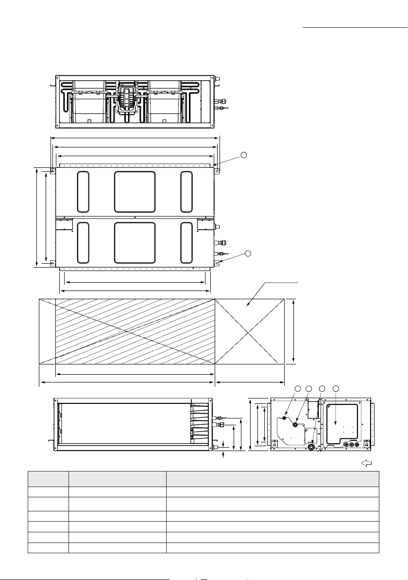
No. Name Description
1 Liquid pipe connection ø9.52
(3/8”)
2 Gas pipe connection ø19.05
(3/4”)
3 Drain pipe connection
OD25 ID20(without drain pump)
4 Drain pipe connection
Using drain pump (Optional)
5 Power supply -
6 Air outlet duct flange -
7 Air inlet duct flange -
8 Hook M8~M10
NS
HHXEG
Unit : mm
6
8
7
4
3
2
1
5
650
650
1200
1300500
534 (Suspension position)
Suction sideDischarge side
360
253
276
2×100=200
2×50=100
80
170
244
299
OD25
28
121
137
20-ø3.2hole
(All around)
1236 (Suspension position)
1200
1000 (Air outlet duct flange)
6×150=900
4×200=800
1160(Air inlet duct flange)
86 222
Drawing of the indoor unit
24
A
1 2
3 4
500
5
6
1350
1450
1200(24x50)
1284
279
850
850
782
360
450
30
220
1439
1392
1350
300(6x50)
(Suspension position)
(Air outlet duct flange)
(Suspension position)
Inspection hole
Suction side
Discharge side
No. Name Description
1 Liquid pipe connection ø9.52(3/8")
2 Gas pipe connection
✴200 / 180✴ : ø19.05(3/4") ; ✴160✴ : ø15.88(5/8")
3 Drain pipe connection OD25 ID20(without drain pump)
4 Power supply connection
5 Air discharge flange
6 Hook M10
Unit:mm
Deciding on where to install the indoor unit
AC
JNHFKH
25
A
Indoor unit installation
When deciding on the location of the air conditioner with the owner, the following restrictions must be taken into account.
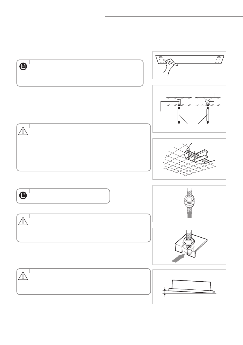
1
Place the pattern sheet on the ceiling at the spot where you want
to install the indoor unit.
2
Insert bolt anchors. Use existing ceiling supports or construct a suit-
able support as shown in figure.
3
Install the suspension bolts depending on the ceiling type.
4
Screw eight nuts to the suspension bolts making space for hanging
the indoor unit.
5
Hang the indoor unit to the suspension bolts between two nuts.
6
Screw the nuts to suspend the unit.
7
Adjust level of the unit by using measurement plate for all 4 sides.
Concrete
Suspension bolt(M8)-field supply
Hole in anchor
hole in plug
Ceiling support
When the drain hose is installed to the right.
Drain hose port
3mm
Insert
•
Since the diagram is made of paper, it may shrink or
stretch slightly due to temperature or humidity. For this
reason, before drilling the holes maintain the correct
dimensions between the markings.
•Ensurethattheceilingisstrongenoughtosupporttheweight
of the indoor unit. Before hanging the unit, test the strength of
each attached suspension bolt.
•Ifthelengthofsuspensionboltismorethan1.5m,
it is required to prevent vibration.
•Ifthisisnotpossible,createanopeningonthefalseceilingin
order to be able to use it to perform the required operations on
the indoor unit.
•Pipingmustbelaidandconnectedinsidetheceilingwhen
suspending the unit. If the ceiling is already constructed, lay the
piping into position for connection to the unit before
placing the unit inside the ceiling.
• For proper drainage of condensate, give a 3mm slant to the
left or right side of the unit which will be connected with the
drain hose, as shown in the gure. Make a tilt when you wish to
install the drain pump, too.
•
You must install all the suspension rods.
CAUTION
CAUTION
CAUTION
NOTE
NOTE
26
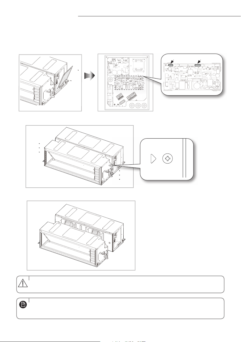
The ducted indoor unit(AC***JNHFKH) has a two-piece construction.
This allows separation of the indoor unit heat exchanger and the fan deck assembly for easier handling into the roof space.
Easier Handling
1
Remove Control Box cover and disconnect indoor sensor connector & EEV connector (AC200JNHFKH
only).
2
Disassemble 6 screws on the LEFT / RIGHT side (Marked as"
").
3
Split.
EEV ConnectorSensor Connector
• Whenassemblingtheproducts,performthereverseprocedureofdisassembling.
• Afterreassemblingtheproducts,checkthattheconnectionpartoftheproductsissealedcompletelyduringthe
trial operation.
• Whendisassemblingtheproducts,thewireconnectorshouldnotbecaughtintheproductnorshoulditbecut.
CAUTION
NOTE
27
Purging the unit
From factory the unit is supplied and set with a pre-charge of nitrogen gas. (insert gas) Therefore, all insert gas must be purged
before connecting the assembly piping.
Unscrew the pinch pipe at the end of each refrigerant pipe.
RESULT : All inert gas escapes from the indoor unit.
• Topreventdirtorforeignobjectsfromgettingintothepipesduring
installation, do NOT remove the pinch pipe completely until you are
ready to connect the piping.
• Connecttheindoorandoutdoorunitsusingpipeswithared
connections(not supplied). For the lines, use insulated, unwelded,
degreased and deoxidized copper pipe (Cu DHP type to ISO 1337 or
UNI EN 12735-1), suitable for operating pressures of at least 4200kPa
and for a burst pressure of at least 20700kPa. Copper pipe for hydro-
sanitary applications is completely unsuitable.
• Forsizingandlimits(heightdierence,linelength,max.bends,
refrigerant charge, etc.) see the outdoor unit installation manual.
•Allrefrigerantconnectionmustbeaccessible,inordertopermiteither
unit maintenance or removing it completely.
The designs and shape are subject
to change according to the model.
G_1
CAUTION
NOTE
NS
HHXEG
AC
JNHFKH
28
A
• Ifthepipesmustbeshortenedrefertopage29.
Refrigerant oil
Spanner
Union
Torque wrench
Flare nut
Outer Diameter (D) Torque (N•m)
ø6.35 mm 14~18
ø9.52 mm 34~42
ø12.70 mm 49~61
ø15.88 mm 68~82
ø19.05 mm 100~120
Connecting the refrigerant pipe
There are two refrigerant pipes of dierent diameters :
◆
A smaller one for the liquid refrigerant
◆
A larger one for the gas refrigerant
◆
The inside of copper pipe must be clean & has no dust
1. Remove the pinch pipe on the pipes and connect the assembly pipes to each pipe, tightening the nuts, rst manually
and then with a torque wrench, a spanner applying the following torque.
2. Must use insulator which is thick enough to cover the refrigerant tube to protect the condensate water on the outside
of pipe falling onto the oor and the eciency of the unit will be better.
3. Cut o any excess foam insulation.
4. Be sure that there must be no crack or wave on the bended area.
5. It would be necessary to double the insulation thickness(10mm or more) to prevent condensation even on the
insulator when if the installed area is warm and humid.
6. Do not use joints or extensions for the pipes that connect the indoor and outdoor unit. The only permitted connections
are those for which the units are designed.
G_4
Drain hose connection port
G_1
Liquid refrigerant port
Gas refrigerant port
Gas refrigerant port
Liquid
refrigerant port
Drain hose connection port
The designs and shape are subject to change according to the model.
NS
HHXEG
AC
JNHFKH
NOTE
29
A
Cutting/Flaring the pipes
1. Make sure that you have the required tools available. (pipe cutter, reamer, aring tool and pipe holder)
2. If you wish to shorten the pipes, cut it with a pipe cutter, taking care to ensure that the cut edge remains at a 90° angle
with the side of the pipe. Refer to the illustrations below for examples of edges cut correctly and incorrectly.
3. To prevent any gas from leaking out, remove all burrs at the cut edge of the pipe, using a reamer.
4. Slide a are nut on to the pipe and modify the are.
5. Check that the flaring is correct, referring to the illustrations below for examples of incorrect flaring.
• IfthepipesrequirebrazingensurethatOFN(OxygenFreeNitrogen)isowingthroughthesystem.
• Nitrogenblowingpressurerangeis0.02~0.05MPa.
Oblique Rough
Burr
Pipe
cutter
Pipe
Outer Diameter (D) Depth (A)
ø6.35 mm 1.3 mm
ø9.52 mm 1.8 mm
ø12.70 mm 2.0 mm
ø15.88 mm 2.2 mm
ø19.05 mm 2.2 mm
Pipe
Flare
Uneven
Thickness
CrackedDamaged
Surface
InclinedCorrect
Outer diameter (D,mm)
Connection torque (N
·
m)
Flare dimension (L,mm) Flare shape (mm)
Ø 6.35 14~18 8.7~9.1
90° ±2°
45° ±2°
R 0.4~0.8
Ø 9.52 34~42 12.8~13.2
Ø 12.70 49~61 16.2~16.6
Ø 15.88 68~82 19.3~19.7
Ø 19.05 100~120 23.6~24.0
CAUTION
30
A
The designs and shape are subject to
change according to the model.
Leak check
Performing leak test & insulation
Once you have checked that there are no leaks in the system, you can insulate the piping and hose.
1
To avoid condensation problems, place T13.0 or thicker Acrylonitrile Butadien Rubber separately around each refrigerant
pipe.
2 Wind insulating tape around the pipes and drain hose avoiding to compress
the insulation too much.
3
Finish wrapping insulating tape around the rest of the pipes leading to the outdoor
unit.
4 The pipes and electrical cables connecting the indoor unit with the outdoor
unit must be xed to the wall with suitable ducts.
5 Select the insulation of the refrigerant pipe.
Insulate the gas side and liquid side pipe referring to the thickness
according to the pipe size.
Indoor temperature of 30°C and humidity of 85% is the stan dard condition.
If installing in a high humidity condition, use one grade thicker insulator by referring to the table below.
If installing in an unfavorable conditions, use thicker one.
Insulator’s heat-resistance temperature should be more than 120°C.
Leak test
Insulation
No gap
NBR(T13.0 or thicker)
Insulation cover pipe
Indoor unit
Be sure to overlap
the insulation
Insulation pipe
• Mustttightlyagainst
body without any gap.
• Alwaysmaketheseamofpipesfaceupwards.
• Allrefrigerantconnectionmustbeaccessible,inordertopermit
either unit maintenance or removing it completely.
• TheinsulationhastobeproducedinfullcomplianceofEuropean
regulation reg. EEC / EU 2037/ 2000 that
requires the use of sheaths insulation form without using CFC and
HCFC gases for health and the environment.
◆
LEAK TEST WITH NITROGEN (before opening valves)
In order to detect basic refrigerant leaks, before recreating the vacuum and
recirculating the R-410A, it’s responsable of installer to pressurize the whole
system with nitrogen (using a cylinder with pressure reducer)
at a pressure above 30 bar (gauge).
◆
LEAK TEST WITH R-410A (after opening valves)
Before opening valves, discharge all the nitrogen into the system and create
vacuum. After opening valves check leaks using a leak detector for refrigerant
R-410A.
• Dischargeallthenitrogentocreateavacuumandchargethesystem.
G_4
NS
HHXEG
AC
JNHFKH
CAUTION
CAUTION
CAUTION
CAUTION
NOTE
31
Pipe
Pipe size
Insulation Type (Heating/Cooling)
RemarksStandard [30°C, 85%] High humidity [30°C, over 85%]
EPDM,NBR
Liquid
pipe
Ø6.35 ~ Ø9.52 9t 9t
Internal temperature is
higher than 120°C
Ø12.7 ~ Ø19.05 13t 13t
Gas
pipe
Ø6.35 13t 19t
Ø9.52
19t 25t
Ø12.70
Ø15.88
Ø19.05
◆
When installing insulation in places and conditions below, use the same insulation that is used for high humidity conditions.
<Geological condition>
- High humidity places such as shoreline, hot spring, near lake or river, and ridge (when the part of the building is covered by
earth and sand.)
<Operation purpose condition>
- Restaurant ceiling, sauna, swimming pool etc.
<Building construction condition>
- The ceiling frequently exposed to moisture and cooling is not covered.
e.g. The pipe installed at a corridor of a dormitory and studio or near an exit that opens and closes frequently.
- The place where the pipe is installed is highly humid due to the lack of ventilation system.
32
A
Drainpipe and drain hose installation
1. Install horizontal drainpipe with a slope of 1/100 or more and fix it by hanger space of 1.0~1.5m.
2. Install U-trap at the end of the drainpipe to prevent a nasty smell to reach the indoor unit.
3. Do not install the drainpipe to upward position. It may cause water flow back to the unit.
Without the drain pump
1~1.5m
Horizontal drainpipe
more than 1/100 slope
Ceiling
Hanger
Flexible hose
Drainpipe Connection
Care must be taken when installing the drain hose for the indoor unit to ensure that any conden-
sate water is correctly drained outside.
The drain hose can be installed to the right of the base pan.
1
Installing the drain hose should be the shorter, the better.
◆ In order to discharge condensation water, the drain hose should keep tilted.
◆ Fix the drain hose with Cable-Tie, so that it will not separate from the machine.
◆ While using draining pump, connect the end with draining pump.
2
Insulate and fix the drain hose according to the figure.
◆ Insert the drain hose to bottom of the outfall of water basin.
◆ Lock steel ring of the drain hose according to the figure.
◆ Wind and wrap steel ring and drain hose fully with thermal insulation sponge; fix both ends of
external layer with ribbon for thermal insulation.
◆ After being installed, drain hose must be insulated fully by heat insulating material. (To be pro-
vided at site.)
A-A’
Steel ring of drain hose
Joint of drain hose
Drain hose
Drain hose
Fix with Cable-Tie
Wrap thermal sleeve hose
Indoor unit
As shown in the figure,
tighten steel ring of the
drain hose.
33
With the drain pump
1. The drain pipe should be installed within 300mm to 550mm from the flexible hose and then lift down 20mm
or more.
2. Install horizontal drainpipe with a slope of 1/100 or more and fix it by hanger space of 1.0~1.5m.
3 Install the air vent in the horizontal drainpipe to prevent water flow back to the indoor unit.
4 The flexible hose should not be installed upward position, it may cause water flow back to the indoor
unit.
1~1.5m
20mm
or more
200mm
or more
Hanger
Within
300~550mm
Air vent
300mm or less
Flexible hose
Horizontal drainpipe
more than 1/100 slope
Ceiling
•
You may not need to install it if there were proper slope in the horizontal drainpipe.
Prepare a little water about 2 liter.
1
Pour water into the base pan in the indoor unit as shown in figure.
2
Confirm that the water flows out through the drain hose.
Testing the drainage
G_6
NS
HHXEG
AC
JNHFKH
NOTE
34
A
Interface module Installation (Optional)
Interface module DC power cable Communication cable PCB Case Cable-tie
Accessories (Interface module : MIM-B13D)
1. Fix the case at with bolts on the side of the control box in the indoor unit.(See the
picture)
2. Attach the Interface module PCB to the case in the control box of the indoor unit,
then connect the power and the communication cable between the Interface
module and the indoor unit;
3. If you install a Interface module to an indoor unit, every outdoor unit which is
connected to an indoor unit can be controlled simultaneously.
4. Each indoor unit connected to the same centralized
controller has its own
Interface module.
Accessories (SPI module : MSD-EAN1)
Refer to the
SPI
module(MSD-EAN1) installation manual for the more information.
Accessories (Interface module : MIM-B14)
External Control PCB Case Haness Wire(2P) Haness Wire (4P) Screw
Connecting the connection cord
• Alwaysremembertoconnecttherefrigerantpipesbeforeperformingtheelectricconnections.
When disconnecting the system, always disconnect the electric cables before disconnecting the refrigerant pipes.
• Alwaysremembertoconnecttheairconditionertothegroundingsystembeforeperforming
the electric connections.
The indoor unit is powered by the outdoor unit by means of a H07 RN-F connection cable (or a more power model),
with insulation in synthetic rubber and jacket in polychloroprene(neoprene), in accordance with the requirements of standard EN 60335-2-40.
1. Remove the screw on the electrical component box and remove the cover plate.
2. Route the connection cord through the side of the indoor unit and connect the cable to terminals; refer to the gure below.
3. Route the other end of the cable to the outdoor unit through the ceiling & the hole on the wall.
4. Reassemble the electrical component box cover, carefully tightening the screw.
CAUTION
ACJNHFKH model only
35
Wiring diagram
N
L3(T)
1(L) 2(N)
L2(S)
L1(R)
F2F1
1(L)
2(N)
1
2 V1 V2 F3 F4
F2F1
1 phase(✴100/125/140/155/160✴)
1(L)
2(N) 1 2 V1 V2 F3 F4
F2F1
1(L) 2(N)
N
L
Indoor Unit
Main power cable
Cable clamp
Communication cable
Cable tie
3 phase(✴160/180✴)
Indoor Unit
Cable clamp
Indoor Power
Indoor Power
Communication cable
3 Phase 4 Wires
power cable
(AC 380V)
Cable tie
N
L3(T)
L2(S)
L1(R)
F2 F1
1(L)
2(N)
1
2 V1 V2 F3 F4
F2 F1
3 phase(✴200✴)
Indoor Unit
Cable clamp
Indoor Power
220-240V~
or
Communication cable
3 Phase 4 Wires
power cable
(AC 380V)
Cable tie
MCCB+
ELB
ELCB
❈
ELCB : Essential Installation
Indoor Power supply
Communication Cable
Power Supply Max/Min(V)
Indoor Power cable
220-240V~, 50Hz ±10%
2.5mm² ↑ ,3wires
0.75~1.25mm²,2wires
❈ Power supply cords of parts of appliances for outdoor use shall not be lighter than polychloroprene sheathed flexible cord. (Code designation
IEC:60245 IEC 57 / CENELEC: H05RN-F or IEC:60245 IEC 66 / CENELEC: H07RN-F)
❈ Screws on terminal block must not be unscrewed with the torque less than 12 kgf•cm.
❈ Since it has the external power supply, refer to the outdoor unit installation manual for MAIN POWER.
Between Indoor and Outdoor Connection cable Specications(Common in use)
When installing the indoor unit in a computer room, use the double shielded(Tape aluminum /
polyester braid + copper)cable of FROHH2R type.
Terminal Block SPEC (Indoor)
AC POWER : M4 SCREW COMMUNICATION : M4 SCREW
8.4 9.5 8.4 9.5
10
10
36
A
Adjusting air flow
With its phase control motor, you can adjust the indoor unit fan speed depending on the installation condition.
If the external static pressure is high so that the duct becomes longer or if the external static pressure is low so
that the duct becomes shorter, adjust the fan speed by referring the following table. In order to set indoor unit fan
speed , refer to the next page (setting the indoor unit option code)
Static Pressure
(mmAq)
5.0~7.5 7.5~12.5 12.5~17.5 17.5~20.0
Model Option code for indoor unit
NS100HHXEG
011014-1563FB-
276470-370000
011044-156060-
276470-370000
011044-1560D5-
276470-370000
011044-1560FA-
276470-370000
NS125HHXEG
011034-15617D-
277D8C-370000
011044-1560C1-
277D8C-370000
011044-156205-
277D8C-370000
011044-15622A-
277D8C-370000
NS140HHXEG
011044-1160F3-
278CA0-370000
011044-1160F6-
278CA0-370000
011044-11628B-
278CA0-370000
011044-11626C-
278CA0-370000
NS155HHXEG
011044-1160F3-
279BAA-370000
011044-1160F6-
279BAA-370000
011044-11628B-
279BAA-370000
011044-11626C-
279BAA-370000
E. S. P(External Static Pressure) setting for phase control motor
•The operating External Static Pressure range of the product is 5~20mmAq.
Using the product outside this range may cause malfunction.
•
Select an adequate option code within the External Static Pressure range for each Indoor unit.
Selecting an inadequate option code may cause malfunction.
The default option code is for External Static Pressure range of 5~7.5mmAq.
Model
AC200JNHFKH AC180JNHFKH AC160JNHFKH
Static Pressure(mmAq)
Option code for indoor unit
5≤ESP<7.5
012474-1C50C0-
20C8E1-320000
01107C-1C50B0-
27B414-370060
01107C-1C50A0-
27A0B4-370060
7.5≤ESP<10
012474-1C50E3-
20C8E1-320000
01107C-1C50E3-
27B414-370060
01107C-1C50D3-
27A0B4-370060
10≤ESP<12.5
012474-1C50F5-
20C8E1-320000
01107C-1C50F5-
27B414-370060
01107C-1C50F5-
27A0B4-370060
12.5≤ESP<15
012474-1C5436-
20C8E1-320000
01107C-1C5436-
27B414-370060
01107C-1C5437-
27A0B4-370060
15≤ESP<17.5
012474-1C5458-
20C8E1-320000
01107C-1C5458-
27B414-370060
01107C-1C5448-
27A0B4-370060
17.5≤ESP≤20
012474-1C548E-
20C8E1-320000
01107C-1C548E-
27B414-370060
01107C-1C5468-
27A0B4-370060
• represents E. S. P(External Static Pressure) range of factory setting.
You don’t have to adjust the fan speed separately if the external static pressure of the installation place is in
. When it is out of
, input the appropriate option code.
•
If you input the inappropriate option code, error may occur or the air conditioner is out of order. The
option code must be inputted correctly by the installation specialist or service agent.
CAUTION
NOTE
37
Easy Tuning
EASY Tuning
If the more cooling and heating airflow rate which set up when installing is wanted, or if the more Silent operation
which sets up when installing is wanted, air conditioner is tuned for comfort.
Indoor unit airflow rate for high, mid, low mode increases or decreases for +2 ~ -2 Steps with wired remocon.
• Press the
button anytime during setup to exit without setting.
• According to airflow changed from the Easy Tuning,Air conditioning performance reducing is
possible.
NOTE
Away/MDS
Main Menu
Sub-menu
1 2 3 54 6
SEG Used
1. Press the User Set button.
(Main Menu) will be displayed, and you can press the [Λ]/
[V] buttons to select No. 8, which will set the Easy Tuning.
2. Press the [>] button to select airow step.
Press the [Λ]/[V] buttons to select airow step(-2,-1,0,1,2)
tuning (During the Easy Tuning setting, AC Fan Speed icon
will be displayed)
3) Press the
button to complete the Easy Tuning.
(When the Easy Tuning setting complete, AC Fan Speed icon will be o)
4) Press the
button to to exit to normal mode.
Main menu Sub menu Functions SEG used Default Range
8 - Easy Tuning 1,2 0
-2 : -2 Step
-1 : -1 Step
0 : No Use
1 : +1 Step
2 : +2 Step

38
A
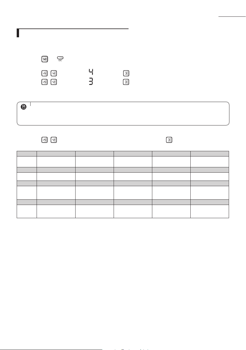
Setting the indoor unit option code
In order to set the indoor unit option code use the wired remote controller and follow the directions below.
1. Press the
and buttons at the same time for more than 3 seconds and then a Main menu will be
displayed.
2. Press the
/ button to select and then press button to enter a Sub-menu setting screen.
3. Press the
/ button to select and then press button to enter a Indoor unit option code setting
screen.
4. Press the
/
button to set the option code in order. Press button to go to the next page.
5. Press the
button to save and complete the option setting.
6. Press the
button to exit to normal mode.
CAUTION
• Option code will not be applied if you don’t press the
• Setting indoor unit option code is only possible in Master wired remote controller.
You can only check the indoor unit option code in Slave wired remote controller.
• Setting indoor unit option code is possible when one indoor unit is connected. If more than 2
indoor units are connected, you can only check the Master indoor unit option code.
Away/MDS
Main Menu
Sub-menu
1 2 3 54 6
Data bit
1 2 3 4 5 6
Option CodePage number
SEG1 SEG2 SEG3 SEG4 SEG5 SEG6
0
✴ ✴ ✴ ✴ ✴
Page number
SEG7 SEG8 SEG9 SEG10 SEG11 SEG12
1
✴ ✴ ✴ ✴ ✴
Page number
SEG13 SEG14 SEG15 SEG16 SEG17 SEG18
2
✴ ✴ ✴ ✴ ✴
Page number
SEG19 SEG20 SEG21 SEG22 SEG23 SEG24
3
✴ ✴ ✴ ✴ ✴
Page number
NOTE
• The first digit represents the page number and the remaining five digits are option codes.
• The option code which is currently setting will icker.
• Press the
button anytime during setup to exit without setting.
NOTE
39
A
Setting an indoor unit address and installation option
• Press the button anytime during setup to exit without setting.
• Address will not be applied if you don't press
button.
• Setting Main/RMC Address of an Indoor unit is available only with a master wired remote controller.
NOTE
NOTE
• The Main/RMC Address which is currently setting will flicker.
• Data bit 1 and 2 present Indoor unit main address checking
• Data bit 3 and 4 present Indoor unit main address setting(outdoor unit reset is needed to set).
• Data bit 5 and 6 present Indoor unit RMC address setting/checking.
Set the indoor unit address and installation option with remote controller option. Set the each option
separately since you cannot set the ADDRESS setting and indoor unit installation setting option at the same
time. You need to set twice when setting indoor unit address and installation option.
Setting an indoor unit address
1. Press the and buttons at the same time for more than 3 seconds and then a Main menu will be
displayed.
2. Press the
/ button to select and then press button to enter a Sub-menu setting screen.
3. Press the
/ button to select and then press button to enter a Indoor Address setting screen.
1 2 3 4 5 6
Data bit
4. Press the
/ button to set the Indoor unit Main/RMC Address.
5. Press the
button to save and complete the option setting.
6. Press the
button to exit to normal mode.
40
Setting an indoor unit installation option
In order to check and set the indoor unit installation option code use the wired remote controller and
follow the directions below.
1. Press the
and buttons at the same time for more than 3 seconds and then a Main menu will be
displayed.
2. Press the
/ button to select and then press button to enter a Sub-menu setting screen.
3. Press the
/ button to select and then press button to enter a Indoor unit installation option
code setting screen.
4. Press the
/ button to set the installation option code in order. Press button to go to the next
page.
SEG1 SEG2 SEG3 SEG4 SEG5 SEG6
0 2 RESERVED
Exterior
temperature sensor
Central control RESERVED
SEG7 SEG8 SEG9 SEG10 SEG11 SEG12
1 Drain pump Use of Hot Coil RESERVED RESERVED RESERVED
SEG13 SEG14 SEG15 SEG16 SEG17 SEG18
2 External control
External control
output
S-Plasma ion Buzzer
Number of hours
using lter
SEG19 SEG20 SEG21 SEG22 SEG23 -
3
Individual control of
a remote controller
Heating setting
compensation
RESERVED RESERVED -
• The rst digit represents the page number and the remaining ve digits are installation option.
• The total option codes are 24 digits. You can set six digits at a time and it is distinguished by page
number (0, 1, 2, 3).
NOTE
Setting an indoor unit address and installation option
41
Option No. : 02XXXX-1XXXXX-2XXXXX-3XXXXX
Option SEG1 SEG2 SEG3 SEG4 SEG5 SEG6
Explanation PAGE MODE
RESERVED
Use of external
temperature
sensor
Use of central
control
RESERVED
Indication
and Details
Indication Details Indication Details Indication Details Indication Details
0 2
0 Disuse 0 Disuse
1 Use 1 Use
Option SEG7 SEG8 SEG9 SEG10 SEG11 SEG12
Explanation PAGE Use of drain pump Use of Hot Coil
RESERVED RESERVED RESERVED
Indication
and Details
Indication Details Indication Details Indication Details
1
0 Disuse 0 Disuse
1 Use 1 Use
2
Use +
3minute
delay
- -
Option SEG13 SEG14 SEG15 SEG16 SEG17 SEG18
Explanation PAGE
Use of external
control
Setting the output
of external control
S-Plasma ion Buzzer control
Number of hours
using lter
Indication
and Details
Indication Details Indication Details Indication Details Indication Details Indication Details Indication Details
2
0 Disuse 0 Thermo on 0 Disuse 0
Use of
buzzer
2 1000 Hour
1
ON/OFF
Control
1 Operation on
1
Use 1
Non
use of
buzzer
6 2000 Hour
2
OFF
Control
3
WINDOW
ON/OFF
Control
Option SEG19 SEG20 SEG21 SEG22 SEG23 -
Explanation PAGE
control of a remote
controller
Heating setting
compensation
RESERVED RESERVED
-
Indication
and Details
Indication Details Indication Details Indication Details -
3
0 or 1 Indoor 1 0 Disuse
-
2 Indoor 2 1 2°C
3 Indoor 3
2 5°C
4 Indoor 4
5.
Press the button to save and complete the option setting.
6. Press the
button to exit to normal mode.
• Press button anytime during setup to exit without setting.
• Option code will not be applied if you don't press
button.
• Setting Installation option code is available only with a master wired remote controller.
• Setting Installation option code is available when there is one on one connection between a wired
remote controller and an indoor unit.
NOTE
42
A
If an error occurs during the operation, one or more LED flickers and the operation is stopped except the LED
.
If you re-operate the air conditioner, it operates normally at first, then detect an error again.
LED Display on the receiver (Optional)
Troubleshooting (NS
HHXEG)
Abnormal conditions
Indicators
Remarks
Concealed Type
Green Red
Standard Type
Power reset
X X X X
Error of temperature sensor
in the indoor unit (Open/Short)
X X X X
Error of heat exchanger sensor
in the indoor unit
X X X
Error of the outdoor temperature sensor
Error of the condensor temperature sensor
Error of the discharge temperature sensor
X X X
1. No communication for 2 minutes
between indoor units
(Communication error for more than 2 minutes)
2. Indoor unit receiving the
communication error from outdoor unit
3. Outdoor unit tracking 3 minutes error
4. When sending the communication
error from the outdoor unit, the
mismatching of the communication num-
bers and installed numbers after comple-
tion of tracking.
(Communication error for more than 2 minutes)
X X X
1. Indoor unit error
(Display is unrelated
with operation)
2. Outdoor unit error
(Display is unrelated
with operation)
43
Abnormal conditions
Indicators
Remarks
Concealed Type
Green Red
Standard Type
Communication error between indoor units
X X X
1. Error of electronic expansion valve close
2. Error of electronic expansion valve open
3. 2’nd detection of high temperature cond
4. 2’nd detection of high temperature
discharge
5. Error of reverse phase
6. Compressor down due to 6th detection
of freezing
X X
Detection of the float switch
X X
Error of setting option switches for optional
accessories
X X X
EEPROM error
X X
EEPROM option error
If you turn off the air conditioner when the LED is flickering, the LED is also turned off.
On
Flickering
X
Off
44
A
Display Explanation Remark
Indoor unit Communication Error
Communication Error
Indoor/Outdoor unit Communication Time Out Error
60 Packet Over data
Indoor unit is not connected
Communication Error between Outdoor Main and Inverter Micom
(Occurred after 1 minute detection in Main and Inverter)
Indoor Temp. Sensor (Open/Short Error)
Indoor Sensor Error
Indoor Unit Eva in Sensor (Open/Short Error)
Indoor Unit Eva in Sensor Separation
Outdoor Temp. Sensor Error (Open/Short Error)
Outdoor Sensor Error
COND Temp. Sensor Error (Open/Short Error)
Inverter Compressor Discharge Temp. sensor Error
(Open/Short Error)
Power cable miss connection error
Indoor Float S/W 2
nd
Detection
Self Diagnosys Error
Outdoor unit - indoor unit communication wire miss connection
(Connected to Power terminal)
Outdoor unit refrigerant Full leakage (Gas leak)
Outdoor Fan 1 Error
Outdoor Fan 2 Error
Discharge over temperature
Outdoor Unit Protection
Control Error
[Inverter] Compressor starting error
Primary Current Over Trip error
[Inverter] DC PEAK error(O.C)
[Inverter] Compressor Rotation error
[Inverter] Current Sensor error
[Inverter] DC LINK Sensor error
[Inverter] EEPROM Read/Write Error
[Inverter] Heatsink temperature over Error
Outdoor unit Capacity Setup option error
Communication error between Indoor unit and wired remote control
Wired Remote Control
Error
Communication error between Master and Slave wired remote control
COM1/COM2 Cross-installed error
Error of setting option for wired remote control COM2
If an error occurs, is displayed on the wired remote control.
If you would like to see an error code, press the Test button.
Wired remote control
Troubleshooting (NS
HHXEG)
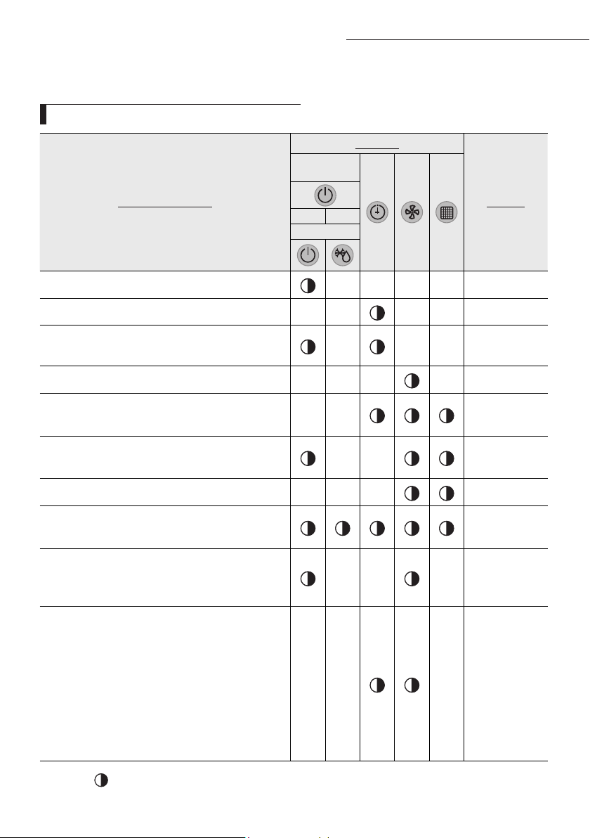
45
A
Abnormal conditions
Indicators
Remarks
Concealed
Type
GREEN RED
Standard Type
Power reset
X X X X
Error of Room sensor in the indoor unit(Open/Short)
X X X X
Error of EVA-IN,EVA-OUT discharge sensor in the indoor
unit(Open/Short)
X X X
Error of Fan motor in the indoor unit
X X X X
1. Error of Outdoor
2. Thermal Fuse Open Error of Indoor's Terminal Block
X X
1. Clogging of outdoor's service valve
2. the refrigerant leakage
X X
Detection of the float switch
X X X
1. Error of EEPROM
2. Error of Option setting
1. Error of Outdoor Temp. sensor
2. Error of Cond Temp. sensor
3. Error of discharge Temp. sensor
X X X
1. No communication for 2 minutes between indoor
units (Communication error for more than 2 minutes)
2. Indoor unit receiving the communication error from
outdoor unit
3. Outdoor unit tracking 3 minutes error
4. When sending the communication error from the
outdoor unit, the mismatching of the communication
numbers and installed numbers after completion of
tracking.(Communication error for more than 2 min-
utes)
X X X
1. Indoor unit
error
(Display is unre-
lated
with operation)
2. Outdoor unit
error
(Display is unre-
lated
with operation)
If an error occurs during the operation, one or more LED flickers and the operation is stopped except the LED.
If you re-operate the air conditioner, it operates normally at first, then detect an error again.
LED Display on the receiver & display unit
Troubleshooting (AC
JNHFKH)
If you turn off the air conditioner when the LED is flickering, the LED is also turned off.
On
Flickering
X
Off
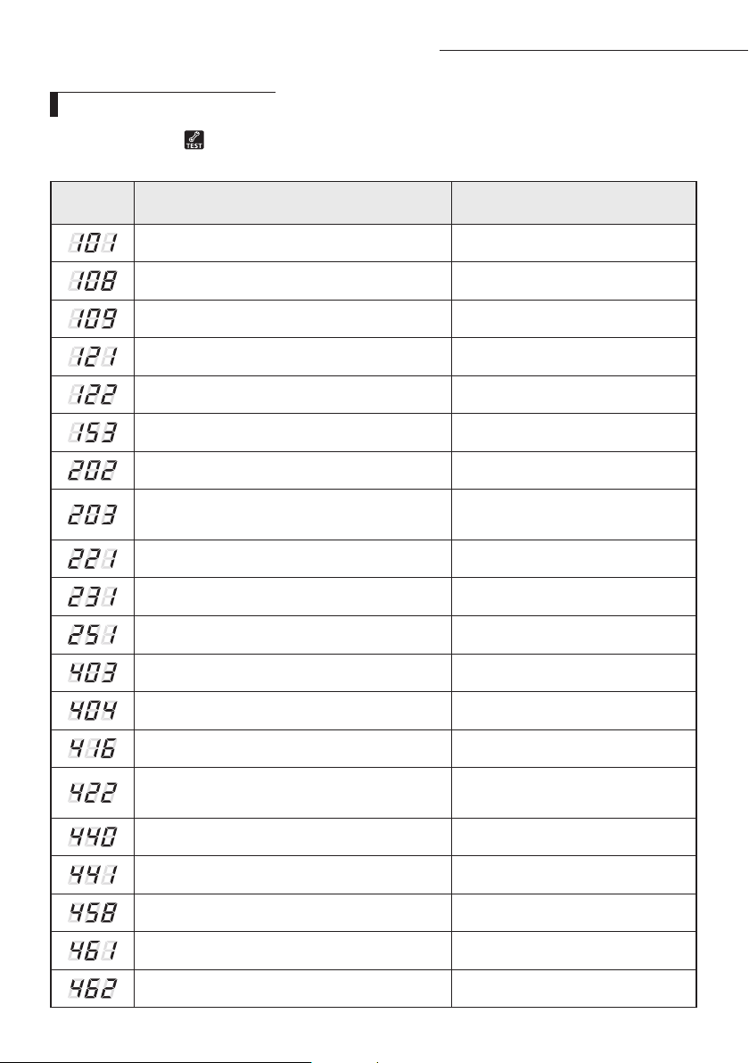
46
A
Wired remote controller
◆
If an error occurs, is displayed on the wired remote controller.
If you would like to see an error code, press the Test button.
Error
mode
Contents Error type
Indoor unit communication error Communication error
Duplicated address setting error Communication error
No response error address from indoor unit Communication error
Indoor temperature sensor (open/short error) Indoor sensor error
Indoor unit Eva In sensor (Open/Short) Indoor sensor error
Indoor floating switch secondary detection Self diagnostic error
Indoor/outdoor communication error (1 min) Communication error
Communication error between indoor/outdoor
INV
↔
MAIN MICOM (1 min)
Communication error
Outdoor temperature sensor error Outdoor sensor error
COND temperature sensor error Outdoor sensor error
[Inverter] Emission temperature sensor error Outdoor sensor error
Detection of Indoor Freezing (when Comp. Stops) Outdoor unit protection control error
Protection of Outdoor Overload (when Comp. Stops) Outdoor unit protection control error
Emission temperature excessively high Outdoor unit protection control error
High pressure blockage error
(Refrigerant completely Leakage error)
Self diagnostic error
Heating operation blocked Self diagnostic error
Cooling operation blocked Self diagnostic error
Outdoor fan 1 error Self diagnostic error
[Inverter] Compressor startup error Outdoor unit protection control error
[Inverter] Total current error/PFC over current error Outdoor unit protection control error
Troubleshooting (AC
JNHFKH)
47
Error
mode
Contents Error type
OLP Overheat and Comp. Stop Outdoor unit protection control error
[Inverter] IPM over current error Outdoor unit protection control error
Compressor V limit error Outdoor unit protection control error
DC LINK over/low voltage error Outdoor unit protection control error
[Inverter] Compressor rotation error Outdoor unit protection control error
[Inverter] Current sensor error Outdoor unit protection control error
[Inverter] DC LINK voltage sensor error Outdoor unit protection control error
EEPROM Read/Write error Outdoor unit protection control error
[Inverter] OTP error Outdoor unit protection control error
AC ZERO CROSSING SIGNAL OUT error Outdoor unit protection control error
Compressor LOCK error Outdoor unit protection control error
Outdoor fan 2 error Self diagnostic error
IPM Overheat Error for Outdoor Unit Inverter Comp. Outdoor unit protection control error
Gas leak error Self diagnostic error
Capacities not matched Outdoor unit protection control error
Communication error between the indoor unit and
wired remote controller
Wired remote controller error
Communication error between the Master and
Slave wired remote controllers
Wired remote controller error
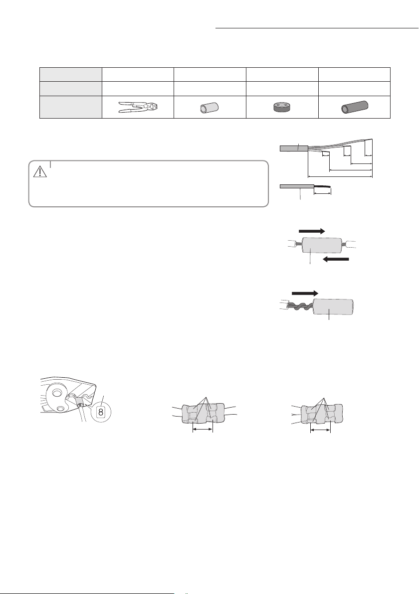
48
A
1. Prepare the following tools.
Tools Crimping pliers Connection sleeve (mm) Insulation tape Contraction tube (mm)
Spec MH-14 20xØ6.5(HxOD) Width 19mm 70xØ8.0(LxOD)
Shape
2. As shown in the gure, peel o the shields from the rubber and wire of the
power cable.
- Peel o 20 mm of cable shields from the pre-installed tube.
• For information about the power cable specications for indoor and
outdoor units, refer to the installation manual.
• After peeling o cable wires from the pre-installed tube, insert a
contraction tube.
CAUTION
(Unit: mm)
120
60
202020
180
Power cable
20
Pre-installed tube for the power cable
3. Insert both sides of core wire of the power cable into the connection sleeve.
Method 1
Push the core wire into the sleeve from both sides.
Connection sleeve
Method 2
Twist the wire cores together and push it into the sleeve.
Connection sleeve
4. Using a crimping tool, compress the two points and ip it over and compress another two points in the same location.
- The compression dimension should be 8.0.
- After compressing it, pull both sides of the wire to make sure it is rmly pressed.
Compression
dimension
Method 1
Compress it 4 times.
5 mm
Method 2
Compress it 4 times.
5 mm
Extending the power cable
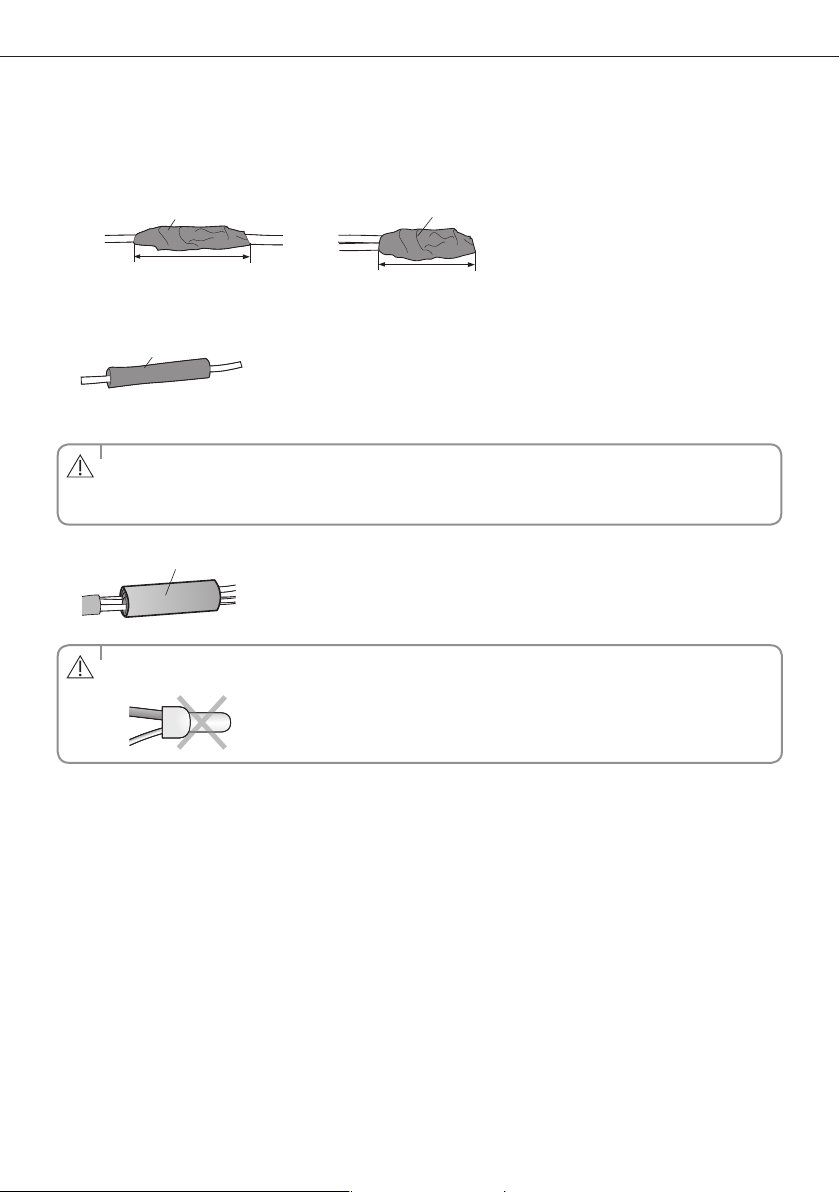
49
5. Wrap it with the insulation tape twice or more and position your contraction tube in the middle of the insulation tape.
Three or more layers of insulation are required.
Method 1
40 mm
Insulation tape
Method 2
Insulation tape
35 mm
6. Apply heat to the contraction tube to contract it.
Contraction tube
7. After tube contraction work is completed, wrap it with the insulation tape to nish.
• Make sure that the connection parts are not exposed to outside.
• Be sure to use insulation tape and a contraction tube made of approved reinforced insulating materials that have
the same level of withstand voltage with the power cable. (Comply with the local regulations on extensions.)
CAUTION
Insulation tape
• In case of extending the electric wire, please DO NOT use a round-shaped Pressing socket.
- Incomplete wire connections can cause electric shock or a re.
WARNING

QUESTIONS OR COMMENTS?
COUNTRY CALL OR VISIT US ONLINE AT
AUSTRALIA
1300 362 603 www.samsung.com/au/support
Duct Type Series
NSHHXEG
ACJNHFKH
Air Conditioner
user & installation manual
imagine the possibilities
Thank you for purchasing this Samsung product.
DB68-06414A-00
EN