WARNING
PERSONAL RISK HAZARD
To avoid the risk of
property damage, personal injury or death due to electrical shock, disconnect the electrical power
before working on this product
.
D
E
Cover
Wiring
Access
Low Voltage
Compartment
S
u
b
b
a
s
e
B
o
x
A
s
s
y
.
A
Wall
Sleeve
B
Z
C
3"
D
11-3/4"
E
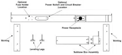
Subbase Assembly
Part/Location Identification
A Left Front Cover
B Right Front Panel
C Front Cord Panel
D Wall Sleeve Hole Location
E Skirting Hole Location
Z Right Front Cover Assembly
IMPORTANT NOTE: To avoid equipment dam-
age, use copper conductors only.
NOTE:
The installation and servicing of this equipment must be performed by
qualified, experienced technicians only.
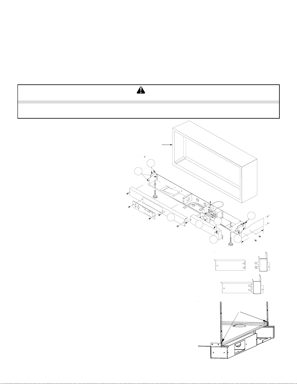
1. Remove (B) and (C) from the subbase and join together using two metal screws
provided. This assembly now becomes the right front cover (Z) of the subbase.
2. Position subbase under the front of the wall sleeve. Locate by aligning flanges
on the subbase to the wall sleeve.
When positioned correctly, the subbase will extend 1-7/16" past the front of the
wall sleeve.
3. Drill four 1/8-inch holes in wall sleeve to line up with holes in subbase (D). Mount
subbase to wall sleeve with four sheet metal screws provided with kit (D).
4. Remove the left front cover from the subbase (A).
5. Position skirting on each side of wall sleeve to prevent the entry of foreign mate-
rials. Trim skirting to desired length. Attach skirting with four sheet metal screws
provided with kit (E).
6. Wire subbase for appropriate voltage (seeWiring Diagram).
NOTE: The proper subbase must be ordered to obtain the correct electrical re-
ceptacle (see NEMA Plug Configurations).
7. After wiring is complete, mount covers A and Z to the subbase with provided
screws.
8. When installing optional accessories to the subbase, refer to each installation
instruction for that accessory.
Z
B
C
+
=
ATTENTION INSTALLING PERSONNEL: As a professional installer you have an obligation to know the product better than the
customer. This includes all safety precautions and related items. Prior to actual installation, thoroughly familiarize yourself with this
Instruction Manual. Pay special attention to all safety warnings. Remember, it is your responsibility to install the product safely and
to know it well enough to be able to instruct a customer in its safe use. Most dealers have a list of specific good safety
practices...follow them. The precautions listed in this Installation Manual are intended as supplemental to existing practices.
However, if there is a direct conflict between existing practices and the content of this manual, the precautions listed herein take
precedence.
The subbase may be installed on the wall sleeve before or after installing the wall sleeve. The subbase is prewired. Electrical
connections can be made on the left side after the access cover is removed. A grounding screw is provided.
NOTE: The wall sleeve must be installed a minimum of 3¼ inches above a finished floor and a minimum of 2¾ inches from a
finished wall.
PTAC
SUBBASE KIT INSTALLATION INSTRUCTIONS
Part No. 11113807
Printed in USA
January 2005
IMPORTANT NOTE: Sub-
base should extend 1-7/16”
past wall sleeve flange. .
LOCATE FLANGE ON SUBBASE
AGAINST WALL SLEEVE FLANGE.
2
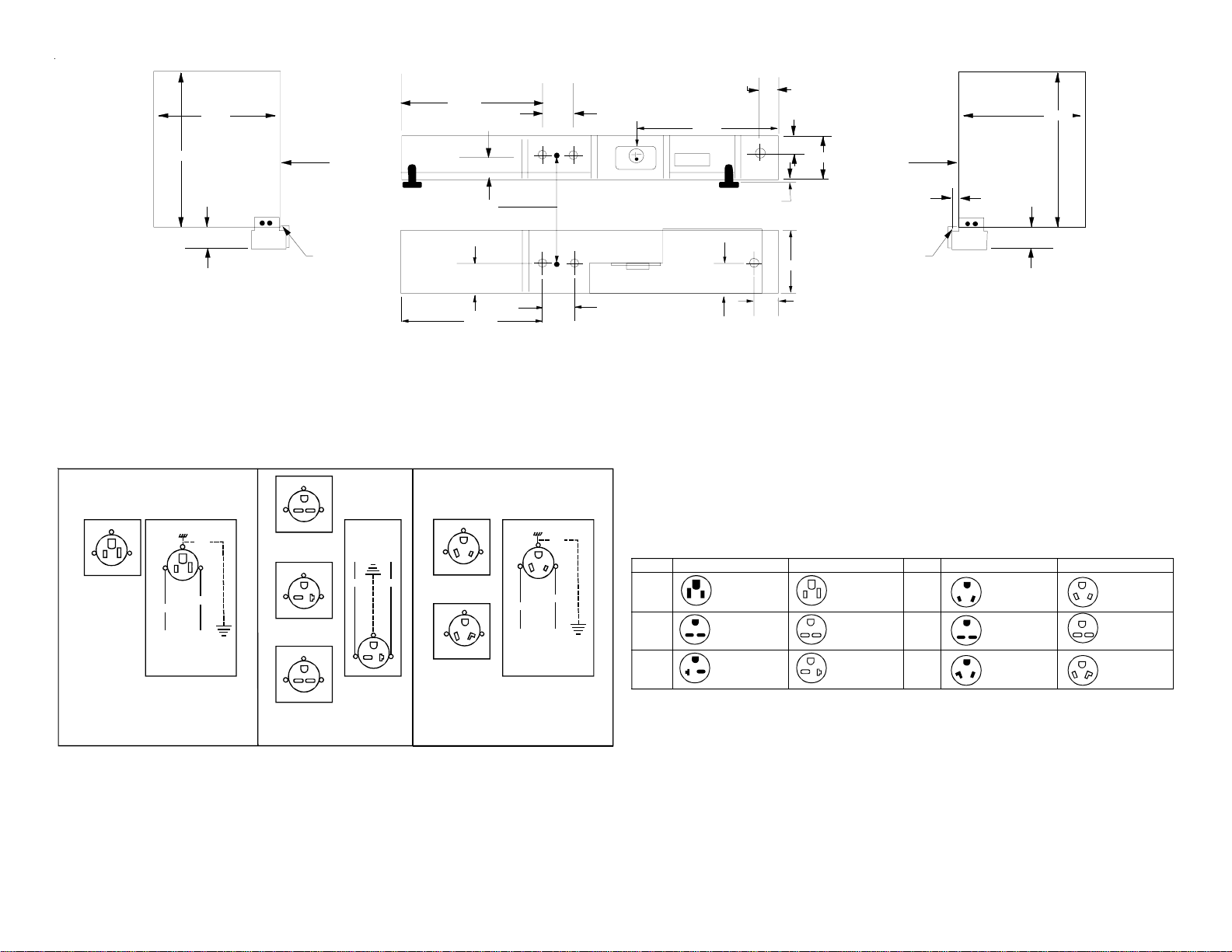
NEMA Plug Configurations
Voltage Unit Plug Subbase Receptacle
230/208
230/208
NEMA 6-15 AMP
NEMA 6-20 AMP
NEMA 6-15 AMP
NEMA 6-20 AMP
L2
L2
L1 L1
L1 L2
L2
L1
G
GG
NEMA 5 -15 AMP NEMA 5-15 AMP
L2 L1 L1 L2
115
230/208
265
265
NEMA 7-20 AMP
NEMA 6-30 AMP
NEMA 7-30 AMP
NEMA 7-20 AMP
NEMA 6-30 AMP
NEMA 7-30 AMP
L2
L2
L2
L1
L1
L1
L2
L2
L2
L1
L1
L1
G
G
G
W
W
G
W
G
W
Voltage Unit Plug Subbase Receptacle
Subbase Dimensions
1-1/4"
Wall Sleeve
(Outdoor Side)
16-1/16"
13-3/4"
3-1/4"
Left End View
Wall
Sleeve
Inside
Edge
Back of
Flange "A"
19-9/16"
1-3/8"
Ground
Screw Location
2"
19-9/16"
Concentric
Knockouts in Rear
Front View
Top View
Concentric
Knockouts in Bottom
3-1/2"
3-1/2"
Receptacle
Provided
Inside Subbase
Accessory
1-1/4"
1-3/8"
1-1/4"
2"
13-1/2"
2-5/8"
4"
2" Max. Adjustment
Wall Sleeve
(Inside Side)
16-1/16"
13-3/4"
3-1/4"
Right End View
Wall
Sleeve
Outdoor
Edge
Back of
Flange "A"
1-7/16"
NOTE: The subbase should
extend into the room 1-7/16"
past the wall sleeve flange.
NOTE: The subbase should
extend into the room 1-7/16"
past the wall sleeve flange.
Wiring Diagram
230/208 VAC Field Schematic 265 VAC Field Schematic
Field Wiring
Line Voltage
G
W
L1 L2
WHT
BLK
GRN
L2L1
G
W
NEMA 7-20R
Receptacle
NEMA 7-30R
Receptacle
L2L1
G
W
G
BLK RED
L1 L2
Field Wiring
Line Voltage
L2L1
L2L1
G
G
NEMA 6-20R
Receptacle
NEMA 6-30R
Receptacle
L2L1
G
NEMA 6-15R
Receptacle
115 VAC Field Schematic
L2L1
G
NEMA 5-15R
Receptacle
W
L1 L2
WHT
BLK
GRN
G
W
Field Wiring
Line Voltage
