Loading ...
Loading ...
Loading ...
Installation Method
Installation manual 13
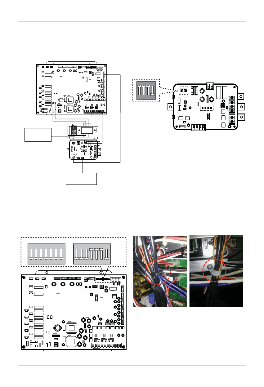
10. Connect the wire of control signal of Damper Actuator of Master Unit to CN_AO(AO_01(A+)) and connect the
wire of control signal of Damper Actuator of Slave Unit to CN_AO(AO_02(B+))
11. Set up the main function dip switch of LAC PCB.
12. Set up the dip switch of MAIN outdoor unit PCB.
13. Using the clamp and tie provided securely attach the wire as shown in the figure.
Step 11
ON
1234
Step 10
AC 24V Power
for Damper Actuator
of Master & Slave
DC 0~10V Control Signal
for Damper Actuator
of Master & Slave
Master(AO_01(A+))
Slave(AO_02(B+))
Step 12 Step 13
ON
SW01B SW02B
1234567
ON
1234567
Loading ...
Loading ...
Loading ...