Quick Start Guide
Commonly Used Tools
- Phillips Head Screwdriver
- Flat Head Screwdriver
- Hammer
- Wire Cutter/Stripper
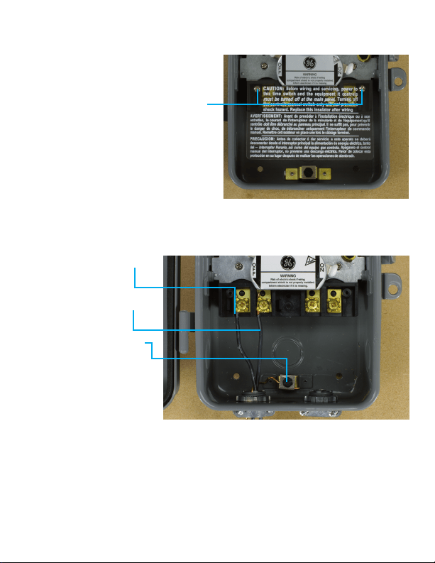
WARNING
• Recommended installation by licensed electrician.
• High Voltage (There may be more that one source of supply)
disconnect all power sources before servicing.
• Risk of electric shock – All terminals are live.
• Use copper wire only.
• Close the cover after setting.
• Tighten connections to 25 lbf-in.
• Use correct gauge wire (8-14 AWG) based on local electrical code
of at least 105C rating.
• Approved for outdoor use.
• Wire strip length ½”
• GROUNDING: National Electrical Code requires that grounding must be
continuous and in proper electrical contact in all grounding conductors,
metallic conduits and grounding terminals.
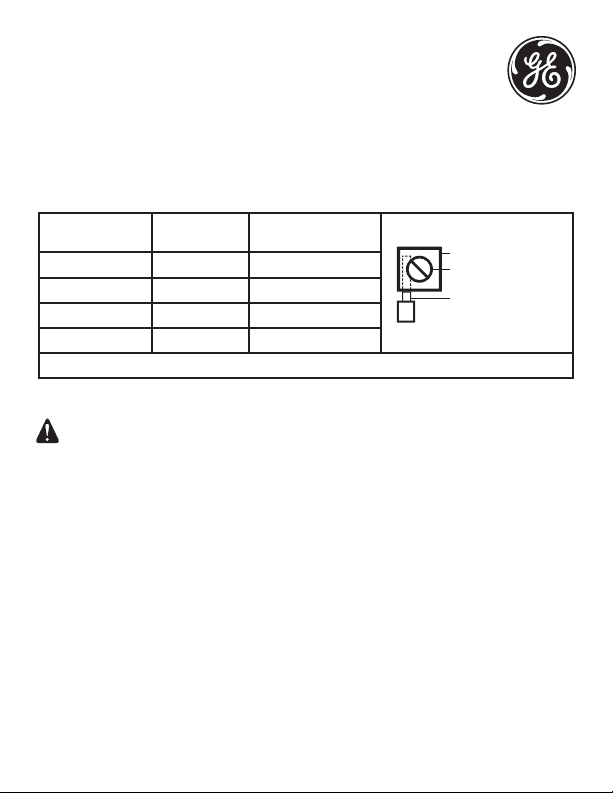
MIN. COPPER WIRE
SIZE (AWG)
MAX LOAD
(AMP)
MINIMUM INSULATION
TEMP (°C)
PRESSURE PLATE
TERMINAL SCREW
MAKE SURE WIRE
INSULATION CLEARS
PRESSURE PLATE
14 15 60
12 20 60
10 30 60
8 40 105
USE CORRECT GAUGE WIRE PER LOCAL ELECTRICAL CODE
Supplied Hardware
- #10 Screw (3)
- #10 Drywall Anchors
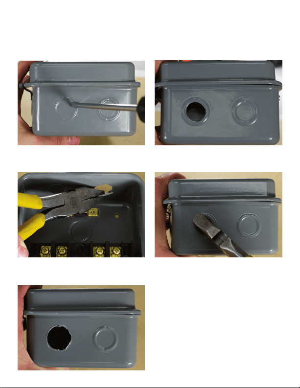
Knockouts
Each metal box comes with ½ ” and ¾” knockouts. Follow the pictures below to
remove knockouts.
For ½” knockout place small blade screw driver as pictured above. Tap lightly to
punch knockout loose.
For ¾” knockout first use screwdriver to punchout ½” knockout then use pliers
to remove outer ring.
Final result of ¾” knockout
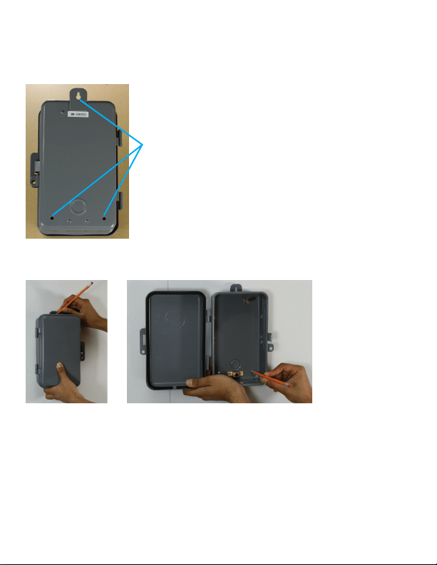
Mounting the timer
1. Select the location for the timer and use the three holes provided for
mounting.
Mounting holes
2. Remove module from timer box. Hold the timer box in place and mark the
holes on the mounting surface.
3. If mounting to drywall:
a. Drill a 3/16” size hole for the drywall anchors at the marked locations
b. Insert an anchor in each hole gently tap the open end of anchor with a
hammer until the anchor is almost flush with the wall.
c. Mount the timer to the anchors using the supplied screws.
4. If mounting to plywood drill a 3/32” size hole for each screw and mount the
timer to the surface using the supplied screws.
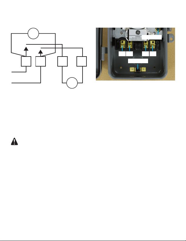
240 VAC Setup: Timer Motor & Load same voltage
Connections:
L- Line Input to Timer Motor and Switch 1
1-Line Input to Timer Motor and Switch 2
X-Line Output of time Switch 1
2-Line Output of Time Switch 2
WARNING
• Recommended installation by licensed electrician.
• High Voltage (There may be more that one source of supply)
disconnect all power sources before servicing.
• Risk of electric shock – All terminals are live.
• Use copper wire only.
• Close the cover after setting.
• Tighten connections to 25 lbf-in.
• Use correct gauge wire (8-14 AWG) based on local electrical code
of at least 105C rating.
• Approved for outdoor use.
• Wire strip length ½”
• GROUNDING: National Electrical Code requires that grounding must be
continuous and in proper electrical contact in all grounding conductors,
metallic conduits and grounding terminals.
2XL
H
H
1
LOAD
M
Typical for same voltage in LOAD and MOTOR
GROUND
GROUND
L X1 2
Step 1: Remove Plastic Guard
Remove screws using a Philips Head
screwdriver and keep them to the side.
Carefully remove plastic guard and
also keep to the side.
Step 2: Connect the Input/Clock Motor Voltage
1. Connect 240VAC Line 1
(Black) input to
Terminal L.
2. Connect 240VAC Line 2
(Black) input to
Terminal 1.
3. Connect the bare wire
to the ground lug.
Tighten the screw
terminals to 25in-lb.
Improper tightening can
cause heating and
equipment failure.
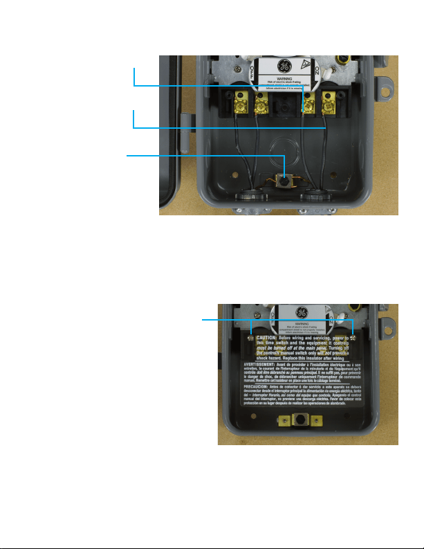
Step 3: Complete the circuit to the load
1. Connect 240VAC Line 1
(Black) of Load to
Terminal L.
2. Connect 240VAC Line 2
(Black) of Load to
Terminal 1.
3. Connect the bare wire
to the ground lug.
Tighten the screw
terminals to 25in-lb.
Improper tightening can
cause heating and
equipment failure.
Step 4: Reinstall the Plastic Guard
Install both screws with the plastic
guard facing the original position.
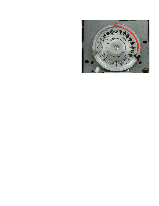
Step 5: Activate Timer
1. Turn the mechanism dial counter
clockwise to set the current time as
accurately as possible.
2. After wiring and setting the timer
with the ON/OFF trippers in the
correct timer positions. Be sure to
depress the ON or OFF lever to set
the timer to the desired state. The
timer will turn ON or OFF at the next
programmed time.
3. You cannot see the dial turning.
Wait at least 30 minutes after the
set ON or OFF time to verify the
timer is operating properly.
Step 6: Check timer after 24 hours
1. After 24 Hours, remove power from the timer and check the connections:
a. Remove plastic guard
b. Verify all screws and connections are still firmly tightened.
c. It is possible that after your initial tightening, the wire has compressed and
loosened the connections.
2. After making sure everything is still tight, replace the plastic guard and
restore power to the timer.
*Please review “Operating Instructions” in the user manual.
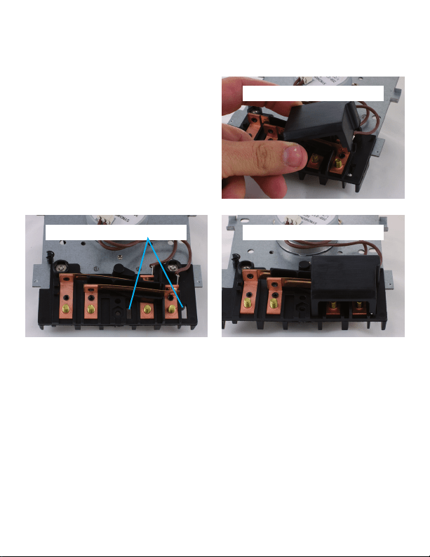
Special Note for Plastic Guard
on the back of the motor
On the back of the motor there is a
plastic guard for “Input” side
connections. It snaps easily in and out
of place. If the guard has come off
during shipment or installation,
reinstall by placing the two tabs at the
bottom in the appropriate slots.
15164 VERSION 1
04/18/12
WWW.JASCOPRODUCTS.COM
Plastic guard fitted correctly
Pictured is plastic guard
Ends fit into these holes