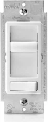
PRELIMINARY
Single-Pole Wiring Application:
LED/Compact Fluorescent/Incandescent Slide Dimmer
Single Pole (One Location) or 3-Way (Two Location)
Cat. No. 6674-P – LED/CFL 150W, Incandescent 600W
120VAC, 60Hz
INSTALLATION INSTRUCTIONS
DI-000-06674-02A-X2
Identifying your wiring application
(most common):
NOTE: If the wiring in the wall box does not resemble any of
these configurations, consult an electrician.
Step 3
Step 4
Removing existing switch: Remove existing
wallplate and switch mounting screws. Carefully pull switch
from wall box. DO NOT remove wires attached to the
switch at this time.
Step 2
Tools needed to install your Dimmer
Slotted/Philips Screwdriver Electrical Tape Pliers
Pencil Cutters Ruler
Installing Dimmer by itself or with other devices
If installing Dimmer in a single device application, proceed with the
INSTALLING YOUR DIMMER section. If installing Dimmer in a
multi-device application, proceed as follows:
WARNING: To avoid fire, shock, or death; TURN OFF
POWER at circuit breaker or fuse and test that power is off
before wiring!
ONOFF
ONOFF
ONOFF
ONOFF
ONOFF
ONOFF
ONOFFONOFF
ONOFF
ONOFF
ONOFF
ONOFF
Step 1
INSTALLING YOUR DIMMER
NOTE: Use check boxes when Steps are completed.
√
MULTI-DEVICE APPLICATION:
In incandescent multi-dimmer installations, the reduction of the dimmer’s
capacity is required. Refer to the chart for maximum load per dimmer.
No derating is required for use in Dimmable CFL or dimmable LED multi-
dimmer installations.
MAXIMUM LOAD PER DIMMER FOR MULTI-DEVICE (Incandescent)
Cat. No. Single Two Devices More than 2 Devices
6674-P
600W 500W 400W
Insert wires
straight
then twist
clockwise
Electrical Tape
Step 5a
Connect wires per WIRING DIAGRAM as follows:
Screw wire nuts on clockwise making sure no bare conductors show
below the wire connectors. Secure each connector with electrical tape.
•
Green dimmer Ground lead to Green or bare copper wire in wall box.
• Black dimmer lead to any wall box wire removed from old switch.
• Red dimmer lead without insulating label to remaining wall box wire.
• Remaining Red dimmer lead should have Red insulation label affixed.
Proceed to Step 6.
NOTE: If insulating label is not affixed to Red lead, use a small wire nut
or electrical tape to cap off. Proceed to Step 6.
Black
Red
Neutral
Green
Ground
Red
This wire is used in 3-way installations only.
For single pole installations,
do not remove this insulating label.
Hot (Black)
Neutral (White)
Black
White
Line 120VAC, 60 Hz
Black
Red
Dimmer
Green Ground
Load
Red
Insulating
Label
WIRE CONNECTOR / # OF COND.
COMBINATION CHART
1- #12 w/ 1 to 3 #14, #16 or #18
2- #12 w/ 1 or 2 #16 or #18
1- #14 w/ 1 to 4 #16 or #18
2- #14 w/ 1 to 3 #16 or #18
For non-standard wiring applications, refer to
Wire Nut and Connector Size Chart
WARNINGS AND CAUTIONS:
• TO AVOID FIRE, SHOCK, OR DEATH; TURN OFF POWER at circuit breaker or fuse and test that power is off
before wiring or servicing fixture!
• Tobeinstalledand/orusedinaccordancewithappropriateelectricalcodesandregulations.
• Ifyouareunsureaboutanypartoftheseinstructions,consultanelectrician.
• Toavoidoverheatingandpossibledamagetothisdeviceandotherequipment,DO NOT install to control a
receptacle, a motor- or a transformer-operated appliance, or any other lighting sources than those specified.
• Usethisdevicewith copper or copper clad wire only.
WARNINGS AND CAUTIONS:
• Useonlyone(1)dimmerina3-or4-waycircuit.Theswitch(es)willturnthelightonatthe
brightness level selected at the dimmer.
•
Use with compatible dimmable LED, CFL bulbs, incandescent or 120V halogen fixtures only.
For a complete list of compatible LED and CFL bulbs refer to www.leviton.com.
• WhenmultiplebulbsareusedwithonedimmerDO NOT mix bulb types. All bulbs shall be either LED; CFL or
incandescent. Using the same make/model of each bulb will enhance dimmer performance.
Single Pole
1. Line (Hot)
2. Neutral
3. Ground
4. Load
IMPORTANT: For 3-Way applications, note that one of the screw terminals
from the old switch being removed will usually be a different color (Black)
or labeled Common. Tag that wire with electrical tape and identify as the
common (Line or Load) in both the dimmer wall box and 3-way wall box.
2
3
1
4
2
4
1
5
3
3-Way
1. Line or Load
(See note below)
2. Neutral
3. Ground
4. First Traveler – note color
5. Second Traveler – note color
Preparing and connecting wires:
Strip gage
Cut
(if necessary)
5/8"
• Makesurethattheendsofthewiresfromthewallboxarestraight
(cut if necessary).
• Remove5/8"(1.6cm)ofinsulationfromeachwireinthewallbox
(shown).
•
For Single-Pole Application, go to Step 5a.
• For 3-Way Application, go to Step 5b.
Loading ...
